Embed Size (px)
Citation preview

**************************************************************************USACE / NAVFAC / AFCEC / NASA UFGS- 33 71 01. 00 40 ( November 2014) Change 1 - 02/ 17 - - - - - - - - - - - - - - - - - - - - - - - - - - - - - - - - - - -Pr epar i ng Act i v i t y: NASA Super sedi ng UFGS- 26 26 00. 00 40 ( November 2008)
UNI FI ED FACI LI TI ES GUI DE SPECI FI CATI ONS
Ref er ences ar e i n agr eement wi t h UMRL dat ed Januar y 2020**************************************************************************
SECTION TABLE OF CONTENTS
DIVISION 33 - UTILITIES
SECTION 33 71 01.00 40
OVERHEAD TRANSMISSION AND DISTRIBUTION
11/14
PART 1 GENERAL
1.1 REFERENCES 1.2 DEFINITIONS 1.3 ADMINISTRATIVE REQUIREMENTS 1.3.1 Pre-Installation Meetings 1.4 SUBMITTALS 1.5 MAINTENANCE MATERIAL SUBMITTALS 1.5.1 Additions to Operations and Maintenance Data 1.6 QUALITY CONTROL 1.6.1 Regulatory Requirements 1.6.2 Standard Products 1.6.2.1 Alternative Qualifications 1.6.2.2 Material and Equipment Manufacturing Date 1.6.3 Ground Resistance Test Reports 1.6.4 Wood Crossarm Inspection Report 1.6.4.1 Field Test Plan 1.7 DELIVERY, STORAGE, AND HANDLING 1.8 WARRANTY
PART 2 PRODUCTS
2.1 SYSTEM DESCRIPTION 2.1.1 Design Requirements 2.2 EQUIPMENT 2.2.1 Hardware 2.2.1.1 Pins 2.2.1.2 Hot-Line Clamps 2.2.1.3 Secondary Racks 2.2.2 Guy Strand 2.2.3 Round Guy Markers 2.2.3.1 Guy Attachment 2.2.4 Anchors and Anchor Rods 2.2.4.1 Screw Anchors 2.2.4.2 Plate Anchors
SECTION 33 71 01.00 40 Page 1

2.2.4.3 Rock Anchors 2.2.5 Grounding and Bonding 2.2.5.1 Driven Ground Rods 2.2.5.2 Grounding Conductors 2.2.5.3 Grounding Connections 2.2.6 Conduit Risers and Conductors 2.2.7 Group-Operated Load Interrupter Switches 2.2.7.1 Manually Operated Type (Switch Handle Operated) 2.2.7.2 Remotely Operated Type (Stored-Energy Actuator) 2.2.8 Recloser 2.2.9 Sectionalizer 2.2.10 Metering Equipment 2.2.10.1 Potential Transformers 2.2.10.2 Current Transformers 2.2.10.3 Watthour Meter 2.2.10.4 Meter Test Block 2.2.10.5 Metering Enclosure 2.2.11 Capacitors 2.2.12 Voltage Regulator 2.2.12.1 Ratings 2.2.12.2 Bypass and Isolation Switches 2.2.12.3 Miscellaneous 2.3 COMPONENTS 2.3.1 Poles 2.3.1.1 Wood Poles 2.3.2 Steel Poles 2.3.3 Concrete Poles 2.3.4 Crossarms and Brackets 2.3.4.1 Wood Crossarms 2.3.4.2 Crossarm Braces 2.3.4.3 Armless Construction 2.3.5 Insulators 2.3.6 Neutral-Supported Secondary and Service Drop Cables 2.3.7 Surge Arresters 2.3.8 Fused Cutouts 2.3.9 Transformer (Overhead-Type Distribution) 2.3.9.1 Specified Transformer Losses 2.3.10 Nameplates 2.3.10.1 Manufacturer's Nameplate 2.3.10.2 Field Fabricated Nameplates 2.4 MATERIALS 2.4.1 Overhead Conductors, Connectors and Splices 2.4.1.1 Solid Copper 2.4.1.2 Aluminum (AAC) 2.4.1.3 Aluminum Alloy (AAAC) 2.4.1.4 Aluminum Conductor Steel Reinforced (ACSR) 2.4.1.5 Connectors and Splices 2.4.2 Electrical Tapes 2.4.3 Caulking Compound 2.5 TESTS, INSPECTIONS, AND VERIFICATIONS 2.5.1 Transformer Test Schedule 2.5.2 Routine and Other Tests
PART 3 EXECUTION
3.1 INSTALLATION 3.1.1 Overhead Service 3.1.2 Tree Trimming 3.1.3 Wood Pole Installation
SECTION 33 71 01.00 40 Page 2

3.1.3.1 Setting Depth of Pole 3.1.3.2 Setting in Soil, Sand, and Gravel 3.1.3.3 Setting in Solid Rock 3.1.3.4 Setting with Soil Over Solid Rock 3.1.3.5 Setting on Sloping Ground 3.1.3.6 Backfill 3.1.3.7 Setting Poles 3.1.3.8 Alignment of Poles 3.1.3.9 Pole Caps 3.1.3.10 Marking 3.1.4 Steel and Concrete Pole Setting 3.1.4.1 Cast-In-Place Foundations 3.1.4.2 Power-Installed Screw Foundations 3.1.5 Anchors and Guys 3.1.5.1 Setting Anchors 3.1.5.2 Backfilling Near [Plate] Anchors 3.1.5.3 Screw Anchors 3.1.5.4 Swamp Anchors 3.1.5.5 Rock Anchors 3.1.5.6 Guy Installation 3.1.6 Hardware 3.1.7 Grounding 3.1.7.1 Grounding Electrode Installation 3.1.7.2 Grounding Electrode Conductors 3.1.7.3 Grounding Electrode Connections 3.1.7.4 Grounding and Grounded Connections 3.1.7.5 Protective Molding 3.1.8 Conductor Installation 3.1.8.1 Line Conductors 3.1.8.2 Connectors and Splices 3.1.8.3 Conductor-To-Insulator Attachments 3.1.8.4 Armor Rods 3.1.8.5 Ties 3.1.8.6 Low-Voltage Insulated Cables 3.1.8.7 Reinstalling Conductors 3.1.8.8 New Conductor Installation 3.1.8.9 Fittings 3.1.8.10 Aluminum Connections 3.1.9 Pole Mounted Metering Equipment 3.1.9.1 Primary Meters 3.1.9.2 Installing Meter System 3.1.10 Pole Top Switch Installation 3.1.10.1 Operating Handle 3.1.11 Recloser 3.1.12 Sectionalizer 3.1.13 Risers 3.1.14 Transformer Installation 3.1.15 Crossarm Mounting 3.1.15.1 Line Arms and Buck Arms 3.1.15.2 Equipment Arms 3.1.16 Field Applied Painting 3.1.17 Field Fabricated Nameplate Mounting 3.2 FIELD QUALITY CONTROL 3.2.1 General 3.2.2 Safety 3.2.3 Medium-Voltage Preassembled Cable Test 3.2.4 Sag and Tension Test 3.2.5 Low-Voltage Cable Test 3.2.6 Pre-Energization Services
SECTION 33 71 01.00 40 Page 3

3.2.7 Performance of Acceptance Checks and Tests 3.2.7.1 Overhead-Type Distribution Transformers 3.2.7.2 Pole Top Interrupter Switch 3.2.7.3 Reclosers 3.2.7.4 Sectionalizers 3.2.7.5 Potential Transformers 3.2.7.6 Current Transformers 3.2.7.7 Metering 3.2.7.8 Grounding System 3.2.8 Devices Subject to Manual Operation 3.2.9 Follow-Up Verification
-- End of Section Table of Contents --
SECTION 33 71 01.00 40 Page 4
**************************************************************************USACE / NAVFAC / AFCEC / NASA UFGS- 33 71 01. 00 40 ( November 2014) Change 1 - 02/ 17 - - - - - - - - - - - - - - - - - - - - - - - - - - - - - - - - - - -Pr epar i ng Act i v i t y: NASA Super sedi ng UFGS- 26 26 00. 00 40 ( November 2008)
UNI FI ED FACI LI TI ES GUI DE SPECI FI CATI ONS
Ref er ences ar e i n agr eement wi t h UMRL dat ed Januar y 2020**************************************************************************
SECTION 33 71 01.00 40
OVERHEAD TRANSMISSION AND DISTRIBUTION11/14
**************************************************************************NOTE: Thi s gui de speci f i cat i on cover s t he r equi r ement s f or over head el ect r i cal wor k and ut i l i t y pol es.
Adher e t o UFC 1-300-02 Uni f i ed Faci l i t i es Gui de Speci f i cat i ons ( UFGS) For mat St andar d when edi t i ng t hi s gui de speci f i cat i on or pr epar i ng new pr oj ect speci f i cat i on sect i ons. Edi t t hi s gui de speci f i cat i on f or pr oj ect speci f i c r equi r ement s by addi ng, del et i ng, or r evi s i ng t ext . For br acket ed i t ems, choose appl i cabl e i t em( s) or i nser t appr opr i at e i nf or mat i on.
Remove i nf or mat i on and r equi r ement s not r equi r ed i n r espect i ve pr oj ect , whet her or not br acket s ar e present.
Comment s, suggest i ons and r ecommended changes f or t hi s gui de speci f i cat i on ar e wel come and shoul d be submi t t ed as a Criteria Change Request (CCR) .
**************************************************************************
**************************************************************************NOTE: Thi s gui de speci f i cat i on does not cover al l possi bl e met hods or r equi r ement s f or pr ovi di ng over head f aci l i t i es. Thi s gui de speci f i cat i on pr esent s t he usual met hods and t he most used al t er nat i ves. Di f f er ent mat er i al s and met hods, pr oper l y speci f i ed, i ndi cat ed, and economi cal l y used ar e accept abl e when appr oved by cogni zant aut hor i t y.
**************************************************************************
**************************************************************************NOTE: TO DOWNLOAD UFGS GRAPHI CS
Go t o http://www.wbdg.org/ffc/dod/unified-facilities-guide-specifications-ufgs/forms-graphics-tables
**************************************************************************
**************************************************************************
SECTION 33 71 01.00 40 Page 5
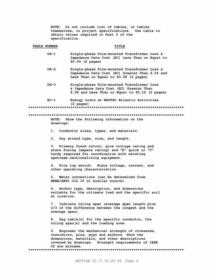
NOTE: Do not i ncl ude l i s t of t abl es, or t abl es t hemsel ves, i n pr oj ect speci f i cat i ons. Use t abl e t o obt ai n val ues r equi r ed i n Par t 2 of t he specification.
TABLE NUMBER TITLE
OH- 1 Si ngl e- phase Pol e- mount ed Tr ansf or mer Loss & I mpedance Dat a Cost ( EC) Less Than or Equal t o $0. 04 ( 2 pages)
OH- 2 Si ngl e- phase Pol e- mount ed Tr ansf or mer Loss & I mpedance Dat a Cost ( EC) Gr eat er Than $. 04 and Less Than or Equal t o $0. 08 ( 2 pages)
OH- 3 Si ngl e- phase Pol e- mount ed Tr ansf or mer Loss & I mpedance Dat a Cost ( EC) Gr eat er Than $. 08 and Less Than or Equal t o $0. 12 ( 2 pages)
EC- 1 Ener gy cost s at NAVFAC At l ant i c Act i v i t i es ( 2 pages)**************************************************************************
**************************************************************************NOTE: Show t he f ol l owi ng i nf or mat i on on t he drawings:
1. Conduct or s i zes, t ypes, and mat er i al s.
2. Guy st r and t ype, s i ze, and l engt h.
3. Pr i mar y f used cut out ; gi ve vol t age r at i ng and st at e f usi ng ( amper e r at i ng) and " K" qui ck or " T" t ar dy r equi r ed f or coor di nat i on wi t h exi st i ng upst r eam sect i onal i z i ng equi pment .
4. Pol e t op swi t ch. St at e vol t age, cur r ent , and ot her oper at i ng char act er i st i cs.
5. Met er connect i ons ( can be det er mi ned f r om NEMA/ ANSI C12. 10 or s i mi l ar sour ce) .
6. Anchor t ype, descr i pt i on, and di mensi ons sui t abl e f or t he ul t i mat e l oad and t he speci f i c soi l at l ocat i on.
7. I ndi cat e r ul i ng span ( aver age span l engt h pl us 2/ 3 of t he di f f er ence bet ween t he l ongest and t he aver age span) .
8. Sag t abl e( s) f or t he speci f i c conduct or , t he r ul i ng span( s) and t he l oadi ng zone.
9. Engi neer t he mechani cal st r engt h of cr ossar ms, i nsul at or s, pi ns, guys and anchor s Show t he di mensi ons, mat er i al s, and ot her descr i pt i ons cover ed by dr awi ngs. St r engt h r equi r ement s of I EEE C2 ar e mi ni mum.
**************************************************************************
SECTION 33 71 01.00 40 Page 6
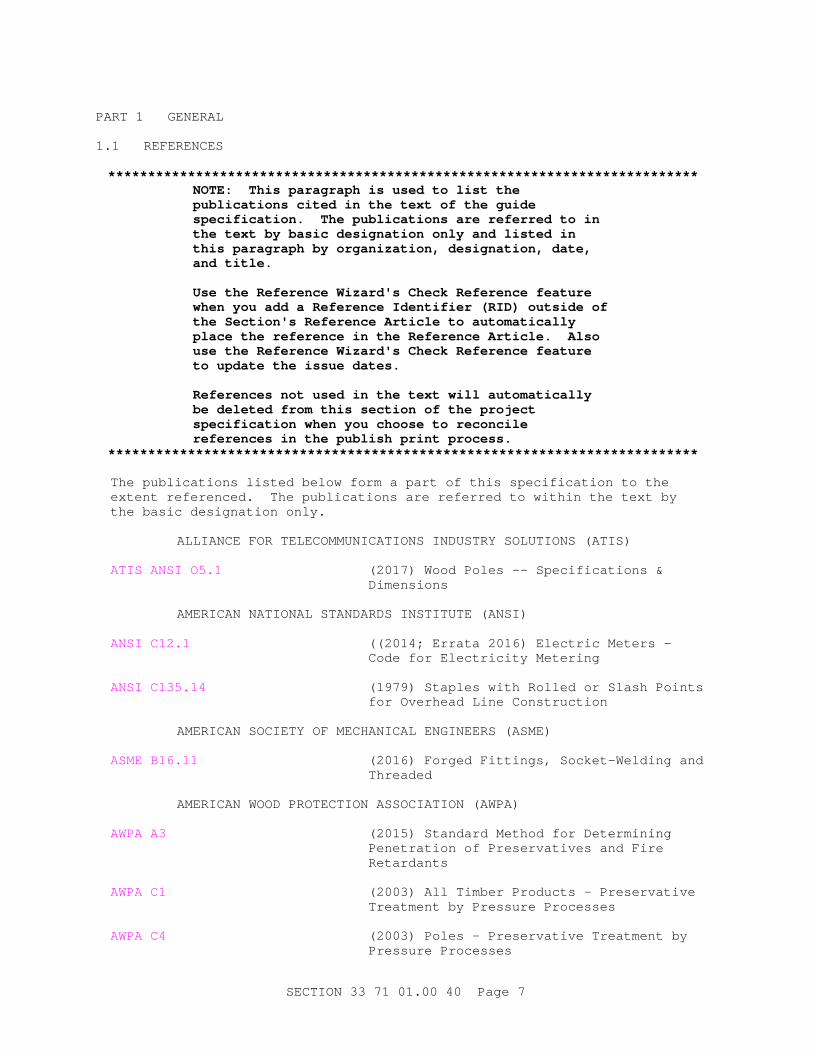
PART 1 GENERAL
1.1 REFERENCES
**************************************************************************NOTE: Thi s par agr aph i s used t o l i s t t he publ i cat i ons c i t ed i n t he t ext of t he gui de speci f i cat i on. The publ i cat i ons ar e r ef er r ed t o i n t he t ext by basi c desi gnat i on onl y and l i s t ed i n t hi s par agr aph by or gani zat i on, desi gnat i on, dat e, and t i t l e.
Use t he Ref er ence Wi zar d' s Check Ref er ence f eat ur e when you add a Ref er ence I dent i f i er ( RI D) out si de of t he Sect i on' s Ref er ence Ar t i c l e t o aut omat i cal l y pl ace t he r ef er ence i n t he Ref er ence Ar t i c l e. Al so use t he Ref er ence Wi zar d' s Check Ref er ence f eat ur e t o updat e t he i ssue dat es.
Ref er ences not used i n t he t ext wi l l aut omat i cal l y be del et ed f r om t hi s sect i on of t he pr oj ect speci f i cat i on when you choose t o r econci l e r ef er ences i n t he publ i sh pr i nt pr ocess.
**************************************************************************
The publications listed below form a part of this specification to the extent referenced. The publications are referred to within the text by the basic designation only.
ALLIANCE FOR TELECOMMUNICATIONS INDUSTRY SOLUTIONS (ATIS)
ATIS ANSI O5.1 (2017) Wood Poles -- Specifications & Dimensions
AMERICAN NATIONAL STANDARDS INSTITUTE (ANSI)
ANSI C12.1 ((2014; Errata 2016) Electric Meters - Code for Electricity Metering
ANSI C135.14 (1979) Staples with Rolled or Slash Points for Overhead Line Construction
AMERICAN SOCIETY OF MECHANICAL ENGINEERS (ASME)
ASME B16.11 (2016) Forged Fittings, Socket-Welding and Threaded
AMERICAN WOOD PROTECTION ASSOCIATION (AWPA)
AWPA A3 (2015) Standard Method for Determining Penetration of Preservatives and Fire Retardants
AWPA C1 (2003) All Timber Products - Preservative Treatment by Pressure Processes
AWPA C4 (2003) Poles - Preservative Treatment by Pressure Processes
SECTION 33 71 01.00 40 Page 7
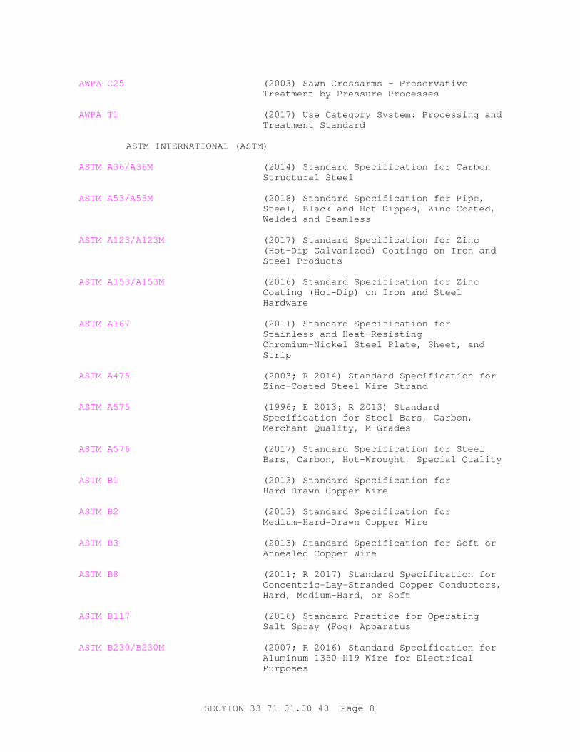
AWPA C25 (2003) Sawn Crossarms - Preservative Treatment by Pressure Processes
AWPA T1 (2017) Use Category System: Processing and Treatment Standard
ASTM INTERNATIONAL (ASTM)
ASTM A36/A36M (2014) Standard Specification for Carbon Structural Steel
ASTM A53/A53M (2018) Standard Specification for Pipe, Steel, Black and Hot-Dipped, Zinc-Coated, Welded and Seamless
ASTM A123/A123M (2017) Standard Specification for Zinc (Hot-Dip Galvanized) Coatings on Iron and Steel Products
ASTM A153/A153M (2016) Standard Specification for Zinc Coating (Hot-Dip) on Iron and Steel Hardware
ASTM A167 (2011) Standard Specification for Stainless and Heat-Resisting Chromium-Nickel Steel Plate, Sheet, and Strip
ASTM A475 (2003; R 2014) Standard Specification for Zinc-Coated Steel Wire Strand
ASTM A575 (1996; E 2013; R 2013) Standard Specification for Steel Bars, Carbon, Merchant Quality, M-Grades
ASTM A576 (2017) Standard Specification for Steel Bars, Carbon, Hot-Wrought, Special Quality
ASTM B1 (2013) Standard Specification for Hard-Drawn Copper Wire
ASTM B2 (2013) Standard Specification for Medium-Hard-Drawn Copper Wire
ASTM B3 (2013) Standard Specification for Soft or Annealed Copper Wire
ASTM B8 (2011; R 2017) Standard Specification for Concentric-Lay-Stranded Copper Conductors, Hard, Medium-Hard, or Soft
ASTM B117 (2016) Standard Practice for Operating Salt Spray (Fog) Apparatus
ASTM B230/B230M (2007; R 2016) Standard Specification for Aluminum 1350-H19 Wire for Electrical Purposes
SECTION 33 71 01.00 40 Page 8

ASTM B231/B231M (2012) Standard Specification for Concentric-Lay-Stranded Aluminum 1350 Conductors
ASTM B232/B232M (2017) Standard Specification for Concentric-Lay-Stranded Aluminum Conductors, Coated-Steel Reinforced (ACSR)
ASTM B398/B398M (2015) Standard Specification for Aluminum-Alloy 6201-T81 Wire for Electrical Purposes
ASTM B399/B399M (2004; R 2015) Standard Specification for Concentric-Lay-Stranded Aluminum-Alloy 6201-T81 Conductors
ASTM D92 (2012a) Standard Test Method for Flash and Fire Points by Cleveland Open Cup Tester
ASTM D97 (2017b) Standard Test Method for Pour Point of Petroleum Products
ASTM D117 (2018) Standard Guide for Sampling, Test Methods, and Specifications for Electrical Insulating Liquids
ASTM D709 (2017) Standard Specification for Laminated Thermosetting Materials
ASTM D877 (2002; R 2007) Standard Test Method for Dielectric Breakdown Voltage of Insulating Liquids Using Disk Electrodes
ASTM D1625 (1971; R 2000) Standard Specifications for Chromated Copper Arsenate
ASTM D1654 (2008; R 2016; E 2017) Standard Test Method for Evaluation of Painted or Coated Specimens Subjected to Corrosive Environments
ASTM D3487 (2016; E2017) Standard Specification for Mineral Insulating Oil Used in Electrical Apparatus
FM GLOBAL (FM)
FM APP GUIDE (updated on-line) Approval Guide http://www.approvalguide.com/
INSTITUTE OF ELECTRICAL AND ELECTRONICS ENGINEERS (IEEE)
IEEE 18 (2012) Standard for Shunt Power Capacitors
IEEE 404 (2012) Standard for Extruded and Laminated Dielectric Shielded Cable Joints Rated 2500 V to 500,000 V
IEEE C2 (2017; Errata 1-2 2017; INT 1 2017)
SECTION 33 71 01.00 40 Page 9

National Electrical Safety Code
IEEE C37.32 (2002) High-Voltage Switches, Bus Supports, and Accessories - Schedules of Preferred Ratings, Construction Guidelines and Specifications
IEEE C37.41 (2016; Corr 2017) Design Tests for High-Voltage (>1000 V) Fuses and Accessories
IEEE C37.42 (2016) Specifications for High-Voltage (> 1000 V) Fuses and Accessories
IEEE C37.63 (2013) Standard Requirements for Overhead, Pad-Mounted, Dry-Vault, and Submersible Automatic Line Sectionalizers for AC Systems
IEEE C57.12.00 (2015) General Requirements for Liquid-Immersed Distribution, Power, and Regulating Transformers
IEEE C57.12.20 (2017) Overhead-Type Distribution Transformers, 500 KVA and Smaller: High Voltage, 34 500 Volts and Below; Low Voltage, 7970/13,800 Y V and Below
IEEE C57.12.28 (2014) Standard for Pad-Mounted Equipment - Enclosure Integrity
IEEE C57.12.90 (2015; Corr 2017) Test Code for Liquid-Immersed Distribution, Power, and Regulating Transformers
IEEE C57.13 (2016) Requirements for Instrument Transformers
IEEE C57.15 (2018) Standard Requirements, Terminology, and Test Code for Step-Voltage Regulators
IEEE C62.11 (2012) Standard for Metal-Oxide Surge Arresters for Alternating Current Power Circuits (>1kV)
IEEE C135.1 (1999) Standard for Zinc-Coated Steel Bolts and Nuts for Overhead Line Construction
IEEE C135.2 (1999) Threaded Zinc-Coated Ferrous Strand-Eye Anchor Rods and Nuts for Overhead Line Construction
IEEE C135.22 (1988) Standard for Zinc-Coated Ferrous Pole-Top Insulator Pins with Lead Threads for Overhead Line Construction
IEEE C135.30 (1988) Standard for Zinc-Coated Ferrous Ground Rods for Overhead or Underground
SECTION 33 71 01.00 40 Page 10
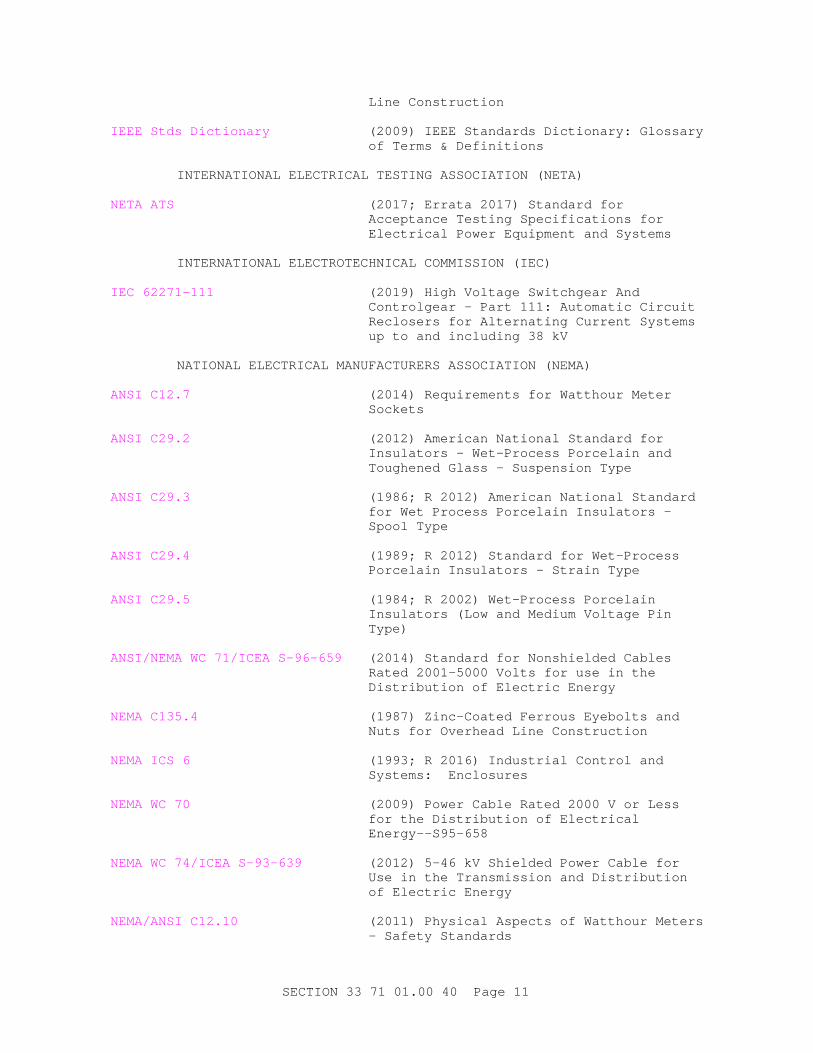
Line Construction
IEEE Stds Dictionary (2009) IEEE Standards Dictionary: Glossary of Terms & Definitions
INTERNATIONAL ELECTRICAL TESTING ASSOCIATION (NETA)
NETA ATS (2017; Errata 2017) Standard for Acceptance Testing Specifications for Electrical Power Equipment and Systems
INTERNATIONAL ELECTROTECHNICAL COMMISSION (IEC)
IEC 62271-111 (2019) High Voltage Switchgear And Controlgear - Part 111: Automatic Circuit Reclosers for Alternating Current Systems up to and including 38 kV
NATIONAL ELECTRICAL MANUFACTURERS ASSOCIATION (NEMA)
ANSI C12.7 (2014) Requirements for Watthour Meter Sockets
ANSI C29.2 (2012) American National Standard for Insulators - Wet-Process Porcelain and Toughened Glass - Suspension Type
ANSI C29.3 (1986; R 2012) American National Standard for Wet Process Porcelain Insulators - Spool Type
ANSI C29.4 (1989; R 2012) Standard for Wet-Process Porcelain Insulators - Strain Type
ANSI C29.5 (1984; R 2002) Wet-Process Porcelain Insulators (Low and Medium Voltage Pin Type)
ANSI/NEMA WC 71/ICEA S-96-659 (2014) Standard for Nonshielded Cables Rated 2001-5000 Volts for use in the Distribution of Electric Energy
NEMA C135.4 (1987) Zinc-Coated Ferrous Eyebolts and Nuts for Overhead Line Construction
NEMA ICS 6 (1993; R 2016) Industrial Control and Systems: Enclosures
NEMA WC 70 (2009) Power Cable Rated 2000 V or Less for the Distribution of Electrical Energy--S95-658
NEMA WC 74/ICEA S-93-639 (2012) 5-46 kV Shielded Power Cable for Use in the Transmission and Distribution of Electric Energy
NEMA/ANSI C12.10 (2011) Physical Aspects of Watthour Meters - Safety Standards
SECTION 33 71 01.00 40 Page 11

NEMA/ANSI C29.7 (1996; 2002) American National Standard for Wet Process Porcelain Insulators - High-Voltage Line Post Type
NATIONAL FIRE PROTECTION ASSOCIATION (NFPA)
NFPA 70 (2017; ERTA 1-2 2017; TIA 17-1; TIA 17-2; TIA 17-3; TIA 17-4; TIA 17-5; TIA 17-6; TIA 17-7; TIA 17-8; TIA 17-9; TIA 17-10; TIA 17-11; TIA 17-12; TIA 17-13; TIA 17-14; TIA 17-15; TIA 17-16; TIA 17-17 ) National Electrical Code
ORGANISATION FOR ECONOMIC CO-OPERATION AND DEVELOPMENT (OECD)
OECD Test 203 (1992) Fish Acute Toxicity Test
U.S. DEPARTMENT OF AGRICULTURE (USDA)
RUS 202-1 (2004) List of Materials Acceptable for Use on Systems of RUS Electrification Borrowers
RUS Bull 345-67 (1998) REA Specification for Filled Telephone Cables, PE-39
RUS Bull 1728H-701 (1993) Wood Crossarms (Solid and Laminated), Transmission Timbers and Pole Keys
U.S. ENVIRONMENTAL PROTECTION AGENCY (EPA)
EPA 600/4-90/027F (1993) Methods for Measuring the Acute Toxicity of Effluents and Receiving Waters to Freshwater and Marine Organisms
EPA 712-C-98-075 (1998) Fate, Transport and Transformation Test Guidelines - OPPTS 835.3100- "Aerobic Aquatic Biodegradation"
UNDERWRITERS LABORATORIES (UL)
UL 6 (2007; Reprint Sep 2019) UL Standard for Safety Electrical Rigid Metal Conduit-Steel
UL 467 (2013; Reprint Jun 2017) UL Standard for Safety Grounding and Bonding Equipment
UL 486A-486B (2018) UL Standard for Safety Wire Connectors
UL 510 (2017) UL Standard for Safety Polyvinyl Chloride, Polyethylene and Rubber Insulating Tape
1.2 DEFINITIONS
Unless otherwise specified or indicated, electrical and electronics terms used in these specifications, and on the drawings, are as defined in
SECTION 33 71 01.00 40 Page 12
IEEE Stds Dictionary .
1.3 ADMINISTRATIVE REQUIREMENTS
Section 26 08 00 APPARATUS INSPECTION AND TESTING applies to this section with additions and modifications specified herein.
1.3.1 Pre-Installation Meetings
Within [30] [_____] calendar days after [date of award] [date of receipt by him of notice of award], submit for the approval of the Contracting Officer [six (6)] [_____] copies of specified drawings of all equipment to be furnished under this contract, together with weights and overall dimensions. Submit the following data and drawings:
a. Connection Diagrams
b. Fabrication Drawings
c. Installation Drawings
Submit certification from the manufacturer indicating conformance with the specified poles and transformer losses:
a. Concrete Poles
b. Steel Poles
c. Wood Poles
d. Wood Crossarms
e. Transformer Losses
Submit operation and maintenance data in accordance with Section 01 78 23 OPERATION AND MAINTENANCE DATA and as specified herein.
1.4 SUBMITTALS
**************************************************************************NOTE: Revi ew Submi t t al Descr i pt i on ( SD) def i ni t i ons i n Sect i on 01 33 00 SUBMI TTAL PROCEDURES and edi t t he f ol l owi ng l i s t t o r ef l ect onl y t he submi t t al s r equi r ed f or t he pr oj ect .
The Gui de Speci f i cat i on t echni cal edi t or s have desi gnat ed t hose i t ems t hat r equi r e Gover nment appr oval , due t o t hei r compl exi t y or cr i t i cal i t y, wi t h a " G" . Gener al l y, ot her submi t t al i t ems can be r evi ewed by t he Cont r act or ' s Qual i t y Cont r ol Syst em. Onl y add a “ G” t o an i t em, i f t he submi t t al i s suf f i c i ent l y i mpor t ant or compl ex i n cont ext of t he pr oj ect .
For submi t t al s r equi r i ng Gover nment appr oval on Ar my pr oj ect s, a code of up t o t hr ee char act er s wi t hi n t he submi t t al t ags may be used f ol l owi ng t he " G" desi gnat i on t o i ndi cat e t he appr ovi ng aut hor i t y. Codes f or Ar my pr oj ect s usi ng t he Resi dent
SECTION 33 71 01.00 40 Page 13
Management Syst em ( RMS) ar e: " AE" f or Ar chi t ect - Engi neer ; " DO" f or Di st r i ct Of f i ce ( Engi neer i ng Di v i s i on or ot her or gani zat i on i n t he Di st r i ct Of f i ce) ; " AO" f or Ar ea Of f i ce; " RO" f or Resi dent Of f i ce; and " PO" f or Pr oj ect Of f i ce. Codes f ol l owi ng t he " G" t ypi cal l y ar e not used f or Navy projects.
An " S" f ol l owi ng a submi t t al i t em i ndi cat es t hat t he submi t t al i s r equi r ed f or t he Sust ai nabi l i t y eNot ebook t o f ul f i l l f eder al l y mandat ed sust ai nabl e r equi r ement s i n accor dance wi t h Sect i on 01 33 29 SUSTAI NABI LI TY REPORTI NG. Locat e t he " S" submi t t al under t he SD number t hat best descr i bes t he submi t t al i t em.
Submi t t al i t ems not desi gnat ed wi t h a " G" ar e consi der ed as bei ng f or i nf or mat i on onl y f or Ar my pr oj ect s and f or Cont r act or Qual i t y Cont r ol appr oval f or Navy pr oj ect s.
**************************************************************************
Government approval is required for submittals with a "G" designation; submittals not having a "G" designation are [for Contractor Quality Control approval.][for information only. When used, a designation following the "G" designation identifies the office that will review the submittal for the Government.] Submittals with an "S" are for inclusion in the Sustainability eNotebook, in conformance to Section 01 33 29 SUSTAINABILITY REPORTING. Submit the following in accordance with Section 01 33 00 SUBMITTAL PROCEDURES:
**************************************************************************NOTE: Use t he f ol l owi ng par agr aph and subpar agr aphs r egar di ng t r ansf or mer submi t t al s f or NAVFAC pr oj ect s. I n t he br acket ed opt i on, i nser t your appr opr i at e NAVFAC Component or gani zat i on and code. For ot her pr oj ect s, per f or m submi t t al r evi ew wi t h t he desi gner of r ecor d. I f submi t t al r evi ew by NAVFAC LANT i s speci f i cal l y desi r ed, ensur e t he r esponsi bl e Gover nment agency coor di nat es wi t h NAVFAC LANT, Code CI EE dur i ng t he desi gn pr ocess. Add appr opr i at e i nf or mat i on i n Sect i on t i t l ed " Submi t t al Pr ocedur es" t o coor di nat e wi t h t he speci al r equi r ement s.
**************************************************************************
[[Code [CIEE] [_____], NAVFAC [Atlantic] [_____] will review and approve transformer submittals.] As an exception to this paragraph, transformers manufactured by ABB in Athens, GA; by Cooper Power Systems in Lumberton, MS; by ERMCO in Dyersburg, TN; or by Howard Industries in Laurel, MS need not meet the submittal requirements of this contract. Instead, submit the following:
a. Provide certification, from the manufacturer, that the technical requirements of this specification are met.
b. Manufacturer is to conduct routine and other tests (paragraph ROUTINE AND OTHER TESTS, which [will] be witnessed by the Government paragraph TESTS, INSPECTIONS, AND VERIFICATIONS). Provide certified copies of
SECTION 33 71 01.00 40 Page 14
the tests.
c. Provide field test reports (paragraph FIELD QUALITY CONTROL).]
SD-02 Shop Drawings
Connection Diagrams ; G[, [____]]
Fabrication Drawings ; G[, [____]]
Installation Drawings ; G[, [____]]
SD-03 Product Data
Conductors ; G[, [____]]
Insulators ; G[, [____]]
Concrete Poles ; G[, [____]]
Steel Poles ; G[, [____]]
Wood Poles ; G[, [____]]
Nameplates ; G[, [____]]
Pole Top Switch ; G[, [____]]
Recloser ; G[, [____]]
Sectionalizer ; G[, [____]]
Cutouts ; G[, [____]]
Transformer ; G[, [____]]
Metering Equipment ; G[, [____]]
Meters ; G[, [____]]
Surge Arresters ; G[, [____]]
Guy Strand ; G[, [____]]
Anchors ; G[, [____]]
SD-05 Design Data
Concrete Pole Design ; G[, [____]]
Steel Pole Design ; G[, [____]]
Power-Installed Screw Foundations [; G[, [____]] ]
SD-06 Test Reports
Wood Crossarm Inspection Report ; G[, [____]]
Field Test Plan ; G[, [____]]
SECTION 33 71 01.00 40 Page 15
Field Quality Control ; G[, [____]]
Ground Resistance Test Reports ; G[, [____]]
SD-07 Certificates
[ Wood Crossarms ; G[, [____]]
] Transformer Losses ; G[, [____]]
SD-09 Manufacturer's Field Reports
Routine and Other Tests ; G[, [____]]
SD-10 Operation and Maintenance Data
Operation and Maintenance Manuals , Data Package 5 ; G[, [____]]
SD-11 Closeout Submittals
Transformer Test Schedule ; G[, [____]]
1.5 MAINTENANCE MATERIAL SUBMITTALS
1.5.1 Additions to Operations and Maintenance Data
In addition to requirements of Data Package 5, include the following in the operation and maintenance manuals provided:
a. Assembly and installation drawings
b. Prices for spare parts and supply list
c. Date of purchase
1.6 QUALITY CONTROL
1.6.1 Regulatory Requirements
In each of the publications referred to herein, consider the advisory provisions to be mandatory. Interpret references in these publications to the "authority having jurisdiction," or words of similar meaning, to mean the Contracting Officer. Provide equipment, materials, installation, and workmanship in accordance with the mandatory and advisory provisions of NFPA 70 and IEEE C2 unless more stringent requirements are specified or indicated.
1.6.2 Standard Products
Provide materials and equipment that are products of manufacturers regularly engaged in the production of such products which are of equal material, design and workmanship. Provide products that have been in satisfactory commercial or industrial use for 2 years prior to bid opening. The 2-year period includes applications of equipment and materials under similar circumstances and of similar size. Provide a product that has been on sale on the commercial market through advertisements, manufacturers' catalogs, or brochures during the 2-year period. Where two or more items of the same class of equipment are
SECTION 33 71 01.00 40 Page 16
required, provide items that are products of a single manufacturer; however, the component parts of the item need not be the products of the same manufacturer unless stated in this section.
1.6.2.1 Alternative Qualifications
Products having less than a 2-year field service record are acceptable if a certified record of satisfactory field operation for not less than 6000 hours, exclusive of the manufacturers' factory or laboratory tests, is furnished.
1.6.2.2 Material and Equipment Manufacturing Date
Do not use products manufactured more than 3 years prior to date of delivery to site, unless specified otherwise.
1.6.3 Ground Resistance Test Reports
Submit the measured ground resistance of grounding system. When testing grounding electrodes and grounding systems, identify each grounding electrode and each grounding system for testing. Include the test method and test setup (i.e. pin location) used to determine ground resistance and soil conditions at the time the measurements were made.
1.6.4 Wood Crossarm Inspection Report
Furnish an inspection report from an independent inspection agency, approved by the Contracting Officer, stating that offered products comply with applicable AWPA and RUS standards. The RUS approved Quality Mark "WQC" on each crossarm is acceptable, in lieu of inspection reports, as evidence of compliance with applicable AWPA treatment standards.
1.6.4.1 Field Test Plan
Provide a proposed field test plan [20] [30] [_____] days prior to testing the installed system. Do not perform field test until the test plan is approved. Provide a test plan that consists of complete field test procedures including tests to be performed, test equipment required, and tolerance limits.
1.7 DELIVERY, STORAGE, AND HANDLING
Visually inspect devices and equipment when received and prior to acceptance from conveyance. Protect stored items from the environment in accordance with the manufacturer's published instructions. Replace damaged items. Store oil filled transformers and switches in accordance with the manufacturer's requirements. For wood poles held in storage more than 2 weeks, store in accordance with ATIS ANSI O5.1 . Handle wood poles in accordance with ATIS ANSI O5.1 , except do not use pointed tools capable of producing indentations more than an inch in depth. Nails and holes are not permitted in top of poles. Handle and store metal poles in accordance with the manufacturer's instructions.
1.8 WARRANTY
Support the equipment items by service organizations which are reasonably convenient to the equipment installation in order to render satisfactory service to the equipment on a regular and emergency basis during the warranty period of the contract.
SECTION 33 71 01.00 40 Page 17

PART 2 PRODUCTS
2.1 SYSTEM DESCRIPTION
**************************************************************************NOTE: Speci f y a 120- hour t est i n a noncor r osi ve envi r onment and speci f y a 480- hour t est i n a cor r osi ve envi r onment .
**************************************************************************
Consider materials specified herein or shown on contract drawings which are identical to materials listed in RUS 202-1 as conforming to requirements. Provide equipment and component items, not hot-dip galvanized or porcelain enamel finished, with corrosion-resistant finishes which withstand [120] [480] hours of exposure to the salt spray test specified in ASTM B117 without loss of paint or release of adhesion of the paint primer coat to the metal surface in excess of 1.6 mm 1/16 inch from the test mark. Provide the described test mark and test evaluation in accordance with ASTM D1654 with a rating of not less than 7 in accordance with TABLE 1, (Procedure A). Coat cut edges or otherwise damaged surfaces of hot-dip galvanized sheet steel or mill galvanized sheet steel with a zinc rich paint conforming to the manufacturer's standard.
2.1.1 Design Requirements
Provide materials and equipment that are products of manufacturers regularly engaged in the production of such products which are of equal material, design and workmanship. Provide products that have been in satisfactory commercial or industrial use for 2 years prior to bid opening. The 2-year period includes applications of equipment and materials under similar circumstances and of similar size. Provide a product that has been on sale on the commercial market through advertisements, manufacturers' catalogs, or brochures during the 2-year period. Where two or more items of the same class of equipment are required, provide items that are products of a single manufacturer; however, the component parts of the item need not be the products of the same manufacturer unless stated in this section.
2.2 EQUIPMENT
2.2.1 Hardware
**************************************************************************NOTE: I n hot humi d mar i ne at mospher es, gal vani zed st eel pol e- l i ne har dwar e i s not accept abl e. Per mi t onl y hot - di p gal vani zed mal l eabl e or duct i l e i r on. Check l ocal usage. Navy pr oj ect s r equi r e hot - di p gal vani zed har dwar e onl y.
**************************************************************************
Provide hot-dip galvanized hardware in accordance with ASTM A153/A153M and ASTM A123/A123M .
**************************************************************************NOTE: Do not use t hi s par agr aph f or Navy pr oj ect s. The pol e l i ne const r uct i on cr i t er i a f or t he Navy, i ncl udi ng t he l i s t i ng of mat er i al s, i s cover ed i n t he pol e pl at es.
SECTION 33 71 01.00 40 Page 18

**************************************************************************
[Provide zinc-coated hardware that complies with IEEE C135.1 , IEEE C135.2 , NEMA C135.4 , ANSI C135.14 IEEE C135.22 . Provide steel hardware that complies with ASTM A575 and ASTM A576. Provide pole-line hardware that is hot-dip galvanized [steel.] [steel, except use anchor rods of the copper-molten welded-to-steel type with nonferrous corrosion-resistant fittings]. ++Install washers under boltheads and nuts on wood surfaces and elsewhere as required. Provide washers used on through-bolts and double-arming bolts that are approximately 57.2 mm square 2-1/4 inches square and 4.8 mm 3/16-inch thick. Make the diameter of holes in washers the correct standard size for the bolt on which a washer is used. Provide washers for use under heads of carriage-bolts, of the proper size to fit over square shanks of bolts. Use eye bolts, bolt eyes, eyenuts, strain-load plates, lag screws, guy clamps, fasteners, hooks, shims, and clevises wherever required to support and to protect poles, brackets, crossarms, guy wires, and insulators.]
2.2.1.1 Pins
Provide pins that are zinc-coated forged steel with lead-thread height to suit the insulator to be installed, but not less than 115 millimeter high by 16 millimeter diameter 4-1/2-inches high by 5/8-inch diameter . Provide shoulder that is not less than 50 millimeter 2-inch diameter and that is designed to distribute the load uniformly to the crossarm. Provide shank that is not less than 16 millimeter diameter by 145 millimeter length 5/8-inch diameter by 5-3/4-inch length , equipped with a 50 millimeter 2-inch square washer, nut, and locknut, and that projects not less than 3 millimeter 1/8-inch nor more than 50 millimeter 2-inches beyond the locknut. Use broad-based corner pins of drop-forged welded steel or malleable iron for turning small angles, as indicated.
2.2.1.2 Hot-Line Clamps
Make connections to overhead primary conductors with hot-line clamps of the screw type with concealed threads. Fill thread chamber with corrosion-resistant compound. Provide hot-line clamp tap conductor of bare soft-drawn seven-strand 5.2 millimeter diameter No. 4 copper, except that for the hot-line clamp tap conductor for lateral lines 6.5 millimeter diameter No. 2 and larger, provide bare soft-drawn copper of the same size and stranding as the lateral line.
Provide stirrups for hot-line clamp connections that are 100 by 100 millimeter 4 by 4 inches , and are constructed of bare hard-drawn copper the same size as the tap line but not less than No. 4.
2.2.1.3 Secondary Racks
Provide secondary racks that are the 2-, 3-, or 4-wire type as required and are furnished complete with spool insulators.
Provide racks that meet industry requirements for the strength and deflection of heavy-duty steel racks and that are either galvanized steel or aluminum alloy.
Provide top of insulator points that are rounded and smooth. Hold insulators in place with a 16 millimeter 5/8-inch buttonhead bolt equipped with a nonferrous cotter pin, or equivalent, at the bottom.
SECTION 33 71 01.00 40 Page 19

2.2.2 Guy Strand
[ ASTM A475, [high-strength] [extra high-strength], Class A or B, galvanized strand steel cable][Class 30 [high-strength][extra high-strength] copper-clad steel]. Provide guy strand that is [_____] mm-inch in diameter with a minimum breaking strength of [_____] Newton pounds . Provide guy terminations designed for use with the particular strand and developing at least the ultimate breaking strength of the strand.
2.2.3 Round Guy Markers
Vinyl or PVC material, [white] [yellow] colored, 2440 mm 8-feet long and shatter resistant at sub-zero temperatures.
2.2.3.1 Guy Attachment
Thimble eye guy attachment.
2.2.4 Anchors and Anchor Rods
**************************************************************************NOTE: Compl et e guy- anchor assembl y pr ovi des st r engt h conf or mi ng t o I EEE C2 f or t he gr ade of const r uct i on of t he l i ne. I n ar eas of ext r emel y hi gh chemi cal act i v i t y of t he soi l , compl et el y encaseanchor r ods and gr ound r ods i n concr et e t o point 100 mm 4 i nches above f i ni shed gr ade. Pr ovi de anchor s t hat ar e a speci al uni t t o be i ndi cat ed.
**************************************************************************
Provide anchors that present holding area indicated on drawings as a minimum. Provide anchor rods that are triple thimble-eye, [19] [25] mm diameter by 2440 mm [3/4] [one]-inch diameter by 8-feet long. Provide anchors and anchor rods that are hot dip galvanized.
2.2.4.1 Screw Anchors
**************************************************************************NOTE: For NAVFAC At l ant i c pr oj ect s nor mal l y use scr ew t ype anchor s. Pr ovi de Newt on pound r at i ng and l eave out " [ f i t t i ng Cl ass 6000] . "
**************************************************************************
Screw type [swamp] anchors having a manufacturer's rating [of not less than [_____] Newton pounds in loose to medium sand/clay soil, Class 6] [at least equal to rating indicated] and extra heavy pipe rods conforming to ASTM A53/A53M, Schedule 80, and couplings conforming to ASME B16.11 , [fitting Class 6000.]
2.2.4.2 Plate Anchors
Minimum area of [_____] square mm inches and rated by manufacturer for [_____] Newton pounds or more in soils classified as medium dense coarse sand and sandy gravels; firm to stiff clays and silts.
2.2.4.3 Rock Anchors
Rock anchors having a manufacturer's rating of [102,310][160,130] Newtons [23,000][36,000] pounds .
SECTION 33 71 01.00 40 Page 20
2.2.5 Grounding and Bonding
2.2.5.1 Driven Ground Rods
**************************************************************************NOTE: Use " copper - c l ad st eel " gr ound r ods f or NAVFAC At l ant i c pr oj ect s.
**************************************************************************
Provide [copper-clad steel ground rods conforming to UL 467 ][zinc-coated steel ground rods conforming to IEEE C135.30 ][solid stainless steel ground rods] not less than 19 mm 3/4-inch in diameter by 3.1 m 10-feet in length. Sectional type rods are acceptable for rods 6.1 m 20-feet or longer.
2.2.5.2 Grounding Conductors
ASTM B8. Provide soft drawn copper wire ground conductors a minimum No. 4 AWG. Provide PVC ground wire protectors.
2.2.5.3 Grounding Connections
UL 467 . Exothermic weld or compression connector.
2.2.6 Conduit Risers and Conductors
Provide PVC riser shield containing a PVC back plate and PVC extension shield or a rigid galvanized steel conduit, as indicated, and conforming to UL 6 . Provide conductors and terminations as specified in Section 33 71 02 UNDERGROUND ELECTRICAL DISTRIBUTION.
[ 2.2.7 Group-Operated Load Interrupter Switches
2.2.7.1 Manually Operated Type (Switch Handle Operated)
Provide manually operated (switch handle operated) load interrupter switches that comply with IEEE C37.32 and are of the outdoor, manually-operated, three-pole, single-throw type with either tilting or rotating insulators. Provide switches that are equipped with interrupters capable of interrupting currents equal to the switch's continuous current rating. Provide preassembled switches for the indicated configuration and mounting. Provide high-pressure, limited-area type moving contacts, designed to ensure continuous surface contact. Provide fused or non-fused switches as indicated. Provide switches complete with necessary operating mechanisms, handles, and other items required for manual operation from the ground. Locate switch operating handles approximately 1.1 meters 42-inches above final grade. Provide insulation of switch operating mechanisms that includes both insulated interphase rod sections and insulated vertical shafts. Provide each handle with a padlock arranged to lock the switch in both the open and the closed position.
[ 2.2.7.2 Remotely Operated Type (Stored-Energy Actuator)
**************************************************************************NOTE: SF6 swi t ches ar e avai l abl e f or nomi nal vol t ages of 15 kV t hr ough 34. 5 kV i n 600 amper e cont i nuous and l oad- br eak r at i ngs. Del et e SCADA equi pment and r emot e t el emet r y when not r equi r ed.
SECTION 33 71 01.00 40 Page 21

**************************************************************************
Provide remotely-operated, [air-insulated] [SF6 insulated] load interrupter switches that are rated in accordance with and comply with the requirements of IEEE C37.32 and are of the outdoor, three-pole, [pole-mounted] [crossarm-mounted] type. Provide interrupter devices that are [air-insulated] [SF6-insulated, puffer-type] switches capable of interrupting currents equal to the switch continuous current ratings indicated. Provide switches that utilize an electric motor-charged, stored-energy (spring-driven) operator to simultaneously trip all phases. Provide a switch-control unit [for push-button operation from the ground] [for push-button operation from the ground and remote switch actuation via telemetry]. Provide a switch-control unit that is pad-lockable, tamper-resistant, in a NEMA ICS 6 , Type [3R] [4] [4X] [4X-SS] enclosure, which is connected to the switch actuator by a shielded control cable. Provide control power for closing and tripping by a battery mounted in the control unit enclosure. Provide the switch control unit with a separate 120 volt ac circuit for the battery powered. Power for charging the operator mechanism is 120 volt ac or battery powered. If operator mechanism charging power is from a battery, provide capacity for a minimum of [_____] [four] sequential opening and closing operation without battery charging. Configure the switch control unit for supervisory, control, and data acquisition (SCADA) function, including local and remote operation. Provide voltage and current sensors, one set for each phase, for monitoring of both normal and fault conditions. Provide switches with visual indication of open switch contact for clearance and isolation purposes. Provide switch mechanisms with provisions for grounding of nonenergized metal parts. Provide the switch control unit with switch operations.
] ][ 2.2.8 Recloser
IEC 62271-111 . [Provide recloser controller that is [electronically] [hydraulically] operated and utilizes an [oil] [vacuum] operating medium.]
][ 2.2.9 Sectionalizer
IEEE C37.63 .
][ 2.2.10 Metering Equipment
**************************************************************************NOTE: " Met er i ng Equi pment " par agr aph and i t s subpar agr aphs ar e f or pr i mar y met er i ng. Onl y use when pr i mar y met er i ng i s r equi r ed by t he l ocal ut i l i t y company and speci f i c met er i ng r equi r ement s have been pr oper l y coor di nat ed wi t h t he cogni zant EFD/ EFA. Cover secondar y met er i ng i n Sect i ons 26 12 19. 10 THREE- PHASE PAD- MOUNTED TRANSFORMERS, 26 12 21 SI NGLE- PHASE PAD- MOUNTED TRANSFORMERS, or 26 20 00 I NTERI OR DI STRI BUTI ON SYSTEM as appl i cabl e.
**************************************************************************
Provide pole mounted metering equipment that includes current transformers, potential transformers, watthour meter, [meter test switch block,] metering enclosure, wire, conduit and fittings.
SECTION 33 71 01.00 40 Page 22
2.2.10.1 Potential Transformers
Provide potential transformers that are rated for outdoor service fitted for crossarm mounting and secondary connection box for conduit connection. Provide [2.4] [4.16] [7.2] [12.0] [12.47] [_____] kV to 120 volts ac, 60 Hz voltage rating. Provide transformers that conform to the requirements of IEEE C57.13 BIL [45] [60] [75] [95] kV and accuracy Class 0.3 (min.) of [75 VA] [burden Y].
2.2.10.2 Current Transformers
Provide current transformers that are rated for outdoor service with crossarm mounting and secondary connection box for conduit connection. Provide [2.4] [4.16] [7.2] [12.47] [12.0] [_____] kV voltage rating. Provide [_____] to 5 amperes current rating. Provide transformers that conform to requirements of IEEE C57.13 , BIL [45] [60] [75] [95] kV and accuracy Class 0.3 at [B2.0] [50 VA].
2.2.10.3 Watthour Meter
Provide meter with provisions for future pulse initiation.
a. Meters : NEMA/ANSI C12.10 and ANSI C12.1 ; when providing meter with electronic time-of-use register.
(1) Form: [5A] [5S] [6A] [6S].
(2) Element: [2] [2 1/2] [3].
(3) Voltage: 120 volts.
(4) Current: 2 1/2 amperes.
(5) Frequency: 60 hertz.
(6) Kilowatt hour register: 5 dial or 5 digit type.
b. Demand register:
(1) Solid state type.
(2) Meter reading multiplier:
(a) Indicate multiplier on the meter face.
(b) Provide multiplier in even hundreds.
(3) Program demand interval length: for [15] [30] [60] minutes with rolling demand up to six subintervals per interval.
c. Mounting:
(1) Provide a meter with [matching socket per ANSI C12.7 with [manual] [automatic] current short-circulating device.] ["A" base type mounting].
[ 2.2.10.4 Meter Test Block
Provide meter test block with [T] [10] pole group of open knife type
SECTION 33 71 01.00 40 Page 23

switches designed for the isolation of metering devices at meter location by opening each circuit individually. Provide current switches that short circuit current supply before opening meter circuit. Provide black switch handles of potential switches. Provide red switch handles of current switches.
] 2.2.10.5 Metering Enclosure
Provide metering enclosure of galvanized steel, weatherproof construction with pole mounting bracket, and 19 mm 3/4-inch exterior plywood, full size backboard and hinged door arranged for padlocking in closed position. Provide adequate internal space to house equipment and wiring but not smaller than 510 by 760 by 280 mm 20 by 30 by 11-inches deep. Paint metal manufacturer's standard finish.
] 2.2.11 Capacitors
Provide capacitor equipment that complies with IEEE 18 and that is of the three-phase, grounded-wye, outdoor type rated for continuous operation and automatically switched. Provide equipment suitable for mounting on a single pole. Do not use polychlorinated biphenyl and tetrachloroethylene (perchloroethylene) as the dielectric. Provide equipment that is rated for the system voltage. Provide the indicated kvars that are automatically switched by [single-step] [time switch] [voltage] [current] [kilovar] [control] [multiple-step] [voltage] [kilovar] [control providing the indicated number of steps and switching the indicated kvar]. Provide necessary transformers for sensing circuit variations and for low-voltage control. Provide oil-immersed switches for automatic switching of capacitors, electrically separate from ungrounded capacitor enclosures and metal frames. Provide installations that include one primary fuse cutout and one surge arrester for each ungrounded phase conductor. Provide fuse link ratings in accordance with the manufacturer's recommendations. Provide capacitor equipment, except for low-voltage control and primary fuse cutouts, that is subassembled and coordinated by one manufacturer. Ship units, including metal pole-mounting supports and hardware, in complete sections ready for connection at the site. Provide low-voltage equipment that is socket or cabinet type, mounted on the pole approximately 1.2 m 4-feet above grade. Connect with the necessary wiring in conduit to capacitor equipment, provided with secondary arrester protection against switching surges when recommended by the manufacturer.
2.2.12 Voltage Regulator
**************************************************************************NOTE: Bypass ar r est er s ar e nor mal l y st andar d equi pment . Coor di nat e wi t h t he manuf act ur er t o det er mi ne i f i ncomi ng l i ne ar r est er s ar e needed.
**************************************************************************
Provide voltage regulators that comply with IEEE C57.15 and are of the outdoor, self-cooled, 55/65 degrees C temperature rise, single-phase type. Provide windings and the load-tap-changing mechanism that are mineral-oil-immersed. When operating under load, provide a regulator with plus and minus 10 percent automatic voltage regulation in approximately 5/8 percent steps, with 16 steps above and 16 steps below rated voltage. Provide automatic control equipment with Class 1 accuracy. Provide bypass surge arresters suitable for [a grounded] [an ungrounded] system and for the associated regulator voltage. [Provide [station] [intermediate] class surge arresters that are mounted next to each incoming line bushing on a
SECTION 33 71 01.00 40 Page 24
regulator tank-mounted bracket and connected to a surge arrester ground pad-mounted on the regulator tank].
2.2.12.1 Ratings
Provide the following ratings at 60 Hz:
Maximum voltage...........................................[_____]
Basic Insulation Level (BIL)..............................[_____]
Current...................................................[_____]
2.2.12.2 Bypass and Isolation Switches
Provide switches of the outdoor, stickhook-operated, single-pole, single-throw, vertical-break type suitable for the indicated mounting. Provide switches of a type designed to provide bypass of a single-phase regulator circuit by an integral sequence which always occurs when each switch is opened or closed. Provide opening sequences that initially bypass the single-phase regulator circuit, then open the input and output circuits, and finally interrupt the exciting current. Make opening any single-phase regulator circuit not possible until after the bypass circuit is closed. Provide ratings at 60 Hz in accordance with IEEE C37.41 and as follows:
Maximum voltage...........................................[_____]
Nominal voltage class.....................................[_____]
BIL.......................................................[_____]
Momentary asymmetrical current in the closed position.....[_____]
Momentary asymmetrical current in the bypass position.....[_____]
Continuous and interrupting current.......................[_____]
2.2.12.3 Miscellaneous
Provide standard accessories and components in accordance with IEEE C57.15 . Provide single-phase units with additional components and accessories required by IEEE C57.15 for three-phase units.
2.3 COMPONENTS
2.3.1 Poles
**************************************************************************NOTE: Use " c l ass" f or wood pol es and " st r engt h" f or concr et e and st eel pol es. Fol l ow l ocal ut i l i t y pr act i ce r egar di ng gr oundi ng met al l i c i t ems on pol es, af t er coor di nat i on wi t h l ocal DPW/ BCE. Speci f y c l ear ances and cl i mbi ng space i n accor dance wi t h I EEE C2 or appl i cabl e st at e code.
**************************************************************************
Provide poles of lengths and [classes] [strengths] indicated.
SECTION 33 71 01.00 40 Page 25

2.3.1.1 Wood Poles
**************************************************************************NOTE: For NAVFAC At l ant i c pr oj ect s, do not use l odgepol e pi ne or West er n Lar ch pol es.
**************************************************************************
Wood poles machine trimmed by turning, [Douglas Fir] [Lodgepole Pine] [Western Larch] [Southern Yellow Pine] [_____] conforming to ATIS ANSI O5.1 and RUS Bull 345-67 . Gain, bore and roof poles before treatment. If additional gains are required subsequent to treatment, provide metal gain plates. Pressure treat poles with [pentachlorophenol,] [ammoniacal copper arsenate (ACA),] [chromated copper arsenate (CCA)], except do not treat Douglas Fir and Western Larch poles with CCA in accordance with AWPA C1 and AWPA C4 as referenced in RUS Bull 345-67 . Ensure the quality of each pole with "WQC" (wood quality control) brand on each piece, or by an approved inspection agency report.
a. Preservative
**************************************************************************NOTE: Choose one of t he f ol l owi ng t hr ee t ypes of pr eser vat i ves, accor di ng t o t he envi r onment .
**************************************************************************
For preservative used for humid, harsh environment, provide Chromated Copper Arsenate type (A)(B)(C) conforming to AWPA T1 and ASTM D1625.
Treat wood poles with waterborne preservatives conforming to AWPA T1.
b. Preservative Application
Apply preservative treatment using a pressure process conforming to and AWPA T1 for Southern Pine. Determine penetration of preservatives as specified in AWPA A3 and obtain complete sapwood penetration.
Before treatment, roof, gain and bore poles that are to be given a full-length preservative treatment. Plug unused holes in poles with treated wood-dowel pins. Treat field-cut gains or field-bored holes in poles with an approved preservative compound.
c. Storage
For poles stored for any reason more than 2 weeks, stack them on pressure treated or decay-resistant skids of such dimensions and so arranged as to support the poles without producing noticeable distortion. Stack poles in a manner that permits free circulation of air; with the bottom poles of the stacks at least 300 millimeter 1-foot above ground level or any vegetation growing thereon. No decayed or decaying wood is permitted to remain underneath stored poles.
d. Handling
Do not drag treated poles along the ground. Do not use pole tongs, cant hooks, and other pointed tools capable of producing indentations more than 25 millimeter 1 inch in depth, in handling the poles. Do not apply tools to the groundline section of any pole. Groundline section is that portion between 300 millimeter 1 foot above and 600 millimeter 2 feet below the ground line.
SECTION 33 71 01.00 40 Page 26

2.3.2 Steel Poles
Provide a steel pole design for withstanding the loads specified in IEEE C2 multiplied by the appropriate overload capacity factors, that are hot-dip galvanized in accordance with ASTM A123/A123M and that are not painted. Provide poles that have tapered tubular members, either round in cross-section or polygonal, and that comply with strength calculations performed by a registered professional engineer. Submit calculations in accordance with the design data portion of paragraph SUBMITTALS. Provide certification, from the manufacturer, that the technical requirements of this specification are met. Provide one piece pole shafts. Provide welded construction poles with no bolts, rivets, or other means of fastening except as specifically approved. Provide pole markings that are approximately 900 to 1270 mm 3 to 4 feet above grade and that include manufacturer, year of manufacture, top and bottom diameters, length, and a loading tree. Provide attachment requirements as indicated, including grounding provisions. Climbing facilities are not required. Provide bases of the anchor-bolt-mounted type.
2.3.3 Concrete Poles
**************************************************************************NOTE: I n ar eas wher e f r eezi ng t emper at ur es occur , i ncr ease t he mi ni mum compr essi ve st r engt h gi ven f or concr et e i n spun pol es i n l i ne wi t h concr et e desi gn f or such t emper at ur es.
**************************************************************************
Provide a concrete pole design for withstanding the loads specified in IEEE C2 multiplied by the appropriate overload capacity factors. Provide reinforced or prestressed, either cast or spun poles. Provide spun poles that are manufactured by a centrifugal spinning process with concrete pumped into a polished round tapered metal mold. Provide concrete for spun poles that has a compressive strength of at least 34.5 MPa 5000 psi at 28 days; steel wire that has an ultimate tensile strength of at least 827 MPa; 120,000 psi; and reinforcing bars that have an ultimate tensile strength of at least 276 MPa 40,000 psi . After the high speed spinning action is completed, cure a spun pole by a suitable wet steam process. Provide spun poles that have a water absorption of not greater than three percent to eliminate cracking and to prevent erosion. Provide concrete poles that have hollow shafts. Provide poles that have a hard, smooth, nonporous surface that is resistant to soil acids, road salts, and attacks of water and frost. Do not install poles for at least 15 days after manufacture. Provide fittings and brackets that conform to the concrete pole design. Provide poles that conform to strength calculations performed by a registered professional engineer and submit in accordance with design data portion of paragraph SUBMITTALS. Provide certification, from the manufacturer, that the technical requirements of this specification are met.
2.3.4 Crossarms and Brackets
2.3.4.1 Wood Crossarms
Conform to RUS Bull 1728H-701 . Pressure treat crossarms with pentachlorophenol, chromated copper arsenate (CCA), or ammoniacal copper arsenate (ACA). Provide treatment that conforms to AWPA C25. Provide solid wood, distribution type crossarms, with a 6.4 mm 1/4-inch 45 degree
SECTION 33 71 01.00 40 Page 27
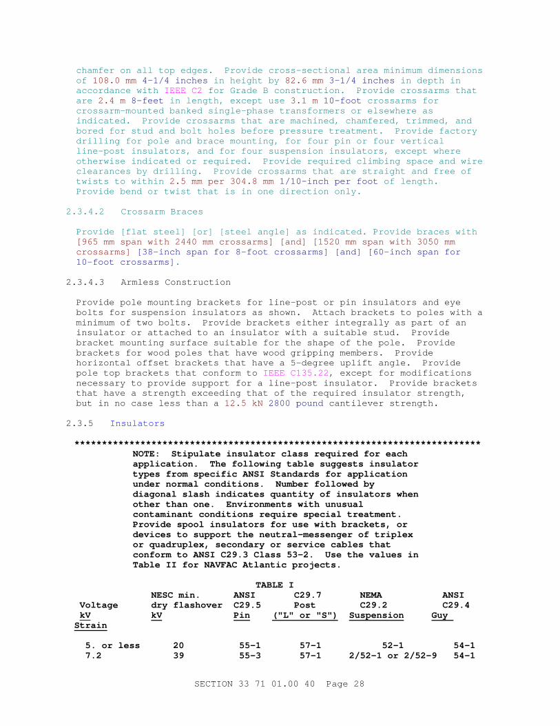
chamfer on all top edges. Provide cross-sectional area minimum dimensions of 108.0 mm 4-1/4 inches in height by 82.6 mm 3-1/4 inches in depth in accordance with IEEE C2 for Grade B construction. Provide crossarms that are 2.4 m 8-feet in length, except use 3.1 m 10-foot crossarms for crossarm-mounted banked single-phase transformers or elsewhere as indicated. Provide crossarms that are machined, chamfered, trimmed, and bored for stud and bolt holes before pressure treatment. Provide factory drilling for pole and brace mounting, for four pin or four vertical line-post insulators, and for four suspension insulators, except where otherwise indicated or required. Provide required climbing space and wire clearances by drilling. Provide crossarms that are straight and free of twists to within 2.5 mm per 304.8 mm 1/10-inch per foot of length. Provide bend or twist that is in one direction only.
2.3.4.2 Crossarm Braces
Provide [flat steel] [or] [steel angle] as indicated. Provide braces with [965 mm span with 2440 mm crossarms] [and] [1520 mm span with 3050 mm crossarms] [38-inch span for 8-foot crossarms] [and] [60-inch span for 10-foot crossarms] .
2.3.4.3 Armless Construction
Provide pole mounting brackets for line-post or pin insulators and eye bolts for suspension insulators as shown. Attach brackets to poles with a minimum of two bolts. Provide brackets either integrally as part of an insulator or attached to an insulator with a suitable stud. Provide bracket mounting surface suitable for the shape of the pole. Provide brackets for wood poles that have wood gripping members. Provide horizontal offset brackets that have a 5-degree uplift angle. Provide pole top brackets that conform to IEEE C135.22 , except for modifications necessary to provide support for a line-post insulator. Provide brackets that have a strength exceeding that of the required insulator strength, but in no case less than a 12.5 kN 2800 pound cantilever strength.
2.3.5 Insulators
**************************************************************************NOTE: St i pul at e i nsul at or c l ass r equi r ed f or each appl i cat i on. The f ol l owi ng t abl e suggest s i nsul at or t ypes f r om speci f i c ANSI St andar ds f or appl i cat i on under nor mal condi t i ons. Number f ol l owed by di agonal s l ash i ndi cat es quant i t y of i nsul at or s when ot her t han one. Envi r onment s wi t h unusual cont ami nant condi t i ons r equi r e speci al t r eat ment . Pr ovi de spool i nsul at or s f or use wi t h br acket s, or devi ces t o suppor t t he neut r al - messenger of t r i pl ex or quadr upl ex, secondar y or ser vi ce cabl es t hat conf or m t o ANSI C29. 3 Cl ass 53- 2. Use t he val ues i n Tabl e I I f or NAVFAC At l ant i c pr oj ect s.
TABLE I NESC mi n. ANSI C29. 7 NEMA ANSI Vol t age dr y f l ashover C29. 5 Post C29. 2 C29. 4 kV kV Pin ( " L" or " S" ) Suspension Guy Strain
5. or l ess 20 55- 1 57- 1 52- 1 54- 1 7. 2 39 55- 3 57- 1 2/ 52- 1 or 2/ 52- 9 54- 1
SECTION 33 71 01.00 40 Page 28
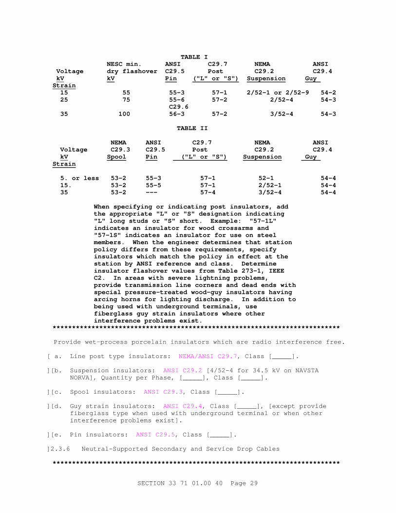
TABLE I NESC mi n. ANSI C29. 7 NEMA ANSI Vol t age dr y f l ashover C29. 5 Post C29. 2 C29. 4 kV kV Pin ( " L" or " S" ) Suspension Guy Strain 15 55 55- 3 57- 1 2/ 52- 1 or 2/ 52- 9 54- 2 25 75 55- 6 57- 2 2/ 52- 4 54- 3 C29. 6 35 100 56- 3 57- 2 3/ 52- 4 54- 3
TABLE I I
NEMA ANSI C29. 7 NEMA ANSI Vol t age C29. 3 C29. 5 Post C29. 2 C29. 4 kV Spool Pin ( " L" or " S" ) Suspension Guy Strain
5. or l ess 53- 2 55- 3 57- 1 52- 1 54- 4 15. 53- 2 55- 5 57- 1 2/ 52- 1 54- 4 35 53- 2 - - - 57- 4 3/ 52- 4 54- 4
When speci f y i ng or i ndi cat i ng post i nsul at or s, add t he appr opr i at e " L" or " S" desi gnat i on i ndi cat i ng " L" l ong st uds or " S" shor t . Exampl e: " 57- 1L" i ndi cat es an i nsul at or f or wood cr ossar ms and " 57- 1S" i ndi cat es an i nsul at or f or use on st eel member s. When t he engi neer det er mi nes t hat st at i on pol i cy di f f er s f r om t hese r equi r ement s, speci f y i nsul at or s whi ch mat ch t he pol i cy i n ef f ect at t he st at i on by ANSI r ef er ence and cl ass. Det er mi ne i nsul at or f l ashover val ues f r om Tabl e 273- 1, I EEE C2. I n ar eas wi t h sever e l i ght ni ng pr obl ems, pr ovi de t r ansmi ssi on l i ne cor ner s and dead ends wi t h speci al pr essur e- t r eat ed wood- guy i nsul at or s havi ng ar ci ng hor ns f or l i ght i ng di schar ge. I n addi t i on t o bei ng used wi t h under gr ound t er mi nal s, use f i ber gl ass guy st r ai n i nsul at or s wher e ot her i nt er f er ence pr obl ems exi st .
**************************************************************************
Provide wet-process porcelain insulators which are radio interference free.
[ a. Line post type insulators: NEMA/ANSI C29.7 , Class [_____].
][ b. Suspension insulators: ANSI C29.2 [4/52-4 for 34.5 kV on NAVSTA NORVA], Quantity per Phase, [_____], Class [_____].
][ c. Spool insulators: ANSI C29.3 , Class [_____].
][ d. Guy strain insulators: ANSI C29.4 , Class [_____], [except provide fiberglass type when used with underground terminal or when other interference problems exist].
][ e. Pin insulators: ANSI C29.5 , Class [_____].
] 2.3.6 Neutral-Supported Secondary and Service Drop Cables
**************************************************************************
SECTION 33 71 01.00 40 Page 29
NOTE: The t er m " secondar y, " f or t hi s gener al pur pose, means ei t her bar e or i nsul at ed conduct or s i nst al l ed bet ween pol es and oper at ed at t he ut i l i zat i on vol t age. Ut i l i ze bar e conduct or s on l ong span, open wi r e desi gn when a neut r al - suppor t ed secondar y cabl e i s not appr opr i at e due t o wei ght . When usi ng bar e conduct or s f or secondar y appl i cat i ons use t he above par agr aph OVERHEAD CONDUCTORS. " Ser vi ces" ar e i nsul at ed conduct or s ext endi ng f r om a pol e t o t he met er i ng poi nt or ser vi ce ent r ance connect i on at t he ut i l i zat i on poi nt . Mi ni mum conduct or s i ze f or al umi num, al umi num al l oy, or ACSR i s No. 4 AWG and f or copper , No. 6 AWG. For LANTNAVFACENGCOM pr oj ect s, do not use ACSR.
**************************************************************************
Provide [Service] [Secondary] cables of [aluminum] [copper], [triplex] [quadruplex] with cross-linked polyethylene insulation on the phase conductors. Provide bare [ACSR] [aluminum alloy] [hard drawn copper] that is the same size as the phase conductors unless otherwise indicated. Provide cables that conform to [ NEMA WC 70][ and ][ANSI/NEMA WC 71/ICEA S-96-659 ] for cross-linked polyethylene insulation.
2.3.7 Surge Arresters
**************************************************************************NOTE: Rat i ng of l i ght ni ng ( sur ge) ar r est er s i s 125 per cent of t he nomi nal l i ne- t o- gr ound vol t age of f our - wi r e, mul t i - gr ounded neut r al syst ems; 80 per cent of t he nomi nal l i ne- t o- l i ne vol t age f or t hr ee- wi r e, sol i dl y gr ounded neut r al syst ems; or nomi nal l i ne- t o- l i ne vol t age f or del t a and ungr ounded- wye syst ems. Nor mal l y use di st r i but i on c l ass ar r est er s. However , use i nt er medi at e c l ass on t he 34. 5 kV syst em at Naval Base, Nor f ol k, VA.
**************************************************************************
IEEE C62.11 , metal oxide, polymeric-housed, surge arresters arranged for [crossarm] [equipment] mounting. Provide [3] [6] [9] [10] [12] [15] [27] [30] [36] kV RMS voltage rating. Provide [Distribution] [Intermediate] [Station] class arresters.
2.3.8 Fused Cutouts
**************************************************************************NOTE: I ncl ude l ast br acket ed sent ence f or NAS Pensacol a pr oj ect s. Del et e i t i n al l ot her pr oj ect s. For NAVFAC At l ant i c pr oj ect s, use " open t ype" cut out s wi t h Type " K" f uses as i ndi cat ed.
**************************************************************************
[Open] [Enclosed] type fused cutouts rated [100] [200] amperes and [_____] amperes symmetrical interrupting current at [[7.8] [15] kV ungrounded] [8.3/15 kV gnd Y] [15/26 kV gnd Y] [27/34.5 kV gnd Y], conforming to IEEE C37.42 . Type [K] [T] fuses conforming to IEEE C37.42 with ampere ratings [as indicated] [equal to 150 percent of the transformer full load rating]. Open link type fuse cutouts are not acceptable. [Provide heavy duty open drop-out type, rated 15 kV, 200 Amp, 7,100 Amp I.C. (Sym.).]
SECTION 33 71 01.00 40 Page 30
2.3.9 Transformer (Overhead-Type Distribution)
**************************************************************************NOTE: Use t he f ol l owi ng gui del i nes f or speci f y i ng transformers.
1. Use I EEE C57. 12. 00, Fi gur e 3 ( a) , vol t age desi gnat i ons, such as 4160 V - 120/ 240 V.
2. Sel ect i mpedance val ue i n accor dance wi t h t echni cal not e under par agr aph SPECI FI ED TRANSFORMER LOSSES.
3. Do not use f ul l y sel f - pr ot ect ed t r ansf or mer s.**************************************************************************
a. IEEE C57.12.20 .
b. Single phase, self-cooled, 65 degrees C. continuous temperature rise, two winding, 60 Hertz.
c. Insulating liquid:
**************************************************************************NOTE: Choose one of t he f ol l owi ng opt i ons. For NAVFAC At l ant i c, choose l ess- f l ammabl e t r ansf or mer l i qui ds f or al l pr oj ect s unl ess t her e i s a speci f i c r equi r ement t o do ot her wi se.
**************************************************************************
[ Mineral oil: ASTM D3487, Type II, tested in accordance with ASTM D117. Provide identification of transformer as "non-PCB" and "Type II mineral oil" on the nameplate.
][ Less-flammable transformer liquids: NFPA 70 and FM APP GUIDE for less-flammable liquids having a fire point not less than 300 degrees C tested per ASTM D92 and a dielectric strength not less than 33 kV tested per ASTM D877. Provide identification of transformer as "non-PCB" and "manufacturer's name and type of fluid on the nameplate.
Provide fluid that is a biodegradable electrical insulating and cooling liquid classified by UL and approved by FM as "less flammable fluids. Provide fluid that meets the following fluid properties:
(1) Pour point: ASTM D97, less than -15 degrees C
(2) Aquatic biodegradation: EPA 712-C-98-075 , 100 percent.
(3) Trout toxicity: OECD Test 203 , zero mortality of EPA 600/4-90/027F , pass.
] d. Ratings:
(1) kVA: [_____].
(2) BIL: [95] [75] [60] kV.
(3) Primary voltage: [_____] kV.
SECTION 33 71 01.00 40 Page 31
(4) Secondary voltage: [_____] volts.
(5) Minimum Tested Impedance at 85 degrees C: [____] percent.
[ e. Single-phase connections:
(1) Connect primary: [Phase-to-phase] [Phase-to-ground].
(2) Provide transformer with [_____] high voltage bushing(s).
][ f. Three-phase connections:
(1) Connect primary: [Grounded wye] [Ungrounded wye] [Delta].
(2) Connect secondary: [Grounded wye] [Delta], for [_____] volt, three phase, [_____] wire service.
(3) Provide transformer with [_____] high voltage bushings.
] g. Taps:
(1) Provide four 2 1/2 percent full capacity taps, two above and two below rated primary voltage. Provide tap changer that has an external handle.
**************************************************************************NOTE: The " ser i es- mul t i pl e vol t age- changi ng swi t ch" i s i n t he pr i mar y wi ndi ng of t he t r ansf or mer and i s f or dual - vol t age syst ems. I t i s nor mal l y used when a base i s pl anni ng a vol t age upgr ade of i t s pr i mar y di st r i but i on syst em or when t her e ar e mul t i pl e syst ems on base and t hey want t he t r ansf or mer t o be i nt er changeabl e. Caut i on: I f t hi s opt i on i s i ndi cat ed, speci f y t he BI L l evel f or t he hi gher vol t age and coor di nat e act ual t r ansf or mer l osses wi t h mul t i pl e manuf act ur er s and speci f y t o obt ai n an ener gy ef f i c i ent t r ansf or mer .
**************************************************************************
[ h. Externally operated Series-Multiple Voltage-Changing Switch.
] i. Corrosion Protection:
**************************************************************************NOTE: I n host i l e envi r onment s, t he addi t i onal cost of st ai nl ess st eel t anks and cover s i s j ust i f i ed.
**************************************************************************
(1) [Provide transformer tanks and covers that are corrosion resistant and are fabricated of stainless steel conforming to ASTM A167, Type 304 or 304L.] Provide paint coating system that complies with IEEE C57.12.28 regardless of tank and cover material. Provide light gray, ANSI color No. 70 finish coat.
j. Show transformer kVA capacity using 65 mm 2-1/2-inch Arabic numerals placed near the low-voltage bushings.
SECTION 33 71 01.00 40 Page 32

2.3.9.1 Specified Transformer Losses
**************************************************************************NOTE: Thi s par agr aph i s f or use on Navy Pr oj ect s onl y. St eps t o speci f y i ng t r ansf or mer l osses.
1. Pr i nt Tabl es OH- 1, OH- 2, OH- 3, and EC- 1 or EC- 2 as appl i cabl e ( di r ect i ons i ncl uded at t he f r ont of t hi s speci f i cat i on) .
2. Obt ai n ener gy cost f or t he speci f i c act i v i t y f r om t he cogni zant EFD or PWC. Base ener gy cost s on t he cost of ener gy wi t hout t he demand char ge f act or s scal ed i n. Use Tabl e EC- 1 f or ener gy cost s at t he NAVFAC At l ant i c act i v i t i es i ndi cat ed.
3. Use Tabl es OH- 1, OH- 2, and OH- 3 t o speci f y l osses and i mpedances f or t r ansf or mer s based on ener gy cost r ange, and t r ansf or mer pr i mar y and secondar y vol t ages.
4. Per f or m f aul t cur r ent cal cul at i ons t o ver i f y t hat di st r i but i on equi pment i s coor di nat ed wi t h i mpedance speci f i ed.
**************************************************************************
Provide no-load losses (NLL) in watts at 20 degrees C, and load losses (LL) in watts at 85 degrees C, as follows:
NAME KVA "NLL" "LL"
[T1] [_____] [_____] [_____]
[T2] [_____] [_____] [_____]
Use the values for the specified losses for comparison with the losses determined during the routine tests. If the routine test values exceed the specified values by more than the tolerances allowed by Table 19 in IEEE C57.12.00 , the transformer is unacceptable.
2.3.10 Nameplates
2.3.10.1 Manufacturer's Nameplate
Provide each item of equipment with a nameplate bearing the manufacturer's name, address, model number, and serial number securely affixed in a conspicuous place; the nameplate of the distributing agent is not acceptable. Provide equipment containing liquid-dielectrics with the type of dielectric on the nameplate.
2.3.10.2 Field Fabricated Nameplates
ASTM D709. Provide laminated plastic nameplates for each equipment enclosure, relay, switch, and device; as specified or as indicated on the drawings. Identify the function and, when applicable, the position with each nameplate inscription. Provide melamine plastic, 3 mm 0.125-inch thick nameplates, white with [black] [_____] center core. Provide matte finish surface. Provide square corners. Accurately align lettering and
SECTION 33 71 01.00 40 Page 33
engrave into the core. Minimum size of nameplates is 25 by 65 mm 1 by 2.5-inches . Minimum size of lettering is 6.35 mm 0.25 inch high normal block style.
2.4 MATERIALS
2.4.1 Overhead Conductors, Connectors and Splices
**************************************************************************NOTE: For NAVFAC At l ant i c pr oj ect s, do not use " al umi num conduct or st eel r ei nf or ced ( ACSR) . "
**************************************************************************
Provide bare [copper] [aluminum (AAC)] [aluminum alloy (AAAC)] [aluminum conductor steel reinforced (ACSR)] Conductors of sizes and types indicated. [Where aluminum conductors are connected to dissimilar metal, use fittings conforming to UL 486A-486B .]
2.4.1.1 Solid Copper
ASTM B1, ASTM B2, and ASTM B3, hard-drawn, medium-hard-drawn, and soft-drawn, respectively. ASTM B8, stranded.
2.4.1.2 Aluminum (AAC)
ASTM B230/B230M and ASTM B231/B231M .
2.4.1.3 Aluminum Alloy (AAAC)
ASTM B398/B398M or ASTM B399/B399M .
2.4.1.4 Aluminum Conductor Steel Reinforced (ACSR)
ASTM B232/B232M , aluminum.
2.4.1.5 Connectors and Splices
Provide connectors and splices of copper alloys for copper conductors, aluminum alloys for aluminum-composition conductors, and a type designed to minimize galvanic corrosion for copper to aluminum-composition conductors. Provide aluminum-composition, aluminum-composition to copper, and copper-to-copper that complies with UL 486A-486B .
2.4.2 Electrical Tapes
Provide UL listed tapes for electrical insulation and other purposes in wire and cable splices. Provide terminations, repairs and miscellaneous purposes, electrical tapes that comply with UL 510 .
2.4.3 Caulking Compound
Provide compound for sealing of conduit risers that is of a puttylike consistency workable with hands at temperatures as low as 2 degrees C 35 degrees F , that does not slump at a temperature of 150 degrees C 300 degrees F , and that does not harden materially when exposed to air. Provide compound that readily caulks or adheres to clean surfaces of the materials with which it is designed to be used. Provide compound that has no injurious effects upon the workmen or upon the materials.
SECTION 33 71 01.00 40 Page 34
2.5 TESTS, INSPECTIONS, AND VERIFICATIONS
2.5.1 Transformer Test Schedule
The Government reserves the right to witness tests. Provide transformer test schedule for tests to be performed at the manufacturer's test facility. Submit required test schedule and location, and notify the Contracting Officer 30 calendar days before scheduled test date. Notify Contracting Officer 15 calendar days in advance of changes to scheduled date.
a. Test Instrument Calibration
(1) Provide a manufacturer that has a calibration program which assures that all applicable test instruments are maintained within rated accuracy.
(2) Provide an accuracy that is directly traceable to the National Institute of Standards and Technology.
(3) Provide instrument calibration frequency schedule that does not exceed 12 months for both test floor instruments and leased specialty equipment.
(4) Provide visible dated calibration labels on all test equipment.
(5) Provide calibrating standard of higher accuracy than that of the instrument tested.
(6) Keep up-to-date records that indicate dates and test results of instruments calibrated or tested. For instruments calibrated by the manufacturer on a routine basis, in lieu of third party calibration, include the following:
(a) Maintain up-to-date instrument calibration instructions and procedures for each test instrument.
(b) Identify the third party/laboratory calibrated instrument to verify that calibrating standard is met.
2.5.2 Routine and Other Tests
IEEE C57.12.00 and IEEE C57.12.90 . Perform routine and other tests by the manufacturer on [each of] the actual transformer(s) prepared for this project to ensure that the design performance is maintained in production. Submit test reports, by serial number and receive approval before delivery of equipment to the project site. Provide required tests as follows:
a. Polarity
b. Ratio
c. No-load losses (NLL) and excitation current
d. Load losses (LL) and impedance voltage
e. Dielectric
SECTION 33 71 01.00 40 Page 35
(1) Impulse
(2) Applied voltage
(3) Induced voltage
f. Leak
PART 3 EXECUTION
3.1 INSTALLATION
**************************************************************************NOTE: I n ar eas wher e t he appl i cabl e St at e code i s mor e st r i ngent , subst i t ut e i t f or I EEE C2 and make t he r equi r ed changes under par agr aph REFERENCES. I n Cal i f or ni a, use CALPUC G. O. 95, St at e of Cal i f or ni a Publ i c Ut i l i t i es Commi ssi on.
**************************************************************************
Provide overhead pole line installation conforming to requirements of [_____] [ IEEE C2 ] [CALPUC G.O. 95] for Grade [B] [C] construction of overhead lines in [light] [medium] [heavy] loading districts and NFPA 70 for overhead services. Provide material required to make connections into existing system and perform excavating, backfilling, and other incidental labor. Consider street, alleys, roads and drives "public." Provide pole configuration as indicated.
3.1.1 Overhead Service
Terminate overhead service conductors into buildings at service entrance fittings or weatherhead outside building. Installation and connection of service entrance equipment to overhead service conductor is included in Section 26 20 00 INTERIOR DISTRIBUTION SYSTEM. Provide nearby support bracket for overhead wires that is not less than [______] meters feet above finished grade at building. Provide drip loops that are formed on conductors at entrances to buildings, cabinets, or conduits.
3.1.2 Tree Trimming
Where lines pass through trees, trim trees at least[ 4.5 meters 15 feet][______] clear on both sides horizontally and below for medium-voltage lines, and[ 1.5 meters 5-feet ][______] clear on both sides horizontally and below for other lines. Do not allow a branch to overhang horizontal clearances. Where trees are indicated to be removed to provide a clear right-of-way, clearing is specified in Section 31 11 00 CLEARING AND GRUBBING.
3.1.3 Wood Pole Installation
**************************************************************************NOTE: I ncl ude t he br acket ed sent ence f or pr oj ect s wher e pol es ar e set i n t r opi cal ar eas of t he Paci f i c Ocean, t hat ar e i nf est ed by t he For mosan t er mi t e, copt ot er mes f or mosanus shi r ake. Del et e i t i n ot her pr oj ect s. For NAVFAC Paci f i c pr oj ect s, cont act Code 18, Envi r onment al Di v i s i on, f or l at est gui dance on t er mi t e t r eat ment met hods.
**************************************************************************
SECTION 33 71 01.00 40 Page 36

Provide pole holes at least as large at the top as at the bottom and large enough to provide 100 mm 4-inch clearance between the pole and side of the hole. [Provide a 150 mm 6-inch band of soil around and down to the base of the pole treated with 7.5 to 11.4 liters 2 to 3 gallons of a one percent dursban TC termiticide solution.]
3.1.3.1 Setting Depth of Pole
Provide pole setting depths as follows:
Length of Pole(mm)
Setting in Soil(mm)
Setting in Solid Rock(mm)
6095 1520 910
7600 1675 1065
9120 1675 1065
10640 1825 1215
12160 1825 1215
13680 1980 1370
15200 2130 1370
16720 2280 1520
18240 2440 1520
19810 2590 1675
21340 2740 1675
22860 2895 1825
24380 3050 1825
25910 3200 1980
27430 3350 1980
28950 3500 2130
30480 3810 2280
Length of Polefeet
Setting in Soil(feet)
Setting in Solid Rock(feet)
20 5.0 3.0
25 5.5 3.5
SECTION 33 71 01.00 40 Page 37

Length of Polefeet
Setting in Soil(feet)
Setting in Solid Rock(feet)
30 5.5 3.5
35 6.0 4.0
40 6.0 4.0
45 6.5 4.5
50 7.0 4.5
55 7.5 5.0
60 8.0 5.0
65 8.5 5.5
70 9.0 5.5
75 9.5 6.0
80 10.0 6.0
85 10.5 6.5
90 11.0 6.5
95 11.5 7.0
100 12.5 7.5
3.1.3.2 Setting in Soil, Sand, and Gravel
"Setting in Soil" depths, as specified in paragraph SETTING DEPTH OF POLE, apply where the following occurs:
a. Where pole holes are in soil, sand, or gravel or any combination of these;
b. Where soil layer over solid rock is more than 610 mm 2-feet deep ;
c. Where hole in solid rock is not substantially vertical; or
d. Where diameter of hole at surface of rock exceeds twice the diameter of pole at same level. [At corners, dead ends and other points of extra strain, set poles that are 12160 mm 40 feet or more long 150 mm 6 inches deeper. ]
3.1.3.3 Setting in Solid Rock
"Setting in Solid Rock," as specified in paragraph SETTING DEPTH OF POLE applies where poles are to be set in solid rock and where hole is substantially vertical, approximately uniform in diameter and large enough to permit use of tamping bars the full depth of hole.
SECTION 33 71 01.00 40 Page 38
3.1.3.4 Setting with Soil Over Solid Rock
Where a layer of soil 610 mm 2-feet or less in depth over solid rock exists, make depth of hole the depth of soil in addition to depth specified under "Setting in Solid Rock" in paragraph SETTING DEPTH OF POLE provided, however, that such depth does not exceed depth specified under "Setting in Soil."
3.1.3.5 Setting on Sloping Ground
On sloping ground, always measure hole depth from low side of hole.
3.1.3.6 Backfill
Thoroughly tamp pole backfill for full depth of the hole and mound excess fill around the pole.
3.1.3.7 Setting Poles
Set poles so that alternate crossarm gains face in opposite directions, except at terminals and dead ends where gains of last two poles are on side facing terminal or dead end. On unusually long spans, set poles so that crossarm comes on side of pole away from long span. Where pole top pins are used, place on opposite side of pole from gain, with flat side against pole.
3.1.3.8 Alignment of Poles
Set poles in alignment and plumb except at corners, terminals, angles, junctions, or other points of strain, set and rake them against the strain. Set not less than 50 mm 2 inches for each 3050 mm 10 feet of pole length above grade, nor more than 100 mm 4 inches for each 3050 mm 10 feet of pole length after conductors are installed at required tension. When average ground run is level, vary consecutive poles by not more than 1525 mm 5 feet in height. When ground is uneven, keep poles differing in length to a minimum by locating poles to avoid the highest and lowest ground points. If it becomes necessary to shorten a pole, saw a piece off the top. Dig holes large enough to permit the proper use of tampers to full depth of hole.
3.1.3.9 Pole Caps
**************************************************************************NOTE: Pol e caps ar e not necessar y f or ACA/ CCA t r eat ed pol es.
**************************************************************************
Provide plastic pole caps with 6.35 mm 1/4-inch sealing rings and four nailing tabs. Fill sealing area with either a bituminous, elastigum roof cement or an acceptable preservative paste to level of sealing ring to eliminate possibility of condensation. Place on pole top and nail each tab down with a 31.75 mm 1-1/4-inch nail.
3.1.3.10 Marking
Mark each pole in accordance with the requirements of ATIS ANSI O5.1 . Locate marking on the face of the pole approximately 3 meter 10-feet from the butt on the pole. Mark on the face of the pole at other locations
SECTION 33 71 01.00 40 Page 39
standard with the pole manufacturer, where approved by the Contracting Officer.
Number poles as indicated. Number poles not having numbers indicated as directed by the Contracting Officer. Provide pole numbers that c onsist of aluminum numerals and characters not less than 65 millimeter 2-1/2-inches high fastened to the pole with aluminum nails. Locate numerals to provide maximum visibility from the road or patrol route.
3.1.4 Steel and Concrete Pole Setting
Mount poles on cast-in-place or power-installed screw foundations. [Embed concrete poles in accordance with the details shown.] Provide conduit elbows for cable entrances into pole interiors.
3.1.4.1 Cast-In-Place Foundations
Provide concrete foundations, sized as indicated, with anchor bolts accurately set in foundations using templates supplied by the pole manufacturer. Concrete work and grouting is specified in Section 03 30 00CAST-IN-PLACE CONCRETE. After the concrete has cured, set pole anchor bases on foundations and level by shimming between anchor bases and foundations or by setting anchor bases on leveling nuts and grouting. Set poles plumb. Provide the manufacturer's standard anchor bolts, and not less than necessary to meet the pole wind loading specified herein and other design requirements.
3.1.4.2 Power-Installed Screw Foundations
Use power-installed screw foundations if they have the required strength, mounting-bolt, and top plate dimensions. Provide at least 6.4 mm 1/4 inch thick structural steel screw foundations conforming to ASTM A36/A36M and hot-dip galvanized in accordance with ASTM A123/A123M . Mark conduit slots in screw foundation shafts and top plates to indicate orientation. Design calculations indicating adequate strength require approval before installation of screw foundation is permitted. Submit calculations in accordance with the design data portion of paragraph SUBMITTALS.
3.1.5 Anchors and Guys
Place anchors in line with strain. Provide indicated length of the guy lead (distance from base of pole to the top of the anchor rod).
3.1.5.1 Setting Anchors
Set anchors in place with anchor rod aligned with, and pointing directly at, guy attachment on the pole with the anchor rod projecting 150 to 230 mm 6 to 9 inches out of ground to prevent burial of rod eye.
3.1.5.2 Backfilling Near [Plate] Anchors
**************************************************************************NOTE: I f pl at e anchor s ar e chosen, f or NAVFAC At l ant i c pr oj ect s, i ncl ude t he br acket ed opt i on i n t he t i t l e of t he par agr aph and use t he second br acket ed sent ence.
**************************************************************************
[ Backfill plate, expanding, concrete, or cone type anchors with tightly
SECTION 33 71 01.00 40 Page 40
tamped coarse rock 610 mm 2 feet immediately above anchor and then with tightly tamped earth filling remainder of hole.
][ Backfill plate anchors with tightly tamped earth for full depth of hole.
] 3.1.5.3 Screw Anchors
Install screw anchors by torquing with boring machine.
3.1.5.4 Swamp Anchors
Install swamp anchors by torquing with boring machine or wrenches, adding sections of pipe as required until anchor helix is fully engaged in firm soil.
3.1.5.5 Rock Anchors
Install rock anchors minimum depth 305 mm 12-inches in solid rock.
3.1.5.6 Guy Installation
**************************************************************************NOTE: I nsul at e or gr ound guy st r and i n conf or mance wi t h I EEE C2 or l ocal pr act i ce.
Compl et e a soi l sur vey ear l y i n t he desi gn t o pr oper l y sel ect t he t ype of anchor .
**************************************************************************
Install guys where indicated, with loads and strengths as indicated, and wherever conductor tensions are not balanced, such as at angles, corners and dead-ends. Where a single guy does not provide the required strength, provide two or more guys. Where guys are wrapped around poles, provide at least two guy hooks. Provide pole shims where guy tension exceeds 27,000 Newtons 6000 pounds . Provide guy clamps 152 mm 6-inches in length with three 16 mm 5/8-inch bolts, or offset-type guy clamps, or approved guy grips at each guy terminal. Securely clamp plastic guy marker to the guy or anchor at the bottom and top of marker. Complete anchor and guy installation, dead end to dead end, and tighten guy before wire stringing and sagging is begun on that line section.[ Provide strain insulators at a point on guy strand 2435 mm 8-feet minimum from the ground and 1825 mm 6-feet minimum from the surface of pole.][ Effectively ground and bond guys to the system neutral.]
3.1.6 Hardware
Install hardware with washer against wood and with nuts and lock nuts applied wrench tight. Provide locknuts on threaded hardware connections. Provide M-F style locknuts and not palnut style.
3.1.7 Grounding
**************************************************************************NOTE: For ARMY or NASA pr oj ect s, speci f y t he gr oundi ng conf i gur at i on and t he number and t ype of el ect r odes r equi r ed. See TM 5- 811- 1 f or gui dance. Coor di nat e wi t h NFPA 70 and I EEE C2.
Del et e t he br acket ed sent ence f or ARMY pr oj ect s.
SECTION 33 71 01.00 40 Page 41
**************************************************************************
Unless otherwise indicated, install grounding that conforms to IEEE C2 and NFPA 70 . [Provide pole grounding electrodes with a resistance to ground not exceeding 25 ohms. When work in addition to that indicated or specified is directed in order to obtain specified ground resistance, apply provisions of the contract covering changes.]
3.1.7.1 Grounding Electrode Installation
**************************************************************************NOTE: Modi f y and/ or del et e par agr aphs i n accor dance wi t h pr oj ect r equi r ement s.
I nvest i gat e t he soi l r esi st i vel y dur i ng t he pr el i mi nar y desi gn phase t o det er mi ne t he desi gn r equi r ed t o ensur e t hat t he gr oundi ng val ues ar e obt ai ned. For ar eas wher e t he wat er t abl e i s l ow and/ or t he soi l r esi st i vel y i s hi gh ( such as vol cani c soi l s, sand, or r ock) , del et e t he addi t i onal el ect r ode pr ovi s i ons and pr ovi de a desi gn t o meet t he s i t e r equi r ement s.
**************************************************************************
Install grounding electrodes as follows:
a. Driven rod electrodes - Unless otherwise indicated, locate ground rods approximately 900 mm 3-feet out from base of the pole and drive into the earth until the tops of the rods are approximately 300 mm 1-foot below finished grade. Evenly space multiple rods at least 3 m 10-feet apart and connect together 600 mm 2-feet below grade with a minimum No. 6 bare copper conductor.
b. Plate electrodes - Install plate electrodes in accordance with the manufacturer's instructions and IEEE C2 and NFPA 70 .
**************************************************************************NOTE: Do not use t he f ol l owi ng par agr aph f or Navy projects.
**************************************************************************
[ c. Ground resistance - Provide a [driven ground rod][plate electrode] with a maximum resistance that does not exceed 25 ohms under normally dry conditions. Whenever the required ground resistance is not met, provide additional electrodes [interconnected with grounding conductors][as indicated], to achieve the specified ground resistance. The additional electrodes are [up to three, [2.4] [3] m [8] [10] feet rods spaced a minimum of 3 m 10 feet apart][a single extension-type rod, [15.9] [19.1] mm [5/8] [3/4] inch diameter, up to 9.1 m 30 feet long, [driven perpendicular to grade] [coupled and driven with the first rod]]. In high ground resistance, use of UL listed chemically charged ground rods is allowed. If the resultant resistance exceeds 25 ohms measured not less than 48 hours after rainfall, notify the Contracting Officer immediately.
] 3.1.7.2 Grounding Electrode Conductors
**************************************************************************NOTE: I f gr oundi ng det ai l s ar e pr ovi ded on t he
SECTION 33 71 01.00 40 Page 42

dr awi ngs, del et e t he br acket ed i nf or mat i on.**************************************************************************
[On multi-grounded circuits, as defined in IEEE C2 , provide a single continuous vertical grounding electrode conductor. Bond neutrals, surge arresters, and equipment grounding conductors to this conductor. For single-grounded or ungrounded systems, provide a grounding electrode conductor for the surge arrester and equipment grounding conductors and a separate grounding electrode conductor for the secondary neutrals. Staple grounding electrode conductors to wood poles at intervals not exceeding 600 mm 2-feet . On metal poles, use a preformed galvanized steel strap, 15.9 mm 5/8-inch wide by 0.853 (22 gauge) 22 gauge minimum by length, secured by a preformed locking method standard with the manufacturer, to support a grounding electrode conductor installation on the pole and space at intervals not exceeding 1.5 m 5-feet with one band not more than 75 mm 3-inches from each end of the vertical grounding electrode conductor. ]Size grounding electrode conductors as indicated. Connect secondary system neutral conductors directly to the transformer neutral bushings, then connect with a neutral bonding jumper between the transformer neutral bushing and the vertical grounding electrode conductor as indicated. Bends greater than 45 degrees in grounding electrode conductor are not permitted.
3.1.7.3 Grounding Electrode Connections
Make above grade grounding connections on pole lines by exothermic weld or by using a compression connector. Make below grade grounding connections by exothermic weld. Make exothermic welds strictly in accordance with manufacturer's written recommendations. Welds which have puffed up or which show convex surfaces indicating improper cleaning, are not acceptable. No mechanical connectors are required at exothermic weldments. Provide compression connectors that are the type that uses a hydraulic compression tool to provide correct pressure. Provide tools and dies recommended by compression connector manufacturer. Provide an embossing die code or similar method as visible indication that a connector has been fully compressed on ground wire.
3.1.7.4 Grounding and Grounded Connections
a. Where no primary or common neutral exists, bond together surge arresters and frames of equipment operating at over 750 volts and connect to a dedicated primary grounding electrode.
b. Where no primary or common neutral exists, transformer secondary neutral bushing, secondary neutral conductor, and bond together frames of equipment operating at under 750 volts and connect to a dedicated secondary grounding electrode.
c. When a primary or common neutral exists, connect all grounding and grounded conductors to a common grounding electrode.
3.1.7.5 Protective Molding
Protect grounding conductors which are run on surface of wood poles by PVC molding extending from ground line throughout communication and transformer spaces.
SECTION 33 71 01.00 40 Page 43
3.1.8 Conductor Installation
3.1.8.1 Line Conductors
**************************************************************************NOTE: Do not use br acket ed sent ence f or Navy pr oj ect s. I nst ead, pr ovi de sag and t ensi on t abl es and val ues i ndi cat ed on t he dr awi ngs.
**************************************************************************
[Unless otherwise indicated, install conductors in accordance with manufacturer's approved tables of sags and tensions. ]Handle conductors with care necessary to prevent nicking, kinking, gouging, abrasions, sharp bends, cuts, flattening, or otherwise deforming or weakening conductor or any damage to insulation or impairing its conductivity. Remove damaged sections of conductor and splice conductor. Provide conductors that are paid out with the free end of conductors fixed and cable reels portable, except where terrain or obstructions make this method unfeasible. Make the bend radius for any insulated conductor not less than the applicable NEMA specification recommendation. Do not draw conductors over rough or rocky ground, nor around sharp bends. When installed by machine power, provide conductors that are drawn from a mounted reel through stringing sheaves in straight lines clear of obstructions. Check the initial sag and tension, in accordance with the manufacturer's approved sag and tension charts, within an elapsed time after installation as recommended by the manufacturer.
3.1.8.2 Connectors and Splices
Provide conductor splices, as installed, that exceed ultimate rated strength of conductor and are of the type recommended by conductor manufacturer. No splices are permitted within 3050 mm 10-feet of a support. Provide connectors and splices that are mechanically and electrically secure under tension and are of the nonbolted compression type. Make splices have a tensile strength of not less than the rated breaking strength of the conductor. Provide splice materials, sleeves, fittings, and connectors that are noncorrosive and that do not adversely affect conductors. Wire brush and apply an oxide inhibitor to aluminum-composition conductors before making a compression connection. Connectors which are factory-filled with an inhibitor are acceptable. Provide types of inhibitors and compression tools recommended by the connector manufacturer. Provide primary line apparatus taps by means of hot line clamps attached to compression type bail clamps (stirrups). Provide solderless pressure type low-voltage connectors for copper conductors. Smoothly tape noninsulated connectors to provide a waterproof insulation equivalent to the original insulation, when installed on insulated conductors. On overhead connections of aluminum and copper, install the aluminum above the copper.
3.1.8.3 Conductor-To-Insulator Attachments
Attach conductors to insulators by means of clamps, shoes or tie wires, in accordance with the type of insulator. For insulators requiring conductor tie-wire attachments, provide tie-wire sizes as specified in TABLE I.
SECTION 33 71 01.00 40 Page 44
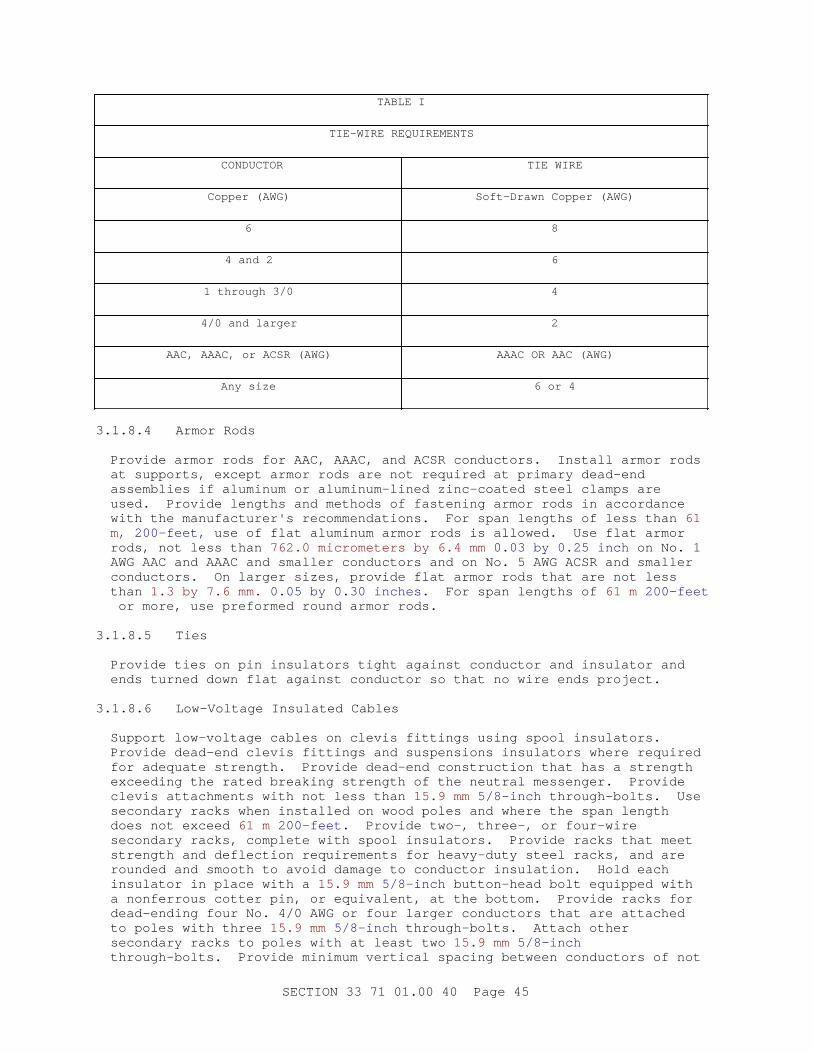
TABLE I
TIE-WIRE REQUIREMENTS
CONDUCTOR TIE WIRE
Copper (AWG) Soft-Drawn Copper (AWG)
6 8
4 and 2 6
1 through 3/0 4
4/0 and larger 2
AAC, AAAC, or ACSR (AWG) AAAC OR AAC (AWG)
Any size 6 or 4
3.1.8.4 Armor Rods
Provide armor rods for AAC, AAAC, and ACSR conductors. Install armor rods at supports, except armor rods are not required at primary dead-end assemblies if aluminum or aluminum-lined zinc-coated steel clamps are used. Provide lengths and methods of fastening armor rods in accordance with the manufacturer's recommendations. For span lengths of less than 61 m, 200-feet, use of flat aluminum armor rods is allowed. Use flat armor rods, not less than 762.0 micrometers by 6.4 mm 0.03 by 0.25 inch on No. 1 AWG AAC and AAAC and smaller conductors and on No. 5 AWG ACSR and smaller conductors. On larger sizes, provide flat armor rods that are not less than 1.3 by 7.6 mm. 0.05 by 0.30 inches. For span lengths of 61 m 200-feet or more, use preformed round armor rods.
3.1.8.5 Ties
Provide ties on pin insulators tight against conductor and insulator and ends turned down flat against conductor so that no wire ends project.
3.1.8.6 Low-Voltage Insulated Cables
Support low-voltage cables on clevis fittings using spool insulators. Provide dead-end clevis fittings and suspensions insulators where required for adequate strength. Provide dead-end construction that has a strength exceeding the rated breaking strength of the neutral messenger. Provide clevis attachments with not less than 15.9 mm 5/8-inch through-bolts. Use secondary racks when installed on wood poles and where the span length does not exceed 61 m 200-feet . Provide two-, three-, or four-wire secondary racks, complete with spool insulators. Provide racks that meet strength and deflection requirements for heavy-duty steel racks, and are rounded and smooth to avoid damage to conductor insulation. Hold each insulator in place with a 15.9 mm 5/8-inch button-head bolt equipped with a nonferrous cotter pin, or equivalent, at the bottom. Provide racks for dead-ending four No. 4/0 AWG or four larger conductors that are attached to poles with three 15.9 mm 5/8-inch through-bolts. Attach other secondary racks to poles with at least two 15.9 mm 5/8-inch through-bolts. Provide minimum vertical spacing between conductors of not
SECTION 33 71 01.00 40 Page 45
less than 200 mm 8-inches .
3.1.8.7 Reinstalling Conductors
**************************************************************************NOTE: Sag t abl es ar e usual l y avai l abl e f r om conduct or manuf act ur er s. For pr oj ect s whi ch ent ai l consi der abl e l engt h of over head l i ne, i ndi cat e sag t abl es f or t he par t i cul ar l i ne as desi gned.
**************************************************************************
String existing conductors to be reinstalled or resagged to "final" sag table values indicated for the particular conductor type and size involved.
3.1.8.8 New Conductor Installation
**************************************************************************NOTE: Sag t abl es ar e usual l y avai l abl e f r om conduct or manuf act ur er s. For pr oj ect s whi ch ent ai l consi der abl e l engt h of over head l i ne, i ndi cat e sag t abl es f or t he par t i cul ar l i ne as desi gned. Use " i ndi cat ed" on NAVFAC At l ant i c pr oj ect s.
**************************************************************************
String new conductors to "initial" sag table values [indicated] [recommended by the manufacturer] for conductor type and size of conductor and ruling span indicated.
3.1.8.9 Fittings
Provide dead end fittings[, clamp or compression type,] that conform to written recommendations of conductor manufacturer and that develop full ultimate strength of conductor.
3.1.8.10 Aluminum Connections
Make aluminum connections to copper or other material using only splices, connectors, lugs, or fittings designed for that specific purpose. Keep a copy of manufacturer's instructions for applying these fittings at job site for use of the inspector.
[ 3.1.9 Pole Mounted Metering Equipment
3.1.9.1 Primary Meters
Install primary metering transformers [as indicated] [according to manufacturer's drawings]. Make connections to metering circuits within each transformer conduit connection box.
3.1.9.2 Installing Meter System
Provide metering enclosure that houses kWh meter [and meter test block]. Secure the enclosure to pole at a height of 1825 mm 6-feet above grade to center of the enclosure. Ground enclosure.
a. Connect meter as indicated.
[ b. Connect meter test block between meter and metering transformers to isolate meter for removal, test or adjustment.
SECTION 33 71 01.00 40 Page 46
] c. Provide identical phase sequence and color code of potential and current leads. Mark wires which are connected to transformer terminals identified with polarity marks (dots) by a colored plastic tape around the wire at each end.
d. No splices are permissible in metering circuits. Provide wire that is trained at sides and bottom of enclosure back board and secured by plastic wraps.
] 3.1.10 Pole Top Switch Installation
Install pole top switch strictly according to manufacturer's installation drawings and information.
3.1.10.1 Operating Handle
Locate approximately 1520 mm 5 feet above ground on field side of pole.
[ 3.1.11 Recloser
Install recloser(s) strictly in accordance with manufacturer's instructions.
][ 3.1.12 Sectionalizer
Install sectionalizer(s) strictly in accordance with manufacturer's instructions.
] 3.1.13 Risers
[Secure galvanized steel conduits on poles by two hole galvanized steel pipe straps spaced as indicated and within 910 mm 3-feet of any outlet or termination. Ground metallic conduits.] [Secure PVC riser shields on poles as indicated.]
3.1.14 Transformer Installation
**************************************************************************NOTE: Speci f y phase sequence i n accor dance wi t h t he l ocal pr act i ce.
**************************************************************************
Carefully install transformers so as not to scratch finishes or damage bushings. Install transformers in accordance with the manufacturer's instructions. After installation, inspect surfaces and touch up scratches with a finish provided by the transformer manufacturer for this purpose.
[ 3.1.15 Crossarm Mounting
**************************************************************************NOTE: Do not use t hi s par agr aph and subpar agr aphs f or Navy pr oj ect s. The Navy pr ovi des t hi s i nf or mat i on on t he dr awi ngs. Ut i l i ze Navy pl at es dur i ng desi gn of Navy pr oj ect s. Ref er t o " I nst r uct i ons t o v i ew/ pr i nt gr aphi cs" f or access t o Navy pl at es.
**************************************************************************
SECTION 33 71 01.00 40 Page 47

**************************************************************************NOTE: Nor mal l y speci f y f l at br aces f or 2. 4 m 8 f oot cr ossar ms and angl e br aces f or 3. 1 m 10 f oot cr ossar ms t o agr ee wi t h REA const r uct i on. An angl e br ace i s al so r equi r ed on 2. 4 m 8 f oot ar ms wher e conduct or s have a br eaki ng st r engt h of mor e t han 20. 0 kN 4500 pounds. Ext r eme l oadi ng condi t i ons al so war r ant s t he ext r a cost of t he st r onger angl e br ace under ot her c i r cumst ances.
Pr ovi de met al cr ossar m br aces t o r educe t he ef f ect i ve BI L r at i ng of t he pol e. I n hi gh l i ght ni ng ar eas speci f y f i ber gl ass br aces.
Consul t REA Bul l et i n 61- 10, " Pr ot ect i on of Bal d and Gol den Eagl es f r om Power l i nes. " Ver i f y t he r equi r ement f or wooden cr ossar m br aces f or each st at e and l and ar ea i n accor dance wi t h t he Bal d Eagl e Pr ot ect i on Act of 1940, ( 16 U. S. C. 703 et seq. ) as amended; Endanger ed Speci es Act of 1973 ( 87 St at . 1064) ; and Mi gr at or y Bi r d Tr eat y of 1918 ( 16 U. S. C 703 et . seq. ) as amended. Pot ent i al r equi r ement sour ces ar e t he Bur eau of Land Management , U. S. Depar t ment of t he I nt er i or , and Feder al , St at e, and Local Land Management or Wi l dl i f e Conser vat i on Agenci es.
**************************************************************************
Bolt crossarms to poles with 15.9 mm 5/8-inch through-bolts with square washers at each end. Extend bolts not less than 3 mm 1/8-inch nor more than 50 mm 2-inches beyond nuts. On single crossarm construction, install the bolt head on the crossarm side of the pole. Provide [fiberglass] [metal] [wood] crossarm braces on crossarms. Provide flat braces for 2.4 m 8-foot crossarms 6.4 by 31.8 mm, 1/4 by 1-1/4-inches, not less than 700 mm 28-inches in length. Bolt flat braces to arms with 9.5 mm 3/8-inch carriage bolts with round or square washers between boltheads and crossarms, and secure to poles with 50.8 by 101.6 mm 1/2 by 4-inch lag screws after crossarms are leveled and aligned. Angle braces are required for 3.1 m 10-foot crossarms. Provide angle braces that are 1.5 m 60-inch span by 457.2 mm 18-inch drop formed in one piece from 38.1 by 38.1 by 4.8 mm 1-1/2 by 1-1/2 by 3/16-inch angle. Bolt angle braces to crossarms with 50.8 mm 1/2-inch bolts with round or square washers between boltheads and crossarms, and secure to poles with 15.9 mm 5/8-inch through-bolts. Securely hold double crossarms in position by means of 15.9 mm 5/8-inch double-arming bolts. Equip each double-arming bolt with four nuts and four square washers.
3.1.15.1 Line Arms and Buck Arms
Provide line arms and buck arms that are set at right angles to lines for straight runs and for angles 45 degrees and greater; and line arms that bisect angles of turns of less than 45 degrees. Use dead-end assemblies for turns where shown. Install buck arms, as shown, at corners and junction poles. Provide double crossarms at ends of joint use or conflict sections, at dead-ends, and at angles and corners to provide adequate vertical and longitudinal strength. Provide double crossarms at each line-crossing structure and where lines not attached to the same pole cross each other.
SECTION 33 71 01.00 40 Page 48
3.1.15.2 Equipment Arms
Set equipment arms parallel or at right angles to lines as required to provide climbing space. Locate equipment arms below line construction to provide necessary wire and equipment clearances.
] 3.1.16 Field Applied Painting
Paint electrical equipment as required to match finish of adjacent surfaces or to meet the indicated or specified safety criteria. Provide painting as specified in Section 09 90 00 PAINTS AND COATINGS.
3.1.17 Field Fabricated Nameplate Mounting
Provide number, location, and letter designation of nameplates as indicated. Fasten nameplates to the device with a minimum of two sheet-metal screws or two rivets.
3.2 FIELD QUALITY CONTROL
**************************************************************************NOTE: Sel ect t ypes t o sui t pr oj ect condi t i ons and del et e al l ot her s. Del et e al l par agr aphs not appl i cabl e. Pr ovi de j ust i f i cat i on f or al l t est s.
**************************************************************************
3.2.1 General
[Perform field testing in the presence of the Contracting Officer. ]Notify the Contracting Officer [_____] days prior to conducting tests. Furnish materials, labor, and equipment necessary to conduct field tests. Perform tests and inspections recommended by the manufacturer unless specifically waived by the Contracting Officer. Maintain a written record of tests which includes date, test performed, personnel involved, devices tested, serial number and name of test equipment, and test results. Sign and date field reports.
3.2.2 Safety
Provide and use safety devices such as rubber gloves, protective barriers, and danger signs to protect and warn personnel in the test vicinity. Replace any devices or equipment which are damaged due to improper test procedures or handling.
3.2.3 Medium-Voltage Preassembled Cable Test
**************************************************************************NOTE: I f t he i nst al l at i on i s t appi ng a new f eeder t o an exi st i ng f eeder usi ng a " T" spl i ce, modi f y t he par agr aph t o i ndi cat e t hat when exi st i ng cabl e cannot be r eadi l y di sconnect ed, onl y t est t he syst em t o t he l ower ( af t er i nst al l at i on) vol t age. Del et e t he t est i f no cabl e i s i nst al l ed i n t he pr oj ect .
**************************************************************************
After installation, prior to connection to an existing system, and before the operating test, give the medium-voltage preassembled cable system a high potential test. Apply direct-current voltage on each phase conductor of the system by connecting conductors at one terminal and connecting
SECTION 33 71 01.00 40 Page 49
grounds or metallic shieldings or sheaths of the cable at the other terminal for each test. Prior to the test, isolate the cables by opening applicable protective devices and disconnecting equipment. Provide the method, voltage, length of time, and other characteristics of the test for initial installation in accordance with NEMA WC 74/ICEA S-93-639 for the particular type of cable installed, and do not exceed the recommendations of IEEE 404 for cable joints unless the cable and accessory manufacturers indicate higher voltages are acceptable for testing. For any cable that fails due to a weakness of conductor insulation or due to defects or injuries incidental to the installation or because of improper installation of cable, cable joints, terminations, or other connections, make necessary repairs or replace cables as directed. Retest repaired or replaced cables.
3.2.4 Sag and Tension Test
Give the Contracting Officer prior notice of the time schedule for stringing conductors or cables serving overhead medium-voltage circuits. The Contracting Officer reserves the right to witness the procedures used for ascertaining that initial stringing sags and tensions are in compliance with requirements for the applicable loading district and cable weight.
3.2.5 Low-Voltage Cable Test
**************************************************************************NOTE: The i nsul at i on r esi st ance t est ( di el ect r i c t est ) val ue i s based on t he r ecommendat i on cont ai ned i n I EEE St d 525. Del et e t he cabl e t est i f no l ow vol t age cabl es ar e i n t he pr oj ect .
**************************************************************************
For underground secondary or service laterals from overhead lines, provide the low-voltage cable, complete with splices, that is tested for insulation resistance after the cables are installed, in their final configuration, ready for connection to the equipment, and prior to energization. The 500 volts dc test voltage, applied for one minute between each conductor and ground and between all possible combinations of conductors in the same trench, duct, or cable, with other conductors in the same trench, duct, or conduit. Provide insulation with a minimum value of:
R in megohms = (rated voltage in kV + 1) x 304,800/(length of cable in meters) R in megohms = (rated voltage in kV + 1) x 1000/(length of cable in feet)
Repair or replace each cable failing this test. Retest the repaired cable then until failures have been eliminated.
3.2.6 Pre-Energization Services
Perform the following services on the equipment listed below. Perform these services subsequent to testing but prior to the initial energization. Inspect the equipment to insure that installation is in compliance with the recommendations of the manufacturer and as shown on the detail drawings. Inspect terminations of conductors at major equipment to ensure the adequacy of connections. Inspect bare and insulated conductors between such terminations to detect possible damage during installation. If factory tests were not performed on completed
SECTION 33 71 01.00 40 Page 50

assemblies, perform tests after the installation of completed assemblies. Inspect components for damage caused during installation or shipment and to ensure that packaging materials have been removed. Provide components capable of being both manually and electrically operated that are operated manually prior to the first electrical operation. Provide components capable of being calibrated, adjusted, and tested and calibrate, adjust and test in accordance with the instructions of the equipment manufacturer. Items for which such services are provided, but are not limited to, are the following:
a. Capacitors
b. Switches
3.2.7 Performance of Acceptance Checks and Tests
Perform in accordance with the manufacturer's recommendations and include the following visual and mechanical inspections and electrical tests, performed in accordance with NETA ATS.
3.2.7.1 Overhead-Type Distribution Transformers
a. Visual and mechanical inspection
(1) Compare equipment nameplate information with specifications and approved shop drawings.
(2) Inspect physical and mechanical condition.
(3) Verify tightness of accessible bolted electrical connections by calibrated torque-wrench method. Thermographic survey is not required.
(4) Perform specific inspections and mechanical tests as recommended by manufacturer.
(5) Verify correct equipment grounding.
b. Electrical tests
**************************************************************************NOTE: Coor di nat e t he opt i on on ser i es- mul t i pl e vol t age- changi ng swi t ch wi t h t he opt i on i n par agr aph OVERHEAD- TYPE DI STRI BUTI ON TRANSFORMERS her ei n.
**************************************************************************
[ (1) Insure that the series-multiple voltage-changing switch is in the correct position. Transformers are normally shipped in the series position.
] (2) Perform insulation-resistance tests.
(3) Perform continuity test.
(4) Set tap changer to provide a secondary voltage of [120/240] [120/208] [_____].
SECTION 33 71 01.00 40 Page 51
3.2.7.2 Pole Top Interrupter Switch
a. Visual and Mechanical Inspection
(1) Compare equipment nameplate information with specifications and approved shop drawings.
(2) Inspect physical and mechanical condition.
(3) Verify appropriate equipment grounding.
(4) Perform mechanical operator tests in accordance with manufacturer's instructions.
(5) Verify correct blade alignment, blade penetration, travel stops, arc interrupter operation, and mechanical operation.
b. Electrical Tests
(1) Perform insulation-resistance tests.
(2) Perform dc over-potential tests.
(3) Perform contact-resistance tests across each switch blade.
[ 3.2.7.3 Reclosers
a. Visual and Mechanical Inspection
(1) Compare equipment nameplate data with specifications and approved shop drawings.
(2) Inspect physical and mechanical condition.
(3) Inspect alignment and grounding.
(4) Perform mechanical operation and contact alignment tests on both the recloser and its operating mechanism in accordance with manufacturer's instructions.
(5) Verify tightness of accessible bolted electrical connections.
(6) Inspect for correct insulating liquid level.
b. Electrical Tests
(1) Perform resistance measurements through all bolted connections with low-resistance ohmmeter.
(2) Perform a contact resistance test.
(3) Sample insulating liquid. Test sample for:
(a) Dielectric breakdown voltage
(b) Color
(c) Visual condition
SECTION 33 71 01.00 40 Page 52
(4) Test protective functions.
[ (5) Perform vacuum bottle integrity test (overpotential) across each vacuum bottle with the recloser in the open position in strict accordance with manufacturer's instructions.
] (6) Perform overpotential tests.
(7) Determine time delay for each programmed reclosing interval.
(8) Verify lockout for unsuccessful reclosing.
(9) Determine reset time.
(10) Verify instantaneous overcurrent lockout.
][ 3.2.7.4 Sectionalizers
a. Visual and Mechanical inspection
(1) Compare equipment nameplate data with approved shop drawings.
(2) Inspect physical and mechanical condition.
(3) Inspect alignment and grounding.
(4) Perform mechanical operation and contact alignment tests on both the sectionalizer and its operating mechanism in accordance with manufacturer's instructions.
(5) Verify tightness of accessible bolted electrical connections.
(6) Inspect for correct insulating liquid level.
b. Electrical Tests
(1) Perform resistance measurements through all bolted connections with low-resistance ohmmeter.
(2) Perform a contact resistance test.
(3) Sample insulating liquid. Test sample for:
(a) Dielectric breakdown voltage
(b) Color
(c) Visual condition
(4) Perform overpotential tests.
(5) Test sectionalizer counting function.
(6) Test sectionalizer lockout function.
(7) Test for reset timing on trip actuator.
SECTION 33 71 01.00 40 Page 53

][ 3.2.7.5 Potential Transformers
a. Visual and Mechanical Inspection
(1) Compare equipment nameplate data with specifications and approved shop drawings.
(2) Verify correct connection.
(3) Verify that adequate clearances exist between primary and secondary circuit wiring.
(4) Verify tightness of accessible bolted electrical connections by calibrated torque-wrench method.
(5) Verify that all required grounding and shorting connections provide good contact.
(6) Verify correct fuse sizes.
b. Electrical Tests
(1) Perform resistance measurements through all bolted connections with low-resistance ohmmeter
(2) Perform insulation-resistance tests.
(3) Perform polarity tests.
(4) Perform turns-ratio tests.
][ 3.2.7.6 Current Transformers
a. Visual and Mechanical Inspection
(1) Compare equipment nameplate data with specifications and approved shop drawings.
(2) Inspect physical and mechanical condition.
(3) Verify correct connection.
(4) Verify tightness of accessible bolted electrical connections by calibrated torque-wrench method.
(5) Verify that all required grounding and shorting connections provide good contact.
b. Electrical Tests
(1) Perform resistance measurements through all bolted connections with low-resistance ohmmeter.
(2) Perform insulation-resistance tests.
(3) Perform polarity tests.
(4) Perform ratio-verification tests.
SECTION 33 71 01.00 40 Page 54
][ 3.2.7.7 Metering
a. Visual and Mechanical Inspection
(1) Compare equipment nameplate data with specifications and approved shop drawings.
(2) Inspect physical and mechanical condition.
(3) Verify tightness of electrical connections.
b. Electrical Tests
(1) Verify accuracy of meters at 25 percent, 50 percent, 75 percent, and 100 percent of full scale.
(2) Calibrate watthour meters according to manufacturer's published data.
(3) Verify all instrument multipliers.
] 3.2.7.8 Grounding System
a. Visual and mechanical inspection
(1) Inspect ground system for compliance with contract plans and specifications.
b. Electrical tests
(1) Perform ground-impedance measurements utilizing the fall-of-potential method. On systems consisting of interconnected ground rods, perform tests after interconnections are complete. On systems consisting of a single ground rod perform tests before any wire is connected. Take measurements in normally dry weather, not less than 48 hours after rainfall. Use a portable ground testing megger in accordance with manufacturer's instructions to test each ground or group of grounds. Provide an instrument that is equipped with a meter reading directly in ohms or fractions thereof to indicate the ground value of the ground rod or grounding systems under test.
3.2.8 Devices Subject to Manual Operation
Operate each device subject to manual operation at least three times, demonstrating satisfactory operation each time.
3.2.9 Follow-Up Verification
Upon completion of acceptance checks and tests, show by demonstration in service that circuits and devices are in good operating condition and properly performing the intended function. As an exception to requirements stated elsewhere in the contract, give the Contracting Officer 5 working days advance notice of the dates and times of checking and testing.
-- End of Section --
SECTION 33 71 01.00 40 Page 55