Embed Size (px)
Citation preview
© 2011 Xilinx, Inc. All Rights Reserved
Intro to System Generator
This material exempt per Department of Commerce license exception TSU
© 2011 Xilinx, Inc. All Rights Reserved For Academic Use Only
SysGen Introduction 2
Objectives
After completing this module, you will be able to:
• Explain why there is a need for an integrated flow from system design to implementation
• Describe System Generator and the tools with which it interfaces

© 2011 Xilinx, Inc. All Rights Reserved For Academic Use Only
SysGen Introduction 3
Outline
• Introduction• System Generator Design Flow• Summary

© 2011 Xilinx, Inc. All Rights Reserved For Academic Use Only
SysGen Introduction 4
MATLAB• The MathWorks MATLAB provides a
technical computing environment that facilitates rapid exploration of mathematical solutions to systems problems– Extensive libraries for math functions, signal
processing, DSP, communications, and much more
– Visualization: Large array of functions to plot and visualize your data and system and design

© 2011 Xilinx, Inc. All Rights Reserved For Academic Use Only
SysGen Introduction 5
SimulinkVisual data flow tool
• The MathWorks Simulink provides a model-based design environment for the development of executable specs of dynamic systems– Fully integrated with the MATLAB engine– Graphical block editor– Event-driven simulator– Models parallelism– Extensive library of parameterizable functions
• Simulink blockset: math, sinks, and sources • DSP blockset: filters or transforms, for
example• Communications blockset: modulation or
DPCM, for example

© 2011 Xilinx, Inc. All Rights Reserved For Academic Use Only
SysGen Introduction 6
Overview of System Generator for DSP
• The industry’s system-level design environment (IDE) for FPGAs– Integrated design flow from the Simulink software to the BIT file– Leverages existing technologies
• MATLAB , Simulink• HDL synthesis• IP Core libraries• FPGA implementation tools
• Simulink library of arithmetic, logic operators, and DSP functions (Xilinx blockset)– BIT and cycle-true to FPGA implementation
• Arithmetic abstraction– Arbitrary precision fixed-point, including quantization and overflow– Simulation of double precision as well as fixed point
© 2011 Xilinx, Inc. All Rights Reserved For Academic Use Only
SysGen Introduction 7
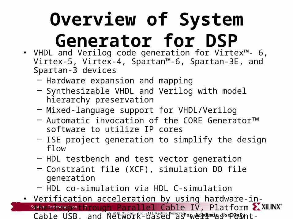
Overview of System Generator for DSP
• VHDL and Verilog code generation for Virtex™- 6, Virtex-5, Virtex-4, Spartan™-6, Spartan-3E, and Spartan-3 devices– Hardware expansion and mapping– Synthesizable VHDL and Verilog with model hierarchy preservation– Mixed-language support for VHDL/Verilog – Automatic invocation of the CORE Generator software to utilize IP cores– ISE project generation to simplify the design flow– HDL testbench and test vector generation– Constraint file (XCF), simulation DO file generation– HDL co-simulation via HDL C-simulation
• Verification acceleration by using hardware-in-the-loop through Parallel Cable IV, Platform Cable USB, and Network-based as well as Point-to-Point Ethernet connections

© 2011 Xilinx, Inc. All Rights Reserved For Academic Use Only
SysGen Introduction 8
ISIM
System Generator for DSP Platform Designs

© 2011 Xilinx, Inc. All Rights Reserved For Academic Use Only
SysGen Introduction 9
• Introduction• System Generator Design Flow• Summary
Outline

© 2011 Xilinx, Inc. All Rights Reserved For Academic Use Only
SysGen Introduction 10
Model Based Design using System Generator
• Develop an executable spec using Simulink
• Refine the hardware algorithm using System generator– Verify hardware against
executable spec
© 2011 Xilinx, Inc. All Rights Reserved For Academic Use Only
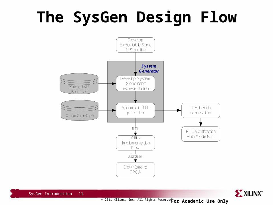
SysGen Introduction 11
The SysGen Design FlowDevelop
Executable Spec in Simulink
Develop System Generator
representation
Automatic RTL generation
Xilinx CoreGen
Xilinx DSP Blockset
Xilinx Implementation
Flow
Download to FPGA
Testbench Generation
RTL
Bitstream
RTL Verification with ModelSim
System Generator

© 2011 Xilinx, Inc. All Rights Reserved For Academic Use Only
SysGen-Based Design FlowSimulink Software Verification
ImplementationImplementation
SynthesisSynthesis
DownloadBitstreamDownloadBitstream
TimingSimulationTimingSimulation
In-CircuitVerificationIn-CircuitVerification
MATLAB/SimulinkMATLAB/Simulink
System GeneratorSystem Generator
Simulink SimulationSimulink Simulation
Functional SimulationFunctional Simulation
SysGen Introduction 12

© 2011 Xilinx, Inc. All Rights Reserved For Academic Use Only
SysGen-Based Design FlowHDL Co-simulation Verification
ImplementationImplementation
SynthesisSynthesis
DownloadBitstreamDownloadBitstream
TimingSimulationTimingSimulation
FunctionalSimulationFunctionalSimulation
In-CircuitVerificationIn-CircuitVerification
MATLAB/SimulinkMATLAB/Simulink
System GeneratorSystem Generator
Simulink SimulationSimulink Simulation
Files Used: Configuration file HDL IP Constraints file
Files Used: Configuration file HDL IP Constraints file
SysGen Introduction 13

© 2011 Xilinx, Inc. All Rights Reserved For Academic Use Only
SysGen-Based Design FlowHardware Co-Simulation Verification
ImplementationImplementation
SynthesisSynthesis
DownloadBitstreamDownloadBitstream
TimingSimulationTimingSimulation
FunctionalSimulationFunctionalSimulation
In-CircuitVerificationIn-CircuitVerification
MATLAB/SimulinkMATLAB/Simulink
System GeneratorSystem Generator
Simulink SimulationSimulink Simulation
Files Used: Configuration
file HDL IP Constraints file
Files Used: Configuration
file HDL IP Constraints file
SysGen Introduction 14

© 2011 Xilinx, Inc. All Rights Reserved For Academic Use Only
SysGen Introduction 15
Outline
• Introduction• System Generator Design Flow• Summary

© 2011 Xilinx, Inc. All Rights Reserved For Academic Use Only
SysGen Introduction 16
Knowledge Check

© 2011 Xilinx, Inc. All Rights Reserved For Academic Use Only
SysGen Introduction 17
• Describe System Generator and the tools with which it interfaces
• Describe how System Generator helps in DSP System Design
Knowledge Check
SysGen Introduction 17

© 2011 Xilinx, Inc. All Rights Reserved For Academic Use Only
SysGen Introduction 18
• Describe System Generator and the tools with which it interfaces– System Generator is a toolbox running under the Simulink
environment. This toolbox provides an integrated design flow by leveraging existing technologies, such as HDL synthesis, IP Core libraries, and FPGA implementation tools
• Describe how System Generator helps in DSP System Design– It provides a simple push-button flow for design and
development under Simulink environment and provides HDL co-simulation and hardware-in-the-loop acceleration verification capability
Answers

© 2011 Xilinx, Inc. All Rights Reserved For Academic Use Only
SysGen Introduction 19
• Traditional system design using Simulink left gap between system designer and FPGA designer
• System Generator toolbox fills that gap so a system designer can design a DSP system in FPGA
• System Generator uses Simulink toolbox, Xilinx HDL synthesis, IP Core libraries, and FPGA implementation tools
• There are three ways to verify your design using System Generator• Simulink• HDL Cosim• HW Cosim
Summary