Embed Size (px)
Citation preview

www.americanradiohistory.com
.. t
TllE LO\\ -COST KEYBOARD. l.IKE l"HE
majority or other typew-riter style keyboards, provides only a singk "make" contact for each key depressed (sec Radio-Electronics. February 1973). Computer terminals. teaching machines. etc, cannot directly use a single-con tact operation, and a device called an encoder must be placed between the keyboard and the computer. The encoder converts the single contact closure into a seven- or eight-bit IC logic compatible parallel code, usually following the ASCII encoding scheme, and allowing for shiji and co111rol key operations. After parallel encoding. there may follow a p11riry generator for error detection. and a 100-word-per-minute para/IC'/ to serial converter that allows the signals to be sent dowr. a single wire or phone line.
The keyboard encoder described here costs only a tiny fraction of commen.:ial eyuivalents. It usi:s three ''dollar'' integrated circuits and a small handrul �f surplus computer diodes. While this encoder was designed as a companion to the low-cost keyboard. it may be used with any keyboard. pro,·idcd the make contacts are less than 1000 ohms when ON and provided that the keys do 1101 have a common ground terminal. The encoder generates all thi: codes shown in Table !. This includes all the capital letters, all thi: often used punctuation. all numerals, and all of the transparent or control functions. Often used control functions such as DELETI:,
SPACE. LINE FEED. ESCAl'E ( Al.T �!ODE ) ,
CARRIAGE RETURN, etc. arc brought out to separate keys. Thi: output is RTL. TTL, DTL a nd M O S compatibk. and a singk IO-volt. 25-mA power source is needed. If an ASCII
buil an
ASCII
ke boa d
c er Here is what you need to couple the keyboard you built in February to a computer, teletype, or teaching machine.
by DON LANCASTER
code is not desirable. the same encoder may be used. through suitable rewiring. to generate IEBDIC. SELECTRIC,
BAUDOT or MORSE codes. Parity and the 100-wpm (words-per-minute) serial converter are easily added to the basic encoder.
What is the ASCII code? Many years ago, the American
S tandards Association decided t o adopt a standard code th<tt computers could use to talk to each other, to their input/output devices. and to allow standardized connections between different brands of computer machinery. The resultant industry wide code is called ASCII. short for A merican Standard Code for Information Interchange. This codi: is a se4uence of six, seven, or eight bi rs (ones or zeros). It may be sent either in serial (bit by bit. least significant bit first) form, or in parallel (all bits at once, on 6. 7, or 8 lines) form. Usually. parallel words are used inside machines, while serial words are used ber1«ee11 machines. Serial words are obviously slower, hut they take far less wire and interconnections.
The basic code consists of seven bits. If we look at all possible combinations of seven ones and zeros from 000-0000, 000-000 I through to
l l l-1111, we'd find a total of 128 different sequences. Each of these may be used to rt:present something distinct. 64 of" these code sequences are used for alphanumeric capital letters. numbers. a blank, and punctuation. 32 more se4ui:nces arc used for rra11spare11r or conrrol commands that never appear on a screen or in print. These commands tell the machinery on the other end what 10 do-things lil-.e re-
turning carriages, clearing. line feeds, bell ringing. and other control functions. A final 32-code se4uences are reserved for lower case alphabet and some little used punctuation. This last group is very seldom used as most computer communications can be handled with only capital letters, numerals, contrnl commands, and common punctuation.
The complete code appears in Table II. It is arranged in a marrix form to make it compact and easy to read. For instance, the transparent command "Carriage Return", or "CR" has a code of 000-1101, starting with bit 7 on the left and going to bit I (the least significant) on the right. A numeric "'6" has the code 011-0110. Note the right half of this code is the same as a binary or a binary-codeddecimal six. A capital L has the code 100-1100. while the lower case L is a 110-1100.
There are several ways to use the codt:, dcpt:nding on how much you want the code to do. If we an:: 011�r interested in upper-case alphabet, numerics, and punctuation, we can use the middle of the code and get by with a six-hit code, sometimes cailed ASCll-6. This is useful in character generators and displays that do not ni:ed transpari:nt commands or lower case alphabets. Many MOS inti:grated circuits art: now available that convert the six-bit subset into a recognizable bunch ol dots on a TV screen or a line printer; these are called ASCII Character Generators.
Or, we can use all seven bi ts, either with or without the lower case stuff, picking up hoth arphanumcrics and control commands. This is often calkd the ASCII-7 code. Finally. if we
APRIL 1973 • RADIO-ELECTRONICS 55
www.americanradiohistory.com
TABLE I OUTPUT CODES The output codes below are shown appear for the SHIFT or CONTROL buttons
in HEXADECIMAL notation to conserve depressed separately. All other keys, space. Thus "3D" is an ASCII 011-1101, whether or not they are used with SHIFT or output a1 = 1, ai = 0, a3 = 1, etc. or CONTROL, produce a Key Depressed The "Key Depressed" output does NOT output.
NORMAL SHIFTED CONTROL KEY CODE CODE CODE
@ 40 40 00 (null) A 41 41 01 (soh) B 42 42 02 (six) c 43 43 03 (etx)
D 44 44 04 (eot) E 4S 4S OS (eng) F 46 46 06 (ack) G 47 47 07 (bell)
H 48 48 08 (bs) I 49 49 09 (ht) J 4A 4 A Q A (Lt) K 4B 4B OB (vi)
L 4C 4C OC (FF) M 4D 4D OD (er) N 4E 4E OE (so) 0 4F 4F OF (si)
p so so 10 (die) a S1 S1 11 (DC1) R S2 S2 12 (DC2) s S3 S3 13 (DC3)
T S4 S4 14 (DC4) u SS SS 1S (NAK) v S6 S6 16 (SYN) w S7 S7 17 (ETB)
x S8 S8 18 (CAN) y S9 S9 19 (EM) z SA SA 1A (SUB)
0 30 20 (space) 1 O (die) 1 31 21 (!) 11 (DC1) 2 32 22 (") 12 (DC2)
.3 33 23 (:::) 13 (DC3)
4 34 24 ($) 14 (DC4)
s 3S 2S (%) 1S (NAK)
6 36 26 (&) 16 (SYN)
7 37 27 (') 17 (ETB)
8 38 28 (() 18 (CAN)
9 39 29 ()) 19 (EM)
3A 2A (� ) 1A (SUB) 3B 2B ( +) 1B (ESC)
< 2C 3C (.) oc (ff) 2D 30 (-) OD (er)
> 2E 3E (.) OE (so) ? 2F 3F (/) OF (si)
SE SE 1 E (rs) SF SF 1 F (us)
SPACE 20 20 00 (null)
LINEFEED OA OA OA (LI)
C. RETURN OD OD OD (er)
ESCAPE (Al T) 1B 1B 1 B (esc)
DELETE 7F 7F 1 F (si)
like, we c<rn add an eighth hi t and use it for error detecting. It is called the parirv hit. In an e1•c11 parirP system, the parity hit makes the total numher or ones in the word ere11. If there are I, ."I. 5. or 7 ones in the \\ ord hel°ore the parity bit is added. the parity hit is a one. If there are 0. 2. 4. or 6 ones. the parity b i t is a 1.ero. This way. there is alwa\S an l!vc11 nuf11 her of ones sent . At the rece iving end. parity is once again tested . If an odd nurnher of ones shows up. ,t mista k e has heen made. and the recei\·er can substitute a ,_.,
.. or ask for the information over
again. Wt: could al o ust: an odd pari ty system just as well. pnivided hoth t:nds ar<? pla ving the game '' ith the >ame ruks. This is called the ASCll-8 code.
Seven hits are rarelv sent het,,een machines .. ·\n eighth wi;e or hit space is usually added , so th<tt if parity is added later. it doesn"t take a hunch of rework. Similarly. most paper tape punches and magnetic tape is in an eight-track code: if pari ty isn·t used. the eighth hit is usually all ones.
You may wonder \\hat al l those transparent commands stand for. Actually. a lot of them are onlv used on \ cry - hig and very compli�at<:d machi nes . and thus aren't really \cry common. The ones you"ll proha hly use are few in numher. For instance. CR is a carriage return that stans a new line on a typewriter. LF is the line feed. used to skip a line. BEL rings a hell or s ignals an opnator. BS is hadspace. h can only he used in some systems. for many CRT te rmi nals and teletypes cannot had. up. The di rect control commands are labeled DC!. DC:!. DC3. and DC4. These are usually yours to do anything you "ant with. such as turning on and off equipment, remote signalling, etc. NUL is a do-nothing command that everything sits in while not
ASCII ENCODER' PARTS LIST ,R1-390 ohms, •;. watt (sets operating torce-
see text) R2. R3. R4-100,000 ohms, '!. watt R5. R7. R10. R16-4700 ohms. •;.watt R6, RB. R9, R11, R12. R13, R14-9100 ohms.
'I• watt 5% R15-470 ohms. •;. watt R17, R18. R19-100 ohms,•;. watt R20-2200 ohms, •;. watt R21, R22. R23-1 a.ODO ohms, •;. watt C1 -0.1-11F disc ceramic capacitor C2. C3-1 00-µF 1 av electrolytic 01 thru 026-1 N914 or similar silicon com-
puter diode D27-1N4736 or sim ilar 6.8-V Zener diode IC1. IC2. IC3-MC 981 BP mwrtl hex inverter 01, 05. 06, 07-2N5139 pnp transistor 02, 03, 04, 08-2N5129 npn transistor MISC: PC board. jumpers. sleeving,. solder.
hardware

www.americanradiohistory.com
in u�e. hnally. ESC is c;illt:d Escape or Alternate mode. This lets vou nreak out of the ASCII code if you ever need a longer sequence or something else special. The technique is l'alled code C'.ne11sio11. One common w;e is on a timesharing terminal. where you can switch nack and forth net ween llASIC.
FORTRA1'. and EXHTTl\"E �!ODE Ian-
� :..:: :..:: :..:: :..:: :..:: :..:: :..:: ::.<: ..... .....
ai ..... .,: .,: en ai en .,: ai ai "' ;: "' ;:: "' "' ..... "' a> � a: a: a: a: a: a: a: a:
guages using th e ESC or exactly equivalent ALT key.
DEL is a 111-1111 .:ode that's used to delete a pre\'ious l'Ornmand or till a paper tape full or holes.
Construction steps The schematic and parh li�t is
shown in Fig. I. The kevs are ar-
R15 470!1
ranged de.:tri<.:ally to form an ··s x 8" array, and pnp transistors translate the positive end of the array back down tn logic levels. This technique requires far fewer diodes than a direct encoding does. The conrro/ and shifi keys suitably alter the code of only those keys they're supposed to change.
A printed circuit board is used fur
�--, c� r-----1
IC1·3 MC9818P
DEL SHIFT<>--+--+-..+--+--1--4---1---4---1--------------1---------�
8-9; 0-7
<? CTRL o--+--f---+--+�+--+-------. ESC CR-LF<>--t--t-�-t--i---------........, SPACEo--1--4---1-_.----...--.
H-0 @-G X-� P-W
000 0-���- -----..-, ........
0010-------.......... 0100-----!t::-i_
D9-11
R17 100!1
025
D22
R5 4.7K
a7
a6
Dl, 2
011 0-----.._+-...... -t-_...�i--+--'VI.,.,,..--��-�--......, 100 o----...,
D5, 6. 7' 8
D3,4 R18 100Q
101 0---+-..... -+---6----<!--..j.-JI\/\('\,.-------. 110i:>--_. ___ ......_��---.._...,..('r--. 1110------
+ <>---.........
INPUTS
Dl-26 IN914
C3. +100/lOV
!SEE TEXT)
R2 100K
R3 100K
R1 390!1
a5
I >o---:1---o a4
I .:>c>---71---o a3
I _:x-.;.-1 --o a2
03-04 D27
I _J
R20
2N5129 6.BV C2 �------------l_N_4_7_3_6__,_+ _:h
100/ -=
"KEY PRESSED"
t OUTPUTS
FIG. 1-SCHEMATIC DIAGRAM OF THE ENCODER shows how simple the device can be when
three Inexpensive IC's are used.
+10V 10V OUTPUT
APRIL 1973 • RADIO-ELECTRONICS 57
www.americanradiohistory.com
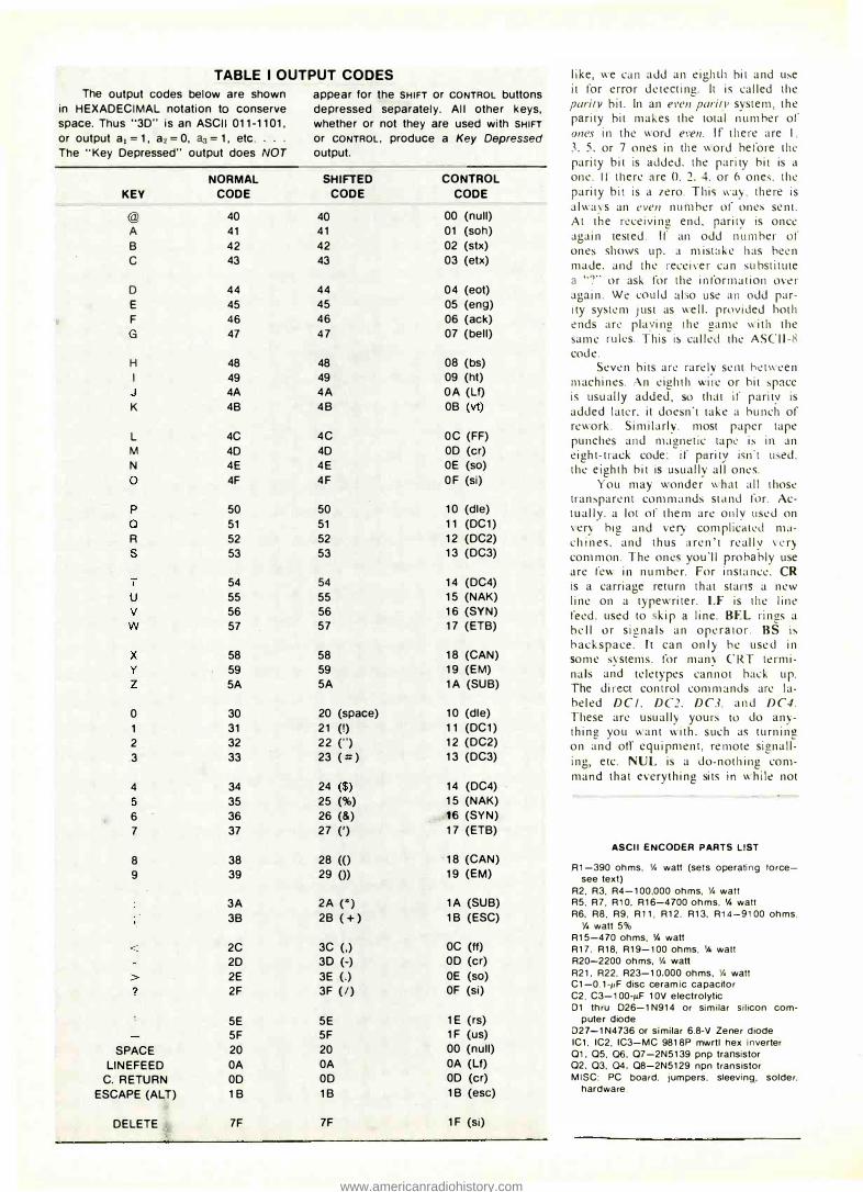
assembly. It's available commercially (see hg. I parts list) or you can make your own using the pattern in Fig. 2 and following the drilling and assembly guides of Figs. 3 and 4. l.:se a small iron and tine solder for assembly
. and be careful to observe th.:
code notch and dot on the !Cs and the polarity bands on the diodes and capacitors.
Resistor RI dctermines thc opcrating force required on the keyboard. It is choscn to be low enough in value that each key's output code is set up and correct at \/3 to 14 the prcssu rc rcq uired to get the .. key pressed .. output command. This way the code i:, sct up and stable before it is sent. Capacitor C3 further delay:. the .. go .. command to insure reliable operation. Bc sure you use only the leading edge of the .. key pressed .. com rnand. for it lasts
1 REC'D ..!.. 'PC MAT'L "
longa than the rest of the code does. Should a second key be pressed before thc first one is released. it will not bc sent. giving a form of .. 2 key rollnvcr .. protection.
The PC board mounts on short spacers directly bclow the keyboard. and connects to the keyboard with a
FIG. 3 (left)- DRILL GUIDE for the PC board. Solid-wire jumpers are on the component side.
FIG. 4 (rlght)-COMPONENT SIDE of the encoder board. Jumpers are shown here as well as in Fig. 3 at left.
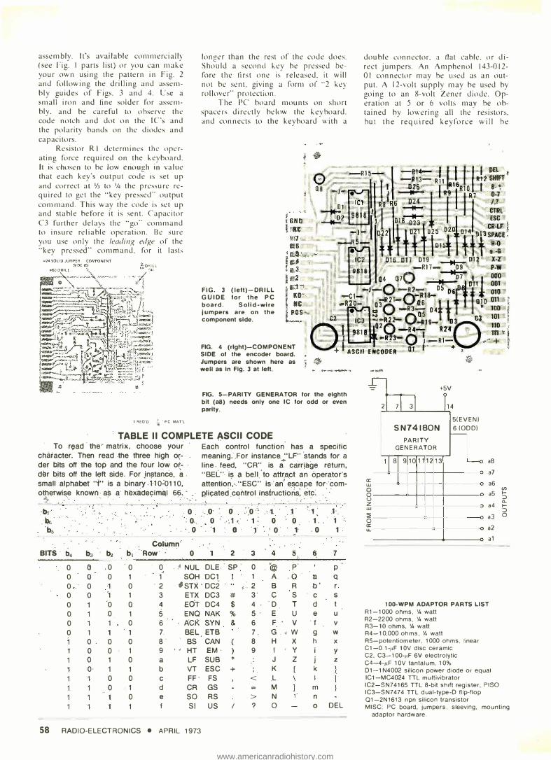
FIG. 5-PARITY GENERATOR for the eighth bit (a8) needs only one IC for odd or even parity.
TABLE I I COMPLETE A,SCll CODE To read· the, matrix, choose your
character. Then read .the three high o�der bits off the top and the four low order �i.ts off the left side. For jn�tanc·e. a . small alphabet "f" is a binary. n 0�0110, otherwise known as a· hexadecirna,i 66. · . .
� .
' .
. . .
.. �· -� 'bs
BITS· b4 b:i bi b1 0 (} .o 0
• . ..... . . . .o . o ..
. ·.o
toru.mn' Row·· 0
0 . . � NUL
Each control function· has a specific meaning.",For instance. "LF" ·stands for a line. feed, "CR" is a"' carriage return, "BEL"· ·is a bell.'to att�a.ct an operator's attention,·. "ESC" is-" an' e_scape for··corni?licated CG>fitrol instructions:
, etc'.
..
· .. o· 0 :.:o:': .'t l" ··1: 1-. • 0 .-: 1 •.
' . 1 � 0 0 1. ' 1 : . ·1 0 ·1 ·. ·. o· 1· 0 1 .
2 3 4 5 6 7
OLE . SP 0 @ j:>· p 0 0 0 1 1 SOH "DC1 1 A .a· 'B q o •.
. 0 ·1 0 ·2 fsrx · oc2 " �: 2 B R b' r. 0 0 ·1 1 3 ETX DC3 # 3· c s c s 0 ·o 0 4 EOT DC4 $ 4 D T d t
0. 0 1 5 ENO NAK % S· E u e u 0 1 0 6 ACK SYN & 6 F v . f v 0 1 1 1 7. BEL ETB 7. u . • w g w
0 0 0 8 BS CAN 8 H x h x 1 0 0 1 9 HT .EM· 9 I y y
0 1 0 a LF SUB * J z j z O· 1 1 b VT ESC + ' . K [ k
0 0 c FF · FS < .L 0 1 d CR GS M rn
0 e so RS > N , . n f SI us I ? 0 0 DEL
58 RADIO-ELECTRONICS • APRIL 1973
double conncctor. a tlat cablc. or direct jumpers. An Amphenol 143-012-01 connector may be used as an output. A 12-volt supply may be used by going to an 8-volt Zencr diodc. Operation at 5 or 6 volts may be obtained by lowcring all the
· resistors
. but the required keyforce will be
� +5V
2 71 31 l14
5(EVENI SN74180N 6 (000)
1--PARITY
GENERATOR 11 s 9 10 1 1 12 13 �
-aB
a7 tr: UJ - a6 0 -0 a5 u z UJ a4
:;; -0 a3 tr: u. a2
- a 1
100-WPM ADAPTOR PARTS LIST R1-1000 ohms, •;,watt R2-2200 ohms. •;, watt R3-10 ohms. 'A watt R4-10,000 ohms, 'A watt RS-potentiom eter. 1000 ohms, linear C1 -0.1-11F 1 OV disc ceramic C2, C3-100-11F 6V electrolytic C4-4-11F 1 OV tantalum, 10% 01-1 N4002 silicon power diode or equal IC1-MC4024 ITL multivibrator IC2-SN74165 TTL 8-bit shift register. PISO IC3-SN7474 TTL dual-type-D flip-flop Q1-2N1613 npn silicon transistor
Cf) I-:::> c.. I-:::> 0
MISC: PC board, jumpers. sleeving. mounting adaptor hardware.

www.americanradiohistory.com
greater and less uniform from key to key. TTL (Transistor Transistor Logic) fanout is I standard load. RTL (Resistor Transistor Logic) fanout is one medium-power gate.
proper codes in Table I. It's particularly important to watch all the bits at once with lamp drivers, IC testers, or something similar during initial checkout to be sure the code is up and stable before the keypressed com-The unit is tested hy noting the
• •
41" 8 -------------i
.156 TYP i
FIG. 2-FOIL PATTERN FOR THE ENCODER PC BOARD. This board mounts just below the keyboard and connects to It through flat cable, PC connectors or direct wired jumpers ..
+5V
lJ 4 14
lCl MC4024
M VB � ASTABLE
g�/'---_-,---5..----,.J
6V -'--
R4 10K
C1 C2
R5 6V ru1 100/
1K
6
6 2
10
1
TELE-T�PE 7
2Nl �113
LINE -
SET TO OUTPUT 9.09 MSEC +
T.P. PERIOD R3 Dl R 2 +5V ion IN4002 2·2K
15 16
1C2 SN74165
P.1.s.o· SHIFT RGSTR
14 12 6543 13 11
9
14 7
11 al KEY PRESSED
\�a� B ------"-.v�-----�/
FROM ENCODER
RJ. lK
13
+5V •P.1.S.O · PARALLEL IN
SERIAL OUT OR
PARITY GENERATOR FIG. 6-TELETYPE FEED Is through a special adapter circuit. This one handles up to 100 words per minute. A precision oscillator controls the storage and output from the shift register.
mand is sent for each and every key. An optional parity generator for
the eighth bit is shown in Fig. 5 and may be used for even or odd parity. A 100 word per minute teletype adaptor
is shown in Fig. 6. The 100-wpm adapter consists of an oscillator whose period must be exactly 9.09 ms. Upon the Key Pressed command, an ASCII code, a START bit and a SYNCHRONIZING bit are loaded into a parallelload shift register. After loading is completed, the oscillator marches out the code bits in proper sequence to be teletype and computer compatible. The circuit may accept a second character anytime after the 110-ms transmission time. The output consists of a transistor that normally shorts the teletype line. It breaks the line anytime a ··I" is to be transmitted. The proper polarity must be observed on the output, and the 20 or 30 mA loop current source is located elsewhere. R-E
CIRCUIT BREAKER SUBSTITUTION BOX
A substitution box with cin.:uit breakers selected by a switch is one of the handiest gadgets on my service bench. With breakers of different ratings, I'm ready to check radios, amplifiers and TV's with blown fuses and questionable circuit breakers.
Generally, I can clip onto the fuse or circuit breaker if the chassis has been pulled. I've rigged up a handy adapter that lets me jump fuses without pulling the chassis when the fuse holder is a post type on a panel or chassis skirt. The drawing shows its construction.
Drill a 'Is inch hole through the
B LOWN GLASS F USE
' I
··'
\
FUSE CAP
HOOK-UP
TO CLIPS
center of a spare fuse-holder cap. Drill small holes slightly off center in the ends of a blown cartridge fuse. Drill a second hole, just large enough to pass a piece of thin insulated hook-up wire, in the center of one end of the fuse. Strip about 'Is inch of insulation off one end of a piece of hook-up wire and pass it through the center of the fuse so the short exposed wire goes through the hole in the far end. Solder. Solder a second piece of hookup wire to the other end and then thread both leads through the fusepost cap and then add clips for connecting to the breaker substitution box.-Arrhur M. Padmore R-E
APRIL 1973 • RADIO-ELECTRONICS 59