Embed Size (px)
Citation preview
University of Alberta
Library Release Form
Name of Author: Yu Fu
Title of Thesis: Transmitter Precoding for Interference Mitigation in Closed-Loop MIMO OFDMSystems
Degree: Doctor of Philosophy
Year this Degree Granted: 2009
Permission is hereby granted to the University of Alberta Library to reproduce single copies of thisthesis and to lend or sell such copies for private, scholarlyor scientific research purposes only.
The author reserves all other publication and other rights in association with the copyright in thethesis, and except as hereinbefore provided, neither the thesis nor any substantial portion thereofmay be printed or otherwise reproduced in any material form whatever without the author’s priorwritten permission.
. . . . . . . . . . . . . . . . . .Yu Fu2nd Floor,Electrical and Computer EngineeringResearch Facility (ECERF)University of AlbertaEdmonton, ABCanada, T6G 2V4
Date: . . . . . . . . .
University of Alberta
TRANSMITTER PRECODING FORINTERFERENCEM ITIGATION IN CLOSED-LOOP MIMOOFDM SYSTEMS
by
Yu Fu
A thesis submitted to the Faculty of Graduate Studies and Research in partial fulfillment of therequirements for the degree ofDoctor of Philosophy.
Department of Electrical and Computer Engineering
Edmonton, AlbertaFall 2009
University of Alberta Faculty of Graduate Studies and Research
The undersigned certify that they have read, and recommend to the Faculty of Graduate Studies and Research for acceptance, a thesis entitled Transmitter Precoding for Interference Mitigation in Closed-Loop MIMO OFDM Systems submitted by Yu Fu in partial fulfillment of the requirements for the degree of Doctor of Philosophy. . . . . . . . . . . . . . . . . . . Dr. Tho Le-Ngoc (External Examiner) Department of Electrical and Computer Engineering, McGill University . . . . . . . . . . . . . . . . . . Dr. Ehab S. Elmallah (Committee Member) Department of Computer Science, University of Alberta . . . . . . . . . . . . . . . . . . Dr. Ivan Fair (Committee Member) Department of Electrical and Computer Engineering, University of Alberta
. . . . . . . . . . . . . . . . . . Dr. Vien Van (Committee Member) Department of Electrical and Computer Engineering, University of Alberta . . . . . . . . . . . . . . . . . . Dr. Sergiy Vorobyov (Committee Member) Department of Electrical and Computer Engineering, University of Alberta . . . . . . . . . . . . . . . . . . Dr. Witold A. Krzymień (Co-Supervisor) Department of Electrical and Computer Engineering, University of Alberta . . . . . . . . . . . . . . . . . . Dr. Chintha Tellambura (Co-Supervisor) Department of Electrical and Computer Engineering, University of Alberta Date: . . . . . . . . .

To my parents, Ryan and Chunlong, who offer me endless encouragement andsupport.

Acknowledgements
I would like to express my sincere thanks to my supervisors, Dr. Krzymien and Dr. Tellambura, for
their invaluable guidance, encouragement, generosity, patience, advice and comments throughout
my research work. I would like to appreciate all their support.
My deepest gratitude goes to my parents, my husband and my son, who have always encour-
aged, supported and cared for me throughout my life. They have always been the source of my
power and courage.
I also wish to give my thanks to my labmates, for their helpfuldiscussion and friendship.
Last but not the least, I would like to thank the Natural Sciences and Engineering Research
Council (NSERC), Informatics Circle of Research Excellence (iCORE) and TRLabs for their fi-
nancial support.
Abstract
Current trends in the development of high-data-rate wireless systems focus on the integration of
orthogonal frequency-division multiplexing (OFDM), multiple-input multiple-output (MIMO) and
closed-loop techniques. In closed-loop systems, transmitprecoding reacts to channel conditions in
order to improve the system capacity or bit error rate (BER).Closed-loop MIMO OFDM allows
transmit precoding on frequency-selective channels to pre-process signals at the subcarrier level,
and facilitates the utilization of capacity or performancegain. OFDM is being widely adopted
in several wireless standards due to its spectrum efficiencyand other advantages. Recent inte-
gration with multiple-antenna techniques promises a significant boost in performance of OFDM.
However, OFDM is sensitive to frequency offset, which immediately results in intercarrier inter-
ference (ICI) and degrades the system performance. On the other hand, MIMO systems are also
constrained by limited antenna spacing, which may lead to correlations among antennas. The an-
tenna correlation always reduces the system data rate and increases the error rate. Furthermore, the
original space-time techniques have poor performance if they are directly employed over antenna-
correlated channels.
This thesis contributes to transmitter precoding design inMIMO OFDM systems for reducing
ICI, and mitigating the degradation due to antenna correlations. Transmitter-based techniques usu-
ally require the complete channel state information at the transmitter (CSIT), which is difficult to
obtain in practical applications. The complete channel information, including frequency offset and
channel gains, is not readily estimated at the transmitter or feedback capability from the receiver
is limited. Therefore, precoding with partial CSIT is first considered. An important property of
the ICI matrix is derived and non-linear Tomlinson-Harashima precoding (THP) with only partial
CSIT, not including frequency offset, is developed. To further reduce the feedback requirements,
linear and non-linear limited-feedback precoders are proposed. Our results significantly reduce the
BER increase due to frequency offsets in single-user and multiuser MIMO OFDM.
Precoders are developed to mitigate the impact of transmit-antenna and path correlations for
MIMO OFDM systems. A pairwise error probability (PEP) optimal precoder is derived, which
requires only covariance information at the transmitter. The covariance (second-order statistics)
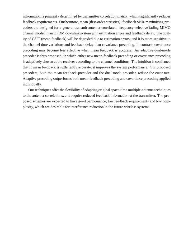
information is primarily determined by transmitter correlation matrix, which significantly reduces
feedback requirements. Furthermore, mean (first-order statistics) -feedback SNR-maximizing pre-
coders are designed for a general transmit-antenna-correlated, frequency-selective fading MIMO
channel model in an OFDM downlink system with estimation errors and feedback delay. The qual-
ity of CSIT (mean feedback) will be degraded due to estimation errors, and it is more sensitive to
the channel time variations and feedback delay than covariance precoding. In contrast, covariance
precoding may become less effective when mean feedback is accurate. An adaptive dual-mode
precoder is thus proposed, in which either new mean-feedback precoding or covariance precoding
is adaptively chosen at the receiver according to the channel conditions. The intuition is confirmed
that if mean feedback is sufficiently accurate, it improves the system performance. Our proposed
precoders, both the mean-feedback precoder and the dual-mode precoder, reduce the error rate.
Adaptive precoding outperforms both mean-feedback precoding and covariance precoding applied
individually.
Our techniques offer the flexibility of adapting original space-time multiple-antenna techniques
to the antenna correlations, and require reduced feedback information at the transmitter. The pro-
posed schemes are expected to have good performance, low feedback requirements and low com-
plexity, which are desirable for interference reduction inthe future wireless systems.
Contents
1 Introduction 1
1.1 MIMO . . . . . . . . . . . . . . . . . . . . . . . . . . . . . . . . . . . . . . . . . 1
1.1.1 Spatial Diversity Coding . . . . . . . . . . . . . . . . . . . . . . . .. . . 2
1.1.2 Spatial Multiplexing . . . . . . . . . . . . . . . . . . . . . . . . . . .. . 5
1.1.3 Diversity-Multiplexing Tradeoff . . . . . . . . . . . . . . . .. . . . . . . 6
1.2 OFDM . . . . . . . . . . . . . . . . . . . . . . . . . . . . . . . . . . . . . . . . . 7
1.2.1 OFDM Systems . . . . . . . . . . . . . . . . . . . . . . . . . . . . . . . . 9
1.2.2 MIMO OFDM . . . . . . . . . . . . . . . . . . . . . . . . . . . . . . . . 11
1.2.3 Multiuser OFDM . . . . . . . . . . . . . . . . . . . . . . . . . . . . . . . 13
1.2.4 OFDM Access . . . . . . . . . . . . . . . . . . . . . . . . . . . . . . . . 14
1.3 Closed-Loop Techniques . . . . . . . . . . . . . . . . . . . . . . . . . . .. . . . 15
1.4 Organization and Contributions . . . . . . . . . . . . . . . . . . . .. . . . . . . . 17
2 Transmitter Precoding for Closed-Loop MIMO Systems 21
2.1 Introduction . . . . . . . . . . . . . . . . . . . . . . . . . . . . . . . . . . . .. . 21
2.2 Layer Separation in MIMO Channels . . . . . . . . . . . . . . . . . . .. . . . . . 23
2.2.1 Linear Precoding . . . . . . . . . . . . . . . . . . . . . . . . . . . . . . .24
2.2.2 Singular Value Decomposition . . . . . . . . . . . . . . . . . . . .. . . . 24
2.2.3 V-BLAST . . . . . . . . . . . . . . . . . . . . . . . . . . . . . . . . . . . 25
2.3 Tomlinson-Harashima Precoding . . . . . . . . . . . . . . . . . . . .. . . . . . . 26
2.3.1 THP Structure and Matrix Calculation . . . . . . . . . . . . . .. . . . . . 26
2.3.2 Basic Concepts . . . . . . . . . . . . . . . . . . . . . . . . . . . . . . . . 28
2.4 Simulation Results . . . . . . . . . . . . . . . . . . . . . . . . . . . . . . .. . . 29
2.5 Summary . . . . . . . . . . . . . . . . . . . . . . . . . . . . . . . . . . . . . . . 31
3 ICI Reduction for Closed-Loop MIMO OFDM 32
3.1 System Model . . . . . . . . . . . . . . . . . . . . . . . . . . . . . . . . . . . . .33
3.2 ICI Reduction in MIMO OFDM . . . . . . . . . . . . . . . . . . . . . . . . . .. 35
3.2.1 Unitary Property of ICI Coefficient Matrix . . . . . . . . . .. . . . . . . 36
3.2.2 THP for MIMO OFDM . . . . . . . . . . . . . . . . . . . . . . . . . . . 36
3.2.3 The Effect of Mismatch on Precoding Performance . . . . .. . . . . . . . 38
3.3 Correlated Spatial Channels . . . . . . . . . . . . . . . . . . . . . . .. . . . . . 39
3.4 Simulation Results . . . . . . . . . . . . . . . . . . . . . . . . . . . . . . .. . . 41
3.4.1 SISO OFDM . . . . . . . . . . . . . . . . . . . . . . . . . . . . . . . . . 41
3.4.2 MIMO OFDM . . . . . . . . . . . . . . . . . . . . . . . . . . . . . . . . 44
3.5 Summary . . . . . . . . . . . . . . . . . . . . . . . . . . . . . . . . . . . . . . . 47
4 MUI and ICI Suppression in Multiuser Multiple-Antenna OFD M Downlink 48
4.1 System Model . . . . . . . . . . . . . . . . . . . . . . . . . . . . . . . . . . . . .49
4.2 MUI and ICI Reduction . . . . . . . . . . . . . . . . . . . . . . . . . . . . . .. . 51
4.2.1 Non-Linear Tomlinson-Harashima Precoding . . . . . . . .. . . . . . . . 52
4.2.2 Iterative ICI and MUI Equalization . . . . . . . . . . . . . . . .. . . . . 53
4.3 Simulation Results . . . . . . . . . . . . . . . . . . . . . . . . . . . . . . .. . . 54
4.4 Summary . . . . . . . . . . . . . . . . . . . . . . . . . . . . . . . . . . . . . . . 57
5 Limited-Feedback Precoding for Multiuser MIMO OFDM Systems with Frequency
Offsets 58
5.1 Limited-Feedback Precoding for MIMO OFDM with Frequency Offsets . . . . . . 60
5.1.1 Precoding Matrix Selection Criteria for Linear Receivers . . . . . . . . . . 62
5.1.2 Matrix Selection Criterion for Maximum-Likelihood Receiver . . . . . . . 64
5.1.3 Limited-Feedback Precoding Design . . . . . . . . . . . . . . .. . . . . . 65
5.1.4 Codebook Design . . . . . . . . . . . . . . . . . . . . . . . . . . . . . . . 66
5.1.5 Non-Linear Tomlinson-Harashima Precoding . . . . . . . .. . . . . . . . 68
5.2 Limited-Feedback Precoding for Spatially Correlated Channels . . . . . . . . . . . 69
5.2.1 Receive Antenna Correlations Only . . . . . . . . . . . . . . . .. . . . . 69
5.2.2 Both Receive and Transmit Antenna Correlations . . . . .. . . . . . . . . 70
5.3 Simulation Results . . . . . . . . . . . . . . . . . . . . . . . . . . . . . . .. . . 71
5.3.1 Spatially Multiplexed OFDM . . . . . . . . . . . . . . . . . . . . . .. . 72
5.3.2 OSTBC OFDM . . . . . . . . . . . . . . . . . . . . . . . . . . . . . . . . 74
5.3.3 Spatially Correlated MIMO Channels . . . . . . . . . . . . . . .. . . . . 75
5.4 Summary . . . . . . . . . . . . . . . . . . . . . . . . . . . . . . . . . . . . . . . 76
6 Covariance Precoding Schemes for MIMO OFDM over Transmit-Antenna and Path-
Correlated Channels 78
6.1 System Model . . . . . . . . . . . . . . . . . . . . . . . . . . . . . . . . . . . . .80
6.1.1 Transmit-Antenna and Path Correlations in OFDM . . . . .. . . . . . . . 80
6.1.2 Impact of Path Correlations . . . . . . . . . . . . . . . . . . . . . .. . . 81
6.2 Precoding Schemes for OSTBC MIMO OFDM . . . . . . . . . . . . . . . .. . . 83
6.2.1 Optimal Precoding Scheme for OSTBC OFDM . . . . . . . . . . . .. . . 84
6.2.2 Non-Linear Tomlinson-Harashima Precoding . . . . . . . .. . . . . . . . 85
6.2.3 Precoding in SM OFDM . . . . . . . . . . . . . . . . . . . . . . . . . . . 85
6.3 Adaptive Dual-Mode Precoding . . . . . . . . . . . . . . . . . . . . . .. . . . . 86
6.3.1 Euclidean-Distance Based Selection of Precoding-Mode . . . . . . . . . . 87
6.3.2 Suboptimal Metric . . . . . . . . . . . . . . . . . . . . . . . . . . . . . .88
6.4 Simulation Results . . . . . . . . . . . . . . . . . . . . . . . . . . . . . . .. . . 89
6.4.1 PEP-Optimal Precoding for OSTBC OFDM . . . . . . . . . . . . . .. . . 89
6.4.2 Adaptive Dual-Mode Precoding . . . . . . . . . . . . . . . . . . . .. . . 93
6.5 Summary . . . . . . . . . . . . . . . . . . . . . . . . . . . . . . . . . . . . . . . 97
7 Precoding for OSTBC OFDM Downlink: Mean or Covariance Feedback? 99
7.1 Introduction . . . . . . . . . . . . . . . . . . . . . . . . . . . . . . . . . . . .. . 99
7.1.1 Contributions . . . . . . . . . . . . . . . . . . . . . . . . . . . . . . . . .100
7.1.2 Organization . . . . . . . . . . . . . . . . . . . . . . . . . . . . . . . . . 101
7.2 System Model . . . . . . . . . . . . . . . . . . . . . . . . . . . . . . . . . . . . .102
7.2.1 MIMO OFDM with Transmit-Antenna Correlations . . . . . .. . . . . . . 102

7.2.2 Models for Mean Feedback and Channel Covariance . . . . .. . . . . . . 103
7.3 Precoding with Mean Feedback and Channel Covariance . . .. . . . . . . . . . . 105
7.3.1 Mean-Feedback Precoding . . . . . . . . . . . . . . . . . . . . . . . .. . 105
7.3.2 Non-Linear Tomlinson-Harashima Precoding . . . . . . . .. . . . . . . . 107
7.3.3 Covariance Precoding . . . . . . . . . . . . . . . . . . . . . . . . . . .. 107
7.4 Mean-Feedback Precoding or Covariance Precoding? . . . .. . . . . . . . . . . . 107
7.4.1 Maximum Achievable SNR . . . . . . . . . . . . . . . . . . . . . . . . . 108
7.4.2 When to Use Mean Feedback . . . . . . . . . . . . . . . . . . . . . . . . 109
7.5 Simulation Results . . . . . . . . . . . . . . . . . . . . . . . . . . . . . . .. . . 110
7.5.1 Maximum Achievable SNR . . . . . . . . . . . . . . . . . . . . . . . . . 111
7.5.2 BER Performance . . . . . . . . . . . . . . . . . . . . . . . . . . . . . . 113
7.6 Summary . . . . . . . . . . . . . . . . . . . . . . . . . . . . . . . . . . . . . . . 116
8 Conclusions and Future Work 119
8.1 Conclusions and Summary of Contributions . . . . . . . . . . . .. . . . . . . . . 119
8.2 Future Work . . . . . . . . . . . . . . . . . . . . . . . . . . . . . . . . . . . . . .121
8.2.1 Complexity Reduction . . . . . . . . . . . . . . . . . . . . . . . . . . .. 121
8.2.2 Robust Precoding in Multiuser OFDM . . . . . . . . . . . . . . . .. . . . 122
8.2.3 Precoding Design in Medium Access Control Layer . . . . .. . . . . . . 123
Appendices 124
Bibliography 127
List of Figures
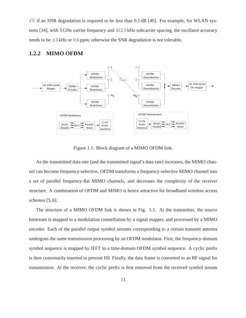
1.1 Block diagram of a MIMO OFDM link. . . . . . . . . . . . . . . . . . . . .. . . 11
2.1 The block diagram of THP in MIMO links. . . . . . . . . . . . . . . . .. . . . . 26
2.2 BERs for THP, SIC, SVD-based precoding and linear precoding with the ZF crite-
rion in a4 × 4 16-QAM system. . . . . . . . . . . . . . . . . . . . . . . . . . . . 30
3.1 BER with THP as a function of the SNR for different values of the normalized
frequency offset for closed-loop SISO 4-QAM64-subcarrier OFDM, with perfect
channel gain matrix at both the transmitter and the receiver. . . . . . . . . . . . . 42
3.2 BER with THP as a function of the SNR for different values of the normalized
frequency offset for closed-loop SISO 4-QAM64-subcarrier OFDM, with perfect
channel gain matrix at the receiver, and inaccurate channelgain matrix at the trans-
mitter. . . . . . . . . . . . . . . . . . . . . . . . . . . . . . . . . . . . . . . . . . 43
3.3 BER with THP as a function of the SNR for different values of the normalized
frequency offset for SISO 4-QAM64-subcarrier OFDM with inaccurate channel
gain matrices used at both transmitter and receiver. . . . . . .. . . . . . . . . . . 44
3.4 The BER as a function of the SNR for different values of thenormalized frequency
offset for2× 2 and2× 4 4-QAM 64-subcarrier OFDM with THP; perfect channel
estimates and uncorrelated spatial channels. . . . . . . . . . . .. . . . . . . . . . 45
3.5 The BER as a function of the SNR for different values of thenormalized frequency
offset for 2 × 2 4-QAM 64-subcarrier OFDM with THP and correlated spatial
channels. The fading correlations are unknown andρ = 0.3 in Group 1. The
fading correlations are known at the transmitter andρ = 0.7 in Group 2. . . . . . . 46
4.1 Block diagram of a multiuser MIMO OFDM downlink. . . . . . . .. . . . . . . . 49
4.2 Block diagram of THP in multiuser MIMO OFDM for decentralized receivers. . . 52
4.3 BER of the proposed precoder/equalizer and full-CSIT THP as a function of the
SNR for different values of the normalized frequency offsetfor 64-subcarrier 4-
QAM 4-user MIMO OFDM with perfect and imperfect feedback;MT = 4, U = 4. 56
4.4 BER of the proposed precoder/equalizer, full-CSIT THP,THP/frequency-offset-
compensation and LP/frequency-offset-compensation as a function of the SNR for
different values of the normalized frequency offset for64-subcarrier multiuser 4-
QAM MIMO OFDM with perfect feedback;MT = 4, U = 2 andMT = 8, U = 4. . 57
5.1 Block diagram of a multiuser OFDM downlink. . . . . . . . . . . .. . . . . . . . 60
5.2 BER of LFB-THP and LFB linear precoding (LFB-LP) with MMSE codebook se-
lection criterion as a function of the SNR for different values of the normalized
frequency offset and 64-subcarrier 2-user 4-QAM-OFDM; perfect CSI at the re-
ceiver;MT = 4, MC = 2, Mu = 2. . . . . . . . . . . . . . . . . . . . . . . . . . 72
5.3 BER of LFB-THP and LFB linear precoding (LFB-LP) with MMSE codebook
selection criterion as a function of the SNR for different values of the normalized
frequency offset and 64-subcarrier 2-user 4-QAM-OFDM;MT = 4, MC = 2,
Mu = 2; estimated CSI at the receiver.K = 64. . . . . . . . . . . . . . . . . . . 74
5.4 BER for LFB-THP as a function of the SNR for different values of the normalized
frequency offset and 64-subcarrier 2-user 4-QAM SM OFDM;MT = 3, MC = 2,
Mu = 2. The MMSE, MSV and MMI codebook selection criteria are compared. . . 75
5.5 BER of LFB-THP with the MMSE selection criterion as a function of the SNR
for different values of the normalized frequency offset and64-subcarrier2 × 4 4-
QAM uncoded (SM) OFDM, 4-QAM Alamouti-coded OFDM, and3 × 4 4-QAM
Alamouti-coded OFDM. . . . . . . . . . . . . . . . . . . . . . . . . . . . . . . . 76
5.6 BER for LFB-THP with the MMSE criterion as a function of the SNR for different
values of the normalized frequency offset and 64-subcarrier 4-QAM SM MIMO
OFDM in spatially correlated channels;MT = 3, MC = 2, Mu = 2. . . . . . . . . 77
6.1 BER as a function of the path-correlation factorp for different values of SNR for a
2 × 2 4-QAM Alamouti-coded64-subcarrier OFDM system with perfect channel
estimation. . . . . . . . . . . . . . . . . . . . . . . . . . . . . . . . . . . . . . . 83
6.2 Tomlinson-Harashima precoding in OSTBC OFDM. . . . . . . . .. . . . . . . . 85
6.3 The adaptive dual-mode precoder. . . . . . . . . . . . . . . . . . . .. . . . . . . 88
6.4 BER with linear precoding (LP), THP and no precoding (NoP) as a function of the
SNR for different values of the normalized transmit-antenna spacing for4× 2 and
4 × 4 16-QAM 1/2-rate OSTBC systems in transmit-antenna correlated channels
with perfect channel estimation,N = 1, L = 1, andp = 0. Vehicular B channel is
considered. . . . . . . . . . . . . . . . . . . . . . . . . . . . . . . . . . . . . . . 90
6.5 BER with linear precoding (LP), THP and no precoding (NoP) as a function of
the SNR for2 × 2 and2 × 4 4-QAM Alamouti-coded64-subcarrier OFDM sys-
tems in transmit-antenna correlated channels with perfectand imperfect channel
estimation,ζT = 0.25, Ωe = 1/25, andp = 0. Vehicular B channel is considered. . 91
6.6 BER with linear precoding (LP), THP and no precoding (NoP) as a function of
the SNR for different values of the normalized transmit-antenna spacing for2 ×2 4-QAM Alamouti-coded64-subcarrier OFDM systems in antenna and path-
correlated channels with perfect channel estimation,p = 0.9. Vehicular B channel
is considered. . . . . . . . . . . . . . . . . . . . . . . . . . . . . . . . . . . . . . 92
6.7 BER as a function of SNR for linear and non-linear precoding with and without
the adaptive structure in2 × 2 64-subcarrier OFDM systems in transmit-antenna
correlated channels with perfect CSIR. One subcarrier per group (Nb = N), R =
4 bits/s/Hz andp = 0, ζT = 0.25. Adaptive precoders use the optimal (exhaustive
search) and suboptimal (metric (6.22)) criteria. . . . . . . . .. . . . . . . . . . . 93
6.8 BER as a function of SNR for linear and non-linear precoding with and without
the adaptive structure in2×2 64-subcarrier OFDM systems over transmit-antenna
correlated channels with imperfect CSIR. One or two subcarriers per group (Nb =
N , Nb = N/2), R = 4 bits/s/Hz,Ωe = 1/25, p = 0, andζT = 0.25. Vehicular B
channel is considered. Adaptive precoding uses the suboptimal criterion. . . . . . 95
6.9 BER as a function of SNR for linear and non-linear precoding with and without
the adaptive structure in2 × 2 64-subcarrier OFDM systems over antenna and
path-correlated channels with perfect CSIR. One subcarrier per group (Nb = N),
R = 4 bits/s/Hz,ζT = 0.25 andp = 0.9. Vehicular B channel is considered.
Adaptive precoding uses the optimal and suboptimal criteria. . . . . . . . . . . . . 96
6.10 BER as a function of SNR for linear and non-linear adaptive precoding using the
optimal switching criterion in2 × 2 64-subcarrier OFDM systems over antenna
and path-correlated channels with perfect and imperfect channel estimation. One
or two subcarriers per group (Nb = N , Nb = N/2), R = 4 bits/s/Hz,ζT = 0.5 and
p = 0.9. Vehicular B channel is considered. . . . . . . . . . . . . . . . . . . . .. 97
7.1 The mean-feedback SNR to covariance SNR ratio with linear precoding (LP) and
THP as a function of the normalized autocovariance for2 × 2 4-QAM Alamouti-
coded64-subcarrier MIMO OFDM systems over transmit-antenna-correlated chan-
nels with different values ofζT ; Ωe = 0. . . . . . . . . . . . . . . . . . . . . . . . 111
7.2 The mean-feedback SNR to covariance SNR ratio with linear precoding (LP) and
THP as a function of the normalized autocovariance for2 × 2 4-QAM Alamouti-
coded64-subcarrier MIMO OFDM systems over transmit-antenna-correlated chan-
nels with different values ofζT , Ωe = 0.01 andΩe = 0.1. . . . . . . . . . . . . . 112
7.3 BER as a function of SNR for mean-feedback linear precoding (MFB-LP), covari-
ance linear precoding (C-LP) and no precoding (NoP) in64-subcarrier4-QAM
Alamouti-coded2 × 2 OFDM systems with perfect feedback.,J ∈ I andJ = 0.9
andJ = 0.998. . . . . . . . . . . . . . . . . . . . . . . . . . . . . . . . . . . . . 113
7.4 BER as a function of SNR for mean-feedback linear precoding (MFB-LP), MFB-
THP, covariance linear precoding (C-LP), C-THP and no precoding (NoP) in64-
subcarrier4-QAM Alamouti-coded2 × 2 OFDM systems with perfect and imper-
fect channel estimation.ζT = ∆dT
λc= 0.4, J ∈ I. . . . . . . . . . . . . . . . . . . 115
7.5 BER as a function of SNR for mean-feedback linear precoding (MFB-LP), MFB-
THP and no precoding (NoP) in64-subcarrier16-QAM 1/2-rate-OSTBC OFDM
and4-QAM Alamouti-coded OFDM systems with perfect and imperfect channel
estimation.ζT = ∆dT
λc= 0.3, MR = 2, J ∈ I. . . . . . . . . . . . . . . . . . . . . 116
7.6 BER as a function of SNR for mean-feedback THP (MFB-THP),covariance THP
(C-THP), adaptive LP and THP, and no precoding (NoP) in a64-subcarrier4-QAM
Alamouti-coded2 × 2 OFDM system.ζT = ∆dT
λc= 0.5, J ∈ I. . . . . . . . . . . . 117
7.7 BER as a function of SNR for mean-feedback THP (MFB-THP),covariance THP
(C-THP), adaptive non-linear precoding, adaptive linear precoding and no precod-
ing (NoP) in64-subcarrier16-QAM 1/2-rate OSTBC4 × 2 OFDM systems with
perfect and imperfect channel estimation.ζT = 0.4, J ∈ I. . . . . . . . . . . . . . 118

List of Abbreviations
Abbreviation Definition
3G third-generation
3GPP third-generation partnership project
4G fourth-generation
ADSL asymmetric digital subscriber lines
AWGN additive white Gaussian noise
BER bit error rate
BS base station
CATV cable TV
CCI co-channel interference
CIR channel impulse response
CSI channel state information
DAB digital audio broadcasting
DFE decision feedback equalization
DFT discrete Fourier transform
DSL digital subscriber line
DAB digital audio broadcasting
DVB digital video broadcasting
EVD eigenvalue decomposition
FDD frequency-division duplex
FDMA frequency-division multiple access
FFT fast Fourier transform
FM frequency modulation
i
HDTV high-definition television
HSDPA high-speed downlink packet access
i.i.d independent and identically distributed
ICI intercarrier interference
IDFT inverse discrete Fourier transform
IFFT inverse fast Fourier transform
ISI intersymbol interference
LFB-THP limited-feedback Tomlinson-Harashima precoding
LOS line-of-sight
MAC medium access control
MAN metropolitan area networks
MIMO multiple-input multiple-output
ML maximum likelihood
MMI maximum mutual information
MMSE minimum mean square error
MS mobile station
MSI maximum singular value
MUD multiuser detection
MUI multiuser interference
OFDMA orthogonal frequency-division multiple access
OFDM orthogonal frequency-division multiplexing
OSTBC orthogonal space-time block coded
PAPR peak-to-average power ratio
pdf probability density function
PSK phase shift keying
QAM quadrature amplitude modulation
QoS quality of service
RF radio frequency
SCM single carrier modulation
SIC successive interference cancelation
SINR signal-to-interference-plus-noise power ratio
SISO single-input single-output
SNR signal-to-noise power ratio
STBC space-time block codes
STD switched transmit diversity
STTC space-time trellis codes
STTD space-time transmit diversity
SVD singular value decomposition
TDD time-division duplex
TH Tomlinson-Harashima
THP Tomlinson-Harashima precoding
TXAA transmit adaptive array
ULA uniform linear array
UMTS Universal Mobile Telecommunications System
V-BLAST vertical-Bell laboratories layered space-time
VHDSL very high-speed digital subscriber line
WCDMA wideband code-division multiple access
WLAN wireless local access network
WNG wireless next generation
WSSUS wide-sense stationary uncorrelated scattering
ZF zero forcing

List of Symbols
Symbol Definition
√−1
I = 0,±1,±2, . . . set of integers
ℜx real part of x
A(m, n) them, n entry ofA
ℑx imaginary part of x
Ξ(m, n) complex Grassmannian space
‖A‖F Frobenius norm of matrixA
δ(·) Kronecker delta
det(A) determinant of matrixA
γ(A) singular values of matrixA
⌈x⌉ the smallest integer greater thanx
Cm them-fold Cartesian product set of the ring of integers
Cm×n the vector space ofm × n complex matrices
Rm Euclideanm-space or Cartesian space
Θ(m, n) the set ofm × n matrices with orthogonal columns
⊗ Kronecker product
E expectation operation
0M×N M × N all-zero matrix
IN N × N identity matrix
iv

∗ element-wise conjugate
† Moore-Penrose pseudo-inverse
H conjugate transposition
T transposition
J0(·) zero-order Bessel function of the first kind
tr(A) trace of matrixA
Chapter 1
Introduction
Wireless communications technologies have recently made great advances. Personal communi-
cation devices now enable ubiquitous communications. The spectacular growth of data commu-
nication, voice and video service over Internet, and the equally rapid expansion of mobile tele-
phony, justify great expectations for high data rates in mobile radio communication systems. Cur-
rent communication systems integrate various functions and applications, such as a mobile tele-
phone or high-rate data in a wireless local area network (WLAN), which is expected to provide
its users with over 100 Mbps information rates. Since radio spectrum is limited, supporting such
high data rates and overcoming the radio channel impairments presents challengs to the design
of future high-speed mobile radio communication systems. Current trends in wireless system de-
sign focus on multiple-input multiple-output (MIMO) techniques to provide capacity (data rate)
gains [1, 2], closed-loop techniques to offer capacity gains or bit-error rate (BER) performance
improvements [3,4], and orthogonal frequency-division multiplexing (OFDM) to facilitate the uti-
lization of these performance gains on frequency-selective channels [5,6].
1.1 MIMO
MIMO antenna techniques have recently emerged as a promising performance enhancing solution
for high-data-rate wireless communications. The MIMO approach employs multiple antenna ar-
rays at both the transmitter and the receiver, effectively exploits the spatial dimension in addition
1
to time and frequency dimensions, and offers significant channel capacity gains [1]. These gains
are available in a rich multipath scattering environment, which provides independent transmission
paths from each transmit antenna to each receive antenna: specifically, the capacity of MIMO sys-
tems grows linearly asmin(MT , MR), whereMT is the number of the transmit antennas andMR is
the number of the receive antennas. The system capacity hence scales linearly withmin(MT , MR)
relative to a single-input single-output (SISO) system [1].
MIMO systems use space-time signal processing, which exploits spatial dimension inherent in
multiple spatially-distributed antenna systems. Currentspace-time processing techniques typically
fall into two categories: spatial diversity coding and spatial multiplexing.
1.1.1 Spatial Diversity Coding
Spatial diversity codes improve power efficiency and reliability of transmission by maximizing
spatial diversity gain. These codes ensure that transmit symbols are sent over multiple indepen-
dently fading paths without signal power or bandwidth expansion. If theMT MR MIMO links fade
independently and the transmitted signal is constructed bysuitable diversity codes, the receiver can
combine the arriving signals such that the resultant signalexhibits considerably reduced amplitude
variability in comparison to a SISO link and achieve theMT MR-order diversity. These techniques
include delay diversity [7,8], space-time trellis coding (STTC) [9,10], and space-time block coding
(STBC) [11,12].
A space-time code is transmitted overT time slots and fromMT transmit antennas, and can
generally be represented by aT × MT transmit matrix
C =
c11 . . . c1MT
.... . .
...cT1 . . . cTMT
, (1.1)
wherectv is the modulation symbol transmitted at timet, t = 1, 2, . . . , T , from thev-th transmit
antenna andT is the number of time slots for transmitting the code matrix.The transmission (code)
rateRc is defined asP/T , whereP represents the number of different data symbols transmitted
2
over theT time slots. The number of rows,T , is equal to the total number of time slots necessary
to transmitP symbols.Rc is the maximum possible rate of a full-diversity code. At each time slot
t, thet-th row of C is transmitted from all transmit antennas simultaneously.Thev-th column of
C represents the sequence of symbols transmitted from thev-th antenna.
1.1.1.1 Delay Diversity
Delay diversity, first proposed in [7] for flat-fading channels, introduces a deliberate resolvable
multipath dispersion by transmitting the data bearing signal 1 and itsMT −1 delayed replicas over
MT transmit antennas. The delays are unique to each antenna andare chosen to be multiples of
the symbol interval. At the receiver, a maximum likelihood (ML) estimator resolves the artificial
multipath in an optimal manner to obtain diversity order ofMT . ForT time slots, the number of
columns isMT , thus the transmit matrix can be given as
Cdelay =
c1 cT ... cT−MT +2
c2 c1 cT−MT +3...
... ......
cT cT−1 cT−MT +1
, (1.2)
where each row represents a signalct and itsMT delayed versions fromMT antennas.
A generalized delay diversity scheme that maximizes the diversity gains for frequency-selective
fading channels was reported in [8], and applied to Global System for Mobile Communications
(GSM) and Enhanced Data Rates for GSM Evolution (EDGE) in [13].
1.1.1.2 Orthogonal Space-Time Bock Coding
To minimize decoding complexity, STBC has been discovered [11, 12]. The orthogonal design of
this scheme supports ML detection based only on linear processing at the receiver. In this thesis,
emphasis within space-time coding is placed on block approaches, which currently dominate the
literature rather than on trellis-based approaches.
STBC based on orthogonal design obtains full diversity gainwith low decoding complexity,
3
and therefore is widely used. An OSTBC1 matrix is composed of linear combinations of con-
stellation symbolsc1, c2, . . . , cP and their conjugates, and encoding therefore only requireslinear
processing. The most important special case is the Alamouticode for two transmit antennas [11].
It is used to achieve space-time transmit diversity (STTD),and has been adopted in several third-
generation (3G) cellular standards because it maximizes diversity gain [14,15].
TheT × MT code matrix for OSTBC satisfies
CHC =(∑P
t=1 |ct|2)IMT
, (1.3)
for all complex code symbolsct. For example, the Alamouti code is an OSTBC with 2 transmit
antennas, for which the transmit matrix is
C1 =
(c1 c2
−c∗2 c∗1
), (1.4)
i.e., two symbolsc1 andc2 and their conjugates are transmitted over two time slots [11]. In the first
time slot,c1 andc2 are transmitted from the antenna1 and2, respectively; during the next symbol
period,−c∗2 is transmitted from the antenna1, andc∗1 is from the antenna2. More general OSTBC
structures are discussed in [12]. For instance, code matrices for rate1/2 and3/4 code using four
antennas are given by
C1/2 =
c1 c2 c3 c4
−c2 c1 −c4 c3
−c3 c4 c1 −c2
−c4 −c3 c2 c1
c∗1 c∗2 c∗3 c∗4−c∗2 c∗1 −c∗4 c∗3−c∗3 c∗4 c∗1 −c∗2−c∗4 −c∗3 c∗2 c∗1
, (1.5)
and
C3/4 =
c1 c2c3√2
c3√2
−c∗2 c∗1c3√2
− c3√2
c∗3√2
c∗3√2
−c1−c∗1+c2−c∗
2
2
−c2−c∗2+c1−c∗
1
2c∗3√2
− c∗3√2
c2+c∗2+c1−c∗
1
2− c1+c∗
1+c2−c∗
2
2
, (1.6)
1OSTBC stands for orthogonal space-time block-coded and orthogonal space-time block coding, depending on thecontext.
4
respectively.
Theoretically, the number of antenna elements through which independent symbols can be
transmitted in oneT × MT code block bounds the achievable order of spatial diversity.
1.1.2 Spatial Multiplexing
Instead of maximizing spatial diversity, spatial multiplexing uses a layering approach to increase
capacity. Accordingly,MT independent symbols are transmitted per symbol period so that the
transmission rate isMT . The SM variants include vertical-Bell laboratories layered space-time (V-
BLAST) [16,17], horizontal BLAST [18], diagonal BLAST [18], and turbo BLAST [19]. Among
the above spatial multiplexing techniques, V-BLAST [16] isthe most promising technique due
to its implementation simplicity. V-BLAST architecture uses ordered serial zero-forcing (ZF) or
minimum mean square error (MMSE) nulling and successive interference cancellation (SIC). This
scheme has three main steps to detect received signals:
1. Estimate the channel state information (CSI) at the receiver;
2. Determine the optimal detecting order and the nulling vectors. The nulling vector is orthogo-
nal to the subspace spanned by the distributions to the received signal vector with the weaker
signals and will detect the strongest signal.
3. Detect the received signals based on the optimal order andSIC.
• ZF or MMSE nulling: ZF or MMSE estimation of the strongest received signal is
obtained via nulling out the weaker signals.
• Detecting: The value of the strongest signal is detected by slicing to the nearest value
in the constellation.
• SIC: The effect of the strongest signal on the other weaker signals to be detected is
removed from the vector of the received signals, after whichwe return to the second
step and continue the decoding successively.
5
Since the data symbols are detected consecutively in spatial (vertical) rather than temporal (hori-
zontal) direction, this approach is called V-BLAST.
In spatial multiplexing, independent data streams are transmitted over multiple antennas to in-
crease the data rate, but full spatial diversity is not achieved [20]. Since a spatial multiplexing
detector uses some form of inverse channel matrix, a unique solution for receiver processing is
only possible if the number of receive antennas is greater than or equal to that of independently
transmitted signals. Performance of spatial multiplexingdegrades over spatially correlated chan-
nels.
1.1.3 Diversity-Multiplexing Tradeoff
A MIMO system can provide two types of gains: spatial multiplexing gains and diversity gains.
Spatial multiplexing is usually used to achieve the former and STBC is used to extract the latter.
Given a MIMO channel, both gains can be simultaneously obtained. However, maximizing one
type of gain trends to minimize the other. As discussed in [20], there is a fundamental tradeoff
between diversity and spatial multiplexing: higher spatial multiplexing gain comes at the price of
sacrificing diversity, and vice versa. The diversity-multiplexing tradeoff is essentially the tradeoff
between the system error probability and the data rate. Generally speaking, to achieve high band-
width efficiency, spatial multiplexing is a better choice. On the other hand, without coding in the
time or space dimension, spatial multiplexing may have higherror rates. Hence, STBC offers a
lower BER.
MIMO opens the space dimension to offer the advantage of diversity and thus has been adopted
in various standards and wireless networks, including broadband wireless access systems, IEEE802.11n
WLAN standard [21], and 3G cellular standards. MIMO can alsobe implemented in the high-
speed downlink packet access (HSDPA) channel, which is a part of the Universal Mobile Telecom-
munications System (UMTS) standard [22].
6
1.2 OFDM
OFDM usesN orthogonal subcarriers so that a high-rate data stream is split into N lower rate
substreams, which are transmitted in parallel on the subcarriers. The time duration of an OFDM
symbol is thereforeN times longer than that of a single-carrier symbol. Because the symbol
duration increases for the lower rate parallel subcarriers, the relative amount of time dispersion
caused by multipath delay spread is decreased. The concept of using parallel data transmission
and frequency division multiplexing (FDM) with orthogonalspectral overlap was published in
the mid 1960s [23, 24]. Some early development can be traced back in 1957, which was for
bandwidth efficient transmission over telephone and high frequency (HF) radio channel [25]. The
basic idea was to use parallel data and FDM with overlapping subcarriers to avoid the use of
high-speed equalization and to combat impulsive noise and multipath distortion as well as to fully
use the available bandwidth. The initial applications werein military communications, such as
KINEPLEX [25] and KATHRYN [26] in HF military systems in the 1960s.
For a large number of subcarriers, in order to avoid the unreasonably expensive and complex
sinusoid generators and coherent demodulators, the discrete Fourier transform (DFT) was imple-
mented in the mid-1960 in military HF radios [26]. Weinsteinand Ebert applied inverse and direct
fast Fourier transform (IFFT/FFT) to simplify the OFDM modulation and demodulation process
in the early 1970s [27]. IFFT/FFT is needed for a completely digital implementation so that the
bank of subcarrier oscillators and coherent demodulators required by the original OFDM pro-
posal [23,24] can be eliminated. Rapid advances in very large scale integration (VLSI) technology
make high-speed large size FFT chips commercially affordable. In 1985, Cimini first investigated
OFDM for mobile wireless communications [28]. In 1990, Bingham has studied the performance
and complexity of OFDM and concluded that the time for OFDM had come [29]. In the 1990s,
OFDM has been investigated for voice-band modems such as asymmetric digital subcarrier loop
(ADSL), high-bit-rate digital subscriber line (HDSL), andvery high-speed digital subscriber line
(VHDSL) [30]. OFDM has also been exploited for wideband datacommunications over mobile
7
radio frequency modulation (FM) channels, digital audio broadcasting (DAB) [31], digital video
broadcasting (DVB) [32] and high-definition television (HDTV) [33].
A broadband wireless system with a very high data rate encounters large delay spread, and
therefore, has to cope with frequency selectivity. OFDM converts a frequency-selective channel
into a number of parallel frequency-flat subcarriers. The subcarriers have the minimum frequency
separation required to maintain orthogonality of their corresponding time-domain waveforms yet
the signal spectra associated with the different subcarriers overlap in frequency domain. The avail-
able bandwidth is hence used efficiently. If knowledge of thechannel is available at the trans-
mitter, OFDM can allocate the transmitted power on a subcarrier basis to match the channel so
that the optimal BER and/or ideal water filling capacity of a frequency-selective channel can be
approached [5]. Therefore, closed-loop OFDM facilitates the utilization of the capacity or BER
performance gains on frequency-selective channels.
OFDM has been exploited for several wireless standards, including IEEE802.11a LAN stan-
dard [34] and IEEE802.16a, metropolitan area network (MAN) standard [35]. The IEEE802.11a
operates at raw data rate up to54 Mb/s with a20 MHz channel spacing, thus yielding a bandwidth
efficiency of2.7 b/s/Hz. The actual throughput is highly dependent on the medium access control
(MAC) protocol. IEEE802.16a operates in many modes depending on channel conditions with a
data rate ranging form4.20 to 22.91 Mb/s in a typical bandwidth of6 MHz, the efficiency is then
0.7 to 3.82 b/s/Hz [35]. OFDM is also being considered in IEEE802.20a, a standard in the making
for maintaining high-bandwidth connections to users moving at speeds up to100 km/h. OFDM is
in addition being regarded as a potential candidate for 4G mobile wireless systems [22]. Recent
integration with MIMO techniques promises a significant boost in performance of OFDM. Broad-
band MIMO OFDM systems with bandwidth efficiency on the orderof 10 b/s/Hz are potentially
feasible for LAN/MAN environments [5].
8
1.2.1 OFDM Systems
An OFDM system can be implemented in discrete time domain using an IDFT as a modulator and
DFT as a demodulator. The transmitted data are the frequency-domain symbols and the samples
at the output of the IDFT are time-domain samples of the transmitted waveform. LetX[n] denote
an M-ary phase shift keyed (PSK) or QAM symbol on then-th subcarrier. The length-N input
data vector can then be written asX =[X[0] X[1] . . . X[N − 1]
]T. The OFDM signal may be
expressed as
x(t) =N−1∑
k=0
X[k]e2πfkt, 0 ≤ t < Ts, (1.7)
wherefk = f0 + k ∆f is thek-th subcarrier frequency;∆f is the subcarrier separation. To satisfy
the orthogonal condition,∆f Ts = 1 is needed, whereTs is the OFDM symbol period. Without
loss of generality, settingf0 = 0, fk = kTs
is obtained. With sampling rateNTs
, then-th sample in
the discrete-time domain is
x(n) =N−1∑
k=0
X[k]e2π kTs
nTsN =
N−1∑
k=0
X[k]e 2πN
kn, (1.8)
which is a form of the IDFT. Consequently, the time-domain OFDM symbol can be generated by
taking an IDFT of an input data vector:
x =[x(0) x(1) . . . x(N − 1)
]T= FNX, (1.9)
whereFN is theN ×N IDFT matrix with entriesFN(m, n) = 1N
e 2πN
mn. The IDFT can be imple-
mented efficiently by the IFFT algorithm, which reduces the number of computations drastically
by exploiting the regularity of the operations in IDFT. A cyclic prefix, which is longer than the
expected maximum excess delay, is customarily inserted at the beginning of each time-domain
OFDM symbol to prevent inter-symbol interference (ISI).
As discussed in [36], the following key advantages make OFDMattractive in several wireless
applications. OFDM is an efficient way to cope with multipathfading channels. Due to parallel
transmission on different subcarriers, the deleterious effect of fading is spread over the entire sym-
bol duration. This weakens the effects of deep fading or impulsive noise, so that only a few signals
9
are slightly affected instead of a number of adjacent signals completely distorted. Further improve-
ment can be obtained with a proper coding and interleaving scheme for many practical systems,
especially in a wide-band mobile environment. Spectral efficiency is another important advantage
of OFDM. The spectra of subcarriers are permitted to overlapwhile preserving orthogonality. An-
other advantage lies in its easy implementation using the FFT algorithm. For a given delay spread,
the implementation is much simpler than that of a single-carrier system with equalization.
However, there are two major drawbacks in OFDM. One is that OFDM is sensitive to frequency
offset and phase noise, which result in intercarrier interference (ICI) and severely degrade system
performance. The other is that OFDM has a relatively large peak-to-average power ratio (PAPR),
which reduces the power efficiency of a radio frequency (RF) amplifier. In this thesis, approaches
will be considered to reduce ICI due to frequency offset in closed-loop MIMO OFDM systems.
1.2.1.1 Impairments Due to Frequency Offset
Frequency offset due to the Doppler shift caused by the relative motion between the transmitter
and receiver, or movement of other objects around transceivers destroys the orthogonality between
the OFDM subcarriers. In addition, the oscillator at the receiver may not produce the exactly same
carrier frequency as the transmitter’s oscillator. The mismatch of oscillators also leads to frequency
offset. Consequently, frequency offset exits at an OFDM receiver. Before the subcarriers are
demodulated, the receiver has to estimate and correct the carrier frequency offset of the received
signal to eliminate the ICI. Otherwise, the system performance will be dramatically degraded.
In the presence of frequency offset, the FFT output for each subcarrier will contain interfer-
ences from all other subcarriers [37, 38]. The lack of orthogonality results in ICI, which will be
added to the desired signal and cause an error floor that increases with the Doppler shift [39]. As
determined in [40], the signal-to-noise power ratio (SNR) degradation caused by a frequency offset,
∆f , is approximately proportional to the square of the normalized frequency offsetε = ∆fTs. The
performance degradation due to ICI thus becomes significantwith increasing carrier frequency,
block size and vehicle velocity [40]. The maximum normalized frequency offset should be around
10
1% if an SNR degradation is required to be less than 0.1 dB [40]. For example, for WLAN sys-
tems [34], with 5 GHz carrier frequency and312.5 kHz subcarrier spacing, the oscillator accuracy
needs to be±3 kHz or0.6 ppm; otherwise the SNR degradation is not tolerable.
1.2.2 MIMO OFDM
OFDMModulation
OFDMModulation
OFDMModulation
MIMOEncoder
M−PSK/QAMMapper
FFTCyclicPrefix
Removal ParallelSerial/ Parallel/
Serial
MIMODecoder
M−PSK/QAMDe−mapper
OFDMDemodulation
OFDMDemodulation
OFDMDemodulation
ParallelSerial/ Parallel/
Serial
CyclicPrefix
InsertionIFFT
OFDM Modulation
RM
OFDM Demodulation
1
2 2
1
MT
εu,v
Figure 1.1: Block diagram of a MIMO OFDM link.
As the transmitted data rate (and the transmitted signal’s data rate) increases, the MIMO chan-
nel can become frequency-selective. OFDM transforms a frequency-selective MIMO channel into
a set of parallel frequency-flat MIMO channels, and decreases the complexity of the receiver
structure. A combination of OFDM and MIMO is hence attractive for broadband wireless access
schemes [5,6].
The structure of a MIMO OFDM link is shown in Fig. 1.1. At the transmitter, the source
bitstream is mapped to a modulation constellation by a signal mapper, and processed by a MIMO
encoder. Each of the parallel output symbol streams corresponding to a certain transmit antenna
undergoes the same transmission processing by an OFDM modulator. First, the frequency-domain
symbol sequence is mapped by IFFT to a time-domain OFDM symbol sequence. A cyclic prefix
is then customarily inserted to prevent ISI. Finally, the data frame is converted to an RF signal for
transmission. At the receiver, the cyclic prefix is first removed from the received symbol stream
11
at the output of the RF front end, and the remaining OFDM symbol is then demodulated by FFT.
A single-tap equalizer per antenna is usually used to compensate for distortion caused by the
transmission channel.
The two space-time signal processing techniques, spatial diversity coding and spatial multi-
plexing, can be extended to MIMO OFDM. Let us consider, as an example, an Alamouti-coded
OFDM system with2 transmit antennas. Note that implementation of the Alamouti scheme re-
quires that the channel remains constant over at least two consecutive symbol periods. Consider
the space-frequency coding: two data symbolsc1 andc2 to be transmitted over two consecutive
OFDM subcarriersk andk + 1. Through an Alamouti encoder, symbolc1 andc2 are transmitted
over antenna 1 and 2, respectively, on subcarrierk, whereas−c∗2 andc∗1 are transmitted over an-
tenna 1 and 2, on subcarrierk+1, in the same OFDM symbol. The receiver detects the transmitted
symbols from the signal received on the two subcarriers using the Alamouti combining scheme
as discussed in [11]. The Alamouti scheme achieves transmitdiversity of order 2 and the same
diversity combining gain as maximum ratio combining (MRC).The technique can be generalized
to systems with more than 2 transmit antennas using OSTBC to achieve full diversity gain.
Analogous to spatial multiplexing for frequency-flat fading MIMO channels with single-carrier
systems, the objective of spatial multiplexing in conjunction with MIMO OFDM is to maximize
the data rate by transmitting independent data streams overdifferent antennas. Thus, spatial mul-
tiplexing in MIMO OFDM reduces to spatial multiplexing overeach subcarrier with the choice of
receiver architectures being identical to that for frequency-flat fading MIMO channels with single-
carrier systems.
MIMO OFDM is also sensitive to frequency offset. Over theu, v-th channel, frequency
offset εu,v may exist. In multiuser OFDM, different users will have distinct values of frequency
offsets. In the most general case, each transmit-receive antenna pair may have a different frequency
offset, i.e., the maximum possible number of frequency-offset values isMR × MT .
12
1.2.3 Multiuser OFDM
OFDM systems are likely deployed in environments where the base station (BS) communicates
with many users simultaneously. For a multiuser system, there are two cases: the uplink, where a
group of users transmits data to the same BS, and the downlink, where the BS attempts to transmit
signals to multiple users. Since there is no coordination among the users, different problems arise
for the uplink and downlink channels.
In the uplink case, the challenge is for the BS to separate thesignals transmitted by the users,
using array processing or multiuser detection (MUD). Sincethe users are not able to coordinate
with each other, the transmitted signals are hard to optimize. If feedback is allowed from the BS
back to the users, some joint process may be possible, but it may require that each user knows all
other users’ channels in addition to its own. Otherwise, thechallenge in the uplink is mainly in the
processing done by the BS to separate all the users.
In the downlink case, since the BS simultaneously transmitsto a group of users, there is mul-
tiuser interference (MUI) among the users. Using MUD techniques, a given user may overcome
the MUI, but such techniques are often too costly to use at thereceiver. To achieve complete pro-
cessing at the receiver, degree of freedom is required, i.e., the number of receive antenna of each
user must be equal to or greater than the number of interferers. This may not be practical for many
application cases. Alternatively, the MUI can be mitigatedby intelligently designing the transmit-
ted signals whenMT ≥ MR. If CSI is available at the BS, it is aware of where interference is
being created for the given user by the signal transmitted toother users. The MUI can therefore
be suppressed by transmitter precoding at the BS. The receiver structure is then simplified from
a multiuser receiver. Moreover, correlated fading models for multiple antennas and closed-loop
solutions for the same have been considered recently in 3G forums, arising when operators are
constrained by considerations of space from placing antennas close to each other at the BS.
Multiuser OFDM is sensitive to frequency offsets, which lead to ICI and MUI. ICI and MUI
suppression schemes will be proposed for multiuser MIMO OFDM downlink in Chapter 4 and 5.
13
1.2.4 OFDM Access
Orthogonal frequency-division multiple access (OFDMA), acombination of OFDM and frequency-
division multiple access (FDMA), inherits OFDM’s attractive features [41]. This broadband wire-
less access technology allows an efficient layer for multiple-user wireless applications. It allows
different users to share one OFDM symbol such that separating different users using subcarrier
orthogonality can avoid the MUI in a cell. Multiple subcarriers can be assigned per user to sup-
port high data rate applications. OFDMA systems can allocate power and data rate adaptively and
optimally among the subcarriers to achieve high throughput. Also, compared with single-carrier
multiple-access systems, OFDMA offers increased robustness to ISI and narrowband interference,
allows straightforward dynamic channel assignment, and simplifies channel equalization at the re-
ceiver by performing one-tap equalization. MIMO OFDMA has been found to be capable of pro-
viding further system capacity gain by exploiting multiuser diversity in both the frequency domain
and the space domain [42]. It thus becomse a strong candidatefor broadband multiuser wireless
communication systems, and have been considered for next-generation wireless systems such as
broadband wireless multiple-access systems in the IEEE 802.16a MAN standard [35], which spec-
ifies the air interface for fixed broadband wireless access systems supporting multimedia services.
OFDMA is also adopted in the Mobile WiMAX Air Interface [43] for improved multi-path per-
formance in non-line-of-sight environments. Mobile WiMAXis a broadband wireless solution
that enables convergence of mobile and fixed broadband networks through a common wide area
broadband radio access technology and flexible network architecture.
In the 802.16a standard, the FFT space of OFDMA is divided into subchannels. They are used
in downlink for separating the data into logical streams. Those streams employ different modula-
tion, coding, and amplitude to address subscribers with different channel characteristics. In uplink
the subchannels are used for multiple access. The subscribers are assigned on subchannels through
Media Access Protocol (MAP) messages sent on the downlink. The subchannel is a subset of sub-
carriers out of the total set of available subcarriers. In order to mitigate the frequency selective
14
fading, the subcarriers of one subchannel are spread along the channel spectrum. In essence the
principle of OFDMA consists of different users sharing the uplink FFT space, while each transmits
over one or more subchannels. The division in subchannels isa form of FDMA. A low uplink data
rate is consistent with the traffic asymmetry where the streams from each subscriber add up in a
multipoint-to-point regime, while in downlink all the subchannels are transmitted together. So the
OFDMA allows for fine granulation of bandwidth allocation, consistent with the needs of most
subscribers, while high consumers of uplink bandwidth are allocated more than one subchannel.
The subchannels in an OFDMA system are orthogonal, resulting in zero same-cell interference:
the interference comes only from other cells. A variety of coding and modulation schemes are
allocated selectively to each subscriber, in both upstreamand downstream. There are trade-offs
between throughput and robustness. The coding and modulation schemes provide efficient uti-
lization of the spectrum, with subscribers in difficult positions taking robust schemes with low
throughput. Those in better positions employ higher throughput schemes and are able to transmit
the same amount of data in shorter allocations. The assignment of various modulation and coding
schemes to subchannels can be used to optimize cell capacity. For urban and suburban propagation
environments an OFDMA system can achieve0.53 bit/s/Hz to1.84 bit/s/Hz [43].
1.3 Closed-Loop Techniques
Closed-loop techniques aim to optimize SISO or MIMO systemsusing the CSI at the transmit-
ter (CSIT). Closed-loop MIMO techniques can better exploitspatial diversity, help customize the
transmitted waveforms to provide higher link capacity and throughput, improve system capacity
by sharing the spatial channel with multiple users simultaneously, simplify multiuser receivers
through interference avoidance, and enable channel-awarescheduling for multiple users [44]. Im-
portantly, when CSI is available at the transmitter, it is easier to obtain the benefits of MIMO,
while reducing the complexity of MIMO reception. Closed-loop diversity techniques, switched
transmit diversity (STD) and transmit adaptive array (TXAA), have been used in the 3G standards,
15
including wideband code-division multiple access (WCDMA)and cdma2000 [3,4].
The availability of CSIT is a primary requirement for closed-loop systems. This information
can be estimated at the transmitter when a time-division duplex (TDD) mode is employed, when
the forward and reverse links are approximately reciprocal. Alternatively, in frequency-division
duplex (FDD) systems, i.e., when the forward and reverse links are independent, the CSI can be
estimated at the receiver and sent back to the transmitter via a feedback link. Closed-loop systems
overcome the disadvantage of open-loop systems, where the CSI is not available at the transmitter
but only known at the receiver, such that open-loop techniques are one-size-fits-all approaches to
achieve transmit diversity or capacity for all users. If accurate instantaneous feedback is available,
closed-loop systems may offer a considerable performance gain over their open-loop counterparts.
Closed-loop techniques, such as transmitter precoding, can be desired to react to the current or
average channel conditions, and significantly improve system capacity or BER performance.
In closed-loop MIMO OFDM, if complete CSI, including both the frequency offset and chan-
nel response, is available at the transmitter, precoding ispossible on frequency-selective channels
to pre-process signals at the subcarrier level, and facilitates the utilization of the capacity or per-
formance gain. Feedback requirements increase as the number of transmit and receive antennas,
delay spread and the number of users grow, while the feedbackcapacity is usually limited. Imper-
fect feedback additionally results in CSI transmitter mismatch, i.e., the CSI which is available at
the transmitter differs from the actual CSI at the time of transmission, which significantly degrades
the system BER due to residual interference. Consequently,reduction of feedback requirements is
an essential issue for precoding design in closed-loop MIMOOFDM systems.
It has been shown that additional performance can be extracted from multiple antennas in the
presence of CSIT through, e.g., waterfilling [45]. It shouldbe noted that although waterfilling
may be optimal from an information theoretic point of view, it is not necessarily the best scheme
using CSIT in practice [1]. This is because the performance of real-world MIMO links are sen-
sitive to BER performance rather than mutual information performance. Schemes that exploit
16
CSIT to directly minimize BER-related metrics are therefore of interest, examples of which are
found in [46–52]. In this thesis, the objective is to design transmitter precoding that could mitigate
interference and save feedback capacity in closed-loop OFDM over uncorrelated and spatially-
correlated MIMO channels. Linear precoding and non-linearTomlinson-Harashima precoding
(THP) are considered. The proposed precoders are expected to have good performance, relatively
low complexity and low feedback requirements, which are disable features for interference miti-
gation schemes in closed-loop MIMO OFDM systems.
1.4 Organization and Contributions
In this thesis, several precoding schemes with only partialCSIT are proposed for ICI reduction in
closed-loop MIMO OFDM systems. Precoders are also developed to reduce BER for OFDM over
spatially correlated MIMO channels. The rest of the thesis is organized as follows.
Chapter 2 reviews pre-processing and post-equalization schemes, and compares their perfor-
mance. It shows advantages of non-linear THP over linear precoding and successive interference
cancellation (SIC) for MIMO transmission. The concept and matrix design of THP in MIMO sys-
tems are introduced. It is clarified that the non-linear TH precoder offers a significant BER gain
over its linear counterpart and the SIC scheme, which is usedin V-BLAST.
In Chapter 3, a TH precoder for closed-loop MIMO OFDM system with frequency offsets is
introduced when only partial CSI (no knowledge of frequencyoffsets) is available at the trans-
mitter. Firstly it is shown that the ICI coefficient matrix isapproximately unitary. An immediate
consequence is that the proposed precoder at the transmitter does not need to know the frequency
offset. This avoids feedback in a TDD system, where frequency offsets may not be readily esti-
mated at the transmitter. In FDD systems, this leads to savings of feedback capacity since a sys-
tem withMT transmit andMR receive antennas may haveMT × MR different frequency offsets.
Frequency-offset mismatch due to imperfect feedback is also avoided. The proposed precoded
OFDM significantly suppresses the BER degradation due to frequency offsets. Furthermore, for
17
spatially-correlated MIMO channels, proposed THP performs with negligible BER-performance
loss.
Chapter 4 presents a novel two-stage technique for ICI and MUI suppression in closed-loop
multiuser spatially-multiplexed (SM) OFDM downlink. The first stage applies non-linear THP at
the BS transmitter to mitigate the MUI and the second stage employs an iterative MMSE equalizer
at each user’s receiver to suppress the ICI due to the frequency offset. The spatial channel gain
matrix H is available at the BS in a typical closed-loop system. Sincethe precoder only needs
H at the BS, the feedback load is reduced. The MMSE equalizer ateach user’s receiver has low
complexity due to the unitary property of the ICI matrix. Ourscheme significantly reduces the
BER increase due to frequency offsets. When the feedback link is perfect, the proposed technique
almost completely cancels the ICI and MUI, and experiences the same BER as in the case when
only full-CSI (channel gains and frequency offset) precoding is used at the BS. Hence, sending
frequency offset information to the BS does not offer additional BER improvement. When the
feedback is inaccurate, our technique outperforms the caseof full-CSI feedback since it avoids the
possible frequency-offset mismatch.
In Chapter 5, both linear precoding and non-linear limited-feedback THP (LFB-THP) are de-
veloped for closed-loop multiuser MIMO OFDM systems with frequency offsets. SM MIMO
OFDM with a linear receiver and OSTBC MIMO OFDM with an ML receiver are considered. Fre-
quency offsets are shown to have no impact on precoding, and hence precoding on per-subcarrier
basis is possible. Exploiting this property, the codebook design criterion previously used for flat-
fading MIMO systems [53–56] is generalized to OFDM systems with frequency offsets. A pre-
designed codebook of precoding matrices, available at boththe transmitter and the receiver, is
proposed. The receiver selects optimal matrices at the subcarrier level according to a certain cri-
terion and sends only their indexes to the transmitter. The explicit values of CSI are hence not
needed at the transmitter. Three precoding matrix selection criteria are analyzed. To further reduce
the number of feedback bits, grouping with interpolation schemes is also introduced. In our pre-
18
coders, the feedback load is reduced to only a limited numberof bits, which reduces feedback bit
rate, and the non-linear property reduces power efficiency loss inherent in linear precoding, which
makes non-linear precoding outperform linear precoding. Our precoders also display significant
BER improvement for OFDM with frequency offsets over spatially correlated MIMO channels.
Chapter 6 considers covariance-based linear and non-linear precoding for MIMO OFDM sys-
tems. The main objective is to design precoders to mitigate the impact of transmit-antenna and
path correlations. First, the impact of path correlations on the pairwise error probability (PEP) is
analyzed, and closed-form, waterfilling-based linear and non-linear precoders are derived to min-
imize the worst-case PEP in OSTBC OFDM. Second, an adaptive transmission strategy is also
developed for switching between precoded SM OFDM and precoded OSTBC OFDM. The system
is designed to achieve a low BER with a target fixed transmission rate. The switching criterion is
the minimum Euclidean distance of the received codebook. A lower complexity switching crite-
rion is also developed. The switching decision sent to the transmitter requires one feedback bit per
subcarrier. To reduce the number of feedback bits, the switching decision can be made for groups
of neighboring subcarriers. The proposed precoders considerably reduce the error rate in antenna
and path-correlated channels. The adaptive strategy outperforms either SM or OSTBC individually
in terms of the BER.
In Chapter 7, precoding is investigated to effectively exploit mean and covariance feedback
for error-rate improvement in OSTBC OFDM downlink. A general system model is considered
in which the receiver imperfectly estimates CSI and sends the inaccurate estimates back to the
BS via a feedback channel which introduces delay. The conditional mean and covariance of the
channel matrix are derived. Mean-feedback precoding is proposed to achieve the maximum pos-
sible SNR in the general OSTBC OFDM system model. Our precoding takes into account the
estimation errors and channel time variations over feedback delay and offers the optimal power
allocation. The long-term channel statistics, including the variance of the estimation error and
feedback delay, are assumed to be available at the transmitter. An adaptive dual-mode precoding
19

which switches between new mean-feedback precoding and covariance precoding is developed.
Our adaptive precoding significantly reduces the required capacity of the feedback link since only
covariance feedback is used when the channel conditions become severe, and individually outper-
forms either mean-feedback or covariance precoding.
Chapter 8 concludes this thesis by summarizing the major contributions and suggesting the
future work.
20
Chapter 2
Transmitter Precoding for Closed-LoopMIMO Systems
This chapter reviews transmitter pre-processing schemes in MIMO channels. It shows advantages
of non-linear THP over linear precoding and successive interference cancellation (SIC) for MIMO
transmission. The concept and matrix design of THP in MIMO systems are introduced. Simu-
lation results clarify that the non-linear TH precoder offers a significant BER gain over its linear
counterpart and the SIC scheme, which is used in V-BLAST.
2.1 Introduction
In an MR × MT MIMO system, different data streams are transmitted simultaneously from the
MT transmit antennas to theMR receive antennas. The general system model can be described
by the basic relationy = Hx + w (2.1). The transmitted data vectorx comprises the transmitted
symbols ofMT parallel data streams. These streams can be formed by parallelizing of a high-
rate data signal, or they can belong to different and independent users. The parallel transmission
of independent streams ensures a high data rate, but resultsin severe inter-stream (inter-layer)
interference at each receive antenna.
The main challenge in MIMO detection is the separation of thelayered data streams. To re-
cover the components of the transmitted data vectorx which interfere at the receiver, interference
cancellation algorithms at the receiver or precoding at thetransmitter need to be applied. The
21
simplest strategy for separating the data streams is linearZF schemes at the receiver, where the
decision vector is generated byx = H†y, where† stands for Moore-Penrose pseudo-inverse op-
eration. Both ZF and MMSE linear layer separation schemes suffer from noise enhancement and
hence have poor BER performance. This disadvantage can be overcome by SIC or V-BLAST [16].
V-BLAST is a non-linear approach, but error propagation mayoccur.
The above methods are signal detection algorithms, which need CSI only at the receiver. Most
practical systems will require some CSI available at the transmitter, in addition to the usual as-
sumption of CSI known at the receiver. It is necessary since practical MIMO channels show highly
varying transmission characteristics, which have to be accounted for in order to reach acceptable
average performance. Complete CSIT enables the received data to be separated by means of pre-
processing at the transmitter, which reduces the complexity of MIMO receivers. With perfect
CSIT, interference at the receiver can be completely avoided by a multiplication of the data vector
A with the right (pseudo) inverseH† of the channel matrix at the transmitter under the ZF cri-
terion. Instead of transmitting the original data symbolsA, the pre-distorted symbolsx = H†A
are transmitted through the channel. However, linear precoding increases the transmit power such
that it has the same loss in power efficiency as the linear separation scheme at the receiver. An-
other popular method for channel pre-processing in MIMO systems is to use the singular value
decomposition (SVD) of the channel matrixH as in (2.3). Since the SVD-based precoding matrix
is unitary, transmit power increase is avoided. However, the performance of SVD-based precod-
ing is mainly determined by the smallest singular value of the channel. It thus approaches linear
precoding at high SNR.
If CSI is available at the transmitter, the SIC at the receiver can be moved to the transmit-
ter, leading to a TH precoder [57–61]. It is a transmitter-based pre-processing technique, which
was originally proposed for temporal equalization of dispersive channels [57–59], and has been ex-
tended to flat-fading MIMO systems in [60,61] to combat the interference between different spatial
transmission layers. Generally, each pre-processing strategy at the transmitter has its counterpart
22
of signal detection algorithm at the receiver [62]. Non-linear THP avoids the error propagation
typical of DFE or SIC (its signal-detection counterparts) since the feedback filter is shifted to the
transmitter, and eliminates the transmit power increase (noise enhancement) typical of linear pre-
coding (its linear counterpart). This chapter studies linear and non-linear precoders, which require
CSIT and reduce complexity of the receiver. The SIC signal detection algorithm is also investi-
gated for performance comparison. THP is shown to outperform its linear precoding counterpart,
SVD-based precoding and its signal-detection counterpartSIC.
The remainder of this chapter is organized as follows. Section 2.2 describes a general MIMO
system model. Linear precoding schemes and V-BLAST are thenbriefly reviewed. Section 2.3
introduces the background and basic concept of TH precoder,and gives the matrix design of the
THP with the ZF criterion. The simulation results are provided in Section 2.4 to illustrate the
advantages of TH precoder. Section 2.5 concludes this chapter.
2.2 Layer Separation in MIMO Channels
This section first gives a general flat-fading MIMO system model. It then briefly introduces linear
ZF/MMSE precoding, SVD-based precoding and V-BLAST techniques. Different scheme requires
different system configurations. Degree of freedom is needed to perform the inverse format of the
channel matrix. Generally speaking, complete transmitterpre-processing needs the number of
transmit antennas is equal to or greater than the number o of receive antennas,MT ≥ MR. Post-
processing schemes requireMR ≥ MT .
The general model of transmission over a Rayleigh flat-fading MIMO channel can be consid-
ered as
y = Hx + w, (2.1)
wherex =[x1 . . . xMT
]Tis the vector of the transmitted symbols;xv, v = 1, . . . , MT is the
symbol sent by thev-th antenna. TheMR×MT H =[hu,v
]denotes the channel matrix of complex
channel gains. Theu-th additive white Gaussian noise (AWGN) sample in theMR-dimensional
23
vectorw has zero mean and varianceσ2w, andy =
[y1 . . . yMR
]Tis the complex-valued vector of
received signals. The data symbols transmitted in parallelexperience inter-layer interference at the
receiver. This interference caused by the MIMO channel has to be eliminated, i.e., an end-to-end
transfer matrixIMTis desired such thatMT parallel, independent channels are generated.
2.2.1 Linear Precoding
For simplicity, linear precoding considers the number of transmit antennas is equal to or greater
than the number o of receive antennas, i.e.,MT ≥ MR. When complete CSI is available at the
transmitter, anMT × MR linear transformation matrixL can be used to pre-process transmitted
symbols so thatx = LA instead ofA is transmitted. With the ZF criterion, the end-to-end
transfer matrix needs to beHLZF = I, such thatLZF = H†. The inter-layer interference is thus
eliminated. However, the channel inverseH† may increase the average transmit power, which will
vary from symbol to symbol. In practical implementation, the average transmit power should be
constant and large fluctuations are undesirable. Moreover,if the channel transfer function has zeros
outside the unit circle, the pseudo inverse of the channel matrix will be unbounded. To alleviate
these problems, one can design a linear precoder subject to apower constraint. Under the average
transmit power constraintEL and the MMSE criterion, the precoding structure is
LMMSE =
√EL
MR
HH
(HHH +
MR
EL
Rww
)−1
, (2.2)
whereRww = E[wwH
]. MMSE precoding outperforms ZF precoding at low SNR and approaches
the latter at high SNR due to noise enhancement.
2.2.2 Singular Value Decomposition
Given the channel matrixH at both the transmitter and the receiver, an SVD ofH generates
H = UΓVH , (2.3)
whereU is MR ×MT andUHU = IMT; V is anMT ×MT unitary matrix.Γ is the singular value
matrix ofH; it is anMT ×MT diagonal matrix with real, non-negative entriesγn, n = 1, . . . , MT ,
24
in descending orderγ1 ≥ γ2 ≥ · · · ≥ γMT≥ 0. The SVD-based transmission scheme is to apply
V as the transmitter precoding matrix andUH at the receiver such thatMT independent parallel
channels are generated. SinceU and V are unitary matrices, in contrast to linear precoding,
the noise enhancement is avoided. SVD-based precoding enables waterfilling power allocation,
which increases capacity of the MIMO link. However, SVD-based precoding may suffer from
highly unequal distribution of the singular values. The worst channel (the smallest singular value)
dominates the error rate. Therefore, at high SNR the performance of the SVD-based scheme
approaches that of linear precoding.
2.2.3 V-BLAST
The noise enhancement of linear precoding can be overcome byV-BLAST, which involves suc-
cessive cancellation of inter-layer interference. V-BLAST is the most popular spatial multiplexing
technique, the details of which have been described in Chapter 1. The architecture uses an ordered
serial ZF or MMSE nulling and SIC scheme [16]. V-BLAST needs perfect CSI only at the receiver,
andMR ≥ MT . Since there is no precoding at the transmitter, the channelsymbolsxu are equal
to the data carrying symbols, i.e.,xv = av, v = 1, . . . , M ′. The key idea in V-BLAST is layer
peeling where the individual data streams are successivelydecoded and stripped away layer by
layer. Under the ZF or MMSE criterion, V-BLAST finds optimal order of processing the receive
signals such that the most reliable decisions are taken initially to reduce the probability of error
propagation. It thus selects the stream with highest signal-to-interference-plus-noise power ratio
(SINR) at each decoding stage. Upon detection of the chosen symbol, its contribution from the
received signal vector is subtracted and the procedure is repeated until all the symbols are detected.
In the absence of error propagation V-BLAST converts the MIMO channel into a set of parallel
SISO channels with increasing diversity order at each successive stage. However, in practice,
error propagation may be encountered. One possible solution to come close to the performance of
an error-free SIC is to move the feedback filter of SIC to the transmitter, which leads to the TH
25
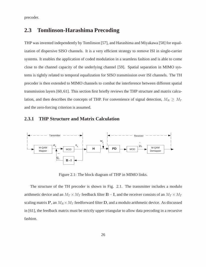
precoder.
2.3 Tomlinson-Harashima Precoding
THP was invented independently by Tomlinson [57], and Harashima and Miyakawa [58] for equal-
ization of dispersive SISO channels. It is a very efficient strategy to remove ISI in single-carrier
systems. It enables the application of coded modulation in aseamless fashion and is able to come
close to the channel capacity of the underlying channel [59]. Spatial separation in MIMO sys-
tems is tightly related to temporal equalization for SISO transmission over ISI channels. The TH
precoder is then extended to MIMO channels to combat the interference between different spatial
transmission layers [60, 61]. This section first briefly reviews the THP structure and matrix calcu-
lation, and then describes the concepts of THP. For convenience of signal detection,MR ≥ MT
and the zero-forcing criterion is assumed.
2.3.1 THP Structure and Matrix Calculation
MOD H PD MOD
B - I
_
k a ^
M-QAM Mapper
M-QAM Demapper
Tansmitter Receiver
k a k w
k x
k q
Figure 2.1: The block diagram of THP in MIMO links.
The structure of the TH precoder is shown in Fig. 2.1. The transmitter includes a modulo
arithmetic device and anMT ×MT feedback filterB− I, and the receiver consists of anMT ×MT
scaling matrixP, anMR×MT feedforward filterD, and a modulo arithmetic device. As discussed
in [61], the feedback matrix must be strictly upper triangular to allow data precoding in a recursive
fashion.
26

To explain the rationale behind the THP transmit structure,we temporarily neglect the non-
linear operator in Fig. 2.1. The precoded symbols are recursively computed from the feedback
structure as follows:
xk = ak −MT∑
i=k
(B(k, i) − 1)xi. (2.4)
Eq. (2.4) can be re-written in a matrix format as
x = B−1a, (2.5)
where theMT ×MT feedback filterB needs to be unit diagonal so that the average transmit power
is constant. For the ZF criterion, the cascade ofPDHB−1 must be an identical matrix such that
the interfering parallel channels are transformed into non-interfering ones. Therefore, the feedback
matrix and feedforward matrix need to satisfy
H = (PD)†B. (2.6)
Therefore, the calculation of the filters in THP can be considered as performing a QR decom-
position of the channel matrix:
H = DHT, (2.7)
whereT =[T (u, v)
]is anMT × MT upper triangular matrix andD is anMT × MR matrix and
DDH = IMT. The matricesP andB can be obtained by:
B = PT;
P = diag[T−1(1, 1) . . . T−1(MT , MT )
],
(2.8)
The scaling matrixP is to keep the average transmit power constant. SinceDDH = IMTandP is
a diagonal matrix, no matrix inversion is needed. The receiver structure is thus simplified. At the
receiver, the cascade of the matrix is
PDHB−1 = PDDHTT−1P−1 = I. (2.9)
The inter-layer interference are therefore eliminated. The filtered noise then has the variance matrix
Rw′w′ = P2σ2w. Discarding the congruent signals, the data symbolsak are corrupted by an additive
27
noise asYk = ak + w′k, wherew′
k is thek-th entry of filtered noise vectorw′. The extension from
ZF to MMSE design is straightforward. The general case is discussed in [61].
2.3.2 Basic Concepts
By passing through the feedback structure, the transmittedsymbolsxk are successively calculated
for the data symbolsak drawn from the initialM-ary QAM square signal constellation
A =
aI + aQ | aI, aQ ∈ ±1,±3, . . . ,±(√
M − 1)
. (2.10)
Inspection of (2.4) reveals that the dynamic range of the precoded sequence depends onB and
may become large in the presence of deep fades. To overcome transmit power boosting, THP
adopts a non-linear modulo-2√
M device, which acts independently over the real and imaginary
parts of its input. The modulo operation generates a unique precoding sequenceqk, qk ∈ Q =
2√
M(qI + qQ)
, whereqI, qQ ∈ I andI is the set of integers. From the setJ = a + q|a ∈
A, q ∈ Q, the effective data symbolsak + qk, instead of data symbolsak, are passed into the
modulo arithmetic feedback structure. Mathematically, integer multiples of2√
M are added to the
real and imaginary part ofxk. The transmitted symbols after the modulo-2√
M operation can be
written as
xk = MOD2√
M
ak −
MT∑
i=k
B(k, i)xi
= ak + qk −
MT∑
i=k
B(k, i)xi. (2.11)
The modulo device periodically limits the expansion due to the inversion ofB to a setJ . From
J the current effective data symbol is selected, which minimizes the magnitude of the correspond-
ing transmitted channel symbolxk. The real and imaginary parts ofqk are chosen symbol-by-
symbol by the memoryless modulo-2√
M operation, such that the transmitted channel symbols
ℜxk ∈(−√
M,√
M]
andℑxk ∈(−√
M,√
M]. Hence, the transmitted channel symbols
xk are restricted in the boundary region ofA, resulting in a transmit signal with smaller power.
At the receiver, a slicer produces estimatesak + qk of the effective data symbols, from which the
unique estimated data symbols are generated by the same modulo operation.
28
The extension to a non-square constellation is straightforward if the boundary regionA is
rotated by45. ForM-ary QAM, whenlog2(M) is odd, the length of a side ofA is 2√
M andqk
comes from√
2MOI, whereO =
(1 −11 1
)is the rotation operator.
THP generates a nearly independent and identically distributed (i.i.d) transmit sequencexk,
uniformly distributed over the initial signal constellationA. The approximation of i.i.d transmit
sequence becomes accurate asM goes to infinity. The average transmit power of THP is thus by
E [|xk|2] = 2M/3 for theM-ary square constellation [61]. For anM-ary constellation the average
power E[|ak|2] = 2(M − 1)/3; the precoding loss can thus be obtained by
ϑ =E [|xk|2]E [|ak|2]
=M
M − 1. (2.12)
As M increases, the precoding loss becomes negligible. Moreover, xk can be assumed mutually
uncorrelated with varianceEs = E [|xk|2], ∀ k. In MIMO systems, each symbol interval is pro-
cessed separately. The precoding loss of spatial THP is lower than (2.12) because the channel
symbols take on more discrete levels when going from component x1 to xMT[61].
The non-linear property of THP eliminates transmit power increase in linear precoding or, in
the case of spectral zero, linear precoding even does not exist. In addition, THP avoids error
propagation, the main shortcoming of V-BLAST, since the feedback filter is moved to transmitter.
Consequently, THP can provide better performance than linear precoding and V-BLAST.
2.4 Simulation Results
Fig. 2.2 compares BERs of linear precoding, SVD-based precoding, V-BLAST (SIC) and THP.
The ZF criterion is used. A4× 4 16-QAM MIMO system is considered. The fading gains are i.i.d
Gaussian random variables with unit variance. The4 × 4 channel matrixH is assumed to change
independently from symbol to symbol, and the receive antennas are already sorted in optimal order.
Obviously, THP can achieve considerable performance gainsover its linear precoding counterparts
and the SVD-based scheme. SVD-based precoding outperformslinear precoding at a low SNR
region since it avoids noise enhancement, however, it approaches linear precoding for high SNRs
29
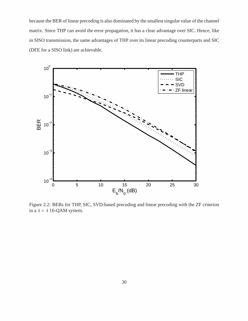
because the BER of linear precoding is also dominated by the smallest singular value of the channel
matrix. Since THP can avoid the error propagation, it has a clear advantage over SIC. Hence, like
in SISO transmission, the same advantages of THP over its linear precoding counterparts and SIC
(DFE for a SISO link) are achievable.
0 5 10 15 20 25 3010
−4
10−3
10−2
10−1
100
Eb/N
0 (dB)
BE
R
THPSICSVDZF linear
Figure 2.2: BERs for THP, SIC, SVD-based precoding and linear precoding with the ZF criterionin a4 × 4 16-QAM system.
30
2.5 Summary
This chapter has introduced linear pre-equalization schemes and SIC, which is used in V-BLAST
technique. The basic concept of a non-linear TH precoder hasalso been reviewed and the appli-
cation of THP to the transmission over multiple-antenna communication links has been described.
TH precoder outperforms the linear pre-equalization schemes and V-BLAST because it avoids
noise enhancement and error propagation.
31
Chapter 3
ICI Reduction for Closed-Loop MIMOOFDM
As discussed in Chapter 1, MIMO OFDM is sensitive to frequency offset. ICI reduction schemes
thus need to be applied. In a typical closed-loop system, thechannel gains can be readily obtained
at the transmitter, while the frequency offset may not be. Ina TDD system, the frequency offset
may be difficult to be estimated at the transmitter. In an FDD system, the frequency offset has
to be estimated at the receiver and fed back to the transmitter. Therefore, a conventional closed-
loop scheme may not be used for ICI suppression since the complete CSI, including both channel
gains and frequency offsets, is needed at the transmitter. The feedback link is needed to convey
the frequency offset in a TDD mode and the complete CSI in FDD systems. This chapter thus
investigates the possibility to use precoding for ICI mitigation in closed-loop MIMO OFDM when
only partial CSI (no knowledge of frequency offsets) is available at the transmitter.
We first show that the ICI coefficient matrix is approximatelyunitary. An immediate conse-
quence is that the proposed precoder at the transmitter doesnot need to know the frequency offset.
This avoids feedback in a TDD system. In FDD systems, this leads to significant savings of feed-
back capacity since a system withMT transmit andMR receive antennas may haveMT × MR
different frequency offsets. Frequency-offset mismatch due to imperfect feedback is also avoided.
The proposed precoder includes two parts: the feedback filter at the transmitter and the feedfor-
ward filter at the receiver. It takes advantage of the property of the ICI matrix and the receiver
32
structure is effectively designed for ICI reduction. The presented precoded MIMO OFDM system
significantly suppresses the impact due to frequency offsets. Furthermore, for spatially-correlated
MIMO channels, proposed THP performs with negligible BER-performance loss.
Previous work on ICI reduction has focused on open-loop SISOand MIMO OFDM. For SISO
systems, an optimum time-domain Nyquist windowing function has been derived in [63], which
mitigates the joint effect of AWGN and ICI. Selected mappingand partial transmit sequence ap-
proaches have been developed in [64] to reduce ICI. In [65] MMSE receivers based on a finite
power series expansion for the time-varying frequency response have been proposed. A two-stage
ICI-suppressing equalizer is presented in [66], which applies a linear preprocessing at the transmit-
ter and an iterative MMSE estimation at the receiver. Self-cancellation schemes involving mapping
of each input symbol to a group of subcarriers have been investigated in [67, 68], at the price of
halving the bandwidth efficiency. For open-loop MIMO OFDM, abank of time-domain ICI can-
cellation filters is proposed to maximize ratio of signal energy to ICI-plus-noise energy [69].
The remainder of this chapter is organized as follows. Section 3.1 describes a MIMO OFDM
system model in the presence of frequency offsets. In Section 3.2, the ICI coefficient matrix is
proven to be unitary and a TH precoder is proposed based on this property. Two cases of channel
mismatch are analyzed. Section 3.3 analyzes the proposed THP in spatial correlated channels.
Simulation results in Section 3.4 show how the proposed TH precoder reduces ICI. Section 3.5
concludes this section.
3.1 System Model
This section will introduce the MIMO OFDM system model with frequency offsets. This model
can also be simplified to SISO OFDM systems.
Consider an OFDM system withMT transmit antennas andMR receive antennas (Fig. 1.1). Let
Xv[n] denote anM-ary QAM symbol on then-th subcarrier sent by thev-th transmit antenna. The
length-N input data vector can then be written asXv =[Xv[0] Xv[1] . . . Xv[N − 1]
]T. In MIMO
33
OFDM transmission, each of theMT time-domain transmitted vectors is generated by taking an
IDFT of an information vector:
xv =[xv(0) xv(1) . . . xv(N − 1)
]T= FNXv. (3.1)
Considering a wideband frequency-selective fading channel with L resolvable paths between
thev-th transmit antenna andu-th receive antenna, the discrete-time domain received signal can
be represented as
yu,v(k) = e 2πN
εu,vk
L−1∑
l=0
hu,v(l)xv(k − l) + wu,v(k) (3.2)
whereεu,v = ∆fu,vTs is the normalized frequency offset between theu-th (u = 1, . . . , MR) receive
andv-th (v = 1, . . . , MT ) transmit antenna. The complex channel gainhu,v(l), l = 0, 1, . . . , L− 1
refers to thel-th path. Each path gain is a zero-mean complex Gaussian random variable (Rayleigh
fading) with varianceσ2l (see the simulation section for details). The channel gainsare assumed to
remain constant over several OFDM symbol intervals.
Discarding the cyclic prefix and performing DFT on the received samples, the signal received
at theu-th receive antenna for thek-th subcarrier is given by
Yu[k] =
MT∑
v=1
Su,v[0]Hu,v[k]Xv[k]
︸ ︷︷ ︸desired signal
+
MT∑
v=1
N−1∑
n=0,n 6=k
Su,v[n − k]Hu,v[n]Xv[n]
︸ ︷︷ ︸ICI component
+
MT∑
v=1
Wu,v[k] (3.3)
for k = 0, 1, · · ·, N − 1, whereWu,v[k] is an AWGN sample with zero mean and varianceσ2W , and
Wu,v[k], ∀ k, are assumed i.i.d. The channel gain on thek-th subcarrier is
Hu,v[k] =
N−1∑
l=0
hu,v(l)e− 2π
Nlk, (3.4)
Hu,v[k] are i.i.d. complex Gaussian random variables with zero meanand variance normalized to
unity. Su,v[n − k] is an ICI coefficient given by [67,70]
Su,v[m] =sin π(εu,v + m)
N sin πN
(εu,v + m)eπ(1− 1
N)(εu,v+m), m = 0, 1, . . . , N − 1. (3.5)
34

All received signals can thus be represented in matrix form as
Y = SHX + W = GX + W (3.6)
where theNMR-dimensional vectorY =[Y1[0] . . . Y1[N − 1] . . . YMR
[N − 1]]T
; theNMT × 1
transmitted vectorX =[XT
1 . . . XTMT
]T; the noise vectorW with the(u − 1)N + kth entry
Wu[k] =∑MT
v=1 Wu,v[k], ∀ k, u. TheNMR ×NMT overall channel matrix isG = SH, whereS is
anNMR × NMRMT ICI matrix
S = diag[S1 . . . SMR
](3.7)
with Su =[Su,1 . . . Su,MT
]; theu, vth element is the ICI coefficient matrix between theu-th
receive andv-th transmit antenna
Su,v =
Su,v[0] Su,v[1] . . . Su,v[N − 1]Su,v[−1] Su,v[0] . . . Su,v[N − 2]
.... . .
...Su,v[−(N − 1)] Su,v[−(N − 2)] . . . Su,v[0]
. (3.8)
And H is anNMRMT × NMT channel gain matrix, which is given by
H =[H1 . . . HMR
]T=
H1,1 . . . 0 . . . HMR,1 . . . 0
.... . .
......
. . ....
0 . . . H1,MT. . . 0 . . . HMR,MT
T
, (3.9)
whereHu = diag[Hu,1 . . . Hu,MT
]with elements being theu, vth channel gain matrixHu,v
at theN orthogonal subcarriers,
Hu,v = diag[Hu,v[0] Hu,v[1] . . . Hu,v[N − 1]
]. (3.10)
WhenMT = 1 andMR = 1, (3.6) reduces to the system model of a SISO OFDM system.
3.2 ICI Reduction in MIMO OFDM
To eliminate the interference from the overall channel matrix (including bothS andH), transmitter
pre-processing or receiver post-processing needs to be applied. For a system with conventional
35

precoding, the full CSI information is required at the transmitter. As discussed in Chapter 2, the
ZF-THP requiresB = PDH. The feedforward matrix of THP is thus designed at the receiver by
using a QR decomposition of the overall channel matrix
G = DHT, (3.11)
whereDDH = I andT =[T (i, j)
]is an upper triangular matrix [71]. The feedback matrixB
and the scaling matrixP can be constructed as in Chapter 2.
This conventional precoding design requires complete CSI at the transmitter. The provision of
frequency-offset estimates at the transmitter is difficult, and hence is undesirable. A precoder for
MIMO OFDM with only partial CSIT is therefore of interest. The ICI coefficient matrix between
thev-th transmit and theu-th receive antennaSu,v is first proven to be unitary. Consequently, the
frequency offsets do not need to be fed back to the transmitter. The proposed THP can thus take
advantage of the frequency offset at the receiver and reduces ICI in its feedforward filter.
3.2.1 Unitary Property of ICI Coefficient Matrix
The following unitary property related to the ICI coefficient matrix on theu, vth channel (3.8)
can be derived using (3.5):
The ICI coefficient matrix can be approximated as a unitary matrix, i.e.,Su,vSHu,v = SH
u,vSu,v = IN .
Therefore, the inverse of the matrix can be easily calculated by taking the conjugate transpose since
S−1u,v = SH
u,v. A proof of this property is in the appendix. The property is used in the design of the
proposed precoder.
3.2.2 THP for MIMO OFDM
For convenience of signal detection, the number of receive antennas is assumed greater than or
equal to that of the transmit antennas, i.e.,MR ≥ MT . Considered the case ofMR different
frequency offsets is , i.e., for theu-th receive antenna,εu,1 = εu,2 = · · · = εu,MT= εu, and
εu 6= εu′, ∀ u 6= u′.
36

Since the frequency offsetεu,v, ∀v, is identical toεu, Su,1 = · · · = Su,MT= Su; andSu is an
N × N unitary matrix. The overall channel matrixG can be re-written as
G = SH, (3.12)
where theNMR × NMT channel gain matrix is
H =
H1,1 · · · H1,MT
.... . .
...HMR,1 · · · HMR,MT
, (3.13)
and theNMR × NMR ICI matrix is
S = diag[S1 · · · SMR
]. (3.14)
SinceSu is unitary,S is also a unitary matrix.
Instead of factorization of the overall channel matrixG, the filters of THP are designed by QR
decoposition of the channel gain matrixH
H = FHT (3.15)
with anNMT × NMR matrixF satisfyingFFH = INMT, and anNMT × NMT upper triangular
matrixT. The feedforward matrix needs to satisfyDDH = INMT. SinceS is unitary, the feedfor-
ward matrix is designed asD = FSH so thatG = DHT = SFHT = SH, which meets the basic
relationship of ZF THP in (2.6).
The feedback filter is set as anNMT × NMT matrix B = PT, where theNMT × NMT
diagonal matrixP satisfies E[THPHPT
]= I. The received signals at the output of the slicer can
be given as
A = PDGB−1A + PDW = ΨA + W′, (3.16)
whereΨ = PDGB−1 = PDDHP−1 is anNMT × NMT identity matrix, if the channel gain
matrixH is perfectly known at the transmitter. The feedforward matrix in the proposed precoder
consists of the inverse (Hermitian) ICI matrix, and eliminates ICI. Because the ICI matrix is uni-
tary, no inversion operation is needed and the receiver structure is simple.
37
With the property of the ICI matrix, the proposed precoder takes advantage of the CSIR (fre-
quency offset at the receiver), and intelligently reduce ICI in the feedforward structure. No ad-
ditional ICI reduction schemes [63–67, 69] are needed. The proposed THP for MIMO OFDM
systems, which does not require the knowledge of frequency offsets at the transmitter, reduces
information load in the feedback channel and avoids the possible frequency-offset transmitter mis-
match due to feedback errors and delay in practical implementation. With perfect information of
channel gains at the transmitter and knowledge of frequencyoffset at the receiver, proposed THP
outperforms linear precoding. Furthermore, because the feedback filter is moved to the transmit-
ter in the TH precoder, the error propagation, which inevitably degrades BER in SIC, is avoided.
Therefore, lower BER can be expected for THP.
3.2.3 The Effect of Mismatch on Precoding Performance
If ideal feedback and precise channel estimates exist, closed-loop systems offer a substantial ad-
vantage over their open-loop counterparts. However, erroneous estimates and/or imperfect feed-
back results in transmitter channel mismatch, i.e., the channel information which is available at the
transmitter differs from the actual channel at the time of transmission due to imperfect estimation,
feedback delay and errors. Two cases of channel mismatch areconsidered. In the first case, the re-
ceiver knowsH perfectly, but the transmitter has imperfect channel matrix H because of feedback
delay or noise. In the second case, the receiver has the imperfect channel estimateHR, while the
transmitter hasHT , which is a noise-corrupted version ofHR because of imperfect feedback.HT
is unknown at the receiver. Since frequency offsets do not need to be sent back to the transmitter,
the frequency-offset transmitter mismatch is not considered here. The impact of frequency-offset
mismatch in conventional THP is shown in the simulation section.
38
3.2.3.1 First Case
In the first case, the receiver has perfect knowledge of the channelH, but the transmitter has an
incorrect estimateH because of errors or delay in the feedback link. The receivedsignals are
A = PDGB−1A + W′ = ΨA + W′, (3.17)
whereΨ = PTB−1 = BB−1. Obviously,Ψ is not a diagonal matrix asΨ in (3.16). Generally,
BB−1 is an upper triangular matrix and introduces residual ICI.
3.2.3.2 Second Case
In the second case of channel information mismatch, the receiver has an imperfect frequency offset
estimateS and the incorrect channel gain estimateHR, while the transmitter hasHT , which is the
noise-corrupted version ofHR. TheHT is unknown at the receiver, andHT 6= HR 6= H. At
the transmitterB is constructed fromHT , and at the receiverD from HR andS. This leads to a
non-identity matrixΨ = PDGB−1.
With the proposed THP in2 × 2 OFDM, the received signals become
A = ΨA + W′ =
[Ψ1 Ψ2
Ψ3 Ψ4
]A + W′, (3.18)
where theN × N matrix Ψ1 andΨ4 are not approximately identity, andΨ2 andΨ3 are not zero
matrices. Clearly, co-channel interference (CCI) and residual ICI are introduced to the combined
signals. In SISO systems, no CCI occurs, however, sinceDDH 6= IN andTT−1 6= IN , residual
ICI is still introduced.
3.3 Correlated Spatial Channels
The MIMO channel with spatial correlations of its gains is studied in this section. The correlated
channel model builds on previous work reported in [72]. For the sake of simplicity, a uniform
linear array (ULA) is assumed at the transmitter and receiver with identical antenna elements. The
39
channel matrixH is assumed to be zero-mean circularly symmetric complex Gaussian (Rayleigh
fading) distributed with a separable spatial correlation function.
For a frequency-selective channel withMT transmit andMR receive antennas, thel-th tap gain
can be represented by anMR × MT matrix h(l), ∀ l. According to the model in [72], the spatial
gain correlation matrix can be represented by
R = RP ⊗ RTT ⊗RR, (3.19)
whereRP is theL×L path correlation matrix; if the paths between each transmit-receive antenna
pair are uncorrelated,RP = diag[σ2
0 . . . σ2L−1
]is only determined by the power delay profiles.RT
andRR are the transmit and receive antenna correlation matrices with entries [72]
RT (m, n) = J0 (2π|m − n|ζT )
RR(m, n) = J0 (2π|m − n|ζR) ,(3.20)
whereJ0 is zero-order Bessel function of the first kind.ζT = ∆dT
λcandζR = dR
λc; λc = c/fc is the
wavelength at the carrier frequencyfc, ∆ is the angle of arrival spread. The transmit and receive
antennas are respectively spaced bydT anddR. The tap gain vector therefore can be obtained as
vec(h(l)) =[RT
T ⊗ RR
]1/2vec(hw(l)) , (3.21)
where vec(hw(l)) is anMRMT -dimensional vector of i.i.d zero mean complex Gaussian random
variables with varianceσ2l .
Usingh(l) in (3.21),∀ l, the channel gain matrix with spatial correlationsH can be constructed
having the same structure asH (3.9) orH (3.13). The proposed non-linear TH precoder can be also
used in MIMO OFDM when the spatial channels are correlated. With known fading correlations
at the transmitter, QR factorization ofH is performed instead ofH or H. The design of feedback
and feedforward filters is the same as that described in the Section 3.2.
40
3.4 Simulation Results
In this section, simulation results show how proposed THP suppresses ICI in OFDM. The vehicular
B channel specified by ITU-R M. 1225 [73], is used where the channel taps are zero-mean complex
Gaussian random processes with variances of−4.9 dB,−2.4 dB,−15.2 dB,−12.4 dB,−27.6 dB,
and−18.4 dB relative to the total power normalized to unity. The excess delays of the channel
taps are0, 300 ns, 8900 ns, 12900 ns, 17100 ns, and20000 ns, respectively. For many wireless
systems, the multipath channels fade slowly. Thus the fading gains are assumed constant over
several OFDM symbol intervals.
3.4.1 SISO OFDM
Fig. 3.1 gives the BER as a function of SNR for different values of the normalized frequency
offset in SISO OFDM with perfect channel knowledge at both the transmitter and the receiver. The
performance of OFDM without precoding is shown as a reference. The proposed THP-OFDM
reduces ICI significantly. For instance, with a normalized frequency offset of10%, THP-OFDM
has almost the same BER as an OFDM system in the absence of frequency offset, i.e., the ICI has
been cancelled almost completely.
Fig. 3.2 presents BER of THP-OFDM when the receiver has perfect knowledge of channel
gain matrixH, while the transmitter has an imperfect channelH due to the feedback channel
noise. Since the feedback channel bandwidth is usually muchsmaller than the downlink traffic
channel capacity, the noise variance of the feedback link isassumed to beσ2F = σ2
W /100. The
frequency offset is perfectly estimated at the receiver. The BER of OFDM with conventional THP
is also shown as a reference in the Fig. 3.2. In that referencecase, conventional THP uses a noise-
corrupted frequency offset at the transmitter, which leadsto serious ICI residuals. The proposed
precoder minimizes the BER degradation by avoiding such frequency-offset mismatch.
In Fig. 3.3, the channel gain matrix estimateHR is assumed imperfect at the receiver, while the
transmitter uses a channel gain matrix estimate corrupted further by feedback errors. The frequency
41
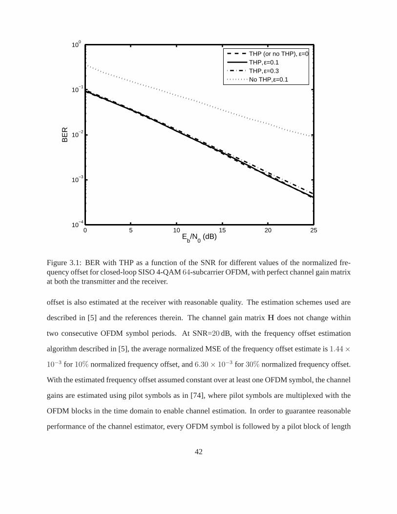
0 5 10 15 20 2510
−4
10−3
10−2
10−1
100
Eb/N
0 (dB)
BE
R
THP (or no THP), ε=0THP, ε=0.1THP, ε=0.3No THP, ε=0.1
Figure 3.1: BER with THP as a function of the SNR for differentvalues of the normalized fre-quency offset for closed-loop SISO 4-QAM64-subcarrier OFDM, with perfect channel gain matrixat both the transmitter and the receiver.
offset is also estimated at the receiver with reasonable quality. The estimation schemes used are
described in [5] and the references therein. The channel gain matrixH does not change within
two consecutive OFDM symbol periods. At SNR=20 dB, with the frequency offset estimation
algorithm described in [5], the average normalized MSE of the frequency offset estimate is1.44×
10−3 for 10% normalized frequency offset, and6.30 × 10−3 for 30% normalized frequency offset.
With the estimated frequency offset assumed constant over at least one OFDM symbol, the channel
gains are estimated using pilot symbols as in [74], where pilot symbols are multiplexed with the
OFDM blocks in the time domain to enable channel estimation.In order to guarantee reasonable
performance of the channel estimator, every OFDM symbol is followed by a pilot block of length
42
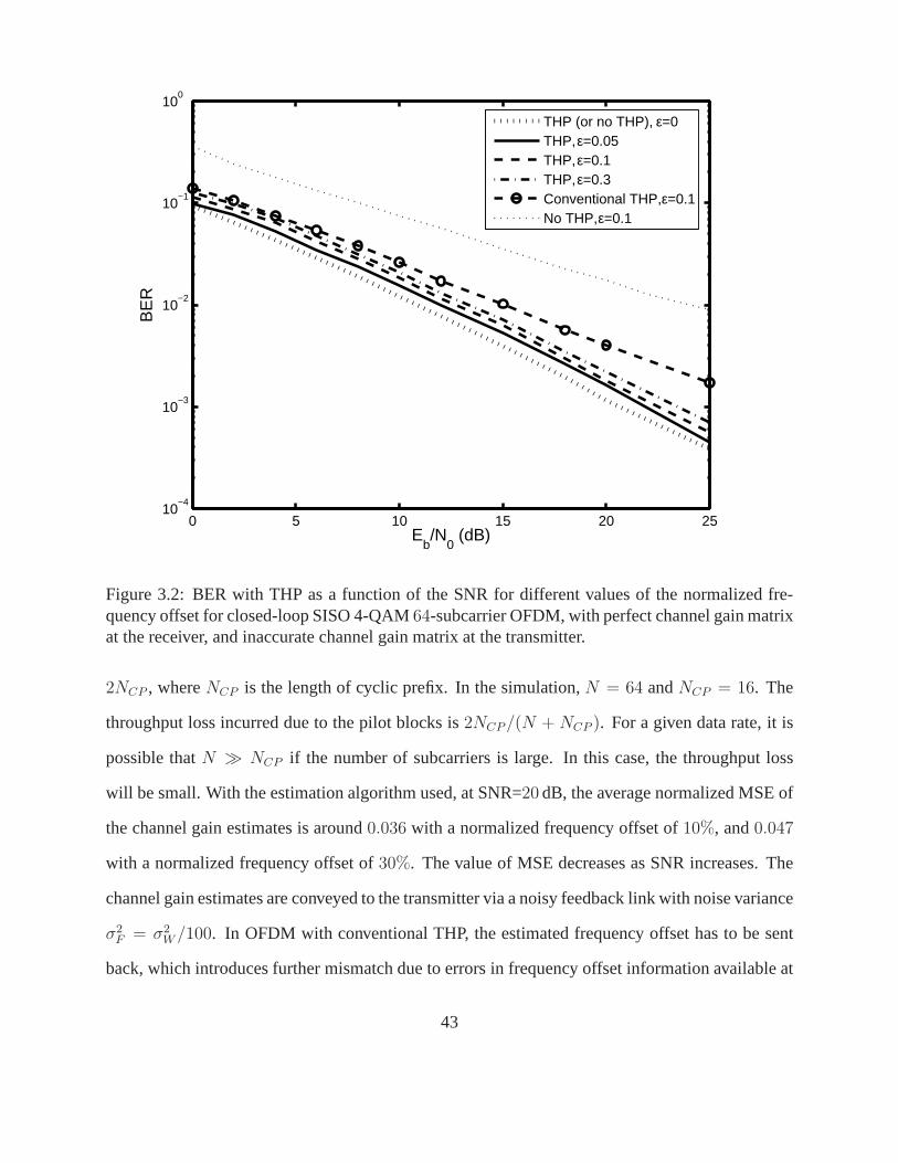
0 5 10 15 20 2510
−4
10−3
10−2
10−1
100
Eb/N
0 (dB)
BE
R
THP (or no THP), ε=0THP, ε=0.05THP, ε=0.1THP, ε=0.3Conventional THP, ε=0.1No THP, ε=0.1
Figure 3.2: BER with THP as a function of the SNR for differentvalues of the normalized fre-quency offset for closed-loop SISO 4-QAM64-subcarrier OFDM, with perfect channel gain matrixat the receiver, and inaccurate channel gain matrix at the transmitter.
2NCP , whereNCP is the length of cyclic prefix. In the simulation,N = 64 andNCP = 16. The
throughput loss incurred due to the pilot blocks is2NCP/(N + NCP ). For a given data rate, it is
possible thatN ≫ NCP if the number of subcarriers is large. In this case, the throughput loss
will be small. With the estimation algorithm used, at SNR=20 dB, the average normalized MSE of
the channel gain estimates is around0.036 with a normalized frequency offset of10%, and0.047
with a normalized frequency offset of30%. The value of MSE decreases as SNR increases. The
channel gain estimates are conveyed to the transmitter via anoisy feedback link with noise variance
σ2F = σ2
W /100. In OFDM with conventional THP, the estimated frequency offset has to be sent
back, which introduces further mismatch due to errors in frequency offset information available at
43
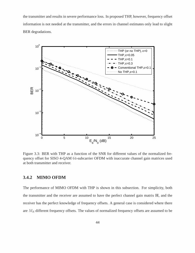
the transmitter and results in severe performance loss. In proposed THP, however, frequency offset
information is not needed at the transmitter, and the errorsin channel estimates only lead to slight
BER degradations.
0 5 10 15 20 2510
−4
10−3
10−2
10−1
100
Eb/N
0 (dB)
BE
R
THP (or no THP), ε=0THP, ε=0.05THP, ε=0.1THP, ε=0.3Conventional THP, ε=0.1No THP, ε=0.1
Figure 3.3: BER with THP as a function of the SNR for differentvalues of the normalized fre-quency offset for SISO 4-QAM64-subcarrier OFDM with inaccurate channel gain matrices usedat both transmitter and receiver.
3.4.2 MIMO OFDM
The performance of MIMO OFDM with THP is shown in this subsection. For simplicity, both
the transmitter and the receiver are assumed to have the perfect channel gain matrixH, and the
receiver has the perfect knowledge of frequency offsets. A general case is considered where there
areMR different frequency offsets. The values of normalized frequency offsets are assumed to be
44
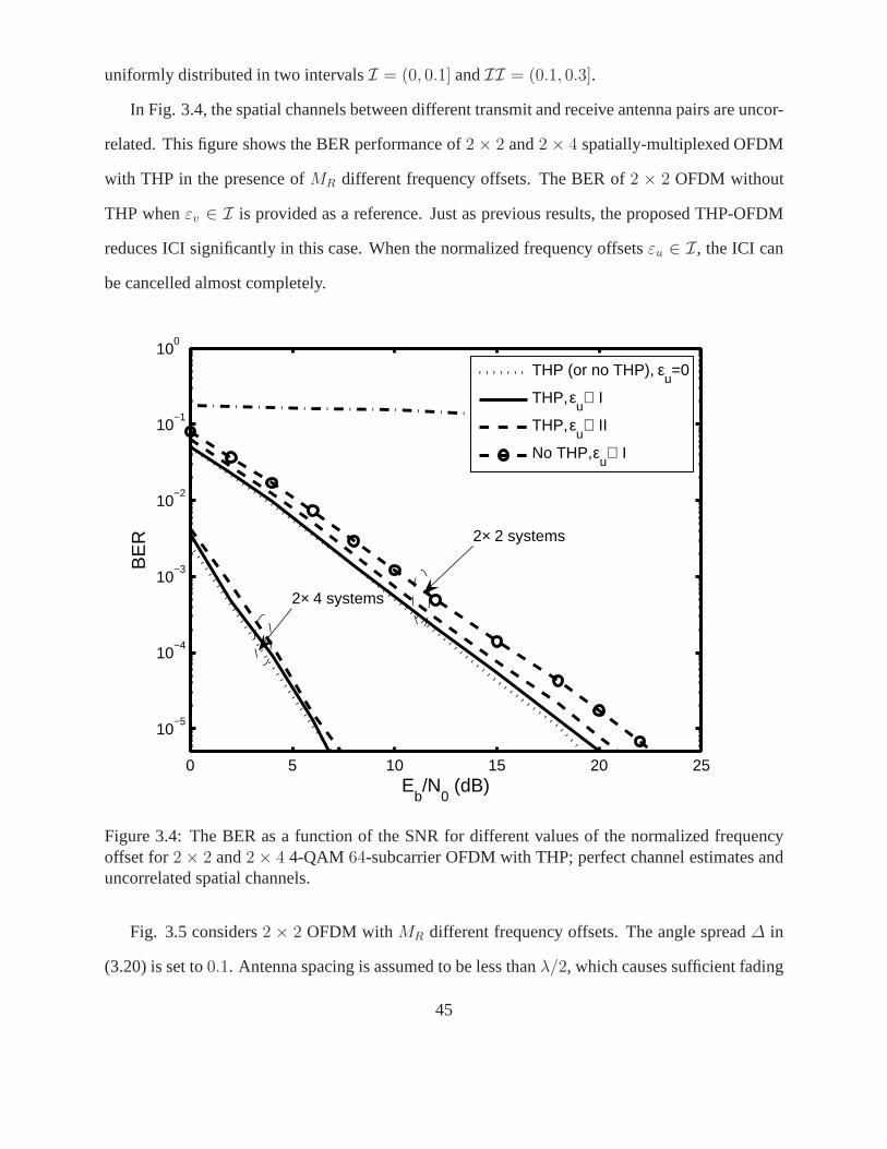
uniformly distributed in two intervalsI = (0, 0.1] andII = (0.1, 0.3].
In Fig. 3.4, the spatial channels between different transmit and receive antenna pairs are uncor-
related. This figure shows the BER performance of2 × 2 and2 × 4 spatially-multiplexed OFDM
with THP in the presence ofMR different frequency offsets. The BER of2 × 2 OFDM without
THP whenεv ∈ I is provided as a reference. Just as previous results, the proposed THP-OFDM
reduces ICI significantly in this case. When the normalized frequency offsetsεu ∈ I, the ICI can
be cancelled almost completely.
0 5 10 15 20 25
10−5
10−4
10−3
10−2
10−1
100
Eb/N
0 (dB)
BE
R
THP (or no THP), ε
u=0
THP, εu∈ I
THP, εu∈ II
No THP, εu∈ I
2× 4 systems
2× 2 systems
Figure 3.4: The BER as a function of the SNR for different values of the normalized frequencyoffset for2 × 2 and2 × 4 4-QAM 64-subcarrier OFDM with THP; perfect channel estimates anduncorrelated spatial channels.
Fig. 3.5 considers2 × 2 OFDM with MR different frequency offsets. The angle spread∆ in
(3.20) is set to0.1. Antenna spacing is assumed to be less thanλ/2, which causes sufficient fading
45
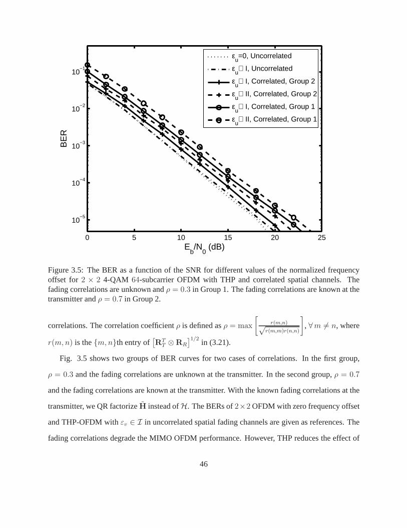
0 5 10 15 20 25
10−5
10−4
10−3
10−2
10−1
Eb/N
0 (dB)
BE
R
εu=0, Uncorrelated
εu∈ I, Uncorrelated
εu∈ I, Correlated, Group 2
εu∈ II, Correlated, Group 2
εu∈ I, Correlated, Group 1
εu∈ II, Correlated, Group 1
Figure 3.5: The BER as a function of the SNR for different values of the normalized frequencyoffset for 2 × 2 4-QAM 64-subcarrier OFDM with THP and correlated spatial channels.Thefading correlations are unknown andρ = 0.3 in Group 1. The fading correlations are known at thetransmitter andρ = 0.7 in Group 2.
correlations. The correlation coefficientρ is defined asρ = max
[r(m,n)√
r(m,m)r(n,n)
], ∀m 6= n, where
r(m, n) is them, nth entry of[RT
T ⊗RR
]1/2in (3.21).
Fig. 3.5 shows two groups of BER curves for two cases of correlations. In the first group,
ρ = 0.3 and the fading correlations are unknown at the transmitter.In the second group,ρ = 0.7
and the fading correlations are known at the transmitter. With the known fading correlations at the
transmitter, we QR factorizeH instead ofH. The BERs of2×2 OFDM with zero frequency offset
and THP-OFDM withεv ∈ I in uncorrelated spatial fading channels are given as references. The
fading correlations degrade the MIMO OFDM performance. However, THP reduces the effect of
46

fading correlations and the BER loss is marginal when the fading correlations are known at the
transmitter.
3.5 Summary
This section has derived a non-linear TH precoder for in closed-loop MIMO OFDM with frequency
offsets. It has been shown that the ICI coefficient matrix is approximately unitary. With this
property the designed precoder only needs partial CSI available at the transmitter, not including
the knowledge of frequency offsets. Since frequency offsets are not necessary to be fed back to
the transmitter, the proposed approach reduces the feedback load in closed-loop MIMO OFDM
systems and avoids detrimental effect of frequency-offsetmismatch due to imperfect feedback.
The degradation due to frequency offset can be significantlyreduced in the proposed THP-OFDM
systems. For spatially-correlated channels, the proposedsystem performs with negligible BER-
performance loss.
47
Chapter 4
MUI and ICI Suppression in MultiuserMultiple-Antenna OFDM Downlink
This chapter considers the multiuser spatially-multiplexed OFDM downlink. Multiuser MIMO
OFDM inherits the attractive features of OFDM but also sensitive to frequency offset. Frequency
offset estimation and ICI suppression schemes [75–78] havebeen reported to address the ICI and
MUI problem in for the uplink case. However, the ICI and MUI still remain to be mitigated in the
broadcast (downlink) case because of the difficulty of MUI mitigation and signal detection caused
by lack of coordination among the independent mobile users.In the downlink case, each mobile
station (MS) knows the frequency offset and channel gains affecting its receiver only, but not those
of other users. If only post-processing techniques are usedat each user’s receiver to reduce MUI
due to spatial multiplexing, the number of receive antennasat each user terminal must be greater
than or equal to the number of transmit antennas, which may not be practical for many applications.
The processing at the user level can hence be quite complex oreven impossible. On the other hand,
since the users are decentralized, it may be difficult to knowat the BS the frequency offsets of all
users. Hence, the application of only transmitter precoding for ICI and MUI mitigation, which
requires full CSI including bothH andS at the BS, is problematic.
A novel two-stage technique for ICI and MUI suppression is thus proposed, in which the first
stage applies non-linear THP at the BS transmitter to mitigate the MUI and the second stage em-
ploys an iterative MMSE equalizer at each user’s receiver tosuppress the ICI due to the frequency
48
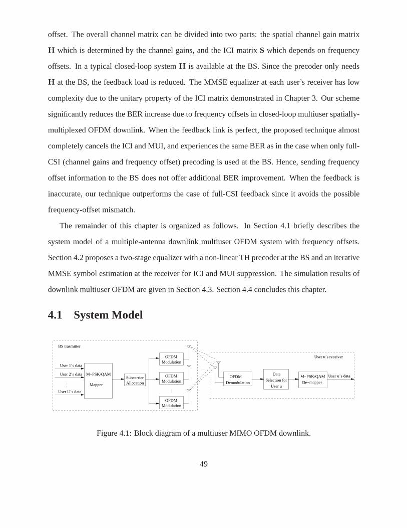
offset. The overall channel matrix can be divided into two parts: the spatial channel gain matrix
H which is determined by the channel gains, and the ICI matrixS which depends on frequency
offsets. In a typical closed-loop systemH is available at the BS. Since the precoder only needs
H at the BS, the feedback load is reduced. The MMSE equalizer ateach user’s receiver has low
complexity due to the unitary property of the ICI matrix demonstrated in Chapter 3. Our scheme
significantly reduces the BER increase due to frequency offsets in closed-loop multiuser spatially-
multiplexed OFDM downlink. When the feedback link is perfect, the proposed technique almost
completely cancels the ICI and MUI, and experiences the sameBER as in the case when only full-
CSI (channel gains and frequency offset) precoding is used at the BS. Hence, sending frequency
offset information to the BS does not offer additional BER improvement. When the feedback is
inaccurate, our technique outperforms the case of full-CSIfeedback since it avoids the possible
frequency-offset mismatch.
The remainder of this chapter is organized as follows. In Section 4.1 briefly describes the
system model of a multiple-antenna downlink multiuser OFDMsystem with frequency offsets.
Section 4.2 proposes a two-stage equalizer with a non-linear TH precoder at the BS and an iterative
MMSE symbol estimation at the receiver for ICI and MUI suppression. The simulation results of
downlink multiuser OFDM are given in Section 4.3. Section 4.4 concludes this chapter.
4.1 System Model
SubcarrierAllocation
Modulation OFDM
Modulation OFDM
Modulation OFDM
Mapper
M−PSK/QAM
User 1’s data
User 2’s data
User U’s data
BS trasmitter
Selection for
Data
User u
M−PSK/QAM
De−mapper
User u’s data OFDM
Demodulation
User u’s receiver
Figure 4.1: Block diagram of a multiuser MIMO OFDM downlink.
49
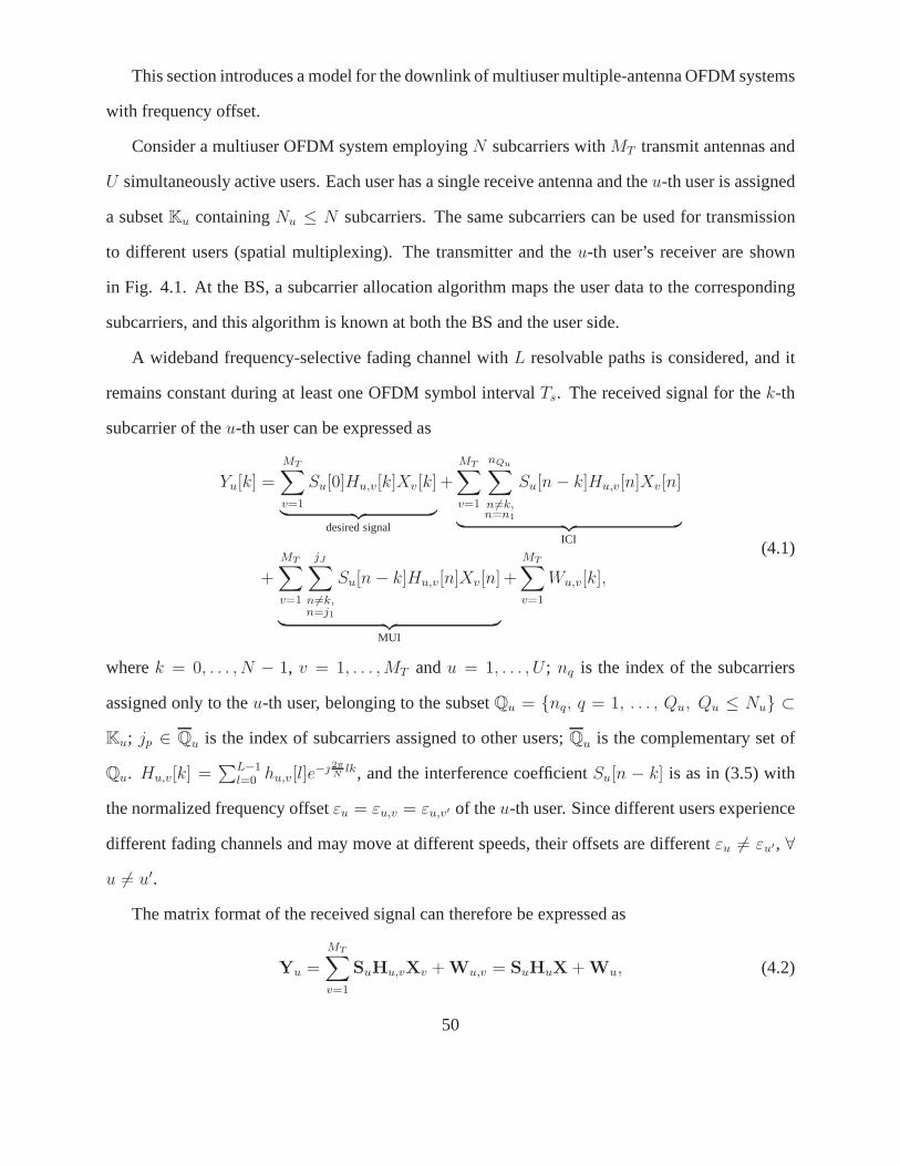
This section introduces a model for the downlink of multiuser multiple-antenna OFDM systems
with frequency offset.
Consider a multiuser OFDM system employingN subcarriers withMT transmit antennas and
U simultaneously active users. Each user has a single receiveantenna and theu-th user is assigned
a subsetKu containingNu ≤ N subcarriers. The same subcarriers can be used for transmission
to different users (spatial multiplexing). The transmitter and theu-th user’s receiver are shown
in Fig. 4.1. At the BS, a subcarrier allocation algorithm maps the user data to the corresponding
subcarriers, and this algorithm is known at both the BS and the user side.
A wideband frequency-selective fading channel withL resolvable paths is considered, and it
remains constant during at least one OFDM symbol intervalTs. The received signal for thek-th
subcarrier of theu-th user can be expressed as
Yu[k] =
MT∑
v=1
Su[0]Hu,v[k]Xv[k]
︸ ︷︷ ︸desired signal
+
MT∑
v=1
nQu∑
n 6=k,n=n1
Su[n − k]Hu,v[n]Xv[n]
︸ ︷︷ ︸ICI
+
MT∑
v=1
jJ∑
n 6=k,n=j1
Su[n − k]Hu,v[n]Xv[n]
︸ ︷︷ ︸MUI
+
MT∑
v=1
Wu,v[k],
(4.1)
wherek = 0, . . . , N − 1, v = 1, . . . , MT andu = 1, . . . , U ; nq is the index of the subcarriers
assigned only to theu-th user, belonging to the subsetQu = nq, q = 1, . . . , Qu, Qu ≤ Nu ⊂
Ku; jp ∈ Qu is the index of subcarriers assigned to other users;Qu is the complementary set of
Qu. Hu,v[k] =∑L−1
l=0 hu,v[l]e− 2π
Nlk, and the interference coefficientSu[n − k] is as in (3.5) with
the normalized frequency offsetεu = εu,v = εu,v′ of theu-th user. Since different users experience
different fading channels and may move at different speeds,their offsets are differentεu 6= εu′, ∀
u 6= u′.
The matrix format of the received signal can therefore be expressed as
Yu =
MT∑
v=1
SuHu,vXv + Wu,v = SuHuX + Wu, (4.2)
50
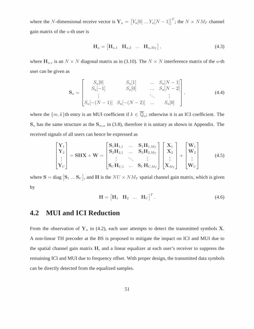
where theN-dimensional receive vector isYu =[Yu[0] ... Yu[N − 1]
]T; theN × NMT channel
gain matrix of theu-th user is
Hu =[Hu,1 Hu,2 ... Hu,MT
], (4.3)
whereHu,v is anN × N diagonal matrix as in (3.10). TheN × N interference matrix of theu-th
user can be given as
Su =
Su[0] Su[1] ... Su[N − 1]Su[−1] Su[0] ... Su[N − 2]
.... . .
...Su[−(N − 1)] Su[−(N − 2)] ... Su[0]
, (4.4)
where them, kth entry is an MUI coefficient ifk ∈ Qu; otherwise it is an ICI coefficient. The
Su has the same structure as theSm,n in (3.8), therefore it is unitary as shown in Appendix. The
received signals of all users can hence be expressed as
Y1
Y2...
YU
= SHX + W =
S1H1,1 ... S1H1,MT
S2H2,1 ... S2H2,MT
.... . .
...SUHU,1 ... SUHU,MT
X1
X2...
XMT
+
W1
W2...
WU
(4.5)
whereS = diag[S1 ... SU
], andH is theNU ×NMT spatial channel gain matrix, which is given
by
H =[H1 H2 ... HU
]T. (4.6)
4.2 MUI and ICI Reduction
From the observation ofYu in (4.2), each user attempts to detect the transmitted symbols X.
A non-linear TH precoder at the BS is proposed to mitigate theimpact on ICI and MUI due to
the spatial channel gain matrixH, and a linear equalizer at each user’s receiver to suppress the
remaining ICI and MUI due to frequency offset. With proper design, the transmitted data symbols
can be directly detected from the equalized samples.
51
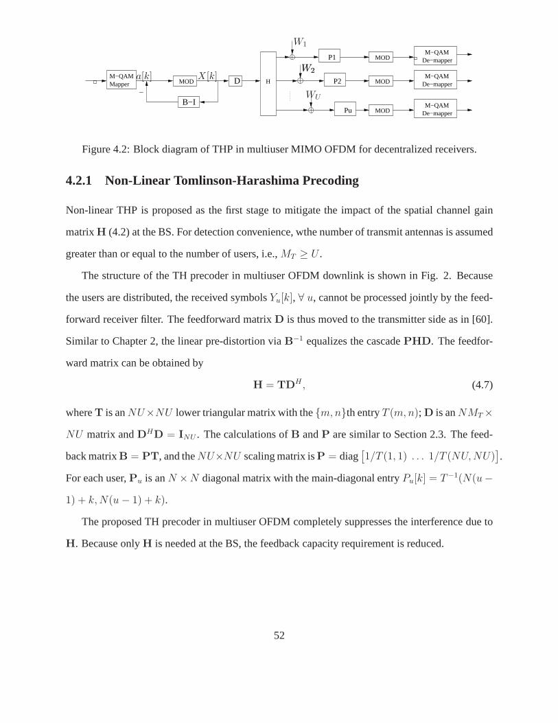
B−I
_
P1
P2
Pu
MOD
MOD
MOD
MODMapperM−QAM
D H De−mapper
De−mapper
De−mapper
M−QAM
M−QAM
M−QAM
a[k] X[k]
W1
W2W2
WU
Figure 4.2: Block diagram of THP in multiuser MIMO OFDM for decentralized receivers.
4.2.1 Non-Linear Tomlinson-Harashima Precoding
Non-linear THP is proposed as the first stage to mitigate the impact of the spatial channel gain
matrixH (4.2) at the BS. For detection convenience, wthe number of transmit antennas is assumed
greater than or equal to the number of users, i.e.,MT ≥ U .
The structure of the TH precoder in multiuser OFDM downlink is shown in Fig. 2. Because
the users are distributed, the received symbolsYu[k], ∀ u, cannot be processed jointly by the feed-
forward receiver filter. The feedforward matrixD is thus moved to the transmitter side as in [60].
Similar to Chapter 2, the linear pre-distortion viaB−1 equalizes the cascadePHD. The feedfor-
ward matrix can be obtained by
H = TDH , (4.7)
whereT is anNU×NU lower triangular matrix with them, nth entryT (m, n); D is anNMT ×
NU matrix andDHD = INU . The calculations ofB andP are similar to Section 2.3. The feed-
back matrixB = PT, and theNU×NU scaling matrix isP = diag[1/T (1, 1) . . . 1/T (NU, NU)
].
For each user,Pu is anN ×N diagonal matrix with the main-diagonal entryPu[k] = T−1(N(u−
1) + k, N(u − 1) + k).
The proposed TH precoder in multiuser OFDM completely suppresses the interference due to
H. Because onlyH is needed at the BS, the feedback capacity requirement is reduced.
52
4.2.2 Iterative ICI and MUI Equalization
Iterative linear MMSE equalization is introduced to suppress the remaining MUI and ICI due to
frequency offset at the individual receiver level. Theu-th user is assumed to know its frequency
offset,εu, and its channel gainshu,v(l), ∀ l.
After modulo reduction at the users’ receivers, as shown in Fig. 4.2, the received signals
become:[Y1 . . . YU
]T= PSHDB−1A + PW
= PSTDHDT−1P−1A + PW = PSP−1A + PW.(4.8)
Clearly, the spatial channel gain matrixH becomes a diagonal matrix, i.e., the spatial channel has
been converted intoNU parallel, independent sub-channels. SinceS = diag[S1 . . . SU
]andP
is a diagonal matrix, the received signal vector of theu-th user in (4.2) is reduced to the single
transmit-antenna case with the interference due to frequency offsets only, which is
Yu = PuSuP−1u A + W′
u, (4.9)
whereW′u = PuWu. Here the index of the transmit antenna inA is omitted for simplicity. The
MMSE linear estimator ofa[k] givenYu is [79, page 382]
a[k] = E(a[k]
)+ Cov
(a[k],Yu
)Cov
(Yu,Yu
)−1 (Yu − E(Yu)
). (4.10)
If E[Wu
]= 0, E
[W′
uW′Hu
]= σ2
WPuPHu , E
[AWH
u
]= 0 and independence amonga[k] with
E[a[k]
]= a[k], a[k] ∈ A = E
[A]
are assumed, the statistical properties are
E[Yu
]= PuSuP
−1u A,
Cov(a[k],Yu
)= Ca[k]P−1
u [k]SHu [k]PH
u ,
Cov(Yu, Yu
)= σ2
WPuPHu + PuSuP
−1u CaP
−Hu SH
u PHu ,
(4.11)
whereCa = diag[Ca[0] . . . Ca[N − 1]
]= EsIN with entriesCa[k] = E[|a[k]|2] = Es, and
Su[k] =[Su[k] Su[k − 1] . . . Su[k − (N − 1)
]Tis thek-th column inSu. The linear iterative
MMSE estimate ofa[k] is
a[k] = a[k] + ∆u[k](Yu −PuSuP
−1u A
), (4.12)
53
where∆u[k] = EsP−1u [k]SH
u [k]PHu
(Cov
(Yu, Yu
))−1.
With the first-stage precoding at the BS, the design for second-stage equalization at each
user’s receiver is simplified to process a single-input OFDMsystem. The complexity of the re-
ceiver’s MMSE equalization is hence primarily determined by the operation of the inversion of
Cov(Yu, Yu
)in (4.12). SinceSu is unitary, the covariance is given by
Cov(Yu, Yu
)= σ2
WPuPHu + PuSuP
−1u CaP
−Hu SH
u PHu
= PuSu
[σ2
W IN + EsP−1u P−H
u
]SH
u PHu = PuSuΨuS
Hu PH
u .(4.13)
SincePu is a diagonal matrix constant for allk = 0, . . . , N − 1 over at least one OFDM symbol
interval,Ψu is a diagonal matrix as well. Therefore, one can easily obtain
(Cov
(Yu, Yu
))−1= P−H
u SuΨ−1u SH
u P−1u . (4.14)
The inversion in (4.12) only requires simple operations, while a typical MMSE estimator needs at
leastO(N2) operations [80]. Complexity of calculations in (4.12) is significantly reduced.
The iterative algorithm is initialized witha[k] = 0 andCa[k] = 1. a[0] is calculated via (4.12)
and updated the initial valuesa[0]new = a[0]. a[1] is next calculated and then immediately update
a[1]new = a[1]. This calculation continues untila[N − 1] is computed, and then repeats again
starting froma[0]. a[k]new is used for next calculation instead of the initiala[k]. The algorithm
terminates when the estimate ofa[k] converges or a specified number of iterations elapses. After
the algorithm terminates, theu-th user selects thea[k], k ∈ Ku, which are the data symbols
transmitted on thek-th subcarrier assigned to theu-th user, and discards the othera[k].
4.3 Simulation Results
The simulation results show how the proposed two-stage precoder/equalizer suppresses ICI and
MUI in multiuser multiple-antenna OFDM. A multiuser MIMO OFDM system with64 4-QAM
subcarriers and4 or 8 transmit antennas over a 6-tap Rayleigh fading channel is considered. The
channel model is vehicular B as defined in ITU R-M1225 [73]. Each user exactly estimates the
54
frequency offset and channel gains affecting its receiver,and the channel gains are sent back to
the BS. Two intervals are considered for the normalized frequency offsets,I = [−0.1, 0.1], and
II = [−0.3,−0.1) ∪ (0.1, 0.3], and the frequency offset values are assumed to be uniformly
distributed in these intervals. The maximum possible number of distinct frequency offset values is
U .
Two benchmark systems are provided for reference. In the first system (System 1), the BS
employs non-linear THP with perfect or imperfect full knowledge of CSI, i.e., bothS and H
are available at the transmitter. Full-CSI THP pre-equalizes bothS andH, and no individual
equalization at each user’s receiver is applied. Since the feedback channel bandwidth is usually
much smaller than the downlink traffic channel capacity,thenoise variance of the feedback link is
assumed to beσ2F = σ2
W /100. In the second system (System 2), THP or linear precoding is used at
the BS to pre-equalizeH; time-domain compensation (phase-rotation in (3.2)) for frequency offset
is used at users’ terminals.
Fig. 4.3 gives the BERs of our technique and System 1 (zero-forcing full-CSI THP only)
with perfect or imperfect feedback; four transmit antennasand four users are considered. The
performance of4-user MIMO OFDM without any precoder/equalizer and with zero-frequency
offset are also shown for reference. With perfect feedback,our technique exhibits practically the
same BER as System 1 when full-CSI THP only is used, and almostcompletely cancels the ICI
and MUI, even for normalized frequency offsets as high as in the intervalII. Hence, System 1, in
which all users’ frequency offsets are sent back to the BS, does not offer any BER improvement
over our scheme. Therefore, frequency offsets do not need tobe fed back, which reduces feedback
bandwidth requirements. When the feedback link is noisy, our scheme has a noise-corruptedH at
the BS and accurate frequency offset at each user’s receiver, while bothS andH are inaccurate
at the BS in System 1. Hence, the proposed scheme outperformsSystem 1 since it avoids the
frequency-offset mismatch at the BS. It is also easier to implement, because for System 1 the BS
needs to know the frequency offset of each user, which may be difficult to achieve.
55
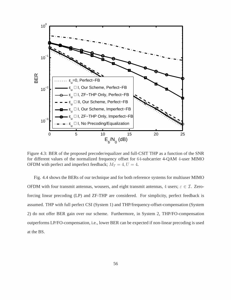
0 5 10 15 20 25
10−3
10−2
10−1
100
Eb/N
0 (dB)
BE
R
εu=0, Perfect−FB
εu ∈ I, Our Scheme, Perfect−FB
εu ∈ I, ZF−THP Only, Perfect−FB
εu ∈ II, Our Scheme, Perfect−FB
εu ∈ I, Our Scheme, Imperfect−FB
εu ∈ I, ZF−THP Only, Imperfect−FB
εu ∈ I, No Precoding/Equalization
Figure 4.3: BER of the proposed precoder/equalizer and full-CSIT THP as a function of the SNRfor different values of the normalized frequency offset for64-subcarrier 4-QAM4-user MIMOOFDM with perfect and imperfect feedback;MT = 4, U = 4.
Fig. 4.4 shows the BERs of our technique and for both reference systems for multiuser MIMO
OFDM with four transmit antennas, wousers, and eight transmit antennas,4 users;ε ∈ I. Zero-
forcing linear precoding (LP) and ZF-THP are considered. For simplicity, perfect feedback is
assumed. THP with full perfect CSI (System 1) and THP/frequency-offset-compensation (System
2) do not offer BER gain over our scheme. Furthermore, in System 2, THP/FO-compensation
outperforms LP/FO-compensation, i.e., lower BER can be expected if non-linear precoding is used
at the BS.
56
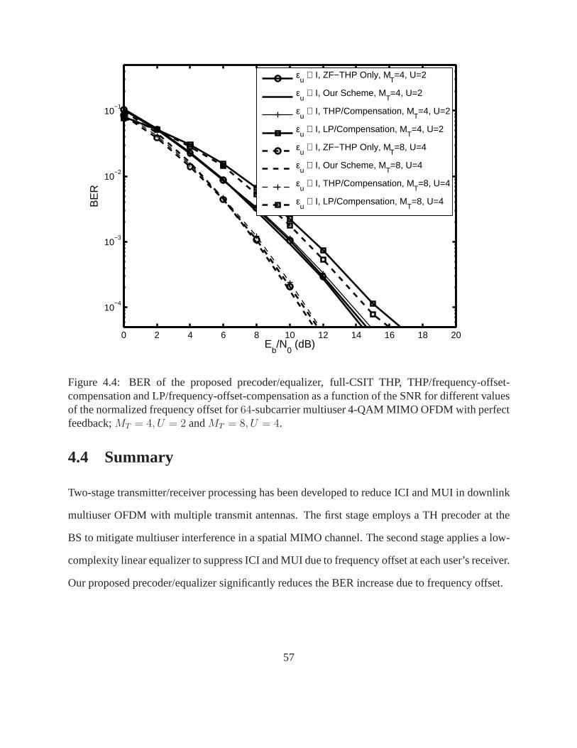
0 2 4 6 8 10 12 14 16 18 20
10−4
10−3
10−2
10−1
Eb/N
0 (dB)
BE
R
εu ∈ I, ZF−THP Only, M
T=4, U=2
εu ∈ I, Our Scheme, M
T=4, U=2
εu ∈ I, THP/Compensation, M
T=4, U=2
εu ∈ I, LP/Compensation, M
T=4, U=2
εu ∈ I, ZF−THP Only, M
T=8, U=4
εu ∈ I, Our Scheme, M
T=8, U=4
εu ∈ I, THP/Compensation, M
T=8, U=4
εu ∈ I, LP/Compensation, M
T=8, U=4
Figure 4.4: BER of the proposed precoder/equalizer, full-CSIT THP, THP/frequency-offset-compensation and LP/frequency-offset-compensation as a function of the SNR for different valuesof the normalized frequency offset for64-subcarrier multiuser 4-QAM MIMO OFDM with perfectfeedback;MT = 4, U = 2 andMT = 8, U = 4.
4.4 Summary
Two-stage transmitter/receiver processing has been developed to reduce ICI and MUI in downlink
multiuser OFDM with multiple transmit antennas. The first stage employs a TH precoder at the
BS to mitigate multiuser interference in a spatial MIMO channel. The second stage applies a low-
complexity linear equalizer to suppress ICI and MUI due to frequency offset at each user’s receiver.
Our proposed precoder/equalizer significantly reduces theBER increase due to frequency offset.
57
Chapter 5
Limited-Feedback Precoding for MultiuserMIMO OFDM Systems with FrequencyOffsets
In an open-loop spatially-multiplexed (SM) system, the number of receive antennas must be equal
to or greater than the number of transmit antennas. In closed-loop systems, transmitter precod-
ing can overcome ill-conditioning of the channel matrix andimprove the system performance.
In Chapter 3 and 4, non-linear THP has been proposed to suppress ICI, using only partial CSI,
not including the knowledge of frequency offsets, at the transmitter. Perfect channel gains at
the transmitter may require a high-rate feedback link. Thus, limited-feedback signal design and
linear precoders have been explored for flat-fading MIMO channels for feedback volume reduc-
tion [44, 53–55, 81, 82]. The basic idea of this approach is tochoose the precoding matrix at the
receiver (rather than at the transmitter) using full CSI such that only the index of the selected
matrix needs to be sent back to the transmitter. Limited-feedback precoding not only can reduce
the number of feedback bits, but also can minimize the systemerror rate and maximize capac-
ity. Nevertheless, this approach so far has only been considered for single-user systems over
flat-fading channels, and is suitable for an ideal OFDM case without frequency offset, in which
the overall channel gain matrix is a block-diagonal matrix.With frequency offsets, the overall
channel gain matrix is not a block-diagonal matrix any more.The original limited-feedback de-
sign in [53–55, 81, 82] cannot hence be applied to a more practical OFDM system with frequency
58
offsets.
This chapter develops both linear precoding and non-linearlimited-feedback THP (LFB-THP)
for closed-loop multiuser MIMO OFDM systems with frequencyoffsets. SM MIMO OFDM with
a linear receiver and OSTBC MIMO OFDM with an ML receiver are considered. Frequency
offsets are shown to have no impact on precoding, and hence precoding on per-subcarrier basis is
possible. Exploiting this property, the codebook design criterion previously used for flat-fading
MIMO systems [53–56] is generalized to multiuser OFDM systems with frequency offsets. The
use of a pre-designed codebook of precoding matrices, available at both the transmitter and the
receiver, is proposed. The receiver selects optimal matrices at the subcarrier level according to
a certain criterion and sends only their indexes to the transmitter. The explicit CSI is hence not
needed at the transmitter. Three precoding matrix selection criteria, MMSE, maximum singular
value (MSV) and maximum mutual information (MMI) are analyzed. To further reduce the number
of feedback bits, grouping and interpolation schemes are also introduced. In our precoders, the
feedback load is reduced to only a limited number of bits, which reduces feedback bit rate, and
the non-linear property reduces power efficiency loss inherent in linear precoding, which makes
non-linear precoding outperform linear precoding. Our precoders also significantly improve BER
for OFDM with frequency offsets over spatially correlated MIMO channels.
This chapter is organized as follows. Section 5.1 proposes linear and non-linear precoding for
both SM and OSTBC multiuser MIMO OFDM in the presence of frequency offset along with the
matrix selection criteria. The impact of the ICI matrix on the optimal precoding matrix and develop
the codebook design scheme is studied. Section 5.2 considers spatially correlated MIMO channels,
and analyze the effect of fading correlations on the feedback matrix design. The simulation results
for SM MIMO OFDM, OSTBC MIMO OFDM and OFDM in spatially correlated channels are
given in Section 5.3. Section 5.4 concludes this chapter.
59
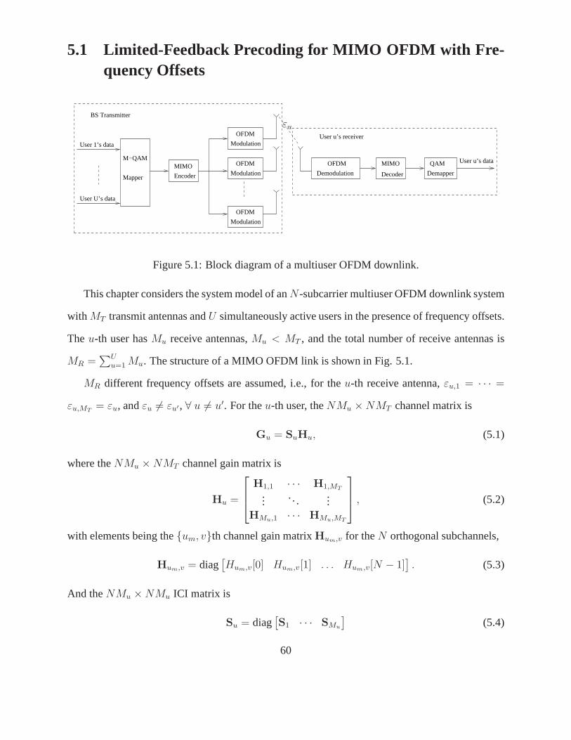
5.1 Limited-Feedback Precoding for MIMO OFDM with Fre-quency Offsets
OFDM
OFDM
M−QAM
Mapper
MIMO
Decoder Demapper
QAM
User u’s receiverUser 1’s data
User U’s data
BS Transmitter
User u’s data
Modulation
MIMO
Encoder Demodulation
Modulation
Modulation
OFDM
OFDM
εu
Figure 5.1: Block diagram of a multiuser OFDM downlink.
This chapter considers the system model of anN-subcarrier multiuser OFDM downlink system
with MT transmit antennas andU simultaneously active users in the presence of frequency offsets.
Theu-th user hasMu receive antennas,Mu < MT , and the total number of receive antennas is
MR =∑U
u=1 Mu. The structure of a MIMO OFDM link is shown in Fig. 5.1.
MR different frequency offsets are assumed, i.e., for theu-th receive antenna,εu,1 = · · · =
εu,MT= εu, andεu 6= εu′, ∀ u 6= u′. For theu-th user, theNMu × NMT channel matrix is
Gu = SuHu, (5.1)
where theNMu × NMT channel gain matrix is
Hu =
H1,1 · · · H1,MT
.... . .
...HMu,1 · · · HMu,MT
, (5.2)
with elements being theum, vth channel gain matrixHum,v for theN orthogonal subchannels,
Hum,v = diag[Hum,v[0] Hum,v[1] . . . Hum,v[N − 1]
]. (5.3)
And theNMu × NMu ICI matrix is
Su = diag[S1 · · · SMu
](5.4)
60
with the unitarySumas in (3.8). Stacking all the users, theNMR × NMT overall channel matrix
G as (3.12) is,
G = SH, (5.5)
where theNMR × NMT channel gain matrix is
H =
H1...
HU
, (5.6)
and theNMR × NMR ICI matrix is
S = diag[S1 · · · SU
]. (5.7)
Similar toSu, S is a unitary matrix.
Previous limited-feedback precoding work focused on the ideal case of MIMO OFDM without
frequency offsets [81, 82]. In this case, theNMR × NMT overall channel matrixG (5.5) is only
determined by channel gains and becomes
G′ = diag[H[0] . . . H[N − 1]
]. (5.8)
The MR × MT sub-matrixH[k] is the channel matrix on the subcarrierk with i.i.d. CN (0, 1)
entries. Precoding can thus be designed on a subcarrier basis using the limited-feedback approach
for flat-fading MIMO systems [54, 55]. However, in the presence of frequency offsets, the overall
channel matrix is dependent on both frequency offset and channel gains. The limited-feedback
precoding design in [54,55,81,82] cannot be directly applied.
Before developing a limited-feedback precoder for both SM and OSTBC MIMO OFDM sys-
tems with frequency offset, the relationship betweenG in (5.5) andG′ in (5.8) is first analyzed.
The channel gain matrixH can be permuted intoG′:
H = Q1G′Q2, (5.9)
whereQ1 is anNMR × NMR unitary permutation matrix andQ2 is anNMT × NMT unitary
permutation matrix. The SVD ofG′ is given by
G′ = U′Γ′V′H , (5.10)
61
whereU′ is anNMR ×NMT matrix andU′HU = INMT
; V′ is anNMT ×NMT unitary matrix.
SinceG′ is a block-diagonal matrix,V′ can be constructed byV′[k], which is generated from the
SVD of H[k] in (5.8). Therefore,V′ is also a block-diagonal matrix. The singular value matrixΓ′
is anNMT ×NMT diagonal matrix with real, positive entriesγn, n = 1, . . . , NMT , in descending
orderγ′1 ≥ γ′
2 ≥ · · · ≥ γ′NMT
> 0. The SVD of the overall channel matrix becomes
G = SH = SQ1G′Q2 = SQ1U
′Γ′V′HQ2 = UΓVH. (5.11)
SinceQ1 andQ2 are unitary matrices, we haveU = SQ1U′, Γ = Γ′ andV = QH
2 V′
. Similarly,
for theu-th user, the SVD of the channel matrix is
Gu = SuQ1G′uQ2 = UuΓuV
Hu , (5.12)
whereUu = SuQ1U′u, Γu = Γ′
u andVu = QH2 V
′
u.
For each user, the precoding matrix is anNMT × NMC matrix, i.e., on each subcarrier the
incoming data streams are multiplexed intoMC streams and sent overMT transmit antennas,
MT ≥ MC . For convenience of detection, we needMu ≥ MC . In the single-user case, we assume
MR ≥ MC . We construct a finite codebook of matrices and choose the precoding matrix from
the codebook at the receiver. The codebook is known at both the transmitter and the receiver such
that only the index of the selected matrix needs to be sent back to the transmitter. We analyze the
matrix selection criteria, and propose the codebook designalgorithms.
5.1.1 Precoding Matrix Selection Criteria for Linear Receivers
The matrix selection criteria are analyzed for SM MIMO OFDM with a ZF receiver. The precoding
matrix of the useru Bu = P(Gu) is assumed, whereP(Gu) is a mapping from the channel
matrix Gu to the codebookB = B1, . . . , BK, optimizing the precoding matrix based on some
performance criterion;K is the size of the codebook. All users share the same codebook. Once
the optimalBu,opt is chosen, the ZF receiver applies aNMC × NMu matrix Du =[GuBu,opt
]†.
For simplicity, in the following analysis, the user indexu is omitted.
62
5.1.1.1 Minimum Mean Squared Error (MMSE) Criterion
The MSE for precoding matrixB can be expressed as [46,54]
MSE(B) = Es
(INMC
+ EsBHGHR−1
WWGB)−1
= Es
(INMC
+Es
σ2W
BHQH2 G
′HG′Q2B
)−1
,(5.13)
whereRWW = E[WWH
]is the noise covariance matrix;Es is the average power of the trans-
mitted symbols. Eq. (5.13) is used to selectB from B according to minimize the MSE
P(G) = arg minBi∈B
tr[MSE(Bi)
]. (5.14)
The relationship betweenG andG′ in (5.11) suggests that the precoding matrix forG is related
to that forG′. Let B′ = Q2B be the precoding matrix forG′. In [46, 82], forH[k] in G′ (5.8),
the optimal precoding matrix on the subcarrierk is B′opt[k] = V′
C[k], whereV′C [k] is formed
from the firstMC columns of the right matrixV′[k] yielded by the SVD of theH[k]. SinceG′
is a block-diagonal matrix,B′opt = V′
C = diag[V′
C [0] . . .V′C [N − 1]
]is also anNMT × NMC
block-diagonal matrix, and the desired overall optimal precoding matrix isB = QH2 B′.
5.1.1.2 Maximum Singular Value (MSV) Criterion
A selection criterion based on the minimum SNR is difficult toimplement since it requires the
computation of the SNR for every OFDM symbol interval. With pre-equalization byB, the system
experiences anNMR × NMC effective channel matrixGB. Since the minimum SNR for a ZF
receiver is lower bounded by the minimum singular value of the effective channel [46, 54],B can
be selected such that the minimum singular value is as large as possible. The optimization problem
therefore is
P(G) = arg maxBi∈B
γmin
(EsB
HGHR−1WWGB
). (5.15)
Similar to the MMSE criterion, the solution is given byBopt = QH2 V′
C .
63

5.1.1.3 Maximum Mutual Information (MMI) Criterion
The mutual information under an average transmit power constraint is given by [83]
C(B) =1
Nlog2
[det(INMC
+ EsBHGHR−1
WWGB)]. (5.16)
The mutual information (5.16) can be maximized by the selection of the feedback matrixB ac-
cording to
P(G) = arg maxBi∈B
C(Bi). (5.17)
The optimization problem (5.17) is equivalent to
P(G) = arg minBi∈B
det(MSE(Bi)). (5.18)
Similar to the MMSE criterion (5.14), the solution isBopt = QH2 V′
C .
5.1.2 Matrix Selection Criterion for Maximum-Likelihood R eceiver
Now the precoding matrix selection criterion for an OSTBC MIMO OFDM with an ML receiver
is considered. Each user has an ML receiver. The user’s indexu is omitted here for simplicity.
To minimize the system BER given the channel matrixG, the Frobenius norm of the effective
channelGB must be maximized [55]. The precoding matrix from the codebook B is therefore
chosen according to
P(G) = arg maxBi∈B
‖GBi‖F = ‖SQ1G′Q2Bi‖F . (5.19)
This selection criterion can be easily implemented by performing a matrix multiplication and com-
puting a Frobenius norm for each of theK codebook matrices. With the SVD ofG′ in (5.10),
the optimalBopt is given byBopt = QH2 V′
C. The receiver performs ML decoding on the effective
channelGBopt.
Similarly as proven in [55], limited-feedback precoding inOSTBC systems achieves full-
diversity order. The proposed LFB-TH precoder thus can be used in a generalized OSTBC system
with an arbitrary number of transmit antennas and with full diversity.
64

5.1.3 Limited-Feedback Precoding Design
To find the optimal precoding matrixBu,opt = QH2 V′
u,C, we need to look forV′u,C. SinceV′
u,C is
a block diagonal matrix, we can build up a codebookB = B1, . . . , BK to find B′u,opt[k] at a sub-
carrier level. Therefore, in our codebookB, each complex matrixBi has a size ofMT ×MC , rather
thanNMT ×NMC . The optimalB′u,opt[k] is chosen from the codebookB at theu-th user’s receiver
according to the current channel conditions. After the optimalV′u,C [k] for all subcarriers are ob-
tained, theNMT × NMC optimal precoding matrixBu,opt = QH2 diag
[B′
u,opt[0] . . . B′u,opt[N − 1]
]
can be constructed. The overall precoding matrix is built upas follows:
Bopt =[B1,opt, . . . , BU,opt
]. (5.20)
The effective overall channel therefore becomes
GBopt =
G1B1,opt · · · G1BU,opt...
. . ....
GUB1,opt · · · GUBU,opt
. (5.21)
Since the codebook is known at both the transmitter and each user, only the index of the selected
precoding matrix needs to be fed back to the BS transmiter. The BS transmitter broadcasts every
user’s precoding index such that each user will also knows other users’ precoding matrix. At the
u-th user’s receiver, the effective channel isGu
∑Uu=1 Bu,opt. Since the index ofBu,opt, ∀ u, is
available at each user’s receiver, the transmitted signal can be detected. For the single-user case,
the overallNMT × NMC precoding matrix isBopt = QH2 diag
[B′
opt[0] . . . B′opt[N − 1]
]. Zero-
forcing detection can be used at the receiver with the assumption of MR ≥ MC .
For each user, the totalN⌈log2 K⌉ feedback bits are required for a codebook withK precoding
matrices. When a better performance is required, a larger codebook can be constructed, i.e., more
bits can be sent to the transmitter. To reduce the total amount of the feedback information, we can
exploit the correlation of precoding matrices on adjacent subcarriers. The significant correlations
between adjacent subcarriers lead to substantial correlation between the precoders corresponding
to neighboring subcarriers. The neighboring subcarriers can therefore be combined into a group
65
and use the precoding matrix corresponding to the center subcarrier for all the subcarriers in the
group. If theN subcarriers are divided intoNb groups, each group includesN/Nb subcarriers.
Since the subcarriers near the group boundary may experience performance degradation, an inter-
polation scheme can be used to improve the performance due togrouping. Interpolation introduces
a unitary matrixQI which takes the unitary-invariance of the optimal precoding matrix into con-
sideration. The optimalQI can be determined by the same criteria used for precoding selection,
and a codebookQ can be built up for optimal interpolation matrix selection.Naturally, a larger size
of the codebookQ will lead to a better BER performance. The details of interpolation schemes
can be found in [81,82].
The following subsections develop the matrix selection criteria for both SM and OSTBC
MIMO OFDM systems and propose the codebook design schemes.
5.1.4 Codebook Design
The construction of the precoding codebookB = B1, . . . , BK is now considered. Frequency
offsets have been first shown to have no impact on the codebookdesign, which makes precoding
on per-subcarrier basis possible. Next, the codebook design criterion which is valid only for flat-
fading MIMO channels in [53–56] is generalized to OFDM systems with frequency offset. The
user index is omitted here.
5.1.4.1 Impact of the ICI Matrix
Since the ICI matrixS is a unitary matrix, the singular value matrix and the right matrix in (5.11)
are actually generated from the eigenvalue decomposition (EVD) of the channel gain matrixHHH:
GHG = HHH = QH2 G′HQH
1 Q1G′Q2 = QH
2 G′HG′Q2 = VΓ2VH . (5.22)
We thus find
Lemma 1: In an OFDM system, if the values of frequency offsets only change on different receive
antennas,B′opt[k] = V′
C [k] is uniformly distributed on the setΘ(MT , MC), i.e., the frequency offset
66

does not have impact on the codebook design compared to an OFDM system without frequency
offset.
Proof: If there is no frequency offset, the overall channel matrixis reduced to a block diagonal
matrix G′, andV′ = Q2V = diag[V′[0] . . .V′[N − 1]
]is also a block diagonal matrix. Each
subblock matrix is uniformly distributed onΘ(MT , MT ) [84], whereΘ(m, n) is the set ofm × n
matrices withn orthonormal columns. As in [54], the optimal precoding matrix on the subcarrier
k B′opt[k] = V′
C [k] is also uniformly distributed on the setΘ(MT , MC).
5.1.4.2 Codebook Design Criteria
SinceB′opt[k] is uniformly distributed overΘ(MT , MC), the codebook matrices are in the set of
Θ(MT , MC). The set of all possible column spaces of the matricesBi, ∀ i, in Θ(MT , MC) is
a complex Grassmannian manifoldΞ(MT , MC), in which Ξ(m, n) is the set ofn-dimensional
subspaces in anm-dimensional vector space. Since each codebook matrix generates a subspace,
there is a set of subspaces yielded by the codebook matricesB1, . . . , BK. These subspaces
can be related by several different distances. The chordal distance between any two subspaces is
defined as
dchord
(Bp, Bq
)=
1√2‖BpB
Hp − BqB
Hq ‖F . (5.23)
The projection two-norm distance between two subspaces is
dnorm
(Bp, Bq
)= ‖BpB
Hp − BqB
Hq ‖2, (5.24)
where‖.‖2 is two-norm distance. The Fubini-Study distance between two subspaces is
dFS
(Bp, Bq
)= arccos | det
∣∣BHp Bq
∣∣ |. (5.25)
The codebook can be designed according to a specific precoding selection criterion. This set
of subspaces is a packing of subspaces inΞ(MT , MC). In OSTBC MIMO OFDM, a packing can
be described by the its minimum chordal distance on the Grassmann manifold
dmin = min1≤p<q≤K
dchord
(Bp, Bq
). (5.26)
67
As in [56], we need to minimize
ρ = max1≤p<q≤K
‖B†pBq‖F , (5.27)
which is related to a packing in a complex Grassmannian space. Since minimizingρ in (5.27) is
equivalent to maximizing the minimum distance of (5.23), the codebook design criterion turns out
to be the problem of Grassmannian subspace packing. The set of K subspaces must therefore be
chosen inΞ(MT , MC) such that dmin is as large as possible. Each precoding matrix in the setB is
given asBi = Φi−1B1, whereB1 is formed by the firstMC columns of a unitary matrix in the set
of Θ(MT , MC), andΦ is anMT ×MT diagonal unitary matrix andΦK = I, i.e.,Φ is aK-th root
of unity. The parameter setΨ = ϕ1, . . . , ϕMT is selected to achieve
min0≤ϕ1,...,ϕMT
≤K−1ρ = min
0≤ϕ1,...,ϕMT≤K−1
maxi=2,...,K
∥∥∥B†1Bi
∥∥∥F
, (5.28)
i.e., the parameter setΨ of the diagonal entries ofΦ is
Ψ = arg max min1≤i≤K−1
d(B1, Φi−1B1
). (5.29)
Geometrically, this construction rotates an initialMT -dimensional subspace using aK-th root of
unity to formK differentMC-dimensional subspaces.
In SM MIMO OFDM, for MSV and MMSE selection criteria, the codebook can be designed
by maximizing the minimum projection two-norm distance between any pair of codeword matrix
column space. For capacity selection criterion, the codebook can be designed by maximizing the
minimum Fubini-Study distance between any pair of codewordmatrix column space [54]. Once
the codebook is designed, the matrix on thek-th subcarrierB[k] ∈ B using the performance criteria
in (5.14), (5.15) or (5.18) is chosen at the receiver. Its index is then delivered to the transmitter
using only⌈log2 K⌉ bits.
5.1.5 Non-Linear Tomlinson-Harashima Precoding
The linear pre-distortionB = B† is equivalent to the feedback structure in Fig. 2. THP can
therefore be proposed for limited-feedback precoding. Thedesign of THP is described in Chapter
68
2. For better clarification,B is named as the feedback matrix of THP in the rest of the chapter,
while B as the precoding matrix.
Specific design targets for linear precoding are consideredin Section 5.1.1 to improve the over-
all system performance. If the input sequencea[k] is a sequence of i.i.d. symbols with varianceEa,
the output of the modulo arithmetic feedback structure is also a sequence of i.i.d. random variables,
and the real and imaginary parts are independent, i.e.,X[k] with varianceEs = E[|X[k]|2
], ∀ k
can be assumed. The linear precoding design criteria in (5.14), (5.15) and (5.16) can thus be applied
to our non-linear precoding selection criteria. Similarly, the feedforward matrixD =[GB
]†.
5.2 Limited-Feedback Precoding for Spatially Correlated Chan-nels
The section focuses on OFDM in spatially correlated fading environments. Insufficient scattering
around antennas of the BS transmitter and/or the receiver makes the channels spatially correlated
[85]. The precoding matrix is restrained to lie in the codebook B = B1, B2, . . . , BK. The
receiver chooses the matrix as a function of the channel conditions to minimize the error rate or
maximize the capacity. The correlated MIMO channel model has been introduced in Section 3.3.
5.2.1 Receive Antenna Correlations Only
First consider the case that each pair of transmit antennas has sufficient distance, i.e., only the
effect of receive correlations needs to be analyzed. The channel is given by
GR = SQ1G′RQ2, (5.30)
whereG′R =
(IN ⊗R
1/2R
)G′ is a block diagonal matrix, andG′ is given by (5.8). Thek-th
subblock on the main diagonal ofG′R is HRc[k] = R
1/2R Hw[k]. Thus, precoding can be designed
on a subcarrier basis. The SVD ofHRc[k] is HRc[k] = URc[k]ΓRc[k]VHRc[k] with singular values
of γRc,1[k] ≥ . . . ≥ γRc,MT[k]. The following lemma describes the distribution ofVRc[k].
Lemma 2: VRc[k] is a uniformly distributed unitary matrix overΘ(MT , MC) and is independent
69

of ΓRc[k], if the channel gain matrixHw[k] (5.6) has i.i.d.CN (0, 1) entries.
Proof: The entriesHu,v[k] of the channel gain matrixHw[k] are i.i.d. complex Gaussian ran-
dom variables with zero mean and unity variance (see detailsin Section 3.1). The distribution of
an uniformly distributed unitary matrix is unchanged when the matrix is multiplied by any deter-
ministic unitary matrix.HRc[k] is thus a right-rotationally invariant random matrix, andVRc[k]
is thus uniformly distributed onΘ(MT , MT ) [84], i.e., ΩVRc[k] is also uniformly distributed if
Ω ∈ Θ(MT , MT ) [86].
Thus, the matrix which is formed by the firstMC columns ofVRc[k] is uniformly distributed on
the setΘ(MT , MC). The codebook design criterion in Section 5.1 is also available for the case that
only receive antenna array is correlated. The feedback matrix can be chosen from the codebookB
by (5.14) or (5.16) for SM MIMO OFDM and (5.19) for OSTBC MIMO OFDM.
5.2.2 Both Receive and Transmit Antenna Correlations
This subsection considers the fully correlated channel model (5.31). The overall channel matrixG
can be given by
G = SQ1G′Q2, (5.31)
where theNMR×NMT spatially-correlated channel gain matrix isG′ = diag[H[0] . . .H[N − 1]
]
with H[k] = R1/2R Hw[k]R
1/2T . We first need to find the optimal matrixB′
opt[k] for H[k], and the
desired overfall optimal precoding matrix isBopt = QH2 B′
opt.
Intuitively, we want to choose a precoding matrix with the effective channelH[k]B′[k] to pro-
vide a performance approaching to that given byH[k]B′opt[k]. Since improvement of probability
of error or capacity is relative to maximize‖H[k]B′[k]‖F , we will attempt to minimize
ϑ = E[‖H[k]B′
opt[k]‖2F − ‖H[k]B′[k]‖2
F
]. (5.32)
Eq. (5.32) can be bounded as
ϑ = E[‖H[k]B′
opt[k]‖2F − ‖GR[k]R
1/2T B′[k]‖2
F
]
≤ E[‖H[k]B′
opt[k]‖2F − γ2
Rc,1‖BHRc,opt[k]R
1/2T B′[k]‖2
F
],
(5.33)
70

whereBRc,opt[k] is theMT ×MC optimal precoding matrix ofHRc[k] in G′R (5.30). SinceVRc[k]
is a uniformly distributed unitary matrix overΘ(MT , MC) and independent of the singular value
matrix, the distribution of (5.33) only has one term which depends on the codebook. As a con-
sequence, it is sufficient to only considerRH/2T BRc,opt[k], which is a subspace correlation as it
only depends on the column space ofBRc,opt[k], BRc,opt[k] ∈ Θ(MT , MC). All column spaces
in Θ(MT , MC) generate the complex Grassmannian manifoldΞ(MT , MC). As shown in Section
5.1, the Grassmannian subspace packing problem in uncorrelated channels can be described by
designing a codebookB = b1, ..,bK to maximize the minimum distance
dmin = min1≤m≤n≤K
d(bm,bn). (5.34)
The proposed codebook in correlated channels from multiplying each element ofB by R1/2T can be
obtianed. Therefore, we design the codebookB by pickingb1, ..,bK that maximize (5.34) and
normalize the codebook to meet the average transmit power constraint
Bi =R
H/2T bi
‖RH/2T bi‖
. (5.35)
This design criterion adapts the precoder to the correlated-channel conditions. The transmit spatial
correlation matrixRT can be estimated at the transmitter so that no feedback for the correlation
matrix is needed.
5.3 Simulation Results
The BER performance of the proposed precoders is simulated.The codebook is known a priori at
both the transmitter and the receiver. A MIMO 4-QAM-OFDM system with64 subcarriers over
a 6-tap Rayleigh fading channel is considered. The vehicular B channel specified by ITU-R M.
1225 [73] is used. For many wireless systems, the multipath channels fade slowly. Thus the fading
gains can be assumed constant over several OFDM symbol intervals. Each user hasMu receive
antennas and different frequency offsets.MR different values of normalized frequency offsets are
assumed to be uniformly distributed in two intervalsI = (0, 0.1] andII = (0.1, 0.3].
71
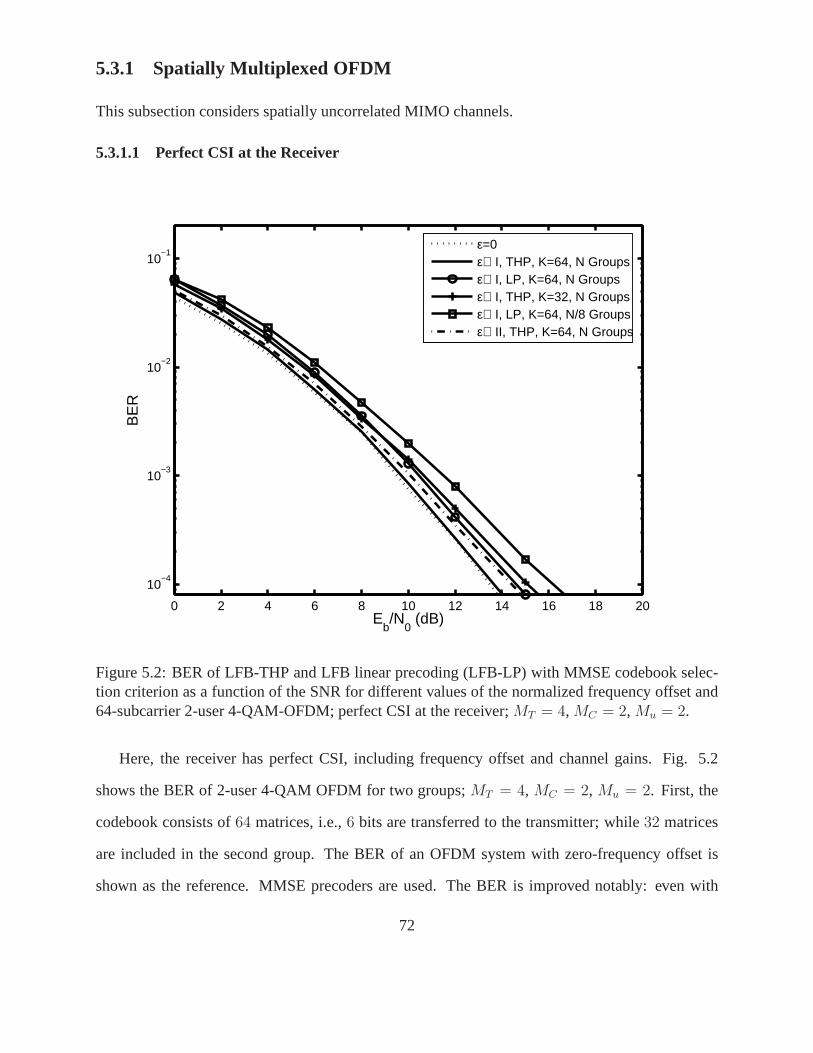
5.3.1 Spatially Multiplexed OFDM
This subsection considers spatially uncorrelated MIMO channels.
5.3.1.1 Perfect CSI at the Receiver
0 2 4 6 8 10 12 14 16 18 20
10−4
10−3
10−2
10−1
Eb/N
0 (dB)
BE
R
ε=0ε∈ I, THP, K=64, N Groupsε∈ I, LP, K=64, N Groupsε∈ I, THP, K=32, N Groupsε∈ I, LP, K=64, N/8 Groupsε∈ II, THP, K=64, N Groups
Figure 5.2: BER of LFB-THP and LFB linear precoding (LFB-LP)with MMSE codebook selec-tion criterion as a function of the SNR for different values of the normalized frequency offset and64-subcarrier 2-user 4-QAM-OFDM; perfect CSI at the receiver;MT = 4, MC = 2, Mu = 2.
Here, the receiver has perfect CSI, including frequency offset and channel gains. Fig. 5.2
shows the BER of 2-user 4-QAM OFDM for two groups;MT = 4, MC = 2, Mu = 2. First, the
codebook consists of64 matrices, i.e.,6 bits are transferred to the transmitter; while32 matrices
are included in the second group. The BER of an OFDM system with zero-frequency offset is
shown as the reference. MMSE precoders are used. The BER is improved notably: even with
72
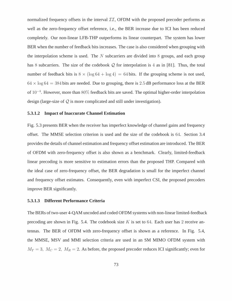
normalized frequency offsets in the intervalII, OFDM with the proposed precoder performs as
well as the zero-frequency offset reference, i.e., the BER increase due to ICI has been reduced
completely. Our non-linear LFB-THP outperforms its linearcounterpart. The system has lower
BER when the number of feedback bits increases. The case is also considered when grouping with
the interpolation scheme is used. TheN subcarriers are divided into8 groups, and each group
has8 subcarriers. The size of the codebookQ for interpolation is4 as in [81]. Thus, the total
number of feedback bits is8 × (log 64 + log 4) = 64 bits. If the grouping scheme is not used,
64 × log 64 = 384 bits are needed. Due to grouping, there is2.5 dB performance loss at the BER
of 10−4. However, more than80% feedback bits are saved. The optimal higher-order interpolation
design (large-size ofQ is more complicated and still under investigation).
5.3.1.2 Impact of Inaccurate Channel Estimation
Fig. 5.3 presents BER when the receiver has imperfect knowledge of channel gains and frequency
offset. The MMSE selection criterion is used and the size of the codebook is64. Section 3.4
provides the details of channel estimation and frequency offset estimation are introduced. The BER
of OFDM with zero-frequency offset is also shown as a benchmark. Clearly, limited-feedback
linear precoding is more sensitive to estimation errors than the proposed THP. Compared with
the ideal case of zero-frequency offset, the BER degradation is small for the imperfect channel
and frequency offset estimates. Consequently, even with imperfect CSI, the proposed precoders
improve BER significantly.
5.3.1.3 Different Performance Criteria
The BERs of two-user 4-QAM uncoded and coded OFDM systems with non-linear limited-feedback
precoding are shown in Fig. 5.4. The codebook sizeK is set to64. Each user has2 receive an-
tennas. The BER of OFDM with zero-frequency offset is shown as a reference. In Fig. 5.4,
the MMSE, MSV and MMI selection criteria are used in an SM MIMOOFDM system with
MT = 3, MC = 2, MR = 2. As before, the proposed precoder reduces ICI significantly; even for
73
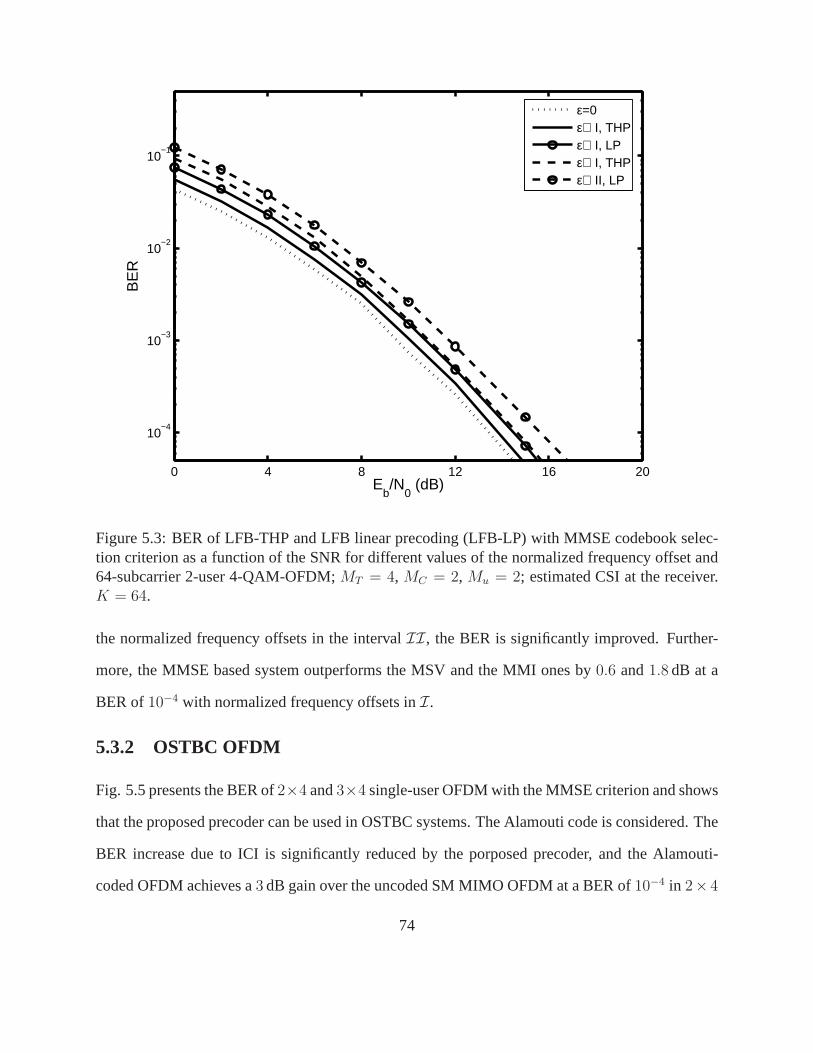
0 4 8 12 16 20
10−4
10−3
10−2
10−1
Eb/N
0 (dB)
BE
R
ε=0ε∈ I, THPε∈ I, LPε∈ I, THPε∈ II, LP
Figure 5.3: BER of LFB-THP and LFB linear precoding (LFB-LP)with MMSE codebook selec-tion criterion as a function of the SNR for different values of the normalized frequency offset and64-subcarrier 2-user 4-QAM-OFDM;MT = 4, MC = 2, Mu = 2; estimated CSI at the receiver.K = 64.
the normalized frequency offsets in the intervalII, the BER is significantly improved. Further-
more, the MMSE based system outperforms the MSV and the MMI ones by0.6 and1.8 dB at a
BER of10−4 with normalized frequency offsets inI.
5.3.2 OSTBC OFDM
Fig. 5.5 presents the BER of2×4 and3×4 single-user OFDM with the MMSE criterion and shows
that the proposed precoder can be used in OSTBC systems. The Alamouti code is considered. The
BER increase due to ICI is significantly reduced by the porposed precoder, and the Alamouti-
coded OFDM achieves a3 dB gain over the uncoded SM MIMO OFDM at a BER of10−4 in 2× 4
74
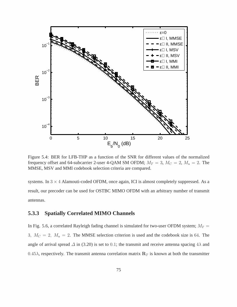
0 5 10 15 20 25
10−4
10−3
10−2
10−1
Eb/N
0 (dB)
BE
Rε=0ε∈ I, MMSEε∈ II, MMSEε∈ I, MSVε∈ II, MSVε∈ I, MMIε∈ II, MMI
Figure 5.4: BER for LFB-THP as a function of the SNR for different values of the normalizedfrequency offset and 64-subcarrier 2-user 4-QAM SM OFDM;MT = 3, MC = 2, Mu = 2. TheMMSE, MSV and MMI codebook selection criteria are compared.
systems. In3 × 4 Alamouti-coded OFDM, once again, ICI is almost completely suppressed. As a
result, our precoder can be used for OSTBC MIMO OFDM with an arbitrary number of transmit
antennas.
5.3.3 Spatially Correlated MIMO Channels
In Fig. 5.6, a correlated Rayleigh fading channel is simulated for two-user OFDM system;MT =
3, MC = 2, Mu = 2. The MMSE selection criterion is used and the codebook size is 64. The
angle of arrival spread∆ in (3.20) is set to0.1; the transmit and receive antenna spacing4λ and
0.45λ, respectively. The transmit antenna correlation matrixRT is known at both the transmitter
75
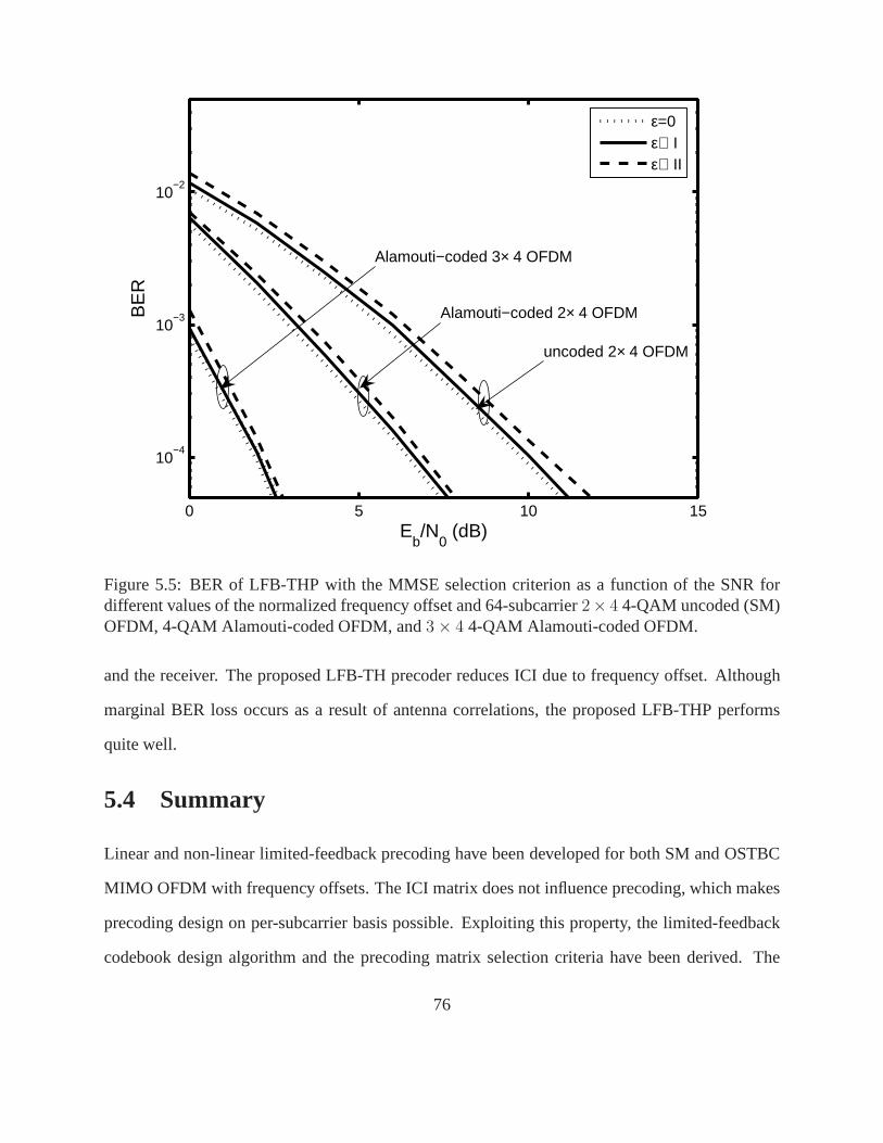
0 5 10 15
10−4
10−3
10−2
Eb/N
0 (dB)
BE
Rε=0ε∈ Iε∈ II
uncoded 2× 4 OFDM
Alamouti−coded 2× 4 OFDM
Alamouti−coded 3× 4 OFDM
Figure 5.5: BER of LFB-THP with the MMSE selection criterionas a function of the SNR fordifferent values of the normalized frequency offset and 64-subcarrier2× 4 4-QAM uncoded (SM)OFDM, 4-QAM Alamouti-coded OFDM, and3 × 4 4-QAM Alamouti-coded OFDM.
and the receiver. The proposed LFB-TH precoder reduces ICI due to frequency offset. Although
marginal BER loss occurs as a result of antenna correlations, the proposed LFB-THP performs
quite well.
5.4 Summary
Linear and non-linear limited-feedback precoding have been developed for both SM and OSTBC
MIMO OFDM with frequency offsets. The ICI matrix does not influence precoding, which makes
precoding design on per-subcarrier basis possible. Exploiting this property, the limited-feedback
codebook design algorithm and the precoding matrix selection criteria have been derived. The
76
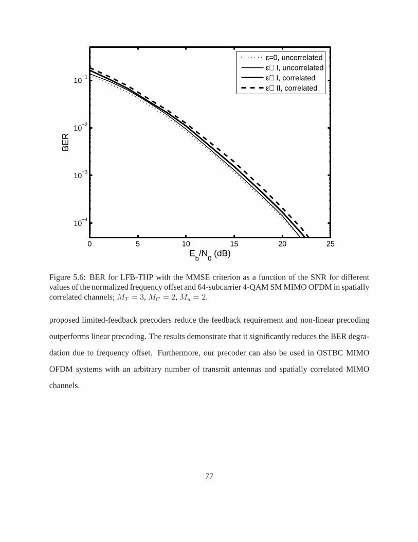
0 5 10 15 20 25
10−4
10−3
10−2
10−1
Eb/N
0 (dB)
BE
Rε=0, uncorrelatedε∈ I, uncorrelatedε∈ I, correlatedε∈ II, correlated
Figure 5.6: BER for LFB-THP with the MMSE criterion as a function of the SNR for differentvalues of the normalized frequency offset and 64-subcarrier 4-QAM SM MIMO OFDM in spatiallycorrelated channels;MT = 3, MC = 2, Mu = 2.
proposed limited-feedback precoders reduce the feedback requirement and non-linear precoding
outperforms linear precoding. The results demonstrate that it significantly reduces the BER degra-
dation due to frequency offset. Furthermore, our precoder can also be used in OSTBC MIMO
OFDM systems with an arbitrary number of transmit antennas and spatially correlated MIMO
channels.
77
Chapter 6
Covariance Precoding Schemes for MIMOOFDM over Transmit-Antenna andPath-Correlated Channels
MIMO OFDM systems can achieve capacity increase or diversity gain, when antenna and path
correlations are negligible [85]. However, these correlations are not negligible in practice be-
cause of many reasons such as insufficient antenna spacing, the presence of scatterers far from the
transmit antenna array in a narrow angular range, and other reasons. Spatial correlations signif-
icantly reduce the system capacity [72] and increase the system BER [87]. Thus, techniques are
required to mitigate the impact of correlations on SM and space-time coding (STC) systems. Pre-
coding/beamforming can mitigate capacity loss in SM MIMO systems [88] or improve BER for
OSTBC systems in spatially correlated flat-fading channels[47, 48, 51, 89, 90], if the channel cor-
relation matrices are available at the transmitter. For SM OFDM over antenna and path-correlated
frequency-selective channels, precoding enables pre-processing of the signals at a subcarrier level
and improves capacity [91]. However, precoders designed toimprove the error rate in OSTBC
OFDM have not been studied yet. Precoders are derived to mitigate the impact of transmit-antenna
and path correlations.
Several schemes that switch between SM and STC and adaptive schemes have been investigated
in the literature. The fundamental diversity-multiplexing trade-off in the high SNR region has been
analyzed in [20]. A switching algorithm between SM and STC isproposed in [92]. Reference [93]
78

presents an antenna selection scheme to choose transmit antennas for SM or selection diversity
combining mode. A multi-mode linear precoder with limited feedback is proposed in [94]. These
approaches [92–94] employ selection diversity combining to improve error rate in high data-rate
transmission over spatially-uncorrelated fading channels. In [95], an adaptive scheme is devel-
oped to achieve maximum-possible capacity subject to a pre-defined BER value. However, these
schemes do not deal with OFDM, assuming only flat-fading MIMOchannels, and [92, 95] do not
consider precoding.
This chapter considers covariance based linear precoding and non-linear THP for MIMO OFDM
systems. The main objective is to design precoders to mitigate the impact of transmit-antenna and
path correlations. First, the impact of path correlations on the pairwise error probability (PEP) is
analyzed, and closed-form, waterfilling-based linear and non-linear precoders are derived to min-
imize the worst-case PEP in OSTBC OFDM. Second, an adaptive transmission strategy is also
developed for switching between precoded SM OFDM and precoded OSTBC OFDM. The system
is designed to achieve a low BER with a target fixed transmission rate. The switching criterion
is the minimum Euclidean distance of the received codebook.A lower complexity switching cri-
terion is also developed. The switching decision sent to thetransmitter requires one feedback bit
per subcarrier. To reduce the number of feedback bits, the switching decision can be made for
groups of neighboring subcarriers. The proposed precodersconsiderably reduce the error rate in
antenna and path-correlated channels; non-linear precoders perform better than linear precoders.
The adaptive strategy outperforms either SM or OSTBC individually in terms of the BER.
The remainder of this chapter is organized as follows. Section 6.1 briefly describes the system
model of SM OFDM and OSTBC OFDM over transmit-antenna and path-correlated channels. The
impact of the path correlations on the error rate of OSTBC OFDM is analyzed. Section 6.2 derives
new linear and non-linear precoders for OSTBC OFDM in correlated channels. In Section 6.3
a selection criterion is developed for switching between SM-based and OSTBC-based precoding
modes, along with adaptive linear and non-linear precoders. The simulation results and conclusions
79
are given in Sections 6.4 and 6.5.
6.1 System Model
This section will introduce the system model of anN-subcarrier OFDM system withMT transmit
antennas andMR receive antennas in the presence of transmit-antenna and path correlations. The
downlink case is analyzed where spatial correlations existbetween the transmit antennas, but none
between the receive antennas. At the receiver (mobile station), a sufficiently uncorrelated set of
antennas can be assumed if antenna spacing is half wavelength of the carrier or more [85]. This
condition is easily satisfied by practical systems that use ahigh carrier frequency in the order of
GHz. The impact of path correlations in OSTBC OFDM is also analyzed.
6.1.1 Transmit-Antenna and Path Correlations in OFDM
The channel between thev-th transmit antenna andu-th receive antenna is a wideband frequency-
selective fading channel withL resolvable paths. Thel-th path gain is a zero-mean complex
Gaussian random variable (Rayleigh fading) with varianceσ2l . The set of thel-th path gains can be
represented by anMR ×MT matrixHl with entrieshu,v[l], ∀ l. The channel gains remain constant
over several OFDM symbol intervals. As in [91], the path gainmatricesHl can be represented as
[H0 · · ·HL−1
]= Hw
[RT
P ⊗ RT
]1/2, (6.1)
whereHw is anMR × MT L matrix of i.i.d zero mean complex Gaussian random variableswith
unit variance. TheL × L path correlation matrixRP is defined as (3.19) with them, nth entry
RP (m, n) = σmσnp|m−n|e θm,n , 0 < p ≤ 1 (6.2)
wherep is the path correlation factor andθm,n is the phase of the path correlation between them-th
and then-th path. The entries of the transmit-antenna correlation matrix RT are given in (3.20).
At the receiver, theMR × MT channel on thek-th subcarrier can be represented as
H[k] =L−1∑
l=0
Hle− 2π
Nkl. (6.3)
80
If the path gain matricesHl satisfy (6.1), (6.3) can be re-written as
H[k] = Hw
(R
T/2P F[k] ⊗ R
1/2T
)= HwR
1/2PT [k], (6.4)
whereF[k] =[e− 2π
Nk0 . . . e− 2π
Nk(L−1)
]Tis anL-element vector;R1/2
PT [k] = RT/2P F[k]⊗R
1/2T is an
MT L × MT matrix. Thek-th received signal vector thus can be given by
Y[k] = H[k]X[k] + W[k]. (6.5)
With SM OFDM, MT independent data symbols are transmitted at each time slot on the k-th
subcarrier. Since the space-time code rate is defined asP/T , whereP is the number of symbols
transmitted over theT time slots, SM OFDM has a rate ofRSM = MT .
6.1.2 Impact of Path Correlations
Correlated fading can significantly affect the wireless performance. In SM OFDM, the achievable
spectral efficiency (in bits/sec/Hz) can decrease due to path correlations and transmit-antenna cor-
relations [91]. The latter has been shown to increase the BERin OSTBC OFDM [87]. We now
show the impact of path correlations on PEP in OSTBC OFDM.
The PEP is the probability that a transmitted signal matrixX[k] is erroneously decoded as a
matrix X[k]. For an ML receiver that uses the Euclidean distance metric,the output decision is
given by
X[k] = arg minX[k]
‖Y[k] − H[k]X[k]‖2F , (6.6)
where‖.‖F is the Frobenius norm. The PEP for thek-th subcarrier can be upper bounded as [87]
Pe
(X[k] −→ X[k]
)≤ exp
(−‖H[k]Ø‖2
F
4σ2W
), (6.7)
whereØ = X[k] − X[k] is the codeword difference matrix. As in [50], by taking the expectation
of (6.7) over the channel statistics, the average PEP can be bounded by
log Pe ≤ −MR log det∣∣Q[k]
∣∣ , (6.8)
81
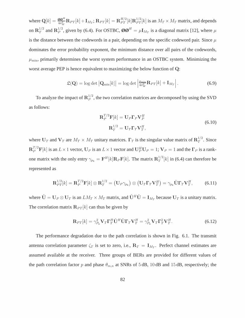
whereQ[k] = ØØH
4σ2
W
RPT [k]+ IMT; RPT [k] = R
H/2PT [k]R
1/2PT [k] is anMT ×MT matrix, and depends
onR1/2T andR
1/2P , given by (6.4). For OSTBC,ØØH = µIMT
is a diagonal matrix [12], whereµ
is the distance between the codewords in a pair, depending onthe specific codeword pair. Sinceµ
dominates the error probability exponent, the minimum distance over all pairs of the codewords,
µmin, primarily determines the worst system performance in an OSTBC system. Minimizing the
worst average PEP is hence equivalent to maximizing the below function ofQ:
L(Q) = log det∣∣Qmin[k]
∣∣ = log det∣∣∣µmin
4σ2
W
RPT [k] + IMT
∣∣∣ . (6.9)
To analyze the impact ofR1/2P , the two correlation matrices are decomposed by using the SVD
as follows:
RT/2P F[k] = UPΓPVH
P
R1/2T = UTΓTVH
T ,(6.10)
whereUT andVT areMT × MT unitary matrices.ΓT is the singular value matrix ofR1/2T . Since
RT/2P F[k] is anL×1 vector,UP is anL×1 vector andUH
P UP = 1; VP = 1 and theΓP is a rank-
one matrix with the only entryγpk= FH [k]RPF[k]. The matrixR1/2
T [k] in (6.4) can therefore be
represented as
R1/2PT [k] = R
T/2P F[k] ⊗R
1/2T =
(UP γpk
)⊗(UTΓT VH
T
)= γpk
UΓTVHT , (6.11)
whereU = UP ⊗UT is anLMT ×MT matrix, andUHU = IMTbecauseUT is a unitary matrix.
The correlation matrixRPT [k] can thus be given by
RPT [k] = γ2Pk
VTΓHT UHUΓT VH
T = γ2Pk
VTΓ2TVH
T . (6.12)
The performance degradation due to the path correlation is shown in Fig. 6.1. The transmit
antenna correlation parameterζT is set to zero, i.e.,RT = IMT. Perfect channel estimates are
assumed available at the receiver. Three groups of BERs are provided for different values of
the path correlation factorp and phaseθm,n at SNRs of5 dB, 10 dB and15 dB, respectively; the
82
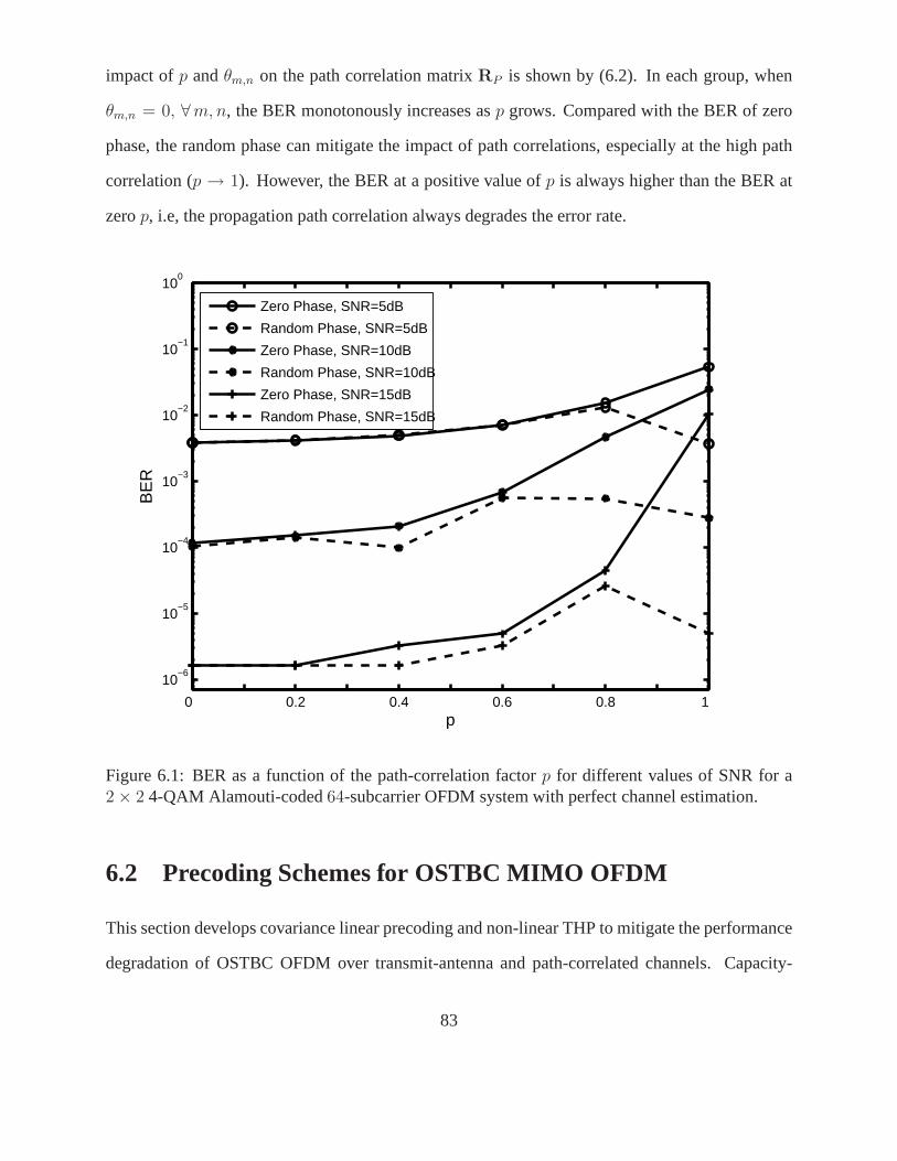
impact ofp andθm,n on the path correlation matrixRP is shown by (6.2). In each group, when
θm,n = 0, ∀m, n, the BER monotonously increases asp grows. Compared with the BER of zero
phase, the random phase can mitigate the impact of path correlations, especially at the high path
correlation (p → 1). However, the BER at a positive value ofp is always higher than the BER at
zerop, i.e, the propagation path correlation always degrades theerror rate.
0 0.2 0.4 0.6 0.8 1
10−6
10−5
10−4
10−3
10−2
10−1
100
p
BE
R
Zero Phase, SNR=5dB
Random Phase, SNR=5dB
Zero Phase, SNR=10dB
Random Phase, SNR=10dB
Zero Phase, SNR=15dB
Random Phase, SNR=15dB
Figure 6.1: BER as a function of the path-correlation factorp for different values of SNR for a2 × 2 4-QAM Alamouti-coded64-subcarrier OFDM system with perfect channel estimation.
6.2 Precoding Schemes for OSTBC MIMO OFDM
This section develops covariance linear precoding and non-linear THP to mitigate the performance
degradation of OSTBC OFDM over transmit-antenna and path-correlated channels. Capacity-
83

optimal precoding is discussedfor SM OFDM.
In covariance precoding systems, the correlation matricesare known to the transmitter. The
transmit-antenna correlation matrices depend on transmitantenna spacing, which changes slower
than the channel response or even does not change at all. As well, transmit-antenna spacing is
known at the transmitter, i.e., feedback forRT is not needed. The feedback load in covariance
precoding is thus significantly reduced.
6.2.1 Optimal Precoding Scheme for OSTBC OFDM
With anMT ×MT precoding matrixEST[k] on thek-th subcarrier the transmitted signal vector on
thek-th subcarrier isEST[k]X[k], instead ofX[k]. The cost metricL(Q) (6.9) becomes
L(Q) = log det∣∣∣EST[k]ØØH
EHST[k]
4σ2
W
RPT [k] + IMT
∣∣∣
= log det∣∣∣µminEST[k]EH
ST[k]
4σ2
W
RPT [k] + IMT
∣∣∣ .(6.13)
The optimal precoding matrix is thus given by
EST[k]opt = arg maxtr(Z[k])=MT
log det∣∣ξZ[k]RPT [k] + IMT
∣∣ , (6.14)
whereξ = µmin
4σ2
W
, Z[k] = EST[k]EHST[k], and tr(·) denotes the matrix trace. Substituting (6.12) into
(6.14) and applying the determinant identity [96], the optimal precoding matrix is given by
EST[k]opt = arg maxtr(Z[k])=MT
log det∣∣ξγ2
PkΓT VH
T Z[k]VT ΓT + IMT
∣∣
= arg maxtr(Z[k])=ξMT
log det∣∣ΓT Z[k]ΓT + IMT
∣∣ , (6.15)
whereΓT = γpkΓT andZ[k] = ξVH
T Z[k]VT . As in [45], a waterfilling solution can be derived
from (6.15). The optimal main-diagonal entries inZ[k]opt will then be
Zkvv =(ρ − γ−2
vv
)+
, v = 1, . . . , MT , (6.16)
where(a)+ denotesmax(a, 0); the parameterρ is chosen to satisfy tr(Z[k]
)= ξMT ; γvv are the
main-diagonal entries ofΓT . Hence, the optimal precoding matrix can be obtained by
EST[k]opt =√
Z[k]opt =
√1
ξVT Z[k]optV
HT K, (6.17)
84
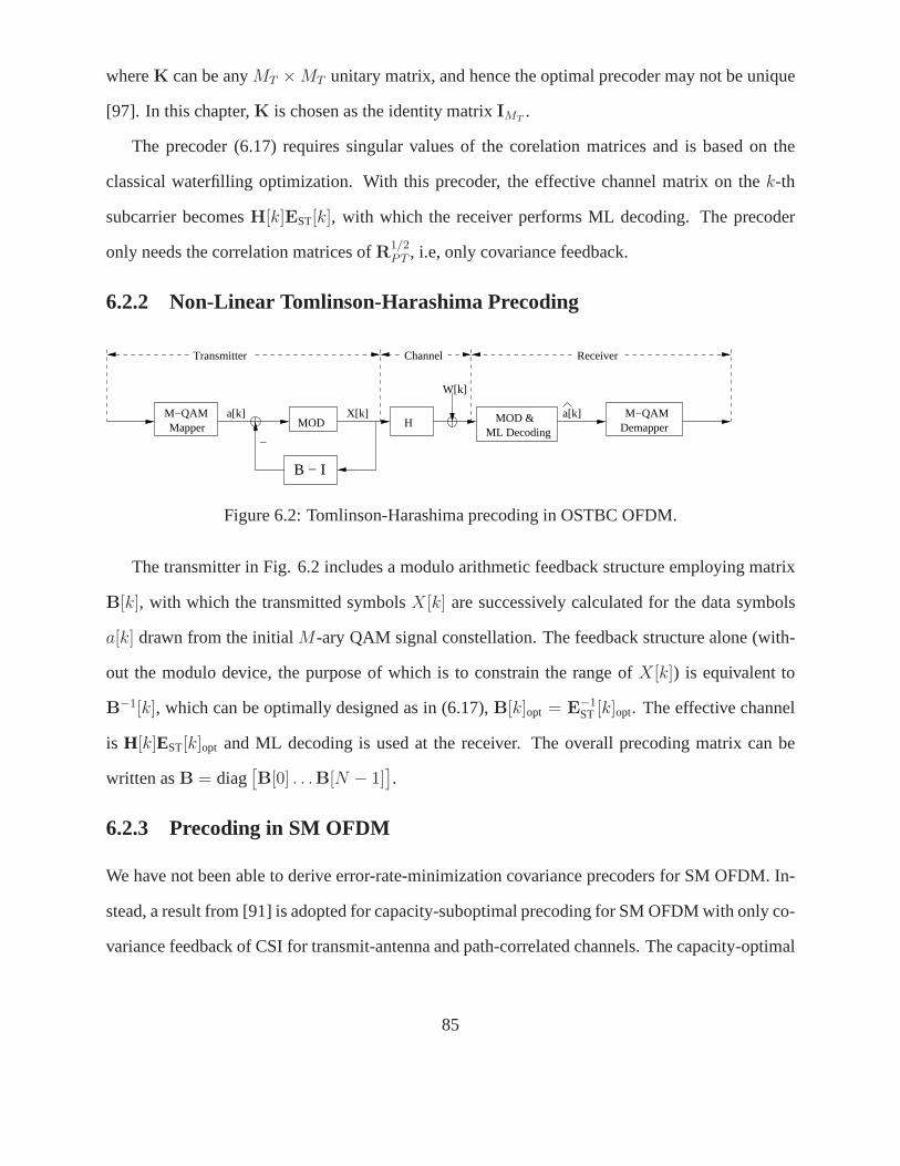
whereK can be anyMT × MT unitary matrix, and hence the optimal precoder may not be unique
[97]. In this chapter,K is chosen as the identity matrixIMT.
The precoder (6.17) requires singular values of the corelation matrices and is based on the
classical waterfilling optimization. With this precoder, the effective channel matrix on thek-th
subcarrier becomesH[k]EST[k], with which the receiver performs ML decoding. The precoder
only needs the correlation matrices ofR1/2PT , i.e, only covariance feedback.
6.2.2 Non-Linear Tomlinson-Harashima Precoding
X[k]
B − I
W[k]
Transmitter Channel
a[k] M−QAMDemapper
Receiver
M−QAM a[k] MOD
_Mapper ML Decoding
MOD &H
Figure 6.2: Tomlinson-Harashima precoding in OSTBC OFDM.
The transmitter in Fig. 6.2 includes a modulo arithmetic feedback structure employing matrix
B[k], with which the transmitted symbolsX[k] are successively calculated for the data symbols
a[k] drawn from the initialM-ary QAM signal constellation. The feedback structure alone (with-
out the modulo device, the purpose of which is to constrain the range ofX[k]) is equivalent to
B−1[k], which can be optimally designed as in (6.17),B[k]opt = E−1ST [k]opt. The effective channel
is H[k]EST[k]opt and ML decoding is used at the receiver. The overall precoding matrix can be
written asB = diag[B[0] . . .B[N − 1]
].
6.2.3 Precoding in SM OFDM
We have not been able to derive error-rate-minimization covariance precoders for SM OFDM. In-
stead, a result from [91] is adopted for capacity-suboptimal precoding for SM OFDM with only co-
variance feedback of CSI for transmit-antenna and path-correlated channels. The capacity-optimal
85
solution can loosely be considered as an MMSE-optimal solution, which can be considered as an
indirect way of reducing the error rate.
The capacity-suboptimal solution of theMT × MT precoding matrixESM[k] is given by [91]
ESM[k]opt
N−1
k=0= arg max
tr(ZSM[k])=MT
1
N
N−1∑
k=0
log det∣∣∣IMT
+ ηkMR
MTΓT ZSM[k]ΓT
∣∣∣ , (6.18)
whereηk =Esγpk
σ2
W
, ZSM[k] = VHT ZSM[k]VT , VT and ΓT are given in (6.10), andZSM[k] =
ESM[k]EHSM[k]. Diagonal matrices of
ZSM[k]
N−1
k=0achieve optimality. This fact can be easily
proven by assuming the fixed power is allocated to each ofZSM[k] and applying the proof in [98].
The optimization entries ofZSM[k]
N−1
k=0can be found by useing water-filling technique [98]. The
suboptimal solution is more practical and efficient; it not only avoids numerical optimization, but
also leads to almost the same capacity as the optimal solution [91]. Similarly, non-linear precoding
can be used for SM OFDM withBSM[k] = E−1SM[k]opt, which can be designed according to (6.18).
Using THP the entire capacity of the underlying MIMO channelcan be achieved [60]. Detailed
discussion of how THP can be applied to reach MIMO capacity isincluded in [60].
Clearly, the precoders in (6.17) and (6.18) need covariancefeedback only, not the full CSI
at the transmitter. They are designed for either capacity improvement in SM OFDM or error-rate
improvement in OSTBC OFDM. We next show how to effectively exploit the two precoding modes
for OFDM over transmit-antenna and path-correlated channels.
6.3 Adaptive Dual-Mode Precoding
This section develops an adaptive strategy which switches between precoded SM OFDM and OS-
TBC OFDM. For each subcarrier, the minimum Euclidean distance of the received codebook is
computed for SM and OSTBC and is used to select the transmission mode. A lower complexity
switching criterion is also derived. The selection decision is sent to the transmitter at a cost of one
feedback bit per subcarrier. To reduce the number of feedback bits, the choice of SM or OSTBC
can also be made for groups of neighboring subcarriers. At the receiver, ML decoding is used for
86
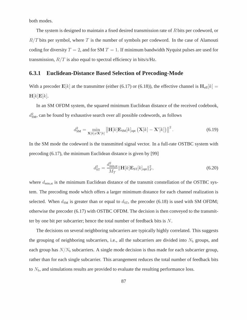
both modes.
The system is designed to maintain a fixed desired transmission rate ofR bits per codeword, or
R/T bits per symbol, whereT is the number of symbols per codeword. In the case of Alamouti
coding for diversityT = 2, and for SMT = 1. If minimum bandwidth Nyquist pulses are used for
transmission,R/T is also equal to spectral efficiency in bits/s/Hz.
6.3.1 Euclidean-Distance Based Selection of Precoding-Mode
With a precoderE[k] at the transmitter (either (6.17) or (6.18)), the effectivechannel isHeff[k] =
H[k]E[k].
In an SM OFDM system, the squared minimum Euclidean distanceof the received codebook,
d2SM, can be found by exhaustive search over all possible codewords, as follows
d2SM = min
X[k] 6=X′[k]
∥∥H[k]ESM[k]opt
(X[k] −X′[k]
)∥∥2. (6.19)
In the SM mode the codeword is the transmitted signal vector.In a full-rate OSTBC system with
precoding (6.17), the minimum Euclidean distance is given by [99]
d2ST =
d2min,st
MT
‖H[k]EST[k]opt‖2F , (6.20)
wheredmin,st is the minimum Euclidean distance of the transmit constellation of the OSTBC sys-
tem. The precoding mode which offers a larger minimum distance for each channel realization is
selected. WhendSM is greater than or equal todST, the precoder (6.18) is used with SM OFDM;
otherwise the precoder (6.17) with OSTBC OFDM. The decisionis then conveyed to the transmit-
ter by one bit per subcarrier; hence the total number of feedback bits isN .
The decisions on several neighboring subcarriers are typically highly correlated. This suggests
the grouping of neighboring subcarriers, i.e., all the subcarriers are divided intoNb groups, and
each group hasN/Nb subcarriers. A single mode decision is thus made for each subcarrier group,
rather than for each single subcarrier. This arrangement reduces the total number of feedback bits
to Nb, and simulations results are provided to evaluate the resulting performance loss.
87
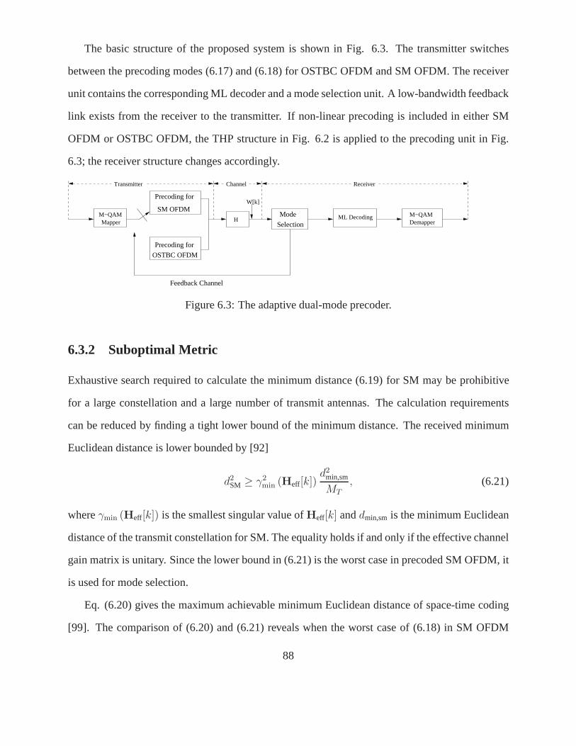
The basic structure of the proposed system is shown in Fig. 6.3. The transmitter switches
between the precoding modes (6.17) and (6.18) for OSTBC OFDMand SM OFDM. The receiver
unit contains the corresponding ML decoder and a mode selection unit. A low-bandwidth feedback
link exists from the receiver to the transmitter. If non-linear precoding is included in either SM
OFDM or OSTBC OFDM, the THP structure in Fig. 6.2 is applied tothe precoding unit in Fig.
6.3; the receiver structure changes accordingly.
M−QAMDemapper
W[k]
Transmitter Channel Receiver
Precoding for
OSTBC OFDM
H ML DecodingM−QAMMapper
Mode
Selection
Precoding for
SM OFDM
Feedback Channel
Figure 6.3: The adaptive dual-mode precoder.
6.3.2 Suboptimal Metric
Exhaustive search required to calculate the minimum distance (6.19) for SM may be prohibitive
for a large constellation and a large number of transmit antennas. The calculation requirements
can be reduced by finding a tight lower bound of the minimum distance. The received minimum
Euclidean distance is lower bounded by [92]
d2SM ≥ γ2
min (Heff[k])d2
min,sm
MT
, (6.21)
whereγmin (Heff[k]) is the smallest singular value ofHeff[k] anddmin,sm is the minimum Euclidean
distance of the transmit constellation for SM. The equalityholds if and only if the effective channel
gain matrix is unitary. Since the lower bound in (6.21) is theworst case in precoded SM OFDM, it
is used for mode selection.
Eq. (6.20) gives the maximum achievable minimum Euclidean distance of space-time coding
[99]. The comparison of (6.20) and (6.21) reveals when the worst case of (6.18) in SM OFDM
88

is better than the best case of (6.17) in OSTBC OFDM. Therefore, the precoding mode (6.18) is
selected when
d2min,st
MT
‖Heff[k]‖2F ≤ γ2
min (Heff[k])d2
min,sm
MT
,
or ς =‖Heff[k]‖F
γmin (Heff[k])≤ dmin,sm
dmin,st,
(6.22)
and SM OFDM is used for transmission; otherwise, (6.17) is applied for OSTBC OFDM. Al-
though the suboptimal criterion (6.22) avoids potential large-scale search, thereby reducing the
computational requirements, it may result in some BER increase.
6.4 Simulation Results
This section presents simulation results to show how our proposed precoders improve the system
performance in OFDM over transmit-antenna and path-correlated channels. The vehicular B chan-
nel specified by ITU-R M. 1225 [73] is used. ML decoding is used. The transmitter only knows
the correlation matricesRT andRP with the antenna-correlation parameterζT = ∆dT
λand path-
correlation factorp, respectively; the path-correlation phaseθm,n in (6.2) is zero. The angle of
arrival spread is assumed12, i.e.,∆ ≈ 0.2.
The simulation cases consider both perfect and imperfect channel estimation. ML estimation
is assumed. The estimation error affects the power loading of the precoders and the variance of the
estimation errorΩe is known at both the transmitter and the receiver. As channelestimation be-
comes accurate, i.e., the variance of estimation errorsΩe becomes negligible, the CSIR approaches
the actual channel.
6.4.1 PEP-Optimal Precoding for OSTBC OFDM
This subsection demonstrates how the proposed linear and non-linear precodersEST[k]opt (6.17)
reduce the system BER for OSTBC OFDM in transmit-antenna andpath-correlated channels.
89
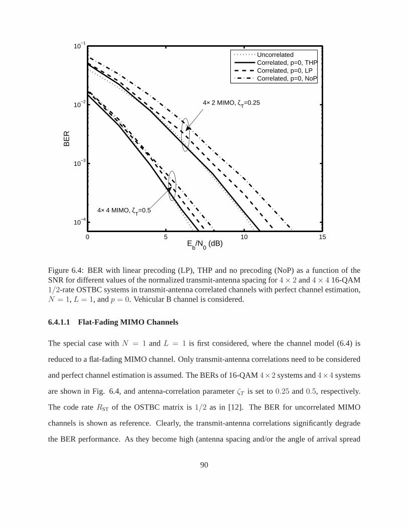
0 5 10 15
10−4
10−3
10−2
10−1
Eb/N
0 (dB)
BE
R
UncorrelatedCorrelated, p=0, THPCorrelated, p=0, LPCorrelated, p=0, NoP
4× 2 MIMO, ζT=0.25
4× 4 MIMO, ζT=0.5
Figure 6.4: BER with linear precoding (LP), THP and no precoding (NoP) as a function of theSNR for different values of the normalized transmit-antenna spacing for4× 2 and4× 4 16-QAM1/2-rate OSTBC systems in transmit-antenna correlated channels with perfect channel estimation,N = 1, L = 1, andp = 0. Vehicular B channel is considered.
6.4.1.1 Flat-Fading MIMO Channels
The special case withN = 1 andL = 1 is first considered, where the channel model (6.4) is
reduced to a flat-fading MIMO channel. Only transmit-antenna correlations need to be considered
and perfect channel estimation is assumed. The BERs of 16-QAM 4×2 systems and4×4 systems
are shown in Fig. 6.4, and antenna-correlation parameterζT is set to0.25 and0.5, respectively.
The code rateRST of the OSTBC matrix is1/2 as in [12]. The BER for uncorrelated MIMO
channels is shown as reference. Clearly, the transmit-antenna correlations significantly degrade
the BER performance. As they become high (antenna spacing and/or the angle of arrival spread
90
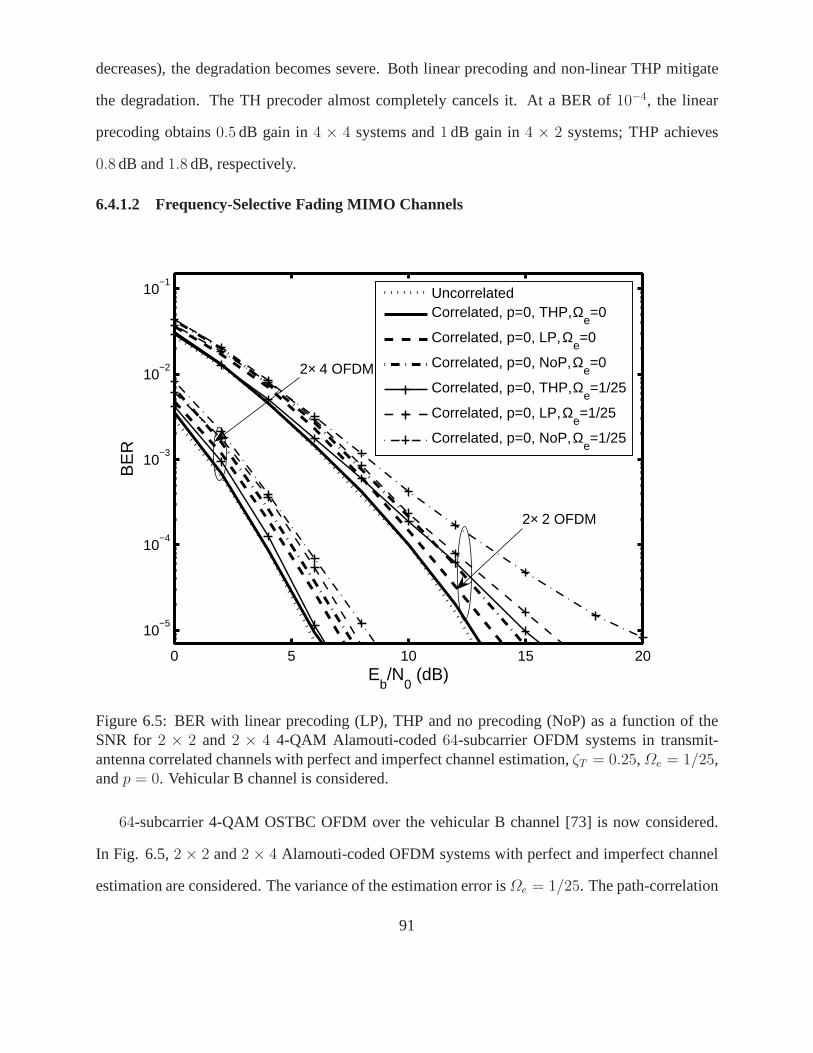
decreases), the degradation becomes severe. Both linear precoding and non-linear THP mitigate
the degradation. The TH precoder almost completely cancelsit. At a BER of 10−4, the linear
precoding obtains0.5 dB gain in4 × 4 systems and1 dB gain in4 × 2 systems; THP achieves
0.8 dB and1.8 dB, respectively.
6.4.1.2 Frequency-Selective Fading MIMO Channels
0 5 10 15 20
10−5
10−4
10−3
10−2
10−1
Eb/N
0 (dB)
BE
R
UncorrelatedCorrelated, p=0, THP, Ω
e=0
Correlated, p=0, LP, Ωe=0
Correlated, p=0, NoP, Ωe=0
Correlated, p=0, THP, Ωe=1/25
Correlated, p=0, LP, Ωe=1/25
Correlated, p=0, NoP, Ωe=1/25
2× 2 OFDM
2× 4 OFDM
Figure 6.5: BER with linear precoding (LP), THP and no precoding (NoP) as a function of theSNR for 2 × 2 and 2 × 4 4-QAM Alamouti-coded64-subcarrier OFDM systems in transmit-antenna correlated channels with perfect and imperfect channel estimation,ζT = 0.25, Ωe = 1/25,andp = 0. Vehicular B channel is considered.
64-subcarrier 4-QAM OSTBC OFDM over the vehicular B channel [73] is now considered.
In Fig. 6.5,2 × 2 and2 × 4 Alamouti-coded OFDM systems with perfect and imperfect channel
estimation are considered. The variance of the estimation error isΩe = 1/25. The path-correlation
91
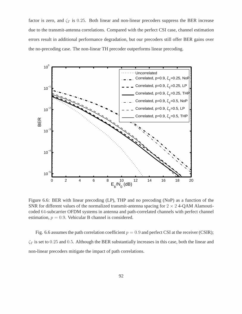
factor is zero, andζT is 0.25. Both linear and non-linear precoders suppress the BER increase
due to the transmit-antenna correlations. Compared with the perfect CSI case, channel estimation
errors result in additional performance degradation, but our precoders still offer BER gains over
the no-precoding case. The non-linear TH precoder outperforms linear precoding.
0 2 4 6 8 10 12 14 16 18 20
10−5
10−4
10−3
10−2
10−1
100
Eb/N
0 (dB)
BE
R
UncorrelatedCorrelated, p=0.9, ζ
T=0.25, NoP
Correlated, p=0.9, ζT=0.25, LP
Correlated, p=0.9, ζT=0.25, THP
Correlated, p=0.9, ζT=0.5, NoP
Correlated, p=0.9, ζT=0.5, LP
Correlated, p=0.9, ζT=0.5, THP
Figure 6.6: BER with linear precoding (LP), THP and no precoding (NoP) as a function of theSNR for different values of the normalized transmit-antenna spacing for2 × 2 4-QAM Alamouti-coded64-subcarrier OFDM systems in antenna and path-correlated channels with perfect channelestimation,p = 0.9. Vehicular B channel is considered.
Fig. 6.6 assumes the path correlation coefficientp = 0.9 and perfect CSI at the receiver (CSIR);
ζT is set to0.25 and0.5. Although the BER substantially increases in this case, both the linear and
non-linear precoders mitigate the impact of path correlations.
92
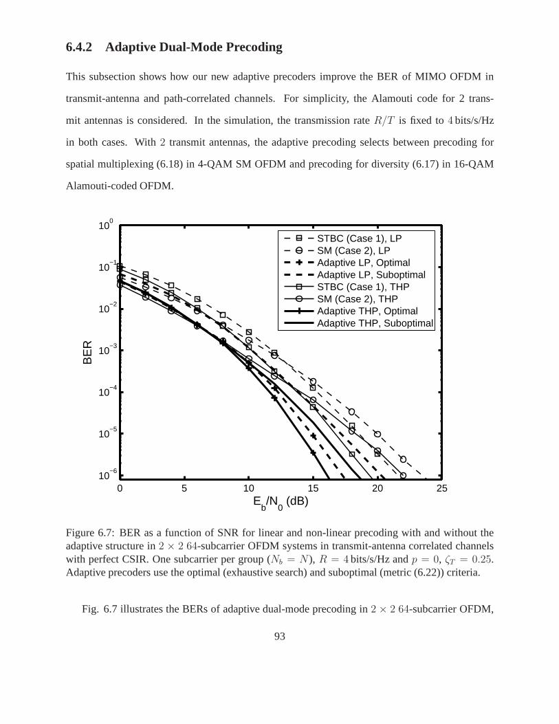
6.4.2 Adaptive Dual-Mode Precoding
This subsection shows how our new adaptive precoders improve the BER of MIMO OFDM in
transmit-antenna and path-correlated channels. For simplicity, the Alamouti code for 2 trans-
mit antennas is considered. In the simulation, the transmission rateR/T is fixed to4 bits/s/Hz
in both cases. With2 transmit antennas, the adaptive precoding selects betweenprecoding for
spatial multiplexing (6.18) in 4-QAM SM OFDM and precoding for diversity (6.17) in 16-QAM
Alamouti-coded OFDM.
0 5 10 15 20 2510
−6
10−5
10−4
10−3
10−2
10−1
100
Eb/N
0 (dB)
BE
R
STBC (Case 1), LPSM (Case 2), LPAdaptive LP, OptimalAdaptive LP, SuboptimalSTBC (Case 1), THPSM (Case 2), THPAdaptive THP, OptimalAdaptive THP, Suboptimal
Figure 6.7: BER as a function of SNR for linear and non-linearprecoding with and without theadaptive structure in2 × 2 64-subcarrier OFDM systems in transmit-antenna correlated channelswith perfect CSIR. One subcarrier per group (Nb = N), R = 4 bits/s/Hz andp = 0, ζT = 0.25.Adaptive precoders use the optimal (exhaustive search) andsuboptimal (metric (6.22)) criteria.
Fig. 6.7 illustrates the BERs of adaptive dual-mode precoding in 2 × 2 64-subcarrier OFDM,
93
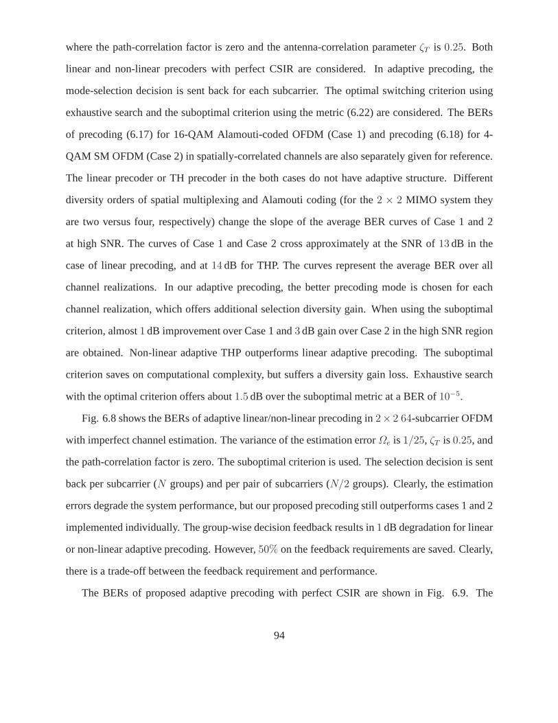
where the path-correlation factor is zero and the antenna-correlation parameterζT is 0.25. Both
linear and non-linear precoders with perfect CSIR are considered. In adaptive precoding, the
mode-selection decision is sent back for each subcarrier. The optimal switching criterion using
exhaustive search and the suboptimal criterion using the metric (6.22) are considered. The BERs
of precoding (6.17) for 16-QAM Alamouti-coded OFDM (Case 1)and precoding (6.18) for 4-
QAM SM OFDM (Case 2) in spatially-correlated channels are also separately given for reference.
The linear precoder or TH precoder in the both cases do not have adaptive structure. Different
diversity orders of spatial multiplexing and Alamouti coding (for the2 × 2 MIMO system they
are two versus four, respectively) change the slope of the average BER curves of Case 1 and 2
at high SNR. The curves of Case 1 and Case 2 cross approximately at the SNR of13 dB in the
case of linear precoding, and at14 dB for THP. The curves represent the average BER over all
channel realizations. In our adaptive precoding, the better precoding mode is chosen for each
channel realization, which offers additional selection diversity gain. When using the suboptimal
criterion, almost1 dB improvement over Case 1 and3 dB gain over Case 2 in the high SNR region
are obtained. Non-linear adaptive THP outperforms linear adaptive precoding. The suboptimal
criterion saves on computational complexity, but suffers adiversity gain loss. Exhaustive search
with the optimal criterion offers about1.5 dB over the suboptimal metric at a BER of10−5.
Fig. 6.8 shows the BERs of adaptive linear/non-linear precoding in2× 2 64-subcarrier OFDM
with imperfect channel estimation. The variance of the estimation errorΩe is 1/25, ζT is 0.25, and
the path-correlation factor is zero. The suboptimal criterion is used. The selection decision is sent
back per subcarrier (N groups) and per pair of subcarriers (N/2 groups). Clearly, the estimation
errors degrade the system performance, but our proposed precoding still outperforms cases 1 and 2
implemented individually. The group-wise decision feedback results in1 dB degradation for linear
or non-linear adaptive precoding. However,50% on the feedback requirements are saved. Clearly,
there is a trade-off between the feedback requirement and performance.
The BERs of proposed adaptive precoding with perfect CSIR are shown in Fig. 6.9. The
94
0 5 10 15 20 2510
−6
10−5
10−4
10−3
10−2
10−1
100
Eb/N
0 (dB)
BE
RSTBC (Case 1), LPSM (Case 2), LPAdaptive, LP, N GroupsAdaptive LP, N/2 GroupsSTBC (Case 1), THPSM (Case 2), THPAdaptive, THP, N GroupsAdaptive, THP, N/2 Groups
Figure 6.8: BER as a function of SNR for linear and non-linearprecoding with and without theadaptive structure in2×2 64-subcarrier OFDM systems over transmit-antenna correlated channelswith imperfect CSIR. One or two subcarriers per group (Nb = N , Nb = N/2), R = 4 bits/s/Hz,Ωe = 1/25, p = 0, andζT = 0.25. Vehicular B channel is considered. Adaptive precoding usesthe suboptimal criterion.
path-correlation factor is0.9 and the antenna-correlation parameterζT is 0.25. The optimal and
suboptimal criteria are considered for adaptive precoding, and the selection decision is fed back
on a subcarrier basis (Nb = N). The proposed linear and non-linear precoders are compared to
precoding without adaptive structure in Case 1 and Case 2. The linear and non-linear adaptive
precoders individually outperform their non-adaptive counterparts in Case 1 and 2. The non-linear
adaptive THP outperforms linear adaptive precoding: at a BER of 10−5, there is1.2 dB gain.
Adaptive precoding suffers a BER increase for MIMO OFDM withboth transmit-antenna and
path correlations compared to that for MIMO OFDM with only transmit-antenna correlations in
95
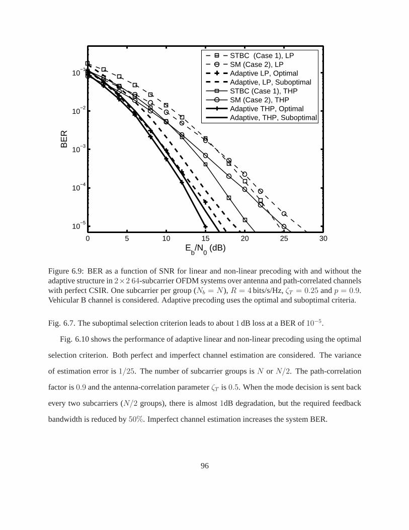
0 5 10 15 20 25 30
10−5
10−4
10−3
10−2
10−1
Eb/N
0 (dB)
BE
RSTBC (Case 1), LPSM (Case 2), LPAdaptive LP, OptimalAdaptive, LP, SuboptimalSTBC (Case 1), THPSM (Case 2), THPAdaptive THP, OptimalAdaptive, THP, Suboptimal
Figure 6.9: BER as a function of SNR for linear and non-linearprecoding with and without theadaptive structure in2×2 64-subcarrier OFDM systems over antenna and path-correlatedchannelswith perfect CSIR. One subcarrier per group (Nb = N), R = 4 bits/s/Hz,ζT = 0.25 andp = 0.9.Vehicular B channel is considered. Adaptive precoding usesthe optimal and suboptimal criteria.
Fig. 6.7. The suboptimal selection criterion leads to about1 dB loss at a BER of10−5.
Fig. 6.10 shows the performance of adaptive linear and non-linear precoding using the optimal
selection criterion. Both perfect and imperfect channel estimation are considered. The variance
of estimation error is1/25. The number of subcarrier groups isN or N/2. The path-correlation
factor is0.9 and the antenna-correlation parameterζT is 0.5. When the mode decision is sent back
every two subcarriers (N/2 groups), there is almost1dB degradation, but the required feedback
bandwidth is reduced by50%. Imperfect channel estimation increases the system BER.
96
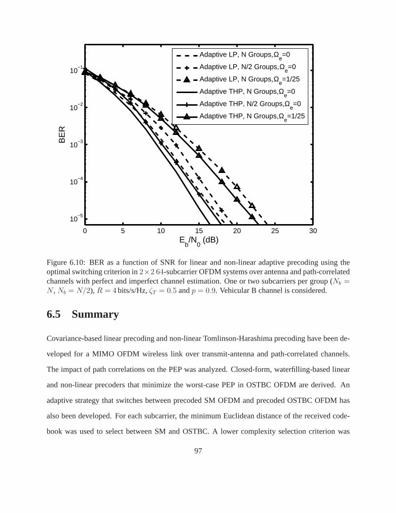
0 5 10 15 20 25 30
10−5
10−4
10−3
10−2
10−1
Eb/N
0 (dB)
BE
RAdaptive LP, N Groups, Ω
e=0
Adaptive LP, N/2 Groups, Ωe=0
Adaptive LP, N Groups, Ωe=1/25
Adaptive THP, N Groups, Ωe=0
Adaptive THP, N/2 Groups, Ωe=0
Adaptive THP, N Groups, Ωe=1/25
Figure 6.10: BER as a function of SNR for linear and non-linear adaptive precoding using theoptimal switching criterion in2×2 64-subcarrier OFDM systems over antenna and path-correlatedchannels with perfect and imperfect channel estimation. One or two subcarriers per group (Nb =N , Nb = N/2), R = 4 bits/s/Hz,ζT = 0.5 andp = 0.9. Vehicular B channel is considered.
6.5 Summary
Covariance-based linear precoding and non-linear Tomlinson-Harashima precoding have been de-
veloped for a MIMO OFDM wireless link over transmit-antennaand path-correlated channels.
The impact of path correlations on the PEP was analyzed. Closed-form, waterfilling-based linear
and non-linear precoders that minimize the worst-case PEP in OSTBC OFDM are derived. An
adaptive strategy that switches between precoded SM OFDM and precoded OSTBC OFDM has
also been developed. For each subcarrier, the minimum Euclidean distance of the received code-
book was used to select between SM and OSTBC. A lower complexity selection criterion was
97

also derived. To reduce the number of feedback bits, mode selection could be based on groups of
neighboring subcarriers. Our proposed precoders significantly reduce the impact of antenna and
path-correlated channels; non-linear precoders perform better than linear precoders. The adaptive
strategy outperforms either SM or OSTBC individually in terms of the BER.
98
Chapter 7
Precoding for OSTBC OFDM Downlink:Mean or Covariance Feedback?
7.1 Introduction
This chapter considers precoding for MIMO OSTBC OFDM downlink, where both the conditional
mean of the channel gain matrix (the first-order channel statistics) and the channel gain covariance
matrix (the long-term/ second-order channel statistics) are available at the transmitter (these two
cases are referred to asmean-feedbackandcovariance precoding, respectively). The application
of the original OSTBC is constrained by insufficient antennaspacing at the transmitter, which
leads to transmit-antenna correlations. Precoding which can optimize the MIMO transmission is
thus needed to offer the original OSTBC the flexibility of adapting to correlated MIMO channels
[47,100,101].
A typical precoding design needs either the channel covariance matrix [47, 101, 102] or full
CSIT [50,103–105]. CSIT thus can be an outdated (due to channel time variations) and imperfect
(due to estimation and feedback errors) estimate. Given CSIT and channel statistics, the con-
ditional mean of the actual channel gain matrix can be calculated, and used for mean-feedback
precoding. On the other hand, since the channel covariance matrix is primarily determined by the
antenna correlation, which can be readily evaluated at the transmitter, the feedback requirement for
covariance precoding in Chapter 6 is much smaller than for mean-feedback precoding. Naturally,
99
the quality of mean-feedback precoding will be degraded dueto estimation errors, and in general
it is more sensitive to the channel time variations and feedback delay than covariance precoding.
In contrast, covariance precoding may become less effective when mean feedback is accurate.
Mean-feedback precoders have been developed for OSTBC systems over an uncorrelated flat-
fading MIMO channel in [50, 103] with the assumption of perfect CSIR or imperfect CSIT with
additive estimation noise but no feedback delay. A more general model has not been consid-
ered yet. If mean feedback and channel covariance matrix areavailable, [104] studies precoding
schemes designed to approach capacity in spatially-uncorrelated flat-fading MIMO channels and
multiple-input single-output (MISO) OFDM downlink (each user has one receive antenna). How-
ever, from available results it is still not clear whether mean feedback could be helpful to reduce
error rates. This paper aims to examine whether and when meanfeedback is necessary to achieve a
lower error rate when considering precoding strategies fora general OSTBC-OFDM system with
channel estimation errors and feedback delay over a spatially-correlated frequency-selective fad-
ing MIMO channel. We assume that the long-term channel statistics, including the variance of the
estimation error and feedback delay, are available at the transmitter. In the mean-feedback model,
the complete channel matrix is sent back so that the transmitter can calculate the conditional mean
of the actual channel matrix given the channel statistics. In the covariance precoding model, the
channel covariance matrix is available at the transmitter;complete CSIT is not necessary.
7.1.1 Contributions
Precoders are developed to effectively exploit mean feedback and channel covariance for error-rate
improvement in OSTBC MIMO OFDM downlink. Our contributionsare summarized as follows:
1. A general system modelis derived, in which the receiver imperfectly estimates CSIand sends
the inaccurate estimates back to the transmitter via a feedback channel, which introduces
delay. The conditional mean and covariance of the channel matrix are derived.
2. Mean-feedback precodingis proposed to maximize the SNR in a general OSTBC OFDM
100
system; SNR determines the error rate in OSTBC systems. Bothlinear precoding and non-
linear THP are considered. The proposed precoders take intoaccount the estimation errors
and channel time variations over feedback delay and offer optimal power allocation. We
confirm the intuition of the fundamental trade-off between mean-feedback and covariance
precoding. As mean feedback becomes accurate, mean-feedback precoding can achieve
a lower BER than covariance precoding considered in Chapter6, i.e., mean feedback is
helpful. Non-linear precoding is shown to outperform linear precoding.
3. Adaptive dual-mode precodingwhich switches between the proposed mean-feedback pre-
coding and covariance precoding in Chapter 6 is also developed. The maximum achievable
SNR is derived and used as the precoding-mode selection metric. The receiver calculates the
metric and decides whether mean feedback is necessary or not. The decision is sent back
to the transmitter using only one bit per subcarrier. Our adaptive precoding significantly
reduces the required capacity of the feedback link since only the channel covariance ma-
trix available at the transmitter is used when the channel conditions become severe, and it
outperforms both mean-feedback and covariance precoding applied individually.
7.1.2 Organization
The remainder of this chapter is organized as follows. In Section 7.2, the system model of OSTBC
OFDM with transmit-antenna correlations is briefly described. The model of mean feedback is
introduced, and the conditional mean and variance of the channel matrix is derived. Section 7.3
proposes mean-feedback precoding. Both linear precoding and non-linear precoding are consid-
ered. covariance precoding is also reviewed. In Section 7.4, the maximum achievable SNRs are
derived for both mean-feedback and covarianc precoding. The metric for switching between the
two precoding modes is developed. Simulation results for proposed precoding are given in Section
7.5. Section 7.6 concludes the chapter.
101

7.2 System Model
This section will introduce the system model of anN-subcarrier OFDM downlink system withMT
transmit antennas andMR receive antennas in the presence of transmit antenna correlations. The
path correlation is not considered.
7.2.1 MIMO OFDM with Transmit-Antenna Correlations
At the time i, the set of thel-th path spatial gains can be represented by anMR × MT matrix
Hw,l[i] with entrieshu,v,l[i] which are i.i.d zero mean complex Gaussian random variableswith
unit variance. The sum of channel tap power gains is normalized to unity. Similar to (6.4), the
MR × MT channel on thek-th subcarrier at the timei can be represented as [72]
H[k, i] =
L−1∑
l=0
Hw,l[i]e− 2π
NklR
1/2T . (7.1)
RT is the transmit antenna correlation matrix with entries which are expressed by (3.20)
RT (p, q) = J0 (2π|p − q|ζT ) , (7.2)
whereζT = ∆dT
λc. RT = RH
T .
At the receiver, thek-th received signal vector can thus be given by
Y[k, i] = H[k, i]X[k, i] + W[k, i]. (7.3)
Stacking all theN received signal vectors, theNMR × NMT overall channel matrix is then
H[i] = diag[H[1, i] . . . H[N, i]
]. (7.4)
This chapter considers the structure described by (7.3), for which precoding can be designed indi-
vidually for each subcarrier.
102
7.2.2 Models for Mean Feedback and Channel Covariance
Here we introduce general MIMO channel models accounting for imperfect channel estimates,
multiplicative time-varying effects, and transmit-antenna correlations. The conditional mean and
covariance of the channel matrix are derived by exploiting the channel statistics.
7.2.2.1 Channel Covariance Model
For simplicity, the sum of the channel tap power gains is normalized to unity. The channel gain
matrix on the subcarrierk in (7.1) is assumed to be a zero-mean complex Gaussian matrixwith
autocovariance
CHH[k] = E[HH [k, i]H[k, i]
]= RT . (7.5)
Hence, the autocovariance matrix is independent of the subcarrier indexes.RT is mainly dependent
on the angle of arrival spread and antenna spacing, which areeasily available at the transmitter.
CHH[k] can also be readily determined at the receiver from the channel estimates. Evaluation of
CHH[k] needs to be done very infrequently, because of the very low rate of change ofRT .
7.2.2.2 Mean Feedback Model
In this model, the complete complex channel gain matrix is sent back to the transmitter and the
transmitter calculates the conditional mean of the actual channel matrix given the channel statistics.
It is called mean feedback in the rest of the chapter. The receiver has inaccurate estimatesHR[k, i]
of the current actual, but unknown, channel gain matrixH[k, i]. The imperfect estimates are sent
to the transmitter via a feedback channel which introduces adelay τ . The transmitter thus has
the inaccurate estimateHT [k, i] of the actual (unknown) but outdated channel matrixH[k, i − τ ],
which is τ seconds older than the current channel matrixH[k, i]. The variance of the estimation
error and feedback delay are available at both the transmitter and the mobile receiver.
The time-variant frequency-selective channel is modeled as follows:
• The entries in a tap gain vector for theu, vth antenna pairhu,v[i] =[hu,v,0[i], . . . , hu,v,L−1[i]
]T
103
are time-varying according to Clarke’s2-D isotropic scattering model with maximum Doppler
shift fD [85]. Sincehu,v[i− τ ] is a delayed version ofhu,v[i], they are jointly Gaussian with
an autocovariance matrix
E[hu,v[i]h
Hu,v[i − τ ]
]= JRP , (7.6)
whereRP = diag[σ2
0, . . . , σ2L−1
], J = J0(2πǫ) is the normalized autocovariance andǫ =
fDτ is the normalized maximum Doppler shift with respect to the feedback delayτ . From
(7.5) and by analogy to (7.6), the following covariance matrix can be obtained:
CT = E[HH [k, i − τ ]H[k, i]
]= JRT . (7.7)
• The channel estimates at the receiver can be expressed as
HR[k, i] = H[k, i] + Eerr[k], (7.8)
whereEerr[k] is the estimation error matrix with i.i.d. entriesEu,v[k] ∼ CN (0, Ωe), ∀ i, k;
Eerr[k] is independent of all other stochastic processes. Therefore, the cross-covariance ma-
trix of H[k, i] andHR[k, i] can be shown as
CHHR= E
[HH[k, i]HR[k, i]
]= RT . (7.9)
The channel matrix estimateHT [k, i] available at the transmitter can be modeled by
HT [k, i] = HR[k, i − τ ] = H[k, i − τ ] + Eerr[k]. (7.10)
Obviously,H[k, i] 6= HT [k, i−τ ] 6= HR[k, i]. The cross-covariance ofHT [k, i] andHR[k, i]
can be obtained similarly to (7.5), (7.6) and (7.7)
CHT HR= JRT + ΩeIMT
;
CHT H = JRT .(7.11)
• GivenHT [k, i], the transmitter can obtain the conditional mean and covariance matrices of
the user following the approach in [79, pp.324] as
HH|HT[k, i] = JHT [k, i]
(RT + ΩeIMT
)−1RT ,
CH|HT= RT − J2RT
(RT + ΩeIMT
)−1RT .
(7.12)
104
A more detailed derivation of (7.12) can be found in the Appendix and [105]. Since the
receiver has the informationHR[k, i − τ ] = HT [k, i], the conditional mean of the channel
matrix at the transmitterHT [k, i] can be calculated at both the transmitter and the receiver,
and the variance is dependent on the correlation matrixRT . Similarly, givenHR[k, i], the
conditional channel and covariance matrices can be obtained as
HH|HR[k, i] = HR[k, i]
(RT + ΩeIMT
)−1RT
CH|HR= ΩeRT
(RT + ΩeIMT
)−1RT .
(7.13)
The conditional meansHH|HT[k, i] andHH|HR
[k, i] can be described as equivalent channels
exploiting the channel statistics and uncertainty structure to mitigate the impact of imperfect CSI
at the transmitter and the receivers [106, 107]. The conditional covariance matricesCH|HTand
CH|HRindicate the CSIT and CSIR channel uncertainty given by the equivalent channels, respec-
tively. Clearly, the CSIR uncertainty is determined by the transmit antenna correlation matrix and
the estimation error. At the transmitter, besideRT and estimation errors, the CSIT uncertainty also
depends on the autocovarianceJ , which is the function of the normalized maximum Doppler shift.
As the maximum Doppler shift increases, which may be caused by increasing velocity of the user,
the mean-feedback uncertainty becomes significant.
7.3 Precoding with Mean Feedback and Channel Covariance
This section proposes mean-feedback precoding to maximizeSNR in the general OSTBC OFDM
system. By exploiting the conditional channel mean and covariance, our precoders take into ac-
count the channel uncertainty due to estimation errors and channel time variations. Both linear
precoding and non-linear THP are presented. The THP structure is shown in Fig. 6.2.
7.3.1 Mean-Feedback Precoding
Here a general case with multiplicative time-varying effects and imperfect CSIR is considered.
With the precoding matrixEMF[k], the effective transmitted signal isEMF[k]X[k]. For simplicity,
the time index is omitted.
105
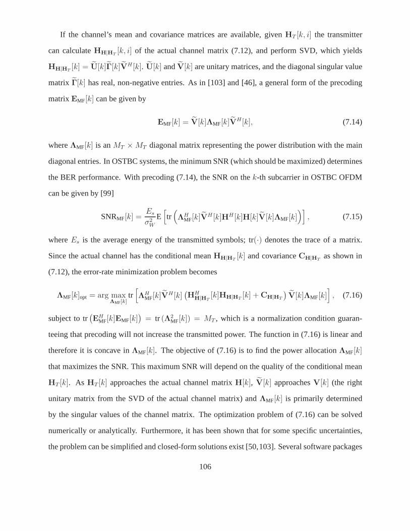
If the channel’s mean and covariance matrices are available, given HT [k, i] the transmitter
can calculateHH|HT[k, i] of the actual channel matrix (7.12), and perform SVD, which yields
HH|HT[k] = U[k]Γ[k]VH [k]. U[k] andV[k] are unitary matrices, and the diagonal singular value
matrix Γ[k] has real, non-negative entries. As in [103] and [46], a general form of the precoding
matrixEMF[k] can be given by
EMF[k] = V[k]ΛMF[k]VH[k], (7.14)
whereΛMF[k] is anMT × MT diagonal matrix representing the power distribution with the main
diagonal entries. In OSTBC systems, the minimum SNR (which should be maximized) determines
the BER performance. With precoding (7.14), the SNR on thek-th subcarrier in OSTBC OFDM
can be given by [99]
SNRMF[k] =Es
σ2W
E[tr(ΛH
MF[k]VH [k]HH [k]H[k]V[k]ΛMF[k])]
, (7.15)
whereEs is the average energy of the transmitted symbols; tr(·) denotes the trace of a matrix.
Since the actual channel has the conditional meanHH|HT[k] and covarianceCH|HT
as shown in
(7.12), the error-rate minimization problem becomes
ΛMF[k]opt = arg maxΛMF[k]
tr[ΛH
MF[k]VH [k](HH
H|HT[k]HH|HT
[k] + CH|HT
)V[k]ΛMF[k]
], (7.16)
subject to tr(EH
MF[k]EMF[k])
= tr (Λ2MF[k]) = MT , which is a normalization condition guaran-
teeing that precoding will not increase the transmitted power. The function in (7.16) is linear and
therefore it is concave inΛMF[k]. The objective of (7.16) is to find the power allocationΛMF[k]
that maximizes the SNR. This maximum SNR will depend on the quality of the conditional mean
HT [k]. As HT [k] approaches the actual channel matrixH[k], V[k] approachesV[k] (the right
unitary matrix from the SVD of the actual channel matrix) andΛMF[k] is primarily determined
by the singular values of the channel matrix. The optimization problem of (7.16) can be solved
numerically or analytically. Furthermore, it has been shown that for some specific uncertainties,
the problem can be simplified and closed-form solutions exist [50,103]. Several software packages
106

are available includingoptimization toolboxin MATLAB. For example, the functionfminconcan
be used, which offers efficient computation within a polynomial time.
7.3.2 Non-Linear Tomlinson-Harashima Precoding
Mean-feedback THP is proposed for SNR maximization in OSTBCMIMO OFDM downlink.
Ignoring the modulo device, the user’s feedback structure is equivalent toB−1[k], which can be
optimally designed as in (7.16),B[k]opt = E−1MF[k]opt. The effective channel isH[k]EMF[k] and ML
decoding is used at the receiver.
7.3.3 Covariance Precoding
When mean feedback is not available, the transmitter knows only the channel covariance matrix
(7.5). The PEP optimal covariance precoding introduced in Chapter 6 has the following form
ECPopt = VTΛCPVHT , (7.17)
whereVT is the rightMT × MT unitary matrix from SVD of the transmit-antenna correlation
matrixRT . The optimalΛCP can be found as discussed in Chapter 6.
The precoding design, involving either mean-feedback (7.16) or covariance precoding (7.17),
aims to minimize the system error rate, which is determined by SNR in OSTBC systems. Mean-
feedback precoding requires a high capacity feedback link,and is more sensitive to the channel
time variations and feedback delay. On the other hand, covariance precoding is a one-size-fits-
all solution which does not reflect the instantaneous and varying channel conditions. Covariance
precoding thus becomes less helpful when mean feedback can be accurate. Naturally, the quality
of the mean and covariance matrices used in precoding determines the achievable error probability.
7.4 Mean-Feedback Precoding or Covariance Precoding?
This section develops adaptive precoding which switches between mean-feedback (7.16) and co-
variance precoding (7.17). The maximum achievable SNR in both cases of (7.16) and (7.17) is
107

derived. The SNRs are calculated at the receiver and used as the selection metric, according to
which the precoding mode is chosen.
7.4.1 Maximum Achievable SNR
In a precoded OSTBC system, the maximized SNR onk-th subcarrier can be given by
SNR[k] =Es
σ2W
E[tr(HH [k]H[k]
)]=
Es
σ2W
tr[EH
opt
(HH
H|HT[k]HH|HT
[k] + CH|HT
)Eopt
]. (7.18)
If only the channel covariance matrix is available,CH|HT= CHH and the conditional mean is an
all-zero matrix. The SNR is then
SNRCP =Es
σ2W
tr(EH
CPoptCHHECPopt
). (7.19)
Substituting the covariance from (7.5) and the precoding matrix (7.17) into (7.19), the SNR of a
covariance precoded system is identical for all subcarriers, and becomes
SNRCP =Es
ξσ2W
tr(VTΛCPV
HT RTVTΛCPV
HT
)=
Es
ξσ2W
tr(Γ2
TΛ2CP
), (7.20)
whereRT = VTΓ2T VH
T . Clearly, the SNR of covariance precoded OSTBC OFDM is independent
of the index of subcarriers and the channel time variations.Different users will have identical
SNRs.
When mean feedback is available, the transmitter can calculate the equivalent channel matrix
HH|HT[k] and the SNR becomes
SNRMF[k] =Es
σ2W
tr(EH
MF[k]opt
(HH
H|HT[k]HH|HT
[k] + CH|HT
)EMF[k]opt
). (7.21)
Substituting (7.12) into (7.21), we have
SNRMF[k]
=Es
σ2W
tr(J2EH
MF[k]optRT
(RT + ΩeIMT
)−1HH
T [k]HT [k]RT
(RT + ΩeIMT
)−1EMF[k]opt
)
+Es
σ2W
tr(EH
MF[k]optRT
(RT + ΩeIMT
)−1 ((1 − J2)RT + ΩeIMT
)EMF[k]opt
).
(7.22)
108

The SNR for a mean-feedback precoded OSTBC system is a function ofJ . The precoding matrix
(7.16) is determined byHT [k] andRT in (7.12), whose accuracy is dominated byJ andΩe. SNR
in (7.21) is sensitive to the channel estimation errors and channel variations.
7.4.2 When to Use Mean Feedback
The SNRs are used as an indicator of the accuracy needed for mean feedback to give a lower
BER than covariance precoding. The accuracy of mean feedback can be gauged by its correlation
with the actual channel matrix, which primarily depends on the normalized autocovarianceJ and
estimation errorsΩe. There may exist certain values ofJ andΩe such that for some channel
realizations, the SNR of mean-feedback precoded systems given by (7.21) is greater than the SNR
of covariance precoded systems given by (7.19), i.e., mean feedback is helpful to achieve a lower
BER.
The mean-feedback precoding on the subcarrierk will outperform covariance precoding if
SNRMF[k] > SNRCP. (7.23)
A simple case of perfect CSIR is first considered, i.e., the estimate errorΩe = 0, ∀u. The mean
and variance of the actual channel are thus simplified to
HH|HT[k] = JHT [k], CH|HT
= (1 − J2)RT . (7.24)
Since from (7.14)EMF[k]opt = V[k]ΛMF[k]VH[k] andHHT [k]HT [k] = V[k]Γ2[k]VH [k], we have
SNRCP =Es
ξσ2W
tr(Γ2
T Λ2CP
)=
Es
ξσ2W
MT∑
m=1
γ2Tm
λ2CPm
,
SNRMF[k] =Es
σ2W
[J2tr
(Λ2
MF[k]Γ2[k])
+ (1 − J2)tr(ΛMF[k]VH [k]RT V[k]ΛMF[k]
)].
(7.25)
Eq. (7.23) can now be simplified to
f − c < J2(b − c), (7.26)
with f = 1ξ
∑MT
m=1 γ2Tm
λ2CPm
, b = tr(Λ2
MF[k]Γ2[k])
, andc = tr(ΛMF[k]VH [k]RT V[k]ΛMF[k]
).
109
The mode selection inequality (7.23) is the selection criterion used by our proposed adaptive
precoding scheme. The inequality depends onJ and Ωe, indicating when mean feedback has
better performance. The receiver calculates (7.19) and (7.21), and adaptively selects the precoding
mode which achieves a higher SNR. The same selection criterion is used for non-linear precoding.
The decision is sent back to the transmitter; one bit per subcarrier is required. The transmitter
allows different subcarriers to use different precoding modes. In an OFDMA system, different
subcarriers may be assigned to different users, and suffer from different channel conditions. When
the channel time variation is fast or the channel conditionsare poor, covariance precoding may
outperform mean-feedback precoding. The channel information then does not need to be sent back
to the transmitter, which significantly reduces the feedback requirements. If mean feedback can
be accurate, mean-feedback precoding may offer a higher SNR. The receiver can thus use mean
feedback to achieve a lower error rate.
To further reduce the feedback load, subcarrier grouping with interpolation can be introduced.
Higher-order interpolation design will lead to a better performance, but is more complex. There
is a trade-off among complexity, performance, and the feedback load. It thus remains a future
research topic to develop a simpler mode switching metric.
7.5 Simulation Results
This section presents simulation results to show how our proposed precoders improve the system
performance in a64-subcarrier OSTBC MIMO OFDM system with transmit-antenna correlations.
The vehicular B channel specified by ITU-R M. 1225 [73] is used. ML decoding is used at the
receiver. The BS and the user terminals know the correlationmatrix RT with the correlation
parameterζT = ∆dT
λ; the angle of arrival spread is assumed12, i.e.,∆ ≈ 0.2.
110
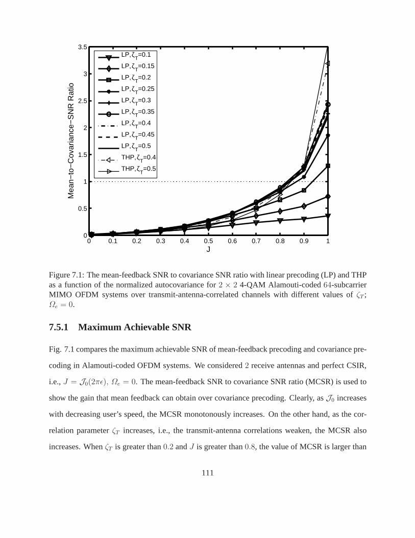
0 0.1 0.2 0.3 0.4 0.5 0.6 0.7 0.8 0.9 10
0.5
1
1.5
2
2.5
3
3.5
J
Mea
n−to
−C
ovar
ianc
e−S
NR
Rat
io
LP, ζT=0.1
LP, ζT=0.15
LP, ζT=0.2
LP, ζT=0.25
LP, ζT=0.3
LP, ζT=0.35
LP, ζT=0.4
LP, ζT=0.45
LP, ζT=0.5
THP, ζT=0.4
THP, ζT=0.5
Figure 7.1: The mean-feedback SNR to covariance SNR ratio with linear precoding (LP) and THPas a function of the normalized autocovariance for2 × 2 4-QAM Alamouti-coded64-subcarrierMIMO OFDM systems over transmit-antenna-correlated channels with different values ofζT ;Ωe = 0.
7.5.1 Maximum Achievable SNR
Fig. 7.1 compares the maximum achievable SNR of mean-feedback precoding and covariance pre-
coding in Alamouti-coded OFDM systems. We considered2 receive antennas and perfect CSIR,
i.e.,J = J0(2πǫ), Ωe = 0. The mean-feedback SNR to covariance SNR ratio (MCSR) is used to
show the gain that mean feedback can obtain over covariance precoding. Clearly, asJ0 increases
with decreasing user’s speed, the MCSR monotonously increases. On the other hand, as the cor-
relation parameterζT increases, i.e., the transmit-antenna correlations weaken, the MCSR also
increases. WhenζT is greater than0.2 andJ is greater than0.8, the value of MCSR is larger than
111
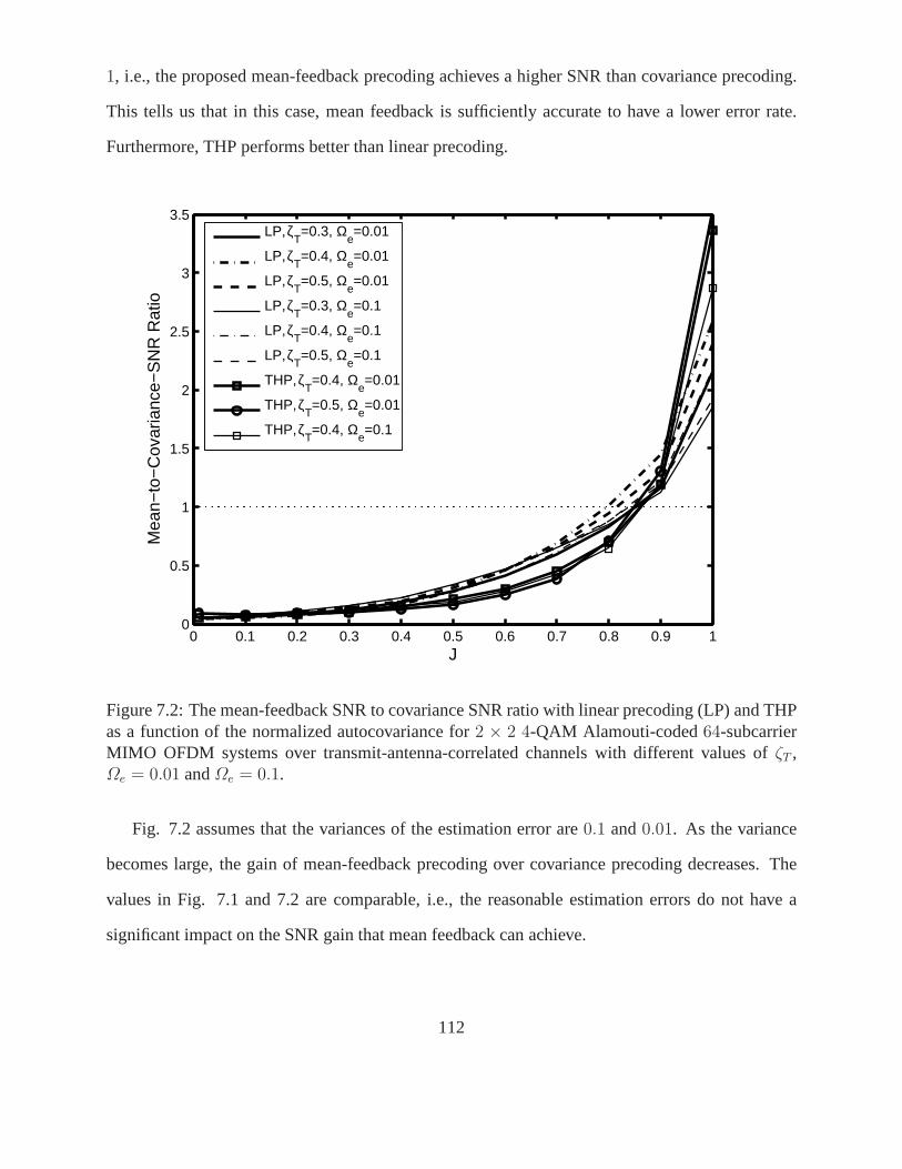
1, i.e., the proposed mean-feedback precoding achieves a higher SNR than covariance precoding.
This tells us that in this case, mean feedback is sufficientlyaccurate to have a lower error rate.
Furthermore, THP performs better than linear precoding.
0 0.1 0.2 0.3 0.4 0.5 0.6 0.7 0.8 0.9 10
0.5
1
1.5
2
2.5
3
3.5
J
Mea
n−to
−C
ovar
ianc
e−S
NR
Rat
io
LP, ζT=0.3, Ω
e=0.01
LP, ζT=0.4, Ω
e=0.01
LP, ζT=0.5, Ω
e=0.01
LP, ζT=0.3, Ω
e=0.1
LP, ζT=0.4, Ω
e=0.1
LP, ζT=0.5, Ω
e=0.1
THP, ζT=0.4, Ω
e=0.01
THP, ζT=0.5, Ω
e=0.01
THP, ζT=0.4, Ω
e=0.1
Figure 7.2: The mean-feedback SNR to covariance SNR ratio with linear precoding (LP) and THPas a function of the normalized autocovariance for2 × 2 4-QAM Alamouti-coded64-subcarrierMIMO OFDM systems over transmit-antenna-correlated channels with different values ofζT ,Ωe = 0.01 andΩe = 0.1.
Fig. 7.2 assumes that the variances of the estimation error are 0.1 and0.01. As the variance
becomes large, the gain of mean-feedback precoding over covariance precoding decreases. The
values in Fig. 7.1 and 7.2 are comparable, i.e., the reasonable estimation errors do not have a
significant impact on the SNR gain that mean feedback can achieve.
112
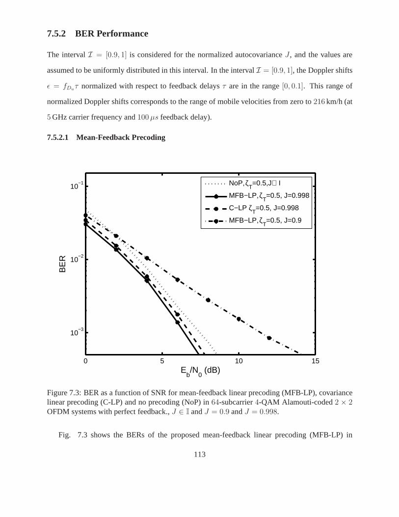
7.5.2 BER Performance
The intervalI = [0.9, 1] is considered for the normalized autocovarianceJ , and the values are
assumed to be uniformly distributed in this interval. In theintervalI = [0.9, 1], the Doppler shifts
ǫ = fDuτ normalized with respect to feedback delaysτ are in the range[0, 0.1]. This range of
normalized Doppler shifts corresponds to the range of mobile velocities from zero to216 km/h (at
5 GHz carrier frequency and100 µs feedback delay).
7.5.2.1 Mean-Feedback Precoding
0 5 10 15
10−3
10−2
10−1
Eb/N
0 (dB)
BE
R
NoP, ζ
T=0.5,J∈ I
MFB−LP, ζT=0.5, J=0.998
C−LP ζT=0.5, J=0.998
MFB−LP, ζT=0.5, J=0.9
Figure 7.3: BER as a function of SNR for mean-feedback linearprecoding (MFB-LP), covariancelinear precoding (C-LP) and no precoding (NoP) in64-subcarrier4-QAM Alamouti-coded2 × 2OFDM systems with perfect feedback.,J ∈ I andJ = 0.9 andJ = 0.998.
Fig. 7.3 shows the BERs of the proposed mean-feedback linearprecoding (MFB-LP) in
113
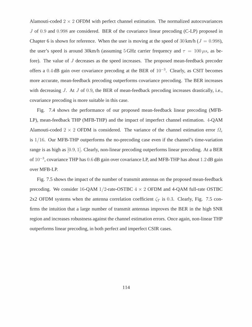
Alamouti-coded2 × 2 OFDM with perfect channel estimation. The normalized autocovariances
J of 0.9 and0.998 are considered. BER of the covariance linear precoding (C-LP) proposed in
Chapter 6 is shown for reference. When the user is moving at the speed of30 km/h (J = 0.998),
the user’s speed is around 30km/h (assuming5 GHz carrier frequency andτ = 100 µs, as be-
fore). The value ofJ decreases as the speed increases. The proposed mean-feedback precoder
offers a0.4 dB gain over covariance precoding at the BER of10−3. Clearly, as CSIT becomes
more accurate, mean-feedback precoding outperforms covariance precoding. The BER increases
with decreasingJ . At J of 0.9, the BER of mean-feedback precoding increases drastically, i.e.,
covariance precoding is more suitable in this case.
Fig. 7.4 shows the performance of our proposed mean-feedback linear precoding (MFB-
LP), mean-feedback THP (MFB-THP) and the impact of imperfect channel estimation.4-QAM
Alamouti-coded2 × 2 OFDM is considered. The variance of the channel estimation error Ωe
is 1/16. Our MFB-THP outperforms the no-precoding case even if the channel’s time-variation
range is as high as[0.9, 1]. Clearly, non-linear precoding outperforms linear precoding. At a BER
of 10−3, covariance THP has0.6 dB gain over covariance LP, and MFB-THP has about1.2 dB gain
over MFB-LP.
Fig. 7.5 shows the impact of the number of transmit antennas on the proposed mean-feedback
precoding. We consider16-QAM 1/2-rate-OSTBC4 × 2 OFDM and 4-QAM full-rate OSTBC
2x2 OFDM systems when the antenna correlation coefficientζT is 0.3. Clearly, Fig. 7.5 con-
firms the intuition that a large number of transmit antennas improves the BER in the high SNR
region and increases robustness against the channel estimation errors. Once again, non-linear THP
outperforms linear precoding, in both perfect and imperfect CSIR cases.
114
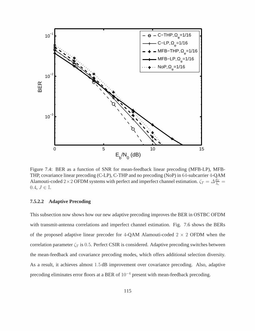
0 5 10 15
10−3
10−2
10−1
Eb/N
0 (dB)
BE
R
C−THP, Ω
e=1/16
C−LP, Ωe=1/16
MFB−THP, Ωe=1/16
MFB−LP, Ωe=1/16
NoP, Ωe=1/16
Figure 7.4: BER as a function of SNR for mean-feedback linearprecoding (MFB-LP), MFB-THP, covariance linear precoding (C-LP), C-THP and no precoding (NoP) in64-subcarrier4-QAMAlamouti-coded2×2 OFDM systems with perfect and imperfect channel estimation. ζT = ∆dT
λc=
0.4, J ∈ I.
7.5.2.2 Adaptive Precoding
This subsection now shows how our new adaptive precoding improves the BER in OSTBC OFDM
with transmit-antenna correlations and imperfect channelestimation. Fig. 7.6 shows the BERs
of the proposed adaptive linear precoder for4-QAM Alamouti-coded2 × 2 OFDM when the
correlation parameterζT is 0.5. Perfect CSIR is considered. Adaptive precoding switches between
the mean-feedback and covariance precoding modes, which offers additional selection diversity.
As a result, it achieves almost1.5 dB improvement over covariance precoding. Also, adaptive
precoding eliminates error floors at a BER of10−4 present with mean-feedback precoding.
115
0 4 8 12 16 2010
−5
10−4
10−3
10−2
10−1
Eb/N
0 (dB)
BE
RMFB−LP, M
T=2,Ω
e=0
MFB−LP, MT=2,Ω
e=1/16
MFB−LP, MT=4,Ω
e=0
MFB−LP, MT=4,Ω
e=1/16
MFB−THP, MT=4,Ω
e=0
MFB−THP, MT=4,Ω
e=1/16
NoP, MT=4,Ω
e=0
Figure 7.5: BER as a function of SNR for mean-feedback linearprecoding (MFB-LP), MFB-THP and no precoding (NoP) in64-subcarrier16-QAM 1/2-rate-OSTBC OFDM and4-QAMAlamouti-coded OFDM systems with perfect and imperfect channel estimation.ζT = ∆dT
λc= 0.3,
MR = 2, J ∈ I.
Fig. 7.7 shows the BERs of our proposed adaptive THP in16-QAM 1/2-rate OSTBC4-
transmit-antenna OFDM with perfect and imperfect CSIR whenζT is 0.4. Adaptive precoding
individually outperforms MFB-THP and C-THP for both perfect and imperfect channel estimation
cases; non-linear THP outperforms linear precoding.
7.6 Summary
For a general transmit-antenna-correlated, frequency-selective fading MIMO channel model in an
OSTBC OFDM downlink system with estimation errors and feedback delay, the conditional mean
116
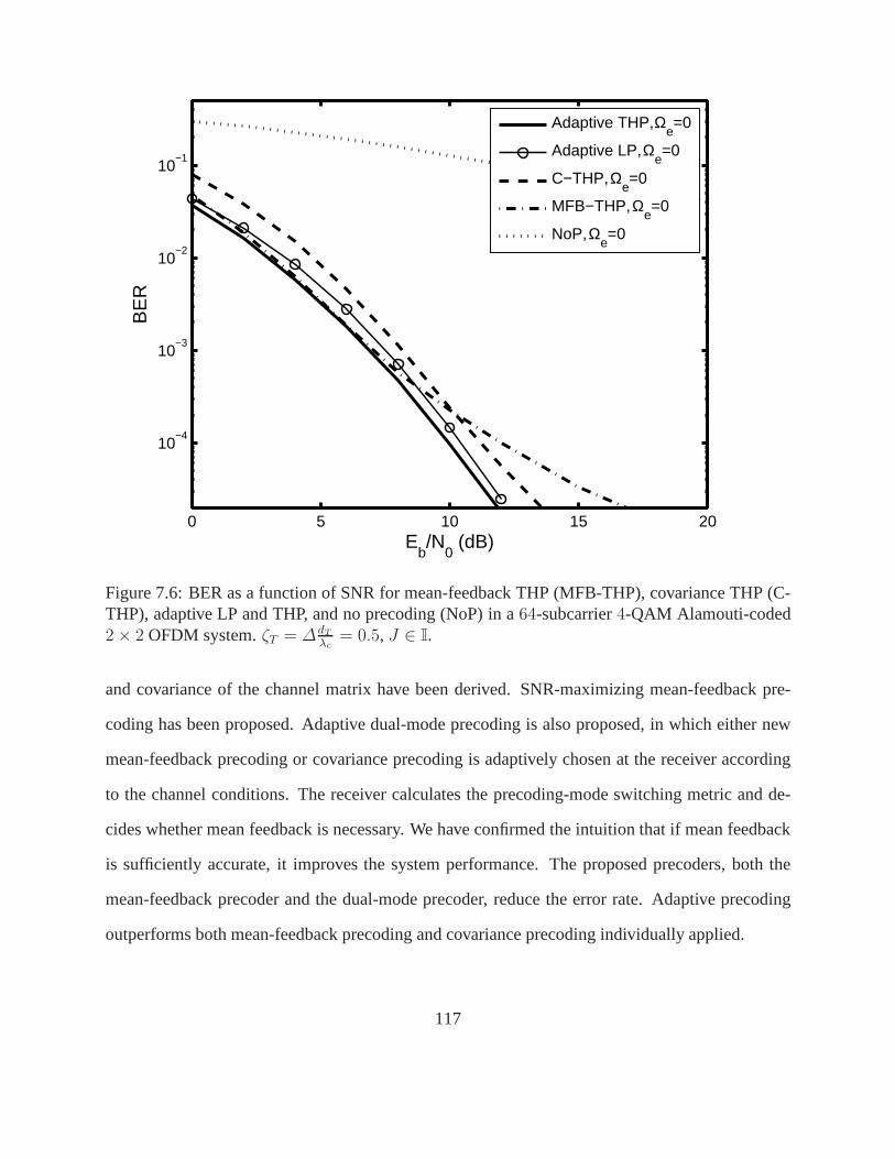
0 5 10 15 20
10−4
10−3
10−2
10−1
Eb/N
0 (dB)
BE
R
Adaptive THP, Ω
e=0
Adaptive LP, Ωe=0
C−THP, Ωe=0
MFB−THP, Ωe=0
NoP, Ωe=0
Figure 7.6: BER as a function of SNR for mean-feedback THP (MFB-THP), covariance THP (C-THP), adaptive LP and THP, and no precoding (NoP) in a64-subcarrier4-QAM Alamouti-coded2 × 2 OFDM system.ζT = ∆dT
λc= 0.5, J ∈ I.
and covariance of the channel matrix have been derived. SNR-maximizing mean-feedback pre-
coding has been proposed. Adaptive dual-mode precoding is also proposed, in which either new
mean-feedback precoding or covariance precoding is adaptively chosen at the receiver according
to the channel conditions. The receiver calculates the precoding-mode switching metric and de-
cides whether mean feedback is necessary. We have confirmed the intuition that if mean feedback
is sufficiently accurate, it improves the system performance. The proposed precoders, both the
mean-feedback precoder and the dual-mode precoder, reducethe error rate. Adaptive precoding
outperforms both mean-feedback precoding and covariance precoding individually applied.
117
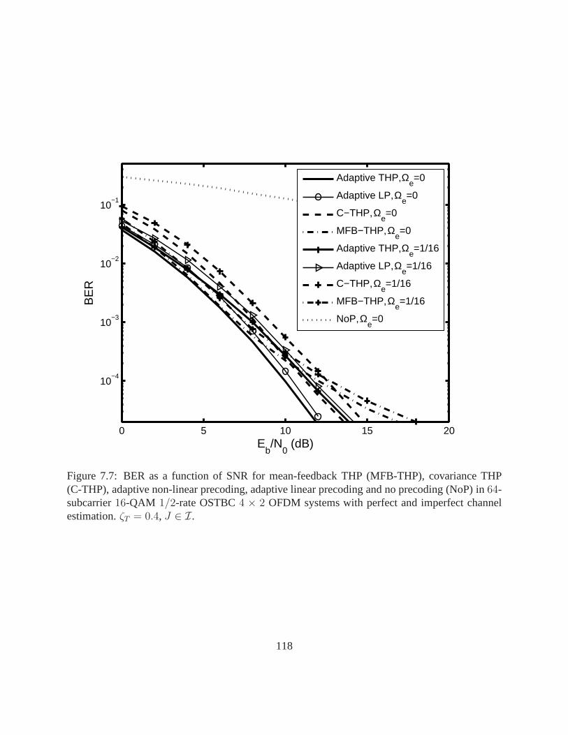
0 5 10 15 20
10−4
10−3
10−2
10−1
Eb/N
0 (dB)
BE
R
Adaptive THP, Ω
e=0
Adaptive LP, Ωe=0
C−THP, Ωe=0
MFB−THP, Ωe=0
Adaptive THP, Ωe=1/16
Adaptive LP, Ωe=1/16
C−THP, Ωe=1/16
MFB−THP, Ωe=1/16
NoP, Ωe=0
Figure 7.7: BER as a function of SNR for mean-feedback THP (MFB-THP), covariance THP(C-THP), adaptive non-linear precoding, adaptive linear precoding and no precoding (NoP) in64-subcarrier16-QAM 1/2-rate OSTBC4 × 2 OFDM systems with perfect and imperfect channelestimation.ζT = 0.4, J ∈ I.
118
Chapter 8
Conclusions and Future Work
8.1 Conclusions and Summary of Contributions
In this thesis, we have developed transmitter precoding schemes to mitigate ICI in closed-loop
MIMO OFDM and multiuser MIMO OFDM downlink. We have also proposed precoders to reduce
BER in MIMO OFDM systems with spatial correlations.
In Chapter 3, ICI reduction in closed-loop MIMO OFDM has beenstudied. A non-linear
TH precoder has been proposed for closed-loop MIMO OFDM withfrequency offsets. It has
been shown that the ICI coefficient matrix is approximately unitary. Exploiting this property,
the proposed TH precoder only needs partial CSI, channel gain matrix, at the transmitter. The
knowledge of frequency offset hence does not need to be fed back to the transmitter, which reduces
the feedback load and avoids possible frequency-offset transmitter mismatch. The proposed THP-
OFDM significantly reduces the BER increase due to frequencyoffset. In addition, it has been
shown that proposed THP also works well for spatially-correlated MIMO channels.
In multiuser OFDM downlink, if only post-processing techniques are used at each user’s re-
ceiver to reduce MUI due to spatial multiplexing, the processing at the user level can hence be
quite complex or even impossible. On the other hand, since the users are decentralized, the ap-
plication of only transmitter precoding for ICI and MUI mitigation, which requires full CSI at the
BS, is problematic. Chapter 4 has thus proposed two-stage transmitter/receiver processing to re-
duce ICI and MUI in downlink multiuser OFDM with multiple transmit antennas. The first stage
119
employs a TH precoder at the BS to mitigate multiuser interference in a spatial MIMO channel.
The second stage applies a low-complexity linear MMSE equalizer to suppress ICI and MUI due
to frequency offset at each user’s receiver. The MMSE equalizer has low complexity due to the
unitary property of the ICI matrix. Our proposed equalizer significantly reduces the BER increase
due to frequency offset. Sending frequency offset information to the BS does not offer additional
BER improvement.
In the previous two chapters, to apply precoding channel gains are needed at the transmitter.
Chapter 5 has developed a LFB-TH precoder for closed-loop multiuser MIMO OFDM with fre-
quency offset. Frequency offsets have been shown to have no impact on precoding, and hence
precoding on per-subcarrier basis is possible. The limited-feedback codebook design algorithm
is proposed, and the precoding matrix selection criteria are derived. With the limited-feedback
feature, the precoding matrix is determined at the receiver, i.e., the CSI is not required at the
transmitter. Since only a limited number of bits needs to be fed back, a low feedback rate can be
maintained, which is desired for closed-loop system design. The proposed LFB-THP significantly
reduces the BER degradation due to frequency offset in SM systems, OSTBC systems, and OFDM
with spatial correlations.
MIMO OFDM systems are also constrained by limited antenna spacing, which may lead to
correlations among antennas. The antenna correlation always reduces the system data rate and
increases the error rate. Furthermore, the original space-time MIMO techniques have poor perfor-
mance if they are directly employed over antenna-correlated channels. In Chapter 6, covariance-
based linear precoding and non-linear Tomlinson-Harashima precoding have been developed for
a MIMO OFDM wireless link over transmit-antenna and path-correlated channels. The impact of
path correlations on the PEP is analyzed. Closed-form, waterfilling-based linear and non-linear
precoders that minimize the worst-case PEP in OSTBC OFDM have been derived. An adaptive
strategy that switches between precoded SM OFDM and precoded OSTBC OFDM has also been
proposed. The system is designed to achieve a low BER with a target fixed transmission rate.
120
For each subcarrier, the minimum Euclidean distance of the received codebook is used to select
between SM and OSTBC. A lower complexity selection criterion is also derived. To reduce the
number of feedback bits, mode selection could be based on groups of neighboring subcarriers. The
proposed precoders significantly reduce the impact of antenna and path-correlated channels; non-
linear precoders perform better than linear precoders. Theadaptive strategy outperforms either SM
or OSTBC individually in terms of the BER.
Taking estimation errors and feedback delay into consideration, Chapter 7 has derived the con-
ditional mean and covariance of the channel matrix in an OSTBC MIMO OFDM downlink sys-
tem over a general transmit-antenna-correlated, frequency-selective fading MIMO channel model.
SNR-maximizing mean-feedback precoding has been developed. This chapter has also proposed
adaptive dual-mode precoding, in which either new mean-feedback precoding or covariance pre-
coding is adaptively chosen at the receiver according to thechannel conditions. The receiver
calculates the precoding-mode switching metric and decides whether mean feedback is necessary.
We have confirmed the intuition that if mean feedback is sufficiently accurate, it improves the sys-
tem performance. The proposed precoders, both the mean-feedback precoder and the dual-mode
precoder, reduce the error rate. Adaptive precoding outperforms both mean-feedback precoding
and covariance precoding applied individually.
Our techniques have good performance, low feedback requirements and low complexity, which
are desirable features in the future wireless systems.
8.2 Future Work
Future research may be carried out in the following three major directions.
8.2.1 Complexity Reduction
There is a trade-off between the amount of CSI fedback to the transmitter and the gain available
from the using CSI. For precoding over MIMO OFDM systems, thefeedback may need to be
121
on a subcarrier basis. To reduce the total amount of the feedback information, the correlation of
precoding matrices on adjacent subcarriers can be explored. The significant correlations between
adjacent subcarriers lead to substantial correlation between the precoders corresponding to neigh-
boring subcarriers. The neighboring subcarriers can therefore be combined into a group and use the
precoding matrix corresponding to the center subcarrier for all the subcarriers in the group. Since
the subcarriers near the group boundary may experience performance degradation, an interpolation
scheme can be used to improve the performance due to grouping. When a better performance is
required, a smaller group can be used, i.e., more bits can be sent to the transmitter. Higher-order
interpolation design will lead to a better performance, butis more complicated. It thus remains
a future research topic to address the trade-off among the complexity of the interpolation design,
performance, and the feedback load.
8.2.2 Robust Precoding in Multiuser OFDM
Precoding schemes need instantaneous CSI or long-term statistics at the transmitter. Accurate
CSIT requires perfect channel estimation and time-invariant channel conditions. However, estima-
tion errors introduce channel mismatch at both the transmitter and the receiver, i.e., the channel
information which is available at the transmitter and the receiver differs from the actual channel at
the time of transmission. The time variations and feedback noise lead to unbalanced CSI between
the transmitter and the receiver and make CSIT mismatch moreserious. As the CSI mismatch
becomes severe, the performance of precoders significantlydegrades. Thus, there is a need to
solve the problem of imperfect and mismatched CSI at the transmitter and the receiver. A new
precoder which is robust against estimation errors and feedback delay for multiuser OFDM over
spatially-correlated MIMO channels is of interest to investigate. A key feature of future wireless
system design is the quality of CSI at the transmitter and related feedback requirements. The robust
precoder with limited feedback is also of interest to explore.
122

8.2.3 Precoding Design in Medium Access Control Layer
A successful broadband wireless system design must includean efficient co-designed MAC layer
for reliable link performance over the wireless channel. The MAC layer design will involve auto-
matic retransmission and fragmentation mechanism, where the transmitter breaks up packets into
smaller sequentially sent subpackects. If a subpacket is received incorrectly, the transmitter re-
quests re-transmission of it. This automatic retransmission request (ARQ) algorithm introduces
time diversity (delay) into the system, which may help to recover the transmitted signals from
noise, interference and fades. It is interesting to developfundamental diversity-multiplexing-delay
tradeoffs of a MIMO retransmission channel, and have insights into benefits of ARQ schemes for
future multiuser MIMO OFDM systems.
123

Appendix
Proof of Unitary Property of the ICI Coefficient Matrix
For simplicity, in the following proof the subscriptu, v of (3.8) is omitted.
As N → ∞, for 1 ≤ k < N2
andk ≫ ε, we have
S[k] ≈ sin π(ε + k)
π(ε + k)ejπ(ε+k) =
sin πε
π(ε + k)ejπε ≈ sin πε
πkejπε. (1)
Note that whenk = 0, S[0] ≈ sinπεπε
ejπε. From (3.5), one can immediately getS[N − k] = S[−k].
The proof includes two steps. Firstly, the diagonal entriesof Z = SHS, Z(m, m), are shown to
approach unity. Secondly, off-diagonal terms are proven tovanish, i.e,|Z(m,m)|2|Z(m,n)|2 → ∞ asε → 0.
SinceS[N − k] = S[−k], them, nth entry ofZ is hence given by
Z(m, n) =
N−1−m∑
k=−m
S[k]S∗[k + m − n] =
N−1∑
k=0
S[k]S∗[k + m − n]. (2)
Let us first consider diagonal entries ofZ. Whenm = n, Z(m, m) are the diagonal entries
Z(m, m) =N−1∑
k=0
S[k]S∗[k] = S[0]S∗[0] +N−1∑
k=1
S[k]S∗[k] =sin2 πε
(πε)2+
sin2 πε
π2
N−1∑
k=1
1
k2, (3)
where the second term in (3) is the Riemann’s Zeta function, i.e.,∑∞
k=11k2 = π2
6[108]. WhenN is
sufficiently large, the terms of1/k2, ∀ k ≥ N , can be omitted. We thus have∑N−1
k=11k2 ≈ π2
6. The
(3) can be approximated asZ(m, m) ≈ sin2(πε)[
1(πε)2
+ 16
], andlimε→0 Z(m, m) = 1.
Now the off-diagonal terms are considered. Whenm 6= n, sinceZ is a Hermitian matrix, i.e.,
Z(m, n) = Z∗(n, m), it is sufficient to consider the case ofm > n:
Z(m, n) = S[0]S∗[m − n] +N−1∑
k=1
S[k]S∗[k + m − n]
=sin2 πε
π2
[1
ε(m − n)
]+
sin2 πε
π2
N−1∑
k=1
1
k(k + m − n)
=sin2 πε
π2(m − n)
(1
ε+
N−1∑
k=1
1
k−
N−1∑
k=1
1
k + m − n
), ∀m > n.
(4)
124

Obviously, only whenm−n = 1, Z(m, n) can reach the maximum valueZ(m, n)max = sin2 πεπ2
(1ε
+ 1 − 1N
).
The least power ratio of the diagonal entries to the non-diagonal entries can be given by
K =Z2(m, m)
Z2(m, n)>
(1 + π2ε2
6
ε2 + ε
)2
. (5)
As ε → 0, K → 1ε2 . The value of the normalized frequency offset has the dominant effect on
the power ratioK. For instance, whenε = 0.3, K > 11.1, which means over90% energy is
concentrated on the main diagonal.K rapidly increases whenε decreases. Therefore, the ICI
coefficient matrixScan be approximated as a unitary matrix.
125
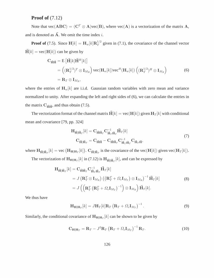
Proof of (7.12)
Note that vec(ABC) = (CT ⊗ A)vec(B), where vec(A) is a vectorization of the matrixA,
and is denoted as~A. We omit the time indexi.
Proof of (7.5). SinceH[k] = Hw[k]R1/2T given in (7.1), the covariance of the channel vector
~H[k] = vec(H[k]) can be given by
C~H~H = E[~H[k]~HH [k]
]
=((R
1/2T )T ⊗ IMR
)vec(Hw[k])vecH(Hw[k])
((R
1/2T )H ⊗ IMR
)
= RT ⊗ IMR,
(6)
where the entries ofHw[k] are i.i.d. Gaussian random variables with zero mean and variance
normalized to unity. After expanding the left and right sides of (6), we can calculate the entries in
the matrixC~H~H, and thus obtain (7.5).
The vectorization format of the channel matrix~H[k] = vec(H[k]) givenHT [k] with conditional
mean and covariance [79, pp. 324]
H~H|~HT[k] = C~H~HT
C−1~HT
~HT
~HT [k]
C~H|~HT= C~H~H −C~H~HT
C−1~HT
~HT
C~HT~H,
(7)
whereH~H|~HT[k] = vec
(HH|HT
[k]). C~H|~HT
is the covariance of the vec(H[k]) given vec(HT [k]).
The vectorization ofHH|HT[k] in (7.12) isH~H|~HT
[k], and can be expressed by
H~H|~HT[k] = C~H~HT
C−1~HT
~HT
~HT [k]
= J(RT
T ⊗ IMR
) ((RT
T + ΩeIMT
)⊗ IMR
)−1 ~HT [k]
= J((
RTT
(RT
T + ΩeIMT
)−1)⊗ IMR
)~HT [k].
(8)
We thus have
HH|HT[k] = JHT [k]RT
(RT + ΩeIMT
)−1. (9)
Similarly, the conditional covariance ofHH|HT[k] can be shown to be given by
CH|HT= RT − J2RT
(RT + ΩeIMT
)−1RT . (10)
126
Bibliography
[1] D. Gesbert, M. Shafi, D. Shiu, P. J. Smith, and A. Naguib, “From theory to practice: an
overview of MIMO space-time coded wireless systems,”IEEE J. Select. Areas Commun.,
vol. 21, no. 3, pp. 281–301, Apr. 2003.
[2] A. J. Paulraj, D. A. Gore, R. U. Nabar, and H. Bolcskei, “An overview of MIMO com-
munications - a key to Gigabit wireless,”Proc. of IEEE, invited paper, vol. 92, no. 2, pp.
198–218, Feb. 2004.
[3] R. T. Derryberry, S. D. Gray, D. M. Ionescu, G. Mandyam, and B. Raghothaman, “Transmit
diversity in 3G CDMA systems,”IEEE Commun. Magazine, vol. 40, no. 4, pp. 68–75, Apr.
2002.
[4] A. S. Dakdouki, V. L. Banket, N. K. Mykhaylov, and A. A. Skopa, “Downlink processing
algorithms for multi-antenna wireless communications,”IEEE Commun. Magazine, vol. 43,
no. 1, pp. 122–127, Jan. 2005.
[5] G. L. Stuber, J. R. Barry, S. W. McLaughlin, Y. G. Li, M. A.Ingram, and T. G. Pratt, “Broad-
band MIMO-OFDM wireless communications,”Proc. of IEEE, invited paper, vol. 92, no. 2,
pp. 271–294, Feb. 2004.
[6] H. Yang, “A road to future broadband wireless access: MIMO-OFDM-based air interface,”
IEEE Commun. Magazine, vol. 43, no. 1, pp. 53–60, Jan. 2005.
127
[7] N. Seshadri and J. H. Winters, “Two signaling schemes forimproving the error performance
of frequency-division-duplex (FDD) transmission system using transmitter antenna diver-
sity,” in Proc. IEEE VTC’93-Spring, vol. 1, Secaucus, NJ, May 1993, pp. 508–511.
[8] D. Gore, S. Sundhu, and A. J. Paulraj, “Delay diversity codes for frequency selective chan-
nels,” inProc. IEEE ICC, New York, NY, May 2002, pp. 1949–1953.
[9] V. Tarokh, H. Jafarkhani, and A. R. Calderbank, “Space-time codes for high data rate wire-
less communication: performance criterion and code construction,” IEEE Trans. Inform.
Theory, vol. 44, no. 2, pp. 744–765, Mar. 1998.
[10] Cenk Kose and Richard D. Wesel, “Universal space time trellis codes ,”IEEE Trans. Inform.
Theory, vol. 49, no. 10, pp. 2717–2727, Oct. 2003.
[11] S. M. Alamouti, “A simple transmit diversity techniquefor wireless communications,”IEEE
J. Select. Areas Commun., vol. 16, no. 8, pp. 1451–1458, Oct. 1998.
[12] V. Tarokh, H. Jafarkhani, and A. R. Calderbank, “Space-time block codes from orthogonal
designs,”IEEE Trans. Inform. Theory, vol. 45, no. 5, pp. 1456–1467, Jul. 1999.
[13] J. Mietzner, P. A. Hoeher, and M. Sandell,, “Compatibleimprovement of the GSM/EDGE
system by means of space-time coding techniques,”IEEE Trans. Wireless Commun., vol. 2,
no. 4, pp. 690–702, 2003.
[14] Telecommunications Industry Association,TIA/EIA Physical Layer Standard for cdma2000
Spread Spectrum Systems, Revision C. TIA/EIA/IS-2000-2.
[15] 3rd Generation Partnership Project,Technical Specification Group Radio Access Network:
Physical Channels and Mapping of Transport Channels onto Physical Channels (FDD)
(release 1999). v.3.2.0, 2000-2003.
128
[16] P. W. Wolniansky, G. J. Foschini, G. D. Golden, and R. A. Valenzuela, “V-BLAST: an
architecture for realizing very high data rates over the rich-scattering wireless channel,” in
Proc. ISSSE’98, invited paper, vol. 6, Pisa, Italy, 1998.
[17] G. J. Foschini and M. J. Gans, “On limits of wireless communication in a fading environment
when using multiple antennas,”Wireless Personal Commun., vol. 6, no. 3, pp. 311–335, Mar.
1998.
[18] G. J. Foschini, “Layered space-time architecture for wireless communication in a fading
environment when using multiple antennas,”Bell Lab. Technol. J., pp. 41–59, Autumn 1996.
[19] M. Sellathurai and S. Haykin, “Turbo-BLAST for high-speed wireless communications:
theory and experiments,”IEEE Trans. Signal Processing, vol. 50, no. 10, pp. 2538–2546,
Oct. 2002.
[20] L. Zheng and D. N. C. Tse, “Diversity and multiplexing: afundamental tradeoff in multiple-
antenna channels,”IEEE Inform. Theory, vol. 49, no. 5, pp. 1073–1096, May 2003.
[21] LAN/MAN Standards Committee,Wireless LAN Medium Access Control (MAC) and Phys-
ical Layer (PHY) Specifications: Amendment 4: Enhancementsfor Higher Throughput.
Dallas, Tx: IEEE Std. 802.11n, Nov. 2008.
[22] A. Bria, F. Gessler, O. Queseth, R. Stridh, M. Unbehaun,J. Wu, and J. Zander, “4th-
generation wireless infrastructures: scenarios and research challenges,”IEEE Personal
Commun., vol. 8, no. 6, pp. 25–31, Dec. 2001.
[23] R. W. Chang, “Synthesis of band-limited orthogonal signals for multichannel data transmis-
sion,” Bell Syst. Tech. J., vol. 45, pp. 1775–1796, Dec. 1966.
[24] B. R. Saltzberg, “Performance of an efficient parallel data transmission system,”IEEE
Trans. Commun. Technol., vol. COM-15, pp. 805–811, Dec. 1967.
129
[25] M. L. Doelz, E. T. Heald, and D. L. Martin, “Binary data tranmission techniques for linear
systems,” inProc. IRE, vol. 45, May 1957, pp. 656–661.
[26] M. S. Zimmerman and A. L. Kirsch, “The AN/GSC-10 (KATHRYN) variable rate data
modem for HF radio,”IEEE Trans. Commun. Technol., vol. COM-15, no. 2, pp. 197–204,
Apr. 1967.
[27] S. B. Weinstein and P. M. Ebert, “Data transmission by frequency division multiplexing
using the discrete Fourier transform,”IEEE Trans. Commun. Technol., vol. COM-19, no. 5,
pp. 628–634, Oct. 1971.
[28] L. J. Cimini, “Analysis and simulation of a digital mobile channel using orthogonal
frequency-division multiplexing,”IEEE Trans. Commun., vol. 33, no. 7, pp. 665–675, 1985.
[29] J. A. C. Bingham, “Multicarrier modulation for data transmission: an idea whose time has
come,”IEEE Commun. Magazine, pp. 5–14, May 1990.
[30] P. S. Chow, J. C. Tu, and J. M. Cioffi, “Performance evaluation of a multichannel transceiver
system for ADSL and VHDSL services,”IEEE J. Select. Areas Commun., vol. 9, no. 6, pp.
909–919, Aug. 1991.
[31] European Telecommunications Standard Institute,Radio Broadcasting Systems; Digital Au-
dio Broadcasting (DAB) to mobile, portable and fixed receivers, 2nd ed. Sophia Antipolis,
France: ETS 300401, May 1997.
[32] ——, Digital Video Broadcasting: Frame Structure, Channel Coding, and Modulation for
Digital Terrestrial Television. Sophia Antipolis, France: ETS EN300-744, Aug. 1997.
[33] T. de Couasnon, R. Monnier, and J. B. Rault, “OFDM for digital TV broadcasting,”Signal
Processing, vol. 39, no. 1-2, pp. 1–31, Sep. 1994.
130
[34] LAN/MAN Standards Committee,Wireless LAN Medium Access Control (MAC) and Phys-
ical Layer (PHY) Specifications: High-Speed Physical Layerin the 5 GHz Band. Piscat-
away, NJ: IEEE Std. 802.11a, Sep. 1999.
[35] ——, Local and Metropolitan Area Networks-Part 16, Air Interface for Fixed Broadband
Wireless Access Systems. Piscataway, NJ: IEEE Std. 802.16a, Apr. 2002.
[36] R. V. Nee and R. Prasad,OFDM for Wireless Multimedia Communication. London: Artech
House Publishers, Apr. 2000.
[37] P. Robertson and S. Kaiser, “Analysis of the loss of orthogonality through Doppler spread
in OFDM systems,” inProc. IEEE Globecom’99, vol. 1, Rio de Janeiro, Brazil, Dec. 1999,
pp. 701–706.
[38] H. Nikookar and R. Prasad, “On the sensitivity of multicarrier transmission over multipath
channels to phase noise and frequency offset,” inProc. IEEE PIMRC’96, vol. 1, Taipei,
Taiwan, Oct. 1996, pp. 68–72.
[39] M. Russell and G. L. Stuber, “Interchannel interference analysis of OFDM in a mobile
environment,” inProc. IEEE VTC’95-Spring, vol. 2, Chicago, IL, Jul. 1995, pp. 820–824.
[40] T. Pollet, M. V. Bladel, and M. Moeneclaey, “BER sensitivity of OFDM systems to carrier
frequency offset and Wiener phase noise,”IEEE Trans. Commun., vol. 43, no. 2/3/4, pp.
191–193, Feb./Mar./Apr. 1995.
[41] Israel Koffman and Vincentzio Roman, “Broadband wireless access solutions based on
OFDM access in IEEE 802.16,”IEEE Commun. Magazine, vol. 40, no. 4, pp. 96–103,
Apr. 2002.
[42] P. W. C. Chan and R. S. Cheng, “Capacity maximization forzero-forcing MIMO-OFDMA
downlink systems with multuser diversity ,”IEEE Trans. Wireless Commun., vol. 6, no. 5,
pp. 1880–1889, May 2007.
131
[43] WiMAX Forum, “Mobile WiMAX C part I: A technical overview and performance evalua-
tion,” [online] http://www.wimaxforum.org/technology.
[44] D. J. Love and R. W. Heath Jr., “What is the value of limited feedback for MIMO channels?”
IEEE Commun. Magazine, vol. 42, no. 10, pp. 54–59, Oct. 2004.
[45] I. E. Telatar, “Capacity of multi-antenna Gaussian channels,” Eur. Trans. Telecomm. ETT,
vol. 10, no. 6, pp. 585–596, Nov. 1999.
[46] A. Scaglione, P. Stoica, S. Barbarossa, G. B. Giannakis, and H. Sampath, “Optimal designs
for space-time linear precoders and decoders,”IEEE Trans. Signal Processing, vol. 50, no. 5,
pp. 1051–1064, May 2002.
[47] M. Vu and A. J. Paulraj, “Optimal linear precoders for MIMO wireless correlated channels
with nonzero mean in space-time coded systems,”IEEE Trans. Signal Processing, vol. 54,
no. 6, pp. 2318–2332, Jun. 2006.
[48] A. Hjørungnes, D. Gesbert, and J. Akhtar, “Precoding ofspace-time block coded signals for
joint transmit-receive correlated MIMO channels,”IEEE Trans. Wireless Commun., vol. 5,
no. 3, pp. 492–497, Mar. 2006.
[49] A. Hjørungnes and D. Gesbert, “Precoding of orthogonalspace-time block codes over cor-
related Ricean MIMO channels,” inProc. IEEE VTC’05-Spring, vol. 5, Stockholm, Sweden,
May 2005, pp. 3024–3028.
[50] G. Jongren, M. Skoglund, and B. Ottersten, “Combiningbeamforming and orthogonal
space-time block coding,”IEEE Trans. Inform. Theory, vol. 48, no. 3, pp. 611–627, Mar.
2002.
[51] S. Zhou and G. B. Giannakis, “Optimal transmitter eigen-beamforming and space-time
block coding based on channel correlations,”IEEE Trans. Inform. Theory, vol. 49, no. 7,
pp. 1673–1689, 2003.
132
[52] A. Hjørungnes and D. Gesbert, “Precoding of space-timeblock codes in an arbitrary corre-
lated MIMO channels: iterative and closed-form solutions,” IEEE Trans. Wireless Commun.,
vol. 6, no. 3, pp. 1072–1082, Mar. 2007.
[53] D. J. Love and R. W. Heath Jr., “Grassmannian beamforming for multiple-input multiple-
output wireless systems,”IEEE Trans. Inform. Theory, vol. 49, no. 10, pp. 2735–2747, Oct.
2003.
[54] ——, “Limited feedback precoding for spatial multiplexing systems,”IEEE Trans. Inform.
Theory, vol. 51, no. 8, pp. 2967–2976, Aug. 2005.
[55] ——, “Limited feedback unitary precoding for orthogonal space-time codes,”IEEE Trans.
Signal Processing, vol. 53, no. 1, pp. 64–73, Jan. 2005.
[56] B. M. Hochwald, T. L. Marzetta, T. J. Richardson, W. Sweldens, and R. Urbanke, “System-
atic design of unitary space-time constellation,”IEEE Trans. Inform. Theory, vol. 46, no. 6,
pp. 1962–1973, Sep. 2000.
[57] M. Tomlinson, “New automatic equalizer employing modulo arithmetic,” Electron. Lett.,
vol. 7, pp. 138–139, Mar. 1971.
[58] H. Harashima and H. Miyakawa, “Matched-transmission technique for channels with inter-
symbol interference,”IEEE Trans. Commun., vol. COM-20, pp. 774–780, Aug. 1972.
[59] G. D. Forney and M. V. Eyuboglu, “Combined equalization and coding using precoding,”
IEEE Commun. Magazine, vol. 29, no. 12, pp. 25–34, Dec. 1991.
[60] C. Windpassinger, R. F. H. Fischer, T. Vencel, and J. B. Huber, “Precoding in multiantenna
and multiuser communications,”IEEE Trans. Wireless Commun., vol. 3, no. 4, pp. 1305–
1315, Jul. 2004.
133
[61] R. F. H. Fischer,Precoding and Signal Shaping for Digital Transmission. New York:
Wiley, 2002.
[62] O. Simeone, Y. Bar-Ness, and U. Spagnolini, “Linear andnonlinear preequaliza-
tion/equalization for MIMO systems with long-term channelstate information at the trans-
mitter,” IEEE Trans. Wireless Commun., vol. 3, no. 2, pp. 373–378, Mar. 2004.
[63] S. H. Muller-Weinfurtner, “Optimal Nyquist windowing in OFDM receivers,”IEEE Trans.
Commun., vol. 49, no. 3, pp. 417–420, Mar. 2001.
[64] K. Sathananthan and C. Tellambura, “Partial transmit sequence and selected mapping
schemes to reduce ICI in OFDM systems,”IEEE Commun. Lett., vol. 6, no. 8, pp. 313–
315, Aug. 2002.
[65] A. Gorokhov and J. - P. Linnartz, “Robust OFDM receiver for dispersive time-varying chan-
nels: equalization and channel acquisition,”IEEE Trans. Commun., vol. 52, no. 4, pp. 572–
583, Apr. 2004.
[66] P. Schniter, “Low-complexity equalization of OFDM in doubly selective channels,”IEEE
Trans. Signal Processing, vol. 52, no. 4, pp. 1002–1011, Apr. 2004.
[67] Y. Zhao and S. - G. Haggman, “Intercarrier interference self-cancellation scheme for OFDM
mobile communication systems,”IEEE Trans. Commun., vol. 49, no. 7, pp. 1185–1191, July
2001.
[68] Y. Fu and C. C. Ko, “A new ICI self-cancellation scheme for OFDM systems based on a
generalized signal mapper,” inProc. IEEE WPMC’02, Honolulu, Hawaii, Oct. 2002, pp.
995–999.
[69] A. Stamoulis, S. N. Diggavi, and A. Al-Dhahir, “Intercarrier interference in MIMO OFDM,”
IEEE Trans. Signal Processing, vol. 50, no. 10, pp. 2451–2464, Oct. 2002.
134
[70] P. H. Moose, “A technique for orthogonal frequency division multiplexing frequency offset
correction,”IEEE Trans. Commun., vol. 42, no. 10, pp. 2908 – 2914, Oct. 1994.
[71] R. A. Horn and C. R. Johnson,Matrix Analysis. New York: Cambridge University Press,
2002.
[72] D. Shiu, G. J. Foschini, M. J. Gans and J. M. Kahn, “Fadingcorrelation and its effect on
the capacity of multi-element antenna systems,”IEEE Trans. Commun., vol. 48, no. 3, pp.
502–512, Mar. 2000.
[73] International Telecommunication Union, Recommendation ITU-R M. 1225,Guidelines for
Evaluation of Radio Transmission Technologies for IMT-2000, Feb. 2002.
[74] Y. - S. Choi, P. J. Voltz, and F. A. Cassara, “On channel estimation and detection for mul-
ticarrier signals in fast and selective Rayleigh fading channels,” IEEE Trans. Commun.,
vol. 49, no. 8, pp. 1375–1387, Aug. 2001.
[75] S. Kapoor, D. J. Marchok, and Y. - F. Huang, “Adaptive interference suppression in multiuser
wireless OFDM systems using antenna arrays,”IEEE Trans. Signal Processing, vol. 47,
no. 12, pp. 3381–3391, Dec. 1999.
[76] Z. Cao, U. Tureli, and Y. - D. Yao, “Deterministic multiuser carrier-frequency offset estima-
tion for interleaved OFDMA uplink,”IEEE Trans. Commun., vol. 52, no. 9, pp. 1585–1594,
Sep. 2004.
[77] M. Morelli, “Timing and frequency synchronization forthe uplink of an OFDMA system,”
IEEE Trans. Commun., vol. 52, no. 2, pp. 296–306, Feb. 2004.
[78] D. Huang and K. B. Letaief, “An interference-cancellation scheme for carrier-frequency
offsets correction in OFDMA systems,”IEEE Trans. Commun., vol. 53, no. 7, pp. 1155–
1165, Jul. 2005.
135
[79] S. M. Kay,Fundamentals of Statistical Signal Processing, Vol. 1, Estimation Theory. Upper
Saddle River, NJ: Prentice Hall, 1993.
[80] D. Bini and V. Pan,Polynomial and Matrix Computations. Boston: Birkhauser, 1994,
vol. I.
[81] J. Choi and R. W. Heath Jr., “Interpolation based unitary precoding for spatial multiplexing
MIMO-OFDM with limited feedback,” inProc. IEEE Globecom’04, vol. 1, Dallas, Tx, Nov.
2004, pp. 214–218.
[82] D. J. Love and R. W. Heath Jr., “Interpolation based transmitter beamforming for MIMO-
OFDM with limited feedback,”IEEE Trans. Signal Processing, vol. 53, no. 11, pp. 4125–
4135, Nov. 2005.
[83] H. Bolcakei, D. Gesbert, and A. J. Paulraj, “On the capacity of OFDM-based spatial multi-
plexing systems,”IEEE Trans. Commun., vol. 50, no. 2, pp. 225–234, Feb. 2002.
[84] A. T. James, “Distribution of matrix variates and latent roots derived from normal samples,”
Ann. Math. Statist., vol. 35, pp. 457–501, 1964.
[85] G. L Stuber,Principles of Mobile Communication, 2nd ed. Boston: Kluwer Academic
Publishers, 2001.
[86] T. L. Martetta and B. M. Hockwald, “Capacity of a mobile multiple-antenna communication
link in Rayleigh flat fading,”IEEE Trans. Inform. Theory, vol. 45, no. 1, pp. 139–157, Jan.
1999.
[87] H. Bolcskei, M. Borgmann, and A. J. Paulraj, “Impact ofthe propagation environment on the
performance of space-frequency coded MIMO-OFDM,”IEEE J. Select. Areas Commun.,
vol. 21, no. 3, pp. 427–439, Mar. 2003.
136
[88] J. Akhtar and D. Gesbert, “A closed-form precoder for spatial multiplexing over correlated
MIMO channels,” inProc. IEEE Globecom’03, vol. 4, San Francisco, CA, Dec. 2003, pp.
1847–1851.
[89] H. Sampath and A. J. Paulraj, “Linear precoding for sapce-time coded systems with known
fading correlations,”IEEE Commun. Lett., vol. 6, no. 6, pp. 239–241, Jun. 2002.
[90] Y. Zhao, R. Adve, and T. J. Lim, “Precoding of orthogonalSTBC with channel covari-
ance feedback for minimum error probability,” inProc. IEEE PIMRC’04, vol. 1, Barcelona,
Spain, Sep. 2004, pp. 503–507.
[91] E. Yoon, J. Hansen, and A. J. Paulraj, “Space-frequencyprecoding with space-tap correla-
tion information at teh transmitter,”IEEE Trans. Commun., vol. 55, no. 9, pp. 1702–1711,
Sep. 2007.
[92] R. W. Heath Jr. and A. J. Paulraj, “Switching between diversity and multiplexing in MIMO
systems,”IEEE Trans. Commun., vol. 53, no. 6, pp. 962–968, Jun. 2005.
[93] R. W. Heath Jr. and D. J. Love, “Multimode antenna selection for spatial multiplexing sys-
tems with linear receivers,”IEEE Trans. Signal Processing, vol. 53, no. 8, pp. 3042–3056,
Aug. 2005.
[94] D. J. Love and R. W. Heath Jr., “Multimode precoding for MIMO wireless systems,”IEEE
Trans. Signal Processing, vol. 53, no. 10, pp. 3674–3687, Oct. 2005.
[95] A. Forenza, M. R. McKay, I. B. Collings, and R. W. Heath Jr., “Switching between OSTBC
and spatial multiplexing with linear receiver in spatiallycorrelated MIMO channels,” in
Proc. IEEE VTC’06-Spring, vol. 3, Melbourne, Australia, May 2006, pp. 1387 – 1391.
[96] M. Brookes, The Matrix Reference Manual. [online]
http://www.ee.ic.ac.uk/hp/staff/dmb/matrix/intro.html, 2005.
137
[97] Y. Ding, T. N. Davidson, Z. - Q. Luo, and K. M. Wong, “Minimum BER block precoders for
zero-forcing equalization,”IEEE Trans. Signal Processing, vol. 51, no. 9, pp. 2410–2423,
Sep. 2003.
[98] I. E. Telatar, “Capacity of multi-antenna Gaussian channels.” Lucent Technol., Bell Labo-
ratories: Tech. Rep., BL0112170-950615-07TM, 1995.
[99] G. Ganesan and P. Stoica, “Space-time block codes: a maximum SNR approach,”IEEE
Trans. Inform. Theory, vol. 47, no. 4, pp. 1650–1656, May 2001.
[100] J. Yang and S. Roy, “On joint transmitter and receiver optimization for multiple-input-
multiple-output (MIMO) transmission systems,”IEEE Trans. Commun., vol. 42, no. 12,
pp. 3221–3231, Jan. 1994.
[101] Y. Fu, W. A. Krzymien, and C. Tellambura, “Transmitter precoding for orthogonal space-
time block-coded OFDM in transmit-antenna and path-correlated channels,” inProc. IEEE
VTC’06-Fall, Montreal, QC, Canada, 2006.
[102] B. Zerlin, M. Joham, W. Utschick, and J. A. Nossek, “Covariance-based linear precoding,”
IEEE J. Select. Areas Commun., vol. 24, no. 1, pp. 190–199, Jan. 2006.
[103] A. Pascual-Iserte, D. P. Palomar, A. I. Perez-Neira,and M. A. Lagunas, “A robust maximin
approach for MIMO communications with imperfect channel state information based on
convex optimization,”IEEE Trans. Signal Processing, vol. 54, no. 1, pp. 346–360, Jan.
2006.
[104] G. Barriac and U. Madhow, “Space-time precoding for mean and covariance feedback: ap-
plication for wideband OFDM,”IEEE Trans. Commun., vol. 54, no. 1, pp. 96–107, Jan.
2006.
138
[105] Y. Fu, C. Tellambura, and W. A. Krzymien, “Precoding for multiuser orthogonal space-time
block-coded OFDM downlink over transmit-antenna-correlated channels,” inProc. IEEE
WCNC’07, Hong Kong, China, 2007.
[106] F. Rey, M. Lamarca, and G. Vazquez, “Robust power allocation algorithm for MIMO OFDM
systems with imperfect CSI,”IEEE Trans. Signal Processing, vol. 53, no. 3, pp. 1070–1085,
Mar. 2005.
[107] Y. Fu, W. A. Krzymien, and C. Tellambura, “Non-linearprecoding for OFDM systems
in spatially-correlated frequency-selective fading MIMOchannels,” inProc. IEEE Globe-
com’06, San Francisco, CA, 2006.
[108] I. S. Gradshteyn and I. M. Ryzhik,Table of Integrals, Series, and Products, 6th ed. San
Diego: Academic Press, 2002.
139


![ck< fu;U=.k d{k] vtesj 2017](https://img.dokumen.tips/doc/110x75/6333d57a4cd921f2410d0d1f/ck-fuuk-dk-vtesj-2017.jpg)