Embed Size (px)
Citation preview
International Research Journal of Engineering and Technology (IRJET) e-ISSN: 2395-0056
Volume: 08 Issue: 04 | Apr 2021 www.irjet.net p-ISSN: 2395-0072
© 2021, IRJET | Impact Factor value: 7.529 | ISO 9001:2008 Certified Journal | Page 635
WIRELESS GESTURE CONTROLLED ROBOT
R.DHARMAPRAKASH, S.SANDHIYA, J. JANANI, P. PRIYANKA , C. SINDHUJA
1Professor, Department of EEE,
2, 3, 4,5 UG Students, Department of EEE,
Panimalar Institute of Technology, Chennai, India
---------------------------------------------------------------------***---------------------------------------------------------------------
Abstract - Gesture Controlled Robot is a robot which can be
controlled by simple gestures. The user just needs to wear a
gesture device which includes a sensor. The sensor will
record the movement of hand in a specific direction which
will result in the movement of the robot in the respective
direction. The robot and the gesture device are connected
wirelessly via radio waves. The wireless communication
enables the user to interact with the robot in a more friendly
way.
1. INTRODUCTION Recently, strong efforts have been carried out to
develop intelligent and natural interfaces between
users and computer based systems based on human
gestures. Gestures provide an intuitive interface to
both human and computer. Thus, such gesture-based
interfaces can not only substitute the common
interface devices, but can also be exploited to extend
their functionality. A Robot is usually an electro-
mechanical machine that can perform tasks
automatically. Some robots require some degree of
guidance, which may be done using a remote control or
with a computer interface. Robots can be autonomous
or remotely controlled. An important aspect of a
successful robotic system is the Human-Machine
interaction.[3] In the early years the only way to
communicate with a robot was to program which
required extensive hard work. With the development
in science and robotics, gesture based recognition came
into life. A Gesture is an action that has to be seen by
someone else and has to convey some piece of
information. Gesture is usually considered as a
movement of part of the body to express an idea or
meaning. Our motivation to work on this project came
from a disabled person who was driving his wheel
chair by hand with quite difficulty. So we wanted to
make a device which would help such people drive
their chairs without even having the need to touch the
wheels of their chairs. Our objective is to make this
device simple and cheap so that it could be mass
produced and can be used for number of purposes.
GESTURE CONTROLLED ROBOT
Gesture recognition technologies are much
younger in the world of today. At this time, there is
much active research in the field and little in the way of
publicly available implementations. Several approaches
have been developed for sensing gestures and
controlling robots. Glove based technique is a well-
known means of recognizing hand gestures. It utilizes a
sensor attached to a glove that directly measures hand
movements. A gesture controlled robot is a kind of
robot which can be controlled by hand gestures and
not the old fashioned way by using buttons. The user
just needs to wear a small transmitting device on his
hand which includes a sensor which is an
accelerometer in our case. Movement of the hand in a
specific direction will transmit a command to the robot
which will then move in a specific direction. The
transmitting device includes [4]a comparator IC for
assigning proper levels to the input voltages from the
accelerometer and an Encoder IC which is used to
encode the four bit data and then it will be transmitted
by an RF transmitter module.
At the receiving end an RF Receiver module will
receive the encoded data and decode it by using a
decoder IC. This data is then processed by a
microcontroller and passed onto a[5] motor driver to
rotate the motors in a specific configuration to make
International Research Journal of Engineering and Technology (IRJET) e-ISSN: 2395-0056
Volume: 08 Issue: 04 | Apr 2021 www.irjet.net p-ISSN: 2395-0072
© 2021, IRJET | Impact Factor value: 7.529 | ISO 9001:2008 Certified Journal | Page 636
the robot move in the same direction as that of the
hand.
Applications of GC Robot:
Through the use of gesture recognition, remote
control with the wave of a hand of various
devices is possible.
Gesture controlling is very helpful for
handicapped and physically disabled people to
achieve certain tasks, such as driving a vehicle.
Gestures can be used to control interaction for
entertainment purposes such as gaming to
make the game player’s experience more
interactive or immersive.
2. LITERATURE REVIEW
1) Prajwal Ashwin Jawalekar has developed a
gesture controlled robot which is controlled
by human gestures. The features of the project
have been explained in the paper “ROBOT
CONTROL BY USING HUMAN HAND
GESTURES”[7] which is proposed in the
conference held in 2018. He used
accelerometer, Arduino, Motor Driver, RF
Transmitter and Receiver in his project.
2) Altaf Ganihar has developed an android based
wireless gesture controlled robot and has
explained its features in the paper “Android
based wireless gesture controlled robot”
and published it in the IEEE conference held in
the year 2014.
3. HARDWARE DESCRIPTION:
The major components in this project are
accelerometer, RF Transmitter and Receiver,
Arduino, Encoder and Decoder, Motor driver, Dc
motor.
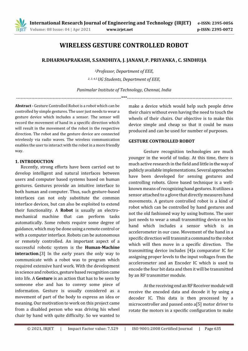
Accelerometer:
The ADXL335 is a small, low power, complete 3-axis accelerometer[8] with signal conditioned voltage outputs. It can measure the static acceleration of gravity in tilt-sensing applications, as well as dynamic acceleration
resulting from motion, shock, or vibration. An accelerometer is an electro mechanical device that measures acceleration forces. These forces may be static or dynamic. It is a kind of sensor which record acceleration and gives an analog data while moving in X, Y, Z direction or may be X, Y direction only depending on type of the sensor.
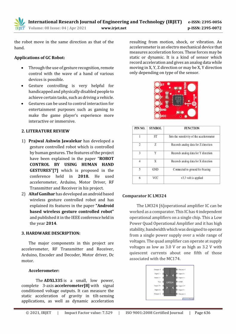
Comparator IC LM324
The LM324 [6]operational amplifier IC can be
worked as a comparator. This IC has 4 independent
operational amplifiers on a single chip. This a Low
Power Quad Operational Amplifier and it has high
stability, bandwidth which was designed to operate
from a single power supply over a wide range of
voltages. The quad amplifier can operate at supply
voltages as low as 3.0 V or as high as 3.2 V with
quiescent currents about one fifth of those
associated with the MC174.
International Research Journal of Engineering and Technology (IRJET) e-ISSN: 2395-0056
Volume: 08 Issue: 04 | Apr 2021 www.irjet.net p-ISSN: 2395-0072
© 2021, IRJET | Impact Factor value: 7.529 | ISO 9001:2008 Certified Journal | Page 637
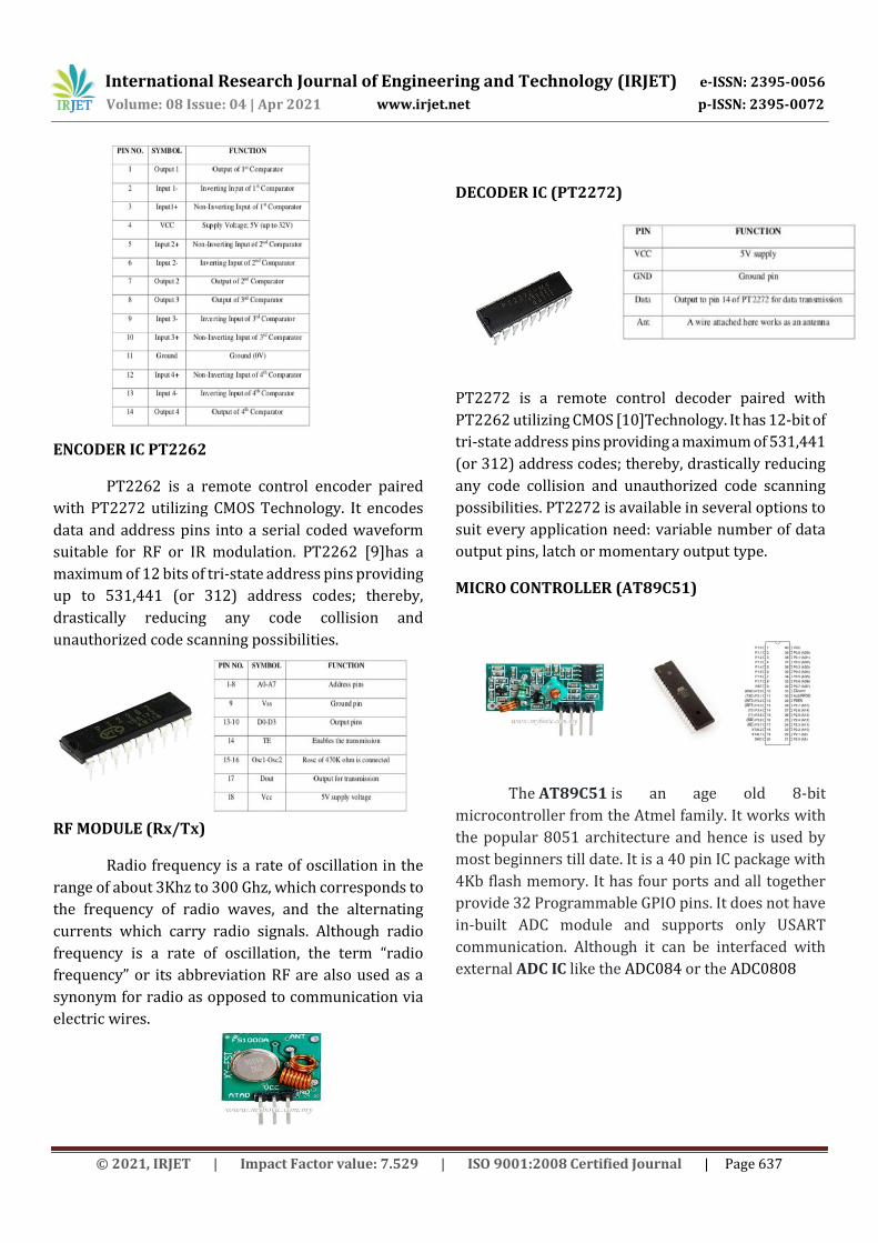
ENCODER IC PT2262
PT2262 is a remote control encoder paired
with PT2272 utilizing CMOS Technology. It encodes
data and address pins into a serial coded waveform
suitable for RF or IR modulation. PT2262 [9]has a
maximum of 12 bits of tri-state address pins providing
up to 531,441 (or 312) address codes; thereby,
drastically reducing any code collision and
unauthorized code scanning possibilities.
RF MODULE (Rx/Tx)
Radio frequency is a rate of oscillation in the
range of about 3Khz to 300 Ghz, which corresponds to
the frequency of radio waves, and the alternating
currents which carry radio signals. Although radio
frequency is a rate of oscillation, the term “radio
frequency” or its abbreviation RF are also used as a
synonym for radio as opposed to communication via
electric wires.
DECODER IC (PT2272)
PT2272 is a remote control decoder paired with
PT2262 utilizing CMOS [10]Technology. It has 12-bit of
tri-state address pins providing a maximum of 531,441
(or 312) address codes; thereby, drastically reducing
any code collision and unauthorized code scanning
possibilities. PT2272 is available in several options to
suit every application need: variable number of data
output pins, latch or momentary output type.
MICRO CONTROLLER (AT89C51)
The AT89C51 is an age old 8-bit
microcontroller from the Atmel family. It works with
the popular 8051 architecture and hence is used by
most beginners till date. It is a 40 pin IC package with
4Kb flash memory. It has four ports and all together
provide 32 Programmable GPIO pins. It does not have
in-built ADC module and supports only USART
communication. Although it can be interfaced with
external ADC IC like the ADC084 or the ADC0808
International Research Journal of Engineering and Technology (IRJET) e-ISSN: 2395-0056
Volume: 08 Issue: 04 | Apr 2021 www.irjet.net p-ISSN: 2395-0072
© 2021, IRJET | Impact Factor value: 7.529 | ISO 9001:2008 Certified Journal | Page 638
A crystal oscillator is attached to the pins 18
and 19 of the microcontroller. The oscillator creates an
electrical signal of a very precise frequency which is
used to keep track of time. Two capacitors are
connected in parallel with the oscillator to remove
unwanted frequencies.
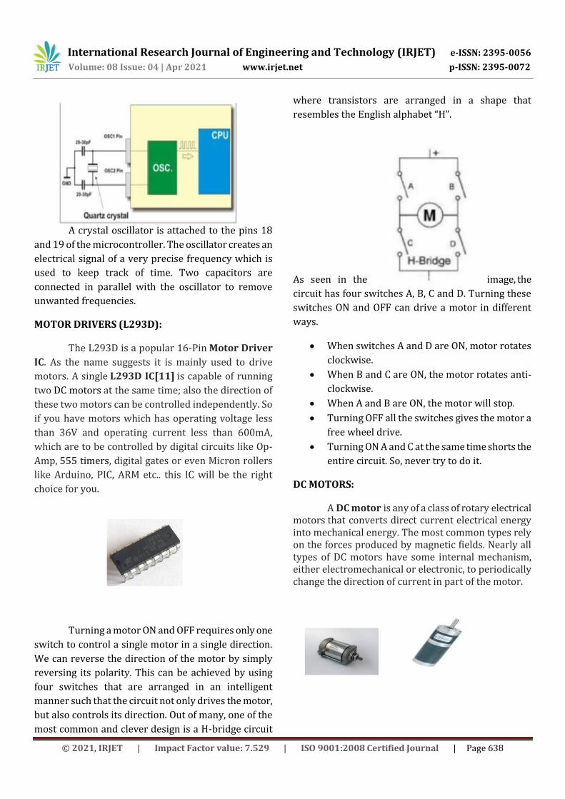
MOTOR DRIVERS (L293D):
The L293D is a popular 16-Pin Motor Driver
IC. As the name suggests it is mainly used to drive
motors. A single L293D IC[11] is capable of running
two DC motors at the same time; also the direction of
these two motors can be controlled independently. So
if you have motors which has operating voltage less
than 36V and operating current less than 600mA,
which are to be controlled by digital circuits like Op-
Amp, 555 timers, digital gates or even Micron rollers
like Arduino, PIC, ARM etc.. this IC will be the right
choice for you.
Turning a motor ON and OFF requires only one
switch to control a single motor in a single direction.
We can reverse the direction of the motor by simply
reversing its polarity. This can be achieved by using
four switches that are arranged in an intelligent
manner such that the circuit not only drives the motor,
but also controls its direction. Out of many, one of the
most common and clever design is a H-bridge circuit
where transistors are arranged in a shape that
resembles the English alphabet “H”.
As seen in the image, the
circuit has four switches A, B, C and D. Turning these
switches ON and OFF can drive a motor in different
ways.
When switches A and D are ON, motor rotates
clockwise.
When B and C are ON, the motor rotates anti-
clockwise.
When A and B are ON, the motor will stop.
Turning OFF all the switches gives the motor a
free wheel drive.
Turning ON A and C at the same time shorts the
entire circuit. So, never try to do it.
DC MOTORS:
A DC motor is any of a class of rotary electrical motors that converts direct current electrical energy into mechanical energy. The most common types rely on the forces produced by magnetic fields. Nearly all types of DC motors have some internal mechanism, either electromechanical or electronic, to periodically change the direction of current in part of the motor.
International Research Journal of Engineering and Technology (IRJET) e-ISSN: 2395-0056
Volume: 08 Issue: 04 | Apr 2021 www.irjet.net p-ISSN: 2395-0072
© 2021, IRJET | Impact Factor value: 7.529 | ISO 9001:2008 Certified Journal | Page 639
DC motors were the first form of motor widely used, as they could be powered from existing direct-current lighting power distribution systems. A DC motor's speed can be controlled over a wide range, using either a variable supply voltage or by changing the strength of current in its field windings. Small DC motors are used in tools, toys, and appliances. The universal motor can operate on direct current but is a lightweight brushed motor used for portable power tools and appliances. Larger DC motors are currently used in propulsion of electric vehicles, elevator and hoists, and in drives for steel rolling mills. The advent of power electronics has made replacement of DC motors with AC motors possible in many applications.
DC GEAR MOTOR:
A gear motor is an all-in-one combination of a motor and gearbox. The addition of a gear head to a motor reduces the speed while increasing the torque output. The most important parameters in regards to gear motors are speed (rpm), torque (lb-in) and efficiency (%). In order to select the most suitable gear motor for your application you must first compute the load, speed and torque requirements for your application. ISL Products offers a variety of Spur Gear Motors, Planetary Gear Motors and Worm Gear Motors to meet all application requirements. Most of our DC motors can be complimented with one of our unique gearheads, providing you with a highly efficient gear motor solution. The speed of the motor is counted in terms of rotations of the shaft per minute and it is termed as RPM[12]. The gear assembly helps in increasing the torque and dropping the speed. Using the correct arrangement of gears in a gear motor, its speed can be reduced to any required figure. This concept of reducing the speed with the help of gears and increasing the torque is known as gear reduction. Reducing the speed put out by the motor while increasing the quantity of applied torque is a important feature of the reduction gear trains found in a gear motor. The decrease in speed is inversely relative to the increase in torque.
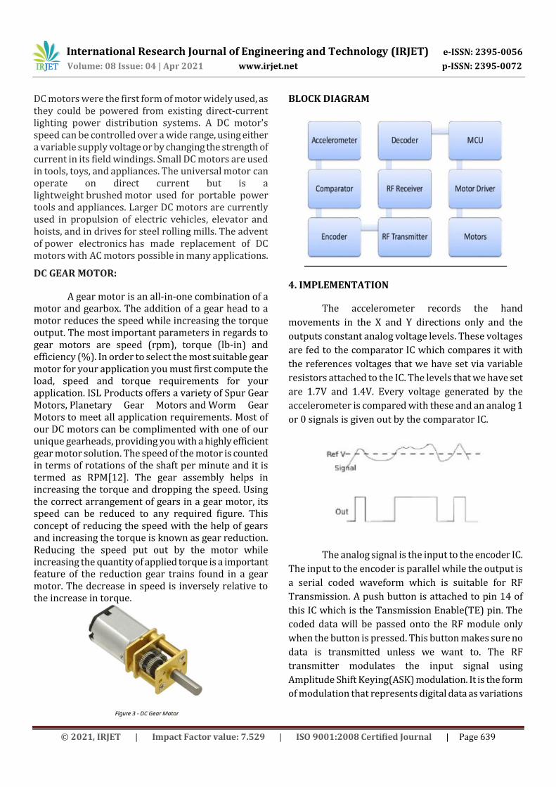
BLOCK DIAGRAM
4. IMPLEMENTATION
The accelerometer records the hand
movements in the X and Y directions only and the
outputs constant analog voltage levels. These voltages
are fed to the comparator IC which compares it with
the references voltages that we have set via variable
resistors attached to the IC. The levels that we have set
are 1.7V and 1.4V. Every voltage generated by the
accelerometer is compared with these and an analog 1
or 0 signals is given out by the comparator IC.
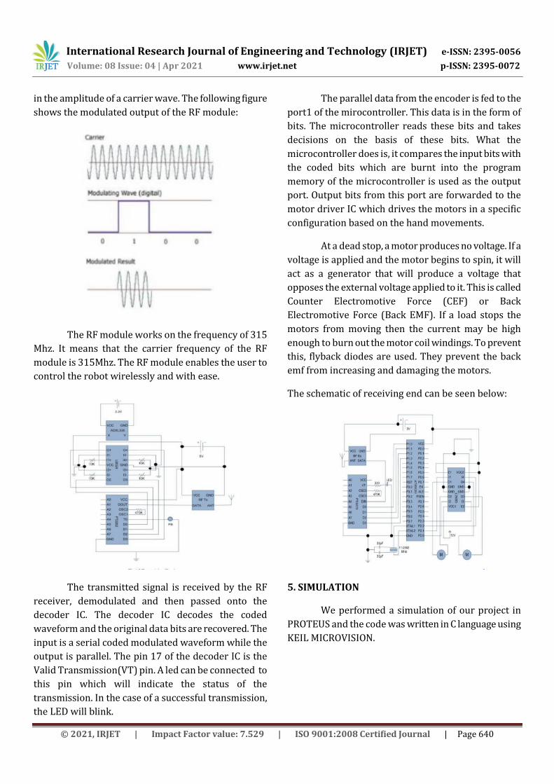
The analog signal is the input to the encoder IC.
The input to the encoder is parallel while the output is
a serial coded waveform which is suitable for RF
Transmission. A push button is attached to pin 14 of
this IC which is the Tansmission Enable(TE) pin. The
coded data will be passed onto the RF module only
when the button is pressed. This button makes sure no
data is transmitted unless we want to. The RF
transmitter modulates the input signal using
Amplitude Shift Keying(ASK) modulation. It is the form
of modulation that represents digital data as variations
International Research Journal of Engineering and Technology (IRJET) e-ISSN: 2395-0056
Volume: 08 Issue: 04 | Apr 2021 www.irjet.net p-ISSN: 2395-0072
© 2021, IRJET | Impact Factor value: 7.529 | ISO 9001:2008 Certified Journal | Page 640
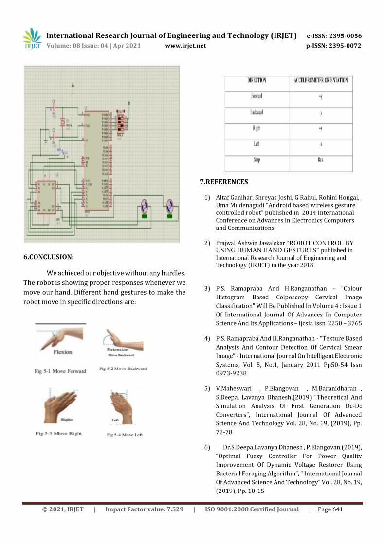
in the amplitude of a carrier wave. The following figure
shows the modulated output of the RF module:
The RF module works on the frequency of 315
Mhz. It means that the carrier frequency of the RF
module is 315Mhz. The RF module enables the user to
control the robot wirelessly and with ease.
The transmitted signal is received by the RF
receiver, demodulated and then passed onto the
decoder IC. The decoder IC decodes the coded
waveform and the original data bits are recovered. The
input is a serial coded modulated waveform while the
output is parallel. The pin 17 of the decoder IC is the
Valid Transmission(VT) pin. A led can be connected to
this pin which will indicate the status of the
transmission. In the case of a successful transmission,
the LED will blink.
The parallel data from the encoder is fed to the
port1 of the mirocontroller. This data is in the form of
bits. The microcontroller reads these bits and takes
decisions on the basis of these bits. What the
microcontroller does is, it compares the input bits with
the coded bits which are burnt into the program
memory of the microcontroller is used as the output
port. Output bits from this port are forwarded to the
motor driver IC which drives the motors in a specific
configuration based on the hand movements.
At a dead stop, a motor produces no voltage. If a
voltage is applied and the motor begins to spin, it will
act as a generator that will produce a voltage that
opposes the external voltage applied to it. This is called
Counter Electromotive Force (CEF) or Back
Electromotive Force (Back EMF). If a load stops the
motors from moving then the current may be high
enough to burn out the motor coil windings. To prevent
this, flyback diodes are used. They prevent the back
emf from increasing and damaging the motors.
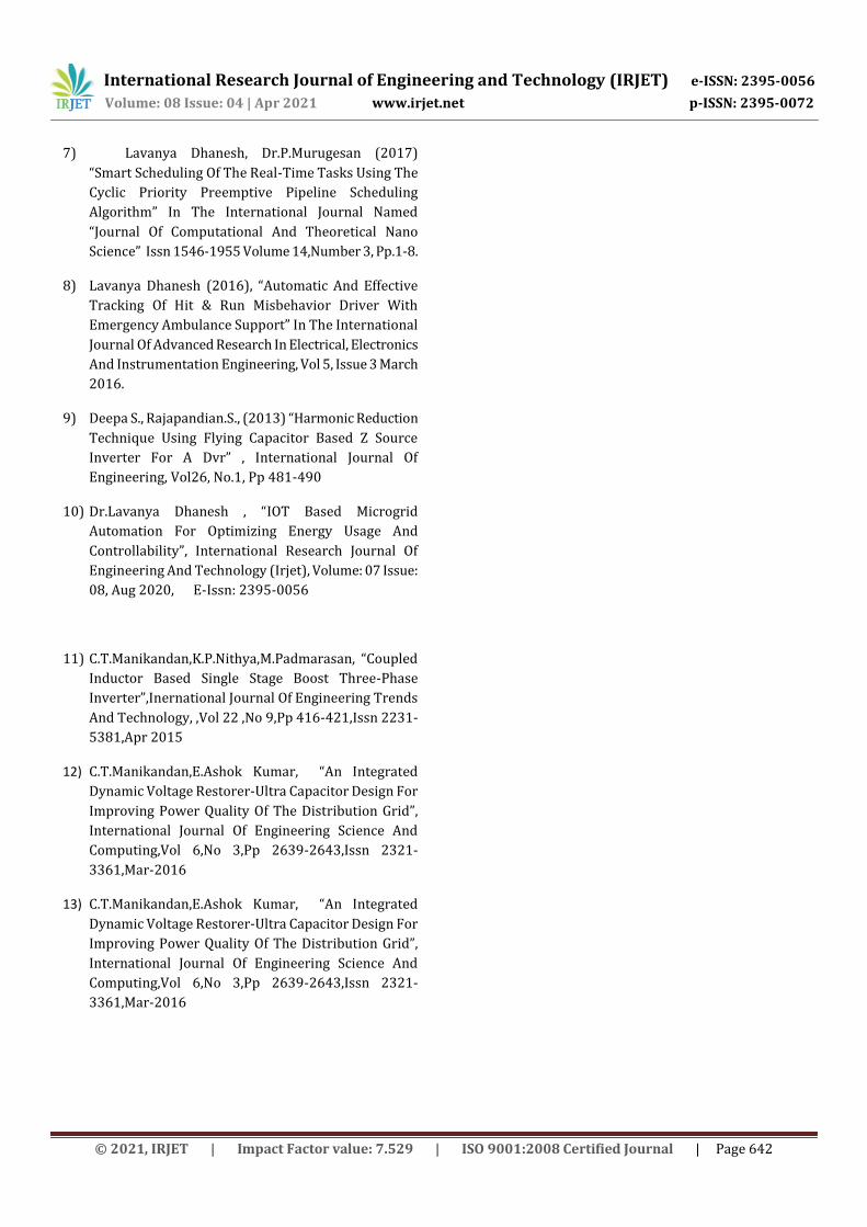
The schematic of receiving end can be seen below:
5. SIMULATION
We performed a simulation of our project in
PROTEUS and the code was written in C language using
KEIL MICROVISION.
International Research Journal of Engineering and Technology (IRJET) e-ISSN: 2395-0056
Volume: 08 Issue: 04 | Apr 2021 www.irjet.net p-ISSN: 2395-0072
© 2021, IRJET | Impact Factor value: 7.529 | ISO 9001:2008 Certified Journal | Page 641
6.CONCLUSION:
We achieced our objective without any hurdles.
The robot is showing proper responses whenever we
move our hand. Different hand gestures to make the
robot move in specific directions are:
7.REFERENCES
1) Altaf Ganihar, Shreyas Joshi, G Rahul, Rohini Hongal, Uma Mudenagudi “Android based wireless gesture controlled robot” published in 2014 International Conference on Advances in Electronics Computers and Communications
2) Prajwal Ashwin Jawalekar “ROBOT CONTROL BY
USING HUMAN HAND GESTURES” published in
International Research Journal of Engineering and
Technology (IRJET) in the year 2018
3) P.S. Ramapraba And H.Ranganathan – “Colour
Histogram Based Colposcopy Cervical Image
Classification" Will Be Published In Volume 4 : Issue 1
Of International Journal Of Advances In Computer
Science And Its Applications – Ijcsia Issn 2250 – 3765
4) P.S. Ramapraba And H.Ranganathan - “Texture Based
Analysis And Contour Detection Of Cervical Smear
Image” - International Journal On Intelligent Electronic
Systems, Vol. 5, No.1, January 2011 Pp50-54 Issn
0973-9238
5) V.Maheswari , P.Elangovan , M.Baranidharan ,
S.Deepa, Lavanya Dhanesh,(2019) “Theoretical And
Simulation Analysis Of First Generation Dc-Dc
Converters”, International Journal Of Advanced
Science And Technology Vol. 28, No. 19, (2019), Pp.
72-78
6) Dr.S.Deepa,Lavanya Dhanesh , P.Elangovan,(2019),
“Optimal Fuzzy Controller For Power Quality
Improvement Of Dynamic Voltage Restorer Using
Bacterial Foraging Algorithm”, “ International Journal
Of Advanced Science And Technology” Vol. 28, No. 19,
(2019), Pp. 10-15
International Research Journal of Engineering and Technology (IRJET) e-ISSN: 2395-0056
Volume: 08 Issue: 04 | Apr 2021 www.irjet.net p-ISSN: 2395-0072
© 2021, IRJET | Impact Factor value: 7.529 | ISO 9001:2008 Certified Journal | Page 642
7) Lavanya Dhanesh, Dr.P.Murugesan (2017)
“Smart Scheduling Of The Real-Time Tasks Using The
Cyclic Priority Preemptive Pipeline Scheduling
Algorithm” In The International Journal Named
“Journal Of Computational And Theoretical Nano
Science” Issn 1546-1955 Volume 14,Number 3, Pp.1-8.
8) Lavanya Dhanesh (2016), “Automatic And Effective
Tracking Of Hit & Run Misbehavior Driver With
Emergency Ambulance Support” In The International
Journal Of Advanced Research In Electrical, Electronics
And Instrumentation Engineering, Vol 5, Issue 3 March
2016.
9) Deepa S., Rajapandian.S., (2013) “Harmonic Reduction
Technique Using Flying Capacitor Based Z Source
Inverter For A Dvr” , International Journal Of
Engineering, Vol26, No.1, Pp 481-490
10) Dr.Lavanya Dhanesh , “IOT Based Microgrid
Automation For Optimizing Energy Usage And
Controllability”, International Research Journal Of
Engineering And Technology (Irjet), Volume: 07 Issue:
08, Aug 2020, E-Issn: 2395-0056
11) C.T.Manikandan,K.P.Nithya,M.Padmarasan, “Coupled
Inductor Based Single Stage Boost Three-Phase
Inverter”,Inernational Journal Of Engineering Trends
And Technology, ,Vol 22 ,No 9,Pp 416-421,Issn 2231-
5381,Apr 2015
12) C.T.Manikandan,E.Ashok Kumar, “An Integrated
Dynamic Voltage Restorer-Ultra Capacitor Design For
Improving Power Quality Of The Distribution Grid”,
International Journal Of Engineering Science And
Computing,Vol 6,No 3,Pp 2639-2643,Issn 2321-
3361,Mar-2016
13) C.T.Manikandan,E.Ashok Kumar, “An Integrated
Dynamic Voltage Restorer-Ultra Capacitor Design For
Improving Power Quality Of The Distribution Grid”,
International Journal Of Engineering Science And
Computing,Vol 6,No 3,Pp 2639-2643,Issn 2321-
3361,Mar-2016


