Embed Size (px)
Citation preview
International Research Journal of Engineering and Technology (IRJET) e-ISSN: 2395-0056
Volume: 08 Issue: 09 | Sep 2021 www.irjet.net p-ISSN: 2395-0072
© 2021, IRJET | Impact Factor value: 7.529 | ISO 9001:2008 Certified Journal | Page 867
Design and Fabrication of the Intake and Exhaust system of a FSAE
Race Car
Siddhant Pawar1, Yogesh Kanade2
1BE Student, Dept. of Mechanical Engineering, RGIT, Maharashtra, India 2BE Student, Dept. of Mechanical Engineering, RGIT, Maharashtra, India
---------------------------------------------------------------------***----------------------------------------------------------------------Abstract - This paper takes a look at the design, optimizing and manufacturing of an Intake and Exhaust system for a formula student race car. The Intake and exhaust system of the vehicle has to strictly comply with the rules of the Formula Bharat Competition. According to the rule, to limit the power capability from the engine, a single circular restrictor of 20mm must be placed in the intake system between the throttle and the engine inlet. The suitable intake system is designed after analytical calculations and numerous flow analysis using CFD tools. Similarly the exhaust system is designed based on packaging constraints and to be capable of attenuating noise level below 110 dB.
Key Words: Intake, FSAE, Exhaust, CFD, Design, Plenum, Helmholtz resonator
I. INTRODUCTION:
The Formula Bharat is a student design competition of designing formula type race cars. This competition is one of the biggest technical event in India and has a specific rule book that every participating team has to adhere to, one of the rule being related to the engine is that a single circular restrictor of 20 mm must be placed in the intake system between the throttle and the engine inlet. The reason of imposing such a rule is to limit the power capability firstly for the safety and secondly as engines ranging up to 610 cc are allowed, this rule helps to almost balance out the engine performance of teams using higher cubic capacity with the teams using lower cubic capacity engines helping in a fair play. This rule however drastically affects the engine performance because of the 20 mm restrictor, thus possessing a great challenge to overcome the losses and increase the engine performance in the given constraints. Therefore to overcome the losses and increase the engine performance we have designed a suitable intake system for a KTM 390 CC engine. The three sub parts of the intake system after the throttle body are:-
a) 20mm Restrictor (Bell nozzle)
b) Plenum (Air-Box)
c) Runner
The exhaust system in an engine, plays a vital role in engine performance of a vehicle. The exhaust system designed for a FSAE car must follow rules such as the noise level for an exhaust must be within 110 dB, calculated at engine speed that corresponds to an average piston speed of 15.25 m/s. The calculated speed will be rounded to the nearest 500 rpm. At idle the maximum permitted sound level is 103 dB(C), fast weighting.
Another constraint is that, all the components of an exhaust system including sensors must be under the envelope and the exhaust outlet(s) must not extend more than 450 mm behind the centerline of the rear axle and shall be no more than 600 mm above the ground.
In this paper we will discuss about the designing and CFD analysis followed by the manufacturing process of the entire intake and the exhaust system.
II. Literature Review:
The paper written by the author Omkar N. Deshpande [1], talks about the two types of restrictors that can be used in a fsae car. It can be observed how the use of De-Laval Nozzle and Bell Nozzle provides almost similar results as a venture with advantage of consuming less space.
Arbaaz Sayyed [2] in his paper describes the detail manufacturing and design of the intake system also discussing the advantage of a log shaped plenum which when used at either side helps in lowering the C.G of the vehicle.
Another paper that discusses the designing of the intake system by Joel Jose [3] has given an insight of their geometrical design, selection of throttle body (ktm 200cc throttle body for a ktm 390cc engine) and the runner length calculation by Vizard’s rule. We have avoided the Vizard’s rule and instead used the induction wave theory as the Vizard’s rule gave comparatively longer length.
The paper by the author S.S Sawant [4], discusses the intake design of their FSAE car, as this paper has used a spherical shaped plenum it can be learned that even a spherical shaped plenum can be equally advantageous as a log shaped plenum.
International Research Journal of Engineering and Technology (IRJET) e-ISSN: 2395-0056
Volume: 08 Issue: 09 | Sep 2021 www.irjet.net p-ISSN: 2395-0072
© 2021, IRJET | Impact Factor value: 7.529 | ISO 9001:2008 Certified Journal | Page 868
Pranav Anil Shinde [5] describes in detail about the venturi design coming to the conclusion that converging angle of 12 and diverging angle of 6 gives maximum recovery of pressure
“Design and Analysis of Intake and Exhaust System of SAE Supra Race Car”, Rahul Puri1, Harshal Darade2 [6].This paper showcases the calculations and CFD analysis for designing both intake and exhaust system. A reactive muffler was used here.
“Exhaust Header Designing for Formula SAE
Car”, Vaibhav Sharma1, Sachin Hittalamane2 [7]. This paper describes the material requirement for a four cylinder exhaust pipe. Analysis was done in Richardo WAVE software for increase in performance.
III. Proposed System:
A. Intake System:
The purpose of an intake system is to boost overall efficiency of the engine by providing maximum amount of air to the engine during suction stroke which helps in burning more amount of fuel and therefore helping in generating more power. The rule of the formula bharat competition mandates that all the air flow in the engine must pass through maximum diameter of 20mm for all IC Engines, this restrictor acts as a constraint in providing maximum engine output efficiency. The intake system we have used consist of a throttle body, restrictor, Air box and a runner to overcome this problem; each device used in the intake system is designed and optimized for achieving maximum air flow.
1. Bell Nozzle
Intake restrictor is a component mandated to be used in the intake system which should have a maximum of 20 mm diameter. Various system can be used to make the restrictor in order to achieve minimum pressure drop and a stabilised air flow. The following instruments can be used as a restrictor:
A) Orifice: An orifice is a simple plate with a 20mm diameter hole fitted after the throttle body. It is one of the most commonly used restrictor by many teams due to its simple design and easy manufacturing. The orifice plate gives coefficient of drag between 0.58 to 0.65 and has more pressure loss as compared to a converging-diverging nozzle. We have avoided this type of restrictor as the flow, in terms of pressure and velocity changes instantaneously upstream and downstream of the orifice plate resulting in lower mass flow rate.
B) Venturi: The Venturi instrument is a converging and diverging nozzle with a 20 mm throat in middle. The Venturi effect is a jet effect; as with a funnel the velocity of the fluid increases as the cross-sectional area decreases, with the static pressure correspondingly decreasing. An equation for the drop in pressure due to the Venturi effect may be derived from a combination of Bernoulli’s principle and the continuity equation. It generally has a coefficient of drag between 0.85 to 0.95. The pressure loss is less and also it gives more stable flow as compared to a normal orifice plate. Therefore, a venturi design is better over an orifice plate.
C) Bell Nozzle: The application of Bernoulli's principle was studied by Carl-de-Laval, who designed the convergent divergent nozzle to accelerate stream to supersonic velocities. It is a tube that is pinched in the middle, making a carefully balanced, asymmetric hourglass shape. Though the venturi-nozzle provides good results, the space occupied by the nozzle is more as it achieves its optimality at a low angle of divergence. Space is a major issue in the packaging of the assembly in the envelope rule of formula bharat competition. Thus, for this purpose we have narrowed down our option to De Laval Nozzle and Bell Nozzle which are analysed as a possible alternative to the venturi. Both of the nozzles achieve optimality at a higher angle of convergence and show similar results as compared to the Venturi Nozzle albeit the bell nozzle occupying lesser space in the engine compartment, thus we have selected this nozzle as it occupies less space without compromising the performance. Due to the smaller design, it also helps in saving material cost.
As the bell nozzle is a complicated shape, to achieve that exact shape and at the same time have light weight we have manufactured it by rapid prototyping using PLA material.
1.1 Calculation and Analysis:
To design and optimise the flow through bell nozzle, we did the pressure and velocity flow analysis using Ansysis fluent.
The known parameters in the design are the inlet diameter (31mm as to fit inside the throttle body) and assuming two different diameters for outlet (32mm and 28mm) and 20mm throat diameter. The converging and diverging angles are the unknown parameter which needs to be selected from the analysis. In the boundary condition of analysis, the pressure at inlet is atmospheric and the temperature at inlet is ambient. For the outlet boundary condition, we can give pressure, velocity or mass flow rate. Since calculation of pressure and velocity is an intricate process and might lead to errors, we chose mass flow rate as the outlet boundary condition.
International Research Journal of Engineering and Technology (IRJET) e-ISSN: 2395-0056
Volume: 08 Issue: 09 | Sep 2021 www.irjet.net p-ISSN: 2395-0072
© 2021, IRJET | Impact Factor value: 7.529 | ISO 9001:2008 Certified Journal | Page 869
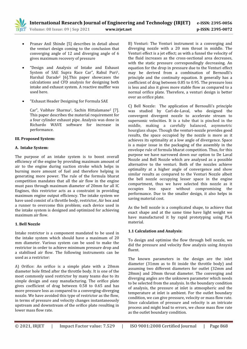
This mass flow rate can be calculated using the Choked flow equation theoretically by formula given by NASA (mass flow for a compressible fluid) as shown in fig:1
Fig-1
Calculating by the values:
M=1 (For Chocked flow)
A=0.001256 m2 (20 mm restrictor)
R=0.286 KJ/KG-K
Pt=101325 Pa
T=300 K
We get the Mass flow rate as = 0.0703 kg/s
Therefore, in boundary condition we took the inlet pressure as 1 bar, Inlet temperature as ambient and mass flow rate at the outlet as 0.0703 kg/s and analysis for various iterations are one as shown in table-1.
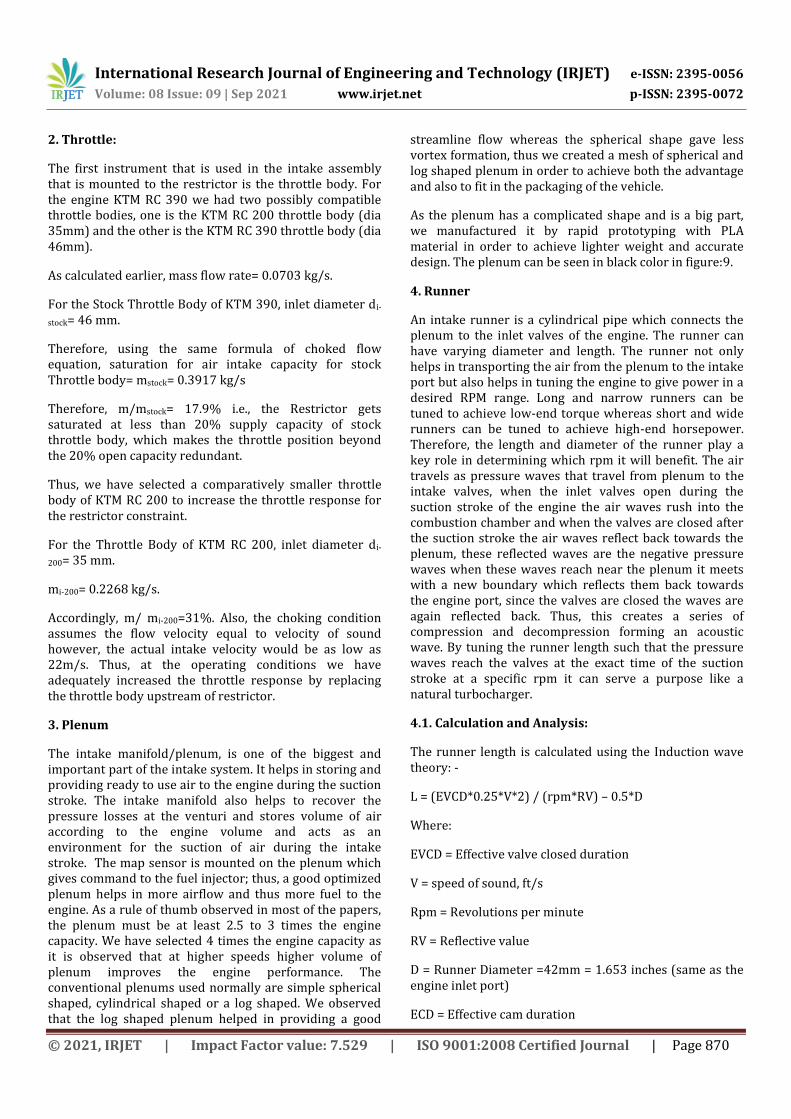
1.2. Design iterations of Restrictor Profile:
Table-1
Several iterations based on the pressure contour and velocity analysis on the regular venturi and the bell nozzle were performed. The tabulated data above (table-1) gives pressure
Drop for varying values of diameter and converging and diverging angles. Here the iteration 1 and 2 represents values on the regular venturi and 3 and 4 on the bell nozzle type.
1.3 CFD Results:
From the Various experiments & CFD analysis, we used dimensional values of iteration 4:
Entrance diameter: 31mm,
Exit diameter: 28mm,
Converging diameter: 10 degrees,
Diverging diameter: 6 degree
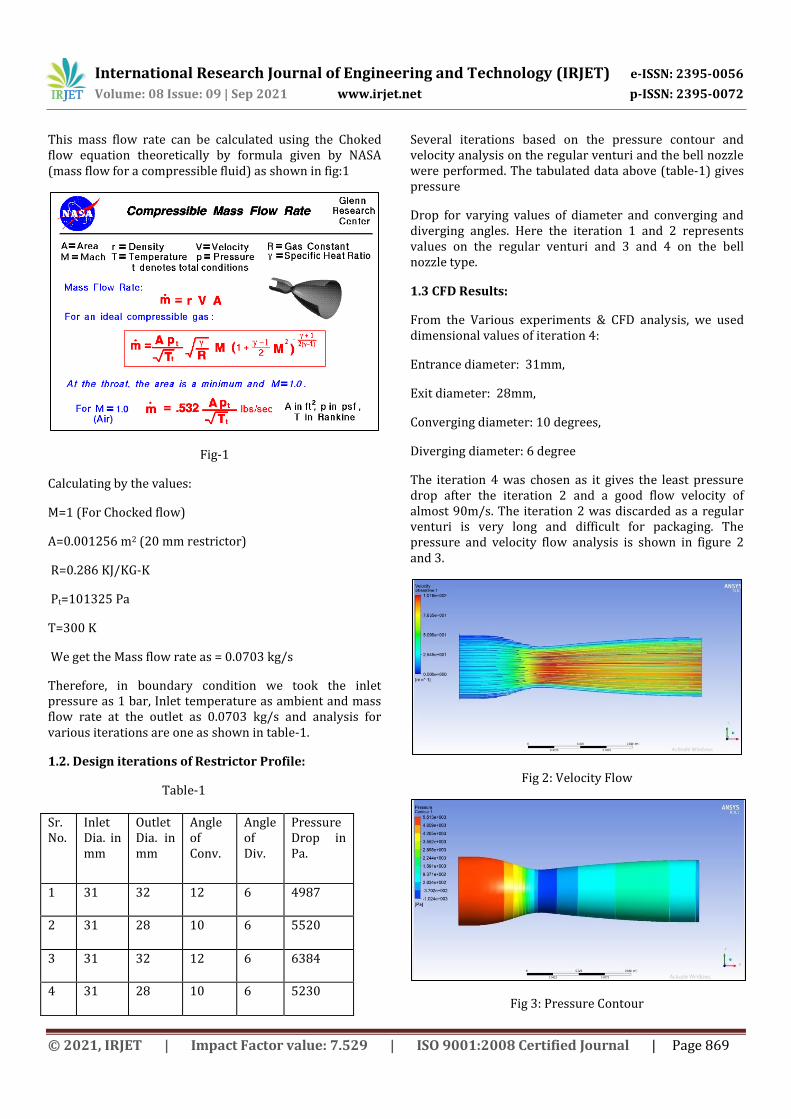
The iteration 4 was chosen as it gives the least pressure drop after the iteration 2 and a good flow velocity of almost 90m/s. The iteration 2 was discarded as a regular venturi is very long and difficult for packaging. The pressure and velocity flow analysis is shown in figure 2 and 3.
Fig 2: Velocity Flow
Fig 3: Pressure Contour
Sr. No.
Inlet Dia. in mm
Outlet Dia. in mm
Angle of Conv.
Angle of Div.
Pressure Drop in Pa.
1 31 32 12 6 4987
2 31 28 10 6 5520
3 31 32 12 6 6384
4 31 28 10 6 5230
International Research Journal of Engineering and Technology (IRJET) e-ISSN: 2395-0056
Volume: 08 Issue: 09 | Sep 2021 www.irjet.net p-ISSN: 2395-0072
© 2021, IRJET | Impact Factor value: 7.529 | ISO 9001:2008 Certified Journal | Page 870
2. Throttle:
The first instrument that is used in the intake assembly that is mounted to the restrictor is the throttle body. For the engine KTM RC 390 we had two possibly compatible throttle bodies, one is the KTM RC 200 throttle body (dia 35mm) and the other is the KTM RC 390 throttle body (dia 46mm).
As calculated earlier, mass flow rate= 0.0703 kg/s.
For the Stock Throttle Body of KTM 390, inlet diameter di-
stock= 46 mm.
Therefore, using the same formula of choked flow equation, saturation for air intake capacity for stock Throttle body= mstock= 0.3917 kg/s
Therefore, m/mstock= 17.9% i.e., the Restrictor gets saturated at less than 20% supply capacity of stock throttle body, which makes the throttle position beyond the 20% open capacity redundant.
Thus, we have selected a comparatively smaller throttle body of KTM RC 200 to increase the throttle response for the restrictor constraint.
For the Throttle Body of KTM RC 200, inlet diameter di-
200= 35 mm.
mi-200= 0.2268 kg/s.
Accordingly, m/ mi-200=31%. Also, the choking condition assumes the flow velocity equal to velocity of sound however, the actual intake velocity would be as low as 22m/s. Thus, at the operating conditions we have adequately increased the throttle response by replacing the throttle body upstream of restrictor.
3. Plenum
The intake manifold/plenum, is one of the biggest and important part of the intake system. It helps in storing and providing ready to use air to the engine during the suction stroke. The intake manifold also helps to recover the pressure losses at the venturi and stores volume of air according to the engine volume and acts as an environment for the suction of air during the intake stroke. The map sensor is mounted on the plenum which gives command to the fuel injector; thus, a good optimized plenum helps in more airflow and thus more fuel to the engine. As a rule of thumb observed in most of the papers, the plenum must be at least 2.5 to 3 times the engine capacity. We have selected 4 times the engine capacity as it is observed that at higher speeds higher volume of plenum improves the engine performance. The conventional plenums used normally are simple spherical shaped, cylindrical shaped or a log shaped. We observed that the log shaped plenum helped in providing a good
streamline flow whereas the spherical shape gave less vortex formation, thus we created a mesh of spherical and log shaped plenum in order to achieve both the advantage and also to fit in the packaging of the vehicle.
As the plenum has a complicated shape and is a big part, we manufactured it by rapid prototyping with PLA material in order to achieve lighter weight and accurate design. The plenum can be seen in black color in figure:9.
4. Runner
An intake runner is a cylindrical pipe which connects the plenum to the inlet valves of the engine. The runner can have varying diameter and length. The runner not only helps in transporting the air from the plenum to the intake port but also helps in tuning the engine to give power in a desired RPM range. Long and narrow runners can be tuned to achieve low-end torque whereas short and wide runners can be tuned to achieve high-end horsepower. Therefore, the length and diameter of the runner play a key role in determining which rpm it will benefit. The air travels as pressure waves that travel from plenum to the intake valves, when the inlet valves open during the suction stroke of the engine the air waves rush into the combustion chamber and when the valves are closed after the suction stroke the air waves reflect back towards the plenum, these reflected waves are the negative pressure waves when these waves reach near the plenum it meets with a new boundary which reflects them back towards the engine port, since the valves are closed the waves are again reflected back. Thus, this creates a series of compression and decompression forming an acoustic wave. By tuning the runner length such that the pressure waves reach the valves at the exact time of the suction stroke at a specific rpm it can serve a purpose like a natural turbocharger.
4.1. Calculation and Analysis:
The runner length is calculated using the Induction wave theory: -
L = (EVCD*0.25*V*2) / (rpm*RV) – 0.5*D
Where:
EVCD = Effective valve closed duration
V = speed of sound, ft/s
Rpm = Revolutions per minute
RV = Reflective value
D = Runner Diameter =42mm = 1.653 inches (same as the engine inlet port)
ECD = Effective cam duration
International Research Journal of Engineering and Technology (IRJET) e-ISSN: 2395-0056
Volume: 08 Issue: 09 | Sep 2021 www.irjet.net p-ISSN: 2395-0072
© 2021, IRJET | Impact Factor value: 7.529 | ISO 9001:2008 Certified Journal | Page 871
In the KTM RC 390 engine the Intake valves opens 2 degrees Before Top Dead Centre (BTDC) and Intake valves closes 44 degrees After Top Dead Centre (ATDC)
ECD = 180°+2°+44°=226° 4 stroke = 720°
EVCD = 720°-ECD-30° = 720°-226°-30° = 464°
Therefore, from the formula the Length of runner = (464*0.25*1125*2) / (7000*4) – 0.5*1.653 =8.49 inches =215.79mm.
Our engine is tuned at stock settings of 7000 rpm and The RV value is taken 4.
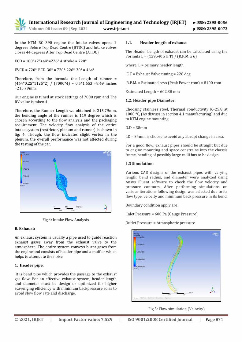
Therefore, the Runner Length we obtained is 215.79mm, the bending angle of the runner is 119 degree which is chosen according to the flow analysis and the packaging requirement. The velocity flow analysis of the entire intake system (restrictor, plenum and runner) is shown in fig: 4. Though, the flow indicates slight vortex in the plenum, the overall performance was not affected during the testing of the car.
Fig 4: Intake Flow Analysis
B. Exhaust:
An exhaust system is usually a pipe used to guide reaction exhaust gases away from the exhaust valve to the atmosphere. The entire system conveys burnt gases from the engine and consists of header pipe and a muffler which helps to attenuate the noise.
1. Header pipe:
It is bend pipe which provides the passage to the exhaust gas flow. For an effective exhaust system, header length and diameter must be design or optimized for higher scavenging efficiency with minimum backpressure so as to avoid slow flow rate and discharge.
1.1. Header length of exhaust
The Header Length of exhaust can be calculated using the Formula L = (129540 x E.T) / (R.P.M. x 6)
where, L = primary header length.
E.T = Exhaust Valve timing = 226 deg
R.P.M. = Estimated revs (Peak Power rpm) = 8100 rpm
Estimated Length = 602.38 mm
1.2. Header pipe Diameter:
Choosing stainless steel, Thermal conductivity K=25.8 at 1000 ℃, (As discuss in section 4.1 manufacturing) and due to KTM engine mounting
O.D = 38mm
I.D = 34mm is choose to avoid any abrupt change in area.
For a good flow, exhaust pipes should be straight but due to engine mounting and space constrains into the chassis frame, bending of possibly large radii has to be design.
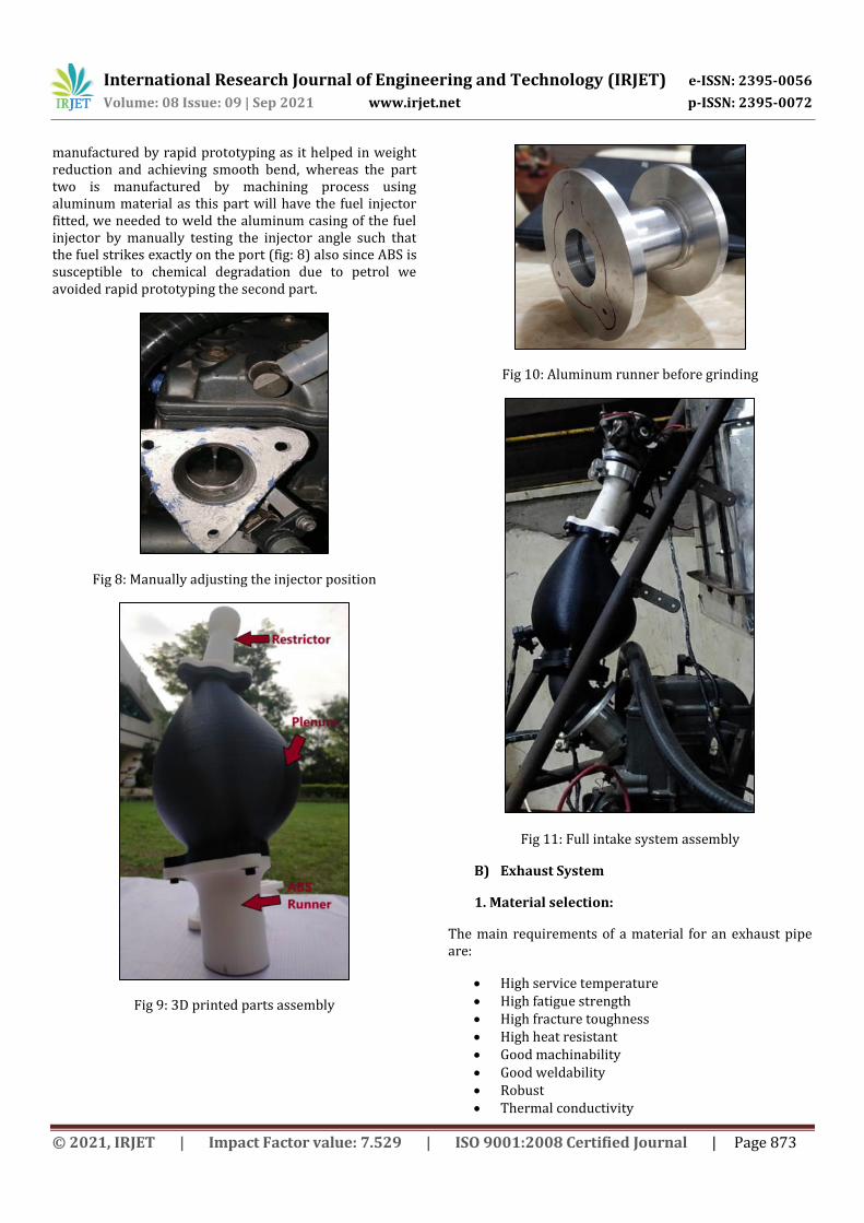
1.3 Simulation:
Various CAD designs of the exhaust pipes with varying length, bend radius, and diameter were analyzed using Ansys Fluent software to check the flow velocity and pressure contours. After performing simulations on various iterations following design was selected due to its flow type, velocity and minimum back pressure in its bend.
Boundary condition apply are
Inlet Pressure = 600 Pa (Gauge Pressure)
Outlet Pressure = Atmospheric pressure
Fig 5: Flow simulation (Velocity)

International Research Journal of Engineering and Technology (IRJET) e-ISSN: 2395-0056
Volume: 08 Issue: 09 | Sep 2021 www.irjet.net p-ISSN: 2395-0072
© 2021, IRJET | Impact Factor value: 7.529 | ISO 9001:2008 Certified Journal | Page 872
Using Ansys Fluent software Flow Simulation was conducted and following result was achieved.
1. Flow with less turbulence 2. Higher flow velocity which leads to higher
scavenging.
Fig 6: Exhaust assembly (without resonator)
The design as shown in fig.6 is the finalized cad model after performing the flow analysis as shown fig.5.
2. MUFFLER:
The main application of muffler is to reduce the loudness of the sound pressure, created due to burning of hot exhaust gas exiting the engine, by acoustic quieting. Among the two types viz. reflective and absorptive, absorptive muffler uses absorptive material such as glass wool to convert acoustic energy into heat energy.
In our case, we have used an absorptive type KTM stock muffler with baffles as it is less complex and reduces backpressure more compared to the reflective type.
3. HELMHOLTZ RESONATOR:
For attenuating the sound, Helmholtz resonator was used. It is an apparatus able to pick out specific frequencies from a complex sound. The Helmholtz resonator consists of a rigid container of a known volume, with a small neck and hole in one end and a larger hole in the other end to emit the sound. Exhaust system frequency can vary between 50-400 hz and are calculated for the range of engine speed as shown in table 2.
Engine Speed (rpm) Primary frequency(Hz)
6000 50
7000 58.33
8000 66.67
8500 70.83
9000 75
Table 2: Engine Frequency Calculation
The resonator dimensions as in Fig: 7 are calculated so that the waves reflected by the resonator help cancel out certain frequencies of sound in the exhaust. The natural frequency given by the following formula,
= (C ÷ 2π )*√( (A/(V*l) )
Where, C = speed of sound
A= Area of neck
l= Length of neck
V= Volume of cylindrical cavity.
The following table in the fig 7 shows the no of iterations conducted for optimum frequency.
Fig 7: Resonant Frequency Calculation
The calculated resonant frequency was 68.22 Hz for below values,
A=0.000314 m2; l =0.2m; V=0.0015079 m3
IV. Manufacturing
A) Intake System:
The DeLaval nozzle and the Plenum (Fig: 9) are manufactured using rapid prototyping with PLA material. Rapid prototyping is used as it helped immensely in weight reduction over aluminum and helped in achieving the complicated shapes accurately.
The runner was manufactured in two parts, one part towards plenum is manufactured by rapid prototyping with ABS material and the other part towards the engine port is made up of Aluminum (Fig 10). The part one is
International Research Journal of Engineering and Technology (IRJET) e-ISSN: 2395-0056
Volume: 08 Issue: 09 | Sep 2021 www.irjet.net p-ISSN: 2395-0072
© 2021, IRJET | Impact Factor value: 7.529 | ISO 9001:2008 Certified Journal | Page 873
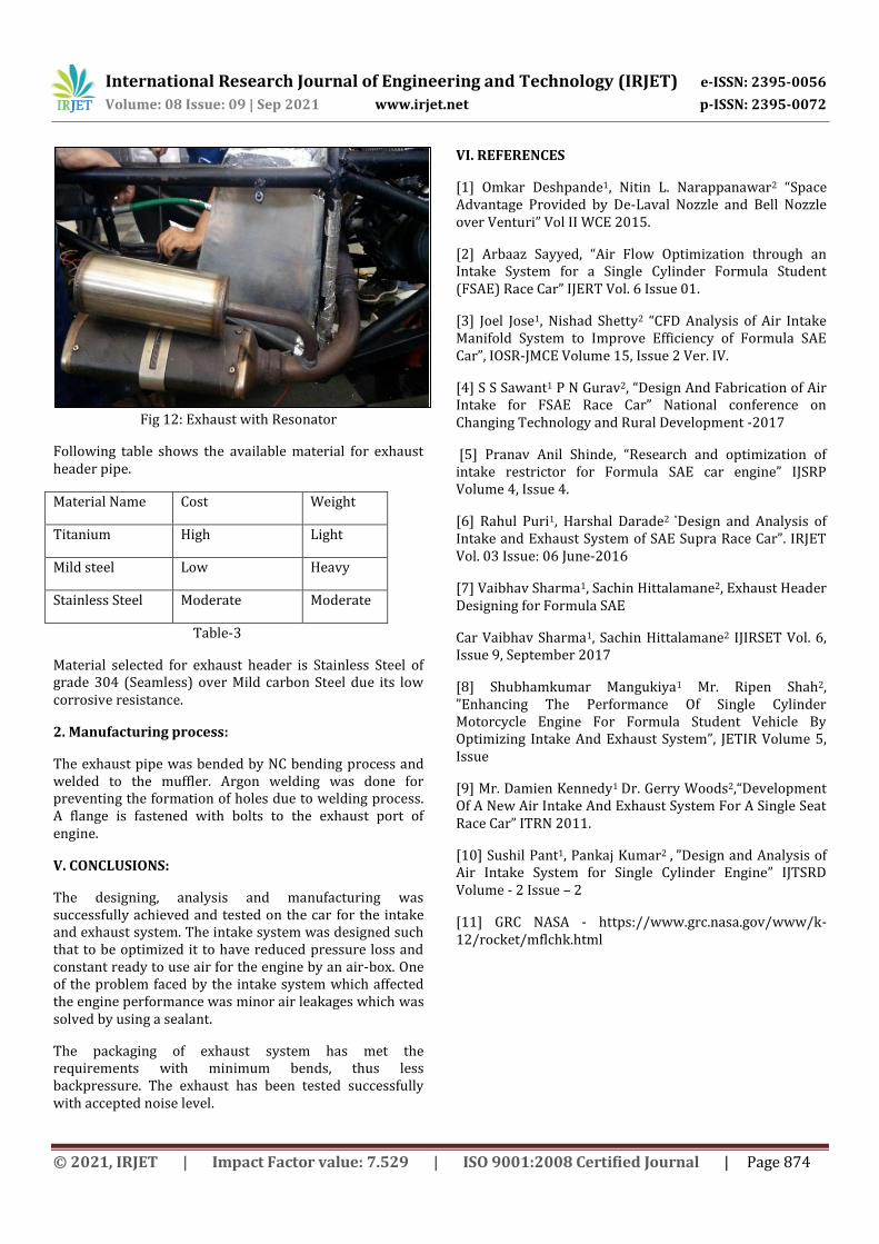
manufactured by rapid prototyping as it helped in weight reduction and achieving smooth bend, whereas the part two is manufactured by machining process using aluminum material as this part will have the fuel injector fitted, we needed to weld the aluminum casing of the fuel injector by manually testing the injector angle such that the fuel strikes exactly on the port (fig: 8) also since ABS is susceptible to chemical degradation due to petrol we avoided rapid prototyping the second part.
Fig 8: Manually adjusting the injector position
Fig 9: 3D printed parts assembly
Fig 10: Aluminum runner before grinding
Fig 11: Full intake system assembly
B) Exhaust System
1. Material selection:
The main requirements of a material for an exhaust pipe are:
High service temperature High fatigue strength High fracture toughness High heat resistant Good machinability Good weldability Robust Thermal conductivity
International Research Journal of Engineering and Technology (IRJET) e-ISSN: 2395-0056
Volume: 08 Issue: 09 | Sep 2021 www.irjet.net p-ISSN: 2395-0072
© 2021, IRJET | Impact Factor value: 7.529 | ISO 9001:2008 Certified Journal | Page 874
Fig 12: Exhaust with Resonator
Following table shows the available material for exhaust header pipe.
Material Name Cost Weight
Titanium High Light
Mild steel Low Heavy
Stainless Steel Moderate Moderate
Table-3
Material selected for exhaust header is Stainless Steel of grade 304 (Seamless) over Mild carbon Steel due its low corrosive resistance.
2. Manufacturing process:
The exhaust pipe was bended by NC bending process and welded to the muffler. Argon welding was done for preventing the formation of holes due to welding process. A flange is fastened with bolts to the exhaust port of engine.
V. CONCLUSIONS:
The designing, analysis and manufacturing was successfully achieved and tested on the car for the intake and exhaust system. The intake system was designed such that to be optimized it to have reduced pressure loss and constant ready to use air for the engine by an air-box. One of the problem faced by the intake system which affected the engine performance was minor air leakages which was solved by using a sealant.
The packaging of exhaust system has met the requirements with minimum bends, thus less backpressure. The exhaust has been tested successfully with accepted noise level.
VI. REFERENCES
[1] Omkar Deshpande1, Nitin L. Narappanawar2 “Space Advantage Provided by De-Laval Nozzle and Bell Nozzle over Venturi” Vol II WCE 2015.
[2] Arbaaz Sayyed, “Air Flow Optimization through an Intake System for a Single Cylinder Formula Student (FSAE) Race Car” IJERT Vol. 6 Issue 01.
[3] Joel Jose1, Nishad Shetty2 “CFD Analysis of Air Intake Manifold System to Improve Efficiency of Formula SAE Car”, IOSR-JMCE Volume 15, Issue 2 Ver. IV.
[4] S S Sawant1 P N Gurav2, “Design And Fabrication of Air Intake for FSAE Race Car” National conference on Changing Technology and Rural Development -2017
[5] Pranav Anil Shinde, “Research and optimization of intake restrictor for Formula SAE car engine” IJSRP Volume 4, Issue 4.
[6] Rahul Puri1, Harshal Darade2 “Design and Analysis of Intake and Exhaust System of SAE Supra Race Car”. IRJET Vol. 03 Issue: 06 June-2016
[7] Vaibhav Sharma1, Sachin Hittalamane2, Exhaust Header Designing for Formula SAE
Car Vaibhav Sharma1, Sachin Hittalamane2 IJIRSET Vol. 6, Issue 9, September 2017
[8] Shubhamkumar Mangukiya1 Mr. Ripen Shah2, ”Enhancing The Performance Of Single Cylinder Motorcycle Engine For Formula Student Vehicle By Optimizing Intake And Exhaust System”, JETIR Volume 5, Issue
[9] Mr. Damien Kennedy1 Dr. Gerry Woods2,“Development Of A New Air Intake And Exhaust System For A Single Seat Race Car” ITRN 2011.
[10] Sushil Pant1, Pankaj Kumar2 , ”Design and Analysis of Air Intake System for Single Cylinder Engine” IJTSRD Volume - 2 Issue – 2
[11] GRC NASA - https://www.grc.nasa.gov/www/k-12/rocket/mflchk.html
International Research Journal of Engineering and Technology (IRJET) e-ISSN: 2395-0056
Volume: 08 Issue: 09 | Sep 2021 www.irjet.net p-ISSN: 2395-0072
© 2021, IRJET | Impact Factor value: 7.529 | ISO 9001:2008 Certified Journal | Page 875
VII. BIOGRAPHIES
Siddhant Pawar The author is an undergraduate student in the department of Mechanical Engineering at RGIT Mumbai, and the Design Head Engineer of the Intake department in Team RGIT Racing.
Yogesh Kanade The author is an undergraduate student in the department of Mechanical Engineering at RGIT Mumbai, and Design Head of the Exhaust department in Team RGIT Racing.


