Embed Size (px)
Citation preview

WIND TURBINE PHONE CHARGER
By
Charles Hummel
Kemal Emre Ercikti
Sachin Reddy
Final Report for ECE 445, Senior Design, Spring 2018
TA: Dongwei Shi
02 May 2018
Project No. 41

ii
Abstract
The wind turbine phone charger provides up to 15W of power to a battery pack which can charge most
portable electronic devices using USB ports. The turbine itself is a two-level Savonius with offset blades
to capture wind from any direction. The blades are connected to a shaft which rotates a gearbox that
steps up the speed for the generator. A permanent magnet DC machine acts as a generator that outputs
an unregulated voltage. This voltage is passed through power electronics and a USB-C interface which
outputs 5V to the battery pack. A microcontroller monitors the output of the generator and calculates
the wind speed based on this. These two values are displayed on an LCD display. Additionally, the
microcontroller provides 5V to many of the chips within the power electronics system. All individual
parts work correctly yet combining all the pieces is problematic.

iii
Acknowledgments We would like to thank all the help we received both within and outside the course. Namely the ECE 445
staff, especially our TA Dongwei Shi. Professor Magdi Ragheb, Professor Kiruba Sivasubramaniam Haran,
Karl Reinhard for all the helpful recommendations and tips they provided us with. We also thank the ECE
Machine for all the help they were able to provide us, specifically Skee Aldrich and Scott McDonald, we
could not have done it without them.

iv
Contents
Acknowledgments ........................................................................................................................................ iii
1. Introduction .............................................................................................................................................. 1
2. Design ........................................................................................................................................................ 2
2.1 Turbine ................................................................................................................................................ 2
2.1.1 Savonius Rotor ............................................................................................................................. 2
2.1.2 Generator ..................................................................................................................................... 4
2.1.3 Gearbox ........................................................................................................................................ 5
2.2 Power Electronics ................................................................................................................................ 5
2.2.1 DC/DC Converter .......................................................................................................................... 5
2.2.2 Control Unit .................................................................................................................................. 8
2.3 Battery System .................................................................................................................................... 9
2.4 Microcontroller ................................................................................................................................... 9
3. Design Verification .................................................................................................................................. 11
3.1 Turbine .............................................................................................................................................. 11
3.1.1 Savonius Rotor ........................................................................................................................... 11
3.1.2 Generator ................................................................................................................................... 11
3.1.3 Gearbox ...................................................................................................................................... 12
3.2 Power Electronics .............................................................................................................................. 12
3.2.1 DC/DC Converter ........................................................................................................................ 12
3.2.2 Control Unit ................................................................................................................................ 13
3.3 Battery System .................................................................................................................................. 13
3.4 Microcontroller ................................................................................................................................. 13
4. Costs ........................................................................................................................................................ 15
4.1 Parts .................................................................................................................................................. 15
4.2 Labor ................................................................................................................................................. 16
4.3 Total Costs ......................................................................................................................................... 16
5. Conclusion ............................................................................................................................................... 17
5.1 Accomplishments .............................................................................................................................. 17
5.2 Uncertainties ..................................................................................................................................... 17
v
5.3 Ethical considerations ....................................................................................................................... 17
5.4 Future work ....................................................................................................................................... 18
References .................................................................................................................................................. 19
Appendix A Requirement and Verification Table ................................................................................... 20
Appendix B Wind Turbine Photograph................................................................................................... 23
Appendix C Converter Simulation Figures .............................................................................................. 24
Appendix D Control Circuit Simulation Figures ...................................................................................... 25
Appendix E Verification Figures and Tables ........................................................................................... 26
1
1. Introduction Renewable energy has been steadily rising in use for many years. There are solar and wind farms that
harvest hundreds of megawatts of daily. This renewable technology is also growing on the smaller scale
with houses having their own solar panels and even external phone batteries can be connected to solar
panels. However, solar can only produce when there is sunlight and battery packs have only so much
storage. There has been little exploration on utilizing small scale wind power and power supplies for
portable devices will be in high demand for the foreseeable future. The wind turbine phone charger
harnesses wind to provide power when solar and battery packs may fail as well as prove the viability of
expanding wind power utilization to the small-scale.
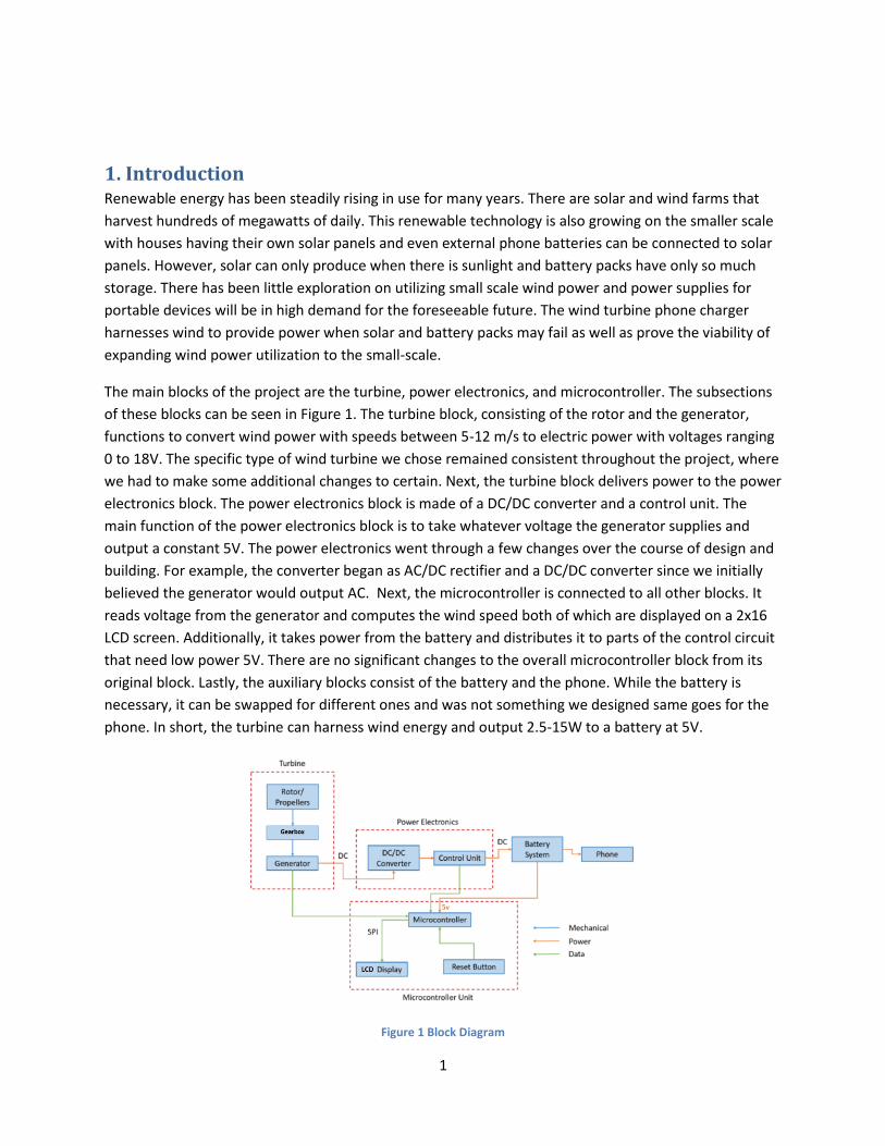
The main blocks of the project are the turbine, power electronics, and microcontroller. The subsections
of these blocks can be seen in Figure 1. The turbine block, consisting of the rotor and the generator,
functions to convert wind power with speeds between 5-12 m/s to electric power with voltages ranging
0 to 18V. The specific type of wind turbine we chose remained consistent throughout the project, where
we had to make some additional changes to certain. Next, the turbine block delivers power to the power
electronics block. The power electronics block is made of a DC/DC converter and a control unit. The
main function of the power electronics block is to take whatever voltage the generator supplies and
output a constant 5V. The power electronics went through a few changes over the course of design and
building. For example, the converter began as AC/DC rectifier and a DC/DC converter since we initially
believed the generator would output AC. Next, the microcontroller is connected to all other blocks. It
reads voltage from the generator and computes the wind speed both of which are displayed on a 2x16
LCD screen. Additionally, it takes power from the battery and distributes it to parts of the control circuit
that need low power 5V. There are no significant changes to the overall microcontroller block from its
original block. Lastly, the auxiliary blocks consist of the battery and the phone. While the battery is
necessary, it can be swapped for different ones and was not something we designed same goes for the
phone. In short, the turbine can harness wind energy and output 2.5-15W to a battery at 5V.
Figure 1 Block Diagram
2
2. Design
2.1 Turbine The turbine is the first step in the powertrain, from converting the mechanical power through the wind
into electrical power. The turbine has 2 main subcomponents, the rotor and the generator, where the
former consists of the rotor blades as well as the rotor bases. The generator is connected through a
shaft and a gearbox to the generator.
Described below in Section 2.1.1, Section 2.1.2 and Section 2.1.3 are some of the design changes we had
to make in detail. Another change not mentioned below is the change of the bottom housing unit. We
had initially expected it to be smaller and lighter, however, stability issues forced us to have enough
space for the shaft. Additionally, there had to be enough space to house the gearbox which was created
using a belt system that needed the extra space.
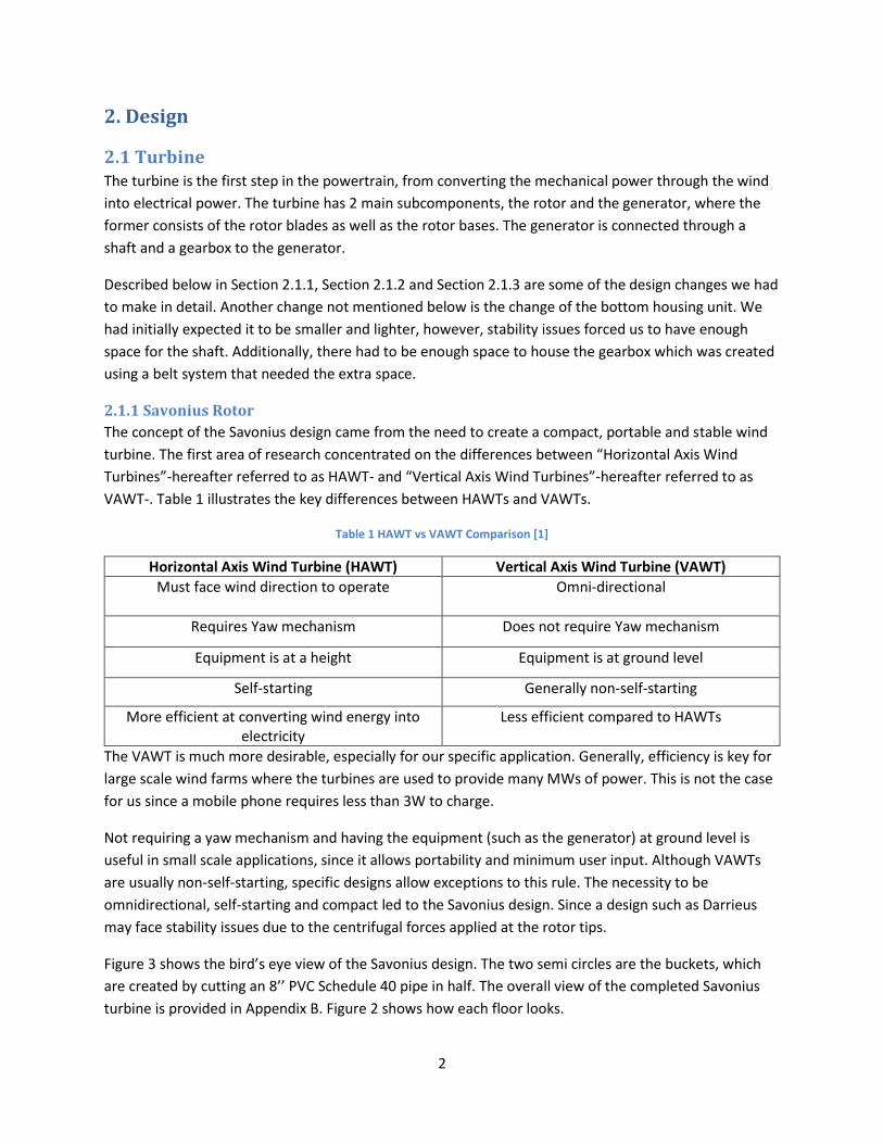
2.1.1 Savonius Rotor
The concept of the Savonius design came from the need to create a compact, portable and stable wind
turbine. The first area of research concentrated on the differences between “Horizontal Axis Wind
Turbines”-hereafter referred to as HAWT- and “Vertical Axis Wind Turbines”-hereafter referred to as
VAWT-. Table 1 illustrates the key differences between HAWTs and VAWTs.
Table 1 HAWT vs VAWT Comparison [1]
Horizontal Axis Wind Turbine (HAWT) Vertical Axis Wind Turbine (VAWT)
Must face wind direction to operate
Omni-directional
Requires Yaw mechanism Does not require Yaw mechanism
Equipment is at a height Equipment is at ground level
Self-starting Generally non-self-starting
More efficient at converting wind energy into electricity
Less efficient compared to HAWTs
The VAWT is much more desirable, especially for our specific application. Generally, efficiency is key for
large scale wind farms where the turbines are used to provide many MWs of power. This is not the case
for us since a mobile phone requires less than 3W to charge.
Not requiring a yaw mechanism and having the equipment (such as the generator) at ground level is
useful in small scale applications, since it allows portability and minimum user input. Although VAWTs
are usually non-self-starting, specific designs allow exceptions to this rule. The necessity to be
omnidirectional, self-starting and compact led to the Savonius design. Since a design such as Darrieus
may face stability issues due to the centrifugal forces applied at the rotor tips.
Figure 3 shows the bird’s eye view of the Savonius design. The two semi circles are the buckets, which
are created by cutting an 8’’ PVC Schedule 40 pipe in half. The overall view of the completed Savonius
turbine is provided in Appendix B. Figure 2 shows how each floor looks.

3
Each floor is shifted by 90 in reference to the other. That is, the top floor is 90 phase shifted compared
to the bottom floor. This allows the Savonius turbine to be omnidirectional and self-starting. This is an
essential characteristic for a VAWT that may otherwise need assistance to start, which lowers the overall
efficiency.
These PVC pipes are then placed on the rotor base parts. The bottom base will house the equipment
including the generator, gearbox, the power electronics and the microcontroller unit. All the parts are
put together, which will create the turbine.
Figure 2 Two-Bucket Savonius
Figure 3 Bird's Eye View - Savonius Design (Two Bucket)
Figure 4 below, shows the relationship between the maximum power extracted from the wind and the
wind speed available. The relationship reflects the modified Betz’s Equation, since the Betz’s coefficient
is the ideal case, and real-life applications do not reflect this. Equation 1.1 is the original Betz’s equation,
whereas Equation 1.2 is the modified version.

4
Equation 1.1
𝑃 =16
27(
𝜌
2) 𝐴𝑣3 [𝑊]
The following calculations are made assuming the following parameters:
Equation 1.2
𝑃 = 0.18 ∗ (𝜌
2) 𝐴𝑣3 [𝑊]
where 𝐴 = ℎ × 𝑟
Air density, ρ = 1.2 kg/m3
Rotor height, h = 0.5 m
Rotor effective radius, R = 0.4 m (this does not reflect the radius of each specific bucket, it is the
effective swept area radius denoted by R as shown in Figure 3.)
Figure 4 Wind Speed vs Maximum Power
As seen above, the biggest contributing factor to the power output is the wind speed. Since the power is
proportional exponentially to the wind speed, higher wind speeds will produce larger wattage.
Additionally, the calculations above are made using a conservative power coefficient of 0.18. There are
varying estimates to the specific power coefficient used, so our results vary depending on the actual
coefficient we can have. [2][3][5]
2.1.2 Generator
Taking its input from the propeller, the generator will provide the conversion of the mechanical motion
of the blades to electrical power. The current generator is a 36W DC permanent magnet motor that can
be run as a DC generator. Using an appropriate gearing scheme, the low speed of the rotor will translate
to high speed rotation the motor can use. After consulting with Professor Haran, he suggested a
permanent magnet motor could be easily run as a generator. Based on the relative availability, size, and
0
10
20
30
0 2 4 6 8 10 12 14
Max
imu
m P
ow
er
[W]
Wind Speed [m/s]
WIND SPEED VS MAX POWER

5
cost this motor was chosen. The generator is rated for 36 W which makes our high-level requirement of
2.5W reachable.
2.1.3 Gearbox
Another key component in the design stage was the use of gears. Since the generator will not operate at
the same rpm as the turbine, it is important that we use gears to minimize our inefficiency. Table 2
demonstrates various gears required at different wind speeds. The gear ratio was calculated using the
following method (the generator is rated at 2500 rpm).
Equation 1.3 Gear Ratio Equations
𝑣 = 𝑤 × 𝑟
𝑓 =𝑤
2𝜋[𝐻𝑧]
1 rpm = 1/60 Hz
Gear Ratio = Generator Rated rpm / f
Table 2 Wind Speed vs Gear Ratio
V [m/s] R [m] f [rpm] Gear Ratio
5 0.3 159 15.7
6 0.3 191 13.1
7 0.3 223 11.2
10 0.3 318 7.9
15 0.3 477 5.2
2.2 Power Electronics
2.2.1 DC/DC Converter
The generator will output unregulated DC, which must be regulated through the converter to a suitable
output voltage for the battery bank. The DC will pass through an input filter first. Then, the converter
will behave as a buck or a boost depending on if the output voltage is higher or lower than what the
output should be. It must output very small ripple to be compatible with commercial devices.
6
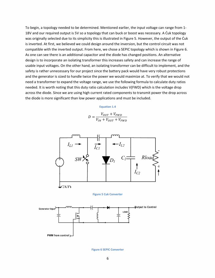
To begin, a topology needed to be determined. Mentioned earlier, the input voltage can range from 1-
18V and our required output is 5V so a topology that can buck or boost was necessary. A Ćuk topology
was originally selected due to its simplicity this is illustrated in Figure 5. However, the output of the Ćuk
is inverted. At first, we believed we could design around the inversion, but the control circuit was not
compatible with the inverted output. From here, we chose a SEPIC topology which is shown in Figure 6.
As one can see there is an additional capacitor and the diode has changed positions. An alternative
design is to incorporate an isolating transformer this increases safety and can increase the range of
usable input voltages. On the other hand, an isolating transformer can be difficult to implement, and the
safety is rather unnecessary for our project since the battery pack would have very robust protections
and the generator is sized to handle twice the power we would maximize at. To verify that we would not
need a transformer to expand the voltage range, we use the following formula to calculate duty ratios
needed. It is worth noting that this duty ratio calculation includes V(FWD) which is the voltage drop
across the diode. Since we are using high current rated components to transmit power the drop across
the diode is more significant than low power applications and must be included.
Equation 1.4
𝐷 =𝑉𝑂𝑈𝑇 + 𝑉𝐹𝑊𝐷
𝑉𝐼𝑁 + 𝑉𝑂𝑈𝑇 + 𝑉𝐹𝑊𝐷
Figure 5 Cuk Converter
Figure 6 SEPIC Converter
7
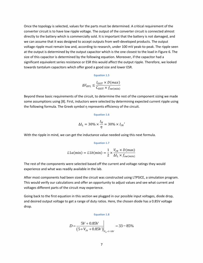
Once the topology is selected, values for the parts must be determined. A critical requirement of the
converter circuit is to have low ripple voltage. The output of the converter circuit is connected almost
directly to the battery which is commercially sold. It is important that the battery is not damaged, and
we can assume that it was designed to accept outputs from well-developed products. The output
voltage ripple must remain low and, according to research, under 100 mV peak-to-peak. The ripple seen
at the output is determined by the output capacitor which is the one closest to the load in Figure 6. The
size of this capacitor is determined by the following equation. Moreover, if the capacitor had a
significant equivalent series resistance or ESR this would affect the output ripple. Therefore, we looked
towards tantalum capacitors which offer good a good size and lower ESR.
Equation 1.5
∆𝑉𝑅𝑃𝐿 ≤𝐼𝑂𝑈𝑇 × 𝐷(𝑚𝑎𝑥)
COUT × 𝑓𝑠𝑤(min)
Beyond these basic requirements of the circuit, to determine the rest of the component sizing we made
some assumptions using [8]. First, inductors were selected by determining expected current ripple using
the following formula. The Greek symbol η represents efficiency of the circuit.
Equation 1.6
∆𝐼𝐿 = 30% ×𝐼𝑁
𝜂= 30% × 𝐼𝐼𝑁′
With the ripple in mind, we can get the inductance value needed using this next formula.
Equation 1.7
𝐿1𝑎(min) = 𝐿1𝑏(min) =1
2×
𝑉𝐼𝑁 × 𝐷(max)
∆𝐼𝐿 × 𝑓𝑠𝑤(𝑚𝑖𝑛)
The rest of the components were selected based off the current and voltage ratings they would
experience and what was readily available in the lab.
After most components had been sized the circuit was constructed using LTPSICE, a simulation program.
This would verify our calculations and offer an opportunity to adjust values and see what current and
voltages different parts of the circuit may experience.
Going back to the first equation in this section we plugged in our possible input voltages, diode drop,
and desired output voltage to get a range of duty ratios. Here, the chosen diode has a 0.85V voltage
drop.
Equation 1.8
( )1~18
5 0.8533 ~ 85%
5 0.85in
IN V V
V VD
V V=
+= =
+ +

8
This is a reasonable range of duty cycles, so the circuit does not require a transformer. Now that we
have a maximum duty ratio it can be used in the next formula to calculate Cout. We initially chose a
switching frequency of 20 kHz to limit the switching losses which are harder to solve for than scaling the
output capacitor and other components. Also, the maximum current at the output is 3 A and using the
desired ripple of 0.1 V we could solve the following equation.
Equation 1.9
3 0.851.275mF
.1 20OUT
AC
V kHz
=
Next, we size the inductors based on the suggested parameters in [8]. First, a ripple current was
arbitrarily chosen based on the suggestion of the design paper. Through our research there was no data
on current ripple for commercial products. In the following formula we used multiple input voltages
from our range and used the one that resulted in the smallest ripple requirements since that would be
our worst case.
Equation 1.11
3 530% 0.4
63%L
IN
A VI A
V
= =
With this ripple value, the inductors could be chosen.
Equation 1.12
0.8554
0.4 20
1
2IN H
k zL V
H ==
One note to this calculation is that there are a multitude of input voltage combinations to try for the
estimated ripple and necessary inductance. Now that these values have been calculated a simulation
was created to verify these calculations. Figure 9 (Appendix C) shows the simulated SEPIC converter
circuit using common capacitor values in the lab and modeling the MOSFET as a switch. The resistor is an
approximate load using Ohms law. The circuit was simulated at multiple input voltages to verify that we
can achieve the needed output voltage with the required ripple. Figure 10 in Appendix C is a screenshot
of the simulation output voltage zoomed in to illustrate the ripple. Both the criteria were met so the
currents and voltages on all the parts were noted and parts were chosen with the appropriate ratings
2.2.2 Control Unit
The main function of the control unit will be to certify that our voltage output will not exceed what the
battery is rated for, 5V. There are three general control strategies: proportional, derivative, and integral.
These can be combined in many combinations. Derivative was not used since it roughly predicts what
the error will be and since wind varies so wildly it is not worth adding the complexity since it would offer
limited benefit. Integral is used since it results in zero steady-state error which is always desired and

9
simple to implement. Lastly, proportional offers quick response but does not offer zero steady-state
error. Therefore, the control system chosen was proportional-integral.
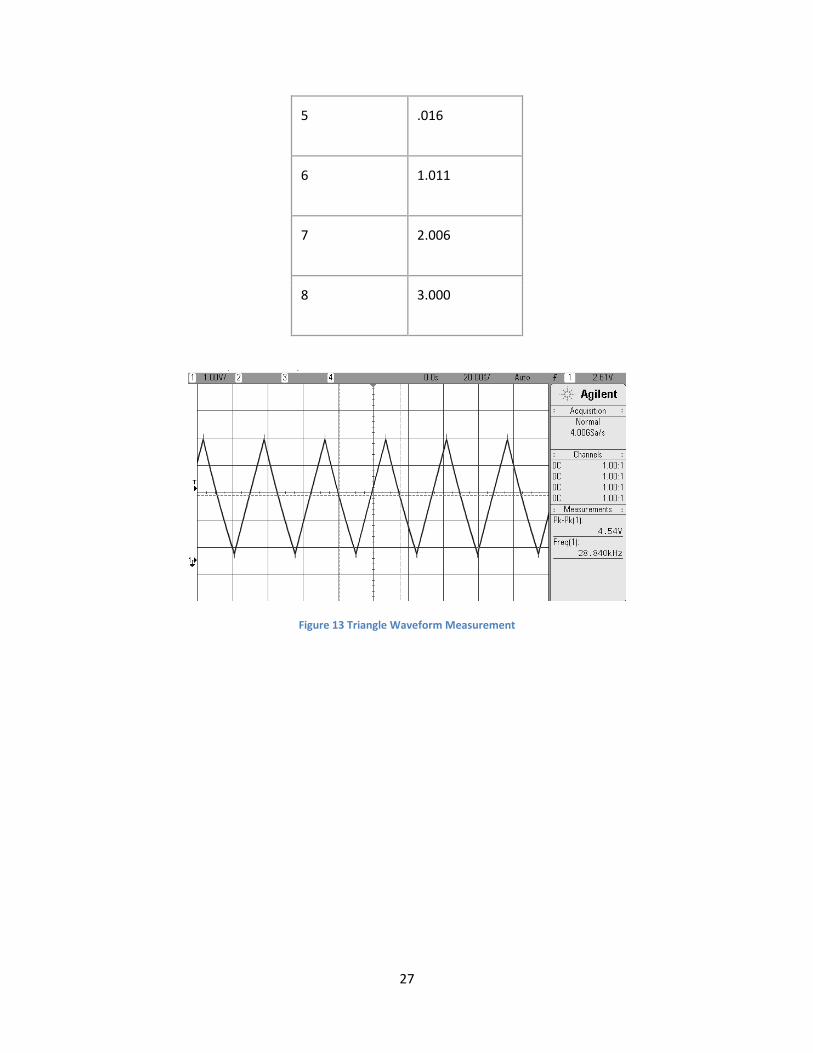
Next part of the control is the waveform generator. To achieve a PWM we need a triangle waveform and
a reference signal to pass through a comparator. When the triangle-wave and the reference signal are
passed through a comparator and if the reference signal is higher than the triangle the comparator
outputs a high signal. This output should perfectly mimic a PWM signal. To get the triangle wave we first
pass a reference signal and a feedback loop to Schmitt trigger. The Schmitt trigger is a comparator with
two reference thresholds for rising and falling edge. So, a DC signal is passed into the Schmitt trigger and
for a period it is above the low threshold and below the high threshold for the same amount of time.
Then, the output of the Schmitt trigger is passed to the next op amp which is in an integrator
configuration which depending on the sign of the output of the Schmitt trigger makes a positive or
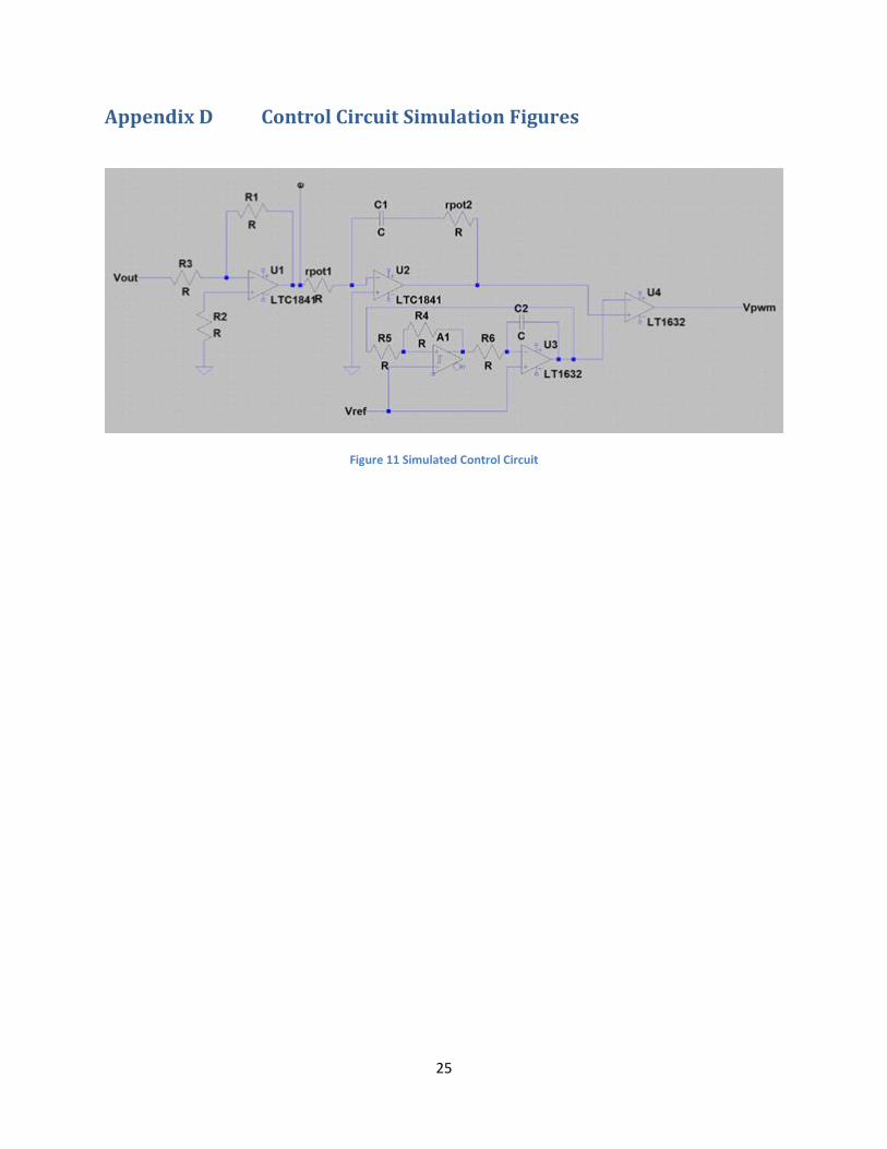
negative ramp thus making a triangle wave. The full topology of this description is in Figure 11 in
appendix D. The amplitude of the triangle wave is given by the following formula and for the frequency
we use the formula following the triangle wave amplitude formula. To simplify things, we can keep Rs1
to be double Rs2 so that the amplitude of the triangle wave is 5V. Lastly, the triangular wave and the
reference signal is passed through a comparator. We can change the reference signal to alter the duty
ratio of the PWM.
Equation 1.13
∆𝑉 = (𝑉𝑑𝑑
2) ∗ (
𝑅𝑆1
𝑅𝑆2)
Equation 1.14
𝐹𝑂𝑃 = (𝑅𝑆2
𝑅𝑆1) (
1
𝑅𝑖𝑛𝑡𝐶𝑖𝑛𝑡) (
𝑉𝑟𝑒𝑓(𝑉𝐷𝐷 − 𝑉𝑅𝐸𝐹)
𝑉𝐷𝐷2 )
2.3 Battery System This will be an off the shelf purchase. It is rated for 15W based on USB-C cable ratings. This will allow us
to charge our device. It will be powered through the output of our DC/DC converter. This will power the
phone and microcontroller. It must have 3 ports so that these functions may be performed correctly.
That is, the battery pack should be able to have a USB-C input to charge the pack up to a maximum
power of 15W, while having two other USB outputs (not required to be USB-C) that will power the
microcontroller while charging the phone.
2.4 Microcontroller We used an ATMEGA32-16PU microcontroller because its relatively low power consumption. This 8-bit
controller has 2 Kilobytes of SRAM, 32 general purpose I/O lines and 32x8 general purpose working
registers. The I/O has a master/slave SPI and other functions that we will need for communicating with
the LCD. The several input output lines serve us well since we will need to input data collected from the
generator and supply the control circuit components with 5V. On top of giving us the needed hardware
for the project, the ATmega32 microprocessor can run at a clock speed of 1MHz with 3V and 1.1mA

10
which is very low amount of power consumed by our generator. Also, since the Arduino Uno uses the
ATMEGA32-16PU, we can use the Arduino IDE to program the microcontroller for our own uses.
11
3. Design Verification
3.1 Turbine
3.1.1 Savonius Rotor
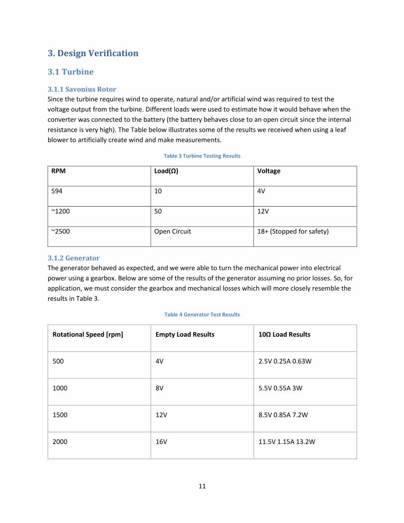
Since the turbine requires wind to operate, natural and/or artificial wind was required to test the
voltage output from the turbine. Different loads were used to estimate how it would behave when the
converter was connected to the battery (the battery behaves close to an open circuit since the internal
resistance is very high). The Table below illustrates some of the results we received when using a leaf
blower to artificially create wind and make measurements.
Table 3 Turbine Testing Results
RPM Load(Ω) Voltage
594 10 4V
~1200 50 12V
~2500 Open Circuit 18+ (Stopped for safety)
3.1.2 Generator
The generator behaved as expected, and we were able to turn the mechanical power into electrical
power using a gearbox. Below are some of the results of the generator assuming no prior losses. So, for
application, we must consider the gearbox and mechanical losses which will more closely resemble the
results in Table 3.
Table 4 Generator Test Results
Rotational Speed [rpm] Empty Load Results 10Ω Load Results
500 4V 2.5V 0.25A 0.63W
1000 8V 5.5V 0.55A 3W
1500 12V 8.5V 0.85A 7.2W
2000 16V 11.5V 1.15A 13.2W
12
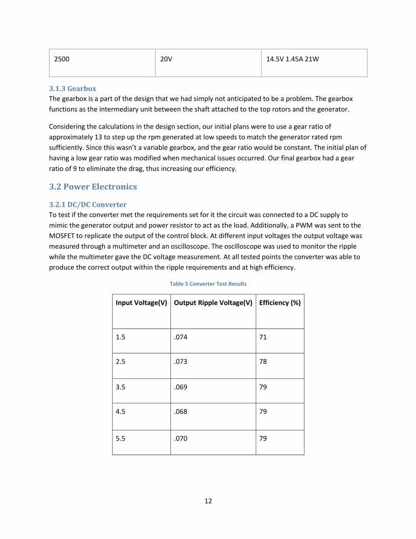
2500 20V 14.5V 1.45A 21W
3.1.3 Gearbox
The gearbox is a part of the design that we had simply not anticipated to be a problem. The gearbox
functions as the intermediary unit between the shaft attached to the top rotors and the generator.
Considering the calculations in the design section, our initial plans were to use a gear ratio of
approximately 13 to step up the rpm generated at low speeds to match the generator rated rpm
sufficiently. Since this wasn’t a variable gearbox, and the gear ratio would be constant. The initial plan of
having a low gear ratio was modified when mechanical issues occurred. Our final gearbox had a gear
ratio of 9 to eliminate the drag, thus increasing our efficiency.
3.2 Power Electronics
3.2.1 DC/DC Converter
To test if the converter met the requirements set for it the circuit was connected to a DC supply to
mimic the generator output and power resistor to act as the load. Additionally, a PWM was sent to the
MOSFET to replicate the output of the control block. At different input voltages the output voltage was
measured through a multimeter and an oscilloscope. The oscilloscope was used to monitor the ripple
while the multimeter gave the DC voltage measurement. At all tested points the converter was able to
produce the correct output within the ripple requirements and at high efficiency.
Table 5 Converter Test Results
Input Voltage(V) Output Ripple Voltage(V) Efficiency (%)
1.5 .074 71
2.5 .073 78
3.5 .069 79
4.5 .068 79
5.5 .070 79
13
3.2.2 Control Unit
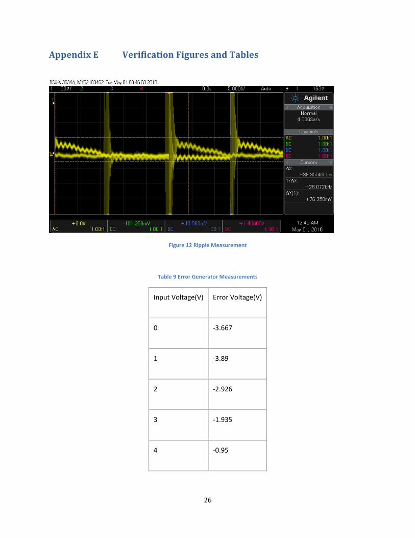
The control unit was tested by connecting the appropriate 5V supplies to the circuit and probing at
specific points. First, the error generator was tested which is the first step in the control. An input
voltage was passed to the leftmost OP-AMP in Figure 9 in Appendix C. The other input is a 5V reference.
A multimeter was connected to the output of this op-amp and the results are recorded in Table in
Appendix E. The error output was accurate for all values. Next, the triangle wave was verified. All this
required was supplying the 5V needed for each chip and monitoring the output of the integrating op-
amp. From Figure in Appendix E it is clear that the required triangle wave is correctly produced.
3.3 Battery System The battery behaved as expected. We had integration issues when connecting the output of our
converter to the battery itself, however, using the additional ports we were able to power the
microcontroller.
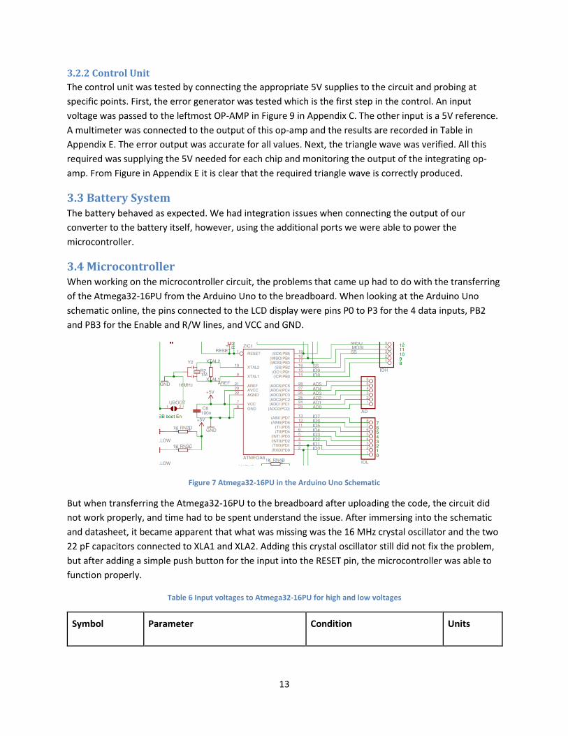
3.4 Microcontroller When working on the microcontroller circuit, the problems that came up had to do with the transferring
of the Atmega32-16PU from the Arduino Uno to the breadboard. When looking at the Arduino Uno
schematic online, the pins connected to the LCD display were pins P0 to P3 for the 4 data inputs, PB2
and PB3 for the Enable and R/W lines, and VCC and GND.
Figure 7 Atmega32-16PU in the Arduino Uno Schematic
But when transferring the Atmega32-16PU to the breadboard after uploading the code, the circuit did
not work properly, and time had to be spent understand the issue. After immersing into the schematic
and datasheet, it became apparent that what was missing was the 16 MHz crystal oscillator and the two
22 pF capacitors connected to XLA1 and XLA2. Adding this crystal oscillator still did not fix the problem,
but after adding a simple push button for the input into the RESET pin, the microcontroller was able to
function properly.
Table 6 Input voltages to Atmega32-16PU for high and low voltages
Symbol Parameter Condition Units

14
VIL Input Low Voltage Vcc= 1.8V - 2.4V V
VIH Input High Voltage Vcc= 2.4V - 5.5V V
When looking at the table above it was important for the microcontroller to be supplied a range of 1.8V
to 5.5V for the analog input. This input would be used to read the voltage being produced by the
generator. Using a voltage divider with 100 Ω and 30 Ω to step a voltage of 20V down to about 4.62V so
the microcontroller can the read the analog value without damaging any components in the circuit.

15
4. Costs
4.1 Parts Table 7 Parts Cost
Description Quantity Per Unit Price ($) Total Parts Cost ($)
36W Permanent Magnet DC motor/generator
1 34.99 (22.99 from international suppliers)
34.99
HD44780 LCDs 1 9.95 9.95
ATMEGA32-16PU 1 4.40 4.40
20000mAh Battery AUKEY PB-Y14-US*
1 39.99 39.99
PCBs (PCBWay) 1 3.10 3.10
Resistors/Potentiometer/5v Regulator 1 2.00 2.00
TPS25810** 1 0 0
Adafruit Pushbutton 2 4.66 4.66
8’’ Sch. 40 Pipe 5 ft (used 1.65ft)
55(used 18.15) 18.15
USB Micro-B Breakout Board 1 1.50 1.50
Fixed Inductor (220uH) 3 5.97 17.91
Aluminum - polymer capacitor (1.2mF) 1 1.34 1.34
Tantalum Capacitor (330uF) 3
1.50 4.50
Conformal coated tantalum capacitor (330uF)
3 6.09 18.27
Ceramic Capacitor (15uF) 1 0.70 0.70
Ceramic Capacitor (2.2uF) 1 0.70 0.70
MOSFET 1 1.13 1.13
Diode Schottky 1 1.76 1.76

16
IC - USB Interface 20-WQFN 1 1.84 1.84
USB-C: Molex 1 2.29 2.29
Switching voltage regulator - 5v to 12v 2 4.42 8.84
Voltage regulator - DC/DC switching regulator
1 0.43 0.43
MIC4426 - Gate driver 1 1.30 1.30
Total - 148.21 179.75
4.2 Labor Our fixed development costs are estimated to be $33.75/hour assuming the average annual salary is
$65,000 per year, 8 hours/week for three people.
3 ×$33.75
ℎ𝑟× 8
ℎ𝑜𝑢𝑟𝑠
𝑤𝑒𝑒𝑘×
10 𝑤𝑒𝑒𝑘𝑠
0.6× 2.5 = $33,750
4.3 Total Costs Considering we build 2 wind turbine generators, this will yield a total development cost of $34,109.5.
*This is an auxiliary component like the phone, so it is important to note that this component may be
subsidized if the user owns a similar product. The battery pack should have 3 ports, as well as USB-C
support to be compatible with the wind turbine. Excluding the battery pack decreases the per unit cost
of the parts by 22%.
**The specific prototype will use a Texas Instruments free sample, however, the unit price for per build
is $1.40 assuming the quantity to be 1-9, a bulk order such as 750-999 lowers the per unit cost to $0.71.
Note: The ECE Machine Shop labor cost and material provided by them such as the MBF wood is not
considered for these costs.

17
5. Conclusion
5.1 Accomplishments We created a robust turbine capable of generating power and withstanding high wind speeds. The
converter is able to take in input ranging from 1 to 18V and output a fixed 5V with minimal ripple and
high efficiency. The control circuit can output a PWM that would fix the output if it deviates from the
desired. The microcontroller can accurately measure the output voltage of the generator and correlate
that measurement with the wind speed and display it on an LCD screen. Additionally, the
microcontroller can supply 5V to components in the control circuit.
5.2 Uncertainties Some assumptions were required to be made during our testing and verification steps. For the turbine
and generation verification, a 10 and 50 Ohm resistor was selected to model the load of the battery
which may not be accurate since we were not able successfully probe the battery. The difficulty in
probing comes from the communication for USB-C the battery must be told to act as a load and cannot
simply be connected to a multimeter. Integration ran into issues at the control circuit. A 5 to 12V
regulator was needed to supply the gate driver but when the PWM logic was added to the input of the
gate driver along with 12V supply the 12V supply could only supply 4.8 V. The source of this issue comes
from the internal circuitry of the gate driver and the limited power output of the 12V regulator. When
connected to 12V bench supply the gate driver reads high power consumption so a new regulator with
high power potential is required.
5.3 Ethical considerations The user of our Wind Turbine will be directly involved with the operation of the device; thus, it is
important that we ensure a safe and reliable product. There must be safeguards in place to protect both
the product and the user.
There are several components in our product that may be potential safety hazards for the user if
mishandled or incorrectly designed. The main components to consider is the battery, the rotor blades,
the gears and the electrical circuitry.
Batteries always pose a risk since they can leak or explode. Proper handling will minimize the risks
associated from damaging the battery due to impact. To prevent an explosion, it’s important to monitor
the temperature of the device, as well as the power input into the battery. Since the input of the battery
is through the output of the power electronics, there is always an underlying risk of unstable power
being fed. The monitor of the output through the phone app, as well as a meticulous power electronics
design will lessen the risks related to the battery.
Another component to consider are the blades that will be spinning when the wind turbine is in motion.
The responsibility is on the user side mostly, users should always approach these machines with the
knowledge that they will have moving parts which should be handled with care. The blades will be made
from a plastic-like material which at high speeds may be dangerous if direct contact is made. As the

18
designer, there is a responsibility to make these blades safe to operate and using tools such as brakes
have the required automated oversight.
Gears in wind turbines are a hot topic of discussion since resolving the issues associated with them may
help extend their longevity. The mechanical fatigue and wear of these components can cause fires in the
long term, if not properly maintained. Future applications of these designs can avoid the use of gears by
using much higher pole generators that would decrease the RPM to match the turbine.
The wind turbine is expected to portable and may be chosen to be brought along on hiking trips or other
strenuous outdoor activities. Such activities may lead to occasional impacts; however, it is not the
normal mode of operation and therefore it should ideally be handled with care. There are many
electrical elements within the structure, and a strong exterior will provide the necessary protection for
the fragile interior. Different weather conditions in which the turbine will operate must also be
considered when designing the exterior and choosing the materials.
In addition to the portability and the conditions in which the turbine will be carried through, we must
also consider the operating conditions. At high speeds there may be vibration and temperature
variations that we must account for. Ideally, the material and structure of our turbine should withstand
these effects. The consideration of a secure mount also holds paramount importance in this aspect, as it
may help to minimize these factors.
Most products assume that the user will behave such that they do not put themselves or others at risk.
This wind turbine is no exception and it assumes that the user will act responsibly. We as the designers
must ensure that all the necessary steps are taken to mitigate the risks.
In compliance with the IEEE Code of Ethics [4], we must consider that our product will be available to
everyone, and that “to treat fairly all persons and to not engage in acts of discrimination based on race,
religion, gender, disability, age, national origin, sexual orientation, gender identity, or gender
expression”, thus adhering to #8 of the IEEE Code of Ethics. Additionally, we must follow the guidelines
underlined in #1, “to hold paramount the safety, health, and welfare of the public…” and in #3, “to be
honest and realistic in stating claims…” We must make sure that our wind turbine operates in a way that
is safe for the environment and surroundings. The output data that we provide in our phone application
must reflect what is measured in our devices.
5.4 Future work Our future work includes better integration of the parts, reducing the weight of the turbine as well as
increasing the efficiencies of the modules that make up the system. The weight of the turbine could be
reduced by implementing a smaller mechanical design. There are much lighter parts available and the
gearbox could easily be refined to take up less space, create less drag, and be lighter. The power
electronics could be made more efficient since some parts ended up oversized. Additionally, safety
features like braking and waterproofing could be incorporated to make the portable wind turbine more
versatile.
19
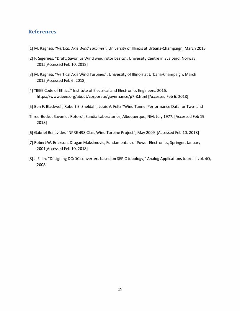
References
[1] M. Ragheb, “Vertical Axis Wind Turbines”, University of Illinois at Urbana-Champaign, March 2015
[2] F. Sigernes, “Draft: Savonius Wind wind rotor basics”, University Centre in Svalbard, Norway,
2015[Accessed Feb 10. 2018]
[3] M. Ragheb, “Vertical Axis Wind Turbines”, University of Illinois at Urbana-Champaign, March
2015[Accessed Feb 6. 2018]
[4] “IEEE Code of Ethics.” Institute of Electrical and Electronics Engineers. 2016.
https://www.ieee.org/about/corporate/governance/p7-8.html [Accessed Feb 6. 2018]
[5] Ben F. Blackwell, Robert E. Sheldahl, Louis V. Feltz “Wind Tunnel Performance Data for Two- and
Three-Bucket Savonius Rotors”, Sandia Laboratories, Albuquerque, NM, July 1977. [Accessed Feb 19.
2018]
[6] Gabriel Benavides “NPRE 498 Class Wind Turbine Project”, May 2009 [Accessed Feb 10. 2018]
[7] Robert W. Erickson, Dragan Maksimovic, Fundamentals of Power Electronics, Springer, January
2001[Accessed Feb 10. 2018]
[8] J. Falin, “Designing DC/DC converters based on SEPIC topology,” Analog Applications Journal, vol. 4Q,
2008.
20
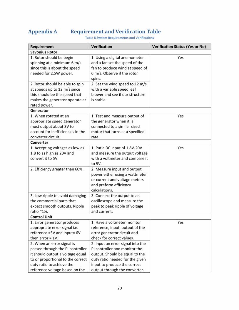
Appendix A Requirement and Verification Table Table 8 System Requirements and Verifications
Requirement Verification Verification Status (Yes or No)
Savonius Rotor
1. Rotor should be begin spinning at a minimum 6 m/s since this is about the speed needed for 2.5W power.
1. Using a digital anemometer and a fan set the speed of the fan to produce wind at speed of 6 m/s. Observe if the rotor spins.
Yes
2. Rotor should be able to spin at speeds up to 12 m/s since this should be the speed that makes the generator operate at rated power.
2. Set the wind speed to 12 m/s with a variable speed leaf blower and see if our structure is stable.
Generator
1. When rotated at an appropriate speed generator must output about 3V to account for inefficiencies in the converter circuit.
1. Test and measure output of the generator when it is connected to a similar sized motor that turns at a specified rate.
Yes
Converter
1. Accepting voltages as low as 1.8 to as high as 20V and convert it to 5V.
1. Put a DC input of 1.8V-20V and measure the output voltage with a voltmeter and compare it to 5V.
Yes
2. Efficiency greater than 60%. 2. Measure input and output power either using a wattmeter or current and voltage meters and preform efficiency calculations.
3. Low ripple to avoid damaging the commercial parts that expect smooth outputs. Ripple ratio ~1%.
3. Connect the output to an oscilloscope and measure the peak to peak ripple of voltage and current.
Control Unit
1. Error generator produces appropriate error signal i.e. reference =5V and input= 6V then error = 1V.
1. Have a voltmeter monitor reference, input, output of the error generator circuit and check for correct values.
Yes
2. When an error signal is passed through the PI controller it should output a voltage equal to or proportional to the correct duty ratio to achieve the reference voltage based on the
2. Input an error signal into the PI controller and monitor the output. Should be equal to the duty ratio needed for the given input to produce the correct output through the converter.

21
input voltage i.e. input =1.8V ref = 5V D=0.74V.
3. The Schmitt Trigger and Integrator circuit should output a triangle waveform of amplitude 1V.
3. With two op-amp circuits connected in series with a feedback loop the output of the circuit should be monitored through an oscilloscope to see if it is the required triangle wave.
Microcontroller
1. Can be programmed using the Arduino IDE and Arduino Uno.
1. Upload an example program written in the Arduino IDE (Blink) and test the circuit using the Arduino to test the Arduino Uno works. Then take out the ATMega32-16PU from the Arduino Uno and test the same circuit using the pins that correlate to the ATMega32-16PU from the Arduino Uno schematic. Use a 5v source to power the microcontroller.
Yes
2. Can monitor and accurately read voltage produced by the generator and power supplied by the battery.
2. Have a regular power supply feed into a node on a breadboard. Step down the voltage so it can be read at a voltage stickly below 5V, so the microcontroller is not damaged. Correlate the value read digitally by the microcontroller to the voltage being supplied by the power source.
3. Can both receive and transmit over Serial Protocol Interface at speeds greater than 2Mbps
3. Connect the microcontroller SPI port to another microcontroller SPI port, such as a BeagleBone. Both connected with a terminal in Putty. (Start Timer) send a 0.2Mbit block of random data from the ATmega32 SPI output to the Beaglebone’s SPI input.

22
Echo the data back, this time from the Beaglebone’s ARM processor. (Stop Timer) ensure that the data received matches the data sent, and the time does not elapse 100ms.

23
Appendix B Wind Turbine Photograph
Figure 8 Wind Turbine Photograph

24
Appendix C Converter Simulation Figures
Figure 9 Simulated SEPIC Circuit
Figure 10 SEPIC Simulation Output
25
Appendix D Control Circuit Simulation Figures
Figure 11 Simulated Control Circuit
26
Appendix E Verification Figures and Tables
Figure 12 Ripple Measurement
Table 9 Error Generator Measurements
Input Voltage(V) Error Voltage(V)
0 -3.667
1 -3.89
2 -2.926
3 -1.935
4 -0.95
27
5 .016
6 1.011
7 2.006
8 3.000
Figure 13 Triangle Waveform Measurement


