Embed Size (px)
Citation preview
EP3000 PRO 1KW~6KW
USER S MANUAL'
100% PURE SINE WAVE WITH CHARGER
Inverter/Charger INVERTER/CHARGER
420-00246-03

Table of Contents
Important Safety Information................................................................................
General Safety Precautions................................................................................
Precautions When Working with Batteries.............................................................
General Information............................................................................................
Application........................................................................................................
Features...........................................................................................................
Basic System Architecture....................................................................................
Product Overview...............................................................................................
Installation........................................................................................................
Unpacking and Inspection.................................................................................
Preparation....................................................................................................
Mounting The Unit...........................................................................................
Battery Connection..........................................................................................
AC Input/Output Connection.............................................................................
Electrical Performance........................................................................................
LCD Display Icons..............................................................................................
Operating Mode Description................................................................................
Warning code/Audible Alarm...............................................................................
Troubleshooting Guide....................................................................................... 20
19
16
14
11
8
7
6
6
6
6
4
4
3
3
2
1
1
1
This manual contains important instructions for all Inverter/Charger models that shall be followed during installation and maintenance of the inverter.
The following cases are not within the scope of warranty1. Out of warranty.2. Series number was changed or lost.3. Battery capacity was declined or external damaged.4. Inverter was damaged caused of transport shift, remissness, ect external factor5. Inverter was damaged caused of irresistible natural disasters.6. Not in accordance with the electrical power supply conditions or operate environment caused damage.
General Safety Precautions1 .Before installing and using the Inverter/Charger, read all instructions and cautionary markings on the Inverter/Charger and all appropriate sections of this guide be sure to read all instructions and cautionary markings for any equipment attached to this unit.2. This unit is designed for indoor use only. Do not expose the Inverter/Charger to rain, snow, or spray.3. To reduce risk of fire hazard, do not cover or obstruct the ventilation openings. Do not install the Inverter/Charger in a zero-clearance compartment. Otherwise overheating may occur.4. Use only attachments recommended or sold by the manufacturer. Doing otherwise may result in a risk of fire, electric shock, or injury to persons.5. To avoid a risk of fire and electric shock, make sure that existing wiring is in good condition and that wire is not undersized. Do not connect the Inverter/Charger with damaged or substandard wiring.6. Do not operate the Inverter/Charger if it has received a sharp blow, been dropped, orotherwise damaged in any way. If the Inverter/Charger is damaged, read the Warranty section.7.Do not disassemble the Inverter/charger. It contains no user-serviceable parts. See Warranty for instructions on obtaining service. Attempting to service the Inverter/Charger yourself may result in a risk of electrical shock or fire. Internal capacitors remain charged after all power is disconnected.8. The Inverter contains more than one live circuits (batteries and AC line).Power may be present at more than one source. To reduce the risk of electrical shock, disconnect both AC and DC power from the Inverter/Charger before attempting any maintenance or cleaning or working on any circuits connected to the Inverter/Charger. Turning off controls will not reduce this risk.9. Use insulated tools to reduce the chance of short-circuits when installing or working with the inverter, the batteries, or PV array.
Precautions When Working with Batteries1 .Make sure the batteries are well ventilated to the environment around.2. Never smoke or allow a spark or flame near the engine or batteries.3. Use caution to reduce the risk of dropping a metal tool on the battery. It could spark or short circuit the battery or other electrical parts and could cause an explosion.
Important Safety Information
WARNING!
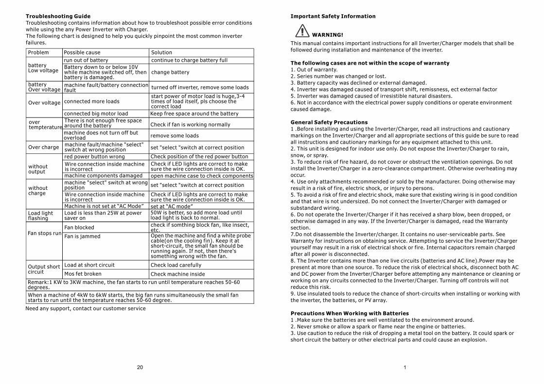
Troubleshooting GuideTroubleshooting contains information about how to troubleshoot possible error conditions while using the any Power Inverter with Charger.The following chart is designed to help you quickly pinpoint the most common inverter failures.
Need any support, contact our customer service
Problem Possible cause Solution
batteryLow voltage
run out of batteryBattery down to or below 10V while machine switched off, then battery is damaged.
continue to charge battery full
change battery
turned off inverter, remove some loadsmachine fault/battery connection fault
batteryOver voltage
Over voltage connected more loads
connected big motor load
start power of motor load is huge,3-4 times of load itself, pls choose the correct loadKeep free space around the battery
Over charge machine fault/machine "select" switch at wrong position set "select "switch at correct position
over tempterature
There is not enough free space around the batterymachine does not turn off but overload
Check if fan is working normally
remove some loads
without output
red power button wrongWire connection inside machine is incorrect
Check position of the red power buttonCheck if LED lights are correct to make sure the wire connection inside is OK.
without charge
machine "select" switch at wrong position
machine components damaged open machine case to check components
set "select "switch at correct position
Wire connection inside machine is incorrectMachine is not set at “AC Mode” set at “AC mode”
Check if LED lights are correct to make sure the wire connection inside is OK.
Load light flashing
Load is less than 25W at power saver on
50W is better, so add more load until load light is back to normal.
Fan stops runFan blocked
Fan is jammed
check if somthing block fan, like insect, etc.Open the machine and find a white probe cable(on the cooling fin). Keep it at short-circuit, the small fan should be running again. If not, then there's something wrong with the fan.
Output short circuit
Load at short circuit
Mos fet broken
Check load carefully
Check machine inside
Remark:1 KW to 3KW machine, the fan starts to run until temperature reaches 50-60 degrees.When a machine of 4kW to 6kW starts, the big fan runs simultaneously the small fan starts to run until the temperature reaches 50-60 degree.
4. Remove all metal items, like rings, brace lets, and watches when working with lead-acid batteries. Lead-acid batteries produce a short circuit current high enough to weld metal to skin, causing a severe burn.5. Make sure someone is close enough to aid you if danger occur when you're working near a lead-acid battery.6. Prepare enough fresh water and soap in case battery acid contacts skin, clothing, or eyes.7. Wear complete eye protection and clothing protection. Avoid touching your eyes while working near batteries.8. If battery acid contacts skin or clothing, wash immediately with soap and water. If acid enters your eye, immediately flood it with cold water and get medical attention immediately.9. If you need to remove a battery, always remove the grounded terminal from the battery first. Make sure all accessories are off so you don't cause a spark.10. Always use identical types of batteries.11 .Never install old or untested batteries. Check each batteries date code label to ensure age and type.12. Batteries are temperature sensitive. For optimal performance, the should be installed in as table temperature environment.13. Always recycle old batteries. Contact your local recycling center for proper disposal information.
General InformationThank you for purchasing the Inverter/Charger.The inverter is a combination of an inverter, charger, solar charger.It is packed with unique features and it is one of the most advanced inverter/charger in the market today.
The inverter features an AC bypass circuit, powering your home appliances from utility or ·
generator power while charging the battery. When utility power fails, the battery backup system keeps your appliances powered until utility power is restored. Internal protection circuits prevent over-discharge of the batteries by shutting down the inverter when a low battery condition occurs. When utility or generator power is restored, the inverter transfers to the AC source and recharges the batteries.
The series inverter can also serve as a central hub of renewable energy system. Set the ·
series inverter to battery priority mode, designates the inverter-preferred UPS configuration.In this configuration, the load power is normally provided by the inverter, However, if the ·
inverter output is interrupted, an internal transfer switch automatically transfers the load from the inverter to commercial utility power. The transfer time between inverter and line is short (6ms typical),and such transfers are normally not detected by even highly sensitive loads. Upon restoration of Battery capacity, the inverter will transfer back to inverter power.
In the line priority mode, when utility power cuts off (or falls out of acceptable range), ·
the transfer relay is de-energized and the load is automatically transferred to the inverter output.
Once the qualified utility power is restored, the relay is energized and the load is automatic· reconnected to utility power.
The inverter is equipped with a powerful charger of up to 70Amp (depending on Mode). ·
The overload capacity is 125%-150% of continuous output for up to 20 seconds to reliably support tools and equipment longer.
Another important feature is that the inverter can be easily customized to solar priority ·
by a DIP switch, this helps to extract maximum power from solar in renewable energy systems.
To get the most out of the power inverter, it must be installed, used and maintained ·
properly. Please read the instructions in the manual before installing and operating.
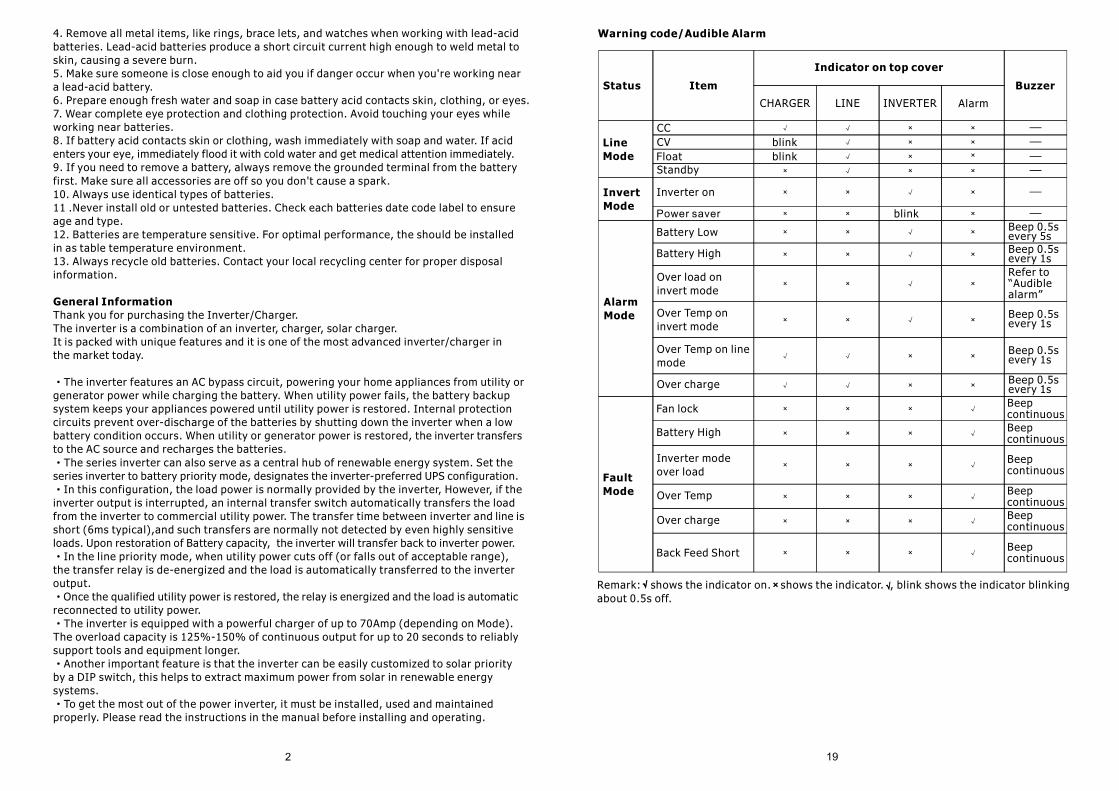
Warning code/Audible Alarm
Remark: shows the indicator on. shows the indicator. , blink shows the indicator blinkingabout 0.5s off.
Status Item
Indicator on top cover
Buzzer
CHARGER LINE INVERTER Alarm
CCCVFloatStandby
Inverter on
blinkblink
blink
Line Mode
Invert Mode
Alarm Mode
Power saver
Battery Low
Battery High
Over load on invert mode
Beep 0.5s every 5sBeep 0.5s every 1sRefer to “Audible alarm”
Beep 0.5s every 1s
Over Temp on invert mode
Over Temp on line mode
Over charge
Beep 0.5s every 1s
Beep 0.5s every 1s
Fault Mode
Fan lock
Battery High
Inverter mode over load
Over Temp
Over charge
Back Feed Short
Beep continuousBeep continuous
Beep continuous
Beep continuousBeep continuous
Beep continuous
ApplicationPower tools-circular saws, drills, grinders, sanders, buffers, weed and hedge trimmers, aircompressors.Office equipment such as computers, printers, monitors, facsimile machines, scanners.Household items-vacuum cleaners, fans, fluorescent and incandescent lights, shavers,sewing machines.Kitchen appliances-coffee makers, blenders, ice markers, toasters.Industrial equipment-metal halide lamp, high-pressure sodium lamp.Home entertainment electronics-television, VCRs, video games, stereos, musical instrumentssatellite equipment.
FeaturesPure sine wave output·
AC/Battery priority Via function switch·
Auto generator start(AGS)·
Max. AC charge current 70A.(Optional)·
Inbuilt pure copper transformer·
Low battery trip volt 10.5V/11.0V·
50HZ/60HZ sense automatically·
RS232 with free CD·
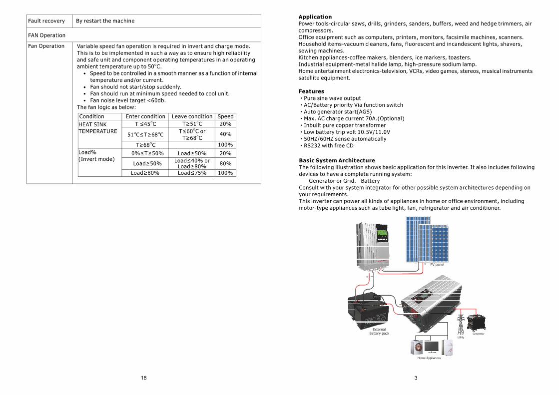
Basic System ArchitectureThe following illustration shows basic application for this inverter. It also includes following devices to have a complete running system: Generator or Grid. BatteryConsult with your system integrator for other possible system architectures depending on your requirements.This inverter can power all kinds of appliances in home or office environment, including motor-type appliances such as tube light, fan, refrigerator and air conditioner.
Fault recovery By restart the machine
FAN Operation
Fan Operation Variable speed fan operation is required in invert and charge mode. This is to be implemented in such a way as to ensure high reliability and safe unit and component operating temperatures in an operating ambient temperature up to 50 C.O
Speed to be controlled in a smooth manner as a function of internal temperature and/or current. Fan should not start/stop suddenly. Fan should run at minimum speed needed to cool unit. Fan noise level target <60db.The fan logic as below:
Condition Enter condition Leave condition SpeedHEAT SINKTEMPERATURE
T ≤45 CO
51 C≤T≥68 CO O
T≥51 CO 20%
40%T≤60 C orO
T≥68 CO
T≥68 CO 100%Load%(Invert mode)
0%≤T≥50%
Load≥50%
Load≥80%
Load≥50%Load≤40% or
Load≥80%Load≤75%
20%
80%
100%
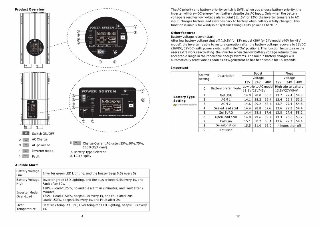
Product Overview
Charge Current Adjuster:25%,50%,75%,100%(Optional)
7. Battery Type Selector8. LCD display
Switch ON/OFF
AC Charge
AC power on
Inverter mode
Fault
Audible Alarm
Battery VoltageLow Inverter green LED Lighting, and the buzzer beep 0.5s every 5s
Inverter green LED Lighting, and the buzzer beep 0.5s every 1s, and Fault after 60s.110%< load<125%, no audible alarm in 2 minutes, and Fault after 2 minutes.125% <load<150%, beeps 0.5s every 1s, and Fault after 20s.Load>150%, beeps 0.5s every 1s, and Fault after 2s.
Heat sink temp. 105 C, Over temp red LED Lighting, beeps 0.5s every ≥ o
1s.
Battery VoltageHigh
Inverter ModeOver-Load
OverTemperature
The AC priority and battery priority switch is SWS. When you choose battery priority, the inverter will draw DC energy from battery despite the AC input. Only when the battery voltage is reaches low voltage alarm point (11 .5V for 12V).the inverter transfers to AC input, charges battery, and switches back to battery when battery is fully charged. This function is mainly for wind/solar systems taking utility power as back up.
Other featuresBattery voltage recover startAfter low battery voltage shut off (10.5V for 12V model /20V for 24V model /40V for 48Vmodel),the inverter is able to restore operation after the battery voltage recovers to 13VDC/26VDC/52VDC (with power switch still in the "On" position). This function helps to save the users extra work reactivating the inverter when the low battery voltage returns to an acceptable range in the renewable energy systems. The built in battery charger willautomatically reactivate as soon as city/generator ac has been stable for 15 seconds.
Important:
- - - - - -4 hours then off
Battery Type Setting
Switchsetting
DescriptionBoost
Voltage12V 24V
Floatvoltage
Battery prefer mode0
1 Gel USAAGM 1AGM 2
Sealed lead acidGel EURO
Open lead acidCalcuim
De sulphation
Not used
Low trip to AC model11.5V/23V/46V
High trip to battery13.5V/27V/54V
48V
23456789
12V 24V 48V
14.014.114.614.414.4
14.815.115.5
28.028.229.228.828.8
29.630.231.0
56.056.458.457.657.6
59.260.462.0
13.713.413.713.613.8
13.313.6
27.426.827.427.227.6
26.627.2
54.853.654.854.455.2
53.254.4
Switch
ON(Power Saver) Power on with saver mode (power saver 25W)≦
INVERTER OFF
ON
Power totally off (If there is AC power lnverter have charger function)
Power on without saver modeProtection
OverTemperatureProtection
Back-FeedProtection
Yes
Heat sink temp. ≥105 C, Fault (shutdown Output) after 30 secondso
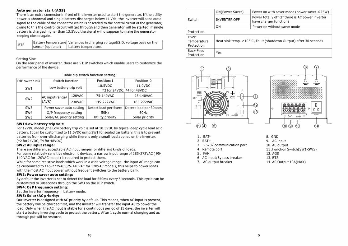
1 . BAT- 2. BAT+ 3. RS232 communication port 4. Remote port 5 . FAN 6. AC input/Bypass breaker 7. AC output breaker
Auto generator start (AGS)There is an extra connector in front of the inverter used to start the generator. If the utility power is abnormal and single battery discharges below 11 Vdc, the inverter will send out a signal to the cable of the connector which is cascaded to the control circuit of the generator, owing to this the control circuit will get through and then generator will be started. if single battery is charged higher than 13.5Vdc,the signal will disappear to make the generator keeping closed again.
BTSBattery temperaturesensor (optional)
Variances in charging voltage&S.D. voltage base on the battery temperature.
Setting SineOn the rear panel of inverter, there are 5 DIP switches which enable users to customize theperformance of the device.
Table dip switch function setting
DIP switch NO
SW1
SW2
SW3SW4SW5 Solar/AC priority setting
O/P frequency settingPower saver auto setting
AC input range/(AVR)
120VAC
230VAC
Utility priority Solar priority 50Hz 60Hz
Low battery trip volt
Switch function Position:1 Position:010.5VDC 11.0VDC
*2 for 24VDC, *4 for 48VDC
75-140VAC 95-140VAC
145-272VAC 185-272VAC
Detect load per 5secs Detect load per 30secs
SW1:Low battery trip volt:For 12VDC model ,the Low battery trip volt is set at 10.5VDC by typical deep cycle lead acidbattery. It can be customized to 11.0VDC using SW1 for sealed car battery, this is to preventbatteries from over-discharging while there is only a small load applied on the inverter. (*2 for24VDC, "4 for 48VDC)SW2: AC input range:There are different acceptable AC input ranges for different kinds of loads.For some relatively sensitive electronic devices, a narrow input range of 185-272VAC ( 95-140 VAC for 120VAC model) is required to protect them.While for some resistive loads which work in a wide voltage range, the input AC range can be customized to 145-272VAC (75-140VAC for 120VAC model), this helps to power loads with the most AC input power without frequent switches to the battery bank.SW3: Power saver auto setting:By default the inverter is set to detect the load for 250ms every 5 seconds. This cycle can becustomized to 30seconds through the SW3 on the DIP switch.SW4: O/P frequency setting:Set the inverter frequency in battery mode.SW5: Solar/AC priority:Our inverter is designed with AC priority by default. This means, when AC input is present, the battery will be charged first, and the inverter will transfer the input AC to power the load. Only when the AC input is stable for a continuous period of 15 days, the inverter will start a battery inverting cycle to protect the battery. After 1 cycle normal charging and ac through put will be restored.
8. GND9. AC input10. AC output11 .Function Switch(SW1-SW5)12. AGS13. BTS14. AC Output 10A(MAX)
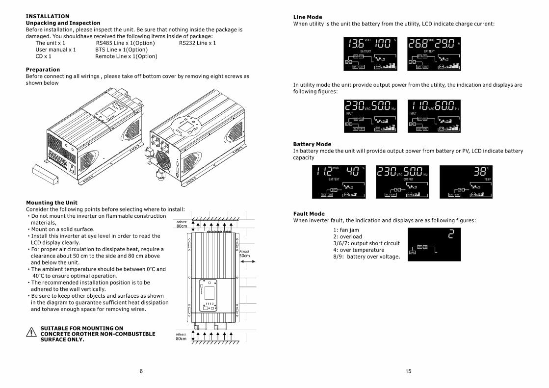
INSTALLATIONUnpacking and InspectionBefore installation, please inspect the unit. Be sure that nothing inside the package is damaged. You shouldhave received the following items inside of package: The unit x 1 RS485 Line x 1(Option) RS232 Line x 1 User manual x 1 BTS Line x 1(Option) CD x 1 Remote Line x 1(Option)
PreparationBefore connecting all wirings , please take off bottom cover by removing eight screws as shown below
Mounting the Unit Consider the following points before selecting where to install:
Do not mount the inverter on flammable construction ·
materials,Mount on a solid surface.·
Install this inverter at eye level in order to read the ·
LCD display clearly.For proper air circulation to dissipate heat, require a ·
clearance about 50 cm to the side and 80 cm above and below the unit.
The ambient temperature should be between 0 C and· o
40 C to ensure optimal operation.o
The recommended installation position is to be ·
adhered to the wall vertically.Be sure to keep other objects and surfaces as shown ·
in the diagram to guarantee sufficient heat dissipation and tohave enough space for removing wires.
SUITABLE FOR MOUNTING ON CONCRETE OROTHER NON-COMBUSTIBLE SURFACE ONLY.
Line ModeWhen utility is the unit the battery from the utility, LCD indicate charge current:
In utility mode the unit provide output power from the utility, the indication and displays arefollowing figures:
Battery ModeIn battery mode the unit will provide output power from battery or PV, LCD indicate battery capacity
Fault ModeWhen inverter fault, the indication and displays are as following figures:
1: fan jam2: overload3/6/7: output short circuit4: over temperature8/9: battery over voltage.
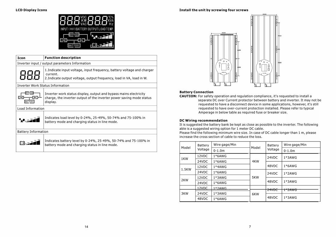
Install the unit by screwing four screws
Battery Connection For safety operation and regulation compliance, it's requested to install a CAUTION:
separate DC over Current protector between battery and inverter. It may not be requested to have a disconnect device in some applications, however, it's still requested to have over-current protection installed. Please refer to typical Amperage in below table as required fuse or breaker size.
DC Wiring recommendationIt is suggested the battery bank be kept as close as possible to the inverter. The following able is a suggested wiring option for 1 meter DC cable.Please find the following minimum wire size. In case of DC cable longer than 1 m, pleaseincrease the cross section of cable to reduce the loss.
ModelBatteryVoltage
Wire gage/Min
0-1.0m
1KW
1.5KW
2KW
3KW
48VDC
24VDC
12VDC
4KW
5KW
6KW
1*6AWG
1*4AWG
1*3AWG
1*2AWG
24VDC
12VDC
24VDC
12VDC
24VDC
12VDC
ModelBatteryVoltage
Wire gage/Min
0-1.0m
1*3AWG
1*6AWG
1*6AWG
1*6AWG
1*6AWG
1*3AWG
1*6AWG48VDC
24VDC
48VDC
24VDC
48VDC
24VDC
1*2AWG
1*3AWG
1*2AWG
1*3AWG
LCD Display Icons
Icon Function description
Inverter input / output parameters Information
1.Indicate input voltage, input frequency, battery voltage and charger current.2.Indicate output voltage, output frequency, load in VA, load in W.
Inverter Work Status Information
Inverter work status display, output and bypass mains electricity charge, the inverter output of the inverter power saving mode status display.
Load Information
Indicates load level by 0-24%, 25-49%, 50-74% and 75-100% in battery mode and charging status in line mode.
Battery Information
Indicates battery level by 0-24%, 25-49%, 50-74% and 75-100% in battery mode and charging status in line mode.
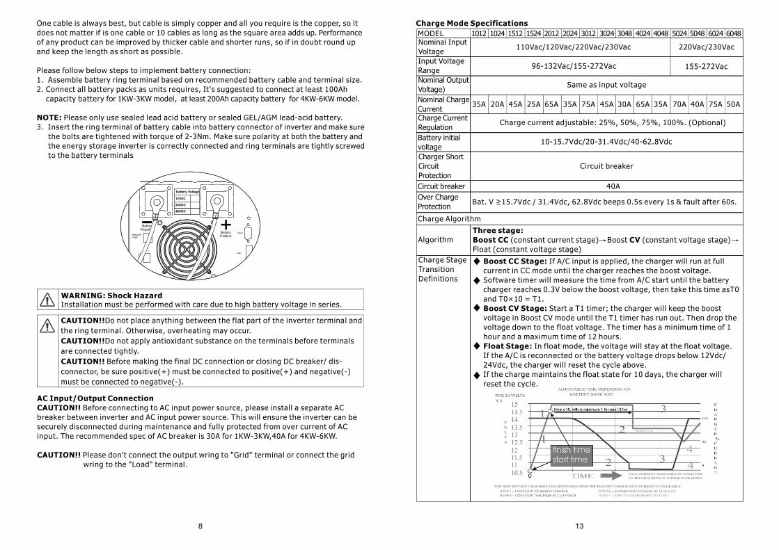
One cable is always best, but cable is simply copper and all you require is the copper, so it does not matter if is one cable or 10 cables as long as the square area adds up. Performance of any product can be improved by thicker cable and shorter runs, so if in doubt round up and keep the length as short as possible.
Please follow below steps to implement battery connection:1. Assemble battery ring terminal based on recommended battery cable and terminal size.2. Connect all battery packs as units requires, It's suggested to connect at least 100Ah capacity battery for 1KW-3KW model, at least 200Ah capacity battery for 4KW-6KW model.
Please only use sealed lead acid battery or sealed GEL/AGM lead-acid battery.NOTE: 3. Insert the ring terminal of battery cable into battery connector of inverter and make sure the bolts are tightened with torque of 2-3Nm. Make sure polarity at both the battery and the energy storage inverter is correctly connected and ring terminals are tightly screwed to the battery terminals
WARNING: Shock HazardInstallation must be performed with care due to high battery voltage in series.
CAUTION!!Do not place anything between the flat part of the inverter terminal and the ring terminal. Otherwise, overheating may occur.
Do not apply antioxidant substance on the terminals before terminals CAUTION!!are connected tightly.
Before making the final DC connection or closing DC breaker/ dis-CAUTION!! connector, be sure positive(+) must be connected to positive(+) and negative(-) must be connected to negative(-).
AC Input/Output ConnectionBefore connecting to AC input power source, please install a separate AC CAUTION!!
breaker between inverter and AC input power source. This will ensure the inverter can be securely disconnected during maintenance and fully protected from over current of AC input. The recommended spec of AC breaker is 30A for 1KW-3KW,40A for 4KW-6KW.
CAUTION!! Please don't connect the output wring to "Grid" terminal or connect the grid wring to the "Load" terminal.
MODEL 1012 1024 1512 1524 2012 2024 3012 3024 3048 4024 4048 5024 5048 6024 6048
110Vac/120Vac/220Vac/230VacNominal Input VoltageInput Voltage Range
Nominal Charge CurrentCharge Current RegulationBattery initial voltageCharger Short Circuit Protection
Circuit breaker
10-15.7Vdc/20-31.4Vdc/40-62.8Vdc
Charge current adjustable: 25%, 50%, 75%, 100%. (Optional)
Circuit breaker 40AOver Charge Protection
Bat. V ≥15.7Vdc / 31.4Vdc, 62.8Vdc beeps 0.5s every 1s & fault after 60s.
Algorithm
Charge StageTransitionDefinitions
Charge Mode Specifications
Same as input voltage
96-132Vac/155-272Vac 155-272Vac
Nominal Output Voltage)
45A
Three stage: (constant current stage) Boost (constant voltage stage) Boost CC CV
Float (constant voltage stage)
220Vac/230Vac
35A 20A 45A 25A 65A 35A 75A 30A 65A 35A 70A 40A 75A 50A
Charge Algorithm
Boost CC Stage: If A/C input is applied, the charger will run at full current in CC mode until the charger reaches the boost voltage. Software timer will measure the time from A/C start until the battery charger reaches 0.3V below the boost voltage, then take this time asT0 and T0×10 = T1.
Start a T1 timer; the charger will keep the boost Boost CV Stage: voltage in Boost CV mode until the T1 timer has run out. Then drop the voltage down to the float voltage. The timer has a minimum time of 1 hour and a maximum time of 12 hours.
In float mode, the voltage will stay at the float voltage. Float Stage:If the A/C is reconnected or the battery voltage drops below 12Vdc/24Vdc, the charger will reset the cycle above.If the charge maintains the float state for 10 days, the charger will reset the cycle.
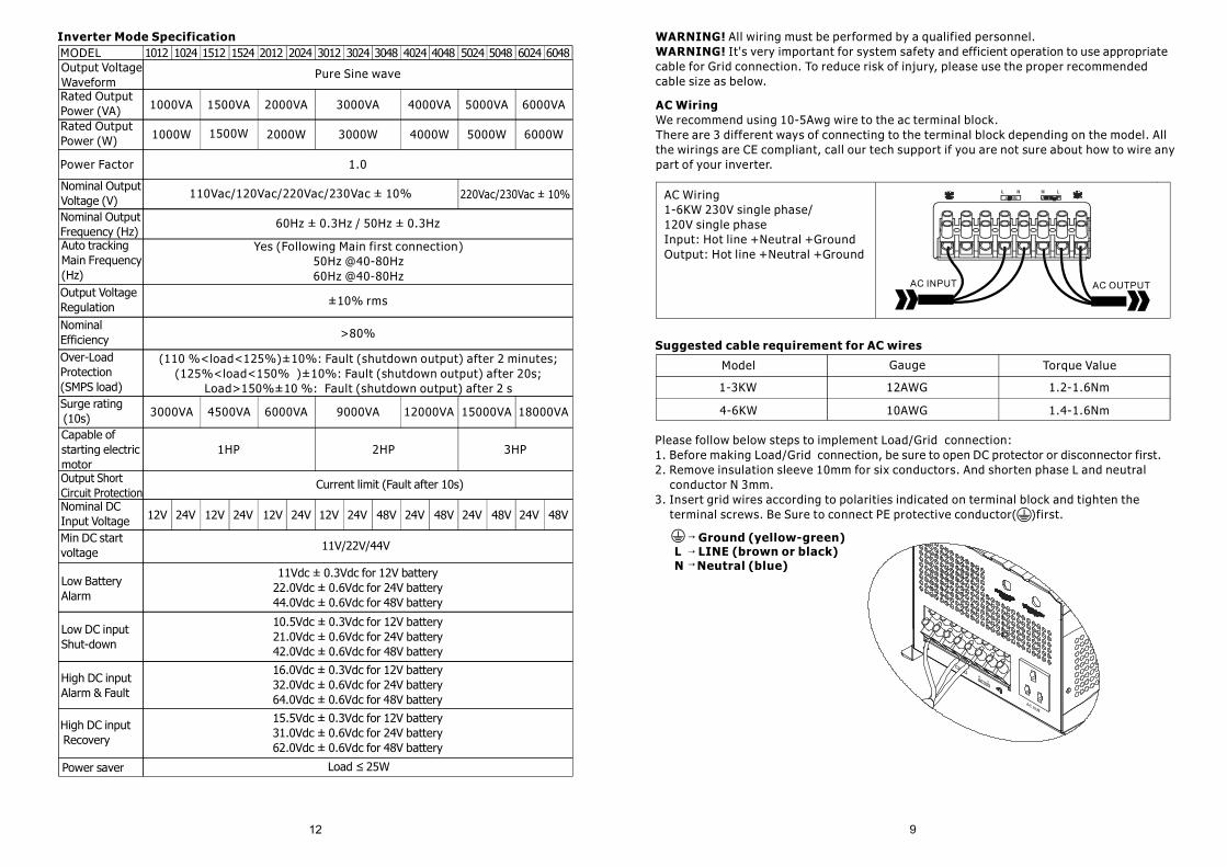
WARNING! All wiring must be performed by a qualified personnel. It's very important for system safety and efficient operation to use appropriate WARNING!
cable for Grid connection. To reduce risk of injury, please use the proper recommended cable size as below.
AC WiringWe recommend using 10-5Awg wire to the ac terminal block.There are 3 different ways of connecting to the terminal block depending on the model. All the wirings are CE compliant, call our tech support if you are not sure about how to wire any part of your inverter.
AC Wiring1-6KW 230V single phase/120V single phaseInput: Hot line +Neutral +GroundOutput: Hot line +Neutral +Ground
Suggested cable requirement for AC wires
Model
1-3KW
4-6KW
Gauge
12AWG
10AWG
Torque Value
1.2-1.6Nm
1.4-1.6Nm
Please follow below steps to implement Load/Grid connection:1. Before making Load/Grid connection, be sure to open DC protector or disconnector first.2. Remove insulation sleeve 10mm for six conductors. And shorten phase L and neutral conductor N 3mm.3. Insert grid wires according to polarities indicated on terminal block and tighten the terminal screws. Be Sure to connect PE protective conductor( )first.
Ground (yellow-green)L LINE (brown or black)N Neutral (blue)
MODEL 1012 1024 1512 1524 2012 2024 3012 3024 3048 4024 4048 5024 5048 6024 6048
Pure Sine waveOutput Voltage WaveformRated Output Power (VA)
Power Factor
Nominal Output Voltage (V)Nominal Output Frequency (Hz)Auto tracking Main Frequency (Hz)
Yes (Following Main first connection)50Hz @40-80Hz60Hz @40-80Hz
60Hz ± 0.3Hz / 50Hz ± 0.3Hz
110Vac/120Vac/220Vac/230Vac ± 10% 220Vac/230Vac ± 10%
Output Voltage Regulation ±10% rms
Nominal Efficiency >80%
Over-Load Protection(SMPS load)
(110 %<load<125%)±10%: Fault (shutdown output) after 2 minutes;(125%<load<150% )±10%: Fault (shutdown output) after 20s;
Load>150%±10 %: Fault (shutdown output) after 2 sSurge rating (10s)Capable of starting electric motorOutput Short Circuit Protection
Current limit (Fault after 10s)
Nominal DC Input VoltageMin DC start voltage 11V/22V/44V
Low Battery Alarm
11Vdc ± 0.3Vdc for 12V battery22.0Vdc ± 0.6Vdc for 24V battery44.0Vdc ± 0.6Vdc for 48V battery
Low DC input Shut-down
10.5Vdc ± 0.3Vdc for 12V battery21.0Vdc ± 0.6Vdc for 24V battery42.0Vdc ± 0.6Vdc for 48V battery
High DC input Alarm & Fault
16.0Vdc ± 0.3Vdc for 12V battery32.0Vdc ± 0.6Vdc for 24V battery64.0Vdc ± 0.6Vdc for 48V battery
High DC input Recovery
15.5Vdc ± 0.3Vdc for 12V battery31.0Vdc ± 0.6Vdc for 24V battery62.0Vdc ± 0.6Vdc for 48V battery
Inverter Mode Specification
1000VA
1000W
1500VA
1500W
2000VA
2000W
3000VA
3000W
4000VA
4000W
5000VA
5000W
6000VA
6000WRated Output Power (W)
1.0
3HP
18000VA15000VA12000VA9000VA
2HP1HP
6000VA4500VA3000VA
12V
Power saver Load 25W≤
24V 12V 24V 12V 24V 12V 24V 48V 24V 48V 24V 48V 24V 48V
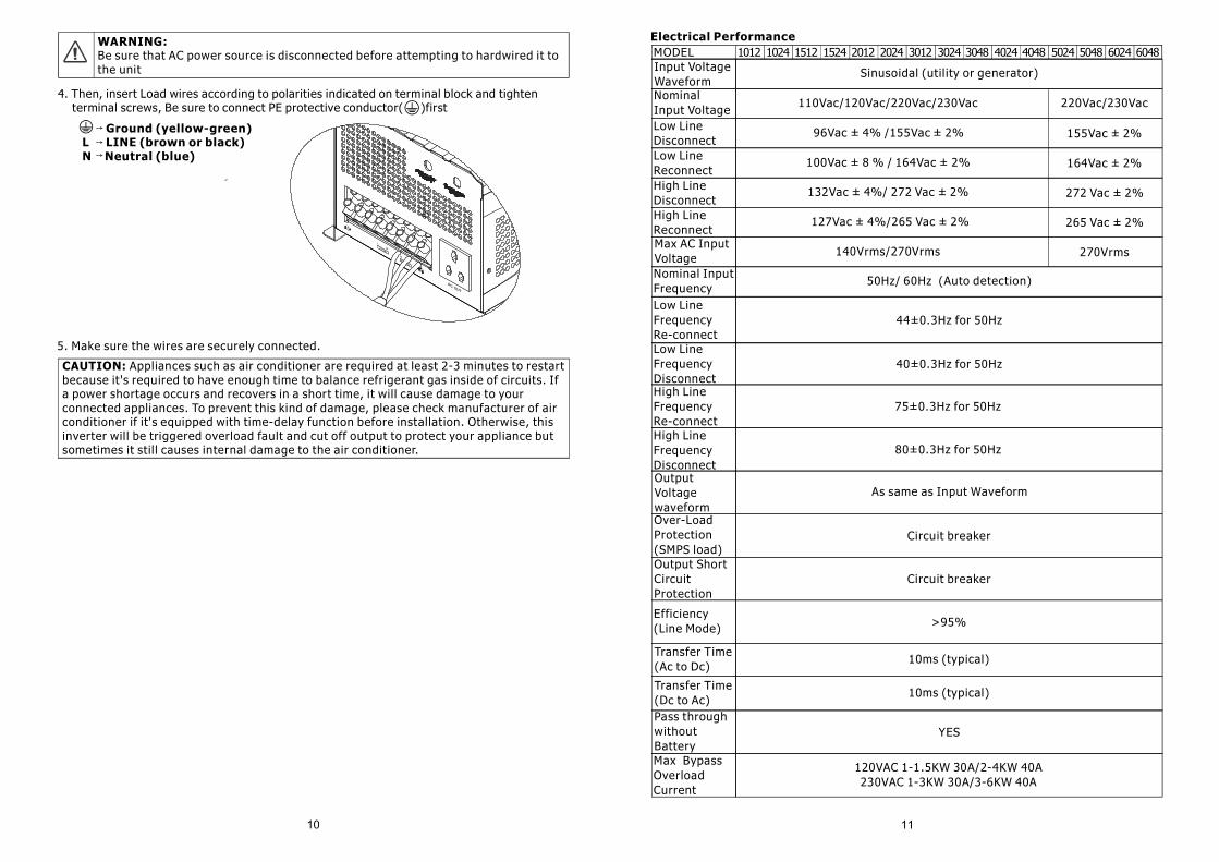
WARNING:Be sure that AC power source is disconnected before attempting to hardwired it to the unit
4. Then, insert Load wires according to polarities indicated on terminal block and tighten terminal screws, Be sure to connect PE protective conductor( )first
Ground (yellow-green)L LINE (brown or black)N Neutral (blue)
CAUTION: Appliances such as air conditioner are required at least 2-3 minutes to restart because it's required to have enough time to balance refrigerant gas inside of circuits. If a power shortage occurs and recovers in a short time, it will cause damage to your connected appliances. To prevent this kind of damage, please check manufacturer of air conditioner if it's equipped with time-delay function before installation. Otherwise, this inverter will be triggered overload fault and cut off output to protect your appliance but sometimes it still causes internal damage to the air conditioner.
5. Make sure the wires are securely connected.
MODEL 1012 1024 1512 1524 2012 2024 3012 3024 3048 4024 4048 5024 5048 6024 6048
Sinusoidal (utility or generator)Input VoltageWaveformNominalInput VoltageLow LineDisconnectLow LineReconnectHigh LineDisconnectHigh LineReconnectMax AC InputVoltage
50Hz/ 60Hz (Auto detection)Nominal InputFrequency
140Vrms/270Vrms 270Vrms
265 Vac ± 2%127Vac ± 4%/265 Vac ± 2%
132Vac ± 4%/ 272 Vac ± 2% 272 Vac ± 2%
100Vac ± 8 % / 164Vac ± 2% 164Vac ± 2%
96Vac ± 4% /155Vac ± 2% 155Vac ± 2%
220Vac/230Vac110Vac/120Vac/220Vac/230Vac
Low LineFrequency Re-connect
44±0.3Hz for 50Hz
Low LineFrequency Disconnect
40±0.3Hz for 50Hz
High LineFrequencyRe-connect
75±0.3Hz for 50Hz
High LineFrequencyDisconnectOutput Voltagewaveform
80±0.3Hz for 50Hz
As same as Input Waveform
Over-LoadProtection(SMPS load)
Circuit breaker
Output Short CircuitProtection
Circuit breaker
Efficiency (Line Mode) >95%
Transfer Time(Ac to Dc)
10ms (typical)
Transfer Time(Dc to Ac)
10ms (typical)
Pass throughwithout Battery
YES
Max Bypass Overload Current
120VAC 1-1.5KW 30A/2-4KW 40A230VAC 1-3KW 30A/3-6KW 40A
Electrical Performance


