Embed Size (px)
Citation preview

1
Western Carolina University Design and Construction Standards Foreword The Design and Construction Standards (Standard) have been developed by Western Carolina University Facilities Management (WCU FM), for use by consultants and university personnel who participate in the design and construction process at Western Carolina University (WCU). The information presented here is to be used as standards for all design and construction projects undertaken by WCU. This document shall familiarize its users with requirements for consultants and the building elements and systems required by WCU. Exceptions to this Standard may be considered by filling out the Variance Request Form. This form shall be submitted to the University Project Lead for review and approval prior to proceeding with a deviation from the Standards. This Design and Construction Standards consists of three major sections:
1. Consultant Requirements contain procedures and processes for accomplishing the design work.
2. Design and Construction Standards contain the requirements for building systems and construction. This section has been organized using the UniFormat system, as developed by the Construction Specifications Institute.
3. Appendices contain additional specific reference information that refers to elements of the project that apply to several Master Spec Format sections.
In addition to these three major sections, the Design and Construction Standards includes the following referenced documents:
1. Comprehensive Campus Master Plan – 20/20 Vision 2. The Image and Character of Western Carolina University 3. Landscape Master Plan 4. Sign & Wayfinding Program Manual 5. Tree Preservation Policy Acknowledgements: WCU Design Guidelines have been developed in accordance with the North Carolina Department of Administration – State Construction Office (SCO) Construction Manual. https://ncadmin.nc.gov/businesses/construction/construction-manual . All aspects of design must meet SCO Guidelines. In cases where conflicts between SCO Guidelines and WCU Design Standards arise, the University Project Lead will make the final decision on which standard will take precedence. Additional reference material from Appalachian State University, Auburn University, and the University of North Carolina were also used to develop this document. Additional reference guidelines for Capital Projects Consultants are required to provide a signed letter certifying that the Western Carolina University Design and Construction Standards have been incorporated into the bidding documents, prior to the project being advertised for bidding.
2
Table of Contents Consultant Requirements Page 3 Design Deliverables Page 14 A10 – Foundations Page 28 A20 – Subgrade Enclosures Page 30B10 – Superstructure Page 31B20 – Exterior Vertical Enclosures Page 32B30 – Exterior Horizontal Enclosures Page 36C10 – Interior Construction Page 38C20 – Interior Finishes Page 42D10 – Conveying Page 47D20 – Plumbing Page 49D30 – HVAC Page 53D40 – Fire Protection Page 59D50 – Electrical Page 68E10 – Equipment Page 73E20 – Furnishings Page 76F20 – Facility Remediation Page 85G10 – Site Preparation Page 86G20 – Site Improvements Page 106G30 – Liquid and Gas Site Utilities Page 113G40 – Electrical Site Improvements Page 125H10 – Sustainable Guidelines Page 126
Appendix A – Commissioning Guide Page 130Appendix B – Testing Page 140Appendix C – Site Survey Requirements Page 146Appendix D – Controls Page 148Appendix E – Water Treatment Procedures Page 155Appendix F – Equipment Identification Page 191Appendix G – Security, Access Control & Door Hardware Page 194Appendix H – Telecommunications Infrastructure Standards Page 209Appendix I – Signage Standards Page 224Appendix J – Sustainable Requirements Page 236 Appendix K – SCO Electrical Guidelines and Policies Page 246 Appendix L – SCO Fire Alarm Guidelines and Policies Page 311 Forms:
Variance Request Form Page 358Energy Estimate Form Page 359Land Disturbance Authorization Page 360
3
Consultant Requirements As part of Basic Services, all Consultants shall become familiar with and follow these requirements. Definitions
Architect/Engineer (A/E) – the Designer of the Project. Budget – The total project budget, established by WCU FM, inclusive of all costs customarily
attributed to the project, including but not limited to construction costs, Professional Services fees, miscellaneous and contingency/reserves. The Project Budget is managed by WCU FM.
Board of Trustees-Approved Project – any new construction, renovation, or alteration project with a total budgeted project cost that meets or exceeds $500,000.
Building Component Systems or Building Systems: component systems of buildings needed for the facility to function properly. Examples include: roofs, windows, exterior walls, doors, interior walls, ceilings, flooring, heating, air conditioning, electrical, plumbing, lighting, ventilation, fire alarm, elevators, or similar systems.
Client – the end-user of the space, building or area for which the Project is being undertaken. The Designer works for and reports to WCU FM, on behalf of the Client.
Complete and Usable Facility: is fully capable of executing its intended mission or operation. In a complete and usable facility, no major building components are incomplete or unfinished that prevent the building from being used for its intended purpose. As an example, a laboratory facility without a roof or interior lighting would not be considered “a complete and usable” facility. By contrast, a two-story building, constructed with the plan that the first floor would be finished out to be fully functional, but with the second floor left unfinished until a later date would be a complete and usable facility.
Construction Contract – An Agreement with a General Contractor or Contractor for construction of a Western Carolina University project. The contract may be further categorized as an Informal or Formal project under SCO guidelines.
Construction Management Contract – An Agreement with a Construction Manager for construction services on a Western Carolina University construction project. The contract may be further categorized as an Informal or Formal project under SCO guidelines.
Construction Manager (CM) – the firm/individual hired to provide construction management services for selected WCU projects. As recognized in State of North Carolina SCO guidelines, a CM is a professional consultant who provides construction expertise and guidance to the Owner and the Project Delivery Team. The CM can perform no physical construction work. On projects where a CM is engaged by WCU, the CM provides services which are complementary to the services provided by the Designer. None of the Designer’s obligations are transferred or eliminated by the Owner’s engagement of the CM.
Construction Phase – The activities after the Notice to Proceed (NTP). Construction activities include site mobilization, material procurement, submittal approval, construction, testing, commissioning, and closeout of a construction contract.
Construction Project Manager (CPM) – The WCU FM Project Lead during the Construction Phase. The Construction Project Manager is responsible for managing the WCU FM processes throughout the Construction Phase of the project.
Design and Construction Standards (DCS) – the document that describes the required processes, procedures and elements within a project.

4
Design Contract – An Agreement with an architectural, engineering, or specialty consultant for design services on a WCU construction project. Design contracts may take the form of an Informal or Formal project under SCO guidelines.
Design Project Manager – The WCU FM Project Lead during the Pre-Construction Phase. The Design Project Manager is responsible for managing the WCU FM processes throughout the programming, design and bidding phases of the project.
Design Team – any Licensed Professional(s) (A/E) and those other professionals that are included on the Team that shall accomplish the Work. The Design Team includes all Licensed and Non-Licensed Professionals on the Designer’s team which has been subcontracted by the Licensed Professional to work on this Project. The Designer is responsible for ensuring that his Team complies with the terms of the Agreement.
Designer – State of North Carolina Licensed Professional with which the Agreement is made for the Work. Depending upon the scope of the Project, the Designer may be an architect, engineer, landscape architect, interior designer, surveyor or other licensed professional as regulated by the State of North Carolina.
Distribution Systems Engineer – an Engineer that has been retained by WCU FM to consult and/or design utilities on the WCU campus. The Design Systems Engineer consults on hot-water, chilled-water, storm sewer and electrical systems. On larger projects, the Design Team may collaborate with the Design Systems Engineer.
Educational & General Purpose (E&G) – a high-level category of expenditures for the direct role and mission activities of the University. Includes the functional classifications of expenditures for Instruction, Research, Public Service, Academic Support, Student Services, Institutional Support, Maintenance and Operations of Plant, and Scholarships and Fellowships. Excludes Auxiliaries and Independent Operations.
General Contractor – A firm hired through a competitive bidding process that shall construct a scope of work as described within the Construction Documents.
Installed Equipment – sometimes called "built-in equipment.” Includes equipment and furnishings required for operation of the basic facility. Installed equipment is generally permanently affixed as a part of the facility or building. The equipment is usually built into the facility as an integral part of the final building design and is essential to make the building a “complete and usable” facility upon completion of the repair, maintenance, alteration, or renovation project. Equipment of this nature is considered part of the facility.
Movable Equipment – furniture or equipment that are loose, portable, or can be easily detached from the structure. In addition, technical, medical, scientific, laboratory, information technology, audio-visual, production, and processing equipment, whether permanently attached or not, are also considered Movable Equipment.
Non-University Organizations – organizations that are not formally part of WCU. Examples include but are not limited to fraternities, sororities, or other Third-Party organizations.
North Carolina Department of Administration - State Construction Office (SCO) – the Authority Having Jurisdiction (AHJ).
Official Project Budget – for new construction projects over $500,000, the Board of Trustees shall approve the project budget. The Board approved budget is the “official” project budget. Projects may not exceed their Board approved budget. See also Board of Trustees-Approved Project.
5
Owner – Western Carolina University. For the purposes of the contract, WCU FM manages contracts on behalf of Western Carolina University.
Pre-Construction Phase – activities prior to the Notice to Proceed (NTP) on a construction project. Pre-Construction activities include planning, program development, testing, design, production of plans and specifications, estimating/budgeting, construction contract packaging, contractor pre-qualification, bidding and award of the construction project, and preparing the construction contract.
Project – Any undertaking to maintain, repair, alter, modify, renovate, or construct University facilities or buildings, including component building systems. The type of work being performed further categorizes projects as follows: º Alterations and Modifications Projects – Change how the space within a facility is used.
Alterations and modifications projects may also improve or upgrade building systems or components, including those that are not necessarily deteriorated to the point that repair or replacement is required. The difference between an alterations and modification project and a renovation project is that the primary purpose of an alteration/modification is to change the use of space within the facility or upgrade the quality of an otherwise functional space, whereas the primary purpose of a renovation is to keep the facility in good operating condition and extend the life of the building.
º Maintenance and Repair Projects – Keep facilities in good operating condition and maintain the existing functionality by fixing or replacing inoperable, deteriorated, or malfunctioning building systems or components. Maintenance and repair projects in a facility typically are not as extensive as renovation projects.
º New Construction Projects – Constructs a new facility or builds a substantive addition to an existing building or infrastructure that increases the assets of the University.
º Renovation Projects – Repair, replace, and upgrade all or most of the systems in a facility, or a major portion of a facility. The purpose of a renovation project is to extend the life of a building. Renovation projects are undertaken when building deterioration is so extensive that a comprehensive repair to the whole building is required to keep facility in good operating condition and to maintain its functionality. Renovation projects may alter, modify, or reconfigure the spaces within a facility.
Project Delivery Team – The entire Design Team, plus the Owner and Client. Project Manual – 8½ x 11 bound volume(s) of project specifications which accompanies the
set of drawings that together form the Contract Documents. WCU FM shall provide the “front end” documents (Division 00) to the Design Team at the outset of the project, with which all of the Contract Documents shall be coordinated.
Record Documents – Drawings and specification of the project, as finally constructed, and as developed by the Designer, including all corrections, revisions and change orders, and as indicated within the Contractor’s “As-Built” documents.
Repair and Renovation – a category of funding utilized by the University to repair and maintain its facilities. R&R funds are allocated annually as part of the overall University General Fund budget. Within the University, Facilities Management manages R&R funds. The intent of Repair and Renovation funding is to maintain the University’s buildings and facilities in an operable condition to ensure they meet the University’s mission.
Requesting Organization – occupies or utilizes a facility or building in the execution of their mission. The Requesting Organization requests project work be done or is notified by WCU
6
FM that a project is needed to keep the facility operable. Requesting Organizations include departments, colleges, and/or the university.
University Project Lead (UPL) – the individual person officially designated to manage the Project on behalf of Western Carolina University. This singular individual is the primary point-of-contact and spokesperson for Western Carolina University for the Project. All official communication with the Owner shall be through the UPL only. During the Pre-Construction Phase, the Western Carolina University Design Project Manager shall be the UPL. During the Construction Phase and Project Closeout, the Western Carolina University Construction Project Manager shall be the UPL.
Western Carolina University Facilities Management (WCU FM) – the manager of the design and construction contracts on behalf of Western Carolina University.
7
1. General 1.1 Throughout the Design and Construction Standards, many elements of the Work have been indicated
that “shall be” provided. If a product or element has been specifically requested, provide that specific element. For brevity, language such as “without prior approval” has been omitted from the Standard. Items which have not been indicated in the Design and Construction Standards, are not approved.
1.2 Any documents, drawings or other information provided by Western Carolina University shall be field verified by the Designer and/or Consultant whichever is applicable.
1.3 Thorough, accurate, professional and effective communication of information is an essential part of every aspect of a project. Open and frequent communication is expected. Maintain constant communication with the primary point-of-contact, the UPL.
1.4 Prior to the start of any work the Designer shall be under contract.
1.5 Prior to proceeding with any extra services the Owner shall issue specific written authorization to the Designer for same.
1.6 The Designer and Construction Manager shall obtain the latest version of WCU Standard forms and documents to be utilized from the UPL at the outset of the Project.
1.7 Specifications section numbers shall be consistent to CSI Masterformat classification (i.e. 08 70 00 Door Hardware).
1.8 Standards such as ANSI, ASTM or other similar references shall be based upon the latest revision of the Standard.
1.9 Design review and comment by WCU and/or SCO shall not be construed as “quality control/quality assurance” for the Designer. The responsibility for the completeness and coordination of each submission and the Bidding Documents is the responsibility of the Designer.
1.10 Review and approval by WCU and/or the SCO shall not relieve the Designer from providing design solutions and documentation which are North Carolina State Building Code-compliant and Design and Construction Standards-compliant. Any conflict between the two documents shall be brought to the attention of the UPL.
1.11 The Designer is the responsible entity when it comes to understanding the building and its systems. Commissioning agents, inspectors, the Owner, testing agencies, contractors, construction managers, cannot assume nor usurp the Designer’s role in the delivery of a fully functional and well-coordinated facility.
1.12 The Designer, Owner and Construction Manager (as appropriate) shall develop a workable schedule to meet agreed upon delivery dates and milestones.
1.13 WCU insists on a balanced design. All components and systems should be of similar levels of quality, performance and life expectancy, for example, an HVAC system with a 100-year life expectancy is not appropriate for a building with a 10-year life expectancy.
1.14 Do not use terms “by others, as required, or field verified” in the Construction Documents. It is the designer’s responsibility to accurately define, dimension, and quantify the scope of work.
1.15 All fees and permits required for the construction of the project are the responsibility of the Contractor(s).
8
2. Specialty Consultants 2.1 If required by the Project, Specialty Consultants may be engaged and added to the Project Delivery
Team. The Project Delivery Team shall jointly develop the list and roles of specialty consultants appropriate for the project. The Owner and Designer may agree to procure the services of these Specialty Consultants as part of or in conjunction with the Designer’s services.
2.2 The Designer shall communicate with the various Specialty Consultants (including those contracted by the Owner) and the Owner such that all parties are fully informed and the documents of all consultants are fully and completely coordinated.
2.3 The Designer shall coordinate and integrate the recommendations of the Specialty Consultant with the work of the Designer so that each is complementary to, and is not at variance with, the other. The Designer shall get all recommendations and comments of Specialty Consultants incorporated into the bid documents as to not delay the project schedule.
2.4 WCU FM often contracts the following specialty services: 2.4.1 Programming and Planning Specialist 2.4.2 Building Envelop Specialists 2.4.3 Commissioning Agents 2.4.4 Laboratory Ventilation Testing 2.4.5 Security, including cameras 2.4.6 AV-Acoustical Specialist 2.4.7 Geotechnical Services 2.4.8 Land Surveying Services 2.4.9 Hazardous Material Testing and Abatement Design 2.4.10 Materials Testing 2.4.11 Special Inspections
3. Owner’s Program 3.1 In cases where the Owner provides a project program or the Design team has developed a program
under an advance design fee, the Designer shall maintain a current and easily understood comparative spreadsheet. The spreadsheet shall describe the actual spaces as shown on the drawing with their respective net areas, plus a tabulation of gross area. The Designer shall prepare a table which compares actual and programmed areas side-by-side and a computation of the difference. This program verification chart is required with the submittal of Schematic Design, Design Development, 50% Construction Documents and 95% Construction Documents. Deviations or modifications to the Owner’s original program shall be readily discernible and shall be approved by the UPL, before further development of the design documents may proceed.
3.2 Advance Planning/Programming – Is not required for all projects but when required will be identified by the UPL. This portion of the project will be handled as a separate design contract prior to the negotiation of the Final Design Contract. The Designer will submit a draft version of the AP/Programming document to the UPL prior to submission to SCO. 3.2.1 Refer to Chapter 500, Section 504 of the SCO Construction Manual for required minimum
submission materials. 3.2.2 Executive summary of the design process used throughout AP/Programming 3.2.3 Description of Goals and Objectives 3.2.4 Narrative for proposed systems 3.2.5 Description of how the AP/Program supports the Masterplan/20-20 Vision
9
3.2.6 Tabulated format for each department listing all programmed spaces and grossing factors with efficiency rates. Include an analysis of all existing building that will be affected by the proposed project.
3.2.7 For projects involving Classroom spaces, a tabulation indicating the Utilization percentage from 7:30 AM – 5:30 PM.
3.2.8 Graphic representation of adjacency diagrams 3.2.9 Initial site considerations including access to adjacent buildings, pedestrian pathways,
entrances, security, receiving/loading, parking, and existing/proposed utilities. 3.2.10 Description for future expansion and connections to other existing/proposed projects 3.2.11 Description of any special or high hazard/sensitive areas including but not limited to unique
air distribution, vibration isolation, or shielding. 3.2.12 Include all Phasing required to complete the project. 3.2.13 Schedule of proposed design phases and construction.
3.3 For projects of limited scope, where no detailed program has been prepared prior to the commencement of the Schematic Design Phase, the approved Schematic Design Drawing shall establish the approved project Program.
3.4 For projects that are not readily defined in terms of areas and spaces, the Designer shall provide a written description of the scope and nature of the project that defines the program of work. This task is typical for systems renovations and certain engineering projects.
4. Sole Source Items 4.1 WCU Facilities Management has written the Design and Construction Standards to allow for
competition in bidding and support the needs of WCU’s maintenance and operations for facilities. Where a sole-source product has been included in the Standards, that product is to be considered basis of design. However, products of equal specification will be considered. Sole Source specifications have been included in the Design and Construction Standards for: 4.1.1 Door Hardware 4.1.2 Security and Access Control Systems 4.1.3 Network Energy Management/Monitoring/Controls 4.1.4 Network Security Monitoring 4.1.5 Fire Alarm/Mass Notification Systems 4.1.6 Exterior Lighting Fixtures: Refer to G40: Electrical Site Improvements 4.1.7 Landscape/Site Furnishings: Refer to G20: Site Improvements
4.2 In all other items, the Designer shall comply with the intent of SCO guidelines and shall specify items for which three (3) or more acceptable/equal products are available. It is the Owner’s desire and intent to achieve competitive pricing/bidding from reputable and reliable sources. All portions of the bid documents shall be structured to invite and encourage maximum competition from among the recognized sources and approved equivalent products, with the exception of any SCO approved Preferred Brand Alternate items.
4.3 4.3. Should the Designer recommend additional Sole Source items, the Designer shall seek written approval from the UPL and provide written justification and documentation as to why a particular item(s) shall be sole source, and then follow the requirements of the State of North Carolina Department of Administration – State Construction Office to document approval of the proposed Preferred Brand Alternate item.
10
5. Review, Approval and Distribution of Documents 5.1 Refer to Design Deliverables for additional information.
5.2 Documents required for approvals, as well as documents required by the Designer’s consultants shall be provided by the Designer.
5.3 The Owner may elect to provide printing and deduct these costs from the Designers’ contract.
5.4 The Designer shall submit documents for review to the UPL (as directed) at the completion of each of the following Phases: 5.4.1 Schematic Design 5.4.2 Design Development 5.4.3 50% Construction Documents 5.4.4 95% Construction Documents 5.4.5 Bidding Documents 5.4.6 Conformance Documents (incorporate addenda and negotiated changes) 5.4.7 Record Documents (incorporate “As-Built” Documents)
6 Design Submissions 6.1 Although WCU FM may provide comments on the overall submission, the responsibility for
compliance with the Design and Construction Standards lies with the Designer. In certain circumstances, WCU FM may retain additional consultants outside of the Project Delivery Team to ensure that the technical portions of the Design and Construction Standards have been adhered to. The inclusion of these additional Consultants does not relieve the Designer from the performance of the duties stipulated within the Agreement for the Work.
6.2 Concept Design – the Designer shall submit a concept plan, massing and elevations as directed for review and approval by the Design Review Committee.
6.3 Schematic Design – the Designer shall submit documents as directed by the UPL suitable for WCU FM review (1 (one) full size hard copy, 2(two) half size hard copy, and 1 (one) electronic copy in PDF format in addition to the required documents for SCO. For Board of Trustees-Approved projects, the Designer shall submit paper and electronic (PDF format) presentation documents suitable for WCU FM review, and Power Point Presentation slides as follows: 6.3.1 Campus Location & Context Plan 6.3.2 Site Plan with discernible colors keyed to functional areas 6.3.3 Floor Plans 6.3.4 Building Section 6.3.5 Exterior Elevations 6.3.6 One three-dimensional view 6.3.7 Exterior equipment location and layout 6.3.8 Other documents as deemed necessary by the UPL
6.4 The following components are required at each submission after the Schematic Design Phase. Each item shall be completed before the UPL can issue approval for each Phase. Prior to start of work on the next phase of service, the Designer shall secure written approval to proceed from the UPL. 6.4.1 Design Drawings 6.4.2 Specifications/Project Manual 6.4.3 Comparative spreadsheet of programmed and actual areas and spaces 6.4.4 Exterior equipment location and layout 6.4.5 Reports/Calculations
11
6.4.6 Separate narrative for specialty built-in equipment such as fume hoods, clean rooms, cranes, paint booths or similar prefabricated items.
6.4.7 Anticipated cost of work (estimate) 6.4.8 Reconciliation of available funds to anticipated cost of the work 6.4.9 Satisfaction of all prior review comments 6.4.10 Phasing of construction 6.4.11 Site Access and Construction Site drawings including Traffic Plan, Parking Plan, Pedestrian
Plan, Construction Traffic Plan, Construction Laydown and Staging, Emergency Vehicle Access
6.4.12 Outage List consisting of expected outages for each service including duration of outage and expected start/finish date of outage
6.4.13 Other documents as deemed necessary by the UPL
6.5 Provide a report which indicates any item within the contract documents which is “by Owner”. This report shall be included in each submission beginning with Design Development Phase.
6.6 Provide a report which indicates any item within the contract documents which is not in compliance with the Design and Construction Standards. This report shall be included in each submission beginning with Design Development Phase. If any element of the Work is not in compliance with the Design and Construction Standards, the Designer shall submit a written request for variance and receive written approval from the UPL.
6.7 Spreadsheets for the following management tasks shall be included in each submission beginning with the Design Development Phase: 6.7.1 Program to Design space allocations 6.7.2 EUI Goal for the project in relation to Energy Model 6.7.3 Expected Submittals 6.7.4 Special Testing Requirements (including tests to be provided by the Owner) 6.7.5 Recommended Attic Stock 6.7.6 Warranties/Guarantees 6.7.7 Owner Training Requirements 6.7.8 Maintenance & Operations Manuals
6.8 Reports/calculations for the following design tasks shall be included in each submission beginning with Design Development Phase: 6.8.1 Annual projected energy and utility consumption and utilization/occupancy diversity
assumptions for each utility required by the Project. 6.8.2 Air exchange rates and codes/standards applied for each space, 6.8.3 Structural loads, lateral forces, geotechnical report interpretation, and seismic considerations
and design calculations for each comparison structural system that was evaluated, 6.8.4 Rain drainage system calculations including gutters/downspouts, internal roof drains,
emergency overflow devices or similar systems, 6.8.5 Lighting calculations and photometric data for each type of space (interior and exterior) and
all spaces that contain an occupancy above 49 persons, 6.8.6 Acoustical narrative for assembly spaces, sleeping units, individual offices and administrative
suites, 6.8.7 Calculations regarding storm water runoff and detention as described in Appendix N, 6.8.8 Site plans which show fire truck and emergency vehicle access and building plans which
indicate critical fire protection assembly rationale and primary service/equipment locations, and
12
6.8.9 Other reports/calculations as deemed necessary during the course of the Work, as determined by the Designer or the Owner.
7 Advertisement for Bids 7.1 The Owner is responsible for the cost of publishing the Advertisement for bids. The Owner shall
prepare and arrange for publication of the Advertisement. The Designer shall assist the Owner as requested.
7.2 The Designer shall review the Advertisement for consistency with the balance of the bidding requirements and contract documents. The Designer shall advise the Owner on the schedule for publication consistent with the Designer’s approved progress schedule and SCO guidelines.
7.3 The Designer shall assist the Owner with the development of project specific Contractor/CMR prequalification criteria.
7.4 The Designer shall provide recommendation in writing to Owner whether or not Contractor/CMR should be prequalified for a project.
8. Construction Administration Services 8.1 The Designer will not be paid for services related to Change Orders that are necessary due to errors,
omissions, or oversights by the Design Team. The Designer may be charged for the premium that the Owner pays for change orders when due to errors and omissions by the Designer.
8.2 Fees for Additional Services related to Change Orders initiated by the Owner that involve a significant change in the scope of the work, are subject to negotiation and payable to the Designer whether the Change Order is accepted or not. A mutual understanding of compensation method shall be reached and agreed upon in writing prior to initiating such services.
8.3 Warranty walkthrough shall be provided within 11 months of Substantial Completion.
9. Record Documents 9.1 Provide both paper and electronic (PDF format) copies of the Record Documents at the conclusion of
the Project.
9.2 The final drawing set within the Record Documents shall be labeled “Record Documents” in the issued-for section of the Title Block and shall not include “clouds” or other indications of the changes during the project process.
9.3 The Designer shall complete the Record Documents, using the As-Built Drawings from the Contractor’s construction site office. The Designer shall specify that the As-Built Drawings are received from the Contractor within one (1) month of Substantial Completion of the Project.
9.4 The Designer shall provide one (1) set of the Record Documents within three (3) months of Substantial Completion of the Project.
9.5 Record Drawings shall be provided in both .pdf and .rvt format.
9.6 Record Specifications shall be provided in both .pdf and .doc format, using the most-recent version of Microsoft Word available at the Substantial Completion of the Project. The Designer shall specify that the Contractor provide an electronic set of all documented modifications to the contract documents shall accompany the Record Documents including but not limited to: 9.6.1 Change Orders 9.6.2 Field Orders 9.6.3 RFI’s 9.6.4 Test Reports

13
9.6.5 Field Observation Reports 9.6.6 Submittals 9.6.7 Site/Construction progress photographs 9.6.8 Site Superintendent’s Daily Reports
9.7 Provide a binder which includes actual samples of all of the interior finishes listing manufacturer, product name and model, color, dye lot and any other description that would be necessary if materials were to be re-ordered for assisting in maintaining the project.
9.8 The Maintenance & Operations Manuals, to be provided by the Contractor during Project Closeout shall be provided in both paper and electronic copy, similar to the Record Documents. The Designer shall specify this requirement in the Contract Documents.
10. Relation of Base Bid to Approved, Budgeted, Cost of the Work 10.1 For projects in excess of $1 million, the Designer shall design the project in such a manner that the
base bid work approximates 90% of the approved budgeted Cost of the Work for projects of less than $5 million or 95% of the approved budgeted Cost of the Work for projects of over $5 million in construction cost.
10.2 For projects in excess of $1 million, additive Alternates shall be defined for budgeted Cost of the Work plus 10%.
11. Payments to the Designer 11.1 Payments shall be made in accordance with SCO Formal/Informal Agreement Between Owner and
Architect, and any special requirements provided within the Agreement, as approved by WCU Procurement, prior to the commencement of the Work, and in accordance with the following: 11.1.1 Draft invoices shall be submitted to the UPL monthly. If the draft invoice is accepted, the final
invoice may be forwarded for approval. Unless otherwise directed, monthly invoices shall be sent directly to UPL for processing.
11.1.2 Invoices for services during the Schematic Design and Design Development Phases may be submitted any month when progress for that phase of service has advanced at least 25% since the prior invoice, and as approved by the Project Lead.
11.1.3 An invoice for final payment during the Schematic Design and Design Development Phases may be submitted after written approval by the UPL, for that phase.
11.1.4 Invoices for services during the Construction Documents Phase may be submitted any month when progress for that phase of service has advanced at least 15% since the prior invoice, and as approved by the UPL.
11.1.5 Prior to submitting each periodic or the final payment request the Designer shall submit a certification that all comments from reviewing parties have been incorporated.
12. Reimbursable Expenses 12.1 At the start of the project the Designer shall prepare for the Owner’s consideration an estimated
schedule of anticipated expenses.
12.2 Reimbursement for all expenses including transportation, food, and lodging shall be in include in the design fee.
14
Design Deliverables As part of the deliverables for formal WCU review at each of the major phases of design listed below, the Designer shall submit this "Design Deliverables Checklist" document to the UPL. The Designer shall indicate the inclusion of the requested item, via check mark. The Designer shall address any item that is NOT included in the review package and the reason for its exclusion. Design deliverables for each successive phase are to include all items listed in the previous phase. Design and Construction Standards Reference
Schematic Phase General
1. Scope of work Executive Summary narrative for all disciplines (C, S, A, FP, PME, and AV) 2. Program compliance spreadsheet 3. Fully completed Room Data sheets 4. Review of Hazardous Material Inventory Report 5. Review of existing topographical survey 6. Review of Geotechnical Report 7. Review of Abatement Report 8. List of applicable building codes 9. Building code review narrative 10. List of building code variance requests 11. Building and space occupancy schedules 12. List of sustainability features incorporated into project design corresponding to WCU listed goals 13. System & material narrative description 14. A list of approved design standard variances 15. Campus Location & Context Plan 16. Phasing Plan 17. Life Safety Plan (with occupancies and fire separation ratings) 18. Architectural Site Plan 19. Demolition Plan 20. Architectural dimensioned floor plan(s) 21. Roof Plan 22. Building Elevations 23. Overall Building Section(s) 24. One three-dimensional rendered view 25. Exterior equipment location and layout 26. Renderings, models, or other graphics as necessary to clearly represent the final concept 27. Anticipated cost of work (estimate) with 20% contingency for future development of design 28. Written approval from WCU and SCO to proceed on to the next phase of design
Specifications
1. Table of Contents
15
A10 Foundations 1. Narrative of proposed foundation systems 2. Geotechnical Report recommendations and compliance/variances of the proposed systems 3. Design criteria
A20 Subgrade Enclosures 1. Narrative of proposed basement construction 2. Description of water proofing systems 3. Design criteria
B10 Superstructure 1. Narrative of proposed superstructure construction including lateral load force resisting system 2. Analysis of other superstructure construction materials considered and reasons for non-selection 3. Design criteria
B20 Exterior Vertical Enclosures 1. Typical elevations 2. Fenestration layout 3. Material designations 4. Overall building cross-sections
B30 Exterior Horizontal Enclosures 1. Roof layout
C10 Interior Construction 1. System narrative 2. Typical floor plans with legends
C20 Interior Finishes 1. System narrative
D10 Conveying 1. System narrative 2. Elevator locations 3. Equipment room locations
D20 Plumbing 1. System narrative 2. One-line diagrams describing the fundamental design concept 3. Indication of the amount of redundancy for all major pieces of mechanical equipment 4. Main water supply, storm, and sanitary connection points 5. Major equipment locations 6. Restroom location(s) 7. Plumbing legend
D30 HVAC 1. System narrative 2. One-line diagrams describing the fundamental design concept 3. Indication of the amount of redundancy for all major pieces of mechanical equipment 4. Major equipment locations 5. Air intake & discharge locations 6. Gross HVAC zoning, and typical individual space zoning 7. Mechanical legend 8. Special occupancy zones
16
D40 Fire Protection 1. System narrative 2. One-line diagrams for each fire protection system, and other materials as required to describe the
fundamental design concept for all fire protection systems 3. Report documenting adequacy of utility (flow test) 4. Connection point to utility 5. Location of fire pump and controller, jockey pump and sprinkler valves 6. Fire Protection legend 7. Fire Alarm panel locations
D50 Electrical 1.0 Electrical System narrative
1.1. Electrical symbols legend 1.2. One-line diagrams with equipment ratings 1.3. Preliminary substation and generator room plans 1.4. Electrical room locations 1.5. Generator and ATS descriptions and locations
2.0 Telecommunications 2.1. Manhole, duct-bank, and building entry locations 2.2. Building Entrance and Service Room locations 2.3. A/V/T and Special Systems descriptions
3.0 Security 3.1. System descriptions 3.2. Panel locations 3.3. Preliminary device location plans
E10 Equipment 1. Equipment narrative
E20 Furnishings 1. Furnishings narrative
F10 Special Construction 1. Narrative of proposed special construction including lateral load force resisting system 2. Analysis of other special construction materials considered and reasons for non-selection 3. Special Inspections draft scope 4. Design criteria
F20 Facility Remediation 1. Include results of Hazardous Materials Report
F30 Demolition 1. Demolition narrative 2. Identify existing infrastructure to remain 3. List of existing items to be removed and returned to WCU 4. List of items to be protected during demolition
G10 Site Preparation 1. Site plans, to include the following:
1.1. Existing conditions 1.2. Demolition
17
1.3. Preliminary grading plan 1.4. Soil retention work
G20 Site Improvement 1. Site plans, to include the following:
1.1. Building outline(s) 1.2. Future expansion 1.3. Site entrance 1.4. Roads & driveways 1.5. Parking locations 1.6. Bus stop/shelter 1.7. Loading dock location 1.8. Waste/recycling collection locations 1.9. Walkway locations 1.10. Stairway locations 1.11. Emergency telephone locations 1.12. Emergency vehicle access
2. Storm water management plan 3. Existing conditions 4. Landscaping concept 5. Existing irrigation
G30 Liquid and Gas Utilities 1. Utility requirements 2. Exterior equipment location and layout
G40 Electrical Site Utilities 1. Utility requirements 2. Exterior equipment location and layout
End of Schematic Design Requirements

18
Design Development Phase General
1. Construction phasing narrative/drawing(s) 2. Narrative/drawing(s) of any proposed occupancy within construction area 3. Life safety/egress narrative/drawings with identification of security and access control points 4. List of programmed and actual areas and spaces 5. List of built-in equipment 6. Anticipated cost of work (estimate) with 10% contingency for future develop of design. 7. Reconciliation of available funds to anticipated cost of the work 8. Satisfaction of all prior review comments 9. Phasing of construction 10. Site Access Plan 11. Outage List consisting of expected outages for each service including duration of outage and
expected start/finish date of outage 12. List of any item within the contract documents which is “by Owner” 13. List of Expected Submittals 14. List of Special Testing Requirements 15. Recommended Attic Stock 16. Warranties/Guarantees 17. Owner Training Requirements 18. Maintenance & Operations Manuals
Specifications
1. Outline specifications indicating project specific features of major equipment as well as component materials, with same section numbering as final specification A10 Foundations
1. Dimensioned foundation plans 2. Foundation sections and details 3. Material specifications 4. Testing and inspection requirements 5. Narrative of proposed drainage system
A20 Subgrade Enclosures 1. Dimensioned basement construction plans 2. Basement construction sections and details 3. Material specifications
B10 Superstructure 1. Typical floor framing plan with member sizes 2. Superstructure sections and details 3. Special loading conditions (where applicable) 4. Material specifications 5. Testing and inspection requirements 6. Deferred submittals (if applicable)
19
B20 Exterior Vertical Enclosures
1. Dew point calculations 2. Building elevations with dimensional heights 3. Typical wall sections 4. Parapet & coping details 5. Exterior door details 6. Typical window details 7. Details of unique features 8. Expansion joint locations 9. Large scale building cross-sections
10. Exterior cladding materials identified B30 Exterior Horizontal Enclosures
1. Roof & drainage plan 2. Rain drainage system calculations
C10 Interior Construction 1. Acoustical narrative for assembly spaces, sleeping units, individual offices and admin suites 2. Floor plans including room numbers 3. Enlarged plans at elevation changes (such as stairs) 4. Enlarged plans at toilet rooms 5. Enlarged plans service closets & rooms 6. Reflected ceiling plans 7. Wall types, fire ratings, smoke control zones 8. Plan to address existing hazardous materials 9. Fixed seating 10. Defined seating, serving, & kitchen facilities 11. Equipment & furniture layouts 12. Important interior elevations 13. Details of unique features 14. Details of fixed equipment 15. Finish schedule 16. Door and hardware schedule 17. Informational signage 18. Schedule of Owner provided equipment 19. Audio-Visual diagram(s)
C20 Interior Finishes 1. Three material options for each finish/space
D10 Conveying 1. Elevator shaft section 2. Equipment description
D20 Plumbing 1. Piping plans with indication of required service access areas (include specialty gases) 2. Meter/manifold locations 3. Back flow preventer locations 4. Fixture schedules, to include lab fixtures
20
5. Equipment schedules 6. Floor plans of service closets and rooms with all equipment, components and required service access
areas 7. Floor drain locations
D30 HVAC 1. Air exchange rates and codes/standards applied for each space 2. Overall building air flow diagram indicating air handlers, exhaust fans, duct risers, and duct mains 3. Plans indicating shaft, chase, recess requirements 4. Duct layout 5. Equipment schedules 6. Equipment locations 7. Locations of fire dampers, smoke dampers, and combination F/S dampers 8. Control diagrams 9. Control sequences 10. M/E smoke control schemes 11. Floor plans of service closets and rooms with all equipment, components and required service
access areas 12. Meter locations and types
D40 Fire Protection 1. Location of test header, drain, and fire department connections 2. Piping plans 3. Floor plans of service closets and rooms with all equipment, components and required
service access areas 4. Fire pump sizing calculations 5. Riser diagram 6. Fire Alarm panel, device and appliance location plans
D50 Electrical 1.0 Electrical
1.1. Lighting calculations and photometric data 1.2. Typical interior lighting and control plans 1.3. Fixture types and schedule 1.4. Control system and control device descriptions 1.5. Dimming, daylighting and low voltage control zones 1.6. Normal power riser diagram with circuit breaker, fuse, conduit and wire sizes 1.7. Emergency power riser diagram with circuit breaker, fuse, conduit and wire sizes 1.8. Grounding riser diagram 1.9. Fault current and coordination studies used to specify equipment ratings 1.10. List of equipment on emergency power 1.11. Electrical load calculations 1.12. Panel schedules 1.13. Electrical equipment location plans 1.14. Electrical outlet location plans 1.15. Plan for temporary power during construction 1.16. Telecommunications junction box location plans 1.17. Security, access control and door hardware junction box location plans
21
2.0 Telecommunications 2.1. Backboard locations 2.2. Raceway and grounding riser diagrams 2.3. Conduit and cable tray plans with conduit and cable tray sizes 2.4. Material cut-sheets 2.5. List of equipment to share telecom rooms 2.6. Heat loads 2.7. Voice, data, and video outlet location plans 2.8. Emergency phone locations 2.9. Riser diagrams 2.10. Equipment descriptions 2.11. A/V/T and other equipment location plans 2.12. Panel locations 2.13. Dimensioned floor box schedule 2.14. Conduit, outlet box and floor box installation details 2.15. Power outlet locations
3.0 Security 3.1. Riser diagrams 3.2. Equipment location plans 3.3. Security office layout 3.4. Card access control equipment closet layout and elevations
E10 Equipment 1. Fixed equipment plans 2. Movable equipment plans 3. Vending equipment plans 4. Laboratory equipment plans
E20 Furnishings 1. Furnishings plans 2. Finish samples 3. Furnishings cut sheets 4. Furnishings lead times 5. Physical samples as directed by UPL
F10 Special Construction 1. Typical floor framing plan with member sizes 2. Superstructure sections and details 3. Special loading conditions (where applicable) 4. Material specifications 5. Testing and inspection requirements 6. Deferred submittals (if applicable)
F20 Facility Remediation 1. List of Owner equipment to be salvaged
F30 Demolition 1. List of Owner equipment to be salvaged 2. Protection plan for existing infrastructure to remain and adjacent improvements
G10 Site Preparation
22
1. Plan to address existing hazardous/contaminated materials 2. Soil erosion and sedimentation control plan
G20 Site Improvement 1. Calculations regarding storm water runoff and detention 2. General dimensions and elevations 3. Permanent exterior signage 4. Parking/roadway plans and elevations 5. Vehicle and pedestrian traffic controls 6. Grading plan 7. Utility plans, elevations and details 8. Soil erosion and sedimentation control plan 9. Dewatering plan 10. Landscape Plan 11. Hardscape Plan 12. Irrigation Plan 13. Site Furnishings Plan 14. Fencing and Bollard Plan 15. Signage Plan
G30 Liquid and Gas Utilities 1. Submit Energy Estimate Form 2. Sanitary sewer flow calculations 3. Exterior equipment details 4. Testing plan 5. Routing plan 6. Manhole and building entry locations 7. Exterior equipment locations 8. Verification of existing utilities
G40 Electrical Site Utilities 1. Submit Energy Estimate Form 2. Lighting and control plans 3. Manhole, duct bank, and building entry plans and details 4. Substation locations and details 5. Lighting calculations and photometric data 6. Routing plan 7. Manhole, duct bank, and building entry locations 8. Exterior equipment locations 9. Site lighting plan 10. Outdoor lighting plans
End of Design Development Requirements
23
Construction Document Phase 1. If multiple bid packages, provide narrative describing of scope of each release 2. Coordinated Engineering section drawings of all systems through service closets, corridors, loading
docks, and space critical rooms Specifications
1. Complete specification including front end documents (Division 00 as described by SCO/WCU) 2. A list of items which have not been specified with three acceptable manufacturers and/or products 3. A list of approved variances from the preferred three or defined “Preferred Brand Alternates”
manufacturers and/or Products A10 Foundations
1. Foundation reinforcing information 2. Foundation drains coordination with Civil 3. Details of shaft sump pits 4. Calculations (95% Submittal Only)
4.1. Index for structural calculations 4.2. Narrative description of design methodology and assumptions used in design of both
gravity and lateral systems. 4.3. Key plan with member designations correlated to calculations 4.4. Input and output design summary for all gravity and lateral load carrying elements
A20 Subgrade Enclosures 1. Basement construction reinforcing information 2. Calculations (95% Submittal Only)
2.1. Index for structural 2.2. Testing and inspection requirements calculations 2.3. Narrative description of design methodology and assumptions used in design of both
gravity and lateral systems. 2.4. Key plan with member designations correlated to calculations 2.5. Input and output design summary for all gravity and lateral load carrying elements
3. Detail of all temporary support/bracing required prior to final component installation (i.e. Deadman and foundations required prior to the installation of the floor slab) 4. Detail of water-proofing/drainage systems
B10 Superstructure 1. Beam, Column, and Slab Schedules 2. Calculations (95% Submittal Only)
2.1. Index for structural calculations 2.2. Narrative description of design methodology and assumptions used in design of both
gravity and lateral systems. 2.3. Key plan with member designations correlated to calculations 2.4. Input and output design summary for all gravity and lateral load carrying elements
B20 Exterior Vertical Enclosures 1. Exterior details 2. Flashing details 3. Control/Expansion joint definition & details (detail transitions from foundation through roof)
24
B30 Exterior Horizontal Enclosures
1. Roof-mounted equipment 2. Roof details 3. Roof accessories – roof access, fall protection and window washing equipment supports
C10 Interior Construction 1. Dimensioned floor plans 2. Partition details 3. Interior details
4. Interior elevations
5. Room signage 6. Schedule of lab fixtures
C20 Interior Finishes 1. Binder of all interior finishes (basis of design and two alternates)
D10 Conveying 1. Dimensioned plans 2. Details of shaft sump pits 3. Elevator cab & equipment support details 4. Details of controls & fixtures 5. Door & frame details 6. Interior details including lighting
D20 Plumbing 1. Water riser diagram, including fixture counts per floor connection 2. Waste and vent riser diagrams including fixture counts per floor connection 3. Detailed piping design with all pipe sizes indicated 4. Project specific plumbing details, including structural support requirements 5. Penetration/sleeve details 6. Design calculations
D30 HVAC 1. Detailed piping and duct design with all sizes indicated 2. Floor plans containing the following: equipment including control panels with required service
access areas, air flow rates for each room, air flow in and out of all doors 3. Lab air valves and volume control boxes each being identified by a unique number assigned by the
Designer. Provide a schedule that indicates the control sequence for each room including room #, room descriptor, control sequence # 4. Single line drawings showing the connection to fire alarm and campus control systems 5. Equipment details, including structural support requirements 6. Penetration/sleeve details 7. Duct construction schedule (on the drawings), indicating materials and pressure class for each duct
system 8. Details indicating Differentiation of trade responsibility for control, power, fire, and control power
wiring 9. Detailed sequences of operation including the setpoints, alarms and time delays for all control loops 10. Design calculations
25
D40 Fire Protection 1. Fire protection service entrance details 2. Fire protection plans including header and riser layout with indication of any required service access
areas 3. Piping design with mains indicated 4. Location of all sprinkler zone valves, drains, and fire hose connections 5. Zoning extents, for areas Where the contractor will size the piping 6. Typical sprinkler installation details, including structural support details 7. Penetration/sleeve details 8. Design calculations 9. Detailed Fire Alarm panel, device and appliance location plans including, but not limited to, duct
detectors, fire/smoke dampers, sprinkler flow and tamper switches, monitor and control modules, door hold-opens, and door lock releases 10. Strobe light candela ratings 11. Detailed sequences of operation 12. Details indicating Differentiation of trade responsibility for control, power, fire, and control power
wiring 13. Coordinate drain of RPZ with civil/plumbing
D50 Electrical 1.0 Electrical
1.1. Interior and exterior lighting plans, including control systems and devices, lighting panels, switching and circuiting 1.2. Lighting control system schematics and wiring diagrams 1.3. Lighting control system detailed sequences of operation 1.4. Installation details, including structural support details 1.5. Normal lighting photometric calculations on 2’ grid 1.6. Emergency lighting Photometric calculations on 2’ grid 1.7. Power plans, including Primary cable raceways, feeder conduits, electrical loads, duplex
and special receptacles, and circuiting 1.8. Emergency power system plans, controls, and details 1.9. Connections to other Building systems, including fire alarm and HVAC systems 1.10. Details of non-standard electrical installations 1.11. Conduit and wire sizes for services, feeders, and branch circuits 1.12. MCC elevations 1.13. Grounding details 1.14. Roof and floor penetration details 1.15. Details indicating Differentiation of trade responsibility for control, power, fire, and
control power wiring 1.16. Coordination of the Owners arc flash, short circuit and protective device coordination
study 1.17. Location of equipment control and disconnecting devices
2.0 Telecommunications 2.1. Dimensioned locations of equipment 2.2. A/V/T equipment schedules 2.3. A/V/T wiring diagrams 2.4. A/V/T installation details
26
2.5. Detailed sequences of operation 3.0 Security
3.1. Detailed equipment locations plans 3.2. Equipment schedules 3.3. Concealed and exposed raceways 3.4. Wiring diagrams 3.5. Installation details 3.6. Detailed sequences of operations
E10 Equipment 1. Warranty Information 2. Installation drawings 3. UL ratings 4. Details indicating the location of and the differentiation of trade responsibility for power, and
telecommunication wiring E20 Furnishings
1. Warranty Information 2. Installation drawings 3. Details indicating the location of and the differentiation of trade responsibility for power, and
telecommunication wiring F10 Special Construction
1. Beam, Column, and Slab Schedules 2. Calculations (95% Submittal Only)
2.1. Index for structural calculations 2.2. Narrative description of design methodology and assumptions used in design of both
gravity and lateral systems. 2.3. Key plan with member designations correlated to calculations 2.4. Input and output design summary for all gravity and lateral load carrying elements
F20 Facility Remediation 1. Coordination of Abatement Design
F30 Demolition 1. Logistics Plan
G10 Site Preparation 1. Details
G20 Site Improvement 1. Extent of construction area 2. Area traffic plan, if existing roads/walks are impacted 3. Site development phasing 4. Construction site access 5. Staging area 6. Construction signage 7. Site details, including hardscape 8. Profiles for underground utilities 9. Pipe sizes 10. Connection details 11. Protection for existing trees and significant plantings during construction
27
12. Soil preparation and planting specifications 13. Landscape and irrigation details
G30 Liquid and Gas Utilities 1. Extent of construction area 2. Area traffic plan, if existing roads/walks are impacted 3. Site development phasing 4. Construction site access 5. Staging area 6. Construction signage 7. Site details, including hardscape 8. Profiles for underground utilities 9. Pipe sizes 10. Connection details 11. Protection for existing trees and significant plantings during construction 12. Soil preparation and specifications 13. Landscape and irrigation details
G40 Electrical Site Utilities 1. Details of power service to Building 2. Extent of construction area 3. Area traffic plan, if existing roads/walks are impacted 4. Site development phasing 5. Construction site access 6. Staging area 7. Construction signage 8. Site details, including hardscape 9. Profiles for underground utilities 10. Connection details 11. Protection for existing trees and significant plantings during construction 12. Soil preparation and specifications 13. Landscape and irrigation details
End of Construction Document Requirements
28
Section A10 Foundations 1. General 1.1. Foundation systems are to be recommended by a Geotechnical Engineer in consultation with a
Structural Engineer. Driven pilings or rammed aggregate foundations are not to be used without prior approval.
1.2. The Structural Engineer must submit a letter to WCU certifying that the Structural Engineer has read the geotechnical report and consulted with the Geotechnical Engineer regarding the foundation system.
1.3. The Designer shall submit to WCU a written statement of the design rationale for the foundation system chosen.
1.4. All through wall/foundation penetrations shall be coordinated with FP-MEP systems.
2. Concrete 2.1. Concrete mix designs shall be submitted by the Contractor to the Structural Engineer for approval so as
not to delay construction. The minimum standard concrete mix shall be 4,000 psi. 2.2. Proper transporting, conveying, depositing, and curing methods for concrete shall be clearly specified
by the Designer. 2.3. Hot and cold weather requirements shall be defined or clearly referenced. 2.4. The Designer shall submit to WCU a written statement of the design rationale for any admixtures that
are specified. 2.5. Calcium chloride or admixtures containing chlorides shall not be used without prior approval from the
UPL. 2.6. An approved air-entraining admixture shall be used for all concrete exposed to weather. When used,
the concrete must be tested at the site immediately prior to placement to verify the proper amount of air-entrainment is present.
2.7. Aluminum conduits and pipes shall not be embedded in any concrete.
3. Testing and Laboratory Analysis 3.1. All testing and laboratory analyses shall be performed by a qualified independent laboratory
(conforming to American Society for Testing and Materials standards) selected and paid for by the Owner. The Designer shall define the scope of work for testing.
3.2. In addition to the sample cylinders required by applicable building codes, the Designer shall specify that sufficient cylinders be made to allow for additional 7 day and 14 day compression tests.
3.3. The Contractor shall notify WCU when testing is to be performed and must report the results of testing immediately to WCU.
4. Slab on Grade 4.1. Control joints, isolation joints, and construction joints shall be designed, located, and otherwise clearly
defined by the Designer. 4.2. Control joints shall be coordinated with interior partition walls to the fullest extent possible. 4.3. Control joints shall be spaced no wider than 30 times the slab thickness. 4.4. Control joints are to be a depth of 1/3 the slab thickness. 4.5. If joints are to be saw cut, they must be sawed within 12 hours of concrete being poured if the overnight
temperature is expected to be greater than 70° F, and within 24 hours in all other cases. All sawed joints to extend the full length of the slab.

29
5. Retaining Walls 5.1. Retaining walls are to be constructed with vertical drainage system behind the wall with an outlet pipe
connected to the storm drainage system, or with a direct outlet to a drainage channel. 5.2. Drainage pipe shall include wrapping the pipe with filter fabric sock and careful bedding of the pipe
with appropriate fill material. 5.3. Weep holes as a means of drainage for retaining wall systems are not to be used without prior approval. 5.4. Retaining Wall material shall be approved by the UPL. 5.5. The use of Gunite walls is discouraged.
30
Section A20 Subgrade Enclosures 1. General 1.1. Basement drainage systems must be drawn and detailed to show the path of water from its
source into some existing drainage structure. Drainage systems shall be coordinated with the civil drawings. Drainage systems shall not rely on pumps or other mechanical means to remove water; instead a positive gravity outfall situation shall be created. Wall drainage perforated piping shall include wrapping the pipe with a filter fabric sock and careful bedding of the pipe with the appropriate fill material.
1.2. If equipment is housed in the basement, there must be a way to access, service, and remove all equipment without making alterations to the building.
1.3. Shoring and/or sheet piling for basement excavation shall be designed by a registered Professional Engineer in the State of North Carolina.
1.4. Provide block or board insulating materials recommended by manufacturer for the indicated application.
2. Waterproofing 2.1. All WCU projects which include waterproofing in the scope of work to be performed shall
have a waterproofing consultant review drawings and specifications throughout the design process.
2.2. For below grade waterproofing, use a composite self-adhering bitumen sheet membrane waterproofing system, compatible with other adjacent flashing materials to complete the building envelop.
2.3. All sheet waterproofing shall be protected by protection board/drainage mat assemblies. 2.4. Waterproofing shall be terminated with a termination bar at footings below grade and with
counter flashings in the cavity wall assembly above grade. 2.5. All waterproofing membranes must be installed to a minimum of 8” above the height of exterior
finish grade. 2.6. Wall joints below grade shall include a water stop. 2.7. Installation of waterproofing systems shall be coordinate to minimize UV exposure and shall
not exceed manufacturer’s written product requirements. No extension of time shall be accepted.
2.8. Installation of the waterproofing system shall be installed on dust free cured concrete per manufacturer’s written product requirements.
31
Section B10 Superstructure 1. General 1.1. Future adaptability of space shall be a major consideration when choosing structural systems.
Two-way post-tensioned flat plate and wood structural systems shall not be used without prior approval.
1.2. Placement of shear walls/braced frame members shall be located to allow for maximum flexibility of interior space.
1.3. The structural design engineer shall clearly define and approve testing methods and frequency for both shop and field work.
1.4. Vibration, deflection, and anticipated settlement shall be analyzed with regard to the specific programmatic requirements of each building. For example, laboratories may have equipment that is especially sensitive to vibration or movement.
1.5. The location of building expansion joints shall be coordinated between all trades including but not limited to structural, mechanical, electrical, architectural, and interior finishes.
2. Concrete 2.1. No lightweight structural concrete is to be used without prior approval. No lightweight
insulating concrete shall be used in roof assemblies. 2.2. Hot and cold weather requirements shall be defined or clearly referenced. 2.3. Calcium chloride or admixtures containing chlorides shall not be used unless approved by
UPL prior to placement of concrete. 2.4. An approved air-entraining admixture shall be used for all concrete exposed to weather. When
used, the concrete must be tested at the site immediately prior to placement to verify the proper amount of air-entrainment.
2.5. Before any admixture is specified, the designer must submit a written rationale for the use of the admixture with regard to the specific project.
2.6. Isolation joints and construction joints shall be designed, located, and otherwise clearly defined by the designer appropriate details. Construction documents must include a comprehensive joint layout and detail drawing.
2.7. Reinforcing coverage in concrete must meet the requirements of the most current version of American Concrete Institute (ACI) 318.
3. Structural Steel 3.1. Clearly define limits and type of paint for metal elements including primers. Shop painting is
preferred. Preparation methods prior to applications of primers and paints shall be described in the specifications.
3.2. All welded connections shall be made by an American Welding Society (AWS) certified welder. The use of "pre-qualified welds" is required.
3.3. In order to achieve the Fire Rating as required by the Building Code, structural steel and steel decking to be protected with sprayed fireproofing systems unless previously approved. Where spray-on fireproofing is used, follow the manufacturer’s guidelines relative to the preparation, priming, and painting the steel.
3.4. All structural steel in exterior locations (such as cornices, parapets, hand rails, guard rails, or canopies) shall be hot dip galvanized.
32
Section B20 Exterior Vertical Enclosures 1. General 1.1. All materials that compose the exterior building envelope are subject to review and approval
by the University Architect and the Design Review Committee. The UPL will coordinate the reviews with these parties, on behalf of the Project Delivery Team. Renderings or images depicting the exterior of the facility shall not be presented to the Client before they have been approved by the UPL, thereby the University Architect.
1.2. The design team shall detail an exterior mock-up of sufficient size and scale to review and portray as-designed condition as part of the bid documents. The mock-up shall represent the total exterior construction with detailing proposed for the project. No “in-place” mock-ups shall be allowed.
1.3. The building envelop system shall be specified and detailed as single system made up of compatible components. Each component shall be mocked-up for review and approval prior to the placement of any material as part of the finished project.
2. Exterior Walls 2.1. General 2.1.1. All exterior material selections shall be submitted to the UPL at each design phase and
reviewed and approved in writing before commencing with the following design phase. 2.1.2. Provide final material selections for the building envelope, including physical samples, at
the Design Development submission. After review and approval by the UPL, material selections shall be specifically documented in the Project Manual. Terms such as “to be selected from the manufacturers’ standard/full range of colors” are not acceptable.
2.1.3. A building envelope assembly mockup panel shall be detailed by the Designer, in the Construction Documents. The mockup panel shall be constructed by the appropriate contractor(s) for approval of workmanship and final building envelope material approval and shall be built on site after the beginning of construction and prior to beginning the building envelope work. The materials used shall be provided by the project suppliers and shall represent the final product in all aspects. The panel shall be protected from construction operations, but shall remain in place and exposed to the elements until all building envelope work has been approved.
2.1.4. Exterior envelope systems shall be selected with low maintenance and longevity as the primary considerations. Exterior Insulation and Finishing System (EIFS) and single-wythe uncoated concrete masonry unit walls are not acceptable.
2.1.5. The Designer shall provide calculations indicating compliance with the building code. 2.2. Masonry 2.2.1. Several brick types and bond patterns are evident in various zones across campus. When
proposing a new structure, or a significant addition to an existing structure, the Designer shall consider using the same brick types and bond patterns as used on the surrounding buildings.
2.2.2. In general, brick masonry units with a smooth-faced texture free of blemishes is desirable. 2.2.3. A minimum of three brick samples, with a variety of mortar selections, from different
suppliers shall be recommended during the Design Development phase by viewing samples on site and comparing them to the buildings in the surrounding area. After written approval of these selections, these three selections will be specified in the Contract Documents.
33
2.2.4. Special shapes shall be inspected by the Designer for uniformity of size and color against the approved sample panel prior to installation.
2.2.5. The Designer shall specify the minimum brick cut allowed at corners and jambs. 2.2.6. Masonry cavity wall assemblies shall be designed to allow water that may enter the cavity
to pass from the outer face of the inner wythe, through the outer wythe and weep to the exterior. The interior wythe and structural framing shall be designed to disallow the passage of water/vapor from the exterior to the interior – in effect the assembly shall be waterproof. Clean and clear cavity spaces, high quality waterproofing membranes, and appropriately sized and spaced weeps are particularly important to the success of the waterproof assembly of the masonry cavity wall.
2.2.7. Design and detail masonry buildings to control efflorescence. 2.2.8. Design and detail masonry expansion joints so that un-controlled cracking does not occur. 2.3. Mortar 2.3.1. Provide tooled concave mortar joints. 2.3.2. There shall be no site mixing of mortar colors. Bags shall come from the manufacturer with
premixed colors with only sand and water added at the site. Sand shall be added in consistent amounts through the use of a measured box rather than shovel counts.
2.4. Stone shall match existing stone types found on neighboring buildings. 2.5. Architectural Precast Concrete 2.5.1. Architectural precast concrete must be fabricated using the wet cast method. 2.5.2. The Contract Documents shall note that the Contractor is responsible for protecting the work
during construction. Stained, vandalized or otherwise damaged work is not acceptable. 2.6. Provide rigid board insulation in the masonry cavity. 2.7. Waterproofing 2.7.1. Use silicone sealants at exterior joints. 2.7.2. Provide the following sealant types at these exterior conditions:
Masonry-to-masonry or Masonry-to-stone Dow Corning 790 Tremco Spectrum 1 Pecora 890
Metal-to-metal or Metal-to-masonry Dow Corning 795 Tremco Spectrum 2 Pecora 895
Stone-to-stone or Metal-to-stone Dow 756
CMU-to-CMU or CMU-to-concrete Sika Flex 2C Sonneborn NP-2 Dymeric 240 FC
2.7.3. Masonry cavity wall construction is preferred. If cavity wall construction utilizing light gauge framing and Dens Glass Gold sheathing board is provided, seal joints between sheathing boards and apply 2” fiberglass mesh tape fully embedded in sealant, before dampproofing is applied.
2.7.4. Through wall flashing assemblies shall consist of a stainless steel “base” pan and a 40-mil asphalt-modified waterproofing membrane.
34
The membrane shall be terminated on the stainless steel base flashing 1” back from the exterior face of the masonry veneer.
Termination of the membrane at the dampproofed backup wall shall be a minimum of 8” above the drainage medium, approximately 16” above the shelf angle/horizontal projection.
Provide a continuous stainless steel termination bar at the top of the membrane flashing. Stainless steel base flashing shall be 26 gauge, T304 alloy with 2D (dull) finish.
Flashing splice shall be at least four inches in length and covered with a third piece of stainless steel base flashing, fully-bedded in sealant.
Provide end dams at vertical terminations and dissimilar systems. Acceptable manufacturers for through-wall flashing systems:
WR Grace Polyguard Carlisle
2.7.5. Provide flashing at all necessary locations; including window and door headers, shelf angles, parapets, roofing transitions and where masonry walls rest on a slab on grade.
2.7.6. Provide thru-wall saddle flashing at all cheek wall intersections. 2.7.7. Provide emulsion-based cavity wall dampproofing.
All dampproofing systems must be water-based and they must be applied pinhole free. The outer face of the inner wythe, or the entire face of the sheathing board shall be
coated with dampproofing. Sealants behind the veneer wall (adjacent to dampproofing) shall be polyurethane. Acceptable manufacturers for dampproofing:
Karnak Sonneborn WR Meadows
2.7.8. Provide full-height weep vents in the vertical joint. 2.7.9. Provide self-sealing or gasketed masonry anchors. 2.7.10. The Designer shall submit a diagrammatical representation of the path of travel of water
from the sky across the exterior building envelope to an appropriate drainage outlet. 2.8. Masonry Restoration and Cleaning 2.8.1. Because of the many variables involved, the Designer planning to clean a masonry building
shall carefully identify the facade materials, investigate the physical properties of each and understand their reactions to various pollutants and cleaners. Selection of the gentlest means possible consistent with accomplishing the desired result is recommended. Sandblasting or acid are not acceptable. Each surface shall be treated separately and protected from cleaning compounds and procedures intended for its neighbor. To determine the condition of the masonry surface and its reaction to cleaning, the Designer shall test-clean sections of the building that exhibit a typical range of problems.
3. Exterior Windows 3.1. Window materials shall be chosen to minimize maintenance. 2-coat hylar-resin finishes such
as Kynar are preferred. Clear anodized aluminum finishes are not acceptable. The finish shall be provided with a 20-year warranty.
35
3.2. The percentage of glazing to solid areas shall be analyzed and designed to fit the intended purpose and if possible to blend into the surrounding buildings.
3.3. Energy conservation must be given prime consideration when incorporating fenestration into building design. Shading, orientation, low emissivity glass, insulating glass, and thermally broken frames shall be given consideration as potential energy conservation methods. When insulating glass is used, it shall be hermetically sealed to prevent condensation between the two layers of glass and shall have a 10-year warranty.
3.4. Window frames shall be thermally-broken aluminum and of weather-tight design. 3.5. Window sills for masonry cladded walls shall be masonry, stone or architectural precast
concrete. 3.6. Provision shall be made to allow for exterior cleaning of all windows with minimum
inconvenience and hazard. For example, double-hung windows which open into building. Windows which are accessible from the ground and which are no higher than forty feet above grade are cleaned from the outside by the University, using a special window cleaning device. Provide swing stage or other similar connections to facilitate window washing where height exceeds 40 feet and reach from nearest ground access exceeds 30 feet.
3.7. Provide tempered or laminated safety glass. Intumescent fire-glass is preferred over wire glass, if required by code.
3.8. Exterior window wall assemblies for multiple stories shall be curtain wall construction. 3.9. Punched window openings can utilize pre-manufactured window waterproofing systems
provided they meet the following minimum criteria: 3.9.1. Have flange for secondary water control. 3.9.2. Minimum air filtration of .06 cfm/sq. ft when tested at 6.24 psf. 3.9.3. No water penetration when tested at 10 psf. 3.10. Field Testing is required on mockup assemblies for all new construction projects. The
testing shall meet a minimum standard of AAMA 501.2-03 criteria. Testing shall be performed by a qualified testing firm.
3.11. Do not fasten window heads up through shelf angles. 4. Exterior Doors 4.1. Refer to Appendix G - Security, Access Control & Door Hardware, for door hardware. 4.2. Materials shall be chosen to minimize maintenance. 4.3. Doors shall have a maximum height of 8'-0” and a minimum height of 6'-8". 4.4. All doors shall have a minimum width of 3' 0". 4.5. Doors shall be standard 3'x 7' where possible. 4.6. Exterior doors shall be aluminum or galvanized 16-gauge steel. 4.7. Exterior steel doors shall be 16-gauge hollow metal construction. 4.8. All exterior door frames shall be aluminum or galvanized 14-gauge steel. 4.9. Frame shall be welded and ground smooth. Knock down or unwelded frames are not
acceptable.
36
Section B30 Exterior Horizontal Enclosures 1. General 1.1. The Designer shall consider the context of the project and recommend systems which support
and sustain the image and character of the campus and the area of campus. There are areas of campus where one or more appearances are prevalent, such as shingles, slate, or metal roofing assemblies. Establish with the UPL what appearance options are acceptable and preferred.
1.2. When determining the roof pitch and general design of roofs for new buildings consideration shall be given to coordinating the design with the surrounding buildings.
1.3. The Designer shall provide drawings and descriptions to facilitate communication with the UPL, the bidders, the contractors and the public how this project will be accessed and how traffic and the public will be protected during the execution of this project.
1.4. The Designers of new buildings are encouraged to seek simpler roof forms with fewer and more consistent details. Designers of retrofit /roof replacement projects are encouraged to look at areas for improvement to the existing condition, not to simply replace old material with new. Roofing assemblies which utilize a single system type as opposed to a blend of assembly types. For example, avoid sloped shingle roofing with pockets of low slope roofing and drains at the roof edge/parapet.
1.5. Pitched roofs are strongly preferred over low slope roofs. Low slope roofs are only acceptable when the building expanse is too great for a pitched roof to be practical or when there is an addition to an existing building with a low slope roof.
1.6. Low slope roofs are those roofs whose slope is between ½:12 and 2:12. Roofing assemblies with a slope greater than 2:12 are considered to be pitched roofs.
1.7. Built-in gutters and systems which bring roof water into the envelope of the building shall be avoided.
1.8. The Designer shall specify that the roofing manufacturer submit a certification of intent to warrant pending proper installation and the contractor shall be approved to install the chosen roofing system.
1.9. Exposed fasteners are not acceptable on metal roofing assemblies, unless specifically approved in writing by the UPL. Areas where exposed fasteners may be considered an option include metal warehouse and similar buildings located off main campus.
1.10.Vegetative “Green” Roofs shall be considered for elevated areas with pedestrian access or for large areas of roof viewed from occupied spaces.
2. Low-Slope Roofs 2.1. When low-slope roofs are approved for use, they shall be provided with a minimum slope of
½ inch per foot and shall be fully-adhered, heat welded, white single ply PVC membrane. 2.2. Acceptable low-slope roofing manufacturers include: 2.2.1. Fibertite 2.2.2. Sarnafil 2.2.3. Carlisle Syntec 2.2.4. Additional manufacturers as recommended by the Designer and approved by the UPL. 2.3. All low-slope roofs must carry a 20 year, no dollar limit warranty. 2.4. The manufacturer of the roofing must submit a letter to the UPL certifying that the entire
roofing assembly is compatible. 2.5. Secondary slope to roof drains shall be provided within two feet of the primary roof drain.
37
2.6. The Design team should make every effort to place roof drains at the perimeter of the roof to reduce conflicts with other utilities in the interstitial space.
2.7. Roof drains shall be kept protected from debris during construction. 2.8. Prior to final inspection, the contractor shall conduct a flood test of the roof in the presence of
the Designer and the UPL to verify drainage. 3. Pitched Roofs 3.1. 24 Gauge Standing Seam Metal roofing with snow guards installed over an ice and water shield
is the preferred roofing assembly for pitched roofs. 3.2. Asphalt shingles shall be considered and in some cases is preferred based on context and
building function. Shingles shall be dimensional architectural shingle with a 35-year warranty from the shingle manufacturer.
3.2.1. Acceptable Asphalt shingle manufacturers include: GAF Celotex Owens Corning
4. Roof Openings 4.1. If the lowest point of the roof is not consistently accessible within 24 feet of the ground or
adjoining roof, a rooftop hatch or door shall be provided to facilitate access for roofing maintenance.
4.2. Roof access shall be as safe as possible. Ladders inside closets are not acceptable for roofs with equipment that requires maintenance. Permanent stairs shall be built into the structure for roof access. Consideration shall also be given to accessing different roof levels.
4.3. If provided, roof hatches shall be oriented and located to facilitate the safe access of personnel needing access to the roof. Roof hatches must be no closer than 8 feet from the roof edge. Orient the hatch and ladder to facilitate access in the safest manner practical.
4.4. The Designer shall incorporate built in personnel tie-off points into the roof design for the purposes of construction and maintenance. Use a similar color to blend with the roof color. Tie-off points shall be provided within and immediately outside the roof hatch.
4.5. Roof top equipment shall be located as far from the roof edge as practical and never closer than 10 feet. If any equipment is located within 8 feet of the roof edge, fall protective railings shall be provided.
4.6. Stair doors opening onto roofs or into mechanical penthouses shall be equipped with a self-locking lockset having free lever on the roof or mechanical area side with access by key only, and a closer mounted on the interior face of the door. Sill pan end-dam flashing and four-sided metal frame to be installed.
4.7. The Designer shall complete a risk assessment and present the findings and recommendations to the UPL.
4.8. When lightning protection is required it shall be coordinated and detailed to minimize roof penetrations and potential roof leaks.
38
Section C10 Interior Construction 1. Partitions 1.1. Provide 5/8" Type X gypsum board on minimum 3-5/8" 22-gauge metal studs, at 16” on-center,
with snap-in 1 5/8" cold rolled channel stiffeners through studs at mid-span to facilitate future rewiring. Brace studs to structure for additional stiffness as required by span tables.
1.2. Provide fire-retardant treated wood blocking to facilitate installation of grab bars, wall stops, similar accessories or other built-in work. Provide details on the drawings to accommodate built-in elements of varying weight.
1.3. Gypsum board shall not touch the floor, provide ½” clearance. 1.4. Provide fiberglass mat (moisture resistant) gypsum board in areas where water is present, such
as bathrooms, kitchens and laboratories and at all interior face of exterior walls. 1.5. Extend partitions through ceiling and anchor to structure above. Do not terminate partitions at
ceiling grid without prior approval. If approved, trim top edge of gypsum board partition with ceiling system “L” trim, white finish.
1.6. Extend all corridor partitions and finish to structure with a minimum smoke-tight enclosure. Enclose all mechanical and electrical rooms with at least one hour rated walls or more as required by current building codes.
1.7. Provide gypsum board on steel stud partitions with approximately 24" x 24" inspection/access panel for all under stair areas (usually the lowest level). Where the design professional feels that this is not appropriate (such as lobby or monumental stairs) please request a variance from the UPL.
1.8. General overall layout of rooms, corridors and facilities shall be functional and logical, and meet current codes. Within the building, attention shall be given to providing a floor plan that provides accessibility for waste removal and ease of transportation to the service dock area.
1.9. Acoustics shall be considered in appropriate areas for comfort, presentations, and privacy. Provide for sound control around offices, conference rooms, restrooms, mechanical rooms and other sensitive areas. The construction shall be tested to meet or exceed STC level recommended by the Acoustical designer but a minimum of value of STC 40 to be constructed.
1.10. Provide a Level 5 finish, as defined by the Gypsum Association’s publication Recommended Levels of Gypsum Board Finish (GA-214-96) in areas specified to receive dark, semi-gloss or gloss paint applications of any color, large open areas or long corridors that are subject to direct natural light, high traffic areas such as lobbies, corridors, and other special-finish areas as determined by the Designer.
2. Interior Doors 2.1. Provide solid core wood, white maple, white birch or red oak veneer doors, except where
existing adjacent door veneers shall be matched in remodeling projects. 2.2. Doors veneers shall be specified by the following characteristics: 2.2.1. Cut: Plain Sliced or Quarter Sliced (White Maple or White Birch) 2.2.2. Cut: Plain Sliced or Rift Cut (Red Oak only) 2.2.3. Grade: AA 2.2.4. Sapwood Allowed: 2.2.4.1.White Maple (Y) 2.2.4.2.White Birch (Y) 2.2.4.3.Red Oak (Y)
39
2.2.5. Heartwood Allowed: 2.2.5.1.White Maple (Y) 2.2.5.2.White Birch (N) 2.2.5.3.Red Oak (Y) 2.2.6. Burls or Knots: 1 per 5 square feet 2.2.7. Veneer Matching: Book Matched 2.2.8. Nominal Minimum Width of Face Components: 2.2.8.1.Plain Sliced – 5 “ 2.2.8.2.Quarter Sliced – 3” 2.2.8.3.Rift Cut – 3” 2.2.9. Rotary cut doors are not acceptable 2.3. Provide welded and formed 16-gauge steel hollow metal interior door frames. 2.4. Doors taller than eight (8) feet shall be approved by the UPL. 3. Specialties 3.1. Toilet and Shower Partitions 3.1.1. Solid plastic – ceiling hung partitions are preferred. Provide heavy duty stainless steel trim
and hardware with self-closing door hinges. Latches that do not depend on precision alignment of door and wall to operate are preferred.
3.2. Toilet Accessories 3.2.1. Unless the restroom is an executive restroom all towel holders, toilet paper dispensers, and
soap dispensers shall be provided by WCU. 3.2.2. Large roll toilet paper dispensers are to be mounted approximately six (6) to eight (8) inches
above the toilet compartment hand rail. 3.2.3. All Toilet accessories to be installed in accordance with ADAAG requirements. 3.3. Postal 3.3.1. All new buildings with three or more floors shall have a central mail room with lockable
mail drawers for each department in the building. 3.4. Attic Space 3.4.1. Where attic spaces are provided, there shall be additional capacity designed into the floor
plan for future use as storage space. This shall be done whether or not the current design calls for an attic floor.
3.4.2. Provide mechanical ventilation in attic spaces 4. Signage 4.1. General 4.1.1. The Designer shall provide a detailed schedule and plan for all interior and exterior signage,
including room signage; way-finding and directories. Signage shall be designed using WCU Signage Standard (Refer to Appendix I) so that occupants are easily directed to destinations in the new building or area. The Designer shall work with the UPL to ensure that exact wording is correct and all key components are identified.
4.1.2. Room name and numbers indicate on the plans and schedules shall correspond to the final WCU naming and numbering convention. Coordinate signage naming and numbering with UPL.
4.1.3. Provide a location for donor and dedication plaques, if requested by the UPL.
40
4.2. Exterior Signage Exterior Signage is defined in the Campus Signage and Wayfinding Standard. Provide
exterior signage as indicated in this Standard and appropriate for the project. 4.2.1. Provide a location for donor/building name signage, if requested by the UPL. If requested,
bronze anodized cast aluminum letters shall be provided. 4.3. Interior Signage 4.3.1. Interior Signage shall match existing within the building, or shall match the Standard, as
provided by the Sign Shop. The UPL will determine the signage type to be utilized on the project.
4.3.2. The Designer shall provide the Egress Plans and .rvt files for use in the fabrication of interior signage. Egress plans shall be installed at each stairwell at each level, at each elevator landing, and at each building entrance immediately inside the building. Provide interior signage for all assigned spaces, life safety requirements, exit stair/keep door closed, inside stair landing, path to exit, exit door, public toilets, ADA compliant toilets, mechanical, service rooms and essential directional signs. Identify service rooms as Custodial, Electrical and Telecommunications where applicable.
4.3.3. Provide signage with Grade 2 Braille, in accordance with ADAAG requirements. Maintain the required spacing of the Braille text from the raised print text. A representative sign sample must be submitted prior to the full production run to demonstrate ADAAG compliance.
5. Room Numbering 5.1. Room numbering shall be determined by the Design Development Phase of the project. 5.2. Final room numbering shall be provided by the UPL, based upon the final room layout. 6. Custodial Closets 6.1. Provide Custodial Closets in each project over 40,000 square feet. Provide one (1) custodian
closet for each 15,000 - 18,000 square feet of building floor space with a minimum of one (1) for each floor. Custodial Closets shall be 10’ x 10’ located adjacent to the freight elevator/service entrance, and shall be provided with shelving on at least one wall. An additional storage room of at least 200 square feet in size shall be located in each building. They shall not be located at the dead end of a corridor, on a stair landing, inside another room, under stairways, or in narrow spaces.
6.2. In each project over 75,000 square feet, provide one office and a break room to accommodate ten custodial employees.
6.3. Corridors, Mechanical Equipment Rooms, or similar spaces shall not serve as a Custodial Closet. Elevator controls, electrical panels, telephone equipment, roof access hatches or similar equipment shall not be located in a Custodian Closet.
6.4. Each 10’ x 10’ Custodian Closet shall be provided with: 6.4.1. Floor drain. 6.4.2. Positive ventilation (negative pressure to adjoining corridors/rooms). 6.4.3. Space for a 6' step ladder. 6.4.4. Pegs for storage of rotary brushes. 6.4.5. Hangers for wet mops over floor receptors. 6.4.6. Hangers for dust mops and brooms furnished by the owner. 6.4.7. Hard surface walls and 10' high ceilings.
41
6.4.8. A 36" door that swings out, not into the room. 6.4.9. Hot and cold water. Faucet shall be threaded for a hose connection, mounted 36" above the
floor and provided with a vacuum breaker before the threaded portion. 6.4.10. Ceramic or quarry tile 36” x 36” minimum mop receptor with 4" front curb and 6" side curbs
located in one corner on the wall beside the entrance door. The remainder of the floor area in the closet may be trowel finished, sealed concrete with a ceramic tile base. A waterproof membrane shall be provided under the entire floor, and the floor shall be pitched to receptor or a drain. Area behind mop station (under faucet) needs to be waterproof (ceramic tile, etc.) due to water usage in this area – sheetrock is inadequate and quickly damaged.
6.4.11. Faucet and floor mop station shall allow space for installation of a wall-hung dilution control unit/system that does not to interfere with the operation of the unit or faucet. Specifications can be provided.
6.4.12. Grounded receptacle in an “open” (accessible!) wall and power for a minimum of 6 devices/equipment. As more and more equipment is moving towards electric or battery (cordless) operation, will need adequate electrical outlets for running and charging equipment.
6.4.13. Floor space for large floor finishing machine. 6.4.14. Space for 40" H x 26" W 48” L trash cart. 6.4.15. Adequate lighting; but no light fixtures or sprinkler heads located above mop receptor. 6.4.16. No standpipes or other mechanical or building operational systems, etc. shall be included in
the janitor closet to take away space or impact Housekeeping usage of the janitor closet. 6.4.17. Shelving – if shelving is adjustable, it must be of a commercial grade with the ability to
lock/secure shelving in place so they are stable and secure. 6.4.18. Closet space is exclusive to Housekeeping and is not to be “shared” space with other user
groups – i.e. contain washer/dryer for student classroom/project use, storage for classroom items, for faculty/staff use, etc.
7. Mechanical/Electrical Rooms 7.1. No ceilings are to be installed in mechanical rooms. 7.2. Primary mechanical/electrical equipment rooms shall be located with access to the building
exterior and allow for convenient service vehicle access and equipment removal. These spaces shall not be combined with custodian closets.
7.3. Walls adjoining occupied spaces shall have a STC rating of 40. 7.4. Walls to be constructed to a minimum 1-hour fire separation rating or higher as determined by
the NCSBC. 8. Toilet Rooms 8.1. Provide a unisex toilet room within the building core on each floor. This single restroom may
be included within the plumbing calculations. 8.2. Doors shall swing in the direction of exit of the toilet rooms with recessed waste containers
located near the exit from the room. 8.3. Wall mounted fixtures are preferred to ease in the process of cleaning. 8.4. All gang toilet rooms to have a hose bib and floor drain.
8.5. Depress floor slabs and install mud beds to achieve positive drainage to floor drains.
42
Section C20 Interior Finishes 1. General 1.1. All finishes shall be selected for durability, ease of maintenance, quality, and aesthetics. Where
appropriate, finish selections should be uniform throughout each University building. 1.2. All interior finishes shall be in accordance with the most current flammability and life safety
codes. 1.3. Interior Finishes recommendations shall be presented to the UPL for approval two working-
days prior to being presented to the Client. 1.4. An Interior Finishes Schedule shall be submitted to the UPL for final approval during the
Design Development and Construction Documents Phases. Submittals shall be approved in writing by the UPL prior to installation. The following interior finishes and accessories shall be reviewed and approved by the UPL:
1.4.1. Architectural Woodwork/Casework/Trim/Work Surfaces 1.4.2. Door Hardware 1.4.3. Paint 1.4.4. Acoustical Wall Panels 1.4.5. Vinyl Composition Tile (VCT) 1.4.6. Ceramic or other hard tile flooring 1.4.7. Carpet/Rugs 1.4.8. Vinyl/Resilient Flooring 1.4.9. Ceiling Tile 1.4.10. Window treatments (blinds and shades) 1.4.11. Decorative Materials 1.4.12. Artwork 1.4.13. Accessories for any of the above finishes 1.4.14. Additional interior finishes, as determined by the specific project. 1.5. Attic Stock for each color, type and pattern of the following interior finishes shall be provided.
Each is to be packaged, protected, identified and stored by the Contractor at a location to be indicated in the Construction Documents.
1.5.1. Flooring – 2% of installed amount 1.5.2. Paint – 2 gallons of each type and color 1.5.3. Wall Covering – 5 linear yards 1.5.4. Tile – 2% of installed amount 1.5.5. Accessory Materials (grout, sealant) – 1% of installed amount 1.5.6. Review the total recommended square footage and materials for Attic Stock with the UPL
prior to the completion of the Construction Documents. 1.5.7. A room of the appropriate size to store the Attic Stock shall be designed into the project.
The room shall be accessible from a public Corridor and shall be at least 8’x10’. 1.6. Refer to Appendix G – Access Control & Door Hardware for door hardware finishes. 1.7. During the Closeout Phase of each project, physical samples and a schedule of interior finishes
shall be incorporated into the Maintenance & Operations Manuals. In addition to the M&O Manuals, a color photocopy of each physical sample and a schedule of interior finishes shall be provided to the UPL.
43
2. Walls 2.1. Unless otherwise approved by the UPL, provide the following interior finishes for walls the
locations indicated: 2.1.1. Corridors and stairwells – Gypsum wallboard with a Level 5 finish and semi-gloss enamel
paint. 2.1.2. Offices and conference rooms – Gypsum wallboard with a Level 4 finish and low luster or
eggshell latex paint. 2.1.3. Toilet Rooms and Showers – Fiberglass mat wallboard and ceramic or other hard tile full
height on wet walls. 2.1.4. Kitchens, Foodservice Venues and Break Rooms – Fiberglass mat wallboard and porcelain
or quarry tile or epoxy paint on CMU. Painted gypsum wallboard is unacceptable. 2.1.5. Mechanical Rooms, Electrical Rooms, Elevator Control/Machine Rooms, Custodial Rooms
and I/T Rooms - Epoxy paint on CMU is preferred. If gypsum wallboard is provided, a Level 4 finish and epoxy paint shall be provided.
2.1.6. Special Rooms – Some spaces are too specialized to list in the Design Standard. In the event that a particular space is included within a project, the Designer shall
recommend the appropriate finishes for approval by the UPL. 2.1.7. Exposed metal studs without a finish is not acceptable. 2.2. Paint 2.2.1. Flat wall paint is unacceptable, except at ceilings 2.2.2. Provide paint products by one of the following manufacturers:
Sherwin Williams Benjamin Moore Devoe/Glidden Other manufacturers with similar high-quality products may be submitted as a
Substitution. 2.3. Wall Coverings 2.3.1. If vinyl wall coverings are specified, Type II mold and mildew resistant products with
micro-perforations shall be provided. 2.3.2. If fabric wall coverings are specified, Type II mold and mildew resistant products with
micro-perforations shall be provided. 2.3.3. If acoustical panels are specified, panels shall meet Class A flammability standards.
If digital images printed on acoustical panels are specified, images shall be approved by the UPL.
Panels shall meet or exceed NRC of 0.80. 3. Flooring 3.1. Unless otherwise approved by the UPL, provide the following interior finishes for flooring at
the locations indicated: 3.1.1. Building entrances shall have a built-in water walk off mat with a minimum length of 7 feet.
In new construction, the walk off mat shall be recessed into the structure. Renovations shall provide for a removable mat to lie on the finished floor.
3.1.2. Flooring shall be durable and easy to maintain. Hard flooring, such as VCT, luxury vinyl flooring, ceramic or other hard tile shall meet Building Code requirements for slip resistance and durability. If carpet is specified, it shall be commercial-grade, high-density with low
44
pile height. Base shall be 4” resilient, tile or wood base as appropriate to the flooring type and project design.
3.1.3. Laboratories - heavy duty sheet seamless flooring with integral base. 3.1.4. Toilet Rooms and Showers - ceramic or other hard tile, sheet vinyl, or sealed concrete on
the floor with 6” minimum cove base. Provide at least one floor drain in each room. 3.1.5. Kitchens, Foodservice Venues and Break Rooms - ceramic or quarry tile or sealed concrete
with 6” minimum cove base. Provide at least one floor drain in each room. 3.1.6. Closets, Storerooms and File rooms - VCT with 4” resilient base. 3.1.7. Offices and Conference Rooms, – Commercial-grade high-density carpet with low pile
height and 4” resilient base. 3.1.8. Mechanical Rooms, Electrical Rooms, Custodial Rooms and IT Rooms – VCT or sealed
concrete with 4” resilient base. 3.1.9. Special Rooms – Some spaces are too specialized to list in the Design Standard. In the event
that a particular space is included within a project, the Designer shall recommend the appropriate finishes for approval by the UPL.
3.2. All hard surface flooring shall be sealed in accordance with the manufacturer’s written instructions.
3.3. If specified, resilient wall base shall be continuous roll 4" cove base. Outside and inside corners shall be formed by using the continuous roll base. Do not provide sections of base that are less than 6’ in length.
3.4. VCT flooring shall be scrubbed to remove factory finish and then waxed with 4 coats of wax. Wax specification to be coordinated by UPL.
3.5. Newly waxed VCT flooring shall be burnished with a hog’s hair pad by a high speed burnisher at 1500-2000 rpm.
3.6. Broadloom Carpet Products: 3.6.1. Rated for heavy traffic with soil, stain protection, red dye stain resistant 3.6.2. 22-34 ounce face weight. 3.6.3. Nylon fiber type 6 or 6-6 3.6.4. Level loop or multi-level loop 3.6.5. When padding is used it shall be integral with carpet 3.6.6. Solution dyed yarns are preferred 3.6.7. Carpet shall contain pre-consumer and post-consumer recycled content. Carpets containing
pre-industrial and post-industrial recycled content are preferred. 3.6.8. Install using a direct-glue method, in accordance with manufacturer’s written instructions. 3.7. Carpet Tile Products: 3.7.1. Rated for heavy traffic with soil, stain protection, red dye stain resistant 3.7.2. 22-34 ounce face weight. 3.7.3. Nylon fiber type 6 or 6-6 3.7.4. Use cushion back tiles as circumstances require, such as in an area where acoustics are
important. 3.7.5. Carpet shall contain pre-consumer and post-consumer recycled content. Carpets containing
pre-industrial and post-industrial recycled content are preferred. 3.7.6. Install using a “releasable” glue system, “peel and stick”, or tackable dots, in accordance
with manufacturer’s written instructions. Direct-glue method is unacceptable. 3.8. Vinyl Composition Tile: 3.8.1. 12 in. x 12 in.
45
3.8.2. 1/8 in. thick 3.8.3. Static Load limit of 125 psi 3.8.4. Fire test data to equal:
ASTM E 648 Critical Radiant Flux - .045 watts/cm2 ASTM E 662 Smoke – 450 or less
3.8.5. Provide a five-year warranty. 3.8.6. Provide waterproof setting materials for flooring applied to below grade floor slabs and
other assemblies as recommended by the Designer. 3.9. Ceramic/porcelain hard tile: 3.9.1. All specified tile must meet or exceed industry standards 3.9.2. Static Coefficient of Friction (COF) Slip resistance of tile
ASTM C1028-06 3.9.3. Abrasion resistance data to equal:
ASTM C1027-99 Class Four or Class Five 3.9.4. Scratch hardness: value of 7 or greater 3.9.5. Water absorption data to equal:
ASTM C373-88 3.9.6. Breaking strength data to equal:
• ASTM C648-04 3.9.7. Chemical resistance data to equal:
ASTM C650-04 3.9.8. Porcelain tile is recommended over ceramic tile 3.9.9. Dark grout is preferred 3.10. Luxury vinyl flooring: 3.10.1. All specified products shall meet or exceed industry standards set by ASTM F 1700 Class
III Solid Vinyl Tile 3.10.2. As a minimum, product should meet the following:
030” high density wear layer Overall gauge of .120” (3mm) nominal 20 Year commercial warrant
4. Ceilings 4.1. Ceilings shall be accessible. If hard ceilings, such as gypsum ceiling board are specified, access
panels shall be specified, detailed and located on the Construction Documents to coordinate with above-ceiling systems which require accessibility and maintenance.
4.2. Acoustical Panel Ceilings: 4.2.1. Suspension system shall be 2 ft. x 2 ft., 15/16" wide intermediate-duty, hot-dip galvanized
with standard white finish. Suspension systems in high-humidity/unconditioned spaces, kitchens, foodservice venues or other specialized spaces shall be aluminum, unless otherwise recommended by the Designer.
4.2.2. Ceiling tile shall be 2 ft. x 2 ft., 3/4" thick, white tegular-edge Armstrong Cirrus. Ceiling tile in high-humidity/unconditioned spaces, kitchens, foodservice venues or other specialized spaces shall be Armstrong Fine Fissured Ceramaguard with hold down clips, unless otherwise recommended by the Designer. In renovation projects, match the existing tile if available.
46
4.2.3. Suspend ceiling system from structure only. 4.2.4. Acoustical ceiling tile shall not be installed until all work above ceilings has been
completed, inspected, approved by the Construction Project Manager and temperature and humidity are consistently maintained as indicated for final occupancy.
5. Stairs 5.1. Stairs, including fire exit stairs, shall be finished with premium grade rubber treads.
Compatible sheet rubber flooring may be used on landings. Risers may be painted. Premium grade rubber treads do not include products with wax and low rubber content.
5.2. Stair nosing to be extruded aluminum alloy base with an abrasive filler locked into extruded channels of the base.
5.3. Magnetic hold-open doors that close automatically when the fire alarm is activated are desirable for enclosed stairwells.
5.4. Natural light in stairwells is considered desirable. 5.5. Vertical pickets for stair railing are required in lieu of horizontal. 5.6. Staircases shall meet all applicable building codes; where two codes are in conflict the most
strenuous requirements shall be used. 5.7. Place electrical outlets on each stairwell landing. Provide (1) 20-amp convenience duplex
outlet per landing.
47
Section D10 Conveying 1. General 1.1. Elevator phone and service shall be in accordance with Appendix G. 1.2. Warranty period and maintenance period to be one year and coincide with General Contractor’s
warranty. 1.3. Elevators to comply with ANSI A17.1 and ADA/ADAG. 1.4. Comply with North Carolina Department of Labor laws that regulate elevators. Designer shall
specify that the Contractor is to pay all fees and to coordinate the inspection of the elevator system with the State Elevator Inspector. Western Carolina University is not responsible for the scheduling of inspections for elevators on the WCU Campus.
1.5. Elevator certifications shall be witnessed by the UPL. 1.6. If there is an attic or penthouse level the elevator shall service, this level only by card access. 1.7. Non-public spaces shall be accessible by card reader access only. 1.8. Elevator rooms shall be sprinkled and equipped with shunt trip devices located outside of the
elevator equipment room for hydraulic elevators or required by code. 1.9. To keep University elevator equipment in peak running environment, all new and renovated
elevators shall have air conditioning and humidity controls in the control cabinets or equipment rooms. Shaft ways exposed to exterior environment (i.e. parking garages) shall be provided with humidity control to prevent water condensation on rails and operating mechanisms. The spaces shall maintain a temperature range between 68 to 84 degrees Fahrenheit year round.
1.10. For passenger elevators, the elevator speed shall be no less than 150 FPM. For freight elevators, the speed is to be determined according to project needs.
1.11. Provide Automatic Fireman’s Recall System; in general, operation shall comply with attached Elevator Recall/Shutdown Matrix for sprinklered and non-sprinklered buildings.
1.12. Provide directional lanterns in the cab jamb of the entrance columns and provide the car position indicator in the main floor of egress hall station, minimum 2” in height.
1.13. Elevator cab lighting shall be LED light fixtures. 1.14. Provide all special diagnostic equipment, meters or monitors manuals needed to trouble
shoot or repair elevators to the University. Proprietary equipment, computer hardware and software, shall not be used. Provide all user and service codes for all diagnostic equipment with instructions.
1.15. Two service and repair manuals for all elevators must be submitted. Service manual must include all diagnostic information. An owner’s manual must be provided to the University. One of the three sets of wiring diagrams must be laminated. All items must be turned over to the UPL upon completion. After the one-year warranty period, all service records, manuals and diagnostic equipment must be turned over to the University and signed for by the UPL.
1.16. Provide key locks for independent service, fire service inspection, and lighting & fan. (four keys for each lock) Access to elevator equipment rooms shall be restricted.
1.17. Provide three copies of the “Certificate of Operation” to the UPL – one to be posted in the elevator cab, one for the UPL, & one for the Maintenance and Operations.
1.18. All elevator controls shall be of a non-proprietary type. 1.19. All elevator controls to be microprocessor logic type. Provide in the service manual a ladder
diagram or other source code, relay wiring diagram, showing all relays, devices and switches. The drawing set shall include electrical schematic diagrams and input/output schedules.
1.20. Elevator control logic for electric traction elevators to be independent or component control logic. All elevator specs to be reviewed by WCU’s elevator consultant.
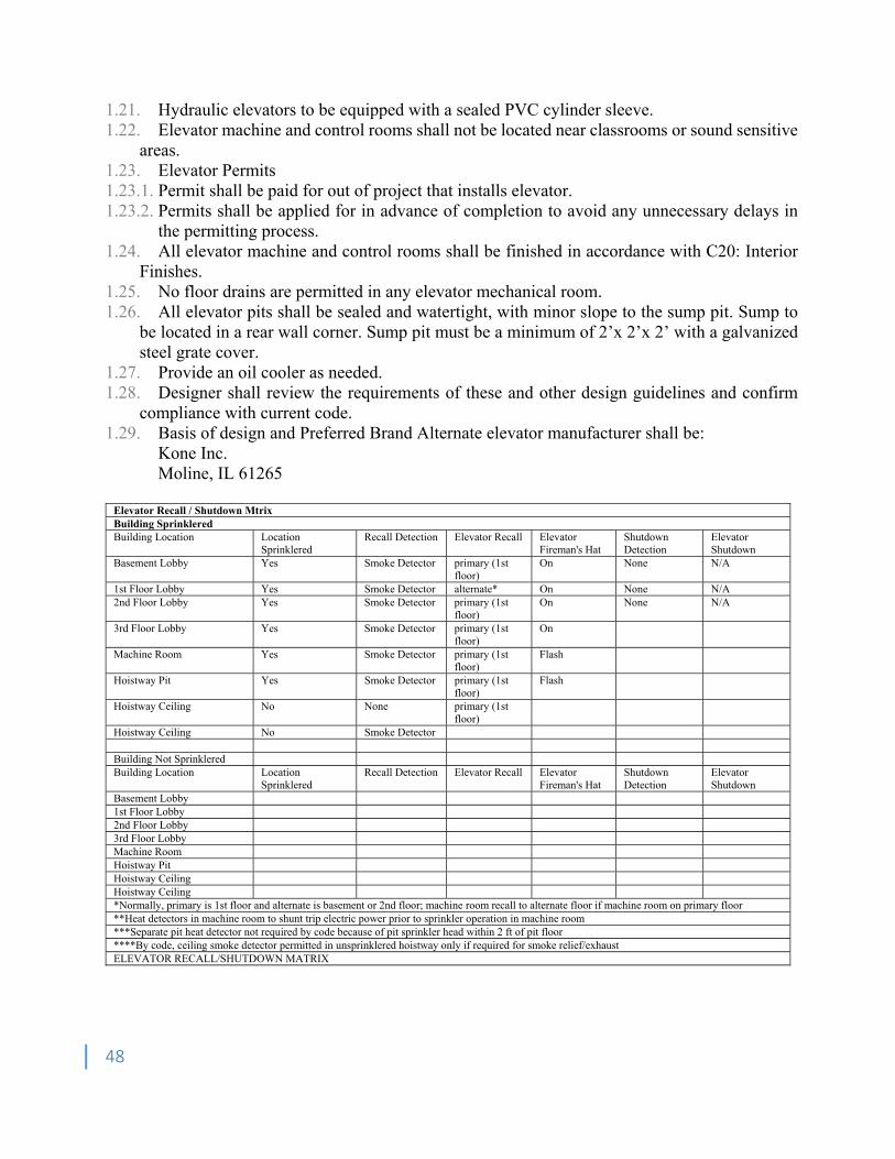
48
1.21. Hydraulic elevators to be equipped with a sealed PVC cylinder sleeve. 1.22. Elevator machine and control rooms shall not be located near classrooms or sound sensitive
areas. 1.23. Elevator Permits 1.23.1. Permit shall be paid for out of project that installs elevator. 1.23.2. Permits shall be applied for in advance of completion to avoid any unnecessary delays in
the permitting process. 1.24. All elevator machine and control rooms shall be finished in accordance with C20: Interior
Finishes. 1.25. No floor drains are permitted in any elevator mechanical room. 1.26. All elevator pits shall be sealed and watertight, with minor slope to the sump pit. Sump to
be located in a rear wall corner. Sump pit must be a minimum of 2’x 2’x 2’ with a galvanized steel grate cover.
1.27. Provide an oil cooler as needed. 1.28. Designer shall review the requirements of these and other design guidelines and confirm
compliance with current code. 1.29. Basis of design and Preferred Brand Alternate elevator manufacturer shall be:
Kone Inc. Moline, IL 61265
Elevator Recall / Shutdown Mtrix Building Sprinklered Building Location Location
Sprinklered Recall Detection Elevator Recall Elevator
Fireman's Hat Shutdown Detection
Elevator Shutdown
Basement Lobby Yes Smoke Detector primary (1st floor)
On None N/A
1st Floor Lobby Yes Smoke Detector alternate* On None N/A 2nd Floor Lobby Yes Smoke Detector primary (1st
floor) On None N/A
3rd Floor Lobby Yes Smoke Detector primary (1st floor)
On
Machine Room Yes Smoke Detector primary (1st floor)
Flash
Hoistway Pit Yes Smoke Detector primary (1st floor)
Flash
Hoistway Ceiling No None primary (1st floor)
Hoistway Ceiling No Smoke Detector Building Not Sprinklered Building Location Location
Sprinklered Recall Detection Elevator Recall Elevator
Fireman's Hat Shutdown Detection
Elevator Shutdown
Basement Lobby 1st Floor Lobby 2nd Floor Lobby 3rd Floor Lobby Machine Room Hoistway Pit Hoistway Ceiling Hoistway Ceiling *Normally, primary is 1st floor and alternate is basement or 2nd floor; machine room recall to alternate floor if machine room on primary floor **Heat detectors in machine room to shunt trip electric power prior to sprinkler operation in machine room ***Separate pit heat detector not required by code because of pit sprinkler head within 2 ft of pit floor ****By code, ceiling smoke detector permitted in unsprinklered hoistway only if required for smoke relief/exhaust ELEVATOR RECALL/SHUTDOWN MATRIX
49
Section D20 Plumbing 1. Piping 1.1. General 1.1.1. Building piping main runs shall be located above corridors unless otherwise approved by
UPL. 1.1.2. Isolation Valves
Provide shut-off valves for all services into laboratory spaces to allow for single lab to be isolated.
Provide isolation of each independent item of equipment and fixture Provide isolation of each floor or section of a floor, provide isolation for each bathroom;
provide isolation of each lab; provide isolation of each mechanical room. 1.1.3. Backflow Preventers
Domestic and Fire water: Install in mechanical room. If reduced pressure type, provide drain funnel and pipe to floor drain.
Irrigation water: Install in pit in yard with separate water meter. 1.1.4. Piping Insulation
End joints of pipe insulation shall be sealed to pipe. A pre-installation conference shall be specified to ensure that proper techniques are
followed. Insulation shall be as listed below for service piping:
º Domestic Cold Water Piping: Fiberglass º Domestic Hot Water Piping: Fiberglass º Minimum Thicknesses: Service Up to 1 ¼” ≥ 1 ½’ Domestic Hot Water 1” 1.5” Domestic Cold Water ¾” 1”
1.1.5. The designer shall minimize quantity of dielectric unions. When used, unions shall be
located in accessible locations for ease of maintenance. Engineer shall provide a drawing indicating location of all dielectric unions. Provide ball valves on each side of union to allow for repair of union.
1.1.6. Floor Sleeves shall be cast-in-place schedule 40 steel pipe, 2” above floor, flush with bottom of slab.
1.2. Gravity 1.2.1. Sanitary Waste and Vent Piping
Waste and Vent Piping above grade: Cast iron no-hub with four band mechanical clamps. Husky Heavy Duty or equivalent.
Waste and Vent Piping below grade: Cast iron hub and spigot. Indirect Drains: Copper type ‘M’ for 1” and smaller, type ‘DWV’ for 1 ¼” and larger
with sweat joints. 1.2.2. Storm Drainage Piping Above/Below Grade
Above Grade: Cast iron no-hub with four band mechanical clamps. Husky Heavy Duty or equivalent.
Below Grade: Cast iron hub and spigot.
50
1.2.3. Floor Drains Provide floor drains in Water Closets and Mechanical rooms. Provide floor drains for all emergency/drench showers. Provide trap primers for all floor drains and floor sinks. All trap primers shall have
isolation valves. Access doors shall be provided if located behind a wall or above a ceiling.
1.2.4. Cleanouts are to be accessible. Locate to the side of the Water Closets with a minimum clearance of 6” from the rough-in of the Water Closets. Preferred location is in ADA stall to allow for additional access.
1.3. Pressure 1.3.1. Domestic Water Piping
Non-Potable Water: Copper type ‘L’, hard drawn, with soldered joints. ProPress or equivalent joints may be used with prior written approval from the UPL.
Potable Water: Copper type ‘L’, hard drawn, with soldered joints. ProPress or equivalent joints may be used with prior written approval from the UPL.
1.4. Fuel Piping 1.4.1. Liquid Petroleum (LP) Gas Piping:
Above grade: Black steel, schedule 40 Below grade: High density polyethylene (HDPE) with electro/heat fusion joints. Pipe
shall be installed per 49CFR Part 192 by a certified installer. 1.4.2. WCU provides all gas meter for installation by contractor. 1.4.3. Natural Gas Piping:
Above grade: Black steel, schedule 40 Below grade: High density polyethylene (HDPE) with electro/heat fusion joints. Pipe
shall be installed per 49CFR Part 192, by a certified installer. 1.5. Process Air and Gas Piping 1.5.1. Air Compressors: Duplex type, 100% capacity each compressor, with ASME stamped
receiver. 1.5.2. Compressed Air Piping: Copper tubing type ‘K’ or ‘L’, less than ½” soft annealed, ½” –
1.5” hard drawn, greater than 1.5” schedule 40 black steel. 1.5.3. Gas Piping:
Oxygen: Copper tubing type ‘K’ or ‘L’, less than ½” soft annealed, ½” –1.5” hard drawn. Argon: Copper tubing type ‘K’ or ‘L’, less than ½” soft annealed, ½” –1.5” hard drawn. Carbon Dioxide: Copper tubing type ‘K’ or ‘L’, less than ½” soft annealed, ½” –1.5”
hard drawn. Helium: Copper tubing type ‘K’ or ‘L’, less than ½” soft annealed, ½” –1.5” hard drawn. Nitrogen: Copper tubing type ‘K’ or ‘L’, less than ½” soft annealed, ½” –1.5” hard
drawn. Nitrous Oxide: Copper tubing type ‘K’ or ‘L’, less than ½” soft annealed, ½” – 1.5” hard
drawn. Acetylene: Stainless steel type 316 with Swagelok fittings. Hydrogen: Stainless steel type 316 with Swagelok fittings.
1.5.4. Vacuum Pumps: Duplex type, 100% capacity each pump. 1.5.5. Vacuum Piping: Copper tubing type ‘K’ or ‘L’, less than ½” soft annealed, ½” – hard
drawn.
51
1.5.6. Medical Gasses: Installation shall be in accordance with NFPA 99. 1.6. Process Water and Waste Piping 1.6.1. Deionized Water Piping: Polyvinylidene fluoride (pvdf) kynar resin SDR 11-21 with
thermal fusion joints. 1.6.2. Distilled Water Piping: Perfluoroalkloxy pipe (PFA) Teflon schedule 40 or 80 with thermal
fusion, mechanical, or threaded joints. 1.6.3. Lab Acid Waste and Vent Piping: High silicon (14%) cast iron, or glass with mechanical
joints, or polypropylene with mechanical joints above grade and thermal fusion joints below grade.
1.7. Reverse Osmosis Water Piping: Polyvinylidene fluoride (pvdf) kynar resin SDR 11-21 with thermal fusion joints.
2. Plumbing Fixtures 2.1. Water Closets 2.1.1. Water Closet to be vitreous china, wall hung with chair carrier. 2.1.2. Water Closet bowl shall be elongated. 2.1.3. Water Closet passage to be a minimum diameter of 2.25” trap-way 2.1.4. Water Closet flush valve shall be a low flow design of 1.2 or 1.6 gallons per flush with
selectable dual flush handle. Flush valves to be dual filtered bypass (minimum), ADA compliant handle.
2.1.5. Water Closet seats to be solid plastic with stainless steel self-sustaining check hinges. 2.1.6. Water Closet water supply connection shall be top spud type with a minimum inlet diameter
of 1". 2.2. Urinals 2.2.1. Urinals to be vitreous china, wall hung with floor mounted carrier, low flow design sensor
type with 1 pint per flush. 2.2.2. Urinal passageway shall be a minimum diameter of 2”. 2.2.3. Urinal water supply connection shall be a top spud type with a minimum inlet diameter of
3/4” 2.3. Lavatories/Sinks 2.3.1. Lavatories to be vitreous china, wall hung shall be provided with concealed arm carrier. 2.3.2. Sinks to be 18-gauge stainless steel. 2.3.3. Sink and lavatory faucets to be ¼ turn ceramic disk cartridge type with 4” minimum length
wrist blade handles. 2.3.4. P-traps to be 17-gauge brass with integral cleanout. 2.3.5. Exposed waste assemblies and all other supplies located beneath handicapped Plumbing
Fixtures shall be protected with pre-molded insulation protectors made especially for that purpose. Trap Wrap to be molded plastic type similar to McGuire Pro-Wrap Truebro LavGuard.
2.3.6. Fixtures shall not contain plastic components. 2.3.7. Traps shall have mechanical connection (not soldered) at wall connection to allow for
removal and use as a cleanout. 2.4. Janitor Room Basins 2.4.1. Mop service basins shall be floor/wall assemblies.
52
2.4.2. Basin shall be a one-piece terrazzo construction. 2.4.3. Basin shall be equipped with aluminum bumper guards. 2.4.4. Basin shall be equipped with a mop hanger bracket. 2.4.5. Basin shall be equipped with a service faucet complete with vacuum breaker, integral check
valves, integral stops, an adjustable wall brace, a pail hook, and a 3/4" hose thread on spout. 2.4.6. Basin shall be equipped with a hose and hose bracket. 2.4.7. Basin shall be equipped with stainless steel wall guards. 2.4.8. Basin and wall guards shall be sealed water tight to the wall and floor. 3. Plumbing Pumps 3.1. Package booster pumping station to be duplex type, utilize variable speed drive pumps when
applicable. 3.2. Sewage ejectors to be used with prior approval from UPL.
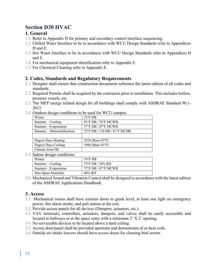
53
Section D30 HVAC 1. General 1.1. Refer to Appendix D for primary and secondary control interface sequencing. 1.2. Chilled Water Interface to be in accordance with WCU Design Standards refer to Appendices
D and E. 1.3. Hot Water Interface to be in accordance with WCU Design Standards refer to Appendices D
and E. 1.4. For mechanical equipment identification refer to Appendix F. 1.5. For Chemical Cleaning refer to Appendix E. 2. Codes, Standards and Regulatory Requirements 2.1. Designer shall ensure that construction documents reference the latest edition of all codes and
standards. 2.2. Required Permits shall be acquired by the contractor prior to installation. This includes boilers,
pressure vessels, etc. 2.3. The MEP energy related design for all buildings shall comply with ASHRAE Standard 90.1-
2013. 2.4. Outdoor design conditions to be used for WCU campus.
Winter 23°F DB Summer – Cooling 91°F DB / 74°F MCWB Summer - Evaporation 77°F DB / 87°F MCWB Summer – Dehumidification 75°F DB / 134 HR / 81°F MCDB Degree Days Heating 2524 (Base 65°F) Degree Days Cooling 1980 (Base 65°F) Climate Zone 9B
2.5. Indoor design conditions. Winter 70°F DB Summer – Cooling 75°F DB / 50% RH Summer - Evaporation 77°F DB / 87°F MCWB Max Space Humidity 60% RH
2.6. Mechanical Sound and Vibration Control shall be designed in accordance with the latest edition of the ASHRAE Applications Handbook.
3. Access 3.1. Mechanical rooms shall have exterior doors to grade level, at least one light on emergency
power, fire alarm strobe, and pull station at the exit. 3.2. Provide access panels for all devices (Dampers, actuators, etc.). 3.3. VAV terminals, controllers, actuators, dampers, and valves shall be easily accessible and
located in hallways or at the space entry with a minimum 2’ X 2’ opening. 3.4. No serviceable devices to be located above a hard ceiling. 3.5. Access door/panel shall be provided upstream and downstream of re-heat coils. 3.6. Outside air intake louvers should have access doors for cleaning bird screen.
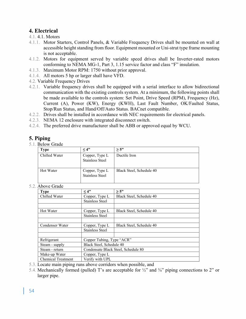
54
4. Electrical 4.1. 4.1. Motors 4.1.1. Motor Starters, Control Panels, & Variable Frequency Drives shall be mounted on wall at
accessible height standing from floor. Equipment mounted or Uni-strut type frame mounting is not acceptable.
4.1.2. Motors for equipment served by variable speed drives shall be Inverter-rated motors conforming to NEMA MG-1, Part 3, 1.15 service factor and class “F” insulation.
4.1.3. Maximum Motor RPM: 1750 without prior approval. 4.1.4. All motors 5 hp or larger shall have VFD. 4.2. Variable Frequency Drives 4.2.1. Variable frequency drives shall be equipped with a serial interface to allow bidirectional
communication with the existing controls system. At a minimum, the following points shall be made available to the controls system: Set Point, Drive Speed (RPM), Frequency (Hz), Current (A), Power (KW), Energy (KWH), Last Fault Number, OK/Faulted Status, Stop/Run Status, and Hand/Off/Auto Status. BACnet compatible.
4.2.2. Drives shall be installed in accordance with NEC requirements for electrical panels. 4.2.3. NEMA 12 enclosure with integrated disconnect switch. 4.2.4. The preferred drive manufacturer shall be ABB or approved equal by WCU. 5. Piping 5.1. Below Grade
Type ≤ 4” ≥ 5”
Chilled Water Copper, Type L Ductile Iron Stainless Steel Hot Water Copper, Type L Black Steel, Schedule 40 Stainless Steel
5.2. Above Grade Type ≤ 4” ≥ 5” Chilled Water Copper, Type L Black Steel, Schedule 40 Stainless Steel Hot Water Copper, Type L Black Steel, Schedule 40 Stainless Steel Condenser Water Copper, Type L Black Steel, Schedule 40 Stainless Steel Refrigerant Copper Tubing, Type “ACR” Steam - supply Black Steel, Schedule 40 Steam - return Condensate Black Steel, Schedule 80 Make-up Water Copper, Type L Chemical Treatment Verify with UPL
5.3. Locate main piping runs above corridors when possible, and 5.4. Mechanically formed (pulled) T’s are acceptable for ½” and ¾” piping connections to 2” or
larger pipe.
55
5.5. Minimize quantity of dielectric unions. Unions shall be located in accessible locations for ease of maintenance. Engineer shall provide a drawing indicating location of all dielectric unions. Provide ball valves on each side of union to allow for repair of union. All dielectric unions to be approved by WCU Facilities.
5.6. Floor sleeves shall be cast-in-place schedule 40 steel pipe, 2” above floor, flush with bottom of slab. Sheet metal sleeves are not acceptable.
5.7. Thrust blocks shall be formed and poured in place. 5.8. Valves 5.8.1. Provide isolation of each independent item of equipment. 5.8.2. Provide isolation at each branch takeoff. 5.8.3. Provide isolation valves to shut down each floor or sections of a floor. 5.8.4. Provide shut-off valves for all services into laboratory spaces to allow for single lab to be
isolated. 5.8.5. Locate isolation valves outside the coil pull line to allow coil removal without disruption of
hydronic service to other equipment and to keep piping disassembly to a minimum 5.8.6. Valves located on Primary water supply and return shall be offset butterfly type with metal
seats. 6. Air Distribution 6.1. Ducts 6.1.1. Fibrous Glass Ducts: Fibrous glass duct or (ductboard) are not acceptable. 6.1.2. Flexible Ducts: Flexible duct runouts to diffusers shall be limited to 5 feet.
Takeoffs for flexible ducts shall be installed at main duct branch. 6.1.3. Metal Ducts: Design and construction shall comply with SMACNA standards. 6.1.4. Specialty ductwork materials (i.e. stainless steel, aluminum, etc.) or construction shall be
clearly noted and hatched on the plans. 6.1.5. Underground ductwork is not acceptable. 6.1.6. Requirements for pressure tests shall be specified for all duct work. 6.1.7. Fume hood and kitchen exhaust ducts to be continuously welded, water tight.
Welded longitudinal joints to be facing up. 6.1.8. During construction all open ducts should be sealed. 6.2. Diffusers/Registers/Grilles 6.2.1. Shall be of corrosion resistant construction of aluminum or stainless steel. 6.2.2. All items visible through return air grilles shall be painted flat black. 7. Equipment 7.1. HVAC Equipment (AHU’s, Pumps, etc.) shall be located on a housekeeping pad. 7.2. Air Handling Units 7.2.1. VAV systems with hot water reheat. 7.2.2. Units shall be double wall construction. 7.2.3. Drain pans shall be constructed of stainless steel. 7.2.4. Air handling units shall not be located above a ceiling without prior written approval by the
UPL. Install Auxiliary drain pans with water sensor on all units above ceilings. Sensor shall be connected to the existing control system.

56
Intermediate drain pans shall be installed on multiple coil sections. 7.2.5. Custom air handlers shall not be specified without prior written approval by the UPL. 7.2.6. Pressure gauges and thermometers to be provided on supply and return of all AHU coils. 7.2.7. Pressure gauges to be provided with gauge valve. 7.2.8. Thermometers to be provided with thermometer well. 7.2.9. P-T Plugs (Pete’s Plugs) shall be provided adjacent to all control sensors for testing and
verification. 7.2.10. Use of fan coil units is discouraged and shall be used in limited scope. Fan coil units shall
not be located above a ceiling without prior written approval by the UPL. 7.3. Locate all maintenance parts (belts, motors, bearings, etc.) outside of contaminated air stream. 7.4. For any fan that exhausts hazardous materials or fumes, locate all maintenance items out of the
air stream. Fans shall have an upblast discharge exterior of building envelop. 7.5. Pumps 7.5.1. Heating and Cooling: Base mounted vertical centrifugal. Provide and install two 100%
capacity pumps for redundancy. Horizontal split case pumps are acceptable for larger capacity requirements.
7.5.2. Steam Condensate: Duplex receiver type 7.6. Boilers and Pressure Vessels 7.6.1. Boilers and pressure vessels shall be designed, constructed, installed, operated, maintained,
and inspected in accordance with uniform Boiler and Pressure Act of North Carolina. 7.6.2. Permits for boilers and pressure vessels, new or relocated, shall be included in project costs.
Permits shall be obtained and maintained by contractor throughout warranty period. 7.6.3. Provide emergency shutdown button switch for each boiler. Switch shall be maintained and
tested, mushroom type at mechanical room entrance. 7.7. Condensate capture steam traps shall be piped back to nearest flash tank. 8. Insulation 8.1. Ducts 8.1.1. No internal duct liner allowed. 8.1.2. Provide externally wrapped fiberglass insulation or factory fabricated double wall duct with
perforated metal liner. 8.1.3. All duct work with the possibility of condensation shall be insulated. 8.1.4. Duct insulation support pins shall be welded to ductwork. Glue-on/stick-on pins are not
acceptable. 8.2. Piping 8.2.1. End joints of pipe insulation shall be sealed to pipe. 8.2.2. A pre-installation conference shall be specified to ensure that proper techniques are
followed. 8.2.3. All elbows and fittings to be fully insulated. 8.2.4. Insulation shall be as listed below for service piping:
Chilled Water Piping: Cellular glass. Underground Pre-insulated Pipe Conduit: Polyurethane or cellular glass. Steam and Condensate Piping: Fiberglass Hot Water Piping: Fiberglass
57
9. Startup 9.1. All equipment shall be field inspected and tested by the manufacturer or a factory trained
authorized representative for installation in compliance with the manufacturer’s installation instructions and recommendations prior to start-up. The manufacturer or a factory trained authorized representative shall do, or be present at, the start-up. Start-up documentation certifying proper installation and start-up shall be submitted to UPL at that time and shall also be included in the O&M manuals.
9.2. HVAC systems shall not be started until cleaning, flushing and pre-treatment has been performed to the satisfaction of the UPL.
9.3. Heating hot water systems shall be cycled through heat up and cool down and checked for leaks prior to substantial completion.
9.4. Following start-up procedures, adjust equipment for proper operation within manufacturer’s published guidelines and tolerances. Demonstrate proper operation of equipment and systems to designated UPL and the Commissioning Agent.
9.5. Refer to Appendix B for System Cx requirements 9.6. Laboratory Ventilation Risk Assessment (LVRA) must be completed by a qualified testing firm
approved by the UPL for all scopes of work which involve fume hood placement or modification.
10. Controls 10.1. Automated Logic (ALC) is our preferred building automation system (BAS) 10.2. WCU requires BAS to use BACnet as communication protocol with the ability to integrate
point lists from 3rd party equipment that may use Modbus or equivalent. 10.3. Programming shall be graphically based and programming logic shall be web-accessible
without requiring additional software or license to view. 10.4. Access to graphical interface shall be web-based and not require individual license per
computer or laptop. 10.5. BAS controllers will use peer-to-peer structure for faster response and redundancy and not
a polling network. 10.6. A thermographic floor plan is required in order to see zones that are not at ideal temperature
setpoint. Colored temperatures associated with area are not an acceptable substitute. 10.7. WCU requires graphics to have a time lapse ability to replay conditions of any given time
period. 10.7.1.1. BAS shall have the ability to record (minimum) 2 years of trends for larger
mechanical equipment (i.e. chillers, cooling towers, boilers, air handlers, heat pumps, etc.) and a minimum of 1 year for field devices (i.e. VAVs and Fan terminal units).
10.8. BAS shall have ability to schedule down to a field device level (i.e. VAVs, Fan terminal units).
10.9. BAS must have the ability to use optimal start for scheduling of all controllers. 10.10. BAS web-interface shall not require constant updating to latest JAVA version. 10.11. BAS must report and trend the percentage of time that a zone is at desired setpoint. 10.12. All controllers must be Underwriters Laboratories (UL) listed. 10.13. Building level router (i.e. LGR, JACE, BCU) shall have UPS and overcurrent protection. 10.14. Contractors shall be responsible for the initial controls testing prior to commissioning by
WCU. All aspects of the system shall be correct in functionality before commencement of
58
commissioning. Commissioning will be performed by WCU, Contractors, BAS Contractor, Construction Administration Engineer, and Commissioning Agent.
11. Test &Balance 11.1. Test and balance of an HVAC system shall be performed for any equipment replacement
and/or system modifications. 11.2. Test and balance shall be performed by an Associated Air Balance Council (AABC) or
National Environmental Balancing Bureau (NEBB) certified T&B contractor that shall be a different company than the mechanical contractor and approved by the UPL.
11.3. Testing and balancing of HVAC systems shall be performed, at minimum, in accordance with AABC or NEBB National Standards.
11.4. Final T&B report shall include design and actual readings with explanation and recommendation for remediation for readings that could not be balanced.

59
Section D40 Fire Protection 1. General 1.1. Codes and Standards: 1.1.1. The codes and standards listed below are utilized as design criteria for “minimal” system
coverage. The University may require additions to these codes and standards based on historical consensus criteria for design and installation of fire protection sprinkler systems specific to facility applications within University type settings. NFPA Compliance: Reference NFPA Standards North Carolina State Construction Office sprinkler guidelines – Refer Appendix L North Carolina Department of Insurance (NCDOI) current applicable requirements
1.1.2. Comply with Authority Having Jurisdiction (AHJ): State Construction Office issues: State Construction Office NC State code requirement issues: NC Department of Insurance Jackson County code requirement issues: Jackson County Code Enforcement University code requirement issues: WCU Facilities Management Design &
Construction Office and WCU Safety & Risk Management Office University policy and system application requirements: WCU Safety & Risk
Management Office 1.1.3. Plans and Specifications Content:
Water supply test data (static pressure, residual pressure, and flow) taken. Design density, remote area size, area per sprinkler, and hose demand. Permitted pipe, valves, sprinkler heads, fittings, and other materials Backflow prevention device requirements, location, and installation detail. Building specific Post Indicator Valve (PIV) location and installation detail. Fire/booster pump requirements and installation detail, when pump used. Sprinkler riser diagram, beginning where the sprinkler system contract does, showing
all cutoff valves, inspector test valves, test connections, supervisory switches, and drains.
1.2. Contractor's Shop Drawings and Hydraulic Calculations: 1.2.1. The specifying engineer (PE), if any, has primary responsibility for review and approval of
sprinkler system shop drawings and calculations. Contractor must provide a minimum of 10 copies (more if required by engineer's specification). PE's review shall be to determine "substantial compliance" with this document and the project specification. After completing this review, the PE is to send one marked-up copy to the WCU Facilities Management Design & Construction Office and WCU Safety & Risk Management Office for review and must include the hydraulic calculations. In addition, the PE is to send two (2) copies of the shop drawings, hydraulic calculations and materials/product data along with his/her review comments to SCO for review and approval.
1.3. Contractor Qualifications and Responsibilities: 1.3.1. The contractor must be licensed by the North Carolina State Board of Examiners of
Plumbing, Heating, and Fire Sprinkler Contractors and must submit evidence of Level III certification in "Inspections and testing of water-based fire protection systems" by NICET. Minimum of 5 years documented experience installing fire sprinkler systems similar in size and scope to this project.
60
1.3.2. The contractor shall be required to furnish evidence of satisfactory performance on previous sprinkler system installations of equivalent size, type, and complexity.
1.3.3. The contractor shall furnish all parts, materials, and labor required for a complete and operating system in accordance with all applicable requirements, even if each needed item is not specifically shown or described in the plans or specs.
1.3.4. The contractor is also responsible for the inevitable adjustments in sprinkler locations, sprinkler quantity, and piping required for full compliance with the NFPA standards, SCO, NCDOI, and the project plans and specifications.
1.3.5. After the project is completed, Contractor’s Material and Test Certificates must be submitted on the installation, in accordance with NFPA 13. The sprinkler system riser must not be connected until the underground piping has been tested, flushed, and certified per NFPA 24 and inspected and approved.
1.3.6. If any conflict is observed between this document and the project plans, referenced codes, or standards obtain a ruling from the AHJ before proceeding with purchase of materials, fabrication, or installation of the system. Failure to do so may cause the sprinkler contractor to be held liable for any cost or delay incurred as a result.
1.3.7. The Installer must be present for the 100% test, Engineer’s inspection and WCU Facilities Management Design & Construction Office and WCU Safety & Risk Management Office inspections.
2. BASIC SYSTEM PARAMETERS 2.1. Hydraulic Calculations: 2.1.1. The actual water supply must be verified by test using a minimum 2 hydrants as close to the
point of connection as possible, witnessed by the Designer, and the WCU Facilities Management Design & Construction Office or WCU Safety & Risk Management Office. The waterflow test results shall be adjusted in accordance with DOI criteria by reducing the flow (gpm) and the residual pressure (psi) by 10%. Calculations start at the gauge hydrant used in the test and must include the backflow preventer and all valves and fittings. Use the "1.4 Rule," and include a 500gpm hose stream allowance if water supply permits. Limit water velocity to 25fps, except use 18fps for any segment with a vane type water flow switch (to comply with UL listing).
2.2. Minimum Design Density: 2.2.1. Ordinary Hazard (Group 1) is the minimum system design normally accepted. 2.2.2. The minimum design density is to be 0.15gpm/SF for the hydraulically most remote 1500
SF. If there are open areas greater than 5,000 SF, or if combustible construction is used, the minimum design density shall be 0.12gpm/SF for the hydraulically most remote 3,000 SF. For dry systems, increase the area of application by 30%. EXCEPTION (1): When QR sprinklers are used and open spaces are relatively limited
in size (e.g., dormitories, classroom-faculty office buildings), NFPA 13 is permitted to be used to reduce the system area of operation (and cost). Upon request, permission may also be granted to exceed the OH-1 area/sprinkler limit (130SF) if OH-1 density is still achieved.
EXCEPTION (2): QR Extended Coverage sprinklers, currently listed only for Light Hazard applications, are permitted to be used in dormitories if density approximating OH-1 results.
61
EXCEPTION (3): When NCDOI allows use of listed attic sprinklers, now listed only for Light Hazard. The minimum design in such spaces shall be the greater of 2,000SF or 5 sprinklers for wet systems, and 2,600SF or 7 sprinklers for dry systems.
2.2.2.1.NOTE: The Appendix of NFPA 13 includes suggested lists of "occupancies" categorized by fire hazard as being Light, Ordinary (Group 1), etc. It carefully qualifies the lists as applying only to "typical" facilities, stating that higher than normal fuel loading, or susceptibility to change, should be considered in classifying the present or potential hazard of each facility. The following facts justify using Ordinary Hazard (Group 1) as the minimum design density: (1) It provides a modest safety factor for changes in building use or occupancy, an important consideration for facilities expected to be in service 50-100 years or more (most public buildings). (2) It helps keep the hydraulic design basis for the system from becoming invalid due to deterioration in the public water supply, a common occurrence due to increasing demand or the build-up of scale in mains. (3) It makes rapid suppression of fire more probable, an important factor in limiting losses and, where plastic pipe is used, in preventing the system from being breached. (4) For residential and institutional facilities using QR sprinkler heads, it increases the probability of saving sleeping occupants in the room of origin. (5) A modest safety factor is also very prudent when the owner is self-insured or has insurance with high loss retention. All these factors apply to the State of NC, which is self-insured. It has high rise facilities in rural areas protected by volunteer fire departments that aren't able to provide the firefighting resources of cities. Public buildings are often in use 100 years or more, with changes in their fire load common. Finally, anyone who has toured crowded State office buildings or typical college dorms in recent years will understand the fuel load is frequently more than "Light." These provide a strong, prudent basis for adopting Ordinary Hazard (Group 1) as the minimum system design normally accepted. Individual project circumstances may warrant an exception to this criterion.
2.3. Extent of Sprinkler Coverage: 2.3.1. Ordinary electrical equipment rooms, telephone closets, housekeeping closets and similar
spaces shall be fully sprinkled. 2.4. System Zoning Requirements: 2.4.1. Each story must be a separate sprinkler zone with a dedicated cutoff valve, tamper switch,
water flow switch, and an Inspector's Test valve piped to a drain capable of handling full flow without backup or splatter. All cutoff and test valves are to be located on the floor they serve, unless the Owner permits a different arrangement.
2.5. Multiple Riser Designs: 2.5.1. Multiple riser designs that require the operation of more than one floor cutoff valve to isolate
any portion of the system are not permitted. 2.5.1.1.NOTE: This assures non-ambiguous waterflow alarm and enables a single valve to shut off
water to any zone. 2.6. Electrical Supervision: 2.6.1. Electrical supervision per NFPA 72 is required for monitoring the position of all sprinkler
cutoff valves beyond the water source valve, including the outside post indicator valve (PIV) and isolation valves for the backflow prevention device. Tamper switches for OS&Y valves shall be mounted to rigid frames secured by bolts through clamp bars. ("J"-hook mounting to the valve's frame is not permitted.)
62
EXCEPTION (1): Valves are permitted to be secured by locks when located in environments unsuitable for supervisory switches approved by the owner.
2.6.2. Non-heated separate pump houses and hot boxes shall be monitored for freezing. Dry pipe and pre-action system air supply must also be monitored, for both low and high pressure, and a manual bleeder valve is to be provided for testing and adjusting air pressure supervisory switches.
2.6.2.1.NOTE: Low air pressure can cause the dry system to trip wet, requiring it to be drained, the dry pipe valve reset, and re-pressurized. High air pressure will retard system response to fire, since the air pressure will first have to bleed down to the trip point before water enters the system.
2.7. Fire/Booster Pump, Water Supply, Throttling, and Metering: 2.7.1. The water supply to the sprinkler system must provide at least 150% of pump rated capacity
at a positive pressure and also meet the system demand at 20psi minimum. The water supply test shall be performed within the most recent 12 months.
2.7.1.1.NOTE: A water supply of 200% of pump capacity is recommended whenever this can be reasonably achieved.
2.7.1.2.NOTE: If the water supply will meet system demand with a modest safety factor, and the pump is needed only to have a desired pressure at the top of the standpipe, contact SCO for possible alternatives.
2.7.2. Per the NC Administrative Code, Title 15A, Subchapter 18C, an automatic pilot-operated throttling valve must be installed on the output side of the booster pump, to maintain required minimum pressure. Suction side control is not permitted, due to possible cavitation. Where permitted by SCO a low pressure shutoff sensing the suction pressure may be substituted if the water supply provides 200% of pump rated capacity at a minimum pressure of 40psi, and an acceptable means is provided to periodically test the calibration of this device in its installed location.
2.7.3. Where pump location does not permit convenient flow testing from the header and play pipes, provide a permanently installed meter for net pump performance testing without water streams. The meter outlet must discharge to a drain or to the suction tank, if provided, or (where permitted by NCDOI) to the suction side of the pump.
3. MATERIALS AND COMPONENTS 3.1. Listing / Approval: 3.1.1. All sprinkler system materials and components must be listed or approved, and installed in
strict conformance to the conditions of their listing / approval. 3.2. Sprinkler Piping: 3.2.1. Metal: 3.2.1.1.Only steel pipe shall be used, with a Corrosion Resistance Ratio (CRR) of one (1) or greater.
Schedule 5 pipe is not permitted, in any size. Schedule 10 steel pipe and the approximately equal "flow” products, sizes 1.5" and larger, are permitted to be used only with listed roll groove end fittings. All dry pipe, deluge, and pre-action system pipe must be galvanized, including any fittings exposed to weather. Listed flexible stainless steel piping systems (e.g. Flex-Head, Flex-Arm) are also permitted.
3.3. Plastic: 3.3.1. Listed CPVC sprinkler pipe is only permitted, with prior written approval by the WCU
Facilities Management Design & Construction Office and WCU Safety & Risk
63
Management Office, to be used in occupancies other than Institutional-Restrained, when all of the following criteria are met: Pipe and fittings shall be post-chlorinated polyvinyl chloride, UL Listed and FM
Approved for sprinkler system use, and fully compliant with ANSI/UL 1821-1994 and ANSI/UL 1887-1996.
Base resin, compound, finished pipe, and fittings shall meet all the ASTM criteria specified for Noveon BlazeMaster2000 CPVC, and must be produced in the USA or Canada by an ISO 9002 Certified facility.
3.3.2. NOTE: The benchmark BlazeMaster product is produced under license by several different manufacturers in the USA and Canada. Any listed product meeting the same ASTM, ANSI/UL, and ISO criteria is also acceptable. System shall be the wet pipe type with quick response sprinkler heads. It must be
installed indoors (only), where the temperature will not exceed 150F. Except in corridors and stairs, pipe shall be run concealed or protected from fire
exposure by one of the following methods: (a) 19/32" plywood, (b) 1/2" gypsum board, (c) prefabricated 20-gauge steel soffit system over mineral wool insulation, (d) plaster ceiling, (e) approved construction providing a 15-minute fire rating.
3.3.3. NOTE: Protection from fire exposure is generally required because CPVC pipe is listed for Light Hazard applications only and we judge most State facilities to be predominantly Ordinary Hazard – Group 1. CPVC pipe shall not be threaded, grooved, or drilled. If stored outdoors the pipe must be protected from exposure to sunlight (UV) by an
opaque covering. Where pipe penetrates rated wall, floors, or ceilings the fire stopping used must be
labeled as being compatible with CPVC. NOTE: Some fire stop sealants and wrap strips contain solvents or plasticizers that may
damage CPVC. It is very important to use only fire stop materials certified to be compatible with this pipe.
If pipe is to be painted, only water-based paints shall be used (no oil-based). 3.3.4. NOTE: Petroleum-based solvents and lubricants are not compatible with CPVC and may
cause damage. For threaded connectors, use only Teflon tape. For the steel portions of the system, any
pipe dope used must be labeled as being compatible with CPVC. 3.3.5. Each installer of CPVC sprinkler pipe must provide documentation supporting they have
attended an authorized training class in how to properly use this material, within the previous two years. They are not permitted to do any CPVC installation work prior to such training, or if not trained within 2 years.
3.4. Fittings and Joints: 3.4.1. All fittings must be listed or approved for the specific pipe and type of system they are used
on. For gasket fittings, install only with the lubricant the manufacturer obtained listing with, since other lubricants may not provide suitable performance.
3.5. Metal: 3.5.1. The following joining methods are acceptable for steel pipe, to the extent permitted by
listings, except that threading or cut groove fittings are accepted for use only on fully complying Schedule 40 and heavier pipe:
64
Threading Shop Welding Cut Groove with Gasket Fitting Roll Groove with Gasket Fitting Full Back Design Clamp-on Fittings "U" Bolt Design Clamp-on Fittings (Only for pipe of 2.5" run size and smaller)
3.5.2. Plain end, hooker, press-on, key type or slip type metal fittings are not permitted. 3.5.3. All grooved metal products on a job (both fittings and couplings) must be products of the
same manufacturer. 3.5.4. Mixing different brands is not allowed as it may cause problems due to variations in design
dimensions and tolerances, which could cause leaks or even failure. 3.6. Plastic: 3.6.1. CPVC pipe and fittings shall be joined by solvent cementing, in accordance with the
following criteria: Use only solvent cements which are specifically tested and listed for use with CPVC,
and which have been approved by the pipe and fitting manufacturer(s). Apply them strictly in accordance with the manufacturer's instructions.
Solvent cement must not be used beyond its shelf life, or if gelled or discolored. To prevent solvent cement from running and plugging sprinkler orifices, the sprinkler
heads are not permitted to be installed until all solvent-welded CPVC pipe, fittings, and head adapters have been allowed to cure a minimum of 30 minutes.
Torque values must be observed when joining threaded or flanged CPVC adapters. 3.6.2. Grooved coupling adapters must be joined only with flexible couplings (not rigid type),
using standard Grade "E" EDPM compound to lubricate the gasket. 3.7. Valves: 3.7.1. An outside post indicator control valve (PIV) must be provided for all systems. All indoor
cutoff valves in the two (2) inch through eight (8) inch range shall be the butterfly type, with integral tamper switch and position indicator.
3.7.2. NOTE: We've had many field problems with frame-mounted tamper switches mounted on OS&Y valves using "J-bolts", often field-fabricated from threaded rod stock. Adjustment to obtain proper operation is often very difficult, and does not hold. Factory installed butterfly valve tamper switches have proven to be very reliable. EXCEPTION (1): Valves on each side of any fire pump are to be the OS&Y type. This
does not apply to the fire pump bypass valves (kept normally open), which are permitted be either the butterfly or OS&Y type. CAUTION: Butterfly valves bolted to a check valve frame may create an interference problem in some cases. Check specs to assure non-interference, or provide a short section of pipe between them.
3.8. Sprinkler Heads: For combustible attics, roof decks, or floors above crawl spaces, use sprinklers that
provide good wetting of exposed combustible members. The acceptable options include listed attic sprinklers, or pendant heads installed upright.
Dry pendant or sidewall sprinklers for protecting refrigerated storage. Quick Response (QR) sprinkler heads shall be used in all sleeping rooms and
laboratories, except where institutional heads are needed for security reasons. The use of QR heads is encouraged in any other applications for which listed.
65
The use of listed/approved residential sprinklers should be considered for all sleeping occupancies.
3.8.1. Residential sprinklers are not to be used in dry systems, unless the spec permits, as water delay might permit too many of these more responsive heads to open.
3.9. Backflow Prevention Devices: 3.9.1. Provide a cutoff valve on both sides of the backflow prevention device in the water supply
connection, for isolation (servicing). RPZ backflow prevention device shall be provided with cutoff valves as part of a complete factory assembly, shipped and provided to the project as a whole. Where a booster pump is installed the backflow assembly, required by water quality regulations to be on the suction side, must be located as far from pump intake as possible (at least 10 pipe diameters).
4. SPECIAL SPRINKLER SYSTEMS 4.1. Preaction Systems: 4.1.1. Preaction valves shall be single interlocked, except for freezer facilities the double
interlocked type must be used. The fire detection system used for preaction valve control must comply with the latest issue of "Fire Detection and Alarm Systems," published by NCDOI.
4.2. Refrigerated Area Systems: 4.2.1. Dry systems for freezers must have a regenerative compressed air dryer that will maintain
the system dew point at least 20F below the lowest freezer operating temperature. For freezers with wet systems and dry pendant or dry sidewall heads, the connection between the sprinkler head and the wet pipe must extend at least 12 inches beyond the cooler and be provided with insulating wrap to prevent sweating.
4.2.1.1.NOTE: To preserve the freezer warranty, only the freezer manufacturer's representative should cut and seal the holes for sprinklers. This should be covered in the engineer's specification.
4.3. Freeze Protection of Systems: 4.3.1. Heat tracing is NOT acceptable for dry pipe or preaction valve freeze protection. A heated
room or closet must be provided to protect these vital components. 4.3.1.1.NOTE: Antifreeze-primed systems are no longer permitted, due to environmental concerns.
5. INSTALLATION, TEST, AND CERTIFICATION 5.1. Locating Valves, Drains, and Inspector's Test Connections: 5.1.1. All sprinkler valves and controls must be located for safe and convenient access during
emergencies and testing. Control valves shall not be located above ceilings. 5.1.1.1.NOTE: Inspector's Test Connections should be operable from floor level whenever possible.
They're permitted to be locked if vandalism is a concern. Where control valves must be located more than 10 feet AFF, provision for access should be provided (e.g., permanent ladder/catwalk or, if the Owner permits, a chain-operated valve).
5.1.2. Identify each valve and control with a prominent engraved phenolic or stamped metal placard. Any such devices that are behind access doors or panels must also have their location made known by an appropriate placard on the means of access. A valve placard I.D. legend shall be posted at the main sprinkler riser denoting the locations of the identified valves.
5.2. Contractor's Inspection of System:
66
5.2.1. The contractor shall thoroughly inspect the completed system to assure compliance with this document, project plans and specs, and applicable codes and standards. IMPORTANT: This must include an operational test of each waterflow alarm switch and all system supervisory devices (valve tamper, hi-low air pressure, pump status, etc.), in coordination with the fire alarm system contractor.
5.2.2. When a fire pump / booster pump is provided, its flow test will be witnessed by the specifying engineer, SCO and/or the Owner. The contractor must notify those 2 weeks before the pump test, to permit sufficient time to schedule an inspector to be there.
5.2.3. Pressure tests shall be done with all sprinkler heads installed. Where an existing sprinkler system is being expanded or renovated, the contractor is responsible for the integrity of all new piping plus existing piping.
5.3. Contractor's Material and Test Certificates: 5.3.1. Prior to final inspection by SCO, NCDOI, and WCU Facilities Management Design &
Construction Office or the WCU Safety & Risk Management Office, the system installer is to submit NFPA-required Contractor's Material and Test Certificate(s) for aboveground, and underground, piping. Send copies to the following: The Specifying Engineer (PE) SCO WCU Facilities Management Design & Construction Office WCU Safety & Risk Management Office
5.3.1.1.EXCEPTION: If the sprinkler contractor did not provide the underground piping, the responsible contractor must submit that certification. The sprinkler contractor is not to connect the riser until underground piping has been flushed, tested, and certified by the responsible contractor.
5.3.2. NOTE: For State of NC building projects, the owner is normally represented by the State Construction Office or by the facility's Construction Project Coordinator, as applicable.
5.4. Reference Information: 5.4.1. For convenient reference, relevant NFPA test requirements are summarized below. See the
applicable NFPA standard for additional details and the forms that must be used by the contractor(s) to document the results of these tests. Underground Pipe Flushing and Test: Underground pipe shall be thoroughly flushed
before being connected to the sprinkler system. Perform hydrostatic pressure test in accordance with NFPA 13 or 24
(generally at 200psi for 2 hours), as applicable. Interior Piping Test: Hydrostatically test all interior piping and appurtenances in
accordance with NFPA 13. This generally requires that the system hold 200psi for 2 hours without any water leakage.
Additional Air Test for Dry Pipe Systems: Pump the system to 40psi and allow to stand for 24 hours. The air pressure must not leak down more than 1.5psi.
Additional Operating Test for Dry Pipe Systems: All dry pipe systems must deliver sustained water flow to the inspector's test connection within sixty (60) seconds.
67
6. INSTRUCTIONS TO DESIGNERS 6.1. This document is not intended to conflict with any Code or NFPA Standard. If conflict is
observed, the designer shall notify the WCU Facilities Management Design & Construction Office and if necessary obtain a ruling from SCO.
Insert this entire document at the back of the specification (as an Appendix). Require compliance by reference in the sprinkler system section (by title and revision date), or
Reference this document in the text (by title and revision date), require compliance, and mandate that the contractor obtain a free copy from NCDOI (available on their website) for use on the project, or
Incorporate all of the relevant portions of this document in the sprinkler specification. To facilitate that process, the electronic version of this document contains a separate, attached MS Word Section, comprised of all of the criteria herein, but with the following items deleted: DOI Letterhead, Introduction, all page headings, and fine print NOTES, the Instructions to Designers, Table of Contents, and Revision Record. This makes it very convenient for the engineer to cut and paste these criteria as part of the sprinkler system specification.
6.2. The designer and contractor are jointly responsible for coordination of system details with the other designers/trades, as needed. This includes suitable location (and access) for all cutoff valves, determination of which contractor provides alarm/supervisory switches, and coordination with the fire alarm designer on sprinkler system monitoring:
Water flow alarm, by sprinkler system zone Supervision of each sprinkler cutoff valve Supervision of high-low air pressure (if used) Supervision of fire/booster pump (if present) Other sprinkler system supervisory signals (as applicable)
6.3. The NC Building Code requires that sprinkler system alarm and supervisory signals be monitored, and transmitted off-premises, by the building fire alarm system. The above signals are permitted to be grouped as follows when received at the remote supervising station: (1) Water flow Alarm, (2) Sprinkler Supervisory Signal (System Status Abnormal)
6.4. Locate points which discharge to the outside of the building (This includes flow testing, system drain down points, and RPZ discharge.) so that any water hazards, erosion hazards, and/or ice hazards are not created by these discharge or drain-down flows.
6.5. Refer to and incorporate Appendix K for the State of North Carolina, Department of Administration – State Construction Office Electrical Guidelines and Policies into all work designed for or constructed on campus.
68
Section D50 Electrical 1. General 6.6. Conductors and Conduit 6.6.1. Conductor/Cable to be the following as applicable
Cu (Copper) THHN Cu THHW Cu XHHW minimum wire size to be #12AWG #12AWG/ #10AWG to be solid #8AWG/larger stranded Service Entrance to be Cu XHHW
6.6.2. Minimum conduit to be ¾” except where UPL approves otherwise. 6.7. Rigid/Intermediate Metal Conduit to be used (indoors/outdoors) above grade where exposed to
direct physical damage; Electrical Metallic Tubing may be used (indoors only) in concealed/protected areas not subject to physical damage; liquid tight flexible metal conduit to be used for final connection to fan/pump motors or vibrating loads.
6.8. PVC or Galvanized Rigid Steel shall be used below grade. If PVC is used, it shall be encased in concrete unless otherwise approved by UPL. The transition from PVC to metal conduit shall be made at a minimum of 12 inches below final grade such that only metal conduit exits concrete or ground. Minimum depth of bury shall be three feet. GRS or PVC Schedule 80 shall be used for direct burial. When PVC is used a tracer shall be pulled for future locating.
6.9. Outdoor enclosures to be NEMA 3R or NEMA 4; indoor enclosures may be NEMA 1 in dry areas, but shall be NEMA 12 in areas exposed to moisture; floor-mount electrical equipment to have individual 4-inch high concrete housekeeping pad extending 6 inches out from base of equipment (at front and both sides); outdoor receptacles to be ground-fault-current-interrupt with weatherproof covers; outdoor light fixtures and wall switches to be suitable for wet/damp locations.
6.10. Electrical Equipment 6.10.1. Secondary power distribution equipment approved manufacturers are:
Square D General Electric Siemens Cutler-Hammer
6.10.2. Non-specialty general lighting fixtures approved manufacturers are: Lithonia Cooper Hubbell Cree Or other manufacturers accepted by WCU Facilities following review
6.11. Receptacles and Wallplates 6.11.1. NEMA 5-20R 6.11.2. Duplex: Construction Series Gray Hubbell 5352AG with stainless steel Hubbell SS8
wallplate or approved equal.
69
6.11.3. GFCI: Commercial Spec-Grade Gray Hubbell GFR5362GYA with stainless steel Hubbell S26 wallplate or approved equal.
6.11.4. External Receptacles: Hubbell Pro-Series GFR5362GY with weather proof cover Hubbell WP8H or approved equal.
6.11.5. Label – panel and circuit number to be listed on all devices/faceplates. 6.12. Wall Switches 6.12.1. 20A, 120V-277V Side-Wire only. 6.12.2. 1-Pole/Toggle Construction Grade Gray Hubbell 1221GY or approved equal. 6.12.3. Way Toggle/Maintain Gray Hubbell 1223GY or approved equal. 6.12.4. 4-Way Toggle/Maintain Hubbell 1224GY or approved equal. 6.12.5. Stainless steel Hubbell SS1 wall plate or approved equal. 6.13. Provide panelboard schedules in spreadsheet form. 6.14. Furnish and install engraved laminated phenolic nameplates for all safety switches,
panelboards, transformers, switchboards, motor control centers, and other electrical equipment supplied for the project identification. Nameplates shall be securely attached to equipment with self-tapping stainless screws; if the screw sharp end is protected; otherwise rivets shall be used. Letters shall be ½” high minimum. Embossed, self-adhesive plastic tape is not acceptable. Nameplate material and Electrical boxes and covers to be color coded as follows:
System Box/Cover Nameplate Surface Nameplate Core 120/208 Volt Equipment Blue Blue White 277/480 Volt Equipment Black Black White Fire Alarm Red Red White Security Burgundy Burgundy White Emergency Green Green White Telephone Orange Orange White Data Brown Brown White Paging White White Black Television Purple Purple White
6.15. All junction boxes shall be permanently labeled indicating the panel, circuit(s), and voltage
refer to Appendix F. 6.16. Electrical boxes (stainless-steel/outdoor-rated) for irrigation control to be mounted on
building (3-ft A.F.G.) with power outlet & control; all holes to be in bottom of box. 6.17. Exposed Conduit: Conduit to be concealed in all public areas (walls, ceiling, floor surfaces);
conduit shall not be exposed except in mechanical, electrical, and telecom rooms or other locations approved by UPL.
6.18. Color Coding – The secondary service, feeds and branch circuits shall be color coded as follows:
Phase 208/120v 480/277v A Black Brown B Red Orange C Blue Yellow
Neutral White Natural Gray Ground Green Green
70
6.19. Electrical rooms: In new facilities, electrical rooms shall be vertically-stacked (with sufficient overlap) to permit straight/vertical route of busway and cable raceway between multiple levels; Electrical Rooms to provide sufficient physical space for present/future needs; Electrical Rooms to be centrally-located (minimal cable lengths) to reduce costs & voltage drop. All new electrical rooms shall have safe area lines painted on floor based on arc flash rating for each electrical panel and switch gear. All electrical panels 480 volts or higher shall have an arc flash rating label applied.
6.20. Each mechanical/electrical room shall have at least one light and power outlet on an emergency circuit, when an emergency generator is installed.
6.21. Telecom rooms shall have two 20-amp 120-volt NEMA duplex power outlets on separate circuit breakers located near the top of the backboard on each wall under the cable tray (typically at 84 to 90 inches AFF). These power outlets/circuits should be on an emergency circuit when an emergency generator is installed.
6.22. Location of all exterior electrical equipment shall be approved by the UPL. 6.23. General Lighting 6.23.1. LED fixtures to be basis of design. T8/12 fluorescent and incandescent bulbs shall not be
used. 6.23.2. Provide lighting calculations to UPL for review prior to 100% design review. 6.23.3. Load Calcs 6.23.4. Maintain uniformity of interior light fixture layout from floor to floor in multistory
buildings. 6.23.5. Diagonally opposite corners of recessed fixtures shall be securely supported from and
directly attached to building structure so as to comply with luminaire mounting requirements in NEC Article 410 independent of any support provided from suspended ceiling grid. All fixtures (recessed and other) shall be directly attached to building structure using reusable bolt-/screw-type hardware.
6.23.6. Provide occupancy sensor lighting controls. Standards are: Application Type Classrooms, Conference rooms, Offices, Break Areas
Multi-technology Ceiling Mount
Restrooms, Hallways Ultrasonic Ceiling Mount Janitor Closets, Small Rooms (i.e. Copy) Passive Infrared Wall Switch
6.24. Emergency Generators 6.24.1. Natural gas or diesel fuel is acceptable; preferred manufacturers are Caterpillar,
Cummins/Onan, Kohler, and Generac (latter for units rated 600kW or less). 6.24.2. If diesel, provide base-mounted tank sufficient to supply any fire pump start/operation for
2.0 hours plus all other rated/connected loads for 72 hours (calculation to be provided for diesel fuel consumption); underground tanks are not acceptable.
6.24.3. Generator shall be subjected to minimum 4-hour test run at full load; load bank to be quoted (as add alternate to generator/automatic-transfer-switch bid) to permit 4-hour test of generator at 100% rated kW load.
6.25. Breakers to be bolt-in type; plug-in/snap-in type not permitted. 6.26. Grounding rods to be CADWELD type; mechanical connections are not permitted. 6.27. Exterior lighting to utilize photoelectric (PE/Time clock) controls.
71
6.28. All wiring shall be in conduit with the exception of telecommunications wiring where cable trays are provided above suspended ceilings.
6.29. Sleeves to be rigid conduit with bushings. 6.30. Ductbank 6.30.1. Required for underground electrical and telecommunications. 6.30.2. Concrete encased PVC pipe with chairs. 6.30.3. Refer to Section 4 Telecommunication Pathways. 6.31. Use of Type MC Cable is not permitted except for light fixture whips. 6.32. Use of Type NM (Romex) Cable is not permitted. 6.33. Cable Tray 6.33.1. Shall be provided for Low voltage/Telecommunications. 6.33.2. No power shall be run in cable tray. 6.34. For fire alarm information see Section D40 Fire Protection. 6.35. Auditorium Lighting – Particular care to be exercised when laying out lights in tiered
auditoriums reference maintenance & lamp replacement. Occupants shall not have to walk through dark auditorium to turn on lights. Aisle lights shall be “on” at all times.
7. Telecommunications- Refer to Appendix H. 7.1. AV Technology will revolve around an Extron-branded system 7.2. Instructional spaces will include Extron IP Intercoms 7.3. Lecterns will be by Spectrum Furniture 7.4. Control Systems will include Extron Control Processors and Touch Panels 7.5. Digital Signage should be located on each floor and near most student collaboration/gathering
spaces. It will be compatible with existing University Standards (Navori QL as of 09/29/16) 7.6. BYOD Spaces will include power-charging accommodations (i.e. laptops will have at least
single gang outlets located in reasonable vicinity to students). This includes classrooms, conference rooms, and student collaboration spaces
7.7. Wiring will be Cat6 to end locations more than 12’ away (excluding audio or specialized signals)
7.8. All spaces will be designed around a digital backbone, not analog 7.9. Projectors will utilize Laser Technology, not bulbs 7.10. Any projectors in ceilings more than 12 feet high will require projector lifts for maintenance 7.11. BYOD and “pc screen sharing” technologies will be leveraged where possible 7.12. Wiring for Video Conferencing Technology will be included in all classrooms and seminar
spaces, routing back to a single video control room 7.13. AV Technology closets will be included on all floors, and are to be keyed separately. 7.14. All teaching spaces and AV spaces will include keycard access (current standard = Schlage) 7.15. Supplemental Displays will be used in all lecture spaces 7.16. All teaching spaces will include Cameras for Remote Support (currently Axis M3014) 7.17. All Technology requiring End-User interaction will be installed in user-accessible racks (i.e.
computer in Spectrum Lectern at front of room) 7.18. Whiteboards will not be located BEHIND projector screens 7.19. All projector screens will be electric, and controls will NOT be located behind the screen 7.20. All technology recommendations will be approved by DoIT 7.21. A majority of primary classroom space(s) will be wired with Audio/Video Capture
equipment such as Pan/Tilt/Zoom Cameras and microphones suitable for pickup of the entire
72
class with captured signals being made present to the computer system within the room as well as remotely in a space managed by IT technicians. This is to support both self-directed & technician assisted video capture/collaboration workflows
7.22. We will utilize Extron branded equipment as a standard solution for the following product categories, unless desired functionality cannot be met with their products. DoIT will approve all substitutions
7.23. System control processors 7.24. Touch panel devices 7.25. AV Switching 7.26. AV distribution amplifiers 7.27. AV signal distribution over Cat6 style cable 7.28. Signal conversion & scaling 7.29. Architectural connectivity panels 7.30. Utilize Biamp branded equipment for any audio DSP application beyond the scope of what
can provided by Extron DSP processing included on their A/V Switchers. Assumed scenarios where a standalone DSP will be required
7.31. Any room that utilizes 4 or more microphones for public address 7.32. Any full room lecture capture 7.33. Any VTC or SoftCodec based conferencing solution 7.34. Utilize Cat6 signal distribution whenever possible for cable runs over 50’ 7.35. Any large format public meeting/event rooms will include flexible architectural AV
connectivity in multiple convenient locations within the space to allow for convenient technology utilization for multiple room configurations. Additionally, said rooms shall be capable of being operated independently of any instructional cart or lectern by means of a redundant secondary wall mount control interface for the system, thus allowing us to completely remove the furniture in the space while still maintaining full control of the AV technology
7.36. Student collaboration spaces should have LED displays and include technology “sharing” capabilities for wireless collaboration
3. Access Control System- Refer to Appendix G. 4. Lightning Protection 9.1. UL listed lightning protection system is required, as assessed by the Designer, it shall be of the
passive type. 9.2. UL Master Label or LPI System Certificate shall be provided; lightning protection system to
be installed by qualified UL or LPI installer; lightning protection system specification shall be provided and installed system to comply with NFPA 780, UL96, and UL96A.
73
Section E10 Equipment 1. General 1.1. Capital improvement project equipment is in one of two categories: 1.1.1. Fixed (built-in) Equipment is defined as equipment that will become an integral part of the
project by the fact that the equipment will require connections with the structural, mechanical, plumbing or electrical systems. The connections are provided through the construction contracts and are in the project budget. This includes items such as: shelving, food service equipment, unit kitchens, cabinets, laboratory work benches, fume hoods and fixed seating. The specifications shall clearly define which contractors have responsibilities relative to equipment receiving, inventory and installation (including utility hook-ups).
1.1.2. Moveable Equipment is defined as equipment that is not permanently attached to the building's systems. This equipment will be purchased by the University directly and is not part of any construction contract. Most of the items will be purchased by the University's Purchasing Department and, therefore, are governed by state purchasing regulations (i.e., competition is required on large or numerous items and a specific brand or model might not be obtained due to the bid process). There may be a preliminary list of moveable equipment in the project’s program
statement and the designer may be asked to help develop the final moveable equipment list.
It is generally the intent of the University to install the moveable equipment after most of the construction is complete. Some of the equipment may require connections to the project structure or utilities; therefore, provision for connections shall be made in the project design (power, water, waste, etc.). Both specifications and drawings shall clearly define who is responsible for receiving, installing and connecting the equipment.
1.2. A list of all equipment installed in the building shall be given to the UPL as part of project closeout.
1.3. All local exhaust ventilation (LEV) systems shall meet the requirements of the American Conference of Governmental Industrial Hygienists (ACGIH) Industrial Ventilation: A Manual of Recommended Practice; and ANSI/AIHA Z9.2-2006 Fundamentals Governing the Design and Operation of Local Exhaust Ventilation Systems.
2. Serviceability and Accessibility 2.1. Equipment must be safely and comfortably accessible by service personnel without causing
disruption to campus activities. 2.2. Gauges, meters, thermometers, etc., shall be accessible and readable from floor level. 2.3. Door and window openings shall be sized to allow replacement of equipment without structural
modifications. 2.4. Design drawings shall include a 1/4" scale or larger drawing showing the layout of all
equipment in primary mechanical rooms and shall indicate path of travel for removal and replacement of largest piece of equipment located in mechanical rooms.
2.5. University policy is that transformer vaults and mechanical equipment rooms are not accessible to occupants of the building. It is therefore necessary that occupants' equipment and controls be located so that the occupants will not have to enter mechanical equipment rooms for routine
74
operation of equipment. This includes fuses, circuit breakers, switches, valves, etc., that might serve departmental equipment.
3. Vending Equipment 3.1. UPL will coordinate vending area requirements to be included in the design. 3.2. Connection requirements of equipment (power, water, etc.) shall be provided to the designer
and included in the design. Equipment shall be provided by the University or vending companies having contracts with the University. Requirements for a typical vending area are as follows:
3.2.1. Drink and snack machines each require a 20-amp duplex receptacle. 3.2.2. All water and electrical outlets around vending equipment shall be 18 inches above finished
floor level. 3.2.3. Floor finishes around vending equipment shall be hard surface (ceramic tile, etc.). 3.2.4. If vending machines contain condensate drains, a floor drain should be provided. 3.2.5. No vending machines allowed above the ground floor. 3.2.6. Place vending machines in a convenient location to serve the building occupants such as an
alcove, break room, vending room or other area as deemed appropriate by the building’s user requirements.
4. Laboratory Equipment 4.1. Fume Hoods 4.1.1. Fume hoods shall be selected based on the needs and use by laboratory personnel and the
department(s) associated with the laboratory. Future laboratory needs should be taken into consideration when making a fume hood selection.
4.1.2. Hood selection shall be based on chemicals and processes to be used which may dictate specific type of hood design such as: perchloric acid, acid digestion, etc.
4.1.3. If a high performance (less than 100 fpm, sash open 18 inches) fume hood is to be considered for use in laboratories, it shall be approved through the UPL.
4.1.4. Low airflow safety alarm consoles shall be factory and field-tested and furnished with each fume hood. Airflow measuring devices shall be capable of indicating design flow rates within +/- 20% of design flow rates.
4.1.5. Reuse of fume hoods from existing laboratory locations shall be evaluated through UPL. 4.1.6. Fume Hood Layout and Installation
Fume hoods shall be located away from doorways and other traffic areas or where airflow may be impeded.
Fume hoods should be labeled to indicate which fan or ventilation system they are connected to. See Appendix K for labeling details.
Fume hood controls and plumbing shall be located on the exterior of the fume hood. Fume hoods shall be ASHRAE 110 tested after installation. Drawings shall include dimensioned locations of service connections.
4.2. Provide a system test and balance report of proper function of the HVAC system and fume hood(s). This report shall be reviewed and approved by UPL prior to substantial completion of the project.
4.3. Continuously vented gas cabinets, per NFPA 55, shall be provided for all gases with an NFPA Health rating of 3 or 4.
75
4.4. Local exhaust ventilation (snorkels, grossing stations, etc.) shall be compliant with ACGIH standards.
4.5. Biological Safety Cabinets (BSCs) shall be certified following installation. Existing BSCs shall be decontaminated prior to moving. Certification shall be coordinated through UPL.
4.6. Flammable Material Refrigerators/Freezers shall be provided if flammable chemicals need to be refrigerated.
4.7. Casework and cabinets shall be selected based on needs of the laboratory and department and selected based on chemicals to be used.
4.8. Countertops shall be chemical and heat/flame resistant. 4.9. Each laboratory shall have an emergency eyewash. Emergency eyewash shall be compliant
with ANSI Z358.1. 4.10. Each laboratory shall have an emergency shower near the main entrance. Emergency shower
shall be compliant with ANSI Z358.1, including the requirement for tepid water. All emergency shower units shall be equipped with a floor drain.
76
Section E20 Furnishings 1. General 1.1. All furnishing selections shall be coordinated with and approved by the UPL and be part of the
North Carolina State Interactive Purchasing System (IPS). 1.2. All data and electrical outlets shall be considered in furniture layout. 1.3. All furnishings shall be grade A and meet BIFMA (Business and Institutional Furniture
Manufacturers Association) and ANSI (American National Standards Institute) standards as determined by the UPL.
1.4. All furnishings shall have a minimum warranty of 10 years for single shift use. 1.5. Glides and casters on seating products must be specified for the flooring type that they will be
used on. 1.6. Finishes for new furnishings shall be consistent throughout new or renovated buildings. 1.7. Approved manufacturers are listed for each furniture category. Alternates shall be approved by
the UPL. 1.8. All residence hall furniture shall be coordinated through the Department of Residence Living. 1.9. Refer to G20: Site Improvements for Site Furnishings. 2. Casegoods 2.1. Horizontal Surfaces shall be high pressure laminate (HPL). Surfaces shall be medium density
fiber board (MDF), particle board, or wheat board and must have a minimum density of 45 lb. per cubic ft. All horizontal surfaces shall be constructed to be dimensionally stable and shall be a minimum 1 1/16” thick.
2.2. Vertical exposed veneer surfaces shall be select grade hardwood veneer, selected, and matched to assure proper balance and consistency.
2.3. Joints and chassis must be fastened by screws, glue, and heavy duty metal fasteners. All fasteners shall be concealed.
2.4. All drawer fronts must be a minimum three ply construction. Drawer Slides must be full extension with steel ball bearing file drawer suspension.
2.5. Box drawers shall hold a minimum of 50 lbs. File drawers shall hold a minimum of 100 lbs. for 24-30” deep drawers, and 130 lbs. for 36” deep drawers.
2.6. All desks must have the option to include grommets for wire management. 2.7. Glides shall be countersunk into hardwood edge at bottom of desk panel and consist of
countersunk threaded metal sleeve and adjustable threaded metal glide. 2.8. Coordination Storage: 2.8.1. Storage cabinets and lateral files shall have capability of being keyed-alike 2.8.2. Master keys shall be provided 2.8.3. Vertical filing cabinets shall not be used 2.8.4. Lateral Files
Width shall be 30”, 36” or 42” Depths shall be 18”, 20” or 24” Maximum height shall be 4 drawers Dual sided metal locking system that shall lock all drawers simultaneously Drawer slides shall be of steel construction with carburized steel ball-bearings
77
2.9. Approved Manufacturers: Kimball KI (Krueger International) OFS
3. Fixed Seating 3.1. Fixed seating shall be minimum 20" wide. 3.2. Seats shall be numbered as specified by UPL. 3.3. Foam seat shall be minimum 3” thick. 3.4. Chairs must be constructed with polypropylene backs and shell. The inside of the back and
seats must be foam covered in fabric or vinyl. 3.5. The minimum requirements for tablet arms are as follows: 3.5.1. Must adequately fit a 13”-16” laptop computer 3.5.2. Must be available right and left-handed 3.5.3. HPL or vinyl clad top 3.5.4. Vinyl edge 3.6. Fixed seating shall be KI (Krueger International) or approved equal. 4. Task Seating 4.1. The minimum requirements are as follows: 4.1.1. Adjustable height arms 4.1.2. Pneumatic adjustable height seat 4.1.3. Adjustable seat depth 4.1.4. High-density foam seat cushion 4.1.5. Seat fabric shall be Crypton, Nanotex, or approved equal. Minimum 75,000 double rubs
using Wyzenbeek method 4.1.6. Mesh or upholstered back 4.1.7. Adjustable lumbar support 4.1.8. Tilt lock mechanism 4.1.9. Hard and soft casters shall be available 4.1.10. Five-star base with dual wheel casters 4.2. Approved Manufacturers:
Herman Miller Knoll SitOnIt Steelcase
5. Lounge Furniture 5.1. Lounge seating fabric covering shall be Crypton or Nanotex finish or approved equal.
Minimum 75,000 double rubs using Wyzenbeek method. 5.2. Approved Manufacturers:
Arcadia Carolina Herman Miller
78
KI 5.3. If lounge chairs are specified with integral tablet arms, the tablet arm shall have a minimum
weight capacity of 300 pounds 5.4. Occasional tables shall be matched to the lounge furniture 6. Side Chairs 6.1. Wood or steel frame. 6.2. Shall have option for padded seat and/or back 6.3. Shall have minimum 300-pound capacity 6.4. Chair glides shall be specified according to type of floor 6.5. Approved Manufacturers:
Herman Miller Knoll SitOnIt Steelcase
7. Task Seating 7.1. Tables 7.1.1. Horizontal Surfaces shall be high pressure laminate (HPL). Surface substrate shall be
medium density fiber board (MDF), particle board, or wheat board and must have a minimum density of 45 lb. per cubic ft. All horizontal surfaces shall be constructed to be dimensionally stable and shall be a minimum 1 1/4” thick.
7.1.2. Flat PVC or vinyl edge 7.1.3. Minimum 18” deep, maximum 30” deep 7.1.4. Height shall be 29-30” 7.1.5. For 60” wide tables, maximum seating capacity is 2; for 84” wide tables, maximum seating
capacity is 3. 7.1.6. Steel base 7.1.7. Glides or locking casters. 7.1.8. Approved Manufacturers:
KI Berco Coalesse Versteel Fixtures
7.2. Chairs 7.2.1. High density stackers or flip/nest. 7.2.2. Weight capacity minimum of 300 lbs. 7.2.3. Any high density stacking chairs must have polypropylene back and seat and tubular steel
frame. 7.2.4. Training room fabric chair coverings shall be Crypton or Nanotex finish or approved equal.
Minimum 75,000 double rubs using Wyzenbeek method. 7.2.5. Chair glides shall be specified according to type of floor. 7.2.6. Approved Manufacturers:
Herman Miller
79
Knoll SitOnIt Steelcase
8. Classroom Furnishings 8.1. Tables and Desks 8.1.1. Horizontal Surfaces shall be high pressure laminate (HPL). Surface substrate shall be
medium density fiber board (MDF), particle board, or wheat board and must have a minimum density of 45 lb. per cubic ft. All horizontal surfaces shall be constructed to be dimensionally stable and shall be a minimum 1 1/4” thick.
8.1.2. Flat PVC or vinyl edge 8.1.3. Minimum 18” deep, maximum 30” deep 8.1.4. Height shall be 29-30” 8.1.5. For 60” wide tables, maximum seating capacity is 2; for 84” wide tables, maximum seating
capacity is 3 8.1.6. Steel base 8.1.7. Glides or locking casters 8.1.8. Approved Manufacturers:
Berco Haworth KI Versteel
8.2. Seating 8.2.1. High density stackers, sled base, four-legged, flip/nest, task seating 8.2.2. Weight capacity minimum of 300 lbs. 8.2.3. No arms 8.2.4. Classroom chair coverings shall be Crypton or Nanotex finish or approved equal. Minimum
75,000 double rubs using Wyzenbeek method 8.2.5. Casters shall be specified according to type of floor 8.2.6. Approved Manufacturers:
Herman Miller Knoll SitOnIt Steelcase
8.3. Tablet Arm Chairs 8.3.1. Must adequately fit a 13”-16” laptop computer 8.3.2. Must be available right and left-handed 8.3.3. HPL or vinyl clad top 8.3.4. Vinyl edge 8.3.5. Tablet arm classroom chair manufacturer is KI (Krueger International) or approved equal 9. Computer Lab Furnishings 9.1. Horizontal Surfaces shall be high pressure laminate (HPL). Surface substrate shall be medium
density fiber board (MDF), particle board, or wheat board and must have a minimum density
80
of 45 lb. per cubic ft. All horizontal surfaces shall be constructed to be dimensionally stable and shall be a minimum 1 1/4” thick.
9.1.1. Flat PVC or vinyl edge 9.1.2. Minimum 18” deep, maximum 30” deep 9.1.3. Height shall be 29-30” 9.1.4. For 60” wide tables, maximum seating capacity is 2; for 84” wide tables, maximum seating
capacity is 3 9.1.5. Steel base 9.1.6. Power infeeds shall be capable of either hardwire or single circuit plug-in 9.1.7. Two duplex receptacles per table for widths over 36” 9.1.8. Table to table power connectors available for a variety of table widths 9.1.9. Power wireway shall provide for separation of electrical and data channels 9.1.10. Pop-up receptacle modules should be provided as an option 9.1.11. Grommets and wire managers shall be available as an option 9.1.12. CPU holders and keyboard trays should be provided as an option 9.1.13. Approved Manufacturers:
KI Haworth Coalesse Versteel
9.2. Seating 9.2.1. Sled base, four-legged, flip/nest, task seating 9.2.2. Weight capacity minimum of 300 lbs. 9.2.3. With or without arms 9.2.4. Computer lab chair coverings shall be Crypton or Nanotex finish or approved equal.
Minimum 75,000 double rubs using Wyzenbeek method. 9.2.5. Approved Manufacturers:
• SitOnIt • Steelcase • Versteel • Haworth • Highmark
10. Conference 10.1. Conference Tables 10.1.1. Veneer or HPL tops 10.1.2. Wood, flat PVC or vinyl edge, minimum 1.5” overall thickness 10.1.3. Height shall be 29-30” 10.1.4. Power/data capabilities shall be an option with grommets and wire managers 10.1.5. Approved Manufacturers:
Kimball National Indiana Coalesse Herman Miller
81
Nucraft 10.2. Conference Seating 10.2.1. Weight capacity minimum of 300 lbs. 10.2.2. Minimum seat width shall be 22” 10.2.3. Pneumatic height adjustable 10.2.4. 5-star swivel base with dual wheel casters 10.2.5. Base understructure shall be steel 10.2.6. Upholstered seat with high density foam 10.2.7. Chairs shall have either fully upholstered or mesh back 10.2.8. Upholstery shall be Crypton or Nanotex finish or approved equal. Minimum 75,000 double
rubs using Wyzenbeek method 10.2.9. Approved Manufacturers:
National SitOnIt Herman Miller Keilhauer Allseating Steelcase
11. Meeting Room 11.1. Meeting Tables: 11.1.1. HPL tops 11.1.2. Wood, flat PVC or vinyl edge, minimum 1.25” overall thickness 11.1.3. Height shall be 29-30” 11.1.4. Power/data capabilities shall be an option with grommets and wire managers. 11.1.5. Approved Manufacturers:
KI National Indiana Herman Miller Versteel
11.2. Meeting Room Seating 11.2.1. Weight capacity minimum of 300 lbs. 11.2.2. Minimum seat width shall be 22” 11.2.3. Base understructure shall be steel 11.2.4. Upholstered seat 11.2.5. Upholstery shall be Crypton or Nanotex finish or approved equal. Minimum 75,000 double
rubs using Wyzenbeek method 11.2.6. Approved Manufacturers:
National SitOnIt Herman Miller KI Steelcase
82
12. Break Room 12.1. Tables 12.1.1. HPL or metal tops 12.1.2. Flat PVC or vinyl edge, minimum 1.25” overall thickness 12.1.3. Minimum 30” deep/diameter 12.1.4. Height shall be 29-42” 12.1.5. Rectangular tables
60” wide rectangular tables, maximum seating capacity is 2 per side 84” wide rectangular tables, maximum seating capacity is 3 per side
12.1.6. Circular tables 36” diameter tables, maximum seating capacity is 4 48” diameter tables, maximum seating capacity is 5 60” diameter tables, maximum seating capacity is 6
12.1.7. Square tables are 30” or 36” square tables, maximum capacity is 4 12.1.8. Steel base 12.1.9. Approved Manufacturers:
KI Berco Versteel National
12.2. Seating 12.2.1. Stackable 12.2.2. Polypropylene back and seat 12.2.3. Tubular steel frame 12.2.4. Chairs with flex back option are acceptable 12.2.5. Chair glides shall be specified according to type of floor (i.e. poly glides for VCT) 12.2.6. Approved Manufacturers
KI Steelcase SitOnIt Haworth
13. Steel Storage 13.1. Minimum 22-gauge steel finished in baked enamel 13.2. Storage cabinets and lateral files shall have the capability of being keyed-alike 13.3. Master keys shall be provided 13.4. Vertical filing cabinets shall not be used 13.5. Lateral Files: 13.5.1. Widths shall be 30”, 36” or 42” 13.5.2. Depths shall be 18” 13.5.3. Maximum height shall be 5 drawers 13.5.4. Dual sided metal locking system that shall lock all drawers simultaneously 13.5.5. Drawer slides shall be of steel construction with carburized steel ball-bearings 13.5.6. Approved Manufacturers:
Steelcase
83
Herman Miller Knoll Haworth Great Openings
13.6. 13.6. Storage Cabinets 13.6.1. Widths shall be 30”, 36” or 42” 13.6.2. Depths shall be 18” or 24” 13.6.3. Heights shall be 28” to 84” 13.6.4. Dual sided metal locking system that shall lock all drawers/doors simultaneously 13.6.5. Approved Manufacturers:
Steelcase Herman Miller Knoll Haworth Great Openings
13.7. Drawer Pedestals 13.7.1. Depths shall be 20”-30” 13.7.2. Metal locking system that shall lock all drawers simultaneously 13.7.3. Shall have full-extension drawers 13.7.4. Approved Manufacturers:
Steelcase Herman Miller Knoll Haworth Great Openings
14. System Furniture 14.1. Panels 14.1.1. The connection system shall be metal-to-metal 14.1.2. All panel connections shall be such that light passage and electrical wiring are concealed 14.1.3. The system must feature replaceable exterior surface skins or tiles that can be replaced in
the field 14.1.4. Individual work station changes shall be capable of being made without disruption to
adjoining workstations 14.1.5. The system shall allow for selective placement of surface finish options 14.1.6. Fabric surface panels shall be tackable 14.1.7. The system shall have wood veneer trim or painted metal top caps and end caps 14.1.8. Panels shall have the ability to stack up and/or down in the field 14.2. Electrical and Lighting 14.2.1. A minimum of three-circuit, eight-wire power system 14.2.2. Separate data and telecommunication raceways shall be provided 14.2.3. Raceway covers shall be securely hinged 14.2.4. Panel system shall be capable of adding or removing baseline or beltline power in the field
without dismantling the system
84
14.2.5. Task light ballasts shall use rapid-start ballast and include one standard, cool white fluorescent lamp or LED
14.2.6. Task lights shall have a minimum 6-foot cord and an on/off rocker switch 14.3. Work Surface 14.3.1. Maximum unsupported length of work surface shall be 5’ 14.3.2. A 7/8”-1” gap at the back of the freestanding or wall supported work surface or provide
grommets or cutouts to allow electrical cords to drop through to cable management components
14.3.3. Panel mounted surfaces shall have a capacity of 31.5 psf 14.3.4. Access to work surface wire management should run the entire length of the back edge of
all work surfaces regardless if it is panel mounted, wall mounted, or freestanding 14.4. Pedestals; refer to Steel Storage 14.5. Overhead Storage 14.5.1. Shall attach to either the panels or the walls (using wall track system) 14.5.2. Minimum 22-gauge steel construction 14.5.3. Provide an anti-dislodgment mechanism on all overhead units 14.5.4. The overhead doors shall open up and over 14.5.5. The load limit for any overhead storage unit or shelf shall be 150 pounds 14.5.6. Shall be lockable and have the ability to be keyed alike 14.5.7. All overheads shall be capable of incorporating a task light with enclosed vertical cord
manager 14.5.8. Approved Manufacturers:
Steelcase Herman Miller Knoll
14.6. Keyboard Trays 14.6.1. Fully articulating with palm rest 14.6.2. Shall include reversible mouse support and include wrist support 14.6.3. Approved Manufacturers:
Humanscale Herman Miller Steelcase ESI Knoll
14.7. Window Treatments 14.7.1. All exterior windows shall have window treatments limited to horizontal metal blinds or
specialty shades 14.7.2. Horizontal metal blinds approved manufacturers:
Hunter Douglas Levelor Bali
14.7.3. Installation Provide installation drawings color coded to indicate furniture dealer.
The following general note shall be added to the plans: When installing panel systems, a licensed electrician shall wire panel system base feed to building power.
85
Section F20 Facility Remediation 1. Hazardous Materials Abatement 1.1. Possible hazardous materials include, but not limited to the following items: 1.1.1. Asbestos 1.1.2. Lead 1.1.3. Mercury
Mercury Thermostats Mercury (sink traps)
1.1.4. PCBs 1.1.5. Formaldehyde 1.1.6. VOCs 1.1.7. Fluorescent Lamps and Tubes 1.1.8. Lamp Ballasts (PCB and non-PCB types) 1.1.9. Perchlorate Salts 1.2. The UPL shall provide available information on identified hazardous material within any
building on campus. The Designer shall report any questionable material which may contain hazardous material to the UPL for further direction
1.3. No dry cutting of concrete within a building or confined spaces allowed on campus
86
Section G10 Site Preparation 1. Site Surveying 1.1. All new project site plans shall be developed from a new topographical map developed
specifically, for that project; not from "as-built" information or previous project grading plans. Accurate information is essential and "special" conditions such as hazardous materials shall be addressed.
1.2. Survey must be performed by a land surveyor with a current professional registration in the State of North Carolina. WCU will contract directly with a land surveyor based on limits and requirements requested by the design team.
1.3. WCU maps are based on the State Plane Coordinate system of North Carolina. Surveys and design drawings must reference this coordinate system. If design firm needs to create its drawings of measurement other than decimal units (such as architectural), a base point of 0, 0 shall be used when rescaling the drawing. The rescaling occurs due to a change in units of measurement and is a scale factor of 12. Any scaling, rotation or change in units shall be noted in writing, on the CAD drawing, outside the plotting limits.
1.4. An WCU Facilities Management checklist enumerating detailed and site specific requirements will be included in the request for proposal to perform the topographic survey. A site survey checklist is included in Appendix C of this document; however, consult the UPL for any project specific requirements.
1.5. Current utilities maps may be viewed in the Facilities Management Office. However, those maps are schematic only and are not intended to relieve the surveyor of any field verification responsibility. Verification of utilities locations shall be made through ‘North Carolina 811 and Facilities Management Office through the UPL.
1.6. For new facilities, the Designer shall evaluate the need for an archeological survey to comply with the North Carolina Office of State Archaeology State Historic Preservation Office reporting guidelines.
1.7. When surveying tree locations, the surveyor shall take three ground shots at the base of the tree trunk and three ground shots at the drip line of the tree.
1.8. When surveying trees, the drip line shall be depicted on the survey. 2. Subsurface Exploration 2.1. WCU will contract directly with geotechnical consultants to perform subsurface investigations
unless otherwise directed by the UPL. The consultant retained for such services must be a professional engineer with current registration in the State of North Carolina.
2.2. The Designer shall coordinate with UPL to develop the necessary testing locations, frequencies, depths, etc. that will be included in the request for proposal of such services.
2.3. The contract documents shall show all boring locations, cross sections and soil reports, all existing conduits, drains, utility lines, sewers, tunnels, cables, trees, paving, walks, foundations, and other objects or obstructions, whether in use or abandoned. Property boundaries shall be clearly indicated.
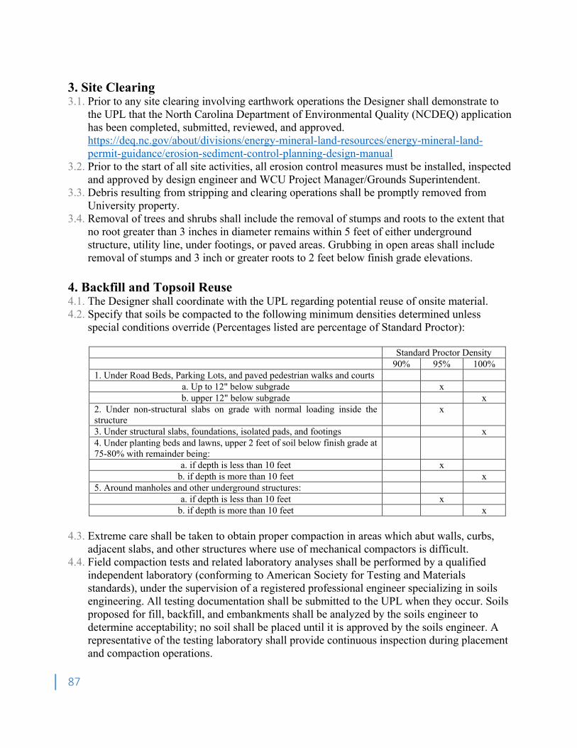
87
3. Site Clearing 3.1. Prior to any site clearing involving earthwork operations the Designer shall demonstrate to
the UPL that the North Carolina Department of Environmental Quality (NCDEQ) application has been completed, submitted, reviewed, and approved. https://deq.nc.gov/about/divisions/energy-mineral-land-resources/energy-mineral-land-permit-guidance/erosion-sediment-control-planning-design-manual
3.2. Prior to the start of all site activities, all erosion control measures must be installed, inspected and approved by design engineer and WCU Project Manager/Grounds Superintendent.
3.3. Debris resulting from stripping and clearing operations shall be promptly removed from University property.
3.4. Removal of trees and shrubs shall include the removal of stumps and roots to the extent that no root greater than 3 inches in diameter remains within 5 feet of either underground structure, utility line, under footings, or paved areas. Grubbing in open areas shall include removal of stumps and 3 inch or greater roots to 2 feet below finish grade elevations.
4. Backfill and Topsoil Reuse 4.1. The Designer shall coordinate with the UPL regarding potential reuse of onsite material. 4.2. Specify that soils be compacted to the following minimum densities determined unless
special conditions override (Percentages listed are percentage of Standard Proctor):
Standard Proctor Density 90% 95% 100% 1. Under Road Beds, Parking Lots, and paved pedestrian walks and courts
a. Up to 12" below subgrade x b. upper 12" below subgrade x
2. Under non-structural slabs on grade with normal loading inside the structure
x
3. Under structural slabs, foundations, isolated pads, and footings x 4. Under planting beds and lawns, upper 2 feet of soil below finish grade at 75-80% with remainder being:
a. if depth is less than 10 feet x b. if depth is more than 10 feet x
5. Around manholes and other underground structures: a. if depth is less than 10 feet x
b. if depth is more than 10 feet x
4.3. Extreme care shall be taken to obtain proper compaction in areas which abut walls, curbs, adjacent slabs, and other structures where use of mechanical compactors is difficult.
4.4. Field compaction tests and related laboratory analyses shall be performed by a qualified independent laboratory (conforming to American Society for Testing and Materials standards), under the supervision of a registered professional engineer specializing in soils engineering. All testing documentation shall be submitted to the UPL when they occur. Soils proposed for fill, backfill, and embankments shall be analyzed by the soils engineer to determine acceptability; no soil shall be placed until it is approved by the soils engineer. A representative of the testing laboratory shall provide continuous inspection during placement and compaction operations.
88
5. Tree and Plant Protection 5.1. A tree protection plan shall be provided for each project as determined by UPL. Tree
protection shall be shown on the Erosion and Sediment Control Plan and Site Development Plan. The UPL shall identify specifically those trees to be saved and those which must be removed.
5.2. All remaining trees shall have protective barriers which shall be the larger of: 5.2.1. The drip line of the tree 5.2.2. Diameter at breast height (in inches) x 1.5 (feet per inch) 5.3. A substantial barrier shall be installed prior to any construction and shall remain until
construction and site cleanup is complete. Install chain-link fence at drip line. When installed call for inspection by WCU Grounds Superintendent.
5.4. No construction material, debris or excavated material shall be stored within the barricaded area. No vehicles, trailers, etc. shall be parked inside the barricaded area. No cleanout or washout to be conducted in protected areas.
5.5. Where trenching for utilities is required within the drip line, tunnel under or around roots by hand digging. Do not cut main lateral or tap roots. Cut smaller roots which interfere with a sharp pruning tool; do not chop or break.
5.6. Do not allow exposed roots to dry out before backfill is placed; provide temporary earth or moist burlap cover.
5.7. Any tree to remain that has had excavation within the drip line shall be pruned by a professional arborist according to the National Arborist Association Standards Class IV - Cutting Back or Drop Crotch Pruning.
5.8. Cutting back or drop crotch pruning shall consist of the reduction of tops, sides, under branches or individual limbs. This practice is to be undertaken only in cases of utility line interference, or where certain portions of the roots or root systems have been severed or severely damaged.
5.9. The following specifications shall apply: 5.9.1. All cuts shall be made sufficiently close to the trunk or parent limb, without cutting into
the branch collar or leaving a protruding stub, so that closure can readily start under normal conditions. All cuts shall be clean. It is necessary to precut branches too heavy to handle to prevent splitting or peeling the bark. Where necessary, to prevent tree or property damage, branches shall be lowered to the ground by proper ropes or equipment.
5.9.2. Remove the weaker, least desirable, crossed or rubbed branches. Such removal shall not leave holes in the general outline of the tree.
5.9.3. Generally, in reducing size (cutting back) not more than one-third of the total area shall be reduced at a single operation. When cutting back, only drop crotch as much as necessary. Where practical, avoid cutting back to small suckers. All effort shall be made to cut back to a lateral, one-third the diameter of the cut being made. In reducing overall size, attention is to be given to the symmetrical appearance. Top is to be higher and sides reduced in order to maintain a tree-like form. When cutting back trees, one shall have in mind to make them shapely and typical of their species.
5.9.4. On thin bark trees, just enough limbs shall be removed to get the effect wanted without admitting too much sunlight to the trunk of the tree or the top of large branches. Care shall be taken with the following species: lindens, maples, beeches, apples, oaks, and other trees
89
susceptible to sunscald, growing in different geographical areas. The damage may be minimized by doing work on susceptible species during the dormant season.
5.9.5. In lifting the lower bottom branches of trees for under clearance, care shall be given to symmetrical appearance, and cuts shall not be made so large that they will prevent normal sap flow.
5.9.6. Periodical drop crotching or cutting back of silver maples, poplars, and other trees with brittle and soft wood is an established practice and has proven beneficial in maintaining the safety of these trees over long periods of growth. Other trees with soft and brittle wood growing in different geographic areas may be specifically named when it is common practice to control growth by cut-back. An alternate method in some situations for maintaining the safety of these trees would be cabling and bracing.
5.9.7. Maintain existing grade outside drip line of trees, unless otherwise indicated on plan. Do not leave open excavations in the vicinity of protected trees for longer than 2 days to prevent soil moisture reduction.
5.10. Fertilization 5.10.1. Where tree roots within the drip line will be covered with asphalt or concrete, feeders shall
be installed as recommended by the National Arborist Association Standards. 5.10.2. Install extended feeders where construction of wells or retaining walls is required within
the drip line. 5.10.3. The design must provide a yard hydrant, irrigation system or other convenient water
source adjacent to trees that remain. 5.10.4. The specifications shall define proper fertilization and the contractor shall fertilize affected
trees during construction. 6. Grading 6.1. Finish grade slopes shall be shallow enough to allow mowing (generally 1:3 or less); steeper
slopes will be permitted only in areas where maintenance-free erosion control (groundcover planting, rip-rap, etc.) is provided.
6.2. All areas disturbed by construction operations and not covered by building, paving, etc. shall be fine graded and temporarily seeded. Sod is to be used for permanent lawns.
7. Demolition 7.1. Demolition plans shall include a general note “Prior to the start of construction the Contractor
shall document all existing conditions through photographic record and site map. All damage to existing campus components not documented prior to construction will be the responsibility of the contractor to repair or replace”.
7.2. Protection of existing conditions shall be noted and inspected by the design team. 7.3. Record Documents shall indicate foundations to remain. 7.4. The project-specific Safety Plan shall indicate requirements for control of dust and noise
mitigation. 7.5. Existing conditions of adjacent structures to remain shall be documented prior to demolition. 7.6. Provide instructions which require the Demolition Contractor to develop the Detailed
Demolition Plan. 7.7. Blasting demolition shall be approved by the UPL. 7.8. Seismographic monitoring may be required on adjacent buildings.
90
8. Site Remediation 8.1. Hazardous materials survey and remediation are assumed to be separate from building design
unless otherwise requested by the UPL and/or Risk Management and Safety. 8.2. WCU will contract directly with environmental consultants to perform the necessary
assessments and remediation, if applicable. The consultant retained for such services must be a professional engineer with current registration in the State of North Carolina in addition to any certifications required by local, state, and federal regulatory agencies.
9. Erosion Control 9.1. General 9.1.1. Erosion and Sediment Control Process Narrative
This document is to provide a clearer picture of how the overall plan to reduce erosion and its resulting sedimentation issues on campus is to be applied. The following are shown in sequential order.
A WCU Construction Project is generated. Selected design Engineer shall be familiar with the WCU Design and Construction
Standard. For land disturbances less than 0.25 Acres, the design engineer may request a variance from
the requirements of the Design and Construction standard and be allowed to incorporate Erosion and Sedimentation Control (ESC) in a more simplistic manner.
Engineer uses WCU ESC Standards to Design Project. Design to include 3 phase ESC plan (1. Pre-Construction, 2. Construction and 3. Post
Construction) including tree protection. Engineer Incorporates necessary unit pricing for possible additional ESC measures
throughout project life. Contractor responsible for installing ESC BMPS. Contractor acquires necessary NCDEQ permit, must present copy of application to WCU. Land Disturbing Authorization requested by WCU Contractor. Land Disturbing Authorization granted by WCU Representative with the approval of Design
Engineer and WCU’s Erosion Consultant. Contractor responsible for necessary NCDEQ inspections. WCU to stock basic ESC materials for emergency response situations. WCU will contract with the engineer of record to conduct its own inspections monthly,
before forecasted rain events, and within 48 hrs after flagged 0.5 inches or greater event. Contractor shall test storm water run-off for turbidity at all outfalls on the site or that collects
run-off from the site. The test shall be performed at minimum once monthly, and within 24 hours after any storm event greater than 0.5 inches.
WCU will contract with the engineer of record to monitor the turbidity of the runoff from each site once monthly, or after any storm event greater than 0.5 inches. The rainfall depth of an event will be determined using NOAA.
As stipulated in General Notes, Contractor to pay any incurred NCDEQ fines. Contractor to Coordinate with WCU Construction Project Manager regarding ESC removal.
91
9.1.2. The methods of erosion and sediment control outlined in this document are not intended to limit engineer creativity and innovation. The listed methods are intended to create a uniform set of standards for designers and contractors to use, to ensure a maximum level of erosion and sediment control is achieved. Any desire to deviate from the standards should be presented to the WCU Project Lead.
9.1.3. All design and construction activity must be performed in compliance with the most current NCDEQ Erosion and Sediment Control Policy as provided by the Department of Risk Management and Safety, in addition to complying with all local, state, and federal regulatory requirements.
9.1.4. The WCU Design and Construction Standards are more stringent and shall to be used to supplement the North Carolina Department of Environmental Quality (NCDEQ) requirements regarding construction site storm water runoff.
9.1.5. Design shall comply with The North Carolina Handbook for Erosion and Sediment Control and Storm Water Management of Construction Sites and Urban Areas.
9.1.6. All construction sites on campus, regardless of size, will be subject to the design requirements here-in. WCU reserves the right to waive the requirements of this document should the UPL deem it appropriate.
9.1.7. All North Carolina Department of Environmental Quality (NCDEQ) permitting and sampling documentation must be prepared by the civil engineering consultant. The civil engineering consultant must be a registered professional engineer in the State of North Carolina as well as meeting any other requirements of a certifying professional as set forth by NCDEQ. Additionally, the civil engineering consultant shall be familiar with WCU’s additional erosion and sediment control standards located here-in.
9.1.8. The Design Return Period Storm for sizing Erosion and Sediment Control Measures shall be a 25 year-24-hour storm.
9.1.9. Before initiating any earthwork not directly associated with the installation of erosion and sediment control measures as indicated on the pre-construction erosion control plan, the Contractor shall submit a Land Disturbance Authorization form from the UPL. The Contractor shall be responsible for obtaining a Notice of Registration from NCDEQ. The Contractor shall provide proof of NCDEQ registration to the Western Carolina University Construction project manager prior to receiving the Land Disturbance Authorization permit.
9.1.10. The Contractor shall be responsible for all monitoring, inspections, etc. to assure the Owner that the site is at all times in accordance with NCDEQ Rules and Regulations. Documentation of QCI and QCP inspections shall be provided to the Owner.
9.1.11. In addition to the inspection, monitoring requirements instituted by NCDEQ, Western Carolina University is requiring that the storm water outfall from any construction site on campus have a turbidity of not more than 50 NTUs (Nephelometric Turbidity Units) for any 25 year, 24-hour event and smaller.
9.1.12. If United States Corp of Engineers approved construction is to be performed in any stream bed, the increase in turbidity from the upstream or “background” flow to the downstream flow shall be no greater than 50 NTUs.
9.1.13. Western Carolina University will contract with the engineer of record to conduct inspections monthly, after each ½” rain event, and prior to any substantial predicted storm event to ensure the contractor is properly maintaining erosion and sediment control.
92
NCDEQ is to be notified if any sites are found to be noncompliant during these inspections.
9.1.14. Western Carolina University will contract with the engineer of record to sample and record turbidity during site inspection throughout the life of the project to determine
9.1.15. whether the civil engineer and contractor have properly designed and installed the Erosion and Sediment Control Measures.
9.1.16. The contractor will be responsible for any incurred regulatory fines throughout the course of construction.
9.1.17. Western Carolina University reserves the right to withhold retainage for all but not limited to the following: Failure to maintain erosion & sediment control measures, the inability to meet Western Carolina University’s turbidity sampling requirements, services rendered by Western Carolina University in the event that a contractor is unresponsive to directives to modify erosion and sedimentation control measures. Western Carolina University also requires the Designer of Record to incorporate site specific Erosion and Sedimentation Control measures as unit prices in the bid package. These unit prices will be implemented in the event the site requires additional protection or if the contractor is nonresponsive to Erosion and Sedimentation problems that occur. These unit prices can also be implemented negatively if the contractor has not met his contractual obligations. Thus allowing the owner to have the BMP’s installed by other means.
9.1.18. There shall be in ALL Construction drawing sets requiring an Erosion and Sediment Control Plan, a sheet of general notes for erosion and sediment control. Following each phase of the Erosion and Sediment Control Plan there shall be a sheet of project applicable details that correspond to the erosion and sediment control best management practices.
9.1.19. All disturbed areas must be protected with temporary seeding within 13 days of the latest disturbance.
9.1.20. It will be imperative that sediment laden runoff not be allowed to enter any pervious pavement areas. These areas shall be protected, at minimum, using a silt fence located up slope of diversion wales.
9.1.21. Western Carolina University strongly encourages designers and contractors to consider the use of processed demolished building debris for appropriate erosion and sediment control measures such as check dams, construction exit pad, temporary roads, ditch lining, outlet protection, and inlet protection.
9.2. Erosion and Sediment Control Plan 9.2.1. The Erosion and Sediment Control Plan is a set of drawings which provides the necessary
measures to reduce erosion on construction sites and minimize the impacts of sediment, turbidity and hydrologic changes off-site throughout the life of the project and beyond. It is to ensure that erosion and sediment control is appropriate for the planned use of the site.
9.2.2. The Erosion and Sedimentation Control Plan shall follow the North Carolina Handbook for Erosion Control, Sediment Control, and Storm Water Management on Construction Sites and Urban Areas and must be reviewed and approved by Western Carolina University Office of Risk Management & Safety and Western Carolina University’s erosion control consultant.
9.2.3. Required content of the Erosion and Sediment Control Plan • Site Map Drawing
o This Sheet to resemble the drawing required by NCDEQ for NPDES permitting, placed on a USGS 7.5-minute Topographic Quadrangle)
93
o Receiving waters labeled o Site discharge points indicated o Point of entry into receiving waters indicated
• Pre-Construction Site Plan Drawing o Note: This plan to show necessary erosion sediment control measures to be installed before land disturbance authorization is granted. Only grading specifically identified as intended for erosion and sediment control shall be permitted prior to land disturbance authorization. o Contours, existing and proposed o Placement of necessary erosion & sediment control BMPs o Tree protection o Discharge points o Expected pre & post-construction flow discharges for 25 year-24 hr event (in table format) o Site specific notes o Note referencing the full sheet of general notes o Erosion and sediment control details
• Construction Site Plan Drawing o Phasing of changes to erosion and sediment control BMPs o Contours, existing and proposed o Placement of erosion & sediment control BMPs o Tree protection o Site specific notes o Note referencing the full sheet of general notes o Erosion and sediment control details
• Post-Construction Site Plan Drawing o Note: This plan to show necessary Erosion Sediment Control Measures to be installed before substantial completion to be awarded. o Contours, existing and proposed o Changes to erosion and sediment control BMPs o Site specific notes o Note referencing the full sheet of general notes o Erosion and sediment control details
9.3. Erosion and sediment control BMPs, details: 9.3.1. This section outlines the design requirements and appropriate applications for Erosion and
Sediment Control Practices on Campus. The acronym in parentheses, following the practice or device, corresponds to the associated detail.
9.3.2. Site Preparation • Construction Exit Pad (CEP)
o Practice Description o Construction exit pads are used to prevent sediment from leaving the site by means of the wheels of construction vehicles exiting the construction site. o Stone shall be NCDOT No. 1 (1” to 3” inch stone) o Pad shall be 6 inches thick.
94
o Pad shall be a minimum of 50 feet long and 20 feet wide. o If stone alone does not sufficiently remove sediment, vehicle tires should be washed before exiting site with sediment-laden runoff draining into an on-site sediment trap or basin. o Geotextile selection shall be in accordance with AASHTO M288. o Should the construction exit pad cease to effectively remove tire born sediment, the top 3 inches of stone shall be removed and replaced.
• Land Grading o The practice of modifying existing topography for desired land uses. o Grading plans should be designed to protect existing vegetation where possible. o Grading should be scheduled to minimize the amount of time disturbed areas are left exposed to erosion elements. Stabilize all disturbed areas within 7 days of suspended activity. o The grade of slopes (excluding channel side slopes) on campus should, as a general practice, be no greater than 3 horizontal feet to 1 vertical foot (3:1). o Retaining walls should be incorporated into the design where site conditions require grades of steeper than 3:1. o Top soil from areas to be graded shall be removed and stockpiled for reapplication upon completion of grading operations. A stockpile location should be suggested by the engineer. Stockpiled vegetation should be protected from erosion by temporary vegetation. o Slope lengths on site should be minimized by the use of diversion channels. Recommendations for diversion placement are given in the table below.
Slope Spacing (Ft) 33-50% 20 25-33% 40 15-25% 60 10-15% 80 6-10% 120 3-6% 200 <3% 300
o Where practical, storm water run-on from adjacent undisturbed sites should be diverted around the construction area to minimize on-site erosion.
• Top Soiling (TSG) o The removal of soil surface useful for establishing vegetation. This practice is applied to areas to be disturbed by excavation, compaction, and general grading operations. Top soil is generally darker than subsoil due to increased levels of organic matter. This soil, upon distribution over the disturbed site is advantageous for establishing vegetation to minimize erosion. o Topsoil shall be relatively free of debris and shall give evidence as a suitable soil for growing vegetation prior to stripping. o pH should be in the range of 6.0-7.0. Any pH below 6.0, shall result in the addition of lime in accordance with a soil test report.
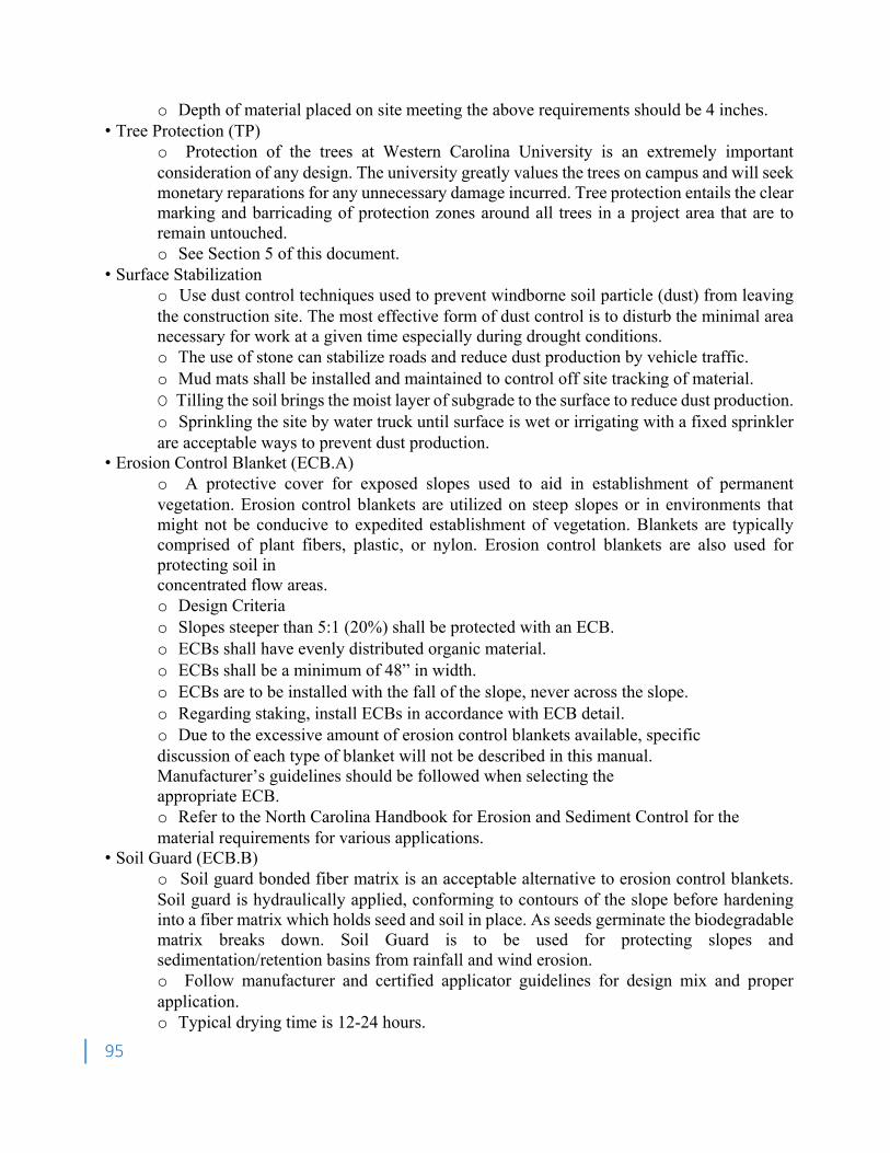
95
o Depth of material placed on site meeting the above requirements should be 4 inches. • Tree Protection (TP)
o Protection of the trees at Western Carolina University is an extremely important consideration of any design. The university greatly values the trees on campus and will seek monetary reparations for any unnecessary damage incurred. Tree protection entails the clear marking and barricading of protection zones around all trees in a project area that are to remain untouched. o See Section 5 of this document.
• Surface Stabilization o Use dust control techniques used to prevent windborne soil particle (dust) from leaving the construction site. The most effective form of dust control is to disturb the minimal area necessary for work at a given time especially during drought conditions. o The use of stone can stabilize roads and reduce dust production by vehicle traffic. o Mud mats shall be installed and maintained to control off site tracking of material. O Tilling the soil brings the moist layer of subgrade to the surface to reduce dust production. o Sprinkling the site by water truck until surface is wet or irrigating with a fixed sprinkler are acceptable ways to prevent dust production.
• Erosion Control Blanket (ECB.A) o A protective cover for exposed slopes used to aid in establishment of permanent vegetation. Erosion control blankets are utilized on steep slopes or in environments that might not be conducive to expedited establishment of vegetation. Blankets are typically comprised of plant fibers, plastic, or nylon. Erosion control blankets are also used for protecting soil in concentrated flow areas. o Design Criteria o Slopes steeper than 5:1 (20%) shall be protected with an ECB. o ECBs shall have evenly distributed organic material. o ECBs shall be a minimum of 48” in width. o ECBs are to be installed with the fall of the slope, never across the slope. o Regarding staking, install ECBs in accordance with ECB detail. o Due to the excessive amount of erosion control blankets available, specific discussion of each type of blanket will not be described in this manual. Manufacturer’s guidelines should be followed when selecting the appropriate ECB. o Refer to the North Carolina Handbook for Erosion and Sediment Control for the material requirements for various applications.
• Soil Guard (ECB.B) o Soil guard bonded fiber matrix is an acceptable alternative to erosion control blankets. Soil guard is hydraulically applied, conforming to contours of the slope before hardening into a fiber matrix which holds seed and soil in place. As seeds germinate the biodegradable matrix breaks down. Soil Guard is to be used for protecting slopes and sedimentation/retention basins from rainfall and wind erosion. o Follow manufacturer and certified applicator guidelines for design mix and proper application. o Typical drying time is 12-24 hours.
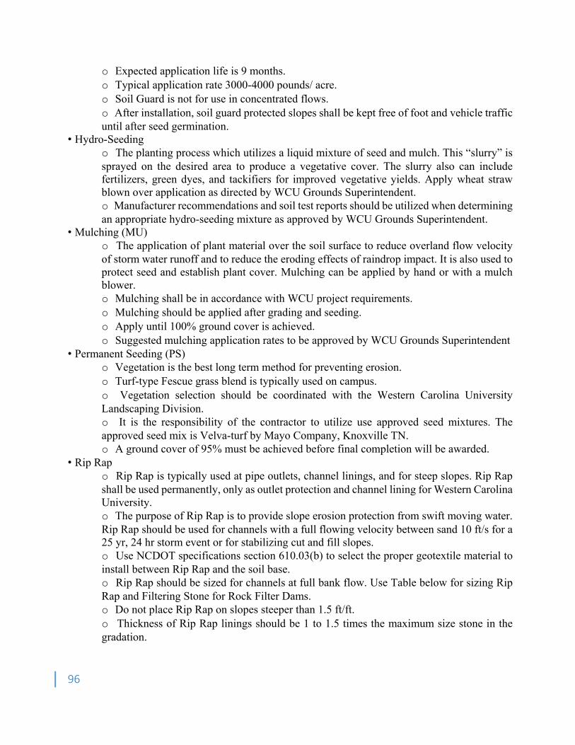
96
o Expected application life is 9 months. o Typical application rate 3000-4000 pounds/ acre. o Soil Guard is not for use in concentrated flows. o After installation, soil guard protected slopes shall be kept free of foot and vehicle traffic until after seed germination.
• Hydro-Seeding o The planting process which utilizes a liquid mixture of seed and mulch. This “slurry” is sprayed on the desired area to produce a vegetative cover. The slurry also can include fertilizers, green dyes, and tackifiers for improved vegetative yields. Apply wheat straw blown over application as directed by WCU Grounds Superintendent. o Manufacturer recommendations and soil test reports should be utilized when determining an appropriate hydro-seeding mixture as approved by WCU Grounds Superintendent.
• Mulching (MU) o The application of plant material over the soil surface to reduce overland flow velocity of storm water runoff and to reduce the eroding effects of raindrop impact. It is also used to protect seed and establish plant cover. Mulching can be applied by hand or with a mulch blower. o Mulching shall be in accordance with WCU project requirements. o Mulching should be applied after grading and seeding. o Apply until 100% ground cover is achieved. o Suggested mulching application rates to be approved by WCU Grounds Superintendent
• Permanent Seeding (PS) o Vegetation is the best long term method for preventing erosion. o Turf-type Fescue grass blend is typically used on campus. o Vegetation selection should be coordinated with the Western Carolina University Landscaping Division. o It is the responsibility of the contractor to utilize use approved seed mixtures. The approved seed mix is Velva-turf by Mayo Company, Knoxville TN. o A ground cover of 95% must be achieved before final completion will be awarded.
• Rip Rap o Rip Rap is typically used at pipe outlets, channel linings, and for steep slopes. Rip Rap shall be used permanently, only as outlet protection and channel lining for Western Carolina University. o The purpose of Rip Rap is to provide slope erosion protection from swift moving water. Rip Rap should be used for channels with a full flowing velocity between sand 10 ft/s for a 25 yr, 24 hr storm event or for stabilizing cut and fill slopes. o Use NCDOT specifications section 610.03(b) to select the proper geotextile material to install between Rip Rap and the soil base. o Rip Rap should be sized for channels at full bank flow. Use Table below for sizing Rip Rap and Filtering Stone for Rock Filter Dams. o Do not place Rip Rap on slopes steeper than 1.5 ft/ft. o Thickness of Rip Rap linings should be 1 to 1.5 times the maximum size stone in the gradation.
97
o Special consideration should be given to the use of processed demolished building debris for appropriate erosion and sediment control measures such as check dams, construction exit pad, temporary roads, ditch lining, outlet protection, and inlet protection. o Filter stone is for placement on the upstream face of rock filter dams. Graded Rip Rap stone for channel lining and outlet protection.
Flow Velocity NCDOT No Size Inches NCDOT (ft./sec.) (Sq. Opening) Filter Stone No.
Max. Avg.2 Min.
2.5 5 1 ½ ¾ No. 8 810 4.5 24 3 1 ½ 1 810 6.5 1 6 3 2 8 9.0 Class 1 Rip Rap 12 6 3 1
11.5 Class 2 Rip Rap 18 9 5 1 13.0 Class 3 Rip Rap 24 12 7 1
• Sodding (SOD)
o The installation of transplanted vegetative cover. The intent is to provide immediate erosion control for disturbed soils. Areas benefiting from the use of sodding are diversions, adjacent to storm drain inlets and outlets, and disturbed slopes. o Turf-type Fescue Blend turf is the standard species used for sodding on campus. o A soil test should be performed to determine any necessary soil amendments to facilitate growth. Soil tests are to be conducted by an approved soil testing laboratory. o Before installation, the soil should be cleared of debris and clods larger than 2” in diameter. o Low spots are to be removed to prevent ponding. o Prepare soil by disking/rotovation and rolling. o Limit the use of heavy equipment to avoid over-compacting the soil and creating a root barrier.
• Temporary Seeding o The establishment of rapidly growing vegetation to stabilize disturbed area and prevent soil erosion until permanent plantings can be installed. Temporary seeding is used when work ceases temporarily or when work is completed in a season not suited for final planting. Temporary seeding shall meet the requirements of approved mix by WCU Grounds Superintendent. o Temporary seeding greatly reduces silt accumulation based maintenance of sediment control devices.
9.3.3. Runoff Conveyance • Hay Bale/Waddle Check Dam (HBCD)
o A row of straw bales or waddle (silt sock) entrenched in a storm water conveyance channel with the purpose of removing sediment from the construction site’s storm water runoff. o The low flow rate of straw bales often leads to ponding and overtopping of bales. Be aware of ponding water concerns when including straw bales in an erosion control plan. o Bale dimensions should be 14” x 18” x 36”.
98
o Bales should be embedded 4” into the soil and staked, using 2, 2” x 2” hardwood stakes. o Hay bale check dams should be spaced at the horizontal distance that corresponds to one vertical foot of elevation change. o Typical useful life of a straw bale is 3 months. o Waddles with a 10” diameter, are acceptable alternatives to hay bales. o Hay or coconut fiber waddles should be staked along both sides of the length of the waddle with a spacing of four feet. o Stakes should be angled away from the waddle to resist upward force applied to the waddle by the flow of water.
• Diversion Channel (DV) o A temporary or permanent excavated channel designed to collect storm water and divert it away from the disturbed site to prevent erosion damage. Diversions can be used to intercept storm water running onto a site and eliminate the need for sediment removal for a potentially substantial volume of water. Rapid establishment of vegetation is crucial to proper diversion function. o Temporary storm water diversions shall be capable of carrying a 25yr, 24hr storm event with a 0.3 foot freeboard. o Permanent storm water diversions shall be capable of carrying a 50yr, 24hr storm event. o Recommended spacing of storm water diversions
= Slope Spacing (Ft) 33-50% 20 25-33% 40 15-25% 60 10-15% 80 6-10% 120 3-6% 200 <3% 300
o Refer to the North Carolina Handbook for Erosion and Sediment Control for guidance regarding further information on storm water diversion design. • Inlet Protection (IP) o Inlet protection is intended to reduce the amount of sediment entering a pipe such as a culvert. Inlet protection is achieved using the hay bale check dam. o See hay bale check dam section.
• Outlet Protection (OP) o Practice applied whenever a high velocity discharge must be released onto an erodible soil, typically at the outlet of a channel or conduit. Protection is achieved by means of a Rip Rap lined apron, concrete baffles, and concrete flumes. o The outlet protection for Western Carolina University should be designed to handle the peak storm water runoff from a 25 yr, 24hr storm. o The North Carolina Handbook for Erosion and Sediment Control provides precise design requirements for outlet protection.
9.3.4. Sediment Control • For Storm Water Detention See G-30 Section 4.3.1
99
• Flocculants o Floc-logs are a semi-hydrated polyacrylamide blended block that when placed within turbid water flows will remove fine particles and reduce NTU values. o Soil Tests are required in order for the manufacturer to select the proper Floc Log mixture. o Placement of Floc Logs should be as close to the source of particle suspension as possible. o Floc Logs can be placed in the invert of drop structures to begin treating sediment-laden water immediately upon entering the collection system. This application is only acceptable if the collection system in which the Floc Log is placed flows into a temporary sedimentation basin. o Floc Logs can be placed in the invert of open ditches directly behind check dams and well upstream from the sedimentation basin. This application is only acceptable if the collection system in which the Floc Log is placed flows into a temporary sedimentation basin. o The use of Floc Logs should be considered in any application in which storm water is detained at a sediment trap before entering the storm water collection network. These traps include excavated drop inlet protection, hay bale check dams, rock filter check dams, and sedimentation basins. o The typical flow treated by one Floc Log is 60-75 GPM.
• Floccin Bags o A manufactured bag filled with the Floccin Flocculating Agent that when placed within turbid water flows, causes suspended soil particles to coagulate and drop from solution, therefore reducing NTU values. o Always follow manufacturer’s dosing recommendations. o Place Floccin Bags as far upstream from the sedimentation basin as feasible to allow more time for mixing and sediment deposition. o Floccin Bags are typically staked to the ground in the invert of the ditch immediately following a check dam. o The use of Floccin Bags should be considered in any application in which storm water is detained at a sediment trap before entering the storm water collection network. These traps include excavated drop inlet protection, hay bale check dams, rock filter check dams, and sedimentation basins.
• Flocculant Covered Fabric at Check Dams o A practice similar to the use of Floc Logs. Polyacrylamide in the form of an emulsified powder is applied to a moist coir fabric attached to the downstream side of check dams in open channels and is used to facilitate sediment deposition and reduction of the NTU value of discharged storm water. o The powder form of polyacrylamide should be applied to a secured, moist fabric, typically 700-900 g/m2 Coir, on downstream face of Check Dam, either Rock or Hay. o Follow manufacturer guidelines for dosing.
• Grate Inlet Protection in Pavement o A sediment barrier formed from filter fabric, gravel, hay or coconut waddles, and sand bags used to minimize the amount of sediment entering an inlet. This method can be used in paved inlets. This method is for protecting inlets with no bypass (inlets in a sag). It can also be used for
100
inlets in disturbed area, but fabric drop inlet protection is preferred. o Drainage area should be less than 1 acre. o The approach slope to the inlet should be less than 1%. o Used for inlets in sag, with no bypass.
o Height of gravel should be 0.5’ high. o Gravel should have a 2:1 side slope or flatter. o #57 washed stone is recommended for the gravel. • Curb Inlet Protection (CIP)
o Type “S” Curb inlets located in paved areas within the same drainage basin as the construction site require protection from sediment laden storm water flowing along the curb and gutter. Type “S” curb inlets constructed prior to paving that are in disturbed areas require either fabric drop inlet protection or block and gravel protection. Curb inlet protection can potentially lead to flooding of roadways. Should unsafe driving water conditions be created due to water standing in roadways remove the inlet protection immediately. o Use 10” diameter hay or coconut fiber waddles. o Waddles are to be held in place by weighting with sand bags or bags of stone. o Place waddles in gutter and at a minimum of 1 foot from the inlet throat. This allows overflow and prevents flooding. o Alternatively, the practice of wrapping 8” concrete blocks with silt fence material is also an acceptable form of inlet protection.
• Fabric Drop Inlet Protection (FIP.1 and FIP.2) o New and existing drop (grate) inlets in disturbed areas (do not use in paved areas) must be protected in order to minimize the amount of sediment laden water from entering the storm water collection network. This can be achieved through manufactured products or constructed on site. This method can be combined with the excavated drop inlet protection (XDIP) for even better results. o Design Criteria-Silt Fence with Wood Supported Frame (FIP.1) o Use only in locations with a drainage basin slope of 5% or less. o This method is not applicable to inlets receiving concentrated flows. o Silt fence type A shall be used for this application. o When sediment has accumulated to ½ the height of the structure, it should be removed and properly disposed. o See detail for dimensioning
• Design Criteria- Frame and Filter Fabric (FIP.2) o Use only in locations with an approach slope of 2% or less. o Drainage area should be less than 1 acre per inlet. o Frame shall be constructed of high density polyethylene copolymer (HDPE). o Frame may be round or square base. o The fitted filter assembly shall be constructed of 100% continuous polyester needle-punched non-woven engineering fabric and follow the guidelines in the American Society for Testing and Materials (ASTM) D1117-99. o The filter fabric shall have a weight on no less than 2.5 ounces per square yard.
101
o The filter fabric shall have a tensile strength of no less than 70 psi with an elongation at break of no less than forty percent (40%). o The filter fabric shall have a minimum U.V. rating of no less than 65% at 500 hrs. o Filter fabric flow shall be no less than 100 gallons/minute/ft2 at the time of installation o Filter fabric shall have minimum puncture strength of 40psi. o Filter fabric shall be composed of 2-stages (D.O.T. Filter). The lower half of the frame supported fabric shall be a 100 gallons/minute/ft2 “low-flow” fabric, while the upper half allows a greater flow to pass through reducing flooding risks. o When sediment has accumulated to ½ the height of the structure, it should be removed, re-deposited, and stabilized on the site.
• Excavated Drop Inlet Protection (XDIP) o The excavated drop inlet is the preferred method of sediment control for grate inlets and open throat inlets placed in unpaved areas. The excavated drop inlet method of protection is the creation of a small sediment basin around a drop inlet in an unpaved area that is allowed to dewater through weep holes cored in the sides of the inlet structure. The sediment laden water is filtered through stone and filter fabric before entering the structure. The detention time allows for sediment deposition. Should the weep holes become fouled, the structure will overtop and allow water to enter through grating or the open throat. o The excavated basin shall have a maximum depth between 1 and 2 feet. o Minimum diameter of the excavated sediment trap, at rim elevation, shall be 12 feet at minimum. o The sediment trap shall be sized to hold 67 cubic yds per disturbed acre. o Side slopes for the basin shall be 2:1 or flatter. o The inlet structure shall at the level of the bottom of the sediment trap, have 4, 2” holes (16 total) cored into each side of the structure. o Type A silt fence shall be wrapped around the structure with the weep holes covered by no less than 1foot in any direction. o Install washed No. 57 stone around the structure to provide protection for the silt fence. The minimum width of the stone filter around the structure shall be 2 feet. o If inlet drains more than 1 acre use fabric drop inlet protection in conjunction with the excavated drop inlet protection. o Remove sediment when accumulation reaches one half the depth of the excavation.
• Rock Filter Dam (RFD) o Rock filter dams are temporary stone filter dams placed in drainage ways, concrete lined or vegetated, to slow the flow of water by dissipating energy and thereby reducing drainage way erosion and allowing for a reduction in turbidity by increasing the available time for soil particles to settle out of suspension. Rock filter dams are commonly placed upstream of sediment ponds to remove courser particles of sediment. o Rock filter dams are utilized only for drainage areas of 10 acres or less. Rock filter dams are used as a finishing tools and work efficiently only if the majority of sediment is removed from storm water before entering the drainage way. o Dam height should not exceed the elevation of the upstream 6” below half the ditch height.
102
o Spacing of rock check dams should be such that the crest of the downstream dam is at the same elevation as the base of the upstream dam. o Stone should be sized using the Rip Rap section of this document. The upstream face should contain smaller stone to facilitate the filtering process. o For additional sedimentation benefits, install jute mats 700-900 g/m2 on downstream face of a Rock filter dam and while wet, spread PAM over jute mats in accordance with manufacturer’s guidelines. Alternatively, fix “floclogs” or “floccin bags” in place on the tailwater side of Rock Filter Dam.
• Sediment Basin (SBN) o Sediment basins are typically employed for large disturbed areas or when the use of smaller localized sediment traps would not provide adequate protection. o Sediment basins are earthen embankments used to detain sediment laden storm water in order to provide adequate time for soil particles to settle out of suspension. Water at the surface of the pond is the most treated and least turbid. Therefore, the storm water is dewatered from the top of the pond by utilizing a skimmer (floating weir). The process is made more efficient through the use of a flocculant to improve sedimentation and baffles for dechannelizing the flow within the pond. Sediment ponds are often converted to storm water detention or retention ponds after the construction phase is complete in order to manage post-construction storm water runoff. o The North Carolina Handbook for Erosion and Sediment Control and Storm Water Management of Construction Sites and Urban Areas provides detailed guidelines for the design and construction of sediment basins. Specifics for the design on Western Carolina University’s campus are listed below. o Minimum basin width shall be 10 feet (toe of slope to toe of slope). o Preferred length to width ration is 3:1. When site constraints do not permit a 3:1 ratio, an absolute minimum length to width ration of 2:1 may be used. o The minimum depth of the basin shall be 4 feet. o Basin side slopes shall be 2:1 or flatter. o The basin shall hold and store at minimum 3600 cubic feet/acre of drainage. o Sediment ponds shall be designed to treat storm water run-off of a 25 year, 24 hr storm. o Basin and skimmer should be designed to store and dewater a 25 year storm event over 3 days. o Floating skimmers shall be the primary method for dewatering the sedimentation basin. Perforated riser designs will not be accepted. o The emergency spillway shall be sized for storm water run-off flows from a 50 year, 24 hr storm. o The emergency spillway may be designed as an overflow channel lined with Rip Rap or a self-cleaning drop inlet structure.
• Dewatering-Dirt Bag (DB) o For temporary dewatering operations the use of a “DIRTBAG” may be employed. The sediment laden water is filtered as it is forced through the porous geotextile fabric of the bag. Filter socks are not acceptable alternatives to dirt bags. o Composition shall be polypropylene nonwoven geotextile o Spout shall be capable of receiving a 4” discharge hose o Place dirt bag on slopes no greater than 2%.
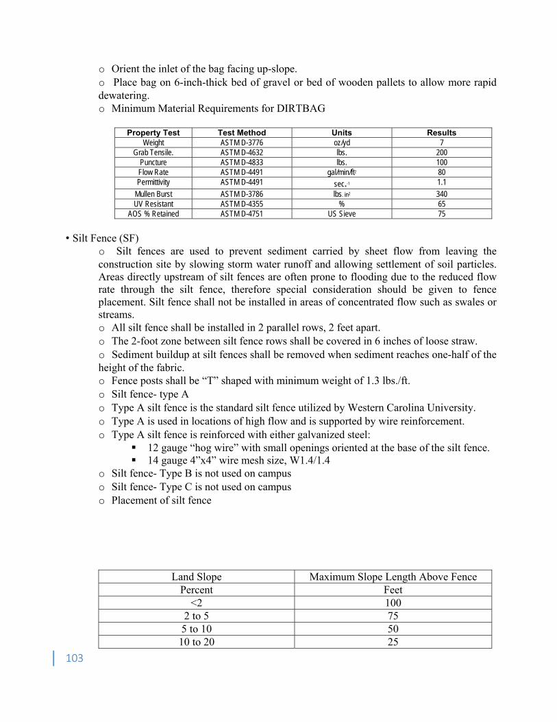
103
o Orient the inlet of the bag facing up-slope. o Place bag on 6-inch-thick bed of gravel or bed of wooden pallets to allow more rapid dewatering. o Minimum Material Requirements for DIRTBAG
Property Test Test Method Units ResultsWeight ASTM D-3776 oz/yd 7
Grab Tensile. ASTM D-4632 lbs. 200 Puncture ASTM D-4833 lbs. 100 Flow Rate ASTM D-4491 gal/min/ft2 80 Permittivity ASTM D-4491 sec.-1 1.1
Mullen Burst ASTM D-3786 lbs. in2 340 UV Resistant ASTM D-4355 % 65
AOS % Retained ASTM D-4751 US Sieve 75
• Silt Fence (SF)
o Silt fences are used to prevent sediment carried by sheet flow from leaving the construction site by slowing storm water runoff and allowing settlement of soil particles. Areas directly upstream of silt fences are often prone to flooding due to the reduced flow rate through the silt fence, therefore special consideration should be given to fence placement. Silt fence shall not be installed in areas of concentrated flow such as swales or streams. o All silt fence shall be installed in 2 parallel rows, 2 feet apart. o The 2-foot zone between silt fence rows shall be covered in 6 inches of loose straw. o Sediment buildup at silt fences shall be removed when sediment reaches one-half of the height of the fabric. o Fence posts shall be “T” shaped with minimum weight of 1.3 lbs./ft. o Silt fence- type A o Type A silt fence is the standard silt fence utilized by Western Carolina University. o Type A is used in locations of high flow and is supported by wire reinforcement. o Type A silt fence is reinforced with either galvanized steel:
12 gauge “hog wire” with small openings oriented at the base of the silt fence. 14 gauge 4”x4” wire mesh size, W1.4/1.4
o Silt fence- Type B is not used on campus o Silt fence- Type C is not used on campus o Placement of silt fence
Land Slope Maximum Slope Length Above Fence Percent Feet
<2 100 2 to 5 75 5 to 10 50 10 to 20 25
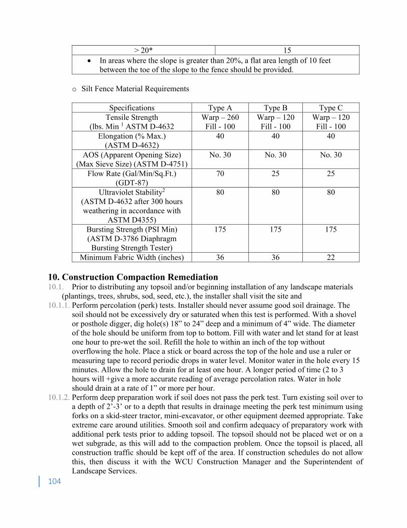
104
> 20* 15 In areas where the slope is greater than 20%, a flat area length of 10 feet
between the toe of the slope to the fence should be provided. o Silt Fence Material Requirements
Specifications Type A Type B Type C Tensile Strength
(lbs. Min 1 ASTM D-4632 Warp – 260 Fill - 100
Warp – 120 Fill - 100
Warp – 120 Fill - 100
Elongation (% Max.) (ASTM D-4632)
40 40 40
AOS (Apparent Opening Size) (Max Sieve Size) (ASTM D-4751)
No. 30 No. 30 No. 30
Flow Rate (Gal/Min/Sq.Ft.) (GDT-87)
70 25 25
Ultraviolet Stability2 (ASTM D-4632 after 300 hours weathering in accordance with
ASTM D4355)
80 80 80
Bursting Strength (PSI Min) (ASTM D-3786 Diaphragm Bursting Strength Tester)
175 175 175
Minimum Fabric Width (inches) 36 36 22
10. Construction Compaction Remediation 10.1. Prior to distributing any topsoil and/or beginning installation of any landscape materials
(plantings, trees, shrubs, sod, seed, etc.), the installer shall visit the site and 10.1.1. Perform percolation (perk) tests. Installer should never assume good soil drainage. The
soil should not be excessively dry or saturated when this test is performed. With a shovel or posthole digger, dig hole(s) 18” to 24” deep and a minimum of 4” wide. The diameter of the hole should be uniform from top to bottom. Fill with water and let stand for at least one hour to pre-wet the soil. Refill the hole to within an inch of the top without overflowing the hole. Place a stick or board across the top of the hole and use a ruler or measuring tape to record periodic drops in water level. Monitor water in the hole every 15 minutes. Allow the hole to drain for at least one hour. A longer period of time (2 to 3 hours will +give a more accurate reading of average percolation rates. Water in hole should drain at a rate of 1” or more per hour.
10.1.2. Perform deep preparation work if soil does not pass the perk test. Turn existing soil over to a depth of 2’-3’ or to a depth that results in drainage meeting the perk test minimum using forks on a skid-steer tractor, mini-excavator, or other equipment deemed appropriate. Take extreme care around utilities. Smooth soil and confirm adequacy of preparatory work with additional perk tests prior to adding topsoil. The topsoil should not be placed wet or on a wet subgrade, as this will add to the compaction problem. Once the topsoil is placed, all construction traffic should be kept off of the area. If construction schedules do not allow this, then discuss it with the WCU Construction Manager and the Superintendent of Landscape Services.

105
10.1.3. If necessary, soil may be amended with a 1” or more of amendment-grade pine bark, tilled-in with front or rear tine tiller, to a depth of 8”.
10.1.4. Verify surface drainage patterns per plans. 10.1.5. Soil under large trees to remain should not require remediation if proper tree protection
measures have been followed. If, however, the soil under large trees has been compacted by construction activities, landscape installer is required to decompact the soil using an air-spade and employ other remedial measures based on the recommendations of the Superintendent of Facilities Landscape Services.

106
Section G20 Site Improvements 1. Roadways 1.1. Roadways, parking areas/lots, service courts, including subgrade and related work, shall be
designed by a Professional Engineer licensed in North Carolina 1.2. Provide North Carolina Department of Transportation (NCDOT) standard pavement material
specifications designed for specific soil conditions and anticipated loading 1.3. Street and parking lot layouts shall comply with Manual on Uniform Traffic Control Devices
(MUTCD). Drive lane width shall be 12’. Parking space shall be 9’ wide and 18’ deep 1.4. Routes to ADA accessible locations (i.e. handicapped parking, drop off locations, building
entrances, etc.) shall be maintained or alternate routes shall be provided and communicated to pedestrian traffic with signage.
1.5. Submit traffic control plan showing sign type, locations, detours in roadway and sidewalks. 1.6. Temporary traffic control signage must be clean and without major defect. When not in use,
signage used for construction efforts should be covered, laid down, or removed from roadway. 1.7. Materials used to cover a sign must be approved. 1.8. If flagmen are required, they must be certified and provided with a radios for communication. º Mobile phones are not acceptable. º Flagmen must be provided with stop/slow paddles. º Flagmen signs indicating presence should be placed well before workzone. 1.9. High visibility vest must be worn at all times when working on a roadway during the day. If
work has been approved to be done at night, high visibility vest with sleeves, and high visibility pants are required.
1.10. Depressions and Abutments to existing pavement shall be prepared by cutting out the pavement to below the base layer extending 12 inches into adjacent sound pavement, unless otherwise indicated. Cut excavation surfaces vertically. Recompact existing unbound-aggregate base course to form new subgrade. Apply tack uniformly to vertical surfaces to join the new pavement with the old. Allow tack coat to cure undisturbed before placing pavement.
º Consideration on using geotextile fabric and geogrid for base reconstruction, and geogrid for asphalt patching.
1.11. If failure occurs on subbase layer during paving activities, remove failure and install patch. 1.12. Asphalt should never be placed in lift thicknesses exceeding 4” without approval from
engineer or WCU Project Management. Compact between each lift. 1.13. Do not apply asphalt materials if subgrade is wet or excessively damp, if rain is imminent
or expected before time required for adequate cure, or if the following conditions are not met: º Tack Coat: Minimum surface temperature of 60°F. º Asphalt Base (Binder) Course: Minimum surface temperature of 40°F and rising at time of
placement. º Asphalt Surface (Wearing) Course: Minimum surface temperature of 60°F at time of
placement. º Pavement-Marking Paint: Proceed with pavement marking only on clean, dry surfaces and
at a minimum ambient or surface temperature of 55°F for water-based materials, and not exceeding 95°F.
107
2. Walks 2.1. Typical width shall be 6 feet for minor walks and 10 feet for major walks 2.2. Provide 6-inch-thick concrete walks with 6 x 6 WWF mesh (4,000 psi concrete min.) 2.2.1. Tooled joints where slab thickness is 6 in. º Spacing for joints in concrete where the maximum-size aggregate less than ¾ in. should be
every 12 ft. º Spacing for joints in concrete where the maximum-size aggregate greater than ¾ in. should
be every 15 ft. º Isolation joints should be installed at the beginning and end of radiuses where sidewalks T,
curve, or are generally unsymmetrical and change condition. º Isolation joints should be installed around ramps, drainage inlets, manholes, and anywhere
differential movement between pavement and structure occur. 2.3. 2.4. Provide a handicapped accessible route around the outside of the construction site 2.5. Selection of paving material shall be based on all of the following criteria as a whole: 2.5.1. Existing paving material in the vicinity cost and economic factors 2.5.2. Maintenance and durability 2.5.3. Aesthetic value 2.6. Concrete Walks 2.6.1. Minimum of six (6) inches thick with welded wire fabric over 4 inches of compacted
gravel base over a compacted soil sub-base. 2.6.2. Subgrade conditions must be considered during design of walks 2.6.3. Light broom finish perpendicular to traffic flow 2.6.4. Joints shall be tooled. No saw cut joints allowed 2.6.5. No fibrous mesh 2.6.6. No stamped or patterned concrete 2.7. Masonry Pavers shall be installed on a concrete, mortar or asphalt substrate using campus
standard color. 2.8. When a curb ramp is built on one side of a street, a companion ramp is required on the opposite
side of the street. When project limits would normally end within a street intersection, the limits must be extended to allow construction of a companion ramp on the opposite side of the intersection. Crosswalks shall be installed only at intersections.
2.9. When a curb ramp is built on one side of a street, a companion ramp is required on the opposite side of the street. Ramps require ADA R304 detectable warning surface. When project limits would normally end within a street intersection, the limits must be extended to allow construction of a companion ramp on the opposite side of the intersection. Crosswalks shall be installed only at intersections. Mid-block crosswalks are not permitted.
3. Site Furnishings 3.1. Exterior benches 3.1.1. Exterior bench with back
• To Be Determined 3.2. Exterior trash and recycling receptacles 3.2.1. Trash Receptacle
• To Be Determined 3.3. Tree grates
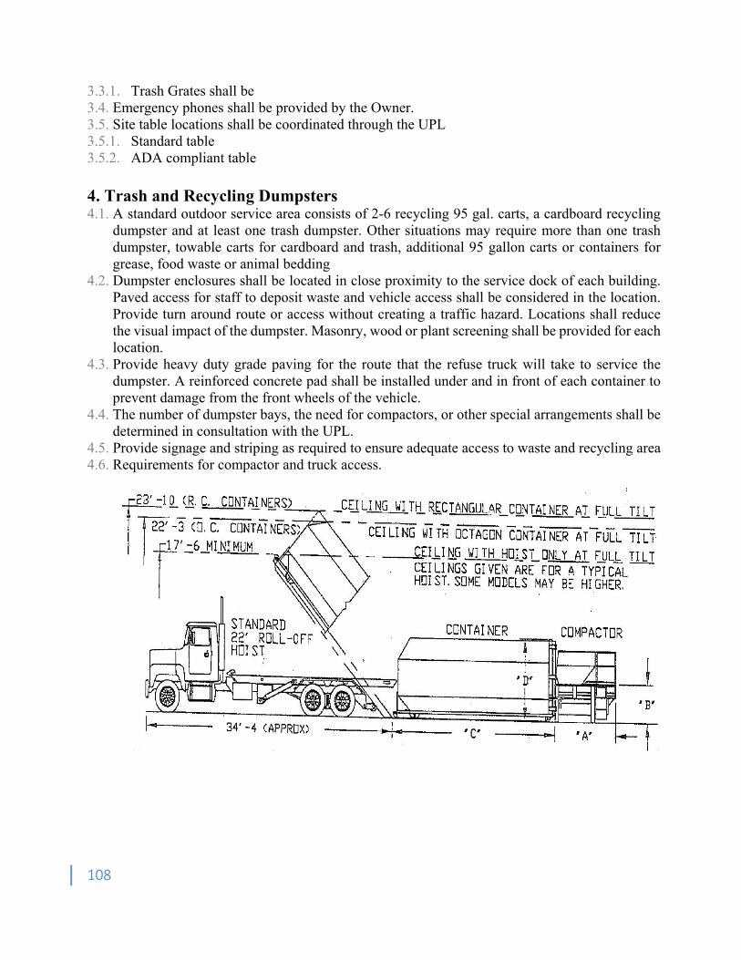
108
3.3.1. Trash Grates shall be 3.4. Emergency phones shall be provided by the Owner. 3.5. Site table locations shall be coordinated through the UPL 3.5.1. Standard table 3.5.2. ADA compliant table 4. Trash and Recycling Dumpsters 4.1. A standard outdoor service area consists of 2-6 recycling 95 gal. carts, a cardboard recycling
dumpster and at least one trash dumpster. Other situations may require more than one trash dumpster, towable carts for cardboard and trash, additional 95 gallon carts or containers for grease, food waste or animal bedding
4.2. Dumpster enclosures shall be located in close proximity to the service dock of each building. Paved access for staff to deposit waste and vehicle access shall be considered in the location. Provide turn around route or access without creating a traffic hazard. Locations shall reduce the visual impact of the dumpster. Masonry, wood or plant screening shall be provided for each location.
4.3. Provide heavy duty grade paving for the route that the refuse truck will take to service the dumpster. A reinforced concrete pad shall be installed under and in front of each container to prevent damage from the front wheels of the vehicle.
4.4. The number of dumpster bays, the need for compactors, or other special arrangements shall be determined in consultation with the UPL.
4.5. Provide signage and striping as required to ensure adequate access to waste and recycling area 4.6. Requirements for compactor and truck access.
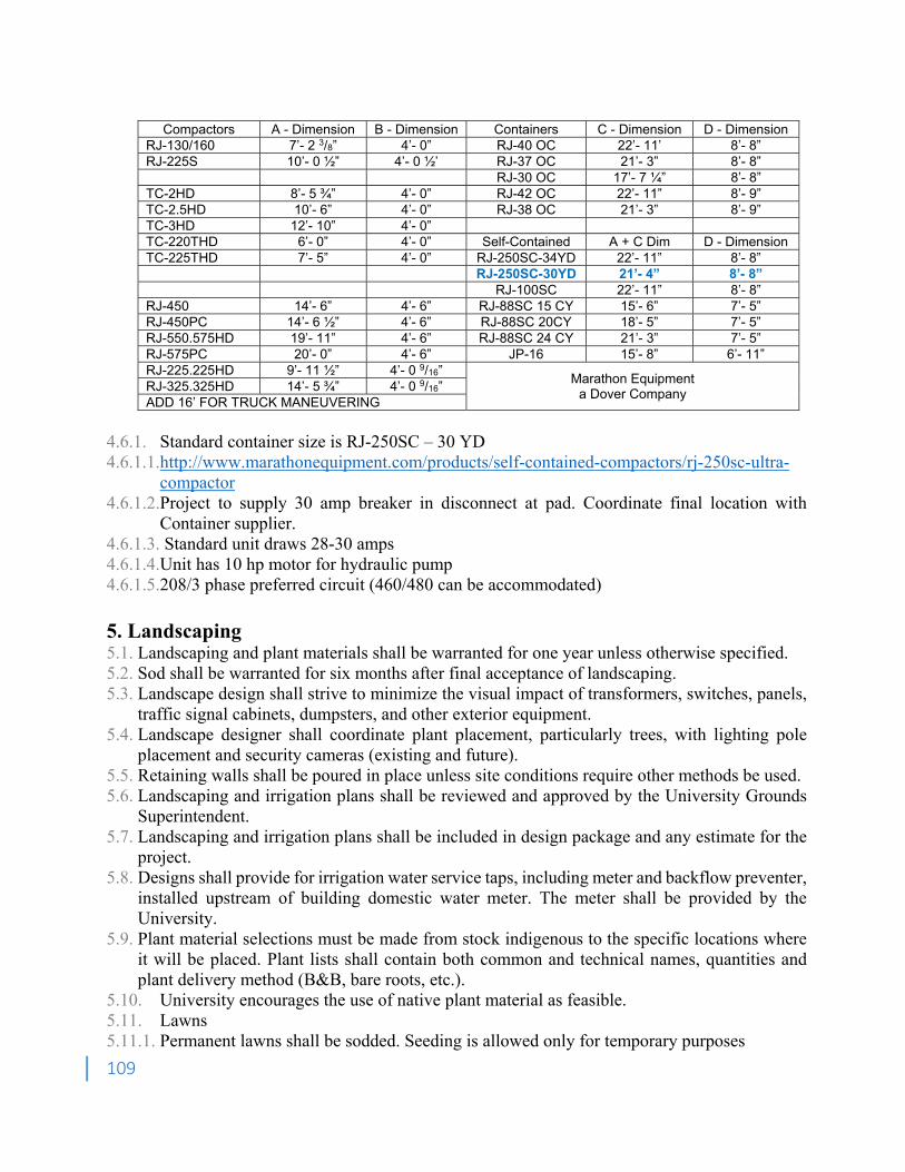
109
Compactors A - Dimension B - Dimension Containers C - Dimension D - Dimension
RJ-130/160 7’- 2 3/8” 4’- 0” RJ-40 OC 22’- 11’ 8’- 8” RJ-225S 10’- 0 ½” 4’- 0 ½’ RJ-37 OC 21’- 3” 8’- 8” RJ-30 OC 17’- 7 ¼” 8’- 8” TC-2HD 8’- 5 ¾” 4’- 0” RJ-42 OC 22’- 11” 8’- 9” TC-2.5HD 10’- 6” 4’- 0” RJ-38 OC 21’- 3” 8’- 9” TC-3HD 12’- 10” 4’- 0” TC-220THD 6’- 0” 4’- 0” Self-Contained A + C Dim D - Dimension TC-225THD 7’- 5” 4’- 0” RJ-250SC-34YD 22’- 11” 8’- 8” RJ-250SC-30YD 21’- 4” 8’- 8” RJ-100SC 22’- 11” 8’- 8” RJ-450 14’- 6” 4’- 6” RJ-88SC 15 CY 15’- 6” 7’- 5” RJ-450PC 14’- 6 ½” 4’- 6” RJ-88SC 20CY 18’- 5” 7’- 5” RJ-550.575HD 19’- 11” 4’- 6” RJ-88SC 24 CY 21’- 3” 7’- 5” RJ-575PC 20’- 0” 4’- 6” JP-16 15’- 8” 6’- 11” RJ-225.225HD 9’- 11 ½” 4’- 0 9/16”
Marathon Equipment a Dover Company RJ-325.325HD 14’- 5 ¾” 4’- 0 9/16”
ADD 16’ FOR TRUCK MANEUVERING
4.6.1. Standard container size is RJ-250SC – 30 YD 4.6.1.1.http://www.marathonequipment.com/products/self-contained-compactors/rj-250sc-ultra-
compactor 4.6.1.2.Project to supply 30 amp breaker in disconnect at pad. Coordinate final location with
Container supplier. 4.6.1.3. Standard unit draws 28-30 amps 4.6.1.4.Unit has 10 hp motor for hydraulic pump 4.6.1.5.208/3 phase preferred circuit (460/480 can be accommodated) 5. Landscaping 5.1. Landscaping and plant materials shall be warranted for one year unless otherwise specified. 5.2. Sod shall be warranted for six months after final acceptance of landscaping. 5.3. Landscape design shall strive to minimize the visual impact of transformers, switches, panels,
traffic signal cabinets, dumpsters, and other exterior equipment. 5.4. Landscape designer shall coordinate plant placement, particularly trees, with lighting pole
placement and security cameras (existing and future). 5.5. Retaining walls shall be poured in place unless site conditions require other methods be used. 5.6. Landscaping and irrigation plans shall be reviewed and approved by the University Grounds
Superintendent. 5.7. Landscaping and irrigation plans shall be included in design package and any estimate for the
project. 5.8. Designs shall provide for irrigation water service taps, including meter and backflow preventer,
installed upstream of building domestic water meter. The meter shall be provided by the University.
5.9. Plant material selections must be made from stock indigenous to the specific locations where it will be placed. Plant lists shall contain both common and technical names, quantities and plant delivery method (B&B, bare roots, etc.).
5.10. University encourages the use of native plant material as feasible. 5.11. Lawns 5.11.1. Permanent lawns shall be sodded. Seeding is allowed only for temporary purposes
110
5.11.2. The areas to be grassed shall be held down 4” below finished grade prior to sodding 5.11.3. Sodded grasses shall be Turf-type Fescue grass blend. 5.11.4. Fertilizer shall be a commercial fertilizer delivered in unopened original containers each
bearing the manufacturer's guaranteed analysis. Any fertilizer which comes caked or otherwise damaged shall not be accepted. Fertilizer selection and application rate shall be determined by soil analysis. Lime shall be granulated agricultural limestone applied at a rate according to soil sample analysis. Apply fertilizer uniformly at specified rate with an approved distributor prior to seeding. Fertilizer shall be worked into the top three to four inches of the soil
5.11.5. Mulch for seeded areas shall be weed-free grain straw. Quantity shall be 3,300 pounds per acre (approximately 75 pounds per 1000 square feet) or 65 bales per acre (1-1/2 bales per 1000 square feet)
5.11.6. Cultivation average shall be a 4" deep layer of topsoil after scarification to a depth of 6" minimum. Pulverize the soil with a roller type pulverizer with 4" tines. Hand rake the soil to level and remove loose stones and other debris leaving a smooth friable condition suitable for sodding
5.11.7. All seeding shall be conducted with moist but not wet soil and broadcasted by means which will ensure uniform distribution and thorough coverage of the entire area. Areas which do not show a prompt "catch" or have been washed shall be reseeded for thorough coverage
5.12. Maintenance 5.12.1. Installed landscaping shall be maintained until final acceptance of the landscaping 5.12.2. Sodded areas shall be sufficiently irrigated to maintain a continually moist condition 5.12.3. Mowing operations shall be conducted to keep the lawn in a neat and well-groomed
appearance. The lawn shall only be cut when grass and soil are dry. Not more than 1/3 of the total leaf surface is to be removed at one mowing. It is not necessary to remove clippings if grass is mowed according to these specifications
5.12.4. General maintenance by the Owner, after final acceptance, shall not void the warranty 5.12.5. Soil analysis, seed and fertilizer data, and instructions for planting and care of the lawn shall
be submitted to the UPL 5.13. 5.12. Irrigation Systems 5.13.1. All fixed irrigation systems shall be a smart type system with capabilities including but not
limited to: • Web based water management software • Advanced flow management capability • Weather monitoring devices • Flexible communication options
5.13.2. Irrigation Controllers shall be grounded 5.13.3. Drip irrigation to be installed in all shrub, annual, perennial, and tree areas of the landscape.
Drip irrigation shall be staked to stable ground every 4' 5.13.4. Gear driven rotor sprinklers shall be installed in all turf areas. Type of head depends on
sprinkler head spacing • Sprinkler head spacing of 35-60’ use large rotor with swing arms • Sprinkler head spacing of 20-35’ install with flex-pipe • Sprinkler head spacing of less than 20’ use 6” head
5.13.5. All sprinkler heads must have a check valve to prevent line drainage 5.13.6. Nozzle selection must utilize Matched Precipitation Rates
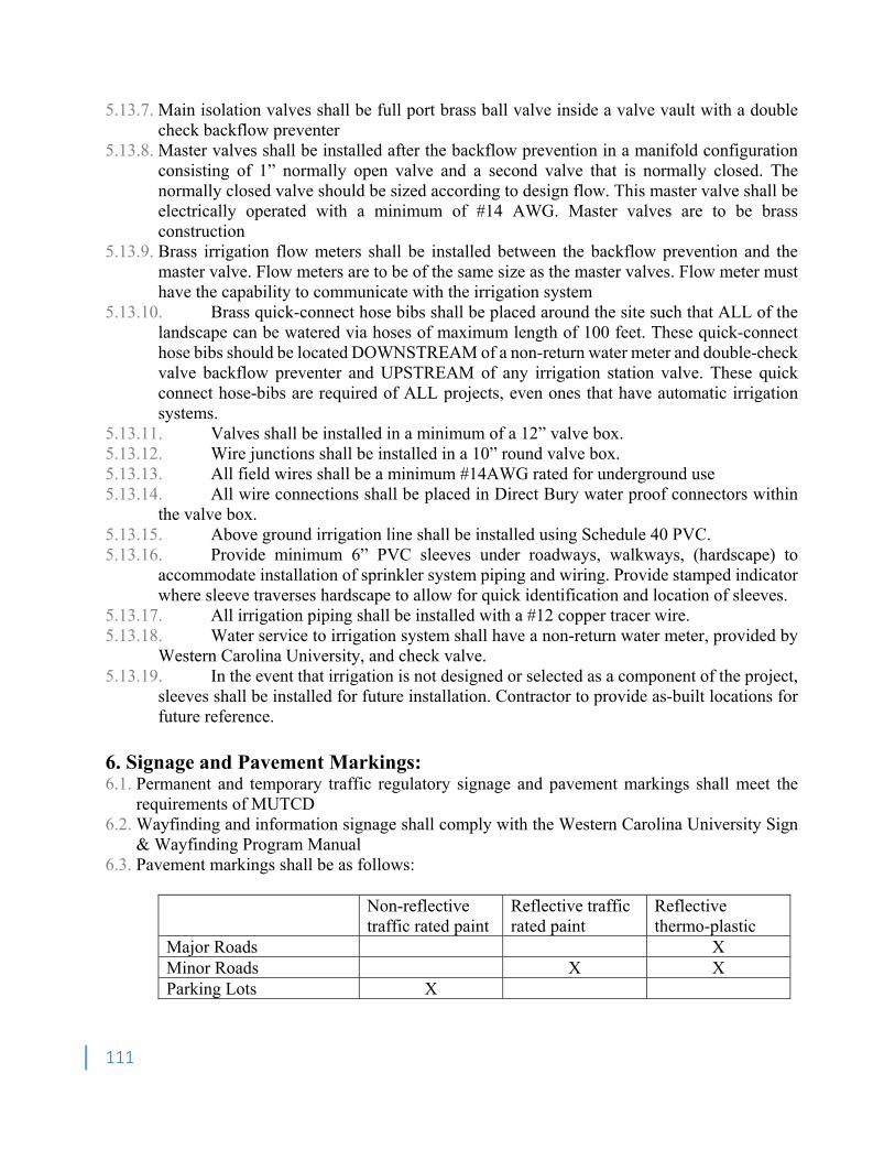
111
5.13.7. Main isolation valves shall be full port brass ball valve inside a valve vault with a double check backflow preventer
5.13.8. Master valves shall be installed after the backflow prevention in a manifold configuration consisting of 1” normally open valve and a second valve that is normally closed. The normally closed valve should be sized according to design flow. This master valve shall be electrically operated with a minimum of #14 AWG. Master valves are to be brass construction
5.13.9. Brass irrigation flow meters shall be installed between the backflow prevention and the master valve. Flow meters are to be of the same size as the master valves. Flow meter must have the capability to communicate with the irrigation system
5.13.10. Brass quick-connect hose bibs shall be placed around the site such that ALL of the landscape can be watered via hoses of maximum length of 100 feet. These quick-connect hose bibs should be located DOWNSTREAM of a non-return water meter and double-check valve backflow preventer and UPSTREAM of any irrigation station valve. These quick connect hose-bibs are required of ALL projects, even ones that have automatic irrigation systems.
5.13.11. Valves shall be installed in a minimum of a 12” valve box. 5.13.12. Wire junctions shall be installed in a 10” round valve box. 5.13.13. All field wires shall be a minimum #14AWG rated for underground use 5.13.14. All wire connections shall be placed in Direct Bury water proof connectors within
the valve box. 5.13.15. Above ground irrigation line shall be installed using Schedule 40 PVC. 5.13.16. Provide minimum 6” PVC sleeves under roadways, walkways, (hardscape) to
accommodate installation of sprinkler system piping and wiring. Provide stamped indicator where sleeve traverses hardscape to allow for quick identification and location of sleeves.
5.13.17. All irrigation piping shall be installed with a #12 copper tracer wire. 5.13.18. Water service to irrigation system shall have a non-return water meter, provided by
Western Carolina University, and check valve. 5.13.19. In the event that irrigation is not designed or selected as a component of the project,
sleeves shall be installed for future installation. Contractor to provide as-built locations for future reference.
6. Signage and Pavement Markings: 6.1. Permanent and temporary traffic regulatory signage and pavement markings shall meet the
requirements of MUTCD 6.2. Wayfinding and information signage shall comply with the Western Carolina University Sign
& Wayfinding Program Manual 6.3. Pavement markings shall be as follows:
Non-reflective Reflective traffic Reflective traffic rated paint rated paint thermo-plastic Major Roads X Minor Roads X X Parking Lots X
112
7. Fencing & Bollards 7.1. Fence type shall conform to the surrounding architecture. Refer to Western Carolina University
Landscape Master Plan 7.2. Typical fence types: 7.2.1. Refer to verify reference to Appendix C for fencing and bollard details. 7.2.2. Chain-Link, Brick, or Wood 7.2.3. Fixed/Removable Bollard 7.3. Provide gates as needed for access and service. 8. Bicycle Racks 8.1. Provide “Campus Rack” manufactured by the DERO Bike Rack Company. Color: Statuary
Bronze Powder Coat. 8.2. Surface Mounted on concrete pad 8.3. Bicycle racks shall be installed at the following ratios: 8.3.1. Residence Halls: one bicycle stall for every four beds. 8.3.2. Classroom Buildings: one bicycle stall for every eight occupants plus six stalls 8.3.3. Office/Administrative Buildings: one bicycle stall for every twenty occupants plus six stalls. 8.4. Racks shall be installed in distributed locations convenient to the entry points of buildings.
They shall not be aggregated together in remote location(s). Minimizing the appearance of bike racks shall be considered in their placement.
8.5. Shelters shall be built over bicycle racks where long-term bicycle parking is anticipated. The architecture of the shelters shall match the architecture of surrounding buildings.
9. Impacts to Existing Parking 9.1. The Designer must review all changes and impact to existing parking with WCU Parking and
Transportation Services and the Director of Facility Planning, Design and Construction. Construction projects that permanently eliminate spaces from the parking inventory on the campus shall either (a) replace the spaces with spaces similarly located on the campus, or (b) pay into the parking fund balance account the then current cost for construction of parking spaces similar to those lost. The current estimated cost (2016-17) per surface space at WCU is $2,500 per space. This cost is to be reviewed for each project.
9.2. Construction access and staging is to be evaluated during the Design Development (DD) phase of the project and included in the DD submittal. Construction staging plans shall be developed in consultation with the WCU Parking and Transportation Services Program Manager and the Director of Facility Planning, Design and Construction regarding construction parking and/or use of parking facilities for construction staging.
9.3. Construction projects of more than four weeks duration, and that negatively impact parking inventory based upon time of year scheduling, are expected to purchase all existing parking permits temporarily lost to construction during the period of loss at the then current permit price for the type of parking impacted. (Current permit rates for 2017-2018 can be viewed at https://www.wcu.edu/discover/campus-services-and-operations/parking-and-transportation/registration-permits-and-fees/index.aspx). Parking losses are to be prorated using annual rates divided by 52 weeks to determine a weekly rate of reimbursement. The purchase requirement shall be for the total number of physical spaces lost and shall be paid into the parking fund balance account.
113
Section G30 Liquid and Gas Site Utilities 1. General 1.1. Utility infrastructure connections shall be coordinated with the UPL. 1.2. Above ground utility appurtenances located in planting beds shall be one inch (1”) above the
landscaped surface. Above ground utility appurtenances located in lawn areas shall be flush to one inch (1”) below the landscaped surface.
1.3. Do not backfill utility trenches until approved by the UPL. 1.4. Survey grade as-builts shall be provided by the contractor including boring coordinates of
trenchless installed utilities. 1.5. Buried Piping 1.6. Provide a minimum of 18” vertical and horizontal clearance between utilities. 1.7. Domestic water, chilled water and fire lines shall be above other utilities in crossings. 1.8. Utility Trench Bedding and Backfill 1.9. See Natural Gas Backfill Section of this document for backfill requirements for gas lines. 1.10. The following requirements apply to potable water, fire, sanitary sewer, and storm sewer
lines. See VERIFY REFERNCE TO APPENDIX A for details. 1.11. Bedding Materials: 1.12. Where trenches are excavated in soil, bedding material shall be #57 stone to a depth of
approximately 4" under barrel of pipe. 1.13. Where trenches are excavated in rock, bedding material shall be #57 stone, placed and
compacted to a depth of approximately 6" under barrel of pipe. 1.14. Backfill Materials 1.15. Where trenches are excavated in soil, backfill material shall be #57 stone to ½ the diameter
of the pipe, then the remainder shall be placed and compacted in suitable soil. 1.16. #57 stone shall be used for backfill in the following trenched locations:
1.17. ・ In rock to a depth of 12 inches above the top of the pipe
1.18. ・ Under paved areas
1.19. ・ Beneath footings and slabs
1.20. ・ At utility crossings to a depth of 12" above the highest pipe. 1.21. Backfill with soil that can be smoothly dressed to match surface of ground adjoining the
edges of the trench, and that will support the vegetation desired for the finished surface. 1.22. General Utility Testing Requirements 1.23. The UPL shall be notified a minimum of 48 hours prior to any testing. 1.24. The contractor is solely responsible for safety during any and all testing. 1.25. The results of all tests shall be provided to the Designer and the UPL. 2. Potable Water Distribution System 2.1. Materials 2.1.1. Piping and Fittings
• All piping 3” and smaller shall be Copper. • All piping 4” and larger shall be ductile iron. • Copper pipe 1” or smaller shall be soft annealed type K.
114
• Copper pipe 1-1/2” or larger shall be rigid type K. • Couplings for copper pipe shall be crimping type rings Rigid ProPress system or approved equal, solid brass conductive union couplings Mueller 110 series or silver brazed, or approved equal. • Ductile iron pipe and fittings shall be cement mortar lined per ANSI/AWWA A21.4/C104. Ductile iron pipe shall also be furnished with outside asphaltic coating of 1 mil thickness per ANSI/AWWA A21.51/C151. • All ductile iron pipe and fittings shall have a minimum pressure class rating of 350. • Joints for ductile iron pipe to be installed underground shall be “Push-on” joint pipe per ANSI/AWWA A21.11-07/C111. • Gaskets for “Push-on” joint pipe shall be Styrene Butadiene Rubber locking type with high strength stainless steel wedges equally spaced around the gasket for full restraint per ANSI/AWWA A21.11-06/C111. Gaskets shall be: o US Pipe and Foundry “Field Lok 350.” o American Cast Iron Pipe Company “Fast Grip.” o Additional Manufacturers may be submitted to UPL for review. • Joints for ductile iron pipe to be installed above ground shall be “Flanged” joint per ANSI/AWWA A21.10-08, A21.15-05/C110, and C115. • Gaskets for “Flanged” joint pipe shall be Styrene Butadiene Rubber per ANSI/AWWA A21.11-06/C111. • Hardware for “Flanged” joint pipe shall be hexagonal type per ASTM A307-10, Grade B. • All below grade ductile iron fittings and valves shall be restrained by use of bolted restraint device shall be mega-lugs by EBBA Iron or approved equal. • All mechanical joint fittings requiring thrust blocks shall be wrapped in plastic prior to installation of concrete. • All new water mains shall include underground warning tape placed 1’ above pipe during pipe backfill operations. Warning tape shall be non-conductive Poly 3” wide with 1” lettering 4 mils thick. Warning tape shall conform to APWA uniform color codes and shall read “BURIED WATER LINE”.
2.1.2. Valves • All gate valves shall have a minimum pressure class rating of 250 with ironbody, bronze mounted, inside-screw, resilient seat, non-rising stem and equipped with rubber O-ring seals at the top of the stems. • Gate valve bodies shall have mechanical joints for use below grade or flanged joints for above grade applications. 2” gate valves installed in vaults shall be standard threaded NPT connections. • Mechanical joint gate valves shall be manufactured per AWWA C515 and provided by Mueller Company (Model Number), M & H Industries (Model Number), or approved equal. • Flanged joint gate valves shall be manufactured per ANSI A21.15 and provided by Mueller Company (Model Number), M & H Industries (Model Number), or approved equal. • Valves 2” and larger installed below grade shall have a 2” square valve operating nut and turn left or counter-clockwise to open. • All valves and valve extensions shall terminate within 2’ of finished grade. • A valve jar shall be provided from valve housing to finish grade. • Valves installed above grade shall have hand wheels.
115
• Automatic air release valves shall be combination type, single body, double orifice with large orifice having a diameter of 2" and small orifice having a diameter of 3/32". Valve body and cover shall be cast iron per ASTM A48, Class 30. Float shall be stainless steel per ASTM A240. Air release valves shall be installed in a precast concrete manhole with a standard cover. Automatic air release valves shall be APCO model 145C or approved equal. • Backflow prevention devices shall be reduced pressure zone type per AWWA C511-92. Watts Water Technologies model 909 or approved equal for ¾” to 10” devices. • Backflow prevention devices shall be installed in mechanical rooms or other above grade locations. If an above grade option does not exist, provide double check backflow preventer in compliance with AWWA C510. Watts Water Technologies model 007 for devices ½” to 3” and model 709 for devices 4” to 10” or approved equal. Coordinate thru-wall drain of a size to accommodate flow. No below grade vaults allowed, • Enclosures for Reduced Pressure Zone backflow preventers installed above grade shall be heated and shall be Hydrocowl, Hot Box, Lok box, or approved equal.
2.1.3. Valve Boxes • Valve boxes shall be two-piece adjustable screw type asphalt coated with an inside diameter of 5 ¼”. Sigma Corporation model VB261-8 or approved equal. • Valve box lid shall be cast iron drop in non-locking type imprinted with “Water” on the top. Sigma Corporation model VB2600W or approved equal. • The following general note shall be added to plans that include installation of a valve box. Valve box risers shall be cast iron and shall conform to that of valve box top section and shall be used in appropriate heights to adapt to changing landscapes. • Valve Boxes shall have a pre-cast concrete collar in landscaped areas and poured-in-place concrete collars in paved areas. • Pre-cast concrete collars shall be 4000 psi with 24” outside diameter with a 10” inside diameter center hole. • Poured-in-place concrete collars shall be 4000 psi 24”x 24” square with inside hole sized to fit valve box.
2.1.4. Hydrants • Hydrants shall be 3 nozzle type in compliance with AWWA C502. Mueller Super-Centurian, Model 250 or approved equal. • All fire hydrant assemblies shall include isolation valves. • The following general note shall be added to plans that include installation of a hydrant. Fire hydrant extensions shall be used to bring hydrants up to grade. Extensions shall be by the same manufacturer as the hydrant. No more than 1 extension riser per hydrant set. • Hydrant anchoring system is to be designed by the engineer. • Anchoring shall be accomplished by one of the following methods: o EBBA Iron MEGA LUG series for ductile iron or approved equal o Roding via the use of stainless steel all-thread rod. At a minimum, all-thread rod shall be ¾” diameter, 18-8 stainless steel. o Concrete braces shall be used in all new fire hydrant sets. o Concrete braces shall not block hydrant weep holes.
2.1.5. Meters • All new meters shall be provided by Western Carolina University. • Provide a strainer and bypass piping system sufficient to sustain water service during meter outage.
116
• All new meter sets will include automated meter reading equipment in conjunction with Western Carolina University’s in place ALC system. • Meter boxes for 1 ½” and smaller meters shall be high density reinforced concrete meter box with non-settling shoulders with a high-density, RF transparent, plastic lid. Nicor or approved equal. • Meter vaults for 2” and larger meters shall be pre-cast or poured-in-place vaults which house meter assemblies and backflow prevention valves centered about the vault. Vaults shall have a locking aluminum traffic rated lid.
2.2. General Location/Installation Requirements 2.2.1. Valves• All service lines off the main shall have an isolation valve.
• All 2” or larger service lines must include a tri-valve arrangement. 2.2.2. Hydrants
• Location and quantity of hydrants for individual projects shall be coordinated with UPL. • Fire hydrant shall be no more than 100 feet from fire department connection. • Fire hydrants shall be installed plumb and such that nozzles are approximately 18” above finished grade.
2.2.3. Meters • All new service lines on campus shall have a water meter. • All meters shall be located in mechanical rooms with lockable bypasses. • A minimum 2’ horizontal and 2’ vertical clearance is required around all meters installed inside mechanical rooms.
2.2.4. Backflow Devices • All backflow prevention devices shall be located in mechanical rooms with lockable bypasses. • A minimum 2’ horizontal and 2’ vertical clearance is required around all backflow devices installed inside mechanical rooms.
2.2.5. Post Indicator Valves are required on all fire service lines and shall be no less than 40 feet from the building.
2.3. Design Requirements 2.3.1. Piping
• Utilize acceptable pipe deflection as the preferred method for making vertical and horizontal bends in pipeline segments. The use of bends shall be limited as to not constrict water flow. • Provide 4” minimum ductile iron pipe, valves, and fittings. • No potable water main or fire main shall have any structure, temporary or permanent, built over the top of it unless approved by UPL. • All domestic and fire lines shall be to be flushed, chlorinated and tested. • Pre-construction fire flow testing shall be performed.
2.3.2. Valves • Provide automatic air release valves directly over water mains in precast concrete manholes. • Tap sleeve and valve connections shall be two sizes larger than the line to be added. Tapping sleeves for line sizes 4” to 24” shall be bolted split type having gaskets extending the entire length of the sleeves. Tapping sleeves shall be ductile iron conforming to the requirements of ANSI/AWWA A21.10/C110. Tap valves shall be Mueller model H-615 or approved equal.
117
• Service tap connections for lines 2 1/2” and smaller shall be ductile iron pipe service saddles with positively confined "O-Ring" type sealing gaskets conforming to the requirements of ANSI/AWWA A21.11/C111. Ford Meter box company model F202 or approved equal. • The following general note shall be added to all plans which include a tap connection to the existing potable water system: The Contractor shall return all tap coupons to the Facilities Management Utilities & Energy Department.
2.3.3. Fire Hydrants • Review geotechnical report for the presence of impervious soils in the project area. In the event impervious soils are present a drainage pit 2’ in diameter and 2’ deep shall be excavated below each hydrant and filled compactly with coarse gravel or crushed stone under and around the hydrant foot and to a level 6” above hydrant weep holes. • Provide isolation valves no more than 5’ from fire hydrant.
2.3.4. Western Carolina University shall provide water meter for installation by the contractor. 3. Sanitary Sewer System 3.1. Materials 3.1.1. Manholes
• Precast reinforced concrete manholes shall meet the requirements of ASTM C- 478. Concrete shall have a minimum compressive strength of 4,000psi at 28 days. Cement shall be Type II with C3A content of 6.5% or less. Manhole connections for sewer piping smaller than 24” shall be accomplished through the use of flexible connectors, connections for sewer piping 24” or larger should be accomplished using mortar comprised of 1 part Portland Type II cement and 2 parts sand by volume. • Manholes shall have interior surfaces coating of high-build glass-flake cementitious epoxy to dry film thickness of not less than 20 mils. Cementitious epoxy coating shall be PCS-9043 Type II, Permite coatings, coal Tar Epoxy coating or approved equal, to dry film thickness of not less than 30 mils or be impregnated with a concrete waterproofing cementitious crystalline admixture such as Xypex. • Manhole base and riser sections shall be equipped with non-penetrating lifting inserts, Press-Seal Gasket Corporation or approved equal, and adhere to the following thicknesses: o Floor Slab – Minimum 6-inch thick o Walls – Minimum 4-inch thick • Manhole cone section shall be eccentric type, equipped with non-penetrating lifting inserts, Press-Seal Gasket Corporation or approved equal, and be suitable for mounting cast iron manhole frames and covers as described below. • Joints between manhole sections shall be offset tongue and groove type and shall utilize a pre-lubricated manhole gasket which meets the following requirements: o Gasket shall consist of a compression section and a serrated mantel section which slides over the compression section as the manhole sections are placed together. o Gasket shall meet the requirements of ASTM C 443, Tylox Super-Seal as manufactured by Hamilton Kent or approved equal. • Manhole frames and covers shall be cast from gray iron meeting the requirements of ANSI A48-83, Class 30 or greater conforming to the following: o All manhole covers shall be self-sealing type with non-penetrating pick holes.
118
o Frames and covers installed in open areas shall weigh not less than 290 lbs. Frames and covers subject to traffic shall be H 20 rated and shall weigh not less than 375 lbs. o Covers shall be labeled “SANITARY SEWER”. • Manhole steps shall conform to one of the following requirements: o Gray Iron or Ductile Iron integrally cast into the manhole barrel, meeting the requirements of ANSI A48-83. o Gray Iron or Ductile Iron equipped with inserts integrally cast into the manhole barrel having steps bolted on, meeting the requirements of ANSI A48-83. o Copolymer polypropylene plastic, meeting the requirements of ASTM D 2146 reinforced with a ½” diameter deformed bar meeting the requirements of ASTM A 615. • Manhole inverts shall be constructed of mortar comprised of 1 part Portland Type II cement and 2 parts sand by volume. Inverts should be hand troweled to a smooth finish. Top of invert shall be a minimum of 8” wide to allow crawler type camera accessibility. To accommodate for wider inverts manholes shall be designed and constructed utilizing 2 tenths of a foot (0.2’ or 2.4”) drop across each manhole or match crown at pipe size changes. In the event 2 tenths of a foot (0.2’ or 2.4”) drop across the manhole is not possible a 5’ diameter Type I base section shall be utilized and the top of the invert cannot be less than 8” wide. • Turns in manholes that change the direction of flow shall not exceed ninety degrees. • Incoming lines with inverts 24” or higher above the exiting invert shall have an exterior drop connection.
3.1.2. Piping and Fittings • Ductile iron pipe and fittings shall be cement mortar lined with asphaltic seal coat in accordance with ANSI/AWWA A21.4/C104. Ductile iron pipe shall also be furnished with outside asphaltic coating of 1 mil thickness per ANSI/AWWA A21.51/C151. Pipe shall be installed such that the pipe bell is upstream of the pipe spigot. • All ductile iron pipe and fittings shall have a minimum pressure class rating of 350. • Joints for ductile iron pipe to be installed underground shall be push-on joint type, in compliance with ANSI/AWWA A21.11-07/C111. • Gaskets for push-on joint type shall be styrene butadiene rubber. • All new sanitary sewer laterals and mains shall include underground warning tape placed 1’ above pipe during pipe backfill operations. Warning tape shall be non-conductive Poly 3” wide with 1” lettering 4 mils thick. Warning tape shall conform to American Public Works Association (APWA) uniform color codes and shall read “BURIED SEWER LINE”.
3.2. General Location Requirements 3.2.1. Manholes
• Maximum spacing between sanitary manholes shall be 400’. • Manholes shall be installed on mains at any location where there is a change in grade, or direction of flow. • All building sewer laterals shall connect to the sanitary sewer collection system at a manhole. • Maximum length of sanitary sewer laterals shall be 100’ from the face of the building. Beyond that distance laterals shall be considered mains and all rules for sanitary mains shall apply.
3.2.2. Piping and Fittings
119
• Cleanouts: Provide combination cleanout plug/relief on first cleanout outside of building • Cleanouts shall be installed on laterals at any location where there is a change in grade, or direction in flow. • All sanitary sewer wyes shall have a cleanout within 1’ of the upstream side of the wye.
3.3. Design Requirements 3.3.1. General
• Package Pumping/Lift Stations are not allowed. • No sanitary sewer manhole, piping or fittings shall have any structure, temporary or permanent, built over the top of it. • Designer shall provide verification that existing system capacity is compatible with the current proposed design. • All new sanitary sewer lines shall be designed with the following minimum line sizes: Laterals 6” and Mains 8”. • All new sanitary sewer lines shall be designed such that the velocity of the flow in the pipe shall not be less than 2 feet per second, nor exceed 10 feet per second. • Sanitary sewer lines shall be a minimum of 18 inches below potable water lines. • Sewer lines and manholes which are no longer in service shall be removed.
3.3.2. Sanitary Sewer Rehabilitation • Acceptable rehabilitation methods include the following: o Sanitary Sewer Lines: Cured-In-Place Pipe (CIPP) Lining Systems conforming to standards from the American Society for Testing and Materials, such as: ASTM F1216 (Rehabilitation of Existing Pipelines and Conduits by the Inversion and Curing of a Resin-Impregnated Tubs), ASTM F1743 (Rehabilitation of Existing Pipelines and Conduits by Pulled-In-Place Installation of Cured-In-Place Thermosetting Resin Pipe (CIPP)), ASTM D5813 (Cured-In-Place Thermosetting Resin Sewer Pipe), ASTM D790 (Test Methods for Flexural Properties of Un-Reinforced and Reinforced Plastics and Electrical Insulating Materials), and D2990 (Tensile, Compressive, and Flexural Creep and Creep-Rupture of Plastics) o Sanitary Sewer Manholes: Cementious Fiber-Reinforced Structural Monolithic Manhole Lining System.
4. Storm Sewer System 4.1. Materials 4.1.1. Manholes
• Manholes shall be Precast Reinforced concrete only. No block or brick masonry. Precast Reinforced Concrete Manholes shall meet the requirements of ASTM C-478. Cement shall be Type II with C3A content of 6.5% or less. Manhole connections shall be accomplished through the use of flexible connectors or using mortar comprised of 1 part Portland Type II cement and 2 parts sand by volume. • Manhole base, eccentric cone and riser section shall be equipped with non-penetrating lifting inserts, Press-Seal GASKET Corporation or approved equal. • Manhole cone section shall be suitable for mounting cast iron manhole frames and covers as described below. • Joints between manhole sections shall be offset tongue and groove type and shall utilize a pre-lubricated manhole gasket which meets the following requirements:
120
o Gasket shall consist of a compression section and a serrated mantel section which slides over the compression section as the manhole sections are placed together. o Gasket shall meet the requirements of ASTM C 443, Tylox Super-Seal as manufactured by Hamilton Kent or approved equal. • Manhole frames and covers shall be cast from gray iron meeting the requirements of ASTM A48, Class 30 or greater conforming to the following: o Minimum clear space opening for frames and covers is 21 7/8”. o Non-drainage frames and covers installed in landscaped areas shall weigh not less than 290 lbs. Non-drainage frames and covers installed in hardscape areas and subject to traffic shall be H 20 rated and shall weigh not less than 375 lbs. Non-drainage frames and covers installed in Type-S inlets shall be Neenah Foundry R-6144 or approved equal. Drainage frames and covers installed in landscaped areas shall be Neenah Foundry R-2560-EA or approved equal. In the event a round cover is not practical use frame and cover of Neenah Foundry R-4346 or approved equal. Drainage frames and covers installed in hardscape areas and subject traffic shall be H 20 rated and shall be Neenah Foundry R-3561 or approved equal. Frames and covers installed in pedestrian areas shall be rated for pedestrian service. o Covers shall be labeled “STORM SEWER.” • Manhole steps shall conform to one of the following requirements: o Gray Iron or Ductile Iron integrally cast into the manhole barrel, meeting the requirements of ASTM A48. o Gray Iron or Ductile Iron equipped with inserts integrally cast into the manhole barrel having steps bolted on, meeting the requirements of ASTM A48. o Copolymer polypropylene plastic, meeting the requirements of ASTM D 2146 reinforced with a ½” diameter deformed bar meeting the requirements of ASTM A 615. • Manhole inverts shall be constructed of mortar comprised of 1 part Portland Type II cement and 2 parts sand by volume. Inverts should be hand troweled to a smooth finish. Top of invert shall be a minimum of 8” wide to allow crawler type camera accessibility. To accommodate for wider inverts manholes shall be designed and constructed utilizing 0.2’ drop across each manhole or match crown at pipe size changes. • Turns in manholes that change the direction of flow shall not exceed ninety degrees. • Maximum spacing between storm sewer manholes shall be 400’. • Manholes shall be installed on mains at any location where there is a change in grade, or direction of flow. • All building drainage laterals shall connect to the storm sewer collection system at a manhole, junction box, or inlet box.
4.1.2. Piping and Fittings • Storm sewer piping 12” and greater: o Reinforced Concrete Pipe (RCP) conforming to the requirements of ASTM C76, Wall type B. Pipe class shall be determined by laying depth; Class III for cuts 0 to 10 feet, Class IV for cuts 10 to 20 feet, Class V for all cuts exceeding 20 feet. Pipe shall be installed such that the pipe bell is upstream of the pipe spigot. o Pipe end treatment shall be bell and spigot manufactured in accordance with ASTM C76 with joint lengths no less than 8’ and no greater than 16’. Gaskets for bell and spigot joints shall be rubber O-ring gaskets manufactured in accordance with ASTM C361 and ASTM C433.
121
o RCP shall be manufactured wet cast, dry cast or centrifugally cast or by the re-densification method. o All pipe lift holes are to be plugged with a mortar mix consisting of one part Portland cement, two parts sand by volume and water as required to produce a stiff workable mixture. o All joints in RCP shall be fully wrapped in filter fabric meeting the requirements of NCDOT Type A silt fence. • Storm sewer piping smaller than 12” in diameter: o Ductile iron pipe which shall be cement mortar lined in accordance with ANSI A21.4/ AWWA C104; standard thickness, with asphaltic seal coat. Ductile iron pipe shall also be furnished with outside asphaltic coating of 1 mil thickness per ANSI A21.51/AWWAC151. Pipe shall be installed such that the pipe bell is upstream of the pipe spigot. o All ductile iron pipe and fittings shall have a minimum pressure class rating of 350. o Joints for ductile iron pipe to be installed underground shall be “Push-on” joint pipe, in compliance with ANSI/AWWA A21.11-07/C111. o Gaskets for “Push-on” joint pipe shall be Styrene Butadiene Rubber. • All new storm sewer laterals and mains shall include underground warning tape placed 1’ above pipe during pipe backfill operations. Warning tape shall be non-conductive Poly 3” wide with 1” lettering 4 mils thick. Warning tape shall conform to APWA uniform color codes and shall read “BURIED SEWER LINE”. • Provide combination cleanout plug/relief on first cleanout outside of building. • Cleanouts shall be installed on laterals at any location where there is a change in grade, or direction in flow. • All storm sewer wyes shall have a cleanout within 1’ of the upstream side of the wye.
4.2. Design Requirements 4.2.1. General
• If a project increases the impervious cover and affects the existing hydrology, determine the appropriate stormwater Best Management Practices (BMPs) to offset the increase in stormwater peak discharge rate and reduction in water quality. • No storm sewer manhole, piping or fittings shall have any structure, temporary or permanent, built over the top of it. • Designer shall confirm available capacity of existing storm system with UPL to ensure system can accept new flow. • Provide minimum 6” laterals and 12” mains. • Minimum velocity 3.5 feet per second. • Maximum velocity 15 feet per second. • Remove existing sewer lines and manholes which are no longer in service. • In stairwells, areaways and similar locations where leaf clogging of conventional drains would be expected provide scupper or cast iron dome type drains. • Install removable bars or grills at open ends of culverts, drains and pipes 10” diameter and larger. • Curb inlets along roadways and in parking lots shall be NCDOT Type S self-cleaning inlets. Allowable spread for roadway applications is 6’ or 1/2 of travel lane width whichever is less. • Gutter downspouts which connect to underground storm system shall utilize a cast iron downspout boot of McKinley type DS4 or approved equal to transition between downspout and drainage lateral.
122
• Inlet sizing and spacing shall be designed to allow no more than 6’ diameter spread around inlets during design rain event. • No above ground detention ponds or weirs are allowed. • All storm sewer junction boxes shall have an access. • No conflict boxes will be allowed.
4.2.2. Underground Detention • Post construction runoff must equal preconstruction runoff for the required design storm. Engineer shall design an underground storm water detention structure sized for the appropriate release rates. Underground detention structure shall meet the following minimum requirements: o All underground detention structures should be constructed on precast concrete vaults, poured in place concrete structures or reinforced concrete pipe. o Multiple barrels of reinforced concrete pipe shall have a manifold at one end with reinforced concrete pipe equal in diameter to the largest pipe barrel used in the detention system, or a junction box larger than the largest pipe barrel used in the detention system. o A trash collection structure must be installed upstream of all underground detention structures. o All underground detention structures must include an air release structure large enough to prevent air locking during a rain event. o All underground detention structures shall have a minimum of 1 standard manhole access point including manhole steps.
5. Natural Gas 5.1. Only approved contractors are allowed to perform work on the University’s natural gas system. 5.2. Materials 5.2.1. Piping and Fittings
• Polyethylene (PE) natural gas pipe and fittings shall be PE 2406 medium density polyethylene (MDPE) meeting cell classification 234363E per ASTM D3350. • All pipe and fittings material shall be opaque, yellow in color, stabilized against ultraviolent deterioration and suitable for unprotected outdoor storage for at least 4 years. • All new natural gas mains and laterals shall include underground warning tape placed 1’ above pipe during pipe backfill operations. Warning tape shall be non-conductive Poly 3” wide with 1” lettering 4 mils thick. Warning tape shall conform to APWA uniform color codes and shall read “BURIED GAS LINE”. • All buried natural gas line shall have a #12 yellow sheathed solid copper wire installed 6” above pipe and brought above grade through a valve jar. • Fittings shall be of the same diameter, type, and wall thickness of the pipeline being constructed. Fittings shall be manufactured and tested in accordance with ASTM D2513 and applicable Federal Department of Transportation regulations. • Line tapping fittings shall be bypass type and of such design that flow through the pipeline being tapped will not be interrupted at any time during the tapping operation. • Electrofusion fittings shall be PE 2406 medium density polyethylene material manufactured in accordance with ASTM F1055. • Polyethylene gas pipe and fittings may be joined together to other materials by transition fittings or fully restrained mechanical couplings. These devices shall be designed for joining
123
polyethylene gas piping to another material and shall be approved by the Federal Department of Transportation. • Transitions between unlike wall thicknesses greater than 1 DR shall be made with a transition nipple or by mechanical means.
5.2.2. Valves • Valves for service ½” through 12” shall be PE 2406 medium density polyethylene ball valves rated for service under working pressure of not less than 175 psi. • Valve ends shall be either butt fusion or heat fusion welded. • Valves 2” and larger installed below grade shall have a 2” square valve operating nut and turn left or counter-clockwise to open.
5.2.3. Valve Boxes • Valve boxes shall be two-piece adjustable screw type asphalt coated with an inside diameter of 5 ¼”. Sigma Corporation model VB261-8 or equal. • Valve box lid shall be cast iron drop in non-locking type imprinted with “Gas” on the top, Sigma Corporation model VB2600W or equal. • Valve Boxes shall have a pre-cast concrete collar in landscaped areas and poured-in-place concrete collars in paved areas. • Pre-cast concrete collars shall be 4000 psi with 24” outside diameter with a 10” inside diameter center hole. • Poured-in-place concrete collars shall be 4000 psi 24”x 24” square with inside hole sized to fit valve box.
5.3. General Location/Installation Requirements 5.3.1. Natural Gas Pipe Bedding
• Pipe trenches excavated in earth (soils). o Where trenches are excavated in earth (soils), the bottom of the trench shall be evenly graded to an elevation approximately 2” below the pipe in order to accommodate the bedding material. o Bedding material of clay soil as described by CFR Title 49 Part 192, shall be placed across the entire width of the trench and shall be compacted to approximately 90% of Standard Proctor Density up to the level of the bottom of the pipe. o The trench shall be backfilled with clay soil as described by CFR Title 49 Part 192, from top of bedding to level 4” above the top of the pipe, and the material shall be compacted to approximately 95% of Standard Proctor Density. o The cross-sectional area of the trench from level 2” below bottom of pipe to level 4” above top of pipe and extending across entire width of trench constitutes the pipe zone where trenches are excavated in soils. • Pipe trenches excavated in rock o Where trenches are excavated in rock the trench shall be excavated to depth 6” below the pipe and bedding material as specified hereinabove shall be placed and compacted to approximately 90% of Standard Proctor Density. o Backfill from top of bedding to level 1'-0” above top of pipe shall be same material as specified for bedding and shall be compacted to approximately 95% of Standard Proctor Density. o The cross-sectional area of the trench from level 6” below bottom of pipe to level 1'-0” above top of pipe and extending across entire width of trench constitutes the pipe zone when trenches are excavated in rock.
124
o The remaining depths of the trenches, from the tops of the pipe zones shall be backfill in accordance with the requirements of these standards, see Section G10, Site Preparation.
5.3.2. Piping • Butt, socket, and saddle fusion joints in polyethylene gas pipe shall be made using procedures that have been qualified and approved in accordance with CFR Title 49 Part 192. • Installation of the gas transmission mains and other gas pipelines shall comply with ASME B31.8. • Soft Poly Pigging of all new gas mains shall be performed before service installation. • There shall be a minimum separation of 18” between natural gas lines and insulated utility lines.
5.3.3. Valves • All service lines off the main shall have an isolation valve. • All 2” or larger service lines must include a tri valve arrangement. • Valves shall be located (tied) to two permanent benchmarks (X, Y, & Z coordinates) on as-built drawings. • All valves installed below grade deeper than 4’ shall have a valve extension to terminate within 2’ of finished grade.
5.3.4. Natural Gas Meters and Regulators • All new services lines are to include installation of a meter and regulator. • Western Carolina University shall provide all gas meters. Gas meters shall be installed by Contractor per piping details provided by Designer. • Locate meters and regulators away from building fresh air intakes. • All above grade black iron or steel gas pipe shall be painted to match meter and regulator with primer, intermediate, and finish coat of 6.5 – 9.5 mils DFT per coat.
5.4. Design Requirements 5.4.1. Piping
• Do not install temporary or permanent structures over natural gas mains and laterals. • 3” polyethylene natural gas main shall not be used. 5.4.2. Natural Gas Meters and Regulators • Western Carolina University provides all natural gas meters. • Designer shall include, on drawings, pressure and flow rate requirements for the gas meter. • Designer shall provide a layout drawing of the meter set including location of valve(s), regulator(s), and meter(s). • Meter set to be installed by Contractor. • The Designer shall consult the gas meter manufacturer and include the manufacturer’s recommended length of straight pipe runs to be installed, both before and after the meter. • Designer shall notify the UPL a minimum of 60 days before a meter is required to allow for ordering and delivery.
5.5. Polyethylene pipelines shall be tested in accordance with CFR 49, Part 192.
125
Section G40 Electrical Site Improvements 1. Electrical Service 1.1. Electrical load estimates and voltage connection requirements should be provided to the UPL
at the conclusion of the Design Development Phase 1.2. The following general note shall be added to the plans: All connections and disconnections to
campus electrical distribution system, including scheduling of outages, shall be coordinated through the UPL.
1.3. Meters are required on all service connections. The following general note shall be added to the plans: Contractor to coordinate meter requests through the UPL a minimum of 45 working days prior to need for energized service
1.4. Meters for University provided services shall be furnished and installed at the Owners expense. All other meters shall be the responsibility of the contractor
2. Electrical Transformers 2.1. Primary distribution transformer for University provided services shall be furnished and
installed at the Contractor’s expense. 2.2. Transformer shall be specified by the Electrical Engineer in coordination with WCU Electrical
Distribution Engineer. 2.3. Final location of primary distribution transformer and service feeds must be approved by UPL 3. Underground Ducts 3.1. Ductbanks shall be concrete encased PVC for primary and secondary power distribution. 3.2. Sufficient spare conduits are to be furnished in underground ductbanks to allow for installation
of one future/additional circuit of the same size/rating as those already provided with cable/conductor
3.3. Provide #12 AWG solid copper tracer wire in all non-metallic underground conduits. 3.4. All permanent electrical service is to be provided underground 4. Lighting Poles and Fixtures 4.1. A dispersed placement pattern of pathway lighting is preferred. Photometric study and catalog
cut sheets shall be provided at the Design Development Phase 4.2. All exterior lighting shall be controlled by a photoelectric cell. A single photocell/time clock
may be provided for multiple fixtures 5. Telecommunications- Refer to Appendix H
126
Section H10 Sustainable Guidelines 1. Sustainable Requirements 3.4. The University shall uphold a sustainable doctrine in conjunction with the UNC Sustainability Policy
600.6.1 (Appendix J) by incorporation of new technologies for existing and future facilities, by providing efficiencies in energy, economic, and environmental performance that are substantially better than conventional practice as a model for the state and region. All new campus construction will be design to meet Energy Star Certification or lowest 25th percentile in energy usage intensity or at least the U.S. Green Building Council’s (USGBC) LEED Silver standard or equivalent.
4. Low Impact Design (LID) New development on campus (or as directed by the Office of Design & Construction) shall follow the guidelines for Low Impact Development (LID) by utilizing innovative storm water management techniques.
4.1. Low Impact Development (LID) is an approach to land development that can be utilized at WCU as the campus continues to grow that works with nature to manage stormwater as close to its source as possible. LID employs principles such as preserving and recreating natural landscape features, minimizing effective imperviousness to create functional and appealing site drainage that treat stormwater as a resource rather than a waste product. There are many practices that have been used to adhere to these principles such as:
Stormwater Wetlands Bioswales Riparian Buffers Cisterns Permeable Pavement Green Roofs Planted Filtering Strips Reduced Roadway Widths
4.2. By implementing LID principles and practices throughout the campus environment, water can be managed in a way that reduces the impact of built areas and promotes the natural movement of water within an ecosystem or watershed. Applied on a broad scale, LID can maintain or restore a watershed’s hydrologic and ecological functions, creating a better environment for the WCU community.
4.2.1. Stormwater Wetlands temporarily store rain runoff in shallow pools that support conditions suitable for the growth of wetland plants. These constructed wetland systems can be utilized as development occurs on campus, are designed to maximize the removal of pollutants from stormwater runoff via several mechanisms; microbial breakdown of pollutants, plant uptake, retention, settling, and absorption. These structural practices are similar to wet ponds, but incorporate wetland plants in a shallow pool. As stormwater runoff flows through the wetland, pollutant removal is achieved by settling and biological uptake.
4.2.2. Bioswales are landscape elements designed to remove silt and pollution from surface runoff water. They consist of a swaled drainage course with gently sloped sides and filled with vegetation, compost and/or riprap. The water’s flow path, along with the wide and shallow ditch, is designed to maximize the time water spends in the swale, which aids the trapping of pollutants and silt. Based on the topography of the mountain landscape, a bioswale likely will have a meandering channel alignment, which would enhance the storage time and lessen the effects of steep sloping elevation changes prevalent on campus. A simple application on campus could be around parking lots, where substantial automotive pollution is collected by the paving and then flushed by rain. The bioswale wraps around the parking lot and treats the runoff before releasing it to the watershed or storm sewer.
127
4.2.3. Riparian Buffers are a vegetated area near a stream, which helps shade and partially protect a stream from the impact of adjacent land uses. They play a key role in increasing water quality in associated streams, rivers, and lakes in the mountain landscape, thus providing environmental benefits. These buffers are important natural biofilters, protecting aquatic environments from excessive sedimentation, polluted surface runoff and erosion. They supply shelter and food for many aquatic animals and shade that is an important part of stream temperature regulation. With development comes the decline of many aquatic ecosystems, riparian buffers can become a conservation choice aimed at increasing water quality and lessening pollution of WCU’s water sources.
4.2.4. Cisterns are receptacles for holding liquids, usually water, often built to catch and store rainwater. Promoting the use of cisterns can provide an alternative source for irrigation, reducing the demand on local water sources within the campus area. To conserve groundwater, rainwater can be collected, stored and used for such things as watering gardens, washing cars or other non-potable water needs throughout the WCU campus.
4.2.5. Permeable Pavement can be utilized throughout the campus for roads, parking lots and walkways that allow the movement of water and air around the paving material. These paving surfaces keep the pollutants in place in the soil and allow water seepage to groundwater recharge while preventing stream erosion problems. They capture the heavy metals that fall on them, preventing them from washing downstream and accumulating inadvertently in the environment. Porous pavement also gives campus trees the rooting space they need to grow to full size. This integrates healthy ecology and the thriving WCU campus, with the living tree canopy above, the campus traffic on the ground, and living tree roots below.
4.2.6. Green Roofs are roofs of buildings that are partially or completely covered with vegetation and soil, or a growing medium, planted over a waterproofing membrane. Numerous benefits can result from the adoption of green roof technologies; the recovery of green space, moderation of the urban heat island effect, improved stormwater management, water and air purification, and a reduction in energy consumption. The mitigation of stormwater runoff can be a great benefit to WCU because of the prevalence of impervious surfaces in the campus area. A major benefit of green roofs is their ability to absorb stormwater and release it slowly.
4.2.7. Planted Filtering Strips are land areas situated between a potential, pollutant-source area and a mountain landscape river, stream, or lake that receives runoff. A planted filter strip provides water-quality protection by reducing the amount of pollutants before the runoff enters the surface water body. Filter strips also provide localized erosion protection since the vegetation covers an area of soil that otherwise might have a high erosion potential.
4.2.8. Reduced Roadway Widths provides WCU with the opportunity to limit the impact runoff pollutants have on surrounding rivers, streams, and lakes. Campus roads, driveways and parking lots can exceed building rooftops as a percentage of the total impervious surface within the community. In addition to lessened stormwater runoff, reducing road width provides other benefits such as construction and maintenance savings, less required clearing and grading during initial construction, as well as slow traffic flow to help alleviate safety concerns.
5. Water Conservation The University will strive to prove itself a leader in water management over time by enforcing the integration of water conservation practices throughout the campus.
5.1. All evidence points to increasingly stressed water supplies in North Carolina and throughout the Southeast. Additionally, trends suggest that water management will be more heavily regulated in the future. By beginning to address these eventualities now, the campus will prove itself a leader in water management.
5.1.1. Reduce freshwater use 40% by implementing technology to enable water capture and reuse as part of the building design.
128
5.1.2. Reduce stormwater runoff impacts by implementing at least one Low Impact Development technology as described above.
5.1.3. Protect surface water by preventing culverts on any currently daylit surface water. Existing surface water enclosed in culverts will be daylit to the extent practical.
5.1.4. Utilize permeable surfaces as much as possible. 5.1.5. Select drought resistant plantings.
6. Energy Efficiency The University will strive to reduce its carbon footprint over time by enforcing the integration of energy efficient practices throughout the campus.
6.1. Whether it be for global concerns of climate change or national concerns of energy independence, the University can have a significant impact on the consumption of energy through subtle and inexpensive changes to conventional design. All new construction on campus shall be designed in an energy efficient manner that complements the overall design intent and reduces total building energy consumption by addressing the following requirements:
6.1.1. Reduce overall building energy loads. 6.1.2. Optimize the use of passive solar design when applicable. 6.1.3. Provide efficient electrical systems to minimize consumption and optimize the use of natural
daylighting. 6.1.4. Utilize vacancy sensor controls and VAV shut-off contacts on operable windows where applicable. 6.1.5. Incorporate exterior shading devices or extended roof overhangs to control heat gain. 6.1.6. Design high performance mechanical systems that minimize energy use while maintaining standards
for indoor air quality and comfort. 6.1.7. Group similar building functions into the same mechanical zone. 6.1.8. Provide Energy Star rated equipment and appliances. 6.1.9. Eliminate the use of ozone-depleting materials. 6.1.10. Incorporated renewable or alternative energy sources. 6.1.11. Utilize energy modeling and life cycle cost analysis. 6.1.12. Utilize commissioning on all new projects.
7. Material Conservation The University will strive to conserve the use of natural materials and resources by enforcing the integration of material conservation practices on all new projects.
7.1. The design and construction for new projects should include strategies that utilize materials with minimal environmental impact. Reusing building materials can greatly reduce the demand for virgin materials, which must be processed, transported and installed.
7.1.1. Specify local materials as a first preference, then regional products to reduce shipping energy cost. 7.1.2. Specify materials with recycled content. 7.1.3. Plan for future growth and expansion. 7.1.4. Utilize flexible design and flexible spaces to provide a maximum lifespan for the use of the building. 7.1.5. Recycling containers within the building shall follow our current standard of community recycling
centers, labeling, and bin type (Appendix J). 7.1.6. Landfill receptacles are not required in classrooms and must be adjacent to recycling bins in all
common areas. 7.1.7. Reduce waste associated with construction and demolition by diverting materials from landfills for
reuse or recycling. 7.1.8. The Designer must use the Waste Type and Management Form (Appendix J) to identify materials,
fixtures, and equipment that are to be salvaged and retained by the university or donated to a non-profit entity. The responsible party for removal, delivery, and/or pick up must also be included.
7.1.9. The Contractor must coordinate salvage or reuse efforts identified on the Designer Waste Type and Management Form with WCU and/or the non-profit entity.
129
7.1.10. The Contractor must provide a Waste Management Plan (Appendix J) to WCU for approval prior to implementing work. The plan should include details on how the generated waste will be managed in accordance with local, state, and federal regulations. Contractor must also provide all materials, personnel, and protective equipment necessary to remove and store wastes in accordance with the plan.
7.1.11. When available, the contractor may utilize University contract pricing for related facility tip costs or recycling rebates. In order to utilize WCU contracts, contractor must coordinate with the University Project Manager and Recycling Coordinator.
7.1.12. All waste must be tracked and compiled in the Waste Management Report (Appendix J). Tracking must include all types of disposition: reuse, recycling, C&D recycling and reclamation, landfill disposal, hazardous, universal and special waste.
7.1.13. The Contractor must use the WCU Materials Tracking Log and Reuse Tracking Log (Appendix J) to compile the Waste Management Report.
7.1.14. The report must include: A list of all facilities and processors used in the disposition process.
Copies of original weight tickets from facilities or processors.
Weights of reuse materials.
Additional associated costs such as container rental, hauling and/or tipping fees.
Revenue associated with sales of recycling. 7.1.15. Reuse and recyclable materials must be separated at the project site to the greatest extent practicable. 7.1.16. C&D recycling, both sorted and non-sorted, must be hauled to a C&D recycling and reclamation
facility. In order to identify common non-sorted or mixed load composition and viability of recycling, the contractor must coordinate with the C&D reclamation facility. The C&D reclamation facility must have an onsite process for segregating the following materials from non-sorted loads: Scrap metal and wire, cardboard, untreated wood and pallets, gypsum board (unpainted) aggregate, concrete, brick and asphalt (free of steel reinforcement unless viable means to recycle is identified) .
7.1.17. All solid waste management facilities must be permitted to operate by NCDEQ in accordance with 15A NCAC 13B .0201. C&D waste must be tracked and reported by:
Disposition Type (reuse, recycle, C&D reclamation, C&D landfill, other) Weight (actual and estimated) Cost (revenue, hauling, and tipping fees)
8. Indoor Environmental Quality The University will maintain healthy and comfortable interior environments that promotes learning.
8.1. Facilities should be designed and constructed with an appreciation of the importance of providing a high-quality interior environment for all users.
8.1.1. Utilize low-emitting materials. 8.1.2. Maximize daylighting for all occupied spaces when possible. 8.1.3. Maximize views to the exterior for all occupied spaces. 8.1.4. Provide operable windows for occupied spaces. 8.1.5. Provide acoustical privacy where appropriate. 8.1.6. Supply adequate levels of outside air to ensure indoor air quality. 8.1.7. Provide CO2 monitoring of common spaces such as classrooms. 8.1.8. Prevent the infiltration of moisture into buildings. Replace water damaged finishes immediately. 8.1.9. Specify low Volatile Organic Compounds (VOC) products for all interior spaces.
130
Appendix A Commissioning Guide 1. General 1.1. 1These guidelines define the role of the Commissioning Authority, Construction Contractor,
Designer, and Test and Balance Contractor 1.2. The Commissioning Authority will work for the University and will not provide direction to
the Contractor, except as forwarded through the UPL 1.3. Training shall be provided for the University employees, designated by the UPL, for all
equipment specified. This training shall include video recording of all required training 1.4. Commissioning must be completed prior to Substantial Completion 1.5. The Commissioning Authority shall be certified in Building Systems Commissioning by the
National Environmental Balancing Bureau (NEBB) 1.6. Commissioning shall be performed in accordance with this document and the following
Guidelines and Standards: 1.6.1. ANSI/ASHRAE/IES Standard 202-2013 Commissioning Process for Buildings and
Systems 1.6.2. ASHRAE Guideline 1.1-2007 HVAC&R Technical Requirements for The Commissioning
Process 1.6.3. ASHRAE Guideline 0-2005 The Commissioning Process 1.7. The Commissioning Team shall be made up of those parties that have been involved in the
design and construction of the elements indicated in the Scope of Commissioning section, as established by the UPL
2. The Commissioning Authority (CxA) Responsibilities 2.1. The CxA shall review the Basis of Design and Owner’s Project Requirements (OPR) provided
by the Designer 2.2. The CxA shall review Design Documents to have full understanding of the project. The
Commissioning Authority shall notify the PM of any found design discrepancy and coordinate resolution of these issues through the PM
2.3. The CxA shall review Construction Shop Drawing and Operation and Maintenance Manuals to observe and report that the systems and equipment identified on these documents are consistent with the design intent and performance criteria. The Commissioning Authority shall notify the PM of any discrepancy with the Design Documents and coordinate resolution of these issues through the PM
2.4. The CxA shall be responsible for developing the Commissioning Plan, Installation Verification checklists, Functional Performance Tests, Preventative Maintenance Program and Training plans. Acceptance of these items is subject to the approval of the UPL. The plan will be forwarded to the Contractor and/or CM for inclusion into the project schedule
2.5. The required training will be performed primarily by the Contractor as provided for in the other specifications. The CxA will coordinate with the Contractor to provide a complete and orderly training effort, supplementing this effort as required to produce effective training sessions for the University
2.6. The CxA shall be responsible for performing and documenting each step of the commissioning process and for recommending acceptance or non-acceptance to the University. Acceptance of these items is subject to the approval of the UPL. Equipment, tools, materials, and personnel
131
required to complete the commissioning work shall be provided by the Commissioning Authority. Materials, tools, and equipment required shall remain the property of the CxA. Specialty tools and testing equipment shall be coordinated with the installing contractor
2.7. The CxA shall be responsible for developing a commissioning specification to be incorporated into the bid documents prepared by the Designer
2.8. The CxA shall orchestrate a regularly scheduled meeting with the project delivery team to discuss project specific items
2.9. The Commissioning Authority shall orchestrate and complete functional performance test records and reports. Site observation reports shall be distributed within three days of site visit
2.10. The CxA shall provide a regularly scheduled progress report summarizing commissioning activities
2.11. The CxA shall develop and submit to the Contractor a Cx activities schedule for incorporation into the Contractor’s Overall Project Schedule
2.12. The CxA shall review the TAB Contractors report(s) for compliance with the contract documents and provide comments to the UPL
3. Design Architect/Engineer (Designer) Responsibility 3.1. The Designer shall incorporate comments of the CxA reviews into the design documents at the
direction of the Owner 3.2. The Designer shall incorporate the commissioning plan and specification into the bid
documents. Should any discrepancies or conflicts be identified in the Design Documents, the UPL will determine what action will be required of the Designer for resolution
4. The Construction Contractor (Contractor) 4.1. The Contractor shall incorporate the Commissioning Plan into the Construction Schedule by
determining when the start-up inspections, tests, or other elements of the Commissioning plan are required. The Contractor shall coordinate their efforts with the CxA and the Commissioning plan.
4.2. The Contractor shall coordinate scheduling of inspections, tests, system start-ups through the Owner and CxA
4.2.1. The Contractor shall incorporate the CxA’s and TAB activities schedule into their Overall Project Schedule
4.2.2. The Contractor shall advise the UPL when required work has been completed for each phase of the Commissioning plan
4.2.3. The Contractor shall establish a date for inspections, testing, and startup required for that test and balance and/or commissioning phase. The date, time and location shall be coordinated through the UPL. Tests shall be repeated until results are approved and accepted by the UPL
4.2.4. The Contractor shall advise subcontractors, manufacturer’s representatives, and other parties designated for any work related to the commissioning, of the date, time and location of inspections
4.3. The Contractor shall be responsible for creating and maintaining as-built documents per the contract documents
4.4. The Contractor shall assist the CxA in verification of Test, Adjust, Balance and commissioning of systems identified by the CxA
132
4.5. The Contractor shall develop and submit Training Agenda to the Owner twenty-one (21) calendar days prior to initial scheduled training session
5. Test and Balance (TAB) Contractor 5.1. The TAB Contractor shall incorporate the Commissioning Plan into the Test and Balance
Schedule by determining when the start-up, inspections, tests, or other elements of the Commissioning plan are required. The TAB Contractor shall coordinate their efforts with the CxA and the Commissioning Plan
5.2. The TAB Contractor shall coordinate scheduling of inspections, tests, and system startups through the UPL and CxA
5.3. The TAB Contractor shall advise the UPL when required work has been completed for each phase of the Commissioning Plan
5.4. The date, time and location shall be coordinated through the UPL. Tests shall be repeated until results are approved and accepted by the UPL
5.5. The TAB Contractor shall advise subcontractors, manufacturer’s representatives, and other parties designated for any work related to the test and balance, of the date, time and location
5.6. The TAB Contractor shall support the CxA with TAB verification and provide a copy of report as each system is completed
6. Scope of Commissioning 6.1. The commissioning process shall encompass and coordinate the traditionally separate functions
of system documentation, equipment start-up, control system calibration, testing and balancing, performance testing, and training
6.2. Systems required to be commissioned include: 6.2.1. HVAC Systems º Terminal units serving office and common space areas shall be tested with a minimum of 10%
sampling rate º All other equipment types shall be tested with a 100% sampling rate 6.2.2. HVAC Building Automation Systems 6.2.3. Lighting and Lighting Controls 6.2.4. Domestic Hot Water Systems 6.3. Other systems that may be commissioned for specific projects (Designer shall consult with the
Owner to determine additional systems to be commissioned) 6.3.1. Fuel Alarm Systems 6.3.2. Laboratory Compressed Air Systems 6.3.3. Laboratory Vacuum Systems 6.3.4. Fire Alarm Systems 6.3.5. Emergency Generator Systems 6.3.6. Electrical Systems 6.3.7. Freezer Alarm Systems 6.3.8. Life Safety Systems 6.4. Scope of commissioning shall include, but shall not be limited to, the following: (Many of these
same items of work, and more, should be completed by the Contractor as part of completing the work within the Contract Documents, prior to verification by the CxA)
6.4.1. Attend design meetings to discuss with the Designer commissioning requirements and observe and report that design requirements are met
133
6.4.2. Review of design documents, shop drawings, as-built installation drawings, operations and maintenance manuals
6.4.3. Maintain an ongoing comment/resolution log for all items starting with drawing reviews and continuing through closeout for the project. Logs should be distributed to Project Team at following intervals:
º During design – at milestone reviews º During construction – monthly or weekly as construction progresses 6.4.4. Witness and report HVAC equipment and system installation for conformity to design
documents and Western Carolina University Design & Construction Guidelines. Observe and report that installations are free of vibration, have proper alignment and rotation, proper size and rating of overload protection, proper location of thermometers, gauges and test plugs
6.4.5. Review report of testing of HVAC piping and duct systems, as specified in the Contract Documents
6.4.6. Review report of static testing of plumbing systems piping, including water, air, gas, and vacuum, as specified in the Contract Documents
6.4.7. Observe and report that dampers, including fire and smoke dampers, are properly located and fully operational
6.4.8. Observe and report proper electrical power wiring to HVAC equipment. Observe and report any direct control wiring (signals not initiated by the BAS such as fire alarm signals that wire directly to necessary HVAC controllers) and BAS control wiring to HVAC equipment controllers as compared to the operational requirements and control schematics
6.4.9. Observe and report calibration of thermostats, humidistats, differential pressure sensors, damper settings, valve positions, and related controls in accordance with sampling rates defined above
6.4.10. Observe and report monitoring and/or control input, output, and status points for the Building Automation System (BAS). Assistance from the BAS installation team shall be available to the Commissioning Authority
6.4.11. Observe and report operation of system modes and Sequences of Operations shown in construction documents, including damper and valve operations Humidification system, heating and cooling coil responses, fan and pump operations, and other automation system points required
6.4.12. Observe and report system response to emergency operational modes, including fan interlocks
6.4.13. Witness and report on TAB Contractor’s readings for 20% of all readings chosen at random by the CxA
6.4.14. Observe and report that total HVAC system is performing to meet specified design intent under full load, part load, emergency, and seasonal conditions
6.4.15. Observe and report performance of filtration devices, including pressure drop measurements and leak testing
6.4.16. Witness and report leak testing of supply, return and exhaust duct systems 6.4.17. Check and report as-built drawings match installation. This includes HVAC construction as
well as controls drawings 6.4.18. Review the Operations and Maintenance documents required by the Contract Documents to
ensure compliance with the Contract Documents. Provide comments on deficiencies to the Owner
134
6.4.19. Participate in the training efforts required by the Contractor within the Contract Documents 6.4.20. Observe and report that equipment is installed in a manner in which it can be reasonably
accessed for service and calibration 6.4.21. Commissioning Tests: º Installation Verification Test. Each system shall be checked for proper installation, shall be
adjusted and shall be calibrated to observe and report that it is ready to function as specified º Pre-Functional Performance Test. Systems shall be inspected and approved for substantial
completion and full operation prior to actual Functional Performance Testing º Functional Performance Test. The objective of these tests is to demonstrate that each system is
operating and complying with specified performance requirements of the OPR and the Contract Documents through possible modes of operation
7. Pre-Construction Commissioning Meeting 7.1. Before construction begins, the CxA shall review the draft Commissioning Plan with members
of the commissioning team 7.2. This meeting shall be held at a time and place designated by the UPL 7.3. The purpose of the meeting will be to familiarize parties with the requirements of the
commissioning process, and to ensure that the responsibilities of each party are clearly understood
8. Shop Drawing Reviews 8.1. The CxA shall review shop drawings for building systems that will be commissioned. 8.2. The review shall be summarized in a report and submitted within fourteen (14) calendar days
of receipt of each submittal to the Owner 8.3. The review shall be structured and reported to identify any discrepancies between the Design
Documents and the shop drawing submittals that would affect the commissioning process 9. Operation and Maintenance Manuals For Equipment And Systems 9.1. The mechanical systems and equipment manuals shall contain the following: 9.1.1. Itemized Equipment List: Include maintenance schedule and detailed work description of
each commissioned maintenance item 9.1.2. Each item of equipment and each system: Include description of unit or system, and
components parts. Identify function, normal operating characteristics, and limiting conditions. Include complete nomenclature and commercial number of replaceable parts
9.1.3. Operating Procedures: Include start-up, break-in, and routine normal operating instructions and sequences. Include regulation, control, stopping, shutdown, and emergency instructions. Include summer, winter, and any special operation instruction
9.1.4. Maintenance Requirements: Include routine procedures and guide for troubleshooting; disassembly, repair and reassembly instructions; and alignment, adjusting, balancing and checking instructions
9.1.5. Provide servicing and lubrication schedule, and list of lubricants required 9.1.6. Include manufacturer’s printed operation and maintenance instructions 9.1.7. Include sequence of operation from BAS controls contractor 9.1.8. Provide original manufacturer’s parts lists, illustrations, assembly drawings and diagrams
required for maintenance
135
9.1.9. Provide wiring diagrams and schematics 9.1.10. Provide control diagram by controls contractor as installed 9.1.11. Provide list of original manufacturer’s spare parts, current prices, and recommended
quantities to be maintained in University stock on-hand 9.1.12. Operations and Maintenance manuals shall be provided in 3-ring binders for hardcopies and on CD’s for electronic PDF versions
9.2. Schedule: 9.2.1. Construction Contractor shall furnish complete Operation and Maintenance Manuals to
Commissioning Authority and Owner for review and assimilation, as defined by specific equipment and materials specifications, and as it applies to commissioning. Furnish within 60 calendar days before scheduled Functional Performance Test(s). Allow minimum fourteen (14) calendar days for review
9.2.2. Construction Contractor shall furnish reviewed and corrected Operation and Maintenance Materials to Commissioning Authority and Owner, fourteen (14) calendar days before scheduled Functional Performance test(s)
9.2.3. Final Operation and Maintenance Materials to be submitted to Owner within fourteen (14) calendar days following completion of Functional Performance Tests
10. Commissioning Procedures 10.1. Test Procedure Development and Test Documentation 10.1.1. The CxA shall prepare and submit to the UPL for review the Commissioning Plan, detailed
descriptions of test procedures that the CxA proposes for demonstration of conformance of completed systems to these Plans and Specifications
10.1.2. Each test procedure shall include the following information: • Purpose of the test • Required personnel, tools, instruments needed to perform the tests • Design information pertinent to the equipment or system being tested • Equipment description • Detailed sequence of operation, including any operating set points. • Scheduling requirements • Special instructions or warnings • Expected results (i.e. truth table) • Sampling strategies
10.1.3. The CxA shall revise each test procedure as necessary to incorporate information specific and particular to the equipment/systems as shown on the Shop Drawings and Operations and Maintenance Manuals. Changes to test procedures, field corrections to equipment or system components, or other modifications that occur during testing must be documented
10.1.4. As-Built Verification: The CxA shall review As-Built Documents for accuracy of commissioned items
10.1.5. The review shall be structured and reported to identify any discrepancies between the As-Built Documents and the actual on-site operation and hardware. Observe and report that system documentation is current
10.1.6. The review shall be summarized in a report and six (6) copies shall be submitted for approval to the UPL. Once approved, two (2) copies shall be forwarded to the Contractor from the UPL
136
10.1.7. The Commissioning Authority shall coordinate and document the resolution of discrepancies identified in the As-Built Verification Report with the Construction Contractor through the UPL
10.2. Documentation and Reports 10.2.1. The CxA shall record and maintain detailed witnessing, observation and testing data. The
data record shall be comprehensive and concise 10.2.2. Data shall be recorded as soon as possible during the course of the witnessing, observation
and testing, changes to test procedures, field corrections to equipment or system components, or other modifications that occur during testing must be documented
10.2.3. Documentation shall have the date, time, weather conditions, and names of persons participating in the inspection and testing
10.2.4. Test instruments shall be documented for valid calibration 10.2.5. The documentation format for records must be approved by the UPL prior to the start of
Functional Performance Testing 10.3. Report 10.3.1. The Commissioning Authority shall prepare and submit to the Owner the report in PDF
format 10.3.2. Submit draft report after completion of initial commissioning at substantial completion 10.3.3. Submit final report after completion of commissioning period. 10.3.4. Report shall document ALL Cx activities including reviews, checklists, issues log, tests
performed, any modifications to tests, comparison to TAB and other agency tests, and verification of compliance with OPR.
10.4. Training Session Requirements 10.4.1. Training Sessions shall be conducted for University Personnel in University Facilities at the
Western Carolina University Campus, with hands-on-training at the project site 10.4.2. Commissioning Authority shall identify personnel, including Construction Contractor,
Designer and manufacturer’s representatives that shall participate in training sessions as required in the Construction Documents. Training time requirements shall be identified in a training matrix for inclusion in Commissioning Plan. The Commissioning Authority shall participate in vendor provided training
10.4.3. Commissioning Authority will review the Training Agenda prepared by the Contractor and provide comments to the UPL
10.4.4. Training Session Topics to be included: • Equipment and system descriptions including design intent • Equipment start-up operation in normal and emergency modes, shutdown procedures, seasonal changeover, and manual/automatic control • Operation and adjustment of dampers, valves and controls • Preventative Maintenance Program: requirements and schedules for routine maintenance on equipment • Special tools needed and a recommended spare parts inventory • Relevant health and safety issues, including emergency procedures • Warranties and guarantees • Hands-on operation of the equipment and systems • Common troubleshooting problems that might arise, with a description of possible causes and corrective measures
137
• Overview of information contained in the operating manuals and location of plans and manuals in the facility • Video record training session for future training needs
10.4.5. Commissioning Authority shall review and comment on the Contractor-provided training materials
10.4.6. The Contractor shall provide professional video production services to record these training sessions. Provide three (3) hard copies of training manuals, contained in 3-ring binders, and one (1) electronic copy in PDF format which include necessary documentation for system hardware operation and maintenance data. Provide three (3) copies of the training session video DVD format
11. General Requirements 11.1. Operating equipment and systems shall be tested by the Commissioning Authority, to
demonstrate compliance with specified requirements. Life safety tests shall be witnessed by the UPL or other Western Carolina University representative identified by the UPL or the CxA. Other tests may be witnessed by, at option of, the Owner
11.2. Prior to installation, required control system components and sensors, as identified in the Commissioning Plan, shall have been bench calibrated
11.3. Prior to start-up, Installation Verification inspection checklists shall be complete. The Contractor shall coordinate with the CxA to develop this checklist
11.4. Before starting Functional Performance Tests, Installation Verification shall be completed and approved by the Owner
11.5. Per the Commissioning Plan, testing shall be conducted under specified design operating conditions, and in accordance with manufacturer’s instructions. BAS testing shall be assisted by personnel of the Contractor and the BAS Sub-Contractor. Manufacturer’s installation team shall assist in testing of other major equipment where applicable to the Commissioning Plan
11.6. Elements of systems shall be tested to demonstrate that total systems satisfy requirements of the Specifications. Testing shall be accomplished on hierarchical basis. Test each piece of equipment for proper operation, followed by each subsystem, followed by entire system, followed by any interfaces to other major systems
11.7. Special commissioning testing materials, tools and equipment shall be provided by and remain the property of the Commissioning Authority
11.8. Commissioning Authority shall provide (6) copies of test reports and records to the UPL within seven (7) days of test. The UPL will provide two (2) copies to the Contractor with requests for corrective action, if required
12. System Start-Up and Installation Verification 12.1. Prior to HVAC system startup, the completed Utility Connection Checklist shall be
reviewed by the UPL and forwarded to the CxA for inclusion in the Cx report 12.2. Contractor shall install temporary additional filters at return air devices to keep return air
duct, plenums, and air handlers clean. 12.3. CxA shall inspect filters and air handlers to ensure that filters are properly maintained by
Contractor 12.4. The CxA shall for purposes of installation verification, verify the following is performed by
the Contractor:
138
12.4.1. Construction Contractor shall ensure that construction debris and dirt have been removed and that systems have been cleaned
12.4.2. Each system shall be checked for proper installation, shall be adjusted, and shall be calibrated to observe and report that it is ready to function as specified
12.4.3. System elements shall be checked to observe and report that they have been installed properly and that connections have been made correctly. Observe and report that each piece of equipment has been checked for proper lubrication, drive rotation, belt tension, control sequence or other conditions that may cause damage. Observe and report that control devices shall have been calibrated and control loops tuned
12.4.4. Observe and report that tests, meter readings and specific electrical characteristics agree with those required by equipment or system manufacturer
12.4.5. Discrete elements and sub-systems shall be adjusted and shall be checked for proper operation. Observe and report that wiring and support components for equipment are complete and tested
12.4.6. Installation Verifications shall be documented in a permanent record for each system/piece of equipment. Settings, readings and/or calibration points shall be listed on the record. Records shall be dated and initialed by the Construction Contractor and stamped by the Commissioning Authority
13. Functional Performance Tests 13.1. A Functional Performance Test shall be performed on each complete system after the
Contractor has completed any tests specified in the individual specifications. Each function shall be demonstrated by the Commissioning Authority on a step-by-step basis as detailed in the written test procedure of the Commissioning Plan
13.2. Functional Performance Tests shall be documented in a permanent record for each system/piece of equipment. Settings, readings, and/or calibration points shall be listed on the record. Records shall be dated and initialed and stamped by the Commissioning Authority
13.3. The Construction Contractor shall make corrective measures of rejected systems and equipment as directed by the Designer and witnessed by the Commissioning Authority.
13.4. The Commissioning Authority shall coordinate re-testing of rejected systems/equipment through the PM after corrective measures have been performed
13.5. The Commissioning Authority shall identify and prepare a list of off-season systems that must be tested after the normal commissioning period to properly establish system performance. This second phase of testing shall take place within 10 months following construction and when weather conditions permit proper demonstration of systems under near-design conditions
13.6. The CxA shall perform a 10 month warranty review with the Owner to discuss ongoing issues and warranty items that need to be documented prior to end of warranty period
13.7. FAILURE: If, during functional performance testing phase the system or equipment fails to perform as required by the contract documents, that point/reading will be retested until it passes and five (5) additional pieces of the same type of equipment will be verified at no cost to Western Carolina University or the CxA
139
14. Owners Demonstration Phase 14.1. The Contractor shall assist the CxA in demonstration of verification of randomly chosen
test and balance readings, controls sequence of operations, and control system points. The following demonstrations shall be performed:
14.1.1. Demonstrate to Owner 10% of TAB readings to be chosen at random by Owner. This is in addition to the TAB readings verified by CxA
14.1.2. Demonstrate to Owner 15% of controls points of operation to be chosen at random by Owner 14.2. FAILURE: If, during owner’s demonstration phase of TAB readings and controls points
readings, points do not perform as required, that point/reading will be retested until it passes and five (5) additional points/readings will be verified at no cost to Western Carolina University
14.3. The Owners Demonstration Phase shall be accounted for in overall construction schedule. Demonstration shall be performed after receipt and approval of Final Commissioning Report
140
Appendix B Testing General Code required testing has not been indicated in this section. 1. A10- Foundations 2. A20- Subgrade Enclosures 3. B10- Superstructure 4. B20- Exterior Vertical Enclosures 5. B30- Exterior Horizontal Enclosures 6. C10- Interior Construction 7. C20- Interior Finishes 8. D10- Conveying 9. D20- Plumbing 10. D30- HVAC 11. D40- Fire Protection 12. D50- Electrical 13. E10- Equipment 14. E20- Furnishings 15. F20- Facilities Remediation 16. G10- Site Preparation 17. G20- Site Improvements 18. G30- Liquid and Gas Site Utilities 18.1. Potable Water 18.1.1. Domestic Water Line 18.1.2. Hydrostatic Test • All pipelines shall be quality control tested in accordance with procedures and practices applicable to the various types and kinds of pipe and to the various sizes of pipe. The Contractor is reminded that personnel not experienced in testing procedures and practices should neither be allowed to conduct the test nor assist in the test procedures. • The Contractor is solely responsible for safety during testing. • The hydrostatic test is to be performed at a pressure of 1.5 times the working pressure of the system at the point of the test, but not less than 150 psi. • Test pressures shall not exceed pipe or restraint device design pressures. • Test pressures shall not exceed the rated pressure of the boundary valves. • Water mains shall be sufficiently backfilled and restrained to prevent movement under pressure. Likewise, fitting restraints should be permanently installed with sufficient cure time for concrete thrust blocking prior to the test. • The line shall be flushed at a minimum flow of 3 feet per second to remove debris and air from the line. If air cannot be removed via flushing, then taps will be made at the points of highest elevation. All taps made shall be converted to manual air release valves through the use of lockable curb stops installed in an approved meter box.
141
• The Contractor shall furnish all meters, gauges, pressure recorders, test plugs, valves, couplings, pitot gauges, test piping and fittings, pumps, compressors, receivers, motors, engines, electric power, fuel, water, supplies, labor tools, materials, equipment and supervision necessary to perform the tests required and shall make all connections necessary to perform the tests required. • Should any pipe line, or any section of the line, fail to meet the criteria established herein below, any deficiencies shall be corrected and the testing repeated until the specified test results have been achieved. • All water supply mains and other water lines underground shall be tested in accordance with the requirements of ANSI/AWWA C600 (for ductile iron pipe) or C605 (for PVC pipe) and in accordance with the requirements of these Specifications. • Test pressure shall not be applied to instruments, controls, regulators or equipment. • Sections of mains placed under test shall be 1200 feet or less in length unless the concurrence of the Architect/Engineer is first secured. • Sections of mains to be placed under test shall be isolated by means of valves or test plugs. • The duration of the test shall be 24 hours, and the test pressure shall be 150 psi or 1½ times the normal working pressure, whichever is greater. • Pressure shall be recorded on a 24-hour pressure recorder satisfactory to the Engineer and test charts shall be provided to the Engineer and to the University Utilities Services Supervisor prior to acceptance of testing. • No pipe line, or section of pipe line, will be accepted if the leakage is greater than that as determined by application of the following formula:
L = SD x (SP/133,200)
where, L = Allowable leakage in gallons per hour D = Nominal diameter of pipe in inches S = Length of pipe being tested in feet P = Average test pressure in PSIG
• During testing the pressure in the main or line being tested shall be maintained as closely as possible to the test pressure specified. • The pressure shall not be allowed to fall more than 5 psi below the specified test pressure. • Should the pressure drop more than 5 psi below the specified test pressure the test shall be restarted. • The water added to the main or pipe line in order to maintain the desired test pressure shall be metered through a bench-tested meter registering in gallons and fractions of a gallon. • The quantity of water added to the main or line during the test period shall be the leakage. • All visible leaks shall be repaired even when tested leakage rates are less than the limits as determined by application of the formula given hereinabove. • Contractor shall prepare reports of testing activities and submit them to the Designer and the Facilities Management Utilities Department. 18.1.3. Disinfection and Bacteriological Testing for Water Mains and Hydrants • The Contractor shall disinfect the pipe, pipe fittings, valves, and hydrants installed in the system. • In general, all disinfection shall be in accordance with AWWA C651, latest revision. At a minimum contractor shall disinfect line in a manner that will result in a chlorine concentration of 50 parts per million (ppm) throughout the newly installed line. The concentration shall remain in
142
the line for a minimum of 24 hours to ensure all bacteria have been eliminated. The residual chlorine concentration, following the 24-hour disinfection period, shall be no less than 25 ppm. • The University Water Treatment Specialist shall witness dechlorination procedure and sampling activities. • Samples for bacteriological examination by the State Health Department shall be taken on consecutive days (two sets of samples taken 24 hours apart) by the Contractor and delivered to the State Health Department; and if the water quality does not meet the standards of the Health Department, the disinfection process shall be repeated until satisfactory water is obtained. o Samples for bacteriological examination shall be collected at no greater than 2,000 foot intervals along transmission mains. • The chain of custody letters for all disinfection sampling shall be turned into the Design Engineer and the University Utility Services Supervisor. • The interior of the pipe fittings and accessories shall be kept clean and free from dirt; pipe shall be cleaned before installation; and shall be protected during installation to prevent debris entering pipe. • During periods when pipe installation is not in progress, open ends of installed pipe shall be protected by means of water-tight plug or other means satisfactory to the Architect/Engineer. • All joints of pipe in trench shall be made up tightly before stopping work at night. • After water mains are installed and pressure tested, they shall be dechlorinated prior to flushing thoroughly, either through fire hydrants or by means of taps at the end of the mains (taps shall be large enough to ensure a cleaning velocity of at least 3.0 f.p.s. in mains). • Should the flushed water not be dechlorinated, it shall be put into a temporary holding basin for natural dechlorination • The Contractor shall furnish all chemical feed pumps, generator sets, valves, connections, materials, labor and equipment required for proper disinfection of the mains. • The Contractor shall prepare reports of purging and disinfecting activities and submit them to the Engineer, the University Utility Services Supervisor, and the University Water Treatment Specialist. • After approval of all bacteriological testing written approval from the Utilities Services Supervisor must be obtained in order to connect to the system. 18.2. Sanitary Sewer 18.2.1. New Installation Testing • All visible or audible leaks in any section of the sewer, manholes, or appurtenances shall be repaired. • Comprehensive quality assurance program including visual inspection, TV/video recordings, and air testing shall be performed to ensure sewers are uniformly bedded and backfilled, all joints are tight with fully compressed gaskets, confirm that no joint opening exceeds ¼”, lines have smooth and uniform interior sections with respect to surfaces, grade, and alignment and confirm that lines are watertight within allowable limits. • TV Video Inspection: Using equipment specifically designed for sewer inspection, provide a video report (digital format) for review and approval by Designer for every segment of new sanitary sewer line and. Final approved video and report shall be submitted with the closeout documents. Media shall be clearly labeled and cross referenced to a Western Carolina University utility map obtained from the UPL. 18.2.2. Low Pressure Air Testing • Newly constructed sanitary sewer mains shall be watertight within allowable limits.
143
• The total quantity of infiltration into the sewer (including manholes) shall not exceed 50 gallons per mile of sewer per inch of inside diameter per 24 hours and in no case shall it exceed 2,500 gallons per mile per 24 hours. • In order that final testing of the sewers not be deferred until the sewers are operating under 'wet weather' and high water table conditions, and that surface restoration work can closely follow construction work. The "low-pressure air testing procedure" shall be employed in order to determine the probable acceptability of the sewers as reasonably watertight conduits (within the limits specified) when operating under 'wet weather' and high water table conditions. • Sewers of sizes 30" and larger will be examined for leaks and/or other interior deficiencies by making a complete interior examination of the pipelines. • Sewers smaller than 30” shall be tested. • If the elevation of the ground water table, at the time of the last visual examination and measurement of leakage should have been less than two (2) feet over the top of the pipe throughout the entire length of the test, the section shall then be tested for exfiltration by use of low-pressure air testing practice as set forth in ASTM C969. • The "low-pressure air test" shall generally conform to the hereinafter outlined procedure:
o Designer shall specify cleaning procedure to be utilized prior to testing. o If the pipe to be tested is subject to external pressure exerted by elevation of ground water table, the elevation of ground water table (with reference to invert of sewer) shall be determined. This may be done by either of the following methods: (1) Insert a pipe probe through backfill to elevation of invert by boring or jetting. Equip top end of probe with a bubbler head. Slowly pass air through bubbler head and probe. Read pressure from air gauge mounted on bubbler head. All base gage pressures specified for the test shall be increased by gage reading. Gage shall be low-pressure, wide range. (2) Install ½ inch diameter pipe through manhole wall at level approximately at top of sewer; turn down pipe outside of manhole to run to elevation of invert; and cap pipe inside of manhole. This should be done at the time when the manhole is constructed. When the line is to be tested remove cap, clear test pipe with compressed air, and connect clear plastic tube to test pipe. Start flow of water through pipe and tube, and read elevation of water in tube (with reference to invert of pipe). Divide reading by 2.31 and add resulting to invert of pipe). Divide reading by 2.31 and add resulting pressure (in psi) to add base gage pressures specified for the test. After all, testing has been completed cap or plug test pipe at manhole wall. o Add air slowly to the plugged section of the sewer under test until the internal air pressure has been raised to 4.0 psig base plus any pressure allowance representing external head as determined above. o After the pre-set pressure (4.0 psig base + allowance) has been obtained, allow at least two minutes for air temperature to stabilize, adding only the amount of air required to maintain the pre-set pressure, then close air supply valve. o When the pressure decreased to a gage reading equal to 3.5 psig base + allowance (such gage reading being termed stabilized pressure), start stopwatch. Determine time in seconds marking drop of 1.0 psig of internal air pressure. o Refer to the AIR TEST TABLE following this section to determine minimum permissible pressure holding time in seconds for particular section of sewer being tested.
• As stated hereinabove, surface restoration shall closely follow construction work. It follows; therefore, that air testing of completed sections of sewer shall closely follow installation of the sewers in order that surface restoration work might be undertaken.
144
• The Contractor shall be responsible for observance of all safety precautions and maintenance of safe conditions during air testing. • These precautions shall include but not be limited to ensuring that personnel not experienced in air testing procedure not be allowed to conduct the air tests and that personnel are not allowed in the manholes at ends of test sections during tests. • Pneumatic plugs shall be seal tested in pipe sections outside of trench before being used to plug sewers; and such test sections shall be internally pressurized to levels adequate to determine sealing efficiency of plugs. • Air supply lines to pneumatic plugs and to sealed section shall be equipped with pressure regulating sets. • Return line from sealed section shall be equipped with pressure gage to monitor pressure rise in sealed section. AIR TEST TABLE MINIMUM HOLDING TIME IN SECONDS REQUIRED FOR PRESSURE TO DROP FROM 3½ TO 2½ PSIG Pipe Size
Pipe Size LF 4” 6” 8” 10” 12” 15” 18” 21” 24” 27” 30” 33” 36” 39” 25 4 10 18 28 40 62 89 121 158 200 248 299 356 418 50 9 20 35 55 79 124 178 243 317 401 495 599 713 837 75 13 30 53 83 119 186 267 364 475 601 743 898 1020 1105100 18 40 70 110 158 248 356 485 634 765 851 935 125 22 50 88 138 198 309 446 595 680 150 26 59 106 165 238 371 510 175 31 69 123 193 277 425 200 35 79 141 220 317 225 40 89 158 248 340 250 44 99 176 275 275 48 109 194 283 300 53 119 211 350 62 139 158 400 70 158 450 70 170 500 88
18.3. Storm Sewer Testing 18.3.1. New Installation Testing • Contractor shall ensure:
o lines are uniformly bedded and backfilled, o joints are tight with fully compressed gaskets, o no joint opening exceeds ¼”, o smooth and uniform interior sections with respect to surfaces, grade, and alignment, and o lines are watertight within allowable limits.
145
• All lines shall be tested in accordance with procedures and practices applicable to the various types and kinds of pipe and to the various sizes of pipe. The Contractor is reminded that personnel not experienced in testing procedures and practices, and particularly in air-testing of pipelines, should neither be allowed to conduct the test nor assist in the test procedures. Contractor shall furnish all labor, supervision, materials and equipment required for testing of sewers. 18.3.2. TV Video Inspection • Contractor shall televise and record every segment of new storm sewer line and provide a video report for Western Carolina University Facilities Management Utilities Department review. Western Carolina University Facilities Management requires 15 days to review and respond to the contractor concerning any items of concern. • Contractor’s television camera shall be specifically designed for sewer line inspection which meets the following requirements:
o Lighting for the camera shall be adequate and adjustable to allow a clear picture of the entire periphery of the pipe. o Camera shall be water proof and operative in 100% humidity conditions. o Camera shall be small enough to pass through and clearly televise the interior of a 6” diameter sewer and all other larger sewer lines up to and including 30”. o Camera height shall be adjustable such that it is centered about the sewer line while performing the inspection. o Camera focal length shall be adjustable through a range of 6” to infinity. o Camera shall be capable of receiving and transmitting a picture having not less than 600 lines of resolution.
• Recordings shall be delivered to Western Carolina University Facilities Management Utilities Department in DVD format including audio and video information for the new sewer. DVD shall be clearly labeled and cross referenced to a map such that the reviewer can easily determine the segment of storm sewer line being reviewed. 19. G40- Site Electrical Utilities
146
Appendix C Site Survey Requirements 1. General 1.1. All drawings and work shall be tied to the State Plane Coordinate System. 1.2. All drawings and work shall be tied to two of the Western Carolina University permanent
control monuments. 1.3. Project Survey and As-built drawings shall be provided to the UPL in both hard copy and
AutoCAD utilizing the State Plane Coordinate System and the two Western Carolina University permanent control monuments.
1.4. Work shall include removal of silt and debris materials to establish depth of competent soils in sections and elevations.
1.5. UPL will provide the surveyor with unverified utility information. This information shall be included on the survey.
1.6. All above ground improvements shall be surveyed. 1.7. Caliper of trees, at 54” above existing grade over 6” diameter, to be surveyed. Show genus,
species, and caliper. 1.8. Boundary Line as specified by the UPL. 1.9. This appendix indicates the minimum requirements for the site survey. UPL may request
additional requirements. 1.10. Typical features to be identified: 1.10.1. Finished floor elevations for all building floors and top of roof parapets within the noted
scope of work (Project Lead to prepare an aerial plan of the limits of survey) 1.10.2. Structures 1.10.3. Pathways/sidewalks 1.10.4. Exterior stairs (top and bottom of runs) 1.10.5. Canopies/overhangs 1.10.6. Site walls (top of and bottom of) 1.10.7. Identify and note all entrances to existing buildings and their elevations. 1.10.8. For the heavily wooded areas – Do Not document individual trees. Note the limits of the
wooded area. 2. Contours 2.1. Establish permanent base reference elevation point from which contours are established and
elevation of building floors can be determined. 2.2. Benchmark shall be mean sea level reference where possible. 2.3. Elevations shall be referenced to Western Carolina University permanent control monuments. 2.4. Include entire site, extending contours 30' beyond property lines and to the far side of adjacent
streets. 2.5. One foot intervals for sites with majority of slopes under 10%. 2.6. Two foot intervals for sites with majority of slopes over 10%. 2.7. Provide spot elevation of existing structures. 2.8. Note adjacent property topographic anomalies. 2.9. Provide spot elevations across site at 50-foot grid intervals. Intervals of spot elevations shown
on the hard copy plan may be greater than a 50’ foot grid interval to provide a clean, readable drawing.
147
3. Utilities 3.1. Water: size 3.2. Gas: size 3.3. Sewer: size, invert elevation 3.4. Storm sewer: size, invert elevation 3.5. Electric power (above and below ground) 3.6. Telephone lines 3.7. Cable T.V. 3.8. Fire hydrants 3.9. Steam and condensate return 3.10. Chilled water 3.11. Hot water 3.12. Data communications 3.13. Natural Gas 3.14. Closest point of tie-in if not on site 3.15. Easements and right-of-ways 4. Water features 4.1. Wells, Ditches, Springs, Seeps 4.2. Bodies of water (lakes, ponds, wetlands, floodplains, stream) Stream data to include spot
elevation in channel & top of banks 5. Format of Deliverables: 5.1. A statement shall be included on the survey to indicate the type of equipment used to obtain
the linear and angular measurements used in the preparation of the survey. 5.2. Site location map denoting the subject parcel’s general location to major thoroughfares and
highways. 5.3. Provide finished survey on a 24”x36” or 30"x42" sheet or other size as specified or authorized
by the client. 5.4. Provide electronic file copy of the finished survey in Autocad (.DWG) format. 5.5. Survey shall include a caption including the following: 5.5.1. -title or name of the project 5.5.2. -county, town, or village, land lot, land district, and subdivision if applicable 5.5.3. -date of survey preparation and issue 5.5.4. -scale (stated and shown graphically) 5.5.5. -name, address, telephone number, and registration number of the land surveyor 5.6. Surveyor shall affix his seal and signature to all final surveys.
6. The surveyor’s proposal should include the following information: 6.1. Time to perform work from notice to proceed. 6.2. Experience surveying the Western Carolina University campus. 6.3. List of similar size projects and references. 6.4. Professional Liability Limits of Coverage. 6.5. Limits of survey illustrative plan. 6.6. Hourly rates for additional services.
148
Appendix D Controls 1. General 1.1. All wiring and conduit shall be installed as a complete and independent system. All control power and control wiring shall be labeled at each end and at any spliced joint. 1.2. Control submittals shall include wiring diagrams for each system or piece of equipment. 2. Power Requirements 2.1. All DDC control panels shall be served by a dedicated circuit fed directly from the panel board. 2.2. All network panels and DDC control panels that serve equipment on emergency power shall be provided with an uninterruptable power supply sized to provide sufficient time for transition to emergency power or equipment shutdown and alarm notification. 3. Control Sequences 3.1. Unoccupied set points shall include reduced airflow set point and temperature set point: 3.1.1. Cooling = 78-80°F 3.1.2. Heating = 55-60°F 3.2. The following control schemes shall be implemented for all air handling units. 3.2.1. Discharge air temperature reset 3.2.2. Static pressure reset 3.3. The following control schemes shall be implemented for all building hydronic systems 3.3.1. Secondary hot water differential pressure set point reset 3.3.2. Building chilled water differential pressure set point reset 3.3.3. Hot water temperature reset 3.3.4. Hot water pump rotation 3.3.5. Chilled water pump rotation 4. Control Schedules 4.1. Set back schedules should be determined after discussion about building use with the building occupants. 4.2. The following standards are to be used as a starting point for setback schedules. 4.2.1. Admin (offices, conference rooms, copy rooms, break rooms, etc.) • Occupied – 6:45 am • Unoccupied – 5:15 pm • Unoccupied on University holidays 4.2.2. Classroom (provide override ability via room thermostat) • Occupied – 1 hour prior to start of 1st class in the building • Unoccupied – 30 minutes after end of last class in the building • Unoccupied on University holidays 4.2.3. Computer Lab • Same as classroom 4.2.4. Teaching Laboratory • Same as classroom
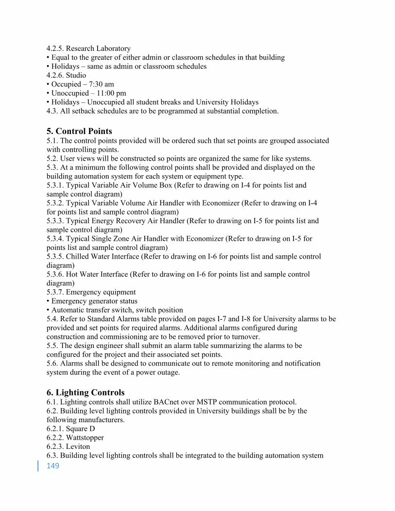
149
4.2.5. Research Laboratory • Equal to the greater of either admin or classroom schedules in that building • Holidays – same as admin or classroom schedules 4.2.6. Studio • Occupied – 7:30 am • Unoccupied – 11:00 pm • Holidays – Unoccupied all student breaks and University Holidays 4.3. All setback schedules are to be programmed at substantial completion. 5. Control Points 5.1. The control points provided will be ordered such that set points are grouped associated with controlling points. 5.2. User views will be constructed so points are organized the same for like systems. 5.3. At a minimum the following control points shall be provided and displayed on the building automation system for each system or equipment type. 5.3.1. Typical Variable Air Volume Box (Refer to drawing on I-4 for points list and sample control diagram) 5.3.2. Typical Variable Volume Air Handler with Economizer (Refer to drawing on I-4 for points list and sample control diagram) 5.3.3. Typical Energy Recovery Air Handler (Refer to drawing on I-5 for points list and sample control diagram) 5.3.4. Typical Single Zone Air Handler with Economizer (Refer to drawing on I-5 for points list and sample control diagram) 5.3.5. Chilled Water Interface (Refer to drawing on I-6 for points list and sample control diagram) 5.3.6. Hot Water Interface (Refer to drawing on I-6 for points list and sample control diagram) 5.3.7. Emergency equipment • Emergency generator status • Automatic transfer switch, switch position 5.4. Refer to Standard Alarms table provided on pages I-7 and I-8 for University alarms to be provided and set points for required alarms. Additional alarms configured during construction and commissioning are to be removed prior to turnover. 5.5. The design engineer shall submit an alarm table summarizing the alarms to be configured for the project and their associated set points. 5.6. Alarms shall be designed to communicate out to remote monitoring and notification system during the event of a power outage. 6. Lighting Controls 6.1. Lighting controls shall utilize BACnet over MSTP communication protocol. 6.2. Building level lighting controls provided in University buildings shall be by the following manufacturers. 6.2.1. Square D 6.2.2. Wattstopper 6.2.3. Leviton 6.3. Building level lighting controls shall be integrated to the building automation system
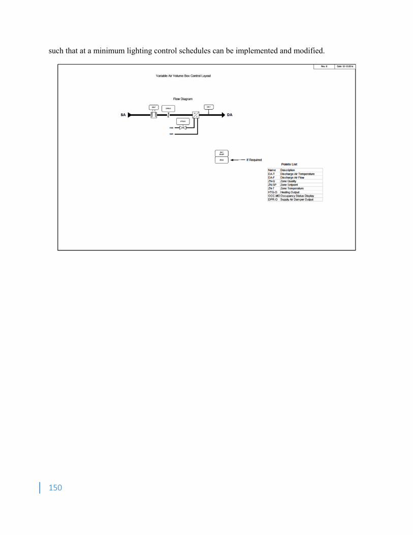
150
such that at a minimum lighting control schedules can be implemented and modified.
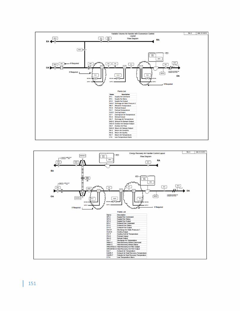
151
152
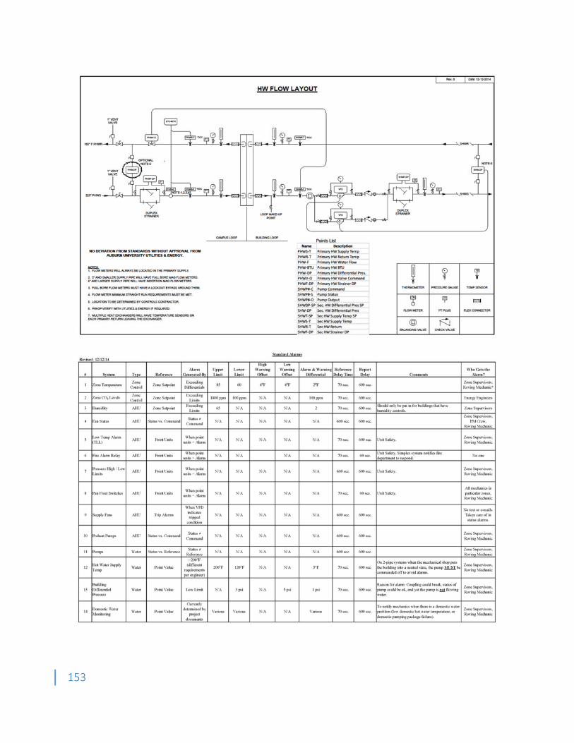
153
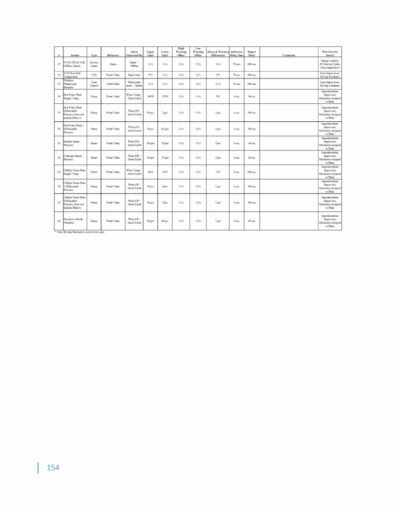
154
155
Appendix E Water Treatment Procedures 1. Purpose 1.1. This document is to provide guidance to the UPL on the hydronic system construction, installation and/or renovation for the establishing of required water treatment conditions. 1.2. It is to be performed in conjunction with and under the technical direction of the Utilities & Energy Water Treatment department. 2. General Guidelines– Closed Loop Treatment 2.1. Submittals - Provide product data for all chemical treatment materials, chemicals and equipment. Product data shall include chemical explanation, MSDS, layouts of feeding equipment and equipment detail sheets. 2.2. Quality Assurance 2.2.1. Retain the resources of the chemical water treatment contractor who is already under contract with the client. 2.2.2. The water treatment chemical and service supplier shall be a recognized specialist, active in the field of industrial water treatment for at least five years, whose major business is in the field of water treatment, and who has full time service personnel within the area of the job site. Laboratory facilities shall be available. Service personnel shall be degreed specialists in the fields of mechanical or chemical engineering or chemistry. 2.2.3. Furnish and install all equipment and material on this project in accordance with the requirements of the authority having jurisdiction, suitable for its intended use on this project, approved by the U.S. Environmental Protection Agency (EPA), and local Department of Environmental Protection, and so certified by the manufacturer. 2.2.4. If not already known, analyze the water from the local water supplier to be used on the project, before establishing treatment procedures. 2.2.5. The cleaning sequence will not be deemed completed until fully signed off and agreed upon by the Western Carolina University Water Treatment Department, as well as, the Plant Operations Group. 2.3. Safety 2.3.1. All chemical and analytical reagents supplied by the vendor shall meet all applicable government regulations. The bidders shall submit an MSDS for all proposed products with the initial technical proposal. The vendor shall be responsible for providing up to date MSDS for all chemicals supplied including reagents. 2.3.2. The mechanical contractor shall be responsible for the safe cleanup of any chemical spills relating to products supplied by the vendor and caused by failure or malfunction of the chemical feed equipment or due to the actions of the field service personnel. Cleanup shall be performed in accordance with all current government regulations and good safety practices. Vendor shall maintain a 24 hour hot line for emergency situations. Bidder shall provide the phone number and procedure to access the hot line including estimated response time in the event of an emergency. 2.4. Technical Services 2.4.1. Mechanical contractor shall be responsible for handling of all water treatment chemicals. 2.4.2. All chemical deliveries shall be made to the point of use by the vendor or an ahead of time agreed up on location such as the mechanical contractors lay down yard. The contractor shall remove, following local, state and federal governances all chemical containment systems as instructed by the vendor.
156
3. Closed Loop New Installation 3.1.Underground Mains – Chilled Water/Ductile Lined 3.1.1. Materials • Pump Strainer shall be fine mesh (3/64-inch maximum). • Sterilization Chemicals shall be non-oxidizing biocide which has halogen like effects such as 2,2-dibromo-3-nitrilopropionamide, also known as DBNPA. Use GE Betz Spectrus NX108 or equivalent. • Water Treatment Chemical shall be GE Betz Corrshield MD407 or equivalent. 3.1.2. Preparation • Contractor shall provide a minimum notice of fourteen (14) days to the water treatment vendor to allow for delivery of chemicals. • Contractor will notify the UPL three (3) working days prior to filling for pressure testing and cleaning of new water pipes. The new piping system shall not be connected/operated until the chemical clean-up is performed. • Contractor shall determine supply and return diameters. If the supply and return lines are less than six inches (6”) they do not require sterilization, however, they do require flushing with system chilled water before they are put into service. 3.1.3. Sterilization/Flushing Sequence for Lines 6” in Diameter and Above • If filling of the pipe is to occur as the pipe sections are constructed, then sterilization shall be accomplished as the pipe is constructed, otherwise, sterilization can be done at the end of each job as long as no water is put into the pipe for any reason. Once a section of pipe between isolation valves is complete, the piping shall be hydro tested, sterilized and treated, in that order. Under no circumstance shall the pipe remain untreated for more than one week after initial filling. • All water shall be metered into the pipe and amounts shall be tabulated and given to UPL to indicate the volume of water in each pipe section between isolation valves. Pipe quantities and sizes shall also be tabulated to verify piping is filled completely. • Two twelve (12) ounce bottles of the system water shall be taken for laboratory analysis prior to the start of the addition of biocide for sterilization or flushing. UPL will be responsible for providing the sample bottles to the mechanical contractor. • Biocide shall be added to pipe at a concentration of 50 ppm based on total water volume in the pipe. • Place the re-circulation pump at the low point of the area to be cleaned so that adequate venting can occur at the high point of the system. • At the high point crossover, contractor to provide a ball valve and sample point for ease of water testing and for venting air from the system. • Circulate the solution for at least twenty four (24) hours or as recommended by the UPL, whichever is less. Balance valves shall be included to ensure pump is operated with sufficient head. Valve shall be manually modulated to obtain proper flow from pump. Pump differential head and certified pump curves shall be utilized to determine pump flow. Biocide shall be circulated to maintain a minimum pipe flow as shown in the following table. Flow rate shall be determined based on the largest diameter piping in the system.
MINIMUM CLEANING WATER Pipe Size (in) Flow (gpm)
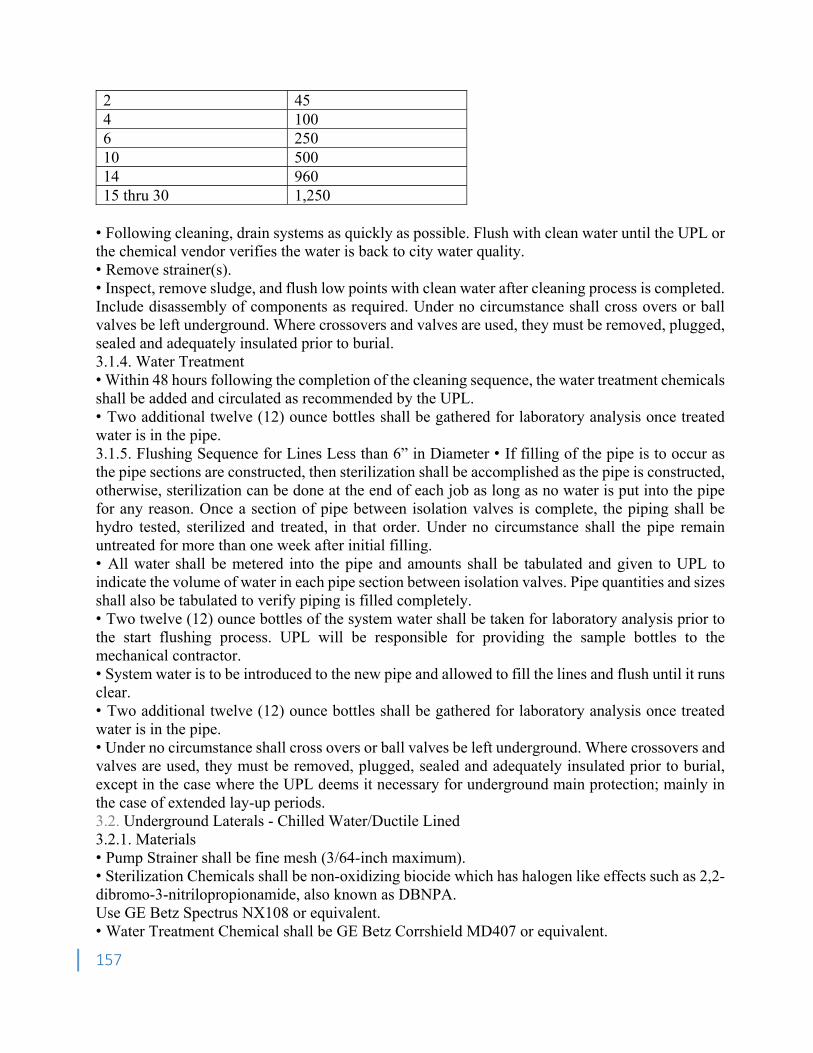
157
2 45 4 100 6 250 10 500 14 960 15 thru 30 1,250
• Following cleaning, drain systems as quickly as possible. Flush with clean water until the UPL or the chemical vendor verifies the water is back to city water quality. • Remove strainer(s). • Inspect, remove sludge, and flush low points with clean water after cleaning process is completed. Include disassembly of components as required. Under no circumstance shall cross overs or ball valves be left underground. Where crossovers and valves are used, they must be removed, plugged, sealed and adequately insulated prior to burial. 3.1.4. Water Treatment • Within 48 hours following the completion of the cleaning sequence, the water treatment chemicals shall be added and circulated as recommended by the UPL. • Two additional twelve (12) ounce bottles shall be gathered for laboratory analysis once treated water is in the pipe. 3.1.5. Flushing Sequence for Lines Less than 6” in Diameter • If filling of the pipe is to occur as the pipe sections are constructed, then sterilization shall be accomplished as the pipe is constructed, otherwise, sterilization can be done at the end of each job as long as no water is put into the pipe for any reason. Once a section of pipe between isolation valves is complete, the piping shall be hydro tested, sterilized and treated, in that order. Under no circumstance shall the pipe remain untreated for more than one week after initial filling. • All water shall be metered into the pipe and amounts shall be tabulated and given to UPL to indicate the volume of water in each pipe section between isolation valves. Pipe quantities and sizes shall also be tabulated to verify piping is filled completely. • Two twelve (12) ounce bottles of the system water shall be taken for laboratory analysis prior to the start flushing process. UPL will be responsible for providing the sample bottles to the mechanical contractor. • System water is to be introduced to the new pipe and allowed to fill the lines and flush until it runs clear. • Two additional twelve (12) ounce bottles shall be gathered for laboratory analysis once treated water is in the pipe. • Under no circumstance shall cross overs or ball valves be left underground. Where crossovers and valves are used, they must be removed, plugged, sealed and adequately insulated prior to burial, except in the case where the UPL deems it necessary for underground main protection; mainly in the case of extended lay-up periods. 3.2. Underground Laterals - Chilled Water/Ductile Lined 3.2.1. Materials • Pump Strainer shall be fine mesh (3/64-inch maximum). • Sterilization Chemicals shall be non-oxidizing biocide which has halogen like effects such as 2,2-dibromo-3-nitrilopropionamide, also known as DBNPA. Use GE Betz Spectrus NX108 or equivalent. • Water Treatment Chemical shall be GE Betz Corrshield MD407 or equivalent.
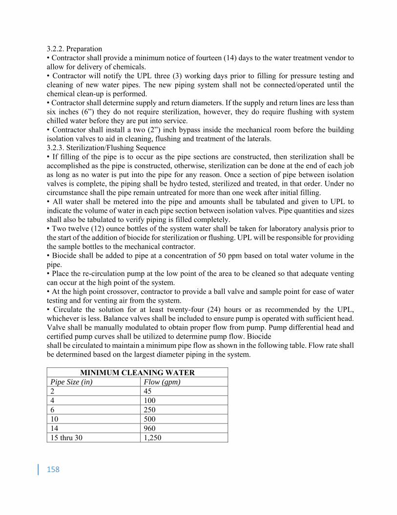
158
3.2.2. Preparation • Contractor shall provide a minimum notice of fourteen (14) days to the water treatment vendor to allow for delivery of chemicals. • Contractor will notify the UPL three (3) working days prior to filling for pressure testing and cleaning of new water pipes. The new piping system shall not be connected/operated until the chemical clean-up is performed. • Contractor shall determine supply and return diameters. If the supply and return lines are less than six inches (6”) they do not require sterilization, however, they do require flushing with system chilled water before they are put into service. • Contractor shall install a two (2”) inch bypass inside the mechanical room before the building isolation valves to aid in cleaning, flushing and treatment of the laterals. 3.2.3. Sterilization/Flushing Sequence • If filling of the pipe is to occur as the pipe sections are constructed, then sterilization shall be accomplished as the pipe is constructed, otherwise, sterilization can be done at the end of each job as long as no water is put into the pipe for any reason. Once a section of pipe between isolation valves is complete, the piping shall be hydro tested, sterilized and treated, in that order. Under no circumstance shall the pipe remain untreated for more than one week after initial filling. • All water shall be metered into the pipe and amounts shall be tabulated and given to UPL to indicate the volume of water in each pipe section between isolation valves. Pipe quantities and sizes shall also be tabulated to verify piping is filled completely. • Two twelve (12) ounce bottles of the system water shall be taken for laboratory analysis prior to the start of the addition of biocide for sterilization or flushing. UPL will be responsible for providing the sample bottles to the mechanical contractor. • Biocide shall be added to pipe at a concentration of 50 ppm based on total water volume in the pipe. • Place the re-circulation pump at the low point of the area to be cleaned so that adequate venting can occur at the high point of the system. • At the high point crossover, contractor to provide a ball valve and sample point for ease of water testing and for venting air from the system. • Circulate the solution for at least twenty-four (24) hours or as recommended by the UPL, whichever is less. Balance valves shall be included to ensure pump is operated with sufficient head. Valve shall be manually modulated to obtain proper flow from pump. Pump differential head and certified pump curves shall be utilized to determine pump flow. Biocide shall be circulated to maintain a minimum pipe flow as shown in the following table. Flow rate shall be determined based on the largest diameter piping in the system.
MINIMUM CLEANING WATER Pipe Size (in) Flow (gpm) 2 45 4 100 6 250 10 500 14 960 15 thru 30 1,250
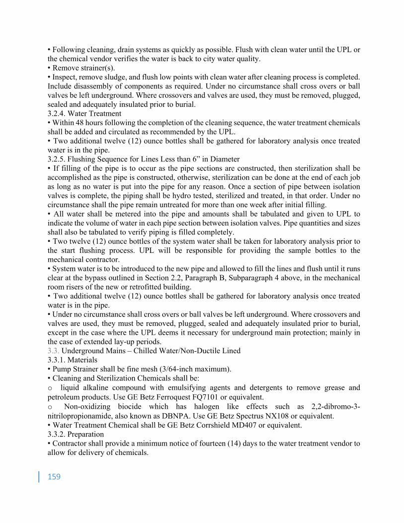
159
• Following cleaning, drain systems as quickly as possible. Flush with clean water until the UPL or the chemical vendor verifies the water is back to city water quality. • Remove strainer(s). • Inspect, remove sludge, and flush low points with clean water after cleaning process is completed. Include disassembly of components as required. Under no circumstance shall cross overs or ball valves be left underground. Where crossovers and valves are used, they must be removed, plugged, sealed and adequately insulated prior to burial. 3.2.4. Water Treatment • Within 48 hours following the completion of the cleaning sequence, the water treatment chemicals shall be added and circulated as recommended by the UPL. • Two additional twelve (12) ounce bottles shall be gathered for laboratory analysis once treated water is in the pipe. 3.2.5. Flushing Sequence for Lines Less than 6” in Diameter • If filling of the pipe is to occur as the pipe sections are constructed, then sterilization shall be accomplished as the pipe is constructed, otherwise, sterilization can be done at the end of each job as long as no water is put into the pipe for any reason. Once a section of pipe between isolation valves is complete, the piping shall be hydro tested, sterilized and treated, in that order. Under no circumstance shall the pipe remain untreated for more than one week after initial filling. • All water shall be metered into the pipe and amounts shall be tabulated and given to UPL to indicate the volume of water in each pipe section between isolation valves. Pipe quantities and sizes shall also be tabulated to verify piping is filled completely. • Two twelve (12) ounce bottles of the system water shall be taken for laboratory analysis prior to the start flushing process. UPL will be responsible for providing the sample bottles to the mechanical contractor. • System water is to be introduced to the new pipe and allowed to fill the lines and flush until it runs clear at the bypass outlined in Section 2.2, Paragraph B, Subparagraph 4 above, in the mechanical room risers of the new or retrofitted building. • Two additional twelve (12) ounce bottles shall be gathered for laboratory analysis once treated water is in the pipe. • Under no circumstance shall cross overs or ball valves be left underground. Where crossovers and valves are used, they must be removed, plugged, sealed and adequately insulated prior to burial, except in the case where the UPL deems it necessary for underground main protection; mainly in the case of extended lay-up periods. 3.3. Underground Mains – Chilled Water/Non-Ductile Lined 3.3.1. Materials • Pump Strainer shall be fine mesh (3/64-inch maximum). • Cleaning and Sterilization Chemicals shall be: o liquid alkaline compound with emulsifying agents and detergents to remove grease and petroleum products. Use GE Betz Ferroquest FQ7101 or equivalent. o Non-oxidizing biocide which has halogen like effects such as 2,2-dibromo-3-nitrilopropionamide, also known as DBNPA. Use GE Betz Spectrus NX108 or equivalent. • Water Treatment Chemical shall be GE Betz Corrshield MD407 or equivalent. 3.3.2. Preparation • Contractor shall provide a minimum notice of fourteen (14) days to the water treatment vendor to allow for delivery of chemicals.
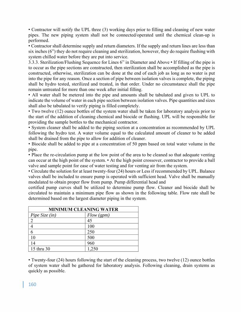
160
• Contractor will notify the UPL three (3) working days prior to filling and cleaning of new water pipes. The new piping system shall not be connected/operated until the chemical clean-up is performed. • Contractor shall determine supply and return diameters. If the supply and return lines are less than six inches (6”) they do not require cleaning and sterilization, however, they do require flushing with system chilled water before they are put into service. 3.3.3. Sterilization/Flushing Sequence for Lines 6” in Diameter and Above • If filling of the pipe is to occur as the pipe sections are constructed, then sterilization shall be accomplished as the pipe is constructed, otherwise, sterilization can be done at the end of each job as long as no water is put into the pipe for any reason. Once a section of pipe between isolation valves is complete, the piping shall be hydro tested, sterilized and treated, in that order. Under no circumstance shall the pipe remain untreated for more than one week after initial filling. • All water shall be metered into the pipe and amounts shall be tabulated and given to UPL to indicate the volume of water in each pipe section between isolation valves. Pipe quantities and sizes shall also be tabulated to verify piping is filled completely. • Two twelve (12) ounce bottles of the system water shall be taken for laboratory analysis prior to the start of the addition of cleaning chemical and biocide or flushing. UPL will be responsible for providing the sample bottles to the mechanical contractor. • System cleaner shall be added to the piping section at a concentration as recommended by UPL following the hydro test. A water volume equal to the calculated amount of cleaner to be added shall be drained from the pipe to allow for addition of cleaner. • Biocide shall be added to pipe at a concentration of 50 ppm based on total water volume in the pipe. • Place the re-circulation pump at the low point of the area to be cleaned so that adequate venting can occur at the high point of the system. • At the high point crossover, contractor to provide a ball valve and sample point for ease of water testing and for venting air from the system. • Circulate the solution for at least twenty-four (24) hours or Less if recommended by UPL. Balance valves shall be included to ensure pump is operated with sufficient head. Valve shall be manually modulated to obtain proper flow from pump. Pump differential head and certified pump curves shall be utilized to determine pump flow. Cleaner and biocide shall be circulated to maintain a minimum pipe flow as shown in the following table. Flow rate shall be determined based on the largest diameter piping in the system.
MINIMUM CLEANING WATER Pipe Size (in) Flow (gpm) 2 45 4 100 6 250 10 500 14 960 15 thru 30 1,250
• Twenty-four (24) hours following the start of the cleaning process, two twelve (12) ounce bottles of system water shall be gathered for laboratory analysis. Following cleaning, drain systems as quickly as possible.
161
• Flush with clean water until the UPL or the chemical vendor verifies the water is back to city water quality. • Two twelve (12) ounce bottles of system water shall be gathered for laboratory analysis following city water flushing. • Remove strainer(s). • Inspect, remove sludge, and flush low points with clean water after cleaning process is completed. Include disassembly of components as required. Under no circumstance shall cross overs or ball valves be left underground. Where crossovers and valves are used, they must be removed, plugged, sealed and adequately insulated prior to burial. 3.3.4. Water Treatment • Within 48 hours following the completion of the cleaning sequence, the water treatment chemicals shall be added and circulated as recommended by the UPL. • Two additional twelve (12) ounce bottles shall be gathered for laboratory analysis once treated water is in the pipe. 3.3.5. Flushing Sequence for Lines Less than 6” in Diameter • If filling of the pipe is to occur as the pipe sections are constructed, then sterilization shall be accomplished as the pipe is constructed, otherwise, sterilization can be done at the end of each job as long as no water is put into the pipe for any reason. Once a section of pipe between isolation valves is complete, the piping shall be hydro tested, sterilized and treated, in that order. Under no circumstance shall the pipe remain untreated for more than one week after initial filling. • All water shall be metered into the pipe and amounts shall be tabulated and given to UPL to indicate the volume of water in each pipe section between isolation valves. Pipe quantities and sizes shall also be tabulated to verify piping is filled completely. • Two twelve (12) ounce bottles of the system water shall be taken for laboratory analysis prior to the start flushing process. UPL will be responsible for providing the sample bottles to the mechanical contractor. • System water is to be introduced to the new pipe and allowed to fill the lines and flush until it runs clear. • Two additional twelve (12) ounce bottles shall be gathered for laboratory analysis once treated water is in the pipe. • Under no circumstance shall cross overs or ball valves be left underground. Where crossovers and valves are used, they must be removed, plugged, sealed and adequately insulated prior to burial, except in the case where the UPL deem it necessary for underground main protection; mainly in the case of extended lay-up periods. 3.4. Underground Laterals – Chilled Water/Non-Ductile Lined 3.4.1. Materials • Pump Strainer shall be fine mesh (3/64-inch maximum). • Cleaning and Sterilization Chemicals shall be o Liquid alkaline compound with emulsifying agents and detergents to remove grease and petroleum products. Use GE Betz Ferroquest FQ7101 or equivalent. o Non-oxidizing biocide which has halogen like effects such as 2,2-dibromo-3-nitrilopropionamide, also known as DBNPA. Use GE Betz Spectrus NX108 or equivalent. • Water Treatment Chemical shall be GE Betz Corrshield MD407 or equivalent. 3.4.2. Preparation • Contractor shall provide a minimum notice of fourteen (14) days to the water treatment vendor to allow for delivery of chemicals.
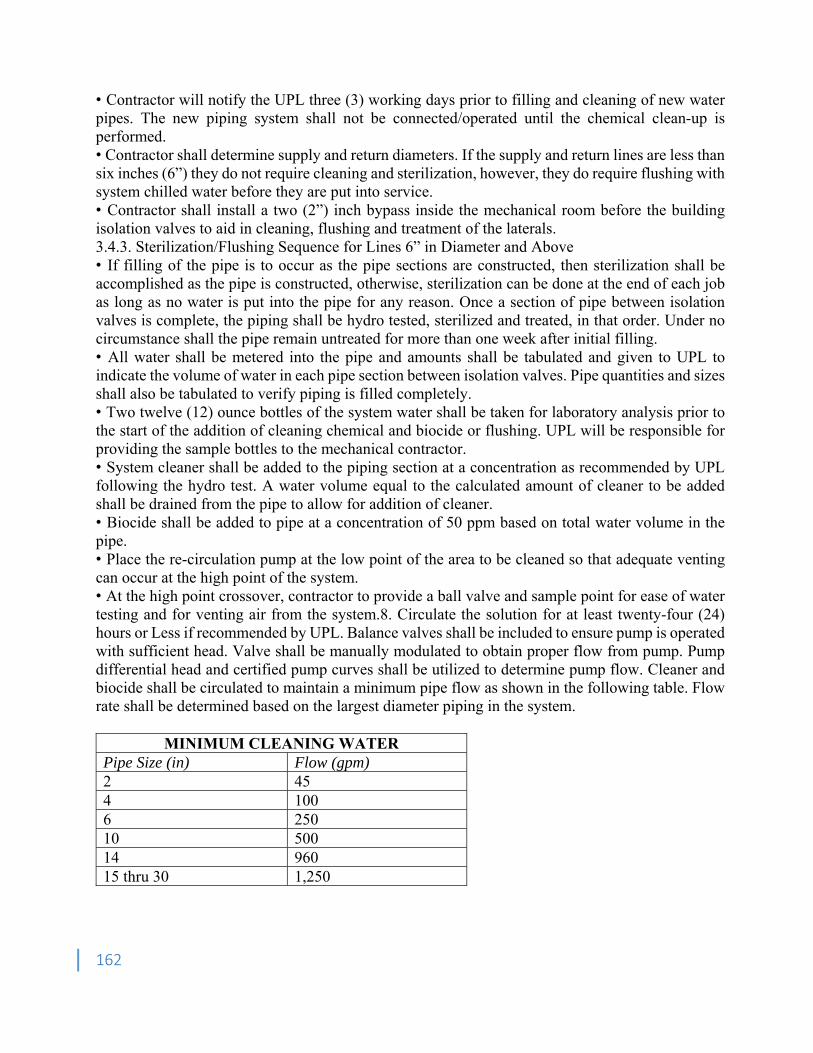
162
• Contractor will notify the UPL three (3) working days prior to filling and cleaning of new water pipes. The new piping system shall not be connected/operated until the chemical clean-up is performed. • Contractor shall determine supply and return diameters. If the supply and return lines are less than six inches (6”) they do not require cleaning and sterilization, however, they do require flushing with system chilled water before they are put into service. • Contractor shall install a two (2”) inch bypass inside the mechanical room before the building isolation valves to aid in cleaning, flushing and treatment of the laterals. 3.4.3. Sterilization/Flushing Sequence for Lines 6” in Diameter and Above • If filling of the pipe is to occur as the pipe sections are constructed, then sterilization shall be accomplished as the pipe is constructed, otherwise, sterilization can be done at the end of each job as long as no water is put into the pipe for any reason. Once a section of pipe between isolation valves is complete, the piping shall be hydro tested, sterilized and treated, in that order. Under no circumstance shall the pipe remain untreated for more than one week after initial filling. • All water shall be metered into the pipe and amounts shall be tabulated and given to UPL to indicate the volume of water in each pipe section between isolation valves. Pipe quantities and sizes shall also be tabulated to verify piping is filled completely. • Two twelve (12) ounce bottles of the system water shall be taken for laboratory analysis prior to the start of the addition of cleaning chemical and biocide or flushing. UPL will be responsible for providing the sample bottles to the mechanical contractor. • System cleaner shall be added to the piping section at a concentration as recommended by UPL following the hydro test. A water volume equal to the calculated amount of cleaner to be added shall be drained from the pipe to allow for addition of cleaner. • Biocide shall be added to pipe at a concentration of 50 ppm based on total water volume in the pipe. • Place the re-circulation pump at the low point of the area to be cleaned so that adequate venting can occur at the high point of the system. • At the high point crossover, contractor to provide a ball valve and sample point for ease of water testing and for venting air from the system.8. Circulate the solution for at least twenty-four (24) hours or Less if recommended by UPL. Balance valves shall be included to ensure pump is operated with sufficient head. Valve shall be manually modulated to obtain proper flow from pump. Pump differential head and certified pump curves shall be utilized to determine pump flow. Cleaner and biocide shall be circulated to maintain a minimum pipe flow as shown in the following table. Flow rate shall be determined based on the largest diameter piping in the system.
MINIMUM CLEANING WATER Pipe Size (in) Flow (gpm) 2 45 4 100 6 250 10 500 14 960 15 thru 30 1,250
163
• Twenty-four (24) hours following the start of the cleaning process, two twelve (12) ounce bottles of system water shall be gathered for laboratory analysis. Following cleaning, drain systems as quickly as possible. • Flush with clean water until the UPL or the chemical vendor verifies the water is back to city water quality. • Two twelve (12) ounce bottles of system water shall be gathered for laboratory analysis following city water flushing. • Remove strainer(s). • Inspect, remove sludge, and flush low points with clean water after cleaning process is completed. Include disassembly of components as required. Under no circumstance shall cross overs or ball valves be left underground. Where crossovers and valves are used, they must be removed, plugged, sealed and adequately insulated prior to burial. 3.4.4. Water Treatment • Within 48 hours following the completion of the cleaning sequence, the water treatment chemicals shall be added and circulated as recommended by the UPL. • Two additional twelve (12) ounce bottles shall be gathered for laboratory analysis once treated water is in the pipe. 3.4.5. Flushing Sequence for Lines Less than 6” in Diameter • If filling of the pipe is to occur as the pipe sections are constructed, then sterilization shall be accomplished as the pipe is constructed, otherwise, sterilization can be done at the end of each job as long as no water is put into the pipe for any reason. Once a section of pipe between isolation valves is complete, the piping shall be hydro tested, sterilized and treated, in that order. Under no circumstance shall the pipe remain untreated for more than one week after initial filling. • All water shall be metered into the pipe and amounts shall be tabulated and given to UPL to indicate the volume of water in each pipe section between isolation valves. Pipe quantities and sizes shall also be tabulated to verify piping is filled completely. • Two twelve (12) ounce bottles of the system water shall be taken for laboratory analysis prior to the start flushing process. UPL will be responsible for providing the sample bottles to the mechanical contractor. • System water is to be introduced to the new pipe and allowed to fill the lines and flush until it runs clear at the bypass outlined in Section 2.4, Paragraph B, Subparagraph 4 above, in the mechanical room risers of the new or retrofitted building. • Two additional twelve (12) ounce bottles shall be gathered for laboratory analysis once treated water is in the pipe. • Under no circumstance shall cross overs or ball valves be left underground. Where crossovers and valves are used, they must be removed, plugged, sealed and adequately insulated prior to burial, except in the case where the UPL deems it necessary for underground main protection; mainly in the case of extended lay-up periods. 3.5. Underground Mains – Hot Water 3.5.1. Materials • Pump Strainer shall be fine mesh (3/64-inch maximum). • Cleaning and Sterilization Chemicals shall be liquid alkaline compound with emulsifying agents and detergents to remove grease and petroleum products. Use GE Betz Ferroquest FQ7101 or equivalent. • Water Treatment Chemical shall be GE Betz Corrshield NT402 or equivalent 3.5.2. Preparation
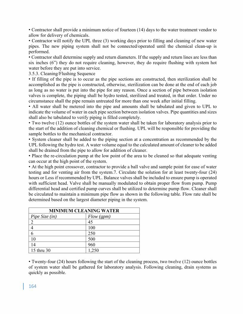
164
• Contractor shall provide a minimum notice of fourteen (14) days to the water treatment vendor to allow for delivery of chemicals. • Contractor will notify the UPL three (3) working days prior to filling and cleaning of new water pipes. The new piping system shall not be connected/operated until the chemical clean-up is performed. • Contractor shall determine supply and return diameters. If the supply and return lines are less than six inches (6”) they do not require cleaning, however, they do require flushing with system hot water before they are put into service. 3.5.3. Cleaning/Flushing Sequence • If filling of the pipe is to occur as the pipe sections are constructed, then sterilization shall be accomplished as the pipe is constructed, otherwise, sterilization can be done at the end of each job as long as no water is put into the pipe for any reason. Once a section of pipe between isolation valves is complete, the piping shall be hydro tested, sterilized and treated, in that order. Under no circumstance shall the pipe remain untreated for more than one week after initial filling. • All water shall be metered into the pipe and amounts shall be tabulated and given to UPL to indicate the volume of water in each pipe section between isolation valves. Pipe quantities and sizes shall also be tabulated to verify piping is filled completely. • Two twelve (12) ounce bottles of the system water shall be taken for laboratory analysis prior to the start of the addition of cleaning chemical or flushing. UPL will be responsible for providing the sample bottles to the mechanical contractor. • System cleaner shall be added to the piping section at a concentration as recommended by the UPL following the hydro test. A water volume equal to the calculated amount of cleaner to be added shall be drained from the pipe to allow for addition of cleaner. • Place the re-circulation pump at the low point of the area to be cleaned so that adequate venting can occur at the high point of the system. • At the high point crossover, contractor to provide a ball valve and sample point for ease of water testing and for venting air from the system.7. Circulate the solution for at least twenty-four (24) hours or Less if recommended by UPL. Balance valves shall be included to ensure pump is operated with sufficient head. Valve shall be manually modulated to obtain proper flow from pump. Pump differential head and certified pump curves shall be utilized to determine pump flow. Cleaner shall be circulated to maintain a minimum pipe flow as shown in the following table. Flow rate shall be determined based on the largest diameter piping in the system.
MINIMUM CLEANING WATER Pipe Size (in) Flow (gpm) 2 45 4 100 6 250 10 500 14 960 15 thru 30 1,250
• Twenty-four (24) hours following the start of the cleaning process, two twelve (12) ounce bottles of system water shall be gathered for laboratory analysis. Following cleaning, drain systems as quickly as possible.
165
• Flush with clean water until the UPL or the chemical vendor verifies the water is back to city water quality. • Two twelve (12) ounce bottles of system water shall be gathered for laboratory analysis following city water flushing. • Remove strainer(s). • Inspect, remove sludge, and flush low points with clean water after cleaning process is completed. Include disassembly of components as required. Under no circumstance shall cross overs or ball valves be left underground. Where crossovers and valves are used, they must be removed, plugged, sealed and adequately insulated prior to burial. 3.5.4. Water Treatment • Within 48 hours following the completion of the cleaning sequence, the water treatment chemicals shall be added and circulated as recommended by the UPL. • Two additional twelve (12) ounce bottles shall be gathered for laboratory analysis once treated water is in the pipe. 3.5.5. Flushing Sequence for Lines Less than 6” in Diameter • If filling of the pipe is to occur as the pipe sections are constructed, then sterilization shall be accomplished as the pipe is constructed, otherwise, sterilization can be done at the end of each job as long as no water is put into the pipe for any reason. Once a section of pipe between isolation valves is complete, the piping shall be hydro tested, sterilized and treated, in that order. Under no circumstance shall the pipe remain untreated for more than one week after initial filling. • All water shall be metered into the pipe and amounts shall be tabulated and given to UPL to indicate the volume of water in each pipe section between isolation valves. Pipe quantities and sizes shall also be tabulated to verify piping is filled completely. • Two twelve (12) ounce bottles of the system water shall be taken for laboratory analysis prior to the start flushing process. UPL will be responsible for providing the sample bottles to the mechanical contractor. • System water is to be introduced to the new pipe and allowed to fill the lines and flush until it runs clear. • Two additional twelve (12) ounce bottles shall be gathered for laboratory analysis once treated water is in the pipe. • Under no circumstance shall cross overs or ball valves be left underground. Where crossovers and valves are used, they must be removed, plugged, sealed and adequately insulated prior to burial, except in the case where the UPL deems it necessary for underground main protection; mainly in the case of extended lay-up periods. 3.6. Underground Laterals – Hot Water 3.6.1. Materials • Pump Strainer shall be fine mesh (3/64-inch maximum). • Cleaning and Sterilization Chemicals shall be liquid alkaline compound with emulsifying agents and detergents to remove grease and petroleum products. Use GE Betz Ferroquest FQ7101 or equivalent. • Water Treatment Chemical shall be GE Betz Corrshield NT402 or equivalent. 3.6.2. Preparation • Contractor shall provide a minimum notice of fourteen (14) days to the water treatment vendor to allow for delivery of chemicals.
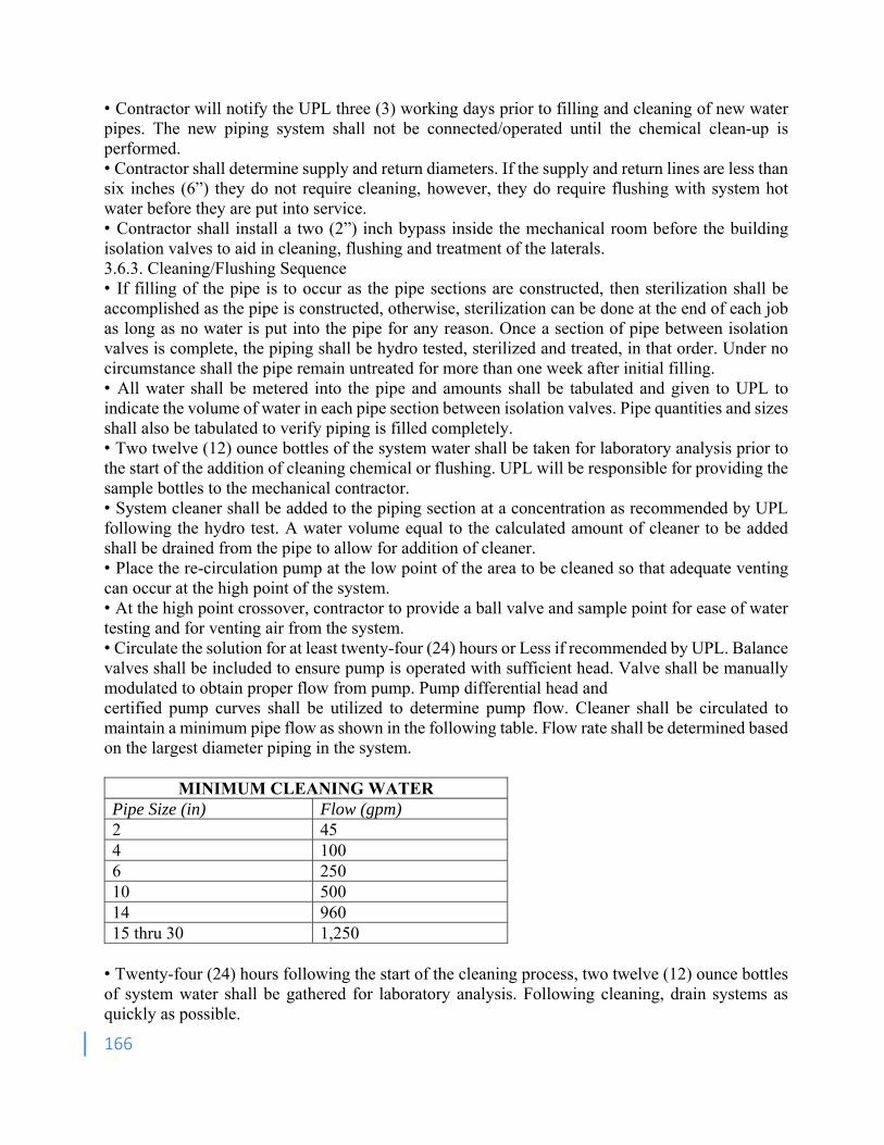
166
• Contractor will notify the UPL three (3) working days prior to filling and cleaning of new water pipes. The new piping system shall not be connected/operated until the chemical clean-up is performed. • Contractor shall determine supply and return diameters. If the supply and return lines are less than six inches (6”) they do not require cleaning, however, they do require flushing with system hot water before they are put into service. • Contractor shall install a two (2”) inch bypass inside the mechanical room before the building isolation valves to aid in cleaning, flushing and treatment of the laterals. 3.6.3. Cleaning/Flushing Sequence • If filling of the pipe is to occur as the pipe sections are constructed, then sterilization shall be accomplished as the pipe is constructed, otherwise, sterilization can be done at the end of each job as long as no water is put into the pipe for any reason. Once a section of pipe between isolation valves is complete, the piping shall be hydro tested, sterilized and treated, in that order. Under no circumstance shall the pipe remain untreated for more than one week after initial filling. • All water shall be metered into the pipe and amounts shall be tabulated and given to UPL to indicate the volume of water in each pipe section between isolation valves. Pipe quantities and sizes shall also be tabulated to verify piping is filled completely. • Two twelve (12) ounce bottles of the system water shall be taken for laboratory analysis prior to the start of the addition of cleaning chemical or flushing. UPL will be responsible for providing the sample bottles to the mechanical contractor. • System cleaner shall be added to the piping section at a concentration as recommended by UPL following the hydro test. A water volume equal to the calculated amount of cleaner to be added shall be drained from the pipe to allow for addition of cleaner. • Place the re-circulation pump at the low point of the area to be cleaned so that adequate venting can occur at the high point of the system. • At the high point crossover, contractor to provide a ball valve and sample point for ease of water testing and for venting air from the system. • Circulate the solution for at least twenty-four (24) hours or Less if recommended by UPL. Balance valves shall be included to ensure pump is operated with sufficient head. Valve shall be manually modulated to obtain proper flow from pump. Pump differential head and certified pump curves shall be utilized to determine pump flow. Cleaner shall be circulated to maintain a minimum pipe flow as shown in the following table. Flow rate shall be determined based on the largest diameter piping in the system.
MINIMUM CLEANING WATER Pipe Size (in) Flow (gpm) 2 45 4 100 6 250 10 500 14 960 15 thru 30 1,250
• Twenty-four (24) hours following the start of the cleaning process, two twelve (12) ounce bottles of system water shall be gathered for laboratory analysis. Following cleaning, drain systems as quickly as possible.
167
• Flush with clean water until the UPL or the chemical vendor verifies the water is back to city water quality. • Two twelve (12) ounce bottles of system water shall be gathered for laboratory analysis following city water flushing. • Remove strainer(s). • Inspect, remove sludge, and flush low points with clean water after cleaning process is completed. Include disassembly of components as required. Under no circumstance shall cross overs or ball valves be left underground. Where crossovers and valves are used, they must be removed, plugged, sealed and adequately insulated prior to burial. 3.6.4. Water Treatment • Within 48 hours following the completion of the cleaning sequence, the water treatment chemicals shall be added and circulated as recommended by the UPL. • Two additional twelve (12) ounce bottles shall be gathered for laboratory analysis once treated water is in the pipe. 3.6.5. Flushing Sequence for Lines Less than 6” in Diameter • If filling of the pipe is to occur as the pipe sections are constructed, then sterilization shall be accomplished as the pipe is constructed, otherwise, sterilization can be done at the end of each job as long as no water is put into the pipe for any reason. Once a section of pipe between isolation valves is complete, the piping shall be hydro tested, sterilized and treated, in that order. Under no circumstance shall the pipe remain untreated for more than one week after initial filling. • All water shall be metered into the pipe and amounts shall be tabulated and given to UPL to indicate the volume of water in each pipe section between isolation valves. Pipe quantities and sizes shall also be tabulated to verify piping is filled completely. • Two twelve (12) ounce bottles of the system water shall be taken for laboratory analysis prior to the start flushing process. UPL will be responsible for providing the sample bottles to the mechanical contractor. • System water is to be introduced to the new pipe and allowed to fill the lines and flush until it runs clear at the bypass outlined in Section 2.6, Paragraph B, Subparagraph 4 above, in the mechanical room risers of the new or retrofitted building. • Two additional twelve (12) ounce bottles shall be gathered for laboratory analysis once treated water is in the pipe. • Under no circumstance shall cross overs or ball valves be left underground. Where crossovers and valves are used, they must be removed, plugged, sealed and adequately insulated prior to burial, except in the case where the UPL deems it necessary for underground main protection; mainly in the case of extended lay-up periods. 3.7. Primary & Secondary Building Water Systems – New Construction 3.7.1. Materials • Temporary Building Strainer Screens shall be fine mesh (3/64-inch maximum). • Cleaning and Sterilization Chemicals shall be: o Liquid alkaline compound with emulsifying agents and detergents to remove grease and petroleum products. Use GE Betz Ferroquest FQ7101 or equivalent. o Non-oxidizing biocide which has halogen like effects such as 2,2-dibromo-3-nitrilopropionamide, also known as DBNPA. Use GE Betz Spectrus NX108 or equivalent for chilled water systems only. • Water Treatment Chemical shall be GE Betz Corrshield MD407or equivalent. 3.7.2. Equipment
168
• Chemical Pot Feeder: Five-gallon carbon steel filter housing, as shown on the drawings, quick opening cap for working pressure of 175 psig. Construct of materials which are impervious to the products being dispersed. o Install isolating and drain valves, and necessary piping. Install around supply and return of system pump unless otherwise specified. o If there is more than one circulation pump in the closed loop, install the chemical pot feeder across the common supply and return so that it may utilized regardless of which pump is in service. o Install isolation valves on the chemical pot feeder as close to the pot feeder as possible for safety reasons associated with the use of the feeder. o Introduce closed system treatment through bypass feeder when required or indicated by test. • Neptune Water Meter: Meter to be supplied by UPL and should be installed on all secondary systems. Meter should be installed in the make-up water line no higher than forty-eight inches (48”) above the floor level in the horizontal position. No by-pass shall be installed around this water meter. 3.7.3. Preparation • Contractor shall provide a minimum notice of fourteen (14) days to the water treatment vendor to allow for delivery of chemicals. • Contractor will notify the UPL fourteen (14) days prior to filling and cleaning of new water pipes. The new piping system shall not be connected/operated until the chemical clean-up is performed. • Cleaning of primary building water systems cannot be performed until all piping in the building, or zone to be cleaned, is installed, leak tested and adequate re-circulation loops are installed to ensure adequate flow is obtained throughout the system. • All heat exchangers and air handler coils must be installed prior to the cleaning sequence beginning. • A temporary chemical by-pass feeder must be installed prior to the start of the cleaning sequence if the system is not cleaned in conjunction with distribution piping connecting to the building. • The cleaning process continues for a minimum of twenty-four (24) hours after the introduction of the cleaning agents and must be planned for in advance with the Western Carolina University Water Treatment Department. • The system pump must be fully operational to maintain steady output at 75 – 100% of design capacity throughout the cleaning process. 3.7.4. Cleaning Sequence • When possible, cleaning shall be accomplished in conjunction with the distribution piping connecting the building. Under no circumstance shall the pipe remain untreated for more than one week after initial filling. • All water shall be metered into the pipe and amounts shall be tabulated and given to UPL to indicate the volume of water inside the building. Pipe quantities and sizes shall also be tabulated to verify piping is filled completely. • Install temporary building strainers on supply piping entering the building to prevent damage to building isolation valve seats and discs. • Force all automatic valves and ball valves into the open position at all air handlers, system heat exchangers and expansion tanks. Ensure the system is filled with water and vented of air and initiate system pumps at 75 – 100% of flow capacity. • During the cleaning, at no time shall the circulation pump be shut off except in the event of an emergency. If for some reason the system pump cannot be used for circulation purposes, the
169
mechanical contractor must provide a temporary pump that has similar flow and pressure capacities to that of the system pump. • Monitor pressure drop across the temporary strainer screen and clean as necessary to maintain the recommended pipe velocity as directed by the UPL. • Two twelve (12) ounce bottles of the system water shall be taken for laboratory analysis prior to the start of the addition of cleaning chemical or flushing. UPL will be responsible for providing the sample bottles to the mechanical contractor. • Cleaner and biocide, when required, shall be added to piping at concentration as recommended by Owners representative following the hydro test. A water volume equal to the calculated amount of cleaner to be added shall be drained from the pipe to allow for addition of cleaner. • Circulate the solution for 24 hours or as recommended by the UPL, whichever is less. Cleaner shall be circulated at 75 – 100% of system pump capacity. • Twenty-four (24) hours following the start of the cleaning process, two twelve (12) ounce bottles of system water shall be gathered for laboratory analysis. • Following cleaning, drain systems as quickly as possible. This should be done by means of draining water to a nearby floor drain and adding clean domestic water through a make-up system or by hosepipe. The draining water should not exceed the amount being made up. The system pump remains on during this time and all valves remain in the forced open position. • Two twelve (12) ounce bottles of system water shall be gathered for laboratory analysis following city water flushing. • Following cleaning remove all temporary bypasses and screens, and install all instruments and controls as required. 3.7.5. Water Treatment • Within twenty-four (24) hours following the completion of the cleaning sequence, the water treatment chemicals will be added and circulated as recommended by the UPL or system water from the primary distribution system will be introduced to the building system. • After addition of water treatment chemicals or distribution water, the system pump will remain on line for an additional eight (8) hours, or less if deemed acceptable by the UPL to ensure a good blend of corrosion inhibitor throughout the entire system. During this time, it is imperative that the air handler coils, and all valves which have been previously forced to the open position remains this way. • Following eight (8) hours or less of circulation, two additional twelve (12) ounce samples will be taken for laboratory analysis. At this point, the system pumps can be shut down. • If for any reason water is drained from the loop after the water treatment chemical is added, the UPL will be notified immediately so that action can be taken to prevent corrosion in the system. 4. Primary & Secondary Building Water Systems – Existing Construction 4.1. General 4.1.1. The following specifications are meant only for piping systems that are preexisting where it has been deemed necessary by Western Carolina University Utilities and Operations Groups, as well as, UPL that an entire building clean-up is necessary to remove excess iron and corrosion by-products which are impeding heat transfer or causing re-circulation issues in the building. 4.1.2. It must be noted that this cleaning process will remove all iron scale (rust) that it comes into contact with. If the existing system contain high amounts of internal corrosion, then pipe failure is likely to occur during this process. 4.1.3. It is recommended that adequate measures be taken to prevent catastrophic failure of key building systems such as electrical equipment, experimental processes, etc. This would include the
170
addition of contractor supplied “roaming guards” throughout the process and the placement of water barriers such as plastic sheeting in critical areas of the building. 4.1.4. The cleaning rate is dependent on a number of factors including temperature and velocities. A typical cleaning at 140 oF may require only a couple of days to clean a system where a cleaning closer to 60 oF may require several weeks to clean. Cleanings taking place at higher temperatures may require more frequent testing versus cleanings operating at cooler temperatures, so adequate planning with the UPL must be made in advance. 4.1.5. Materials • Temporary Building Strainer Screens: Fine mesh (3/64-inch maximum). • Cleaning Chemicals o Liquid alkaline compound with emulsifying agents and detergents to remove grease and petroleum products. Use GE Betz Ferroquest FQ7101 or equivalent. o Neutralizing Agent to maintain system pH. Use GE Betz Ferroquest FQ7102 or equivalent. • Water Treatment Chemical: GE Betz Corrshield MD407 or equivalent. 4.1.6. Equipment • Chemical Pot Feeder: Five-gallon carbon steel filter housing, as shown on the drawings, quick opening cap for working pressure of 175 psig. Construct of materials which are impervious to the products being dispersed. o Install isolating and drain valves, and necessary piping. Install around supply and return of system pump unless otherwise specified. o If there is more than one circulation pump in the closed loop, install the chemical pot feeder across the common supply and return so that it may utilized regardless of which pump is in service. o Install isolation valves on the chemical pot feeder as close to the pot feeder as possible for safety reasons associated with the use of the feeder. o Introduce closed system treatment through bypass feeder when required or indicated by test. • A 3/4" nipple and locking stainless steel ball valve should be installed on the suction side of the system pump prior to system being cleaned. This will allow easy addition of Ferroquest cleaning chemical to the loop if the by-pass feeder is not large enough. • Neptune Water Meter: Meter to be supplied by UPL should be installed on all secondary systems. Meter should be installed in the makeup water line no higher than forty-eight inches (48”) above the floor level in the horizontal position. No by-pass shall be installed around this water meter. 4.1.7. Preparation • Contractor shall provide a minimum notice of fourteen (14) days to the water treatment vendor to allow for delivery of chemicals. • Contractor will notify the UPL fourteen (14) days prior to the start of cleaning process. • Contractor shall provide adequate personnel to monitor the cleaning process throughout the entire procedure. This may include, but not be limited to, inside the mechanical rooms, classrooms, hallways, etc. of the entire building. • Cleaning of existing primary building water systems cannot be performed until all new piping in the building, or zone to be cleaned, is installed, leak tested and adequate re-circulation loops are installed to ensure adequate flow is obtained throughout the system. • All new heat exchangers and air handler coils must be installed prior to the cleaning sequence beginning. • A temporary chemical by-pass feeder must be installed prior to the start of the cleaning sequence if the system is not cleaned in conjunction with distribution piping connecting to the building.
171
• The cleaning process continues for a minimum of twenty-four (24) hours after the introduction of the cleaning agents and must be planned for in advance with the Western Carolina University Water Treatment Department. • The system pump must be fully operational to maintain steady output at 75 – 100% of design capacity throughout the cleaning process. 4.1.8. Cleaning Sequence • Install temporary building strainers on supply piping entering the building to prevent damage to building isolation valve seats and discs. • Force all automatic valves and ball valves into the open position at all air handlers, system heat exchangers and expansion tanks. The mechanical contractor will be responsible for ensuring this is accomplished via communication with BAS and the building mechanics. • Ensure the system is filled with water and vented of air and initiate system pumps at 75 – 100% of flow capacity. • During the cleaning, at no time shall the circulation pump be shut off except in the event of an emergency. If for some reason the system pump cannot be used for circulation purposes, the mechanical contractor must provide a temporary pump that has similar flow and pressure capacities to that of the system pump, with a minimum flow rate of three (3) feet per second. • Monitor pressure drop across the temporary strainer screen and clean as necessary to maintain the recommended pipe velocity as directed by the UPL. • Two twelve (12) ounce bottles of the system water shall be taken for laboratory analysis prior to the start of the addition of cleaning chemical or flushing. UPL will be responsible for providing the sample bottles to the mechanical contractor. • Cleaner shall be added to piping at concentration of 10% of the total volume of the system to be cleaned. In order to do this, the city make-up should be turned off and 10% of the total volume be drained from the system while the system pump continues to circulate. Close attention should be paid to the pump during this time to ensure cavitation does not occur. • The conductivity of the water should increase by about 10,000 micromesh above the starting point conductivity, which will indicate 10% volume has been reached in the system. • Once the Ferroquest cleaning solution is added to the loop, if it is lost due to leaks in the system, it is the responsibility of the University's mechanics to locate, isolate and repair the leaks. Once complete, it is the responsibility of the University to supply additional Ferroquest chemical to re-charge the system and complete the cleaning. • pH and Iron tests should be conducted on a regular basis throughout the cleaning process, at least once every four hours. These tests will be conducted by the Western Carolina University Water Treatment Department. • pH should be maintained throughout the cleaning process at 6.5 to 7.2 by the addition of Ferroquest FQ7102. Iron levels should not be allowed to exceed 8000 ppm any time during the cleaning. If they exceed this level, the system should be dumped immediately and replenished with fresh water. • Twenty-four (24) hours, forty-eight (48), seventy-two (72), etc. following the start of the cleaning process, two twelve (12) ounce bottles of system water shall be gathered for laboratory analysis. • When iron levels are no longer increasing and pH levels remain steady, drain systems using a blowdown and flush method. This should be done by means of draining water to a nearby floor drain and adding clean domestic water through a make-up system or by hosepipe. The draining water should not exceed the amount being made up. The system pump remains on during this time and all valves remain in the forced open position.
172
• Two twelve (12) ounce bottles of system water shall be gathered for laboratory analysis following city water flushing. • Following cleaning remove all temporary bypasses and screens. 4.1.9. Water Treatment • Within twenty-four (24) hours following the completion of the cleaning sequence, the water treatment chemicals will be added and circulated as recommended by the UPL or system water from the primary distribution system will be introduced to the building system. • After addition of water treatment chemicals or distribution water, the system pump will remain on line for an additional eight (8) hours, or less if deemed acceptable by the UPL to ensure a good blend of corrosion inhibitor throughout the entire system. During this time, it is imperative that the air handler coils, and all valves which have been previously forced to the open position remains this way. • Following eight (8) hours or less of circulation, two additional twelve (12) ounce samples will be taken for laboratory analysis. At this point, the system pumps can be shut down. • If for any reason water is drained from the loop after the water treatment chemical is added, the UPL will be notified immediately so that action can be taken to prevent corrosion in the system. 5. Boiler Treatment General Guidelines 5.1. Summary- This Section includes the following HVAC water-treatment systems 5.1.1. HVAC water treatment performance requirements. 5.1.2. Chemical treatment test equipment. 5.1.3. HVAC water-treatment chemicals. 5.1.4. Makeup water softeners. 5.1.5. Alkaline boil-out procedure for steam or hot water boilers. 5.2. Definitions 5.2.1. Low Voltage: As defined in NFPA 70 for circuits and equipment operating at less than 50 V or for remote-control, signaling power-limited circuits. 5.2.2. Total Dissolved Solids (TDS): A measure of the combined content of all inorganic and organic substances contained in a liquid in: molecular, ionized or micro granular suspended form. 5.2.3. PPM: Part Per Million. 5.3. Performance Requirements 5.3.1. Water quality for HVAC systems shall minimize corrosion, scale buildup, and biological growth for optimum efficiency of HVAC equipment without creating a hazard to operating personnel or the environment. 5.3.2. Base HVAC water treatment on quality of water available at Project site, HVAC system equipment material characteristics and functional performance characteristics, operating personnel capabilities, and requirements and guidelines of authorities having jurisdiction. 5.3.3. Provide all equipment, accessories, instrumentation, controllers, automated valves, and electrical connections as required to maintain specified performance requirements stated herein. 5.3.4. Feed water and Boiler Water • Feed water o pH: Maintain a value between 8.3 to 10.5. o Dissolved Oxygen: Maintain a value < 0.007 ppm. o Total Hardness: Maintain a value <0.25 ppm. • Boiler Water o pH: Maintain a value within 8.5 to 10.5. o Total Alkalinity: Maintain a value < 700 ppm.
173
o Total Solids: Maintain a value < 3,000 ppm. o Sulfite: Maintain a value within 30 to 50 ppm. o Molybdenum: Maintain a value within 75 to 100 ppm as Mo6+. 5.4. Submittals 5.4.1. Product Data: Include rated capacities, operating characteristics, furnished specialties, and accessories for the following products • Inhibitor injection timers. • TDS controllers. • Chemical solution tanks. • Injection pumps. • Chemical test equipment. • Chemical material safety data sheets. • Water softeners. 5.4.2. Shop Drawings: Pretreatment and chemical treatment equipment showing tanks, maintenance space required, and piping connections to HVAC systems. Include plans, elevations, sections, details, and attachments to other work. 5.4.3. Wiring Diagrams: Power and control wiring. 5.4.4. Field quality-control test reports. 5.4.5. Operation and Maintenance Data: For sensors, injection pumps, water softeners, and controllers to include in emergency, operation, and maintenance manuals. 5.4.6. Other Informational Submittals • Water-Treatment Program: Written sequence of operation on an annual basis for the application equipment required to achieve water quality defined in the "Performance Requirements" Article above. • Water Analysis: Illustrate water quality available at Project site. • Material Safety Data Sheets (MSDS) and product fact sheet for all chemicals to be used for the clean-up and long term treatment of the boiler system. 5.5. Quality Assurance 5.5.1. Retain the resources of the chemical water treatment contractor who is already under contract with the client. 5.5.2. The water treatment chemical and service supplier shall be a recognized specialist, active in the field of industrial water treatment for at least five years, whose major business is in the field of water treatment, and who has full time service personnel within the area of the job site. Laboratory facilities shall be available. Service personnel shall be degreed specialists in the fields of mechanical or chemical engineering or chemistry. 5.5.3. Furnish and install all equipment and material on this project in accordance with the requirements of the authority having jurisdiction, suitable for its intended use on this project, approved by the U.S. Environmental Protection Agency (EPA), and local Department of Environmental Protection, and so certified by the manufacturer. 5.5.4. If not already known, analyze the water from the local water supplier to be used on the project, before establishing treatment procedures. 5.5.5. The cleaning sequence will not be deemed completed until fully signed off and agreed upon by the Western Carolina University Water Treatment Department, as well as, the Plant Operations or Mechanical Shop Groups. 5.6. Safety
174
5.6.1. All chemical and analytical reagents supplied by the vendor shall meet all applicable government regulations. The bidders shall submit a MSDS for all proposed products with the initial technical proposal. The vendor shall be responsible for providing up to date MSDS for all chemicals supplied including reagents. 5.6.2. The mechanical contractor shall be responsible for the safe cleanup of any chemical spills relating to products supplied by the vendor and caused by failure or malfunction of the chemical feed equipment or due to the actions of the field service personnel. Cleanup shall be performed in accordance with all current government regulations and good safety practices. Vendor shall maintain a 24 hour hot line for emergency situations. Bidder shall provide the phone number and procedure to access the hot line including estimated response time in the event of an emergency. 5.7. Technical Services 5.7.1. Mechanical contractor shall be responsible for handling of all water treatment chemicals. 5.7.2. All chemical deliveries shall be made to the point of use by the vendor or an ahead of time agreed up on location such as the mechanical contractors lay down yard. The contractor shall remove, following local, state and federal governances all chemical containment systems as instructed by the vendor. 6. Boiler Treatment – Products 6.1. Manufacturers: Subject to compliance with requirements, provide products by the contracted Western Carolina University water treatment provider. 6.1.1. TDS Controller - Microprocessor-based controller, one percent (1%) accuracy in a range from zero (0) to five thousand (5000) micromolh. Incorporate solid-state integrated circuits and digital LCD display in NEMA 250, Type 12 enclosure with gasketed and lockable door. 6.1.2. Digital display and touch pad for input. 6.1.3. Sensor probe adaptable to sample stream manifold. 6.1.4. High, low, and normal conductance indication. 6.1.5. High or low conductance alarm light, trip points field adjustable; with silence switch. 6.1.6. Hand-off-auto switch for solenoid bleed-off valve. 6.1.7. Bleed-off valve activated indication. 6.1.8. Internal adjustable hysteresis or dead band. 6.1.9. Bleed Valves - Steam Boilers: Motorized ball valve, steel body, with seats and seals rated for pressure and temperature of boiler water. 6.2. Chemical Solution Tanks 6.2.1. Chemical-resistant reservoirs fabricated from high-density opaque polyethylene with minimum 110 percent containment vessel. 6.2.2. Molded cover with recess for mounting pump. 6.2.3. Capacity: as required for four-week storage. 6.3. Chemical Solution Injection Pumps 6.3.1. Self-priming, positive-displacement; rated for intended chemical with minimum 25 percent safety factor for design pressure and temperature. 6.3.2. Adjustable flow rate. 6.3.3. Metal and thermoplastic construction. 6.3.4. Built-in relief valve. 6.4. Chemical Solution Tubing: Polyethylene tubing with compression fittings and joints except ASTM A 269, Type 316, stainless steel for steam boiler injection assemblies. 6.5. Injection Assembly 6.5.1. Quill: Minimum NPS 1/2 with insertion length sufficient to discharge into at least
175
25 percent of pipe diameter. 6.5.2. Ball Valve: Two-piece, stainless steel as described in "Stainless-Steel Pipes and Fittings" Article below; and selected to fit quill. 6.5.3. Packing Gland: Mechanical seal on quill of sufficient length to allow quill removal during system operation. 6.5.4. Assembly Pressure/Temperature Rating: Minimum 600 psig at 200 °F 6.6. Stainless-Steel Pipes and Fittings 6.6.1. Stainless-Steel Tubing: Comply with ASTM A 269, Type 316. 6.6.2. Stainless-Steel Fittings: Complying with ASTM A 815/A 815M, Type 316, Grade WP-S. 6.6.3. Two-Piece, Full-Port, Stainless-Steel Ball Valves: ASTM A 351, Type 316 stainless-steel body; ASTM A 276, Type 316 stainless-steel stem and vented ball, threaded body design with adjustable stem packing, threaded ends, and 250-psig SWP and 600-psig CWP ratings. 6.7. Chemical Treatment Test Equipment 6.7.1. Test Kit: Manufacturer recommended equipment and chemicals in a wall mounted cabinet for testing pH, TDS, inhibitor, chloride, alkalinity, and hardness; sulfite and testable polymer for high pressure boilers. 6.7.2. Sample Cooler 6.7.2.1. Tube: Sample. • Size: NPS 1/4 tubing. • Material: ASTM A 666, Type 316 stainless steel. • Pressure Rating: Minimum 2000 psig. • Temperature Rating: Minimum 850 0F. 6.7.2.2. Shell: Cooling water. • Material: ASTM A 666, Type 304 stainless steel. • Pressure Rating: Minimum 250 psig. • Temperature Rating: Minimum 450 0F. 6.7.2.3. Capacities and Characteristics • Tube: Sample. o Flow Rate: 0.25 gallon per minute. o Entering Temperature: 400 0F. o Leaving Temperature: 88 0F. o Pressure Loss: 6.5 psig. • Shell: Cooling water. o Flow Rate: 3 gallons per minute. o Entering Temperature: 70 0F. o Pressure Loss: 1.0 psig. 6.8. Chemicals 6.8.1. Chemicals shall be as recommended by water-treatment system manufacturer that are compatible with piping system components and connected equipment, and that can attain water quality specified in Part 1 "Performance Requirements" Article. 6.8.2. Water Softener Chemicals • Mineral: High-capacity, sulfonated-polystyrene ion-exchange resin that is stable over entire pH range with good resistance to bead fracture from attrition or shock. Resin exchange capacity minimum 30,000 grains/cu. ft. of calcium carbonate of resin when regenerated with 15 pounds (lbs.) of salt.
176
• Salt for Brine Tanks: High-purity sodium chloride, free of dirt and foreign material. Rock and granulated forms are not acceptable. 6.8.3. Boil Out Chemicals • GE Betz Optisperse ADJ0346 or equivalent. 6.8.4. Operational Chemicals for Steam Boilers • GE Betz Optisperse AP302 or equivalent. • GE Betz Cortrol IS104 or equivalent. • GE Betz Optiguard ADJ560 or equivalent. • GE Betz Steamate NA700 or NA702 or equivalent. • GE Betz Optiguard MCM4277 or equivalent. 6.8.5. Operational Chemicals for Hot Water Boilers • GE Betz Corrshield NT402 or equivalent. 6.9. HVAC Makeup Water Softener 6.9.1. Description: Twin mineral tanks and one brine tank, factory mounted on skid. 6.9.2. Mineral Tanks • Fabricate and label FRP filter tanks to comply with ASME Boiler and Pressure Vessel Code: Section X, if indicated. • Pressure Rating: 125 psig minimum. • Wetted Components: Suitable for water temperatures from 40 to at least 100 0F. • Freeboard: 50 percent, minimum, for backwash expansion above the normal resin bed level. • Support Legs or Skirt: Constructed of structural steel, welded or bonded to tank before testing and labeling. • Upper Distribution System: Single-point type, fabricated from galvanized-steel pipe and fittings. • Lower Distribution System: Hub and radial-arm or header-lateral type; fabricated from PVC pipe and fittings with individual, fine-slotted, nonclogging PE strainers; arranged for even-flow distribution through resin bed. 6.9.3. Controls: Automatic; factory mounted on mineral tanks and factory wired. • Adjustable duration of regeneration steps. • Push-button start and complete manual operation override. • Pointer on pilot-control valve shall indicate cycle of operation. • Means of manual operation of pilot-control valve if power fails. • Main Operating Valves: Industrial, automatic, multiport, diaphragm type with the following features: o Slow opening and closing, non-slam operation. o Diaphragm guiding on full perimeter from fully open to fully closed. o Isolated dissimilar metals within valve. o Self-adjusting, internal, automatic brine injector that draws brine and rinses at constant rate independent of pressure. o Float-operated brine valve to automatically measure the correct amount of brine to the softener and refill with fresh water. o Sampling cocks for soft water. • Flow Control: Automatic control of backwash and flush rates over variations in operating pressures that do not require field adjustments. Equip mineral tanks with automatic-reset-head water meter that electrically activates cycle controller to initiate regeneration at preset total in gallons, and automatically resets after regeneration to preset total in gallons for next service run. Include alternator to regenerate one mineral tank with the other in service.
177
6.9.4. Brine Tank: Combination measuring and wet-salt storing system. • Tank and Cover Material: Fiberglass a minimum of 3/16 inch thick; or molded PE a minimum of 3/8 inch thick. • Brine Valve: Float operated and plastic fitted for automatic control of brine withdrawn and freshwater refill. • Size: Large enough for at least four regenerations at full salting. 6.9.5. Factory-Installed Accessories • Piping, valves, tubing, and drains. • Sampling cocks. • Main-operating-valve position indicators. • Water meters. 6.9.6. Water Test Kit: Include water test kit in wall-mounting enclosure for water softener. 7. Boiler Treatment – Execution 7.1.Preparation for Boil Out of Boiler Internals 7.1.1. Contractor shall provide a minimum notice of fourteen (14) days to the water treatment vendor to allow for delivery of chemicals. 7.1.2. Contractor will notify the UPL a minimum of three (3) working days prior to filling for pressure testing and cleaning of new boilers. The new boiler system shall not be connected/operated until the chemical clean-up is performed. 7.1.3. Feed Point • OptiSperse ADJ0346 should be fed via a chemical feed line to the feed water. Following the boil-out procedures, ensure that this chemical feed-line is adequately rinsed. • Optisperse ADJ0346 can be fed via man way or vent using a positive displacement pump. If this method is employed, the mechanical contractor should take special care to cover the boiler shell with plastic to prevent splashing of Optisperse ADJ0346 onto painted surfaces. 7.1.4. Feed rate - OptiSperse ADJ0346 should be applied at ten (10) pounds per one thousand (1000) pounds water in the boiler. 7.1.5. Dilution - The product may be fed neat or diluted with condensate, softened water, demineralized water, or feed water to any convenient strength. 7.1.6. Equipment - A steel transfer pump is recommended for adding the product to the selected feed point. 7.2.Boil Out Procedure 7.2.1. After the addition of OptiSperse ADJ0346, close all man ways and fill boiler to the top of the gauge glass with the vents open. Fire the boiler in accordance with the standard procedure. When steam is flowing freely from the vents, close those not specified by the boiler manufacturer for super heater protection. Unless contrary to the manufacturer’s recommendations, raise the pressure to one-half the normal pressure and maintain this pressure for 24 to 48 hours. 7.2.2. The boiler should be blown down in the amount of one-half of a gauge glass every eight hours through the bottom blowdown line. In case there is more than one blowdown line, alternate valves. After each blow-down, refill to maximum height in the gauge glass. 7.2.3. At the end of the boil-out period, allow the unit to cool gradually. Cool to 200°F 93°C), open all drains and blowdown lines to drain the unit completely. Wash all water-side surfaces as thoroughly as possible with a high pressure hose. If inspection shows oil or scum remaining, the boil-out procedure should be repeated. 7.2.4. These procedures are meant to supplement, not replace those of the boiler manufacturer.

178
7.3. Preparation for Installation of Boiler Water Treatment Equipment 7.3.1. Existing Boiler Plants Being Retrofitted With New Boilers • Mechanical contractor to discuss existing water treatment equipment with prior to demolition of any boiler room equipment. When equipment can be salvaged and re-used, the will make this recommendation to the mechanical contractor who will request a change order when necessary. 7.3.2. New and Existing Boiler Plants • The mechanical contractor will engage the early in the construction phase to determine placement of the following o Chemical Tanks and Spill Basins o Chemical Pumps and Supply Tubing o Blowdown control equipment to include blowdown controller, motorized blowdown valve, back pressure valves, blowdown equipment rack, blowdown waste line, etc. o Sample coolers o Chemical injection quills oWater softener and brine tank o The mechanical contractor will ensure, with the help of the boiler manufacturer, that a complete surface blowdown skim kit is factory installed in the boiler. This will include, at a minimum, a sub-surface blowdown syphon tube connecting to a flange passing through the boiler’s outer shell. • The surface blowdown point cannot, under any circumstances, originate from the water column on the boiler. It must come from the recommended surface blowdown port as designed by the boiler manufacturer. • Copper pipe and copper fitting are not allowed for any blowdown line, surface or bottom. 7.4. Perform an analysis of supply water to determine quality of water available at Project site. 7.5. Installation 7.5.1. Install chemical application equipment on concrete bases, level and plumb. Maintain manufacturer's recommended clearances. Arrange units so controls and devices that require servicing are accessible. Anchor chemical tanks and floor mounting accessories to substrate. 7.5.2. Install water testing equipment on wall near water chemical application equipment. 7.5.3. Install interconnecting control wiring for chemical treatment controls and sensors. 7.5.4. Mount sensors and injectors in piping circuits. 7.5.5. Install automatic chemical-feed equipment for steam boiler and steam condensate systems and include the following • Install makeup water softener. • Install water meter in makeup water supply. • Install inhibitor injection pumps and solution tanks with injection timer sensing contacts in water meter. o Pumps shall operate for timed interval when contacts close at water meter in makeup water supply connection. o Injection pump shall discharge into boiler feed water tank or feed water supply connection at boiler. • Install test equipment and furnish test-kit to Owner. • Install TDS controller with sensor and bleed valves. Bleed valves shall cycle to maintain maximum TDS concentration. 7.5.6. Install blowdown control piping and valves on field erected stand if adequate wall space is not available. The control valves and sensors must be located well below the boiler water level and
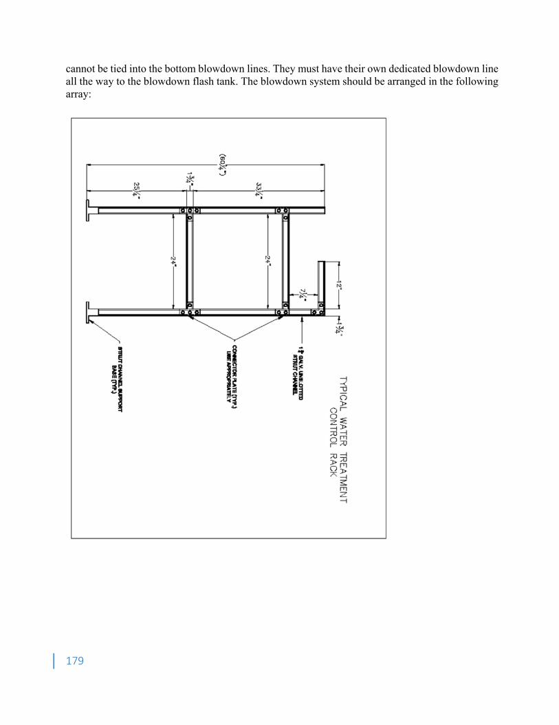
179
cannot be tied into the bottom blowdown lines. They must have their own dedicated blowdown line all the way to the blowdown flash tank. The blowdown system should be arranged in the following array:
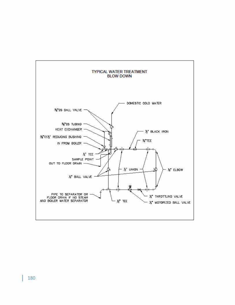
180
181
7.5.7. Install sample cooling stations on the following: • Each individual boiler • Feed Water • Combined condensate return 7.6. Water Softener Installation 7.6.1. Install water softener equipment on concrete bases, level and plumb. Maintain manufacturer's recommended clearances. Arrange units so controls and devices that require servicing are accessible. Anchor mineral and brine tanks and floor mounting accessories to substrate. 7.6.2. Install brine lines and fittings furnished by equipment manufacturer but not factory installed. Install sample point for water treatment testing purposes on the leaving side of the water softener. 7.6.3. Prepare mineral-tank distribution system and under-bed for minerals and place specified mineral into mineral tanks. 7.6.4. Install water-testing sets on wall adjacent to water softeners. 7.7. Connections 7.7.1. Piping installation requirements are specified in other Division 15 Sections. 7.7.2. Drawings indicate general arrangement of piping, fittings, and specialties. 7.7.3. Install piping adjacent to equipment to allow service and maintenance. 7.7.4. Make piping connections between HVAC water-treatment equipment and dissimilar-metal piping with dielectric fittings. Dielectric fittings are specified in Division 15 Section "Basic Mechanical Materials and Methods." 7.7.5. Install shutoff valves on HVAC water-treatment equipment inlet and outlet. Metal general-duty valves are specified in Division 15 Section "Valves." 7.7.6. Refer to Division 15 Section "Domestic Water Piping Specialties" for backflow preventers required in makeup water connections to potable-water systems. 7.7.7. Confirm applicable electrical requirements in Division 16 Sections for connecting electrical equipment. 7.7.8. Ground equipment according to Division 16 Section "Grounding and Bonding." 7.7.9. Connect wiring according to Division 16 Section "Conductors and Cables." 7.8. Field Quality Control 7.8.1. Manufacturer's Field Service: Engage a factory-authorized service representative to inspect, test, and adjust components, assemblies, and equipment installations, including connections. Report results in writing. 7.8.2. Tests and Inspections: • Inspect field-assembled components and equipment installation, including piping and electrical connections. • Inspect piping and equipment to determine that systems and equipment have been cleaned, flushed, and filled with water, and are fully operational before introducing chemicals for water-treatment system. • Place HVAC water-treatment system into operation and calibrate controls during the preliminary phase of HVAC systems' startup procedures. • Do not enclose, cover, or put piping into operation until it is tested and satisfactory test results are achieved. • Test for leaks and defects. If testing is performed in segments, submit separate report for each test, complete with diagram of portion of piping tested.
182
• Leave uncovered and unconcealed new, altered, extended, and replaced water piping until it has been tested and approved. Expose work that has been covered or concealed before it has been tested and approved. • Cap and subject piping to static water pressure of 50 psig above operating pressure, without exceeding pressure rating of piping system materials. Isolate test source and allow test pressure to stand for four hours. Leaks and loss in test pressure constitutes defects. • Repair leaks and defects with new materials and retest piping until no leaks exist. 7.8.3. Remove and replace malfunctioning units and retest as specified above. 7.8.4. Sample boiler water at one-week intervals after boiler startup for a period of five weeks, and prepare test report advising Owner of changes necessary to adhere to Part 1 "Performance Requirements" Article for each required characteristic. Sample boiler water at four-week intervals following the testing noted above to show that automatic chemical-feed systems are maintaining water quality within performance requirements specified in this Section. 7.8.5. Comply with ASTM D 3370 and with the following standards • Silica: ASTM D 859. • Steam System: ASTM D 1066. • Acidity and Alkalinity: ASTM D 1067. • Iron: ASTM D 1068. • Water Hardness: ASTM D 1126 7.9. Demonstration 7.9.1. Engage a factory-authorized service representative to train Owner's maintenance personnel to adjust, operate, and maintain HVAC water-treatment systems and equipment. Refer to Division 1 Section "Demonstration and Training." 7.9.2. Training: Provide a "how-to-use" self-contained breathing apparatus video that details exact operating procedures of equipment. 8. Evaporative Cooling Water Systems – General 8.1.Submittals 8.1.1. Shop Drawings • Schematic piping and chemical equipment layout. • Identify connection points to condenser/cooling tower water piping system. • Provide product data for all chemical treatment materials, chemicals and equipment. Product data shall include chemical explanation, MSDS, layouts of feeding equipment and equipment detail sheets. • Detailed cleaning and passivation procedures. 8.2. Quality Assurance 8.2.1. Retain the resources of the chemical water treatment contractor who is already under contract with the client. 8.2.2. The water treatment chemical and service supplier shall be a recognized specialist, active in the field of industrial water treatment for at least five years, whose major business is in the field of water treatment, and who has full time service personnel within the area of the job site. Laboratory facilities shall be available. Service personnel shall be degreed specialists in the fields of mechanical or chemical engineering or chemistry. 8.2.3. Furnish and install all equipment and material on this project in accordance with the requirements of the authority having jurisdiction, suitable for its intended use on this project, approved by the U.S. Environmental Protection Agency (EPA), and local Department of Environmental Protection, and so certified by the manufacturer.
183
8.2.4. If not already known, analyze the water from the local water supplier to be used on the project, before establishing treatment procedures. 8.2.5. The pre-cleaning sequence will not be deemed completed until fully signed off. 8.3. Safety 8.3.1. All chemical and analytical reagents supplied by the vendor shall meet all applicable government regulations. The bidders shall submit a MSDS for all proposed products with the initial technical proposal. The vendor shall be responsible for providing up to date MSDS for all chemicals supplied including reagents. 8.3.2. The mechanical contractor shall be responsible for the safe cleanup of any chemical spills relating to products supplied by the vendor and caused by failure or malfunction of the chemical feed equipment or due to the actions of the field service personnel. Cleanup shall be performed in accordance with all current government regulations and good safety practices. Vendor shall maintain a 24 hour hot line for emergency situations. Bidder shall provide the phone number and procedure to access the hot line including estimated response time in the event of an emergency. 8.4. Technical Services 8.4.1. Mechanical contractor shall be responsible for handling of all water treatment chemicals. 8.4.2. All chemical deliveries shall be made to the point of use by the vendor or an ahead of time agreed upon location such as the mechanical contractors lay down yard. The contractor shall remove, following local, state and federal governances all chemical containment systems as instructed by the vendor. 9. Evaporative Cooling Water Systems – Products 9.1. General 9.1.1. Accepted Manufacturers 9.1.1.1.Chemical Feed Pumps • Base: Prominent Concept Plus • Optional: LMI or Neptune 9.1.1.2.Controllers • Base: Prominent/Aquatrac or GE Water and Process Technologies. • Optional: Walchem or LMI. 9.2. Cooling Tower Treatment System 9.2.1. Cooling Tower Water Treatment System - Prefabricated, integrated electronic control system for cooling tower water circuit to monitor and control total dissolved solids, corrosion inhibitors, and biocides. 9.2.2. Controller: Microprocessor based type for use in recirculating cooling tower water systems. • Accurately control level of total dissolved solids (TDS) in terms of electrolytic conductivity. • Provide a programmable twenty-eight (28) day biocide timer for accurate addition of algaecide. • Provide for proportional feed of inhibitor, and/or dispersant chemicals based upon make-up water as measured by a contacting head water meter. 9.3. Main Control Panel and Accessories 9.3.1. Housed in a NEMA Type 4X enclosure. • Hinged key Jock door with viewing window. • 2440 mm8 FT, 3-wire power cord with molded plug. • Provide minimum of three (3) 115V, Single Phase, 60 Hz receptacles located on enclosure for electrical connection and control of chemical pumps. • Prewired for ease of installation. 9.3.2. Provide an external combination mounted flow switch
184
• Disable control outputs upon loss of water flow to prevent chemical feeding. • Provide complete with 3/4 IN connections and combination conductivity and temperature electrode. • Keypad or remote control: Access all measurements and set points through chemical resistant key pad or remote. • Security code to prevent unauthorized access. • Utilize microprocessor technology. • Menu driver programs. • Liquid crystal display (LCD). • Provide temperature corrected measurements (Range: 0-100 0C with an adjustable high alarm) by reading water temperature and adjusting conductivity values according to known temperature curve. • Provide real-time clock. • Conductivity /monitor. • Provide linear measurements of full range. • Provide two scales for selection of high and low in field to assure accurate measurements. • Provide increments of one (1) micro Mohs with adjustable hysteresis. • Provide bleed-off control in following manner o Standard operation-controller actuates a bleed off solenoid valve when dissolved solids level is exceeded by trip point. o Provide an adjustable bleed limit timer to prevent excessive bleed off. o An alarm contact shall close when timer has timed out. • Biocide operation o Provide a secondary bleed off timer to lower conductivity in system prior to biocide feed. o Lock out cooling water bleed-off during biocide feed period. • Chemical feed control: Provide three biocide timers and one inhibitor control algorithm capable of operating in the following field programmable mode. o Counter-timer-chemical feed proportioned to make-up water rate. o Controller shall send and / or receive low voltage signal to a contacting head water meter. o Low voltage signal will ensure long contact life. oWater meter shall read in gallons. o Provide alarm LEDs with silence button for high and low conductivity, ten (10) to sixty (60) minute bleed-off, chemical feed limit timers and chemical drum level. Provide remote output relay to indicate alarm condition to Building Management and Control System (BMCS). o Controller operating data history
・ Retain in memory all operating data for following parameters:
・ Standard memory shall allow acquisition and storage of all analog inputs for a one-week period.
・ A three (3) hour minimum, maximum average of all conditions shall be stored for a one-week period.
・ A minute-by-minute account of operating conditions shall be available for latest three-hour period. o Electrode: Combination temperature and conductivity type.
・ Quick disconnect.
185
・ Supplied in flow switch assembly.
o pH monitor
・ Sensor for monitoring purposes only.
・ Acid shall not be used to control pH.
oWater meters
・ Meters provided by owner, installed by contractor.
・ Provide meters at cooling tower make up and bleed lines.
oSingle phase, variable frequency drive chemical pumps shall be provided. 9.4. Positive Displacement Type Pump 9.4.1. Provide with anti-siphon/pressure relief valve installed on pump head which provides anti-siphon protection and aids in priming under pressure. 9.4.2. Capacity: As determined by Water Treatment Vendor. 9.4.3. Complete with discharge check valves, foot valves, polyethylene suction, and discharge tubing. 9.4.4. Provide a non-metallic shelf to mount chemical pumps. 9.4.5. Discharge tubing shall be routed from the chemical storage area to the tower return line or to the tower basin for adequate mixing 9.4.6. Quantity: Two (2) to four (4) based on chemicals chosen by Water Treatment Vendor. 9.5. Bleed-off piping assembly. 9.5.1. Inlet shut-off valve. 9.5.2. Wye strainer. 9.5.3. Strainer blowdown valve. 9.5.4. Throttling valve. 9.5.5. Brass solenoid valve compatible with main control panel. 9.5.6. Assembly shall be sized by Water Treatment Vendor. 9.6. Chemical storage containers with secondary containment 9.6.1. Material: Polyethylene. 9.6.2. Container capacity: Sixty (60) gallon each (minimum). 9.6.3. Provide each secondary containment pallet with grating and drain plug. Size shall be Sufficient to accommodate all three containers and have sufficient volume to contain the contents of one container. 9.6.4. Provide one portable loading ramp. 9.6.5. Container quantity: Two (2) to Four (4) Determined by Water Treatment Vendor. 9.7. Provide liquid level switch assemblies to mount directly into chemical drums. 9.7.1. Interface with main control panel. 9.7.2. Quantity: Two (2) to Four (4) Determined by Water Treatment Vendor. 9.8. Corrosion monitor rack 9.8.1. Materials: Corrosion resistant. 9.8.2. Construction: ASME specifications. 9.8.3. Number of coupons: Four (4). 9.8.4. Coupon holders: Quick disconnect type. 9.9. Provide two (2) to four (4) CPVC corporation stop injection nozzles if chemical are to be injected into tower supply header. Water Treatment Vendor to determine total number required.
186
9.10. Provide test kits for monitoring inhibitor levels, total dissolved solids, chlorides, alkalinity and closed system inhibitors. 9.11. Provide one (1) year's supply of chemical treatment including quantity of chemicals necessary to chemically treat system to control scale, corrosion, and biological fouling. 9.12. Provide water treatment products that perform the following: 9.12.1. Inhibitor to protect against corrosion and scale formation. 9.12.2. Two liquid biocides for prevention of slime, bacteria, and algae. 9.12.3. Chromate based chemical are unacceptable. 9.12.4. Water treatment chemicals to remain stable throughout operating temperature range. 9.12.5. Are compatible with pump seals and other elements in the systems. 9.12.6. Provide pre-cleaning chemicals to remove system dirt, debris, and cutting oils from system for all condenser piping. Pre-cleaning materials to be non-acid in composition and not harmful to system metallurgy. 9.12.7. All chemicals to be acceptable for discharge to sanitary sewer. 10. Pre-Cleaning and Passivation of Cooling Towers 10.1. Pre-cleaning of closed-circuit cooling tower shall include removal of all accumulated debris and cleaning/flushing of spray section and open water basin. 10.2. Passivation of closed-circuit cooling tower shall include chemical treatment to provide a protective film coating of the spray section and open water basin. 11. Pre-Cleaning Of Condensers and Evaporators 11.1. Pre-cleaning of the condensers may occur simultaneously with the cleaning of the cooling towers, provided system metallurgy allows for this approach, (i.e no galvanized metals present). The final judgment will be made by the Western Carolina University Water Treatment Department, the Western Carolina University Plant Operations Group and the Water Treatment Vendor. 11.2. If simultaneous cleaning of the condenser and tower cannot occur, then the mechanical contractor is responsible for ensuring adequate chemical cleaning of the condenser following Western Carolina University’s standard closed loop pre-cleaning practices. 11.3. Pre-cleaning of the evaporator is to be performed by the mechanical contractor following Western Carolina University’s standard closed loop pre-cleaning practices. 12. Cooling Tower Connection 12.1. Installation 12.1.1. Install all systems and components in accordance with manufacturer's instructions and recommendations. 12.1.2. Provide all piping and wiring for a complete functional system. 12.1.3. All wiring shall be in metallic conduit complying with Electrical Specification Divisions. 12.1.4. Locate chemical feed pumps, chemical drums, and other components as field dictated based on available wall, floor space and proximity to re-circulating lines and floor drains. 12.1.5. Install impulse water meter at the following locations • Cooling tower make up piping. • Cooling tower blowdown line, upstream of blowdown solenoid valve. 12.1.6. Provide a by-pass line around water meters and bleed off piping assembly. Provide ball valves to allow for bypassing, isolation, and servicing of components. 12.1.7. Bleed off water piping with bleed off piping assembly shall be piped from pressure side of circulating water piping to a convenient drain. Bleed off connection to main circulating water piping shall be upstream of chemical injection nozzles.
187
12.1.8. Provide DN 251 IN Schedule 80 PVC piping for the flow assembly piping to the main control panel and accessories. • The inlet piping shall connect to the discharge side of the circulating water pump. • The outlet piping shall connect to the water piping serving the cooling tower downstream of the heat source. • Provide inlet PVC wye strainer and PVC ball valves to isolate and service main control panel and accessories. 12.1.9. Install PVC injection nozzles with corporation stops in the water piping serving the cooling tower downstream of the heat source. 12.1.10.Provide Schedule 80 PVC piping for corrosion monitor rack per manufacturer's installation instructions. Provide PVC ball valves to isolate and service rack. 12.1.11.Provide installation supervision, start-up, and operating instruction by manufacturer's technical representative. 12.1.12.Provide minimum of four hours instruction of Owner's personnel. 13. Pre-Cleaning and Passivation of Cooling Towers and/or Condensers 13.1. Contractor shall provide a minimum notice of fourteen (14) days to the water treatment vendor to allow for delivery of chemicals. 13.2. Contractor will notify the fourteen (14) days prior to filling and cleaning of new water pipes. The new piping system shall not be connected/operated until the chemical cleanup is performed. 13.3. Cleaning of condenser water systems cannot be performed until all piping is installed, leak tested and adequate re-circulation loops are installed to ensure adequate flow is obtained throughout the system. 13.4. Make sure all chemicals are on-site and that pH control is available. If possible the tower should be exposed to atmosphere for 4 to 6 weeks prior to start-up. 13.5. Pre-cleaning and passivation procedures shall not damage galvanized and stainless steel panels, structural components, fasteners, and all other elements of the cooling tower. 13.6. Pre-cleaning procedure shall include 13.6.1. Products Required • HPS-1 dispersant product to achieve 25 to 100 ppm active polymer. • HRA to achieve 8 to 20 ppm active HRA. • Non-oxidizing biocide to achieve 50 to 75 ppm as product. Do not exceed registered maximum as indicated on product label. • Surfactant at approximately 20 to 50 ppm as product — should provide oil/grease dispersancy as well as general surfactant properties. • Antifoam as needed. • If an oxidizing biocide is used at this point, keep levels at or below 1.0 ppm free residual chlorine. • Sulfuric acid may be required for pH control. 13.6.2. Procedure • Make sure that tower is full with fresh make-up water. Begin to circulate water through spray system. • Control pH in the 7.0 to 8.0 range. • Add chemicals to tower basin near pump screens shot wise to achieve desired concentrations. Add products in order as given above or minimally, add HPS-1 dispersant and HRA azole first. • Circulate for 24 hours. • Flush all traces of chemicals and any dispersed oils, etc. at this point.
188
• Immediately institute passivation/pre-filming procedure and avoid keeping precleaning solution in system for long periods of time. 13.7. Passivation/Pre-filming 13.7.1. For the first thirty (30) to sixty (60) days of system operation, control the system pH in the 7.0 to 8.0 range. 13.7.2. If an oxidizing biocide is used (chlorine or bromide based) keep free residual as chlorine below 1.0 ppm. 13.7.3. It is best to maintain standard high ortho phosphate, low phosphonate cooling water treatment programs during this time. Excessive phosphonate levels are detrimental to zinc coated surfaces. 13.7.4. Moderate calcium hardness levels of l00 to 300 ppm as CaCO3 and alkalinity levels of 50 to 150 ppm as CaCO3 are ideal during the 30 to 60-day passivation period. 13.7.5. Once the 60-day passivation period is complete, desired treatment technology can begin including programs that include higher cycles to achieve higher alkalinity and hardness levels. 14.Pre-Cleaning of Condensers and/or Evaporators Following Western Carolina University University’s Standard Closed Loop Pre-Cleaning Practices 14.1. Materials 14.1.1. Temporary Loop Strainer Screens: Fine mesh (3/64-inch maximum). 14.1.2. Cleaning and Sterilization Chemicals • Liquid alkaline compound with emulsifying agents and detergents to remove grease and petroleum products. Use GE Betz Ferroquest FQ7101 or equivalent. • Non-oxidizing biocide which has halogen like effects such as 2,2-dibromo-3- nitrilopropionamide, also known as DBNPA. Use GE Betz Spectrus NX108 or equivalent for chilled water systems only. 14.1.3. Condenser Water Treatment Chemical: GE Betz Genguard GN8020 or equivalent. 14.1.4. Evaporator Water Treatment Chemical: GE Betz Corrshield MD407 or equivalent. 14.2. Preparation 14.2.1. Contractor shall provide a minimum notice of fourteen (14) days to the water treatment vendor to allow for delivery of chemicals. 14.2.2. Contractor will notify the Western Carolina University Water Treatment Department fourteen (14) days prior to filling and cleaning of new water pipes. The new piping system shall not be connected/ operated until the chemical clean-up is performed. 14.2.3. Cleaning of condenser/evaporator water systems cannot be performed until all piping to be cleaned is installed, leak tested and adequate re-circulation loops are installed to ensure adequate flow is obtained throughout the system. 14.2.4. A temporary chemical by-pass feeder must be installed prior to the start of the cleaning sequence if the system is not cleaned in conjunction with distribution piping connecting to the building. 14.2.5. The cleaning process continues for a minimum of twenty-four (24) hours after the introduction of the cleaning agents and must be planned for in advance with the Western Carolina University Water Treatment Department. 14.2.6. The system pump must be fully operational to maintain steady output at 75 – 100% of design capacity throughout the cleaning process. 14.2.7. If the system pumps are not operational, the mechanical contractor must provide a pump capable of producing similar flows to that of the system or the table as outline below.
189
MINIMUM CLEANING WATER
Pipe Size (in) Flow (gpm) 2 45 4 100 6 250 10 500 14 960 15 thru 30 1,250
14.3. Cleaning Sequence 14.3.1. Under no circumstance shall the condenser/evaporator remain untreated for more than one week after initial filling. 14.3.2. All water shall be metered into the pipe and amounts shall be tabulated and given to Owner's representative to indicate the volume of water inside the building. Pipe quantities and sizes shall also be tabulated to verify piping is filled completely. 14.3.3. Install temporary building strainers on supply piping entering the building to prevent damage to building isolation valve seats and discs. 14.3.4. Force all automatic valves and ball valves into the open position at all air handlers, system heat exchangers and expansion tanks. Ensure the system is filled with water and vented of air and initiate system pumps at 75 – 100% of flow capacity. 14.3.5. During the cleaning, at no time shall the circulation pump be shut off except in the event of an emergency. If for some reason the system pump cannot be used for circulation purposes, the mechanical contractor must provide a temporary pump that has similar flow and pressure capacities to that of the system pump. 14.3.6. Monitor pressure drop across the temporary strainer screen and clean as necessary to maintain the recommended pipe velocity as directed by the Owner's Representative. 14.3.7. Two twelve (12) ounce bottles of the system water shall be taken for laboratory analysis prior to the start of the addition of cleaning chemical or flushing. Western Carolina University Water Treatment Department will be responsible for providing the sample bottles to the mechanical contractor. 14.3.8. Cleaner and biocide, when required, shall be added to piping at concentration as recommended by Owners representative following the hydro test. A water volume equal to the calculated amount of cleaner to be added shall be drained from the pipe to allow for addition of cleaner. 14.3.9. Circulate the solution for 24 hours or as recommended by the Owner's representative, whichever is less. Cleaner shall be circulated at 75 – 100% of system pump capacity. 14.3.10. Twenty-four (24) hours following the start of the cleaning process, two twelve (12) ounce bottles of system water shall be gathered for laboratory analysis. 14.3.11.Following cleaning, drain systems as quickly as possible. This should be done by means of draining water to a nearby floor drain and adding clean domestic water through a make-up system or by hosepipe. The draining water should not exceed the amount being made up. The system pump remains on during this time and all valves remain in the forced open position. 14.3.12. Two twelve (12) ounce bottles of system water shall be gathered for laboratory analysis following city water flushing.
190
14.3.13.Following cleaning remove all temporary bypasses and screens, and install all instruments and controls as required. 14.4. Water Treatment 14.4.1. Within twenty-four (24) hours following the completion of the cleaning sequence, the water treatment chemicals will be added and circulated as recommended by the Owner’s Representative or system water from the primary distribution system will be introduced to the building system. 14.4.2. After addition of water treatment chemicals or distribution water, the system pump will remain on line for an additional eight (8) hours, or less if deemed acceptable by the Owner’s Representative to ensure a good blend of corrosion inhibitor throughout the entire system. During this time, it is imperative that all valves which have been previously forced to the open position remain this way. 14.4.3. Following eight (8) hours or less of circulation, two additional twelve (12) ounce samples will be taken for laboratory analysis. At this point, the system pumps can be shut down. 14.4.4. If for any reason water is drained from the loop after the water treatment chemical is added, Western Carolina University Water Treatment Department and/or the Owner’s Representative will be notified immediately so that action can be taken to prevent corrosion in the system.
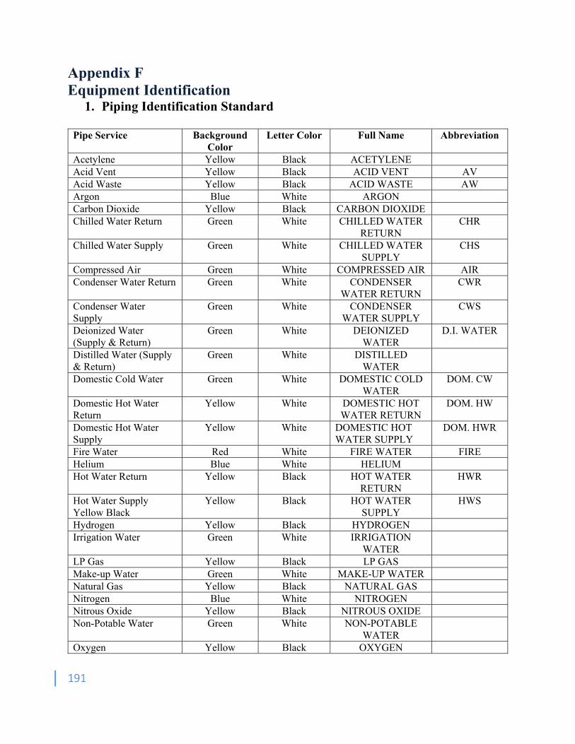
191
Appendix F Equipment Identification
1. Piping Identification Standard
Pipe Service Background Color
Letter Color Full Name Abbreviation
Acetylene Yellow Black ACETYLENE Acid Vent Yellow Black ACID VENT AV Acid Waste Yellow Black ACID WASTE AW Argon Blue White ARGON Carbon Dioxide Yellow Black CARBON DIOXIDE Chilled Water Return Green White CHILLED WATER
RETURN CHR
Chilled Water Supply Green White CHILLED WATER SUPPLY
CHS
Compressed Air Green White COMPRESSED AIR AIR Condenser Water Return Green White CONDENSER
WATER RETURN CWR
Condenser Water Supply
Green White CONDENSER WATER SUPPLY
CWS
Deionized Water (Supply & Return)
Green White DEIONIZED WATER
D.I. WATER
Distilled Water (Supply & Return)
Green White DISTILLED WATER
Domestic Cold Water Green White DOMESTIC COLD WATER
DOM. CW
Domestic Hot Water Return
Yellow White DOMESTIC HOT WATER RETURN
DOM. HW
Domestic Hot Water Supply
Yellow White DOMESTIC HOT WATER SUPPLY
DOM. HWR
Fire Water Red White FIRE WATER FIRE Helium Blue White HELIUM Hot Water Return Yellow Black HOT WATER
RETURN HWR
Hot Water Supply Yellow Black
Yellow Black HOT WATER SUPPLY
HWS
Hydrogen Yellow Black HYDROGEN Irrigation Water Green White IRRIGATION
WATER
LP Gas Yellow Black LP GAS Make-up Water Green White MAKE-UP WATER Natural Gas Yellow Black NATURAL GAS Nitrogen Blue White NITROGEN Nitrous Oxide Yellow Black NITROUS OXIDE Non-Potable Water Green White NON-POTABLE
WATER
Oxygen Yellow Black OXYGEN
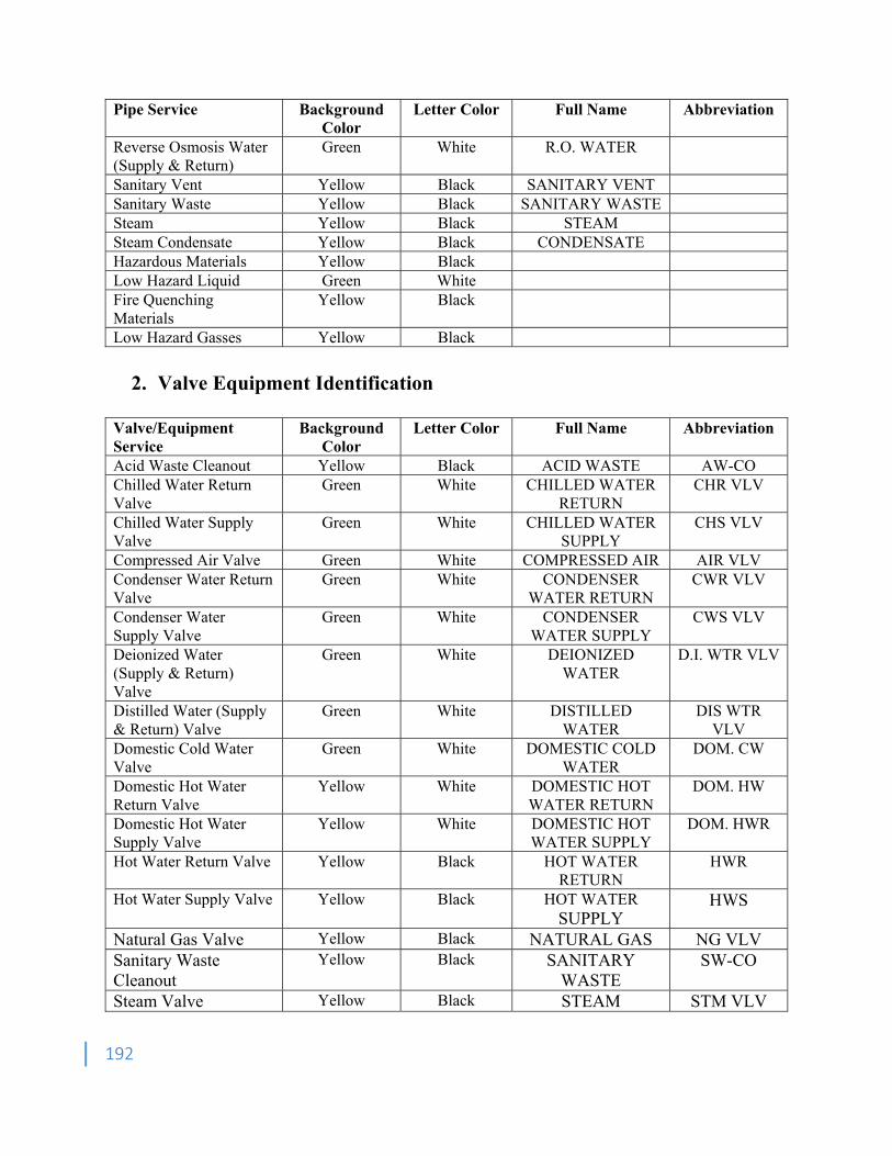
192
Pipe Service Background Color
Letter Color Full Name Abbreviation
Reverse Osmosis Water (Supply & Return)
Green White R.O. WATER
Sanitary Vent Yellow Black SANITARY VENT Sanitary Waste Yellow Black SANITARY WASTE Steam Yellow Black STEAM Steam Condensate Yellow Black CONDENSATE Hazardous Materials Yellow Black Low Hazard Liquid Green White Fire Quenching Materials
Yellow Black
Low Hazard Gasses Yellow Black
2. Valve Equipment Identification
Valve/Equipment Service
Background Color
Letter Color Full Name Abbreviation
Acid Waste Cleanout Yellow Black ACID WASTE AW-CO Chilled Water Return Valve
Green White CHILLED WATER RETURN
CHR VLV
Chilled Water Supply Valve
Green White CHILLED WATER SUPPLY
CHS VLV
Compressed Air Valve Green White COMPRESSED AIR AIR VLV Condenser Water Return Valve
Green White CONDENSER WATER RETURN
CWR VLV
Condenser Water Supply Valve
Green White CONDENSER WATER SUPPLY
CWS VLV
Deionized Water (Supply & Return) Valve
Green White DEIONIZED WATER
D.I. WTR VLV
Distilled Water (Supply & Return) Valve
Green White DISTILLED WATER
DIS WTR VLV
Domestic Cold Water Valve
Green White DOMESTIC COLD WATER
DOM. CW
Domestic Hot Water Return Valve
Yellow White DOMESTIC HOT WATER RETURN
DOM. HW
Domestic Hot Water Supply Valve
Yellow White DOMESTIC HOT WATER SUPPLY
DOM. HWR
Hot Water Return Valve Yellow Black HOT WATER RETURN
HWR
Hot Water Supply Valve Yellow Black HOT WATER SUPPLY
HWS
Natural Gas Valve Yellow Black NATURAL GAS NG VLV Sanitary Waste Cleanout
Yellow Black SANITARY WASTE
SW-CO
Steam Valve Yellow Black STEAM STM VLV
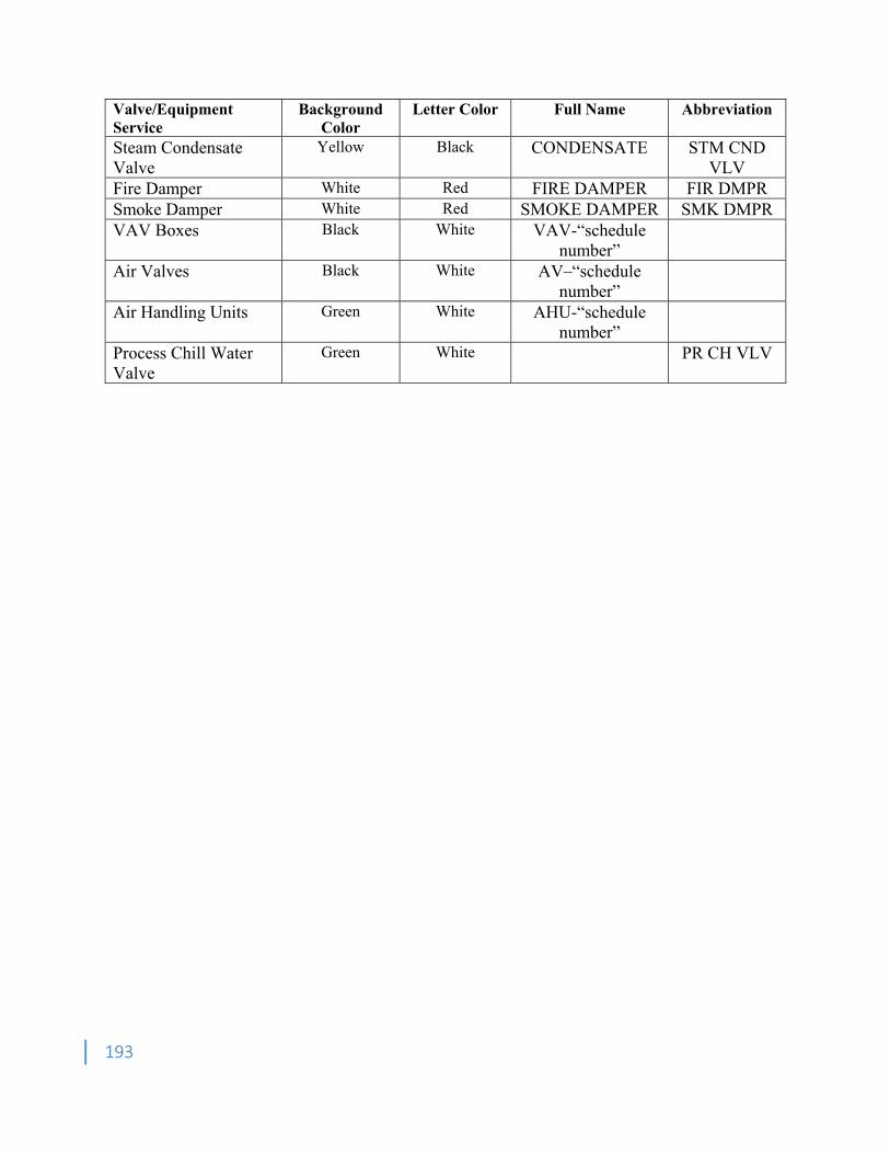
193
Valve/Equipment Service
Background Color
Letter Color Full Name Abbreviation
Steam Condensate Valve
Yellow Black CONDENSATE STM CND VLV
Fire Damper White Red FIRE DAMPER FIR DMPR Smoke Damper White Red SMOKE DAMPER SMK DMPR VAV Boxes Black White VAV-“schedule
number”
Air Valves Black White AV–“schedule number”
Air Handling Units Green White AHU-“schedule number”
Process Chill Water Valve
Green White PR CH VLV
194
Appendix G Security, Access Control & Door Hardware 1. General 1.1. This Appendix does not provide a solution for every type of opening that may occur on the
Project. The Designer shall become familiar with, and interpret this section of the Design and Construction Standards in accordance with the programmatic requirements of the Project. If variations are recommended, these shall be reviewed and approved by the UPL, prior to inclusion into the Bid Documents.
1.2. Access Control System and Card Access System shall be Lenel OnGuard. This is a Sole-Source system. Substitutions are not acceptable.
1.3. Although a Security Consultant may be retained, the scope of work shall be provided by the Designer.
1.4. Access Control and Security requirements for each project shall be evaluated and determined by the Project Delivery Team during the Schematic Design Phase.
1.5. Buildings shall be equipped with card access. 1.6. Card readers shall be provided in the following locations: 1.6.1. Main [ADA-compliant] entrance along the accessible route 1.6.2. Secondary entrances 1.6.3. Classrooms in excess of 100 seats 1.6.4. Multimedia/Control Rooms 1.6.5. Computer Laboratories 1.6.6. Classroom and Research Laboratories 1.6.7. IT/Telecommunication Closets 1.6.8. Mechanical/Electrical Rooms 1.6.9. Exterior openings to a single room with an interior door 1.6.10. Other such vital infrastructure spaces 1.6.11. Additional openings may be provided with card readers, if desired by the Project Delivery
Team 1.7. All doors without card readers shall be monitored. 1.8. Card access control panel(s) for all access-controlled openings shall be located in a single
IT/Telecommunications Room. This room may be located up to 250’ from the opening. 1.9. Single-leaf door openings are preferred to double-leaf door openings. If double-leaf door
openings are required by the project, a keyed removable mullion shall be provided. 1.10. Exterior doors shall be provided with Electrified Panic Hardware and shall be monitored by
the Access Control System. An exterior opening which is not hinged, such as a large sliding, overhead coiling or similar opening shall be monitored.
1.11. If aluminum storefront systems are specified, only wide-stile doors are acceptable. Provide a 12” bottom rail on aluminum storefront doors.
1.12. All cable shall be in minimum 3/4" conduit from door to cable tray and from cable tray to head-end panels. Home run conduit from junction box to security panel shall be minimum 1” conduit. All conduit and cable shall be concealed.
1.13. All cable shall be shielded and plenum rated.
195
2. Security 2.1. General 2.1.1. This document provides internal policy, guidance and considerations for integrating
physical security in all Western Carolina University owned, managed, or occupied buildings. Security shall be an integral consideration in the selection and development of both new building sites and renovation projects. The guidelines in this Appendix set forth minimum security features and arrangements that are required for all campus buildings and facilities.
2.1.2. Security design, including drawings and specifications, shall include, but not be limited to the physical, electrical and/or electronic, CCTV, and mechanical security design details. Bid Documents shall be signed and sealed by the North Carolina Licensed Professional who prepared them.
2.1.3. Security infrastructure components shall not be located in Custodial Closets, Mechanical Rooms or Electrical Rooms. All equipment shall be located in the Telecommunications Closet.
2.1.4. The Designer shall develop the set of construction documents for a turn-key security package, including all scope items required to meet this Standard.
2.2. Definitions 2.2.1. CCTV Maintenance Agreement Vendor/Contractor – the entity responsible for the
integration of the security system. This entity is referred to as the Integrator. 2.2.2. Contractor – the entity responsible for the installation of the security system. This entity is
referred to as the Installer and may be a prime contractor, or a subcontractor. 2.2.3. Executive Director, Public Safety & Security (EDPSS) – the Western Carolina University
entity responsible for determination of the Threat Level of the project, evaluation of the Security Assessment and management of the systems and contract with CCTV Maintenance Vendor/Contractor.
2.2.4. Installation – the efforts required to install the security system in the project: • Devices shall be installed with credentials set to factory defaults. • Cameras shall be pointed, aimed, focused and flashed. • Switches shall be HP ProCurve and accommodate 20% growth. • Switches shall be flashed. • Pathways, wiring and connections to each device within the project scope. • Provide server(s) for installation by Integrator.
2.2.5. Integration – the efforts required to connect the installed security system to the Western Carolina University system backbone: • Provide IP addresses for each device to the Installer. • Install server(s) at the Campus Security Operations Center (CSOC). • Install software on the new server(s). • Program recording equipment. • Program alarm equipment. • Service and maintain the equipment installed at the CSOC.
2.2.6. Office of Information Technology (OIT) – the Western Carolina University office responsible for material, installation, cost estimate, and maintenance of the following components for the system: • Campus fiber network • Fiber connections within building from IT closet to IT closet
196
• Fiber jumpers as required for CCTV installations • UPS for network switches in building required for CCTV installations • Space in IT closet switch racks for CCTV switches • Identification and marking of fiber cables
2.2.7. Security Assessment – a written document that describes the Designer’s response to the Threat Level that has been assigned to the project. The Security Assessment shall be included in the Schematic Design Submission, and updated as the project is developed.
2.2.8. Security Consultant – if retained by Owner or Designer, this consultant may provide the Security Assessment, recommend the scope of work, review the design to ensure that recommended scope is adequately captured in the design/bid/construction documents and/or provide commissioning services for the security systems.
2.3. Facility Threat Level (TL) Designation 2.3.1. General
• The level of security required will be dependent on the function of the facility and of specific space within the facility. • Final determination of the required level(s) of security shall be coordinated by the UPL.
2.3.2. Designations • TL-1 General – All campus buildings and facilities, not otherwise defined below. • TL-2 Confidential – Buildings, or spaces within buildings or facilities in which information of a confidential nature is stored or otherwise maintained. This category includes, but not limited to, human resources file rooms; student records rooms or other areas regulated by the Family Education Rights and Privacy Act and areas housing proprietary research or sensitive operational information. • TL-3 Known Threat – Areas, buildings or other spaces known to be, or logically assumed to be, targeted for destruction, disruption, or vandalism by extremist individuals or groups, as well as areas of specific safety concern to students, faculty, visitors, or staff. These areas include, but not limited to, the College of Veterinary Medicine, buildings which house controlled substances, student dormitories, and certain parking areas and walkways. • TL-4 Hazardous Materials & Bio-Safety Level 3 and above Laboratories – Areas used for storage or utilization of hazardous chemicals or materials, and laboratories known to or intended to house potentially dangerous biological agents.
2.4. Security Hardware 2.4.1. Site Security:
• Structural barriers such as bollards and fencing shall be installed at the primary and secondary entrances to new buildings to prevent vehicular approaches and intrusions. Refer also to G20 Site Improvements for additional requirements. • Landscaping shall be selected and placed in such a manner that opportunities for concealment are minimized. • TL-1 – no additional requirements. • TL-2 – comply with TL-1. • TL-3 – comply with TL-2 and provide locking gates to separate off-limits areas to the general public. • TL-4 – comply with TL-3.
2.4.2. CCTV (Closed Circuit Television):
197
• CCTV equipment shall be compatible with existing video and access control security integration system. CCTV equipment shall be compatible with Genetech Omnicast Video Management software. • CCTV cameras shall have sufficient resolution and be located such that recognizable images of individuals are captured by the CCTV system. • Provide dedicated electrical circuit(s) on emergency or back-up power system for the CCTV system. • CCTV systems shall have capability of being viewed and recorded at each facility and/or transmitted to the Campus Security Operations Center (CSOC) for viewing and recording. • CCTV equipment shall be manufactured by one of the following manufacturers:
o Axis o Pelco o Bosch
• CCTV cameras shall either be “fixed” or “pan-tilt-zoom” type (PTZ). PTZ cameras shall have an alarm output, thereby allowing the camera to be viewed automatically when a signaling hardware element is annunciated, such as an emergency phone or access control door hardware. • TL-1 – install CCTV cameras in the following locations:
o Coverage of the entire Loading Dock. o Ground level openings.
• TL-2 – comply with TL-1, plus provide CCTV camera(s) in storage rooms. • TL-3 – comply with TL-2, plus provide CCTV camera(s) in parking lots, parking decks, roadway entrances, walkways and stairwells. • TL-4 – comply with TL-3, plus provide CCTV camera(s) viewing hazmat and/or biological safety cabinets and laboratory storage areas.
2.4.3. Locks and Access Control • TL-1 – refer to Section 3, Door Hardware. • TL-2 – comply with TL-1, plus provide card access at openings into confidential spaces. • TL-3 – comply with TL-1, plus provide card access at openings into known threat spaces, excluding student sleeping units. • TL-4 – comply with TL-1, plus provide card access at openings into HazMat/BSL3 spaces.
2.4.4. Lighting: • Refer to Design and Construction Standard D50 Electrical and G40 Site Electrical Utilities for additional lighting requirements. • TL-1 – in areas covered by CCTV cameras, provide minimum lighting levels recommended by the CCTV camera manufacturer. • TL-2 – comply with TL-1. • TL-3 – TL-1, plus additional exterior lighting in pedestrian and vehicular areas. • TL-4 – comply with TL-1; provide emergency/back-up power on interior lighting.
2.4.5. Alarms: • System shall be capable of integration with campus security and access control systems and be capable of being monitored at CSOC. • TL-1- TL-4 – as determined by the Project Team.
2.4.6. Emergency Telephone Systems: • Emergency phones shall be provided by the Owner. Refer to Appendix M.
198
• Locate emergency telephone systems and required infrastructure at the following locations:
o Building exterior within 100 feet of the main entrance(s). o Each parking lot. o Each level of parking decks adjacent to egress stairway(s).
2.4.7. Building Miscellaneous Security: • Roof access hatches shall be locked at all times from the inside, and electronically monitored through the access control system. • All windows within 6’ of the grade plane shall open 6”, maximum. • TL-1 – no additional requirements. • TL-2 – compartmentalize spaces from public-use areas. • TL-3 – comply with TL-2. • TL-4 – comply with TL-2; elevators and stairwells shall be capable of limiting access.
3. Door Hardware 3.1. General 3.1.1. Preferred manufacturer for door hardware is Corbin Russwin unless noted otherwise in this
section. 3.1.2. Finishes for door hardware shall match either US26D or 626, consistently throughout the
project. On renovation projects, other finishes may be submitted to the UPL for review, if matching the existing finishes is desired.
3.1.3. Permanent cores shall be provided by the Contractor. Provide Stanley Best cores for Residential Living projects and Corbin Russwin for Academic projects. Construction cores during the construction phase. Near the end of the project, WCU FM will remove the construction cores, install the permanent cores and return the construction cores to the Contractor. WCU FM shall develop the final keying schedule prior to purchasing and delivery of the permanent cores.
3.2. Access Control Hardware 3.2.1. Access Control hardware shall be provided by the following:
• Von Duprin 3.2.2. Locksets shall accept Best 7-pin or Corbin Pyramid interchangeable cores and cylinders. 3.2.3. Card readers shall be Allegion/Schlage AD series. 3.2.4. Proximity readers shall be Allegion AptiQ Multi-Technology. 3.2.5. Electrified panic hardware shall be Von Duprin 99 Series Rim Device with night latch (NL),
electric latch retraction (EL) and request to exit (RX). Manual/key latching or cylinder dogging is not acceptable.
3.2.6. Automatic door operators, if used, shall be Nabco GT500/GT8500. Substitutions are not acceptable. If an automatic door operator is used on any card access door, the door shall have both card reader and proximity reader tied into the Access Control System.
3.2.7. All doors and frames shall be prepped for EPT-10 (Electric Power Transfer) when electrified hardware is present.
3.2.8. Control post, if used for housing an automatic door operator pushbutton, card reader or proximity reader, shall be Wikk Ingress’s, model I36-3 US32D, with 6” x 6” x 48” tall bollard, Stainless Steel finish. Bollard shall be factory-prepped for both card and proximity readers.
199
3.2.9. The programming and configuration to the access control system shall be by the Contractor with system integration by the Western Carolina University manufacture-certified installer.
3.3. Hinges 3.3.1. Hinges shall be provided by one of the following:
• Hager • McKinney • Stanley
3.3.2. Continuous gear-type hinges, manufactured of extruded 6063-T6 aluminum alloy/temper and consisting of three interlocking extrusions in a pin-less assembly applied to the full height of the door and frame, shall be provided at all exterior openings. Finish to match door.
3.3.3. Butt hinges shall be manufactured to template screw locations and be non-handed. 3.3.4. Thrust bearings shall carry the vertical loads and be completely concealed by the gear cap
the full length of the hinge. 3.3.5. Hinges shall comply with ANSI A156, Grade 1. 3.4. Mechanical Locks and Latches 3.4.1. Locksets shall be provided by the following:
• Stanley Best cores for Residential Living projects • Corbin Russwin for Academic projects
3.4.2. Locksets shall accept Best 7-pin or Corbin Pyramid interchangeable cores and cylinders. 3.4.3. Plastic parts in locksets are not acceptable. 3.4.4. If specified, mortise-type locksets shall comply with ANSI A156, Grade 1, with 3/4 inch
throw latch bolt. Inside trim shall include a turn lever to permit egress when door is locked. 3.4.5. Mortise cylinders shall have a concealed internal set screw for securing the cylinder to the
body. Corbin Russwin ML2000 series shall be provided. 3.4.6. Deadbolts shall be constructed of hardened stainless steel and shall extend a minimum of 1”
into the door casing, beyond the door strike. Levers shall be operated with a roller bearing spindle hub mechanism. The use of dead bolts shall be approved by UPL.
3.4.7. Latchbolts shall extend a minimum of 3/8” into the door casing, beyond the door strike. 3.4.8. Furnish locksets with sufficient curved strike lip to protect door trim. 3.4.9. Locksets to have self-aligning, thru-bolted trim. 3.4.10. Auxiliary dead latches shall be constructed of one piece hardened stainless steel,
permanently lubricated. 3.4.11. Lever handles shall be forged of cast brass, bronze, or stainless steel and shall conform to
ANSI A117.1. Hollow cavity levers are not acceptable. 3.5. Panic Hardware 3.5.1. Panic hardware shall be Von Duprin, 99 Series Rim Device. 3.5.2. Exterior doors shall be equipped with Electrified Panic Hardware. 3.5.3. Outside trim shall be pull without a movable handle. Vertical rod devices are not acceptable. 3.5.4. Panic hardware shall be UL listed for Accident Hazard. 3.5.5. Panic hardware in a fire-rated assembly shall bear factory installed UL listing for specified
rating. 3.5.6. Panic hardware on doors with card readers shall also be keyed. Keys shall not be provided
on exterior doors without card readers. 3.5.7. Panic hardware shall have a three-year warranty. 3.6. Door Closers
200
3.6.1. Closers shall be provided by Hagar 5100 series 3.6.2. Closers shall be mounted on interior side of space/room. Closer shall be mounted in an
inverted overhead position or in a parallel arm position. 3.6.3. Closers shall be equipped with “delayed-action” feature. 3.6.4. Closers shall be equipped with “back-check” feature. 3.7. Operating Trim 3.7.1. Door Operating Trim shall be provided by one of the following:
• Glynn-Johnson • McKinney • Rockwood
3.7.2. Flush and surface bolts shall comply with ANSI A156, Grade 1. 3.7.3. Coordinators shall comply with ANSI A156, Grade 1. 3.7.4. Where through-bolts are used to attach hardware to doors, spacer sleeves in doors shall be
provided to prevent collapse of the door. 3.7.5. Thru-bolt fasteners shall be templated so as not to make contact with the frame assembly. 3.8. Architectural Trim 3.8.1. Architectural Trim shall be provided by one of the following:
• Glynn-Johnson • McKinney • Rockwood
3.8.2. Metal protection plates shall comply with ANSI A156, Grade 1. Provide .050 stainless steel plate with four beveled edges, door leaf width, less 2” for a single door, less 1” for pairs of doors. Provide 8” height kick- and 34” for armor-plate.
3.8.3. Furnish screws to match finish. 3.9. Door Stops and Holders 3.9.1. Door Stops and Holders shall be provided by the following:
• Glynn-Johnson • Rockwood • Sargent
3.9.2. Provide an overhead stop at exterior openings, similar to Glynn-Johnson 100. 3.9.3. Wall stops are preferred. 3.9.4. Floor stops are not desired, unless a wall stop cannot be provided. 3.10. Door Seals 3.10.1. Door Seals shall be provided by the following:
• National Guard • Pemko • Zero
3.10.2. Provide sound-rated seals at all classrooms, offices and sleeping units, and those spaces recommended by the Designer, or Acoustician.
3.10.3. Weather-stripping shall be provided by the storefront manufacturer. 3.11. Thresholds 3.11.1. Thresholds shall be provided by the following:
• National Guard • Pemko • Zero
201
3.11.2. Provide ADA-compliant thresholds at all exterior openings and those spaces recommended by the Designer.
4. Standard Openings Schedule 4.1. The list below is intended to provide the Designer with an understanding of the level of detail
and quality that is expected for the documentation of openings that are most-often used at Western Carolina University. The final recommendation for each of these openings will be dependent on the project requirements. The Designer has the responsibility for the coordination of these products into the Construction Documents.
4.1.1. Single Exterior Door – Storefront • Hinge, continuous • Rim Cylinder • Electrified Panic Hardware • Power Transfer • Power Supply Unit • Card Reader (or Proximity Reader) • Pull Bar • Push Bar • Closer (or Power Operator) • Power Operator Pushbuttons • Overhead Stop • Weather-stripping • Threshold • Control post (if required) • Security Opening A (refer to Section 5 below)
4.1.2. Single Exterior Door – Hollow Metal • Hinge • Rim Cylinder • Electrified Panic Hardware • Power Transfer • Power Supply Unit (if electrified hardware is specified) • Card Reader (or Proximity Reader), if applicable • Exit Device Outside Trim • Closer • Overhead Stop • Weather-stripping • Threshold • Control post (if required) • Security Opening B
4.1.3. Double Exterior Door – Storefront (note ADA leaf) • (2) Hinges, continuous • (2) Rim Cylinders • Keyed Removable Mullion (with cylinder) • (2) Electrified Panic Hardware • (2) Power Transfers • (2) Power Supply Units
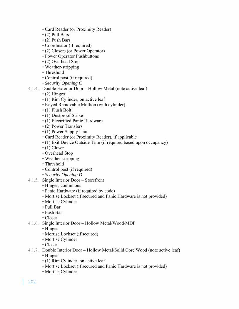
202
• Card Reader (or Proximity Reader) • (2) Pull Bars • (2) Push Bars • Coordinator (if required) • (2) Closers (or Power Operator) • Power Operator Pushbuttons • (2) Overhead Stop • Weather-stripping • Threshold • Control post (if required) • Security Opening C
4.1.4. Double Exterior Door – Hollow Metal (note active leaf) • (2) Hinges • (1) Rim Cylinder, on active leaf • Keyed Removable Mullion (with cylinder) • (1) Flush Bolt • (1) Dustproof Strike • (1) Electrified Panic Hardware • (2) Power Transfers • (1) Power Supply Unit • Card Reader (or Proximity Reader), if applicable • (1) Exit Device Outside Trim (if required based upon occupancy) • (1) Closer • Overhead Stop • Weather-stripping • Threshold • Control post (if required) • Security Opening D
4.1.5. Single Interior Door – Storefront • Hinges, continuous • Panic Hardware (if required by code) • Mortise Lockset (if secured and Panic Hardware is not provided) • Mortise Cylinder • Pull Bar • Push Bar • Closer
4.1.6. Single Interior Door – Hollow Metal/Wood/MDF • Hinges • Mortise Lockset (if secured) • Mortise Cylinder • Closer
4.1.7. Double Interior Door – Hollow Metal/Solid Core Wood (note active leaf) • Hinges • (1) Rim Cylinder, on active leaf • Mortise Lockset (if secured and Panic Hardware is not provided) • Mortise Cylinder
203
• Keyed Removable Mullion (with cylinder) • (1) Flush Bolt • (1) Dustproof Strike • (1) Closer
4.1.8. Single Electrical/Mechanical/IT Room Door – Hollow Metal/Solid Core Wood • Hinges • Electrified Mortise Lockset • Power Transfer • Power Supply Unit • Card Reader (or Proximity Reader) • Closer • Security Opening E
5. Security Coordination 5.1. The attached Security Opening drawings are examples of typical security openings on Western
Carolina University projects. The Designer shall develop similar elevations as required for the Project.
5.2. Legend 5.2.1. DC- door contact 5.2.2. PT- power transfer 5.2.3. PD – panic device 5.2.4. EL – electric latch 5.2.5. CR – card reader 5.2.6. PR – proximity reader 5.2.7. JB – junction box 5.2.8. CP – control post
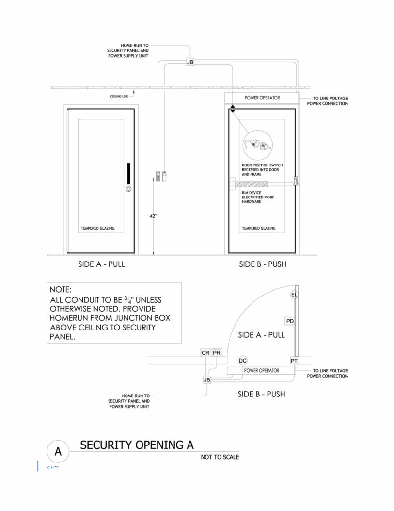
204

205
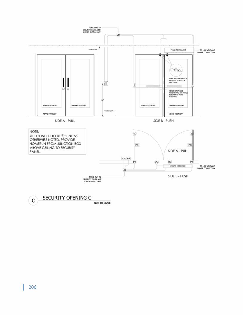
206
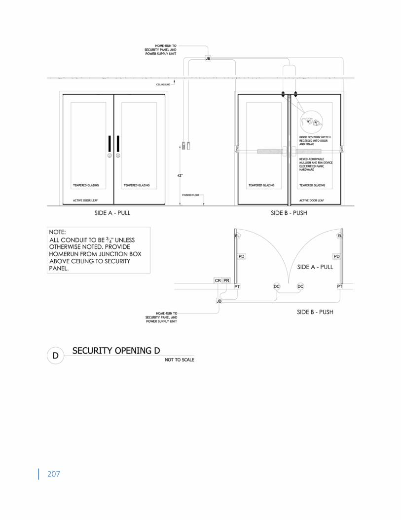
207
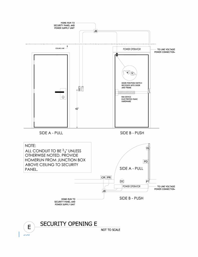
208
209
Appendix H OIT Telecommunications Infrastructure Standards 1. General Scope of WCU Telecom Design 1.1. This document defines the telecommunications infrastructure standards at Western Carolina University University. It is intended to be used as a guide during the planning and design stages of renovation and new construction projects. These standards reflect minimum requirements and should be followed on all jobs. Exceptions to these standards must be coordinated and approved by the Western Carolina University Office of Information Technology (OIT). 1.2. The guidelines in this document should be used by architects, engineers and planners in the design phase of projects to properly address the telecommunication infrastructure spaces and pathways. [OIT is responsible for telecom structured cable installation, and therefore, the Architect is not required to include telecom cabling specifications in the design.] It is essential that OIT be involved early-on in the planning and design process, at each design review, at pre-construction meetings, and throughout the project (e.g. OAC meetings, inspections, etc.) so that all telecommunication considerations and needs may be addressed at the appropriate point in the project schedule. 1.3. OIT should be copied on all updates of the electrical, auxiliary, and communications blueprints, and building floor plans and site plans during the design, pre-construction, and construction phases of the project including but not limited to RFIs, CCDs, ASIs, and COs that affect telecom design as well as progress meetings and inspection scheduling. 1.4. OIT is responsible for telecommunications wiring specifications, bidding, and selection of the telecommunication installation contractor for all Western Carolina University projects. 1.5. The Designer must include the requirements of this document in the electrical specifications, drawings, and notes for the job, including the Project Manual. 1.6. It is the electrical subcontractor’s responsibility to install all telecommunications pathways according to the requirements of this document. 2. General Standards 2.1. The telecommunications infrastructure wiring standards used at Western Carolina University generally, follow the TIA/EIA 568B wiring standard as developed by the Telecommunications Industry Association (TIA) and the Electronic Industries Alliance (EIA). A Category-6 structured cabling design and installation is required at Western Carolina University for all new telecommunication voice and data outlets that are included in construction projects. 2.2. The number and location of telecommunication outlets in a new or renovated building should be determined during the architectural design stage of the project with significant input provided by the Western Carolina University college/division/department that is the principle owner or will be the principle occupant of the new or renovated space. OIT should also be involved in the architectural design stages of the project to provide feedback related to the proper location of telecommunication rooms and backboards, pathways from the backboards to the outlets, and other cable management concerns. This design should follow closely the TIA/EIA-569 industry standards for telecommunications spaces and pathways. Where not specified otherwise in this document, then the TIA/EIA-569 standards shall be followed. 2.3. A Category-6 and CATV wiring installation requires the distance (cable length) not to exceed 100 meters between equipment connected to a telecommunications outlet and the electronics in the
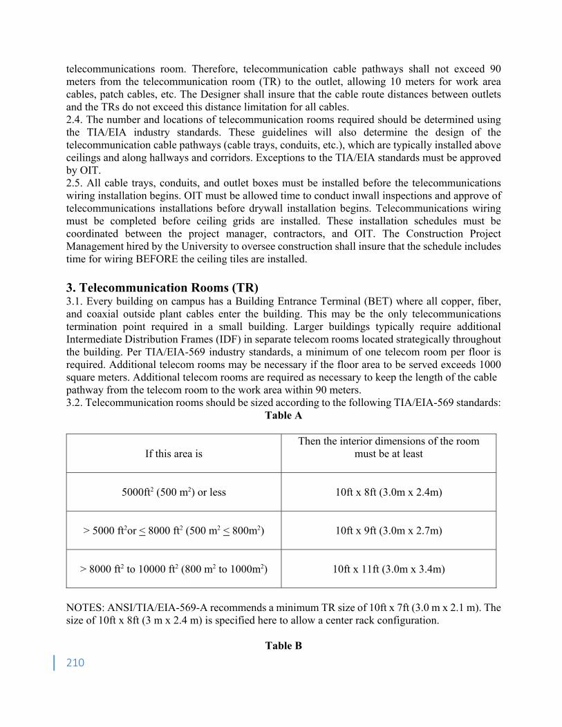
210
telecommunications room. Therefore, telecommunication cable pathways shall not exceed 90 meters from the telecommunication room (TR) to the outlet, allowing 10 meters for work area cables, patch cables, etc. The Designer shall insure that the cable route distances between outlets and the TRs do not exceed this distance limitation for all cables. 2.4. The number and locations of telecommunication rooms required should be determined using the TIA/EIA industry standards. These guidelines will also determine the design of the telecommunication cable pathways (cable trays, conduits, etc.), which are typically installed above ceilings and along hallways and corridors. Exceptions to the TIA/EIA standards must be approved by OIT. 2.5. All cable trays, conduits, and outlet boxes must be installed before the telecommunications wiring installation begins. OIT must be allowed time to conduct inwall inspections and approve of telecommunications installations before drywall installation begins. Telecommunications wiring must be completed before ceiling grids are installed. These installation schedules must be coordinated between the project manager, contractors, and OIT. The Construction Project Management hired by the University to oversee construction shall insure that the schedule includes time for wiring BEFORE the ceiling tiles are installed. 3. Telecommunication Rooms (TR) 3.1. Every building on campus has a Building Entrance Terminal (BET) where all copper, fiber, and coaxial outside plant cables enter the building. This may be the only telecommunications termination point required in a small building. Larger buildings typically require additional Intermediate Distribution Frames (IDF) in separate telecom rooms located strategically throughout the building. Per TIA/EIA-569 industry standards, a minimum of one telecom room per floor is required. Additional telecom rooms may be necessary if the floor area to be served exceeds 1000 square meters. Additional telecom rooms are required as necessary to keep the length of the cable pathway from the telecom room to the work area within 90 meters. 3.2. Telecommunication rooms should be sized according to the following TIA/EIA-569 standards:
Table A
If this area is
Then the interior dimensions of the room must be at least
5000ft2 (500 m2) or less
10ft x 8ft (3.0m x 2.4m)
> 5000 ft2or < 8000 ft2 (500 m2 < 800m2)
10ft x 9ft (3.0m x 2.7m)
> 8000 ft2 to 10000 ft2 (800 m2 to 1000m2)
10ft x 11ft (3.0m x 3.4m)
NOTES: ANSI/TIA/EIA-569-A recommends a minimum TR size of 10ft x 7ft (3.0 m x 2.1 m). The size of 10ft x 8ft (3 m x 2.4 m) is specified here to allow a center rack configuration.
Table B
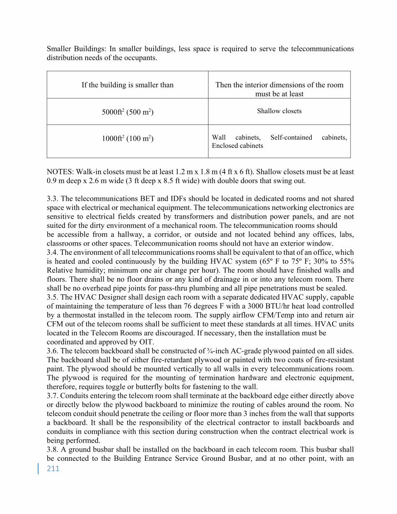
211
Smaller Buildings: In smaller buildings, less space is required to serve the telecommunications distribution needs of the occupants.
If the building is smaller than
Then the interior dimensions of the room
must be at least
5000ft2 (500 m2)
Shallow closets
1000ft2 (100 m2)
Wall cabinets, Self-contained cabinets, Enclosed cabinets
NOTES: Walk-in closets must be at least 1.2 m x 1.8 m (4 ft x 6 ft). Shallow closets must be at least 0.9 m deep x 2.6 m wide (3 ft deep x 8.5 ft wide) with double doors that swing out. 3.3. The telecommunications BET and IDFs should be located in dedicated rooms and not shared space with electrical or mechanical equipment. The telecommunications networking electronics are sensitive to electrical fields created by transformers and distribution power panels, and are not suited for the dirty environment of a mechanical room. The telecommunication rooms should be accessible from a hallway, a corridor, or outside and not located behind any offices, labs, classrooms or other spaces. Telecommunication rooms should not have an exterior window. 3.4. The environment of all telecommunications rooms shall be equivalent to that of an office, which is heated and cooled continuously by the building HVAC system (65º F to 75º F; 30% to 55% Relative humidity; minimum one air change per hour). The room should have finished walls and floors. There shall be no floor drains or any kind of drainage in or into any telecom room. There shall be no overhead pipe joints for pass-thru plumbing and all pipe penetrations must be sealed. 3.5. The HVAC Designer shall design each room with a separate dedicated HVAC supply, capable of maintaining the temperature of less than 76 degrees F with a 3000 BTU/hr heat load controlled by a thermostat installed in the telecom room. The supply airflow CFM/Temp into and return air CFM out of the telecom rooms shall be sufficient to meet these standards at all times. HVAC units located in the Telecom Rooms are discouraged. If necessary, then the installation must be coordinated and approved by OIT. 3.6. The telecom backboard shall be constructed of ¾-inch AC-grade plywood painted on all sides. The backboard shall be of either fire-retardant plywood or painted with two coats of fire-resistant paint. The plywood should be mounted vertically to all walls in every telecommunications room. The plywood is required for the mounting of termination hardware and electronic equipment, therefore, requires toggle or butterfly bolts for fastening to the wall. 3.7. Conduits entering the telecom room shall terminate at the backboard edge either directly above or directly below the plywood backboard to minimize the routing of cables around the room. No telecom conduit should penetrate the ceiling or floor more than 3 inches from the wall that supports a backboard. It shall be the responsibility of the electrical contractor to install backboards and conduits in compliance with this section during construction when the contract electrical work is being performed. 3.8. A ground busbar shall be installed on the backboard in each telecom room. This busbar shall be connected to the Building Entrance Service Ground Busbar, and at no other point, with an
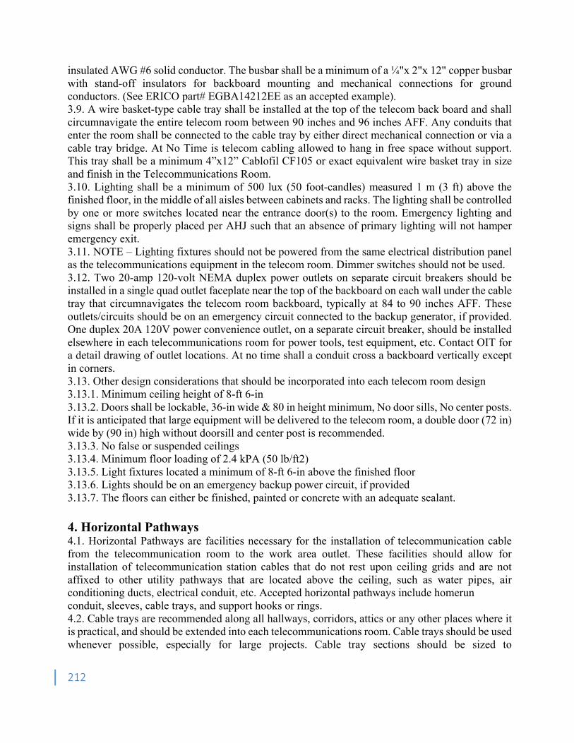
212
insulated AWG #6 solid conductor. The busbar shall be a minimum of a ¼"x 2"x 12" copper busbar with stand-off insulators for backboard mounting and mechanical connections for ground conductors. (See ERICO part# EGBA14212EE as an accepted example). 3.9. A wire basket-type cable tray shall be installed at the top of the telecom back board and shall circumnavigate the entire telecom room between 90 inches and 96 inches AFF. Any conduits that enter the room shall be connected to the cable tray by either direct mechanical connection or via a cable tray bridge. At No Time is telecom cabling allowed to hang in free space without support. This tray shall be a minimum 4”x12” Cablofil CF105 or exact equivalent wire basket tray in size and finish in the Telecommunications Room. 3.10. Lighting shall be a minimum of 500 lux (50 foot-candles) measured 1 m (3 ft) above the finished floor, in the middle of all aisles between cabinets and racks. The lighting shall be controlled by one or more switches located near the entrance door(s) to the room. Emergency lighting and signs shall be properly placed per AHJ such that an absence of primary lighting will not hamper emergency exit. 3.11. NOTE – Lighting fixtures should not be powered from the same electrical distribution panel as the telecommunications equipment in the telecom room. Dimmer switches should not be used. 3.12. Two 20-amp 120-volt NEMA duplex power outlets on separate circuit breakers should be installed in a single quad outlet faceplate near the top of the backboard on each wall under the cable tray that circumnavigates the telecom room backboard, typically at 84 to 90 inches AFF. These outlets/circuits should be on an emergency circuit connected to the backup generator, if provided. One duplex 20A 120V power convenience outlet, on a separate circuit breaker, should be installed elsewhere in each telecommunications room for power tools, test equipment, etc. Contact OIT for a detail drawing of outlet locations. At no time shall a conduit cross a backboard vertically except in corners. 3.13. Other design considerations that should be incorporated into each telecom room design 3.13.1. Minimum ceiling height of 8-ft 6-in 3.13.2. Doors shall be lockable, 36-in wide & 80 in height minimum, No door sills, No center posts. If it is anticipated that large equipment will be delivered to the telecom room, a double door (72 in) wide by (90 in) high without doorsill and center post is recommended. 3.13.3. No false or suspended ceilings 3.13.4. Minimum floor loading of 2.4 kPA (50 lb/ft2) 3.13.5. Light fixtures located a minimum of 8-ft 6-in above the finished floor 3.13.6. Lights should be on an emergency backup power circuit, if provided 3.13.7. The floors can either be finished, painted or concrete with an adequate sealant. 4. Horizontal Pathways 4.1. Horizontal Pathways are facilities necessary for the installation of telecommunication cable from the telecommunication room to the work area outlet. These facilities should allow for installation of telecommunication station cables that do not rest upon ceiling grids and are not affixed to other utility pathways that are located above the ceiling, such as water pipes, air conditioning ducts, electrical conduit, etc. Accepted horizontal pathways include homerun conduit, sleeves, cable trays, and support hooks or rings. 4.2. Cable trays are recommended along all hallways, corridors, attics or any other places where it is practical, and should be extended into each telecommunications room. Cable trays should be used whenever possible, especially for large projects. Cable tray sections should be sized to
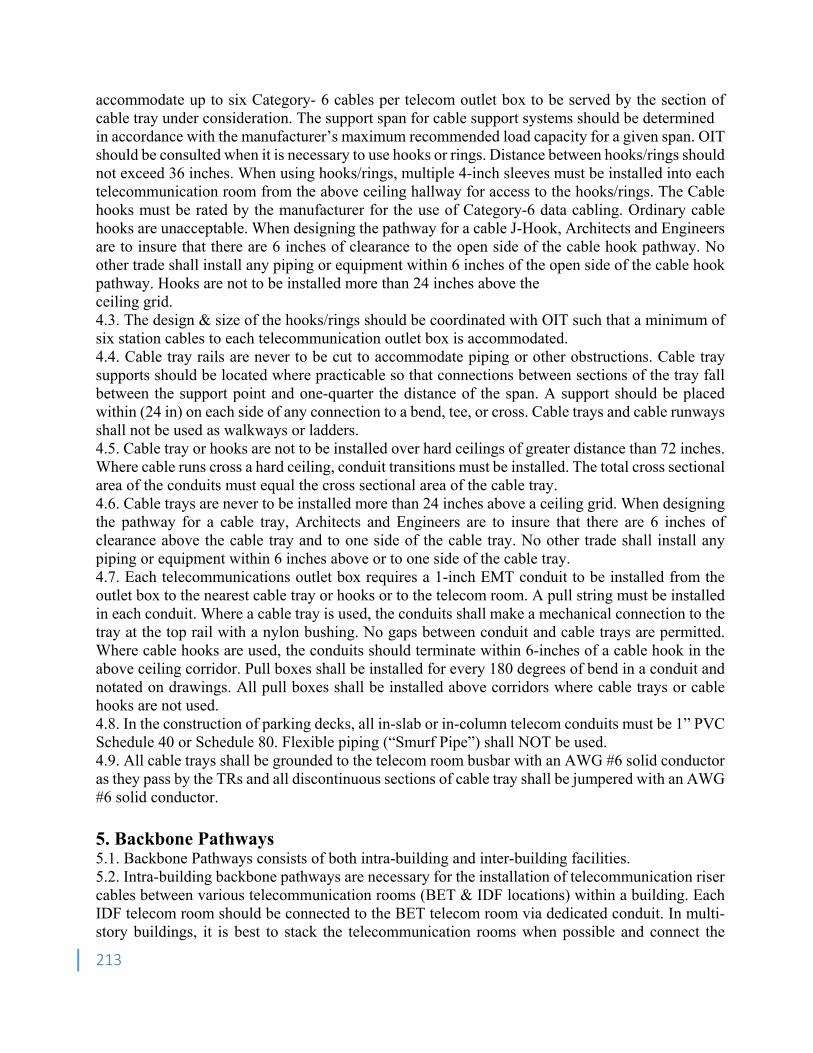
213
accommodate up to six Category- 6 cables per telecom outlet box to be served by the section of cable tray under consideration. The support span for cable support systems should be determined in accordance with the manufacturer’s maximum recommended load capacity for a given span. OIT should be consulted when it is necessary to use hooks or rings. Distance between hooks/rings should not exceed 36 inches. When using hooks/rings, multiple 4-inch sleeves must be installed into each telecommunication room from the above ceiling hallway for access to the hooks/rings. The Cable hooks must be rated by the manufacturer for the use of Category-6 data cabling. Ordinary cable hooks are unacceptable. When designing the pathway for a cable J-Hook, Architects and Engineers are to insure that there are 6 inches of clearance to the open side of the cable hook pathway. No other trade shall install any piping or equipment within 6 inches of the open side of the cable hook pathway. Hooks are not to be installed more than 24 inches above the ceiling grid. 4.3. The design & size of the hooks/rings should be coordinated with OIT such that a minimum of six station cables to each telecommunication outlet box is accommodated. 4.4. Cable tray rails are never to be cut to accommodate piping or other obstructions. Cable tray supports should be located where practicable so that connections between sections of the tray fall between the support point and one-quarter the distance of the span. A support should be placed within (24 in) on each side of any connection to a bend, tee, or cross. Cable trays and cable runways shall not be used as walkways or ladders. 4.5. Cable tray or hooks are not to be installed over hard ceilings of greater distance than 72 inches. Where cable runs cross a hard ceiling, conduit transitions must be installed. The total cross sectional area of the conduits must equal the cross sectional area of the cable tray. 4.6. Cable trays are never to be installed more than 24 inches above a ceiling grid. When designing the pathway for a cable tray, Architects and Engineers are to insure that there are 6 inches of clearance above the cable tray and to one side of the cable tray. No other trade shall install any piping or equipment within 6 inches above or to one side of the cable tray. 4.7. Each telecommunications outlet box requires a 1-inch EMT conduit to be installed from the outlet box to the nearest cable tray or hooks or to the telecom room. A pull string must be installed in each conduit. Where a cable tray is used, the conduits shall make a mechanical connection to the tray at the top rail with a nylon bushing. No gaps between conduit and cable trays are permitted. Where cable hooks are used, the conduits should terminate within 6-inches of a cable hook in the above ceiling corridor. Pull boxes shall be installed for every 180 degrees of bend in a conduit and notated on drawings. All pull boxes shall be installed above corridors where cable trays or cable hooks are not used. 4.8. In the construction of parking decks, all in-slab or in-column telecom conduits must be 1” PVC Schedule 40 or Schedule 80. Flexible piping (“Smurf Pipe”) shall NOT be used. 4.9. All cable trays shall be grounded to the telecom room busbar with an AWG #6 solid conductor as they pass by the TRs and all discontinuous sections of cable tray shall be jumpered with an AWG #6 solid conductor. 5. Backbone Pathways 5.1. Backbone Pathways consists of both intra-building and inter-building facilities. 5.2. Intra-building backbone pathways are necessary for the installation of telecommunication riser cables between various telecommunication rooms (BET & IDF locations) within a building. Each IDF telecom room should be connected to the BET telecom room via dedicated conduit. In multi-story buildings, it is best to stack the telecommunication rooms when possible and connect the
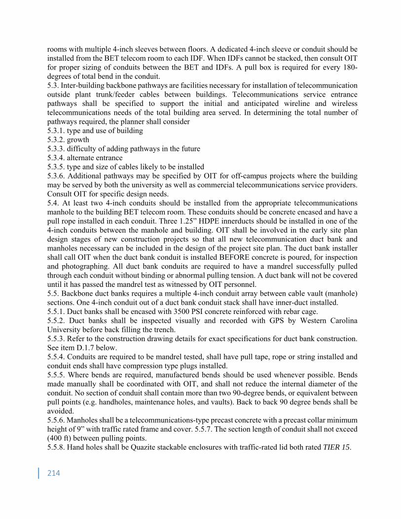
214
rooms with multiple 4-inch sleeves between floors. A dedicated 4-inch sleeve or conduit should be installed from the BET telecom room to each IDF. When IDFs cannot be stacked, then consult OIT for proper sizing of conduits between the BET and IDFs. A pull box is required for every 180-degrees of total bend in the conduit. 5.3. Inter-building backbone pathways are facilities necessary for installation of telecommunication outside plant trunk/feeder cables between buildings. Telecommunications service entrance pathways shall be specified to support the initial and anticipated wireline and wireless telecommunications needs of the total building area served. In determining the total number of pathways required, the planner shall consider 5.3.1. type and use of building 5.3.2. growth 5.3.3. difficulty of adding pathways in the future 5.3.4. alternate entrance 5.3.5. type and size of cables likely to be installed 5.3.6. Additional pathways may be specified by OIT for off-campus projects where the building may be served by both the university as well as commercial telecommunications service providers. Consult OIT for specific design needs. 5.4. At least two 4-inch conduits should be installed from the appropriate telecommunications manhole to the building BET telecom room. These conduits should be concrete encased and have a pull rope installed in each conduit. Three 1.25” HDPE innerducts should be installed in one of the 4-inch conduits between the manhole and building. OIT shall be involved in the early site plan design stages of new construction projects so that all new telecommunication duct bank and manholes necessary can be included in the design of the project site plan. The duct bank installer shall call OIT when the duct bank conduit is installed BEFORE concrete is poured, for inspection and photographing. All duct bank conduits are required to have a mandrel successfully pulled through each conduit without binding or abnormal pulling tension. A duct bank will not be covered until it has passed the mandrel test as witnessed by OIT personnel. 5.5. Backbone duct banks requires a multiple 4-inch conduit array between cable vault (manhole) sections. One 4-inch conduit out of a duct bank conduit stack shall have inner-duct installed. 5.5.1. Duct banks shall be encased with 3500 PSI concrete reinforced with rebar cage. 5.5.2. Duct banks shall be inspected visually and recorded with GPS by Western Carolina University before back filling the trench. 5.5.3. Refer to the construction drawing details for exact specifications for duct bank construction. See item D.1.7 below. 5.5.4. Conduits are required to be mandrel tested, shall have pull tape, rope or string installed and conduit ends shall have compression type plugs installed. 5.5.5. Where bends are required, manufactured bends should be used whenever possible. Bends made manually shall be coordinated with OIT, and shall not reduce the internal diameter of the conduit. No section of conduit shall contain more than two 90-degree bends, or equivalent between pull points (e.g. handholes, maintenance holes, and vaults). Back to back 90 degree bends shall be avoided. 5.5.6. Manholes shall be a telecommunications-type precast concrete with a precast collar minimum height of 9” with traffic rated frame and cover. 5.5.7. The section length of conduit shall not exceed (400 ft) between pulling points. 5.5.8. Hand holes shall be Quazite stackable enclosures with traffic-rated lid both rated TIER 15.
215
5.5.9. Duct bank design at Western Carolina University often includes electrical duct bank encased together with Telecom duct bank. If the designer is designing a duct bank for any purpose, the Engineer shall contact the Facilities Project Manager for any possible telecom or electrical duct bank inclusion in the design and installation. If so warranted, the telecom duct bank shall be installed with the electrical duct bank and designed not only for proposed use but for future use. Coordinate with WCU representatives before designing electrical and telecom duct bank routes. 6. Telecommunication Outlets 6.1. Telecommunication outlet boxes shall be installed wherever telephone, computer, and/or cable television service is required or desired. Generally, voice and data jacks in offices, classrooms, conference rooms, etc. will share the same outlet box. It is not necessary to install a separate outlet box for voice and data with the exception of wall mounted telephone locations. For known cable television outlet locations, a separate outlet box may be desired and should be installed at the location requested. Telecommunication outlet locations should be coordinated with the furniture layout. 6.2. A standard double-gang electrical outlet box (4" x 4" x 2" deep) should be installed at each telecommunication outlet location indicated on the blueprints. All outlet boxes are to be securely fastened to the studs of the interior wall. A 1- inch conduit should be installed from the outlet box, running up the interior of the wall, out into the hallway above the ceiling, and mechanically attached to the telecom cable tray. The conduit should interface the top of the double-gang outlet box at an off-center position to allow for maximum bending radius of future cable installs.. A pull-string or pull-wire should be installed in each conduit. The conduit should have no more than 180 degrees of bends between the outlet box and the above ceiling corridor space, and therefore a junction box above the ceiling over an office should not be necessary. Do not place junction boxes above the ceilings over offices. 6.3. The 1-inch conduit from each wall outlet box shall be installed to the nearest cable tray, hooks or telecommunications room. Where it is necessary to aggregate several of these conduits into a junction box, the conduit from the junction box to the cable tray/hooks or telecommunication room shall be sized according to the number of 1-inch conduits being aggregated. Exposed cabling should not be installed in open ceiling spaces, unless concealed and protected by a cable tray. 6.4. Where surface mounted raceway is installed in a room or lab, the raceway must have a metallic separation barrier between the telecom cabling and 120-VAC cabling. The cover for the raceway should be a snap-on design with pre-punched holes for telecom jacks every 36 inches. Telecom outlet locations will be determined by OIT and the building tenants. At locations along the raceway where a power outlet is installed but no telecommunication outlet, the telecom cable channel faceplate shall be covered with a blank faceplate by the electrical contractor. Where surface mounted raceways are required within a room or lab, the raceway must be connected via a one-inch conduit for every six feet of raceway, or the equivalent thereof. Each conduit must run from the raceway to the nearest cable tray or telecom room. 6.5. Where floor mounted telecommunication outlets are required, specify FSR FL-500P-BLP-6 floor boxes for standard applications. FSR FL-600 should be used under lecterns in auditoriums. Covers will vary with application. Wiremold RFB4-C1-1 compartment combination floor box may also be used for standard applications. The stamped steel version shall not be used in contact with grade.
216
Only the cast steel version is rated for grade contact applications. Coordinate with OIT when specifying floor mounted outlet boxes. A telecommunication outlet will not be installed if the station cable must be exposed to a surface mounted box. 6.6. When the design of an office space requires the use of cubicles or other modular type office furniture, it is recommended that the furniture chosen have as part of its design an integrated raceway for installation of telecommunication cables and outlets. If the floor plan of the office space dictates the furniture to be located in the center of the room and not adjacent to any walls, the telecommunications and power access requirements may be met through closely coordinated core drills in the floor that align with the walls of the modular furniture. This is the recommended solution for modular furniture located above the ground floor of a building. For 3-inch thick cubicle walls, 2 ½ inch core drilled holes are recommended, with a 1 ½ inch EMT conduit installed from each core drilled hole to the telecom cable tray on the floor below. The conduit should stub into the telecom raceway within the wall of the modular furniture where it will be accessible for the pulling of the telecom wire. Where multiple contiguous modular offices are planned, a core drill should be made for every three offices. For example, two core drills strategically placed are needed for a configuration of six modular offices. Likewise, four core drills are needed for twelve offices. This method is preferred over the use of tele-power poles. OIT should be consulted for modular furniture that is to be located on the ground floor. Furniture layout should be planned such that telecommunication wiring will not be exposed. At no time is exposed telecommunications wiring from conduits to furniture allowed. Floor boxes have proven to be unworkable for modular furniture and therefore shall not be used. In Lecture Halls, Meeting Rooms and similar locations where power and data are to be supplied to table tops, the WIREMOLD DeQuorum flipup module with a 20-Amp duplex power outlet and dual-data outlet shall be used where such power and data needs are required by the intended users of the room or lecture hall. Wired data in portable tables are discouraged. 6.7. Where tele-power poles are required, coordinate with OIT on the selection of products which accommodate both telecommunications and electrical wiring. 6.8. When a network wireless access point (WAP) is required to be on a hard ceiling or on some architectural ceiling design feature, the Architect will insure that the design incorporates and supports wireless access point installation on the ceiling or design feature, whichever is lowest, with a telecom conduit to a double-ganged box with easy access to the units for maintenance. WCU Telecom WAPs do not need a power outlet as our design supplies power-over-ethernet (POE) to the WAP. 7. Miscellaneous Standards and Life Safety Equipment Requirements 7.1. Room Numbers 7.1.1. Final official room numbers are required before telecommunications wiring can be installed, since room numbers are needed for labeling faceplates and wire terminations. Also, room numbers are critical to an accurate Emergency 911 database, which is maintained by the OIT. 7.2. Small Projects 7.2.1. There are several issues associated with small renovation projects that are often overlooked. Proper communication with OIT should address these issues. 7.2.2. Room number changes due to renovation of an office suite sometimes affect the entire floor of the building. Western Carolina University telecommunication records track cable facilities using room number and jack number designations. More importantly, Emergency 911 records are maintained by OIT, so it is vitally important that OIT be notified of all room numbering changes.
217
7.2.3. Old telecom cabling being replaced as part of any size renovation project shall (per NEC) be removed as part of the project. The removal of old cable should be covered by funds in the renovation project, including small projects with no Telecom funds budgeted. 7.3. Plenum Environments 7.3.1. For design and budget considerations, telecommunication installation costs are significantly higher when plenum cable is required because of exposure to return-air ceiling environments. The cost of horizontal telecommunications cable is typically 50% higher or more for plenum cables than non-plenum. In some cases the hallway ceiling space is nonplenum while the ceiling space above offices or classrooms is plenum. In this case, the standard conduit run from the telecommunication outlet box into the hallway ceiling will be sufficient to allow for a non-plenum cable installation. 7.4. Emergency Phones 7.4.1. The Emergency phone equipment will be purchased by OIT and charged to the project. The standard WCU Emergency phone is a Gai-Tronics 234 Silent Sentinel Stanchion, 297-003 Smart Phone Stainless with a 530-001 LED Strobe 120 VAC. 7.4.2. Emergency Phones require two conduits from a building depicted on the electrical plans. One ¾" conduit for power and One 1” conduit for telecom cabling as well as a grounding rod shall be installed. The grounding rod and the conduits shall be installed in the concrete base pad of the emergency phone within the area of the bolt template. The electrical contractor shall install pull strings in both conduits, construct the concrete pad upon which the phone will be mounted and stub-up the conduits 6-12 inches above the pad. WCU Telecom will supply the electrical contractor with the emergency phone template kit consisting of four j-bolts, nuts, washers, and a plastic spacing template to insure proper j-bolt spacing in the concrete pad. 7.4.3. The Architect or Designer shall insure that the emergency phone pad meets ADA guidelines for accessibility and shall consult with WCU Representatives on the size of the pad and for approved location of the emergency phone. 7.4.4. The OIT/Telecom contractor will install the emergency phone. 7.4.5. If a University Building or area is being renovated, no emergency phone shall be moved, removed, or taken out of service nor shall power or telecom services to an emergency phone be disconnected without the consent of WCU OIT/Telecom. 7.5. For multi-story buildings where AoR systems are required, the Designer shall specify. 7.5.1. Installation of the Talk-A-Phone AoR Command Unit Model CU-16 adjacent to the Fire Alarm Annunciator panel at the Fireman's entrance to the building. 7.5.2. Installation of the Talk-A-Phone AoR Station ETP-100MB (surface mounted) or ETP100EB (flush mounted) in each stairwell. 7.5.3. Installation of a 3/4" home run conduit from the AoR Command Unit to each AoR Station. Install an accessible pull-box for every two 90-degree bends in the home run conduit. 7.5.4. Installation of one shielded twisted pair copper circuit (not to exceed 25 ohms resistance) from the AoR Command Unit to each AoR Station via the home run conduit. 7.5.5. Installation of a 3/4" conduit homerun from the Telecom Room to the AoR Command Unit. This is to be notated on the drawings. A pull box is required for every 180 degrees of total bend. 7.6. Building Elevator Phones 7.6.1. The model elevator phone that WCU Telecom specifies is the Viking E- 1600-02A. The phone should be flush-mounted at the appropriate ADA approved height. 7.6.2. The phone electronics should be accessible by simply removing the flushmounted phone cover, and not having to remove any other elevator control panels.
218
7.6.3. A conduit shall be installed homerun from the Telecom Room to each elevator controller box in the elevator control room with a double ganged box installed no more than 12 inches from the elevator controller box. 7.6.4. Please coordinate installation of all elevator phones and/or cables with University Project Lead. 7.7. Building Automation Systems (BAS) 7.7.1. Western Carolina University uses Building Automation Systems (BAS) for energy management and control. The designer shall insure that a data conduit is supplied to the Main BAS Controller as designated by the controls contractor and is routed to the nearest cable tray or telecom room. 7.7.2. The Electrical Subcontractor will coordinate the installation of the data conduit with the controls contractor so that it is connected directly to the BAS controller box. 7.8. Fire Alarm Control Panel (FACP) Network Connection. Western Carolina University uses Edwards Fire Alarm Systems. The designer shall specifically spell out in the specifications and note on the drawings that the FACP is to be connected to the nearest Telecom Room with a homerun ¾-inch conduit. This is a requirement of Western Carolina University. A pull box is required for every 180 degrees of total bend. 7.9. Lock Access Network Controller. When the lock access system controller is not located in the telecom room, a telecom conduit shall be installed from the controller location to the nearest cable tray or telecom room. 8. Contact Information 8.1. If you have any questions about these standards, please contact the Western Carolina University Office of Information Technology, Monday through Friday, 7:45am to 4:45pm CST. 8.2. Address: WCU Telecommunications Project Management
Facilities Management 3476 Old Cullowhee Road Cullowhee, NC 28723 Phone: 828.227.7441
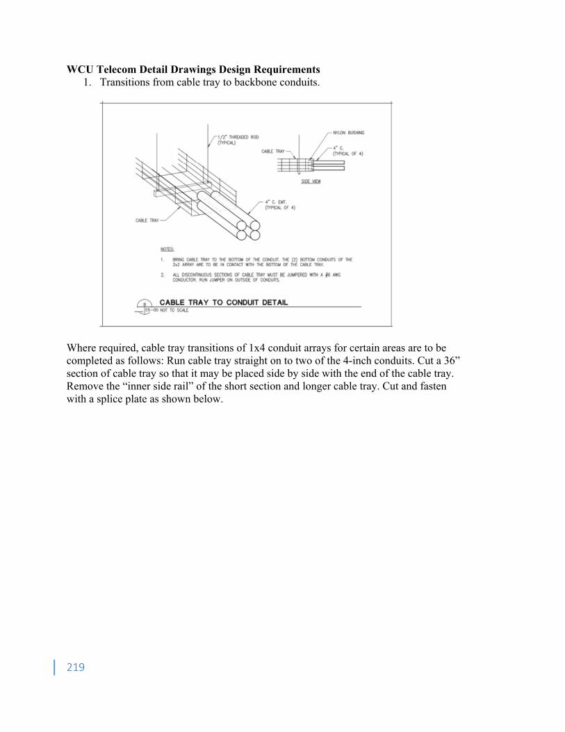
219
WCU Telecom Detail Drawings Design Requirements 1. Transitions from cable tray to backbone conduits.
Where required, cable tray transitions of 1x4 conduit arrays for certain areas are to be completed as follows: Run cable tray straight on to two of the 4-inch conduits. Cut a 36” section of cable tray so that it may be placed side by side with the end of the cable tray. Remove the “inner side rail” of the short section and longer cable tray. Cut and fasten with a splice plate as shown below.
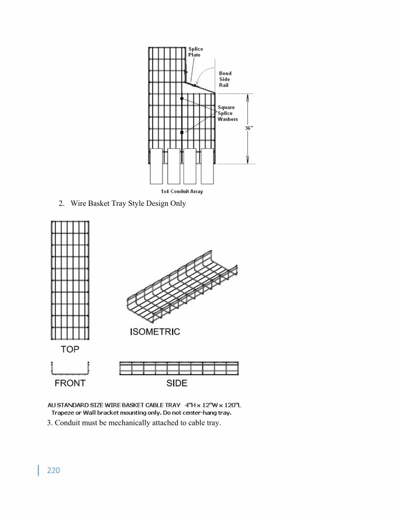
220
2. Wire Basket Tray Style Design Only
3. Conduit must be mechanically attached to cable tray.
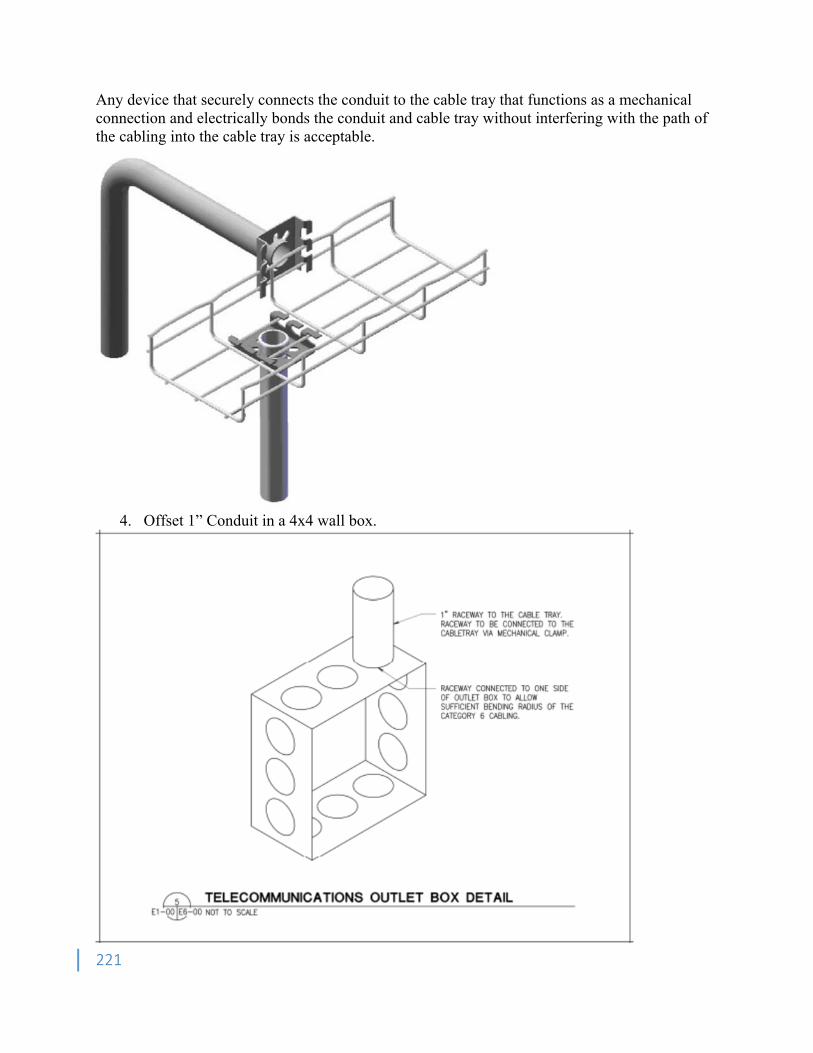
221
Any device that securely connects the conduit to the cable tray that functions as a mechanical connection and electrically bonds the conduit and cable tray without interfering with the path of the cabling into the cable tray is acceptable.
4. Offset 1” Conduit in a 4x4 wall box.
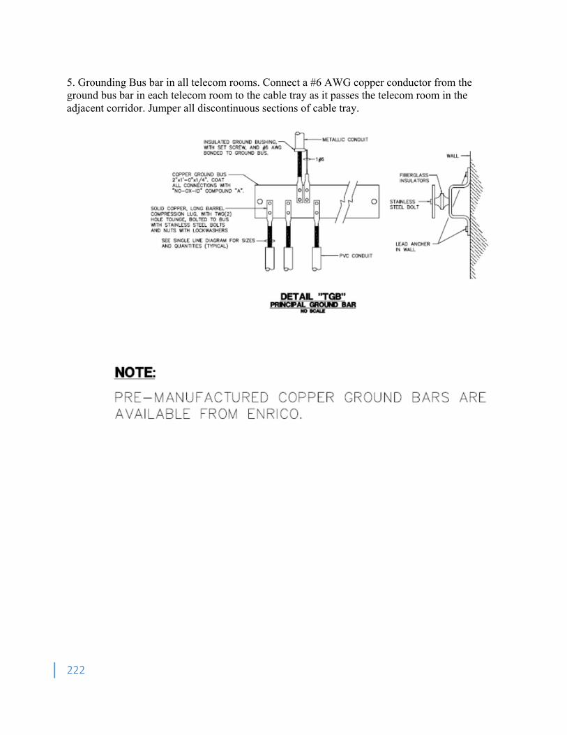
222
5. Grounding Bus bar in all telecom rooms. Connect a #6 AWG copper conductor from the ground bus bar in each telecom room to the cable tray as it passes the telecom room in the adjacent corridor. Jumper all discontinuous sections of cable tray.
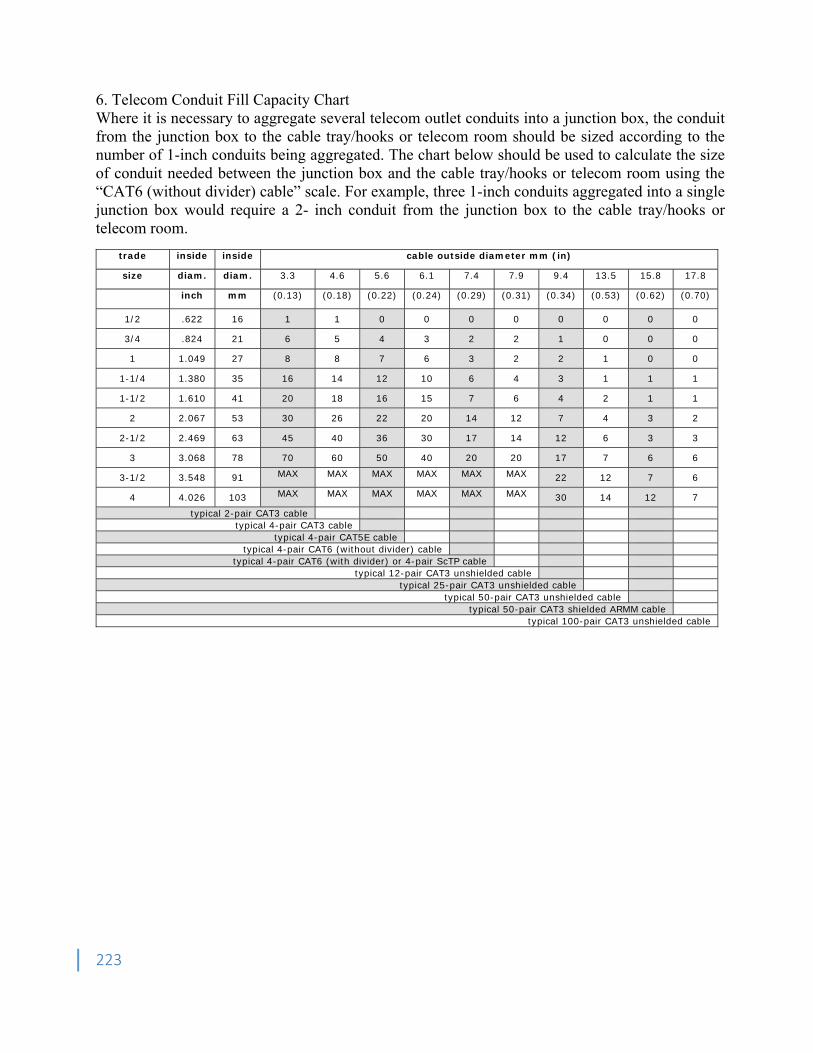
223
6. Telecom Conduit Fill Capacity Chart Where it is necessary to aggregate several telecom outlet conduits into a junction box, the conduit from the junction box to the cable tray/hooks or telecom room should be sized according to the number of 1-inch conduits being aggregated. The chart below should be used to calculate the size of conduit needed between the junction box and the cable tray/hooks or telecom room using the “CAT6 (without divider) cable” scale. For example, three 1-inch conduits aggregated into a single junction box would require a 2- inch conduit from the junction box to the cable tray/hooks or telecom room.
trade inside inside cable outside diameter mm (in)
size diam. diam. 3.3 4.6 5.6 6.1 7.4 7.9 9.4 13.5 15.8 17.8
inch mm (0.13) (0.18) (0.22) (0.24) (0.29) (0.31) (0.34) (0.53) (0.62) (0.70)
1/2 .622 16 1 1 0 0 0 0 0 0 0 0
3/4 .824 21 6 5 4 3 2 2 1 0 0 0
1 1.049 27 8 8 7 6 3 2 2 1 0 0
1-1/4 1.380 35 16 14 12 10 6 4 3 1 1 1
1-1/2 1.610 41 20 18 16 15 7 6 4 2 1 1
2 2.067 53 30 26 22 20 14 12 7 4 3 2
2-1/2 2.469 63 45 40 36 30 17 14 12 6 3 3
3 3.068 78 70 60 50 40 20 20 17 7 6 6
3-1/2 3.548 91 MAX MAX MAX MAX MAX MAX 22 12 7 6
4 4.026 103 MAX MAX MAX MAX MAX MAX 30 14 12 7
typical 2-pair CAT3 cable typical 4-pair CAT3 cable
typical 4-pair CAT5E cable typical 4-pair CAT6 (without divider) cable
typical 4-pair CAT6 (with divider) or 4-pair ScTP cable typical 12-pair CAT3 unshielded cable
typical 25-pair CAT3 unshielded cable typical 50-pair CAT3 unshielded cable
typical 50-pair CAT3 shielded ARMM cabletypical 100-pair CAT3 unshielded cable
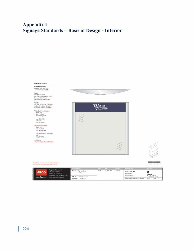
224
Appendix I Signage Standards – Basis of Design - Interior
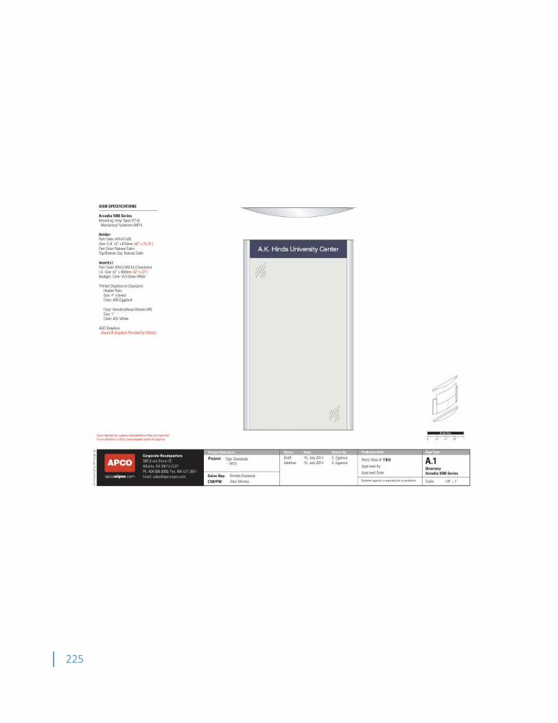
225
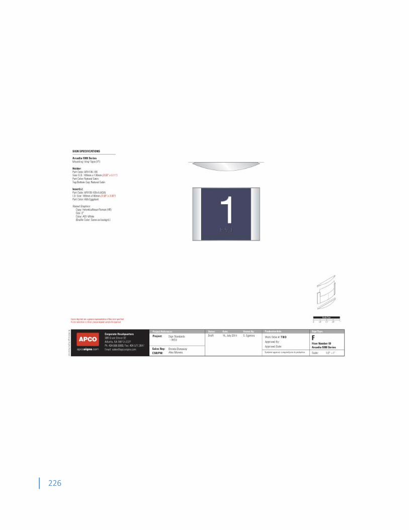
226
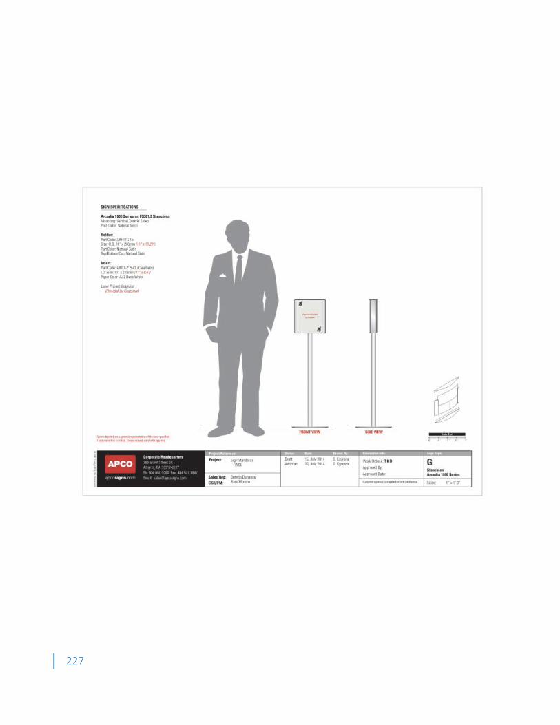
227
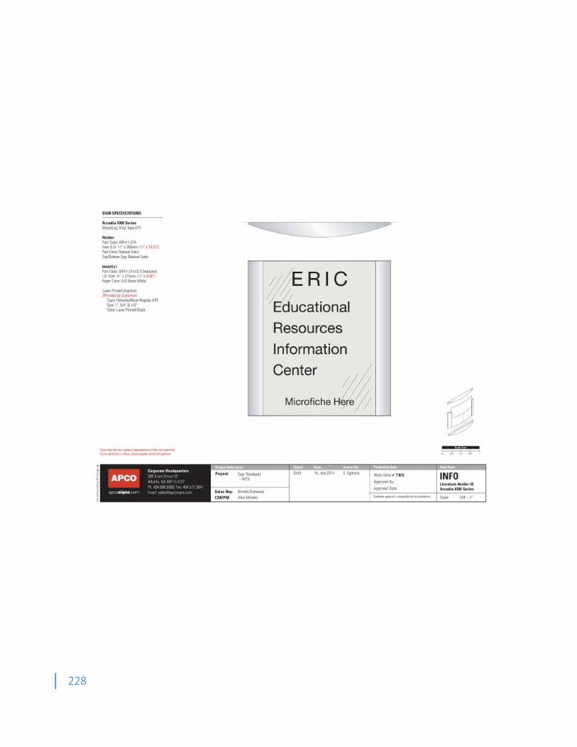
228
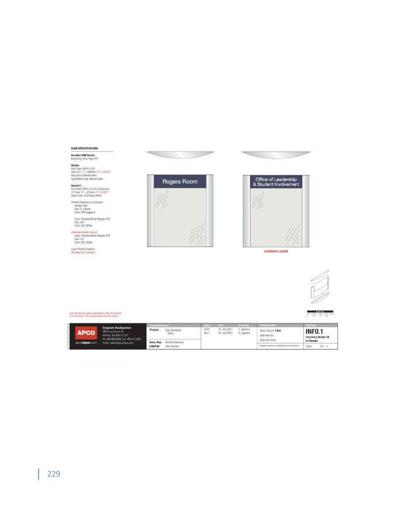
229

230
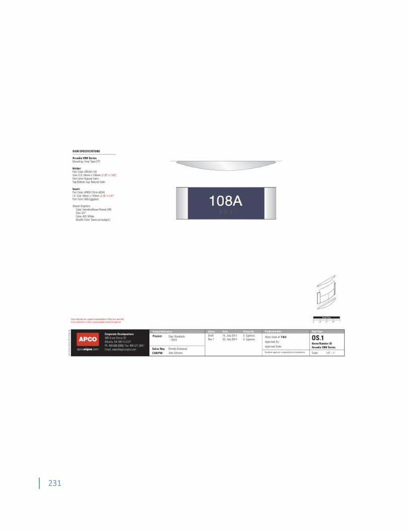
231
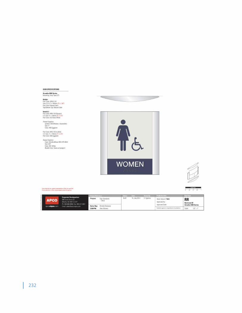
232
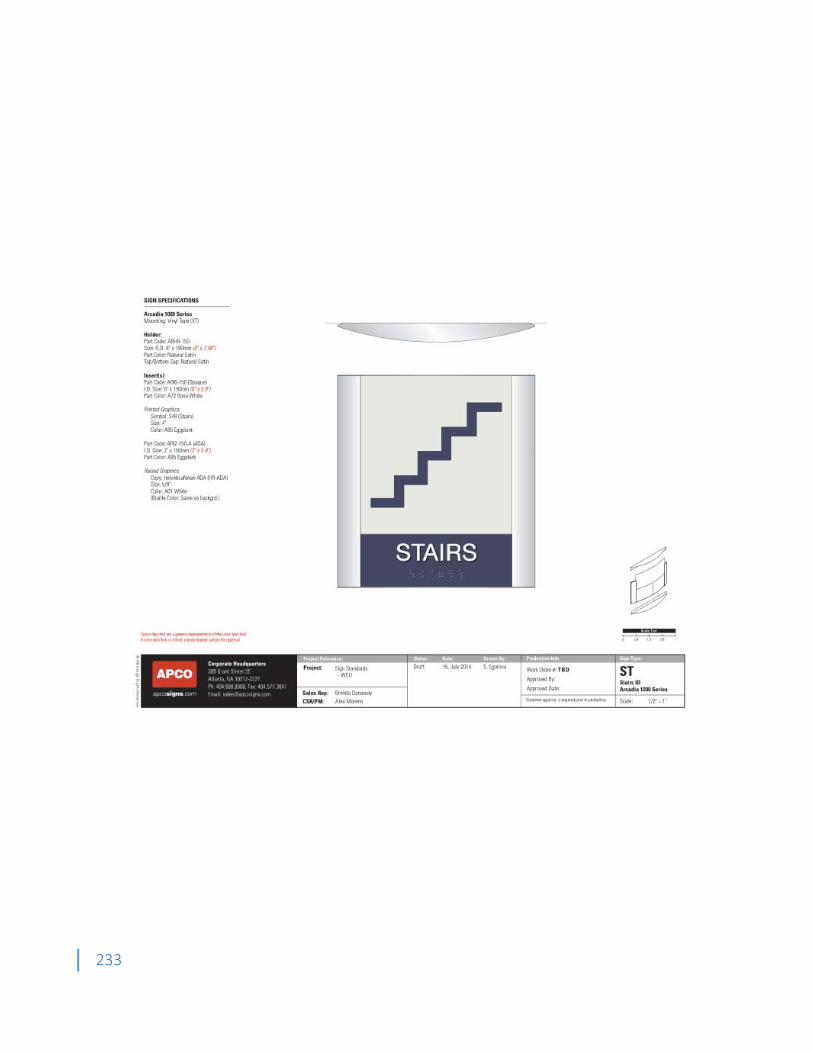
233
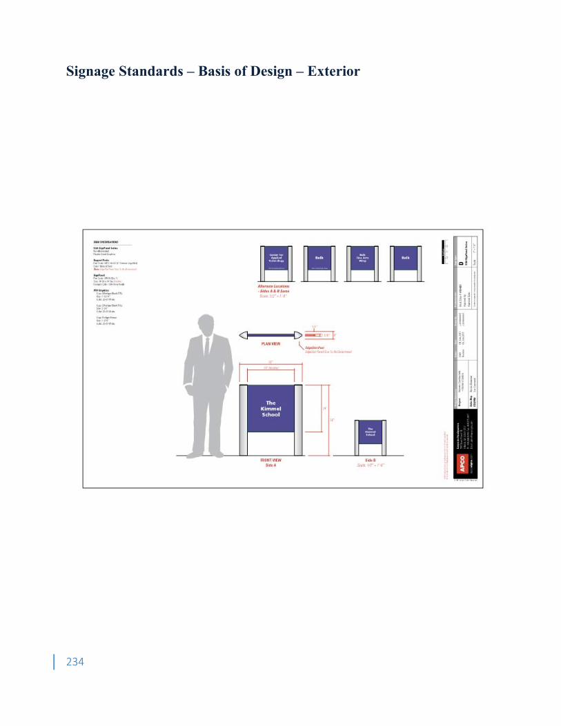
234
Signage Standards – Basis of Design – Exterior
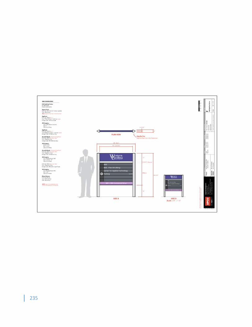
235
236
Appendix J WASTE MANAGEMENT PLAN
General Wastes from construction, renovation, demolition, abatement, decommissioning, and other projects with environmental consequences warrant waste management plans to ensure proper waste management practices and recognition of responsibilities. Many of these types of projects involve contracted services, for which the University and its contractor(s) assume liabilities. Waste management plans, as developed by WCU, are intended to identify potential wastes to be managed, proper management practices, responsible parties, and needed services in simple and concise forms. Two forms have been developed for this purpose, the first for project design and the second for project implementation (demolition/construction). Waste management must be addressed as part of project design, and should be incorporated in project and/or bid documents. Project design may include site preparation and/or construction. Site preparation may include land clearing, relocation of utilities, decontamination of existing structures, and demolition of existing structures. As the project progresses, some adjustments may be necessary for waste management activities, including relocation of waste areas and managing newly-discovered waste materials. Completion of the Designer Waste Information Form allows WCU to identify wastes of concern and prepare for any necessary services to ensure compliance with environmental regulations. The contractor’s Waste Management Plan enables WCU to efficiently plan regulated waste disposal and control costs. Waste management plans will vary depending on the scale and scope of the project. In the most general terms, the plan should identify the general types of wastes that may be encountered for each phase of the project, the collection and accumulation strategy, marking and identification requirements, and procedures for appropriate removal of wastes from the site. The forms should be completed by the designer prior to contract award, preferably as part of the bid process. The contractor will submit a waste management plan to the University for approval prior to implementing any work. The approved plan will serve as the basis for project-specific plans. The Plan will specify procedures for all aspects of waste management. Assignment of Waste Responsibilities
Waste generated by demolition, decontamination, decommissioning, abatement, maintenance of fixed facilities, and most site preparation wastes will be attributable to both the contractor and the University as co-generated waste (University waste materials removed under contract, including lamp replacement and remediation). Accumulation and initial management of waste generated by project activities will be the responsibility of the contractor(s). The University may provide oversight to ensure protection of properties and liabilities. The contractor will prepare waste for collection by the University or shipment to facilities identified in the waste management plan. Hazardous or universal waste generated as a direct result of project activities (e.g., decontamination or demolition of structures, removal of batteries or mercury-containing articles) will leave the University under the University’s signature.
NOTE: Wastes derived solely from materials that the contractor brought to the site, such as construction materials and cleaning of contractor equipment, will be the responsibility of the contractor, and may be included in the waste management plan. The University Project Manager shall receive copies of disposal certifications and shipping papers for all wastes shipped.
237
Designer Waste Information Form The Designer Waste Management Form contains preliminary information beneficial to identifying the types of wastes expected to be removed by the project. Once the designer completes the form, it can be submitted to the WCU Project Manager. Basic sections of the form that require completion are as follows:
Project Name; Project Designer; Waste Types: The types of wastes listed are those that are often subject to environmental
regulation due to potential hazards. Indicate if wastes are present within the project area and scope using Y (yes) or N (no). If there are additional wastes on-site, add them next to “Other” and indicate their presence.
Comment Signature (designer)
Contractor Waste Management Form The Contractor Waste Management Form contains updated and more detailed information for managing wastes of concern for WCU. Once the contract has been awarded, the primary contractor completes the form which identifies the WCU Project Manager, the principal contractor, and any responsible subcontractors. After completing the form, the contractor can submit the form via email to the WCU Project Manager. The contractor is responsible for implementing the plans prepared by the project designer and managing site activities.
Project Name: Contact Information:
o WCU Project Manager o Contractor name, address, phone, and e-mail: Consider this to be the primary contractor. o Onsite contact and phone number o Emergency contact and phone number: The contractor is generally held accountable for
accidents that may occur on a project site. The role of WCU in the event of an emergency is to protect University personnel and property beyond the project boundaries or scope.
o Subcontractor name, address, phone, and e-mail: Consider this to be the subcontractor(s) responsible for managing project “wastes of concern.”
o Subcontractor’s emergency contact and phone number requires information regarding facilities that may recycle, treat, or dispose of “wastes of concern” if disposed by the contractor.
o Wastes of Concern: Common wastes identified by WCU as posing environmental or regulatory concerns have been listed, and additional wastes may be added by WCU based on project design information. The contractor shall identify container types and specific storage locations for each type of waste listed.
o Areas where hazardous wastes are accumulated are required to be inspected at least weekly to ensure spills and other releases are minimized and controlled, and wastes are secured.
o The “wastes of concern” include materials that would be hazardous wastes if not managed properly. The contractor will comply with WCU requirements to document the inspection of waste areas on a weekly basis while “wastes of concern” are present. A weekly inspection log has been provided as a template for minimum inspection requirements.
o Inspection criteria are presented with a simple description of concerns. The inspector’s legible signature, date, and time are required. The “Corrective Actions” should indicate the unacceptable condition, date corrected, and signature.
o Waste removal: The WCU Project Manager shall contact WCU Recycling
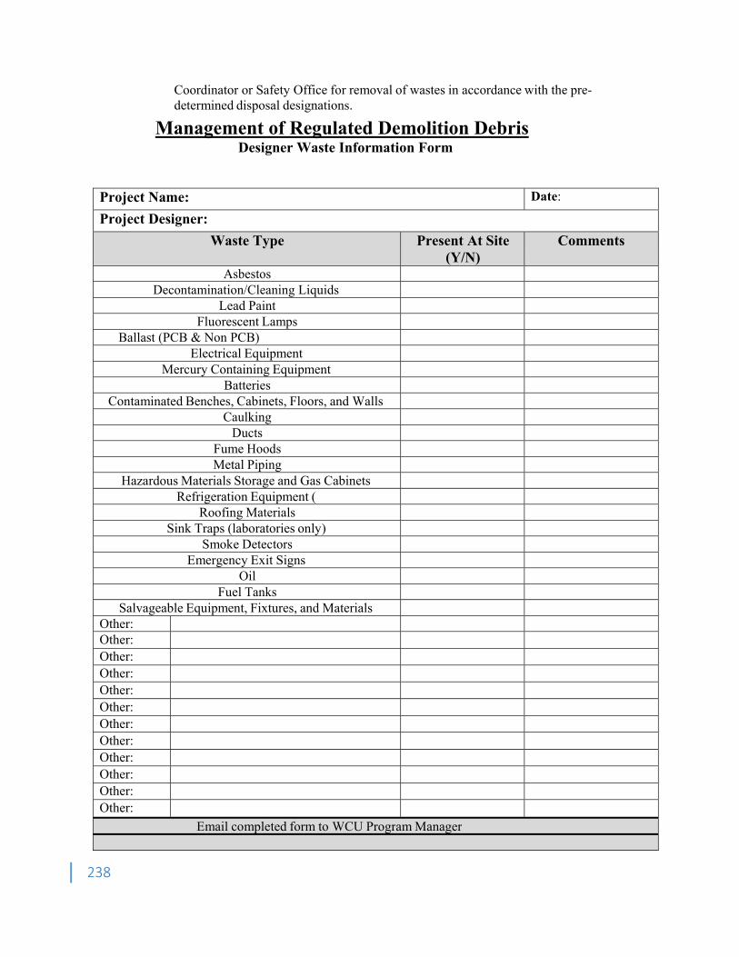
238
Coordinator or Safety Office for removal of wastes in accordance with the pre-determined disposal designations.
Management of Regulated Demolition Debris Designer Waste Information Form
Project Name: Date:
Project Designer:
Waste Type Present At Site (Y/N)
Comments
Asbestos Decontamination/Cleaning Liquids
Lead Paint Fluorescent Lamps
Ballast (PCB & Non PCB) Electrical Equipment
Mercury Containing Equipment Batteries
Contaminated Benches, Cabinets, Floors, and Walls Caulking
Ducts Fume Hoods Metal Piping
Hazardous Materials Storage and Gas Cabinets Refrigeration Equipment (
Roofing Materials Sink Traps (laboratories only)
Smoke Detectors Emergency Exit Signs
Oil Fuel Tanks
Salvageable Equipment, Fixtures, and Materials Other: Other: Other: Other: Other: Other: Other: Other: Other: Other: Other: Other:
Email completed form to WCU Program Manager
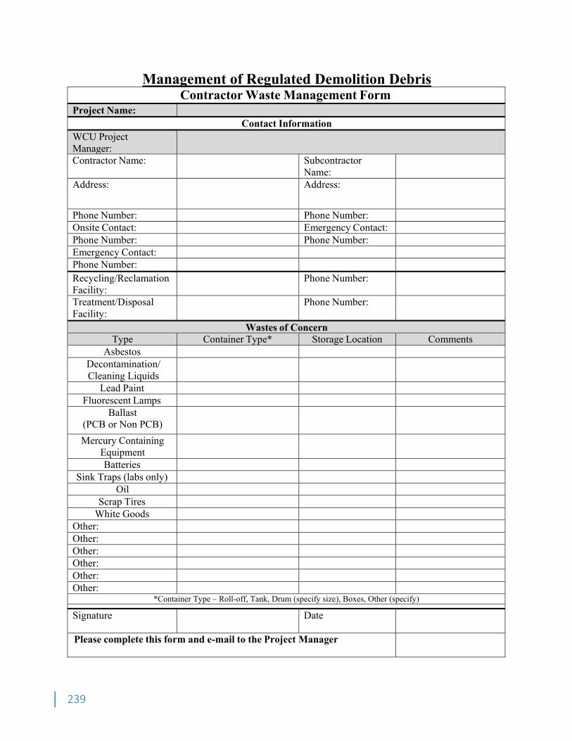
239
Management of Regulated Demolition Debris Contractor Waste Management Form
Project Name:
Contact Information WCU Project Manager:
Contractor Name: Subcontractor Name:
Address: Address:
Phone Number: Phone Number: Onsite Contact: Emergency Contact: Phone Number: Phone Number: Emergency Contact: Phone Number:
Recycling/Reclamation Facility:
Phone Number:
Treatment/Disposal Facility:
Phone Number:
Wastes of ConcernType Container Type* Storage Location Comments
Asbestos Decontamination/ Cleaning Liquids
Lead Paint Fluorescent Lamps
Ballast (PCB or Non PCB)
Mercury Containing Equipment
Batteries Sink Traps (labs only)
Oil Scrap Tires
White Goods Other: Other: Other: Other: Other: Other:
*Container Type – Roll-off, Tank, Drum (specify size), Boxes, Other (specify)
Signature Date
Please complete this form and e-mail to the Project Manager
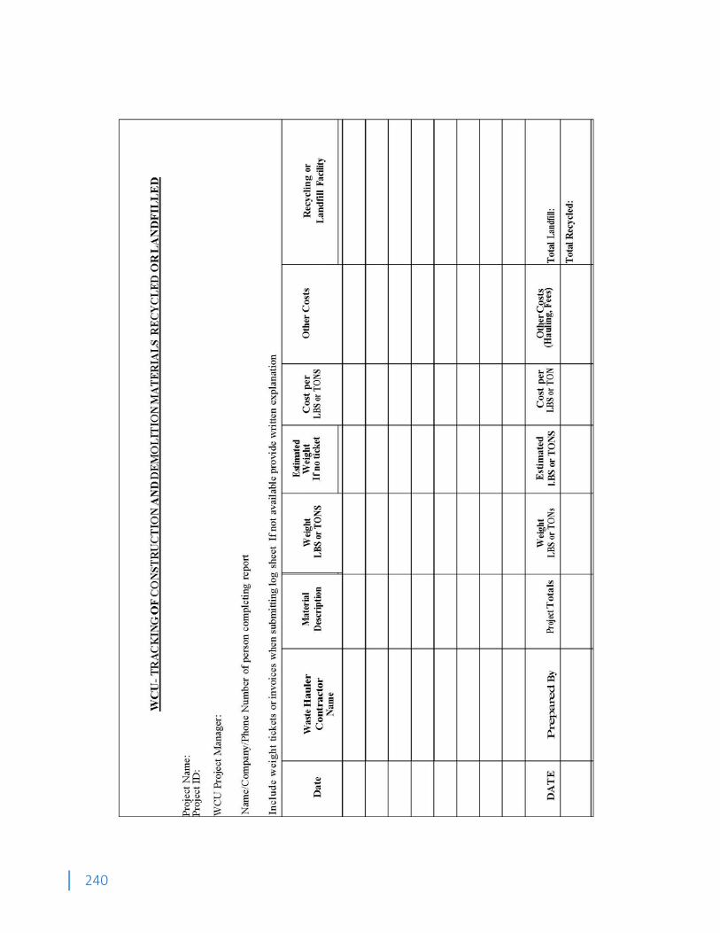
240
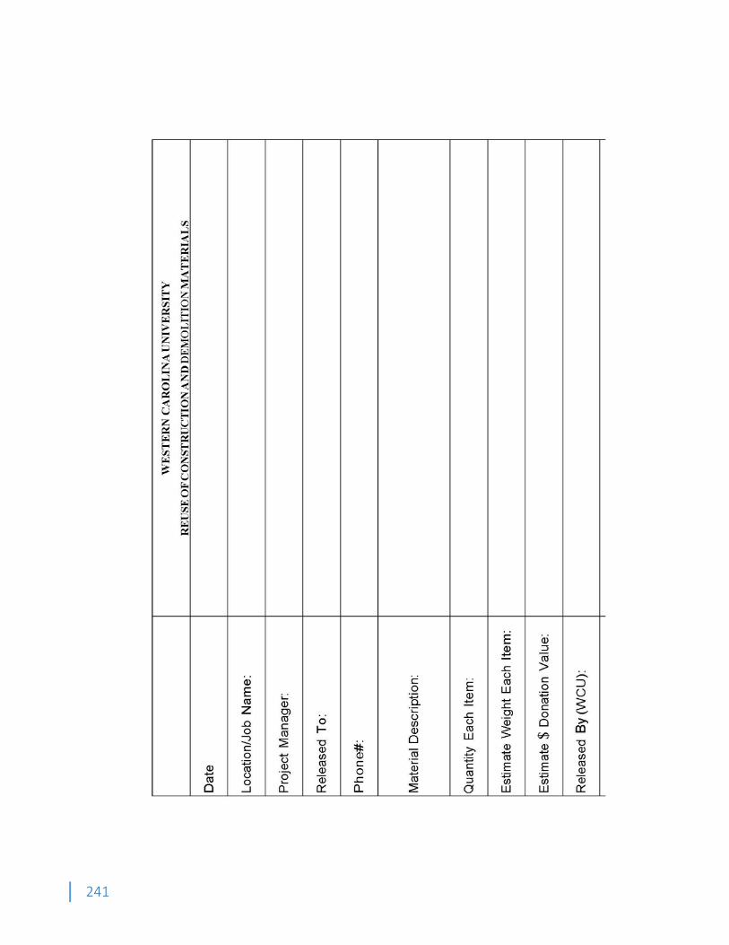
241

242
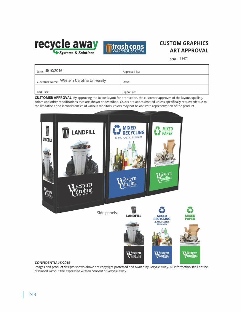
243

244

245

246
Appendix K State of North Carolina Department of Administration – State Construction Office
Electrical Guidelines and Policies (2011)
STATE OF NORTH CAROLINA
DEPARTMENT OF ADMINISTRATION
STATE CONSTRUCTION OFFICE
ELECTRICAL
GUIDELINES AND POLICIES
2011
Electrical Guidelines and Policies-2011
- 1 -
The following guidelines and policies are established to aid the designer during design development and specification writing. Contents herein are not to be included in designer’s specification by reproduction, but shall be used as a guide only. Variances of these guidelines and policies shall be discussed with the State Construction Office prior to submitting design to alleviate possible extra work on the designer’s part.
The following replaces the Electrical Guidelines and Policies --2008 in its
entirety.
Major changes are highlighted in the right hand margin by a bar.
Electrical Guidelines and Policies-2011
- 2 -
TABLE OF CONTENTS
SECTION PAGE NO. 26 01 00 Basic Electrical Requirements ............................................................................. 04 26 02 05 Division of Work ................................................................................................... 06 26 08 00 Electrical Testing ................................................................................................. 07 26 05 00 Minor Electrical Demolition For Remodeling ........................................................ 09 26 05 33 Conduit ................................................................................................................ 09 26 05 43 Ductbanks ........................................................................................................... 11 26 05 13 Medium Voltage Cable ........................................................................................ 12 26 05 19 Building Wire and Cable ...................................................................................... 15 26 27 26 Wiring Devices ..................................................................................................... 17 26 05 26 Grounding and Bonding ....................................................................................... 18 26 05 29 Supporting Devices ............................................................................................. 19 26 05 53 Electrical Identification ......................................................................................... 19 26 43 13 Surge Protective Devices (SPD) .......................................................................... 20 26 11 00 Unit Substations .................................................................................................. 20 26 12 19 Pad Mounted Distribution Transformers ............................................................... 20 26 18 00 Air Interrupter Switches ....................................................................................... 23 26 18 01 Oil Interrupter Switches ....................................................................................... 23 33 71 00 Overhead Power Distribution ............................................................................... 23 26 24 13 Distribution Switchboards (600 Volt) .................................................................... 24 26 28 16 Enclosed Switches .............................................................................................. 25 26 22 00 Dry Type Transformer .......................................................................................... 25 26 24 16 Panelboards ........................................................................................................ 25 26 28 13 Fuses .................................................................................................................. 26 26 24 19 Motor Control Centers ......................................................................................... 27 26 36 00 Automatic Transfer Switches ............................................................................... 27 26 51 00 Interior Luminaries ............................................................................................... 29 26 56 00 Site and Exterior Lighting ..................................................................................... 34 26 33 00 Static Emergency Power Supplies ....................................................................... 34 26 32 13 Packaged Engine Generator Systems ................................................................. 34 26 41 00 Lightning Protection Systems .............................................................................. 40 28 31 13 Fire Alarm Systems ............................................................................................. 40 27 05 00 Telecommunications ............................................................................................ 41
Electrical Guidelines and Policies-2011
- 3 -
APPENDIX PAGE NO. Lighting Life Cycle Cost Analysis (LCCA)………………………………………………. E-00 Fire Alarm System Symbols………………………………………………………………. E-01 Generator System Wiring…………………………………………………………………. E-1 Emergency Generator (Outside) - 100% Transfer ..................................................... E-4 Emergency Generator (Inside) - Not 100% Transfer…………………………………… E-5 Typical Panelboard Schedule .................................................................................... E-6 Typical Grounding Detail for Three Phase Pad Mounted Transformers .................... E-7 Load Tabulation Breakdown ...................................................................................... E-8 Working Clearance for Electrical Equipment .......................................................... ..E-9 Dedicated Space for Electrical Equipment ............................................................... ..E-10 Report of Primary Voltage Testing (Standard Form)................................................ ..E-11 Fire Pump Controller Grounding…………………………………………………………. E-12 Service Equipment Grounding …………………………………………………………… E-13 Dry Type Transformer Grounding………………………………………………………… E-14 Receptacle Grounding…………………………………………………………………….. E-15 Lighting Fixture Mounting Detail .............................................................................. ..E-16 Typical Exterior Pole Base Detail ............................................................................ ..E-17 Electrical Equipment Connection ............................................................................. ..E-18
Electrical Guidelines and Policies-2011
- 4 -
26 01 00 BASIC ELECTRICAL REQUIREMENTS
a) AEIC (American Association of Edison Illuminating Companies)
b) ANSI C82.11 (American National Standards Institute for Fluorescent Ballasts)
c) ASTM (American Society for Testing and Materials)
d) ASHRAE/IES (90.1 energy conservation code)
e) BOCA (Building Officials Code Administrators)
f) ICEA (Insulated Cable Engineers Association)
g) ICC (International Code Council)
h) ICBO (International Conference of Building Officials)
i) IEEE (Institute of Electrical and Electronic Engineers)
j) NCCM (N.C. Construction Manual w/G.S. as listed)
k) NCSBC (N.C. State Building Code)
l) NEC (National Electrical Code)
m) NECA .(National Electrical Contractor Association)
n) NEMA (National Electrical Manufacturers Association)
o) NESC (National Electrical Safety Code)
p) NFPA (National Fire Protection Association)
q) NEIS (National Electrical Installation Standards)
r) U/L (Underwriters' Laboratories Inc.)
s) OSHA (Occupational Safety and Health Administration)
t) SBCCI (Southern Building Code Congress International)
u) TCLP (Toxicity Characteristic Leaching Procedure)
2. Non Appropriated Funds Projects, such as: Privately Funded Projects on State Land, or Privately Funded Projects on Private Land that will be maintained by the state, or Privately Funded Projects on Community College Land shall be designed to meet or exceed requirements of the Electrical Guidelines and Policies issued by this office, the Fire Alarm Guidelines, the State Construction Office manual, and the STS 1000 for the telecommunication systems. Strict adherence to these publications is required. Please see State Construction Manual, Section for the non appropriated funds projects.
3. Specifications for electrical work shall clearly indicate the responsibility of the electrical contractor to notify the State Electrical Inspector with Department of Administration; for state
Electrical Guidelines and Policies-2011
- 5 -
owned projects, and to notify the local inspectors; for community college & county owned buildings, to schedule required inspections.
4. At the bid document submittal, electrical drawings and specifications shall be sealed, signed and dated by the design engineer of record registered in the State of North Carolina. Professional seal is also required on the electrical plans for the design of the special systems, such as the stage lighting, the audio/video and the like.
5. An electrical symbol schedule and legend shall appear on the first sheet of the electrical drawings. The electrical symbols shown on the bid documents shall consist of standard design symbols. For the purpose of clarification “standard symbols” can be found in current editions of the Architectural Graphic Standards, the American Electricians’ Handbook, and in the IEEE Standards. Fire Alarm and life Safety symbols should be based on symbols defined in the American National Standard NECA 100.
6. On the electrical drawings the Designer shall include a Load Tabulation Breakdown in KVA rating for the existing peak demand load, if any, the new connected load, and demand load, and the diversity factor. Where two or more non-coincident loads will be used simultaneously, the largest load only shall be calculated. (See Appendix, Sheet E-8).
7. Special attention is directed to N.C. General Statute 133-3 (Specifications to Carry Competitive Items, Substitution of Materials) for strict adherence thereto (for all equipment where available). See the procedure provided on the SCO web site regarding this issue.
8. The design engineer shall provide a short-circuit study and shall ensure that coordination study is performed between the main protective devices for the system, feeder protective devices for the system, and all downstream protective devices. It is the engineer’s responsibility to make sure the system is fully coordinated and properly protected against short circuit, overload & ground fault. The coordination study is required for projects involving the use of protective relays, adjustable circuit breakers and main fuses, and shall be performed in accordance with recommendation of the IEEE standards and NEC. If requested by the SCO, the engineer's basis-of-design sealed studies shall be submitted to the State Construction Office at the time of “working drawing” review. After the design engineer’s approval of the vendor “shop drawings” final coordination study based on the protective device vender chosen for the project should be reviewed, stamped approved and dated by the design engineer of record, if requested, the study shall be submitted to SCO for verification.
9. List for Third Party Agencies Accredited by the NCBCC to Label Electrical and Mechanical Equipment, shall be obtained from Department of Insurance, Electrical Inspection Section. The list can be found on DOI web site.
10. On the electrical drawings the designer shall include an Energy Table showing the method of compliance (prescriptive, performance, or energy cost budget) and the total watts specified VS. allowed for the interior and the exterior lighting. Energy Table shall be signed and dated by the Engineer of record.
11. Thermal detection test shall be performed on the MV equipment connections, preferably July or August, prior to the expiration of the one year contracted warranty.
12. Equipment Installation: The complete electrical installation shall fully comply with all requirements of the regulations, laws, ordinances, the National Electrical Code, referenced Standards, the State Construction Office Electrical Guidelines, and other Codes applicable to this project. In addition, equipment shall be installed in accordance with the manufacturer’s
Electrical Guidelines and Policies-2011
- 6 -
instructions as required by NEC 110.3 (B). While our reviews are intended to be thorough and accurate, they do not include all aspects of the applicable Codes, nor do they relieve the need for the designers to thoroughly check their plans for Code compliance. Therefore, any change order due to not complying with these Codes’ requirements is the responsibility of the Engineer of Record.
26 02 05 DIVISION OF WORK
1. This section delineates the division of work between the Electrical Contractor and any other Contractor.
2. Specific work to be done under Division 26 is hereinafter listed or described. All other work necessary for the operation of Division 23 equipment shall be performed under Division 23.
3. All individual motor starters and drives for mechanical equipment (fans, pumps, etc.) shall be furnished and installed under Division 23 unless indicated as a part of a motor control center. Motor starters for mechanical equipment provided in motor control centers shall be furnished under Division 26.
4. Under Division 26, power wiring shall be provided up to a termination point consisting of a junction box, trough, starter, VFD or disconnect switch. Under Division 26 line side terminations shall be provided. Wiring from the termination point to the mechanical equipment, including final connections, shall be provided under Division 23.
5. Duct smoke detectors, if provided per NFPA 90A requirements, shall be furnished and wired by Division 28, installed by Division 23. Fire alarm AHU shut down circuits shall be wired from the fire alarm control panel to a termination point, adjacent to the AHU control, under Division 28. AHU control wiring from the termination point to the equipment shall be under Division 23.
6. Equipment less than 110 Volt, all relays, actuators, timers, seven-day clocks, alternators, pressure, vacuum, float, flow, pneumatic-electric, and electric-pneumatic switches, aquastats, freeze-stats, line and low voltage thermostats, thermals, remote selector switches, remote push-button stations, emergency break-glass stations, interlocking, disconnect switches beyond termination point, and other appurtenances associated with equipment under Division 23 shall be furnished, installed and wired under Division 23.
7. All wiring required for controls and instrumentation not indicated on the drawings shall be furnished and installed by Division 23.
8. Roof exhaust fans with built-in disconnects provided under Division 23, or doors provided with built-in outlets shall be wired under Division 26 to the line side of the disconnect switch, or the outlet. A disconnect switch shall be provided under Division 26 if the fan is not provided with a built-in disconnect switch. In this case wiring from the switch to the fan shall be under Division 23. See sheet E-18 regarding the location and wiring of disconnects for other equipment. The built-in switch for the roof top equipment shall be in NEMA 3R enclosure.
9. The sequence of control for all equipment shall be as indicated on the Division 23 Drawings and specified in Section 23, HVAC Control System.
10. Horsepower for all motors shall be indicated on the Division 23 and Division 26 Drawings.
Electrical Guidelines and Policies-2011
- 7 -
11. VFD Cable shall be specified under section 23, for the mechanical contractor. The Mechanical Engineer shall specify 3-phase, 3 ground, copper tape spiral shield, galvanized steel interlocked Armor cable for the VFD cable. To ensure system reliability, the cable shall be terminated in connector designed exclusively for ASD/VFD cable.
12. All sprinkler flow and tamper switches shall be furnished and installed under Division 21, and wired under Division 28.
13. Where electrical wiring is required by trades other than covered by Division 26, specifications for that section shall refer to same wiring materials and methods as specified under Division 26. Exception to that is the low-voltage control wiring; the use of the J-Hooks to support the low-voltage control wiring system is acceptable; as outlined in Section 4, the Telecom STS -1000 Guidelines.
14. For kitchen equipment, Division 26 contractor shall install wiring from a power source to a termination point, adjacent to the kitchen equipment. Contractor providing kitchen equipment will wire to the equipment from the termination point.
15. The use of combination starter is recommended over the use of individual starter and disconnect switch. Also, the use of VSD for pump and fan motors five H.P and larger is recommended.
16. A diagram clarifying who is to provide and install the termination point, such as (trough, VFD, individual starter, disconnect switch, JB, --- etc.) shall be placed on the electrical and the mechanical plans. (See Appendix, Sheet E-18)
17. Disconnects for the elevator and the elevator’s car shall be provided and installed by the electrical contractor.
18. Reports showing the sizes of the maximum overcurrent protection (MOCP) and the maximum circuit ampacity (MCA) and overload setting of the devices for all motors; shall be provided by the contractor providing the equipment to this engineer before project final approval.
19. All electrical work shall be performed by companies properly licensed by the NC State Electrical Board of Examiners.
20. Exit doors & other doors provided with built-in outlets shall be wired by the electrical contractor all the way to the door outlet. Electrical Engineer shall coordinate with the Architect when specifying Door shutters and magnetically held doors to ensure all required fire alarm devices are shown and specified.
26 08 00 ELECTRICAL TESTING
FEEDER INSULATION RESISTANCE TESTING
1. All current carrying phase conductors and neutrals shall be tested as installed, and before connections are made, for insulation resistance and accidental grounds. This shall be done with a 500 volt megger. The procedures listed below shall be followed:
Electrical Guidelines and Policies-2011
- 8 -
a) Minimum readings shall be one million (1,000,000) or more ohms for #6 AWG wire and smaller, 250,000 ohms or more for #4 AWG wire or larger, between conductors and between conductor and the grounding conductor.
b) After all fixtures, devices and equipment are installed and all connections completed to each panel, the contractor shall disconnect the neutral feeder conductor from the neutral bar and take a megger reading between the neutral bar and the grounded enclosure. If this reading is less than 250,000 ohms, the contractor shall disconnect the branch circuit neutral wires from this neutral bar. He shall then test each one separately to the panel and until the low readings are found. The contractor shall correct troubles, reconnect and retest until at least 250,000 ohms from the neutral bar to the grounded panel can be achieved with only the neutral feeder disconnected.
c) At final inspection, the contractor shall furnish a megger and show the engineers and State Construction Office representatives that the panels comply with the above requirements. He shall also furnish a hook-on type ammeter and voltmeter to take current and voltage readings as directed by the representatives.
GROUND SYSTEM TESTING
1. Upon completion of installation of the electrical grounding and bonding systems, the ground resistance shall be tested with a ground resistance tester. Where tests show resistance-to-ground is over 25 ohms, appropriate action should be taken to reduce the resistance to 25 ohms, or less, by driving additional ground rods. (The compliance should be demonstrated by retesting.)
CIRCUIT BREAKER TESTS
1. For services 1000 amperes and larger, the following tests should be performed on the service circuit breakers and the distribution circuit breakers. Testing shall be performed by a qualified factory technician at the job site. All readings shall be tabulated:
a) Phase tripping tolerance (within 20% of U/L requirements).
b) Trip time (per phase) in seconds.
c) Instantaneous trip (amps) per phase.
d) Insulation resistance (in megohms) at 100 volts (phase to phase, and line to load).
GROUND FAULT PROTECTION SYSTEM
1. The ground fault protection on the new circuit breakers (if provided) shall be performance tested in the field and properly calibrated and set in accordance with the coordination study.
Electrical Guidelines and Policies-2011
- 9 -
DOCUMENTATION
1. All tests specified shall be completely documented indicating time of day, date, temperature and all pertinent test information.
2. All required documentation of readings indicated above shall be submitted to the engineer prior to, and as one of the prerequisites for, final acceptance of the project.
26 05 00 MINOR ELECTRICAL DEMOLITION FOR REMODELING
1. Abandoned conduit/boxes shall have all electrical wiring removed completely and not just made "safe." Conduit/boxes shall be removed where practical without creating additional demolition/restitution work for other trades.
26 05 33 CONDUIT
UNDERGROUND RACEWAYS
1. Raceways run external to building foundation walls, with the exception of branch circuit raceways, shall be encased with a minimum of three (3) inches of concrete on all sides.
a) Encased raceways must have a minimum cover of eighteen (18) inches, except for raceways containing circuits with voltages above 600 volts, which must have a minimum cover of thirty (30) inches.
b) Encased raceways shall be of a type approved by the NEC as "suitable for concrete encasement."
2. Branch circuit raceways run underground external to building foundation walls shall be run in raceways installed in accordance with the NEC, and shall be of a type approved by the NEC as "suitable for direct burial." Minimum raceway size shall be 3/4 inch.
3. All underground raceways shall be identified by underground line marking tape located directly above the raceway at 6 to 8 inches below finished grade. Tape shall be permanent, bright-colored, continuous printed, plastic tape compounded for direct burial not less than 6 inches wide and 4 mils thick. Printed legend shall be indicative of general type of underground line below.
4. Raceways run underground internal to building foundation walls shall be of a type and installed by a method approved by the NEC.
5. Where underground raceways are required to turn up into cabinets, equipment, etc., and on to poles, the elbow required and the stub-up out of the slab or earth shall be of rigid steel.
Electrical Guidelines and Policies-2011
- 10 -
6. The raceway system shall not be relied on for grounding continuity. See Section 26 05 26 Grounding and Bonding for clarification.
7. Where passing through a "below grade" wall from a conditioned interior building space, raceways shall be sealed utilizing fittings similar and equal to OZ/GEDNEY type "FSK" thru-wall fitting with "FSKA" membrane clamp adapter if required.
ABOVE GROUND RACEWAYS
1. Conduit shall be sized in accordance with the latest edition of the NEC unless shown otherwise, with minimum conduit size being 1/2 inch. Flexible metal and watertight ("sealtight") conduit in size 1/2 inch and larger are acceptable for motor, appliance and fixture connections provided green wire is installed and NEC is followed.
2. Conduit, exposed and concealed (except "in-slab"), shall be neatly installed parallel to, or at right angles to beams, walls and floors of buildings.
3. EMT may be utilized as permitted by the NEC, with the following restrictions. EMT conduit, couplings, elbows and fittings shall not be installed:
a) Any location outdoors, in direct contact with earth, or underground (in/below slab- on grade or in earth)
b) Indoors in wet or damp locations, or in concrete, cinderblocks or bricks.
c) Where exposed to severe corrosive influence and/or severe physical damage.
d) Encased in concrete.
e) For transition between EMT and rigid conduits, use JB.
4. The raceway system shall not be relied upon for grounding continuity. Section 26 05 26 Grounding and Bonding for clarification.
5. EMT conduit provided below roof deck shall be installed 11/2 inches away from the deck to allow for screws not to penetrate the EMT conduit during reroofing.
6. Conduits, JBs, Troughs, any enclosure when mounted outside on the walls, shall be off the walls by one inch.
7. The use of "LB's" shall be limited where possible. Where necessary to use "LB's" sized larger than 2 inches, mogul units shall be installed.
8. PVC schedule 40 shall not be used exposed or concealed in gypsum walls, but may be used in CMU walls. PVC schedule 40 may be used in elevated floor slabs and in foundation slabs. Minimum concrete cover shall be 3/4 inch at finished or formed surface and shall be 3 inches at concrete surface cast against earth or for slabs placed on-grade. Greater amounts of concrete cover shall be used in areas subject to damage or corrosion. Installed systems shall comply with the minimum requirements of ACI318 Chapter 6. The placement of conduit in floor slabs must be thoroughly coordinated with, and approved by, the structural engineer of record. Such placement must be clearly addressed by the construction documents. Potential conflicts with steel reinforcing bars, composite slab shear anchors, and reductions in net concrete sections
Electrical Guidelines and Policies-2011
- 11 -
are among the issues that must be considered by the structural engineer. The effect of closely spaced conduit groups on fire-rated horizontal assemblies shall be addressed by the design team. Post-bid proposals to move under-floor conduit into the slab are subject to approval by the structural engineer and related slab reinforcement or slab reconfiguration could require a credit from the contractor.
TERMINATIONS
1. IMC and GRC shall terminate with either a double locknut / bushing set, or in a threaded hub.
2. Where concentric, eccentric or over-sized knockouts are encountered, a grounding-type insulated bushing shall be provided.
3. All conduits shall be provided with Insulated throat.
4. EMT terminations shall be made utilizing steel-plated hexagonal compression connectors. No pot metal, set screw or Indented type fittings shall be utilized.
CONDUIT COUPLINGS
1. Where conduits of any type pass over a building expansion joint, a standard "expansion joint fitting," compatible with the type raceway being used, shall be provided.
2. Conduit couplings for IMC, GRC and PVC shall be in accordance with the NEC.
3. EMT couplings shall be of the plated-steel hexagonal compression type. No pot metal, set screw or Indented type couplings shall be utilized.
26 05 43 DUCTBANKS
(See Section 26 05 33 Underground Raceways, for additional coverage on underground raceways.)
1. Excavation and backfill shall conform to "Division 2" of the specifications except heavy-duty, hydraulic-operated compaction equipment shall not be used.
2. Trenches should be cut neatly and uniformly, sloping uniformly to required pitch.
3. Ducts should be pitched to drain toward manholes and hand-holes and away from buildings and equipment. Minimum slope shall be 4 inches in 100 feet. Where necessary to achieve this between manholes, ducts should be sloped from a high point in the run to drain in both directions.
4. Concrete encased nonmetallic ducts shall be supported on plastic separators coordinated with duct size and spacing. Separators shall be spaced close enough to prevent sagging and deforming of ducts. Separators to the earth and to ducts should be secured to prevent floating
Electrical Guidelines and Policies-2011
- 12 -
during placement of concrete. Steel or tie wires should not be used in such a way as to form conductive or magnetic loops around ducts or duct groups.
5. Waterproof marking cord should be installed 130-pound tensile test (marked at least every foot), equivalent to Greenlee No. 435, in all ducts, including spares, after thoroughly rodding, clearing and swabbing all lines free of any and all obstructions.
6. All ducts should be sealed at terminations, using sealing compound and plugs, as required to withstand 15 psi minimum hydrostatic pressure.
7. The installation of MHs should be in accordance with OSHA requirements.
8. After installation of the raceway system and before pulling the cables, the raceway system shall be air tested to 15 psi hydrostatic pressure.
26 05 13 MEDIUM-VOLTAGE CABLE
CABLE CONSTRUCTION
1. Conductors shall be soft drawn, Type MV-105, Class "B", concentric compact or compressed, stranded copper, single conductor shielded cable. The shielding process shall be one of the following; either a, b, or c:
a) A true triple extrusion (done simultaneously, in a common extrusion head which does not expose the EPR insulation to the atmosphere). The cable shielding shall consists of, semi-conducting strand shield, EPR insulation and semi-conducting insulation shield.
b) A true triple tandem extrusion process, where the semi-conducting strand shield, the insulation and the semi-conducting insulation shield are EPR.
c) Double extrusion process for the non-conducting cable shield and the insulation; the non-conducting cable shield shall be continuously tested for 2kv DC test while the shield is over the conductor and prior to the EPR insulation & the insulation shield being applied.
2. Cable shall be capable of operating at a normal continuous conductor temperature of 105°C, an emergency overload conductor temperature of 140°C, and a short circuit conductor temperature of 250°C.
3. Cable shall be shielded with 5 mil metallic uncoated copper tape helically applied with 25% nominal overlap.
4. The EPR insulation shall be compounded by the cable manufacturer in its own facility.
5. The overall jacket or sheath shall be oil, acid, alkali, and sunlight-resistant PVC compound which shall be rated for use in conduit or aerial construction. Cable identification shall be printed on this jacket using indelible ink. The cable identification shall indicate “the manufacturer, the plant number, cable size, year of manufacture, insulation thickness, insulation type, voltage rating, KV% insulation level& sequential footage number.”
Electrical Guidelines and Policies-2011
- 13 -
6. Primary cable ratings: The primary cable ratings shall be 5,000 Volts; nominal 115 mils thickness, 15,000 volts; nominal 220 mils thickness, or 25,000 volts; nominal 345 mils thickness. Cable thickness shall meet or exceed AEIC and ICEA requirements and shall have 133% insulation.
7. The cable shall be provided with 600 volts grounded neutral.
8. Cable shall pass the flame test in accordance with the IEEE 1202, CSA FT4 & ICEA T-29-520.
9. The cable shall meet or exceed the following standards: ICEA S-93-639, NEMA WC 74, AEIC CS-8, ASTM B-496, UL-1072 (type MV-105) for all cables, IEEE 383 for cables 1/0 AWG and larger.
10. The Quality Assurance Program and the ISO certification shall be provided to State Construction Office upon request.
11. Qualification Test Report for the cable insulation system (conductor-shield, insulation, and insulation-shield) shall be provided to State Construction Office upon request.
12. The cable supplied must have been manufactured within 12 months prior to date of order placement.
INSTALLATION
1. The approved cable shall be installed in continuous lengths where possible, and shall be fireproofed in each manhole.
a) The fireproofing tape shall consist of a flexible conformable fabric having one side coated with a flame-retardant, flexible polymeric coating and/or a chlorinated elastomer.
b) The tape shall be 1/16 inch thick by 3 inches wide, wrapped around each conductor spirally with the coated side toward the conductor.
c) The tape shall extend for the total length of the conductor in the manhole and 1 inch into the ducts.
d) The tape shall be non-corrosive to the cable jacket, self-extinguishing, and shall not support combustion.
2. Splices are to be permitted only at points designated on the plans. All splices and terminations, unless otherwise specified, are to be fabricated in accordance with the cable and termination manufacturer's recommendations, or in accordance with the details of such instructions included on the drawings.
3. M.V Cable pulling tension and side wall pressure calculations shall be performed to assure that all circuits are installed in strict accordance with the physical limits of the cables as stated by the manufacturer.
4. Cable shall be manufactured by General Cable, Kerite, Okonite, Prysmian, or an approved substitute. Before approval by the engineer, any proposed substitution shall be discussed with the State Construction Office prior to the opening of bids.
Electrical Guidelines and Policies-2011
- 14 -
MEDIUM VOLTAGE CABLE TEST REPORT
1. The cable shall be tested at the factory. The contractor shall be required to furnish a Certified Manufacturer’s Test Report for the "Master Reel" of each cable length shipped, for approval by the engineer. The test report shall include:
a) A high voltage test (A.C)
b) Corona test.
2. The manufacturer's certified test report shall include all the data. Copy of the test report shall be sent to the owner.
3. After installation, but prior to energizing the system, the contractor shall also high-pot the system in accordance with the design engineer's specified testing procedure, as witnessed and "signed-off" by the design engineer. Copies of this test report shall be sent to the owner, to the engineer, and to the State Construction Office, attention Design/Review Section.
MEDIUM VOLTAGE CABLE WARRANTY
1. The cable manufacturer shall warrant to the owner that each reel of cable is free from defects in material, design and workmanship and will provide reliable performance for a twenty-five (25) year life from the date of project final acceptance.
2. The warranty assumes the cable is installed, spliced, terminated and maintained in accordance with manufacturer's recommendations.
3. Prior to cable termination or splicing, contractor shall submit the qualifications of personnel directly responsible for completing this work to the engineer. Upon approval by the engineer in writing, contractor may proceed with this portion of the work.
4. Defective cable shall be replaced at no cost to the owner.
a) When the manufacturer and the owner mutually determine a portion of or all of the cable is defective, the cable manufacturer shall furnish replacement of said cable without charge.
b) The replacement cable shall comply with these requirements and be delivered to the original delivery point free of any charge to the owner or the State of North Carolina.
5. Cable shop drawings shall include said described warranty from the cable manufacturer properly signed, and having the manufacturer's corporate seal affixed thereto.
REEL HANDLING AND STORGE:
1. The manufacturer shall ship all reels in an upright position on the flanges. The cable ends shall be sealed to prevent the entrance of moisture, gases or vapors into the cable. After the cutting of any length, the exposed ends of any remaining cable on the reel shall have heat-shrinkable
Electrical Guidelines and Policies-2011
- 15 -
end caps applied to prevent the entrance of water or vapor. The manufacturer shall be responsible to indicate to any commercial carrier the requirements for shipping the reels of completed cable. The Contractor and the Engineer shall be responsible for the acceptance inspection of the shipped cable reels and shall note any visible damage on arrival in any unacceptable orientation or condition and inform the carrier, distributor and manufacturer of such damage or unacceptable condition. Any movement or lifting of completed reels of cable shall be by the use of a bar inserted through the arbor hole in the cable reel and, as appropriate or necessary, use of a spreader bar to avoid damage to the reel flanges. No completed reel of cable shall be lifted by any force on or connection directly to the reel drum. Completed reels of cable shall be covered with a suitable material to reduce the impact of weather, rain or sunlight on the cable. Reels under the covering should have adequate ventilation to prevent the formation of condensation.
CABLE IDENTIFICATION:
1. Each reel shall have an identification tag by the manufacturer securely attached to each flange
and shall contain the following information, manufacturer’s name & location, cable trade name, conductors size and voltage rating, identification of insulation and jacket material, footage, and UL label.
26 05 19 BUILDING WIRE AND CABLE
GENERAL
1. All wire and cable shall be listed by an "approved" third-party testing agency.
2. Prior to energizing feeders, sub-feeders and service conductor cables shall be tested for electrical continuity and short circuits. A copy of these tests shall be sent to the State Construction Office, the engineer of record, and the owner.
3. All wire and cable shall run in raceway.
4. In special cases, type “AC” and type "NM" cables are permitted provided the State Construction Office has approved the application. Upon consultation with the State Construction Office, Review Section, the use of type MC Cable is approved. The MC: 1) shall not exceed 6 feet in length, 2) shall be minimum ½-inch diameter trade size, 3) conductors shall be provided with minimum #12 AWG solid copper rated at 600 Volts, and 4) shall contain #12 AWG separate green ground wire.
5. Minimum of full size individual neutral wire shall be provided for each circuit; in other words, no sharing of the neutral between circuits is allowed.
CONDUCTORS
1. Power and lighting circuits #10 AWG and smaller shall have solid copper conductors. Conductor sizes #8 AWG and larger shall have Class B stranded copper conductors. Aluminum
Electrical Guidelines and Policies-2011
- 16 -
conductor may be used as a service conductor for the main distribution panel, and/or as a feeder conductor for the electrical sub-panel, in situation where the designer and State Construction Office find it to be beneficial.
2. Power and lighting circuits’ minimum conductor size shall be #12 AWG, and maximum conductor size allowed shall be 500 Kcmil.
3. Fire alarm and control wiring shall have stranded copper conductors. See the Fire Alarm Guidelines provided on the State Construction Office Web Site.
4. Full size neutral conductor shall be provided for each service panel and sub-panel.
INSULATION The insulation type for interior wiring shall be dual-rated THHN/THWN or XHHW.
VOLTAGE DROP
1. Conductors for branch circuits shall be sized to prevent a voltage drop exceeding three percent (3%) at the farthest outlet of power, heating and lighting loads, or any combination of such loads. The maximum total voltage drop on both feeders and branch circuits to the farthest outlet shall not exceed five percent (5%).
2. If the actual load to be plugged to the receptacles is not known; assume 16amp load for the 20amp circuit breaker, and 12amp load for the 15amp circuit breakers; unless the breakers are rated to carry 100% load.
3. Where the conductor length from the panel to the first outlet on a 277 volt circuit exceeds 125 feet, the branch circuit conductors from the panel to the first outlet shall not be smaller than #10 AWG.
4. Where the conductor length from the panel to the first outlet on a 120 volt circuit exceeds 50 feet, the branch circuit conductors from the panel to the first outlet shall not be smaller than #10 AWG.
COLOR CODING
1. The secondary service, feeders and branch circuits shall be color coded as follows:
PHASE 208/120v 480/277v
A Black Brown
B Red Orange
C Blue Yellow
Neutral White Natural Gray
Electrical Guidelines and Policies-2011
- 17 -
Ground Green Green
SPLICING
1. Joints in solid conductors shall be spliced using Ideal "wirenuts", 3M Company "Scotchlock" or T&B connectors in junction boxes, outlet boxes and lighting fixtures.
2. "Sta-kon" or other permanent type crimp connectors shall not be used for branch circuit connections.
3. Joints in stranded conductors shall be spliced by approved mechanical connectors and gum rubber tape or friction tape. Solderless mechanical connectors for splices and taps, provided with U/L-approved insulating covers, may be used instead of mechanical connectors plus tape.
4. Conductors, in all cases, shall be continuous from outlet to outlet and no splicing shall be made except within outlet or junction boxes, troughs and gutters.
26 27 26 WIRING DEVICES
SWITCHES
1. Toggle switches shall be single pole, three-way, or four-way as indicated on the drawings. Switches shall be of the grounding type, with hex-head grounding screw, rated 20A, 120/277 volt, A.C only. Lighted handle switches shall have neon lights of the correct voltage rating where indicated on the drawings. All switches shall have quiet operating mechanisms without the use of mercury switches. All switches shall be listed by an "approved" third-party agency, approved for the voltage and amperage indicated.
2. The use of occupancy sensors are not permitted for the interior egress and exit lighting. The exit sign and egress lighting shall not be switched and shall remain on at all times.
RECEPTACLES
1. Duplex receptacles shall be of the grounding type, arranged for back and side wiring, with separate single or double grounding terminals. Receptacles shall be straight blade, rated 20A, 125 volt and the face configuration shall conform to the NEMA Standard No. WD-1, NEMA WD-6, DSCC W-C-596G & UL-498, and shall be "approved" third-party listed. Self-grounding or automatic type grounding receptacles are not acceptable in lieu of receptacles with separate grounding screw lugs and a direct, green insulated conductor connection to the equipment grounding system.
2. Receptacles shall be industrial specification heavy duty grade, mounted vertically. Receptacles mounted over counters, back-splashes, etc., shall be mounted horizontally.
3. Special wiring devices shall be shown on the drawings with complete description thereof.
Electrical Guidelines and Policies-2011
- 18 -
4. GFCI receptacles shall be rated minimum 20amp (NEMA 5-20R configuration).
5. GFCI receptacles shall be provided where installed to serve countertop.
6. GFCI receptacles shall be provided where located within 6 feet of a sink.
7. Breakers feeding sleeping areas shall be provided as required per Code.
8. Arc fault receptacles shall be provided for the“Dormitory” as required per code.
9. Receptacles shall not be mounted back to back.
DEVICE PLATES
1. Cover plates for flush mounted wiring devices and for telephone outlets shall be Type "302" stainless steel or nylon type, standard size, single or ganged as shown on the drawings. Cover plate mounting screws shall be slotted head oval screws and shall match the finish and material of the plate, and shall be furnished with the plate by the plate manufacturer. Quantity of 2% spare cover plates of each type shall be provided to the owner.
2. Switch and receptacle cover plates on exposed work shall be galvanized cast ferrous metal, standard size, and shall be single or ganged as indicated on the drawings.
3. Exterior mounted switch and receptacle plates, and those noted to be weatherproof, shall be weatherproof PVC cover plates, standard size, single or ganged as indicated on the drawings, and shall be "approved” third party listed as "rain-tight while in use."
26 05 26 GROUNDING AND BONDING
1. Grounding conductors, where insulated, shall be colored solid green. Conductors intended as neutral shall be colored solid white on 120/208 volt circuits and natural gray on 277/480 volt circuits.
2. The raceway system shall not be relied on for ground continuity. A green grounding conductor, properly sized per NEC Table 250-122, shall be run in ALL raceways except for telecommunications, data, and audio systems.
3. Grounding electrode conductor #4 AWG and larger shall be installed in raceway system.
4. Transformer grounding requirements (See Appendix relating to these requirements).
5. Generator and ATS grounding requirements (See Appendix relating to these requirements).
6. The electrical service shall be grounded by three (3) means:
a) To the metallic cold water pipe, as per NEC Article 250-52.
b) To the steel frame of the building, provided the building frame is effectively grounded.
c) To ground rod(s). Ground rods shall be 10 feet long and 3/4 inch in diameter, and shall be of copper-clad steel construction. All ground connections shall be accessible.
Electrical Guidelines and Policies-2011
- 19 -
7. Boxes with concentric, eccentric or over-sized knockouts shall be provided with bonding bushings and jumpers. The jumper shall be sized per NEC Table 250-122 and lugged to the box.
8. Where one building is feeding another building and a grounding conductor is run with the ungrounded conductors, a metallic conduit shall be provided between the buildings to establish improved grounding system.
9. The gas piping system shall be bonded to the equipment groun as required per the Gas Code Section 309.1
10. Identify each grounding electrode connected to a common ground bus. The height and the thickness of the common ground bus shall not be less than 2”*1/4”.
26 05 29 SUPPORTING DEVICES
1. Conduit shall be supported in a method and at a spacing as approved by the NEC, except as described herein.
2. Conduit shall be supported by approved pipe straps or clamps.
a) Conduits installed on the interior of exterior building walls shall be spaced off the wall surface a minimum of 1/4 inch using "clamp-backs" or strut.
3. Pipe straps or clamps shall be secured by means of:
a) Toggle bolts on hollow masonry.
b) Metal expansion shields and machine screws, or standard pre-set inserts, on concrete or solid masonry.
c) Machine screws or bolts on metal surfaces.
d) Wood screws on wood construction.
e) Powder actuated fasteners are not allowed.
26 05 53 ELECTRICAL IDENTIFICATION
1. Furnish and install engraved laminated phenolic nameplates for all safety switches, panelboards, transformers, switchboards, motor control centers and other electrical equipment supplied for the project for identification. Nameplates shall be securely attached to equipment with self-tapping stainless steel screws; if the screw sharp end is protected; otherwise Rivets shall be used. Letters shall be approximately 1/2 inch high minimum. Embossed, self-adhesive plastic tape is not acceptable for marking equipment. Nameplate material colors shall be:
....Blue surface with white core for 120/208 volt equipment.
....Black surface with white core for 277/480 volt equipment.
Electrical Guidelines and Policies-2011
- 20 -
....Bright red surface with white core for all equipment related to fire alarm system.
....Dark red (burgundy) surface with white core for all equipment related to security.
....Green surface with white core for all equipment related to "emergency" systems.
....Orange surface with white core for all equipment related to telephone systems.
....Brown surface with white core for all equipment related to data systems.
....White surface with black core for all equipment related to paging systems.
....Purple surface with white core for all equipment related to TV systems.
2. All empty conduit runs and conduit with conductors for future use shall be identified for use and
shall indicate where they terminate. Identification shall be by tags with string or wire attached to conduit or outlet.
3. All outlet boxes, junction boxes and pull boxes shall have their covers and exterior visible surfaces painted with colors to match the surface color scheme outlined above. This includes covers on boxes above lift-out and other type accessible ceilings.
26 43 13 SURGE PROTECTIVE DEVICES (SPD)
1. The System shall meet the following standards: IEEE C62.41& IEEE C62.45, NEMA LS 1, UL 1449, NEC Article 285. The TVSS shall be installed on the load side of the overcurrent protective device. SPD category “1 “shall be mounted at the service Transformer, Category “2” should be mounted at the service disconnecting means, Category “3” shall be mounted at the branch panel and Category “4” shall cover the entire system.
2. Reference the UL 1449, the Third edition. Also reference the ANSI/ IEEE C62.34.
26 11 00 UNIT SUBSTATIONS
1. The pad mounted transformer shall be of the five-legged core design, filled with "Listed less flammable type" oil for cooling. See Section 16321, Pad Mounted Distribution Transformers for further details.
2. The substation shall be "Metal-clad" type with "draw-out" vacuum breakers for 5 KV, 15 KV or 25 KV, as applicable.
3. Equipment shall meet requirements of the Arc Resistant Standards.
26 12 19 PAD MOUNTED SERVICE TRANSFORMERS
THREE-PHASE PAD MOUNTED TRANSFORMERS (DEAD FRONT)
Electrical Guidelines and Policies-2011
- 21 -
(NOTE: For use of "LIVE FRONT" construction, contact State Construction Office.)
Location of the Power Utility’s pad mounted transformer shall comply with ANSI/IEEE 979.
CONSTRUCTION
1. Transformers shall comply with latest applicable standards of NEMA and ANSI, IEEE C57.12.37.
2. Transformers shall be manufactured by General Electric, ETN, ABB, Square D or Cooper Power Systems. Comply with G.S 133-3 when using brand name specifications.
3. The "compartment type" pad mounted transformer shall be three-phase, oil cooled, tamper resistant, 65 degree C temperature rise rated, 60 hertz frequency, 12470 grd. wye 7200 primary voltage, or applicable primary voltage. The KVA and rated secondary voltage (208 grounded wye/120 or 480 grounded wye/277 volts) shall be as specified on the drawings. Oil shall be "R-Temp" or any "LISTED less flammable liquid" similar to BIOTEMP, or FR3 as required per NEC 450-23.
4. The transformer tank shall be of a sealed-tank construction as specified in ANSI Standard C57.12.26. The tank shall be a minimum of 12 gauge sheet steel, and strong enough to withstand a pressure of 7 psi without permanent distortion and 15 psi without rupturing or displacing of transformer components. A removable main cover may be provided over a bolted-on, tamperproof handhold. Handholds shall be provided for access to high voltage isolation links, three-phase switches, neutral connections, etc.
5. The transformer tank, high voltage compartment and low voltage compartment shall be constructed as an integral unit that will limit disassembly, breakage and prying open of any of the doors, panels and sills with the doors in the closed and locked position. There shall be no exposed screws, bolts or other fastening devices which are externally removable. There shall be no openings through which foreign objects such as sticks, rods or wires might be inserted to contact live parts. Lifting eyes and jacking pads shall be provided as part of the transformer and shall be arranged to provide a distributed balanced fit.
6. Each terminal compartment shall be full-height, air-filled with individual doors. The doors shall be constructed with sheet steel (minimum 13 gauge) and braced to prevent distortion. They shall be installed using lift-off type stainless steel hinges of a gauge equal to, or greater, than the door. A three-point latching mechanism with a cabinet- type handle, having provisions for the use of a single padlock, shall be provided on the low voltage door. A 1/2 inch penta-head stainless steel spring-loaded captive bolt shall also be provided with a blind bolt hole. Removal of the penta-head locking bolt may only be accomplished after removal of the padlock. This latching mechanism shall be designed and located to provide access to the high voltage compartment only after the door to the low voltage compartment has been opened. There shall be one more additional fastening device that must be removed before the high voltage door can be opened. Door stops shall be provided to hold the doors open when working in the compartments. The doors and the front sill of the compartments shall be removable to allow sliding the transformer into position over conduit stubs. The high and low voltage compartments shall be separated by a steel barrier. When facing the transformer, the low voltage compartment shall be on the right.
Electrical Guidelines and Policies-2011
- 22 -
7. Transformer tank grounding provisions shall be in accordance with ANSI standards. The grounding provisions shall be capped before painting the unit.
8. The core and coil assembly shall be of a five-legged design to provide adequate short-circuit strength and heat dissipation. When required, corrugated cooling panels shall be provided on the back and sides of the oil-filled tank to maintain a safe operating temperature. Internal leads shall be insulated, trained and anchored to prevent phase-to-phase flashover.
9. Transformers are to be equipped with four (4) taps rated approximately 2-1/2 percent, with two (2) above and two (2) below normal. The tap changer shall be externally hook stick operated and located in the high voltage compartment. The tap changer shall be designed and marked for de-energized operation.
10. The high voltage terminations and equipment shall be of the dead front construction.
11. Two high voltage bushings per phase shall be provided to permit operating a loop feed dead front transformer from a looped primary cable system. The high voltage bushings shall be one piece type for use with loadbreak elbow terminators. As an optional method to the engineer, provide a radial feed transformer with one bushing well and one loadbreak feed-thru insert per phase. Construction shall conform to ANSI/IEEE Standard 386. Bushings shall be externally clamped and externally removable. High and low voltage winding lead lengths shall be long enough to permit field replacement of bushings or bushing wells. All gasketed joints are to afford a sealed tank in accordance with industry standards. Gasket material must be durable and reusable. Parking stands shall be provided for mounting accessory equipment.
12. The lightning arrestors shall be similar and equal to RTE "M.O.V.E." type. The arrestor shall be mounted to the insert (ANSI/IEEE Standard 386).
13. Transformer overcurrent protection shall be a combination of oil-immersed current-limiting fuses in series with bayonet oil-immersed, overload sensing, expulsion fuses coordinated to provide full range protection with the expulsion fuse clearing low-current faults and the current limiting fuses clearing high-current faults up to 50,000 amperes. The fuse assembly shall have an interrupting rating of (3500A at 8.3 KV) or (1800 A at 15.5 KV) single phase, and a loadbreak rating of 125A at 80% power-factor for (8.3 KV or 15.5 KV) single phase. The bayonet fuses must be accessible through the primary compartment. They must be externally removable and field replaceable using a hotstick. This operation must be accomplished without having to remove the transformer compartment top. A welded-on oil dripshield must be located under the bayonet fuse to protect the primary connections.
14. The low voltage bushing shall be molded epoxy and capable of withstanding a load in a vertical direction of 800 inch-lbs. without causing a deflection sufficient to produce a leak. The bushings shall be externally clamped, blade type spade terminals with four (4)-hole NEMA standard spacing for transformers up to 500 KVA. Transformers above 500 KVA shall be equipped with six (6)-hole NEMA spacing. The bushings shall be arranged for vertical take-off.
15. The high voltage neutral shall be connected internally to the low voltage neutral with provisions for opening this connection for testing. The neutral bushing shall be fully insulated but connected to an adjacent ground pad (on the tank) with a detachable strap of sufficient size to carry the maximum fault current available from the transformer.
16. Equipment to be furnished as standard shall include:
a) A 1-inch drain valve with sampling device and 1 inch filler plug
Electrical Guidelines and Policies-2011
- 23 -
b) Liquid level indicator
c) Pressure-relief device equal to a Qualitrol 202-032-01 that will automatically relieve pressure and effectively keep the transformer sealed with no leakage of air or oil or any permanent distortion. Any pressure-relief device must exclude moisture from the transformer and have a life equal to the transformer.
17. Installed inside the low voltage compartment shall be a permanently affixed stainless steel nameplate containing the transformer serial number and style number plus other pertinent information. The transformer must be identified as non-PCB oil cooled unit with the PCB content clearly and permanently marked on the nameplate. The manufacturer is responsible for maintaining adequate documentation of the oil furnished in each unit and must provide copies upon request. All transformers shall be provided with a NEMA Standard Fig. 3 outside warning label on the outside high voltage compartment door, and a NEMA Standard Fig. 4 inside "DANGER" label on the inside of the low voltage compartment door.
18. The transformer(s) shall be designed for flexibility, convenience and reliability. All insulating components, oil, paper and wire enamel shall be made of thermally upgraded materials conforming to industry standards. In preparation of painting the transformer, the metal shall be washed with a solvent to remove rust, oil and grease. A minimum primer coat of 2 mils dry finish shall be applied. The finish coat of paint, with a minimum of 2-1/2 mils dry finish shall be olive green 7GY3.29/1.5, gray or equivalent.
GROUNDING: See Appendix, Sheet E-7.
26 18 00 AIR INTERRUPTER SWITCHES
1. Manual air interrupter switches, dead front application type.
2. The puffer vacuum air interrupter switch, and/or the gas (SF6) switch.
3. Fused cutout switches, air (load-break) type.
26 18 01 OIL INTERRUPTER SWITCHES
1. Oil interrupter switches are not acceptable for new construction.
2. Existing oil switches "RA" style, which do not have a close-into-fault rating, shall be removed and replaced with manual air switches or gas switches.
3. The "non-spring loaded" type switch is not acceptable for new construction.
33 71 00 OVERHEAD POWER DISTRIBUTION
1. Bare aluminum "ACSR" conductors shall be utilized for overhead primary distribution systems (5 KV, 15 KV, or 25 KV). Conductors shall be spliced using compression fittings by use of an approved dye and tool compression arrangement.
Electrical Guidelines and Policies-2011
- 24 -
2. Poles for overhead wiring shall be specified as pressure treated, Southern Yellow Pine, American Standard Class 5 poles. Poles shall be designed to support 125-150 ft. spans, adequate to sustain wind loads that meet or exceed NCSBC for the specific project location and a load in addition created by 1/2 inch of ice on the wire.
3. Crossarms shall be specified as untreated, straight-grain fir, or similar as approved by the State Construction Office. Dimensions shall be as recommended by the Edison Electric Institute Standards. The arms shall have spacing between center pins of 30 inches. Braces shall be made from galvanized flat iron.
4. Guywires shall not be less than 3/8 inch stranded galvanized cable, with appropriate galvanized steel hardware. They shall be heavy enough to sustain wind loads that meet or exceed NCSBC for the specific project location along with typical worst case weather conditions appropriate for the area. Two (2) strain insulators shall be inserted in each guy- one six (6) feet from the pole itself, and the other six (6) feet from the lower end of the guy and at least eight (8)feet from the ground.
5. Insulators shall be made of porcelain with wire grooves on top and sides.
26 24 13 DISTRIBUTION SWITCHBOARDS (600 Volt)
1. Switchboards shall have proper working clearances per NEC. Attention is directed to Article 110-26.
2. All bussing shall be tin-plated or silver-plated copper.
3. Switchboards identified for use as service equipment shall be so labeled.
4. Switchboards shall be provided with adhesive tape on front of enclosure to depict actual bus arrangement inside cubicles.
5. Switchboards shall be mounted on a nominal four (4) inch concrete housekeeping pad properly anchored in accordance with manufacturer's recommendations.
6. Each switchboard component shall be provided with adequate nameplate on front of cubicle (see Section 26 05 53 Electrical Identification).
7. Design documents shall include plan, side, and top views of switchboards along with adequate schedule locating and describing components therein.
8. Switchboards with bussing 1000 ampere or larger shall contain a metering section to include analog type meters such as ammeters, voltmeters, watt-hour, power factor, or electronic power metering.
9. Upon completion of installation, and prior to final inspection, the contractor shall reduce in size the "as-built" single line diagram (riser), frame same under glass, and mount in a conspicuous place adjacent to the switchboard.
10. Recommend all breakers 600 ampere and larger to be solid state trip type.
11. The flash protection boundary and the incident energy for the electrical equipment shall be determined in accordance with IEEE 1584 and NFPA 70E requirements. Equipment shall be
Electrical Guidelines and Policies-2011
- 25 -
field marked to warn qualified persons of potential electric flash hazard per NEC 110-16 requirements.
26 28 16 ENCLOSED SWITCHES
1. Safety switches shall be the "heavy duty" type. General duty switches are not acceptable.
2. Safety switches shall be third-party listed.
3. Switches shall have defeatable door interlocks that prevent the door from opening when the operating handle is in the "on" position.
4. Switches shall have handles whose positions are easily recognizable in the "on" or "off" position. For safety reasons, padlock shall be provided for switches located in the public areas.
5. Switches shall have nonteasible, positive, quick make-quick break mechanisms.
6. Switches shall be properly labeled. See Section 26 05 53, Electrical Identification.
26 22 00 DRY TYPE TRANSFORMER
1. The use of energy efficient transformer is required. Transformers with load factor up to 35% of their capacity shall have efficiency of 98% and shall meet or exceed NEMA TP-1 requirements.
Class 220, 115 C transformer shall be used when the load factor is up to 50% of their capacity,
otherwise, class 220C, 80 C rise shall be specified. The transformer overload capability shall be in accordance with IEEE C57.96; for standard transformers, and IEEE C57.110; for K-rated transformers. The K-rated transformer, when used shall also be energy efficient and shall bear the energy star label and shall also meet NEMA TP-1 requirements.
2. The energy policy act of 2005 (EPACT 2005), public Law 109-58, came into effect January 1, 2007, shall be enforced.
26 24 16 PANELBOARDS
1. Panelboards identified for use as service equipment shall be so labeled.
2. Panels 600amp and less shall be specified with bolt-on breakers.
3. Bus bars shall be copper.
4. Full size copper neutral bus shall be included in all panels. Copper ground bus shall be provided with the panel.
5. Feed-through panels are not permitted.
6. A typed directory card shall be supplied, mounted on the inside of each door.
7. An engraved nameplate shall be provided for each panel. See Section 26 05 53, Electrical Identification.
Electrical Guidelines and Policies-2011
- 26 -
8. "Load Centers" are not acceptable except in certain instances approved by the State Construction Office.
9. The use of series rated breakers is not acceptable.
10. Panelboards feeding electronic equipment shall be provided with a "full size" ground bus, a "full size" neutral bus, or 200% neutral bus, and shall be fed with feeders having a "full size" or larger neutral. Branch circuits shall have individual neutrals, in other words, no sharing of the neutral between circuits is allowed.
11. Panelboards schedules placed on contract documents shall follow the preferred format as indicated (see Appendix, Sheet E-6).
12. Equipment labeling for the flash protection boundary and the incident energy shall be determined in accordance with IEEE 1584, NFPA 70E & NEC 110-16 requirements.
13. Maximum numbers of breakers in a panelboard shall not exceed 42 poles.
14. On large buildings, the electrical panels that feed luminaires shall not feed receptacles and electrical panels that feed receptacles shall not feed luminaires.
15. The number of the branch circuit shall be identified with permanent wire tag attached to the wire.
16. Circuit breakers feeding sleeping areas such as “Dorms” shall be provided as required per Code.
26 28 13 FUSES (600 VOLTS OR LESS)
1. Fuses shall be so selected as to provide a fully selective system.
2. The following criteria shall be followed for fuse selection:
a) CIRCUIT TYPE FUSE TYPE
b) Service Entrance & Class L, U/L listed, current limiting with
c) Feeder Circuits over 600A 200K Amp interrupting rating.
d) Service Entrance & Feeder Class RK1 or J, U/L listed, current
e) Circuits 600A and less limiting with 200K Amp interrupting rating.
f) Motor, Motor Controller & Class RK5, U/L listed, current limiting time
g) Transformer Circuits Delay, with 200K Amp interrupting rating.
h) Individual Equipment where fault Class K5, U/L listed, with 50 KA
i) Current does not exceed 50 KA Interrupting rating.
Electrical Guidelines and Policies-2011
- 27 -
3. Fusible safety switches with short-circuit withstand ratings of 100K Amp or 200K Amp require Class R or Class J rejection fuse block feature.
4. Specify spare set of fuses for the equipment.
26 24 19 MOTOR CONTROL CENTERS
1. Motor control center structure shall be a totally enclosed, free-standing assembly, ninety (90) inches high and not more than twenty (20) inches deep.
2. Motor control center shall be mounted on a nominal four (4) inch high housekeeping pad.
3. A horizontal copper ground bus shall be provided for the entire length of the enclosure.
4. All bus assemblies shall be braced for minimum of 42,000 ampere short-circuit current.
5. The main horizontal and vertical busses shall be tin-plated or silver-plated copper.
6. The main horizontal busses shall run the full length of the enclosures. Provisions shall be made to extend the horizontal bus at either end in the future with standard splice plates. Bus shall be pre-drilled to accept standard splice plates.
7. The motor control center bus compartments shall have horizontal and vertical bus barriers to reduce the hazard of accidental contact with the bus.
8. A minimum six (6) inch high horizontal wireway, with steel covers removable from the front, shall be provided at the top and bottom of each unit. Adequate vertical wiring space, accessible from the front, shall be provided for each section.
9. Factory internal wiring shall be NEMA Class 1, Type B. Each combination starter shall be provided with removable-type terminal strips. A wiring diagram for each starter shall be mounted inside the door of each unit.
10. Unit compartments shall have padlocking provisions for one to three padlocks to lock the disconnect in the "OFF" position.
11. Unit compartments shall have mechanical interlocks to prevent opening of the door unless the disconnect device is in the "OFF" position. This interlock shall be defeatable.
12. Control components shall be provided as required by the mechanical control sequence and shall be powered by individual fused control transformers in each starter assembly.
13. Units shall be properly identified. See Section 26 05 53, Electrical Identification.
26 36 00 AUTOMATIC TRANSFER SWITCHES
1. The automatic transfer switch shall be either four-pole type or three-pole with overlapping neutral. Full-size neutral contactor shall be provided. The ATS shall conform to the requirements of U/L 1008-Standard.
Electrical Guidelines and Policies-2011
- 28 -
SEQUENCE of OPERATION
1. Source drops below a range of 70-95% of rated voltage (factory set at 85%) after an adjustable time delay period of .05 to 6 seconds (factory set at 3 seconds) to allow for momentary dips. The transfer switch shall transfer to emergency as soon as the generator voltage has reached a range of 75-100% of rated voltage (factory set at 90%) and generator rated frequency of 85-100% (factory set at 90%).
a) After restoration of normal power on all phases to 90% of rated voltage, an adjustable time delay period of 0-30 minutes (factory set at 5 minutes) shall delay re-transfer to normal power until it has stabilized. If the emergency power source should fail during the time delay period, the time delay shall be by-passed and the switch shall return, immediately, to the normal source.
b) After the switch has transferred to normal, the engine generator shall be allowed to operate at no load for 5 minutes to allow it to cool before shutdown. The engine cool-down timer may be installed in the generator control panel.
Components
1. The automatic transfer switch shall include, but not be limited to, the following features and characteristics:
a) The transfer switch shall be continuous duty rated.
b) Three phase transfer switches shall be 3-pole with overlapping neutral transfer contacts, or 4-pole with neutral contacts of same capacity as phase contacts.
c) Transfer Switch Control System:
(1) The control module shall direct the operation of the transfer switch. The module's sensing and logic shall be microprocessor-based. The control settings shall be stored in nonvolatile memory.
(2) The control module shall have a three-position, key-operated, programming control switch. The key shall be removable in any position.
2. The positions shall be:
a) Off - Allows all enabled accessories to be monitored only. Settings cannot be changed while in this position.
b) Local - Allows all enabled accessory settings to be changed locally at the transfer switch control panel
c) Remote - Allows all enabled accessories to be altered via the remote communications port.
3. Test switch or push button to simulate normal power failure.
Electrical Guidelines and Policies-2011
- 29 -
4. Generator exercising time switch with load/no load selector switch.
5. Transfer time not to exceed one-sixth (1/6) second.
6. The normal and emergency contacts shall be positively interlocked, mechanically and electrically, to prevent simultaneous closing. The main contacts shall be mechanically locked into position for both the normal and emergency positions without the use of hooks, latches, magnets or springs.
7. In-phase monitoring shall continuously monitor the contactor transfer times, source voltage, frequency and phase angle to provide a self-adjusting, zero crossing contactor transfer signal.
8. Anti single phasing protection shall detect regenerative voltage as a failed source condition.
Status Indicators
1. Light-emitting diodes shall indicate the following:
a) Contactor Position: Normal (Utility) and Emergency (Generator).
b) Plant Exerciser Active.
c) In Phase Monitor Active.
d) A test push button shall light all light-emitting diodes.
2. Auxiliary contacts shall be furnished for the following:
a) Contactor in normal positions, 2 sets minimum.
b) Contactor in emergency position, 2 sets minimum.
Construction
1. The transfer switch shall be rigidly constructed to close into and withstand the bolted fault current available at the switch.
a) All transfer switch coils, springs, and control elements shall be easily inspectable and conveniently removable from the front of the transfer switch without major disassembly or disconnection of power conductors.
b) All feeder lugs, relays, timers, control wiring and accessories shall be front accessible.
c) The control module and transfer switch shall be physically separated.
d) Main contacts shall be of silver alloy composition.
25 51 00 INTERIOR LUMINAIRES
Electrical Guidelines and Policies-2011
- 30 -
1. The specifying of energy efficient electronic ballasts is required. However, electronic ballasts must meet the following criteria:
a) Ballast to be "U/L Listed, Class P", “Sound Rated A”, and meet or exceed ANSI C82.11 requirements.
b) Ballast shall have high power factor (minimum of 90%).
c) Lamp current crest factor shall be equal to, or less than, 1.7.
d) Input current third harmonics shall not exceed ANSI recommendations (32% total harmonic distortion, 27.5% of the third triplets).
e) Flicker shall be 15% or less with any lamp suitable for the ballast.
f) Ballast design shall withstand line transients per IEEE 587, Category A and shall meet FCC Rules and Regulations, part 18.
g) Ballast case temperature shall not exceed 25 degrees C rise over 40 degrees C ambient.
h) Parallel wiring between the ballast and the fixture is recommended.
i) Minimum of five (5) years warranty is required with each electronic ballast.
j) The listed manufacturers shall have at lease five (5) years of experience in manufacturing electronic ballasts.
2. Energy saving lighting shall be specified for fixtures used in State Owned buildings; high efficiency lamps with high efficiency electronic ballasts. Evaluation of the life cycle cost shall be performed as required per SB 1946 (which was SB 668). See Appendix Sheet E-00
3. When LCCA is provided; as required per SB 1946, shall include the followings:
a) Provide complete description of each option, the fixture type, the numbers of fixtures, watts per lamp, numbers of lamps per fixture, the total watts per fixture, the lumens per lamp, the lumens per fixture the operating numbers of hrs per day and per year, the total KWH, the power utility energy cost and the maintenance cost.
b) Provide the cost per fixture for each option specified in the LCCA, the cost for the occupancy sensor and day-lighting sensor, dimming ballast, and the cost for the electrical equipment used in the study.
c) The base fixture for the evaluation shall be the standard T8 32watts. The base fixture shall be evaluated against the energy efficient 4 ft T8 lamp, 25Watts, the T8 28Watts, T5 28Watts, or the T5HO fixture; or any other energy efficient fixture. Approval of the LED fixtures is based on performing LCCA that demonstrates their validity as a prudent investment for the state.
d) To calculate the numbers included in the SIR sheet of a particular alternative, in column B include the (capital plus interest plus replacement cost) and in column C include the (energy plus maintenance cost). If the ranking of the options listed in the SIR sheet show (-) or less than one, please do not select this option, as it does not provide the proper savings.
Electrical Guidelines and Policies-2011
- 31 -
e) At the end of the study, provide summary of the engineer’s conclusion of the best option to be included in the project design.
f) Please use Sheet E-00 from the Appendix while performing the LCCA
4. The electronic ballast shall be provided with end-of-life shutdown circuit.
5. The thickness of the lenses shall not be less than 0.125.
6. Where a recessed fluorescent, high intensity or downlight fixture replaces a section or part of a ceiling tile, fixture is to be supported at the two (2) opposite ends to the steel frame of the building. Supports shall be provided with the same type of wire as used to support the lay-in ceiling track, and shall be distinguished by color and tag. Attach one end of the wire to one corner of the luminaire and the other end to the building's structural system. The lay-in luminaire shall then be screwed to the main runners of the lay-in ceiling track at all four (4) corners using sheet metal screws. For fire rated suspended ceiling, luminaire shall be supported to the Building Structure as per the Ceiling Design Criteria, luminaire shall then be screwed to the main runners of the suspended ceiling track at all four (4) corners using sheet metal screws. It is the electrical designer's responsibility to make sure this work is coordinated with the work of the ceiling contractor through the ceiling specifications. Also, see the ASTM Section “E-580-02” items 3.3, 4.3, 5.5& 5.6 and the NEC 300.11 & 410-36(B)
7. To save energy, the lighting illumination levels shall be designed in accordance with the State Energy Conservation Code and the IES standers. Lighting system shall be controlled utilizing any of the following methods: lighting control panels, occupancy sensors, optical sensors, automatic day-lighting controls, bi-level HID controls, dimming control, and plug load controls, timers, photo cells, or manual control.
8. Program start or Rapid start ballasts shall be specified when Occupancy sensors are used. It is not recommended to use Instant start ballast with Occupancy sensors as it shorten the life of the Lamp.
9. Fluorescent lamps shall comply with the EPA Guidelines regarding the Toxicity Characteristic Leaching Procedure TCLP.
10. Calculations regarding point by point symmetrical and asymmetrical lighting distribution shall be provided to State Construction Office upon request.
11. Where disconnecting means is required for the double-ended lamps, per NEC 410-130, the disconnect shall be labeled and located next to the room’s local switch, and shall be within sight of the lighting fixture, unless UL as part of the fixture package.
12. For the purpose of energy conservation and in accordance with requirements of Senate Bill #1946 and G.S 143-64.17,
a) Specify the installation of occupancy sensors and/or optical sensors as the lighting control method where appropriate for the intended use.
b) Specify LED exit signs.
c) Specify compact fluorescent lighting for new facilities and existing facilities being renovated.
Electrical Guidelines and Policies-2011
- 32 -
13. In order for this office to certify the lighting design, provide table showing the designed illumination levels in Footcandles for each functional area of the facility. The provided lighting levels for each functional area of the facility shall comply with tables listed in the North Carolina Energy Conservation Code; Chapter 805.5.2, and/or with tables provided in the IESNA books, whichever is more stringent. The lighting levels shall be part of the building integrated Life Cycle Cost analysis as required per G.S 143-64.15(a)
14. The LCCA shall be submitted to State Construction Office for review in the Schematic phase submittal and amended or updated as needed at the Design Development and working drawing submittals.
15. Lighting fixtures mounted outside, such as in parking deck, shall be listed for the location and be installed according to the listing. Ballast and lamp shall be cold weather rated.
16. Install battery operated unit at the generator to illuminate the control panel, at the fire pump room to illuminate the fire pump controller, and at the sprinkler Riser room to illuminated the main shut-off valves.
EMERGENCY EXIT LUMINARE
1. It shall be completely self-contained, provided with maintenance-free battery, automatic charger, and other features. No battery is required if the fixture is fed from a generator, or any other emergency power source. Luminaire must be third-party listed as emergency lighting equipment, and meet or exceed the following standards; NEC, N.C. Building Code, Energy Conservation Code, NFPA-101, and NEMA Standards.
BATTERY
1. It shall be sealed, maintenance-free type, with minimum of 90 minutes operating endurance. Must have a normal life expectancy of 10 years. Batteries shall be a high temperature type with an operating range of O degree C to 60 degrees C and contain a resealable pressure vent, a sintered + positive terminal and - negative terminal.
CHARGER
1. It shall be fully automatic solid state type, full wave rectifying, with current limiting. Charger shall restore the battery to its full charge within 24 hours after a discharge of 90 minutes under full rated load. The unit shall be activated when the voltage drops below 80 percent. A low voltage disconnect switch shall be included if LEAD Battery is used, to disconnect the battery from the load and prevent damage from a deep discharge during extended power outage.
ADDITIONAL FEATURES
1. Pilot light to indicate the unit is connected to AC power. The battery shall have high rate charge pilot light, unless self-diagnostic type. Tests switch to simulate the operation of the unit upon loss of A.C power by energizing the lamps from the battery. This simulation must also exercise the transfer relay.
Electrical Guidelines and Policies-2011
- 33 -
WARRANTY
1. The entire unit shall be warranted for three years. The battery must have an additional two more years pro-rated warranty. Warranty shall start from the date of project final acceptance. Warranty shall be included in the contract document.
LED
1. The use of LED is required due to their reliable performance, low power consumption, and limited maintenance requirements. Maximum LED failure rate shall be 25% within a seven (7) year period; otherwise, if exceeded, manufacturer shall replace the complete unit at no charge to the owner.
UNIT TEST
1. Contractor shall perform a test on each unit after it is permanently installed and charged for a minimum of 24 hours. Battery shall be tested for 90 minutes, in accordance with NEC 700. The battery test shall be done 10 days prior to final inspection by the State Construction Office. Any unit which fails the test must be repaired or replaced, and tested again. Copy of the test report shall be sent to the State Construction Office.
EMERGENCY EGRESS LUMINARE
1. Shall be completely self-contained, provided with maintenance-free 12 volt battery, automatic charger, two lamps, and other features. Luminaire shall be third-party listed as emergency lighting equipment, and meet or exceed the following standards: NEC, N.C. Building Code, Energy Conservation Code, NFPA-101, and NEMA Standards.
ADDITIONAL FEATURES
1. Pilot light to indicate the unit is connected to A.C power. The battery shall have high rate charge pilot light, unless self-diagnostic type. A test switch to simulate the operation of the unit upon loss of A.C power by energizing the lamps from the battery. This simulation must also exercise the transfer rely. If fluorescent emergency unit is used, an LED charging indicator light must be easily visible after installation and a remote test switch shall be installed adjacent to the fixture.
BATTERY
1. It shall be sealed, maintenance free type, with minimum of 90 minutes operating endurance. Must have a normal life expectancy of 10 years. Batteries shall be a high temperature type with an operating range of O degree C to 60 degrees C and contain a resealable pressure vent, a sintered + positive terminal and - negative terminal.
Electrical Guidelines and Policies-2011
- 34 -
CHARGER
1. It shall be fully automatic solid state type, full wave rectifying, with current limiting. Charger shall restore the battery to its full charge within 24 hours after a discharge of 90 minutes under full rated load. The unit shall be activated when the voltage drops below 80%. A low voltage disconnect switch shall be included if LEAD battery is used, to disconnect the battery from the load and prevent damage from a deep discharge during extended power outage.
WARRANTY
1. The entire unit shall be warranted for three years. The battery must have an additional two more years pro-rated warranty. Warranty shall start from the date of project final acceptance. Warranty shall be included in the contract document.
UNIT TEST
1. Contractor shall perform a test on each unit after it is permanently installed and charged for a minimum of 24 hours. Battery shall be tested for 90 minutes, in accordance with NEC 700. The battery test shall be done 10 days prior to final inspection by the State Construction Office. Any unit which fails the test must be repaired or replaced, and tested again. Copy of the test report shall be sent to the State Construction Office.
26 56 00 SITE and EXTERIOR LIGHTING
1. Pole bases for site lighting shall be detailed on the construction documents. The designer shall verify that the base detail is adequate to sustain wind loads for the specific project location with the specified pole and luminaire. See Typical Exterior Pole Base Detail, Page E-17 of Appendix, for suggested minimum standards.
2. Branch circuit wiring shall be accessible at each pole by means of a gasketed hand-hole in the pole.
3. Lamps for luminaries specified shall be metal halide or sodium vapor.
4. Control of site lighting fixtures shall be by means of a common photo-cell and/or contactor.
5. The use of solar lighting is recommended for lighting poles.
6. Calculations regarding point by point symmetrical and asymmetrical lighting distribution shall be provided to State Construction Office upon request.
26 33 00 STATIC EMERGENCY POWER SUPPLIES
1. Emergency power supplies with central battery and remote devices shall be warranted for five (5) years.
Electrical Guidelines and Policies-2011
- 35 -
26 32 13 PACKAGED ENGINE GENERATOR SYSTEMS
1. These guidelines cover legally required and optional standby power systems and include engine generator sets, and associated auxiliary and control equipment. The engine generator shall provide back-up power for the emergency power distribution system during utility or normal power outage. Power outage sensing, generator starting, transfer of load, re-transfer to normal power, and engine cool down running time shall be a completely automated system and shall not require attended operation. Generator specifications shall reference the generator UL-2200 listing.
ENGINE REQUIREMENTS
1. The engine shall be a compression ignition model for diesel fueled that has been manufactured and successfully operated in similar service for a period sufficient to thoroughly establish its reliability. In some locations, Natural Gas fuel is also acceptable, check with the AHJ regarding the location. The engine shall be 4 stroke cycle multi-cylinder design. The engine speed shall not exceed 1800 RPM at normal full load operation when equipped with all necessary operating accessories such as air cleaners, oil pump, water pump, generator, etc. In conformance with the requirements of NFPA 110 Standard for Emergency and Standby Power Systems, the engine shall produce sufficient power to pickup 100% of nameplate KW rating in one step, less applicable site condition derating factors. Engine ratings shall not exceed the standby power service rating published by the manufacturer.
2. The engine shall be designed to operate on no. 2 fuel oil.
a) The fuel system shall be that which is normally used by the diesel engine manufacturer and shall include secondary fuel filter, water separator, manual fuel priming pump, fuel shut-off solenoid, and all piping and appurtenances required for complete system.
b) It shall include a fuel transfer pump (if needed to lift the fuel from the fuel tank) and a replaceable fuel filter element conveniently located for servicing.
c) The Tank shall meet EPA and UL 2085 requirements for two hrs. rating. Tank pressure test shall meet UL 142 requirements.
d) The sub-base fuel tank assembly shall be welded steel construction and have the structural integrity to support the generator set and associated components. It shall include, but not be limited to: heavy gauge steel, double wall tank, with all welded construction, prime coated and finished painted outside. Minimum capacity shall be 100 gallons. Secondary containment of fuel tank and all other accessories. Lockable fuel filler cap. Low fuel level alarm switch. Fuel level gauge. Inter-tank leak detection alarm switch. Fractional HP thermally protected motor. Fuel line check valve. Tank drain. Threaded pipe connections.
3. Tank vent shall meet NFPA37 requirements (12-ft above grade level) spill containment.
4. If generator designed to operate on liquid propane gas (LPG): The fuel system shall be that which is normally used by the engine generator set manufacturers and shall include a secondary regulator and gas carburetor specifically adjusted for the fuel used. Primary line regulator shall be provided, fuel shut-off solenoid, and flexible section of fuel line for connection between stationary gas piping and the engine components.
Electrical Guidelines and Policies-2011
- 36 -
BATTERY CHARGING
1. An automatic, solid-state, current limiting, float equalizing. It shall maintain the battery at normal capacity and recharge battery after cranking. The charger shall be 120 volt input with appropriate output. It shall be capable of automatically switching from one rate to another rate to meet the needs of the discharged batteries. It shall be capable of recharging a completely discharged battery in a maximum of 8 hours. It shall also have: overload protection, voltage surge suppressers, D.C ammeter, D.C voltmeter, low D.C voltage alarm relay; with a minimum continuous output of 10 amperes D.C, battery charger malfunction alarm contact, and third-party listed.
GOVERNOR
1. The engine governor shall maintain acceptable frequency regulation from no load to full rated load. The steady state operating band shall be within 2%
LUBRICATING SYSTEM
1. The engine shall have a lubricating oil pump for supplying oil under pressure to main bearings, crank pin bearings, pistons, pistons pins, timing gears, camshaft bearings and valve rocker mechanism. Full flow oil filters, conveniently located for servicing, shall be provided. Lube oil drain extension and valve terminated on the outside of the generator base shall be provided.
AIR CLEANERS
1. One or more dry type air cleaners shall be provided, as recommended by the manufacturer.
EXHAUST
1. Critical grade silencer shall be provided to reduce engine exhaust noise to a maximum DBA level of 85 at a distance of 10 feet. If the equipment is located outside, the silencer with piping shall be mounted on top of the weatherproof enclosure, the exhaust silencer outlet shall be terminated with a tailpipe (45 degree cut) or an exhaust elbow and raincap. If the equipment is located inside the building, the exhaust piping shall extend through the building side wall using a ventilated thimble discharge (horizontal discharge with tailpipe 45 degree cut, or vertical discharge with a raincap. Piping shall be schedule 40, black steel; piping inside the building shall be insulated. A seamless stainless steel flexible connector shall be installed on the engine exhaust outlet.
2. Coordinate the generator exhaust diameter and length with the Mechanical Engineer to ensure that the generator’s backpressure specification is not exceeded.
ENGINE BLOCK HEATER
1. A single phase, thermostatically controlled, immersion type engine coolant heater shall be provided. Minimum coolant temperature shall not be less than 120 degree F. Each heater shall
Electrical Guidelines and Policies-2011
- 37 -
be provided with contactor in a rated NEMA enclosure. Heater(s) shall be disconnected while the engine is running.
COOLING SYSTEM
1. A closed recovery cooling system with sufficient capacity shall be provided to cool the engine when the generator set is delivering full rated load at minimum ambient temperature of 105 degree F. Radiator, fan, engine-driven centrifugal water pump and thermostatic valve shall be provided. System shall be protected against freezing and corrosion. Radiator duct flange shall be provided for equipment installed inside the building.
BASE AND VIBRATION ISOLATORS
1. The engine-generator assembly shall be fastened to a welded steel base which shall allow mounting to a raised concrete pad or the sub-base fuel tank. Anchor bolts and vibration isolators shall be used to mount the heavy steel base to the concrete pad. Vibration isolators, either integral or external, shall be provided and installed as recommended by the manufacturer. Vibration isolators shall be one-piece units resistant to corrosion and environmental degradation. When sub-base tanks are specified, vibration isolators shall be located between the generator set and the fuel tank.
OUTDOOR ENCLOSURE
1. Enclosure shall be tamper resistant, heavy gauge steel or aluminum construction, gasketed with fixed open air louvers, lockable latches, and side and rear doorways to access components. Enclosure shall be primed and finished painted.
EMERGENCY LIGHTING UNIT
1. Emergency lighting unit, with battery back-up, shall be provided in the generator room.
GENERATOR
1. The generator shall be 208/120 or 480/277 volt, three-phase, 4 wire for rated KW and power factor. The rating shall be applicable for continuous service in stand-by application.
a) Generator shall be revolving field type, close-coupled or directly coupled to the engine flywheel. The generator housing shall have a single ball bearing support for the rotor. The rotor shall be dynamically balanced up to 25% over-speed.
b) The generator shall have Class H insulation as recognized by NEMA. The field shall be equipped with full amortisseur windings.
c) The voltage regulator shall be of the solid-state design and provide volts-per-hertz operation. It shall be mounted on top or side of the generator and enclosed in a “NEMA
Electrical Guidelines and Policies-2011
- 38 -
RATED” enclosure. A built-in voltage adjusting rheostat shall provide 10% voltage adjustment. An isolation transformer in the voltage regulator circuit shall be provided.
2. For the purpose of adding a second generator to the same building, Contact State Construction Office for specific requirements.
GENERATOR SET MAIN CIRCUIT BREAKERS
1. Molded case with solid state trip unit circuit breakers in suitable enclosures for generator shall be provided. Resettable three phase line current sensing circuit breakers with inverse time verses current response, set to open after a 10 second fault condition, shall be provided for generators 1000KW and larger. The generator circuit breakers shall be third-party listed. Emergency system overcurrent devices shall be selectively coordinated with all supply side overcurrent protective devices. (See Appendix sheet E-1)
2. The circuit breaker at the generator for the fire pump:
a) Provide molded case breaker at the generator, breaker shall be short circuit protection only and shall be sized above 125% of the motor IFL and less than 250% of the motor IFL.
b) Provide the short circuit fault available at the motor.
c) The breaker at the generator shall be TCC coordinated with the magnetic only MCP breaker at the fire pump.
d) After approval of the fire pump shop drawings by the mechanical engineer, the Electrical engineer shall obtain the required electrical information form the mechanical engineered to perform TCC coordination. TCC coordination shall be performed between the MCP breaker at the fire pump and the breaker at the generator.
e) The performed breakers TCC coordination shall be sealed and sigend by the Engineer of record.
f) The breaker at the generator shall hold without tripping for 30 seconds or longer at the motor locked rotor current.
g) The instantaneous trip sitting for the breaker at the generator shall not exceed the calculated short circuit fault available from the generator.
h) Copy of the performed breakers TCC shall be submitted to SCO upon request.
3. If only one feeder is provided from the generator to the building to feed emergency and optional/stand-by loads, the feeder shall come to compartmental type panel. The emergency breaker in the panel shall be in separate compartment than the optional/stand-by breaker, and the circuit breaker at the generator shall be short circuit type. (See Appendix sheet E-1)
GENERATOR PERFORMANCE
1. The voltage regulation from no load to rated load shall be within a 2% band of rated voltage. Steady state voltage modulation shall not exceed one cycle per second.
Electrical Guidelines and Policies-2011
- 39 -
a) For any addition of load up to and including 90% of rated, the voltage shall recover to and remain within the steady band in not more than 1.5 seconds. The voltage dip shall not exceed 20% of the rated voltage at any time.
b) The frequency regulation from no load to rated load shall conform to the engine governor performance. For any addition of load up to 90% of rated load, the frequency shall recover to the steady state frequency within 5 seconds.
2. Generator’s control panel specifications shall be per NFPA 110 requirements.
CONTRACTOR TESTING
1. Prior to acceptance of the installation, the generator shall be load tested. This test shall be performed at the job site in the presence of the Owner. Testing shall be accordance with NFPA 110, Chapter #7.13 requirements. After testing is complete:
a) A full tank of fuel shall be provided, replacing any fuel used for testing (N/A for natural gas). Diesel fuel shall be treated with an alcohol-free additive to disperse water and clean injectors.
b) Copy of the generator’s load test report shall be sent to the engineer of record, the owner, and the State Construction Office.
FINAL ACCEPTANCE
1. The installation shall be supervised, checked and tested by a qualified representative of the engine generator manufacturer. Written certification shall be sent to the designer and/or owner prior to final acceptance.
DOCUMENTATION AND TRAINING
1. Documentation: Prior to final acceptance, the manufacturer shall supply three (3) copies of complete instruction manuals to the owner. The manuals shall include operation and maintenance procedures, complete parts lists, dimensional drawings, unit wiring diagrams and schematics, and interconnection wiring drawings.
2. Training: Prior to final acceptance, the manufacturer shall provide comprehensive training to the owner's designated personnel. Training shall cover, but not be limited to, operation, maintenance and troubleshooting of the equipment.
Warranty
1. The emergency generator, transfer switch and associated equipment shall be warranted by the manufacturer for a period of five (5) years, from the date of final inspection and acceptance. The warranty shall be included in the contract document. The warranty shall include all parts, labor (including travel), expenses and equipment necessary to perform replacement and/or repairs.
Electrical Guidelines and Policies-2011
- 40 -
26 41 00 LIGHTNING PROTECTION SYSTEMS
1. System shall be Underwriters' Laboratories certified in accordance with UL-96A Requirements. (See the latest edition of NFPA-780 Lightning Protection Code).
2. Upon completion and review by U/L, contractor shall obtain, and deliver to owner the UL certifications.
3. The system shall be grounded to the steel frame of the building, provided building is effectively grounded. This is in addition to ground grid as required by U/L.
4. If surge protection is installed in project that also includes lightning protection, the surge protection should be rated for “Lightning Surges”.
28 31 13 FIRE ALARM SYSTEMS
1. The design engineer is responsible for designing the fire alarm system using State Building Code, Fire Alarm Guidelines, and referenced NFPA Standards.
2. Designers for State projects involving fire alarm systems shall use and follow the document “Fire Detection and Alarm Systems” guidelines and criteria only for the purpose of preparing the designer’s plans and specifications for the specific project in their contract. The document is not written in contractual language for bidding purposes and contract enforcement. Therefore the designer is not to insert the document “as-is” into the specifications. The designer is to revise the language to be contractual, make project specific decisions on alternatives and options, and provide device locations specific to the project. This document is available on the SCO web Site.
3. Prior to final inspection, the Designer is responsible for verifying that the fire alarm contractor has fully tested and certified the system in accordance with NFPA 72. Copy of the NFPA 72 Record of Completion shall be sent to the Engineer of record and to State Construction Office.
4. Smoke detector shall be provided in all egress corridors.
5. Strobes shall be provided per requirements of NCSBC Chapter #11 & ANSI 117.
6. Any trouble signal transmitted to the FACP shall be delayed in the FACP for 60 seconds.
7. The numbers of the fire alarm devices in a loop shall not exceed 20 otherwise provide MI modular. IM shall be used every 20 fire alarm devices.
8. The smoke detector in a Handicap accessible room shall also activate the strobe for that room.
9. Addressable devices shall not be installed in unconditioned spaces.
10. Proper installation and physical location of each duct detector and access doors shall be coordinated between the Electrical, the Mechanical, and the Fire Alarm Subcontractors, and approved by the Electrical Engineer prior to equipment installation.
Electrical Guidelines and Policies-2011
- 41 -
11. If new devices or new Fire Alarm Control Panel is added to an existing system, new certification for the existing Fire Alarm Control Panel shall be issued in accordance with NFPA 72.
12. Fire Alarm devices mounted outside, such as in parking deck, shall be listed for the location and be installed according to the listing.
13. See Appendix E-01 for Fire Alarm System Symbols details
27 05 00 TELECOMMUNICATIONS
1. Please refer to the following publication issued by ITS office: STS-1000, TELECOMMUNICATION WIRING GUIDELINES. The publication can be downloaded from the web site http://WWW.its.state.nc.us/
2. Please contact the ITS Office for questions or clarifications regarding the above document.

Electrical Guidelines and Policies-2011
- 42 -
APPENDIX
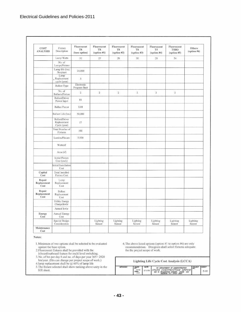
Electrical Guidelines and Policies-2011
- 43 -
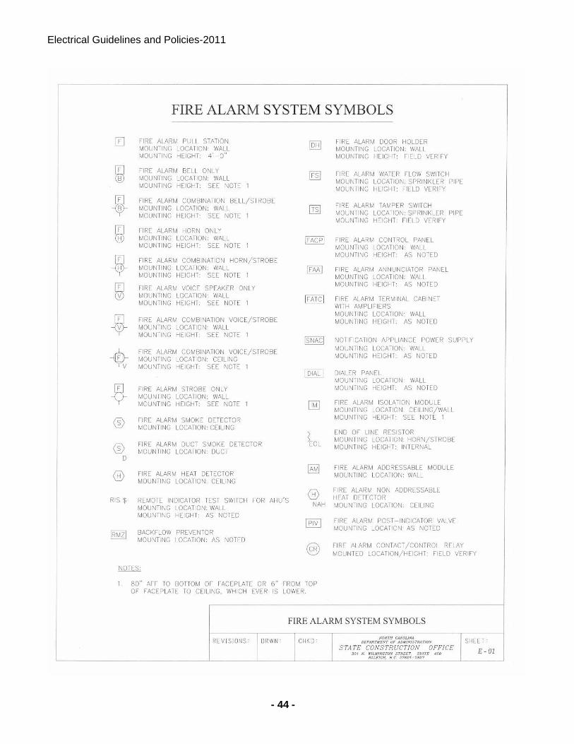
Electrical Guidelines and Policies-2011
- 44 -
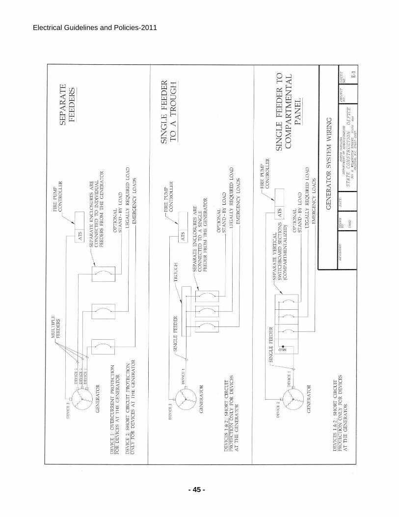
Electrical Guidelines and Policies-2011
- 45 -
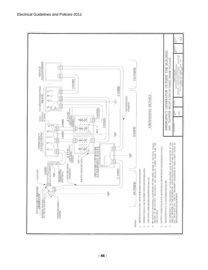
Electrical Guidelines and Policies-2011
- 46 -
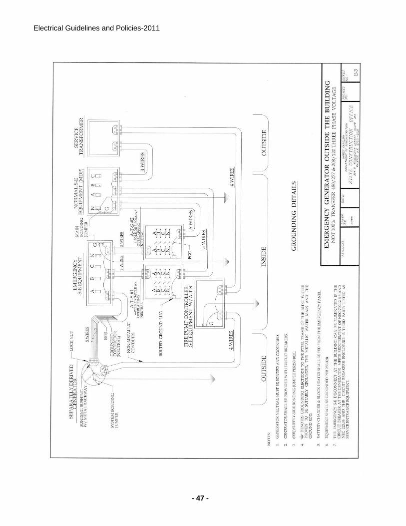
Electrical Guidelines and Policies-2011
- 47 -
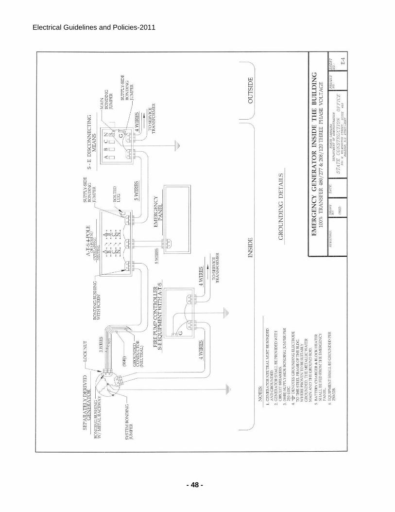
Electrical Guidelines and Policies-2011
- 48 -
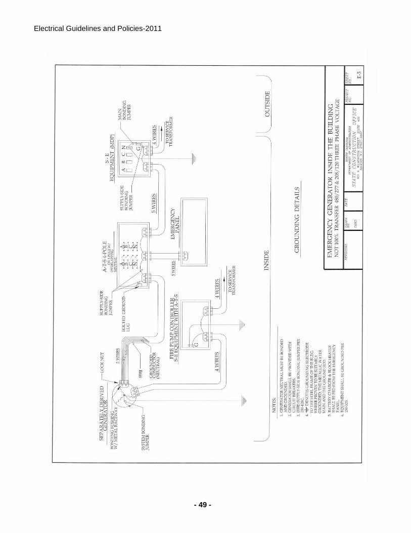
Electrical Guidelines and Policies-2011
- 49 -
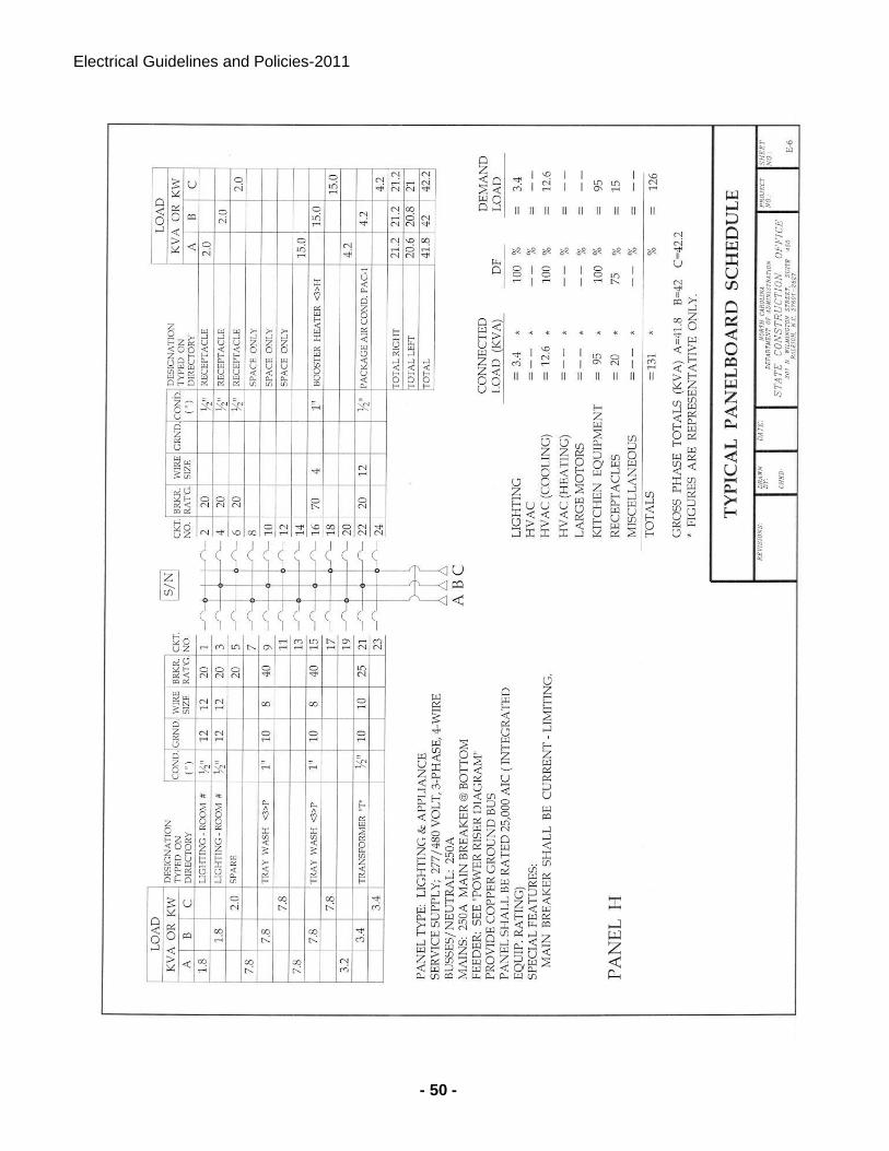
Electrical Guidelines and Policies-2011
- 50 -
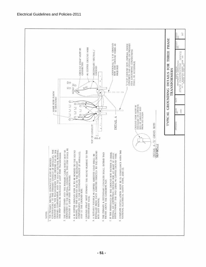
Electrical Guidelines and Policies-2011
- 51 -
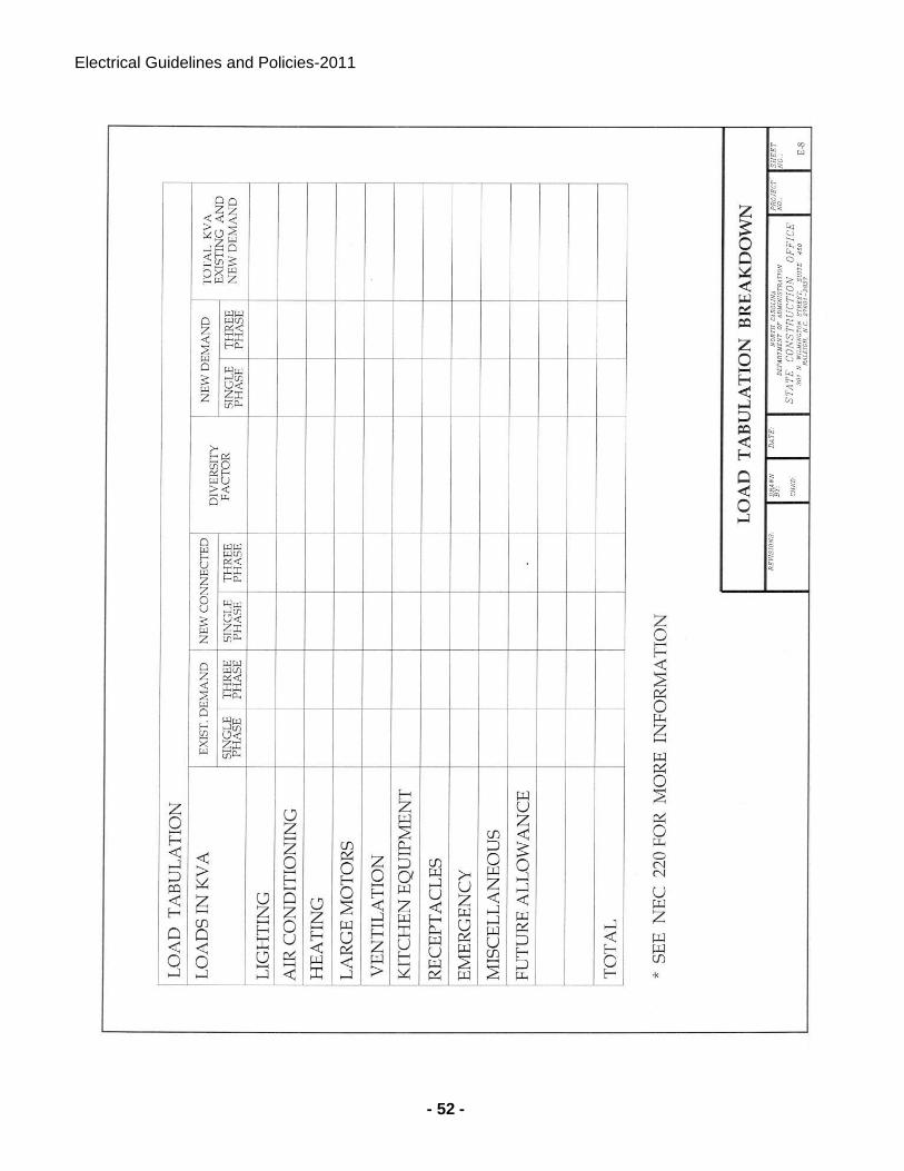
Electrical Guidelines and Policies-2011
- 52 -
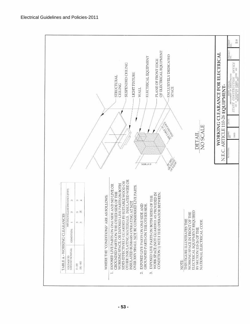
Electrical Guidelines and Policies-2011
- 53 -
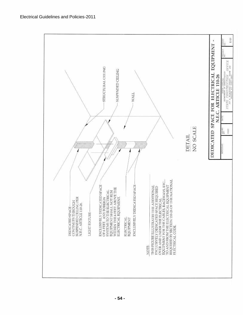
Electrical Guidelines and Policies-2011
- 54 -
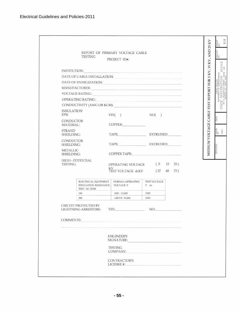
Electrical Guidelines and Policies-2011
- 55 -
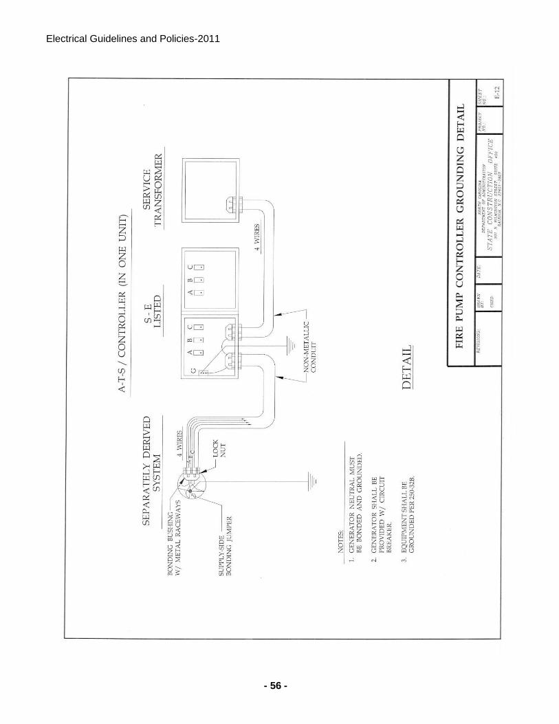
Electrical Guidelines and Policies-2011
- 56 -
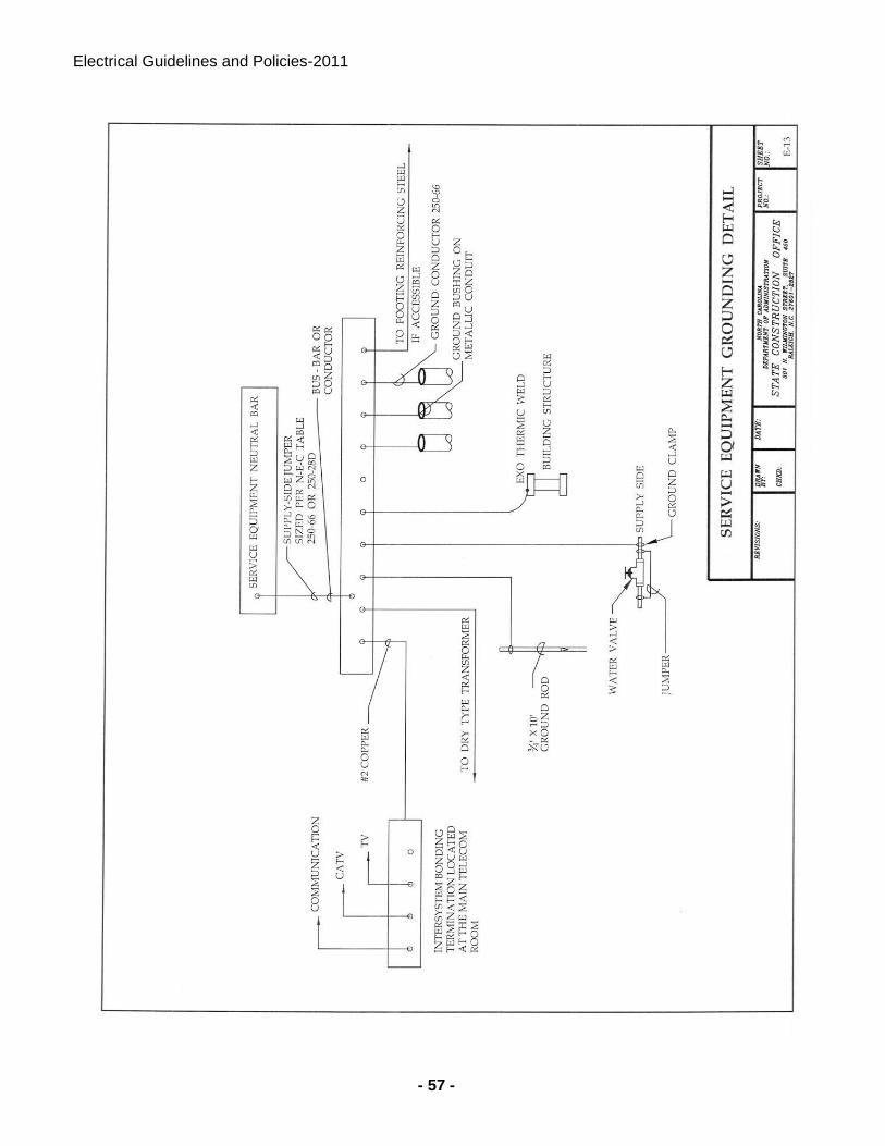
Electrical Guidelines and Policies-2011
- 57 -
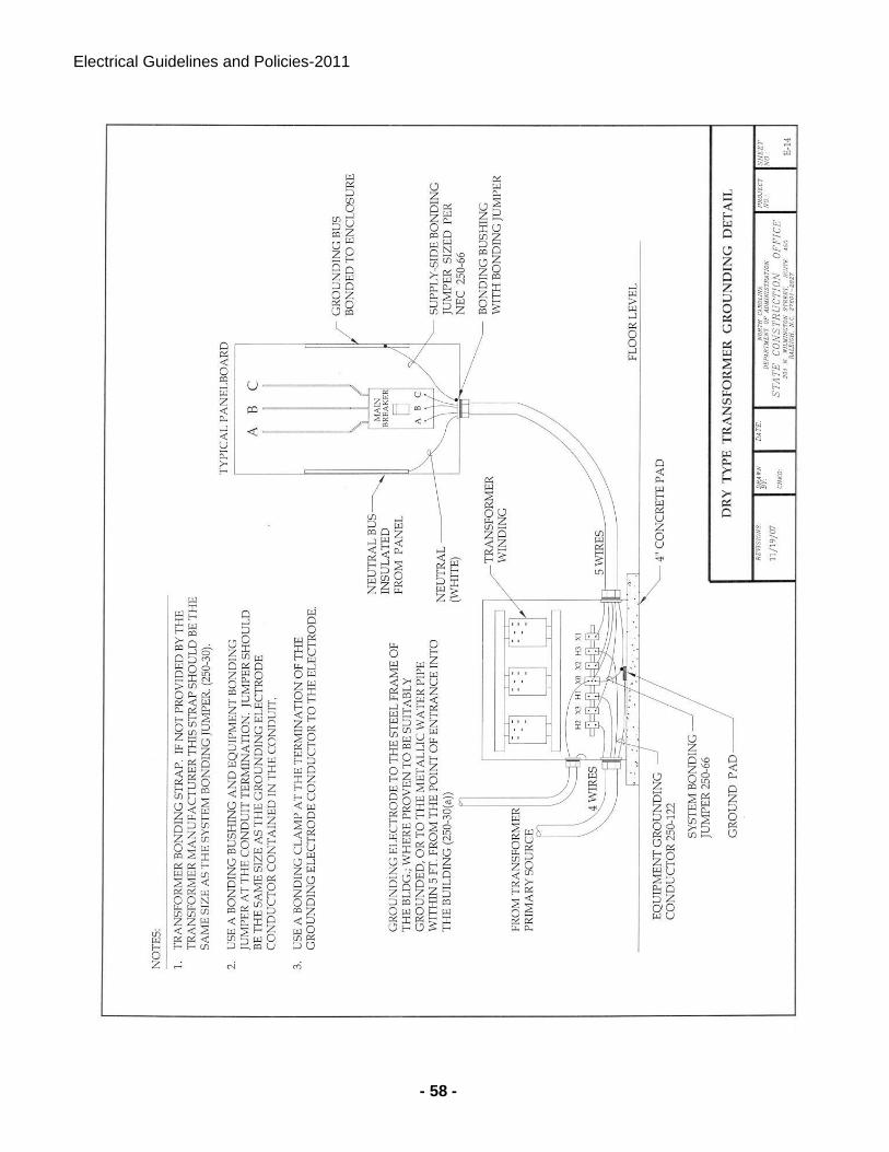
Electrical Guidelines and Policies-2011
- 58 -
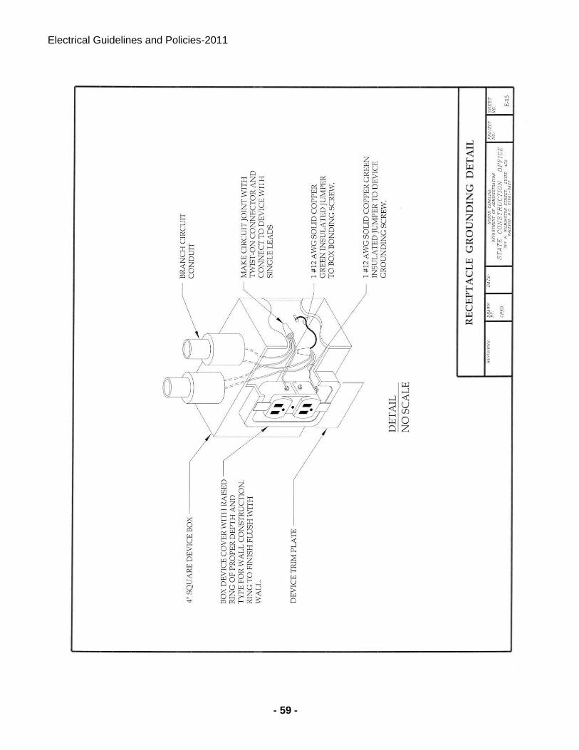
Electrical Guidelines and Policies-2011
- 59 -
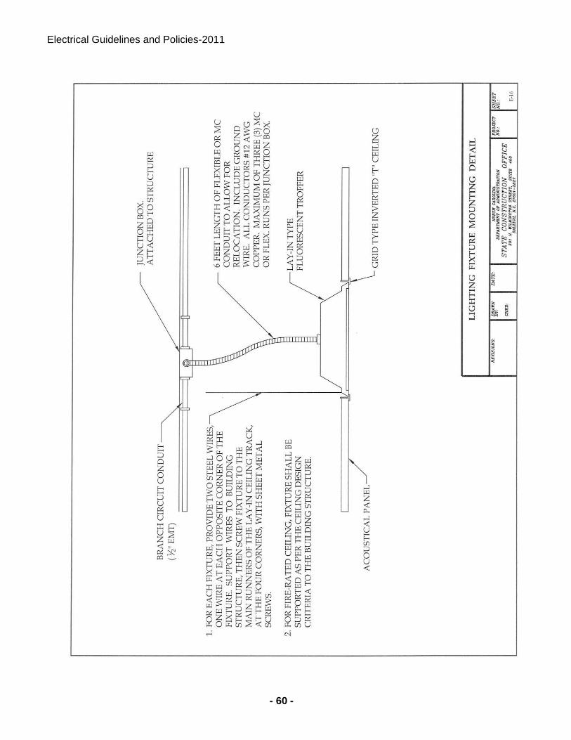
Electrical Guidelines and Policies-2011
- 60 -
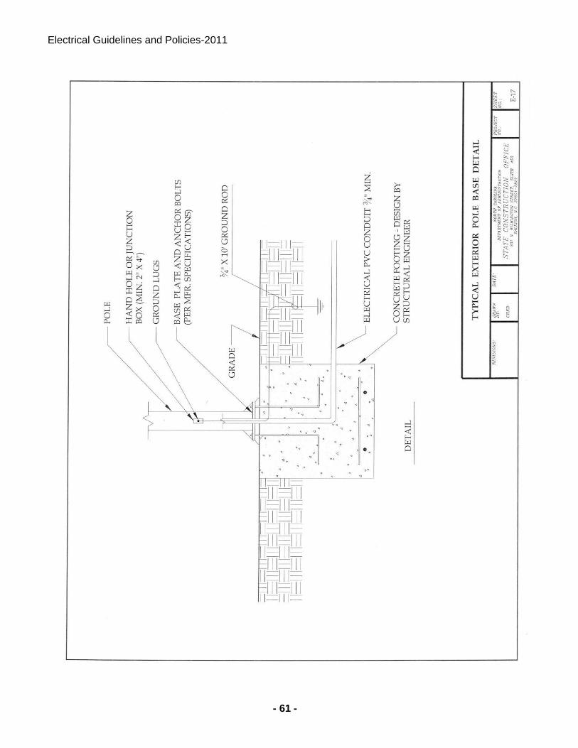
Electrical Guidelines and Policies-2011
- 61 -
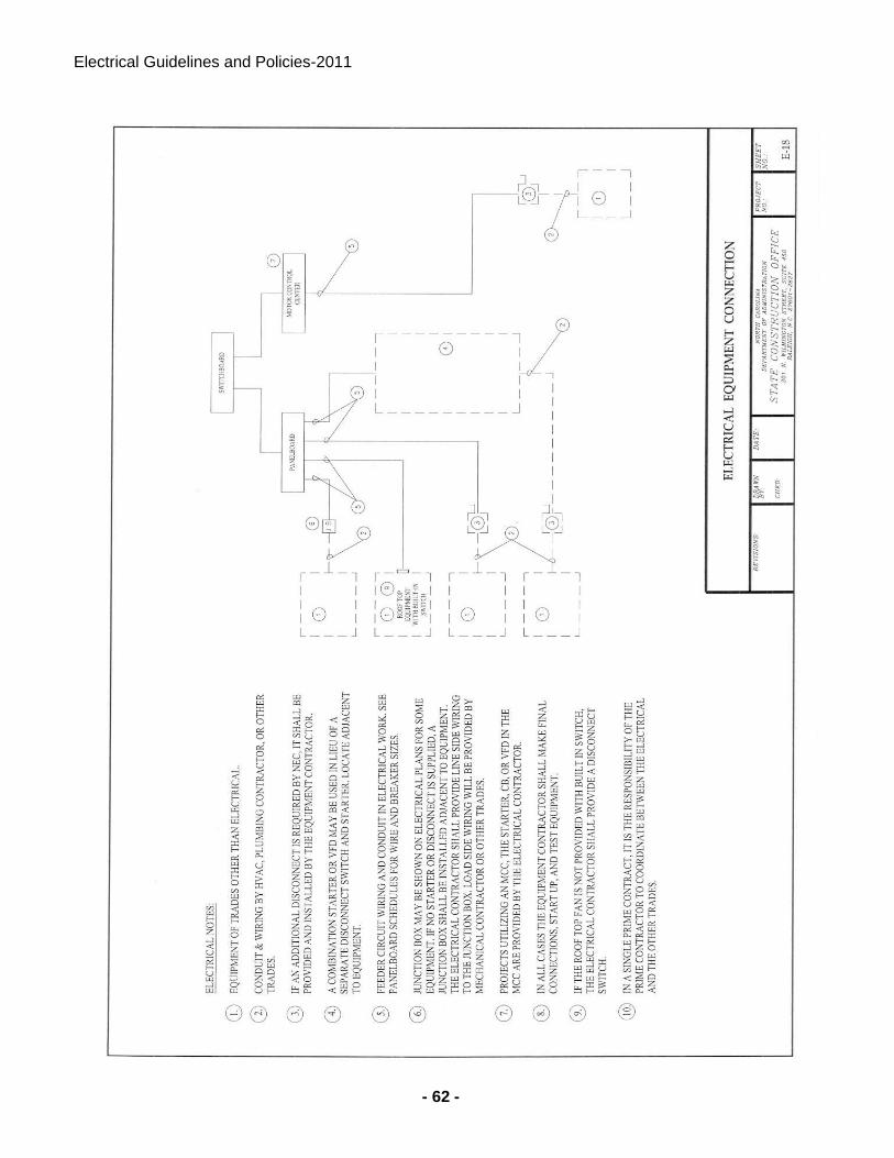
Electrical Guidelines and Policies-2011
- 62 -

Electrical Guidelines and Policies-2011
- 63 -
311
Appendix L State of North Carolina Department of Administration – State Construction Office
Fire Alarm Guidelines and Policies (2011)
STATE OF NORTH CAROLINA
DEPARTMENT OF ADMINISTRATION
STATE CONSTRUCTION OFFICE
Fire Alarm
GUIDELINES AND POLICIES
2011
Fire Alarm Guidelines
- 2 -
Instruction to Designers:
1. Designers for State projects involving fire alarm systems shall use and follow the Department of Administration document “Fire Alarm Guidelines and Policies” only for the purpose of preparing the designer’s plans and specifications for the specific project in their contract. The document is not written in contractual language for bidding purposes and/or contract enforcement. Therefore the designer is not to insert the document as is into the specifications. (The Designers can copy from the Guidelines applicable sections and paste to project written specifications.)
2. It is the Engineer’s responsibility to read and comply with all relevant criteria in the SCO Fire Alarm Guidelines and Policies. These Guidelines and others are available at the State Construction Office web site http://www.nc-sco.com/ Any design noncompliance with the Fire Alarm Guidelines and Policies resulting in a change order shall be the responsibility of the designer.
3. Clarification: When expressions are shown between two forward slanted lines, the Designer is to select the most appropriate expression. Example: //Provide photoelectric smoke detection, ionization smoke detection and rate of rise thermal detection.//
Fire Alarm Guidelines
- 3 -
1.
2.
3.
4.
5.
6.
7.
8.
9.
10.
1.
2.
3.
4.
5.
1.
2.
3.
4.
5.
6.
7.
TABLE OF CONTENTS
A. General
Fire Alarm System in State Owned Facilities ------------------------------------------------ 5
Document Specific -------------------------------------------------------------------------------- 5
Furnishing, Installation & Connection of the System ---------------------------------------- 5
Applicable Codes ---------------------------------------------------------------------------------- 5
Fire Alarm Control Panel ------------------------------------------------------------------------- 5
Secondary Power ------------------------------------------------------------------------------- 5
Quality Assurance ----------------------------------------------------------------------------------- 6
Code and Standards --------------------------------------------------------------------------- 6
Definition --------------------------------------------------------------------------- 6
Submittals --------------------------------------------------------------------------- 7
B. Part 2- Products
Fire Alarm Control Panel --------------------------------------------------------------------- 9
Alarm Appliances ---------------------------------------------------------------------- 14
Initiating Devices -------------------------------------------------------------- 15
Miscellaneous System items ------------------------------------------------------------- 17
Wiring ------------------------------------------------------------ 20
C. Part 3- Execution
Fire Alarm System ------------------------------------------------------------------------- 21
Fire Alarm Control Equipment Installation --------------------------------------------------- 22
Addressable Interface Modules (control and monitor Modules) ------------------------ 22
Surge Protection ---------------------------------------------------------------------------- 23
Riser Design ----------------------------------------------------------------------------- 23
AC Power --------------------------------------------------------------------------- 23
Conduit and Wiring ------------------------------------------------------------------------ 24
Fire Alarm Guidelines
- 4 -
8.
9.
10.
11.
12.
13.
14.
15.
16.
17.
18.
19.
20.
21.
22.
23.
24.
25.
26.
27.
Notification devices ------------------------------------------------------------------------ 25
Detectors ------------------------------------------------------------------------- 26
Duct Mounted Smoke Detectors --------------------------------------------------------------- 28
Linear Beam Smoke Detectors -------------------------------------------------------------- 28
Printer -------------------------------------------------------------------------------------- 28
Air Handler Unit (AHU) Shutdown ------------------------------------------------------------ 28
Annunciator ------------------------------------------------------------------------------------ 29
Alarm Verification for Smoke Detectors ---------------------------------------------------- 29
Emergency Voice/Alarm Communication --------------------------------------------------- 29
Remote Alarm Transmission Requirements ------------------------------------------------ 31
Automatic Smoke door and Automatic Lock Requirements ----------------------------- 32
Sprinkler System Monitoring ------------------------------------------------------------------ 33
Kitchen Exhaust Hood Extinguishing Systems ---------------------------------------------- 33
Fire Alarm System Installation and Configuration ------------------------------------------ 33
Fire and Life Safety Criteria for Doors Controlled by Fire Alarm System ------------- 34
System Documentation, Training, and Maintenance ------------------------------------ 35
Spare Parts -------------------------------------------------------------------------------------- 37
System Testing & Certification ------------------------------------------------------------------ 38
Pre-Final Inspection -------------------------------------------------------------------------- 39
Final Inspection ----------------------------------------------------------------------------- 39
APPENDIX
Table 1 Applications Matrix for Selection Detection Devices --------------------------------- 42
Fire Alarm System Symbols ----------------------------------------------------------------- FA- 01
Fire Alarm Riser (Example) ----------------------------------------------------------------- FA-02
Fire Alarm Riser Notes (Example) ------------------------------------------------------------- FA-03
Fire Alarm Matrix (Example) ------------------------------------------------------------------ FA-04
Transient Arrestor Installation Detail -------------------------------------------------------- FA-05
Fire Alarm Guidelines
- 5 -
Part 1- General *
1. This document is to help assure that the fire detection and alarm systems installed in State Owned buildings are reliable, maintainable, and have a long service life.
2. This document does not constitute a complete design specification and must be edited and supplemented with project-specific requirements written by the design professional.
3. This document includes the furnishing, installation, and connection of the microprocessor controlled, intelligent reporting fire alarm equipment required to form a complete coordinated system ready for operation. It shall include, but not be limited to, alarm initiating devices, alarm notification appliances, control panels, auxiliary control devices, annunciators, power supplies, and wiring.
4. The fire alarm system shall comply with applicable provisions of the NC Building Code, NFPA 70 - National Electrical Code (NEC) and NFPA 72 -National Fire Alarm Code. The Contractor shall furnish all parts, materials, and labor customarily required or provided for a complete and operating system, in accordance with all requirements applicable, even if each needed item is not specifically shown or described in the project plans or specifications
5. The Fire Alarm Control Panel (FACP) shall be located for convenient, rapid access. When not located in a public or normally occupied area, a Remote Anunnciator (FAA) with audible-visible trouble indication is required. Consult with facility manager and the local fire official, prior to locating the FACP, FAA or printer. If there is no constantly attended station, the FACP or FAA shall be located in a lobby or a corridor adjacent to the entrance used by responding personnel.
6. Systems are to be provided with a separate and independent source of secondary power. The State does not contract for full Central Station Service (with runners), so all systems that report to a Central or Remote Supervising Station shall have a minimum of 60 hours battery power capacity, plus 5/15 minutes of full alarm load. Proprietary and other systems require 24 hours capacity plus 5/15 minutes alarm load.
a) When automatic starting generator is provided, use 24 hours for battery endurance, plus the appropriate (5 or 15 minutes) alarm load. See NFPA 72.
b) Most campus alarm supervising stations are normally classified as “Proprietary” systems.
c) Most Facilities can use the State Capitol Police located in Raleigh “Remote Supervising Station”
* If system is being installed to replace an existing system verify that the Drawings detail the scope of any demolition that may be required. Pay particular attention to items that may be reused in the new system.
7. QUALITY ASSURANCE
a) Manufacturer's Qualifications: Firms regularly engaged in manufacture of fire alarm systems of types, sizes, and electrical characteristics required, and whose products are
Fire Alarm Guidelines
- 6 -
Listed and Labeled. Products of firms that do not maintain factory authorized service organization and spare parts stock are not acceptable for use on State Owned Buildings.
b) Acceptable Manufacturers: Designers shall list minimum of three manufacturers.
c) Installer’s Qualifications:
d) Company specializing in performing the work and making the final terminations and connections. Minimum of 5 years documented experience installing fire detection and alarm systems similar in size and scope to the project. Only the Installer may make program changes and must be present for the 100% test, Designer’s pre-final review and Owner inspections.
e) All connections to the FACP and the system's programming shall be done only by the manufacturer, or by an authorized distributor that stocks a full compliment of spare parts for the system. The technicians are required to be trained and individually certified by the manufacturer, for the FACP model/series being installed. This training and certification must have occurred within the most recent 24 months, except that a NICET Level III certification will extend this to 36 months. Copies of the certifications must be part of the Shop Drawing submittal to the Designers, prior to installation. The submittal cannot be approved without this information.
8. Codes and Standards:
a) NFPA Compliance: Comply with applicable requirements of NFPA-72, National Fire Alarm Code.
b) NEC Compliance: Comply with applicable requirements of NFPA-70, National Electrical Code (NEC) standards pertaining to fire alarm systems.
c) Testing Laboratory Compliance: Comply with provisions of UL safety standards pertaining to fire alarm systems. Provide products and components which are Listed and Labeled.
d) FM Compliance: Provide fire alarm systems and accessories which are FM approved.
9. Definitions:
a) For State-owned facilities in North Carolina the AHJ for Code compliance is the NC Department of Administration – State Construction Office. The AHJ for construction administration and inspection purposes is the entity that contracted for the design services, either the State Construction Office or the owning Agency, as applicable. (Fire alarm system inspection or acceptance testing may be delegated to the design engineer by contract.)
b) For Community College or local government projects the AHJ is the local government entity that approves project plans, issues building permits, and inspects construction.
c) Building Permits:
(1) No building permit is required for construction or renovation of facilities that are funded by the State of North Carolina and located on State-owned land. However, privately-funded projects on land leased from the State (e.g., student housing) must still be submitted to local building officials for approval, permits, and inspections. Written NCDOA/SCO
Fire Alarm Guidelines
- 7 -
approval of the plans and specifications submitted for review is considered the equivalent of a building permit for State projects but that alone does not give authorization to proceed with construction. Such authorization requires written clearance from the entity that administers the contract.
(2) Fire Alarm Control Panel (FACP) - Also called a Fire Alarm Control Unit (FACU) by some entities. See requirements in Part 2
(3) Remote Anunnciator (FAA) – Provides LCD display with a text statement of the panel status and/or LED lamps to indicate the status of the fire alarm system. It is provided to assist fire fighters who respond to a call and to assist technicians who respond to a trouble condition.
(4) Graphic Anunnciator (GA) – Used to provide information regarding the status of detection, sprinkler and supervisor devices by zone and or floor of the building.
10. SUBMITTALS:
a) General: Submittals shall demonstrate compliance with technical requirements by reference to each subsection of the Engineer’s written specification.
b) Product Data: Submittals shall provide mA draw for each device submitted and the listed minimum voltage required to operate. Panel submittal shall list voltage drop allowed for panel and for individual NAC circuits.
c) Shop Drawings:
(1) The fire alarm contractor shall submit complete Shop Drawings to the engineer for review, prior to performing any work. They shall clearly demonstrate compliance with the engineer’s plans and specifications, which have a System Response Matrix showing the fire alarm system's actions (outputs) required for each type of alarm, supervisory, and trouble signal. Any non-compliant features must be fully described.
(2) The submitted shop drawings shall show equipment, device identification numbers and locations, and connecting wiring of entire fire alarm system. Include wiring and riser diagrams. Wiring diagrams shall be based on the project floor plans, with devices and proposed conduit routing. The conductor composition for each conduit section shall be provided. The distance and route for each NAC (Notification Appliance Circuit) shall be shown. Riser diagrams shall show consecutive connections for all devices with addresses and candela and Candela ratings.
(3) Engineer’s approval (with or without corrections) of contractor’s Shop Drawings, samples, cut sheets, etc., is for general conformance with the contract documents and design concept. It shall not relieve the contractor of responsibility for full compliance with the project plans and specifications, EXCEPT for any specific non-compliant features for which the engineer gives written authorization.
d) Installation Instructions: The contractor shall submit to the engineer of record the Manufacturer's detailed installation instruction for the Fire Alarm Control Panel and all duct mounted smoke detectors, flow switches, tamper switches, supervisory switches, and similar items which require mechanical installation.
e) Battery Calculations:
Fire Alarm Guidelines
- 8 -
(1) Include a copy of system battery sizing calculations with the shop drawing submittal to the engineer. Use manufacturer's battery discharge curve to determine expected battery voltage after 60/24 hours of providing standby power. Then use calculated Notification Appliance Circuit current draw in the alarm mode to determine expected voltage drop at End of the Line Resistor (EOL), based on conductor resistance per manufacturer's data sheet or NEC.
(2) Fire Alarm Vendor’s calculations must be submitted with the shop drawings, and prior to installation of equipment. (Buildings without generators typically require 60 hours of battery backup to cover the weekend. Otherwise 24 hour battery backup is required. ) In the submittal package identify Notification Appliance Circuits (NAC) current draws and voltage drops for each circuit. In no case shall the calculated voltage at any notification appliance fall below the minimum listed operating voltage for the devices used.
(3) The voltage drop at EOL must not exceed 14% of the expected battery voltage, after the required standby time plus alarm time. (Typically, for a 24 volt system, this limits the voltage drop from the battery to the EOL to 3 volts). Determine "worst case" voltage at far end of each NAC, by subtracting its calculated V-drop from the expected battery voltage. The result must be no less than the minimum listed operating voltage for the alarm notification appliances used.
(4) All of these calculations must be placed on a dedicated sheet of as-built drawings, for future reference by fire alarm service technicians. NAC voltage drop is to be verified during system tests.
f) Maintenance Data: The contractor shall submit maintenance data and parts lists for each type of fire alarm equipment installed, including furnished specialties and accessories. Include this data, product data, and shop drawings in maintenance manual.
g) Maintenance Contract: (this paragraph shall be included in the specs ONLY if the Owner/agency do not have program in place for maintenance) The contractor shall submit a quote for a maintenance contract to provide all maintenance, test, and repair described below and/or in accordance with NFPA-72, "Guide for Testing Protection Signaling Systems". Include also a quote for unscheduled maintenance/repair, including hourly rates for technicians trained on this equipment, and response travel costs. Submittals that do not identify all post contract maintenance costs will not be accepted. Rates and costs shall be valid for the period of five (5) years after expiration of the guaranty. Maintenance and testing shall be on a semiannual basis or as required which ever is the most restrictive. A preventive maintenance schedule shall be provided by the Contractor that shall describe the protocol for preventive maintenance. The schedule shall include:
(1) Semiannual systematic examination, adjustment and cleaning of all detectors, manual fire alarm stations, control panels, power supplies, relays, water flow switches and all accessories of the fire alarm system.
(2) Semiannual testing of each circuit in the fire alarm system.
(3) Semiannual testing of each smoke detector in accordance with the requirements of NFPA 72.
h) Certifications:
Fire Alarm Guidelines
- 9 -
(1) Submit a certification from the major equipment manufacturer indicating that the proposed supervisor of installation and the proposed performer of contract maintenance is an authorized representative of the major equipment manufacturer. Include names and addresses, and telephone numbers in the certification.
(2) Installer’s training certificate as defined under Quality Assurance.
i) Existing Fire Alarm System to be replaced with new system in occupied building shall continue to be operational until the new Fire Alarm System is up and running, otherwise, 24hrs Fire watch man shall be provided.
PART 2 - PRODUCTS
1. FIRE ALARM CONTROL PANEL (FACP)
a) FACP - General: The FACP shall meet the following general requirements (unless otherwise required by the owner for certain systems):
(1) The system is to be the addressable type, with a 24vdc nominal operating voltage.
(2) The system is to have multiple access levels so owner's authorized personnel can disable individual alarm inputs or normal system responses (outputs) for alarms, without changing the system's executive programming or affecting operation of the rest of the system. The process on how to do this must be included in the training required to be given to the owner's designated personnel, and must also be part of the written documentation provided by the fire alarm equipment supplier.
(3) Signal Line Circuits: (SLC) also called addressable loop - Alarm, trouble and supervisory signals from all intelligent reporting devices shall be encoded onto an NFPA Style 6 (Class A) Signaling Line Circuit (SLC) with no “T” taps.
(4) Initiation Device Circuits: Initiation Device Circuits (IDC) shall be wired Class A (NFPA 72 Style D).
(5) Notification Appliance Circuits: Notification appliance circuits shall be wired Class B (NFPA 72 Style Y).
(6) Digitized electronic signals shall employ check digits or multiple polling. In general a single ground or open on any system signaling line circuit, initiating device circuit, or notification appliance circuit shall not cause system malfunction, loss of operating power or the ability to report an alarm.
(7) Loss of Power: Alarm signals arriving at the main FACP shall not be lost following a power failure (or outage) until the alarm signal is processed and recorded.
(8) The FACP must have an Alarm Silence switch, and be equipped with the Subsequent Alarm (alarm resound) feature. Any remote annunciators or graphic displays located away from the alarm area must also include an audible signal with alarm resound feature.
b) System Response to an Alarm Condition: When a fire alarm condition is detected and reported by one of the system initiating devices or appliances, the following functions shall immediately occur:
Fire Alarm Guidelines
- 10 -
(1) The system alarm LED shall flash.
(2) A local piezo-electric signal in the control panel shall sound.
(3) An 80-character minimum LCD display shall indicate all information associated with the fire alarm condition, including the type of alarm point and its location within the protected premises.
(4) On systems equipped with a printer, printing and history storage equipment shall log the information associated with each new fire alarm control panel condition, along with time and date of occurrence.
(5) All system output programs assigned via control-by-event equations to be activated by the particular point in alarm shall be executed, and the associated system outputs (alarm notification appliances and/or relays) shall be activated. Exact programming shall be provided by the Contractor to meet the Owner’s requirements.
(6) Activate all fire alarm Notification Appliances in the building, sounding and flashing in synchronization continuously until the initiating device and control unit have been reset to normal condition.
(7) Activate digital alarm communicator.
(8) Deactivate door hold control relay such that all smoke doors are allowed to close.
(9) Deactivate control relays so that HVAC units shut down. Exception is for hazardous exhaust systems and smoke control.
(10) Activate elevator recall sequence if smoke is detected in any elevator lobby, shaft, or in the elevator equipment room.
c) System Response to a Trouble Condition:
(1) Systems AC power trouble signal shall not be sent unless maintained for 1 to 3 hours (or more) Provide additional relays as required for this purpose.
(2) Provide immediate transmission of all other supervising signals.
(3) Provide adjustable time delay for all other trouble signals prior to transmission.
(4) FACP - Minimum Requirements: The FACP shall contain a microprocessor based Central Processing Unit (CPU). The CPU and its associated equipment shall be protected so it can not be affected by voltage surges or line transients consistent with UL standard 864. The CPU shall communicate with and control the following types of equipment used to make up the system: intelligent detectors, addressable modules, local and remote operator terminals, printers, annunciators, and other system controlled devices. The main FACP shall perform the following functions:
(5) Supervise and monitor all intelligent addressable detectors and monitor modules connected to the system for normal, trouble and alarm conditions.
(6) Supervise all initiating, signaling, and notification circuits throughout the facility by way of connection to monitor and control modules.
Fire Alarm Guidelines
- 11 -
(7) Detect the activation of any initiating device and the location of the alarm condition. Operate all notification appliances and auxiliary devices as programmed.
(8) Visually and audibly annunciate any trouble, supervisory or alarm condition on operator's terminals, panel display, and annunciators.
d) System Capacity and General Operation: The system shall have the following capacities and general operation modes:
(1) The FACP shall provide, or be capable of expansion to 198 intelligent/addressable devices per Signaling Line Circuits (SLC) and 2048 annunciation points, minimum, per system. The number of SLCs provided shall be as indicated on the Drawings. Total points shall be as indicated on the drawings or otherwise specified.
(2) The FACP shall include a full featured operator interface control and annunciation panel that shall include a backlit, 80 minimum character liquid crystal display, individual, color coded system status LEDs, and an alphanumeric keypad for the field programming and control of the fire alarm system.
(3) All programming or editing of the existing program in the system shall be achieved without special equipment and without interrupting the alarm monitoring functions of the fire alarm control panel.
e) The FACP shall be able to provide the following features:
(1) Upload/Download to PC Computer
(2) Charger Rate Control
(3) Drift Compensation
(4) Automatic Day/Night Sensitivity Adjust
(5) Device Blink Control
(6) Pre-alarm Control Panel Indication
(7) Trouble Reminder
(8) NFPA 72 Smoke Detector Sensitivity Test
(9) System Status Reports
(10) Periodic Detector Test
(11) Alarm Verification, by device, with tally
(12) Non-Alarm Module Reporting
(13) Block Acknowledge
(14) Smoke Detector Maintenance Alert
(15) Control-By-Time
Fire Alarm Guidelines
- 12 -
f) The control panel shall be capable of printing historical data and device parameters and shall
include all equipment necessary to produce printouts, including an external printer and shall be U.L. listed as meeting the NFPA 72 sensitivity testing and maintenance requirements without the need for manually removing and testing each smoke detector. The control panel shall provide a display and a printed list of these sensitivity measurements as a permanent record of the required sensitivity testing. The system shall also annunciate a trouble condition when any smoke detector approaches 80% of its alarm threshold due to gradual contamination, with an annunciation of the location of the smoke detector requiring service. If any specialized equipment must be used to program any function of the smoke detector devices, then one must be furnished as part of the system.
g) The system shall perform time based control functions including automatic changes of specified smoke detector sensitivity settings.
h) Central Processing Unit: The Central Processing Unit (CPU) shall communicate with, monitor, and control all other modules within the control panel. Removal, disconnection or failure of any control panel module shall be detected and reported to the system display by the CPU.
(1) The CPU shall contain and execute all control-by-event (including ANDing, ORing, NOTing, CROSSZONEing) programs for specific action to be taken if an alarm condition is detected by the system. Such control-by-event programs shall be held in non-volatile programmable memory, and shall not be lost with system primary and secondary power failure. The CPU shall also provide a real-time clock for time annotation of all system displays. The Time-of-Day and date shall not be lost if system primary and secondary power supplies fail.
(2) The CPU shall be capable of being programmed on site without requiring the use of any external programming equipment. Systems that require the use of external programmers or change of EPROMs are not acceptable.
i) Operators Control: Provide an operators interface which allows the following minimum functions. In addition, the operators interface shall support any other functions required for system control and/or operation:
(1) Acknowledge (ACK/STEP) Switch
(2) Signal Silence Switch
(3) System Reset Switch
(4) System Test Switch
(5) Lamp Test Switch
j) Display: The system display shall provide all the controls and indicators used by the
system operator and may also be used to program all system operational parameters. The display assembly shall contain, and display as required, custom alphanumeric labels for all intelligent detectors, addressable modules, and software zones.
(1) The system display shall provide an 80minimum -character back-lit alphanumeric Liquid Crystal Display (LCD).
Fire Alarm Guidelines
- 13 -
(2) The Display shall also provide four Light-Emitting-Diodes (LEDs), that will indicate the status of the following system parameters: AC POWER, SYSTEM ALARM, SYSTEM TROUBLE, and SIGNAL SILENCE.
(3) The system display shall provide a touch key-pad with control capability to command all system functions, entry of any alphabetic or numeric information, and field programming. Two different password levels shall be accessible through the display interface assembly to prevent unauthorized system control or programming.
k) Signaling Line Circuit (SLC) Interface Board: The FACP shall contain SLC interface boards as required to communicate with the SLC. Each SLC board shall monitor and control a minimum of 198 intelligent addressable devices. This includes 99 analog detectors (Ionization, Photoelectric, or Thermal) and 99 monitor or control modules.
(1) Each SLC interface board shall contain its own microprocessor, and shall be capable of operating in a local mode (any SLC input activates all or specific SLC outputs) in the event of a failure in the main CPU of the control panel. The SLC interface board shall not require any jumper cuts or address switch settings to initialize SLC Loop operations. SLC interface boards shall provide power and communicate with all intelligent addressable detectors and modules connected to its SLC Loop on a single pair of wires. This SLC Loop shall be capable of operation as NFPA 72 Style 6.
(2) Each SLC interface board shall receive analog information from all intelligent detectors and shall process this information to determine whether normal, alarm, or trouble conditions exist for that particular detector. The SLC interface board software shall include software to automatically maintain the detector's desired sensitivity level by adjusting for the effects of environmental factors, including the accumulation of dust in each detector. The analog information may also be used for automatic detector testing and for the automatic determination of detector maintenance requirements.
l) Printer: Provide a printer to provide hard-copy printout of all changes in status of the system. The printer shall time-stamp such printouts with the current time-of-day and date. The printer shall be standard carriage with 80-characters per line and shall use standard pin-feed paper. Thermal printers are not acceptable. The printer shall operate from a 120 VAC, 60 Hz power source. Provide table and stand for printer if it is to remain constantly connected to the fire alarm panel.
m) Remote Transmissions: The FACP shall be interfaced to a Digital Alarm Communications Transmitter (DACT).
n) Power Supply: The FACP power supplies shall operate on 120 VAC, 60 Hz and shall have a continuous rating adequate to power all equipment and functions in full alarm continuously. All modules and drivers must be able to withstand prolonged short circuits in the field wiring, either line-to-line or line-to-ground, without damage. Further, the power supply shall be expandable for additional notification appliance power in 3.0 Ampere increments.
o) The power supply shall provide a battery charger using dual-rate charging techniques for fast battery recharge.
p) Batteries: Shall be completely maintenance free, shall not require liquids, fluid level checks or refilling, and shall not be capable of producing spills and/or leaks. Batteries shall be sealed gel-cell type with expected life of 10 years. Battery voltage shall be as required by the FACP and related equipment. Battery shall have sufficient capacity to power the fire alarm system
Fire Alarm Guidelines
- 14 -
for not less than //24//60// hours plus // 5 // 15 // minutes of alarm upon a normal AC power failure. NAC circuits shall not exceed 75% of maximum current load allowed. (For batteries serving emergency voice communications the duration of alarm reserve shall be15 minutes in lieu of 5 minutes)
q) Enclosures: The FACP shall be housed in a 3rd party listed cabinet suitable for surface or semi-flush mounting. Cabinet and front shall be corrosion protected, given a rust-resistant prime coat, and manufacturer's standard finish. The door shall provide a key lock and shall include a glass or other transparent opening for viewing of all indicators. For convenience, the door may be hinged on either the right or left side (field selectable).
2. ALARM APPLIANCES
a) Programmable Electronic Sounders: Sounders located outdoors shall be listed for use in wet locations. Electric sounders shall operate with synchronized audible output and have the following specifications:
(1) Voltage: Programmable electronic sounders shall operate on 24 VDC nominal.
(2) Programming: Electronic Sounders shall provide the ANSI S3.41 three-pulse temporal pattern audible evacuation signal, described in NFPA 72, with an output sound level of at least 90 dBA measured at 10 feet from the device. Output sound level shall be 120 dB maximum. Electronic Sounders shall be field programmable without the use of special tools.
b) Strobe Lights shall be located as shown on the Drawings. Strobe lights indicated for use exterior to the building shall be mounted at the indicated elevation and listed for use in wet locations. Strobe lights shall operate with synchronized flash output and have the following specifications:
(1) Voltage: Strobe lights shall operate on 24 VDC nominal.
(2) Maximum pulse duration: 2/10ths of one second.
(3) Strobe intensity and flash rate: Must meet minimum requirements of UL 1971. Provide strobe lights with minimum intensity Candela (Cd) rating of 15/75 Cd, or greater if such is indicated adjacent to the device symbol on the Drawings.
c) Speakers: Speakers, where provided, shall have audible sound with taps at 1/4 watt, 1/2 watt, 1 watt, 2 watt. Speakers shall operate at // 70.7V // 24 V //. Provide back boxes for all speakers. Speakers shall be tapped at 1 watt for design purposes. See additional requirements for Programmable Electronic Sounders.
d) Horns: Where provided, shall provide average ambient sound level of dBA as listed in the NEPA 72.
e) Audible/Visual Combination Devices shall comply with all applicable requirements for both Programmable Electronic Sounders and Strobe Lights.
f) Bells shall be 10" diameter vibrating type located as shown on the Drawings; bells located outdoors shall be listed for use in wet locations. Bells shall have the following specifications: Voltage: Bells shall operate on 24 VDC nominal.
Fire Alarm Guidelines
- 15 -
3. INITIATING DEVICES
a) Addressable Devices - General: All initiating devices shall be individually addressable. Addressable devices shall comply with the following requirements:
(1) All addressable spot type and duct smoke detectors shall be the analog type and the alarm system shall automatically compensate for detector sensitivity changes due to ambient conditions and dust build-up within detectors. This feature must be armed and sensitivities set prior to acceptance of the system.
(2) Address Setting: Addressable devices shall provide an address-setting means.
(3) Connections: Addressable devices shall be connected to a Signaling Line Circuit (SLC) with two (2) wires.
(4) Operational Indications: Addressable initiation devices shall provide dual alarm and power LEDs. Both LEDs shall flash under normal conditions, indicating that the device is operational and in regular communication with the control panel. Both LEDs shall be placed into steady illumination by the FACP to indicate that an alarm condition has been detected. The flashing mode operation of the detector LEDs shall be optional through the system field program. An output connection shall also be provided in the device base to connect an external remote alarm LED.
(5) Intelligent Initiation Devices: All smoke detectors shall be the "intelligent" in that smoke detector sensitivity shall be set through the FACP and shall be adjustable in the field through the field programming of the system. Sensitivity shall be capable of being automatically adjusted by the FACP on a time-of-day basis. Using software in the FACP, detectors shall be capable of automatically compensating for dust accumulation and other slow environmental changes that may affect performance. The detectors shall be listed by UL as meeting the calibrated sensitivity test requirements of NFPA Standard 72.
(6) Spot-type detectors must be the plug-in type, with a separate base (not a mounting ring), to facilitate their replacement and maintenance. The base shall have integral terminal strips for circuit connections, rather than wire pigtails. Each detector or detector base shall incorporate an LED to indicate alarm.
(7) Device mounting Base: Unless otherwise specified all detectors shall be ceiling-mount and shall include a separate twist-lock base with tamper proof feature.
(8) Sounder Base: Provide bases with a built-in (local) sounder rated at 85 dBA minimum, measured at 10ft. Configure sounder bases such that sounders are activated under conditions as described in the Matrix.
(9) Test Means: The detectors shall provide a test means whereby they will simulate an alarm condition and report that condition to the control panel. Such a test may be initiated at the detector itself (by activating a magnetic switch) or initiated remotely on command from the control panel when in the "test" condition.
(10) Device Identification: Detectors shall store an internal identifying type code that the control panel shall use to identify the type of device. Device identifications shall be either ION, PHOTO, or THERMAL.
Fire Alarm Guidelines
- 16 -
b) Photoelectric Smoke Detectors: Photoelectric smoke detectors shall use the photoelectric (light-scattering) principal to measure smoke density and shall, on command from the control panel, send data to the panel representing the analog level of smoke density.
c) Ionization Smoke Detector: Ionization smoke detectors shall use the dual-chamber ionization principal to measure products of combustion and shall, on command from the control panel, send data to the panel representing the analog level of products of combustion.
d) Thermal Detectors: Thermal Detectors shall be intelligent addressable devices rated at 135°F (58°C) and shall have a rate-of-rise element rated at 15° F. (9.4°C) per minute. It shall connect via two wires to the Fire Alarm Control Panel Signaling Line Circuit. Up to 99 intelligent heat detectors may connect to one SLC loop. Thermal detectors shall use an electronic sensor to measure thermal conditions caused by a fire and shall, on command from the control panel, send data to the panel representing the analog level of such thermal measurements.
(1) Non-Rate of Rise Detectors: Provide thermal detectors with non-rate of rise thermal elements. Non-rate of rise detectors are indicated by NRR adjacent to the thermal detector symbol.
(2) Specialized Element Temperature Ratings: Provide thermal detectors with specialized element temperature ratings. Specialized element temperatures are indicated by a temperature rating adjacent to the thermal detector symbol, e.g. 195°F.
e) Multisensor Detectors: Detectors employ two or more of the above detection types with integrated operating principals, mounted in a single housing. The outputs of the analog sensors shall be transformed into digital signals that are combined and processed by special algorithms. The computations shall be designed to discriminate between normal ambient changes in a building and those changes associated with a fire. //Provide photoelectric smoke detection and rate of rise thermal detection. //Provide photoelectric smoke detection, ionization smoke detection and rate of rise thermal detection.//
f) Duct Smoke Detector: In-Duct Smoke Detector Housings shall accommodate a velocity rated photoelectric detector. The device, independent of the type used, shall provide continuous analog monitoring and alarm verification from the panel. When sufficient smoke is sensed, an alarm signal shall be initiated at the FACP.
g) Addressable Pull Stations - General: Addressable pull stations shall, on command from the Control Panel, send data to the panel representing the state of the manual switch. They shall use a key operated test-reset lock, and shall be designed so that after actual emergency operation, they cannot be restored to normal use except by the use of a key. All pull stations shall be dual-action, have a positive, visual indication of operation and utilize a key type reset. The Glass-break rods are not allowed.
h) LINEAR BEAM SMOKE DETECTORS
(1) Linear Beam Smoke Detectors shall be configured as an integral part of the Fire Alarm system. Linear beam smoke detectors shall meet the following requirements:
(2) Linear beam detectors shall have a minimum of three calibrated sensitivity settings capable of maintaining sensitivity between 1.0% and 2.0% per meter obscuration, at any operating distance between 10 and 60 meters.
Fire Alarm Guidelines
- 17 -
(3) The manufacturer of linear beam detector shall provide a calibration chart giving the Smoke Sensitivity versus Operating Distance for each sensitivity setting. This chart shall show the 3rd party listed sensitivity limits for the entire range of rated operating distances.
(4) Linear beam detectors must be rated for continuous operation up to 122°F (50°C) and a 95% relative humidity.
(5) Compensating circuits must be provided in the detector to maintain normal sensitivity as environment conditions change and as dust builds up on the lenses. When the limits of this compensation are reached, a "trouble" signal must be initiated.
(6) Horizontal and vertical adjustments must be provided, on both the transmitter and the receiver, for alignment of the IR beam. They must permit a minimum angular change of 7.5° from the center axis, in any direction.
(7) The IR beam must be modulated, to assure reliable operation in the presence of very high ambient light and/or background IR.
(8) Abrupt, maintained blockage of the IR beam shall result in a "trouble" signal (not alarm), to be initiated within a time span of 10 seconds minimum to 60 seconds
4. MISCELLANEOUS SYSTEM ITEMS
a) Addressable Dry Contact Monitor Module: Addressable Monitor Modules shall be provided to connect one supervised zone (either Style D or Style B) of non-addressable Alarm Initiating Devices (any Normally Open [N.O.] dry contact device) to one of the Fire Alarm Control Panel Signaling Line Circuit Loops. Monitor modules shall be installed as required by the system configuration. All required monitor modules may not be shown on the Drawings.
(1) Indication of Operation: An LED shall be provided that shall flash under normal conditions, indicating that the Monitor Module is operational and in regular communication with the control panel.
(2) Supervision: Unless specifically noted otherwise on the drawings provide one monitor module for each sprinkler switch.
b) Two Wire Detector Monitor Module: Addressable Monitor Modules shall be provided to
connect one supervised IDC zone, // Class A // B (Style D or Style B operation) //of non-addressable 2- wire smoke detectors or alarm initiating devices (any N.O. dry contact device) to one of the Fire Alarm Control Panel Signaling Line Circuit Loops. Monitor modules shall be installed as required by the system configuration. All required monitor modules may not be shown on the Drawings. Indication of Operation: Unless otherwise indicated on the Drawings an LED shall be provided that shall flash under normal conditions, indicating that the Monitor Module is operational and in regular communication with the control panel.
c) Addressable Control Module: Addressable Control Modules shall be provided to supervise and control the operation of one conventional Notification Appliance Circuit (NAC) of compatible, 24 VDC powered, polarized Audio/Visual (A/V) Notification Appliances. For fan shutdown and other auxiliary control functions, the control module may be set to operate as a dry contract relay. The control module shall provide address-setting means using DIP switches and shall also store an internal identifying code that the control panel shall use to
Fire Alarm Guidelines
- 18 -
identify the type of device. An LED shall be provided that shall flash under normal conditions, indicating that the control module is operational and is in regular communication with the control panel.
(1) Configuration: The control module NAC circuit may be wired for // Style Z // Style Y // (Class A/B) // with up to 1 Amp of inductive A/V signal, or 2 Amps of resistive A/V signal operation, or as a dry contact (Form C) relay. The control module shall be suitable for pilot duty applications and rated for a minimum of 0.6 amps at 30 VDC. The relay coil shall be magnetically latched to reduce wiring connection requirements, and to insure that 100% of all auxiliary relay or NACs may be energized at the same time on the same pair of wires.
(2) Power Source: Audio/visual power shall be provided by a separate supervised power loop from the main fire alarm control panel or from a supervised, 3rd party listed remote power supply. A/V power sources and connections are not shown on the Drawings
(3) Test Switch: A magnetic test switch shall be provided to test the module without opening or shorting its NAC wiring.
d) Isolator Module: Isolator Modules shall be provided to automatically isolate wire-to-wire short
circuits on an SLC loop. The Isolator Module shall limit the number of modules or detectors that may be rendered inoperative by a short circuit fault on the SLC Loop. Modules must be readily accessible (not above ceiling) and clearly labeled.
(1) Operation: Isolator Modules shall operate such that if a wire-to-wire short occurs, the Isolator module shall automatically open-circuit (disconnect) the SLC loop. When the short circuit condition is corrected, the Isolator Module shall automatically reconnect the isolated section. The Isolator Module shall not require any address-setting, and its operations shall be totally automatic. It shall not be necessary to replace or reset an Isolator Module after its normal operation.
(2) The Isolator Modules shall provide a single LED that shall flash to indicate that the Isolator is operational and shall illuminate steadily to indicate that a short circuit condition has been detected and isolated.
e) Water Flow Switch: Flow switches shall be integral, mechanical, non-coded, non-accumulative retard type. Flow switches shall have an alarm transmission delay time that is conveniently adjustable from 0 to 60 seconds. Initial settings shall be 30-45 seconds. Flow switches shall be located a minimum of one (1) foot from a fitting that changes the direction of the flow and a minimum of three (3) feet from a valve as required per NFPA 13. Installation: Water Flow Switches shall be connected by the Division 16 (Electrical) Contractor but furnished and installed by the Division 23 (Mechanical) Contractor.
f) Sprinkler and Standpipe Valve Supervisory Switch: Supervisory switch mechanisms shall be contained in a weatherproof housings that shall provide a 3/4 inch tapped conduit entrance and shall incorporate the necessary facilities for attachment to the valves. Switch housing shall be finished in red baked enamel. Mounting: Mount switch so as not to interfere with the normal operation of the valve and adjust to operate within two revolutions toward the closed position of the valve control, or when the stem has moved no more than one-fifth of the distance from its normal position.
Fire Alarm Guidelines
- 19 -
g) Serially Connected Remote Annunciator: Annunciator shall communicate with the fire alarm control panel via an EIA-485 communications loop (four-wire) and shall individually annunciate all zones in the system. System zones shall be as indicated on the Drawings. Up to 10 annunciators may be connected to the EIA-485 communications loop.
(1) Annunciator Indicators: The annunciator shall provide a red Alarm LED per zone, and a yellow Trouble LED per zone. The annunciator shall also have an "ON-LINE" LED, local piezo sounder, local acknowledge/lamp test switch, and custom zone/function identification labels. Annunciator switches may be used for System control such as, Global Acknowledge, Global Signal Silence, and Global System Reset. All anunnciator switches and indicators shall be software programmable.
(2) LCD Alphanumeric Display Annunciator: The Alphanumeric Display Annunciator shall be a supervised, remotely located back-lit LCD display containing a minimum of eighty (80) characters for alarm annunciation in clear English text. The LCD Annunciator shall display all alarms and trouble conditions in the system.
(3) System Capacity: The system shall allow a minimum of four LCD annunciators. In addition to annunciation functions, each LCD annunciator shall be capable of the following software programmed system functions: Acknowledge, Signal Silence and Reset.
(4) Connections: The annunciator shall connect to a two-wire EIA-485 interface. The two-wire connection shall be capable operation at distances of 6,000 feet. Provide interface to fiber optic cable systems and/or repeater units where such are indicated on the Drawings.
h) Remote Annunciator Indicator Lights (RAIL): RAILs shall be provided with a key type switch for testing of the annunciated device. In addition, RAILs shall have the following features: Voltage: RAILs shall operate on 24 VDC nominal.
i) Door Hold-Open Magnets: Door hold open magnets shall be suitable for mounting in a single gang electrical device box. Door hold open magnets shall be furnished with keepers, door chains, and other accessories as required to properly hold open doors as indicated on the Drawings. Holding force of the magnet shall be appropriate for the door to be held open. Door hold open magnets shall operate in a fail safe manner, i.e., the door shall release in event of a failure of voltage to the device. Power Source: Door hold open magnets shall be configured to operate from a nominal 24 VDC system as supplied by the FACP or other power supply listed for the purpose. All hold open magnet supply sources, whether a part of the FACP or whether derived from a separate power supply, shall be supervised. Door hold open magnet circuits which use step-down transformers, 120 VAC, or local relays are not permitted. Door shall close after 60 seconds of the power loss.
j) Battery Power Supply (BPS) &/or Supplementary Notification Appliance Circuit (SNAC): These types of panels shall be completely maintenance free, shall not require liquids, fluid level checks or refilling, and shall not be capable of producing spills and/or leaks. Batteries shall be sealed gel-cell type with expected life of 10 years. Battery voltage shall be as required by the FACP and related equipment. Battery shall have sufficient capacity to power the fire alarm system for not less than //24 // 60 // hours plus // 5 // 15 // minutes of alarm upon a normal AC power failure. Battery cabinet shall be twice the size of the batteries it will contain. NAC circuits shall not exceed 75% of maximum current load allowed.
Fire Alarm Guidelines
- 20 -
k) Surge Protection: The following protection against voltage transients and surges must be provided by the fire alarm equipment supplier, and installed by the electrical contractor:
(1) On AC Input: A feed-through (not shunt-type) branch circuit transient suppressor such as Leviton 51020-WM-DN, or Di-Tech DTK-120S20A, or equivalent UL 1449 - 2nd Edition Listed device.
(2) On DC Circuits Extending Outside Building: Adjacent to the FACP, and also near point of entry to outlying building, provide "pi"-type filter on each leg, consisting of a primary arrestor, series impedance, and a fast acting secondary arrestor that clamps at 30v-40v. Some acceptable models: Simplex 2081-9027, Simplex 2081-9028, Transtector TSP8601, Ditek DTK 2MHLP24B series, Citel America B280-24V, and Northern Technologies DLP-42. Submit data on others to the engineer for approval. UL 497B listing is normally a prerequisite for their consideration. Devices using only MOV active elements are not acceptable.
5. Wiring
a) Addressable loop (signaling line) circuits shall be wired with type FPL/FPLR/FPLP fire alarm cable, AWG 18 minimum, low capacitance, twisted shielded copper pair. Cable shield drain wires are to be connected at each device on the loop to maintain continuity, taped to insulate from ground, and terminated at the FACP. Acceptable cables include Atlas 228-18-1-1STP, BSCC S1802s19 (same as EEC 7806LC), West Penn D975, D991 (AWG 16), D995 (AWG 14), or equal wire having capacitance of 30pf/ft. maximum between conductors. Belden 5320FJ acceptable if only FPL rating needed. The cable jacket color shall be red, with red (+) and black (-) conductor insulation.
(1) Unshielded cable, otherwise equal to the above, is permitted to be used if the manufacturer's installation manual requires, or states preference for, unshielded cable.
(2) In underground conduit, use Type TC or PLTC cable (PE insulated) to avoid problems from moisture.
PART 3 - EXECUTION
1. FIRE ALARM SYSTEM:
a) The fire alarm system shall be new and furnished with a warranty (parts & labor) of at least one year from the date of final inspection and/or acceptance by the Owner. Equipment, initiating devices, and alarm appliances shall be arranged and the annunciator zones shall be configured as described by the engineer’s written specifications.
b) All equipment supplied must be specifically listed for its intended use and shall be installed in accordance with the manufactures recommendations. The contractor shall consult the manufacturer's installation manuals for all wiring diagrams, schematics, physical equipment sizes, etc., before beginning system installation. Contractor shall refer to the Riser/Connection diagram for all specific system installation/termination/wiring data.
c) All system components shall be attached to walls and ceiling/floor assemblies and shall be held firmly in place (e.g., detectors shall not be supported solely by suspended ceilings). Fasteners and supports shall be adequate to support the required load. Adhesives are not permitted to mount fire alarm system components to building surfaces or structure. See Symbol sheet.
Fire Alarm Guidelines
- 21 -
d) When programming the system, activate the automatic drift compensation feature for all spot-type smoke detectors. Systems with alarm verification are not to have this feature activated without written direction from the owner's representative or the AHJ. Alarm verification must not be used with multi-sensor/multi-criteria detectors under any circumstances, as inadequate system response may result. Most applications of analog addressable smoke detectors do not require alarm verification to reduce nuisance alarms, as they are better able to discriminate between fire and common non-fire ambient events. A short operational test with normal occupancy can determine if transient ambient events are a problem
e) Set spot-type smoke detector sensitivities to normal/medium, unless directed otherwise by the design engineer/owner's rep. High sensitivity may be appropriate in relatively benign, clean environments such as art museums and libraries, to improve system response time without causing nuisance alarms
f) Print a complete System Status and Programming Report after the above steps have been done. This must include the program settings for each alarm initiating device and the current sensitivity of each analog addressable smoke detector.
2. FIRE ALARM CONTROL EQUIPMENT INSTALLATION
a) The technician who makes final connections and programs the FACP is the "installer" even though most field connections to system devices and appliances are normally made by electrical contractor personnel. The responsibility for assuring a proper installation overall rests with this individual fire alarm system technician. In addition to doing the final hookups and activating the system, this individual is expected to check the field connections to assure all work is properly done. The absence of system "trouble" signals is not a sufficient measure of the field wiring, which could have "T" taps, the wrong type of wire, improper terminations, ground (drain wire) issues, etc.
b) Avoid placing the FACP in a locked room, since this could delay access during an emergency. Avoid M/E rooms for the same reason, and because the environment there is often inhospitable to electronics. Proper location of the FACP can make an FAA redundant. Possible location is the main entrance of a building.
c) Notification Appliance Circuit booster power supplies must be individually monitored by the FACP and protected by a smoke detector per NFPA 72. They shall not be located above a ceiling, or in non-conditioned space. A 24vdc power circuit serving addressable control relays must also be monitored for integrity.
d) Basic operating instructions shall be framed and permanently mounted at the FACP. (If the owner concurs, they may instead be affixed to the inside of the FACP's door.) In addition, the NFPA 72 "Record of Completion" must either be kept at/in the FACP, or its location shall be permanently indicated there by an engraved label.
e) Provide an engraved label inside the FACP identifying its 120vac power source, as follows: Panelboard location, panelboard identification, and branch circuit number.
f) Alarm notification appliances (audible and visible) are to comply with NFPA 72, the North Carolina Building Code, and ANSI 117 criteria for intensity and placement. The standard audible evacuation signal is the ANSI S3.41 three-pulse temporal pattern except it shall not be used if the planned action during fire emergency is to relocate occupants or protect in place,
Fire Alarm Guidelines
- 22 -
instead of immediate evacuation (e.g., some health care facilities, prisons). All strobe lights installed in a single space must be synchronized. Devices are allowed to be mounted on the ceiling with 80”minimum and 96” maximum. See the NFPA 72 for additional alarm notification appliance requirements for special situations.
3. ADDRESSABLE INTERFACE MODULES (Control and Monitor Modules)
a) Addressable interface modules (used to monitor all contact type initiating devices) must be located in conditioned space, unless they are tested, listed, and marked for continuous duty across the range of temperatures and humidity expected at their installed location.
b) One module can serve as many as 3 sprinkler system valve supervisory switches in a single space; otherwise provide one module per switch.
c) One module may serve as many as 6 heat detectors, in a single space.
d) Sprinkler system supervisory circuits for monitoring valve position, air pressure, water temperature, pump status, etc., must cause distinct audible and visible indications at the FACP. The audible supervisory signal shall either be a 4" diameter bell or a pulsing piezo-electric alarm. Provide the following engraved label adjacent to the bell/alarm: "SPRINKLER STATUS ABNORMAL". If only valve position is supervised, provide an engraved label reading: "SPRINKLER VALVE CLOSED"
4. SURGE PROTECTION
a) For each AC power circuit that interfaces with fire alarm equipment install an AC suppressor in a listed enclosure near the electrical panelboard, and trim excess lead lengths. Wind small coil in the branch circuit conductor just downstream of the suppressor connection. Coil to be 5 to 10 turns, about 1" diameter, and securely tie-wrapped. This series impedance will improve the effectiveness of the suppressor in clipping fast rise time voltage transients.
b) On DC Circuits Extending Outside Building: Install the surge arrestor in a labeled enclosure near the point of entry to or exit from each building.
5. RISER DESIGN
a) Typically show one loop per floor; except for signaling-line circuits, which is a common design for larger multi-story buildings. Show the outgoing and return loops run in 2 separate vertical risers, to promote survivability during fire (critical for high-rise).
b) Unless the specification requires otherwise, for small size buildings, a single loop is permitted to serve a maximum of 3 floors and, except for High Rise buildings, the outgoing and return loops may share a common vertical chase. However, if any loop serves more than 1 floor, include an isolation module at each terminal cabinet it uses.
c) Provide isolation modules (or isolator bases) along each SLC (addressable loop).
d) Notification Appliance Circuits (NAC's) are permitted to be Class "B" and, unless specifically permitted by the specification (e.g., for very small footprint buildings), each shall serve a maximum of 3 floors.
Fire Alarm Guidelines
- 23 -
6. AC POWER
a) Systems are to be provided with a separate and independent source of emergency power. Switching to emergency power during alarm shall not cause signal drop-out. Batteries must meet the appropriate NFPA capacity requirements, with a 25% safety factor. This requirement is in effect even if generator power is supplied to the Fire Alarm Control Panel.
b) The branch circuit breaker(s) supplying the system must be physically protected by panelboard lock or handle lock and each must be identified with a 1/4" permanent red dot applied to handle or exposed body area.
c) Provide an engraved label at each fire alarm system control unit, system sub-panel or data gathering panel, supplementary notification appliance (SNAC) panel, digital alarm communicator, etc.
d) The fire alarm system shall monitor 120vac power to shunt trip breakers used in conjunction with fire suppression systems. Examples include a shunt trip used for cooking appliance power shut-off when the kitchen hood fire suppression system shoots, or primary elevator power shut-down upon sprinkler flow in any elevator equipment space or shaft. Use an addressable monitor module to accomplish this supervisory function.
7. CONDUIT AND WIRING
a) The exterior of all junction boxes containing fire alarm conductors shall be painted red; box interiors shall not be painted. Or Box covers for junction boxes containing fire alarm conductors shall be painted red on both sides.
b) Box covers shall be labeled to indicate the circuit(s) or function of the conductors contained therein. Labels shall be neatly applied black lettering on a clear background. Handwritten labels or labels made from embossed tape are not acceptable.
c) All fire alarm system wiring shall be in metal conduit or surface metal raceway. All fire alarm system raceway, couplers, and connectors must meet the performance and installation requirements of Electrical Specification Section "RACEWAYS".
(1) If cable size and the requirement to maintain a Class "A" loop on all Signaling Line Circuits cause conduit fill to exceed specified maximums for the 1/2" size; therefore, 3/4" raceway should be used.
(2) PVC conduit is permitted to be used underground, in concrete, and in locations approved by the AHJ.
(3) Engineers shall discuss buildings on the historic register with the AHJ.
d) All conduits that penetrate outside walls from air conditioned space must have internal sealing (duct-seal), to prevent condensation from infiltrating humid air
e) All wiring shall be color coded All the circuits in the system shall be wired with AWG 14, minimum, stranded copper, THHN/THWN conductor, installed in metallic conduits. Color Coded wires shall be in accordance with the following scheme, which shall be maintained throughout the system, without color change in any wire run:
(1) Initiating Circuits, General -------------------------- Red (+)/White (-)
Fire Alarm Guidelines
- 24 -
(2) Initiating Circuits, Smoke Only -------------------- Violet (+)/Gray (-)
(3) Signal Line Circuit cable --------------------------- Red jacket with Red(+)/Black(-)
(4) Alarm Indicating Appliance Circuits ------------- Blue (+)/Black (-)
(5) AHU Shutdown Circuits ---------------------------- Yellow (+)/Brown (-)
(6) Door Control Circuits -------------------------------- Orange
(7) Elevator Capture Circuits --------------------------- Brown
f) To minimize wiring fault impact, isolation modules shall be provided in all of the locations listed below. If ceiling height ≤10 feet, isolator base type initiating devices are permitted to be used to satisfy any or all of the following
(1) In or immediately adjacent to the FACP, at each end of the addressable loop. These two isolators must be in the same room and within 15 feet of the FACP.
(2) After each 20 initiating devices and control points on the addressable loop, or a lesser number where recommended by the manufacturer. (Check instructions.)
(3) For loops with 20 devices and control points, install an isolator at the approximate middle of the loop (in addition to those at the FACP.
(4) Near the point any addressable circuit extends outside the building, except for those attached to the building exterior walls and well sheltered by walkways.
(5) For loops covering more than one floor, install isolator at terminal cabinet on each floor (with additional isolator[s] on any floor with over 20 addresses).
(6) Each isolation module must be clearly labeled, readily accessible for convenient inspection (not above a lay-in ceiling), and shown on as-built drawings
g) Detection or alarm circuits must not be included in raceways containing AC power or AC control wiring. Within the FACP, any 120 VAC control wiring or other circuits with an externally supplied AC/DC voltage above the nominal 24 VDC system power must be properly separated from other circuits and the enclosure must have an appropriate warning label to alert service personnel to the potential hazard.
h) Style 6 Circuits Required: Systems with one or more addressable sub-panels that (1) have an integral addressable loop controller, or (2) monitor multiple non-addressable initiation zones, shall comply with the NFPA 72 requirements for Style 6 circuits.
i) I) There shall be no splices in the system other than at device terminal blocks, or on terminal blocks in cabinets. "Wire nuts" and crimp splices will not be permitted. Permanent wire markers shall be used to identify all connections at the FACP and other control equipment, at power supplies, and in terminal cabinets All terminal block screws shall have pressure wire connectors of the self-lifting or box lug type.
j) J) In multistory buildings, all circuits leaving the riser on each floor shall feed through a labeled terminal block in a hinged enclosure accessible from the floor. If building layout requires the terminal cabinet to be above a drop ceiling, its location must be clearly and
Fire Alarm Guidelines
- 25 -
permanently identified with a placard readable from floor. Terminal block screws shall have pressure wire connectors of the self-lifting or box lug type.
k) All wiring shall be checked for grounds, opens, and shorts, prior to termination at panels and installation of detector heads. The minimum resistance to ground or between any two conductors shall be ten (10) megohms, as verified with a megger. Provide advance notice to the Engineer of record of these tests.
l) The system shall be electrically supervised for open or (+/-) ground fault conditions in SLC, alarm circuits, and control circuits. Removal of any detection device, alarm appliance, plug-in relay, system module, or standby battery connection shall also result in a trouble signal. Fire alarm signal shall override trouble signals, but any pre-alarm trouble signal shall reappear when the panel is reset.
8. NOTIFICATION DEVICES
a) Both audible and visible alarm signals shall be provided. Visible signals must be the strobe (flash discharge) type, with white or clear lens, and shall comply with current ADA requirements for intensity and placement.
b) Alarm notification appliance (NAC) circuits shall be NFPA 72 Style Y (Class B). The load connected to each circuit must not exceed 80% of rated module output and the coverage of each circuit shall not exceed 3 floors (to limit the effect of faults, and to facilitate trouble-shooting). The NAC voltage drop during alarm must not exceed 14% of the voltage measured across the batteries at that time. To achieve this, the design must consider wire size, length of circuit, device load, inherent voltage loss within the FACP 's power supply, etc. The contractor shall use power outage testing to verify that the NAC circuit was designed and installed properly.
c) End of Line (EOL) Device: The end of line device shall be installed in accessible terminal cabinets or dedicated accessible boxes, to facilitate testing and maintenance.
9. DETECTORS
a) Design for most occupancies: Shall install smoke detectors in interior exit access corridors, M/E rooms, computer rooms, and un-sprinkled storage rooms
b) Automatic fire/smoke detectors used shall be selected in accordance with Table I, “Applications Matrix for Selecting Detection Devices”. The Table does not require detection devices in any location or application, but simply states how they are to be selected when automatic detection is planned for the areas or occupancies listed. Where ionization or photoelectric is specified, multi-sensor smoke detectors including these technologies are permitted to be used.
c) Multisensor detectors (not to be confused with "combination" detectors) are recommended for difficult environments such as college dormitories, health care facilities, jails and prisons. They employ two or more integrated operating principles in a single housing. The outputs of their analog sensors are transformed into digital signals that are combined and then processed by special algorithms. These computations enable multi-sensor smoke detectors, as a class, to respond faster when fire occurs and they also improve their ability to discriminate between the normal ambient changes in a building and those produced by fire. As a result, they have extremely low rates of nuisance ("false") alarms, an attribute that is critical in some applications.
Fire Alarm Guidelines
- 26 -
d) This document covers only addressable fire alarm systems. Non-addressable, non-analog initiating devices have commonly been called "conventional" detectors. However, since most new systems now utilize analog-addressable smoke detectors, they are the norm (or the "convention" per Webster's). Therefore, the preferred term for those older technology devices is now "non-addressable".
e) Dormitory and student apartment sleeping rooms and suite areas shall have smoke detectors with "sounder" bases controlled by the FACP, to assure audibility. Program the detectors so that sleeping room smoke initiates local alarm in the room, pre-signal indication at the FACP, and notification at the Supervising Station. Any common area alarm must cause immediate general alarm throughout the building, including all sounder bases in the sleeping rooms.
f) Detectors used for elevator: Primary, alternate recall points and the machine room & the shaft shall be indicated on the control Matrix. Elevator capture or control signals shall come from the FACP as relayed by control modules.
g) The FACP and all other control equipment locations, including any transponders, sub-panels, and booster power supplies, must be protected by a spot type smoke detector located within 15 feet of the equipment (measured horizontally).
h) When installed in a room, detectors shall be oriented so their alarm light is visible from the nearest door to the corridor, unless Remote Alarm Indicator Light (RAIL) equipped.
i) Spot-type smoke detectors shall secure the head to the base thru the built-in locking device. For detector mounted within 12 feet of the floor, activate this lock after the system has been inspected and given final acceptance.
j) Spot-type smoke detectors shall not be used where ceiling height exceeds 25 feet because it makes access for maintenance very difficult and could impede response. Projected beam smoke detectors are recommended for these applications because they can be mounted on wall surfaces, where access is convenient (or at least where they can be reached with an extension ladder). These integrating devices can be located to compensate for possible smoke stratification. Refer to NFPA 72.
k) Unless suitably protected against dust, paint, etc., spot type smoke detectors shall not be installed until the final construction clean-up has been completed. In the event of contamination during construction, the detectors must be replaced by the contractor at no additional cost to the Owner. Covers supplied with smoke detector heads do not provide protection against heavy construction dust, spray painting, etc., and must not be used for that purpose. They are suitable only during final, minor cleanup or touchup operations.
l) A detector installed where accidental damage or deliberate abuse is expected shall be provided with a guard that is listed for use with it and is acceptable to the AHJ.
(1) Mechanical guards always make access for regular testing and maintenance more difficult. Therefore the preferred approach, where practical, is to relocate the detectors out of harm's way, consistent with proper device response. For prison cells, one alternative is to arrange the ventilation so that a spot type detector can be installed adjacent to each cell, in the low velocity HVAC return air stream, but not necessarily in a duct. This detector is usually in the adjacent mechanical chase, beyond a baffle to protect it from abuse, accessible for maintenance. Duct type smoke detectors are not permitted to substitute for area detection.
Fire Alarm Guidelines
- 27 -
(2) Air sampling type smoke detectors should be considered to protect prison cells, mental patient rooms, and other locations of relatively limited area which have a high potential for severe abuse. They're also very suited for use in semiconductor clean rooms and other very high value facilities where the capability for high sensitivity and multiple alarm levels is useful.
m) Identification of individual detectors is required. Assign each a unique number as follows, in sequence starting at the FACP: (Addressable Loop # -- Device #) Show on the as-built plans, and also permanently mount on each detector's base so that it's readable standing on the floor below without having to remove the smoke detector. Exception: For detectors with housings (i.e., air duct, projected beam, air sampling, flame), apply the identification to a suitable location on exterior of their housing. Device labels may not be affixed to the device. Identification labels must be printed labels with black lettering on a clear background. Handwritten labels or labels made from embossed tape are not acceptable.
10. DUCT MOUNTED SMOKE DETECTORS
a) All air duct/plenum detectors must have a Remote Alarm Indicator Lamp (RAIL) installed in the nearest corridor or public area and identified by an engraved label affixed to the wall or ceiling. Duct smoke detectors are permitted to be installed only inside an air duct. It is not appropriate to mount them in front of a return air opening. Duct detectors shall also be installed in a manner that provides suitable, convenient access for required periodic cleaning and calibration. The numbers of detectors per duct shall be per NFPA 72 requirements based on the size of the air duct, air duct configuration, air speed, and duct manufacture’s installation requirements.
b) Each duct detector installation shall have a hinged or latched duct access panel, 12x12 inches minimum, for sampling tube inspection and cleaning. Indicate airflow direction on the duct, adjacent to the detector, using stencil or permanent decal.
c) Duct detector sampling tubes shall extend the full width of the duct. Those over 36 inches long must be provided with far end support for stability.
(1) The preferred method for providing support is to extend the intake tube through the far side of the duct, seal around the tube where it penetrates the duct wall, and plug the end with a rubber stopper. This facilitates visual inspection, intake tube cleaning, and injection of smoke or equivalent aerosol for testing the detector
d) Duct smoke detector mounting position and air sampling tube orientation, are critical for proper operation. The Manufacturer's detailed installation instructions must be followed. The contractor shall mark the direction of air flow on the duct at each duct detector location.
e) Unless the AHJ requires otherwise, all duct smoke detectors shall be programmed for fire alarm (not for supervisory annunciation).
11. LINEAR BEAM SMOKE DETECTORS
a) Linear beam type smoke detectors shall be installed in locations as specified on plans.
12. PRINTER: An event printer is required for all systems exceeding 100 addressable points, or if the building exceeds 3 occupied floors or 60,000 SF. Provide a 120vac tractor feed printer that uses
Fire Alarm Guidelines
- 28 -
ordinary (non-thermal) paper. Install in location selected by the owner. For high rise buildings only, the printer is required to be FACP -monitored and powered from a 120vac circuit supported by the generator.
13. AIR HANDLER UNIT (AHU) SHUTDOWN
a) A supervised "AHU Shutdown Defeat" switch must be provided in/adjacent to the FACP or as a key-operated function in the Remote Annunciator (if provided). If the FAA option is utilized, provide an informative engraved label at the FACP about this function. The switch must cause a system "trouble" indication when it's placed in the off-normal ("Shutdown Defeated") position. This is to provide the owner with a convenient means to temporarily resume HVAC operation in the event an unwanted alarm will not clear, prior to arrival of the fire alarm service technician.
b) If the system includes AHU shutdown or smoke removal startup, silencing the alarm (without resetting) must not reverse the shutdown. A supervised "AHU Shutdown Defeat" switch must be provided in the FACP. The switch must be labeled and its "Normal" position indicated. Provide supervised Hand-Off-Auto switch(es) at the FACP for any building smoke control equipment (pressurization or exhaust fans).
c) If the building has smoke control system fans (pressurization or exhaust), or smoke purge fans, provide Hand-Auto-Off switch(es) in or adjacent to FACP. They must be clearly labeled, and FACP -monitored or provided with status indicator lights. This is often provided by the controls contractor, rather than the fire alarm contractor, and does not need to be part of the fire alarm system. Responsibility should be clearly indicated in the project specification. For three-position toggle switches we recommend this intuitive arrangement: Hand (Manual Run) to be "up" and have an amber LED; Auto to be center position with a green LED; Off to be down and have a red LED.
14. ANNUNCIATOR - Each addressable fire alarm system must include an LED-type "zone" annunciator at (or in) the FACP, or in another location if acceptable to the AHJ. As a minimum, this annunciator is to indicate the specific type of alarm or supervisory signal (smoke detector, waterflow, sprinkler valve closed, etc.), for groups of addressable devices. The area ("zone") that is represented by each LED shall not exceed 1 floor or 22,500 square feet, and must not cross building fire walls or smoke compartments.
(1) Systems in 1 or 2-story buildings, which have 30 or fewer initiating devices, are permitted to omit the LED-type "zone" annunciator.
(2) Systems with a Graphic Annunciator (GA) are permitted to omit the LED-type "zone" annunciator.
(3) The LED annunciator is permitted to be omitted if the FACP has a multi-line display that automatically defaults to displaying the first alarm, plus the first 3 (minimum) waterflow alarms and the last alarm. This is permitted to be done using 2 automatically alternating screens. If there is no sprinkler system, program the FACP to show the first 4 alarms plus the last alarm received.
15. ALARM VERIFICATION FOR SMOKE DETECTORS
a) The fire alarm system shall be equipped with Alarm Verification.
Fire Alarm Guidelines
- 29 -
b) System shall provide as a feature an alternate signal processing algorithm to verify the presence of smoke. The algorithm shall be selectable during system programming. The total effective delay created by the verification algorithm shall not exceed 60 seconds.
16. EMERGENCY VOICE/ALARM COMMUNICATIONS
a) Where specified by the design engineer, or required by Code, the system shall have Emergency Voice/Alarm Communications capability. This may include just one or more items, as follows:
(1) One-way Emergency Voice-Alarm (PA Type) System.
(2) Two-way (Firemen's Telephone) Communications System.
(3) Firemen's Telephone Systems are provided in high rise buildings, unless the local Fire Chief and AHJ agree to their omission; if omitted, an amplifying system for the fire department radios shall be specified. One-way Voice-Alarm (PA) systems are required for Assembly occupancies exceeding 1000 persons and may optionally be installed in large, low-rise buildings. The PA feature is useful for non-fire emergencies (e.g., bomb threat or severe weather) but is not for general building paging. Please call SCO to discuss the situation if your "A" occupancy calculates to hold more than 1000 persons but no room or space exceeds 300 and there is no location constantly attended. More benefit might be obtained from additional detection instead of a voice-alarm system.
(4) Emergency Voice/Alarm Communications Systems installed in high rise buildings shall be designed for survivability in accordance with NFPA 72. An acceptable way to meet this is to have widely separated dual risers and to feed approximately half the speakers on each floor from each riser. This requirement is based on the fact that total evacuation may be impractical in high rise building fires, so the occupants of some zones may need to be relocated to areas of refuge and given further instructions until the situation is under control and their safety is assured. For most other buildings, where total and rapid evacuation is both practical and intended, alarm notification only needs to function for a few minutes to be effective and, therefore, survivability of the fire alarm system is not a major consideration in those cases.
b) One-way Voice/Alarm (PA) installations in buildings classified as high rise shall be dual-channel, permitting the transmission of an evacuation signal to one or more zones and simultaneous manual voice paging to other zones, selectively and in any combination. For all buildings, the One-way Voice/Alarm (PA) Communications System, where provided, must meet the following requirements.
(1) Each floor, stairway, elevator bank, and Assembly space (>300) is to be a separate communication zone. Speakers are to be spaced to provide required sound levels. Check audio levels in all areas; adjust taps or install additional speakers, if needed. Strobe lights are not to be installed in elevator cars, stairways, or photo darkrooms.
(1) Speakers in stairways should normally be installed at every third floor landing, to avoid
excessive audio levels and reverberation. Speakers in elevator cars, restrooms, and other very small, confined spaces should be tapped on very low power levels or, where permitted by the AHJ, muted to reduce sound output. Intelligibility is improved in most building areas by installing speakers closer together and using lower wattage, as opposed to the opposite. Some mechanical spaces (especially chiller rooms) and
Fire Alarm Guidelines
- 30 -
factory-industrial occupancies may have sound levels that are too high to permit effective audible alarm notification. In those situations, provide visible alarm notification appliances with ratings and spacing selected for compliance with NFPA 72. Large Assembly occupancies generally require special system design and procedural considerations to assure safe and effective egress of large crowds in a fire (or other) emergency, without causing panic. Some medical facility areas such as OR, ICU, CCU, PICU, Sleep Labs, and animal research areas also need special designs, subject to AHJ approval.
(2) Normal audio amplifier power shall be a minimum of 120% of the system design load, per channel. For purposes of this calculation, use the amplifier's continuous two-tone output rating and the designed power setting of each individual speaker. Provide a copy of this calculation with the shop drawing submittal to the engineer. Also include on the "calculations" sheet included as part of the as-built drawings.
(3) At least one backup amplifier shall be provided for each channel, equal in power to the largest primary amplifier. For systems with distributed amplifiers, provide one backup at each transponder location. Failure of any amplifier shall automatically result in the defective unit being switched off-line and replaced with the backup.
(4) The audible emergency evacuation signal shall comply with 1.11. This does not preclude the system from providing additional (non-evacuation) notification signals, including recorded voice messages, for specific emergency situations. Visible alarm notification appliances must also be provided per NC Code and ADA requirements.
(5) One-way Voice/Alarm and Two-way (Fireman’s Telephone) digital audio circuits are to be wired with twisted pair copper conductors (AWG 18 minimum) in jacketed cable, or with fiber optic cable. Analog audio circuits are to be wired with AWG 18 minimum twisted pair copper conductors in shielded cable, Belden 8790, West Penn 293, or equal. Cable jacket color is to be gray, with red (+) and black (-) conductor insulation. For shielded cables, the shield must be continuously connected from the amplifiers to the end of line. Tape the shield splice at each speaker and handset, to insulate from ground. Single point ground the shield at the amplifier or control unit unless prohibited by system manufacturer.
(6) The Fireman's Telephone system, if provided, shall indicate the location of each phone station in use and shall permit selective calling and party line operation. Provide stations per Code and also in each elevator machine room, at the fire pump, and in the room(s) containing the main switchgear and emergency generator.
(7) Communications equipment shall be housed in the FACP and/or in adjacent cabinets(s) of matching appearance and size. All connections between the FACP and the voice communications panel shall be made via cables or harness assemblies which have been prewired and tested by the system manufacturer.
(8) Evacuation signal shall be a "three-pulse" temporal pattern complying with ANSI S3.41-1990.
17. REMOTE ALARM TRANSMISSION REQUIREMENTS
a) Each system with automatic fire detection, or which monitors a sprinkler system, shall be equipped with a 4-channel (minimum) Digital Alarm Communicator Transmitter (DACT) for transmission of fire alarm, supervisory, and trouble signals to a Central Station, Remote
Fire Alarm Guidelines
- 31 -
Supervising Station, or Proprietary Supervising Station. DACT shall be dual line type in accordance with NFPA 72.
b) The following signals shall be reported as applicable:
• Fire Alarm • Sprinkler Waterflow Alarm • Fire Pump Running Alarm (if pump provided) • Fire Pump Abnormal Status Supervisory Signal • Sprinkler Valve Tamper (Closed) Supervisory Signal • Sprinkler Low Temperature / Air Pressure Supervisory Signal • Burglary / Intrusion / Duress / Other Security or Emergency Alarm
• Fire Alarm System AC Power Trouble (only if 120vac interrupted for 1 to 8 hours)
(1) In lieu of a DACT, the use of an addressable network is acceptable. Other appropriate means of transmitting fire alarm system signals off-premises may be permitted to be used, at the discretion of the AHJ who approves the plans.
(2) For buildings where full-time on-site staffing assures response (prison camps), an outside bell and high power strobe light could be an effective means of signaling alarm. Where specifically permitted by the AHJ, the following shall be provided:
Fire Alarm Bell, 10" diameter, weatherproof Strobe Light, 100 cd minimum, double flash, clear lens, weatherproof.
c) Sprinkler and fire pump supervisory signals are permitted to be combined by the DACT, for
transmission. Contact the AHJ for more information.
d) The precedence of DACT / signals transmitted to the Supervising Station shall be as follows:
(1) Fire Alarm
(2) Supervisory Signal
(3) Trouble Signal*
(4) Security Alarm
e) Do not confuse fire suppression system "supervisory" signals and fire alarm system "trouble" signals. These are completely different types of signals, annunciated and transmitted as separate and distinct events.
f) The Contractor must provide a type of DACT that is compatible with the owner's alarm receiving equipment, or the Supervising Station selected by the owner, as applicable. He must also program the PROM, connect each DACT to the telephone line(s) provided to him, and verify proper signal receipt by the Supervising Station. The transmission means shall comply with NFPA 72 (which does not permit VOIP).
(1) See NFPA 72 for means of transmission requirements. It permits the phone line(s) to be shared, since the DACT can capture a line that's busy if needed. However, PBX station circuits are not permitted to be used. Contact the AHJ if VOIP, cellular, derived local channel, or RF technology is intended for the reporting means
Fire Alarm Guidelines
- 32 -
(2) Where leased or dedicated lines are available back to the Owner's security station provide a polarity reversal type alarm module. Polarity reversal type alarm modules report only Alarm, Line Trouble, and OK conditions.
18. AUTOMATIC SMOKE DOOR AND AUTOMATIC LOCK REQUIREMENTS
a) Wall-mounted magnetic door holders and separate heavy-duty closers shall be used, instead of combination door control units. The electromagnets shall be controlled by the building's smoke detection system FACP. Individual smoke detector auxiliary contacts shall not be used to release door holders.
b) Automatic door locks controlled by the system must be either fail safe magnetic locks or fail-safe electro-mechanical with reverse bevel dead bolts.
c) All locked protected doors must immediately unlock upon fire alarm, loss of AC power, disablement of the fire alarm system (defined as loss of 24 VDC power) or upon manual operation of an unlock switch at a constantly attended location.
19. SPRINKLER SYSTEM MONITORING
a) The following sprinkler system alarm and supervisory functions shall be provided as a part of the fire alarm system:
(1) Waterflow alarm, by sprinkler zone (not to exceed one floor).
(2) Supervision of each control valve.
(3) Supervision of air pressure, if used (both high and low).
(4) Supervision of fire pump.
b) Sprinkler supervisory monitoring of flow switches, tamper switches, and similar functions shall be accomplished with a separate system address for each activity monitored.
20. KITCHEN EXHAUST HOOD EXTINGUISHING SYSTEMS
a) Installation shall comply with the current edition of NFPA 72 Standard for the type of system installed.
b) System(s) shall be interconnected with the fire alarm system as a separate system address.
c) The exhaust fan must continue running after the system has been discharged, (except on carbon dioxide systems) to remove smoke; the supply fan should stop. All sources of heat for appliances served by the extinguishing system (both electric and/or gas) must be turned off.
21. FIRE ALARM SYSTEM INSTALLATION AND CONFIGURATION
a) Supervision required: The connection between individual addressable modules and their contact type initiating device(s) must be supervised.
b) Where indicated on the Drawings, a Graphic Annunciator (GA) with separate Light Emitting Diodes (LED) indication for each alarm and supervisory signal initiating device shall be included. Multiple initiating devices of the same type within a single room may be permitted to
Fire Alarm Guidelines
- 33 -
share a common LED. The GA must show all major building features such as corridors, elevators, stairs, exits, and "YOU ARE HERE". GA layout must be submitted for approval.
c) Graphic Chart must be mounted behind Plexiglass and secured to surface. Mounting shall be such that charts cannot be removed without a flat head screw driver.
d) Floor Plans with Device Numbers: A copy of the floor plans shall be provided in the control panel. A separate sheet shall be provided for each floor. Plans shall be reduced in size from engineering plans in order to fit on 11 x 14 sheets. All device addresses shall be clearly labeled on plans. Indicate locations of all cabinets, modules and end of line device. Plans shall be bound in book form. Sheets shall be laminated. Provide legend for symbols. Provide holder for plan book in panel or in a locked box adjacent to panel keyed to match panel. Provide label for box and book.
e) Loop 1 shall be assigned to the first floor devices and loop number shall increase with floor number. Device numbering starts in the same location on each floor and increase accordingly as circuit location increases.
22. FIRE AND LIFE SAFETY CRITERIA FOR DOORS CONTROLLED BY FIRE ALARM SYSTEM:
a) For life safety reasons, any exit or exit access doors that are locked to delay egress, in accordance with the NC Building Code, must utilize one of the following types of locking hardware:
(1) Magnetic Lock (fail-safe) utilizing a 24vdc magnet and contact plate
(2) Electro-Mechanical Lock (fail-safe) with reverse bevel type dead bolt
b) These doors must immediately unlock upon any fire alarm signal, loss of building AC power, disablement of the fire alarm system (defined as loss of its 24vdc power), or upon manual operation of an unlock switch at a constantly attended location.
c) Where installed on smoke or fire doors, power failure shall cause these mechanisms to default to the egress mode with normal mechanical latching
(1) This is to assure the smoke or fire doors continue to perform their vital function in a power failure situation, instead of swinging open and allowing the passage of smoke and fire between compartments.
d) Smoke doors are permitted to be held open by 24vdc wall/floor-mounted magnets powered by the FACP, and released upon alarm. The resulting current drain shall be included in the standby battery calculations or the system must be programmed to drop the door hold-open magnet load 60 seconds after the loss of 120vac power
e) Wall-mounted magnetic door holders and separate heavy-duty closers are recommended for control of smoke doors, instead of combination frame-mounted units that include an integral smoke detector and control mechanism, due to long-term reliability problems with the latter. Although ac-powered electromagnets are available, they have several disadvantages including the need for many additional addressable control relays, the Code requirement to separate power limited and non-power limited circuits, safety considerations for fire alarm maintenance personnel (some magnets are 120vac), and noticeable door hum caused by the magnets operating on self-rectified voltage ("raw", unfiltered dc from integral bridge rectifier).
Fire Alarm Guidelines
- 34 -
Relevant NFPA 72 Standards require that smoke door to floor clearance not exceed 3/4 inch and that the gap between door pairs not exceed 1/8 inch.
f) For life safety reasons, all rolling steel fire doors must descend at a constant rate of 0.5 to 2 foot/second maximum, whether released by their thermal link or closed by FACP command. Also, in response to strong requests from many facility managers, these fire doors must either: (1) Automatically reset when raised to their normal position, or (2) Have a motor down - motor up mechanism controlled by the FACP
g) Contact the AHJ for guidance on programming the fire alarm system to determine which fire alarm initiation devices should cause release of these doors. The customary setup is to have this done for selected smoke detector and/or waterflow alarm in adjacent spaces, rather than upon general alarm, to minimize the potential disruption of possible nuisance alarms in remote parts of the building. The FACP should have an appropriate information placard regarding this function, to avoid nuisance drops during routine system maintenance operations
23. SYSTEM DOCUMENTATION, TRAINING, AND MAINTENANCE
a) Maintenance: The manufacturer, or authorized distributor, must maintain software version records on the system installed. The system software shall be upgraded free of any charge if a new VER is released during the warranty period. For new VER to correct operating problems, free upgrade shall apply during the entire life of the system.
b) System Report In addition to the Shop Drawing submittal described elsewhere, the fire alarm system contractor shall provide the engineer two bound copies of the following technical information, for transmittal to the owner:
(1) As-Built wiring diagram showing all loop numbers and device addresses, plus terminal numbers where they connect to control equipment.
(2) As-built wiring and conduit layout diagrams, including wire color code and/or label numbers, and showing all interconnections in the system.
(3) Electronic circuit diagrams of all control panels, modules, annunciators, communications panels, etc.
(4) Manufacturer's detailed maintenance requirement.
(5) Technical literature on all control equipment, isolation modules, power supplies, batteries, detectors, manual stations, alarm/supervisory signal initiating devices, alarm notification appliances, relays, remote alarm transmission means, etc.
(6) The as-built "calculations" sheet.
c) Electronic archive: Complete configuration data (site-specific programming) for the system must be stored on electronic media and archived by the fire alarm system manufacturer or authorized distributor. A diskette or CD copy of this data shall be submitted to the engineer for transmission to the owner on the day the system is commissioned
d) The contractor shall provide the owner with one copy of the following:
(1) All software required, both for the installed fire alarm system and personal computer (PC) necessary to access the fire alarm system for trouble shooting, programming,
Fire Alarm Guidelines
- 35 -
modifications, monitoring, de-bugging, or similar functions, (if Owner does not have the needed PC to check the system).
(2) Complete documentation for all software for both the installed fire alarm system and for any interface PC software necessary for system functions as described above.
(3) Framed floor plans, mounted at the FACP. Plans shall show all system devices with the unique device identification numbers indicated adjacent to each device. The identification numbers shall match those represented in the as-built drawings and those reported at the FACP and the LCD annunciator.
(4) Interconnection cable where such is required to connect the fire alarm system to a PC; (if Owner does not have the needed PC to check the system)
e) The manufacturer's authorized representative must instruct the owner's designated employees in operation of the system, and in all required periodic maintenance. A minimum of 8 hours on-site time will be allocated for this purpose and, for those facilities operating on a 24-hour basis (prisons, hospitals, etc.) one additional hour of instruction will be individually provided for the 2nd and 3rd shift. Two copies of a written, bound summary will be provided, for future reference.
(1) Some facilities maintain their own systems and require more in-depth training. Check to verify needs and requirements.
(2) Scheduling of training must be arranged to meet the Owner’s schedule. Additional training shall be available at a cost to be mutually agreed upon by the Owner and the Contractor.
(3) Training shall be in the Owner’s provided classroom.
(4) The training may not be waived, deleted or reduced in the number of hours required.
(5) Training shall cover as minimum the following topics:
(i) Preventive maintenance service techniques and schedules, including historical data trending of alarm and trouble records.
(ii) Overall system concepts, capabilities, and functions. Training shall be in depth, so that the owner shall be able to take any device out of service and return any device to service without need of Manufacture’s approval or assistance.
(iii) Explanation of all control functions, including training to program and operate the system software.
(iv) Methods and means of troubleshooting and replacement of all field wiring devices.
(v) Methods and procedures for troubleshooting the main fire alarm control panel, including field peripheral devices as to programming,
Fire Alarm Guidelines
- 36 -
bussing systems, internal panel and unit wiring, circuitry and interconnections.
(vi) Manuals, drawings, and technical documentation. Actual system software used for training shall be provided in digital form and shall be left with the Owner at the completion of training for the Owner’s use in the future.
The FOLLOWING PARAGRAPH IS USED by several owners for their PROJECTS f) The University maintains and services all fire alarm equipment on campus. The contractor
shall provide any and all factory training, any and all software, and license agreements necessary for the University to have the capability to develop a database and any operating scenario for the buildings fire alarm system without permission from outside distributors. This arrangement shall recognize the University as a trained and licensed Fire Alarm System installer independent of local distributors. Any cost to the University including training hours required by the manufacturer above and beyond what is required in these Guidelines shall be included as alternate bid.
* AN ALTERNATE BID MAY BE REQUIRED FOR THE FOLLOWING. DISCUSS WITH OWNER
g) Training Quote: Provide a quote for one of the owner’s Employees to receive one week of factory level training on the system being installed. Quote is not to include travel, room or food allowance.
* The following section HAS been used by some of our larger institutions. Discuss the training needs with the owner and edit or delete this section based on that discussion.
h) The owner shall be trained to perform all NFPA 72 required maintenance. The training shall include both demonstration and supervision of a “hands-on” replacement of heads. Panel modifications required to take detector heads out of service and return them to service shall be “hands-on” training session. The training shall be in a minimum of two 4-hour sessions provided on separate days. The schedule shall be coordinated with the owner. A written competency test must be submitted to the engineer and to the owner as a sample prior to using the written competency test at the site. A written description of a hands-on test shall be provided to the engineer and owner for review prior to using the test at the site. As a minimum the following tests shall occur during certification of the owner’s employee.
(6) Three smoke heads shall be taken offline at the panel and removed physically.
(7) Three smoke heads shall be reinstalled and returned to service at the fire alarm panel.
(8) The vendor shall provide three dirty smoke detector heads to be installed at various positions in the building. The owner shall print a sensitivity report and the employees shall find the “dirty” smoke detector heads by reviewing the sensitivity report.
(9) A ground fault and an isolation problem shall be introduced by the vendor into the system. The employees shall then find the ground fault and the isolation problem.
(10) An NFPA 72 “Record of Completion” form shall be provided and the employees shall fill out the forms which shall be checked by the vendor for proper use of the form.
(11) The written testing for how to perform services on a panel shall be given during the last 4 hour session with the employees.
Fire Alarm Guidelines
- 37 -
(12) The vendors shall witness the owner’s “trained” employees, train other employees and correct any mistakes made during the training session. This is expected to occur during the 2nd four hour session.
24. SPARE PARTS:
a) The following spare parts shall be provided with the system. For multi-building projects, calculate quantities separately for each building that contains a dedicated fire alarm control panel. If FACP also serves auxiliary buildings (e.g., storage, boiler/chiller), calculate as if one building. Increase decimal quantities to the next higher whole number
Fuses (If Used)......................................................2 of each size in system Manual Fire Alarm Boxes......................................2% of installed quantity Addressable Control Relays..................................4% of installed quantity Indoor Horns/Speakers with Strobes Lights..........4% of installed quantity Indoor Strobe-only Notification Appliances...........4% of installed quantity Monitor Modules (Addressable Interface).............4% of installed quantity Isolation Modules / Isolation Bases.......................4% of installed quantity Addressable, Electronic Heat Detectors...............4% of installed quantity Spot-Type Smoke Detectors / Sounder Bases.....6% of installed quantity
* No spares are required for projected beam, air sampling, or duct smoke detectors
25. SYSTEM TESTING & CERTIFICATION
a) Upon completion of the installation the Contractor and the Manufacturer's authorized installer together shall conduct a 100% performance test of each and every alarm initiating device for proper response. The system shall operate for 48 hours prior to start of test. The Contractor shall be present for the full 100% test.
b) The A/E and owner must be given 7 days advance notice of the tests. All Audio Visual Device Testing shall be scheduled with the owner.
c) 100% Test: The manufacturer or authorized distributor (by definition, "installer") must 100% test all site-specific software functions for the system and then provide a detailed report or check list showing the system's operational matrix. This documentation must be part of the "System Status and Programming Report".
(1) Upon completion of the installation and its programming, the installer's technician shall test every alarm initiating device for proper response and indication, and all alarm notification appliances for effectiveness. Also, in coordination with the other building system contractors, all other system functions shall be verified, including (where applicable) elevator capture and the control of HVAC systems, door locks, pressurization fans, fire or smoke doors/dampers/shutters, etc. The engineer must be notified in advance of these 100% tests, to permit witnessing them if desired.
(2) If AHU shutdown occurs for any alarm, then the matrix would indicate the specific control relay(s) for that function being commanded to operate for alarm from any initiating device. If a rolling steel fire door is to drop only upon waterflow alarm from its sprinkler zone, or upon any two spot smoke detectors in adjacent spaces being simultaneously in alarm, the matrix would show the door's control relay activating upon alarm from the applicable waterflow switch(es), or from any two smoke detectors in the selected spaces (AND gate)
Fire Alarm Guidelines
- 38 -
(3) The digital communicator shall be on-line and tested for proper communication to the receiving station.
(4) All supervised circuits must also be tested to verify proper supervision. (Control circuits and remote annunciation lines are among those required to be supervised.)
(5) All testing described above shall be repeated in the event that subsequent software or wiring modifications are determined necessary to meet the requirements of the contract documents. Such re-testing shall be included as part of the base bid and provided at no additional cost to the Owner.
d) Test Documentation: The installer must fill out and submit the following documentation to the owner, through the engineer, prior to the AHJ's system acceptance inspection:
(1) Written verification that this 100% system test was done with copy of print out generated during test.
(2) The NFPA 72, "Record of Completion" Form. Use this form (no substitutes) to detail the system installation and also to certify that: (a.) It was done per Code, and (b.) The Code-required 100% test was performed. The fire alarm installer (manufacturer or authorized distributor's technician) must sign this form. If a representative of the AHJ, owner, or engineer witnesses the tests, in whole or in part, they must also sign the form to signify that fact only (annotating the form as needed to clarify their limited role).
(3) For buildings with a smoke control or smoke purge system, an HVAC balance report, in the smoke control / smoke purge mode.
(4) The System Status and Programming Report described in NFPA 72. This must be generated on the day of the system acceptance inspection and shall include the measured sensitivity of each smoke detector.
(5) The purpose of doing Item (iv) on the day of the inspection is to assure detector sensitivity has not been affected by construction dust. Prudent contractors will have taken measures to prevent detector contamination during construction, and will also have had the system do a detector sensitivity test and printout prior to the day of the inspection, to make certain all devices are properly programmed and operating within their limits.
e) After completion of the 100% system test and submission of documentation as described above the installer is to request the engineer to set up an inspection. The system must operate for at least two days prior to this inspection The responding Fire Department shall be notified of this, for pre-fire planning purposes. On local government projects, local fire authorities may also want to participate in system acceptance inspections. However, for State-owned property they have no inspection jurisdiction and, if present, are only to observe.
26. PRE -FINAL INSPECTION: At the Owner’s request and after passing the Designer’s pre-final inspection, the Contractor and Manufacturer’s authorized installer will conduct system test in the presence of the Owner and the Designer. (Note to designers: Several Universities require the engineers to witness a full system test prior to the Owners’s Inspection which is also a 100% test. Please discuss these requirements with the Owner and add them to the specification. )
Fire Alarm Guidelines
- 39 -
27. FINAL INSPECTION: The fire alarm system will be inspected, with portions of it functionally tested. This will normally include the use of appropriate means to simulate smoke for testing detectors, as well as functionally testing the system interface with building controls, fire extinguishing systems and any off-premises supervising station. Operation of any smoke removal system will be checked as instructed by the AHJ. This statistical (sampling) inspection is intended to assure that the contractor has properly installed the system and performed the 100% operational test as required by NFPA 72. The electrical contractor shall provide two-way radios, ladders, and any other materials needed for testing the system, including a suitable smoke source.
a) Smoke control and smoke management systems are normally tested by measuring air flow rates and pressure differentials, plus observing any effect the system has on the operation of exit, elevator, and stairway doors. Testing with smoke "bombs" (smoke candles) is NOT appropriate because they produce cold chemical smoke that lacks buoyancy and, therefore, does not rise like the smoke from a fire.
b) The test will be conducted entirely by the Contractor. A copy of the final database software must be presented to the Owner before this test. The software shall be loaded from these disks into the system in the presence of the Owner. The review will then be conducted using this software. Any deficiencies shall be recorded and corrected. After the items have been corrected, the system shall be tested again.
(1) In the event of malfunctions or excessive nuisance alarms, the Contractor must take prompt corrective action. The Owner may require a repeat of the Contractor's 100% system test, or other inspections.
(2) Test Report: Upon successful completion of the Inspection and after the correction of all efficiencies, the manufacturer’s authorized representative shall issue a test report to the Engineer and Owner, detailing and certifying the test.
(3) System Acceptance: After successful completion of the Final Inspection and recommendation of the Engineer, the system will be accepted by the Owner. At this time the warranty period begins.

Fire Alarm Guidelines
- 40 -
APPENDIX
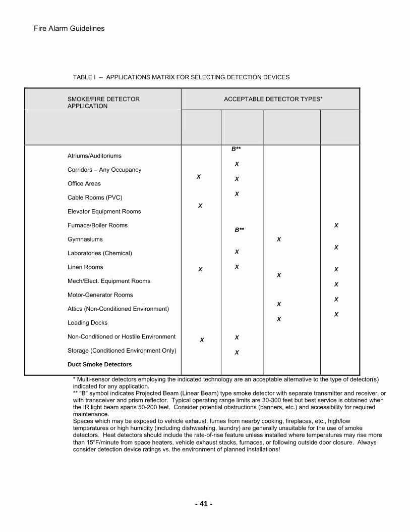
Fire Alarm Guidelines
- 41 -
TABLE I -- APPLICATIONS MATRIX FOR SELECTING DETECTION DEVICES
SMOKE/FIRE DETECTOR APPLICATION
ACCEPTABLE DETECTOR TYPES*
Atriums/Auditoriums Corridors – Any Occupancy Office Areas Cable Rooms (PVC) Elevator Equipment Rooms Furnace/Boiler Rooms Gymnasiums Laboratories (Chemical) Linen Rooms Mech/Elect. Equipment Rooms Motor-Generator Rooms Attics (Non-Conditioned Environment) Loading Docks Non-Conditioned or Hostile Environment Storage (Conditioned Environment Only) Duct Smoke Detectors
X
X
X
X
B**
X
X
X
B**
X
X
X
X
X
X
X
X
X
X
X
X
X
X
* Multi-sensor detectors employing the indicated technology are an acceptable alternative to the type of detector(s) indicated for any application. ** "B" symbol indicates Projected Beam (Linear Beam) type smoke detector with separate transmitter and receiver, or with transceiver and prism reflector. Typical operating range limits are 30-300 feet but best service is obtained when the IR light beam spans 50-200 feet. Consider potential obstructions (banners, etc.) and accessibility for required maintenance. Spaces which may be exposed to vehicle exhaust, fumes from nearby cooking, fireplaces, etc., high/low temperatures or high humidity (including dishwashing, laundry) are generally unsuitable for the use of smoke detectors. Heat detectors should include the rate-of-rise feature unless installed where temperatures may rise more than 15F/minute from space heaters, vehicle exhaust stacks, furnaces, or following outside door closure. Always consider detection device ratings vs. the environment of planned installations!
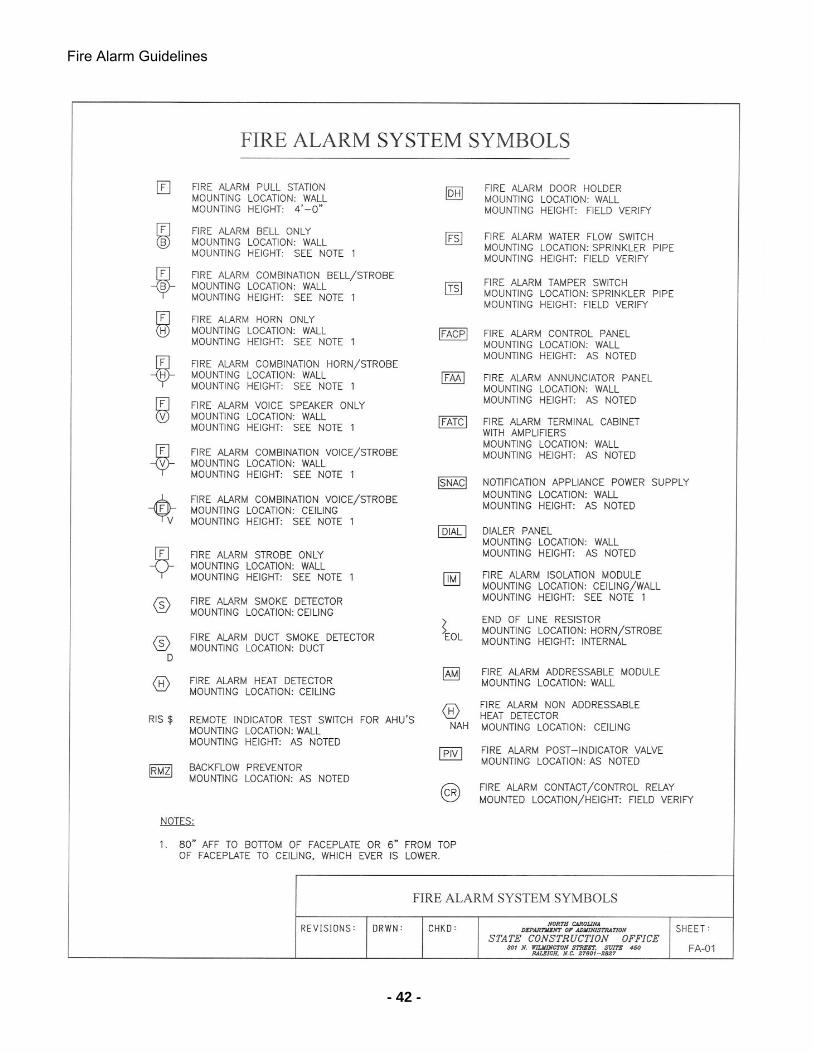
Fire Alarm Guidelines
- 42 -
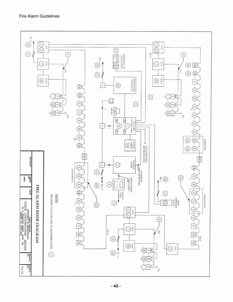
Fire Alarm Guidelines
- 43 -
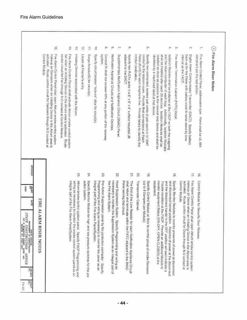
Fire Alarm Guidelines
- 44 -
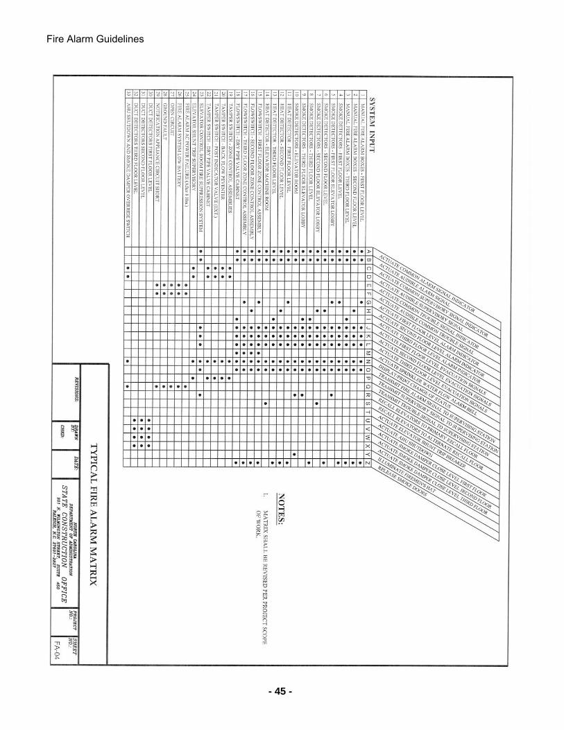
Fire Alarm Guidelines
- 45 -
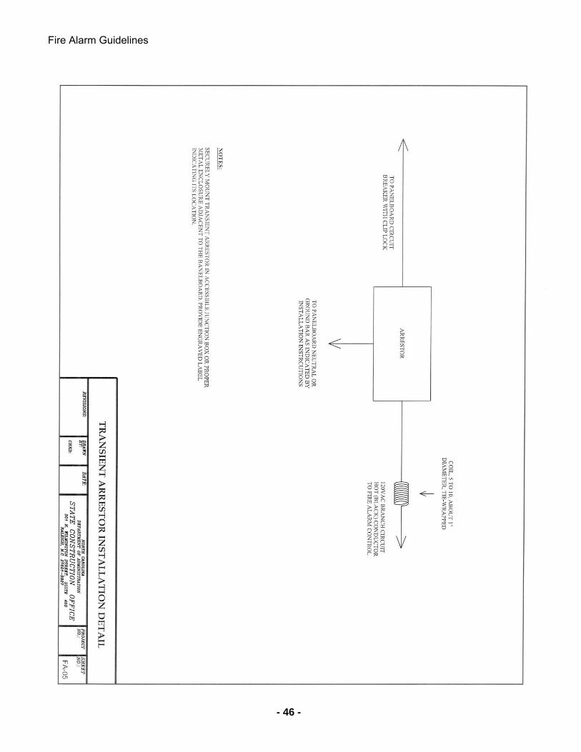
Fire Alarm Guidelines
- 46 -
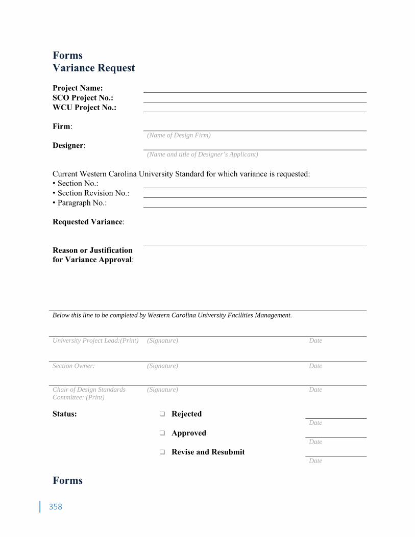
358
Forms Variance Request Project Name: SCO Project No.: WCU Project No.: Firm: (Name of Design Firm)
Designer:
(Name and title of Designer’s Applicant)
Current Western Carolina University Standard for which variance is requested: • Section No.: • Section Revision No.: • Paragraph No.:
Requested Variance:
Reason or Justification for Variance Approval:
Below this line to be completed by Western Carolina University Facilities Management. University Project Lead:(Print) (Signature) Date Section Owner: (Signature) Date Chair of Design Standards Committee: (Print)
(Signature) Date
Status: Rejected
Date Approved Date Revise and Resubmit Date
Forms
359
Energy Estimate Building Name: SCO Project No.: WCU Project No.: Electricity: (kWH) (kVA) Natural Gas:
(CF) (CFH)
Domestic Water
(kGal) (GPM)
Fire Water
(GPM @ Pressure)
(Demand only) Chilled Water (kGal & Btu) (GPM)
Steam (#) (Btu):
(# & Btu) (#/hr)
Sanitary Drainage:
(DFU) (CFS)
Storm Drainage:
(DFU) (CFS)
Assumptions: (attach additional pages as necessary) 1. Gallons of chilled water usage based on 40°F EWT and 55°F LWT.
2. Gallons of hot water usage based on 225°F EWT and 165°F LWT.
3. Pounds of steam usage based on:
4. Domestic water usage based on:
5. Electrical usage based on:
6. Other assumptions:
Estimate Prepared By:
Firm:
(Name of Design Firm) Designer:
(Name and title of Designer’s Applicant) Date
360
Forms Land Disturbance Authorization Project Name: SCO Project No.: WCU Project No.: NCDEQ Permit No.: (If permit has not yet been obtained, attach a copy of the contractor’s Notice of Registration with NCDEQ) As representative/agent of Western Carolina University, after visually inspecting the installed Erosion and Sediment Control measures on site with the Engineer of Record and with Western Carolina University’s Erosion and Sediment Control Consultant, and having acquired the approval of the installed Erosion and Sediment Control measures from the Engineer of Record and WCU Consultant, I hereby authorize (Name and title of Contractor’s Applicant)
with (Name of Contractor)
(Address of Contractor)
to commence land disturbance operations on (Date of Authorization) WCU Representative (Print) (Signature) Date Contractor (Print) (Signature) Date Engineer of Record (Print) (Signature) Date WCU Erosion Consultant (Print) (Signature) Date