Embed Size (px)
Citation preview

Wave optics second course
Assist Prof. DR.Mariam Mohamed Abud
1
HUYGENS' PRINCIPLE
Huygens nearly three centuries ago proposed the rule that each point on a
wavefront may be regarded as a new source of waves (see chapter one)
Huygens’ theory is essentially based on a geometrical construction which
allows us to determine the shape of the wavefront at any time. He results are
follows:
1) When waves pass through an aperture or past the edge of an obstacle, they
always spread to some extent into the region which is not directly exposed to
the oncoming waves. This phenomenon is called diffraction.
2) Huygens explained many of the known propagation characteristics of light,
According to Huygens ’ Principle, each point of a wave front is a source of
secondary disturbance, and the wavelets emanating from these points spread out in
all directions with the speed of the wave. The envelope of these wavelets gives
the shape of the new wave front.
Huygens’ Principle, along with the fact that the secondary wavelets mutually
interfere, is known as the Huygens–Fresnel principle.
(8-2)Interference in the phenomena of superposition of two coherence
waves in the region of superposition, light waves occurs whenever two or
more waves overlap at a given point.

Wave optics second course
Assist Prof. DR.Mariam Mohamed Abud
2
Conditions for sustained interference of light waves
1. The sources are coherent, which means that the waves they emit must
maintain a constant phase with respect to one another.
coherence
incoherence waves
2. The waves have identical wavelengths and frequency, the interfering
waves equal amplitudes
3. The two waves is interference must be propagated at the same line.
4. Two sources must be narrow
We can write the separate displacements as follows: we can write
the separate displacements as follows:
(1)
According to the principle of superposition, the resultant
displacement Y is merely the sum of y1 and y2, and we have:
(2)
When the expression for the sine of the difference of two angles is
used, this can be written
(3)

Wave optics second course
Assist Prof. DR.Mariam Mohamed Abud
3
We are justified in setting:
(4)
The Amplitude of the wave is conserved by each wave period A the
law of cosines gives
(5)
Phase difference φ between two waves are given by ∅ = 𝛼1 − 𝛼2
(8-2) Theory of interference
According figure (1) has two sources such as young’s experiment
Figure (1): Construction for analyzing the double-slit interference pattern. A bright fringe, or
intensity maximum, is observed at O.
Where the wave travels the distance L in a medium, then
Phase difference= 2𝜋
𝜆∗ 𝑝𝑎𝑡ℎ 𝑑𝑖𝑓𝑓𝑒𝑟𝑒𝑛𝑐𝑒

Wave optics second course
Assist Prof. DR.Mariam Mohamed Abud
4
∅ =2𝜋∆
𝜆=
2𝜋𝑛𝐿
𝜆 (7)
∆ is the optical path difference=n L
Where ∆ is the optical path difference, and E the superposition of two
sinusoidal waves having the same frequency
ER = EA+EB
When two waves have a different phase of electric field can be given by:
The Phase difference produces a resultant amplitude by two waves we use
the law of cosine
ER2 = E1
2 + E22 – 2 E1 E
2cos (𝜋 − ∅) (8)
Although the waves are in phase as the slits, the phase difference
∅ = 𝑟2 − 𝑟1 = 𝑑 sin 𝜃 At point P.
A path difference of λ (condition of constructive interference) ,according
phase difference 2𝜋 rad , we get the ratio following:
∆
𝜆=
∅
2𝜋
∅ = 2𝜋
𝜆 ∆=
2𝜋
𝜆 𝑑 sin 𝜃
we can obtain the magnitude of the resultant electric field at point P :

Wave optics second course
Assist Prof. DR.Mariam Mohamed Abud
5
(10)
Interference
Ep=a1+a2 if coherence source Ep= E+E=2E this is maimum
amplitude where a1=a2=E
The intensity is squre of amplitude .
When the phase difference ∅ = 0 and I1=I2=I0,
Ir= A2= (a1+a2)2
Ir=I1+I2 =2IO the interference produced at this points is known as
constructive interference (As stationary bright band)
We have the maximum amount of light: Imax= 4I0
The following features about monochromatic wave
1- The wave has a single frequency definite (𝑓 =𝑤
2𝜋)in optics ,the waves
have a single frequency and wavelength called monochromatic.

Wave optics second course
Assist Prof. DR.Mariam Mohamed Abud
6
2- the electric vector E-vibration are coordinate y-z plane .therfore the
wave is plane polarized (linearly polarized)
3- phase difference and coherence :
∅ =2𝜋𝐿
𝜆 (11)
(8-2-1)INTENSITY DISTRIBUTION OF THE DOUBLE-SLIT
INTERFERENCE PATTERN
The bright fringes in the interference pattern do not have sharp
edges.
The equations developed give the location of only the centers of the
bright and dark fringes.
▪ We can calculate the distribution of light intensity associated with
the double-slit interference pattern.
▪ Assumptions:
▪ The two slits represent coherent sources of sinusoidal waves.
▪ The waves from the slits have the same angular frequency, ω.
▪ The waves have a constant phase difference, φ.
▪ The total magnitude of the electric field at any point on the
screen is the superposition of the two waves.
▪

Wave optics second course
Assist Prof. DR.Mariam Mohamed Abud
7
–The sources must be coherent. •The waves they emit must maintain a constant phase with respect to each other. –The waves must have identical wavelengths.
Producing coherence sources
Light from a monochromatic source is allowed to pass through a narrow slit.
•The light from the single slit is allowed to fall on a screen containing two narrow slits.
•The first slit is needed to insure the light comes from a tiny region of the source which is coherent.

Wave optics second course
Assist Prof. DR.Mariam Mohamed Abud
8
Currently, it is much more common to use a laser as a coherent source.
•The laser produces an intense, coherent, monochromatic beam over a width of several millimeters.
•The laser light can be used to illuminate multiple slits directly. The intensity of a wave is proportional to the square of the resultant electric
field magnitude at that point
Therefore express the light intensity at point P as
(12)
Most light-detecting instruments measure time-averaged light intensity, and
the time-averaged value of sin2(w t +Φ/2) over one cycle is Therefore, we
can write the average light intensity at point P as
(13)
(8-2-2) intensity Distribution
The intensity light wave is given by square of its amplitude
Ir= I1+I2 +2√𝐼1𝐼2 cos ∅
At point that max and min, when I1=I2=I0 ,we get:
Ir= I0 +I0 + 2I0cos∅
= 2I0 (1+cos ∅)
Since the identify 1+cos∅ = 2 cos2 (1
2∅) , 𝑤𝑒 𝑔𝑒𝑡:
𝐼 = 4𝐼0𝑐𝑜𝑠2(1
2∅) (14)

Wave optics second course
Assist Prof. DR.Mariam Mohamed Abud
9
Figure ( 2 ): Light intensity versus d sin for a double-slit interference pattern when the screen is
far from the slits (L >>d)
(15)

Wave optics second course
Assist Prof. DR.Mariam Mohamed Abud
10
(8-3) PRACTICAL (EXPERIMENTAL) COHERENCE PRODUCES
I. INTERFERENCE BY DIVISION OF WAVE FRONT:
1- YOUNG’S DOUBLE-SLIT EXPERIMENT
2-FRESNEL'S BIPRISM
3-FRESNEL'S MIRROR
4- LLOYD’S MIRROR
II. INTERFERENCE BY DVSION OF AMPLITUDE
1-MICHELSON INTERFEROMETER
2-TWEEMAN&GREEN INTERFERMETER
3-JAMIN INTERFEROMETER
4-MACH-ZEHNDER INTERFEROMETER
5-RAYLEGH'S REFREFOMETER
III.INTERFEROMETER BY A MULTPLE REFLECTON
1-NEWTON'S RINGS
2-TWO PARALLEL THIN FILM
In constructive interference the amplitude of the resultant wave is greater
than that of either individual wave.
In destructive interference the amplitude of the resultant wave is less than
that of either individual wave.
All interference associated with light waves arises when the electromagnetic
fields that constitute the individual waves combine.

Wave optics second course
Assist Prof. DR.Mariam Mohamed Abud
11
(8-3-1) Interference by Division of Wave front
1-YOUNG’S DOUBLE-SLIT EXPERIMENT
Thomas Young first demonstrated interference in light waves from two
sources in 1801.the described of details the experiment as following:
•Light is incident on a screen with a narrow slit S0,
•The light waves emerging from this slit arrive at a second screen that
contains two narrow, parallel slits, S1and S2
•The narrow slits, S1and S2 act as real sources of waves.
•The waves emerging from the slits originate from the same wave front and
therefore are always in phase. As shown in fig (3).
Figure (3): (a) Geometric construction for describing Young’s double-slit experiment
(not to scale). (b) The path difference between the two rays is

Wave optics second course
Assist Prof. DR.Mariam Mohamed Abud
12
∅ = 𝑟2 − 𝑟1 = 𝑑𝑠𝑖𝑛𝜃 . it is essential that L >>d.
The incident waves (planar wave) on the slit So from this slit arrive at a
second barrier that contains two parallel slits S1 and S2. These two slits serve
as a pair of coherent light sources because waves emerging from them
originate from the same wave front and therefore maintain a constant phase
relationship. The light from S1 and S2 produces on a viewing screen a
visible pattern of bright and dark parallel bands called fringes .When the
light from the two slits combines destructively at any location on the screen,
a dark fringe results an interference pattern produced by two coherent
vibrating sources in a water tank.
Figure (4) : the two slits produced a pair coherence sources and form max bright fringes
on screen.

Wave optics second course
Assist Prof. DR.Mariam Mohamed Abud
13
The planar waves clashed on slit So, it is emerging from this slit arrive at a
second barrier that contains two parallel slits S1 and S2. These two slits serve
as a pair of coherent light sources because waves emerging from them
originate from the same wave front and therefore maintain a constant phase
relationship. The light from S1 and S2 produces on a viewing screen a
visible pattern of bright and dark parallel bands called fringes .When the
light from the two slits combines destructively at any location on the screen,
a dark fringe results an interference pattern produced by two coherent
vibrating sources in a water tank.
Results interference pattern
The light from the two slits form a visible pattern on a screen.
•The pattern consists of a series of bright and dark parallel bands called
fringes.
•Constructive interference occurs where a bright fringe appears.
Path difference ∅ =𝑟2 − 𝑟1 = 𝑑𝑠𝑖𝑛𝜃 = m λ (15)
•Destructive interference results in a dark fringe. The condition for destructive interference
(16)
It is useful to obtain expressions for the positions of the bright and dark
fringes measured vertically from O to P. In addition to our assumption that
we assume that These can be valid assumptions because in practice
L is often of the order of 1 m, d a fraction of a millimeter, and a fraction of a
micrometer for visible light. Under these conditions, is small

Wave optics second course
Assist Prof. DR.Mariam Mohamed Abud
14
(17)
The positions of the bright fringes measured from O are given by the
expression
(18)
(19)
Young’s double-slit experiment provides a method for measuring
wavelength of the light.
Figure (5): Young’s double-slit experiment set up
φ

Wave optics second course
Assist Prof. DR.Mariam Mohamed Abud
15
▪ This experiment gave the wave model of light a great deal of
credibility.
▪ It was inconceivable that particles of light could cancel each other
in a way that would explain the dark fringes.
▪ ∅ = 𝒅 𝒔𝒊𝒏𝜽 = 𝒅 𝑿
𝑳 (20)
Example 1: A pair of screens are placed 13.7m apart. A third order fringe is
seen on the screen 2.50cm from the central fringe. If the slits were cut
0.0960 cm apart, determine the wavelength of this light. Roughly what
color is it?
Just to make sure you’ve got all the numbers from the question matched
with the correct variables…
L = 13.7 m
n = 3
x = 2.50cm = 0.0250 m
d = 0.0960cm = 9.60e-4 m
It’s probably a yellow light being used given the wavelength we've measured.
If a white light is used in the double slit experiment, the different colours will
be split up on the viewing screen according to their wavelengths.
• The violet end of the spectrum (with the shortest wavelengths) is
closer to the central fringe, with the other colours being further away
in order.
There is also a version of the formula where you measure the angle between
the central fringe and whatever fringe you are measuring.

Wave optics second course
Assist Prof. DR.Mariam Mohamed Abud
16
Example 2: For a single slit experiment apparatus like the one described
above, determine how far from the central fringe the first order violet (λ =
350nm) and red (λ = 700nm) color’s will appear if the screen is 10 m away
and the slit is 0.050 cm wide.
We need to solve the formula for “x”, the distance from the central fringe.
For the violet light
For the red light
1. Fresnel’s Biprism:
Some objected Young’s Experiment result and said that: “the bright fringes
were probably due to some complicated modification of the light by the

Wave optics second course
Assist Prof. DR.Mariam Mohamed Abud
17
edges of the slits and not interference” Fresnel did new experiments to prove
that they were interference. S is the real source, and the other S’s are virtual.
Figure (8) Diagram of Fresnel's biprism experiment
To find d: the distance between sources or virtual images sources
When a: distance between the slit and biprism
𝛼 = 𝑟𝑒𝑓𝑟𝑎𝑐𝑡𝑖𝑛𝑔 𝑎𝑛𝑔𝑙𝑒 𝑜𝑓 𝑡ℎ𝑒 𝑏𝑖𝑝𝑟𝑖𝑠𝑚
𝑑 = 2𝛿𝑥𝑎 = 2𝑎(𝑛 − 1)𝛼 (21)
𝛿: 𝑡ℎ𝑒 𝑑𝑒𝑣𝑖𝑎𝑡𝑖𝑜𝑛 𝑝𝑟𝑜𝑑𝑢𝑐𝑒𝑑 𝑏𝑦 𝑒𝑎𝑐ℎ ℎ𝑎𝑙𝑓 𝑜𝑓 𝑡ℎ𝑒 𝑝𝑟𝑖𝑠𝑚 = 𝛿 = (𝑛 − 1)𝛼
In fig 4 the central point between be region fringe of maximum intensity
occurs there.
The fringes width of dark or bright fringe is 𝛽 =𝜆𝐷
𝑑 (22)
Where D: distance between source and screen
The wavelength is given by:
𝜆 =𝛽 𝑑
𝑎 + 𝐶
A
a
D
B

Wave optics second course
Assist Prof. DR.Mariam Mohamed Abud
18
D= a+c
Example 3 :a) calculate the separation between the coherent sources formed by biprism whose inclined faces make angles of 2 with its base ,the slit being 0.1 m away from the biprism (n=1.5)?
𝛼 = 2𝑜 = 𝜋
180𝑥 2 𝑟𝑎𝑑𝑖𝑎𝑛𝑠
𝑑 = 2𝑥0.1𝑥(1.5 − 1)𝑥𝜋
180 𝑥2 = 0.0034
Example 4: In a Fresnel’s bi-prism experiment, the refracting angle of prism
were 1.5 o and refractive index of the glass was 1.5.with the angle slit 5 cm
from the bi-prism and using light of wavelength 580nm,fringes were formed
on a screen 1m from the single slit ,calculate the fringes width?
Solution
Example 3: In a Fresnel’s bi-prism experiment, the refracting angle of prism
were 1.5 o and refractive index of the glass was 1.5.with the angle slit 5 cm
from the bi-prism and using light of wavelength 580nm,fringes were formed
on a screen 1m from the single slit ,calculate the fringes width?
Solution
𝑑 = 2𝛿𝑥𝑎 = 2𝑎(𝑛 − 1)𝛼
d=2x5(1.5-1)(1.5x 3.14/180)=0.1308=0.131 cm
The fringe width is
∆𝑥 =𝜆 𝐷
𝑑=
580 𝑥 10−7𝑐𝑚 𝑥 100 𝑐𝑚
0.131 𝑐𝑚= 0.044 𝑐𝑚

Wave optics second course
Assist Prof. DR.Mariam Mohamed Abud
19
Figure (9): Interference and diffraction fringes produced in the Fresnel biprism
3. Fresnel’s Mirrors:
Here, Fresnel used two mirrors. Light from a slit S is reflected (not
refracted) from two plane mirrors slightly inclined to each other. The
mirrors produce two virtual images of S. They act exactly like two
sources formed by the biprism.
Figure (10): Fresnel's mirrors.
L
a b

Wave optics second course
Assist Prof. DR.Mariam Mohamed Abud
20
Light from a slit is reflected in two plane mirrors slightly inclined to each
other. The mirrors produce two virtual images of the slit, a narrow slit S is
illuminated by a monochromatic light wavelength 𝜆
It is placed parallel to the line of intersection of mirror surface, one portion
of cylinder wavelength is reflected from the first mirror and another portion
of the wave front is reflected from the second mirror. The virtual sources S1
and S2 are coherence sources which produced from the source S. the fringes
from (ae) region are equal width. The distance between virtual sources is d
Fringes width ∆𝑥 =𝜆𝐿
𝑑=
𝜆(𝑎+𝑏)
𝑑 (23)
∆𝑆1𝑂𝑆2 = 2𝜃
Then the distance between two virtual slits 𝐴𝑟𝑐 𝑆1𝑆2 = 𝑑 = 𝑎 ∗ 2𝜃 Then the eq.23 becomes:
∆𝑥 =𝜆𝐿
𝑑=
𝜆(𝑎 + 𝑏)
2𝑎𝜃
Compared between the fringes by Fresnel’s biprism and Mirrors:
Both cases are similar, but the double mirror are narrower than Fresnel’s biprism fringes.
4. Lloyd’s Mirrors:
This method is used to single long mirror about 30 cm. The
interference is produced by the light reflected from the mirror and the
light coming directly from the source (the slit 𝑆1)
Figure (11): Set up Lloyd’s Mirrors
O

Wave optics second course
Assist Prof. DR.Mariam Mohamed Abud
21
A cylindrical wave front coming from a narrow slit S1 falls on the
mirror which reflects a portion of incident wave front, giving rise to a
virtual image of the slit s’.
The slit s1 and s2 represent at two coherent sources. The point O
equidistant from s and s’
An arrangement for producing an interference pattern with a single light
source
•Waves reach point O either by a direct path or by reflection.
•The reflected ray can be treated as a ray from the source S’ behind the
mirror.
O is central (zero-order) fringes. With white light the central point o is
expected white, but in practice it is dark. The phase change leads to a
path difference of λ/2 and here destructive interference occurs.
To determine of wavelength𝜆, the fringes width is:
∆𝑥 =𝜆𝐿
𝑑
𝑚𝑒𝑎𝑠𝑢𝑟𝑚𝑖𝑛𝑔 ∆𝑥, 𝐿 𝑎𝑛𝑑 𝑑.
Comparison between the fringes produced by biprism and
Lloyd’s mirror:
1. In biprism the complete set of fringes is obtained. In Lloyd’s
mirror a few fringes on one side of the central fringe are noted, the
central fringe which being invisible
2. In biprism the zero-order (central fringe) is bright, but the central
fringe of Lloyd’s mirror is dark.
3. The central fringe is less sharp in biprism than in Lloyd’s mirror.
O

Wave optics second course
Assist Prof. DR.Mariam Mohamed Abud
22
Example (5):
In young’s experiment, interference bands are produced on screen placed 1.5
m from two slits 0.15 mm apart and illuminated by the light of wavelength
6000Å. Find
a) Fringe width
b) Change in fringe width if the screen is taken away from the slits by 50
cm?
Solution
a) ∆𝑥 =𝜆𝐿
𝑑=
6000𝑥10−10 𝑚𝑥1.5 𝑚
0.15𝑥10−3𝑚
∆𝑥 = 6 𝑚𝑚
b) ∆𝑥 =𝜆𝐿
𝑑=
6000𝑥10−10 𝑚𝑥50 𝑥10−2 𝑚
0.15𝑥10−3𝑚= 2mm
Example (6):
A light falls on two slits ( 2 mm) apart and produces on a screen 1 m away
from the fourth –order bright line 1 mm from the center of the pattern .what
is the wavelength of the light used?
Solution:
N=4 order , d=2mm
D=1 m
sin 𝜃 = tan 𝜃 = 𝑦
𝐿
𝑑 sin 𝜃 = 𝑚𝜆
𝜆 = 𝑑 ( 𝑦
𝐿)(
1
𝑛)

Wave optics second course
Assist Prof. DR.Mariam Mohamed Abud
23
𝜆 = (2 𝑥 10−3)(10−3(1
4)
𝜆 = (1
2) 𝑥 10−6
𝜆 = (0.5𝑥 10−6 = 500 𝑛𝑚
Example (7): yellow light pass through two slits and interference pattern
is observed on a screen
1) The bright fringes will increase in width if the yellow light is replaced
blue
2) The bright fringes will increase in width if the distance between slit
minimized
3) The intensity of light decreases if it is far from the central fringes
4) The intensity of light is constant if it is far from the central fringe which
is the correct statement?
Solution:
d:distance between slit is smaller than the distance between slit and
screen, so the angle is very small

Wave optics second course
Assist Prof. DR.Mariam Mohamed Abud
24
sin 𝜃 = tan 𝜃 = 𝑦
𝐿
𝑑 sin 𝜃 = 𝑚𝜆
𝜆 = 𝑑 ( 𝑦
𝐿)(
1
𝑛)
n: no. of bright lines is proportional inversely to the wavelength
Yellow wavelength (small frequency) is larger than blue light.
Blue light is changed; the wavelength λ is decrease, so the number of
bright lines is increase.
This statement is correct
2) The bright fringes will increase in width if the distance between slit
minimized
d sin 𝜃 = tan 𝜃 = 𝑦
𝐿

Wave optics second course
Assist Prof. DR.Mariam Mohamed Abud
25
If The bright fringes will increase in width if the distance between slit
minimized, the number of bright lines (n) decreses.
𝑛𝜆 = 𝑑 ( 𝑦
𝐿)
The bright fringes will increase in width if the distance between slit
minimized
This statement is incorrect
3) The intensity of light decreases if it is far from the central fringes
This statement is correct
Intensity related to the light level. Intensity is proportional inversely to
the distance. If the distance is increased the intensity is decrease(the
light dimmer)
4)The intensity of light is constant if it is far from the central fringe which
is the correct statement?
This statement is incorrect
Example (8):
Suppose in double slit arrangement, d=0.150 mm, L=120 cm, the
wavelength =833 nm, and the width fringe y=2 cm
a) What is the path difference δ for the rays from the two slits arriving at
point P
b) Express this path difference in terms of λ?

Wave optics second course
Assist Prof. DR.Mariam Mohamed Abud
26
c) Does point P corresponds to a maximum or minimum, is intermediate
condition?
Solution:
a) φ = d sin θ bright = d 𝒚
𝑳= 𝟏. 𝟓 𝒙𝟏𝟎−𝟒𝒎
𝟐𝒙 𝟏𝟎−𝟐𝒎
𝟏.𝟐= 𝟐. 𝟓 𝒙 𝟏𝟎−𝟔𝒎
b) from a) we get
𝜑
𝜆=
2.5𝑥 10−6𝑚
8.33𝑥10−7𝑚 ≈ 3
Path difference
𝜑 = 3𝜆
c) at point P the path difference φ = ∓ 𝑚𝜆 𝑖𝑠 𝑎the multiple
wavelength , so the intensity y at point p is maximum
COHERENT SOURCES
The two incident light beams must have the same frequency and be in phase
at the two slits (or at least have a definite time-independent phase relation);
two such beams are said to be coherent sources. The result is that the
difference in phase between any pair of points in the two sources always
remains constant, and so the interference fringes are stationary. Such as
Young's experiment and in Fresnel's mirrors and biprism, the two sources Sl
and S2 always have a point-to-point correspondence of phase, since they are
both derived from the same source any interference experiment with light
that the sources must have this point-to-point phase relation, and sources that
have this relation are called coherent sources.
While special arrangements are necessary for producing coherent sources of
light, the same is not true of microwaves, which are radio waves of a few
centimeters wavelength. If in Young's experiment the source slit S (Fig. 12)
is made too wide or the angle between the rays which leave it too large, the

Wave optics second course
Assist Prof. DR.Mariam Mohamed Abud
27
double slit no longer represents two coherent sources and the interference
fringes disappear
Interference fringes with white light and monochromatic
If the slit illuminated by white light in the in Young's experiment the source
slit S is used and Fresnel’s biprism. The interference pattern consist of a
central white light around it on both sides a few coloured fringes. The
central fringe will be dark and others will be colors. With white light, fringes
are observed only when the path difference is small.
(8-3-2 ). INTERFERENCE BY DVSION OF AMPLITUDE
1-MICHELSON’s INTERFEROMETER
Principle:
Two beams are interference formed by division of amplitude.
Construction of Michelson and works:
The light source S is monochromatic(known (as with a laser beam), have
incident beam (a plane waver fronts on light silvered Mirror pass by striking
glass which has inclined 45 degree.
The two plane-parallel plates of glass Gland G2, sometime used one glass
G.to get interference the mirrors M1 and M2 have perpendicular each other,
with a finely threaded screw adjustment.
Figure (12): diagram of young’s Experiment

Wave optics second course
Assist Prof. DR.Mariam Mohamed Abud
28
Figure (13): Construction of Michelson
The beam is divided into two beams
1) from reflection
2) from transmission
in this process the amplitudes have divide represents a two sources
Under these conditions, the interference pattern is a series of bright and dark
parallel fringes as described in Example figure (14(b). The tilting screws on
M2 are turned until one pair of images falls exactly on the other, the
interference fringes should appear. When they first appear, the
fringes will not be clear unless the eye is focused on or near the back mirror
M1 so the observer should look constantly at this mirror while searching for
the fringes.
As M1 is moved, the fringe pattern shifts. For example, if a dark fringe
appears in the field of view (corresponding to destructive interference) and
M1 is then moved a distance λ/4 toward M, the path difference changes by
λ/2 (twice the separation between M1 see fig (14(c) and what was a dark
fringe now becomes a bright Fringe.
As M1 is moved an additional distance λ /4 toward M, the bright fringe
becomes a dark fringe. Thus, the fringe pattern shifts by one-half fringe each
time M1 is moved a distance λ /4. The wavelength of light is then measured

Wave optics second course
Assist Prof. DR.Mariam Mohamed Abud
29
by counting the number of fringe shifts for a given displacement of M1. If
the wavelength is accurately mirror displacements can be measured to within
a fraction of the wavelength.
(a) (b) (c )
Figure (14) : a) A pair of images, b) arrangement two image and
Circular fringes are produced with laser light when the mirrors M1 and
M2 are exactly perpendicular to each other.(c) As M1 is moved, the
fringe pattern shifts. For example, if a dark fringe appears in the field
of view as forward or backward.
Optical path
The two waves will interfere constructively or destructively as per the following conditions of
Path difference ∆:
∆ =2𝑚𝜆
2= 𝑚𝜆 𝑎𝑡 𝑚𝑎𝑥. 𝑖. 𝑒 𝑏𝑟𝑖𝑔ℎ𝑡 𝑓𝑟𝑖𝑛𝑔𝑒𝑠 , where m is integer
𝑚 = ∓1, ∓2, ∓3 … … … … . . ∓𝑚
∆= (2𝑚 + 1)𝜆/2
at min. or dark fringes ,when m is also integer
(24)

Wave optics second course
Assist Prof. DR.Mariam Mohamed Abud
30
Figure (15) Schematic of the Michelson interferometer.
Types of fringes
1) Circular fringes
Circular fringes are produced with monochromatic light when the
mirrors M1 and M2 are exactly perpendicular to each other.
The ones used in most kinds of measurement with the interferometer. Their
origin can be understood by reference to the diagram in Fig. 10. M2'
Is the virtual image of M2 and it is parallel to M1. For simplicity, light
source L is at the observer's position. L1 and L2 are the virtual images of L
formed by M1 and M2', and are coherent. Let d be the distance between M1
and M2', therefore the distance between L1 and L2 is 2d.

Wave optics second course
Assist Prof. DR.Mariam Mohamed Abud
31
θ: the angle between the incident beam originated at P and the reflected
beams from M1 and M2'. Then path difference between light beams from
points Pand P" is 2d cos θ.
A maximum (bright fringe) will be formed when 2dcosθ = m . For a fixed
value of n, and d, the value of θ is a constant, and the contour of the
maximum point becomes a ring. The Centre of the ring is in line with the
observer and perpendicular to the mirror plane. Each circular ring
corresponds to a particular value of θ. Hence the fringes are known as
fringes of equal inclination. Fig (11 a) Fringes of this kind, where parallel
beams are brought to interference with a
phase difference determined by the angle of inclination θ, are often referred
to as fringes of equal inclination.
This type may remain visible over very large path differences
2𝑑 cos 𝜃 = 𝑚𝜆 (25)
Figure (16) form of circular fringes (Concentric circular fringes) as known as
fringes of equal inclination
Since for a given m, λ.,and d the angle θ is constant, the maxima will lie in
the form of circles about the foot of the perpendicular from the eye to the
p P’’
p 2d
θ P”
2d cos θ
L1 L2

Wave optics second course
Assist Prof. DR.Mariam Mohamed Abud
32
mirrors. By expanding the cosine, it can be shown from Eq. (25) that the
radii of the rings are proportional to the square roots of integers, as in the
case of Newton's rings . The intensity distribution across the rings follows
Eq. (13), in which the phase difference is given by
∅ = 2𝜋
𝜆 2𝑑 cos 𝜃 (26)
2) Curved fringes (fringes of equal thickness):
When M1 and virtual image M2' are inclined to each other, the film enclosed
is wedge shaped. Then curved fringes can be observed as shown in Fig. 11.
These are also known as fringes of equal thickness
Figure 17: form fringes of equal thickness
The difference between two fringes has explain in fig.18

Wave optics second course
Assist Prof. DR.Mariam Mohamed Abud
33
Figure 18: a) difference fringes between a) fringes of equal inclination
B) fringes of equal thickness and c. d) moved M2’ formed circular fringes e) form
straight fringes.
a b
c
d
e

Wave optics second course
Assist Prof. DR.Mariam Mohamed Abud
34
3) Straight line fringes:
When M1 and virtual image M2' intersect, straight line fringes are obtained
around the point of intersection (see Fig. 13). The path
Figure 19: shape of Straight line fringes
Figure 20: Appearance of the various types of fringes observed in the Michelson
interferometer. Upper row, circular fringes. Lower row, localized fringes. Path
difference increases outward, in both directions, from the center.
4) White light fringes: if white light is used, the central fringe will be
dark and other will be coloured.fringes are observed only when the
path difference is small. These fringes are important because they are
used to locate the position of zero path difference.
Wave optics second course
Assist Prof. DR.Mariam Mohamed Abud
35
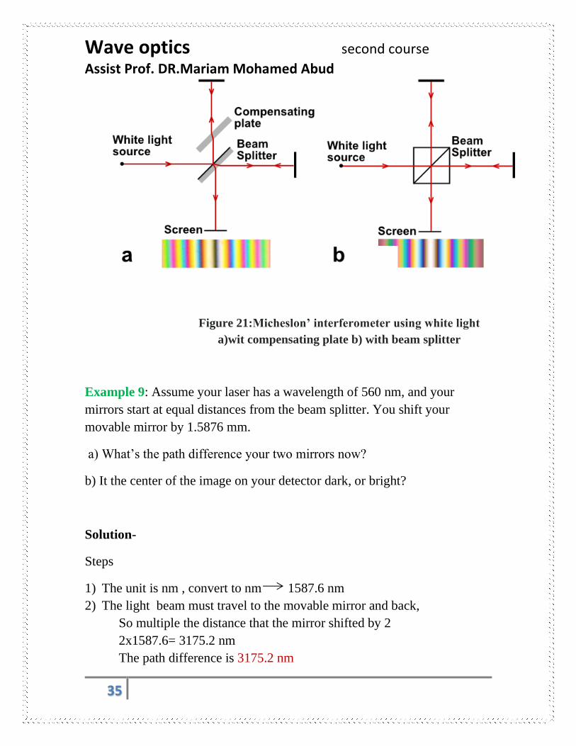
Figure 21:Micheslon’ interferometer using white light
a)wit compensating plate b) with beam splitter
Example 9: Assume your laser has a wavelength of 560 nm, and your
mirrors start at equal distances from the beam splitter. You shift your
movable mirror by 1.5876 mm.
a) What’s the path difference your two mirrors now?
b) It the center of the image on your detector dark, or bright?
Solution-
Steps
1) The unit is nm , convert to nm 1587.6 nm
2) The light beam must travel to the movable mirror and back,
So multiple the distance that the mirror shifted by 2
2x1587.6= 3175.2 nm
The path difference is 3175.2 nm

Wave optics second course
Assist Prof. DR.Mariam Mohamed Abud
36
This no. an odd integer multiple of (λ/2) (in which case it would cause
destructive interference and result in darkness in the center), or an
integer multiple of λ (which would cause constructive interference
and a result in a bright center)
Step 2:
3175.2 nm/560 nm =5.67 ≈ 𝟔
5.67 is an integer, so it’s constructive interference resulting in a bright
center on the image at the detector.
Note: Limiting path difference as determined by the length of wave packets.
VISIBILITY OF THE FRINGES
There are three principal types of measurement that can be made with the
interferometer:
(I) width and fine structure of spectrum lines, (2) lengths or displacements
in terms of wavelengths of light, and (3) refractive indices
In Michelson’s interferometer, the intensity is given by:
𝐼 = 4𝐼0𝑐𝑜𝑠2(1
2∅) (14)
Since the phase path ∅ =2𝜋
𝜆 (2𝑑 cos 𝜃)
Where d: distance between M1 & M2’.the intensity is max. When ∅ is an
integral multiple of 2𝜋 . The intensity is zero when ∅ is an odd multiple of 𝜋
Michelson’s interferometer measured the visibility, defined as
𝑉 =𝐼𝑚𝑎𝑥− 𝐼𝑚𝑖𝑛
𝐼𝑚𝑎𝑥+ 𝐼𝑚𝑖𝑛 (27)
Where Imax and Imin are the intensities at the maxima and minima of the
fringe pattern. The more slowly V decreases with increasing path difference,
the sharper the line.
Wave optics second course
Assist Prof. DR.Mariam Mohamed Abud
37
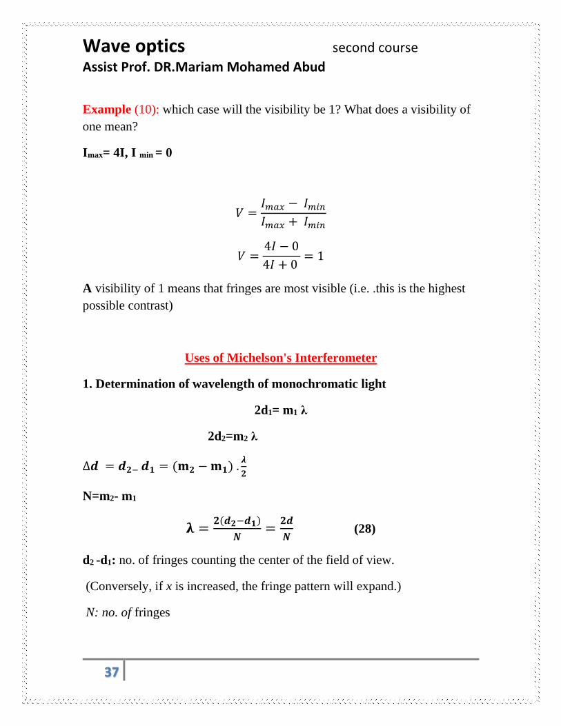
Example (10): which case will the visibility be 1? What does a visibility of
one mean?
Imax= 4I, I min = 0
𝑉 =𝐼𝑚𝑎𝑥 − 𝐼𝑚𝑖𝑛
𝐼𝑚𝑎𝑥 + 𝐼𝑚𝑖𝑛
𝑉 =4𝐼 − 0
4𝐼 + 0 = 1
A visibility of 1 means that fringes are most visible (i.e. .this is the highest
possible contrast)
Uses of Michelson's Interferometer
1. Determination of wavelength of monochromatic light
2d1= m1 λ
2d2=m2 λ
∆𝒅 = 𝒅𝟐− 𝒅𝟏 = (𝐦𝟐 − 𝐦𝟏) .𝝀
𝟐
N=m2- m1
𝛌 =𝟐(𝒅𝟐−𝒅𝟏)
𝑵=
𝟐𝒅
𝑵 (28)
d2 -d1: no. of fringes counting the center of the field of view.
(Conversely, if x is increased, the fringe pattern will expand.)
N: no. of fringes

Wave optics second course
Assist Prof. DR.Mariam Mohamed Abud
38
Michelson tested the lines from various sources and concluded that a certain
red line in the spectrum of cadmium was the most satisfactory .The standard
meter in Paris with the wavelengths of intense red, green, And blue lines of
cadmium by Michelson and Benoit
Red line λ= 6438.4722 Å or λ = 643.84 nm
Green line λ= 5085.8240 Å or λ = 508.5824 nm
Blue line λ = 4799.9107 Å or λ= 479.9991 nm
Example 11: A red laser (He-Ne) of wavelength 632.8 nm is used in
Michelson’s interferometer. While kept the mirror M1 is fixed and M2 is
moved. The fringes were found to move past a fixed cross-hair in the
observer .find the distance of the mirror M2 is moved for single fringe to
move past the origin line.

Wave optics second course
Assist Prof. DR.Mariam Mohamed Abud
39
Solution:
∆𝒅 = 𝒅𝟐− 𝒅𝟏 = (𝐦𝟐 − 𝐦𝟏) .𝝀
𝟐
2(∆𝑑) = 𝑚𝜆
∆𝑑 = 𝑚𝜆
2= 1𝑥
632.8𝑛𝑚
2= 316.4 𝑛𝑚 = 0.3146 𝜇𝑚
Example 12: In an interferometer using laser produced 200 fringes cross
the field of view when the mirror is moved through 0.0589 mm. calculate the
wavelength of light used?
Solution
𝛌 =𝟐(𝒅𝟐−𝒅𝟏)
𝑵=
𝟐𝒅
𝑵=
𝟐𝒙 𝟎.𝟎𝟓𝟖𝟗 𝒙𝟏𝟎−𝟑𝒎
𝟐𝟎𝟎= 𝟓𝟖𝟗 𝒏𝒎
2- Determination of different in wavelength between two neighbor lines
or two waves
Let the source of light emit close wavelength 𝛌1 and λ2 such as sodium
lamp, the apparatus is adjusted to form circular rings. the arrangement of the
position of mirror M1 is moved and reached when a bright fringes of one set
falls on the bright fringe of the other an fringes are again distinct.
2d=m1λ1=m2 λ2 (29)
If condition λ1>λ2, since m2=m1+1, subst. in eq. 29

Wave optics second course
Assist Prof. DR.Mariam Mohamed Abud
40
2d= m1λ1 = (m1+1) λ2
𝑚1 =𝜆2
𝜆1 − 𝜆2
∴ 2𝑑 =𝜆1𝜆2
𝜆1 − 𝜆2
𝜆1 − 𝜆2 = 𝜆1𝜆2
2𝑑
If used λ as a mean wavelength of two wavelength λ1and λ2, the small
difference between them is∶
∆𝜆 =𝜆2
𝑚𝑒𝑎𝑛
2𝑥 (30)
3-determination of the refractive index of gases
The path difference introduce between the two interfering beam is 2(n-1) L
Where n: Refractive index of gas
L: length of the tube. If m fringes cross the center of the field of view thus:
2(n-1)L=mλ
𝑛 =𝑚𝜆
2𝐿+ 1 (31)
Example (13):
In an experiment for determine the refractive index of gas using Michelson
interferometer a shift of 140 fringes is observed. When all the gas is
removed from the tube. If the wavelength of light used is 5460Å and the
length of the tube is 20 cm, calculate the refractive index of the gas?
Solution

Wave optics second course
Assist Prof. DR.Mariam Mohamed Abud
41
𝑛 =𝑚𝜆
2𝐿+ 1
𝑛 =140𝑥5460𝑥10−10𝑚
2𝑥0.2+ 1 = 1.00019
(8-4) Index of refractive by interference Methods
If a thickness t of a substance having an index of refraction n is introduced
into the path of one of the interfering beams in the interferometer, the optical
path in this beam is increased because of the fact that light travels more
slowly in the substance and consequently has a shorter wavelength. The
optical path ∆= 𝑛 𝑡 is now nt through the medium, whereas it was
practically t through the corresponding thickness of air (n = 1). Thus the
increase in optical path due to insertion of the substance is (n - l)t.t This will
introduce (n - l)t). Extra waves in the path of one beam; so if we call ∆𝑚 the
number of fringes by which the fringe system is displaced when the
substance is placed in the beam, we have
Interferometry
Instrument used by the principle of interference of light is called
interferometer this instrument designed used to determine the refractive
index of each solid ,liquid and solutions transparent substances .
Refractive index of Solid state using 1) Michelson’s form of interferometer
2) Twyman & Green interferometer.
3) James and 4) Rayleigh is used to determine the refractive index of gases
and is known as refract meter
2. Twyman and Green interferometer
The Twyman Green interferometer is a variant of the Michelson
interferometer. It is used industrially for the interferometry control of non-
plane optical surfaces and mirrors or lens objectives. Figure 22 presents the

Wave optics second course
Assist Prof. DR.Mariam Mohamed Abud
42
Twyman-Green device. It instrument for testing the distortion of optical
parts such as prisms and lenses. The piece to be tested is located in one of
the two beam paths. A mirror behind it, chosen that the reflected beams is
plane waves from the other arm of the interferometer by another lens, at the
focus of which the eye is placed. If the prism or lens is optically perfect, so
that the returning waves are strictly plane, the field will appear uniformly
illuminated. Any local variation of the optical path will, however, produce
fringes in the corresponding part of the field, which are essentially the
contour lines of the distorted wave front.
Figure (22): Twyman Green Interferometer

Wave optics second course
Assist Prof. DR.Mariam Mohamed Abud
43
3) Jamin’s interferometer
The Jamin interferometer allows very exact measurements of
the refractive index and of gases; a transparent pressure chamber can be
positioned in the instrument. The phase shift due to changes in pressure is
quite easy to measure.
Figure (23) The Jamin interferometer.
G1&G2 is two thickness parallel plates with one mirror face. S is broader
source of monochromatic light. Two Similar evacuated tubes T1 and T2 of
equal length are placed in the two parallel beams. To calculate its refractive
index (n)
Gas is slowly admitted to tube T2. If the number of fringes ∆m crossing the
field is counted while the gas reaches the desired pressure and temperature,
the value of n can be found by applying the optical path is now nt
Through the medium, whereas it was practically t through the corresponding
thickness of air (n = 1). Thus the increase in optical path due to insertion of
the substance is (n - 1) t.
Extended
source

Wave optics second course
Assist Prof. DR.Mariam Mohamed Abud
44
The number of fringes by which the fringe system is displaced when the
Substance is placed in the beam, we have (𝑛 − 1)𝑡 = ∆𝑚 ∗ 𝜆
In principle a measurement of ∆𝑚, t, and λ thus gives a determination of n.
The main source beam will broke into two parallel beams passing through
the two tubes. The recombines in G2 causes an interference fringes known
as Brewster’s fringes where
𝑛2 − 1
𝑛2 + 2= (𝑛 − 1)
𝑛 + 1
𝑛2 + 2= 𝑐𝑜𝑛𝑠𝑡.∗ 𝜌
This is a special case of the Lorenz-Lorentz* law, according to which
𝜌: 𝑔𝑎𝑠 𝑑𝑒𝑛𝑠𝑖𝑡𝑦
4- Mach-Zehnder interferometer
Figure 25: the Mach-Zehnder interferometer.
The Mach-Zehnder interferometer is suitable only for studying slight
changes of refractive index. Which like Michelson’ interferometer
except that it have a large separation in beams path.

Wave optics second course
Assist Prof. DR.Mariam Mohamed Abud
45
5- Rayleigh's refractometer
In Rayleigh's refractometer (Fig. 26) monochromatic light from a
linear source S is made parallel by a lens L1, L2 are two converging
lenses and split into two beams by a fairly wide double slit. After
passing through two exactly similar tubes T1, T2 and the
compensating plates C1 &C2, these are brought to interfere by the lens
L2. This form of refractometer is often used to measure slight
differences in refractive index of liquids and solutions.
Figure 27: Rayleigh's refractometer
III.INTERFEROMETER BY A MULTPLE REFLECTON
1-NEWTON'S RINGS
2-TWO PARALLEL THIN FILM
1) Newton's rings This method for determining the wavelength of light was proposed by Sir
Isaac Newton in his book Optics, published in 1717. The experimental
arrangement is shown in Figure 1.
A plano-convex lens of large radius of curvature R is placed on a plane glass
plate with its curved surface downwards and is illuminated from above with a
parallel beam of monochromatic light. Some of the light is reflected from the
upper

Wave optics second course
Assist Prof. DR.Mariam Mohamed Abud
46
surface of the glass plate and some from the lower surface of the lens;
interference thus occurs by division of amplitude, the fringes being localised
in the air gap between the lens and plate.
At any point a distance r from the axis of the lens the path difference will be
2h, where h is the distance between the lens and the plate at that point (See
Figure 2). whenever the thickness of the air film satisfies the condition R2= rm2+(R –t) 2

Wave optics second course
Assist Prof. DR.Mariam Mohamed Abud
47
rm represents the radius of the mth dark ring;the thickness of the air film
(where the mth dark ring is formed) is t. the optical path difference between
the two waves is very nearly equal to 2nt, where n is the refractive index of

Wave optics second course
Assist Prof. DR.Mariam Mohamed Abud
48
the film and t is the thickness of the film. Thus, whenever the thickness of
the air film
satisfies the condition
If a liquid of refractive index n is introduced between the
lens and the glass plate, the radii of the dark rings are given by
(because it is reflected from a medium of lower
refractive index). Hence,
the optical path difference
The interference fringes are circular because the system is symmetrical about
the centre of the lens. The radius of any ring is given by:
(2R - t)t = r2 r2 = 2Rt – t2

Wave optics second course
Assist Prof. DR.Mariam Mohamed Abud
49
But t2 is small compared with 2Rt and so: 2Rt = r2 The path difference (2t) is therefore r2/R
A phase change of 𝜋 occurs when the light reflects from the top surface of
the plate but not at the lower surface of the lens, and therefore:
For a bright ring viewed by reflection: (2m + 1)λ/2 = rm2/R
For a dark ring viewed by reflection: mλ = rm2/R
Where m = 0, 1, 2, 3, etc and rm is the radius of the mth ring. If a graph is plotted of r2 against m for the dark
rings a straight line should be produced with a gradient given by:
(rm
2 - r12)/(m - 1) = λR
where r1 and rm are the radii of the first and mth rings respectively. (See Figure 3).
When doing the experiment it is much easier (and more accurate) to measure the diameter of the rings and then calculate their radius. A dark
central spot should be obtained when viewed by reflection.
The rings can be viewed by transmission by putting the microscope below the plate, and if this is done
the equations for bright and dark rings should be interchanged as two phase changes will occur,
producing an effective phase difference of 2𝜋. A
bright central spot should be obtained.
If white light is used a few coloured rings will be seen due to the different wavelengths of the different colours of light.
.

Wave optics second course
Assist Prof. DR.Mariam Mohamed Abud
50
2) Interference in thin films
The beautiful colours in soap films and in oil floating
on water are due to interference by reflection. We
will first consider the interference due to a parallel-
sided film as shown in Figure 1. Interference can be
seen at O by division of amplitude, some light being
reflected from each side of the film.
Part of the light beam travels a distance BEP = 2BE
while the other travels a distance BM.
The path difference is therefore = 2nBE – BM
Now the distance 2BE is in the thin film which has a
refractive index n and so the equivalent path length
in a vacuum is 2nBE
So path difference = 2nBE – nBN = n(BE + EF - BN)
= nNF = 2nt cos r
where n is the refractive index of the film of
thickness t.
Path difference in a thin film = 2nt cosr
For a soap film in air a phase change will occur at the first face and so a maximum will
occur when the path difference is equal to an odd number of half wavelengths.
Therefore:
Path difference in a thin film = 2nt cosr = (m + ½)λ
where m = 0, 1, 2, etc.
For an oil film on water the phase changes will depend on the refractive index of the oil.
If we now consider the soap film and normal incidence (i.e. cos r = 1) it is easy to see
why thick films reflect light but do not show coloured effects and appear transparent and
why very thin films appear 'black' i.e. do not reflect light. The idea of the next set of
calculation is to see which wavelengths will 'fit' into the film and so give a maximum. In
other words to find out which colours will be seen. Consider a soap film of refractive
index 1.33 illuminated by white light.
For t =10-7m and m = 0 λ = 5.32x 10⁻⁷m = 532 nm (green)
while for m=1 λ = 1.77x10⁻⁷ m = 177 nm (ultraviolet)
Therefore only one colour is visible at this thickness at normal incidence.
For t = 10-6 m and m= 0 λ = 5.32 x 10⁻⁶ m = 5320 nm (infrared)
m = 4 λ = 5.91 x 10⁻⁷ m = 591 nm (yellow)

Wave optics second course
Assist Prof. DR.Mariam Mohamed Abud
51
m = 5 λ = 4.75 x 10⁻⁷ m = 475 nm (blue)
All higher values of m give wavelengths in the ultraviolet region, so only two colours are
visible.
For t= 10-5 m and with m= 0 λ = 5.32 x 10⁻⁵m (infrared)
with m=36 λ = 7.28x10⁻⁷m (red)
with m=59 λ= 4.52x10- 7m (violet)
All higher values of m give wavelengths in the ultraviolet region. Therefore values of m
between 36 and 59 will "fit", there are 24 wavelengths that give maxima and so the
appearance is very nearly white.
For thicker films still many more wavelengths can 'fit in', and so all thicker films appear
to reflect white light.
For very thin films the distance travelled inside the film is insignificant and so the two
reflected waves are almost exactly out of phase with each other (due to the phase
change at one surface); they interfere destructively and the film appears 'black'. For this
reason when a soap film goes black it is about to burst.
Example (1) A film of oil 0.0005 mm thick and of refractive index 1.42 lies on a pool of water. Which colour will be missing from the spectrum when a point on the film is viewed at 400 to the vertical? Solution Destructive interference occurs: m = 2ntcos r
m = 2 x 1.42 x 5 x 10-7 x cos r
Therefore: m = 2 x 1.42 x 5 x 10-7 x 0.89
m = 1 1.26 x 10⁻⁶ m (infrared) m = 2 6.33 x 10⁻⁷ m (orange) m = 3 4.22 x 10⁻⁷ m (ultraviolet). Thus the only colour missing from the visible part of the spectrum will be an orange line of wavelength 6.33 x 10⁻⁷ m.
The colours in a soap film can be observed clearly by
projecting them on to a screen. A wire ring with a soap film
formed across it should be mounted vertically in the beam of
a high-intensity light source in such a way that the light is
focused just behind the film. A further lens may then be used
to project the colours formed on to a screen. As the water
runs from the film it gets progressively narrower at the top
and turns black when it is about to break. Beautiful effects
may be obtained by blowing gently on the film.

Wave optics second course
Assist Prof. DR.Mariam Mohamed Abud
52
Problems interferences
Q1-How far must the movable mirror of a Michelson interferometer be
displaced for 2500 fringes of the red cadmium line to cross the center of the
field of view?
Q2- If the mirror of a Michelson interferometer is moved 1.0 mm, how
many fringes of the blue cadmium line will be counted crossing the field of
view?
Q3: A double-slit source with slit separation 0.2 mm is located 1.2 m from a
screen. The distance between successive bright fringes on the screen is
measured to be 3.30 mm. What is the wavelength of the light?
Answer: 550nm
Q4: In young’s Experiment, the distance between two slit is 0.8 mm and the
distance of the screen from the slits is 1.2 m. If the fringe width is 0.75 mm,
calculate the wavelength of light? Answer 500 nm
Q5: In young’s double slit experiment the distance between the slits is 1 mm
and fringe width is 0.6 mm when a light of certain wavelength is used. When
the screen is moved through 0.25 m the fringe width increases by 0.15 mm?
What is the wavelength of light used?
Q6: In young’s experiment, interference bands are produced on the screen
placed 1.5 m from two slits apart and illuminated by the light of
wavelength 6000 Å. Find (1) the fringe width (2) change the fringe width
taken away from the slit by 50 cm.
Q7: two slit 3 mm apart, 1 meter from the screen .if produced the sixth –
order bright line 1 mm from the center of the pattern , what is the
wavelength of the light used?
Q8: laser light illuminates two narrow parallel slits and the interference
pattern produced is observed on a wall 4 m away. The distance between the
two slits is 0.5 mm and the angular position of the fourth maximum is 0.3˚.
Find the wavelength λ of the light?

Wave optics second course
Assist Prof. DR.Mariam Mohamed Abud
53
Q9: In a biprism experiment, the width of a fringe is 0.75 mm when the eye-
piece is at a distance of one meter from the slits. The eye-piece is now
moved away from the slits by 50 cm.Find the fringes width
Answer: new fringe width is 1.125 mm
Q10: In a biprism experiment, the width of a fringe is 0.12 mm when the
eye-piece is at a distance of 100 cm from the slits. The eye-piece is now
moved away from the slits by 25 cm.Find the fringes width
Answer: new fringe width is 0.09 mm
Chapter nine Diffraction is special case from interference, to explain the diffraction
Define of Diffraction:
The bending of waves around the edges of an obstacle
When a beam of light passes through a narrow slit, it spreads out to a certain
extent into the region of the geometrical shadow.
Fresnel and Fraunhofer diffraction
We can define two distinct types of diffraction:
(a) Fresnel diffraction is produced when light from a point source meets an
obstacle, the waves are spherical and the pattern observed is a fringed image
of the object.
(b) Fraunhofer diffraction occurs with plane wave-fronts with the object
effectively at infinity. The pattern is in a particular direction and is a fringed
image of the source.
Fresnel diffraction
Fresnel diffraction can be observed with the minimum of apparatus but the
mathematics are complex. We will therefore only treat it experimentally
here.
If a razor blade is placed between the observer and a point source of
monochromatic light, dark and bright diffraction fringes can be seen in the
edges of the shadow. The same effects can be produced with a pinhead,
when a spot of light will be seen in the center of the shadow.

Wave optics second course
Assist Prof. DR.Mariam Mohamed Abud
54
Fraunhofer diffraction - Single slit
the general condition for a minimum for a single slit is:
mλ = a sin θ
where m = 1, 2, 3, 4 and so on
For a circular aperture and a small angle the formula has to be modified to
give:
Smallest resolvable angle (φ) = 1.2λ/a
You can see that higher resolution is possible with large apertures or with
short- wavelength radiation such as ultraviolet light, X-rays or even
electrons.
This is why ultra violet light or electrons are used in microscopes where a very high magnification is needed.
The eye can resolve fine detail rather better if the lighting is not too strong,
so that the pupil will have a large aperture.

Wave optics second course
Assist Prof. DR.Mariam Mohamed Abud
55
The problem with very large optical telescope mirrors has been overcome to
some extent by the use of multiple mirror telescopes. These instruments use
a number of smaller mirrors mounted to give the same light-gathering power
and resolving power as a very large single mirror
Fresnel diffraction Fraunhofer diffraction
1- Either the source and the screen
or both are finite distance from the
diffraction element
1- both of light source and
screen are an infinite
distance from diffraction
element
2-We are dealing with spherical
wave
2-We are dealing with plane wave
3- lenses are not required 3-lenses are required
A diffraction grating consists of a large number of equally spaced, identical
slits. The condition for intensity maxima in the interference pattern of a

Wave optics second course
Assist Prof. DR.Mariam Mohamed Abud
56
diffraction grating for normal incidence i s
Where d is the spacing between adjacent slits and m is the order number of
the diffraction pattern. The mth order of, the diffraction pattern is
Where N is the number of lines in the grating that are illuminated.
And difference between interference and diffraction
Interference Diffraction
1.is results of interaction of light
coming from different wave front
originating from the source
1. is results of interaction of light
coming from different parts of the
same wave front .
2.interference fringes are the same
width or may not be the same width
2. diffraction fringes are not the
same width
3. All bright bands are of same
intensity
3. the difference max. of varying
intensities with max. intensity for
central maximum.


