Embed Size (px)
Citation preview
vSRX Deployment Guide for KVM
Published
2020-12-28

Juniper Networks, Inc.1133 Innovation WaySunnyvale, California 94089USA408-745-2000www.juniper.net
Juniper Networks, the Juniper Networks logo, Juniper, and Junos are registered trademarks of Juniper Networks, Inc.in the United States and other countries. All other trademarks, service marks, registered marks, or registered servicemarks are the property of their respective owners.
Juniper Networks assumes no responsibility for any inaccuracies in this document. Juniper Networks reserves the rightto change, modify, transfer, or otherwise revise this publication without notice.
vSRX Deployment Guide for KVMCopyright © 2020 Juniper Networks, Inc. All rights reserved.
The information in this document is current as of the date on the title page.
YEAR 2000 NOTICE
Juniper Networks hardware and software products are Year 2000 compliant. Junos OS has no known time-relatedlimitations through the year 2038. However, the NTP application is known to have some difficulty in the year 2036.
END USER LICENSE AGREEMENT
The Juniper Networks product that is the subject of this technical documentation consists of (or is intended for usewith) Juniper Networks software. Use of such software is subject to the terms and conditions of the End User LicenseAgreement ("EULA") posted at https://support.juniper.net/support/eula/. By downloading, installing or using suchsoftware, you agree to the terms and conditions of that EULA.
ii
Table of Contents
About This Guide | vii
1 Overview
vSRX Overview | 2
Understand vSRX with KVM | 5
Requirements for vSRX on KVM | 10
Junos OS Features Supported on vSRX | 20
2 Installing vSRX in KVM
Prepare Your Server for vSRX Installation | 36
Enable Nested Virtualization | 36
Upgrade the Linux Kernel on Ubuntu | 37
Install vSRX with KVM | 38
Install vSRX with virt-manager | 38
Install vSRX with virt-install | 41
Example: Install and Launch vSRX on Ubuntu | 44
Requirements | 44
Overview | 45
Quick Configuration - Install and Launch a vSRX VM on Ubuntu | 45
| 49
Step by Step Configuration | 49
Load an Initial Configuration on a vSRX with KVM | 61
Create a vSRX Bootstrap ISO Image | 62
Provision vSRX with an ISO Bootstrap Image on KVM | 63
Use Cloud-Init in an OpenStack Environment to Automate the Initialization of vSRXInstances | 65
iii
Perform Automatic Setup of a vSRX Instance Using an OpenStack Command-Line Interface | 68
Perform Automatic Setup of a vSRX Instance from the OpenStack Dashboard (Horizon) | 70
3 vSRX VM Management
Connect to the vSRX Management Console on KVM | 84
Add a Virtual Network to a vSRX VM with KVM | 84
Add a Virtio Virtual Interface to a vSRX VM with KVM | 86
Configure SR-IOV and PCI on KVM | 89
SR-IOV Overview | 89
SR-IOV HA Support with Trust Mode Disabled (KVM only) | 90
Understand SR-IOV HA Support with Trust Mode Disabled (KVM only) | 90
Configure SR-IOV support with Trust Mode Disabled (KVM only) | 91
Limitations | 91
Configure an SR-IOV Interface on KVM | 92
Upgrade a Multi-core vSRX | 96
Configure the Queue Value for vSRX VM with KVM | 97
Shutdown the vSRX Instance with virt-manager | 97
Upgrade vSRX with virt-manager | 98
Monitor the vSRX VM in KVM | 100
Manage the vSRX Instance on KVM | 101
Power On the vSRX Instance with virt-manager | 101
Power On the vSRX Instance with virsh | 102
Pause the vSRX Instance with virt-manager | 102
Pause the vSRX Instance with virsh | 102
Rebooting the vSRX Instance with virt-manager | 102
Reboot the vSRX Instance with virsh | 103
Power Off the vSRX Instance with virt-manager | 103
Power Off the vSRX Instance with virsh | 104
iv
Shutdown the vSRX Instance with virt-manager | 104
Shutdown the vSRX Instance with virsh | 105
Remove the vSRX Instance with virsh | 105
Recover the Root Password for vSRX in a KVM Environment | 106
4 Configuring and Managing vSRX
vSRX Configuration and Management Tools | 110
Configure vSRX Using the CLI | 111
Configuring vSRX Using the J-Web Interface | 113
Accessing the J-Web Interface and Configuring vSRX | 113
Applying the Configuration | 116
Adding vSRX Feature Licenses | 117
Managing Security Policies for Virtual Machines Using Junos Space Security Director | 117
Software Receive Side Scaling | 118
Overview | 118
Understanding Software Receive Side Scaling Configuration | 119
GTP Traffic with TEID Distribution and SWRSS | 120
Overview GTP Traffic Distribution with TEID Distribution and SWRSS | 121
Enabling GTP-U TEID Distribution with SWRSS for Asymmetric Fat Tunnels | 122
5 Configuring vSRX Chassis Clusters
Configure a vSRX Chassis Cluster in Junos OS | 126
Chassis Cluster Overview | 126
Enable Chassis Cluster Formation | 127
Chassis Cluster Quick Setup with J-Web | 128
Manually Configure a Chassis Cluster with J-Web | 130
vSRX Cluster Staging and Provisioning for KVM | 137
Chassis Cluster Provisioning on vSRX | 137
v
Creating the Chassis Cluster Virtual Networks with virt-manager | 139
Creating the Chassis Cluster Virtual Networks with virsh | 139
Configuring the Control and Fabric Interfaces with virt-manager | 141
Configuring the Control and Fabric Interfaces with virsh | 141
Configuring Chassis Cluster Fabric Ports | 141
Verify the Chassis Cluster Configuration | 142
6 Troubleshooting
Finding the Software Serial Number for vSRX | 145
vi
About This Guide
Use this guide to install the vSRX Virtual Firewall in a kernel-based virtual machine (KVM) environment.This guide also includes basic vSRX configuration and management procedures.
After completing the installation and basic configuration procedures covered in this guide, refer to theJunos OS documentation for information about further software configuration.
vii
1CHAPTER
Overview
vSRX Overview | 2
Understand vSRX with KVM | 5
Requirements for vSRX on KVM | 10
Junos OS Features Supported on vSRX | 20
vSRX Overview
SUMMARY
In this topic you learn about vSRX architecture andits benefits.
IN THIS SECTION
Benefits | 5
vSRX is a virtual security appliance that provides security and networking services at the perimeter oredge in virtualized private or public cloud environments. vSRX runs as a virtual machine (VM) on astandard x86 server. vSRX is built on the Junos operating system (Junos OS) and delivers networkingand security features similar to those available on the software releases for the SRX Series ServicesGateways.
The vSRX provides you with a complete Next-Generation Firewall (NGFW) solution, including corefirewall, VPN, NAT, advanced Layer 4 through Layer 7 security services such as Application Security,intrusion detection and prevention (IPS), and UTM features including Enhanced Web Filtering and Anti-Virus. Combined with Sky ATP, the vSRX offers a cloud-based advanced anti-malware service withdynamic analysis to protect against sophisticated malware, and provides built-in machine learning toimprove verdict efficacy and decrease time to remediation.
2
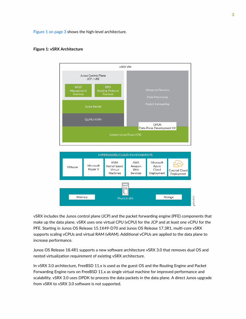
Figure 1 on page 3 shows the high-level architecture.
Figure 1: vSRX Architecture
vSRX includes the Junos control plane (JCP) and the packet forwarding engine (PFE) components thatmake up the data plane. vSRX uses one virtual CPU (vCPU) for the JCP and at least one vCPU for thePFE. Starting in Junos OS Release 15.1X49-D70 and Junos OS Release 17.3R1, multi-core vSRXsupports scaling vCPUs and virtual RAM (vRAM). Additional vCPUs are applied to the data plane toincrease performance.
Junos OS Release 18.4R1 supports a new software architecture vSRX 3.0 that removes dual OS andnested virtualization requirement of existing vSRX architecture.
In vSRX 3.0 architecture, FreeBSD 11.x is used as the guest OS and the Routing Engine and PacketForwarding Engine runs on FreeBSD 11.x as single virtual machine for improved performance andscalability. vSRX 3.0 uses DPDK to process the data packets in the data plane. A direct Junos upgradefrom vSRX to vSRX 3.0 software is not supported.
3
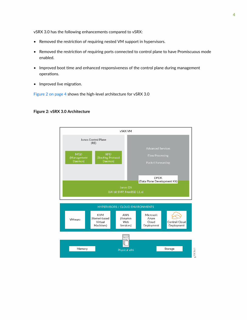
vSRX 3.0 has the following enhancements compared to vSRX:
• Removed the restriction of requiring nested VM support in hypervisors.
• Removed the restriction of requiring ports connected to control plane to have Promiscuous modeenabled.
• Improved boot time and enhanced responsiveness of the control plane during managementoperations.
• Improved live migration.
Figure 2 on page 4 shows the high-level architecture for vSRX 3.0
Figure 2: vSRX 3.0 Architecture
4
Benefits
vSRX on standard x86 servers enables you to quickly introduce new services, deliver customizedservices to customers, and scale security services based on dynamic needs. vSRX is ideal for public,private, and hybrid cloud environments.
Some of the key benefits of vSRX in a virtualized private or public cloud multitenant environmentinclude:
• Stateful firewall protection at the tenant edge
• Faster deployment of virtual firewalls into new sites
• Ability to run on top of various hypervisors and public cloud infrastructures
• Full routing, VPN, core security, and networking capabilities
• Application security features (including IPS and App-Secure)
• Content security features (including Anti Virus, Web Filtering, Anti Spam, and Content Filtering)
• Centralized management with Junos Space Security Director and local management with J-WebInterface
• Juniper Networks Sky Advanced Threat Prevention (Sky ATP) integration
Release History Table
Release Description
15.1X49-D70 Starting in Junos OS Release 15.1X49-D70 and Junos OS Release 17.3R1, multi-core vSRXsupports scaling vCPUs and virtual RAM (vRAM). Additional vCPUs are applied to the data plane toincrease performance.
Understand vSRX with KVM
IN THIS SECTION
vSRX on KVM | 6
vSRX Scale Up Performance | 7
5
This section presents an overview of vSRX on KVM.
vSRX on KVM
The Linux kernel uses the kernel-based virtual machine (KVM) as a virtualization infrastructure. KVM isopen source software that you can use to create multiple virtual machines (VMs) and to install securityand networking appliances.
The basic components of KVM include:
• A loadable kernel module included in the Linux kernel that provides the basic virtualizationinfrastructure
• A processor-specific module
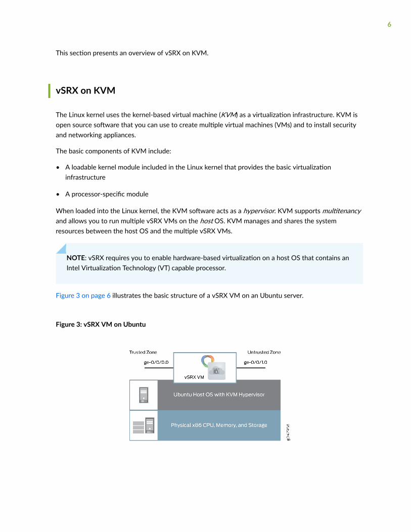
When loaded into the Linux kernel, the KVM software acts as a hypervisor. KVM supports multitenancyand allows you to run multiple vSRX VMs on the host OS. KVM manages and shares the systemresources between the host OS and the multiple vSRX VMs.
NOTE: vSRX requires you to enable hardware-based virtualization on a host OS that contains anIntel Virtualization Technology (VT) capable processor.
Figure 3 on page 6 illustrates the basic structure of a vSRX VM on an Ubuntu server.
Figure 3: vSRX VM on Ubuntu
6
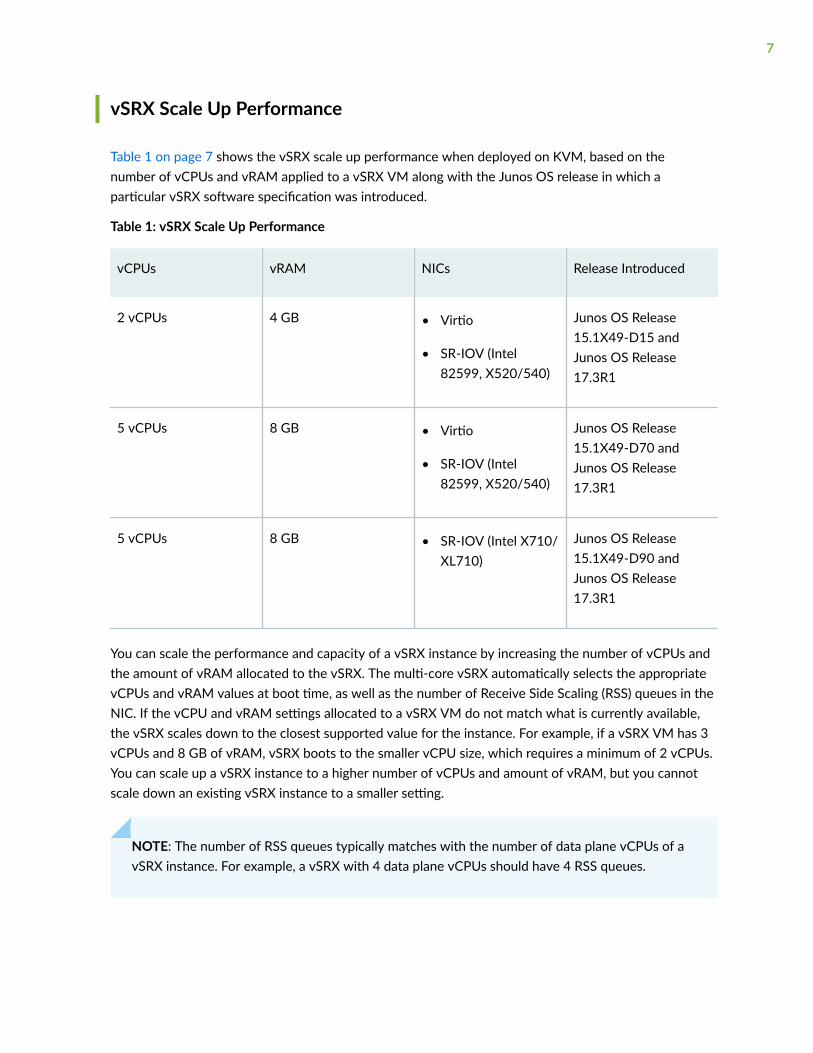
vSRX Scale Up Performance
Table 1 on page 7 shows the vSRX scale up performance when deployed on KVM, based on thenumber of vCPUs and vRAM applied to a vSRX VM along with the Junos OS release in which aparticular vSRX software specification was introduced.
Table 1: vSRX Scale Up Performance
vCPUs vRAM NICs Release Introduced
2 vCPUs 4 GB • Virtio
• SR-IOV (Intel82599, X520/540)
Junos OS Release15.1X49-D15 andJunos OS Release17.3R1
5 vCPUs 8 GB • Virtio
• SR-IOV (Intel82599, X520/540)
Junos OS Release15.1X49-D70 andJunos OS Release17.3R1
5 vCPUs 8 GB • SR-IOV (Intel X710/XL710)
Junos OS Release15.1X49-D90 andJunos OS Release17.3R1
You can scale the performance and capacity of a vSRX instance by increasing the number of vCPUs andthe amount of vRAM allocated to the vSRX. The multi-core vSRX automatically selects the appropriatevCPUs and vRAM values at boot time, as well as the number of Receive Side Scaling (RSS) queues in theNIC. If the vCPU and vRAM settings allocated to a vSRX VM do not match what is currently available,the vSRX scales down to the closest supported value for the instance. For example, if a vSRX VM has 3vCPUs and 8 GB of vRAM, vSRX boots to the smaller vCPU size, which requires a minimum of 2 vCPUs.You can scale up a vSRX instance to a higher number of vCPUs and amount of vRAM, but you cannotscale down an existing vSRX instance to a smaller setting.
NOTE: The number of RSS queues typically matches with the number of data plane vCPUs of avSRX instance. For example, a vSRX with 4 data plane vCPUs should have 4 RSS queues.
7
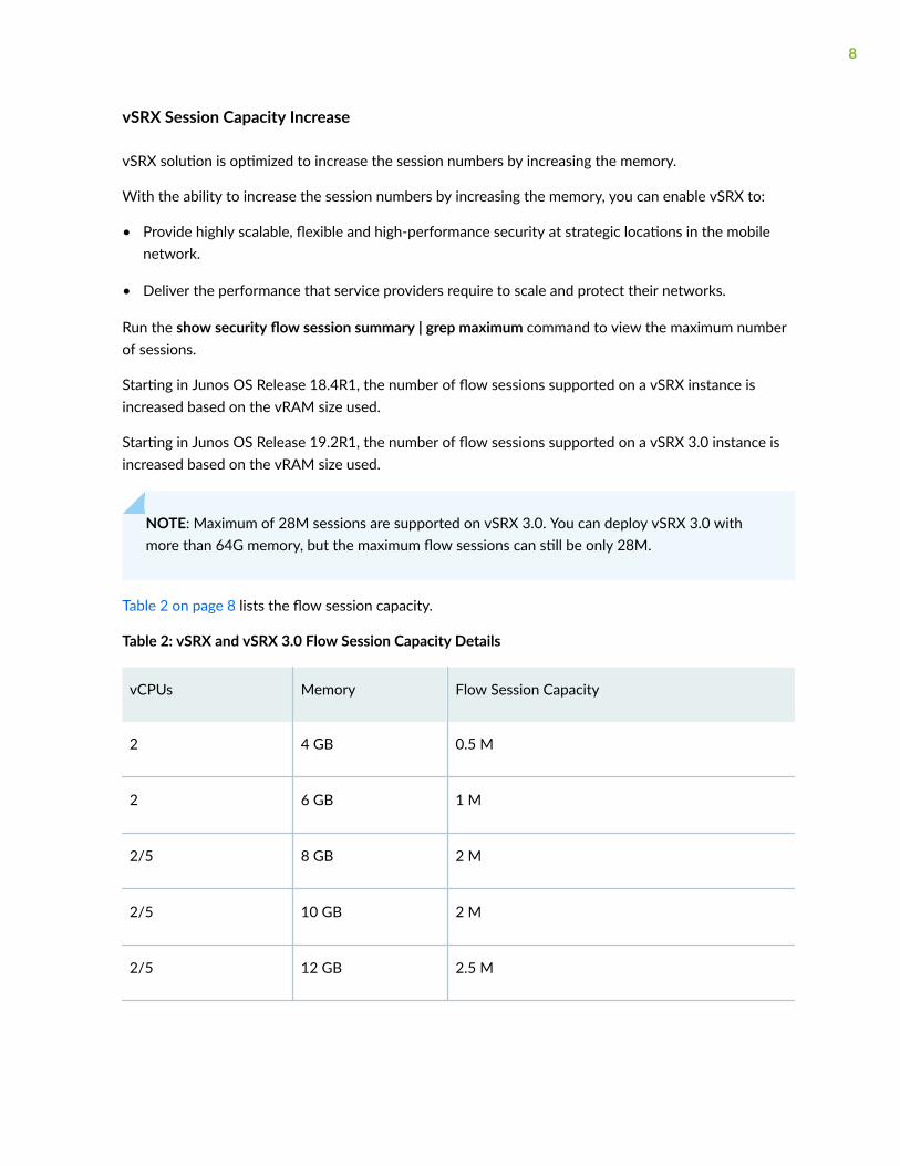
vSRX Session Capacity Increase
vSRX solution is optimized to increase the session numbers by increasing the memory.
With the ability to increase the session numbers by increasing the memory, you can enable vSRX to:
• Provide highly scalable, flexible and high-performance security at strategic locations in the mobilenetwork.
• Deliver the performance that service providers require to scale and protect their networks.
Run the show security flow session summary | grep maximum command to view the maximum numberof sessions.
Starting in Junos OS Release 18.4R1, the number of flow sessions supported on a vSRX instance isincreased based on the vRAM size used.
Starting in Junos OS Release 19.2R1, the number of flow sessions supported on a vSRX 3.0 instance isincreased based on the vRAM size used.
NOTE: Maximum of 28M sessions are supported on vSRX 3.0. You can deploy vSRX 3.0 withmore than 64G memory, but the maximum flow sessions can still be only 28M.
Table 2 on page 8 lists the flow session capacity.
Table 2: vSRX and vSRX 3.0 Flow Session Capacity Details
vCPUs Memory Flow Session Capacity
2 4 GB 0.5 M
2 6 GB 1 M
2/5 8 GB 2 M
2/5 10 GB 2 M
2/5 12 GB 2.5 M
8
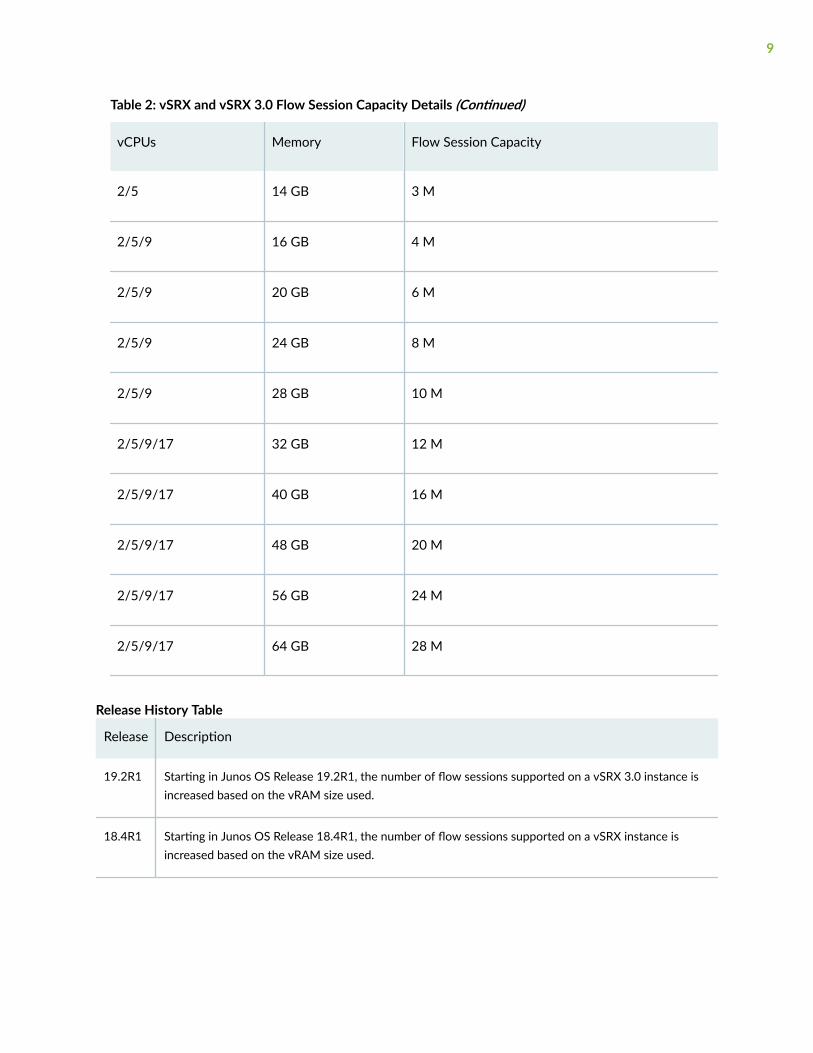
Table 2: vSRX and vSRX 3.0 Flow Session Capacity Details (Continued)
vCPUs Memory Flow Session Capacity
2/5 14 GB 3 M
2/5/9 16 GB 4 M
2/5/9 20 GB 6 M
2/5/9 24 GB 8 M
2/5/9 28 GB 10 M
2/5/9/17 32 GB 12 M
2/5/9/17 40 GB 16 M
2/5/9/17 48 GB 20 M
2/5/9/17 56 GB 24 M
2/5/9/17 64 GB 28 M
Release History Table
Release Description
19.2R1 Starting in Junos OS Release 19.2R1, the number of flow sessions supported on a vSRX 3.0 instance isincreased based on the vRAM size used.
18.4R1 Starting in Junos OS Release 18.4R1, the number of flow sessions supported on a vSRX instance isincreased based on the vRAM size used.
9
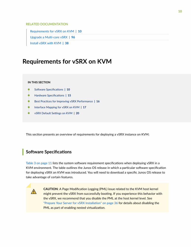
RELATED DOCUMENTATION
Requirements for vSRX on KVM | 10
Upgrade a Multi-core vSRX | 96
Install vSRX with KVM | 38
Requirements for vSRX on KVM
IN THIS SECTION
Software Specifications | 10
Hardware Specifications | 15
Best Practices for Improving vSRX Performance | 16
Interface Mapping for vSRX on KVM | 17
vSRX Default Settings on KVM | 20
This section presents an overview of requirements for deploying a vSRX instance on KVM;
Software Specifications
Table 3 on page 11 lists the system software requirement specifications when deploying vSRX in aKVM environment. The table outlines the Junos OS release in which a particular software specificationfor deploying vSRX on KVM was introduced. You will need to download a specific Junos OS release totake advantage of certain features.
CAUTION: A Page Modification Logging (PML) issue related to the KVM host kernelmight prevent the vSRX from successfully booting. If you experience this behavior withthe vSRX, we recommend that you disable the PML at the host kernel level. See"Prepare Your Server for vSRX Installation" on page 36 for details about disabling thePML as part of enabling nested virtualization.
10
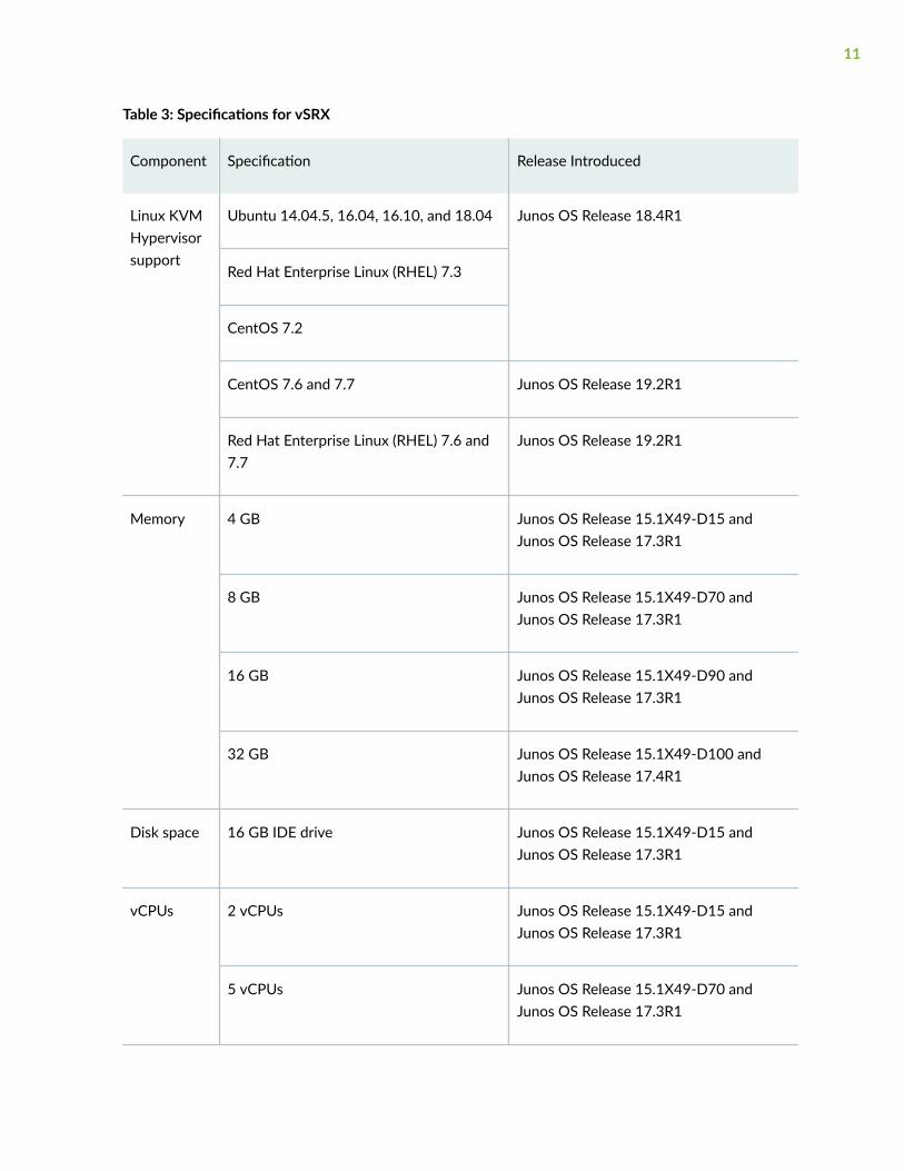
Table 3: Specifications for vSRX
Component Specification Release Introduced
Linux KVMHypervisorsupport
Ubuntu 14.04.5, 16.04, 16.10, and 18.04 Junos OS Release 18.4R1
Red Hat Enterprise Linux (RHEL) 7.3
CentOS 7.2
CentOS 7.6 and 7.7 Junos OS Release 19.2R1
Red Hat Enterprise Linux (RHEL) 7.6 and7.7
Junos OS Release 19.2R1
Memory 4 GB Junos OS Release 15.1X49-D15 andJunos OS Release 17.3R1
8 GB Junos OS Release 15.1X49-D70 andJunos OS Release 17.3R1
16 GB Junos OS Release 15.1X49-D90 andJunos OS Release 17.3R1
32 GB Junos OS Release 15.1X49-D100 andJunos OS Release 17.4R1
Disk space 16 GB IDE drive Junos OS Release 15.1X49-D15 andJunos OS Release 17.3R1
vCPUs 2 vCPUs Junos OS Release 15.1X49-D15 andJunos OS Release 17.3R1
5 vCPUs Junos OS Release 15.1X49-D70 andJunos OS Release 17.3R1
11

Table 3: Specifications for vSRX (Continued)
Component Specification Release Introduced
9 vCPUs Junos OS Release 15.1X49-D90 andJunos OS Release 17.3R1
17 vCPUs Junos OS Release 15.1X49-D100 andJunos OS Release 17.4R1
vNICs 2-8 vNICs.
• Virtio
• SR-IOV (Intel 82599, X520/X540)
For SR-IOV limitations, see the KnownBehavior section of the vSRX ReleaseNotes.
Junos OS Release 15.1X49-D15 andJunos OS Release 17.3R1
• SR-IOV (X710/XL710) Junos OS Release 15.1X49-D90
• SR-IOV (Mellanox ConnectX-3/ConnectX-3 Pro and MellanoxConnectX-4 EN/ConnectX-4 Lx EN)
Junos OS Release 18.1R1
Starting in Junos OS Release 19.4R1,DPDK version 18.11 is supported onvSRX. With this feature the MellanoxConnect Network Interface Card (NIC) onvSRX now supports OSPF Multicast andVLANs.
Junos OS Release 19.4R1
vSRX3.0 supports LiquidIO DPDK driverwith KVM hypervisor. If you use theLiquidIO II smart NICs, then you can usevSRX3.0 by the VF of SR-IOV.
Junos OS Release 20.4R1
12
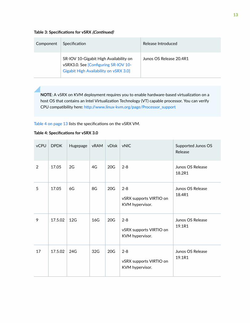
Table 3: Specifications for vSRX (Continued)
Component Specification Release Introduced
SR-IOV 10-Gigabit High Availability onvSRX3.0. See [Configuring SR-IOV 10-Gigabit High Availability on vSRX 3.0]
Junos OS Release 20.4R1
NOTE: A vSRX on KVM deployment requires you to enable hardware-based virtualization on ahost OS that contains an Intel Virtualization Technology (VT) capable processor. You can verifyCPU compatibility here: http://www.linux-kvm.org/page/Processor_support
Table 4 on page 13 lists the specifications on the vSRX VM.
Table 4: Specifications for vSRX 3.0
vCPU DPDK Hugepage vRAM vDisk vNIC Supported Junos OSRelease
2 17.05 2G 4G 20G 2-8 Junos OS Release18.2R1
5 17.05 6G 8G 20G 2-8
vSRX supports VIRTIO onKVM hypervisor.
Junos OS Release18.4R1
9 17.5.02 12G 16G 20G 2-8
vSRX supports VIRTIO onKVM hypervisor.
Junos OS Release19.1R1
17 17.5.02 24G 32G 20G 2-8
vSRX supports VIRTIO onKVM hypervisor.
Junos OS Release19.1R1
13
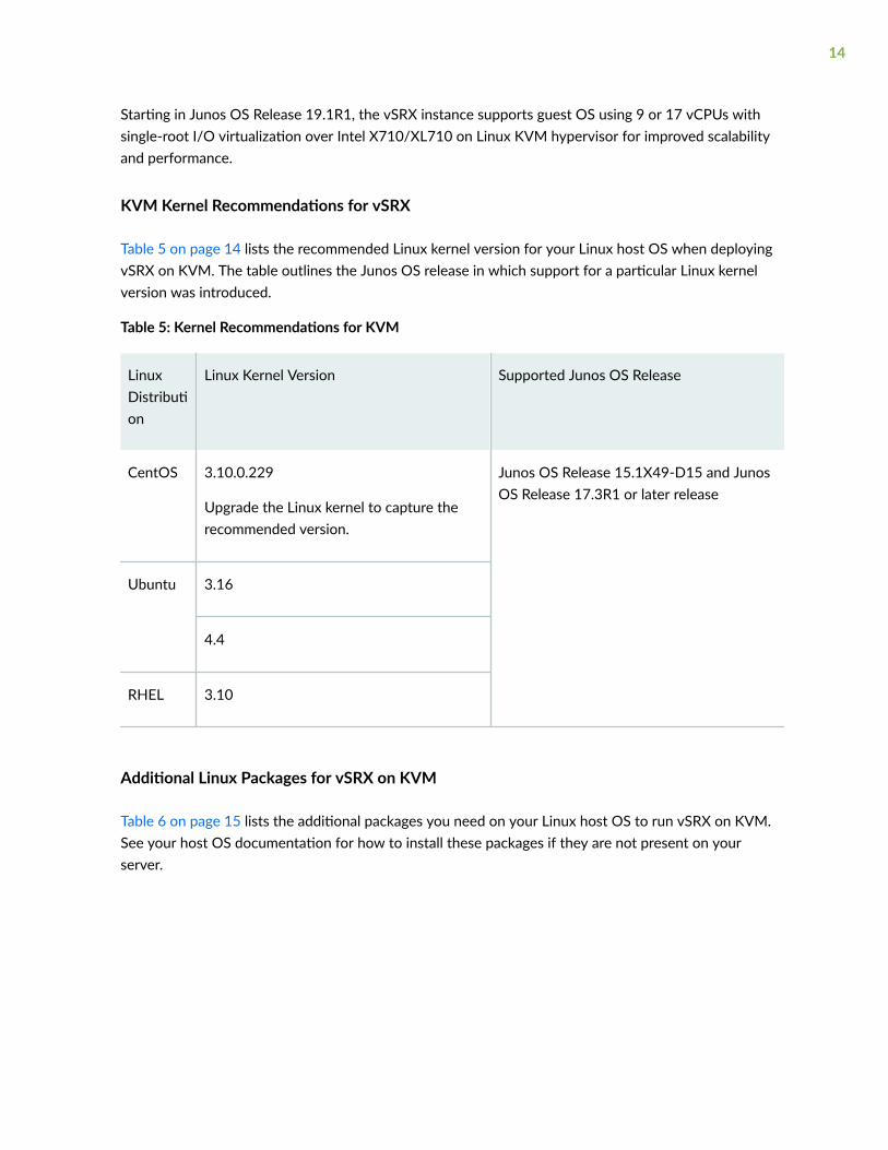
Starting in Junos OS Release 19.1R1, the vSRX instance supports guest OS using 9 or 17 vCPUs withsingle-root I/O virtualization over Intel X710/XL710 on Linux KVM hypervisor for improved scalabilityand performance.
KVM Kernel Recommendations for vSRX
Table 5 on page 14 lists the recommended Linux kernel version for your Linux host OS when deployingvSRX on KVM. The table outlines the Junos OS release in which support for a particular Linux kernelversion was introduced.
Table 5: Kernel Recommendations for KVM
LinuxDistribution
Linux Kernel Version Supported Junos OS Release
CentOS 3.10.0.229
Upgrade the Linux kernel to capture therecommended version.
Junos OS Release 15.1X49-D15 and JunosOS Release 17.3R1 or later release
Ubuntu 3.16
4.4
RHEL 3.10
Additional Linux Packages for vSRX on KVM
Table 6 on page 15 lists the additional packages you need on your Linux host OS to run vSRX on KVM.See your host OS documentation for how to install these packages if they are not present on yourserver.
14
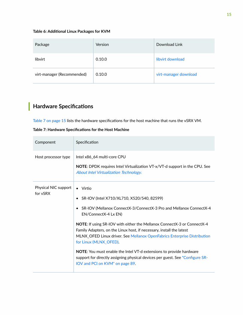
Table 6: Additional Linux Packages for KVM
Package Version Download Link
libvirt 0.10.0 libvirt download
virt-manager (Recommended) 0.10.0 virt-manager download
Hardware Specifications
Table 7 on page 15 lists the hardware specifications for the host machine that runs the vSRX VM.
Table 7: Hardware Specifications for the Host Machine
Component Specification
Host processor type Intel x86_64 multi-core CPU
NOTE: DPDK requires Intel Virtualization VT-x/VT-d support in the CPU. SeeAbout Intel Virtualization Technology.
Physical NIC supportfor vSRX
• Virtio
• SR-IOV (Intel X710/XL710, X520/540, 82599)
• SR-IOV (Mellanox ConnectX-3/ConnectX-3 Pro and Mellanox ConnectX-4EN/ConnectX-4 Lx EN)
NOTE: If using SR-IOV with either the Mellanox ConnectX-3 or ConnectX-4Family Adapters, on the Linux host, if necessary, install the latestMLNX_OFED Linux driver. See Mellanox OpenFabrics Enterprise Distributionfor Linux (MLNX_OFED).
NOTE: You must enable the Intel VT-d extensions to provide hardwaresupport for directly assigning physical devices per guest. See "Configure SR-IOV and PCI on KVM" on page 89.
15
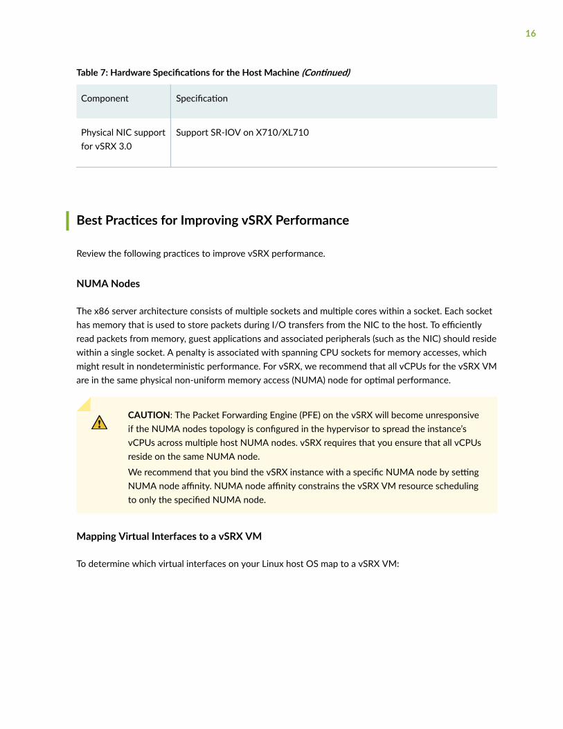
Table 7: Hardware Specifications for the Host Machine (Continued)
Component Specification
Physical NIC supportfor vSRX 3.0
Support SR-IOV on X710/XL710
Best Practices for Improving vSRX Performance
Review the following practices to improve vSRX performance.
NUMA Nodes
The x86 server architecture consists of multiple sockets and multiple cores within a socket. Each sockethas memory that is used to store packets during I/O transfers from the NIC to the host. To efficientlyread packets from memory, guest applications and associated peripherals (such as the NIC) should residewithin a single socket. A penalty is associated with spanning CPU sockets for memory accesses, whichmight result in nondeterministic performance. For vSRX, we recommend that all vCPUs for the vSRX VMare in the same physical non-uniform memory access (NUMA) node for optimal performance.
CAUTION: The Packet Forwarding Engine (PFE) on the vSRX will become unresponsiveif the NUMA nodes topology is configured in the hypervisor to spread the instance’svCPUs across multiple host NUMA nodes. vSRX requires that you ensure that all vCPUsreside on the same NUMA node.
We recommend that you bind the vSRX instance with a specific NUMA node by settingNUMA node affinity. NUMA node affinity constrains the vSRX VM resource schedulingto only the specified NUMA node.
Mapping Virtual Interfaces to a vSRX VM
To determine which virtual interfaces on your Linux host OS map to a vSRX VM:
16
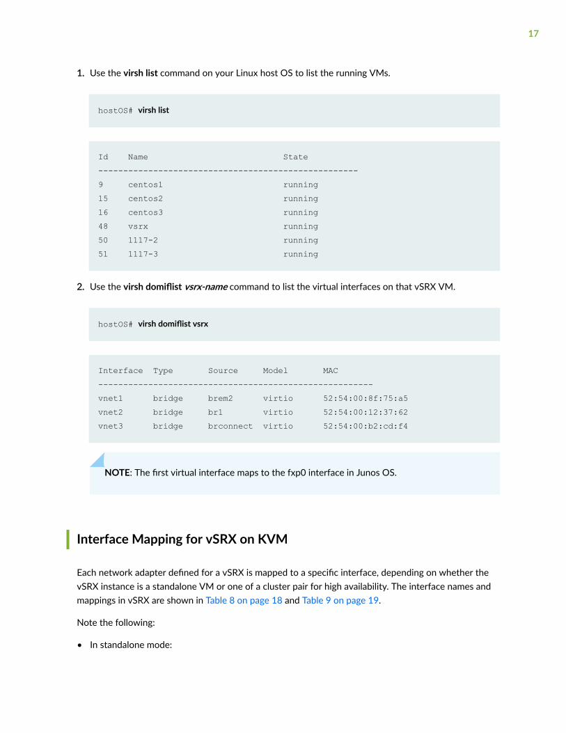
1. Use the virsh list command on your Linux host OS to list the running VMs.
hostOS# virsh list
Id Name State----------------------------------------------------9 centos1 running15 centos2 running16 centos3 running48 vsrx running50 1117-2 running51 1117-3 running
2. Use the virsh domiflist vsrx-name command to list the virtual interfaces on that vSRX VM.
hostOS# virsh domiflist vsrx
Interface Type Source Model MAC-------------------------------------------------------vnet1 bridge brem2 virtio 52:54:00:8f:75:a5vnet2 bridge br1 virtio 52:54:00:12:37:62vnet3 bridge brconnect virtio 52:54:00:b2:cd:f4
NOTE: The first virtual interface maps to the fxp0 interface in Junos OS.
Interface Mapping for vSRX on KVM
Each network adapter defined for a vSRX is mapped to a specific interface, depending on whether thevSRX instance is a standalone VM or one of a cluster pair for high availability. The interface names andmappings in vSRX are shown in Table 8 on page 18 and Table 9 on page 19.
Note the following:
• In standalone mode:
17
• fxp0 is the out-of-band management interface.
• ge-0/0/0 is the first traffic (revenue) interface.
• In cluster mode:
• fxp0 is the out-of-band management interface.
• em0 is the cluster control link for both nodes.
• Any of the traffic interfaces can be specified as the fabric links, such as ge-0/0/0 for fab0 on node0 and ge-7/0/0 for fab1 on node 1.
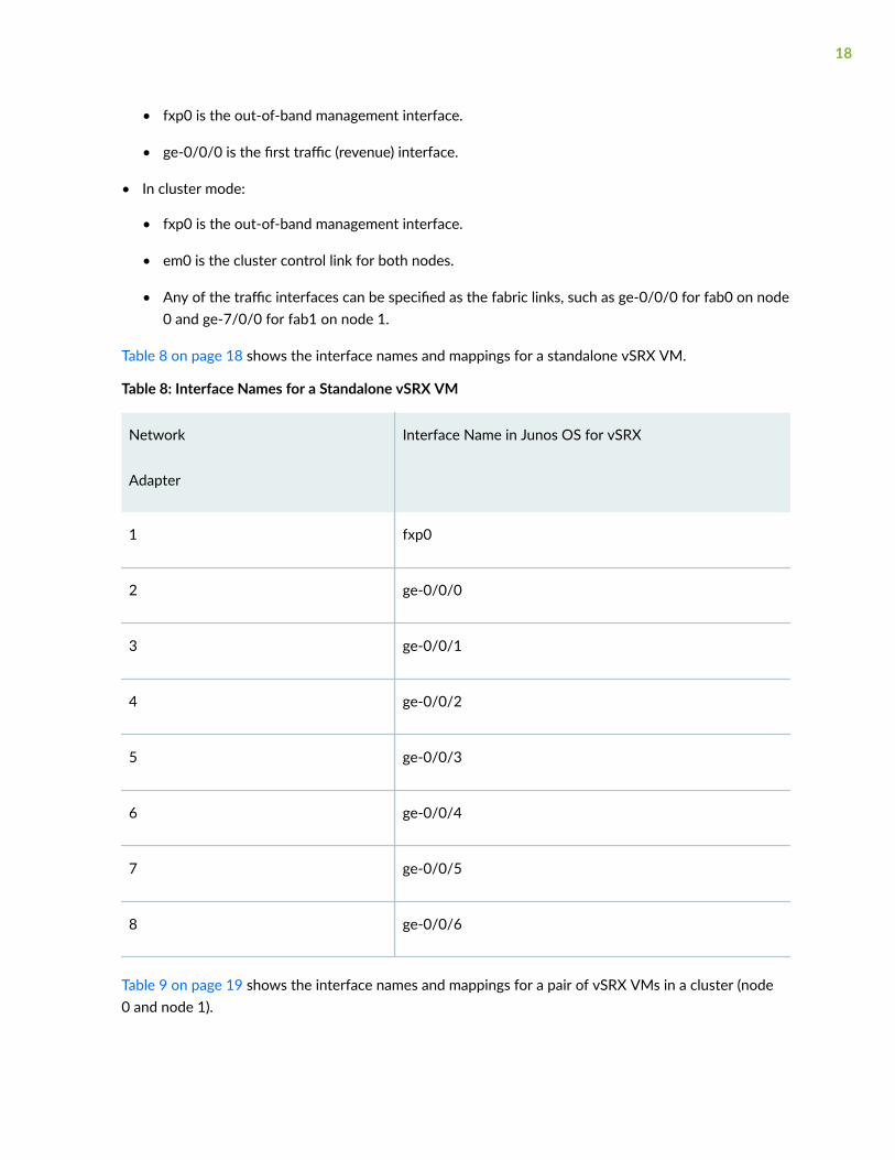
Table 8 on page 18 shows the interface names and mappings for a standalone vSRX VM.
Table 8: Interface Names for a Standalone vSRX VM
Network
Adapter
Interface Name in Junos OS for vSRX
1 fxp0
2 ge-0/0/0
3 ge-0/0/1
4 ge-0/0/2
5 ge-0/0/3
6 ge-0/0/4
7 ge-0/0/5
8 ge-0/0/6
Table 9 on page 19 shows the interface names and mappings for a pair of vSRX VMs in a cluster (node0 and node 1).
18
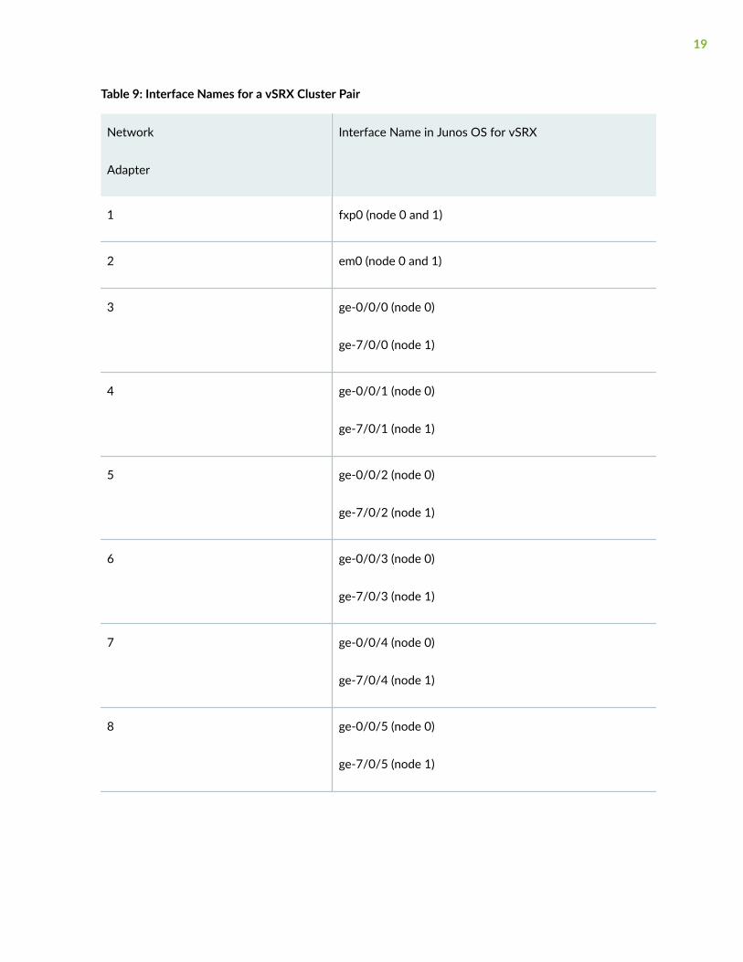
Table 9: Interface Names for a vSRX Cluster Pair
Network
Adapter
Interface Name in Junos OS for vSRX
1 fxp0 (node 0 and 1)
2 em0 (node 0 and 1)
3 ge-0/0/0 (node 0)
ge-7/0/0 (node 1)
4 ge-0/0/1 (node 0)
ge-7/0/1 (node 1)
5 ge-0/0/2 (node 0)
ge-7/0/2 (node 1)
6 ge-0/0/3 (node 0)
ge-7/0/3 (node 1)
7 ge-0/0/4 (node 0)
ge-7/0/4 (node 1)
8 ge-0/0/5 (node 0)
ge-7/0/5 (node 1)
19
vSRX Default Settings on KVM
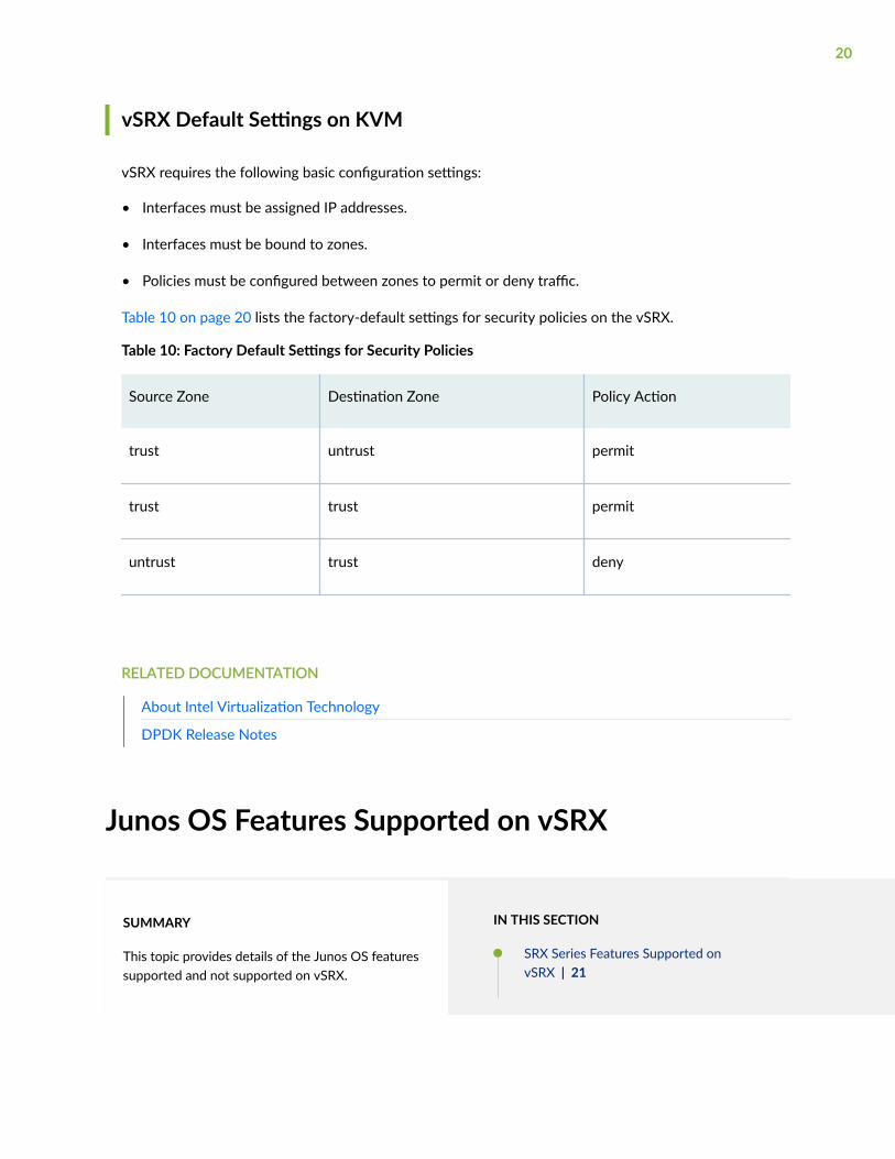
vSRX requires the following basic configuration settings:
• Interfaces must be assigned IP addresses.
• Interfaces must be bound to zones.
• Policies must be configured between zones to permit or deny traffic.
Table 10 on page 20 lists the factory-default settings for security policies on the vSRX.
Table 10: Factory Default Settings for Security Policies
Source Zone Destination Zone Policy Action
trust untrust permit
trust trust permit
untrust trust deny
RELATED DOCUMENTATION
About Intel Virtualization Technology
DPDK Release Notes
Junos OS Features Supported on vSRX
SUMMARY
This topic provides details of the Junos OS featuressupported and not supported on vSRX.
IN THIS SECTION
SRX Series Features Supported onvSRX | 21
20
SRX Series Features Not Supported onvSRX | 26
SRX Series Features Supported on vSRX
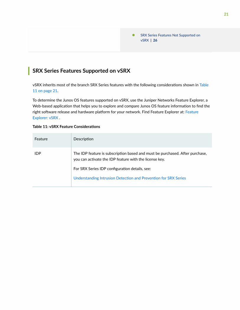
vSRX inherits most of the branch SRX Series features with the following considerations shown in Table11 on page 21.
To determine the Junos OS features supported on vSRX, use the Juniper Networks Feature Explorer, aWeb-based application that helps you to explore and compare Junos OS feature information to find theright software release and hardware platform for your network. Find Feature Explorer at: FeatureExplorer: vSRX .
Table 11: vSRX Feature Considerations
Feature Description
IDP The IDP feature is subscription based and must be purchased. After purchase,you can activate the IDP feature with the license key.
For SRX Series IDP configuration details, see:
Understanding Intrusion Detection and Prevention for SRX Series
21
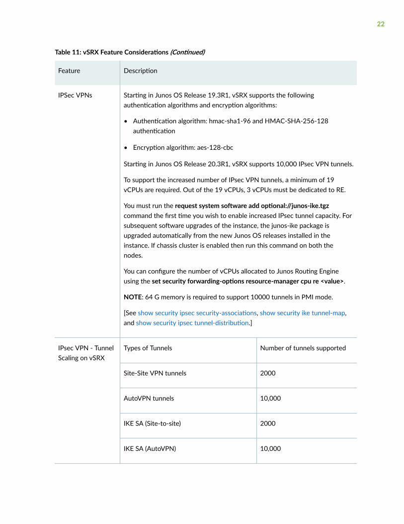
Table 11: vSRX Feature Considerations (Continued)
Feature Description
IPSec VPNs Starting in Junos OS Release 19.3R1, vSRX supports the followingauthentication algorithms and encryption algorithms:
• Authentication algorithm: hmac-sha1-96 and HMAC-SHA-256-128authentication
• Encryption algorithm: aes-128-cbc
Starting in Junos OS Release 20.3R1, vSRX supports 10,000 IPsec VPN tunnels.
To support the increased number of IPsec VPN tunnels, a minimum of 19vCPUs are required. Out of the 19 vCPUs, 3 vCPUs must be dedicated to RE.
You must run the request system software add optional://junos-ike.tgzcommand the first time you wish to enable increased IPsec tunnel capacity. Forsubsequent software upgrades of the instance, the junos-ike package isupgraded automatically from the new Junos OS releases installed in theinstance. If chassis cluster is enabled then run this command on both thenodes.
You can configure the number of vCPUs allocated to Junos Routing Engineusing the set security forwarding-options resource-manager cpu re <value>.
NOTE: 64 G memory is required to support 10000 tunnels in PMI mode.
[See show security ipsec security-associations, show security ike tunnel-map,and show security ipsec tunnel-distribution.]
IPsec VPN - TunnelScaling on vSRX
Types of Tunnels Number of tunnels supported
Site-Site VPN tunnels 2000
AutoVPN tunnels 10,000
IKE SA (Site-to-site) 2000
IKE SA (AutoVPN) 10,000
22
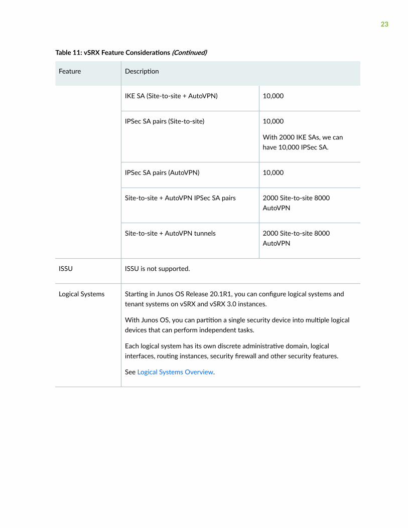
Table 11: vSRX Feature Considerations (Continued)
Feature Description
IKE SA (Site-to-site + AutoVPN) 10,000
IPSec SA pairs (Site-to-site) 10,000
With 2000 IKE SAs, we canhave 10,000 IPSec SA.
IPSec SA pairs (AutoVPN) 10,000
Site-to-site + AutoVPN IPSec SA pairs 2000 Site-to-site 8000AutoVPN
Site-to-site + AutoVPN tunnels 2000 Site-to-site 8000AutoVPN
ISSU ISSU is not supported.
Logical Systems Starting in Junos OS Release 20.1R1, you can configure logical systems andtenant systems on vSRX and vSRX 3.0 instances.
With Junos OS, you can partition a single security device into multiple logicaldevices that can perform independent tasks.
Each logical system has its own discrete administrative domain, logicalinterfaces, routing instances, security firewall and other security features.
See Logical Systems Overview.
23
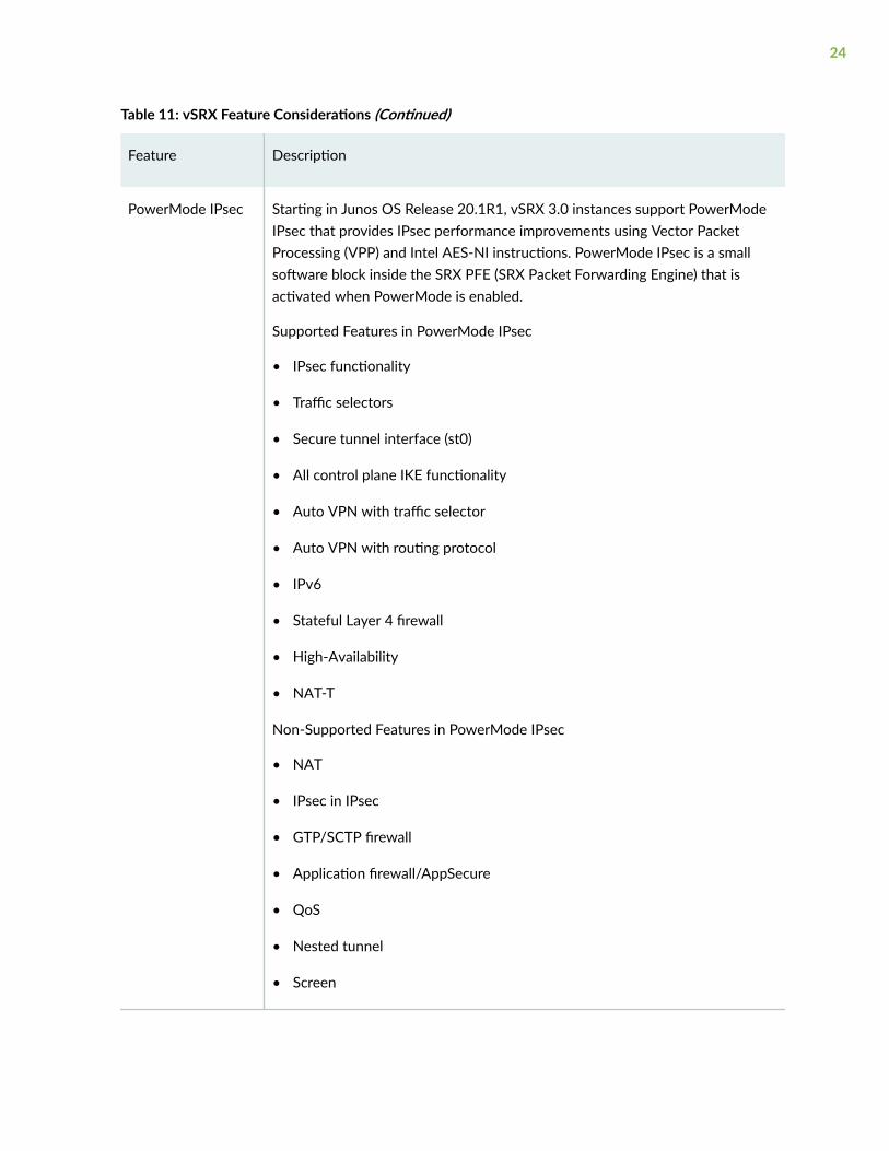
Table 11: vSRX Feature Considerations (Continued)
Feature Description
PowerMode IPsec Starting in Junos OS Release 20.1R1, vSRX 3.0 instances support PowerModeIPsec that provides IPsec performance improvements using Vector PacketProcessing (VPP) and Intel AES-NI instructions. PowerMode IPsec is a smallsoftware block inside the SRX PFE (SRX Packet Forwarding Engine) that isactivated when PowerMode is enabled.
Supported Features in PowerMode IPsec
• IPsec functionality
• Traffic selectors
• Secure tunnel interface (st0)
• All control plane IKE functionality
• Auto VPN with traffic selector
• Auto VPN with routing protocol
• IPv6
• Stateful Layer 4 firewall
• High-Availability
• NAT-T
Non-Supported Features in PowerMode IPsec
• NAT
• IPsec in IPsec
• GTP/SCTP firewall
• Application firewall/AppSecure
• QoS
• Nested tunnel
• Screen
24
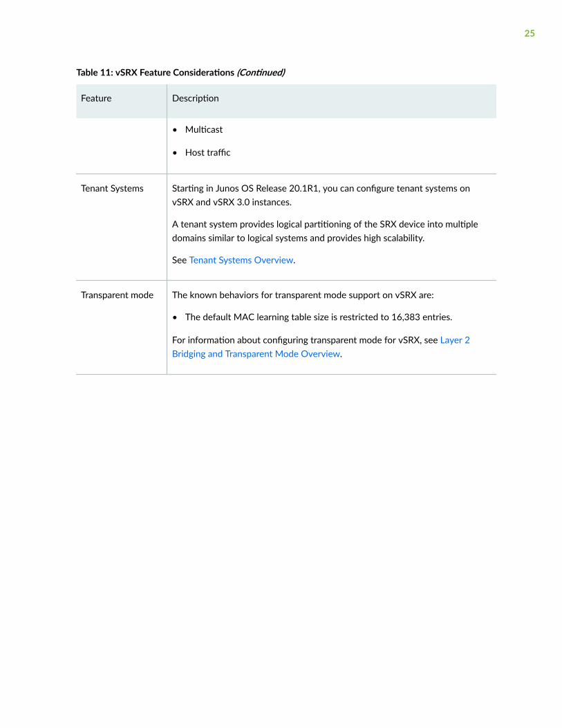
Table 11: vSRX Feature Considerations (Continued)
Feature Description
• Multicast
• Host traffic
Tenant Systems Starting in Junos OS Release 20.1R1, you can configure tenant systems onvSRX and vSRX 3.0 instances.
A tenant system provides logical partitioning of the SRX device into multipledomains similar to logical systems and provides high scalability.
See Tenant Systems Overview.
Transparent mode The known behaviors for transparent mode support on vSRX are:
• The default MAC learning table size is restricted to 16,383 entries.
For information about configuring transparent mode for vSRX, see Layer 2Bridging and Transparent Mode Overview.
25
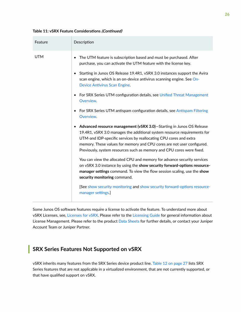
Table 11: vSRX Feature Considerations (Continued)
Feature Description
UTM • The UTM feature is subscription based and must be purchased. Afterpurchase, you can activate the UTM feature with the license key.
• Starting in Junos OS Release 19.4R1, vSRX 3.0 instances support the Avirascan engine, which is an on-device antivirus scanning engine. See On-Device Antivirus Scan Engine.
• For SRX Series UTM configuration details, see Unified Threat ManagementOverview.
• For SRX Series UTM antispam configuration details, see Antispam FilteringOverview.
• Advanced resource management (vSRX 3.0)—Starting in Junos OS Release19.4R1, vSRX 3.0 manages the additional system resource requirements forUTM-and IDP-specific services by reallocating CPU cores and extramemory. These values for memory and CPU cores are not user configured.Previously, system resources such as memory and CPU cores were fixed.
You can view the allocated CPU and memory for advance security serviceson vSRX 3.0 instance by using the show security forward-options resource-manager settings command. To view the flow session scaling, use the showsecurity monitoring command.
[See show security monitoring and show security forward-options resource-manager settings.]
Some Junos OS software features require a license to activate the feature. To understand more aboutvSRX Licenses, see, Licenses for vSRX. Please refer to the Licensing Guide for general information aboutLicense Management. Please refer to the product Data Sheets for further details, or contact your JuniperAccount Team or Juniper Partner.
SRX Series Features Not Supported on vSRX
vSRX inherits many features from the SRX Series device product line. Table 12 on page 27 lists SRXSeries features that are not applicable in a virtualized environment, that are not currently supported, orthat have qualified support on vSRX.
26
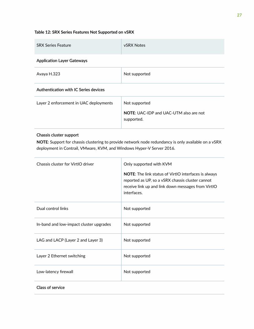
Table 12: SRX Series Features Not Supported on vSRX
SRX Series Feature vSRX Notes
Application Layer Gateways
Avaya H.323 Not supported
Authentication with IC Series devices
Layer 2 enforcement in UAC deployments Not supported
NOTE: UAC-IDP and UAC-UTM also are notsupported.
Chassis cluster support
NOTE: Support for chassis clustering to provide network node redundancy is only available on a vSRXdeployment in Contrail, VMware, KVM, and Windows Hyper-V Server 2016.
Chassis cluster for VirtIO driver Only supported with KVM
NOTE: The link status of VirtIO interfaces is alwaysreported as UP, so a vSRX chassis cluster cannotreceive link up and link down messages from VirtIOinterfaces.
Dual control links Not supported
In-band and low-impact cluster upgrades Not supported
LAG and LACP (Layer 2 and Layer 3) Not supported
Layer 2 Ethernet switching Not supported
Low-latency firewall Not supported
Class of service
27
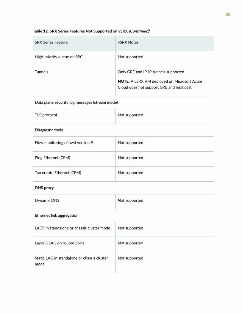
Table 12: SRX Series Features Not Supported on vSRX (Continued)
SRX Series Feature vSRX Notes
High-priority queue on SPC Not supported
Tunnels Only GRE and IP-IP tunnels supported
NOTE: A vSRX VM deployed on Microsoft AzureCloud does not support GRE and multicast.
Data plane security log messages (stream mode)
TLS protocol Not supported
Diagnostic tools
Flow monitoring cflowd version 9 Not supported
Ping Ethernet (CFM) Not supported
Traceroute Ethernet (CFM) Not supported
DNS proxy
Dynamic DNS Not supported
Ethernet link aggregation
LACP in standalone or chassis cluster mode Not supported
Layer 3 LAG on routed ports Not supported
Static LAG in standalone or chassis clustermode
Not supported
28
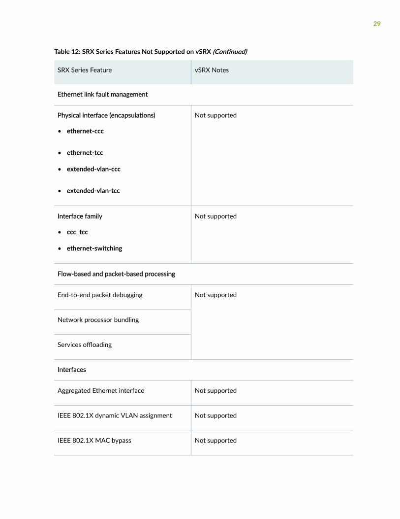
Table 12: SRX Series Features Not Supported on vSRX (Continued)
SRX Series Feature vSRX Notes
Ethernet link fault management
Physical interface (encapsulations)
• ethernet-ccc
• ethernet-tcc
• extended-vlan-ccc
• extended-vlan-tcc
Not supported
Interface family
• ccc, tcc
• ethernet-switching
Not supported
Flow-based and packet-based processing
End-to-end packet debugging Not supported
Network processor bundling
Services offloading
Interfaces
Aggregated Ethernet interface Not supported
IEEE 802.1X dynamic VLAN assignment Not supported
IEEE 802.1X MAC bypass Not supported
29
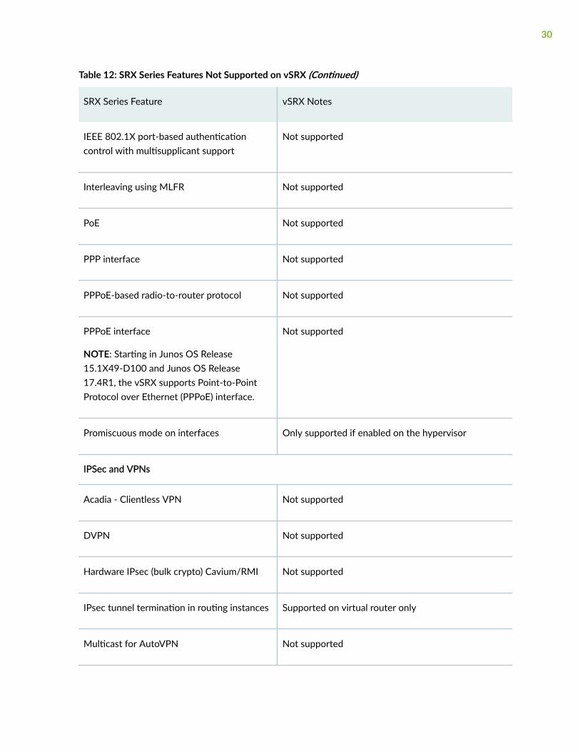
Table 12: SRX Series Features Not Supported on vSRX (Continued)
SRX Series Feature vSRX Notes
IEEE 802.1X port-based authenticationcontrol with multisupplicant support
Not supported
Interleaving using MLFR Not supported
PoE Not supported
PPP interface Not supported
PPPoE-based radio-to-router protocol Not supported
PPPoE interface
NOTE: Starting in Junos OS Release15.1X49-D100 and Junos OS Release17.4R1, the vSRX supports Point-to-PointProtocol over Ethernet (PPPoE) interface.
Not supported
Promiscuous mode on interfaces Only supported if enabled on the hypervisor
IPSec and VPNs
Acadia - Clientless VPN Not supported
DVPN Not supported
Hardware IPsec (bulk crypto) Cavium/RMI Not supported
IPsec tunnel termination in routing instances Supported on virtual router only
Multicast for AutoVPN Not supported
30
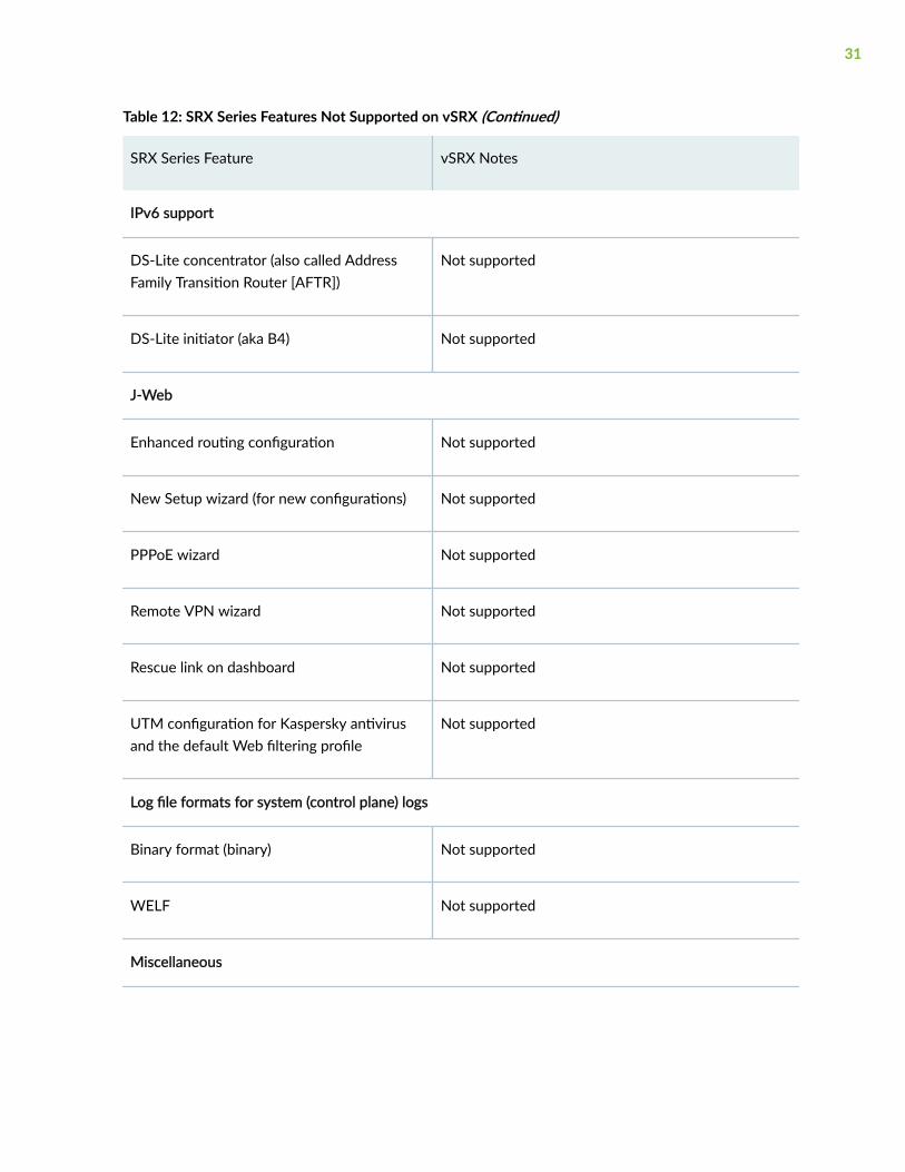
Table 12: SRX Series Features Not Supported on vSRX (Continued)
SRX Series Feature vSRX Notes
IPv6 support
DS-Lite concentrator (also called AddressFamily Transition Router [AFTR])
Not supported
DS-Lite initiator (aka B4) Not supported
J-Web
Enhanced routing configuration Not supported
New Setup wizard (for new configurations) Not supported
PPPoE wizard Not supported
Remote VPN wizard Not supported
Rescue link on dashboard Not supported
UTM configuration for Kaspersky antivirusand the default Web filtering profile
Not supported
Log file formats for system (control plane) logs
Binary format (binary) Not supported
WELF Not supported
Miscellaneous
31
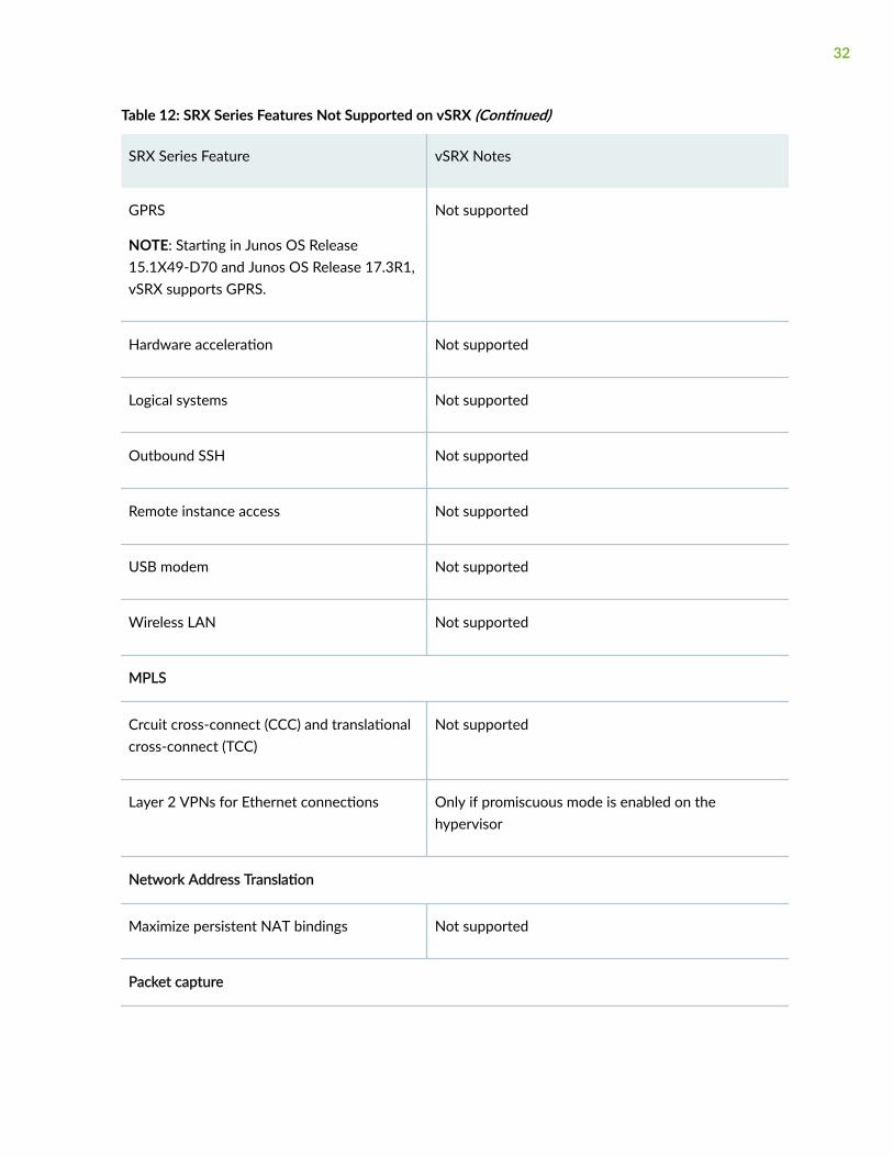
Table 12: SRX Series Features Not Supported on vSRX (Continued)
SRX Series Feature vSRX Notes
GPRS
NOTE: Starting in Junos OS Release15.1X49-D70 and Junos OS Release 17.3R1,vSRX supports GPRS.
Not supported
Hardware acceleration Not supported
Logical systems Not supported
Outbound SSH Not supported
Remote instance access Not supported
USB modem Not supported
Wireless LAN Not supported
MPLS
Crcuit cross-connect (CCC) and translationalcross-connect (TCC)
Not supported
Layer 2 VPNs for Ethernet connections Only if promiscuous mode is enabled on thehypervisor
Network Address Translation
Maximize persistent NAT bindings Not supported
Packet capture
32
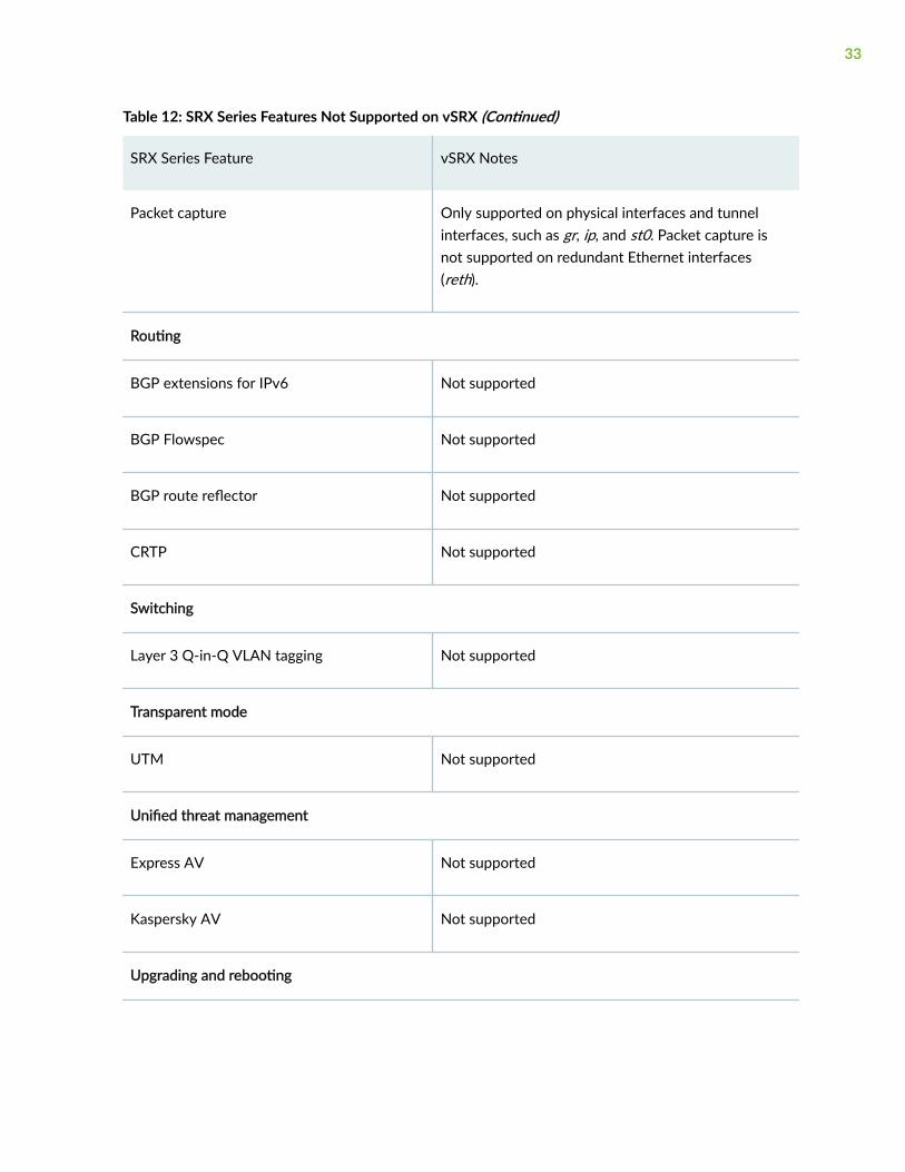
Table 12: SRX Series Features Not Supported on vSRX (Continued)
SRX Series Feature vSRX Notes
Packet capture Only supported on physical interfaces and tunnelinterfaces, such as gr, ip, and st0. Packet capture isnot supported on redundant Ethernet interfaces(reth).
Routing
BGP extensions for IPv6 Not supported
BGP Flowspec Not supported
BGP route reflector Not supported
CRTP Not supported
Switching
Layer 3 Q-in-Q VLAN tagging Not supported
Transparent mode
UTM Not supported
Unified threat management
Express AV Not supported
Kaspersky AV Not supported
Upgrading and rebooting
33
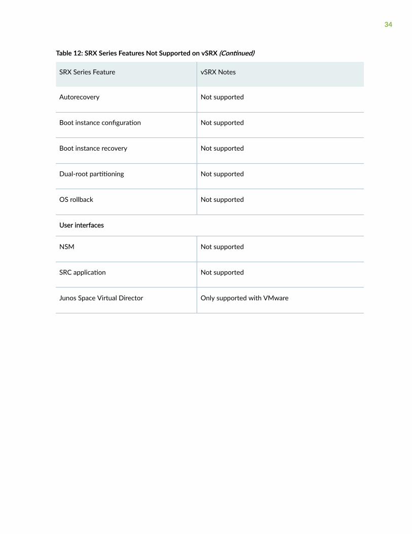
Table 12: SRX Series Features Not Supported on vSRX (Continued)
SRX Series Feature vSRX Notes
Autorecovery Not supported
Boot instance configuration Not supported
Boot instance recovery Not supported
Dual-root partitioning Not supported
OS rollback Not supported
User interfaces
NSM Not supported
SRC application Not supported
Junos Space Virtual Director Only supported with VMware
34
2CHAPTER
Installing vSRX in KVM
Prepare Your Server for vSRX Installation | 36
Install vSRX with KVM | 38
Example: Install and Launch vSRX on Ubuntu | 44
Load an Initial Configuration on a vSRX with KVM | 61
Use Cloud-Init in an OpenStack Environment to Automate the Initialization ofvSRX Instances | 65
Prepare Your Server for vSRX Installation
IN THIS SECTION
Enable Nested Virtualization | 36
Upgrade the Linux Kernel on Ubuntu | 37
Enable Nested Virtualization
We recommend that you enable nested virtualization on your host OS or OpenStack compute node.Nested virtualization is enabled by default on Ubuntu but is disabled by default on CentOS.
Use the following command to determine if nested virtualization is enabled on your host OS. The resultshould be Y.
hostOS# cat /sys/module/kvm_intel/parameters/nested
hostOS# Y
NOTE: APIC virtualization (APICv) does not work well with nested VMs such as those used withKVM. On Intel CPUs that support APICv (typically v2 models, for example E5 v2 and E7 v2), youmust disable APICv on the host server before deploying vSRX.
To enable nested virtualization on the host OS:
1. Depending on your host operating system, perform the following:
• On CentOS, open the /etc/modprobe.d/dist.conf file in your default editor.
hostOS# vi /etc/modprobe.d/dist.conf
• On Ubuntu, open the /etc/modprobe.d/qemu-system-x86.conf file in your default editor.
hostOS# vi /etc/modprobe.d/qemu-system-x86.conf
36
2. Add the following line to the file:
hostOS# options kvm-intel nested=y enable_apicv=n
NOTE: A Page Modification Logging (PML) issue related to the KVM host kernel mightprevent the vSRX from successfully booting. We recommend that you add the following lineto the file instead of the line listed above in Step 2:
hostOS# options kvm-intel nested=y enable_apicv=n pml=n
3. Save the file and reboot the host OS.
4. (Optional) After the reboot, verify that nested virtualization is enabled.
hostOS# cat /sys/module/kvm_intel/parameters/nested
hostOS# Y
5. On Intel CPUs that support APICv ( for example, E5 v2 and E7 v2), disable APICv on the host OS.
root@host# sudo rmmod kvm-intel
root@host# sudo sh -c “echo ’options kvm-intel enable_apicv=n’ >> /etc/modprobe.d/dist.conf”
root@host# sudo modprobe kvm-intel
6. Optionally, verify that APICv is now disabled.
root@host# cat /sys/module/kvm_intel/parameters/enable_apicv
N
Upgrade the Linux Kernel on Ubuntu
To upgrade to the latest stable Linux kernel on Ubuntu:
37
1. Get and install the available updated kernel.
hostOS:$ sudo apt-get install linux-image-generic-lts-utopic
2. Reboot the host OS.
hostOS:$ reboot
3. Optionally, type uname -a in a terminal on your host OS to verify that the host OS is using the latestkernel version.
hostOS:$ uname -a
3.16.0-48-generic
Install vSRX with KVM
IN THIS SECTION
Install vSRX with virt-manager | 38
Install vSRX with virt-install | 41
You use virt-manager or virt-install to install vSRX VMs. See your host OS documentation for completedetails on these packages.
NOTE: To upgrade an existing vSRX instance, see Migration, Upgrade, and Downgrade in thevSRX Release Notes.
Install vSRX with virt-manager
Ensure that sure you have already installed KVM, qemu, virt-manager, and libvirt on your host OS. Youmust also configure the required virtual networks and storage pool in the host OS for the vSRX VM. Seeyour host OS documentation for details.
You can install and launch vSRX with the KVM virt-manager GUI package.
38
To install vSRX with virt-manager:
1. Download the vSRX QCOW2 image from the Juniper software download site.
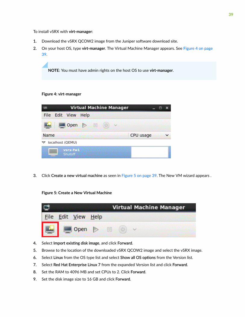
2. On your host OS, type virt-manager. The Virtual Machine Manager appears. See Figure 4 on page39.
NOTE: You must have admin rights on the host OS to use virt-manager.
Figure 4: virt-manager
3. Click Create a new virtual machine as seen in Figure 5 on page 39. The New VM wizard appears .
Figure 5: Create a New Virtual Machine
4. Select Import existing disk image, and click Forward.
5. Browse to the location of the downloaded vSRX QCOW2 image and select the vSRX image.
6. Select Linux from the OS type list and select Show all OS options from the Version list.
7. Select Red Hat Enterprise Linux 7 from the expanded Version list and click Forward.
8. Set the RAM to 4096 MB and set CPUs to 2. Click Forward.
9. Set the disk image size to 16 GB and click Forward.
39
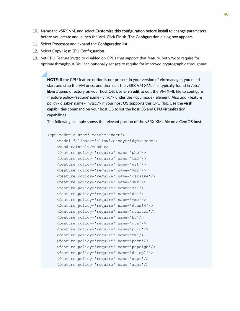
10. Name the vSRX VM, and select Customize this configuration before install to change parametersbefore you create and launch the VM. Click Finish. The Configuration dialog box appears.
11. Select Processor and expand the Configuration list.
12. Select Copy Host CPU Configuration.
13. Set CPU Feature invtsc to disabled on CPUs that support that feature. Set vmx to require foroptimal throughput. You can optionally set aes to require for improved cryptographic throughput
NOTE: If the CPU feature option is not present in your version of virt-manager, you needstart and stop the VM once, and then edit the vSRX VM XML file, typically found in /etc/libvirt/qemu directory on your host OS. Use virsh edit to edit the VM XML file to configure<feature policy='require' name='vmx'/> under the <cpu mode> element. Also add <featurepolicy='disable' name='invtsc'/> if your host OS supports this CPU flag. Use the virshcapabilities command on your host OS to list the host OS and CPU virtualizationcapabilities.
The following example shows the relevant portion of the vSRX XML file on a CentOS host:
<cpu mode='custom' match='exact'> <model fallback='allow'>SandyBridge</model> <vendor>Intel</vendor> <feature policy='require' name='pbe'/> <feature policy='require' name='tm2'/> <feature policy='require' name='est'/> <feature policy='require' name='vmx'/> <feature policy='require' name='osxsave'/> <feature policy='require' name='smx'/> <feature policy='require' name='ss'/> <feature policy='require' name='ds'/> <feature policy='require' name='vme'/> <feature policy='require' name='dtes64'/> <feature policy='require' name='monitor'/> <feature policy='require' name='ht'/> <feature policy='require' name='dca'/> <feature policy='require' name='pcid'/> <feature policy='require' name='tm'/> <feature policy='require' name='pdcm'/> <feature policy='require' name='pdpe1gb'/> <feature policy='require' name='ds_cpl'/> <feature policy='require' name='xtpr'/> <feature policy='require' name='acpi'/>
40
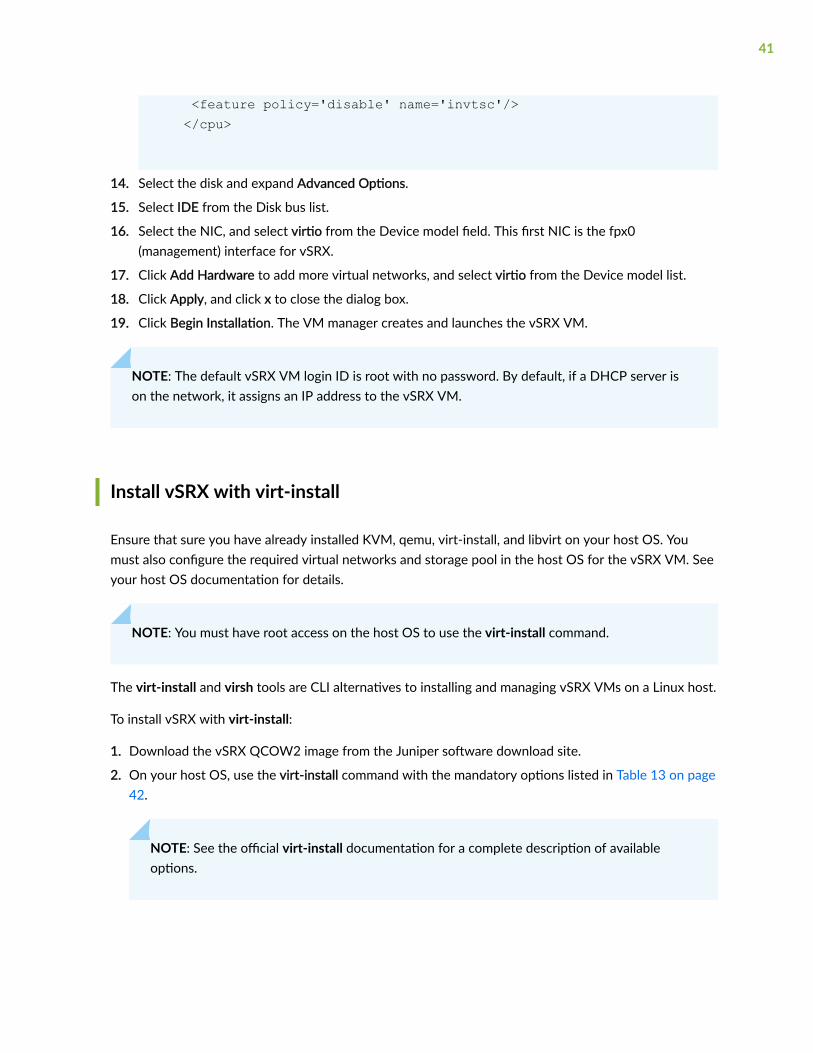
<feature policy='disable' name='invtsc'/> </cpu>
14. Select the disk and expand Advanced Options.
15. Select IDE from the Disk bus list.
16. Select the NIC, and select virtio from the Device model field. This first NIC is the fpx0(management) interface for vSRX.
17. Click Add Hardware to add more virtual networks, and select virtio from the Device model list.
18. Click Apply, and click x to close the dialog box.
19. Click Begin Installation. The VM manager creates and launches the vSRX VM.
NOTE: The default vSRX VM login ID is root with no password. By default, if a DHCP server ison the network, it assigns an IP address to the vSRX VM.
Install vSRX with virt-install
Ensure that sure you have already installed KVM, qemu, virt-install, and libvirt on your host OS. Youmust also configure the required virtual networks and storage pool in the host OS for the vSRX VM. Seeyour host OS documentation for details.
NOTE: You must have root access on the host OS to use the virt-install command.
The virt-install and virsh tools are CLI alternatives to installing and managing vSRX VMs on a Linux host.
To install vSRX with virt-install:
1. Download the vSRX QCOW2 image from the Juniper software download site.
2. On your host OS, use the virt-install command with the mandatory options listed in Table 13 on page42.
NOTE: See the official virt-install documentation for a complete description of availableoptions.
41
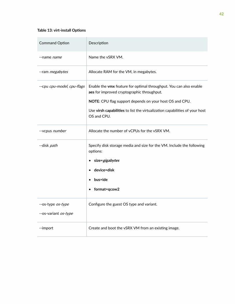
Table 13: virt-install Options
Command Option Description
--name name Name the vSRX VM.
--ram megabytes Allocate RAM for the VM, in megabytes.
--cpu cpu-model, cpu-flags Enable the vmx feature for optimal throughput. You can also enableaes for improved cryptographic throughput.
NOTE: CPU flag support depends on your host OS and CPU.
Use virsh capabilities to list the virtualization capabilities of your hostOS and CPU.
--vcpus number Allocate the number of vCPUs for the vSRX VM.
--disk path Specify disk storage media and size for the VM. Include the followingoptions:
• size=gigabytes
• device=disk
• bus=ide
• format=qcow2
--os-type os-type
--os-variant os-type
Configure the guest OS type and variant.
--import Create and boot the vSRX VM from an existing image.
42
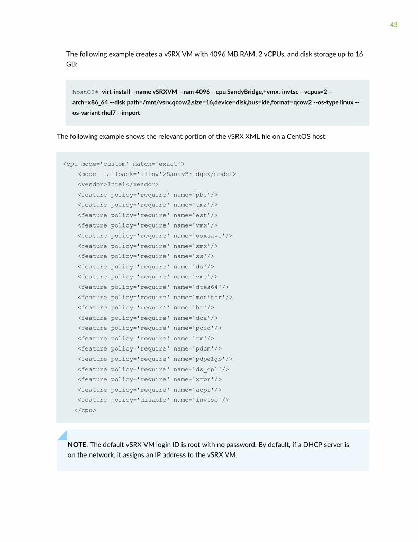
The following example creates a vSRX VM with 4096 MB RAM, 2 vCPUs, and disk storage up to 16GB:
hostOS# virt-install --name vSRXVM --ram 4096 --cpu SandyBridge,+vmx,-invtsc --vcpus=2 --
arch=x86_64 --disk path=/mnt/vsrx.qcow2,size=16,device=disk,bus=ide,format=qcow2 --os-type linux --os-variant rhel7 --import
The following example shows the relevant portion of the vSRX XML file on a CentOS host:
<cpu mode='custom' match='exact'> <model fallback='allow'>SandyBridge</model> <vendor>Intel</vendor> <feature policy='require' name='pbe'/> <feature policy='require' name='tm2'/> <feature policy='require' name='est'/> <feature policy='require' name='vmx'/> <feature policy='require' name='osxsave'/> <feature policy='require' name='smx'/> <feature policy='require' name='ss'/> <feature policy='require' name='ds'/> <feature policy='require' name='vme'/> <feature policy='require' name='dtes64'/> <feature policy='require' name='monitor'/> <feature policy='require' name='ht'/> <feature policy='require' name='dca'/> <feature policy='require' name='pcid'/> <feature policy='require' name='tm'/> <feature policy='require' name='pdcm'/> <feature policy='require' name='pdpe1gb'/> <feature policy='require' name='ds_cpl'/> <feature policy='require' name='xtpr'/> <feature policy='require' name='acpi'/> <feature policy='disable' name='invtsc'/> </cpu>
NOTE: The default vSRX VM login ID is root with no password. By default, if a DHCP server ison the network, it assigns an IP address to the vSRX VM.
43
RELATED DOCUMENTATION
Installing a virtual machine using virt-install
Migration, Upgrade, and Downgrade
Linux CPU Flags
Example: Install and Launch vSRX on Ubuntu
IN THIS SECTION
Requirements | 44
Overview | 45
Quick Configuration - Install and Launch a vSRX VM on Ubuntu | 45
| 49
Step by Step Configuration | 49
This example shows how to install and launch a vSRX instance on an Ubuntu server with KVM.
Requirements
This example uses the following hardware and software components:
• Generic x86 server
• Junos OS Release 15.1X49-D20 for vSRX
• Ubuntu version 14.04.2
Before you begin:
• This example assumes a fresh install of the Ubuntu server software.
• Ensure that your host OS meets the requirements specified in "Requirements for vSRX on KVM" onpage 10.
44
Overview
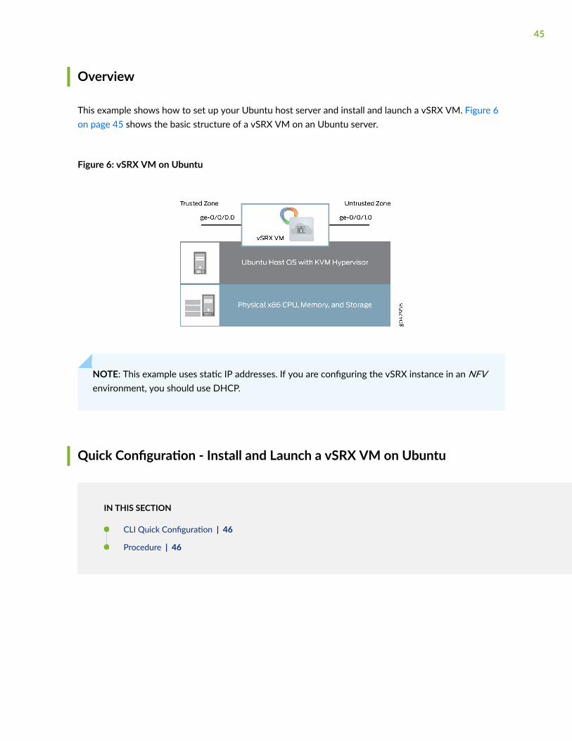
This example shows how to set up your Ubuntu host server and install and launch a vSRX VM. Figure 6on page 45 shows the basic structure of a vSRX VM on an Ubuntu server.
Figure 6: vSRX VM on Ubuntu
NOTE: This example uses static IP addresses. If you are configuring the vSRX instance in an NFVenvironment, you should use DHCP.
Quick Configuration - Install and Launch a vSRX VM on Ubuntu
IN THIS SECTION
CLI Quick Configuration | 46
Procedure | 46
45
CLI Quick Configuration
To quickly configure this example, copy the following commands, paste them into a text file, remove anyline breaks, change any details necessary to match your network configuration, and copy and paste thecommands into the Ubuntu server terminal or vSRX console as specified.
Procedure
Step-by-Step Procedure
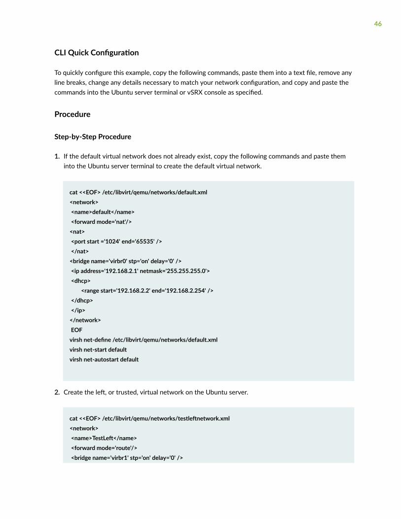
1. If the default virtual network does not already exist, copy the following commands and paste theminto the Ubuntu server terminal to create the default virtual network.
cat <<EOF> /etc/libvirt/qemu/networks/default.xml <network> <name>default</name> <forward mode='nat'/> <nat> <port start ='1024' end='65535' /> </nat><bridge name='virbr0' stp='on' delay='0' /> <ip address='192.168.2.1' netmask='255.255.255.0'> <dhcp> <range start='192.168.2.2' end='192.168.2.254' /> </dhcp> </ip> </network> EOFvirsh net-define /etc/libvirt/qemu/networks/default.xmlvirsh net-start defaultvirsh net-autostart default
2. Create the left, or trusted, virtual network on the Ubuntu server.
cat <<EOF> /etc/libvirt/qemu/networks/testleftnetwork.xml <network> <name>TestLeft</name> <forward mode='route'/> <bridge name='virbr1' stp='on' delay='0' />
46
<ip address='192.168.123.1' netmask='255.255.255.0'> <dhcp> <range start='192.168.123.100' end='192.168.123.250' /> </dhcp> </ip> </network> EOFvirsh net-define /etc/libvirt/qemu/networks/testleftnetwork.xmlvirsh net-start TestLeftvirsh net-autostart TestLeft
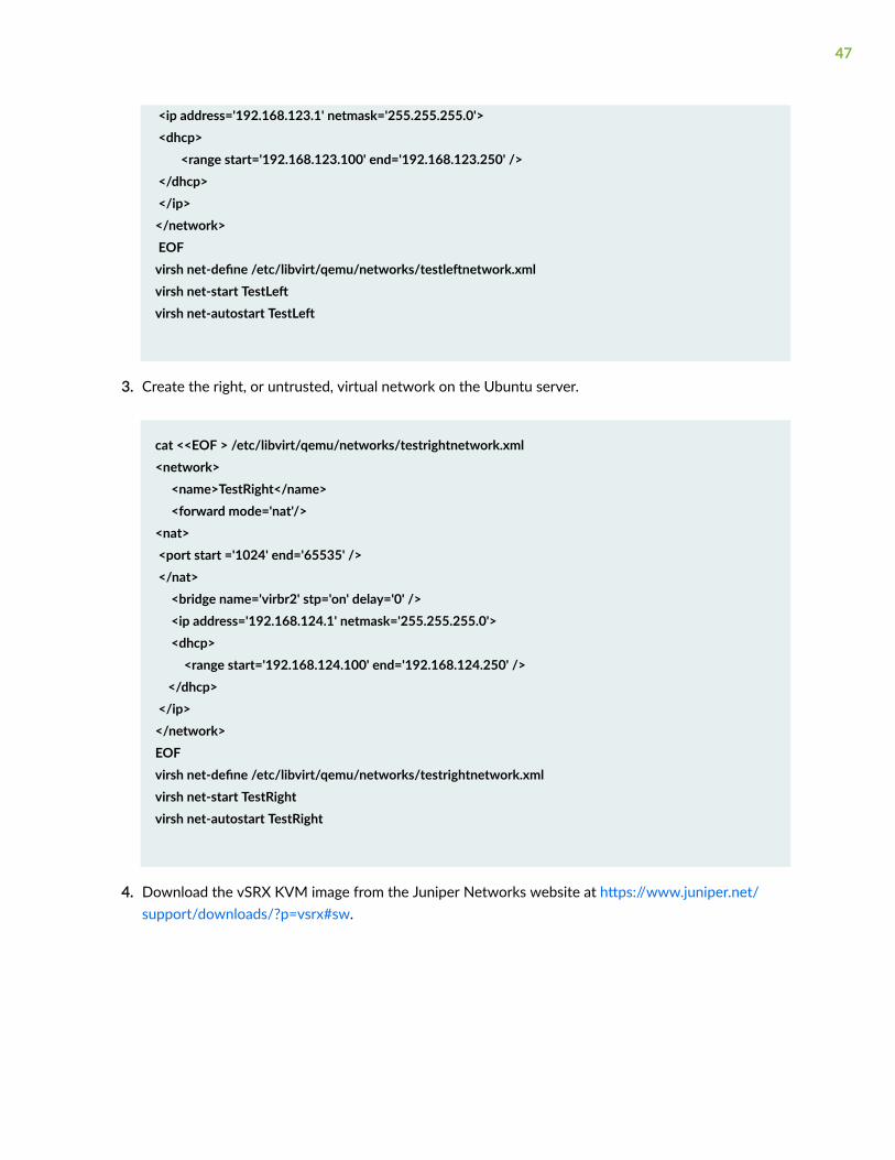
3. Create the right, or untrusted, virtual network on the Ubuntu server.
cat <<EOF > /etc/libvirt/qemu/networks/testrightnetwork.xml<network> <name>TestRight</name> <forward mode='nat'/> <nat> <port start ='1024' end='65535' /> </nat> <bridge name='virbr2' stp='on' delay='0' /> <ip address='192.168.124.1' netmask='255.255.255.0'> <dhcp> <range start='192.168.124.100' end='192.168.124.250' /> </dhcp> </ip></network>EOFvirsh net-define /etc/libvirt/qemu/networks/testrightnetwork.xmlvirsh net-start TestRightvirsh net-autostart TestRight
4. Download the vSRX KVM image from the Juniper Networks website at https://www.juniper.net/support/downloads/?p=vsrx#sw.
47

5. Copy the following commands and modify the cpu parameter and flags to match your Ubuntu serverCPU. Paste the resulting commands into the Ubuntu server terminal to copy the image to a mountpoint and create the vSRX VM.
cp junos-vsrx-vmdisk-15.1X49-D20.2.qcow2 /mnt/vsrx20one.qcow2
virt-install --name vSRX20One --ram 4096 --cpu SandyBridge,+vmx,-invtc, --vcpus=2 --arch=x86_64 --disk path=/mnt/vsrx20one.qcow2,size=16,device=disk,bus=ide,format=qcow2 --os-type linux --os-variant rhel7 --import --network=network:default,model=virtio --network=network:TestLeft,model=virtio --network=network:TestRight,model=virtio
NOTE: The CPU model and flags in the virt-install command might vary based on the CPUand features in the Ubuntu server.
6. To set the root password on the vSRX VM, copy and paste the command into the vSRX CLI at the[edit] hierarchy level.
set system root-authentication plain-text-password
7. To create a base configuration on the vSRX VM, copy the following commands, paste them into atext file, remove any line breaks, change any details necessary to match your network configuration,copy and paste the following commands into the vSRX CLI at the [edit] hierarchy level, and thenenter commit from configuration mode.
set interfaces fxp0 unit 0 family inet dhcp-client set interfaces ge-0/0/0 unit 0 family inet address 192.168.123.254/24 set interfaces ge-0/0/1 unit 0 family inet dhcp-client
set security zones security-zone trust interfaces ge-0/0/0.0 host-inbound-traffic system-services all
set security zones security-zone untrust interfaces ge-0/0/1.0 host-inbound-traffic system-services dhcp
set routing-instances CUSTOMER-VR instance-type virtual-router
set routing-instances CUSTOMER-VR interface ge-0/0/0.0
set routing-instances CUSTOMER-VR interface ge-0/0/1.0
set security nat source rule-set source-nat from zone trust
set security nat source rule-set source-nat to zone untrust
set security nat source rule-set source-nat rule nat1 match source-address 0.0.0.0/0
set security nat source rule-set source-nat rule nat1 then source-nat interface
48
IN THIS SECTION
| 49
Step-by-Step Procedure
Step by Step Configuration
IN THIS SECTION
Add Virtual Networks | 49
Verify the Virtual Networks | 53
Download and Installing the vSRX Image | 53
Verify the vSRX Installation | 54
Create a Base Configuration on the vSRX Instance | 57
Verify the Basic Configuration on the vSRX Instance | 60
Use the following sections for a more detailed set of procedures to install and launch a vSRX VM.
Add Virtual Networks
Step-by-Step Procedure
You need to create virtual networks on the Ubuntu server to provide network connectivity to interfaceson the vSRX VM. Copy and paste these command into a terminal on the Ubuntu server.
This example uses three virtual networks:
49
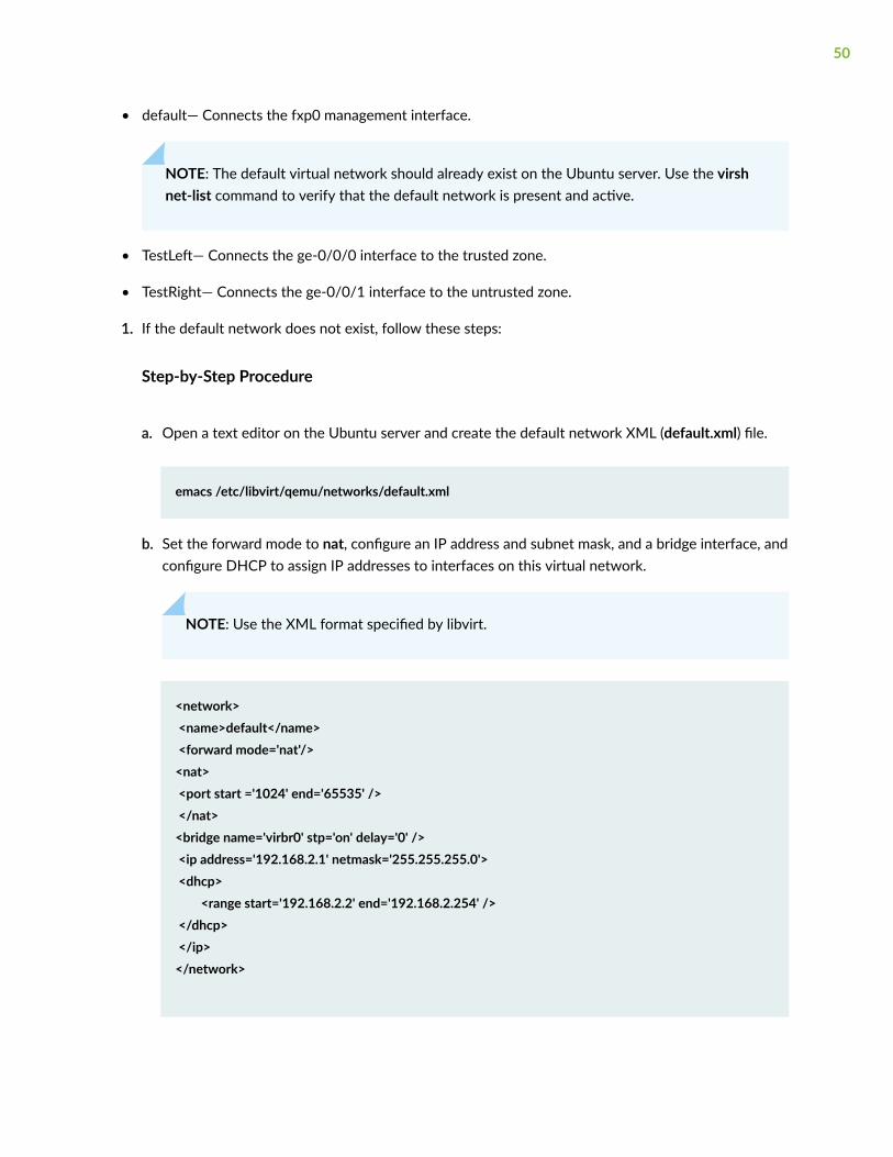
• default— Connects the fxp0 management interface.
NOTE: The default virtual network should already exist on the Ubuntu server. Use the virshnet-list command to verify that the default network is present and active.
• TestLeft— Connects the ge-0/0/0 interface to the trusted zone.
• TestRight— Connects the ge-0/0/1 interface to the untrusted zone.
1. If the default network does not exist, follow these steps:
Step-by-Step Procedure
a. Open a text editor on the Ubuntu server and create the default network XML (default.xml) file.
emacs /etc/libvirt/qemu/networks/default.xml
b. Set the forward mode to nat, configure an IP address and subnet mask, and a bridge interface, andconfigure DHCP to assign IP addresses to interfaces on this virtual network.
NOTE: Use the XML format specified by libvirt.
<network> <name>default</name> <forward mode='nat'/> <nat> <port start ='1024' end='65535' /> </nat><bridge name='virbr0' stp='on' delay='0' /> <ip address='192.168.2.1' netmask='255.255.255.0'> <dhcp> <range start='192.168.2.2' end='192.168.2.254' /> </dhcp> </ip> </network>
50
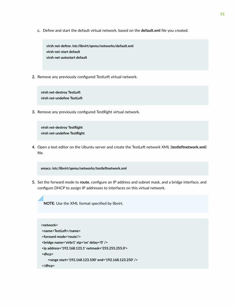
c. Define and start the default virtual network, based on the default.xml file you created.
virsh net-define /etc/libvirt/qemu/networks/default.xmlvirsh net-start defaultvirsh net-autostart default
2. Remove any previously configured TestLeft virtual network.
virsh net-destroy TestLeftvirsh net-undefine TestLeft
3. Remove any previously configured TestRight virtual network.
virsh net-destroy TestRightvirsh net-undefine TestRight
4. Open a text editor on the Ubuntu server and create the TestLeft network XML (testleftnetwork.xml)file.
emacs /etc/libvirt/qemu/networks/testleftnetwork.xml
5. Set the forward mode to route, configure an IP address and subnet mask, and a bridge interface, andconfigure DHCP to assign IP addresses to interfaces on this virtual network.
NOTE: Use the XML format specified by libvirt.
<network> <name>TestLeft</name> <forward mode='route'/> <bridge name='virbr1' stp='on' delay='0' /> <ip address='192.168.123.1' netmask='255.255.255.0'> <dhcp> <range start='192.168.123.100' end='192.168.123.250' /> </dhcp>
51
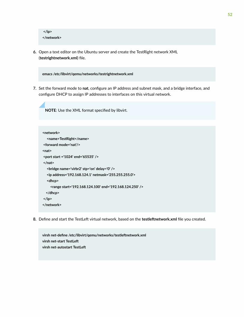
</ip> </network>
6. Open a text editor on the Ubuntu server and create the TestRight network XML(testrightnetwork.xml) file.
emacs /etc/libvirt/qemu/networks/testrightnetwork.xml
7. Set the forward mode to nat, configure an IP address and subnet mask, and a bridge interface, andconfigure DHCP to assign IP addresses to interfaces on this virtual network.
NOTE: Use the XML format specified by libvirt.
<network> <name>TestRight</name> <forward mode='nat'/> <nat> <port start ='1024' end='65535' /> </nat> <bridge name='virbr2' stp='on' delay='0' /> <ip address='192.168.124.1' netmask='255.255.255.0'> <dhcp> <range start='192.168.124.100' end='192.168.124.250' /> </dhcp> </ip></network>
8. Define and start the TestLeft virtual network, based on the testleftnetwork.xml file you created.
virsh net-define /etc/libvirt/qemu/networks/testleftnetwork.xmlvirsh net-start TestLeftvirsh net-autostart TestLeft
52
9. Define and start the TestRight virtual network, based on the testrightnetwork.xml file you created.
virsh net-define /etc/libvirt/qemu/networks/testrightnetwork.xmlvirsh net-start TestRightvirsh net-autostart TestRight
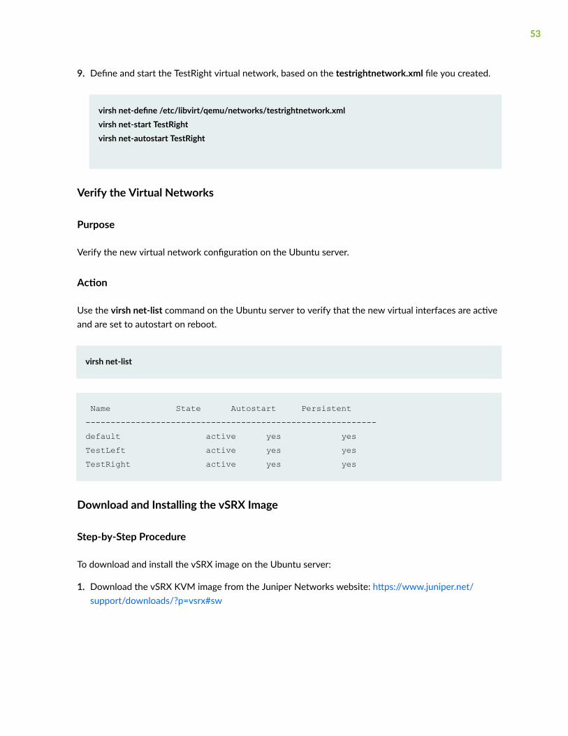
Verify the Virtual Networks
Purpose
Verify the new virtual network configuration on the Ubuntu server.
Action
Use the virsh net-list command on the Ubuntu server to verify that the new virtual interfaces are activeand are set to autostart on reboot.
virsh net-list
Name State Autostart Persistent----------------------------------------------------------default active yes yesTestLeft active yes yesTestRight active yes yes
Download and Installing the vSRX Image
Step-by-Step Procedure
To download and install the vSRX image on the Ubuntu server:
1. Download the vSRX KVM image from the Juniper Networks website: https://www.juniper.net/support/downloads/?p=vsrx#sw
53
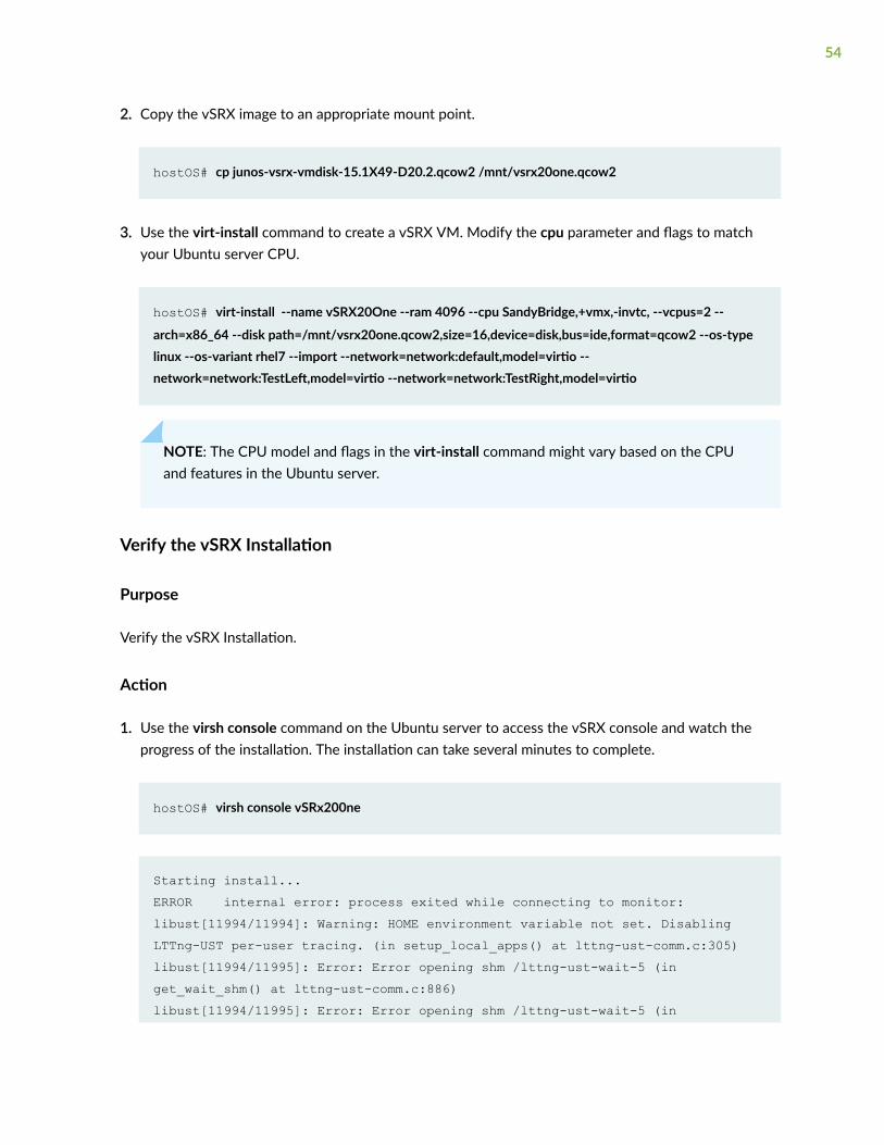
2. Copy the vSRX image to an appropriate mount point.
hostOS# cp junos-vsrx-vmdisk-15.1X49-D20.2.qcow2 /mnt/vsrx20one.qcow2
3. Use the virt-install command to create a vSRX VM. Modify the cpu parameter and flags to matchyour Ubuntu server CPU.
hostOS# virt-install --name vSRX20One --ram 4096 --cpu SandyBridge,+vmx,-invtc, --vcpus=2 --
arch=x86_64 --disk path=/mnt/vsrx20one.qcow2,size=16,device=disk,bus=ide,format=qcow2 --os-type linux --os-variant rhel7 --import --network=network:default,model=virtio --network=network:TestLeft,model=virtio --network=network:TestRight,model=virtio
NOTE: The CPU model and flags in the virt-install command might vary based on the CPUand features in the Ubuntu server.
Verify the vSRX Installation
Purpose
Verify the vSRX Installation.
Action
1. Use the virsh console command on the Ubuntu server to access the vSRX console and watch theprogress of the installation. The installation can take several minutes to complete.
hostOS# virsh console vSRx200ne
Starting install...ERROR internal error: process exited while connecting to monitor: libust[11994/11994]: Warning: HOME environment variable not set. Disabling LTTng-UST per-user tracing. (in setup_local_apps() at lttng-ust-comm.c:305)libust[11994/11995]: Error: Error opening shm /lttng-ust-wait-5 (in get_wait_shm() at lttng-ust-comm.c:886)libust[11994/11995]: Error: Error opening shm /lttng-ust-wait-5 (in
54
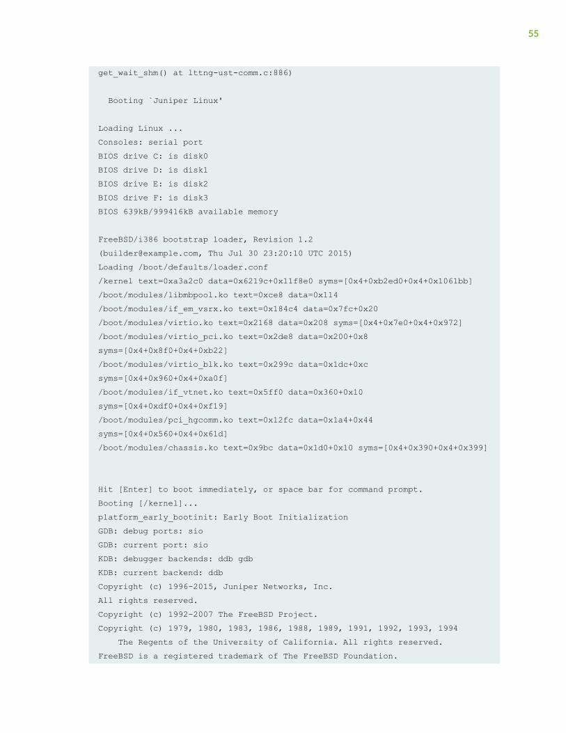
get_wait_shm() at lttng-ust-comm.c:886) Booting `Juniper Linux' Loading Linux ...Consoles: serial portBIOS drive C: is disk0BIOS drive D: is disk1BIOS drive E: is disk2BIOS drive F: is disk3BIOS 639kB/999416kB available memory FreeBSD/i386 bootstrap loader, Revision 1.2([email protected], Thu Jul 30 23:20:10 UTC 2015)Loading /boot/defaults/loader.conf/kernel text=0xa3a2c0 data=0x6219c+0x11f8e0 syms=[0x4+0xb2ed0+0x4+0x1061bb]/boot/modules/libmbpool.ko text=0xce8 data=0x114/boot/modules/if_em_vsrx.ko text=0x184c4 data=0x7fc+0x20/boot/modules/virtio.ko text=0x2168 data=0x208 syms=[0x4+0x7e0+0x4+0x972]/boot/modules/virtio_pci.ko text=0x2de8 data=0x200+0x8 syms=[0x4+0x8f0+0x4+0xb22]/boot/modules/virtio_blk.ko text=0x299c data=0x1dc+0xc syms=[0x4+0x960+0x4+0xa0f]/boot/modules/if_vtnet.ko text=0x5ff0 data=0x360+0x10 syms=[0x4+0xdf0+0x4+0xf19]/boot/modules/pci_hgcomm.ko text=0x12fc data=0x1a4+0x44 syms=[0x4+0x560+0x4+0x61d]/boot/modules/chassis.ko text=0x9bc data=0x1d0+0x10 syms=[0x4+0x390+0x4+0x399] Hit [Enter] to boot immediately, or space bar for command prompt.Booting [/kernel]...platform_early_bootinit: Early Boot InitializationGDB: debug ports: sioGDB: current port: sioKDB: debugger backends: ddb gdbKDB: current backend: ddbCopyright (c) 1996-2015, Juniper Networks, Inc.All rights reserved.Copyright (c) 1992-2007 The FreeBSD Project.Copyright (c) 1979, 1980, 1983, 1986, 1988, 1989, 1991, 1992, 1993, 1994 The Regents of the University of California. All rights reserved.FreeBSD is a registered trademark of The FreeBSD Foundation.
55
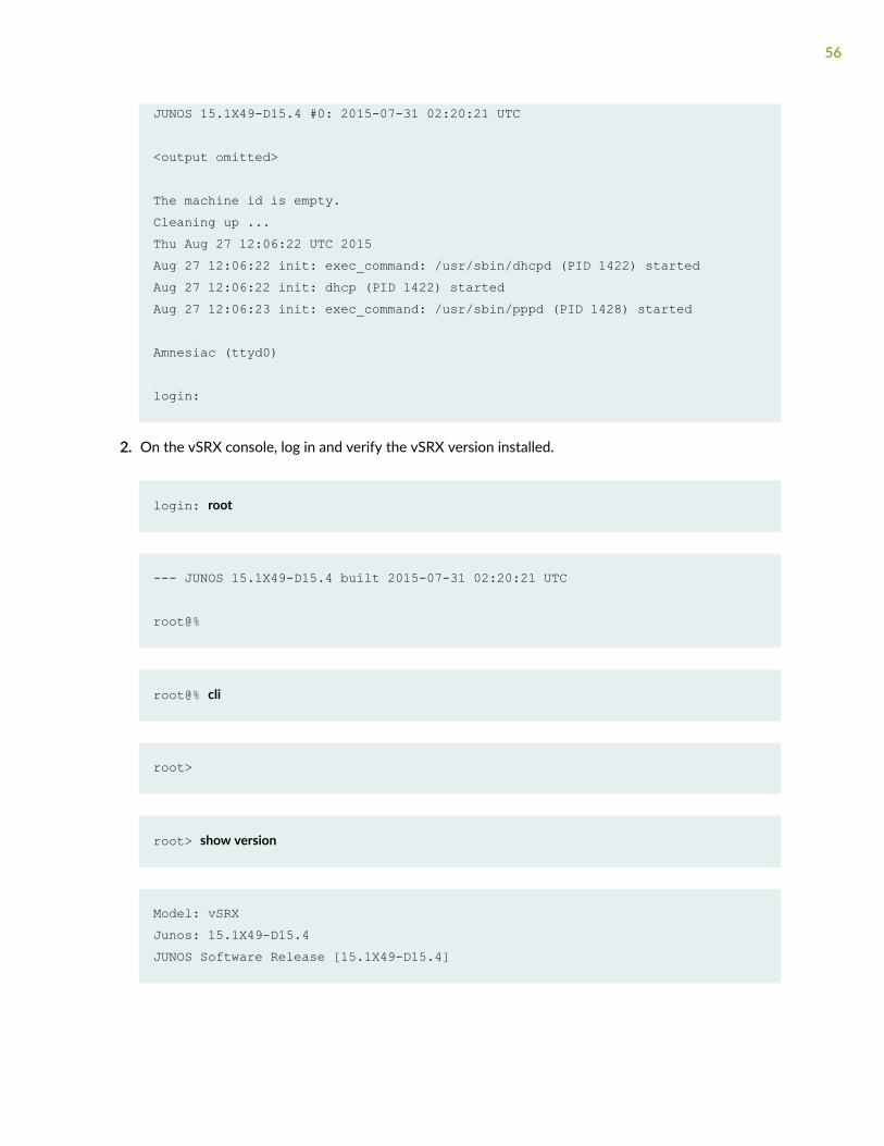
JUNOS 15.1X49-D15.4 #0: 2015-07-31 02:20:21 UTC
<output omitted>
The machine id is empty.Cleaning up ...Thu Aug 27 12:06:22 UTC 2015Aug 27 12:06:22 init: exec_command: /usr/sbin/dhcpd (PID 1422) startedAug 27 12:06:22 init: dhcp (PID 1422) startedAug 27 12:06:23 init: exec_command: /usr/sbin/pppd (PID 1428) started Amnesiac (ttyd0) login:
2. On the vSRX console, log in and verify the vSRX version installed.
login: root
--- JUNOS 15.1X49-D15.4 built 2015-07-31 02:20:21 UTC root@%
root@% cli
root>
root> show version
Model: vSRXJunos: 15.1X49-D15.4JUNOS Software Release [15.1X49-D15.4]
56
Create a Base Configuration on the vSRX Instance
Step-by-Step Procedure
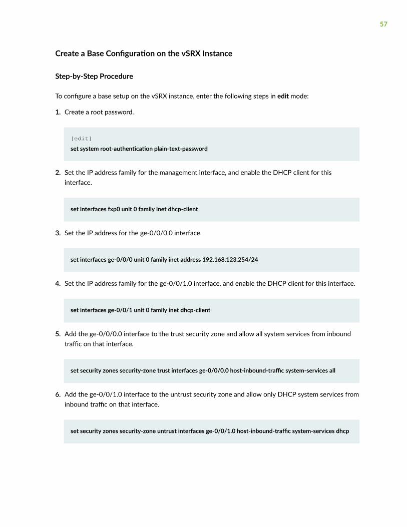
To configure a base setup on the vSRX instance, enter the following steps in edit mode:
1. Create a root password.
[edit]set system root-authentication plain-text-password
2. Set the IP address family for the management interface, and enable the DHCP client for thisinterface.
set interfaces fxp0 unit 0 family inet dhcp-client
3. Set the IP address for the ge-0/0/0.0 interface.
set interfaces ge-0/0/0 unit 0 family inet address 192.168.123.254/24
4. Set the IP address family for the ge-0/0/1.0 interface, and enable the DHCP client for this interface.
set interfaces ge-0/0/1 unit 0 family inet dhcp-client
5. Add the ge-0/0/0.0 interface to the trust security zone and allow all system services from inboundtraffic on that interface.
set security zones security-zone trust interfaces ge-0/0/0.0 host-inbound-traffic system-services all
6. Add the ge-0/0/1.0 interface to the untrust security zone and allow only DHCP system services frominbound traffic on that interface.
set security zones security-zone untrust interfaces ge-0/0/1.0 host-inbound-traffic system-services dhcp
57
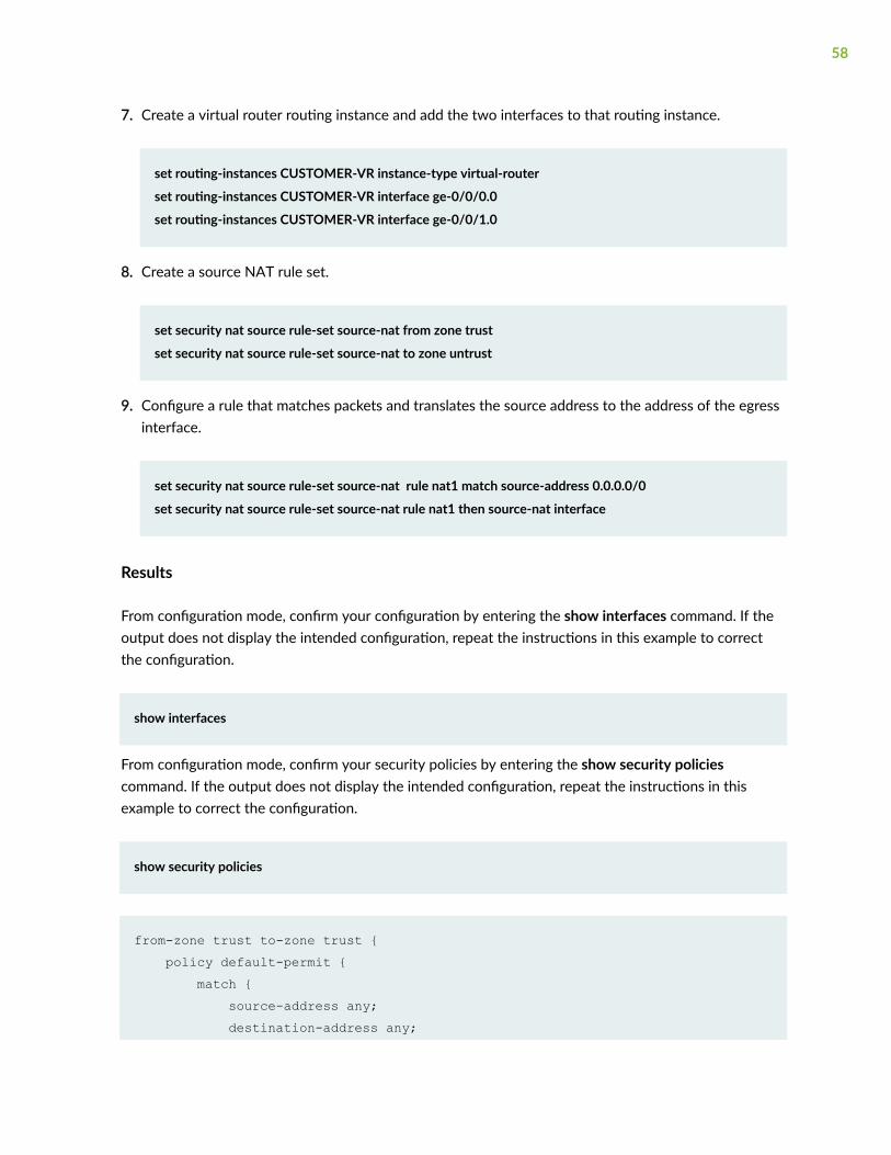
7. Create a virtual router routing instance and add the two interfaces to that routing instance.
set routing-instances CUSTOMER-VR instance-type virtual-router
set routing-instances CUSTOMER-VR interface ge-0/0/0.0
set routing-instances CUSTOMER-VR interface ge-0/0/1.0
8. Create a source NAT rule set.
set security nat source rule-set source-nat from zone trust
set security nat source rule-set source-nat to zone untrust
9. Configure a rule that matches packets and translates the source address to the address of the egressinterface.
set security nat source rule-set source-nat rule nat1 match source-address 0.0.0.0/0
set security nat source rule-set source-nat rule nat1 then source-nat interface
Results
From configuration mode, confirm your configuration by entering the show interfaces command. If theoutput does not display the intended configuration, repeat the instructions in this example to correctthe configuration.
show interfaces
From configuration mode, confirm your security policies by entering the show security policiescommand. If the output does not display the intended configuration, repeat the instructions in thisexample to correct the configuration.
show security policies
from-zone trust to-zone trust { policy default-permit { match { source-address any; destination-address any;
58
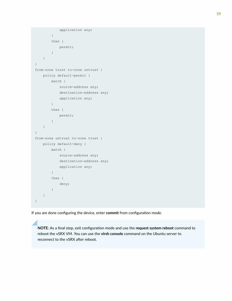
application any; } then { permit; } }}from-zone trust to-zone untrust { policy default-permit { match { source-address any; destination-address any; application any; } then { permit; } }}from-zone untrust to-zone trust { policy default-deny { match { source-address any; destination-address any; application any; } then { deny; } }}
If you are done configuring the device, enter commit from configuration mode.
NOTE: As a final step, exit configuration mode and use the request system reboot command toreboot the vSRX VM. You can use the virsh console command on the Ubuntu server toreconnect to the vSRX after reboot.
59
Verify the Basic Configuration on the vSRX Instance
Purpose
Verify the basic configuration on the vSRX instance.
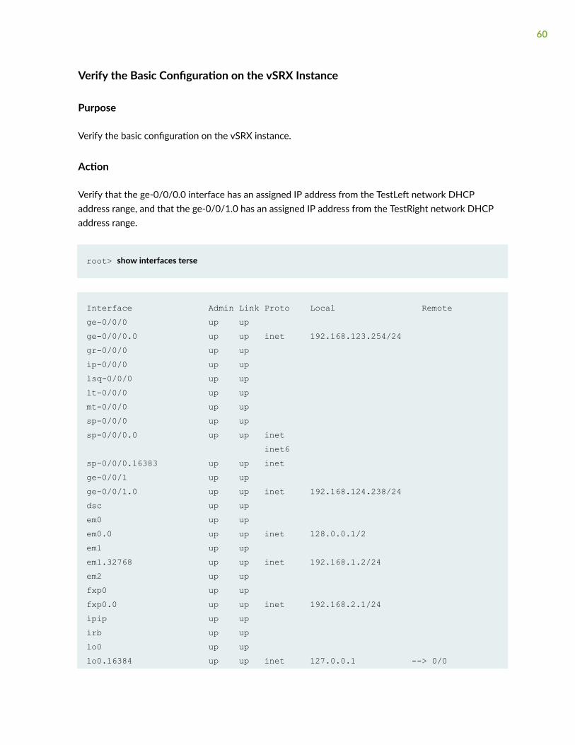
Action
Verify that the ge-0/0/0.0 interface has an assigned IP address from the TestLeft network DHCPaddress range, and that the ge-0/0/1.0 has an assigned IP address from the TestRight network DHCPaddress range.
root> show interfaces terse
Interface Admin Link Proto Local Remotege-0/0/0 up upge-0/0/0.0 up up inet 192.168.123.254/24gr-0/0/0 up upip-0/0/0 up uplsq-0/0/0 up uplt-0/0/0 up upmt-0/0/0 up upsp-0/0/0 up upsp-0/0/0.0 up up inet inet6sp-0/0/0.16383 up up inetge-0/0/1 up upge-0/0/1.0 up up inet 192.168.124.238/24dsc up upem0 up upem0.0 up up inet 128.0.0.1/2em1 up upem1.32768 up up inet 192.168.1.2/24em2 up upfxp0 up upfxp0.0 up up inet 192.168.2.1/24ipip up upirb up uplo0 up uplo0.16384 up up inet 127.0.0.1 --> 0/0
60
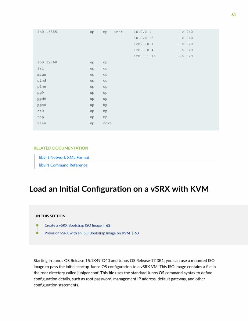
lo0.16385 up up inet 10.0.0.1 --> 0/0 10.0.0.16 --> 0/0 128.0.0.1 --> 0/0 128.0.0.4 --> 0/0 128.0.1.16 --> 0/0lo0.32768 up uplsi up upmtun up uppimd up uppime up uppp0 up upppd0 up upppe0 up upst0 up uptap up upvlan up down
RELATED DOCUMENTATION
libvirt Network XML Format
libvirt Command Reference
Load an Initial Configuration on a vSRX with KVM
IN THIS SECTION
Create a vSRX Bootstrap ISO Image | 62
Provision vSRX with an ISO Bootstrap Image on KVM | 63
Starting in Junos OS Release 15.1X49-D40 and Junos OS Release 17.3R1, you can use a mounted ISOimage to pass the initial startup Junos OS configuration to a vSRX VM. This ISO image contains a file inthe root directory called juniper.conf. This file uses the standard Junos OS command syntax to defineconfiguration details, such as root password, management IP address, default gateway, and otherconfiguration statements.
61
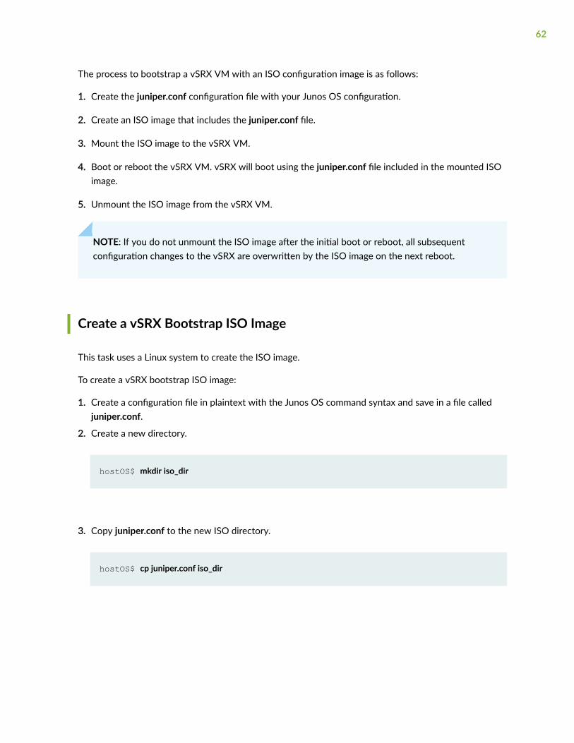
The process to bootstrap a vSRX VM with an ISO configuration image is as follows:
1. Create the juniper.conf configuration file with your Junos OS configuration.
2. Create an ISO image that includes the juniper.conf file.
3. Mount the ISO image to the vSRX VM.
4. Boot or reboot the vSRX VM. vSRX will boot using the juniper.conf file included in the mounted ISOimage.
5. Unmount the ISO image from the vSRX VM.
NOTE: If you do not unmount the ISO image after the initial boot or reboot, all subsequentconfiguration changes to the vSRX are overwritten by the ISO image on the next reboot.
Create a vSRX Bootstrap ISO Image
This task uses a Linux system to create the ISO image.
To create a vSRX bootstrap ISO image:
1. Create a configuration file in plaintext with the Junos OS command syntax and save in a file calledjuniper.conf.
2. Create a new directory.
hostOS$ mkdir iso_dir
3. Copy juniper.conf to the new ISO directory.
hostOS$ cp juniper.conf iso_dir
62

NOTE: The juniper.conf file must contain the full vSRX configuration. The ISO bootstrapprocess overwrites any existing vSRX configuration.
4. Use the Linux mkisofs command to create the ISO image.
hostOS$ mkisofs -l -o test.iso iso_dir
I: -input-charset not specified, using utf-8 (detected in locale settings)Total translation table size: 0Total rockridge attributes bytes: 0Total directory bytes: 0Path table size(bytes): 10Max brk space used 0175 extents written (0 MB)
NOTE: The -l option allows for a long filename.
Provision vSRX with an ISO Bootstrap Image on KVM
To provision a vSRX VM from an ISO bootstrap image:
1. Use the virsh edit command on the KVM host server where the vSRX VM resides to add thebootstrap ISO image as a disk device.
<disk type='file' device='cdrom'> <driver name='qemu' type='raw'/> <source file='/home/test.iso'/> <target dev='hdc' bus='ide'/> <readonly/> <address type='drive' controller='0' bus='1' target='0' unit='0'/> </disk>
63
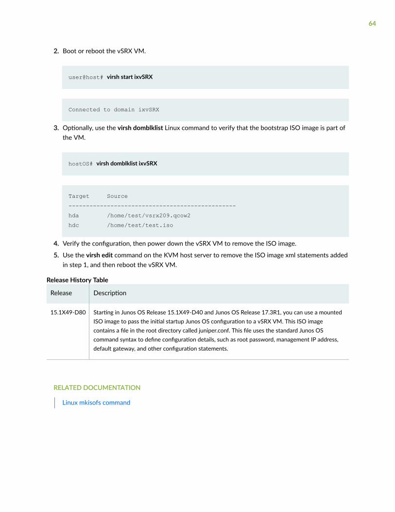
2. Boot or reboot the vSRX VM.
user@host# virsh start ixvSRX
Connected to domain ixvSRX
3. Optionally, use the virsh domblklist Linux command to verify that the bootstrap ISO image is part ofthe VM.
hostOS# virsh domblklist ixvSRX
Target Source------------------------------------------------hda /home/test/vsrx209.qcow2hdc /home/test/test.iso
4. Verify the configuration, then power down the vSRX VM to remove the ISO image.
5. Use the virsh edit command on the KVM host server to remove the ISO image xml statements addedin step 1, and then reboot the vSRX VM.
Release History Table
Release Description
15.1X49-D80 Starting in Junos OS Release 15.1X49-D40 and Junos OS Release 17.3R1, you can use a mountedISO image to pass the initial startup Junos OS configuration to a vSRX VM. This ISO imagecontains a file in the root directory called juniper.conf. This file uses the standard Junos OScommand syntax to define configuration details, such as root password, management IP address,default gateway, and other configuration statements.
RELATED DOCUMENTATION
Linux mkisofs command
64

Use Cloud-Init in an OpenStack Environment toAutomate the Initialization of vSRX Instances
IN THIS SECTION
Perform Automatic Setup of a vSRX Instance Using an OpenStack Command-Line Interface | 68
Perform Automatic Setup of a vSRX Instance from the OpenStack Dashboard (Horizon) | 70
Starting in Junos OS Release 15.1X49-D100 and Junos OS Release 17.4R1, the cloud-init package(version 0.7x) comes pre-installed in the vSRX image to help simplify configuring new vSRX instancesoperating in an OpenStack environment according to a specified user-data file. Cloud-init is performedduring the first-time boot of a vSRX instance.
Cloud-init is an OpenStack software package for automating the initialization of a cloud instance atboot-up. It is available in Ubuntu and most major Linux and FreeBSD operating systems. Cloud-init isdesigned to support multiple different cloud providers so that the same virtual machine (VM) image canbe directly used in multiple hypervisors and cloud instances without any modification. Cloud-initsupport in a VM instance runs at boot time (first-time boot) and initializes the VM instance according tothe specified user-data file.
A user-data file is a special key in the metadata service that contains a file that cloud-aware applicationsin the VM instance can access upon a first-time boot. In this case, it is the validated Junos OSconfiguration file that you intend to upload to a vSRX instance as the active configuration. This file usesthe standard Junos OS command syntax to define configuration details, such as root password,management IP address, default gateway, and other configuration statements.
When you create a vSRX instance, you can use cloud-init with a validated Junos OS configuration file(juniper.conf) to automate the initialization of new vSRX instances. The user-data file uses the standardJunos OS syntax to define all the configuration details for your vSRX instance. The default Junos OSconfiguration is replaced during the vSRX instance launch with a validated Junos OS configuration thatyou supply in the form of a user-data file.
NOTE: If using a release earlier than Junos OS Release 15.1X49-D130 and Junos OS Release18.4R1, the user-data configuration file cannot exceed 16 KB. If your user-data file exceeds thislimit, you must compress the file using gzip and use the compressed file. For example, the gzipjunos.conf command results in the junos.conf.gz file.
65
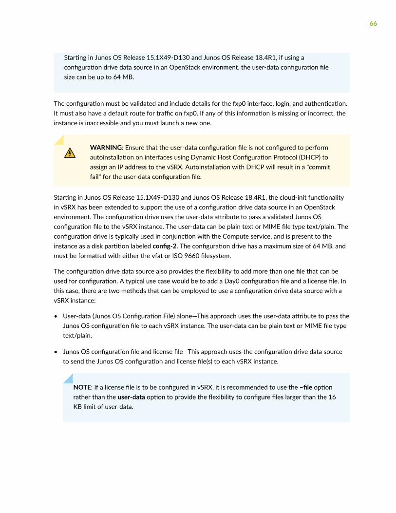
Starting in Junos OS Release 15.1X49-D130 and Junos OS Release 18.4R1, if using aconfiguration drive data source in an OpenStack environment, the user-data configuration filesize can be up to 64 MB.
The configuration must be validated and include details for the fxp0 interface, login, and authentication.It must also have a default route for traffic on fxp0. If any of this information is missing or incorrect, theinstance is inaccessible and you must launch a new one.
WARNING: Ensure that the user-data configuration file is not configured to performautoinstallation on interfaces using Dynamic Host Configuration Protocol (DHCP) toassign an IP address to the vSRX. Autoinstallation with DHCP will result in a "commitfail" for the user-data configuration file.
Starting in Junos OS Release 15.1X49-D130 and Junos OS Release 18.4R1, the cloud-init functionalityin vSRX has been extended to support the use of a configuration drive data source in an OpenStackenvironment. The configuration drive uses the user-data attribute to pass a validated Junos OSconfiguration file to the vSRX instance. The user-data can be plain text or MIME file type text/plain. Theconfiguration drive is typically used in conjunction with the Compute service, and is present to theinstance as a disk partition labeled config-2. The configuration drive has a maximum size of 64 MB, andmust be formatted with either the vfat or ISO 9660 filesystem.
The configuration drive data source also provides the flexibility to add more than one file that can beused for configuration. A typical use case would be to add a Day0 configuration file and a license file. Inthis case, there are two methods that can be employed to use a configuration drive data source with avSRX instance:
• User-data (Junos OS Configuration File) alone—This approach uses the user-data attribute to pass theJunos OS configuration file to each vSRX instance. The user-data can be plain text or MIME file typetext/plain.
• Junos OS configuration file and license file—This approach uses the configuration drive data sourceto send the Junos OS configuration and license file(s) to each vSRX instance.
NOTE: If a license file is to be configured in vSRX, it is recommended to use the –file optionrather than the user-data option to provide the flexibility to configure files larger than the 16KB limit of user-data.
66

To use a configuration drive data source to send Junos OS configuration and license file(s) to a vSRXinstance, the files needs to be sent in a specific folder structure. In this application, the folder structureof the configuration drive data source in vSRX is as follows:
- OpenStack - latest - junos-config - configuration.txt - junos-license - License_file_name.lic - License_file_name.lic
//OpenStack//latest/junos-config/configuration.txt
//OpenStack//latest/junos-license/license.lic
Before you begin:
• Create a configuration file with the Junos OS command syntax and save it. The configuration file canbe plain text or MIME file type text/plain. The string #junos-config must be the first line of the user-data configuration file before the Junos OS configuration.
NOTE: The #junos-config string is mandatory in the user-data configuration file; if it is notincluded, the configuration will not be applied to the vSRX instance as the activeconfiguration.
• Determine the name for the vSRX instance you want to initialize with a validated Junos OSconfiguration file.
• Determine the flavor for your vSRX instance, which defines the compute, memory, and storagecapacity of the vSRX instance.
• Starting in Junos OS Release 15.1X49-D130 and Junos OS Release 18.4R1, if using a configurationdrive, ensure the following criteria is met to enable cloud-init support for a configuration drive inOpenStack:
• The configuration drive must be formatted with either the vfat or iso9660 filesystem.
NOTE: The default format of a configuration drive is an ISO 9660 file system. To explicitlyspecify the ISO 9660/vfat format, add the config_drive_format=iso9660/vfat line to thenova.conf file.
67
• The configuration drive must have a filesystem label of config-2.
• The folder size must be no greater than 64 MB.
Depending on your OpenStack environment, you can use either an OpenStack command-line interface(such as nova boot or openstack server create) or the OpenStack Dashboard (“Horizon”) to launch andinitialize a vSRX instance.
Perform Automatic Setup of a vSRX Instance Using an OpenStackCommand-Line Interface
You can launch and manage a vSRX instance using either the nova boot or openstack server createcommands, which includes the use of a validated Junos OS configuration user-data file from your localdirectory to initialize the active configuration of the target vSRX instance.
To initiate the automatic setup of a vSRX instance from an OpenStack command-line client:
1. If you have not done so already, create a configuration file with the Junos OS command syntax andsave the file. The configuration file can be plain text or MIME file type text/plain.
The user-data configuration file must contain the full vSRX configuration that is to be used as theactive configuration on each vSRX instance, and the string #junos-config must be the first line of theuser-data configuration file before the Junos OS configuration.
NOTE: The #junos-config string is mandatory in the user-data configuration file; if it is notincluded, the configuration will not be applied to the vSRX instance as the activeconfiguration.
2. Copy the Junos OS configuration file to an accessible location from where it can be retrieved tolaunch the vSRX instance.
3. Depending on your OpenStack environment, use the nova boot or openstack server createcommand to launch the vSRX instance with a validated Junos OS configuration file as the specifieduser-data.
NOTE: You can also use the nova boot equivalent in an Orchestration service such as HEAT.
For example:
• nova boot -user-data </path/to/vsrx_configuration.txt> --image vSRX_image --flavorvSRX_flavor_instance
68
• openstack server create -user-data </path/to/vsrx_configuration.txt> --image vSRX_image --flavor vSRX_flavor_instance
Where:
-user-data </path/to/vsrx_configuration.txt> specifies the location of the Junos OSconfiguration file. The user-data configuration file size is limited to approximately 16,384 bytes.
--image vSRX_image identifies the name of a unique vSRX image.
--flavor vSRX_flavor_instance identifies the vSRX flavor (ID or name).
Starting in Junos OS Release 15.1X49-D130 and Junos OS Release 18.4R1, to enable the use of aconfiguration drive for a specific request in the OpenStack compute environment, include the -config-drive true parameter in the nova boot or openstack server create command.
NOTE: It is possible to enable the configuration drive automatically on all instances byconfiguring the OpenStack Compute service to always create a configuration drive. To do this,specify the force_config_drive=True option in the nova.conf file.
For example, to use the user-data attribute to pass the Junos OS configuration to each vSRXinstance:
nova boot -config-drive true -flavor vSRX_flavor_instance -image vSRX_image -user-data </path/to/vsrx_configuration.txt>
Where:
-user-data </path/to/vsrx_configuration.txt> specifies the location of the Junos OS configurationfile. The user-data configuration file size is limited to approximately 64 MB.
-image vSRX_image identifies the name of a unique vSRX image.
-flavor vSRX_flavor_instance identifies the vSRX flavor (ID or name).
For example, to specify the configuration drive with multiple files (Junos OS configuration file andlicense file):
nova boot -config-drive true -flavor vSRX_flavor_instance -image vSRX_image [-file /junos-config/configuration.txt=/path/to/file] [-file /junos-license/license.lic=path/to/license]
Where:
[-file /junos-config/configuration.txt=/path/to/file] specifies the location of the Junos OSconfiguration file.
69
[-file /junos-license/license.lic=path/to/license] specifies the location of the Junos OS configurationfile.
-image vSRX_image identifies the name of a unique vSRX image.
-flavor vSRX_flavor_instance identifies the vSRX flavor (ID or name).
4. Boot or reboot the vSRX instance. During the initial boot-up sequence, the vSRX instance processesthe cloud-init request.
NOTE: The boot time for the vSRX instance might increase with the use of the cloud-initpackage. This additional time in the initial boot sequence is due to the operations performedby the cloud-init package. During this operation, the cloud-init package halts the bootsequence and performs a lookup for the configuration data in each data source identified inthe cloud.cfg. The time required to look up and populate the cloud data is directlyproportional to the number of data sources defined. In the absence of a data source, thelookup process continues until it reaches a predefined timeout of 30 seconds for each datasource.
5. When the initial boot-up sequence resumes, the user-data file replaces the original factory-defaultJunos OS configuration loaded on the vSRX instance. If the commit succeeds, the factory-defaultconfiguration will be permanently replaced. If the configuration is not supported or cannot be appliedto the vSRX instance, the vSRX will boot using the default Junos OS configuration.
SEE ALSO
Cloud-Init Documentation
OpenStack command-line clients
Compute service (nova) command-line client
Openstack Server Create
Enabling the configuration drive (configdrive)
Instances
Perform Automatic Setup of a vSRX Instance from the OpenStackDashboard (Horizon)
Horizon is the canonical implementation of the OpenStack Dashboard. It provides a Web-based userinterface to OpenStack services including Nova, Swift, Keystone, and so on. You can launch and managea vSRX instance from the OpenStack Dashboard, which includes the use of a validated Junos OS
70
configuration user-data file from your local directory to initialize the active configuration of the targetvSRX instance.
To initiate the automatic setup of a vSRX instance from the OpenStack Dashboard:
1. If you have not done so already, create a configuration file with the Junos OS command syntax andsave the file. The configuration file can be plain text or MIME file type text/plain.
The user-data configuration file must contain the full vSRX configuration that is to be used as theactive configuration on each vSRX instance, and the string #junos-config must be the first line ofthe user-data configuration file before the Junos OS configuration.
NOTE: The #junos-config string is mandatory in the user-data configuration file; if it is notincluded, the configuration will not be applied to the vSRX instance as the activeconfiguration.
2. Copy the Junos OS configuration file to an accessible location from where it can be retrieved tolaunch the vSRX instance.
3. Log in to the OpenStack Dashboard using your login credentials and then select the appropriateproject from the drop-down menu at the top left.
4. On the Project tab, click the Compute tab and select Instances. The dashboard shows the variousinstances with its image name, its private and floating IP addresses, size, status, availability zone,task, power state, and so on.
5. Click Launch Instance. The Launch Instance dialog box appears.
71
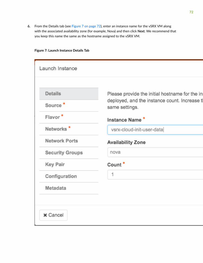
6. From the Details tab (see Figure 7 on page 72), enter an instance name for the vSRX VM alongwith the associated availability zone (for example, Nova) and then click Next. We recommend thatyou keep this name the same as the hostname assigned to the vSRX VM.
Figure 7: Launch Instance Details Tab
72

7. From the Source tab (see Figure 8 on page 74), select a vSRX VM image source file from theAvailable list and then click +(Plus). The selected vSRX image appears under Allocated. Click Next.
73
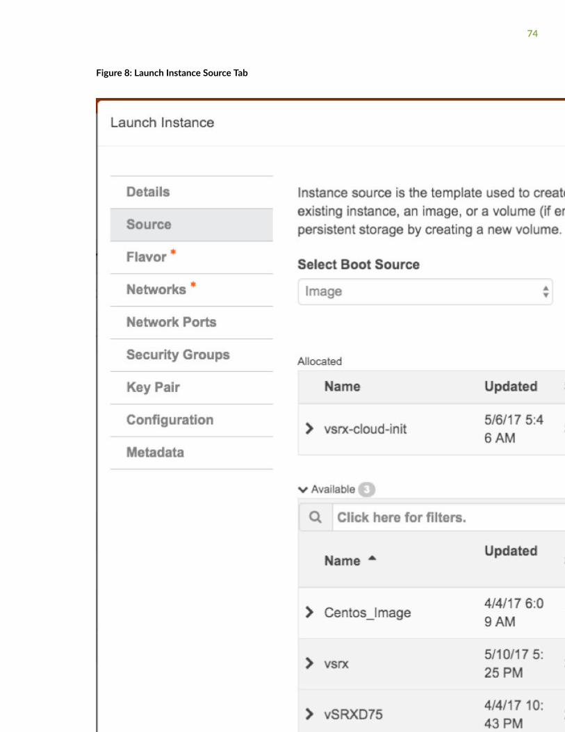
Figure 8: Launch Instance Source Tab
74

8. From the Flavor tab (see Figure 9 on page 76), select a vSRX instance with a specific compute,memory, and storage capacity from the Available list and then click +(plus sign). The selected vSRXflavor appears under Allocated. Click Next.
75
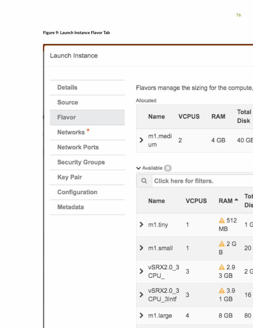
Figure 9: Launch Instance Flavor Tab
76

9. From the Networks tab (see Figure 10 on page 79), select the specific network of the vSRXinstance from the Available list and then click +(plus sign). The selected network appears underAllocated. Click Next.
77

NOTE: Do not update any parameters in the Network Ports, Security Groups, or Key Pairtabs in the Launch Instance dialog box.
78
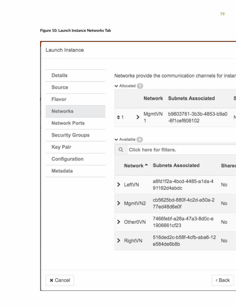
Figure 10: Launch Instance Networks Tab
79
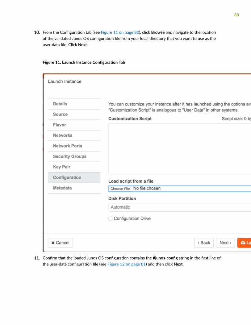
10. From the Configuration tab (see Figure 11 on page 80), click Browse and navigate to the locationof the validated Junos OS configuration file from your local directory that you want to use as theuser-data file. Click Next.
Figure 11: Launch Instance Configuration Tab
11. Confirm that the loaded Junos OS configuration contains the #junos-config string in the first line ofthe user-data configuration file (see Figure 12 on page 81) and then click Next.
80
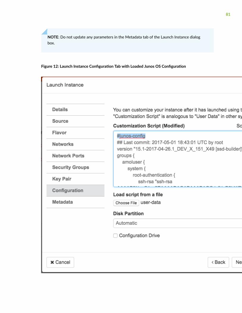
NOTE: Do not update any parameters in the Metadata tab of the Launch Instance dialogbox.
Figure 12: Launch Instance Configuration Tab with Loaded Junos OS Configuration
81
12. Click Launch Instance. During the initial boot-up sequence, the vSRX instance processes the cloud-init request.
NOTE: The boot time for the vSRX instance might increase with the use of the cloud-initpackage. This additional time in the initial boot sequence is due to the operations performedby the cloud-init package. During this operation, the cloud-init package halts the bootsequence and performs a lookup for the configuration data in each data source identified inthe cloud.cfg. The time required to look up and populate the cloud data is directlyproportional to the number of data sources defined. In the absence of a data source, thelookup process continues until it reaches a predefined timeout of 30 seconds for each datasource.
13. When the initial boot-up sequence resumes, the user-data file replaces the original factory-defaultJunos OS configuration loaded on the vSRX instance. If the commit succeeds, the factory-defaultconfiguration will be permanently replaced. If the configuration is not supported or cannot beapplied to the vSRX instance, the vSRX will boot using the default Junos OS configuration.
SEE ALSO
Cloud-Init Documentation
OpenStack Dashboard
Launch and Manage Instances
Horizon: The OpenStack Dashboard Project
Release History Table
Release Description
15.1X49-D130
Starting in Junos OS Release 15.1X49-D130 and Junos OS Release 18.4R1, the cloud-initfunctionality in vSRX has been extended to support the use of a configuration drive data source inan OpenStack environment. The configuration drive uses the user-data attribute to pass avalidated Junos OS configuration file to the vSRX instance.
15.1X49-D100
Starting in Junos OS Release 15.1X49-D100 and Junos OS Release 17.4R1, the cloud-init package(version 0.7x) comes pre-installed in the vSRX image to help simplify configuring new vSRXinstances operating in an OpenStack environment according to a specified user-data file. Cloud-init is performed during the first-time boot of a vSRX instance.
82
3CHAPTER
vSRX VM Management
Connect to the vSRX Management Console on KVM | 84
Add a Virtual Network to a vSRX VM with KVM | 84
Add a Virtio Virtual Interface to a vSRX VM with KVM | 86
Configure SR-IOV and PCI on KVM | 89
Upgrade a Multi-core vSRX | 96
Monitor the vSRX VM in KVM | 100
Manage the vSRX Instance on KVM | 101
Recover the Root Password for vSRX in a KVM Environment | 106
Connect to the vSRX Management Console on KVM
Ensure that you have the virt-manager package or virsh installed on your host OS.
To connect to the vSRX management console using virt-manager:
1. Launch virt-manager.
2. Highlight the vSRX VM you want to connect to from the list of VMs displayed.
3. Click Open.
4. Select View>Text Consoles>Serial 1. The vSRX console appears.
To connect to the vSRX VM with virsh:
1. Use the virsh console command on the Linux host OS.
user@host# virsh console vSRX-kvm-2
Connected to domain vSRX-kvm-2
2. The vSRX console appears.
RELATED DOCUMENTATION
virt-tools
Add a Virtual Network to a vSRX VM with KVM
You can extend an existing vSRX VM to use additional virtual networks.
To create a virtual network with virt-manager:
1. Launch virt-manager and select Edit>Connection Details. The Connection details dialog box appears.
2. Select Virtual Networks. The list of existing virtual networks appears.
3. Click + to create a new virtual network for the control link. The Create a new virtual network wizardappears.
4. Set the subnet for this virtual network and click Forward.
84
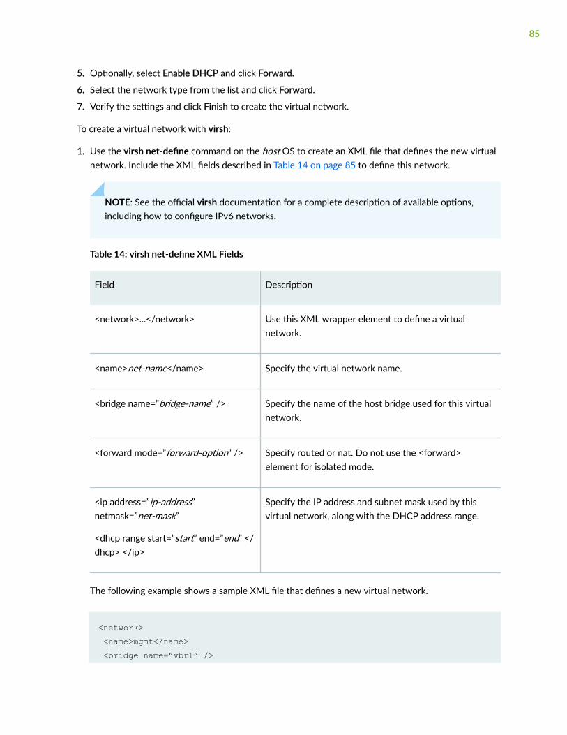
5. Optionally, select Enable DHCP and click Forward.
6. Select the network type from the list and click Forward.
7. Verify the settings and click Finish to create the virtual network.
To create a virtual network with virsh:
1. Use the virsh net-define command on the host OS to create an XML file that defines the new virtualnetwork. Include the XML fields described in Table 14 on page 85 to define this network.
NOTE: See the official virsh documentation for a complete description of available options,including how to configure IPv6 networks.
Table 14: virsh net-define XML Fields
Field Description
<network>...</network> Use this XML wrapper element to define a virtualnetwork.
<name>net-name</name> Specify the virtual network name.
<bridge name=”bridge-name” /> Specify the name of the host bridge used for this virtualnetwork.
<forward mode=”forward-option” /> Specify routed or nat. Do not use the <forward>element for isolated mode.
<ip address=”ip-address”netmask=”net-mask”
<dhcp range start=”start” end=”end” </dhcp> </ip>
Specify the IP address and subnet mask used by thisvirtual network, along with the DHCP address range.
The following example shows a sample XML file that defines a new virtual network.
<network> <name>mgmt</name> <bridge name=”vbr1” />
85
<forward mode=”nat” /> <ip address=”10.10.10.1” netmask=”255.255.255.0” > <dhcp><range start=”10.10.10.2” end=”10.10.10.99” /> </dhcp> </ip></network>
2. Use the virsh net-start command in the host OS to start the new virtual network.
hostOS# virsh net-start mgmt
3. Use the virsh net-autostart command in the host OS to automatically start the new virtual networkwhen the host OS boots.
hostOS# virsh net-autostart mgmt
4. Optionally, use the virsh net-list –all command in the host OS to verify the new virtual network.
HostOS# # virsh net-list --all Name State Autostart Persistent---------------------------------------------------------- mgmt active yes yes default active yes yes
RELATED DOCUMENTATION
virt tools
Add a Virtio Virtual Interface to a vSRX VM withKVM
You can add additional virtio virtual interfaces to an existing vSRX VM with KVM.
To add additional virtio virtual interfaces to a vSRX VM using virt-manager:
1. In virt-manager, double-click the vSRX VM and select View>Details. The vSRX Virtual Machinedetails dialog box appears.
86
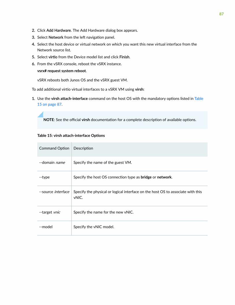
2. Click Add Hardware. The Add Hardware dialog box appears.
3. Select Network from the left navigation panel.
4. Select the host device or virtual network on which you want this new virtual interface from theNetwork source list.
5. Select virtio from the Device model list and click Finish.
6. From the vSRX console, reboot the vSRX instance.
vsrx# request system reboot.
vSRX reboots both Junos OS and the vSRX guest VM.
To add additional virtio virtual interfaces to a vSRX VM using virsh:
1. Use the virsh attach-interface command on the host OS with the mandatory options listed in Table15 on page 87.
NOTE: See the official virsh documentation for a complete description of available options.
Table 15: virsh attach-interface Options
Command Option Description
--domain name Specify the name of the guest VM.
--type Specify the host OS connection type as bridge or network.
--source interface Specify the physical or logical interface on the host OS to associate with thisvNIC.
--target vnic Specify the name for the new vNIC.
--model Specify the vNIC model.
87
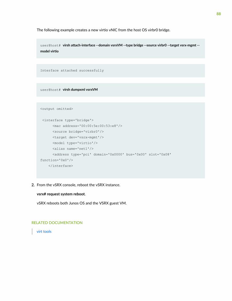
The following example creates a new virtio vNIC from the host OS virbr0 bridge.
user@host# virsh attach-interface --domain vsrxVM --type bridge --source virbr0 --target vsrx-mgmt --
model virtio
Interface attached successfully
user@host# virsh dumpxml vsrxVM
<output omitted>
<interface type='bridge'> <mac address='00:00:5e:00:53:e8'/> <source bridge='virbr0'/> <target dev='vsrx-mgmt'/> <model type='virtio'/> <alias name='net1'/> <address type='pci' domain='0x0000' bus='0x00' slot='0x08' function='0x0'/> </interface>
2. From the vSRX console, reboot the vSRX instance.
vsrx# request system reboot.
vSRX reboots both Junos OS and the VSRX guest VM.
RELATED DOCUMENTATION
virt tools
88
Configure SR-IOV and PCI on KVM
IN THIS SECTION
SR-IOV Overview | 89
SR-IOV HA Support with Trust Mode Disabled (KVM only) | 90
Configure an SR-IOV Interface on KVM | 92
This section includes the following topics on SR-IOV for a vSRX instance deployed on KVM:
SR-IOV Overview
vSRX on KVM supports single-root I/O virtualization (SR-IOV) interface types. SR-IOV is a standard thatallows a single physical NIC to present itself as multiple vNICs, or virtual functions (VFs), that a virtualmachine (VM) can attach to. SR-IOV combines with other virtualization technologies, such as Intel VT-d,to improve the I/O performance of the VM. SR-IOV allows each VM to have direct access to packetsqueued up for the VFs attached to the VM. You use SR-IOV when you need I/O performance thatapproaches that of the physical bare metal interfaces.
NOTE: SR-IOV in KVM does not remap interface numbers. The interface sequence in the vSRXVM XML file matches the interface sequence shown in the Junos OS CLI on the vSRX instance.
SR-IOV uses two PCI functions:
• Physical Functions (PFs)—Full PCIe devices that include SR-IOV capabilities. Physical Functions arediscovered, managed, and configured as normal PCI devices. Physical Functions configure andmanage the SR-IOV functionality by assigning Virtual Functions. When SR-IOV is disabled, the hostcreates a single PF on one physical NIC.
• Virtual Functions (VFs)—Simple PCIe functions that only process I/O. Each Virtual Function is derivedfrom a Physical Function. The number of Virtual Functions a device may have is limited by the devicehardware. A single Ethernet port, the Physical Device, may map to many Virtual Functions that canbe shared to guests. When SR-IOV is enabled, the host creates a single PF and multiple VFs on onephysical NIC. The number of VFs depends on the configuration and driver support.
89
SR-IOV HA Support with Trust Mode Disabled (KVM only)
IN THIS SECTION
Understand SR-IOV HA Support with Trust Mode Disabled (KVM only) | 90
Configure SR-IOV support with Trust Mode Disabled (KVM only) | 91
Limitations | 91
Understand SR-IOV HA Support with Trust Mode Disabled (KVM only)
A Redundant Ethernet Interface (RETH) is a virtual interface consisting of equal number of memberinterfaces from each participating node of an SRX cluster. All logical configurations such as IP address,QoS, zones, and VPNs are bound to this interface. Physical properties are applied to the member or childinterfaces. A RETH interface has a virtual MAC address which is calculated using the cluster id. RETHhas been implemented as an aggregated interface/LAG in Junos OS. For a LAG, the parent (logical) IFDsMAC address is copied to each of the child interfaces. When you configure the child interface under theRETH interface, the RETH interface’s virtual MAC gets overwritten on the current MAC address field ofthe child physical interface. This also requires the virtual MAC address to be programmed on thecorresponding NIC.
Junos OS runs as a VM on vSRX. Junos OS does not have direct access to the NIC and only has a virtualNIC access provided by the hypervisor which might be shared with other VMs running on the same hostmachine. This virtual access comes with certain restrictions such as a special mode called trust mode,which is required to program a virtual MAC address on the NIC. During deployments, providing the trustmode access might not be feasible because of possible security issues. To enable RETH model to work insuch environments, MAC rewrite behavior is modified. Instead of copying the parent virtual MACaddress to the children, we keep the children’s physical MAC address intact and copy the physical MACaddress of the child belonging to the active node of the cluster to the current MAC of the reth interface.This way, MAC rewrite access is not required when trust mode is disabled.
In case of vSRX, the DPDK reads the physical MAC address provided by the hypervisor and shares itwith the Junos OS control plane. In standalone mode, this physical MAC address is programmed on thephysical IFDs. But the support for the same is unavailable in cluster mode, because of which the MACaddress for the physical interface is taken from the Juniper reserved MAC pool. In an environmentwhere trust mode is not feasible, the hypervisor is unable to provide the physical MAC address.
To overcome this problem, we have added support to use the hypervisor provided physical MAC addressinstead of allocating it from the reserved MAC pool. See "Configure SR-IOV support with Trust ModeDisabled (KVM only)" on page 91.
90
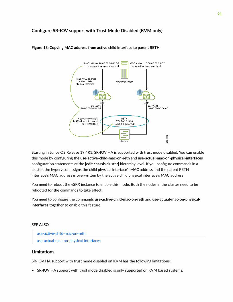
Configure SR-IOV support with Trust Mode Disabled (KVM only)
Figure 13: Copying MAC address from active child interface to parent RETH
Starting in Junos OS Release 19.4R1, SR-IOV HA is supported with trust mode disabled. You can enablethis mode by configuring the use-active-child-mac-on-reth and use-actual-mac-on-physical-interfacesconfiguration statements at the [edit chassis cluster] hierarchy level. If you configure commands in acluster, the hypervisor assigns the child physical interface’s MAC address and the parent RETHinterface’s MAC address is overwritten by the active child physical interface’s MAC address
You need to reboot the vSRX instance to enable this mode. Both the nodes in the cluster need to berebooted for the commands to take effect.
You need to configure the commands use-active-child-mac-on-reth and use-actual-mac-on-physical-interfaces together to enable this feature.
SEE ALSO
use-active-child-mac-on-reth
use-actual-mac-on-physical-interfaces
Limitations
SR-IOV HA support with trust mode disabled on KVM has the following limitations:
• SR-IOV HA support with trust mode disabled is only supported on KVM based systems.
91
• A reth interface can have maximum one port as a member on each vSRX cluster node.
• You cannot use security nat proxy-arp feature for NAT pools because no G-ARP is sent out onfailover for the IP addresses in NAT pools. Instead, one can set the routes to the NAT pool range inthe upstream router to point to the vSRX reth interface’s IP address as the next-hop. Or, if directlyconnected hosts need to access the NAT pool addresses, these NAT pool addresses can beconfigured for proxy ARP under the reth interface.
• If the reth interface is configured with many VLANs, it might take some time to send all the G-ARPson a failover. This might lead to a noticeable interruption in traffic.
• A dataplane failover will result in a change of the MAC address of the reth interface. Therefore thefailover is not transparent to directly connected neighboring Layer 3 devices (routers or servers). ThevSRX reth IP address must be mapped to a new MAC address in the ARP table on the neighboringdevices. vSRX will send out a G-ARP which will help these devices. In case these neighboring devicesdo not act on the G-ARP received from the vSRX or show a slow response, the traffic might beinterrupted until that device updates it’s ARP table correctly.
Configure an SR-IOV Interface on KVM
If you have a physical NIC that supports SR-IOV, you can attach SR-IOV-enabled vNICs or virtualfunctions (VFs) to the vSRX instance to improve performance. We recommend that if you use SR-IOV, allrevenue ports are configured as SR-IOV.
Note the following about SR-IOV support for vSRX on KVM:
• Starting in Junos OS Release 15.1X49-D90 and Junos OS Release 17.3R1, a vSRX instance deployedon KVM supports SR-IOV on an Intel X710/XL710 NIC in addition to Intel 82599 or X520/540.
• Starting in Junos OS Release 18.1R1, a vSRX instance deployed on KVM supports SR-IOV on theMellanox ConnectX-3 and ConnectX-4 Family Adapters.
NOTE: See the vSRX Performance Scale Up discussion in "Understand vSRX with KVM" on page5 for the vSRX scale up performance when deployed on KVM, based on vNIC and the number ofvCPUs and vRAM applied to a vSRX VM.
Before you can attach an SR-IOV enabled VF to the vSRX instance, you must complete the followingtasks:
• Insert an SR-IOV-capable physical network adapter in the host server.
92
• Enable the Intel VT-d CPU virtualization extensions in BIOS on your host server. The Intel VT-dextensions provides hardware support for directly assigning a physical devices to guest. Verify theprocess with the vendor because different systems have different methods to enable VT-d.
• Ensure that SR-IOV is enabled at the system/server BIOS level by going into the BIOS settings duringthe host server boot-up sequence to confirm the SR-IOV setting. Different server manufacturershave different naming conventions for the BIOS parameter used to enable SR-IOV at the BIOS level.For example, for a Dell server ensure that the SR-IOV Global Enable option is set to Enabled.
NOTE: We recommend that you use virt-manager to configure SR-IOV interfaces. See the virshattach-device command documentation if you want to learn how to add a PCI host device to aVM with the virsh CLI commands.
To add an SR-IOV VF to a vSRX VM using the virt-manager graphical interface:
1. In the Junos OS CLI, shut down the vSRX VM if it is running.
vsrx> request system power-off
2. In virt-manager, double-click the vSRX VM and select View>Details. The vSRX Virtual Machinedetails dialog box appears.
3. Select the Hardware tab, then click Add Hardware. The Add Hardware dialog box appears.
4. Select PCI Host Device from the Hardware list on the left.
5. Select the SR-IOV VF for this new virtual interface from the host device list.
6. Click Finish to add the new device. The setup is complete and the vSRX VM now has direct access tothe device.
7. From the virt-manager icon bar at the upper-left side of the window, click the Power On arrow. ThevSRX VM starts. Once the vSRX is powered on the Running status will display in the window.
You can connect to the management console to watch the boot-up sequence.
NOTE: After the boot starts, you need to select View>Text Consoles>Serial 1 in virt-managerto connect to the vSRX console.
To add an SR-IOV VF to a vSRX VM using virsh CLI commands:
93
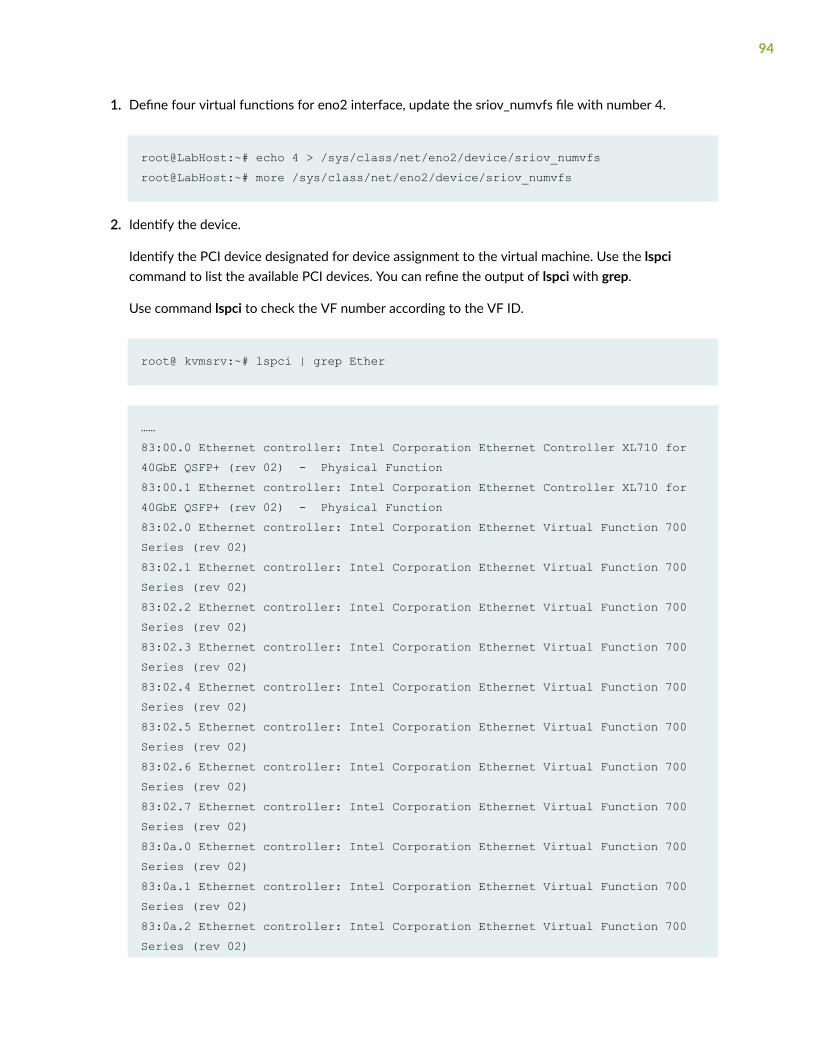
1. Define four virtual functions for eno2 interface, update the sriov_numvfs file with number 4.
root@LabHost:~# echo 4 > /sys/class/net/eno2/device/sriov_numvfsroot@LabHost:~# more /sys/class/net/eno2/device/sriov_numvfs
2. Identify the device.
Identify the PCI device designated for device assignment to the virtual machine. Use the lspcicommand to list the available PCI devices. You can refine the output of lspci with grep.
Use command lspci to check the VF number according to the VF ID.
root@ kvmsrv:~# lspci | grep Ether
…… 83:00.0 Ethernet controller: Intel Corporation Ethernet Controller XL710 for 40GbE QSFP+ (rev 02) - Physical Function83:00.1 Ethernet controller: Intel Corporation Ethernet Controller XL710 for 40GbE QSFP+ (rev 02) - Physical Function83:02.0 Ethernet controller: Intel Corporation Ethernet Virtual Function 700 Series (rev 02)83:02.1 Ethernet controller: Intel Corporation Ethernet Virtual Function 700 Series (rev 02)83:02.2 Ethernet controller: Intel Corporation Ethernet Virtual Function 700 Series (rev 02)83:02.3 Ethernet controller: Intel Corporation Ethernet Virtual Function 700 Series (rev 02)83:02.4 Ethernet controller: Intel Corporation Ethernet Virtual Function 700 Series (rev 02)83:02.5 Ethernet controller: Intel Corporation Ethernet Virtual Function 700 Series (rev 02)83:02.6 Ethernet controller: Intel Corporation Ethernet Virtual Function 700 Series (rev 02)83:02.7 Ethernet controller: Intel Corporation Ethernet Virtual Function 700 Series (rev 02)83:0a.0 Ethernet controller: Intel Corporation Ethernet Virtual Function 700 Series (rev 02)83:0a.1 Ethernet controller: Intel Corporation Ethernet Virtual Function 700 Series (rev 02)83:0a.2 Ethernet controller: Intel Corporation Ethernet Virtual Function 700 Series (rev 02)
94
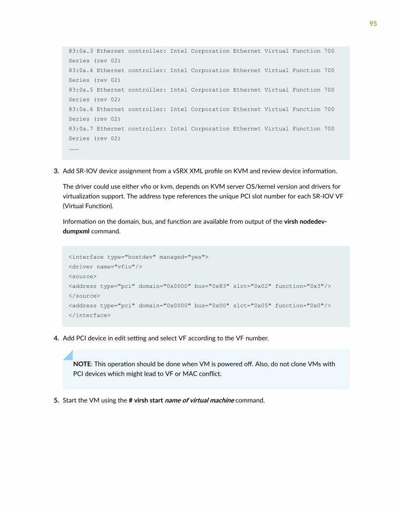
83:0a.3 Ethernet controller: Intel Corporation Ethernet Virtual Function 700 Series (rev 02)83:0a.4 Ethernet controller: Intel Corporation Ethernet Virtual Function 700 Series (rev 02)83:0a.5 Ethernet controller: Intel Corporation Ethernet Virtual Function 700 Series (rev 02)83:0a.6 Ethernet controller: Intel Corporation Ethernet Virtual Function 700 Series (rev 02)83:0a.7 Ethernet controller: Intel Corporation Ethernet Virtual Function 700 Series (rev 02)………
3. Add SR-IOV device assignment from a vSRX XML profile on KVM and review device information.
The driver could use either vfio or kvm, depends on KVM server OS/kernel version and drivers forvirtualization support. The address type references the unique PCI slot number for each SR-IOV VF(Virtual Function).
Information on the domain, bus, and function are available from output of the virsh nodedev-dumpxml command.
<interface type="hostdev" managed="yes"><driver name="vfio"/><source> <address type="pci" domain="0x0000" bus="0x83" slot="0x02" function="0x3"/></source> <address type="pci" domain="0x0000" bus="0x00" slot="0x05" function="0x0"/></interface>
4. Add PCI device in edit setting and select VF according to the VF number.
NOTE: This operation should be done when VM is powered off. Also, do not clone VMs withPCI devices which might lead to VF or MAC conflict.
5. Start the VM using the # virsh start name of virtual machine command.
95

Release History Table
Release Description
18.1R1 Starting in Junos OS Release 18.1R1, a vSRX instance deployed on KVM supports SR-IOV on theMellanox ConnectX-3 and ConnectX-4 Family Adapters.
15.1X49-D90 Starting in Junos OS Release 15.1X49-D90 and Junos OS Release 17.3R1, a vSRX instancedeployed on KVM supports SR-IOV on an Intel X710/XL710 NIC in addition to Intel 82599 orX520/540.
RELATED DOCUMENTATION
Requirements for vSRX on KVM | 10
Intel SR-IOV Explanation
PCI-SIG SR-IOV Primer
SR-IOV
Intel - SR-IOV Configuration Guide
Red Hat - SR–IOV - PCI Devices
Upgrade a Multi-core vSRX
IN THIS SECTION
Configure the Queue Value for vSRX VM with KVM | 97
Shutdown the vSRX Instance with virt-manager | 97
Upgrade vSRX with virt-manager | 98
Starting in Junos OS Release 15.1X49-D70 and Junos OS Release 17.3R1, you can use virt-manager toscale the performance and capacity of a vSRX instance by increasing the number of vCPUs or theamount of vRAM allocated to the vSRX. See "Requirements for vSRX on KVM" on page 10 for thesoftware requirement specifications for a vSRX VM.
See your host OS documentation for complete details on the virt-manager package
96
NOTE: You cannot scale down the number of vCPUs or decrease the amount of vRAM for anexisting vSRX VM.
Configure the Queue Value for vSRX VM with KVM
Before you plan to scale up vSRX performance, modify the vSRX VM XML file to configure networkmulti-queuing as a means to support an increased number of dataplane vCPUs for the vSRX VM. Thissetting updates the libvirt driver to enable multi-queue virtio-net so that network performance can scaleas the number of dataplane vCPUs increases. Multi-queue virtio is an approach that enables theprocessing of packet sending and receiving to be scaled to the number of available virtual CPUs (vCPUs)of a guest, through the use of multiple queues.
The configuration of multi-queue virtio-net, however, can only be performed in the XML file. OpenStackdoes not support multi-queue.
To update the queue, at the <driver name='vhost' queues='x'/> line in the vSRX VM XML file, match thenumber of queues with number of dataplane vCPUs you plan to configure for the vSRX VM. The defaultis 4 dataplane vCPUs, but you can scale that number to 4, 8, or 16 vCPUs.
The following XML file example configures 8 queues for a vSRX VM with 8 dataplane vCPUs:
<output omitted>
<interface type='network'> <source network='net2'/> <model type='virtio'/> <driver name='vhost' queues='8'/> <address type='pci' domain='0x0000' bus='0x00' slot='0x04' function='0x0'/> </interface>
Shutdown the vSRX Instance with virt-manager
In situations where you want to edit and modify the vSRX VM XML file, you need to completely shutdown vSRX and the associated VM.
97
To gracefully shutdown the vSRX instance with virt-manager:
1. Launch virt-manager.
2. Check the vSRX instance you want to power off.
3. Select Open to open a console window to the vSRX instance.
4. From the vSRX console, reboot the vSRX instance.
vsrx# request system power-off.
5. From virt-manager, select Shut Down to completely shutdown the VM so you can edit the XML file.
NOTE: Do not use Force Reset or Force Off on any active VM as it may create file corruptions.
Upgrade vSRX with virt-manager
You must shut down the vSRX VM before you can update vCPU or vRAM values for the VM.
You can upgrade and launch vSRX with the KVM virt-manager GUI package.
To scale up a vSRX VM with virt-manager to a higher number of vCPUs or to an increased amount ofvRAM:
1. On your host OS, type virt-manager. The Virtual Machine Manager appears. See Figure 14 on page99.
98
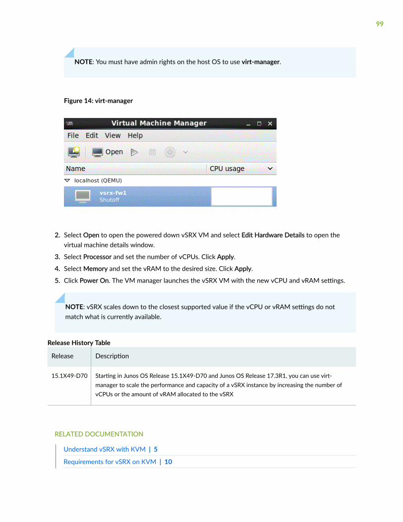
NOTE: You must have admin rights on the host OS to use virt-manager.
Figure 14: virt-manager
2. Select Open to open the powered down vSRX VM and select Edit Hardware Details to open thevirtual machine details window.
3. Select Processor and set the number of vCPUs. Click Apply.
4. Select Memory and set the vRAM to the desired size. Click Apply.
5. Click Power On. The VM manager launches the vSRX VM with the new vCPU and vRAM settings.
NOTE: vSRX scales down to the closest supported value if the vCPU or vRAM settings do notmatch what is currently available.
Release History Table
Release Description
15.1X49-D70 Starting in Junos OS Release 15.1X49-D70 and Junos OS Release 17.3R1, you can use virt-manager to scale the performance and capacity of a vSRX instance by increasing the number ofvCPUs or the amount of vRAM allocated to the vSRX
RELATED DOCUMENTATION
Understand vSRX with KVM | 5
Requirements for vSRX on KVM | 10
99
Installing a virtual machine using virt-install
Monitor the vSRX VM in KVM
You can monitor the overall state of the vSRX VM with virt-manager or virsh.
To monitor the vSRX VM with virt-manager:
1. From the virt-manager GUI, select the vSRX VM you want to monitor.
2. Select View>Graph and select the statistics you want to monitor. Options include CPU, memory, diskI/O, and network interface statistics.
The window updates with thumbnail graphs for the statistics you selected.
3. Optionally, double-click on the thumbnail graph to expand the view.
To monitor the vSRX VM with virsh, use the commands listed in Table 16 on page 100.
Table 16: virsh Monitor Commands
Command Description
virsh cpu-stats vm-name Lists the CPU statistics for the VM.
virsh domifstat vm-name interface-name Displays the vNIC statistics for the VM.
virsh dommemstat vm-name Displays memory statistics for the VM.
virsh vcpuinfo vm-name Displays vCPU details for the VM.
virsh nodecpustats Displays CPU statistics for the host OS.
RELATED DOCUMENTATION
virt tools
100
Manage the vSRX Instance on KVM
IN THIS SECTION
Power On the vSRX Instance with virt-manager | 101
Power On the vSRX Instance with virsh | 102
Pause the vSRX Instance with virt-manager | 102
Pause the vSRX Instance with virsh | 102
Rebooting the vSRX Instance with virt-manager | 102
Reboot the vSRX Instance with virsh | 103
Power Off the vSRX Instance with virt-manager | 103
Power Off the vSRX Instance with virsh | 104
Shutdown the vSRX Instance with virt-manager | 104
Shutdown the vSRX Instance with virsh | 105
Remove the vSRX Instance with virsh | 105
Each vSRX instance is an independent VM that you can power on, pause, or shut down. You can managethe vSRX VM with multiple tools, including virt-manager and virsh.
Power On the vSRX Instance with virt-manager
To power on the vSRX instance with virt-manager:
1. Launch virt-manager.
2. Check the vSRX instance you want to power on.
3. From the icon bar, select the power on arrow. The vSRX VM starts. You can connect to themanagement console to watch the boot-up sequence.
NOTE: After the boot starts, you need to select View>Text Consoles>Serial 1 in virt-managerto connect to the vSRX console.
101
Power On the vSRX Instance with virsh
To power on the vSRX instance with virsh:
Use the virsh start command on the host OS to start a vSRX VM.
user@host# virsh start vSRX-kvm-2
Domain vSRX-kvm-2 started
Pause the vSRX Instance with virt-manager
To pause the vSRX instance with virt-manager:
1. Launch virt-manager.
2. Check the vSRX instance you want to pause.
3. From the icon bar, select the power on pause icon. The vSRX VM pauses.
Pause the vSRX Instance with virsh
To pause the vSRX instance with virsh:
Use the virsh suspend command on the host OS to pause a vSRX VM.
user@host# virsh suspend vSRX-kvm-2
Domain vSRX-kvm-2 suspended
Rebooting the vSRX Instance with virt-manager
To reboot the vSRX instance with virt-manager:
102
1. Launch virt-manager.
2. Check the vSRX instance you want to reboot.
3. Select Open to open a console window to the vSRX instance.
4. From the vSRX console, reboot the vSRX instance.
vsrx# request system reboot.
vSRX reboots both Junos OS and the VSRX guest VM.
Reboot the vSRX Instance with virsh
To reboot the vSRX VM with virsh:
1. Use the virsh console command on the host OS to connect to the vSRX VM.
2. On the vSRX console, use the request system reboot command to reboot Junos OS and the vSRXVM.
user@host# virsh console vSRX-kvm-2
Connected to domain vSRX-kvm-2
vsrx# request system reboot
Power Off the vSRX Instance with virt-manager
To power off the vSRX instance with virt-manager:
1. Launch virt-manager.
2. Check the vSRX instance you want to power off.
3. Select Open to open a console window to the vSRX instance.
103
4. From the vSRX console, power off the vSRX instance.
vsrx> request system power-off
vSRX powers off both Junos OS and the guest VM.
Power Off the vSRX Instance with virsh
To power off the vSRX instance with virsh:
1. Use the virsh console command on the host OS to connect to the vSRX VM.
2. On the vSRX console, use the request system power-off command to power off Junos OS and thevSRX VM.
user@host# virsh console vSRX-kvm-2
Connected to domain vSRX-kvm-2
vsrx# request system power-off
Shutdown the vSRX Instance with virt-manager
In situations where you want to edit and modify the vSRX VM XML file, you need to completely shutdown vSRX and the associated VM.
To gracefully shutdown the vSRX instance with virt-manager:
1. Launch virt-manager.
2. Check the vSRX instance you want to power off.
3. Select Open to open a console window to the vSRX instance.
4. From the vSRX console, reboot the vSRX instance.
104
vsrx# request system power-off.
5. From virt-manager, select Shut Down to completely shutdown the VM so you can edit the XML file.
NOTE: Do not use Force Reset or Force Off on any active VM as it may create file corruptions.
Shutdown the vSRX Instance with virsh
In situations where you want to modify the vSRX VM XML file, you need to completely shut down vSRXand the associated VM.
To gracefully shutdown the vSRX instance with virsh:
1. Use the virsh console command on the host OS to connect to the vSRX VM.
2. On the vSRX console, use the request system power-off command to power off Junos OS and thevSRX VM.
3. On the host OS, use the virsh shutdown command to shut down the VM after vSRX has powered off.
user@host# virsh console vSRX-kvm-2
Connected to domain vSRX-kvm-2
vsrx# request system power-off
user@host# virsh shutdown vSRX-kvm-2
NOTE: Do not use the virsh destroy command on any active VM as it may create filecorruptions.
Remove the vSRX Instance with virsh
In situations where you want to completely remove the vSRX instance, you need to destroy the vSRXVM and undefine the associated XML file.
105
To completely remove the vSRX instance with virsh:
1. On the host OS, use the virsh destroy command to destroy the vSRX VM.
2. On the host OS, use the virsh undefine command to undefine the vSRX XML file.
user@host# virsh destroy vSRX-kvm-2
user@host# virsh undefine vSRX-kvm-2
RELATED DOCUMENTATION
virt tools
Recover the Root Password for vSRX in a KVMEnvironment
If you forget the root password for a vSRX instance deployed in a KVM environment, use this passwordrecovery procedure to reset the root password. (KB article 31790).
NOTE: You need console access to recover the root password
To recover the root password for a vSRX instance:
1. Reboot the vSRX instance by entering the virsh reboot command, specifying either domain-id ordomain-name.
2. Immediately attempt to login to the vSRX instance by entering the virsh console domain-namecommand to access the vSRX console.
NOTE: We recommend that you specify domain-name when attempting the vSRX instancelogin. It is possible that domain-id might change after the vSRX instance reboot.
106
3. After login you will see a prompt similar to Escape character is ^]. Press Enter two or three timesuntil the boot process begins. Continue with the boot process until you see the following prompt:
Hit [Enter] to boot immediately, or space bar for command prompt. Booting [kernel] in 9 seconds...
4. Press the space bar two or three times to stop the boot sequence, and then enter boot -s to loginto single-user mode.
5. Enter recovery to start the root password recovery procedure.
Enter full pathname of shell or 'recovery' for root password recovery or RETURN for /bin/sh: recovery
Once the script terminates you will be in vSRX operational mode.
6. Enter configuration mode in the CLI.
7. Set the root password.
[edit]user@host# set system root-authentication plain-text-password
8. Enter the new root password.
New password: xxxxxxxxRetype new password:
9. At the second prompt, reenter the new root password.
10. If you are finished configuring the new root password for the vSRX instance, commit theconfiguration.
root@host# commitcommit complete
11. Exit from configuration mode.
12. Exit from operational mode.
13. Enter y to reboot the device.
Reboot the system? [y/n] y
107

The start up messages display on the screen.
14. Once again, press the space bar two or three times to access the bootstrap loader prompt.
15. The vSRX instance starts up again and prompts you to enter a user name and password. Enter thenewly configured password.
login: root
Password: xxxxxxxx
108
4CHAPTER
Configuring and Managing vSRX
vSRX Configuration and Management Tools | 110
Configure vSRX Using the CLI | 111
Configuring vSRX Using the J-Web Interface | 113
Managing Security Policies for Virtual Machines Using Junos Space SecurityDirector | 117
Software Receive Side Scaling | 118
GTP Traffic with TEID Distribution and SWRSS | 120
vSRX Configuration and Management Tools
SUMMARY
This topic provides an overview of the various toolsavailable to configure and manage a vSRX VM once ithas been successfully deployed.
IN THIS SECTION
Understanding the Junos OS CLI and JunosScripts | 110
Understanding the J-Web Interface | 110
Understanding Junos Space SecurityDirector | 110
Understanding the Junos OS CLI and Junos Scripts
Junos OS CLI is a Juniper Networks specific command shell that runs on top of a UNIX-based operatingsystem kernel.
Built into Junos OS, Junos script automation is an onboard toolset available on all Junos OS platforms,including routers, switches, and security devices running Junos OS (such as a vSRX instance).
You can use the Junos OS CLI and the Junos OS scripts to configure, manage, administer, andtroubleshoot vSRX.
Understanding the J-Web Interface
The J-Web interface allows you to monitor, configure, troubleshoot, and manage vSRX instances bymeans of a Web browser. J-Web provides access to all the configuration statements supported by thevSRX instance.
Understanding Junos Space Security Director
As one of the Junos Space Network Management Platform applications, Junos Space Security Directorhelps organizations improve the reach, ease, and accuracy of security policy administration with ascalable, GUI-based management tool. Security Director automates security provisioning of a vSRX
110
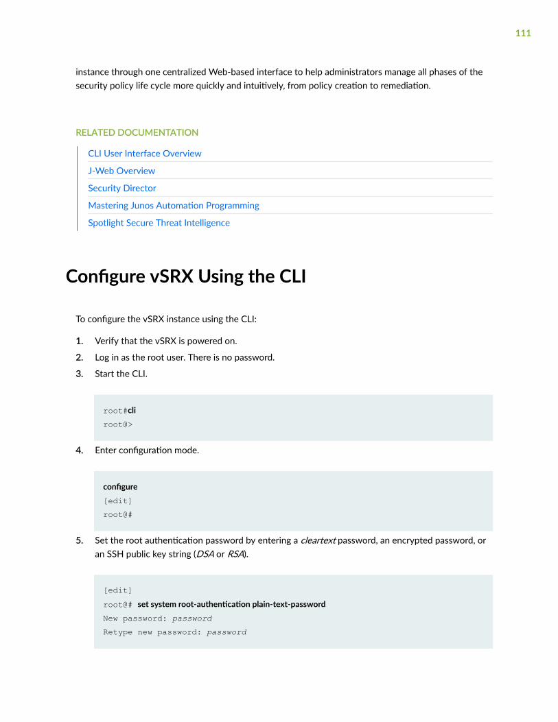
instance through one centralized Web-based interface to help administrators manage all phases of thesecurity policy life cycle more quickly and intuitively, from policy creation to remediation.
RELATED DOCUMENTATION
CLI User Interface Overview
J-Web Overview
Security Director
Mastering Junos Automation Programming
Spotlight Secure Threat Intelligence
Configure vSRX Using the CLI
To configure the vSRX instance using the CLI:
1. Verify that the vSRX is powered on.
2. Log in as the root user. There is no password.
3. Start the CLI.
root#cliroot@>
4. Enter configuration mode.
configure [edit]root@#
5. Set the root authentication password by entering a cleartext password, an encrypted password, oran SSH public key string (DSA or RSA).
[edit]root@# set system root-authentication plain-text-passwordNew password: password Retype new password: password
111
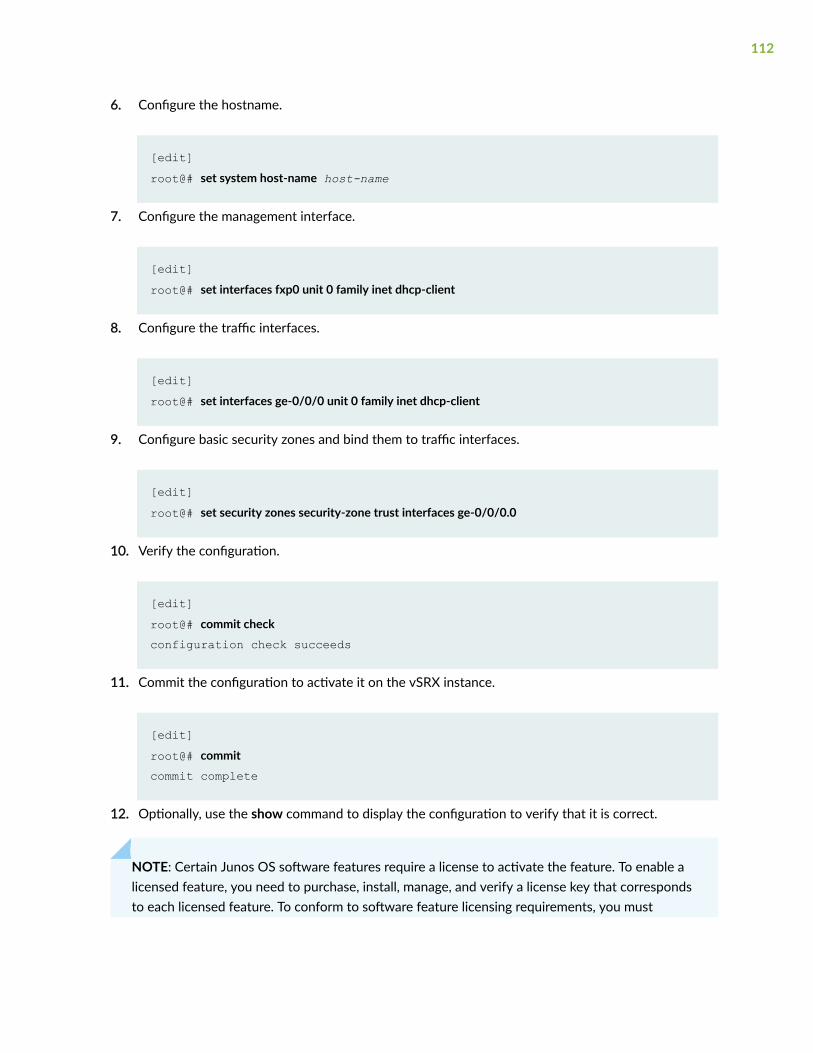
6. Configure the hostname.
[edit]root@# set system host-name host-name
7. Configure the management interface.
[edit]root@# set interfaces fxp0 unit 0 family inet dhcp-client
8. Configure the traffic interfaces.
[edit]root@# set interfaces ge-0/0/0 unit 0 family inet dhcp-client
9. Configure basic security zones and bind them to traffic interfaces.
[edit]root@# set security zones security-zone trust interfaces ge-0/0/0.0
10. Verify the configuration.
[edit]root@# commit checkconfiguration check succeeds
11. Commit the configuration to activate it on the vSRX instance.
[edit]root@# commitcommit complete
12. Optionally, use the show command to display the configuration to verify that it is correct.
NOTE: Certain Junos OS software features require a license to activate the feature. To enable alicensed feature, you need to purchase, install, manage, and verify a license key that correspondsto each licensed feature. To conform to software feature licensing requirements, you must
112
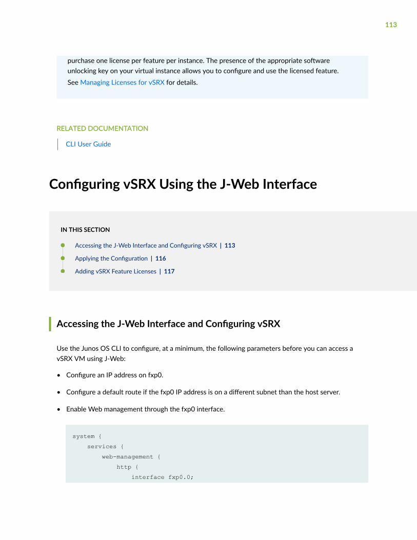
purchase one license per feature per instance. The presence of the appropriate softwareunlocking key on your virtual instance allows you to configure and use the licensed feature.
See Managing Licenses for vSRX for details.
RELATED DOCUMENTATION
CLI User Guide
Configuring vSRX Using the J-Web Interface
IN THIS SECTION
Accessing the J-Web Interface and Configuring vSRX | 113
Applying the Configuration | 116
Adding vSRX Feature Licenses | 117
Accessing the J-Web Interface and Configuring vSRX
Use the Junos OS CLI to configure, at a minimum, the following parameters before you can access avSRX VM using J-Web:
• Configure an IP address on fxp0.
• Configure a default route if the fxp0 IP address is on a different subnet than the host server.
• Enable Web management through the fxp0 interface.
system { services { web-management { http { interface fxp0.0;
113
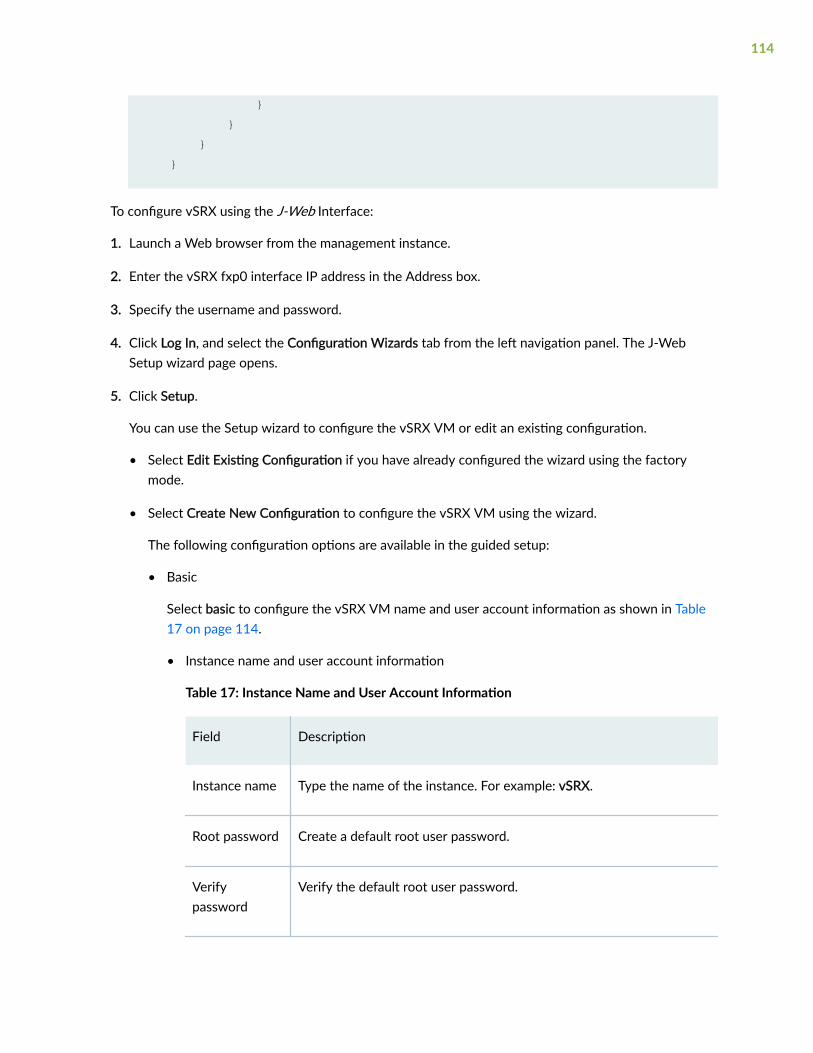
} } } }
To configure vSRX using the J-Web Interface:
1. Launch a Web browser from the management instance.
2. Enter the vSRX fxp0 interface IP address in the Address box.
3. Specify the username and password.
4. Click Log In, and select the Configuration Wizards tab from the left navigation panel. The J-WebSetup wizard page opens.
5. Click Setup.
You can use the Setup wizard to configure the vSRX VM or edit an existing configuration.
• Select Edit Existing Configuration if you have already configured the wizard using the factorymode.
• Select Create New Configuration to configure the vSRX VM using the wizard.
The following configuration options are available in the guided setup:
• Basic
Select basic to configure the vSRX VM name and user account information as shown in Table17 on page 114.
• Instance name and user account information
Table 17: Instance Name and User Account Information
Field Description
Instance name Type the name of the instance. For example: vSRX.
Root password Create a default root user password.
Verifypassword
Verify the default root user password.
114
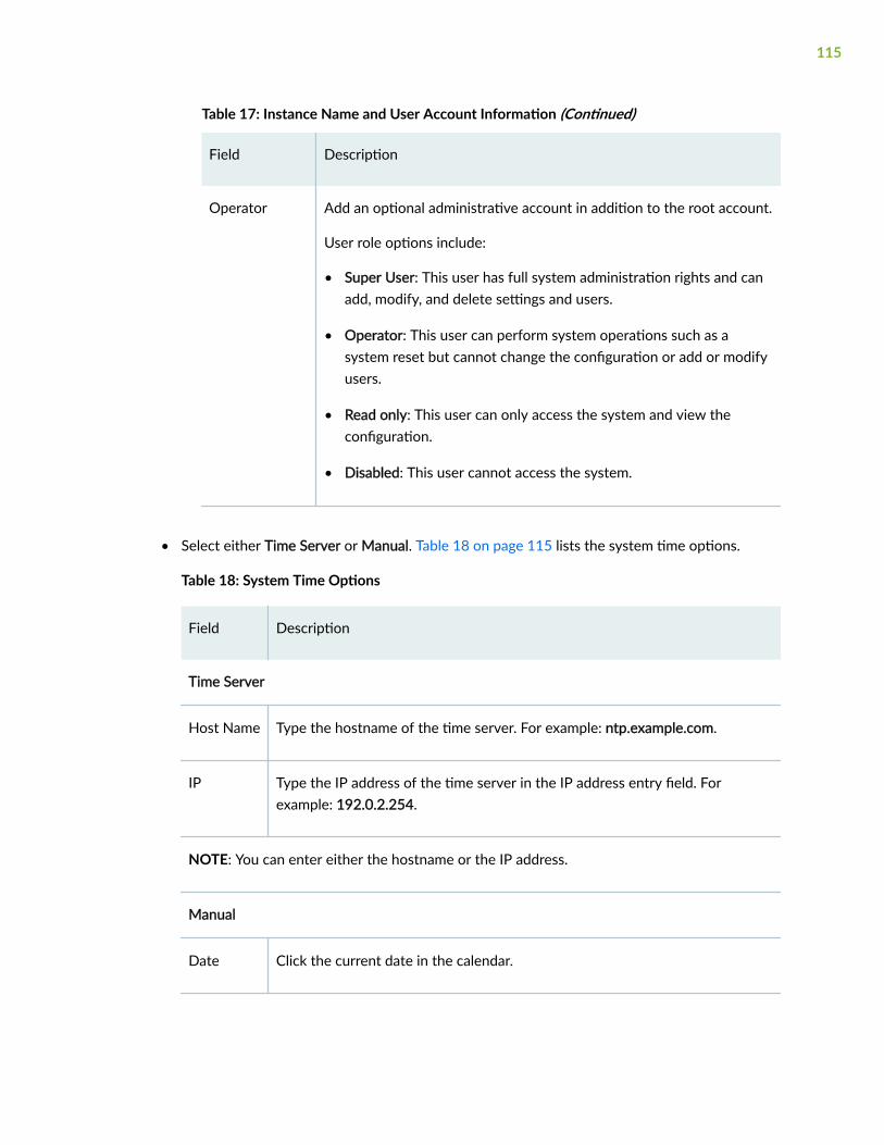
Table 17: Instance Name and User Account Information (Continued)
Field Description
Operator Add an optional administrative account in addition to the root account.
User role options include:
• Super User: This user has full system administration rights and canadd, modify, and delete settings and users.
• Operator: This user can perform system operations such as asystem reset but cannot change the configuration or add or modifyusers.
• Read only: This user can only access the system and view theconfiguration.
• Disabled: This user cannot access the system.
• Select either Time Server or Manual. Table 18 on page 115 lists the system time options.
Table 18: System Time Options
Field Description
Time Server
Host Name Type the hostname of the time server. For example: ntp.example.com.
IP Type the IP address of the time server in the IP address entry field. Forexample: 192.0.2.254.
NOTE: You can enter either the hostname or the IP address.
Manual
Date Click the current date in the calendar.
115
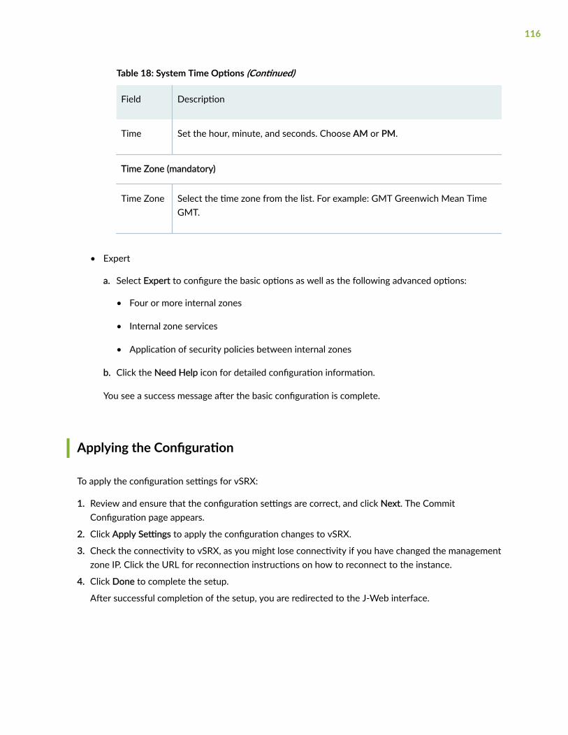
Table 18: System Time Options (Continued)
Field Description
Time Set the hour, minute, and seconds. Choose AM or PM.
Time Zone (mandatory)
Time Zone Select the time zone from the list. For example: GMT Greenwich Mean TimeGMT.
• Expert
a. Select Expert to configure the basic options as well as the following advanced options:
• Four or more internal zones
• Internal zone services
• Application of security policies between internal zones
b. Click the Need Help icon for detailed configuration information.
You see a success message after the basic configuration is complete.
Applying the Configuration
To apply the configuration settings for vSRX:
1. Review and ensure that the configuration settings are correct, and click Next. The CommitConfiguration page appears.
2. Click Apply Settings to apply the configuration changes to vSRX.
3. Check the connectivity to vSRX, as you might lose connectivity if you have changed the managementzone IP. Click the URL for reconnection instructions on how to reconnect to the instance.
4. Click Done to complete the setup.
After successful completion of the setup, you are redirected to the J-Web interface.
116
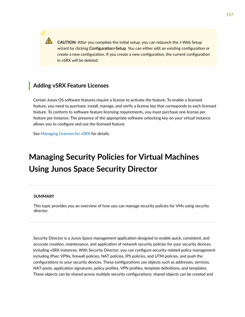
CAUTION: After you complete the initial setup, you can relaunch the J-Web Setupwizard by clicking Configuration>Setup. You can either edit an existing configuration orcreate a new configuration. If you create a new configuration, the current configurationin vSRX will be deleted.
Adding vSRX Feature Licenses
Certain Junos OS software features require a license to activate the feature. To enable a licensedfeature, you need to purchase, install, manage, and verify a license key that corresponds to each licensedfeature. To conform to software feature licensing requirements, you must purchase one license perfeature per instance. The presence of the appropriate software unlocking key on your virtual instanceallows you to configure and use the licensed feature.
See Managing Licenses for vSRX for details.
Managing Security Policies for Virtual MachinesUsing Junos Space Security Director
SUMMARY
This topic provides you an overview of how you can manage security policies for VMs using securitydirector.
Security Director is a Junos Space management application designed to enable quick, consistent, andaccurate creation, maintenance, and application of network security policies for your security devices,including vSRX instances. With Security Director, you can configure security-related policy managementincluding IPsec VPNs, firewall policies, NAT policies, IPS policies, and UTM policies. and push theconfigurations to your security devices. These configurations use objects such as addresses, services,NAT pools, application signatures, policy profiles, VPN profiles, template definitions, and templates.These objects can be shared across multiple security configurations; shared objects can be created and
117
used across many security policies and devices. You can create these objects prior to creating securityconfigurations.
When you finish creating and verifying your security configurations from Security Director, you canpublish these configurations and keep them ready to be pushed to all security devices, including vSRXinstances, from a single interface.
The Configure tab is the workspace where all of the security configuration happens. You can configurefirewall, IPS, NAT, and UTM policies; assign policies to devices; create and apply policy schedules; createand manage VPNs; and create and manage all the shared objects needed for managing your networksecurity.
RELATED DOCUMENTATION
Security Director
Software Receive Side Scaling
IN THIS SECTION
Overview | 118
Understanding Software Receive Side Scaling Configuration | 119
Overview
Contemporary NICs support multiple receive and transmit descriptor queues (multi-queue). Onreception, a NIC can send different packets to different queues to distribute processing among CPUs.The NIC distributes packets by applying a filter to each packet that assigns it to one of a small number oflogical flows. Packets for each flow are steered to a separate receive queue, which in turn can beprocessed by separate CPUs. This mechanism is generally known as Receive-side Scaling (RSS). The goalof RSS technique is to increase performance uniformly. RSS is enabled when latency is a concern orwhenever receive interrupt processing forms a bottleneck. Spreading load between CPUs decreasesqueue length. For low latency networking, the optimal setting is to allocate as many queues as there areCPUs in the system (or the NIC maximum, if lower). The most efficient high-rate configuration is likely
118
the one with the smallest number of receive queues where no receive queue overflows due to asaturated CPU. You can improve bridging throughput with Receive Side Scaling.
As per flow thread affinity architecture each flow thread (FLT) polls for packet from dedicated receivingqueue of NIC and process the packets until run to completion. Therefore, flow threads are bound to NICreceiving (RX) and transmitting (TX) queues for packet processing to avoid any disagreement. Hence,NIC must have same number of RX and TX queues as number of vSRX data plane CPU to support multicore vSRX flavors. Software RSS (SWRSS) removes this limitation of NIC HW queues to run vSRX multi-core flavors by implementing software-based packet spraying across various FLT thread.
Software RSS offloads the handling of individual flows to one of the multiple kernel, so the flow threadthat takes the packets from the NIC can process more packets. Similar to RSS, network throughputimprovement when using SWRSS has a linear correlation with CPU utilization.
In SWRSS, each NIC port is initialized with equal or lesser number of hardware RX/TX queues as that ofI/O threads. I/O threads are determined based on total data-path CPU and minimum of NIC queuesamong all the NIC interface in vSRX. For example, if I/O thread is computed as 4, then number of HWqueue per NIC port can be less or equal to 4 queues.
If NICs do not have sufficient number of queues as FLT threads in vSRX instances supported, thenSoftware RSS (SWRSS) is enabled by flowd data-path. SWRSS implements software model of packetdistribution across FLTs after obtaining the packets from NIC receiving queues. By removing NIC HWqueue limitation, SWRSS helps to scale vCPUs by supporting various vSRX instance types.
During the I/O operation the packets are fetched from receiving queues of NIC ports and packetclassification is performed. Followed by distribution of packets to FLT threads virtual queues. Thesevirtual queues are implemented over DPDK ring queue. In the transmission path, SWRSS fetches thepackets from virtual transmitting queues of FLT threads and pushes these packets to NIC transmittingqueues for transmit.
Number of SWRSS I/O threads are selected based on total CPU and number of NIC queues found invSRX instances. Mix mode of operation with HWRSS and and SWRSS is not supported.
Understanding Software Receive Side Scaling Configuration
This topic provide you details on types of Software Receive Side Scaling (SWRSS) and its configuration.
SWRSS supports two modes of operation and it gets enabled based on number of data-path CPUneeded. These modes are Shared IO mode and dedicated IO mode. These modes are enabled based onnumber of data-path CPUs needed. vSRX and vSRX3.0 supports dedicated I/O mode only.
In dedicated I/O mode flowd process creates dedicated I/O threads for I/O operation. Based on numberof required I/O threads for vSRX, I/O thread is associated to a dedicated NIC port. NIC ports receivingand transmitting queue is then bonded to each I/O thread in round robin method for uniform
119
distribution and to avoid I/O thread locks. Each dedicated I/O thread pulls the packets in burst modefrom NIC receiving queue and distributes to FLT threads and vice versa for TX path for packet transmit.
SWRSS is enabled based on the number of vCPUs. If NIC does not have sufficient number of queues asflow thread (FLT) in vSRX with different vCPUs, then Software RSS (SWRSS) is enabled by flowdprocess.
SWRSS is not enabled in the following scenarios:
• When the NIC has sufficient number of hardware RX or TX queues for required PFE data-path CPU.
• When the vSRX (based on number of vCPUs) and NIC result the smaller number of FLT CPUs as thatobtained in nearest hardware RSS (HWRSS) mode. In such scenario, vSRX will be enabled withHWRSS mode which results more FLT CPU than SWRSS mode, providing better packet processingthroughput.
• SWRSS is not recommended for vSRX with certain type of NIC that supports lesser number of NICqueues than needed to run dedicated IO thread. In such cases, SWRSS is enabled but extra CPUs areattached to FLT CPU, until I/O CPUs are completely utilized.
If SWRSS is not enabled use the set security forwarding-options receive-side-scaling software-rssmode enable command to enable SWRSS. When you run this command SWRSS will be enabled by forceregardless of the NIC RSS or the number of vCPUs. If you do not enable SWRSS using the CLI thenenabling of SWRSS automatically is decided based on the default ratio of FLT: IO ( 4:1).
To configure the number of required IO threads, use the set security forwarding-options receive-side-scaling software-rss io-thread-number <1-8> command. To view the actual number of vCPUs assignedto IO flow threads use the show security forwarding-options resource-manager command.
You can decide enabling of SWRSS automatically or by force based on the architecture and conceptionof IO thread and worker thread. Enabling SWRSS impacts the performance, so we recommend that thenumber of IO thread should be changed only if required and until the performance impact bottleneckpoint is reached.
GTP Traffic with TEID Distribution and SWRSS
IN THIS SECTION
Overview GTP Traffic Distribution with TEID Distribution and SWRSS | 121
Enabling GTP-U TEID Distribution with SWRSS for Asymmetric Fat Tunnels | 122
120
Overview GTP Traffic Distribution with TEID Distribution and SWRSS
IN THIS SECTION
GTP Traffic Performance with TEID Distribution and SWRSS | 121
The topic provides an overview of asymmetric fat tunnel solution for GTP traffic with TEID distributionand SWRSS.
With TEID-based hash distributions feature, the GTP packets would be distributed to the flow threadaccording to the hash value calculated by TEID. The algorithm of hash calculation is same as GTPdistribution in flow module, which ensures the GTP packets would not be reinjected again in the flowprocess.
There is a 4-byte field inside GTP payload called tunnel endpoint identifier (TEID), which is used toidentify different connections in the same GTP tunnel.
A fat GTP tunnel carries data from different users. IPsec tunnels on the security gateway could be a fattunnel due to the fat GTP tunnel. vSRX can create one GTP session with a high-bandwidth of GTPtraffic. However, the throughput is limited to one core processor's performance.
If you use TEID-based hash distribution for creating GTP-U sessions, then you can:
• Enable vSRX and vSRX 3.0 instances to process asymmetric fat tunnels for parallel encryption onmultiple cores for one tunnel.
• You can split a fat GTP session to multiple sessions and distribute them to different cores. This helpsto increase the bandwidth for fat GTP tunnel.
The TEID based hash distribution creates GTP-U sessions to multiple cores. The clear text traffic acts asa fat GTP tunnel. This helps a fat GTP session to split into multiple slim GTP sessions and handle themon multiple cores simultaneously.
GTP Traffic Performance with TEID Distribution and SWRSS
vSRX instances support Software Receive Side Scaling (SWRSS) feature. SWRSS is a technique in thenetworking stack to increase parallelism and improve performance for multi-processor systems. If NICsdo not have sufficient number of queues as flow thread (FLT), based on vSRX type, then Software RSS(SWRSS) is enabled by flowd process.
With Software Receive Side Scaling (SWRSS) support on vSRX and vSRX 3.0, you can assign morevCPUs to the vSRX regardless of the limitation of RSS queue of underlying interfaces.
121
Based on SWRSS you can improve the GTP traffic performance using Tunnel endpoint identifier (TEID)distribution and asymmetric fat tunnel solution by:
• Assigning specific number of vCPUs for input output flow usage—With SWRSS enabled, you canassign more vCPUs for input/output (IO) threads when the IO threads are less. Or you can assign lessvCPUs for IO threads if the flow process is consuming more vCPU. Use the set security forwarding-options receive-side-scaling software-rss io-thread-number <io-thread-number>.
• Distributing the packets to flow threads according to the TEID inside the packet, which would avoidreinjecting the packets in flow process—This feature is enabled when both SWRSS is enabled andwhen you configure the set security forwarding-process application-services enable-gtpu-distribution command.
With this feature, the GTP packets would be distributed to the flow thread according to the hashvalue calculated by TEID. The algorithm of hash calculation is same as GTP distribution in flowmodule, which ensures the GTP packets would not be reinjected again in flow process.
• Utilizing fragment matching and forwarding mechanism in input/output thread when GTPUdistribution is enabled—This mechanism ensures that all the fragments of the same packet would bedistributed to one flow thread according to the TEID.
SWRSS uses IP pair hash to distribute packets to flow threads. For GTP traffic with GTPUdistribution enabled, TEID distribution is used to distribute packets to the flow threads. Forfragmented packets, TEID cannot be retrieved from non-first fragments. This will require fragmentmatching and forwarding logic to ensure all fragments are forwarded to the flow thread based onTEID.
Enabling GTP-U TEID Distribution with SWRSS for Asymmetric FatTunnels
The following configuration helps you enable PMI and GTP-U traffic distribution with SWRSS enabled.
Before you begin, understand:
• SWRSS concepts and configurations.
• How to establish PMI and GTP-U
With Software Recieve Side Scaling (SWRSS) enabled, you can assign more vCPUs for input/output (IO)threads when the IO threads are less. Or you can assign less vCPUs for IO threads if the flow process isconsuming more vCPU. You can configure the number of IO threads required. With SWRSS is enabledand IO threads configured, reboot the vSRX for configuration to take effect. After IO threads areconfigured, distribute the GTP traffic to the configured IO threads according to TEID-based hash
122
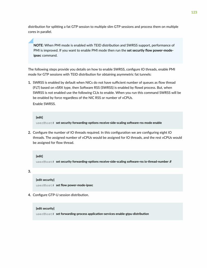
distribution for splitting a fat GTP session to multiple slim GTP sessions and process them on multiplecores in parallel.
NOTE: When PMI mode is enabled with TEID distribution and SWRSS support, performance ofPMI is improved. If you want to enable PMI mode then run the set securtiy flow power-mode-ipsec command.
The following steps provide you details on how to enable SWRSS, configure IO threads, enable PMImode for GTP sessions with TEID distribution for obtaining asymmetric fat tunnels:
1. SWRSS is enabled by default when NICs do not have sufficient number of queues as flow thread(FLT) based on vSRX type, then Software RSS (SWRSS) is enabled by flowd process. But, whenSWRSS is not enabled use the following CLIs to enable. When you run this command SWRSS will bebe enabled by force regardless of the NIC RSS or number of vCPUs.
Enable SWRSS.
[edit]
user@host# set security forwarding-options receive-side-scaling software-rss mode enable
2. Configure the number of IO threads required. In this configuration we are configuring eight IOthreads. The assigned number of vCPUs would be assigned for IO threads, and the rest vCPUs wouldbe assigned for flow thread.
[edit]
user@host# set security forwarding-options receive-side-scaling software-rss io-thread-number 8
3.
[edit security]
user@host# set flow power-mode-ipsec
4. Configure GTP-U session distribution.
[edit security]
user@host# set forwarding-process application-services enable-gtpu-distribution
123
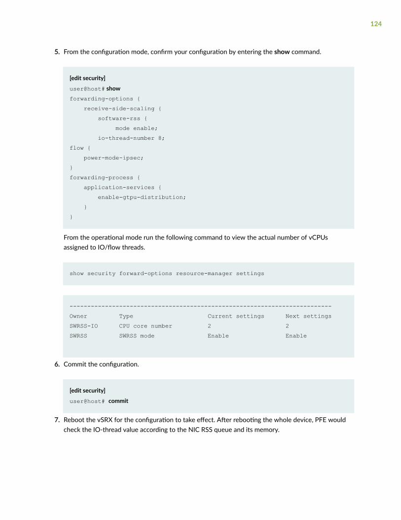
5. From the configuration mode, confirm your configuration by entering the show command.
[edit security]
user@host# show forwarding-options { receive-side-scaling { software-rss { mode enable; io-thread-number 8;flow { power-mode-ipsec;}forwarding-process { application-services { enable-gtpu-distribution; }}
From the operational mode run the following command to view the actual number of vCPUsassigned to IO/flow threads.
show security forward-options resource-manager settings
--------------------------------------------------------------------------Owner Type Current settings Next settingsSWRSS-IO CPU core number 2 2SWRSS SWRSS mode Enable Enable
6. Commit the configuration.
[edit security]
user@host# commit
7. Reboot the vSRX for the configuration to take effect. After rebooting the whole device, PFE wouldcheck the IO-thread value according to the NIC RSS queue and its memory.
124
5CHAPTER
Configuring vSRX Chassis Clusters
Configure a vSRX Chassis Cluster in Junos OS | 126
vSRX Cluster Staging and Provisioning for KVM | 137
Verify the Chassis Cluster Configuration | 142
Configure a vSRX Chassis Cluster in Junos OS
IN THIS SECTION
Chassis Cluster Overview | 126
Enable Chassis Cluster Formation | 127
Chassis Cluster Quick Setup with J-Web | 128
Manually Configure a Chassis Cluster with J-Web | 130
Chassis Cluster Overview
Chassis cluster groups a pair of the same kind of vSRX instances into a cluster to provide network noderedundancy. The vSRX instances in a chassis cluster must be running the same Junos OS release, andeach instance becomes a node in the chassis cluster. You connect the control virtual interfaces on therespective nodes to form a control plane that synchronizes the configuration and Junos OS kernel stateon both nodes in the cluster. The control link (a virtual network or vSwitch) facilitates the redundancy ofinterfaces and services. Similarly, you connect the data plane on the respective nodes over the fabricvirtual interfaces to form a unified data plane. The fabric link (a virtual network or vSwitch) allows for themanagement of cross-node flow processing and for the management of session redundancy.
The control plane software operates in active/passive mode. When configured as a chassis cluster, onenode acts as the primary and the other as the secondary to ensure stateful failover of processes andservices in the event of a system or hardware failure on the primary . If the primary fails, the secondarytakes over processing of control plane traffic.
NOTE: If you configure a chassis cluster across two hosts, disable igmp-snooping on the bridgethat each host physical interface belongs to and that the control virtual NICs (vNICs) use. Thisensures that the control link heartbeat is received by both nodes in the chassis cluster.
The chassis cluster data plane operates in active/active mode. In a chassis cluster, the data planeupdates session information as traffic traverses either node, and it transmits information between thenodes over the fabric link to guarantee that established sessions are not dropped when a failover occurs.In active/active mode, traffic can enter the cluster on one node and exit from the other node.
Chassis cluster functionality includes:
126
• Resilient system architecture, with a single active control plane for the entire cluster and multiplePacket Forwarding Engines. This architecture presents a single device view of the cluster.
• Synchronization of configuration and dynamic runtime states between nodes within a cluster.
• Monitoring of physical interfaces, and failover if the failure parameters cross a configured threshold.
• Support for generic routing encapsulation (GRE) and IP-over-IP (IP-IP) tunnels used to routeencapsulated IPv4 or IPv6 traffic by means of two internal interfaces, gr-0/0/0 and ip-0/0/0,respectively. Junos OS creates these interfaces at system startup and uses these interfaces only forprocessing GRE and IP-IP tunnels.
At any given instant, a cluster node can be in one of the following states: hold, primary, secondary-hold,secondary, ineligible, or disabled. Multiple event types, such as interface monitoring, Services ProcessingUnit (SPU) monitoring, failures, and manual failovers, can trigger a state transition.
Enable Chassis Cluster Formation
You create two vSRX instances to form a chassis cluster, and then you set the cluster ID and node ID oneach instance to join the cluster. When a vSRX instance joins a cluster, it becomes a node of that cluster.With the exception of unique node settings and management IP addresses, nodes in a cluster share thesame configuration.
You can deploy up to 255 chassis clusters in a Layer 2 domain. Clusters and nodes are identified in thefollowing ways:
• The cluster ID (a number from 1 to 255) identifies the cluster.
• The node ID (a number from 0 to 1) identifies the cluster node.
Generally, on SRX Series devices, the cluster ID and node ID are written into EEPROM. On the vSRXinstance, vSRX stores and reads the IDs from boot/loader.conf and uses the IDs to initialize the chassiscluster during startup.
Prerequisites
Ensure that your vSRX instances comply with the following prerequisites before you enable chassisclustering:
• You have committed a basic configuration to both vSRX instances that form the chassis cluster. SeeConfigure vSRX Using the CLI.
• Use show version in Junos OS to ensure that both vSRX instances have the same software version.
127
• Use show system license in Junos OS to ensure that both vSRX instances have the same licensesinstalled.
You must set the same chassis cluster ID on each vSRX node and reboot the vSRX VM to enable chassiscluster formation.
1. In operational command mode, set the chassis cluster ID and node number on vSRX node 0.
user@vsrx0>set chassis cluster cluster-id number node 0 reboot
2. In operational command mode, set the chassis cluster ID and node number on vSRX node 1.
user@vsrx1>set chassis cluster cluster-id number node 1 reboot
NOTE: The vSRX interface naming and mapping to vNICs changes when you enable chassisclustering. See "Requirements for vSRX on KVM" on page 10 for a summary of interface namesand mappings for a pair of vSRX VMs in a cluster (node 0 and node 1).
Chassis Cluster Quick Setup with J-Web
To configure chassis cluster from J-Web:
1. Enter the vSRX node 0 interface IP address in a Web browser.
2. Enter the vSRX username and password, and click Log In. The J-Web dashboard appears.
3. Click Configuration Wizards> Cluster (HA) Setup from the left panel. The Chassis Cluster SetupWizard appears. Follow the steps in the setup wizard to configure the cluster ID and the two nodesin the cluster, and to verify connectivity.
NOTE: Use the built-in Help icon in J-Web for further details on the Chassis Cluster Setupwizard.
NOTE: Navigate to Configure>Device Settings>Cluster (HA) Setup from Junos OS release18.1 and later to configure the chassis cluster setup.
128

4. Configure the secondary node Node1 by selecting Yes, this is the secondary unit to be setup (Node1) using radio button.
5. Click Next.
6. Specify the settings such as Enter password, Re-enter password, Node 0 FXP0 IP, and Node 1 FXP0IP for secondary node access.
7. Click Next.
8. Select the secondary unit’s Control Port and Fabric Port.
9. Click Next.
10. (Optional) Select Save a backup file before proceeding with shutdown using check box to re-configure it for chassis cluster.
11. Click Next.
12. Click Shutdown and continue to connect to other unit.
13. Click Refresh Browser.
14. Configure the primary node Node0 by selecting No, this is the primary unit to be setup (Node 0) toconfigure primary unit and establish a chassis cluster configuration.
15. Click Next.
16. Specify the settings such as Enter password, Re-enter password, Node 0 FXP0 IP, and Node 1 FXP0IP for primary node access.
17. Click Next to restart the primary unit.
18. (Optional) Select Save a backup file before proceeding with shutdown to save a backup file ofcurrent settings before proceeding.
19. Click Reboot and continue. After completing the reboot, power on the secondary unit to establishthe chassis cluster connection.
20. Login to the device console and add static route to get the J-Web access.
21. Login to the J-Web and click Configuration Wizards> Cluster (HA) Setup from the left panel. TheChassis Cluster Setup Wizard appears.
22. Click Next to get the primary unit connected.
23. Configure the basic settings DHCP Client, IP address, Default gateway, Member interface Node 0,Member interface Node 1.
24. Click Next to complete the chassis cluster configuration.
25. Click Finish to exit the wizard. You can access the primary node using J-Web.
129
Manually Configure a Chassis Cluster with J-Web
You can use the J-Web interface to configure the primary node 0 vSRX instance in the cluster. Once youhave set the cluster and node IDs and rebooted each vSRX, the following configuration willautomatically be synced to the secondary node 1 vSRX instance.
Select Configure>Chassis Cluster>Cluster Configuration. The Chassis Cluster configuration pageappears.
NOTE: Navigate to Configure>Device Settings>Cluster (HA) Setup from Junos OS release 18.1and later to configure the HA cluster setup.
Table 19 on page 130 explains the contents of the HA Cluster Settings tab.
Table 20 on page 132 explains how to edit the Node Settings tab.
Table 21 on page 133 explains how to add or edit the HA Cluster Interfaces table.
Table 22 on page 134 explains how to add or edit the HA Cluster Redundancy Groups table.
Table 19: Chassis Cluster Configuration Page
Field Function
Node Settings
Node ID Displays the node ID.
Cluster ID Displays the cluster ID configured for the node.
Host Name Displays the name of the node.
Backup Router Displays the router used as a gateway while the Routing Engine is insecondary state for redundancy-group 0 in a chassis cluster.
Management Interface Displays the management interface of the node.
130
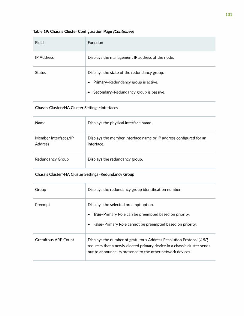
Table 19: Chassis Cluster Configuration Page (Continued)
Field Function
IP Address Displays the management IP address of the node.
Status Displays the state of the redundancy group.
• Primary–Redundancy group is active.
• Secondary–Redundancy group is passive.
Chassis Cluster>HA Cluster Settings>Interfaces
Name Displays the physical interface name.
Member Interfaces/IPAddress
Displays the member interface name or IP address configured for aninterface.
Redundancy Group Displays the redundancy group.
Chassis Cluster>HA Cluster Settings>Redundancy Group
Group Displays the redundancy group identification number.
Preempt Displays the selected preempt option.
• True–Primary Role can be preempted based on priority.
• False–Primary Role cannot be preempted based on priority.
Gratuitous ARP Count Displays the number of gratuitous Address Resolution Protocol (ARP)requests that a newly elected primary device in a chassis cluster sendsout to announce its presence to the other network devices.
131
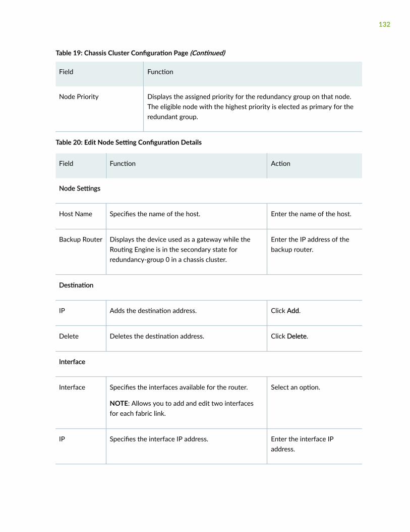
Table 19: Chassis Cluster Configuration Page (Continued)
Field Function
Node Priority Displays the assigned priority for the redundancy group on that node.The eligible node with the highest priority is elected as primary for theredundant group.
Table 20: Edit Node Setting Configuration Details
Field Function Action
Node Settings
Host Name Specifies the name of the host. Enter the name of the host.
Backup Router Displays the device used as a gateway while theRouting Engine is in the secondary state forredundancy-group 0 in a chassis cluster.
Enter the IP address of thebackup router.
Destination
IP Adds the destination address. Click Add.
Delete Deletes the destination address. Click Delete.
Interface
Interface Specifies the interfaces available for the router.
NOTE: Allows you to add and edit two interfacesfor each fabric link.
Select an option.
IP Specifies the interface IP address. Enter the interface IPaddress.
132
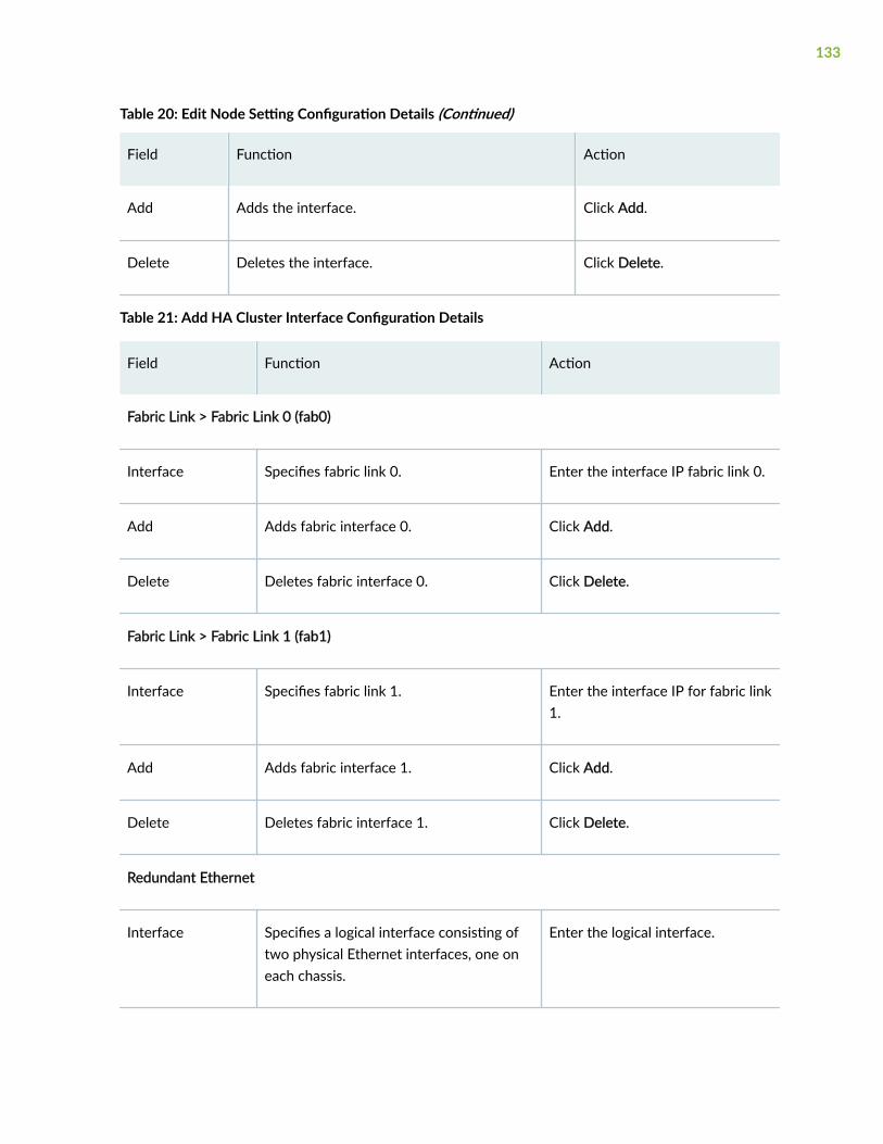
Table 20: Edit Node Setting Configuration Details (Continued)
Field Function Action
Add Adds the interface. Click Add.
Delete Deletes the interface. Click Delete.
Table 21: Add HA Cluster Interface Configuration Details
Field Function Action
Fabric Link > Fabric Link 0 (fab0)
Interface Specifies fabric link 0. Enter the interface IP fabric link 0.
Add Adds fabric interface 0. Click Add.
Delete Deletes fabric interface 0. Click Delete.
Fabric Link > Fabric Link 1 (fab1)
Interface Specifies fabric link 1. Enter the interface IP for fabric link1.
Add Adds fabric interface 1. Click Add.
Delete Deletes fabric interface 1. Click Delete.
Redundant Ethernet
Interface Specifies a logical interface consisting oftwo physical Ethernet interfaces, one oneach chassis.
Enter the logical interface.
133
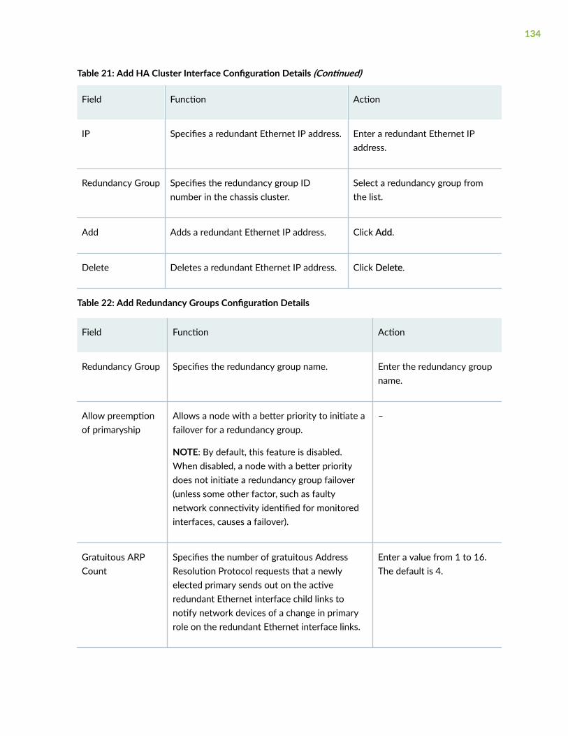
Table 21: Add HA Cluster Interface Configuration Details (Continued)
Field Function Action
IP Specifies a redundant Ethernet IP address. Enter a redundant Ethernet IPaddress.
Redundancy Group Specifies the redundancy group IDnumber in the chassis cluster.
Select a redundancy group fromthe list.
Add Adds a redundant Ethernet IP address. Click Add.
Delete Deletes a redundant Ethernet IP address. Click Delete.
Table 22: Add Redundancy Groups Configuration Details
Field Function Action
Redundancy Group Specifies the redundancy group name. Enter the redundancy groupname.
Allow preemptionof primaryship
Allows a node with a better priority to initiate afailover for a redundancy group.
NOTE: By default, this feature is disabled.When disabled, a node with a better prioritydoes not initiate a redundancy group failover(unless some other factor, such as faultynetwork connectivity identified for monitoredinterfaces, causes a failover).
–
Gratuitous ARPCount
Specifies the number of gratuitous AddressResolution Protocol requests that a newlyelected primary sends out on the activeredundant Ethernet interface child links tonotify network devices of a change in primaryrole on the redundant Ethernet interface links.
Enter a value from 1 to 16.The default is 4.
134
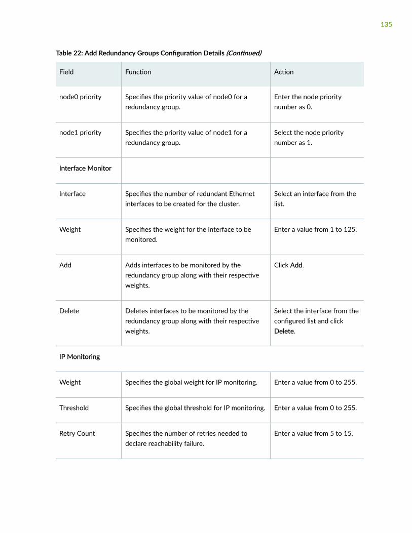
Table 22: Add Redundancy Groups Configuration Details (Continued)
Field Function Action
node0 priority Specifies the priority value of node0 for aredundancy group.
Enter the node prioritynumber as 0.
node1 priority Specifies the priority value of node1 for aredundancy group.
Select the node prioritynumber as 1.
Interface Monitor
Interface Specifies the number of redundant Ethernetinterfaces to be created for the cluster.
Select an interface from thelist.
Weight Specifies the weight for the interface to bemonitored.
Enter a value from 1 to 125.
Add Adds interfaces to be monitored by theredundancy group along with their respectiveweights.
Click Add.
Delete Deletes interfaces to be monitored by theredundancy group along with their respectiveweights.
Select the interface from theconfigured list and clickDelete.
IP Monitoring
Weight Specifies the global weight for IP monitoring. Enter a value from 0 to 255.
Threshold Specifies the global threshold for IP monitoring. Enter a value from 0 to 255.
Retry Count Specifies the number of retries needed todeclare reachability failure.
Enter a value from 5 to 15.
135
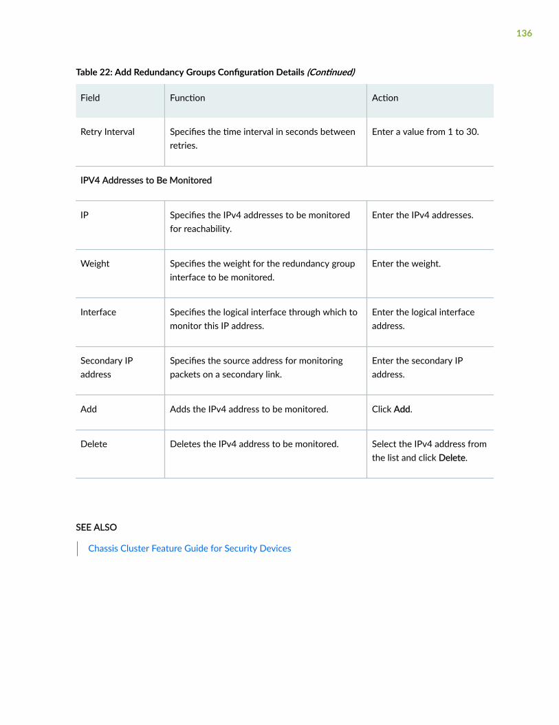
Table 22: Add Redundancy Groups Configuration Details (Continued)
Field Function Action
Retry Interval Specifies the time interval in seconds betweenretries.
Enter a value from 1 to 30.
IPV4 Addresses to Be Monitored
IP Specifies the IPv4 addresses to be monitoredfor reachability.
Enter the IPv4 addresses.
Weight Specifies the weight for the redundancy groupinterface to be monitored.
Enter the weight.
Interface Specifies the logical interface through which tomonitor this IP address.
Enter the logical interfaceaddress.
Secondary IPaddress
Specifies the source address for monitoringpackets on a secondary link.
Enter the secondary IPaddress.
Add Adds the IPv4 address to be monitored. Click Add.
Delete Deletes the IPv4 address to be monitored. Select the IPv4 address fromthe list and click Delete.
SEE ALSO
Chassis Cluster Feature Guide for Security Devices
136
vSRX Cluster Staging and Provisioning for KVM
IN THIS SECTION
Chassis Cluster Provisioning on vSRX | 137
Creating the Chassis Cluster Virtual Networks with virt-manager | 139
Creating the Chassis Cluster Virtual Networks with virsh | 139
Configuring the Control and Fabric Interfaces with virt-manager | 141
Configuring the Control and Fabric Interfaces with virsh | 141
Configuring Chassis Cluster Fabric Ports | 141
You can provision the vSRX VMs and virtual networks to configure chassis clustering.
The staging and provisioning of the vSRX chassis cluster includes the following tasks:
Chassis Cluster Provisioning on vSRX
Chassis cluster requires the following direct connections between the two vSRX instances:
• Control link, or virtual network, which acts in active/passive mode for the control plane trafficbetween the two vSRX instances
• Fabric link, or virtual network, which acts in active/active mode for the data traffic between the twovSRX instances
NOTE: You can optionally create two fabric links for more redundancy.
The vSRX cluster uses the following interfaces:
• Out-of-band Management interface (fxp0)
• Cluster control interface (em0)
• Cluster fabric interface (fab0 on node0, fab1 on node1)
137
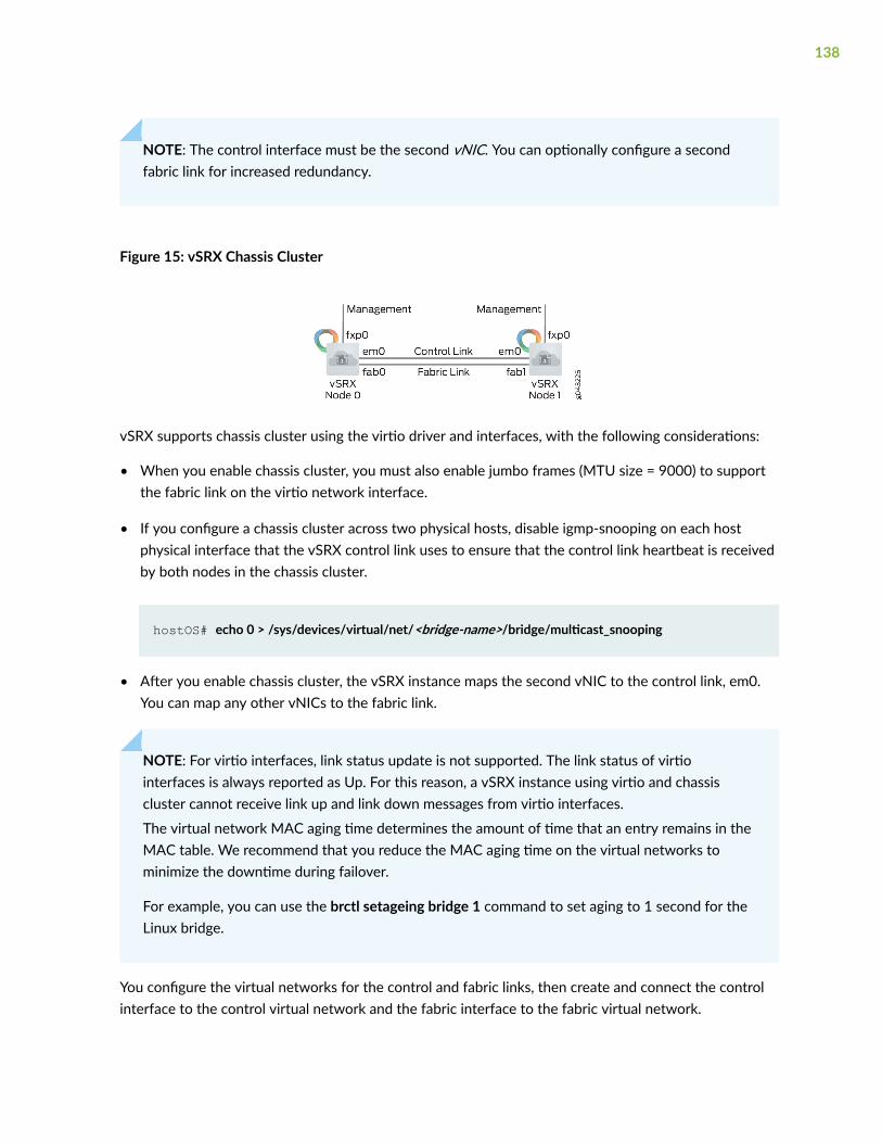
NOTE: The control interface must be the second vNIC. You can optionally configure a secondfabric link for increased redundancy.
Figure 15: vSRX Chassis Cluster
vSRX supports chassis cluster using the virtio driver and interfaces, with the following considerations:
• When you enable chassis cluster, you must also enable jumbo frames (MTU size = 9000) to supportthe fabric link on the virtio network interface.
• If you configure a chassis cluster across two physical hosts, disable igmp-snooping on each hostphysical interface that the vSRX control link uses to ensure that the control link heartbeat is receivedby both nodes in the chassis cluster.
hostOS# echo 0 > /sys/devices/virtual/net/<bridge-name>/bridge/multicast_snooping
• After you enable chassis cluster, the vSRX instance maps the second vNIC to the control link, em0.You can map any other vNICs to the fabric link.
NOTE: For virtio interfaces, link status update is not supported. The link status of virtiointerfaces is always reported as Up. For this reason, a vSRX instance using virtio and chassiscluster cannot receive link up and link down messages from virtio interfaces.
The virtual network MAC aging time determines the amount of time that an entry remains in theMAC table. We recommend that you reduce the MAC aging time on the virtual networks tominimize the downtime during failover.
For example, you can use the brctl setageing bridge 1 command to set aging to 1 second for theLinux bridge.
You configure the virtual networks for the control and fabric links, then create and connect the controlinterface to the control virtual network and the fabric interface to the fabric virtual network.
138
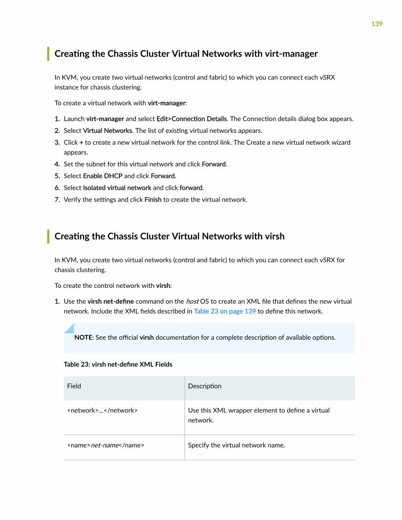
Creating the Chassis Cluster Virtual Networks with virt-manager
In KVM, you create two virtual networks (control and fabric) to which you can connect each vSRXinstance for chassis clustering.
To create a virtual network with virt-manager:
1. Launch virt-manager and select Edit>Connection Details. The Connection details dialog box appears.
2. Select Virtual Networks. The list of existing virtual networks appears.
3. Click + to create a new virtual network for the control link. The Create a new virtual network wizardappears.
4. Set the subnet for this virtual network and click Forward.
5. Select Enable DHCP and click Forward.
6. Select Isolated virtual network and click forward.
7. Verify the settings and click Finish to create the virtual network.
Creating the Chassis Cluster Virtual Networks with virsh
In KVM, you create two virtual networks (control and fabric) to which you can connect each vSRX forchassis clustering.
To create the control network with virsh:
1. Use the virsh net-define command on the host OS to create an XML file that defines the new virtualnetwork. Include the XML fields described in Table 23 on page 139 to define this network.
NOTE: See the official virsh documentation for a complete description of available options.
Table 23: virsh net-define XML Fields
Field Description
<network>...</network> Use this XML wrapper element to define a virtualnetwork.
<name>net-name</name> Specify the virtual network name.
139
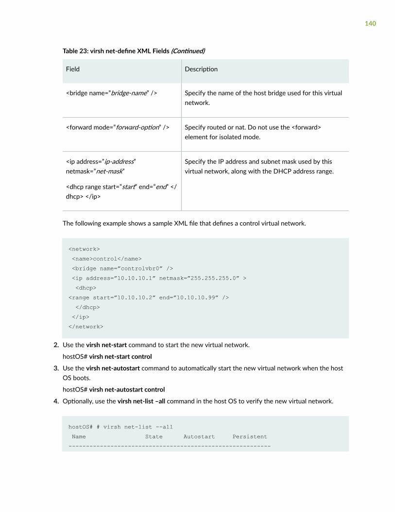
Table 23: virsh net-define XML Fields (Continued)
Field Description
<bridge name=”bridge-name” /> Specify the name of the host bridge used for this virtualnetwork.
<forward mode=”forward-option” /> Specify routed or nat. Do not use the <forward>element for isolated mode.
<ip address=”ip-address”netmask=”net-mask”
<dhcp range start=”start” end=”end” </dhcp> </ip>
Specify the IP address and subnet mask used by thisvirtual network, along with the DHCP address range.
The following example shows a sample XML file that defines a control virtual network.
<network> <name>control</name> <bridge name=”controlvbr0” /> <ip address=”10.10.10.1” netmask=”255.255.255.0” > <dhcp><range start=”10.10.10.2” end=”10.10.10.99” /> </dhcp> </ip></network>
2. Use the virsh net-start command to start the new virtual network.
hostOS# virsh net-start control
3. Use the virsh net-autostart command to automatically start the new virtual network when the hostOS boots.
hostOS# virsh net-autostart control
4. Optionally, use the virsh net-list –all command in the host OS to verify the new virtual network.
hostOS# # virsh net-list --all Name State Autostart Persistent----------------------------------------------------------
140
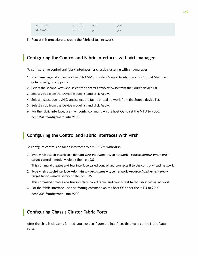
control active yes yes default active yes yes
5. Repeat this procedure to create the fabric virtual network.
Configuring the Control and Fabric Interfaces with virt-manager
To configure the control and fabric interfaces for chassis clustering with virt-manager:
1. In virt-manager, double-click the vSRX VM and select View>Details. The vSRX Virtual Machinedetails dialog box appears.
2. Select the second vNIC and select the control virtual network from the Source device list.
3. Select virtio from the Device model list and click Apply.
4. Select a subsequent vNIC, and select the fabric virtual network from the Source device list.
5. Select virtio from the Device model list and click Apply.
6. For the fabric interface, use the ifconfig command on the host OS to set the MTU to 9000.
hostOS# ifconfig vnet1 mtu 9000
Configuring the Control and Fabric Interfaces with virsh
To configure control and fabric interfaces to a vSRX VM with virsh:
1. Type virsh attach-interface --domain vsrx-vm-name --type network --source control-vnetwork --target control --model virtio on the host OS.
This command creates a virtual interface called control and connects it to the control virtual network.
2. Type virsh attach-interface --domain vsrx-vm-name --type network --source fabric-vnetwork --target fabric --model virtio on the host OS.
This command creates a virtual interface called fabric and connects it to the fabric virtual network.
3. For the fabric interface, use the ifconfig command on the host OS to set the MTU to 9000.
hostOS# ifconfig vnet1 mtu 9000
Configuring Chassis Cluster Fabric Ports
After the chassis cluster is formed, you must configure the interfaces that make up the fabric (data)ports.
141
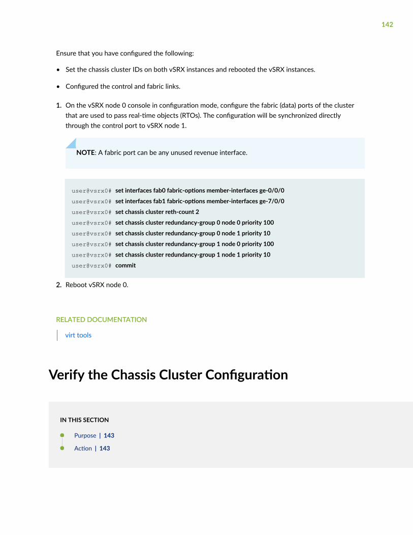
Ensure that you have configured the following:
• Set the chassis cluster IDs on both vSRX instances and rebooted the vSRX instances.
• Configured the control and fabric links.
1. On the vSRX node 0 console in configuration mode, configure the fabric (data) ports of the clusterthat are used to pass real-time objects (RTOs). The configuration will be synchronized directlythrough the control port to vSRX node 1.
NOTE: A fabric port can be any unused revenue interface.
user@vsrx0# set interfaces fab0 fabric-options member-interfaces ge-0/0/0
user@vsrx0# set interfaces fab1 fabric-options member-interfaces ge-7/0/0
user@vsrx0# set chassis cluster reth-count 2
user@vsrx0# set chassis cluster redundancy-group 0 node 0 priority 100
user@vsrx0# set chassis cluster redundancy-group 0 node 1 priority 10
user@vsrx0# set chassis cluster redundancy-group 1 node 0 priority 100
user@vsrx0# set chassis cluster redundancy-group 1 node 1 priority 10
user@vsrx0# commit
2. Reboot vSRX node 0.
RELATED DOCUMENTATION
virt tools
Verify the Chassis Cluster Configuration
IN THIS SECTION
Purpose | 143
Action | 143
142
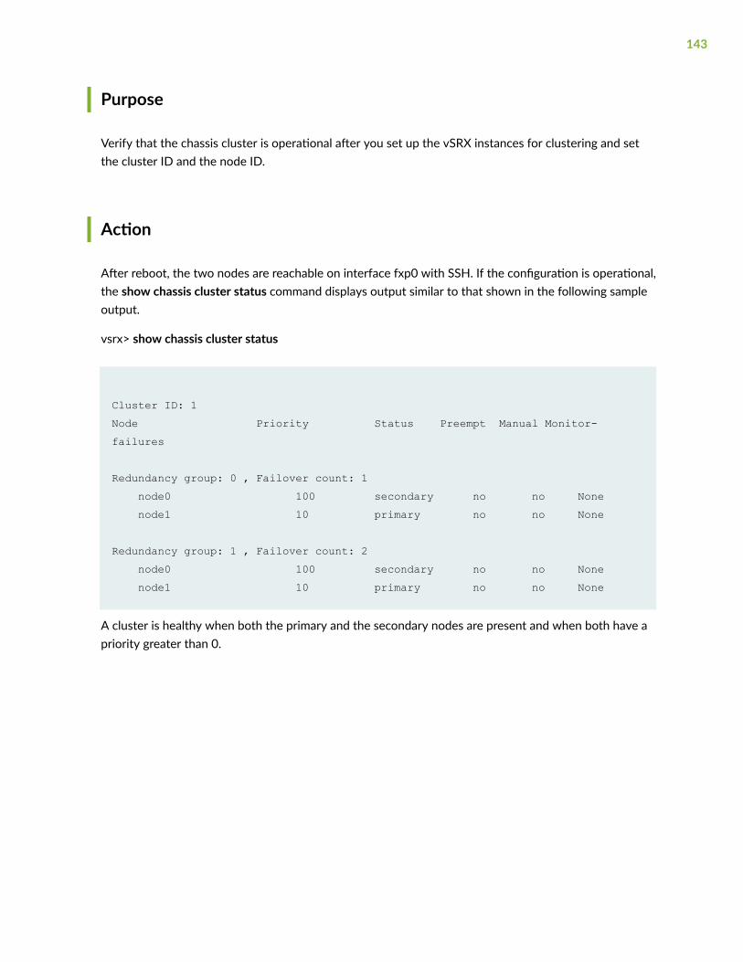
Purpose
Verify that the chassis cluster is operational after you set up the vSRX instances for clustering and setthe cluster ID and the node ID.
Action
After reboot, the two nodes are reachable on interface fxp0 with SSH. If the configuration is operational,the show chassis cluster status command displays output similar to that shown in the following sampleoutput.
vsrx> show chassis cluster status
Cluster ID: 1 Node Priority Status Preempt Manual Monitor-failures
Redundancy group: 0 , Failover count: 1 node0 100 secondary no no None node1 10 primary no no None
Redundancy group: 1 , Failover count: 2 node0 100 secondary no no None node1 10 primary no no None
A cluster is healthy when both the primary and the secondary nodes are present and when both have apriority greater than 0.
143
6CHAPTER
Troubleshooting
Finding the Software Serial Number for vSRX | 145
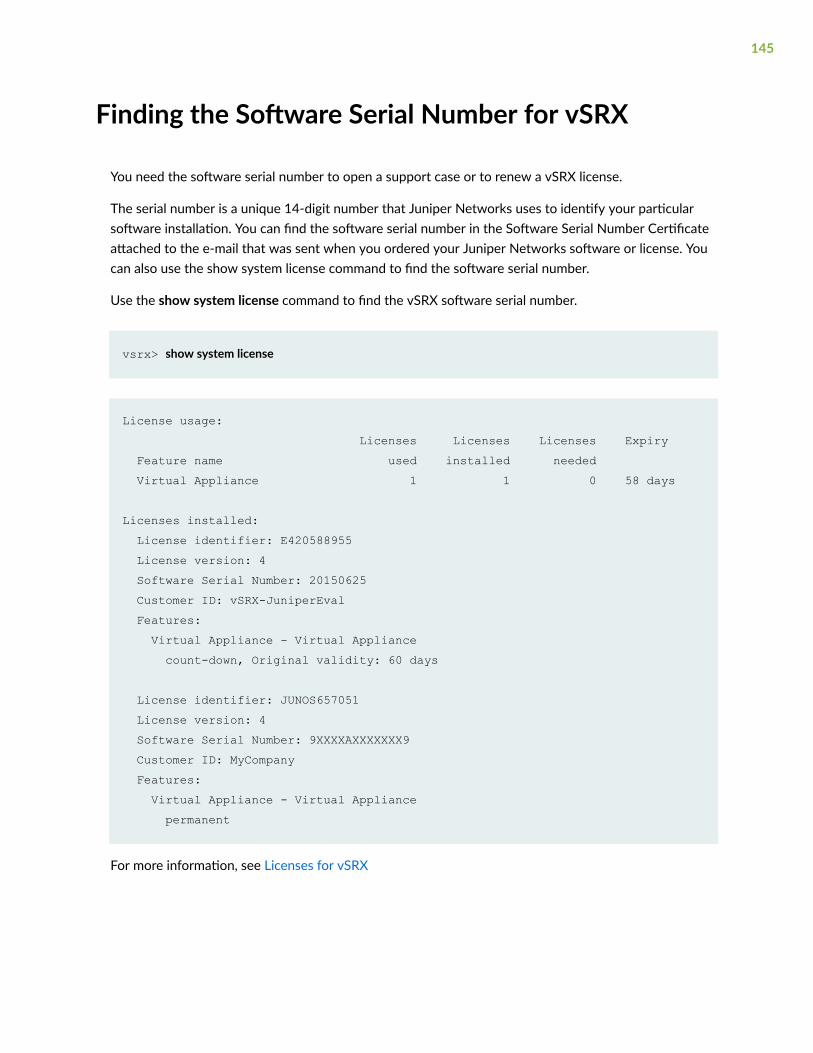
Finding the Software Serial Number for vSRX
You need the software serial number to open a support case or to renew a vSRX license.
The serial number is a unique 14-digit number that Juniper Networks uses to identify your particularsoftware installation. You can find the software serial number in the Software Serial Number Certificateattached to the e-mail that was sent when you ordered your Juniper Networks software or license. Youcan also use the show system license command to find the software serial number.
Use the show system license command to find the vSRX software serial number.
vsrx> show system license
License usage: Licenses Licenses Licenses Expiry Feature name used installed needed Virtual Appliance 1 1 0 58 days
Licenses installed: License identifier: E420588955 License version: 4 Software Serial Number: 20150625 Customer ID: vSRX-JuniperEval Features: Virtual Appliance - Virtual Appliance count-down, Original validity: 60 days
License identifier: JUNOS657051 License version: 4 Software Serial Number: 9XXXXAXXXXXXX9 Customer ID: MyCompany Features: Virtual Appliance - Virtual Appliance permanent
For more information, see Licenses for vSRX
145


