Embed Size (px)
Citation preview
Overview
• Functional Block Concept
• Oscillator Review
• Basic Performance Metrics
• Methods of Tuning
• Advanced Performance Metrics
• Conclusion
9
Overview
• Functional Block Concept
– Applications
– Specifications
• Oscillator Review
• Basic Performance Metrics
• Methods of Tuning
• Advanced Performance Metrics
• Conclusion
10
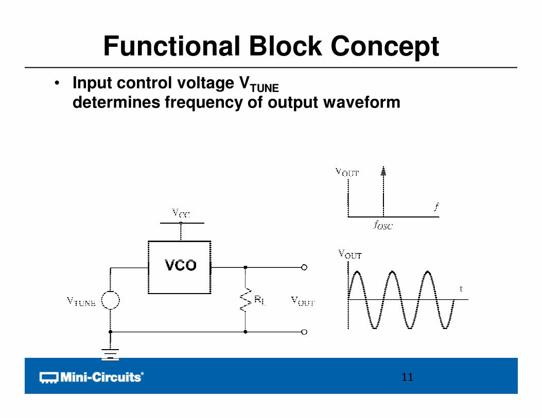
Functional Block Concept• Input control voltage VTUNE
determines frequency of output waveform
11
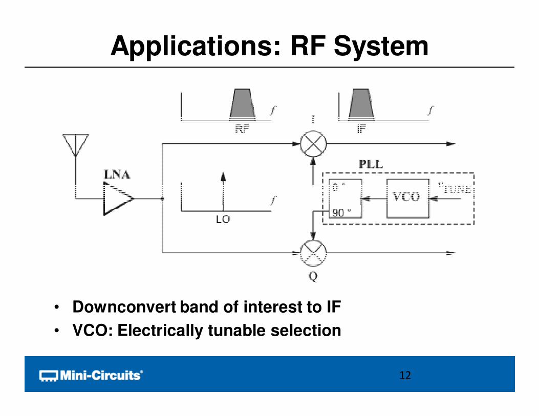
Applications: RF System
• Downconvert band of interest to IF
• VCO: Electrically tunable selection
12
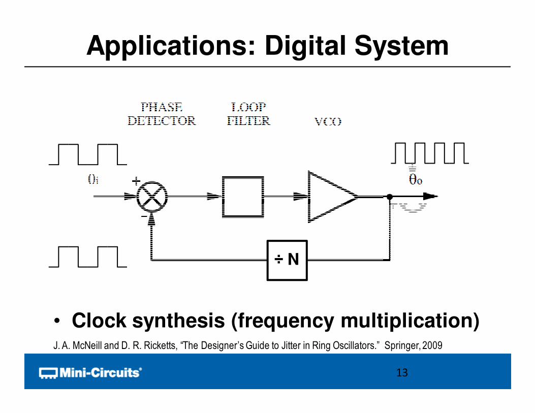
Applications: Digital System
• Clock synthesis (frequency multiplication)
÷ N
13
J. A. McNeill and D. R. Ricketts, “The Designer’s Guide to Jitter in Ring Oscillators.” Springer, 2009
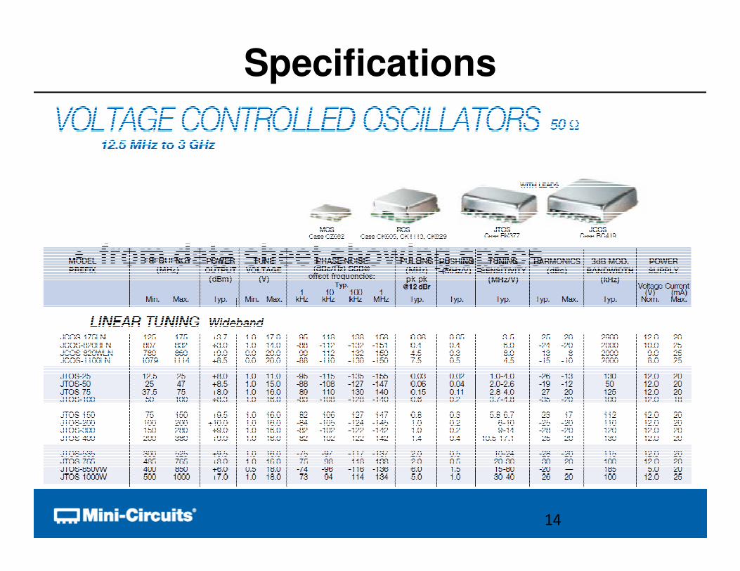
• from data sheet showing specs
Specifications
14
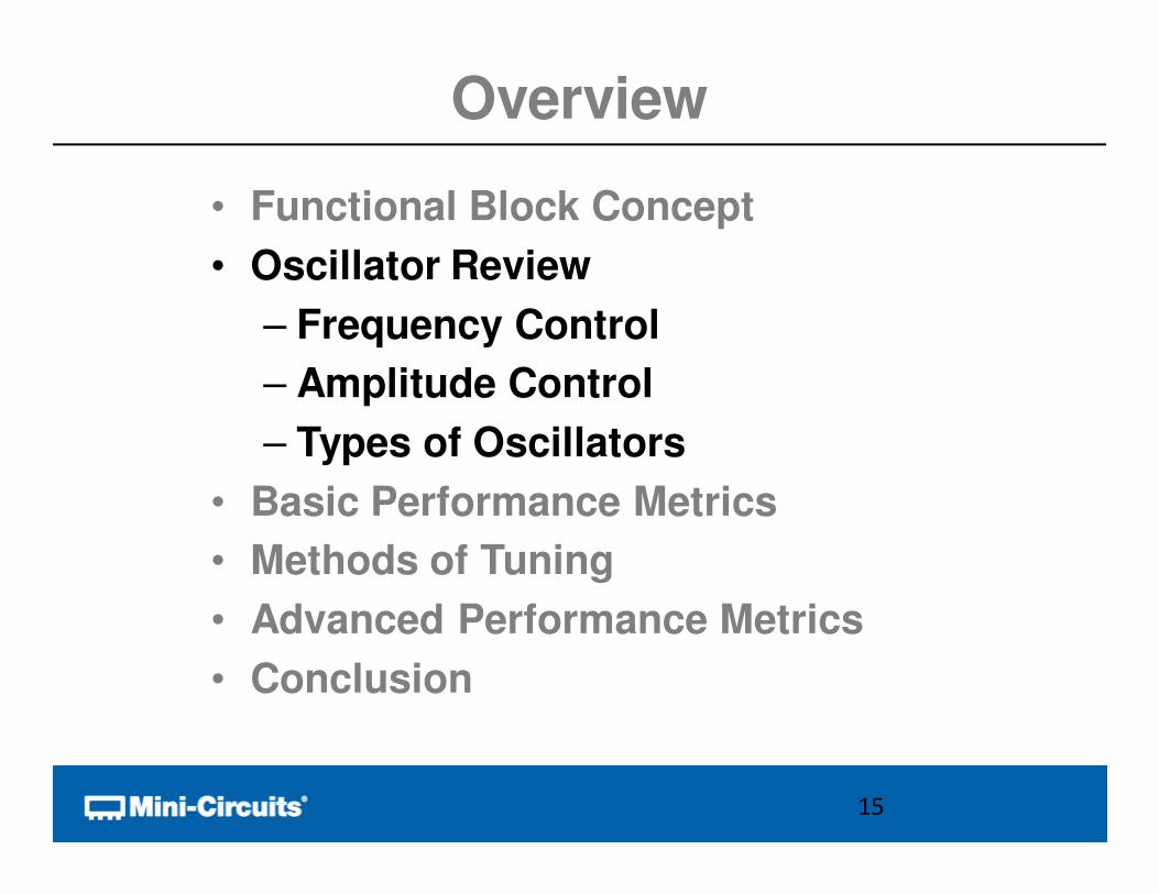
Overview
• Functional Block Concept
• Oscillator Review
– Frequency Control
– Amplitude Control
– Types of Oscillators
• Basic Performance Metrics
• Methods of Tuning
• Advanced Performance Metrics
• Conclusion
15
Oscillator Review
• Types of Oscillators
– Multivibrator
– Ring
– Resonant
– Feedback
• Basic Factors in Oscillator Design
– Frequency
– Amplitude / Output Power
– Startup
16
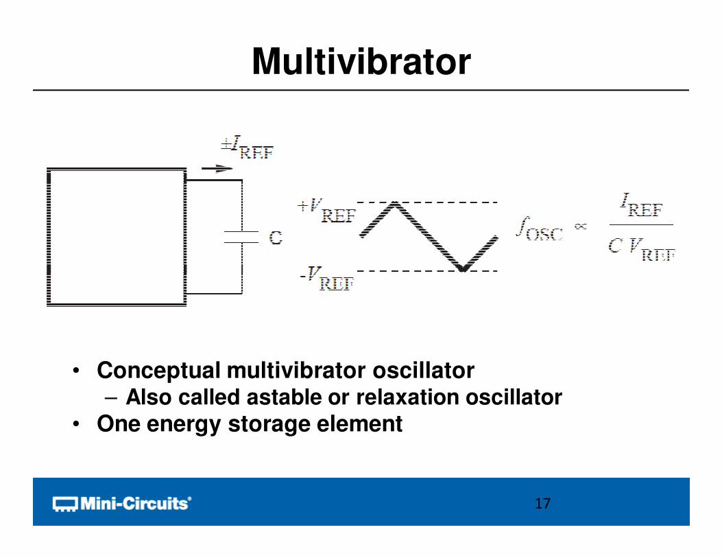
Multivibrator
• Conceptual multivibrator oscillator– Also called astable or relaxation oscillator
• One energy storage element
17
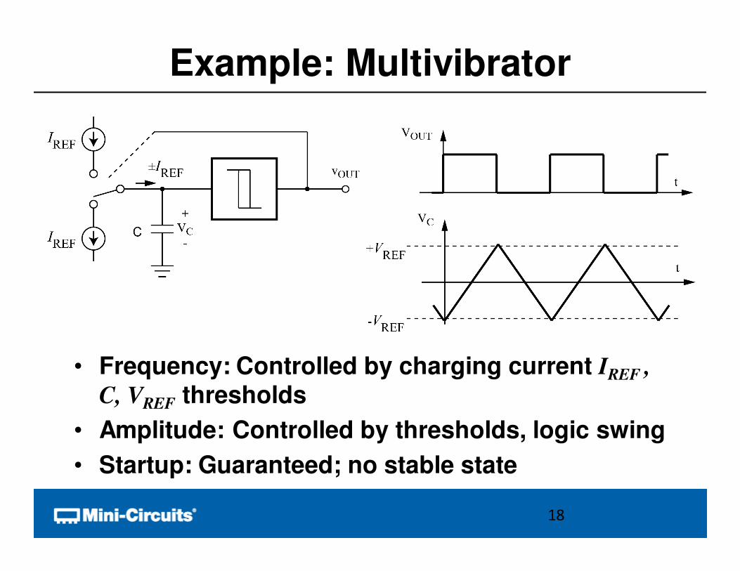
Example: Multivibrator
• Frequency: Controlled by charging current IREF ,
C, VREF thresholds
• Amplitude: Controlled by thresholds, logic swing
• Startup: Guaranteed; no stable state
18
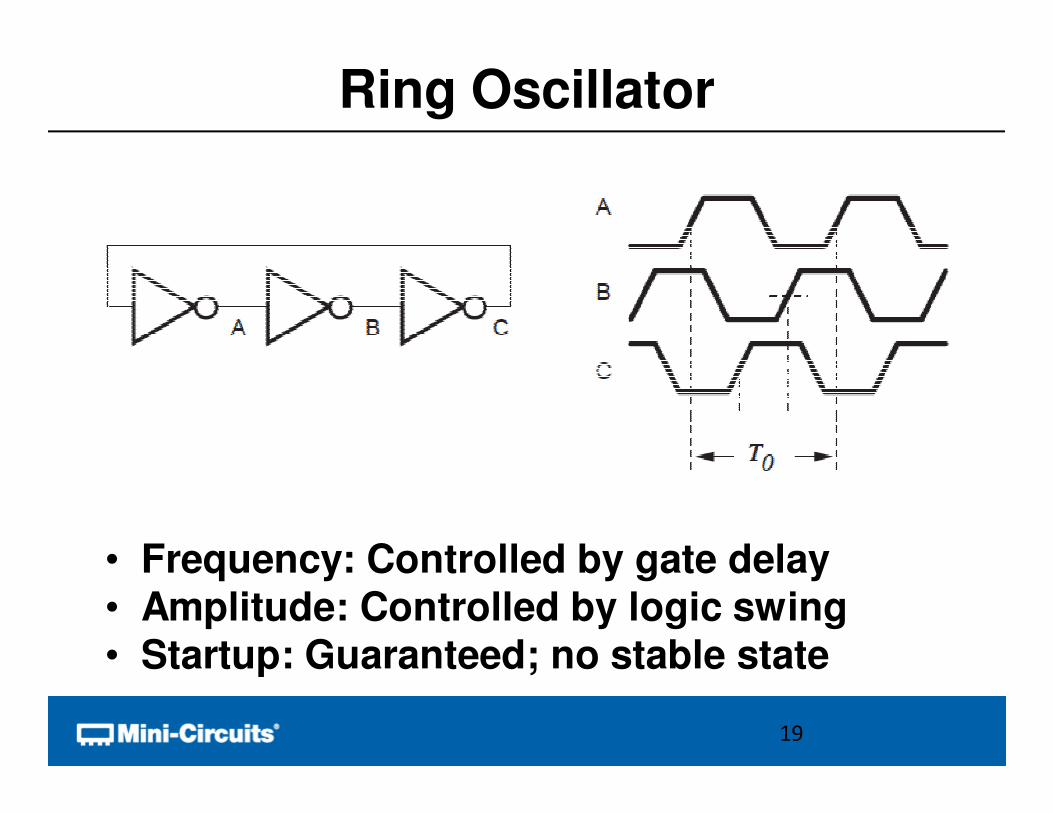
Ring Oscillator
• Frequency: Controlled by gate delay• Amplitude: Controlled by logic swing• Startup: Guaranteed; no stable state
19
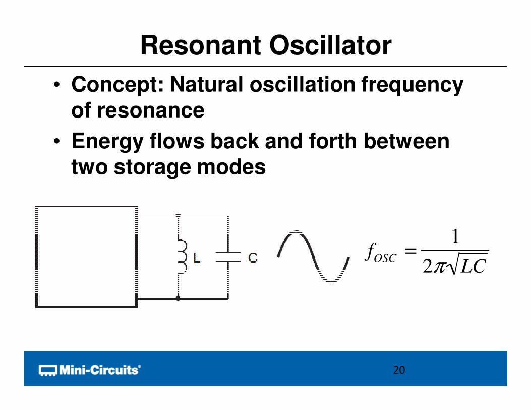
Resonant Oscillator
• Concept: Natural oscillation frequency of resonance
• Energy flows back and forth between two storage modes
20
fOSC =1
2π LC
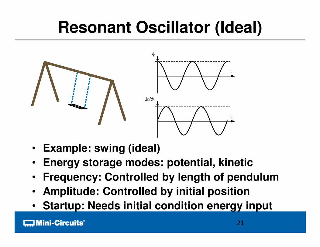
Resonant Oscillator (Ideal)
• Example: swing (ideal)
• Energy storage modes: potential, kinetic
• Frequency: Controlled by length of pendulum
• Amplitude: Controlled by initial position
• Startup: Needs initial condition energy input
21
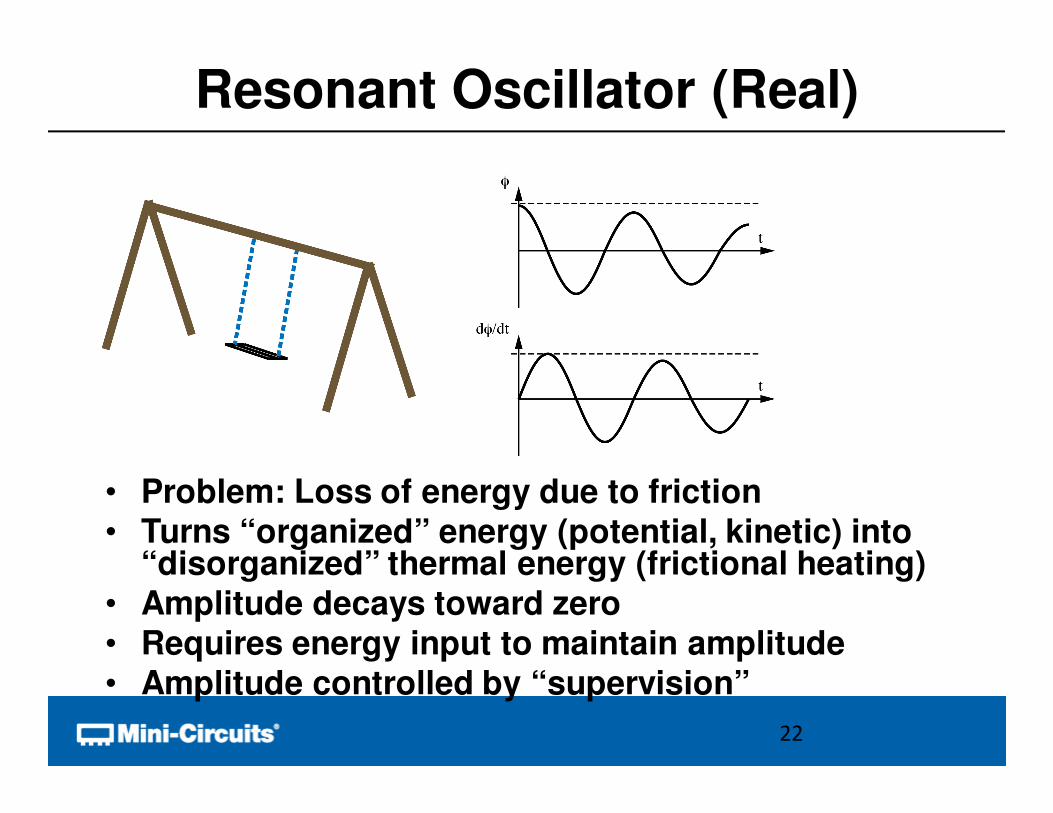
Resonant Oscillator (Real)
• Problem: Loss of energy due to friction• Turns “organized” energy (potential, kinetic) into
“disorganized” thermal energy (frictional heating)• Amplitude decays toward zero• Requires energy input to maintain amplitude• Amplitude controlled by “supervision”
22
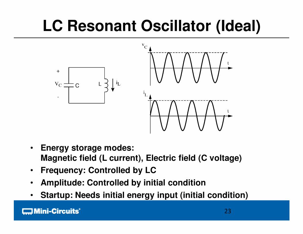
LC Resonant Oscillator (Ideal)
• Energy storage modes:
Magnetic field (L current), Electric field (C voltage)
• Frequency: Controlled by LC
• Amplitude: Controlled by initial condition
• Startup: Needs initial energy input (initial condition)
23
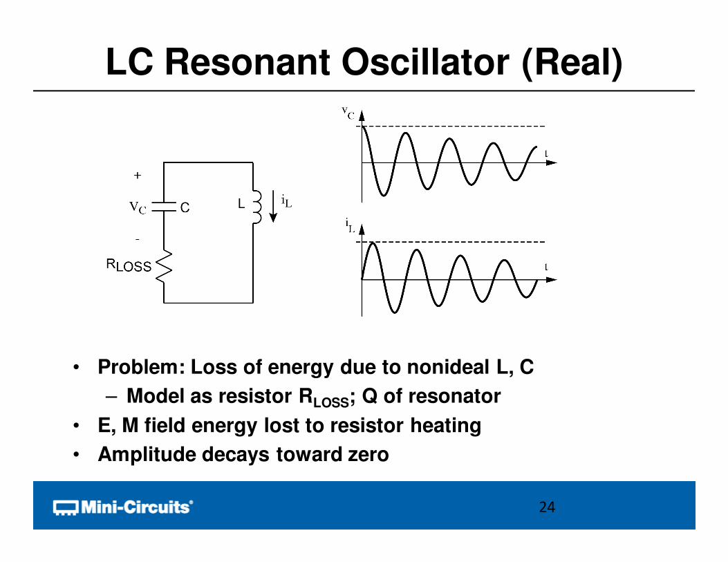
LC Resonant Oscillator (Real)
• Problem: Loss of energy due to nonideal L, C
– Model as resistor RLOSS; Q of resonator
• E, M field energy lost to resistor heating
• Amplitude decays toward zero
24
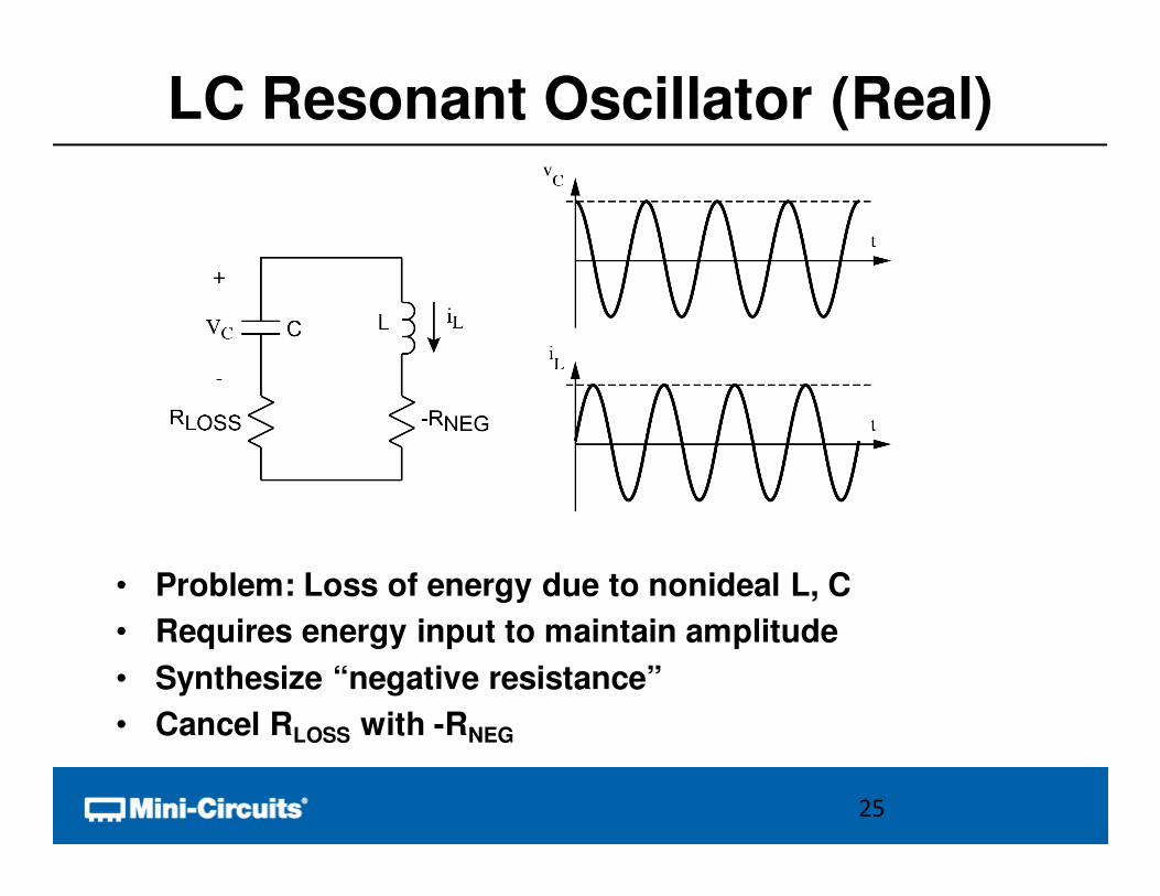
LC Resonant Oscillator (Real)
• Problem: Loss of energy due to nonideal L, C
• Requires energy input to maintain amplitude
• Synthesize “negative resistance”
• Cancel RLOSS with -RNEG
25
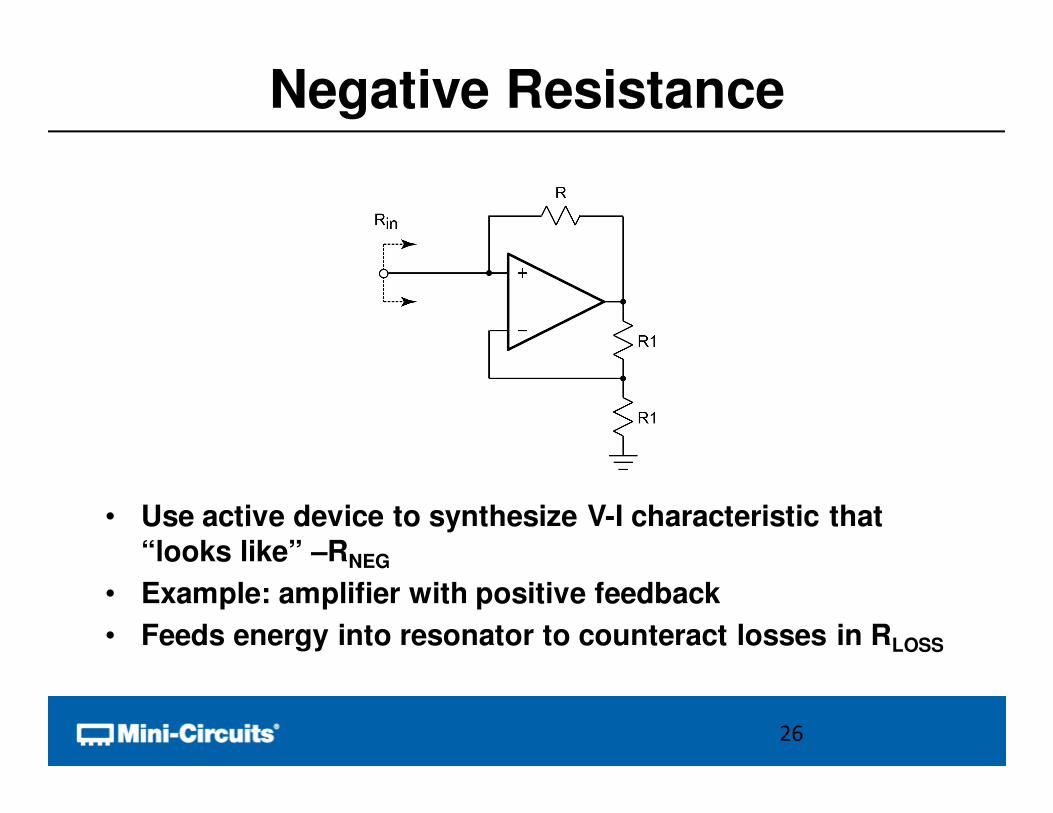
Negative Resistance
• Use active device to synthesize V-I characteristic that
“looks like” –RNEG
• Example: amplifier with positive feedback
• Feeds energy into resonator to counteract losses in RLOSS
26
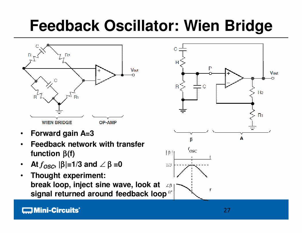
Feedback Oscillator: Wien Bridge
• Forward gain A=3
• Feedback network with transfer
function ββββ(f)
• At fOSC, |ββββ|=1/3 and ∠ ββββ =0
• Thought experiment: break loop, inject sine wave, look at signal returned around feedback loop
27

Aββββ=1
• “Just right”waveform is self sustaining
28
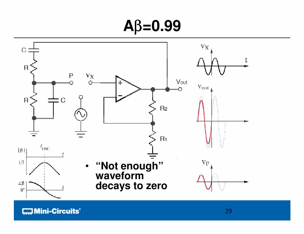
Aββββ=0.99
• “Not enough”waveform decays to zero
29
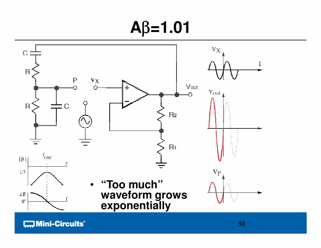
Aββββ=1.01
• “Too much”waveform growsexponentially
30
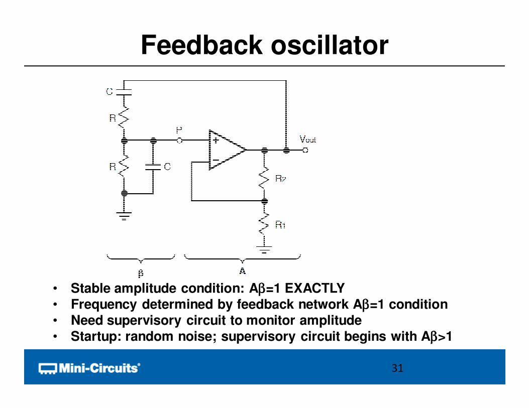
Feedback oscillator
• Stable amplitude condition: Aββββ=1 EXACTLY• Frequency determined by feedback network Aββββ=1 condition• Need supervisory circuit to monitor amplitude• Startup: random noise; supervisory circuit begins with Aββββ>1
31
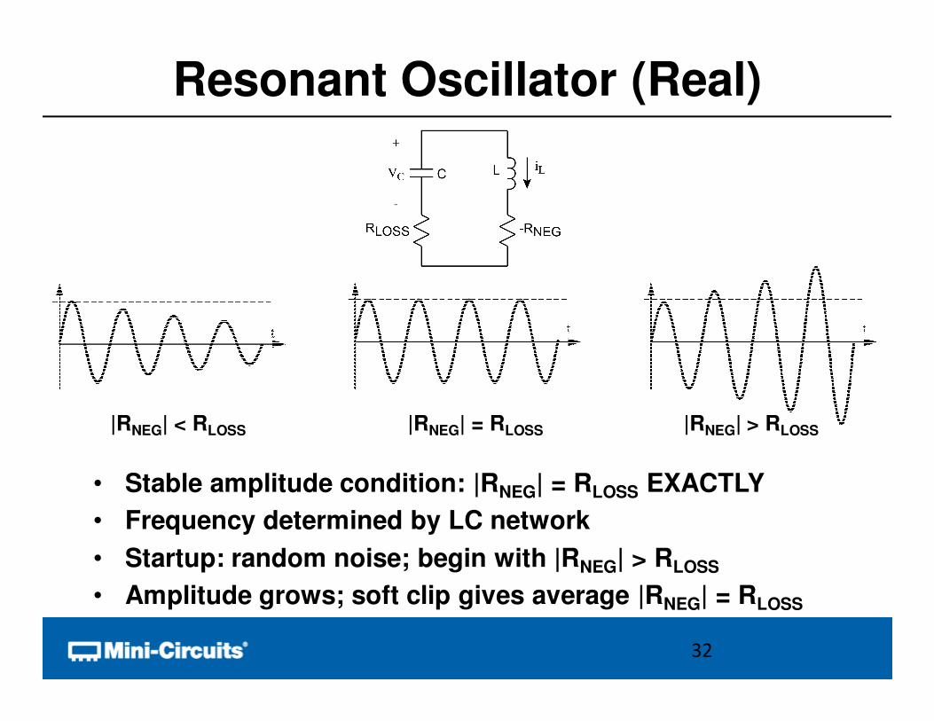
Resonant Oscillator (Real)
• Stable amplitude condition: |RNEG| = RLOSS EXACTLY
• Frequency determined by LC network
• Startup: random noise; begin with |RNEG| > RLOSS
• Amplitude grows; soft clip gives average |RNEG| = RLOSS
32
|RNEG| < RLOSS |RNEG| = RLOSS |RNEG| > RLOSS
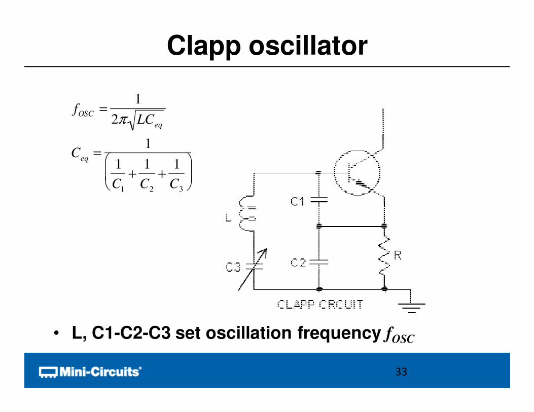
Clapp oscillator
• L, C1-C2-C3 set oscillation frequency fOSC
33
fOSC =1
2π LCeq
Ceq
=1
1
C1
+1
C2
+1
C3
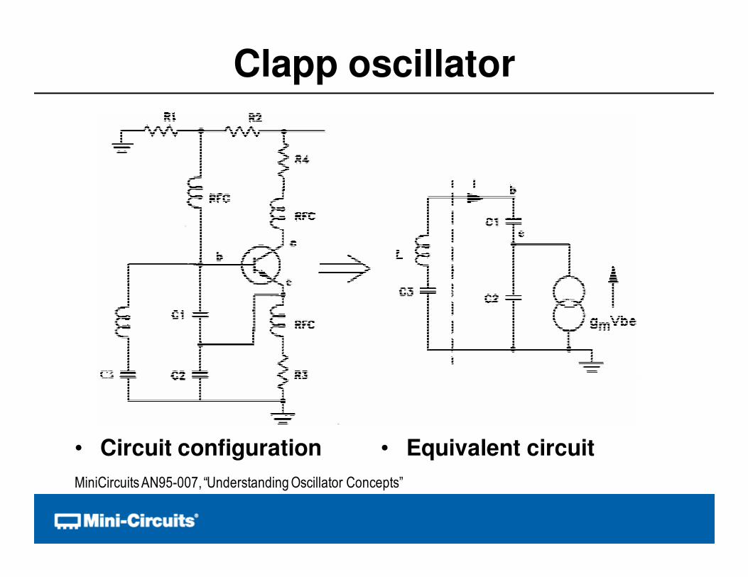
Clapp oscillator
• Circuit configuration • Equivalent circuit
MiniCircuitsAN95-007, “Understanding Oscillator Concepts”
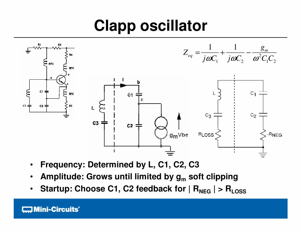
Clapp oscillator
• Frequency: Determined by L, C1, C2, C3
• Amplitude: Grows until limited by gm soft clipping
• Startup: Choose C1, C2 feedback for | RNEG | > RLOSS
Zeq
=1
jωC1
+1
jωC2
−g
m
ω 2C
1C
2
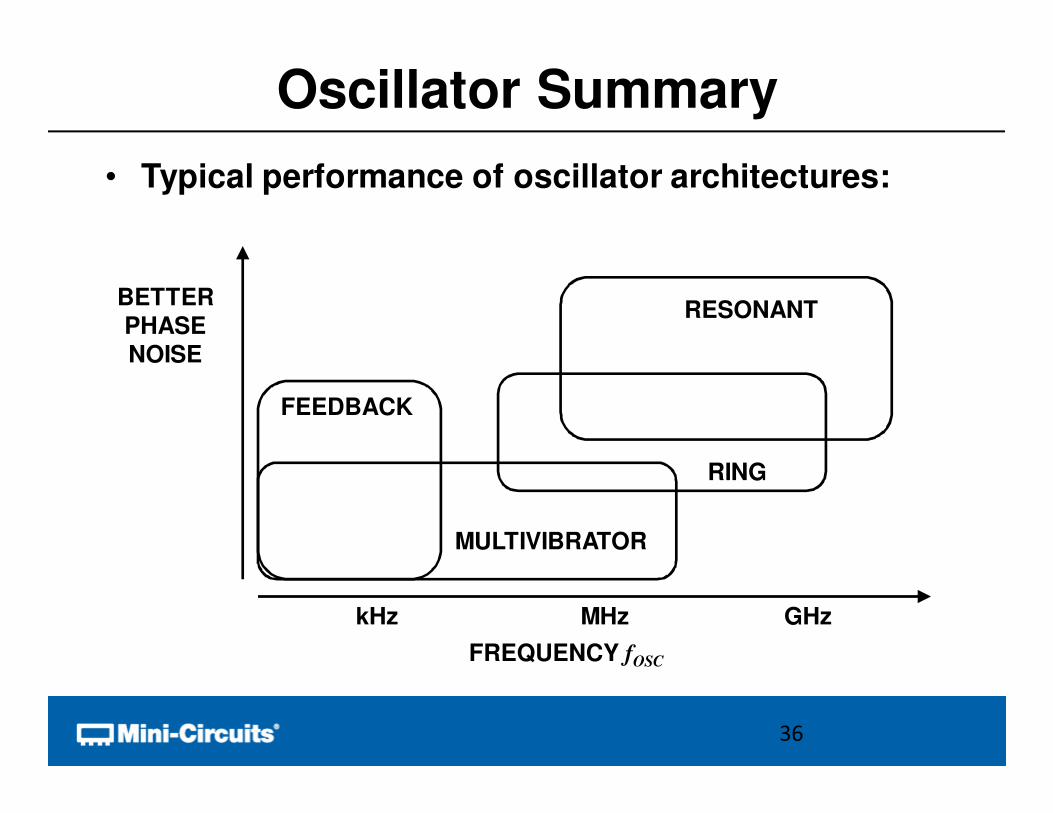
Oscillator Summary
• Typical performance of oscillator architectures:
36
kHz MHz GHz
FREQUENCY fOSC
BETTERPHASENOISE
RESONANT
RING
MULTIVIBRATOR
FEEDBACK
Overview
• Functional Block Concept
• Oscillator Review
• Basic Performance Metrics
– Frequency Range
– Tuning Range
• Methods of Tuning
• Advanced Performance Metrics
• Conclusion
37
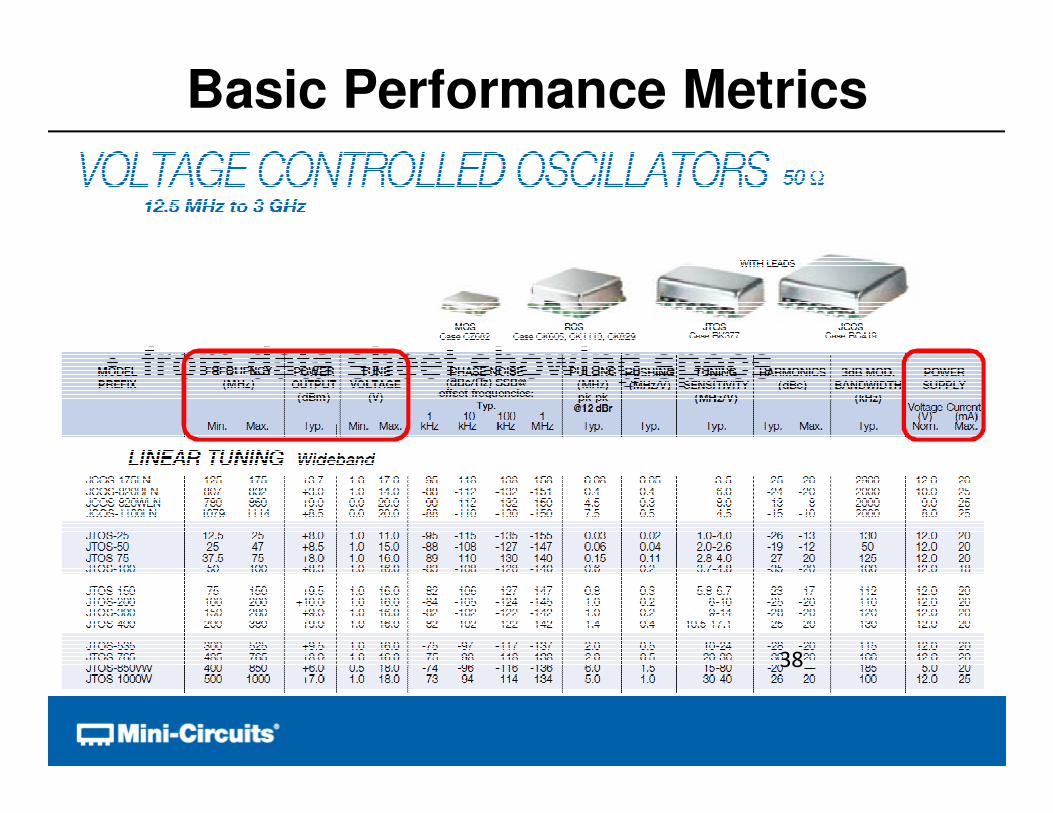
• from data sheet showing specs
Basic Performance Metrics
38
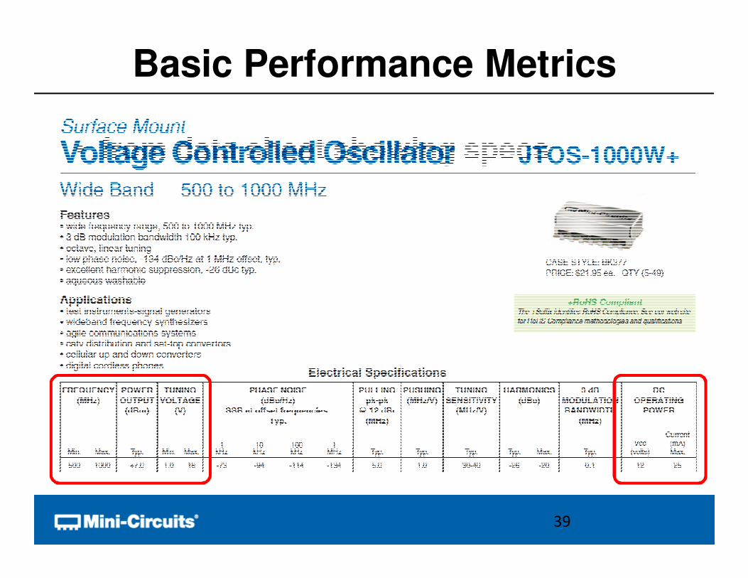
• from data sheet showing specs
Basic Performance Metrics
39
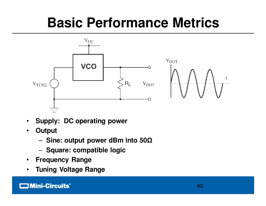
Basic Performance Metrics
• Supply: DC operating power
• Output
– Sine: output power dBm into 50Ω
– Square: compatible logic
• Frequency Range
• Tuning Voltage Range
40
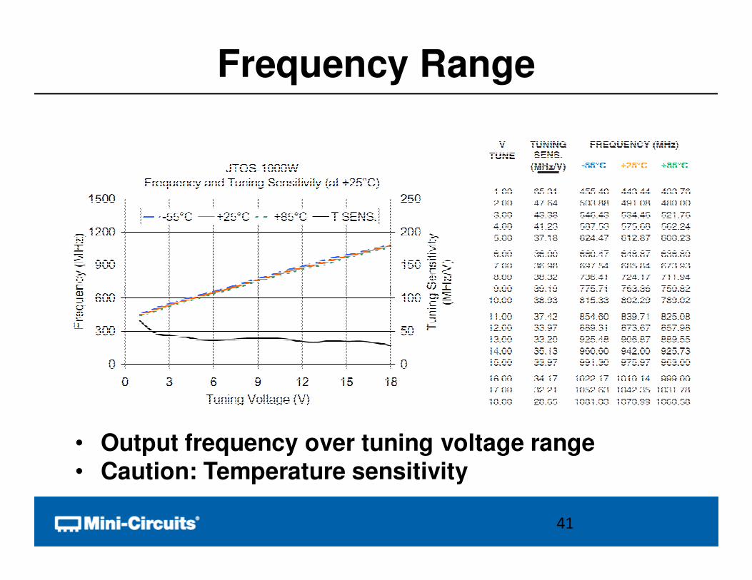
Frequency Range
• Output frequency over tuning voltage range• Caution: Temperature sensitivity
41
Overview
• Functional Block Concept
• Oscillator Review
• Basic Performance Metrics
• Methods of Tuning
• Advanced Performance Metrics
• Conclusion
42
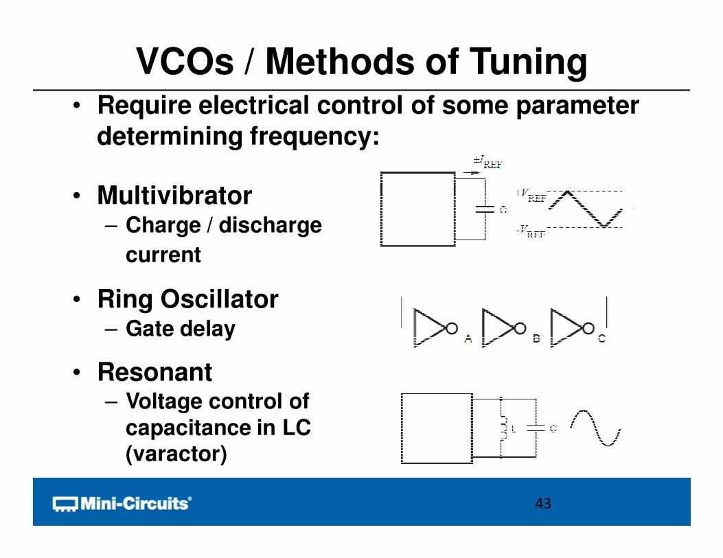
VCOs / Methods of Tuning• Require electrical control of some parameter
determining frequency:
• Multivibrator– Charge / discharge
current
• Ring Oscillator– Gate delay
• Resonant– Voltage control of
capacitance in LC (varactor)
43
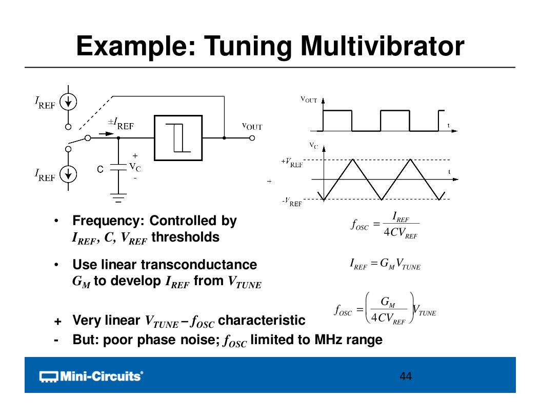
Example: Tuning Multivibrator
• Frequency: Controlled by IREF , C, VREF thresholds
• Use linear transconductanceGM to develop IREF from VTUNE
+ Very linear VTUNE – fOSC characteristic
- But: poor phase noise; fOSC limited to MHz range
44
fOSC =IREF
4CVREF
fOSC =GM
4CVREF
VTUNE
IREF = GMVTUNE
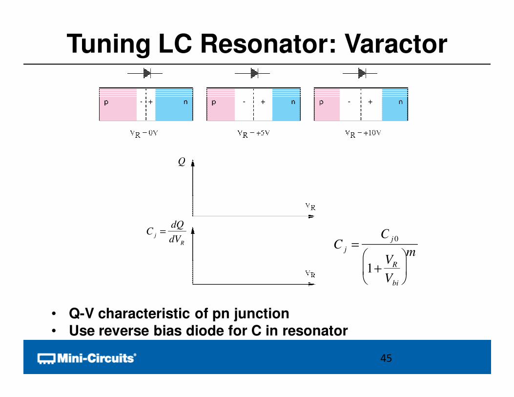
Tuning LC Resonator: Varactor
• Q-V characteristic of pn junction
• Use reverse bias diode for C in resonator
45
C j =C j 0
1+VR
Vbi
m
C j =dQ
dVR
Q
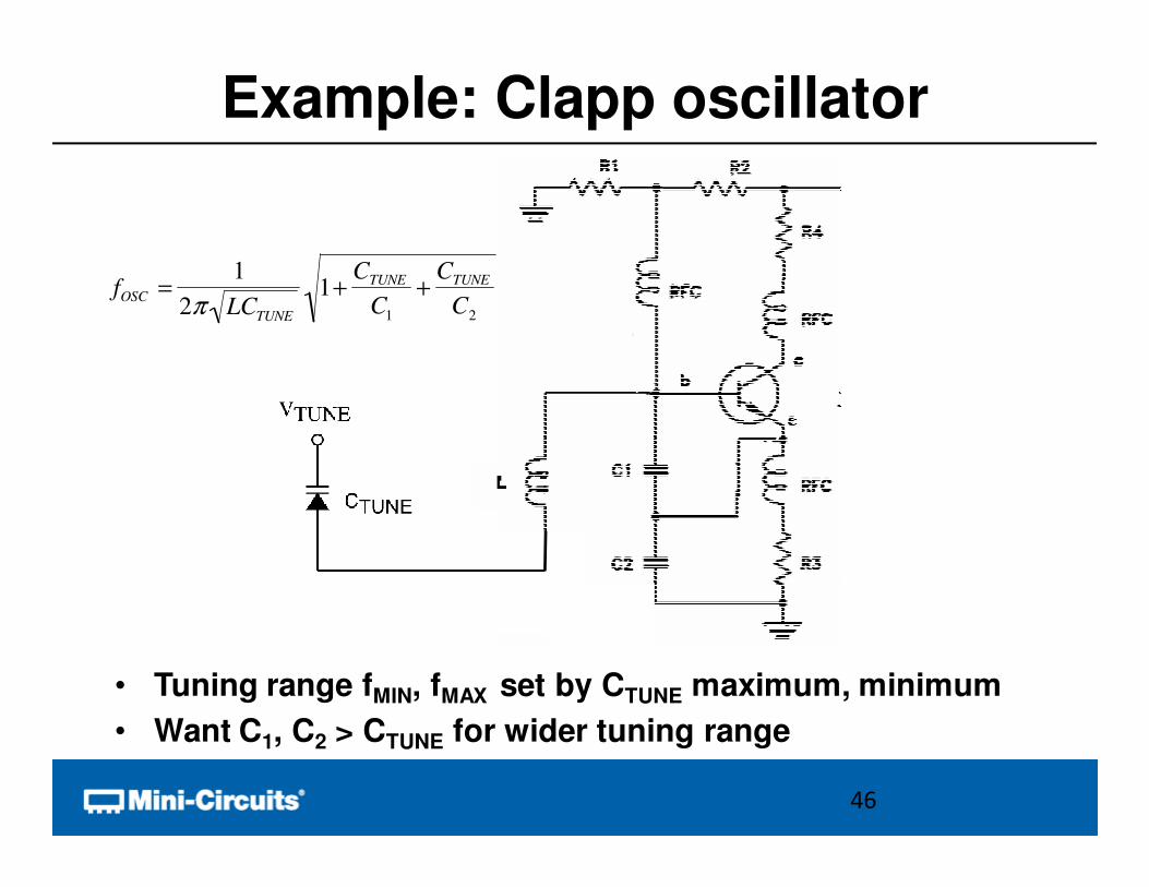
Example: Clapp oscillator
• Tuning range fMIN, fMAX set by CTUNE maximum, minimum
• Want C1, C2 > CTUNE for wider tuning range
46
fOSC =1
2π LCTUNE
1+CTUNE
C1
+CTUNE
C2
Overview
• Functional Block Concept
• Oscillator Review
• Basic Performance Metrics
• Methods of Tuning
• Advanced Performance Metrics
– Tuning Sensitivity
– Phase Noise
– Supply Pushing
– Load Pulling
• Conclusion
47
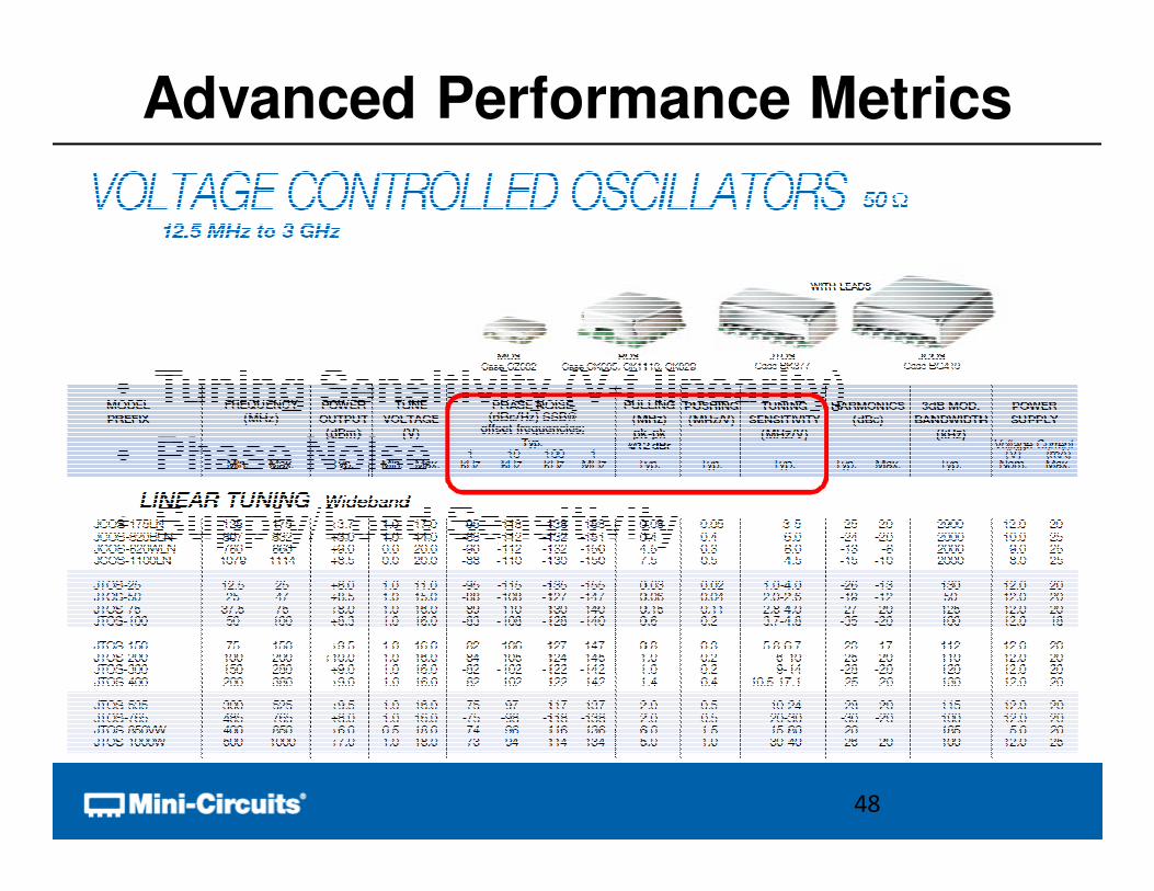
Advanced Performance Metrics
• Tuning Sensitivity (V-f linearity)
• Phase Noise
• Supply/Load Sensitivity
48
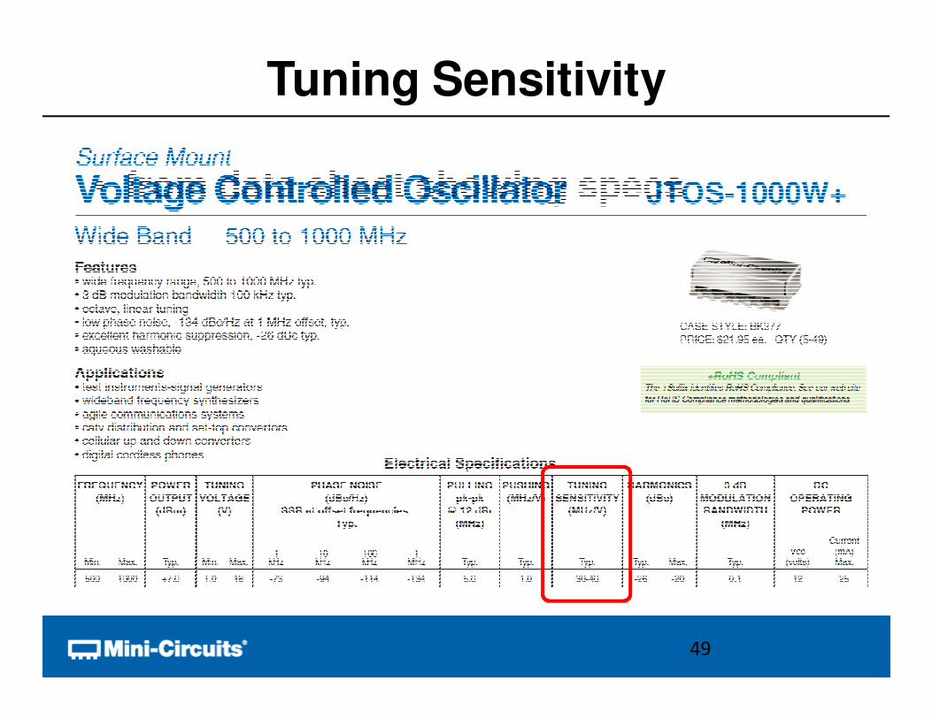
• from data sheet showing specs
Tuning Sensitivity
49
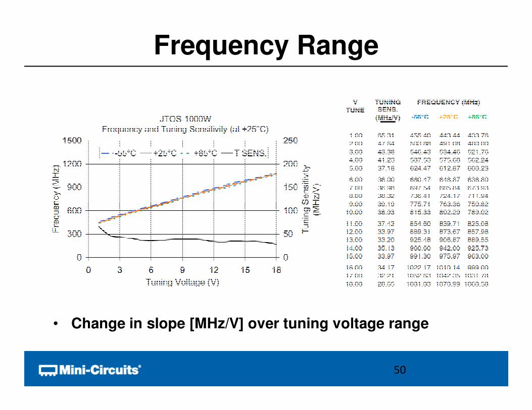
Frequency Range
• Change in slope [MHz/V] over tuning voltage range
50
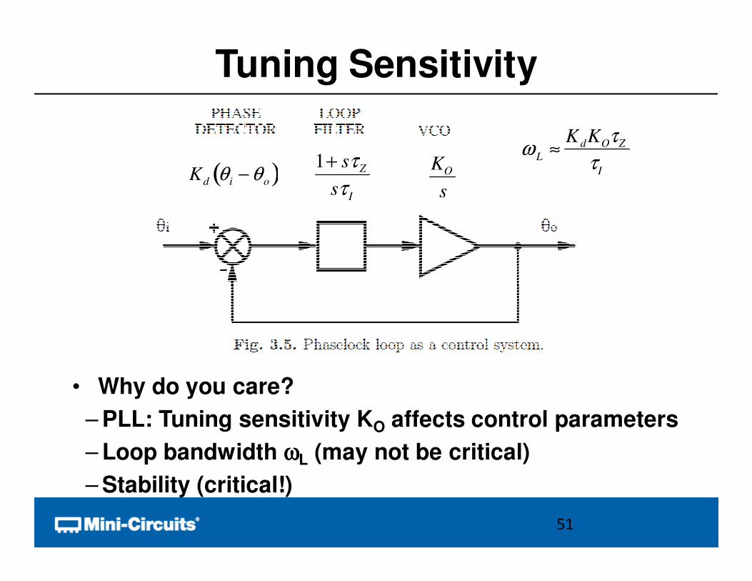
Tuning Sensitivity
• Why do you care?
– PLL: Tuning sensitivity KO affects control parameters
– Loop bandwidth ωωωωL (may not be critical)
– Stability (critical!)
51
Kd θ i − θo( )1+ sτZ
sτI
KO
s
ωL
≈KdKOτZ
τI
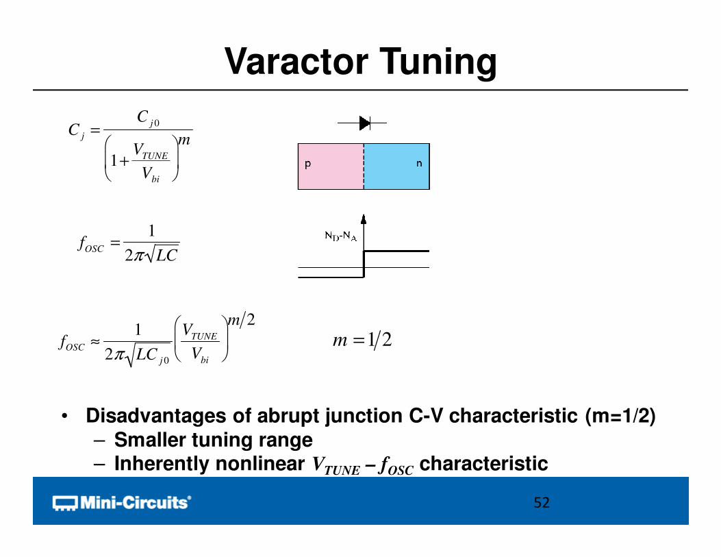
Varactor Tuning
• Disadvantages of abrupt junction C-V characteristic (m=1/2)
– Smaller tuning range– Inherently nonlinear VTUNE – fOSC characteristic
52
C j =C
j 0
1+V
TUNE
Vbi
m
fOSC
=1
2π LC
fOSC ≈1
2π LC j 0
VTUNE
Vbi
m 2
m =1 2
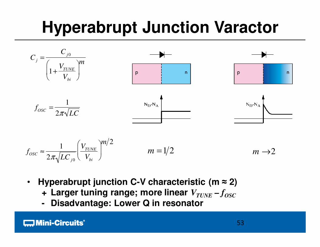
Hyperabrupt Junction Varactor
• Hyperabrupt junction C-V characteristic (m ≈ 2)+ Larger tuning range; more linear VTUNE – fOSC
- Disadvantage: Lower Q in resonator
53
C j =C
j 0
1+V
TUNE
Vbi
m
fOSC
=1
2π LC
fOSC ≈1
2π LC j 0
VTUNE
Vbi
m 2
m =1 2 m →2
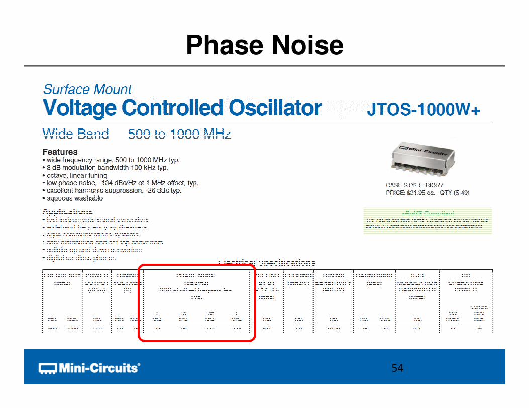
• from data sheet showing specs
Phase Noise
54
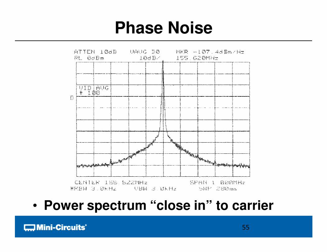
Phase Noise
• Power spectrum “close in” to carrier
55
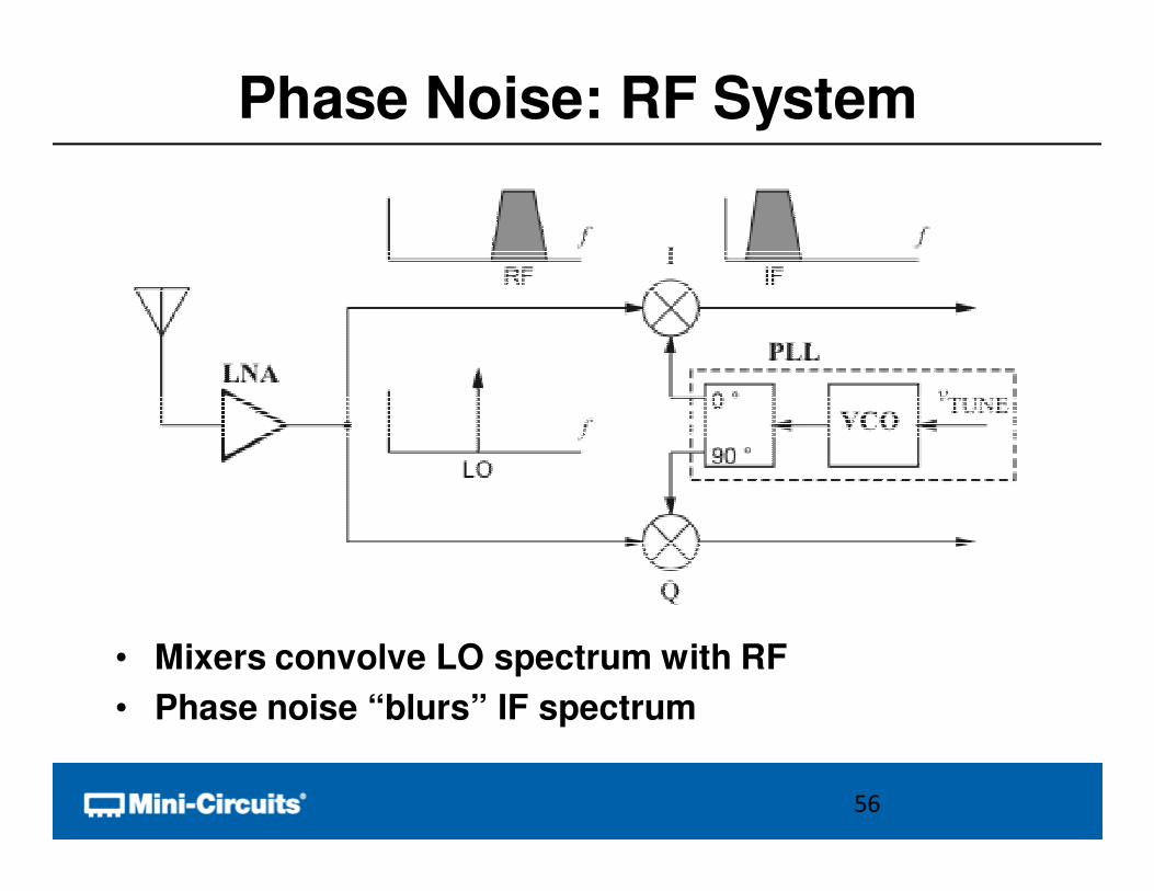
Phase Noise: RF System
• Mixers convolve LO spectrum with RF
• Phase noise “blurs” IF spectrum
56
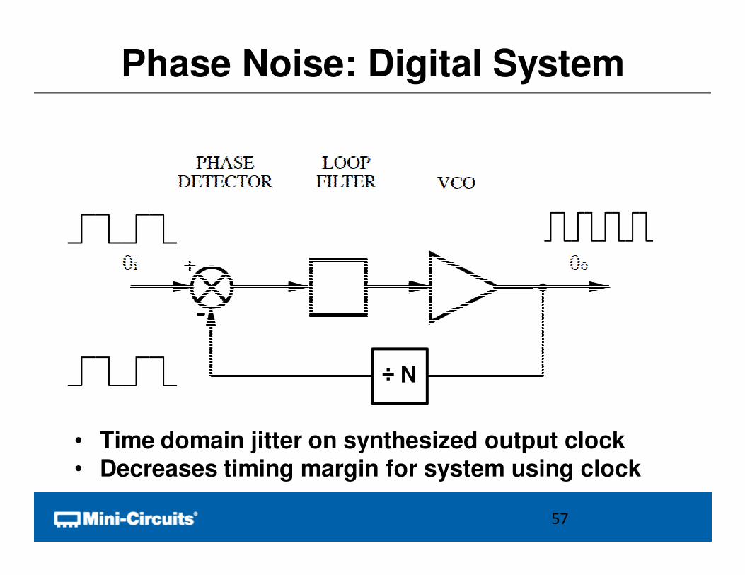
Phase Noise: Digital System
• Time domain jitter on synthesized output clock• Decreases timing margin for system using clock
÷ N
57
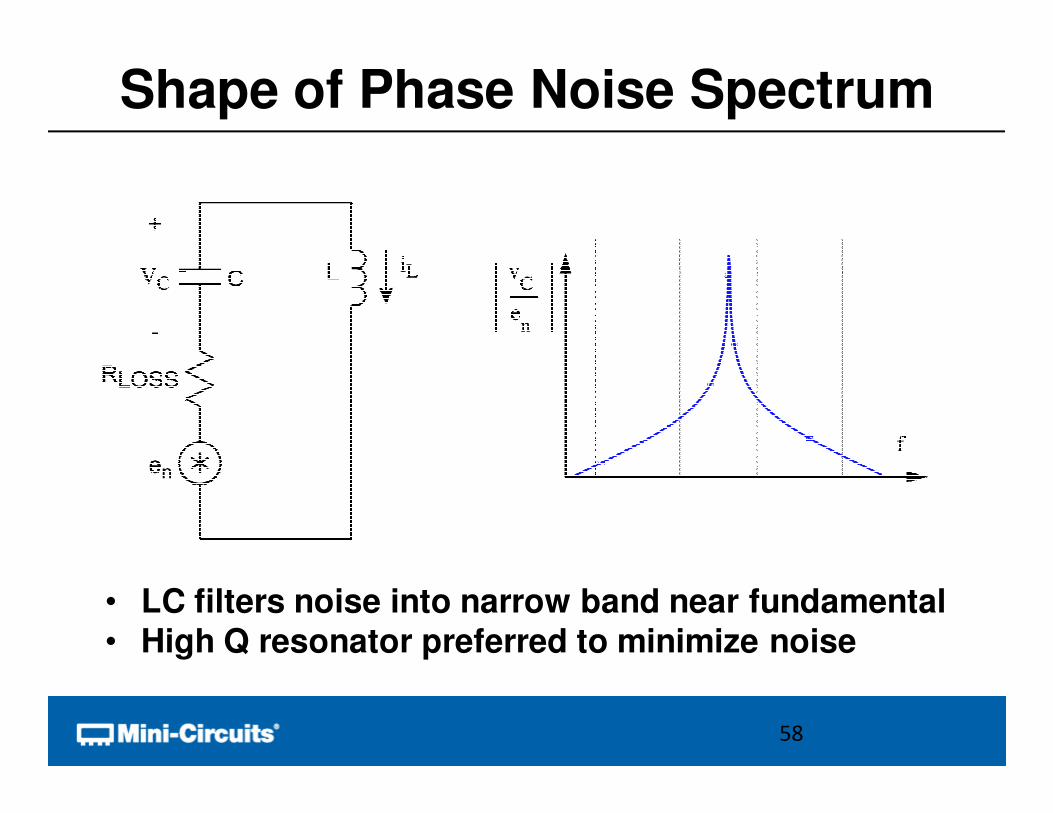
Shape of Phase Noise Spectrum
• LC filters noise into narrow band near fundamental• High Q resonator preferred to minimize noise
58
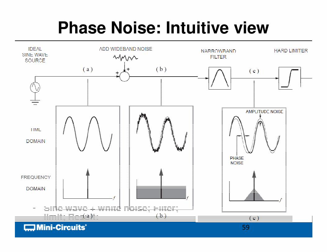
Phase Noise: Intuitive view
• Sine wave + white noise; Filter; limit; Result:
59
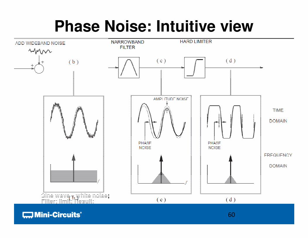
Phase Noise: Intuitive view
• Sine wave + white noise;Filter; limit; Result:
60
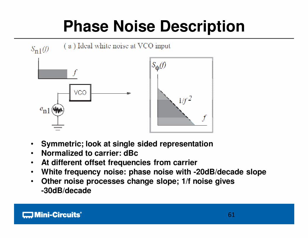
Phase Noise Description
• Symmetric; look at single sided representation• Normalized to carrier: dBc• At different offset frequencies from carrier• White frequency noise: phase noise with -20dB/decade slope• Other noise processes change slope; 1/f noise gives
-30dB/decade
61
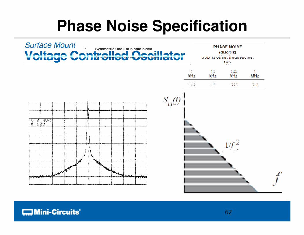
Phase Noise Specification
• Symmetric; look at single sided• Normalized to carrier: dBc• At different offset frequencies from carrier
62
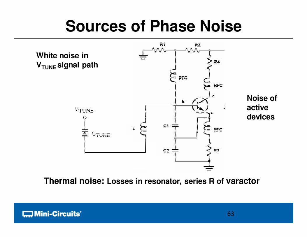
Sources of Phase Noise
Noise of active devices
63
Thermal noise: Losses in resonator, series R of varactor
White noise in VTUNE signal path
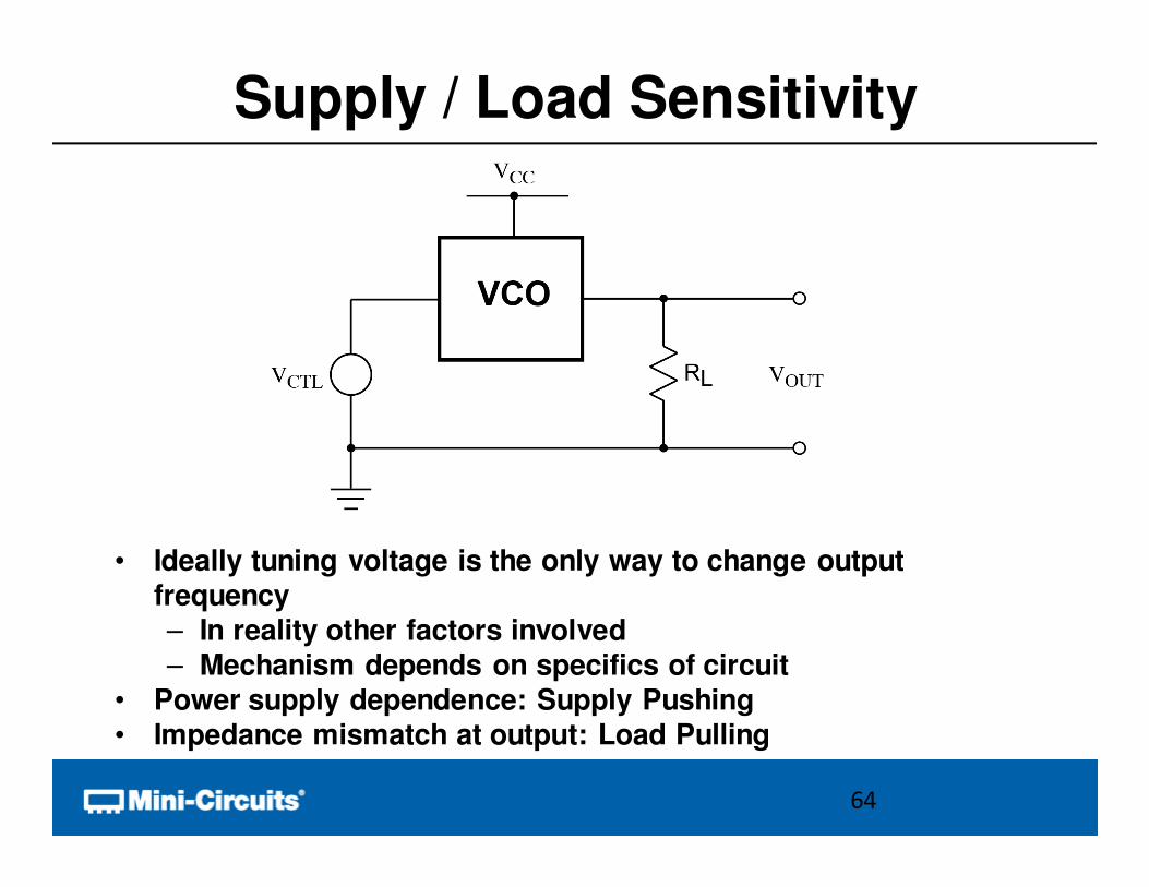
Supply / Load Sensitivity
• Ideally tuning voltage is the only way to change output frequency– In reality other factors involved– Mechanism depends on specifics of circuit
• Power supply dependence: Supply Pushing• Impedance mismatch at output: Load Pulling
64
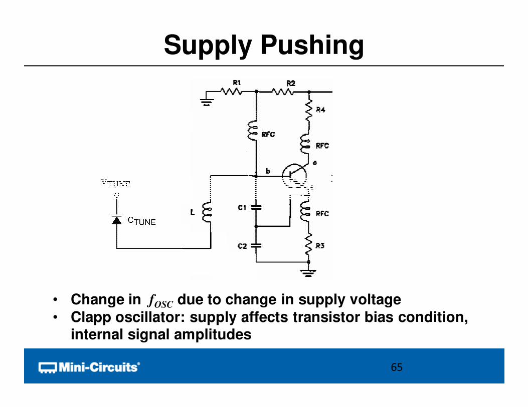
Supply Pushing
• Change in fOSC due to change in supply voltage
• Clapp oscillator: supply affects transistor bias condition, internal signal amplitudes
65
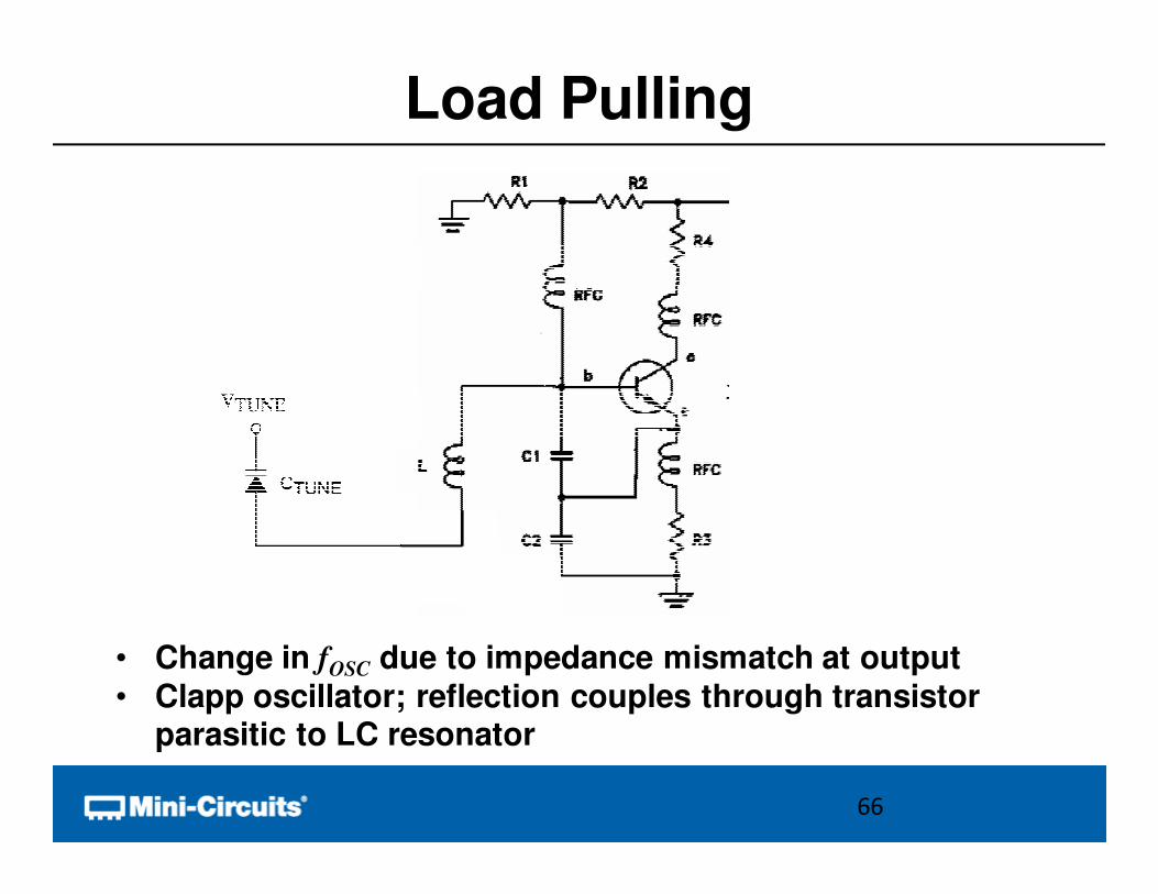
Load Pulling
• Change in fOSC due to impedance mismatch at output
• Clapp oscillator; reflection couples through transistor parasitic to LC resonator
66
Overview
• Functional Block Concept
• Oscillator Review
• Basic Performance Metrics
• Methods of Tuning
• Advanced Performance Metrics
• Conclusion
67
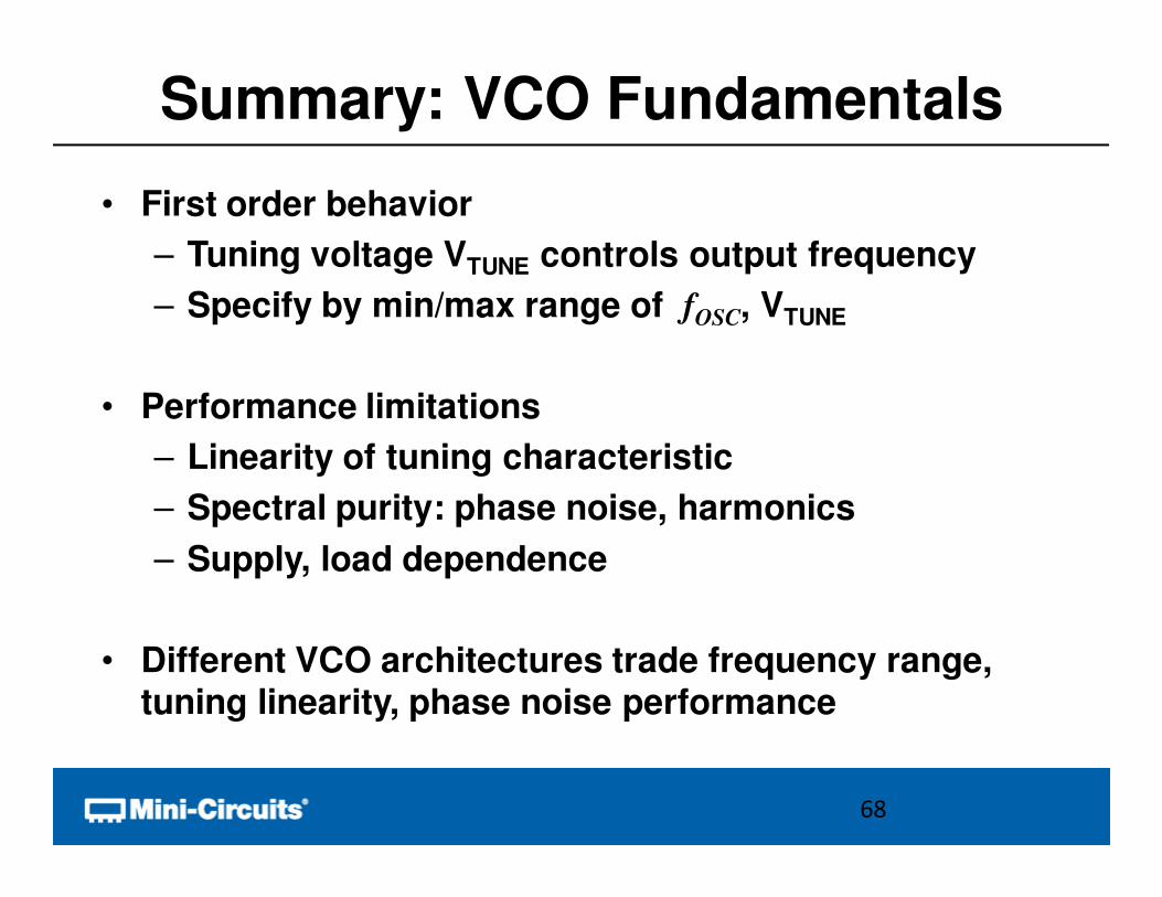
Summary: VCO Fundamentals
• First order behavior
– Tuning voltage VTUNE controls output frequency
– Specify by min/max range of fOSC, VTUNE
• Performance limitations
– Linearity of tuning characteristic
– Spectral purity: phase noise, harmonics
– Supply, load dependence
• Different VCO architectures trade frequency range, tuning linearity, phase noise performance
68
Questions?
69
Thank you to our presenter John McNeill and our
sponsor Mini-Circuits