Embed Size (px)
Citation preview
INTERNATIONAL JOURNAL OF AUTOMOTIVE AND MECHANICAL ENGINEERING (IJAME) ISSN: 2229-8649 e-ISSN: 2180-1606 VOL. 17, ISSUE 4, 8397 – 8410 DOI: https://doi.org/10.15282/ijame.17.4.2020.15.0635
*CORRESPONDING AUTHOR | Mohanad Kadhim Mejbel | [email protected] 8397 © The Authors 2020. Published by Penerbit UMP. This is an open access article under the CC BY license.
ORIGINAL ARTICLE
Variable Valve Timing (VVT) Modelling by Lotus Engine Simulation Software Mohammed Kadhim Allawi, Mohanad Kadhim Mejbel* and Mahmood Hasan Oudah
Middle Technical University, Technical Engineering College – Baghdad, Iraq Phone: +964 7729258115
ARTICLE HISTORY Received: 25th Mar 2020 Revised: 22nd Oct 2020 Accepted: 24th Dec 2020 KEYWORDS
VVT; Brake power; Brake thermal efficiency; Volume efficiency; Fuel consumption
NOMENCLATURE
BSFC brake specific fuel consumption (kg/(kW.hr) BTDC before top dead centre (º) ABDC after bottom dead centre (º) ATDC after top dead centre (º) LES lotus engine simulation BMEP brake mean effective pressure (bar) GDI gasoline direct injection 𝜂𝜂𝑉𝑉. efficiency volumetric BTE brake thermal efficiency (MOP) maximum opening point BTDC before top dead centre LEVO late exhaust valve opening EIVO early intake valve opening LIVO late intake valve opening LIVC late intake valve closing SI. Engine spark-ignition engine IVO inlet valve open IVC inlet valve close EIVC early intake valve closing EVC exhaust valve closing PT port injection bp brake power (kW) EVO exhaust valve opening
INTRODUCTION
Automotive industry is a key industrial sector for many country’s economy given that extensive studies have been adopted by many researchers to improve, develop and enhance the performance of car parts and their applications in the automotive industry [1-3]. Improving fuel consumption and engine performance in the automotive industry with reducing pollutant emissions is a challenging mission for engineers for the past few decades [4, 5]. Many techniques have been suggested and adopted. Variable valve timing (VVT) might possibly be the best successful method to achieve most of the highest engine performance requirements. VVT is a relatively modern technique established to improve the fuel economy for gasoline engines [6]. VVT permits the engine to gain optimal intake mixture amount for higher efficiency, particularly at the upper and lower load/speed regions. VVT technology is utilised in engines of spark-ignition (SI) type to increase
ABSTRACT – Variable valve timing (VVT) is an advanced modern technique applied in internal combustion engines by altering the valve lift event timing. This work aims to contribute to the continuing industrial VVT development to improve engine efficiency, fuel consumption and performance. To observe the influence on the spark-ignition (SI) engine’s performance, four valve timing strategies are selected carefully by varying the intake and exhaust valve timing. Lotus Engine Simulation, a simulation engineering software, is adapted in this study. The engine characteristics used in this modelling are spark engine, multicylinder, four strokes, port injection fuel system and constant compression ratio. A comparison between a conventional standard exhaust/intake valve timing and three other different timing cases is carried out. Results reveal that the overlap case of 98° showed a good brake-specific fuel consumption by approximately 3% less than the conventional case. An improvement of 6.2% for volume efficiency and 2.9% in brake thermal efficiency is also reported.
Mohammed Kadhim Allawi et al. │ International Journal of Automotive and Mechanical Engineering │ Vol. 17, Issue 4 (2020)
8398 journal.ump.edu.my/ijame ◄
peak power/torque, reduce NOx gases and improve fuel economy [7]. To improve the performance of an engine, the main contributor lies in optimising the valve timing and lifting of an intake valve. The VVT mechanism varies from increasing the valve lift as well as the time duration, forwarding and retarding [8]. Pumping losses can be significantly reduced in part-load operations by optimising the exhaust and intake valve timing [9]. Varying the lift or exhaust and intake valve timings improves the fuel economy, reduces emissions from the exhaust and provides better power and brake torque, which is all controlled by the VVT system [10].
To build up a suitable control strategy for the engine control system, prediction and optimisation via modelling and computer simulations using commercial well-known software packages is the optimum solution [11]. Without the requirement for difficult and long experiments on an actual engine bed, these simulations are inexpensive and flexible in developing the control algorithms. Optimising and solving engineering operational troubles in accordance with the design layouts of the internal combustion engines (ICEs) is conducted using various developed commercial packages currently available in the market [11].
AVL fire, GT Power, Ricardo Wave (RW) and lotus engine simulation (LESoft) are four leading commercial engine simulation packages adopted at present in the automotive industry. These packages have identical functionality and purposes. LESoft is developed as an in-house coded package by Lotus engineering; it is used by several researchers for the last decade [11]. Basaran and Ozsoysal in 2017 [12] utilised Lotus engine simulation to model a six-cylinder, intercooled and turbocharged diesel engine. They studied the effect of VVT by altering the intake valve closure (IVC) timing on the exhaust gas temperature at low loads. This condition was achieved by retarding and advancing the IVC timing from the base condition to increase the inlet exhaust temperature above the target 250 °C. They adjusted the rate of fuel injection to obtain a constant brake mean effective pressure of 2.5 bar as a low engine load and 1200 rpm engine speed. They revealed positive and negative results concerning engine performance in general.
Bapiri and Sorusbay [13] used AVL BOOST software to measure the VVT timing effect on the efficiency of the engine. They adopted different valve timing strategies to analyse their influence and compared their simulations and fixed valve timing case references. They revealed that higher engine performance was achieved and provided with substantial fuel consumption improvements. Caufield et al. [14] revealed that through accurate simulations of fluid path in a small SI engine, fuel consumption can be reduced via the VVT system. Dahlan et al. [15] used the GT-power commercial software in a 1-D model on a proton Iriz gasoline engine to find the optimum exhaust and IVO and closing timing characteristics that improve the fuel consumption and targeted engine performance. They adopted miller and Atkinson cycles in a dual VVT system on a 1.6-litre proton engine at 1000–6250 rpm engine speed .
Kumar et al. in 2016 [16], used computer-aided engineering software to investigate the effect of varying closing and intake valve timing on the performance of engine at a wide speed. They reported good improvement on the engine power produced and fuel consumed by optimising the closing and opening angles at different engine speeds. Ham and Park in 1991 [17] checked the varying influences of the maximum intake lifting valve to stabilise and control the burning rate and the intensity inside the cylinder turbulence. They stated that the most sensitive parameter to vary the engine’s breathing ability is the IVC. At high engine speeds, the volumetric efficiency increased considerably by delaying the IVC. In addition, volumetric efficiency was penalised at low speeds.
Soderberg and Johansson in 1997 [18] tested late intake valve closure (LIVC) strategies with symmetric valve events. They reported that early intake valve closure (EIVC) developed a faster combustion event with a longer flame period. A stabilised combustion occurred with EIVC better than that of LIVC. Saunders and Abdul-Wahab in 1989 [19] used two procedures to enhance the efficiency of the engine. The first method is to reduce the losses in pumping using LIVC in a VVT system, and the other approach is to increase the expansion ratio by using a variable compression ratio. The authors stated that using LIVC could improve the brake-specific fuel consumption (BSFC) by 13%. Ma in 1988 [20] studied the concept of LIVC on an engine with a valve of multi intake. Ma revealed that producing a prolonged period of intake opening is easy by arranging the first intake valve to be variably delayed when phasing with the second intake valve. He revealed that LIVC is an applicable and practical strategy for engines.
Damasceno and Gallo in 2013 [21] studied the engine performance under full engine operation loading conditions by varying some parameters of the valve timing and searched for the best valve timing strategies. They applied and developed a model of thermodynamic simulation under full loading conditions at two high engine speeds to explore the optimisation possibilities of valve timing to a hypothetic engine cylinder. They reported the best timing of the valve configuration for 2000 and 5200 rpm. Roth in 1998 [22] correlated an investigation at the top dead centre (TDC) using intake pseudo flow velocities with optimised IVO. They revealed that the backflow at the period of overlapping reduced by retarding IVO and, that engine performance could be maintained normally by delaying IVO significantly. Khudhur et al. in 2015 [23] studied the effect of three valve overlaps (104°, 108° and 112°). They managed experimentally to reduce 3% of the fuel consumption, 5.65% improvement in brake thermal efficiency, 12.58% enhancement in volumetric efficiency and a reduction in exhaust emissions by selecting the best combination of the compression ratio of 9 and an overlap period of 104°.
Nouhov and Chen in 2002 [24] used LES, a commercial engine simulation package to model and simulate a spark-ignition engine of four-stroke, 13500 rpm engine speed, four-cylinder and 0.6 L. They showed that IVO could either reduce the backflow during the period of overlapping or enhance the inlet charging effect utilisation. To the best knowledge of the authors, investigations using LES software for VVT research are few, and no literature on adopting Lotus software is available to investigate the influence of the four specific VVT study cases on the engine performance and report their performance profiles (contours). The aim of this modelling research is to use four different VVT case
Mohammed Kadhim Allawi et al. │ International Journal of Automotive and Mechanical Engineering │ Vol. 17, Issue 4 (2020)
8399 journal.ump.edu.my/ijame ◄
philosophies to enhance the performance of the engine and illustrate, for the first time, the engine performance profiles (contours) by optimising power, fuel consumption and engine torque at different engine speeds by adopting LES.
MODELLING
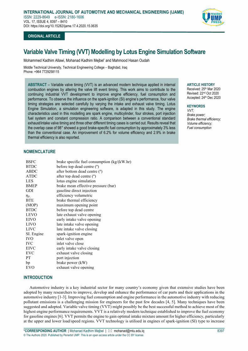
Engine Specifications Four-cylinder, four-strokes, gasoline fuel, was used in the modelling. Details of the engine are illustrated in Table 1
and Figure 1. These engine specifications are utilised to build the engine model in the LES program. For engine characterisation purposes, all the dimensions in lotus software were considered. Predicting and estimating the combustion, flow of gas and overall engine performance are the essential aims of this software. A wide engine’s feature range and types could be simulated by applying this program, such as firing intervals, arrangements of the arbitrary cylinder, four- or two-stroke engines, SI combustion systems and IDI or DI diesel engines. Volumetric efficiency, consumption of fuel, torque and power are the requirements and key performance parameters on a global scale. These parameters have been validated on a wide range of engine industry at present. Lotus software is designed and developed to solve the continuity, momentum and energy formulas in an appropriate manner within each element to provide flow velocity and variables of the thermodynamic state of each crank angle during an engine cycle .
Table 1. Engine specifications.
N Part Name Value N Part Name Value 1 Cylinder 4 6 Density (kg/liter) 0.75 2 Stroke 4 7 Calorific value of fuel (kJ/kg) 43000 3 Bore (mm) 87 8 Firing order 4-2-1-3 4 Stroke length (mm) 84 9 Fuel system PT 5 Compression ratio 11 10 Con-rod length (mm) 130
(a) (b)
Figure 1. Conventional gasoline assembly of engine induction: (a) assembly of induction and, (b) timing of the valve.
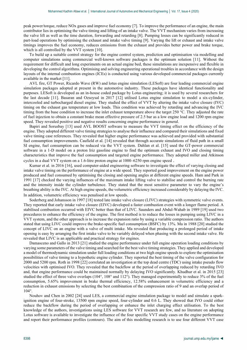
A model of a gasoline engine with four cylinders was built and investigated. The model is demonstrated explicitly in Figure 2. The simulation starts with an intake system, including inlet pipes, ports and valves, intake throttle and the intake plenum. On the discharging component, as exhaust valves, exhaust throttle and exhaust plenum. The simulation of the engine is carried out between 1000 and 3000 rpm at four different valve timing.
VVT Model The study focused on the alteration of the exhaust and intake valve timing of an engine to investigate their effect on
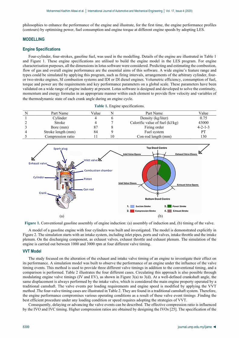
its performance. A simulation model was built to observe the performance of an engine under the influence of the valve timing events. This method is used to provide three different valve timings in addition to the conventional timing, and a comparison is performed. Table 2 illustrates the four different cases. Circulating this approach is also possible through modulating engine valve timings (IV and EV), as shown in Figure 3(a) to 3(d). At a well-defined crankshaft angle, the same displacement is always performed by the intake valve, which is considered the main engine property operated by a traditional camshaft. The valve events per loading requirements and engine speed is modified by applying the VVT method . The four-valve timing cases are illustrated in Table 2. They are found in a traditional camshaft system. Therefore, the engine performance compromises various operating conditions as a result of these valve event timings . Finding the best efficient procedure under any loading condition or speed requires adopting the strategies of VVT.
Consequently, delaying or advancing the valve events can be described. The effective compression ratio is influenced by the IVO and IVC timing. Higher compression ratios are obtained by designing the IVOs [25]. The specification of the
Mohammed Kadhim Allawi et al. │ International Journal of Automotive and Mechanical Engineering │ Vol. 17, Issue 4 (2020)
8400 journal.ump.edu.my/ijame ◄
compression ratio is smaller when the late or early IVC is adopted [22]. The lift of a valve is a critical factor that allows air/fuel mixture or air amount to enter into the cylinder. When the opening valve period is reduced, the maximum life decreased. Hence, a reduction in the maximum volume is observed [20].
Figure 2. Schematic of engine model by LOTUS.
Table 2. Exhaust and intake valve timing case strategies.
(a)
(b)
Case no. Case Type Inlet valve Exhaust valve Overlap
period IVO IVC MOP EVO EVC MOP
1 Decreasing clearance 7° aTDC
48° aBDC 110.5 50°
bBDC 3°
aTDC -
113.5 98
2 Decreasing clearance 12° bTDC
58° aBDC 113 58°
bBDC 12°
aTDC -113 116
3 Conventional clearance 14.7° aTDC
60.3° aBDC 112.8 40°
bBDC 20°
aTDC -100 100.3
4 Increasing clearance 15° bTDC
60° aBDC 112.5 40°
bBDC 20°
aTDC -100 100
Mohammed Kadhim Allawi et al. │ International Journal of Automotive and Mechanical Engineering │ Vol. 17, Issue 4 (2020)
8401 journal.ump.edu.my/ijame ◄
(c)
(d)
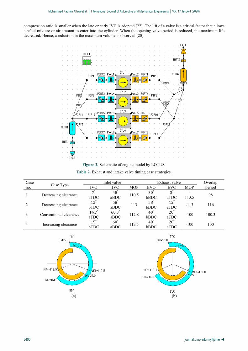
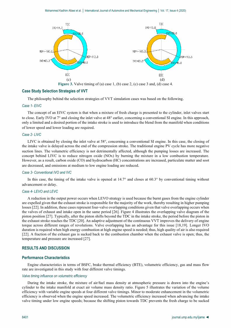
Figure 3. Valve timing of (a) case 1, (b) case 2, (c) case 3 and, (d) case 4.
Case Study Selection Strategies of VVT The philosophy behind the selection strategies of VVT simulation cases was based on the following .
Case 1- EIVC The concept of an EIVC system is that when a mixture of fresh charge is presented to the cylinder, inlet valves start
to close. Early IVO at 7° and closing the inlet valve at 48° earlier, concerning a conventional SI engine. In this approach, only a limited and a desired portion of the intake stroke is used to introduce the blend from the manifold when conditions of lower speed and lower loading are required . Case 2- LIVC
LIVC is obtained by closing the inlet valve at 58°, concerning a conventional SI engine. In this case, the closing of the intake valve is delayed across the end of the compression stroke. The traditional engine PV cycle has more negative suction lines. The volumetric efficiency is not detrimentally affected, although the pumping losses are increased. The concept behind LIVC is to reduce nitrogen oxide (NOx) by burning the mixture in a low combustion temperature. However, as a result, carbon oxide (CO) and hydrocarbon (HC) concentrations are increased, particulate matter and soot are decreased, and emissions at medium to low engine loading are reduced . Case 3- Conventional IVO and IVC
In this case, the timing of the intake valve is opened at 14.7° and closes at 60.3° by conventional timing without advancement or delay . Case 4- LEVO and LEVC
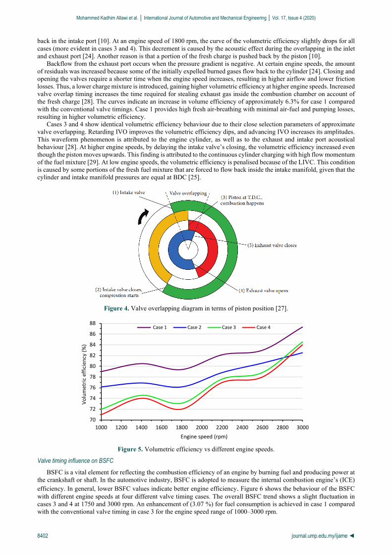
A reduction in the output power occurs when LEVO strategy is used because the burnt gases from the engine cylinder are expelled given that the exhaust stroke is responsible for the majority of the work, thereby resulting in higher pumping losses [22]. In addition, these cases represent four-valve overlapping conditions given that valve overlapping occurs when the valves of exhaust and intake open in the same period [26]. Figure 4 illustrates the overlapping valve diagram of the piston position [27]. Typically, after the piston shifts beyond the TDC in the intake stroke, the period before the piston in the exhaust stroke reaches the TDC [20]. An adaptive adjustment of the continuous VVT improves the delivery of engine torque across different ranges of revolutions. Valve overlapping has an advantage for this issue [18,19]. Longer IVO duration is required when high energy combustion at high engine speed is needed; thus, high quality of air is also required [22]. A fraction of the exhaust gas is sucked back to the combustion chamber when the exhaust valve is open; thus, the temperature and pressure are increased [27].
RESULTS AND DISCUSSION
Performance Characteristics Engine characteristics in terms of BSFC, brake thermal efficiency (BTE), volumetric efficiency, gas and mass flow
rate are investigated in this study with four different valve timings.
Valve timing influence on volumetric efficiency
During the intake stroke, the mixture of air/fuel mass density at atmospheric pressure is drawn into the engine’s cylinder to the intake manifold at exact air volume mass density ratio. Figure 5 illustrates the variation of the volume efficiency with variable engine speeds at four different valve timings. Minor to moderate enhancement in the volumetric efficiency is observed when the engine speed increased. The volumetric efficiency increased when advancing the intake valve timing under low engine speeds; because the shifting piston towards TDC prevents the fresh charge to be sucked
Mohammed Kadhim Allawi et al. │ International Journal of Automotive and Mechanical Engineering │ Vol. 17, Issue 4 (2020)
8402 journal.ump.edu.my/ijame ◄
back in the intake port [10]. At an engine speed of 1800 rpm, the curve of the volumetric efficiency slightly drops for all cases (more evident in cases 3 and 4). This decrement is caused by the acoustic effect during the overlapping in the inlet and exhaust port [24]. Another reason is that a portion of the fresh charge is pushed back by the piston [10].
Backflow from the exhaust port occurs when the pressure gradient is negative. At certain engine speeds, the amount of residuals was increased because some of the initially expelled burned gases flow back to the cylinder [24]. Closing and opening the valves require a shorter time when the engine speed increases, resulting in higher airflow and lower friction losses. Thus, a lower charge mixture is introduced, gaining higher volumetric efficiency at higher engine speeds. Increased valve overlap timing increases the time required for stealing exhaust gas inside the combustion chamber on account of the fresh charge [28]. The curves indicate an increase in volume efficiency of approximately 6.3% for case 1 compared with the conventional valve timings. Case 1 provides high fresh air-breathing with minimal air-fuel and pumping losses, resulting in higher volumetric efficiency .
Cases 3 and 4 show identical volumetric efficiency behaviour due to their close selection parameters of approximate valve overlapping. Retarding IVO improves the volumetric efficiency dips, and advancing IVO increases its amplitudes. This waveform phenomenon is attributed to the engine cylinder, as well as to the exhaust and intake port acoustical behaviour [28] . At higher engine speeds, by delaying the intake valve’s closing, the volumetric efficiency increased even though the piston moves upwards. This finding is attributed to the continuous cylinder charging with high flow momentum of the fuel mixture [29]. At low engine speeds, the volumetric efficiency is penalised because of the LIVC. This condition is caused by some portions of the fresh fuel mixture that are forced to flow back inside the intake manifold, given that the cylinder and intake manifold pressures are equal at BDC [25].
Figure 4. Valve overlapping diagram in terms of piston position [27].
Figure 5. Volumetric efficiency vs different engine speeds.
Valve timing influence on BSFC
BSFC is a vital element for reflecting the combustion efficiency of an engine by burning fuel and producing power at the crankshaft or shaft. In the automotive industry, BSFC is adopted to measure the internal combustion engine’s (ICE) efficiency. In general, lower BSFC values indicate better engine efficiency. Figure 6 shows the behaviour of the BSFC with different engine speeds at four different valve timing cases. The overall BSFC trend shows a slight fluctuation in cases 3 and 4 at 1750 and 3000 rpm. An enhancement of (3.07 %) for fuel consumption is achieved in case 1 compared with the conventional valve timing in case 3 for the engine speed range of 1000–3000 rpm.
70
72
74
76
78
80
82
84
86
88
1000 1200 1400 1600 1800 2000 2200 2400 2600 2800 3000
Volu
met
ric e
ffici
ency
(%)
Engine speed (rpm)
Case 1 Case 2 Case 3 Case 4
Mohammed Kadhim Allawi et al. │ International Journal of Automotive and Mechanical Engineering │ Vol. 17, Issue 4 (2020)
8403 journal.ump.edu.my/ijame ◄
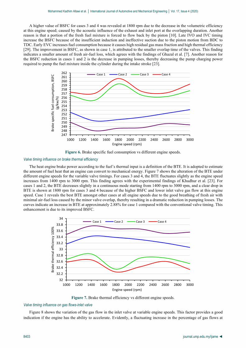
A higher value of BSFC for cases 3 and 4 was revealed at 1800 rpm due to the decrease in the volumetric efficiency at this engine speed; caused by the acoustic influence of the exhaust and inlet port at the overlapping duration. Another reason is that a portion of the fresh fuel mixture is forced to flow back by the piston [10]. Late IVO and IVC timing increase the BSFC because of the insufficient induction and ineffective suction due to the piston motion from BDC to TDC. Early EVC increases fuel consumption because it causes high residual gas mass fraction and high thermal efficiency [29]. The improvement in BSFC, as shown in case 1, is attributed to the smaller overlap time of the valves. This finding indicates a smaller amount of fresh air-fuel loss, which agrees with the findings of Ghazal et al. [7]. Another reason for the BSFC reduction in cases 1 and 2 is the decrease in pumping losses, thereby decreasing the pump charging power required to pump the fuel mixture inside the cylinder during the intake stroke [23].
Figure 6. Brake specific fuel consumption vs different engine speeds.
Valve timing influence on brake thermal efficiency
The heat engine brake power according to the fuel’s thermal input is a definition of the BTE. It is adopted to estimate the amount of fuel heat that an engine can convert to mechanical energy. Figure 7 shows the alteration of the BTE under different engine speeds for the variable valve timings. For cases 3 and 4, the BTE fluctuates slightly as the engine speed increases from 1400 rpm to 3000 rpm. This finding agrees with the experimental findings of Khudhur et al. [23]. For cases 1 and 2, the BTE decreases slightly in a continuous mode starting from 1400 rpm to 3000 rpm, and a clear drop in BTE is shown at 1800 rpm for cases 3 and 4 because of the higher BSFC and lower inlet valve gas flow at this engine speed. Case 1 reveals the best BTE amongst other cases at all engine speeds due to the good breathing of fresh air with minimal air-fuel loss caused by the minor valve overlap, thereby resulting in a dramatic reduction in pumping losses. The curves indicate an increase in BTE at approximately 2.88% for case 1 compared with the conventional valve timing. This enhancement is due to its improved BSFC.
Figure 7. Brake thermal efficiency vs different engine speeds.
Valve timing influence on gas flows-inlet valve
Figure 8 shows the variation of the gas flow in the inlet valve at variable engine speeds. This factor provides a good indication if the engine has the ability to accelerate . Evidently, a fluctuating increase in the percentage of gas flows at
247248249250251252253254255256257258259260261262
1000 1200 1400 1600 1800 2000 2200 2400 2600 2800 3000
Brak
e sp
ecifi
c fu
el c
onsu
mpt
ion,
BSF
C (g
/kw
/h)
Engine speed (rpm)
Case 1 Case 2 Case 3 Case 4
32
32.2
32.4
32.6
32.8
33
33.2
33.4
33.6
33.8
34
1000 1200 1400 1600 1800 2000 2200 2400 2600 2800 3000
Brak
e th
erm
al e
ffici
ency
100
%
Engine speed (rpm)
Case 1 Case 2 Case 3 Case 4
Mohammed Kadhim Allawi et al. │ International Journal of Automotive and Mechanical Engineering │ Vol. 17, Issue 4 (2020)
8404 journal.ump.edu.my/ijame ◄
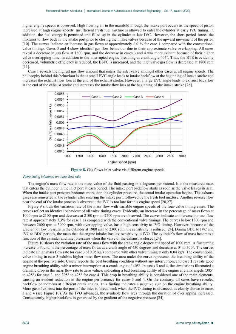
higher engine speeds is observed. High flowing air in the manifold through the intake port occurs as the speed of piston increased at high engine speeds. Insufficient fresh fuel mixture is allowed to enter the cylinder at early IVC timing. In addition, the fuel charge is permitted and filled up in the cylinder at late IVC. However, the short period forces the mixtures to flow back in the intake port prior to closing the intake valves because of the upward movement of the piston [10]. The curves indicate an increase in gas flows at approximately 6.0 % for case 1 compared with the conventional valve timings. Cases 3 and 4 show identical gas flow behaviour due to their approximate valve overlapping. All cases reveal a decrease in gas flow at 1800 rpm, and the decrease in cases 3 and 4 was more evident because of their higher valve overlapping time, in addition to the interrupted engine breathing at crank angle 405°. Thus, the BTE is evidently decreased, volumetric efficiency is reduced, the BSFC is increased, and the inlet valve gas flow is decreased at 1800 rpm [11].
Case 1 reveals the highest gas flow amount that enters the inlet valve amongst other cases at all engine speeds. The philosophy behind this behaviour is that a small EVC angle leads to intake backflow at the beginning of intake stroke and increases the exhaust flow loss at the end of the exhaust stroke. However, a large EVC angle leads to exhaust backflow at the end of the exhaust stroke and increases the intake flow loss at the beginning of the intake stroke [28].
Figure 8. Gas flows-inlet valve vis different engine speeds.
Valve timing influence on mass flow rate
The engine’s mass flow rate is the mass value of the fluid passing in kilograms per second. It is the measured mass that enters the cylinder in the inlet port at each period. The intake port backflow starts as soon as the valve leaves its seat. When the intake port pressure becomes more than the cylinder pressure, the actual intake operation begins. The exhaust gases are reinserted in the cylinder after entering the intake port, followed by the fresh fuel mixture. Another reverse flow near the end of the intake process is observed; the IVC is too late for this engine speed [20,27].
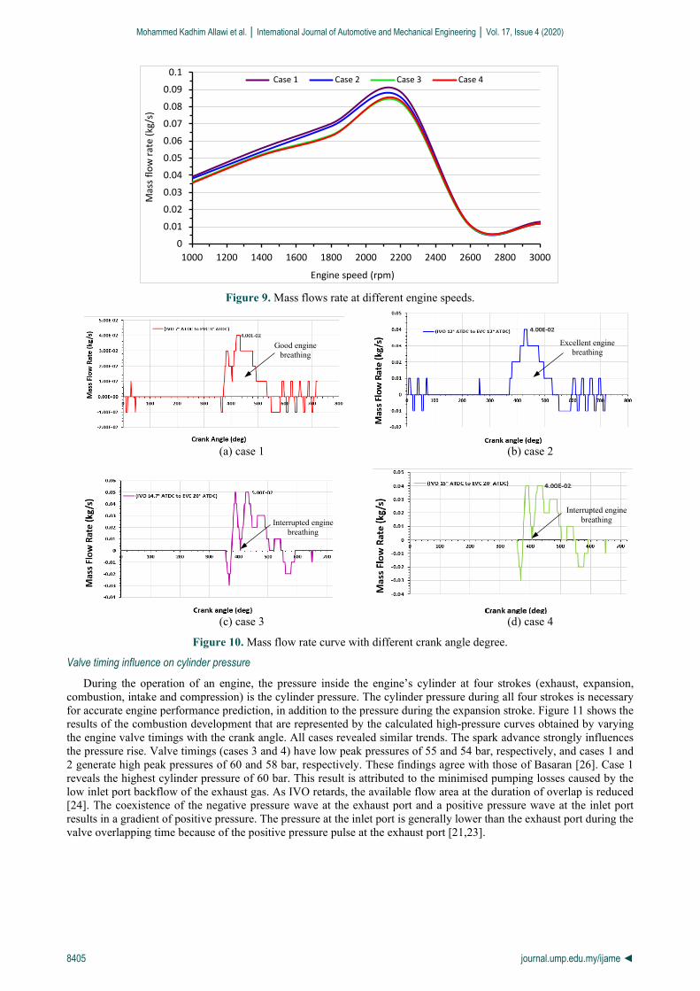
Figure 9 shows the variation rate of the mass flow with variable engine speeds of the four-valve timing cases. The curves reflect an identical behaviour of all valve timing cases. Evidently, an increase in the percentage of mass flows at 1000 rpm to 2100 rpm and decrease at 2100 rpm to 2700 rpm are observed. The curves indicate an increase in mass flow rate at approximately 7.3% for case 1 as compared with the conventional valve timings. The curves below 1800 rpm and between 2600 rpm to 3000 rpm, with overlapping valve, has a high sensitivity to IVO timing. However, because of the gradient of low pressure in the cylinder at 1900 rpm to 2300 rpm, the sensitivity is reduced [24]. During BDC to IVC and IVC to BDC periods, the mass that the engine inhales has less sensitivity to IVO. The cylinder’s flow of mass becomes a function of the cylinder and inlet pressures when the valve of the exhaust is closed [24].
Figure 10 shows the variation rate of the mass flow with the crank angle degree at a speed of 1000 rpm. A fluctuating increase is found in the percentage of mass flows at a crank angle of 450 degrees and decrease at 0° to 300°. The curves indicate a high mass flow rate for case 3 of 0.05 kg/s compared with other valve timing at only 0.04 kg/s. The conventional valve timing in case 3 exhibits higher mass flow rates. The area under the curve represents the breathing ability of the engine at the positive side. Case 2 reports the best breathing condition without any interruption, and case 1 reveals good engine breathing ability with a minor interruption at a crank angle of 405°. In cases 3 and 4, the simulations illustrated a dramatic drop in the mass flow rate to zero values, indicating a bad breathing ability of the engine at crank angels (385° to 425°) for case 3, and 395° to 425° for case 4. This drop in breathing ability is considered one of the main elements, causing an evident reduction in the engine performance for cases 3 and 4. On the contrary, all cases have revealed backflow phenomena at different crank angles. This finding indicates a negative sign on the engine breathing ability. More gas of exhaust into the port of the inlet is forced back when the IVO timing is advanced, as clearly shown in cases 3 and 4 (see Figure 10) . As the IVO advances, the available flow area through the duration of overlapping increased. Consequently, higher backflow is generated by the gradient of the negative pressure [24].
0.0045
0.0046
0.0047
0.0048
0.0049
0.005
0.0051
0.0052
0.0053
0.0054
0.0055
1000 1200 1400 1600 1800 2000 2200 2400 2600 2800 3000
Gas f
low
/ In
let v
alve
/ kg
Engine speed (rpm)
Case 1 Case 2 Case 3 Case 4
Mohammed Kadhim Allawi et al. │ International Journal of Automotive and Mechanical Engineering │ Vol. 17, Issue 4 (2020)
8405 journal.ump.edu.my/ijame ◄
Figure 9. Mass flows rate at different engine speeds.
(a) case 1 (b) case 2
(c) case 3 (d) case 4
Figure 10. Mass flow rate curve with different crank angle degree.
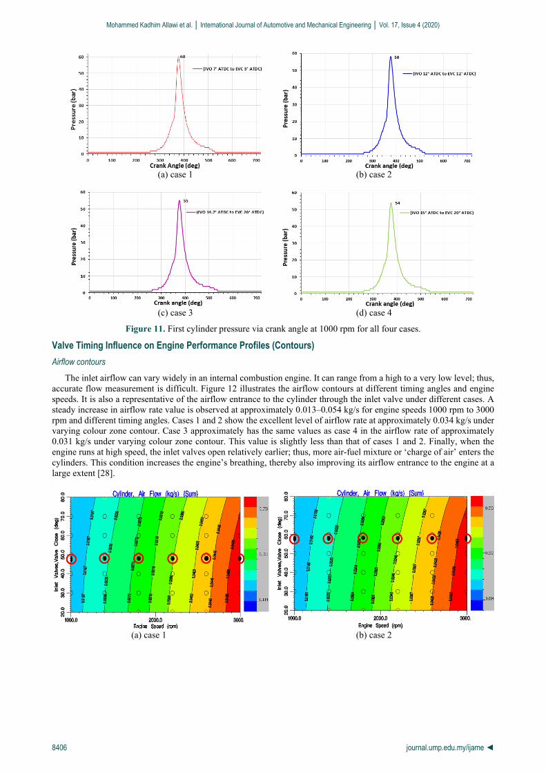
Valve timing influence on cylinder pressure During the operation of an engine, the pressure inside the engine’s cylinder at four strokes (exhaust, expansion,
combustion, intake and compression) is the cylinder pressure. The cylinder pressure during all four strokes is necessary for accurate engine performance prediction, in addition to the pressure during the expansion stroke. Figure 11 shows the results of the combustion development that are represented by the calculated high-pressure curves obtained by varying the engine valve timings with the crank angle. All cases revealed similar trends. The spark advance strongly influences the pressure rise. Valve timings (cases 3 and 4) have low peak pressures of 55 and 54 bar, respectively, and cases 1 and 2 generate high peak pressures of 60 and 58 bar, respectively. These findings agree with those of Basaran [26]. Case 1 reveals the highest cylinder pressure of 60 bar. This result is attributed to the minimised pumping losses caused by the low inlet port backflow of the exhaust gas. As IVO retards, the available flow area at the duration of overlap is reduced [24]. The coexistence of the negative pressure wave at the exhaust port and a positive pressure wave at the inlet port results in a gradient of positive pressure. The pressure at the inlet port is generally lower than the exhaust port during the valve overlapping time because of the positive pressure pulse at the exhaust port [21,23].
0
0.01
0.02
0.03
0.04
0.05
0.06
0.07
0.08
0.09
0.1
1000 1200 1400 1600 1800 2000 2200 2400 2600 2800 3000
Mas
s flo
w ra
te (k
g/s)
Engine speed (rpm)
Case 1 Case 2 Case 3 Case 4
Good engine breathing
Excellent engine breathing
Interrupted engine breathing
Interrupted engine breathing
Mohammed Kadhim Allawi et al. │ International Journal of Automotive and Mechanical Engineering │ Vol. 17, Issue 4 (2020)
8406 journal.ump.edu.my/ijame ◄
(a) case 1 (b) case 2
(c) case 3 (d) case 4
Figure 11. First cylinder pressure via crank angle at 1000 rpm for all four cases.
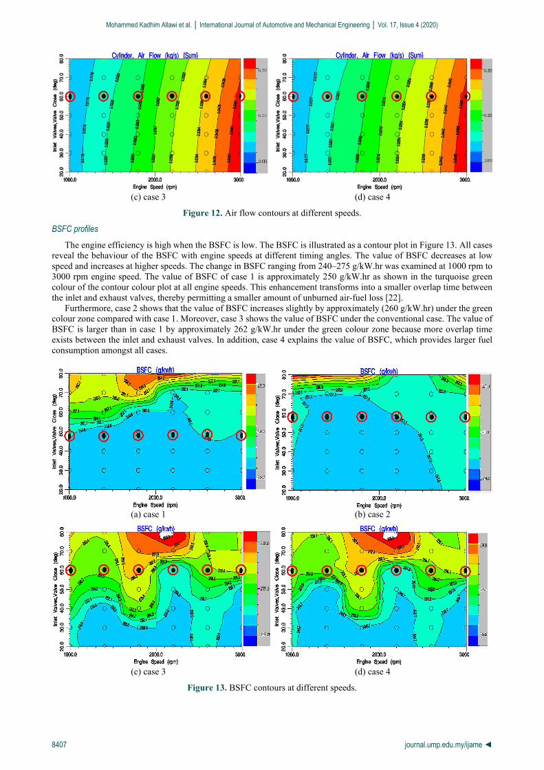
Valve Timing Influence on Engine Performance Profiles (Contours) Airflow contours
The inlet airflow can vary widely in an internal combustion engine. It can range from a high to a very low level; thus, accurate flow measurement is difficult. Figure 12 illustrates the airflow contours at different timing angles and engine speeds. It is also a representative of the airflow entrance to the cylinder through the inlet valve under different cases. A steady increase in airflow rate value is observed at approximately 0.013–0.054 kg/s for engine speeds 1000 rpm to 3000 rpm and different timing angles. Cases 1 and 2 show the excellent level of airflow rate at approximately 0.034 kg/s under varying colour zone contour. Case 3 approximately has the same values as case 4 in the airflow rate of approximately 0.031 kg/s under varying colour zone contour. This value is slightly less than that of cases 1 and 2. Finally, when the engine runs at high speed, the inlet valves open relatively earlier; thus, more air-fuel mixture or ‘charge of air’ enters the cylinders. This condition increases the engine’s breathing, thereby also improving its airflow entrance to the engine at a large extent [28].
(a) case 1 (b) case 2
Mohammed Kadhim Allawi et al. │ International Journal of Automotive and Mechanical Engineering │ Vol. 17, Issue 4 (2020)
8407 journal.ump.edu.my/ijame ◄
(c) case 3 (d) case 4
Figure 12. Air flow contours at different speeds.
BSFC profiles
The engine efficiency is high when the BSFC is low. The BSFC is illustrated as a contour plot in Figure 13. All cases reveal the behaviour of the BSFC with engine speeds at different timing angles. The value of BSFC decreases at low speed and increases at higher speeds. The change in BSFC ranging from 240–275 g/kW.hr was examined at 1000 rpm to 3000 rpm engine speed. The value of BSFC of case 1 is approximately 250 g/kW.hr as shown in the turquoise green colour of the contour colour plot at all engine speeds. This enhancement transforms into a smaller overlap time between the inlet and exhaust valves, thereby permitting a smaller amount of unburned air-fuel loss [22].
Furthermore, case 2 shows that the value of BSFC increases slightly by approximately (260 g/kW.hr) under the green colour zone compared with case 1. Moreover, case 3 shows the value of BSFC under the conventional case. The value of BSFC is larger than in case 1 by approximately 262 g/kW.hr under the green colour zone because more overlap time exists between the inlet and exhaust valves. In addition, case 4 explains the value of BSFC, which provides larger fuel consumption amongst all cases.
(a) case 1 (b) case 2
(c) case 3 (d) case 4
Figure 13. BSFC contours at different speeds.
Mohammed Kadhim Allawi et al. │ International Journal of Automotive and Mechanical Engineering │ Vol. 17, Issue 4 (2020)
8408 journal.ump.edu.my/ijame ◄
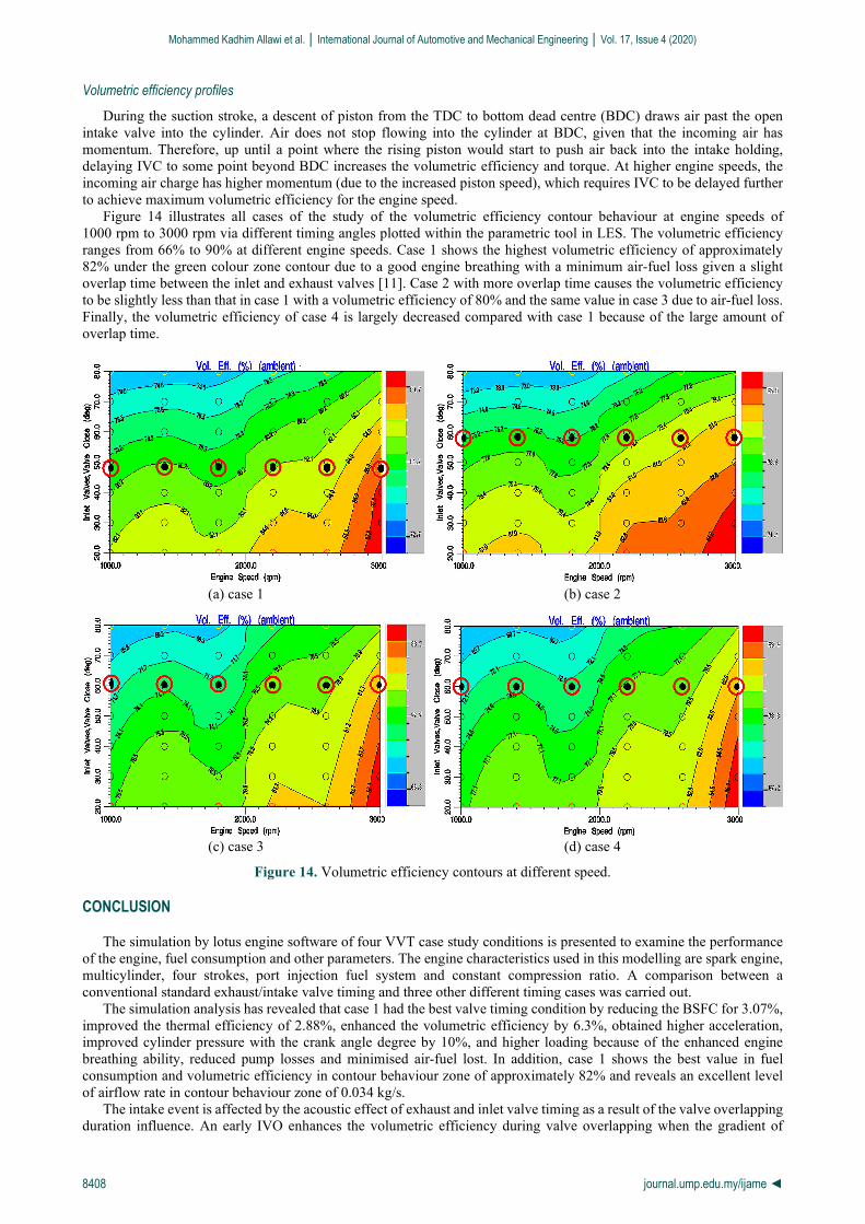
Volumetric efficiency profiles
During the suction stroke, a descent of piston from the TDC to bottom dead centre (BDC) draws air past the open intake valve into the cylinder. Air does not stop flowing into the cylinder at BDC, given that the incoming air has momentum. Therefore, up until a point where the rising piston would start to push air back into the intake holding, delaying IVC to some point beyond BDC increases the volumetric efficiency and torque. At higher engine speeds, the incoming air charge has higher momentum (due to the increased piston speed), which requires IVC to be delayed further to achieve maximum volumetric efficiency for the engine speed.
Figure 14 illustrates all cases of the study of the volumetric efficiency contour behaviour at engine speeds of 1000 rpm to 3000 rpm via different timing angles plotted within the parametric tool in LES. The volumetric efficiency ranges from 66% to 90% at different engine speeds. Case 1 shows the highest volumetric efficiency of approximately 82% under the green colour zone contour due to a good engine breathing with a minimum air-fuel loss given a slight overlap time between the inlet and exhaust valves [11]. Case 2 with more overlap time causes the volumetric efficiency to be slightly less than that in case 1 with a volumetric efficiency of 80% and the same value in case 3 due to air-fuel loss. Finally, the volumetric efficiency of case 4 is largely decreased compared with case 1 because of the large amount of overlap time.
(a) case 1 (b) case 2
(c) case 3 (d) case 4
Figure 14. Volumetric efficiency contours at different speed.
CONCLUSION
The simulation by lotus engine software of four VVT case study conditions is presented to examine the performance of the engine, fuel consumption and other parameters. The engine characteristics used in this modelling are spark engine, multicylinder, four strokes, port injection fuel system and constant compression ratio. A comparison between a conventional standard exhaust/intake valve timing and three other different timing cases was carried out.
The simulation analysis has revealed that case 1 had the best valve timing condition by reducing the BSFC for 3.07%, improved the thermal efficiency of 2.88%, enhanced the volumetric efficiency by 6.3%, obtained higher acceleration, improved cylinder pressure with the crank angle degree by 10%, and higher loading because of the enhanced engine breathing ability, reduced pump losses and minimised air-fuel lost. In addition, case 1 shows the best value in fuel consumption and volumetric efficiency in contour behaviour zone of approximately 82% and reveals an excellent level of airflow rate in contour behaviour zone of 0.034 kg/s.
The intake event is affected by the acoustic effect of exhaust and inlet valve timing as a result of the valve overlapping duration influence. An early IVO enhances the volumetric efficiency during valve overlapping when the gradient of
Mohammed Kadhim Allawi et al. │ International Journal of Automotive and Mechanical Engineering │ Vol. 17, Issue 4 (2020)
8409 journal.ump.edu.my/ijame ◄
positive pressure via the cylinder occurs. To enhance the volumetric efficiency dips, IVO needs to be retarded whenever negative pressure gradient occurs. The highest volumetric efficiency was reported with (valve overlap of 98°). Varying the engine speed fluctuates the ideal IVO timing. Ideal IVC previously reported trends are different. Therefore, advancing or retarding the phasing of intake may not always satisfy the criteria of IVC and IVO. Across the range of most engine speeds, the volumetric efficiency dips and peaks are potentially improved by varying IVO. Applying IVC and IVO variable timing strategy improves the performance of the engine at a specific case selection. Finally, the authors would strongly recommend the lotus software to be widely applied by engine car manufacturers to improve their engine VVT systems.
ACKNOWLEDGEMENT
The Authors would like to thank the Technical Engineering College-Baghdad/ Power Mechanics Engineering Department and Materials Techniques Engineering Department for their kind support.
REFERENCES
[1] Zulhilmi IM, Peeie MH, Eiman RIM, et al. Investigation on vehicle dynamic behaviour during emergency braking at different speed. International Journal of Automotive and Mechanical Engineering 2019; 16(1), 6161-6172.
[2] Corzo SF, Ramajo DE, Nigro NM. Transient numerical assessment of race car dry-sump oil under extreme maneuvers. International Journal of Automotive and Mechanical Engineering 2018; 15(3), 5636-5651
[3] Allawi MK, Oudah MH, Mejbel MK. Analysis of exhaust manifold of spark-ignition engine by using computational fluid dynamics (CFD). Journal of Mechanical Engineering Research and Developments 2019; 42: 211–215.
[4] Stanton DW. Systematic development of highly efficient and clean engines to meet future commercial vehicle greenhouse gas regulations. SAE International Journal of Engines 2013; 6(3): 1395-1480.
[5] Cecchel S, Chindamo D, Turrini E, Carnevale C, et al. Impact of reduced mass of light commercial vehicles on fuel consumption, CO2 emissions, air quality, and socio-economic costs. Science of The Total Environment 2018; 613: 409–417.
[6] Cairns A, Todd A, Aleiferis P, et al. A comparison of inlet valve operating strategies in a single cylinder spark ignition engine. In: IMeche - Internal Combustion Engines: Performance, Fuel Economy and Emissions, London, UK; 8-9 December, 2009.
[7] Ghazal OH, Najjar YS, AL-Khishali KJ. Effect of inlet valve variable timing in the spark ignition engine on achieving greener transport. International Journal of Mechanical, Aerospace, Industrial, Mechatronic and Manufacturing Engineering 2011; 5: 2543–2547.
[8] Abdul Rasid AF, Mohamad TI, Ghazali MJ, et al. improvement of engine performance using an adaptive valve lift and timing (AVLT) mechanism at high engine speeds. Applied Mechanics and Materials 2014; 663: 359–365.
[9] Fontana G, Galloni E. Variable valve timing for fuel economy improvement in a small spark-ignition engine. Applied Energy 2009; 86: 96–105.
[10] Cinar C, Akgün F. Effect of intake valve closing time on engine performance and exhaust emissions in a spark ignition engine. Politeknik Dergisi 2007; 10(4): 371-375.
[11] Allawi MK, Mejbel MK, Younis YM, et al. A Simulation of the Effect of Iraqi Diesel Fuel Cetane Number on the Performance of a Compression Ignition Engine. International Review of Mechanical Engineering (IREME) 2020; 14: 151–159.
[12] Basaran HU, Ozsoysal OA. Effects of application of variable valve timing on the exhaust gas temperature improvement in a low-loaded diesel engine. Applied Thermal Engineering 2017; 122: 758–767.
[13] Bapiri S, Sorusbay C. Investigating the effects of variable valve timing on spark ignition engine performance. Advances in Science and Technology Research Journal 2019; 13(2): 100-111
[14] Caulfield S, Rubenstein B, Martin JK, et al. A comparison between CFD predictions and measurements of inlet port discharge coefficient and flow characteristics. Epub ahead of print 1999. DOI: 10.4271/1999-01-3339.
[15] Dahlan AA, Shahrafi M, Said MFM. Simulation of intake and exhaust valve timing on internal combustion engine. Jurnal Teknologi 2017; 79: 47-52.
[16] Kumar A, Tyagi S, Singh A, et al. Optimisation of variable valve timings of an SI engine using CAE Software, ELK Asia Pacific Journal of Mechanical Engineering Research 2016; 2(1): 1–10.
[17] Ham Y-Y, Park P. The effects of intake valve events on engine breathing capability. SAE Technical Paper: 912470; 1991. [18] Söderberg F, Johansson B. Fluid flow, combustion and efficiency with early or late inlet valve closing. SAE Technical Paper:
972937; 1997. [19] Saunders RJ, Abdul-Wahab EA. Variable valve closure timing for load control and the Otto Atkinson cycle engine. SAE
Technical Paper: 890677; 1989. [20] Ma TH. Effect of variable engine valve timing on fuel economy. SAE Technical Paper: 880390; 1988. [21] Damasceno LIR, Gallo WLR. Variable valve timing and its effects on performance of a spark-ignition engine. SAE Technical
Paper: 2013-36-0318; 2013. [22] Roth DB. Intake valve opening optimization. SAE Technical Paper: 981028; 1998. [23] Khudhur SH, Saleh AM, Chaichan MT. The effect of variable valve timing on SIE performance and emissions. International
Journal of Scientific & Engineering Research 2015; 6: 173–179. [24] Nouhov D, Chen R. A simulation study on the effect of inlet valve opening on performance of high speed engines. In: 17th
JSAE Internal Combustion Engine Symposium, Tokyo, Japan, pp. 149–152; 2002. [25] Asmus TW. Valve events and engine operation. SAE Technical Paper: 820749, 1982. [26] Başaran HÜ. Modelling the effect of intake valve closing timing on exhaust thermal management of a turbocharged and
intercooled diesel engine. Gemi ve Deniz Teknolojisi 2016; 206: 3-17. [27] Chan K, Ordys A, Volkov K, et al. Comparison of engine simulation software for development of control system. Modelling
and Simulation in Engineering 2013; 2013: 21. [28] Parvate-Patil GB, Hong H, Gordon B. An assessment of intake and exhaust philosophies for variable valve timing. SAE
Mohammed Kadhim Allawi et al. │ International Journal of Automotive and Mechanical Engineering │ Vol. 17, Issue 4 (2020)
8410 journal.ump.edu.my/ijame ◄
Technical Paper: 2003-32-0078; 2003. [29] Allawi MK, Mejbel MK, Oudah MH. Iraqi gasoline performance at low engine speeds. IOP Conference Series: Materials
Science and Engineering 2020; 881: 12065.