Embed Size (px)
Citation preview
2-7576
Page 1 of 10F-4126 7-7-08
715828036
TRACTOR AND VALVE KIT GENERAL INFORMATION
Valve and plumbing kit can be installed on tractor usingtools ordinarily available. Valve control linkage has beenfactory preassembled for ease of installation.
WARNING: Escaping hydraulic fluidunder pressure can penetrate skin,causing serious personal injury.
Do not use your hands to check for leaks. Usea piece of cardboard or paper. Always weareye protection when searching for leaks.
Place control lever in float position and stoptractor engine to relieve hydraulic pressurebefore connecting or disconnecting lines.
Tighten all connections before startingengine or pressurizing lines.
If any fluid is injected into skin, obtain medical atten-tion immediately or gangrene may result.
Shut off tractor engine, remove key, engage tractorbrakes, and completely lower three-point hitch duringinstallation.
If tractor has no optional auxiliary valve continue withinstructions on page 1. If tractor is equipped with oneor two optional auxiliary valves continue instructions onpage 5.
TRACTOR WITH NO OPTIONAL AUXILIARY VALVE:
ASSEMBLING VALVE AND HOSES ONTO VALVEMOUNTING TUBE (Figures 1 & 2)
1. Unpack all parts and check to see that nothing ismissing.
2. Install 3/8” x 78” hose (9) to tank port of controlvalve (1). Slide 78” nylon sleeve (15) over 3/8” x 78”hose (9) and secure it to fitting at valve end withplastic tie strap (30).
VALVE & PLUMBING KIT INSTRUCTIONSNEW HOLLAND 620TL LOADER
NEW HOLLAND TRACTORS
ASSEMBLY MANUAL
Keep With Operator’s Manual
Install 3/8” x 36” hose (11) to pressure port ofcontrol valve (1). Slide 36” nylon sleeve (17) over 3/8” x 36” hose (11) and secure it to fitting at valveend with plastic tie strap (30). Tighten hoses (9 &11) to ports in valve.
3. Install 3/8” x 85” hose (10) to power beyond port oncontrol valve (1). Slide 86” nylon sleeve (16) over3/8” x 85” hose (10) and secure it to fitting at valveend with plastic tie strap. Tighten hose (10) tocontrol valve (1).
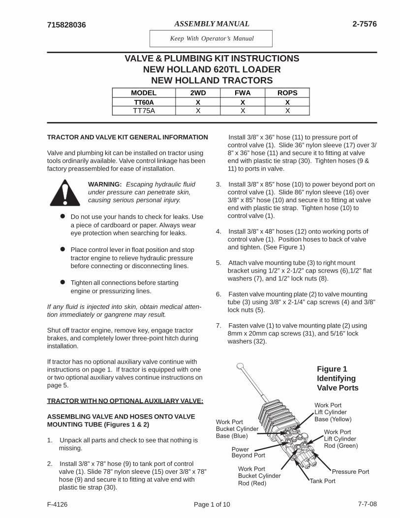
4. Install 3/8” x 48” hoses (12) onto working ports ofcontrol valve (1). Position hoses to back of valveand tighten. (See Figure 1)
5. Attach valve mounting tube (3) to right mountbracket using 1/2” x 2-1/2” cap screws (6),1/2” flatwashers (7), and 1/2” lock nuts (8).
6. Fasten valve mounting plate (2) to valve mountingtube (3) using 3/8” x 2-1/4” cap screws (4) and 3/8”lock nuts (5).
7. Fasten valve (1) to valve mounting plate (2) using8mm x 20mm cap screws (31), and 5/16” lockwashers (32).
MODEL 2WD FWA ROPSTT60A X X XTT75A X X X
Figure 1IdentifyingValve Ports
Pressure Port
Tank Port
PowerBeyond Port
Work PortBucket CylinderBase (Blue)
Work PortBucket Cylinder
Rod (Red)
Work PortLift Cylinder
Base (Yellow)
Work PortLift Cylinder
Rod (Green)
2-7576
Page 2 of 10F-4126 7-7-08
715828036
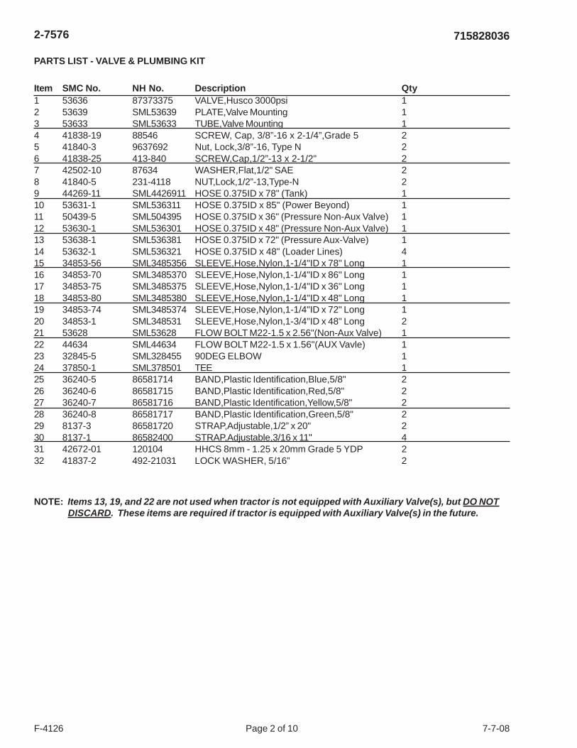
PARTS LIST - VALVE & PLUMBING KIT
Item SMC No. NH No. Description Qty1 53636 87373375 VALVE,Husco 3000psi 12 53639 SML53639 PLATE,Valve Mounting 13 53633 SML53633 TUBE,Valve Mounting 14 41838-19 88546 SCREW, Cap, 3/8”-16 x 2-1/4”,Grade 5 25 41840-3 9637692 Nut, Lock,3/8”-16, Type N 26 41838-25 413-840 SCREW,Cap,1/2”-13 x 2-1/2" 27 42502-10 87634 WASHER,Flat,1/2" SAE 28 41840-5 231-4118 NUT,Lock,1/2”-13,Type-N 29 44269-11 SML4426911 HOSE 0.375ID x 78" (Tank) 110 53631-1 SML536311 HOSE 0.375ID x 85" (Power Beyond) 111 50439-5 SML504395 HOSE 0.375ID x 36" (Pressure Non-Aux Valve) 112 53630-1 SML536301 HOSE 0.375ID x 48" (Pressure Non-Aux Valve) 113 53638-1 SML536381 HOSE 0.375ID x 72" (Pressure Aux-Valve) 114 53632-1 SML536321 HOSE 0.375ID x 48" (Loader Lines) 415 34853-56 SML3485356 SLEEVE,Hose,Nylon,1-1/4"ID x 78" Long 116 34853-70 SML3485370 SLEEVE,Hose,Nylon,1-1/4"ID x 86" Long 117 34853-75 SML3485375 SLEEVE,Hose,Nylon,1-1/4"ID x 36" Long 118 34853-80 SML3485380 SLEEVE,Hose,Nylon,1-1/4"ID x 48" Long 119 34853-74 SML3485374 SLEEVE,Hose,Nylon,1-1/4"ID x 72" Long 120 34853-1 SML348531 SLEEVE,Hose,Nylon,1-3/4"ID x 48" Long 221 53628 SML53628 FLOW BOLT M22-1.5 x 2.56"(Non-Aux Valve) 122 44634 SML44634 FLOW BOLT M22-1.5 x 1.56"(AUX Vavle) 123 32845-5 SML328455 90DEG ELBOW 124 37850-1 SML378501 TEE 125 36240-5 86581714 BAND,Plastic Identification,Blue,5/8" 226 36240-6 86581715 BAND,Plastic Identification,Red,5/8" 227 36240-7 86581716 BAND,Plastic Identification,Yellow,5/8" 228 36240-8 86581717 BAND,Plastic Identification,Green,5/8" 229 8137-3 86581720 STRAP,Adjustable,1/2” x 20" 230 8137-1 86582400 STRAP,Adjustable,3/16 x 11" 431 42672-01 120104 HHCS 8mm - 1.25 x 20mm Grade 5 YDP 232 41837-2 492-21031 LOCK WASHER, 5/16” 2
NOTE: Items 13, 19, and 22 are not used when tractor is not equipped with Auxiliary Valve(s), but DO NOTDISCARD. These items are required if tractor is equipped with Auxiliary Valve(s) in the future.
2-7576
Page 3 of 10F-4126 7-7-08
715828036
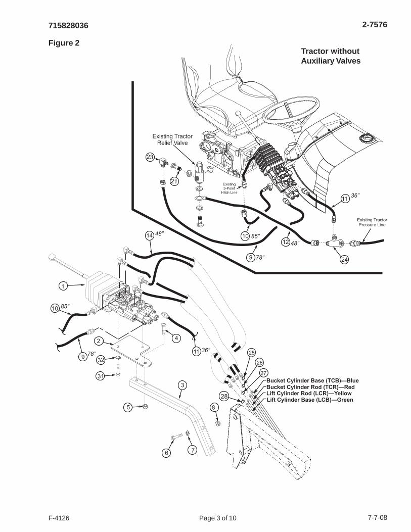
Figure 2
Bucket Cylinder Base (TCB)—BlueBucket Cylinder Rod (TCR)—Red
Lift Cylinder Base (LCB)—GreenLift Cylinder Rod (LCR)—Yellow
25
28
26
27
6 7
8
11
24
1012
21
23
9
Existing TractorPressure Line
Existing TractorRelief Valve
Existing3-Point
Hitch Line
1
2
3
4
5
31
329
10
14 85”
78”
48”
36”
~
~ ~
11
48”
85”
78”36”
Tractor withoutAuxiliary Valves
2-7576
Page 4 of 10F-4126 7-7-08
715828036
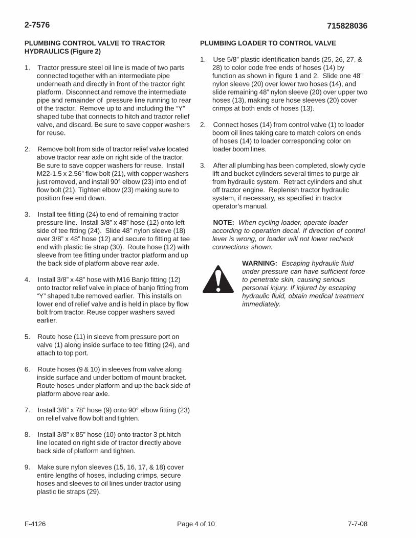
PLUMBING CONTROL VALVE TO TRACTORHYDRAULICS (Figure 2)
1. Tractor pressure steel oil line is made of two partsconnected together with an intermediate pipeunderneath and directly in front of the tractor rightplatform. Disconnect and remove the intermediatepipe and remainder of pressure line running to rearof the tractor. Remove up to and including the “Y”shaped tube that connects to hitch and tractor reliefvalve, and discard. Be sure to save copper washersfor reuse.
2. Remove bolt from side of tractor relief valve locatedabove tractor rear axle on right side of the tractor.Be sure to save copper washers for reuse. InstallM22-1.5 x 2.56” flow bolt (21), with copper washersjust removed, and install 90° elbow (23) into end offlow bolt (21). Tighten elbow (23) making sure toposition free end down.
3. Install tee fitting (24) to end of remaining tractorpressure line. Install 3/8” x 48” hose (12) onto leftside of tee fitting (24). Slide 48” nylon sleeve (18)over 3/8” x 48” hose (12) and secure to fitting at teeend with plastic tie strap (30). Route hose (12) withsleeve from tee fitting under tractor platform and upthe back side of platform above rear axle.
4. Install 3/8” x 48” hose with M16 Banjo fitting (12)onto tractor relief valve in place of banjo fitting from“Y” shaped tube removed earlier. This installs onlower end of relief valve and is held in place by flowbolt from tractor. Reuse copper washers savedearlier.
5. Route hose (11) in sleeve from pressure port onvalve (1) along inside surface to tee fitting (24), andattach to top port.
6. Route hoses (9 & 10) in sleeves from valve alonginside surface and under bottom of mount bracket.Route hoses under platform and up the back side ofplatform above rear axle.
7. Install 3/8” x 78” hose (9) onto 90° elbow fitting (23)on relief valve flow bolt and tighten.
8. Install 3/8” x 85” hose (10) onto tractor 3 pt.hitchline located on right side of tractor directly aboveback side of platform and tighten.
9. Make sure nylon sleeves (15, 16, 17, & 18) coverentire lengths of hoses, including crimps, securehoses and sleeves to oil lines under tractor usingplastic tie straps (29).
PLUMBING LOADER TO CONTROL VALVE
1. Use 5/8” plastic identification bands (25, 26, 27, &28) to color code free ends of hoses (14) byfunction as shown in figure 1 and 2. Slide one 48”nylon sleeve (20) over lower two hoses (14), andslide remaining 48” nylon sleeve (20) over upper twohoses (13), making sure hose sleeves (20) covercrimps at both ends of hoses (13).
2. Connect hoses (14) from control valve (1) to loaderboom oil lines taking care to match colors on endsof hoses (14) to loader corresponding color onloader boom lines.
3. After all plumbing has been completed, slowly cyclelift and bucket cylinders several times to purge airfrom hydraulic system. Retract cylinders and shutoff tractor engine. Replenish tractor hydraulicsystem, if necessary, as specified in tractoroperator’s manual.
NOTE: When cycling loader, operate loaderaccording to operation decal. If direction of controllever is wrong, or loader will not lower recheckconnections shown.
WARNING: Escaping hydraulic fluidunder pressure can have sufficient forceto penetrate skin, causing seriouspersonal injury. If injured by escapinghydraulic fluid, obtain medical treatmentimmediately.
2-7576
Page 5 of 10F-4126 7-7-08
715828036
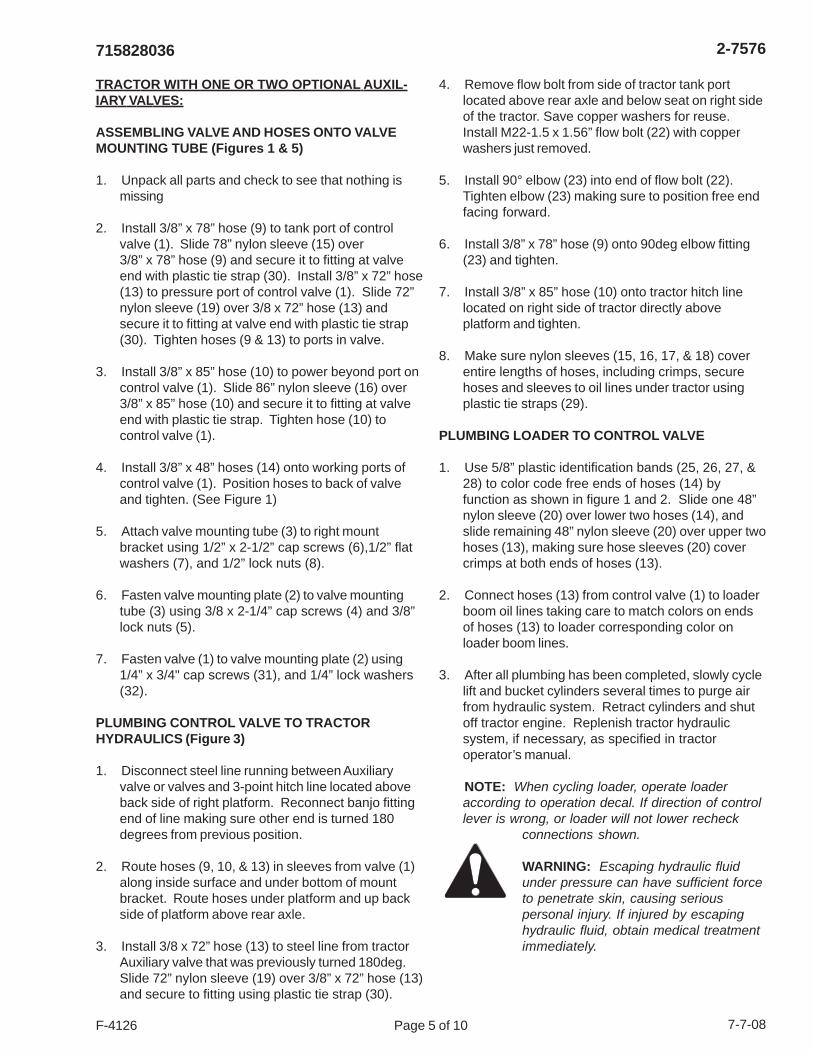
TRACTOR WITH ONE OR TWO OPTIONAL AUXIL-IARY VALVES:
ASSEMBLING VALVE AND HOSES ONTO VALVEMOUNTING TUBE (Figures 1 & 5)
1. Unpack all parts and check to see that nothing ismissing
2. Install 3/8” x 78” hose (9) to tank port of controlvalve (1). Slide 78” nylon sleeve (15) over3/8” x 78” hose (9) and secure it to fitting at valveend with plastic tie strap (30). Install 3/8” x 72” hose(13) to pressure port of control valve (1). Slide 72”nylon sleeve (19) over 3/8 x 72” hose (13) andsecure it to fitting at valve end with plastic tie strap(30). Tighten hoses (9 & 13) to ports in valve.
3. Install 3/8” x 85” hose (10) to power beyond port oncontrol valve (1). Slide 86” nylon sleeve (16) over3/8” x 85” hose (10) and secure it to fitting at valveend with plastic tie strap. Tighten hose (10) tocontrol valve (1).
4. Install 3/8” x 48” hoses (14) onto working ports ofcontrol valve (1). Position hoses to back of valveand tighten. (See Figure 1)
5. Attach valve mounting tube (3) to right mountbracket using 1/2” x 2-1/2” cap screws (6),1/2” flatwashers (7), and 1/2” lock nuts (8).
6. Fasten valve mounting plate (2) to valve mountingtube (3) using 3/8 x 2-1/4” cap screws (4) and 3/8”lock nuts (5).
7. Fasten valve (1) to valve mounting plate (2) using1/4” x 3/4" cap screws (31), and 1/4” lock washers(32).
PLUMBING CONTROL VALVE TO TRACTORHYDRAULICS (Figure 3)
1. Disconnect steel line running between Auxiliaryvalve or valves and 3-point hitch line located aboveback side of right platform. Reconnect banjo fittingend of line making sure other end is turned 180degrees from previous position.
2. Route hoses (9, 10, & 13) in sleeves from valve (1)along inside surface and under bottom of mountbracket. Route hoses under platform and up backside of platform above rear axle.
3. Install 3/8 x 72” hose (13) to steel line from tractorAuxiliary valve that was previously turned 180deg.Slide 72” nylon sleeve (19) over 3/8” x 72” hose (13)and secure to fitting using plastic tie strap (30).
4. Remove flow bolt from side of tractor tank portlocated above rear axle and below seat on right sideof the tractor. Save copper washers for reuse.Install M22-1.5 x 1.56” flow bolt (22) with copperwashers just removed.
5. Install 90° elbow (23) into end of flow bolt (22).Tighten elbow (23) making sure to position free endfacing forward.
6. Install 3/8” x 78” hose (9) onto 90deg elbow fitting(23) and tighten.
7. Install 3/8” x 85” hose (10) onto tractor hitch linelocated on right side of tractor directly aboveplatform and tighten.
8. Make sure nylon sleeves (15, 16, 17, & 18) coverentire lengths of hoses, including crimps, securehoses and sleeves to oil lines under tractor usingplastic tie straps (29).
PLUMBING LOADER TO CONTROL VALVE
1. Use 5/8” plastic identification bands (25, 26, 27, &28) to color code free ends of hoses (14) byfunction as shown in figure 1 and 2. Slide one 48”nylon sleeve (20) over lower two hoses (14), andslide remaining 48” nylon sleeve (20) over upper twohoses (13), making sure hose sleeves (20) covercrimps at both ends of hoses (13).
2. Connect hoses (13) from control valve (1) to loaderboom oil lines taking care to match colors on endsof hoses (13) to loader corresponding color onloader boom lines.
3. After all plumbing has been completed, slowly cyclelift and bucket cylinders several times to purge airfrom hydraulic system. Retract cylinders and shutoff tractor engine. Replenish tractor hydraulicsystem, if necessary, as specified in tractoroperator’s manual.
NOTE: When cycling loader, operate loaderaccording to operation decal. If direction of controllever is wrong, or loader will not lower recheck
connections shown.
WARNING: Escaping hydraulic fluidunder pressure can have sufficient forceto penetrate skin, causing seriouspersonal injury. If injured by escapinghydraulic fluid, obtain medical treatmentimmediately.
2-7576
Page 6 of 10F-4126 7-7-08
715828036
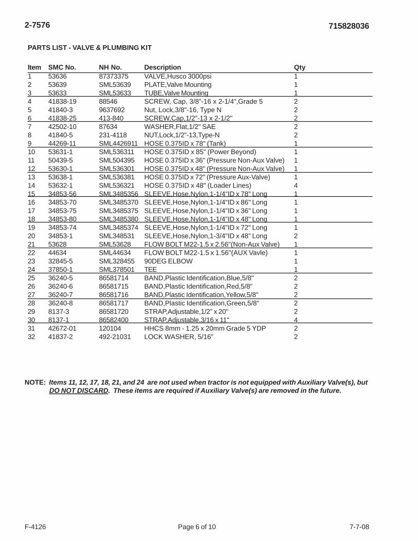
PARTS LIST - VALVE & PLUMBING KIT
Item SMC No. NH No. Description Qty1 53636 87373375 VALVE,Husco 3000psi 12 53639 SML53639 PLATE,Valve Mounting 13 53633 SML53633 TUBE,Valve Mounting 14 41838-19 88546 SCREW, Cap, 3/8”-16 x 2-1/4”,Grade 5 25 41840-3 9637692 Nut, Lock,3/8”-16, Type N 26 41838-25 413-840 SCREW,Cap,1/2”-13 x 2-1/2" 27 42502-10 87634 WASHER,Flat,1/2" SAE 28 41840-5 231-4118 NUT,Lock,1/2”-13,Type-N 29 44269-11 SML4426911 HOSE 0.375ID x 78" (Tank) 110 53631-1 SML536311 HOSE 0.375ID x 85" (Power Beyond) 111 50439-5 SML504395 HOSE 0.375ID x 36" (Pressure Non-Aux Valve) 112 53630-1 SML536301 HOSE 0.375ID x 48" (Pressure Non-Aux Valve) 113 53638-1 SML536381 HOSE 0.375ID x 72" (Pressure Aux-Valve) 114 53632-1 SML536321 HOSE 0.375ID x 48" (Loader Lines) 415 34853-56 SML3485356 SLEEVE,Hose,Nylon,1-1/4"ID x 78" Long 116 34853-70 SML3485370 SLEEVE,Hose,Nylon,1-1/4"ID x 86" Long 117 34853-75 SML3485375 SLEEVE,Hose,Nylon,1-1/4"ID x 36" Long 118 34853-80 SML3485380 SLEEVE,Hose,Nylon,1-1/4"ID x 48" Long 119 34853-74 SML3485374 SLEEVE,Hose,Nylon,1-1/4"ID x 72" Long 120 34853-1 SML348531 SLEEVE,Hose,Nylon,1-3/4"ID x 48" Long 221 53628 SML53628 FLOW BOLT M22-1.5 x 2.56"(Non-Aux Valve) 122 44634 SML44634 FLOW BOLT M22-1.5 x 1.56"(AUX Vavle) 123 32845-5 SML328455 90DEG ELBOW 124 37850-1 SML378501 TEE 125 36240-5 86581714 BAND,Plastic Identification,Blue,5/8" 226 36240-6 86581715 BAND,Plastic Identification,Red,5/8" 227 36240-7 86581716 BAND,Plastic Identification,Yellow,5/8" 228 36240-8 86581717 BAND,Plastic Identification,Green,5/8" 229 8137-3 86581720 STRAP,Adjustable,1/2” x 20" 230 8137-1 86582400 STRAP,Adjustable,3/16 x 11" 431 42672-01 120104 HHCS 8mm - 1.25 x 20mm Grade 5 YDP 232 41837-2 492-21031 LOCK WASHER, 5/16” 2
NOTE: Items 11, 12, 17, 18, 21, and 24 are not used when tractor is not equipped with Auxiliary Valve(s), butDO NOT DISCARD. These items are required if Auxiliary Valve(s) are removed in the future.
2-7576
Page 7 of 10F-4126 7-7-08
715828036
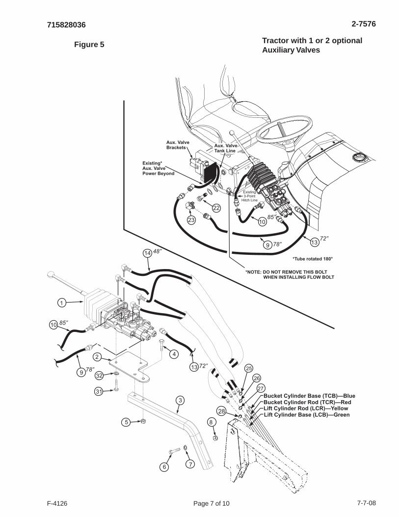
Figure 5 Tractor with 1 or 2 optionalAuxiliary Valves
10
139
23
78”
85”
72”
22
Aux. ValveTank Line
Existing*Aux. ValvePower Beyond
*Tube rotated 180°
*NOTE: DO NOT REMOVE THIS BOLTWHEN INSTALLING FLOW BOLT
Aux. ValveBrackets
1
2
3
4
5
31
329
10
14
~
~
48”
85”
78”
Bucket Cylinder Base (TCB)—BlueBucket Cylinder Rod (TCR)—Red
Lift Cylinder Base (LCB)—GreenLift Cylinder Rod (LCR)—Yellow
25
28
26
27
6 7
8
~
13 72”
Existing3-Point
Hitch Line

2-7576
Page 8 of 10F-4126 7-7-08
715828036
1
1
2
2
2
2726
26
25
25
3
3
6
6
7
7
8
8
9
9
10
10
11
11
12
12
12
12
13
13
13
13
14
14
(4) PL
(4) PL
27
21
21
7
7
18
18
12
12
2
5
5
19
128
29
29
15
1616
1717
4
Service Parts for Valve Assembly
Item CNH No. Husco No. Description Qty1 87018550* 43-116* O-Ring 116 12 87019271* 62-113* O-Ring 113 43 D8NNC820BA 3272 Ball 84 NSS 3392-G Plate-Name 15 292023 3432 Cap Screw-Soc. Head 26 87018492 3658 Ball 27 87019272 5012 Plate-Seal 68 NSS 5013 Spring Seat 29 NSS 5014 Spring 210 87019279 5018 Spring 211 87019275 5028 Cap-Spool 212 74995327* 5029* Wiper 413 87018499 5217 Cap Screw-Soc. Head 414 87018541 6388-1 Sleeve-Detent 115 NSS 9212-A4 Housing-Valve 116 87018555 53698 Poppet-C.V. 217 87018554 53757 Spring 218 87019273 53800 Spacer 219 256174A1 53859 Spacer-Cap,Spool 120 87585081 54659-1 Sleeve Detent 121 NSS 55969 Cap Screw-Soc. Head 222 87018509 59048-1 Spacer 223 NSS 59049-1 Spool 124 NSS 59050-1 Spool 125 NSS 59191 Washer-Flat 226 NSS 59726 Spring Seat 227 NSS 59727 Spool End-Detent Pin 228 87548574 400011 Plug Assy.-SAE 129 87548573** 400085** Plug Assy.-SAE 230 87591533 61268 Seal Kit, Includes parts marked * & ** 1
2-7576
Page 9 of 10F-4126 7-7-08
715828036
1
2
3
4
5
6
7
8
9
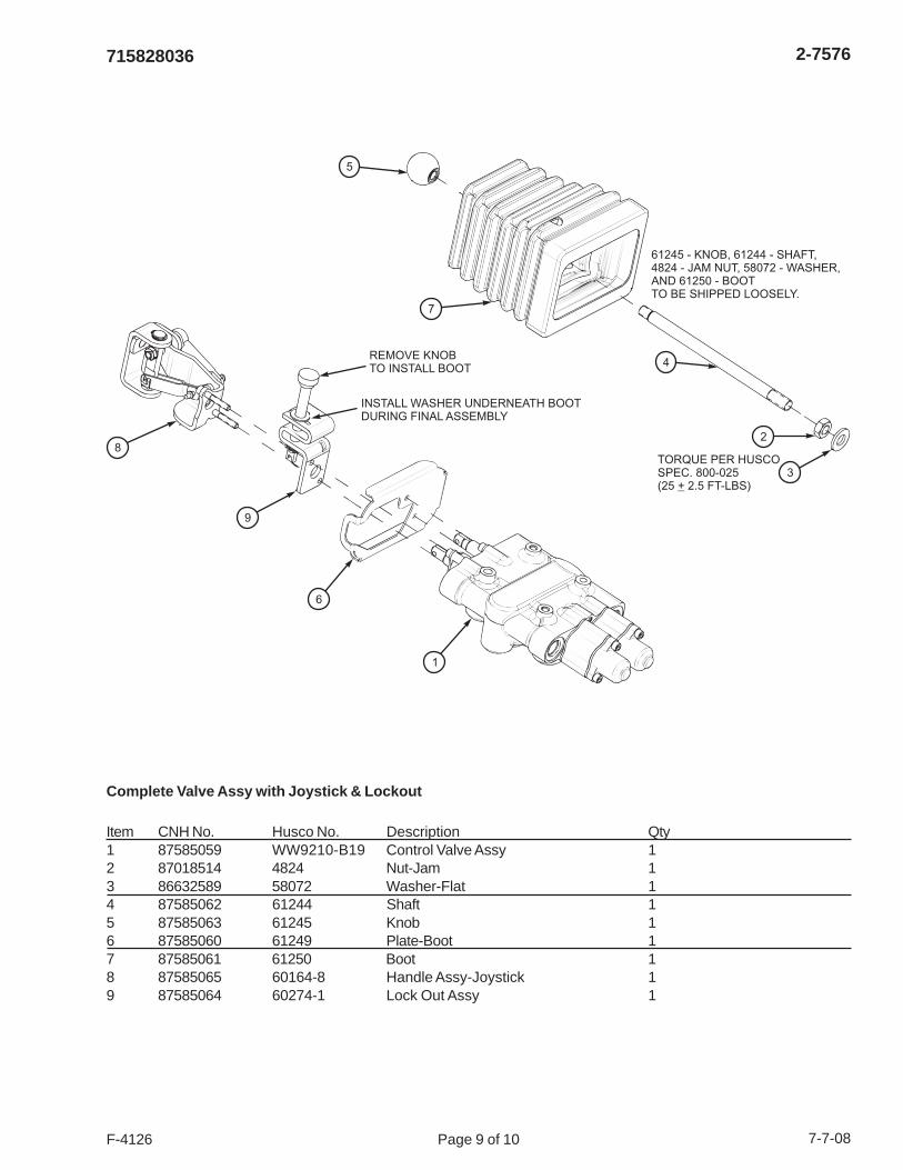
REMOVE KNOBTO INSTALL BOOT
TORQUE PER HUSCOSPEC. 800-025(25 2.5 FT-LBS)+
61245 - KNOB, 61244 - SHAFT,4824 - JAM NUT, 58072 - WASHER,AND 61250 - BOOTTO BE SHIPPED LOOSELY.
INSTALL WASHER UNDERNEATH BOOTDURING FINAL ASSEMBLY
Complete Valve Assy with Joystick & Lockout
Item CNH No. Husco No. Description Qty1 87585059 WW9210-B19 Control Valve Assy 12 87018514 4824 Nut-Jam 13 86632589 58072 Washer-Flat 14 87585062 61244 Shaft 15 87585063 61245 Knob 16 87585060 61249 Plate-Boot 17 87585061 61250 Boot 18 87585065 60164-8 Handle Assy-Joystick 19 87585064 60274-1 Lock Out Assy 1
2-7576
Page 10 of 10F-4126 7-7-08
715828036
AMERICAN STANDARD CAP SCREWS METRIC CAP SCREWS
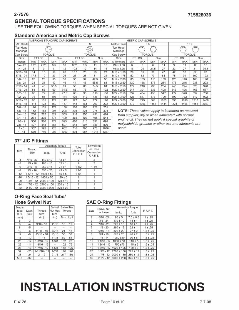
GENERAL TORQUE SPECIFICATIONSUSE THE FOLLOWING TORQUES WHEN SPECIAL TORQUES ARE NOT GIVEN
SAE GradeTyp. HeadMarkings
Metric ClassTyp. HeadMarkings
5 8 8.8 10.9
Cap Screw TORQUE
Assembly Torque
TORQUE TORQUE TORQUESize FT·LBS N·m FT·LBS N·m FT·LBS N·m FT·LBS N·m
Inches MIN MAX MIN MAX MIN MAX MIN MAX6.25 7.25 8.5 10 8.25 9.5 11 13
8 9 11 12 10.5 12 14 1614 15 19 20 18.5 20 25 27
17.5 19 23 26 23 25 31 3426 28 35 38 35 37 47.5 5031 34 42 46 41 45 55.5 6141 45 55.5 61 55 60 74.5 8151 55 69 74.5 68 75 92 10265 72 88 97.5 86 96 116 13076 84 103 114 102 112 138 15295 105 129 142 127 140 172 190111 123 150 167 148 164 200 222126 139 171 188 168 185 228 251152 168 206 228 203 224 275 304238 262 322 355 318 350 431 474274 305 371 409 365 402 495 544350 386 474 523 466 515 631 698407 448 551 607 543 597 736 809537 592 728 802 716 790 970 1070670 740 908 1003 894 987 1211 1337
Swivel Nutor Hose
ConnectionF. F. F. T.
TubeConnection
F. F. F. T.ft.·lb.in.·lb.Thread
SizeSize
Assembly Torque
ft.·lb.in.·lb.Swivel Nut
or HoseSize F. F. F. T.
-4
234568
10121416202432
5/16 - 243/8 - 24
7/16 - 201/2 - 20
9/16 - 183/4 - 167/8 - 14
1 1/16 - 121 3/16 - 121 5/16 - 121 5/8 - 121 7/8 - 122 1/2 - 12
90 ± 5170 ± 10220 ± 15260 ± 15320 ± 20570 ± 251060 ±501300 ± 501750 ±75
1920 ± 1252700 ± 1503000 ± 1503900 ± 200
7.5 ± 0.514 ± 118 ± 122 ± 127 ± 248 ± 290 ± 5110 ± 5145 ± 6160 ± 6
225 ± 12250 ± 12325 ± 15
1 ± .251 ± .251 ± .251 ± .25
1.5 ± .251.5 ± .251.5 ± .251.5 ± .251.5 ± .251.5 ± .251.5 ± .251.5 ± .251.5 ± .25
7/16 - 20 140 ± 10 12 ± 1 2 2-5 1/2 - 20 180 ± 15 15 ± 1 2 2-6 9/16 - 18 250 ± 15 21 ± 1 1 1/2 1 1/4-8 3/4 - 16 550 ± 25 45 ± 5 1 1/2 1
-12 1 1/16 - 12 1000 ± 50 85 ± 5 1 1/4 1-16 1 5/16 - 12 1450 ± 50 120 ± 5 1 1-20 1 5/8 - 12 2000 ± 100 170 ± 10 1 1-24 1 7/8 - 12 2400 ± 150 200 ± 15 1 1-32 2 1/2 - 12 3200 ± 200 270 ± 20 1 1
MIN MAX MIN MAX MIN MAX MIN MAX6 8 8 11 9 11 12 15
16 20 21.5 27 23 27 31 36.529 35 39 47 42 52 57 7052 62 70 84 75 91 102 12385 103 115 139 120 146 163 198
130 158 176 214 176 216 238 293172 210 233 284 240 294 325 398247 301 335 408 343 426 465 577332 404 450 547 472 576 639 780423 517 573 700 599 732 812 992637 779 863 1055 898 1098 1217 1488872 1066 1181 1444 1224 1496 1658 2027
1/4 - 201/4 - 285/16 - 185/16 - 243/8 - 163/8 - 247/16 - 147/16 - 201/2 - 131/2 - 209/16 - 129/16 - 18
Cap ScrewSize
MillimetersM6 x 1.00M8 x 1.25M10 x 1.50M12 x 1.75M14 x 2.00M16 x 2.50M18 x 2.50M20 x 2.50M22 x 2.50M24 x 3.00M27 x 3.00M30 x 3.00
5/8 - 115/8 - 183/4 - 103/4 - 167/8 - 9
7/8 - 141 - 8
1 - 14
37° JIC Fittings
Standard American and Metric Cap Screws
SAE O-Ring Fittings
NOTE: These values apply to fasteners as receivedfrom supplier, dry or when lubricated with normalengine oil. They do not apply if special graphite ormolysulphide greases or other extreme lubricants areused.
Swivel NutTorque
SwivelNut Hex
Size(in.)
ThreadSize(in.)
DashSize
-3-4-5-6-8
-10-12-14-16-20-24-32
568
1012162022253238
50.8
--9/16 - 18
--11/16 - 1613/16 - 16
1 - 141-3/16 - 121-3/16 - 121-7/16 - 121-11/16 - 12
2 - 12--
--11/16
--13/1615/161-1/81-3/8
--1-5/81-7/82-1/4
--
--16--245069
102102142190217--
--N·m lb ·ftf
12--1837517575
105140160--
O-Ring Face Seal Tube/Hose Swivel Nut
MetricTubeO.D.(mm)
INSTALLATION INSTRUCTIONS


