Embed Size (px)
Citation preview

Using Integer Linear Programming for InstructionScheduling and Register Allocationin Multi-issue Processors*Chia-Ming Chang Chien-Ming Chen Chung-Ta KingDepartment of Computer ScienceNational Tsing Hua UniversityHsinchu, Taiwan 300, R.O.C.e-mail: [email protected] scheduling and register allocation are two very important optimizations in mod-ern compilers for advanced processors. These two optimizations must be performed simulta-neously in order to maximize the instruction-level parallelism and to fully utilize the registers[11]. In this paper we solve register allocation and instruction scheduling simultaneously usinginteger linear programming (ILP). We have successfully worked out the ILP formulations forthe problem with and without register spilling. Two kinds of optimizations are considered: (1)Fix the number of free registers and then solve for the minimumnumber of cycles to execute theinstructions, or (2) �x the maximum execution cycles for the instructions and solve for the min-imum number of registers needed. Besides being theoretically interesting, our solution serves asa reference point for other heuristic solutions. The formulations are also applicable to high-levelsynthesis of ASICs and designs for embedded processors. In these application domains, the codequality is more important than the compilation time.Keywords: Integer linear programming, compiler optimization, instruction scheduling, reg-ister allocation, processor architecture1 IntroductionIn modern compilers for advanced multi-issue processors, instruction scheduling and register allo-cation are two very important optimizations. Due to their complexities, many previous works con-sidered these optimizations separately and concentrated more on their phase-ordering [10, 11, 21].However, no matter which optimization is done �rst, the earlier phase has to make decisions withoutknowing how the later phase will do. As a result, the latter could only work with more constrained*This research was supported in part by the National Science Council under grants NSC-86-2213-E007-043 andNSC-86-2213-E-007-043 1

conditions and �nd it more di�cult to optimize the code. Furthermore, with the multi-issue fea-ture of modern processors, the more the instructions are issued at the same cycle, the more theregisters are required. Without enough registers, either register spilling has to take place or someinstructions must be delayed. To minimize the execution time and to fully utilize the registers,instruction scheduling and register allocation must be considered at the same time.Several heuristics have been proposed to solve register allocation and instruction schedulingtogether. For example, the strategy used in [6, 8, 23] is to keep the information on the next use ofeach register. The register whose next use is the farthest is spilled if there are not enough registers.In [22], a graph combining the control/data ow graph and the register interference graph wasproposed to solve the two optimizations simultaneously. The problem with this approach is thatone cannot determine the edges in the complement graph of the parallel interference graph if wehave more than three function units of the same type and more than two instructions using thattype of function units.In this paper we solve register allocation and instruction scheduling simultaneously using integerlinear programming (ILP). One reason for using ILP is because the technique has been appliedsuccessfully to problems in application domains such as high-level synthesis for ASICs [15]. Ourwork can build upon those results. In addition, with ILP the resultant code is better than or asgood as that obtained by heuristics, e.g., list scheduling [1, 5]. Thus, the ILP solution can serve asa reference for other heuristic solutions.We will consider the optimization problem of solving instruction scheduling and register alloca-tion simultaneously with and without register spilling. The goals of the ILP formulations are eitherto solve for the minimum number of cycles to execution the given instructions or for the minimumnumber of registers needed. As far as we know, there is no attempt being made so far to solve suchoptimizations using ILP. Our formulations have their theoretical merits. Furthermore, just as itis applicable to high-level synthesis, our formulations can be used in other application domains inwhich the code quality is more important than the compilation time.Remainder of this paper is organized as follows. Basic assumptions and notations of our modelsare introduced in section 2. ILP formulation for the optimization problem with register spilling notallowed will be discussed in section 3, and that with spilling allowed will be discussed in section 4.Experimental results on example code segments will be presented in section 5. The formulated2

ILPs were solved using the LINDO package [17], which produced optimal integer solutions usingbranch-and-bound. Finally section 6 gives our concluding remarks.2 PreliminariesIn this paper, we will consider the following two optimization problems:Problem NRS: Schedule instructions and allocate registers in a basic block with register spillingnot allowed.Problem RS: Schedule instructions and allocate registers in a basic block with register spillingallowed.We will use ILP to solve these two problems. Our ILP formulations consider the following twooptimizations:Optimization TIME: Fix the number of free registers and solve for the minimum number ofcycles to execute the instructions.Optimization REG: Fix the maximum execution cycles of the instructions and solve for theminimum number of registers needed.Our formulations are based on the following assumptions:� The target processor has a multi-issue, load/store architecture with multiple function units.� Life ranges of the registers in the schedule will not span across basic block boundaries.� Every instruction takes only one cycle to execute.� All registers are of the same type.� Every operand of an instruction occupies only one register.� Registers used in a STORE instruction can be rede�ned in the same cycle.Several notations will be used throughout the paper. Let n be the total number of instructionsin the given code segment and Ii be the i-th instruction. The binary variable xi;c denotes whetherIi is scheduled to cycle c. If so, then xi;c = 1; otherwise xi;c = 0. Let R be the number of available3

registers in the processor. The notation Ii ! Ij means that there is a data dependence from Iito Ij . We call Ii a parent of Ij and Ij a child of Ii. Let CH(Ii) denote the set of all childrenof instruction Ii. Suppose there are t types of function units in the processor. For each type offunction units Fk, 1 � k � t, there are Nk units. The notation Ii 2 Fk will be used to indicate thatIi requires a function unit of type Fk .In order to illustrate our ILP formulations, the example code listed in Fig. 1(a) will be used.Suppose that the target processor has one load/store unit, one multiplier, and two adders. Thedata ow graph (DFG) [9] corresponding to the example code is shown in Fig. 1(b). Nodes in thegraph represent instructions and edges represent data dependence relations between instructions.Since it is assumed that the result of an instruction must be in one register, we can view an edgein the DFG to represent not only a dependence relation but also a register de�ne-use chain. Also,we have assumed that life ranges of the registers do not span across block boundaries. Thus inthe DFG, the instructions without parents must be LOAD instructions and those without childrenmust be STORE instructions. ********************* Figure 1 goes here *********************Since the solution time of ILP depends on the number of variables in the formula, it is criticalto reduce the number of variables. One common approach is to constrain the solution space withthe earliest and latest issue times of each instruction. Let Ei denote the earliest issue time of aninstruction Ii. Then, Ei can be estimated as follows. Let ck be the number of predecessors of Iiwhich require a function unit of type Fk. Let a and b denote the earliest issue times of two of theparents of Ii. Then, we haveEi = maxfa; b; dc1=N1e; dc2=N2e; : : : ; dct=Nteg+ 1:To compute the latest issue time Li of Ii, we must know the maximum execution time Tmax of allinstructions. Without loss of generality, we can set Tmax = n, as if the instructions were executedsequentially. Next, reverse the directions of all edges in DFG and compute the earliest issue timeEi0 of Ii. The latest issue time can then be obtained as Li = Tmax �Ei0 + 1.4

LOAD/STORE MULT ADDCycle I1 I2 I4 I6 I7 I10 I5 I9 I3 I81 x1;1 x2;1 x4;1 x6;1 x7;12 x1;2 x2;2 x4;2 x6;2 x7;23 x1;3 x2;3 x4;3 x6;3 x7;3 x3;3 x8;34 x1;4 x2;4 x4;4 x6;4 x7;4 x5;4 x3;4 x8;45 x1;5 x2;5 x4;5 x6;5 x7;5 x5;5 x9;5 x3;5 x8;56 x1;6 x2;6 x4;6 x6;6 x7;6 x10;6 x5;6 x9;6 x3;6 x8;67 x4;7 x6;7 x7;7 x10;7 x5;7 x9;7 x3;7 x8;78 x10;8 x5;8 x9;8 x8;89 x10;9 x9;910 x10;10Table 1: The variable distribution table of the illustrative example in solving Problem NRS3 ILP for Problem NRSProblem NRS considers instruction scheduling and register allocation without register spilling. It issuitable for cases in which there are a large number of free registers and the number of instructionsin the basic block is small. In this section we present the ILP formulations for Problem NRS.The constraints for instruction scheduling and register allocation are introduced separately in twosubsections. Their combination forms the complete formulation for this problem, which is given insection 3.3.3.1 Constraints for Instruction SchedulingIn this subsection, we consider the constraints in the ILP formulation for instruction scheduling.To reduce the solution space, we can use the earliest issue time Ei and the latest issue time Li ofan instruction Ii. From Ei and Li a variable distribution table can be constructed. Table 1 showssuch a table for our illustrative example. An empty entry means that the corresponding variableis out of the range de�ned by Ei and Li and will not be considered in the ILP formulation. Onthe other hand, a non-empty entry xi;c means that instruction Ii may be scheduled at cycle c. Ittakes a value of 0 or 1. From this table, we can formulate the possible constraints for instructionscheduling. The formulation generally follows that introduced in [15] for solving local instructionscheduling. For completeness of presentation the expressions are listed below.� Function unit constraint: 5

The total number of instructions which can be executed simultaneously by a particular typeof function units cannot exceed the total number of that type of function units. In otherwords, XIi2Fk xi;c �Nk � 0; for 1 � c � Tmax and 1 � k � t: (1)For the illustrative example we have the following inequalities for the load/store units at the�rst two cycles:x1;1 + x2;1 + x4;1 + x6;1 + x7;1 � 1 � 0 for the �rst cyclex1;2 + x2;2 + x4;2 + x6;2 + x7;2 � 1 � 0 for the second cycleAs another example, at cycle 7 we have the following inequalities for multipliers and adders:x5;7 + x9;7 � 1 � 0 for multipliersx3;7 + x8;7 � 2 � 0 for adders� Appearance constraint:Since one instruction can only be executed in exactly one cycle, we have the following expres-sions: LiXc=Ei xi;c = 1; for 1 � i � n: (2)Note that the summation is taken from Ei to Li instead of from 1 to Tmax. Consider instruc-tion I1 in the illustrative example. The following expression will be generated:x1;1 + x1;2 + x1;3 + x1;4 + x1;5 + x1;6 = 1� Precedence constraint:When there is a data dependence from instruction Ii to Ij , i.e., Ii ! Ij , Ii cannot be scheduledafter or at the same cycle as Ij . This leads to the following inequalities:LiXc=Ei(c� xi;c)� LjXc=Ej(c� xj;c) � �1; 8Ii ! Ij : (3)6

For example, the data dependence from instruction I8 to I9 in the illustrative example pro-duces the following inequality:3x8;3 + 4x8;4 + 5x8;5 + 6x8;6 + 7x8;7 + 8x8;8 � 5x9;5 � 6x9;6 � 7x9;7 � 8x9;8 � 9x9;9 � �1� Time constraint:To minimize Tmin means that no instruction can be scheduled after Tmin. That isLiXc=Ei(c� xi;c)� Tmin � 0; 8Ii without successors (4)For the illustrative example, we have the following inequality:6x10;6 + 7x10;7 + 8x10;8 + 9x10;9 + 10x10;10� Tmin � 03.2 Constraints for Register AllocationThis subsection considers the ILP formulation for register allocation for Problem NRS. To facilitatethe formulation, a new 0/1 variable Ui;c is de�ned. It is equal to 1 when the register de�ned ininstruction Ii is alive at cycle c, i.e., the instruction occupies a register in cycle c. Note that we donot have to compute Ui;c of a STORE instruction.If instruction Ii has only one child Ij , i.e., CH(Ii) = fIjg, thenUi;c = cXk=1 xi;k � cXk=1 xj;k (5)However, if Ii has K children (K > 1), then the inequality corresponding to Ui;c becomes di�cultto formulate. Our solution here is to de�ne a temporary variable UTi;c such thatUTi;c = K � cXk=1 xi;k � XIj2CH(Ii)( cXk=1xj;k) (6)Obviously, the register de�ned in Ii is alive at cycle c if and only if UTi;c > 0. That is, Ui;c = 1when UTi;c > 0 and Ui;c = 0 when UTi;c = 0. So we have the following two inequalities to constrainUi;c using UTi;c. Ui;c � UTi;c � 0 (7)K � Ui;c � UTi;c � 0 (8)7

Using Ui;c, we can then constrain the number of registers used in each cycle by limiting that numberto be smaller than the total number of registers R:XIi 6=STOREUi;c � R � 0; for each cycle c (9)Since each instruction in the illustrative example has only one successor, Eq. 5 can be applied.For example, we have the following expressions for I2:U2;1 = x2;1U2;2 = U2;1 + x2;2U2;c = U2;c�1 + x2;c � x3;c, for 3 � c � 6The constraint on the number of registers in each cycle can then be obtained. For example, at the�rst cycle we have U1;1 + U2;1 + U4;1 + U6;1 + U7;1 �R � 03.3 Complete Formulation for Problem NRSThe complete ILP formulation for solving Problem NRS based on Optimization TIME is as follows.Minimize Tmin (10)subject to XIi2Fk xi;c �Nk � 0; for 1 � c � Tmax and 1 � k � t (1)LiXc=Ei xi;c = 1; for 1 � i � n (2)LiXc=Ei(c� xi;c)� LjXc=Ej(c� xj;c) � �1; 8Ii ! Ij (3)LiXc=Ei(c� xi;c)� Tmin � 0; 8Ii without successors (4)XIi 6=STOREUi;c � R � 0; for each cycle c (9)8

Note that we can also solve for Optimization REG by replacing Tmin with the given Tmaxand then try to minimize R. Also, we can solve for the minimum execution cycles subject to theminimum number of free registers. This is done by �rst solving for Optimization REG to get theminimum number of registers, say Rmin, and then replacing R with Rmin to solve for OptimizationTIME. Similarly, we can also solve for the minimum number of registers subject to the minimumexecution cycles. Again this is done by �rst solving for Optimization TIME to get the minimumnumber of cycles, say T , and then replacing Tmax with T to solve for Optimization REG.4 ILP for Problem RSIn this section we consider the ILP formulation for Problem RS, in which register spilling is allowed.Basic ideas of our formulation are introduced �rst, followed by the constraints for instructionscheduling and register allocation. The complete formulation is shown in section 4.4.4.1 Basic IdeaThe ILP formulation for instruction scheduling and register allocation becomes very complex whenregister spilling is taken into account. First, it is hard to use ILP to determine which registershould be spilled. Second, dynamically added spill code also makes the formulation for instructionscheduling extremely di�cult. Third, the spill code changes the live range of registers, which alsocomplicated ILP formulations.Our strategy here is to add spill code at every possible location �rst and then eliminate thoseunwanted. Several issues have to be resolved when using this strategy:� Where should spill code be added?In our formulation we add spill code in the following two cases:{ LOAD instructions:For a LOAD instruction with only one successor, we do not change anything. For aLOAD with K successors, where K > 1, we add K � 1 identical copies of that LOADto the basic block. In this way we can split the life range of registers if some of theseLOAD instructions are e�ective. 9
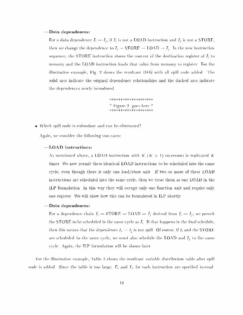
{ Data dependences:For a data dependence Ii ! Ij , if Ii is not a LOAD instruction and Ij is not a STORE,then we change the dependence to Ii ! STORE! LOAD! Ij . In the new instructionsequence, the STORE instruction stores the content of the destination register of Ii tomemory and the LOAD instruction loads that value from memory to register. For theillustrative example, Fig. 2 shows the resultant DFG with all spill code added. Thesolid arcs indicate the original dependence relationships and the dashed arcs indicatethe dependences newly introduced.********************* Figure 2 goes here *********************� Which spill code is redundant and can be eliminated?Again, we consider the following two cases:{ LOAD instructions:As mentioned above, a LOAD instruction with K (K > 1) successors is replicated Ktimes. We now permit these identical LOAD instructions to be scheduled into the samecycle, even though there is only one load/store unit. If two or more of these LOADinstructions are scheduled into the same cycle, then we treat them as one LOAD in theILP formulation. In this way they will occupy only one function unit and require onlyone register. We will show how this can be formulated in ILP shortly.{ Data dependences:For a dependence chain Ii ! STORE ! LOAD ! Ij derived from Ii ! Ij , we permitthe STORE to be scheduled in the same cycle as Ii. If that happens in the �nal schedule,then this means that the dependence Ii ! Ij is not spill. Of course, if Ii and the STOREare scheduled to the same cycle, we must also schedule the LOAD and Ij to the samecycle. Again, the ILP formulation will be shown later.For the illustrative example, Table 2 shows the resultant variable distribution table after spillcode is added. Since the table is too large, Ei and Li for each instruction are speci�ed instead.10

LOAD/STOREI1 I2 I31S I31L I4 I51S I51L I6Ei 1 1 3 5 1 4 6 1Li 12 12 13 14 13 14 15 13LOAD/STORE MULT ADDI7 I81S I81L I10 I5 I9 I3 I8Ei 1 3 5 6 4 5 3 3Li 13 14 15 16 14 15 13 14Table 2: The variable distribution table of the illustrative example for solving Problem RSIn the next two subsections, we will see how the ideas presented in this subsection are applied toformulating the constraints of the ILP for Problem RS.4.2 Constraints for Instruction Scheduling� Function unit constraint:For ease of explanation, we divide all instructions into four groups:(1) A LOAD instruction with only one child or an instruction which is not a LOAD and isnot in a spill code:For each such instruction Ii, we de�ne a 0/1 variable fi;c to denote if Ii occupies afunction unit in cycle c. Note that xi;c can be viewed as the number of function units(0 or 1) that Ii uses in cycle c. Thus we havefi;c � xi;c = 0; for Ei � c � Li (11)In the illustrative example, instructions I1 � I10 are in this group. Take I2 as an example.We have the expressions: f2;c � x2;c = 0; for 1 � c � 12(2) LOAD instructions with more than one child:Each instruction Ii in the group is a LOAD instruction with K children, where K > 1.As mentioned above, there will be K identical copies of that LOAD instruction. Let the11

copies be denoted Ii1 ; Ii2 ; : : : ; IiK . Since these LOAD instructions can be scheduledinto the same cycle, we must determine the number of load/store units they use preciselyat each cycle. De�ne a 0/1 variable fi;c to denote the number of load/store units usedby Ii in cycle c. Then, fi;c = 0 if xi1;c + xi2;c + : : :+ xiK ;c = 0 and fi;c = 1 otherwise.We thus have the following inequalities for fi;c:fi;c � (xi1;c + xi2;c + : : :+ xiK ;c) � 0 (12)K � fi;c � (xi1;c + xi2;c + : : :+ xiK ;c) � 0 (13)When PKk=1 xik;c = 0, Eq. 12 forces fi;c to be 0, while Eq. 13 has no e�ect on fi;c. Onthe other hand, when PKk=1 xik ;c = 1, Eq. 13 forces fi;c to 1, while Eq. 12 has no e�ect.(3) STORE instructions which are in a spill code:We de�ne one 0/1 variable fiS ;c for each set of STORE instructions with the same parentIi. The variable fiS ;c denotes whether these STORE instructions occupy a function unitin cycle c. Denote the STOREs in that set as Ii1S ; Ii2S ; : : : ; IiKS , where K > 0.We must do some preprocessing. De�ne a new variable yikS ;c for each xikS ;c to denotewhether xikS ;c is an e�ective STORE. That is, if xikS ;c = 1 and xi;c = 0, then yikS ;c = 1,otherwise yikS ;c = 0. The variable helps to determine whether IikS occupies one functionunit at cycle c. It is constrained by the following inequalities:yikS ;c � ( LikSXm=EikS m� xikS ;m � LiXm=Eim� xi;m) � 0 (14)yikS ;c � xikS ;c � 0 (15)T � LikSXm=EikS yikS ;m � ( LikSXm=EikS m� xikS ;m � LiXm=Eim� xi;m) � 0 (16)We then have the following inequalities to constrain fiS ;c:fiS ;c � KXk=1 yikS ;c � 0 (17)K � fiS ;c � KXk=1 yikS ;c � 0 (18)Note that xi;c = xikS ;c = 1 for some k means that the destination register of Ii will notbe spilled by IikS . In this case we can delete that STORE instruction and the associated12

LOAD. Note that if Ii has only one child in the original code, we can use fiS ;c directlyto replace yikS ;c in Eq. 14, 15 and 16, and delete Eq. 17 and 18. In our example, thechildren of I3; I5; I8 are in this group. Consider the children of I3. We have the followinginequalities:y31S ;c � (P13m=3m� x31S ;m �P13m=3m� x3;m) � 0, 8 3 � c � 13y31S ;c � x31S ;c � 0, 8 3 � c � 1316P13m=3 y31S ;m � (P13m=3m� x31S ;m �P13m=3m� x3;m) � 0f3S ;c � y31S ;c � 0, 3 � c � 13f3S ;c � y31S ;c � 0, 3 � c � 13(4) LOAD instructions which are in a spill code:De�ne one 0/1 variable fiL;c for each set of such LOAD instructions whose parent'sparent is Ii. The variable fiL;c denotes if these LOAD instructions occupy a functionunit in cycle c. Suppose we have K LOAD instructions Ii1L ; Ii2L ; : : : ; IiKL in such aset. We also need to do some preprocessing. De�ne a new variable yikL;c for each xikL;cto denote whether xikL;c is an e�ective LOAD. That is, if xikL;c = 1 and xj;c = 0, thenyikL;c = 1, where Ij is the child of IikL , otherwise yikL;c = 0. The variable is used todetermine whether IikL occupies one function unit at cycle c. Constraints associatedwith such variables are as follows:yikL;c � ( LjXm=Ej m� xj;m � LikLXm=EikL m� xikL;m) � 0 (19)yikL;c � xikL;c � 0 (20)T � max(LikL)Xm=min(EikL ) yikL;m � ( LjXm=Ej m� xj;m � LikLXm=EikL m� xikL;m) � 0 (21)We then have the following inequalities to constrain fiL;c:fiL;c � KXk=1 yikL;c � 0 (22)K � fiL;c � KXk=1 yikL;c � 0 (23)Note that xj;c = xikL;c = 1 for some k means that the destination register of Ii willnot be spilled and reloaded by IikL later. Thus we can delete that LOAD instruction.13

Note that if Ii has only one child in the original code, we can use fiL;c to replace yikL;c.Consider instruction I3 in our example. We havey31L;c � (P14m=4m� x5;m �P14m=5m� x31L;m) � 0 5 � c � 14y31L;c � x31L;c � 0, 8 5 � c � 1416P14m=5 y31L;m � (P14m=4m� x5;m �P14m=5m� x31L;m) � 0f3L;c � y31L;c � 0 5 � c � 14f3L;c � y31L;c � 0 5 � c � 14Finally we can derive the ILP constraints related to the function units.Xf�;c2Fk f�;c �Nk � 0; for 1 � c � T and 1 � k � t (24)Note that f�;c 2 Fk means that the type of the function unit that f�;c will use is Fk .� Appearance constraint:Since one instruction may appear in exactly one cycle, we have the following expressions:LiXc=Ei xi;c = 1; 1 � i � n; (25)where n is now the total number of instructions after adding all spill code.� Precedence constraint:If the two instructions in the precedence relation Ii ! Ij cannot be scheduled to the samecycle, then we have the following expression:LiXc=Ei c� xi;c � LjXc=Ej c� xj;c � �1 (26)If the two instructions in the precedence relation can be scheduled to the same cycle, thenwe have the following expression:LiXc=Ei c� xi;c � LjXc=Ej c� xj;c � 0 (27)Note that if they are scheduled to the same cycle, then the spill code is ine�ective.14

� Time constraint:The constraint is the same as in Problem NRS:LiXc=Ei(c� xi;c)� Tmin � 0; 8 Ii without successors (28)4.3 Constraints for Register AllocationWe de�ne a 0/1 variable Ui;c for each instruction Ii in the original code segment, where \1" meansthat the register de�ned in instruction Ii is alive at cycle c. In other words, it must occupy a registerin cycle c. When a LOAD instruction has more than one child, we add spill code and require thatthey share the same Ui;c. Note that we do not have to compute Ui;c of a STORE instruction.If CH(Ii) = fIjg and Ii is a LOAD or Ij is a STORE instruction, thenUi;c = cXm=1xi;m � cXm=1 xj;m (29)However, if Ii is a LOAD with K (K > 1) children in the original code, then we can de�ne atemporary variable UTi;c such thatUTi;c = KXk=1 cXm=1 xik ;m � XIj2CH(Ii) cXm=1 xj;m (30)Suppose Ii is an instruction whose child is not a STORE. Then we haveUTi;c = K cXm=1 xi;m � cXm=1 KXk=1 yikS ;m + cXm=1 KXk=1 yikL ;m � XIj2CH(Ii) cXm=1 xj;m; (31)where yikS and yikL are de�ned in the previous subsection. The variable UTi;c can thus be used tocompute Ui;c as follows. Ui;c � UTi;c � 0 (7)K � Ui;c � UTi;c � 0 (8)After we have all Ui;c's, the number of registers used in each cycle can be constrained by limitingthat number to smaller than R:XIi 6=STOREUi;c �R � 0; for each cycle c (32)15

4.4 Complete Formulation for Problem RSThe complete ILP formulation for solving Problem NRS based on Optimization TIME is as follows.Minimize Tmin (33)subject to Xf�;c2Fk f�;c �Nk � 0; for 1 � c � T; 1 � k � t (24)LiXc=Ei xi;c = 1; 1 � i � n (25)LiXc=Ei c� xi;c � LjXc=Ej c� xj;c � �1 (or 0); 8Ii ! Ij (! is dashed) (26)LiXc=Ei(c� xi;c)� Tmin � 0; 8 Ii without successors (28)XIi 6=STOREUi;c �R � 0; for each cycle c (32)5 Experimental ResultsTo evaluate the e�ectiveness of our ILP formulations, two examples were used. The �rst one isour illustrative example shown in Figure 1, which will be referred to as Example 1. The secondexample is shown in Figure 3, which will be referred to as Example 2. All the ILP formulationsare solved on a SPARC-10 workstation using the LINDO package [17]. LINDO produces an integersolution for an ILP problem using the branch-and-bound method.********************* Figure 3 goes here *********************Statitics related to the ILP formulations and their running times on the SPARC-10 workstationare listed in Table 3. This table gives a general idea of the complexity of our formulations. Fromthe table we can see that the formulation for Problem RS has about four times more variables and16

ILP for NRS ILP for RSExample Variables Inequalities Time Variables Inequalities Time1 56 93 2 � 15 sec 248 335 20 min2 231 206 1 min � �Table 3: Statistics of the ILP formulations and their running timesinequalities than that for Problem NRS. The solution time is about 60 times more. Thus, solvingfor Problem NRS is computationally more feasible than solving for Problem RS. Note that we didnot solve Problem NRS for Example 2, because its formulation is very complex and we do not havea suitable tool to generate the expressions automatically.Using LINDO, we were able to obtain optimal solutions to the ILP formulations for Examples 1and 2. When the number of registers is limited to two, the code in Example 1 will be scheduled asin Figure 4 by solving Problem RS. We can see from the �gure that there is a register spilling atcycle 5. On the other hand, the code in Example 1 renders no solution if Problem NRS is to besolved and the number of registers is limited to two.********************* Figure 4 goes here *********************6 Concluding RemarksPrevious approaches to code compilation for multi-issue processors usually consider instructionscheduling and register allocation separately. These two optimizations must be considered simulta-neously in order to maximize the instruction-level parallelism and minimize the number of registersused. In this paper we have shown how to solve register allocation and instruction schedulingsimultaneously using ILP. We have successfully worked out the ILP formulations for the problemwith and without register spilling. When applying the formulations to our example codes, optimumschedules were obtained for the target machine.One major problem with ILP is that the number of variables and expressions in the formulationscould be very large for only a small code segment. This results in a very long solution time. Toreduce the time complexity we need a more accurate way of estimating the earliest and latest issuetime, perhaps through some heuristics. We also need to further re�ne the formulations to minimize17

redundant variables and/or inequalities. We believe that through these re�nements, we shouldbe able to develop a more general technique to instruction scheduling and register allocation inmulti-issue processors.References[1] Adam, A Comparison of List Schedules for Parallel Processing Systems, Communica-tions of the ACM, pp. 685-690, (1974).[2] M. Auslander and M. Hopkins, An Overview of the PL.8 Compiler, Proceedings ofthe ACM SIGPLAN Symposium on Compiler Construction, (1982).[3] D.G. Bradlee, S.J. Eggers, and R.R. Henry, Integrating Register Allocation andInstruction Scheduling for RISCs, Proceedings of the Fourth International Conferenceon Architectural Support for Programming Languages and Operating Systems, pp. 122-131, (1991).[4] G.J. Chaitin, \Register Allocation and Spilling via Graph Coloring," ACM SIGPLANSymposium on Compiler Construction, (1982).[5] S. Davidson, Some Experiments in Local Microcode Compaction for Horizontal Ma-chines, IEEE Transactions on Computers, pp. 460-477, (1982).[6] J.R. Ellis, A Compiler for VLIW Architectures, MIT Press, Cambridge, (1986).[7] J.A. Fisher, The Optimization of Horizontal Microcode Within and Beyond BasicBlocks, Ph.D. Thesis, New York University, (1979).[8] S.M. Freudenberger and J.C. Ruttenberg, Phase Ordering of Register Allocationand Instruction Scheduling, Code Generation|Concepts, Tools and Techniques, (1991).[9] D.D. Gajski, N.D. Dutt, A.C. Wu, and Y.L. Lin, High-Level Synthesis, KluwerAcademic Publishers, (1992).[10] P.B. Gibbons and S.S. Muchnick, E�cient Instruction Scheduling for a PipelinedArchitecture, ACM SIGPLAN'86 Symposium on Compiler Construction, (1986).[11] J.R. Goodman andW. Hsu, Code Scheduling and Register Allocation in Large BasicBlocks, Proceedings of the International Conference on Supercomputing, pp. 442-452,(1988).[12] J.L. Hennessy and T. Gross, Hardware/Software Tradeo�s for Increased Perfor-mance, ACM Transactions on Programming Languages and Systems, (1983).[13] J.L. Hennessy and D.A. Patterson, Computer Architecture a Quantitative Ap-proach, Morgan Kaufmann, (1990).[14] W. Hsu, Register Allocation and Code Scheduling for Load/Store Architectures, Com-puter Science Technical Report #722, University of Wisconsin-Madsion, (1987).18

[15] C.T. Hwang, Optimum and Heuristic Algorithms for the Scheduling Problem in HighLevel Synthesis, Ph.D. Thesis, National Tsing-Hua University, (1992).[16] S. Jain, Circular Scheduling: A New Technique to Perform Software Pipelining, Pro-ceedings of the ACM SIGPLAN '91 Conference on Programming Language Design andImplementation, (1991).[17] LINDO System, Inc., LINDO: Linear INteractive and Discrete Optimizer for linear,integer, and quadratic programming problems.[18] B.Y. Lin, A Study on Local Instruction Scheduling in SuperSPARC by Modi�ed GCCCompiler, Master Thesis, National Tsing-Hua University, (1993).[19] C. Norris and L.L. Pollock, A Scheduler-Sensitive Global Register Allocator, Pro-ceedings of the International Conference on Supercomputing, (1993).[20] K. Kennedy, P. Briggs, K.D. Cooper, and L. Torczon, Coloring Heuristics forRegister Allocation, ACM SIGPLAN NOTICES, (1989).[21] D.M. Lavery, P.P. Chang, and W.W. Hwu, The Importance of Prepass CodeScheduling for Superscalar and Superpipelined Processors, Technical Report no. CRHC-91-18, University of Ill., Urbana-Champaign, (1991).[22] S.S. Pinter, Register Allocation with Instruction Scheduling: a New Approach, Pro-ceedings of the ACM SIGPLAN Conference on Programming Language Design andImplementation, pp. 258-257, (1993).[23] R.F. Touzeau, A FORTRAN Compiler for the FPS-164 Scienti�c Computer, ACMSIGPLAN '84 Symposium on Compiler Construction, (1984).19

I1 LOAD PR1,aI2 LOAD PR2,bI3 ADD PR3,PR1,PR2I4 LOAD PR4,cI5 MULT PR5,PR3,PR4I6 LOAD PR6,dI7 LOAD PR7,eI8 ADD PR8,PR6,PR7I9 MULT PR9,PR5,PR8I10 STORE PR9,fPR# denotes a pseudo registerI1I2
I3 I4
I5
I10
I9
I6 I7
I8(a) the code segment (b) the DFGFigure 1: An example code segment and its DFG20

I1I2
I3
I4
I5
I31S
I31L
I6 I7
I8
I10
I9
I81S
I81L
I51S
I51L
Figure 2: The DFG of the illustrative example with spill code added21

I1 LOAD PR1,aI2 LOAD PR2,bI3 MULT PR3,PR1,PR2I4 LOAD PR4,cI5 LOAD PR5,dI6 ADD PR6,PR4,PR5I7 LOAD PR7,eI8 ADD PR8,PR1,PR7I9 MULT PR9,PR6,PR8I10 ADD PR10,PR3,PR9I11 ADD PR11,PR3,PR6I12 STORE PR10,fI13 STORE PR11,gPR# denotes a pseudo registerI1I2
I3
I4 I5
I6
I7
I8
I9
I11 I10
13I I12(a) the code segment (b) the DFGFigure 3: Another example code segment and its DFG22

Function UnitCycle L/S ADD MULT1 I12 I23 I4 I34 I6 I55 I51S6 I77 I51L I88 I99 I10Figure 4: Example 1 after our optimization (number of free registers is two)23


