Embed Size (px)
Citation preview

Submersible Borehole Pump
UPA
6 inch - UPA 150C8 inch - UPA 200, UPA 200B10 inch - UPA 250C12 - 14 inch - UPA 300, UPA 350
Type Series Booklet

Legal information/Copyright
Type Series Booklet UPA
All rights reserved. The contents provided herein must neither be distributed, copied, reproduced,edited or processed for any other purpose, nor otherwise transmitted, published or made available to athird party without the manufacturer's express written consent.
Subject to technical modification without prior notice.
© KSB SE & Co. KGaA, Frankenthal 09/04/2020

Contents
Water Supply..................................................................................................................................................... 5Submersible Borehole Pumps.................................................................................................................................................... 5
General overview, 50 Hz...................................................................................................................................................... 5Overview of submersible motors .................................................................................................................................. 6
UPA 150C .............................................................................................................................................................................. 7Main applications........................................................................................................................................................... 7Fluids handled ................................................................................................................................................................ 7Operating data............................................................................................................................................................... 7Design details ................................................................................................................................................................. 7Designation .................................................................................................................................................................... 8Materials ......................................................................................................................................................................... 8Product benefits ............................................................................................................................................................. 8Product information ...................................................................................................................................................... 9Certifications .................................................................................................................................................................. 9Technical data .............................................................................................................................................................. 10Scope of supply ............................................................................................................................................................ 27Accessories .................................................................................................................................................................... 27
UPA 200, 200B, 250C.......................................................................................................................................................... 30Main applications......................................................................................................................................................... 30Fluids handled .............................................................................................................................................................. 30Operating data............................................................................................................................................................. 30Design details ............................................................................................................................................................... 30Designation .................................................................................................................................................................. 31Materials ....................................................................................................................................................................... 31Coating and preservation............................................................................................................................................ 32Product benefits ........................................................................................................................................................... 32Product information .................................................................................................................................................... 33Certifications ................................................................................................................................................................ 33Technical data .............................................................................................................................................................. 34Scope of supply ............................................................................................................................................................ 57
UPA 300, 350 ...................................................................................................................................................................... 58Main applications......................................................................................................................................................... 58Fluids handled .............................................................................................................................................................. 58Operating data............................................................................................................................................................. 58Design details ............................................................................................................................................................... 58Designation .................................................................................................................................................................. 59Materials ....................................................................................................................................................................... 59Coating and preservation............................................................................................................................................ 60Product benefits ........................................................................................................................................................... 60Product information .................................................................................................................................................... 61Certifications ................................................................................................................................................................ 61Technical data .............................................................................................................................................................. 62Scope of supply ............................................................................................................................................................ 74
Accessories for sizes UPA 200 to UPA 350 ........................................................................................................................ 75Installation parts .......................................................................................................................................................... 75Motor accessories ......................................................................................................................................................... 75Electrical accessories..................................................................................................................................................... 75
Related Documents .................................................................................................................................................................. 77List of components............................................................................................................................................................. 77
List of UPA 150C components ..................................................................................................................................... 77List of UPA 200 components........................................................................................................................................ 79List of UPA 200B components ..................................................................................................................................... 85List of UPA 250C components ..................................................................................................................................... 87List of UPA 300 components........................................................................................................................................ 90List of UPA 350 components........................................................................................................................................ 92
Power cables....................................................................................................................................................................... 94Main applications......................................................................................................................................................... 94Operating data............................................................................................................................................................. 94Designation .................................................................................................................................................................. 94Design details ............................................................................................................................................................... 94Selection information .................................................................................................................................................. 95
Contents
3

Dimensions and weights.............................................................................................................................................. 97Cable connector ................................................................................................................................................................. 98Cable clips ......................................................................................................................................................................... 100Flow velocity past the motor........................................................................................................................................... 101
Contents
4

Water SupplySubmersible Borehole Pumps
5General overview, 50 Hz
3400
.5/1
0-EN
Water Supply
Submersible Borehole Pumps
General overview, 50 Hz
1000
10
5005020 200100 100050,50,2 21 10
1 50,5 10 100202 50 200 2000500 4000
Q
Q [m3/h]
Q [U.S. gpm]
[l/s]
Q [Imp. g.p.m.]
10
10
100
100
1000
1000
10000
10000
50
50
500
500
5000
5000
5
5
100
1000
2000
50
500
40
400
300
20
30
200
H[m]
5
40
50
100
200
2000
3000
4000
5000
300
400
500
1000
H
[ft]
20
30
UPA 150C
UPA 200
UPA 200B
UPA 300,350
UPA 250C

Water SupplySubmersible Borehole Pumps
6 General overview, 50 Hz
3400
.5/1
0-EN
Overview of submersible motorsThe following submersible motors are available:
Selection table
Well diameter Motor size Voltage range Rated power Number of poles
2 poles 4 poles
4 inch 1~ Franklin DN 100 Up to 1 kV 0.37 to 2.2 kW ✔ -3~ Franklin DN 100 Up to 1 kV 0.37 to 7.5 kW ✔ -
6 inch UMA 150E 1) Up to 1 kV 5.5 to 37 kW ✔ -
8 inch UMA 200D Up to 1 kV 37 to 90 kW ✔ -10 inch UMA 250D Up to 1 kV 85 to 190 kW ✔ -12 inch UMA 300D Up to 1 kV 250 to 400 kW ✔ -
Up to 1 kV 175 to 280 kW - ✔TCD 1 to 3 kV 170 to 300 kW ✔ -
14 inch 14D Up to 1 kV 250 to 600 kW ✔ -Up to 1 kV 150 to 400 kW - ✔
VBD 1 to 3 kV 140 to 400 kW ✔ -VMD 1 to 3 kV 170 to 400 kW - ✔
16 inch XBD 1 to 3 kV 400 to 830 kW ✔ -3 to 6 kV 260 to 700 kW ✔ -
XMD 1 to 3 kV 280 to 500 kW - ✔3 to 6 kV 220 to 450 kW - ✔
19 inch ZBD 1 to 3 kV 650 to 1000 kW ✔ -3 to 6 kV 650 to 1000 kW ✔ -
ZMD 1 to 3 kV 400 to 800 kW - ✔3 to 6 kV 400 to 800 kW - ✔
24 inch EBD 1 to 3 kV 900 to 1600 kW ✔ -3 to 6 kV 900 to 1600 kW ✔ -
EMD 1 to 3 kV 900 to 2000 kW - ✔3 to 6 kV 900 to 2000 kW - ✔
Further motor data for the UMA asynchronous motor see type series booklet No. 3455.51
Further motor data for the UMA-S synchronous motor see type series booklet No. 3455.52
1) Also available as UMA-S 150E synchronous motor for operation on a frequency inverter.

Water SupplySubmersible Borehole Pumps
7UPA 150C
3400
.5/1
0-EN
UPA 150C
Main applications▪ Spray irrigation systems
▪ General irrigation systems
▪ Pressure boosting
▪ Lowering groundwater levels
▪ Domestic water supply
▪ Air-conditioning systems
▪ Water supply systems
Fluids handled▪ Drinking water
▪ Cooling water
▪ River water, lake water and groundwater
▪ Max. permissible sand content of the fluid 50 g/m³
Operating data
Operating properties
Characteristic Value
Flow rate Q [m3/h] ≤ 79Q [l/s] ≤ 22
Head H [m] ≤ 440Fluid temperature T [°C] ≤ +50Speed n [rpm] ≤ 2900Well diameter D [mm] 150
D [″] 6
Design details
Design▪ Centrifugal pump
▪ Single-stage or multistage
▪ Single-entry
▪ Ring-section design
▪ Rigid connection between pump and motor
Type of installation▪ Vertical installation
▪ Horizontal installation (depending on the number ofstages)
DriveAsynchronous motor:
▪ With squirrel cage motor for submerged use
▪ Standard connection to NEMA
▪ Frequency 50 Hz
▪ IP68 enclosure
▪ DOL starting or star-delta starting
▪ Frequency of starts– DN 100: 20 start per hour– UMA 150E: 15 starts per hour
▪ Winding J1 (PVC) or, for higher temperatures, J2 (VPE /XLPE)
Synchronous motor:
▪ Interior (buried) permanent magnet synchronous motor(IPMSM)
▪ IP68 enclosure
▪ Standard connection to NEMA
▪ Winding J2 (VPE / XLPE)
▪ Frequency of starts ≤ 15 starts per hour
Electrical connection▪ Delivered ex-factory with 1 or 2 motor leads (including
earth conductor and internal earthing)
▪ Extension cable connected with water-tight cableconnector
▪ Motor lead and extension cable suitable for drinkingwater use
Impeller type▪ Radial or mixed flow versions
Bearings▪ Radial plain bearings
▪ Pump bearings lubricated by fluid handled; motorbearings lubricated by water fill
▪ Axial thrust is balanced by a tilting-pad thrust bearing inthe motor (lower end)
▪ Intermediate bearing in every stage
Connections▪ Pump screw-ended or flanged
▪ With lift check valve or connection branch

Water SupplySubmersible Borehole Pumps
8 UPA 150C
3400
.5/1
0-EN
Designation
Example: UPA 150C - 16 / 9
Designation key
Code Description
UPA Pump type series150 Nominal size [mm]C Design status16 Flow rate at best efficiency point [m³/h]9 Number of stages
Materials
Material selection for UPA 150C pumps
Component Material variant
C1 C2
Impeller CrNi steel (1.4301) CrNiMo steel (1.4404)Suction casing / body of the lift checkvalve
CrNiMo steel (1.4408)
Screws, bolts and nuts CrNiMo steel (A4)Stage casing CrNi steel (1.4301) CrNiMo steel (1.4404)Shaft CrNi steel (1.4305) CrNiMo steel (1.4401)
Material selection for UMA 150E motors, DN 100
Component Material variant
C1 C2
Bearing carrier DN 100 CrNi steel (1.4301) CrNiMo steel (1.4404)UMA 150E CrNi steel (1.4301) CrNiMo steel (1.4571)
Stator case DN 100 CrNi steel (1.4301) CrNiMo steel (1.4571)UMA 150E CrNi steel (1.4301) CrNiMo steel (1.4571)
Shaft DN 100 CrNi steel (1.4305) CrNiMo steel (1.4460)UMA 150E CrNi steel (1.4021)2) /
CrNiMo steel (1.4462)3)CrNiMo steel (1.4462)
Product benefits▪ High operating reliability and long service life due to
reinforced suction strainer, robust drive lantern and liftcheck valve made of investment cast stainless steel, laser-welded impellers and protection against thrust reversal
▪ High operating reliability as all components are made ofhigh-quality stainless steel.
▪ Optimised hydraulic design enables high efficiencies.
▪ High efficiencies in combination with UMA-S150Esynchronous motor
▪ High flexibility by vertical, horizontal and angularinstallation options
▪ Reliable operation by anti-jam lift check valve
▪ Highly flexible operating range through adjustment ofmotor dimensions
▪ Easy to install with service-friendly hydraulic system design
2) For motors < 18.5 kW3) For motors ≥ 18.5 kW

Water SupplySubmersible Borehole Pumps
9UPA 150C
3400
.5/1
0-EN
Product information
Product information as per Regulation No. 547/2012(for 4" and 6" water pumps) implementing "Ecodesign"Directive 2009/125/EC▪ Minimum efficiency index: see data sheet
▪ The benchmark for the most efficient water pumps is MEI≥ 0.70.
▪ Year of construction: see data sheet
▪ Manufacturer’s name or trade mark, commercialregistration number and place of manufacture: see datasheet or order documentation
▪ Product’s type and size identificator: see data sheet
▪ Hydraulic pump efficiency (%) with trimmed impeller: seedata sheet
▪ Pump performance curves, including efficiencycharacteristics: see documented characteristic curve
▪ The efficiency of a pump with a trimmed impeller isusually lower than that of a pump with full impellerdiameter. Trimming of the impeller will adapt the pumpto a fixed duty point, leading to reduced energyconsumption. The minimum efficiency index (MEI) is basedon the full impeller diameter.
▪ Operation of this water pump with variable duty pointsmay be more efficient and economic when controlled, forexample, by the use of a variable speed drive that matchesthe pump duty to the system.
▪ Information relevant for disassembly, recycling or disposalat end of life: see installation/operating manual
▪ Information on benchmark efficiency or benchmarkefficiency graph for MEI = 0.70 (0.40) for the pump basedon the model shown in the Figure are available at: http://www.europump.org/efficiencycharts
Product information as per Regulation No.1907/2006 (REACH)For information as per chemicals Regulation (EC) No. 1907/2006(REACH), see http://www.ksb.com/reach.
Information on characteristic curves
The characteristic curves shown are intended to allow pre-selection. Refer to the quotation for the precise selection data.
▪ Tolerance to ISO 9906 Cl. 2B, > 10 kW
▪ Tolerance to ISO 9906 Cl. 3B, < 10 kW
▪ Threaded end to DIN ISO 228, Part 1
▪ Flanged end to DIN EN 1092
Hv Head losses in the lift check valve. The head losses Hv in the lift check valve are not included in the pump characteristiccurves.
ηp Pump efficiency (without lift check valve)NPSH Net positive suction head required by pump
Certifications
Overview
Label Effective in: Comment
All countries Certified quality management toISO 9001
France Approved in accordance with theFrench drinking water regulation

Water SupplySubmersible Borehole Pumps
10 UPA 150C
3400
.5/1
0-EN
Technical data
Selection chart
n = 2900 rpm
80
20
0
60
400
500
40
30
20
15
10
5
8
6
4
200
300
150
100
80
60
50
H
100
1000
1500
200
20
400
40
500
50
600
60
800
80
300
30
H
10 20 30 405 506 608 80 100
40 80 10050 6020 20030 300
4030 50 60 80 100 200 300
4 6 8 102 20153 51,5
15
10 20 30 405 506 608 80Q 10015
[%]
[m]
[ft]
Q [U.S. gpm]
Q [Imp. g.p.m.]
[m3/h]
Q [l/s]
η
Q [m3/h]
UPA 150C - 16UPA 150C - 30
UPA 150C - 48
UPA 150C - 60
UPA 150C - 16UPA 150C - 30
UPA 150C - 48UPA 150C - 60
Fig. 1: Selection chart UPA 150C

Water SupplySubmersible Borehole Pumps
11UPA 150C
3400
.5/1
0-EN
UPA 150C - 16/..., number of stages 1 - 20
Operating range
Qmin = 5 m3/hQmax= end of stage curve
Connection types
Standard pump end = G 2 1/2
Possible connection types:
▪ Threaded connection– G 3– G 4
▪ Flanged connection– DN 50– DN 65– DN 80
Alternative pump ends are possible.The length of the pump set LA and the diameter Dmax
depend on the pump end.
For an alternative pump end the length of the pump set LA*
is calculated as follows:
LA* = LA - LG + LG*
Values for calculating the dimensions if using a differentpump end:
▪ G 2 1/2:LG* = 40 mmDmax* ≙ Dmax
▪ G 3:LG* = 48 mmDmax* ≙ Dmax
▪ G 4:LG* = 93 mmDmax* ≙ Dmax
DmaxG 2 1/2
L G
L P
L A
▪ DN 50:LG* = 77 mmDmax* = 165 mm
▪ DN 65:LG* = 77 mmDmax* = 185 mm
▪ DN 80:LG* = 77 mmDmax* = 200 mm
Dimensions of UPA 150C - 16 / ... [mm]

Water SupplySubmersible Borehole Pumps
12 UPA 150C
3400
.5/1
0-EN
Dimensions, weights and installation type depending on the motor [mm]
UPA 150C - 16 DN motor UMA motor Type ofinstallation
LP LA LG4) Dmax Total weight LP LA LG
4) Dmax Total weight
Ver
tica
l
Ho
rizo
nta
l5)
DOL DOL Y - Δ
[mm] [mm] [mm] [mm] [kg] [mm] [mm] [mm] [mm] [mm] [kg]
16/1 336 607 40 139 16 - - - - - - ✘ ✘16/2 397 718 40 139 19 - - - - - - ✘ ✘16/3 457 810 40 139 23 - - - - - - ✘ ✘16/4 518 926 40 139 26 - - - - - - ✘ ✘16/5 578 986 40 139 27 - - - - - - ✘ ✘16/6 639 1159 40 139 33 - - - - - - ✘ ✘16/7 699 1352 40 139 42 731 1410 40 142 142 58 ✘ ✘16/8 760 1413 40 139 43 791 1470 40 142 142 61 ✘ ✘16/9 820 1473 40 139 45 852 1531 40 142 142 62 ✘ ✘16/10 881 1612 40 139 50 912 1611 40 142 142 65 ✘ ✘16/11 941 1672 40 139 51 973 1672 40 142 142 67 ✘ ✘16/12 1002 1733 40 139 53 1033 1732 40 142 142 68 ✘ ✘16/13 1062 1793 40 139 54 1094 1793 40 142 142 69 ✘ ✘16/14 - - - - - 1154 1883 40 142 142 74 ✘ ✘16/15 - - - - - 1215 1944 40 142 142 75 ✘ ✘16/16 - - - - - 1275 2004 40 142 142 76 ✘ ✘16/17 - - - - - 1336 2145 40 142 142 86 ✘ ✘16/18 - - - - - 1396 2205 40 142 142 87 ✘ ✘16/19 - - - - - 1457 2266 40 142 142 89 ✘ ✘16/20 - - - - - 1517 2326 40 142 142 90 ✘ ✘
Technical data
UPA 150C - 16 Pump Motor Motor lead, flat
Hea
d
Q =
0 m
3 /h
Rat
ed p
ow
er
Max
. flu
idte
mp
erat
ure
v ≥
0,2
m/s
(0,
0m
/s)
Rat
ed c
urr
ent
Effi
cien
cy
Pow
er f
acto
r Number × cross-section of cores
H0 PN T max IN ηM cos φ DOL Y - Δ
[m] [kW] [°C] [A] [%] [mm2] [mm2]
DN motor
1 + DN 100-0.75 11,2 0,75 30 (30) 2,0 70,0 0,77 4 × 1,5 -
2 + DN 100-1.5 22 1,50 30 (30) 3,9 73,0 0,78 4 × 1,5 -
3 + DN 100-2.2 32,5 2,20 30 (30) 5,5 75,0 0,77 4 × 1,5 -
4 + DN 100-3.0 44 3,00 30 (30) 7,5 76,0 0,77 4 × 1,5 -
5 + DN 100-3.0 54 3,00 30 (30) 7,5 76,0 0,77 4 × 1,5 -
6 + DN 100-3.7 65 3,70 30 (30) 9,0 78,0 0,78 4 × 1,5 -
7 + DN 100-5.5 79 5,50 30 (20) 12,6 79,0 0,81 4 × 1,5 -
8 + DN 100-5.5 90 5,50 30 (20) 12,6 79,0 0,81 4 × 1,5 -
9 + DN 100-5.5 100 5,50 30 (20) 12,6 79,0 0,81 4 × 1,5 -
10 + DN 100-7.5 110 7,50 30 (20) 17,1 79,0 0,81 4 × 1,5 -
11 + DN 100-7.5 121 7,50 30 (20) 17,1 79,0 0,81 4 × 1,5 -
12 + DN 100-7.5 131 7,50 30 (20) 17,1 79,0 0,81 4 × 1,5 -
13 + DN 100-7.5 140 7,50 30 (20) 17,1 79,0 0,81 4 × 1,5 -
UMA motor
7 + UMA 150E 5/21 80 4,50 41 (38) 12,2 76,5 0,70 4 × 2,5 3/4 × 2,5
8 + UMA 150E 5/21 91 5,00 39 (35) 12,9 76,5 0,73 4 × 2,5 3/4 × 2,5
9 + UMA 150E 5/21 102 5,50 37 (32) 13,8 76,1 0,76 4 × 2,5 3/4 × 2,5
10 + UMA 150E 7/21 113 6,50 36 (31) 16,3 77,0 0,74 4 × 2,5 3/4 × 2,5
11 + UMA 150E 7/21 124 7,00 33 (28) 17,2 77,0 0,77 4 × 2,5 3/4 × 2,5
12 + UMA 150E 7/21 134 7,50 31 (25) 18,1 77,0 0,78 4 × 2,5 3/4 × 2,5
13 + UMA 150E 7/21 145 7,50 31 (25) 18,1 77,0 0,78 4 × 2,5 3/4 × 2,5
14 + UMA 150E 9/21 157 8,50 32 (27) 20,3 78,5 0,77 4 × 2,5 3/4 × 2,5
15 + UMA 150E 9/21 168 9,00 30 (24) 21,2 78,3 0,79 4 × 2,5 3/4 × 2,5
16 + UMA 150E 9/21 178 9,30 29 (23) 21,7 78,1 0,79 4 × 2,5 3/4 × 2,5
17 + UMA 150E 13/21 193 10,50 35 (30) 26,1 80,6 0,72 4 × 2,5 3/4 × 2,5
18 + UMA 150E 13/21 204 11,00 34 (29) 26,8 80,6 0,74 4 × 2,5 3/4 × 2,5
19 + UMA 150E 13/21 215 11,50 33 (27) 27,6 80,5 0,75 4 × 2,5 3/4 × 2,5
20 + UMA 150E 13/21 225 12,00 31 (26) 28,4 80,5 0,76 4 × 2,5 3/4 × 2,5
4) Length of pump end fitted as standard5) To reliably dissipate the motor heat of pump sets installed in a horizontal position, sufficient flow velocity past the motor is
necessary. A cooling shroud, hood or similar must be used.

Water SupplySubmersible Borehole Pumps
13UPA 150C
3400
.5/1
0-EN
UPA 150C - 16/..., number of stages 21 - 40
Operating range
Qmin = 5 m3/hQmax= end of stage curve
Connection types
Standard pump end = G 2 1/2
Possible connection types:
▪ Threaded connection– G 3– G 4
▪ Flanged connection– DN 50– DN 65– DN 80
Alternative pump ends are possible.The length of the pump set LA and the diameter Dmax
depend on the pump end.
For an alternative pump end the length of the pump set LA*
is calculated as follows:
LA* = LA - LG + LG*
Values for calculating the dimensions if using a differentpump end:
▪ G 2 1/2:LG* = 40 mmDmax* ≙ Dmax
▪ G 3:LG* = 48 mmDmax* ≙ Dmax
▪ G 4:LG* = 93 mmDmax* ≙ Dmax
DmaxG 2 1/2
L G
L P
L A
▪ DN 50:LG* = 77 mmDmax* = 165 mm
▪ DN 65:LG* = 77 mmDmax* = 185 mm
▪ DN 80:LG* = 77 mmDmax* = 200 mm
Dimensions of UPA 150C - 16 / ... [mm]

Water SupplySubmersible Borehole Pumps
14 UPA 150C
3400
.5/1
0-EN
Dimensions, weights and installation type depending on the motor [mm]
UPA 150C - 16 DN motor UMA motor Type ofinstallation
LP LA LG6) Dmax Total weight LP LA LG
6) Dmax Total weight
Ver
tica
l
Ho
rizo
nta
l7)
DOL DOL Y - Δ
[mm] [mm] [mm] [mm] [kg] [mm] [mm] [mm] [mm] [mm] [kg]
16/21 - - - - - 1578 2387 40 142 142 91 ✘ ✘16/22 - - - - - 1638 2447 40 142 142 93 ✘ ✘16/23 - - - - - 1699 2508 40 142 142 94 ✘ ✘16/24 - - - - - 1759 2613 40 142 142 100 ✘ ✘16/25 - - - - - 1820 2674 40 142 142 101 ✘ ✘16/26 - - - - - 1880 2734 40 142 142 102 ✘ ✘16/27 - - - - - 1941 2840 40 142 142 109 ✘ ✘16/28 - - - - - 2001 2900 40 142 142 110 ✘ ✘16/29 - - - - - 2062 2961 40 142 142 111 ✘ ✘16/30 - - - - - 2122 3021 40 142 142 113 ✘ -8)
16/31 - - - - - 2183 3082 40 142 142 114 ✘ -8)
16/32 - - - - - 2243 3142 40 142 142 115 ✘ -8)
16/33 - - - - - 2304 3293 40 142 142 126 ✘ -8)
16/34 - - - - - 2364 3353 40 142 142 127 ✘ -8)
16/35 - - - - - 2425 3414 40 142 142 128 ✘ -8)
16/36 - - - - - 2485 3474 40 142 142 130 ✘ -8)
16/37 - - - - - 2546 3535 40 142 142 131 ✘ -8)
16/38 - - - - - 2606 3595 40 142 142 133 ✘ -8)
16/39 - - - - - 2667 3761 40 142 142 145 ✘ -8)
16/40 - - - - - 2727 3821 40 142 142 146 ✘ -8)
Technical data
UPA 150C - 16 Pump Motor Motor lead, flat
Hea
d
Q =
0 m
3 /h
Rat
ed p
ow
er
Max
. flu
idte
mp
erat
ure
v ≥
0,2
m/s
(0,
0m
/s)
Rat
ed c
urr
ent
Effi
cien
cy
Pow
er f
acto
r Number × cross-section of cores
H0 PN T max IN ηM cos φ DOL Y - Δ
[m] [kW] [°C] [A] [%] [mm2] [mm2]
UMA motor
21 + UMA 150E 13/21 236 13,00 28 (22) 30,1 80,3 0,78 4 × 2,5 3/4 × 2,5
22 + UMA 150E 13/21 246 13,00 28 (22) 30,1 80,3 0,78 4 × 2,5 3/4 × 2,5
23 + UMA 150E 13/21 256 13,00 28 (22) 30,1 80,3 0,78 4 × 2,5 3/4 × 2,5
24 + UMA 150E 15/21 269 14,00 32 (26) 31,7 81,5 0,78 4 × 4,0 3/4 × 2,5
25 + UMA 150E 15/21 280 15,00 29 (23) 33,4 81,3 0,80 4 × 4,0 3/4 × 2,5
26 + UMA 150E 15/21 290 15,00 29 (23) 33,4 81,3 0,80 4 × 4,0 3/4 × 2,5
27 + UMA 150E 18/21 305 16,00 31 (25) 38,0 82,1 0,74 4 × 4,0 3/4 × 2,5
28 + UMA 150E 18/21 315 16,50 30 (24) 38,8 82,1 0,75 4 × 4,0 3/4 × 2,5
29 + UMA 150E 18/21 326 17,00 29 (22) 39,6 82,0 0,76 4 × 4,0 3/4 × 2,5
30 + UMA 150E 18/21 336 17,50 28 (21) 40,4 81,9 0,76 4 × 4,0 3/4 × 2,5
31 + UMA 150E 18/21 347 18,00 26 (19) 41,2 81,8 0,77 4 × 4,0 3/4 × 2,5
32 + UMA 150E 18/21 357 18,50 25 (18) 42,1 81,6 0,78 4 × 4,0 3/4 × 2,5
33 + UMA 150E 22/21 373 20,00 32 (26) 45,9 83,4 0,75 4 × 4,0 3/4 × 2,5
34 + UMA 150E 22/21 383 20,00 32 (26) 45,9 83,4 0,75 4 × 4,0 3/4 × 2,5
35 + UMA 150E 22/21 394 21,00 30 (24) 47,6 83,3 0,77 4 × 4,0 3/4 × 2,5
36 + UMA 150E 22/21 404 22,00 28 (21) 49,2 83,1 0,78 4 × 4,0 3/4 × 2,5
37 + UMA 150E 22/21 415 22,00 28 (21) 49,2 83,1 0,78 4 × 4,0 3/4 × 2,5
38 + UMA 150E 22/21 425 22,00 28 (21) 49,2 83,1 0,78 4 × 4,0 3/4 × 2,5
39 + UMA 150E 26/21 441 24,00 34 (28) 53,6 84,7 0,76 4 × 6,0 3/4 × 4,0
40 + UMA 150E 26/21 451 24,00 34 (28) 53,6 84,7 0,76 4 × 6,0 3/4 × 4,0
6) Length of pump end fitted as standard7) To reliably dissipate the motor heat of pump sets installed in a horizontal position, sufficient flow velocity past the motor is
necessary. A cooling shroud, hood or similar must be used.8) On request

Water SupplySubmersible Borehole Pumps
15UPA 150C
3400
.5/1
0-EN
UPA 150C - 30/..., number of stages 1 - 18
Operating range
Qmin = 12 m3/hQmax= end of stage curve
Connection types
Standard pump end = G 3
Possible connection types:
▪ Threaded connection– G 4
▪ Flanged connection– DN 65– DN 80
Alternative pump ends are possible.The length of the pump set LA and the diameter Dmax
depend on the pump end.
For an alternative pump end the length of the pump set LA*
is calculated as follows:
LA* = LA - LG + LG*
Values for calculating the dimensions if using a differentpump end:
▪ G 3:LG* = 48 mmDmax* ≙ Dmax
▪ G 4:LG* = 93 mmDmax* ≙ Dmax
DmaxG 3
L PL G
L A
▪ DN 65:LG* = 77 mmDmax* = 185 mm
▪ DN 80:LG* = 77 mmDmax* = 200 mm
Dimensions of UPA 150C - 30 / ... [mm]

Water SupplySubmersible Borehole Pumps
16 UPA 150C
3400
.5/1
0-EN
Dimensions, weights and installation type depending on the motor [mm]
UPA 150C - 30 DN motor UMA motor Type ofinstallation
LP LA LG9) Dmax Total weight LP LA LG
9) Dmax Total weight
Ver
tica
l
Ho
rizo
nta
l10)
DOL DOL Y - Δ
[mm] [mm] [mm] [mm] [kg] [mm] [mm] [mm] [mm] [mm] [kg]
30/1 389 686 48 139 17 - - - - - - ✘ ✘30/2 485 838 48 139 22 - - - - - - ✘ ✘30/3 581 989 48 139 26 - - - - - - ✘ ✘30/4 677 1197 48 139 31 - - - - - - ✘ ✘30/5 773 1426 48 139 41 805 1484 48 146 148 58 ✘ ✘30/6 869 1522 48 139 42 901 1580 48 146 148 60 ✘ ✘30/7 965 1696 48 139 48 997 1696 48 146 148 63 ✘ ✘30/8 - - - - - 1093 1792 48 146 148 65 ✘ ✘30/9 - - - - - 1189 1918 48 146 148 69 ✘ ✘30/10 - - - - - 1285 2014 48 146 148 71 ✘ ✘30/11 - - - - - 1381 2110 48 146 148 72 ✘ ✘30/12 - - - - - 1477 2286 48 146 148 82 ✘ ✘30/13 - - - - - 1573 2382 48 146 148 84 ✘ ✘30/14 - - - - - 1669 2478 48 146 148 85 ✘ ✘30/15 - - - - - 1765 2574 48 146 148 87 ✘ ✘30/16 - - - - - 1861 2715 48 147 148 93 ✘ ✘30/17 - - - - - 1957 2811 48 147 148 95 ✘ ✘30/18 - - - - - 2053 2952 48 147 148 101 ✘ ✘
Technical data
UPA 150C - 30 Pump Motor Motor lead, flat
Hea
d
Q =
0 m
3 /h
Rat
ed p
ow
er
Max
. flu
idte
mp
erat
ure
v ≥
0,2
m/s
(0,
0m
/s)
Rat
ed c
urr
ent
Effi
cien
cy
Pow
er f
acto
r Number × cross-section of cores
H0 PN T max IN ηM cos φ DOL Y - Δ
[m] [kW] [°C] [A] [%] [mm2] [mm2]
DN motor
1 + DN 100-1.1 10,6 1,10 30 (30) 2,8 74,0 0,78 4 × 1,5 -
2 + DN 100-2.2 21,5 2,20 30 (30) 5,5 75,0 0,77 4 × 1,5 -
3 + DN 100-3.0 32,0 3,00 30 (30) 7,5 76,0 0,77 4 × 1,5 -
4 + DN 100-3.7 43,0 3,70 30 (30) 9,0 78,0 0,78 4 × 1,5 -
5 + DN 100-5.5 55,0 5,50 30 (20) 12,6 79,0 0,81 4 × 1,5 -
6 + DN 100-5.5 66,0 5,50 30 (20) 12,6 79,0 0,81 4 × 1,5 -
7 + DN 100-7.5 76,0 7,50 30 (20) 17,1 79,0 0,81 4 × 1,5 -
UMA motor
5 + UMA 150E 5/21 56 4,50 41 (38) 12,2 76,5 0,70 4 × 2,5 3/4 × 2,5
6 + UMA 150E 5/21 67 5,50 37 (32) 13,8 76,1 0,76 4 × 2,5 3/4 × 2,5
7 + UMA 150E 7/21 78 6,50 36 (31) 16,3 77,0 0,74 4 × 2,5 3/4 × 2,5
8 + UMA 150E 7/21 88 7,00 33 (28) 17,2 77,0 0,77 4 × 2,5 3/4 × 2,5
9 + UMA 150E 9/21 100 8,00 34 (30) 19,4 78,7 0,76 4 × 2,5 3/4 × 2,5
10 + UMA 150E 9/21 110 9,00 30 (24) 21,2 78,3 0,79 4 × 2,5 3/4 × 2,5
11 + UMA 150E 9/21 120 9,30 29 (23) 21,7 78,1 0,79 4 × 2,5 3/4 × 2,5
12 + UMA 150E 13/21 134 11,00 34 (29) 26,8 80,6 0,74 4 × 2,5 3/4 × 2,5
13 + UMA 150E 13/21 144 11,50 33 (27) 27,6 80,5 0,75 4 × 2,5 3/4 × 2,5
14 + UMA 150E 13/21 154 12,50 30 (24) 29,2 80,4 0,77 4 × 2,5 3/4 × 2,5
15 + UMA 150E 13/21 165 13,00 28 (22) 30,1 80,3 0,78 4 × 2,5 3/4 × 2,5
16 + UMA 150E 15/21 176 14,50 30 (24) 32,51 81,4 0,79 4 × 4,0 3/4 × 2,5
17 + UMA 150E 15/21 186 15,00 29 (23) 33,4 81,3 0,80 4 × 4,0 3/4 × 2,5
18 + UMA 150E 18/21 200 16,00 31 (25) 38,0 82,1 0,74 4 × 4,0 3/4 × 2,5
9) Length of pump end fitted as standard10) To reliably dissipate the motor heat of pump sets installed in a horizontal position, sufficient flow velocity past the motor is
necessary. A cooling shroud, hood or similar must be used.

Water SupplySubmersible Borehole Pumps
17UPA 150C
3400
.5/1
0-EN
UPA 150C - 30/..., number of stages 19 - 35
Operating range
Qmin = 12 m3/hQmax= end of stage curve
Connection types
Standard pump end = G 3
Possible connection types:
▪ Threaded connection– G 4
▪ Flanged connection– DN 65– DN 80
Alternative pump ends are possible.The length of the pump set LA and the diameter Dmax
depend on the pump end.
For an alternative pump end the length of the pump set LA*
is calculated as follows:
LA* = LA - LG + LG*
Values for calculating the dimensions if using a differentpump end:
▪ G 3:LG* = 48 mmDmax* ≙ Dmax
▪ G 4:LG* = 93 mmDmax* ≙ Dmax
DmaxG 3
L PL G
L A
▪ DN 65:LG* = 77 mmDmax* = 185 mm
▪ DN 80:LG* = 77 mmDmax* = 200 mm
Dimensions of UPA 150C - 30 / ... [mm]

Water SupplySubmersible Borehole Pumps
18 UPA 150C
3400
.5/1
0-EN
Dimensions, weights and installation type depending on the motor [mm]
UPA 150C - 30 DN motor UMA motor Type ofinstallation
LP LA LG11) Dmax Total weight LP LA LG
11) Dmax Total weight
Ver
tica
l
Ho
rizo
nta
l12)
DOL DOL Y - Δ
[mm] [mm] [mm] [mm] [kg] [mm] [mm] [mm] [mm] [mm] [kg]
30/19 - - - - - 2149 3048 48 147 148 102 ✘ -13)
30/20 - - - - - 2245 3144 48 147 148 104 ✘ -13)
30/21 - - - - - 2341 3240 48 147 148 105 ✘ -13)
30/22 - - - - - 2437 3426 48 147 148 116 ✘ -13)
30/23 - - - - - 2533 3522 48 147 148 117 ✘ -13)
30/24 - - - - - 2629 3618 48 147 148 119 ✘ -13)
30/25 - - - - - 2725 3714 48 147 148 121 ✘ -13)
30/26 - - - - - 2821 3915 48 149 149 133 ✘ -13)
30/27 - - - - - 2917 4011 48 149 149 135 ✘ -13)
30/28 - - - - - 3013 4107 48 149 149 136 ✘ -13)
30/29 - - - - - 3109 4203 48 149 149 138 ✘ -13)
30/30 - - - - - 3205 4299 48 149 149 140 ✘ -13)
30/31 - - - - - 3301 4495 48 149 149 151 ✘ -13)
30/32 - - - - - 3397 4591 48 149 149 153 ✘ -13)
30/33 - - - - - 3493 4687 48 149 149 154 ✘ -13)
30/34 - - - - - 3589 4783 48 149 149 156 ✘ -13)
30/35 - - - - - 3685 4959 48 149 149 164 ✘ -13)
Technical data
UPA 150C - 30 Pump Motor Motor lead, flat
Hea
d
Q =
0 m
3 /h
Rat
ed p
ow
er
Max
. flu
idte
mp
erat
ure
v ≥
0,2
m/s
(0,
0m
/s)
Rat
ed c
urr
ent
Effi
cien
cy
Pow
er f
acto
r Number × cross-section of cores
H0 PN T max IN ηM cos φ DOL Y - Δ
[m] [kW] [°C] [A] [%] [mm2] [mm2]
UMA motor
19 + UMA 150E 18/21 210 17,00 29 (22) 39,6 82,0 0,76 4 × 4,0 3/4 × 2,5
20 + UMA 150E 18/21 220 18,00 26 (19) 41,2 81,8 0,77 4 × 4,0 3/4 × 2,5
21 + UMA 150E 18/21 230 18,50 25 (18) 42,1 81,6 0,78 4 × 4,0 3/4 × 2,5
22 + UMA 150E 22/21 244 20,00 32 (26) 45,9 83,4 0,75 4 × 4,0 3/4 × 2,5
23 + UMA 150E 22/21 254 21,00 30 (24) 47,6 83,3 0,77 4 × 4,0 3/4 × 2,5
24 + UMA 150E 22/21 265 22,00 28 (21) 49,2 83,1 0,78 4 × 4,0 3/4 × 2,5
25 + UMA 150E 22/21 275 22,00 28 (21) 49,2 83,1 0,78 4 × 4,0 3/4 × 2,5
26 + UMA 150E 26/21 289 24,00 34 (28) 53,6 84,7 0,76 4 × 6,0 3/4 × 4,0
27 + UMA 150E 26/21 299 24,00 34 (28) 53,6 84,7 0,76 4 × 6,0 3/4 × 4,0
28 + UMA 150E 26/21 309 25,00 32 (26) 55,2 84,5 0,77 4 × 6,0 3/4 × 4,0
29 + UMA 150E 26/21 320 26,00 31 (25) 56,9 84,4 0,78 4 × 6,0 3/4 × 4,0
30 + UMA 150E 26/21 330 26,00 31 (25) 56,9 84,4 0,78 4 × 6,0 3/4 × 4,0
31 + UMA 150E 30/21 345 28,00 32 (26) 63,6 84,3 0,75 4 × 6,0 3/4 × 4,0
32 + UMA 150E 30/21 355 29,00 31 (25) 65,2 84,2 0,76 4 × 6,0 3/4 × 4,0
33 + UMA 150E 30/21 365 30,00 30 (23) 66,8 84,2 0,77 4 × 6,0 3/4 × 4,0
34 + UMA 150E 30/21 376 30,00 30 (23) 66,8 84,2 0,77 4 × 6,0 3/4 × 4,0
35 + UMA 150E 37/22 389 32,00 44 (38) 73,4 83,9 0,75 3/4 × 4,014) 3/4 × 4,0
11) Length of pump end fitted as standard12) To reliably dissipate the motor heat of pump sets installed in a horizontal position, sufficient flow velocity past the motor is
necessary. A cooling shroud, hood or similar must be used.13) On request14) Parallel cable

Water SupplySubmersible Borehole Pumps
19UPA 150C
3400
.5/1
0-EN
UPA 150C - 48/..., number of stages 1 - 14
Operating range
Qmin = 22 m3/hQmax= end of stage curve
Connection types
Standard pump end = G 3
Possible connection types:
▪ Threaded connection– G 4
▪ Flanged connection– DN 65– DN 80
Alternative pump ends are possible.The length of the pump set LA and the diameter Dmax
depend on the pump end.
For an alternative pump end the length of the pump set LA*
is calculated as follows:
LA* = LA - LG + LG*
Values for calculating the dimensions if using a differentpump end:
▪ G 3:LG* = 48 mmDmax* ≙ Dmax
▪ G 4:LG* = 93 mmDmax* ≙ Dmax
DmaxG 3
L PL G
L A
▪ DN 65:LG* = 77 mmDmax* = 185 mm
▪ DN 80:LG* = 77 mmDmax* = 200 mm
Dimensions of UPA 150C - 48 / ... [mm]

Water SupplySubmersible Borehole Pumps
20 UPA 150C
3400
.5/1
0-EN
Dimensions, weights and installation type depending on the motor [mm]
UPA 150C - 48 DN motor UMA motor Type ofinstallation
LP LA LG15) Dmax Total weight LP LA LG
15) Dmax Total weight
Ver
tica
l
Ho
rizo
nta
l16)
DOL DOL Y - Δ
[mm] [mm] [mm] [mm] [kg] [mm] [mm] [mm] [mm] [mm] [kg]
48/1 406 759 48 139 23 - - - - - - ✘ ✘48/2 519 927 48 139 27 - - - - - - ✘ ✘48/3 632 1284,5 48 139 42 663 1342 48 143 146 58,3 ✘ ✘48/4 745 1475,5 48 139 47 776 1475 48 143 146 32,6 ✘ ✘48/5 - - - - - 889 1618 48 143 146 67,9 ✘ ✘48/6 - - - - - 1002 1731 48 143 146 70,1 ✘ ✘48/7 - - - - - 1115 1924 48 143 146 80,4 ✘ ✘48/8 - - - - - 1228 2037 48 143 146 82,7 ✘ ✘48/9 - - - - - 1341 2195 48 145 146 89,9 ✘ ✘48/10 - - - - - 1454 2353 48 145 146 96,2 ✘ ✘48/11 - - - - - 1567 2466 48 145 146 98,5 ✘ ✘48/12 - - - - - 1680 2579 48 145 146 100,7 ✘ ✘48/13 - - - - - 1793 2782 48 145 146 112 ✘ ✘48/14 - - - - - 1906 2895 48 145 146 114,3 ✘ ✘
Technical data
UPA 150C - 48 Pump Motor Motor lead, flat
Hea
d
Q =
0 m
3 /h
Rat
ed p
ow
er
Max
. flu
idte
mp
erat
ure
v ≥
0,2
m/s
(0,
0m
/s)
Rat
ed c
urr
ent
Effi
cien
cy
Pow
er f
acto
r Number × cross-section of cores
H0 PN T max IN ηM cos φ DOL Y - Δ
[m] [kW] [°C] [A] [%] [mm2] [mm2]
DN motor
1 + DN 100-2.2 13,2 2,20 30 (30) 5,5 75,0 0,77 4 × 1,5 -
2 + DN 100-3.0 26,5 3,00 30 (30) 7,5 76,0 0,77 4 × 1,5 -
3 + DN 100-5.5 41,0 5,50 30 (20) 12,6 79,0 0,81 4 × 1,5 -
4 + DN 100-7.5 54,0 7,50 30 (20) 17,1 79,0 0,81 4 × 1,5 -
UMA motor
3 + UMA 150E 5/21 42 5,00 39 (35) 12,9 76,5 0,73 4 × 2,5 3/4 × 2,5
4 + UMA 150E 7/21 55 6,50 36 (31) 16,3 77,0 0,74 4 × 2,5 3/4 × 2,5
5 + UMA 150E 9/21 69 8,00 34 (30) 19,4 78,7 0,76 4 × 2,5 3/4 × 2,5
6 + UMA 150E 9/21 81 9,30 29 (23) 21,7 78,1 0,79 4 × 2,5 3/4 × 2,5
7 + UMA 150E 13/21 97 11,50 33 (27) 27,6 80,5 0,75 4 × 2,5 3/4 × 2,5
8 + UMA 150E 13/21 109 12,50 30 (24) 29,2 80,4 0,77 4 × 2,5 3/4 × 2,5
9 + UMA 150E 15/21 123 14,50 30 (24) 32,5 81,4 0,79 4 × 4,0 3/4 × 2,5
10 + UMA 150E 18/21 138 16,00 31 (25) 38,0 82,1 0,74 4 × 4,0 3/4 × 2,5
11 + UMA 150E 18/21 151 17,50 28 (21) 40,4 81,9 0,76 4 × 4,0 3/4 × 2,5
12 + UMA 150E 18/21 163 18,50 25 (18) 42,1 81,6 0,78 4 × 4,0 3/4 × 2,5
13 + UMA 150E 22/21 179 21,00 30 (24) 47,6 83,3 0,77 4 × 4,0 3/4 × 2,5
14 + UMA 150E 22/21 191 22,00 28 (21) 49,2 83,1 0,78 4 × 4,0 3/4 × 2,5
15) Length of pump end fitted as standard16) To reliably dissipate the motor heat of pump sets installed in a horizontal position, sufficient flow velocity past the motor is
necessary. A cooling shroud, hood or similar must be used.

Water SupplySubmersible Borehole Pumps
21UPA 150C
3400
.5/1
0-EN
UPA 150C - 48/..., number of stages 15 - 24
Operating range
Qmin = 22 m3/hQmax= end of stage curve
Connection types
Standard pump end = G 3
Possible connection types:
▪ Threaded connection– G 4
▪ Flanged connection– DN 65– DN 80
Alternative pump ends are possible.The length of the pump set LA and the diameter Dmax
depend on the pump end.
For an alternative pump end the length of the pump set LA*
is calculated as follows:
LA* = LA - LG + LG*
Values for calculating the dimensions if using a differentpump end:
▪ G 3:LG* = 48 mmDmax* ≙ Dmax
▪ G 4:LG* = 93 mmDmax* ≙ Dmax
DmaxG 3
L PL G
L A
▪ DN 65:LG* = 77 mmDmax* = 185 mm
▪ DN 80:LG* = 77 mmDmax* = 200 mm
Dimensions of UPA 150C - 48 / ... [mm]

Water SupplySubmersible Borehole Pumps
22 UPA 150C
3400
.5/1
0-EN
Dimensions, weights and installation type depending on the motor [mm]
UPA 150C - 48 DN motor UMA motor Type ofinstallation
LP LA LG17) Dmax Total weight LP LA LG
17) Dmax Total weight
Ver
tica
l
Ho
rizo
nta
l18)
DOL DOL Y - Δ
[mm] [mm] [mm] [mm] [kg] [mm] [mm] [mm] [mm] [mm] [kg]
48/15 - - - - - 2019 3113 48 146 147 128 ✘ -19)
48/16 - - - - - 2132 3226 48 146 147 130 ✘ -19)
48/17 - - - - - 2245 3339 48 146 147 132 ✘ -19)
48/18 - - - - - 2358 3552 48 146 147 144 ✘ -19)
48/19 - - - - - 2471 3665 48 146 147 147 ✘ -19)
48/20 - - - - - 2584 3858 48 145 147 156 ✘ -19)
48/21 - - - - - 2697 3971 48 145 147 158 ✘ -19)
48/22 - - - - - 2810 4084 48 145 147 160 ✘ -19)
48/23 - - - - - 2923 4197 48 145 147 163 ✘ -19)
48/24 - - - - - 3036 4310 48 145 147 165 ✘ -19)
Technical data
UPA 150C - 48 Pump Motor Motor lead, flat
Hea
d
Q =
0 m
3 /h
Rat
ed p
ow
er
Max
. flu
idte
mp
erat
ure
v ≥
0,2
m/s
(0,
0m
/s)
Rat
ed c
urr
ent
Effi
cien
cy
Pow
er f
acto
r Number × cross-section of cores
H0 PN T max IN ηM cos φ DOL Y - Δ
[m] [kW] [°C] [A] [%] [mm2] [mm2]
UMA motor
15 + UMA 150E 26/21 207 24,00 34 (28) 53,6 84,7 0,76 4 × 6,0 3/4 × 4,0
16 + UMA 150E 26/21 219 26,00 31 (25) 56,9 84,4 0,78 4 × 6,0 3/4 × 4,0
17 + UMA 150E 26/21 232 26,00 31 (25) 56,9 84,4 0,78 4 × 6,0 3/4 × 4,0
18 + UMA 150E 30/21 248 29,00 31 (25) 65,2 84,2 0,76 4 × 6,0 3/4 × 4,0
19 + UMA 150E 30/21 261 30,00 30 (23) 66,8 84,2 0,77 4 × 6,0 3/4 × 4,0
20 + UMA 150E 37/22 276 32,00 44 (38) 73,4 83,9 0,75 3/4 × 4,020) 3/4 × 4,0
21 + UMA 150E 37/22 289 33,00 43 (37) 75,0 83,8 0,76 3/4 × 4,020) 3/4 × 4,0
22 + UMA 150E 37/22 301 35,00 40 (34) 78,2 83,6 0,77 3/4 × 4,020) 3/4 × 4,0
23 + UMA 150E 37/22 314 36,00 39 (32) 79,9 83,4 0,78 3/4 × 4,020) 3/4 × 4,0
24 + UMA 150E 37/22 327 37,00 38 (31) 81,6 83,3 0,79 3/4 × 4,020) 3/4 × 4,0
17) Length of pump end fitted as standard18) To reliably dissipate the motor heat of pump sets installed in a horizontal position, sufficient flow velocity past the motor is
necessary. A cooling shroud, hood or similar must be used.19) On request20) Parallel cable

Water SupplySubmersible Borehole Pumps
23UPA 150C
3400
.5/1
0-EN
UPA 150C - 60/..., number of stages 1 - 13
Operating range
Qmin = 32 m3/hQmax= end of stage curve
Connection types
Standard pump end = G 3
Possible connection types:
▪ Threaded connection– G 4
▪ Flanged connection– DN 65– DN 80
Alternative pump ends are possible.The length of the pump set LA and the diameter Dmax
depend on the pump end.
For an alternative pump end the length of the pump set LA*
is calculated as follows:
LA* = LA - LG + LG*
Values for calculating the dimensions if using a differentpump end:
▪ G 3:LG* = 48 mmDmax* ≙ Dmax
▪ G 4:LG* = 93 mmDmax* ≙ Dmax
DmaxG 3
L PL G
L A
▪ DN 65:LG* = 77 mmDmax* = 185 mm
▪ DN 80:LG* = 77 mmDmax* = 200 mm
Dimensions of UPA 150C - 60 / ... [mm]
Water SupplySubmersible Borehole Pumps
24 UPA 150C
3400
.5/1
0-EN
Dimensions, weights and installation type depending on the motor [mm]
UPA 150C - 60 DN motor UMA motor Type ofinstallation
LP LA LG21) Dmax Total weight LP LA LG
21) Dmax Total weight
Ver
tica
l
Ho
rizo
nta
l22)
DOL DOL Y - Δ
[mm] [mm] [mm] [mm] [kg] [mm] [mm] [mm] [mm] [mm] [kg]
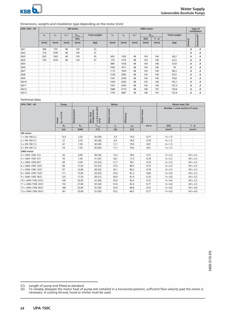
60/1 406 759 48 139 22 - - - - - - ✘ ✘60/2 519 1039 48 139 31 - - - - - - ✘ ✘60/3 632 1363 48 139 45 663 1362 48 143 146 60,2 ✘ ✘60/4 745 1476 48 139 47 776 1475 48 143 146 62,5 ✘ ✘60/5 - - - - - 889 1618 48 143 146 67,8 ✘ ✘60/6 - - - - - 1002 1811 48 143 146 78 ✘ ✘60/7 - - - - - 1115 1924 48 143 146 80,3 ✘ ✘60/8 - - - - - 1228 2082 48 145 146 87,6 ✘ ✘60/9 - - - - - 1341 2240 48 145 146 93,8 ✘ ✘60/10 - - - - - 1454 2443 48 145 146 105,1 ✘ ✘60/11 - - - - - 1567 2556 48 145 146 107,4 ✘ ✘60/12 - - - - - 1680 2774 48 146 147 120,6 ✘ ✘60/13 - - - - - 1793 2887 48 146 147 122,9 ✘ ✘
Technical data
UPA 150C - 60 Pump Motor Motor lead, flat
Hea
d
Q =
0 m
3 /h
Rat
ed p
ow
er
Max
. flu
idte
mp
erat
ure
v ≥
0,2
m/s
(0,
0m
/s)
Rat
ed c
urr
ent
Effi
cien
cy
Pow
er f
acto
r Number × cross-section of cores
H0 PN T max IN ηM cos φ DOL Y - Δ
[m] [kW] [°C] [A] [%] [mm2] [mm2]
DN motor
1 + DN 100-2.2 13,4 2,20 30 (30) 5,5 75,0 0,77 4 × 1,5 -
2 + DN 100-3.7 27 3,70 30 (30) 9,0 78,0 0,78 4 × 1,5 -
3 + DN 100-7.5 41 7,50 30 (20) 17,1 79,0 0,81 4 × 1,5 -
4 + DN 100-7.5 53 7,50 30 (20) 17,1 79,0 0,81 4 × 1,5 -
UMA motor
3 + UMA 150E 7/21 42 6,00 38 (34) 15,5 78,0 0,72 4 × 2,5 3/4 × 2,5
4 + UMA 150E 7/21 55 7,50 31 (25) 18,1 77,0 0,78 4 × 2,5 3/4 × 2,5
5 + UMA 150E 9/21 69 9,30 29 (23) 21,7 78,1 0,79 4 × 2,5 3/4 × 2,5
6 + UMA 150E 13/21 84 11,50 33 (27) 27,6 80,5 0,75 4 × 2,5 3/4 × 2,5
7 + UMA 150E 13/21 97 13,00 28 (22) 30,1 80,3 0,78 4 × 2,5 3/4 × 2,5
8 + UMA 150E 15/21 111 15,00 29 (23) 33,4 81,3 0,80 4 × 4,0 3/4 × 2,5
9 + UMA 150E 18/21 125 17,50 28 (21) 40,4 81,9 0,76 4 × 4,0 3/4 × 2,5
10 + UMA 150E 22/21 140 20,00 32 (26) 45,9 83,4 0,75 4 × 4,0 3/4 × 2,5
11 + UMA 150E 22/21 153 21,00 30 (24) 47,6 83,3 0,77 4 × 4,0 3/4 × 2,5
12 + UMA 150E 26/21 168 23,00 35 (30) 52,0 84,8 0,75 4 × 6,0 3/4 × 4,0
13 + UMA 150E 26/21 181 25,00 32 (26) 55,2 84,5 0,77 4 × 6,0 3/4 × 4,0
21) Length of pump end fitted as standard22) To reliably dissipate the motor heat of pump sets installed in a horizontal position, sufficient flow velocity past the motor is
necessary. A cooling shroud, hood or similar must be used.

Water SupplySubmersible Borehole Pumps
25UPA 150C
3400
.5/1
0-EN
UPA 150C - 60/..., number of stages 14 - 20
Operating range
Qmin = 32 m3/hQmax= end of stage curve
Connection types
Standard pump end = G 3
Possible connection types:
▪ Threaded connection– G 4
▪ Flanged connection– DN 65– DN 80
Alternative pump ends are possible.The length of the pump set LA and the diameter Dmax
depend on the pump end.
For an alternative pump end the length of the pump set LA*
is calculated as follows:
LA* = LA - LG + LG*
Values for calculating the dimensions if using a differentpump end:
▪ G 3:LG* = 48 mmDmax* ≙ Dmax
▪ G 4:LG* = 93 mmDmax* ≙ Dmax
DmaxG 3
L PL G
L A
▪ DN 65:LG* = 77 mmDmax* = 185 mm
▪ DN 80:LG* = 77 mmDmax* = 200 mm
Dimensions of UPA 150C - 60 / ... [mm]

Water SupplySubmersible Borehole Pumps
26 UPA 150C
3400
.5/1
0-EN
Dimensions, weights and installation type depending on the motor [mm]
UPA 150C - 60 DN motor UMA motor Type ofinstallation
LP LA LG23) Dmax Total weight LP LA LG
23) Dmax Total weight
Ver
tica
l
Ho
rizo
nta
l24)
DOL DOL Y - Δ
[mm] [mm] [mm] [mm] [kg] [mm] [mm] [mm] [mm] [mm] [kg]
60/14 - - - - - 1906 3000 48 146 147 125,1 ✘ -25)
60/15 - - - - - 2019 3213 48 146 147 137 ✘ -25)
60/16 - - - - - 2132 3326 48 146 147 140 ✘ -25)
60/17 - - - - - 2245 3519 48 145 147 149 ✘ -25)
60/18 - - - - - 2358 3632 48 145 147 151 ✘ -25)
60/19 - - - - - 2471 3745 48 145 147 154 ✘ -25)
60/20 - - - - - 2584 3858 48 145 147 156 ✘ -25)
Technical data
UPA 150C - 60 Pump Motor Motor lead, flat
Hea
d
Q =
0 m
3 /h
Rat
ed p
ow
er
Max
. flu
idte
mp
erat
ure
v ≥
0,2
m/s
(0,
0m
/s)
Rat
ed c
urr
ent
Effi
cien
cy
Pow
er f
acto
r Number × cross-section of cores
H0 PN T max IN ηM cos φ DOL Y - Δ
[m] [kW] [°C] [A] [%] [mm2] [mm2]
UMA motor
14 + UMA 150E 26/21 194 26,00 31 (25) 56,9 84,4 0,78 4 × 6,0 3/4 × 4,0
15 + UMA 150E 30/21 210 29,00 31 (25) 65,2 84,2 0,76 4 × 6,0 3/4 × 4,0
16 + UMA 150E 30/21 223 30,00 30 (23) 66,8 84,2 0,77 4 × 6,0 3/4 × 4,0
17 + UMA 150E 37/22 237 33,00 43 (37) 75,0 83,8 0,76 3/4 × 4,026) 3/4 × 4,0
18 + UMA 150E 37/22 251 35,00 40 (34) 78,2 83,6 0,77 3/4 × 4,026) 3/4 × 4,0
19 + UMA 150E 37/22 264 36,00 39 (32) 79,9 83,4 0,78 3/4 × 4,026) 3/4 × 4,0
20 + UMA 150E 37/22 277 37,00 38 (31) 81,6 83,3 0,79 3/4 × 4,026) 3/4 × 4,0
23) Length of pump end fitted as standard24) To reliably dissipate the motor heat of pump sets installed in a horizontal position, sufficient flow velocity past the motor is
necessary. A cooling shroud, hood or similar must be used.25) On request26) Parallel cable

Water SupplySubmersible Borehole Pumps
27UPA 150C
3400
.5/1
0-EN
Scope of supplyDepending on the model, the following items are included inthe scope of supply:
▪ Pump set with motor lead
▪ Back-up name plate
Optional:
▪ Extension cable optional: connected or supplied but notfitted
▪ Cable connector
▪ Cable clips
▪ Pedestals
▪ Cooling shroud, suction shroud or pressure shroud
▪ Supporting clamps and mounting clamps
▪ Electrical protection equipment
▪ Automatic control units
Accessories
Pump accessories
Overview of pump accessories
Description Connection /length
Quantity Mat. No. [kg]
Pump end, Flanged DN 50, PN 16 - 40 Per piece 01116438 3,3DN 65, PN 16 - 40 Per piece 01116439 3,6DN 80, PN 16 - 40 Per piece 01116440 4,1
Pump end, Screw-ended G3" Per piece 01124645 0,9G4" Per piece 01124644 1,4
Supporting and installation clamps R 2" / DN 50 Per pair 95000294 3,4R 2 1/2" / DN 65 Per pair 95000296 12R 3" / DN 80 Per pair 95000298 12R 4" / DN 100 Per pair 95000300 21
Pedestals, shaft centreline height 95 mm for UMA 150E motor Per set 01117821 1,5Cable tie, Size 1 Per piece 01088095 0,04Power cable, round, drinking water(with earth conductor)
4 x 1,5 mm² Per metre 90068174 0,184 x 2,5 mm² Per metre 90068175 0,2594 x 4 mm² Per metre 90068176 0,3564 x 6 mm² Per metre 90068177 0,64 x 10 mm² Per metre 90068178 1,14 x 16 mm² Per metre 90068179 1,224 x 25 mm² Per metre 90068180 1,84 x 35 mm² Per metre 90068181 2,34 x 50 mm² Per metre 90068182 3,24 x 70 mm² Per metre 90068183 4,4
Power cable, drinking water(without earth conductor)
3 x 1.5 mm² Per metre 90068148 0,13 x 2.5 mm² Per metre 90068149 0,23 x 4 mm² Per metre 90068150 0,23 x 6 mm² Per metre 90068151 0,33 x 10 mm² Per metre 90068152 0,63 x 16 mm² Per metre 90068153 0,83 x 25 mm² Per metre 90068154 1,13 x 35 mm² Per metre 90068155 1,43 x 50 mm² Per metre 90068156 2,13 x 70 mm² Per metre 90068157 2,8
Cable kit for 3~ motors DN 100, 4-core, flat, 4 x 1.5 mm²27), formaterial variants C1 and C2
L = 5 m Per set 1712501 0,7L = 10 m Per set 1712502 1,3L = 15 m Per set 1712503 2,07L = 20 m Per set 1712504 2,74L = 25 m Per set 1712505 3,3L = 30 m Per set 1712506 4,1L = 35 m Per set 1712507 4,77L = 40 m Per set 1712508 5,54
27) Specify the material number of the pump when ordering.

Water SupplySubmersible Borehole Pumps
28 UPA 150C
3400
.5/1
0-EN
Description Connection /length
Quantity Mat. No. [kg]
Cable kit for 3~ motors DN 100, 4-core, round, 4 x 1.5 mm²27), formaterial variant C1
L = 5 m Per set 1431841 0,7L = 10 m Per set 1435407 1,3L = 15 m Per set 1435408 2,07L = 20 m Per set 1435409 2,74L = 25 m Per set 1435410 3,3L = 30 m Per set 1435411 4,1L = 35 m Per set 1435412 4,77L = 40 m Per set 1435413 5,54
Cable connector size 28 For 1 × motor lead to 1 × extension cable 95005106 0,5Cable connector size 28 includes connection and sealing For 1 × motor lead to 1 × extension cable 90049385 0,5Cable connector size 35 For 1 × motor lead to 1 × extension cable 90049397 0,6Cable connector size 35 includes connection and sealing For 1 × motor lead to 1 × extension cable 90049387 0,6Cable connector size 43 For 1 × motor lead to 1 × extension cable 90049399 0,8Cable connector size 43 For 2 × motor leads to 1 × extension cable 90049400 0,8Cable connector size 43 includes connection and sealing For 1 × motor lead to 1 × extension cable 90049389 0,8Cable connector size 43 includes connection and sealing For 2 × motor leads to 1 × extension cable 90049390 0,8Cable connector size 53 For 2 × motor leads to 1 × extension cable 90049401 1Cable connector size 53 includes connection and sealing For 1 × motor lead to 1 × extension cable 90049391 1Dry running protection device Fully automatic operation(with 1 relay and 3 electrodes)
Per set 90009554 2
Dry running protection device Semi-automatic operation(with 1 relay, 1 pressure switch)
Per set 90009553 2
Control cabinet UPA ControlFor DOL starting, temperature-compensated, insulating enclosureWith 4 PG cable glands for round cables3 immersion electrodes and integrated selector switch for "Dry running protection" or "Water level control" operation, as well aswith thermal overcurrent relay with phase failure protection, for motor sizes:1~230 V 3~400 V- 0,37 kW - 40980887 3,5- 0,55 + 0,75 kW - 40980889 3,5- 1,10 + 1,50 kW - 40980891 3,50,55 kW - - 40980893 3,50,75 kW 2,20 kW - 40980895 3,51,10 kW 3,00 + 3,70 kW - 40980897 3,51,50 kW - - 40980899 3,52,20 kW 5,50 kW - 40984811 3,5- 7,50 kW - 90052649 3,5- UMA 150E - 5/21 - 40984811 3,5- UMA 150E - 7/21 - 90052649 3,5Lightning protection For 3~400 V Per set 00533299 0,3Pressure controller 0 - 8 bar Per piece 01151586 1
Motor accessories
Description Mat. No. [kg]
Fill check kit, for checking and topping up the motor fill after prolongedstorage for UMA 150D, UMA 150E, UMA 200D, UMA 250D
90066762 0,25
Automatic control units
Description Mat. No. [kg]
Cervomatic EDP.2 automatic control unit 01185581 2,5
Controlmatic E automatic control unit 90053395 1,3

Water SupplySubmersible Borehole Pumps
29UPA 150C
3400
.5/1
0-EN
Cooling shroud made of stainless steel 1.4301
UPA150C
Motor type 3~400 V
Cooling shroud Suction strainer
DN100
UMA150E
Ø × length Vertical installation Horizontalinstallation
(includingpedestals)
Ø × length Mat. No. [kg]
[kW] [kW] [mm] Mat. No. [kg] Mat. No. [kg] [mm]
16/...30/...
≤ 1,5 - Ø 160 (180) × 450 01138258 2,5 01138255 4,9 Ø 160 × 158 01138982 0,5≤ 2,2 - Ø 160 (180) × 500 01138259 2,7 01138256 5,1 Ø 160 × 158 01138982 0,5≤ 3,0 - Ø 160 (180) × 625 01138260 3,8 01138317 6,2 Ø 160 × 158 01138982 0,5≤ 5,5 - Ø 160 (180) × 800 01138261 3,9 01138318 6,3 Ø 160 × 158 01138982 0,5≤ 7,5 - Ø 160 (180) × 1000 01315559 6,4 - - Ø 160 × 158 01138982 0,5- ≤ 9,3 Ø 180 (200) × 800 01584802 5,5 01584805 7,9 Ø 180 × 192 01138984 0,6- ≤ 18,5 Ø 180 (200) × 1000 01584806 6 01584817 9,6 Ø 180 × 192 01138984 0,6- ≤ 26,0 Ø 180 (200) × 1250 01584818 8,6 01584819 12,2 Ø 180 × 192 01138984 0,6- ≤ 37,0 Ø 180 (200) × 1500 01584820 10,6 01584821 14,2 Ø 180 × 192 01138984 0,6
48/...60/...
≤ 2,2 - Ø 180 (200) × 500 01138262 3,7 01138319 6,1 Ø 180 × 192 01138984 0,6≤ 3,0 - Ø 180 (200) × 625 01138263 4 01138320 6,4 Ø 180 × 192 01138984 0,6≤ 5,5 - Ø 180 (200) × 800 01138264 5,5 01138321 7,9 Ø 180 × 192 01138984 0,6≤ 7,5 - Ø 180 (200) × 1000 01315560 7,5 - - Ø 180 × 192 01138984 0,6- ≤ 9,3 Ø 200 (220) × 800 01584822 5,8 01584823 8,5 Ø 200 × 192 01138985 0,8- ≤ 18,5 Ø 200 (220) × 1000 01584842 6,3 01584843 10,3 Ø 200 × 192 01138985 0,8- ≤ 26,0 Ø 200 (220) × 1250 01584844 11 01584845 15 Ø 200 × 192 01138985 0,8- ≤ 37,0 Ø 200 (220) × 1500 01584846 12,4 01584867 16,4 Ø 200 × 192 01138985 0,8
Cooling shroud in material variant C2 on request

Water SupplySubmersible Borehole Pumps
30 UPA 200, 200B, 250C
3400
.5/1
0-EN
UPA 200, 200B, 250C
Main applications▪ Water supply systems
▪ Spray irrigation systems
▪ Mining
▪ General irrigation systems
▪ Pressure boosting
▪ Fire-fighting systems
▪ Lowering groundwater levels
Fluids handled▪ Drinking water
▪ Cooling water
▪ River water, lake water and groundwater
▪ Seawater28)
▪ Max. permissible sand content of the fluid 50 g/m³
Operating data
Operating properties
Characteristic Value
Flow rate Q [m3/h] ≤ 330Q [l/s] ≤ 92
Head H [m] ≤ 460Fluid temperature T [°C] ≤ +50Speed n [rpm] ≤ 2900Well diameter D [mm] 200/250
D [″] 8/10
Design details
Design▪ Centrifugal pump
▪ Single-stage or multistage
▪ Single-entry
▪ Ring-section design
▪ Rigid connection between pump and motor
Type of installation▪ Vertical installation
▪ Horizontal installation (depending on the number ofstages)
DriveAsynchronous motor:
▪ With squirrel cage motor for submerged use
▪ Standard connection to NEMA
▪ Frequency 50 Hz
▪ IP68 enclosure
▪ DOL starting or star-delta starting
▪ Frequency of starts– UMA 150E: 15 starts per hour– UMA 200D, UMA 250D: 10 starts per hour– UMA 300D: 5 starts per hour
▪ Winding J1 (PVC) or, for higher temperatures, J2 (VPE /XLPE)
Synchronous motor:
▪ Interior (buried) permanent magnet synchronous motor(IPMSM)
▪ IP68 enclosure
▪ Standard connection to NEMA
▪ Winding J2 (VPE / XLPE)
▪ Frequency of starts ≤ 15 starts per hour
Electrical connection▪ Delivered ex-factory with 1 or 2 motor leads (including
earth conductor and internal earthing)
▪ Extension cable connected with water-tight cableconnector
▪ Motor lead and extension cable suitable for drinkingwater use
Impeller type▪ Radial or mixed flow versions
Bearings▪ Radial plain bearings
▪ Pump bearings lubricated by fluid handled; motorbearings lubricated by water fill
▪ Axial thrust is balanced by a tilting-pad thrust bearing inthe motor (lower end)
▪ 1 intermediate bearing in the pump, depending on thepump size and the number of stages
28) Only for pumps in material variant C3 (duplex)

Water SupplySubmersible Borehole Pumps
31UPA 200, 200B, 250C
3400
.5/1
0-EN
Connections▪ Pump screw-ended or flanged
▪ With lift check valve or connection branch
Designation
Example: UPA 200B - 80B / 5d
Designation key
Code Description
UPA Pump type series200 Minimum well diameter [mm]B Design status80 Flow rate at best efficiency point [m³/h]B Impeller material (e.g. B = bronze)5 Number of stagesd Trimmed impellers
Materials
Material selection for UPA 200 pumps
Component Material variant
G B
Casing Grey cast iron (EN-GJL-200) Bronze (CC480K-DW)Impeller Glass fibre reinforced Noryl (PPO)Screws, bolts and nuts CrNiMo steel (A4-70)Shaft Chrome steel (1.4021) CrNiMo steel (1.4462)
Material selection for UPA 200B and 250C pumps
Component Material variant
G B C3
Casing Grey cast iron (EN-GJL-250) Bronze (CC480K-DW) CrNiMo steel (1.4517)Impeller 200B Glass fibre reinforced Noryl (PPO) / bronze (CC480K-DW) CrNiMo steel (1.4517)
250C Bronze (CC480K-DW) CrNiMo steel (1.4517)Screws, bolts and nuts CrNiMo steel (A4-70) CrNiMo steel (1.4462)Shaft Chrome steel (1.4021) CrNiMo steel (1.4462) CrNiMo steel (1.4462)
Material selection for UMA 150E, 200D, 250D, 300D motors
Component Material variant
G C1 C2 C3
Casing 150E - CrNi steel (1.4301) CrNiMo steel (1.4571) CrNiMo steel (1.4539)200D Grey cast iron (EN-
GJL-200)- CrNiMo steel (1.4408) CrNiMo steel (1.4539)
250D Grey cast iron (EN-GJL-200)
- CrNiMo steel (1.4408) CrNiMo steel (1.4539)
300D Grey cast iron (EN-GJL-250)
- - CrNiMo steel (1.4517)
Screws, bolts andnuts
150E - CrNiMo steel (A4-70) CrNiMo steel (A4-70) CrNiMo steel (1.4539)200D CrNiMo steel (A4-70) - CrNiMo steel (A4-70) CrNiMo steel (1.4539)250D CrNiMo steel (A4-70) - CrNiMo steel (A4-70) CrNiMo steel (1.4539)300D CrNiMo steel (1.4571) - - CrNiMo steel (1.4462)
Shaft 150E - CrNi steel (1.4021)29) /CrNiMo steel (1.4462)30)
CrNiMo steel (1.4462) CrNiMo steel (1.4462)
200D CrNiMo steel (1.4460) - CrNiMo steel (1.4462) CrNiMo steel (1.4462)250D CrNiMo steel (1.4460) - CrNiMo steel (1.4462) CrNiMo steel (1.4462)300D CrNiMo steel (1.4462) - - CrNiMo steel (1.4462)
29) For motors < 18.5 kW30) For motors ≥ 18.5 kW

Water SupplySubmersible Borehole Pumps
32 UPA 200, 200B, 250C
3400
.5/1
0-EN
Coating and preservationOnly for pump sets in material variant grey cast iron.
▪ 2-component high-build coating, epoxy resin base paint– Coating structure: primer and top coat– Film thickness: 100 to 150 µm– Colour: ultramarine blue (RAL 5002)
Product benefits▪ High efficiencies through optimised hydraulic design
▪ High operating reliability and a long service life byintegrated sand separator, robust wear rings and enclosedpump bearings
▪ Reliable operation by anti-jam lift check valve
▪ High flexibility by vertical, horizontal and angularinstallation options
▪ Durable, completely maintenance-free design withhydrodynamic bearings
▪ Easy to install with service-friendly hydraulic system design
▪ Low noise level

Water SupplySubmersible Borehole Pumps
33UPA 200, 200B, 250C
3400
.5/1
0-EN
Product information Product information as per Regulation No.1907/2006 (REACH)For information as per chemicals Regulation (EC) No. 1907/2006(REACH), see http://www.ksb.com/reach.
Information on characteristic curves
The characteristic curves shown are intended to allow pre-selection. Refer to the quotation for the precise selection data.
▪ Tolerance to ISO 9906 Cl. 2B, > 10 kW
▪ Tolerance to ISO 9906 Cl. 3B, < 10 kW
▪ Threaded end to DIN ISO 228, Part 1
▪ Flanged end to DIN EN 1092
Hv Head losses in the lift check valve. The head losses Hv in the lift check valve are not included in the pump characteristiccurves.
ηp Pump efficiency (without lift check valve)NPSH Net positive suction head required by pump
Certifications
Overview
Label Effective in: Comment
All countries Certified quality managementto ISO 9001
31)
France French drinking waterapproval
31) Valid for pump materials G and B and motor materials G, C1, C2 and C3

Water SupplySubmersible Borehole Pumps
34 UPA 200, 200B, 250C
3400
.5/1
0-EN
Technical data
Selection chart
n = 2900 rpm
UPA 200-11
UPA 200-14
UPA 200B-80
UPA 200B-130
UPA 250C-120UPA 250C-150
UPA 250C-250
UPA 200-11 UPA 200-14UPA 200B-80
UPA 200B-130
UPA 250C-120UPA 250C-150
UPA 250C-250
Fig. 2: Selection chart UPA 200, 200B, 250CSelection charts or characteristic curves for UPA in material variant C3 (duplex) only on request.

Water SupplySubmersible Borehole Pumps
35UPA 200, 200B, 250C
3400
.5/1
0-EN
UPA 200 - 11 / ...
Optimum impeller Ø "d" Maximum impeller Ø
Operating range
Qmin = 8 m3/hQmax= end of stage curve
Types of connection
Standard pump end = G 3
Connection types:
▪ Flanged connection– DN 80
Alternative pump ends are possible.The length of the pump set LA and the diameterDmax depend on the pump end.
For an alternative pump end the length of thepump set LA* is calculated as follows:
LA* = LA - LG + LG*
Values for calculating the dimensions if using adifferent pump end:
▪ G 3:LG* = 200 mmDmax* ≙ Dmax
▪ DN 80:LG* = 200 mmDmax* = 200 mm
L A
L P
Dmax
G 3
L G
A 220 320
200
Ø13,5
Dimensions of UPA 200 - 11 / ... [mm]

Water SupplySubmersible Borehole Pumps
36 UPA 200, 200B, 250C
3400
.5/1
0-EN
Dimensions, weights and installation type depending on the motor [mm]
UPA 200 - 11 A LP LA LG32) Dmax Total weight Type of
installation
DOL Y - Δ Material variant
Ver
tica
l
Ho
rizo
nta
l33)
G B C3
[mm] [mm] [mm] [mm] [mm] [mm] [kg] [kg] [kg]
1e + UMA 150E 5/21 635 515 1194 200 192 195 75 80 - ✘ ✘1d + UMA 150E 5/21 635 515 1194 200 192 195 75 80 - ✘ ✘1 + UMA 150E 5/21 635 515 1194 200 192 195 75 80 - ✘ ✘2e + UMA 150E 5/21 700 580 1259 200 192 195 79 85 - ✘ ✘2c + UMA 150E 5/21 700 580 1259 200 192 195 79 85 - ✘ ✘2 + UMA 150E 7/21 710 580 1279 200 192 195 81 87 - ✘ ✘3d + UMA 150E 7/21 775 645 1344 200 192 195 85 92 - ✘ ✘3 + UMA 150E 9/21 790 645 1374 200 192 195 88 95 - ✘ ✘4c + UMA 150E 13/21 895 710 1519 200 192 195 100 108 - ✘ ✘4 + UMA 150E 13/21 895 710 1519 200 192 195 100 108 - ✘ ✘5b + UMA 150E 13/21 960 775 1584 200 192 195 104 112 - ✘ ✘5 + UMA 150E 15/21 980 775 1629 200 193 195 109 117 - ✘ ✘6b + UMA 150E 15/21 1045 840 1694 200 193 195 113 122 - ✘ ✘6 + UMA 150E 18/21 1070 840 1739 200 193 195 117 126 - ✘ ✘7 + UMA 150E 22/21 1180 905 1894 200 193 195 130 140 - ✘ ✘8 + UMA 150E 26/21 1295 970 2064 200 194 196 146 156 - ✘ ✘9 + UMA 150E 26/21 1360 1035 2129 200 194 196 150 161 - ✘ ✘10 + UMA 150E 30/21 1475 1100 2294 200 194 196 164 176 - ✘ ✘11 + UMA 150E 37/22 - 1165 2439 200 196 196 175 188 - ✘ -34)
12 + UMA 150E 37/22 - 1230 2504 200 196 196 179 193 - ✘ -34)
13 + UMA 150E 37/22 - 1295 2569 200 196 196 184 197 - ✘ -34)
14 + UMA 200D 45/21 1755 1360 2590 200 199 199 244 258 - ✘ ✘
Technical data
UPA 200 - 11 Pump Motor Motor lead, flat
Hea
d
Q =
0 m
3 /h
Rat
ed p
ow
er
Max
. flu
idte
mp
erat
ure
v ≥
0,2
m/s
(0,
0m
/s)
Rat
ed c
urr
ent
Effi
cien
cy
Pow
er f
acto
r Number × cross-section of cores
H0 PN T max IN ηM cos φ DOL Y - Δ
[m] [kW] [°C] [A] [%] [mm2] [mm2]
1e + UMA 150E 5/21 19 2,5 45 (42) 10,0 69,2 0,53 4 × 2,5 3/4 × 2,5
1d + UMA 150E 5/21 20 2,5 45 (42) 10,0 69,2 0,53 4 × 2,5 3/4 × 2,5
1 + UMA 150E 5/21 23 3,5 44 (41) 10,9 74,9 0,62 4 × 2,5 3/4 × 2,5
2e + UMA 150E 5/21 36 4,5 41 (38) 12,2 76,5 0,70 4 × 2,5 3/4 × 2,5
2c + UMA 150E 5/21 41 5,5 37 (32) 13,8 76,1 0,76 4 × 2,5 3/4 × 2,5
2 + UMA 150E 7/21 45 6,0 38 (34) 15,5 78,0 0,72 4 × 2,5 3/4 × 2,5
3d + UMA 150E 7/21 59 7,0 33 (28) 17,2 77,0 0,77 4 × 2,5 3/4 × 2,5
3 + UMA 150E 9/21 66 9,0 30 (24) 21,2 78,3 0,79 4 × 2,5 3/4 × 2,5
4c + UMA 150E 13/21 83 10,0 37 (32) 25,3 80,6 0,71 4 × 2,5 3/4 × 2,5
4 + UMA 150E 13/21 89 12,0 31 (26) 28,4 80,5 0,76 4 × 2,5 3/4 × 2,5
5b + UMA 150E 13/21 103 12,5 30 (24) 29,2 80,4 0,77 4 × 2,5 3/4 × 2,5
5 + UMA 150E 15/21 110 14,5 30 (34) 32,5 81,4 0,79 4 × 4,0 3/4 × 2,5
6b + UMA 150E 15/21 123 15,0 29 (23) 33,4 81,3 0,80 4 × 4,0 3/4 × 2,5
6 + UMA 150E 18/21 133 17,5 28 (21) 40,4 81,9 0,76 4 × 4,0 3/4 × 2,5
7 + UMA 150E 22/21 155 21,0 30 (24) 47,6 83,3 0,77 4 × 4,0 3/4 × 2,5
8 + UMA 150E 26/21 178 24,0 34 (28) 53,6 84,7 0,76 4 × 6,0 3/4 × 4,0
9 + UMA 150E 26/21 199 26,0 31 (25) 56,9 84,4 0,78 4 × 6,0 3/4 × 4,0
10 + UMA 150E 30/21 222 29,0 31 (25) 65,2 84,2 0,76 4 × 6,0 3/4 × 4,0
11 + UMA 150E 37/22 245 32,0 44 (38) 73,4 83,9 0,75 3/4 × 4,0 35) 3/4 × 4,0
12 + UMA 150E 37/22 266 35,0 40 (34) 78,2 83,6 0,77 3/4 × 4,0 35) 3/4 × 4,0
13 + UMA 150E 37/22 286 37,0 38 (31) 81,6 83,3 0,79 3/4 × 4,0 35) 3/4 × 4,0
14 + UMA 200D 45/21 315 42,0 30 (25) 85,0 86,1 0,83 3/4 × 6,0 36) 3/4 × 6,0
32) Length of pump end fitted as standard33) To reliably dissipate the motor heat of pump sets installed in a horizontal position, sufficient flow velocity past the motor is
necessary. A cooling shroud, hood or similar must be used.34) On request35) Parallel cable36) Delta configuration in cable connector or control cabinet

Water SupplySubmersible Borehole Pumps
37UPA 200, 200B, 250C
3400
.5/1
0-EN
UPA 200 - 14 / ...
Optimum impeller Ø "d" Maximum impeller Ø
Operating range
Qmin = 10 m3/hQmax= end of stage curve
Types of connection
Standard pump end = G 3
Connection types:
▪ Flanged connection– DN 80
Alternative pump ends are possible.The length of the pump set LA and the diameterDmax depend on the pump end.
For an alternative pump end the length of thepump set LA* is calculated as follows:
LA* = LA - LG + LG*
Values for calculating the dimensions if using adifferent pump end:
▪ G 3:LG* = 200 mmDmax* ≙ Dmax
▪ DN 80:LG* = 200 mmDmax* = 200 mm
L A
L P
Dmax
G 3
L G
A 220 320
200
Ø13,5
Dimensions of UPA 200 - 14 / ... [mm]

Water SupplySubmersible Borehole Pumps
38 UPA 200, 200B, 250C
3400
.5/1
0-EN
Dimensions, weights and installation type depending on the motor [mm]
UPA 200 - 14 A LP LA LG37) Dmax Total weight Type of
installation
DOL Y - Δ Material variant
Ver
tica
l
Ho
rizo
nta
l38)
G B C3
[mm] [mm] [mm] [mm] [mm] [mm] [kg] [kg] [kg]
1e + UMA 150E 5/21 650 530 1209 200 192 195 76 81 - ✘ ✘1d + UMA 150E 5/21 650 530 1209 200 192 195 76 81 - ✘ ✘1 + UMA 150E 5/21 650 530 1209 200 192 195 76 81 - ✘ ✘2e + UMA 150E 7/21 740 610 1309 200 192 195 83 89 - ✘ ✘2d + UMA 150E 7/21 740 610 1309 200 192 195 83 89 - ✘ ✘2 + UMA 150E 9/21 755 610 1339 200 192 195 86 92 - ✘ ✘3d + UMA 150E 13/21 875 690 1499 200 192 195 99 106 - ✘ ✘3 + UMA 150E 13/21 875 690 1499 200 192 195 99 106 - ✘ ✘4c + UMA 150E 15/21 975 770 1624 200 193 195 109 117 - ✘ ✘4 + UMA 150E 18/21 1000 770 1669 200 193 195 113 121 - ✘ ✘5c + UMA 150E 18/21 1080 850 1749 200 193 195 118 127 - ✘ ✘5 + UMA 150E 22/21 1125 850 1839 200 193 195 127 136 - ✘ ✘6c + UMA 150E 22/21 1205 930 1919 200 193 195 132 142 - ✘ ✘6 + UMA 150E 26/21 1255 930 2024 200 194 196 143 153 - ✘ ✘7c + UMA 150E 26/21 1335 1010 2104 200 194 196 148 159 - ✘ ✘7 + UMA 150E 30/21 1385 1010 2204 200 194 196 158 169 - ✘ ✘8 + UMA 150E 37/22 - 1090 2364 200 196 196 170 182 - ✘ -39)
9 + UMA 150E 37/22 - 1170 2444 200 196 196 176 188 - ✘ -39)
10 + UMA 200D 45/21 1645 1250 2480 200 199 199 237 250 - ✘ ✘11 + UMA 200D 55/21 1780 1330 2670 200 199 199 262 277 - ✘ ✘12 + UMA 200D 55/21 1860 1410 2750 200 199 199 267 282 - ✘ ✘13 + UMA 200D 55/21 1940 1490 2830 200 199 199 272 288 - ✘ ✘
Technical data
UPA 200 - 14 Pump Motor Motor lead, flat
Hea
d
Q =
0 m
3 /h
Rat
ed p
ow
er
Max
. flu
idte
mp
erat
ure
v ≥
0,2
m/s
(0,
0m
/s)
Rat
ed c
urr
ent
Effi
cien
cy
Pow
er f
acto
r Number × cross-section of cores
H0 PN T max IN ηM cos φ DOL Y - Δ
[m] [kW] [°C] [A] [%] [mm2] [mm2]
1e + UMA 150E 5/21 18 3,0 45 (42) 10,4 72,7 0,57 4 × 2,5 3/4 × 2,5
1d + UMA 150E 5/21 21 3,5 44 (41) 10,9 74,9 0,62 4 × 2,5 3/4 × 2,5
1 + UMA 150E 5/21 25 4,5 41 (38) 12,2 76,5 0,70 4 × 2,5 3/4 × 2,5
2e + UMA 150E 7/21 35 6,0 38 (34) 15,5 78,0 0,72 4 × 2,5 3/4 × 2,5
2d + UMA 150E 7/21 42 7,0 33 (28) 17,2 77,0 0,77 4 × 2,5 3/4 × 2,5
2 + UMA 150E 9/21 50 8,5 32 (27) 20,3 78,5 0,77 4 × 2,5 3/4 × 2,5
3d + UMA 150E 13/21 65 10,5 35 (30) 26,1 80,6 0,72 4 × 2,5 3/4 × 2,5
3 + UMA 150E 13/21 75 12,5 30 (24) 29,2 80,4 0,77 4 × 2,5 3/4 × 2,5
4c + UMA 150E 15/21 90 14,5 30 (24) 32,5 81,4 0,79 4 × 4,0 3/4 × 2,5
4 + UMA 150E 18/21 101 17,0 29 (22) 39,6 82,0 0,76 4 × 4,0 3/4 × 2,5
5c + UMA 150E 18/21 113 18,0 26 (19) 41,2 81,8 0,77 4 × 4,0 3/4 × 2,5
5 + UMA 150E 22/21 126 21,0 30 (24) 47,6 83,3 0,77 4 × 4,0 3/4 × 2,5
6c + UMA 150E 22/21 136 22,0 28 (21) 49,2 83,1 0,78 4 × 4,0 3/4 × 2,5
6 + UMA 150E 26/21 151 25,0 32 (26) 55,2 84,5 0,77 4 × 6,0 3/4 × 4,0
7c + UMA 150E 26/21 159 26,0 31 (25) 56,9 84,4 0,78 4 × 6,0 3/4 × 4,0
7 + UMA 150E 30/21 177 30,0 30 (23) 66,8 84,2 0,77 4 × 6,0 3/4 × 4,0
8 + UMA 150E 37/22 202 34,0 41 (35) 76,6 83,7 0,77 3/4 × 4,0 40) 3/4 × 4,0
9 + UMA 150E 37/22 225 37,0 38 (31) 81,6 83,3 0,79 3/4 × 4,0 40) 3/4 × 4,0
10 + UMA 200D 45/21 255 44,0 30 (24) 89,0 86,0 0,84 3/4 × 6,0 41) 3/4 × 6,0
11 + UMA 200D 55/21 283 48,0 33 (27) 98,0 87,2 0,82 3/4 × 6,0 41) 3/4 × 6,0
12 + UMA 200D 55/21 307 52,0 30 (24) 104,0 87,1 0,83 3/4 × 6,0 41) 3/4 × 6,0
13 + UMA 200D 55/21 331 55,0 27 (21) 109,0 86,9 0,84 3/4 × 6,0 41) 3/4 × 6,0
37) Length of pump end fitted as standard38) To reliably dissipate the motor heat of pump sets installed in a horizontal position, sufficient flow velocity past the motor is
necessary. A cooling shroud, hood or similar must be used.39) On request40) Parallel cable41) Delta configuration in cable connector or control cabinet

Water SupplySubmersible Borehole Pumps
39UPA 200, 200B, 250C
3400
.5/1
0-EN
UPA 200B - 80 / ...
Optimum impeller Ø "f" Maximum
impeller Ø
Operating range
Qmin = 15 m3/hQmax= end of stage curve
Types of connection
Standard pump end = G 5
Connection types:
▪ Flanged connection– DN 125
Alternative pump ends are possible.The length of the pump set LA and the diameterDmax depend on the pump end.
For an alternative pump end the length of thepump set LA* is calculated as follows:
LA* = LA - LG + LG*
Values for calculating the dimensions if using adifferent pump end:
▪ G 5:LG* = 200 mmDmax* ≙ Dmax
▪ DN 125:LG* = 150 mmDmax* = 250 mm (PN 10/16)Dmax* = 270 mm (PN 25/40)
Dmax
G 5
L P
L G
L A
Dimensions of UPA 200B - 80 / ... [mm]

Water SupplySubmersible Borehole Pumps
40 UPA 200, 200B, 250C
3400
.5/1
0-EN
Dimensions, weights and installation type depending on the motor [mm]
UPA 200B - 80 A LP LA LG42) Dmax Total weight Type of
installation
DOL Y - Δ Material variant
Ver
tica
l
Ho
rizo
nta
l43)
G B C3
[mm] [mm] [mm] [mm] [mm] [mm] [kg] [kg] [kg]
1g + UMA 150E 5/21 610 582 1261 200 193 196 81 88 89 ✘ ✘1f + UMA 150E 7/21 620 582 1281 200 193 196 83 90 91 ✘ ✘1d + UMA 150E 7/21 620 582 1281 200 193 196 83 90 91 ✘ ✘1 + UMA 150E 9/21 635 582 1311 200 193 196 86 93 94 ✘ ✘2g + UMA 150E 13/21 810 714 1523 200 193 196 104 114 115 ✘ ✘2f + UMA 150E 13/21 810 714 1523 200 193 196 104 114 115 ✘ ✘2d + UMA 150E 15/21 830 714 1568 200 194 196 109 119 120 ✘ ✘2 + UMA 150E 18/21 855 714 1613 200 194 196 113 123 124 ✘ ✘3f + UMA 150E 18/21 985 846 1745 200 194 196 124 135 136 ✘ ✘3e + UMA 150E 18/21 985 846 1745 200 194 196 124 135 136 ✘ ✘3d + UMA 150E 22/21 1030 846 1835 200 194 196 133 144 145 ✘ ✘3 + UMA 150E 22/21 1030 846 1835 200 194 196 133 144 145 ✘ ✘4e + UMA 150E 26/21 1215 978 2072 200 195 198 154 167 169 ✘ ✘4c + UMA 150E 30/21 1265 978 2172 200 195 198 164 177 179 ✘ ✘4 + UMA 150E 30/21 1265 978 2172 200 195 198 164 177 179 ✘ ✘5d + UMA 150E 37/22 - 1110 2384 200 198 198 182 197 199 ✘ -44)
5 + UMA 150E 37/22 - 1110 2384 200 198 198 182 197 199 ✘ -44)
6c + UMA 200D 45/21 1550 1242 2475 200 201 201 249 266 268 ✘ ✘6 + UMA 200D 45/21 1550 1242 2475 200 201 201 249 266 268 ✘ ✘7c + UMA 200D 55/21 1735 1374 2715 200 201 201 280 298 301 ✘ ✘7 + UMA 200D 55/21 1735 1374 2715 200 201 201 280 298 301 ✘ ✘8c + UMA 200D 55/21 1865 1506 2845 200 201 201 290 311 313 ✘ ✘8 + UMA 200D 65/21 1930 1506 2975 200 205 205 313 334 336 ✘ ✘9 + UMA 200D 75/21 - 1638 3200 200 205 205 340 362 365 ✘ -44)
10 + UMA 200D 75/21 - 1770 3330 200 205 205 350 374 377 ✘ -44)
11 + UMA 200D 90/21 - 1902 3645 200 211 211 394 420 423 ✘ -44)
12 + UMA 200D 90/21 - 2034 3775 200 211 211 404 432 436 ✘ -44)
Technical data
UPA 200B - 80 Pump Motor Motor lead, flat
Hea
d
Q =
0 m
3 /h
Rat
ed p
ow
er
Max
. flu
idte
mp
erat
ure
v ≥
0,2
m/s
(0,
0m
/s)
Rat
ed c
urr
ent
Effi
cien
cy
Pow
er f
acto
r Number × cross-section of cores
H0 PN T max IN ηM cos φ DOL Y - Δ
[m] [kW] [°C] [A] [%] [mm2] [mm2]
1g + UMA 150E 5/21 20 5,5 37 (32) 13,8 76,1 0,76 4 × 2,5 3/4 × 2,5
1f + UMA 150E 7/21 24 6,0 38 (34) 15,5 78,0 0,72 4 × 2,5 3/4 × 2,5
1d + UMA 150E 7/21 25 7,5 31 (25) 18,1 77,0 0,78 4 × 2,5 3/4 × 2,5
1 + UMA 150E 9/21 27 8,0 34 (30) 19,4 78,7 0,76 4 × 2,5 3/4 × 2,5
2g + UMA 150E 13/21 39 10,5 35 (30) 26,1 80,6 0,72 4 × 2,5 3/4 × 2,5
2f + UMA 150E 13/21 44 12,0 31 (26) 28,4 80,5 0,76 4 × 2,5 3/4 × 2,5
2d + UMA 150E 15/21 48 14,5 30 (24) 32,5 81,4 0,79 4 × 4,0 3/4 × 2,5
2 + UMA 150E 18/21 53 16,0 31 (25) 38,0 82,1 0,74 4 × 4,0 3/4 × 2,5
3f + UMA 150E 18/21 67 16,0 31 (25) 38,0 82,1 0,74 4 × 4,0 3/4 × 2,5
3e + UMA 150E 18/21 70 18,0 26 (19) 41,2 81,8 0,77 4 × 4,0 3/4 × 2,5
3d + UMA 150E 22/21 73 20,0 32 (26) 45,9 83,4 0,75 4 × 4,0 3/4 × 2,5
3 + UMA 150E 22/21 78 22,0 28 (21) 49,2 83,1 0,78 4 × 4,0 3/4 × 2,5
4e + UMA 150E 26/21 94 24,0 34 (28) 53,6 84,7 0,76 4 × 6,0 3/4 × 4,0
4c + UMA 150E 30/21 99 28,0 32 (26) 53,6 84,3 0,75 4 × 6,0 3/4 × 4,0
4 + UMA 150E 30/21 104 30,0 30 (23) 66,8 84,2 0,77 4 × 6,0 3/4 × 4,0
5d + UMA 150E 37/22 122 33,0 43 (37) 75,0 83,8 0,76 3/4 × 4,0 45) 3/4 × 4,0
5 + UMA 150E 37/22 129 37,0 38 (31) 81,6 83,3 0,79 3/4 × 4,0 45) 3/4 × 4,0
6c + UMA 200D 45/21 150 44,0 30 (24) 89,0 86,0 0,84 3/4 × 6,0 46) 3/4 × 6,0
6 + UMA 200D 45/21 158 45,0 27 (20) 90,0 86,0 0,84 3/4 × 6,0 46) 3/4 × 6,0
7c + UMA 200D 55/21 176 50,0 31 (25) 101,0 87,2 0,83 3/4 × 6,0 46) 3/4 × 6,0
7 + UMA 200D 55/21 185 54,0 28 (22) 108,0 87,0 0,84 3/4 × 6,0 46) 3/4 × 6,0
8c + UMA 200D 55/21 200 55,0 26 (20) 109,0 86,9 0,84 3/4 × 6,0 46) 3/4 × 6,0
8 + UMA 200D 65/21 213 62,0 30 (23) 123,0 87,7 0,83 3/4 × 10 46) 3/4 × 10
42) Length of pump end fitted as standard43) To reliably dissipate the motor heat of pump sets installed in a horizontal position, sufficient flow velocity past the motor is
necessary. A cooling shroud, hood or similar must be used.44) Horizontal installation on request and only with pedestals in special design45) Parallel cable46) Delta configuration in cable connector or control cabinet

Water SupplySubmersible Borehole Pumps
41UPA 200, 200B, 250C
3400
.5/1
0-EN
UPA 200B - 80 Pump Motor Motor lead, flat
Hea
d
Q =
0 m
3 /h
Rat
ed p
ow
er
Max
. flu
idte
mp
erat
ure
v ≥
0,2
m/s
(0,
0m
/s)
Rat
ed c
urr
ent
Effi
cien
cy
Pow
er f
acto
r Number × cross-section of cores
H0 PN T max IN ηM cos φ DOL Y - Δ
[m] [kW] [°C] [A] [%] [mm2] [mm2]
9 + UMA 200D 75/21 239 70,0 27 (20) 143,0 87,4 0,81 3/4 × 10 46) 3/4 × 10
10 + UMA 200D 75/21 264 75,0 22 (15) 151,0 87,3 0,83 3/4 × 10 46) 3/4 × 10
11 + UMA 200D 90/21 292 86,0 27 (20) 173,0 88,1 0,82 3/4 × 16 46) 3/4 × 16
12 + UMA 200D 90/21 317 90,0 23 (16) 181,0 88,0 0,82 3/4 × 16 46) 3/4 × 16

Water SupplySubmersible Borehole Pumps
42 UPA 200, 200B, 250C
3400
.5/1
0-EN

Water SupplySubmersible Borehole Pumps
43UPA 200, 200B, 250C
3400
.5/1
0-EN
UPA 200B - 130 / ...
Optimum impeller Ø "d" Maximum impeller Ø
Operating range
Qmin = 15 m3/hQmax= end of stage curve
Types of connection
Standard pump end = G 5
Connection types:
▪ Flanged connection– DN 125
Alternative pump ends are possible.The length of the pump set LA and the diameterDmax depend on the pump end.
For an alternative pump end the length of thepump set LA* is calculated as follows:
LA* = LA - LG + LG*
Values for calculating the dimensions if using adifferent pump end:
▪ G 5:LG* = 200 mmDmax* ≙ Dmax
▪ DN 125:LG* = 150 mmDmax* = 250 mm (PN 10/16)Dmax* = 270 mm (PN 25/40)
Dmax
G 5
L P
L G
L A
Dimensions of UPA 200B - 130 / ... [mm]

Water SupplySubmersible Borehole Pumps
44 UPA 200, 200B, 250C
3400
.5/1
0-EN
Dimensions, weights and installation type depending on the motor [mm]
UPA 200B - 130 A LP LA LG47) Dmax Total weight Type of
installation
DOL Y - Δ Material variant
Ver
tica
l
Ho
rizo
nta
l48)
G B C3
[mm] [mm] [mm] [mm] [mm] [mm] [kg] [kg] [kg]
1g + UMA 150E 5/21 615 595 1274 200 193 196 80 88 89 ✘ ✘1e + UMA 150E 7/21 625 595 1294 200 193 196 82 90 91 ✘ ✘1c + UMA 150E 7/21 625 595 1294 200 193 196 82 90 91 ✘ ✘1 + UMA 150E 9/21 640 595 1324 200 193 196 85 93 94 ✘ ✘2g + UMA 150E 13/21 825 740 1549 200 193 196 104 113 115 ✘ ✘2f + UMA 150E 13/21 825 740 1549 200 193 196 104 113 115 ✘ ✘2e + UMA 150E 13/21 825 740 1549 200 193 196 104 113 115 ✘ ✘2d + UMA 150E 15/21 845 740 1594 200 194 196 109 118 120 ✘ ✘2c + UMA 150E 15/21 845 740 1594 200 194 196 109 118 120 ✘ ✘2 + UMA 150E 18/21 870 740 1639 200 194 196 113 122 124 ✘ ✘3e + UMA 150E 18/21 1015 885 1784 200 194 196 123 134 136 ✘ ✘3d + UMA 150E 22/21 1060 885 1874 200 194 196 132 143 145 ✘ ✘3c + UMA 150E 22/21 1060 885 1874 200 194 196 132 143 145 ✘ ✘3b + UMA 150E 26/21 1110 885 1979 200 195 198 143 154 156 ✘ ✘3 + UMA 150E 26/21 1110 885 1979 200 195 198 143 154 156 ✘ ✘4d + UMA 150E 30/21 1305 1030 2224 200 195 198 164 177 179 ✘ ✘4c + UMA 150E 30/21 1305 1030 2224 200 195 198 164 177 179 ✘ ✘4b + UMA 150E 30/21 1305 1030 2224 200 195 198 164 177 179 ✘ ✘4 + UMA 150E 37/22 - 1030 2304 200 198 198 171 184 186 ✘ -49)
5c + UMA 150E 37/22 - 1175 2449 200 198 198 184 198 201 ✘ -49)
5b + UMA 150E 37/22 - 1175 2449 200 198 198 184 198 201 ✘ -49)
5 + UMA 200D 45/21 1470 1175 2405 200 201 201 238 252 255 ✘ ✘6c + UMA 200D 45/21 1615 1320 2550 200 201 201 248 265 269 ✘ ✘6b + UMA 200D 55/21 1670 1320 2660 200 201 201 268 285 289 ✘ ✘6 + UMA 200D 55/21 1670 1320 2660 200 201 201 268 285 289 ✘ ✘7b + UMA 200D 55/21 1815 1465 2805 200 201 201 279 297 301 ✘ ✘7 + UMA 200D 65/21 1880 1465 2935 200 205 205 302 320 324 ✘ ✘8 + UMA 200D 75/21 - 1610 3170 200 205 205 328 349 353 ✘ -49)
9 + UMA 200D 75/21 - 1755 3315 200 205 205 339 361 366 ✘ -49)
10 + UMA 200D 90/21 - 1900 3640 200 211 211 382 406 411 ✘ -49)
11 + UMA 200D 90/21 - 2045 3785 200 211 211 393 419 425 ✘ -49)
Technical data
UPA 200B - 130 Pump Motor Motor lead, flat
Hea
d
Q =
0 m
3 /h
Rat
ed p
ow
er
Max
. flu
idte
mp
erat
ure
v ≥
0,2
m/s
(0,
0m
/s)
Rat
ed c
urr
ent
Effi
cien
cy
Pow
er f
acto
r Number × cross-section of cores
H0 PN T max IN ηM cos φ DOL Y - Δ
[m] [kW] [°C] [A] [%] [mm2] [mm2]
1g + UMA 150E 5/21 17 5,5 37 (32) 13,8 76,1 0,76 4 × 2,5 3/4 × 2,5
1e + UMA 150E 7/21 20 6,5 36 (31) 16,3 77,0 0,74 4 × 2,5 3/4 × 2,5
1c + UMA 150E 7/21 23 7,5 31 (25) 18,1 77,0 0,78 4 × 2,5 3/4 × 2,5
1 + UMA 150E 9/21 25 9,0 30 (24) 21,2 78,3 0,79 4 × 2,5 3/4 × 2,5
2g + UMA 150E 13/21 34 11,0 34 (29) 26,8 80,6 0,74 4 × 2,5 3/4 × 2,5
2f + UMA 150E 13/21 37 11,5 33 (27) 27,6 80,5 0,75 4 × 2,5 3/4 × 2,5
2e + UMA 150E 13/21 39 13,0 28 (22) 30,1 80,3 0,78 4 × 2,5 3/4 × 2,5
2d + UMA 150E 15/21 42 14,0 32 (26) 31,7 81,5 0,78 4 × 4,0 3/4 × 2,5
2c + UMA 150E 15/21 44 15,0 29 (23) 33,4 81,3 0,80 4 × 4,0 3/4 × 2,5
2 + UMA 150E 18/21 48 17,0 29 (22) 39,6 82,0 0,76 4 × 4,0 3/4 × 2,5
3e + UMA 150E 18/21 58 18,5 25 (18) 42,1 81,6 0,78 4 × 4,0 3/4 × 2,5
3d + UMA 150E 22/21 63 21,0 30 (24) 47,6 83,3 0,77 4 × 4,0 3/4 × 2,5
3c + UMA 150E 22/21 66 22,0 28 (21) 49,2 83,1 0,78 4 × 4,0 3/4 × 2,5
3b + UMA 150E 26/21 70 24,0 34 (28) 53,6 84,7 0,76 4 × 6,0 3/4 × 4,0
3 + UMA 150E 26/21 72 25,0 32 (26) 55,2 84,5 0,77 4 × 6,0 3/4 × 4,0
4d + UMA 150E 30/21 84 28,0 32 (26) 63,6 84,3 0,75 4 × 6,0 3/4 × 4,0
4c + UMA 150E 30/21 89 30,0 30 (23) 66,8 84,2 0,77 4 × 6,0 3/4 × 4,0
4b + UMA 150E 30/21 92 30,0 30 (23) 66,8 84,2 0,77 4 × 6,0 3/4 × 4,0
4 + UMA 150E 37/22 96 34,0 41 (35) 76,6 83,7 0,77 3/4 × 4,0 50) 3/4 × 4,0
5c + UMA 150E 37/22 110 37,0 38 (31) 81,6 83,3 0,79 3/4 × 4,0 50) 3/4 × 4,0
47) Length of pump end fitted as standard48) To reliably dissipate the motor heat of pump sets installed in a horizontal position, sufficient flow velocity past the motor is
necessary. A cooling shroud, hood or similar must be used.49) Horizontal installation on request and only with pedestals in special design50) Parallel cable

Water SupplySubmersible Borehole Pumps
45UPA 200, 200B, 250C
3400
.5/1
0-EN
UPA 200B - 130 Pump Motor Motor lead, flat
Hea
d
Q =
0 m
3 /h
Rat
ed p
ow
er
Max
. flu
idte
mp
erat
ure
v ≥
0,2
m/s
(0,
0m
/s)
Rat
ed c
urr
ent
Effi
cien
cy
Pow
er f
acto
r Number × cross-section of cores
H0 PN T max IN ηM cos φ DOL Y - Δ
[m] [kW] [°C] [A] [%] [mm2] [mm2]
5b + UMA 150E 37/22 114 37,0 38 (31) 81,6 83,3 0,79 3/4 × 4,0 50) 3/4 × 4,0
5 + UMA 200D 45/21 122 44,0 30 (24) 89,0 86,0 0,84 3/4 × 6,0 51) 3/4 × 6,0
6c + UMA 200D 45/21 135 45,0 28 (21) 90,0 86,0 0,84 3/4 × 6,0 51) 3/4 × 6,0
6b + UMA 200D 55/21 142 48,0 32 (27) 98,0 87,2 0,82 3/4 × 6,0 3/4 × 6,0
6 + UMA 200D 55/21 146 52,0 30 (24) 104,0 87,1 0,83 3/4 × 6,0 51) 3/4 × 6,0
7b + UMA 200D 55/21 164 55,0 27 (21) 109,0 86,9 0,84 3/4 × 6,0 51) 3/4 × 6,0
7 + UMA 200D 65/21 171 60,0 31 (25) 120,0 87,8 0,83 3/4 × 10,0 51) 3/4 × 10,0
8 + UMA 200D 75/21 196 70,0 27 (21) 143,0 87,4 0,81 3/4 × 10,0 51) 3/4 × 10,0
9 + UMA 200D 75/21 219 75,0 23 (15) 151,0 87,3 0,83 3/4 × 10,0 51) 3/4 × 10,0
10 + UMA 200D 90/21 245 86,0 27 (20) 173,0 88,1 0,82 3/4 × 16,0 51) 3/4 × 16,0
11 + UMA 200D 90/21 267 90,0 23 (16) 181,0 88,0 0,82 3/4 × 16,0 51) 3/4 × 16,0
51) Delta configuration in cable connector or control cabinet

Water SupplySubmersible Borehole Pumps
46 UPA 200, 200B, 250C
3400
.5/1
0-EN

Water SupplySubmersible Borehole Pumps
47UPA 200, 200B, 250C
3400
.5/1
0-EN
UPA 250C - 120 / ...
Optimum impeller Ø "f"
Maximum impeller Ø
Operating range
Qmin = 20 m3/hQmax= end of stage curve
Types of connection
Standard pump end = G 6
Connection types:
▪ Flanged connection– DN 150
Alternative pump ends are possible.The length of the pump set LA and the diameterDmax depend on the pump end.
For an alternative pump end the length of thepump set LA* is calculated as follows:
LA* = LA - LG + LG*
Values for calculating the dimensions if using adifferent pump end:
▪ G 6:LG* = 229 mmDmax* ≙ Dmax
▪ DN 150:LG* = 179 mmDmax* = 285 mm (PN 10/16)Dmax* = 300 mm (PN 25/40)
Dmax
G 6
L P
L G
L A
Dimensions of UPA 250C - 120 / ... [mm]

Water SupplySubmersible Borehole Pumps
48 UPA 200, 200B, 250C
3400
.5/1
0-EN
Dimensions, weights and installation type depending on the motor [mm]
UPA 250C - 120 A LP LA LG52) Dmax Total weight Type of
installation
DOL Y - Δ Material variant
Ver
tica
l
Ho
rizo
nta
l53)
G B C3
[mm] [mm] [mm] [mm] [mm] [mm] [kg] [kg] [kg]
1l + UMA 150E 9/21 700 681 1410 229 230 232 117 129 132 ✘ ✘1k + UMA 150E 13/21 740 681 1490 229 230 232 125 137 140 ✘ ✘1g + UMA 150E 13/21 740 681 1490 229 230 232 125 137 140 ✘ ✘1d + UMA 150E 15/21 765 681 1535 229 230 232 130 142 145 ✘ ✘1 + UMA 150E 18/21 785 681 1580 229 230 232 134 146 149 ✘ ✘2l + UMA 150E 18/21 935 828 1727 229 230 232 157 173 173 ✘ ✘2k + UMA 150E 22/21 980 828 1817 229 230 232 166 182 182 ✘ ✘2h + UMA 150E 26/21 1030 828 1922 229 232 233 177 193 193 ✘ ✘2f + UMA 150E 26/21 1030 828 1922 229 232 233 177 193 193 ✘ ✘2d + UMA 150E 30/21 1080 828 2022 229 232 233 187 203 203 ✘ ✘2 + UMA 150E 37/22 - 828 2102 229 233 233 194 210 210 ✘ -54)
3h + UMA 150E 37/22 - 975 2249 229 233 233 220 240 236 ✘ -54)
3f + UMA 150E 37/22 - 975 2249 229 233 233 220 240 236 ✘ -54)
3e + UMA 200D 45/21 1245 975 2205 229 235 235 274 294 290 ✘ ✘3c + UMA 200D 45/21 1245 975 2205 229 235 235 274 294 290 ✘ ✘3 + UMA 200D 55/21 1300 975 2315 229 235 235 294 314 310 ✘ ✘4f + UMA 200D 55/21 1450 1122 2465 229 235 235 318 341 334 ✘ ✘4d + UMA 200D 65/21 1515 1122 2595 229 239 239 341 364 357 ✘ ✘4 + UMA 200D 75/21 1560 1122 2685 229 239 239 357 380 373 ✘ ✘5e + UMA 200D 75/21 1705 1269 2830 229 239 239 380 407 397 ✘ ✘5c + UMA 200D 75/21 1705 1269 2830 229 239 239 380 407 397 ✘ ✘5 + UMA 200D 90/21 - 1269 3010 229 244 244 412 439 429 ✘ -54)
6c + UMA 250D 110/21 1835 1416 2945 229 257 257 508 540 525 ✘ ✘6 + UMA 250D 110/21 1835 1416 2945 229 257 257 508 540 525 ✘ ✘7 + UMA 250D 132/21 - 1563 3220 229 257 257 576 611 592 ✘ -54)
8 + UMA 250D 160/21 - 1710 3480 229 257 266 636 675 653 ✘ -54)
9 + UMA 250D 190/21 - 1857 3775 229 266 280 710 753 727 ✘ -54)
10 + UMA 250D 190/21 - 2004 3925 229 266 280 733 780 751 ✘ -54)
11 + UMA 300D 250/22 - 2151 4225 229 304 304 886 936 898 ✘ -54)
12 + UMA 300D 250/22 - 2298 4370 229 304 304 909 963 922 ✘ -54)
Technical data
UPA 250C - 120 Pump Motor Motor lead, flat
Hea
d
Q =
0 m
3 /h
Rat
ed p
ow
er
Max
. flu
idte
mp
erat
ure
v ≥
0,2
m/s
(0,
0m
/s)
Rat
ed c
urr
ent
Effi
cien
cy
Pow
er f
acto
r Number × cross-section of cores
H0 PN T max IN ηM cos φ DOL Y - Δ
[m] [kW] [°C] [A] [%] [mm2] [mm2]
1l + UMA 150E 9/21 29 9,0 30 (24) 21,2 78,3 0,79 4 × 2,5 3/4 × 2,5
1k + UMA 150E 13/21 32 10,5 35 (30) 26,1 80,6 0,72 4 × 2,5 3/4 × 2,5
1g + UMA 150E 13/21 36 12,0 31 (26) 28,4 80,5 0,76 4 × 2,5 3/4 × 2,5
1d + UMA 150E 15/21 40 14,0 32 (26) 31,7 81,5 0,78 4 × 4,0 3/4 × 2,5
1 + UMA 150E 18/21 43 16,5 30 (24) 38,8 82,1 0,75 4 × 4,0 3/4 × 2,5
2l + UMA 150E 18/21 57 18,0 26 (19) 41,2 81,8 0,77 4 × 4,0 3/4 × 2,5
2k + UMA 150E 22/21 62 21,0 30 (24) 47,6 83,3 0,77 4 × 4,0 3/4 × 2,5
2h + UMA 150E 26/21 68 24,0 34 (28) 53,6 84,7 0,76 4 × 6,0 3/4 × 4,0
2f + UMA 150E 26/21 72 26,0 31 (25) 56,9 84,4 0,78 4 × 6,0 3/4 × 4,0
2d + UMA 150E 30/21 79 29,0 31 (25) 65,2 84,2 0,76 4 × 6,0 3/4 × 4,0
2 + UMA 150E 37/22 84 34,0 41 (35) 76,6 83,7 0,77 3/4 × 4,055) 3/4 × 4,0
3h + UMA 150E 37/22 99 35,0 40 (34) 78,2 83,6 0,77 3/4 × 4,055) 3/4 × 4,0
3f + UMA 150E 37/22 106 37,0 38 (31) 81,6 83,3 0,79 3/4 × 4,055) 3/4 × 4,0
3e + UMA 200D 45/21 113 42,0 31 (25) 85,0 86,1 0,83 3/4 × 6,056) 3/4 × 6,0
3c + UMA 200D 45/21 122 45,0 27 (20) 90,0 86,0 0,84 3/4 × 6,056) 3/4 × 6,0
3 + UMA 200D 55/21 125 52,0 30 (24) 104,0 87,1 0,83 3/4 × 6,056) 3/4 × 6,0
4f + UMA 200D 55/21 145 54,0 29 (23) 108,0 87,0 0,84 3/4 × 6,056) 3/4 × 6,0
4d + UMA 200D 65/21 158 60,0 31 (25) 120,0 87,8 0,83 3/4 × 10,056) 3/4 × 10,0
4 + UMA 200D 75/21 168 70,0 27 (21) 143,0 87,4 0,81 3/4 × 10,056) 3/4 × 10,0
5e + UMA 200D 75/21 189 70,0 27 (21) 143,0 87,4 0,81 3/4 × 10,056) 3/4 × 10,0
52) Length of pump end fitted as standard53) To reliably dissipate the motor heat of pump sets installed in a horizontal position, sufficient flow velocity past the motor is
necessary. A cooling shroud, hood or similar must be used.54) Horizontal installation on request and only with pedestals in special design55) Parallel cable56) Delta configuration in cable connector or control cabinet

Water SupplySubmersible Borehole Pumps
49UPA 200, 200B, 250C
3400
.5/1
0-EN
UPA 250C - 120 Pump Motor Motor lead, flat
Hea
d
Q =
0 m
3 /h
Rat
ed p
ow
er
Max
. flu
idte
mp
erat
ure
v ≥
0,2
m/s
(0,
0m
/s)
Rat
ed c
urr
ent
Effi
cien
cy
Pow
er f
acto
r Number × cross-section of cores
H0 PN T max IN ηM cos φ DOL Y - Δ
[m] [kW] [°C] [A] [%] [mm2] [mm2]
5c + UMA 200D 75/21 203 75,0 22 (14) 151,0 87,3 0,83 3/4 × 10,056) 3/4 × 10,0
5 + UMA 200D 90/21 209 86,0 27 (20) 173,0 88,1 0,82 3/4 × 16,056) 3/4 × 16,0
6c + UMA 250D 110/21 247 95,0 27 (20) 191,0 88,7 0,81 3/4 × 25,056) 3/4 × 25,0
6 + UMA 250D 110/21 251 105,0 23 (15) 208,0 88,6 0,83 3/4 × 25,056) 3/4 × 25,0
7 + UMA 250D 132/21 293 120,0 24 (16) 229,0 89,2 0,85 3/4 × 25,056) 3/4 × 25,0
8 + UMA 250D 160/21 335 140,0 24 (16) 268,0 89,5 0,85 3/4 × 25,055) 3/4 × 35,0
9 + UMA 250D 190/21 380 155,0 25 (17) 309,0 90,0 0,81 3/4 × 35,055)57) 3/4 × 50,057)
10 + UMA 250D 190/21 420 175,0 20 (11) 341,0 89,9 0,83 3/4 × 35,0 55)57) 3/4 × 50,057)
11 + UMA 300D 250/22 471 195,0 58 (52) 366,0 90,6 0,85 2×3×70 + 1×3555)58) 2×3×70 + 1×35 58)
12 + UMA 300D 250/22 513 215,0 56 (50) 398,0 90,7 0,86 2×3×70 + 1×35 55)58) 2×3×70 + 1×3558)
57) 1 × 3-core, flat and 1 × 4-core, round58) 2 × 3-core, flat and 1 × 1-core, round

Water SupplySubmersible Borehole Pumps
50 UPA 200, 200B, 250C
3400
.5/1
0-EN

Water SupplySubmersible Borehole Pumps
51UPA 200, 200B, 250C
3400
.5/1
0-EN
UPA 250C - 150 / ...
Optimum impeller Ø "g" Maximum impeller Ø
Operating range
Qmin = 30 m3/hQmax= end of stage curve
Types of connection
Standard pump end = G 6
Connection types:
▪ Flanged connection– DN 150
Alternative pump ends are possible.The length of the pump set LA and the diameterDmax depend on the pump end.
For an alternative pump end the length of thepump set LA* is calculated as follows:
LA* = LA - LG + LG*
Values for calculating the dimensions if using adifferent pump end:
▪ G 6:LG* = 229 mmDmax* ≙ Dmax
▪ DN 150:LG* = 179 mmDmax* = 285 mm (PN 10/16)Dmax* = 300 mm (PN 25/40)
Dmax
G 6
L P
L G
L A
Dimensions of UPA 250C - 150 / ... [mm]

Water SupplySubmersible Borehole Pumps
52 UPA 200, 200B, 250C
3400
.5/1
0-EN
Dimensions, weights and installation type depending on the motor [mm]
UPA 250C - 150 A LP LA LG59) Dmax Total weight Type of
installation
DOL Y - Δ Material variant
Ver
tica
l
Ho
rizo
nta
l60)
G B C3
[mm] [mm] [mm] [mm] [mm] [mm] [kg] [kg] [kg]
1l + UMA 150E 13/21 745 690 1499 229 230 232 123 135 140 ✘ ✘1k + UMA 150E 15/21 765 690 1544 229 230 232 128 140 145 ✘ ✘1d + UMA 150E 18/21 790 690 1589 229 230 232 132 144 149 ✘ ✘1 + UMA 150E 22/21 835 690 1679 229 230 232 141 153 158 ✘ ✘2k + UMA 150E 30/21 1095 846 2040 229 232 233 186 202 205 ✘ ✘2h + UMA 150E 30/21 1095 846 2040 229 232 233 186 202 205 ✘ ✘2f + UMA 150E 37/22 - 846 2120 229 233 233 193 209 212 ✘ -61)
2c + UMA 150E 37/22 - 846 2120 229 233 233 193 209 212 ✘ -
2 + UMA 200D 45/21 1110 846 2075 229 235 235 247 263 266 ✘ ✘3h + UMA 200D 45/21 1270 1002 2235 229 235 235 269 288 290 ✘ ✘3g + UMA 200D 55/21 1325 1002 2345 229 235 235 289 308 310 ✘ ✘3d + UMA 200D 55/21 1325 1002 2345 229 235 235 289 308 310 ✘ ✘3b + UMA 200D 65/21 1390 1002 2475 229 239 239 312 331 333 ✘ ✘3 + UMA 200D 65/21 1390 1002 2475 229 239 239 312 331 333 ✘ ✘4e + UMA 200D 75/21 1590 1158 2720 229 239 239 351 373 373 ✘ ✘4c + UMA 200D 75/21 1590 1158 2720 229 239 239 351 373 373 ✘ ✘4b + UMA 200D 90/21 - 1158 2900 229 244 244 383 405 405 ✘ -
4 + UMA 200D 90/21 - 1158 2900 229 244 244 383 405 405 ✘ -
5c + UMA 250D 110/21 1730 1314 2845 229 257 257 477 503 501 ✘ ✘5b + UMA 250D 110/21 1730 1314 2845 229 257 257 477 503 501 ✘ ✘5 + UMA 250D 110/21 1730 1314 2845 229 257 257 477 503 501 ✘ ✘6c + UMA 250D 132/21 - 1470 3130 229 257 257 543 573 569 ✘ -61)
6b + UMA 250D 132/21 - 1470 3130 229 257 257 543 573 569 ✘ -61)
6 + UMA 250D 132/21 - 1470 3130 229 257 257 543 573 569 ✘ -61)
7b + UMA 250D 160/21 - 1626 3395 229 257 266 602 635 629 ✘ -61)
7 + UMA 250D 190/21 - 1626 3545 229 266 280 653 686 680 ✘ -61)
8 + UMA 250D 190/21 - 1782 3700 229 266 280 675 711 704 ✘ -61)
9 + UMA 300D 250/22 - 1938 4010 229 304 304 826 865 851 ✘ -61)
10 + UMA 300D 250/22 - 2094 4165 229 304 304 848 891 874 ✘ -61)
11 + UMA 300D 250/22 - 2250 4325 229 304 304 870 916 898 ✘ -61)
Technical data
UPA 250C - 150 Pump Motor Motor lead, flat
Hea
d
Q =
0 m
3 /h
Rat
ed p
ow
er
Max
. flu
idte
mp
erat
ure
v ≥
0,2
m/s
(0,
0m
/s)
Rat
ed c
urr
ent
Effi
cien
cy
Pow
er f
acto
r Number × cross-section of cores
H0 PN T max IN ηM cos φ DOL Y - Δ
[m] [kW] [°C] [A] [%] [mm2] [mm2]
1l + UMA 150E 13/21 27 11,0 34 (29) 26,8 80,6 0,74 4 × 2,5 3/4 × 2,5
1k + UMA 150E 15/21 32 14,0 32 (26) 31,7 81,5 0,78 4 × 4,0 3/4 × 2,5
1d + UMA 150E 18/21 38 18,5 25 (18) 42,1 81,6 0,78 4 × 4,0 3/4 × 2,5
1 + UMA 150E 22/21 41 22,0 28 (21) 49,2 83,1 0,78 4 × 4,0 3/4 × 2,5
2k + UMA 150E 30/21 64 28,0 32 (26) 63,6 84,3 0,75 4 × 6,0 3/4 × 4,0
2h + UMA 150E 30/21 68 30,0 30 (23) 66,8 84,2 0,77 4 × 6,0 3/4 × 4,0
2f + UMA 150E 37/22 73 34,0 41 (35) 76,6 83,7 0,77 3/4 × 4,062) 3/4 × 4,0
2c + UMA 150E 37/22 77 37,0 38 (31) 81,6 83,3 0,79 3/4 × 4,062) 3/4 × 4,0
2 + UMA 200D 45/21 82 44,0 28 (22) 89,0 86,0 0,84 3/4 × 6,063) 3/4 × 6,0
3h + UMA 200D 45/21 99 45,0 27 (20) 90,0 86,0 0,84 3/4 × 6,063) 3/4 × 6,0
3g + UMA 200D 55/21 105 50,0 31 (25) 101,0 87,2 0,83 3/4 × 6,063) 3/4 × 6,0
3d + UMA 200D 55/21 112 55,0 27 (20) 109,0 86,9 0,84 3/4 × 6,063) 3/4 × 6,0
3b + UMA 200D 65/21 118 62,0 30 (24) 123,0 87,7 0,83 3/4 × 10,063) 3/4 × 10,0
3 + UMA 200D 65/21 121 65,0 27 (20) 129,0 87,7 0,84 3/4 × 10,063) 3/4 × 10,0
4e + UMA 200D 75/21 146 72,0 26 (19) 146,0 87,4 0,82 3/4 × 10,063) 3/4 × 10,0
4c + UMA 200D 75/21 152 75,0 22 (15) 151,0 87,3 0,83 3/4 × 10,063) 3/4 × 10,0
4b + UMA 200D 90/21 158 82,0 28 (21) 167,0 88,2 0,81 3/4 × 16,063) 3/4 × 16,0
4 + UMA 200D 90/21 162 88,0 25 (18) 177,0 88,1 0,82 3/4 × 16,063) 3/4 × 16,0
5c + UMA 250D 110/21 192 100,0 25 (18) 199,0 88,6 0,82 3/4 × 25,063) 3/4 × 25,0
5b + UMA 250D 110/21 197 105,0 23 (15) 208,0 88,6 0,83 3/4 × 25,063) 3/4 × 25,0
59) Length of pump end fitted as standard60) To reliably dissipate the motor heat of pump sets installed in a horizontal position, sufficient flow velocity past the motor is
necessary. A cooling shroud, hood or similar must be used.61) Horizontal installation on request and only with pedestals in special design62) Parallel cable63) Delta configuration in cable connector or control cabinet

Water SupplySubmersible Borehole Pumps
53UPA 200, 200B, 250C
3400
.5/1
0-EN
UPA 250C - 150 Pump Motor Motor lead, flat
Hea
d
Q =
0 m
3 /h
Rat
ed p
ow
er
Max
. flu
idte
mp
erat
ure
v ≥
0,2
m/s
(0,
0m
/s)
Rat
ed c
urr
ent
Effi
cien
cy
Pow
er f
acto
r Number × cross-section of cores
H0 PN T max IN ηM cos φ DOL Y - Δ
[m] [kW] [°C] [A] [%] [mm2] [mm2]
5 + UMA 250D 110/21 202 110,0 19 (10) 215,0 88,5 0,84 3/4 × 25,063) 3/4 × 25,0
6c + UMA 250D 132/21 230 120,0 25 (18) 229,0 89,2 0,85 3/4 × 25,063) 3/4 × 25,0
6b + UMA 250D 132/21 236 125,0 23 (14) 237,0 89,1 0,86 3/4 × 25,063) 3/4 × 25,0
6 + UMA 250D 132/21 241 132,0 19 (10) 249,0 89,0 0,86 3/4 × 25,063) 3/4 × 25,0
7b + UMA 250D 160/21 275 145,0 21 (12) 276,0 89,4 0,85 3/4 × 25,062) 3/4 × 35,0
7 + UMA 250D 190/21 286 160,0 24 (16) 317,0 90,0 0,81 3/4 × 35,062)64) 3/4 × 50,064)
8 + UMA 250D 190/21 325 180,0 18 (8) 349,0 89,8 0,83 3/4 × 35,062)64) 3/4 × 50,064)
9 + UMA 300D 250/22 373 210,0 57 (51) 389,0 90,7 0,86 2×3×70 + 1×3562)65) 2×3×70 + 1×3565)
10 + UMA 300D 250/22 413 230,0 55 (48) 424,0 90,7 0,87 2×3×70 + 1×3562)65) 2×3×70 + 1×3565)
11 + UMA 300D 250/22 453 250,0 52 (45) 458,0 90,7 0,87 2×3×70 + 1×3562)65) 2×3×70 + 1×3565)
64) 1 × 3-core, flat and 1 × 4-core, round65) 2 × 3-core, flat and 1 × 1-core, round

Water SupplySubmersible Borehole Pumps
54 UPA 200, 200B, 250C
3400
.5/1
0-EN

Water SupplySubmersible Borehole Pumps
55UPA 200, 200B, 250C
3400
.5/1
0-EN
UPA 250C - 250 / ...
Optimum impeller Ø "h" Maximum impeller Ø
Operating range
Qmin = 50 m3/hQmax= end of stage curve
Types of connection
Standard pump end = G 6
Connection types:
▪ Flanged connection– DN 150
Alternative pump ends are possible.The length of the pump set LA and the diameterDmax depend on the pump end.
For an alternative pump end the length of thepump set LA* is calculated as follows:
LA* = LA - LG + LG*
Values for calculating the dimensions if using adifferent pump end:
▪ G 6:LG* = 229 mmDmax* ≙ Dmax
▪ DN 150:LG* = 179 mmDmax* = 285 mm (PN 10/16)Dmax* = 300 mm (PN 25/40)
Dmax
G 6
L P
L G
L A
Dimensions of UPA 250C - 250 / ... [mm]

Water SupplySubmersible Borehole Pumps
56 UPA 200, 200B, 250C
3400
.5/1
0-EN
Dimensions, weights and installation type depending on the motor [mm]
UPA 250C - 250 A LP LA LG66) Dmax Total weight Type of
installation
DOL Y - Δ Material variant
Ver
tica
l
Ho
rizo
nta
l67)
G B C3
[mm] [mm] [mm] [mm] [mm] [mm] [kg] [kg] [kg]
1k + UMA 150E 18/21 790 709 1608 229 230 230 131 143 149 ✘ ✘1f + UMA 150E 22/21 835 709 1698 229 230 230 140 152 158 ✘ ✘1 + UMA 150E 26/21 885 709 1803 229 232 233 151 163 169 ✘ ✘2l + UMA 150E 37/22 - 884 2158 229 233 233 193 208 211 ✘ -
2g + UMA 150E 37/22 - 884 2158 229 233 233 193 208 211 ✘ -
2d + UMA 200D 45/21 1130 884 2115 229 235 235 247 262 265 ✘ ✘2 + UMA 200D 55/21 1185 884 2225 229 235 235 267 282 285 ✘ ✘3h + UMA 200D 55/21 1360 1059 2400 229 235 235 288 307 308 ✘ ✘3f + UMA 200D 65/21 1425 1059 2530 229 239 239 311 330 331 ✘ ✘3d + UMA 200D 75/21 1470 1059 2620 229 239 239 327 346 347 ✘ ✘3 + UMA 200D 75/21 1470 1059 2620 229 239 239 327 346 347 ✘ ✘4g + UMA 200D 75/21 1645 1234 2795 229 239 239 352 375 374 ✘ ✘4e + UMA 200D 90/21 - 1234 2975 229 244 244 384 407 406 ✘ -
4c + UMA 250D 110/21 1630 1234 2765 229 257 257 454 477 476 ✘ ✘4 + UMA 250D 110/21 1630 1234 2765 229 257 257 454 477 476 ✘ ✘5e + UMA 250D 110/21 1805 1409 2940 229 257 257 476 502 499 ✘ ✘5c + UMA 250D 132/21 - 1409 3070 229 257 257 520 546 543 ✘ -68)
5 + UMA 250D 132/21 - 1409 3070 229 257 257 520 546 543 ✘ -68)
6d + UMA 250D 132/21 - 1584 3245 229 257 257 541 571 567 ✘ -68)
6 + UMA 250D 160/21 - 1584 3355 229 257 266 578 608 604 ✘ -68)
7c + UMA 250D 190/21 - 1759 3680 229 266 280 651 684 678 ✘ -68)
7 + UMA 250D 190/21 - 1759 3680 229 266 280 651 684 678 ✘ -68)
8c + UMA 300D 250/22 - 1934 4005 229 304 304 802 838 825 ✘ -68)
8 + UMA 300D 250/22 - 1934 4005 229 304 304 802 838 825 ✘ -68)
9 + UMA 300D 250/22 - 2109 4180 229 304 304 823 863 848 ✘ -68)
10 + UMA 300D 300/22 - 2284 4535 229 282 282 923 966 951 ✘ -68)
Technical data
UPA 250C - 250 Pump Motor Motor lead, flat
Hea
d
Q =
0 m
3 /h
Rat
ed p
ow
er
Max
. flu
idte
mp
erat
ure
v ≥
0,2
m/s
(0,
0m
/s)
Rat
ed c
urr
ent
Effi
cien
cy
Pow
er f
acto
r Number × cross-section of cores
H0 PN T max IN ηM cos φ DOL Y - Δ
[m] [kW] [°C] [A] [%] [mm2] [mm2]
1k + UMA 150E 18/21 29 18,5 25 (18) 42,1 81,6 0,78 4 × 4,0 3/4 × 2,5
1f + UMA 150E 22/21 32 21,0 30 (24) 47,6 83,3 0,77 4 × 4,0 3/4 × 2,5
1 + UMA 150E 26/21 38 26,0 31 (25) 56,9 84,4 0,78 4 × 6,0 3/4 × 4,0
2l + UMA 150E 37/22 55 35,0 40 (34) 78,2 83,6 0,77 3/4 × 4,069) 3/4 × 4,0
2g + UMA 150E 37/22 60 37,0 38 (31) 81,6 83,3 0,79 3/4 × 4,0 69) 3/4 × 4,0
2d + UMA 200D 45/21 70 45,0 27 (20) 90,0 86,0 0,84 3/4 × 6,070) 3/4 × 6,0
2 + UMA 200D 55/21 75 52,0 30 (24) 104,0 87,1 0,83 3/4 × 6,070) 3/4 × 6,0
3h + UMA 200D 55/21 87 55,0 27 (20) 109,0 86,9 0,84 3/4 × 6,070) 3/4 × 6,0
3f + UMA 200D 65/21 94 62,0 30 (24) 123,0 87,7 0,83 3/4 × 10,070) 3/4 × 10,0
3d + UMA 200D 75/21 103 68,0 28 (21) 140,0 87,5 0,81 3/4 × 10,070) 3/4 × 10,0
3 + UMA 200D 75/21 109 75,0 24 (16) 151,0 87,3 0,83 3/4 × 10,070) 3/4 × 10,0
4g + UMA 200D 75/21 120 75,0 22 (15) 151,0 87,3 0,83 3/4 × 10,070) 3/4 × 10,0
4e + UMA 200D 90/21 131 86,0 27 (20) 173,0 88,1 0,82 3/4 × 16,070) 3/4 × 16,0
4c + UMA 250D 110/21 142 95,0 26 (19) 191,0 88,7 0,81 3/4 × 25,070) 3/4 × 25,0
4 + UMA 250D 110/21 147 105,0 24 (16) 208,0 88,6 0,83 3/4 × 25,070) 3/4 × 25,0
5e + UMA 250D 110/21 164 110,0 21 (12) 215,0 88,5 0,84 3/4 × 25,070) 3/4 × 25,0
5c + UMA 250D 132/21 176 120,0 25 (17) 229,0 89,2 0,85 3/4 × 25,070) 3/4 × 25,0
5 + UMA 250D 132/21 182 125,0 22 (13) 237,0 89,1 0,86 3/4 × 25,070) 3/4 × 25,0
6d + UMA 250D 132/21 204 132,0 18 (8) 249,0 89,0 0,86 3/4 × 25,070) 3/4 × 25,0
6 + UMA 250D 160/21 218 150,0 19 (9) 284,0 89,3 0,86 3/4 × 25,069) 3/4 × 35,0
7c + UMA 250D 190/21 248 170,0 22 (13) 333,0 89,9 0,82 3/4 × 35,069) 3/4 × 50,0
7 + UMA 250D 190/21 256 180,0 19 (9) 349,0 89,8 0,83 3/4 × 35,069)71) 3/4 × 50,071)
66) Length of pump end fitted as standard67) To reliably dissipate the motor heat of pump sets installed in a horizontal position, sufficient flow velocity past the motor is
necessary. A cooling shroud, hood or similar must be used.68) Horizontal installation on request and only with pedestals in special design69) Parallel cable70) Delta configuration in cable connector or control cabinet71) 1 × 3-core, flat and 1 × 4-core, round

Water SupplySubmersible Borehole Pumps
57UPA 200, 200B, 250C
3400
.5/1
0-EN
UPA 250C - 250 Pump Motor Motor lead, flat
Hea
d
Q =
0 m
3 /h
Rat
ed p
ow
er
Max
. flu
idte
mp
erat
ure
v ≥
0,2
m/s
(0,
0m
/s)
Rat
ed c
urr
ent
Effi
cien
cy
Pow
er f
acto
r Number × cross-section of cores
H0 PN T max IN ηM cos φ DOL Y - Δ
[m] [kW] [°C] [A] [%] [mm2] [mm2]
8c + UMA 300D 250/22 288 195,0 58 (52) 366,0 90,6 0,85 2×3×70 + 1×3569)72) 2×3×70 + 1×3572)
8 + UMA 300D 250/22 299 210,0 57 (51) 389,0 90,7 0,86 2×3×70 + 1×3569)72) 2×3×70 + 1×3572)
9 + UMA 300D 250/22 335 235,0 54 (48) 430,0 90,7 0,87 2×3×70 + 1×3569)72) 2×3×70 + 1×3572)
10 + UMA 300D 300/22 374 260,0 56 (50) 482,0 91,2 0,86 6×1×95 + 1×9569)73) 6×1×95 + 1×9573)
Scope of supplyDepending on the model, the following items are included inthe scope of supply:
▪ Pump set with motor lead
▪ Back-up name plate
Optional:
▪ Extension cable optional: connected or supplied but notfitted
▪ Cable connector
▪ Cable clips
▪ Pedestals
▪ Cooling shroud, suction shroud or pressure shroud
▪ Supporting clamps and mounting clamps
▪ Electrical protection equipment
▪ Automatic control units
72) 2 × 3-core, flat and 1 × 1-core, round73) 7×1-core, round

Water SupplySubmersible Borehole Pumps
58 UPA 300, 350
3400
.5/1
0-EN
UPA 300, 350
Main applications▪ Water supply systems
▪ Spray irrigation systems
▪ Mining
▪ General irrigation systems
▪ Pressure boosting
▪ Fire-fighting systems
▪ Lowering groundwater levels
Fluids handled▪ Drinking water
▪ Cooling water
▪ River water, lake water and groundwater
▪ Seawater74)
▪ Max. permissible sand content of the fluid 50 g/m³
Operating data
Operating properties
Characteristic Value
Flow rate Q [m3/h] ≤ 840Q [l/s] ≤ 234
Head H [m] ≤ 480Fluid temperature T [°C] ≤ +50Speed n [rpm] ≤ 2900Well diameter D [mm] 300/350
D [″] 12/14
Design details
Design▪ Centrifugal pump
▪ Single-stage or multistage
▪ Single-entry
▪ Ring-section design
▪ Rigid connection between pump and motor
Type of installation▪ Vertical installation
▪ Horizontal installation (depending on the number ofstages)
Drive▪ Three-phase asynchronous motor
▪ With squirrel cage motor for submerged use
▪ Frequency 50 Hz
▪ IP68 enclosure
▪ DOL starting or star-delta starting
▪ Frequency of starts– UMA 200D, UMA 250D: 10 starts per hour– UMA 300D: 5 starts per hour
▪ Winding J1 (PVC) or, for higher temperatures, J2 (VPE /XLPE)
Electrical connection▪ Delivered ex-factory with 1 or 2 motor leads (including
earth conductor and internal earthing)
▪ Extension cable connected with water-tight cableconnector
▪ Motor lead and extension cable suitable for drinkingwater use
Impeller type▪ Mixed flow hydraulic system with trimmable impellers
Bearings▪ Radial plain bearings
▪ Pump bearings lubricated by fluid handled; motorbearings lubricated by water fill
▪ Axial thrust is balanced by a tilting-pad thrust bearing inthe motor (lower end)
▪ 1 or 2 intermediate bearing(s) in the pump, depending onthe pump size and the number of stages
Connections▪ Pump screw-ended or flanged
▪ With lift check valve or connection branch
74) Only for pumps in material variant C3 (duplex)

Water SupplySubmersible Borehole Pumps
59UPA 300, 350
3400
.5/1
0-EN
Designation
Example: UPA 300 - 94 / 5 b
Designation key
Code Description
UPA Pump type series300 Minimum well diameter [mm]94 Flow rate at best efficiency point [l/s]5 Number of stagesb Trimmed impellers
Materials
Material selection for UPA 300 and 350 pumps
Component Material variant
G B C3
Casing Grey cast iron (EN-GJL-200) /nodular cast iron (JS 1030)
Bronze (CC480K-DW) /aluminium bronze (CC333G-GS)
CrNiMo steel (1.4517)
Impeller Bronze (CC480K-DW) CrNiMo steel (1.4517)Screws, bolts andnuts
CrNiMo steel (A4-70) CrNiMo steel (1.4462)
Shaft Chrome steel (1.4021) CrNiMo steel (1.4462) CrNiMo steel (1.4462)
Material selection for UMA 200D, 250D, 300D motors
Component Material variant
G C2 C3
Casing 200D Grey cast iron (EN-GJL-200) CrNiMo steel (1.4408) CrNiMo steel (1.4539)250D Grey cast iron (EN-GJL-200) CrNiMo steel (1.4408) CrNiMo steel (1.4539)300D Grey cast iron (EN-GJL-250) - CrNiMo steel (1.4517)
Screws, boltsand nuts
200D CrNiMo steel (A4-70) CrNiMo steel (A4-70) CrNiMo steel (1.4539)250D CrNiMo steel (A4-70) CrNiMo steel (A4-70) CrNiMo steel (1.4539)300D CrNiMo steel (A4-70) - CrNiMo steel (1.4462)
Shaft 200D CrNiMo steel (1.4462) CrNiMo steel (1.4462) CrNiMo steel (1.4462)250D CrNiMo steel (1.4462) CrNiMo steel (1.4462) CrNiMo steel (1.4462)300D CrNiMo steel (1.4462) - CrNiMo steel (1.4462)

Water SupplySubmersible Borehole Pumps
60 UPA 300, 350
3400
.5/1
0-EN
Coating and preservationOnly for pump sets in material variant grey cast iron.
▪ 2-component high-build coating, epoxy resin base paint– Coating structure: primer and top coat– Film thickness: 100 to 150 µm– Colour: ultramarine blue (RAL 5002)
Product benefits▪ High efficiencies through optimised hydraulic design
▪ High operating reliability and a long service life byintegrated sand separator, robust wear rings and enclosedpump bearings
▪ Reliable operation by anti-jam lift check valve
▪ High flexibility by vertical, horizontal and angularinstallation options
▪ Durable, completely maintenance-free design withhydrodynamic bearings
▪ Easy to install with service-friendly hydraulic system design
▪ Low noise level

Water SupplySubmersible Borehole Pumps
61UPA 300, 350
3400
.5/1
0-EN
Product information Product information as per Regulation No.1907/2006 (REACH)For information as per chemicals Regulation (EC) No. 1907/2006(REACH), see http://www.ksb.com/reach.
Information on characteristic curves
The characteristic curves shown are intended to allow pre-selection. Refer to the quotation for the precise selection data.
▪ Tolerance to ISO 9906 Cl. 2B, > 10 kW
▪ Threaded end to DIN ISO 228, Part 1
▪ Flanged end to DIN EN 1092
Hv Head losses in the lift check valve. The head losses Hv in the lift check valve are not included in the pump characteristiccurves.
ηp Pump efficiency (without lift check valve)NPSH Net positive suction head required by pump
Certifications
Overview
Label Effective in: Comment
All countries Certified quality managementto ISO 9001
75)
France French drinking waterapproval
75) Valid for pump materials G and B and motor materials G, C1, C2 and C3
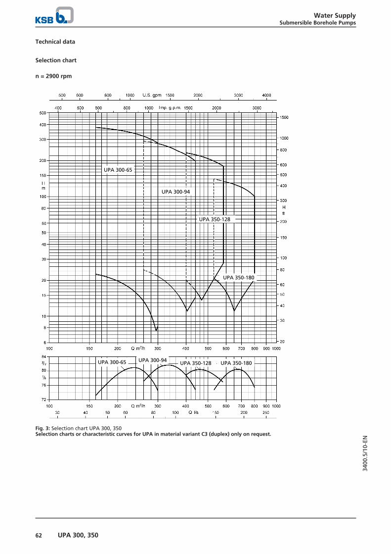
Water SupplySubmersible Borehole Pumps
62 UPA 300, 350
3400
.5/1
0-EN
Technical data
Selection chart
n = 2900 rpm
UPA 300-65
UPA 300-94
UPA 350-180
UPA 350-128
UPA 300-65 UPA 300-94 UPA 350-180UPA 350-128
Fig. 3: Selection chart UPA 300, 350Selection charts or characteristic curves for UPA in material variant C3 (duplex) only on request.

Water SupplySubmersible Borehole Pumps
63UPA 300, 350
3400
.5/1
0-EN
UPA 300 - 65 / ...
Operating range
Qmin = 50 m3/hQmax= end of stage curve
Types of connection
Standard pump end = G 6
Connection types:
▪ Flanged connection– DN 150
Alternative pump ends are possible.The length of the pump set LA and the diameter Dmax
depend on the pump end.
For an alternative pump end the length of the pump set LA*
is calculated as follows:
LA* = LA - LG + LG*
Values for calculating the dimensions if using a differentpump end:Pump design with lift checkvalve:
▪ G 6:LG* = 255 mmDmax* ≙ Dmax
▪ DN 150:LG* = 220 mm (PN 10/16)LG* = 228 mm (PN 25/40)Dmax* = 285 mm (PN10/16)Dmax* = 300 mm (PN25/40)
Dmax
G 6
L P
L G
L A
Version with connectionnozzle:
▪ G 6:LG* = 150 mmDmax* ≙ Dmax
▪ DN 150:LG* = 140 mm (PN 10/16)LG* = 148 mm (PN 25/40)Dmax* = 285 mm (PN10/16)Dmax* = 300 mm (PN25/40)
A365
40013,5
250
Dimensions of UPA 300 - 65 / ... [mm]

Water SupplySubmersible Borehole Pumps
64 UPA 300, 350
3400
.5/1
0-EN
Dimensions, weights and installation type depending on the motor [mm]
UPA 300 - 65 A LP76) LA
76) LG77) Dmax Total weight Type of
installation
DOL Y - Δ Material variant
Ver
tica
l
Ho
rizo
nta
l78)
Wit
h li
ftch
eck
valv
e
Wit
hco
nn
ecti
on
no
zzle
G B C3
[mm] [mm] [mm] [mm] [mm] [mm] [mm] [kg] [kg] [kg]
1n + UMA 200D 37/21 945 735 1875 255 150 276 276 221 235 245 ✘ ✘1m + UMA 200D 37/21 945 735 1875 255 150 276 276 221 235 245 ✘ ✘1l + UMA 200D 37/21 945 735 1875 255 150 276 276 221 235 245 ✘ ✘1f + UMA 200D 37/21 945 735 1875 255 150 276 276 221 235 245 ✘ ✘1 + UMA 200D 37/21 945 735 1875 255 150 276 276 221 235 245 ✘ ✘2m + UMA 200D 45/21 1155 900 2130 255 150 276 276 265 284 294 ✘ ✘2l + UMA 200D 45/21 1155 900 2130 255 150 276 276 265 284 294 ✘ ✘2g + UMA 200D 55/21 1210 900 2240 255 150 276 276 285 304 315 ✘ ✘2d + UMA 200D 65/21 1275 900 2370 255 150 275 275 308 327 338 ✘ ✘2 + UMA 200D 75/21 1320 900 2460 255 150 275 275 324 343 353 ✘ ✘3k + UMA 200D 75/21 1485 1065 2625 255 150 275 275 361 387 398 ✘ ✘3h + UMA 200D 90/21 - 1065 2805 255 150 278 278 393 419 431 ✘ -
3e + UMA 200D 90/21 - 1065 2805 255 150 278 278 393 419 431 ✘ -
3d + UMA 250D 110/21 1500 1095 2624 255 150 289 289 463 489 496 ✘ ✘3 + UMA 250D 110/21 1500 1095 2624 255 150 289 289 463 489 496 ✘ ✘4g + UMA 250D 110/21 1665 1260 2789 255 150 289 289 492 522 528 ✘ ✘4e + UMA 250D 132/21 1730 1260 2919 255 150 289 289 536 566 572 ✘ ✘4b + UMA 250D 132/21 1730 1260 2919 255 150 289 289 536 566 572 ✘ ✘4 + UMA 250D 160/21 - 1260 3029 255 150 289 289 573 603 609 ✘ -79)
5e + UMA 250D 160/21 - 1425 3194 255 150 289 289 603 637 645 ✘ -79)
5b + UMA 250D 190/21 - 1425 3344 255 150 298 311 654 688 696 ✘ -79)
5 + UMA 300D 250/22 - 1425 3498 255 150 325 325 779 813 819 ✘ -79)
6e + UMA 250D 190/21 - 1590 3509 255 150 298 311 682 721 728 ✘ -79)
6b + UMA 300D 250/22 - 1590 3663 255 150 325 325 807 846 851 ✘ -79)
6 + UMA 300D 250/22 - 1590 3663 255 150 325 325 807 846 851 ✘ -79)
7 + UMA 300D 300/22 - 1755 4008 255 150 304 304 913 957 964 ✘ -79)
8 + UMA 300D 300/22 - 1920 4173 255 150 304 304 942 990 997 ✘ -79)
Technical data
UPA 300 - 65 Pump Motor Motor lead, flat
Hea
d
Q =
0 m
3 /h
Rat
ed p
ow
er
Max
. flu
idte
mp
erat
ure
v ≥
0,2
m/s
(0,
0m
/s)
Rat
ed c
urr
ent
Effi
cien
cy
Pow
er f
acto
r Number × cross-section of cores
H0 PN T max IN ηM cos φ DOL Y - Δ
[m] [kW] [°C] [A] [%] [mm2] [mm2]
1n + UMA 200D 37/21 30 16,0 44 (42) 43,5 83,0 0,64 3/4 × 6,080) 3/4 × 6,0
1m + UMA 200D 37/21 35 20,0 43 (40) 48,5 84,6 0,71 3/4 × 6,080) 3/4 × 6,0
1l + UMA 200D 37/21 39 23,0 41 (38) 53,0 85,2 0,75 3/4 × 6,080) 3/4 × 6,0
1f + UMA 200D 37/21 42 27,0 38 (34) 59,0 85,5 0,79 3/4 × 6,080) 3/4 × 6,0
1 + UMA 200D 37/21 48 34,0 32 (26) 70,0 85,4 0,83 3/4 × 6,080) 3/4 × 6,0
2m + UMA 200D 45/21 71 40,0 32 (27) 82,0 86,2 0,82 3/4 × 6,080) 3/4 × 6,0
2l + UMA 200D 45/21 77 45,0 28 (21) 90,0 86,0 0,84 3/4 × 6,080) 3/4 × 6,0
2g + UMA 200D 55/21 83 54,0 29 (23) 108,0 87,0 0,84 3/4 × 6,080) 3/4 × 6,0
2d + UMA 200D 65/21 91 60,0 30 (25) 120,0 87,8 0,83 3/4 × 10,080) 3/4 × 10,0
2 + UMA 200D 75/21 98 70,0 27 (20) 143,0 87,4 0,81 3/4 × 10,080) 3/4 × 10,0
3k + UMA 200D 75/21 118 72,0 25 (18) 146,0 87,4 0,82 3/4 × 10,080) 3/4 × 10,0
3h + UMA 200D 90/21 124 82,0 28 (22) 167,0 88,2 0,81 3/4 × 16,080) 3/4 × 16,0
3e + UMA 200D 90/21 130 88,0 26 (18) 177,0 88,1 0,82 3/4 × 16,080) 3/4 × 16,0
3d + UMA 250D 110/21 137 95,0 26 (19) 191,0 88,7 0,81 3/4 × 25,080) 3/4 × 25,0
3 + UMA 250D 110/21 147 110,0 20 (11) 215,0 88,5 0,84 3/4 × 25,080) 3/4 × 25,0
4g + UMA 250D 110/21 167 110,0 19 (10) 215,0 88,5 0,84 3/4 × 25,080) 3/4 × 25,0
4e + UMA 250D 132/21 174 120,0 25 (17) 229,0 89,2 0,85 3/4 × 25,080) 3/4 × 25,0
4b + UMA 250D 132/21 186 130,0 20 (10) 245,0 89,1 0,86 3/4 × 25,080) 3/4 × 25,0
4 + UMA 250D 160/21 196 145,0 21 (12) 276,0 89,4 0,85 3/4 × 25,081) 3/4 × 35,082)
5e + UMA 250D 160/21 217 145,0 20 (11) 276,0 89,4 0,85 3/4 × 25,081) 3/4 × 35,082)
76) UPA 300 - 65 in C3 material variant: Subtract 5 mm.77) Length of pump end fitted as standard78) To reliably dissipate the motor heat of pump sets installed in a horizontal position, sufficient flow velocity past the motor is
necessary. A cooling shroud, hood or similar must be used.79) Horizontal installation on request and only with pedestals in special design80) Delta configuration in cable connector or control cabinet81) Parallel cable82) 1×3-core, flat and 1×4-core, round

Water SupplySubmersible Borehole Pumps
65UPA 300, 350
3400
.5/1
0-EN
UPA 300 - 65 Pump Motor Motor lead, flat
Hea
d
Q =
0 m
3 /h
Rat
ed p
ow
er
Max
. flu
idte
mp
erat
ure
v ≥
0,2
m/s
(0,
0m
/s)
Rat
ed c
urr
ent
Effi
cien
cy
Pow
er f
acto
r Number × cross-section of cores
H0 PN T max IN ηM cos φ DOL Y - Δ
[m] [kW] [°C] [A] [%] [mm2] [mm2]
5b + UMA 250D 190/21 235 165,0 22 (13) 325,0 90,0 0,82 3/4 × 35,082) 3/4 × 50,082)
5 + UMA 300D 250/22 252 190,0 59 (53) 359,0 90,5 0,85 2×3×70 + 1×3581)83) 2×3×70 + 1×3583)
6e + UMA 250D 190/21 261 180,0 19 (9) 349,0 89,8 0,83 3/4 × 35,081)82) 3/4 × 50,082)
6b + UMA 300D 250/22 287 205,0 57 (51) 382,0 90,6 0,86 2×3×70 + 1×3581)83) 2×3×70 + 1×3583)
6 + UMA 300D 250/22 300 225,0 55 (49) 414,0 90,7 0,87 2×3×70 + 1×3581)83) 2×3×70 + 1×3583)
7 + UMA 300D 300/22 351 265,0 56 (49) 491,0 91,2 0,86 6×1×95 + 1×9581)84) 6×1×95 + 1×9584)
8 + UMA 300D 300/22 399 300,0 53 (46) 546,0 91,2 0,87 6×1×95 + 1×9581)84) 6×1×95 + 1×9584)
83) 2×3-core, flat and 1×1-core, round84) 7×1-core, round

Water SupplySubmersible Borehole Pumps
66 UPA 300, 350
3400
.5/1
0-EN

Water SupplySubmersible Borehole Pumps
67UPA 300, 350
3400
.5/1
0-EN
UPA 300 - 94 / ...
Operating range
Qmin = 70 m3/hQmax= end of stage curve
Types of connection
Standard pump end = G 8
Connection types:
▪ Flanged connection– DN 200
Alternative pump ends are possible.The length of the pump set LA and the diameter Dmax
depend on the pump end.
For an alternative pump end the length of the pump set LA*
is calculated as follows:
LA* = LA - LG + LG*
Values for calculating the dimensions if using a differentpump end:Pump design with lift checkvalve:
▪ G 8:LG* = 290 mmDmax* ≙ Dmax
▪ DN 200:LG* = 240 mm (PN 10/16)LG* = 244 mm (PN 25)Dmax* = 340 mm (PN10/16)Dmax* = 360 mm (PN 25)
Dmax
G 8
L P
L G
L A
Version with connectionnozzle:
▪ G 8:LG* = 200 mmDmax* ≙ Dmax
▪ DN 200:LG* = 134 mm (PN 10/16)LG* = 138 mm (PN 25)Dmax* = 340 mm (PN10/16)Dmax* = 360 mm (PN 25)
A365
42513,5
250
Dimensions of UPA 300 - 94 / ... [mm]

Water SupplySubmersible Borehole Pumps
68 UPA 300, 350
3400
.5/1
0-EN
Dimensions, weights and installation type depending on the motor [mm]
UPA 300 - 94 A LP LA LG85) Dmax Total weight Type of
installation
DOL Y - Δ Material variant
Ver
tica
l
Ho
rizo
nta
l86)
Wit
h li
ftch
eck
valv
e
Wit
hco
nn
ecti
on
no
zzle
G B C3
[mm] [mm] [mm] [mm] [mm] [mm] [mm] [kg] [kg] [kg]
1n + UMA 200D 37/21 960 775 1915 290 200 286 286 235 252 276 ✘ ✘1m + UMA 200D 37/21 960 775 1915 290 200 286 286 235 252 276 ✘ ✘1k + UMA 200D 37/21 960 775 1915 290 200 286 286 235 252 276 ✘ ✘1g + UMA 200D 45/21 1005 775 2005 290 200 286 286 251 268 292 ✘ ✘1d + UMA 200D 45/21 1005 775 2005 290 200 286 286 251 268 292 ✘ ✘1 + UMA 200D 55/21 1060 775 2115 290 200 286 286 271 288 312 ✘ ✘2m + UMA 200D 65/21 1300 950 2420 290 200 285 285 335 359 372 ✘ ✘2k + UMA 200D 75/21 1345 950 2510 290 200 285 285 351 375 388 ✘ ✘2h + UMA 200D 90/21 - 950 2690 290 200 288 288 383 407 420 ✘ -
2d + UMA 250D 110/21 1360 980 2509 290 200 299 299 453 477 498 ✘ ✘2 + UMA 250D 110/21 1360 980 2509 290 200 299 299 453 477 498 ✘ ✘3k + UMA 250D 110/21 1535 1155 2684 290 200 299 299 484 514 535 ✘ ✘3h + UMA 250D 132/21 1600 1155 2814 290 200 299 299 528 558 579 ✘ ✘3e + UMA 250D 132/21 1600 1155 2814 290 200 299 299 528 558 579 ✘ ✘3c + UMA 250D 160/21 1655 1155 2924 290 200 299 308 565 595 616 ✘ ✘3 + UMA 250D 190/21 - 1155 3074 290 200 308 321 616 646 667 ✘ -87)
4f + UMA 250D 190/21 - 1330 3249 290 200 308 321 650 684 703 ✘ -87)
4c + UMA 300D 250/22 - 1330 3403 290 200 331 331 775 809 829 ✘ -87)
4 + UMA 300D 250/22 - 1330 3403 290 200 331 331 775 809 829 ✘ -87)
5 + UMA 300D 300/22 - 1505 3758 290 200 311 311 886 925 946 ✘ -87)
6 + UMA 300D 400/22 - 1680 4053 290 200 311 311 970 1014 1032 ✘ -87)
7e + UMA 300D 400/22 - 1855 4228 290 200 311 311 1001 1051 1069 ✘ -87)
Technical data
UPA 300 - 94 Pump Motor Motor lead, flat
Hea
d
Q =
0 m
3 /h
Rat
ed p
ow
er
Max
. flu
idte
mp
erat
ure
v ≥
0,2
m/s
(0,
0m
/s)
Rat
ed c
urr
ent
Effi
cien
cy
Pow
er f
acto
r Number × cross-section of cores
H0 PN T max IN ηM cos φ DOL Y - Δ
[m] [kW] [°C] [A] [%] [mm2] [mm2]
1n + UMA 200D 37/21 34 29,0 37 (32) 62,0 85,6 0,80 3/4 × 6,088) 3/4 × 6,0
1m + UMA 200D 37/21 38 32,0 34 (29) 67,0 85,5 0,82 3/4 × 6,088) 3/4 × 6,0
1k + UMA 200D 37/21 43 36,0 30 (25) 73,0 85,3 0,84 3/4 × 6,088) 3/4 × 6,0
1g + UMA 200D 45/21 47 42,0 31 (25) 85,0 86,1 0,83 3/4 × 6,088) 3/4 × 6,0
1d + UMA 200D 45/21 51 45,0 27 (20) 90,0 86,0 0,84 3/4 × 6,088) 3/4 × 6,0
1 + UMA 200D 55/21 54 54,0 29 (23) 108,0 87,0 0,84 3/4 × 6,088) 3/4 × 6,0
2m + UMA 200D 65/21 78 62,0 29 (23) 123,0 87,7 0,83 3/4 × 10,088) 3/4 × 10,0
2k + UMA 200D 75/21 90 74,0 25 (18) 149,0 87,3 0,83 3/4 × 10,088) 3/4 × 10,0
2h + UMA 200D 90/21 96 82,0 28 (22) 167,0 88,2 0,81 3/4 × 16,088) 3/4 × 16,0
2d + UMA 250D 110/21 105 95,0 26 (19) 191,0 88,7 0,81 3/4 × 25,088) 3/4 × 25,0
2 + UMA 250D 110/21 112 110,0 20 (10) 215,0 88,5 0,84 3/4 × 25,088) 3/4 × 25,0
3k + UMA 250D 110/21 138 110,0 20 (10) 215,0 88,5 0,84 3/4 × 25,088) 3/4 × 25,0
3h + UMA 250D 132/21 146 125,0 24 (15) 237,0 89,1 0,86 3/4 × 25,088) 3/4 × 25,0
3e + UMA 250D 132/21 155 130,0 20 (11) 245,0 89,1 0,86 3/4 × 25,088) 3/4 × 25,0
3c + UMA 250D 160/21 162 145,0 20 (11) 276,0 89,4 0,85 3/4 × 25,089) 3/4 × 35,0
3 + UMA 250D 190/21 172 165,0 22 (14) 325,0 90,0 0,82 3/4 × 35,089)90) 3/4 × 50,090)
4f + UMA 250D 190/21 204 175,0 19 (10) 341,0 89,9 0,83 3/4 × 35,089)90) 3/4 × 50,090)
4c + UMA 300D 250/22 222 205,0 57 (52) 382,0 90,6 0,86 2×3×70 + 1×3589)91) 2×3×70 + 1×3591)
4 + UMA 300D 250/22 232 225,0 55 (49) 414,0 90,7 0,87 2×3×70 + 1×3589)91) 2×3×70 + 1×3591)
5 + UMA 300D 300/22 290 280,0 54 (48) 516,0 91,2 0,86 6×1×95 + 1×9589)92) 6×1×95 + 1×9592)
6 + UMA 300D 400/22 348 335,0 52 (45) 619,0 91,4 0,86 6×1×95 + 1×9589)92) 6×1×95 + 1×9592)
7e + UMA 300D 400/22 371 315,0 54 (47) 586,0 91,4 0,85 6×1×95 + 1×9589)92) 6×1×95 + 1×9592)
85) Length of pump end fitted as standard86) To reliably dissipate the motor heat of pump sets installed in a horizontal position, sufficient flow velocity past the motor is
necessary. A cooling shroud, hood or similar must be used.87) Horizontal installation on request and only with pedestals in special design88) Delta configuration in cable connector or control cabinet89) Parallel cable90) 1×3-core, flat and 1×4-core, round91) 2×3-core, flat and 1×1-core, round92) 7×1-core, round

Water SupplySubmersible Borehole Pumps
69UPA 300, 350
3400
.5/1
0-EN

Water SupplySubmersible Borehole Pumps
70 UPA 300, 350
3400
.5/1
0-EN
UPA 350 - 128 / ...
Operating range
Qmin = 100 m3/hQmax= end of stage curve
Types of connection
Standard pump end = G 8
Connection types:
▪ Flanged connection– DN 200
Alternative pump ends are possible.The length of the pump set LA and the diameter Dmax
depend on the pump end.
For an alternative pump end the length of the pump set LA*
is calculated as follows:
LA* = LA - LG + LG*
Values for calculating the dimensions if using a differentpump end:Pump design with lift checkvalve:
▪ G 8:LG* = 328 mmDmax* ≙ Dmax
▪ DN 200:LG* = 278 mm (PN 10/16)Dmax* = 340 mm (PN10/16)
Dmax
G 8L P
L G
L A
Version with connectionnozzle:
▪ G 8:LG* = 169 mmDmax* ≙ Dmax
▪ DN 200:LG* = 123 mm (PN 10/16)Dmax* = 340 mm (PN10/16)
A445
48513,5
250
36513,5
250
Dimensions of UPA 350 - 128 / ... [mm]

Water SupplySubmersible Borehole Pumps
71UPA 300, 350
3400
.5/1
0-EN
Dimensions, weights and installation type depending on the motor [mm]
UPA 350 - 128 A LP LA LG93) Dmax Total weight Type of
installation
DOL Y - Δ Material variant
Ver
tica
l
Ho
rizo
nta
l94)
Wit
h li
ftch
eck
valv
e
Wit
hco
nn
ecti
on
no
zzle
G B C3
[mm] [mm] [mm] [mm] [mm] [mm] [mm] [kg] [kg] [kg]
1l + UMA 200D 37/21 1020 898 2038 328 169 322 322 274 298 315 ✘ ✘1k + UMA 200D 45/21 1065 898 2128 328 169 322 322 290 314 331 ✘ ✘1h + UMA 200D 55/21 1120 898 2238 328 169 322 322 310 334 351 ✘ ✘1f + UMA 200D 65/21 1185 898 2368 328 169 320 320 333 357 374 ✘ ✘1d + UMA 200D 75/21 1230 898 2458 328 169 320 320 349 373 390 ✘ ✘1b + UMA 200D 90/21 - 898 2638 328 169 324 324 381 405 422 ✘ -
1 + UMA 250D 110/21 1215 898 2427 328 169 334 334 451 475 493 ✘ ✘2h + UMA 250D 110/21 1415 1098 2627 328 169 334 334 497 532 542 ✘ ✘2g + UMA 250D 132/21 1480 1098 2757 328 169 334 334 541 576 586 ✘ ✘2e + UMA 250D 132/21 1480 1098 2757 328 169 334 334 541 576 586 ✘ ✘2d + UMA 250D 160/21 1535 1098 2867 328 169 334 343 578 613 623 ✘ ✘2b + UMA 250D 190/21 - 1098 3017 328 169 343 357 629 664 674 ✘ -95)
2 + UMA 300D 250/22 - 1108 3181 328 169 360 360 754 789 800 ✘ -95)
3c + UMA 300D 250/22 - 1308 3381 328 169 360 360 799 839 849 ✘ -95)
3 + UMA 300D 300/22 - 1308 3561 328 169 341 341 877 917 929 ✘ -95)
4b + UMA 300D 400/22 - 1508 3881 328 169 341 341 972 1019 1029 ✘ -95)
4 + UMA 300D 400/22 - 1508 3881 328 169 341 341 972 1019 1029 ✘ -95)
Technical data
UPA 350 - 128 Pump Motor Motor lead, flat
Hea
d
Q =
0 m
3 /h
Rat
ed p
ow
er
Max
. flu
idte
mp
erat
ure
v ≥
0,2
m/s
(0,
0m
/s)
Rat
ed c
urr
ent
Effi
cien
cy
Pow
er f
acto
r Number × cross-section of cores
H0 PN T max IN ηM cos φ DOL Y - Δ
[m] [kW] [°C] [A] [%] [mm2] [mm2]
1l + UMA 200D 37/21 40 35,0 31 (25) 72,0 85,3 0,83 3/4 × 6,096) 3/4 × 6,0
1k + UMA 200D 45/21 45 44,0 28 (22) 89,0 86,0 0,84 3/4 × 6,096) 3/4 × 6,0
1h + UMA 200D 55/21 52 55,0 27 (20) 109,0 86,9 0,84 3/4 × 6,096) 3/4 × 6,0
1f + UMA 200D 65/21 57 64,0 28 (22) 127,0 87,7 0,84 3/4 × 10,096) 3/4 × 10,0
1d + UMA 200D 75/21 63 75,0 23 (15) 151,0 87,3 0,83 3/4 × 10,096) 3/4 × 10,0
1b + UMA 200D 90/21 69 88,0 25 (18) 177,0 88,1 0,82 3/4 × 16,096) 3/4 × 16,0
1 + UMA 250D 110/21 75 105,0 22 (14) 208,0 88,6 0,83 3/4 × 25,096) 3/4 × 25,0
2h + UMA 250D 110/21 104 110,0 19 (10) 215,0 88,5 0,84 3/4 × 25,096) 3/4 × 25,0
2g + UMA 250D 132/21 109 120,0 24 (16) 229,0 89,2 0,85 3/4 × 25,096) 3/4 × 25,0
2e + UMA 250D 132/21 117 132,0 18 (9) 249,0 89,0 0,86 3/4 × 25,096) 3/4 × 25,0
2d + UMA 250D 160/21 126 150,0 18 (9) 284,0 89,3 0,86 3/4 × 25,097) 3/4 × 35,098)
2b + UMA 250D 190/21 138 175,0 19 (10) 341,0 89,9 0,83 3/4 × 35,097)98) 3/4 × 50,098)
2 + UMA 300D 250/22 153 210,0 57 (51) 389,0 90,7 0,86 2×3×70 + 1×3597)99) 2×3×70 + 1×3599)
3c + UMA 300D 250/22 196 240,0 54 (47) 439,0 90,7 0,87 2×3×70 + 1×3597)99) 2×3×70 + 1×3599)
3 + UMA 300D 300/22 228 300,0 52 (45) 546,0 91,2 0,87 6×1×95 + 1×9597)100) 6×1×95 + 1×95100)
4b + UMA 300D 400/22 280 355,0 50 (42) 652,0 91,4 0,86 6×1×95 + 1×9597)100) 6×1×95 + 1×95100)
4 + UMA 300D 400/22 302 400,0 45 (35) 728,0 91,2 0,87 6×1×95 + 1×9597)100) 6×1×95 + 1×95100)
93) Length of pump end fitted as standard94) To reliably dissipate the motor heat of pump sets installed in a horizontal position, sufficient flow velocity past the motor is
necessary. A cooling shroud, hood or similar must be used.95) Horizontal installation on request and only with pedestals in special design96) Delta configuration in cable connector or control cabinet97) Parallel cable98) 1×3-core, flat and 1×4-core, round99) 2×3-core, flat and 1×1-core, round100) 7×1-core, round

Water SupplySubmersible Borehole Pumps
72 UPA 300, 350
3400
.5/1
0-EN
UPA 350 - 180 / ...
G8 / DN 200DN 250
Operating range
Qmin = 120 m3/hQmax= end of stage curve
Types of connection
Standard pump end = G 8
Connection types:
▪ Flanged connection– DN 200
Alternative pump ends are possible.The length of the pump set LA and the diameter Dmax
depend on the pump end.
For an alternative pump end the length of the pump set LA*
is calculated as follows:
LA* = LA - LG + LG*
Values for calculating the dimensions if using a differentpump end:Pump design with lift checkvalve:
▪ G 8:LG* = 328 mmDmax* ≙ Dmax
▪ DN 200:LG* = 278 mm (PN 10/16)Dmax* = 340 mm (PN10/16)
Dmax
G 8L P
L G
L A
Version with connectionnozzle:
▪ G 8:LG* = 169 mmDmax* ≙ Dmax
▪ DN 200:LG* = 123 mm (PN 10/16)Dmax* = 340 mm (PN10/16)
A440
48013,5
250
36513,5
250
Dimensions of UPA 350 - 180 / ... [mm]

Water SupplySubmersible Borehole Pumps
73UPA 300, 350
3400
.5/1
0-EN
Dimensions, weights and installation type depending on the motor [mm]
UPA 350 - 180 A LP LA LG101) Dmax Total weight Type of
installation
DOL Y - Δ Material variant
Ver
tica
l
Ho
rizo
nta
l102)
Wit
h li
ftch
eck
valv
e
Wit
hco
nn
ecti
on
no
zzle
G B C3
[mm] [mm] [mm] [mm] [mm] [mm] [mm] [kg] [kg] [kg]
1m + UMA 200D 55/21 1120 898 2238 328 169 322 322 317 342 351 ✘ ✘1l + UMA 200D 65/21 1185 898 2368 328 169 320 320 340 365 374 ✘ ✘1h + UMA 200D 65/21 1185 898 2368 328 169 320 320 340 365 374 ✘ ✘1e + UMA 200D 75/21 1230 898 2458 328 169 320 320 356 381 390 ✘ ✘1c + UMA 200D 90/21 - 898 2638 328 169 324 324 388 413 422 ✘ -
1 + UMA 250D 110/21 1215 898 2427 328 169 334 334 458 483 493 ✘ ✘2k + UMA 250D 132/21 1480 1098 2757 328 169 334 334 546 578 587 ✘ ✘2g + UMA 250D 132/21 1480 1098 2757 328 169 334 334 546 578 587 ✘ ✘2f + UMA 250D 160/21 1535 1098 2867 328 169 334 343 583 615 624 ✘ ✘2d + UMA 250D 190/21 - 1098 3017 328 169 343 357 634 666 675 ✘ -103)
2b + UMA 250D 190/21 - 1098 3017 328 169 343 357 634 666 675 ✘ -103)
2 + UMA 300D 250/22 - 1108 3181 328 169 360 360 759 791 798 ✘ -103)
3e + UMA 300D 250/22 - 1308 3381 328 169 360 360 801 840 846 ✘ -103)
3 + UMA 300D 400/22 - 1308 3681 328 169 341 341 931 970 976 ✘ -103)
4f + UMA 300D 400/22 - 1508 3881 328 169 341 341 974 1021 1025 ✘ -103)
4d + UMA 300D 400/22 - 1508 3881 328 169 341 341 974 1021 1025 ✘ -103)
Technical data
UPA 350 - 180 Pump Motor Motor lead, flat
Hea
d
Q =
0 m
3 /h
Rat
ed p
ow
er
Max
. flu
idte
mp
erat
ure
v ≥
0,2
m/s
(0,
0m
/s)
Rat
ed c
urr
ent
Effi
cien
cy
Pow
er f
acto
r Number × cross-section of cores
H0 PN T max IN ηM cos φ DOL Y - Δ
[m] [kW] [°C] [A] [%] [mm2] [mm2]
1m + UMA 200D 55/21 41 54,0 29 (23) 108,0 87,0 0,84 3/4 × 6,0104) 3/4 × 6,0
1l + UMA 200D 65/21 45 62,0 30 (24) 123,0 87,7 0,83 3/4 × 10,0104) 3/4 × 10,0
1h + UMA 200D 65/21 49 65,0 28 (21) 129,0 87,7 0,84 3/4 × 10,0104) 3/4 × 10,0
1e + UMA 200D 75/21 55 75,0 24 (16) 151,0 87,3 0,83 3/4 × 10,0104) 3/4 × 10,0
1c + UMA 200D 90/21 62 86,0 27 (20) 173,0 88,1 0,82 3/4 × 16,0104) 3/4 × 16,0
1 + UMA 250D 110/21 66 100,0 25 (17) 199,0 88,6 0,82 3/4 × 25,0104) 3/4 × 25,0
2k + UMA 250D 132/21 95 130,0 22 (13) 245,0 89,1 0,86 3/4 × 25,0104) 3/4 × 25,0
2g + UMA 250D 132/21 100 132,0 18 (9) 249,0 89,0 0,86 3/4 × 25,0104) 3/4 × 25,0
2f + UMA 250D 160/21 111 150,0 20 (11) 284,0 89,3 0,86 3/4 × 25,0105) 3/4 × 35,0106)
2d + UMA 250D 190/21 121 165,0 22 (14) 325,0 90,0 0,82 3/4 × 35,0105)106) 3/4 × 50,0106)
2b + UMA 250D 190/21 128 180,0 18 (9) 349,0 89,8 0,83 3/4 × 35,0105)106) 3/4 × 50,0106)
2 + UMA 300D 250/22 137 210,0 57 (51) 389,0 90,7 0,86 2×3×70 + 1×35105)107) 2×3×70 + 1×35107)
3e + UMA 300D 250/22 173 240,0 53 (47) 439,0 90,7 0,87 2×3×70 + 1×35105)107) 2×3×70 + 1×35107)
3 + UMA 300D 400/22 205 320,0 54 (47) 595,0 91,4 0,85 6×1×95 + 1×95105)108) 6×1×95 + 1×95108)
4f + UMA 300D 400/22 226 310,0 54 (47) 580,0 91,4 0,85 6×1×95 + 1×95105)108) 6×1×95 + 1×95108)
4d + UMA 300D 400/22 245 345,0 51 (44) 634,0 91,4 0,86 6×1×95 + 1×95105)108) 6×1×95 + 1×95108)
101) Length of pump end fitted as standard102) To reliably dissipate the motor heat of pump sets installed in a horizontal position, sufficient flow velocity past the motor is
necessary. A cooling shroud, hood or similar must be used.103) Horizontal installation on request and only with pedestals in special design104) Delta configuration in cable connector or control cabinet105) Parallel cable106) 1×3-core, flat and 1×4-core, round107) 2×3-core, flat and 1×1-core, round108) 7×1-core, round
Water SupplySubmersible Borehole Pumps
74 UPA 300, 350
3400
.5/1
0-EN
Scope of supplyDepending on the model, the following items are included inthe scope of supply:
▪ Pump set with motor lead
▪ Back-up name plate
Optional:
▪ Extension cable optional: connected or supplied but notfitted
▪ Cable connector
▪ Cable clips
▪ Pedestals
▪ Cooling shroud, suction shroud or pressure shroud
▪ Supporting clamps and mounting clamps
▪ Electrical protection equipment
▪ Automatic control units

Water SupplySubmersible Borehole Pumps
75Accessories for sizes UPA 200 to UPA 350
3400
.5/1
0-EN
Accessories for sizes UPA 200 to UPA 350
Installation parts
Selection table
Description Mat. No. Weight[kg]
Set of pedestals for horizontal installation, comprising: 2 pedestals and fastening elementsGalvanised steel (S235 JRG2+Z) UPA 200 with UMA 150E motor 90017255 2,5
UPA 200 with UMA 200D motor 01046640 2,5CrNi steel (1.4301) UPA 200B with UMA 150E motor 01061866 2,5
UPA 200B with UMA 200D motor 01061867 2,5UPA 250C with UMA 150E motor 01061868 2,5UPA 250C with UMA 200D motor 01061869 2,5UPA 250C with UMA 250D motor 01061870 2,5
Galvanised steel (S235 JRG2+Z) UPA 300-65 with UMA 200D motor 01046644 7,8UPA 300-94 with UMA 200D motor 01046645 7,8UPA 350 with UMA 200D motor 01046646 8,0UPA 300-65 with UMA 250D motor 01053905 16,0UPA 300-94 with UMA 250D motor 01053906 16,0UPA 350 with UMA 250D motor 01053907 17,2
Bolts for fastening the pedestals to the foundation are not included in the scope of supply; they must be provided atthe site.
Pedestals for pump sets in material variant C3 (duplex) on request.Centring device for UMA 150E and UMA 200D, for use in wells of up to DN 350
Plastic (PE) Up to DN 250 90047662 -Up to DN 300 90047663 -Up to DN 350 90047664 -
Cooling, suction and pressure shroudMaterial: CrNiMo steel or galvanised steel
On request
Adapter from screwed end to flange, PN 10/40, with 2 recesses in the flange, offset by 90°G 3 to DN 80, CrNiMo steel H = 180 mm, D = 200 mm 95000233 5,6
Pair of supporting and installation clamps for the following riser sizes, incl. fastening elements, material: painted steelR 3 / DN 80 L = 600 mm, F = 17,5 kN 95000298 12R 4 / DN 100 L = 700 mm, F = 24,5 kN 95000300 21R 5 / DN 125 L = 800 mm, F = 31,0 kN 95000302 29R 6 / DN 150 L = 800 mm, F = 31,0 kN 95000304 29R 8 / DN 200 L = 900 mm, F = 108 kN 95000307 70
2 pairs are required for installation and dismantling.
Motor accessories
Description Mat. No. [kg]
Fill check kit, for checking and topping up the motor fill after prolongedstorage for UMA 150D, UMA 150E, UMA 200D, UMA 250D
90066762 0,25
Electrical accessories
Selection table
Description Mat. No. Weight[kg]
Extension cable, blue, rubber-sheathed cable for drinking water applications, maximum ambient temperatures +50 °C
G RD GWT - J, 4-core, round, with earth conductor Values indicated per meter
4 x 1,5 mm² 90068174 0,184 x 2,5 mm² 90068175 0,2594 x 4 mm² 90068176 0,3564 x 6 mm² 90068177 0,4754 x 10 mm² 90068178 0,8374 x 16 mm² 90068179 1,22

Water SupplySubmersible Borehole Pumps
76 Accessories for sizes UPA 200 to UPA 350
3400
.5/1
0-EN
Description Mat. No. Weight[kg]
G RD GWT - J, 4-core, round, with earth conductor Values indicated per meter
4 x 25 mm² 90068180 1,774 x 35 mm² 90068181 2,3044 x 50 mm² 90068182 3,1854 x 70 mm² 90068183 4,364
G FL GWT - O, 3-core, flat, without earth conductor Values indicated per meter
3 x 1.5 mm² 90068148 0,113 x 2.5 mm² 90068149 0,1713 x 4 mm² 90068150 0,2523 x 6 mm² 90068151 0,3193 x 10 mm² 90068152 0,4863 x 16 mm² 90068153 0,753 x 25 mm² 90068154 1,1073 x 35 mm² 90068155 1,4383 x 50 mm² 90068156 2,0543 x 70 mm² 90068157 2,76
Shielded Hydrofirm (T) cableS07BC4B - F 3 x 6 / 6 KON 01101358 -S07BC4B - F 3 x 16 / 16 KON 01101360 -S07BC4B - F 3 x 35 + 3G16 / 3 01101361 -
Cable connector, non-separable, including sealing compound, for connecting 1 extension cable to 1 or 2 motor leadsSize 28 for connection to:1 motor lead Supplied but not fitted 95005106 0,5
Connected and sealed at the factory 90049385 0,5Size 35 for connection to:1 motor lead Supplied but not fitted 90049397 0,6
Connected and sealed at the factory 90049387 0,6Size 43 for connection to:1 motor lead Supplied but not fitted 90049399 0,8
Connected and sealed at the factory 90049389 0,82 motor leads Supplied but not fitted 90049400 0,8
Connected and sealed at the factory 90049390 0,8Sizes 53 and 78 for connection On request
Cable clip for fastening the cable to the riserSize 1 (rubber strap / plastic studs), for up to 1 cable, flat, 3 x 6 mm2 or 4 x 6 mm2 and 1 cable, round, 4 x 6 mm2
01088095 0,04
Sizes 2 - 11 (metal strap / screw band with tension screw / rubber cable protector), for larger cross-sections up to 70 mm2
On request -
Cable clips for pump sets in material variant B (special), C3 (duplex) on request.
Use 1 cable clip each per cable and per 3 m of riser pipe.Dry running protection equipment (supply voltage 220 V / 240 V) for
Semi-automatic operation (1 relay, 1 pushbutton + 2 electrodes) 90009553 2Fully automatic operation (1 relay + 3 electrodes) 90009554 2Plus 1 control current line, blue, 1 x 1.5 mm2 for each electrode; values indicated per metre 01096713 0,1
Pressure controller, insulating enclosure (membrane type), 1 to 8 bar, with pressure connection G 3/8 01151586 1Pt100 temperature monitoring equipment for use in submersible motors to protect the windings from overheating. Comprises:
Pt100 temperature sensor with 10 m cable4 x 0.5 mm2 for motor_
UMA 150E material variant C1, C2 01532593 1,1UMA 150E material variant C3 01532594 1,1UMA 200D, UMA 250D material variant G, C2 90063006 1,1UMA 200D, UMA 250D material variant C3 On request -
Display / switchgear (supply voltage V = 110/220 V) 90064446 0,32Control cable, blue, round 4 x 0.5 mm2 Per metre 01049403 0,08
Immersion electrodesSet of electrodes: 3 electrodes made of stainlesssteel
40980055 0,3
Set of electrodes: 1 electrode made of stainlesssteel
40980056 0,1

Water SupplyRelated Documents
77List of components
3400
.5/1
0-EN
Related Documents
List of components
List of UPA 150C components
914.01
145
756
759412
751905
58 - 1
210
825
545
752
108.05
316
92252 - 4230
503
108.02
108.01
108.01502
550
143
106
92081 - 39914.03
914.02
849

Water SupplyRelated Documents
78 List of components
3400
.5/1
0-EN
List of UPA 150C components
Quantity Part No. Description Scope of supply Recommended inaddition:
1 per stage 52-4 Locking sleeve - -1 58-1 Protecting plug - -Depending on the length of thepump and the number of cableguards
81-39 Cable clip - 914.02
1 106 Suction casing - -1 per stage 108.01 Stage casing 502, 545 -1 per stage 108.02 Stage casing with drilled holes 502, 545 -1 108.05 Upper stage casing 752, 545 3161 143 Suction strainer - 914.031 145 Adapter - 412, 914.011 210 Shaft 849 -1 per stage 230 Impeller 503 52-4, 9221 per stage 230 109) Impeller, complete set 503, 52-4, 922 -
1 316 Bearing 110) - 108.05
1 412 O-ring 110) - 914.01
1 per stage 502 Casing wear ring 110) - 503
1 per stage 503 Impeller wear ring 110) - 502
1 per stage 545 Bearing bush 110) - -
1 550 Disc - 5021 751 Valve body - 4121 752 Valve seat - -1 756 Valve spring - -1 759 Valve disc - -1 759 Valve disc, complete set 110) 412, 752, 756, 914.01 -
1 per cable 825 Cable guard - 81-39, 914.02, 914.034 905 Metal strap - 9208 914.01 Hexagon socket head cap screw 110) - -
2 x depending on the length ofthe pump and the number ofcable guards
914.02 Hexagon socket head cap screw M5× 8
- -
1 914.03 Hexagon socket head cap screw M5× 25
- -
4 920 Nut - -1 per stage 922 109) Impeller nut - -
109) Special tool required for assembly110) Recommended spare parts

Water SupplyRelated Documents
79List of components
3400
.5/1
0-EN
List of UPA 200 components
List of UPA 200 components, material variant G
901.11
751
920.01
550.01
756
759
917
58-1
900.01
171.01
108.01
540.01
108.02
171.02
232
503
502
525.01
751
916.11
81-73
900.21
81-39.21
752.12
752.11
545
932.01
529
550.02
81-39.22
825
520.01
940.01
412
211
106
940.02
849904.01
143
900.02
904.02
901.01
920.03
920.02
900.01
171.02
108.02
Diffuser fastening for UPA 200-14
521
932.02
550.02
Axial thrust balancing for pumps with ≥ 11 stages
211
525.01
106
525.02
849
904.01
UPA 200 with connection to a UMA 200D motor UPA 200 with connection to a UMA 150E motor

Water SupplyRelated Documents
80 List of components
3400
.5/1
0-EN
List of UPA 200 components, material variant G
Quantity Part No. Description Scope of supply Additionallyrecommended:
1 58-1 Protecting plug111) - -
1 per cable 81-39.21 Clamp - 900.211 per cable 81-39.22 Disc - -1 per cable 81-73 Cable support - -1 106 Suction casing Incl. 502 143, 412, 900.021 108.01 Stage casing (last stage)111) Incl. 171.01, 545, 900.01 or
900.01+920.02412, 58-1
Number of stages -1 108.02 Stage casing Incl. 171.02, 540.01, 900.01or 900.01+920.02
412
1 143 Suction strainer111) - 900.02
1 171.01 Diffuser (last stage) Incl. 108.01 -Number of stages -1 171.02 Diffuser - 900.01 or
900.01+920.021 211 Pump shaft - 550.02, 932.01/.02,
940.01/.02Number of stages 232 Clockwise impeller (radial) Incl. 503 -Number of stages +1 412 O-ring111) - -
1 502112) Casing wear ring111) - -
Number of stages 503 Impeller wear ring111) - -
Number of stages -1 520.01 Sleeve111) - -
1 521113) Stage sleeve111) - 550.02, 932.02
1 525.01 Spacer sleeve - 550.02, 932.011 525.02 Spacer sleeve - -1 529 Bearing sleeve - 545, 550.02, 932.01Number of stages -1 540.01 Bush111) - -
1 545 Bearing bush - 529, 58-14 550.01 Disc111) - -
10 550.02113) Disc - -
1 751 Valve body Incl. 752.11/.12, 756, 759,901.11, 916.11
-
1 752.11 Valve seat - 752.121 752.12 Valve seat (rubber) - -1 756 Valve spring - -1 759 Valve disc - -1 per cable 825 Cable guard - 81-39.21/.22, 81-73,
900.211 849 Sleeve coupling - 904.01, 904.02, 940.02Number of stages x 3 900.01 Bolt/screw - -2 900.02 Bolt/screw111) - -
2 900.21 Bolt/screw - -4 901.01 Hexagon head bolt - -2 901.11 Hexagon head bolt - -1 904.01 Grub screw111) - -
1 904.02114) Grub screw111) - -
1 916.11 Plug - -4 917 Metal strap - 550.01, 920.014 920.01 Nut - -Number of stages x 3 920.02115) Nut (diffuser) - -
4 920.03 Nut - -1 932.01 Circlip111) - -
111) Recommended spare parts112) Only for UPA 200-11113) Only for pump sets with axial thrust balancing114) Only for UMA 200D115) Only for UPA 200-14

Water SupplyRelated Documents
81List of components
3400
.5/1
0-EN
Quantity Part No. Description Scope of supply Additionallyrecommended:
1 932.02113) Circlip111) - -
Number of stages 940.01 Key111) - -
1 940.02114) Key111) - -

Water SupplyRelated Documents
82 List of components
3400
.5/1
0-EN
List of UPA 200 components, material variant B
901.11
751
920.01
550.01
756
759
917
58-1
900.01
171.01
108.01
540.01
108.02
171.02
232
503
502
525.01
751
916.11
81-73
900.21
81-39.21
752.12
752.11
545.01
901.01
529.01
550.02
81-39.22
825
520.01
940.01
412
211
106
940.02
849
904.01
143
900.02
904.02
901.02
920.03
550.03
920.02
900.01
171.02
108.02
Diffuser fastening for UPA 200-14
521
501
550.03
Axial thrust balancing for pumps with ≥ 11 stages
211
525.01
106
525.02
849
904.01
UPA 200 with connection to a UMA 200D motor UPA 200 with connection to a UMA 150E motor

Water SupplyRelated Documents
83List of components
3400
.5/1
0-EN
List of UPA 200 components, material variant B
Quantity Part No. Description Scope of supply Additionallyrecommended:
1 58-1 Protecting plug116) - -
1 per cable 81-39.21 Clamp - 900.211 per cable 81-39.22 Disc - 900.211 per cable 81-73 Cable support - -1 106 Suction casing Incl. 502 143, 412, 900.021 108.01 Stage casing (last stage)116) Incl. 171.01, 545.01, 900.01
or 900.01+920.02412, 58-1
Number of stages -1 108.02 Stage casing Incl. 171.02, 540.01, 900.01or 900.01+920.02
412
1 143 Suction strainer116) - 900.02
1 171.01 Diffuser (last stage) Incl. 108.01 -Number of stages -1 171.02 Diffuser - 540.01, 900.01 or
900.01+920.021 211 Pump shaft - 501, 550.03, 940.01/.02Number of stages 232 Clockwise impeller (radial) Incl. 503 -Number of stages +1 412 O-ring116) - -
1 501117) Segmental ring116) - 550.03
1 502118) Casing wear ring116) - -
Number of stages 503 Impeller wear ring116) - -
Number of stages -1 520.01 Sleeve116) - -
1 521117) Stage sleeve116) - 501, 550.03
1 525.01 Spacer sleeve - -1 525.02 Spacer sleeve - -1 529.01 Bearing sleeve116) - 545.01, 550.03
Number of stages -1 540.01 Bush116) - -
1 545.01 Bearing bush - 529.01, 58-14 550.01 Disc - -1 550.02 Disc - -10 550.03117) Disc116) - -
1 751 Valve body Incl. 752.11/.12, 756, 759,901.11, 916.11
-
1 752.11 Valve seat - 752.121 752.12 Valve seat (rubber) - -1 756 Valve spring - -1 759 Valve disc - -1 per cable 825 Cable guard - 81-39.21/.22, 81-73,
900.211 849 Sleeve coupling - 904.01, 904.02, 940.02Number of stages x 3 900.01 Bolt/screw - -2 900.02 Bolt/screw116) - -
2 900.21 Bolt/screw - -1 901.01 Hexagon head bolt116) -
4 901.02 Hexagon head bolt - -2 901.11 Hexagon head bolt - -1 904.01 Grub screw116) - -
1 904.02119) Grub screw116) - -
1 916.11 Plug - -4 917 Metal strap - 550.01, 920.014 920.01 Nut - -Number of stages x 3 920.02120) Nut (diffuser) - -
116) Recommended spare parts117) Only for pump sets with axial thrust balancing118) Only for UPA 200-11119) Only for UMA 200D120) Only for UPA 200-14

Water SupplyRelated Documents
84 List of components
3400
.5/1
0-EN
Quantity Part No. Description Scope of supply Additionallyrecommended:
4 920.03 Nut - -Number of stages 940.01 Key116) - -
1 940.02119) Key116) - -

Water SupplyRelated Documents
85List of components
3400
.5/1
0-EN
List of UPA 200B components
901.11
751
756
752.12
825
931
513
545
270
412.01
232
540
940.01
503
849
904.02
759
58--1
752.11
902.11
920.11
901.01
550.01
529
902.01
920.01
108
520.01
502
211
900
143
412.02
75-6
525.02
940.02
904.01
901.02
920.02
545
529
Intermediate bearing in the first stagefor pumps with ≥ 8 stages
521
940.01
932
550.02
Axial thrust balancing in the pump:1 × for ≤ 10 stages; 2 × for ≥ 11 stages
503
849
904.02
502
525.01
211
520.02
900
143
412.02
106
UPA 200B with connection to a UMA 200D motor UPA 200B with connection to a UMA 150E motor
121) Recommended spare parts122) For UMA 150E only123) Only for pump sets with axial thrust balancing124) Only for UMA 200D125) 2 pieces for pumps ≥ 8 stages

Water SupplyRelated Documents
86 List of components
3400
.5/1
0-EN
List of UPA 200B components
Quantity Part No. Description Scope of supply Recommended inaddition:
1 58-1 Protecting plug 121) - 513
1 75-6 Valve disc guide Incl. 752.12, 756, 759 -1 106 Suction casing Incl. 502 143, 412.01, 9001 108 Stage casing (last stage) Incl. 270, 545, 752.11,
902.01412.01, 58-1, 513,920.01
Number of stages -1 108 Stage casing Incl. 270, 502, 540, 902.01 412.01, 920.011 143 Suction strainer 121) - 900
1 211 Pump shaft - 550.01, 932, 940.01/.02Number of stages 232 Clockwise impeller Incl. 503 550.02Number of stages 270 Deflector - -Number of stages 412.01 O-ring 121) - -
1 412.02 O-ring 121) - -
Number of stages 502 Casing wear ring 121) - 503
Number of stages 503 Impeller wear ring 121) - 502
1 513 Replacement ring - -Number of stages -1 520.01 Sleeve - 5401 520.02 122) Sleeve - -
1 521 123) Stage sleeve - -
1 525.01 122) Spacer sleeve - -
1 525.02 124) Spacer sleeve - -
1 125) 529 Bearing sleeve 121) - 545
Number of stages -1 540 Bush - 520.01
1 125) 545 Bearing bush 121) - 529
1 550.01 Disc 121) - -
10 550.02 123) Disc 121) - -
1 751 Valve body Incl. 75-6, 752.11/.12, 756,759, 901.11, 902.11
920.11
1 752.11 Valve seat - 752.121 752.12 Valve seat (rubber) - -1 756 Valve spring - -1 759 Valve disc - 752.121 per cable 825 Cable guard - 9311 849 Sleeve coupling - 904.01, 904.02, 940.023 900 Screw/bolt 121) - -
1 901.01 Hexagon head bolt - -4 901.02 124) Hexagon head bolt - -
2 901.11 Hexagon head bolt - -Number of stages x 8 902.01 Stud - -8 902.11 Stud - -2 904.01 124) Grub screw 121) - -
1 904.02 Grub screw 121) - -
Number of stages x 8 920.01 Nut - -4 920.02 124) Nut - -
8 920.11 Nut - -1 per cable 931 Lock washer - -1 932 123) Circlip 121) - -
Number of stages 940.01 Key 121) - -
1 940.02 124) Key 121) - -

Water SupplyRelated Documents
87List of components
3400
.5/1
0-EN
List of UPA 250C components
550.11
901.11
756
759
58--1
81--39
931
550.01
108
412.01
940.01
520
540
825
529.01
270
545.01
502.01
211
106
940.05
904.03
914.11
753
751
75--6
752.12
752.11
902.11
920.11
901.01
545.02
232
940.03
502.02
940.04
940.02
525.01
529.02
503
902.01
920.01
849
143
900.01
901.02
920.02
211
849
904.01
412.02
106
Connection to a 150E motor
106
211
940.05
904.02
901.02
920.02 904.01849
412.02
UPA 250C with connection to a UMA 250D motor Connection to a UMA 200D motor

Water SupplyRelated Documents
88 List of components
3400
.5/1
0-EN
211
940.05
904.04
106
904.04
849
525.02
106
211
412.02
500.01
940.05
902.02
920.03
849
562.01904.05
Connection to a UMA 300D motor Connection to a 14D / VBD motor
List of UPA 250C components
Quantity Part No. Description Scope of supply Recommended inaddition:
1 58-1 Protecting plug 126) - -
1 75-6 Valve disc guide Incl. 550.11, 752.12, 753,756, 759, 914.11
-
1 per cable 81-39 Cable clip - -1 106 Suction casing Incl. 412.01, 502.01, 502.02 143, 900.011 108 Stage casing (last stage) Incl. 270, 412.01,
545.01/.02, 752.11, 902.0158-1, 920.01
Number of stages -1 108 Stage casing Incl. 270, 412.01,502.01/.02, 540, 545.01/.02,902.01
920.01
1 143 Suction strainer 126) - 900.01
1 211 Pump shaft - 940Number of stages 232 Clockwise impeller Incl. 503 -Number of stages 270 Deflector - -Number of stages +1 412.01 O-ring 126) - -
1 412.02 O-ring 126) - -
1 500.01 Ring - 412.02Number of stages 502.01 Casing wear ring 126) - -
Number of stages 502.02 Casing wear ring 126) - 503
Number of stages 503 Impeller wear ring 126) - 502.02
Number of stages - number ofpump bearings 127)
520.01 Sleeve 126) - 540
Number of pump bearings 127) 525.01 Spacer sleeve - -
1 525.02 Spacer sleeve - -
Number of pump bearings 127) 529.01 Bearing sleeve 126) - 545.01
Number of pump bearings 127) 529.02 Bearing sleeve 126) - 545.02
Number of stages - number ofpump bearings 127)
540 Bush 126) - 520
Number of pump bearings 127) 545.01 Bearing bush 126) - 529.01
Number of pump bearings 127) 545.02 Bearing bush 126) - 529.02
1 550.01 Disc - -1 550.11 Disc - -2 562.01 Parallel pin 126) - -
126) Recommended spare parts127) Up to 3 stages: 1 bearing; 4 and more stages: 2 bearings

Water SupplyRelated Documents
89List of components
3400
.5/1
0-EN
Quantity Part No. Description Scope of supply Recommended inaddition:
1 751 Valve body Incl. 412.01, 752.12, 901.11,902.11
920.11
1 752.11 Valve seat - 752.121 752.12 Valve seat (rubber) 126) - -
1 753 Valve plug Incl. 550.11, 752.12, 75-6,756, 759, 914.11
-
1 756 Valve spring Incl. 550.11, 752.12, 753,75-6, 759, 914.11
-
1 759 Valve disc Incl. 550.11, 752.12, 753,75-6, 756, 914.11
-
1 per cable 825 Cable guard - -1 849 Sleeve coupling - 412.02, 562.01, 904,
940.053 900.01 Screw/bolt 126) - -
1 901.01 Hexagon head bolt - -4 901.02 Hexagon head bolt - -1 901.11 Hexagon head bolt - -
Number of stages x 8 128) 902.01 Stud - -
Number of stages x 12129) 902.01 Stud - -
8 902.02 Stud - -
8 128) 902.11 Stud - -
12 129) 902.11 Stud - -
1 904.01 Grub screw 126) - -
2 904.02 Grub screw 126) - -
4 904.03 Grub screw 126) - -
2 904.04 Grub screw 126) - -
2 904.05 Grub screw 126) - -
1 914.11 Hexagon socket head cap screw - -
Number of stages x 8 128) 920.01 Nut - -
Number of stages x 12 129) 920.01 Nut - -
4 920.02 Nut - -8 920.03 Nut - -
8 128) 920.11 Nut - -
12 129) 920.11 Nut - -
1 per cable 931 Lock washer - -Number of stages 940.01 Key 126) - -
Number of stages - number ofpump bearings 127)
940.02 Key 126) - -
Number of pump bearings 127) 940.03 Key 126) - -
Number of pump bearings 127) 940.04 Key 126) - -
1 940.05 Key 126) - -
128) For pump sets with ≤ 8 stages129) For pump sets with ≥ 9 stages
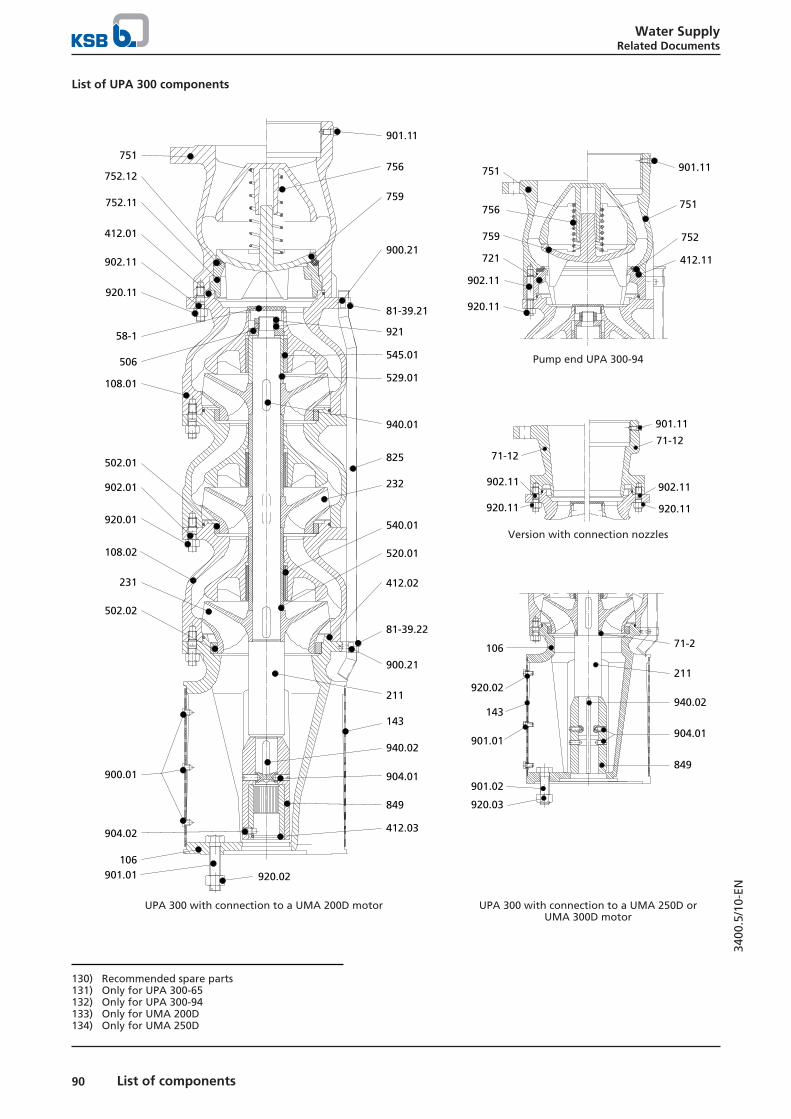
Water SupplyRelated Documents
90 List of components
3400
.5/1
0-EN
List of UPA 300 components
901.11
759
756
900.21
81-39.21
921
529.01
545.01
940.01
825
232
540.01
520.01
412.02
81-39.22
900.21
751
752.12
752.11
412.01
920.11
902.11
58-1
506
108.01
902.01
920.01
502.01
108.02
231
900.01
502.02
904.02
920.02901.01106
211
143
940.02
904.01
849
412.03
751
759
756
902.11
920.11
721
901.11
751
752
412.11
Pump end UPA 300-94
901.11
71-12
902.11
920.11
71-12
902.11
920.11
Version with connection nozzles
71-2
211
940.02
904.01
849
106
920.02
143
901.01
901.02
920.03
UPA 300 with connection to a UMA 200D motor UPA 300 with connection to a UMA 250D orUMA 300D motor
130) Recommended spare parts131) Only for UPA 300-65132) Only for UPA 300-94133) Only for UMA 200D134) Only for UMA 250D

Water SupplyRelated Documents
91List of components
3400
.5/1
0-EN
List of UPA 300 components
Quantity Part No. Description Scope of supply Recommended inaddition:
1 58-1 Protecting plug 130) - -
1 71-2 Collar - -1 71-12 Connection nozzle Incl. 901.11, 902.11 920.111 per cable 81-39.21/.
22Cable clip - 900.21
1 106 Suction casing Incl. 502.02, 412.02 143, 900.01, 901.021 108.01 Stage casing (last stage) Incl. 412.01, 545.01, 902.01 58-1Number of stages -1 108.02 Stage casing Incl. 412.02, 502.01, 540.01,
902.01-
1 143 Suction strainer 130) Incl. 920.02 900.01, 901.01
1 211 Pump shaft - 506, 940.01/.02, 9211 231 Suction stage impeller - 940.01Number of stages -1 232 Clockwise impeller - 940.011 412.01131) O-ring 130) - -
Number of stages -1 412.01 132) O-ring 130) - -
Number of stages 412.02 131) O-ring 130) - -
1 412.03 133) O-ring 130) - -
1 412.11 O-ring 130) - -
Number of stages -1 502.01 Casing wear ring 130) - -
1 502.02 Casing wear ring 130) - -
1 506 Retaining ring - -Number of stages -1 520.01 Sleeve - -1 529.01 Bearing sleeve 130) - 545.01
Number of stages -1 540.01 Bush - -1 545.01 Bearing bush 130) - 529.01
1 721 Adapter Incl. 412.11 7521 751 Valve body Incl. 752.11/.12, 756, 759,
901.11, 902.11920.11
1 752.11 Valve seat - 752.121 752.12 Valve seat (rubber) - 752.111 756 Valve spring - -1 759 Valve disc - 752.121 per cable 825 Cable guard - 81-39.21/.22, 900.211 849 Sleeve coupling - 904.01, 904.02, 940.023 900.01 133) Screw/bolt 130) - -
4 per cable 900.21 Screw/bolt 130) - -
4 901.01 133) Hexagon head bolt - -
3 901.01134) Hexagon head bolt 130) - -
4 901.02 134) Hexagon head bolt - -
2 901.11 Hexagon head bolt - -Number of stages x 12 902.01 Stud - 920.018 902.11 131) Stud - 920.11
12 902.11 132) Stud - 920.11
2 904.01 Grub screw 130) - -
4 904.01 134) Grub screw 130) - -
1 904.02 133) Grub screw 130) - -
Number of stages x 12 920.01 Nut - -4 920.02 133) Nut - -
3 920.02 134) Nut 130) - -
4 920.03 134) Nut - -
8 920.11 131) Nut - -
12 920.11 132) Nut - -
2 921 Shaft nut 130) - -
Number of stages 940.01 Key 130) - -
1 940.02 Key 130) - -

Water SupplyRelated Documents
92 List of components
3400
.5/1
0-EN
List of UPA 350 components
901.11
751
756
900.21
81-39.21
529.01
545.01
502.01
825
211
540.01
520.01
904.02
81-39.22
520.01
751
759
752
412.11
920.11
902.11
58-1
506
108.01
902.01
920.01
540.01
108.02
232
901.02
502.02
920.03
920.02
901.01
143
231
106
940.02
904.01
849
412.03
721
921
940.01
412.01
71-12
902.01
920.01
901.11
71-12
Connection nozzle
920.02
143
901.01
106 71-12
211
940.02
904.01
849
901.02
920.03
UPA 350 with connection to a UMA 200D motor UPA 350 with connection to a UMA 250D orUMA 300D motor
135) Recommended spare parts136) Only for UMA 200D137) Only for UMA 200D and 250D138) Only for UMA 250D

Water SupplyRelated Documents
93List of components
3400
.5/1
0-EN
List of UPA 350 components
Quantity Part No. Description Scope of supply Recommended inaddition:
1 58-1 Protecting plug 135) - -
1 71-2 Collar - -1 71-12 Connection nozzle Incl. 901.11, 902.01 920.011 per cable 81-39.21/.
22Cable clip - 900.21
1 106 Suction casing Incl. 502.01, 412.01 143, 901.011 108.01 Stage casing (last stage) Incl. 412.01, 545.01, 902.01 58-1Number of stages -1 108.02 Stage casing Incl. 412.02, 502.01, 540.01,
902.01-
1 143 Suction strainer 135) Incl. 920.02 901.01
1 211 Pump shaft - 506, 940.01/.02, 9211 231 Suction stage impeller - 940.01Number of stages -1 232 Clockwise impeller - 940.01Number of stages -1 412.01 O-ring 135) - -
1 412.03136) O-ring 135) - -
1 412.11 O-ring 135) - -
Number of stages -1 502.01 Casing wear ring 135) - -
1 502.02 Casing wear ring 135) - -
1 506 Retaining ring - -Number of stages -1 520.01 Sleeve - -1 529.01 Bearing sleeve 135) - 545.01
Number of stages -1 540.01 Bush - -1 545.01 Bearing bush 135) - 529.01
1 721 Adapter Incl. 412.11, 902.01 920.011 751 Valve body Incl. 752, 756, 759, 901.11,
902.11920.11
1 752 Valve seat - -1 756 Valve spring - -1 759 Valve disc - 7521 per cable 825 Cable guard - 81-39.21/.22, 900.211 849 Sleeve coupling - 904.01, 904.02, 940.024 per cable 900.21 Screw/bolt 135) - -
3 901.01 Hexagon head bolt 135) - -
4 901.02 137) Hexagon head bolt - -
2 901.11 Hexagon head bolt 135) - -
Number of stages x 12 902.01 Stud - 920.0112 902.11 Stud - 920.112 904.01 Grub screw 135) - -
4 904.01138) Grub screw 135) - -
1 904.02 136) Grub screw 135) - -
Number of stages x 12 920.01 Nut - -3 920.02 Nut 135) - -
4 920.03137) Nut
12 920.11 Nut - -2 921 Shaft nut 135) - -
Number of stages 940.01 Key 135) - -
1 940.02 Key 135) - -

Water SupplyRelated Documents
94 Power cables
3400
.5/1
0-EN
Power cables
Main applications▪ For use with drinking water applications
▪ Motor lead for submersible motors, cable laid under water
▪ Extension cable for the motor lead, cable laid freelyexposed to air
Operating data
Operating properties
Characteristic Value
Rated voltage VN [V] ≤ 1000Ambient temperature T [°C] ≤ 50Immersion depth IM [m] ≤ 500
Designation
Example: ZN 1391 - G FL GWT -J 4G25 - Cu-Rubber
Designation key
Code Description
ZN Works standardG Insulation, rubberFL Type of power cable
FL FlatRD Round
GWT Suitable for drinking waterJ Information about earth conductor
J With earth conductorO Without earth conductor
4G25 Number of cores4G25 With earth conductor, 4-core, cross-section
25 mm2
3x25 Without earth conductor, 3-core, cross-section 25 mm2
Cu-rubber Material
Design details▪ 3-core or 4-core rubber-sheathed cable
Comprising:– Stranded copper conductor– Bare– Core insulation and outer sheath made of a special
EPR-based rubber compound (ethylene propylenerubber)
– Blue
Cable designs
Cable type Characteristic
Flat cable3 cores, flat4 cores, flat
Round cable1 core, round
4 cores, round

Water SupplyRelated Documents
95Power cables
3400
.5/1
0-EN
Selection information
Permissible cable lengths for starting method: DOL
Applies to 1 cable or 2 cables in parallel 139)
Conditions:
▪ V = 400 V; ΔV = 3 %; T ≤ 30 °C; laid freely exposed to air and in contact with surfaces
4,0 mm2
1
2
3
4
5
6
789
10
20
30
40
50
60
708090
IN[A]
L [m]
70 mm2
400
300
200
100
Imax = 250 A
Imax = 202 A
Imax = 162 A
Imax = 131 A
Imax = 99 A
Imax = 74 A
Imax = 53 A
Imax = 41 A
Imax = 30 A
Imax = 23 A
50 mm2
35 mm2
25 mm2
16 mm2
10 mm2
6,0 mm2
4,0 mm2
2,5 mm2
1,5 mm2
10 20 30 40 20010080706050 500400300
A B
Example AIN = 68 ACable design: 1 x 16 mm2
Cable length: L ≤ 105 m
Example BIN = 68 ACable design: 1 x 25 mm2
Cable length: L ≤ 165 m
139) For parallel cables the value is doubled to obtain the permissible length.

Water SupplyRelated Documents
96 Power cables
3400
.5/1
0-EN
Permissible cable lengths for starting method: YΔApplies to 2 cables
Conditions:
▪ V = 400 V; ΔV = 3 %; T ≤ 30 °C; laid freely exposed to air and in contact with surfaces
1
2
3
4
5
6
789
10
20
30
40
50
60
708090
IN[A]
400
300
200
100
L [m]10 20 30 40 20010080706050 500400300
70 mm2
50 mm2
35 mm2
25 mm2
16 mm2
10 mm2
6,0 mm2
4,0 mm2
2,5 mm2
1,5 mm2
Imax = 433 A
Imax = 350 A
Imax = 280 A
Imax = 227 A
Imax = 171 A
Imax = 128 A
Imax = 92 A
Imax = 71 A
Imax = 52 A
Imax = 40 A
A B
Example AIN = 27 ACable design: 2 x 6.0 mm2
Cable length: L ≤ 145 m
Example BIN = 27 ACable design: 2 x 10 mm2
Cable length: L ≤ 235 m

Water SupplyRelated Documents
97Power cables
3400
.5/1
0-EN
Voltage drop in the extension cableWhen calculating the required conductor cross-section q notonly IN, but also the voltage drop ΔV along the cable length L(distance from motor to control unit) must be taken intoaccount. Proper functioning of our submersible motorsrequires ΔV ≤ 3 % of the supply voltage V.If ΔV > 3 %, a larger conductor cross-section must be used. The voltage drop is calculated using the following equations:
Starting method DOL/autotransformer▪ 1 cable:
ΔU =3,1 × L × IN × cos φ
q × U [%]
▪ 2 cables in parallel (II):
ΔU =1,55 × L × IN × cos φ
q × U [%]
Starting method YΔ (2 cables):
▪ΔU =
2,1 × L × IN × cos φq × U [%]
Power loss ΔP:
▪ΔP = ΔU
(cos φ)2 [%]
Key
Code Description
L Single cable length [m]IN Rated current [A]:cos φ Power factor at 4/4 loadq Conductor cross-section [mm2]U Supply voltage [V]
Maximum permissible rated motor current
For ambient temperature t ≤ 30 °C
Starting method Used as ... Imax [A]for the following conductor cross-sections [mm2]
1,5 2,5 4 6 10 16 25 35 50 70 95
DOL(1 cable or 2cables in parallel)
Motor lead 29 38 52 67 94 125 166 205 256 316 517Extension cable 23 30 41 53 74 99 131 162 202 250 409
YΔ(2 cables)
Motor lead 50 66 90 116 163 217 288 355 443 547 895Extension cable 40 52 71 92 128 171 227 280 350 433 708
Dimensions and weights
Selection table: dimensions [mm]
Core type Conductor cross-section [mm2]
1,5 2,5 4 6 10 16 25 35 50 70 95
Height 5,2 +1,0 6,1 +1,5 7,0 +2,0 7,6 +2,2 9,3 +2,2 11,2 +2,3 13,0 +2,5 14,6 +2,9 17,0 +3,0 19,3 +2,7 -Width 11,0 +2,0 13,2 +2,3 15,5 +3,5 17,4 +3,6 21,5 +3,5 26,7 +4,3 31,6 +3,9 35,5 +5,0 42,1 +4,9 48,4 +3,6 -Height 5,2 +1,0 6,1 +1,5 - 7,6 +2,2 9,3 +2,2 11,2 +2,3 13,0 +2,5 - - - -Width 14,5 +2,7 17,5 +2,5 - 23,5 +3,0 29,0 +3,5 35,0 +2,4 41,5 +4,5 - - - -Diameter 5,3 +1,1 - - - - - - 13,8 +3,6 16,0 +3,8 18,5 +3,6 21,9 +1,5
Diameter 10,0 +2,0 12,0 +1,9 13,9 +2,0 15,7 +2,1 21,1 +2,1 24,5 +4,3 29,7 +4,3 33,3 +5,5 39,0 +5,6 44,2 +5,8 -
Selection table: weight [kg/m]
Co
rety
pe Conductor cross-section [mm2]
1,5 2,5 4 6 10 16 25 35 50 70 95
0,110 0,171 0,252 0,319 0,486 0,750 1,107 1,438 2,054 2,760 -0,165 0,237 - 0,440 0,704 1,026 1,457 - - - -0,051 - - - - - - 0,499 0,699 0,940 1,140
0,180 0,259 0,356 0,475 0,837 1,220 1,770 2,304 3,185 4,364 -

Water SupplyRelated Documents
98 Cable connector
3400
.5/1
0-EN
Cable connector
ApplicationFor providing a sealed, water-tight connection between extension cables and motor leads of submersible motors.
▪ Ambient temperature: T ≤ + 50 °C
▪ Immersion depth: ≤ 500 m
Selection tableThe table below only shows the cables on stock. Connectors for other cables on request.
Selection table
Motorlead
Extension cable [mm2]
[mm2] 1,5 2,5 4 6 10 16 25 35 50 70
Cable connector size
1,5 / 2,5 28 28 28 35 35 43 53 53 - -4 - 35 35 35 35 43 53 53 - -6 - - 35 35 35 43/29f 53/29f 53/29f - -10 - - - 43 43/29f 43/29f 53/29f 53/29f - -16 - - - - - 53 53 53 66 6625 - - - - - - 66 66 66 6635 - - - - - - - 66 66 6650 - - - - - - - 66 66 6670 - - - - - - - - - 66
1,5 / 2,5 28 28 28 35 35 43 53 53 - -4 - 35 35 35 35 43 53 53 - -6 - - 35 35 35 43 53 53 - -10 - - - 43 43 43 53 53 - -16 - - - - - 53 53 53 66 6625 - - - - - - 66 66 66 66
+ or +
1,5 28 28 28 35 35 - - - - -2,5 35 35 35 35 35 - - - - -4 - - 35 35 35 43 - - - -6 - - - 43 43 43 53 53 66 6610 - - - 66 66 66 66 66 66 6616 - - - - - 66 66 66 66 6625 - - - - - - 78 78 78 -
1,5 / 2,5 / 4 28 28 28 28 35 43 - - - -6 28 28 28 28 35 43 53 53 - -10 - - 35 35 35 43 53 53 - -16 - - - - 43 43 53 53 66 6625 - - - - - 53 53 53 66 7835 - - - - - - - 53 66 7850 - - - - - - - - 66 7870 - - - - - - - - - 78
35 - - - - - - - 35 - -50 - - - - - - - - 35 -70 - - - - - - - - - 35

Water SupplyRelated Documents
99Cable connector
3400
.5/1
0-EN
Key
Cable symbols Description Cable designation
1-core, round G RD GWT - O 1 G
4-core, round G RD GWT - J 4 G
3-core, flat G FL GWT - O 3x ...4-core, flat G FL GWT - J 4G ...

Water SupplyRelated Documents
100 Cable clips
3400
.5/1
0-EN
Cable clips
Applications▪ Securing cables at the riser / discharge pipe.
▪ Suitable for use in normal or slightly aggressive water.
▪ Versions for use in more aggressive water (e.g. seawater) on request.
Selection table
CableC
able
clip
size
Weight Required strap length L [mm] per cable clip for the following risers
Type Number x ∅ of cores
G 1
1/4
/D
N 3
2
G 1
1/2
/D
N 4
0
G 2
/ D
N50 D
N 6
5
G 3
/ D
N80 G
4 /
DN
100
G 5
/ D
N12
5
G 6
/ D
N15
0
DN
175
G 8
/ D
N20
0
DN
250
DN
300
DN
350
DN
400
[mm] [kg]
Flat 3 x 1.5to
3 x 6,0
4 x 1.5to
4 x 6.0
1 0,01 270 280 320 360 400 450 500 600 - - - - - -
3 x 10to
3 x 70
4 x 10to
4 x 70
11 0,01 - - 350 400 450 550 650 800 950 1100 1300 1500 1700 1900
Round 3 x 1.5to
3 x 6.0
4 x 1.5to
4 x 6.0
1 0,01 270 280 320 360 400 450 500 600 - - - - - -
3 x 10 4 x 10 2 0,08 - - 350 400 450 550 650 800 950 1100 1300 1500 1700 19003 x 163 x 25
4 x 16 3a 0,19 - - 350 400 450 550 650 800 950 1100 1300 1500 1700 1900
3 x 353 x 50
4 x 254 x 35
3 0,19 - - - 450 500 600 700 850 1000 1150 1350 1550 1750 1950
3 x 70 4 x 50 3b 0,19 - - - 450 500 600 700 850 1000 1150 1350 1550 1750 19503 x 95 4 x 70
4 x 954 0,55 - - - - - 650 750 900 1050 1200 1400 1600 1800 2000
3 cables 1 x 50 7 0,6 - - - - - 700 800 950 1100 1250 1450 1650 1850 20503 cables 1 x 70 8 0,6 - - - - 700 800 950 1100 1250 1450 1650 1850 20503 cables 1 x 95 6 0,6 - - - - 700 800 950 1100 1250 1450 1650 1850 20503 cables 1 x 1203 cables 1 x 150
9 0,6 - - - - 700 800 950 1100 1250 1450 1650 1850 2050
Cable clip sizes
Size 1 Sizes 2, 3, 3a, 3b, 4 Sizes 6 to 9 Size 11
1
2
3
4
2
3
4
1
5
1 = cable2 = riser
3 = plastic stud4 = rubber strap
1 = screw band with tension screw (re-usable)2 = cable guard
3 = cable4 = metal strap
5 = riser

Water SupplyRelated Documents
101Flow velocity past the motor
3400
.5/1
0-EN
Flow velocity past the motor
Application▪ Required motor cooling
Flow velocity past the motorv = 0 m/sThe flow velocity past the motor is not defined. The heat is dissipated freely. This heat dissipation must not be influenced orhindered by any structures, and a supply of fresh water must be provided at all times.
▪ Example: pump set freely suspended in a vertical position inside a large tank
Flow velocity past the motorv > 0.2 m/sv > 0.5 m/sThe flow velocity past the motor is defined for the installation conditions, see table below. Decisive factors are the inside welldiameter or the inside shroud diameter, the operating data and the outside dimensions of the pump.
▪ Example: pump set installed in a vertical position above the screen/filter in a well; values in accordance with the table below.
▪ Example: pump set installed in a horizontal position in a tank, fitted with a cooling shroud, or pump set installed in a verticalposition in a pump sump, fitted with a cooling shroud; values in accordance with the table below
Maximum permissible inside diameter of the well or shroud
Flow rate Flow velocity
Inside diameter of the well or shroud [mm]
Q [m³/h] v [m/s] ForUMA 150DUMA 150E
UMA-S 150E
ForUMA 200D
UMA-S 200D
ForUMA 250D
ForUMA 300D
For14D
15 ≥ 0,2 ≤ 215 - - - -≥ 0,5 ≤ 175 - - - -
25 ≥ 0,2 ≤ 255 - - - -≥ 0,5 ≤ 195 - - - -
50 ≥ 0,2 ≤ 330 ≤ 350 - - -≥ 0,5 ≤ 235 ≤ 265 - - -
75 ≥ 0,2 ≤ 390 ≤ 410 ≤ 430 - -≥ 0,5 ≤ 270 ≤ 300 ≤ 330 - -
100 ≥ 0,2 ≤ 445 ≤ 460 ≤ 480 - -≥ 0,5 ≤ 300 ≤ 325 ≤ 355 - -
125 ≥ 0,2 ≤ 490 ≤ 510 ≤ 525 - -≥ 0,5 ≤ 330 ≤ 350 ≤ 380 - -
150 ≥ 0,2 ≤ 535 ≤ 550 ≤ 565 ≤ 590 -≥ 0,5 ≤ 355 ≤ 380 ≤ 400 ≤ 430 -
175 ≥ 0,2 ≤ 575 ≤ 590 ≤ 605 ≤ 625 -≥ 0,5 ≤ 380 ≤ 400 ≤ 420 ≤ 450 -
200 ≥ 0,2 ≤ 615 ≤ 625 ≤ 640 ≤ 660 ≤ 690≥ 0,5 ≤ 405 ≤ 420 ≤ 445 ≤ 470 ≤ 510
250 ≥ 0,2 ≤ 680 ≤ 690 ≤ 705 ≤ 725 ≤ 750≥ 0,5 ≤ 445 ≤ 460 ≤ 480 ≤ 505 ≤ 540
300 ≥ 0,2 ≤ 745 ≤ 755 ≤ 765 ≤ 780 ≤ 800≥ 0,5 ≤ 485 ≤ 500 ≤ 515 ≤ 540 ≤ 570
350 ≥ 0,2 - ≤ 810 ≤ 820 ≤ 835 ≤ 860≥ 0,5 - ≤ 530 ≤ 550 ≤ 570 ≤ 600
400 ≥ 0,2 - ≤ 865 ≤ 875 ≤ 890 ≤ 910≥ 0,5 - ≤ 565 ≤ 580 ≤ 605 ≤ 630
500 ≥ 0,2 - ≤ 960 ≤ 970 ≤ 985 ≤ 1000≥ 0,5 - ≤ 625 ≤ 640 ≤ 660 ≤ 690
600 ≥ 0,2 - ≤ 1050 ≤ 1055 ≤ 1070 ≤ 1090≥ 0,5 - ≤ 680 ≤ 695 ≤ 710 ≤ 740
800 ≥ 0,2 - ≤ 1205 ≤ 1215 ≤ 1225 ≤ 1240≥ 0,5 - ≤ 775 ≤ 790 ≤ 805 ≤ 830
1000 ≥ 0,2 - ≤ 1345 ≤ 1350 ≤ 1360 ≤ 1370≥ 0,5 - ≤ 865 ≤ 875 ≤ 890 ≤ 910
1200 ≥ 0,2 - - - ≤ 1485 ≤ 1500

Water SupplyRelated Documents
102 Flow velocity past the motor
3400
.5/1
0-EN
Flow rate Flow velocity
Inside diameter of the well or shroud [mm]
Q [m³/h] v [m/s] ForUMA 150DUMA 150E
UMA-S 150E
ForUMA 200D
UMA-S 200D
ForUMA 250D
ForUMA 300D
For14D
1200 ≥ 0,5 - - - ≤ 965 ≤ 9801400 ≥ 0,2 - - - ≤ 1600 ≤ 1610
≥ 0,5 - - - ≤ 1030 ≤ 10501600 ≥ 0,2 - - - ≤ 1705 ≤ 1720
≥ 0,5 - - - ≤ 1100 ≤ 11201800 ≥ 0,2 - - - ≤ 1805 ≤ 1820
≥ 0,5 - - - ≤ 1165 ≤ 11802000 ≥ 0,2 - - - ≤ 1900 ≤ 1910
≥ 0,5 - - - ≤ 1225 ≤ 1240


KSB SE & Co. KGaAJohann-Klein-Straße 9 • 67227 Frankenthal (Germany)Tel. +49 6233 86-0www.ksb.com
3400
.5/1
0-EN
09/0
4/20
20


![LSA [RUS] - Web-Shop KSB](https://img.dokumen.tips/doc/110x75/633476fe62e2e08d4902a322/lsa-rus-web-shop-ksb.jpg)

