Embed Size (px)
Citation preview
KOLLMORGEN Steuerungstechnik GmbH Cologne, Germany / 2011-04-07 / DO_SYSKSB_gb
Kollmorgen Shaftbus (KSB)
System documentation
Kollmorgen Steuerungstechnik GmbH Kollmorgen Lift Controls Ltd. Broichstraße 32 Unit 2, The Office Village D 51109 Köln Chester Business Park Telefon +49 (0) 221 89 85 0 Chester, Cheshire, CH4 9QP Telefax +49 (0) 221 89 85 30 Telephone + 44 (0) 1244-67 85 49 http://www.kollmorgen.de Fax +44 (0) 1244-68 15 78 Email [email protected] Email [email protected]
Kollmorgen Shaftbus (KSB) System documentation
2 2011-04-07
Contents 1 Description ....................................................................................................................3
1.1 Scope of Performance.......................................................................................................... 3 2 Topology........................................................................................................................5
2.1 Single control ....................................................................................................................... 5 2.2 Duplex control system ......................................................................................................... 6 2.3 Jumperpositions of addresses 1 – 63 .................................................................................. 7
3 Technical description....................................................................................................8 3.1 Floor module KBC................................................................................................................ 8 3.2 Floor module KBD................................................................................................................ 9 3.3 Short-circuit protection – module SKC.............................................................................. 10 3.4 Short-circuit protection – module SKD.............................................................................. 11 3.5 Floor indicator module KBI / Car indicator module KBK – 8x16........................................ 12 3.6 Floor indicator module KBI / Car indicator module KBK – 16x16...................................... 13 3.7 4-Lead Button Connecting Cable ....................................................................................... 14 3.8 HSS Voice Output Module.................................................................................................. 15
3.8.1 SD-Card........................................................................................................................ 16 3.9 Technical data .................................................................................................................... 17
4 MPK-Menu functions...................................................................................................18 4.1 General ............................................................................................................................... 18 4.2 KBI / KBK Display Module.................................................................................................. 19
4.2.1 Menu functions.............................................................................................................. 19 4.2.2 Set Floor and Special Text ............................................................................................. 20 4.2.3 Activate Special Text ..................................................................................................... 20
Kollmorgen Shaftbus (KSB)
System documentation
2011-04-07 3
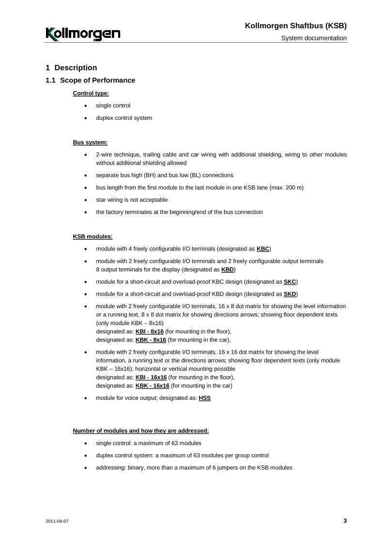
1 Description 1.1 Scope of Performance
Control type:
single control
duplex control system
Bus system:
2-wire technique, trailing cable and car wiring with additional shielding, wiring to other modules without additional shielding allowed
separate bus high (BH) and bus low (BL) connections
bus length from the first module to the last module in one KSB lane (max. 200 m)
star wiring is not acceptable
the factory terminates at the beginning/end of the bus connection
KSB modules:
module with 4 freely configurable I/O terminals (designated as KBC)
module with 2 freely configurable I/O terminals and 2 freely configurable output terminals 8 output terminals for the display (designated as KBD)
module for a short-circuit and overload-proof KBC design (designated as SKC)
module for a short-circuit and overload-proof KBD design (designated as SKD)
module with 2 freely configurable I/O terminals, 16 x 8 dot matrix for showing the level information or a running text, 8 x 8 dot matrix for showing directions arrows; showing floor dependent texts (only module KBK – 8x16) designated as: KBI - 8x16 (for mounting in the floor), designated as: KBK - 8x16 (for mounting in the car),
module with 2 freely configurable I/O terminals, 16 x 16 dot matrix for showing the level information, a running text or the directions arrows; showing floor dependent texts (only module KBK – 16x16); horizontal or vertical mounting possible designated as: KBI - 16x16 (for mounting in the floor), designated as: KBK - 16x16 (for mounting in the car)
module for voice output; designated as: HSS
Number of modules and how they are addressed:
single control: a maximum of 63 modules
duplex control system: a maximum of 63 modules per group control
addressing: binary, more than a maximum of 6 jumpers on the KSB modules
Kollmorgen Shaftbus (KSB) System documentation
4 2011-04-07
IMPORTANT!
in the lift group:
- it is always necessary to also have a GLON connection
- each group control has to have its own KSB lane the two KSB lanes may not be connected with one another
- the KSB modules of the other group subscriber may not be programmed.
signals may not displayed flashing
a self-defined code may not shown on the display of module KBD
one module address may not be assigned several times in one KSB lane
the KSB modules have to be initialised by RESET on the control after initial installation
if initialised KSB modules are switched off, the eight outputs of the KBD module have to be re-initialised with RESET on the control after power returns to trigger the display. None of the remaining inputs/outputs of the KSB modules have to be re-initialised.
no initialising or parametering data are permanently stored on the KSB modules
Kollmorgen Shaftbus (KSB)
System documentation
2011-04-07 5
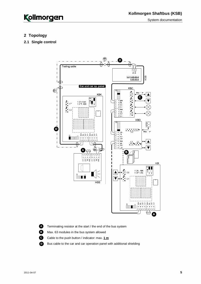
2 Topology 2.1 Single control
132 0VBL
BH
U+
0VBL
BH
U+
BH
BL
132 0VBL
BH
U+
0VBL
BH
U+
T
0V BL
BHU+
0V BL
BH
U+
T
132
KS
B
A Terminating resistor at the start / the end of the bus system
B Max. 63 modules in the bus system allowed
C Cable to the push button / indicator: max. 1 m
D Bus cable to the car and car operation panel with additional shielding
Kollmorgen Shaftbus (KSB) System documentation
6 2011-04-07
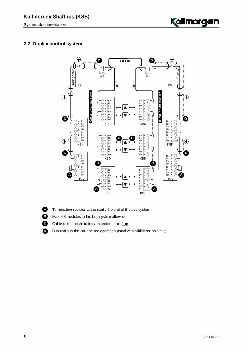
2.2 Duplex control system
GLON
CC
KS
B
KS
B
BH
BL
Car
and
car
op.
pan
el
0VBLBH
U+
0VBLBH
U+
T
HSS
0VBLBH
U+
0VBLBH
U+
KBK
0VBLBH
U+
0VBLBH
U+
T
KBI
0VBLBH
U+
0VBLBH
U+
KBD
0VBLBH
U+
0VBLBH
U+
KBC
BST
A
A
B
D
Trai
ling
cabl
e
D
BH BL
Car and car op. panel
0VBLBH
U+
0VBLBH
U+
T
HSS
0VBLBH
U+
0VBLBH
U+
KBK
0VBLBH
U+
0VBLBH
U+
T
KBI
0VBLBH
U+
0VBLBH
U+
KBD
0VBLBH
U+
0VBLBH
U+
KBC
BST
A
A
B
D
Trailing cable
D
D D
A Terminating resistor at the start / the end of the bus system
B Max. 63 modules in the bus system allowed
C Cable to the push button / indicator: max. 1 m
D Bus cable to the car and car operation panel with additional shielding
Kollmorgen Shaftbus (KSB)
System documentation
2011-04-07 7
Note!
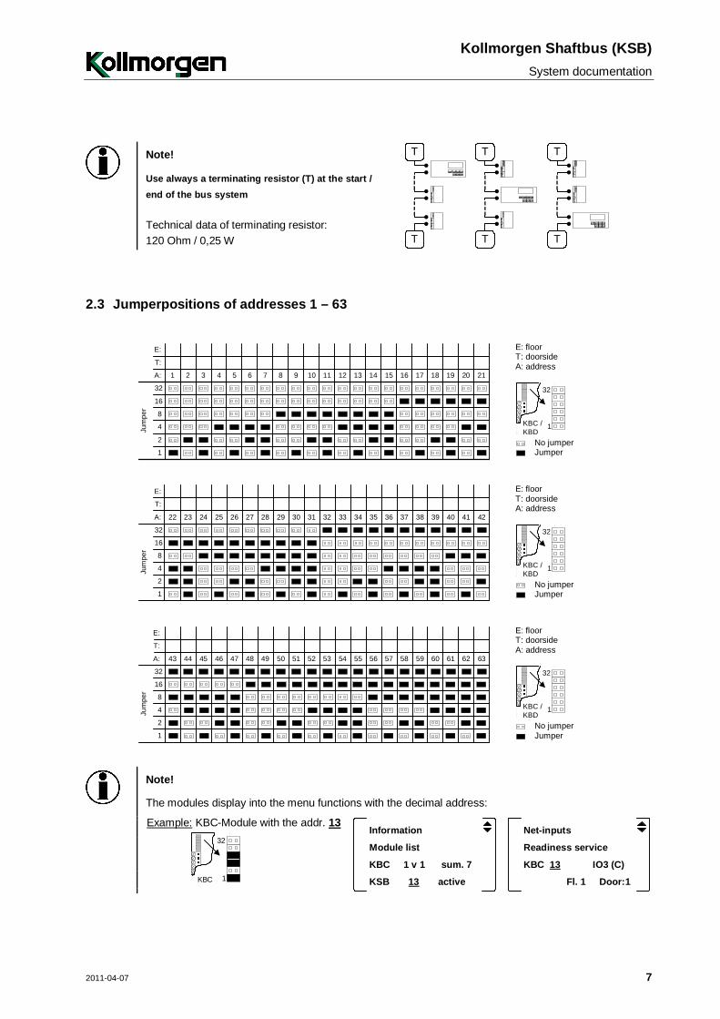
Use always a terminating resistor (T) at the start / end of the bus system Technical data of terminating resistor: 120 Ohm / 0,25 W
T
T
T
T
T
T
2.3 Jumperpositions of addresses 1 – 63
E: floor
T: doorside A: address
1
32
KBC /KBD
No jumper 1
2
4
8
16
32
A: 1 2 3 4 5 6 7 8 9 10 11 12 13 14 15 16 17 18 19 20 21
Jum
per
T:
E:
Jumper
E: floor
T: doorside A: address
1
32
KBC /KBD
No jumper 1
2
4
8
16
32
22 23 24 25 26 27 28 29 30 31 32 33 34 35 36 37 38 39 40 41 42
Jum
per
A:
T:
E:
Jumper
E: floor
T: doorside A: address
1
32
KBC /KBD
No jumper 1
2
4
8
16
32
43 44 45 46 47 48 49 50 51 52 53 54 55 56 57 58 59 60 61 62 63
Jum
per
A:
T:
E:
Jumper
Note!
The modules display into the menu functions with the decimal address:
Information Net-inputs
Module list Readiness service
KBC 1 v 1 sum. 7 KBC 13 IO3 (C)
KSB 13 active Fl. 1 Door:1
Example: KBC-Module with the addr. 13
1
32
KBC
Kollmorgen Shaftbus (KSB) System documentation
8 2011-04-07
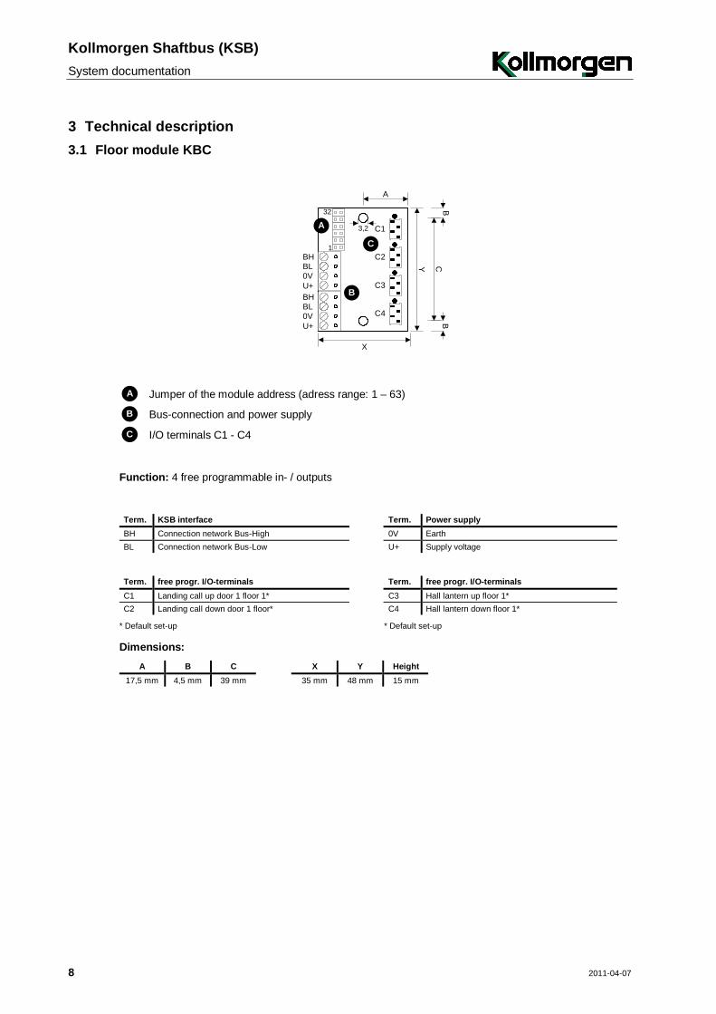
3 Technical description 3.1 Floor module KBC
A
0VBLBH
U+
0VBLBH
U+
C1
C2
C3
C4
3,2
Y CB
B
X
B
A
C1
32
A Jumper of the module address (adress range: 1 – 63)
B Bus-connection and power supply
C I/O terminals C1 - C4
Function: 4 free programmable in- / outputs
Term. KSB interface Term. Power supply BH Connection network Bus-High 0V Earth BL Connection network Bus-Low U+ Supply voltage
Term. free progr. I/O-terminals Term. free progr. I/O-terminals C1 Landing call up door 1 floor 1* C3 Hall lantern up floor 1* C2 Landing call down door 1 floor* C4 Hall lantern down floor 1*
* Default set-up * Default set-up
Dimensions: A B C X Y Height
17,5 mm 4,5 mm 39 mm 35 mm 48 mm 15 mm
Kollmorgen Shaftbus (KSB)
System documentation
2011-04-07 9
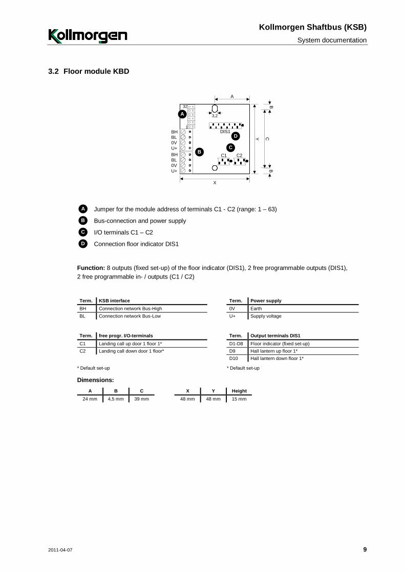
3.2 Floor module KBD
A
0VBLBH
U+
0VBLBH
U+
DIS1
C1 C2
Y
X
CB
B
3,2
B
A
C
D
1
32
A Jumper for the module address of terminals C1 - C2 (range: 1 – 63)
B Bus-connection and power supply
C I/O terminals C1 – C2
D Connection floor indicator DIS1
Function: 8 outputs (fixed set-up) of the floor indicator (DIS1), 2 free programmable outputs (DIS1), 2 free programmable in- / outputs (C1 / C2)
Term. KSB interface Term. Power supply BH Connection network Bus-High 0V Earth BL Connection network Bus-Low U+ Supply voltage
Term. free progr. I/O-terminals Term. Output terminals DIS1 C1 Landing call up door 1 floor 1* D1-D8 Floor indicator (fixed set-up) C2 Landing call down door 1 floor* D9 Hall lantern up floor 1* D10 Hall lantern down floor 1*
* Default set-up * Default set-up
Dimensions: A B C X Y Height
24 mm 4,5 mm 39 mm 48 mm 48 mm 15 mm
Kollmorgen Shaftbus (KSB) System documentation
10 2011-04-07
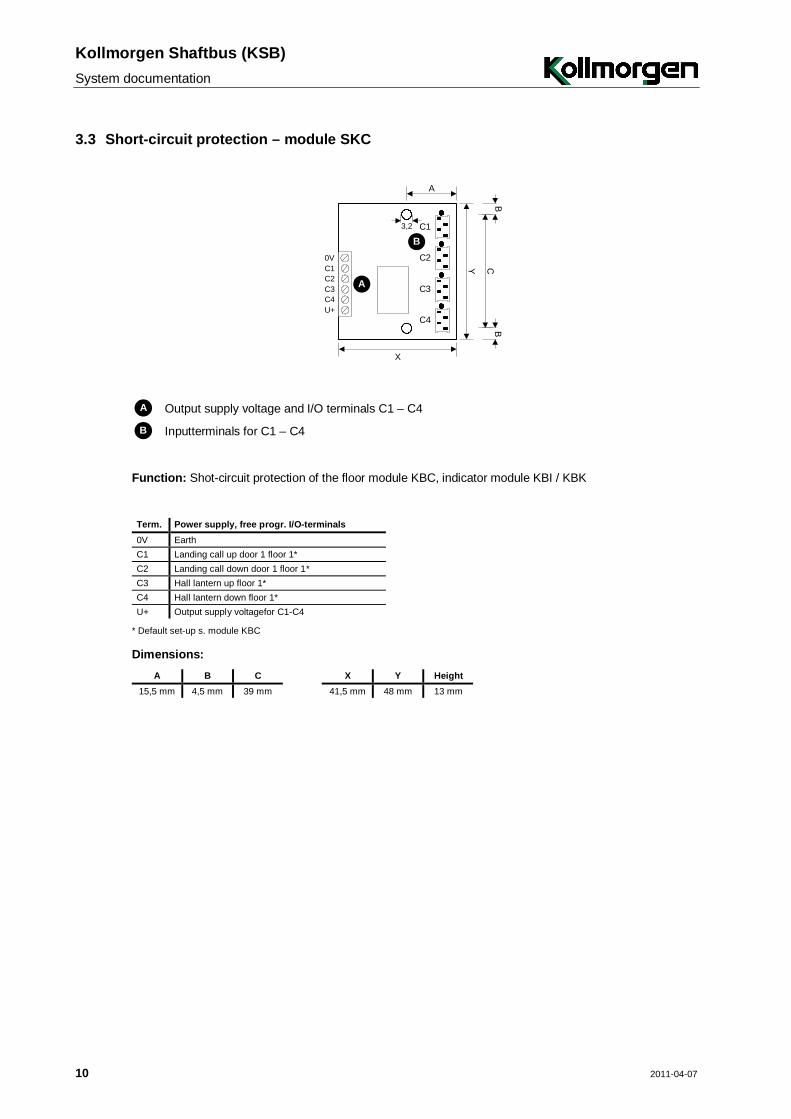
3.3 Short-circuit protection – module SKC
C10V
C3C2
U+C4
C1
C2
C3
C4
3,2
Y CB
B
A
X
B
A
A Output supply voltage and I/O terminals C1 – C4
B Inputterminals for C1 – C4
Function: Shot-circuit protection of the floor module KBC, indicator module KBI / KBK
Term. Power supply, free progr. I/O-terminals 0V Earth C1 Landing call up door 1 floor 1* C2 Landing call down door 1 floor 1* C3 Hall lantern up floor 1* C4 Hall lantern down floor 1* U+ Output supply voltagefor C1-C4
* Default set-up s. module KBC
Dimensions: A B C X Y Height
15,5 mm 4,5 mm 39 mm 41,5 mm 48 mm 13 mm
Kollmorgen Shaftbus (KSB)
System documentation
2011-04-07 11
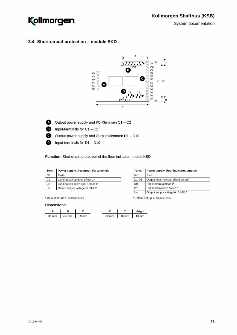
3.4 Short-circuit protection – module SKD
C10V
0VU+
U+C2 D4
D5
D2D3
0VD1
D10U+
D8D9
D6D7
DIS1
C1 C2
3,2
Y
A
CB
B
X
B
D
A
C
A Output power supply and I/O Klemmen C1 – C2
B Input-terminals for C1 – C2
C Output power supply and Outputsklemmen D1 – D10
D Input-terminals for D1 – D10
Function: Shot-circuit protection of the floor indicator module KBD
Term. Power supply, free progr. I/O-terminals Term. Power supply, floor indicator, outputs 0V Earth 0V Earth C1 Landing call up door 1 floor 1* D1-D8 Output floor indicator (fixed set-up) C2 Landing call down door 1 floor 1* D9 Hall lantern up floor 1* U+ Output supply voltagefür C1-C2 D10 Hall lantern down floor 1* U+ Output supply voltagefür D1-D10
* Default set-up s. module KBD * Default set-up s. module KBD
Dimensions: A B C X Y Height
31 mm 4,5 mm 39 mm 62 mm 48 mm 13 mm
Kollmorgen Shaftbus (KSB) System documentation
12 2011-04-07
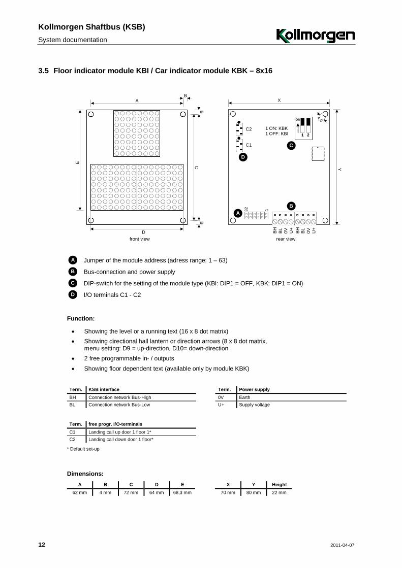
3.5 Floor indicator module KBI / Car indicator module KBK – 8x16
AB
CB
B
E
D
Y
0VBL
BH
U+
0VBL
BH
U+
132
C2
C1
4,0
A
X
1 ON: KBK1 OFF: KBI
ON
1 2
B
D
C
front view rear view
A Jumper of the module address (adress range: 1 – 63)
B Bus-connection and power supply
C DIP-switch for the setting of the module type (KBI: DIP1 = OFF, KBK: DIP1 = ON)
D I/O terminals C1 - C2
Function:
Showing the level or a running text (16 x 8 dot matrix) Showing directional hall lantern or direction arrows (8 x 8 dot matrix,
menu setting: D9 = up-direction, D10= down-direction
2 free programmable in- / outputs Showing floor dependent text (available only by module KBK)
Term. KSB interface Term. Power supply BH Connection network Bus-High 0V Earth BL Connection network Bus-Low U+ Supply voltage
Term. free progr. I/O-terminals C1 Landing call up door 1 floor 1* C2 Landing call down door 1 floor*
* Default set-up
Dimensions: A B C D E X Y Height
62 mm 4 mm 72 mm 64 mm 68,3 mm 70 mm 80 mm 22 mm
Kollmorgen Shaftbus (KSB)
System documentation
2011-04-07 13
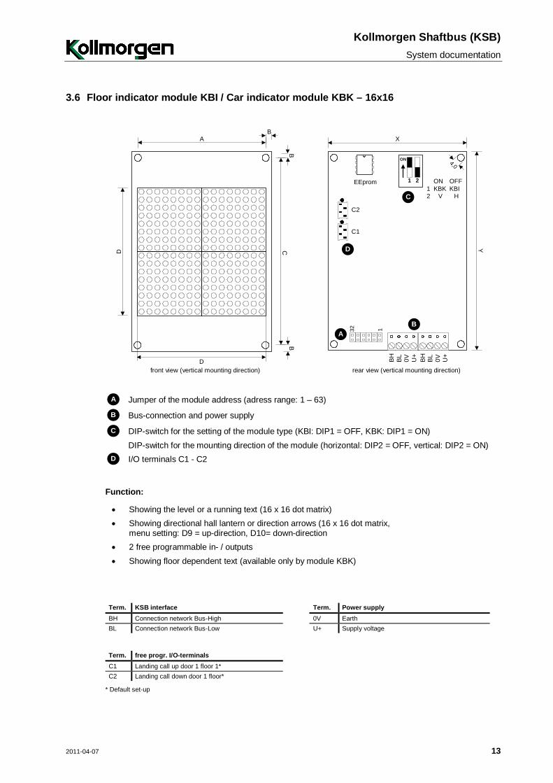
3.6 Floor indicator module KBI / Car indicator module KBK – 16x16
AB
CB
B
D
D
Y
0VBL
BH
U+
0VBL
BH
U+
132
C2
C1
4,0
AB
D
X
ON
1 2 ONKBK
V
OFFKBI
H12C
EEprom
front view (vertical mounting direction) rear view (vertical mounting direction)
A Jumper of the module address (adress range: 1 – 63)
B Bus-connection and power supply
C DIP-switch for the setting of the module type (KBI: DIP1 = OFF, KBK: DIP1 = ON) DIP-switch for the mounting direction of the module (horizontal: DIP2 = OFF, vertical: DIP2 = ON)
D I/O terminals C1 - C2
Function:
Showing the level or a running text (16 x 16 dot matrix) Showing directional hall lantern or direction arrows (16 x 16 dot matrix,
menu setting: D9 = up-direction, D10= down-direction
2 free programmable in- / outputs Showing floor dependent text (available only by module KBK)
Term. KSB interface Term. Power supply BH Connection network Bus-High 0V Earth BL Connection network Bus-Low U+ Supply voltage
Term. free progr. I/O-terminals Term. free progr. outputs C1 Landing call up door 1 floor 1* D9 Hall latern up floor 1* C2 Landing call down door 1 floor* D10 Hall latern down floor 1*
* Default set-up
Kollmorgen Shaftbus (KSB) System documentation
14 2011-04-07
Dimensions: A B C D X Y Height
62 mm 4 mm 92 mm 64 mm 70 mm 100 mm 22 mm
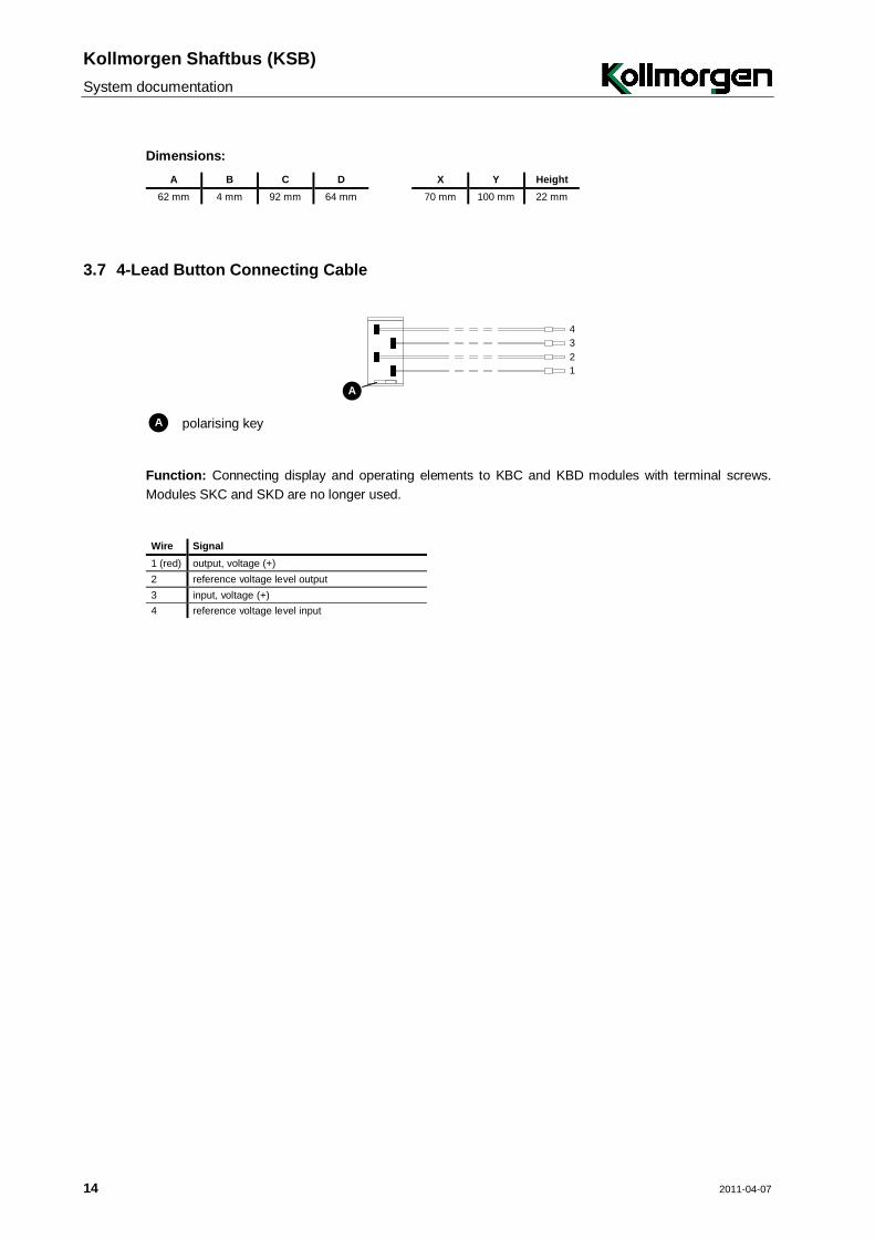
3.7 4-Lead Button Connecting Cable
1234
A
A polarising key
Function: Connecting display and operating elements to KBC and KBD modules with terminal screws. Modules SKC and SKD are no longer used.
Wire Signal 1 (red) output, voltage (+) 2 reference voltage level output 3 input, voltage (+) 4 reference voltage level input
Kollmorgen Shaftbus (KSB)
System documentation
2011-04-07 15
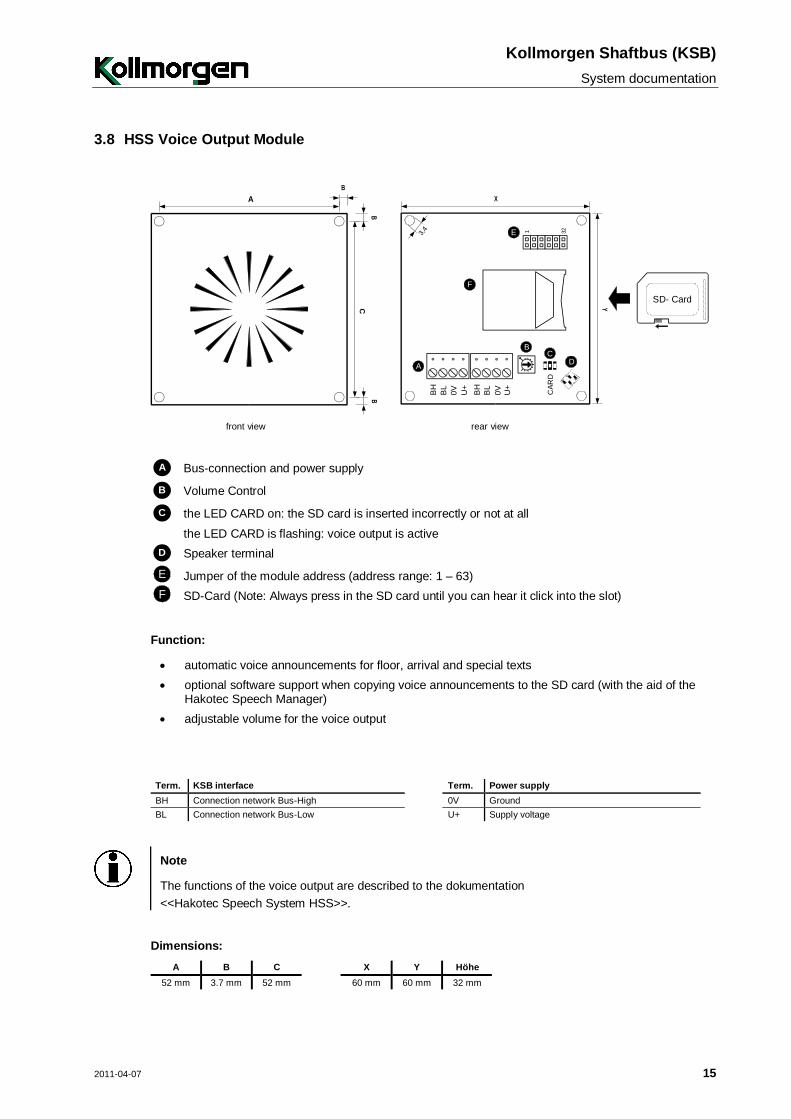
3.8 HSS Voice Output Module
A
CB
B
B
BH
BL
0V U+
BH
BL
0V U+
1 32
X
Y
3,4 E
DC
B
A
CAR
D
F
SD- Card
front view rear view
A Bus-connection and power supply
B Volume Control
C the LED CARD on: the SD card is inserted incorrectly or not at all the LED CARD is flashing: voice output is active
D Speaker terminal
E Jumper of the module address (address range: 1 – 63)
F SD-Card (Note: Always press in the SD card until you can hear it click into the slot)
Function:
automatic voice announcements for floor, arrival and special texts optional software support when copying voice announcements to the SD card (with the aid of the
Hakotec Speech Manager) adjustable volume for the voice output
Term. KSB interface Term. Power supply BH Connection network Bus-High 0V Ground BL Connection network Bus-Low U+ Supply voltage
Note
The functions of the voice output are described to the dokumentation <<Hakotec Speech System HSS>>.
Dimensions: A B C X Y Höhe
52 mm 3.7 mm 52 mm 60 mm 60 mm 32 mm
Kollmorgen Shaftbus (KSB) System documentation
16 2011-04-07
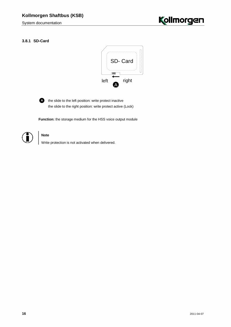
3.8.1 SD-Card
SD- Card
Aleft right
A the slide to the left position: write protect inactive the slide to the right position: write protect active (Lock)
Function: the storage medium for the HSS voice output module
Note
Write protection is not activated when delivered.
Kollmorgen Shaftbus (KSB)
System documentation
2011-04-07 17
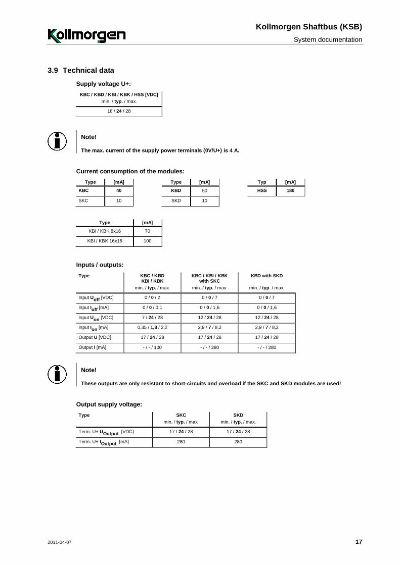
3.9 Technical data
Supply voltage U+: KBC / KBD / KBI / KBK / HSS [VDC]
min. / typ. / max.
18 / 24 / 28
Note!
The max. current of the supply power terminals (0V/U+) is 4 A.
Current consumption of the modules: Type [mA] Type [mA] Typ [mA]
KBC 40 KBD 50 HSS 180
SKC 10 SKD 10
Type [mA]
KBI / KBK 8x16 70
KBI / KBK 16x16 100
Inputs / outputs: Type KBC / KBD
KBI / KBK KBC / KBI / KBK
with SKC KBD with SKD
min. / typ. / max. min. / typ. / max. min. / typ. / max.
Input Uoff [VDC] 0 / 0 / 2 0 / 0 / 7 0 / 0 / 7
Input Ioff [mA] 0 / 0 / 0,1 0 / 0 / 1,6 0 / 0 / 1,6
Input Uon [VDC] 7 / 24 / 28 12 / 24 / 28 12 / 24 / 28
Input Ion [mA] 0,35 / 1,8 / 2,2 2,9 / 7 / 8,2 2,9 / 7 / 8,2
Output U [VDC] 17 / 24 / 28 17 / 24 / 28 17 / 24 / 28
Output I [mA] - / - / 100 - / - / 280 - / - / 280
Note!
These outputs are only resistant to short-circuits and overload if the SKC and SKD modules are used!
Output supply voltage: Type SKC SKD min. / typ. / max. min. / typ. / max.
Term. U+ UOutput [VDC] 17 / 24 / 28 17 / 24 / 28
Term. U+ IOutput [mA] 280 280
Kollmorgen Shaftbus (KSB) System documentation
18 2011-04-07
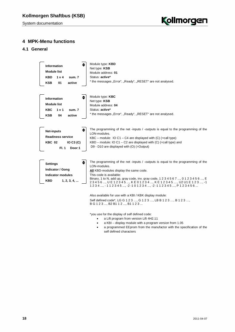
4 MPK-Menu functions 4.1 General
Information
Module list
KBD 1 v 4 sum. 7
KSB 01 active
Module type: KBD Net type: KSB Module address: 01 Status: active* * the messages „Error“, „Ready“, „RESET“ are not analysed.
Information
Module list
KBC 1 v 1 sum. 7
KSB 04 active
Module type: KBC Net type: KSB Module address: 04 Status: active* * the messages „Error“, „Ready“, „RESET“ are not analysed.
Net-inputs
Readiness service
KBC 02 IO C3 (C)
Fl. 1 Door:1
The programming of the net -inputs / -outputs is equal to the programming of the LON-modules. KBC – module: IO C1 – C4 are displayed with (C) (=call type) KBD – module: IO C1 – C2 are displayed with (C) (=call type) and D9 - D10 are displayed with (O) (=Output)
Settings
Indicator / Gong
Indicator modules
KBD 1, 2, 3, 4, ...
The programming of the net -inputs / -outputs is equal to the programming of the LON-modules. All KBD-modules display the same code. This code is available: Binary, 1 to N, add up, gray code, inv. gray code, 1 2 3 4 5 6 7 ..., 0 1 2 3 4 5 6 ..., E 1 2 3 4 5 6 ..., U E 1 2 3 4 5 ..., K E 0 1 2 3 4 ..., K E 1 2 3 4 5 ...., U2 U1 E 1 2 3 ..., -1 0 1 2 3 4 ..., - 1 1 2 3 4 5 ..., -2 -1 0 1 2 3 4 ..., -2 -1 1 2 3 4 5 ..., P 1 2 3 4 5 6 ... Also available for use with a KBI / KBK display module: Self defined code*, LG G 1 2 3 …, G 1 2 3 …, LB B 1 2 3 …, B 1 2 3 …, B G 1 2 3 ..., B2 B1 1 2 ..., B1 1 2 3 ...
*you use for the display of self defined code: a Lift program from version Lift 4H2.11 a KBI – display module with a program version from 1.05 a programmed EEprom from the manufactor with the specification of the
self defined characters
Kollmorgen Shaftbus (KSB)
System documentation
2011-04-07 19
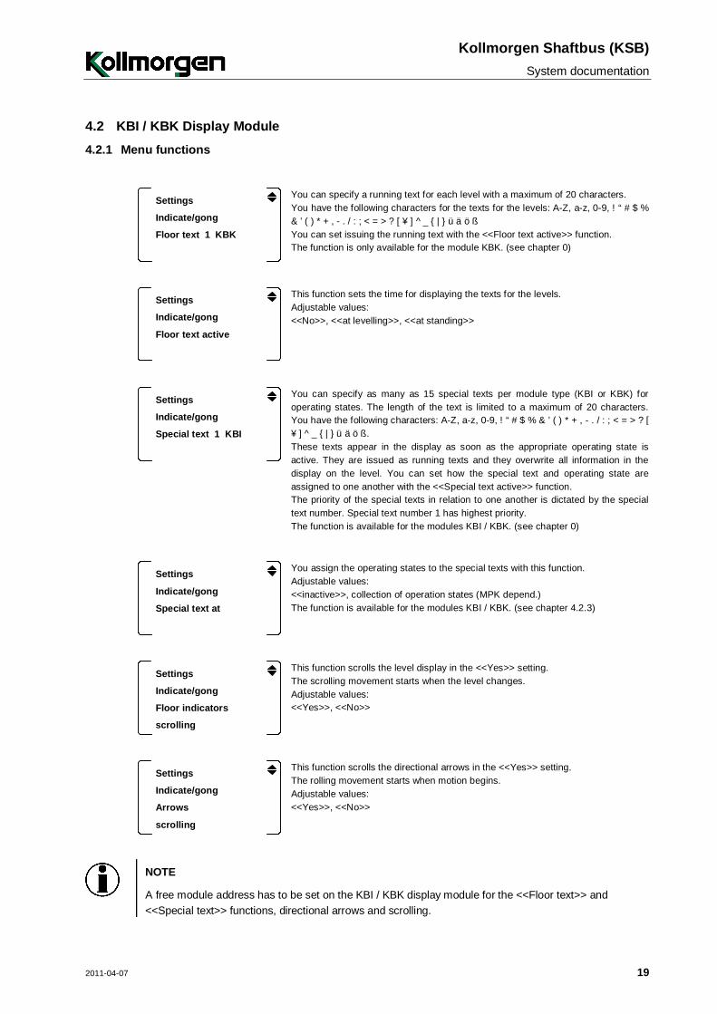
4.2 KBI / KBK Display Module 4.2.1 Menu functions
Settings
Indicate/gong
Floor text 1 KBK
You can specify a running text for each level with a maximum of 20 characters. You have the following characters for the texts for the levels: A-Z, a-z, 0-9, ! “ # $ % & ’ ( ) * + , - . / : ; < = > ? [ ¥ ] ^ _ { | } ü ä ö ß You can set issuing the running text with the <<Floor text active>> function. The function is only available for the module KBK. (see chapter 0)
Settings
Indicate/gong
Floor text active
This function sets the time for displaying the texts for the levels. Adjustable values: <<No>>, <<at levelling>>, <<at standing>>
Settings
Indicate/gong
Special text 1 KBI
You can specify as many as 15 special texts per module type (KBI or KBK) for operating states. The length of the text is limited to a maximum of 20 characters. You have the following characters: A-Z, a-z, 0-9, ! “ # $ % & ’ ( ) * + , - . / : ; < = > ? [ ¥ ] ^ _ { | } ü ä ö ß. These texts appear in the display as soon as the appropriate operating state is active. They are issued as running texts and they overwrite all information in the display on the level. You can set how the special text and operating state are assigned to one another with the <<Special text active>> function. The priority of the special texts in relation to one another is dictated by the special text number. Special text number 1 has highest priority. The function is available for the modules KBI / KBK. (see chapter 0)
Settings
Indicate/gong
Special text at
You assign the operating states to the special texts with this function. Adjustable values: <<inactive>>, collection of operation states (MPK depend.) The function is available for the modules KBI / KBK. (see chapter 4.2.3)
Settings
Indicate/gong
Floor indicators
scrolling
This function scrolls the level display in the <<Yes>> setting. The scrolling movement starts when the level changes. Adjustable values: <<Yes>>, <<No>>
Settings
Indicate/gong
Arrows
scrolling
This function scrolls the directional arrows in the <<Yes>> setting. The rolling movement starts when motion begins. Adjustable values: <<Yes>>, <<No>>
NOTE
A free module address has to be set on the KBI / KBK display module for the <<Floor text>> and <<Special text>> functions, directional arrows and scrolling.
Kollmorgen Shaftbus (KSB) System documentation
20 2011-04-07
Settings
Indicate/gong
KBI 16x16
Settings
Indicate/gong
KBK 16x16
The function defines, which informations display the indicators KBI 16x16 and KBK 16x16. Adjustable values: - <<Floor indicator or Arrows>> - <<Arrows only>> - <<Floor indicator only>> - <<Floor indicator and Arrows>> Note, that this function is available from program versions Lift 4h 2.29 (control) and KBI 1.16 (Indicator module).
4.2.2 Set Floor and Special Text
Follow the steps in this routine for setting the texts.
Floor text:
Settings
Floor text 1
Indicator / gong
+ -
OK
Ground floor / exitOK
2.
3. 4.
5.
1.
Routine: 1.: select the floor for the text 2.: change into the 4th menu line 3.: select letter position 4.: select letter
Repeat steps 3 and 4 until the text has been set. 5.: store text and go back to 3rd menu line
Special text:
Settings
Special text 4
Indicator / gong
+ -
Please get out of the car!OK
4.
5. 6.
7.
OK
+ - KBI + -1.
2.3.
c
Routine: 1.: select special text number (in this case 4) 2.: goto module type selection (if required) 3.: select module KBI or KBK (if required) 4.: change into the 4th menu line 5.: select letter position 6.: select letter
Repeat steps 5 and 6 until the text has been set. 7.: store text and go back to 3rd menu line
4.2.3 Activate Special Text
Follow the steps in this routine for activating the special texts.
Settings
Act. Special text 4
Indicator / gong
+ -
OK
ThermistorOK
4.
5.6.
+ - KBI + -1.
2.3.
Routine: 1.: select special text number (in this case 4) 2.: goto module type selection (if required) 3.: select module KBI or KBK (if required) 4.: change into the 4th menu line 5.: select operation status 6.: store allocation and go back to 3rd menu line


![LSA [RUS] - Web-Shop KSB](https://img.dokumen.tips/doc/110x75/633476fe62e2e08d4902a322/lsa-rus-web-shop-ksb.jpg)


