Embed Size (px)
Citation preview
Corrosion Protectionand Sealing
R

Ultratec Division
Corrosion Protection and Sealing
R

Contents
General 4
Corrosion Protection and Sealing
1
Corrosion Protection 122
Corrosion Protection and Sealing 42
1 Bell-and-spigot joints MPSM, MEPS 442 Special bell-and-spigot joints - TIS-K,
thrust-secured TIS-K, TISKW-F 463 Special bell-and-spigot joints - TIS,
thrust-secured TISW-F 48
3
Sealing and Leak Repair 50
1 Leak Repair GRSM 50Rayseal 52
2 Sealing of oversized pipe casings CSEM 543 Heat-shrinkable wall feedthroughs WAFT-KT200 56
4
1 Pipes and pipe couplers CPSM 122 Coating of girth welds TPSM 14
WPC 16HTLP 60 18
3 Coating of girth welds for horizontal drillings DIRAX System 20
4 Repair system for damaged PERP,mill-applied PE coating PERP Melt Stick 22
5 Weld-on tees HTTE 246 Weld-on blocking tees BLOT 287 Straight branch-off fittings STTE 308 Pipe bends Flexclad 329 Flange couplings FCMS, FCWS 3410 Steel end caps FCMS-CAP 38
Installation Accessories 586
Product Innovations and New Technologies 627
3
Coupling 56
1 Dissimilar low pressure gas pipes Raytrans 56
5

General
Tsukuba (Tokyo), Japan
Internationalmanufacturing locations
Raychem manufacturers a wide range of high performance products for the electronics,telecommunication and energy related industries. Our manufacturing plants are locatedin key economic regions of the world. The organisation has internationally recognisedISO 9001 approvals.
1
General4
Ultratec Division
Kessel-Lo, Belgium
High performance corrosion protection fortransmission pipelines.
Effective corrosion protection and sealing forfittings in gas-distribution networks.
Long-lasting sleeve joints and seals for districtheating piping systems.
Corrosion Protection, Sealing and Coupling
The Ultratec Division of Raychem offers unique solutions in the areas of corrosionprotection, sealing and pipe coupling. The products, based on modern polymertechnology, are specifically designed for use in gas and water distribution, pipelineconstruction and district heating. Ultratec products are manufactured at the Kessel-Lo plant in Belgium and in Tijuana, Mexico.
Tijuana, Mexico
Menlo Park, California

General 5
In addition to Ultratec, Raychem has four other market-oriented divisions:
1. Electronics.
2. Energy Products.
3. Telecommunications.
4. Chemelex.
Over the last 35 years, Raychem has become a valued partner in the utilities and in-dustrial markets. Supplying reliable and cost effective solutions to meet our custo-mers needs.
Raychem Divisions
1
43
2

General6
Thermoplastic materials are composed ofextremely long, very thin molecules in a randomarrangement. The strength of such materialsdepends upon the distance between its molecules,and the crystalline nature of its molecularstructure. It is these crystals which provide mostof the strength of the material.
As the material is heated over the “Chrystallinemelting point” ( 120 °C), these crystalsdisappear. The molecules can then slip past eachother easily and the material flows.
With the advent of atomic energy, the importantdiscovery was made that the exposure of someplastic materials to high-energy penetratingradiation can cause the permanent crosslinking,or intermolecular joining, of adjacent molecules.
This linking results in the chemical bonding ofthe plastic structure into a new three-dimensional system.Once the material has been crosslinked, it willnot melt or flow at any temperature. When thematerial is heated, the crystals still disappear asbefore, but it will no longer flow or change shapebecause the crosslinks act as ties between themolecules. The crosslinked structure, however, iselastic. This when it is heated to a temperaturewhere the crystals have melted, the materialbehaves like rubber.Because of radiation crosslinking, crosslinkedproducts have perfect elastic memory. Theseproducts are supplied in a deformed or expandedcondition. When heated, they will shrink andtightly cover the object over which they havebeen placed. They are ideal for covering avariety of electrical and electronic components,as well as wires, lugs, terminals, connectors andpipe fittings.
Crosslinking through Radiation Chemistry
Figure 1 is an enlarged schematic view of a verysmall crosslinked section of extremely longmolecules.
Once the tubing has been crosslinked, the nextstep in imparting elastic memory is to heat thecompound above its crystalline melting point.The molecules are then tied together only by thecrosslinks as shown in Figure 2.
While hot, the tubing is deformed by applyingpressure, thus stretching the crosslinkedmolecule, see Figure 3.
While in this deformed position, the tubing iscooled; the crystals then reappear, therebylocking the structure together in this deformedcondition indefinitely. This is the form in whichthe material is supplied to customers (Figure 4).
The customer then heats the product, melting thecrystals. The crosslinks allow the material to re-turn to its original shape as shown in figure 5.This is the perfect elastic memory of crosslinkedmaterial.
After cooling, the crystals reform and the tubingis locked in its recovered form, as shown inFigure 6. Upon subsequent reheating, no furtherchange in shape will take place, unlessmechanical force is applied.
1
2
3
4
5
6
Raychem fabricates its compounds into theirfinal form and then subjects them to high energyradiation, thus permanently “freezing” them intothe desired shape. The following illustrationsdemonstrate what happens to the molecularstructure of crosslinked tubing during subsequentstages of manufacture and during application.Next to each illustration is an end view of apiece of heat-shrinkable tubing.

General 7
Raychem pioneered the development of heatschrinkable technology.
By cross-linking polyethylene, our products shrink and automatically conform to avariety of difficult shapes and sizes - taking the guesswork out of site-work.
At Raychem, materials matter. That’s why our quality program includes training of yourfield installers.
Cross-linked technology - it’s smarter to shrink !
WAFT
KT 20
0
for w
all
feed
thro
ughs
FlexC
lad
for p
rote
ction
of s
teel
bend
s
CSEM
-F
for s
ealin
g pipe
casin
gs
FCM
S /
FCW
S
for f
lange
prot
ectio
n
CPSM
for p
rote
ction
of
mecha
nical
coup
lers
MPS
M /
MEP
S
for H
igh tr
ansit
ions
(coup
lers,
redu
ction
s) FCM
S-CAP
for s
teel
end ca
ps
HTTE
for w
eld-on
tees ST
TE
for s
traigh
t tee
s
GRSM /
Ray
seal
gas r
epair
slee
ve
DIRAX
for w
elded
joint
s in
direc
tiona
l drill
ings
WPC
/ H
TLP
for w
elded
pipe
joint
s
PERP
for r
epair
ing m
ill-
appli
ed P
E co
ating
HTTE
for w
eld-on
tees
TPSM
for w
elded
pipe
joint
sBLO
T
for b
lockin
g tee
s
Shrink to conform - a technology that fits!
STTE
for
stra
ight
tees
Raytra
ns
for c
oupli
ng
of ga
s pipe
s
General8
Functional properties / technical guidelines
Functional properties
Ultratec products are tested in accordance with the requirements and standards to meetspecific application needs. Engineered to withstand temperature cycling, soil stresses,chemical and environmental attack (salt water, fungi, bacteria, ultra-violet radiation andsoil alkhalis).
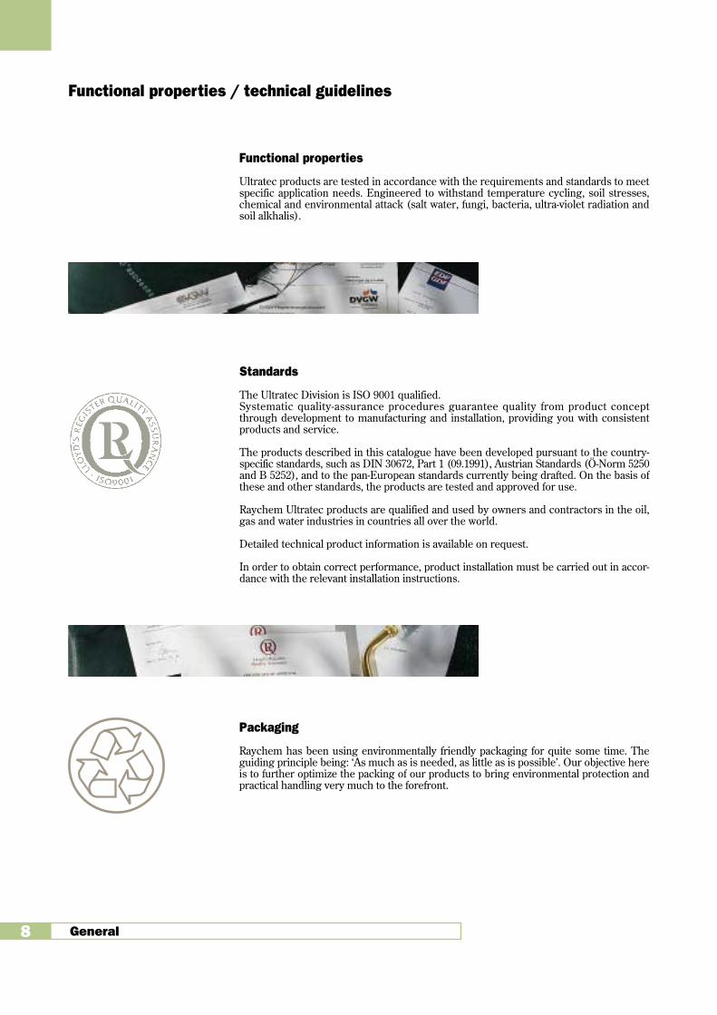
Standards
The Ultratec Division is ISO 9001 qualified.Systematic quality-assurance procedures guarantee quality from product conceptthrough development to manufacturing and installation, providing you with consistentproducts and service.
The products described in this catalogue have been developed pursuant to the country-specific standards, such as DIN 30672, Part 1 (09.1991), Austrian Standards (Ö-Norm 5250and B 5252), and to the pan-European standards currently being drafted. On the basis ofthese and other standards, the products are tested and approved for use.
Raychem Ultratec products are qualified and used by owners and contractors in the oil,gas and water industries in countries all over the world.
Detailed technical product information is available on request.
In order to obtain correct performance, product installation must be carried out in accor-dance with the relevant installation instructions.
Packaging
Raychem has been using environmentally friendly packaging for quite some time. Theguiding principle being: ‘As much as is needed, as little as is possible’. Our objective hereis to further optimize the packing of our products to bring environmental protection andpractical handling very much to the forefront.
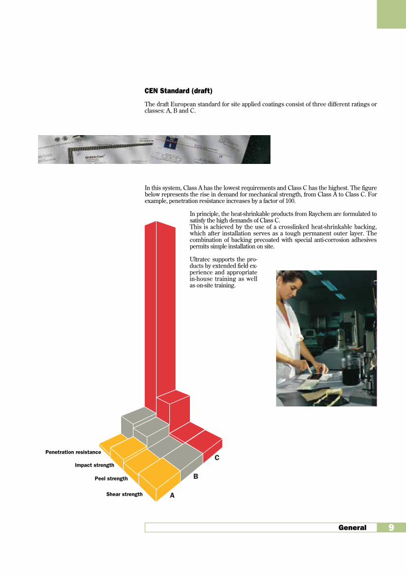
CEN Standard (draft)
The draft European standard for site applied coatings consist of three different ratings orclasses: A, B and C.
In this system, Class A has the lowest requirements and Class C has the highest. The figurebelow represents the rise in demand for mechanical strength, from Class A to Class C. Forexample, penetration resistance increases by a factor of 100.
In principle, the heat-shrinkable products from Raychem are formulated tosatisfy the high demands of Class C.This is achieved by the use of a crosslinked heat-shrinkable backing,which after installation serves as a tough permanent outer layer. Thecombination of backing precoated with special anti-corrosion adhesivespermits simple installation on site.
Ultratec supports the pro-ducts by extended field ex-perience and appropriatein-house training as wellas on-site training.
General 9
A
C
B
Eindruckwiderstand
Schlagbeständigkeit
Schälfestigkeit
ScherfestigkeitShear strength
Penetration resistance
Impact strength
Peel strength

Raychem: around your pipe,around the world.

Corrosion Protection 11
DIRAX
HTLP
WPC-C50
PERP
WPC
Corrosion Protection
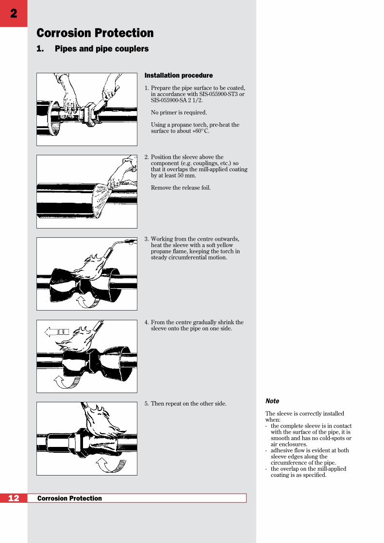
Installation procedure
1. Prepare the pipe surface to be coated,in accordance with SIS-055900-ST3 or SIS-055900-SA 2 1/2.
No primer is required.
Using a propane torch, pre-heat thesurface to about +60°C.
2. Position the sleeve above thecomponent (e.g. couplings, etc.) sothat it overlaps the mill-applied coatingby at least 50 mm.
Remove the release foil.
3. Working from the centre outwards,heat the sleeve with a soft yellowpropane flame, keeping the torch insteady circumferential motion.
4. From the centre gradually shrink thesleeve onto the pipe on one side.
5. Then repeat on the other side.
1. Pipes and pipe couplers
12
Note
The sleeve is correctly installedwhen:- the complete sleeve is in contact
with the surface of the pipe, it issmooth and has no cold-spots orair enclosures.
- adhesive flow is evident at bothsleeve edges along thecircumference of the pipe.
- the overlap on the mill-appliedcoating is as specified.
Corrosion Protection
2

Product description
The CPSM heat-shrinkable sleeve is re-markable for its high shrink ratio whichallows awkward, irregular shapes to becoated easily.
When heated, the CPSM sleeve shrinksand the sealant melts, encapsulatingmechanical couplings and straight pipeswith a strong impervious seal. While thesleeve conforms to the shape of the coup-ling or pipe, the melted sealant is forcedinto all surface irregularities providing apermanent environmental seal.
Special characteristics
• Quick and simple installation.
• Outstanding adhesion to metals, plas-tics, etc.
• In the event of mechanical damage thesealing adhesive flows and seals off thedamaged area (in other words, the da-mage is “self-healing”).
• Economical inventory keeping - thanksto the high shrink ratio only a few sizesneed be kept in stock.
Corrosion Protection 13
Heat-shrinkable tubing CPSM
Selection table - Ordering information - Dimensions
Pipe diameter Order descriptionwhere applied on coupling
DN-25 CPSM-C30-70/26-1000
DN-40 CPSM-C30-90/36-1000
DN-50 CPSM-C30-120/54-1000
DN-80 CPSM-C30-164/80-1000
DN-100 CPSM-C30-195/102-1000
Ordering example:
e.g. CPSM-C30-90/36-1000length (mm)max. recovered diameter (mm)diameter as delivered, expanded (mm)continuous operating temperature up to + 30°Cmechanical resistance class
Ordering length 1000 mm
The 1000 mm long product should be cut on site to suit the application requirements;300 mm is a commonly used length.
Special lengths are available upon request

Corrosion Protection
Installation procedure
1. Slide the heat-shrinkable sleeve,complete with its protective foil, ontothe pipe before the joint is made.
2. Prepare the pipe surface that is to becoated, according to SIS-055900-ST3or SIS-055900-SA 2 1/2.
No primer is required.
3. Using a propane torch, pre-heat thesurface to about + 60°C.
4. Position the sleeve over the weldedjoint so that it overlaps the mill-applied coating by at least 50 mm.
Remove the release foil.
5. Working from the centre outwards,heat the sleeve with a soft yellowpropane flame, keeping the torch insteady circumferential motion.
2.1 Coating of welded jointsHeat-shrinkable tubing
14
Note
The sleeve is correctly installedwhen:- the complete sleeve is in contact
with the surface of the pipe, it issmooth and has no cold-spots orair enclosures.
- adhesive flow is evident at bothsleeve edges along thecircumference of the pipe.
- the overlap on the mill-appliedcoating is as specified.
Product description
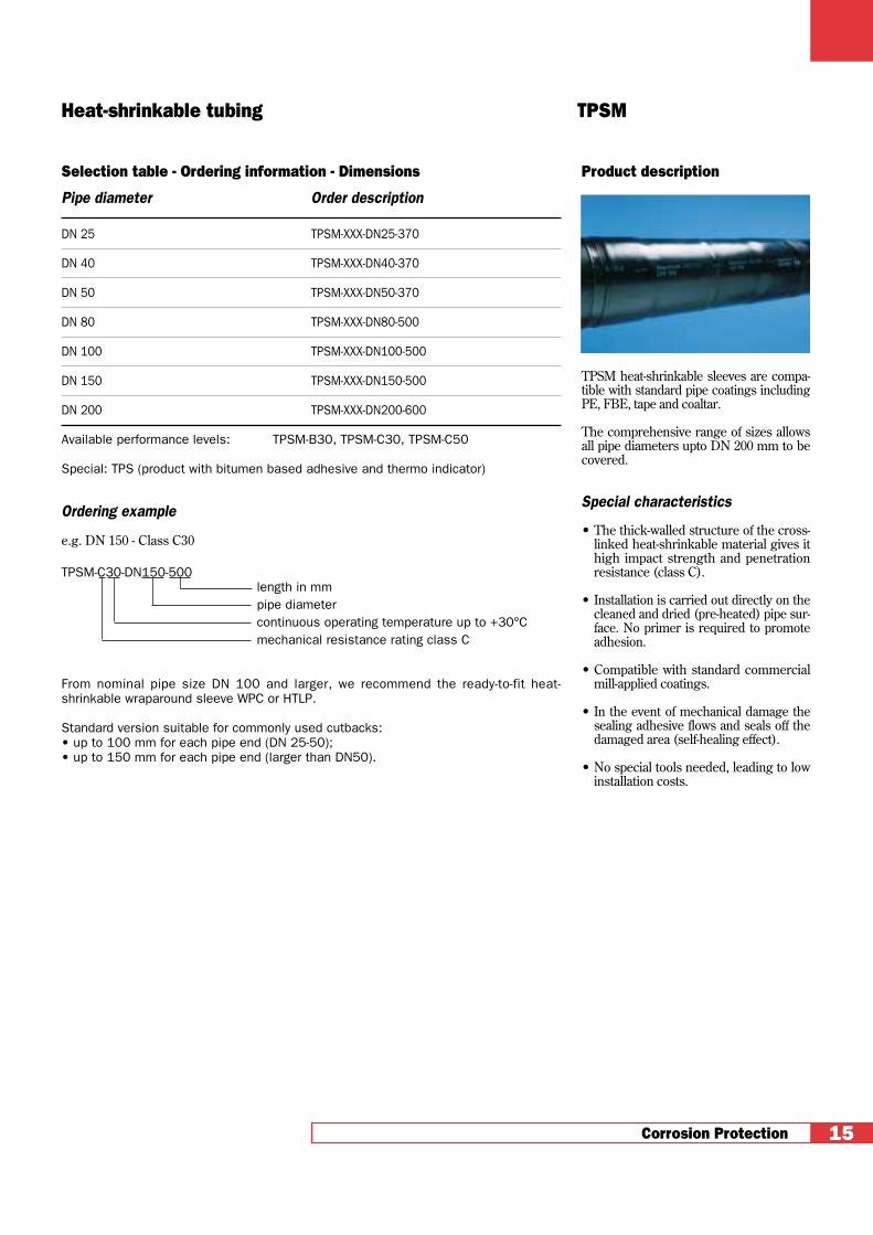
TPSM heat-shrinkable sleeves are compa-tible with standard pipe coatings includingPE, FBE, tape and coaltar.
The comprehensive range of sizes allowsall pipe diameters upto DN 200 mm to becovered.
Special characteristics
• The thick-walled structure of the cross-linked heat-shrinkable material gives ithigh impact strength and penetrationresistance (class C).
• Installation is carried out directly on thecleaned and dried (pre-heated) pipe sur-face. No primer is required to promoteadhesion.
• Compatible with standard commercialmill-applied coatings.
• In the event of mechanical damage thesealing adhesive flows and seals off thedamaged area (self-healing effect).
• No special tools needed, leading to lowinstallation costs.
Corrosion Protection 15
Heat-shrinkable tubing TPSM
Selection table - Ordering information - Dimensions
Pipe diameter Order description
DN 25 TPSM-XXX-DN25-370
DN 40 TPSM-XXX-DN40-370
DN 50 TPSM-XXX-DN50-370
DN 80 TPSM-XXX-DN80-500
DN 100 TPSM-XXX-DN100-500
DN 150 TPSM-XXX-DN150-500
DN 200 TPSM-XXX-DN200-600
Available performance levels: TPSM-B30, TPSM-C30, TPSM-C50
Special: TPS (product with bitumen based adhesive and thermo indicator)
Ordering example
e.g. DN 150 - Class C30
TPSM-C30-DN150-500length in mmpipe diametercontinuous operating temperature up to +30°Cmechanical resistance rating class C
From nominal pipe size DN 100 and larger, we recommend the ready-to-fit heat-shrinkable wraparound sleeve WPC or HTLP.
Standard version suitable for commonly used cutbacks:• up to 100 mm for each pipe end (DN 25-50);• up to 150 mm for each pipe end (larger than DN50).
Corrosion Protection
Installation procedure
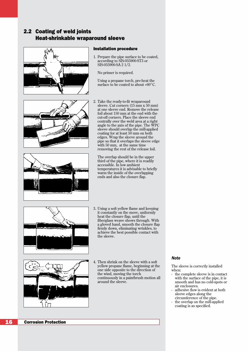
1. Prepare the pipe surface to be coated,according to SIS-055900-ST3 orSIS-055900-SA 2 1/2.
No primer is required.
Using a propane torch, pre-heat thesurface to be coated to about +60°C.
2. Take the ready-to-fit wraparoundsleeve. Cut corners (15 mm x 50 mm)at one sleeve end. Remove the releasefoil about 150 mm at the end with thecut-off corners. Place the sleeve endcentrally over the weld area at a rightangle to the axis of the pipe. The WPCsleeve should overlap the mill-appliedcoating for at least 50 mm on bothedges. Wrap the sleeve around thepipe so that it overlaps the sleeve edgewith 50 mm, at the same timeremoving the rest of the release foil.
The overlap should be in the upperthird of the pipe, where it is readilyaccessible. In low ambienttemperatures it is advisable to brieflywarm the inside of the overlappingends and also the closure flap.
3. Using a soft yellow flame and keepingit constantly on the move, uniformlyheat the closure flap, until thefiberglass weave shows through. Witha gloved hand, smooth the closure flapfirmly down, eliminating wrinkles, toachieve the best possible contact withthe sleeve.
4. Then shrink on the sleeve with a softyellow propane flame, beginning at theone side opposite to the direction ofthe wind, moving the torchcontinuously in a paintbrush motion allaround the sleeve.
2.2 Coating of weld jointsHeat-shrinkable wraparound sleeve
16
Note
The sleeve is correctly installedwhen:- the complete sleeve is in contact
with the surface of the pipe, it issmooth and has no cold-spots orair enclosures.
- adhesive flow is evident at bothsleeve edges along thecircumference of the pipe.
- the overlap on the mill-appliedcoating is as specified.

Product description
WPC is a heat-shrinkable ready-to-fitassembly for the corrosion protection ofwelded joints compatible with standardpipe coatings including PE, FPE, tapeand coaltar. The closure patch consistsof fiberglass reinforced, flexible plasticsheet and is coated with a high shear-strength quick-bonding adhesive.
Special characteristics
• The available unisleeve is an all-in-oneunit, which is easy to install.
• The thick-walled structure of the cross-linked heat-shrinkable sleeve gives thematerial high impact strength and highpenetration resistance.
• Installation is carried out directly on thecleaned and dried (pre-heated) pipe sur-face. No primer is required.
• Compatible with standard mill-appliedcoatings.
• In the event of mechanical damage thesealing adhesive fills and immediatelyseals off the damaged area (“self-hea-ling” effect).
• No special tools needed, leading to lowinstallation costs.
Other available products
Ultratec supplies products for high tem-perature field joint coating, ambient andhigh temperature line coating both on-and off-shore. Also available are completesolutions for pipeline rehabiliation.
Corrosion Protection 17
Heat-shrinkable wraparound sleeve WPC
Selection table - Ordering information - Dimensions
Pipe diameter Order description WPC cut-DN Inches length in mm
DN 80 3 WPC-XXX-3500 x 18/UNI 380
DN 100 4 WPC-XXX-4500 x 18/UNI 460
DN 125 5 WPC-XXX-5625 x 18/UNI 550
DN 150 6 WPC-XXX-6625 x 18/UNI 640
DN 200 8 WPC-XXX-8625 x 18/UNI 800
DN 250 10 WPC-XXX-10750 x 18/UNI 980
DN 300 12 WPC-XXX-12750 x 18/UNI 1,150
DN 350 14 WPC-XXX-14000 x 18/UNI 1,260
DN 400 16 WPC-XXX-16000 x 18/UNI 1,420
DN 500 20 WPC-XXX-20000 x 18/UNI 1,770
DN 600 24 WPC-XXX-24000 x 18/UNI 2,110
DN 700 28 WPC-XXX-28000 x 18/UNI 2,430
Nominal sizes larger than DN 700 are available upon requestWPC type products are available in different performance levels: B30, C30, C50.WPC type products are available in rolls (30M or 100 feet), or as Unisleeve.WPC B30, WPC C30 and WPCT products should not be used in high soil stressenvironments or on pipe diameters above DN 500 mm (20").
Specials• WPCT (product with bitumen based adhesive and thermo indicator)• GAPS (Unisleeves with special features such as special size printing, cut corners
and overlap indicators)
Ordering examplesrolls: WPC-C50-18 x 100
rollenght: 100 feet or 30 Mwidth as delivered: 18” or 450 mmcontinuous operating temperature up to +50°Cmechanical resistance rating class C
Unisleeves:WPC-C50-4500 x 18/UNI
designates pre-attached closure for the UNISLEEVE constructionwidth as delivered: 18” or 450 mmpipe diameter ( in mills)continuous operating temperature up to +50°Cmechanical resistance rating class C
The standard width of 450 mm (18”) is suitable for cutbacks of up to 150 mm (6”) foreach pipe end.Other widths, e.g. 600 mm (24”) and 900 mm (36”) (roll length 20 m) on request
Closure flap WPCP IV (fiberglass-reinforced) for roll stockOrder descriptionWPCP IV 4x18 for pipe diameters ≤ DN 400 or 16”WPCP IV 6x18 for pipe diameters > DN 400 or 16”

Corrosion Protection
Installation procedure
1. Recommended surface preparation isSIS-055900-SA 2 1/2 and PE abrading.
2. Pre-heat the surface to min. 70°C andapply the prepared and properly mixedtwo-component epoxy resin on thesteel area and the adjacent line coatingto be covered with the sleeve.
3. Place the sleeve end centrally over theweld area at a right angle to the axis ofthe pipe. The HTLP sleeve shouldoverlap the mill-applied coating for atleast 50 mm on both edges. Wrap thesleeve, with its closure flap, around thepipe ensuring the opposite sleeve edgeoverlaps the other edge by 50 mm.
4. Next, using a soft yellow flame, andkeeping it constantly moving in apaintbrush motion, uniformly heat theclosure patch, until the fiberglassweave shows through. With a glovedhand, smooth the closure patch firmlydown, free from wrinkles. Roll out theclosure area with a silicone roller.
5. Then shrink on the sleeve with a softyellow propane flame, beginning at theone side opposite to the direction ofthe wind, moving the torchcontinuously in a paintbrush motion allaround the sleeve.
2.3 Coating of weld jointsHeat-shrinkable wraparound sleeve
18
Note
The sleeve is correctly installedwhen:- the complete sleeve is in contact
with the surface of the pipe, it issmooth and has no cold-spots orair enclosures,
- adhesive flow is evident at bothsleeve edges along thecircumference of the pipe,
- the overlap on the mill-appliedcoating is as specified.
Product description
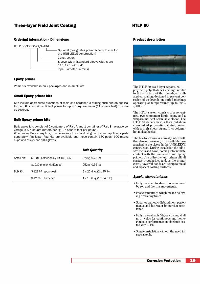
The HTLP 60 is a 3-layer (epoxy, co-polymer, polyethylene) coating, similarto the structure of the three-layer mill-applied coating, designed to prevent cor-rosion of girthwelds on buried pipelinesoperating at temperatures up to 60°C(140F).
The HTLP system consists of a solvent-free, two-component liquid epoxy and awraparound heat shrinkable sleeve. TheHTLP 60 sleeves have a thick radiation-crosslinked polyolefin backing coatedwith a high shear strength copolymerhot-melt adhesive.
The flexible closure is normally kitted withthe sleeve, however, it is available pre-attached to the sleeve in the UNISLEEVEconstruction. During installation the adhe-sive melts and flows, coming into intimatecontact with the uncured liquid epoxyprimer. The adhesive and primer fill allsurface irregularities and, as the primercures, powerful bonds are set-up to metaland adjacent coating surfaces.
Special characteristics
• Fully resistant to shear forces inducedby soil and thermal movements.
• Fast curing times which means no dry-ing or waiting times.
• Superior cathodic disbondment perfor-mance and hot water immersion resis-tance.
• Fully reconstructs 3-layer coating at allgirth welds for continuous and homo-geneous performance on pipelines coa-ted with 3LPE.
• Simple installation without the need forspecial tools.
Corrosion Protection 19
Three-layer Field Joint Coating HTLP 60
Ordering information - Dimensions
HTLP 60-36000-24/A/UNIOptional (designates pre-attached closure for the UNISLEEVE construction)ConstructionSleeve Width (Standard sleeve widths are 11”, 17”, 24”, 34”)Pipe Diameter (in mills)
Epoxy primer
Primer is available in bulk packages and in small kits.
Small Epoxy primer kits
Kits include appropriate quantities of resin and hardener, a stirring stick and an applica-tor pad. Kits contain sufficient primer for up to 1 square meter (11 square feet) of surfa-ce coverage.
Bulk Epoxy primer kits
Bulk epoxy kits consist of 2-containers of Part A and 1-container of Part B, average co-verage is 5.5 square meters per kg (27 square feet per pound).When using Bulk epoxy kits, it is necessary to order dosing pumps and applicator padsseperately. Applicator Pad kits are available and these contain 150 pads, 100 mixingcups and sticks and 100 gloves.
Unit Quantity
Small Kit: S1301 primer epoxy kit 15 (USA) 320 g (0.73 lb)
S1239 primer kit (Europe) 252 g (0.56 lb)
Bulk Kit: S-1239-A epoxy resin 2 x 20.4 kg (2 x 45 lb)
S-1239-B hardener 1 x 15.6 kg (1 x 34.5 lb)
Corrosion Protection
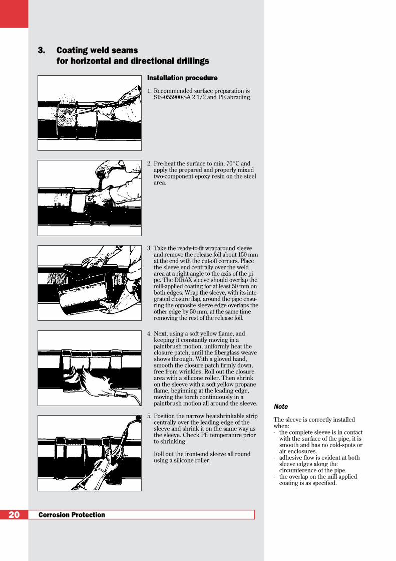
Installation procedure
1. Recommended surface preparation isSIS-055900-SA 2 1/2 and PE abrading.
2. Pre-heat the surface to min. 70°C andapply the prepared and properly mixedtwo-component epoxy resin on the steelarea.
3. Take the ready-to-fit wraparound sleeveand remove the release foil about 150 mmat the end with the cut-off corners. Placethe sleeve end centrally over the weldarea at a right angle to the axis of the pi-pe. The DIRAX sleeve should overlap themill-applied coating for at least 50 mm onboth edges. Wrap the sleeve, with its inte-grated closure flap, around the pipe ensu-ring the opposite sleeve edge overlaps theother edge by 50 mm, at the same timeremoving the rest of the release foil.
4. Next, using a soft yellow flame, andkeeping it constantly moving in apaintbrush motion, uniformly heat theclosure patch, until the fiberglass weaveshows through. With a gloved hand,smooth the closure patch firmly down,free from wrinkles. Roll out the closurearea with a silicone roller. Then shrinkon the sleeve with a soft yellow propaneflame, beginning at the leading edge,moving the torch continuously in apaintbrush motion all around the sleeve.
5. Position the narrow heatshrinkable stripcentrally over the leading edge of thesleeve and shrink it on the same way asthe sleeve. Check PE temperature priorto shrinking.
Roll out the front-end sleeve all roundusing a silicone roller.
3. Coating weld seamsfor horizontal and directional drillings
20
Note
The sleeve is correctly installedwhen:- the complete sleeve is in contact
with the surface of the pipe, it issmooth and has no cold-spots orair enclosures.
- adhesive flow is evident at bothsleeve edges along thecircumference of the pipe.
- the overlap on the mill-appliedcoating is as specified.

Product description
The DIRAX System is based on a high-performance heat-shrinkable sleeve andguarantees the corrosion protection ofwelded pipe joints in the case of horizon-tal or directional drillings.
The DIRAX System consists of:
a. a wraparound, fiberglass-reinforced,heat-shrinkable sleeve with a pre-attached closure and a coating of high-shear-strength thermoplastic hot-meltadhesive. The special glassfiber rein-forced sleeve gives the material a highabrasion resistance while remainingflexible to follow bending radius.
b. a solvent-free two-component epoxyresin.
c. a leading edge sleeve consisting of anarrow fiberglass-reinforced heat-shrinkable sleeve with a preattachedclosure and a coating of high-shear -strength hot-melt adhesive.
Special characteristics
• High shear strength and peel strength.
• Good abrasion resistance with ade-quate flexibility.
• Fast curing times.
• Superior cathodic disbondment perfor-mance.
• Compatible with standard commercialmill-applied PE coatings and FBE.
• Simple installation without special tools.
Corrosion Protection 21
DIRAX System
Ordering information - Dimensions
Order description
DIRAX-XXXXX-YY/zKz units of epoxy resin S1239-Primer-Kit-252 (separate ordering and delivery required by shipping regulations)sleeve width in inches (24 = 600 mm)Pipe diameter in inches (available from 3 1/2 in., DN 80)
Remark
From DN 600 up, 2 units of epoxy resin are required in the case of 600 mm wide sleeves,e.g.: 1pc DIRAX-24000 - 24/2K
2pc S1239 Primer Kits 252
max. cutback400 mm
Leading edge sleeve Integrated closure patch
Fiberglassreinforced, heat-shrinkablesleeve coated with hot-melt adhesiveStandard width of the sleeve: 600 mm or 24” (Other widths: 300 mm or12”, 425 mm or 17” available on request.)
Corrosion Protection
Installation procedure
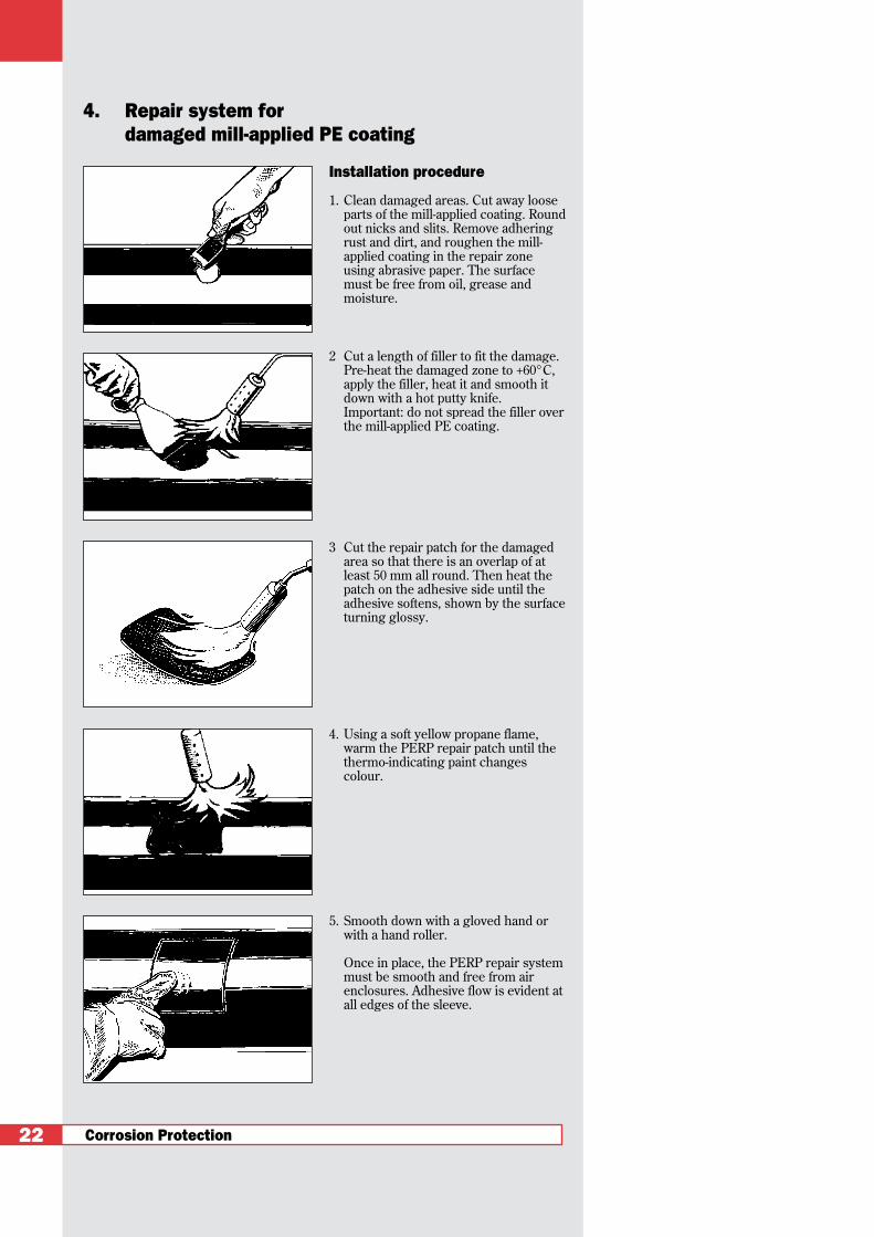
1. Clean damaged areas. Cut away looseparts of the mill-applied coating. Roundout nicks and slits. Remove adheringrust and dirt, and roughen the mill-applied coating in the repair zoneusing abrasive paper. The surfacemust be free from oil, grease andmoisture.
2 Cut a length of filler to fit the damage.Pre-heat the damaged zone to +60°C,apply the filler, heat it and smooth itdown with a hot putty knife. Important: do not spread the filler overthe mill-applied PE coating.
3 Cut the repair patch for the damagedarea so that there is an overlap of atleast 50 mm all round. Then heat thepatch on the adhesive side until theadhesive softens, shown by the surfaceturning glossy.
4. Using a soft yellow propane flame,warm the PERP repair patch until thethermo-indicating paint changescolour.
5. Smooth down with a gloved hand orwith a hand roller.
Once in place, the PERP repair systemmust be smooth and free from airenclosures. Adhesive flow is evident atall edges of the sleeve.
4. Repair system for damaged mill-applied PE coating
22

Product description
PERP is designed to repair damagedareas in mill-applied PE coating on steelpipes and ductile cast iron pipes.
The system consists of two components:
• PERP Filler• PERP Repair patch
Special characteristics
• The PERP Repair System resists highshear forces and shows excellent adhe-sion to commercial polyethylene-basedmill-applied coatings.
• No primer required.
• Specific repair system, and thereforehighly economic.
Corrosion Protection 23
Repair system PERP
Ordering information - Dimensions
For damaged area less than 40x70 mm : PERP-KIT
Kit components:Carrier material 140x170 with rounded cornersFillerAbrasion paper R60Installation instructions
Order descriptionPERP-KIT
For extensive areas of damage: PERP roll.(typically applied with larger projects)Roll length 10 m. Widths 170 mm and 425 mm.
Order descriptionPERP 170-10000-TCPERP 425-10000-TC
Filling adhesive: PERP Filler(necessary where rolls are used)
Strip: length 3 m, width 50 mm, thickness 3 mm
Order descriptionS1137 - 50 x 3 x 3000
Note: experience has shown that on average, 3 rolls of filler adhesive are used per roll of PERP.
System scheme
Filler material for the repair of damages that do not extend to thesteel surface: PERP Melt Stick.
Size Ø 25 mm x 310 mm: PERP Melt Stick.
Order descriptionPERP-MELT-STICK
PERP repair patchPERP filler
Mill-applied PE coatingSteel pipe
Corrosion Protection
Installation procedure
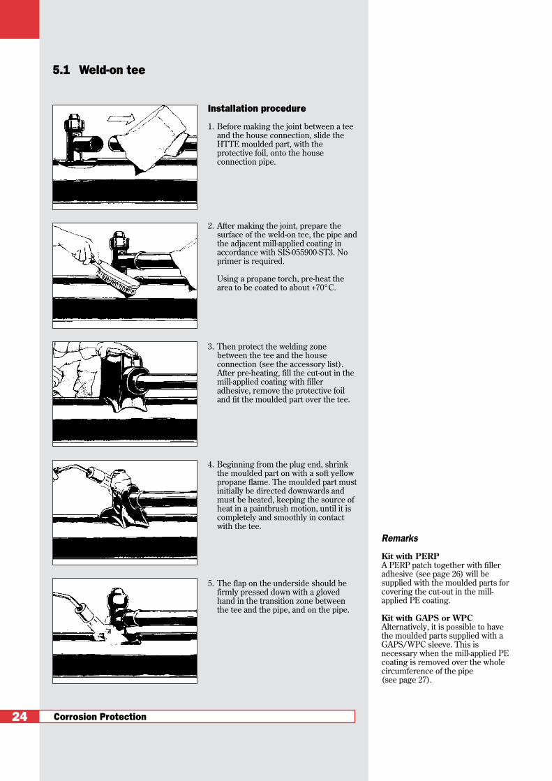
1. Before making the joint between a teeand the house connection, slide theHTTE moulded part, with theprotective foil, onto the houseconnection pipe.
2. After making the joint, prepare thesurface of the weld-on tee, the pipe andthe adjacent mill-applied coating inaccordance with SIS-055900-ST3. Noprimer is required.
Using a propane torch, pre-heat thearea to be coated to about +70°C.
3. Then protect the welding zonebetween the tee and the houseconnection (see the accessory list).After pre-heating, fill the cut-out in themill-applied coating with filleradhesive, remove the protective foiland fit the moulded part over the tee.
4. Beginning from the plug end, shrinkthe moulded part on with a soft yellowpropane flame. The moulded part mustinitially be directed downwards andmust be heated, keeping the source ofheat in a paintbrush motion, until it iscompletely and smoothly in contactwith the tee.
5. The flap on the underside should befirmly pressed down with a glovedhand in the transition zone betweenthe tee and the pipe, and on the pipe.
5.1 Weld-on tee
24
Remarks
Kit with PERPA PERP patch together with filleradhesive (see page 26) will besupplied with the moulded parts forcovering the cut-out in the mill-applied PE coating.
Kit with GAPS or WPCAlternatively, it is possible to havethe moulded parts supplied with aGAPS/WPC sleeve. This isnecessary when the mill-applied PEcoating is removed over the wholecircumference of the pipe (see page 27).

Product description
HTTE is a heat-shrinkable moulded partspecially developed for weld-on tees.
The thick-walled, highly expanded moul-ded part is coated with a specially formu-lated hot-melt adhesive for this applica-tion, which, during installation, melts andunder pressure from the shrinking sleeveis forced into any irregularities providingan excelent seal.To prevent corrosion of the service pipewhere the house connection is made, theuse of a compatible WPC or GAPS heat-shrinkable wraparound sleeve or PERPpatch is recommended.
The PERP patches and the filling adhesi-ve supplied with the moulded part areemployed when no more than a windowhas been cut out of the original mill-applied coating to allow for the weldingwork; WPC or GAPS is used when the millcoating has been removed completely.
Alternatively, the HTTE corrosion protec-tion moulded part can be supplied on re-quest as a kit with the sleeve for the mainpipe and the house connection pipe.
Special characteristics
• No primer required.
• Installation can be carried out directlyon the cleaned and pre-heated tee.
• Compatible with standard commercialmill-applied coatings.
• HTTE ensures reliable corrosion pro-tection with high impact strength andpenetration resistance and obviatesthe need of rock shielding as additio-nal security for the pipes.
• No special tools needed, leading to lowinstallation costs.
Corrosion Protection 25
Moulded part HTTE
Ordering information - Dimensions
D1 D2 D3 H1 L H2 H3sup. rec. sup. rec. sup. rec. rec. rec. rec. rec.
Part number min. max. min. max. min. max. min.mm mm mm mm mm mm mm mm mm mm
HTTE-1500-02* 80 27 no cap 70 23 137 48 137 53
HTTE-1600** 110 37 110 27 70 32 90 45 78 40
HTTE-1700** 160 58 160 35 95 45 116 41 95 51
HTTE-1800** 160 58 160 35 95 45 135 41 113 70
HTTE-2000** 160 58 160 35 95 45 165 41 141 51
HTTE-4000** 160 58 160 35 85 33 187 47 155 61
HTTE-4500** 160 58 160 35 85 33 169 47 162 68
HTTE-5000-02* 160 58 no cap 95 45 214 41 185 92
* only available in 02-version sup.: as supplied** 01 and 02 version available rec.: after full unrestricted recovery
Ordering information
Example
HTTE-1600-XXxx=01 with capxx=02 without capxx=04 without cap + CPSMsize code
D1
D2
H3
H1H2
L
D3
Corrosion Protection
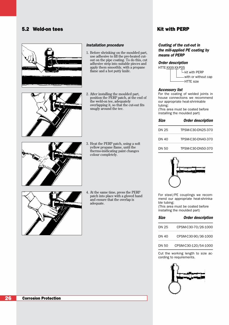
Installation procedure
1. Before shrinking on the moulded part,use adhesive to fill the pre-heated cut-out on the pipe coating. To do this, cutadhesive strip into suitable pieces andapply them smoothly, with a propaneflame and a hot putty knife.
2. After installing the moulded part,position the PERP patch, at the end ofthe weld-on tee, adequatelyoverlapping it, so that the cut-out fitssnugly around the tee.
3. Heat the PERP patch, using a softyellow propane flame, until thethermo-inidicating paint changescolour completely.
4. At the same time, press the PERPpatch into place with a gloved handand ensure that the overlap isadequate.
5.2 Weld-on tees Kit with PERP
26
Coating of the cut-out in the mill-applied PE coating bymeans of PERP
Order descriptionHTTE-XXXX-XX-P05
kit with PERPwith or without capHTTE size
Accessory listFor the coating of welded joints inhouse connections we recommendour appropriate heat-shrinkable tubing:(This area must be coated beforeinstalling the moulded part)
Size Order description
DN 25 TPSM-C30-DN25-370
DN 40 TPSM-C30-DN40-370
DN 50 TPSM-C30-DN50-370
For steel/PE couplings we recom-mend our appropriate heat-shrinka-ble tubing:(This area must be coated beforeinstalling the moulded part)
Size Order description
DN 25 CPSM-C30-70/26-1000
DN 40 CPSM-C30-90/36-1000
DN 50 CPSM-C30-120/54-1000
Cut the working length to size ac-cording to requirements.

Installation procedure
1. After pre-heating to about +60°C, drawthe sleeve over the end of the alreadycoated weld-on tee so that the closureis opposite the house connection line.Push the plain end of the sleeve underthe other sleeve end until it pushesagainst the weld-on tee.
2. Heat the closure flap with a soft yellowpropane flame, moving it in apaintbrush motion, until the fiberglassweave shows through.
3. With a gloved hand, firmly press theclosure flap down so that it is smoothand free from wrinkles.
4. Working from the centre outwards,heat the sleeve with a soft yellowpropane flame in a paintbrush motion.
5. When one side of the heat-shrinkablesleeve has been smoothly shrunk ontothe entire circumference, continue theprocess along to the other end, untilthe whole sleeve is smooth and tightand the adhesive flow is evident atboth edges over the wholecircumference.
Coating of the cut-back in the mill-applied PE coating bymeans of a GAPS or WPC heat-shrinkable sleeve
Coating of the supply mains pipewith GAPS as a kit with HTTE moul-ded part:
Nominal diameter Order of supply mains description
DN 80 HTTE....-..-GO5-DN80
DN 100 HTTE....-..-GO5-DN100
DN 150 HTTE....-..-GO5-DN150
DN 200 HTTE....-..-GO5-DN200
The corresponding GAPS-05 slee-ves can also be supplied separately(see page 29).
Ordering example
e.g. HTTE 4000-01-G05-DN 100DN 100: diameter main pipeG05: HTTE kit with GAPS01: HTTE with cap4000: HTTE size
Corrosion Protection 27
5.3. Weld-on Tees Kit with GAPS
Corrosion Protection
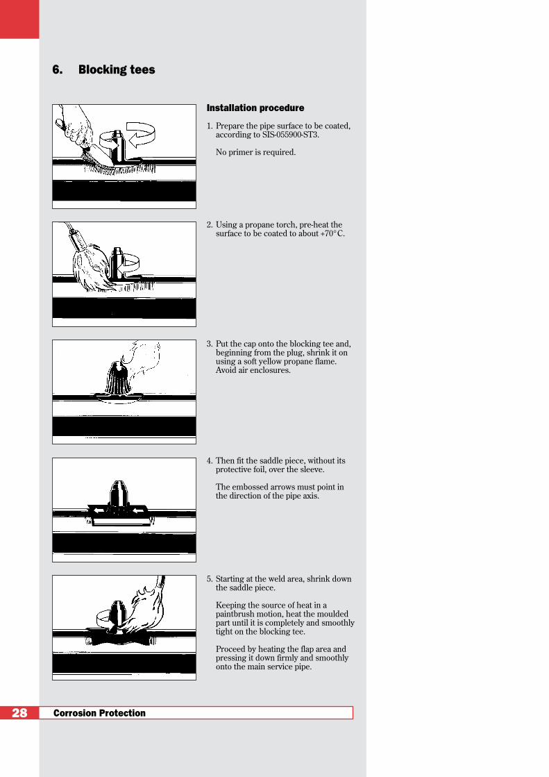
Installation procedure
1. Prepare the pipe surface to be coated,according to SIS-055900-ST3.
No primer is required.
2. Using a propane torch, pre-heat thesurface to be coated to about +70°C.
3. Put the cap onto the blocking tee and,beginning from the plug, shrink it onusing a soft yellow propane flame.Avoid air enclosures.
4. Then fit the saddle piece, without itsprotective foil, over the sleeve.
The embossed arrows must point inthe direction of the pipe axis.
5. Starting at the weld area, shrink downthe saddle piece.
Keeping the source of heat in apaintbrush motion, heat the mouldedpart until it is completely and smoothlytight on the blocking tee.
Proceed by heating the flap area andpressing it down firmly and smoothlyonto the main service pipe.
6. Blocking tees
28
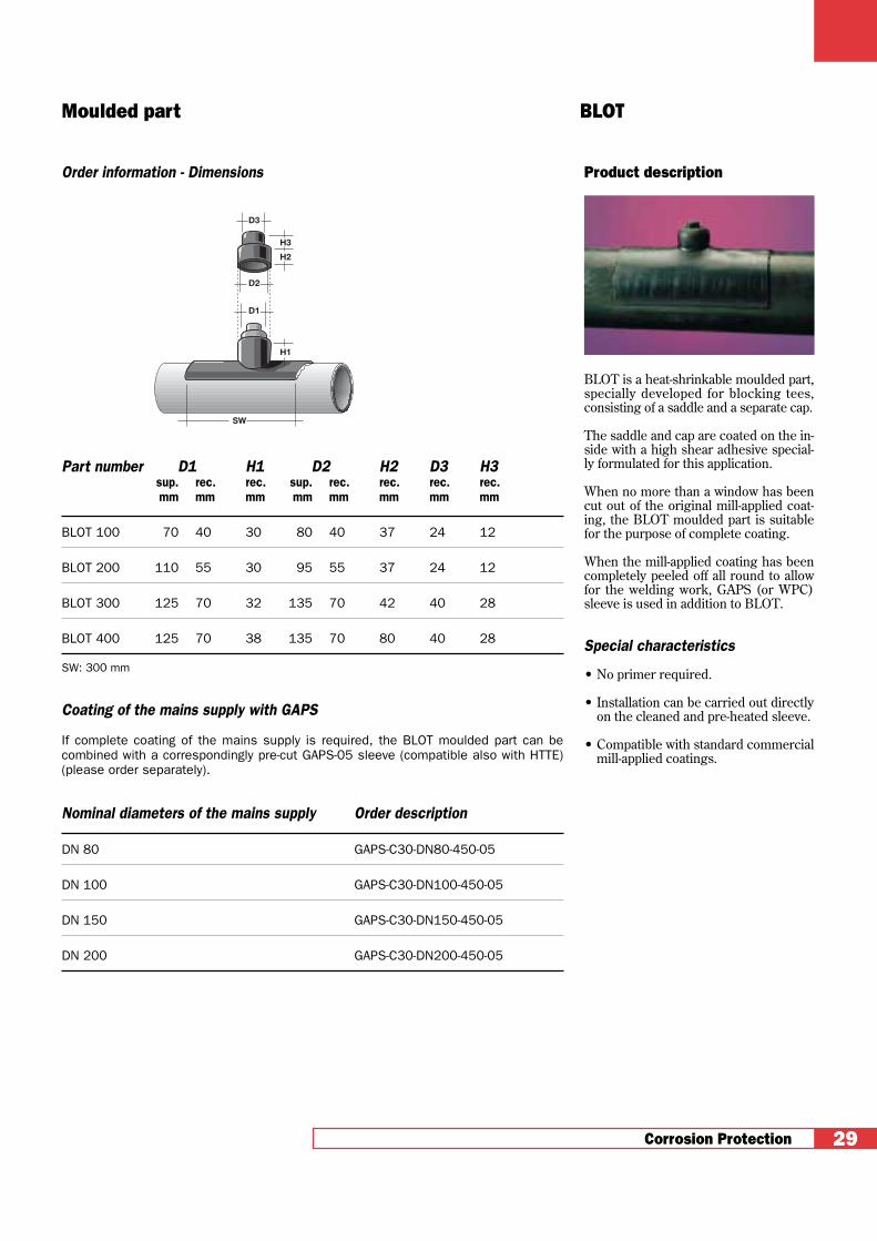
Product description
BLOT is a heat-shrinkable moulded part,specially developed for blocking tees,consisting of a saddle and a separate cap.
The saddle and cap are coated on the in-side with a high shear adhesive special-ly formulated for this application.
When no more than a window has beencut out of the original mill-applied coat-ing, the BLOT moulded part is suitablefor the purpose of complete coating.
When the mill-applied coating has beencompletely peeled off all round to allowfor the welding work, GAPS (or WPC)sleeve is used in addition to BLOT.
Special characteristics
• No primer required.
• Installation can be carried out directlyon the cleaned and pre-heated sleeve.
• Compatible with standard commercialmill-applied coatings.
Corrosion Protection 29
Moulded part BLOT
Order information - Dimensions
Part number D1 H1 D2 H2 D3 H3sup. rec. rec. sup. rec. rec. rec. rec.mm mm mm mm mm mm mm mm
BLOT 100 70 40 30 80 40 37 24 12
BLOT 200 110 55 30 95 55 37 24 12
BLOT 300 125 70 32 135 70 42 40 28
BLOT 400 125 70 38 135 70 80 40 28
SW: 300 mm
Coating of the mains supply with GAPS
If complete coating of the mains supply is required, the BLOT moulded part can becombined with a correspondingly pre-cut GAPS-05 sleeve (compatible also with HTTE)(please order separately).
Nominal diameters of the mains supply Order description
DN 80 GAPS-C30-DN80-450-05
DN 100 GAPS-C30-DN100-450-05
DN 150 GAPS-C30-DN150-450-05
DN 200 GAPS-C30-DN200-450-05
D3
D1
D2
H3
H1
H2
SW
Corrosion Protection
Installation procedure
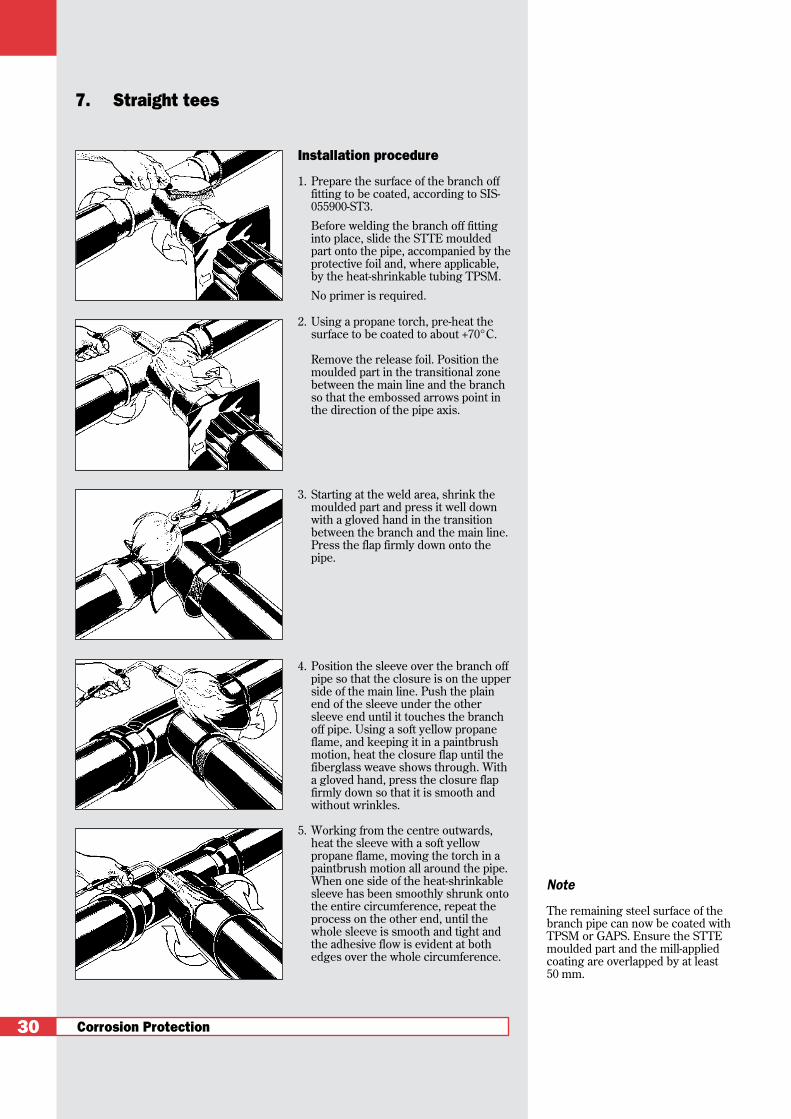
1. Prepare the surface of the branch offfitting to be coated, according to SIS-055900-ST3.
Before welding the branch off fittinginto place, slide the STTE mouldedpart onto the pipe, accompanied by theprotective foil and, where applicable,by the heat-shrinkable tubing TPSM.
No primer is required.
2. Using a propane torch, pre-heat thesurface to be coated to about +70°C.
Remove the release foil. Position themoulded part in the transitional zonebetween the main line and the branchso that the embossed arrows point inthe direction of the pipe axis.
3. Starting at the weld area, shrink themoulded part and press it well downwith a gloved hand in the transitionbetween the branch and the main line.Press the flap firmly down onto thepipe.
4. Position the sleeve over the branch offpipe so that the closure is on the upperside of the main line. Push the plainend of the sleeve under the othersleeve end until it touches the branchoff pipe. Using a soft yellow propaneflame, and keeping it in a paintbrushmotion, heat the closure flap until thefiberglass weave shows through. Witha gloved hand, press the closure flapfirmly down so that it is smooth andwithout wrinkles.
5. Working from the centre outwards,heat the sleeve with a soft yellowpropane flame, moving the torch in apaintbrush motion all around the pipe.When one side of the heat-shrinkablesleeve has been smoothly shrunk ontothe entire circumference, repeat theprocess on the other end, until thewhole sleeve is smooth and tight andthe adhesive flow is evident at bothedges over the whole circumference.
7. Straight tees
30
Note
The remaining steel surface of thebranch pipe can now be coated withTPSM or GAPS. Ensure the STTEmoulded part and the mill-appliedcoating are overlapped by at least 50 mm.

Product description
STTE combined with GAPS (or WPC)permits simple coating of straight pipetees.
Special characteristics
• The thick-walled structure of the cross-linked heat-shrinkable material gives ithigh impact strength and penetrationresistance.The high shrink ratio of theSTTE moulded parts together with thecutting lines on the GAPS sleeves ena-ble several pipe diameter combinationsto be covered.
• Installation is carried out directly onthe cleaned and dried (pre-heated)pipe surface, no primer is required.
• Compatible with standard commercialmill-applied coatings.
• No special tools needed, leading tolow installation costs.
Corrosion Protection 31
Moulded part STTE
Selection tables - Ordering Information- Dimensions
Selecting the STTE moulded part
Size of the branch pipe Order description
DN 40 STTE DN 40-DN 50DN 50 STTE DN 40-DN 50
DN 65 STTE DN 65-DN 80DN 80 STTE DN 65-DN 80
DN 100 STTE DN 100-DN 150DN 125 STTE DN 100-DN 150DN 150 STTE DN 100-DN 150
Selecting the corresponding GAPS sleeve
Size of the main pipe Order description
DN 80 GAPS-C30-DN 80-450-S
DN 100 GAPS-C30-DN 100-450-S
DN 150 GAPS-C30-DN 150-450-S
DN 200 GAPS-C30-DN 200-450-S
DN 250 GAPS-C30-DN 250-450-S
DN 300 GAPS-C30-DN 300-450-S
The GAPS sleeves can be used for all branch pipes of diameters DN 40 - DN 150.
Ordering example
Main pipe DN 100, branch DN 50:• 1 STTE DN 40-DN 50• 1 GAPS-C30 DN 100-450-S

Corrosion Protection
Installation procedure
1. Prepare the surface of the pipe to becoated, according to SIS-055900-ST3 orSIS-055900-SA 2 1/2.
No primer is required.
2. Using a propane torch, pre-heat thesurface to be coated to about +70°C.
Remove the protective foil and wind theFlexclad tape tightly around the pipe,beginning on the mill-applied coating.After the first complete turn, apply thetape spirally so as to give a 50% overlapeach turn. If the bend is to be wrappedwith Overflex as a second layer, anoverlap of 10-15 mm is sufficient.
3. Wrap the entire bend in this manner,paying attention to the minimum overlap.The Flexclad tape should extend about50 mm over the mill-applied coating.Secure the end of the tape using thesupplied closure strips.
4. Heat the coated pipe bend with a softyellow propane flame. Working againstthe wrapping of the Flexclad tape,advance the flame spirally around thepipe until the adhesive melts and issuccessively squeezed out along the edgeof the tape.
5. The surface wrapped with Flexclad mustbe smooth and tight and without any airentrapments. Adhesive flow shall beevident at the overlaps around the wholecircumference at the tape edges.
8. Pipe bends
32
Note
If the higher temperature andmechanical resistance class C 50 isrequired, the shrinking of theFlexclad II C-30 must beimmediately followed by a secondlayer, this time of Overflex tape,with a 50% overlap. Position theOverflex centrally over the previouslayer of Flexclad II, work in theopposite direction to the Flexcladwrapping, and use closure strips forfixing. Heat-shrinking is carried outexactly as with Flexclad.
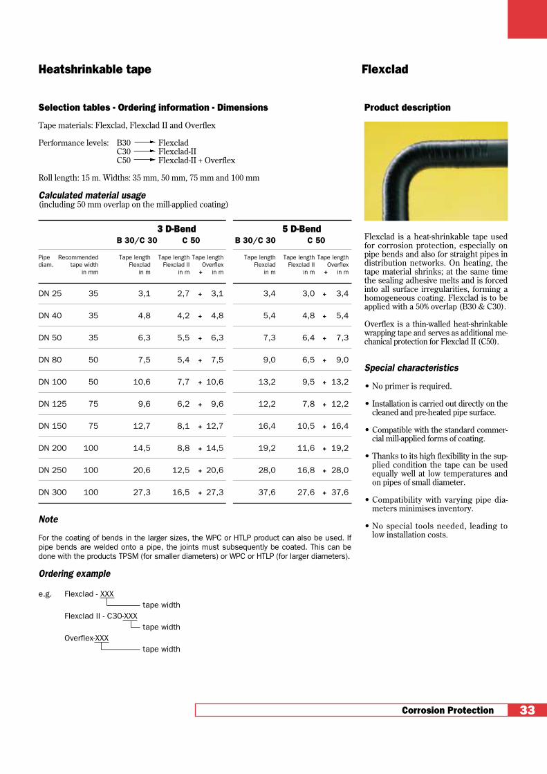
Product description
Flexclad is a heat-shrinkable tape usedfor corrosion protection, especially onpipe bends and also for straight pipes indistribution networks. On heating, thetape material shrinks; at the same timethe sealing adhesive melts and is forcedinto all surface irregularities, forming ahomogeneous coating. Flexclad is to beapplied with a 50% overlap (B30 & C30).
Overflex is a thin-walled heat-shrinkablewrapping tape and serves as additional me-chanical protection for Flexclad II (C50).
Special characteristics
• No primer is required.
• Installation is carried out directly on thecleaned and pre-heated pipe surface.
• Compatible with the standard commer-cial mill-applied forms of coating.
• Thanks to its high flexibility in the sup-plied condition the tape can be usedequally well at low temperatures andon pipes of small diameter.
• Compatibility with varying pipe dia-meters minimises inventory.
• No special tools needed, leading tolow installation costs.
Corrosion Protection 33
Heatshrinkable tape Flexclad
Selection tables - Ordering information - Dimensions
Tape materials: Flexclad, Flexclad II and Overflex
Performance levels: B30 FlexcladC30 Flexclad-IIC50 Flexclad-II + Overflex
Roll length: 15 m. Widths: 35 mm, 50 mm, 75 mm and 100 mm
Calculated material usage(including 50 mm overlap on the mill-applied coating)
3 D-Bend 5 D-BendB 30/C 30 C 50 B 30/C 30 C 50
Pipe Recommended Tape length Tape length Tape length Tape length Tape length Tape lengthdiam. tape width Flexclad Flexclad II Overflex Flexclad Flexclad II Overflex
in mm in m in m + in m in m in m + in m
DN 25 35 3,1 2,7 + 3,1 3,4 3,0 + 3,4
DN 40 35 4,8 4,2 + 4,8 5,4 4,8 + 5,4
DN 50 35 6,3 5,5 + 6,3 7,3 6,4 + 7,3
DN 80 50 7,5 5,4 + 7,5 9,0 6,5 + 9,0
DN 100 50 10,6 7,7 + 10,6 13,2 9,5 + 13,2
DN 125 75 9,6 6,2 + 9,6 12,2 7,8 + 12,2
DN 150 75 12,7 8,1 + 12,7 16,4 10,5 + 16,4
DN 200 100 14,5 8,8 + 14,5 19,2 11,6 + 19,2
DN 250 100 20,6 12,5 + 20,6 28,0 16,8 + 28,0
DN 300 100 27,3 16,5 + 27,3 37,6 27,6 + 37,6
Note
For the coating of bends in the larger sizes, the WPC or HTLP product can also be used. Ifpipe bends are welded onto a pipe, the joints must subsequently be coated. This can bedone with the products TPSM (for smaller diameters) or WPC or HTLP (for larger diameters).
Ordering example
e.g. Flexclad - XXXtape width
Flexclad II - C30-XXXtape width
Overflex-XXXtape width

Corrosion Protection
Installation procedure
1. Before assembling the flanges, slide theFCMS heat-shrinkable sleeve, togetherwith its release foil, onto the pipe.
Prepare the surface to be coatedaccording to SIS-055900-ST3.
No primer is required.
2. Using a propane torch, dry off thesurface that is to be coated and pre-heat the two pipe ends to about +60°C.
3. Position the moulded sleeve centrallyover the flange and remove the releasefoil.
4. Working from the centre outwards,heat the sleeve with a soft yellowpropane flame, moving the torch in apaintbrush motion. Start by shrinkingthe sleeve onto the flange.
5. Then shrink one end of the sleeve ontothe pipe.
Finally, shrink the other end of thesleeve starting again in the middle tocomplete the operation.
9.1 Flange couplingsClosed moulded part
34

Product description
The FCMS heat-shrinkable moulded slee-ve is capable of accommodating the largediameter difference between flanges andpipes.
When heated, the moulded sleeve adaptsitself to the shape of the flange. The visco-elastic sealing adhesive at both ends ofthe moulded part produces reliable seal-ing of the pipe coupling.
The moulded part is not coated in theflange zone, therefore should it becomenecessary to dismantle the joint, theflangebolts will be readily accessiblewithout any further cleaning.
Special characteristics
• No primer is required.
• Installation is carried out directly onthe cleaned, dried and prepared pipesurface.
• Compatible with standard commercialmill-applied coatings.
• The installed sleeve possesses highmechanical strength.
• Simple re-entry.
Corrosion Protection 35
Heat-shrinkable moulded part FCMS
Selection tables - Ordering information - Dimensions
Pipe diameter Order description
DN 40FCMS 170/40
DN 50
DN 65FCMS 230/70
DN 100
DN 125
DN 150 FCMS 350/110
DN 200
Ordering example
e.g. DN 100
FCMS 230/70maximum diameter (mm) after full unrestricted recoverymin diameter (mm) as supplied
Corrosion Protection
Installation procedure
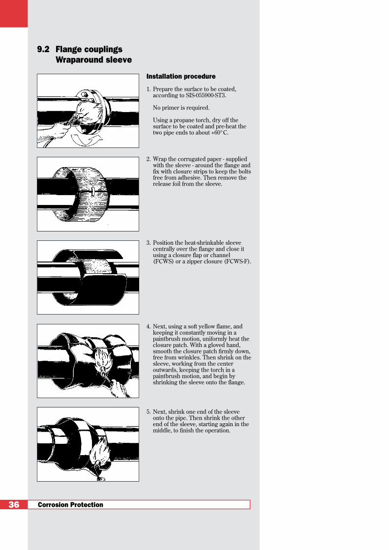
1. Prepare the surface to be coated,according to SIS-055900-ST3.
No primer is required.
Using a propane torch, dry off thesurface to be coated and pre-heat thetwo pipe ends to about +60°C.
2. Wrap the corrugated paper - suppliedwith the sleeve - around the flange andfix with closure strips to keep the boltsfree from adhesive. Then remove therelease foil from the sleeve.
3. Position the heat-shrinkable sleevecentrally over the flange and close itusing a closure flap or channel(FCWS) or a zipper closure (FCWS-F).
4. Next, using a soft yellow flame, andkeeping it constantly moving in apaintbrush motion, uniformly heat theclosure patch. With a gloved hand,smooth the closure patch firmly down,free from wrinkles. Then shrink on thesleeve, working from the centeroutwards, keeping the torch in apaintbrush motion, and begin byshrinking the sleeve onto the flange.
5. Next, shrink one end of the sleeveonto the pipe. Then shrink the otherend of the sleeve, starting again in themiddle, to finish the operation.
9.2 Flange couplingsWraparound sleeve
36
Product description
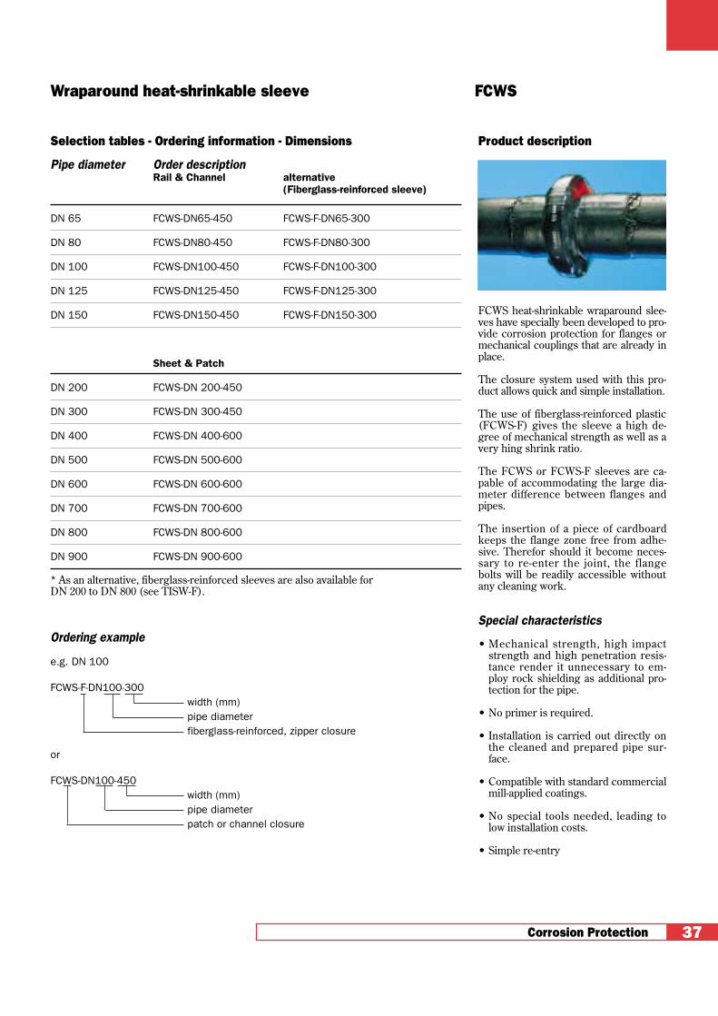
FCWS heat-shrinkable wraparound slee-ves have specially been developed to pro-vide corrosion protection for flanges ormechanical couplings that are already inplace.
The closure system used with this pro-duct allows quick and simple installation.
The use of fiberglass-reinforced plastic(FCWS-F) gives the sleeve a high de-gree of mechanical strength as well as avery hing shrink ratio.
The FCWS or FCWS-F sleeves are ca-pable of accommodating the large dia-meter difference between flanges andpipes.
The insertion of a piece of cardboardkeeps the flange zone free from adhe-sive. Therefor should it become neces-sary to re-enter the joint, the flangebolts will be readily accessible withoutany cleaning work.
Special characteristics
• Mechanical strength, high impactstrength and high penetration resis-tance render it unnecessary to em-ploy rock shielding as additional pro-tection for the pipe.
• No primer is required.
• Installation is carried out directly onthe cleaned and prepared pipe sur-face.
• Compatible with standard commercialmill-applied coatings.
• No special tools needed, leading tolow installation costs.
• Simple re-entry
Corrosion Protection 37
Wraparound heat-shrinkable sleeve FCWS
Selection tables - Ordering information - Dimensions
Pipe diameter Order descriptionRail & Channel alternative
(Fiberglass-reinforced sleeve)
DN 65 FCWS-DN65-450 FCWS-F-DN65-300
DN 80 FCWS-DN80-450 FCWS-F-DN80-300
DN 100 FCWS-DN100-450 FCWS-F-DN100-300
DN 125 FCWS-DN125-450 FCWS-F-DN125-300
DN 150 FCWS-DN150-450 FCWS-F-DN150-300
Sheet & Patch
DN 200 FCWS-DN 200-450
DN 300 FCWS-DN 300-450
DN 400 FCWS-DN 400-600
DN 500 FCWS-DN 500-600
DN 600 FCWS-DN 600-600
DN 700 FCWS-DN 700-600
DN 800 FCWS-DN 800-600
DN 900 FCWS-DN 900-600
* As an alternative, fiberglass-reinforced sleeves are also available for DN 200 to DN 800 (see TISW-F).
Ordering example
e.g. DN 100
FCWS-F-DN100-300width (mm)pipe diameterfiberglass-reinforced, zipper closure
or
FCWS-DN100-450width (mm)pipe diameterpatch or channel closure

Corrosion Protection
Installation procedure
1. Prepare the surface to be coated,according to SIS-055900-ST3.
No primer is required.
2. Using a propane torch, pre-heat thesurface to be coated to about +60°C.
3. Slide the moulded part onto the pipeso that it touches the steel end cap.
4. Using a soft yellow propane flame, heatthe shrinkable moulding starting at theendcap. Ensure that it does not moveby pressing a gloved hand against it ifnecessary. Complete the installation byheating by a continuous paintbrushmotion around the pipe.
10. Steel end caps
38
Note
Any remaining exposed steel can becoated with TPSM or WPC. In thisoperation, ensure an overlap of at least50 mm with the FCMS-CAP mouldedpart and the mill-applied coating.
Product description
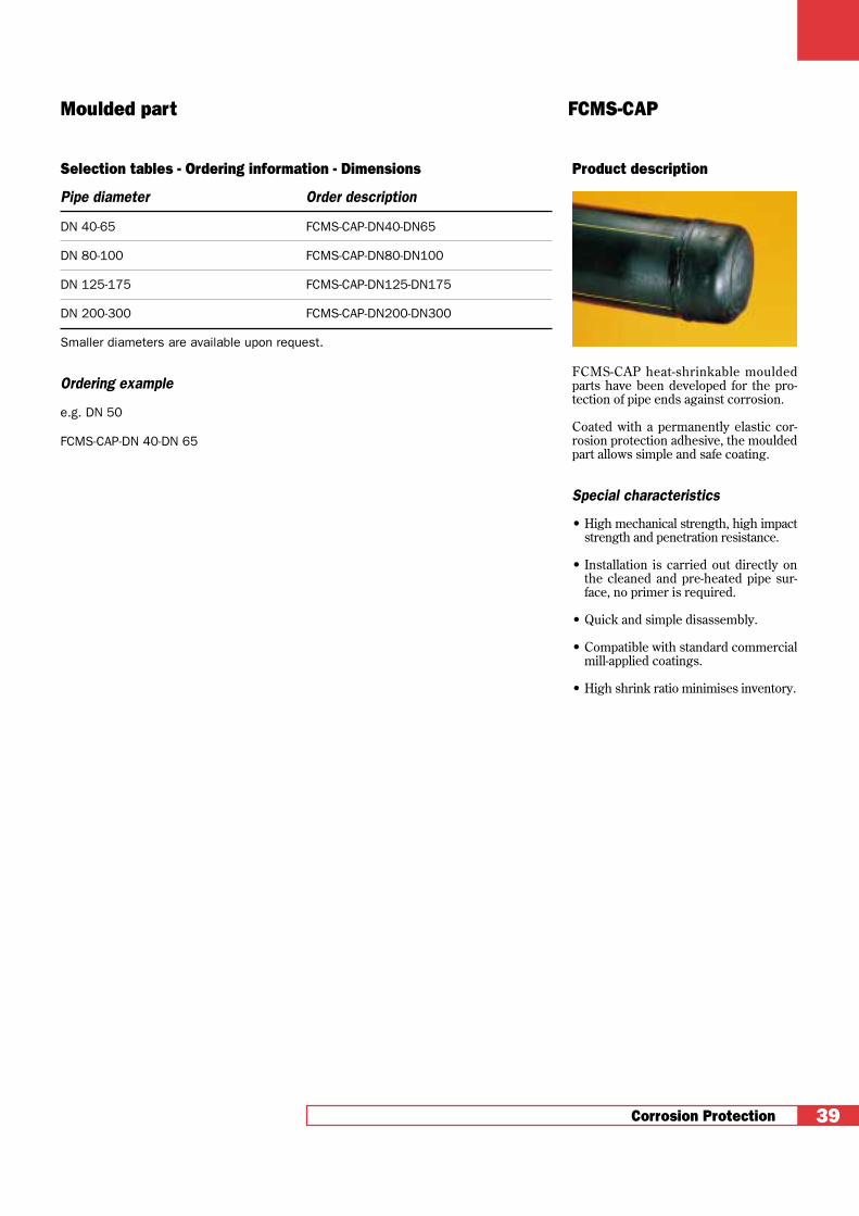
FCMS-CAP heat-shrinkable mouldedparts have been developed for the pro-tection of pipe ends against corrosion.
Coated with a permanently elastic cor-rosion protection adhesive, the mouldedpart allows simple and safe coating.
Special characteristics
• High mechanical strength, high impactstrength and penetration resistance.
• Installation is carried out directly onthe cleaned and pre-heated pipe sur-face, no primer is required.
• Quick and simple disassembly.
• Compatible with standard commercialmill-applied coatings.
• High shrink ratio minimises inventory.
Corrosion Protection 39
Moulded part FCMS-CAP
Selection tables - Ordering information - Dimensions
Pipe diameter Order description
DN 40-65 FCMS-CAP-DN40-DN65
DN 80-100 FCMS-CAP-DN80-DN100
DN 125-175 FCMS-CAP-DN125-DN175
DN 200-300 FCMS-CAP-DN200-DN300
Smaller diameters are available upon request.
Ordering example
e.g. DN 50
FCMS-CAP-DN 40-DN 65


Corrosion Protection 41
GRSM
FLEXCLAD
RAYTRANS
HTTE
MEPS
Corrosion Protection and Sealing
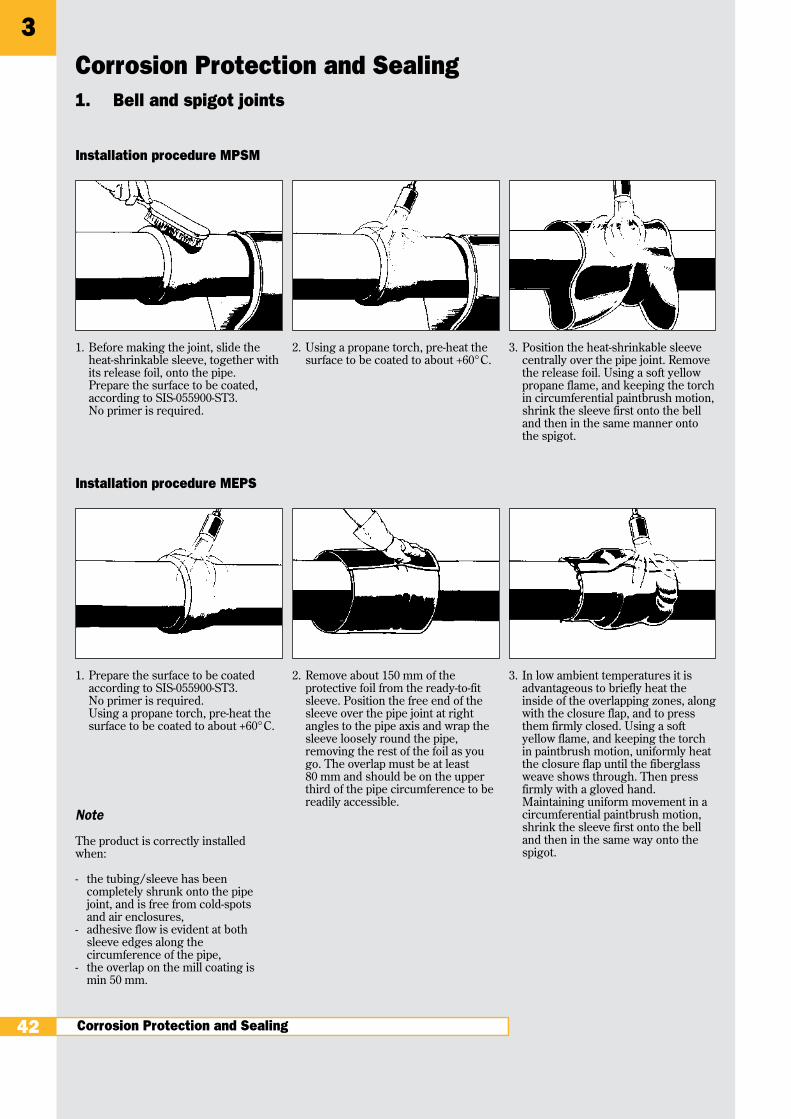
1. Prepare the surface to be coatedaccording to SIS-055900-ST3.No primer is required.Using a propane torch, pre-heat thesurface to be coated to about +60°C.
2. Remove about 150 mm of theprotective foil from the ready-to-fitsleeve. Position the free end of thesleeve over the pipe joint at rightangles to the pipe axis and wrap thesleeve loosely round the pipe,removing the rest of the foil as yougo. The overlap must be at least80 mm and should be on the upperthird of the pipe circumference to bereadily accessible.
3. In low ambient temperatures it isadvantageous to briefly heat theinside of the overlapping zones, alongwith the closure flap, and to pressthem firmly closed. Using a softyellow flame, and keeping the torchin paintbrush motion, uniformly heatthe closure flap until the fiberglassweave shows through. Then pressfirmly with a gloved hand.Maintaining uniform movement in acircumferential paintbrush motion,shrink the sleeve first onto the belland then in the same way onto thespigot.
1. Bell and spigot joints
42
Note
The product is correctly installedwhen:
- the tubing/sleeve has beencompletely shrunk onto the pipejoint, and is free from cold-spotsand air enclosures,
- adhesive flow is evident at bothsleeve edges along thecircumference of the pipe,
- the overlap on the mill coating ismin 50 mm.
Corrosion Protection and Sealing
1. Before making the joint, slide theheat-shrinkable sleeve, together withits release foil, onto the pipe.Prepare the surface to be coated,according to SIS-055900-ST3.No primer is required.
2. Using a propane torch, pre-heat thesurface to be coated to about +60°C.
3. Position the heat-shrinkable sleevecentrally over the pipe joint. Removethe release foil. Using a soft yellowpropane flame, and keeping the torchin circumferential paintbrush motion,shrink the sleeve first onto the belland then in the same manner ontothe spigot.
Installation procedure MPSM
Installation procedure MEPS
3

Product description
MPSM tubing and Unisleeve MEPS areheat-shrinkable products designed forthe effective coating of specific bell-and-spigot categories, such as:- ductile cast-iron pipes with outer mill-
applied PE coating,- ductile cast-iron pipes with outer mill-
applied fiber-cement coating,- steel bell-and-spigotpipes with outer
mill-applied PE coating.
The special visco-elastic adhesive coa-ting ensures reliable sealing.
Due to their high shrink ratio the slee-ves will shrink down tight and clean on-to the bell and the spigot of the pipes.
The structure and characteristics ofMEPS is similar to WPC, the anti-corro-sion sleeve for steel pipes.Bell-and-spigot pipes can be coated withMEPS after they have been laid.
Special characteristics
• The angling tolerance and lengthwiseplay of the bell-and-spigot joint is fullyretained.
• No primer is required.
• Installation is carried out directly onthe cleaned and prepared pipe surface.
• Compatible with the usual commer-cial mill-applied coatings.
• The thick-walled structure of the cross-linked heat-shrinkable material gives ithigh impact strength and high penetra-tion resistance.
• No special tools needed leading to lowinstallation costs.
• Vacuum-tight sealing to exclude ground-water.
Corrosion Protection and Sealing 43
Heat-shrinkable Sleeve MPSM & MEPS
Heat-shrinkable sleeve MPSM Ready-to-fitPipe Max. Bell Order Unit MEPS MEPS-300diameter Ø (mm) description Order description Cutting length
DN 80 151 MPSM-C30-DN80-350
DN 100 171 MPSM-C30-DN100-300
DN 150 217 MPSM-C30-DN150-300 MEPS-C30-DN150-300 845 mm
DN 200 278 MPSM-C30-DN200-300 MEPS-C30-DN200-300 1040 mm
DN 250 336 MPSM-C30-DN250-300 MEPS-C30-DN250-300 1220 mm
DN 300 393 MPSM-C30-DN300-300 MEPS-C30-DN300-300 1400 mm
DN 350 444 MEPS-C30-DN350-300 1580 mm
DN 400 500 MEPS-C30-DN400-300 1740 mm
DN 500 607 MEPS-C30-DN500-300 2100 mm
DN 600 715 MEPS-C30-DN600-300 2450 mm
DN 700 824 MEPS-C30-DN700-300 2790 mm
DN 800 942 MEPS-C30-DN800-300 3160 mm
Ordering example
e.g. DN 100
MPSM-C30-DN100-300width as suppliedpipe diameterperformanceclassification
Note
Special width: 450 mm, 600 mmavailable on request.
AlternativeRolls of MEPSRoll length 30 m, width 300 mm
Order descriptionMEPS-C30-300
Closure patch WPCP IVfor rolls(fiberglass-reinforced)
Order descriptionWPCP IV-150x298for all pipe diameters
Selection tables - Ordering information - Dimensions
on request
Bell and spigot joints
}
Corrosion Protection and Sealing
2. Special bell-and-spigot joints - TIS-K
44
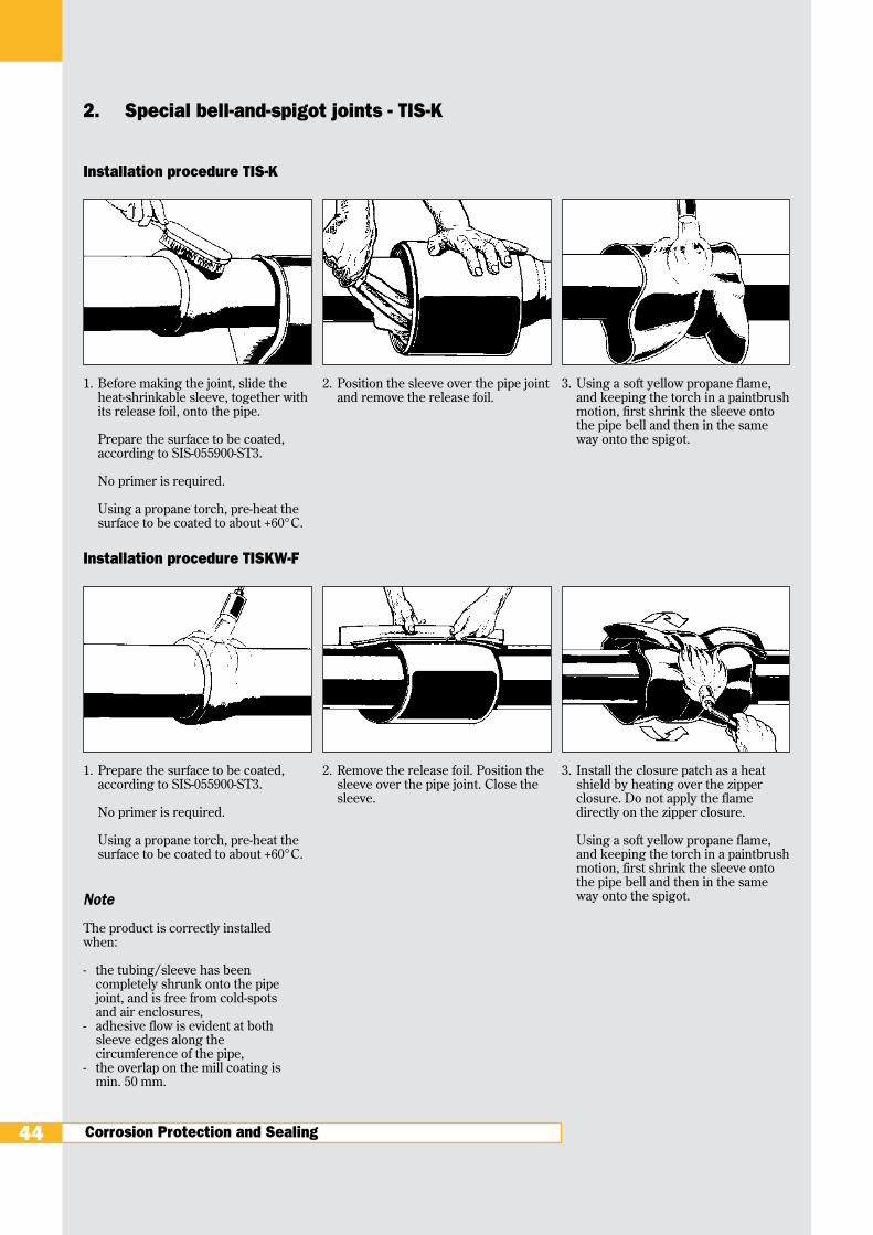
1. Prepare the surface to be coated,according to SIS-055900-ST3.
No primer is required.
Using a propane torch, pre-heat thesurface to be coated to about +60°C.
2. Remove the release foil. Position thesleeve over the pipe joint. Close thesleeve.
3. Install the closure patch as a heatshield by heating over the zipperclosure. Do not apply the flamedirectly on the zipper closure.
Using a soft yellow propane flame,and keeping the torch in a paintbrushmotion, first shrink the sleeve ontothe pipe bell and then in the sameway onto the spigot.
1. Before making the joint, slide theheat-shrinkable sleeve, together withits release foil, onto the pipe.
Prepare the surface to be coated,according to SIS-055900-ST3.
No primer is required.
Using a propane torch, pre-heat thesurface to be coated to about +60°C.
2. Position the sleeve over the pipe jointand remove the release foil.
3. Using a soft yellow propane flame,and keeping the torch in a paintbrushmotion, first shrink the sleeve ontothe pipe bell and then in the sameway onto the spigot.
Installation procedure TIS-K
Installation procedure TISKW-F
Note
The product is correctly installedwhen:
- the tubing/sleeve has beencompletely shrunk onto the pipejoint, and is free from cold-spotsand air enclosures,
- adhesive flow is evident at bothsleeve edges along thecircumference of the pipe,
- the overlap on the mill coating ismin. 50 mm.
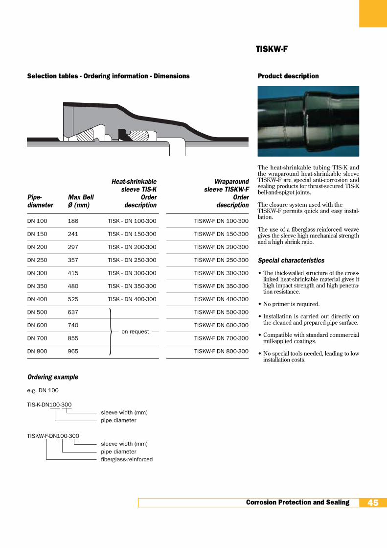
Product description
The heat-shrinkable tubing TIS-K andthe wraparound heat-shrinkable sleeveTISKW-F are special anti-corrosion andsealing products for thrust-secured TIS-Kbell-and-spigot joints.
The closure system used with theTISKW-F permits quick and easy instal-lation.
The use of a fiberglass-reinforced weavegives the sleeve high mechanical strengthand a high shrink ratio.
Special characteristics
• The thick-walled structure of the cross-linked heat-shrinkable material gives ithigh impact strength and high penetra-tion resistance.
• No primer is required.
• Installation is carried out directly onthe cleaned and prepared pipe surface.
• Compatible with standard commercialmill-applied coatings.
• No special tools needed, leading to lowinstallation costs.
Corrosion Protection and Sealing 45
TISKW-F
Selection tables - Ordering information - Dimensions
Heat-shrinkable Wraparoundsleeve TIS-K sleeve TISKW-F
Pipe- Max Bell Order Orderdiameter Ø (mm) description description
DN 100 186 TISK - DN 100-300 TISKW-F DN 100-300
DN 150 241 TISK - DN 150-300 TISKW-F DN 150-300
DN 200 297 TISK - DN 200-300 TISKW-F DN 200-300
DN 250 357 TISK - DN 250-300 TISKW-F DN 250-300
DN 300 415 TISK - DN 300-300 TISKW-F DN 300-300
DN 350 480 TISK - DN 350-300 TISKW-F DN 350-300
DN 400 525 TISK - DN 400-300 TISKW-F DN 400-300
DN 500 637 TISKW-F DN 500-300
DN 600 740 TISKW-F DN 600-300
DN 700 855 TISKW-F DN 700-300
DN 800 965 TISKW-F DN 800-300
Ordering example
e.g. DN 100
TIS-K-DN100-300sleeve width (mm)pipe diameter
TISKW-F-DN100-300sleeve width (mm)pipe diameterfiberglass-reinforced
} on request

Corrosion Protection and Sealing
Installation procedure
1. Prepare the surface to be coated,according to SIS-055900-ST3.
No primer is required.
2. Using a propane torch pre-heat thesurface to be coated to about +60°C.
3. Position the heat-shrinkable sleeveover the pipe joint. Remove the releasefoil. Close the sleeve.
4. Install the closure patch as a heatshield over the zipper closure. Do notapply the flame directly on the patch.
Using a soft yellow propane flame, andkeeping the torch in a continuouspaintbrush motion, first shrink thesleeve onto the thrust stop and thenonto the pipe bell and the spigot.
3. Special bell-and-spigot joints - TIS
46
Note
The product is correctly installed when:
- the tubing/sleeve has beencompletely shrunk onto the pipe joint,and is free from cold-spots and airenclosures,
- adhesive flow is evident at both sleeveedges along the circumference of thepipe,
- the overlap on the mill coating is min.50 mm.
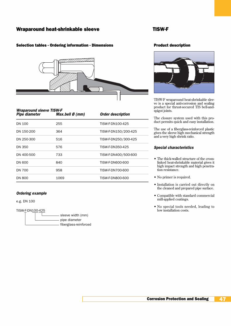
Product description
TISW-F wraparound heat-shrinkable slee-ve is a special anti-corrosion and sealingproduct for thrust-secured TIS bell-and-spigot joints.
The closure system used with this pro-duct permits quick and easy installation.
The use of a fiberglass-reinforced plasticgives the sleeve high mechanical strengthand a very high shrink ratio.
Special characteristics
• The thick-walled structure of the cross-linked heat-shrinkable material gives ithigh impact strength and high penetra-tion resistance.
• No primer is required.
• Installation is carried out directly onthe cleaned and prepared pipe surface.
• Compatible with standard commercialmill-applied coatings.
• No special tools needed, leading tolow installation costs.
Corrosion Protection and Sealing 47
Wraparound heat-shrinkable sleeve TISW-F
Selection tables - Ordering information - Dimensions
Wraparound sleeve TISW-FPipe diameter Max.bell Ø (mm) Order description
DN 100 255 TISW-F-DN100-425
DN 150-200 364 TISW-F-DN150/200-425
DN 250-300 516 TISW-F-DN250/300-425
DN 350 576 TISW-F-DN350-425
DN 400-500 733 TISW-F-DN400/500-600
DN 600 840 TISW-F-DN600-600
DN 700 958 TISW-F-DN700-600
DN 800 1069 TISW-F-DN800-600
Ordering example
e.g. DN 100
TISW-F-DN100-425sleeve width (mm)pipe diameterfiberglass-reinforced

Sealing
Installation procedure
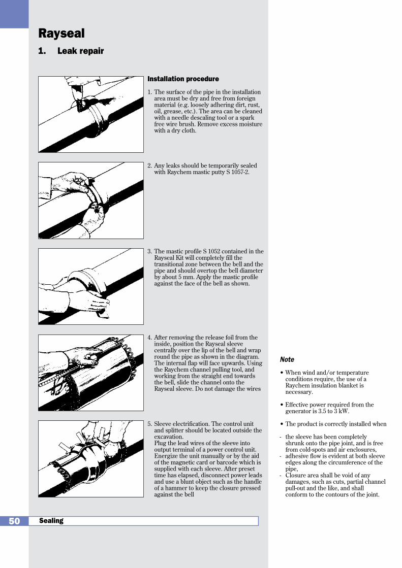
1. The surface of the pipe in the installationarea must be dry and free from foreignmaterial (e.g. loosely adhering dirt, rust,oil, grease, etc.). The area can be cleanedwith a needle descaling tool or a sparkfree steel-wire brush.
2. Any leaks should be temporarily sealedwith Raychem mastic putty S 1057-2.
Using a propane torch pre-heat the pipe inthe installation area to about +60°C.
3. The mastic profile S 1052 contained in theGRSM Kit will completely fill thetransitional zone between the bell and thepipe and should overtop the bell diameterby about 5 mm. Apply the mastic profileagainst the face of the bell as shown.
4. After removing the release foil from theinside, position the GRSM sleevecentrally over the lip of the bell and wrapround the pipe. The internal flap will faceupwards. Using the Raychem channelpulling tool, and working from thestraight end towards the bell, slide thechannel onto the GRSM sleeve. In the case of the GRSM-F product, closethe zipper closure. Avoid shifting thesleeve, to ensure that no displacement ofthe mastic profile occurs. In the case ofGRSM-F, install the closure patch as aheat shield over the zipper closure byheating it. Do not apply the flame directlyon the closure.
5. Beginning from the center of the sleeve,use a soft yellow flame to shrink theGRSM sleeve onto the pipe, keeping thetorch in a steady paintbrush motion.
Then, working outwards from the bell,install the sleeve with the same procedureon the other side. During the installation,use a blunt object such as the handle of ahammer to press the closure downwardagainst the bell.
1. Leak repair
48
Note:
The product is correctly installed when
- the sleeve has been completelyshrunk onto the pipe joint, and is freefrom cold-spots and air enclosures,
- adhesive flow is evident at both sleeveedges along the circumference of thepipe,
- Closure area shall be void of anydamages, such as cuts, partial channelpull-out and the like, and shallconform to the contours of the joint.
Sealing4
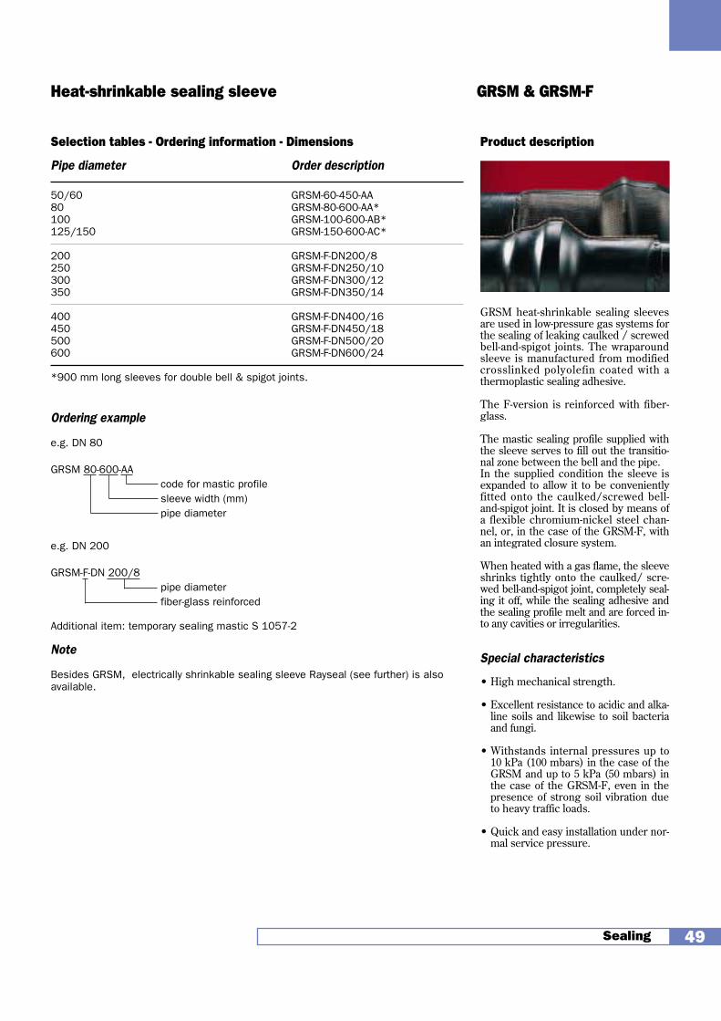
Product description
GRSM heat-shrinkable sealing sleevesare used in low-pressure gas systems forthe sealing of leaking caulked / screwedbell-and-spigot joints. The wraparoundsleeve is manufactured from modifiedcrosslinked polyolefin coated with athermoplastic sealing adhesive.
The F-version is reinforced with fiber-glass.
The mastic sealing profile supplied withthe sleeve serves to fill out the transitio-nal zone between the bell and the pipe. In the supplied condition the sleeve isexpanded to allow it to be convenientlyfitted onto the caulked/screwed bell-and-spigot joint. It is closed by means ofa flexible chromium-nickel steel chan-nel, or, in the case of the GRSM-F, withan integrated closure system.
When heated with a gas flame, the sleeveshrinks tightly onto the caulked/ scre-wed bell-and-spigot joint, completely seal-ing it off, while the sealing adhesive andthe sealing profile melt and are forced in-to any cavities or irregularities.
Special characteristics
• High mechanical strength.
• Excellent resistance to acidic and alka-line soils and likewise to soil bacteriaand fungi.
• Withstands internal pressures up to10 kPa (100 mbars) in the case of theGRSM and up to 5 kPa (50 mbars) inthe case of the GRSM-F, even in thepresence of strong soil vibration dueto heavy traffic loads.
• Quick and easy installation under nor-mal service pressure.
Sealing 49
Heat-shrinkable sealing sleeve GRSM & GRSM-F
Selection tables - Ordering information - Dimensions
Pipe diameter Order description
50/60 GRSM-60-450-AA80 GRSM-80-600-AA*100 GRSM-100-600-AB*125/150 GRSM-150-600-AC*
200 GRSM-F-DN200/8250 GRSM-F-DN250/10300 GRSM-F-DN300/12350 GRSM-F-DN350/14
400 GRSM-F-DN400/16450 GRSM-F-DN450/18500 GRSM-F-DN500/20600 GRSM-F-DN600/24
*900 mm long sleeves for double bell & spigot joints.
Ordering example
e.g. DN 80
GRSM 80-600-AAcode for mastic profilesleeve width (mm)pipe diameter
e.g. DN 200
GRSM-F-DN 200/8pipe diameterfiber-glass reinforced
Additional item: temporary sealing mastic S 1057-2
Note
Besides GRSM, electrically shrinkable sealing sleeve Rayseal (see further) is alsoavailable.
Sealing
Installation procedure
1. The surface of the pipe in the installationarea must be dry and free from foreignmaterial (e.g. loosely adhering dirt, rust,oil, grease, etc.). The area can be cleanedwith a needle descaling tool or a sparkfree wire brush. Remove excess moisturewith a dry cloth.
2. Any leaks should be temporarily sealedwith Raychem mastic putty S 1057-2.
3. The mastic profile S 1052 contained in theRayseal Kit will completely fill thetransitional zone between the bell and thepipe and should overtop the bell diameterby about 5 mm. Apply the mastic profileagainst the face of the bell as shown.
4. After removing the release foil from theinside, position the Rayseal sleevecentrally over the lip of the bell and wrapround the pipe as shown in the diagram.The internal flap will face upwards. Usingthe Raychem channel pulling tool, andworking from the straight end towardsthe bell, slide the channel onto theRayseal sleeve. Do not damage the wires
5. Sleeve electrification. The control unitand splitter should be located outside theexcavation.Plug the lead wires of the sleeve intooutput terminal of a power control unit.Energize the unit manually or by the aidof the magnetic card or barcode which issupplied with each sleeve. After presettime has elapsed, disconnect power leadsand use a blunt object such as the handleof a hammer to keep the closure pressedagainst the bell
1. Leak repair
50
Note
• When wind and/or temperatureconditions require, the use of aRaychem insulation blanket isnecessary.
• Effective power required from thegenerator is 3.5 to 3 kW.
• The product is correctly installed when
- the sleeve has been completelyshrunk onto the pipe joint, and is freefrom cold-spots and air enclosures,
- adhesive flow is evident at both sleeveedges along the circumference of thepipe,
- Closure area shall be void of anydamages, such as cuts, partial channelpull-out and the like, and shallconform to the contours of the joint.
Rayseal
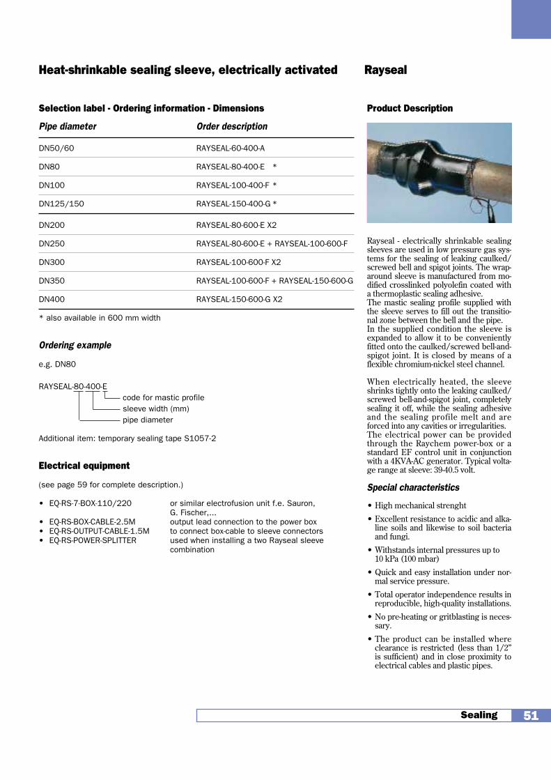
Product Description
Rayseal - electrically shrinkable sealingsleeves are used in low pressure gas sys-tems for the sealing of leaking caulked/screwed bell and spigot joints. The wrap-around sleeve is manufactured from mo-dified crosslinked polyolefin coated witha thermoplastic sealing adhesive.The mastic sealing profile supplied withthe sleeve serves to fill out the transitio-nal zone between the bell and the pipe. In the supplied condition the sleeve isexpanded to allow it to be convenientlyfitted onto the caulked/screwed bell-and-spigot joint. It is closed by means of aflexible chromium-nickel steel channel.
When electrically heated, the sleeveshrinks tightly onto the leaking caulked/screwed bell-and-spigot joint, completelysealing it off, while the sealing adhesiveand the sealing profile melt and areforced into any cavities or irregularities.The electrical power can be providedthrough the Raychem power-box or astandard EF control unit in conjunctionwith a 4KVA-AC generator. Typical volta-ge range at sleeve: 39-40.5 volt.
Special characteristics
• High mechanical strenght
• Excellent resistance to acidic and alka-line soils and likewise to soil bacteriaand fungi.
• Withstands internal pressures up to 10 kPa (100 mbar)
• Quick and easy installation under nor-mal service pressure.
• Total operator independence results inreproducible, high-quality installations.
• No pre-heating or gritblasting is neces-sary.
• The product can be installed whereclearance is restricted (less than 1/2”is sufficient) and in close proximity toelectrical cables and plastic pipes.
Sealing 51
Heat-shrinkable sealing sleeve, electrically activated Rayseal
Selection label - Ordering information - Dimensions
Pipe diameter Order description
DN50/60 RAYSEAL-60-400-A
DN80 RAYSEAL-80-400-E *
DN100 RAYSEAL-100-400-F *
DN125/150 RAYSEAL-150-400-G *
DN200 RAYSEAL-80-600-E X2
DN250 RAYSEAL-80-600-E + RAYSEAL-100-600-F
DN300 RAYSEAL-100-600-F X2
DN350 RAYSEAL-100-600-F + RAYSEAL-150-600-G
DN400 RAYSEAL-150-600-G X2
* also available in 600 mm width
Ordering example
e.g. DN80
RAYSEAL-80-400-Ecode for mastic profilesleeve width (mm)pipe diameter
Additional item: temporary sealing tape S1057-2
Electrical equipment
(see page 59 for complete description.)
• EQ-RS-7-BOX-110/220 or similar electrofusion unit f.e. Sauron, G. Fischer,...
• EQ-RS-BOX-CABLE-2.5M output lead connection to the power box• EQ-RS-OUTPUT-CABLE-1.5M to connect box-cable to sleeve connectors• EQ-RS-POWER-SPLITTER used when installing a two Rayseal sleeve
combination

Sealing
Installation procedure
1. Prepare the surface that is to becoated, according to SIS-055900-ST3.
No primer is required.
2. Using a propane torch, pre-heat thesurface to be coated to about +60°C.
3. Wrap the cut-to-size supporting sleeveround the casing. Work the interlacedfingers down onto the service pipe andclose off with adhesive tape.
4. Remove the release foil. Takingaccount of the difference in diameter,position the sleeve so that the contactsurface when installed should beequally divided between the casingand the service pipe. Close the sleeveusing a closure flap or a channel(CSEM), or a zipper closure (CSEM-F).
5. Using a soft yellow propane flame, andkeeping the torch in a steadycircumferential paintbrush motion,first shrink the sleeve onto the casingand then onto the transitional zone asfar as the service pipe.
Installation is complete when thesleeve fits snugly and smoothly aroundthe pipe and the sealing adhesive hasbeen squeezed out at the edges.
2. Sealing of pipe casings
52
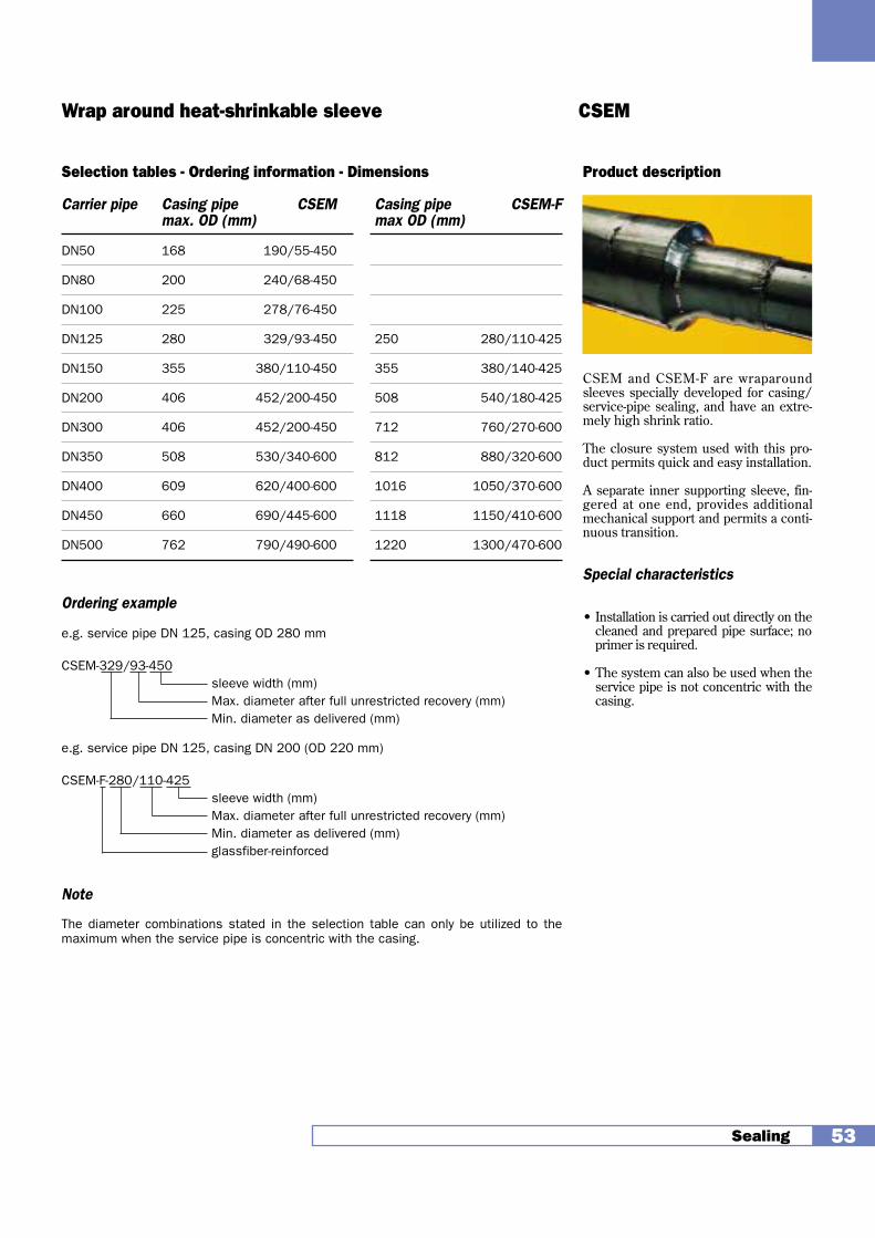
Product description
CSEM and CSEM-F are wraparoundsleeves specially developed for casing/service-pipe sealing, and have an extre-mely high shrink ratio.
The closure system used with this pro-duct permits quick and easy installation.
A separate inner supporting sleeve, fin-gered at one end, provides additionalmechanical support and permits a conti-nuous transition.
Special characteristics
• Installation is carried out directly on thecleaned and prepared pipe surface; noprimer is required.
• The system can also be used when theservice pipe is not concentric with thecasing.
Sealing 53
Wrap around heat-shrinkable sleeve CSEM
Selection tables - Ordering information - Dimensions
Carrier pipe Casing pipe CSEM Casing pipe CSEM-Fmax. OD (mm) max OD (mm)
DN50 168 190/55-450
DN80 200 240/68-450
DN100 225 278/76-450
DN125 280 329/93-450 250 280/110-425
DN150 355 380/110-450 355 380/140-425
DN200 406 452/200-450 508 540/180-425
DN300 406 452/200-450 712 760/270-600
DN350 508 530/340-600 812 880/320-600
DN400 609 620/400-600 1016 1050/370-600
DN450 660 690/445-600 1118 1150/410-600
DN500 762 790/490-600 1220 1300/470-600
Ordering example
e.g. service pipe DN 125, casing OD 280 mm
CSEM-329/93-450sleeve width (mm)Max. diameter after full unrestricted recovery (mm)Min. diameter as delivered (mm)
e.g. service pipe DN 125, casing DN 200 (OD 220 mm)
CSEM-F-280/110-425sleeve width (mm)Max. diameter after full unrestricted recovery (mm)Min. diameter as delivered (mm)glassfiber-reinforced
Note
The diameter combinations stated in the selection table can only be utilized to themaximum when the service pipe is concentric with the casing.

Sealing
Installation procedure
1. Position the heat-shrinkable wallfeedthroughs concentrically in thehole through the wall. Fill any gapswith cement mortar or a quick-curingmastic on both sides.
2. After allowing sufficient time forcuring, remove the sealing caps. Cleanthe pipe or cable and pass it through.
3. Position the pipe or cable and shrinkdown the two ends of the feedthroughstarting at the supporting helicalspring. Allow ends of the feedthroughto cool to room temperature beforesubjecting them to mechanical load.Using a suitable sealant, coat the areasurrounding the hole on the exteriorwall.
3. Heat-shrinkable wall feedthroughs
54
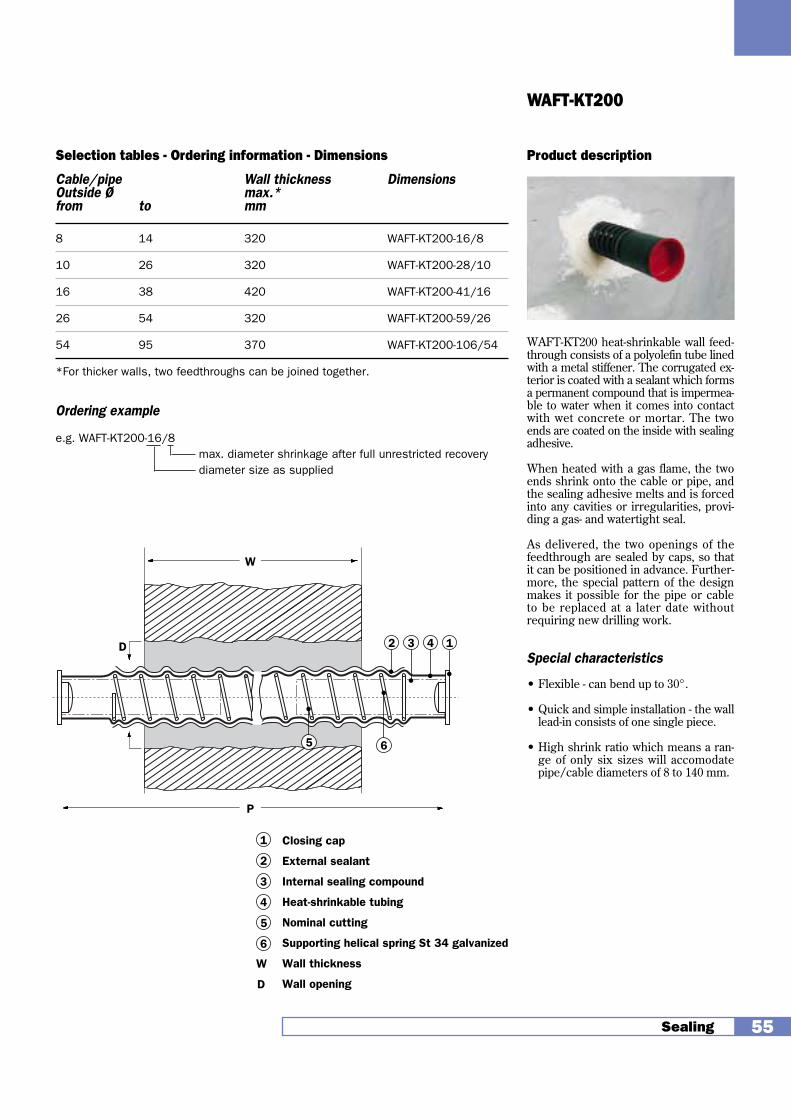
Product description
WAFT-KT200 heat-shrinkable wall feed-through consists of a polyolefin tube linedwith a metal stiffener. The corrugated ex-terior is coated with a sealant which formsa permanent compound that is impermea-ble to water when it comes into contactwith wet concrete or mortar. The twoends are coated on the inside with sealingadhesive.
When heated with a gas flame, the twoends shrink onto the cable or pipe, andthe sealing adhesive melts and is forcedinto any cavities or irregularities, provi-ding a gas- and watertight seal.
As delivered, the two openings of thefeedthrough are sealed by caps, so thatit can be positioned in advance. Further-more, the special pattern of the designmakes it possible for the pipe or cableto be replaced at a later date withoutrequiring new drilling work.
Special characteristics
• Flexible - can bend up to 30°.
• Quick and simple installation - the walllead-in consists of one single piece.
• High shrink ratio which means a ran-ge of only six sizes will accomodatepipe/cable diameters of 8 to 140 mm.
Sealing 55
WAFT-KT200
Selection tables - Ordering information - Dimensions
Cable/pipe Wall thickness DimensionsOutside Ø max.*from to mm
8 14 320 WAFT-KT200-16/8
10 26 320 WAFT-KT200-28/10
16 38 420 WAFT-KT200-41/16
26 54 320 WAFT-KT200-59/26
54 95 370 WAFT-KT200-106/54
*For thicker walls, two feedthroughs can be joined together.
Ordering example
e.g. WAFT-KT200-16/8max. diameter shrinkage after full unrestricted recoverydiameter size as supplied
W
P
42 3 1
5 6
Closing cap
External sealant
Internal sealing compound
Heat-shrinkable tubing
Nominal cutting
Supporting helical spring St 34 galvanized
Wall thickness
Wall opening
D
1
2
3
4
5
6
W
D

Coupling
Installation instruction
1. Put Raytrans sleeve onto one of thepipes to be joined. The surface of thepipe in the installation area must bedry and free from foreign materialssuch as scale, dirt, dust, rust, moisture,oil, grease, etc.Clean metal pipe surface in accordancewith SIS-055900-SA 1/2 or SIS-055900-ST3. PE, lead and copper pipe surfaceshould be abraded (P60).Align and support the pipes. Themaximum gap allowed between thepipes is 5 mm. max. pipe diameterdifference allowed is 25 mm.
2. Apply the prepared and properly mixedtwo-component epoxy resin on themetal pipe. Snugly wrap the dented transitionsmoothing tape around the larger pipesection at the junction of the pipe ends.
3. Carefully move Raytrans in positionand affix the sleeve to the pipes byapplying the fixation tape which issupplied with the kit.
4. Ensure the power control unit is notenergized. Plug both connectors intothe outlet terminals of the powercontrol unit. Energize the control unitmanually or by the aid of the magneticcard or barcode which is supplied witheach sleeve.
5. After the preset time has elapsed,carefully disconnect the power leads.
1. Coupling of dissimilar low pressure gas pipes
56
Note
• The Raytrans sleeve can be reheatedto correct possible installationproblems once the sleeve hassubstantially cooled down.
• Effective power required from thegenerator is 3.5 to 3 kW.
• Check the installed Raytrans sleevefor following points:
- adhesive flow shall be evident at bothsleeve edges along the circumferenceof the pipe;
- sleeve surface shall be smooth withoutdimples, bubbles, signs of airentrapment, punctures, pinholes, burnmarks etc ...
5Coupling
St, Cu
PE, Pb, Ld
Asbest
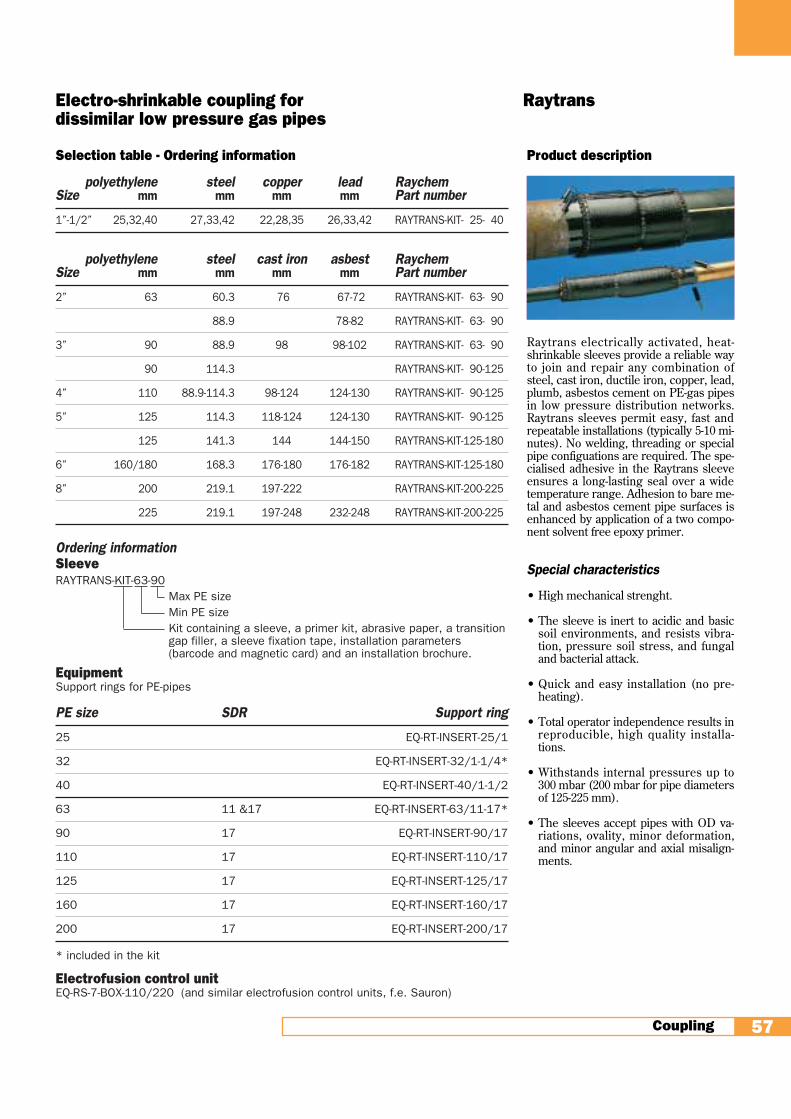
Product description
Raytrans electrically activated, heat-shrinkable sleeves provide a reliable wayto join and repair any combination ofsteel, cast iron, ductile iron, copper, lead,plumb, asbestos cement on PE-gas pipesin low pressure distribution networks.Raytrans sleeves permit easy, fast andrepeatable installations (typically 5-10 mi-nutes). No welding, threading or specialpipe configuations are required. The spe-cialised adhesive in the Raytrans sleeveensures a long-lasting seal over a widetemperature range. Adhesion to bare me-tal and asbestos cement pipe surfaces isenhanced by application of a two compo-nent solvent free epoxy primer.
Special characteristics
• High mechanical strenght.
• The sleeve is inert to acidic and basicsoil environments, and resists vibra-tion, pressure soil stress, and fungaland bacterial attack.
• Quick and easy installation (no pre-heating).
• Total operator independence results inreproducible, high quality installa-tions.
• Withstands internal pressures up to300 mbar (200 mbar for pipe diametersof 125-225 mm).
• The sleeves accept pipes with OD va-riations, ovality, minor deformation,and minor angular and axial misalign-ments.
Coupling 57
Electro-shrinkable coupling for Raytrans dissimilar low pressure gas pipes
Selection table - Ordering information
polyethylene steel copper lead RaychemSize mm mm mm mm Part number
1”-1/2” 25,32,40 27,33,42 22,28,35 26,33,42 RAYTRANS-KIT- 25- 40
polyethylene steel cast iron asbest RaychemSize mm mm mm mm Part number
2” 63 60.3 76 67-72 RAYTRANS-KIT- 63- 90
88.9 78-82 RAYTRANS-KIT- 63- 90
3” 90 88.9 98 98-102 RAYTRANS-KIT- 63- 90
90 114.3 RAYTRANS-KIT- 90-125
4” 110 88.9-114.3 98-124 124-130 RAYTRANS-KIT- 90-125
5” 125 114.3 118-124 124-130 RAYTRANS-KIT- 90-125
125 141.3 144 144-150 RAYTRANS-KIT-125-180
6” 160/180 168.3 176-180 176-182 RAYTRANS-KIT-125-180
8” 200 219.1 197-222 RAYTRANS-KIT-200-225
225 219.1 197-248 232-248 RAYTRANS-KIT-200-225
Ordering informationSleeveRAYTRANS-KIT-63-90
Max PE sizeMin PE sizeKit containing a sleeve, a primer kit, abrasive paper, a transitiongap filler, a sleeve fixation tape, installation parameters (barcode and magnetic card) and an installation brochure.
EquipmentSupport rings for PE-pipes
PE size SDR Support ring
25 EQ-RT-INSERT-25/1
32 EQ-RT-INSERT-32/1-1/4*
40 EQ-RT-INSERT-40/1-1/2
63 11 &17 EQ-RT-INSERT-63/11-17*
90 17 EQ-RT-INSERT-90/17
110 17 EQ-RT-INSERT-110/17
125 17 EQ-RT-INSERT-125/17
160 17 EQ-RT-INSERT-160/17
200 17 EQ-RT-INSERT-200/17
* included in the kit
Electrofusion control unitEQ-RS-7-BOX-110/220 (and similar electrofusion control units, f.e. Sauron)
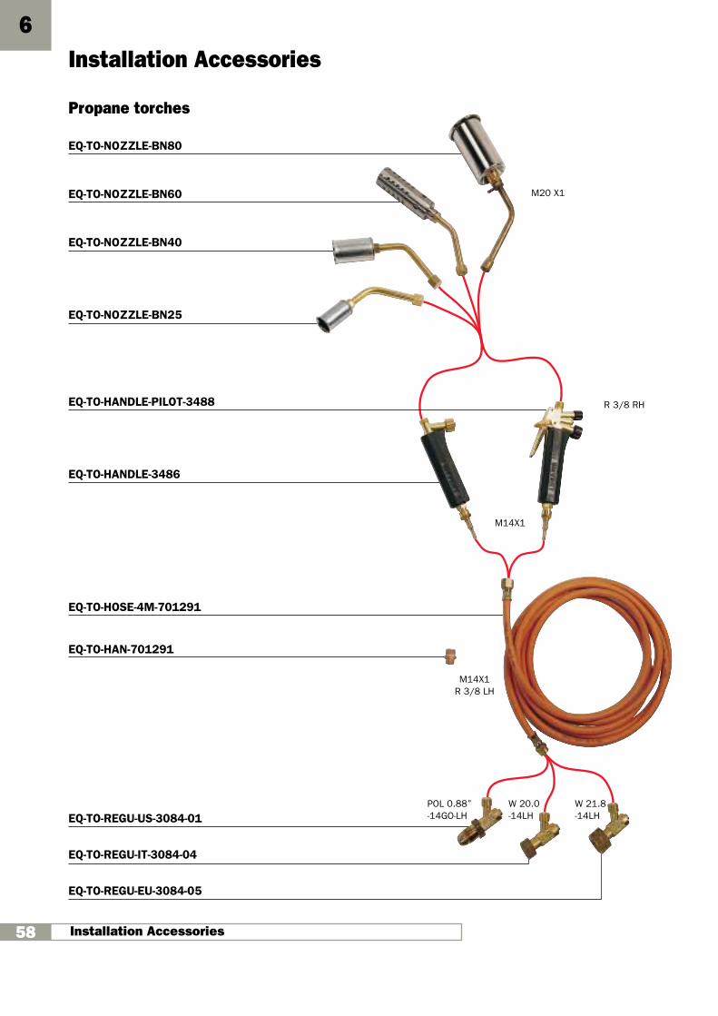
Propane torches
EQ-TO-NOZZLE-BN80
EQ-TO-NOZZLE-BN60
EQ-TO-NOZZLE-BN40
EQ-TO-NOZZLE-BN25
EQ-TO-HANDLE-PILOT-3488
EQ-TO-HANDLE-3486
EQ-TO-HOSE-4M-701291
EQ-TO-HAN-701291
EQ-TO-REGU-US-3084-01
EQ-TO-REGU-IT-3084-04
EQ-TO-REGU-EU-3084-05
Installation Accessories6
Installation Accessories58
M20 X1
W 21.8-14LH
W 20.0-14LH
POL 0.88”-14GO-LH
M14X1R 3/8 LH
M14X1
R 3/8 RH
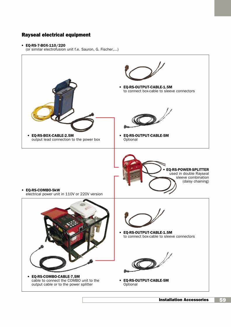
Installation Accessories 59
Rayseal electrical equipment
• EQ-RS-COMBO-5kWelectrical power unit in 110V or 220V version
• EQ-RS-BOX-CABLE-2.5Moutput lead connection to the power box
• EQ-RS-OUTPUT-CABLE-1.5Mto connect box-cable to sleeve connectors
• EQ-RS-OUTPUT-CABLE-1.5Mto connect box-cable to sleeve connectors
• EQ-RS-POWER-SPLITTERused in double Rayseal
sleeve combination (daisy chaining)
• EQ-RS-COMBO-CABLE-7,5Mcable to connect the COMBO unit to theoutput cable or to the power splitter
• EQ-RS-7-BOX-110/220(or similar electrofusion unit f.e. Sauron, G. Fischer,...)
• EQ-RS-OUTPUT-CABLE-5MOptional
• EQ-RS-OUTPUT-CABLE-5MOptional
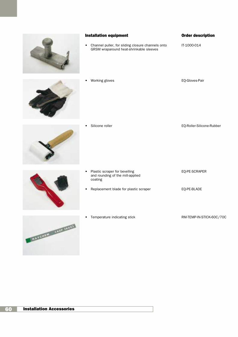
Installation Accessories60
Installation equipment Order description
• Channel puller, for sliding closure channels onto IT-1000-014GRSM wraparound heat-shrinkable sleeves
• Working gloves EQ-Gloves-Pair
• Silicone roller EQ-Roller-Silicone-Rubber
• Plastic scraper for bevelling EQ-PE-SCRAPERand rounding of the mill-applied coating
• Replacement blade for plastic scraper EQ-PE-BLADE
• Temperature indicating stick RM-TEMP-IN-STICK-60C/70C

R
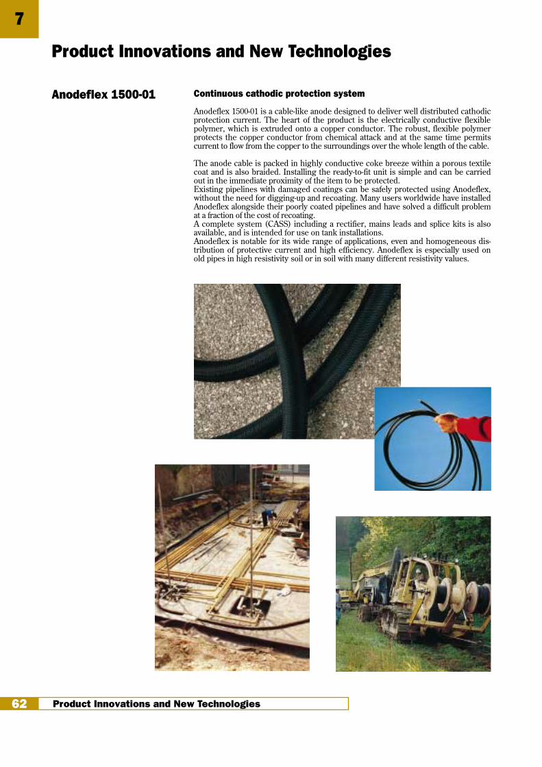
7
Product Innovations and New Technologies62
Product Innovations and New Technologies
Anodeflex 1500-01 Continuous cathodic protection system
Anodeflex 1500-01 is a cable-like anode designed to deliver well distributed cathodicprotection current. The heart of the product is the electrically conductive flexiblepolymer, which is extruded onto a copper conductor. The robust, flexible polymerprotects the copper conductor from chemical attack and at the same time permitscurrent to flow from the copper to the surroundings over the whole length of the cable.
The anode cable is packed in highly conductive coke breeze within a porous textilecoat and is also braided. Installing the ready-to-fit unit is simple and can be carriedout in the immediate proximity of the item to be protected.Existing pipelines with damaged coatings can be safely protected using Anodeflex,without the need for digging-up and recoating. Many users worldwide have installedAnodeflex alongside their poorly coated pipelines and have solved a difficult problemat a fraction of the cost of recoating.A complete system (CASS) including a rectifier, mains leads and splice kits is alsoavailable, and is intended for use on tank installations. Anodeflex is notable for its wide range of applications, even and homogeneous dis-tribution of protective current and high efficiency. Anodeflex is especially used onold pipes in high resistivity soil or in soil with many different resistivity values.
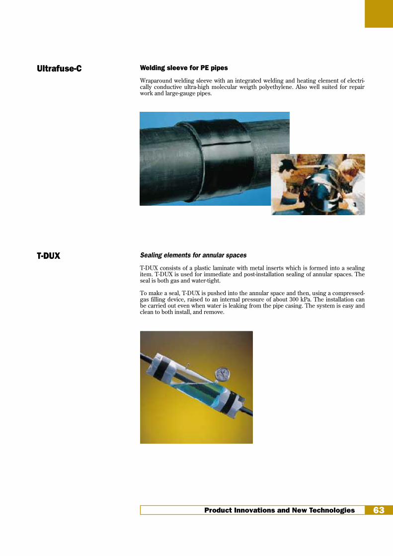
Product Innovations and New Technologies 63
Welding sleeve for PE pipes
Wraparound welding sleeve with an integrated welding and heating element of electri-cally conductive ultra-high molecular weigth polyethylene. Also well suited for repairwork and large-gauge pipes.
Ultrafuse-C
T-DUX Sealing elements for annular spaces
T-DUX consists of a plastic laminate with metal inserts which is formed into a sealingitem. T-DUX is used for immediate and post-installation sealing of annular spaces. Theseal is both gas and water-tight.
To make a seal, T-DUX is pushed into the annular space and then, using a compressed-gas filling device, raised to an internal pressure of about 300 kPa. The installation canbe carried out even when water is leaking from the pipe casing. The system is easy andclean to both install, and remove.
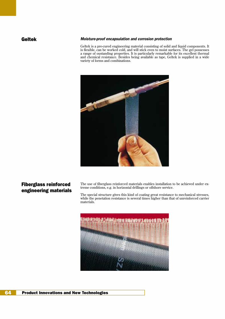
Geltek Moisture-proof encapsulation and corrosion protection
Geltek is a pre-cured engineering material consisting of solid and liquid components. Itis flexible, can be worked cold, and will stick even to moist surfaces. The gel possessesa range of oustanding properties. It is particularly remarkable for its excellent thermaland chemical resistance. Besides being available as tape, Geltek is supplied in a widevariety of forms and combinations.
The use of fiberglass reinforced materials enables installation to be achieved under ex-treme conditions, e.g. in horizontal drillings or offshore service.
The special structure gives this kind of coating great resistance to mechanical stresses,while the penetation resistance is several times higher than that of unreinforced carriermaterials.
Fiberglass reinforcedengineering materials
Product Innovations and New Technologies64

Absender
.......................................................................................................................................................
.......................................................................................................................................................
.......................................................................................................................................................
.......................................................................................................................................................
Telephone: ...................................................... Fax: .................................................................
Sender
Please send
Raychem Specification
Technical Information
for the following Products
CPSM PERP FCMS/FCWS-F GRSM/GRSM-F Anodeflex/CASS
TPSM HTTE FCMS-CAP RAYSEAL Ultrafuse-C
WPC/GAPS BLOT MPSM/MEPS CSEM-F Geltek
HTLP 60 STTE TISKW-F WAFT T-DUX
DIRAX FLEXCLAD TISW-F RAYTRANS
Corrosion Protection and Sealing-catalogue
Information on district heating products
Information on products for transmission pipelines (new construction and rehabilitation)
Information on products for cathodic corrosion protection
Other information requirement
................................................................................................................................................................
................................................................................................................................................................
R
Ultratec DivisionCorrosion Protection, Sealing and Coupling
Absender
Fax (32) 16 / 351 202 • Fax (44) 1743 572 549 • Fax 800 540 1009
Customer service
FAX
UK USB

Notes

Notes

Notes

Remark
All of the above information, including illustrations, is believed to be reliable. Usershowever, should independently evaluate the suitability of each product for theirapplication. Raychem makes no warranties as to the accuracy of completeness ofthe information and disclaims any liability regarding its use. Raychem’s only obliga-tions are those in the Standard Terms and Conditions of Sale for this product andin no case will Raychem be liable for any incidental, indirect or consequential da-mages arising from the sale, resale, use or misuse of the product. Raychem Speci-fications are subject to change without notice. In addition Raychem reserves theright to make changes in materials or processing, without notification to the Buyer,which do not affect compliance with any applicable specification.
WPC, HTLP, ANODEFLEX, GELTEK, TDUX, RDSS, ULTRAFUSE, RAYSEAL, RAYTRANS, CPSM,TPSM, GAPS, DIRAX, PERP, HTTE, BLOT, STTE, FLEXCLAD, FCMS, FCWS, MPSM, MEPS, TIS-K,TISKW, TISW, GRSM, CSEM and WAFT are trade marks of Raychem Corporation.
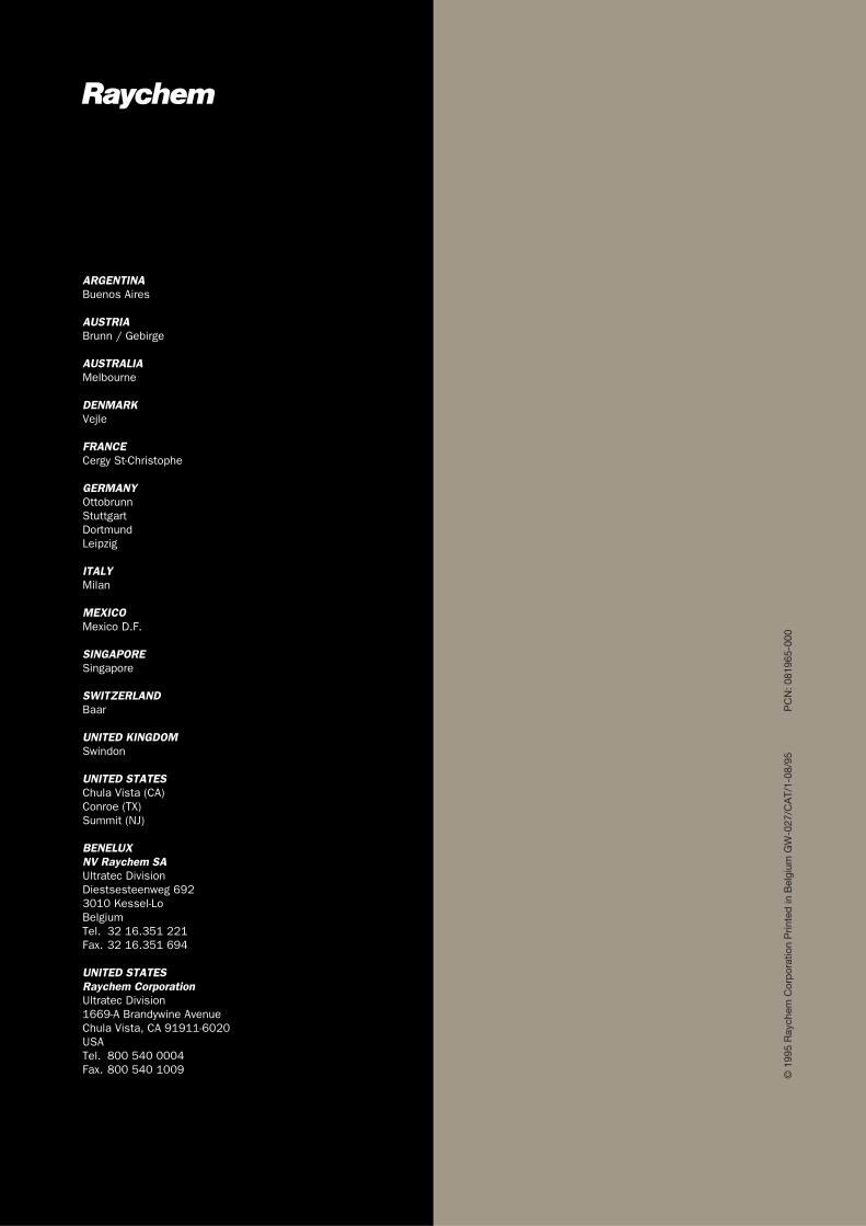
R
ARGENTINABuenos Aires
AUSTRIABrunn / Gebirge
AUSTRALIAMelbourne
DENMARKVejle
FRANCECergy St-Christophe
GERMANYOttobrunnStuttgartDortmundLeipzig
ITALYMilan
MEXICOMexico D.F.
SINGAPORESingapore
SWITZERLANDBaar
UNITED KINGDOMSwindon
UNITED STATESChula Vista (CA)Conroe (TX)Summit (NJ)
BENELUXNV Raychem SAUltratec DivisionDiestsesteenweg 6923010 Kessel-LoBelgiumTel. 32 16.351 221Fax. 32 16.351 694
UNITED STATESRaychem CorporationUltratec Division1669-A Brandywine AvenueChula Vista, CA 91911-6020USATel. 800 540 0004Fax. 800 540 1009 ©
199
5 R
aych
em C
orp
orat
ion
Prin
ted
in B
elgi
um G
W-0
27/C
AT/
1-08
/95
P
CN
: 081
965-
000