Embed Size (px)
Citation preview
Redistrib
Ultrasonic wave propagation in stereo-lithographical bonereplicas
Haydar Aygüna�
Medical Physics, Post-Graduate Medical Institute, The University of Hull, Cottingham Road, Hull HU67RX, United Kingdom
Keith AttenboroughDepartment of Design, Development, Environment and Materials, The Open University, Milton Keynes MK76AA, United Kingdom
Walter LauriksLaboratorium voor Akoestiek en Thermische Fysica, Katholieke Universiteit Leuven, Celestijnenlaan 200 D,B-3001 Heverlee, Belgium
Christian M. LangtonDepartment of Medical Physics, Queensland University of Technology, 2 George Street, Brisbane QLD4001, Australia
�Received 12 February 2010; revised 22 March 2010; accepted 26 March 2010�
Predictions of a modified anisotropic Biot–Allard theory are compared with measurements of pulsescentered on 100 kHz and 1 MHz transmitted through water-saturated stereo-lithographical bonereplicas. The replicas are 13 times larger than the original bone samples. Despite the expectedeffects of scattering, which is neglected in the theory, at 100 kHz the predicted and measuredtransmitted waveforms are similar. However, the magnitude of the leading negative edge of thewaveform is overpredicted, and the trailing parts of the waveforms are not predicted well. At 1MHz, although there are differences in amplitudes, the theory predicts that the transmittedwaveform is almost a scaled version of that incident in conformity with the data.© 2010 Acoustical Society of America. �DOI: 10.1121/1.3397581�
PACS number�s�: 43.80.Cs, 43.80.Qf, 43.80.Vj �CCC� Pages: 3781–3789
I. INTRODUCTION
Understanding the propagation of acoustic wavesthrough cancellous bone is an important pre-requisite to im-proving the prediction of fracture risk by ultrasound. Boneessentially has two types of structure, both having the samemineralized collagen composition. Cortical bone may gener-ally be considered to be solid; cancellous bone consists of acomplex open-celled porous network of rod- and plate-shaped elements termed trabeculae. The porosity of humancancellous bone ranges between 70% and 95%, the remain-ing volume being perfused with bone marrow. In the adulthuman vertebral body for example, both horizontal and ver-tical trabeculae range from 50–120 �m in thickness, andspaced at intervals of between 1200–5000 and700–2000 �m, respectively �Thomsen et al., 2002�.
Two mechanisms give rise to the structure of bone, mod-eling and remodeling. “Modeling” is the process primarilyresponsible for maintaining bones in their correct shape asthey grow and respond to their biomechanical environment;it also controls the cortical thickness and marrow cavity di-ameter of bones as they age. “Remodeling” is mainly con-cerned with the continual replacing of old cancellous boneand occurs at discrete foci on the surface of the trabeculae
a�Author to whom correspondence should be addressed. Electronic mail:
[email protected]J. Acoust. Soc. Am. 127 �6�, June 2010 0001-4966/2010/127�6
ution subject to ASA license or copyright; see http://acousticalsociety.org/c
�Frost et al., 2001�. During remodeling, osteoclast cells cre-ate a resorption cavity that is subsequently filled with newcollagen by osteoblast cells. In osteoporosis, there is a symp-tomatic negative imbalance in remodeling, thereby creating abone loss, particularly at sites of predominantly cancellousbone such as the spine, hip, wrist, and heel; this ultimatelyleads to skeletal fragility and increased risk of fracture�Rosen, 2004�.
The conventional method of assessing osteoporosis inthe clinical environment is bone mineral density �BMD,g cm−2�, an areal parameter describing the bone mineral con-tent within a projected area. BMD is generally measured atsites most at risk of osteoporotic fracture, the spine, hip, andwrist. BMD is generally measured using the technique ofdual energy X-ray absorptiometry �DXA� �Njeh and Shep-herd, 2004�. True volumetric bone density may be derivedusing quantitative computed tomography �QCT�, utilizing aconventional CT scanner, a calibration phantom beingscanned with the subject to convert Hounsfield numbers intog cm−3 �Lang, 2004�. QCT is increasingly being used, par-ticularly at the lumbar spine although there is a higher radia-tion dose compared to DXA. Although generally utilized as aresearch tool for the measurement of excised tissue samples,microCT provides a typical spatial resolution of 0.01 mmand hence replicates the true trabecular structure, comparedto resolutions of approximately 1 mm for DXA, and slightly
better than 1 mm for QCT. A technique that is gaining in-© 2010 Acoustical Society of America 3781�/3781/9/$25.00
ontent/terms. Download to IP: 194.81.151.145 On: Mon, 17 Mar 2014 14:45:00

Redistrib
creasing interest is magnetic resonance �MR� imaging whichessentially measures the water content of tissues. Bone doesnot therefore give an MR signal, although its presence maybe inferred from a “negative” image �Pothuaud and Majum-dar, 2004�.
Quantitative ultrasound �QUS� generally involves mea-surements of the transmission of ultrasonic signals, eitheralong a cortical bone surface or through a bone such as theheel and phalanx �Njeh et al., 1997�. There are two funda-mental measurement parameters, velocity �ms−1� and attenu-ation �dB�. Velocity is obtained by dividing the propagationdistance by the corresponding transit time, with through-transmission measurements recorded at the calcaneus �heel�and phalanx, and surface-transmission recorded primarily atthe tibia. This technique is only correct in the absence ofdispersion. If dispersion is present �which is the case in po-roelastic media�, this technique gives wrong results �Haiatet al., 2006�. Attenuation is generally expressed as broad-band ultrasound attenuation �BUA, dB MHz−1� at the calca-neus, describing the linear increase in attenuation with fre-quency between 200 and 600 kHz. It has been clinicallydemonstrated that velocity provides higher precision, ex-pressed as CV%, whereas BUA exhibits higher dynamicrange. It is generally accepted that of the QUS options, BUAmeasurement at the calcaneus provides the most accurate in-dication of osteoporotic fracture risk, particularly for hipfracture.
A fundamental relationship exists linking the velocity�v� of a sound wave to the elasticity �E� and density ��� of amaterial, namely, v= ��E /��, although the elasticity modulusused in the relationship is dependent on the sound propaga-tion mode; for example, bulk modulus +4 /3 of the rigiditymodulus for the longitudinal wave ��+4 /3��, the rigiditymodulus for the shear wave and the Young’s modulus for thebar wave. Young’s modulus is derived from mechanical test-ing and longitudinal velocity from ultrasound measurements�Njeh et al., 1996�. A similar fundamental relationship doesnot exist for BUA. It has been shown however that BUAfollows a parabolic-type dependence on porosity having aminimum values corresponding to both solid bone �0% po-rosity� and marrow �100% porosity� �Hodgskinson et al.,1996�. Hence, similar BUA values may be obtained for a fewmarrow pores within a largely solid bone �Sasso et al., 2008�and a few bony trabeculae within a largely marrow sample.A parameter that follows a similar pattern is the surface areaof the bone-marrow interface; associated with this, a linearrelationship between BUA and fractal dimension has beendemonstrated �Langton et al., 1998�.
Even though 25 years have passed since BUA was firstdescribed �Langton et al., 1984�, there remains a lack of afundamental understanding of the dependence of ultrasoundpropagation, and BUA, in particular, on the material andstructural properties of cancellous bone. In order to elucidatethese relationships, a number of theoretical approaches havebeen considered including scattering, simple mixtures, ideal-ized microstructures, and Biot. Scattering is caused by sud-den spatial changes in elastic properties, the magnitude beingdependent on relative size of inhomogeneities and the ultra-
sound wavelength. Multiple scattering may also be consid-3782 J. Acoust. Soc. Am., Vol. 127, No. 6, June 2010
ution subject to ASA license or copyright; see http://acousticalsociety.org/c
ered, being a combination of the original and previouslyscattered waves �Luppé et al., 2003; Haiat et al., 2008a,2008b�. Boutin �2007� has combined rigid-porous theory andscattering to investigate the low frequency scattering ofacoustic wave propagation in heterogeneous media made ofair and motionless inclusions. The simple mixture theory ex-presses velocity in terms of bone volume fraction, density,and bulk modulus. The theory of Chernov �1960� combinesscattering and simple mixture theory via velocity fluctuationsand scatterer size. Simple mixture theories have had limitedsuccess for porous media such as cancellous bone. Two theo-ries that are inherently applicable to a solid framework per-fused with a viscous fluid are the Schoenberg and Biot theo-ries. The theory of Schoenberg �1983, 1984, 1986� considersperiodically alternating parallel solid-fluid layers, but doesnot consider the viscous absorption. Biot theory predicts twocompressional waves, often referred to as “fast and “slow,”when the waves propagating through the solid frame of boneand marrow are in- and out-of-phase, respectively. Biottheory was specifically developed to describe acoustic wavepropagation in fluid-saturated porous elastic media �Biot,1956a, 1956b�. Although its original context was geophysicaltesting of porous rocks, it has been used extensively to de-scribe the wave motion in cancellous bone. It allows for anarbitrary microstructure, with separate motions consideredfor the solid elastic framework �bone� and the interspersedfluid �marrow�, induced by the ultrasonic wave, and alsoincludes energy loss due to viscous friction between solid�bone� and fluid �marrow�. In addition to the two compres-sional waves predicted by Schoenberg’s theory, Biot theoryalso predicts a shear wave. McKelvie and Palmer �1991�were first to apply Biot theory to ultrasonic wave propaga-tion in cancellous bone. Hosokawa and Otani �1997� firstobserved experimentally the two theoretically predictedcompressional waves in cancellous bone at ultrasonic fre-quencies. Subsequently Biot theory has been used exten-sively to describe the wave motion in trabecular �cancellous�bone �Haire and Langton, 1999; Fellah et al., 2004; Sebaaet al., 2006�. A modified Biot–Attenborough �MBA� modelhas also been proposed for acoustic wave propagation in anon-rigid porous medium with circular cylindrical poresstarting from a formulation for a rigid-framed porous mate-rial �Roh et al., 2003; Attenborough 1982, 1983�. The MBAhas been used to predict the dependences of velocity andattenuation on frequency and porosity in bovine cancellousbone �Lee et al. 2003; Lee and Yoon 2006�.
For geophysical applications �Carcione 1996�, Biottheory has been further developed including semi-analyticalapproach that allows for transverse anisotropy in the frameelastic moduli, tortuosity and permeability. The angular de-pendences of phase velocities for the fast and the slow wavesin cancellous bone have been predicted �Hughes et al. 1999�,along with the anisotropic behavior of acoustic wave propa-gation �Hughes et al. 2007�. Also the Biot model has beenmodified to include the acoustic anisotropy of cancellousbone by introducing empirical angle-dependent parameters,and used to predict both the fast and slow wave velocities asa function of propagation angle with respect to the trabecular
alignment of cancellous bone �Lee et al. 2007�.Aygün et al.: Ultrasonic wave propagation in bone replicas
ontent/terms. Download to IP: 194.81.151.145 On: Mon, 17 Mar 2014 14:45:00

Redistrib
Most recently, Aygün et al. �2009� have extended previ-ous work on the influence of anisotropic pore structure andelasticity in cancellous bone by developing an anisotropicBiot–Allard model, allowing for angle-dependent elasticityand angle-and-porosity dependent tortuosity. The extremeangle dependence of tortuosity corresponding to the parallelplate microstructure used by Hughes et al. �2007� has beenreplaced by angle-and-porosity dependent tortuosity valuesbased on data for slow wave transmission through air-filledstereo-lithography �STL� bone replicas �Attenborough et al.2005�. It has been suggested that the anisotropic Biot–Allardmodel could be used to give further insight into the factorsthat have the most important influence on the angle depen-dency of wave speeds and attenuation in cancellous bone.
This paper reports measurements of ultrasonic transmis-sion made through water-saturated bone replicas at 100 kHzand 1 MHz. The resulting data are compared with predictionsof a modified Biot–Allard model with anisotropic angle-and-porosity dependent tortuosity and angle-dependent elasticity.First we summarize the theory. Second we present the devel-opment of STL bone replicas. Then we present the measure-ments and default parameters used for the predictions and,finally, we compare data and predictions.
II. THEORY
A porous sample of length L is subjected to an ultrasonicwave in fluid �water� Pi. Part of ultrasonic wave is reflectedback into the fluid Pr, while other part is transmitted throughthe sample Pt. Fellah et al. �2004� presented an analyticalmodel based on the Biot’s theory modified by Johnson et al.�1987� model to describe the viscous interaction betweenfluid and a porous elastic structure. The Fourier transform ofthe transmitted field is given by Fellah et al. �2004� as
P3�x,�� = T���exp�− j��x − L�
c0�����, x � L , �1�
where ���� is the Fourier transform of the incident field�Pi�t��, T��� is the Fourier transform of the transmissionkernel, � is the angular frequency of motion, c0 is the speedof sound in fluid, and L is the thickness of the material. Amore detailed consideration of the transformed field can befound in the paper of Fellah et al. �2004�. The transmissioncoefficient T��� is given by
T��� =j�2� fc0F4���
�j�� fc0F4����2 − �j�F3��� − 1�2 , �2�
where F4��� and F3��� are given in the Appendix.The parallel orientation of the trabeculae in cancellous
bone means that cancellous bone has transverse anisotropy.Such inherent anisotropy means that the acoustical propertiesvary with transmission direction �Attenborough et al., 2005�.Aygün et al. �2009� introduced such anisotropy into Biot–Allard model by allowing angle-and-porosity dependent tor-tuosity and angle-dependent elasticity. A heuristic form forporosity- and angle-dependent tortuosity is proposed by
Aygün et al. �2009� asJ. Acoust. Soc. Am., Vol. 127, No. 6, June 2010
ution subject to ASA license or copyright; see http://acousticalsociety.org/c
�� = 1 − r�1 −1
� + k cos2�� , �3�
where is the porosity, is the variable between 0° and 90°,and r and k can be considered adjustable. A range of possiblevalues of r and k have been found by comparing predictionsof Eq. �3� for =0° and 90°, respectively with values de-duced from air-filled replica bones �Attenborough et al.,2005� of known porosity. Values of r and k are found bysolving the resulting simultaneous equations.
To predict transmission through an anisotropic poroelas-tic sample it is necessary to allow for elastic anisotropy also.Williams �1992� suggested that the dependence of skeletalframe modulus �Young’s modulus Eb, bulk Modulus Kb, andrigidity modulus �b� in terms of bone volume fraction �1−� and the Young’s modulus of the solid material of theframe �Es� are given by Eb=Es�1−�n, Kb=Eb / �1–2�b�, and�b=Eb / �1+2�b�, respectively, where vb is the Poisson’s ratioof frame and the exponent n varies from 1 to 3 according toGibson �1985�, depending on the angle �� with respect tothe dominant structural orientation according to n=n1 sin2��+n2 cos2��. Values of n1=1.23 and n2=2.35 arechosen by Lee et al. �2007� to be consistent with the work ofWilliams �1992�. The Biot–Allard model for waves in fluid-saturated poro-elastic media �Allard, 1993� allows for ther-mal exchange and viscous drag between pore-fluid and thesolid framework. Thermal exchange effects between solidand fluid can be included through a frequency-dependentbulk modulus of the fluid. However, whereas thermal effectsare fairly important in air-filled porous materials, they areexpected to be of minor importance in the water-filled bonereplicas.
III. DEVELOPMENT OF STL BONE REPLICAS
Several authors such as Strelitzki et al. �1997�, Wear�2005�, and Lee and Choi �2007� investigated the phase ve-locities and attenuation in cancellous-bone-mimicking phan-toms. Stereo-lithographical bone replicas made of resin havebeen developed �Langton et al., 1997�. STL is a form ofrapid prototyping that allows complex solid objects to bemanufactured directly from three dimensional �3D� computermodels in the form of successive layers of light-cured resin.There are two stages to stereo-lithography: design and manu-facturing. During the design stage the required object is ini-tially created using standard 3D solid modeling techniquesand then converted into the stereo-lithography format con-sisting of a series of thin slices. The stereo-lithographymanufacturing system consists of a vat of light-sensitiveresin with an elevator and computer-controlled scanning la-ser. At the start of the process, the elevator is positioned justbelow the surface �typically 0.1 mm� of the liquid stereo-lithography resin. The laser scanner “prints” the bottom layeronto the resin surface, which solidifies upon exposure to thelaser beam. The elevator then moves down by an incrementaldistance, and the stereo-lithography resin is respread over thesurface of the vat prior to the next scan. As successive solidlayers are formed, they bond to produce a single solid object.When the model is completed the elevator is raised, and the
unused resin is allowed to drain. The laser cures the stereo-Aygün et al.: Ultrasonic wave propagation in bone replicas 3783
ontent/terms. Download to IP: 194.81.151.145 On: Mon, 17 Mar 2014 14:45:00

Redistrib
lithography resin to approximately 60%. The curing processis completed in an ultraviolet oven. The resolution of thestereo-lithography process is governed by the laser spot sizeand the vertical movement of the elevator. Typically, the la-ser spot diameter will be better than 0.3 mm, and the elevatormovement resolution will be about 2.5 �m. Further detailsof stereo-lithography technique can be found elsewhere�Langton et al. 1997�. The views of four stereo-lithographical bone replicas are shown in Fig. 1.
The primary reason for creating stereo-lithography rep-licas is that multiple copies may be created. This is particu-larly valuable for mechanical testing, where measurement inone direction may damage a sample and preclude testing inother orthogonal directions. The models were created at amagnification of �13 to ensure spatial fidelity between thevoxel size of the microCT scan of the original natural tissuesamples and the minimum wall thickness achievable withSTL. Bone “corrosion” due to osteoporosis can be simulatedphysically by corresponding stereo-lithographical bone rep-licas. Therefore bone replicas should enable studies of theacoustical effects of changes in microstructure. Since the
CALCANEOUS LUMBAR SPINE
ILIAC CREST FEMORAL HEAD
FIG. 1. �Color online� Views of four stereo-lithographical bone replicas.
(Water Tank)
Transducers
STL bone replicas
Trigger
Pulse generator High frequency filteringPre-amplifier
Digital oscilloscope
Computer
FIG. 2. �Color online� Experimental setup for ultrasonic measurements
�Fellah et al., 2004�.3784 J. Acoust. Soc. Am., Vol. 127, No. 6, June 2010
ution subject to ASA license or copyright; see http://acousticalsociety.org/c
STL bone replicas used in measurements have 13 times theactual size of the bone microstructure, spatial matching be-tween sample microstructure and ultrasound wavelengthscould be achieved by lowering the frequency. Hence 1 MHzshould be reduced to approximately 100 kHz. To simulatethe 200–600 kHz measurements used in BUA, it would benecessary to use between 15.4 and 46.2 kHz.
IV. MEASUREMENTS
The experimental procedure used by Fellah et al. �2004�has been followed to perform measurements in a water tank�see Fig. 2�. Two broadband Panametrics A 303S plane pi-ezoelectric transducers having 1 cm diameter with 1 MHzcentral frequency, and two Panametrics V3052 transducershaving 44 mm diameter with 100 kHz central frequency havebeen used for experiments. 400 V pulses are provided by a5058PR Panametrics pulser/receiver. Electronic interferenceis removed by 1000 acquisition averages.
When a wave impinges on a STL bone replica, part ofthe wave is reflected back. The part of the wave penetrating
4.2 4.4 4.6 4.8 5 5.2 5.4 5.6 5.8 6
x 10-5
-2
0
2
Time (s)
Amplitude(V)
0.2 0.4 0.6 0.8 1 1.2 1.4 1.6 1.8 2 2.2
x 105
-40
-35
-30
-25
Frequency (Hz)
Amplitude(dB)
(a)
(b)
FIG. 3. �a� Incident �reference� signal versus time; �b� spectrum of theIncident signal versus frequency, 100 kHz transducer.
3.8 4 4.2 4.4 4.6 4.8 5 5.2
x 10-5
-2
-1
0
1
2
Time (s)
Amplitude(V)
0.4 0.6 0.8 1 1.2 1.4 1.6 1.8
x 106
-70
-60
-50
-40
-30
-20
Frequency (Hz)
Amplitude(dB)
(a)
(b)
FIG. 4. �a� Incident �reference� signal versus time; �b� spectrum of the
Incident signal versus frequency, 1MHz transducer.Aygün et al.: Ultrasonic wave propagation in bone replicas
ontent/terms. Download to IP: 194.81.151.145 On: Mon, 17 Mar 2014 14:45:00
Redistrib
into the sample undergoes mode conversion into fast andslow components, which are transmitted through the STLbone replica. The measurements have been made parallel tothe trabeculae direction. The stereo-lithographical bone rep-licas used in the measurements are in the form of 57 mmcubes. The incident �reference� signals generated by 100 kHzand 1 MHz transducers and transmitted through fluid �water�are shown in Figs. 3�a� and 4�a�, and their spectra are shownin Figs. 3�b� and 4�b�, respectively. Predicted transmissioncoefficients in frequency domain for lumbar spine �LS2B� at100 kHz and 1 MHz are shown in Fig. 5.
V. COMPARISONS BETWEEN DATA ANDPREDICTIONS
The parameters used in the predictions are listed inTable I. The elastic moduli of the STL bone replicas made ofresin have been taken to be equal to the elastic modulus ofresin which is 6.04 GPa �DSM Somos� and is smaller thanthe elastic modulus of real bone, which is 20 GPa �Williams1992�. Assuming that the permeability of the bone is 5�10−9 m3 �McKelvie and Palmer 1991�, the permeability ofbone replicas has been taken to be 132 times higher becauseof the magnification of the actual size of the bone micro-structure by 13 times in each direction. The assumed charac-teristics of the saturating fluid �water� are: density � f
=1000 kg /m−3, viscosity =10−3 kg ms−1, and speed ofsound in water c0=1490 m /s.
0 0.5 1 1.5 2 2.5 3 3.5 4
x 106
0
0.5
1
Frequency (Hz)
|T(w)|
0 0.5 1 1.5 2 2.5 3 3.5 4
x 105
0
0.5
1
Frequency (Hz)
|T(w)|
1 MHz
100 kHz
FIG. 5. Numerical simulation of the transmission coefficient versus fre-quency at 100 kHz and 1 MHz.
TABLE I. Default input parameters for STL bone re
Parameters Ili
Density of replica �s �Attenborough et al., 2005� 12Young’s modulus Es �DSM Somos�Poisson’s ratio of solid vs
Poisson’s ratio of frame vb
Porosity �Attenborough et al., 2005�Permeability k0 84Viscous characteristic length �
r �Aygün et al., 2009�k �Eq. �3��
J. Acoust. Soc. Am., Vol. 127, No. 6, June 2010
ution subject to ASA license or copyright; see http://acousticalsociety.org/c
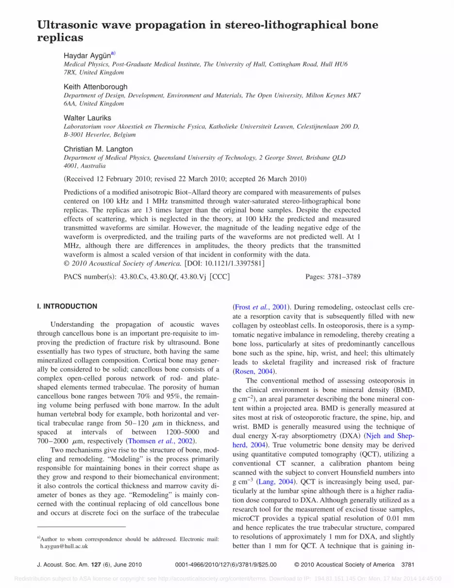
Measured and predicted transmitted signals are travelingthrough the bone replicas in the same direction as the trabe-cular alignment �x direction�. The incident signal shown inFig. 3 has been used for predictions. Predicted transmittedwaves of STL iliac crest �ICF�, femoral head �FRA�, andLS2B replicas versus time are compared with measuredtransmitted waves in water at 100 kHz in Figs. 6–8, respec-tively. In Fig. 6 the initial parts of the measured and pre-dicted transmitted waveforms can be identified as the fastwave arrival, while the second and major parts of the trans-mitted waveforms can be identified as the slow wave contri-bution. Although two compressional wave arrivals can beobserved in both data and predictions in Fig. 6, they can beobserved only in the predictions in Fig. 7, and in the data inFig. 8. While the agreement between the overall structure ofthe waveform data and predictions is reasonable, the magni-tude of the leading negative spike is consistently overesti-mated by the predictions, and the trailing parts of the pulsesare not predicted very accurately. The root mean square er-rors between predictions and data have been calculated. Theerror for FRA, ICF, and LS2B bone replicas are 0.021, 0.01,and 0.016 V at 100 kHz, respectively.
Predicted transmitted waveforms through water-filledSTL FRA, ICF, LS2B, and CAB replicas are compared withmeasured transmitted waves in water at 1 MHz in Figs.9–12, respectively. Although the predicted and measuredtransmitted waveforms are similar, there are significant dif-ferences between the predicted and measured transmitted
.
est ICF Femoral head FRA Lumbar spine LS2 Calcaneus CAB
kg /m3 1227 kg /m3 1206.6 kg /m3 1171 kg /m3
GPa 6.04 GPa 6.04 GPa 6.04 GPa30 0.30 0.30 0.3036 0.40 0.38 0.34386 0.7426 0.9173 0.88220−9 m3 845�10−9 m3 845�10−9 m3 845�10−9 m3
�m 60 �m 220 �m 150 �m88 0.591 0.521 0.81668 0.684 0.143 0.574
3.5 4 4.5 5 5.5 6 6.5 7 7.5 8
x 10-5
-0.2
-0.15
-0.1
-0.05
0
0.05
0.1
0.15
0.2
Time (s)
Amplitude(V)
DataPrediction
Fast waveSlow wave
FIG. 6. �Color online� Comparison of predicted and measured transmittedwaveforms through a water-saturated ICF bone replica at 100 kHz.
plicas
ac cr
33.46.04
0.0.
0.85�1100
0.80.4
Aygün et al.: Ultrasonic wave propagation in bone replicas 3785
ontent/terms. Download to IP: 194.81.151.145 On: Mon, 17 Mar 2014 14:45:00

Redistrib
amplitudes at 1 MHz. The root mean square error betweenpredictions and data for CAB, FRA, ICF, and LS2B bonereplicas are 0.00188, 0.0031, 0.0049, and 0.0055 V at 1MHz, respectively. The measured amplitudes of transmittedwaveforms through the femoral head and iliac crest replicasare larger than the predicted ones, while those measuredthrough the lumbar spine and calcaneus replicas are smallerthan the predicted ones. In the latter two cases, the fact thatthe measured amplitudes are smaller than predicted could beattributed to the effects of scattering, which should give riseto additional attenuation. This interpretation is not consistentwith the cases where the measured transmitted amplitudesare larger than the predicted ones. The lack of consistency inthe agreement between predictions and data might be relatedto the assumption that the permeabilities of the replicas areall the same, whereas the known differences in porosityshould be reflected in differences in permeability. Moreover,scattering can be expected to be more important when thetypical dimensions of the frame and pore microstructure arelarger. In this respect it is interesting to note that the lumbarspine and calcaneus bone replicas have higher fitted viscouscharacteristic lengths than the femoral head and iliac crestbone replicas. Porosity and density of STL bone replicas are
3 4 5 6 7 8
x 10-5
-0.1
-0.05
0
0.05
0.1
0.15
Time (s)
Amplitude(V)
DataPredictionSlow wave
Fast wave
FIG. 7. �Color online� Comparison of predicted and measured transmittedwaveforms through a water-saturated FRA bone replica at 100 kHz.
4 4.5 5 5.5 6 6.5 7
x 10-5
-0.4
-0.3
-0.2
-0.1
0
0.1
0.2
0.3
0.4
Time (s)
Amplitude(V)
DataPrediction
Fast wave
Slow wave
FIG. 8. �Color online� Comparison of predicted and measured transmitted
waveforms through a water-saturated LS2B bone replica at 100 kHz.3786 J. Acoust. Soc. Am., Vol. 127, No. 6, June 2010
ution subject to ASA license or copyright; see http://acousticalsociety.org/c
given by Attenborough et al. �2005�. The values of r for allSTL bone replicas are given by Aygün et al. �2009�. Onlytwo parameters, Poisson’s ratio of frame and viscous charac-teristic length, were adjusted in order to obtain the “best-fit.”In particular, the predictions are very sensitive to the as-sumed values of viscous characteristic length. The “best-fit”characteristic length values �Table I� for the replicas areabout 13 times those found for real bone in the literature i.e.,between 5 and 10 �m �Fellah et al., 2004; Sebaa et al.,2006�.
VI. DISCUSSION AND CONCLUSION
The use of stereo-lithograpical bone replicas made fromresin has the potential to enable systematic investigations ofthe influences of perforation and thinning in cancellous boneon the acoustical and mechanical properties of the bonestructure. Waves transmitted through STL bone replicas withhigher porosity values have higher amplitudes. Osteoporotic
3.2 3.4 3.6 3.8 4 4.2 4.4
x 10-5
-0.04
-0.03
-0.02
-0.01
0
0.01
0.02
0.03
0.04
Time (s)
Amplitude(V)
DataPrediction
FIG. 9. �Color online� Comparison of predicted and measured transmittedwaveforms through a water-saturated FRA bone replica at 1 MHz.
3.5 3.6 3.7 3.8 3.9 4 4.1 4.2 4.3 4.4 4.5
x 10-5
-0.06
-0.04
-0.02
0
0.02
0.04
0.06
Time (s)
Amplitude(V)
DataPrediction
FIG. 10. �Color online� Comparison of predicted and measured transmitted
waveforms through a water-saturated ICF bone replica at 1 MHz.Aygün et al.: Ultrasonic wave propagation in bone replicas
ontent/terms. Download to IP: 194.81.151.145 On: Mon, 17 Mar 2014 14:45:00

Redistrib
bones will have higher porosity values due to bone loss, sogreater energy will be transmitted through them in compari-son with normal bone.
A consequence of using replica bones, which are 13times the actual size of the bone microstructure, is that scat-tering should become important at lower frequencies than inmeasurements with real bone samples. Transmitted signalsfor water-saturated stereo-lithograpical bone replicas havebeen predicted by modified anisotropic Biot–Allard model,which neglects scattering, and the results have been com-pared to measurements made in a water-filled tank at 100kHz and 1 MHz. The wavelengths of the slow and fast wavesin water-saturated STL bone replicas at 100 kHz are 15 and30 mm, respectively. These wavelengths are comparablewith the dimensions of microstructural elements of STL bonereplicas. According to Williams �1992�, the pore sizes in can-cellous bone vary between 0.5 and 1 mm, so typical trabe-culae widths in the replicas vary between 6.5 and 13 mm.Remarkably, scattering seems not to cause significant dis-crepancies between predictions and data at 100 kHz �whichwould be equivalent to 1.3 MHz in real bone�, perhaps as a
3.6 3.7 3.8 3.9 4 4.1 4.2 4.3 4.4 4.5 4.6
x 10-5
-0.1
-0.05
0
0.05
0.1
0.15
Time (s)
Amplitude(V)
DataPrediction
FIG. 11. �Color online� Comparison of predicted and measured transmittedwaveforms through a water-saturated LS2B bone replica at 1 MHz.
3.6 3.8 4 4.2 4.4 4.6
x 10-5
-0.06
-0.04
-0.02
0
0.02
0.04
0.06
Time (s)
Amplitude(V)
DataPrediction
FIG. 12. �Color online� Comparison of predicted and measured transmitted
waveforms through a water-saturated CAB bone replica at 1 MHz.J. Acoust. Soc. Am., Vol. 127, No. 6, June 2010
ution subject to ASA license or copyright; see http://acousticalsociety.org/c
consequence of the fact that the samples behave as low passfilters. Scattering should be even more important at 1 MHz�equivalent to 13 MHz in real bone�, where the fast and slowwavelengths are 3 and 1.5 mm, respectively. So the agree-ment between predictions and data is rather surprising.
These data and predictions support further use of Biot-based theories and of STL replicas for studying ultrasonictransmission through bone.
ACKNOWLEDGMENT
This paper has been supported by Leverhulme Grant No.F/00 181/N, which provided for collaboration with the Labo-ratory of Acoustics and Thermal Physics at Leuven wherethe data reported here were obtained.
APPENDIX: BASIS FOR THE PREDICTION OF THETRANSMISSION COEFFICIENT
The transmission coefficient T��� is given by Fellah etal. �2004�
T��� =j�2� fc0F4���
�j�� fc0F4����2 − �j�F3��� − 1�2 ,
where
Fi��� = �1 + �Ii��� − 1�x��i���
��i���
sinh�l��i����2
����, i = 1,2,
F3��� = � fc0�F1���cosh�l��1����
+ F2���cosh�l��2���� ,
F4��� = F1��� + F2��� ,
The eigenvalues �1��� and �2��� are the squared complexwave numbers of the two compressional waves and are givenby
�1��� =1
2�− �1�2 + �2�j��3/2
− ���12 − 4�3��4 + 2��1�2 − 2�4��j��7/2 + �2
2�j��3� ,
�2��� =1
2�− �1�2 + �2�j��3/2
+ ���12 − 4�3��4 + 2��1�2 − 2�4��j��7/2 + �2
2�j��3� ,
where
�1 = R��11 + P��22 − 2Q��12,
�2 = 2�R� + P� + 2Q�� ,
�3 = �R�P� − Q�2���11�22 − �122 � ,
and
�4 = A�R�P� − Q�2���11 + �22 − 2�12� .
Coefficients R�, P�, and Q� are given by
Aygün et al.: Ultrasonic wave propagation in bone replicas 3787
ontent/terms. Download to IP: 194.81.151.145 On: Mon, 17 Mar 2014 14:45:00
Redistrib
R� =R
PR − Q2 ,
Q� =Q
PR − Q2 ,
and
179–191.
3788 J. Acoust. Soc. Am., Vol. 127, No. 6, June 2010
ution subject to ASA license or copyright; see http://acousticalsociety.org/c
P� =P
PR − Q2 ,
where P, R, and Q are generalized elastic constants.The eigenvectors I1��� and I2��� are given by
I1��� =�2�5 − �1��2 + ��2 − 2�6��j��3/2 − ���1
2 − 4�3��4 + 2��1�2 − 2�4��j��7/2 + �22�j��3
2�− �7�2 − �6�j��3/2�,
I2��� =�2�5 − �1��2 + ��2 − 2�6��j��3/2 + ���1
2 − 4�3��4 + 2��1�2 − 2�4��j��7/2 + �22�j��3
2�− �7�2 − �6�j��3/2�,
where
�5 = �R��11 − Q��12� ,
�6 = A�R� + Q�� ,
�7 = �R��12 − Q��22� .
The coefficients �1���, �2���, and ���� are given by
�1��� = Z2��� − �1 − �Z4��� ,
�2��� = �1 − �Z3��� − Z1��� ,
���� = 2�Z1���Z4��� − �Z2���Z3��� ,
and the coefficients Z1���, Z2���, Z3���, and Z4��� by
Z1��� = �P + QI1�����1��� ,
Z2��� = �P + QI2�����2��� ,
Z3��� = �Q + RI1�����1��� ,
Z4��� = �Q + RI2�����2��� .
Allard, J. F. �1993�. Propagation of Sound in Porous Media: ModellingSound Absorbing Materials �Chapman and Hall, London�.
Attenborough, K. �1982�. “Acoustical characteristics of porous materials,”Phys. Rep. 82, 179–227.
Attenborough, K. �1983�. “Acoustic characteristics of rigid fibrous absor-bents and granular materials,” J. Acoust. Soc. Am. 73, 785–799.
Attenborough, K., Qin, Q., Fagan, M. J., Shin, H.-C., and Langton, C. M.�2005�. “Measurements of tortuosity in stereolithographical bone replicasusing audio-frequency pulses,” J. Acoust. Soc. Am. 118, 2779–2782.
Aygün, H., Attenborough, K., Postema, M., Lauriks, W., and Langton, C. M.�2009�. “Predictions of angle dependent tortuosity and elasticity effects onsound propagation in cancellous bone,” J. Acoust. Soc. Am. 126, 3286–3290.
Biot, M. A. �1956a�. “Theory of propagation of elastic waves in a fluidsaturated porous solid, I. Low frequency range,” J. Acoust. Soc. Am. 28,168–178.
Biot, M. A. �1956b�. “Theory of propagation of elastic waves in a fluidsaturated porous solid, II. High frequency range,” J. Acoust. Soc. Am. 28,
Boutin, C. �2007�. “Rayleigh scattering of acoustic waves in rigid porousmedia,” J. Acoust. Soc. Am. 122, 1888–1905.
Carcione, J. �1996�. “Wave propagation in anisotropic, saturated porous me-dia: Plane-wave theory and numerical simulation,” J. Acoust. Soc. Am. 99,2655–2666.
Chernov, L. A. �1960�. Wave Propagation in a Random Medium �McGraw-Hill, New York�.
DSM Somos, The ProtoFunctional Materials Company, WaterClear 10110.Fellah, Z. E. A., Chapelon, J. Y., Berger, S., Lauriks, W., and Depollier, C.
�2004�. “Ultrasonic wave propagation in human cancellous bone: Appli-cation of Biot theory,” J. Acoust. Soc. Am. 116, 61–73.
Frost, M. L., Blake, G. M., and Fogelman, I. �2001�. “Quantitative ultra-sound and bone mineral density are equally strongly associated with riskfactors for osteoporosis,” J. Bone Miner. Res. 16, 406–416.
Gibson, L. J. �1985�. “The mechanical behaviour of cancellous bone,” J.Biomech. 18, 317–328.
Haiat, G., Lhémery, A., and Renaud, F. �2008a�. “Velocity dispersion intrabecular bone: Influence of multiple scattering and of absorption,” J.Acoust. Soc. Am. 124, 4047–4058.
Haiat, G., Lhémery, A., Padilla, F., Laugier, P., and Naili, S. �2008b�. “Mod-eling of “anomalous” velocity dispersion in trabecular bone: Effect ofmultiple scattering and of viscous absorption,” in Proceedings of the Euro-Noise, Paris.
Haiat, G., Padilla, F., Cleveland, R. O., and Laugier, P. �2006�. “Effects offrequency-dependent attenuation and velocity dispersion on in vitro ultra-sound velocity measurements in intact human femur specimens,” IEEETrans. Ultrason. Ferroelectr. Freq. Control 53, 39–51.
Haire, T. J., and Langton, C. M. �1999�. “Biot theory: A review of its appli-cation on ultrasound propagation through cancellous bone,” Bone 24,291–295.
Hodgskinson, R., Njeh, C. F., Whitehead, M. A., and Langton, C. M. �1996�.“Non-linear relationship between BUA and porosity in cancellous bonemimics,” Phys. Med. Biol. 41, 2411–2420.
Hosokawa, A., and Otani, T. �1997�. “Ultrasonic wave propagation in bo-vine cancellous bone,” J. Acoust. Soc. Am. 101, 558–562.
Hughes, E. R., Leighton, T. G., Petley, G. W., and White, P. R. �1999�.“Ultrasonic propagation in cancellous bone: A new stratified model,” Ul-trasound Med. Biol. 25, 811–821.
Hughes, E. R., Leighton, T. G., White, P. R., and Petley, G. W. �2007�.“Investigation of an anisotropic tortuosity in a Biot model of ultrasonicpropagation in cancellous bone,” J. Acoust. Soc. Am. 121, 568–574.
Johnson, D. L., Koplik, J., and Dashen, R. �1987�. “Theory of dynamicpermeability and tortuosity in fluid-saturated porous media,” J. FluidMech. 176, 379–402.
Lang, T. �2004�. “Quantitative computed tomography,” in The PhysicalMeasurement of Bone, edited by C. M. Langton and C. F. Njeh �IOPP,Bristol, UK�, pp. 308–318.
Langton, C. M., Palmer, S. B., and Porter, R. W. �1984�. “The measurement
Aygün et al.: Ultrasonic wave propagation in bone replicas
ontent/terms. Download to IP: 194.81.151.145 On: Mon, 17 Mar 2014 14:45:00
Redistrib
of broadband ultrasonic attenuation in cancellous bone,” Eng. Med. 13,89–91.
Langton, C. M., Whitehead, M. A., Haire, T. J., and Hodgskinson, R.�1998�. “Fractal dimension predicts broadband ultrasound attenuation instereolithography models of cancellous bone,” Phys. Med. Biol. 43, 467–471.
Langton, C. M., Whitehead, M. A., Langton, D. K., and Langley, G. �1997�.“Development of a cancellous bone structural model by stereolithographyfor ultrasound characterisation of the calcaneus,” Med. Eng. Phys. 19,599–604.
Lee, K. I., and Choi, M. J. �2007�. “Phase velocity and normalized broad-band ultrasonic attenuation in polyacetal cuboid bone-mimicking phan-toms,” J. Acoust. Soc. Am. 121, EL263–EL269.
Lee, K. I., Hughes, E. R., Humphery, V. F., Leighton, T. G., and Choi, M. J.�2007�. “Empirical angle-dependent Biot and MBA models for acousticanisotropy in cancellous bone,” Phys. Med. Biol. 52, 59–73.
Lee, K. I., Roh, H.-S., and Yoon, S. W. �2003�. “Acoustic wave propagationin bovine cancellous bone: Application of the Modified Biot–Attenborough model,” J. Acoust. Soc. Am. 114, 2284–2293.
Lee, K. I., and Yoon, S. W. �2006�. “Comparison of acoustic characteristicspredicted by Biot’s theory and the modified Biot–Attenborough model incancellous bone,” J. Biomech. 39, 364–368.
Luppé, F., Conoir, J. M., and Franklin, H. �2003�. “Multiple scattering in atrabecular bone: Influence of the marrow viscosity on the effective prop-erties,” J. Acoust. Soc. Am. 113, 2889–2892.
McKelvie, M. L., and Palmer, S. B. �1991�. “The interaction of ultrasoundwith cancellous bone,” Phys. Med. Biol. 36, 1331–1340.
Njeh, C. F., Boivin, C. M., and Langton, C. M. �1997�. “The role of ultra-sound in the management of osteoporosis: a review,” Osteoporos. Int. 7,7–22.
Njeh, C. F., Hodgskinson, R., Currey, J. D., and Langton, C. M. �1996�.“Orthogonal relationships between ultrasonic velocity and material prop-erties of bovine cancellous bone,” Med. Eng. Phys. 18, 373–381.
Njeh, C. F., and Shepherd, J. A. �2004�. “Absorptiometric measurement,” inThe Physical Measurement of Bone, edited by C. M. Langton and C. F.Njeh, �IOPP, Bristol, UK�, pp. 267–307.
J. Acoust. Soc. Am., Vol. 127, No. 6, June 2010
ution subject to ASA license or copyright; see http://acousticalsociety.org/c
Pothuaud, L., and Majumdar, S. �2004�. “Magnetic resonance imaging,” inThe Physical Measurement of Bone, edited by C. M. Langton and C. F.Njeh, �IOPP, Bristol, UK�, pp. 379–411.
Roh, H. S., Lee, K. I., and Yoon, S. W. �2003�. “Acoustic characteristics ofa non-rigid porous medium with circular cylindrical pores,” J. KoreanPhys. Soc. 45, 55–62.
Rosen, C. J. �2004�. “Anatomy, physiology and disease,” in The PhysicalMeasurement of Bone, edited by C. M. Langton and C. F. Njeh, �IOPP,Bristol, UK�, pp. 3–34.
Sasso, M., Haiat, G., Yamato, Y., Naili, S., and Matsukawa, M. �2008�.“Dependence of ultrasonic attenuation on bone mass and microstructure inbovine cortical bone,” J. Biomech. 41, 347–355.
Schoenberg, M. �1983�. “Wave propagation in a finely laminated periodicelastoacoustic medium,” Appl. Phys. Lett. 42, 350–352.
Schoenberg, M. �1984�. “Wave propagation in alternating solid and fluidlayers,” Wave Motion 6, 303–320.
Schoenberg, M. �1986�. “Wave propagation in alternating solid and viscousfluid layers: Size effects in attenuation and dispersion of fast and slowwaves,” Appl. Phys. Lett. 48, 1249–1251.
Sebaa, N., Fellah, Z., Fellah, M., Ogam, E., Wirgin, A., Mitri, F., Depollier,C., and Lauriks, W. �2006�. “Ultrasonic characterisation of human cancel-lous bone using the Biot theory: Inverse problem,” J. Acoust. Soc. Am.120, 1816–1824.
Strelitzki, R., Evans, J. A., and Clarke, A. J. �1997�. “The influence ofporosity and pore size on the ultrasonic properties of bone investigatedusing a phantom material,” Osteoporosis Int. 7, 370–375.
Thomsen, J. S., Ebbesen, E. N., and Mosekilde, L. �2002�. “Age-relateddifferences between thinning of horizontal and vertical trabeculae in hu-man lumbar bone as assessed by a new computerized method,” Bone 31,136–142.
Wear, K. A. �2005�. “The dependences of phase velocity and dispersion onthe trabecular thickness and spacing in trabecular bone-mimicking phan-toms,” J. Acoust. Soc. Am. 118, 1186–1192.
Williams, J. L. �1992�. “Ultrasonic wave propagation in cancellous and cor-tical bone: Predictions of some experimental results by Biot’s Theory,” J.Acoust. Soc. Am. 91, 1106–1112.
Aygün et al.: Ultrasonic wave propagation in bone replicas 3789
ontent/terms. Download to IP: 194.81.151.145 On: Mon, 17 Mar 2014 14:45:00