Embed Size (px)
Citation preview
US ModelCanadian Model
‘Dolby’ and the double-D symbol are the trade marks of
Dolby Laboratories Licensing Corporation. Noise reduction
system manufactured under license from Dolby Laboratories
Licensing Corporation.
SPECIFICATIONS
Recording system 4-track 2-channel stereoFast-forward and rewind time
Approx. 100 sec. (with C-60 cassette)Bias frequency 105 kHzSignal-to-noise ratio (NAB, at peak level)
OFF B-TYPE ON C-TYPE ON
TYPE IV (Sony METALLIC) 56 dB 65 dB 71 dB
TYPE III (Sony FeCr) 59 dB 66 dB 72 dB
TYPE II (Sony UCX) 56 dB 63 dB 69 dB
TYPE I (Sony BHF or HFX) 54 dB 61 dB 67 dB
Total harmonic distortion1.0% (with Sony METALLIC and FeCrcassettes)
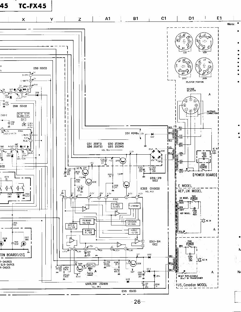
SAFETY-RELATED COMPONENT WARNING!!
COMPONENTS IDENTIFIED BY SHADING AND MARK
A O N T H E S C H E M A T I C D I A G R A M S , E X P L O D E D
VIEWS AND IN THE PARTS LIST ARE CRITICAL TOSAFE OPERATION. REPLACE THESE COMPONENTS
WITH SONY PARTS WHOSE PART NUMBERS APPEAR
AS SHOWN IN THIS MANUAL OR IN SUPPLEMENTSPUBLISHED BY SONY.
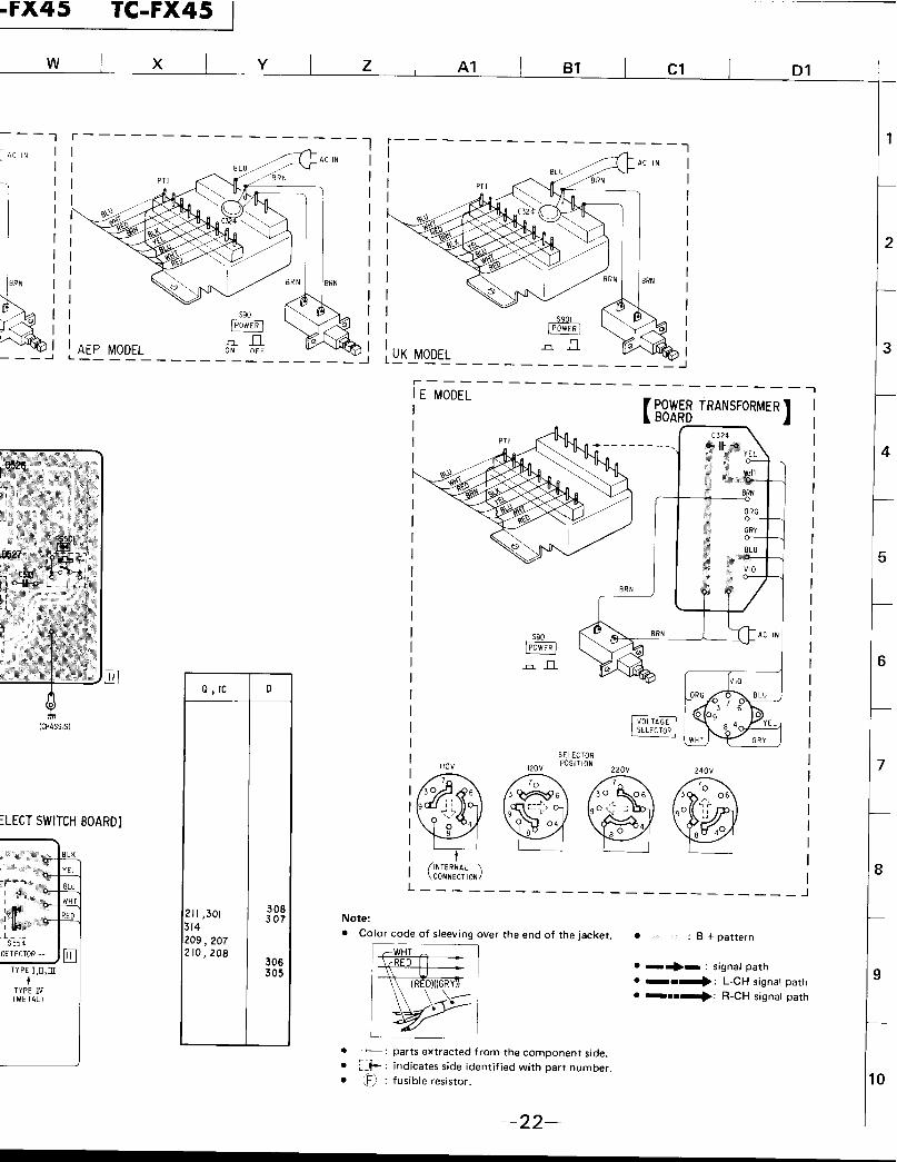
AEP ModelUK Model
E Model
Frequency response DOLBY NR OFFl With TYPE IV cassette (Sony METALLIC)
20 18,000 Hz30 - 16,000 Hz (±3 dB), (DIN)30 - 13,000 Hz (±3 dB, 0 VU recording)
l With TYPE III cassette (Sony FeCr)20 - 16,000 Hz30 - 16,000 Hz ( ± 3 dB), (DIN)
l With TYPE II cassette (Sony UCX)20 17,000 Hz30 - 15,000 Hz (±3 dB), (DIN)
l With TYPE I cassette (Sony BHF or HFX)20 - 16,000 Hz
Continued on page 2-
ATTENTION AU COMPOSANT AYANT RAPPORT
A LA SECURITE!
LES COMPOSANTS IDENTIFIES PAR UNE TRAME ET
U N E M A R Q U E A S U R L E S DIAGRAMMES SCHE-MATIQUES, L E S V U E S ECLATEES E T L A LISTE D E S
P I E C E S S0NT CRIT IQUES POUR LA SECURITE D E
FONCTIONNEMENT. NE REMPLACER CES COMPO-
SANTS QUE PAR DES PIECES SONY DONT LES NU-MEROS SONT DONNES DANS CE MANUEL OU OANS
LES SUPPLEMENTS PUBLIES PAR SONY.
STEREO CASSETTE DECKS O N Y :[MICROFILM
Wow and Flutter: 0.05% WRMS (NAB)±0.14% (DIN)
Inputs: Microphone inputs (phone jacks)Sensitivity 0.25 mV (-70 dB)For a low-impedance microphone
Line inputs (phono jacks)Sensitivity 77.5 mV (-20 dB)Input impedance 47 k ohms
outputs: Line outputs (phono jacks)Output level 0.44 V (-5 dB) at loadimpedance 47 k ohmsLoad impedance over 10 k ohms
Headphone outputOutput level -28dB at a load impedanceof 8 ohms
General
Power Requirements: AEP model: 220 V ac, 50/60 Hz(240 V ac adjustable by authorizedSony personnel)
UK model: 240 V ac, 50 Hz(220 V ac adjustable by authorizedSony personnel)
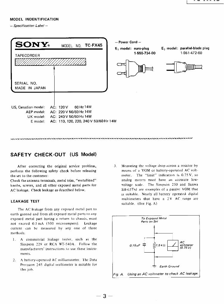
US, Canadian model: 120 V ac, 60 HzE model: 110,120,220 or 240 V ac ad-
justable, 50/60 Hz
Power Consumption: 14 watts
Dimensions: Approx. 430 x 105 x 275 mm (w/h/d)(17 x 4¼, x 107/s inches)
including projecting parts and controls
Weight: US, Canadian, AEP, UK model:Approx. 4.4 kg (9lbs 12oz)
E model: Approx. 4.5 kg (9 Ibs 15oz)
(OdB=0.775V 1
1 Tape Transport Mechanism Type 1 TCM-130VlO
FEATURES
Dolby NR C-type noise reduction systemIn addition to the conventional B-type Dolby NR system, thiscassette deck employs the newly-developed C-type Dolby NRsystem which reduces tape noise twice as effectively as the B-typesystem. The C-type system also incorporates an anti-saturationnetwork to improve the high-frequency dynamic range by 4 dB at 10kHz.
Full-logic “feather-touch” operationAt the slightest touch, the “feather-touch” function buttons enableyou to switch directly from one mode to another without goingthrough the stop mode.
Blank skip functionBlank spaces of at least 10 seconds long can be skipped in the fast-forward mode so that only the recorded portions of the tape areplayed back.
Music scan functionThe first 10 seconds or so of all the selections on a tape can beplayed back in sequence. Thus the particular selection can belocated easily.
Repeat playPlayback of one side of the cassette can be repeated five times. Atthe end of the tape, the cassette deck will automatically go into therewind mode, and playback will be repeated from the beginning ofthe tape.
AMS (Automatic Music Sensor)The AMS locates the beginning of the selection being played, or thefollowing selection, by searching either forward, or in reverse, forthe blank space between selections, and then plays back the selec-tion automatically.
Automatic tape select systemThe tape type is automatically detected and the recorder is ad-justed to its optimum bias current for recording and the optimumequalization for both recording and playback by simply Insertingthe cassette in the cassette holder.
Auto playThe auto play function makes automatic replay possible promptlyafter the tape is rewound to the beginning.
Remote control operationUsing the optional RM-50, RM-51 or RM-80 remote control unit,various operations-recording, playback, AMS, record mutingoperation, etc.-can be remotely controlled. When the RM-65 syn-chro remote control unit is used to connect this cassette deck witha turntable equipped with a synchro remote control jack, the opera-tion of the cassette deck and the turntable will be synchronized.
Timer-activated recording or playbackA timer switch is provided to turn the deck on and off at timespreset on an optional timer.
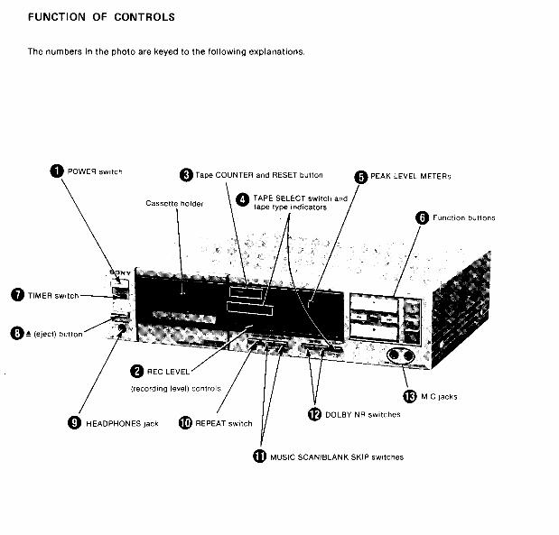
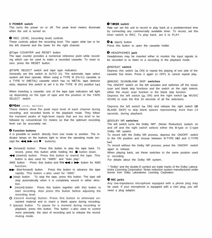
0 POWER switchThis turns the power on or off. The peak level meters illuminatewhen the unit is turned on.
@ REC LEVEL (recording level) controlsThese controls adjust the recording level. The upper slide bar is forthe left channel and the lower for the right channel.
@Tape COUNTER and RESET buttonThe tape counter provides a numerical reference point while record-ing which can be used to index a recorded cassette. To reset tozero. press the RESET button.
@TAPE SELECT switch and tape type indicatorsGenerally set this switch to AUTO (n). The automatic tape selectsystem will then operate. When using a TYPE Ill (Fe-Cr) cassette ora TYPE IV (METAL) cassette which has no METAL tape detectorslots, depress this switch to set it to the TYPE Ill (IV) position (n).
When Inserting a cassette, one of the tape type indicators will lightup depending on the type of tape and the position of the TAPESELECT switch.
@PEAK L E V E L M E T E R S
These meters show the peak input level of each channel duringrecording, and recorded levels in the playback mode. They followthe transient peaks of high-level inputs that are too brief to befollowed by conventional VU meters so that the optimum recordinglevel can be accurately set.
0 Function buttonsIt is possible to switch directly from one mode to another. The in-dicator lamps on the buttons light to show the operating mode (ex-cept the 44, H and n buttons).
) (forward) button : Press this button to play the tape back. Torecord, press this button while holding the 0 button down.
tl (rewind) button : Press this button to rewind the tape. Thisbutton is also used for “AMS” and “Auto play”.
AMS button : Press this button and the’+4 or H button for AMSfunction.
H (fast-forward) button : Press this button to advance the taperapidly. This button IS also used for “AMS”.
w (stop) button : To stop the tape, press this button. The tape willstop automatically when it is completely wound in either direc-tion.
l (record) button : Press this button together with the) button tostart recording. Also press this button before adjusting therecording level.
0 (record muting) button: Press this button to eliminate un-wanted material and to insert a blank space during recording.
II (pause) button : To pause for a moment during recording orplayback, press this button. This button IS also used to controlmore precisely the start of recording and to release the recordmuting mode.
@TIMER switchYou can set the unit to record or play back at a predetermined timeby connecting any commercially available timer. To record, set thistimer switch to REC. To play back, set it to PLAY.
0 6 (eject) buttonPress this button to open the cassette holder
0 HEADPHONES jackHeadphones may be inserted either to monitor the input signals tobe recorded or to listen to a recording in the playback mode.
@REPEAT switchDepress this switch (P ON) to repeat the playing of one side of thecassette five times. Press it again (n OFF) to cancel repeat play.
@MUSIC SCAN/BLANK SKIP switchesThe ON/OFF switch on the left actuates and switches off the musicscan and blank skip functions and the switch on the right selectseither the music scan function or the blank skip function.Depress the left switch (- ON) and the right switch (P MUSICSCAN) to scan the first 10 seconds of all the selections.
Depress the left switch (a ON) and release the right switch (nBLANK SKIP) to skip blank spaces representing more than 1 0seconds, during playback.
@DOLBY NR switchesThe left switch turns the Dolby NR* (Noise Reduction) system onand off and the right switch selects either the B-type or C-typeDolby NR system.To record with the Dolby NR process, depress the ON/OFF switchto the ON position and choose between B-TYPE (n) and C-TYPE
(=).To record without the Dolby NR process, press the ON/OFF switchagain to release.When playing back, set these switches to the same position usedin recording.For details about the Dolby NR system.
* “Dolby” and the double-D symbol are trade marks of the Dolby Labora-tories Licensing Corporation. Noise reduction system manufactured underlicense from Dolby Laboratones Licensing Corporation.
@I MIC jacksAny low-impedance microphone equipped with a phone plug maybe used. If your microphone is equipped with a mini plug, you willneed a plug adaptor.
TROUBLE CHECKS
The following trouble checks will help you correct the most com-mon problems encountered with a tape deck. Should any problempersist after you have made these checks, consult your nearestSony service facility.Before proceeding with these trouble checks, first check thesebasic points :l The power cord must be firmly connected.l Amplifier connections must be firmly made.0 Heads, capstan and pinch roller should be clean.l The amplifier controls and switches should be set correctly.
The function buttons do not activate right after the POWER switchis turned on.0 Logic-controlled function buttons operate approximately 2seconds after the POWER switch is turned on.
The 0 button and the ) button do not activate.l The cassette holder is not fully closed.
The 0 button does not activate.0 No cassette in the holder.l The tab has been removed from the cassette.
The automatic shut-off mechanism activates before the end of thetape.l The tape is slack.l This situation may also be caused by a deformed cassette shell.
Tape transport noise seems excessively loud in rewind or fast-forward mode.l This situation depends upon the cassette used and is not a prob-lem.
Recording or playback cannot be made or there is a decrease insound level.l Contamination or magnetic build-up on the record/playbackhead.l improper connection.0 Improper setting of the amplifier controls.
The AMS does not operate.l The blank space between the selections is less than fourseconds long.0 Severe noise or hum exists in the blank spaces.l A recorded selection is less than 20 seconds long.
The MUSIC SCAN and BLANK SKIP functions do not operate.@The ON/OFF switch on the left of the MUSIC SCAN/BLANK SKIPswitches is released (OFF).
Excessive wow or flutter or drop outl Contamination of the capstan or pinch roller.
incomplete erasurel Contamination of the erase head.
increase of noise or erasure of high frequencies0 Magnetic build-up on the head.
Unbalanced tone in higher frequencies0 improper setting of the DOLBY NR switches. When playing back,set the switches to the same position used in recording.0 Improper setting of the TAPE SELECT switch. Depress the TAPESELECT switch when using a TYPE Ill (Fe-Cr) cassette or a TYPE IV(METAL) cassette which has no METAL tape detector slots.
Oscillation occurs when trying to record from microphones.l The microphone is too near the loudspeakers. Move themicrophone away from the loudspeakers or reduce the amplifiervolume.
Hum noisel The tape deck is stacked on or under the amplifier. Separate theunits.
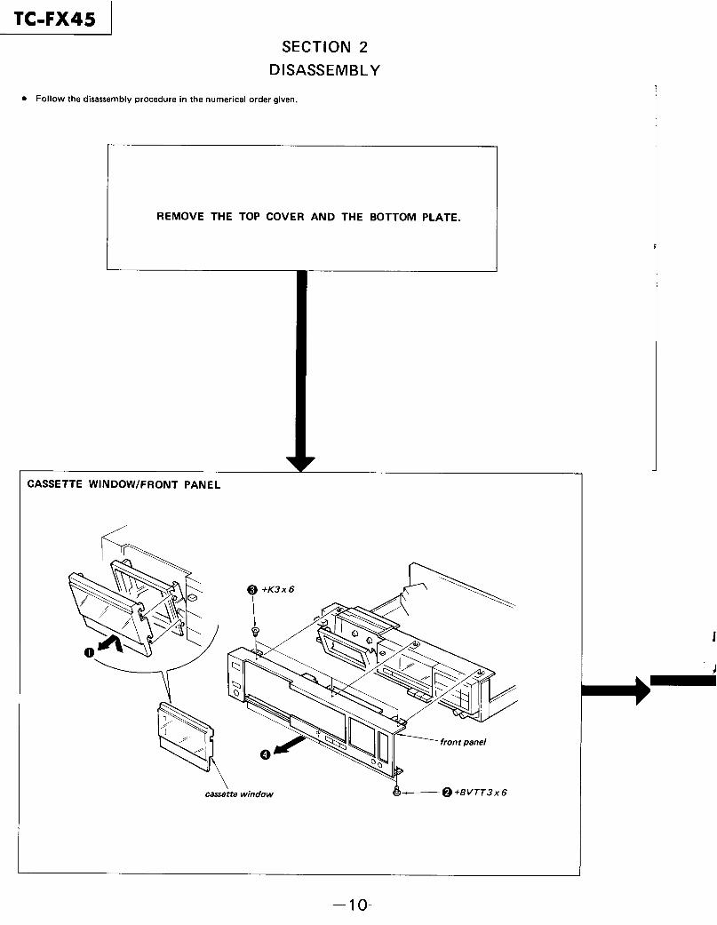
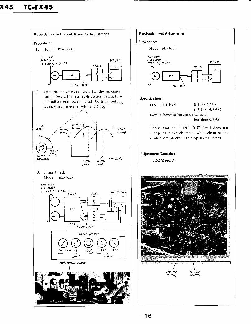
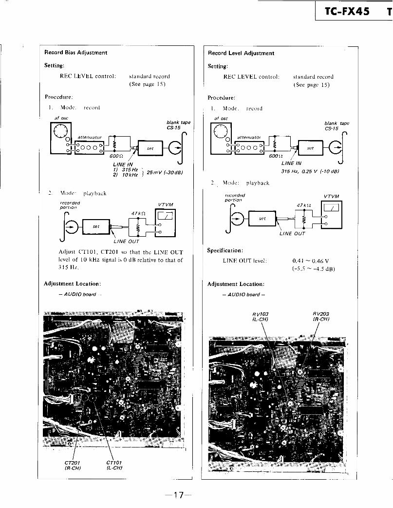
TC-FX45 SECTION 3
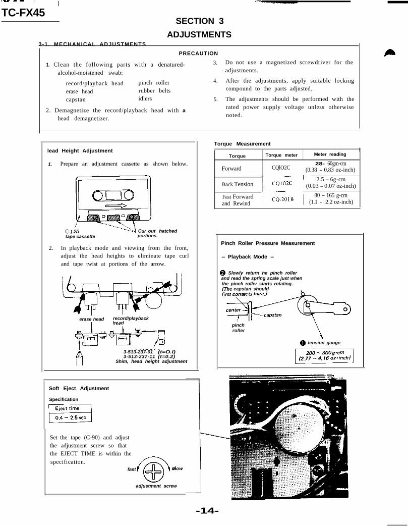
ADJUSTMENTS3-1. MECHANICAL ADJUSTMENTS
PRECAUTION
1. Clean the following parts with a denatured- 3.
alcohol-moistened swab:
record/playback head pinch roller 4.
erase head rubber belts
capstan idlers 5.
2. Demagnetize the record/playback head with a
head demagnetizer.
Do not use a magnetized screwdriver for theadjustments.
After the adjustments, apply suitable lockingcompound to the parts adjusted.
The adjustments should be performed with therated power supply voltage unless otherwisenoted.
lead Height Adjustment
1. Prepare an adjustment cassette as shown below.
C- 1 Cur out hatchedtape cassette portions.
2. In playback mode and viewing from the front,adjust the head heights to eliminate tape curland tape twist at portions of the arrow.
erase head record/playback
>;
3-513-237-01 (t=O.l)3-513-237-11 (t=0.2)
Shim, head height adjustment
Soft Eject Adjustment
Specification
Set the tape (C-90) and adjustthe adjustment screw so thatthe EJECT TIME is within the
specification.fast
@
slow
adjustment screw
Torque Measurement 1
Torque Torque meter Meter reading
28- 60gm-cmForward CQlO2C ’ (0.38 - 0.83 oz-inch)
2.5 - 6g-cmBack Tension (0.03 - 0.07 oz-inch)
Fast Forward 80 - 165 g-cmand Rewind (1.1 - 2.2 oz-inch)
Pinch Roller Pressure Measurement
- Playback Mode -
@ Slowly return he pinch rollerand read the spring scale just whenthe pinch roller starts rotating.(The capstan should
pinchroller
\0 tension gauge
-14-
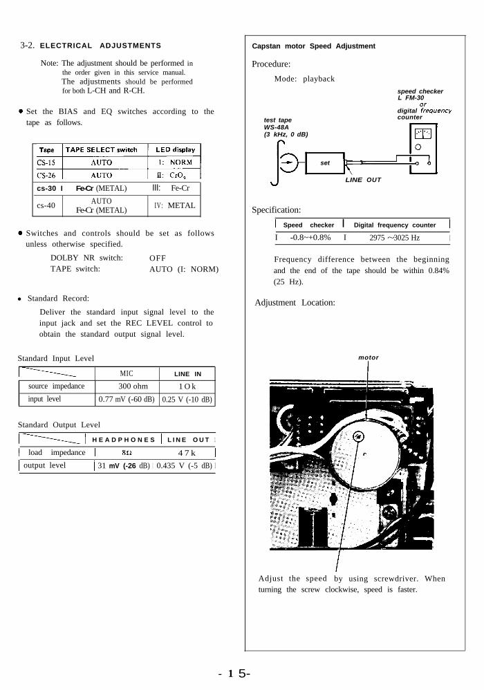
3-2. ELECTRICAL ADJUSTMENTS Capstan motor Speed Adjustment
Note: The adjustment should be performed inthe order given in this service manual.The adjustments should be performedfor both L-CH and R-CH.
Set the BIAS and EQ switches according to thetape as follows.
gj
cs-30 I Fe-Cr (METAL) III: Fe-Cr
cs-40 AUTOFe-Cr (METAL)
IV: METAL
Switches and controls should be set as followsunless otherwise specified.
DOLBY NR switch: OFFTAPE switch: AUTO (I: NORM)
l Standard Record:
Deliver the standard input signal level to theinput jack and set the REC LEVEL control toobtain the standard output signal level.
Standard Input Level
MIC LINE IN
source impedance 300 ohm 1 O k
input level 0.77 mV (-60 dB) 0.25 V (-10 dB)
Standard Output Level
1 \ 1 H E A D P H O N E S 1 L I N E O U T 1
1 load impedance 1 8n I 4 7 k 11 output level 1 31 mV (-26 dB) 1 0.435 V (-5 dB) I
- 1 5-
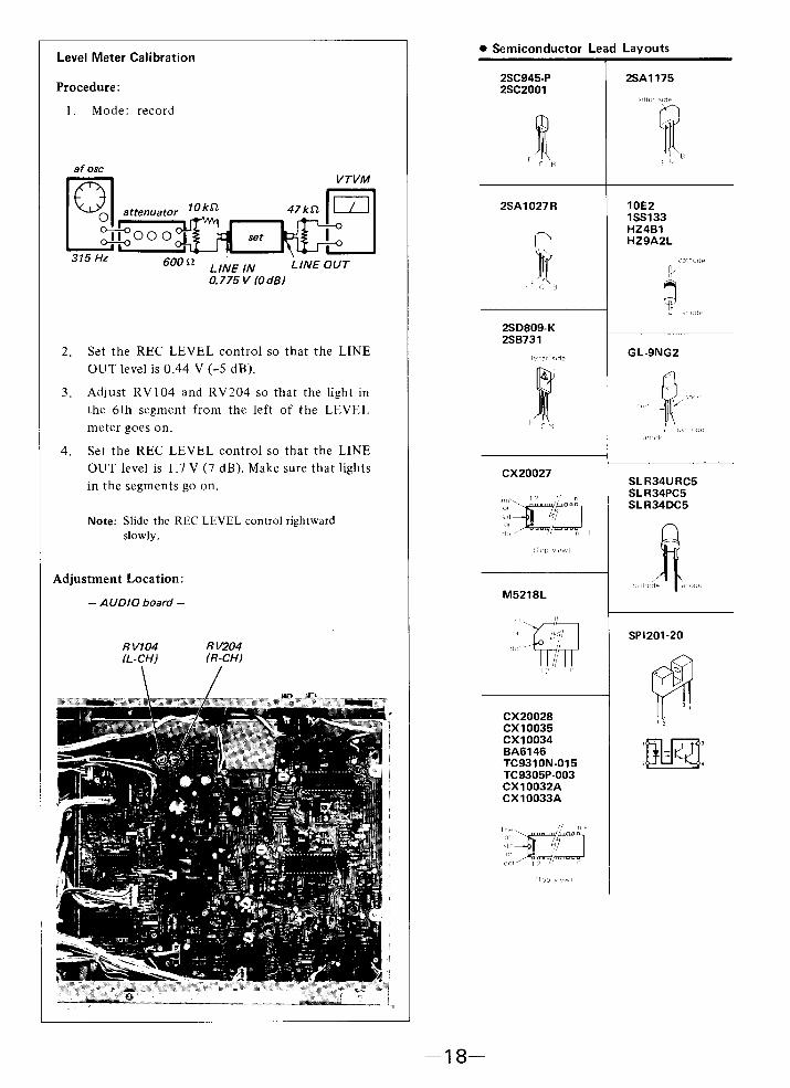
Procedure:
Mode: playback
speed checkerL FM-30
digital ?Ferkquencvtest tapeWS-48A(3 kHz, 0 dB)
counter
set
LINE OUT
Specification:
1 Speed checker I Digital frequency counter II -0.8~+0.8% I 2975 ~ 3025 Hz I
Frequency difference between the beginningand the end of the tape should be within 0.84%(25 Hz).
Adjustment Location:
motor
Adjust the speed by using screwdriver. Whenturning the screw clockwise, speed is faster.
TC-FX45
GENERAL SECTION
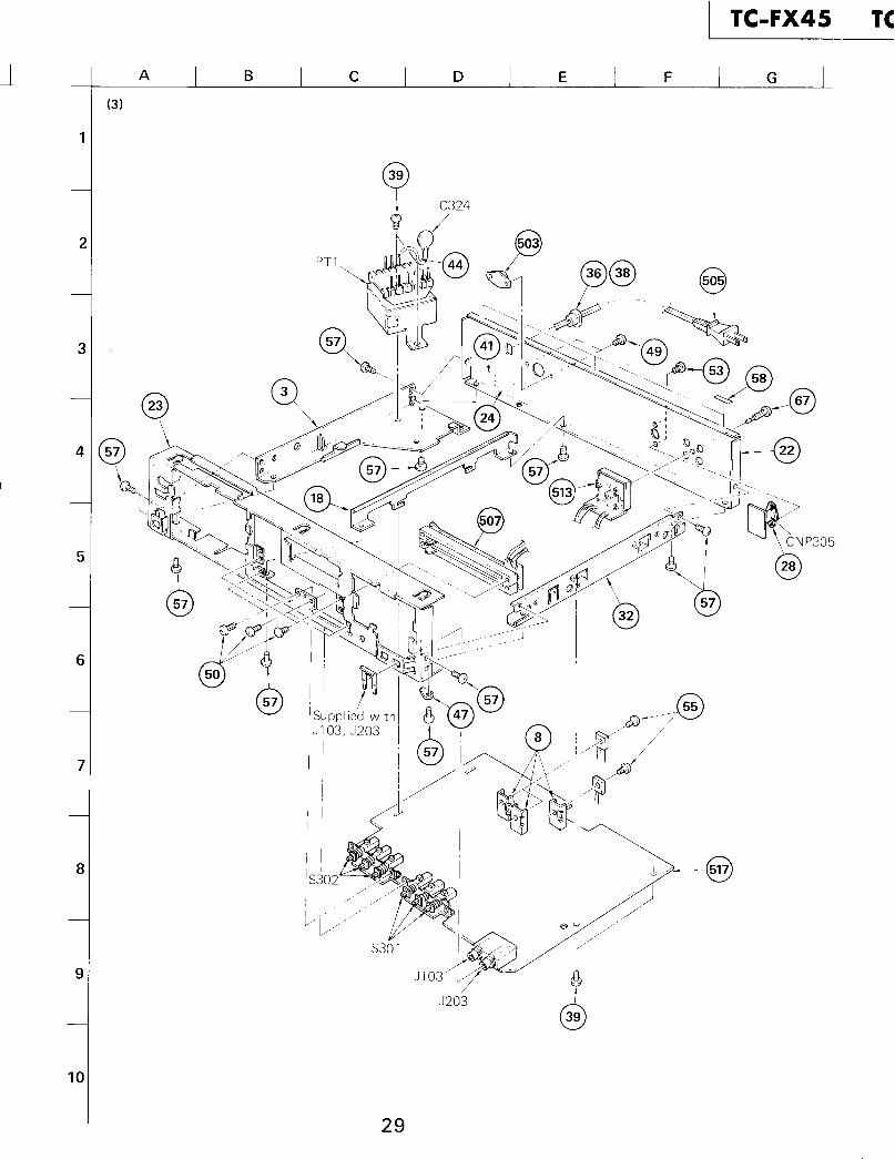
N o2 Part No.
1 l-548-574-002 3-304-419-413 b ;3-304-423-00
4 6 ;3-307-517-005 3-307-533-006 3-307-538-51
7 3-307-563-018 4 ;3-312-615-319 3-313-213-11
10 6 ;3-315-102-0011 3-315-105-0012 3-315-112-11
13 3-315-113-1114 3-315-114-1115 3-315-117-11
16 4 ;3-315-118-0017 3-315-119-1118 6 ;3-315-120-00
19 3-315-121-1120 6 ;3-315-122-0021 3-315-124-00
22 6 ;3-315-125-3222 6 ;3-315-125-4222 6 ;3-315-125-5223 ) ;3-315-127-00
24 3-315-128-0024 3-315-129-0024 3-315-130-0024 3-315-131-00
25 3-315-132-0026 d ;3-315-146-0027 3-315-153-00
28 6 ;3-315-156-0029 3-480-135-0030 3-540-244-00
31 3-575-524-0032 4 ;3-575-529-1133 b ;3-575-538-31
34 3-575-539-0035 3-576-731-1136 3-701-682-00
37 3-701-690-0038 3-703-244-0039 3-703-249-01
Description h
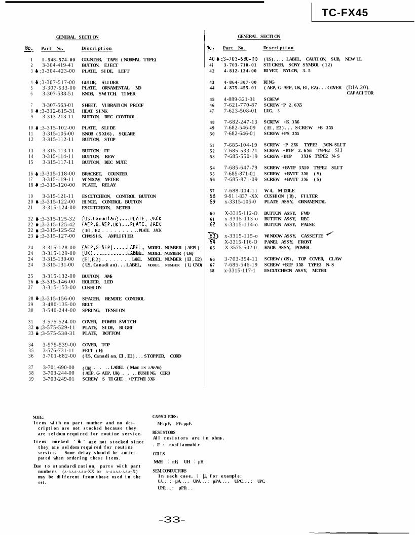
COUNTER, TAPE (NORMAL TYPE)BUTTON. EJECTPLATE, SIDE, LEFT
GUIDE, SLIDERPLATE, ORNAMENTAL, MDKNOB, SWITCH, TIMER
SHEET, VIBRATION PROOFHEAT SINKBUTTON, REC CONTROL
PLATE, SLIDEKNOB (5X16), SQUAREBUTTON, STOP
BUTTON, FFBUTTON, REWBUTTON, REC MUTE
BRACKET, COUNTERWINDOW, METERPLATE, RELAY
ESCUTCHEON, CONTROL BUTTONHINGE, CONTROL BUTTONESCUTCHEON, METER
(US,Canadian).:::pP:;;;, ,“A”:,”(AEP,G-AEP,UK) ,(El,E2) . . . . . . . . ..PLATE. JACKCHASSIS, AMPLIFIER
[;$,G-AEP).....LABEL,. . . . . . . . . . ..LABEL.
(El,E2)) . . . . . . . ..LABEL.(US,Canadian)...LABEL,
MODEL NUMBER (AEPl)MODEL NUMBER (UK)MODEL NUMBER (El,E2)MODEL NUMBER (U,CND)
BUTTON, AMSHOLDER, LEDCUSHION
SPACER, REMOTE CONTROLBELTSPRING, TENSION
COVER, POWER SWITCHPLATE, SIDE, RIGHTPLATE, BOTTOM
COVER, TOPFELT (H)(US,Canadian,El,E2)...STOPPER, CORD
(UK) . . ..LABEL (MADE IN JAPAN)(AEP,G-AEP,UK)) . . ..BUSHlNG. CORDSCREW, S TIGHT, +PTTWH 3X6
GENERAL SECTION
IO2 Part No.
40&;3-703-680-003-703-710-014i
42 4-812-134-00
(US).... LABEL, CAUTION, SUB, NEW ULSTICKER, SONY SYMBOL (12)RIVET, NYLON, 3.5
4344
4-864-307-004-875-455-01
RING(AEP,G-AEP,UK,El,EZ)...COVER (DlA.20).
45 4-889-321-01 SCREW46 7-621-770-87 SCREW +P 2.6X547 7-623-508-01 LUG, 3
48 7-682-247-13 SCREW +K 3X649 7-682-546-09 (El,E2).... SCREW +B 3X550 7-682-646-01 SCREW +PS 3X5
51 7-685-104-1952 7-685-533-2153 7-685-550-19
54 7-685-647-7955 7-685-871-0156 7-685-871-09
SCREW +P 2X6 TYPE2 NON-SLITSCREW +BTP 2.6X6 TYPE2 SLISCREW +BTP 3X16 TYPE2 N-S
SCREW +BVTP 3X10 TYPE2 SLITSCREW +BVTT 3X6 (S)SCREW +BVTT 3X6 (S)
57
;;
7-688-004-11 W 4, MIDDLE9-91 l-837 -XX CUSHION (B), FILTERx-3315-105-0 PLATE ASSY, ORNAMENTAL
6061
;
65
X-3315-112-O BUTTON ASSY, FWDx-3315-113-o BUTTON ASSY, RECx-3315-114-o BUTTON ASSY, PAUSE
x-3315-115-o WINDOW ASSY, CASSETTE JX-3315-116-O PANEL ASSY, FRONTX-3575-502-0 KNOB ASSY, POWER
66 3-703-354-11 SCREW (OS), TOP COVER, CLAW67 7-685-546-19 SCREW +BTP 3X8 TYPE2 N-S68 x-3315-117-1 ESCUTCHEON ASSY, METER
Description
CAPACITOR
NOTE: CAPACITORS:Items with no part number and no des- MF:µF, PF:µµF.cription are not stocked because theyare seldom required for routine service. RESISTORS
Items marked " b "All resistors are in ohms.
are not stocked sincethey are seldom required for routine . F : nonflammableservice. Some delay should be antici- COILSpated when ordering these items.
Due to standardization, parts with partMMH : mH, UH : µH
numbers (A-AAA-AAA-XX or A-AAAA-AAA-X) SEMICONDUCTORSmay be different from those used in the In each case, U : µ, for example:set. UA...: µA..., UPA...: µPA..., UPC...: UPC,
UPD...: µPD...
-33-
ACCESSORY & PACKING MATERIAL MECHANISM SECTION
No. Part No.
101 1-551-734-11102 3-315-149-00103 3-315-150-00
104 3-315-151-00105 3-315-152-00
106 3-573-625-00107 3-701-360-00108 3-701-630-00
109 3-773-485-11
109 3-773-485-21109 3-773-485-41
110 3-793-828-11111 8-890-454-10112 x-3701-105-0113 3-315-155-00
Description
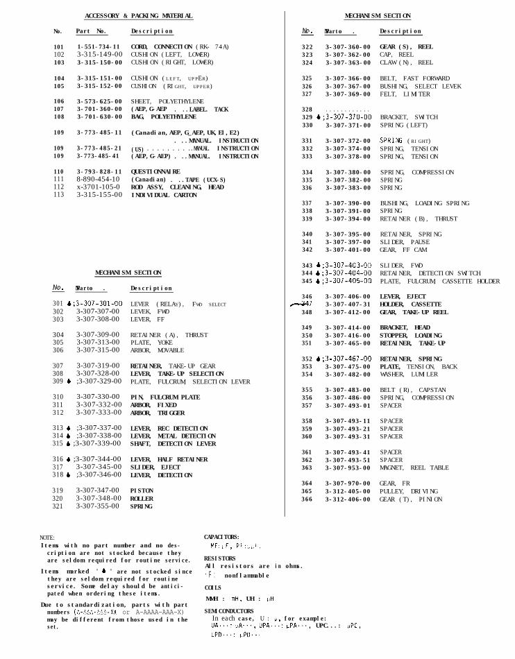
CORD, CONNECTION (RK- 74A)CUSHION (LEFT, LOWER)CUSHION (RIGHT, LOWER)
No-? N o .Part
322 3-307-360-00323 3-307-362-00324 3-307-363-00
CUSHION (LEFT, UPPER) 325 3-307-366-00CUSHION (RIGHT, UPPER) 326 3-307-367-00
SHEET, POLYETHYLENE(AEP,G-AEP) . ..LABEL. TACKBAG, POLYETHYLENE
327 3-307-369-00
328 . . . . . . . . . . . .329 4;3-307-370-00330 3-307-371-00
(Canadian,AEP,G_AEP,UK,El,E2). ..MANUAL. INSTRUCTION
(US) . . . . . . . . ..MANUAL. INSTRUCTION(AEP,G-AEP)) . ..MANUAL. INSTRUCTION
QUESTIONNAIRE(Canadian) . ..TAPE (UCX-S)ROD ASSY, CLEANING, HEADINDIVIDUAL CARTON
MECHANISM SECTION
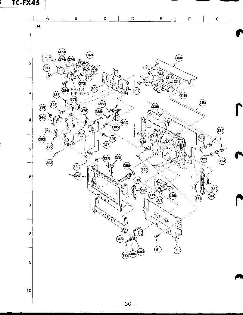
N o2 N o .Part Description
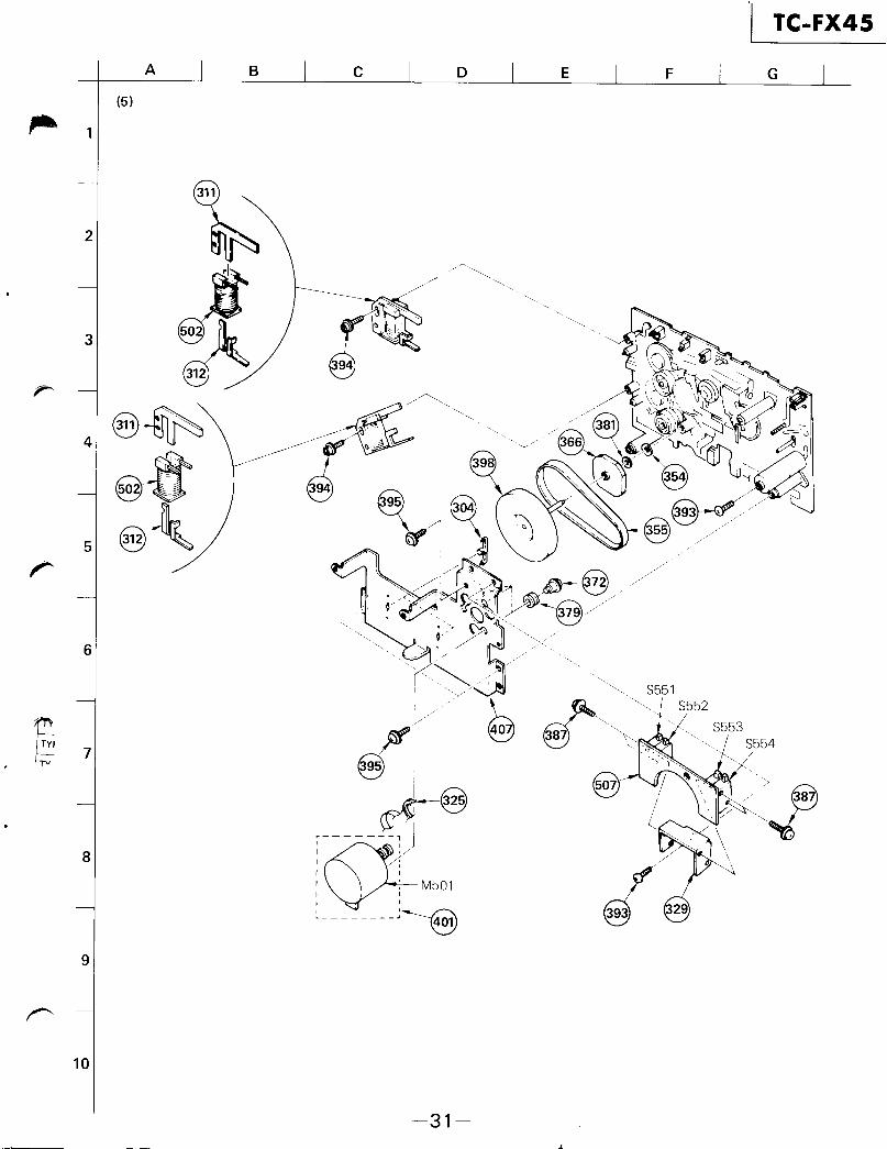
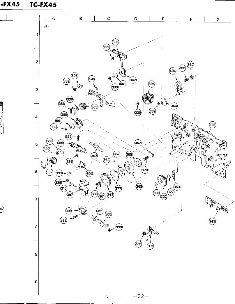
301 ~;3-307-301-00302 3-307-307-00303 3-307-308-00
304 3-307-309-00305 3-307-313-00306 3-307-315-00
307 3-307-319-00308 3-307-328-00309 b ;3-307-329-00
310 3-307-330-00311 3-307-332-00312 3-307-333-00
313 6 ;3-307-337-00314 6 ;3-307-338-00315 4 ;3-307-339-00
316 6 ;3-307-344-00317 3-307-345-00318 4 ;3-307-346-00
319 3-307-347-00320 3-307-348-00321 3-307-355-00
NOTE: CAPACITORS:
LEVER (RELAY), FWD SELECT
LEVEK, FWDLEVER, FF
RETAINER (A), THRUSTPLATE, YOKEARBOR, MOVABLE
RETAINER, TAKE-UP GEARLEVER, TAKE-UP SELECTIONPLATE, FULCRUM, SELECTION LEVER
PIN, FULCRUM PLATEARBOR, FIXEDARBOR, TRIGGER
LEVER, REC DETECTIONLEVER, METAL DETECTIONSHAFT, DETECTION LEVER
LEVER, HALF RETAINERSLIDER, EJECTLEVER, DETECTION
PISTONROLLERSPRING
331 3-307-372-00332 3-307-374-00333 3-307-378-00
334 3-307-380-00335 3-307-382-00336 3-307-383-00
337 3-307-390-00338 3-307-391-00339 3-307-394-00
340 3-307-395-00341 3-307-397-00342 3-307-401-00
343 &:3-307-403-00344 &f3-307-404-00345 4;3-307-405-00
346 3-307-406-0047 3-307-407-31
348 3-307-412-00
349 3-307-414-00350 3-307-416-00351 3-307-465-00
352 &;3-307-467-00353 3-307-475-00354 3-307-482-00
355 3-307-483-00356 3-307-486-00357 3-307-493-01
358 3-307-493-11359 3-307-493-21360 3-307-493-31
361 3-307-493-41362 3-307-493-51363 3-307-953-00
364 3-307-970-00365 3-312-405-00366 3-312-406-00
Items with no part number and no des-cription are not stocked because they
MF:uF, PF:~I,F.
are seldom required for routine service. RESISTORS
Items marked " & " are not stocked sinceAll resistors are in ohms.
they are seldom required for routine . F : nonflammable
service. Some delay should be antici- COILSpated when ordering these items.
Due to standardization, parts with partMMH : mH , UH : uH
numbers (A-AAA-MA-XX or A-AAAA-AAA-X) SEMICONDUCTORSmay be different from those used in the In each case, U : p, for example:set. UA...: PA..., UPA...: uPA..., UPC...: UPC,
UPD...: uPD...
Description
GEAR (S), REELCAP, REELCLAW (N), REEL
BELT, FAST FORWARDBUSHING, SELECT LEVEKFELT, LIMITER
BRACKET, SWITCHSPRING (LEFT)
SPRING (RIGHT)SPRING, TENSIONSPRING, TENSION
SPRING, COMPRESSIONSPRINGSPRING
BUSHING, LOADING SPRINGSPRINGRETAINER (B), THRUST
RETAINER, SPRINGSLIDER, PAUSEGEAR, FF CAM
SLIDER, FWDRETAINER, DETECTION SWITCHPLATE, FULCRUM, CASSETTE HOLDER
LEVER, EJECTHOLDER, CASSETTEGEAR, TAKE-UP REEL
BRACKET, HEADSTOPPER, LOADINGRETAINER, TAKE-UP
RETAINER, SPRINGPLATE, TENSION, BACKWASHER, LUMILER
BELT (R), CAPSTANSPRING, COMPRESSIONSPACER
SPACERSPACERSPACER
SPACERSPACERMAGNET, REEL TABLE
GEAR, FRPULLEY, DRIVINGGEAR (T), PINION
MECHANISM SECTION ELECTRICAL PARTS
N o2 N o .Part
367 3-312-408-00368 3-312-409-00369 3-312-412-00
370 3-312-429-00371 3-312-432-00372 . . . . . . . . . . . .
373 3-513,237-01374 3-513-237-11375 3-531-541-00
376 3-539-237-00377 3-561-827-00378 3-570-895-02
379 . . . . . . . . . . . .380 3-575-392-00381 3-701-438-11
382 . . . . . . . . . . . .383 3-701-465-00384 3-701-466-00
385 3-701-467-00386 4 ;3-701-822-00387 7-621-760-05
388 J-621-770-20389 7-621-772-00390 . . . . . . . . . . . .
391 7-624-105-04392 7-671-111-11393 7-685-860-04
394 7-687-204-21395 7-687-246-21396 A-2142-022-A
397 x-3307-301-0398 X-3307-302-5399 b ;x-3307-305-O
F 400 x-3307-307-0fl 401 X-3307-308-3
402 4 ;x-3307-309-O
403~;x-3307-310-0 PLATE (RIGHT) my, SIDE404 X-3307-312-0 LEVER ASSY, FR405 x-3307-330-1 CHASSIS (N) ASSY, MECHANICAL
406 X-3307-338-0407 b ;x-3307-345-O408 .X-3307-348-0409 x-3307-920-0
Description
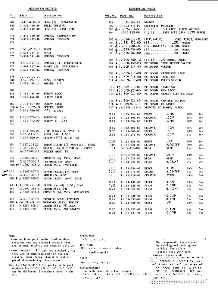
GEAK (B), CONVERSIONBELT, DRIVINGGEAR (B), CPM, FWD
SPRING, COMPRESSIONSPKING, TENSION
PLATEPLATESPRING, TENSION
SPRING (3), COMPRESSIONPLATE (A), HYSTERESISSPRING. TENSION
RING, PISTONWASHER, 2.5
SCREW, LOCKSCREW, LOCK
SCREW, LOCKHOLDER, WIRE+PSW, 2.6X16
SCREW +B 2x5SCREW +B 2X3
STOP RING 2.3, TYPE -ESTEEL BALL 1.5MMSCREW +BVTT 2.6X4 (S)
TOTSU PTPWH 2X6 NON-SLIT, TYPE2SCREW, TUTSU PTPWH 3X8, TYPE2PULLEY ASSY, FR
CHASSIS (N) ASSY, HEADFLYWHEEL (N) ASSYLEVEK ASSY, FWD LOCK
PINCH ROLLER (N) ASSYMOTOR (N) ASSYPLATE (LEFT) ASSY, SIDE
BEARING ASSY, CAPSTANRETAINER ASSY, THRUSTLEVER ASSY, Fi LOCKPLATE ASSY, ADJUSTMENT
NOTE:Items with no part number and no des-cription are not stocked because theyare seldom required for routine service.
Items marked u b u are not stocked Sincethey are seldom required for routineservice. Some delay should be antici-pated when ordering these items.
Due to standardlzatlon, parts with partnumbers (:,-!.Ci!,-:,.:o-XX or I^,-:,LACa-.l.?:i-X)may be different from those used In theset.
Ref.No. Part No. Description
501 l-452-202-00502 l-454-316-00503 n .l-526-576-51504 l-535-139-00
505 h .1-534-817-Xx505 h .l-551-472-00505 h .1-551-506-Xx505 B .I-555-734-00505 A .I-556-562-00
506 A .l-605-860-12507 b ;l-608-169-00508 b ;l-609-914-00
509 b ;l-609-915-00510 b ;l-609-916-00511 b ;l-609-917-00
512 b ;l-609-918-00513 b ;l-609-920-00514 b il-609-921-00
515 b :l-609-922-00516 b fl-609-923-00517 b ;A-2056-203-A
Cl03 l-123-354-00Cl04 l-102-106-00Cl05 l-123-354-00
Cl06 l-102-106-00Cl07 l-123-380-00Cl08 l-161-271-00
Cl09 l-123-356-00Cl10 l-161-326-00Cl11 l-107-165-00
Cl12 l-161-321-00Cl13 l-107-036-00Cl14 l-130-624-00
Cl16 l-123-354-00Cl17 l-108-571-00Cl18 l-161-316-00
Cl19 l-124-185-00Cl22 l-130-620-00Cl23 l-130-622-00
Cl24 l-130-620-00Cl25 l-130-633-00Cl26 l-123-380-00
Cl27 l-130-633-00Cl28 l-130-637-00
CAPACITORS:MF:l,F, PF:,I;IF.
RESISTORSAll reslsto-s are in ohms.. F : nonflammable
COILS
MMH : mti, UH : uH
SEMICONDUCTORSIn each case, U : U, for example:UA...: uA..., UPA...: UPA..., UPC...: ,,IUPD...: uPD...
MAGNETSOLENOID, PLUNGER
. ..SELECTOR. POWER VOLTAGE
. ..BASE POST 19MM (1DMM PITCH)
(AEP,G-AEP) . . . ..CORD. POWEH, EURO PLUG(E2) . . . . . . . . . . ..CORD. POWER[;:jCanadian) . ..CORD. POWER
. . . . . . . . . . ..CORD. POWER(UK) . . . . . . . . . . ..CORD. POWER
(El,E2) . ..PC BOARD, POWERPC BOARD, TAPE SELECT SWITCHPC BOARD, VOLUME
PC BOARD, HEADPHONE JACKPC BOARD, TYPE INDPC BOARD, PHOTO SENSOR
PC BOARD, TIMER SWPC BOARD, PIN JACKPC BORAD, REMOTE CONTROL JACK
PC BOARD. CONTROL BUTTONPC BOARD; FL METERMOUNTED PC BOARD, AUDIO
ELECTCERAMICELECT
3.3MF1OOPF3.3MF
CERAMIC 1OOPFELECT 1MFCEKAMIC 1OOPF
ELECTCERAMICMICA
1OMF0.0022MF56PF
CERAMICMICAFILM
68OPF68PF0.022MF
ELECTMYLARCERAMIC
3.3MF0.0047MF270PF
ELECTFILMFILM
4.7MFO.OlMF0.015MF
FILMFILMELECT
O.OlMF0.12MF1MF
FILMFILM
0.12MF0.27MF
20%10%20%
10%20%5%
20%30%5%
10%5%5%
20%5%10%
20%5%5%
5%5%20%
5%5%
5ov5ov5ov
5ov5ov5ov
5ov5ov5oov
5ov5oov5ov
5ov5ov5ov
5ov5ov5ov
5ov5ov5ov
5ov5ov
.\.' The components identified
:
by shading and mark barecritical for safety.Replace only with part
number specified.
Les composants IdentlflPs parune trame et une marquensont
crltlques pour la securlt4.
'C, : :Ne .~les remplacer que parune piece portant le numero
sp&ifie..
Ref.No.
Cl29Cl30Cl31
ELECTRICAL PARTS
N o .Part Description
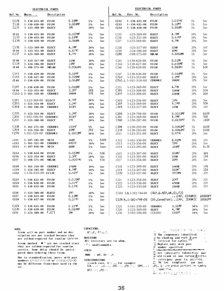
l-130-635-00 FILMl-130-630-00 FILMl-123-380-00 ELECT
0.18MF0.068MF1MF
Cl32 l-130-625-00 FILM 0.027MFCl33 l-130-635-00 FILM 0.18MFCl34 l-130-630-00 FILM 0.068MF
Cl35Cl36Cl37
l-123-369-00 ELECTl-123-351-00 ELECTl-123-369-00 ELECT
4.7MF0.47MF4.7MF
Cl38Cl39Cl40
l-123-317-00 ELECTl-124-186-00 ELECTl-108-575-00 MYLAR
22MF1OMF0.0068MF
Cl41Cl44Cl46
l-130-620-00 FILMl-130-627-00 FILMl-130-630-00 FILM
O.OlMF0.039MF0.068MF
Cl47Cl50c150-1
l-130-630-00 FILMl-123-353-00 ELECTl-161-318-00 CERAMIC
0.068MF2.2MF390PF
Cl51C203C204
C205C206C207
C208c209c210
c211c212C213
C214C216C217
C218c219c222
C223C224 l-130-620-00 FILMC225 l-130-633-00 FILM
C226 l-123-380-00 ELECTC227 l-130-633-00 FILMC228 l-130-637-00 FILM
c229 l-130-635-00 FILM 0.18MFC230 l-130-630-00 FILM 0.068MFC231 l-123-380-00 ELECl 1MF
l-123-369-00 ELECTl-123-354-00 ELECTl-102-106-00 CERAMIC
4.7MF3.3MF1OOPF
l-123-354-00 ELECT 3.3MFl-102-106-00 CERAMIC 1OOPFl-123-380-00 ELECT 1MF
l-161-271-00 CERAMIC 1OOPFl-123-356-00 ELECT 1OMFl-161-326-00 CERAMIC 0.0022MF
l-107-165-00 MICAl-161-321-00 CERAMICl-107-036-00 MICA
l-130-624-00 FILMl-123-354-00 ELECTl-108-571-00 MYLAR
l-161-316-00 CERAMICl-124-185-00 ELECTl-130-620-00 FILM
l-130-622-00 FILM
56PF68OPF68PF
0.022MF3.3MF0.0047MF
270PF4.7MFO.OlMF
0.015MFO.OlMF0.12MF
1MF0.12MF0.27MF
5%5%20%
5%5%5%
20%20%20%
20%20%5%
5%5%5%
5%
:o";
20%20%10%
20%10%20%
Z%30%
5%10%5%
5%20%5%
10%20%5%
5%5%5%
20%5%5%
5%5%20%
5ov5ov5ov
5ov5ov5ov
5ov5ov5ov
16V5ov5ov
5ov5ov5ov
5ov5ov5ov
5ov5ov5ov
5ov5ov5ov
5ov5ov5ov
5OUV5ov5oov
5ov5ov5OV
5ov5ov5ov
5ov5ov5ov
5ov5ov5ov
5ov5ov5ov
ELECTRICAL PARTS
Ref.No. Part No.
C232 l-130-625-00C233 l-130-635-00C234 l-130-630-00
C235 -123-369-00C236 -123-351-00C237 l-123-369-00
C238 -123-317-00c239 -124-186-00C240 -108-575-00
C241 l-130-620-00C244 l-130-627-00C246 l-130-630-00
C247 l-130-630-00C250 l-123-353-00C250-1 l-161-318-00
ELECT 4.7MF 20% 5ovELECT 0.47MF 20% 5ovELECT 4.7MF 20% 5ov
ELECT 22MF 20% 16VELECT 1OMF 20% 5ovMYLAR 0.0068MF 5% 5ov
FILM O.OlMF 5% 5ovFILM 0.039MF 5% 5ovFILM 0.068MF 5% 5OV
FILM 0.068MF 5% 5ovELECT 2.2MF 20% 5ovCERAMIC 390PF 10% 5ov
C251 l-123-369-00 ELECT 4.7MF 20% 5ovc301 l-123-308-00 ELECT 220MF 20% 1ovC302 l-123-308-00 ELECT 220MF 20% 1ov
c303 l-123-356-00c304 l-123-369-00c305 l-123-317-00
C306 l-129-708-00c307 l-123-369-00C308 l-130-287-00
c309 l-130-293-00c310 l-130-293-00c311 l-123-351-00
C312 l-161-330-00c313 l-123-356-00c314 l-123-295-00
c315 l-123-307-00C316 l-123-305-00c317 l-123-356-00
C318 l-123-309-00c319 l-123-307-00C320 l-123-337-00
C321 l-123-356-00C322 l-123-336-00C323 l-123-335-00
C324 L&.1-161-744-00
C324n.l-161-749-00
ELECT 1OMF 20% 25VELECT 470MF 20% 25VELECT 330MF 20% 25V
(AEP,G-AEP,UK:;;J;;)
(US,Canadian)...CAP:(:ERAMIC 1OOOOPF:ERAMIC 1OOOOPF
C325 l-161-330-00 CERAMIC O.OlMF 30% 25VC326 l-123-369-00 ELECT 4.7MF 20% 5ovC336 l-102-106-00 CERAMIC 1OOPF 10% 5ov
Description
FILM 0.027MF 5% 5ovFILM 0.18MF 5% 5ovFILM 0.068MF 5% 5ov
ELECT 1OMF 20% 5ovELECT 4.7MF 20% 5ovELECT 22MF 20% 16V
FILMELECTFILM
zMO:3MF0:0039MF
10% 63OV20% 5OV5% 1oov
FILM 0.0068MF 5% 1oovFILM 0.0068MF 5% 1oovELECT 0.47MF 20% 5ov
CERAMIC O.OlMF 30% 25VELECT 1OMF 20% 5ovELECT 1OOMF 20% 6.3V
ELECT 1OOMF 20% 1ovELECT 33MF 20% 1ovELECT 1OMF 20% 5ov
ELECT 330MF 20% 1ovELECT 1OOMF 20% 1ovELECT 1OOOMF 20% 25V
NOTE:Items with no part number and no des-cription are not stocked because theyare seldom required for routine service.
Items marked " b " are not stocked sincethey are seldom required for routineservice. Some delay should be antici-pated when ordering these items.
Due to standardization, parts with partnumbers (tl-CCL-fL',;.-XX or A-AAAA-MA-X)may be different from those used in theset.
CAPACITORS:MF:.,F, PF:ubF.
RESISTORSAll resistors are in ohms.. F : nonflammableCOILS
. . “‘,‘.:i”,:..: :. ‘.‘. . ..’ ..\.
‘:.’ . . . . .:: :,. . . .
..:t:.: The components identified ..:;:; by shading and mdrknare ‘.” : critical for safety. . :‘~‘1 Replace only with part..>,' number specified...i
MMH : mH, UH : ,H,,i?:i Les composants Identifies par!,'c une trame et une marquensont ‘..
SEMICONDUCTORS:..,: : critiques pour la securite.
In each case, U : U, for example: ;sfi: Ne les remplacer que parUA...: uA..., UPA...: UPA..., UPC...: UPC, i:j:' une plice portant le numgro
UPD...: uPD... : sp&ifi&.. .. ..\;:,::i :,:,: :::::,::,,,, . . . . ::::.: . . . . . .:. ,, . ...;. I::,. . . . . . . . .,, .,.
ELECTRICAL PARTS ELECTRICAL PARTS
Ref.No. Part No.
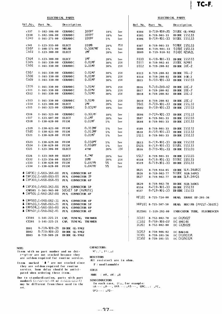
c337 l-102-106-00C338 l-102-106-00c340 I-161-271-00
c341 l-123-333-00C502 l-108-571-00c503 l-123-380-00
c504 l-123-380-00c505 l-161-330-00C506 l-161-330-00
c507 l-161-330-00C508 l-161-330-00c509 l-161-330-00
c510 l-161-330-00c511 l-161-330-00C512 l-161-330-00
c513 l-161-330-00c514 l-123-380-00c515 l-161-323-00
C516 l-161-323-00c517 l-123-607-00C518 l-130-620-00
c519 l-130-621-00C520 l-130-621-00C521 l-130-620-00
C523 l-130-629-00C524 l-130-629-00C525 l-123-306-00
C526 l-123-369-00C532 l-123-356-00c533 l-130-628-00c534 l-130-628-00
b CNP301;1-560-064-00b CNP302:1-560-060-00CNP303fl-560-064-00
PIN, CONNECTOR 6PPIN, CONNECTOR 2PPIN, CONNECTOR 6P
CNP304;1-560-063-00CNP305 l-561-965-00CNP501;1-560-062-00
PIN, CONNECTOR 5PSOCKET 5P (REMOTE)PIN, CONNECTOR 4P
CNP502;1-560-062-31CNP503;1-560-063-21CNP504;1-560-065-00CNP507;1-560-062-41
PIN, CONNECTOR 4PPIN, CONNECTOR 5PPIN, CONNECTOR 8PPIN, CONNECTOR 4P
CT101 1-141-225-21CT201 1-141-225-21
CAP, TUNING, TRIMMERCAP, TUNING, TRIMMER
D301 8-719-909-20 DIODE GL-9NG2D302 8-719-909-20 DIODE GL-9NG2D303 8-719-909-20 DIODE GL-9NG2
NOTE: CAPACITORS:Items with no part number and no des- MF:i,F, PF:bpf
Description
CERAMIC 1OOPFCERAMIC ZOOPFCERAMIC 1OOPF
ELECT 1OOMFMYLAR 0.0047MFELECT 1MF
ELECTCERAMICCERAMIC
1MFO.OlMFO.OlMF
CERAMICCERAMICCERAMIC
O.OlMFO.OlMFO.OlMF
CERAMICCERAMICCERAMIC
O.OlMFO.OlMFO.OlMF
CERAMICELECTCERAMIC
O.OlMF1MFO.OOlMF
CERAMICELECTFILM
O.OOlMFO.lMFO.OlMF
FILMFILMFILM
0.012MF0.012MFO.OlMF
FILMFILMELECT
0.056MF0.056MF47MF
ELECTELECTFILMFILM
4.7MF1OMF0.047MF0.047MF
10%10%5%
20%5%20%
20%30%30%
30%30%30%
30%30%30%
30%20%10%
10%20%5%
5%5%5%
5%5%20%
20%20%
::
cnption are not stocked because theyare seldom required for routine service.
Items marked ' b u are not stocked sincethey are seldom required for routineservice. Some delay should be antici-pated when ordering these items.
Due to standardization, parts with partnumber5 (A-Ah&-hzW,-XX or A-A&AC-~~~-X)may be different from those used in theset.
5ov5ov5ov
25v5ov5ov
5ov25V25V
25V25V25V
25V25V25V
25V5ov5ov
5ov5ov5ov
5ov5ov5ov
5ov5ov1ov
5ov25V5ov5ov
1 TC-FI
Ref.No. Part No. Description
0304 8-719-909-20 DIODE GL-9NG20305 8-719-901-33 DIODE lSS1330306 8-719-901-33 DIODE lSS133
0307 8-719-901-33 DIODE lSS133D308 8-719-901-33 DIODE lSS133D309 8-719-910-92 DIODE HZ9A2L
D310 8-719-901-33D311 8-719-992-41D312 8-719-200-02
0313 8-719-200-020314 8-719-200-02D315 8-719-901-33
D316 8-719-200-02D317 8-719-200-02D318 8-719-200-02
D319 8-719-200-02D501 8-719-901-33D502 8-719-901-33
D506 8-719-901-33D507 8-719-901-33D508 8-719-901-33
0509 8-719-901-33D510 8-719-901-33D511 8-719-901-33
D513 8-719-901-33D515 8-719-931-33D516 8-719-901-33
0517 8-719-901-330518 8-719-901-330519 8-719-901-33
D525 8-719-934-05D526 8-719-902-77D527 8-719-902-77
D529 8-719-902-780534 8-719-901-330537 8-719-901-33
HE101 8-725-724-00
HRPlOl 8-725-507-50
FLT301 l-519-292-00
IClOl 8-752-002-70IC102 8-759-906-02IC201 8-752-002-80
IC202 8-759-906-02IC301 8-759-101-56IC302 8-759-101-55
RESISTORSAll resistor5 are in ohms.
F : nonflammableCOILS
MMH : mti, IJH : QH
SEMICONDUCTORSIn each case, U : ii. for example:IJA...: ,,A.... UPA...: UPA..., UPC...: "PC,UPD...: iJPD.'
DIODE lSS133DIODE HZ4BlDIODE lOE-2
DIODE lOE-2DIODE IOE-2DIODE lSS133
DIODE lOE-2DIODE IOE-2DIODE lOE-2
DIODE lOE-2DIODE lSS133DIODE lSS133
DIODE lSS133DIODE lSS133DIODE lSS133
DIODE lSS133DIODE lSS133DIODE lSS133
DIODE lSS133DIODE lSS133DIODE lSS133
DIODE lSS133DIODE lSS133DIODE lSS133
OIODE SLR-34URC5DIODE SLR-34PC5DIODE SLR-34PC5
DIODE SLR-34DC5DIODE lSS133DIODE lSS133
HEAD, ERASE EF-201-36
HEAD, REC/PB (PP227-3602C)
INDICATOR TUBE, FLUORESCEN
IC CX20027IC BA6146IC CX20028
IC BA6146IC CX10033AIC CX10032A
-R7-
ELECTRICAL PARTS
Ref.No. Part No. Description
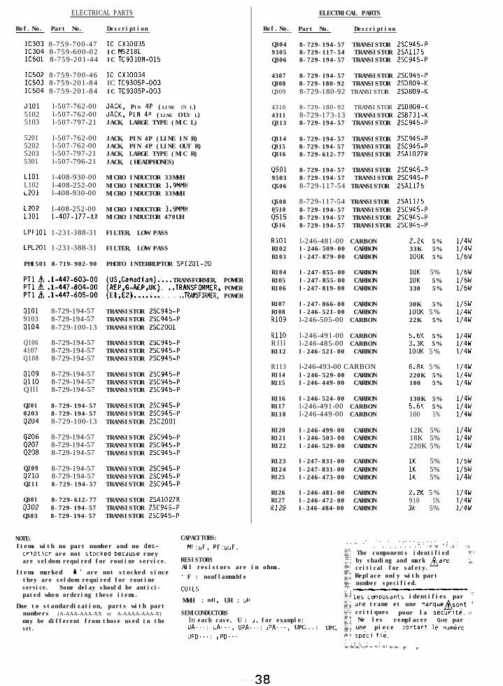
IC303 8-759-700-47 IC cx10035IC304 8-759-600-02 IC M5218LIC501 8-759-201-44 IC TC9310N-015
IC502 8-759-700-46 IC cx10034IC503 8-759-201-84 IC TC9305P-003IC504 8-759-201-84 IC TC9305P-003
JlOl l-507-762-00 JACK, PIN 4~ (LINE IN L)5102 l-507-762-00 JACK, PIN 4~ (LINE O UT L)5103 l-507-797-21 JACK, LARGE TYPE (MIC L)
5201 l-507-762-00 JACK, PIN 4P (LINE IN R)5202 l-507-762-00 JACK, PIN 4P (LINE OUT R)5203 l-507-797-21 JACK, LARGE TYPE (MIC R)5301 l-507-796-21 JACK, (HEADPHONES)
LlOl l-408-930-00 MICRO INDUCTOR 33MMHL102 l-408-252-00 MICRO INDUCTOR 3.9MMHL20f l-408-930-00 MICRO INDUCTOR 33MMH
L202 l-408-252-00 MICRO INDUCTOR 3.9MMHL301 l-407-177-xx MICRO INDUCTOR 470UH
LPFlOl 1-231-388-31 FILTER, LOW PASS
LPL201 1-231-388-31 FILTER, LOW PASS
PHI501 8-719-902-90 PHOTO INTERRUPTOR SPI201-20
PTl L& .l-447-603-00PTl hi .l-447-604-00PTl /& .l-447-605-00
(US,Canadian).... TRANSFORMER, POWER#;P;&AEP.UK) . ..TRANSFORMER. POWER
, . . . . . . . . ..TRANSFORMER. POWER
TRANSISTOR 2SC945-PTRANSISTOR 2SC945-PTRANSISTOR 2SC2001
TRANSISTOR 2SC945-PTRANSISTOR 2SC945-PTRANSISTOR 2SC945-P
TRANSISTOR 2SC945-PTRANSISTOR 2SC945-PTRANSISTOR 2SC945-P
QlOl 8-729-194-579103 8-729-194-57QlO4 8-729-100-13
Q106 8-729-194-574107 8-729-194-57Q108 8-729-194-57
QlO9 8-729-194-57QllO 8-729-194-57Qlll 8-729-194-57
Q201 8-729-194-57 TRANSISTOR 2SC945-P0203 8-729-194-57 TRANSISTOR 2SC945-P6204 8-729-100-13 TRANSISTOR 2SC2001
9206 8-729-194-57 TRANSISTOR 2SC945-P9207 8-729-194-57 TRANSISTOR 2SC945-P0208 8-729-194-57 TRANSISTOR 2SC945-P
Q209 8-729-194-57 TRANSISTOR 2SC945-PQ210 8-729-194-57 TRANSISTOR 2SC945-PQ211 8-729-194-57 TRANSISTOR 2SC945-P
TRANSISTOR 2SA1027RTRANSISTOR 2SC945-PTRANSISTOR 2SC945-P
Q301 8-729-612-77Q302 8-729-194-57Q303 8-729-194-57
NOTE: CAPACITORS:Items with no part number and no des- MF:uF, PF:t,t,F.criprion are not stockea oecause rneyare seldom required for routine service.
Items marked ' b ' are not stocked sincethey are seldom required for routineservice. Some delay should be antici-pated when ordering these items.
Due to standardization, parts with partnumbers (A-AAA-AAA-XX or A-AAAA-AAA-X)may be different from those used in theset.
ELECTRICAL PARTS
Ref.No. Part No. Description
Q304 8-729-194-57 TRANSISTOR 2SC945-P9305 8-729-117-54 TRANSISTOR 2SA1175Q306 8-729-194-57 TRANSISTOR 2SC945-P
4307 8-729-194-57 TRANSISTOR 2SC945-PQ308 8-729-180-92 TRANSISTOR 2SD809-KQ309 8-729-180-92 TRANSISTOR 2SD809-K
4310 8-729-180-92 TRANSISTOR 2SD809-K4311 8-729-173-13 TRANSISTOR 2SB731-KQ313 8-729-194-57 TRANSISTOR 2SC945-P
Q314 8-729-194-57 TRANSISTOR 2SC945-PQ315 8-729-194-57 TRANSISTOR 2SC945-PQ316 8-729-612-77 TRANSISTOR 2SA1027R
Q501 8-729-194-57 TRANSISTOR 2SC945-P9503 8-729-194-57 TRANSISTOR 2SC945-PQ506 8-729-117-54 TRANSISTOR 2SA1175
Q508 8-729-117-54 TRANSISTOR 2SA11750510 8-729-194-57 TRANSISTOR 2SC945-P6515 8-729-194-57 TRANSISTOR 2SC945-PQ516 8-729-194-57 TRANSISTOR 2SC945-P
RlOl l-246-481-00 CARBON 2.2K 5%R102 l-246-509-00 CARBON 33K 5%R103 l-247-879-00 CARBON 1OOK 5%
R104 l-247-855-00 CARBON 10K 5%R105 l-247-855-00 CARBON 10K 5%R106 l-247-819-00 CARBON 330 5%
R107 l-247-866-00 CARBON 30K 5%R108 l-246-521-00 CARBON 1OOK 5%R109 l-246-505-00 CARBON 22K 5%
RllO l-246-491-00 CARBON 5.6K 5%Rll l l-246-485-00 CARBON 3.3K 5%R112 l-246-521-00 CARBON 1OOK 5%
R113 l-246-493-00 CARBON 6.8K 5%R114 l-246-529-00 CARBON 220K 5%R115 l-246-449-00 CARBON 100 5%
R116 l-246-524-00 CARBON 130K 5%R117 l-246-491-00 CARBON 5.6K 5%R118
R120R121R122
R123R124R125
R126R127RI28
l-246-449-00 CARBON
l-246-499-00 CARBONl-246-503-00 CARBONl-246-529-00 CARBON
l-247-831-00 CARBONl-247-831-00 CARBONl-246-473-00 CARBON
l-246-481-00 CARBONl-246-472-00 CARBONI-246-484-00 CARBON
100 5%
12K 5%18K 5%220K 5%
1/4w1/4w1/4w
1/4w1/4w1/4w
1K 5% 1/6W1K 5% 1/6W1K 5% 1/4w
2.2K 5%910 5%3K 5%
1/4w1/4w1/4w
RESISTORSAll resistors are in ohms.. F : nonflammableCOILS
MMH : mH, UH : uHSEMICONDUCTORS
In each case, U : p. for example:UA...: uA..., UPA...: UPA..., UPC...:UPD...: PPD...
1/4w1/4w1/6W
1/6W1/6W1/6W
1/6W1/4w1/4w
1/4w1/4w1/4w
1/4w1/4w1/4w
. : . . .: .: .,.,., ,. ‘: . .:.: . . ..: : . . . . ., : .,
. . . . . . . . . “.. ::: . : ...:: : : :,
: . . . . . . .
,?;,;:il The components identified ','"" by shading and mark Aare.:::: '.;./z critical for safety.?fj;j Replace only with partj,$:i number specified.. . . .. . . . .:::::j:::.!:: Les conposants identifies par "": : : ::I:;$, une trame et une marqueAsont .i:::::.:;:;:I:; critiques pour la securite. .:;$i Ne les remplacer que par .,
UPC, 'z{j une piece portant le numero:::..'.: sp&ci fib.. . .:\. .,.: : : ._:_:_:.: : : . . . . ..~..),.,.... .,,.,,.,.,., .,:. ..:. ..;,.,: ,,.. . . .: ‘.
-38-
Ref.No.
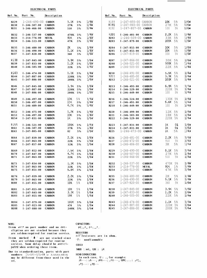
K129R130R131
R132R133R134
R135R136R137
RI38R139R140
RI43R144R145
R146R147R148
R149R150R151
R152R153R154
K155R161R163
R164R166R167
R169R170R171
R173R174R175
R176R179R180
R181R182R183
R184R185R188
NOTE:
ELECTRICAL PARTS
Part No. Description
l-246-490-00 CARBONl-246-507-00 CARBON1-246-466-00 CARBON
l-246-537-00 CARBONl-214-776-00 METALl-246-513-00 CARBON
l-246-480-00l-246-490-00l-247-820-00
l-247-845-00l-247-833-00l-246-505-00
l-246-474-00l-247-887-00l-247-886-00
CARBONCARBONCARBON
CARBONCARBONCARBON
CARBONCARBONCARBON
l-247-845-00 CARBONl-247-887-00 CARBONl-247-886-00 CARBON
l-246-497-00 CARBONl-246-497-00 CARBONl-246-489-00 CAKBON
l-246-475-00 CARBONl-246-497-00 CARBONl-247-831-00 CARBON
l-246-521-00 CARBONl-246-507-00 CARBONl-247-805-00 CARBON
l-247-839-00l-247-863-00l-247-857-00
l-247-852-00l-247-847-00l-247-863-00
l-247-834-00l-247-863-00l-247-851-00
l-247-839-00l-247-863-00l-247-855-00
l-247-855-00l-247-843-00l-247-855-00
l-247-879-00l-247-823-00l-247-888-00
CARBONCARBONCARBON
CARBONCARBONCARBON
CARBONCARBONCARBON
CARBONCARBONCARBON
CARBONCARBONCARBON
CARBONCARBONCARBON
5.1K 5%27K 5%510 5%
470K 5%91K 1%47K 5%
5%FlK 5%360 5%
3.9K 5%1.2K 5%22K 5%
l.lK 5%220K 5%200K 5%
3.9K 5%220K 5%200K 5%
10K 5%10K 5%4.7K 5%
1.2K 5%10K 5%1K 5%
1OOK 5%27K 5%82 5%
2.2K 5%22K 5%12K 5%
7.5K 5%4.7K 5%22K 5%
1.3K 5%22K 5%6.8K 5%
2.2K 5%22K 5%10K 5%
10K 5%3.3K 5%10K 5%
1OOK 5%470 5%240K 5%
1/4w1/4w1/4w
1/4w1/4w1/4w
1/4w1/4w1/6W
1/6W1/6W1/4w
1/4w1/6W1/6W
1/6W1/6W1/6W
1/4w1/4w1/4w
1/4w1/4w1/6W
1/4w1/4w1/6W
1/6W1/6W1/6W
1/6W1/6W1/6W
1/6W1/6W1/6W
1/6W1/6W1/6W
1/6W1/6W1/6W
1/6W1/6W1/6W
CAPACITORS:
ELECTRICAL PARTS
Ref.No. Part No. Description
R189 l-247-855-00 CARBONR191 l-247-865-00 CARBONR192 l-247-807-00 CARBON
R2Dl l-246-481-00 CARBONR202 l-246-509-00 CARBONR203 l-247-879-00 CARBON
R204R205R206
R207R208R209
R210R211R212
l-247-855-00l-247-855-00l-247-819-00
l-247-866-00l-246-521-00l-246-505-00
l-246-491-00l-246-485-00l-246-521-00
CARBONCARBONCARBON
CARBONCARBONCARBON
CARBONCARBONCARBON
R213 l-246-493-00 CARBONR214 l-246-529-00 CARBONR215 I-246-449-00 CARBON
R216 l-246-524-00 CARBONR217 l-246-491-00 CARBONR218 l-246-449-00 CARBON
R220 l-246-499-00 CARBONR221 l-246-503-00 CARBONR222 l-246-529-00 CARBON
R223 l-247-831-00 CARBONR224 l-247-831-00 CARBONR225
R226R227R228
R229R230R231
R232R233R234
R235R236R237
R238R239R240
R243R244R245
Items with no part number and no des- MF:nF, PF:bbF.cfiption are not stocked because theyare seldom required for routine service. RESISTORS...
Items marked " 4 " are not stocked sinceAII resistors are in ohms.
they are seldom required for routine . F : nonflammable
l-246-473-00 CARBON
l-246-481-00l-246-472-00l-246-484-00
l-246-490-00l-246-507-00l-246-466-00
l-246-537-00l-214-776-00l-246-513-00
l-246-480-00l-246-490-00l-247-820-00
l-247-845-00l-247-833-00l-246-505-00
l-246-474-00l-247-887-00I-247-886-00
CARBONCARBONCARBON
CARBONCARBONCARBON
CARBONMETALCARBON
CARBONCARBONCARBON
CARBONCARBONCARBON
CARBONCARBONCARBON
10K 5%27K 5%100 5%
2.2K 5%33K 5%1OOK 5%
1/6W1/6W1/6W
1/4w1/4w1/6W
10K 5%10K 5%330 5%
30K 5%1OOK 5%22K 5%
1/6W1/6W1/6W
1/6W1/4w1/4w
5.6K 5%3.3K 5%1DOK 5%
1/4w1/4w1/4w
6.8K 5%220K 5%100 5%
130K 5%5.6K 5%100 5%
12K 5%18K 5%220K 5%
1/4w1/4w1/4w
1/4w1/4w1/4w
1/4w1/4w1/4w
1K 1/6W1K :: 1/6W1K 5% 1/4w
2.2K 5%910 5%3K 5%
1/4w1/4w1/4w
5.1K 5%27K 5%510 5%
470K 5%91K 1%47K 5%
1/4wlf4W1/4w
1/4w1/4w1/4w
2K 5%5.1K 5%360 5%
3.9K 5%1.2K 5%22K 5%
1/4w1/4w1/6W
1/6W1/6W1/4w
l.lK 5%220K 5%200K 5%
1/4w1/6W1/6W
service. Some delay should be antici- COILSpated when ordering these items.
Due to standardization, parts with partMMH : mH, UH : uH
numbers (n-AAA-f,AA-XX or A-AAAA-AM-X) SEMICONDUCTORSmay be different from those used in the In each case, U : V, for example:set. UA...: LIA..., UPA...: UPA..., UPC....: UPC,
UPD...: uPD...
ELECTRICAL PARTS
Ref.No. Part No. Description
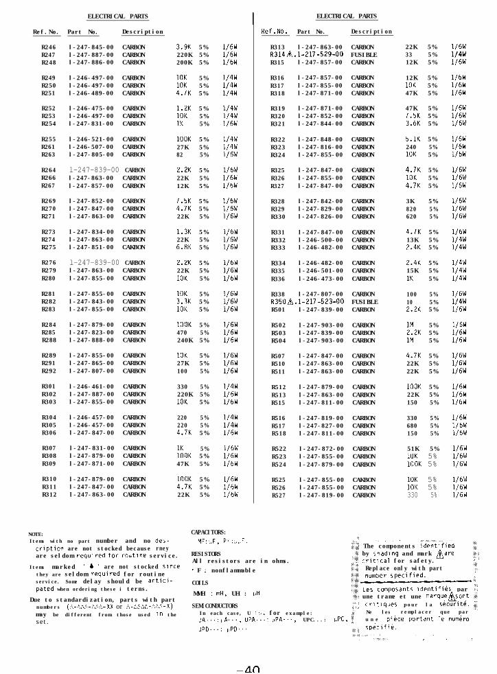
R246R247R248
R249R250R251
R252R253R254
R255R261R263
R264R266R267
R269R270R271
R273R274R275
R276R279R280
R281R282R283
R284R285R288
R289R291R292
R301R302R303
R304R305R306
R307R308R309
R310R311R312
l-247-845-00 CARBONl-247-887-00 CARBONl-247-886-00 CARBON
l-246-497-00 CARBONl-246-497-00 CARBONl-246-489-00 CARBON
l-246-475-00 CARBONl-246-497-00 CARBONl-247-831-00 CARBON
l-246-521-00 CARBONl-246-507-00 CARBONl-247-805-00 CARBON
l-247-839-00 CARBONl-247-863-00 CARBONl-247-857-00 CARBON
l-247-852-00 CARBONl-247-847-00 CARBONl-247-863-00 CARBON
l-247-834-00 CARBONl-247-863-00 CARBONl-247-851-00 CAKBON
l-247-839-00 CARBONl-247-863-00 CARBONl-247-855-00 CARBON
l-247-855-00 CARBONl-247-843-00 CARBONl-247-855-00 CARBON
l-247-879-00 CARBONl-247-823-00 CARBONl-247-888-00 CARBON
l-247-855-00 CARBONl-247-865-00 CARBONl-247-807-00 CARBON
l-246-461-00 CARBONl-247-887-00 CARBONl-247-855-00 CARBON
l-246-457-00 CARBONl-246-457-00 CARBONl-247-847-00 CARBON
l-247-831-00 CARBONl-247-879-00 CARBONl-247-871-00 CARBON
l-247-879-00 CARBONl-247-847-00 CARBONl-247-863-00 CARBON
3.9K 5%220K 5%200K 5%
10K 5%10K 5%4.7K 5%
1.2K 5%10K 5%1K 5%
1OOK 5%27K 5%82 5%
2.2K 5%22K 5%12K 5%
7.5K 5%4.7K 5%22K 5%
1.3K 5%22K 5%6.8K 5%
2.2K 5%22K 5%10K 5%
10K 5%3.3K 5%10K 5%
1OOK 5%470 5%240K 5%
10K 5%27K 5%100 5%
330 5%220K 5%10K 5%
220 5%220 5%4.7K 5%
5%::OK 5%47K 5%
1OOK 5%4.7K 5%22K 5%
1/6W1/6W1/6W
1/4w1/4w1/4w
1/4w1/4w1/6W
1/4w1/4w1/6W
1/6W1/6W1/6W
1/6W1/6W1/6W
1/6W1/6W1/6W
1/6W1/6W1/6W
1/6W1/6W1/6W
1/6W1/6W1/6W
1/6W1/6W1/6W
1/4w1/6W1/6W
1/4w1/4w1/6W
1/6W1/6W1/6W
1/6W1/6W1/6W
I ELECTRICAL PARTS
Ref.No. Part No. Description
R313 l-247-863-00 CARBONR3148.1-217-529-00 FUSIBLER315 l-247-857-00 CARBON
R316 l-247-857-00 CARBONR317 l-247-855-00 CARBONR318 l-247-871-00 CARBON
R319R320R321
l-247-871-00 CARBONl-247-852-00 CARBONl-247-844-00 CARBON
R322R323R324
l-247-848-00 CARBONl-247-816-00 CARBONl-247-855-00 CARBON
R325R326R327
l-247-847-00 CARBONl-247-855-00 CARBONl-247-847-00 CARBON
R328R329R330
l-247-842-00 CARBONl-247-829-00 CARBONl-247-826-00 CARBON
R331R332R333
l-247-847-00 CARBONl-246-500-00 CARBONl-246-482-00 CARBON
R334R335R336
l-246-482-00 CARBONl-246-501-00 CARBONl-246-473-00 CARBON
R338 l-247-807-00 CARBONR350n.l-217-523-00 FUSIBLER501 l-247-839-00 CARBON
R502R503R504
R507R510R511
R512R513R515
R516R517R518
R522R523R524
R525R526R527
l-247-903-00 CARBONl-247-839-00 CARBONl-247-903-00 CARBON
l-247-847-00 CARBONl-247-863-00 CARBONl-247-863-00 CARBON
l-247-879-00 CARBONl-247-863-00 CARBONl-247-811-00 CARBON
l-247-819-00 CARBONl-247-827-00 CARBONl-247-811-00 CARBON
l-247-872-00 CARBONl-247-855-00 CARBONl-247-879-00 CARBON
l-247-855-00 CAKBONl-247-855-00 CARBONl-247-819-00 CARBON
22K 5%33 5%12K 5%
12K 5%10K 5%47K 5%
47K 5%7.5K 5%3.6K 5%
5.1K 5%240 5%10K 5%
4.7K 5%10K 5%4.7K 5%
3K 5%820 5%620 5%
4.7K 5%13K 5%2.4K 5%
2.4K 5%15K 5%1K 5%
100 5%10 5%2.2K 5%
1M 5%2.2K 5%1M 5%
4.7K 5%22K 5%22K 5%
1OOK 5%22K 5%150 5%
330 5%680 5%150 5%
51K 5%10K 5%1OOK 5%
10K 5%10K 5%330 5%
1/6W1/4w1/6W
1/6W1/6W1/6W
1/6W1/6W1/6W
1/6W1/6W1/6W
1/6W1/6W1/6W
1/6W1/6W1/6W
1/6W1/4w1/4w
1/4w1/4w1/4w
1/6W1/4w1/6W
1/6W1/6W1/6W
1/6W1/6W1/6W
1/6W1/6W1/6W
1/6W1/6W1/6W
1/6W1/6W1/6W
1/6W1/6W1/6W
NOTE: CAPACITORS:Items with no part number and nocriptlon are not stocked because
des- MF:L.F, PF:L~F.‘,,
::. .\ . . .
rney 5':::: The components identi'iiedare seldom required tar routine service. RESISTORS
All resistors are in ohms.'<: by chadlng and mark Aare
z:.,
.?:: critical for safety.:;,:.,:,. :
Items marked " b II are not stocked Since .::..:I:j: Replace only with part:I::
. F : nonflammable j :y.they are seldom required for routineservice. Some delay should be antlci- COILS
.::. ...:
pated when ordering these i terns. :.::..MMH : mH, UH : uH
1:; Les ccmposants identlfibs par ;'
Due to standardization, parts with part ii-_: une trame et une marquensont .:j.
numbers (A-AAA-,“,?>A-XX or A-AAAA-MA-X) SEMICONDUCTORS "'..:: .,. crltlques pour la s6curit6. iI
may be different from those used In the In each case, U : LI, for example:>.:.. Ne les remplacer que par T
set. IJA...: uA..., UPA...: ,JPA..., UPC...: UPC, :; u n e pi&ce portant le numCr0
upcl...: PPD... .,I,,, sp&iflk..::_: .,,. . . . . . . . .. . :..: :. .i :
-LLn
Ref.No.
R529R530R531
R532R533R534
R535R536R537
R538R539R540
ELECTRICAL PARTS
Part No. Description
l-247-831-00 CARBONl-247-831-00 CARBONl-247-831-00 CARBON
1K1K1K
l-247-831-00 CARBON 1Kl-247-831-00 CARBON 1Kl-247-831-00 CARBON 1K
l-247-831-00 CARBON 1Kl-247-831-00 CARBON 1Kl-247-831-00 CARBON 1K
l-247-847-00 CARBON 4.7Kl-247-855-00 CARBON 10Kl-247-839-00 CARBON 2.2K
R541 l-247-868-00 CARBON 36KR542 l-247-879-00 CARBON 1OOKR543 l-247-809-00 CARBON 120
R544 l-247-831-00 CARBON 1KR546 l-247-889-00 CARBON 270KR547 l-247-887-00 CARBON 220K
R548R549R550
R551R566R568
R571R573
l -247-875-00l-247-871-00l-247-831-00
l-247-871-00l-247-871-00l-247-863-00
l-247-831-00l-247-831-00
CARBONCARBONCARBON
68K47K1K
CARBONCARBONCARBON
47K47K22K
CARBON 1KCARBON 1K
5%5%5%
5%5%5%
5%
:z
5%5%5%
5%5%5%
5%5%5%
5%5%5%
5%5%5%
5%5%
1/6W1/6W1/6W
1/6W1/6W1/6W
1/6W1/6W1/6W
1/6W1/6W1/6W
1/6W1/6W1/6W
1/6W1/6W1/6W
1/6W1/6W1/6W
1/6W1/6W1/6W
1/6W1/6W
RVlOl l-226-991-00 RES, VAR, SLIOE 20K/20K (REC LEVEL LRV201 l-226-991-00 RES, VAR, SLIDE 20K/20K (REC LEVEL R
RV102 l-226-236-00 RES, ADJ, CARBON 10KRV103 1-226-851-41 RES, ADJ, CARBON 10KRV104 l-226-236-00 RES, ADJ, CARBON 10K
RV202 l-226-236-00 RES, ADJ, CARBON 10KRV203 1-226-851-41 RES, ADJ. CARBON 10KRV204 l-226-236-00 RES, ADJ; CARBON 10K
RY301 1-515-473-12 RELAY
ELECTRICAL PARTS
Ref.No. Part No. Description
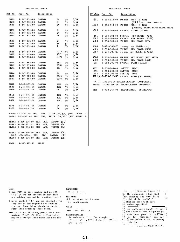
s301 l-554-510-00 SWITCH, PUSH (3 KEY)(DOLBY NR, TAPE SELECT)
S302 l-554-510-00 SWITCH, PUSH (3 KEY)(REPEAT, MUSIC SCAN/BLANK SKIP)
s303 l-554-208-00 SWITCH, SLIDE (TIMER)
s501 l-554-303-00 SWITCH. KEY BOARD CREW)S502 l-554-303-00 SWITCH; KEY BOARD (STOi)s503 l-554-303-00 SWITCH, KEY BOARD (PB)
s504 1-554-303-00 SWITCH, KEY BOARD (F F)S506 l-554-303-00 SWITCH, KEY BOARD (REC)s507 1-554-303-00 SWITCH, KEY BOARD (PAUSE)
S508 l-554-303-00 SWITCH, KEY BOARD (REC MUTE)s509 l-554-303-00 SWITCH, KEY BOARD (AMS)s551 l-554-205-00 SWITCH, PUSH (EJECT)
S552 l-554-205-00 SWITCH, PUSHs553 l-554-205-00 SWITCH, PUSHs554 l-554-205-00 SWITCH, PUSHS9018.1-553-318-00 SWITCH, PUSH (AC POWER)
SPKlOl l-235-186-00 ENCAPSULATED COMPONENTSPK201 l-235-186-00 ENCAPSULATED COMPONENT
T301 l-433-267-00 TRANSFORMER, OSCILLATOR
NOTE: CAPACITORS: . . .Items with no part number and no des- MF:L,F, PF:vbF.
;:::,:,.> :.: :,,.,.,i,,.., 5,: y. :&::::j,:,I :: ::. . . . . ..\ ,.,.. . .crlptlon are not stocked because they :':: The components identified :are seldom required for routine service. RESISTORS
All resistors are in ohms.by shading and marknare i:j,.
I terns marked II b II are not stocked since+ critical for safety.‘. :.:
they are seldom required for routine . F : nonflammable ..: Replace only with part
service. Some delay should be antici-,:I':; number specified.
COILS.
pated when ordering these items.:::'::,
MMH : mH, UH : uH :cG Les composants identlfihs par "'.::::..Due to standardization, parts with part .;:i une trame et une marquensont
numbers (C-AAC-Ct)C-XX or A-t~fi?,-:,x-X) SEMICONDUCTORS.i>:. . . . critiques pour la s&curlt&. 'I..
may be different from those used in the In each case, U : p, for example: j;::.:i:::: Ne les remplacer que par ."'
set. UA...: ,,A..., UPA...: "PA..., UPC...: UPC. $ une plbce portant le numbroUPD...: uPD... :...:. sp&ifi&.
:,:::...,,.,......,.;... . . . . . . . . . . ,., ,, . . . . . . .. .,: ::::,:::.: ‘: :::: ..,;i’i’.:,.::,. f’. ; : ‘.:::.;I.
41--


