Embed Size (px)
Citation preview
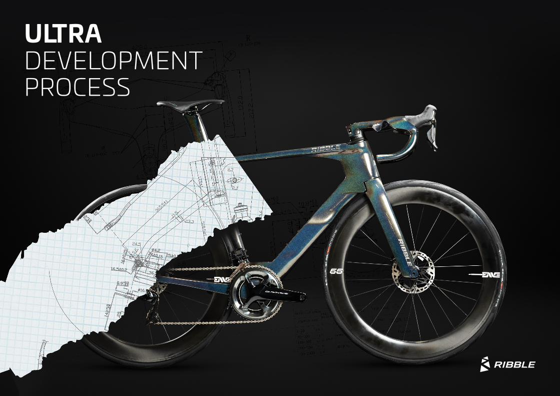
ULTRA DEVELOPMENT PROCESS
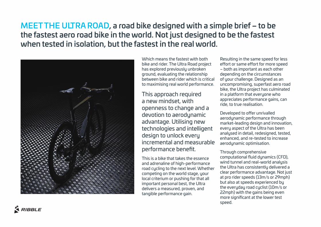
MEET THE ULTRA ROAD, a road bike designed with a simple brief – to be the fastest aero road bike in the world. Not just designed to be the fastest when tested in isolation, but the fastest in the real world.
Which means the fastest with both bike and rider. The Ultra Road project has explored previously unbroken ground, evaluating the relationship between bike and rider which is critical to maximising real world performance.
This approach required a new mindset, with openness to change and a devotion to aerodynamic advantage. Utilising new technologies and intelligent design to unlock every incremental and measurable performance benefit.This is a bike that takes the essence and adrenaline of high-performance road cycling to the next level. Whether competing on the world stage, your local criterium or pushing for that all important personal best, the Ultra delivers a measured, proven, and tangible performance gain.
Resulting in the same speed for less effort or same effort for more speed – both as important as each other depending on the circumstances of your challenge. Designed as an uncompromising, superfast aero road bike, the Ultra project has culminated in a platform that everyone who appreciates performance gains, can ride, to true realisation.
Developed to offer unrivalled aerodynamic performance through market-leading design and innovation, every aspect of the Ultra has been analysed in detail, redesigned, tested, enhanced, and re-tested to increase aerodynamic optimisation.
Through comprehensive computational fluid dynamics (CFD), wind tunnel and real-world analysis the Ultra has consistently delivered a clear performance advantage. Not just at pro rider speeds (13m/s or 29mph) but also at speeds experienced by the everyday road cyclist (10m/s or 22mph) with the gains being even more significant at the lower test speed.
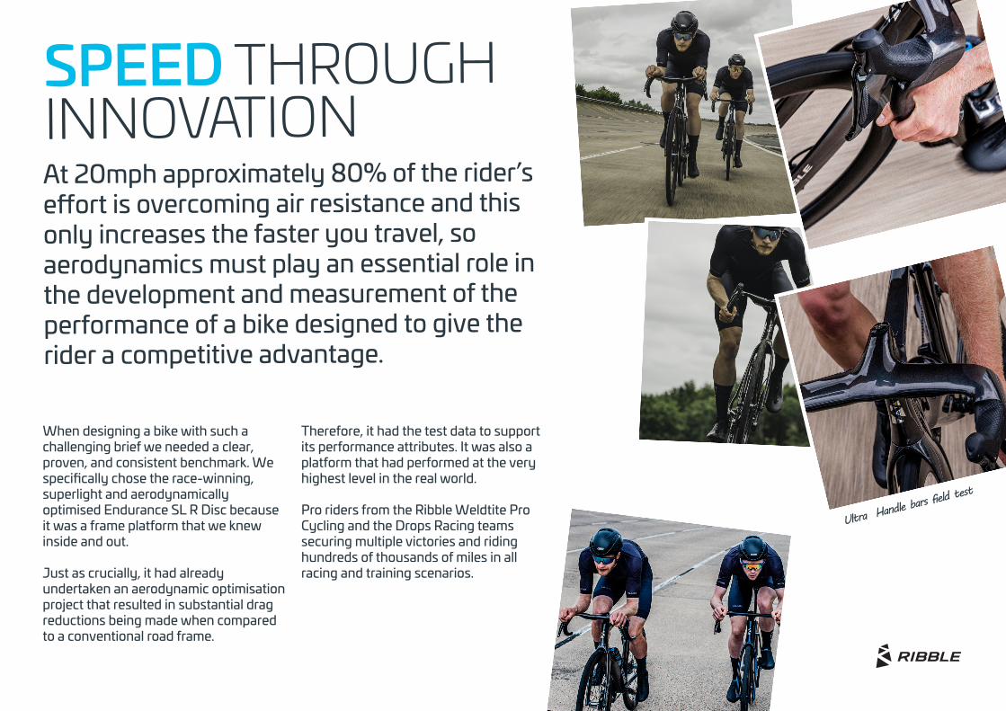
SPEED THROUGHINNOVATIONAt 20mph approximately 80% of the rider’s effort is overcoming air resistance and this only increases the faster you travel, so aerodynamics must play an essential role in the development and measurement of the performance of a bike designed to give the rider a competitive advantage.
Ultra Handle ba
rs field test
When designing a bike with such a challenging brief we needed a clear, proven, and consistent benchmark. We specifically chose the race-winning, superlight and aerodynamically optimised Endurance SL R Disc because it was a frame platform that we knew inside and out.
Just as crucially, it had already undertaken an aerodynamic optimisation project that resulted in substantial drag reductions being made when compared to a conventional road frame.
Therefore, it had the test data to support its performance attributes. It was also a platform that had performed at the very highest level in the real world.
Pro riders from the Ribble Weldtite Pro Cycling and the Drops Racing teams securing multiple victories and riding hundreds of thousands of miles in all racing and training scenarios.
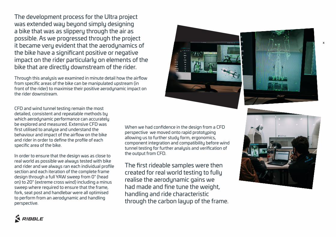
The development process for the Ultra project was extended way beyond simply designing a bike that was as slippery through the air as possible. As we progressed through the project it became very evident that the aerodynamics of the bike have a significant positive or negative impact on the rider particularly on elements of the bike that are directly downstream of the rider.
Through this analysis we examined in minute detail how the airflow from specific areas of the bike can be manipulated upstream (in front of the rider) to maximise their positive aerodynamic impact on the rider downstream.
CFD and wind tunnel testing remain the most detailed, consistent and repeatable methods by which aerodynamic performance can accurately be explored and measured. Extensive CFD was first utilised to analyse and understand the behaviour and impact of the airflow on the bike and rider in order to define the profile of each specific area of the bike.
In order to ensure that the design was as close to real world as possible we always tested with bike and rider and we always ran each individual profile section and each iteration of the complete frame design through a full YAW sweep from 0° (head on) to 20° (extreme cross wind) including a minus sweep where required to ensure that the frame, fork, seat post and handlebar were all optimised to perform from an aerodynamic and handling perspective.
x
When we had confidence in the design from a CFD perspective we moved onto rapid prototyping allowing us to further study form, ergonomics, component integration and compatibility before wind tunnel testing for further analysis and verification of the output from CFD.
The first rideable samples were then created for real world testing to fully realise the aerodynamic gains we had made and fine tune the weight, handling and ride characteristic through the carbon layup of the frame.
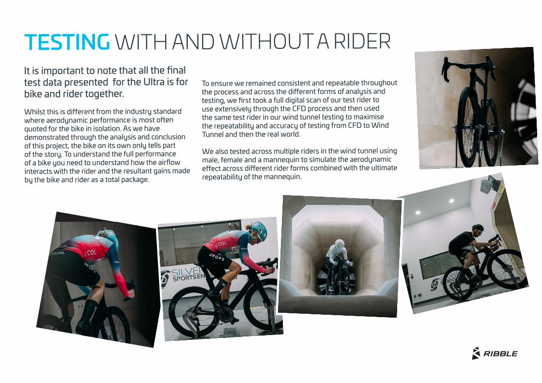
To ensure we remained consistent and repeatable throughout the process and across the different forms of analysis and testing, we first took a full digital scan of our test rider to use extensively through the CFD process and then used the same test rider in our wind tunnel testing to maximise the repeatability and accuracy of testing from CFD to Wind Tunnel and then the real world.
We also tested across multiple riders in the wind tunnel using male, female and a mannequin to simulate the aerodynamic effect across different rider forms combined with the ultimate repeatability of the mannequin.
It is important to note that all the final test data presented for the Ultra is for bike and rider together.
Whilst this is different from the industry standard where aerodynamic performance is most often quoted for the bike in isolation. As we have demonstrated through the analysis and conclusion of this project, the bike on its own only tells part of the story. To understand the full performance of a bike you need to understand how the airflow interacts with the rider and the resultant gains made by the bike and rider as a total package.
TESTING WITH AND WITHOUT A RIDER
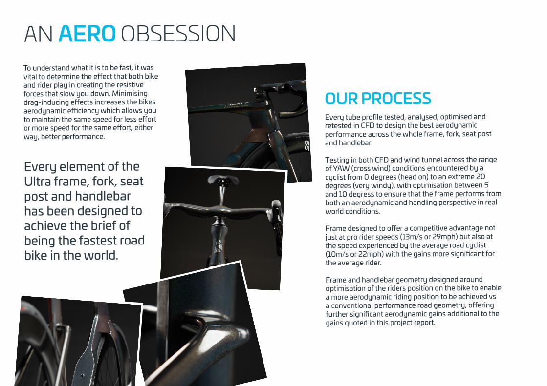
To understand what it is to be fast, it was vital to determine the effect that both bike and rider play in creating the resistive forces that slow you down. Minimising drag-inducing effects increases the bikes aerodynamic efficiency which allows you to maintain the same speed for less effort or more speed for the same effort, either way, better performance.
Every element of the Ultra frame, fork, seat post and handlebar has been designed to achieve the brief of being the fastest road bike in the world.
AN AERO OBSESSION
Every tube profile tested, analysed, optimised and retested in CFD to design the best aerodynamic performance across the whole frame, fork, seat post and handlebar
Testing in both CFD and wind tunnel across the range of YAW (cross wind) conditions encountered by a cyclist from 0 degrees (head on) to an extreme 20 degrees (very windy), with optimisation between 5 and 10 degress to ensure that the frame performs from both an aerodynamic and handling perspective in real world conditions.
Frame designed to offer a competitive advantage not just at pro rider speeds (13m/s or 29mph) but also at the speed experienced by the average road cyclist (10m/s or 22mph) with the gains more significant for the average rider.
Frame and handlebar geometry designed around optimisation of the riders position on the bike to enable a more aerodynamic riding position to be achieved vs a conventional performance road geometry, offering further significant aerodynamic gains additional to the gains quoted in this project report.
OUR PROCESS
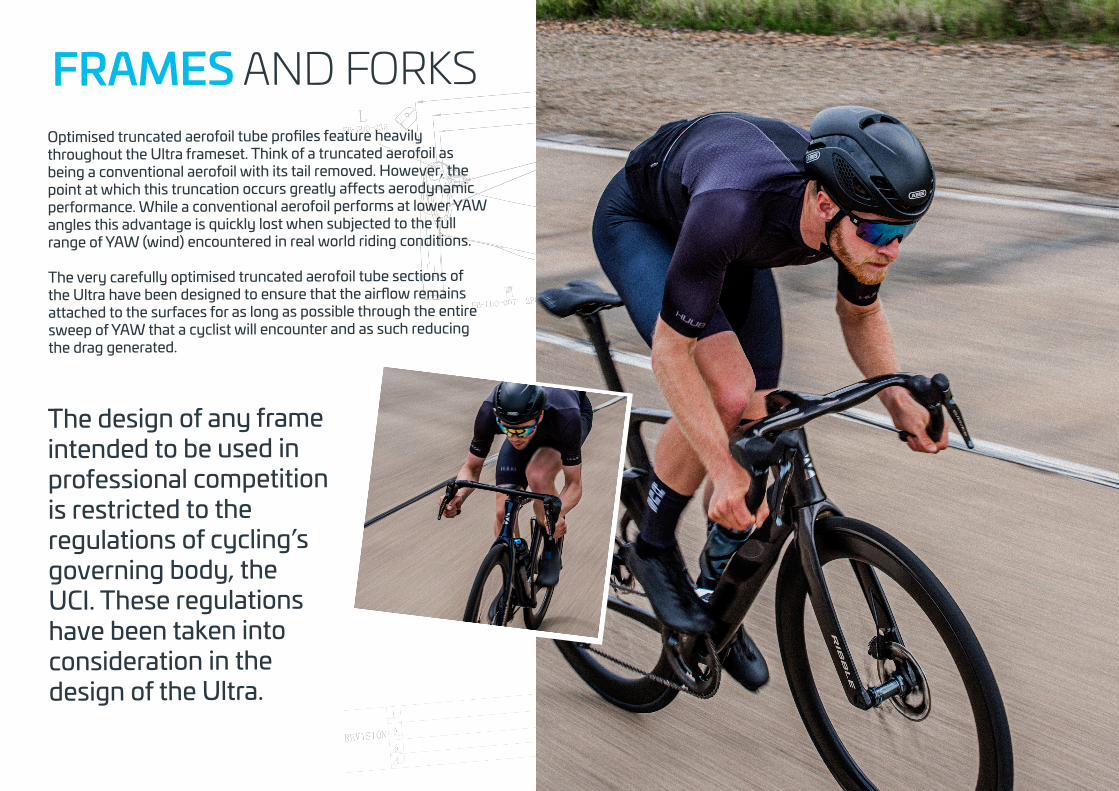
FRAMES AND FORKSOptimised truncated aerofoil tube profiles feature heavily throughout the Ultra frameset. Think of a truncated aerofoil as being a conventional aerofoil with its tail removed. However, the point at which this truncation occurs greatly affects aerodynamic performance. While a conventional aerofoil performs at lower YAW angles this advantage is quickly lost when subjected to the full range of YAW (wind) encountered in real world riding conditions.
The very carefully optimised truncated aerofoil tube sections of the Ultra have been designed to ensure that the airflow remains attached to the surfaces for as long as possible through the entire sweep of YAW that a cyclist will encounter and as such reducing the drag generated.
The design of any frame intended to be used in professional competition is restricted to the regulations of cycling’s governing body, the UCI. These regulations have been taken into consideration in the design of the Ultra.
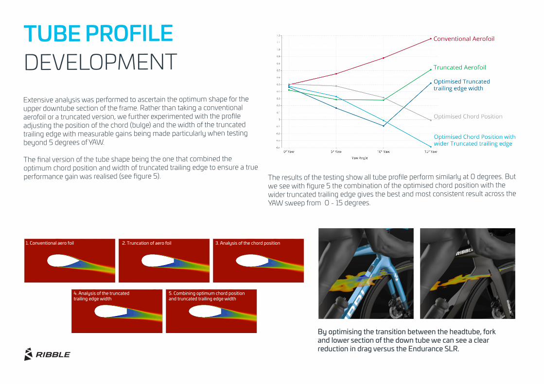
TUBE PROFILE DEVELOPMENTExtensive analysis was performed to ascertain the optimum shape for the upper downtube section of the frame. Rather than taking a conventional aerofoil or a truncated version, we further experimented with the profile adjusting the position of the chord (bulge) and the width of the truncated trailing edge with measurable gains being made particularly when testing beyond 5 degrees of YAW.
The final version of the tube shape being the one that combined the optimum chord position and width of truncated trailing edge to ensure a true performance gain was realised (see figure 5). The results of the testing show all tube profile perform similarly at 0 degrees. But
we see with figure 5 the combination of the optimised chord position with the wider truncated trailing edge gives the best and most consistent result across the YAW sweep from 0 - 15 degrees.
By optimising the transition between the headtube, forkand lower section of the down tube we can see a clear reduction in drag versus the Endurance SLR.
4. Analysis of the truncatedtrailing edge width
5. Combining optimum chord position and truncated trailing edge width
3. Analysis of the chord position 2. Truncation of aero foil1. Conventional aero foil
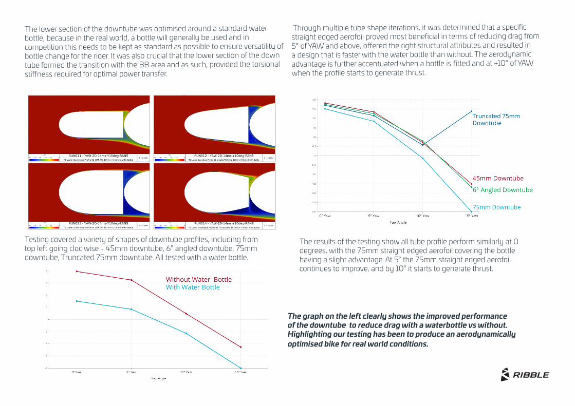
The lower section of the downtube was optimised around a standard water bottle, because in the real world, a bottle will generally be used and in competition this needs to be kept as standard as possible to ensure versatility of bottle change for the rider. It was also crucial that the lower section of the down tube formed the transition with the BB area and as such, provided the torsional stiffness required for optimal power transfer.
Through multiple tube shape iterations, it was determined that a specific straight edged aerofoil proved most beneficial in terms of reducing drag from 5° of YAW and above, offered the right structural attributes and resulted in a design that is faster with the water bottle than without. The aerodynamic advantage is further accentuated when a bottle is fitted and at +10° of YAW when the profile starts to generate thrust.
Testing covered a variety of shapes of downtube profiles, including from top left going cloclwise - 45mm downtube, 6° angled downtube, 75mm downtube, Truncated 75mm downtube. All tested with a water bottle.
The results of the testing show all tube profile perform similarly at 0 degrees, with the 75mm straight edged aerofoil covering the bottle having a slight advantage. At 5° the 75mm straight edged aerofoil continues to improve, and by 10° it starts to generate thrust.
The graph on the left clearly shows the improved performance of the downtube to reduce drag with a waterbottle vs without. Highlighting our testing has been to produce an aerodynamically optimised bike for real world conditions.
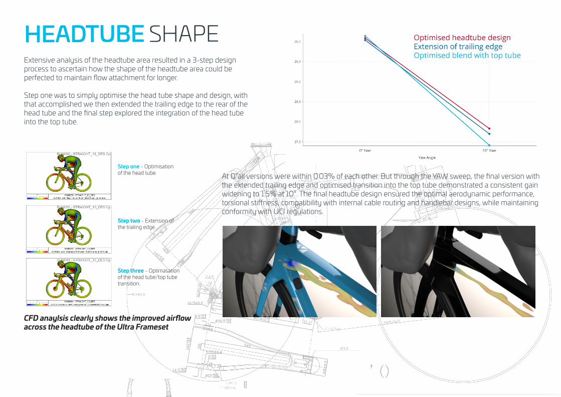
HEADTUBE SHAPEExtensive analysis of the headtube area resulted in a 3-step design process to ascertain how the shape of the headtube area could be perfected to maintain flow attachment for longer.
Step one was to simply optimise the head tube shape and design, with that accomplished we then extended the trailing edge to the rear of the head tube and the final step explored the integration of the head tube into the top tube.
At 0°all versions were within 0.03% of each other. But through the YAW sweep, the final version with the extended trailing edge and optimised transition into the top tube demonstrated a consistent gain widening to 1.5% at 10°. The final headtube design ensured the optimal aerodynamic performance, torsional stiffness, compatibility with internal cable routing and handlebar designs, while maintaining conformity with UCI regulations.
Step one - Optimisation of the head tube.
Step two - Extension of the trailing edge.
Step three - Optimasation of the head tube/top tube transition.
CFD anaylsis clearly shows the improved airflow across the headtube of the Ultra Frameset
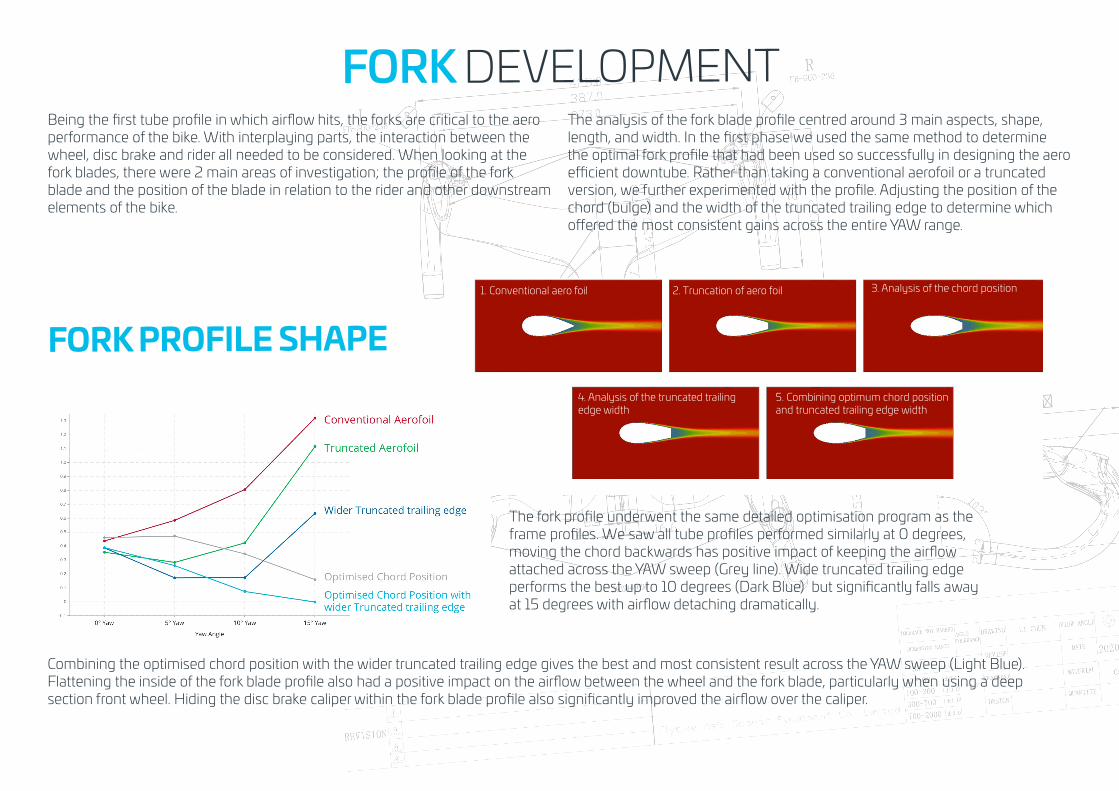
FORK DEVELOPMENTBeing the first tube profile in which airflow hits, the forks are critical to the aero performance of the bike. With interplaying parts, the interaction between the wheel, disc brake and rider all needed to be considered. When looking at the fork blades, there were 2 main areas of investigation; the profile of the fork blade and the position of the blade in relation to the rider and other downstream elements of the bike.
The analysis of the fork blade profile centred around 3 main aspects, shape, length, and width. In the first phase we used the same method to determine the optimal fork profile that had been used so successfully in designing the aero efficient downtube. Rather than taking a conventional aerofoil or a truncated version, we further experimented with the profile. Adjusting the position of the chord (bulge) and the width of the truncated trailing edge to determine which offered the most consistent gains across the entire YAW range.
The fork profile underwent the same detailed optimisation program as the frame profiles. We saw all tube profiles performed similarly at 0 degrees, moving the chord backwards has positive impact of keeping the airflow attached across the YAW sweep (Grey line). Wide truncated trailing edge performs the best up to 10 degrees (Dark Blue) but significantly falls away at 15 degrees with airflow detaching dramatically.
Combining the optimised chord position with the wider truncated trailing edge gives the best and most consistent result across the YAW sweep (Light Blue). Flattening the inside of the fork blade profile also had a positive impact on the airflow between the wheel and the fork blade, particularly when using a deep section front wheel. Hiding the disc brake caliper within the fork blade profile also significantly improved the airflow over the caliper.
1. Conventional aero foil 2. Truncation of aero foil
4. Analysis of the truncated trailing edge width
FORK PROFILE SHAPE
3. Analysis of the chord position
5. Combining optimum chord position and truncated trailing edge width
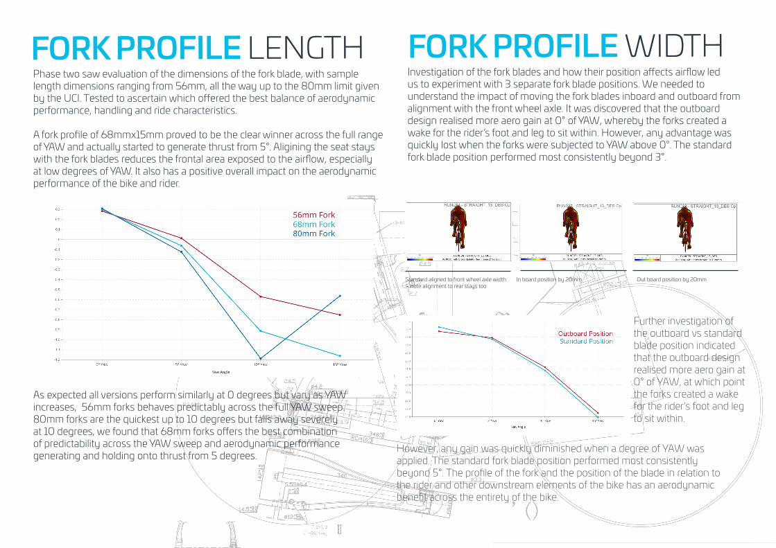
FORK PROFILE LENGTHPhase two saw evaluation of the dimensions of the fork blade, with sample length dimensions ranging from 56mm, all the way up to the 80mm limit given by the UCI. Tested to ascertain which offered the best balance of aerodynamic performance, handling and ride characteristics.
A fork profile of 68mmx15mm proved to be the clear winner across the full range of YAW and actually started to generate thrust from 5°. Aligining the seat stays with the fork blades reduces the frontal area exposed to the airflow, especially at low degrees of YAW. It also has a positive overall impact on the aerodynamic performance of the bike and rider.
As expected all versions perform similarly at 0 degrees but vary as YAW increases, 56mm forks behaves predictably across the full YAW sweep. 80mm forks are the quickest up to 10 degrees but falls away severely at 10 degrees, we found that 68mm forks offers the best combination of predictability across the YAW sweep and aerodynamic performance generating and holding onto thrust from 5 degrees.
FORK PROFILE WIDTHInvestigation of the fork blades and how their position affects airflow led us to experiment with 3 separate fork blade positions. We needed to understand the impact of moving the fork blades inboard and outboard from alignment with the front wheel axle. It was discovered that the outboard design realised more aero gain at 0° of YAW, whereby the forks created a wake for the rider’s foot and leg to sit within. However, any advantage was quickly lost when the forks were subjected to YAW above 0°. The standard fork blade position performed most consistently beyond 3°.
Standard aligned to front wheel axle width – note alignment to rear stays too
Out board position by 20mmIn board position by 20mm
Further investigation of the outboard vs standard blade position indicated that the outboard design realised more aero gain at 0° of YAW, at which point the forks created a wake for the rider’s foot and leg to sit within.
However, any gain was quickly diminished when a degree of YAW was applied. The standard fork blade position performed most consistently beyond 5°. The profile of the fork and the position of the blade in relation to the rider and other downstream elements of the bike has an aerodynamic benefit across the entirety of the bike.
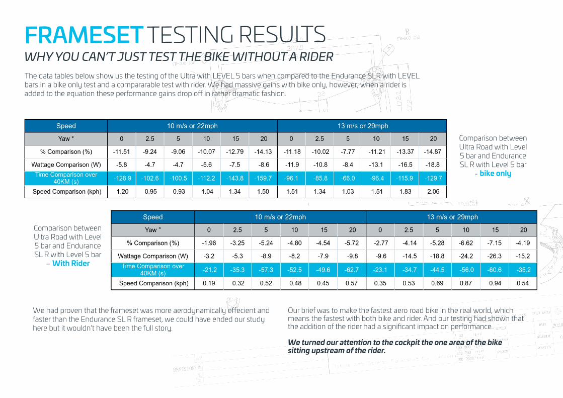
WHY YOU CAN’T JUST TEST THE BIKE WITHOUT A RIDERThe data tables below show us the testing of the Ultra with LEVEL 5 bars when compared to the Endurance SLR with LEVEL bars in a bike only test and a compararable test with rider. We had massive gains with bike only, however, when a rider is added to the equation these performance gains drop off in rather dramatic fashion.
Comparison between Ultra Road with Level 5 bar and Endurance SL R with Level 5 bar
- bike only
Comparison between Ultra Road with Level 5 bar and Endurance SL R with Level 5 bar
– With Rider
We had proven that the frameset was more aerodynamically effecient and faster than the Endurance SL R frameset, we could have ended our study here but it wouldn’t have been the full story.
Our brief was to make the fastest aero road bike in the real world, which means the fastest with both bike and rider. And our testing had shown that the addition of the rider had a significant impact on performance.
We turned our attention to the cockpit the one area of the bikesitting upstream of the rider.
FRAMESET TESTING RESULTS
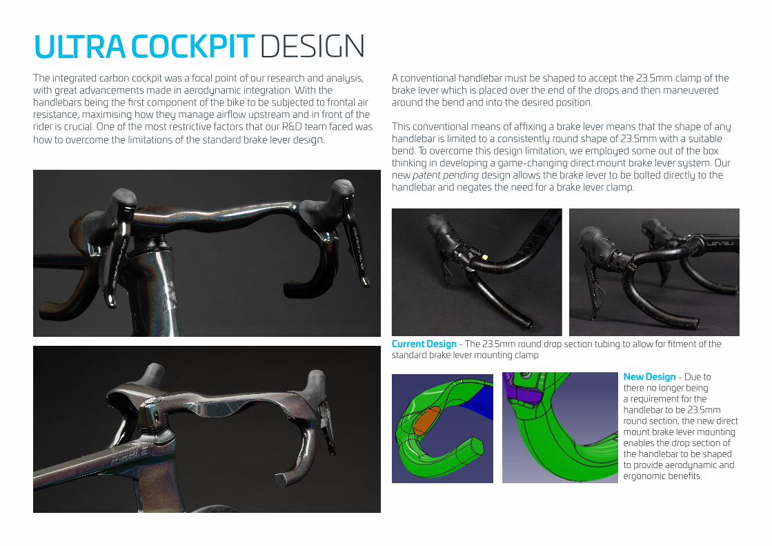
ULTRA COCKPIT DESIGNThe integrated carbon cockpit was a focal point of our research and analysis, with great advancements made in aerodynamic integration. With the handlebars being the first component of the bike to be subjected to frontal air resistance, maximising how they manage airflow upstream and in front of the rider is crucial. One of the most restrictive factors that our R&D team faced was how to overcome the limitations of the standard brake lever design.
A conventional handlebar must be shaped to accept the 23.5mm clamp of the
A conventional handlebar must be shaped to accept the 23.5mm clamp of the brake lever which is placed over the end of the drops and then maneuvered around the bend and into the desired position.
This conventional means of affixing a brake lever means that the shape of any handlebar is limited to a consistently round shape of 23.5mm with a suitable bend. To overcome this design limitation, we employed some out of the box thinking in developing a game-changing direct mount brake lever system. Our new patent pending design allows the brake lever to be bolted directly to the handlebar and negates the need for a brake lever clamp.
Current Design - The 23.5mm round drop section tubing to allow for fitment of the standard brake lever mounting clamp
New Design - Due to there no longer being a requirement for the handlebar to be 23.5mm round section, the new direct mount brake lever mounting enables the drop section of the handlebar to be shaped to provide aerodynamic and ergonomic benefits.
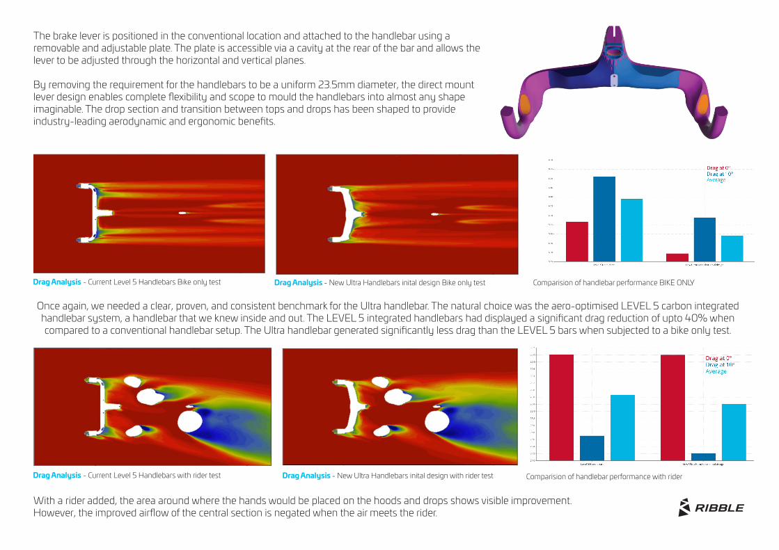
The brake lever is positioned in the conventional location and attached to the handlebar using a removable and adjustable plate. The plate is accessible via a cavity at the rear of the bar and allows the lever to be adjusted through the horizontal and vertical planes.
By removing the requirement for the handlebars to be a uniform 23.5mm diameter, the direct mount lever design enables complete flexibility and scope to mould the handlebars into almost any shape imaginable. The drop section and transition between tops and drops has been shaped to provide industry-leading aerodynamic and ergonomic benefits.
Once again, we needed a clear, proven, and consistent benchmark for the Ultra handlebar. The natural choice was the aero-optimised LEVEL 5 carbon integrated handlebar system, a handlebar that we knew inside and out. The LEVEL 5 integrated handlebars had displayed a significant drag reduction of upto 40% when compared to a conventional handlebar setup. The Ultra handlebar generated significantly less drag than the LEVEL 5 bars when subjected to a bike only test.
Drag Analysis - Current Level 5 Handlebars Bike only test Drag Analysis - New Ultra Handlebars inital design Bike only test Comparision of handlebar performance BIKE ONLY
With a rider added, the area around where the hands would be placed on the hoods and drops shows visible improvement. However, the improved airflow of the central section is negated when the air meets the rider.
Drag Analysis - Current Level 5 Handlebars with rider test Drag Analysis - New Ultra Handlebars inital design with rider test Comparision of handlebar performance with rider
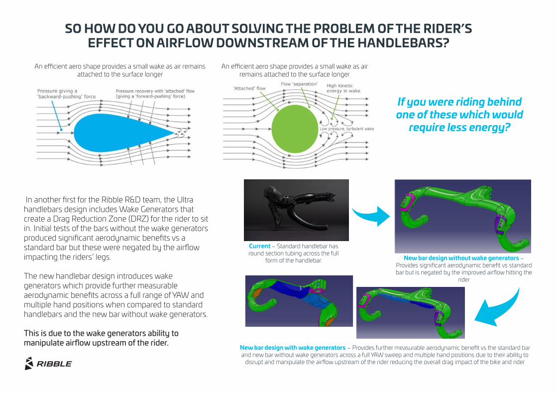
In another first for the Ribble R&D team, the Ultra handlebars design includes Wake Generators that create a Drag Reduction Zone (DRZ) for the rider to sit in. Initial tests of the bars without the wake generators produced significant aerodynamic benefits vs a standard bar but these were negated by the airflow impacting the riders’ legs.
The new handlebar design introduces wake generators which provide further measurable aerodynamic benefits across a full range of YAW and multiple hand positions when compared to standard handlebars and the new bar without wake generators.
This is due to the wake generators ability to manipulate airflow upstream of the rider.
Current – Standard handlebar has round section tubing across the full
form of the handlebar. New bar design without wake generators – Provides significant aerodynamic benefit vs standard bar but is negated by the improved airflow hitting the
rider
New bar design with wake generators – Provides further measurable aerodynamic benefit vs the standard bar and new bar without wake generators across a full YAW sweep and multiple hand positions due to their ability to
disrupt and manipulate the airflow upstream of the rider reducing the overall drag impact of the bike and rider
SO HOW DO YOU GO ABOUT SOLVING THE PROBLEM OF THE RIDER’S EFFECT ON AIRFLOW DOWNSTREAM OF THE HANDLEBARS?
An efficient aero shape provides a small wake as air remains attached to the surface longer
An efficient aero shape provides a small wake as air remains attached to the surface longer
If you were riding behind one of these which would
require less energy?
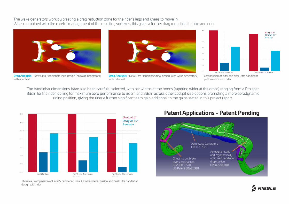
The wake generators work by creating a drag reduction zone for the rider’s legs and knees to move in. When combined with the careful management of the resulting vortexes, this gives a further drag reduction for bike and rider.
The handlebar dimensions have also been carefully selected, with bar widths at the hoods (tapering wider at the drops) ranging from a Pro spec 33cm for the rider looking for maximum aero performance to 36cm and 38cm across other cockpit size options promoting a more aerodynamic
riding position, giving the rider a further significant aero gain additional to the gains stated in this project report.
Drag Analysis - New Ultra Handlebars inital design (no wake generators) with rider test
Drag Analysis - New Ultra Handlebars final design (with wake generators) with rider test
Comparision of inital and final Ultra handlebarperformance with rider
Threeway comparision of Level 5 handlebar, Inital Ultra handlebar design and final Ultra handlebar design with rider
Patent Applications - Patent Pending
Aero Wake Generators - EP21173702.8
Direct mount brake levers mechanism - EP20205557.0 US Patent 506811918
Aerodynamically and ergonomically optimised handlebar drop section - EP20205558.8
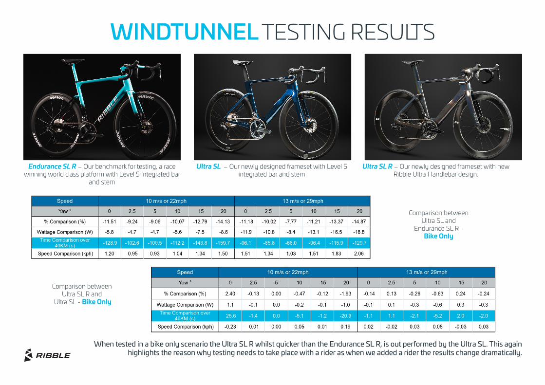
Comparison between Ultra SL and
Endurance SL R - Bike Only
Comparison between Ultra SL R and
Ultra SL - Bike Only
When tested in a bike only scenario the Ultra SL R whilst quicker than the Endurance SL R, is out performed by the Ultra SL. This again highlights the reason why testing needs to take place with a rider as when we added a rider the results change dramatically.
WINDTUNNEL TESTING RESULTS
Endurance SL R – Our benchmark for testing, a race winning world class platform with Level 5 integrated bar
and stem
Ultra SL – Our newly designed frameset with Level 5 integrated bar and stem
Ultra SL R – Our newly designed frameset with new Ribble Ultra Handlebar design.
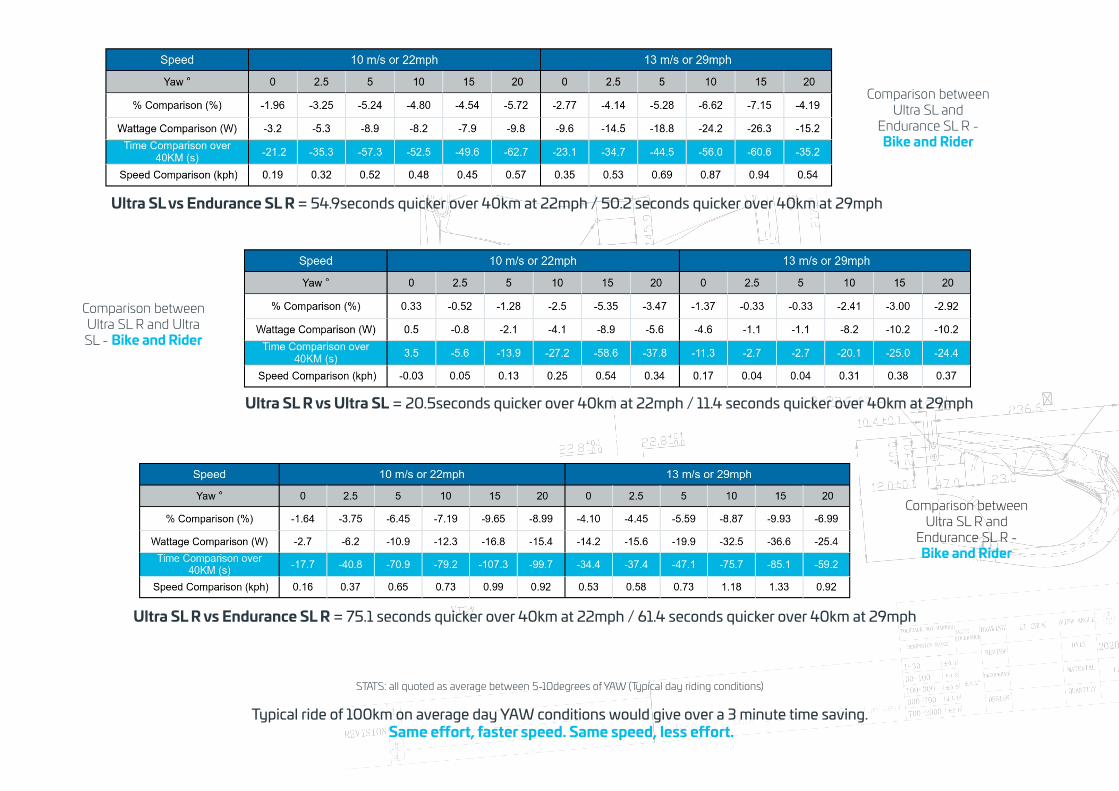
Comparison between Ultra SL R and Ultra SL - Bike and Rider
Comparison between Ultra SL and
Endurance SL R - Bike and Rider
Comparison between Ultra SL R and
Endurance SL R - Bike and Rider
Ultra SL R vs Endurance SL R = 75.1 seconds quicker over 40km at 22mph / 61.4 seconds quicker over 40km at 29mph
Ultra SL vs Endurance SL R = 54.9seconds quicker over 40km at 22mph / 50.2 seconds quicker over 40km at 29mph
Ultra SL R vs Ultra SL = 20.5seconds quicker over 40km at 22mph / 11.4 seconds quicker over 40km at 29mph
STATS: all quoted as average between 5-10degrees of YAW (Typical day riding conditions)
Typical ride of 100km on average day YAW conditions would give over a 3 minute time saving. Same effort, faster speed. Same speed, less effort.
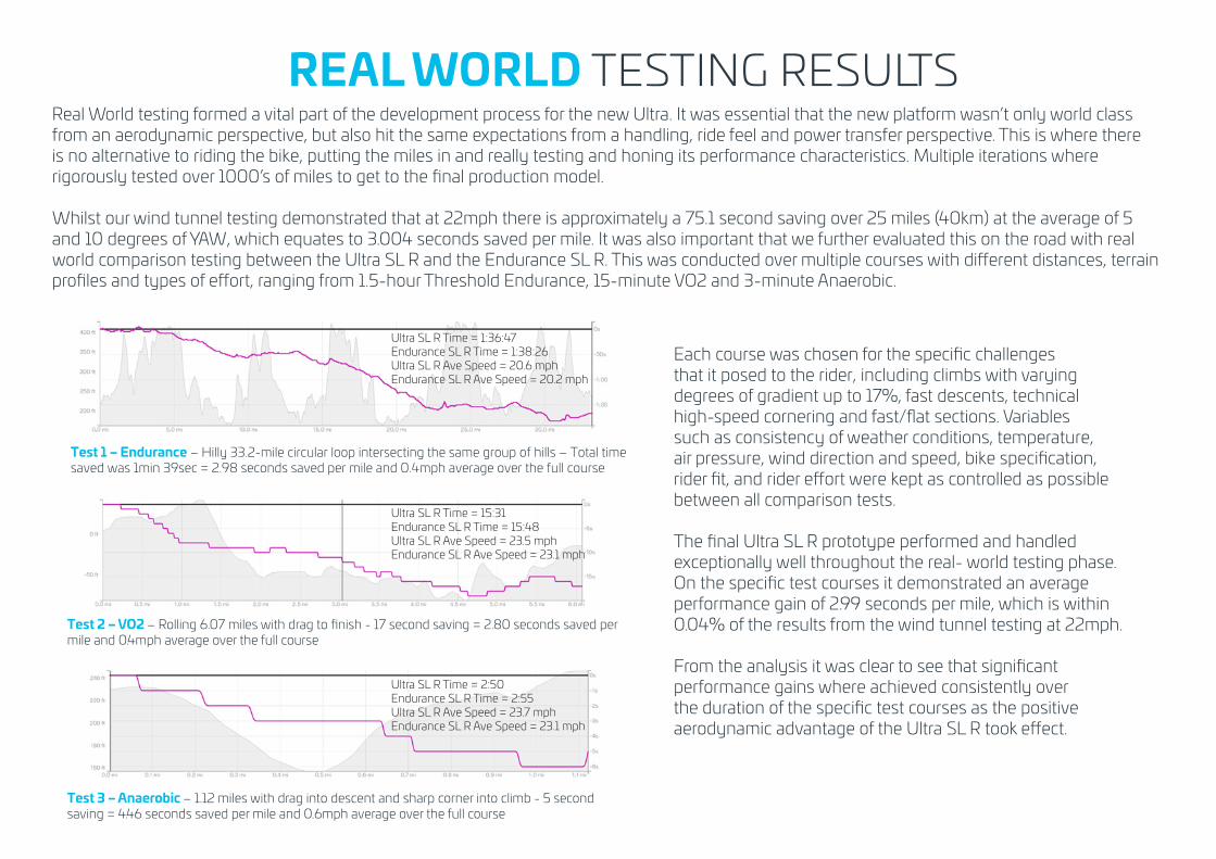
REAL WORLD TESTING RESULTSReal World testing formed a vital part of the development process for the new Ultra. It was essential that the new platform wasn’t only world class from an aerodynamic perspective, but also hit the same expectations from a handling, ride feel and power transfer perspective. This is where there is no alternative to riding the bike, putting the miles in and really testing and honing its performance characteristics. Multiple iterations where rigorously tested over 1000’s of miles to get to the final production model.
Whilst our wind tunnel testing demonstrated that at 22mph there is approximately a 75.1 second saving over 25 miles (40km) at the average of 5 and 10 degrees of YAW, which equates to 3.004 seconds saved per mile. It was also important that we further evaluated this on the road with real world comparison testing between the Ultra SL R and the Endurance SL R. This was conducted over multiple courses with different distances, terrain profiles and types of effort, ranging from 1.5-hour Threshold Endurance, 15-minute VO2 and 3-minute Anaerobic.
Test 1 – Endurance – Hilly 33.2-mile circular loop intersecting the same group of hills – Total time saved was 1min 39sec = 2.98 seconds saved per mile and 0.4mph average over the full course
Test 2 – VO2 – Rolling 6.07 miles with drag to finish - 17 second saving = 2.80 seconds saved per mile and 0.4mph average over the full course
Test 3 – Anaerobic – 1.12 miles with drag into descent and sharp corner into climb - 5 second saving = 4.46 seconds saved per mile and 0.6mph average over the full course
Each course was chosen for the specific challenges that it posed to the rider, including climbs with varying degrees of gradient up to 17%, fast descents, technical high-speed cornering and fast/flat sections. Variables such as consistency of weather conditions, temperature, air pressure, wind direction and speed, bike specification, rider fit, and rider effort were kept as controlled as possible between all comparison tests. The final Ultra SL R prototype performed and handled exceptionally well throughout the real- world testing phase. On the specific test courses it demonstrated an average performance gain of 2.99 seconds per mile, which is within 0.04% of the results from the wind tunnel testing at 22mph.
From the analysis it was clear to see that significant performance gains where achieved consistently over the duration of the specific test courses as the positive aerodynamic advantage of the Ultra SL R took effect.
Ultra SL R Time = 1:36:47Endurance SL R Time = 1:38:26 Ultra SL R Ave Speed = 20.6 mph Endurance SL R Ave Speed = 20.2 mph
Ultra SL R Time = 15:31Endurance SL R Time = 15:48 Ultra SL R Ave Speed = 23.5 mph Endurance SL R Ave Speed = 23.1 mph
Ultra SL R Time = 2:50Endurance SL R Time = 2:55 Ultra SL R Ave Speed = 23.7 mph Endurance SL R Ave Speed = 23.1 mph

ribblecycles.co.uk
Facebook / Ribble Cycles Instagram / ribble_cycles Twitter / RibbleCycles Youtube / TheRibbleCycles
Our range of award winning bikes are fully customisable & designed in-house by cyclists who live & breathe bikes.