Embed Size (px)
Citation preview
Copyright © 2013 Altair Engineering, Inc. Proprietary and Confidential. All rights reserved. Copyright © 2013 Altair Engineering, Inc. Proprietary and Confidential. All rights reserved.
Tutorial - Crash Bumper Analysis
Copyright © 2013 Altair Engineering, Inc. Proprietary and Confidential. All rights reserved. Copyright © 2013 Altair Engineering, Inc. Proprietary and Confidential. All rights reserved.
Why Crash Analysis?
To find deformation, stress, and energy absorbing capacity of various
structural components of a vehicle hitting a stationary or moving object.
The component is said to be crashworthy (safe) if it meets the plastic strain and
energy targets.
Bumper is one of the components which is used to protect passengers
from front and rear collision.
Bumper crash tests are necessary for instance to calculate the energy
absorption of this component during a crash.
Copyright © 2013 Altair Engineering, Inc. Proprietary and Confidential. All rights reserved. Copyright © 2013 Altair Engineering, Inc. Proprietary and Confidential. All rights reserved.
Agenda
Geometry meshing with HyperMesh
Mesh preparations and modifications with HyperCrash
Material creation and assignment
Property creation and assignment
Welding
Mirror to full model
Global contact definition
Load case creation
Model check
Start of simulation
Copyright © 2013 Altair Engineering, Inc. Proprietary and Confidential. All rights reserved. Copyright © 2013 Altair Engineering, Inc. Proprietary and Confidential. All rights reserved.
Mesh preferences for crash analysis
For crash analysis the preferred element type is hexa over tetra when
using 3D elements, shell elements are used for 2D modeling (as in
the case of this analysis). Follow the mesh flow line requirement and
avoid rotating quads, or diamond element formation.
Constant mesh size is preferred over variable mesh size.
Make sure the element quality matches requirements. Checking
element quality is a good practice.
Element characteristic lengths should allow a reasonable initial time
step.
Copyright © 2013 Altair Engineering, Inc. Proprietary and Confidential. All rights reserved. Copyright © 2013 Altair Engineering, Inc. Proprietary and Confidential. All rights reserved.
Mesh preferences for crash analysis
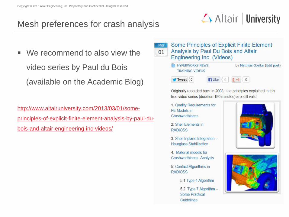
We recommend to also view the
video series by Paul du Bois
(available on the Academic Blog)
http://www.altairuniversity.com/2013/03/01/some-
principles-of-explicit-finite-element-analysis-by-paul-du-
bois-and-altair-engineering-inc-videos/
Copyright © 2013 Altair Engineering, Inc. Proprietary and Confidential. All rights reserved. Copyright © 2013 Altair Engineering, Inc. Proprietary and Confidential. All rights reserved.
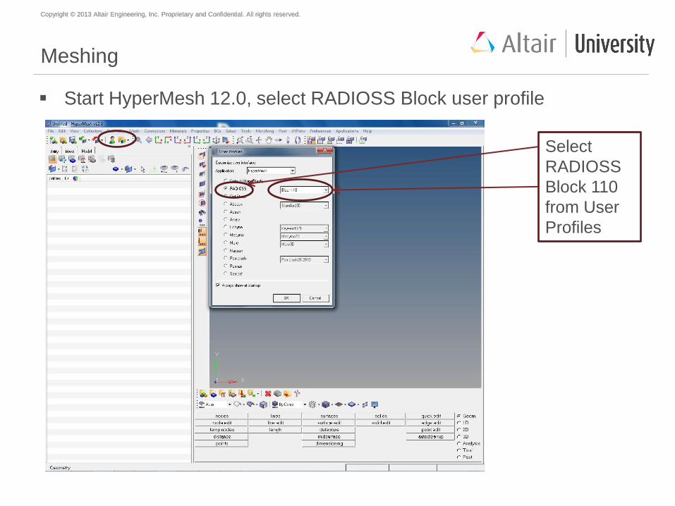
Meshing
Start HyperMesh 12.0, select RADIOSS Block user profile
Select
RADIOSS
Block 110
from User
Profiles
Copyright © 2013 Altair Engineering, Inc. Proprietary and Confidential. All rights reserved. Copyright © 2013 Altair Engineering, Inc. Proprietary and Confidential. All rights reserved.
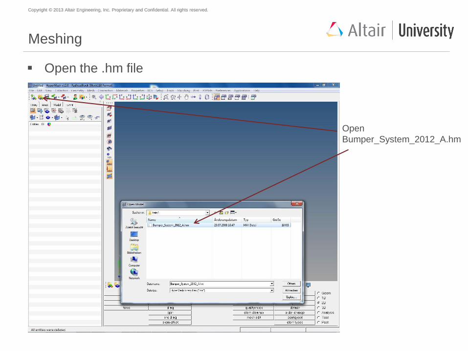
Meshing
Open the .hm file
Open
Bumper_System_2012_A.hm
Copyright © 2013 Altair Engineering, Inc. Proprietary and Confidential. All rights reserved. Copyright © 2013 Altair Engineering, Inc. Proprietary and Confidential. All rights reserved.
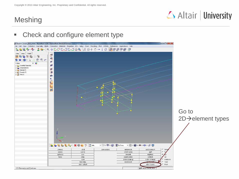
Meshing
Check and configure element type
Go to
2Delement types
Copyright © 2013 Altair Engineering, Inc. Proprietary and Confidential. All rights reserved. Copyright © 2013 Altair Engineering, Inc. Proprietary and Confidential. All rights reserved.
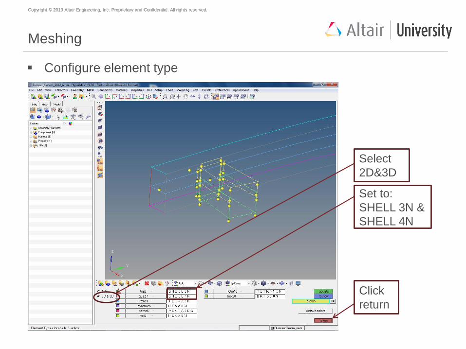
Meshing
Configure element type
Select
2D&3D
Set to:
SHELL 3N &
SHELL 4N
Click
return
Copyright © 2013 Altair Engineering, Inc. Proprietary and Confidential. All rights reserved. Copyright © 2013 Altair Engineering, Inc. Proprietary and Confidential. All rights reserved.
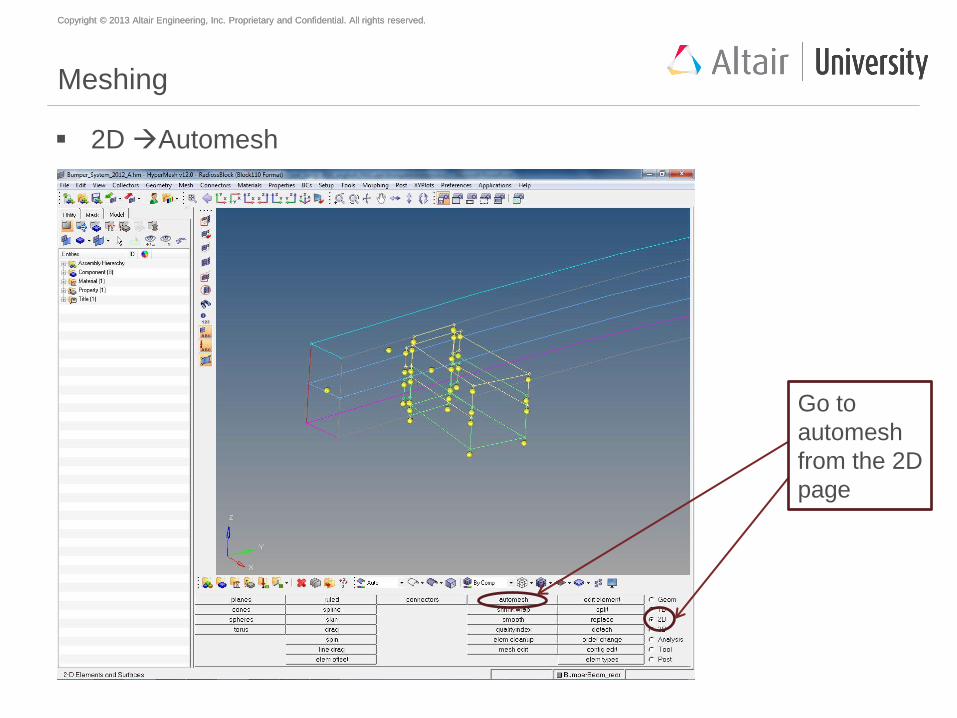
Meshing
2D Automesh
Go to
automesh
from the 2D
page
Copyright © 2013 Altair Engineering, Inc. Proprietary and Confidential. All rights reserved. Copyright © 2013 Altair Engineering, Inc. Proprietary and Confidential. All rights reserved.
Meshing
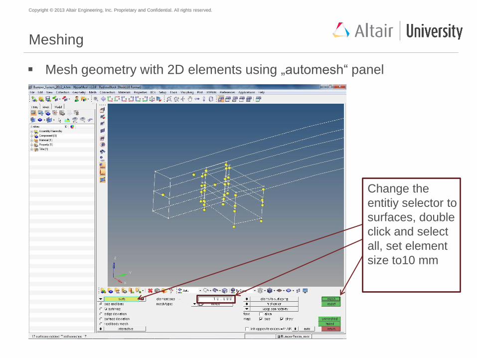
Mesh geometry with 2D elements using „automesh“ panel
Change the
entitiy selector to
surfaces, double
click and select
all, set element
size to10 mm
Copyright © 2013 Altair Engineering, Inc. Proprietary and Confidential. All rights reserved. Copyright © 2013 Altair Engineering, Inc. Proprietary and Confidential. All rights reserved.
Meshing
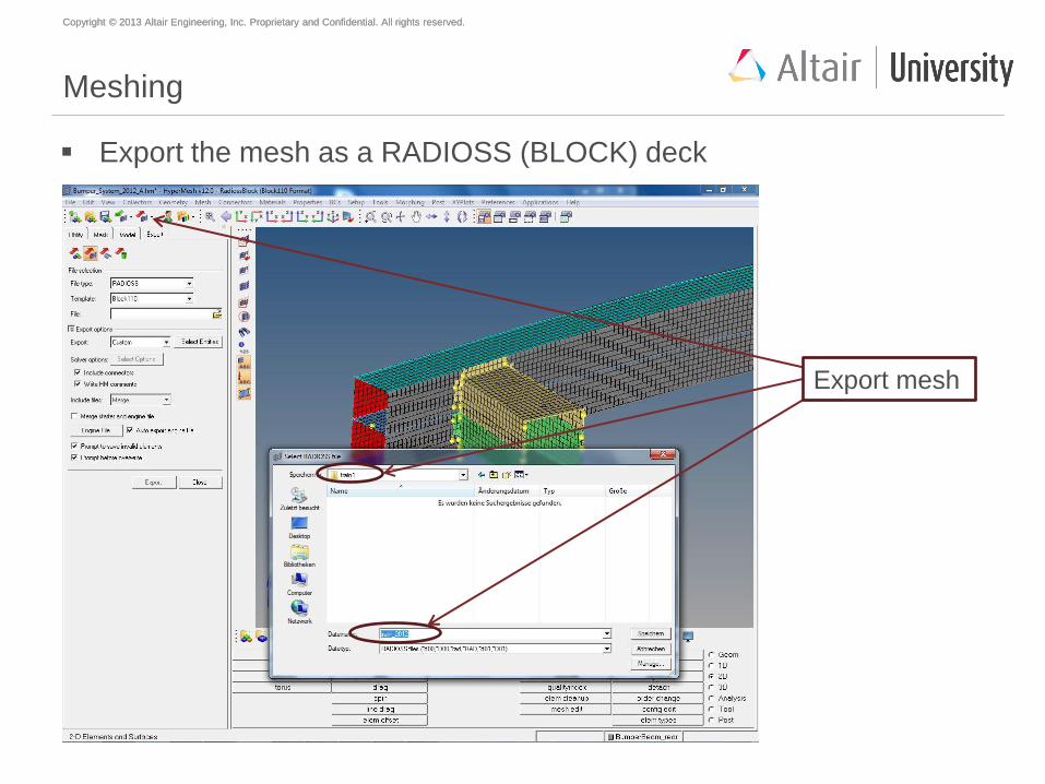
Export the mesh as a RADIOSS (BLOCK) deck
Export mesh
Copyright © 2013 Altair Engineering, Inc. Proprietary and Confidential. All rights reserved. Copyright © 2013 Altair Engineering, Inc. Proprietary and Confidential. All rights reserved.
Agenda
Geometry meshing with HyperMesh
Mesh preparations and modifications with HyperCrash
Material creation and assignment
Property creation and assignment
Welding
Mirror to full model
Global contact definition
Load case creation
Model check
Start of simulation
Copyright © 2013 Altair Engineering, Inc. Proprietary and Confidential. All rights reserved. Copyright © 2013 Altair Engineering, Inc. Proprietary and Confidential. All rights reserved.
Mesh modifications
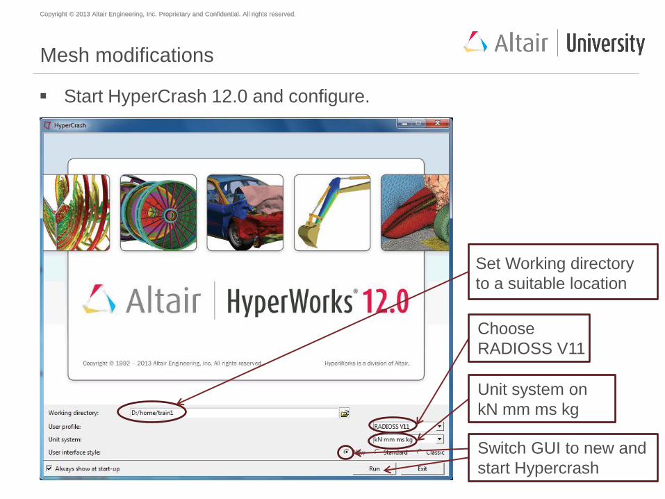
Start HyperCrash 12.0 and configure.
Set Working directory
to a suitable location
Choose
RADIOSS V11
Unit system on
kN mm ms kg
Switch GUI to new and
start Hypercrash
Copyright © 2013 Altair Engineering, Inc. Proprietary and Confidential. All rights reserved. Copyright © 2013 Altair Engineering, Inc. Proprietary and Confidential. All rights reserved.
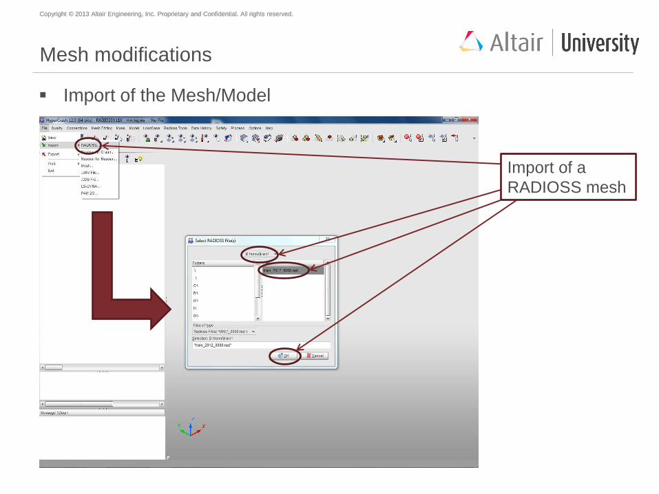
Mesh modifications
Import of the Mesh/Model
Import of a
RADIOSS mesh
Copyright © 2013 Altair Engineering, Inc. Proprietary and Confidential. All rights reserved. Copyright © 2013 Altair Engineering, Inc. Proprietary and Confidential. All rights reserved.
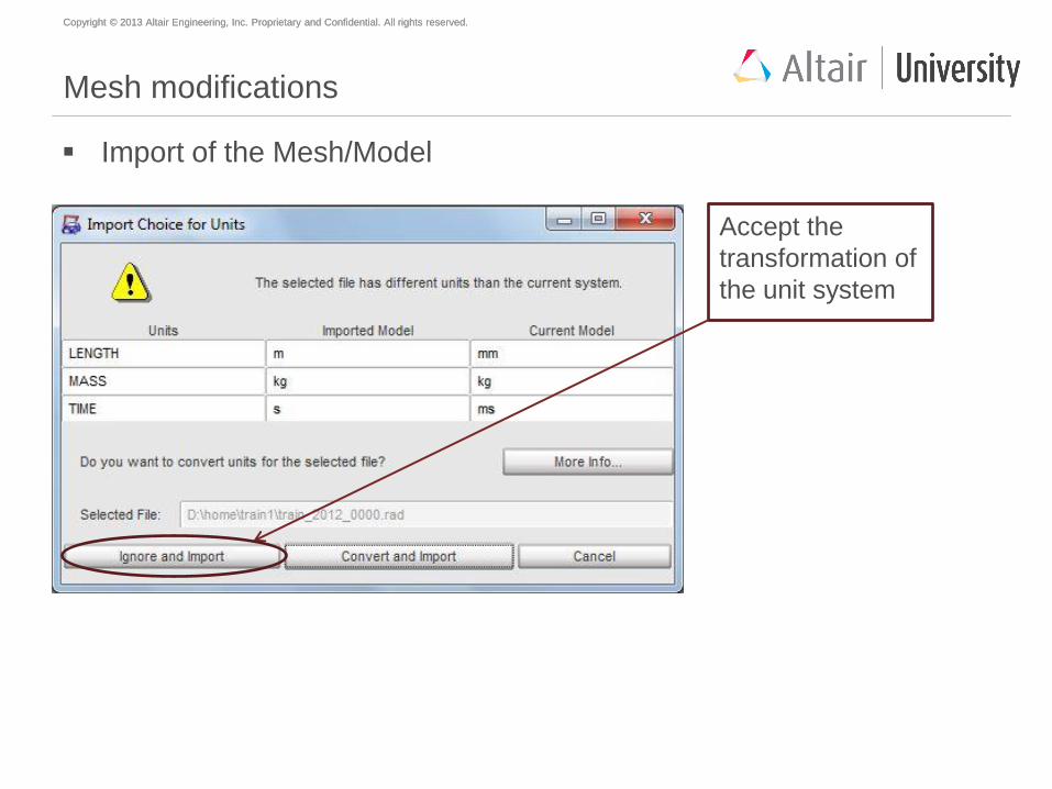
Mesh modifications
Import of the Mesh/Model
Accept the
transformation of
the unit system
Copyright © 2013 Altair Engineering, Inc. Proprietary and Confidential. All rights reserved. Copyright © 2013 Altair Engineering, Inc. Proprietary and Confidential. All rights reserved.
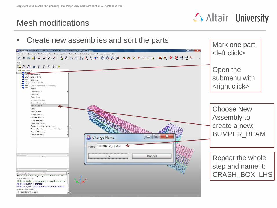
Mesh modifications
Create new assemblies and sort the parts Mark one part
<left click>
Open the
submenu with
<right click>
Choose New
Assembly to
create a new:
BUMPER_BEAM
Repeat the whole
step and name it:
CRASH_BOX_LHS
Copyright © 2013 Altair Engineering, Inc. Proprietary and Confidential. All rights reserved. Copyright © 2013 Altair Engineering, Inc. Proprietary and Confidential. All rights reserved.
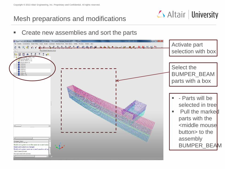
Mesh preparations and modifications
Create new assemblies and sort the parts
Activate part
selection with box
Select the
BUMPER_BEAM
parts with a box
- Parts will be
selected in tree
Pull the marked
parts with the
<middle mouse
button> to the
assembly
BUMPER_BEAM
Copyright © 2013 Altair Engineering, Inc. Proprietary and Confidential. All rights reserved. Copyright © 2013 Altair Engineering, Inc. Proprietary and Confidential. All rights reserved.
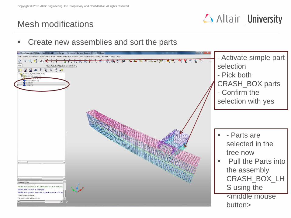
Mesh modifications
Create new assemblies and sort the parts
- Activate simple part
selection
- Pick both
CRASH_BOX parts
- Confirm the
selection with yes
- Parts are
selected in the
tree now
Pull the Parts into
the assembly
CRASH_BOX_LH
S using the
<middle mouse
button>
Copyright © 2013 Altair Engineering, Inc. Proprietary and Confidential. All rights reserved. Copyright © 2013 Altair Engineering, Inc. Proprietary and Confidential. All rights reserved.
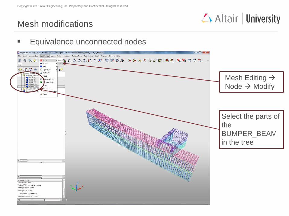
Mesh modifications
Equivalence unconnected nodes
Mesh Editing
Node Modify
Select the parts of
the
BUMPER_BEAM
in the tree
Copyright © 2013 Altair Engineering, Inc. Proprietary and Confidential. All rights reserved. Copyright © 2013 Altair Engineering, Inc. Proprietary and Confidential. All rights reserved.
Why equivalence?
To ensure connectivity between the elements, you need to equivalence any
coincident nodes in the model. The equivalence operation identifies any
location where two or more nodes exist within the specified search tolerance.
During equivalence, one of the nodes is retained and any element definitions
referencing the other nodes are re-defined to use the retained node.
Copyright © 2013 Altair Engineering, Inc. Proprietary and Confidential. All rights reserved. Copyright © 2013 Altair Engineering, Inc. Proprietary and Confidential. All rights reserved.
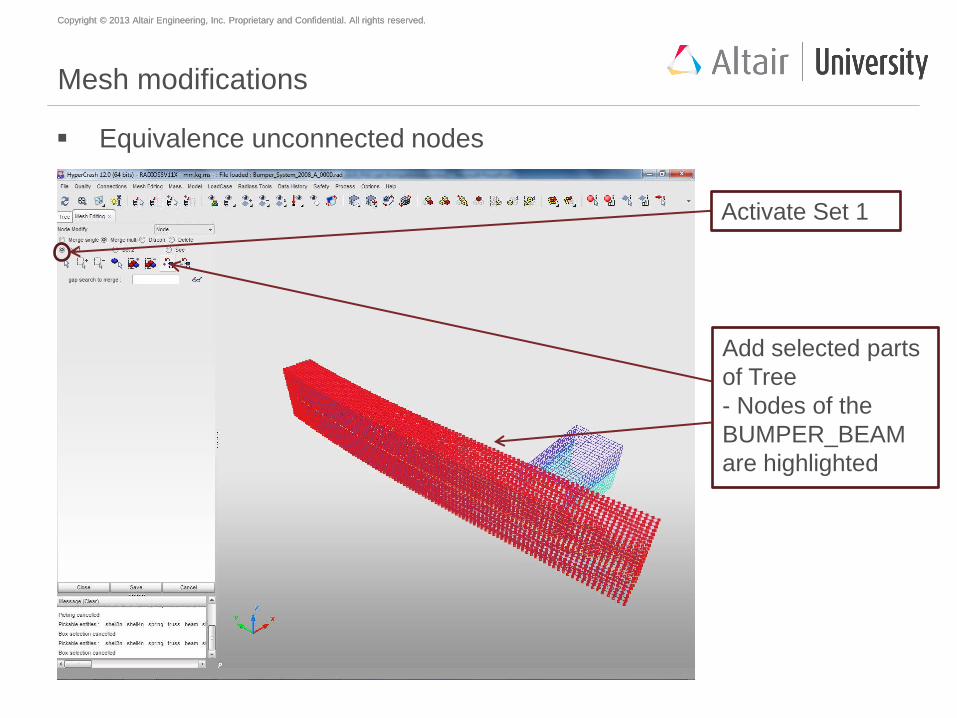
Mesh modifications
Equivalence unconnected nodes
Add selected parts
of Tree
- Nodes of the
BUMPER_BEAM
are highlighted
Activate Set 1
Copyright © 2013 Altair Engineering, Inc. Proprietary and Confidential. All rights reserved. Copyright © 2013 Altair Engineering, Inc. Proprietary and Confidential. All rights reserved.
Mesh modifications
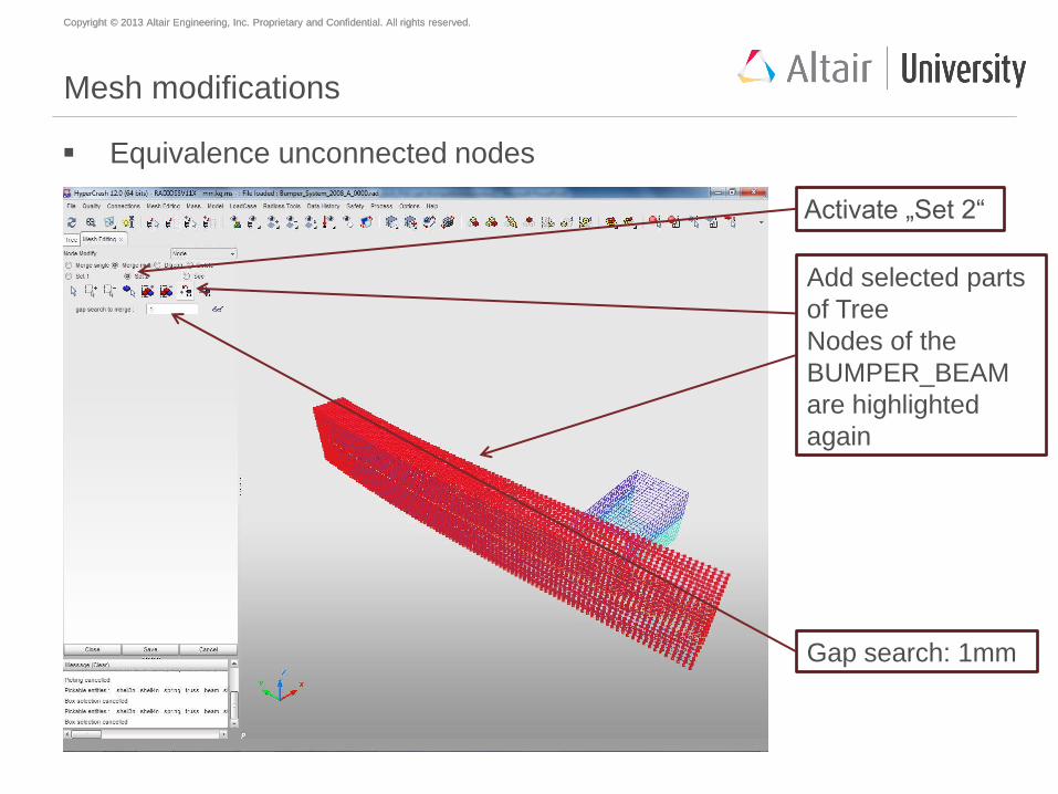
Equivalence unconnected nodes
Activate „Set 2“
Add selected parts
of Tree
Nodes of the
BUMPER_BEAM
are highlighted
again
Gap search: 1mm
Copyright © 2013 Altair Engineering, Inc. Proprietary and Confidential. All rights reserved. Copyright © 2013 Altair Engineering, Inc. Proprietary and Confidential. All rights reserved.
Mesh modifications
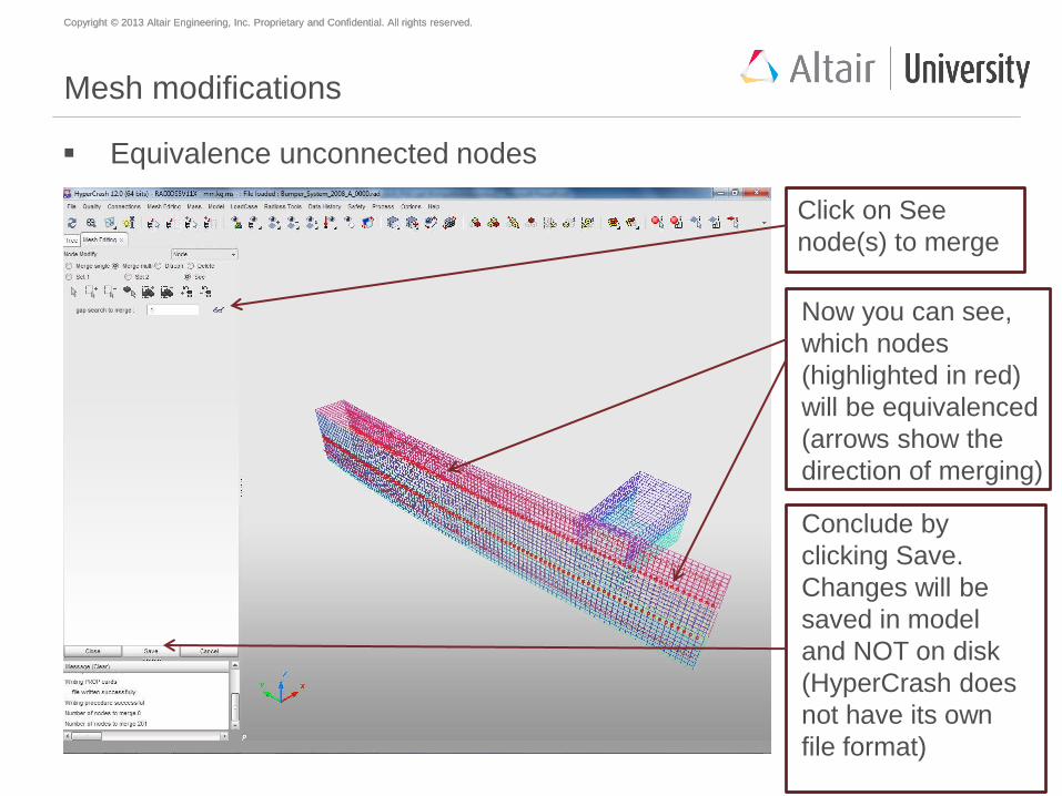
Equivalence unconnected nodes
Click on See
node(s) to merge
Now you can see,
which nodes
(highlighted in red)
will be equivalenced
(arrows show the
direction of merging)
Conclude by
clicking Save.
Changes will be
saved in model
and NOT on disk
(HyperCrash does
not have its own
file format)
Copyright © 2013 Altair Engineering, Inc. Proprietary and Confidential. All rights reserved. Copyright © 2013 Altair Engineering, Inc. Proprietary and Confidential. All rights reserved.
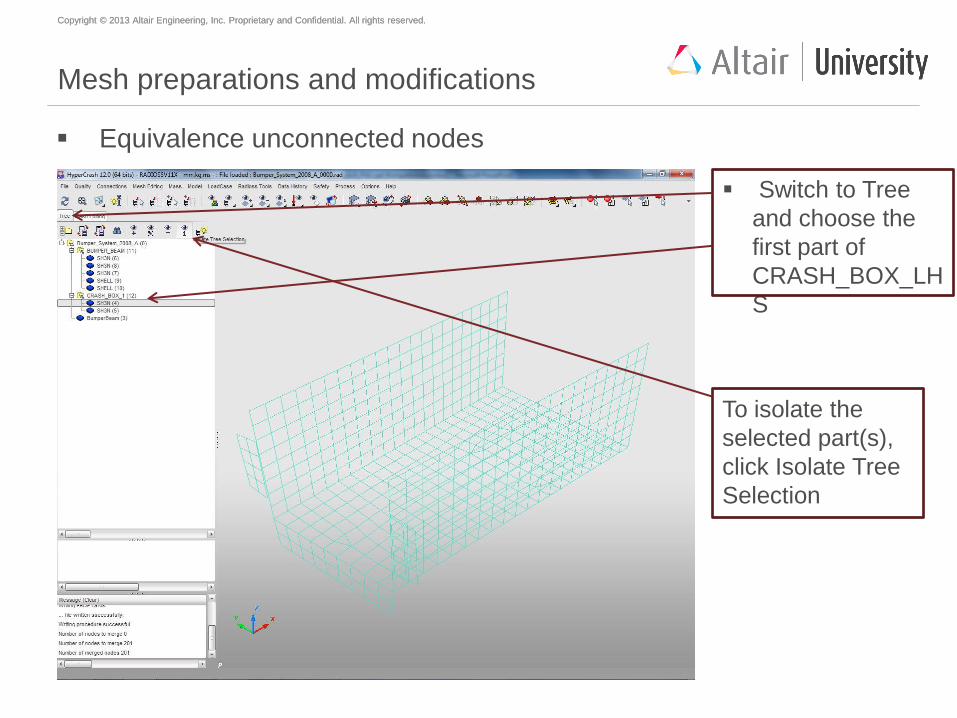
Mesh preparations and modifications
Equivalence unconnected nodes
Switch to Tree
and choose the
first part of
CRASH_BOX_LH
S
To isolate the
selected part(s),
click Isolate Tree
Selection
Copyright © 2013 Altair Engineering, Inc. Proprietary and Confidential. All rights reserved. Copyright © 2013 Altair Engineering, Inc. Proprietary and Confidential. All rights reserved.
Mesh modifications
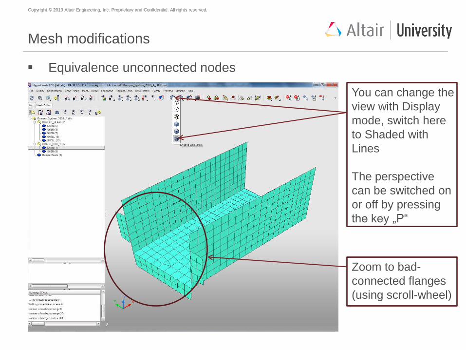
Equivalence unconnected nodes
You can change the
view with Display
mode, switch here
to Shaded with
Lines
The perspective
can be switched on
or off by pressing
the key „P“
Zoom to bad-
connected flanges
(using scroll-wheel)
Copyright © 2013 Altair Engineering, Inc. Proprietary and Confidential. All rights reserved. Copyright © 2013 Altair Engineering, Inc. Proprietary and Confidential. All rights reserved.
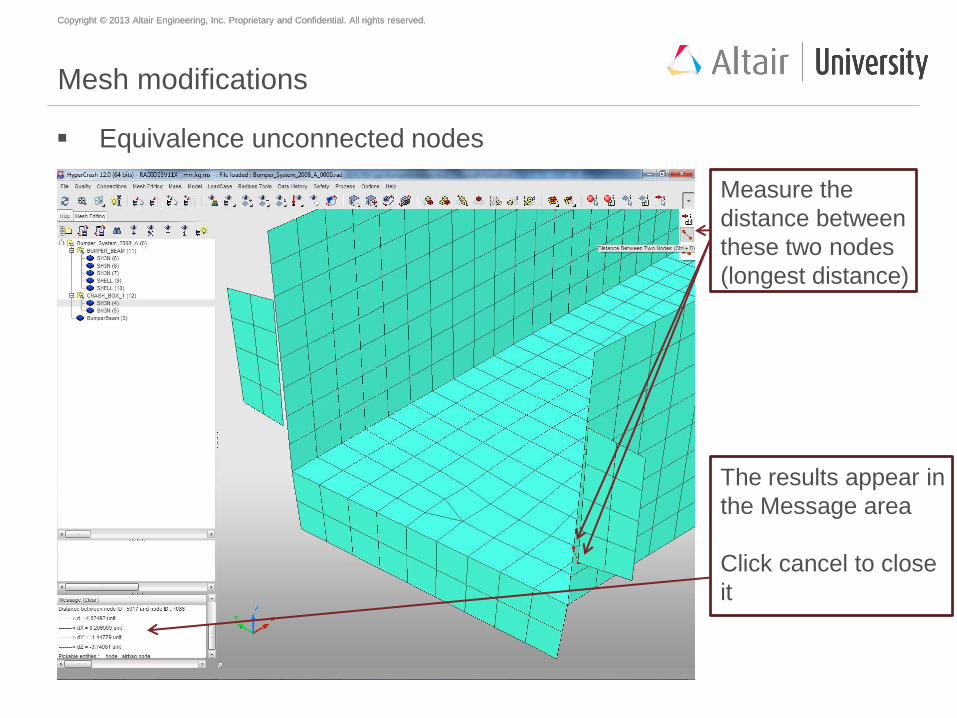
Mesh modifications
Equivalence unconnected nodes
Measure the
distance between
these two nodes
(longest distance)
The results appear in
the Message area
Click cancel to close
it
Copyright © 2013 Altair Engineering, Inc. Proprietary and Confidential. All rights reserved. Copyright © 2013 Altair Engineering, Inc. Proprietary and Confidential. All rights reserved.
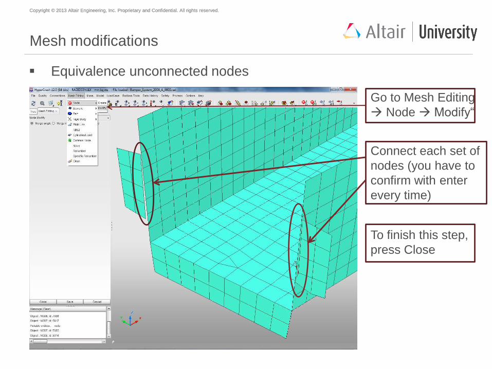
Mesh modifications
Equivalence unconnected nodes
Connect each set of
nodes (you have to
confirm with enter
every time)
Go to Mesh Editing
Node Modify“
To finish this step,
press Close
Copyright © 2013 Altair Engineering, Inc. Proprietary and Confidential. All rights reserved. Copyright © 2013 Altair Engineering, Inc. Proprietary and Confidential. All rights reserved.
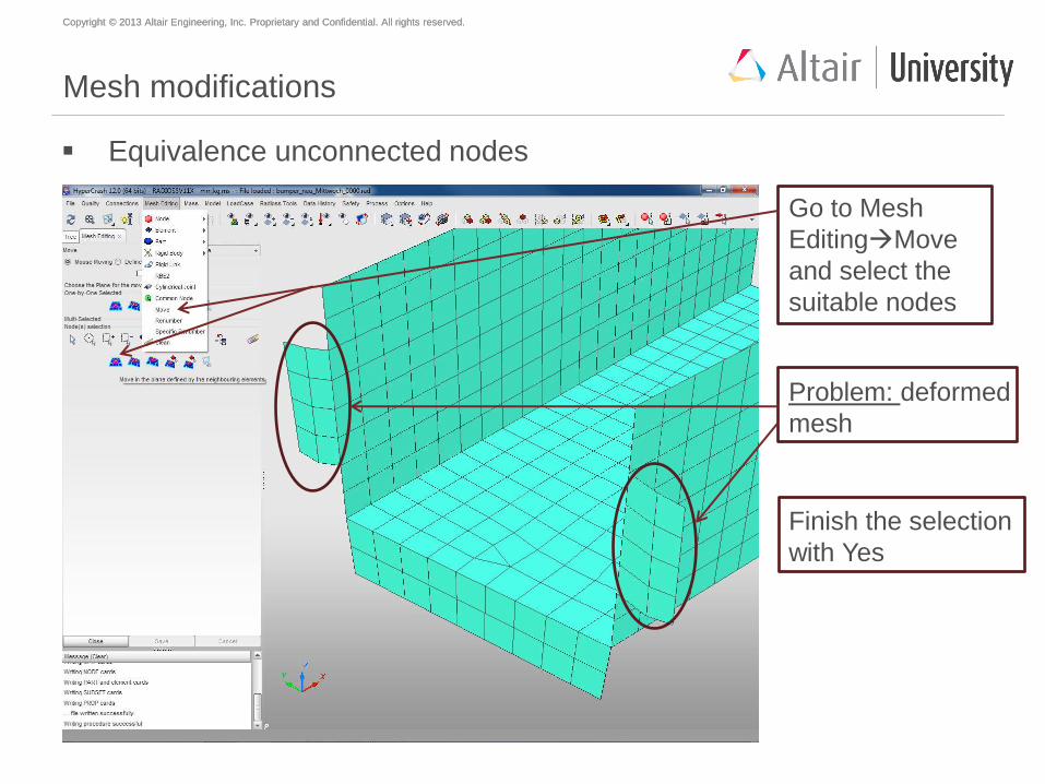
Mesh modifications
Equivalence unconnected nodes
Go to Mesh
EditingMove
and select the
suitable nodes
Problem: deformed
mesh
Finish the selection
with Yes
Copyright © 2013 Altair Engineering, Inc. Proprietary and Confidential. All rights reserved. Copyright © 2013 Altair Engineering, Inc. Proprietary and Confidential. All rights reserved.
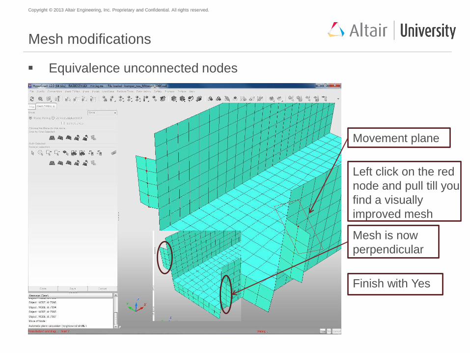
Mesh modifications
Equivalence unconnected nodes
Movement plane
Left click on the red
node and pull till you
find a visually
improved mesh
Finish with Yes
Mesh is now
perpendicular
Copyright © 2013 Altair Engineering, Inc. Proprietary and Confidential. All rights reserved. Copyright © 2013 Altair Engineering, Inc. Proprietary and Confidential. All rights reserved.
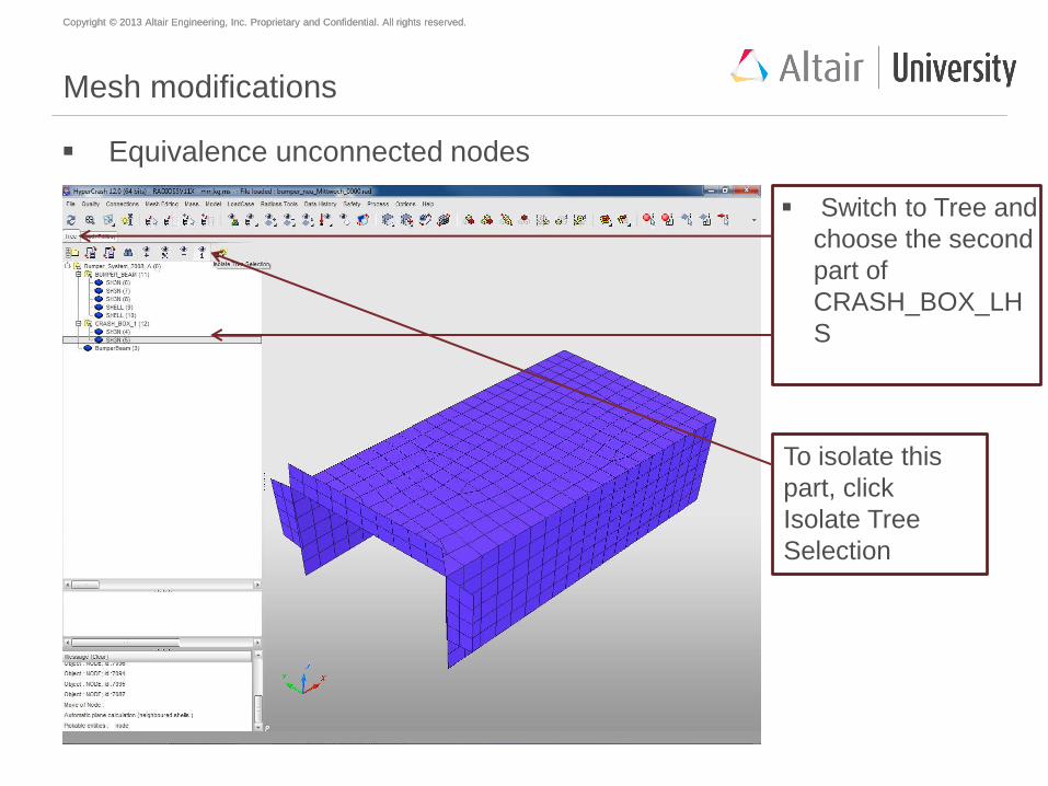
Mesh modifications
Equivalence unconnected nodes
Switch to Tree and
choose the second
part of
CRASH_BOX_LH
S
To isolate this
part, click
Isolate Tree
Selection
Copyright © 2013 Altair Engineering, Inc. Proprietary and Confidential. All rights reserved. Copyright © 2013 Altair Engineering, Inc. Proprietary and Confidential. All rights reserved.
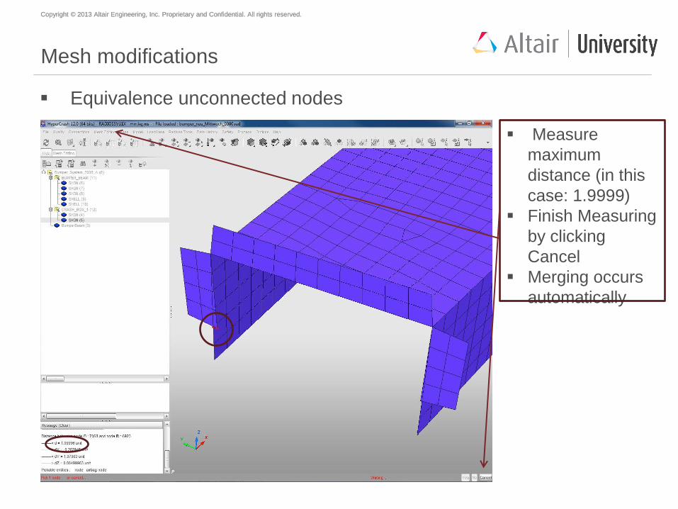
Mesh modifications
Equivalence unconnected nodes
Measure
maximum
distance (in this
case: 1.9999)
Finish Measuring
by clicking
Cancel
Merging occurs
automatically
Copyright © 2013 Altair Engineering, Inc. Proprietary and Confidential. All rights reserved. Copyright © 2013 Altair Engineering, Inc. Proprietary and Confidential. All rights reserved.
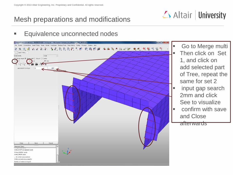
Mesh preparations and modifications
Equivalence unconnected nodes
Go to Merge multi
Then click on Set
1, and click on
add selected part
of Tree, repeat the
same for set 2
input gap search
2mm and click
See to visualize
confirm with save
and Close
afterwards
Copyright © 2013 Altair Engineering, Inc. Proprietary and Confidential. All rights reserved. Copyright © 2013 Altair Engineering, Inc. Proprietary and Confidential. All rights reserved.
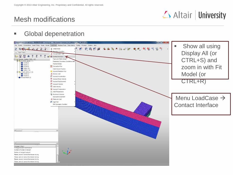
Mesh modifications
Global depenetration
Show all using
Display All (or
CTRL+S) and
zoom in with Fit
Model (or
CTRL+R)
Menu LoadCase
Contact Interface
Copyright © 2013 Altair Engineering, Inc. Proprietary and Confidential. All rights reserved. Copyright © 2013 Altair Engineering, Inc. Proprietary and Confidential. All rights reserved.
What are penetrations and intersections?
Penetration is defined as the overlap of the material thickness of shell
elements, while Intersection is defined as elements that actually pass
completely through one another
All models and especially impact models should be checked for
penetrations and intersections and depenetrated to ensure the
integrity of the model
Penetrations adversely affects results and should be removed
Copyright © 2013 Altair Engineering, Inc. Proprietary and Confidential. All rights reserved. Copyright © 2013 Altair Engineering, Inc. Proprietary and Confidential. All rights reserved.
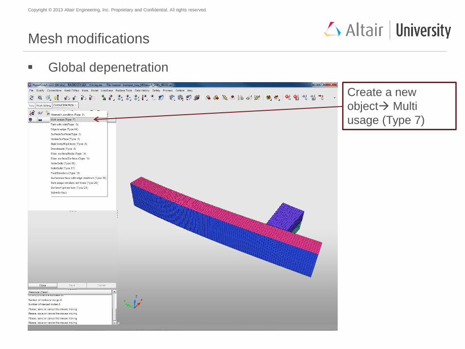
Mesh modifications
Global depenetration
Create a new
object Multi
usage (Type 7)
Copyright © 2013 Altair Engineering, Inc. Proprietary and Confidential. All rights reserved. Copyright © 2013 Altair Engineering, Inc. Proprietary and Confidential. All rights reserved.
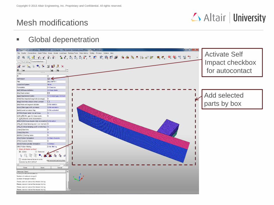
Mesh modifications
Global depenetration
Activate Self
Impact checkbox
for autocontact
Add selected
parts by box
Copyright © 2013 Altair Engineering, Inc. Proprietary and Confidential. All rights reserved. Copyright © 2013 Altair Engineering, Inc. Proprietary and Confidential. All rights reserved.
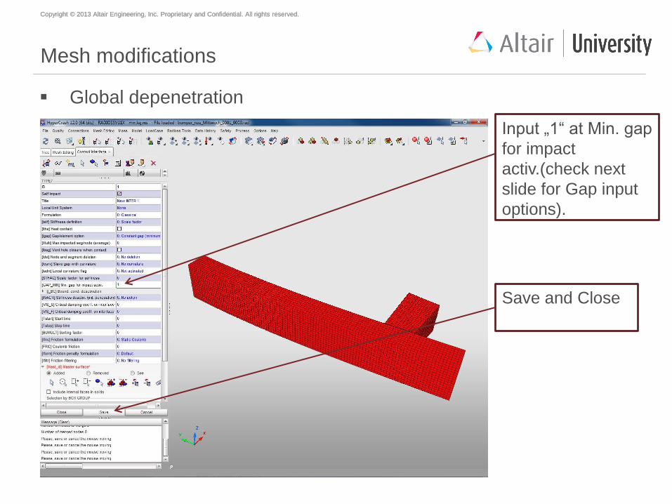
Mesh modifications
Global depenetration
Input „1“ at Min. gap
for impact
activ.(check next
slide for Gap input
options).
Save and Close
Copyright © 2013 Altair Engineering, Inc. Proprietary and Confidential. All rights reserved. Copyright © 2013 Altair Engineering, Inc. Proprietary and Confidential. All rights reserved.
Intersection-penetration check
HyperCrash checks for intersections and penetrations. The list of
intersecting nodes is displayed at the bottom of the menu.
To find and to correct the penetrations use the “variable gap” or a
“constant gap” option.
1.The variable gap option (if "Gap_interface" = "variable")
searches and corrects the penetrations taking into account the
actual thickness' of the plates (coming from the PID).
2.The constant gap option (if a value for "Gap_interface" is
entered) uses a (user-defined) fixed value to search and correct
the penetrations (the value can be the gap of the interface, for
instance).
Copyright © 2013 Altair Engineering, Inc. Proprietary and Confidential. All rights reserved. Copyright © 2013 Altair Engineering, Inc. Proprietary and Confidential. All rights reserved.
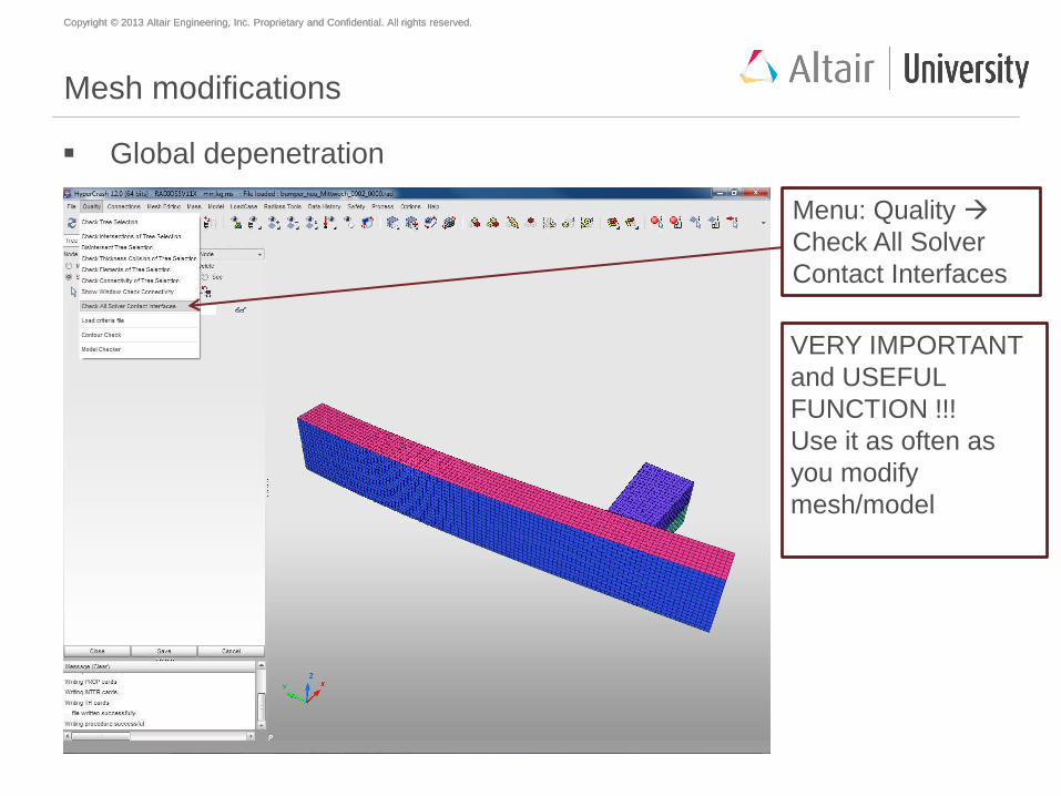
Mesh modifications
Global depenetration
Menu: Quality
Check All Solver
Contact Interfaces
VERY IMPORTANT
and USEFUL
FUNCTION !!!
Use it as often as
you modify
mesh/model
Copyright © 2013 Altair Engineering, Inc. Proprietary and Confidential. All rights reserved. Copyright © 2013 Altair Engineering, Inc. Proprietary and Confidential. All rights reserved.
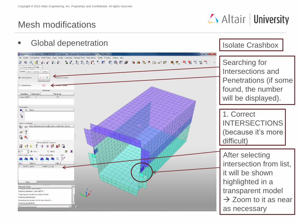
Mesh modifications
Global depenetration
Searching for
Intersections and
Penetrations (if some
found, the number
will be displayed).
After selecting
intersection from list,
it will be shown
highlighted in a
transparent model
Zoom to it as near
as necessary
Isolate Crashbox
1. Correct
INTERSECTIONS
(because it’s more
difficult)
Copyright © 2013 Altair Engineering, Inc. Proprietary and Confidential. All rights reserved. Copyright © 2013 Altair Engineering, Inc. Proprietary and Confidential. All rights reserved.
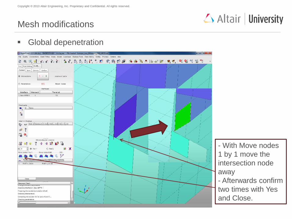
Mesh modifications
Global depenetration
- With Move nodes
1 by 1 move the
intersection node
away
- Afterwards confirm
two times with Yes
and Close.
Copyright © 2013 Altair Engineering, Inc. Proprietary and Confidential. All rights reserved. Copyright © 2013 Altair Engineering, Inc. Proprietary and Confidential. All rights reserved.
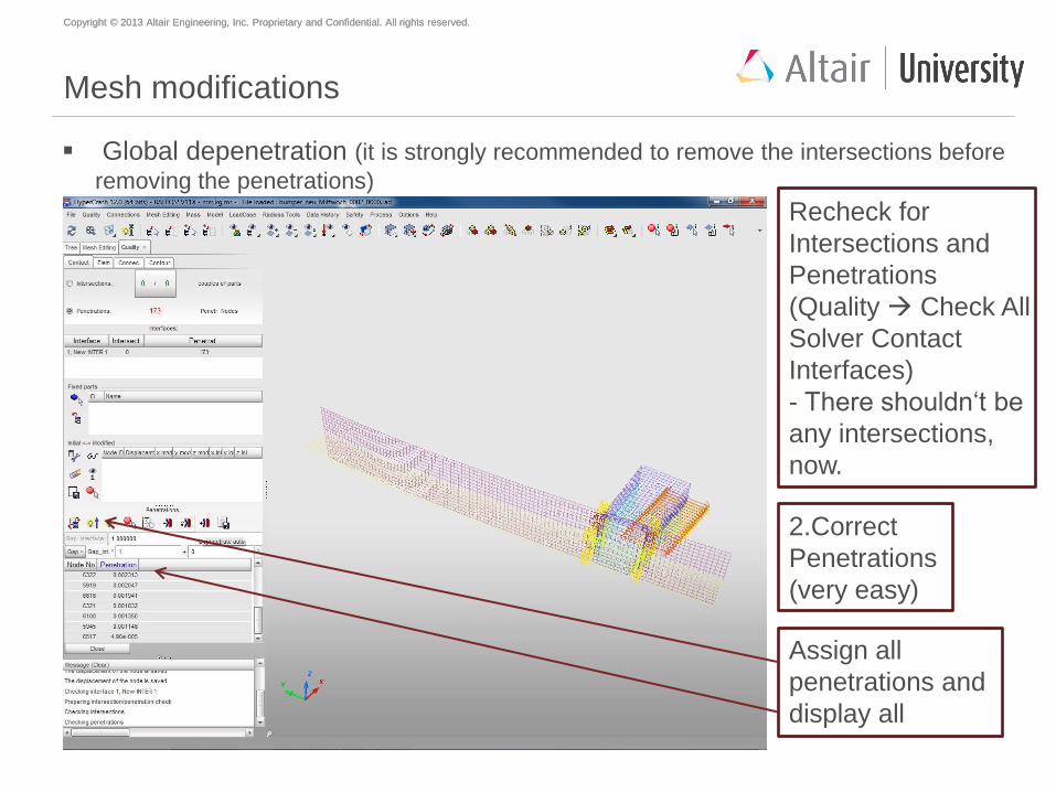
Mesh modifications
Global depenetration (it is strongly recommended to remove the intersections before
removing the penetrations)
Recheck for
Intersections and
Penetrations
(Quality Check All
Solver Contact
Interfaces)
- There shouldn‘t be
any intersections,
now.
Assign all
penetrations and
display all
2.Correct
Penetrations
(very easy)
Copyright © 2013 Altair Engineering, Inc. Proprietary and Confidential. All rights reserved. Copyright © 2013 Altair Engineering, Inc. Proprietary and Confidential. All rights reserved.
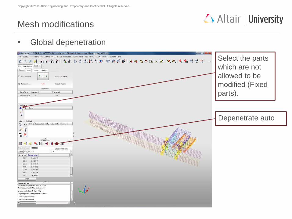
Mesh modifications
Global depenetration
Select the parts
which are not
allowed to be
modified (Fixed
parts).
Depenetrate auto
Copyright © 2013 Altair Engineering, Inc. Proprietary and Confidential. All rights reserved. Copyright © 2013 Altair Engineering, Inc. Proprietary and Confidential. All rights reserved.
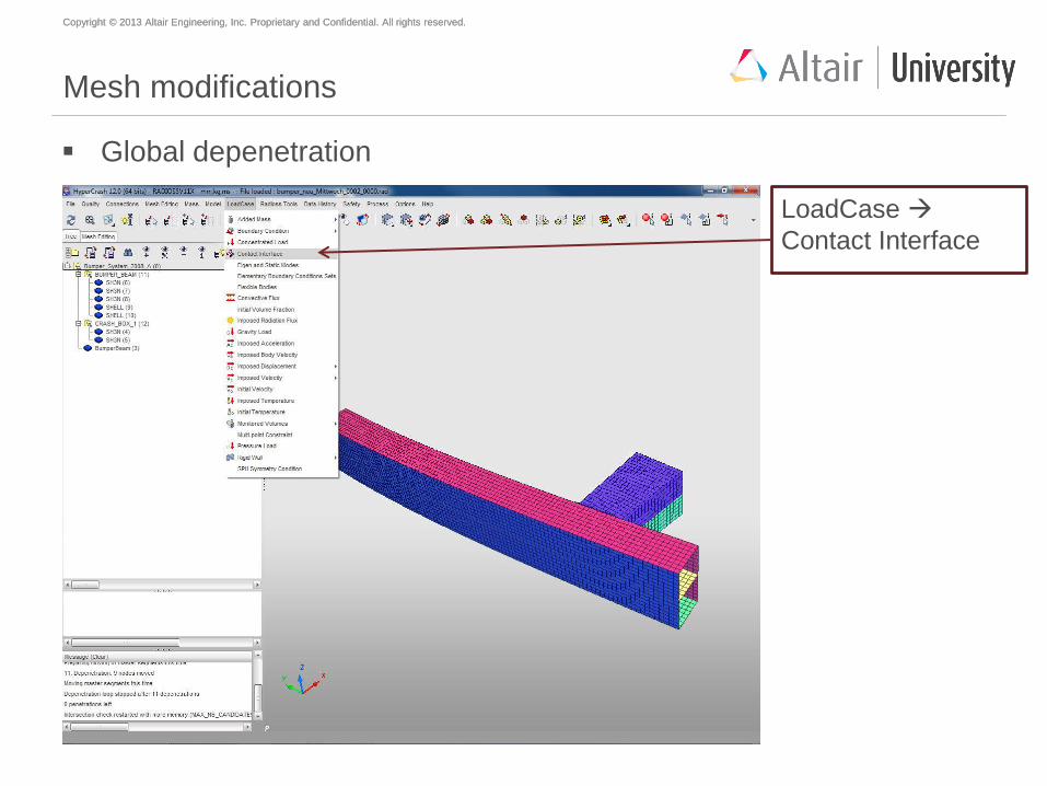
Mesh modifications
Global depenetration
LoadCase
Contact Interface

Copyright © 2013 Altair Engineering, Inc. Proprietary and Confidential. All rights reserved. Copyright © 2013 Altair Engineering, Inc. Proprietary and Confidential. All rights reserved.
Mesh modifications
Global depenetration: delete temporary contact interface
Select Contact and
Delete selected
item(s)
Close
Copyright © 2013 Altair Engineering, Inc. Proprietary and Confidential. All rights reserved. Copyright © 2013 Altair Engineering, Inc. Proprietary and Confidential. All rights reserved.
Agenda
Geometry meshing with HyperMesh
Mesh preparations and modifications with HyperCrash
Material creation and assignment
Property creation and assignment
Welding
Mirror to full model
Global contact definition
Load case creation
Model check
Start of simulation
Copyright © 2013 Altair Engineering, Inc. Proprietary and Confidential. All rights reserved. Copyright © 2013 Altair Engineering, Inc. Proprietary and Confidential. All rights reserved.
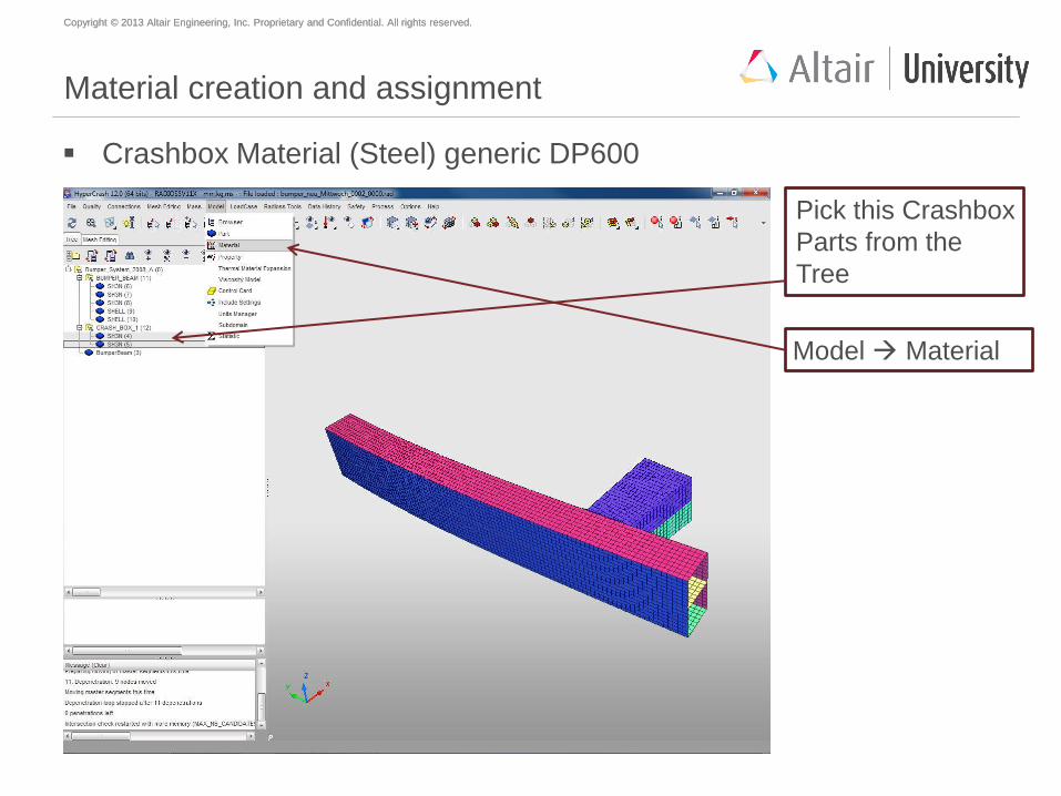
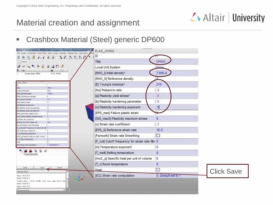
Material creation and assignment
Crashbox Material (Steel) generic DP600
Model Material
Pick this Crashbox
Parts from the
Tree
Copyright © 2013 Altair Engineering, Inc. Proprietary and Confidential. All rights reserved. Copyright © 2013 Altair Engineering, Inc. Proprietary and Confidential. All rights reserved.
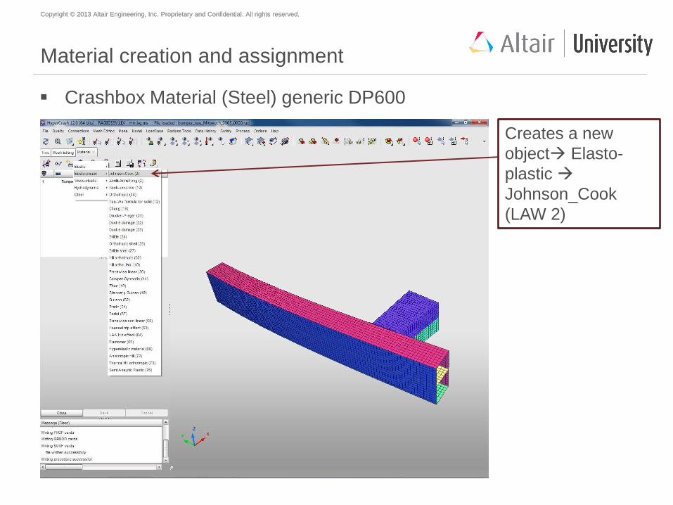
Material creation and assignment
Crashbox Material (Steel) generic DP600
Creates a new
object Elasto-
plastic
Johnson_Cook
(LAW 2)
Copyright © 2013 Altair Engineering, Inc. Proprietary and Confidential. All rights reserved. Copyright © 2013 Altair Engineering, Inc. Proprietary and Confidential. All rights reserved.
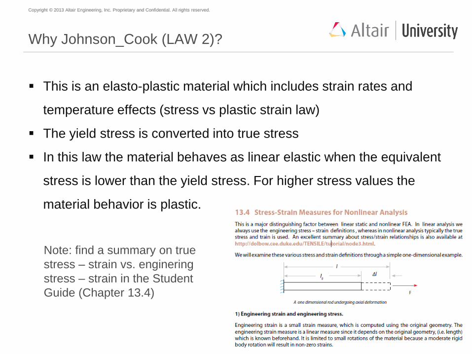
Why Johnson_Cook (LAW 2)?
This is an elasto-plastic material which includes strain rates and
temperature effects (stress vs plastic strain law)
The yield stress is converted into true stress
In this law the material behaves as linear elastic when the equivalent
stress is lower than the yield stress. For higher stress values the
material behavior is plastic.
Note: find a summary on true
stress – strain vs. enginering
stress – strain in the Student
Guide (Chapter 13.4)
Copyright © 2013 Altair Engineering, Inc. Proprietary and Confidential. All rights reserved. Copyright © 2013 Altair Engineering, Inc. Proprietary and Confidential. All rights reserved.
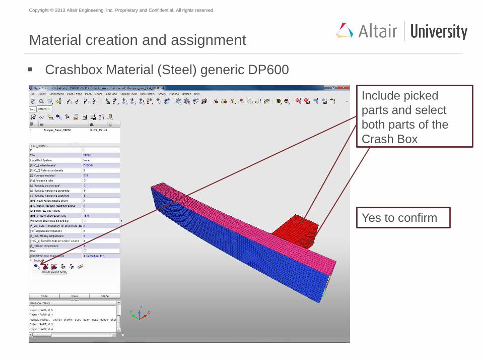
Material creation and assignment
Include picked
parts and select
both parts of the
Crash Box
Yes to confirm
Crashbox Material (Steel) generic DP600
Copyright © 2013 Altair Engineering, Inc. Proprietary and Confidential. All rights reserved. Copyright © 2013 Altair Engineering, Inc. Proprietary and Confidential. All rights reserved.
Material creation and assignment
Crashbox Material (Steel) generic DP600
Click Save
Copyright © 2013 Altair Engineering, Inc. Proprietary and Confidential. All rights reserved. Copyright © 2013 Altair Engineering, Inc. Proprietary and Confidential. All rights reserved.
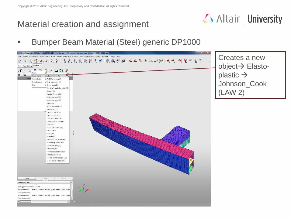
Material creation and assignment
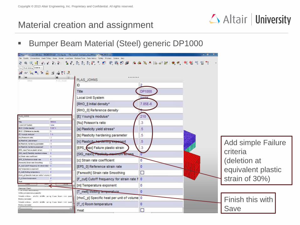
Bumper Beam Material (Steel) generic DP1000
Creates a new
object Elasto-
plastic
Johnson_Cook
(LAW 2)
Copyright © 2013 Altair Engineering, Inc. Proprietary and Confidential. All rights reserved. Copyright © 2013 Altair Engineering, Inc. Proprietary and Confidential. All rights reserved.
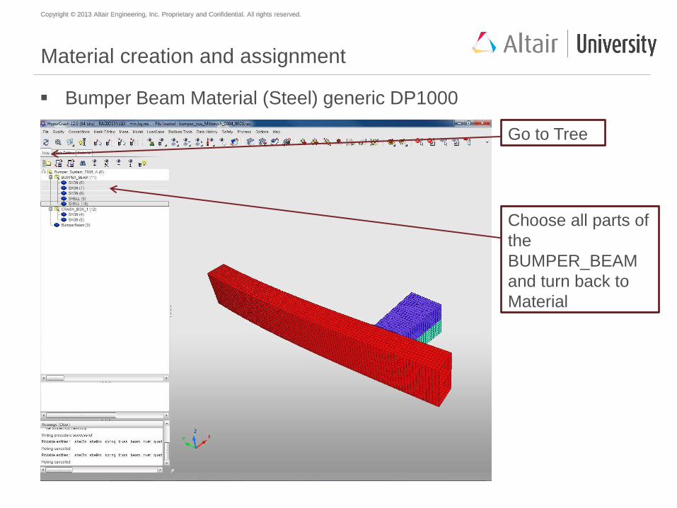
Material creation and assignment
Bumper Beam Material (Steel) generic DP1000
Go to Tree
Choose all parts of
the
BUMPER_BEAM
and turn back to
Material
Copyright © 2013 Altair Engineering, Inc. Proprietary and Confidential. All rights reserved. Copyright © 2013 Altair Engineering, Inc. Proprietary and Confidential. All rights reserved.
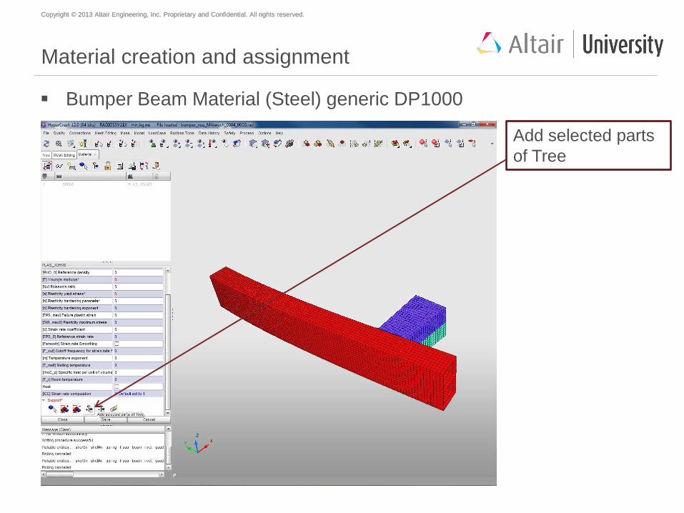
Material creation and assignment
Bumper Beam Material (Steel) generic DP1000
Add selected parts
of Tree
Copyright © 2013 Altair Engineering, Inc. Proprietary and Confidential. All rights reserved. Copyright © 2013 Altair Engineering, Inc. Proprietary and Confidential. All rights reserved.
Material creation and assignment
Bumper Beam Material (Steel) generic DP1000
Add simple Failure
criteria
(deletion at
equivalent plastic
strain of 30%)
Finish this with
Save
Copyright © 2013 Altair Engineering, Inc. Proprietary and Confidential. All rights reserved. Copyright © 2013 Altair Engineering, Inc. Proprietary and Confidential. All rights reserved.
Agenda
Geometry meshing with HyperMesh
Mesh preparations and modifications with HyperCrash
Material creation and assignment
Property creation and assignment
Welding
Mirror to full model
Global contact definition
Load case creation
Model check
Start of simulation
Copyright © 2013 Altair Engineering, Inc. Proprietary and Confidential. All rights reserved. Copyright © 2013 Altair Engineering, Inc. Proprietary and Confidential. All rights reserved.
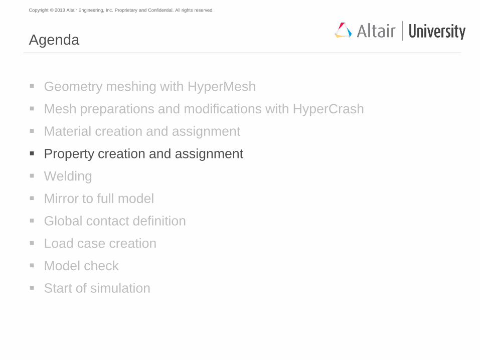
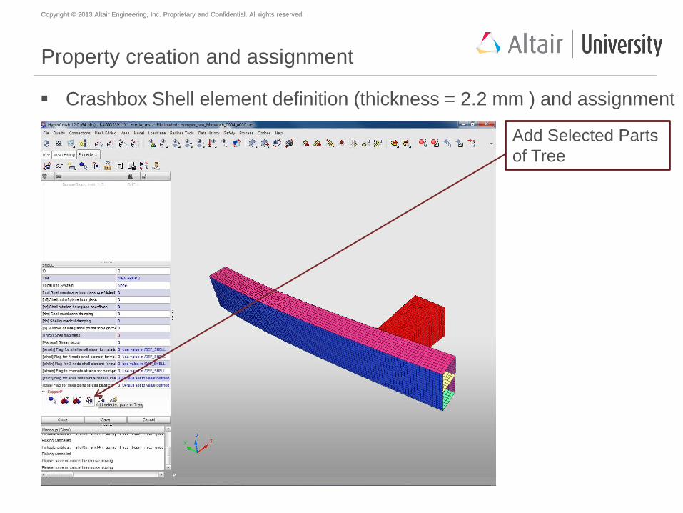
Property creation and assignment
Crashbox Shell element definition (thickness = 2.2 mm ) and assignment
Select Crash Box
parts out of the tree
Copyright © 2013 Altair Engineering, Inc. Proprietary and Confidential. All rights reserved. Copyright © 2013 Altair Engineering, Inc. Proprietary and Confidential. All rights reserved.
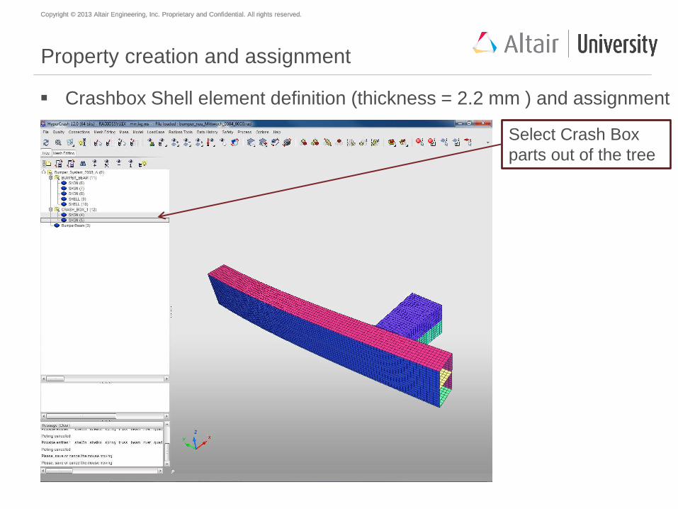
Property creation and assignment
Crashbox Shell element definition (thickness = 2.2 mm ) and assignment
Model Property
Creates a new
object Surface
Shell (1)
Copyright © 2013 Altair Engineering, Inc. Proprietary and Confidential. All rights reserved. Copyright © 2013 Altair Engineering, Inc. Proprietary and Confidential. All rights reserved.
Property creation and assignment
Crashbox Shell element definition (thickness = 2.2 mm ) and assignment
Add Selected Parts
of Tree
Copyright © 2013 Altair Engineering, Inc. Proprietary and Confidential. All rights reserved. Copyright © 2013 Altair Engineering, Inc. Proprietary and Confidential. All rights reserved.
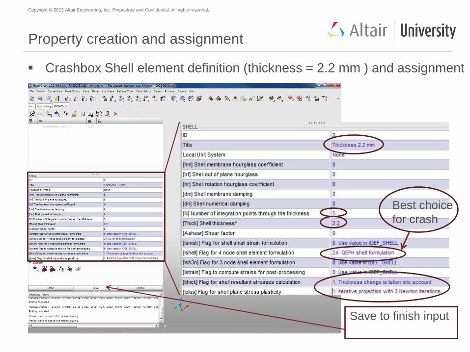
Property creation and assignment
Crashbox Shell element definition (thickness = 2.2 mm ) and assignment
Save to finish input
Best choice
for crash
Copyright © 2013 Altair Engineering, Inc. Proprietary and Confidential. All rights reserved. Copyright © 2013 Altair Engineering, Inc. Proprietary and Confidential. All rights reserved.
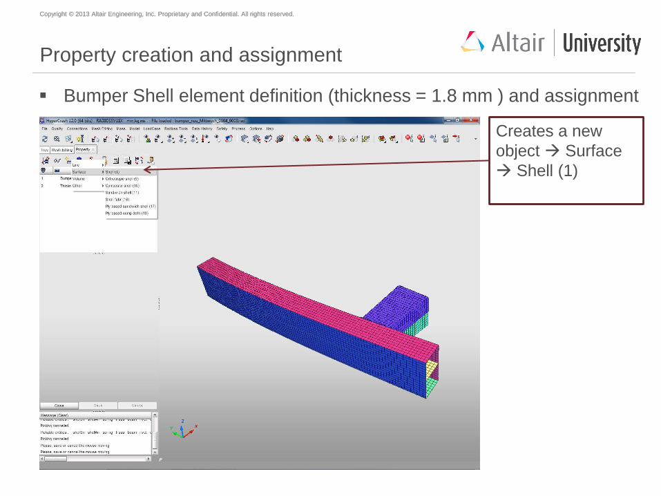
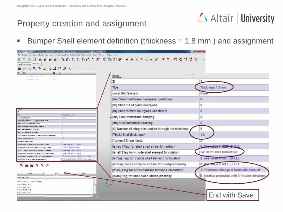
Property creation and assignment
Bumper Shell element definition (thickness = 1.8 mm ) and assignment
Creates a new
object Surface
Shell (1)
Copyright © 2013 Altair Engineering, Inc. Proprietary and Confidential. All rights reserved. Copyright © 2013 Altair Engineering, Inc. Proprietary and Confidential. All rights reserved.
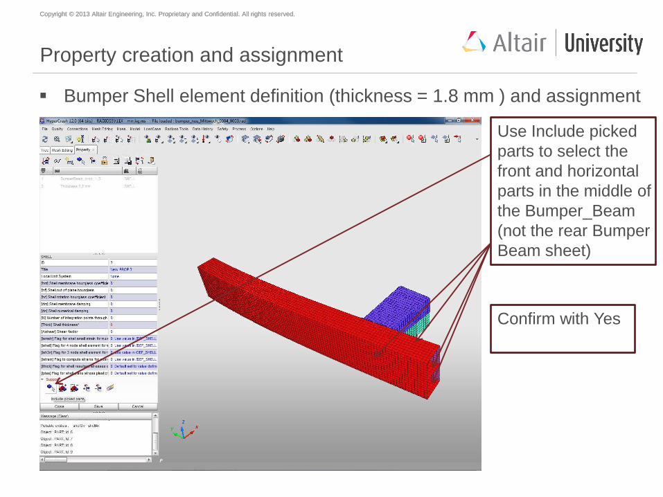
Property creation and assignment
Bumper Shell element definition (thickness = 1.8 mm ) and assignment
Use Include picked
parts to select the
front and horizontal
parts in the middle of
the Bumper_Beam
(not the rear Bumper
Beam sheet)
Confirm with Yes
Copyright © 2013 Altair Engineering, Inc. Proprietary and Confidential. All rights reserved. Copyright © 2013 Altair Engineering, Inc. Proprietary and Confidential. All rights reserved.
Property creation and assignment
Bumper Shell element definition (thickness = 1.8 mm ) and assignment
End with Save
Copyright © 2013 Altair Engineering, Inc. Proprietary and Confidential. All rights reserved. Copyright © 2013 Altair Engineering, Inc. Proprietary and Confidential. All rights reserved.
Why QEPH shell formulation?
QEPH (Quadrilateral ElastoPlastic Physical Hourglass Control) element
With one-point integration formulation, if the non-constant part follows exactly
the state of constant part for the case of elasto-plastic calculation, the
plasticity will be under-estimated due to the fact that the constant equivalent
stress is often the smallest one in the element and element will be stiffer.
Therefore, QEPH, defining a yield criterion for the non-constant part seems to
be a good ideal to overcome this drawback.
QEPH shells are more accurate for elastic or elasto-plastic loads, whatever
the loading type - quasi-static or dynamic.
QEPH shells will give better results if the mesh is fine enough. It is not
recommended for coarse mesh.
Copyright © 2013 Altair Engineering, Inc. Proprietary and Confidential. All rights reserved. Copyright © 2013 Altair Engineering, Inc. Proprietary and Confidential. All rights reserved.
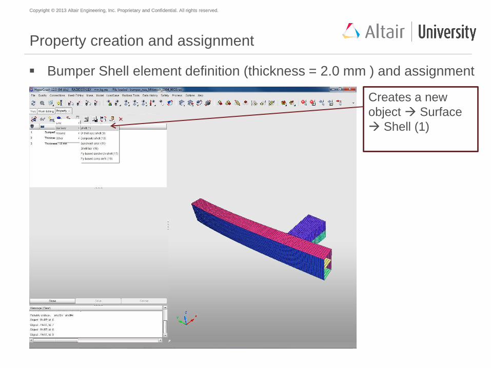
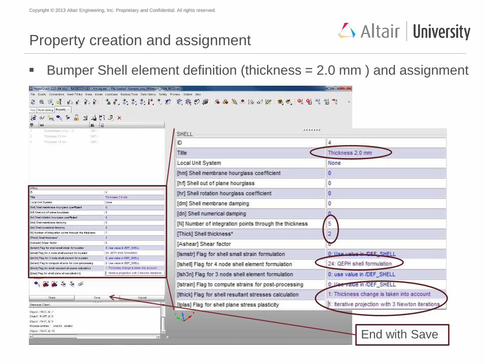
Property creation and assignment
Bumper Shell element definition (thickness = 2.0 mm ) and assignment
Creates a new
object Surface
Shell (1)
Copyright © 2013 Altair Engineering, Inc. Proprietary and Confidential. All rights reserved. Copyright © 2013 Altair Engineering, Inc. Proprietary and Confidential. All rights reserved.
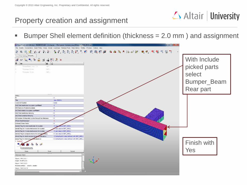
Property creation and assignment
Bumper Shell element definition (thickness = 2.0 mm ) and assignment
With Include
picked parts
select
Bumper_Beam
Rear part
Finish with
Yes
Copyright © 2013 Altair Engineering, Inc. Proprietary and Confidential. All rights reserved. Copyright © 2013 Altair Engineering, Inc. Proprietary and Confidential. All rights reserved.
Property creation and assignment
Bumper Shell element definition (thickness = 2.0 mm ) and assignment
End with Save
Copyright © 2013 Altair Engineering, Inc. Proprietary and Confidential. All rights reserved. Copyright © 2013 Altair Engineering, Inc. Proprietary and Confidential. All rights reserved.
Why use 5 integration points in the thickness
of shell elements?
In case of an elastic behavior, one gets the exact solution from three
integration points – that is to say that the bending moments are exactly
integrated through the thickness of the shell – and it is not necessary to use
more integration points.
In case of a plastic behavior, the bending moments are not integrated
exactly. Using more integration points, the solution becomes more accurate;
so it is recommended to use five integration points.
Copyright © 2013 Altair Engineering, Inc. Proprietary and Confidential. All rights reserved. Copyright © 2013 Altair Engineering, Inc. Proprietary and Confidential. All rights reserved.
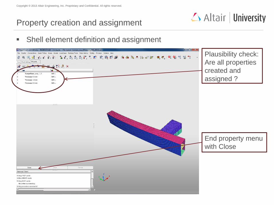
Property creation and assignment
Shell element definition and assignment
Plausibility check:
Are all properties
created and
assigned ?
End property menu
with Close
Copyright © 2013 Altair Engineering, Inc. Proprietary and Confidential. All rights reserved. Copyright © 2013 Altair Engineering, Inc. Proprietary and Confidential. All rights reserved.
Agenda
Geometry meshing with HyperMesh
Mesh preparations and modifications with HyperCrash
Material creation and assignment
Property creation and assignment
Welding (SPOTWELDS)
Mirror to full model
Global contact definition
Load case creation
Model check
Start of simulation
Copyright © 2013 Altair Engineering, Inc. Proprietary and Confidential. All rights reserved. Copyright © 2013 Altair Engineering, Inc. Proprietary and Confidential. All rights reserved.
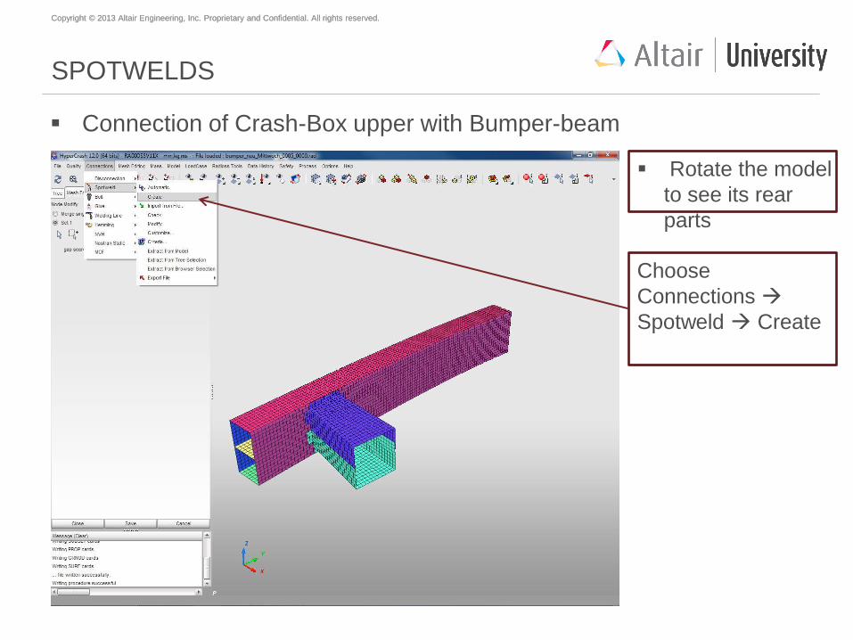
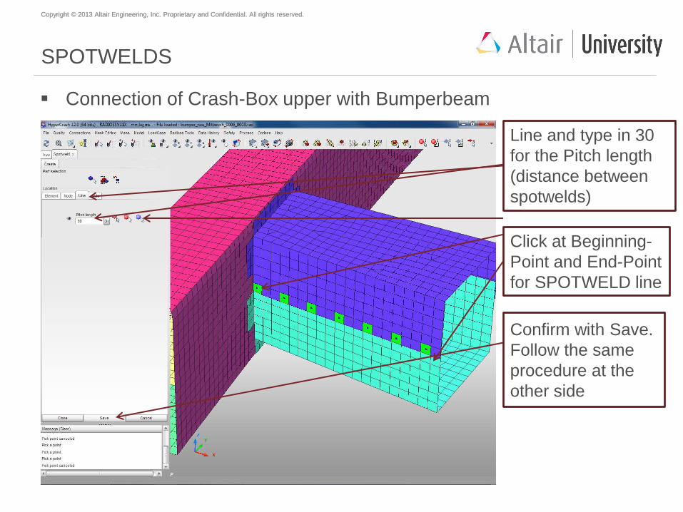
SPOTWELDS
Connection of Crash-Box upper with Bumper-beam
Rotate the model
to see its rear
parts
Choose
Connections
Spotweld Create
Copyright © 2013 Altair Engineering, Inc. Proprietary and Confidential. All rights reserved. Copyright © 2013 Altair Engineering, Inc. Proprietary and Confidential. All rights reserved.
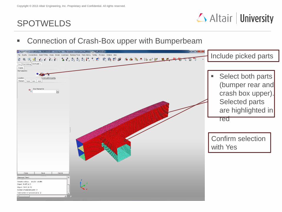
SPOTWELDS
Connection of Crash-Box upper with Bumperbeam
Include picked parts
Select both parts
(bumper rear and
crash box upper).
Selected parts
are highlighted in
red
Confirm selection
with Yes
Copyright © 2013 Altair Engineering, Inc. Proprietary and Confidential. All rights reserved. Copyright © 2013 Altair Engineering, Inc. Proprietary and Confidential. All rights reserved.
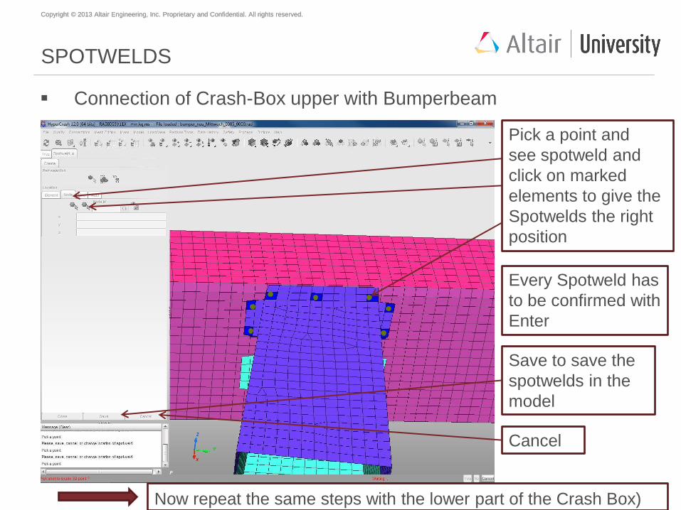
SPOTWELDS
Connection of Crash-Box upper with Bumperbeam
Pick a point and
see spotweld and
click on marked
elements to give the
Spotwelds the right
position
Every Spotweld has
to be confirmed with
Enter
Save to save the
spotwelds in the
model
Cancel
Now repeat the same steps with the lower part of the Crash Box)
Copyright © 2013 Altair Engineering, Inc. Proprietary and Confidential. All rights reserved. Copyright © 2013 Altair Engineering, Inc. Proprietary and Confidential. All rights reserved.
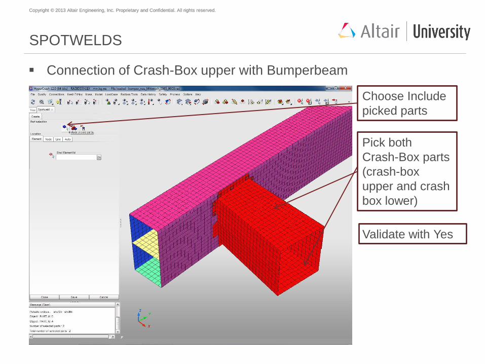
SPOTWELDS
Connection of Crash-Box upper with Bumperbeam
Choose Include
picked parts
Pick both
Crash-Box parts
(crash-box
upper and crash
box lower)
Validate with Yes
Copyright © 2013 Altair Engineering, Inc. Proprietary and Confidential. All rights reserved. Copyright © 2013 Altair Engineering, Inc. Proprietary and Confidential. All rights reserved.
SPOTWELDS
Connection of Crash-Box upper with Bumperbeam
Line and type in 30
for the Pitch length
(distance between
spotwelds)
Click at Beginning-
Point and End-Point
for SPOTWELD line
Confirm with Save.
Follow the same
procedure at the
other side
Copyright © 2013 Altair Engineering, Inc. Proprietary and Confidential. All rights reserved. Copyright © 2013 Altair Engineering, Inc. Proprietary and Confidential. All rights reserved.
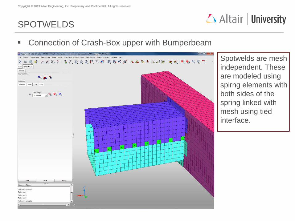
SPOTWELDS
Connection of Crash-Box upper with Bumperbeam
Spotwelds are mesh
independent. These
are modeled using
spirng elements with
both sides of the
spring linked with
mesh using tied
interface.
Copyright © 2013 Altair Engineering, Inc. Proprietary and Confidential. All rights reserved. Copyright © 2013 Altair Engineering, Inc. Proprietary and Confidential. All rights reserved.
Agenda
Geometry meshing with HyperMesh
Mesh preparations and modifications with HyperCrash
Material creation and assignment
Property creation and assignment
Welding (SPOTWELDS)
Mirror to full model
Global contact definition
Load case creation
Model check
Start of simulation
Copyright © 2013 Altair Engineering, Inc. Proprietary and Confidential. All rights reserved. Copyright © 2013 Altair Engineering, Inc. Proprietary and Confidential. All rights reserved.
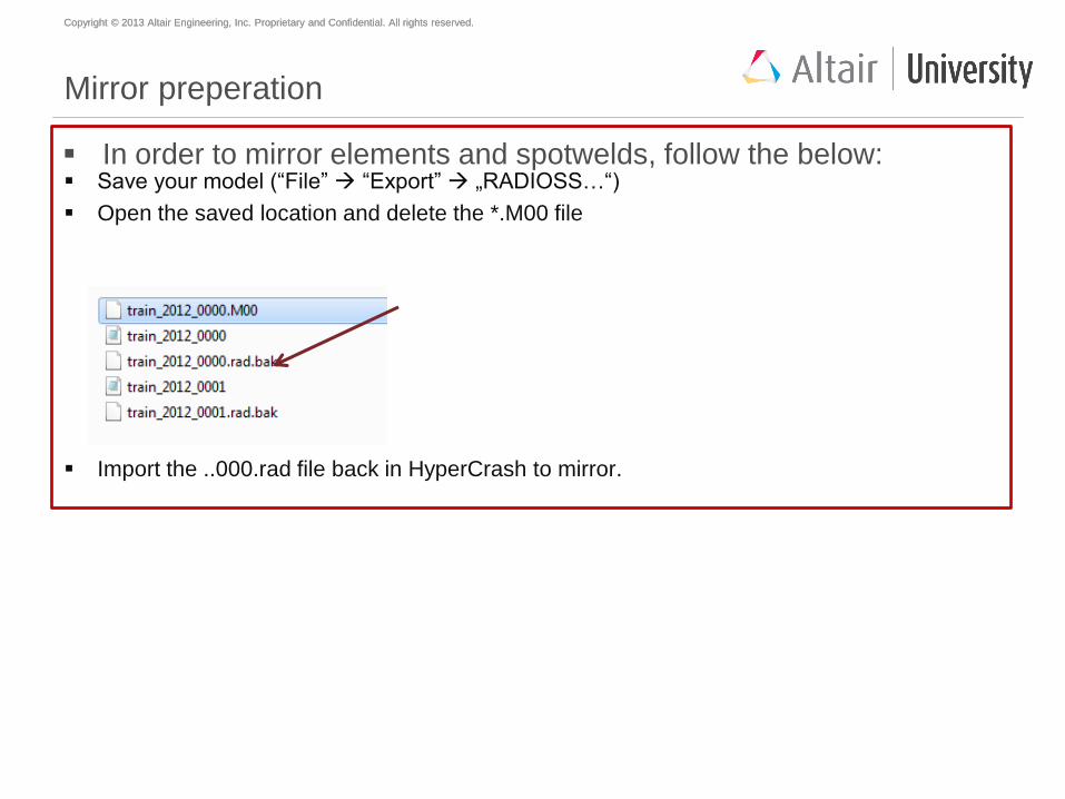
Mirror preperation
Save your model (“File” “Export” „RADIOSS…“)
Open the saved location and delete the *.M00 file
Import the ..000.rad file back in HyperCrash to mirror.
In order to mirror elements and spotwelds, follow the below:
Copyright © 2013 Altair Engineering, Inc. Proprietary and Confidential. All rights reserved. Copyright © 2013 Altair Engineering, Inc. Proprietary and Confidential. All rights reserved.
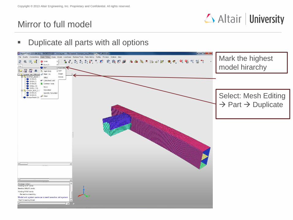
Mirror to full model
Duplicate all parts with all options
Select: Mesh Editing
Part Duplicate
Mark the highest
model hirarchy
Copyright © 2013 Altair Engineering, Inc. Proprietary and Confidential. All rights reserved. Copyright © 2013 Altair Engineering, Inc. Proprietary and Confidential. All rights reserved.
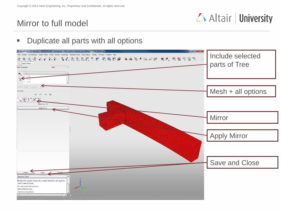
Mirror to full model
Duplicate all parts with all options
Mirror
Include selected
parts of Tree
Apply Mirror
Save and Close
Mesh + all options
Copyright © 2013 Altair Engineering, Inc. Proprietary and Confidential. All rights reserved. Copyright © 2013 Altair Engineering, Inc. Proprietary and Confidential. All rights reserved.
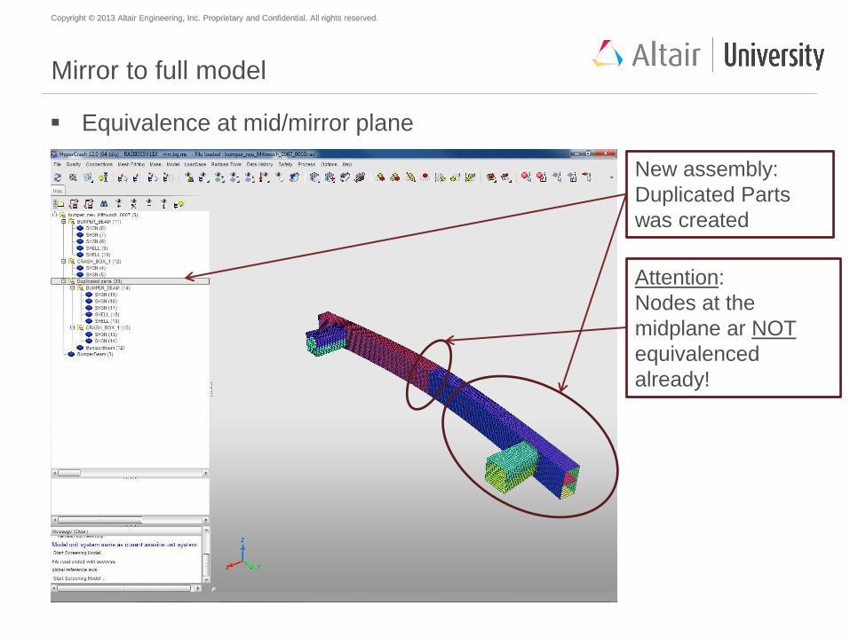
Mirror to full model
Equivalence at mid/mirror plane
Attention:
Nodes at the
midplane ar NOT
equivalenced
already!
New assembly:
Duplicated Parts
was created
Copyright © 2013 Altair Engineering, Inc. Proprietary and Confidential. All rights reserved. Copyright © 2013 Altair Engineering, Inc. Proprietary and Confidential. All rights reserved.
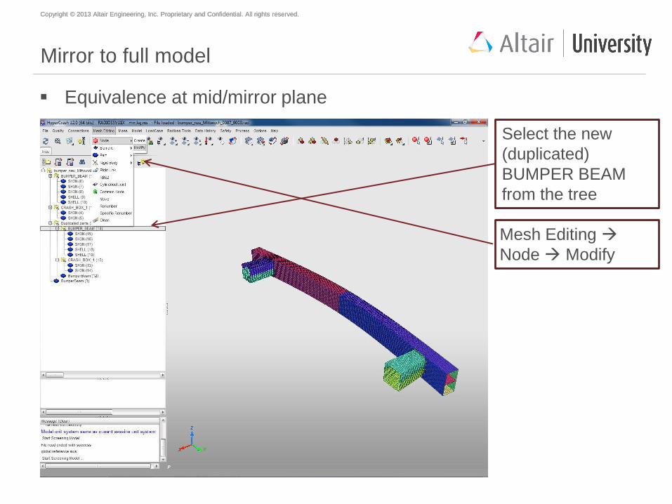
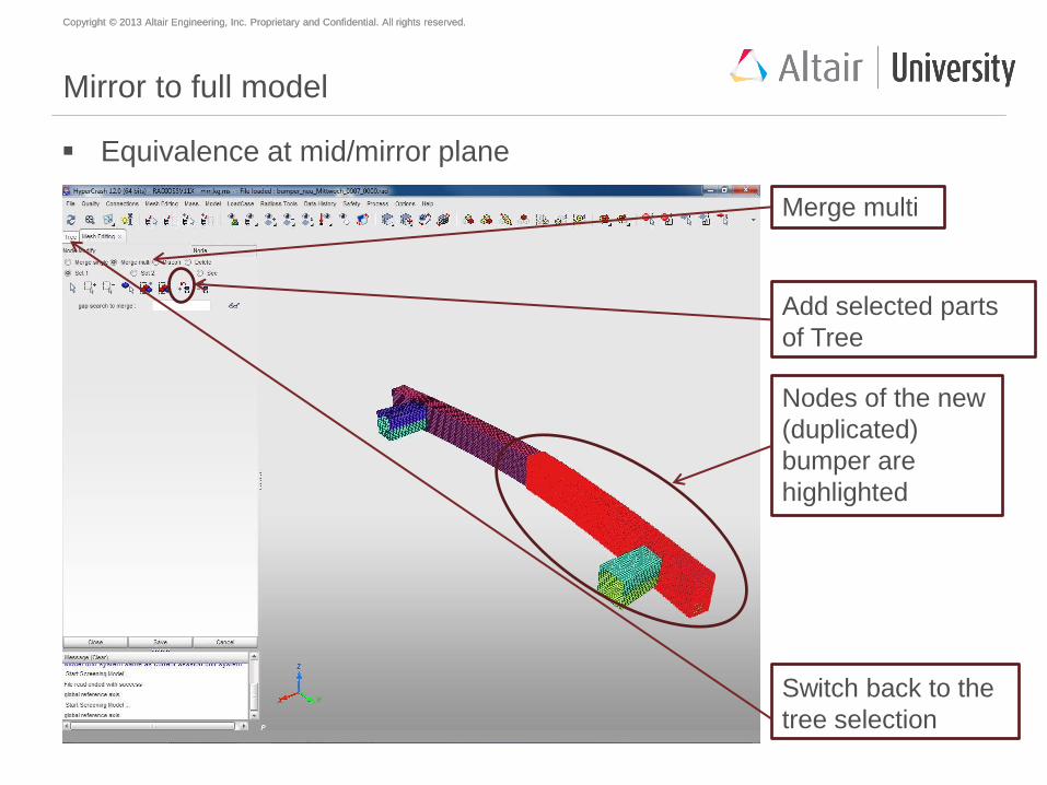
Mirror to full model
Equivalence at mid/mirror plane
Mesh Editing
Node Modify
Select the new
(duplicated)
BUMPER BEAM
from the tree
Copyright © 2013 Altair Engineering, Inc. Proprietary and Confidential. All rights reserved. Copyright © 2013 Altair Engineering, Inc. Proprietary and Confidential. All rights reserved.
Mirror to full model
Equivalence at mid/mirror plane
Add selected parts
of Tree
Merge multi
Nodes of the new
(duplicated)
bumper are
highlighted
Switch back to the
tree selection
Copyright © 2013 Altair Engineering, Inc. Proprietary and Confidential. All rights reserved. Copyright © 2013 Altair Engineering, Inc. Proprietary and Confidential. All rights reserved.
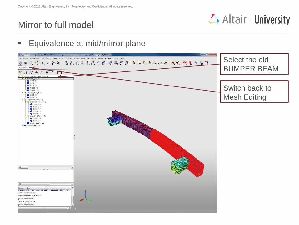
Mirror to full model
Equivalence at mid/mirror plane
Switch back to
Mesh Editing
Select the old
BUMPER BEAM
Copyright © 2013 Altair Engineering, Inc. Proprietary and Confidential. All rights reserved. Copyright © 2013 Altair Engineering, Inc. Proprietary and Confidential. All rights reserved.
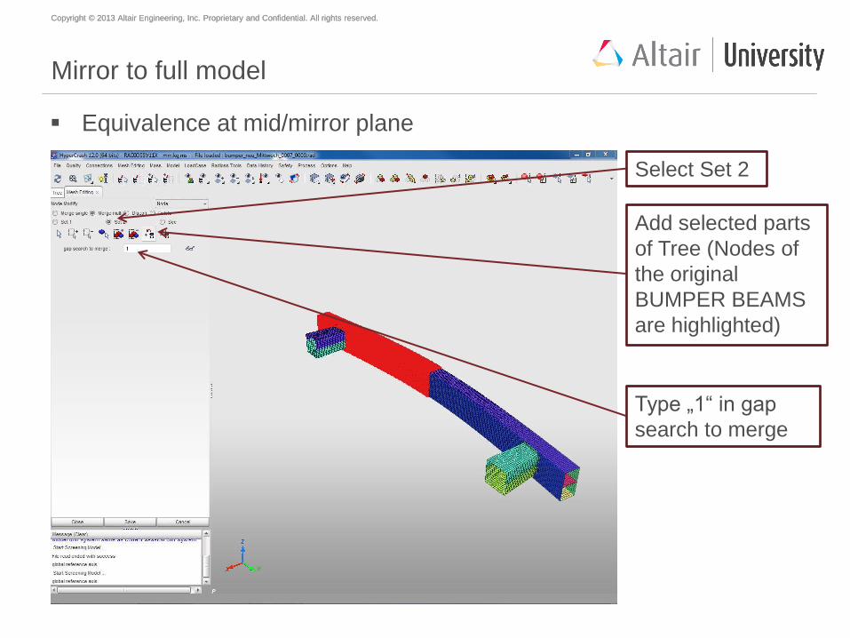
Mirror to full model
Equivalence at mid/mirror plane
Add selected parts
of Tree (Nodes of
the original
BUMPER BEAMS
are highlighted)
Select Set 2
Type „1“ in gap
search to merge
Copyright © 2013 Altair Engineering, Inc. Proprietary and Confidential. All rights reserved. Copyright © 2013 Altair Engineering, Inc. Proprietary and Confidential. All rights reserved.
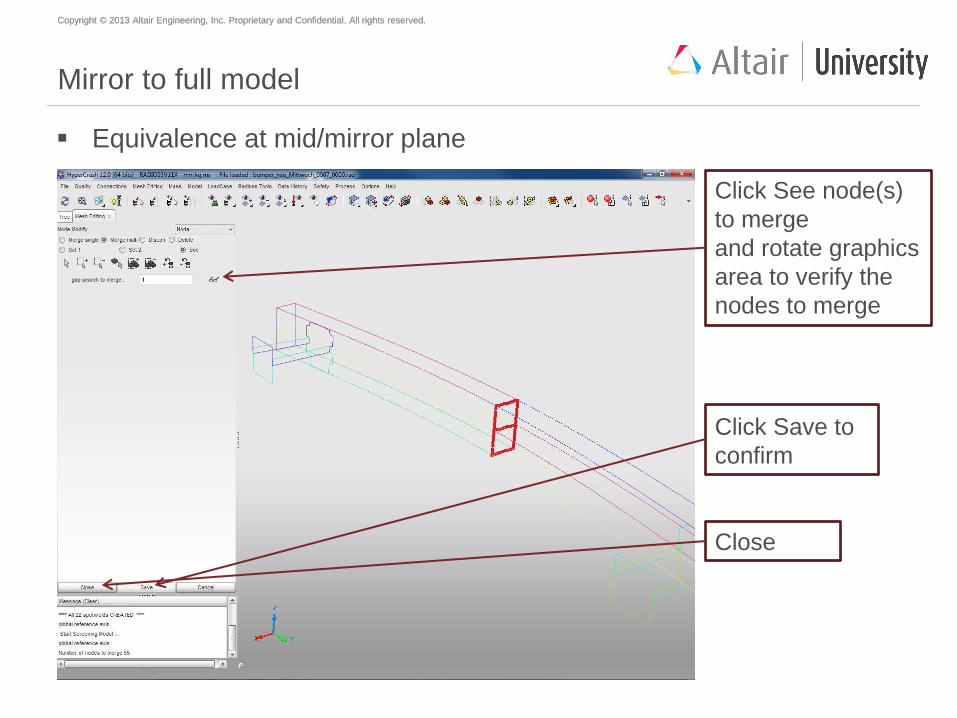
Mirror to full model
Equivalence at mid/mirror plane
Click See node(s)
to merge
and rotate graphics
area to verify the
nodes to merge
Click Save to
confirm
Close
Copyright © 2013 Altair Engineering, Inc. Proprietary and Confidential. All rights reserved. Copyright © 2013 Altair Engineering, Inc. Proprietary and Confidential. All rights reserved.
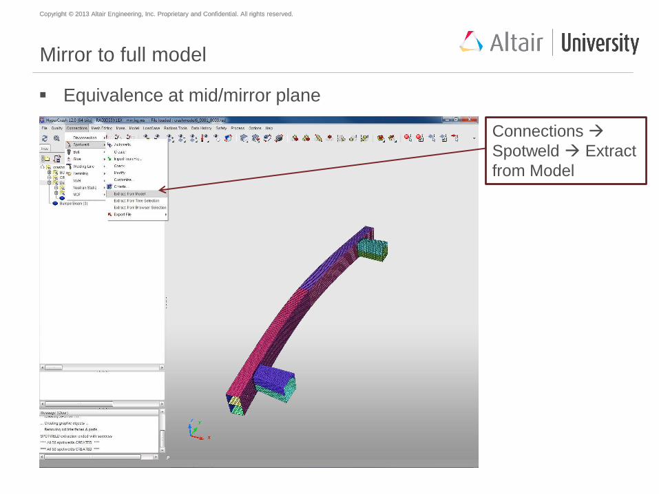
Mirror to full model
Equivalence at mid/mirror plane
Connections
Spotweld Extract
from Model
Copyright © 2013 Altair Engineering, Inc. Proprietary and Confidential. All rights reserved. Copyright © 2013 Altair Engineering, Inc. Proprietary and Confidential. All rights reserved.
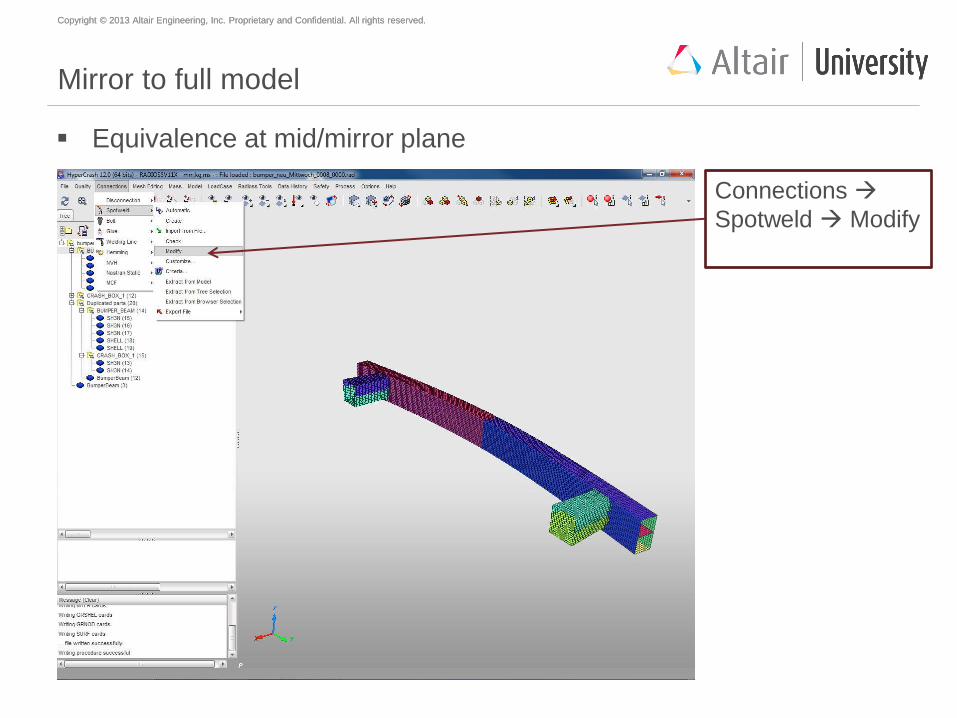
Mirror to full model
Equivalence at mid/mirror plane
Connections
Spotweld Modify
Copyright © 2013 Altair Engineering, Inc. Proprietary and Confidential. All rights reserved. Copyright © 2013 Altair Engineering, Inc. Proprietary and Confidential. All rights reserved.
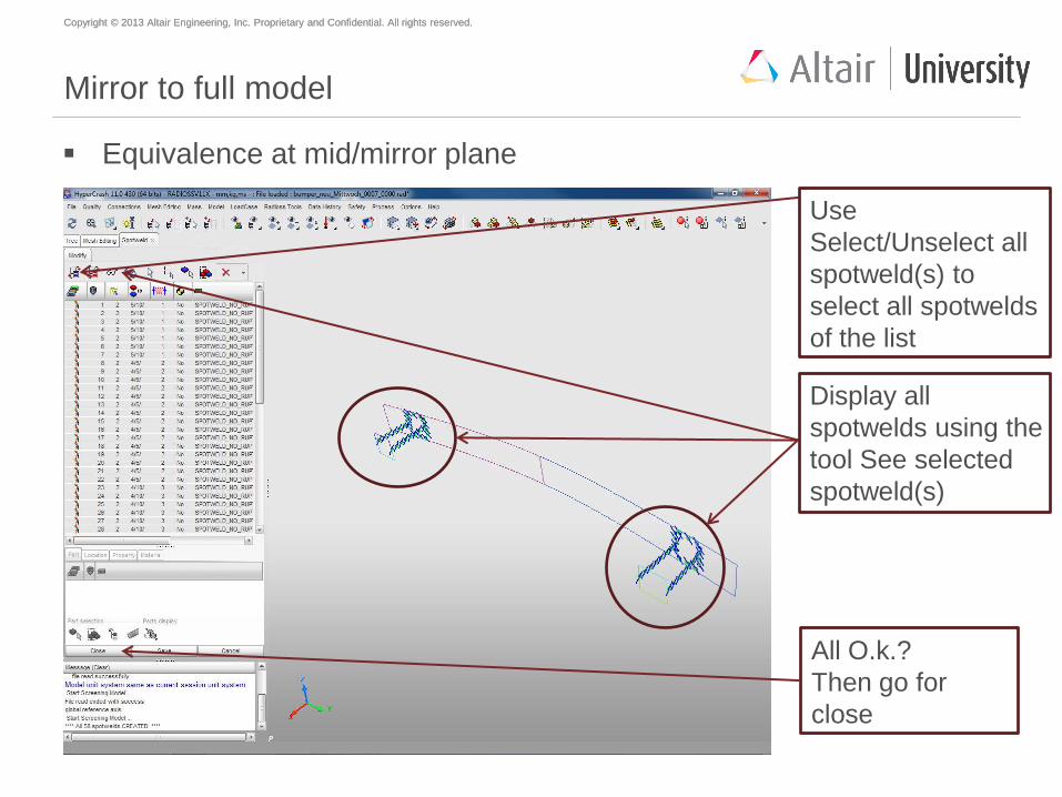
Mirror to full model
Equivalence at mid/mirror plane
Use
Select/Unselect all
spotweld(s) to
select all spotwelds
of the list
Display all
spotwelds using the
tool See selected
spotweld(s)
All O.k.?
Then go for
close
Copyright © 2013 Altair Engineering, Inc. Proprietary and Confidential. All rights reserved. Copyright © 2013 Altair Engineering, Inc. Proprietary and Confidential. All rights reserved.
Agenda
Geometry meshing with HyperMesh
Mesh preparations and modifications with HyperCrash
Material creation and assignment
Property creation and assignment
Welding (SPOTWELDS)
Mirror to full model
Global contact definition
Load case creation
Model check
Start of simulation
Copyright © 2013 Altair Engineering, Inc. Proprietary and Confidential. All rights reserved. Copyright © 2013 Altair Engineering, Inc. Proprietary and Confidential. All rights reserved.
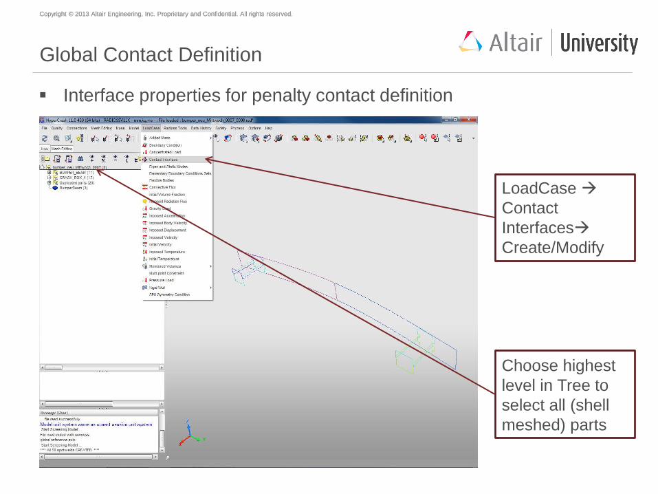
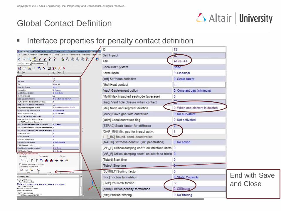
Global Contact Definition
Interface properties for penalty contact definition
Choose highest
level in Tree to
select all (shell
meshed) parts
LoadCase
Contact
Interfaces
Create/Modify
Copyright © 2013 Altair Engineering, Inc. Proprietary and Confidential. All rights reserved. Copyright © 2013 Altair Engineering, Inc. Proprietary and Confidential. All rights reserved.
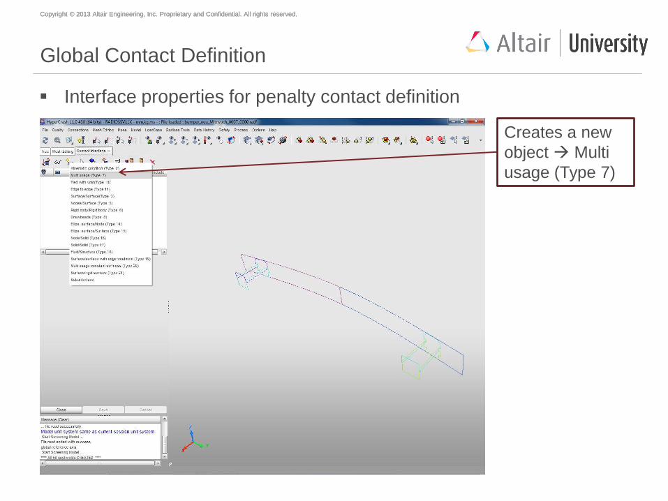
Global Contact Definition
Interface properties for penalty contact definition
Creates a new
object Multi
usage (Type 7)
Copyright © 2013 Altair Engineering, Inc. Proprietary and Confidential. All rights reserved. Copyright © 2013 Altair Engineering, Inc. Proprietary and Confidential. All rights reserved.
Why type 7? What is interface gap?
This interface simulates the most general type of contacts and impacts
Impacts occur between a master surface and a set of slave nodes.
All limitations encountered with interface types 3, 4 and 5 are solved with this
interface.
It is a fast search algorithm without limitations.
Interfaces have a gap that determines when contact between two segments
occurs. This gap is user defined, but some interfaces will calculate an
automatic default gap.
Copyright © 2013 Altair Engineering, Inc. Proprietary and Confidential. All rights reserved. Copyright © 2013 Altair Engineering, Inc. Proprietary and Confidential. All rights reserved.
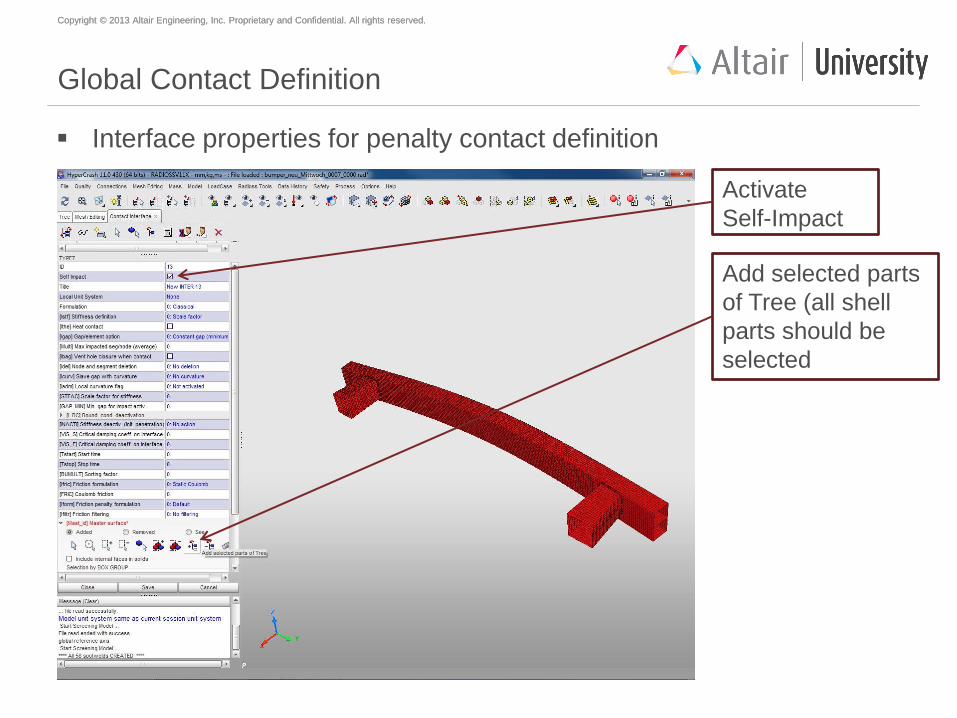
Global Contact Definition
Interface properties for penalty contact definition
Activate
Self-Impact
Add selected parts
of Tree (all shell
parts should be
selected
Copyright © 2013 Altair Engineering, Inc. Proprietary and Confidential. All rights reserved. Copyright © 2013 Altair Engineering, Inc. Proprietary and Confidential. All rights reserved.
Global Contact Definition
Interface properties for penalty contact definition
End with Save
and Close
Copyright © 2013 Altair Engineering, Inc. Proprietary and Confidential. All rights reserved. Copyright © 2013 Altair Engineering, Inc. Proprietary and Confidential. All rights reserved.
What is coulomb`s friction law?
Type 7 interface allows sliding between contact surfaces. Coulomb friction
between the surfaces is modelled.
Coulomb’s friction law is a classic friction law which states that frictional force
= coeff of friction*force acting on the object [Ff= µ*F]. Example - a block
sliding on an inclined plane.
It states that the Kinetic friction is independent of the sliding velocity.
The Coulomb approximation mathematically follows from the assumptions
that surfaces are in atomically close contact only over a small fraction of their
overall area, that this contact area is proportional to the normal force
(until saturation, which takes place when all area is in atomic contact), and
that frictional force is proportional to the applied normal force, independently
of the contact area .
Copyright © 2013 Altair Engineering, Inc. Proprietary and Confidential. All rights reserved. Copyright © 2013 Altair Engineering, Inc. Proprietary and Confidential. All rights reserved.
Agenda
Geometry meshing with HyperMesh
Mesh preparations and modifications with HyperCrash
Material creation and assignment
Property creation and assignment
Welding (SPOTWELDS)
Mirror to full model
Global contact definition
Load case creation
Model check
Start of simulation
Copyright © 2013 Altair Engineering, Inc. Proprietary and Confidential. All rights reserved. Copyright © 2013 Altair Engineering, Inc. Proprietary and Confidential. All rights reserved.
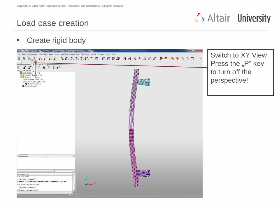
Load case creation
Create rigid body
Switch to XY View
Press the „P“ key
to turn off the
perspective!
Copyright © 2013 Altair Engineering, Inc. Proprietary and Confidential. All rights reserved. Copyright © 2013 Altair Engineering, Inc. Proprietary and Confidential. All rights reserved.
What is a rigid body?
A rigid body is an idealization of a solid body in which deformation is
neglected. In other words, the distance between any two given points of a
rigid body remains constant in time regardless of the external forces exerted
on it.
Rigid body elements are used to
- impose equal displacement to a set of nodes;
- model rigid connections and pin-joints;
- enforce symmetry;
- model transitions, connections, spot-welds, seam-welds between non-
matching (dissimilar) meshes;
- distribute concentrated loads/masses to a set of nodes
Copyright © 2013 Altair Engineering, Inc. Proprietary and Confidential. All rights reserved. Copyright © 2013 Altair Engineering, Inc. Proprietary and Confidential. All rights reserved.
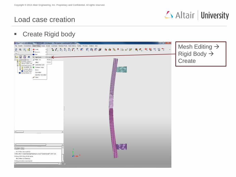
Load case creation
Create Rigid body
Mesh Editing
Rigid Body
Create
Copyright © 2013 Altair Engineering, Inc. Proprietary and Confidential. All rights reserved. Copyright © 2013 Altair Engineering, Inc. Proprietary and Confidential. All rights reserved.
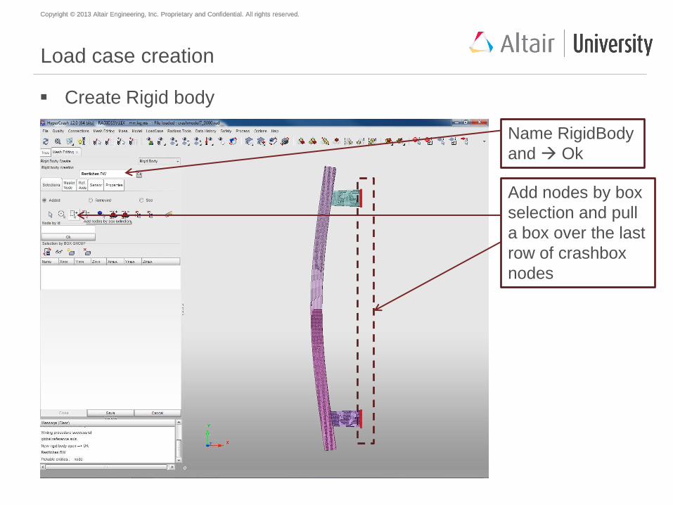
Load case creation
Create Rigid body
Name RigidBody
and Ok
Add nodes by box
selection and pull
a box over the last
row of crashbox
nodes
Copyright © 2013 Altair Engineering, Inc. Proprietary and Confidential. All rights reserved. Copyright © 2013 Altair Engineering, Inc. Proprietary and Confidential. All rights reserved.
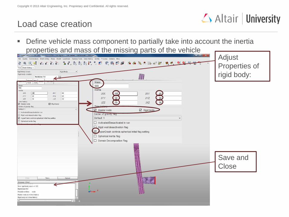
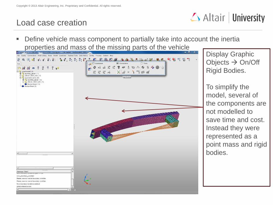
Load case creation
Define vehicle mass component to partially take into account the inertia
properties and mass of the missing parts of the vehicle Adjust
Properties of
rigid body:
Save and
Close
Copyright © 2013 Altair Engineering, Inc. Proprietary and Confidential. All rights reserved. Copyright © 2013 Altair Engineering, Inc. Proprietary and Confidential. All rights reserved.
Load case creation
Define vehicle mass component to partially take into account the inertia
properties and mass of the missing parts of the vehicle Display Graphic
Objects On/Off
Rigid Bodies.
To simplify the
model, several of
the components are
not modelled to
save time and cost.
Instead they were
represented as a
point mass and rigid
bodies.
Copyright © 2013 Altair Engineering, Inc. Proprietary and Confidential. All rights reserved. Copyright © 2013 Altair Engineering, Inc. Proprietary and Confidential. All rights reserved.
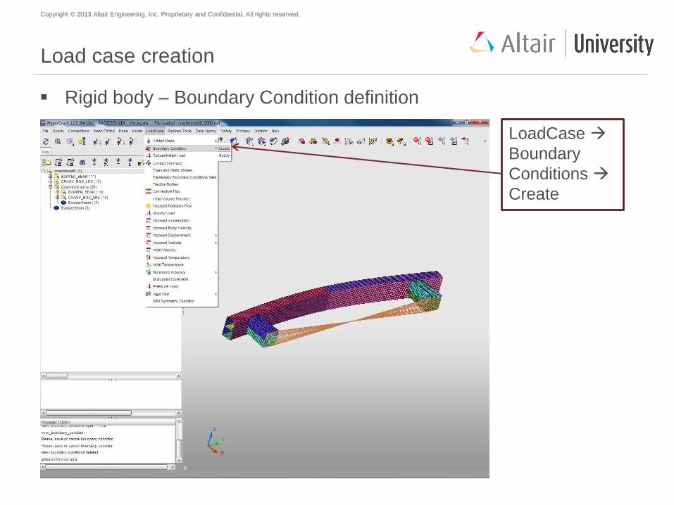
Load case creation
Rigid body – Boundary Condition definition
LoadCase
Boundary
Conditions
Create
Copyright © 2013 Altair Engineering, Inc. Proprietary and Confidential. All rights reserved. Copyright © 2013 Altair Engineering, Inc. Proprietary and Confidential. All rights reserved.
What is a boundary condition?
A boundary condition is simply the load applied to the system.
Boundary conditions are an approximation of the actual physical conditions
the system experiences and should match reality as closely as possible.
Boundary conditions include forces, imposed velocities and accelerations,
pressure loads, constraints on the movement of certain nodes, etc.
Copyright © 2013 Altair Engineering, Inc. Proprietary and Confidential. All rights reserved. Copyright © 2013 Altair Engineering, Inc. Proprietary and Confidential. All rights reserved.
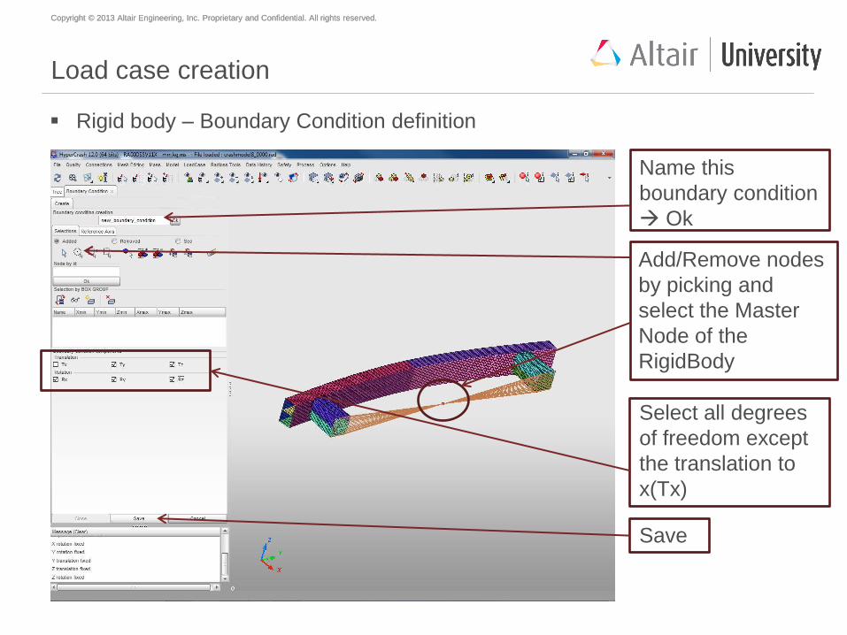
Load case creation
Rigid body – Boundary Condition definition
Name this
boundary condition
Ok
Add/Remove nodes
by picking and
select the Master
Node of the
RigidBody
Select all degrees
of freedom except
the translation to
x(Tx)
Save
Copyright © 2013 Altair Engineering, Inc. Proprietary and Confidential. All rights reserved. Copyright © 2013 Altair Engineering, Inc. Proprietary and Confidential. All rights reserved.
Why Translation to TX not chosen?
In this case the boundary condition being created is to constraint he
movement of the component in unwanted directions.
We do not constrain movement in the TX direction or Translation in the X
direction, because we need the bumper to move in this direction for our
simulation, this also reflects the reality of its movement.
Copyright © 2013 Altair Engineering, Inc. Proprietary and Confidential. All rights reserved. Copyright © 2013 Altair Engineering, Inc. Proprietary and Confidential. All rights reserved.
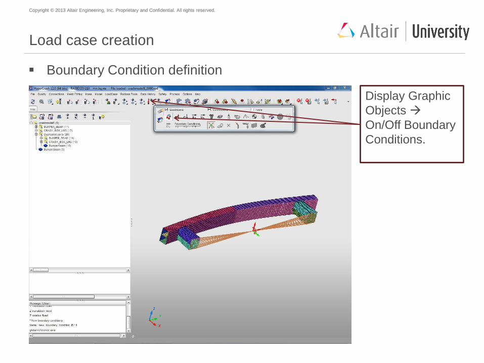
Load case creation
Boundary Condition definition
Display Graphic
Objects
On/Off Boundary
Conditions.
Copyright © 2013 Altair Engineering, Inc. Proprietary and Confidential. All rights reserved. Copyright © 2013 Altair Engineering, Inc. Proprietary and Confidential. All rights reserved.
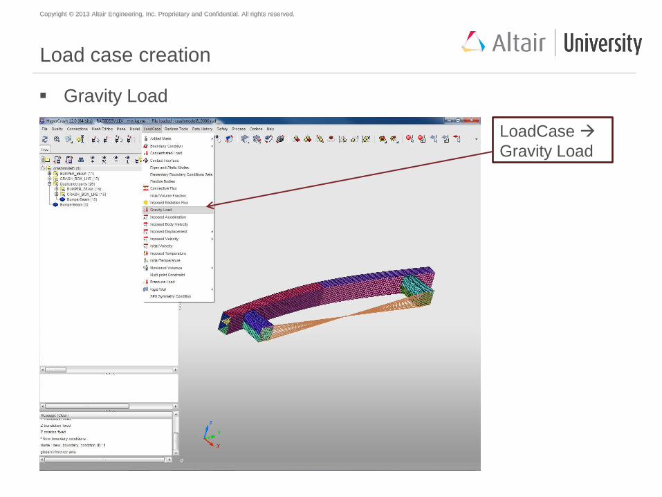
Load case creation
Gravity Load
LoadCase
Gravity Load
Copyright © 2013 Altair Engineering, Inc. Proprietary and Confidential. All rights reserved. Copyright © 2013 Altair Engineering, Inc. Proprietary and Confidential. All rights reserved.
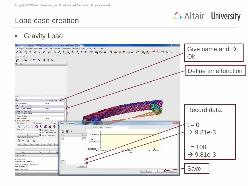
Load case creation
Gravity Load
Give name and
Ok
Record data:
t = 0
9.81e-3
t = 100
9.81e-3
Save
Define time function
Copyright © 2013 Altair Engineering, Inc. Proprietary and Confidential. All rights reserved. Copyright © 2013 Altair Engineering, Inc. Proprietary and Confidential. All rights reserved.
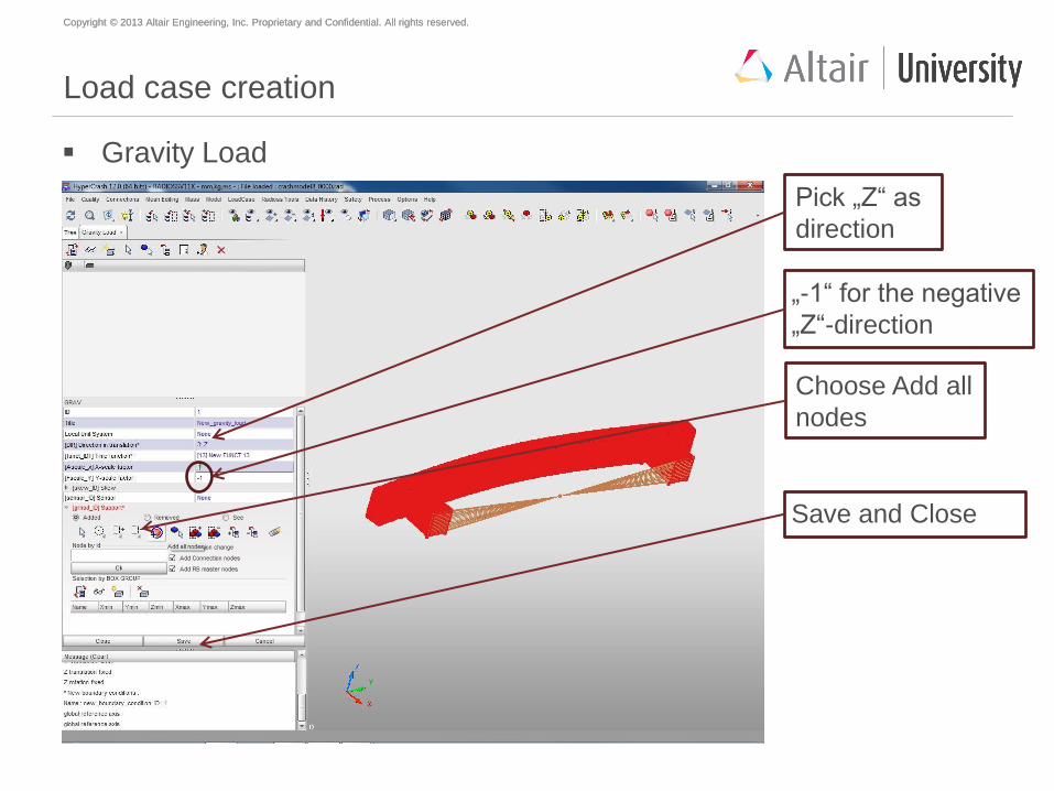
Load case creation
Gravity Load
Choose Add all
nodes
Pick „Z“ as
direction
„-1“ for the negative
„Z“-direction
Save and Close
Copyright © 2013 Altair Engineering, Inc. Proprietary and Confidential. All rights reserved. Copyright © 2013 Altair Engineering, Inc. Proprietary and Confidential. All rights reserved.
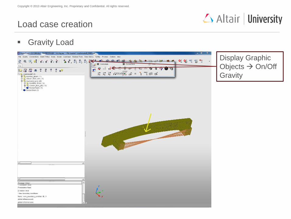
Load case creation
Gravity Load
Display Graphic
Objects On/Off
Gravity
Copyright © 2013 Altair Engineering, Inc. Proprietary and Confidential. All rights reserved. Copyright © 2013 Altair Engineering, Inc. Proprietary and Confidential. All rights reserved.
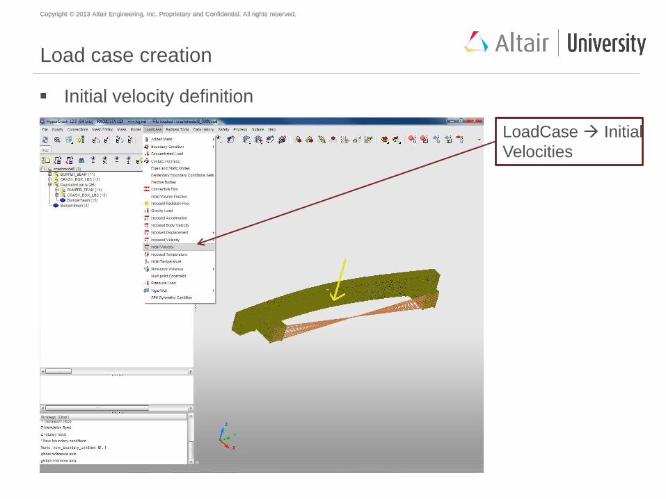
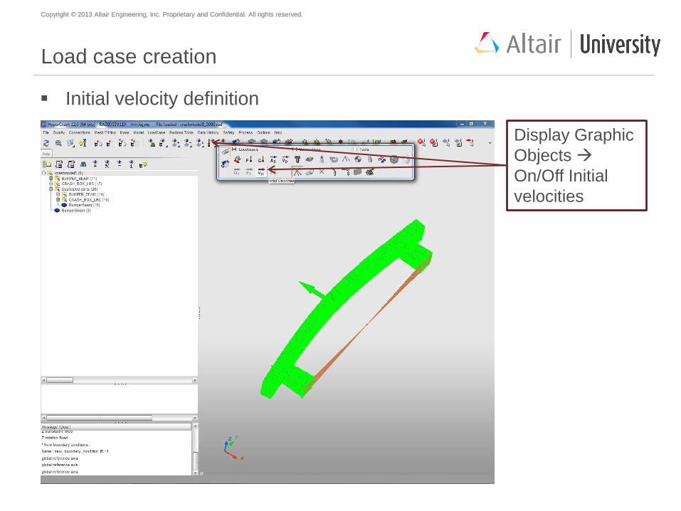
Load case creation
Initial velocity definition
LoadCase Initial
Velocities
Copyright © 2013 Altair Engineering, Inc. Proprietary and Confidential. All rights reserved. Copyright © 2013 Altair Engineering, Inc. Proprietary and Confidential. All rights reserved.
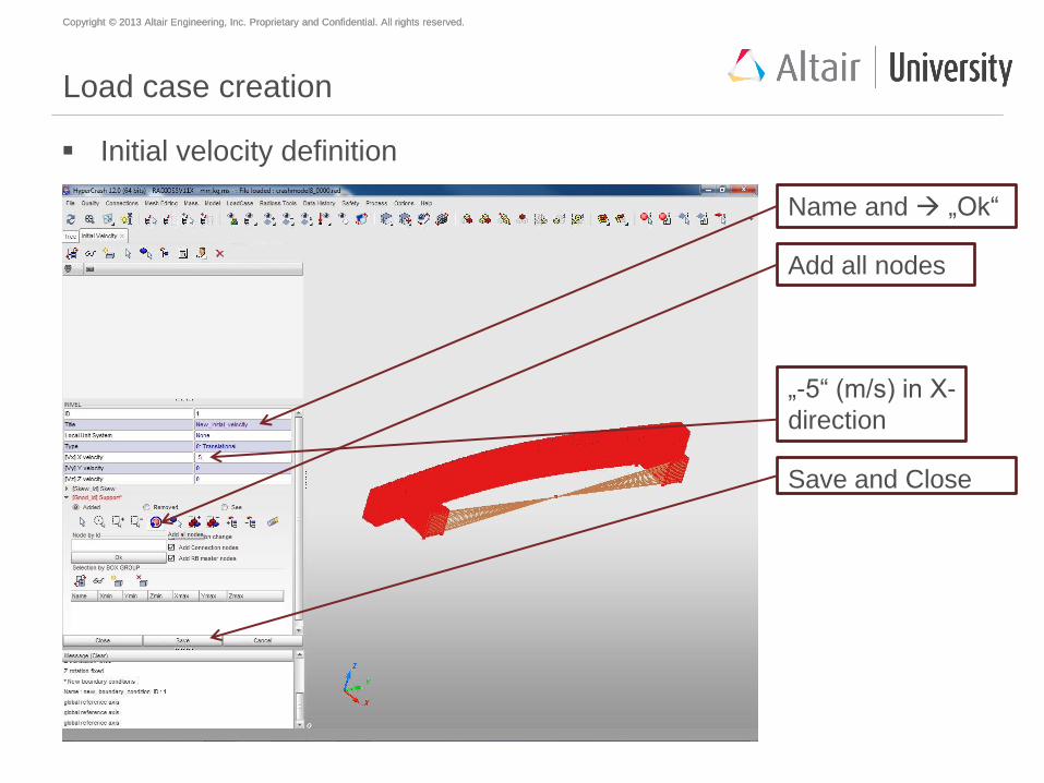
Load case creation
Initial velocity definition
Name and „Ok“
Add all nodes
„-5“ (m/s) in X-
direction
Save and Close
Copyright © 2013 Altair Engineering, Inc. Proprietary and Confidential. All rights reserved. Copyright © 2013 Altair Engineering, Inc. Proprietary and Confidential. All rights reserved.
Load case creation
Initial velocity definition
Display Graphic
Objects
On/Off Initial
velocities
Copyright © 2013 Altair Engineering, Inc. Proprietary and Confidential. All rights reserved. Copyright © 2013 Altair Engineering, Inc. Proprietary and Confidential. All rights reserved.
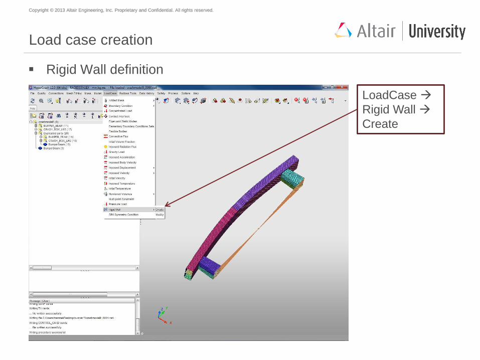
Load case creation
Rigid Wall definition
LoadCase
Rigid Wall
Create
Copyright © 2013 Altair Engineering, Inc. Proprietary and Confidential. All rights reserved. Copyright © 2013 Altair Engineering, Inc. Proprietary and Confidential. All rights reserved.
What is a rigid wall?
A rigid wall is a nodal constraint applied to a set of slave nodes in order to
avoid the node penetration to the wall. If contact is detected, then the slave
node acceleration and velocity are modified.
Mainly to constrain movement of a moving body after impact, We will be using
a cylindrical wall.
An infinite cylindrical wall is a cylinder which extends to infinity. It is defined
with two points (or one point and one node) and a diameter. Note that contact
is only possible from outside the cylindrical wall.
Copyright © 2013 Altair Engineering, Inc. Proprietary and Confidential. All rights reserved. Copyright © 2013 Altair Engineering, Inc. Proprietary and Confidential. All rights reserved.
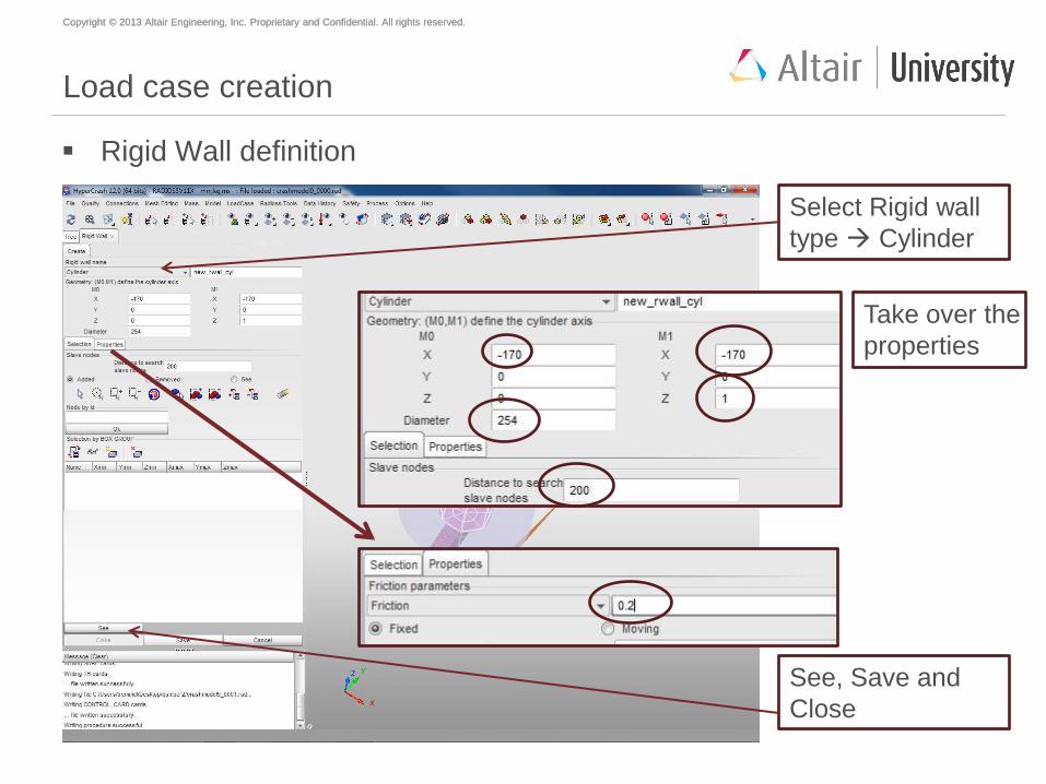
Load case creation
Rigid Wall definition
Select Rigid wall
type Cylinder
Take over the
properties
See, Save and
Close
Copyright © 2013 Altair Engineering, Inc. Proprietary and Confidential. All rights reserved. Copyright © 2013 Altair Engineering, Inc. Proprietary and Confidential. All rights reserved.
Load case creation
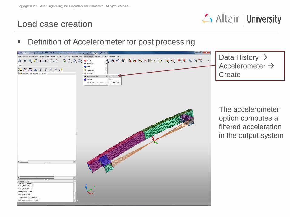
Definition of Accelerometer for post processing
Data History
Accelerometer
Create
The accelerometer
option computes a
filtered acceleration
in the output system
Copyright © 2013 Altair Engineering, Inc. Proprietary and Confidential. All rights reserved. Copyright © 2013 Altair Engineering, Inc. Proprietary and Confidential. All rights reserved.
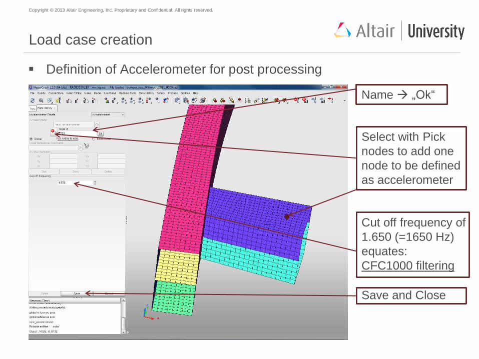
Load case creation
Definition of Accelerometer for post processing
Name „Ok“
Select with Pick
nodes to add one
node to be defined
as accelerometer
Cut off frequency of
1.650 (=1650 Hz)
equates:
CFC1000 filtering
Save and Close
Copyright © 2013 Altair Engineering, Inc. Proprietary and Confidential. All rights reserved. Copyright © 2013 Altair Engineering, Inc. Proprietary and Confidential. All rights reserved.
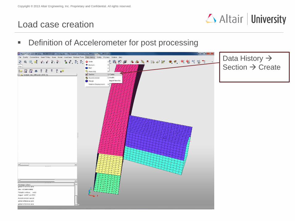
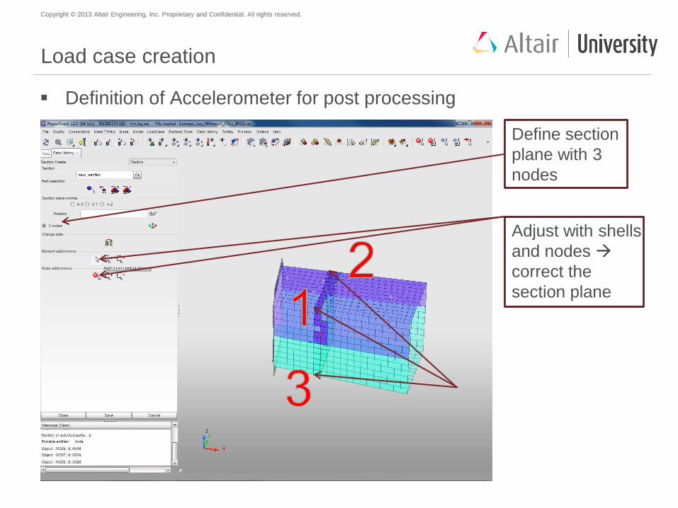
Load case creation
Definition of Accelerometer for post processing
Data History
Section Create
Copyright © 2013 Altair Engineering, Inc. Proprietary and Confidential. All rights reserved. Copyright © 2013 Altair Engineering, Inc. Proprietary and Confidential. All rights reserved.
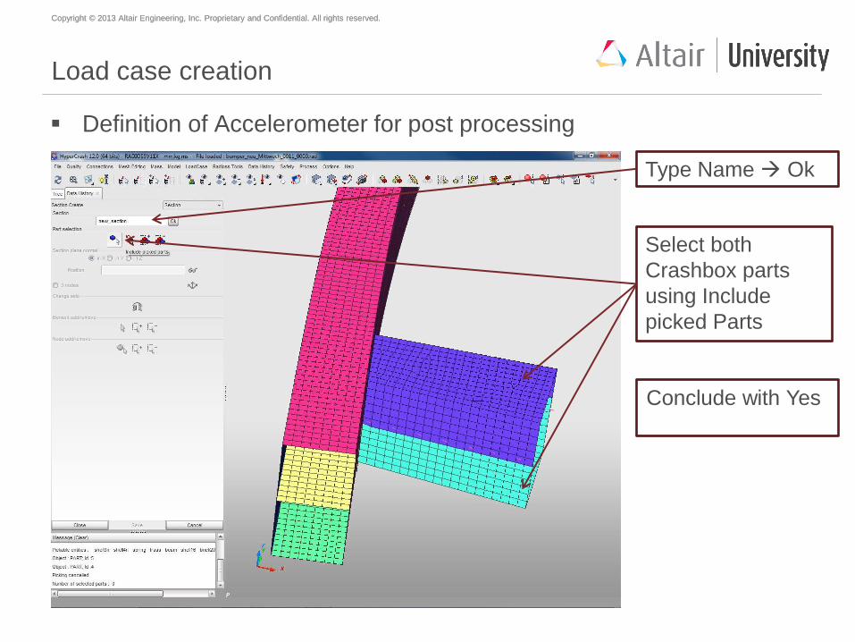
Load case creation
Definition of Accelerometer for post processing
Type Name Ok
Select both
Crashbox parts
using Include
picked Parts
Conclude with Yes
Copyright © 2013 Altair Engineering, Inc. Proprietary and Confidential. All rights reserved. Copyright © 2013 Altair Engineering, Inc. Proprietary and Confidential. All rights reserved.
Load case creation
Definition of Accelerometer for post processing
Define section
plane with 3
nodes
Adjust with shells
and nodes
correct the
section plane
Copyright © 2013 Altair Engineering, Inc. Proprietary and Confidential. All rights reserved. Copyright © 2013 Altair Engineering, Inc. Proprietary and Confidential. All rights reserved.
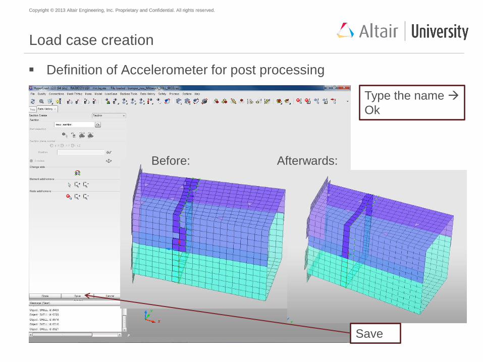
Load case creation
Definition of Accelerometer for post processing
Type the name
Ok
Before: Afterwards:
Save
Copyright © 2013 Altair Engineering, Inc. Proprietary and Confidential. All rights reserved. Copyright © 2013 Altair Engineering, Inc. Proprietary and Confidential. All rights reserved.
Agenda
Geometry meshing with HyperMesh
Mesh preparations and modifications with HyperCrash
Material creation and assignment
Property creation and assignment
Welding (SPOTWELDS)
Mirror to full model
Global contact definition
Load case creation
Model check
Start of simulation
Copyright © 2013 Altair Engineering, Inc. Proprietary and Confidential. All rights reserved. Copyright © 2013 Altair Engineering, Inc. Proprietary and Confidential. All rights reserved.
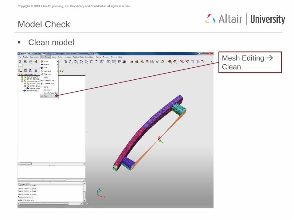
Model Check
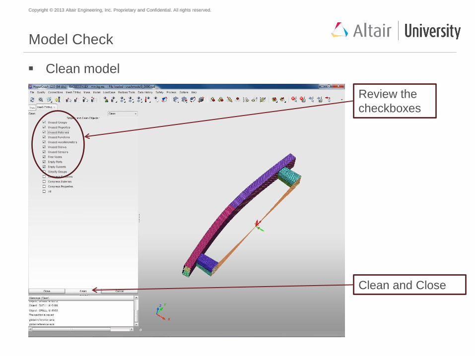
Clean model
Mesh Editing
Clean
Copyright © 2013 Altair Engineering, Inc. Proprietary and Confidential. All rights reserved. Copyright © 2013 Altair Engineering, Inc. Proprietary and Confidential. All rights reserved.
Model Check
Clean model
Clean and Close
Review the
checkboxes
Copyright © 2013 Altair Engineering, Inc. Proprietary and Confidential. All rights reserved. Copyright © 2013 Altair Engineering, Inc. Proprietary and Confidential. All rights reserved.
Model Check
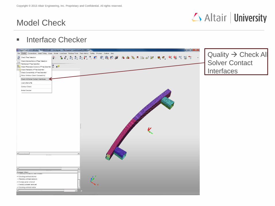
Interface Checker
Quality Check All
Solver Contact
Interfaces
Copyright © 2013 Altair Engineering, Inc. Proprietary and Confidential. All rights reserved. Copyright © 2013 Altair Engineering, Inc. Proprietary and Confidential. All rights reserved.
Model Check
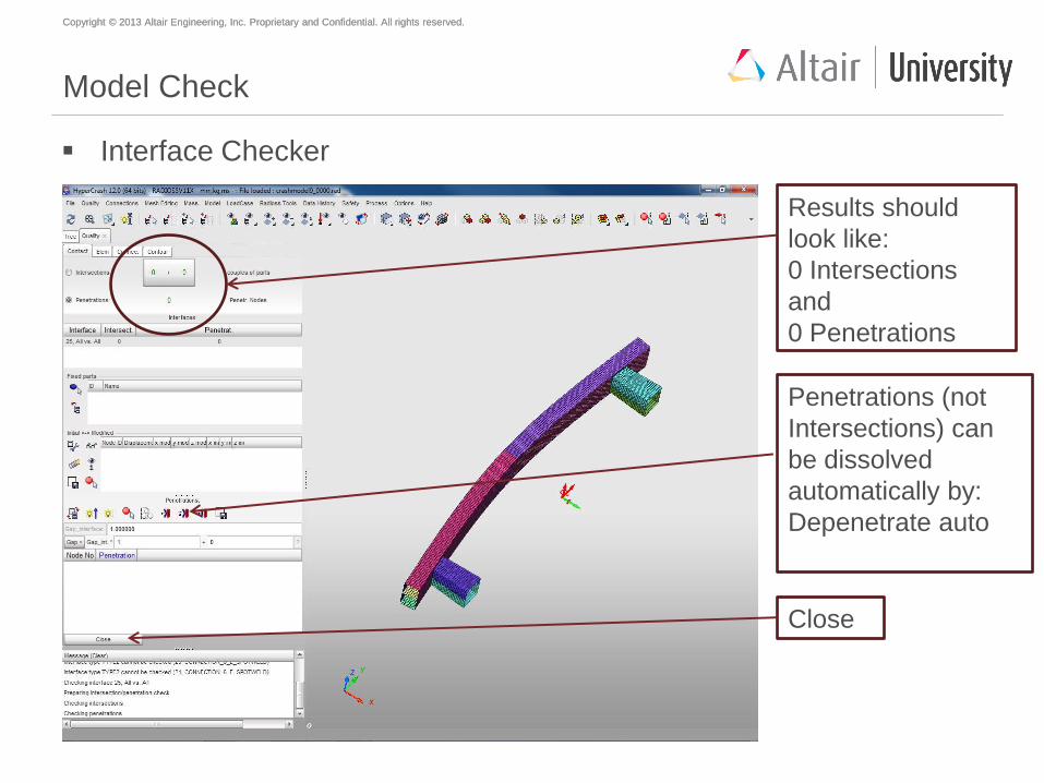
Interface Checker
Results should
look like:
0 Intersections
and
0 Penetrations
Penetrations (not
Intersections) can
be dissolved
automatically by:
Depenetrate auto
Close
Copyright © 2013 Altair Engineering, Inc. Proprietary and Confidential. All rights reserved. Copyright © 2013 Altair Engineering, Inc. Proprietary and Confidential. All rights reserved.
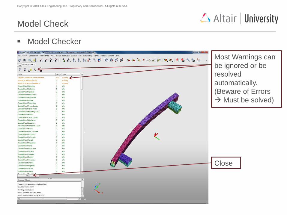
Model Check
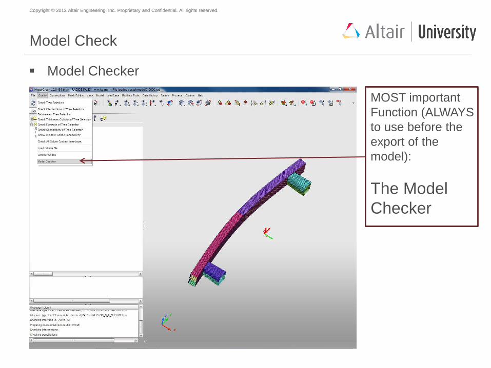
Model Checker
MOST important
Function (ALWAYS
to use before the
export of the
model):
The Model
Checker
Copyright © 2013 Altair Engineering, Inc. Proprietary and Confidential. All rights reserved. Copyright © 2013 Altair Engineering, Inc. Proprietary and Confidential. All rights reserved.
Model Check
Model Checker
Most Warnings can
be ignored or be
resolved
automatically.
(Beware of Errors
Must be solved)
Close

Copyright © 2013 Altair Engineering, Inc. Proprietary and Confidential. All rights reserved. Copyright © 2013 Altair Engineering, Inc. Proprietary and Confidential. All rights reserved.
Agenda
Geometry meshing with HyperMesh
Mesh preparations and modifications with HyperCrash
Material creation and assignment
Property creation and assignment
Welding (SPOTWELDS)
Mirror to full model
Global contact definition
Load case creation
Model check
Start of simulation
Copyright © 2013 Altair Engineering, Inc. Proprietary and Confidential. All rights reserved. Copyright © 2013 Altair Engineering, Inc. Proprietary and Confidential. All rights reserved.
Simulation
RADIOSS (BLOCK) is the solver used for solving non-linear implicit and
explicit problems.
HyperCrash/RADIOSS essentially writes out starter file and Engine file.
Engine files are used to set up the model, including termination times, output
requests, and other checks that control the execution of the job.
Starter file contains actual model definition. Engine file executes the actual
computation.
Copyright © 2013 Altair Engineering, Inc. Proprietary and Confidential. All rights reserved. Copyright © 2013 Altair Engineering, Inc. Proprietary and Confidential. All rights reserved.
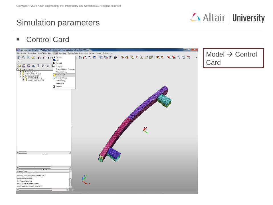
Simulation parameters
Control Card
Model Control
Card
Copyright © 2013 Altair Engineering, Inc. Proprietary and Confidential. All rights reserved. Copyright © 2013 Altair Engineering, Inc. Proprietary and Confidential. All rights reserved.
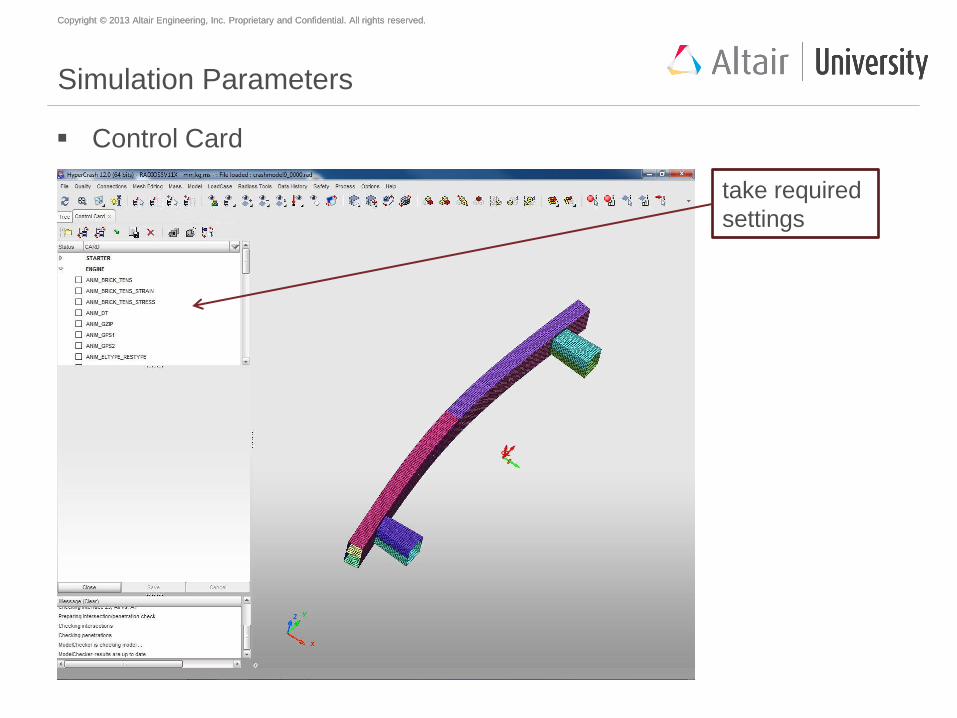
Simulation Parameters
Control Card
take required
settings
Copyright © 2013 Altair Engineering, Inc. Proprietary and Confidential. All rights reserved. Copyright © 2013 Altair Engineering, Inc. Proprietary and Confidential. All rights reserved.
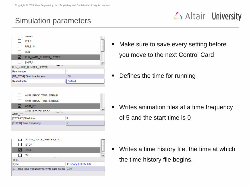
Simulation parameters
Make sure to save every setting before
you move to the next Control Card
Defines the time for running
Writes animation files at a time frequency
of 5 and the start time is 0
Writes a time history file. the time at which
the time history file begins.
Copyright © 2013 Altair Engineering, Inc. Proprietary and Confidential. All rights reserved. Copyright © 2013 Altair Engineering, Inc. Proprietary and Confidential. All rights reserved.
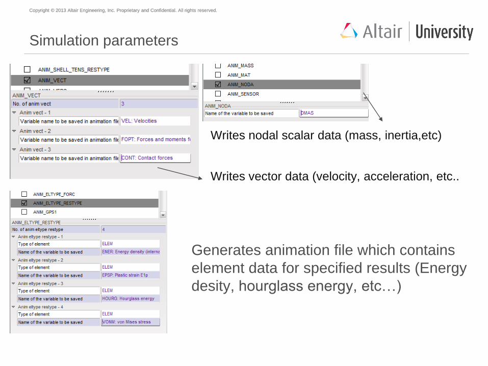
Generates animation file which contains
element data for specified results (Energy
desity, hourglass energy, etc…)
Writes nodal scalar data (mass, inertia,etc)
Writes vector data (velocity, acceleration, etc..
Simulation parameters
Copyright © 2013 Altair Engineering, Inc. Proprietary and Confidential. All rights reserved. Copyright © 2013 Altair Engineering, Inc. Proprietary and Confidential. All rights reserved.
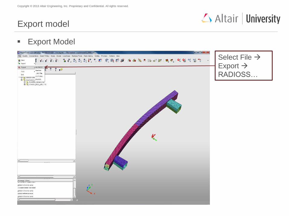
Export model
Export Model
Select File
Export
RADIOSS…
Copyright © 2013 Altair Engineering, Inc. Proprietary and Confidential. All rights reserved. Copyright © 2013 Altair Engineering, Inc. Proprietary and Confidential. All rights reserved.
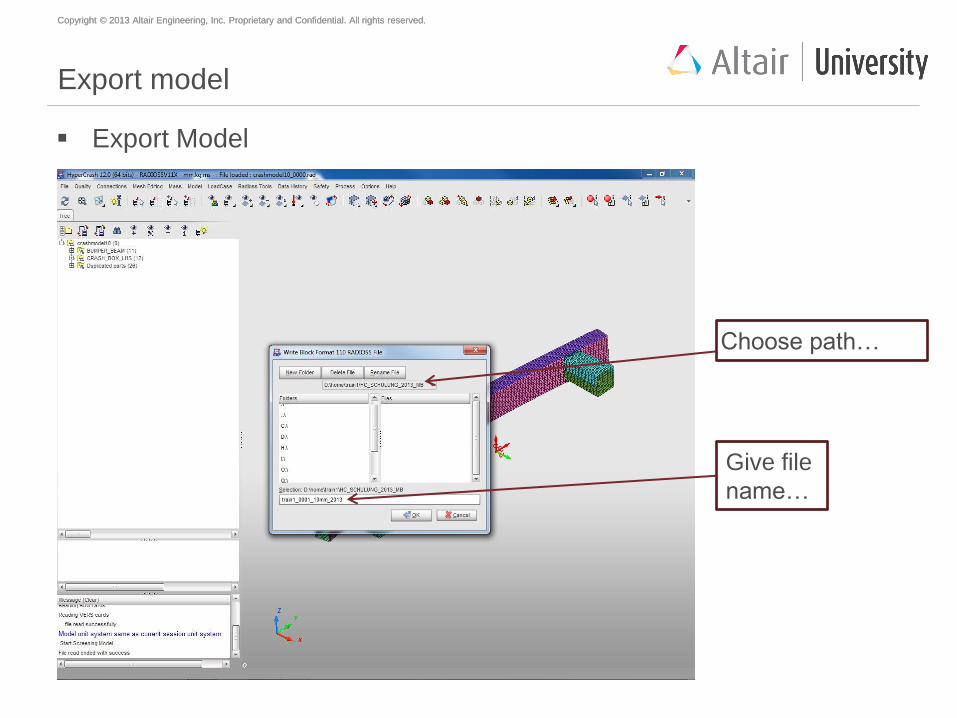
Export model
Export Model
Choose path…
Give file
name…
Copyright © 2013 Altair Engineering, Inc. Proprietary and Confidential. All rights reserved. Copyright © 2013 Altair Engineering, Inc. Proprietary and Confidential. All rights reserved.
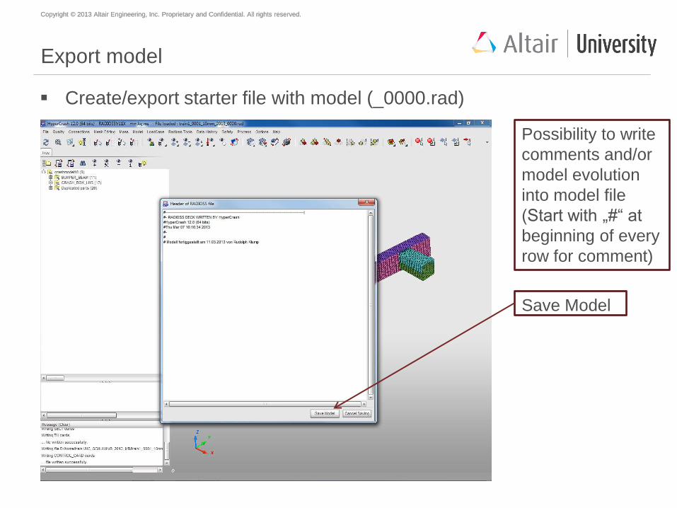
Export model
Create/export starter file with model (_0000.rad)
Possibility to write
comments and/or
model evolution
into model file
(Start with „#“ at
beginning of every
row for comment)
Save Model
Copyright © 2013 Altair Engineering, Inc. Proprietary and Confidential. All rights reserved. Copyright © 2013 Altair Engineering, Inc. Proprietary and Confidential. All rights reserved.
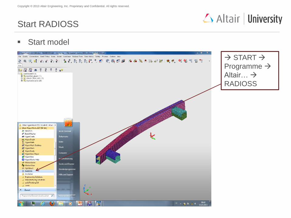
Start RADIOSS
Start model
START
Programme
Altair…
RADIOSS
Copyright © 2013 Altair Engineering, Inc. Proprietary and Confidential. All rights reserved. Copyright © 2013 Altair Engineering, Inc. Proprietary and Confidential. All rights reserved.
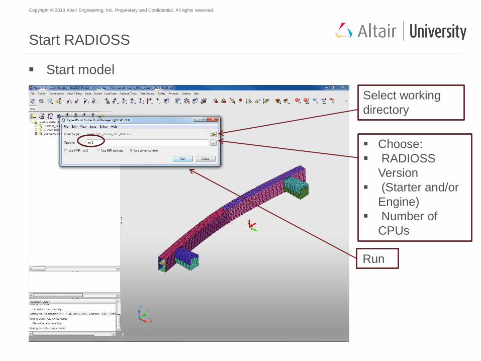
Start RADIOSS
Start model
Select working
directory
Choose:
RADIOSS
Version
(Starter and/or
Engine)
Number of
CPUs
Run
Copyright © 2013 Altair Engineering, Inc. Proprietary and Confidential. All rights reserved. Copyright © 2013 Altair Engineering, Inc. Proprietary and Confidential. All rights reserved.
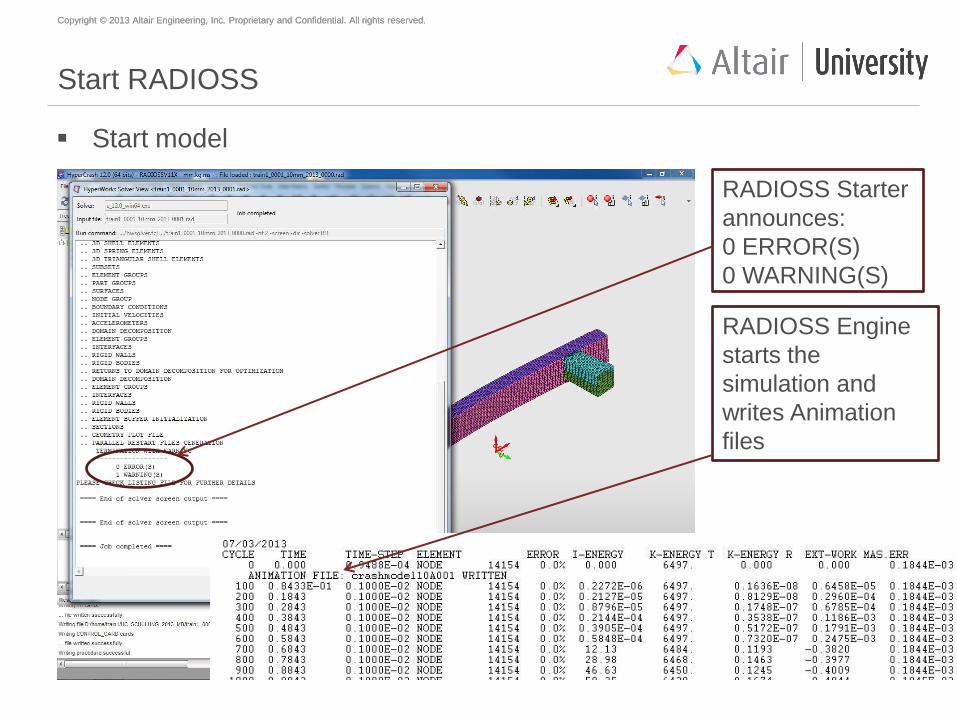
Start RADIOSS
Start model
RADIOSS Starter
announces:
0 ERROR(S)
0 WARNING(S)
RADIOSS Engine
starts the
simulation and
writes Animation
files
Copyright © 2013 Altair Engineering, Inc. Proprietary and Confidential. All rights reserved. Copyright © 2013 Altair Engineering, Inc. Proprietary and Confidential. All rights reserved.
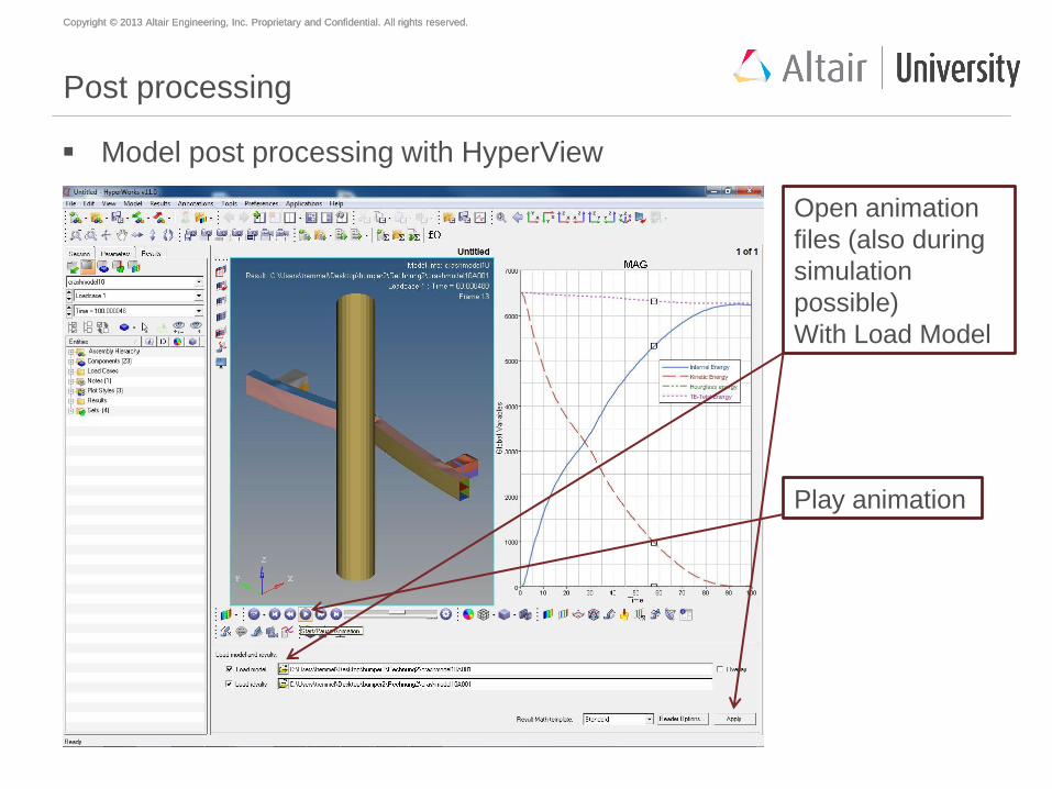
Post processing
Model post processing with HyperView
Open animation
files (also during
simulation
possible)
With Load Model
Play animation