Embed Size (px)
Citation preview
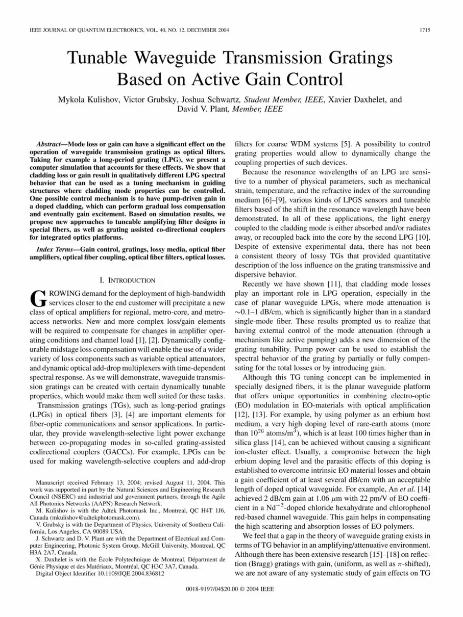
IEEE JOURNAL OF QUANTUM ELECTRONICS, VOL. 40, NO. 12, DECEMBER 2004 1715
Tunable Waveguide Transmission GratingsBased on Active Gain Control
Mykola Kulishov, Victor Grubsky, Joshua Schwartz, Student Member, IEEE, Xavier Daxhelet, andDavid V. Plant, Member, IEEE
Abstract—Mode loss or gain can have a significant effect on theoperation of waveguide transmission gratings as optical filters.Taking for example a long-period grating (LPG), we present acomputer simulation that accounts for these effects. We show thatcladding loss or gain result in qualitatively different LPG spectralbehavior that can be used as a tuning mechanism in guidingstructures where cladding mode properties can be controlled.One possible control mechanism is to have pump-driven gain ina doped cladding, which can perform gradual loss compensationand eventually gain excitement. Based on simulation results, wepropose new approaches to tuneable amplifying filter designs inspecial fibers, as well as grating assisted co-directional couplersfor integrated optics platforms.
Index Terms—Gain control, gratings, lossy media, optical fiberamplifiers, optical fiber coupling, optical fiber filters, optical losses.
I. INTRODUCTION
GROWING demand for the deployment of high-bandwidthservices closer to the end customer will precipitate a new
class of optical amplifiers for regional, metro-core, and metro-access networks. New and more complex loss/gain elementswill be required to compensate for changes in amplifier oper-ating conditions and channel load [1], [2]. Dynamically config-urable midstage loss compensation will enable the use of a widervariety of loss components such as variable optical attenuators,and dynamic optical add-drop multiplexers with time-dependentspectral response. As we will demonstrate, waveguide transmis-sion gratings can be created with certain dynamically tunableproperties, which would make them well suited for these tasks.
Transmission gratings (TGs), such as long-period gratings(LPGs) in optical fibers [3], [4] are important elements forfiber-optic communications and sensor applications. In partic-ular, they provide wavelength-selective light power exchangebetween co-propagating modes in so-called grating-assistedcodirectional couplers (GACCs). For example, LPGs can beused for making wavelength-selective couplers and add-drop
Manuscript received February 13, 2004; revised August 11, 2004. Thiswork was supported in part by the Natural Sciences and Engineering ResearchCouncil (NSERC) and industrial and government partners, through the AgileAll-Photonics Networks (AAPN) Research Network.
M. Kulishov is with the Adtek Photomask Inc., Montreal, QC H4T 1J6,Canada ([email protected]).
V. Grubsky is with the Department of Physics, University of Southern Cali-fornia, Los Angeles, CA 90089 USA.
J. Schwartz and D. V. Plant are with the Department of Electrical and Com-puter Engineering, Photonic System Group, McGill University, Montreal, QCH3A 2A7, Canada.
X. Daxhelet is with the Ecole Polytechnique de Montreal, Départment deGénie Physique et des Matériaux, Montréal, QC H3C 3A7, Canada.
Digital Object Identifier 10.1109/JQE.2004.836812
filters for coarse WDM systems [5]. A possibility to controlgrating properties would allow to dynamically change thecoupling properties of such devices.
Because the resonance wavelengths of an LPG are sensi-tive to a number of physical parameters, such as mechanicalstrain, temperature, and the refractive index of the surroundingmedium [6]–[9], various kinds of LPGS sensors and tuneablefilters based of the shift in the resonance wavelength have beendemonstrated. In all of these applications, the light energycoupled to the cladding mode is either absorbed and/or radiatesaway, or recoupled back into the core by the second LPG [10].Despite of extensive experimental data, there has not beena consistent theory of lossy TGs that provided quantitativedescription of the loss influence on the grating transmissive anddispersive behavior.
Recently we have shown [11], that cladding mode lossesplay an important role in LPG operation, especially in thecase of planar waveguide LPGs, where mode attenuation is
0.1–1 dB/cm, which is significantly higher than in a standardsingle-mode fiber. These results prompted us to realize thathaving external control of the mode attenuation (through amechanism like active pumping) adds a new dimension of thegrating tunability. Pump power can be used to establish thespectral behavior of the grating by partially or fully compen-sating for the total losses or by introducing gain.
Although this TG tuning concept can be implemented inspecially designed fibers, it is the planar waveguide platformthat offers unique opportunities in combining electro-optic(EO) modulation in EO-materials with optical amplification[12], [13]. For example, by using polymer as an erbium hostmedium, a very high doping level of rare-earth atoms (morethan 10 atoms/m ), which is at least 100 times higher than insilica glass [14], can be achieved without causing a significantion-cluster effect. Usually, a compromise between the higherbium doping level and the parasitic effects of this doping isestablished to overcome intrinsic EO material losses and obtaina gain coefficient of at least several dB/cm with an acceptablelength of doped optical waveguide. For example, An et al. [14]achieved 2 dB/cm gain at 1.06 m with 22 pm/V of EO coeffi-cient in a Nd -doped chloride hexahydrate and chlorophenolred-based channel waveguide. This gain helps in compensatingthe high scattering and absorption losses of EO polymers.
We feel that a gap in the theory of waveguide grating exists interms of TG behavior in an amplifying/attenuative environment.Although there has been extensive research [15]–[18] on reflec-tion (Bragg) gratings with gain, (uniform, as well as -shifted),we are not aware of any systematic study of gain effects on TG
0018-9197/04$20.00 © 2004 IEEE

1716 IEEE JOURNAL OF QUANTUM ELECTRONICS, VOL. 40, NO. 12, DECEMBER 2004
Fig. 1. General structure of an amplifying tunable filter based on (a) grating-assisted codirectional coupler and (b) long-period fiber grating.
transmission characteristics. Theoretical models [3], [4], [19]that are generally based on coupled wave equations do not ac-count for mode attenuation/amplification. Partially this gap inLPG theory has been filled by our recent brief communication[11]. Here we provide more details to our analysis, extendingit to include TG gain/loss behaviors for uniform and -shiftedrefractive index profiles.
On the basis of our simulations we show how TG character-istics are affected by gain/loss factor in the cladding modes. Inaddition, we present new experimental results to support ourtheory. Based on the results of this analysis, a number of rec-ommendations for GACC and LPG designs are provided.
II. MODEL DESCRIPTION AND POSSIBLE
DESIGN IMPLEMENTATIONS
We suggest a TG filter, which allows to introduce loss orgain for one of the waveguide modes, shown schematically inFig. 1 using either a planar waveguide, or a fiber configuration.Fig. 1(a) shows a proposed GACC implementation, where a TGprovides coupling between two mismatched parallel guides.
The GACC can also be realized with an LPG made in a spe-cial fiber, for example by using so-called twin-core fiber [20]in which one core is doped with erbium, and the other core re-mains undoped. The TG written in such a fiber basically formsa codirectional coupler.
Alternatively, the loss/gain control of the cladding mode canbe implemented in LPGs written in special rare-earth dopedfibers. Schematic design of such fiber is presented in Fig. 1(b).Unlike traditional fibers in which the core is doped with rare-earth ions, the proposed design features a doped region aroundthe core in the form of concentric ring with an internal radius ex-ceeding the effective radius of the core mode [21]. Such fibersare often referred to as double-clad fibers. The pumping can beachieved through a large, multimode inner cladding that em-braces the core, as well as the Er-doped ring. The pump light
launched into the inner cladding has higher overlapping factorfor signal cladding modes, than the signal core mode, that willresult mainly in the cladding mode amplification without af-fecting the core mode. (Details on the pump techniques and fiberdesigns can be found in the literature [21]–[24]). At the sametime, these cladding modes will suffer high losses if there is nopump provided.
Loss of the cladding mode can also be induced by applyinga high-index material to the cladding surface and varying itsrefractive index [6], [10]. In practice, this could be accomplishedwith electrically controlled liquid crystal.
In the filter, the TG provides wavelength selective coupling oflight from a low-loss signal guide 1 (or core for an LPG) withpropagation constant ( here is the real part ofthe propagation constant; the loss of this mode can be neglectedfor simplicity, ) into an Er-doped guide 2 (cladding) withthe propagation constant where the light can beattenuated (without pump, ) or amplified andreturned back into guide 1. Guides 1 and 2 will henceforth bereferred to as the undoped and doped guide, respectively.
For our calculations we use the following parameters for theTG model: effective indices of the modes are 1.487 068 and1.48 for undoped and doped guides, respectively. To couplethese modes at 1.555- m wavelength, the TG has a period of220 m. These parameters are quite realistic for both proposedstructures: the twin-core and the rare-earth-ring doped fibers. Tomodel TGs, the preferred piecewise-uniform approach proceedswith identifying a fundamental matrix for each uniform sectionof the TG, and then multiplying these together to obtain a singlematrix that describes the whole TG.
III. TRANSFER MATRIX EQUATIONS
Our approach for calculating the properties of gratings withloss or gain is based on the coupled-mode theory [25]. This sim-plified approach is built on the assumption that the perturba-tion of the waveguide caused by the grating is sufficiently small,so that it does not change the modes significantly. This is truefor typical long-period gratings in optical fibers, which explainswhy the experimental LPG results match the formulas of thecoupled-mode theory very closely [3].
Although the coupled-mode theory is usually applied tomodes with real propagation constants (no gain or loss), thebasic equations are derived in a very general form [25] andtherefore should hold even in the case when the propagationconstants of one or both modes become complex. In otherwords, the interaction between modes with gain or loss will becorrectly described by the standard coupled-mode equationsif the real propagation constant is replaced with a complexvalue .
From the coupled-mode theory, light transmission in wave-guides with a uniform TG can be described by a 2 2 transfermatrix . In our case, the matrix relates the input undoped guide
and the doped guide amplitudes at coordinate withtheir respective amplitudes and at coor-dinate , where is the TG length. The elements of thistransfer matrix are derived using coupled wave equations, andthey can be found, in their most complete form, in the paper by

KULISHOV et al.: TUNABLE WAVEGUIDE TRANSMISSION GRATINGS BASED ON ACTIVE GAIN CONTROL 1717
Syms et al. [26]. The mode losses or pump-driven gains result incomplex propagation constants, therefore, all phase factors thatare neglected for loss-free models must now be carefully ac-counted for. We also account for the matrix dependence on thecoordinate at which the amplitudes andare presumed to be known. Usually for a uniform TG,however, in the case of abrupt phase discontinuities (so-called
-shifts) within the grating, or sampled TGs, the resultant ma-trix is a product of the individual matrices responsible for eachuniform parts of the structure. In this case it is very important toprovide the right initial coordinates. We use the matrix with thefollowing elements:
(1)
where is the cross-coupling coefficient, is the grating period,and is the detuning factor. For our design, ,and , where once againand are the complex propagation constants forthe undoped and doped guides, respectively. The element isresponsible for the normalized light amplitude in the undopedguide, whereas describes the signal amplitude for the dopedguide. If light is launched only in the undoped guide at the input,the output signal power values are given by and
.The group delay and dispersion of the transmitted light can
be determined from the complex transmission amplitudeand . The phase response of the TG can be found asthe argument of the complex amplitude. Alternatively, due to thecausality of the TG response, the phase of the transmitted coremode can also be calculated as a Hilbert transform of ,provided that the TG has no zeros in its spectrum [27]. Groupdelay and dispersion can be identified, using the principleof Taylor series expansion, as
(2)
(3)
measured in picoseconds and picoseconds/nanometers,respectively.
IV. ANALYSIS OF MODE COUPLING IN PRESENCE OF
LOSS OR GAIN
In the case of a grating without loss or gain , thepower transmitted through the undoped guide at the resonancewavelength is
(4)
Fig. 2. Optimum loss or gain to coupling ratio � =(2�) that provides 100%attenuation at the resonance wavelength for a given grating strength �L.
which means that light will be completely coupled into the modeof the doped guide at a distance . At larger distance,the direction of coupling will reverse until all light comes backinto the undoped guide. After that, the process will repeat cycli-cally, which was experimentally verified in the case of LPGs bymeasuring a grating transmission as a function of its length [28].
The interaction between modes becomes somewhat morecomplicated when either loss or gain for one of the modes (themode of the doped guide in our case) is present. In this case,the resonance transmission of the TG becomes
(5a)
(5b)
where and . Asshown in our previous work [11], there is an optimum valueof losses that provides complete energy attenuation at the res-onance wavelength in “over-coupled” gratings .Here we expand on that study by investigating the effects ofboth loss and gain . The optimum attenua-tion condition can be obtained from the (5) by setting
(6a)
(6b)
Solving these equations, the optimum value of loss/gain canbe found for a given and . In Fig. 2 the solution of (6) ispresented in dimensionless variables: and . For eachvalue of the curve gives us the optimum ratio between theloss/gain value and the coupling coefficient that provides 100%signal attenuation in the undoped guide. As we can see from theplot, there is no solution for , i.e., it is impossible

1718 IEEE JOURNAL OF QUANTUM ELECTRONICS, VOL. 40, NO. 12, DECEMBER 2004
Fig. 3. Variation of the grating transmission at the resonance wavelength with the grating strength �L for different gain/loss parameter values.
to achieve full signal attenuation when loss becomes very high.However, losses allow us to provide 100% attenuation for any
value of (over-coupled TG) and gain allows toreach 100% attenuation for any (under-coupled TG).This presents a new picture of the TG performance in which theshape of the transmission spectrum can be controlled by varyingthe mode loss or gain.
To provide some physical insight into the mode cou-pling process in the presence of gain or loss, we show thegrating transmission as a function of for various values of
. (Fig. 3). The conventional sinusoidal transmission ofloss/gain-free grating is shown as a solid curve. We can clearlysee distinct types of TG behavior depending on the magnitudeof loss/gain.
A. Low to Moderate Loss
The TG exhibits periodic attenuation peaks, as in the loss-freecase. However, in between the attenuation peaks, the transmis-sion becomes progressively weaker along the TG length dueto the absorption of the light in the doped guide. The attenu-ation peaks are spaced farther from one another and the firstpeak occurs at a longer TG length, than the loss-free case. Thispeak shift makes it possible to achieve the complete attenationfor over-coupled TGs with by increasing the loss.For example, the dotted curve corresponding toshows how the total reversal of “full transmission” to “full at-tenuation” happens at .
B. High Loss
With high loss the light in the doped guide, the attenuationpeaks disappear. Instead, we see a gradual, almost exponen-tial decay of light intensity over distance. Perhaps counter-in-tuitively, the signal attenuation decreases as the loss goes up, as
evident by comparing the curves corresponding toand . It is easy to show that for the TGtransmission can be approximated by
(7)
This effect is due to the detuning factor becoming too large,which reduces the coupling efficiency into the doped guidefaster than the loss increases. Practically any light coupled intothe doped guide dissipates there and does not return back intothe undoped guide.
C. Low to Moderate Gain
Just as in the case of low loss, the evolution of the transmis-sion over distance preserves periodic, equally spaced attenua-tion peaks. The peaks are spaced farther from one another andthe first peak occurs at a shorter TG length when compared tothe grain-free case. The peak shift makes possible complete at-tenuation for under-coupled TGs with . In betweenthe peaks, the light intensity gradually increases over distance.
D. High Gain
Only the first attenuation peak now remains, as opposed tomultiple, periodic peaks in the low-gain case. The peak con-tinues to shift to shorter distance with increasing gain. The in-tensity of light increases almost exponentially with distance aswe go away from the maximum attenuation distance . Infact, one can show that for
(8)
which means that the light in the both guides propagates withthe same constant gain.

KULISHOV et al.: TUNABLE WAVEGUIDE TRANSMISSION GRATINGS BASED ON ACTIVE GAIN CONTROL 1719
Fig. 4. Transmission spectra of the filter with �L = �, L = 50 mm; � = 62:8 m for the following cladding loss values: (a) � = 0 (solid); � = 6:8 m(dotted); � = 51 m (dashed); � = 84:8 m (dotted–dashed); (b) � = 91:6 m (solid); � = 102 m (dotted); � = 118:8 m (dashed);� = 135:8 m (dotted–dashed).
V. SIMULATIONS AND EXPERIMENTAL MEASUREMENT OF
GRATING SPECTRA
A. Spectrally Homogenous Gain/Loss
In this section we consider as a wavelength independentfactor. This treatment is justified as long as the TG spectral band-width is much narrower than the gain spectrum for the Erdoped fiber. Small changes in the refractive index due to thepump will also be neglected. In addition, gain/loss distributionalong the TG length is considered to be uniform.
1) Uniform Transmission Gratings: The TG spectrain Fig. 4(a) demonstrate how losses in the doped guide grad-
ually evolve the spectrum from 100% transmission at the reso-nance wavelength (solid curve) for loss-free TG ( , solid)to practically complete attenuation when the losses achieve itsoptimum value ( , dashed-dotted) in accordancewith (6a). This spectrum evolution is accompanied by vanishingside-lobes. We call this loss value an “optimum” one, becausefurther loss beyond this value leads to weaker rejections, as canbe seen in Fig. 4(b).
It is interesting to note that the grating presence can speed upthe light passing through it within the resonance wavelength,when , or vice versa to retard it when
. This transitional point between retarding and accel-erating optical transmission through the grating can be usedto minimize the dispersion, as demonstrated in Fig. 5 wherethe dotted curve represents a transition between accelerating( , dashed) and retarding ( , solid) TGregimes. The corresponding transmission spectra are plotted ona logarithmic scale in Fig. 5(a) for the losses m .This group delay distribution makes possible an extremely lowdispersion level (less than 0.015 ps/nm) in Fig. 5(b) (dotted).This compares favorably to the dispersion level of 0.18 ps/nmfor a loss-free TG with a similar attenuation level ( 19.5 dB)and bandwidth, as shown by dotted–dashed curve in Fig. 5(a),where these spectra practically coincide. It must be noted thatthis low dispersion regime exists here at a substantial level ofsignal attenuation.
Fig. 5. (a) Transmission spectra and (b) dispersions of the filter with TG lengthL = 50 mm and � = 85:3 m ; � = 83:2 m (solid); � = 95:2 m(dotted); � = 100:5 m (dashed); and L = 8:33 mm; � = 0; � =
176:7 m (dotted–dashed).
In general the dispersion properties of TGs are uniquelyrelated to their transmission spectrum of the core mode for
1720 IEEE JOURNAL OF QUANTUM ELECTRONICS, VOL. 40, NO. 12, DECEMBER 2004
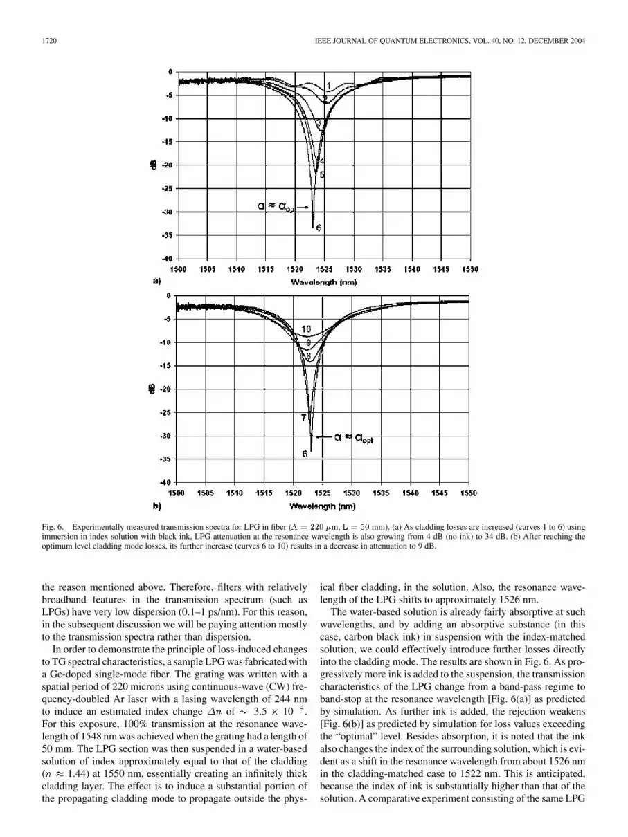
Fig. 6. Experimentally measured transmission spectra for LPG in fiber (� = 220 �m, L = 50 mm). (a) As cladding losses are increased (curves 1 to 6) usingimmersion in index solution with black ink, LPG attenuation at the resonance wavelength is also growing from 4 dB (no ink) to 34 dB. (b) After reaching theoptimum level cladding mode losses, its further increase (curves 6 to 10) results in a decrease in attenuation to 9 dB.
the reason mentioned above. Therefore, filters with relativelybroadband features in the transmission spectrum (such asLPGs) have very low dispersion (0.1–1 ps/nm). For this reason,in the subsequent discussion we will be paying attention mostlyto the transmission spectra rather than dispersion.
In order to demonstrate the principle of loss-induced changesto TG spectral characteristics, a sample LPG was fabricated witha Ge-doped single-mode fiber. The grating was written with aspatial period of 220 microns using continuous-wave (CW) fre-quency-doubled Ar laser with a lasing wavelength of 244 nmto induce an estimated index change of 3.5 10 .For this exposure, 100% transmission at the resonance wave-length of 1548 nm was achieved when the grating had a length of50 mm. The LPG section was then suspended in a water-basedsolution of index approximately equal to that of the cladding( 1.44) at 1550 nm, essentially creating an infinitely thickcladding layer. The effect is to induce a substantial portion ofthe propagating cladding mode to propagate outside the phys-
ical fiber cladding, in the solution. Also, the resonance wave-length of the LPG shifts to approximately 1526 nm.
The water-based solution is already fairly absorptive at suchwavelengths, and by adding an absorptive substance (in thiscase, carbon black ink) in suspension with the index-matchedsolution, we could effectively introduce further losses directlyinto the cladding mode. The results are shown in Fig. 6. As pro-gressively more ink is added to the suspension, the transmissioncharacteristics of the LPG change from a band-pass regime toband-stop at the resonance wavelength [Fig. 6(a)] as predictedby simulation. As further ink is added, the rejection weakens[Fig. 6(b)] as predicted by simulation for loss values exceedingthe “optimal” level. Besides absorption, it is noted that the inkalso changes the index of the surrounding solution, which is evi-dent as a shift in the resonance wavelength from about 1526 nmin the cladding-matched case to 1522 nm. This is anticipated,because the index of ink is substantially higher than that of thesolution. A comparative experiment consisting of the same LPG

KULISHOV et al.: TUNABLE WAVEGUIDE TRANSMISSION GRATINGS BASED ON ACTIVE GAIN CONTROL 1721
Fig. 7. Transmission spectra of the filter with �L = �, L = 50 mm;� = 62:8 m ; � = 84:8 m (dotted–dashed); � = 0 (dashed);� = �6:8 m (dotted); � = �20:4 m (solid).
submersed in ordinary water showed us virtually nosuch response to ink because the cladding mode was still wellconfined to the physical cladding.
The effect of cladding mode loss on LPG spectrum was alsostudied before by Patrick et al. [6] and by Stegall and Erdogan[10]. In these works, the authors considered an LPG with ini-tially 100% coupling , which was then reduced andbroadened by including variable loss for the cladding mode withhigh-index oils applied to the cladding surface. This behavioris in good agreement with our simulations shown in Fig. 3. Incontrast with these works, here we show that, for a LPG withinitially 100% transmission , totally new behavior ispossible—LPG attenuation increases with loss by over 30 dB.In addition, a new dimension of the LPG behavior could be ex-plored by tuning loss and turning it into gain.
Fig. 7 demonstrates transmission characteristics for a uniformTG with strength . Without pumping, the total losslevel (total contribution of Er-ion absorption, material absorp-tion and scattering) is set at the optimum value of84.9 m 1555 nm or equivalently 7.4 dB/cm. This pro-vides broadband attenuation (dotted–dashed curve). The trans-parency threshold is presented by the dashed curve ,beyond which amplification takes place (dotted curve,
6.8 m or 0.6 dB/cm; and solid curve 20.4 m or1.77 dB/cm).
The gain achievable in a standard fiber with Er -dopedcore usually does not exceed 2–4 dB/m. However, higherlevels of optical amplification become feasible in erbium-phos-phate glass, where gain coefficients are on the order of2–3 dB/cm [29]. Semiconductor based GACCs with gain ex-ceeding 600 dB/cm and mode-beating lengths on the order of15–20 m [30] provide much opportunity for device design.
Fig. 8 demonstrates how the transmission evolves for a TGof fixed length (50 mm) and gain 20.4 m with
Fig. 8. Transmission spectra of the filter with the TG length L = 50mm withgain � = �20:4 m ; � = 62:8 m (solid); � = 50:3 m (dotted);� = 37:7 m (dashed); � = 25:1 m (dotted–dashed).
varying coupling coefficients. Such a device can be practicallyrealized using electro-optically (EO) induced gratings [31]. Thecoupling coefficient is changed from 62.8 m ( ,solid) to 25.1 m ( , dashed-dotted). It is inter-esting to note that practically complete attenuation at the reso-nance wavelength is achieved for this gain value at(more than 40 dB). As we explained earlier, complete powerattenuation in the core guide with can be achieved onlyat the TG strength (see Fig. 2). However, whenusing an actively pumped medium with a positive gain, com-plete mode attenuation is possible at . The shorterthe grating, the higher the gain must be in order to achieve fullpower transfer. For example, for the grating with strength
, complete transfer is achievable at , i.e.,46.7 m when 25.1 m . However, this strong at-
tenuation at the resonance wavelength is accompanied by strongamplification in the two neighboring side-lobes.
2) Transmission Grating With a -Shift: Phase shifts inTGs can drastically alter their transmission characteristics.For example, a -shift introduced in the center of a uniformloss-free LPG with changes its spectrum fromband-stop to a band-pass regime. Numerous publications onthe phase-shifted LPG properties [32] describe them with theloss-free approximation, which is a fairly good one for thegratings written in standard fiber. The situation may be verydifferent for TGs written, etched or electro-optically inducedin GACCs, especially in planar waveguides where losses aremuch higher that in standard fibers. We are not aware of anyquantitative study on phase-shifted TGs with losses (or gain)that would analyze their effect on TG performance. This anal-ysis is particularly useful for devices with electro-opticallyinduced TG where phase shift(s) can be easily introduced aswell as easily removed in any place along the grating by simplyreversing the applied voltage polarity for a portion(s) of theinterdigitated electrode fingers [33].

1722 IEEE JOURNAL OF QUANTUM ELECTRONICS, VOL. 40, NO. 12, DECEMBER 2004
The transmission characteristics of a codirectional couplerwith a -shift that divides the grating into two parts with thelengths and can be described by the ma-trix product: , where is thephase-shift matrix
(9)
Using our matrix approach it is straightforward to get an expres-sion for the signal amplitude in the undoped (core) and doped(clad) guides for the phase-shifted TG
(10)
(11)
where is the distance of the phase shift lo-cation from the TG center. For a half wavelength phase shift
(10) and (11) are transformed into the following ex-pressions
(12)
(13)
When there is no shift in the loss-free TG , thetransmittivity is minimum at the resonance wavelength for thelow grating strength values . The minimumreaches zero when the TG strength is equal to . Whena phase shift of is introduced at the center of the TG, i.e.,
, the minimum becomes a maximum with 100% trans-mission ( , ) for an arbitrary value, and two rejec-tion bands appear (dotted curve in Fig. 9). The TG strength hasto be increased to to achieve complete attenuationin these rejection bands. The losses in the doped guide reducetransmission at the resonance wavelength and increase transmis-sion in the rejection band (solid and dashed curves in Fig. 9). Onthe contrary, gain in the doped guide produces a narrow-bandamplification at the resonance wavelength, simultaneously in-creasing attenuation in the rejection bands ( 15.5 dB attenua-tion for the dotted–dashed curve in Fig. 9). Comparing the am-plifying spectra in Fig. 7 (solid) and Fig. 9 (dotted–dashed), onecan say that -shift introduction leads to narrowing the ampli-fying bandwidth with higher attenuation at the extremes.
For the situation of loss/gain in the doped guide, mis-match factor takes on a nonzero, purely imaginary value,
, which causes the normalized signal power inthe undoped guide at the resonance wavelength to obey the
Fig. 9. Transmission spectra of the filter with �-shift in the middle of TG with�L = �=2, L = 50 mm; � = 31:4 m ; � = 40:7 m (solid); � =
10:2 m (dashed); � = 0 (dotted); � = �20:4m (dotted–dashed).
Fig. 10. Transmission at the resonance wavelength as a function of the relative�-shift distance from the TG center for the grating with�L = �=2 and differentvalue of the gain/loss factor:� = 0:6� (solid);� = 0 (dotted);� = �0:2�(dashed); � = �0:4� (dotted–dashed).
following expression (in dimensionless variablesand )
(14)
The transmission at resonance is therefore a function of the-shift distance from the grating center , as it is shown
in Fig. 10. When , it means that -shift is at the veryend and the result is a uniform grating. The plot demonstratesthat by moving the -shift position from the center it is pos-sible to gradually reduce amplification at the resonance wave-length and reach a position with zero transmission. An exampleof the spectrum control through the -shift position is shownin Fig. 11, where transmission at the resonance wavelength is

KULISHOV et al.: TUNABLE WAVEGUIDE TRANSMISSION GRATINGS BASED ON ACTIVE GAIN CONTROL 1723
Fig. 11. Transmission spectra of the filter with the �-shifted TG for L =
50mm;� = �20:4m ; � = 31:4m for different distances of the �-shiftfrom the TG center: �=L = 0 (solid); �=L = 0:2 (dotted); �=L = 0:3(dashed); �=L = 0:42 (dotted–dashed).
gradually tuned from 2.1 dB of amplification to 30 dB ofattenuation.
B. Spectrally Nonuniform Gain/Loss
The assumption of a uniform gain spectrum works well fornarrow-band Bragg gratings, however, in the case of TGs withgenerally much broader transmission spectrum, gain, as well asloss, may have a significant dependence on wavelength. The re-lationship between the real and imaginary parts of a mediumscomplex ionic susceptibility associated with a resonant absorp-tion transition is governed by the well-known Kramers-Kronigequations. For a medium with refractive index into which adopant with susceptibility is introduced, the refrac-tive index and absorption coefficient are given by
(15)
where is the speed of light in vacuum. Spectral distribution ofthe ionic susceptibility of erbium-doped fiber can be presentedas and can be approximated by complex Lorenz functions[34].
We calculated the gain/loss coefficient spectra from linearcombinations of the gain and absorption data in the followingratios: 0:100, 20:80, and 100:0 (i.e., unpumped, partial inver-sion and full inversion). The maximum loss/gain at 1532-nmpeak was 2 dB/cm. The calculated variation of the refractiveindex turned out to be . The variation of therefractive index would be significant for the TG spectrum, if
, where is the characteristic wavelength scale ofthe TG spectral features and its period. For typical values of
2 nm and 220 m, we get maximum allowed indexchange 10 , which is much larger than the variation of therefractive index due to erbium absorption or gain. Therefore, theonly effect of the gain spectral nonuniformity on the TG spec-trum would be due to amplifying or attenuating specific wave-lengths depending on the values of the material absorption andgain. Equations (1)–(14) will be still valid, but with the constantgain/loss parameter replaced by .
C. Spatially Nonuniform Gain/Loss
Finally, we consider how transmission would be affected byspatial nonuniformity of the gain/loss. The gain/loss is spatiallyuniform only for the two extreme situations: unpumped, andstrongly pumped to 100% inversion all along the TG. For theintermediate states, the pump light intensity is reduced alongthe TG, due to absorption, creating a gain/loss nonuniformity.We estimated the effect of this nonuniformity by integrating (1)and found no substantial spectrum distortions as the inversionincreased. Unlike the case of spectral gain/loss nonuniformity,where it affects particular spectral components of the transmis-sion spectrum, the spatial nonuniformity has the effect of beingintegrated: it is important only how much gain/loss is accumu-lated over the grating length.
VI. CONCLUSION
The lossy nature of cladding layers in waveguide structuresand specially designed fibers plays a very important role in thespectral behavior of a transmission grating, such as LPG. Anunderstanding of how these loss or gain in waveguide modesaffects the grating spectral characteristics enables improvedgrating design and invites much potential for dynamicallycontrolled filtering characteristics. We have demonstrated thatcertain levels of losses in the cladding modes lead to distinctbehavior of LPGs as band rejection filters and sensing elements.By keeping the proper loss-to-coupling or gain-to-couplingratio, virtually complete attenuation of the core mode can beachieved at the resonance wavelength for any value of thegrating strength . This is impossible for traditional, loss-freeor low-loss LPGs, in which complete energy transfer to thecladding is only achieved at fixed values of the grating strength
. In contrast to loss-free uniform LPGs,those featuring optimized loss levels provide transmissionspectrum with slightly wider bandwidth of side-lobe-free tails.Once the optimum level of losses for 100% attenuation is setfor the chosen value of the grating strength, the LPG preservesa Gaussian-like, side-lobe free transmission spectrum for anyvalue of the LPG length and the coupling coefficient.
We also demonstrated that the attenuation/amplification levelcan be controlled by introducing -shift along the grating. Thistype of control can be combined with the pump control in planarwaveguides based on rare-earth-doped electro-optic polymers.Not only -shift position, but also the length and the couplingcoefficient of the grating could be controlled in these types ofdevices. It was also demonstrated that wavelength dependenceof the gain in Er-doped fibers factor does not lead to severespectrum distortions in the case of erbium-doped waveguides.
REFERENCES
[1] J. J. Pan, K. Guan, X. Qiu, W. Wang, M. Zhang, J. Jiang, E. Zhang, andF. Q. Zhou, “Advantages of low-cost, miniature, intelligent EDFAs fornext-generation dynamic metro/access networks,” Opt. Fiber Technol.,vol. 9, pp. 80–94, 2003.
[2] Z. Wang, T. Durhuus, B. Mikkeleson, and K. E. Stubkjaer, “Distributedfeedback laser amplifiers combining the functions of amplifiers andchannel filters,” Appl. Phys. Lett., vol. 64, pp. 2065–2067, 1994.

1724 IEEE JOURNAL OF QUANTUM ELECTRONICS, VOL. 40, NO. 12, DECEMBER 2004
[3] T. Erdogan, “Fiber grating spectra,” J. Lightwave Technol., vol. 15, pp.1277–1294, July 1997.
[4] A. M. Vengsarkar, P. J. Lemaire, J. B. Judkins, V. Bhatia, T. Erdogan,and J. E. Sipe, “Long-period fiber gratings as band-rejection filters,” J.Lightwave Technol., vol. 14, pp. 58–65, Jan. 1996.
[5] V. Grubsky, D. S. Starodubov, and J. Feinberg, “Wavelength-selectivecoupler and add-drop multiplexer using long-period fiber gratings,” inProc. OFC , 2000, pp. 28–30.
[6] H. J. Patrick, A. D. Kersey, and F. Bucholtz, “Analysis of the responseof long-period gratings to external index of refraction,” J. LightwaveTechnol., vol. 16, pp. 1606–1612, Sept. 1998.
[7] Q. Li, A. A. Au, C.-H. Lin, E. R. Lyons, and H. P. Lee, “An efficient all-fiber variable optical attenuator via acoustooptic mode coupling,” IEEEPhoton. Technol. Lett., vol. 14, pp. 1563–1565, Nov. 2002.
[8] S. Ramachandran, M. F. Yan, E. Monberg, F. V. Dimarcello, P. Wisk, andS. Ghalmi, “Record bandwidth, spectrally flat coupling with microbendgratings in dispersion-tailored fibers,” IEEE Photon. Technol. Lett., vol.15, pp. 1561–1563, Nov. 2003.
[9] X. Shu, L. Zhang, and I. Bennion, “Sensitivity characteristics of long-period fiber gratings,” J. Lightwave Technol., vol. 20, pp. 255–266, Feb.2002.
[10] D. B. Stegall and T. Erdogan, “Leaky cladding mode propagation inlong-period fiber gratings devices,” IEEE Photon. Technol. Lett., vol.11, pp. 343–345, Mar. 1999.
[11] X. Daxhelet and M. Kulishov, “Theory and practice of long-period grat-ings: when a loss becomes a gain,” Opt. Lett., vol. 28, pp. 686–688, 2003.
[12] D. An, Z. Yue, and R. T. Chen, “Dual-functional polymeric waveguidewith optical amplification and electro-optic modulation,” Appl. Phys.Lett., vol. 72, pp. 2806–2808, 1998.
[13] I. Baumann, S. Bosso, R. Brinkmann, R. Corsini, M. Dinand, A. Greiner,K. Schäfer, J. Söchtig, W. Sohler, H. Suche, and R. Wessel, “Er-dopedintegrated optical devices in LiNbO3,” IEEE J. Select. Topics QuantumElectron., vol. 2, pp. 355–366, June 1996.
[14] H. Ma, A. K.-Y. Jen, and L. R. Dalton, “Polymer-based optical waveg-uides: materials, processing and devices,” Adv. Mater., vol. 14, pp.1339–1365, 2002.
[15] G. Karve, B. Bihari, and R. T. Chen, “Demonstration of optical gainat 1.06 �m in a neodymium-doped polyimide waveguide,” Appl. Phys.Lett., vol. 77, pp. 1253–1255, 2000.
[16] G. G. Karapetyan, A. V. Daryan, D. M. Meghavoryan, and N. E.Gevoryan, “Theoretical investigation of active fiber Bragg grating,”Opt. Commun., vol. 205, pp. 421–425, 2002.
[17] V. E. Kochergin and E. V. Kochergin, “Optical tunneling through fiberBragg grating with gain,” Opt. Commun., vol. 211, pp. 121–128, 2002.
[18] H. V. Baghdasaryan and T. M. Knyazyan, “Simulation of amplifyingphase-shifted fiber Bragg gratings by the method of single expression,”Opt. Quantum Electron., vol. 35, pp. 493–506, 2003.
[19] V. Rastogi, “Long-period gratings in planar optical waveguides,” Appl.Opt., vol. 41, pp. 6351–6355, 2002.
[20] Y. B. Lu and P. L. Chu, “Gain flattening by using dual-core fiber in Er-bium-doped fiber amplifier,” IEEE Photon. Technol. Lett., vol. 12, pp.1616–1618, Dec. 2000.
[21] K. Thyagarajan and J. K. Anad, “A novel design of an intrinsically gain-flattened erbium doped fiber,” Opt. Commun., vol. 183, pp. 407–413,2000.
[22] S. Woods, “Specialty-fiber innovations benefit fiber lasers,” Laser FocusWorld, pp. 85–88, June 2003.
[23] L. J. A. Nilsson, D. C. Hanna, J. D. Minelly, and R. E. Paschotta, “Op-tical Amplifier and Light Source,” U.S. Patent 6 445 494, Sept. 3, 2002.
[24] J. P. Koplow, S. W. Moore, and D. A. V. Kliner, “A new method for sidepumping of double-cladd fiber sources,” IEEE J. Quantum. Electron.,vol. 39, pp. 529–540, Apr. 2003.
[25] A. W. Snyder and J. D. Love, Optical Waveguide Theory. London,U.K.: Chapman and Hall, 1983.
[26] R. R. A. Syms, S. Makrimichalou, and A. S. Holms, “High-speed opticalsignal processing potential of grating-coupled waveguide filters,” Appl.Optics, vol. 30, pp. 3762–3769, 1991.
[27] G. Lenz, B. J. Eggleton, C. R. Giles, C. K. Madsen, and R. E. Slusher,“Dispersive properties of optical filters for WDM systems,” IEEE J.Quantum Electron., vol. 34, pp. 1390–1401, Aug. 1998.
[28] D. S. Starodubov, V. Grubsky, and J. Feinberg, “All-fiber bandpass filterwith adjustable transmission using cladding-mode coupling,” IEEEPhoton. Technol. Lett., vol. 10, pp. 1590–1592, Nov. 1998.
[29] B. C. Hwang, S. Jiang, T. Luo, K. Seneschal, G. Sorbello, M. Morrell,F. Smektala, S. Honkanen, J. Lukas, and N. Peyghambarian, “Perfor-mance of high-concentration Er -doped phosphate fiber amplifiers,”IEEE Photon. Technol. Lett., vol. 13, pp. 197–199, Mar. 2001.
[30] Y.-H. Jan, M. E. Heimbuch, L. A. Coldren, and S. P. DenBaars,“InP/GaAsP grating-assisted codirectional coupler tunable receiverwith a 30 nm wavelength tuning range,” Electron. Lett., vol. 32, pp.1697–1699, 1996.
[31] M. Kulishov, X. Daxhelet, M. Mounir, and M. Chaker, “Electronicallyreconfigurable superimposed waveguide long-period gratings,” J. Opt.Soc. Amer. A, vol. 19, pp. 1632–1648, 2002.
[32] H. Ke, K. S. Chiang, and J. H. Peng, “Analysis of phase-shifted long-pe-riod fiber gratings,” IEEE Photon. Technol. Lett., vol. 10, pp. 1596–1598,Nov. 1998.
[33] M. Kulishov and X. Daxhelet, “Reconfigurable �-shifted and Mach-Zehnder bandpass filters on the basis of electro optically induced long-period gratings in a planar waveguide,” J. Lightwave Technol., vol. 21,pp. 854–861, Mar. 2003.
[34] F. Matera, M. Romagnoli, M. Settembre, and M. Tamburrini, “Evalua-tion of chromatic dispersion in erbium doped fiber amplifiers,” Electron.Lett., vol. 27, pp. 1687–1689, 1991.
Mykola Kulishov received the M.S. degree in radiophysics from Kyiv StateUniversity, Kyiv, Ukraine, in 1978, and the Ph.D. degree in optoelectronics fromthe Institute of Cybernetics, Ukrainian Academy of Sciences, Kyiv, in 1993.
He is currently with Adtek Photomask Inc., Montreal, QC, Canada. His re-search interests include tuneable fiber-optic components, optical waveguides,integrated optics, and reconfigurable optical filters.
Victor Grubsky received the M.S. degree in physics from the Moscow Instituteof Physics and Technology, Russia, in 1995, and the Ph.D. degree in physicsfrom the University of Southern California, Los Angeles, in 1999.
He was a member of the founding team of Sabeus Photonics, where he workedfrom 1998 to 2004 as a Vice-President of Research and Development. He wasinvolved in the development of fiber-optic components for telecom and sensorapplications. He was the inventor of the precise passive filter technology basedon long-period fiber gratings, and a co-inventor of the award-winning tech-nology for noninvasive manufacturing of Bragg gratings with near-UV light.Currently, he is with the University of Southern California. His research in-terests are related to optical waveguide properties, such as nonlinear effects infibers, mode-converting devices, waveguide gratings, and fiber lasers.
Joshua Schwartz (S’00) received the B.S. (Hons.) degree from McGill Univer-sity, Montreal, QC, Canada, where he is currently pursuing the Ph.D. degree.
He is working under the supervision of David Plant, gaining experience withlong period gratings and waveguide characterization. He has also recently pub-lished his undergraduate research on chip-to-chip free-space optical links.
Xavier Daxhelet was born in Mouscron, Belgium, in 1964. He received the B.S.degree in mathematic physics from the University of Montreal, Montreal, QC,Canada, in 1987, and the Ph.D. degree in engineering physics from the EcolePolytechnique de Montreal, Montreal, QC, Canada, in 1990.
He is currently a Research Fellow with the Ecole Polytechnique de Montreal.His main interests are all-fiber components such as fused couplers, Bragg grat-ings, and tapered fibers.
David V. Plant (S’86–M’89) received the Ph.D. degree in electrical engineeringfrom Brown University, Providence, RI, in 1989.
From 1989 to 1993, he was a Research Engineer in the Department of Elec-trical and Computer Engineering, University of Southern California, Los An-geles. In 1993, he joined the Department of Electrical and Computer Engi-neering, McGill University, Montreal, QC, Canada, as an Assistant Professor,was promoted to Associate Professor 1997 and to Professor in 2004. During the2000–2001 academic year, he went on leave from McGill to become the Di-rector of Optical Integration at Accelight Networks, Pittsburgh, PA. He is thePrinciple Investigator (PI) and Scientific Director of the NSERC funded AgileAll-Photonic Networks (AAPN) research program, and the PI and Center Di-rector of the Quebec-funded Center for Advanced Systems and Technologies inCommunications.
Dr. Plant has received numerous awards, most recently the Carrie M. DerickAward for Graduate Student Supervision, Teaching, and Research in 2004 andwas named a James McGill Professor in 2001.


