Embed Size (px)
Citation preview
This article appeared in a journal published by Elsevier. The attachedcopy is furnished to the author for internal non-commercial researchand education use, including for instruction at the authors institution
and sharing with colleagues.
Other uses, including reproduction and distribution, or selling orlicensing copies, or posting to personal, institutional or third party
websites are prohibited.
In most cases authors are permitted to post their version of thearticle (e.g. in Word or Tex form) to their personal website orinstitutional repository. Authors requiring further information
regarding Elsevier’s archiving and manuscript policies areencouraged to visit:
http://www.elsevier.com/authorsrights
Author's personal copy
Tribological behavior of three-dimensional needled carbon/siliconcarbide and carbon/carbon brake pair
Xingya Xu, Shangwu Fan n, Litong Zhang, Yong Du, Laifei ChengScience and Technology on Thermostructural Composite Materials Laboratory, Northwestern Polytechnical University, Xi’an 710072, Shaanxi, China
a r t i c l e i n f o
Article history:Received 13 January 2014Received in revised form20 March 2014Accepted 9 April 2014Available online 18 April 2014
Keywords:Tribological behaviorBrake pairCarbon/carbon compositesCarbon/silicon carbide composites
a b s t r a c t
Tribological properties of C/SiC–C/C pair have been systematically investigated in dry, fresh water, seawater and static conditions. The static coefficient of friction (COF) has a great increase compared withC/C–C/C. Also, C/SiC–C/C is less susceptible to fresh water and sea water. The friction mechanism isa synergism of plough effect and surface molecular interactions. Plough effect ensures better frictionproperties than C/C–C/C. For C/SiC–C/C, C/SiC disk is almost not worn, allowing C/SiC disk for brakeassembly to be thinner. With same size and amount of disks, brake assembly using C/SiC–C/C pair can bemuch lighter than that using C/SiC–C/SiC pair. In conclusion, C/SiC–C/C pair can well meet therequirements of high performance and light weight of aircraft brake applications.
& 2014 Elsevier Ltd. All rights reserved.
1. Introduction
Recently, high speed and heavy load are the trend for aircrafts. Foraircraft brakes, the rubbing surfaces are required to convert kineticenergy to heat of about 4500 J cm�2 per unit area in about halfminute, making the temperatures of the surfaces really high [1].Consequently, the brake materials for aircrafts must meet severalrequirements, such as high specific heat, excellent thermo-mechanicalproperties, high fusing point, high friction coefficients, excellent wearproperties and so on [2].Meanwhile, the brake materials must fit inwith different service conditions such as wetness and salt fog.
C/C composites have high strength and specific modulus, highthermal conductivity, high heat capacity, low thermal expansioncoefficient, good wear property, low density and self-lubricatingcapability [3,4]. Therefore, C/C composites have been used as brakematerials for both military and commercial aircrafts since the1960s [1]. However, C/C brakes suffer from poor oxidation resis-tance and instability of friction coefficient caused by humidity[5–8]. It is reported that the COF of C/C brakes is low in moistcondition. C/C brakes perform poor in the morning, after putovernight, staying in a wet area [7]. Also, C/C brakes showextremely low COF in the marine environment. In addition, thestatic COF is relatively low. These disadvantages must be overcomefor better application of C/C aircraft brakes.
Recently, C/SiC composites have been developed as a promisinghigh performance brake materials for aircraft. C/SiC composites
have excellent properties, such as good resistance to high tem-perature, high strength, great thermal properties, stable frictionalproperty, low wear rate and long life [9,10]. Compared with C/C,C/SiC composites have good resistance to oxidation, high staticCOF and low sensibility to surroundings such as humidity. There-fore, C/SiC composite is a potential new generation of brakematerials for aircraft. [11–15]. However, C/SiC composites showa higher density than C/C composites. The brake assembly usingC/SiC brakes is heavier than that using C/C brakes with otherconditions being equal, which restricts the application of C/SiCbrakes on some weight-sensitive aircrafts.
To overcome the disadvantages of C/C and/or C/SiC brakes, themethod of matrix modification is taken [4,16–19]. However, thismethod requires plenty of experiments as well as time. Also, thepublished articles refer to self-mated pairs, i.e. with the samematerialsfor both brakes [4,16–19]. In this paper, the idea of using C/SiC–C/Cbrake pair for brake assembly was proposed. C/SiC–C/C pair wassystematically tested in dry, fresh water, sea water and static condi-tions. The friction mechanism has been discussed. Also, the resultshave been compared with that of C/C and C/SiC self-mated pair, tryingto figure out whether C/SiC–C/C pair can well meet the requirementsof high performance and light weight for aircraft brakes.
2. Experiments
2.1. Materials
The C/SiC composite used was fabricated by threemain procedures.Firstly, the three-dimensional fiber preform was prepared by needling
Contents lists available at ScienceDirect
journal homepage: www.elsevier.com/locate/triboint
Tribology International
http://dx.doi.org/10.1016/j.triboint.2014.04.0080301-679X/& 2014 Elsevier Ltd. All rights reserved.
n Corresponding author. Tel.: þ86 29 8849 4622; fax: þ86 29 8849 4620.E-mail addresses: [email protected], [email protected] (S. Fan).
Tribology International 77 (2014) 7–14
Author's personal copy
method. It was fabricated by repeatedly overlapping the layers of 01non-woven fiber cloth, short-cut fiber web, and 901 non-woven fibercloth with needle-punching step by step. Then chemical vaporinfiltration (CVI) was used to deposit pyrolytic carbon. At last, theporous carbon/carbon composite was infiltrated with melt silicon,which has been reported in detail before [20]. Similarly, the C/Ccomposite was made by two major steps. At first, the 3D-needledpreforms were fabricated. And then, CVI process was employed tomake the final C/C composites. The precursor used was propylenegas. The densities of the C/SiC and C/C composites are 2.0 g/cm3 and1.7 g/cm3, respectively.
2.2. Braking tests
The braking tests were conducted on a disk-on-disk laboratoryscale dynamometer (MM-1000). The tests were carried out withone rotating brake disk of Ø76 mm�Ø52 mm�10 mm (76 mm inouter diameter, 52 mm in inner diameter and 10 mm in thickness),pressed against one stationary disk of Ø90 mm�Ø55 mm�10 mm. Brake pairs tested in this study are C/SiC self-mated pair,C/C self-mated pair and C/SiC–C/C pair with C/SiC serving as therotor disk and C/C as the stator disk.
2.2.1. Tests in dry conditionThe moment of inertia, rotating speed and brake pressure were
0.235 kg m2, 8000 r/min (28 m/s) and 0.7 MPa, respectively. Dur-ing braking tests, parameters such as braking time t (s),brakingtorque Mcp (N m), coefficient of friction μ, temperature T (1C) androtating speed n (r/min) were recorded automatically.
The wear performance was evaluated with linear wear. Thelinear wear rate was calculated with the thickness difference ofthe disk before and after braking tests divided by braking times.
2.2.2. Tests in wet conditionBraking test in wet condition was conducted after the samples
were soaked in water, either in fresh water or sea water, for 5 min.The moment of inertia, rotating speed and brake pressure were thesame as tests in dry condition. The decay rate of COF in wetcondition (D) was determined by the following equation.
D ð%Þ ¼ ð1�μwet=μdryÞ � 100 ð1Þ
where μwet is the average COF in wet condition and μdry in drycondition. After tests in wet conditions, more braking tests wereconducted until the performances recover to that in dry condition,which were called recovery tests.
2.2.3. Static friction coefficient testsIn the test, brake pressure of 0.9 MPawas exerted to the pairs at
first. Then, the operator rotated the spindle of the machine slowlyby hand until the brakes began to slide relatively. During theprocess from still to slid, the friction coefficient was recorded, andthe maximum was the static friction coefficient.
2.3. Friction surface and debris analysis
The friction surfaces were observed by digital camera (PanasonicDMC-FS5) for macroscopic observation and true-color confocalmicroscope (Lasertec C130) for microscopic observation. The mor-phology and elements of debris were examined by scanning electronmicroscope/energy dispersive X-ray spectroscopy (SEM-EDS, Hitachi
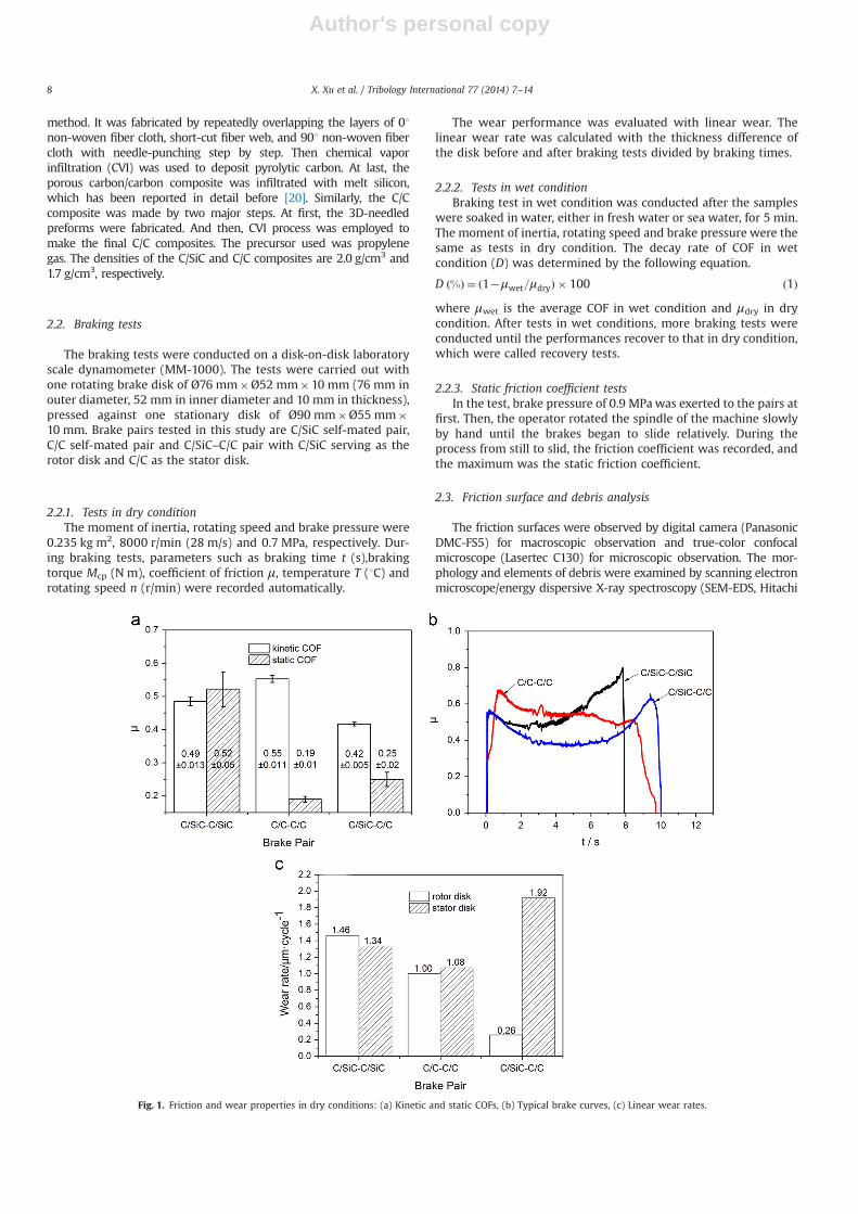
Fig. 1. Friction and wear properties in dry conditions: (a) Kinetic and static COFs, (b) Typical brake curves, (c) Linear wear rates.
X. Xu et al. / Tribology International 77 (2014) 7–148
Author's personal copy
S-4200, Japan). The X-ray photoelectron spectroscopy (XPS, K-Alpha)was used for bonding analysis of debris.
3. Results and discussions
3.1. Friction and wear properties in dry conditions
Fig. 1 shows COFs, brake curves and wear rates of different pairs indry conditions. The dynamic COF of C/SiC–C/C pair is a little lower butmore stable than that of C/SiC and C/C self-mated pairs. Static COF ofC/SiC–C/C pair is 32% higher than that of C/C–C/C pair, which canreduce the taxiing distance of aircrafts before takeoff [21]. The brake
curve of C/SiC–C/SiC pair is in shape of horse saddle with a pre-up andtail-up. As to C/C self-mated pair, the COF decreases rapidly at the endof braking stage. The curve of C/SiC–C/C pair is also in the shape ofhorse saddle. High COF in the end helps shorten the braking time and/or braking distance.
The linear wear rates are demonstrated in Fig. 1(c). The wearrate of C/SiC–C/C pair (2.18 μm cycle�1) is lower than C/SiC–C/SiC(2.80 μm cycle�1) and almost the same as C/C–C/C (2.08 μm cycle�1).However, the wear rate of the stator disk (C/C disk) accounts for about90% of all the wear, while C/SiC disk is almost not worn. Consideringthat, the C/C disk must be designed thicker than disks as usual and theC/SiC disk can be thinner during structure design for brake assembly.With thicker C/C disks and thinner C/SiC disks, the brake assembly
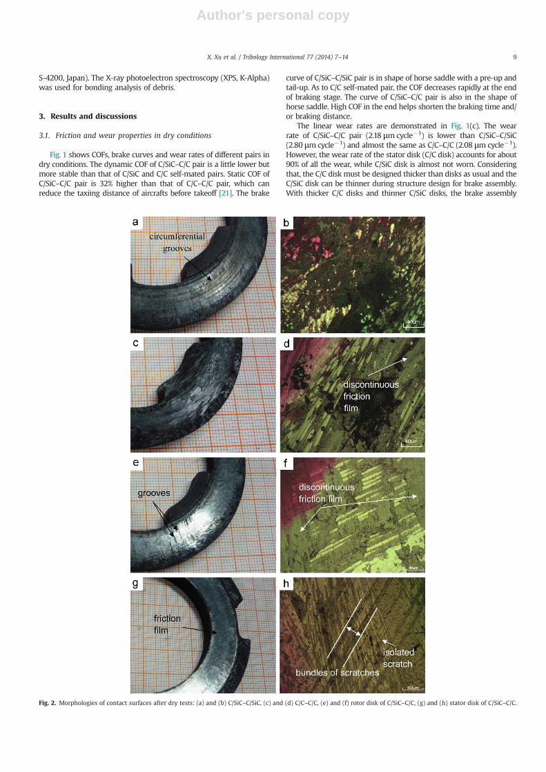
Fig. 2. Morphologies of contact surfaces after dry tests: (a) and (b) C/SiC–C/SiC, (c) and (d) C/C–C/C, (e) and (f) rotor disk of C/SiC–C/C, (g) and (h) stator disk of C/SiC–C/C.
X. Xu et al. / Tribology International 77 (2014) 7–14 9
Author's personal copy
using C/SiC–C/C pair can be much lighter than typical brake assemblyusing C/SiC disks, with other conditions being equal. Also, the newkind of brake assembly is less likely to suffer from high surfacetemperature of disks thanks to the high heat capacity of C/Ccomposites [3].
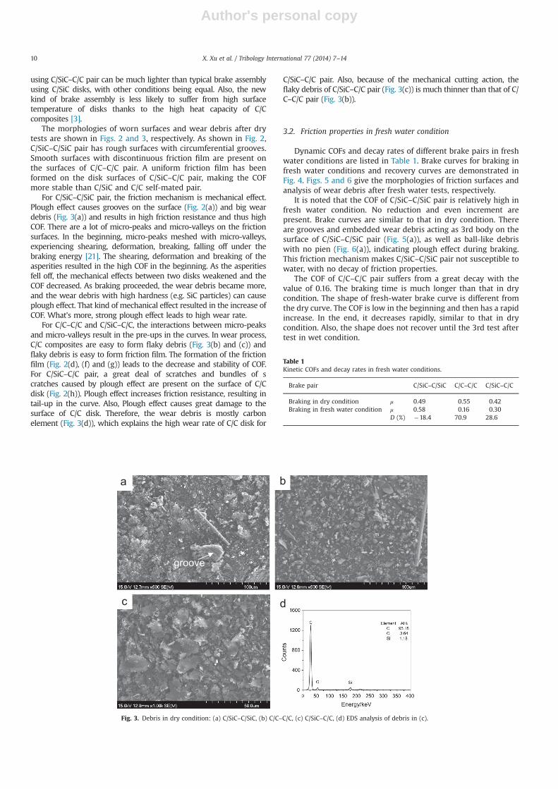
The morphologies of worn surfaces and wear debris after drytests are shown in Figs. 2 and 3, respectively. As shown in Fig. 2,C/SiC–C/SiC pair has rough surfaces with circumferential grooves.Smooth surfaces with discontinuous friction film are present onthe surfaces of C/C–C/C pair. A uniform friction film has beenformed on the disk surfaces of C/SiC–C/C pair, making the COFmore stable than C/SiC and C/C self-mated pair.
For C/SiC–C/SiC pair, the friction mechanism is mechanical effect.Plough effect causes grooves on the surface (Fig. 2(a)) and big weardebris (Fig. 3(a)) and results in high friction resistance and thus highCOF. There are a lot of micro-peaks and micro-valleys on the frictionsurfaces. In the beginning, micro-peaks meshed with micro-valleys,experiencing shearing, deformation, breaking, falling off under thebraking energy [21]. The shearing, deformation and breaking of theasperities resulted in the high COF in the beginning. As the asperitiesfell off, the mechanical effects between two disks weakened and theCOF decreased. As braking proceeded, the wear debris became more,and the wear debris with high hardness (e.g. SiC particles) can causeplough effect. That kind of mechanical effect resulted in the increase ofCOF. What's more, strong plough effect leads to high wear rate.
For C/C–C/C and C/SiC–C/C, the interactions between micro-peaksand micro-valleys result in the pre-ups in the curves. In wear process,C/C composites are easy to form flaky debris (Fig. 3(b) and (c)) andflaky debris is easy to form friction film. The formation of the frictionfilm (Fig. 2(d), (f) and (g)) leads to the decrease and stability of COF.For C/SiC–C/C pair, a great deal of scratches and bundles of scratches caused by plough effect are present on the surface of C/Cdisk (Fig. 2(h)). Plough effect increases friction resistance, resulting intail-up in the curve. Also, Plough effect causes great damage to thesurface of C/C disk. Therefore, the wear debris is mostly carbonelement (Fig. 3(d)), which explains the high wear rate of C/C disk for
C/SiC–C/C pair. Also, because of the mechanical cutting action, theflaky debris of C/SiC–C/C pair (Fig. 3(c)) is much thinner than that of C/C–C/C pair (Fig. 3(b)).
3.2. Friction properties in fresh water condition
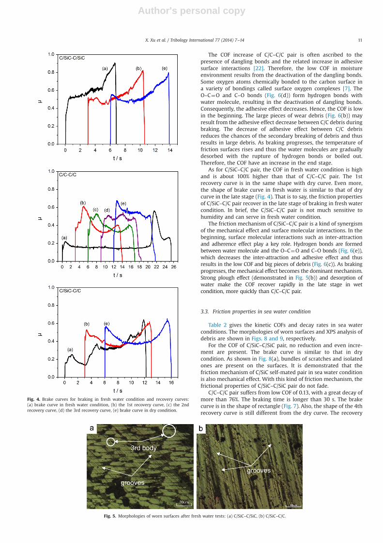
Dynamic COFs and decay rates of different brake pairs in freshwater conditions are listed in Table 1. Brake curves for braking infresh water conditions and recovery curves are demonstrated inFig. 4. Figs. 5 and 6 give the morphologies of friction surfaces andanalysis of wear debris after fresh water tests, respectively.
It is noted that the COF of C/SiC–C/SiC pair is relatively high infresh water condition. No reduction and even increment arepresent. Brake curves are similar to that in dry condition. Thereare grooves and embedded wear debris acting as 3rd body on thesurface of C/SiC–C/SiC pair (Fig. 5(a)), as well as ball-like debriswith no pien (Fig. 6(a)), indicating plough effect during braking.This friction mechanism makes C/SiC–C/SiC pair not susceptible towater, with no decay of friction properties.
The COF of C/C–C/C pair suffers from a great decay with thevalue of 0.16. The braking time is much longer than that in drycondition. The shape of fresh-water brake curve is different fromthe dry curve. The COF is low in the beginning and then has a rapidincrease. In the end, it decreases rapidly, similar to that in drycondition. Also, the shape does not recover until the 3rd test aftertest in wet condition.
Fig. 3. Debris in dry condition: (a) C/SiC–C/SiC, (b) C/C–C/C, (c) C/SiC–C/C, (d) EDS analysis of debris in (c).
Table 1Kinetic COFs and decay rates in fresh water conditions.
Brake pair C/SiC–C/SiC C/C–C/C C/SiC–C/C
Braking in dry condition μ 0.49 0.55 0.42Braking in fresh water condition μ 0.58 0.16 0.30
D (%) �18.4 70.9 28.6
X. Xu et al. / Tribology International 77 (2014) 7–1410
Author's personal copy
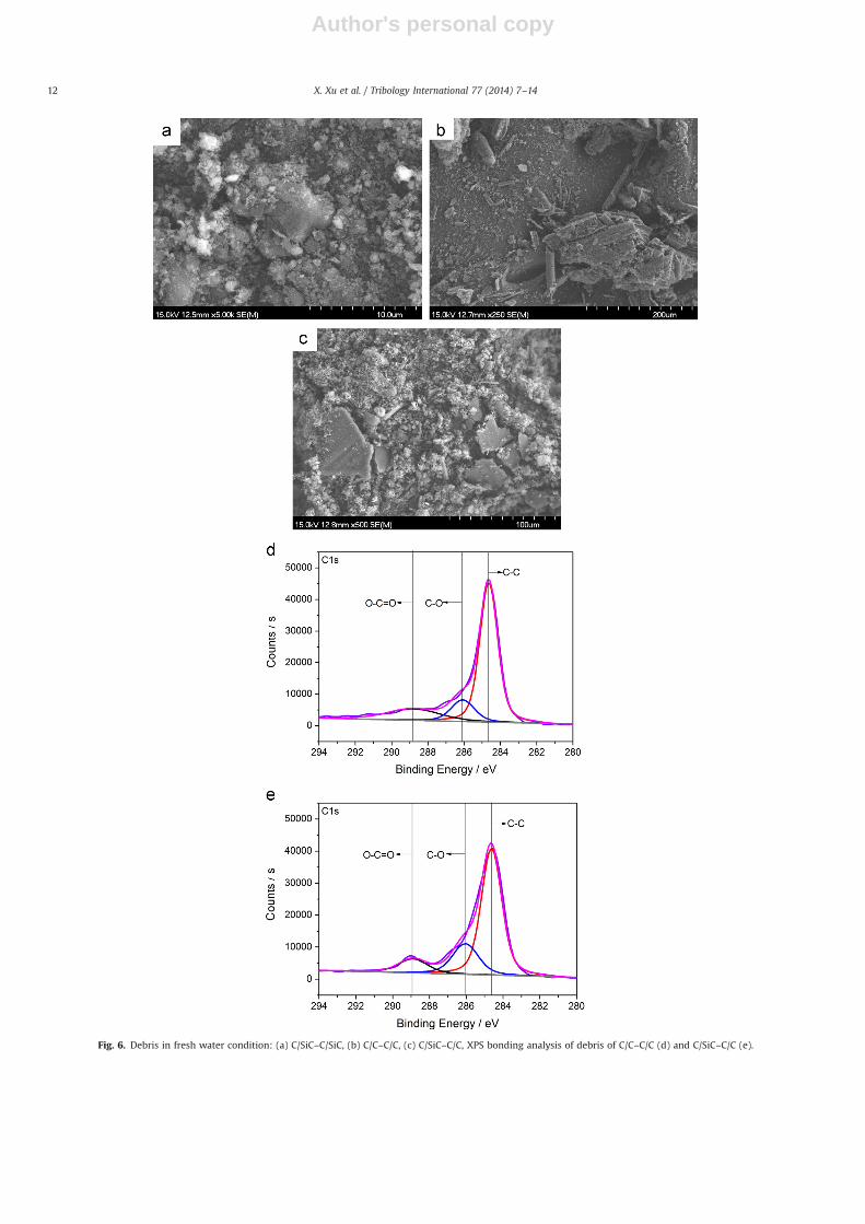
The COF increase of C/C–C/C pair is often ascribed to thepresence of dangling bonds and the related increase in adhesivesurface interactions [22]. Therefore, the low COF in moistureenvironment results from the deactivation of the dangling bonds.Some oxygen atoms chemically bonded to the carbon surface ina variety of bondings called surface oxygen complexes [7]. TheO–C¼O and C–O bonds (Fig. 6(d)) form hydrogen bonds withwater molecule, resulting in the deactivation of dangling bonds.Consequently, the adhesive effect decreases. Hence, the COF is lowin the beginning. The large pieces of wear debris (Fig. 6(b)) mayresult from the adhesive effect decrease between C/C debris duringbraking. The decrease of adhesive effect between C/C debrisreduces the chances of the secondary breaking of debris and thusresults in large debris. As braking progresses, the temperature offriction surfaces rises and thus the water molecules are graduallydesorbed with the rupture of hydrogen bonds or boiled out.Therefore, the COF have an increase in the end stage.
As for C/SiC–C/C pair, the COF in fresh water condition is highand is about 100% higher than that of C/C–C/C pair. The 1strecovery curve is in the same shape with dry curve. Even more,the shape of brake curve in fresh water is similar to that of drycurve in the late stage (Fig. 4). That is to say, the friction propertiesof C/SiC–C/C pair recover in the late stage of braking in fresh watercondition. In brief, the C/SiC–C/C pair is not much sensitive tohumidity and can serve in fresh water condition.
The friction mechanism of C/SiC–C/C pair is a kind of synergismof the mechanical effect and surface molecular interactions. In thebeginning, surface molecular interactions such as inter-attractionand adherence effect play a key role. Hydrogen bonds are formedbetween water molecule and the O–C¼O and C–O bonds (Fig. 6(e)),which decreases the inter-attraction and adhesive effect and thusresults in the low COF and big pieces of debris (Fig. 6(c)). As brakingprogresses, the mechanical effect becomes the dominant mechanism.Strong plough effect (demonstrated in Fig. 5(b)) and desorption ofwater make the COF recover rapidly in the late stage in wetcondition, more quickly than C/C–C/C pair.
3.3. Friction properties in sea water condition
Table 2 gives the kinetic COFs and decay rates in sea waterconditions. The morphologies of worn surfaces and XPS analysis ofdebris are shown in Figs. 8 and 9, respectively.
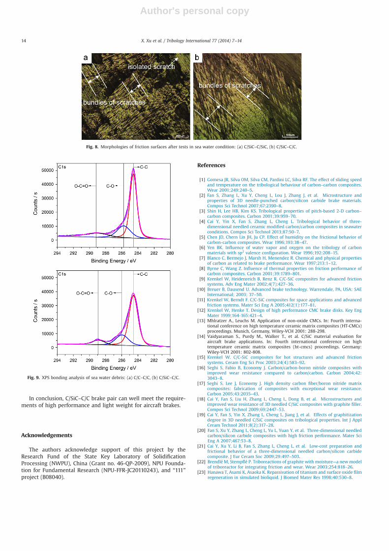
For the COF of C/SiC–C/SiC pair, no reduction and even incre-ment are present. The brake curve is similar to that in drycondition. As shown in Fig. 8(a), bundles of scratches and isolatedones are present on the surfaces. It is demonstrated that thefriction mechanism of C/SiC self-mated pair in sea water conditionis also mechanical effect. With this kind of friction mechanism, thefrictional properties of C/SiC–C/SiC pair do not fade.
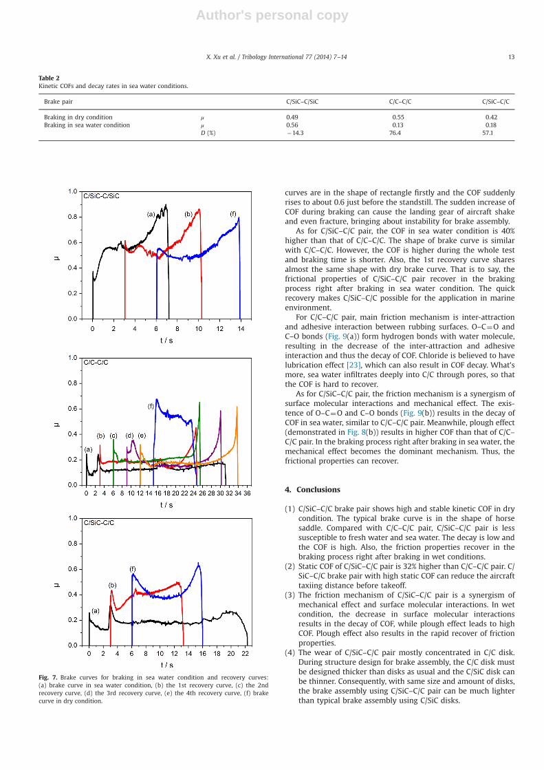
C/C–C/C pair suffers from low COF of 0.13, with a great decay ofmore than 76%. The braking time is longer than 30 s. The brakecurve is in the shape of rectangle (Fig. 7). Also, the shape of the 4threcovery curve is still different from the dry curve. The recovery
Fig. 4. Brake curves for braking in fresh water condition and recovery curves:(a) brake curve in fresh water condition, (b) the 1st recovery curve, (c) the 2ndrecovery curve, (d) the 3rd recovery curve, (e) brake curve in dry condition.
Fig. 5. Morphologies of worn surfaces after fresh water tests: (a) C/SiC–C/SiC, (b) C/SiC–C/C.
X. Xu et al. / Tribology International 77 (2014) 7–14 11
Author's personal copy
Fig. 6. Debris in fresh water condition: (a) C/SiC–C/SiC, (b) C/C–C/C, (c) C/SiC–C/C, XPS bonding analysis of debris of C/C–C/C (d) and C/SiC–C/C (e).
X. Xu et al. / Tribology International 77 (2014) 7–1412
Author's personal copy
curves are in the shape of rectangle firstly and the COF suddenlyrises to about 0.6 just before the standstill. The sudden increase ofCOF during braking can cause the landing gear of aircraft shakeand even fracture, bringing about instability for brake assembly.
As for C/SiC–C/C pair, the COF in sea water condition is 40%higher than that of C/C–C/C. The shape of brake curve is similarwith C/C–C/C. However, the COF is higher during the whole testand braking time is shorter. Also, the 1st recovery curve sharesalmost the same shape with dry brake curve. That is to say, thefrictional properties of C/SiC–C/C pair recover in the brakingprocess right after braking in sea water condition. The quickrecovery makes C/SiC–C/C possible for the application in marineenvironment.
For C/C–C/C pair, main friction mechanism is inter-attractionand adhesive interaction between rubbing surfaces. O–C¼O andC–O bonds (Fig. 9(a)) form hydrogen bonds with water molecule,resulting in the decrease of the inter-attraction and adhesiveinteraction and thus the decay of COF. Chloride is believed to havelubrication effect [23], which can also result in COF decay. What'smore, sea water infiltrates deeply into C/C through pores, so thatthe COF is hard to recover.
As for C/SiC–C/C pair, the friction mechanism is a synergism ofsurface molecular interactions and mechanical effect. The exis-tence of O–C¼O and C–O bonds (Fig. 9(b)) results in the decay ofCOF in sea water, similar to C/C–C/C pair. Meanwhile, plough effect(demonstrated in Fig. 8(b)) results in higher COF than that of C/C–C/C pair. In the braking process right after braking in sea water, themechanical effect becomes the dominant mechanism. Thus, thefrictional properties can recover.
4. Conclusions
(1) C/SiC–C/C brake pair shows high and stable kinetic COF in drycondition. The typical brake curve is in the shape of horsesaddle. Compared with C/C–C/C pair, C/SiC–C/C pair is lesssusceptible to fresh water and sea water. The decay is low andthe COF is high. Also, the friction properties recover in thebraking process right after braking in wet conditions.
(2) Static COF of C/SiC–C/C pair is 32% higher than C/C–C/C pair. C/SiC–C/C brake pair with high static COF can reduce the aircrafttaxiing distance before takeoff.
(3) The friction mechanism of C/SiC–C/C pair is a synergism ofmechanical effect and surface molecular interactions. In wetcondition, the decrease in surface molecular interactionsresults in the decay of COF, while plough effect leads to highCOF. Plough effect also results in the rapid recover of frictionproperties.
(4) The wear of C/SiC–C/C pair mostly concentrated in C/C disk.During structure design for brake assembly, the C/C disk mustbe designed thicker than disks as usual and the C/SiC disk canbe thinner. Consequently, with same size and amount of disks,the brake assembly using C/SiC–C/C pair can be much lighterthan typical brake assembly using C/SiC disks.
Table 2Kinetic COFs and decay rates in sea water conditions.
Brake pair C/SiC–C/SiC C/C–C/C C/SiC–C/C
Braking in dry condition μ 0.49 0.55 0.42Braking in sea water condition μ 0.56 0.13 0.18
D (%) �14.3 76.4 57.1
Fig. 7. Brake curves for braking in sea water condition and recovery curves:(a) brake curve in sea water condition, (b) the 1st recovery curve, (c) the 2ndrecovery curve, (d) the 3rd recovery curve, (e) the 4th recovery curve, (f) brakecurve in dry condition.
X. Xu et al. / Tribology International 77 (2014) 7–14 13
Author's personal copy
In conclusion, C/SiC–C/C brake pair can well meet the require-ments of high performance and light weight for aircraft brakes.
Acknowledgements
The authors acknowledge support of this project by theResearch Fund of the State Key Laboratory of SolidificationProcessing (NWPU), China (Grant no. 46-QP-2009), NPU Founda-tion for Fundamental Research (NPU-FFR-JC20110243), and “111”project (B08040).
References
[1] Gomesa JR, Silva OM, Silva CM, Pardini LC, Silva RF. The effect of sliding speedand temperature on the tribological behaviour of carbon–carbon composites.Wear 2001;249:240–5.
[2] Fan S, Zhang L, Xu Y, Cheng L, Lou J, Zhang J, et al. Microstructure andproperties of 3D needle-punched carbon/silicon carbide brake materials.Compos Sci Technol 2007;67:2390–8.
[3] Shin H, Lee HB, Kim KS. Tribological properties of pitch-based 2-D carbon–carbon composites. Carbon 2001;39:959–70.
[4] Cai Y, Yin X, Fan S, Zhang L, Cheng L. Tribological behavior of three-dimensional needled ceramic modified carbon/carbon composites in seawaterconditions. Compos Sci Technol 2013;87:50–7.
[5] Chen JD, Chern Lin JH, Ju CP. Effect of humidity on the frictional behavior ofcarbon-carbon composites. Wear 1996;193:38–47.
[6] Yen BK. Influence of water vapor and oxygen on the tribology of carbonmaterials with sp2 valence configuration. Wear 1996;192:208–15.
[7] Blanco C, Bermejo J, Marsh H, Menendez R. Chemical and physical propertiesof carbon as related to brake performance. Wear 1997;213:1–12.
[8] Byrne C, Wang Z. Influence of thermal properties on friction performance ofcarbon composites. Carbon 2001;39:1789–801.
[9] Krenkel W, Heidenreich B, Renz R. C/C-SiC composites for advanced frictionsystems. Adv Eng Mater 2002;4(7):427–36.
[10] Breuer B, Dausend U. Advanced brake technology. Warrendale, PA, USA: SAEInternational; 2003; 37–50.
[11] Krenkel W, Berndt F. C/C-SiC composites for space applications and advancedfriction systems. Mater Sci Eng A 2005;412(1):177–81.
[12] Krenkel W, Henke T. Design of high performance CMC brake disks. Key EngMater 1999;164-165:421–4.
[13] Mhlratzer A., Leuchs M. Application of non-oxide CMCs. In: Fourth interna-tional conference on high temperature ceramic matrix composites (HT-CMCs)proceedings. Munich, Germany, Wiley-VCH 2001: 288-298.
[14] Vaidyaraman S., Purdy M., Walker T., et al. C/SiC material evaluation foraircraft brake applications. In: Fourth international conference on hightemperature ceramic matrix composites (ht-cmcs) proceedings. Germany:Wiley-VCH 2001: 802-808.
[15] Krenkel W. C/C-SiC composites for hot structures and advanced frictionsystems. Ceram Eng Sci Proc 2003;24(4):583–92.
[16] Seghi S, Fabio B, Economy J. Carbon/carbon-boron nitride composites withimproved wear resistance compared to carbon/carbon. Carbon 2004;42:3043–8.
[17] Seghi S, Lee J, Economy J. High density carbon fiber/boron nitride matrixcomposites: fabrication of composites with exceptional wear resistance.Carbon 2005;43:2035–43.
[18] Cai Y, Fan S, Liu H, Zhang L, Cheng L, Dong B, et al. Microstructures andimproved wear resistance of 3D needled C/SiC composites with graphite filler.Compos Sci Technol 2009;69:2447–53.
[19] Cai Y, Fan S, Yin X, Zhang L, Cheng L, Jiang J, et al. Effects of graphitizationdegree in 3D needled C/SiC composites on tribological properties. Int J ApplCeram Technol 2011;8(2):317–28.
[20] Fan S, Xu Y, Zhang L, Cheng L, Yu L, Yuan Y, et al. Three-dimensional needledcarbon/silicon carbide composites with high friction performance. Mater SciEng A 2007;467:53–8.
[21] Cai Y, Xu Y, Li B, Fan S, Zhang L, Cheng L, et al. Low-cost preparation andfrictional behavior of a three-dimensional needled carbon/silicon carbidecomposite. J Eur Ceram Soc 2009;29:497–503.
[22] Brendlé M, Stempflé P. Triboreactions of graphite with moisture—a newmodelof triboreactor for integrating friction and wear. Wear 2003;254:818–26.
[23] Hanawa T, Asami K, Asaoka K. Repassivation of titanium and surface oxide filmregeneration in simulated bioliquid. J Biomed Mater Res 1998;40:530–8.
Fig. 8. Morphologies of friction surfaces after tests in sea water condition: (a) C/SiC–C/SiC, (b) C/SiC–C/C.
Fig. 9. XPS bonding analysis of sea water debris: (a) C/C–C/C, (b) C/SiC–C/C.
X. Xu et al. / Tribology International 77 (2014) 7–1414