Embed Size (px)
Citation preview

Acta metall, mater. Vol. 38, No. 11, pp. 2327-2336, 1990 0956-7151/90 $3.00 + 0.00 Printed in Great Britain. All rights reserved Copyright © 1990 Pergamon Press plc
TRANSIENT SUBCRITICAL CRACK-GROWTH BEHAVIOR IN TRANSFORMATION-TOUGHENED CERAMICS
R. H. D A U S K A R D T 1'2, W. C. CARTER 3, D. K. VEIRS 2 and R. O. RITCHIE 1'2
1Department of Materials Science and Mineral Engineering, University of California, Berkeley and 2Center for Advanced Materials, Lawrence Berkeley Laboratory, University of California, Berkeley, CA 94720 and 3National Institute for Standards and Technology, Gaithersburg, MD 20899, U.S.A.
(Received 10 April 1990)
Abstract--Transient subcritical crack-growth behavior following abrupt changes in the applied load are studied in transformation-toughened ceramics. A mechanics analysis is developed to model the transient nature of transformation shielding of the crack tip, Ks, with subcritical crack extension following the applied load change. Conditions for continued crack growth, crack growth followed by arrest, and no crack growth after the load change, are considered and related to the magnitude and sign of the applied load change and to materials properties such as the critical transformation stress. The analysis is found to provide similar trends in K s compared to values calculated from experimentally measured transformation zones in a transformation-toughened Mg-PSZ. In addition, accurate prediction of the post load-change transient crack-growth behavior is obtained using experimentally derived steady-state subcritical crack- growth relationships for cyclic fatigue in the same material.
Rfsumf---On 6tudie, dans des cframiques durcies par transformation, la croissance transitoire de fissures sous-critiques pour des variations rapides de la charge appliqufe. Nous dfveloppons une analyse basfe sur la mfcanique pour modfliser la nature transitoire de l'fcrantage par transformation, K~, de l'extrfmit6 de la fissure, avec l'allongement de la fissure sous-critique consfcutif/i la variation de charge appliqufe. Nous considfrons les conditions pour une croissance des fissures qui se prolonge, pour une croissance des fissures interrompue et pour aucune croissance des fissures aprfs la variation de la charge, et nous relions ces conditions ~ l'amplitude et au signe de la variation de charge appliqufe, ainsi qu'~ des propriftfs du matfriau telles que la contrainte critique de transformation. Cette analyses fournit des comportements de K s semblables aux valeurs calculfes fi partir des zones de transformation measurfes expfrimentalement dans un Mg-PSZ durci par transformation. En outre, on peut prfdire de fa~on prfcise le mode transitoire de croissance des fissures, aprSs une variation de la charge, fi l'aide des relations de croissance des fissures sous-critiques permanentes que l'on dfduit de l'expfrience pour la fatigue cyclique dans le mfme matfriau.
Zusammenfassung--An umwandlungsverst/irkten Keramiken wurde das Obergangsverhalten des subkritischen RiBwachstums nach plftzlichen ,~nderungen der/iul3eren Spannung untersucht. Mit einer mechanischen Analyse wird die t]bergangsnatur der Abschirmung Ks der Ril3spitze durch Umwandlungen modelliert als subkritische RiBerweiterung nach der ,~nderung der /iuBeren Spannung. Bedingungen werden betrachtet ffir kontinuierliches Ril3wachstum, Ril3wachstum mit nachfolgendem Stop und ffir fehlendes RiBwachstum nach Last~inderung; diese werden mit der Hfhe und dem Vorzeichen des/iul3eren Lastwechsels und mit Materialeigenschaften, wie etwa der kritischen Umwandlungsspannung, in Beziehung gesetzt. Die Analyse ergibt ffir K s Trends, die denen/ihneln, die aus experimentell gemessenen Umwandlungszonen in einer umwandlungsverst/irkten Mg-PSZ folgen. AuBerdem wird das t]bergangs- verhalten des RiBwachstums nach dem Lastwechsel mittels experimentell abgeleiteten Zusammenh~ingen fiber das station/ire subkritische RiBwachstum bei der Wechselverformung desselben Materials erhalten.
1. INTRODUCTION
Transformat ion toughening of inherently brittle ceramic materials has been widely studied and a well developed mechanics analysis exists from which the impressive achievements in toughening may be estimated [1-4]. Compelling arguments for the morph- ology of the transformation zone based on various martensitic nucleation criterion and stress couplings [4, 5], the effect of the transformable precipitate shape and orientation on toughening [5], and resistance- curve behavior between the initial and fully developed zone configurations [1-4] have been formulated. More recently, detailed analysis of the growing crack
with its evolving transformation zone under increasing, far-field, Mode-I loading have revealed the surprising result that maximum toughening is achieved after a finite crack extension [6]. The implication of this transient crack-growth behavior is that the potential toughening is underestimated when based on values obtained from steady-state conditions.
Alternatively, processes of subcritical crack growth have received far less attention. Possible mechanisms that have been identified in toughened ceramics include environmentally assisted [7-10] and cyclically induced [10-13] crack growth. The present study examines the mechanics of subcritical crack growth in transformation-toughened systems, particularly
AM 38/I ]--T 2 3 2 7

2328 DAUSKARDT et al.: CRACK-GROWTH IN TRANSFORMATION-TOUGHENED CERAMICS
Constant K: Steady State Zone
K ° = c o n s t
H o = const
Increased K: lncreased Zone Width
.~.... A a ;
K>K °
11 (=K/K °) > 1
Decreased K: Decreased Zone Width
~ ) K<K° 'q<l Fig. 1. Transformation-zone configurations contemplated in the present study, indicating (a) the initial steady-state, fully developed zone, (b) the increased zone size with increased far-field loading (r/> 1) and (c) the decreased zone emerging from the larger previous zone following decreased far-field
loading (q < 1).
following abrupt changes in the applied loading, where transient crack growth is known to occur [12]. Understanding this transient response is important in providing a basis for the eventual prediction of growth rates during spectrum-loading conditions actually encountered in service.
The study begins by contemplating processes of subcritical cracking for which the crack-growth rate, v, is related to the near-tip stress-intensity factor, Ktip. The extent of transformation toughening depends on the transformation-zone width, which is dependent on the maximum applied (far-field) stress-intensity factor K, and is unaffected by the subcritical crack- growth process. The initial steady-state crack configur- ation has a fully developed uniform zone [Fig. l(a)], which is subsequently allowed to change in size in response to the applied far-field loads. The transient nature of the crack-driving force, expressed in terms of Kti p, is then analyzed as a function of crack extension following abrupt changes in applied K [Fig. l(b,c)].
Results of the mechanics analysis are next applied to suberitical crack-growth processes where changes in K are shown to result in transient crack-growth rate behavior. Estimates of the transformation toughening, Ks, are calculated from experimentally measured transformation zones to facilitate comparison with the mechanics analysis. Finally, experimental data are presented for cyclically induced fatigue-crack growth where transient growth rates are measured following various far-field cyclic block loading, and single cycle, events and compared to predicted behavior.
2. SUBCRITICAL CRACK-GROWTH PROCESSES
Environmentally enhanced subcritical crack- growth processes have been extensively demonstrated in ceramic materials and the crack velocity v can generally be characterized by the relation [14, 15]
da/dt = v = vo(K/I~)" (1)
where a is the crack length, K is the applied (far-field) stress intensity, K c is the critical fracture toughness, and v 0 and n are constants for the particular material and environmental conditions. For transformation- toughened zirconia, n is typically in the range 40-120 [9, 12]. A threshold stress intensity, Kth, is often defined below which crack growth is assumed dormant.
10-7(o )
Mg-PSZ (MS)
A ~ lO-a
10-9
"~ io-~O
10-i I
. . . . . . i
Slow Crack-Growth
,tr,~, '7 t~
"rougl'~ing" D
I I I I I i i
Stress Intensity. Kma x (MPa-m~l
10-4 (b| . . . . . . . . .
~ -51 Mg'Psz (MS) CyclIc Faugue
10 I 10-6~ K°(I"R) KC(I"R ~
Z v(,,,Kn v(AlO "~ ~10-7 d ¢¢1
m 10-S o/ "Toughening" j / "1 , ott,o. t~10 -9 °J o X spocing~
~_~10_1C / / per cycle
10-11 , -r, , , , ,Kth . . . . 10
Stress Intensity Range. &K (MPa-m 'a)
Fig. 2. Subcritical crack-growth process for a transformation- toughened zirconia ceramic showing the v(Ktip) and v(K) relations for (a) environmentally induced slow crack-growth and (b) cyclically induced crack-growth with exponents n and m in the v(Ktip) formulations of 45 and 22, respectively. The marked effect of toughening is indicated by the "shift" between the v(Ktip) and v(K) functions. The maximum crack-growth velocity, v', occurs when Kti p = K0 in the
v (Ktiv) relationship.

DAUSKARDT et al.: CRACK-GROWTH IN TRANSFORMATION-TOUGHENED CERAMICS 2329
More recently, cyclic fatigue crack propagation has been reported in transformation-toughened zirconia ceramics [10-13]. Crack-growth was demonstrated to be cyclically induced and not directly associated with processes of environmentally enhanced slow crack growth often attributed to cyclic fatigue effects in ceramics [14]. Similar to behavior in metals, crack- growth rates were dependent on the applied range of stress intensity, AK(= Km~x - Kmm), and were sensitive to the mean load, cyclic frequency and environment [11, 12]. Here, under tension-tension loading, the cyclic crack-growth rate per cycle, da/dN, may be described by the relation [12]
da /dN = AKo/(1 - R) (AK/Kc) m (2)
where the load ratio R = Kmin/Kmax, Ko is the intrinsic toughness (without transformation shielding), and A and m constants for the material and test environ- ment conditions. Values of m range from 20 to 40 for zirconia ceramics [11, 12].
The above empirical relationships express the notion that provided the process of subcritical cracking does not change the degree of crack-tip shielding, crack- growth velocities are mechanistically related to the near-tip stress and strain fields. Under these con- ditions, v(K/K¢) and v(K~p) formulations are in fact equivalent [12, 15]. (For cyclic loading, premature contact of the crack surfaces on unloading, i.e. crack closure, must also be accounted for in determining AKti p .) Alternatively, the potent effect of toughening on subcritical crack-growth rates may be emphasized by expressing v in terms of the applied (far-field) K. This is manifest by the crack-velocity functions, v(K~p) and v(K), shown in Fig. 2, for processes of mono- tonic and cyclic crack growth in a transformation- toughened Mg-PSZ ceramic. Note that, in general, the v(K) data exhibits an increased slope compared to the v(Ktip) data, reflecting the increasing effect of transformation shielding with applied K, quantitatively expressed by equation (8) below.
The general steepness of the crack-velocity functions v (K), apparent by the high exponents n and m, imply that small changes in the transformation shielding may be expected to produce significant variations in the crack-growth rates. Such behavior has been demonstrated for steady-state, environmentally en- hanced [8, 9] and cyclically induced [12] crack growth in materials which undergo phase transformation to exhibit various degrees of toughening. The effect of loading history, involving abrupt applied load changes, on transformation toughening and hence subcritical crack-growth rates are considered in the present study.
3. ZONE SHIELDING MECHANICS
be invoked, the stress field remote from the zone boundary, and near to the crack tip, may be described using the applied far-field and near-tip stress-intensity factors, K and K~p, respectively. Transformation toughening may then be characterized by the stress- intensity change, Ks, defined as
Ks = K - K~p. (3)
The shielding effect, Ks, may be directly calculated using either energy considerations [2] or weight- function techniques [1, 3, 4]. Using the latter tech- niques [3, 16, 17] expressed in Cartesian coordinates where the crack tip is located at the origin, for a purely dilational, completely transformed (supercritical) zone, integration over the entire zone area yields
Ks = C 0 f r-3/2 cos(30 /2) dA ,) z one
x-r = (r + x ) 1/2 7 d x dy (4)
o n e
where
- e e ~ Co = 6(2n)1/2(1 _ v) (5)
is a material constant; e x is the dilational transform- ation strain, fi is the volume fraction of transform- able phase, v is Poisson's ratio, and E is the elastic modulus. Conditions of plane strain are assumed and all approximations of linear elasticity apply. Other than Co, shielding depends only upon the size and shape of the transformed zone.
For a transformation activated by the hydrostatic crack-tip stress field, the steady-state zone width, 2H [Fig. l(a)], is given by [2, 3]
H 3 1 / 2 ( l + v ) 2 ( K ) 2 12n ~mm =BZ(K) z (6)
where a~, is the critical hydrostatic transformation stress (i.e. stress at the zone boundary). For the case of a fully developed steady-state zone, evaluation of equation (4) yields [3]
o _ ~eTEfvx/H o (7) K s -
where ~ = 0.22 for the hydrostatic zone specified by equation (6). The superscript 0 indicates steady- state conditions. Combining equations (6) and (7), the extent of shielding for the steady-state zone configuration may be written as
K ° = ~K ° (8)
where/? is a constant for a given material toughness condition. (fl ~ 1/30 of the toughening parameter, 09, defined in Ref. [6].)
3.1. Background
Assuming small transformation-zone sizes, for which the small scale zone-size approximation may
3.2. Shielding calculation
For the purposes of the present analysis, H ° is used as a scale factor to transform the integral in
2330 DAUSKARDT et al.: CRACK-GROWTH IN TRANSFORMATION-TOUGHENED CERAMICS
the shielding expression [equation (4)] to the more convenient form
C O H ° gt ip = K -- ~ I s (zone shape)
CoBo K° = K x / ~ Is (zone shape) (9)
where I~(zone shape) is the dimensionless integral related to equation (4); its value depends only on the shape of the transformed zone and not upon its size. B o is a constant which depends upon material properties, as defined in equation (6).
The effects of varying far-field loading (or varying zone size and shape) on the near-tip driving force in a transforming material may now readily be clarified using /(tip, given by equation (9). For convenience, crack extension, Aa, following the far-field load change (K°---, K) is normalized by the initial crack-tip zone half width, H ° (for K = K ° ) , which has a fully formed uniform wake of transformed material. Similarly, Ktip can be normalized by K °
Kti p _ K ]~I s (Aa) (10)
K ° K 0 I °
which elucidates the separate roles of load (through K), material properties (through fl), and history [through Is(Aa)]. The expressions which make up Is may be found in the Appendix.
3.3. Skidding mechanics results
The transient behavior of K~p following changes in the far*field K, expressed as the ratio K/K°= ~, are now considered. To exclude stable crack growth typically observed during resistance-curve tests, ~ is upper bounded to ensure that/(tip < K0, where K0 is the intrinsic fracture toughness. In practice, for con- tinued subcritical crack growth of the type envisioned here [equations (1) and (2)], ~ is strictly bounded such that Kt~p remains in the relatively narrow range Kth ~< Ktip-~< K0 dictated by the v(Ktip) function.
As the crack extends, a new zone, with a width H dependent on the current value of K [equation (6)], emerges from the existing transformation zone [Fig. l(b,c)]. The transient effects of the perturbation of the zone are evaluated by equation (10); these effects will diminish as the old zone is left behind in the wake of the crack, and a new steady-state condit ion established, for which
K [3K (Ktip/K°)ss -- K0 K0 = r/(1 -- fl). (11)
3.3.1. K increased. When K is increased, new regions of transformation are assumed to appear immediately in response to the increased mean stress [Fig. l(b)]. Analogous to the initial zone formed during resistance-curve behavior [1-6], the new areas of transformed material are assumed to have no effect on K S. Thus, enough transformed material must appear in the wake (along the edges of the pre-existing
,-r
E z _
2 3 4
Load Change Parameter, "q ('q---K/K °)
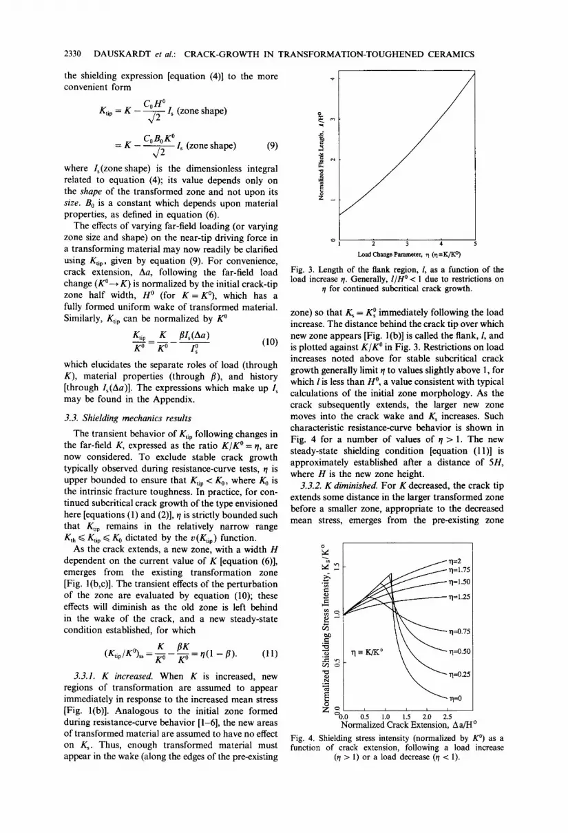
Fig. 3. Length of the flank region, /, as a function of the load increase t7. Generally, I/H ° < 1 due to restrictions on
r/ for continued subcritical crack growth.
zone) so that Ks = K ° immediately following the load increase. The distance behind the crack tip over which new zone appears [Fig. 1 (b)] is called the flank,/ , and is plotted against K/K ° in Fig. 3. Restrictions on load increases noted above for stable subcritical crack growth generally limit r/to values slightly above 1, for which l is less than H °, a value consistent with typical calculations of the initial zone morphology. As the crack subsequently extends, the larger new zone moves into the crack wake and Ks increases. Such characteristic resistance-curve behavior is shown in Fig. 4 for a number of values of r / > 1. The new steady-state shielding condit ion [equation (11)] is approximately established after a distance of 5H, where H is the new zone height.
3.3.2. K diminished. For K decreased, the crack tip extends some distance in the larger transformed zone before a smaller zone, appropriate to the decreased mean stress, emerges from the pre-existing zone
~ . . ~ -
.=.
0
~ "q=l.50
~ T1=1.25
z o , , , : : d0.0 0.5 1.0 1.5 2 0 2 5
Normalized Crack Extension, A a/H o
Fig. 4. Shielding stress intensity (normalized by K °) as a function of crack extension, following a load increase
(r/> 1) or a load decrease (r/< 1).
DAUSKARDT et al.: CRACK-GROWTH IN TRANSFORMATION-TOUGHENED CERAMICS 2331
[Fig. l(c)]. Note that transformed material in the pie-shaped region, - ~ / 3 < 0 < +7r/3, ahead of the crack tip adds positive terms to Ks, which thwarts the beneficial shielding effect of transformed material behind the crack tip. Therefore, as transformed material from the large zone moves from the pie- shaped region into the wake, a temporarily enhanced shielding effect occurs. This behavior is shown in Fig. 4 for values of r / < 1. The enhanced shielding increases almost linearly with crack extension, independent of r/, until the new zone appears. Ks then decreases with further crack advance [decaying as (H°)2/(Aa)3/2], finally becoming asymptotic with the new steady-state condition [equation (11)].
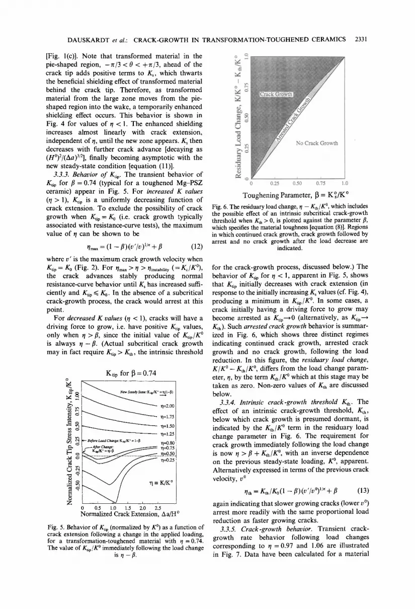
3.3.3. Behavior o f Kti p. The transient behavior of Kti p for fl = 0.74 (typical for a toughened Mg-PSZ ceramic) appear in Fig. 5. For increased K values (q > 1), Kti p is a uniformly decreasing function of crack extension. To exclude the possibility of crack growth when g t i p - ~ - g 0 (i.e. crack growth typically associated with resistance-curve tests), the maximum value of r /can be shown to be
/']max = (1 - - f l ) ( V t / V ) TM @ f l ( 1 2 )
where v' is the maximum crack growth velocity when Ktip = K0 (Fig. 2). For qm,x > q > qinst~bility (=K~/K°), the crack advances stably producing normal resistance-curve behavior until Ks has increased suffi- ciently and Kup ~< K0. In the absence of a subcritical crack-growth process, the crack would arrest at this point.
For decreased K values (q < 1), cracks will have a driving force to grow, i.e. have positive Kt~p values, only when r /> fl, since the initial value of Ktip/K ° is always r / - ft. (Actual subcritical crack growth may in fact require/(tip > Kth, the intrinsic threshold
g~
~5 c.2
b~
o Z
Ktip for 13 = 0.74
• ~1=1.25 ~ Before Load C,'~'~gt:K,~,IK" = 1-13 TI__0.80
¢r Change: ~ 1"1=0 75
0.5 1.0 1.5 2.0 2.5 Normalized Crack Extension, A a/H o
Fig. 5. Behavior of Kti p (normalized by K °) as a function of crack extension following a change in the applied loading, for a transformation-toughened material with q =0.74. The value of Ktip/K ° immediately following the load change
is q -/~.
I
Q
o 0 0.25 0.50 0.75 1.0
Toughening Parameter, 13 = K ° / K °
Fig. 6. The residuary load change, r / - Kth/K °, which includes the possible effect of an intrinsic subcritical crack-growth threshold when Kth > 0, is plotted against the parameter fl, which specifies the material toughness [equation (8)]. Regions in which continued crack growth, crack growth followed by arrest and no crack growth after the load decrease are
indicated.
for the crack-growth process, discussed below.) The behavior of g t i p for ~/< 1, apparent in Fig. 5, shows that K~p initially decreases with crack extension (in response to the initially increasing K s values (cf. Fig. 4), producing a minimum in Ktip/K °. In some cases, a crack initially having a driving force to grow may become arrested as Ktip"*0 (alternatively, as Ktip"-~ Kth). Such arrested crack growth behavior is summar- ized in Fig. 6, which shows three distinct regimes indicating continued crack growth, arrested crack growth and no crack growth, following the load reduction. In this figure, the residuary load change, K / K ° -- Kth/K °, differs from the load change param- eter, q, by the term K,h/K ° which at this stage may be taken as zero. Non-zero values of Kth are discussed below.
3.3.4. Intrinsic crack-growth threshold Kth. The effect of an intrinsic crack-growth threshold, Kth, below which crack growth is presumed dormant, is indicated by the Kth/K ° term in the residuary load change parameter in Fig. 6. The requirement for crack growth immediately following the load change is now r / > fl + Kth/K °, with an inverse dependence on the previous steady-state loading, K °, apparent. Alternatively expressed in terms of the previous crack velocity, v °
/']th = Kth/Ko(1 - fl)(v'/v°) TM + fl (13)
again indicating that slower growing cracks (lower v °) arrest more readily with the same proportional load reduction as faster growing cracks.
3.3.5. Crack-growth behavior. Transient crack- growth rate behavior following load changes corresponding to ~/= 0.97 and 1.06 are illustrated in Fig. 7. Data have been calculated for a material

2332 DAUSKARDT et al.: CRACK-GROWTH IN TRANSFORMATION-TOUGHENED CERAMICS
>
4 o
.o
Crack Growth Rate, ~ = 0.74
rl = 1 . 0 6
, . ~ ~ . . . . . . . . . . . . . . . . . . . . . . . . . . . . . . . . . . . . . . . . . . . . . . . . . . . . . . . . . . . . . . . . . .
¢o
d o - .97 X
1 2 3 4 5 Normalized Crack Length, Aa/H °
Fig. 7. Predicted transient crack-growth rate behavior follow- ing load changes corresponding to r/= 0.97 (3% decrease) and 1.06 (6% increase). Data have been calculated for a material with /~ = 0.74 and a subcritical crack-growth relation v (K~p) typical for cyclic fatigue in zireonia ceramics
(Fig. 2) with exponent m = 22.
with fl = 0.74 and a subcritical crack-growth relation v(Ktip) typical for cyclic fatigue in zirconia ceramics (Fig. 2), with exponent m = 22. Immediately follow- ing the load increase, the growth rate increases ,,,2 orders of magnitude before decaying to the new steady-state growth rate after a crack extension of ~ 5.6H ° (= 5H, since, H = r/2 H°). Conversely, after decreasing the loads, the growth rate immediately decreases approximately one order of magnitude, which is followed by a further decrease with minimal subsequent crack extension as the crack-tip shielding increases (Fig. 4). The growth rate then increases becoming asymptotic with the new steady-state con- dition again after ~ 5H. Experimental observation of this theoretically predicted growth-rate behavior is presented in the following section.
4. CYCLIC FATIGUE
4.1. Procedures
4.1.1. Materials. Zirconia, partially-stabilized by the addition of 9 mol% MgO and heat treated to the mid-toughness (MS, ~ = 0.74) and peak-toughness (TS, /~ = 0.78) conditions,t was used in the present study. The microstructure consists of 50/zm cubic phase ZrO 2 grains, containing lens-shaped metastable tetragonal precipitates ( ~ 35-40 vol.%) of maximum dimension 300 nm. The tetragonal precipitates undergo a stress-induced martensitic phase trans- formation to the monoclinic phase. The material has been described in detail elsewhere [12, 18-20].
4.1.2. Cyclic fatigue testing. Cracks, with their associated transformation zones, were produced under
tNicra, MS and TS grades.
well defined cyclic loading conditions in 3-mm-thick compact C(T) specimens. 50 Hz sine wave loading with a load ratio R nominally equal to 0.1, together with continuous monitoring of the crack length (resolution ~ 5/~m), allowed precise closed-loop stress-intensity (AK) control. Unloading compliance measurements from back-face strain gauges were used to assess the extent of fatigue crack closure in terms of the far-field stress intensity, Kcl, at first contact of the fracture surfaces during the unloading cycle [21]. Comprehen- sive descriptions of the experimental techniques have been reported previously [11, 12].
4.1.3. Transformation zones. The transformation zones surrounding cracks grown under various load histories were characterized using a novel spatially-resolved Raman spectroscopy system [22]. This allows a direct measure of the fraction Fmono of monoclinic phase within the zone. The system uses a two-dimensional detector to resolve simultaneously the Raman energy spectra at successive points (7.84#m separation) along a line of illumination across the crack. The specimen was translated in 125/zm steps while collecting data to produce a map of the monoclinic phase content surrounding the crack.
Transformation shielding at points along the crack path was investigated using the zone-shielding formula [equation (4)] derived in Section 3. Employing an adaptive subdivision strategy, the integral in equation (4) was evaluated numerically using the Raman data, with fv = Fmono included in the integral to accom- modate the varying fraction of transformed material within the zone. The frontal transformed zone at any point along the crack path was naturally obscured by the passage of the crack but its effect on Ks was estimated using two independent procedures. In one, using simulated transformed zones with hydrostatic circular frontal boundaries, the effect of performing the integration over the zone wake up to a line through the crack tip was found to exceed the full zone integration (which included the frontal zone) by 40%. The value of K s obtained for the actual Raman data up to the crack-tip position of interest was therefore reduced by an amount corresponding to a 40% reduction of Ks found for a uniform zone obtained by reproducing the crack-tip zone profile into the crack wake. In the other procedure, the value of K s for a steady-state zone of uniform width was first calculated by numerically integrating equation (7) over the zone profile at the crack-tip position of interest. A value of • = 0.26, typical for transformed zones in PSZ, was used [23]. Using the same crack-tip profile reproduced in the wake to simulate a uniform wake zone, integration of equation (4) up to the crack tip yields a value which differs from the above by an amount dependent on the transformed material ahead of the crack tip. This difference was calculated at each position of interest and subtracted from the value of Ks found for the actual wake zone. Close agreement was found between the two procedures.

DAUSKARDT et al.:
Appropriate "background" corrections to Fmo,o were made to account for the pre-existing monoclinic phase in the specimen.
4.2. Transient crack-growth behavior
Cyclic crack-growth rates following high-to-low and low-to-high constant AK loading sequences in mid-toughness (MS) material are shown in Fig. 8. The experimental data closely resemble the predicted transient growth-rate behavior (Fig. 7), which, with appropriate values ofv 0 and H 0 = 85/~m, is shown by the dashed line in Fig. 8. On reducing the cyclic loads so that ~/( = Km~x/K°~x) = 0.97, a transient retardation is seen (although a further decrease apparent in the mechanics analysis was beyond the resolution of the crack-growth rate determination scheme and not observed) followed by a gradual increase in growth rates until the new steady-state velocity is achieved. On increasing the cyclic loads so that q = 1.06, growth rates exhibit a transient acceleration before decaying to the steady-state velocity. For the present material, the affected crack-growth increments are ~500/~m, approximately five times the measured transformation-zone width of ~85 to 108#m [12].
Similar transient crack-growth retardation follow- ing a high-to-low load reduction ( r /= 0.89) is shown for peak-toughness (TS) material in Fig. 9(a). In addition, the effect of a single tensile overload where i / = 1.32, above the maximum load increase Q/m,x 1.06) for subcritical crack growth but below that for unstable propagation (?]instability ~ 1.7), was observed to advance the crack rapidly [v ~ v', g t i p ~ g 0 ( c f .
Fig. 2)] until arrest. Cyclic loading after the overload ( i /= 0.76) resulted in initially significantly retarded crack-growth rates followed by increasing rates to the new steady state.
Premature contact of the crack surfaces during unloading, e.g. crack closure due to fracture-surface asperity contact, is known to dramatically affect crack-growth rates during cyclic fatigue [24, 25]. To facilitate comparison with the mechanics analysis, which does not consider crack closure, the effect of K~ on AKtip must be experimentally determined. Far-field crack-closure levels corresponding to the growth-rate data in Fig. 9(a), measured as a function of crack extension, are presented as a ratio of KJKm~x in Fig. 9(b). Closure levels are seen to exhibit a transient increase following the load decrease, but surprisingly to decrease after the single-cycle overload. Trends observed in the growth-rate data [Fig. 9(a)] therefore do not appear to be consistent with the measured closure datat [Fig. 9(b)]. Previous work [12], however,
CRACK-GROWTH IN TRANSFORMATION-TOUGHENED CERAMICS 2333
10-4
10 -~
.~ 10 -e
Z
10_7 ~.K = 5.48 - J ~ &K = 5.30 ~ F -z~K = 5.60 MPa~/m
Ng-PSZ (MS)
tSimilar behavior in metals, following single tensile over- loads, also show a reduction in crack closure, measured globally using back-face strain compliance (associated with crack-tip blunting from the overload cycle). If closure loads are measured locally using strain gauges located in the vicinity of the crack tip, however, (near- tip) K d values are seen to increase as the crack penetrates the overload plastic zone [26].
~ - - o - experimental data l d 16
H
. . . . prediction
10 -11 I I L I I I 0 1 2 3 4 5 6 7
C r a c k E x t e n s i o n , 6 a ( m m )
Fig. 8. Comparison of experimentally measured and predicted transient cyclic fatigue-crack growth behavior in mid- toughness (MS) Mg-PSZ, showing crack-growth retardation following high-to-low AK loading (~/= 0.97), and acceleration following low:to-high load increases (~/= 1.06). Predictions rely on steady-state crack-growth rate data (Fig. 2) and computation of the crack-tip "driving force" (AKti p) following
the load change [equation (10)].
(o)
i0 -e / • ~ o ,.,- J o = / o~ 1 0 -s I' I
I I 0 i(~ ~o I
i z~K = 9.5 "='~ &K = 3.5 - Z~K = 8.5 r , ~ zXK = 5.0 MPaVrn
10 -11 r I i f i l i 0 1 2 3 4 5 6 7
C r a c k E x t e n s i o n , A a ( r a m )
(b) 0 . 6
Kalax = 12.3 MPax/m
4 ~ K = 3.5 I ~.K = 8.5 ~,K = B.5 ] ~ K = 5.0 MPaVr
~o I
i\ i o "° / d -
~1 ° Mg-PSZ O'S) moo
o.," I i i I i i t 1 2 3 4. 5 6 7
Crack E x t e n s i o n , Aa ( r a m )
Fig. 9. Transient cyclic fatigue-crack growth behavior in peak-toughness (TS) Mg-PSZ showing (a) transient crack- growth rate behavior following a load reduction (~/= 0.89) and a single cycle overload (~/= 132) during which the crack advanced 0.3 mm, and (b) corresponding back-face strain crack-closure data plotted as a ratio of KJKma x.
Load reduction (,1 = 0.89) ,Overload,
35
2334 DAUSKARDT et al.: CRACK-GROWTH IN TRANSFORMATION-TOUGHENED CERAMICS
0 ,.... 0 E
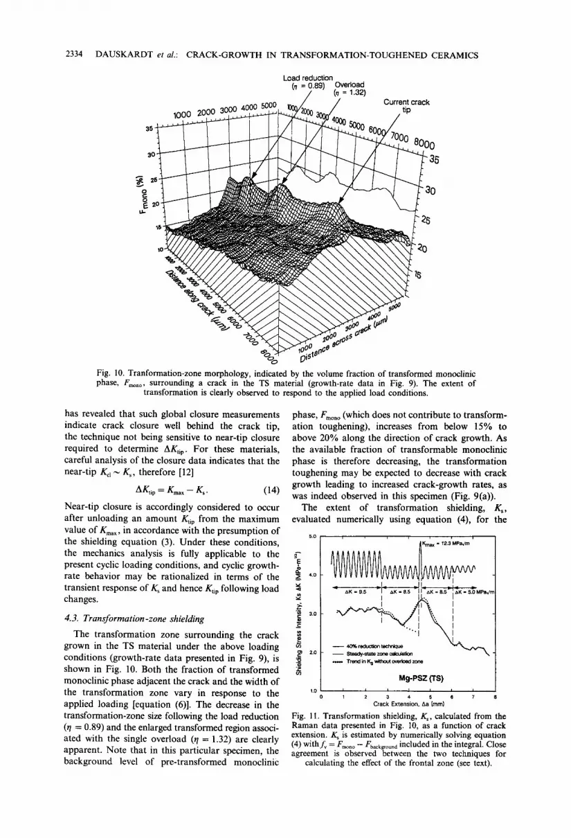
Fig. 10. Tranformation-zone morphology, indicated by the volume fraction of transformed monoclinic phase, Fm .... surrounding a crack in the TS material (growth-rate data in Fig. 9). The extent of
transformation is clearly observed to respond to the applied load conditions.
has revealed that such global closure measurements indicate crack closure well behind the crack tip, the technique not being sensitive to near-tip closure required to determine AKap. For these materials, careful analysis of the closure data indicates that the near-tip Kcl ~ K,, therefore [12]
A g t i p = g m a x - - Ks. ( 1 4 )
Near-tip closure is accordingly considered to occur after unloading an amount K, ip from the maximum value of Kmax, in accordance with the presumption of the shielding equation (3). Under these conditions, the mechanics analysis is fully applicable to the present cyclic loading conditions, and cyclic growth- rate behavior may be rationalized in terms of the transient response of Ks and hence K~p following load changes.
4.3. Transformation-zone shielding
The transformation zone surrounding the crack grown in the TS material under the above loading conditions (growth-rate data presented in Fig. 9), is shown in Fig. 10. Both the fraction of transformed monoclinic phase adjacent the crack and the width of the transformation zone vary in response to the applied loading [equation (6)]. The decrease in the transformation-zone size following the load reduction ( r /= 0.89) and the enlarged transformed region associ- ated with the single overload ( r /= 1.32) are clearly apparent. Note that in this particular specimen, the background level of pre-transformed monoclinic
phase, Fmono (which does not contribute to transform- ation toughening), increases from below 15% to above 20% along the direction of crack growth. As the available fraction of transformable monoclinic phase is therefore decreasing, the transformation toughening may be expected to decrease with crack growth leading to increased crack-growth rates, as was indeed observed in this specimen (Fig. 9(a)).
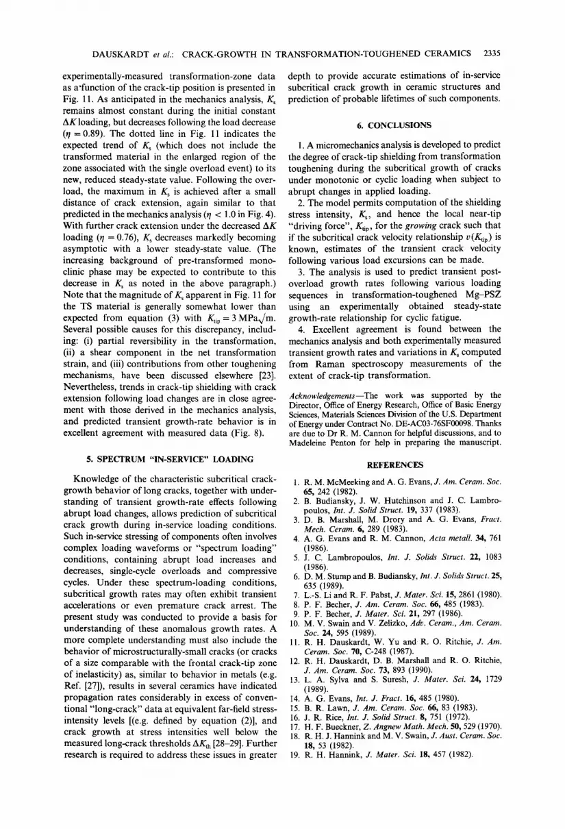
The extent of transformation shielding, K,, evaluated numerically using equation (4), for the
5.0 ~Kma x = 72.3 MPa,/m /
~ 4.o
- & K = 9 . 5 ~ l - ~ K = 8 , 5 ~ I I - & K = 8 . 5 ~ , X K - 5 , O M P a v m [
• " "" .... k I "~ 3.o " '., I
X l .
2.0 - - S t e a a y - s t a t e z o e e ~ - " " \ "~ . ~ TrerRi kl Ks without overioad zone
Mg-PSZ (TS) 1.o I i i L i I i
1 2 3 4 5 6 7 Crack Ex tens ion , Aa (ram)
Fig. l I. Transformation shielding, K,, calculated from the Raman data presented in Fig. 10, as a function of crack extension. K s is estimated by numerically solving equation (4) withfv = Fmono - - Fbackgroun d included in the integral. Close agreement is observed between the two techniques for
calculating the effect of the frontal zone (see text).
DAUSKARDT et al.: CRACK-GROWTH IN TRANSFORMATION-TOUGHENED CERAMICS 2335
experimentally-measured transformation-zone data as a'function of the crack-tip position is presented in Fig. 11. As anticipated in the mechanics analysis, K s remains almost constant during the initial constant AK loading, but decreases following the load decrease ( r /= 0.89). The dotted line in Fig. 11 indicates the expected trend of K s (which does not include the transformed material in the enlarged region of the zone associated with the single overload event) to its new, reduced steady-state value. Following the over- load, the maximum in K s is achieved after a small distance of crack extension, again similar to that predicted in the mechanics analysis ( r /< 1.0 in Fig. 4). With further crack extension under the decreased AK loading ( t /= 0.76), K s decreases markedly becoming asymptotic with a lower steady-state value. (The increasing background of pre-transformed mono- clinic phase may be expected to contribute to this decrease in Ks as noted in the above paragraph.) Note that the magnitude of K s apparent in Fig. 11 for the TS material is generally somewhat lower than expected from equation (3) with g t i p = 3 MPax/m. Several possible causes for this discrepancy, includ- ing: (i) partial reversibility in the transformation, (ii) a shear component in the net transformation strain, and (iii) contributions from other toughening mechanisms, have been discussed elsewhere [23]. Nevertheless, trends in crack-tip shielding with crack extension following load changes are in close agree- ment with those derived in the mechanics analysis, and predicted transient growth-rate behavior is in excellent agreement with measured data (Fig. 8).
5. SPECTRUM "IN-SERVICE" LOADING
Knowledge of the characteristic subcritical crack- growth behavior of long cracks, together with under- standing of transient growth-rate effects following abrupt load changes, allows prediction of subcritical crack growth during in-service loading conditions. Such in-service stressing of components often involves complex loading waveforms or "spectrum loading" conditions, containing abrupt load increases and decreases, single-cycle overloads and compressive cycles. Under these spectrum-loading conditions, subcritical growth rates may often exhibit transient accelerations or even premature crack arrest. The present study was conducted to provide a basis for understanding of these anomalous growth rates. A more complete understanding must also include the behavior of microstructurally-small cracks (or cracks of a size comparable with the frontal crack-tip zone of inelasticity) as, similar to behavior in metals (e.g. Ref. [27]), results in several ceramics have indicated propagation rates considerably in excess of conven- tional "long-crack" data at equivalent far-field stress- intensity levels [(e.g. defined by equation (2)], and crack growth at stress intensities well below the measured long-crack thresholds AKth [28-29]. Further research is required to address these issues in greater
depth to provide accurate estimations of in-service subcritical crack growth in ceramic structures and prediction of probable lifetimes of such components.
6. CONCLUSIONS
1. A micromechanics analysis is developed to predict the degree of crack-tip shielding from transformation toughening during the subcritical growth of cracks under monotonic or cyclic loading when subject to abrupt changes in applied loading.
2. The model permits computation of the shielding stress intensity, Ks, and hence the local near-tip "driving force", Kap, for the growing crack such that if the subcritical crack velocity relationship v(Ktip) is known, estimates of the transient crack velocity following various load excursions can be made.
3. The analysis is used to predict transient post- overload growth rates following various loading sequences in transformation-toughened Mg-PSZ using an experimentally obtained steady-state growth-rate relationship for cyclic fatigue.
4. Excellent agreement is found between the mechanics analysis and both experimentally measured transient growth rates and variations in Ks computed from Raman spectroscopy measurements of the extent of crack-tip transformation.
Acknowledgements--The work was supported by the Director, Office of Energy Research, Office of Basic Energy Sciences, Materials Sciences Division of the U.S. Department of Energy under Contract No. DE-AC03-76SF00098. Thanks are due to Dr R. M. Cannon for helpful discussions, and to Madeleine Penton for help in preparing the manuscript.
REFERENCES
1. R. M. McMeeking and A. G. Evans, J. Am. Ceram. Soc. 65, 242 (1982).
2. B. Budiansky, J. W. Hutchinson and J. C. Lambro- poulos, Int. J. Solid Struct. 19, 337 (1983).
3. D. B. Marshall, M. Drory and A. G. Evans, Fract. Mech. Ceram. 6, 289 (1983).
4. A. G. Evans and R. M. Cannon, Acta metall. 34, 761 (1986).
5. J. C. Lambropoulos, Int. J. Solids Struct. 22, 1083 (1986).
6. D. M. Stump and B. Budiansky, Int. J. Solids Struct. 25, 635 (1989).
7. L.-S. Li and R. F. Pabst, J. Mater. Sci. 15, 2861 (1980). 8. P. F. Becher, J. Am. Ceram. Soc. 66, 485 (1983). 9. P. F. Becher, J. Mater. Sci. 21, 297 (1986).
10. M. V. Swain and V. Zelizko, Adv. Ceram., Am. Ceram. Soc. 24, 595 (1989).
11. R. H. Dauskardt, W. Yu and R. O. Ritchie, J. Am. Ceram. Soc. 70, C-248 (1987).
12. R. H. Dauskardt, D. B. Marshall and R. O. Ritchie, J. Am. Ceram. Soc. 73, 893 (1990).
13. L. A. Sylva and S. Suresh, J. Mater. Sci. 24, 1729 (1989).
14. A. G. Evans, Int. J. Fract. 16, 485 (1980). 15. B. R. Lawn, J. Am. Cerarn. Soc. 66, 83 (1983). 16. J. R. Rice, Int. J. Solid Struct. 8, 751 (1972). 17. H. F. Bueckner, Z. Angnew Math. Mech. 50, 529 (1970). 18. R. H. J. Hannink and M. V. Swain, J. Aust. Ceram. Soc.
18, 53 (1982). 19. R. H. Hannink, J. Mater. Sci. 18, 457 (1982).

2336 D A U S K A R D T et al.: CRACK-GROWTH IN TRANSFORMATION-TOUGHENED CERAMICS
20. D. B. Marshall and M. V. Swain, J. Am. Ceram. Soc. 71, 399 (1988).
21. R. O. Ritchie and W. Yu, in Small Fatigue Cracks (edited by R. O. Ritchie and J. Lankford), pp. 167-189. T.M.S.-A.I.M.E., Warrendale, Pa (1986).
22. R. H. Dauskardt, D. K. Veirs and R. O. Ritchie, J. Am. Ceram. Soc. 72, 1124 (1989).
23. D. B. Marshall, M. C. Shaw, R. H. Dauskardt, R. O. Ritchie, M. Readey and A. H. Heuer, J. Am. Ceram. Soc. 73, (1990). In press.
24. N. Walker and C. E. Beevers, Fatigue Engng Mater. Struct. 1, 135 (1979).
25. S. Suresh and R. O. Ritchie, Metall. Trans. A 13A, 1627 (1982).
26. C. M. Ward-Close, A. F. Blom and R. O. Ritchie, Engng Fraet. Mech. 32, 613 (1989).
27. R. O. Ritchie and J. Lankford (editors) Small Fatigue Cracks. T.M.S.-A.I.M.E., Warrendale, Pa (t986).
28. M. Yoda, Int. J. Fract. 39, R-23 (1989). 29. A. A. Steffen, R. H. Dauskardt and R. O. Ritchie, in
FATIGUE '90, Proc. 4th Int. Conf. on Fatigue and Fatigue Thresholds (edited by H. Kitagawa and T. Tanaka), Vol. 2, pp. 745-752. MCEP, Birmingham, U.K. (1990).
A P P E N D I X
Assuming a circular-zone front which connects to a fiat wake of half-width H at angles of +rr/3 from the crack plane (Fig. A1), the integral, Is, can be evaluated in terms of known functions. This assumption makes only a slight change in the value of I ° when compared to more exact treatments (2). For the assumed initial zone configur- ation, ~=-5 / [9 (3 )1 /4nu2]=-0 .2381 . (Ref. 2 has I ° = _ l/[2(3)u4rr 1/2] = -0.2143.)
For the assumed geometry, the zone shapes will be composed of circular and flat parts. The integral in equation (4) can be evaluated for a circle of arbitrary radius and center, and for a fiat of arbitrary half-width and location. For the circle, integrating along the y-axis first, yields
_ 1 ( / 2 4h2U/2
-T) 4h 2 r / 4h2 \u27~
x
- [I - sign(e)] l¢ I '/2 [Al(a)]
Y
Fig. AI. Schematic illustration of the transformation- zone configuration following a load increase showing the
coordinate system with origin at the crack tip.
where 4h \1/2
u(~) = - - - c 2 - 2~c [Al(b)] 3 ) + c
where c is the distance from the center o f the circle to the crack tip, h is the zone half-width (i.e. the height of the circle at 0 = n/3) and ¢ is a variable associated with the x-coordinate to be evaluated at the limits specified below. All parameters of length are normalized by H °. The contri- bution of a circle to I S is calculated by evaluation of I¢i~: between the upper and lower limits of the circle
Is(circle ) = l¢irc(upper limit; h, c)
- loire(lower limit; h, c). (A2)
The following form of/~irc is often useful
¢ ]3/2
For fiat portions of the transformation zone, integration along the x-axis first, yields
l f la t (~; h ) = - -21/2[(¢ 2 -I-- h2) I/2 - ~]1/2
+ [1 - sign(¢)][¢l 1/2 (A4)
and, as before
Is(flat) = / ~ ( u p p e r limit; h)
- &a,(lower limit; h). (A5)
The calculation of the effects of the entire zone shape can be achieved by adding appropriate flats and circles from the above formulae.


