Embed Size (px)
Citation preview

MEASUREMENT OF THE NEUTRON (3He) SPIN STRUCTURE FUNCTIONS
AT LOW Q2: A CONNECTION BETWEEN THE BJORKEN AND
GERASIMOV-DRELL-HEARN SUM RULE
A Dissertation
Presented to
The Faculty of the Department of Physics
The College of William and Mary in Virginia
In Partial Fulfillment
Of the Requirements for the Degree of
Doctor of Philosophy
by
Pibero Djawotho
2002


To Mom and Dad,
Mundara, Afoyo, Djamundu, and Utembi
iii

TABLE OF CONTENTS
LIST OF TABLES viii
LIST OF FIGURES xi
1 PHYSICS MOTIVATION 2
1.1 Introduction . . . . . . . . . . . . . . . . . . . . . . . . . . . . . . . . 2
1.2 Kinematics . . . . . . . . . . . . . . . . . . . . . . . . . . . . . . . . 5
1.3 Cross Section . . . . . . . . . . . . . . . . . . . . . . . . . . . . . . . 6
1.4 Leptonic and Hadronic Tensors . . . . . . . . . . . . . . . . . . . . . 7
1.4.1 Leptonic Tensor Lµν . . . . . . . . . . . . . . . . . . . . . . . 8
1.4.2 Hadronic Tensor W µν . . . . . . . . . . . . . . . . . . . . . . . 8
1.4.3 Contraction of Lµν and Wµν . . . . . . . . . . . . . . . . . . . 9
1.5 Virtual Photon-Nucleon Total Cross Section . . . . . . . . . . . . . . 12
1.6 Virtual Photon-Nucleon Asymmetries . . . . . . . . . . . . . . . . . . 15
1.7 Experimental Cross Sections and Asymmetries . . . . . . . . . . . . . 15
1.8 The Bjorken Sum Rule . . . . . . . . . . . . . . . . . . . . . . . . . . 16
1.9 The Gerasimov-Drell-Hearn Sum Rule . . . . . . . . . . . . . . . . . 18
1.9.1 Introduction . . . . . . . . . . . . . . . . . . . . . . . . . . . . 18
1.9.2 Derivation . . . . . . . . . . . . . . . . . . . . . . . . . . . . . 18
1.9.3 Experimental Verification . . . . . . . . . . . . . . . . . . . . 21
1.10 The Generalized GDH Integral . . . . . . . . . . . . . . . . . . . . . . 23
1.11 Chiral Perturbation Theory . . . . . . . . . . . . . . . . . . . . . . . 26
1.11.1 Chiral Symmetry . . . . . . . . . . . . . . . . . . . . . . . . . 26
1.11.2 Chiral Perturbation Theory . . . . . . . . . . . . . . . . . . . 27
1.11.3 The GDH Sum Rule at Low Q2 . . . . . . . . . . . . . . . . . 27
1.12 GDH Integral from 3He . . . . . . . . . . . . . . . . . . . . . . . . . . 28
iv

1.12.1 Introduction . . . . . . . . . . . . . . . . . . . . . . . . . . . . 28
1.12.2 No Nuclear Effects . . . . . . . . . . . . . . . . . . . . . . . . 28
1.12.3 The Effective Nucleon Polarizations . . . . . . . . . . . . . . . 29
1.12.4 The Convolution Approach . . . . . . . . . . . . . . . . . . . . 30
1.12.5 First Moment and the GDH Integral . . . . . . . . . . . . . . 30
1.13 The GDH Integral for the Proton . . . . . . . . . . . . . . . . . . . . 31
2 EXPERIMENTAL SETUP 34
2.1 Continuous Electron Beam Accelerator Facility . . . . . . . . . . . . 34
2.1.1 Injector, Linac, and ARC . . . . . . . . . . . . . . . . . . . . 34
2.1.2 Beam Energy and Spin Precesssion . . . . . . . . . . . . . . . 35
2.1.3 Mott Polarimeter . . . . . . . . . . . . . . . . . . . . . . . . . 36
2.2 Beamline in Hall A . . . . . . . . . . . . . . . . . . . . . . . . . . . . 40
2.2.1 Beamline . . . . . . . . . . . . . . . . . . . . . . . . . . . . . 41
2.2.2 Absolute Beam Energy Measurement . . . . . . . . . . . . . . 41
2.2.3 Beam Position Monitors . . . . . . . . . . . . . . . . . . . . . 44
2.2.4 Beam Current Monitors . . . . . . . . . . . . . . . . . . . . . 45
2.2.5 Møller Polarimeter . . . . . . . . . . . . . . . . . . . . . . . . 47
2.2.6 Fast Raster . . . . . . . . . . . . . . . . . . . . . . . . . . . . 51
2.2.7 Target Scattering Chamber . . . . . . . . . . . . . . . . . . . 52
2.2.8 Beam Exit Channel and Beam Dump . . . . . . . . . . . . . . 53
2.3 High Resolution Spectrometers . . . . . . . . . . . . . . . . . . . . . 53
2.3.1 Coordinate Systems . . . . . . . . . . . . . . . . . . . . . . . . 55
2.3.2 Transport . . . . . . . . . . . . . . . . . . . . . . . . . . . . . 57
2.3.3 Optics . . . . . . . . . . . . . . . . . . . . . . . . . . . . . . . 60
2.3.4 Extended Target Optics Studies . . . . . . . . . . . . . . . . . 60
2.4 Focal Plane Instrumentation . . . . . . . . . . . . . . . . . . . . . . . 63
2.4.1 Vertical Drift Chamber . . . . . . . . . . . . . . . . . . . . . . 63
2.4.2 Scintillator Planes . . . . . . . . . . . . . . . . . . . . . . . . 67
2.4.3 Gas Cherenkov Counter . . . . . . . . . . . . . . . . . . . . . 69
2.4.4 Lead-glass Calorimeter . . . . . . . . . . . . . . . . . . . . . . 71
2.5 Data Acquisition . . . . . . . . . . . . . . . . . . . . . . . . . . . . . 72
2.5.1 Description . . . . . . . . . . . . . . . . . . . . . . . . . . . . 73
2.5.2 CODA . . . . . . . . . . . . . . . . . . . . . . . . . . . . . . . 75
v

2.5.3 CODA File Format . . . . . . . . . . . . . . . . . . . . . . . . 76
2.5.4 ESPACE . . . . . . . . . . . . . . . . . . . . . . . . . . . . . . 77
2.6 Polarized 3He Target . . . . . . . . . . . . . . . . . . . . . . . . . . . 78
2.6.1 Introduction . . . . . . . . . . . . . . . . . . . . . . . . . . . . 78
2.6.2 Optical Pumping . . . . . . . . . . . . . . . . . . . . . . . . . 78
2.6.3 Spin Exchange . . . . . . . . . . . . . . . . . . . . . . . . . . 80
2.6.4 NMR Polarimetry . . . . . . . . . . . . . . . . . . . . . . . . . 81
2.6.5 EPR Polarimetry . . . . . . . . . . . . . . . . . . . . . . . . . 82
2.6.6 Polarized 3He Target Setup . . . . . . . . . . . . . . . . . . . 88
3 ANALYSIS 90
3.1 Procedure of Analysis . . . . . . . . . . . . . . . . . . . . . . . . . . . 90
3.2 Data Reduction . . . . . . . . . . . . . . . . . . . . . . . . . . . . . . 91
3.2.1 Geometrical Cuts . . . . . . . . . . . . . . . . . . . . . . . . . 92
3.2.2 Electron Arm Shower Counters . . . . . . . . . . . . . . . . . 92
3.2.3 Hadron Arm Shower Counter . . . . . . . . . . . . . . . . . . 96
3.2.4 Cherenkov Detectors . . . . . . . . . . . . . . . . . . . . . . . 99
3.3 Charge Determination . . . . . . . . . . . . . . . . . . . . . . . . . . 107
3.4 Acceptance . . . . . . . . . . . . . . . . . . . . . . . . . . . . . . . . 107
3.5 Monte Carlo Techniques . . . . . . . . . . . . . . . . . . . . . . . . . 107
3.6 Passage of Electrons Through Matter . . . . . . . . . . . . . . . . . . 107
3.6.1 Ionization . . . . . . . . . . . . . . . . . . . . . . . . . . . . . 109
3.6.2 External Bremsstrahlung . . . . . . . . . . . . . . . . . . . . . 111
3.6.3 Internal Bremsstrahlung . . . . . . . . . . . . . . . . . . . . . 112
3.6.4 Multiple Scattering Through Small Angles . . . . . . . . . . . 113
3.7 Radiators . . . . . . . . . . . . . . . . . . . . . . . . . . . . . . . . . 113
3.8 Radiative Corrections . . . . . . . . . . . . . . . . . . . . . . . . . . . 120
3.8.1 Elastic Radiative Tail . . . . . . . . . . . . . . . . . . . . . . . 120
3.8.2 Elastic Form Factor of 14N . . . . . . . . . . . . . . . . . . . . 124
3.8.3 Elastic Form Factor of 3He . . . . . . . . . . . . . . . . . . . . 128
3.8.4 Elastic Radiative Tail Contributions . . . . . . . . . . . . . . 128
3.8.5 Radiative Tail of a Discrete Level . . . . . . . . . . . . . . . . 131
3.8.6 Continuum Radiative Corrections . . . . . . . . . . . . . . . . 131
vi

4 RESULTS 135
4.1 Experimental Cross Sections and Asymmetries . . . . . . . . . . . . . 135
4.1.1 Inclusive Spin-Averaged Cross Sections . . . . . . . . . . . . . 135
4.1.2 Scattering Asymmetries . . . . . . . . . . . . . . . . . . . . . 137
4.2 Polarized Spin Structure Functions g1 and g2 . . . . . . . . . . . . . . 139
4.3 Extraction of Neutron from 3He . . . . . . . . . . . . . . . . . . . . . 142
4.4 GDH Integrand . . . . . . . . . . . . . . . . . . . . . . . . . . . . . . 143
4.5 GDH Sum Rule and Integral . . . . . . . . . . . . . . . . . . . . . . . 144
4.6 Conclusion and Outlook . . . . . . . . . . . . . . . . . . . . . . . . . 148
5 ADDENDUM 149
A Tables of g1(x), g2(x), and σ′TT 152
BIBLIOGRAPHY 190
VITA 199
vii

ACKNOWLEDGMENTS
This dissertation would not have been possible without the enormous assistance
and guidance of my advisor, Prof. J.M. Finn. This document is a testament to
his wisdom and patience. I would also like to acknowledge the Jefferson Laboratory
E94-010 Collaboration for providing a nurturing environment in which I was able
to grow as a physicist. I especially enjoyed working with the graduate students,
Karl, Alexander, Stephen, and Ioannis. To my parents, I am eternally grateful for
emphasizing at an early stage the importance of education and providing me relentless
support throughout the years. Much love to my little sister and brothers for reminding
me how blessed I am.
Life would not be bearable without the warmth and support of friends. In particu-
lar, I have enjoyed the friendships of Fefo and Paolo during my stay in Williamsburg.
I thank them for the experience and hope that the camaraderie only grows stronger
with time. Many thanks to Vittorio and Elio from Sal’s for providing me with a
place “where everybody knows your name”. I would also like to thank Gary, Lucho,
and Tatiana from my undergraduate days for remaining good friends throughout the
years. Thanks also to Jojo, Carlos, Fanculo, Hovanes, and Claudio.
Last but not least, I would like to acknowledge the invaluable help of the ad-
ministrative staff, Sylvia, Paula, and Dianne, in navigating effortlessly through the
College of William and Mary’s bureaucracy. It is an understatement to assert that I
will never truly know how much I benefited from their assistance. Finally, thanks to
countless other people who are just too numerous to name and have contributed in
one way or another in making this achievement a reality.
viii

LIST OF TABLES
1.1 Tests of the Bjorken sum rule . . . . . . . . . . . . . . . . . . . . . . 17
1.2 Experimental verification of the GDH sum rule . . . . . . . . . . . . 23
2.1 Beam parameters . . . . . . . . . . . . . . . . . . . . . . . . . . . . . 42
2.2 Table of energy measurements made in Hall A during E94-010 . . . . 45
2.3 Hall A HRS general characteristics . . . . . . . . . . . . . . . . . . . 54
3.1 Radiators before scattering for Electron and Hadron arms . . . . . . 115
3.2 Radiators after scattering for Electron and Hadron Arms . . . . . . . 116
3.3 Atomic and Nuclear Properties of Materials . . . . . . . . . . . . . . 116
3.4 Composition of Corning 1720 . . . . . . . . . . . . . . . . . . . . . . 117
3.5 Composition of GE 180 . . . . . . . . . . . . . . . . . . . . . . . . . . 117
3.6 Composition of air . . . . . . . . . . . . . . . . . . . . . . . . . . . . 117
3.7 Composition of kapton . . . . . . . . . . . . . . . . . . . . . . . . . . 117
3.8 Parameters of elastic form factors for 14N . . . . . . . . . . . . . . . . 125
3.9 Elastic form factors of 14N at Ebeam = 250 MeV . . . . . . . . . . . . 126
3.10 Elastic form factors of 14N at Ebeam = 400 MeV . . . . . . . . . . . . 126
3.11 Parameters for 3He elastic form factors . . . . . . . . . . . . . . . . . 128
3.12 3He electric form factors . . . . . . . . . . . . . . . . . . . . . . . . . 130
3.13 3He magnetic form factors . . . . . . . . . . . . . . . . . . . . . . . . 131
4.1 Experimental values for the GDH integral before nuclear corrections . 146
A.1 g1(x) at Ebeam = 0.86 GeV . . . . . . . . . . . . . . . . . . . . . . . . 152
A.2 g1(x) at Ebeam = 1.7 GeV . . . . . . . . . . . . . . . . . . . . . . . . 153
A.3 g1(x) at Ebeam = 2.6 GeV . . . . . . . . . . . . . . . . . . . . . . . . 154
A.3 g1(x) at Ebeam = 2.6 GeV . . . . . . . . . . . . . . . . . . . . . . . . 155
ix

A.4 g1(x) at Ebeam = 3.4 GeV . . . . . . . . . . . . . . . . . . . . . . . . 155
A.4 g1(x) at Ebeam = 3.4 GeV . . . . . . . . . . . . . . . . . . . . . . . . 156
A.5 g1(x) at Ebeam = 4.2 GeV . . . . . . . . . . . . . . . . . . . . . . . . 157
A.5 g1(x) at Ebeam = 4.2 GeV . . . . . . . . . . . . . . . . . . . . . . . . 158
A.6 g1(x) at Ebeam = 5.1 GeV . . . . . . . . . . . . . . . . . . . . . . . . 158
A.6 g1(x) at Ebeam = 5.1 GeV . . . . . . . . . . . . . . . . . . . . . . . . 159
A.7 g2(x) at Ebeam = 0.86 GeV . . . . . . . . . . . . . . . . . . . . . . . . 159
A.7 g2(x) at Ebeam = 0.86 GeV . . . . . . . . . . . . . . . . . . . . . . . . 160
A.8 g2(x) at Ebeam = 1.7 GeV . . . . . . . . . . . . . . . . . . . . . . . . 160
A.8 g2(x) at Ebeam = 1.7 GeV . . . . . . . . . . . . . . . . . . . . . . . . 161
A.9 g2(x) at Ebeam = 2.6 GeV . . . . . . . . . . . . . . . . . . . . . . . . 161
A.9 g2(x) at Ebeam = 2.6 GeV . . . . . . . . . . . . . . . . . . . . . . . . 162
A.10 g2(x) at Ebeam = 3.4 GeV . . . . . . . . . . . . . . . . . . . . . . . . 162
A.10 g2(x) at Ebeam = 3.4 GeV . . . . . . . . . . . . . . . . . . . . . . . . 163
A.10 g2(x) at Ebeam = 3.4 GeV . . . . . . . . . . . . . . . . . . . . . . . . 164
A.11 g2(x) at Ebeam = 4.2 GeV . . . . . . . . . . . . . . . . . . . . . . . . 164
A.11 g2(x) at Ebeam = 4.2 GeV . . . . . . . . . . . . . . . . . . . . . . . . 165
A.12 g2(x) at Ebeam = 5.1 GeV . . . . . . . . . . . . . . . . . . . . . . . . 166
A.13 g1(x) at Q2 = 0.10 GeV2 . . . . . . . . . . . . . . . . . . . . . . . . . 167
A.14 g1(x) at Q2 = 0.26 GeV2 . . . . . . . . . . . . . . . . . . . . . . . . . 167
A.14 g1(x) at Q2 = 0.26 GeV2 . . . . . . . . . . . . . . . . . . . . . . . . . 168
A.15 g1(x) at Q2 = 0.42 GeV2 . . . . . . . . . . . . . . . . . . . . . . . . . 168
A.15 g1(x) at Q2 = 0.42 GeV2 . . . . . . . . . . . . . . . . . . . . . . . . . 169
A.16 g1(x) at Q2 = 0.58 GeV2 . . . . . . . . . . . . . . . . . . . . . . . . . 169
A.17 g1(x) at Q2 = 0.74 GeV2 . . . . . . . . . . . . . . . . . . . . . . . . . 169
A.17 g1(x) at Q2 = 0.74 GeV2 . . . . . . . . . . . . . . . . . . . . . . . . . 170
A.18 g1(x) at Q2 = 0.90 GeV2 . . . . . . . . . . . . . . . . . . . . . . . . . 170
A.18 g1(x) at Q2 = 0.90 GeV2 . . . . . . . . . . . . . . . . . . . . . . . . . 171
A.19 g2(x) at Q2 = 0.10 GeV2 . . . . . . . . . . . . . . . . . . . . . . . . . 171
A.19 g2(x) at Q2 = 0.10 GeV2 . . . . . . . . . . . . . . . . . . . . . . . . . 172
A.20 g2(x) at Q2 = 0.26 GeV2 . . . . . . . . . . . . . . . . . . . . . . . . . 172
A.21 g2(x) at Q2 = 0.42 GeV2 . . . . . . . . . . . . . . . . . . . . . . . . . 172
A.21 g2(x) at Q2 = 0.42 GeV2 . . . . . . . . . . . . . . . . . . . . . . . . . 173
x

A.22 g2(x) at Q2 = 0.58 GeV2 . . . . . . . . . . . . . . . . . . . . . . . . . 173
A.22 g2(x) at Q2 = 0.58 GeV2 . . . . . . . . . . . . . . . . . . . . . . . . . 174
A.23 g2(x) at Q2 = 0.74 GeV2 . . . . . . . . . . . . . . . . . . . . . . . . . 174
A.24 g2(x) at Q2 = 0.90 GeV2 . . . . . . . . . . . . . . . . . . . . . . . . . 175
A.25 σ′TT vs. W at Ebeam = 0.86 GeV . . . . . . . . . . . . . . . . . . . . . 176
A.26 σ′TT vs. W at Ebeam = 1.7 GeV . . . . . . . . . . . . . . . . . . . . . 176
A.26 σ′TT vs. W at Ebeam = 1.7 GeV . . . . . . . . . . . . . . . . . . . . . 177
A.27 σ′TT vs. W at Ebeam = 2.6 GeV . . . . . . . . . . . . . . . . . . . . . 177
A.27 σ′TT vs. W at Ebeam = 2.6 GeV . . . . . . . . . . . . . . . . . . . . . 178
A.28 σ′TT vs. W at Ebeam = 3.4 GeV . . . . . . . . . . . . . . . . . . . . . 178
A.28 σ′TT vs. W at Ebeam = 3.4 GeV . . . . . . . . . . . . . . . . . . . . . 179
A.28 σ′TT vs. W at Ebeam = 3.4 GeV . . . . . . . . . . . . . . . . . . . . . 180
A.29 σ′TT vs. W at Ebeam = 4.2 GeV . . . . . . . . . . . . . . . . . . . . . 180
A.29 σ′TT vs. W at Ebeam = 4.2 GeV . . . . . . . . . . . . . . . . . . . . . 181
A.29 σ′TT vs. W at Ebeam = 4.2 GeV . . . . . . . . . . . . . . . . . . . . . 182
A.30 σ′TT vs. W at Ebeam = 5.1 GeV . . . . . . . . . . . . . . . . . . . . . 182
A.30 σ′TT vs. W at Ebeam = 5.1 GeV . . . . . . . . . . . . . . . . . . . . . 183
A.31 σ′TT vs. ν at Q2 = 0.10 GeV2 . . . . . . . . . . . . . . . . . . . . . . 183
A.32 σ′TT vs. ν at Q2 = 0.26 GeV2 . . . . . . . . . . . . . . . . . . . . . . 183
A.32 σ′TT vs. ν at Q2 = 0.26 GeV2 . . . . . . . . . . . . . . . . . . . . . . 184
A.33 σ′TT vs. ν at Q2 = 0.42 GeV2 . . . . . . . . . . . . . . . . . . . . . . 184
A.33 σ′TT vs. ν at Q2 = 0.42 GeV2 . . . . . . . . . . . . . . . . . . . . . . 185
A.33 σ′TT vs. ν at Q2 = 0.42 GeV2 . . . . . . . . . . . . . . . . . . . . . . 186
A.34 σ′TT vs. ν at Q2 = 0.58 GeV2 . . . . . . . . . . . . . . . . . . . . . . 186
A.34 σ′TT vs. ν at Q2 = 0.58 GeV2 . . . . . . . . . . . . . . . . . . . . . . 187
A.35 σ′TT vs. ν at Q2 = 0.74 GeV2 . . . . . . . . . . . . . . . . . . . . . . 188
A.35 σ′TT vs. ν at Q2 = 0.74 GeV2 . . . . . . . . . . . . . . . . . . . . . . 189
A.36 σ′TT vs. ν at Q2 = 0.90 GeV2 . . . . . . . . . . . . . . . . . . . . . . 189
A.36 σ′TT vs. ν at Q2 = 0.90 GeV2 . . . . . . . . . . . . . . . . . . . . . . 190
xi

LIST OF FIGURES
1.1 Polarized 3He target as polarized neutron target . . . . . . . . . . . . 3
1.2 Kinematic coverage of Jefferson Laboratory Experiment E94-010 . . . 4
1.3 Kinematics for inelastic electron-nucleon scattering . . . . . . . . . . 5
1.4 Longitudinal electron-nucleon spin configuration . . . . . . . . . . . . 11
1.5 Transverse electron-nucleon spin configuration . . . . . . . . . . . . . 11
1.6 Real photon-nucleon scattering . . . . . . . . . . . . . . . . . . . . . 13
1.7 Feynman diagram for forward Compton scattering . . . . . . . . . . . 19
1.8 Feynman diagram for the optical theorem . . . . . . . . . . . . . . . 20
1.9 Feynman diagram for pion photoproduction . . . . . . . . . . . . . . 22
1.10 GDH integrals for the neutron . . . . . . . . . . . . . . . . . . . . . . 25
1.11 Comparison of g3He1 (x) with and without nuclear corrections . . . . . 30
1.12 Comparison of InGDH(Q2) with and without nuclear corrections . . . . 32
1.13 GDH integrand and running GDH integral for the proton . . . . . . . 33
2.1 The Continuous Electron Beam Accelerator Facility (CEBAF) . . . . 35
2.2 Cross section of the 5 MeV Mott polarimeter . . . . . . . . . . . . . . 37
2.3 Cross section of a detector for the 5 MeV Mott polarimeter . . . . . . 38
2.4 Sherman function S(θ) for several kinetic energies . . . . . . . . . . . 39
2.5 Detector arrangement for Mott polarimetry . . . . . . . . . . . . . . 40
2.6 Layout of Hall A . . . . . . . . . . . . . . . . . . . . . . . . . . . . . 41
2.7 Hall A beamline . . . . . . . . . . . . . . . . . . . . . . . . . . . . . . 42
2.8 The ARC for absolute beam energy measurement . . . . . . . . . . . 43
2.9 eP equipment for absolute beam energy measurement in Hall A . . . 44
2.10 Hall A beam position monitors . . . . . . . . . . . . . . . . . . . . . 46
2.11 Block diagram of the Hall A beam current monitors . . . . . . . . . . 47
2.12 Sample beam current profile in Hall A during E94-010 . . . . . . . . . 48
xii
2.13 Tree-level Feynman diagrams for Møller scattering . . . . . . . . . . . 49
2.14 Optics of the Møller polarimeter . . . . . . . . . . . . . . . . . . . . . 50
2.15 Results of Møller polarimetry for E94-010 . . . . . . . . . . . . . . . 51
2.16 Target ladder . . . . . . . . . . . . . . . . . . . . . . . . . . . . . . . 52
2.17 QQDQ configuration of magnetic elements for HRS in Hall A . . . . 55
2.18 Hall A HRS Electron arm detector package . . . . . . . . . . . . . . . 56
2.19 Hall A HRS Hadron arm detector package . . . . . . . . . . . . . . . 57
2.20 Trajectory of spectrometer central ray from target to focal plane . . . 58
2.21 Spectrometer reconstructed coordinate system . . . . . . . . . . . . . 58
2.22 Spectrometer focal-plane coordinate system . . . . . . . . . . . . . . 59
2.23 First-order transport matrix elements vs. of optical path length . . . 61
2.24 Sieve slit . . . . . . . . . . . . . . . . . . . . . . . . . . . . . . . . . . 63
2.25 Carbon foils . . . . . . . . . . . . . . . . . . . . . . . . . . . . . . . . 64
2.26 Layout of the Hall A VDC . . . . . . . . . . . . . . . . . . . . . . . . 65
2.27 Side and top view of the Hall A VDC . . . . . . . . . . . . . . . . . . 66
2.28 Cross-sectional view of a VDC . . . . . . . . . . . . . . . . . . . . . . 67
2.29 Particle track through a VDC wire plane . . . . . . . . . . . . . . . . 68
2.30 VDC readout electronics block diagram . . . . . . . . . . . . . . . . . 69
2.31 A single-wire drift-time spectrum . . . . . . . . . . . . . . . . . . . . 70
2.32 Drift distance vs. drift time conversion . . . . . . . . . . . . . . . . . 71
2.33 Drift-distance spectrum . . . . . . . . . . . . . . . . . . . . . . . . . . 72
2.34 Cherenkov radiation . . . . . . . . . . . . . . . . . . . . . . . . . . . 73
2.35 Hall A data acquisition system . . . . . . . . . . . . . . . . . . . . . . 74
2.36 CODA physical record format . . . . . . . . . . . . . . . . . . . . . . 76
2.37 ESPACE flowchart . . . . . . . . . . . . . . . . . . . . . . . . . . . . 77
2.38 Doublet D1 and D2 of alkali metals . . . . . . . . . . . . . . . . . . . 79
2.39 Optical pumping . . . . . . . . . . . . . . . . . . . . . . . . . . . . . 79
2.40 Instrumentation for EPR polarimetry . . . . . . . . . . . . . . . . . . 85
2.41 EPR lineshape . . . . . . . . . . . . . . . . . . . . . . . . . . . . . . 86
2.42 First derivative of EPR lineshape . . . . . . . . . . . . . . . . . . . . 86
2.43 PI controller for EPR instrumentation . . . . . . . . . . . . . . . . . 87
2.44 EPR frequency shift . . . . . . . . . . . . . . . . . . . . . . . . . . . 87
2.45 Polarized 3He target schematic . . . . . . . . . . . . . . . . . . . . . . 88
xiii

3.1 Analysis flowchart . . . . . . . . . . . . . . . . . . . . . . . . . . . . . 91
3.2 Geometrical cuts . . . . . . . . . . . . . . . . . . . . . . . . . . . . . 93
3.3 E/p and σ/p as a function of p . . . . . . . . . . . . . . . . . . . . . 95
3.4 Shower detection efficiency . . . . . . . . . . . . . . . . . . . . . . . . 96
3.5 E/p and preshower/p cuts . . . . . . . . . . . . . . . . . . . . . . . . 97
3.6 Pion suppression with preshower and Cherenkov cuts . . . . . . . . . 98
3.7 E/p and σ/p as a function of p for the Hadron arm . . . . . . . . . . 99
3.8 Detection efficiency of the Hadron arm shower counter . . . . . . . . 100
3.9 Raw Cherenkov ADC spectra . . . . . . . . . . . . . . . . . . . . . . 101
3.10 Calibrated Cherenkov ADC spectra . . . . . . . . . . . . . . . . . . . 102
3.11 Stability of the Electron and Hadron arm Cherenkov detectors . . . . 103
3.12 Detection efficiency of the Cherenkov detector for the Electron arm . 104
3.13 Detection efficiency of the Cherenkov detector for the Hadron arm . . 105
3.14 Cherenkov detection efficiency as a function of momentum p . . . . . 106
3.15 Fractional momentum spectra of carbon in the Electron Arm . . . . . 108
3.16 Landau density . . . . . . . . . . . . . . . . . . . . . . . . . . . . . . 111
3.17 Landau distribution . . . . . . . . . . . . . . . . . . . . . . . . . . . . 111
3.18 Lowest order Feynman diagrams for real bremsstrahlung . . . . . . . 113
3.19 Radiators for E94-010 . . . . . . . . . . . . . . . . . . . . . . . . . . 114
3.20 Comparison of data and simulation for target variables . . . . . . . . 118
3.21 Comparison of data and simulation for excitation energy . . . . . . . 119
3.22 Vacuum polarization . . . . . . . . . . . . . . . . . . . . . . . . . . . 122
3.23 Vertex correction . . . . . . . . . . . . . . . . . . . . . . . . . . . . . 122
3.24 Spence function Φ(x) . . . . . . . . . . . . . . . . . . . . . . . . . . . 123
3.25 Elastic form factor of 14N at Ebeam = 250 MeV . . . . . . . . . . . . . 127
3.26 Elastic form factor of 14N at Ebeam = 400 MeV . . . . . . . . . . . . . 127
3.27 3He electric form factor . . . . . . . . . . . . . . . . . . . . . . . . . . 129
3.28 3He magnetic form factor . . . . . . . . . . . . . . . . . . . . . . . . . 129
3.29 Raw cross section at Ebeam=862 MeV . . . . . . . . . . . . . . . . . . 132
3.30 External bremsstrahlung before scattering . . . . . . . . . . . . . . . 133
3.31 External bremsstrahlung after scattering . . . . . . . . . . . . . . . . 133
3.32 Internal bremsstrahlung before scattering . . . . . . . . . . . . . . . . 133
3.33 Internal bremsstrahlung after scattering . . . . . . . . . . . . . . . . 133
xiv

4.1 Inclusive spin-averaged inelastic cross sections . . . . . . . . . . . . . 136
4.2 Scattering asymmetries as a function of energy loss . . . . . . . . . . 138
4.3 Polarized structure functions of 3He as a function of invariant mass . 140
4.4 Polarized structure functions as a function of the Bjorken variable . . 141
4.5 σ′TT as a function of invariant mass W . . . . . . . . . . . . . . . . . 145
4.6 GDH integral as a function of Q2 . . . . . . . . . . . . . . . . . . . . 147
5.1 Jefferson Laboratory E94-010 Collaboration . . . . . . . . . . . . . . 151
xv

ABSTRACT
This dissertation presents results of experiment E94-010 performed at Jefferson
Laboratory (simply known as JLab) in Hall A.
The experiment aimed to measure the low Q2 evolution of the Gerasimov-Drell-
Hearn (GDH) integral from Q2 = 0.1 to 0.9 GeV2. The GDH sum rule at the
real photon point provides an important test of Quantum Chromodynamics (QCD).
The low Q2 evolution of the GDH integral contests various resonance models, Chiral
Perturbation Theory (χPT) and lattice QCD calculations, but more importantly, it
helps us understand the transition between partonic and hadronic degrees of freedom.
At high Q2, beyond 1 GeV2, the difference of the GDH integrals for the proton and
the neutron is related to the Bjorken sum rule, another fundamental test of QCD. In
addition, results of the measurements for the spin structure functions g1 and g2, cross
sections, and asymmetries are presented.
E94-010 was the first experiment of its kind at JLab. It used a high-pressure,
polarized 3He target with a gas pressure of 10 atm and average target polarization
of 35%. For the first time, the polarized electron source delivered an average beam
polarization of 70% with a beam current of 15 µA. The limit on the beam current
was only imposed by the target. The experiment required six different beam energies
from 0.86 to 5.1 GeV. This was the first time the accelerator ever reached 5.1 GeV.
Both High-Resolution Spectrometers of Hall A, used in singles mode, were positioned
at 15.5 each.
xvi

MEASUREMENT OF THE NEUTRON (3He) SPIN STRUCTURE FUNCTIONS
AT LOW Q2: A CONNECTION BETWEEN THE BJORKEN AND
GERASIMOV-DRELL-HEARN SUM RULE

Chapter 1
PHYSICS MOTIVATION
1.1 Introduction
Jefferson Laboratory experiment E94-010 [1], also known as the GDH experiment,
with co-spokepersons Z.-E. Meziani, G. Cates, and J.-P. Chen (for a complete list
of collaborators and institutions represented, see the addendum) was an experiment
with many firsts: It was the commissioning experiment for the newly formed polarized3He collaboration at the Thomas Jefferson National Accelerator Facility (Jefferson
Laboratory), in Newport News, Virginia. It was the first experiment to run at this
laboratory requiring both polarized beam and a polarized target from September 25
to December 24, 1998. The purpose of this experiment was to explore the connection
between two powerful sum rules of hadronic physics, a Gerasimov-Drell-Hearn (GDH)
sum rule I(0) applicable to the real photon limit corresponding to a vanishing four-
momentum transfer squared (Q2 = 0) and a virtual photon Bjorken sum rule valid
at high Q2. It was the successor of the high energy work at SLAC, involving many
of the same people, which studied both neutron and proton scattering at high Q2
to test the fundamental Bjorken sum rule. The present experiment proposed to test
the Q2 evolution of a generalized GDH sum rule I(Q2) to see if the gap between
the low energy and high energy theorems could be bridged. In 3He, the two protons
couple to zero spin as a first approximation. Therefore, polarized 3He is a good
approximation to a free neutron target; see Fig. 1.1. As compared to the other choice
of using polarized deuterium as a source for polarized neutrons, 3He targets are easier
to make and require a weak holding field compared to current deuterated ammonia
2

CHAPTER 1. PHYSICS MOTIVATION 3
He3
p p
n
n
n
Figure 1.1: The 3He nucleus is composed of two protons with opposite spins most of
the time and one neutron whose spin dictates the overall spin of the nucleus. Thus, to
a fair approximation, a polarized 3He nucleus behaves much like a polarized neutron.
targets, which must be brute force polarized by using superconducting magfnets at
high fields which can have the effect of distorting incident and outgoing electron
momenta. Furthermore, the targets can be made in relatively pure form, avoiding
the severe dilution effects of ND3 ammonia cells. However, the nuclear corrections
are more pronounced in 3He and require sophisticated corrections to the data.
Three essential pieces of apparatus were needed to carry out this effort: first the
high intensity polarized electron source of the Continuous Electron Beam Accelerator
Facility (CEBAF) at Jefferson Laboratory was used to provide electrons of the desired
energies (1-5 GeV) with the needed high currents. Secondly, a polarized target of
sufficient density and polarization had to be developed by this collaboration. Finally,
the Hall A High Resolution Spectrometers were employed to detect the data. In order
to acquire data over an extended region of Q2 and energy transfer ν = E − E ′, the
run plan called for measurements of data at multiple beam energies and spectrometer
settings, as shown in the kinematics diagram of Fig. 1.2. Data were acquired at six

CHAPTER 1. PHYSICS MOTIVATION 4
incident beam energies of 0.86, 1.7, 2.6, 3.4, 4.2, and 5.1 GeV, and interpolations were
made to extract results at six constant Q2 values ranging from 0.1 to 0.9 GeV2. The
average target polarization was 35%, while the average beam polarization was 70%.
0.50 1.00 1.50 2.00 2.50
W (GeV )
0.01
0.10
1.00
Q2 (
Ge
V2/c
2)
Kinematic coverage of JLab E94-010 Experiment
E = 0.862 G eV
E =1.720 G eV
E = 2.591 G eV
E = 3.384 G eV
E = 4.255 G eV E = 5.070 G eVii
i
i
i
i
Figure 1.2: Kinematic coverage of Jefferson Laboratory experiment E94-010. Plotted
in the figure are the Q2, W range of our experiment with each bin indicating different
setting of E, E ′. The different colored bands represent the six different beam energies.
The nominal scattering angle was fixed throughout the experiment at 15.5. Each
block represents one E, E ′ spectrometer setting.
Because any discussion of sum rules is deeply theoretical in nature and requires
a basic understanding of quantum electrodynamics, the remainder of this chapter
will be spent on the development of the mathematical formalism and a review of
the essential physical concepts. The second chapter will then present a detailed
description of the physical apparatus. The third chapter will present the analysis of

CHAPTER 1. PHYSICS MOTIVATION 5
the data, which forms the core subject matter of this Ph.D. dissertation, while the
final chapter presents a discussion of the experimental results and their significance.
The success of this experiment has opened the door to a large, active experimental
program of polarized 3He studies at Jefferson Laboratory. The present and future
directions of this program will be briefly reviewed as part of the concluding remarks.
1.2 Kinematics
u(k, s)
u(k′, s′)
θ
u(p, S)
u(X)
−ieγµ
−igµν/q2
−ieΓν
Figure 1.3: Kinematics for inelastic electron-nucleon scattering in the one-photon
exchange approximation. Here the four-momentum transfer is carried by the virtual
photon and is absorbed on a nucleon of mass M leading to an excited system of
invariant mass W which is in the continuum.
Fig. 1.3 shows a typical Feynman diagram for inclusive inelastic electron-nucleon
scattering. The incident electron has four-momentum k = (E,k) and spin four-vector
s. The scattered electron has four-momentum k′ = (E ′,k′) and spin four-vector s′.

CHAPTER 1. PHYSICS MOTIVATION 6
The scattering angle θ is with respect to the incident momentum direction. The
exchanged virtual photon has four-momentum q = (ν,q). The energy transfer or
energy loss is ν. The preferred Lorentz frame is the lab frame where the target
nucleon is at rest before the collision and has four-momentum p = (M,0) and spin
four-vector S satisfying S2 = −1 and S · p = 0. M is the target nucleon rest mass.
The recoiling hadronic system X has four-momentum W known as the invariant mass.
Energy-momentum conservation at the leptonic vertex requires q = k − k ′, that is,
q2 = (k − k′)2 = k2 + k′2 − 2k · k′ = m2 +m2 − 2EE ′ + 2|k||k′| cos θ, (1.1)
where m = 0.511 MeV is the mass of the electron. The lowest beam energy for E94-
010 was 862 MeV which is much larger than the rest mass of the electron. Therefore
the mass terms can be safely dropped from Eq. (1.1). Einstein’s energy-momentum
relation E2 = |k|2 + m2 may also forgo the mass term at high energies and becomes
E = |k|. The net result is a simpler expression for Eq. (1.1):
q2 = −2EE ′ + 2EE ′ cos θ = −2EE ′(1− cos θ) = −4EE ′ sin2 θ
2, (1.2)
It is customary to introduce a new Lorentz invariant Q2 to do away with the minus
sign in Eq. (1.2):
Q2 = −q2 = 4EE ′ sin2 θ
2. (1.3)
Energy-momentum conservation at the hadronic vertex gives:
W 2 = (p+ q)2 = p2 + q2 + 2p · q = M 2 −Q2 + 2Mν. (1.4)
1.3 Cross Section
The differential cross section for the scattering process A+B → 1 + 2 + · · ·+ n is [2]
dσ =1
F|M(A+B → pi)|2dΠn (1.5)
where F = |vA − vB|2EA · 2EB = 4 [(pA · pB)−m2Am
2B]
12 is the incident flux for a
general collinear collision between A and B,
dΠn = (2π)4δ4(pA + pB −n∑
i=1
pi)n∏
i=1
d3pi(2π)32Ei
(1.6)

CHAPTER 1. PHYSICS MOTIVATION 7
is the relativistically invariant n-body phase space or Lorentz invariant phase space,
and M(pA + pB → pi) is the invariant amplitude. The amplitude M isolates the
dynamics of the particular scattering process under study from the kinematics in the
cross section. vA and vB are the velocities of the initial states in the laboratory frame.
1.4 Leptonic and Hadronic Tensors
The Feynman rules of quantum electrodynamics (QED) for Dirac particles summa-
rized in [2] give, for the differential cross section of the inelastic electron-nucleon
scattering process of Fig. 1.3
dσ =1
(2E)(2M)
∑
spins
∑
X
∣∣∣∣u(k′, s′)(−ieγµ)u(k, s)
(−igµνq2
)u(X)(−ieΓν)u(p, S)
∣∣∣∣2
× d3k′
(2π)32E ′
N∏
i=1
d3p′i(2π)32E ′i
(2π)4δ4(p+ q −N∑
i=1
p′i), (1.7)
where the sum∑
X includes all possible many-particle states X. u and u are Dirac
spinors and the structure of the hadron vertex is encapsulated in Γν . The phase space
factor for the scattered electron is
d3k′
(2π)32E ′=E ′2dE ′dΩ
(2π)32E ′=E ′dE ′dΩ
2(2π)3. (1.8)
Futhermore, the invariant amplitude can be separated into the leptonic tensor Lµν
and the hadronic tensor W µν [3] where
Lµν =∑
s,s′
|u(k′, s′)γµu(k, s)|2 , (1.9)
W µν =1
4πM
∑
spins
∑
N
|u(X)Γµu(p, S)|2∫ N∏
i=1
d3p′i(2π)32E ′i
×(2π)4δ4(p+ q −N∑
i=1
p′i). (1.10)
Finally, the differential cross section can be written as
d2σ
dΩdE ′=α2
Q4
E ′
ELµνWµν , (1.11)
where the definition of the fine-structure constant α = e2/4π was used.

CHAPTER 1. PHYSICS MOTIVATION 8
1.4.1 Leptonic Tensor Lµν
The leptonic tensor can be completely calculated in QED since the electron is a Dirac
point particle. In polarized experiments, the incident electron is ususally polarized
along the beam direction (Transverse polarizatin states are smaller by a factor of 1/γ
relative to the longitudinal part). Let ↓ denote the helicity of a left-handed electron
and ↑ denote the helicity of a right-handed electron. The corresponding projection
operators PL = (1− γ5)/2 and PR = (1 + γ5)/2 must be applied to the spinor u(k, s)
to obtain the respective helicity states. The leptonic tensor is then summed over all
final spin states since the detectors are typically insensitive to polarization. Eq. (1.9),
with the aid of trace technology, is transformed into [2]
Lµν(↓) =∑
s,s′
∣∣∣∣u(k′, s′)γµ(
1− γ5
2
)u(k, s)
∣∣∣∣2
, (1.12)
= 2(kµk′ν + k′µkν − gµνk · k′ + iεµναβkαk′β), (1.13)
where all mass terms were dropped in the high energy limit. εµναβ is the totally
antisymmetric tensor. The leptonic tensor can be separated into symmetric and
antisymmetric parts under µ, ν interchange.
LµνS (↓) = 2(kµk′ν + k′µkν − gµνk · k′), (1.14)
LµνA (↓) = 2iεµναβkαk′β. (1.15)
Similarly, for a right-handed incident electron,
LµνS (↑) = 2(kµk′ν + k′µkν − gµνk · k′), (1.16)
LµνA (↑) = −2iεµναβkαk′β. (1.17)
1.4.2 Hadronic Tensor W µν
The form of the hadronic tensor is constrained by gauge invariance and symmetry
principles. It can be formulated as [4]
Wµν = W1(ν,Q2)
(−gµν +
qµqνq2
)
+W2(ν,Q2)
M2
(pµ −
p · qq2
qµ
)(pν −
p · qq2
qν
)
+iεµναβqαSβMG1(ν,Q2)
+iεµναβqα(p · qSβ − q · Spβ)
G2(ν,Q2)
M, (1.18)

CHAPTER 1. PHYSICS MOTIVATION 9
where W1 and W2 are the spin-averaged structure functions. G1 and G2 are the spin-
dependent structure functions. All structure functions depend only on the variables
ν and Q2. G1 and G2 are the only structure functions multiplying terms with the
nucleon spin S, hence the nomenclature. In analogy to the leptonic case, the hadronic
tensor also lends itself to partition into symmetric and antisymmetric sections,
W Sµν = W1(ν,Q2)
(−gµν +
qµqνq2
)
+W2(ν,Q2)
M2
(pµ −
p · qq2
qµ
)(pν −
p · qq2
qν
),
WAµν = iεµναβq
αSβMG1(ν,Q2)
+iεµναβqα(p · qSβ − q · Spβ)
G2(ν,Q2)
M. (1.19)
Note that the symmetric part involves the unpolarized structure functions while the
antisymmetric part involves the polarized structure functions only.
1.4.3 Contraction of Lµν and Wµν
The cross section is proportional to the contraction of the leptonic and hadronic
tensors (1.11). The contraction of a symmetric and antisymmetric tensor is zero,
that is, LµνS WAµν = LµνA W
Sµν = 0, resulting in,
LµνWµν = LµνS WSµν + LµνA W
Aµν . (1.20)
First, contraction of the symmetric (spin-averaged) tensors is considered.
LµνS WSµν = 2(kµk′ν + k′µkν − gµνk · k′)
×[2W1
(−gµν +
qµqνq2
)
+W2
M2
(pµ −
p · qq2
qµ
)(pν −
p · qq2
qν
)](1.21)
= 2W1
[k · k′ + 2(k · q)(k′ · q)
q2
]
+2W2
M2
[2
(k · p− (p · q)(k · q)
q2
)(k′ · p− (p · q)(k′ · q)
q2
)
− (k · k′)(p2 − (p · q)2
q2
)]. (1.22)

CHAPTER 1. PHYSICS MOTIVATION 10
In the high energy limit and in the target nucleon rest frame, k2 = k′2 = 0, and
|k| = E and |k′| = E ′. Therefore,
Q2 = −q2 = 4EE ′ sin2 θ
2, (1.23)
k · k′ =1
2Q2, (1.24)
k · q = −1
2Q2, (1.25)
k′ · q =1
2Q2, (1.26)
k · p = ME, (1.27)
k′ · p = ME ′, (1.28)
p · q = Mν, (1.29)
p2 = M2. (1.30)
The contraction becomes
LµνS WSµν = 8W1EE
′ sin2 θ
2+ 4W2EE
′ cos2 θ
2. (1.31)
The spin-averaged cross section is then
d2σ
dΩdE ′=
4α2
Q4E ′2[2W1(ν,Q2) sin2 θ
2+W2(ν,Q2) cos2 θ
2
]. (1.32)
Second, contraction of the antisymmetric (spin-dependent) tensors yields
LµνA WAµν = ±iεµναβkαk′β
[iεµνρσq
ρSσMG1 + iεµνρσqρ(p · qSσ − q · Spσ)
G2
M
]
= ±4[(k · q)(k′ · S)− (k · S)(k′ · q)]MG1
±4[(k · q)(k′ · S)(p · q)− (k · S)(k′ · q)(p · q)
−(k · q)(k′ · p)(q · S) + (k · p)(k′ · q)(q · S)]G2
M. (1.33)
where + (-) stands for a left-handed (right-handed) incident electron. In a typical
double-polarization experiment, the spin of the incident electron is flipped pseudo-
randomly along the beam line. The spin of the target nucleon is held stationary
in a direction parallel or perpendicular to the beam line. Thus the four polarized
cross sections of interest are σ↓↑, σ↑↑, σ↓→, and σ↑→ where the first arrow superscript
denotes electron polarization and the second arrow superscript denotes target nucleon
polarization. For the case of a longitudinally polarized target and left-handed

CHAPTER 1. PHYSICS MOTIVATION 11
S
k S
k′
θ
Figure 1.4: Incident (k) and scattered (k′) electron momentum with nucleon spin (S)
longitudinal with respect to beam line in nucleon rest frame.
S
k
S k′
θ
Figure 1.5: Incident (k) and scattered (k′) electron momentum with nucleon spin (S)
transverse with respect to beam line in nucleon rest frame.
electron, the nucleon spin can be chosen to be S = (0, 0, 0, 1) as shown in Fig. 1.4. It
follows that
k · S = −E, (1.34)
k′ · S = −E ′ cos θ, (1.35)
q · S = −E + E ′ cos θ. (1.36)
The contraction of the spin-dependent leptonic and hadronic tensors becomes
LµνA (↓)WAµν(↑) = 2Q2(E + E ′ cos θ)MG1 − 2Q4G2. (1.37)
The right-handed electron counterpart differs only by a minus sign,
LµνA (↑)WAµν(↑) = −2Q2(E + E ′ cos θ)MG1 + 2Q4G2. (1.38)
For the case of a transversely polarized target and left-handed electron, the nucleon
spin can be chosen to be either S = (0, 1, 0, 0) or S = (0, 0, 1, 0) as shown in Fig. 1.5.

CHAPTER 1. PHYSICS MOTIVATION 12
This time, it follows that
k · S = 0, (1.39)
k′ · S = −E ′ sin θ, (1.40)
q · S = E ′ sin θ. (1.41)
The contraction of the spin-dependent leptonic and hadronic tensors now becomes
LµνA (↓)WAµν(→) = 2Q2E ′ sin θ(MG1 + 2EG2). (1.42)
Again, the right-handed counterpart differs only by a minus sign,
LµνA (↑)WAµν(→) = −2Q2E ′ sin θ(MG1 + 2EG2). (1.43)
For the purpose of forming asymmetries, the sum and differences of polarized cross
sections are of interest.
∆σ‖ =d2σ
dΩdE ′(↓↑ − ↑↑) =
4α2
Q2
E ′
E[(E + E ′ cos θ)MG1 −Q2G2], (1.44)
Σσ‖ =d2σ
dΩdE ′(↓↑ + ↑↑) =
8α2
Q4E ′2[2W1 sin2 θ
2+W2 cos2 θ
2
], (1.45)
∆σ⊥ =d2σ
dΩdE ′(↓→ − ↑→) =
4α2
Q2
E ′2
Esin θ[MG1 + 2EG2], (1.46)
Σσ⊥ =d2σ
dΩdE ′(↓→ + ↑→) =
8α2
Q4E ′2[2W1 sin2 θ
2+W2 cos2 θ
2
]. (1.47)
Note Σσ‖ = Σσ⊥ because they do not dependent on beam and target polarizations
(involve only unpolarized structure functions W1 and W2).
1.5 Virtual Photon-Nucleon Total Cross Section
Consider real photon-nucleon scattering as shown in Fig. 1.6. For an incident real
photon (q2 = 0) with energy K, transverse polarization εµλ(q), and helicity λ = ±1,
the cross section defined in section 1.3 and the Feynman rules of QED [2] yield
dσ =1
(2K)(2M)|εµλ(q)u(X)(−ieΓµ)u(p, S)|2
∫ N∏
i=1
d3p′i(2π)32E ′i
×(2π)4δ4(p+ q −N∑
i=1
p′i). (1.48)

CHAPTER 1. PHYSICS MOTIVATION 13
εµλ(q)
u(p, S)
u(X)
−ieΓµ(q, p, S)
Figure 1.6: Real photon-nucleon scattering. X can be any excited final state.
Using the definition of the hadronic tensor in Eq. (1.10), the total cross section is
written as
σ(γN → X) =4π2α
Kεµ∗Wµνε
ν . (1.49)
The invariant mass W of the final state is:
W 2 = (p+ q)2 = M2 + 2MK. (1.50)
Real photons possess two transverse polarization states. A common convention is to
use [2]:
ε+ =1√2
(0, 1, i, 0), (1.51)
ε− =1√2
(0, 1,−i, 0). (1.52)
Virtual photons have an additional polarization state chosen as:
ε0 =1√Q2
(√ν2 +Q2, 0, 0, ν). (1.53)
Generalizing the total cross section to virtual photon-nucleon scattering (q2 6= 0)
raises one difficulty: the flux factor 4MK is ill-defined or arbitrary. One particular
convention is to preserve Eq. (1.50) in defining the virtual photon flux:
K =W 2 −M2
2M= ν − Q2
2M. (1.54)

CHAPTER 1. PHYSICS MOTIVATION 14
This is known as the Hand convention [5]. Another convention commonly used is the
Gilman convention [6]:
K = |q| =√ν2 +Q2. (1.55)
The leptonic tensor is well-known and completely computable in QED. The interesting
hadronic physics happens at the hadronic vertex. By way of the optical theorem,
the virtual photon-nucleon (photoabsorption) total cross section may be related to
the imaginary (absorptive) part of the forward virtual Compton amplitude,Mab→cd,
where a, b, c and d represent helicities of the incident virtual photon and nucleon
and scattered virtual photon and nucleon respectively. The forward virtual Compton
amplitudes are related to the hadronic tensor by helicity decomposition:
Mab→cd = εµ∗(λc)Wµνεν(λa), (1.56)
where εµ(λ) is the photon polarization four-vector of helicity λ. The virtual photon
of spin 1 has three helicity states: two transverse, +1 and -1, and one longitudinal, 0.
The nucleon of spin 1/2 has two helicity states: +1/2 and -1/2. Angular momentum
conservation restricts the number of possible amplitudes to ten. Additional symme-
try laws futher reduce the number of independent amplitudes to four, the number
of independent structure functions. There are three helicity-preserving amplitudes
(M1 12→1 1
2,M1− 1
2→1− 1
2andM0 1
2→0 1
2) and one helicity-flip amplitude (M0 1
2→1− 1
2) with
respect to nucleon polarization. The relationships between the photoabsorption cross
sections and the structure functions result from combining (1.49) and (1.56):
σ1/2 =4π2α
KM1− 1
2→1− 1
2=
4π2α
K
[W1 +MνG1 −Q2G2
], (1.57)
σ3/2 =4π2α
KM1 1
2→1 1
2=
4π2α
K
[W1 −MνG1 +Q2G2
], (1.58)
σL =4π2α
KM0 1
2→0 1
2=
4π2α
K
[W2
(1 +
ν2
Q2
)−W1
], (1.59)
σLT =4π2α
KM0 1
2→1− 1
2=
4π2α
K
√Q2 [MG1 + νG2] . (1.60)
The numerical subscripts, 1/2 and 3/2, on the transverse photoabsorption cross sec-
tions designate the total angular momentum projection along the q axis. The lon-
gitudinal photoabsorption cross section is σL and the photoabsorption cross section
resulting from transverse and longitudinal interference is σLT . The total transverse

CHAPTER 1. PHYSICS MOTIVATION 15
photoabsorption cross section is defined by:
σT =1
2(σ1/2 + σ3/2) =
4π2α
KW1. (1.61)
The transverse-transverse interference photoabsorption cross section is defined by:
σTT =1
2(σ1/2 − σ3/2) =
4π2α
K(MνG1 −Q2G2). (1.62)
1.6 Virtual Photon-Nucleon Asymmetries
Having introduced virtual photoabsorption cross sections, these may be used to define
virtual photoabsorption asymmetries A1 and A2:
A1 =σ1/2 − σ3/2
σ1/2 + σ3/2
=σTTσT
=1
W1
(MνG1 −Q2G2), (1.63)
A2 =2σLT
σ1/2 + σ3/2
=σLTσT
=
√Q2
W1
(MG1 + νG2). (1.64)
1.7 Experimental Cross Sections and Asymmetries
The longitudinal, A‖, and transverse, A⊥ asymmetries are defined as:
A‖ =σ↓↑ − σ↑↑σ↓↑ + σ↑↑
=∆σ‖Σσ‖
, (1.65)
A⊥ =σ↓→ − σ↑→σ↓→ + σ↑→
=∆σ⊥Σσ⊥
. (1.66)
The measured asymmetries and cross sections can be related to the corresponding
virtual photoabsorption quantities with:
A‖ = D(A1 + ηA2), (1.67)
A⊥ = d(A2 − ζA1), (1.68)
and
d2σ
dΩdE ′= Γ(σT + εσL), (1.69)
d2σ
dΩdE ′(↓↑ − ↑↑) = 2ΓD(1 + εR)(σTT + ησLT ), (1.70)
d2σ
dΩdE ′(↓→ − ↑→) = 2Γd(1 + εR)(σLT − ζσTT ), (1.71)

CHAPTER 1. PHYSICS MOTIVATION 16
where
Γ =α
4π2
K
Q2
E ′
E
2
1− ε , (1.72)
1
ε= 1 + 2
(1 +
1
γ2
)tan2 θ
2, (1.73)
γ =√Q2/ν, (1.74)
D(1 + εR) = 1− E ′ε/E, (1.75)
d(1 + εR) =√
2ε/(1 + ε), (1.76)
η = ε√Q2/(E − E ′ε), (1.77)
ζ = η(1 + ε)/2ε, (1.78)
R = σL/σT . (1.79)
The polarization of the virtual photon in the laboratory frame is ε and the photon
depolarization factor is D. A typical doubly-polarized experiment would measure
σ↓↑, σ↑↑, σ↓→ and σ↑→ from which σTT and σLT can be extracted using the set of
equations above. Note σTT is needed for the GDH sum rule.
1.8 The Bjorken Sum Rule
A sum rule is a comparison between an integral over all excitation energies invoking
closure, which is then compared to a specific experimental result. For example, the
Bjorken sum rule is a sum of inelastic electron scattering from the nucleon which,
in the infinite Q2 limit, can be related to the β decay of the nucleon. In the limit
Q2 →∞ and ν →∞, yet finite Bjorken scaling variable x = Q2/2Mν, the structure
functions scale as:
MW1(ν,Q2) → F1(x), (1.80)
νW2(ν,Q2) → F2(x), (1.81)
M2νG1(ν,Q2) → g1(x), (1.82)
Mν2G2(ν,Q2) → g2(x). (1.83)
The Bjorken sum rule, radiatively corrected to finite Q2, is fundamental to our under-
standing of Quantum Chromodynamics (QCD). The importance of QCD sum rules is
that they are model-independent. The Bjorken sum rule relates the first moments of

CHAPTER 1. PHYSICS MOTIVATION 17
Experiment Q2 Γp1 − Γn1 Bjorken sum rule
CERN SMC [11] 5 GeV2 0.181+0.012+0.018+0.015−0.011−0.018−0.006 0.181± 0.003
SLAC E154 [12] 5 GeV2 0.171± 0.005± 0.010± 0.006 0.181± 0.003
Table 1.1: Tests of the Bjorken sum rule [10]. The errors for Γp1 − Γn1 are statistical,
systematic, and theoretical. The Bjorken sum rule is calculated to order α2s [13].
the polarized spin structure functions with the ratio of axial to axial-vector coupling
constants of neutron β-decay [7]:
Γp1 − Γn1 =
∫ 1
0
(gp1(x)− gn1 (x)) dx =1
6
∣∣∣∣gAgV
∣∣∣∣ , (1.84)
where ΓN1 =∫ 1
0gN1 (x)dx is the first moment of the structure function gN1 for the
nucleon N , gA and gV are the axial and vector neutron β-decay coupling constants,
respectively. Their ratio is gA/gV = −1.2601± 0.0025 [8]. The Bjorken sum rule was
initially derived in the framework of U(6)⊗U(6) current algebra of Gell-Mann, Feyn-
man, and Zweig [9], then was later rederived in QCD under the Operator Product
Expansion (OPE) formalism. Historically, its is rather amusing to note that Bjorken
referred to his sum rule as a “worthless equation” due to the absence of polarized ex-
periments at the time. In an attempt to “salvage” the sum rule, he chose to emphasize
an inequality involving unpolarized cross sections instead [7]. Nowadays, with the aid
of rapid technological advances in both polarized sources and targets, the Bjorken sum
rule has been verified to better than 10% [10]. Experiments are always performed at
finite Q2. The OPE method can be used to extend the validity of the Bjorken sum
rule to finite Q2 [4]. In fact, QCD radiative corrections to the Bjorken sum rule have
been calculated to third order in the strong coupling constant [13]. In this respect,
the Bjorken sum rule provides validation for the QCD radiative corrections:
Γp−n1 (Q2) =
∫ 1
0
(gp1(x,Q2)− gn1 (x,Q2)
)dx
=1
6
∣∣∣∣gAgV
∣∣∣∣[1−
(αsπ
)− 3.5833
(αsπ
)2
− 20.2153(αsπ
)3]
(1.85)
where αs(Q2) = 12π/(33 − 2nf ) ln(Q2/Λ2) is the strong coupling constant. nf = 3
is the number of flavors: u, d, and s. Λ is a free parameter fixed by experiment.
It determines the transition from quark and gluonic degrees of freedom to hadronic

CHAPTER 1. PHYSICS MOTIVATION 18
and mesonic degrees of freedom. Λ is believed to lie in the range 0.1 to 0.5 GeV [3].
Estimates of QCD corrections to order α4s have been made in Ref. [14].
Conversely, assuming the validity of the Bjorken sum rule, a value for the strong
coupling constant can be extracted. It is standard convention to quote this value at
the mass of the Z boson MZ = 91.19 GeV [15],
αs(MZ) = 0.118+0.010−0.024. (1.86)
1.9 The Gerasimov-Drell-Hearn Sum Rule
1.9.1 Introduction
In the limit Q2 → 0 (real photon scattering), the Gerasimov-Drell-Hearn sum rule [16]
relates the helicity structure of the sum over all nucleon photo-excitations with its
anomalous magnetic moment. It is based on general physics principles: Lorentz and
gauge invariance, crossing symmetry, causality, and unitarity.
IGDH =
∫ ∞
νthr
dν
ν(σ1/2 − σ3/2) = −2π2α
M2κ2 =
−204.5 µb for the proton
−232.8 µb for the neutron, (1.87)
where νthr = m2π/2M + mπ ≈ 150 MeV is the threshold energy for pion photopro-
duction. σ1/2 and σ3/2 are the photoabsorption cross sections of total helicity 1/2
and 3/2, respectively. α = e2/4π ≈ 1/137 is the fine structure constant, M is the
nucleon mass (Mp = 938.3 MeV/c2 and Mn = 939.6 MeV/c2), and κ is the anomalous
magnetic moment of the nucleon defined by µp/µN = 1 + κp = 2.793 for the proton
and µn/µN = κn = −1.913 for the neutron. µp and µn are the proton and neutron
magnetic moment, respectively. µN = eh/2Mpc is the nuclear magneton.
1.9.2 Derivation
The starting point for deriving the GDH sum rule is the forward Compton ampli-
tude [17,18] depicted in Fig. 1.7. The form of the amplitude used is that of Drell and
Hearn [16].
T (ν) = χ†[f1(ν)ε∗ · ε+ iνf2(ν)σ · (ε∗× ε)]χ, (1.88)

CHAPTER 1. PHYSICS MOTIVATION 19
γ(q, ε) γ(q, ε)
N(p, s) N(p, s)
Figure 1.7: Feynman diagram for forward Compton scattering. The photon γ has
four-momentum q and spin ε, and the nucleon N has four-momentum p and spin s.
where ν is the photon energy, χ is the spin of the nucleon, ε is photon polarization
vector, and σ is the Pauli spin matrices vector. Crossing symmetry requires that
f1(ν) and f2(ν) are even.
Consider a photon of helicity λ = +1 and polarization four-vector
ε+ = (0, 1, i, 0)/√
2. (1.89)
It follows that:
ε∗ · ε = 1, (1.90)
ε∗× ε = ie3, (1.91)
For a nucleon with spin axis quantized along the photon polarization vector, χ+ =(
10
)
for spin +12
and χ− =(
01
)for spin −1
2. Therefore the amplitudes T3/2 and T1/2 where
the photon and nucleon spins are parallel and antiparallel, respectively, are:
T3/2 = f1 − νf2, (1.92)
T1/2 = f1 + νf2. (1.93)
The Low Energy Theorem (LET) of Low, Gell-Mann, and Goldberger [19] asserts
that the forward Compton amplitude can be expanded in powers of the frequency
and the expansion coefficients are expressed in terms of macroscopic properties of the
nucleon [20]:
f1(ν) = − α
M+ (αE + βM)ν2 +O(ν4), (1.94)
f2(ν) = − ακ2
2M2+ γν2 +O(ν4), (1.95)

CHAPTER 1. PHYSICS MOTIVATION 20
σ ∼∑
X
∣∣∣∣∣∣∣∣∣∣∣∣∣∣∣∣∣
γ
N
X
∣∣∣∣∣∣∣∣∣∣∣∣∣∣∣∣∣
2
= Im
γ γ
N N
Figure 1.8: Feynman diagram for the optical theorem. The total cross section is
related to the absorptive (imaginary) part of the forward amplitude.
where αE and βM are the electric and magnetic polarizabilities of the nucleon, re-
spectively. κ is the anomalous magnetic moment of the nucleon and γ is the vector
polarizability of the nucleon.
The optical theorem [2] connects the forward Compton amplitude to the total
photoabsorption cross section:
Im T1/2(3/2) =ν
4πσ1/2(3/2). (1.96)
This is illustrated in Fig. 1.8. Thus,
Im f1 =ν
8π(σ1/2 + σ3/2), (1.97)
Im f2 =1
8π(σ1/2 − σ3/2). (1.98)
If the additional assumption is made that |f2(ν)| → 0 as ν → ∞ (no subtraction
hypothesis) so that the half-circles at ∞ do not contribute to the Cauchy integral,
then an unsubtracted dispersion relation emerges for f2(ν):
Re f2(ν) =2
π
∫ ∞
νthr
ν ′dν ′
ν ′2 − ν2Im f2(ν ′). (1.99)
Combining Eqs. (1.95), (1.98) and (1.99), and taking the limit ν → 0 results in:
− ακ2
2M2= Re f2(0) =
1
4π2
∫ ∞
νthr
dν
ν(σ1/2 − σ3/2). (1.100)
In a similar fashion, other sum rules may be derived [21]. Baldin’s sum rule [22] is:
αE + βM =1
2π2
∫ ∞
νthr
dν
ν2σtotal, (1.101)

CHAPTER 1. PHYSICS MOTIVATION 21
where σtotal = (σ1/2 + σ3/2)/2. The forward spin polarizability [18] is:
γ =1
4π2
∫ ∞
νthr
dν
ν3(σ1/2 − σ3/2). (1.102)
1.9.3 Experimental Verification
Up until very recently, the only experimental verification of the GDH sum rule avail-
able was from phase shift analysis of pion photoproduction data. Recently real photon
experiments have been completed at both Mainz and Bonn, but the data is not yet
analyzed or published. Karliner [23] used isospin decomposition of the anomalous
magnetic moments of the proton and neutron:
κp =1
2κS +
1
2κV , (1.103)
κn =1
2κS −
1
2κV , (1.104)
into isoscalar (κS) and isovector (κV ) components. Three GDH sum rules immediately
follow. They are the isovector-isovector (VV), isoscalar-isoscalar (SS), and isovector-
isoscalar (VS) interference or mixed sum rules. They may be written down as:
IV V =
∫ ∞
νthr
dν
ν
(σV V1/2 − σV V3/2
)=
2π2α
M2
(1
2κV
)2
= −218.5 µb, (1.105)
ISS =
∫ ∞
νthr
dν
ν
(σSS1/2 − σSS3/2
)=
2π2α
M2
(1
2κS
)2
= −0.3 µb, (1.106)
IV S =
∫ ∞
νthr
dν
ν
(σV S1/2 − σV S3/2
)=
2π2α
M2
(1
2κV κS
)= +14.7 µb. (1.107)
The proton and neutron GDH sum rules can be recovered from the individual isospin
components:
Ip = IV V + ISS + IV S, (1.108)
In = IV V + ISS − IV S. (1.109)
Single-pion photoproduction amplitudes can be decomposed into amplitudes of defi-
nite isospin [23–25]:
M(γ + p→ π+ + n) =1√3
[M (3) −
√2(M (1) −M (0)
)], (1.110)
M(γ + p→ π0 + p) =1√3
[√2M (3) +
(M (1) −M (0)
)], (1.111)
M(γ + n→ π− + p) =1√3
[M (3) −
√2(M (1) +M (0)
)], (1.112)

CHAPTER 1. PHYSICS MOTIVATION 22
γ(k) π(q)
N(p1) N(p2)
Figure 1.9: Feynman diagram for pion photoproduction γ +N → π +N .
where M (3) is the amplitude for isospin 3/2, M (1) for isospin 1/2, and M (0) is the
isoscalar amplitude. The cross sections for different isospin states are related to the
isospin amplitudes:
σV V ∝ |M (3)|2 + |M (1)|2, (1.113)
σSS ∝ |M (0)|2, (1.114)
σV S ∝ −[(M (0))∗M (1) +M (0)(M (1))∗]. (1.115)
The cross sections of definite helicity can be separated into terms with amplitudes
of definite parity and angular momentum [23]:
σ1/2 =8πq
k
∞∑
l=0
(l + 1)(|Al+|2 + |A(l+1)−|2
), (1.116)
σ3/2 =8πq
k
∞∑
l=0
1
4[l(l + 1)(l + 2)]
(|Bl+|2 + |B(l+1)−|2
), (1.117)
where Al± and Bl± are amplitudes for a state with pion orbital angular momentum
l, parity P = (−1)l+1, and total angular momentum j = l ± 1/2. See Fig. 1.9 for a
definition of kinematic variables. Isospin and angular momentum decomposition as
outlined above permit us to estimate the GDH sum rule from pion photoproduction
cross sections. Table 1.2 summarizes the experimental situation at the time. Clearly,
the isovector-isovector sum rule is saturated and the isoscalar-isoscalar sum rule is
small. Only the interference term seems in disagreement and even carries the wrong
sign! Nonetheless the conclusion was that the GDH sum rule held and more precise
measurements were needed.

CHAPTER 1. PHYSICS MOTIVATION 23
GDH Experiment Theory
Integral (µb) (µb)
IV V -219 -218.5
ISS -2.92 -0.3
IV S -39 +14.7
Ip -261 -204.1
In -183 -233.5
Table 1.2: Early experimental tests of the GDH sum rule from analysis of pion photo-
production data [23]. The column titled Experimental is an evaluation of the integral∫∞νthr
dν/ν(σ1/2 − σ3/2) from ν = 0.8 GeV to ν = 1.2 GeV. The column titled Theory
represents the quantity −2π2ακ2/M2.
1.10 The Generalized GDH Integral
Let us recall the definitions of the virtual photoabsorption cross sections defined
earlier:
σT =1
2(σ3/2 + σ1/2), (1.118)
σ′TT =1
2(σ3/2 − σ1/2), (1.119)
and their relations to the structure functions:
σT =4π2α
MKF1, (1.120)
σL =4π2α
K
[F2
ν
(1 +
1
γ2
)− F1
M
], (1.121)
σ′LT = −4π2α
MKγ(g1 + g2), (1.122)
σ′TT = −4π2α
MK(g1 − γ2g2), (1.123)
where γ =√Q2/ν, σ′LT = −σLT , and σ′TT = −σTT . The virtual photon flux factor
is:
K =
ν(1− x) for the Hand convention [5]
ν√
1 + γ2 for the Gilman convention [6]. (1.124)

CHAPTER 1. PHYSICS MOTIVATION 24
Different model dependent conventions exist. However, here we use the Hand conven-
tion because it is related to the Compton amplitude. Drechsel et al. [26] generalized
the GDH integral with the following Q2-dependence:
I1(Q2) =2M2
Q2
∫ x0
0
g1(x,Q2)dx→−1
4κ2N for Q2 → 0
2M2
Q2 Γ1 +O(1/Q4) for Q2 →∞, (1.125)
where x0 = Q2/(2Mmπ + m2π + Q2) is the threshold of single-pion production. The
integral I1 can be recast in terms of the virtual photoabsorption cross sections:
I1(Q2) =M2
8π2α
∫ ∞
ν0
1− x1 + γ2
(σ1/2 − σ3/2 − 2γσ′LT )dν
ν, (1.126)
where ν0 = mπ + (m2π + Q2)/2M is the threshold energy for single-pion production.
The term γσ′LT is of order Q2 and vanishes in the real photon limit. At finite Q2,
however, the contribution of σ′LT to I1(Q2) is significant. To remedy this situation,
several alternate definitions of the GDH integral have been proposed [17,26]:
IA(Q2) =M2
8π2α
∫ ∞
ν0
(1− x)(σ1/2 − σ3/2)dν
ν
=2M2
Q2
∫ x0
0
(g1 − γ2g2)dx, (1.127)
IB(Q2) =M2
8π2α
∫ ∞
ν0
1− x√1 + γ2
(σ1/2 − σ3/2)dν
ν
=2M2
Q2
∫ x0
0
1√1 + γ2
(g1 − γ2g2)dx, (1.128)
IC(Q2) =M2
8π2α
∫ ∞
ν0
(σ1/2 − σ3/2)dν
ν
=2M2
Q2
∫ x0
0
1
1− x(g1 − γ2g2)dx. (1.129)
Plots of the different GDH integrals, as produced with MAID 2000 extended ver-
sion [27], are shown in Fig. 1.10. Note that variations between the different GDH
integrals are significant. Therefore when comparing results from various theoretical
models and experimental data, it is paramount to specify which definition is being
employed.

CHAPTER 1. PHYSICS MOTIVATION 25
-1
-0.9
-0.8
-0.7
-0.6
-0.5
-0.4
-0.3
-0.2
-0.1
0
0 0.1 0.2 0.3 0.4 0.5 0.6 0.7 0.8 0.9 1
I GD
H(Q
2 )
Q2 (GeV2)
I1IAIBIC
GDH sum rule
Figure 1.10: The GDH integrals I1, IA, IB, and IC for the neutron, integrated up to
Wmax = 2 GeV, generated with MAID 2000 extended version [27]. The × at the real
photon point (Q2 = 0) is the value of the GDH sum rule.

CHAPTER 1. PHYSICS MOTIVATION 26
1.11 Chiral Perturbation Theory
1.11.1 Chiral Symmetry
The Lagrangian for a massless Dirac particle is [28]
L = ψi/∂ψ. (1.130)
The Dirac wave function ψ can be separated into components of definite chirality
(handedness),
ψ = ψL + ψR, ψL,R = ΓL,Rψ, (1.131)
where ΓL,R = (1± γ5)/2 are the left- and right-handed chirality projection operators,
respectively. They obey the following relationships:
ΓL + ΓR = 1, Γ2L,R = ΓL,R, ΓLΓR = ΓRΓL = 0, (1.132)
which follow from properties of the Dirac γ-matrices [3]. A massless particle’s chirality
is a Lorentz-invariant. Two observers in different frames of reference will see the same
chirality for a particle. A typical example in the Standard Model is the neutrino which
always appears left-handed. The Lagrangian L is invariant under the global chiral
phase transformations
ψL,R(x)→ exp (−iαL,R)ψL,R(x), (1.133)
where αL,R are arbitrary real constants. By virtue of Noether’s theorem, the following
conserved currents result:
JµL,R = ψL,RγµψL,R. (1.134)
The corresponding chiral charges are defined as
QL,R =
∫d3xJ0
L,R(x). (1.135)
Linear combinations of the chiral currents provide the vector current,
V µ = JµL + JµR = ψγµψ, (1.136)
and the axial-vector current,
Aµ = JµL − JµR = ψγµγ5ψ. (1.137)

CHAPTER 1. PHYSICS MOTIVATION 27
In a similar fashion, the vector charge Q and axial-vector charge Q5 are
Q = QL +QR, Q5 = QL −QR. (1.138)
The vector charge Q and axial-vector charge Q5 are simply the sum and difference,
respectively, of left- and right-handed particles.
1.11.2 Chiral Perturbation Theory
Chiral Perturbation Theory (ChPT) [28, 29] is an effective field theory that requires
global chiral symmetry of the Lagrangian. The quarks are considered massless par-
ticles. Pions and kaons are the Goldstone bosons under SU(3) symmetry breaking.
They are the degrees of freedom of the effective theory. In Heavy Baryon Chiral
Perturbation Theory (HBχPT) the nucleons are considered infinitely heavy.
1.11.3 The GDH Sum Rule at Low Q2
From Q2 = 0 to about 0.2 GeV2, the GDH sum rule can be described in the language
of ChPT in terms of hadronic degrees of freedom. Bernard et al. [30] calculated the
slope of IC at Q2 = 0 in ChPT to order p3 where p is an arbitrary external momentum.
They obtained1:
I ′C(0) =1
6M2
(gA
4πmπfπ
)2
= 9.1 GeV−2, (1.139)
where gA = 1.26 is the axial coupling constant, fπ = 92.4 MeV is the pion decay
constant, M = 938 MeV is the proton mass, and mπ = 138 MeV is the pion mass. Ji
1The exact relationship between IC and Bernard et al. [30] GDH integral is IC(Q2) =M2
8π2αIBKM (q2). Moreover, their slope for the GDH integral is taken with respect to q2 = −Q2.
Hence, the sign flip.

CHAPTER 1. PHYSICS MOTIVATION 28
et al. [31] performed the order p4 calculation and found:
I ′A(0) =1
6M2
(gA
4πmπfπ
)2 [1− π
4
mπ
M(13 + 2τ3 + 2κV )
]
=
−14.5 GeV−2 for the proton
−10.3 GeV−2 for the neutron, (1.140)
I ′1(0) =1
6M2
(gA
4πmπfπ
)2π
8
mπ
M[1 + 3κV + 2τ3(1 + 3κS)]
=
7.0 GeV−2 for the proton
5.7 GeV−2 for the neutron, (1.141)
where κV = 3.706 and κS = −0.120 are the isovector and isoscalar components of the
anomalous magnetic moment, respectively. The isospin τ3 is +1 and -1 for the proton
and neutron, respectively. The difference between the O(p3) and O(p4) calculations is
quite significant. In fact, the next-to-leading order contribution to the GDH integral
is more than twice the leading order and of opposite sign! This explains the sign
reversal of the slope when going from order p3 to order p4.
1.12 GDH Integral from 3He
1.12.1 Introduction
C. Ciofi degli Atti and S. Scopetta [32,33] pointed out that the neutron spin structure
function gn1 (x), asymmetry An(x), and Gerasimov-Drell-Hearn (GDH) integral may be
reasonably extracted from those of 3He in the resonance and deep inelastic scattering
(DIS) region if nuclear effects are taken into account.
1.12.2 No Nuclear Effects
To a good approximation, the 3He nucleus sits in a pure symmetric S state and the
spin structure functions and asymmetries are simply:
g3He1 (x) = gn1 (x), (1.142)
A3He(x) = fnAn(x), (1.143)
where x = Q2/2Mν is the Bjorken variable, An(x) = 2xgn1 (x)/F n2 (x) is the neutron
asymmetry, and fn = F n2 (x)/(2F p
2 (x) + F n2 (x)) is the neutron dilution factor.

CHAPTER 1. PHYSICS MOTIVATION 29
1.12.3 The Effective Nucleon Polarizations
In a more realistic model of the 3He nucleus, the 3He wave function is an admixture of
a symmetric S state, a state S’ of mixed symmetry, and a state D of mixed symmetry.
The 3He nucleus has even parity (JP = 12
+). Conservation of parity requires that
the P-state only enters in second order in the wave function. Hence the P-state
contribution is negligible (see pp. 180-190 of Ref. [34] and p. 320 of Ref. [35]).
If Fermi motion and binding effects are ignored, the spin structure functions and
asymmetries are written:
g3He1 (x) = 2ppg
p1(x) + png
n1 (x), (1.144)
A3He(x) = 2fpppAp + fnpnAn, (1.145)
where
fN = FN2 (x)/(2F p
2 (x) + F n2 (x)), (1.146)
AN(x) = 2xgN1 (x)/FN2 (x). (1.147)
Here, fN is the nucleon dilution factor, AN(x) is the nucleon asymmetry, and pN is
the effective nucleon polarization given by:
pp = P (+)p − P (−)
p = −0.028± 0.004, (1.148)
pn = P (+)n − P (−)
n = 0.86± 0.02, (1.149)
where P(+)n = 1−∆ and P
(−)n = ∆ are the probabilities of having a neutron with spin
parallel and antiparallel with the spin of the 3He nucleus, respectively. P(±)p = 1
2∓∆′
are the equivalent quantities for the proton. The quantities ∆ = 13(PS′ + 2PD) and
∆′ = 16(PD − PS′) are model-dependent. A fit on world calculations of the three-
nucleon system yields ∆ = 0.07 ± 0.01 and ∆′ = 0.014 ± 0.002 [36]. Afnan and
Birrell [37] solved the Faddeev equations [38–41] in momentum space with a unitary
pole expansion (UPE) of a Reid soft core (RSC) nucleon-nucleon potential [42] using
the partial wave decomposition of Derrick and Blatt [35] involving basis states of
definite symmetry (S=symmetric, A=antisymmetric, and M=mixed) for the 3He wave
function. They obtained the percentage probabilities PS = 89.2%, PS′ = 1.6%, and
PD = 9.1% for the three-body system. The 3He nucleus is mostly in the S state,
in which both protons carry opposite spins and cancel each other. The effective
polarization of the neutron contributes the most to the overall nuclear polarization.

CHAPTER 1. PHYSICS MOTIVATION 30
1.12.4 The Convolution Approach
Fermi motion and binding effects are included by using the convolution approach of
C. Ciofi degli Atti et al. [32] in which the spin structure functions of the individual
nucleons are weighted by the nuclear spectral functions of 3He, integrated over en-
ergy, momentum, and the Bjorken variable, then finally summed over all constituent
nucleons. The full expression is presented in Ref. [32]. The formula is based on two
different prescriptions from Refs. [41] and [44], that nonetheless yield the same re-
sult in the Bjorken limit. The nuclear spectral functions are related to the effective
nucleon polarizations. The spin structure functions obtained with the convolution
approach differ from those of Eq. (1.144) by at most 4% for x ≤ 0.9 in the DIS
region. The disagreement is more pronounced in the resonance region where Fermi
motion smears the peaks of the dominant resonances (see Fig. 1.11).
Figure 1.11: Comparison of g3He1 calculated with Fermi motion and binding effects
(solid curve) vs. effective nucleon polarizations only (dashed curve) in (a) DIS at
Q2 = 10 GeV2 and (b) resonance at Q2 = 1 GeV2. The figure is taken from Ref. [33].
1.12.5 First Moment and the GDH Integral
The first moment ΓN =∫ 1
0gN1 (x)dx of the structure function gN1 (x) is of interest
because it enters the expression for the Bjorken sum rule [7]:
Γp − Γn =
∫ 1
0
(gp1(x)− gn1 (x)) dx =1
6
gAgV
(1− αS
π
)(1.150)
where gA and gV are the axial and vector coupling constants respectively from neutron
beta decay, and αS is the strong coupling constant. The importance of the Bjorken

CHAPTER 1. PHYSICS MOTIVATION 31
Sum Rule as a proving ground for our present knowledge of Quantum Chromody-
namics (QCD) in the high Q2 regime can hardly be overemphasized. At low Q2, the
integrated quantity of interest is the Gerasimov-Drell-Hearn sum rule [16]:
IGDH(Q2 = 0) =
∫ ∞
νthr
dν
ν
(σ1/2(ν,Q2 = 0)− σ3/2(ν,Q2 = 0)
)= −2π2α
M2κ2 (1.151)
where νthr = (Q2 + 2mπM + m2π)/2M is the pion production threshold energy, σ1/2
and σ3/2 are the virtual photoabsorption cross sections with photon-nucleon total
helicity 1/2 and 3/2, respectively, α is the fine structure constant, M is the hadron
mass, and κ is the anomalous magnetic moment of the nucleon. The GDH integral:
IGDH(Q2) =
∫ ∞
νthr
dν
ν
(σ1/2(ν,Q2)− σ3/2(ν,Q2)
)(1.152)
is measured at finite Q2 and can be related to the spin structure function gA1 (ν,Q2)
of a spin 1/2 target A by:
IA(Q2) =8π2α
M
∫ ∞
νthr
dν
ν
(1 +Q2/ν2)
KgA1 (ν,Q2) (1.153)
where K is the virtual photon flux. The integrated quantities, ΓN(Q2) and IA(Q2),
differ by at most 5% when Fermi motion and binding effects are compared with the
nuclear effects of effective nucleon polarizations only. See Fig. 1.12. Therefore the
following expressions:
Γn(Q2) =1
pn
(Γ
3He(Q2)− 2ppΓp(Q2)
), (1.154)
In(Q2) =1
pn
(I
3He(Q2)− 2ppIp(Q2)
)(1.155)
were used to extract integrated quantities of the neutron from 3He. gp1 from the MAID
model [27] was used as input.
1.13 The GDH Integral for the Proton
The GDH integral for the proton has recently been measured at MAMI (Mainz) by
direct measurement of the total photoabsorption cross section of circularly polarized
real photons produced by bremsstrahlung of longitudinally polarized electrons, in the

CHAPTER 1. PHYSICS MOTIVATION 32
Figure 1.12: The crosses represent the GDH integral for the neutron In(Q2) obtained
with Eq. (1.155) where the model of Burkert et al. [45] was used for gp1 and the
convolution formula of Ciofi degli Atti et al. [33] for g3He1 coupled with Eq. (1.153) to
get Ip(Q2) and I3He(Q2), respectively. The solid curve represents the GDH integral
for the neutron In(Q2) obtained with the model of Burkert et al. [45] for gn1 and
Eq. (1.153). The dots represent the GDH integral for 3He as acquired previously.
Note In(Q2) and In(Q2) differ only by at most 5%. The figure is taken from Ref. [33].
energy range 200 < Eγ < 800 MeV, on longitudinally polarized protons [46]. The
GDH sum rule for the proton is∫ ∞
ν0
dν
ν(σ3/2 − σ1/2) =
2π2α
M2κ2 = 205 µb, (1.156)
where the integral on the left is adopted for the GDH integral. The Mainz measure-
ment for the GDH integral between 200 and 800 MeV was 226±5 (stat)±12 (syst) µb.
Outside the measured range of energies, theoretical models may be reasonably em-
ployed to predict the missing contributions to the GDH integral. The UIM model [27]
(also known as the MAID model) gives −30 µb below 200 MeV and 40 µb in the range
800 < Eγ < 1650 MeV. Beyond 1650 MeV, Bianchi and Thomas [47] predict a contri-
bution of −26 µb. The resulting GDH integral is 210 µb, a value consistent with the
GDH sum rule of 205 µb within experimental errors. Fig. 1.13 shows the GDH inte-

CHAPTER 1. PHYSICS MOTIVATION 33
-200
-100
0
100
200
300
400
500
600
100 200 300 400 500 600 700 800
Eγ (MeV)
σ 3/2
- σ 1/
2 (
µbar
n)This work
Ref.[1] (pπ0+nπ+)HDT (Nπ)
SAID (Nπ)
UIM (Nπ+Nππ+η)
-50
0
50
100
150
200
250
100 200 300 400 500 600 700 800
Eγ (MeV)
runn
ing
GD
H in
tegr
al (
µb)
SAID
HDT
This work
UIM
Figure 1.13: GDH integrand for the proton (left) and running GDH integral (right).
“This work” refers to the data of Mainz [46] and “Ref.[1]” is a reference to an earlier
measurement by the same group but at a more restricted range of photon energies.
HDT [48] and SAID [49] are multipole analysis models and UIM [27] is a unitary
isobar model.
grand (left) and the running GDH integral (right) along with some theoretical model
predictions. Notice that the MAID model (curve labeled UIM in Fig. 1.13) gives a
reasonable fit over the bulk of the data region. The contribution to the GDH integral
at higher photon energies, where the theory begins to diverge from the data, is in fact
suppressed by a factor of 1/ν. This gives us confidence that we can make a reason-
able correction to the 3He data using the MAID model. In the final result, systematic
errors due to this correction are included in the analysis of the GDH integrand for
the neutron.

Chapter 2
EXPERIMENTAL SETUP
2.1 Continuous Electron Beam Accelerator Facil-
ity
2.1.1 Injector, Linac, and ARC
The Continuous Electron Beam Accelerator Facility (CEBAF), shown in Figure 2.1 is
an electron accelerator with a 45-MeV injector and two 500-MeV linear accelerators
(linacs) that can deliver high duty cycle, polarized electron beams simultaneously in
three end stations (Hall A, B, and C) after a maximum of five recirculation passes.
The polarized beam is produced by a strained GaAs photocathode. A chopper with
slits of different sizes is placed in front of the beam to allow for delivery of different
currents in each hall. The chopper’s frequency is 1.497 GHz. After the chopper,
the beam enters the injector, a set of two and a quarter cryomodules, where it is
accelerated to 45 MeV. Each cryomodule consists of eight superconducting niobium
cavities maintained at 2 K by liquid helium supplied by the Central Helium Liquefier.
The beam then enters the North Linac, a set of twenty cryomodules, where it is
accelerated by an additional 0.5 GeV. Before entering the recirculation arcs, the beam
is split into components of different momenta (from different number of recirculation
passes). This is done because each momentum requires a different bending magnetic
field. Hence, there are five separate arcs with different magnet settings. The beam,
as a whole, is bent by the East Arc in a half-circle. The beam is then recombined and
enters the South Linac, another string of twenty cryomodules, where it is accelerated
34

CHAPTER 2. EXPERIMENTAL SETUP 35
Drawings:MachineConfiguration/JM/mbs
AB
CEnd
Stations
0.4-GeV Linac
HeliumRefrigerator
ExtractionElements
0.4-GeV Linac(20 Cryomodules)
(20 Cryomodules)
MACHINE CONFIGURATION efferson LabJ
RecirculationArcs
FEL Facility
45-MeV Injector(2 1/4 Cryomodules)
Figure 2.1: The Continuous Electron Beam Accelerator Facility (CEBAF) features a
45-MeV injector and two 500-MeV linear accelerators (linacs) that can deliver high
duty cycle, polarized electrons beam simultaneously in three end stations (Hall A, B,
and C) after a maximum of five recirculation passes.
by an additional 0.5 GeV. Now, the beam is bent in another half-circle, the West
Arc, back to the North Linac. The cycle is repeated up to a total of five recirculation
passes or until the desired beam energy is achieved. At which point the beam is
extracted from the accelerator and split among the halls at the Beam Switch Yard
(BSY).
2.1.2 Beam Energy and Spin Precesssion
The actual relationship between single linac energy and final beam energy at an end
station is:
E = (2n+ α)El, (2.1)
with some minor corrections due to synchrotron radiation at the recirculating arcs.
El is the single linac energy, n is the number of recirculation passes, and α = 0.1125

CHAPTER 2. EXPERIMENTAL SETUP 36
is the ratio of injector energy to linac energy. In addition, the spin of the electron in
its rest frame will precess due to Thomas precession [52]:
∆θ = γ
(g − 2
2
)∆φ, (2.2)
where ∆θ is the precession of the spin in the electron rest frame, γ = E/mec2 and
me = 0.510998902 MeV/c2 is the electron rest mass, (g−2)/2 = (115965.77±0.35)×10−8 is the anomalous magnetic moment of the electron, and ∆φ is the rotation angle
of the momentum in the lab frame. The single linac energy can be conveniently
adjusted anywhere from 200 to 600 MeV in order to allow for maximal longitudinal
polarization of the beam in all three halls [53–55].
2.1.3 Mott Polarimeter
The Mott polarimeter is a device used to measure beam polarization at the injector.
It is based on the principle of Mott polarimetry in which the left-right asymmetry
in the cross sections of the scattered electrons is exploited to infer the polarization
of the initial incident beam. The Injector Group [56] at Jefferson Lab operates a 5
MeV Mott polarimeter [57–59]. The projectile is a polarized electron beam and the
target is a gold foil (Au, Z=79) of thickness 1 µm. The rate achieved is 1 kHz/µA.
The scattering angle is at 172.6 where the analyzing power is at a maximum, -0.52,
but there is a dilution factor of 0.006 due to multiple scatterings. A schematic of
the polarimeter is shown in Fig. 2.2. The polarimeter is equipped with two detectors
shown in Fig 2.3.
Principle of Operation
The differential cross section for Mott scattering of a polarized electron from a heavy
nucleus is given by [60]:
σ(θ, φ) = I(θ)[1 + S(θ)P · n], (2.3)
where I(θ) = |f |2 + |g|2 is the differential cross section for a beam with no initial
transverse polarization.
S(θ) = ifg∗ − f ∗g|f |2 + |g|2 =
2 Im(f ∗g)
|f |2 + |g|2 (2.4)

CHAPTER 2. EXPERIMENTAL SETUP 37
aluminum-liners
adjustable aluminumcollimator
aluminum windows
viewport
target ladder
survey targetmounting
Figure 2.2: Cross section of the Jefferson Lab 5 MeV Mott polarimeter. The polarized
electron beam enters through an entrance on the left and travels along the central
axis. The beam is scattered by a gold foil target lowered into the scattering chamber
with a target ladder. The scattered electrons are registered by two detectors placed
at ±172.6 from the incident beam direction.
is real and is the so-called Sherman function [61] or analyzing power. It establishes
the link between asymmetry and polarization. Plots of the Sherman function S(θ)
for several electron kinetic energies are graphed in Fig. 2.4. Note the location in
scattering angle θ = 172.6 of the Jefferson Lab Mott polarimeter which corresponds
to a maximum analyzing power S(θ). The complex scattering amplitudes f and g,
defined in Ref. [60], are matrix elements of the scattering matrix, and P is the initial
polarization vector of the electron. Other useful combinations of the functions f and
g are the so-called spin-rotation functions:
T (θ) =|f |2 − |g|2|f |2 + |g|2 , (2.5)
U(θ) =fg∗ − f ∗g|f |2 + |g|2 =
2 Re(fg∗)
|f |2 + |g|2 . (2.6)
S, T and U satisfy the identity S2 + T 2 + U 2 = 1. Together they determine how the
polarization P is altered by scattering.
A derivation of the differential cross section for Mott scattering has traditionally
been carried out by solving the Dirac equation with a Coulomb potential. The am-

CHAPTER 2. EXPERIMENTAL SETUP 38
flangelead - collimator
aluminum -collimator
photo - tube
photo - tube
scintillator
e-
light - guide
Figure 2.3: Cross section of a detector for the Jefferson Lab 5 MeV Mott polarimeter.
The scattered electron enters through an aluminum collimator, with an angular ac-
ceptance of 1 in θ and 40 in φ, on the right and triggers a signal in a NE102a plastic
scintillator attached to a phototube. A second phototube is mounted at right angle
to the primary one. Its signal is used as a trigger and serves to eliminate background
noise from stray radiation.
plitudes are broken down in partial-wave analysis. The literature on the subject is
extensive; see Refs. [60, 63–65].
Experimental Technique
Consider the equipment setup shown in Fig. 2.5 for a Mott polarimeter. Assume
perfect alignment and negligible instrumental errors. The number of counts in D1
and D2 for a spin-up electron e ↑ is [60]
L↑ = nNε1Ω1I(θ)(1 + PS(θ)), (2.7)
R↑ = nNε2Ω2I(θ)(1− PS(θ)), (2.8)
respectively. Here, n is the number of incident electrons, N is the number of target
nuclei per unit area, and P is the polarization of the incident beam. ε and Ω are
the detector efficiency and angular acceptance, respectively. If the polarization of the
incident electron beam is reversed, the number of counts for a spin-down electron e ↓

CHAPTER 2. EXPERIMENTAL SETUP 39
-0.6
-0.5
-0.4
-0.3
-0.2
-0.1
0
0.1
0 20 40 60 80 100 120 140 160 180
She
rman
func
tion
S(θ
)
Scattering angle θ (degrees)
5.0 MeV2.0 MeV1.0 MeV0.4 MeV0.1 MeV
Figure 2.4: Plots of the Sherman function S(θ) for electron kinetic energies of 5.0,
2.0, 1.0, 0.4 and 0.1 MeV generated with Formula (1A-402) of Ref. [62] for a point
nucleus with no screening.
is
L↓ = n′N ′ε1Ω1I(θ)(1− PS(θ)), (2.9)
R↓ = n′N ′ε2Ω2I(θ)(1 + PS(θ)). (2.10)
By introducing the quantities N+ and N−,
N+ =√L↑R↓ =
√nn′NN ′ε1ε2Ω1Ω2I(1 + PS), (2.11)
N− =√R↑L↓ =
√nn′NN ′ε1ε2Ω1Ω2I(1− PS), (2.12)
the asymmetry A can be written as
A =N+ −N−N+ +N−
=(1 + PS)− (1− PS)
(1 + PS) + (1− PS)= PS. (2.13)
This equation is affectionately called the “APS rule” and relates the polarization P to
the asymmetry A via the Sherman function S. Note that all instrumental systematics
cancel out.

CHAPTER 2. EXPERIMENTAL SETUP 40
y
z
D
P
x
θ
θ
D2
1
e−
Au
Figure 2.5: Detector arrangement for Mott polarimetry. The incident electron e−
with polarization P is elastically scattered from nuclei in a gold foil and picked up by
detectors D1 and D2 at an angle θ to the left and right of the beam line, respectively.
Using the 5 MeV Mott polarimeter, the Injector Group can measure beam polar-
ization at the injector with an instrumental precision of 0.5% and with an instrumental
helicity-correlated false asymmetry of (4± 6)× 10−4 [59].
2.2 Beamline in Hall A
Hall A [50], the largest of the three end stations, has a diameter of 53 m. The layout
of the Hall showing the two High Resolution Spectrometers is shown in Fig. 2.6. The
electron beam from the beamline is incident upon the target on the target platform in
the center of the hall. The beam is then scattered into one of the spectrometers. The
two spectrometers were designed for coincidence (e,e’X) experiments with the nominal
Electron arm to the left looking from above and the Hadron arm to the right. For
this experiments both spectrometers were used to detect electrons in single arm data
acquisition (DAQ) mode and the Electron and Hadron arms will be referred to as the

CHAPTER 2. EXPERIMENTAL SETUP 41
Figure 2.6: Layout of Hall A showing the beamline, the target platform in the center,
and the Electron and Hadron spectrometers.
Left and Right spectrometers, respectively. The scattered electrons are then detected
in detectors housed in the detector hut of each spectrometer. The left spectrometer
can be moved to a central scattering angle from 12.5 to 165 from the beamline. The
Right spectrometer has an angular range of 12.5 to 130.
2.2.1 Beamline
Fig. 2.7 shows the schematic of the main elements of the beamline. The beam pa-
rameters are summarized in Table 2.1 [66].
2.2.2 Absolute Beam Energy Measurement
The ARC Method
The beam enters Hall A through a 40-m arc section with a bend angle θ = 34.3318
as shown in Fig. 2.8. A series of eight dipoles and nine quadrupoles are stationed
along the arc section to bend and focus the beam, respectively. The beam energy can
be calculated from accurate knowledge of the bend angle and magnetic field in the

CHAPTER 2. EXPERIMENTAL SETUP 42
Figure 2.7: Hall A beamline elements from shield wall to target chamber.
Energy 0.8− 6.0 GeV
Energy spread 2.5× 10⁻⁵
Current 1− 190 µA
Emittance 2× 10⁻⁹ m-rad
Duty cycle 100% CW
Instantaneous size 35 µm
Table 2.1: Beam parameters.
dipoles.
An electron carrying charge e and velocity v in a magnetic field B is subject to
the Lorentz force F :
F =dp
dt= ev ×B. (2.14)
The incremental change in momentum ∆p for a small time increment ∆t is
∆p = e∆l‖B⊥, (2.15)
where ∆l‖ is the component of the displacement along the path length and B⊥ is the
magnetic field component orthogonal to the path length. The change in momentum
defines a small angle θ = ∆p/p. In addition, at high enough energy, the energy of the
electron E is simply E = pc. It therefore follows that
E =0.299792
θ
∫dl‖B⊥, (2.16)

CHAPTER 2. EXPERIMENTAL SETUP 43
where distances are measured in meters, magnetic fields in teslas, angles in radians,
and the resulting energy is in GeV. ARC energy measurements taken in Hall A during
E94-010 are shown in Table 2.2. The ARC method covers a beam energy range of 0.5
Figure 2.8: ARC equipment for absolute beam energy measurement in Hall A.
to 6 GeV with an accuracy of ∆p/p ≤ 2× 10⁻⁴ (FWHM). The ARC equipment was
built and installed by a group from CEA/DAPNIA of Saclay, France. Much technical
information about the ARC apparatus in Hall A is available in Ref. [67].
The eP Method
The eP method for measuring beam energies utilizes the elastic reaction p(e, e′p).
The target is a rotating tape of CH2 of thickness 10-30 µm. The electron and proton
are detected in coincidence in silicon strip detectors with pitch 100 µm, augmented
with scintillators and gas Cherenkov counters (CO2). The eP equipment was built
and installed by a group from CNRS/IN2P3 of Clermont-Ferrand, France. The beam
energy is given by
E = M
(cos θe + sin θe/ tan θp − 1
1− cos θe
), (2.17)
where θe and θp are the angles from the beamline of the scattered electron and scat-
tered proton, respectively. The angle θp is fixed at 60 and θe varies with incident

CHAPTER 2. EXPERIMENTAL SETUP 44
beam energy from 9 to 41. The energy range covered is 0.5 to 6 GeV. The accuracy
achieved is ∆p/p ≤ 2× 10⁻⁴ (FWHM). A schematic of the eP apparatus is shown in
Fig 2.9.
Figure 2.9: eP equipment for absolute beam energy measurement in Hall A. Beam
enters from the right and exits from the left. The scattered electrons and protons are
detected in the two vertical detection chambers.
2.2.3 Beam Position Monitors
The beam position monitors (BPMs) measure the beam position in the xy-plane
(transverse to the beamline). This measurement is noninvasive, thus allowing con-
tinuous monitoring and adjustement of the beam position. Five BPMs are located
between the Hall A shield wall and the target. However, the BPMs of primary interest
for Hall A are IPM1H03A, located 7.524 m upstream of the target, and IPM1H03B,
located 1.286 m upstream of the target. A BPM consists of a cavity with a four-wire
antenna array tuned to the fundamental beam frequency of 1.497 GHz. Two wires are
for the x-position and the other two for the y-position. A beam of charged particles

CHAPTER 2. EXPERIMENTAL SETUP 45
Hall A Beam Energy Measurements
E94-010 Oct-Dec 1998
Date Mode Enominal EeP EARC
Oct 24 Disp 3385 3379.7
Nov 3 Disp 1709.1
Nov 6 Disp 4255 4236.2 4232.64
Nov 20 Achr 4233.2
Dec 8 Disp 2594 2581.1 2578.8
Dec 8 Achr 2594 2582.33
Dec 17 Achr 5055.16
Dec 22 Achr 5055.82
Table 2.2: Table of energy measurements made in Hall A during E94-010. The mode
indicates whether the energy tune was dispersive (Disp) or achromatic (Achr). All
energies are in MeV.
(current) induces a signal in each wire. The asymmetry between the induced signals
from the wires is proportional to the distance from the beam. The beam position can
be determined within 100 µm for currents above 1 µA. A diagram of the Hall A BPM
subsystem and its associated electronics is shown in Fig. 2.10.
2.2.4 Beam Current Monitors
The beam current monitors (BCMs) allow measurement of the beam current in Hall
A. The Hall A beam current monitors consist of one Unser (Parametric Current
Transformer) and two radio-frequency (RF) cavity monitors tuned at 1.497 GHz
(beam frequency). The Unser has an absolute accuracy of ± 300 nA at 100 µA. The
RF cavities have a non-linearity of less than 0.2%. A block diagram of the Hall A
beam current monitors are shown in Fig. 2.11 and currents obtained with the BCMs
during a typical run is shown in Fig. 2.12.

CHAPTER 2. EXPERIMENTAL SETUP 46
!#"%$'& ()*(+"-,/.0.213) 45 67.984:<;>=?"%$'&
@ .2=A'@B !
CD) E0"%=
FHG3I3JLKMGJ CNLO
F CNLO!QPRS) T ;?"%=
KLG3@ ;?.U-V @WB !
67";?"%X;>.'=
@WB !YWZ [>Z R Z:?) 4]\]^%\_WB !`$a;_0b FHc :
+d
CDeT ;?)*(0T*"fE0"%=FaA2J 1NLO6g"%&eT ;?) (T*">E"%=
hi N
hi N
_2@ 1NLO_2@ 1NLO_2@ 1NLO_2@ 1NLORS) T ;>"%=
U NjgkQkQlnmK 3opg6j
U qNjgkQkQlnmU rqopg6j
s ;>.tlQk [ o h
V A Z J 1NLOCDeT ;>) (T*">E"%=
d
Figure 2.10: Hall A beam position monitors. The wire strip chambers use four wires
pickup coils. Sums and differences are taken from the outputs to determine the
average current and the mean beam x and y displacements from the central axis.

CHAPTER 2. EXPERIMENTAL SETUP 47
Figure 2.11: Block diagram of the Hall A beam current monitors.
2.2.5 Møller Polarimeter
Møller polarimetry [68] is a method for measuring beam polarization at high energies
at the target based on the reaction ~e + ~e → e + e, known as Møller scattering. The
Møller spin-dependent cross section is
dσ
dΩ=dσ0
dΩ
[1 +
∑
i,j
P bi AijP
tj
], (2.18)

CHAPTER 2. EXPERIMENTAL SETUP 48
0
2
4
6
8
10
12
14
16
0 5 10 15 20 25 30 35 40 45 50
Cur
rent
(uA
)
Time [min]
BEAM CURRENTRUN 2065
Ux1Dx1Dx3
Dx10
Figure 2.12: Beam current in Hall A during E94-010 for a typical run. Note that
the beam is relatively constant except at dips occuring at 23 and 40 minutes usually
caused by RF trips.
where
dσ0
dΩ=
α2
4m2
1
ξ2
(4− sin2 θ)2
sin4 θ, (2.19)
Azz = −(7 + cos2 θ) sin2 θ
(3 + cos2 θ)2, (2.20)
Axx = −Ayy = −1
ξ
2 sin3 θ cos θ
(3 + cos2 θ)2, (2.21)
Axy = Ayx = Ayz = Azy = 0, (2.22)
ξ =
√E +m
2m, (2.23)
i, j = x, y, z, (2.24)
where dσ0/dΩ is the unpolarized cross section in the ultrarelativistic limit (E m). The quantities P b
i and P tj are components of the beam and target polarizations
respectively. The Aij are asymmetry parameters. The asymmetry parameters assume

CHAPTER 2. EXPERIMENTAL SETUP 49
Figure 2.13: Tree-level Feynman diagrams for Møller scattering ~e+ ~e→ e+ e.
maxima at θ = 90:
Azz = −7
9, (2.25)
Axx = −Ayy = −1
9, (2.26)
at which point dσ0/dΩ = 9α2/4m2 = 0.179 barn/sr. Axx and Ayy are suppressed by
a factor of 1/ξ. Therefore, at high energy, Azz becomes the dominant term. A Monte
Carlo simulation of the Møller spectrometer acceptance gives Azz = 0.76. The raw
asymmetry along the longitudinal beam direction is:
Araw =σ↑↑ − σ↑↓σ↑↑ + σ↑↓
= PbAzzPt cos θt, (2.27)
where the arrow superscripts denote target and beam polarizations respectively, and
θt is the angle between the beam direction and the target foil. The beam polarization
can then be inferred:
Pb =Araw
Pt cos θtAzz. (2.28)
The Hall A Møller polarimeter is situated 17.5 m upstream of the Hall A target
platform. The target is a foil made of Supermendur, a ferromagnetic Fe-Co alloy
(49% Fe, 49% Co, 2% V by weight), with thickness 12.5 µm. Polarization is induced
on the target electrons by applying an external magnetic field of 300 Gauss which
forces alignment of the electron spins along the field direction. The target polarization
is obtained from:
Pt =M
neµB
g′ − 1
g′ge
ge − 1, (2.29)

CHAPTER 2. EXPERIMENTAL SETUP 50
Target Quad1 Quad2 Quad3 Dipole Detector
Helmholtz Top View
coils Moller Polarimeter
700 cm
Beam
Side View
9.6cm
48.5 cm
Patsy Tessa Felicia Lilly
100 108.5 65.7 148.6 277.2
208.5 274.2
422.8
Figure 2.14: The optics of the Møller polarimeter is QQQD. The target on the left is
a foill of ferromagnetic Fe-Co alloy called Supermendur. The detector on the right is
a lead-glass calorimeter.
where M is the foil magnetization, ne is the electron density, ge = 2.002319 is the free
electron g-factor, µB = 9.273× 10⁻²¹ G cm3 is the Bohr magneton, and g′ = 1.916±0.002 is the magnetomechanical ratio due to the orbital contribution to magnetization
for a 50-50 Fe-Co alloy, assuming the Vanadium’s contribution to be negligible. A
target polarization of 7.60± 0.23% was achieved. The scattered electrons are focused
by a QQQD spectrometer and detected in coincidence in lead-glass calorimeters. The
optics of the Møller polarimeter is shown in Fig. 2.14. A Møller measurement is an
invasive procedure that takes about an hour and an additional forty minutes to alter
magnet settings. The results of the Møller polarimeter measurements along with the
Mott polarimeter measurements from the injector, for comparison, obtained during
E94-010 are displayed in Fig. 2.15. The average beam polarization was about 72%
during this experiment.

CHAPTER 2. EXPERIMENTAL SETUP 51
Figure 2.15: Møller and Mott polarimeter measurements taken during E94-010. The
average beam polarization is about 72%. The Møller measurements were carried out
in the Hall A end station, whereas the Mott measurements were made at the injecter.
2.2.6 Fast Raster
The Hall A fast raster is a couple of horizontal (X) and vertical (Y) air-core dipole
magnets located 23 m upstream of teh target. It rasters the beam on target with an
amplitude of several millimeters to prevent overheating due to prolonged application
of the beam at a single spot. The fast raster can be operated in either sinusoidal or
amplitude modulated mode.
In sinusoidal mode, both the X and Y dipole pairs are driven with pure sine waves.
The ratio of frequencies is irrational (not a ratio of integers) so that the beam sweeps
the targeted area in a non-Lissajous pattern, i.e., the entire phase space is filled at a

CHAPTER 2. EXPERIMENTAL SETUP 52
Figure 2.16: Target ladder containing the main polarized target cell (top), the seven12C foils (center middle), the BeO target window (front middle), and the reference
cell (bottom).
pseudo-random but predictable way.
In the amplitude modulated scheme, both the X and Y dipole pairs are driven at
18 kHz with a 90 relative phase. The resulting pattern is circular. Furthermore, the
radius is modulated at 1 kHz.
For this experiment, the amplitude modulated scheme was used to raster the
beam.
2.2.7 Target Scattering Chamber
The targets are enclosed in the target scattering chamber which is made of a high-
density polymer. Inside the target scattering chamber are several targets:
• The polarized 3He cell is the main target used throughout most of the produc-
tion runs. The target is a 40-cm long gas cylinder oriented along the beam
axis. In addition to helium, the target cell contains traces of nitrogen gas used
to quench depolarization of helium from photons emitted during the optical
pumping process and traces of rubidium. The target cell is described in more
detail in a later section.

CHAPTER 2. EXPERIMENTAL SETUP 53
• The reference cell is of identical construction to the main target cell. It is used in
one of two modes. When used as an empty reference cell, it maintains a vacuum
and is used to estimate the backgound from the glass windows. When used as
a nitrogen reference cell, it is filled with nitrogen gas and used to estimate the
backgound from nitrogen contamination.
• The BeO (beryllium oxide) target is used as a bull’s-eye for beam position and
spot size alignment before any production run is taken.
• The optics alignment target consists of an array of seven 12C foils. Since this
was the first time that such a long cell had been used in Hall A, additional optics
studies were required to extend the optics database used to map the particle
trajectories. Results of measurements made with this target will be shown in
the section discussing spectrometer optics.
A diagram of the target ladder is shown in Fig. 2.16.
2.2.8 Beam Exit Channel and Beam Dump
After the target chamber the beam is channeled into the beam dump. This exit beam
pipe is made of a thin walled aluminum spiral corrugated pipe of welded construction.
The diameter varies from 6 inches to 36 inches. The pipe is maintained at a vacuum
of 10−5 Torr with a turbomolecular pump. A diffuser with a beryllium window is
connected via a 12-inch port to this exit of the pipe. The beam dump can sustain 1
MW of power (200 µA at 5 GeV).
2.3 High Resolution Spectrometers
The High-Resolution Spectrometers (HRS) [69] consist of nearly identical Electron
and Hadron arms shown in Fig. 2.6, and can be operated in singles or coincidence
mode. Each arm has a QQDQ configuration of magnetic elements shown in Fig. 2.17.
All quadrupole (Q) and dipole (D) magnets are superconducting magnets. General
characteristics of the HRS are summarized in Table 2.3. The layout of the detector
package in both spectrometer arms are displayed in Figs. 2.18 and 2.19. In the Elec-
tron arm, E94-010 utilized the Vertical Drift Chamber (VDC) for reconstruction of

CHAPTER 2. EXPERIMENTAL SETUP 54
Momentum range 0.3-4.0 GeV/c
Configuration QQDQ
Bend angle 45
Optical length 23.4 m
Momentum acceptance ±4.5%
Dispersion (D) 12.4 cm/%
Radial linear magnification (M) 2.5
D/M 5
Momentum resolution (FWHM) 1× 10⁻⁴
Angular acceptance:
Horizontal ±28 mr
Vertical ±60 mr
Solid angle:
Rectangular approximation 6.7 msr
Elliptical approximation 5.3 msr
Angular resolution (FWHM):
Horizontal 0.6 mr
Vertical 2.0 mr
Transverse length acceptance ±5 cm
Transverse position resolution (FWHM) 1.5 mm
Spectrometer angle determination accuracy 0.1 mr
Table 2.3: Hall A HRS general characteristics.

CHAPTER 2. EXPERIMENTAL SETUP 55
High Resolution SpectrometersDetector
Q2Q1Dipole
Q3
53 m
Figure 2.17: QQDQ configuration of magnetic elements for HRS in Hall A.
particle tracks, the scintillator planes S1 and S2 for triggering, the gas Cherenkov
for pion rejection, and the preshower and shower counters for scattered energy mea-
surement. The aerogel Cherenkov was not used for this experiment; see Fig. 2.18.
In the Hadron arm, the experiment used the Vertical Drift Chamber (VDC) for re-
construction of particle tracks, the scintillator planes S1 and S2 for triggering, and
the gas Cherenkov for pion rejection. The aerogel Cherenkov, the carbon analyzer
or focal-plane polarimeter (FPP), and the scintillator plane S3, typically used in co-
incidence experiments, were not utilized in this experiment. However, a lead glass
calorimeter (not shown in the figure) was added in the rear for particle identification;
see Fig. 2.19.
2.3.1 Coordinate Systems
The spectrometer optics allows one to reconstruct physical variables at the target from
physical quantities measured at the focal plane in the detector hut, as illustrated in
Fig. 2.20. Even though five different coordinate systems are described in the ESPACE
manual [70], only two will be considered here.

CHAPTER 2. EXPERIMENTAL SETUP 56
Aerogel
total absorptionShower
counters
S2
S1
Cerenkov
pre Shower counters
VDC
Centra
l Ray
Electron Arm
Detector
Package Gas
Cerenkov
Figure 2.18: Hall A HRS Electron arm detector package. E94-010 made use of the Ver-
tical Drift Chamber (VDC) for reconstruction of particle tracks, the scintillator planes
S1 and S2 for triggering, the gas Cherenkov for pion rejection, and the preshower and
shower counters for scattered energy measurement. The aerogel Cherenkov was not
used for this experiment.
Spectrometer Reconstructed Coordinate System
The origin of this coordinate system is defined as a point at a distance of 1.25 m from
the center of the central sieve-slit hole. The z-axis ztg points from the origin to the
center of the central sieve-slit hole. The x-axis xtg is orthogonal to the z-axis and
points downwards. The angle in the horizontal plane (yz-plane) is φtg and the angle
in the vertical plane (xz-plane) is θtg. The spectrometer angle between the beam line
and the z-axis is Θ0. The spectrometer reconstructed coordinate system is illustrated
in Fig. 2.21.
Spectrometer Focal-Plane Coordinate System
The origin of this coordinate system is defined by the intersection of wire 184 in the
first wire plane of the drift chamber and the projection on the first wire plane of wire
184 in the second plane. The z-axis zfp is the projection of the central ray in the
vertical plane. The x-axis xfp is perpendicular to the z-axis and points downward.

CHAPTER 2. EXPERIMENTAL SETUP 57
Aerogel
S2
S1
Cerenkov
VDC
Centra
l Ray
Front StrawChambers
Carbon Analyzer5 plates, total 60 cm
Rear Straw Chambers
S3
Hadron Arm
Detector
Package
Gas Cerenkov
Figure 2.19: Hall A HRS Hadron arm detector package. E94-010 made use of the
Vertical Drift Chamber (VDC) for reconstruction of particle tracks, the S1 and S2
scintillator planes for triggering, and the gas Cherenkov for pion rejection. The carbon
analyzer or focal-plane polarimeter (FPP) was not utilized in this experiment. Neither
was the aerogel Cherenkov nor the S3 scintillator plane, typically used in coincidence
experiments. However, a lead glass calorimeter (not shown in the figure) was added
in the rear for particle identification.
As a result, the x- and z-axis vary with fractional momentum ∆p/p of the charged
particle. The spectrometer focal-plane coordinate system is illustrated in Fig. 2.22.
2.3.2 Transport
Kinematic variables at the focal plane can be mapped to kinematic variables at the
target using the spectrometer optics tensor [71, 72]. Assuming mid-plane symmetry

CHAPTER 2. EXPERIMENTAL SETUP 58
Figure 2.20: The spectrometer central ray is scattered at the target. The central ray
is then deflected by an angle of 45 at the dipole magnet (not shown). The position
of the central ray is finally measured at the focal plane with the aid of the vertical
drift chamber (VDC). The matrix elements of the spectrometer optics tensor map
the kinematic variables at the focal plane (fp) to those at the target (tg).
sieve slit
beam line
Y
X
Θ0Z
θtg φtg
Figure 2.21: Spectrometer reconstructed coordinate system. The origin is a point
1.25 m from the center of the sieve slit located at the entrance of the spectrometer.

CHAPTER 2. EXPERIMENTAL SETUP 59
particle track
Z
wire plane
Y
X
φfp
θfp
Figure 2.22: Spectrometer focal-plane coordinate system.
and setting xtg = 0, a first-order approximation to this matrix is:
δ
θ
y
φ
tg
=
〈δ|x〉 〈δ|θ〉 0 0
〈θ|x〉 〈θ|θ〉 0 0
0 0 〈y|y〉 〈y|φ〉0 0 〈φ|y〉 〈φ|φ〉
x
θ
y
φ
fp
, (2.30)
where δ = (p−p0)/p0 is the fractional momentum of the particle, p is the momentum,
and p0 is the central momentum of the spectrometer. This simple matrix assumes a
block-diagonal form because of mid-plane symmetry. In practice, the matrix above
poorly describes the spectrometer optics. Instead, each target variable is expanded
as a power series (up to fifth order) in the focal plane variables. That is:
ytg =∑
j,k,l
Yjklθjfpy
kfpφ
lfp, (2.31)
θtg =∑
j,k,l
Tjklθjfpy
kfpφ
lfp, (2.32)
φtg =∑
j,k,l
Pjklθjfpy
kfpφ
lfp, (2.33)
δtg =∑
j,k,l
Djklθjfpy
kfpφ
lfp, (2.34)
(2.35)

CHAPTER 2. EXPERIMENTAL SETUP 60
where the transfer tensors Yjkl, Tjkl, Pjkl, and Djkl are polynomials in xfp, i.e. Yjkl =∑
iCixifp. The subscripts j, k, and l of the transfer tensors are just powers of the focal
plane variables θfp, yfp, and φfp, respectively. The Ci’s are the matrix elements of
the spectrometer optics tensor. Optimum values for the transfer tensors are obtained
by minimizing the χ2 of the following aberration functions:
∆(y) =∑
s
[∑j,k,l Yjklθ
jfpy
kfpφ
lfp − y0
tg
σsy
]2
, (2.36)
∆(θ, φ) =∑
s
[∑j,k,l Tjklθ
jfpy
kfpφ
lfp − θ0
tg
σsθ
]2
+∑
s
[∑j,k,l Pjklθ
jfpy
kfpφ
lfp − φ0
tg
σsφ
]2
, (2.37)
∆(δ) =∑
s
[∑j,k,lDjklθ
jfpy
kfpφ
lfp − δ0
tg
σsδ
]2
, (2.38)
where σ is the resolution of the subscript variable.
2.3.3 Optics
The evolution of the transport matrix elements as a function of optical path length
(z) is shown in Fig. 2.23. The 〈x|θ0〉 term is large in the dipole to provide good
momentum resolution at the moderate bending angle of 45. The 〈y|y0〉 term remains
small inside the entire spectrometer to allow the use of extended targets (10 cm at
90). The spectrometer is a double-focusing design providing point-to-point focus
in the dispersive direction, 〈x|θ0〉 = 0, and point-to-point focus in the transverse
direction, 〈y|φ0〉 = 0, at the focal plane, z ≈ 20 m. There is a transverse crossover in
the middle of the dipole to keep the transverse elements 〈y|y0〉 small.
2.3.4 Extended Target Optics Studies
In previous measurements, the longest target used in Hall A was a 15-cm long hydro-
gen cryotarget. The polarized 3He target cells are limited in density due to the need
to obtain long polarization lifetimes. This led us to the design of a 40-cm long cell
to obtain the desired luminosity. This, in turn, requires a new set of optics measure-
ments to obtain a database over a larger range of ytg. Measurements were undertaken

CHAPTER 2. EXPERIMENTAL SETUP 61
x-plane
Z0 5 10 15 20
-6
-4
-2
0
2
4
6
8
10
12
<x|θ0>
y-plane
z0 5 10 15 20
-4
-2
0
2
4
6
8
Q1 Q2 Q3Dipole
Q1 Q2 Dipole Q3
<x|x0>
<x|δ>
<y|φ0>
<y|y0>
[m]
[m]
[m]
[m]
Figure 2.23: Evolution of the first-order transport matrix elements along the optical
path length of the HRS.

CHAPTER 2. EXPERIMENTAL SETUP 62
at the beginning of our experiment using an array of thin 12C foils spanning the tar-
get length of helium in conjunction with the installation of a sieve slit collimator in
front of the first quadrupole of the spectrometer. Measurements were taken on elas-
tic scattering on 12C at various positions of the focal plane. The methodology used
was to obtain a simultaneous bid to a collection of dispersive, angular, and extended
target matrix elements. Although the measurements were taken simultaneously, the
experimental procedure conceptually can be broken down into three tasks:
1. Measurements of the elastic scattering from 12C at the center of the focal plane
were used to obtain the best momentum focus, then the peak was scanned to
obtain a set of dispersive matrix elements. By this mean, a central momentum
resolution better than 10−4 was obtained.
2. The angular matrix elements were constrained by the passage of the electrons
through the holes in the sieve slit as shown in Fig. 2.24. The fitting routine
required both a good resolution of the virtual image and a proper spacing of the
holes in the spectrum. As shown in the figure, the sieve slit consists of a 7× 7
array of small holes machined through a lead collimator. Two of the holes were
enlarged to resolve ambiguities in the orientation of the collimator coordinate
system. As shown in the reconstructed image in the right of the collimator,
these two holes are clearly resolved. After correcting the matrix elements, the
holes are aligned exactly as predicted.
3. The critical item for this set of measurements was to obtain an extended set
of ytg matrix elements. This requires a simultaneous fit to optimize ytg. As
shown in Fig. 2.25 only the central five foils are visible in the acceptance of
the spectrometer. At a forward scattering angle of 15.5, the resolution along
the z direction is not very good, only about 1.5 cm (FWHM). However, this
corresponds to a 4 mm (FWHM) resolution in the ytg direction. Again the
observed array spacing is exactly as predicted.
The target is sufficiently long that the end windows are usually out of the acceptance.
Although in some cases, one or both of the target windows can be seen. Using the new
set of matrix elements, we can cut the windows out of the analysis using the analysis
software. This totally eliminates the major source of background to the experiment.
Further details on spectrometer optics can be found in Ref. [50].

CHAPTER 2. EXPERIMENTAL SETUP 63
φ tg
θ tg
-0.08
-0.06
-0.04
-0.02
0
0.02
0.04
0.06
0.08
-0.02 0 0.02
Figure 2.24: Geometric (left) and reconstructed (right) configurations of the sieve slit.
The two large holes, which allow for an unambiguous identification of the orientation
of the image at the focal plane, can be clearly identified in the right figure.
2.4 Focal Plane Instrumentation
2.4.1 Vertical Drift Chamber
The Vertical Drift Chamber (VDC) [73], designed and constructed by the Nuclear
Interactions Group at the MIT Laboratory for Nuclear Science, is used for particle
tracking. Each spectrometer has one VDC mounted on rails and inserted between
the exit of the quadrupole magnet Q3 and the entrance of the detector hut. Each
VDC is capable of achieving a resolution of 145 µm FWHM when operated at −4.8
kV or 225 µm FWHM at −4.0 kV.
Description
A layout of a VDC is shown in Figs. 2.26 and 2.27. Each VDC has a lower and an
upper chamber. The lower chamber is upstream of the central ray and the upper
chamber is downstream. The dimensions of the active area of each chamber are 211.8
cm (dispersive direction ) × 28.8 cm (transverse direction). The distance between
corresponding planes in each chamber is 33.5 cm. The placement of each chamber is
such that the central ray passes through the center of the active area. Each chamber

CHAPTER 2. EXPERIMENTAL SETUP 64
Z_react [m]
Co
un
ts
0
1000
2000
3000
-0.2 -0.1 0 0.1 0.2
Figure 2.25: Reconstructed position along the beam line (zreact) for 862 MeV electrons
scattered from the set of 12C foil targets. The lines indicate the expected positions of
the foils. The central five of seven thin foils are visible within the ytg acceptance of
the HRS.

CHAPTER 2. EXPERIMENTAL SETUP 65
45o
45o
45o
nominal 45o particle trajectory
Figure 2.26: Layout of the Hall A VDC. The lower and upper chambers lie in the
horizontal plane and are aligned in such a way that the central ray passes through
the center of the active area of each chamber.
has three high-voltage planes in the horizontal. Sandwiched between two high-voltage
planes is a wire plane. Each wire planes contains 368 sense wires at 45 from the
dispersive direction; wires from different wire planes are orthogonal to each other.
Each sense wire is made of gold-plated tungsten and is 20 µm in diameter. The sense
wire-to-sense wire distance is 4.243 mm.
Principle of Operation
A VDC consists of a plane of evenly spaced, anode wires. Directly above and below the
wires are two conducting planes kept at a negative high voltage. A 1/r electric field
is generated near each wire; see Fig. 2.29. The entire chamber is filled with an argon-
ethane gas mixture at 50%/50% proportion by volume. A charged particle traveling
through the chamber leaves behind a trail of electrons and ions from the gas mixture.
As these electrons approach the anode wires along the electric field lines, an avalanche
of electrons and ions is created that induces a negative signal in the conducting wire.
This signal is captured by dedicated electronics, amplified, discriminated, and read

CHAPTER 2. EXPERIMENTAL SETUP 66
Upper Chamber
Lower Chamber
nominal 45o particle trajectory
U1
V1
U2
V2
SIDE VIEW
Lower Chamber
Upper Chamber
TOP VIEW
nominal 45o particle trajectory
Figure 2.27: Side and top view of the Hall A VDC. The lower and upper chambers
lie in the horizontal plane of the hall. The central ray is angled at 45 from each
chamber and crosses the center of the active area of each chamber. Each chamber
has two wire planes where one set of sense wires is angled at 45 from the particle
trajectory and the other set is angled at −45. The lower (upstream) wire plane is
identified as the U-plane and the upper (downstream) wire plane is identified as the
V-plane.

CHAPTER 2. EXPERIMENTAL SETUP 67
single-sided HV plane
single-sided HV plane
gas window
gas window double-sided HV plane
WF
WFWF
WF
PCB
PCB
gas
box gas box
a
b
b
c
c
Gas Region
Gas Region
Figure 2.28: Cross-sectional view of a Vertical Drift Chamber (VDC). A VDC has
three high-voltage (HV) planes (solid lines) and two wire planes (dashed lines). The
flow of the argon-ethane gas mixture is indicated by the wiggly line. The wire frames
are labelled WF. The printed circuit boards (PCB) relay the signals to the readout
electronics.
out by the data acquisition system. The VDC readout electronics is pictured in
Fig. 2.30. The particle track is angled at 45 from the wire plane and typically
induces signals in five neighboring wires. By using the triggers from the scintillators
and some Time-to-Digital Converters (TDC), the drift time of the electrons from the
particle track to the anode wire can be estimated, and subsequently the distance of
the particle track to the anode wire. A single-wire drift-time spectrum is shown in
Fig. 2.31. The number of events per time bin is
dN
dt=dN
ds
ds
dt, (2.39)
where dN/ds is constant. The relationship between drift distance and drift time is
shown in Fig. 2.32. Finally, a drift-distance spectrum is shown in Fig. 2.33.
2.4.2 Scintillator Planes
Each HRS contains two scintillator planes, S1 and S2. Each scintillator plane in
turn consists of six paddles. The active area on each S1 paddle is 29.cm × 35.5 cm.
The active area on each S2 paddle is 54.0 cm × 37.0 cm. Each paddle is made of 5

CHAPTER 2. EXPERIMENTAL SETUP 68
θ
1 2 3
4 5
cross-over point
geodetic
perpendicular distance (ycorr)
Figure 2.29: A particle track through a VDC wire plane resulting in avalanches of
drift electrons in five sense wires. The paths of the drift electrons are the paths of
least time and are called geodetics. The ellipses drawn around each sense wires are
loci of transition where the electric fields change from linear to 1/r. The drift times
measured and knowledge of the drift velocities due to properties of the gas mixture
provide the perpendicular distances from the charged particle track to each sense
wire. A least square fit of these distances is finally used to reconstruct the particle
track.

CHAPTER 2. EXPERIMENTAL SETUP 69
event trigger
analog signalfrom sense wire
DISC
TDCpreamp
START
STOP
Figure 2.30: VDC readout electronics block diagram. The pulse induced by the
charged particle in the sense wire is first amplified, then discriminated. This signal
is used as a START signal to a time-to-digital converter (TDC). The STOP signal
comes from the event trigger in the S2 scintillator plane. The output of the TDC is
the drift time, the interval of time between initial ionization in the drift chamber and
induction of the signal in the sense wire.
mm-thick BICRON 408 plastic scintillator and use multi-strip adiabatic light guides
ending in a long cylindrical spool. At both ends of each paddle, at the cylindrical
spools, are 2-inch Burle 8575 photomultiplier tubes (PMT). There is a 10 mm overlap
between S1 paddles and a 5 mm overlap between S2 paddles.
Operation
Each PMT in a S2 scintillator paddle registers about 400-500 photons per passage of
a single charged particle. This yields about 80-100 photoelectrons in a fresh PMT.
The discriminator threshold is typically set to 45 mV. A typical PMT gain is 3× 10⁶.
The high voltage (HV) is set to about 1.8-2.0 kV. The time resolution achieved is
about 0.2 ns.
2.4.3 Gas Cherenkov Counter
Principle
The Hall A CO2 gas Cherenkov counters, built by Saclay and INFN, operate by de-
tecting Cherenkov radiation. Cherenkov radiation is emitted when a charged particle
travels faster than light in a medium (in this case carbon dioxide) with a certain index
of refraction (n = 1.00041 at atmospheric pressure). This radiation is emitted in a
forward cone about the particle’s track at a well-defined angle as shown in Fig. 2.34.
After a time t, the charged particle has traveled a distance βct and electromagnetic

CHAPTER 2. EXPERIMENTAL SETUP 70
Figure 2.31: A single-wire drift-time spectrum.
radiation emitted from the moving particle forms a coherent wavefront with radius
ct/n. The angle θ of the cone is related to the speed of the particle by:
cos θ =ct/n
βct=
1
βn. (2.40)
The threshold of production for Cherenkov radiation is β = 1/n, i.e., θ = 0. The
threshold momentum for a particle of mass m is p = γβmc, where γ = 1/√
1− β2.
Using me = 0.511 MeV/c2 for the electron and mπ = 139.6 MeV/c2 for the charged
pion, the threshold momenta for emission of Cherenkov radiation are 17.84 MeV/c
and 4.875 GeV/c for electrons and pions, respectively. In E94-010, the momentum
settings never exceeded the threshold for pions. Therefore, the Cherenkov counters
can be used effectively, in theory, for pion rejection. The Cherenkov counters were
designed achieve pion rejection of 1000:1.
Description
The Electron spectrometer detector is a tank filled with CO2 of dimension 1.996 m
× 0.558 m × 1.5 m. The Cherenkov light is reflected by 10 spherical mirrors and

CHAPTER 2. EXPERIMENTAL SETUP 71
Figure 2.32: Drift distance vs. drift time conversion. The dotted curves represent the
possible range of fits for different angles of incidence.
collected by 5-inch PMTs of type Burle 8854. The signals are discriminated and sent
to scalers and the trigger electronics.
2.4.4 Lead-glass Calorimeter
Principle
An electron hitting a lead-glass calorimeter or shower counter will trigger an electro-
magnetic shower in the detector. This happens when a high-energy electron enters
the lead-glass and emmits bremstrahlung radiation. These photons in turn create
electron-positron pairs that emits more photons by bremstrahlung radiation. The
cycle is repeated until there is not enough energy left to create any electron-positron
pair. Visible light emitted by Cherenkov radiation is detected by PMTs at the end
of each lead-glass block.

CHAPTER 2. EXPERIMENTAL SETUP 72
Figure 2.33: Drift-distance spectrum. Show is the drift time spectrum for Fig. 2.31
after making the drift-distance to drift-time conversion shown in Fig. 2.32. The re-
sulting spectrum is flat as expected when scattering in the structureless deep inelastic
region.
Description
The Electron arm has two layers of lead-glass blocks. The first layer constitutes the
preshower and the second layer the shower counter. Together, these two layers make
a total absorption calorimeter, i.e. the electron will lose all of its kinetic energy in
the detector in the form of radiation. A similar lead-glass detector was built for the
Hadron arm but unlike the Electron arm it was not total absorption.
2.5 Data Acquisition
Upon completion of E94-010, over 4 terabytes of raw data were successfully archived in
mass storage. A schematic of the Hall A DAQ (Data Acquisition) system is shown in
Fig. 2.35. The workhorse behind the data acquisition process is the CODA (CEBAF

CHAPTER 2. EXPERIMENTAL SETUP 73
ctβ
ct/n
θ
Figure 2.34: Cherenkov radiation. A charged particle in a medium with index of
refraction n travels from left to right at speed βc greater than the speed of light c/n
in that medium. A shock wave is created and propagates in a coherent wavefront
defined by the angle θ.
Online Data Acquisition) [74] software package.
2.5.1 Description
The Electron arm has one FASTBUS crate and the Hadron Arm has two FASTBUS
crates. The second FASTBUS crate in the Hadron Arm houses the FPP (Focal Plane
Polarimeter) electronics. The FPP was not used during this experiment. The crates
provide power to their modules and coordinate the flow of data between modules.
The crates house different types of modules:
• LeCroy 1877 TDCs operating in common-stop mode with 0.5 ns resolution for
the vertical drift chambers
• LeCroy 1875A TDCs operating in common-start mode with 0.1 ns resolution
for the trigger scintillators and Cherenkov counters
• LeCroy 1881M ADCs for the trigger scintillators, Cherenkov counters, and lead
glass counters

CHAPTER 2. EXPERIMENTAL SETUP 74
Figure 2.35: The passage of a charged particle through one of the spectrometers
causes the Trigger Supervisor to initiate readouts of all ADCs, TDCs, and scalers in
the corresponding FASTBUS and VME crates. The Event Builder then assembles
the many fragments into a single event. Events are written into a CODA file which is
later sent to mass storage. The user controls the data acquisition system via a GUI
(Graphical User Interface) called Run Control running on a Unix workstation located
in the Counting House.

CHAPTER 2. EXPERIMENTAL SETUP 75
Each spectrometer is equiped with a VME crate for BPM (Beam Position Monitor)
and raster data. The following nomenclature is used for refering to the readout
controllers (ROCs) in different crates in Hall A:
• ROC1: FASTBUS on E-arm
• ROC2: FASTBUS on H-arm
• ROC3: FASTBUS on H-arm for FPP (not used during E94-010)
• ROC14: VME on H-arm
• ROC15: VME on E-arm
The Trigger Supervisor is an electronic module developed by the Jefferson Lab Data
Acquisition Group to synchronize readouts and prescale trigger inputs. Each spec-
trometer has its own TS and can therefore be run independently. Experiments can
choose to run in 1-TS or 2-TS mode. In single Trigger Supervisor mode, only the
Trigger Supervisor in the Hadron Arm is operated. The naming scheme for Trigger
Supervisors is:
• TS0: TS on E-arm
• TS1: TS on H-arm
2.5.2 CODA
The CODA software package [74] is a toolkit developed by the Jefferson Lab Data
Acquisition Group to control complex data acquisition systems. The User’s Manual
for CODA 1.4 is a rich source of information about elementary concepts in CODA [74].
A charged particle incident upon one of the spectrometers generates electronic sig-
nals in the detectors (vertical drift chambers, trigger scintillators, Cerenkov counters,
and lead glass counters). These signals are sent to ROCs (Readout Controllers). Af-
ter suitable discrimination, signals from S1 and S2 scintillator planes, and Cherenkov
counters are utilized by the trigger electronics to classify the event as a possible trig-
ger type; T1 or T2 for the Electron Arm, and T3 or T4 for the Hadron Arm. In case
an event was registered, the Trigger Supervisor initiates readouts from all ROCs as
well as scaler in VME crates. The CODA Event Builder then bundles the multitude

CHAPTER 2. EXPERIMENTAL SETUP 76
031
BLOCK SIZE
BLOCK NUMBER
HEADER LENGTH
START
END
VERSION
RESERVED
RESERVED
Figure 2.36: CODA physical record format. Shown here is the header for a CODA
physical structure. The actual elements of the data block are self-describing as to
type of data and length of arrays.
of readouts into a CODA event. Finally, the event is saved into a CODA file to be
archived later in mass storage. The CODA Data Distribution system can be used
effectively as a powerful tool that allows real-time display of scalers and histogram-
ming of detector signals to monitor the quality of data during the running of the
experiment. In addition, the codes DHIST and DATASPY, based on the DD system,
are used in Hall A for real-time data monitoring [75].
2.5.3 CODA File Format
A CODA file is a series of fixed-size physical records. Typically a physical record
would have size of 32,768 words where a word is 4 bytes (32 bits), thus the record
size is 128 KB. Each physical record has the structure shown in Fig. 2.36.

CHAPTER 2. EXPERIMENTAL SETUP 77
raw data file(CODA file)
headerfile
databasefile
detectormap
ESPACE
HBOOK files
Figure 2.37: ESPACE reads in a raw data file, a header file, a database file, and a
detector map, then writes several HBOOK files to disk.
2.5.4 ESPACE
ESPACE (Experiment Scanning Program for hall A Collaboration Experiments) [70]
is the de facto off-line analyzer for Hall A. ESPACE was originally developed by Eddy
Offermann and based on an earlier analyzer from Mainz. Much documentation about
ESPACE can be found on its website [70]. ESPACE accepts the following files for
input:
• Raw data file as output by CODA during each run
• Header file which contains information needed to construct some of the vari-
ables

CHAPTER 2. EXPERIMENTAL SETUP 78
• Database file which contains spectrometer constants and detectors
• Detector map which catalogs a comprehensive mapping between detector
readouts and electronic channels.
A KUMAC file is a macro file for the KUIP [76] command interpreter which provides
ESPACE with a PAW-like [77] interface. ESPACE executes the commands in the
KUMAC file then outputs several HBOOK files with ntuples and histograms. The
entire process is diagrammed in Figure 2.37.
2.6 Polarized 3He Target
2.6.1 Introduction
Experiment E94-010 utilized a polarized 3He target cell as a source of polarized neu-
trons. Polarization of the target cell is a two-step process: optical pumping and spin
exchange.
2.6.2 Optical Pumping
Alkali metals have a single electron in their outer shell. The ground state of that
electron is denoted 2S1/2. In the spectroscopic notation n2S+1LJ with n the principal
quantum number, S is the spin, L is the orbital angular momentum, and J is the
total angular momentum. 2S + 1 is the multiplicity of the state. Electrons have
spin S = 1/2 so the multiplicity is 2. L takes on the values S = 0, P = 1, D = 2,
F = 3, G = 4, etc. J = |L± S| is the sum of the orbital and spin angular momenta.
So for a P -state electron, J = |1 ± 1/2| = 1/2 or 3/2. It follows that alkali metals
also have an excited state split by spin-orbit coupling: 2P1/2 and 2P3/2. These states
undergo further Zeeman splitting by the introduction of an external magnetic field.
An electron in one of the excited states will drop down to the ground state via optical
transitions D1 (2P1/2 → 2S1/2) and D2 (2P3/2 → 2S1/2). These spectral lines are
termed a doublet (see Fig. 2.38), the most famous of which is the sodium doublet
appearing in the optical spectrum as two distinct lines at D1 = 589.59 nm and D2 =
588.96 nm. In optical pumping of alkali metals, right circularly polarized photons,
tuned to the wavelength of the D1 line are applied to a sample in a holding magnetic
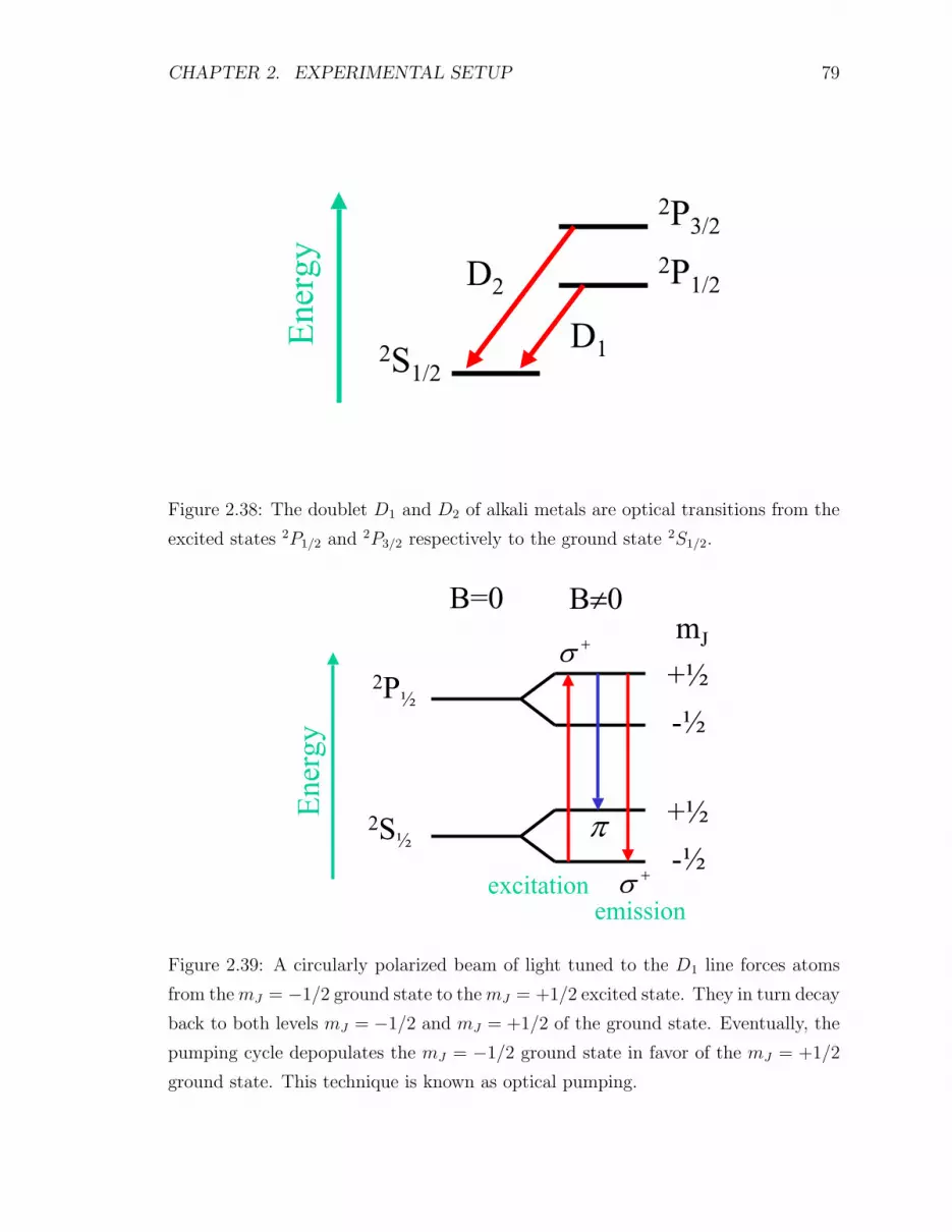
CHAPTER 2. EXPERIMENTAL SETUP 79
D2
D1
2P3/2
En
erg
y2P1/2
2S1/2
Figure 2.38: The doublet D1 and D2 of alkali metals are optical transitions from the
excited states 2P1/2 and 2P3/2 respectively to the ground state 2S1/2.
B=0 B 0mJ
+½2P½
-½
Ener
gy
+½2S½-½
emissionexcitation
Figure 2.39: A circularly polarized beam of light tuned to the D1 line forces atoms
from themJ = −1/2 ground state to themJ = +1/2 excited state. They in turn decay
back to both levels mJ = −1/2 and mJ = +1/2 of the ground state. Eventually, the
pumping cycle depopulates the mJ = −1/2 ground state in favor of the mJ = +1/2
ground state. This technique is known as optical pumping.

CHAPTER 2. EXPERIMENTAL SETUP 80
field. These pumping photons must be in the direction of the applied magnetic field.
Because of selection rules in optical transitions, only transitions from the ground state2S1/2, mJ = −1/2 to the excited state 2P1/2, mJ = +1/2 are induced. Transitions
back to the ground states 2S1/2, mJ = +1/2 and 2S1/2, mJ = −1/2 occur by emission
of linearly polarized light π and right circularly polarized light σ+, respectively, as
shown in Fig. 2.39. In time, the pumping cycle will depopulate the ground state
mJ = −1/2 in favor of mJ = +1/2. The polarization of the alkali metal can be
reduced by relaxation processes that include collisions between atoms and collisions
with the wall of the container. Moreover, when the excited electrons radiatively
decay back to the ground state, they do so by emitting unpolarized fluorescence
photons at the D1 or D2 line. That is they would tend to populate the mJ = +1/2
and mJ = −1/2 ground state equally. To quench this depolarization process, trace
amounts of a buffer gas, in this case nitrogen (N2), are introduced into the target
cell. This way, the excited electrons are able to decay radiationlessly, by transferring
energy to the vibrational, rotational, and translational degrees of freedom of the
N2 molecule, to the ground state. Unfortunately, since the introduction of nitrogen
dilutes the 3He cross section, there is a tradeoff between its quenching ability and
its polluting of the 3He cross section. Typically, the nitrogen to 3He number density
ratio is about 1:80. The alkali metal used in E94-010 was rubidium. Its D1 line is at
795 nm and D2 line at 780 nm [78]. The natural abundance of the two stable isotopes
of rubidium is 72.165% for 85Rb (I = 5/2) and 27.835% for 87Rb (I = 3/2) [43].
2.6.3 Spin Exchange
The spin exchange process involves the hyperfine interaction of the electronic spin of
Rb with the nuclear spin of 3He. Schematically, the reaction is
Rb(↑) + 3He(↓)→ Rb(↓) + 3He(↑). (2.41)
The magnetic dipole moment µn of the neutron in the 3He nucleus is [79, 80]
µn =gne
2mp
I = gnµNI (2.42)
where gn is the neutron g-factor, I is the nuclear spin, and µN = e/2mp is the nuclear
magneton. The magnetic dipole moment µe of the rubidium valence electron is
µe = − e
me
S = −2µBS (2.43)

CHAPTER 2. EXPERIMENTAL SETUP 81
where S is the electronic spin and µB = e/2me is the Bohr magneton. The magnetic
field generated by µn is [52]
B =3(µn · r)− µn
r3+
8π
3µnδ(r) (2.44)
The potential energy of a dipole in an external magnetic field is U = −µ ·B, therefore
the interaction Hamiltonian is
HSE = −[
3(µn · r)(µe · r)− (µn · µe)
r3
]− 8π
3(µn · µe)δ(r) (2.45)
For an electron in a spherically symmetric s state, the expectation value of the first
term vanishes and the spin exchange Hamiltonian becomes [81]
HSE =16π
3gnµNµBI · S|ψe(0)|2 (2.46)
The time evolution of the 3He polarization is [81,89]
PHe(t) = 〈PRb〉[
γSEγSE + Γ1
] [1− e−(γSE+Γ1)t
](2.47)
where 〈PRb〉 is the average Rb polarization, γSE is the spin exchange rate, and Γ1 is
the 3He polarization relaxation rate excluding spin exchange.
2.6.4 NMR Polarimetry
Consider a magnetic dipole with moment µ immersed in a magnetic field B. The
torque τ experienced by the magnetic dipole in the presence of the magnetic field is
given by
τ = µ×B. (2.48)
If S is the spin that gives rise to the dipole, then
µ = γS (2.49)
where γ is the gyromagnetic ratio. Since torque is the rate of change of angular
momentum,
dµ
dt= γµ×B. (2.50)

CHAPTER 2. EXPERIMENTAL SETUP 82
In a macroscopic medium with many dipoles, it is customary to introduce the mag-
netization M as the magnetic dipole moment per unit volume. The magnetization is
given by [82]
dM
dt= γM×B (2.51)
Eq. 2.51 describes the vector M as precessing in an inertial frame with angular veloc-
ity ω = −γB. In a physical sample, spin-lattice relaxation or longitudinal relaxation
involves the exchange of energy with other degrees of freedom (lattice). This relax-
ation mode is characterized by a relaxation time T1 and relaxes Mz to an equilibrium
value M0. Spin-spin relaxation or transverse relaxation involves destructive interfer-
ence with other spins. This relaxation mode is characterized by a relaxation time
T2 and relaxes Mx and My to 0 [83]. Phenomenologically, the equation of motion is
modified to provide the Bloch equations, first introduced by Felix Bloch in 1946 [84]:
dMx/dt = γ(MyBz −MzBy)−Mx/T2
dMy/dt = γ(MzBx −MxBz)−My/T2
dMz/dt = γ(MxBy −MyBx)− (Mz −M0)/T1
(2.52)
2.6.5 EPR Polarimetry
Principle
The EPR (Electron Paramagnetic Resonance) sometimes known as ESR (Electron
Spin Resonance) principle is very similar to NMR (Nuclear Magnetic Resonance).
Whereas NMR relies on the interaction of the nuclear spin with an external magnetic
field, EPR is a result of the electronic spin of paramagnetic substances interacting with
an external magnetic field. A paramagnetic material is one possessing an unpaired
outer shell electron producing a net, non-zero electronic spin. The case of paired
outer shell electrons with zero net spin or closed shell atoms is termed a diamagnetic
substance. The energy splitting ∆E in the presence of the magnetic field B provides
the fundamental equation of EPR [85]
hν = ∆E = gSµBB (2.53)
where h = 4.135 667 27(16) × 10−15 eV s is the Planck constant, ν is the frequency
in Hz, gS = −2.002 319 304 3737(82) is the Lande g-factor of the electron, and

CHAPTER 2. EXPERIMENTAL SETUP 83
µB = eh/2me = 5.788 381 749(43) × 10−5 eV T−1 is the Bohr magneton [86–88].
During E94-010, the holding field was set around 18 G. This puts the resonance
frequency at about 50 MHz, in the RF (Radio Frequency) region.
EPR polarimetry involves measuring the shift of the Rb Zeeman resonance line
induced by the magnetic field created by polarized 3He [89]. There are two processes
responsible for shifting the Rb Zeeman resonance: Rb-He spin exchange and 3He
magnetization. The hyperfine structure Hamiltonian for an atom in a magnetic field
B is [90, 91]
H = hAI · S +B3(I · S)2 + 3
2(I · S)− I(I + 1)S(S + 1)
2I(2I − 1)S(2S − 1)
+gSµBS ·B + gIµNI ·B (2.54)
where I is the nuclear spin and S is the electronic spin. A is the magnetic dipole
interaction constant and B is the electric quadrupole interaction constant. Its is zero
for S = 0 or 1/2 because the electron distribution is spherically symmetric for these
cases. gI is the Lande g-factor of the Rb nucleus. The quantity µN = eh/2mp =
3.152 451 238(24) × 10−8 eV T−1 is the nuclear magneton [86]. The ratio µI/µN =
+1.353 351 5 and I = 5/2 for 85Rb [43]. Furthermore, since µI = gIµNI [85],
gI = 0.541 340 6. The Rb-He spin-exchange process contributes a K · S term to the
Hamiltonian [78]
H = hAI · S + hαK · S + gSµBS ·B + gIµNI ·B (2.55)
where K is the nuclear spin of 3He and α is the frequency shift parameter. The bulk
magnetization of the polarized 3He adds an effective static field δB to the external
magnetic field B
δB = GµHe[He]PHe (2.56)
where PHe is the polarization of 3He, [He] is the 3He number density, µHe is the mag-
netic moment of 3He, and G is a geometrical factor characterizing the target cell. For
example, G = 8π/3 for spherical volumes. The term I ·S dominates the Hamiltonian.
A = 1012 MHz in comparison to gSµBB/h = 50 MHz at B = 18 G. The I ·B term is
even more diminutive since µN/µB = me/mp ≈ 1/1836. Consequently, in considering
eigenstates of H, it is reasonable to invoke the eigenstates of total angular momentum
F = I + S. Their energies are given exactly by the Breit-Rabi formula [90–92] for an

CHAPTER 2. EXPERIMENTAL SETUP 84
intermediate field, that is the interaction between the external magnetic field and the
atom is comparable to the hyperfine interaction,
E(F = I ± 1/2,MF ) = −hA4− gIµNBMF ±
hA
4(2I + 1)
×√
1 +4MF
2I + 1x+ x2 (2.57)
where x = 2(gSµBB + gIµNB + hα〈K〉)/hA(2I + 1). The energy difference between
adjacent energy levels is
∆E = E(F,MF )− E(F,MF − 1) (2.58)
=hA
4(2I + 1)
[√1 +
4MF
2I + 1x+ x2 −
√1 +
4(MF − 1)
2I + 1x+ x2
](2.59)
x 1 at low magnetic field, so x2 can be dropped in expanding the radical terms in
Taylor series.
hν = ∆E =hA
2x =
(gSµB + gIµN)(B + δB) + hα〈K〉2I + 1
(2.60)
where the classical magnetic field δB of the polarized 3He is shown explicitly. The
frequencies for each polarization direction are
ν↑ =gSµB(B + δB) + hα〈K〉
h(2I + 1)(2.61)
ν↓ =gSµB(B − δB)− hα〈K〉
h(2I + 1)(2.62)
where the gIµN term was ignored since it is much smaller then the corresponding
gSµB term. The EPR frequency shift is then
∆νEPR = ν↑ − ν↓ =gSµB
h(2I + 1)δB +
α〈K〉2I + 1
(2.63)
The EPR frequency shift is usually written as [93]
∆νEPR =gSµB
h(2I + 1)
8π
3κ0µHe[He]PHe (2.64)
where κ0 is a constant that depends on temperature only [94]
κ0 = (5.17± 0.37)
[1 +
T − 100C
(563± 30)C
](2.65)
Measuring the 3He polarization is reduced to measuring the difference in EPR fre-
quencies for each polarization orientation.

CHAPTER 2. EXPERIMENTAL SETUP 85
FrequencyCounter
Lock-inAmplifier
PIController
FunctionGenerator(150 Hz)
+VCO
SweepGenerator
RFAmplifier
EPR coil
NMR coil
NMR coil
Lasers
B
Oven
TargetCell
p-i-n diode
Ref
Figure 2.40: Instrumentation for EPR polarimetry. The p-i-n diode picks up the
EPR signal from a window on top of the oven. That signal is extracted with a lock-
in amplifier, then sent to a PI controller box which outputs the frequency at which
the signal is zero (EPR resonance frequency). The resulting signal is mixed with a
modulation source, then sent to a VCO to provide the frequency that drives the EPR
coil. The EPR coil provides the RF excitation to induce EPR transitions of Rb in
the target cell.

CHAPTER 2. EXPERIMENTAL SETUP 86
Frequency
Intensity
Figure 2.41: EPR lineshape.
Frequency
Intensity
Figure 2.42: First derivative of EPR
lineshape.
Instrumentation
The apparatus to detect the EPR resonance of rubidium is shown in Fig. 2.40. A RF
field of 6 kHz modulated at 200 Hz was applied via the EPR coil. The field is trans-
verse to the main holding field. The effect of the RF field is to induce the transition
MF = 3 → 2 in rubidium. The electrons in the state MF = 2 are then optically
pumped to the excited P-states. Most of these excited electrons decay back to the
ground S-state radiationlessly with the help of the buffer gas (nitrogen). However, a
small minority, typically 3 to 5%, decays by emitting a D1 = 795 nm or D2 = 780 nm
fluorescence photon. Due to frequency modulation of the magnetic field, the intensity
of the fluorescence is proportional to the first derivative of the EPR resonance with
respect to the excitation frequency [95]. The EPR lineshape and its first derivative
are shown in Figs. 2.41 and 2.42. To avoid stray D1 radiation from the pumping
lasers, a D2 filter is placed in front of the p-i-n diode or photodiode that monitors
the fluorescence of the pumping chamber. The EPR signal from the photodiode is
extracted with a lock-in amplifier, then sent to a PI (proportional-integral) controller.
The PI controller locks in to the EPR resonance frequency which is the frequency at
which the first derivative of the EPR lineshape is zero. The resonance frequency is
mixed with a low frequency modulation source, then fed to a frequency counter and
a VCO (voltage-controlled oscillator) to drive the EPR coil. The purpose of the feed-
back circuit (PI controller) is to account for drifts in the holding field and hence drifts
in the EPR resonance frequency. The particulars of the feedback circuit are exposed
in Fig. 2.43. A typical EPR data taking session consisted of sweeping the frequency
through EPR resonance using the technique of AFP (Adiabatic Fast Passage) to flip

CHAPTER 2. EXPERIMENTAL SETUP 87
modV
12k12k
12k1k
100k
1k100k
12k
12k
12k
Vin
Vout
10u
0.01u
0.01u
Integral reset
Relative gain
Absolute gain
+
−
+
−
+
−+
−
Figure 2.43: The proportional-integral controller output coupled with the modulation
source Vmod adjusts the input to the voltage-controlled oscillator at Vout to keep the
input to the lock-in amplifier Vin at zero [89].
12000
12005
12010
12015
12020
12025
12030
12035
12040
0 50 100 150 200 250 300 350 400
EP
R F
requ
ency
(kH
z)
Time (arb. units)
EPR Frequency Shift
Figure 2.44: Representative EPR frequency shift data set taken on 9/28/1998 at 9:53
pm. The difference in the EPR resonance frequencies between the alternate spin
directions is proportional to the 3He polarization. Here the EPR frequency shift is
roughly 21 kHz out of 12 MHz.

CHAPTER 2. EXPERIMENTAL SETUP 88
Jlab Hall A E94-010 Target Setup Schematic
Collimating Lensl4
l4
l4
Four30 WDiodeLasersTunedto795 nm
RF - Drive Coil
RF - Drive Coil
Mai
n H
oldi
ng C
oil
Mai
n H
oldi
ng C
oil
EPR Coil
Pick Up Coils
Collimating Lens
Diode
PolarizingOptics
Figure 2.45: Schematic of the polarized 3He target used during E94-010. The upper
right features a set of high-power lasers. The upper left displays the polarizing optics.
Only one set of Helmholtz coils is shown. The RF drive coils are used for both EPR
and NMR measurements. The target cell sits at the center with its pumping chamber
located inside an oven.
the spins at intervals of about a minute. A sample EPR data set is shown in Fig. 2.44.
The difference in EPR resonance frequencies is proportional to the 3He polarization.
2.6.6 Polarized 3He Target Setup
The setup of the polarized 3He target is shown in Fig. 2.45. A set of high-power diode
lasers is shown on the upper right. They are used for optical pumping of the target
cell. Four lasers are used for each pumping direction: longitudinal and transverse. In
the upper left is shown the polarizing optics which consists of focusing lenses, mirrors,
half-wave plates and quarter-wave plates. The latter are used to polarize the laser

CHAPTER 2. EXPERIMENTAL SETUP 89
beam. The beam polarization achieved is close to 100%. The oven, in the center of
the diagram, holds the pumping chamber. The oven is used to bring the rubidium
in the pumping chamber to a temperature of 170C and in its gaseous state, to be
used in spin-exchange collisions with the helium in the target cell. There are two sets
of Helmholtz (main holding) coils, but only one set is shown in the diagram. The
other set is perpendicular to the first one. The combination of all four Helmholtz
coils provide a main holding magnetic field in any direction in the horizontal plane.
The field is utilized to define the polarization direction. The RF drive coils provide
a radio frequency field of 91 kHz during a NMR target polarization measurement.
The EPR drive coils achieve a similar purpose but for the EPR target polarization
measurement technique. The EPR p-i-n diode reads the shift in the rubidium optical
transition which is proportional to polarization. The pick-up coils, along the length
of the target chamber, are used to read the induced signal during an AFP/NMR
measurement of the target polarization. Not shown is the target ladder that includes
the reference cell and other targets used for calibration.

Chapter 3
ANALYSIS
There are two fundamental quantities of interest that are sought after in many ex-
perimental nuclear and particle physics experiments: cross section and asymmetry.
From these two observables, much of the physics being investigated can be readily
extracted. These quantities bridge the gap between experiment and theory in physics.
The experimental differential cross section is obtained with the following formula:(
d2σ
dΩdE ′
)
exp
=N
NincNtarget∆Ω∆E ′, (3.1)
where σ is the total cross section, ∆Ω = ∆θ∆φ is the angular acceptance of the
spectrometer, ∆E ′ is the bin size in scattered electron energy, N is the number of
scattered electrons, Ninc = Q/e is the number of incident electrons and is simply
the accumulated charge Q normalized by the electronic charge e, and Ntarget is the
number of target nuclei per unit area. The experimental asymmetry is calculated
with the following formula:
Aexp =1
fPbPt
N+/Q+ −N−/Q−N+/Q+ +N−/Q−
, (3.2)
where f is a dilution factor introduced by unpolarized nuclei in the target cell, notably
nitrogen, Pb is the beam polarization, Pt is the target polarization, and N+(−) is the
number of detected scattered electrons with positive (negative) helicity.
3.1 Procedure of Analysis
A grand overview of the analysis procedure is illustrated in Fig. 3.1. The raw count-
ing rates N+ and N− for particles detected in the spectrometers may contain pions
90

CHAPTER 3. ANALYSIS 91
and other unwanted particles besides electrons. Thus, the events are subjected to
particle identification with the shower and Cherenkov counters. Events that fail to
provide a good track reconstruction by the drift chambers are also eliminated. In
addition, each detector introduces a detection efficiency which must be corrected for.
Normalizing the resulting scattered electrons counting rates N+e and N−e by the total
beam charge, the dilution factor, the beam and target polarization, the target density,
the angular acceptance of the spectrometer obtained by Monte Carlo simulations, the
beam energy, and the radiative corrections provide the cross sections and asymme-
tries. Suitable combinations of the cross sections and various kinematical factors give
the structure functions and GDH sum rule for 3He. The corresponding physics quan-
tities for the neutron are extracted from 3He by accounting for nuclear effects with
the convolution approach of C. Ciofi degli Atti et al. [32].
N+
N-
N+
N-
corr
corr
Particle ID Detection Efficiency
N+
N-e
e
Nitrogen Dilution
Q+
Q-Pbeam
Ptarget
n t Ebeam∆Ω
Current Calibration
Beam and Target Polarimetry
Target Analysis
Spectrometer Simulation
Beam Energy Measurements
Radiative Corrections
σ +
-σ||
||
σ +
-σ
g1(x,Q )2
g2(x,Q )2
Sum Rule
He3
g1(x,Q )2
g2(x,Q )2
Sum Rule
neutron
Nuclear Structure
Figure 3.1: Analysis flowchart from raw counting rates to neutron structure functions
and the GDH sum rule.
3.2 Data Reduction
The event mode data goes through several stages of filtering in the process of extract-
ing cross sections and scattering asymmetries. These stages include:

CHAPTER 3. ANALYSIS 92
1. Event acquisition is limited by the data readout and data transferred rates,
requiring normalization to the raw trigger rate, as described in a later section.
2. Events are selected for processing by requiring the reconstruction of a good
event track in the wire chamber. Multiple tracks are rejected by the algorithm.
The results are renormalized to account for the events not analyzed and other
deadtime corrections.
3. “Good events” are further filtered by geometrical cuts and particle ID cuts
discussed further in the following sections.
4. The cross section generated must then be normalized for luminosity and accep-
tance. Most of these corrections are standard to event mode in Hall A HRS
event analysis.
Here only the cuts specific to this experiment will be discussed.
3.2.1 Geometrical Cuts
The main purpose of the geometrical cuts is to get rid of events coming from the
target windows and to cut off the edges of the spectrometer acceptance. That is, it is
desirable to stay within a well-understood part of the acceptance and keep away from
regions such as the edges of the acceptance where poor statistics yield large errors
and the acceptance is not well understod. The geometrical cuts are applied on target
variables θ, φ, y, and δ. Two two-dimensional cuts were applied to the data from
both the Electron and Hadron spectrometers. The first is a cut on the transverse
acceptance variables φ and y. The second is a cut on the bend plane observables θ
and δ. The geometrical cuts used in the final analysis are shown in Fig. 3.2.
3.2.2 Electron Arm Shower Counters
Calibration of the shower counters is essential in order to determine pion rejection
rates (π/e ratio). Cuts on the lead glass calorimeters along with cuts on the Cherenkov
counters can separate pions from electrons by several orders of magnitude. An un-
derstanding of the issues associated with these detectors such as detector efficiencies
and pion suppression abilities is of paramount importance. The calibration of the

CHAPTER 3. ANALYSIS 93
-50-40-30-20-10
01020304050
-100 -50 0 50 100
Phi Vs. Y-target Theta Vs. Dp
-100-80-60-40-20
020406080
100
-0.05 0 0.05
Figure 3.2: Geometrical cuts on target variables θ (Theta), φ (Phi), y (Y-target), and
δ (Dp) used in the final analysis. The concentration of events in the lower right-hand
quadrant outside the cut region in the left figure is due to the target windows.
shower counters for both the Electron and Hadron Arms during E94-010 is detailed
in Ref. [96]. The technique employed is described in detail in Ref. [97].
Calibration
Einstein’s relation, E2 = p2 + m2, simplifies to E ≈ p or E/p ≈ 1 for electrons
(me = 0.511 MeV) at the high beam energies of E94-010 (0.862-5.070 GeV). This is
verified in the plot of E/p vs. p in Fig. 3.3. The low data points come from runs
taken near the end of the experiment when the scintillator threshold was lowered
due to efficiency problems. It is believed that some of the helium which was used to
fill the target chamber escaped and corrupted the vacuum of the phototubes of the
scintillator counters thereby lowering their efficiency. The immediate solution was
to lower the threshold of the trigger scintillators which caused some noise in trigger.
However, after final cuts, this was no longer a problem. The high data points come
from runs with momentum settings near the limits of the spectrometers. The NMR
probe of the dipole proves unreliable and a gaussmeter must be used instead. The
difference can be attributed in part to a systematic error between the NMR probe
and the gaussmeter. The fractional resolution σ/E scales inversely as the square root

CHAPTER 3. ANALYSIS 94
of energy E. This is because electromagnetic showers obey a Poisson distribution, for
which the variance σ2 is equal to the mean energy E. A shower counter’s fractional
resolution is then:
σ
E=
√E
E=
1√E. (3.3)
An additional factor is needed to account for various fundamental processes that
lead to energy deposition in the detector [98, 99]. In particular for lead-glass shower
counters, σ/E ∼ 5%/√E as indicated in Table 27.5 of Ref. [100]. This agrees well
with the measured values shown in Fig. 3.3 (σ/p ∼ 5.3%/√p) and Fig. 3.7 (σ/p ∼
4.2%/√p) for the Electron Arm and Hadron Arm, respectively.
Detection Efficiency
A T1 event is recorded when paddles from scintillator planes S1 and S2 fire in an
acceptable pattern, and the Cherenkov counter fires. The recipe for calculating the
efficiency of the calorimeter after selecting T1 events that pass the geometrical cuts
described above is:
efficiency =events registered in preshower, shower, and Cherenkov counters
events registered in Cherenkov counter. (3.4)
As can be seen in Fig. 3.4, the detection efficiency is consistently better than 99%
except at low energy (862 MeV) where a few events are omitted by the cluster forma-
tion algorithm. This fact is dramatically illustrated in Fig. 3.5. Many events to the
left of the histogram never enter the data acquisition system. A possible remedy for
the situation is to use the output of the raw ADCs instead. The E/p and preshower/p
cuts introduced in Fig. 3.5 excludes certain good electron events. Nonetheless, the
inefficiency of these cuts was kept below 1%. [
Pion Suppression
The estimate for pion contamination is achieved by applying cuts on different detec-
tors:
1. Cut on the preshower: An initial anti-Cherenkov cut, i.e. selection of all par-
ticles that fail to trigger the Cherenkov, is submitted. Ideally, no electrons are
left in the histogram. A cut is now made on the preshower where the pion peak

CHAPTER 3. ANALYSIS 95
0.860.880.9
0.920.940.960.98
11.021.04
0 0.5 1 1.5 2 2.5 3 3.5 4 4.5 5
0.04
0.05
0.06
0.07
0.08
0.09
0.1
0 0.5 1 1.5 2 2.5 3 3.5 4 4.5 5
1720 MeV2591 MeV3384 MeV4240 MeV5070 MeV
862 MeV
wid
th
0.01293 + 0.05314/ x
σ/P vs. P
Electron ArmE/P vs. P
Figure 3.3: Plots of E/p (top) and σ/p (bottom) vs. p showing proper calibration of
the shower counters in the Electron Arm.

CHAPTER 3. ANALYSIS 96
0.984
0.99
1
0 0.5 1 1.5 2 2.5 3 3.5 4
Shower Detection Efficiency
GeV/c
(E-arm)
862 MeV1720 MeV2591 MeV3384 MeV4240 MeV5070 MeV
Figure 3.4: Detection efficiency for the Electron Arm. At low energy (862 MeV) the
cluster formation algorithm drops a few events.
is much more pronounced since not all of the pion energy is absorbed in this first
stage of the shower counter. The ratio of pions before to after the preshower
cut is the preshower pion suppression factor. It is typically around 4–5.
2. Cut on the Cherenkov: An E/p plot reveals two peaks. Pions are on the left
and electrons on the right. An E/p cut then separates pions from electrons. A
further anti-Cherenkov cut then selects pions. The ratio of pions before to after
the anti-Cherenkov cut is the Cherenkov pion suppression factor.
to obtain suppression factors. The results are shown in Fig. 3.6. The final pion
contamination is the ratio of pions to electrons inside the E/p cut, divided by the
preshower and Cherenkov suppression factors.
3.2.3 Hadron Arm Shower Counter
A calorimeter consisting of 32 (16×2) lead-glass blocks was added to the rear of the
detector stack in the Hadron Arm prior to E94-010.

CHAPTER 3. ANALYSIS 97
0
0.2
0.4
0.6
0.8
1
1.2
1.4
0 0.2 0.4 0.6 0.8 1 1.2 1.4
E/p cut
prsh/p cut
Lost events
Pre
show
er /
P
Shower / P
Figure 3.5: Two-dimensional histogram of preshower/p vs. shower/p at 862 MeV
showing E/p and preshower/p cuts, where E =preshower+shower. The cluster forma-
tion algorithm drops some events on the left as is discussed in the left hand spectrum,
resulting in a reduced efficiency.
Calibration
The shower counter in the Hadron Arm is not a total absorption calorimeter. The
method used to calibrate the Electron Arm calorimeter cannot be used here. For
calibration purpose, only events that fire in a single block are examined. This is to
avoid miscalibration with events that pass through fissures between adjacent blocks in
the calorimeter. The method of analysis is fully described in Ref. [96]. The software
gain of each block is then manually adjusted to normalize the shower output by
particle momentum to unity. The results are displayed in Fig. 3.7. The detector
resolution σ/E of the Hadron Arm calorimeter is worse than that of the Electron
Arm by about 1%.

CHAPTER 3. ANALYSIS 98
1
10
10 2
10 3
10 4
0 0.5 1 1.5E/p (pions) E/p
1
10
10 2
10 3
10 4
0 0.5 1 1.5
Run 3392
N f
N i
(A) (B)
Before preshower cut
After preshower cut
Before Cerenkov cut
After Cerenkov cut
Figure 3.6: (A) Pion suppression with a preshower cut. An anti-Cherenkov cut is
applied to the initial data sample to isolate pions. A preshower cut is made on the
pion population. A factor of 4-5 is obtained in this fashion for the ratio of pions
before to after the preshower cut. (B) Pion suppression with a Cherenkov cut. Pions
are identified as those particles to the left of the E/p cut. An anti-Cherenkov cut is
then applied to the pion sample. The resulting ratio of pions before and after the
anti-Cherenkov cut is of a couple of orders of magnitude.
Detection Efficiency
The detection efficiency of the Hadron Arm shower counter is reduced by the loss of
electrons that pass through the spacing between adjacent lead-glass blocks. However,
the detector efficiency is kept higher than 99%. The result is shown in Fig. 3.8.
Cut Efficiency
The cut on the Hadron shower was chosen in such a way to preserve inefficiency below
0.5%. The π/e ratios and detector efficiencies for both the Electron and Hadron Arms
are tabulated in Ref. [96].

CHAPTER 3. ANALYSIS 99
0.75
0.8
0.85
0.9
0.95
1
1.05
0.5 1 1.5 2 2.5 3
0.14
0.145
0.15
0.155
0.16
0.165
0.17
0.175
0.18
0.185
0.19
0.5 1 1.5 2 2.5 3
GeV/c
GeV/c
wid
th
1720 MeV2591 MeV3384 MeV4240 MeV5070 MeV
862 MeV
Hadron ArmShower/P vs. P
σ/P vs. P
0.12181 + 0.04194/ x
Figure 3.7: Plots of E/p and σ/p vs. p for the Hadron Arm. Note the shower counter
in the Hadron Arm is not a total absorption calorimeter.
3.2.4 Cherenkov Detectors
Calibration
Calibrating the Cherenkov detectors entails adjusting the offsets and gains of the
individual phototube ADCs. Since some electrons will fire several phototubes, one
needs to sum over all phototubes to obtain a good collection efficiency. Histograms
of the raw and calibrated Cherenkov ADCs are shown in Figs. 3.9 and 3.10. Note
the location of the single photoelectron peak on the left before and after calibration.
Stability
It was found that the output of the Cherenkov ADCs was reasonably stable over the
momentum range of E94-010 (see Fig. 3.11).

CHAPTER 3. ANALYSIS 100
(H-arm)
GeV/c
0.984
0.99
1
0 0.5 1 1.5 2 2.5 3 3.5
862 MeV1720 MeV2591 MeV3384 MeV4240 MeV5070 MeV
Shower Detection Efficiency
Figure 3.8: Detection efficiency of the Hadron Arm shower counter. Electrons lost
in the spacing between blocks effectively reduce the detector efficiency. Nevertheless,
an efficiency of better than 99% is maintained throughout.
Detection Efficiency
The detection efficiency ε for a Poisson process like the emission of Cherenkov radia-
tion is:
ε = 1− e−µ, (3.5)
where µ is the average number of photoelectrons produced per meter, e−µ is the
probability of emitting no photoelectron, and µ ≈ 9 [102] yields ε ≈ 99.99%. The
method used to calculate efficiencies in the Electron and Hadron Arms is illustrated
in Figs. 3.12 and 3.13. For the Electron Arm (Fig. 3.12), a tight two-dimensional cut
is applied to the preshower vs. shower to select good electrons, followed by a cut on
the Cherenkov signal. The Cherenkov detection efficiency is the is the ratio of events
that pass the Cherenkov cut to these that pass the two-dimensional preshower vs.
shower cut:
Detection efficiency =events registered in the Cherenkov detector
events that pass the preshower vs. shower 2-D cut. (3.6)
For the Hadron Arm (Fig. 3.13), a shower/p cut is made to select good electrons.
The Cherenkov detection efficiency is the number of events that fire the Cherenkov

CHAPTER 3. ANALYSIS 101
1 2
3 4
5 6
7 8
9 10
10 210 4
0 1000 2000 3000 4000
10 210 4
0 1000 2000 3000 4000
110 210 410 5
0 1000 2000 3000 400010 210 310 4
0 1000 2000 3000 4000
10 310 5
0 1000 2000 3000 4000
10 3
10 5
0 1000 2000 3000 4000
10 310 410 5
0 1000 2000 3000 4000
10 3
10 5
0 1000 2000 3000 4000
10 210 310 4
0 1000 2000 3000 400010 210 310 4
0 1000 2000 3000 4000
Figure 3.9: Raw Cherenkov ADC spectra.
counter to the number of events that pass the shower/p cut:
Detection efficiency =events registered in the Cherenkov detector
events that pass the shower cut. (3.7)
The efficiencies as a function of momentum were also investigated with the results
shown in Fig. 3.14. Pion contamination is more pronounced at lower momenta. See
tables in Ref. [96]. This degrades the detection efficiency.
Cut Efficiency
Values for detection and cut efficiencies are tabulated for all kinematics in the ap-
pendix of Ref. [101].

CHAPTER 3. ANALYSIS 102
1 2
3 4
5 6
7 8
9 10
110 210 410 5
0 1000 2000 3000 4000
10 210 4
0 1000 2000 3000 4000
10 210 410 5
0 1000 2000 3000 4000
10 210 310 4
0 1000 2000 3000 4000
10 210 410 5
0 1000 2000 3000 4000
10 310 5
0 1000 2000 3000 4000
10 310 410 5
0 1000 2000 3000 4000
10 210 410 5
0 1000 2000 3000 4000
10 210 310 4
0 1000 2000 3000 4000
10 210 310 4
0 1000 2000 3000 4000
Figure 3.10: Calibrated Cherenkov ADC spectra.

CHAPTER 3. ANALYSIS 103
140150160170180190200210220230240
0 0.5 1 1.5 2 2.5 3 3.5 4
Single photo-electron peak vs. P
GeV/cELECTRON ARM
862 MeV1720 MeV2591 MeV3384 MeV4240 MeV5070 MeV
GeV/cHADRON ARM
220230240250260270280290300310320
0 0.5 1 1.5 2 2.5 3 3.5 4
AD
C C
HA
NN
EL
AD
C C
HA
NN
EL
Figure 3.11: Stability of the Electron and Hadron Arm Cherenkov detectors. The
data points are averages of the 10 single photoelectron peaks. The low data points
in the top plot are mostly from the 2.591 GeV and 5.070 GeV runs near the end of
the experiment when the threshold on the trigger scintillators had to be lowered.

CHAPTER 3. ANALYSIS 104
0
1000
2000
3000
0 1000 2000 30000
1000
2000
3000
0 1000 2000 3000
010
30
50
70
90
0 4000 8000 12000 16000 20000
Cerenkov Detection Efficiency
ENTRIES 36844
PRESHOWER vS. SHOWER
ENTRIES 6954
CERENKOV
Entries 6947
ε = 99.899%
Run 2221
Figure 3.12: Detection efficiency of the Cherenkov detector for the Electron Arm.
The plot in the upper left shows preshower vs. shower output without any cuts. A
tight two-dimensional cut is applied to the preshower vs. shower histogram resulting
in the plot in the upper right. The bottom plot shows the output of the Cherenkov
counter with the previous cut. The efficiency is the number of electrons that fire the
Cherenkov counter to the number of events that pass the preshower vs. shower cut.

CHAPTER 3. ANALYSIS 105
1
10
10 2
10 3
0 0.2 0.4 0.6 0.8 1 1.2 1.4 1.6 1.8 2
1
10
10 2
0 4000 8000 12000 16000 20000
Shower/p
CERENKOV
Hadron Arm Cerenkov Detection Efficiency
π
"good" e- E = 3.384 GeV; P = 0.988 GeV/c Run 2203
ε = 96.682%
Entries 18123
Figure 3.13: Detection efficiency of the Cherenkov detector for the Hadron Arm. The
upper plot shows the cuts used to select good electron events. The lower graph shows
the output of the Cherenkov with the previous cut. The efficiency is the number of
events that fire the Cherenkov to the number of events that pass the shower cut. The
events in the hashed area are pions obtained with an anti-Cherenkov cut and serve
only to illustrate the amount of pion contaminants.

CHAPTER 3. ANALYSIS 106
96
97
98
99
100
0.5 1 1.5 2 2.5 3 3.5 4GeV/c
Detection Efficiency vs. P
99.5
99.6
99.7
99.8
99.9
100
0.5 1 1.5 2 2.5 3 3.5 4GeV/c
862 MeV1720 MeV2591 MeV3384 MeV4240 MeV5070 MeV
Electron Arm
Figure 3.14: Cherenkov detection efficiency vs. momentum p. The top plot is for the
Electron Arm and the bottom plot is for the Hadron Arm. The efficiency is decreased
at lower momenta because of pion contamination [96].

CHAPTER 3. ANALYSIS 107
3.3 Charge Determination
The beam charge is determined from a particular V/F (voltage-to-frequency) scaler
as the product of the current and the duration of the run:
Q = I × T = RV/F ×T
αI, (3.8)
where RV/F is the V/F rate and αI is a calibration constant. The charge is accurate
to better than 1%.
3.4 Acceptance
In order to understand the acceptance of the spectrometer, a simulation of the 12C
data was done and subsequently compared with data runs. The results are shown in
Fig. 3.15.
3.5 Monte Carlo Techniques
The Monte Carlo method is a powerful tool to simulate electron scattering on a com-
puter. Such a program was developed by A. Deur [103,104] and subsequently used to
understand the acceptance of the Jefferson Lab Hall A High Resolution Spectrometers
during E94-010 [105]. Often, in a Monte Carlo simulation, it is desired to generate
some distribution with a certain probability density function. Of particular interest
is the Gaussian or normal distribution. A popular algorithm for generating two inde-
pendent, normally distributed random numbers z1 and z2 with mean 0 and variance
1 is to generate two uniformly distributed random variables u1 and u2 in the interval
(0,1), then calculate z1 = cos 2πu1
√−2 ln u2 and z2 = sin 2πu1
√−2 ln u2 [87,106–108].
Repeated evaluations of the trigonometric functions is somewhat inefficient, so faster
algorithms have been developed and implemented. See for instance the Fortran rou-
tine RNORML (V120) from CERNLIB [109].
3.6 Passage of Electrons Through Matter
The dominant physical processes for energy loss by electrons traversing a layer of
material at the incident energies of E94-010 are:

CHAPTER 3. ANALYSIS 108
Horizontal scattering angle(Rd)
Foil 2
Foil 3
Foil 4
Foil 5
Foil 6
dp/p=-4% dp/p=-2%
Experimental data
dp/p=0 dp/p=+2% dp/p=+4%
C(e’,e) elastic12 in the HRS frame.
0.862 GeV, 15.5 oSimulation
Figure 3.15: Fractional momentum δ = dp/p spectra of carbon data for experimental
data (in green) and simulation (in red) as measured in the Electron Arm.

CHAPTER 3. ANALYSIS 109
• Ionization
• External bremsstrahlung
• Internal bremsstrahlung
3.6.1 Ionization
Energy loss by ionization is a consequence of inelastic collisions with the atomic
electrons of the material. The expression for the average energy loss per unit path
length also known as stopping power was first worked out using classical arguments
by Bohr. Later Bethe, Bloch and others developed a formula based on quantum
mechanics. The Bethe-Bloch formula [87,98] is
−dEdx
= 2πNAr2emec
2ρZ
A
z2
β2
[ln
(2mec
2β2γ2Tmax
I2
)− 2β2
](3.9)
where
2πNAr2emec
2 = 0.1535 MeV/g cm−2 (3.10)
and
NA is Avogadro’s number 6.02214199(47)× 1023 mol−1.
re is the classical electron radius 2.817940285(31)× 10−13 cm.
me is the mass of the electron 0.510998902(21) MeV/c2.
ρ is the density of the material.
Z is the atomic number of the material.
A is the atomic weight of the material.
z is the charge of the incident particle in e.
β = v/c is the speed of the incident particle.
γ = 1/√
1− β2
Tmax is the maximum kinetic energy per collision.

CHAPTER 3. ANALYSIS 110
I = I0Z is the mean excitation potential and I0 ≈ 13.5 eV.
The energy loss by ionization of particles crossing a thin absorber, where the energy
lost by the particle is small compared to its incident energy, is a statistical process
and spread out according to a distribution which was first calculated by Landau. This
Landau straggling follows a distribution [98,110,111]:
f(x,∆) =1
ξφ(λ) (3.11)
where
ξ = 2πNAr2emec
2ρZ
A
z2
β2x (3.12)
φ(λ) =1
2πi
∫ ε+i∞
ε−i∞ez ln z+λzdz (3.13)
λ =1
ξ
[∆− ξ
(lnξ
ε+ 1− γE
)](3.14)
ln ε = ln
(I2
2mec2β2γ2
)+ β2 (3.15)
and
x is the thickness of the absorber.
∆ is the energy loss.
ξ is approximately the mean energy loss.
λ is a dimensionless variable.
φ(λ) is the probability density function.
γE is the Euler-Mascheroni constant 0.577216.
Often in Monte Carlo simulations of the energy loss it is desired to generate random
numbers according to the Landau distribution. It is useful to introduce a distribution
function Φ(λ) of the density φ(λ), and its inverse Ψ(x):
Φ(λ) =
∫ λ
−∞φ(λ′)dλ′ (3.16)
Ψ(x) = Φ−1(x) (3.17)

CHAPTER 3. ANALYSIS 111
−10 0 10 20 30λ
0
0.05
0.1
0.15
0.2
φ(λ)
Figure 3.16: Landau density
−10 0 10 20 30λ
0
0.2
0.4
0.6
0.8
1
Φ(λ
)
Figure 3.17: Landau distribution
If x is a random variable distributed uniformly between 0 and 1, then Ψ(x) is the
corresponding is distributed according to the Landau density Φ(λ). The energy loss
can then be deduced from λ using Eq. (3.14). Figs. 3.16 and 3.17 show the Landau
density and distribution, respectively. The Landau density peaks at λ = −0.222782
with φ(λ) = 0.180655. The corresponding most probable energy loss is:
∆mp = ξ
[lnξ
ε+ 0.200002
](3.18)
For the purpose of evaluating φ(λ) a couple of integral representations of the Landau
distribution function have been derived [112]:
φ(λ) =1
πe−σ
∫ ∞
0
exp
[σ
2ln
(1 +
u2
σ2
)− u arctan
u
σ
]
cos
[u
2ln
(1 +
u2
σ2
)− u+ σ arctan
u
σ
]du
φ(λ) =1
π
∫ ∞
0
e−λuu−u sinπudu
where σ = e−λ−1 and the first formula is used for negative λ while the second formula
is used for positive λ. The CERNLIB program library contains the LANDAU (G110)
package which includes the Fortran routines DENLAN, DISLAN, and RANLAN
for evaluating φ(λ), Φ(λ), and Ψ(x) respectively [109].
3.6.2 External Bremsstrahlung
The emission of radiation by scattering from nuclei other than the target nucleon is
termed external bremsstrahlung [113]. Let Ie(E,∆, t) d∆ represent the probability

CHAPTER 3. ANALYSIS 112
of an electron with incident energy E traversing a material with thickness t in units
of radiation length to lose energy between ∆ and ∆ + d∆. The density function
Ie(E,∆, t) is [114,115]:
Ie(E,∆, t) =1
Γ(bt)
1
∆
(∆
E
)btφ
(∆
E
)(3.19)
where
b =4
3
1 +
1
9[(Z + 1)/(Z + ξ)][ln(183Z−1/3)]−1
(3.20)
ξ = ln(1440Z−2/3)/ ln(183Z−1/3) (3.21)
φ(v) = 1− v +3
4v2 (3.22)
and φ(v) is due to the screening of nuclear potentials by atomic electrons. For the
purpose of Monte Carlo simulations the integral of Ie(E,∆, t) is:
∫ ∆
0
Ie(E,∆′, t) d∆′ =
1
Γ(1 + bt)
(∆
E
)bt+O
(∆
E
)1+bt
(3.23)
Following the transformation method [106, 107], if R is a random number in [0,1] let
R = (∆/E)bt. Therefore the formula:
∆ = ER1bt (3.24)
will generate energy losses ∆ according to the external bremsstrahlung distribution
Ie(E,∆, t) provided:
1
Γ(1 + bt)∼ 1 and
(∆
E
)1+bt
(
∆
E
)bt. (3.25)
3.6.3 Internal Bremsstrahlung
Internal bremsstrahlung refers to the real photons emitted during scattering with
the target nucleon. The scattering process has an angular distribution of 1/γ and
therefore strongly peaked along the direction of the incident and outgoing electrons.
The Feynman diagrams representing these processes are displayed in Fig. 3.18. This
effect can be approximated by placing an effective or virtual before and after the
target, each of thickness [114]:
bt =α
π
[ln
(Q2
m2e
)− 1
](3.26)
where Q2 is the momentum transfer squared.

CHAPTER 3. ANALYSIS 113
Figure 3.18: Lowest order Feynman diagrams for real bremsstrahlung.
3.6.4 Multiple Scattering Through Small Angles
Charged particles traveling through a certain material suffer deflections due to multi-
ple Coulomb scatterings from nuclei. The distribution of scattering angles is described
by the theory of Moliere and is approximately Gaussian for small angles with a tail
that follows a 1/ sin4(θ/2) dependence as a result of Rutherford single scatterings.
The width of the central Gaussian is given by [87,116]:
θ0 =13.6 MeV
β2γmec2
√t [1 + 0.038 ln t] (3.27)
where t is the target thickness in radiation lengths.
3.7 Radiators
In order to be able to calculate radiation loss by electrons going through various ma-
terials, a list of materials and some of their atomic and nuclear properties is required.
Such a list was originally compiled by F. Xiong [118] and reproduced in Fig. 3.19,
and Table 3.1 and 3.2. Corning 1720 [119] is an aluminosilicate glass used for the
construction of the reference cell. GE 180 [120] is another type of glass used for the
construction of the target cell Armageddon. The composition of both glasses and
some of their properties are listed in Table 3.4 and 3.5. The effective atomic num-
ber, atomic weight, and X0 for compounds and mixtures were calculated using the

CHAPTER 3. ANALYSIS 114
0.01" Be
θe25.7 cm
1" air
20 cm
Beam DumpBeam Line
0.01" Al
0.01" Al
0.007" Kapton
0.004" TitaniumDetector
e
He3 Target Cell
0.13/0.142 mm glass window
~1.3 mm glass wall
42 cm
Detectore
Spectrometer
Hadron Arm
Electron ArmTarget Enclosure65.2 cm air
64.2 cm air
He4 jets45.7 cm
e
~
Figure 3.19: Radiators for E94-010.

CHAPTER 3. ANALYSIS 115
Material Length Thickness Thickness
(cm) (g/cm2) (radiation length)
Beryllium 0.0254 4.694× 10⁻² 7.200× 10⁻⁴
Air 2.54 3.060× 10⁻³ 8.347× 10⁻⁵
Aluminum 0.0254 6.855× 10⁻² 2.855× 10⁻³
Helium 25.7 4.274× 10⁻³ 4.532× 10⁻⁵
Corning 1720 0.013 3.302× 10⁻² 1.229× 10⁻³
or GE 180 0.013 3.588× 10⁻² 1.846× 10⁻³
Nitrogen 20 2.331× 10⁻² 6.135× 10⁻⁴
Table 3.1: Radiators before scattering for Electron and Hadron arms.
following formulas [98]:
Zeff =∑
aiZi, (3.28)
Aeff =∑
aiAi, (3.29)
1
X0
=∑ wi
Xi
, (3.30)
where ai is the number of atom of the ith element in the compound, wi = aiAi/Aeff
is the fraction by weight of the ith element, Zi is the atomic number of the ith
element, and Ai is the atomic weight of the ith element. Values of Z, A, and X0 for
elements are taken from Table III.6 of Ref. [121]. Their densities are from Ref. [122].
Compositions and densities of air and kapton were obtained from Ref. [123] and
reproduced in Table 3.6 and 3.7. X0 for air and kapton are taken from Ref. [87].
The data and simulation are displayed in red and blue respectively in Figs. 3.20 and
3.21. The simulation is normalized by area to the data. δtg and ytg of the simulation
are slightly shifted to the left with respect to the data. θtg and φtg yield rather good
agreement between simulation and data. The excitation energy EX is defined by:
EX = W −M, (3.31)
W =√M2 −Q2 + 2Mν, (3.32)
Q2 = 4EE ′ sin2 θ
2, (3.33)
ν = E − E ′, (3.34)

CHAPTER 3. ANALYSIS 116
Material Length Thickness Thickness
(cm) (g/cm2) (radiation length)
Corning 1720 0.4865 1.236 4.602× 10⁻²
or GE 180 0.4865 1.343 6.908× 10⁻²
Helium 42 6.985× 10⁻³ 7.406× 10⁻⁵
Aluminum 0.0254 6.855× 10⁻² 2.855× 10⁻³
Air (Electron Arm) 65.2 7.855× 10⁻² 2.143× 10⁻³
Air (Hadron Arm) 64.2 7.735× 10⁻² 2.110× 10⁻³
Kapton 0.0178 2.528× 10⁻² 6.232× 10⁻⁴
Titanium 0.0102 4.631× 10⁻² 2.864× 10⁻³
Table 3.2: Radiators after scattering for Electron and Hadron arms
Material Z A Density X0
(g/cm3) (g/cm2)
Helium 2 4.002602 1.6632× 10⁻⁴ 94.32
Beryllium 4 9.012182 1.848 65.19
Nitrogen 7 14.00674 1.1653× 10⁻³ 37.99
Aluminum 13 26.981538 2.6989 24.01
Titanium 22 47.867 4.54 16.17
Kapton 6.35993 12.70147 1.42 40.56
Air 7.372747 14.801088 1.20479× 10⁻³ 36.66
Corning 1720 33.0586 66.7270 2.54 26.86
GE 180 33.5138 82.9943 2.76 19.44
Table 3.3: Atomic and Nuclear Properties of Materials.

CHAPTER 3. ANALYSIS 117
Material Weight Z A X0
Percentage (g/cm2)
SiO2 60.7 30 60.0843 27.05
Al2O3 17.3 50 101.961276 17.29
B2O3 5.0 34 69.6202 38.42
Na2O 1.0 30 61.97894 29.17
K2O 0.2 46 94.196 18.90
MgO 7.4 20 40.3044 28.03
CaO 8.6 28 56.0774 19.01
As2O3 0.5 90 197.8414 14.18
Table 3.4: Composition of Corning 1720.
Material Weight Z A X0
Percentage (g/cm2)
SiO2 60.3 30 60.0843 27.05
CaO 6.5 28 56.0774 19.01
BaO 18.2 34 153.3264 9.02
SrO 0.25 46 103.6194 12.04
Al2O3 14.3 50 101.961276 17.29
Table 3.5: Composition of GE 180.
Material Fraction by weight
Carbon 0.000124
Nitrogen 0.755267
Oxygen 0.231781
Argon 0.012827
Table 3.6: Composition of
air.
Material Fraction by weight
Hydrogen 0.026362
Carbon 0.691133
Nitrogen 0.073270
Oxygen 0.209235
Table 3.7: Composition of kap-
ton.

CHAPTER 3. ANALYSIS 118
Figure 3.20: δtg, ytg, θtg, and φtg for nitrogen elastic peak at Ebeam=1.7169 GeV.

CHAPTER 3. ANALYSIS 119
Figure 3.21: Excitation energy spectrum in GeV for nitrogen elastic peak at
Ebeam=1.7169 GeV.

CHAPTER 3. ANALYSIS 120
where W is the missing mass, M is the target mass (in this case nitrogen), Q2 is
the four-momentum transfer squared, E is the beam energy, E ′ is the scattered en-
ergy, θ is the scattering angle, and ν is the energy loss. The simulated excitation
energy spectrum agrees well with the data, with the provision that the beam energy
dispersion be 3× 10⁻⁴.
3.8 Radiative Corrections
The measured cross section contains radiative effects. The method utilized to extract
the Born cross section from the experimentally measured cross section consists of
three main steps:
1. Subtract the elastic radiative tail.
2. Subtract the radiative tails of discrete levels such as the quasielastic and the ∆.
3. Unfold the Born cross section from the continuous spectrum by considering
external and internal radiative effects.
The contribution of the elastic radiative tail to the cross section is much more signif-
icant than that of the discrete levels. The elastic radiative tail runs throughout the
entire spectrum whereas the effects of the radiative tails of the discrete levels are only
felt by neighboring levels.
3.8.1 Elastic Radiative Tail
Following the treatment of Stein et al. [125], the elastic radiative tail in the peaking
approximation may be written as:
σpk tail = (σp + σb)Fsoft, (3.35)
where σp is the elastic radiative tail in the angle-peaking approximation with internal
radiation only and σb is the elastic radiative tail with straggling caused by target
bremsstrahlung and ionization loss only (external radiation). These cross sections

CHAPTER 3. ANALYSIS 121
are calculated by:
σp ≡(
d2σ
dΩdEp
)
p
=MT + (Es − ωs)(1− cos θ)
MT − Ep(1− cos θ)σel(Es − ωs)
[btrφ(vs)
ωs
]
+σel(Es)
[btrφ(vp)
ωp
], (3.36)
σb ≡(
d2σ
dΩdEp
)
b
=MT + (Es − ωs)(1− cos θ)
MT − Ep(1− cos θ)σel(Es − ωs)
[btrφ(vs)
ωs+
ξ
2ω2s
]
+σel(Es)
[btrφ(vp)
ωp+
ξ
2ω2p
], (3.37)
ωs = Es −Ep
1− (Ep/MT )(1− cos θ), (3.38)
ωp =Es
1 + (Es/MT )(1− cos θ)− Ep, (3.39)
vs = ωs/Es, (3.40)
vp = ωp/(Ep + ωp), (3.41)
ξ =πm
2α
ta + tb(Z + η) ln(183Z−1/3
, (3.42)
b =4
31 +
1
9[(Z + 1)/(Z + η)][ln(183Z−1/3]−1, (3.43)
η = ln(1440Z−2/3)/ ln(183Z−1/3), (3.44)
tr =1
b
α
π
[ln
(Q2
m2e
)− 1
], (3.45)
where σel(E) = F (Q2)σel(E) is the elastic cross section corrected by a factor F (Q2).
The function φ(v) = 1 − v + 34v2 characterizes the shape of the bremsstrahlung
spectrum. The variables tb and ta designate the total path lengths in units of radiation
lengths before and after scattering, respectively.

CHAPTER 3. ANALYSIS 122
Figure 3.22: Vacuum polarization. Figure 3.23: Vertex correction.
Factor F (Q2)
The factor F (Q2) represents all other corrections independent of ∆E = Epeakp −Emin
p .
It is given by:
F (Q2) = 1 + γEbT
+2α
π
[−14
9+
13
12ln
(Q2
m2e
)]
− α
2πln2
(EsEp
)
+α
π
[π2
6− Φ
(cos2 θ
2
)], (3.46)
where γE ≈ 0.577216 is the Euler-Mascheroni constant [126]. The first term is an
approximation:
1/Γ(1 + bT ) ≈ 1 + γEbT. (3.47)
The second term is the sum of the vacuum polarization (Fig. 3.22) and vertex cor-
rection (Fig. 3.23) diagrams:
δvacuum =2α
π
[−5
9+
1
3ln
(Q2
m2e
)], (3.48)
δvertex =2α
π
[−1 +
3
4ln
(Q2
m2e
)]. (3.49)

CHAPTER 3. ANALYSIS 123
-14
-12
-10
-8
-6
-4
-2
0
2
4
0.1 1 10 100
x
Spence Function Φ(x)
Φ(x)Φ(-x)
Figure 3.24: The Spence function Φ(x). Note the logarithmic scale on the x-axis.
The third term is an approximation to the sum of a couple of Spence functions:
Φ
(Ep − EsEp
)+ Φ
(Es − EpEs
)≈ −1
2ln2
(EsEp
). (3.50)
The last term is the Schwinger correction. The definition of the Spence function,
shown in Fig. 3.24, is
Φ(x) =
∫ x
0
− ln |1− y|y
dy. (3.51)
Below are properties of the Spence function used in computer codes for the purpose
of its evaluation:
Φ(1) =π2
6, (3.52)
Φ(−1) = −π2
12, (3.53)
Φ(x) =∞∑
n=1
xn
n2= x+
x2
4+x3
9+ · · · if |x| ≤ 1, (3.54)
Φ(x) = −1
2ln2 |x|+ π2
3− Φ
(1
x
)if x > 1, (3.55)
Φ(x) = −1
2ln2 |x| − π2
6− Φ
(1
x
)if x < −1. (3.56)

CHAPTER 3. ANALYSIS 124
Elastic Cross Section
The elastic cross section is defined as
σel ≡(dσ
dΩ
)
el
= σMottE ′
E|F (Q2, θ)|2, (3.57)
where the Mott cross section in the ultrarelativistic limit and the recoil factor are
σMott ≡(dσ
dΩ
)
Mott
=Z2α2
4E2
cos2(θ/2)
sin4(θ/2), (3.58)
E ′
E=
[1 +
2E
MT
sin2 θ
2
]−1
, (3.59)
respectively. The form factor F (Q2, θ) depends on the target.
3.8.2 Elastic Form Factor of 14N
The elastic form factors of 14N used in the simulation are those of Ref. [124], where
data was taken at incident beam energy 250 MeV and scattering angles from 40 to
90, and incident beam energy 400 MeV and scattering angles from 32 to 85. The
data was then analyzed with a harmonic-well shell model in the Born approximation.
The Q2 and θ dependence of the elastic form factor can be explicitly separated by
introducing two separate form factors:
F 2(Q2, θ) = F 2L(Q2) +
[1
2+ tan2 θ
2
]F 2T (Q2), (3.60)
where F 2L(Q2) is the longitudinal or Coulomb form factor and F 2
T (Q2) is the transverse
form factor. Multipole expansions of the form factors gives:
F 2L(Q2) =
∞∑
λ=0
F 2Cλ(Q2), (3.61)
F 2T (Q2) =
∞∑
λ=1
[F 2Eλ(Q
2) + F 2Mλ(Q2)]. (3.62)

CHAPTER 3. ANALYSIS 125
In the case of elastic scattering, only the C0, C2, and M1 terms contribute:
F 2C0(Q2) =
∣∣∣∣(
1− 2α
2 + 3α
)e−(x+d)
∣∣∣∣2
, (3.63)
F 2C2(Q2) =
Q4
180
(J + 1)(2J + 3)
J(2J − 1)
(Q
Z
)2
e−2(x+d), (3.64)
F 2M1(Q2) =
2
3
J + 1
J
x
a2m2p
( µZ
)2[1− 2
3x+ α
2
3x
]2
e−2(x+d), (3.65)
x =1
4Q2a2, (3.66)
d =1
4Q2
(a2p −
a2
A
), (3.67)
ap =2
3
√〈r2p〉, (3.68)
where the parameters for 14N are summarized in Table 3.8. The experimental
Parameter Value
a 1.75± 1.2 fm
|µ| 30± 65 µN
α 0.44± 0.35
Q 1.52± 4.2 fm2
ap 0.63 fm
J 1
Z 7
A 14
Table 3.8: Parameters of elastic form factors for 14N.
points along with the corresponding calculated values for the 14N form factor are
displayed in Tables 3.9 and 3.10 for incident energies 250 and 400 MeV, respectively.
Figs. 3.25 and 3.26 are graphs of the data along with two theoretical fits. Both fits are
harmonic-well models. The fit by Ref. [124] uses the electric monopole (C0), electric
quadrupole (C2) and magnetic dipole (M1) terms. The fit by Ref. [125] only uses the
electric monopole term.

CHAPTER 3. ANALYSIS 126
θ q 104 × F 2(q2) 104 × F 2(q2)
(deg) (fm−1) (experimental) (calculated)
40 0.86 1643± 63 1840
50 1.07 637± 16 679
60 1.26 195± 6 209
70 1.45 42.3± 1.2 44.4
80 1.62 7.25± 0.54 7.84
90 1.78 3.50± 0.31 3.34
Table 3.9: Elastic form factors of 14N at Ebeam = 250 MeV.
θ q 104 × F 2(q2) 104 × F 2(q2)
(deg) (fm−1) (experimental) (calculated)
32 1.12 500± 15 496
35 1.22 261± 7 262
38 1.32 120± 4 126
40 1.38 73.2± 2.3 76.6
43 1.48 28.8± 0.9 30.0
45 1.55 14.7± 0.5 14.4
48 1.64 6.18± 0.19 5.67
50 1.70 3.56± 0.10 3.72
53 1.80 3.03± 0.13 3.33
55 1.86 3.32± 0.11 3.67
65 2.16 3.43± 0.15 3.39
75 2.44 1.72± 0.11 1.34
80 2.58 0.799± 0.076 0.686
85 2.70 0.310± 0.060 0.354
Table 3.10: Elastic form factors of 14N at Ebeam = 400 MeV.

CHAPTER 3. ANALYSIS 127
1e-06
1e-05
0.0001
0.001
0.01
0.1
1
0 0.5 1 1.5 2 2.5 3
F2 (q
2 )
q (fm-1)
Elastic form factor of 14N at Ebeam=250 MeV
Dally et al. (1970)Stein et al. (1975)
Experiment
Figure 3.25: Elastic form factor of 14N at Ebeam = 250 MeV. The fits by Dally et
al. [124] and Stein et al. [125] are harmonic-well models.
1e-06
1e-05
0.0001
0.001
0.01
0.1
1
0 0.5 1 1.5 2 2.5 3
F2 (q
2 )
q (fm-1)
Elastic form factor of 14N at Ebeam=400 MeV
Dally et al. (1970)Stein et al. (1975)
Experiment
Figure 3.26: Elastic form factor of 14N at Ebeam = 400 MeV. The fits by Dally et
al. [124] and Stein et al. [125] are harmonic-well models.

CHAPTER 3. ANALYSIS 128
Electric Magnetic
a=0.675 ± 0.008 fm a=0.654 ± 0.024 fm
b=0.366 ± 0.025 fm b=0.456 ± 0.029 fm
c=0.836 ± 0.032 fm c=0.821 ± 0.053 fm
d=(-6.78 ± 0.83) × 10−3
q0=3.98 ± 0.09 fm−1
p=0.90 ± 0.16 fm−1
Table 3.11: Parameters for 3He elastic form factors.
3.8.3 Elastic Form Factor of 3He
In order to estimate the contribution of the 3He elastic radiative tail in the raw cross
section the 3He elastic form factor must be known. The 3He elastic form factor is
taken from Refs. [128] and [129]. Here, the differential cross section is given by:
σel = σMottE ′
E
[W2(q2) + 2W1(q2) tan2 θ
2
], (3.69)
W2(q2) =F 2e (q2) + τF 2
m(q2)(1 +K)2
1 + τ, (3.70)
W1(q2) = τF 2m(q2)(1 +K)2, (3.71)
τ = q2/4M2, (3.72)
F (q2) = e−a2q2 − b2q2e−c
2q2
, (3.73)
∆F = d exp
[−(q − q0
p
)2], (3.74)
where 1 + K = −2.127624857 is the anomalous magnetic moment of the 3He nu-
cleus [43]. Here, F (q2) is the form factor and ∆F (q2) is a modification to the electric
form factor needed to reproduce the diffraction minimum in the fit. The parameters
used to fit the form factors are shown in Table 3.11. The experimental points with
errors are graphed in Figs. 3.27 and 3.28, and tabulated in Tables 3.12 and 3.13.
3.8.4 Elastic Radiative Tail Contributions
Using the elastic form factors of 14N and 3He established in the previous sections,
the amount of contamination in the raw data by the elastic radiative tails can be

CHAPTER 3. ANALYSIS 129
1e-08
1e-07
1e-06
1e-05
0.0001
0.001
0.01
0.1
1
0 5 10 15 20
Fe2 (q
2 )
q2 (fm-2)
3He electric form factor
Figure 3.27: 3He electric form factor.
1e-07
1e-06
1e-05
0.0001
0.001
0.01
0.1
1
0 2 4 6 8 10 12 14 16
Fm
2 (q2 )
q2 (fm-2)
3He magnetic form factor
Figure 3.28: 3He magnetic form factor.

CHAPTER 3. ANALYSIS 130
q2 (fm−2) F 2e (q2) q2 (fm−2) F 2
e (q2)
0.347 (6.82± 0.17)× 10−1 3.50 (2.72± 0.09)× 10−2
0.400 (6.51± 0.16)× 10−1 4.00 (1.70± 0.06)× 10−2
0.451 (6.02± 0.15)× 10−1 4.50 (1.08± 0.05)× 10−2
0.500 (5.82± 0.15)× 10−1 5.00 (6.76± 0.23)× 10−3
0.542 (5.48± 0.14)× 10−1 5.50 (4.07± 0.14)× 10−3
0.600 (5.16± 0.13)× 10−1 6.00 (2.64± 0.08)× 10−3
0.639 (4.87± 0.12)× 10−1 6.50 (1.67± 0.10)× 10−3
0.700 (4.55± 0.11)× 10−1 7.00 (1.05± 0.06)× 10−3
0.800 (4.26± 0.11)× 10−1 7.50 (6.61± 0.80)× 10−4
0.900 (3.85± 0.10)× 10−1 8.00 (4.09± 0.59)× 10−4
1.000 (3.32± 0.08)× 10−1 9.00 (1.69± 0.39)× 10−4
1.100 (2.97± 0.08)× 10−1 9.50 (1.07± 0.34)× 10−4
1.200 (2.69± 0.07)× 10−1 10.00 (3.75± 3.15)× 10−5
1.500 (1.93± 0.05)× 10−1 11.00 (0.0 + 2.29,−0.00)× 10−5
1.800 (1.39± 0.04)× 10−1 11.50 (3.6 + 15,−3.6)× 10−6
2.000 (1.15± 0.03)× 10−1 12.50 (0.0 + 1.5,−0.0)× 10−5
2.20 (9.43± 0.24)× 10−2 13.50 (2.55± 0.91)× 10−5
2.50 (6.91± 0.18)× 10−2 14.00 (4.95± 1.62)× 10−5
2.70 (5.71± 0.17)× 10−2 16.00 (3.05± 0.62)× 10−5
2.80 (4.94± 0.16)× 10−2 18.00 (3.51± 0.99)× 10−5
3.00 (4.19± 0.11)× 10−2 20.00 (3.06± 0.64)× 10−5
Table 3.12: 3He electric form factors.

CHAPTER 3. ANALYSIS 131
q2 (fm−2) F 2m(q2) q2 (fm−2) F 2
m(q2)
2.00 (1.03± 0.35)× 10−1 7.50 (1.06± 0.46)× 10−3
2.80 (4.90± 0.97)× 10−2 8.00 (3.80± 3.13)× 10−4
3.00 (3.88± 0.35)× 10−2 9.00 (2.04± 1.53)× 10−4
3.50 (1.42± 0.85)× 10−2 9.50 (1.20± 1.18)× 10−4
4.00 (1.39± 0.36)× 10−2 10.00 (1.93± 1.05)× 10−4
4.50 (1.04± 0.13)× 10−2 11.00 (1.46± 0.73)× 10−4
5.00 (5.28± 1.57)× 10−3 11.50 (5.66± 4.71)× 10−5
5.50 (5.56± 0.85)× 10−3 12.50 (4.2 + 5.3,−4.2)× 10−5
6.00 (3.07± 0.33)× 10−3 14.00 (0.5 + 0.9,−0.5)× 10−5
6.50 (2.13± 0.69)× 10−3 16.00 (0.3 + 0.7,−0.3)× 10−5
7.00 (1.29± 0.39)× 10−3
Table 3.13: 3He magnetic form factors.
estimated. Fig. 3.29 shows such an example for Ebeam=862 MeV and θ=15.5. The14N cross section has been normalized by the factor 2[N]/[He] where the factor of 2
is a correction for nitrogen being a diatomic molecule, and [N] and [He] represent the
partial pressures of nitrogen and helium, respectively. Notice that the rise of the tail
in the raw data at high energy loss is not due to the elastic radiative tails of 14N or3He. The rise of the tail was later proved to originate from multiple scattering of
electrons in the target materials [130].
3.8.5 Radiative Tail of a Discrete Level
The radiative tails of excited states was investigated and found to be negligible. In
addition, the contribution of rubidium to the radiative corrections is insignificant
since only trace amounts of the element enter the target cells.
3.8.6 Continuum Radiative Corrections
External Bremsstrahlung
External bremsstrahlung is the result of energy loss by electrons due to bremsstrahlung
in the field of atomic nuclei other than the nucleus causing the large angle scattering.

CHAPTER 3. ANALYSIS 132
0
100
200
300
400
500
600
700
100 200 300 400 500
cros
s se
ctio
n (n
b)
energy loss (MeV)
Comparison of Cross Sections
Ebeam=862 MeV
E94-010 experiment3He elastic radiative tail14N elastic radiative tail
Figure 3.29: Raw cross section at Ebeam=862 MeV.
This process is illustrated in the Feynman diagrams of Figs. 3.30 and 3.31 where
the electron traverses a radiator before and after scattering, respectively. In order
to remove external radiation to the continuum state, the following prescription of
Mo and Tsai [115] was employed:
σrad(Es, Ep, T ) =
∫ T
0
dt
T
∫ Es
Esmin (Ep)
dE ′s
∫ Epmax (E′s)
Ep
dE ′p
×Ie(Es, E ′s, t)σ(E ′s, E′p, t)Ie(E
′p, Ep, T − t), (3.75)
Ie(E0, E, t) =bt
E0 − E
[E
E0
+3
4
(E0 − EE0
)2] [
ln
(E0
E
)]bt, (3.76)
Esmin(Ep) =
m2π + 2Mmπ + 2MEp
2M − 2Ep(1− cos θ), (3.77)
Epmax(E ′s) =2ME ′s − 2Mmπ −m2
π
2M + 2E ′s(1− cos θ), (3.78)
where Ie(E0, E, t)dE is the probability of finding an electron in the energy interval
dE after an electron with initial energy E0 and final energy E travels a distance t
in units of radiation lengths. The unradiated cross section σ is the quantity sought.

CHAPTER 3. ANALYSIS 133
Figure 3.30: External
bremsstrahlung before scattering.
Figure 3.31: External
bremsstrahlung after scattering.
Figure 3.32: Internal
bremsstrahlung before scattering.
Figure 3.33: Internal
bremsstrahlung after
scattering.

CHAPTER 3. ANALYSIS 134
The unfolding procedure consists of solving for σ by iteration. The technique goes as
follows. The experimentally measured cross section σexp is used as a starting guess
for σ and inserted into the multidimensional integral above. A radiated cross section
σrad is obtained in this fashion. Next, the unradiated cross section σ is corrected by
a factor σexp/σrad:
σ ← σexp
σrad
× σ. (3.79)
The integration process is restarted and the entire unfolding procedure is repeated a
number of times until a satisfactory convergence is achieved. Typically, five passes
are sufficient [127].
Internal Bremsstrahlung
Internal bremsstrahlung constitutes the emission of a real photon before and after
scattering as in Figs. 3.32 and 3.33, respectively. Internal radiative corrections were
treated using a modified version of POLRAD [131] to account for the polarizations
of the beam and target.

Chapter 4
RESULTS
4.1 Experimental Cross Sections and Asymmetries
4.1.1 Inclusive Spin-Averaged Cross Sections
The spin-averaged inclusive inelastic cross section can be expressed in terms of two
invariant structure functions as follows [133–135]:
d2σ
dΩdE ′=
(dσ
dΩ
)
NS
[W2(ν,Q2) + 2W1(ν,Q2) tan2 θ
2
], (4.1)
(dσ
dΩ
)
NS
=
(dσ
dΩ
)
Mott
E ′
E, (4.2)
(dσ
dΩ
)
Mott
=α2
4E2
cos2(θ/2)
sin4(θ/2). (4.3)
The structure functions W1(ν,Q2) and W2(ν,Q2) embody the physics of interest.
The inclusive unpolarized inelastic cross sections for the six incident beam energies
of this experiment (862, 1717.9, 2580.5, 3381.8, 4238.6, and 5058.2 MeV) are shown
in Fig. 4.1. Displayed are the unpolarized cross sections after averaging over both
spectrometer arms and after removal of the elastic peak and its radiative tail. The
solid lines show the raw inelastic cross section before radiative corrections whereas the
dashed lines indicate cross sections after inelastic radiative corrections are applied.
The spectra are characterized by several important features, namely, the quasielastic,
resonance and deep inelastic regions. The quasielastic peak, centered at ν = Q2/2M ,
dominates the spectrum at the lower energies. The width of this peak is due to Fermi
motion of the constituent nucleons. As the beam energy is increased, contribution
135

CHAPTER 4. RESULTS 136
0
50
100
150
200
250
300
350
400
0 50 100 150 200 250 300 350 400 450 500
dσ/d
ΩdE
’ (nb
/MeV
/sr)
ν=E-E’ (MeV)
Ebeam=0.86 GeV
Before radiative correctionsAfter radiative corrections
0
0.2
0.4
0.6
0.8
1
1.2
1.4
1.6
0 500 1000 1500 2000 2500
dσ/d
ΩdE
’ (nb
/MeV
/sr)
ν=E-E’ (MeV)
Ebeam=3.4 GeV
Before radiative correctionsAfter radiative corrections
0
5
10
15
20
25
30
35
40
45
0 200 400 600 800 1000 1200
dσ/d
ΩdE
’ (nb
/MeV
/sr)
ν=E-E’ (MeV)
Ebeam=1.7 GeV
Before radiative correctionsAfter radiative corrections
0
0.1
0.2
0.3
0.4
0.5
0.6
0 500 1000 1500 2000 2500 3000
dσ/d
ΩdE
’ (nb
/MeV
/sr)
ν=E-E’ (MeV)
Ebeam=4.2 GeV
Before radiative correctionsAfter radiative corrections
0
2
4
6
8
10
12
0 200 400 600 800 1000 1200 1400 1600 1800 2000
dσ/d
ΩdE
’ (nb
/MeV
/sr)
ν=E-E’ (MeV)
Ebeam=2.6 GeV
Before radiative correctionsAfter radiative corrections
0 0.05
0.1 0.15
0.2 0.25
0.3 0.35
0.4 0.45
0.5
1800 2000 2200 2400 2600 2800 3000 3200
dσ/d
ΩdE
’ (nb
/MeV
/sr)
ν=E-E’ (MeV)
Ebeam=5.1 GeV
Before radiative correctionsAfter radiative corrections
Figure 4.1: Inclusive spin-averaged inelastic cross sections before (solid red lines)
and after (dashed blue lines) radiative corrections for the six beam energies of this
experiment. Indicated on the plots are the quasielastic, the first and second resonance
regions, and the deep inelastic scattering region. The elastic tail has already been
removed from this figure.

CHAPTER 4. RESULTS 137
from the first resonance region dominated by the ∆(1232) or P33 resonance becomes
apparent at an energy loss ν ≈ Q2/2M+300 MeV. As beam energy increases further,
additional resonances at increasing excitation energies become visible. At yet higher
energies, the quasielastic peak and resonance peaks diminish due to the falloff with
Q2 of their respective form factors. For W > 2 GeV scattering from point-like partons
occurs. In the deep inelastic scattering (DIS) region, as ν,Q2 → ∞ but finite Q2/ν,
the form factors W1(ν,Q2) and W2(ν,Q2) follow simple scaling limits to first order in
QCD:
MW1(ν,Q2) → F1(x), (4.4)
νW2(ν,Q2) → F2(x). (4.5)
F1(x) and F2(x) are now functions of a single dimensionless variable x = Q2/2Mν
known as the Bjorken scaling variable. Moreover, in the quark parton model, the
scaling structure functions F1(x) and F2(x) obey the Callan-Gross relation [136]:
2xF1(x) = F2(x). (4.6)
Nowadays, these partons are identified as due to point-like quark constituents. Note
that even below this point, the overlapping resonances appear to scale as predicted
by the Bloom-Gilman duality arguments. At the highest beam energies of 4.2 and
5.1 GeV, the contribution from the scaling region dominates the spectra.
4.1.2 Scattering Asymmetries
Traditionally, the asymmetries have been the easier physical quantities to extract,
chiefly, because various normalization factors cancel each other out. The asymmetries
were defined in the theory chapter as:
A‖ =σ↓↑ − σ↑↑σ↓↑ + σ↑↑
, (4.7)
A⊥ =σ↓→ − σ↑→σ↓→ + σ↑→
, (4.8)
where the first arrow superscript on the polarized cross sections refers to the beam
polarization and the second arrow superscript refers to the target polarization. For the
parallel asymmetry A‖, the target polarization is kept fixed along the beam direction
and the beam polarization, longitudinal to the beamline, is pseudo-randomly flipped.

CHAPTER 4. RESULTS 138
-0.03
-0.02
-0.01
0
0.01
0.02
0.03
0 50 100 150 200 250 300 350 400 450 500
ν=E-E’ (MeV)
Ebeam=0.86 GeV
A||A⊥
-0.05
-0.04
-0.03
-0.02
-0.01
0
0.01
0.02
0.03
0 500 1000 1500 2000 2500 3000
ν=E-E’ (MeV)
Ebeam=3.4 GeV
A||A⊥
-0.03
-0.02
-0.01
0
0.01
0.02
0.03
0 200 400 600 800 1000 1200 1400
ν=E-E’ (MeV)
Ebeam=1.7 GeV
A||A⊥
-0.04
-0.03
-0.02
-0.01
0
0.01
0.02
0 500 1000 1500 2000 2500 3000
ν=E-E’ (MeV)
Ebeam=4.2 GeV
A||A⊥
-0.03
-0.02
-0.01
0
0.01
0.02
0.03
0 500 1000 1500 2000
ν=E-E’ (MeV)
Ebeam=2.6 GeV
A||A⊥
-0.04
-0.03
-0.02
-0.01
0
0.01
0.02
1500 2000 2500 3000 3500
ν=E-E’ (MeV)
Ebeam=5.1 GeV
A||A⊥
Figure 4.2: Parallel (red circles) and perpendicular (blue triangles) asymmetries as a
function of energy loss. The error bars are statistical only.

CHAPTER 4. RESULTS 139
For the perpendicular asymmetry A⊥, the target polarization is maintained transverse
to the beam direction and the beam polarization is again pseudo-randomly flipped.
A‖ has a large negative value at the ∆ (≈ 2%) and is Q2-independent. Similarly A⊥
has a large positive value at the ∆. It is interesting to note that A‖ and A⊥ are rough
mirror images of each other in the resonance region. In the deep inelastic scattering
regime, A‖ becomes large whereas A⊥ quickly dies out. The measured asymmetries
are diluted by contribution from unpolarized backgrounds such as nitrogen. However,
the results presented here have been corrected for dilution and radiative corrections.
4.2 Polarized Spin Structure Functions g1 and g2
The polarized structure functions G1(ν,Q2) and G2(ν,Q2) are related to the measured
polarized cross sections in the following way [133]:
d2σ
dΩdE ′(↑↓ − ↑↑) =
4α2
M3Q2
E ′
E[M(E + E ′ cos θ)G1 −Q2G2], (4.9)
d2σ
dΩdE ′(↑→ − ↑←) =
4α2
M3Q2
E ′2
Esin θ[MG1 + 2EG2]. (4.10)
Like their unpolarized counterparts, in the scaling limit, the polarized structure func-
tions G1(ν,Q2) and G2(ν,Q2) are replaced by the scaling polarized structure functions
g1(x) and g2(x) [133]:
ν
MG1(ν,Q2)→ g1(x), (4.11)
ν2
M2G2(ν,Q2)→ g2(x). (4.12)
Plots of the g1 and g2 structure functions for 3He as a function of energy loss ν are
shown in Fig 4.3. It is to be noted that the quasielastic region does not contribute
significantly to the structure functions. However, the ∆ and resonance regions play a
major role for both g1 and g2. In the scaling region, g1 dominates. Plots of g1 and g2
as a function of the Bjorken scaling variable x are shown in Fig. 4.4 at the six beam
energies of this experiment and at six chosen and equally spaced Q2: 0.10, 0.26, 0.42,
0.58, 0.74, and 0.90 GeV2. The evaluation of g1 and g2 from constant beam energy to
constant Q2 was done by interpolation and in a few instances by extrapolation [137].

CHAPTER 4. RESULTS 140
-0.4
-0.2
0
0.2
0.4
0.6
0.8
800 1000 1200 1400 1600 1800 2000 2200 2400
W (MeV)
Ebeam=0.86 GeV
g1g2
-0.6-0.5-0.4-0.3-0.2-0.1
0 0.1 0.2 0.3 0.4
800 1000 1200 1400 1600 1800 2000 2200 2400
W (MeV)
Ebeam=3.4 GeV
g1g2
-1.5
-1
-0.5
0
0.5
1
800 1000 1200 1400 1600 1800 2000 2200 2400
W (MeV)
Ebeam=1.7 GeV
g1g2
-0.2
-0.15
-0.1
-0.05
0
0.05
0.1
0.15
0.2
800 1000 1200 1400 1600 1800 2000 2200 2400
W (MeV)
Ebeam=4.2 GeV
g1g2
-0.6
-0.4
-0.2
0
0.2
0.4
0.6
0.8
1
1.2
800 1000 1200 1400 1600 1800 2000 2200 2400
W (MeV)
Ebeam=2.6 GeV
g1g2
-0.2
0
0.2
0.4
0.6
0.8
1
800 1000 1200 1400 1600 1800 2000 2200 2400
W (MeV)
Ebeam=5.1 GeV
g1g2
Figure 4.3: The 3He polarized structure functions g1 (red circles) and g2 (blue trian-
gles) as a function of invariant mass. The error bars are statistical only.

CHAPTER 4. RESULTS 141
0 0.5 1x
−0.2
0
0.2
−0.10
0.10.2
−0.1
0
−0.1
0
0.1
−0.1
0
−0.1
0
0.1
g 1(x)
& g
2(x)
0.87 GeV
1.7 GeV
2.6 GeV
3.4 GeV
4.2 GeV
5.1 GeV
0 0.5 1x
−0.2
0
0.2
−0.1
0
0.1
−0.1
0
−0.1
0
0.1
−0.1
0
−0.1
0
g 1(x)
& g
2(x)
0.10 GeV2
0.26 GeV2
0.42 GeV2
0.58 GeV2
0.74 GeV2
0.90 GeV2
Figure 4.4: g1(x) (blue solid circles) and g2(x) (red solid circles) as a function of the
Bjorken scaling variable x at the six beam energies of this experiment (left plot) and
at six chosen fixed Q2 (right plot).

CHAPTER 4. RESULTS 142
4.3 Extraction of Neutron from 3He
In this experiment, all measurements were performed on a polarized 3He target. Hence
spin structure functions and asymmetries extracted so far are those of 3He. However,
in a naıve model of the 3He nucleus, all nucleons sit in a S-wave state. In this picture,
both protons carry opposite’ spins and cancel each other out. What is left is the
spin of the neutron. Thus, to a large extent, the neutron may be approximated by
a 3He nucleus. The spin structure functions and asymmetries for 3He and the neu-
tron are then identical. Unfortunately, the scenario just described is not completely
accurate. In a realistic model of the 3He wave function, where effective nucleon po-
larizations are taken into account but not nuclear effects, the S state is augmented by
an admixture of S’- and D-wave components, with a negligible P-wave contribution.
World calculations on the three-body system for the extra wave function percentages
give PD = 9.8% and PS′ = 1.4%. The prescription for getting at the neutron spin
structure functions and asymmetries from those of 3He and the proton is [33]:
g3He1 = 2ppg
p1(x) + png
n1 (x), (4.13)
A3He = 2fpppA~p + fnpnA~n, (4.14)
Here the important quantities are the effective nucleon polarizations pp and pn of
the proton and neutron, respectively. Their values from world calculations are pp =
−0.028 ± 0.004 and pn = 0.86 ± 0.02. The dilution factor of the proton(neutron) is
defined as fp(n) = Fp(n)2 /(2F p
2 + F n2 ), and the asymmetry is A~p(~n) = 2xg
p(n)1 /F
p(n)2 . In
the same fashion, a formula for the GDH integral is developed [33]:
I3He(Q2) = 2ppI
p(Q2) + pnIn(Q2). (4.15)
In order to introduce nuclear effects, namely Fermi motion and binding effects, a
convolution approach [33] is employed. The method consists of defining the spin
structure function of 3He as a convolution of the spin structure function of the nu-
cleon and its spectral functions, summed over the constituent nucleons. This last
convolution approach differ from the method of effective nucleon polarizations by at
most 5%. However, the correction to the GDH integral of the neutron from 3He may
be as large as 30%. All the cross sections, asymmetries, and structure functions pre-
sented in this thesis do not include corrections for nuclear effects. However, results
for the GDH integral are presented for both the neutron in 3He (no correction for

CHAPTER 4. RESULTS 143
nuclear effects) and the free neutron (corrections for nuclear effects included). The
extraction of the neutron GDH integral from 3He was obtained by multiplying by a
factor InGDH/I3HeGDH acquired from Ref. [33].
4.4 GDH Integrand
The polarized cross sections measured in this experiment are connected to the transverse-
transverse interference term σ′TT and the longitudinal-transverse interference term σ ′LT
by [138]:
σ↓↑ − σ↑↑ ≡ d2σ↓↑
dΩdE ′− d2σ↑↑
dΩdE ′= 2ΓD(1 + εR)(σ′TT + ησ′LT ), (4.16)
σ↓→ − σ↑→ ≡ d2σ↓→
dΩdE ′− d2σ↑→
dΩdE ′= 2Γd(1 + εR)(σ′LT − ζσ′TT ), (4.17)
where
Γ =α
4π2
K
Q2
E ′
E
2
1− ε . (4.18)
The photon depolarization factor D = (1− εE ′/E)/(1 + εR), d = D√
2ε/(1 + ε), η =
ε√Q2/(E−εE ′), ζ = η(1+ε)/2ε, ε−1 = 1+2(1+γ−2) tan2(θ/2), γ = 2Mx/
√Q2, R =
σL/σT , and K is the photon flux and is convention-dependent. In this experiment, the
convention picked is the so-called Hand convention and is defined as K = ν−Q2/2M .
Substituting D and d in the equations for the differences of polarized cross sections
above yield a new set of linear equations:
σ↓↑ − σ↑↑ = 2Γ(1− εE ′/E)(σ′TT + ησ′LT ), (4.19)
σ↓→ − σ↑→ = 2Γ(1− εE ′/E)(σ′LT − ζσ′TT ). (4.20)
This removes the dependency of R and obviates the need to obtain experimentally
measured values for R = σL/σT . This experiment measured the quantities σ↓↑, σ↑↑,
σ↓→, and σ↑→. All the other factors (Γ, ε, η, and ζ) depend only on the kinemat-
ics. The GDH integrand σ′TT and σ′LT may now be extracted from the set of linear
equations above. For completeness sake, the spin-averaged cross section in the above
formalism is simply:
d2σ
dΩdE ′= Γ(σT + εσL). (4.21)

CHAPTER 4. RESULTS 144
Thus, having measured the polarized cross sections, the interference terms required
by the GDH sum rule are readily extracted. Fig. 4.5 shows σ ′TT as a function of
invariant mass W at the six constant beam energies of this experiment (left plot)
and σ′TT as a function of energy loss ν as a function of six chosen and equally spaced
Q2 values. All values are averaged over both the Electron and Hadron arms. The
dominant feature of σ′TT is the ∆(1232) or P33 resonance. It is by far the single largest
contributor to the GDH integral.
4.5 GDH Sum Rule and Integral
The GDH sum rule links the total photoabsorption cross-section difference to the nu-
cleon anomalous magnetic moment [16]. This relationship is captured in the following
equation:
∫ ∞
ν0
dν
ν(σ1/2 − σ3/2) = −2π2α
M2κ2. (4.22)
σ1/2(3/2) is the total photoabsorption cross section where the index represents the
projection of total angular momentum along the quantization axis for the photon-
nucleon pair. Here, ν is the energy loss and ν0 is the threshold of pion production. M
is the mass of the nucleon and κ is the anomalous magnetic moment of the nucleon.
The prediction of the GDH sum rule is restricted to real photons only, that is Q2 = 0.
In this experiment, a beam of electrons interacted with the target nucleons via virtual
photons. Thus it is necessary to extend the GDH sum rule to virtual photons if
a meaningful dialogue between theory and experiment is to be engaged. This is
traditionally done by redefining the GDH integral for finite Q2. Several definitions of
the GDH integral exist in the literature [26, 31]. The one chosen for this experiment
is [139]:
I(Q2) = 2
∫ ∞
ν0
dν
ν(1− x)σ′TT . (4.23)
x = Q2/2Mν is the Bjorken scaling variable. As defined above, the real photon limit
for the GDH integral is:
I(0) = −2π2α
M2κ2. (4.24)

CHAPTER 4. RESULTS 145
1000 1500 2000 2500W (MeV)
−200
−100
0
−200
−100
0
−50
0
−50
0
−10
0
−5
0
5σ' T
T (
µb)
0.86 GeV
1.7 GeV
2.6 GeV
3.4 GeV
4.2 GeV
5.1 GeV
0 1000 2000ν = E − E’ (MeV)
−200
−100
0
−100
0
−50
0
−50
0
−25
0
−25
0
σ' TT (
µb)
Q2 = 0.10 GeV
2
Q2 = 0.26 GeV
2
Q2 = 0.42 GeV
2
Q2 = 0.58 GeV
2
Q2 = 0.74 GeV
2
Q2 = 0.90 GeV
2
Figure 4.5: σ′TT as a function of invariant mass W at the six beam energies of this
experiment (left) and σ′TT as a function of energy loss ν for six chosen, equally spaced
Q2 values (right). Statistical errors are represented by the error bars on the data
points and systematic errors are represented by the error bands on the horizontal
axes. The open circles represent interpolated points.

CHAPTER 4. RESULTS 146
Q2 (GeV2) IGDH (µb) Statistical (µb) Systematic (µb)
0.10 -187.50 5.23 28.43
0.26 -109.92 2.04 13.77
0.42 -53.51 1.21 5.48
0.58 -31.68 0.74 3.72
0.74 -18.27 0.64 2.42
0.90 -10.47 0.46 1.52
Table 4.1: Experimentally measured values for I3HeGDH(Q2) before nuclear corrections
along with their corresponding statistical and systematic errors; see Ref. [1].
On the other side of the momentum spectrum,
I(Q2)→ 16π2αΓ1(Q2)
Q2as Q2 →∞, (4.25)
where Γ1(Q2) =∫ 1
0g1(x,Q2)dx. This experiment measured values of the GDH inte-
gral for the neutron from 3He. If, in addition, measurements of the GDH integral for
the proton are obtained, the difference,
Γp1(Q2)− Γn1 (Q2) =1
6
∣∣∣∣gAgV
∣∣∣∣[1− αs(Q
2)
π
], (4.26)
is the well-known Bjorken sum rule [7] and has been calculated to high accuracy in
the fundamental theory of quantum chromodynamics (QCD). Here, gA/gV is the ratio
of the axial to vector coupling constant in the β decay of the neutron and αs is the
strong coupling constant. Table 4.1 contains values for the GDH integral measured
in this experiment. These values have been evaluated at fixed Q2 by interpolating
between values of constant beam energies. In addition, alongside the experimental
points, theoretical predictions for both the GDH sum rule and integral are plotted in
Fig. 4.6. Note the GDH integral of the model of Ref. [26] does not match the GDH
sum rule at Q2 = 0. This is possibly due to some missing resonances or insufficient
strengths of certain resonances in their model.

CHAPTER 4. RESULTS 147
0 0.2 0.4 0.6 0.8 1Q
2 (GeV
2)
−350
−300
−250
−200
−150
−100
−50
0
50G
DH
Int
egra
l (µb
)
Hermes (DIS) GDH Sum Rule
3He
Resonance Resonance+DIS
1 10
0 0.2
−400
−200
0
Figure 4.6: GDH integral as a function of Q2 for this experiment. The red solid
circles represent IGDH without any nuclear corrections. The blue hollow squares rep-
resent IGDH corrected for nuclear effects but with resonance contribution only. The
blue solid squares represent IGDH corrected for nuclear effects including resonance and
DIS contributions. The hollow diamonds are DIS data from the HERMES collabo-
ration [140]. The star is the value of the GDH integral for the neutron. The solid
blue curve is a calculation based on the MAID model [26]. The red dashed line in
the lower left corner represents ChPT calculations of Ref. [31]. The red solid line and
pink band represent ChPT calculations of Ref. [141]. The band includes uncertainties
in resonance parameters used. The green error band on the horizontal axis represents
systematic errors. The statistical errors are represented by error bars on the data
points. When absent, the error bars are simply smaller than the data points shown.
Note that beyond a Q2 of 1 GeV2, the data points are plotted with a semi-log scale.

CHAPTER 4. RESULTS 148
4.6 Conclusion and Outlook
This dissertation describes the first experiment to measure g1, g2, σ′TT , and InGDH(Q2)
in the low Q2 range of 0.1 to 0.9 GeV2. The low Q2 evolution of the GDH integral
may be compared with model predictions from different phenomenologies: chiral per-
turbation theory, lattice quantum chromodynamics (when available), and high twist
expansion. Future experiments at Jefferson Lab aim to extend these measurements to
lower Q2 [142] to answer the question whether the GDH integral makes the expected
dramatic turnover at Q2 below 0.1 GeV2 and meets the predicted value for the GDH
sum rule of I(0) = −232.8 µb.
Experiment E94-010 is the first of a series of many successful experiments in
Hall A to use the polarized 3He target. As part of that programme, a polarized3He target facility has been built at Jefferson Laboratory and a target cell building
facility has been setup at the College of William and Mary under the auspices of T.
Averett. The latter is an ongoing active research effort and target cells with record
ever increasing polarization have been developed. In addition, the accelerator group
has been breaking new grounds by achieving ever higher beam polarization at high
luminosity and reliability. One can only wait with anticipation at the physics results
pouring out of this program in the next few years.

Chapter 5
ADDENDUM
An experiment of this magnitude involves a large collaborative effort and many years
of preparation. I would like to thank the co-spokepersons, Prof. Z.-E. Meziani,
Prof. G. Cates, and Dr. J.-P. Chen, for proposing the experiment and for the dedica-
tion and effort to bring the experiment to fruition and build the required polarized3He target system specifically needed for this measurement. I would like to acknowl-
edge Jefferson Laboratory Accelerator Division for providing high-quality polarized
beam using the Continuous Electron Accelerator Facility. Thanks also to the entire
Hall A Collaboration and its leader Dr. Kees de Jager for providing the standard
experimental High-Resolution Spectrometers and additional apparatus needed, and
the manpower.
Such a large experiment is, of necessity, a collective endeavor of numerous people,
not the least significant of which is the work of my fellow Ph.D. thesis students,
K. Slifer, A. Deur, S. Jensen, and I. Kominis, and a cadre of postdocs, notably,
Drs. D. Pripstein, S. Choi, and X. Jiang. A complete list of collaborators is presented
at the end of this section, extracted from the first publication of the work described
in this thesis. Space prohibits my mentioning all by name.
In the work of this magnitude, the question arises as to the specific contribution
of any one individual, namely myself. At the request of Prof. J.D. Walecka, I would
like to acknowledge a partial list of specific contributions I have made to this project:
1. I participated in the initial construction and installation of the polarized 3He
target and its initial calibration. Some specific contributions I made include:
cabling for target ladder controller, building of the oven by working closely with
149
CHAPTER 5. ADDENDUM 150
the design team, and assisting with early water polarimetry.
2. I also made very significant contributions of both the commissioning and pro-
duction run for E94-010. This includes taking 55 shifts on the experiment, more
than any other individual collaborator. My primary contribution during data
acquisition was that of Target Operator and Data Acquisition Shift Worker.
3. Contributions to the subsequent analysis included much of the work needed to
obtain the absolute cross section, including extraction scintillator inefficiencies,
nitrogen dilution factors, deadtime analysis, and elastic radiative tail correc-
tions. Normalized cross sections are important for extracting the GDH inte-
grand. In addition, I did a thorough investigation of all the runs to check the
scaler data and cross-check target polarization orientations, as well as eliminat-
ing bad data.
4. Last, but not least important, is my work and love of this thesis which has
taken so many years of my time and from which I have learned so much. In
the process, I have learned to write an important document, and I would like
to thank the members of my thesis committee for their feedback and patience.
These people are College of William and Mary Profs. J.M. Finn, T.D. Averett,
D.S. Armstrong, K.A. Griffioen, Distinguished Prof. J.D. Walecka, and the
external examinator Dr. J.-P. Chen from Jefferson Laboratory.

CHAPTER 5. ADDENDUM 151
Q2 Evolution of the Generalized Gerasimov-Drell-Hearn Integralfor the Neutron using a 3He Target
M. Amarian,5 L. Auerbach,20 T. Averett,6,23 J. Berthot,4 P. Bertin,4 W. Bertozzi,11 T. Black,11 E. Brash,16 D. Brown,10
E. Burtin,18 J. R. Calarco,13 G. D. Cates,15,22 Z. Chai,11 J.-P. Chen,6 Seonho Choi,20 E. Chudakov,6 E. Cisbani,5
C.W. de Jager,6 A. Deur,4,6,22 R. DiSalvo,4 S. Dieterich,17 P. Djawotho,23 M. Finn,23 K. Fissum,11 H. Fonvieille,4
S. Frullani,5 H. Gao,11 J. Gao,1 F. Garibaldi,5 A. Gasparian,3 S. Gilad,11 R. Gilman,6,17 A. Glamazdin,9 C. Glashausser,17
E. Goldberg,1 J. Gomez,6 V. Gorbenko,9 J.-O. Hansen,6 F.W. Hersman,13 R. Holmes,19 G. M. Huber,16 E.W. Hughes,1
T. B. Humensky,15 S. Incerti,20 M. Iodice,5 S. Jensen,1 X. Jiang,17 C. Jones,1 G. M. Jones,8 M. Jones,23 C. Jutier,4,14
A. Ketikyan,24 I. Kominis,15 W. Korsch,8 K. Kramer,23 K. S. Kumar,12,15 G. Kumbartzki,17 M. Kuss,6 E. Lakuriqi,20
G. Laveissiere,4 J. Lerose,6 M. Liang,6 N. Liyanage,6,11 G. Lolos,16 S. Malov,17 J. Marroncle,18 K. McCormick,14
R. McKeown,1 Z.-E. Meziani,20 R. Michaels,6 J. Mitchell,6 Z. Papandreou,16 T. Pavlin,1 G. G. Petratos,7 D. Pripstein,1
D. Prout,7 R. Ransome,17 Y. Roblin,4 D. Rowntree,11 M. Rvachev,11 F. Sabatie,14 A. Saha,6 K. Slifer,20 P. A. Souder,19
T. Saito,21 S. Strauch,17 R. Suleiman,7 K. Takahashi,21 S. Teijiro,21 L. Todor,14 H. Tsubota,21 H. Ueno,21 G. Urciuoli,5
R. Van der Meer,6,16 P. Vernin,18 H. Voskanian,24 B. Wojtsekhowski,6 F. Xiong,11 W. Xu,11 J.-C. Yang,2
B. Zhang,11 and P. Zolnierczuk8
(Jefferson Lab E94010 Collaboration)
1California Institute of Technology, Pasadena, California 911252Chungnam National University, Taejon 305-764, Korea
3Hampton University, Hampton, Virginia 236684LPC IN2P3/CNRS, Universite Blaise Pascal, F-63170 Aubiere CEDEX, France
5Istituto Nazionale di Fiscica Nucleare, Sezione Sanita, 00161 Roma, Italy6Thomas Jefferson National Accelerator Facility, Newport News, Virginia 23606
7Kent State University, Kent, Ohio 442428University of Kentucky, Lexington, Kentucky 40506
9Kharkov Institute of Physics and Technology, Kharkov 310108, Ukraine10University of Maryland, College Park, Maryland 20742
11Massachusetts Institute of Technology, Cambridge, Massachusetts 0213912University of Massachusetts–Amherst, Amherst, Massachusetts 01003
13University of New Hampshire, Durham, New Hampshire 0382414Old Dominion University, Norfolk, Virginia 23529
15Princeton University, Princeton, New Jersey 0854416University of Regina, Regina, Canada SK S4S 0A2
17Rutgers, The State University of New Jersey, Piscataway, New Jersey 0885518
CEA Saclay, DAPNIA/SPhN, F-91191 Gif sur Yvette, France19Syracuse University, Syracuse, New York 13244
20Temple University, Philadelphia, Pennsylvania 1912221
Tohoku University, Sendai 980, Japan22University of Virginia, Charlottesville, Virginia 22904
23The College of William and Mary, Williamsburg, Virginia 2318724
Yerevan Physics Institute, Yerevan 375036, Armenia(Received 15 May 2002; published 26 November 2002)
We present data on the inclusive scattering of polarized electrons from a polarized 3He target atenergies from 0.862 to 5.06 GeV, obtained at a scattering angle of 15:5. Our data include measurementsfrom the quasielastic peak, through the nucleon resonance region, and beyond, and were used todetermine the virtual photon cross-section difference 1=2 3=2. We extract the extended Gerasimov-Drell-Hearn integral for the neutron in the range of four-momentum transfer squared Q2 of0:1–0:9 GeV2.
DOI: 10.1103/PhysRevLett.89.242301 PACS numbers: 25.30.–c, 11.55.Hx
Sum rules involving the spin structure of the nucleonoffer an important opportunity to study quantum chro-modynamics (QCD). At long distance scales or in theconfinement regime, a sum rule of great interest is that
due to Gerasimov, Drell, and Hearn (GDH) [1,2]. TheGDH sum rule relates an integral over the full excitationspectrum of the spin-dependent total photoabsorp-tion cross section to the nucleon’s anomalous magnetic
VOLUME 89, NUMBER 24 P H Y S I C A L R E V I E W L E T T E R S 9 DECEMBER 2002
242301-1 0031-9007=02=89(24)=242301(6)$20.00 2002 The American Physical Society 242301-1
Figure 5.1: Cover page from initial publication of this work showing the Jefferson
Laboratory E94-010 collaborators and their respective institutions.

Appendix A
Tables of g1(x), g2(x), and σ′TT
Presented in this chapter are tables of the physics quantities measured in this ex-
periment. Tables 1-6 include values of g1(x) at constant beam energy. Tables 7-12
include values of g2(x) at constant beam energy. Tables 13-18 include values of g1(x)
at constant Q2. Tables 19-24 include values of g2(x) at constant Q2. Tables 25-30
include values of σ′TT vs. W at constant beam energy. Tables 31-36 include values of
σ′TT vs. ν at constant Q2. The last column of each table represents statistical errors
only.
Table A.1: g1(x) at Ebeam = 0.86 GeV
x g1(x) Statistical
1.12 0.14182250E-01 0.26234046E-02
0.35 0.91571636E-01 0.60040797E-02
0.20 0.11382457E-01 0.82934806E-02
0.13 0.10658792E-02 0.81755072E-02
0.09 -0.49901415E-01 0.40711936E-01
0.07 -0.13679247E+00 0.24238409E-01
0.06 -0.22968970E+00 0.33332061E-01
0.04 -0.17004804E+00 0.47813617E-01
0.03 -0.10828505E+00 0.50857317E-01
0.03 -0.33049781E-01 0.59056628E-01
0.02 -0.90949327E-01 0.16542999E+00
0.02 -0.23331431E+00 0.30727485E+00
152

APPENDIX A. TABLES OF G1(X), G2(X), AND σ′TT 153
Table A.2: g1(x) at Ebeam = 1.7 GeV
x g1(x) Statistical
4.51 -0.16306395E-02 0.10699913E-03
1.46 -0.22705919E-02 0.21377730E-02
0.85 0.34619238E-01 0.79466505E-02
0.59 0.41623883E-01 0.72399811E-02
0.44 0.34726663E-02 0.59218481E-02
0.35 -0.16102279E-01 0.77965166E-02
0.29 -0.18617181E-01 0.89896452E-02
0.24 -0.11674576E+00 0.13463100E-01
0.20 -0.13845623E+00 0.22265524E-01
0.17 -0.10323865E-01 0.25535723E-01
0.15 0.19927669E-01 0.16946007E-01
0.13 0.14430597E-01 0.18075427E-01
0.12 -0.42113303E-02 0.16524276E-01
0.10 -0.34073610E-01 0.21528162E-01
0.09 0.51094666E-01 0.28412353E-01
0.08 -0.13106216E-01 0.25847560E-01
0.07 -0.20000676E-02 0.29022532E-01
0.06 -0.63624866E-01 0.39962627E-01
0.06 0.70814778E-04 0.39350338E-01
0.05 -0.12766827E-01 0.77100240E-01
0.05 -0.72170891E-01 0.51351890E-01
0.04 0.57972752E-01 0.44542219E-01
0.04 0.50687820E+00 0.19393364E+00
0.03 0.10037500E+01 0.27364549E+00
0.03 0.14831458E+01 0.21846020E+00
0.02 0.19500046E+01 0.33972446E-01

APPENDIX A. TABLES OF G1(X), G2(X), AND σ′TT 154
Table A.3: g1(x) at Ebeam = 2.6 GeV
x g1(x) Statistical
10.22 0.36296681E-01 0.63235092E-03
3.34 0.35186585E-02 0.10241738E-04
1.96 0.32382572E-03 0.20288014E-03
1.37 -0.13550362E-02 0.11910818E-02
1.05 0.26851977E-03 0.35099837E-02
0.84 0.17225698E-02 0.46784608E-02
0.69 0.20381914E-01 0.39229984E-02
0.59 0.14061023E-01 0.40358393E-02
0.51 -0.94419662E-02 0.55401931E-02
0.44 -0.44636104E-01 0.98728212E-02
0.39 -0.53154502E-01 0.12776713E-01
0.35 -0.82318485E-01 0.13364040E-01
0.31 -0.59743538E-01 0.16884565E-01
0.28 -0.58646314E-01 0.14159492E-01
0.26 -0.42269982E-01 0.12391546E-01
0.23 0.18245949E-02 0.15401202E-01
0.21 0.22452618E-02 0.16328041E-01
0.19 0.15153727E-01 0.15674304E-01
0.18 -0.60126376E-02 0.20183455E-01
0.16 0.10961683E-01 0.20105746E-01
0.15 0.16520057E-01 0.18633366E-01
0.14 0.23036931E+00 0.22658363E-01
0.13 0.55162704E+00 0.21369396E-01
0.12 0.84337813E+00 0.24912560E-01
0.11 0.12172891E+01 0.21434600E-01
0.10 0.15553987E+01 0.23642356E-01
0.09 0.19741496E+01 0.22993388E-01
0.09 0.16165129E+01 0.24930939E-01
0.08 -0.13816418E+00 0.25629917E-01
0.07 -0.16858179E-01 0.28302766E-01

APPENDIX A. TABLES OF G1(X), G2(X), AND σ′TT 155
Table A.3: g1(x) at Ebeam = 2.6 GeV
x g1(x) Statistical
0.07 -0.40372554E-01 0.28958468E-01
0.06 -0.68981551E-01 0.33252705E-01
0.06 -0.90578087E-01 0.33722520E-01
0.05 -0.73108234E-01 0.29512106E-01
0.05 -0.54406628E-01 0.40314399E-01
0.05 -0.15339199E+00 0.54153755E-01
0.04 0.21072589E+00 0.13131882E+00
0.04 -0.18311450E+00 0.50190572E-01
0.03 -0.16698907E+00 0.18729267E+00
Table A.4: g1(x) at Ebeam = 3.4 GeV
x g1(x) Statistical
1.84 -0.26862817E-04 0.54414594E-03
1.48 -0.69356535E-03 0.34488586E-03
1.23 -0.21423807E-03 0.74801873E-03
1.05 0.28862262E-02 0.14576418E-02
0.91 0.58034372E-01 0.22032454E-02
0.80 0.68118731E-02 0.21556602E-02
0.71 0.38112768E-02 0.31887873E-02
0.64 -0.95562711E-02 0.38042590E-02
0.58 -0.23624588E-01 0.48740194E-02
0.53 -0.37551660E-01 0.66223340E-02
0.48 -0.46644263E-01 0.65085799E-02
0.44 -0.23888119E-01 0.62438259E-02
0.41 -0.21869641E-01 0.65440098E-02
0.38 -0.82710752E-03 0.79535833E-02
0.35 0.18345626E-01 0.79408344E-02
0.32 -0.17569920E+00 0.84132487E-02
0.30 -0.57906967E+00 0.92388699E-02

APPENDIX A. TABLES OF G1(X), G2(X), AND σ′TT 156
Table A.4: g1(x) at Ebeam = 3.4 GeV
x g1(x) Statistical
0.28 -0.71906912E+00 0.11570845E-01
0.26 -0.79048979E+00 0.10951820E-01
0.25 -0.73019654E+00 0.11092637E-01
0.23 -0.59086710E+00 0.13427658E-01
0.22 -0.40579370E+00 0.14305437E-01
0.20 -0.20995156E+00 0.14672418E-01
0.19 0.64403981E-01 0.15120492E-01
0.18 -0.12374887E-01 0.17340321E-01
0.17 -0.23902573E-01 0.15521068E-01
0.16 -0.22538722E-01 0.15925694E-01
0.15 -0.41337423E-01 0.21149745E-01
0.14 -0.22313419E+00 0.15706538E+00
0.13 -0.14013819E+00 0.55227943E-01
0.13 -0.82780495E-01 0.31293456E-01
0.12 -0.62498111E-01 0.18735601E-01
0.11 -0.83540969E-01 0.23571163E-01
0.11 -0.18613680E+00 0.59740413E-01
0.10 -0.10718542E+00 0.37500184E-01
0.09 -0.69411345E-01 0.31711966E-01
0.09 -0.80979288E-01 0.23585496E-01
0.08 -0.99490821E-01 0.35758894E-01
0.08 -0.11014149E+00 0.45921136E-01
0.07 -0.11045226E+00 0.45349233E-01
0.07 -0.93336336E-01 0.27916530E-01
0.06 -0.82355820E-01 0.47905438E-01
0.06 -0.61615016E-01 0.40889718E-01
0.06 -0.56889951E-01 0.38737681E-01
0.05 -0.48980452E-01 0.48134804E-01

APPENDIX A. TABLES OF G1(X), G2(X), AND σ′TT 157
Table A.5: g1(x) at Ebeam = 4.2 GeV
x g1(x) Statistical
1.30 0.80808077E-03 0.16237996E-02
1.16 -0.62457827E-03 0.18325783E-02
1.05 0.52421396E-02 0.34310624E-02
0.95 0.19452974E-01 0.38110972E-02
0.87 0.53533177E+01 0.52270875E-02
0.80 -0.95838638E+02 0.40947930E-02
0.73 -0.72953491E+02 0.24826899E-02
0.68 -0.53496925E+02 0.24193737E-02
0.63 -0.43318588E+02 0.33312179E-02
0.59 -0.36649883E+02 0.38725245E-02
0.55 -0.31842117E+02 0.54022931E-02
0.52 -0.28248373E+02 0.56709526E-02
0.48 -0.25304966E+02 0.55362713E-02
0.45 -0.22956518E+02 0.52327006E-02
0.43 -0.20864058E+02 0.53148521E-02
0.40 -0.15755212E+02 0.65190136E-02
0.38 0.76201224E+00 0.72898748E-02
0.36 0.71846750E-02 0.79123322E-02
0.34 0.16173370E-03 0.74368124E-02
0.32 -0.42652260E-02 0.83301868E-02
0.31 -0.73306621E-02 0.10533367E-01
0.29 -0.17781585E-01 0.11892070E-01
0.28 0.81141023E-02 0.11807044E-01
0.26 0.14994864E-01 0.11533692E-01
0.25 -0.11311520E-03 0.14761130E-01
0.24 -0.32201316E-01 0.16177498E-01
0.23 -0.48282448E-01 0.16572295E-01
0.22 -0.31293787E-01 0.15804337E-01
0.21 -0.15409846E-01 0.20686787E-01
0.20 -0.68948515E-01 0.38399711E-01

APPENDIX A. TABLES OF G1(X), G2(X), AND σ′TT 158
Table A.5: g1(x) at Ebeam = 4.2 GeV
x g1(x) Statistical
0.19 0.15892087E-01 0.49721401E-01
0.18 0.53825393E-01 0.64382814E-01
0.17 0.35791159E-01 0.46547893E-01
0.16 -0.31354681E-01 0.20832958E-01
0.16 -0.68346553E-01 0.18339409E-01
0.15 -0.71198612E-01 0.24392886E-01
0.14 -0.10926700E+00 0.50926276E-01
0.14 -0.36866434E-01 0.90590693E-01
0.13 -0.81900870E-02 0.50177231E-01
0.12 -0.63442580E-01 0.25287675E-01
0.12 -0.36305726E-01 0.23834264E-01
0.11 0.68128407E-02 0.30182019E-01
0.11 -0.32328241E-01 0.57840478E-01
0.10 0.23692858E+00 0.14878465E+00
0.10 0.98638915E-01 0.14331158E+00
0.09 -0.13922465E-01 0.17079030E+00
0.09 -0.66735268E-01 0.12662871E+00
0.08 -0.64184606E-01 0.44997573E-01
0.08 -0.13073483E+00 0.46533972E-01
0.07 -0.13420624E+00 0.47769587E-01
Table A.6: g1(x) at Ebeam = 5.1 GeV
x g1(x) Statistical
0.35 -0.10876932E-01 0.38251005E-01
0.33 -0.17921032E-01 0.17171517E-01
0.32 -0.39308652E-01 0.15422063E-01
0.31 -0.25113815E-01 0.15015876E-01
0.29 -0.38317807E-01 0.13653855E-01
0.28 -0.23837000E-01 0.15711963E-01

APPENDIX A. TABLES OF G1(X), G2(X), AND σ′TT 159
Table A.6: g1(x) at Ebeam = 5.1 GeV
x g1(x) Statistical
0.27 -0.32783128E-01 0.24473397E-01
0.26 -0.46943195E-01 0.37591878E-01
0.25 -0.28414562E-01 0.32654881E-01
0.24 -0.72196223E-01 0.34150403E-01
0.23 -0.47591273E-01 0.27213020E-01
0.22 -0.51551163E-01 0.29033868E-01
0.21 -0.42569071E-01 0.28567731E-01
0.20 -0.34861658E-01 0.27691448E-01
0.20 -0.30992478E-01 0.25501471E-01
0.19 -0.35756044E-01 0.23836128E-01
0.18 -0.78248248E-01 0.24240701E-01
0.17 -0.57427771E-01 0.23874903E-01
0.17 -0.72669260E-01 0.27138056E-01
0.16 0.63001132E-02 0.38236555E-01
0.15 -0.71755931E-01 0.40560432E-01
0.15 -0.72652660E-01 0.40890533E-01
0.14 -0.37801217E-01 0.32166842E-01
0.14 -0.27906664E-01 0.29541388E-01
0.13 -0.57806838E-02 0.28385323E-01
0.13 -0.43886282E-01 0.33899467E-01
Table A.7: g2(x) at Ebeam = 0.86 GeV
x g2(x) Statistical
1.12 0.27885041E-02 0.47925930E-03
0.35 -0.65823947E-03 0.26677263E-02
0.20 0.18484594E-01 0.48397072E-02
0.13 0.11621362E-01 0.94528040E-02
0.09 0.25718626E-01 0.62590532E-01
0.07 0.94635196E-01 0.38580269E-01

APPENDIX A. TABLES OF G1(X), G2(X), AND σ′TT 160
Table A.7: g2(x) at Ebeam = 0.86 GeV
x g2(x) Statistical
0.06 0.22264320E+00 0.81016377E-01
0.04 0.33829698E+00 0.13896564E+00
0.03 0.19557568E+00 0.19038598E+00
0.03 0.31593511E+00 0.31553167E+00
0.02 -0.70127529E+00 0.11809517E+01
0.02 -0.13266039E+01 0.27056563E+01
Table A.8: g2(x) at Ebeam = 1.7 GeV
x g2(x) Statistical
4.51 0.13113629E-03 0.67125989E-05
1.46 -0.25170215E-02 0.60995331E-03
0.85 -0.47840908E-01 0.34291146E-02
0.59 -0.88774245E-02 0.39000800E-02
0.44 -0.54638605E-02 0.33809291E-02
0.35 0.22773990E-01 0.53295195E-02
0.29 0.55060979E-01 0.80480902E-02
0.24 0.11348634E+00 0.13998950E-01
0.20 0.19289444E+00 0.22120127E-01
0.17 0.17270193E+00 0.29828928E-01
0.15 0.17572418E+00 0.28791560E-01
0.13 0.96148312E-01 0.34437601E-01
0.12 0.95983885E-01 0.39344389E-01
0.10 0.10395623E+00 0.52595701E-01
0.09 0.89846887E-01 0.57348460E-01
0.08 0.33866489E+00 0.84321029E-01
0.07 0.17358233E+00 0.10964624E+00
0.06 0.10261069E+00 0.13286522E+00
0.06 0.93905151E-01 0.13542095E+00
0.05 0.64683771E+00 0.29728234E+00

APPENDIX A. TABLES OF G1(X), G2(X), AND σ′TT 161
Table A.8: g2(x) at Ebeam = 1.7 GeV
x g2(x) Statistical
0.05 0.83249402E+00 0.29097408E+00
0.04 -0.29760832E+00 0.27344880E+00
0.04 -0.24869750E+01 0.54956543E+00
0.03 -0.49600582E+01 0.71932501E+00
0.03 -0.72450256E+01 0.65940708E+00
0.02 -0.93047047E+01 0.61662209E+00
Table A.9: g2(x) at Ebeam = 2.6 GeV
x g2(x) Statistical
10.22 -0.10347107E-02 0.61112063E-04
3.34 0.35251534E-03 0.18192650E-05
1.96 -0.40775496E-04 0.10988500E-03
1.37 -0.25275792E-02 0.44954079E-03
1.05 -0.21270551E-01 0.15252163E-02
0.84 -0.37918430E-01 0.27365880E-02
0.69 -0.29802185E-01 0.30924613E-02
0.59 -0.46039494E-02 0.36086801E-02
0.51 0.18219635E-01 0.41933530E-02
0.44 0.47052942E-01 0.77798334E-02
0.39 0.58717731E-01 0.11652213E-01
0.35 0.37495442E-01 0.12453332E-01
0.31 0.75240046E-01 0.18154012E-01
0.28 0.10294256E+00 0.19714605E-01
0.26 0.52345145E-01 0.18813258E-01
0.23 0.76889649E-01 0.26884345E-01
0.21 0.70254341E-01 0.30220868E-01
0.19 0.44259496E-01 0.31125495E-01
0.18 0.28168401E-01 0.44181269E-01
0.16 0.73325068E-01 0.52295960E-01

APPENDIX A. TABLES OF G1(X), G2(X), AND σ′TT 162
Table A.9: g2(x) at Ebeam = 2.6 GeV
x g2(x) Statistical
0.15 -0.10655407E+00 0.52053329E-01
0.14 -0.20818665E+01 0.75569667E-01
0.13 -0.47278953E+01 0.85708342E-01
0.12 -0.76890163E+01 0.93827710E-01
0.11 -0.10788750E+02 0.73560975E-01
0.10 -0.13958464E+02 0.90141393E-01
0.09 -0.17440351E+02 0.12539820E+00
0.09 -0.15735399E+02 0.14307803E+00
0.08 0.81296331E+00 0.15095492E+00
0.07 0.24216191E+00 0.18065728E+00
0.07 0.35254613E+00 0.18235725E+00
0.06 -0.19724467E+00 0.31993115E+00
0.06 -0.51721507E+00 0.45744944E+00
0.05 0.38586816E+00 0.34145319E+00
0.05 0.63905513E+00 0.41788423E+00
0.05 -0.48829159E+00 0.53447092E+00
0.04 0.25086136E+01 0.20694494E+01
0.04 -0.81686592E+00 0.63964081E+00
0.03 -0.22445283E+01 0.28045101E+01
Table A.10: g2(x) at Ebeam = 3.4 GeV
x g2(x) Statistical
1.84 0.29848295E-03 0.17503301E-03
1.48 -0.34626466E-03 0.12407143E-03
1.23 -0.42937514E-02 0.33455272E-03
1.05 -0.20335959E-01 0.77853008E-03
0.91 -0.11331205E+00 0.13307380E-02
0.80 -0.26349830E-01 0.15091615E-02
0.71 -0.10966114E-01 0.22690326E-02

APPENDIX A. TABLES OF G1(X), G2(X), AND σ′TT 163
Table A.10: g2(x) at Ebeam = 3.4 GeV
x g2(x) Statistical
0.64 0.20481190E-01 0.27423869E-02
0.58 0.38339611E-01 0.38444058E-02
0.53 0.50096646E-01 0.58071609E-02
0.48 0.50954200E-01 0.65254192E-02
0.44 0.55072680E-01 0.73112561E-02
0.41 0.66082060E-01 0.81934277E-02
0.38 0.64914674E-01 0.10758860E-01
0.35 0.13039641E+00 0.11625396E-01
0.32 -0.17603824E+01 0.12963668E-01
0.30 -0.68226404E+01 0.14430132E-01
0.28 -0.11640256E+02 0.20093977E-01
0.26 -0.16408232E+02 0.20593785E-01
0.25 -0.20772755E+02 0.22581417E-01
0.23 -0.25280010E+02 0.28784575E-01
0.22 -0.29810057E+02 0.31858865E-01
0.20 -0.23608360E+02 0.33077598E-01
0.19 0.12676399E+01 0.36305796E-01
0.18 0.27158186E-01 0.47217242E-01
0.17 0.15589987E+00 0.60150422E-01
0.16 0.94048403E-01 0.64455770E-01
0.15 0.45180198E-01 0.88895760E-01
0.14 0.10360028E+00 0.13962804E+00
0.13 0.11749584E+00 0.18079364E+00
0.13 0.15545757E+00 0.13835025E+00
0.12 0.22148925E+00 0.88642843E-01
0.11 0.45845095E-01 0.11474291E+00
0.11 -0.12874320E+00 0.27480280E+00
0.10 -0.25832298E+00 0.21276821E+00
0.09 -0.17790152E+00 0.19411911E+00
0.09 0.14818901E+00 0.14897765E+00

APPENDIX A. TABLES OF G1(X), G2(X), AND σ′TT 164
Table A.10: g2(x) at Ebeam = 3.4 GeV
x g2(x) Statistical
0.08 0.12458502E+00 0.23466431E+00
0.08 0.17584492E+00 0.32869774E+00
0.07 0.10173831E+00 0.34428817E+00
0.07 -0.87773368E-01 0.22449318E+00
0.06 0.22429270E+00 0.40544233E+00
0.06 0.11109690E+00 0.46351609E+00
0.06 0.22788687E+00 0.48341268E+00
0.05 0.63306129E+00 0.64937007E+00
Table A.11: g2(x) at Ebeam = 4.2 GeV
x g2(x) Statistical
1.84 0.29848295E-03 0.17503301E-03
1.48 -0.34626466E-03 0.12407143E-03
1.23 -0.42937514E-02 0.33455272E-03
1.05 -0.20335959E-01 0.77853008E-03
0.91 -0.11331205E+00 0.13307380E-02
0.80 -0.26349830E-01 0.15091615E-02
0.71 -0.10966114E-01 0.22690326E-02
0.64 0.20481190E-01 0.27423869E-02
0.58 0.38339611E-01 0.38444058E-02
0.53 0.50096646E-01 0.58071609E-02
0.48 0.50954200E-01 0.65254192E-02
0.44 0.55072680E-01 0.73112561E-02
0.41 0.66082060E-01 0.81934277E-02
0.38 0.64914674E-01 0.10758860E-01
0.35 0.13039641E+00 0.11625396E-01
0.32 -0.17603824E+01 0.12963668E-01
0.30 -0.68226404E+01 0.14430132E-01
0.28 -0.11640256E+02 0.20093977E-01

APPENDIX A. TABLES OF G1(X), G2(X), AND σ′TT 165
Table A.11: g2(x) at Ebeam = 4.2 GeV
x g2(x) Statistical
0.26 -0.16408232E+02 0.20593785E-01
0.25 -0.20772755E+02 0.22581417E-01
0.23 -0.25280010E+02 0.28784575E-01
0.22 -0.29810057E+02 0.31858865E-01
0.20 -0.23608360E+02 0.33077598E-01
0.19 0.12676399E+01 0.36305796E-01
0.18 0.27158186E-01 0.47217242E-01
0.17 0.15589987E+00 0.60150422E-01
0.16 0.94048403E-01 0.64455770E-01
0.15 0.45180198E-01 0.88895760E-01
0.14 0.10360028E+00 0.13962804E+00
0.13 0.11749584E+00 0.18079364E+00
0.13 0.15545757E+00 0.13835025E+00
0.12 0.22148925E+00 0.88642843E-01
0.11 0.45845095E-01 0.11474291E+00
0.11 -0.12874320E+00 0.27480280E+00
0.10 -0.25832298E+00 0.21276821E+00
0.09 -0.17790152E+00 0.19411911E+00
0.09 0.14818901E+00 0.14897765E+00
0.08 0.12458502E+00 0.23466431E+00
0.08 0.17584492E+00 0.32869774E+00
0.07 0.10173831E+00 0.34428817E+00
0.07 -0.87773368E-01 0.22449318E+00
0.06 0.22429270E+00 0.40544233E+00
0.06 0.11109690E+00 0.46351609E+00
0.06 0.22788687E+00 0.48341268E+00
0.05 0.63306129E+00 0.64937007E+00

APPENDIX A. TABLES OF G1(X), G2(X), AND σ′TT 166
Table A.12: g2(x) at Ebeam = 5.1 GeV
x g2(x) Statistical
0.35 0.52131038E-01 0.91907576E-01
0.33 -0.57930150E-02 0.41470263E-01
0.32 -0.23541455E-02 0.37955854E-01
0.31 0.16747264E-01 0.36695741E-01
0.29 0.27337383E-01 0.35714973E-01
0.28 0.14536730E-01 0.39873265E-01
0.27 0.19663107E+00 0.72203971E-01
0.26 0.19686541E+00 0.11647356E+00
0.25 -0.70491433E-01 0.10067608E+00
0.24 0.15292150E+00 0.10452728E+00
0.23 -0.13596360E+00 0.12561518E+00
0.22 -0.68554848E-01 0.19777824E+00
0.21 -0.99554108E-02 0.29942465E+00
0.20 0.35385232E-01 0.33802202E+00
0.20 0.59309892E-01 0.30401003E+00
0.19 0.63493766E-01 0.19983892E+00
0.18 0.36037505E-01 0.18797620E+00
0.17 0.32597390E+00 0.20682092E+00
0.17 0.25173798E+00 0.20582953E+00
0.16 0.42220491E+00 0.20934789E+00
0.15 0.43642411E+00 0.19858848E+00
0.15 -0.32202285E-01 0.18603705E+00
0.14 0.21568009E+00 0.17659219E+00
0.14 -0.31669974E+00 0.18677635E+00
0.13 0.41004401E+00 0.21848904E+00
0.13 -0.49650133E-01 0.23953831E+00

APPENDIX A. TABLES OF G1(X), G2(X), AND σ′TT 167
Table A.13: g1(x) at Q2 = 0.10 GeV2
x g1(x) Statistical
0.10 -0.11158335E+00 0.33910330E-01
0.15 0.91623388E-01 0.19273477E-01
0.20 0.87445276E-02 0.14562094E-01
0.25 -0.40141199E-01 0.11834145E-01
0.30 -0.73109843E-01 0.12622668E-01
0.35 -0.88818818E-01 0.89337444E-02
0.40 -0.36289845E-01 0.62139235E-02
0.45 -0.59278817E-02 0.46057347E-02
0.50 -0.21221477E-03 0.44207717E-02
0.55 0.94467849E-02 0.37835811E-02
0.60 0.19764334E-01 0.38501890E-02
0.65 0.29139536E-01 0.41699368E-02
0.70 0.35288587E-01 0.53482326E-02
0.75 0.33862803E-01 0.49535735E-02
0.80 0.31187534E-01 0.49312972E-02
0.85 0.29211586E-01 0.55696662E-02
0.90 0.26823286E-01 0.66894284E-02
0.95 0.22984846E-01 0.61996030E-02
Table A.14: g1(x) at Q2 = 0.26 GeV2
x g1(x) Statistical
0.10 -0.10570808E+00 0.25326915E-01
0.15 0.52386034E+00 0.12479737E-01
0.20 -0.37882370E+00 0.10843997E-01
0.25 0.66024768E+00 0.11966434E-01
0.30 0.50666946E+00 0.93274387E-02
0.35 0.34497440E+00 0.11277024E-01
0.40 0.20483106E+00 0.12257409E-01
0.45 0.46421710E-01 0.96706720E-02

APPENDIX A. TABLES OF G1(X), G2(X), AND σ′TT 168
Table A.14: g1(x) at Q2 = 0.26 GeV2
x g1(x) Statistical
0.50 -0.12514859E-01 0.51027434E-02
0.55 0.56925188E-02 0.38009030E-02
0.60 0.15419142E-01 0.36185225E-02
0.65 0.19628642E-01 0.29490222E-02
0.70 0.20956535E-01 0.35138694E-02
0.75 0.18645603E-01 0.32254371E-02
0.80 0.13134829E-01 0.35591449E-02
0.85 0.87130368E-02 0.41020927E-02
0.90 0.76945447E-02 0.37823445E-02
0.95 0.67869220E-02 0.34091338E-02
Table A.15: g1(x) at Q2 = 0.42 GeV2
x g1(x) Statistical
0.10 0.13680476E+00 0.12765191E+00
0.15 -0.74600279E-01 0.23415986E-01
0.20 -0.12037601E+00 0.11956813E-01
0.25 -0.65469432E+00 0.86461101E-02
0.30 0.97238129E+00 0.66386112E-02
0.35 0.11716455E+01 0.63631930E-02
0.40 0.13357460E+01 0.76234397E-02
0.45 0.15121013E+01 0.73071662E-02
0.50 0.17252523E+01 0.64880042E-02
0.55 0.20518212E+01 0.38151927E-02
0.60 0.23197465E+01 0.31982264E-02
0.65 0.23596463E+01 0.30912017E-02
0.70 0.12295235E+01 0.25412766E-02
0.75 -0.97585849E-01 0.30892177E-02
0.80 -0.29237071E+00 0.28113280E-02
0.85 -0.19934699E+00 0.37345823E-02

APPENDIX A. TABLES OF G1(X), G2(X), AND σ′TT 169
Table A.15: g1(x) at Q2 = 0.42 GeV2
x g1(x) Statistical
0.90 0.12203064E-01 0.36789952E-02
0.95 0.16542977E-01 0.30200544E-02
Table A.16: g1(x) at Q2 = 0.58 GeV2
x g1(x) Statistical
0.20 -0.86336493E-01 0.47594175E-01
0.25 -0.19080795E-01 0.33664674E-01
0.30 0.26197352E-02 0.14296498E-01
0.35 0.14267374E+01 0.35996050E-01
0.40 0.17098308E+01 0.17387846E-01
0.45 -0.28271429E+02 0.91032395E-02
0.50 -0.29098772E+02 0.57925927E-02
0.55 -0.30869200E+02 0.52279127E-02
0.60 -0.33662571E+02 0.36466890E-02
0.65 -0.37869530E+02 0.34515772E-02
0.70 -0.45245285E+02 0.29849573E-02
0.75 -0.54063557E+02 0.28785029E-02
0.80 -0.48988483E+02 0.34480547E-02
0.85 -0.37596872E+01 0.35678432E-02
0.90 0.80572739E+01 0.31267202E-02
0.95 -0.67427512E-02 0.35038802E-02
Table A.17: g1(x) at Q2 = 0.74 GeV2
x g1(x) Statistical
0.05 0.63121833E-01 0.41306160E-01
0.10 -0.77485493E-02 0.45814771E-01
0.15 -0.21547560E+00 0.22742502E-01

APPENDIX A. TABLES OF G1(X), G2(X), AND σ′TT 170
Table A.17: g1(x) at Q2 = 0.74 GeV2
x g1(x) Statistical
0.20 -0.53406775E-01 0.25159264E-01
0.25 -0.77850656E-02 0.99901194E-02
0.30 0.10345538E-01 0.67646303E-02
0.35 0.18542362E-01 0.79092160E-02
0.40 0.52164655E-01 0.65356041E-02
0.45 0.80583312E-01 0.57434482E-02
0.50 0.10205472E+00 0.62014181E-02
0.55 0.10617282E+00 0.63711382E-02
0.60 0.97173735E-01 0.57250606E-02
0.65 0.87161496E-01 0.51632957E-02
0.70 0.77240378E-01 0.47535789E-02
0.75 0.67876227E-01 0.44901352E-02
0.80 0.59203159E-01 0.43141469E-02
0.85 0.51386595E-01 0.42469059E-02
0.90 0.44400983E-01 0.42559928E-02
0.95 0.38186539E-01 0.43122913E-02
Table A.18: g1(x) at Q2 = 0.90 GeV2
x g1(x) Statistical
0.05 -0.14199643E+00 0.60775027E-01
0.10 0.29183605E+00 0.23046233E-01
0.15 -0.23845188E-01 0.15655419E-01
0.20 -0.34096723E-02 0.13631987E-01
0.25 -0.13730502E+00 0.17146252E-01
0.30 -0.55133384E-01 0.81176423E-02
0.35 -0.79683028E-02 0.63012172E-02
0.40 -0.94402311E-02 0.64572166E-02
0.45 0.21825559E-02 0.52648708E-02
0.50 0.16462233E-01 0.51988554E-02

APPENDIX A. TABLES OF G1(X), G2(X), AND σ′TT 171
Table A.18: g1(x) at Q2 = 0.90 GeV2
x g1(x) Statistical
0.55 0.30430946E-01 0.53742323E-02
0.60 0.41934077E-01 0.71663549E-02
0.65 0.43159720E-01 0.64593698E-02
0.70 0.42208087E-01 0.59206695E-02
0.75 0.40133584E-01 0.60364809E-02
0.80 0.37483141E-01 0.68156514E-02
0.85 0.34600057E-01 0.79451595E-02
0.90 0.30443974E-01 0.74470900E-02
0.95 0.26665734E-01 0.67661600E-02
Table A.19: g2(x) at Q2 = 0.10 GeV2
x g2(x) Statistical
0.10 0.12194709E+00 0.13832770E+00
0.15 -0.31062260E+01 0.61504032E-01
0.20 0.99042714E-01 0.27027769E-01
0.25 0.10783166E+00 0.17068695E-01
0.30 0.82483746E-01 0.12050298E-01
0.35 0.89692600E-01 0.79599964E-02
0.40 0.49045198E-01 0.49481601E-02
0.45 0.22050608E-01 0.33259396E-02
0.50 0.56787180E-02 0.29660200E-02
0.55 -0.87576769E-02 0.23893828E-02
0.60 -0.16801247E-01 0.22787480E-02
0.65 -0.19467810E-01 0.25289252E-02
0.70 -0.21609116E-01 0.30398797E-02
0.75 -0.31646512E-01 0.26643896E-02
0.80 -0.40825237E-01 0.26116108E-02
0.85 -0.48648432E-01 0.29014924E-02
0.90 -0.53878304E-01 0.33300612E-02

APPENDIX A. TABLES OF G1(X), G2(X), AND σ′TT 172
Table A.19: g2(x) at Q2 = 0.10 GeV2
x g2(x) Statistical
0.95 -0.47613263E-01 0.29236584E-02
Table A.20: g2(x) at Q2 = 0.26 GeV2
x g2(x) Statistical
0.10 0.16111828E-02 0.14529759E+00
0.15 -0.37826653E+01 0.50831605E-01
0.20 -0.95934515E+01 0.26241340E-01
0.25 0.33655887E+01 0.20694267E-01
0.30 0.22607601E+01 0.12930835E-01
0.35 0.13544909E+01 0.11195152E-01
0.40 0.74159914E+00 0.11143207E-01
0.45 0.25076681E+00 0.75538391E-02
0.50 0.20902367E-01 0.38793965E-02
0.55 0.38774167E-02 0.29397334E-02
0.60 -0.93250489E-02 0.30979468E-02
0.65 -0.21647885E-01 0.23475040E-02
0.70 -0.29490806E-01 0.26431421E-02
0.75 -0.32160521E-01 0.21674030E-02
0.80 -0.36253773E-01 0.21135961E-02
0.85 -0.38868431E-01 0.22891257E-02
0.90 -0.40171839E-01 0.20224652E-02
0.95 -0.37741497E-01 0.17327776E-02
Table A.21: g2(x) at Q2 = 0.42 GeV2
x g2(x) Statistical
0.10 -0.13044302E+00 0.51859683E+00
0.15 0.14145450E+00 0.89858763E-01

APPENDIX A. TABLES OF G1(X), G2(X), AND σ′TT 173
Table A.21: g2(x) at Q2 = 0.42 GeV2
x g2(x) Statistical
0.20 -0.17344654E+02 0.27359808E-01
0.25 -0.11961409E+02 0.16797574E-01
0.30 0.46070409E+01 0.10490685E-01
0.35 0.45887179E+01 0.83883340E-02
0.40 0.43412995E+01 0.75572166E-02
0.45 0.41858869E+01 0.65618176E-02
0.50 0.41406817E+01 0.50992812E-02
0.55 0.43159342E+01 0.28813274E-02
0.60 0.43877325E+01 0.24303959E-02
0.65 0.40861335E+01 0.26875539E-02
0.70 0.19300663E+01 0.21031226E-02
0.75 -0.22757466E+00 0.24280045E-02
0.80 -0.49474898E+00 0.19682252E-02
0.85 -0.34057862E+00 0.23155320E-02
0.90 -0.48821401E-01 0.21489353E-02
0.95 -0.31104621E-01 0.16467809E-02
Table A.22: g2(x) at Q2 = 0.58 GeV2
x g2(x) Statistical
0.20 -0.57851095E-01 0.30260411E+00
0.25 0.99303648E-01 0.10016484E+00
0.30 -0.31412456E-01 0.34675408E-01
0.35 0.44941292E+02 0.76308027E-01
0.40 0.17895435E+02 0.30597277E-01
0.45 -0.12956802E+03 0.13536014E-01
0.50 -0.11001259E+03 0.74252598E-02
0.55 -0.99715714E+02 0.54675457E-02
0.60 -0.95487503E+02 0.35912110E-02
0.65 -0.96324020E+02 0.30817136E-02

APPENDIX A. TABLES OF G1(X), G2(X), AND σ′TT 174
Table A.22: g2(x) at Q2 = 0.58 GeV2
x g2(x) Statistical
0.70 -0.10476864E+03 0.24369508E-02
0.75 -0.11589037E+03 0.23065964E-02
0.80 -0.98393379E+02 0.28031957E-02
0.85 -0.65585346E+01 0.27594806E-02
0.90 0.14679336E+02 0.22682690E-02
0.95 -0.21313158E+00 0.24980090E-02
Table A.23: g2(x) at Q2 = 0.74 GeV2
x g2(x) Statistical
0.05 -0.13976388E+00 0.20013879E+00
0.10 0.75830728E-01 0.13706098E+00
0.15 0.17025550E+00 0.33826094E-01
0.20 0.37782088E-01 0.28502582E-01
0.25 0.12376348E-01 0.90431813E-02
0.30 0.93531236E-02 0.47495365E-02
0.35 0.11848436E-01 0.38457653E-02
0.40 0.65943873E-02 0.29525224E-02
0.45 0.79393742E-03 0.26272102E-02
0.50 -0.45842249E-02 0.27438232E-02
0.55 -0.58788061E-02 0.25815379E-02
0.60 -0.46865167E-02 0.21555198E-02
0.65 -0.34723934E-02 0.18461179E-02
0.70 -0.23865860E-02 0.16425387E-02
0.75 -0.12635161E-02 0.15110556E-02
0.80 0.21950458E-03 0.14135010E-02
0.85 0.13833352E-02 0.13489298E-02
0.90 0.22817883E-02 0.13027670E-02
0.95 0.29650258E-02 0.12658676E-02

APPENDIX A. TABLES OF G1(X), G2(X), AND σ′TT 175
Table A.24: g2(x) at Q2 = 0.90 GeV2
x g2(x) Statistical
0.05 0.18815590E+00 0.50781012E+00
0.10 -0.73557359E+00 0.88587388E-01
0.15 0.88600405E-01 0.32265611E-01
0.20 0.15494074E+00 0.19301601E-01
0.25 0.15451050E+00 0.15492702E-01
0.30 0.68237647E-01 0.72828676E-02
0.35 0.30764911E-01 0.47556204E-02
0.40 0.11073907E-01 0.40764292E-02
0.45 -0.39705583E-02 0.30529476E-02
0.50 -0.92766648E-02 0.28173872E-02
0.55 -0.10068273E-01 0.30287791E-02
0.60 -0.10345665E-01 0.38474146E-02
0.65 -0.21109315E-01 0.32337641E-02
0.70 -0.30541271E-01 0.28591915E-02
0.75 -0.38111959E-01 0.28577512E-02
0.80 -0.43877102E-01 0.31086362E-02
0.85 -0.47907863E-01 0.34308776E-02
0.90 -0.42536244E-01 0.30367081E-02
0.95 -0.36688864E-01 0.26140495E-02

APPENDIX A. TABLES OF G1(X), G2(X), AND σ′TT 176
Table A.25: σ′TT vs. W at Ebeam = 0.86 GeV
W (MeV) σ′TT (µb) Statistical
935.30 0.00000000E+00 0.00000000E+00
985.77 0.23872638E+03 0.58040337E+02
1033.79 -0.51506783E+02 0.19571472E+02
1079.66 -0.12003312E+02 0.11697751E+02
1123.67 -0.41153759E+02 0.35602165E+02
1166.02 -0.85515076E+02 0.13989582E+02
1206.88 -0.11695153E+03 0.15533202E+02
1246.40 -0.81075706E+02 0.17916586E+02
1284.71 -0.40148804E+02 0.16091085E+02
1321.91 -0.17325794E+02 0.16250257E+02
1358.09 -0.86456604E+01 0.39949593E+02
1393.33 -0.34033348E+02 0.65946007E+02
Table A.26: σ′TT vs. W at Ebeam = 1.7 GeV
W (MeV) σ′TT (µb) Statistical
846.01 0.00000000E+00 0.00000000E+00
903.22 0.00000000E+00 0.00000000E+00
957.01 0.40638672E+04 0.27370477E+03
1007.94 0.16117961E+03 0.41239220E+02
1056.42 0.22450829E+02 0.12935129E+02
1102.77 -0.46995949E+02 0.98287964E+01
1147.25 -0.56235802E+02 0.80386019E+01
1190.06 -0.10546619E+03 0.87497435E+01
1231.39 -0.10960032E+03 0.10481890E+02
1271.38 -0.39343872E+02 0.99150219E+01
1310.14 -0.20133341E+02 0.59196520E+01
1347.80 -0.64882026E+01 0.53764439E+01
1384.42 -0.81688213E+01 0.43842978E+01
1420.11 -0.12585336E+02 0.49459610E+01

APPENDIX A. TABLES OF G1(X), G2(X), AND σ′TT 177
Table A.26: σ′TT vs. W at Ebeam = 1.7 GeV
W (MeV) σ′TT (µb) Statistical
1454.92 0.54177108E+01 0.56496258E+01
1488.91 -0.13339189E+02 0.48546782E+01
1522.15 -0.47516394E+01 0.49905319E+01
1554.67 -0.11339153E+02 0.62061977E+01
1586.53 -0.14793873E+01 0.56571012E+01
1617.76 -0.97990427E+01 0.10354173E+02
1648.40 -0.17177513E+02 0.65067768E+01
1678.48 0.91022625E+01 0.52986503E+01
1708.03 0.71789955E+02 0.21749601E+02
1737.08 0.13083112E+03 0.29167950E+02
1765.65 0.17838147E+03 0.22186171E+02
1793.77 0.21737479E+03 0.31750927E+01
Table A.27: σ′TT vs. W at Ebeam = 2.6 GeV
W (MeV) σ′TT (µb) Statistical
669.02 0.00000000E+00 0.00000000E+00
742.16 0.00000000E+00 0.00000000E+00
808.71 0.00000000E+00 0.00000000E+00
870.19 0.00000000E+00 0.00000000E+00
927.60 0.00000000E+00 0.00000000E+00
981.66 0.58845844E+03 0.42722424E+02
1032.89 0.16803969E+03 0.14988063E+02
1081.70 0.21362612E+02 0.84011898E+01
1128.40 -0.28664665E+02 0.60918913E+01
1173.25 -0.57396259E+02 0.75078468E+01
1216.44 -0.50613792E+02 0.76114731E+01
1258.15 -0.39880058E+02 0.61663799E+01
1298.52 -0.36283302E+02 0.65777822E+01
1337.67 -0.34385960E+02 0.49771271E+01

APPENDIX A. TABLES OF G1(X), G2(X), AND σ′TT 178
Table A.27: σ′TT vs. W at Ebeam = 2.6 GeV
W (MeV) σ′TT (µb) Statistical
1375.71 -0.17039873E+02 0.37420244E+01
1412.72 -0.83510008E+01 0.41390100E+01
1448.79 -0.58426433E+01 0.38519399E+01
1483.98 -0.56841964E+00 0.33018134E+01
1518.36 -0.25546432E+01 0.38618681E+01
1551.98 -0.18014046E+01 0.35818310E+01
1584.88 0.63375568E+01 0.30369565E+01
1617.11 0.95541229E+02 0.34748108E+01
1648.72 0.19172987E+03 0.31008217E+01
1679.73 0.26702914E+03 0.32705314E+01
1710.17 0.33400858E+03 0.25785139E+01
1740.09 0.38192947E+03 0.26843841E+01
1769.50 0.42971164E+03 0.25357070E+01
1798.42 0.33322974E+03 0.25845962E+01
1826.89 -0.20523111E+02 0.25033047E+01
1854.93 -0.34975870E+01 0.26249590E+01
1882.54 -0.59243984E+01 0.25464399E+01
1909.76 -0.43723145E+01 0.28281002E+01
1936.59 -0.43302326E+01 0.27573090E+01
1963.06 -0.72732735E+01 0.22794085E+01
1989.17 -0.64762383E+01 0.29798372E+01
2014.95 -0.91607323E+01 0.38520107E+01
2040.40 0.70946126E+01 0.88742371E+01
2065.54 -0.10084033E+02 0.33070204E+01
2090.37 -0.59392753E+01 0.11871027E+02
Table A.28: σ′TT vs. W at Ebeam = 3.4 GeV
W (MeV) σ′TT (µb) Statistical
725.29 0.00000000E+00 0.00000000E+00

APPENDIX A. TABLES OF G1(X), G2(X), AND σ′TT 179
Table A.28: σ′TT vs. W at Ebeam = 3.4 GeV
W (MeV) σ′TT (µb) Statistical
795.09 0.00000000E+00 0.00000000E+00
859.24 0.00000000E+00 0.00000000E+00
918.92 0.00000000E+00 0.00000000E+00
974.96 0.16423141E+04 0.18086731E+02
1027.95 0.11481177E+03 0.64880748E+01
1078.33 0.25211567E+02 0.51368699E+01
1126.47 -0.30182846E+02 0.39203565E+01
1172.63 -0.40859558E+02 0.36994786E+01
1217.04 -0.41318871E+02 0.39545796E+01
1259.88 -0.34874180E+02 0.32229073E+01
1301.32 -0.22792971E+02 0.26629767E+01
1341.48 -0.20222073E+02 0.23579597E+01
1380.47 -0.11609659E+02 0.24799991E+01
1418.38 -0.14610475E+02 0.21773667E+01
1455.31 0.16673625E+03 0.20347669E+01
1491.33 0.53138525E+03 0.19729800E+01
1526.50 0.77244006E+03 0.22643285E+01
1560.87 0.92287390E+03 0.19633154E+01
1594.51 0.10029381E+04 0.18332040E+01
1627.44 0.10580249E+04 0.20444658E+01
1659.73 0.10878901E+04 0.20132287E+01
1691.40 0.74621735E+03 0.19114623E+01
1722.48 -0.28635044E+02 0.18479316E+01
1753.02 -0.19229591E+01 0.20126452E+01
1783.03 -0.56074438E+01 0.17863615E+01
1812.55 -0.38219185E+01 0.17206304E+01
1841.59 -0.44121585E+01 0.21510484E+01
1870.18 -0.20560553E+02 0.14024057E+02
1898.34 -0.12980453E+02 0.48807950E+01
1926.09 -0.82439232E+01 0.26929195E+01

APPENDIX A. TABLES OF G1(X), G2(X), AND σ′TT 180
Table A.28: σ′TT vs. W at Ebeam = 3.4 GeV
W (MeV) σ′TT (µb) Statistical
1953.45 -0.68931818E+01 0.15421171E+01
1980.43 -0.65441875E+01 0.18537123E+01
2007.04 -0.12286748E+02 0.44809809E+01
2033.31 -0.56621461E+01 0.27235620E+01
2059.24 -0.35772011E+01 0.22172558E+01
2084.85 -0.60161457E+01 0.15869985E+01
2110.15 -0.68256893E+01 0.23201444E+01
2135.15 -0.74445133E+01 0.28795536E+01
2159.86 -0.69192796E+01 0.27498357E+01
2184.29 -0.50861406E+01 0.16387496E+01
2208.45 -0.52798953E+01 0.27254982E+01
2232.34 -0.36576624E+01 0.22489214E+01
2255.99 -0.35621371E+01 0.20636330E+01
2279.39 -0.38600247E+01 0.24866321E+01
Table A.29: σ′TT vs. W at Ebeam = 4.2 GeV
W (MeV) σ′TT (µb) Statistical
781.89 0.00000000E+00 0.00000000E+00
848.88 0.00000000E+00 0.00000000E+00
910.95 0.00000000E+00 0.00000000E+00
969.06 0.33305702E+02 0.30901402E+02
1023.88 -0.30003561E+05 0.13140122E+02
1075.90 0.25850167E+06 0.62946572E+01
1125.53 0.12826684E+06 0.25537138E+01
1173.05 0.68435883E+05 0.18545702E+01
1218.73 0.42741395E+05 0.20131516E+01
1262.75 0.29155834E+05 0.18945949E+01
1305.29 0.21110795E+05 0.21555500E+01
1346.49 0.16033922E+05 0.19566722E+01

APPENDIX A. TABLES OF G1(X), G2(X), AND σ′TT 181
Table A.29: σ′TT vs. W at Ebeam = 4.2 GeV
W (MeV) σ′TT (µb) Statistical
1386.46 0.12582608E+05 0.17186161E+01
1425.31 0.10180604E+05 0.14431522E+01
1463.13 0.83677607E+04 0.13112220E+01
1500.00 0.56980332E+04 0.14445028E+01
1535.98 -0.19754628E+03 0.14573374E+01
1571.14 -0.24642427E+01 0.14214426E+01
1605.53 -0.39629109E+01 0.12263510E+01
1639.20 -0.10454947E+01 0.12600607E+01
1672.19 -0.22424088E+01 0.14865228E+01
1704.54 -0.15933988E+01 0.15961498E+01
1736.29 0.40521827E+00 0.14933943E+01
1767.47 -0.25750408E+00 0.13623844E+01
1798.10 0.29280770E+00 0.16400646E+01
1828.23 -0.31437540E+01 0.16900610E+01
1857.87 -0.33141983E+01 0.16232817E+01
1887.04 -0.39910483E+01 0.14678764E+01
1915.76 -0.29133797E+01 0.18222896E+01
1944.07 -0.65906911E+01 0.32124660E+01
1971.96 0.29129739E+01 0.40505409E+01
1999.47 0.58340383E+01 0.50280604E+01
2026.60 0.25919595E+01 0.34879522E+01
2053.38 -0.46365991E+01 0.15199368E+01
2079.81 -0.57374058E+01 0.12798226E+01
2105.91 -0.45197983E+01 0.16373482E+01
2131.69 -0.42621431E+01 0.33028479E+01
2157.16 -0.11484808E+01 0.55676789E+01
2182.33 -0.54382908E+00 0.30194767E+01
2207.22 -0.44589071E+01 0.14911675E+01
2231.83 -0.32495971E+01 0.13601984E+01
2256.17 0.17455764E+00 0.16622009E+01

APPENDIX A. TABLES OF G1(X), G2(X), AND σ′TT 182
Table A.29: σ′TT vs. W at Ebeam = 4.2 GeV
W (MeV) σ′TT (µb) Statistical
2280.25 -0.82317406E+00 0.31232882E+01
2304.08 0.12863067E+02 0.77130637E+01
2327.67 0.52200379E+01 0.72459517E+01
2351.02 -0.68557596E+00 0.84128628E+01
2374.14 -0.32480986E+01 0.60836191E+01
2397.03 -0.29474616E+01 0.21072907E+01
2419.71 -0.57322569E+01 0.21256075E+01
2442.18 -0.57593422E+01 0.21294460E+01
Table A.30: σ′TT vs. W at Ebeam = 5.1 GeV
W (MeV) σ′TT (µb) Statistical
1765.07 -0.29578459E+01 0.47500529E+01
1796.58 -0.15268990E+01 0.19875954E+01
1827.54 -0.35153534E+01 0.16763963E+01
1857.99 -0.26131589E+01 0.15307620E+01
1887.95 -0.38210886E+01 0.13279629E+01
1917.44 -0.22077000E+01 0.14373534E+01
1946.48 -0.61478081E+01 0.21728075E+01
1975.10 -0.67587619E+01 0.31911206E+01
2003.31 -0.97094178E+00 0.26340632E+01
2031.13 -0.70761366E+01 0.26248944E+01
2058.57 -0.14885625E+01 0.21282835E+01
2085.65 -0.25550830E+01 0.23797996E+01
2112.38 -0.25611489E+01 0.26111257E+01
2138.78 -0.24483323E+01 0.25379467E+01
2164.85 -0.23355691E+01 0.21450121E+01
2190.62 -0.25456409E+01 0.16540686E+01
2216.09 -0.46114674E+01 0.15689034E+01
2241.26 -0.52678785E+01 0.15079292E+01

APPENDIX A. TABLES OF G1(X), G2(X), AND σ′TT 183
Table A.30: σ′TT vs. W at Ebeam = 5.1 GeV
W (MeV) σ′TT (µb) Statistical
2266.16 -0.53606730E+01 0.15992177E+01
2290.79 -0.20403736E+01 0.20963972E+01
2315.15 -0.58384333E+01 0.21389573E+01
2339.26 -0.33935263E+01 0.20863252E+01
2363.13 -0.27438452E+01 0.16048216E+01
2386.76 -0.22350153E-01 0.14392922E+01
2410.15 -0.17873483E+01 0.13541114E+01
2433.32 -0.17810215E+01 0.15661767E+01
Table A.31: σ′TT vs. ν at Q2 = 0.10 GeV2
ν (MeV) σ′TT (µb) Statistical
25.00 0.00000000E+00 0.00000000E+00
75.00 0.23872638E+03 0.58040337E+02
125.00 -0.51506783E+02 0.19571472E+02
175.00 -0.12003312E+02 0.11697751E+02
225.00 -0.41153759E+02 0.35602165E+02
275.00 -0.85515076E+02 0.13989582E+02
325.00 -0.11695153E+03 0.15533202E+02
375.00 -0.81075706E+02 0.17916586E+02
425.00 -0.40148804E+02 0.16091085E+02
475.00 -0.17325794E+02 0.16250257E+02
525.00 -0.86456604E+01 0.39949593E+02
575.00 -0.34033348E+02 0.65946007E+02
Table A.32: σ′TT vs. ν at Q2 = 0.26 GeV2
ν (MeV) σ′TT (µb) Statistical
25.00 0.00000000E+00 0.00000000E+00

APPENDIX A. TABLES OF G1(X), G2(X), AND σ′TT 184
Table A.32: σ′TT vs. ν at Q2 = 0.26 GeV2
ν (MeV) σ′TT (µb) Statistical
75.00 0.00000000E+00 0.00000000E+00
125.00 0.40638672E+04 0.27370477E+03
175.00 0.16117961E+03 0.41239220E+02
225.00 0.22450829E+02 0.12935129E+02
275.00 -0.46995949E+02 0.98287964E+01
325.00 -0.56235802E+02 0.80386019E+01
375.00 -0.10546619E+03 0.87497435E+01
425.00 -0.10960032E+03 0.10481890E+02
475.00 -0.39343872E+02 0.99150219E+01
525.00 -0.20133341E+02 0.59196520E+01
575.00 -0.64882026E+01 0.53764439E+01
625.00 -0.81688213E+01 0.43842978E+01
675.00 -0.12585336E+02 0.49459610E+01
725.00 0.54177108E+01 0.56496258E+01
775.00 -0.13339189E+02 0.48546782E+01
825.00 -0.47516394E+01 0.49905319E+01
875.00 -0.11339153E+02 0.62061977E+01
925.00 -0.14793873E+01 0.56571012E+01
975.00 -0.97990427E+01 0.10354173E+02
1025.00 -0.17177513E+02 0.65067768E+01
1075.00 0.91022625E+01 0.52986503E+01
1125.00 0.71789955E+02 0.21749601E+02
1175.00 0.13083112E+03 0.29167950E+02
1225.00 0.17838147E+03 0.22186171E+02
1275.00 0.21737479E+03 0.31750927E+01
Table A.33: σ′TT vs. ν at Q2 = 0.42 GeV2
ν (MeV) σ′TT (µb) Statistical
25.00 0.00000000E+00 0.00000000E+00

APPENDIX A. TABLES OF G1(X), G2(X), AND σ′TT 185
Table A.33: σ′TT vs. ν at Q2 = 0.42 GeV2
ν (MeV) σ′TT (µb) Statistical
75.00 0.00000000E+00 0.00000000E+00
125.00 0.00000000E+00 0.00000000E+00
175.00 0.00000000E+00 0.00000000E+00
225.00 0.00000000E+00 0.00000000E+00
275.00 0.58845844E+03 0.42722424E+02
325.00 0.16803969E+03 0.14988063E+02
375.00 0.21362612E+02 0.84011898E+01
425.00 -0.28664665E+02 0.60918913E+01
475.00 -0.57396259E+02 0.75078468E+01
525.00 -0.50613792E+02 0.76114731E+01
575.00 -0.39880058E+02 0.61663799E+01
625.00 -0.36283302E+02 0.65777822E+01
675.00 -0.34385960E+02 0.49771271E+01
725.00 -0.17039873E+02 0.37420244E+01
775.00 -0.83510008E+01 0.41390100E+01
825.00 -0.58426433E+01 0.38519399E+01
875.00 -0.56841964E+00 0.33018134E+01
925.00 -0.25546432E+01 0.38618681E+01
975.00 -0.18014046E+01 0.35818310E+01
1025.00 0.63375568E+01 0.30369565E+01
1075.00 0.95541229E+02 0.34748108E+01
1125.00 0.19172987E+03 0.31008217E+01
1175.00 0.26702914E+03 0.32705314E+01
1225.00 0.33400858E+03 0.25785139E+01
1275.00 0.38192947E+03 0.26843841E+01
1325.00 0.42971164E+03 0.25357070E+01
1375.00 0.33322974E+03 0.25845962E+01
1425.00 -0.20523111E+02 0.25033047E+01
1475.00 -0.34975870E+01 0.26249590E+01
1525.00 -0.59243984E+01 0.25464399E+01

APPENDIX A. TABLES OF G1(X), G2(X), AND σ′TT 186
Table A.33: σ′TT vs. ν at Q2 = 0.42 GeV2
ν (MeV) σ′TT (µb) Statistical
1575.00 -0.43723145E+01 0.28281002E+01
1625.00 -0.43302326E+01 0.27573090E+01
1675.00 -0.72732735E+01 0.22794085E+01
1725.00 -0.64762383E+01 0.29798372E+01
1775.00 -0.91607323E+01 0.38520107E+01
1825.00 0.70946126E+01 0.88742371E+01
1875.00 -0.10084033E+02 0.33070204E+01
1925.00 -0.59392753E+01 0.11871027E+02
Table A.34: σ′TT vs. ν at Q2 = 0.58 GeV2
ν (MeV) σ′TT (µb) Statistical
225.00 0.00000000E+00 0.00000000E+00
275.00 0.00000000E+00 0.00000000E+00
325.00 0.00000000E+00 0.00000000E+00
375.00 0.00000000E+00 0.00000000E+00
425.00 0.16423141E+04 0.18086731E+02
475.00 0.11481177E+03 0.64880748E+01
525.00 0.25211567E+02 0.51368699E+01
575.00 -0.30182846E+02 0.39203565E+01
625.00 -0.40859558E+02 0.36994786E+01
675.00 -0.41318871E+02 0.39545796E+01
725.00 -0.34874180E+02 0.32229073E+01
775.00 -0.22792971E+02 0.26629767E+01
825.00 -0.20222073E+02 0.23579597E+01
875.00 -0.11609659E+02 0.24799991E+01
925.00 -0.14610475E+02 0.21773667E+01
975.00 0.16673625E+03 0.20347669E+01
1025.00 0.53138525E+03 0.19729800E+01
1075.00 0.77244006E+03 0.22643285E+01

APPENDIX A. TABLES OF G1(X), G2(X), AND σ′TT 187
Table A.34: σ′TT vs. ν at Q2 = 0.58 GeV2
ν (MeV) σ′TT (µb) Statistical
1125.00 0.92287390E+03 0.19633154E+01
1175.00 0.10029381E+04 0.18332040E+01
1225.00 0.10580249E+04 0.20444658E+01
1275.00 0.10878901E+04 0.20132287E+01
1325.00 0.74621735E+03 0.19114623E+01
1375.00 -0.28635044E+02 0.18479316E+01
1425.00 -0.19229591E+01 0.20126452E+01
1475.00 -0.56074438E+01 0.17863615E+01
1525.00 -0.38219185E+01 0.17206304E+01
1575.00 -0.44121585E+01 0.21510484E+01
1625.00 -0.20560553E+02 0.14024057E+02
1675.00 -0.12980453E+02 0.48807950E+01
1725.00 -0.82439232E+01 0.26929195E+01
1775.00 -0.68931818E+01 0.15421171E+01
1825.00 -0.65441875E+01 0.18537123E+01
1875.00 -0.12286748E+02 0.44809809E+01
1925.00 -0.56621461E+01 0.27235620E+01
1975.00 -0.35772011E+01 0.22172558E+01
2025.00 -0.60161457E+01 0.15869985E+01
2075.00 -0.68256893E+01 0.23201444E+01
2125.00 -0.74445133E+01 0.28795536E+01
2175.00 -0.69192796E+01 0.27498357E+01
2225.00 -0.50861406E+01 0.16387496E+01
2275.00 -0.52798953E+01 0.27254982E+01
2325.00 -0.36576624E+01 0.22489214E+01
2375.00 -0.35621371E+01 0.20636330E+01
2425.00 -0.38600247E+01 0.24866321E+01

APPENDIX A. TABLES OF G1(X), G2(X), AND σ′TT 188
Table A.35: σ′TT vs. ν at Q2 = 0.74 GeV2
ν (MeV) σ′TT (µb) Statistical
475.00 0.00000000E+00 0.00000000E+00
525.00 0.00000000E+00 0.00000000E+00
575.00 0.00000000E+00 0.00000000E+00
625.00 0.33305702E+02 0.30901402E+02
675.00 -0.30003561E+05 0.13140122E+02
725.00 0.25850167E+06 0.62946572E+01
775.00 0.12826684E+06 0.25537138E+01
825.00 0.68435883E+05 0.18545702E+01
875.00 0.42741395E+05 0.20131516E+01
925.00 0.29155834E+05 0.18945949E+01
975.00 0.21110795E+05 0.21555500E+01
1025.00 0.16033922E+05 0.19566722E+01
1075.00 0.12582608E+05 0.17186161E+01
1125.00 0.10180604E+05 0.14431522E+01
1175.00 0.83677607E+04 0.13112220E+01
1225.00 0.56980332E+04 0.14445028E+01
1275.00 -0.19754628E+03 0.14573374E+01
1325.00 -0.24642427E+01 0.14214426E+01
1375.00 -0.39629109E+01 0.12263510E+01
1425.00 -0.10454947E+01 0.12600607E+01
1475.00 -0.22424088E+01 0.14865228E+01
1525.00 -0.15933988E+01 0.15961498E+01
1575.00 0.40521827E+00 0.14933943E+01
1625.00 -0.25750408E+00 0.13623844E+01
1675.00 0.29280770E+00 0.16400646E+01
1725.00 -0.31437540E+01 0.16900610E+01
1775.00 -0.33141983E+01 0.16232817E+01
1825.00 -0.39910483E+01 0.14678764E+01
1875.00 -0.29133797E+01 0.18222896E+01
1925.00 -0.65906911E+01 0.32124660E+01

APPENDIX A. TABLES OF G1(X), G2(X), AND σ′TT 189
Table A.35: σ′TT vs. ν at Q2 = 0.74 GeV2
ν (MeV) σ′TT (µb) Statistical
1975.00 0.29129739E+01 0.40505409E+01
2025.00 0.58340383E+01 0.50280604E+01
2075.00 0.25919595E+01 0.34879522E+01
2125.00 -0.46365991E+01 0.15199368E+01
2175.00 -0.57374058E+01 0.12798226E+01
2225.00 -0.45197983E+01 0.16373482E+01
2275.00 -0.42621431E+01 0.33028479E+01
2325.00 -0.11484808E+01 0.55676789E+01
2375.00 -0.54382908E+00 0.30194767E+01
2425.00 -0.44589071E+01 0.14911675E+01
2475.00 -0.32495971E+01 0.13601984E+01
2525.00 0.17455764E+00 0.16622009E+01
2575.00 -0.82317406E+00 0.31232882E+01
2625.00 0.12863067E+02 0.77130637E+01
2675.00 0.52200379E+01 0.72459517E+01
2725.00 -0.68557596E+00 0.84128628E+01
2775.00 -0.32480986E+01 0.60836191E+01
2825.00 -0.29474616E+01 0.21072907E+01
2875.00 -0.57322569E+01 0.21256075E+01
2925.00 -0.57593422E+01 0.21294460E+01
Table A.36: σ′TT vs. ν at Q2 = 0.90 GeV2
ν (MeV) σ′TT (µb) Statistical
1825.00 -0.29578459E+01 0.47500529E+01
1875.00 -0.15268990E+01 0.19875954E+01
1925.00 -0.35153534E+01 0.16763963E+01
1975.00 -0.26131589E+01 0.15307620E+01
2025.00 -0.38210886E+01 0.13279629E+01
2075.00 -0.22077000E+01 0.14373534E+01

APPENDIX A. TABLES OF G1(X), G2(X), AND σ′TT 190
Table A.36: σ′TT vs. ν at Q2 = 0.90 GeV2
ν (MeV) σ′TT (µb) Statistical
2125.00 -0.61478081E+01 0.21728075E+01
2175.00 -0.67587619E+01 0.31911206E+01
2225.00 -0.97094178E+00 0.26340632E+01
2275.00 -0.70761366E+01 0.26248944E+01
2325.00 -0.14885625E+01 0.21282835E+01
2375.00 -0.25550830E+01 0.23797996E+01
2425.00 -0.25611489E+01 0.26111257E+01
2475.00 -0.24483323E+01 0.25379467E+01
2525.00 -0.23355691E+01 0.21450121E+01
2575.00 -0.25456409E+01 0.16540686E+01
2625.00 -0.46114674E+01 0.15689034E+01
2675.00 -0.52678785E+01 0.15079292E+01
2725.00 -0.53606730E+01 0.15992177E+01
2775.00 -0.20403736E+01 0.20963972E+01
2825.00 -0.58384333E+01 0.21389573E+01
2875.00 -0.33935263E+01 0.20863252E+01
2925.00 -0.27438452E+01 0.16048216E+01
2975.00 -0.22350153E-01 0.14392922E+01
3025.00 -0.17873483E+01 0.13541114E+01
3075.00 -0.17810215E+01 0.15661767E+01

BIBLIOGRAPHY
[1] A. Amarian et al., Phys. Rev. Lett. 89, 242301 (2002).
[2] M.E. Peskin and D.V. Schroeder, An Introduction to Quantum Field Theory,
Addison-Wesley Publishing Company, Reading, Massachusetts, 1995.
[3] F. Halzen and A.D. Martin, Quarks & Leptons: An Introductory Course in
Modern Particle Physics, John Wiley & Sons, New York, 1984.
[4] W. Greiner and A. Schafer, Quantum Chromodynamics, Springer-Verlag,
Berlin, 1994.
[5] L.N. Hand, Phys. Rev. 129, 1834 (1963).
[6] F.J. Gilman, Phys. Rev. 167, 1365 (1968).
[7] J.D. Bjorken, Phys. Rev. 148, 1467 (1966); J.D. Bjorken, Phys. Rev. D 1, 1376
(1971); J.D. Bjorken and E.A. Paschos, Phys. Rev. D 1, 3151 (1970).
[8] Particle Data Group, R.M. Barnett et al., Phys. Rev. D 54, 1 (1996);
http://pdg.lbl.gov/.
[9] M. Gell-Mann, Phys. Rev. 125, 1062 (1962); R. Feynman, M. Gell-Mann,
G. Zweig, Phys. Rev. Letters 13, 678 (1964).
[10] E. Hughes and R. Voss, Annu. Rev. Nucl. Part. Sci. 49, 303-339 (1999).
[11] SMC, B. Adeva et al., Phys. Rev. D 58, 112002 (1998).
[12] E154 Collaboration, K. Abe et al., Phys. Lett. B 405, 180 (1997).
[13] S.A. Larin and J.A.M. Vermaseren, Phys. Lett. B 259, 345 (1991).
191

BIBLIOGRAPHY 192
[14] A.L. Kataev and V.V. Starshenko, CERN-TH-7190/94 (1994); hep-ph/9405294.
[15] I. Hinchliffe and A.V. Manohar, Annu. Rev. Nucl. Part. Sci. 50, 643-678 (2000);
hep-ph/0004186.
[16] S.B. Gerasimov, Yad. Fiz. 2, 839 (1965) [Sov. J. Nucl. Phys. 2, 589 (1966)];
S.D. Drell and A.C. Hearn, Phys. Rev. Lett. 16, 908 (1966).
[17] R. Pantforder, Ph.D. Thesis, Universitat Bonn, 1998 (unpublished); hep-
ph/9805434.
[18] M. Gell-Mann, M.L. Goldberger, and W. Thirring, Phys. Rev. 95, 1612 (1954).
[19] F.E. Low, Phys. Rev. 96, 1428 (1954); M. Gell-Mann and M.L. Goldberger,
Phys. Rev. 96, 1433 (1954).
[20] D. Drechsel, Prog. Part. Nucl. Phys. 34, 181-200 (1995), nucl-th/9411034.
[21] D. Drechsel, in Hadronic Structure, edited by J.L. Goity, World Scientific, Sin-
gapore, 2001.
[22] A.M. Baldin, Nucl. Phys. 18, 310 (1960).
[23] I. Karliner, Phys. Rev. D 7, 2717 (1973).
[24] R.L. Walker, Phys. Rev. 182, 1729 (1969).
[25] K.M. Watson, Phys. Rev. 85, 852 (1952).
[26] D. Drechsel, S.S. Kamalov, and L. Tiator, Phys. Rev. D 63, 114010 (2001);
hep-ph/0008306.
[27] D. Drechsel et al., Nucl. Phys. A 645, 145-174 (1999); nucl-th/9807001; MKPH-
T-98-10; MAID, An Interactive Program for Pion Electroproduction;
http://www.kph.uni-mainz.de/MAID/.
[28] J.F. Donoghue, E. Golowich, and B. Holstein, Dynamics of the Standard Model,
Cambridge University Press, Cambridge, 1992.
[29] B. Holstein, in Hadronic Structure, edited by J.L. Goity, World Scientific, Sin-
gapore, 2001.

BIBLIOGRAPHY 193
[30] V. Bernard, N. Kaiser, and Ulf-G. Meissner, Phys. Rev. D 48, 3062 (1993).
[31] X. Ji and J. Osborne, J. Phys. G 27, 127 (2001); hep-ph/9905410; X. Ji, C.-
W. Kao, and J. Osborne, Phys. Lett. B 472, 1-4 (2000); hep-ph/9910256.
[32] C. Ciofi degli Atti and S. Scopetta, Phys. Rev. C 48, 968-972 (1993).
[33] C. Ciofi degli Atti and S. Scopetta, Phys. Lett. B 404, 223-229 (1997).
[34] R.G. Sachs, Nuclear Theory, Addison-Wesley, Cambridge, Massachusetts, 1953.
[35] G. Derrick and J.M. Blatt, Nucl. Phys. 8, 310-324 (1958).
[36] J.L. Friar, B.F. Gibson, G.L. Payne, A.M. Bernstein, and T.E. Chupp, Phys.
Rev. C 42, 2310 (1990).
[37] I.R. Afnan and N.D. Birrell, Phys. Rev. C 16, 823 (1977).
[38] L.D. Faddeev, ZhETF 39 (1960); (JETP (Sov. Phys.) 12, 1014 (1961)).
[39] T.A. Osborn, SLAC Report No. 79; Ph.D. Thesis, Stanford (1968);
http://www.slac.stanford.edu/pubs/slacreports/slac-r-079.html.
[40] R.A. Malfliet and J.A. Tjon, Nucl. Phys. A127, 161-168 (1969).
[41] B. Blankleider and R.M. Woloshyn, Phys. Rev. C 29, 538 (1984).
[42] R.V. Reid, Ann. Phys., 50, 411 (1968).
[43] R. Firestone et al., Table of Isotopes, 8th Ed., John Wiley, New York (1996).
[44] R.-W. Schultze and P.U. Sauer, Phys. Rev. C 48, 38 (1993).
[45] V. Burkert and Z. Li, Phys. Rev. D 47, 46 (1993); V. Burkert and B.L. Ioffe,
Phys. Lett. B 296, 223 (1992).
[46] J. Ahrens et al. (GDH and A2 Collaborations), Phys. Rev. Lett. 87, 022003-1
(2001).
[47] N. Bianchi and T. Thomas, Phys. Lett. B 450, 439 (1999).
[48] O. Hanstein et al., Nucl. Phys. A632, 561 (1998).

BIBLIOGRAPHY 194
[49] R.A. Arndt et al., Phys. Rev. C 53, 430 (1996).
[50] J. Alcorn et al. (The Jefferson Lab Hall A Collaboration), Basic Instrumentation
for Hall A at Jefferson Lab, 2003, submitted to Nucl. Instr. and Meth.
[51] Z.-E. Meziani, G. Cates, and J.-P. Chen, Measurement of the Neutron (3He)
Spin Structure Function at Low Q2; a Connection between the Bjorken and
Drell-Hearn-Gerasimov Sum Rules, Jefferson Lab PR-94-010 Proposal (1994);
http://www.jlab.org/e94010/.
[52] J.D. Jackson, Classical Electrodynamics, 2nd Ed., John Wiley & Sons, New
York, 1975.
[53] F. Xiong, E94-010 Technical Note #5, 1998.
[54] C.K. Sinclair, TJNAF-TN-96-032, 1996.
[55] C.K. Sinclair, TJNAF-TN-97-021, 1997.
[56] The Electron Gun Group, http://www.jlab.org/accel/inj group/
[57] J.S. Price et al., 5 MeV Mott Polarimeter for Rapid Precise Electron Beam
Measurements, Jefferson Lab Technical Report JLAB-ACC-96-22, 1996;
http://www.jlab.org/div dept/admin/publications/.
[58] J.S. Price et al., 5 MeV Mott Polarimeter Development at Jefferson Lab, Jef-
ferson Lab Technical Report JLAB-ACC-97-27, 1997;
http://www.jlab.org/div dept/admin/publications/.
[59] M. Steigerwald, MeV Mott Polarimetry at Jefferson Lab, 2000;
http://www.jlab.org/accel/inj group/mott/mott.pdf.
[60] J. Kessler, Polarized Electrons, Second Edition, Springer-Verlag, Berlin, 1985.
[61] N. Sherman, Phys. Rev. 103, 1601 (1956).
[62] J.W. Motz, H. Olsen, and H.W. Koch, Rev. Mod. Phys. 36, 881 (1964).
[63] N.F. Mott and H.S. Massey, The Theory of Atomic Collisions, Third Edition,
Oxford University Press, London, 1965.

BIBLIOGRAPHY 195
[64] H. Uberall, Electron Scattering from Complex Nuclei, Academic Press, New
York, 1971.
[65] P.G. Burke and C.J. Joachain, Theory of Electron-Atom Collisions, Plenum
Press, New York, 1995.
[66] A. Saha, Hall A Beam and Polarimeters;
http://hallaweb.jlab.org/equipment/beam.html.
[67] D. Marchand, Ph.D. Thesis, Universite Blaise Pascal, 1998.
[68] http://www.jlab.org/˜moller/.
[69] http://hallaweb.jlab.org/equipment/HRS.htm.
[70] The Hall A Collaboration, ESPACE Manual Version 2.9.0β, August 12, 2002.
[71] N. Liyanage, http://www.jlab.org/˜nilanga/physics/optimization.ps.
[72] K. Wijesooriya, Ph.D. Thesis, The College of William & Mary, 1999 (unpub-
lished).
[73] K.G. Fissum et al., Nucl. Instr. and Meth. A 474, 108 (2001).
[74] CEBAF Online Data Acquisition;
http://coda.jlab.org/.
[75] R. Michaels, Online Codes: DATASPY and DHIST for Hall A Spectrometers,
January 2001;
http://hallaweb.jlab.org/equipment/daq/dplot.html.
[76] KUIP, CERN Program Library Long Writeup I102, Version 2.05;
http://wwwinfo.cern.ch/asdoc/kuip/kuipoverview.html.
[77] PAW, CERN Program Library Long Writeup Q121;
http://wwwinfo.cern.ch/asd/paw/.
[78] T.B. Smith, Ph.D. Thesis, University of Michigan, 1998 (unpublished).
[79] D.J. Griffiths, Introduction to Quantum Mechanics, Prentice-Hall, Englewood
Cliffs, New Jersey, 1995.

BIBLIOGRAPHY 196
[80] J.R. Taylor, C.D. Zafiratos, Modern Physics for Scientists and Engineers, Pren-
tice Hall, Englewood Cliffs, New Jersey, 1991.
[81] H.L. Middleton, Ph.D. Thesis, Princeton University, 1991 (unpublished).
[82] A. Abragam, The Principles of Nuclear Magnetism, Oxford University Press,
London, 1961.
[83] B. Cowan, Nuclear Magnetic Resonance and Relaxation, Cambridge University
Press, Cambridge, 1997.
[84] F. Bloch, Phys. Rev. 70, 460 (1946).
[85] H. Haken and H.C. Wolf, The Physics of Atoms and Quanta: Introduction to
Experiments and Theory, 5th Ed., Springer-Verlag, Berlin, 1996.
[86] National Institute of Standards and Technology, The NIST Reference on Con-
stants, Units, and Uncertainty ;
http://physics.nist.gov/constants.
[87] D.E. Groom et al., The European Physical Journal C15 1, (2000).
[88] J.K. Tuli, Nuclear Wallet Cards, 6th Ed., Brookhaven National Laboratory,
Upton, New York, 2000.
[89] M.V. Romalis, Ph.D. Thesis, Princeton University, 1997 (unpublished).
[90] A. Corney, Atomic and Laser Spectroscopy, Oxford University Press, 1979.
[91] G.K. Woodgate, Elementary Atomic Structure, McGraw-Hill, London, 1970.
[92] G. Breit and I.I. Rabi, Phys. Rev. 38, 2002 (1930).
[93] A.S. Barton et al., Phys. Rev. A49, 2766 (1994).
[94] N.R. Newbury et al., Phys. Rev. A48, 558 (1993).
[95] C.P. Poole, Jr., Electron Spin Resonance: A Comprehensive Treatise on Exper-
imental Techniques, 2nd Ed., John Wiley & Sons, New York, 1983.

BIBLIOGRAPHY 197
[96] K. Slifer, E94-010 Technical Note #31: Shower Detector Calibration and Cut
Optimization for E94-010, May 2, 2000, unpublished;
http://www.jlab.org/e94010/tech notes.html.
[97] A. Ketikyan, H. Voskanyan, and B. Wojtsekhowski, About Shower Detector
Software, September 1997, unpublished;
http://www.jlab.org/˜armen/sh web page/general.html.
[98] W.R. Leo, Techniques for Nuclear and Particle Physics Experiments, 2nd Ed.,
Springer-Verlag, New York, 1994.
[99] U. Fano, Phys. Rev. 72, 26 (1947).
[100] K. Hagiwara et al., Phys. Rev. D 66, 010001 (2002).
[101] K. Slifer, E94-010 Technical Note #32: Analysis of the Hall A HRS Cerenkov
Detectors for E94-010, July 2000, unpublished;
http://www.jlab.org/e94010/tech notes.html.
[102] M. Iodice et al., The CO2 Gas Cerenkov Detectors for the Jefferson Lab Hall
A Spectrometers, Elsevier Preprint (January 1998).
[103] A. Deur, E94-010 Technical Note #33 (2000), unpublished.
[104] X. Jiang, Ph.D. Thesis, University of Massachusetts, Amherst, 1998 (unpub-
lished).
[105] A. Deur, E94-010 Technical Note #36 (2000), unpublished.
[106] W.H. Press et al., Numerical Recipes in C, Cambridge University Press, Cam-
bridge, 1988.
[107] B.P. Roe, Probability and Statistics in Experimental Physics, Springer-Verlag,
New York, 1992.
[108] F. James, Reports on Progress in Physics 43, 1145-1189 (1980); in: T. Ferbel,
Experimental Techniques in High Energy Physics, Addison-Wesley, Reading,
1987.
[109] http://wwwinfo.cern.ch/asdoc/cernlib.html.

BIBLIOGRAPHY 198
[110] L.D. Landau, J. Phys. (USSR) 8, 201 (1944); in: L.D. Landau, Collected Pa-
pers, ed. D. ter Haar (Pergamon Press, Oxford, 1965) p. 417.
[111] G. Cowan, Statistical Data Analysis, Clarendon Press, Oxford, 1998.
[112] K.S. Kolbig and B. Schorr, Comp. Phys. Comm. 31, 97-111 (1984).
[113] H.A. Bethe and W. Heitler, Proc. Roy. Soc. London Ser. A146, 83-112 (1934);
in: H.A. Bethe, Selected Works of Hans A. Bethe: With Commentary, World
Scientific, Singapore, 1997, p. 187.
[114] Y.S. Tsai, SLAC-PUB-0848, January 1971.
[115] L.W. Mo and Y.S. Tsai, Rev. Mod. Phys. 41, 205 (1969).
[116] E. Segre, Nuclei and Particles, W.A. Benjamin, Inc., New York, 1964.
[117] J. Schwinger, Phys. Rev. 76, 760 (1949).
[118] F. Xiong, private communication, 1999.
[119] C.T. Lynch, Ed., CRC Handbook of Materials Science, CRC Press, Inc., Boca
Raton, Florida, 1989.
[120] I. Kominis, private communication, 2000.
[121] Y.S. Tsai, Rev. Mod. Phys. 46, 815 (1974).
[122] R.M. Sternheimer et al., Atomic Data and Nuclear Data Tables 30, 261-271
(1984).
[123] http://www.physics.nist.gov/cgi-bin/Star/compos.pl.
[124] E.B. Dally, M.G. Croissiaux, and B. Schweitz, Phys. Rev. C 2, 2057 (1970).
[125] S. Stein, W.B. Atwood, E.D. Bloom, R.L.A. Cottrell, H. DeStaebler, C.L. Jor-
dan, H.G. Piel, C.Y. Prescott, R. Siemann, and R.E. Taylor, Phys. Rev. D 12,
1884 (1975).
[126] G. Arfken, Mathematical Methods for Physicists, Third Edition, Academic
Press, Inc., San Diego (1985).

BIBLIOGRAPHY 199
[127] I. Kominis, Ph.D. Thesis, Princeton University, (2001), unpublished.
[128] J.S. McCarthy, I. Sick, R.R. Whitney, and M.R. Yearian, Phys. Rev. Lett. 25,
884 (1970).
[129] J.S. McCarthy, I. Sick, and R.R. Whitney, Phys. Rev. C 15, 1396 (1977).
[130] A. Deur, private communication (2002).
[131] I. Akushevich, A. Ilyichev, N. Shumeiko, A. Soroko, and A. Tolkachev, Comp.
Phys. Comm. 104, 201-244 (1997).
[132] A. Deur, Ph.D. Thesis, Universite Blaise Pascal (2000), unpublished.
[133] R.G. Roberts, The Structure of the Proton, Cambridge University Press, Cam-
bridge (1990).
[134] F.E. Close, An Introduction to Quarks and Partons, Academic Press, London
(1979).
[135] S. Boffi, C. Giusti, F.D. Pacati, and M. Radici, Electromagnetic Response of
Atomic Nuclei, Clarendon Press, Oxford (1996).
[136] C.G. Callan and D.J. Gross, Phys. Rev. Lett. 22, 156 (1969).
[137] S. Choi, private communication, 2002.
[138] K. Abe et al. (The E143 Collaboration), SLAC-PUB-7753 (1998).
[139] M. Anselmino, B.L. Ioffe, and E. Leader, Sov. J. Nucl. Phys. 49, 136 (1989).
[140] K. Ackerstaff et al. (The HERMES Collaboration), Phys. Lett. B 444, 531
(1998).
[141] V. Bernard, T.R. Hemmert, and Ulf.-G. Meißner, hep-ph/0203167.
[142] J.-P. Chen, A. Deur, and F. Garibaldi, Jefferson Laboratory Proposal PR-97-
010.

BIBLIOGRAPHY 200
VITA
Pibero Djawotho
Born in Aungba, Orientale, Democratic Republic of Congo, September 18, 1970.
Graduated from Atlantic City High School in Atlantic City, New Jersey, May 1988,
B.S., The Richard Stockton College of New Jersey, May 1996.
In September 1996, the author started graduate studies at the College of William
and Mary in the Department of Physics.


