Embed Size (px)
Citation preview
N � d’ordre: 3067
THÈSE
Présentée devant
devant l’Université de Rennes 1
pour obtenir
le grade de : Docteur de l’Université de Rennes 1Mention Informatique
par
Eléna Zinovieva-Leroux
Équipe d’accueil : VerTeCsÉcole doctorale : MATISSE
Composante universitaire : IFSIC/IRISA
Titre de la thèse :
Méthodes symboliques pour la génération de tests desystèmes réactifs comportant des données
soutenue le 22 novembre 2004 devant la commission d’examen
M. : Olivier Ridoux PrésidentMM. : Jan Tretmans Rapporteurs
Bruno LegeardMM. : Claude Jard Examinateurs
Bruno MarreVlad Rusu


To my parents Lidia and Alexandre,
my sister Irina and
my grandparents Maria and Nikolai.


Acknowledgments
First of all I would like to thank my scientific advisors Vlad Rusu, Thierry Jéronand Claude Jard for their help and encouragement throughout my studies. Theyhave made sure that the work, started four years ago, gave the scientific resultswhich published in the papers and written as a thesis; and more importantlyI learned something from each step of the research process, starting from theexploration of a bibliography and a research field to the implementation of newideas and publishing them in papers. I am grateful for that.
Jan Tretmans, Bruno Legeard, Bruno Marre and Olivier Ridoux are kindlythanked to their willing to judge this dissertation and to be members of thecommittee.
I also would like to thank all members of the research group VerTeCs fora good research environment. Special thanks are addressed to Duncan Clarkewho gave a life to pure theoretical ideas of Vlad and Thierry in the world oftechniques for software testing. The prototype developed by him and called laterSTG became a lego-like toy for me for the three years. I am very pleased tomeet Duncan at the first year of my PhD study as he helped me to understandthe rules of the “PhD game” and did not give me to sink in the huge volumeof the new information. His enthusiasm and humor is missed. I am grateful toBertrand Jeannet. In collaboration with him I developed semantic-based methodfor selection of test cases (see Chapter 7, Section 7.4) and implement it in STG.Discussions with Bertrand opened the interesting world of abstract interpretationfor me. I am also thankful to François-Xavier Ponscarme who spend almost halfof his time debugging STG.
I am most grateful to those who have expressed confidence to my ability.Yakov Zaidelman, Konstantin Shvachko, Sergey Duzhin and Walid Taha in par-ticular were a great influence. Yakov sparked my interest in programming. Kon-stantin and Sergey helped me to make the first steps in computer science andapplied mathematics. Konstantin and Walid encouraged me to pursue a PhDstudy. For them I reserve a mixture of emotions including gratitude.
Also I would like thank all my friends in France, Sweden, USA, Russia andelsewhere in the world who helped me to go through all difficulties I met alongthe way. Especially I would like to thank Mathieu Leroux who corrected somesections of the thesis and helped me to translate the extended abstract of thisthesis in French. I am also thankful to Jullia Lawall for her careful reading of theintroductory part of the thesis.
Finally, I reserve greatest thanks for my husband Aurélien who helped toclarify some hard parts of my dissertation by reading and discussing them withme, who always provided encouragement and moral support, and who helpedme to remember the things that really matter in the life. I also would like to

2
express my gratitude to my parents Lidia and Alexandre, my sister Irina and mygrandparents Maria and Nikolai, who have always been behind me. This thesisis dedicated to them.
Eléna Zinovieva-Leroux,
Rennes, November 2004.


Contents
Résumé i1.1 Introduction . . . . . . . . . . . . . . . . . . . . . . . . . . . . . . i1.2 État de l’art du test de conformité . . . . . . . . . . . . . . . . . ii1.3 Génération de tests symboliques . . . . . . . . . . . . . . . . . . . iii
1.3.1 Modèle : système symbolique de transitions à entrées/sorties iii1.3.2 Opérations sur les IOSTS . . . . . . . . . . . . . . . . . . viii1.3.3 Test de conformité avec les IOSTS . . . . . . . . . . . . . xi1.3.4 Principes de la génération de tests symboliques . . . . . . xix1.3.5 Correction d’un cas de test . . . . . . . . . . . . . . . . . . xxxiv1.3.6 Conclusion . . . . . . . . . . . . . . . . . . . . . . . . . . . xxxvi
1.4 Implémentation et résultats expérimentaux . . . . . . . . . . . . . xxxvi1.5 Conclusion . . . . . . . . . . . . . . . . . . . . . . . . . . . . . . . xxxvii
1 Introduction 11.1 Reactive Systems . . . . . . . . . . . . . . . . . . . . . . . . . . . 11.2 Testing . . . . . . . . . . . . . . . . . . . . . . . . . . . . . . . . . 3
1.2.1 General View . . . . . . . . . . . . . . . . . . . . . . . . . 31.2.2 Testing Methods . . . . . . . . . . . . . . . . . . . . . . . 4
1.3 Testing and Verification . . . . . . . . . . . . . . . . . . . . . . . 61.4 About this Thesis . . . . . . . . . . . . . . . . . . . . . . . . . . . 7
1.4.1 Motivation and Objectives . . . . . . . . . . . . . . . . . . 71.4.2 Plan of the Thesis . . . . . . . . . . . . . . . . . . . . . . 8
I State of the Art in Conformance Testing 11
2 Formal Methods in Conformance Testing 132.1 Conformance . . . . . . . . . . . . . . . . . . . . . . . . . . . . . 14
2.1.1 Specification . . . . . . . . . . . . . . . . . . . . . . . . . . 142.1.2 Implementation . . . . . . . . . . . . . . . . . . . . . . . . 142.1.3 Conformance as an Implementation Relation . . . . . . . . 15
i
ii Contents
2.2 Conformance Testing . . . . . . . . . . . . . . . . . . . . . . . . . 162.2.1 Test Architecture . . . . . . . . . . . . . . . . . . . . . . . 172.2.2 Test Execution . . . . . . . . . . . . . . . . . . . . . . . . 17
2.3 Test Suite Properties . . . . . . . . . . . . . . . . . . . . . . . . . 18
3 Test Generation 213.1 Test Generation based on Finite State Machines . . . . . . . . . . 21
3.1.1 Model: Mealy Machines . . . . . . . . . . . . . . . . . . . 223.1.2 The Problem of Conformance Testing . . . . . . . . . . . . 243.1.3 Test Generation Methods . . . . . . . . . . . . . . . . . . 263.1.4 Conclusion . . . . . . . . . . . . . . . . . . . . . . . . . . . 33
3.2 Test Generation Based on Transition Systems . . . . . . . . . . . 333.2.1 Testing based on Labeled Transition Systems . . . . . . . 343.2.2 Testing based on Input-Output (Labeled) Transition Systems 413.2.3 Ioco-Based Test Generation Algorithms . . . . . . . . . . . 513.2.4 Test Generation Tools . . . . . . . . . . . . . . . . . . . . 643.2.5 Conclusion . . . . . . . . . . . . . . . . . . . . . . . . . . . 66
3.3 Symbolic Test Generation Techniques . . . . . . . . . . . . . . . . 673.3.1 Symbolic Testing for LOTOS . . . . . . . . . . . . . . . . 673.3.2 Agatha . . . . . . . . . . . . . . . . . . . . . . . . . . . . . 683.3.3 GATeL . . . . . . . . . . . . . . . . . . . . . . . . . . . . . 683.3.4 BZ-Testing-Tool . . . . . . . . . . . . . . . . . . . . . . . . 693.3.5 Test Generation Tools for Structural Testing . . . . . . . . 703.3.6 Conclusion . . . . . . . . . . . . . . . . . . . . . . . . . . . 70
II Symbolic Test Generation 73
Introduction 75
4 Model: Input-Output Symbolic Transition Systems 774.1 Running Example . . . . . . . . . . . . . . . . . . . . . . . . . . . 774.2 Syntax of IOSTS . . . . . . . . . . . . . . . . . . . . . . . . . . . 794.3 Semantics of IOSTS . . . . . . . . . . . . . . . . . . . . . . . . . . 83
4.3.1 IOLTS as the semantics of IOSTS . . . . . . . . . . . . . . 834.3.2 Behaviors, Sequences and Traces . . . . . . . . . . . . . . 89
4.4 Subclasses of IOSTS . . . . . . . . . . . . . . . . . . . . . . . . . 914.4.1 Instantiated, Initialized and Deterministic IOSTS . . . . . 924.4.2 Complete and Input-Complete IOSTS . . . . . . . . . . . 95
Contents iii
5 Operations with IOSTS 995.1 Parallel Composition . . . . . . . . . . . . . . . . . . . . . . . . . 99
5.1.1 Traces of the Parallel Composition . . . . . . . . . . . . . 1055.2 Product . . . . . . . . . . . . . . . . . . . . . . . . . . . . . . . . 112
5.2.1 Preliminary Definitions and Notations for Product . . . . . 1195.2.2 Traces of the Product . . . . . . . . . . . . . . . . . . . . . 122
6 Conformance Testing with IOSTS 1376.1 Specification . . . . . . . . . . . . . . . . . . . . . . . . . . . . . . 1376.2 Implementation . . . . . . . . . . . . . . . . . . . . . . . . . . . . 1386.3 Conformance . . . . . . . . . . . . . . . . . . . . . . . . . . . . . 1396.4 Test Case . . . . . . . . . . . . . . . . . . . . . . . . . . . . . . . 1436.5 Test Execution . . . . . . . . . . . . . . . . . . . . . . . . . . . . 1446.6 Property of a Test Case: Soundness . . . . . . . . . . . . . . . . . 1466.7 Test Purpose . . . . . . . . . . . . . . . . . . . . . . . . . . . . . 1476.8 Conformance Relative to Test Purpose . . . . . . . . . . . . . . . 1506.9 Relationships Between
�����and
���������. . . . . . . . . . . . . . . . 158
6.9.1 Conformance Implies Relative Conformance . . . . . . . . 1586.9.2 Relative Conformance Does Not Imply Conformance . . . 159
6.10 Properties of a Test Case: Relative Exhaustiveness, Accuracy andConclusiveness . . . . . . . . . . . . . . . . . . . . . . . . . . . . 161
6.11 Correctness of Test Cases . . . . . . . . . . . . . . . . . . . . . . 163
7 Symbolic Test Generation 1677.1 Making a Test Purpose Complete . . . . . . . . . . . . . . . . . . 1697.2 Product . . . . . . . . . . . . . . . . . . . . . . . . . . . . . . . . 1737.3 Construction of Visible Behaviors . . . . . . . . . . . . . . . . . . 175
7.3.1 Closure: Eliminating Internal Actions . . . . . . . . . . . . 1757.3.2 Determinization . . . . . . . . . . . . . . . . . . . . . . . . 1767.3.3 Example Illustrating Closure and Determinization . . . . . 178
7.4 Selection of a Test Graph . . . . . . . . . . . . . . . . . . . . . . . 1787.4.1 Symbolic Analysis for IOSTS . . . . . . . . . . . . . . . . 1807.4.2 Algorithm for the Test Graph Selection . . . . . . . . . . . 1857.4.3 Traces of � Leading to Pass/Inconclusive States . . . . . 196
7.5 Making a Test Graph Input-Complete . . . . . . . . . . . . . . . . 2027.5.1 Algorithm Making �� Input-Complete . . . . . . . . . . . 2027.5.2 Traces of a Test Case . . . . . . . . . . . . . . . . . . . . . 208
7.6 Correctness of a Test Case . . . . . . . . . . . . . . . . . . . . . . 213
Conclusion 221
iv Contents
III Implementation and Experimental Results 223
8 STG: Symbolic Test Generator 2258.1 Architecture of STG . . . . . . . . . . . . . . . . . . . . . . . . . 225
8.1.1 Connection of STG with Other Tools . . . . . . . . . . . . 2288.2 Case Study: Bounded Retransmission Protocol . . . . . . . . . . . 228
8.2.1 Architecture of the BRP . . . . . . . . . . . . . . . . . . . 2298.2.2 The Specification of the BRP sender . . . . . . . . . . . . 2308.2.3 The Test Purpose . . . . . . . . . . . . . . . . . . . . . . . 2328.2.4 The Test Case . . . . . . . . . . . . . . . . . . . . . . . . . 2338.2.5 Conclusion . . . . . . . . . . . . . . . . . . . . . . . . . . . 235
8.3 Related Works . . . . . . . . . . . . . . . . . . . . . . . . . . . . . 236
9 Conclusion 2399.1 Summary . . . . . . . . . . . . . . . . . . . . . . . . . . . . . . . 2399.2 Future Research . . . . . . . . . . . . . . . . . . . . . . . . . . . . 241
A Appendix 245A.1 Closure: Eliminating Internal Actions . . . . . . . . . . . . . . . . 246
A.1.1 The Collapsing Operation for a � -Sequence . . . . . . . . . 247A.1.2 Syntactic Livelocks in IOSTS . . . . . . . . . . . . . . . . 257A.1.3 Closure for IOSTS without Syntactic Livelocks . . . . . . . 258A.1.4 Traces of the Closure . . . . . . . . . . . . . . . . . . . . . 263A.1.5 Traces and Accepting Traces of
��� ��������� ��������� ���� . . . . 270A.2 Determinization . . . . . . . . . . . . . . . . . . . . . . . . . . . . 274
A.2.1 Local Determinization : Particular Case . . . . . . . . . . 275A.2.2 Local Determinization : General Case . . . . . . . . . . . . 287A.2.3 Traces and Accepting Traces of � ���� ��� ������������������� ���� � . . 299A.2.4 Global Determinization . . . . . . . . . . . . . . . . . . . . 304
List of Figures 314
Bibliography 317
Index 330
Résumé
1.1 Introduction
Le test, dans toutes ses variantes, est l’une des techniques de validation de logi-ciels parmi les plus utilisées. Dans cette thèse, nous nous concentrons sur le test
de conformité [ISO/IEC, 1992] appliqué aux systèmes réactifs [Harel and Pnueli,1985]. Par système réactif, nous entendons un logiciel réagissant aux stimuli deson environnement. Le test de conformité consiste à vérifier si le comportementd’une implémentation réelle sous test ����� d’un système réactif est correcte parrapport à une spécification formelle. Le code de l’ ����� est inconnu et son com-portement est uniquement visible par interaction avec un testeur qui contrôleet observe l’ ����� à travers des interfaces spécifiques appelés points de contrôle et
d’observation (PCO). Ceci explique la nature boîte noire du test de conformité.Une approche théorique du test de conformité a été formulé dans les travaux
de E. Brinsksma et J. Tretmans (voir par exemple, [Brinksma, 1988], [Tretmans,1996b]). Cela permet de définir plusieurs notions: la relation de conformité quifixe l’ensemble des implémentations sous test correctes par rapport à une spéci-fication donnée, les cas de test, leur exécution sur une ����� et les verdicts de test
associés à l’exécution. Cependant, le processus d’écriture des cas de test manuelspour une spécification de grande taille est compliqué, cher et peut mener à deserreurs.
Ceci est l’une des raisons du développement intensif des techniques pour lagénération automatique de tests fondées sur une base théorique solide. Certainesde ces techniques sont basées sur le modèle des systèmes de transitions à en-trées/sorties (IOLTS1) et sur des algorithmes à la volée efficaces. Il existe déjà desoutils universitaires (par exemple TorX [Belinfante et al., 1999], TGV [Fernandezet al., 1996]) et industriels (par exemple Autolink [Telelogic, 1998], TestCom-poser [Kerbrat and Ober, 1999]) qui implémentent ces algorithmes et produisentdes cas de test corrects dans un cadre formel. Néanmoins, ces théories et outilsne prennent pas explicitement en compte les données du système car le modèlesous-jacent d’IOLTS ne permet pas de le faire. Ainsi, afin de modéliser une spé-
1Provient de la terminologie anglaise “Input-Output Labeled Transition System”.
i
ii Résumé
cification de systèmes réactifs par IOLTS, il est nécessaire d’énumérer les valeursde chaque donnée utilisée par ce système. Ceci peut conduire au problème clas-sique de l’explosion de l’espace d’états. De plus, cette énumération a aussi l’effetd’obtenir des cas de test où toutes les données sont instanciées. Cela contreditla pratique industrielle où les cas de test (écrits, par exemple, dans le langageTTCN [ISO/IEC/JTC1/SC21, 1992]) sont de vrais programmes avec des don-nées (variables, constantes symboliques et paramètres de communication). Lagénération de tels cas de test exige de nouveaux modèles et techniques.
Dans cette thèse, nous avons atteint deux objectifs :
(1) Nous avons introduit un nouveau modèle appelé systèmes symboliques detransitions à entrées/sorties (IOSTS2) et qui inclut explicitement toutes lesdonnées d’un système réactif.
(2) Nous avons proposé et implémenté une nouvelle technique de génération detests qui traite symboliquement toutes les données d’un système en combi-nant l’approche de génération de tests proposée dans les travaux précédentsde notre équipe de recherche (voir par exemple, [Fernandez et al., 1996]et [Jéron, 2004]) avec l’interprétation abstraite (voir [Cousot and Cousot,1976], [Cousot and Cousot, 1977]).
Ces travaux sont inspirés de l’article [Rusu et al., 2000].
1.2 État de l’art du test de conformité
La première partie de ce document consiste en deux chapitres décrivant l’état del’art pour le test de conformité boîte noire.
Dans le premier chapitre de cette partie (le chapitre 2) nous introduisonsles concepts formels utilisés dans la suite de cette thèse, c’est-à-dire que nousexposons les notions présentés dans “Formal Methods in Conformance Testing”[ISO/IEC, 1996], et nous évoquons brièvement les nouveaux développements deces dernières années dans le domaine de la formalisation du test de conformité.Nous essayons en particulier de rendre le lecteur familier avec les principauxconcepts utilisés dans le test de conformité boîte noire.
Dans le deuxième chapitre de cette partie (le chapitre 3) nous nous focal-isons principalement sur le test des machines d’états finis et des systèmes detransitions à entrées/sorties. Nous présentons différents types de relations deconformité pour les IOLTS, ainsi que différentes approches pour la générationautomatique de tests. Enfin, nous décrivons certains des outils existants utilisés
2Provient de la terminologie anglaise “Input-Output Symbolic Transition System”.
Génération de tests symboliques iii
pour le test de conformité de systèmes réactifs tels que TorX [Belinfante et al.,1999], TGV [Fernandez et al., 1996] et Agatha [Lugato et al., 2002].
1.3 Génération de tests symboliques
La seconde partie de ce document est le cœur de notre travail. Il comportequatre chapitres dans lesquels nous introduisons un modèle symbolique utiliséafin de spécifier des systèmes réactifs, ainsi qu’une technique symbolique pourla génération de test basée sur ce modèle. Ici, nous résumons succinctement lespoints principaux dans cette partie de la thèse.
1.3.1 Modèle : système symbolique de transitions à en-trées/sorties
Dans le chapitre 4 de cette thèse, nous définissons un modèle de systèmes réactifsque nous utilisons pour le test de conformité. Ce modèle est appelé système sym-bolique de transitions à entrées/sorties (IOSTS) et á été précédemment introduitdans [Rusu et al., 2000]. Le modèle des IOSTS est une version étendue du modèledes systèmes de transitions á entrées/sorties (IOLTS). Il inclut explicitement lesdonnées des systèmes réactifs et les manipule de façon symbolique.
Dans cette section, nous présentons une syntaxe des IOSTS au niveau intuitif(la syntaxe formelle de ce modèle est évoquée dans la Section 4.2, page 79). Puis,nous expliquons la sémantique des IOSTS et nous introduisons les notions decomportement et de trace, qui sont fréquemment employées tout au long de cedocument. Enfin, nous présentons quelques sous-classes d’IOSTS utilisées plustard en génération de tests symboliques.
1.3.1.1 Syntaxe des IOSTS
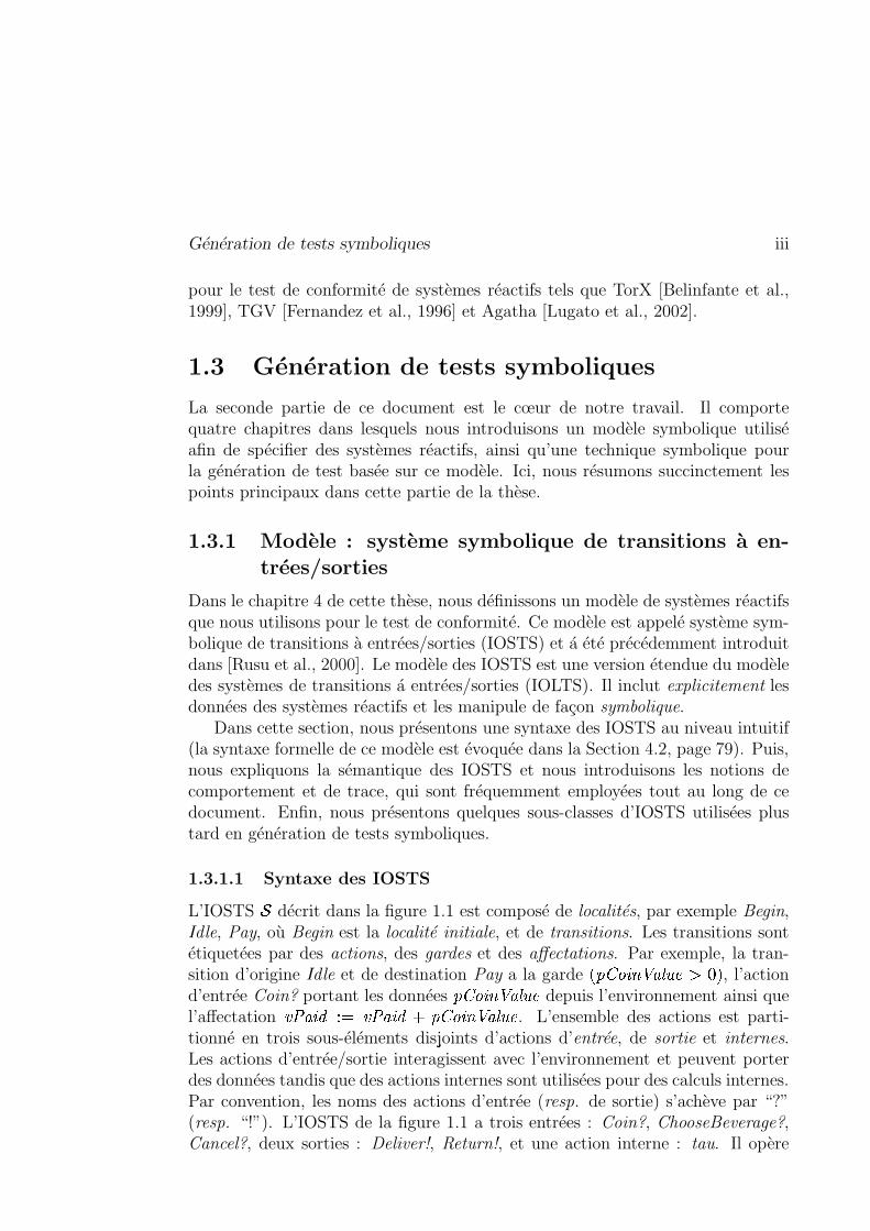
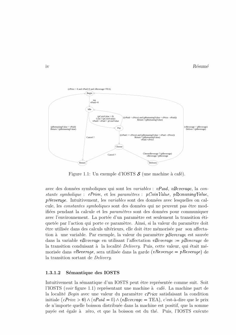
L’IOSTS � décrit dans la figure 1.1 est composé de localités, par exemple Begin,Idle, Pay, où Begin est la localité initiale, et de transitions. Les transitions sontétiquetées par des actions, des gardes et des affectations. Par exemple, la tran-sition d’origine Idle et de destination Pay a la garde
� ������������ � �� �� � , l’action
d’entrée Coin? portant les données�����
������� � � depuis l’environnement ainsi quel’affectation � �� ������� � �� ����� �����
������� � � . L’ensemble des actions est parti-tionné en trois sous-éléments disjoints d’actions d’entrée, de sortie et internes.Les actions d’entrée/sortie interagissent avec l’environnement et peuvent porterdes données tandis que des actions internes sont utilisées pour des calculs internes.Par convention, les noms des actions d’entrée (resp. de sortie) s’achève par “?”(resp. “!”). L’IOSTS de la figure 1.1 a trois entrées : Coin?, ChooseBeverage?,Cancel?, deux sorties : Deliver!, Return!, et une action interne : tau. Il opère
iv Résumé
(cPrice > 0 and vPaid=0 and vBeverage=TEA)
tauvPaid:=0
(pCoinValue > 0)Coin ? (pCoinValue)
vPaid:= vPaid + pCoinValue
Cancel ?
(pRemaningValue = vPaid)Return ! (pRemaningValue)
((vPaid < cPrice) and (pRemaningValue = cPrice - vPaid))Return ! (pRemaningValue)
((vPaid >= cPrice) and (pRemaningValue = vPaid - cPrice))Return ! (pRemaningValue)
vPaid:=cPrice
ChooseBeverage ? (pBeverage)vBeverage:=pBeverageCancel ?
(vBeverage = pBeverage)Deliver ! (pBeverage)
Begin
Idle
Pay
Choose
Return Delivery
Figure 1.1: Un exemple d’IOSTS � (une machine à café).
avec des données symboliques qui sont les variables : � � ��� , � � � � ��� �� � , la con-
stante symbolique :� � � � ��� , et les paramètres :
������������ � � , ��� ��� � ���� ��� � � ,� � � � ��� �� � . Intuitivement, les variables sont des données avec lesquelles on cal-
cule, les constantes symboliques sont des données qui ne peuvent pas être mod-ifiées pendant la calcule et les paramètres sont des données pour communiqueravec l’environnement. La portée d’un paramètre est seulement la transition éti-quetée par l’action qui porte ce paramètre. Ainsi, si la valeur du paramètre doitêtre utilisée dans des calculs ultérieurs, elle doit être mémorisée par son affecta-tion à une variable. Par exemple, la valeur du paramètre
� � � � ��� �� � est sauvéedans la variable � � � � ��� �� � en utilisant l’affectation � � � � ��� �� � � � � � � � ��� �� � dela transition conduisant à la localité Delivery. Puis, cette valeur, qui était mé-morisée dans � � � � ��� �� � , sera utilisée dans la garde
� � � � � ��� �� � � � � � � ��� �� � � dela transition sortant de Delivery.
1.3.1.2 Sémantique des IOSTS
Intuitivement la sémantique d’un IOSTS peut être représentée comme suit. Soitl’IOSTS (voir figure 1.1) représentant une machine à café. La machine part dela localité Begin avec une valeur du paramètre
� � � � ��� satisfaisant la conditioninitiale
��� � � � ��� � �� � � �� ��� � � �� � � � � � ��� �� � � TEA � , c’est-à-dire que le prixde n’importe quelle boisson distribuée dans la machine est positif, que la sommepayée est égale à zéro, et que la boisson est du thé. Puis, l’IOSTS exécute
Génération de tests symboliques v
la transition étiquetée par l’action interne tau, il affecte la variable � �� ��� , quimémorise la somme déjà réglée, à 0, et il atteint la localité Idle. Ensuite,la machine attend une pièce, dénotée par l’action d’entrée Coin? qui porte en�����
������� � � la valeur de la pièce insérée. Dès que la machine reçoit une pièce, lavariable � �� ��� est augmentée par
������������ � � et la machine va à la localité Pay.
Si la somme n’est pas suffisante, c’est-à-dire � � ����� � � � � ��� , la machine revientà la localité Idle et retourne (grâce à l’action de sortie Return!) la différenceentre � �� ��� et
� � � � ��� . Dans la localité Choose, la machine attend le choix de laboisson (thé ou café), puis la distribue et revient à la localité Begin. Il convientde noter que dans les localités Idle et Choose, on peut appuyer sur le boutonCancel, au quel cas la machine rend la somme déjà payée et revient à la localitéinitiale.
Plus formellement, la sémantique opérationnelle d’un IOSTS � est un IOLTS��� ����� (voir Définition 3.7 dans le Chapitre 3, page 41) dont les états, l’alphabetet la relation de transition sont définis comme suit. Un état � est une paire � ����� ,où est une localité et � le vecteur de valeurs des variables et des constantessymboliques, par exemple, � �� Delivery �� � � � � ��� ����� � �� ��� ����� � � � � ��� �� � �TEA ��� . Un état initial ��� ����� ���!�"� est un état où �� est la localité initiale, etoù � � est un vecteur de valeurs des variables et des constantes symboliques quisatisfont à la condition initiale. Nous notons # (resp. # � ) l’ensemble de tous lesétats (resp. les états initiaux). Une action valuée $ est une paire �%&�(')� , où % estune action et où ' est un vecteur de valeurs des paramètres de % , par exemple,$ �*,+.-�/,01�� ����� ������� � � �324��� ou $ �5�67%98:��;��� . Nous notons <��=<?>A@B<DC�@B<FEl’ensemble des actions valuées qui est partitionné en trois sous-ensembles d’entréevaluée, de sortie valuée et d’actions internes. Ensuite, nous définissons la relation
locale de transition GIHKJ�# � < � # comme l’ensemble de triplets ;�4�L$F�M� NO� , où���5�7���P� , � N �5� N ��� N � sont des états et $ �*�%&�(')� une action valuée telle que �et ' sont des vecteurs de valeurs des variables, des constantes symboliques et desparamètres qui satisfont la garde d’une transition 6 d’origine et de destination Nqui est étiqueté par l’action % , et telle que �QN est le nouveau vecteur de valeurs desvariables et des constantes symboliques obtenues à partir de � par les affectationsde variables de 6 . La relation globale de transition G est R HTSMU � GVH � , où � dénotel’ensemble des transitions symboliques de l’IOSTS. Nous écrivons �XWG � N pour;�4�L$F�M�YNO�[Z1G .
Comportements et traces. Dans cet paragraphe, nous introduisons les no-tions de comportements et de traces pour un IOSTS � arbitraire avec un ensem-ble # d’états, un ensemble # � J\# d’états initiaux, et un ensemble < �]<?>M@^<DC_@F<FEd’actions valuées. Ces notions nous permettent de raisonner formellement à pro-pos de l’IOSTS � .
vi Résumé
Définition 1.1 (Comportement et ensemble des comportements) Uncomportement � est une séquence d’états et d’actions valuées partant d’un étatinitial et suivant la relation de transition, c’est-à-dire :
��� � � � W��G ��� W��G ������� ���� W��G �� où G est la relation globale de transition, � � Z # � , et pour tout / Z ��� ��0Q� :���AZ # , $��AZ < . On note
� ��� � � � ����� � � l’ensemble de tous les comportements del’IOSTS � . �
Afin de définir la notion de trace de l’IOSTS � nous introduisons d’abord larelation de trace � J]# � � <?> @ <[C ��� � # comme suit :
– ���� � N � � � � N �"! �$# ���"�����Y�M�� Z #�� � � � ��� E �G ������� ���� E �G � � � N � � ,où pour tout / � � �%� 0 : �&�AZB<FE , et ' est la séquence vide.
– � W� � N # ���"�M� Z #�� � � �� ��� WG � �� � N � , où $ Z � < > @ <DC � .– ��(� � N # ���M���� �M�� �Z #�� � ���3��� W �� �)����L�� ���� W �+* �� �� � � N � , où pour
tout / � � �%� 0-, �: $.�AZ � <)> @ <DC � , et / Z � < > @�<DC ��� .
Définition 1.2 (Ensemble de traces) L’ensemble de traces de � est définicomme suit :
� ������� � � 0 / Z � < > @ < C � �21 # � � Z # � �M�.Z #3� � � � (� �Y�54�
1.3.1.3 Sous-classes d’IOSTS
Dans cette section, nous définissons des sous-classes d’IOSTS qui sont utiliséesdans la méthode symbolique de génération de test présentée au Chapitre 7.
IOSTS instanciés et initialisés. Le fait de disposer de constantes symbol-iques dans le modèle IOSTS permet de décrire des spécifications génériques et,on le verra, de produire des tests eux-mêmes génériques. Cependant, au cours del’exécution des tests, les valeurs de toutes les constantes symboliques et de toutesles variables doivent toujours être définies. Par conséquent, nous avons besoind’introduire deux sous-classes d’IOSTS appelés IOSTS instanciés et initialisés.
Soit � un IOSTS avec un ensemble + de constantes symboliques, un ensemble6de variables et une condition initiale 7 . Soit aussi 8.Z:9<;>= � + � , où 9<;?= � + �
est un domaine de + , un vecteur de valeurs de constantes symboliques + . Alors :
Génération de tests symboliques vii
(1) � est dit instancié si son ensemble + de constantes symboliques est vide.
(2) En remplaçant chaque constante symbolique � Z + par une valeur 8 � � � , onobtient un IOSTS noté � � 8 � et appelé un instance de � .
(3) � est dit initialisé si pour chaque instance � � 8�� , il existe au plus un
vecteur de valeurs de ses variables6
qui satisfait à la condition initiale 7 .
Il est important de remarquer que chaque instance d’un IOSTS initialisé a unétat initial unique.
IOSTS déterministe. Par la suite, nous interdisons les cas de test non-déterministes dans le test, car un verdict de test ne doit pas dépendre des choixinternes du testeur. Par conséquent, dans ce paragraphe, nous introduisonsune sous-classe d’IOSTS déterministes qui seront utilisés ultérieurement pourla représentation des cas de test.
Un IOSTS � est déterministe s’il ne contient pas d’actions internes, c’est-à-dire <FE � �
, et si une transition au plus peut être exécutée à partir de chaqueétat, autrement dit, � � Z # � $ Z � < >:@�<[C � � � � � � � 0 � N Z # 1 �IWG � N 4���� � � .
Il est important de remarquer que pour chaque trace / de chaque instancede l’IOSTS initialisé et déterministe � , l’ensemble d’états � ��� � � / est unsingleton. Ici, � ��� � �� / �0 � Z # 1 # � � Z # � � � � � (� �Y�54 , où # (resp. # � ) est unensemble d’états (resp. d’états initiaux) de � . Cette proposition est formuléedans le théorème 4.1 au chapitre 4 (voir page 94).
IOSTS complets et complets en entrée. Dans ce paragraphe, nous intro-duisons deux sous-classes des IOSTS qui seront nécessaires durant la générationde test et le processus d’exécution de tests.
En effet, pour un IOSTS � représentant soit un cas de test soit une implé-mentation sous test, nous devons supposer qu’il accepte toujours (qu’il ne bloquepas) les entrées. Un tel IOSTS est appelé complet en entrée et défini commesuit : � � Z # �L$ Z < > # � N Z # � � � W� � N � , où # est un ensemble d’états de � et< > est l’ensemble des actions d’entrée valuées de � .
Par analogie avec l’approche de génération de test proposée par dans [Fernan-dez et al., 1996], notre méthode symbolique de génération décrite au chapitre 7 dece document utilise un objectif de test comme mécanisme de sélection de test. End’autres termes, le but des objectifs de test est de marquer les traces d’une spéci-fication donnée qui devraient être testées, sans modifier l’ensemble de toutes lestraces de cette spécification. Pour cela, chaque objectif de test �� doit être com-
plet par rapport sa spécification�������
, c’est-à-dire que pour chaque état � Z #��et pour chaque action valuée $\Z � < �� � <�������� � , l’ensemble 0 � N Z #��� 1 � WG � N 4n’est pas vide, et la condition initiale 7��� de l’objectif de test �� ne contient
viii Résumé
pas contraintes sur les variables et les constantes symboliques de la spécification�������.
1.3.2 Opérations sur les IOSTS
Cette section résume les deux opérations principales sur les IOSTS définies auchapitre 5. L’opération de composition parallèle est utilisée dans l’exécution dutest sur un système sous test car elle permet de modéliser une interaction entredeux processus représentés par des IOSTS. Cette opération est inspirée de la com-position parallèle de deux processus modélisés soit par LTS, soit par IOLTS (voir
par exemple, [Tretmans, 2002]). L’opération produit est l’opération principale dela génération de tests car elle permet une interaction entre les comportementsd’une spécification et son objectif de test, et donc de sélectionner la partie de laspécification pour laquelle un cas de test doit être généré. Cette opération est in-spirée de l’opération produit définie sur les IOLTS et utilisée dans la méthode degénération de tests décrite, par exemple, dans [Jéron, 2004]. La différence entreces deux opérations réside dans le fait que le produit défini sur les IOSTS effectueune synchronisation non seulement sur les actions communes de deux systèmesdonnés, mais également sur les données de ces systèmes (rappelons que le modèleIOSTS inclut explicitement les données du système). Ainsi, cette différence nouspermet d’accomplir une sélection plus précise du cas de test.
Composition parallèle. L’opération de composition parallèle permet à chaquesystème d’exécuter indépendemment ses actions internes et impose une synchroni-sation sur les actions d’entrée et de sortie partagées. L’opération est définie pourdes IOSTS compatibles. De manière informelle, deux IOSTS � � et � sontcompatibles si (1) ils n’ont pas de données communes, c’est-à-dire � �����2 � �
,(2) l’alphabet des actions d’entrée (resp. de sortie) de � � est égal à l’alphabetdes actions de sortie (resp. d’entrée) de � , et si les alphabets d’actions internesde � � et � sont disjoints, (3) en outre, les actions communes doivent porterdes paramètres du même type et en nombre égal dans les deux IOSTS. En outre,la définition formelle de compatibilité pour la composition parallèle est donnéedans la section 5.1 du chapitre 5.
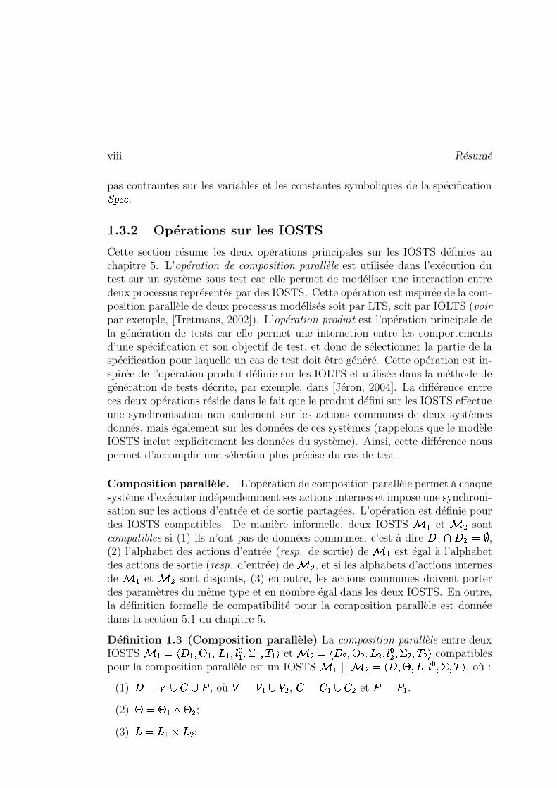
Définition 1.3 (Composition parallèle) La composition parallèle entre deuxIOSTS � � �3�� �M��7 �M��� �"���� � ��� �"� �)�(� et � �3��2 ��7 Y�� ����� ��� �� �"M� compatiblespour la composition parallèle est un IOSTS � � 1 1 � �3�� ��7 ��?�� � ��� � � � , où :
(1) � � 6 @�+ @� , où6 � 6 � @ 6 , + �]+ �:@�+ et ��<� .
(2) 7�� 7 � 7 ;(3) � � � � �
� ;
Génération de tests symboliques ix
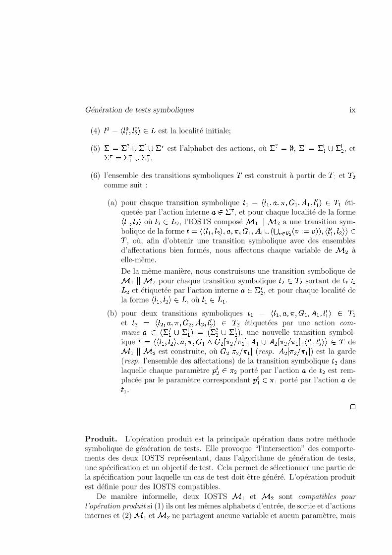
(4) � � � � � �� � �?Z � est la localité initiale;
(5) � � � > @ �DC @ �FE est l’alphabet des actions, où �?> � �, �DC � �DC� @ �DC , et
�FE ���FE � @ �FE .(6) l’ensemble des transitions symboliques � est construit à partir de � � et �
comme suit :
(a) pour chaque transition symbolique 6�� � � �M��%&� � � 2��� � �"�� N � � Z �)� éti-quetée par l’action interne % Z �)E , et pour chaque localité de la forme� �M�� M� où Z � , l’IOSTS composé � � 1 1 � a une transition sym-bolique de la forme 6 � �� �M�� L� ��%&� � � �M� � � @ � R�� S�� �
��� � � � � �L��� N � �� M��� Z� , où, afin d’obtenir une transition symbolique avec des ensemblesd’affectations bien formés, nous affectons chaque variable de � àelle-même.
De la même manière, nous construisons une transition symbolique de� � 1%1 � pour chaque transition symbolique 6 Z �" sortant de Z� et étiquetée par l’action interne % Z�� E , et pour chaque localité dela forme � �M�� L�[Z�� , où � Z�� � .
(b) pour deux transitions symboliques 6�� � � �"��%&� � � 2��� � �"�� N � � Z � �et 6 � � ���%&� � � >Y� � ��� N � Z � étiquetées par une action com-
mune % Z �� > � @ � C� � � �
� > @ � C � , une nouvelle transition symbol-ique 6 � �� �M�� "� ��%&� � � 2� ? � � � �K��� � � @ � � � � � �7�,��� N � �� N ��� Z � de� � 1%1 � est construite, où ? � � � �7� (resp.
� � � � �7� ) est la garde(resp. l’ensemble des affectations) de la transition symbolique 6 danslaquelle chaque paramètre � � Z � porté par l’action % de 6 est rem-placée par le paramètre correspondant � � � Z � � porté par l’action % de6 � .
�
Produit. L’opération produit est la principale opération dans notre méthodesymbolique de génération de tests. Elle provoque “l’intersection” des comporte-ments des deux IOSTS représentant, dans l’algorithme de génération de tests,une spécification et un objectif de test. Cela permet de sélectionner une partie dela spécification pour laquelle un cas de test doit être généré. L’opération produitest définie pour des IOSTS compatibles.
De manière informelle, deux IOSTS � � et � sont compatibles pour
l’opération produit si (1) ils ont les mêmes alphabets d’entrée, de sortie et d’actionsinternes et (2) � � et � ne partagent aucune variable et aucun paramètre, mais
x Résumé
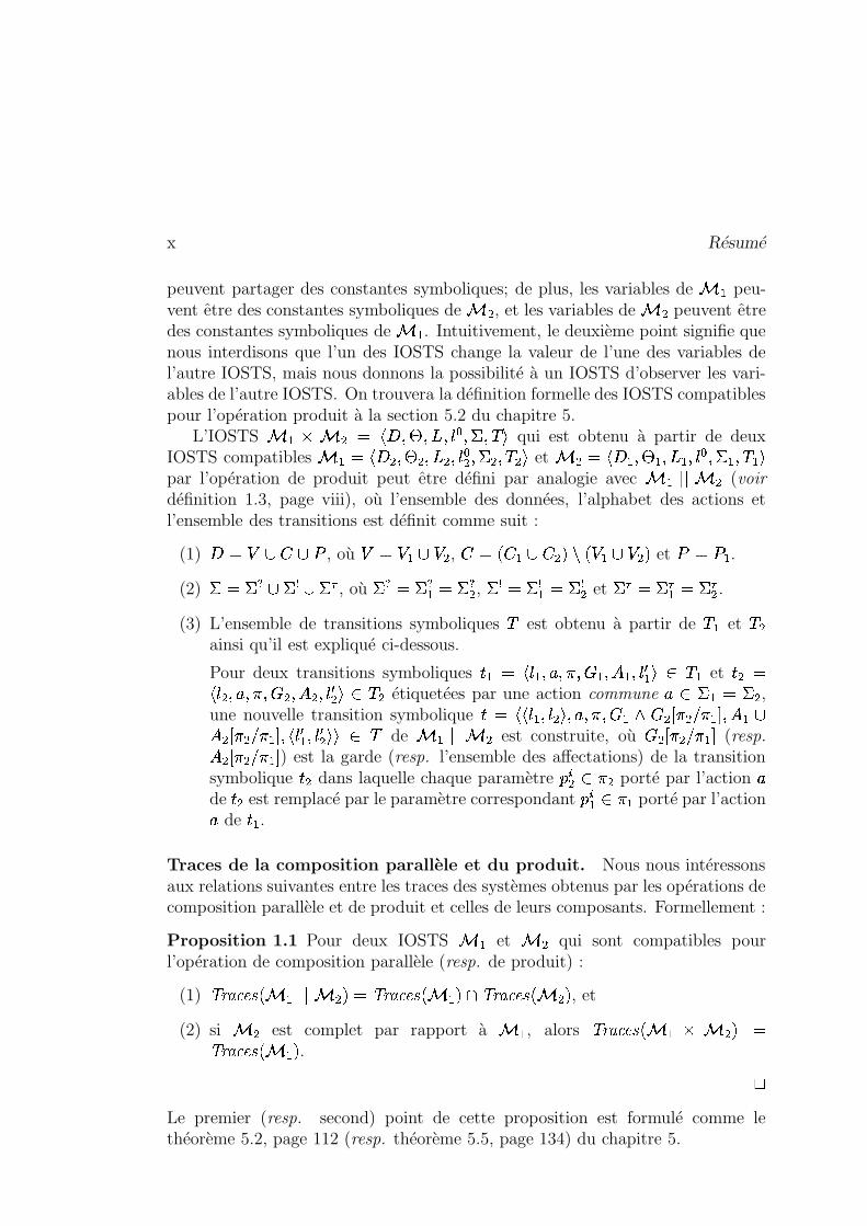
peuvent partager des constantes symboliques; de plus, les variables de � � peu-vent être des constantes symboliques de � , et les variables de � peuvent êtredes constantes symboliques de � � . Intuitivement, le deuxième point signifie quenous interdisons que l’un des IOSTS change la valeur de l’une des variables del’autre IOSTS, mais nous donnons la possibilité à un IOSTS d’observer les vari-ables de l’autre IOSTS. On trouvera la définition formelle des IOSTS compatiblespour l’opération produit à la section 5.2 du chapitre 5.
L’IOSTS � � � � � ��B��7 �� �� � ���.� � � qui est obtenu à partir de deuxIOSTS compatibles � ���X��2 ��7 Y�� �� � ��� � �""� et � ��X�� �M��7 �M� � �L�� � � ��� �M� �)���par l’opération de produit peut être défini par analogie avec � � 1 1 � (voir
définition 1.3, page viii), où l’ensemble des données, l’alphabet des actions etl’ensemble des transitions est définit comme suit :
(1) � � 6 @�+ @� , où6 � 6 � @ 6 , + � � + � @ + ���� � 6 � @ 6 � et ��<� .
(2) � � � >:@ �DC @ �FE , où � > ��� > � ��� > , �DC ���DC� � �DC et �FE � �FE � � �FE .(3) L’ensemble de transitions symboliques � est obtenu à partir de � � et �
ainsi qu’il est expliqué ci-dessous.
Pour deux transitions symboliques 6���� � �"��%&� � � �L� � �M�� N � � Z �)� et 6 �� ��%&� � � ? � � �� N � Z � étiquetées par une action commune % Z � � � � ,une nouvelle transition symbolique 6 � ��$�M�� L� ��%&� � � � > � � � �7�,� � � @� � � � �K�,��� N � �� N ��� Z � de � � 1 1 � est construite, où ? � � � �7� (resp.� � � � �K� ) est la garde (resp. l’ensemble des affectations) de la transitionsymbolique 6 dans laquelle chaque paramètre � � Z � porté par l’action %de 6 est remplacé par le paramètre correspondant � � � Z � � porté par l’action% de 6 � .
Traces de la composition parallèle et du produit. Nous nous intéressonsaux relations suivantes entre les traces des systèmes obtenus par les opérations decomposition parallèle et de produit et celles de leurs composants. Formellement :
Proposition 1.1 Pour deux IOSTS � � et � qui sont compatibles pourl’opération de composition parallèle (resp. de produit) :
(1) � ������� � � 1%1 � ���� � ������� � � � � � ������� � �� , et
(2) si � est complet par rapport à � � , alors � ������� � � � � � � � ������� � � � .
�Le premier (resp. second) point de cette proposition est formulé comme lethéorème 5.2, page 112 (resp. théorème 5.5, page 134) du chapitre 5.
Génération de tests symboliques xi
1.3.3 Test de conformité avec les IOSTS
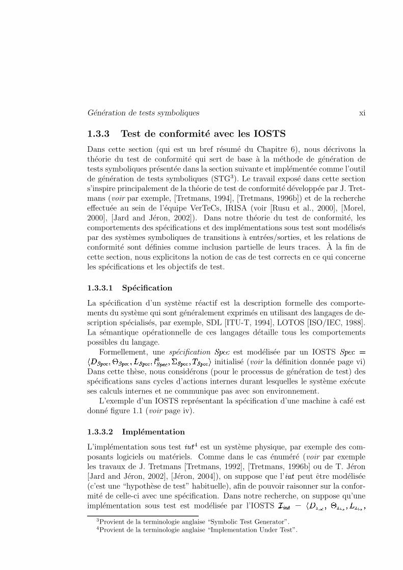
Dans cette section (qui est un bref résumé du Chapitre 6), nous décrivons lathéorie du test de conformité qui sert de base à la méthode de génération detests symboliques présentée dans la section suivante et implémentée comme l’outilde génération de tests symboliques (STG3). Le travail exposé dans cette sections’inspire principalement de la théorie de test de conformité développée par J. Tret-mans (voir par exemple, [Tretmans, 1994], [Tretmans, 1996b]) et de la rechercheeffectuée au sein de l’équipe VerTeCs, IRISA (voir [Rusu et al., 2000], [Morel,2000], [Jard and Jéron, 2002]). Dans notre théorie du test de conformité, lescomportements des spécifications et des implémentations sous test sont modéliséspar des systèmes symboliques de transitions à entrées/sorties, et les relations deconformité sont définies comme inclusion partielle de leurs traces. À la fin decette section, nous explicitons la notion de cas de test corrects en ce qui concerneles spécifications et les objectifs de test.
1.3.3.1 Spécification
La spécification d’un système réactif est la description formelle des comporte-ments du système qui sont généralement exprimés en utilisant des langages de de-scription spécialisés, par exemple, SDL [ITU-T, 1994], LOTOS [ISO/IEC, 1988].La sémantique opérationnelle de ces langages détaille tous les comportementspossibles du langage.
Formellement, une spécification�������
est modélisée par un IOSTS������� �
���������� ��7�������"���������"�� � ������� ���������� � ����������� initialisé (voir la définition donnée page vi)Dans cette thèse, nous considérons (pour le processus de génération de test) desspécifications sans cycles d’actions internes durant lesquelles le système exécuteses calculs internes et ne communique pas avec son environnement.
L’exemple d’un IOSTS représentant la spécification d’une machine à café estdonné figure 1.1 (voir page iv).
1.3.3.2 Implémentation
L’implémentation sous test ��� � 4 est un système physique, par exemple des com-posants logiciels ou matériels. Comme dans le cas énuméré (voir par exempleles travaux de J. Tretmans [Tretmans, 1992], [Tretmans, 1996b] ou de T. Jéron[Jard and Jéron, 2002], [Jéron, 2004]), on suppose que l’ ����� peut être modélisée(c’est une “hypothèse de test” habituelle), afin de pouvoir raisonner sur la confor-mité de celle-ci avec une spécification. Dans notre recherche, on suppose qu’uneimplémentation sous test est modélisée par l’IOSTS
������ � ����� ���(� 7��� ��������� �����3Provient de la terminologie anglaise “Symbolic Test Generator”.4Provient de la terminologie anglaise “Implementation Under Test”.
xii Résumé
��� ��� �� �� � �(� � �� ���K� , dont on ne connaît que l’alphabet d’actions d’entrée et de sortie,et on suppose que (1) le type et le nombre de paramètres de ces actions sontles mêmes que celles d’une spécification
�������donnée, et (2) les paramètres de
����� sont en bijection avec les paramètres de�������
. On peut trouver la définitionformelle d’une implémentation sous test à la section 6.2 du chapitre 6.
1.3.3.3 Objectif de test
Par analogie avec l’approche de génération de tests proposée dans [Fernandezet al., 1996], notre méthode de génération de tests symboliques exposée auchapitre 7 de ce document, utilise le concept d’objectif de test. Un objectifde test décrit des comportements d’un système donné devant être testé, et sertà sélectionner une partie de la spécification du système pour laquelle un cas detest sera généré.
Formellement, soit un IOSTS�������
modélisant une spécification. Alors, unobjectif de test de
�������est un IOSTS �� 5 avec la localité spéciale
� �������� tel
que : �� est initialisé (voir page vi) et complet par rapport à�������
(voir page vii).En outre, nous devrions être capable d’exécuter l’opération produit entre �� et�������
, c’est-à-dire que �� devrait être compatible pour l’opération produit avec�������(voir le paragraphe appelé Produit à la page page ix).
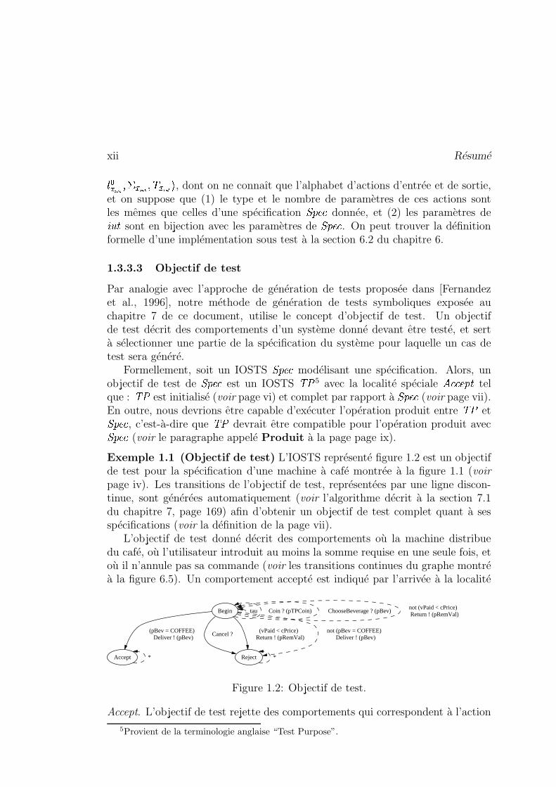
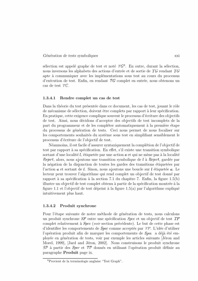
Exemple 1.1 (Objectif de test) L’IOSTS représenté figure 1.2 est un objectifde test pour la spécification d’une machine à café montrée à la figure 1.1 (voir
page iv). Les transitions de l’objectif de test, représentées par une ligne discon-tinue, sont générées automatiquement (voir l’algorithme décrit à la section 7.1du chapitre 7, page 169) afin d’obtenir un objectif de test complet quant à sesspécifications (voir la définition de la page vii).
L’objectif de test donné décrit des comportements où la machine distribuedu café, où l’utilisateur introduit au moins la somme requise en une seule fois, etoù il n’annule pas sa commande (voir les transitions continues du graphe montréà la figure 6.5). Un comportement accepté est indiqué par l’arrivée à la localité
Begin tau Coin ? (pTPCoin) ChooseBeverage ? (pBev)not (vPaid < cPrice) Return ! (pRemVal)
Accept
(pBev = COFFEE) Deliver ! (pBev)
Reject
Cancel ? (vPaid < cPrice)
Return ! (pRemVal)not (pBev = COFFEE)
Deliver ! (pBev)
* *
Figure 1.2: Objectif de test.
Accept. L’objectif de test rejette des comportements qui correspondent à l’action5Provient de la terminologie anglaise “Test Purpose”.

Génération de tests symboliques xiii
d’annulation (Cancel), ou à l’insertion de plus d’une pièce. Les comportementsrejetés ne sont pas nécessairement faux, mais ils ne sont pas ciblés par l’objectifde test. Notons aussi que l’objectif de test �� observe, mais ne modifie pas lavariable � �� ��� de la spécification
�������. �
1.3.3.4 Relation de conformité
Dans la sous-section précédente, nous avons défini les notions de spécification,d’implémentation sous test et d’objectif de test. Nous avons également supposéqu’ils pouvaient tous être exprimés dans le modèle des IOSTS. Ce postulat nouspermet de raisonner formellement à propos des spécifications, des implémenta-tions sous test et des objectifs de test.
Par conséquent, nous pouvons exprimer la conformité des implémentationspar rapport aux spécifications (et possiblement “filtrée” avec un objectif de test)par des relations de conformité formelles entre leurs modèles. Une relation deconformité définit exactement l’ensemble des implémentations conformes à unespécification donnée.
Les relations de conformité introduites dans cette section et utilisées tout aulong de cette thèse sont des versions plus faibles des relations de conformité
� ��� ��� �et
� ��� �exposées par J. Tretmans et al. pour des IOLTS (voir [Tretmans, 1995],
[Tretmans, 1996b], [Tretmans, 2002]). Elles sont appelées�����
et� ��� �� . Nous
définissons ces relations de conformité au lieu d’utiliser l’un de leurs prédécesseursplus puissants (
����� ��� � et����� �
) car :
(1)�����
et����� �� ne prennent en compte aucun blocage syntaxique (c’est-à-dire
blocages de sortie (ou outputlock), blocages complets (ou deadlocks) etblocages vivants (ou livelocks) présentés page 42) des IOSTS, et
(2) le problème de décider si un système représenté par un IOSTS est bloquéou pas est indécidable en général. Cependant, dans le cas d’un IOSTS sansblocages vivants syntaxiques, il est possible de construire syntaxiquementl’IOSTS suspendu correspondant (un IOSTS suspendu est défini de manièresemblable à un IOLTS suspendu, voir définition 3.9 page 44). Il est doncpossible d’étendre la relation
�����à la relation
����� �définie par J. Tretmans.
L’idée de l’extension à déjà été proposée dans [Rusu et al., 2004].
Avant de donner la définition formelle des relations de conformité�����
et����� ��
pour des spécifications, des objectifs de test et des implémentations instanciés,nous introduisons auparavant :
(1) l’ensemble des actions de sortie valuées pouvant être générées par un IOSTS� avec un ensemble d’états # , quand � est dans un état � N parmi un
xiv Résumé
ensemble d’états # N J�# est défini comme suit :����
� # N � 0 $3Z<[C 1 # � N Z # N �M�.Z # � � � N.WG �Y� 4 .
(2) l’ensemble des comportements acceptés d’un IOSTS� � 6 � ��������� � �� �
qui contient les comportements de la spécification�������
sélectionnés parl’objectif de test �� de
�������grâce à l’opération produit, défini comme
suit :� � ��� � � � ����� � ��� 0 � � �9� � W �G ��� W �G �����L�� ���� W �G ������� 1
� � Z # �� � �������FZ #��������� �$. ZB<�� � � /^Z � � ��0-, � � � � ��:Z # ��� $.�1Z < � ��� 4
où < � � est l’ensemble des actions valuées de� � , # � � est l’ensemble des états
de� � , # �� � est l’ensemble des états initiaux de
� � , et # �������� est l’ensembledes états accepteurs de
� � défini comme suit : 0 � Z # � � 1 # � �������K� � ��������(�?Z
������[� Z 9<;?= � 6 ���D@ + � ��� � � � � ���� � � �7� � ��������(�"�����7� 4 .
Il est important de remarquer que l’opération produit nous permet de sélec-tionner précisément les comportements de la spécification acceptée parl’objectif de test. En effet, d’après cette définition, on sait qu’un com-portement accepté du produit synchrone
� � est, à une projection près,un comportement accepté de l’objectif de test �� . De plus, d’après lesthéorèmes 5.3 et 5.4 (voir pages 126 et 132), sa projection est un comporte-ment de la spécification
�������. Intuitivement,
� � ��� � � � ������������� � ���� et� ��� � � � ����� ������� � � � � ��� � � � ����� ���� sont égaux à une projection près.
(3) l’ensemble des traces acceptées du produit synchrone� � � ��������� � ����
qui contient les traces de la spécification�������
sélectionnées par l’objectif detest �� de
�������grâce à l’opération produit, noté
� � ������� � ��� , est obtenu,à partir de l’ensemble des comportements acceptés de
� � par la projection
sur les alphabets d’actions valuées d’entrée et de sortie de� � .
Proposition 1.2 (Ensemble de traces acceptées de� � ) Pour une
spécification�������
et un objectif de test �� de�������
, l’ensemble des tracesacceptées de leur produit
��������� �� est inclus dans l’ensemble des tracesde
�������et dans l’ensemble des traces acceptées de �� , c’est-à-dire :
� � ����������������� �� �� �� �^J � ������� ������� � � � � ������� ����
Nous remarquons que, pour les traces acceptées du produit synchrone, ilest impossible d’obtenir l’égalité comme dans le cas des comportementsacceptés á cause de la projection. �
6Provient de la terminologie anglaise “Synchronous Product”.
Génération de tests symboliques xv
(4) l’ensemble des préfixes des traces acceptées� � ��������� � � est défini comme
suit :����������� ������������� ����� �
�( S��
���! � �#"�$ � �&%!')( N+*
�-, > ���/. , C��� � �1032 ( N N+* �-, > ���4. , C� � � �6587 (:9;( N < ( N N>=-?
où < > ��� et <DC� � sont les ensembles d’actions d’entrée et de sortie valuées de� � , et où / N @ / N N est l’opération de concaténation entre deux mots / N et / N N .(5) l’ensemble des préfixes stricts de
� � ����� � � � � qui ne sont pas des tracesacceptées de
� � , est défini comme suit :�A����������� ������������� �/��� 9 ��������B�/�A�����C�C�����A�/���EDF/�A���������G��� �����
Définition 1.4 (Relations de conformité�����
et����� �� ) Soient
�������une spé-
cification instanciée, �� un objectif de test instancié de�������
, et ��� � une implé-mentation modélisée par une IOSTS instanciée
������. Alors :
(1) l’implémentation est conforme à la spécification, noté� �� � � � ��� ������� � , si pour
toutes les traces / Z � ������� ������� � :����
� ����� ��� � �� / �)J ����
� ������� ��� � �� / � .(2) l’implémentation est conforme à la spécification relativement à l’objectif
de test, noté� ����� ��������� ������� � , si pour toutes les traces / Z� � ���IH � � � ����������������� ���� � :
����
� ������ ��� � � / �^J �� �
� ������� ��� � �� / � . �
Intuitivement, une implémentation est conforme à une spécification donnéesi, après chaque trace de la spécification, les actions de sortie possibles del’implémentation sont inclues dans celles de la spécification. Dans le second cas,l’inclusion doit être toujours vraie après chaque préfixe strict d’une trace de laspécification qui est sélectionné par un objectif de test donné grâce à l’opérationproduit.
La définition des relations de conformité�����
et����� �� est étendue au cas général
(autrement dit aux spécifications, aux cas de test et aux implémentations non-instanciées) dans les sections 6.3 et 6.8 du chapitre 6. Dans ces mêmes sections, lelecteur peut également trouver les exemples illustrant ces relations de conformité.
1.3.3.5 Cas de test
Les cas de test introduits dans ce paragraphe jouent un rôle central dans le test.Au cours de l’exécution, les cas de test interagissent avec les implémentations soustest, observent leurs sorties et, en se basant sur ces observations, génèrent des
xvi Résumé
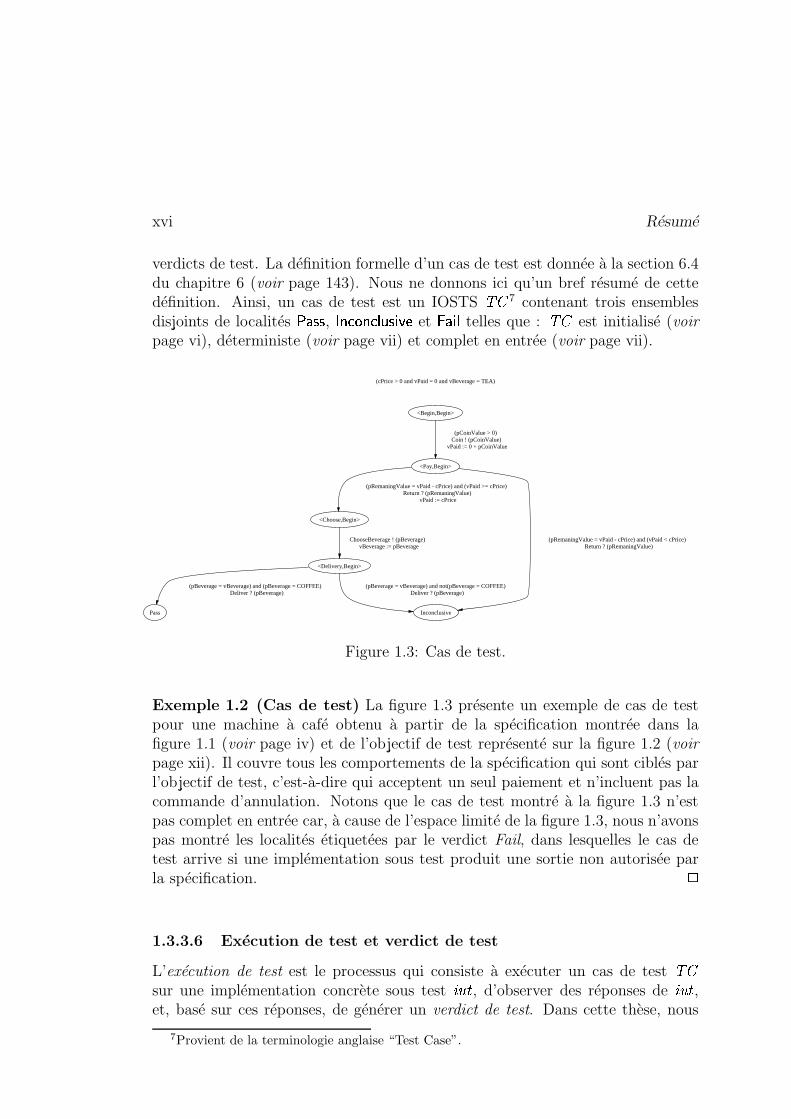
verdicts de test. La définition formelle d’un cas de test est donnée à la section 6.4du chapitre 6 (voir page 143). Nous ne donnons ici qu’un bref résumé de cettedéfinition. Ainsi, un cas de test est un IOSTS � 7 contenant trois ensemblesdisjoints de localités � � � � , � � � ��� ��� � � � �
et � � � � telles que : � est initialisé (voir
page vi), déterministe (voir page vii) et complet en entrée (voir page vii).
(cPrice > 0 and vPaid = 0 and vBeverage = TEA)
<Begin,Begin>
<Pay,Begin>
(pCoinValue > 0) Coin ! (pCoinValue)
vPaid := 0 + pCoinValue
<Choose,Begin>
(pRemaningValue = vPaid - cPrice) and (vPaid >= cPrice) Return ? (pRemaningValue)
vPaid := cPrice
Inconclusive
(pRemaningValue = vPaid - cPrice) and (vPaid < cPrice) Return ? (pRemaningValue)
<Delivery,Begin>
ChooseBeverage ! (pBeverage) vBeverage := pBeverage
Pass
(pBeverage = vBeverage) and (pBeverage = COFFEE) Deliver ? (pBeverage)
(pBeverage = vBeverage) and not(pBeverage = COFFEE) Deliver ? (pBeverage)
Figure 1.3: Cas de test.
Exemple 1.2 (Cas de test) La figure 1.3 présente un exemple de cas de testpour une machine à café obtenu à partir de la spécification montrée dans lafigure 1.1 (voir page iv) et de l’objectif de test représenté sur la figure 1.2 (voir
page xii). Il couvre tous les comportements de la spécification qui sont ciblés parl’objectif de test, c’est-à-dire qui acceptent un seul paiement et n’incluent pas lacommande d’annulation. Notons que le cas de test montré à la figure 1.3 n’estpas complet en entrée car, à cause de l’espace limité de la figure 1.3, nous n’avonspas montré les localités étiquetées par le verdict Fail, dans lesquelles le cas detest arrive si une implémentation sous test produit une sortie non autorisée parla spécification. �
1.3.3.6 Exécution de test et verdict de test
L’exécution de test est le processus qui consiste à exécuter un cas de test �sur une implémentation concrète sous test ��� � , d’observer des réponses de ����� ,et, basé sur ces réponses, de générer un verdict de test. Dans cette thèse, nous
7Provient de la terminologie anglaise “Test Case”.
Génération de tests symboliques xvii
modélisons l’exécution de test par la composition parallèle entre � et le modèle �� � �d’ ����� .
Avant de formaliser la notion de verdict de test, nous notons d’abord par �������(resp. �����.;������ � ����� , ��� �� ) l’ensemble des états d’un cas de test donné dontles localités sont dans l’ensemble � � � � (resp. � � � ��� ��� � � � �
, � � � � ).Puis, nous considérons un cas de test � et une implémentation sous test ��� �
modélisée par �� � �
. Pour une trace / Z � �� � � 1 1 � � , le cas de test � produitle verdict �� ��� (resp. � � � � � � � � � ��� � , � � � ) si l’état dans lequel � arrive après /appartient à ������� (resp. �����.;�������� ����� , ��� �� ). Formellement :
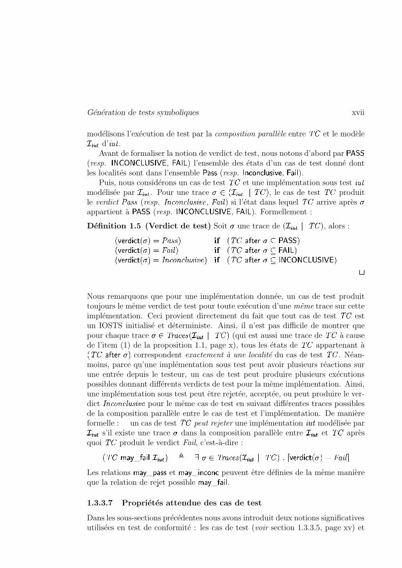
Définition 1.5 (Verdict de test) Soit / une trace de� ������ 1 1 � � , alors :
� � �� � � ����� / � � �� ��� � ��� � � ��� � �� / J ������� �� � �� � � ����� / � ��� � � � ��� � � ��� � �� / J ��� ����� � �� � � ����� / � ��� � � � � � � � � ��� � ����� � � ��� � �� / J �����.;������ � ����� ��
Nous remarquons que pour une implémentation donnée, un cas de test produittoujours le même verdict de test pour toute exécution d’une même trace sur cetteimplémentation. Ceci provient directement du fait que tout cas de test � estun IOSTS initialisé et déterministe. Ainsi, il n’est pas difficile de montrer quepour chaque trace / Z � ������� ����� 1 1 � � (qui est aussi une trace de � à causede l’item (1) de la proposition 1.1, page x), tous les états de � appartenant à� � ��� � �� / � correspondent exactement à une localité du cas de test � . Néan-moins, parce qu’une implémentation sous test peut avoir plusieurs réactions surune entrée depuis le testeur, un cas de test peut produire plusieurs exécutionspossibles donnant différents verdicts de test pour la même implémentation. Ainsi,une implémentation sous test peut être rejetée, acceptée, ou peut produire le ver-dict � � � � � � � � � ��� � pour le même cas de test en suivant différentes traces possiblesde la composition parallèle entre le cas de test et l’implémentation. De manièreformelle : un cas de test � peut rejeter une implémentation ��� � modélisée par �� � �
s’il existe une trace / dans la composition parallèle entre ������
et � aprèsquoi � produit le verdict Fail, c’est-à-dire :
� �! ��" _ ��� � � ������ � # / Z � ������� �� � � 1 1 � � � � � � � ����� � / � �#� � ���Les relations
��" _ $ � � � et ��" _ � � � � � �
peuvent être définies de la même manièreque la relation de rejet possible
��" _ ��� � � .
1.3.3.7 Propriétés attendue des cas de test
Dans les sous-sections précédentes nous avons introduit deux notions significativesutilisées en test de conformité : les cas de test (voir section 1.3.3.5, page xv) et
xviii Résumé
les relations de conformité (voir section 1.3.3.4, page xiii). L’objectif de cettesous-section est d’établir le lien entre ces deux notions définies indépendamment.Nous savons que ce lien existe. En effet, comme le but des cas de test est de nousdonner des informations sur la conformité d’une implémentation par rapport àsa spécification, le cas de test doit conserver certaines propriétés de la relationde conformité. Par exemple, produire le verdict � � � doit impliquer la détectionde non-conformité dans une implémentation sous test. On dit alors que le cas detest est non biaisé. En outre, nous définissons aussi plusieurs propriétés de cas detest qui nous permettent de relier les cas de test non seulement aux spécificationset aux implémentations, mais aussi aux objectifs de test.
La définition de telles propriétés est donnée plus bas. Il est essentiel de re-marquer qu’elles sont ici formulées pour des spécifications, des objectifs de test,des cas de test et des implémentations instanciées. On trouvera les définitionsgénérales de ces propriétés aux sections 6.6 et 6.10 du chapitre 6.
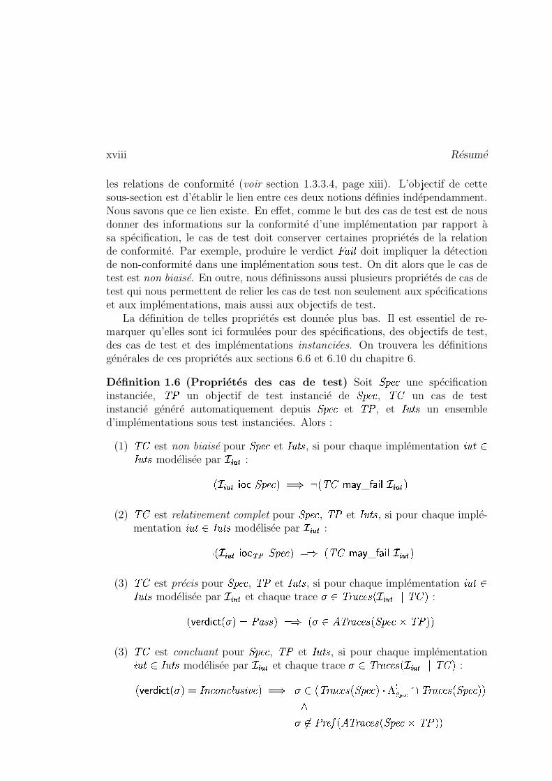
Définition 1.6 (Propriétés des cas de test) Soit�������
une spécificationinstanciée, �� un objectif de test instancié de
�������, � un cas de test
instancié généré automatiquement depuis�������
et �� , et � ��� � un ensembled’implémentations sous test instanciées. Alors :
(1) � est non biaisé pour�������
et � ��� � , si pour chaque implémentation �����?Z� � � � modélisée par
�� � �:
� � � � � ��� ������� � � � �� � ��" _ ��� � � �� � � �
(2) � est relativement complet pour�������
, �� et � ��� � , si pour chaque implé-mentation �����)Z � ��� � modélisée par
�����:
�� �� � � ��������� ������� � � � � �! ��" _ ��� � � ������ �
(3) � est précis pour�������
, �� et � ��� � , si pour chaque implémentation ����� Z� � � � modélisée par
�� � �et chaque trace / Z � ������� ����� 1%1 � � :
� � � � ������� / � � �� ��� � � � � / Z � � ����������������� ���� �
(3) � est concluant pour�������
, �� et � � � � , si pour chaque implémentation����� Z � � � � modélisée par
�� � �et chaque trace / Z � ������� ����� 1 1 � � :
� � � � � ��� � / � ��� � � � � � � � � ��� � � � � / Z � � ��������������� � @ < C������� � � ������� ������� � �/ �Z � � �IH � � � ������� ��������� �� � �
Génération de tests symboliques xix
�
Intuitivement, dire que le cas de test est non biaisé signifie qu’il ne rejette pasles implémentations conformes (dans un ensemble donné). Cette propriété peutêtre satisfaite en pratique, mais elle n’est pas suffisante en général. Par exem-ple, un cas de test acceptant toutes les implémentations possibles est non biaisé.L’exhaustivité relative signifie que le cas de test peut détecter, dans un ensembledonné, toutes les implémentations non conformes avec la spécification relative-ment à l’objectif de test. Précision signifie que le verdict �� ��� est donné lorsquela trace observée de l’implémentation est une trace de la spécification qui estsélectionnée par l’objectif de test. Cas de test concluant signifie que le verdict� � � � � � � � � ��� � est donné quand la trace observée de l’implémentation est une tracede la spécification qui finit par une action de sortie mais aucun prolongement decette trace ne peut produire le verdict �� ��� . Toutes les propriétés d’un cas de testsont illustrées par des exemples intuitifs aux sections 6.6 et 6.10 du chapitre 6.
Enfin, nous introduisons le concept de cas de test correct. Intuitivement, celasignifie que le cas de test donne toujours le bon verdict lorsqu’il est exécuté surune implémentation sous test donnée. Formellement :
Définition 1.7 (Cas de test correct) Un cas de test � est correct pour unensemble � � � � d’implémentations s’il est non biaisé par rapport à
�������et � ��� � ; et
relativement exhaustif, précis et concluant par rapport à�������
, � ��� � et �� (voir
définition 1.6, page xviii). �
1.3.4 Principes de la génération de tests symboliques
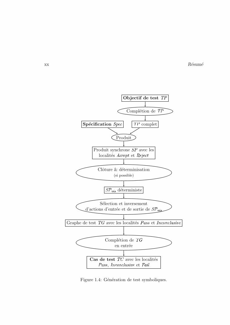
L’approche symbolique de génération de tests proposée dans cette thèse se décom-pose en plusieurs étapes résumées dans la figure 1.4 (voir page xx). Elle prend enentrée une spécification
�������et un objectif de test �� de
�������. Comme on accepte
les objectifs de test incomplets, le premier pas de cette approche est de les rendrecomplets par rapport à leurs spécifications. Dans un second temps, on va calculerle produit entre la
�������donnée et le �� complété afin de marquer les comporte-
ments de�������
comme étant soit acceptés, soit rejetés par l’objectif de test, et onva obtenir le produit synchrone
� � (voir figure 1.4, page xx). La troisième phaseconstruit les comportements déterministes visibles de
� � . En d’autres termes,elle va supprimer les actions internes et les choix non-déterministes possibles de� � . Le résultat de cette étape est noté
� � � ��� (voir figure 1.4, page xx). L’étapesuivante, la sélection, consiste à extraire de
� � � ��� ses comportements permettantd’aller de la localité initiale aux localités Pass ou Inconclusive. Le résultat de la
xx Résumé
Cas de test � avec les localités�� ��� , � � � � � � � � � ��� � et � � �
Complétion de �en entrée
Graphe de test � avec les localités �� ��� et � � � � � � � � � ��� �
Sélection et inversementd’actions d’entrée et de sortie de
� � � ���
� � � ��� déterministe
Clôture & déterminisation(si possible)
Produit synchrone� � avec les
localités� �������
� et� ��� ���
�
Produit
Spécification������� �� complet
Complétion de ��
Objectif de test ��
Figure 1.4: Génération de test symboliques.
Génération de tests symboliques xxi
sélection est appelé graphe de test et noté � 8. En outre, durant la sélection,nous inversons les alphabets des actions d’entrée et de sortie de � rendant �apte à communiquer avec les implémentations sous test au cours du processusd’exécution de test. Enfin, en rendant � complet en entrée, nous obtenons uncas de test � .
1.3.4.1 Rendre complet un cas de test
Dans la théorie du test présentée dans ce document, les cas de test, jouant le rôlede mécanisme de sélection, doivent être complets par rapport à leur spécification.En pratique, cette exigence complique souvent le processus d’écriture des objectifsde test. Ainsi, nous décidons d’accepter des objectifs de test incomplets de lapart du programmeur et de les compléter automatiquement à la première étapedu processus de génération de tests. Ceci nous permet de nous focaliser surles comportements souhaités du système sous test en simplifiant sensiblement leprocessus d’écriture de l’objectif de test.
Néanmoins, il est facile d’assurer syntaxiquement la complétion de l’objectif detest par rapport à sa spécification. En effet, s’il existe une transition symboliquesortant d’une localité , étiquetée par une action % et qui ne mène pas à la localité� ��� ���
� , alors, nous ajoutons une transition symbolique de à� ��� ���
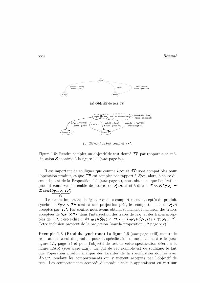
� , gardée parla négation de la disjonction de toutes les gardes des transitions étiquetées parl’action % et sortant de . Sinon, nous ajoutons une boucle sur étiquetée % . Lelecteur peut trouver l’algorithme qui rend complet un objectif de test donné parrapport à sa spécification à la section 7.1 du chapitre 7. Enfin, la figure 1.5(b)illustre un objectif de test complet obtenu à partir de la spécification montrée à lafigure 1.1 et l’objectif de test dépeint à la figure 1.5(a) par l’algorithme expliquéintuitivement plus haut.
1.3.4.2 Produit synchrone
Pour l’étape suivante de notre méthode de génération de tests, nous calculonsun produit synchrone
� � entre une spécification�������
et un objectif de test ��complet relativement à
�������(voir section précédente). Le but de cette phase est
d’identifier les comportements de�������
comme acceptés par �� . L’idée d’utiliserl’opération produit afin de marquer les comportements de
�������a déjà été em-
ployée en génération de tests, voir par exemple les articles suivants [Jéron andMorel, 1999], [Jard and Jéron, 2002]. Nous construisons le produit synchrone� � à partir des
�������et �� donnés en utilisant l’opération produit définie au
paragraphe Produit page ix.
8Provient de la terminologie anglaise “Test Graph”.
xxii Résumé
(pBev = COFFEE)Deliver ! (pBev) Cancel ? (vPaid < cPrice)
Return ! (pRemVal)
Start
Begin
Accept Reject
(a) Objectif de test ��� .
Begin tau Coin ? ChooseBeverage ?not (vPaid < cPrice) Return ! (pRemVal)
Accept
(pBev = COFFEE) Deliver ! (pBev)
Reject
Cancel ? (vPaid < cPrice)
Return ! (pRemVal)not (pBev = COFFEE)
Deliver ! (pBev)
* *
(b) Objectif de test complet ����� .
Figure 1.5: Rendre complet un objectif de test donné ��� par rapport à sa spé-cification � montrée à la figure 1.1 (voir page iv).
Il est important de souligner que comme ���� et ��� sont compatibles pourl’opération produit, et que ��� est complet par rapport à ���� , alors, à cause dusecond point de la Proposition 1.1 (voir page x), nous obtenons que l’opérationproduit conserve l’ensemble des traces de ���� , c’est-à-dire : ������ ����������� ���������� ����������� ������ !#" $%'& � .
Il est aussi important de signaler que les comportements acceptés du produitsynchrone ���� (�)��� sont, à une projection près, les comportements de ���� acceptés par ��� . Par contre, nous avons obtenu seulement l’inclusion des tracesacceptées de ���� *�+��� dans l’intersection des traces de ���� et des traces accep-tées de ��� , c’est-à-dire : ,-������ ����������� .�/���0�-12������ ����������� ��435,-������ ����6�7���0� .Cette inclusion provient de la projection (voir la proposition 1.2 page xiv).
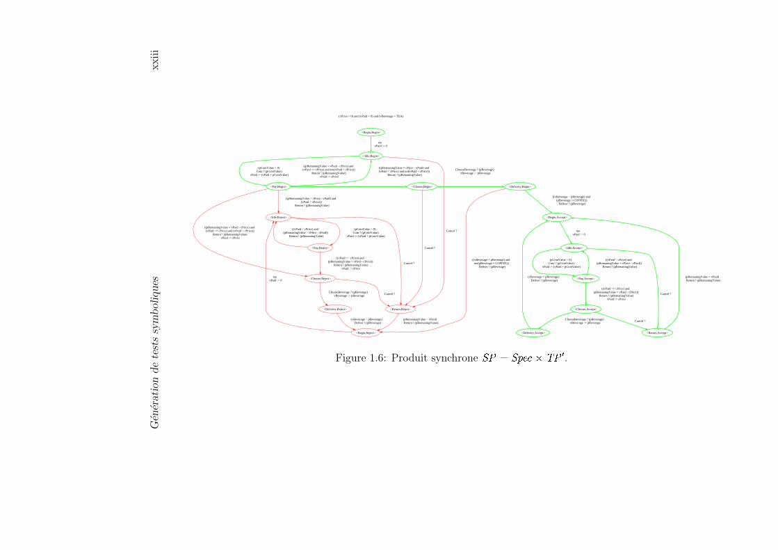
Exemple 1.3 (Produit synchrone) La figure 1.6 (voir page xxiii) montre lerésultat du calcul du produit pour la spécification d’une machine à café (voirfigure 1.1, page iv) et pour l’objectif de test de cette spécification décrit à lafigure 1.5(b) (voir page xxii). Le but de cet exemple est de souligner le faitque l’opération produit marque des localités de la spécification donnée avec,8 � ��#:9 , rendant les comportements qui y mènent acceptés par l’objectif detest. Les comportements acceptés du produit calculé apparaîssent en vert sur
Gén
érati
on
de
test
ssy
mb
oliques
xxiii
(cPrice > 0) and (vPaid = 0) and (vBeverage = TEA)
<Begin,Begin>
<Idle,Begin>
tau vPaid := 0
<Pay,Begin>
(pCoinValue > 0) Coin ? (pCoinValue)
vPaid := (vPaid + pCoinValue)
<Return,Reject>
Cancel ?
((pRemaningValue = cPrice - vPaid) and (vPaid < cPrice) and not(vPaid < cPrice))
Return ! (pRemaningValue)
<Idle,Reject>
((pRemaningValue = cPrice - vPaid) and (vPaid < cPrice))
Return ! (pRemaningValue)
<Choose,Reject>
((pRemaningValue = vPaid - cPrice) and (vPaid >= cPrice) and (vPaid < cPrice))
Return ! (pRemaningValue) vPaid := cPrice
<Choose,Begin>
((pRemaningValue = vPaid - cPrice) and (vPaid >= cPrice) and not(vPaid < cPrice))
Return ! (pRemaningValue) vPaid := cPrice
<Begin,Reject>
(pRemaningValue = vPaid) Return ! (pRemaningValue)
Cancel ?
<Pay,Reject>
(pCoinValue > 0) Coin ? (pCoinValue)
vPaid := (vPaid + pCoinValue)
Cancel ?
<Delivery,Reject>
ChooseBeverage ? (pBeverage) vBeverage := pBeverage
Cancel ?
<Delivery,Begin>
ChooseBeverage ? (pBeverage) vBeverage := pBeverage
tau vPaid := 0
((vPaid < cPrice) and (pRemaningValue = cPrice - vPaid))
Return ! (pRemaningValue)
((vPaid >= cPrice) and (pRemaningValue = vPaid - cPrice))
Return ! (pRemaningValue) vPaid := cPrice
(vBeverage = pBeverage) Deliver ! (pBeverage)
((vBeverage = pBeverage) and not(pBeverage = COFFEE))
Deliver ! (pBeverage)
<Begin,Accept>
((vBeverage = pBeverage) and (pBeverage = COFFEE))
Deliver ! (pBeverage)
<Idle,Accept>
tau vPaid := 0
<Pay,Accept>
(pCoinValue > 0) Coin ? (pCoinValue)
vPaid := (vPaid + pCoinValue)
<Return,Accept>
Cancel ?
((vPaid < cPrice) and (pRemaningValue = cPrice - vPaid))
Return ! (pRemaningValue)
<Choose,Accept>
((vPaid >= cPrice) and (pRemaningValue = vPaid - cPrice))
Return ! (pRemaningValue) vPaid := cPrice
(pRemaningValue = vPaid) Return ! (pRemaningValue)
Cancel ?
<Delivery,Accept>
ChooseBeverage ? (pBeverage) vBeverage := pBeverage
(vBeverage = pBeverage) Deliver ! (pBeverage)
Figure 1.6: Produit synchrone �� � � �� �� � � � .
xxiv Résumé
la figure 1.6 (voir page xxiii). Tous les autres comportements, imprimés enrouge, sont considérés comme rejetés. Les comportements rejetés indiquent lescomportements de la spécification pour lesquels le cas de test ne sera pas généré.Ils seront éliminés au cours des étapes suivantes de la méthode de génération detests. �
Les prochains pas de la méthode de génération de tests décrite dans le reste de cechapitre consistent à transformer et à simplifier le produit �� � ������ � ���0� afind’obtenir un cas de test correct dans le sens de la définition 1.7 (voir page xix).
1.3.4.3 Construction de comportements visibles
Il est important d’insister sur le fait que le test n’autorise pas le non-déterminismecar les verdicts de test ne doivent pas dépendre des choix internes du testeur.C’est pourquoi cette étape de la méthode de génération de tests est réservée àl’élimination des actions internes de l’IOSTS �� , c’est-à-dire à la construction de��� ������� �#��0� , et à la résolution de choix non-déterministes restant pour les actionsd’entrée/sortie de ��� � ��� ������� �#��-� � . Pour cela, nous proposons les opérationssyntaxiques de clôture et de déterminisation telles que :
������ ������#��0��� ������ ������ ��� ������� �#��-� � � ������ ����6�� ��� � ��� ������� ����0� �'� (1.1)
,-������ ������#��0��� ,-������ ������ ��� ������� �#��-� � � ,-������ ������� ��� � ��� ������� ����0� �'� (1.2)
Les procédures de clôture et de déterminisation et leurs propriétés sont décritesaux sections A.1 et A.2 du chapitre 7, et brièvement résumées dans les deuxparagraphes suivants.
Clôture : éliminer les actions internes. Pour éliminer des actions internesde �� , l’idée est de calculer l’effet de toute séquence d’actions internes qui mèneà une transition symbolique étiquetée par une action d’entrée ou de sortie, et decoder cet effet dans la garde et les affectations de la dernière transition symbol-ique.
Ceci résulte en une procédure syntaxique simple qui termine si l’IOSTS ��n’a pas de blocages vivants syntaxiques (c’est-à-dire des cycles d’actions internes).Ceci est une hypothèse courante en test de conformité [Tretmans, 1999] posée pourl’ensemble de ce travail de recherche. Soit ���
���� � �����������! ��"� � �� �#$� une séquence de
transitions symboliques étiquetées par les actions internes %&��'������(%� et menantà la transition symbolique �� �#$�
)� � �� *#+� étiquetée par l’action , d’entrée ou desortie (voir figure 1.7(a), page xxv). Supposons que les gardes et les affectationscorrespondant à %.- ( / �10&�2�43 ) sont 56- et 78- ; et que les gardes et les affectationscorrespondant à , sont 5 ) et 7 ) . Alors, cette séquence est remplacée par une
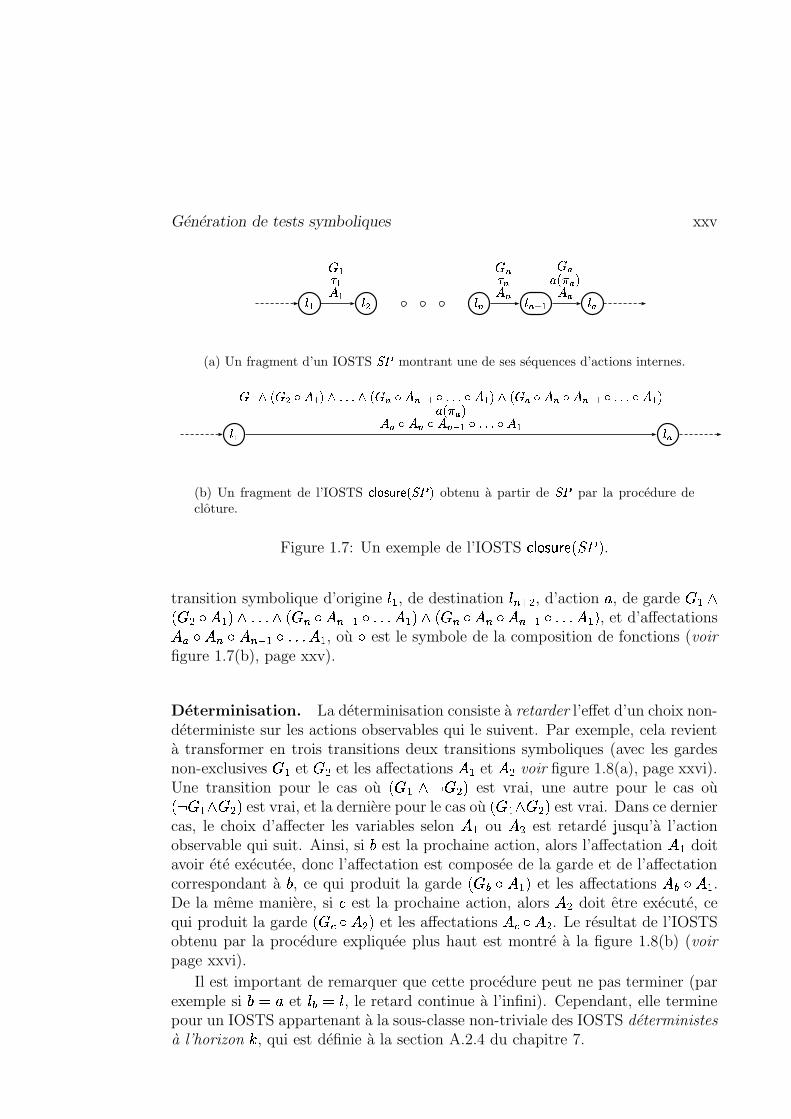
Génération de tests symboliques xxv
��� ��� ��� ������ ��� � �� �
� � �� ��
����� ���
(a) Un fragment d’un IOSTS ��� montrant une de ses séquences d’actions internes.
��� ��� ��� � � ��� � ��������� ��� � � �!� � �#"$�%�&������� � �'�(� � � )� � �!� � ��"$���&������� � �'�
����� #�� )� � �!� � ��"*�%�&������� � �
(b) Un fragment de l’IOSTS +#, -/. 021�3245���76 obtenu à partir de ��� par la procédure declôture.
Figure 1.7: Un exemple de l’IOSTS ��� ������� �#��-� .
transition symbolique d’origine ��� , de destination �� �#+� , d’action , , de garde 5 �98� 56�;: 7 �'�<8 �����/8 ��56 =: 7 *> �?: ������76���@8 ��56 A: 78 =: 78 $> �?: � ��� 7 �'� , et d’affectations7 ) : 78 B: 7 *> �C:6� ����76� , où : est le symbole de la composition de fonctions (voirfigure 1.7(b), page xxv).
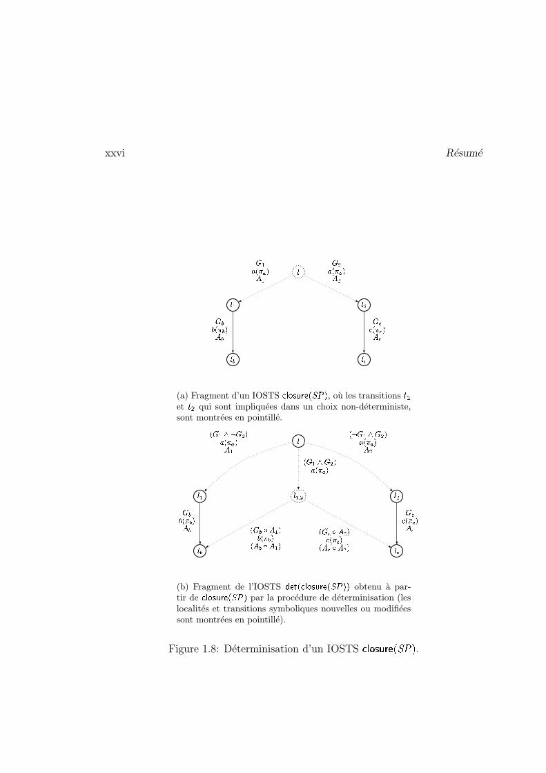
Déterminisation. La déterminisation consiste à retarder l’effet d’un choix non-déterministe sur les actions observables qui le suivent. Par exemple, cela revientà transformer en trois transitions deux transitions symboliques (avec les gardesnon-exclusives 5 � et 5 � et les affectations 7 � et 78� voir figure 1.8(a), page xxvi).Une transition pour le cas où ��5 �=8ED 56� � est vrai, une autre pour le cas où��D 5 �/8 5 � � est vrai, et la dernière pour le cas où � 5 �F8 5 � � est vrai. Dans ce derniercas, le choix d’affecter les variables selon 7 � ou 78� est retardé jusqu’à l’actionobservable qui suit. Ainsi, si G est la prochaine action, alors l’affectation 7 � doitavoir été exécutée, donc l’affectation est composée de la garde et de l’affectationcorrespondant à G , ce qui produit la garde � 5�H;: 76��� et les affectations 7IH;: 76� .De la même manière, si J est la prochaine action, alors 7 � doit être exécuté, cequi produit la garde ��5LK<: 78� � et les affectations 7MK?: 78� . Le résultat de l’IOSTSobtenu par la procédure expliquée plus haut est montré à la figure 1.8(b) (voirpage xxvi).
Il est important de remarquer que cette procédure peut ne pas terminer (parexemple si G � , et �NH � � , le retard continue à l’infini). Cependant, elle terminepour un IOSTS appartenant à la sous-classe non-triviale des IOSTS déterministesà l’horizon O , qui est définie à la section A.2.4 du chapitre 7.
xxvi Résumé
�
��� ���
��� ���
� �� ������ �� �� ������ �
� �� � � �� �� ����� � �� �
(a) Fragment d’un IOSTS ��� ������� ��!#"%$'& , où les transitions (�)et (+* qui sont impliquées dans un choix non-déterministe,sont montrées en pointillé.
,
,�- ,�.
,�/ ,�0
, - 1 .
2�3 -5476 3 .+89 2 :�; 8< -2 6 3 -54 3 .#89 2 :�; 8< .2=3 ->4 3 .+89 2�:�; 8
2�3 /�? < -@8A 2 : / 82 < /�? < -B82�3 05? < .+8C 2�: 0 82 < 0D? < .+8
3 /A 2 : / 8< /3 0C 2�: 0 8< 0
(b) Fragment de l’IOSTS EDFHGJILK�M N�O�P�Q F�I#R%S'TUT obtenu à par-tir de K�M N�OJP5QVF5I+R%S'T par la procédure de déterminisation (leslocalités et transitions symboliques nouvelles ou modifiéessont montrées en pointillé).
Figure 1.8: Déterminisation d’un IOSTS WYX Z\[�]_^@`baHcedgf .
Génération de tests symboliques xxvii
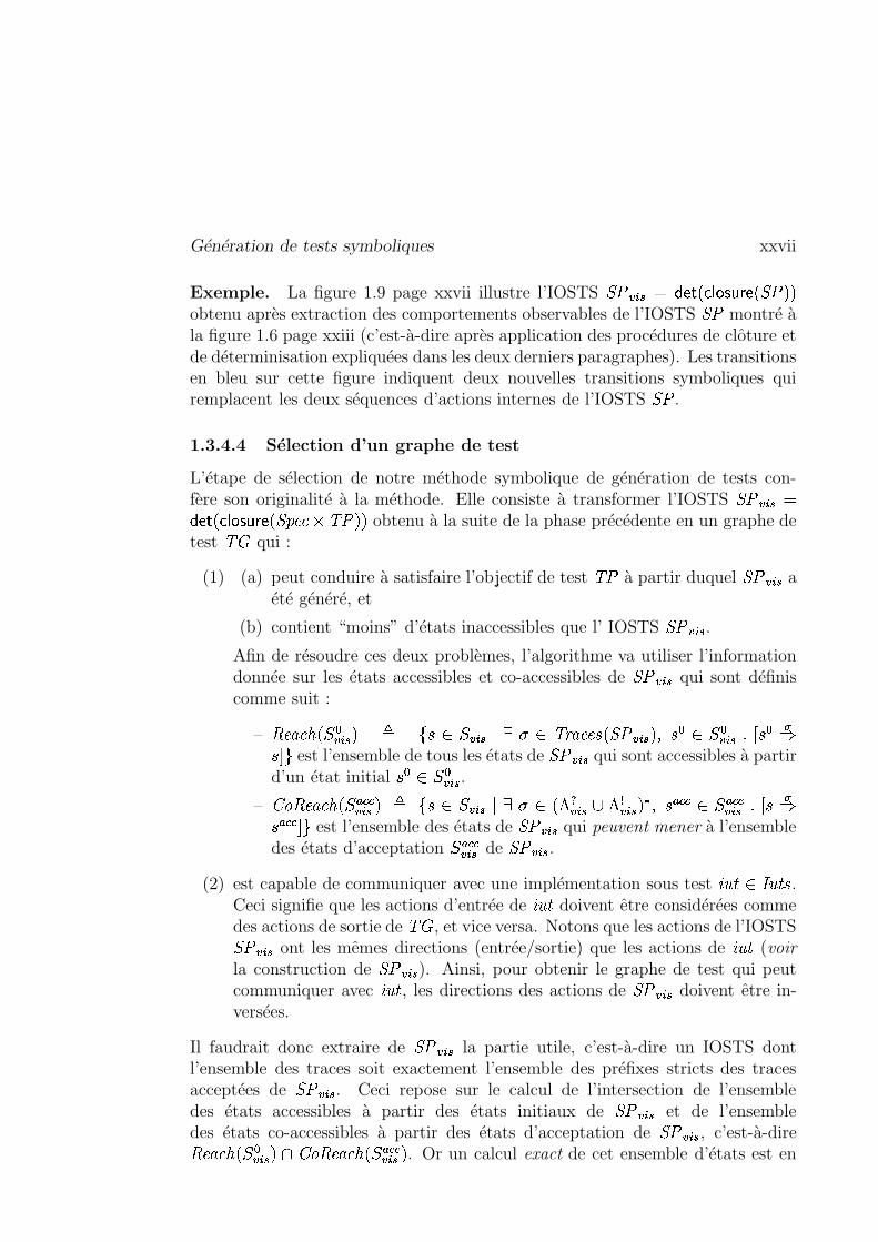
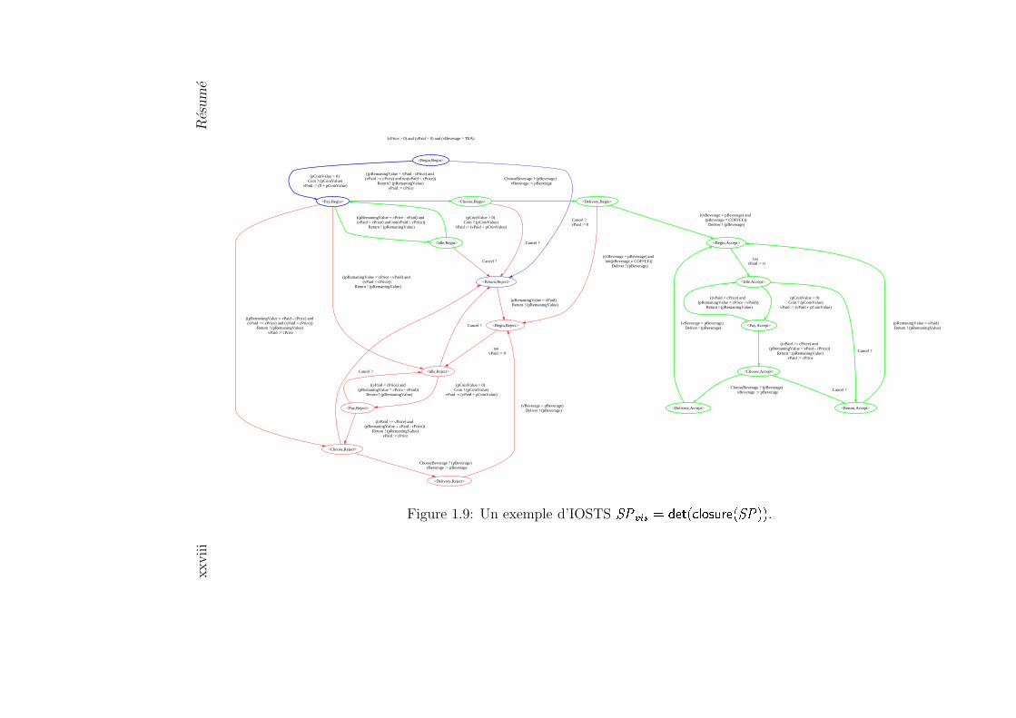
Exemple. La figure 1.9 page xxvii illustre l’IOSTS ����(-�� � �.� � ��� ������� �#��0�'�obtenu après extraction des comportements observables de l’IOSTS �� montré àla figure 1.6 page xxiii (c’est-à-dire après application des procédures de clôture etde déterminisation expliquées dans les deux derniers paragraphes). Les transitionsen bleu sur cette figure indiquent deux nouvelles transitions symboliques quiremplacent les deux séquences d’actions internes de l’IOSTS �� .
1.3.4.4 Sélection d’un graphe de test
L’étape de sélection de notre méthode symbolique de génération de tests con-fère son originalité à la méthode. Elle consiste à transformer l’IOSTS ����(-��.� �.� � ��� ������� �#���� � ���-�'� obtenu à la suite de la phase précédente en un graphe detest � � qui :
(1) (a) peut conduire à satisfaire l’objectif de test ��� à partir duquel ���� -�� aété généré, et
(b) contient “moins” d’états inaccessibles que l’ IOSTS ���� -�� .Afin de résoudre ces deux problèmes, l’algorithme va utiliser l’informationdonnée sur les états accessibles et co-accessibles de ����(-�� qui sont définiscomme suit :
– � ���� ���� �� -�� � � ��������(-���������� ������ ������#���� -���� '������� �� -�� �! "���$#%�'&�( est l’ensemble de tous les états de ����(-�� qui sont accessibles à partird’un état initial � � �) ��(-�� .
– *,+-� ���� � �. ) K K�(-�� �/� ���0�1�� -���������� �3254�(-��!6 2�7�(-�� �98�'�� ) K K �1 ) K K� -�� �! :�/#%� ) K K &3( est l’ensemble des états de ��;�(-�� qui peuvent mener à l’ensembledes états d’acceptation ) K K�(-�� de ���� -�� .
(2) est capable de communiquer avec une implémentation sous test <>=�9?�A@B= 9 � .Ceci signifie que les actions d’entrée de <>=�9 doivent être considérées commedes actions de sortie de � � , et vice versa. Notons que les actions de l’IOSTS���� -�� ont les mêmes directions (entrée/sortie) que les actions de <>= 9 (voirla construction de ��;�(-�� ). Ainsi, pour obtenir le graphe de test qui peutcommuniquer avec <>=�9 , les directions des actions de ���� -�� doivent être in-versées.
Il faudrait donc extraire de ���� -�� la partie utile, c’est-à-dire un IOSTS dontl’ensemble des traces soit exactement l’ensemble des préfixes stricts des tracesacceptées de ��;�(-�� . Ceci repose sur le calcul de l’intersection de l’ensembledes états accessibles à partir des états initiaux de ����(-�� et de l’ensembledes états co-accessibles à partir des états d’acceptation de ����(-�� , c’est-à-dire� ���� � �.C��(-�� � 3D*,+-� ���� � �. ) K K�(-�� � . Or un calcul exact de cet ensemble d’états est en
xxvi
iiR
ésum
é
(cPrice > 0) and (vPaid = 0) and (vBeverage = TEA)
<Begin,Begin>
<Pay,Begin>
(pCoinValue > 0) Coin ? (pCoinValue)
vPaid := (0 + pCoinValue)
<Return,Reject>
Cancel ? vPaid := 0
<Idle,Begin>
(pCoinValue > 0) Coin ? (pCoinValue)
vPaid := (vPaid + pCoinValue)
Cancel ?
((pRemaningValue = cPrice - vPaid) and (vPaid < cPrice) and not(vPaid < cPrice))
Return ! (pRemaningValue)
<Idle,Reject>
((pRemaningValue = cPrice - vPaid) and (vPaid < cPrice))
Return ! (pRemaningValue)
<Choose,Reject>
((pRemaningValue = vPaid - cPrice) and (vPaid >= cPrice) and (vPaid < cPrice))
Return ! (pRemaningValue) vPaid := cPrice
<Choose,Begin>
((pRemaningValue = vPaid - cPrice) and (vPaid >= cPrice) and not(vPaid < cPrice))
Return ! (pRemaningValue) vPaid := cPrice
<Begin,Reject>
(pRemaningValue = vPaid) Return ! (pRemaningValue)
Cancel ?
<Pay,Reject>
(pCoinValue > 0) Coin ? (pCoinValue)
vPaid := (vPaid + pCoinValue)
Cancel ?
<Delivery,Reject>
ChooseBeverage ? (pBeverage) vBeverage := pBeverage
Cancel ?
<Delivery,Begin>
ChooseBeverage ? (pBeverage) vBeverage := pBeverage
tau vPaid := 0
((vPaid < cPrice) and (pRemaningValue = cPrice - vPaid))
Return ! (pRemaningValue)
((vPaid >= cPrice) and (pRemaningValue = vPaid - cPrice))
Return ! (pRemaningValue) vPaid := cPrice
(vBeverage = pBeverage) Deliver ! (pBeverage)
((vBeverage = pBeverage) and not(pBeverage = COFFEE))
Deliver ! (pBeverage)
<Begin,Accept>
((vBeverage = pBeverage) and (pBeverage = COFFEE))
Deliver ! (pBeverage)
<Idle,Accept>
tau vPaid := 0
<Pay,Accept>
(pCoinValue > 0) Coin ? (pCoinValue)
vPaid := (vPaid + pCoinValue)
<Return,Accept>
Cancel ?
((vPaid < cPrice) and (pRemaningValue = cPrice - vPaid))
Return ! (pRemaningValue)
<Choose,Accept>
((vPaid >= cPrice) and (pRemaningValue = vPaid - cPrice))
Return ! (pRemaningValue) vPaid := cPrice
(pRemaningValue = vPaid) Return ! (pRemaningValue)
Cancel ?
<Delivery,Accept>
ChooseBeverage ? (pBeverage) vBeverage := pBeverage
(vBeverage = pBeverage) Deliver ! (pBeverage)
Figure 1.9: Un exemple d’IOSTS �� �� � � � �� ��� � � � � �� � � .
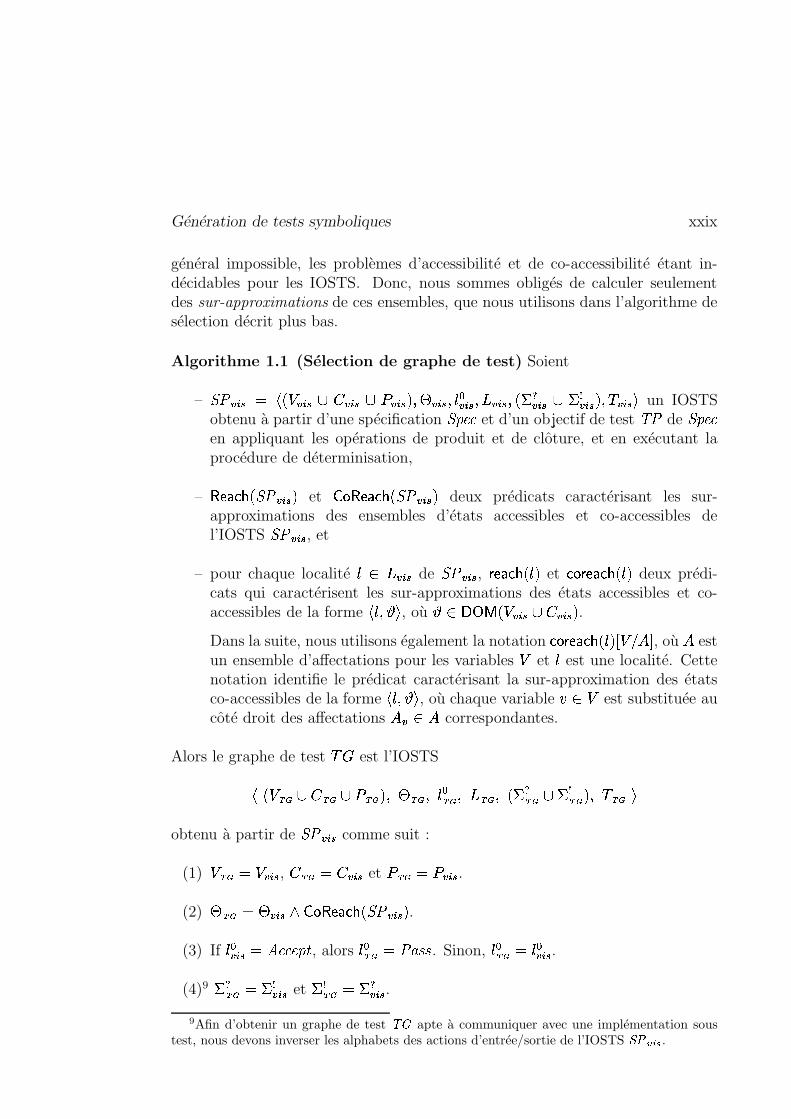
Génération de tests symboliques xxix
général impossible, les problèmes d’accessibilité et de co-accessibilité étant in-décidables pour les IOSTS. Donc, nous sommes obligés de calculer seulementdes sur-approximations de ces ensembles, que nous utilisons dans l’algorithme desélection décrit plus bas.
Algorithme 1.1 (Sélection de graphe de test) Soient
– ���� -�� � � ��� �(-�� 6�� �(-�� 6�� �(-���� '����(-���'��3��(-�� ' �(-���'7���?4�(-�� 6 �;7�(-�� � ' � �(-���� un IOSTSobtenu à partir d’une spécification ���� et d’un objectif de test ��� de ���� en appliquant les opérations de produit et de clôture, et en exécutant laprocédure de déterminisation,
– � ������� ������ -���� et � � � ������� ������ -���� deux prédicats caractérisant les sur-approximations des ensembles d’états accessibles et co-accessibles del’IOSTS ��;�(-�� , et
– pour chaque localité ���� �(-�� de ����(-�� , ���� ��� � �#� et �.� ���� ��� ��� � deux prédi-cats qui caractérisent les sur-approximations des états accessibles et co-accessibles de la forme
� �('��� , où � ����� � �!� �(-�� 6"� �(-���� .Dans la suite, nous utilisons également la notation � ��������� ��� �' #�%$.7;& , où 7 estun ensemble d’affectations pour les variables � et � est une localité. Cettenotation identifie le prédicat caractérisant la sur-approximation des étatsco-accessibles de la forme
� �('�&� , où chaque variable ' �(� est substituée aucôté droit des affectations 7�� � 7 correspondantes.
Alors le graphe de test � 5 est l’IOSTS
� ���*),+ 6"� ),+ 6-� ).+ � '/�0).+ ' � � ).+ '12),+ ' �!� 4 ),+�6 � 7 ),+ � '3�4).+5�
obtenu à partir de ��;�(-�� comme suit :
(1) �6).+ �7� �(-�� , � ).+-� � �(-�� et � ),+-� � �(-�� .
(2) �0),+ �7���(-��;88� � � ��� ��� ������(-���� .(3) If � ��(-�� � , � ��#:9 , alors �3� ),+ � � �7��� . Sinon, � � ).+ � � ��(-�� .
(4)9 �?4 ),+ �9�;7� -�� et �;7 ),+ �7�?4�(-�� .9Afin d’obtenir un graphe de test �;: apte à communiquer avec une implémentation sous
test, nous devons inverser les alphabets des actions d’entrée/sortie de l’IOSTS �7�4<>=@? .
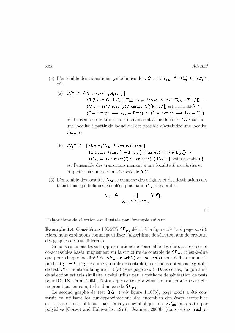
xxx Résumé
(5) L’ensemble des transitions symboliques de � � est : � ).+ � � �����).+ 6 � � �������),+ ,où :
(a) �����).+ � ����������������� ),+ ������� ).+��! "$# ���%�����������&���'���)( �+* � -���,.- �+/021435376�8:9<; � * "$= 4�(-��.> = 7� -��7?$@)? ;" � ).+ 0 " � ;BA�CEDGFIH " � ? ;JFLKMA�CEDGFIH " �)( ? -ON ),+QP � @)? est satisfiable ? ;" � ( 021R3�3�6%8:9<0TS � ).+ 02UWVGX�X ? ; " � ( /0214353�6%8:9<0TS � ).+ 0 � ( ?ZYest l’ensemble des transitions menant soit à une localité � �7��� soit àune localité à partir de laquelle il est possible d’atteindre une localité� �7��� , et
(b) � �������).+ � �[���%����������� ).+ ���'��\5] 35^ ] 3L_`QX�acbM6 �d "$# ���%���e�������f������� ( �+* �(-���,g- �h/021R3�3�6%8:9i; � * = 7�(-�� @)? ;" � ).+ 0 " � ;jA�CEDGFIH " � ? ;lk�FLKmA�CEDGFIH " � ( ? -ON&).+ P � @)? est satisfiable ?4Yest l’ensemble des transitions menant à une localité Inconclusive etétiquetée par une action d’entrée de � � .
(6) L’ensemble des localités /).+ se compose des origines et des destinations destransitions symboliques calculées plus haut � ).+ , c’est-à-dire
1).+ � noqp�r ) r smr t.r ugr pwvwxzyE{ ),+ � � '��( (
�L’algorithme de sélection est illustrée par l’exemple suivant.
Exemple 1.4 Considérons l’IOSTS ����(-�� décrit à la figure 1.9 (voir page xxvii).Alors, nous expliquons comment utiliser l’algorithme de sélection afin de produiredes graphes de test différents.
Si nous calculons les sur-approximations de l’ensemble des états accessibles etco-accessibles basés uniquement sur la structure de contrôle de ����(-�� (c’est-à-direque pour chaque localité � de ��;� -�� , ���� ��� � �#� et � ��������� � � � sont définis comme leprédicat � 8� � , où � est une variable de contrôle), alors nous obtenons le graphede test � � � montré à la figure 1.10(a) (voir page xxxi). Dans ce cas, l’algorithmede sélection est très similaire à celui utilisé par la méthode de génération de testspour IOLTS [Jéron, 2004]. Notons que cette approximation est imprécise car ellene prend pas en compte les données de ����(-�� .
Le second graphe de test � � � (voir figure 1.10(b), page xxxi) a été con-struit en utilisant les sur-approximations des ensembles des états accessibleset co-accessibles obtenus par l’analyse symbolique de ����(-�� abstraite parpolyèdres [Cousot and Halbwachs, 1978], [Jeannet, 2000b] (dans ce cas �������� ��� �
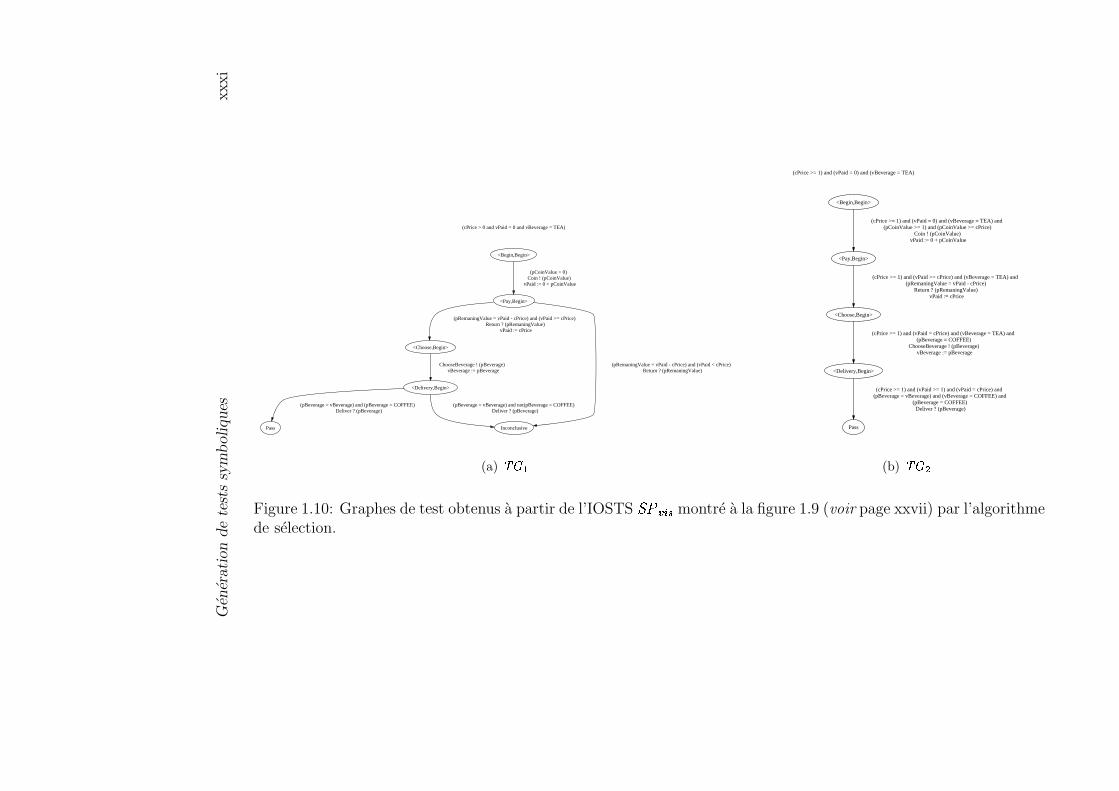
Gén
érati
on
de
test
ssy
mb
oliques
xxxi
(cPrice > 0 and vPaid = 0 and vBeverage = TEA)
<Begin,Begin>
<Pay,Begin>
(pCoinValue > 0) Coin ! (pCoinValue)
vPaid := 0 + pCoinValue
<Choose,Begin>
(pRemaningValue = vPaid - cPrice) and (vPaid >= cPrice) Return ? (pRemaningValue)
vPaid := cPrice
Inconclusive
(pRemaningValue = vPaid - cPrice) and (vPaid < cPrice) Return ? (pRemaningValue)
<Delivery,Begin>
ChooseBeverage ! (pBeverage) vBeverage := pBeverage
Pass
(pBeverage = vBeverage) and (pBeverage = COFFEE) Deliver ? (pBeverage)
(pBeverage = vBeverage) and not(pBeverage = COFFEE) Deliver ? (pBeverage)
(a) � � �
(cPrice >= 1) and (vPaid = 0) and (vBeverage = TEA)
<Begin,Begin>
<Pay,Begin>
(cPrice >= 1) and (vPaid = 0) and (vBeverage = TEA) and (pCoinValue >= 1) and (pCoinValue >= cPrice)
Coin ! (pCoinValue) vPaid := 0 + pCoinValue
<Choose,Begin>
(cPrice >= 1) and (vPaid >= cPrice) and (vBeverage = TEA) and (pRemaningValue = vPaid - cPrice)
Return ? (pRemaningValue) vPaid := cPrice
<Delivery,Begin>
(cPrice >= 1) and (vPaid = cPrice) and (vBeverage = TEA) and (pBeverage = COFFEE)
ChooseBeverage ! (pBeverage) vBeverage := pBeverage
Pass
(cPrice >= 1) and (vPaid >= 1) and (vPaid = cPrice) and (pBeverage = vBeverage) and (vBeverage = COFFEE) and
(pBeverage = COFFEE) Deliver ? (pBeverage)
(b) � � �
Figure 1.10: Graphes de test obtenus à partir de l’IOSTS �� �� � montré à la figure 1.9 (voir page xxvii) par l’algorithmede sélection.
xxxii Résumé
et � ��������� � � � sont plus précis que ceux calculés dans le cas précédent). Commeon peut le voir aisément sur la figure 1.10 (voir page xxxi), la sélection baséesur cette abstraction est plus précise que celle décrite plus haut. En effet,elle supprime avec succès deux localités @�� B+�� � = �<��6� qui apparaissaient dans� � � . La première localité @�� B+�� � = �<��6� est éliminée en renforçant la gardede la première transition symbolique de � � � de telle façon qu’il est possibled’atteindre la localité � �7��� . Pour cela, nous avons utilisé l’information que lapremière somme payée doit être suffisante pour recevoir la boisson. La secondelocalité @�� B+�� � = �<��6� est éliminée en utilisant le même principe que plus haut,c’est-à-dire en renforçant la garde de la transition symbolique où l’utilisateurchoisit la boisson. En effet, nous obligeons l’utilisateur à choisir du café, ce quicorrespond évidement à ce qu’il souhaite, voir l’objectif de test de la figure 1.2page xii. �
Nous allons maintenant étudier la relation de trace entre l’IOSTS ����(-�� et legraphe de test � � obtenu à partir de ����(-�� par l’algorithme de sélection (voirpage xxix). Remarquons tout d’abord que l’algorithme n’ajoute aucune tran-sition symbolique à ��;� -�� mais restreint les gardes de certaines transitions etrenomme certaines localités de ����(-�� dans “pass” ou “inconclusive”. Par con-séquent, l’ensemble de traces de � � ne peut être plus grand que l’ensemble detraces de ��;�(-�� . Cependant, nous ne pouvons assurément pas obtenir l’égalitéentre ������ �������� � � et ������ ������#��;�(-���� . En effet, le but de l’algorithme de sélec-tion est de choisir (1) les traces de ����(-�� menant aux états à partir desquels ilest possible d’aller vers les états d’acceptation, et (2) les traces de ���� -�� se ter-minant par une action d’entrée valuée et menant aux états à partir desquels ilest impossible d’aller vers un état d’acceptation, et dont les préfixes stricts sontdes traces conduisant aux états à partir desquels il est possible d’aller vers desétats d’acceptation. Dans le dernier cas, le graphe de test � � doit produire leverdict @�� B+�� � = �<��6� . (Étant donné que le problème de savoir si à partir d’unétat on peut atteindre un état accepteur est indécidable, nous calculons une sur-approximation de l’ensemble des états possédants cette propriété.) Ainsi, il estclair que l’ensemble de traces de � � est inclus dans l’ensemble de traces de ����(-�� .Dans la proposition ci-dessous, nous caractérisons l’ensemble des traces de ���� -��ainsi que ses sous-ensembles de traces menant aux états “pass” ou “inconclusive”.
Proposition 1.3 (Traces de � � ) Soit � � un graphe de test obtenu à partirde l’IOSTS ����(-��8� �.� � ��� ������� ������ .� ���-� � , où ���� est une spécification avecl’alphabet des actions d’entrée valuées 2�7%���� , et ��� est un objectif de test de���� . Alors :
(1) ������ �������� � � 1 ������ ����������� -���� ,
Génération de tests symboliques xxxiii
(2) ������ ���� ������� �7� � � 1�,-������ ����������� �� ���-� , plus précisément,
(2.a) ������ ���� ������� �7� � � � �� ��� � �#,-������ ������#���� 0�����0�'� , et
(3) ������ �������� � � � �7� *-� 1 �7������ ����6������ �� � 2 7%���� 3 ������ ����6������ �� � ��*��� � � ,-������ ������#���� 0�����0� � .Notons que si la calcul exact était possible, alors la dernière inclusion setransforme en une égalité.
où ������ ���� � ���� �7� � � et ������ �������� � � � �7� � � sont les ensembles de traces du graphe detest � � conduisant respectivement aux états “pass” et “inconclusive” de � � . �
Les propriétés (1), (2) et (3) de traces d’un graphe de test � � sont formellementprouvées dans la section 7.4 du chapitre 7. Il est aussi important de soulignerque nous avons obtenu un cas de test � � qui est déterministe (voir lemme 7.1,page 195 au chapitre 7).
1.3.4.5 Rendre un graphe de test complet en entrée
La dernière étape de notre méthode symbolique de génération de tests consisteà transformer le graphe de test � � , obtenu à partir d’une spécification ���� etd’un objectif de test ��� de ���� par les opérations et algorithmes décrits dans lessections précédentes, en un cas de test � * . À cause de la définition d’un cas detest donnée page xv, le cas de test � * doit toujours réagir sur n’importe quelleentrée venant d’une implémentation sous test <>= 9 . Ceci signifie que � * ne doitbloquer aucune entrée de <>= 9 , mais doit répondre négativement aux entrées incor-rectes. Par conséquent, nous devons exiger que chaque localité du graphe de test� � , à l’exception des localités � �7��� et @�� B+�� � = �<��6� , (1) accepte n’importe quelleentrée de <>= 9 , et (2) redirige les entrées incorrectes vers la nouvelle localité � � < � ,c’est-à-dire rende � � complet en entrée. Pour accomplir ceci, nous proposonsune procédure syntaxique simple.
Soit � � un graphe de test avec un ensemble des localités , un ensemble desvariables � , un ensemble des transitions symboliques � et un alphabet d’actionsd’entrée/sortie � � � 4 6 �;7 . Le cas de test � * est l’IOSTS obtenu à partir de� � en ajoutant une nouvelle localité � � < ����� et, pour chaque localité � ��et chaque action d’entrée , � � 4 , en ajoutant une transition symbolique � �� �d’origine � , de destination � � < � , d’action , , d’affectations 7�� ��� � y�� � '�� � '�� et degarde 5������ � v�� o p�r ) r s r t! v r u" v r p v x ��D 5#� v � . Autrement dit, toute entrée non exécutabledans � � devient exécutable dans � * et mène aux nouvelles localités (de blocagecomplet) � � < � . L’algorithme qui transforme � � en un cas de test complet enentrée � * est donné dans la section 7.5 du chapitre 7.
xxxiv Résumé
Un cas de test � * obtenu par la procédure décrite plus haut contient troistypes de verdicts : � �7��� , @�� B+�� � = �<��6� et � � < � . Par conséquent, les ensem-bles de traces de � * qui contiennent respectivement les traces menant auxétats “pass”, “inconcusive” et “fail” sont notés respectivement ������ ���� � ���� ��� *0� ,������ �������� � � � �7� *0� et ������ ������ � ��� ��� *-� . Dans la proposition ci-dessous, nous carac-térisons ces ensembles de traces.
Proposition 1.4 (Traces de � * ) Soit � * un cas de test obtenu à partir d’ungraphe de test � � � � ��� � ��� � �.� � ��� �&����� ������ � ���0� �'� , où ���� est une spécificationavec un alphabet d’actions d’entrée valuées 2 4 %�� �� , ��� est un objectif de test de���� et select est l’algorithme 1.1 (voir page xxix). Alors :
(1) ������ �������� *-� � ������ ������7� � � 6 ������ ������ � ��� ��� *-� ,(2) ������ ���� � ���� ��� *-� � ������ ���� ������ ��� � � ,(3) ������ ������ � � � � ��� *-� � ������ �������� � � � �7� � � , et
(4) ������ ������ � ��� �7� *0� 1/�������� ����������� �� � 2;7%�� �� � ������ ����������� �� � , plus précisément
(4.a) ������ ������ � ��� �7� *0��� �7������ ������7� � � � 2 7%�� �� � ������ ������7� � � � .�
Les propriétés (1), (2), (3) et (4) de traces d’un cas de test � * sont formellementdémontrées à la section 7.5 du chapitre 7, et la preuve de la propriété (4.a) estune conséquence directe de la procédure qui rend un graphe de test complet enentrée. Il est aussi important de souligner que le cas de test � * que nous avonsobtenu est déterministe (pour les détails, le lecteur peut se référer au deuxièmepoint du théorème 7.2, page 203 du chapitre 7).
Exemple 1.5 Considérons le graphe de test � � � montré à la figure 1.10(b)(voir page xxxi) obtenu par l’algorithme de sélection (voir page xxix). Lafigure 1.11 (voir page xxxv) illustre le cas de test complet en entrée � * obtenu,à partir du graphe de test � � donné, par la procédure expliquée dans cettesection. �
1.3.5 Correction d’un cas de test
Dans la section 1.3.4, nous avons décrit comment générer un cas de test symbol-ique � * à partir d’une spécification ���� et d’un objectif de test ��� de ���� .Nous avons également montré que le cas de test résultant � * est initialisé (par laconstruction du cas de test) et déterministe (voir théorème 7.2, page 203). Cepen-dant, nous n’avons pas montré que � * produit des résultats corrects lorsqu’il est

Gén
érati
on
de
test
ssy
mb
oliques
xxxv
(cPrice >= 1) and (vPaid = 0) and (vBeverage = TEA)
<Begin,Begin>
<Pay,Begin>
(cPrice >= 1) and (vPaid = 0) and (vBeverage = TEA) and (pCoinValue >= 1) and (pCoinValue >= cPrice)
Coin ! (pCoinValue) vPaid := 0 + pCoinValue
Fail
Return ? (pRemaningValue) Deliver ? (pBeverage)<Choose,Begin>
(cPrice >= 1) and (vPaid >= cPrice) and (vBeverage = TEA) and (pRemaningValue = vPaid - cPrice)
Return ? (pRemaningValue) vPaid := cPrice
not ((cPrice >= 1) and (vPaid >= cPrice) and (vBeverage = TEA) and (pRemaningValue = vPaid - cPrice))
Return ? (pRemaningValue)Deliver ? (pBeverage)
<Delivery,Begin>
(cPrice >= 1) and (vPaid = cPrice) and (vBeverage = TEA) and (pBeverage = COFFEE)
ChooseBeverage ! (pBeverage) vBeverage := pBeverage
Return ? (pRemaningValue) Deliver ? (pBeverage)
Pass
(cPrice >= 1) and (vPaid >= 1) and (vPaid = cPrice) and
(pBeverage = vBeverage) and (vBeverage = COFFEE) Deliver ? (pBeverage)
Return ? (pRemaningValue)
not ((cPrice >= 1) and (vPaid >= 1) and (vPaid = cPrice) and
(pBeverage = vBeverage) and (vBeverage = COFFEE)) Deliver ? (pBeverage)
Figure 1.11: Cas de test complet en entrée � � .
xxxvi Résumé
exécuté sur une implémentation sous test. Ainsi, le but de cette thèse est dedémontrer la correction du cas de test donné par rapport à la spécification ���� ,l’objectif de test ��� de ���� , et l’ensemble des implémentations @ =�9 � , au sens dela définition 1.7 (voir page xix). Formellement :
Théorème 1.1 (Correction de � * ) Le cas de test � * généré à partir de laspécification ���� et de l’objectif de test ��� par notre méthode symbolique degénération de tests est correcte pour l’ensemble des implémentations sous test@ =�9 � . �Le lecteur trouvera la preuve formelle de la correction du cas de test à la sec-tion 7.6 du chapitre 7.
1.3.6 Conclusion
Nous avons tout d’abord proposé un modèle pour la représentation des systèmesréactifs appelé système symbolique des transitions à entrée/sortie (IOSTS). Cemodèle nous permet de décrire plus précisément les systèmes réactifs en prenantexplicitement en compte leurs données. De plus, il nous autorise à générer descas de test sous la forme de programmes avec des variables, des constantes sym-boliques et des paramètres (c’est-à-dire des cas de test génériques).
Ensuite, nous avons brièvement décrit les principes essentiels de la générationsymbolique de tests basée sur les IOSTS. Cette méthode traite symboliquementles données d’un système en combinant l’approche de génération de tests pro-posée auparavant par notre groupe de recherche [Fernandez et al., 1996] avecl’interprétation abstraite [Cousot and Cousot, 1976], [Cousot and Cousot, 1977]que l’on utilise pour la sélection des cas de test. De plus, ce modèle nous per-met d’éviter le problème de l’explosion de l’espace d’états et de dériver des casde test génériques. Enfin, nous avons montré que notre méthode symbolique degénération de tests dérive des cas de test corrects.
L’ensemble de ces travaux constituent un extension de l’approche proposéeinitialement dans [Rusu et al., 2000].
1.4 Implémentation et résultats expérimentaux
La troisième partie de ce document est consacrée à l’implémentation de la méth-ode symbolique de génération de tests proposée dans la seconde partie de la thèse,ainsi qu’à l’étude de cas pour laquelle cette implémentation a été utilisée. Plusprécisément, au chapitre 8, nous employons la théorie et les algorithmes présen-tés dans la deuxième partie de la thèse afin d’implémenter un prototype pourla génération automatique et symbolique de cas de test appelé STG10 [Clarke
10Provient de la terminologie anglaise “Symbolic Test Generator”.
Conclusion xxxvii
et al., 2002], [Clarke et al., 2001b], [Clarke et al., 2001c]. Nous décrivons ensuitel’utilisation de STG dans le test d’un protocole de communication qui transfèreun fichier de données présenté sous la forme d’une séquence de paquets. Le pro-tocole est fondé sur le protocole classique du bit alterné, mais ne permet qu’unnombre fini de retransmissions de chaque paquet. Enfin, nous comparons STGà d’autres outils existants utilisés pour la génération de tests de conformité dessystèmes réactifs.
1.5 Conclusion
Ce mémoire s’achève par un résumé des principaux résultats obtenus, et par unediscussion sur les perspectives. Une brève description du dernier chapitre de cedocument est donnée ci-après.
Résumé. Cette thèse se situe dans le domaine du test de conformité boîte noirepour les systèmes réactifs. De tels systèmes sont généralement complexes et detaille importante. Il n’est donc pas aisé de les implémenter sans erreur. Mêmeune petite erreur peut mener à de sérieux dysfonctionnements du système (voirles exemples donnés page 2). Il est par conséquent essentiel de développer destechniques de détection d’erreur dans les systèmes réactifs qui les rendent plusfiables. Dans cette thèse, nous nous concentrons sur l’une de ces techniquesappelée le test.
Au début de ce document, nous mentionnions qu’au cours des dernières décen-nies, les théories de test et les techniques pour la dérivation automatique de testsont été développées. Certaines de ces techniques sont basées sur le modèle desmachines d’états finis (FSM11), et d’autres sur le modèle des systèmes de transi-tions à entrée/sortie (IOLTS). Puisque, à notre avis, le modèle IOLTS est mieuxadapté pour le test des systèmes réactifs que le modèle FSM, nous nous sommesfocalisé sur l’étude des méthodes et algorithmes pour la dérivation automatiquede tests fondés sur les IOLTS. Nous avons tout particulièrement pris en con-sidération deux algorithmes à la volée efficaces proposés dans [Tretmans, 1992],[Jéron and Morel, 1999]. Nous avons également décrit des outils académiques(par exemple TorX [Belinfante et al., 1999], TGV [Fernandez et al., 1996]) etindustriels (par exemple Autolink [Telelogic, 1998], TestComposer [Kerbrat andOber, 1999]) déjà existants, qui implémentent ces algorithmes et produisent descas de test corrects, ce qui signifie essentiellement qu’ils émettent toujours unverdict correct.
Néanmoins, les théories et les outils fondés sur des IOLTS sont relativementlimités. Ils ne prennent pas explicitement en compte les données du système car
11Provient de la terminologie anglaise “Finite State Machine”.
xxxviii Résumé
le modèle sous-jacent des IOLTS ne permet pas de le faire. Ainsi, pour modéliserune spécification du système réactif avec des IOLTS, il est nécessaire d’énumérerles valeurs de chaque donnée employée par le système. Ceci peut conduire auproblème classique de l’explosion de l’espace d’états. De plus, cette énumérationa aussi pour effet d’obtenir des cas de test où toutes les données sont instanciées.Ceci contredit la pratique industrielle où les cas de test (écrits, par exemple dansla langage TTCN [ISO/IEC/JTC1/SC21, 1992]) sont de vrais programmes avecdes données (variables, constantes symboliques et paramètres de communication).
Afin de résoudre les problèmes mentionnés ci-devant, nous avons proposé uneextension de l’approche [Rusu et al., 2000] pour la génération automatique decas de test symboliques sous la forme de systèmes étendus de transitions avecdes variables, des constantes symboliques et des paramètres de communication.Ces systèmes sont appelés systèmes symboliques de transitions à entrées/sorties(IOSTS).
Puis, nous avons présenté les concepts du test de conformité basé sur lesIOSTS. En d’autres termes, nous avons défini formellement (1) la relation deconformité � � � entre une spécification et une implémentation sous test qui sonttoutes deux modélisées avec des IOSTS, (2) la notion de cas de test et (3) lespropriétés des cas de test, permettant d’établir un lien entre les cas de test et larelation de conformité.
Nous avons décrit ensuite l’approche de génération symbolique de tests fondéesur la théorie de test introduite plus haut et implémentée dans l’outil STG. Ladescription de cet outil et une étude de cas du protocole de retransmission bornéesont données dans la troisième partie de notre travail. Enfin, nous avons com-paré notre approche avec d’autres approches symboliques pour la génération au-tomatique de tests. La majorité de celles-ci sont basées sur la propagation decontraintes et utilisent des techniques de résolution de contraintes. De surcroît,elles ne traitent pas du problème du non-déterminisme (rappelons que nous avonsposé comme hypothèse que le non-déterminisme est formellement interdit dans letest). Les éléments originaux de notre approche sont : l’emploi d’une techniqued’interprétation abstraite au moment de la sélection du cas de test et les solu-tions partielles au non-déterminisme. Notons que nous n’avons pas résolu tousles problèmes en rapport avec la génération symbolique de tests. En particulier,notre approche utilise aussi une technique de résolution de contrainte lorsque l’oninstancie des cas de test symboliques pendant leur exécution.
Nous pensons que notre approche symbolique de génération de tests mérited’être étudiée et que la recherche future peut améliorer son applicabilité auxsystèmes réactifs industriels.
Recherche future. Les idées suivantes pour la recherche à venir sont inspiréesdu travail présenté dans cette thèse.

Conclusion xxxix
De ioc à ioco. Avant d’entrer en détails dans les perspectives décrites dans ceparagraphe, nous rappelons la différence entre les relations � � �.� [Tretmans,1996a] et � � � (voir définition 1.4, page xv). Autrement dit, d’une part, larelation ioco crée un lien entre une spécification suspendue � �#���� �� et lemodèle suspendu d’une implémentation sous test � ��� ������� . Elle vérifie si,après l’exécution de chaque trace de suspension (c’est-à-dire trace pouvantcontenir l’action de sortie spéciale � ) de la spécification, l’implémentationproduit ou pas uniquement des actions de sortie spécifiées. D’autre part,la relation ioc crée un lien entre une spécification ���� avec une implémen-tation sous test � ����� , et effectue la même vérification que � � �.� mais pourchacune de ses traces propres (c’est-à-dire trace ne contenant aucune action� ) de la spécification.
Dans cette thèse, nous proposons une approche pour la génération sym-bolique de tests qui est basée sur le modèle IOSTS et sur la relation ioc.Cependant, cette approche a quelques faiblesses. L’une d’entre elles est leproblème des blocages, qui n’ont pas été traités dans la partie de la thèseabordant la génération symbolique de tests. En revanche, nous avons décritceci dans l’introduction (voir page 42). Afin d’améliorer notre générationsymbolique de tests dans ce domaine, il serait possible d’essayer l’approchesuivante (publiée dans [Rusu et al., 2004]).
(1) Limiter le modèle des IOSTS à un modèle qui ne contient pas deblocages vivants syntaxiques (cycles d’actions internes), et qui utilisela relation ioco [Tretmans, 1996a] comme critère de correction au lieude la relation ioc.
(2) Pour une spécification donnée, construire son IOSTS suspendu en co-dant tous les blocages potentiels (de sortie et complets) d’une spécifi-cation donnée avec l’action de sortie spéciale � .
Remarquons que le problème de la détection des blocages est indécidablepour les IOSTS en général. Cependant, dans le cas de l’absence de blocagesvivants syntaxiques sur un IOSTS � , il est possible de construire syntax-iquement l’IOSTS suspendu de � .
La solution classique pour détecter des blocages non-spécifiés dans une im-plémentation sous test durant une expérience de test est d’équiper chaquetesteur avec une minuterie indiquant le temps que le testeur doit attendreavant qu’une sortie n’apparaisse. Si la sortie n’a pas lieu avant un certaintemps, alors le testeur peut conclure que cette sortie n’aura plus lieu. Dansce cas, il décide que l’implémentation est bloquée.
Nous pensons que les suggestions données dans ce paragraphe aideront àaméliorer notre méthode symbolique de génération de tests.
xl Résumé
Propriétés de sûreté. Le rapport [Rusu et al., 2004] propose une approchepour combiner la vérification et les techniques de test de conformité. Dansce rapport, la spécification formelle ���� d’un système réactif donné estmodélisé par IOSTS, et chaque propriété de sécurité de ���� est représen-tée de la même manière qu’un objectif de test employé dans la méthodesymbolique de génération de tests. Alors,
Premièrement, chaque propriété est vérifiée sur ���� en utilisant des tech-niques automatiques (par exemple, l’interprétation abstraite) qui sontfiables mais pas nécessairement complètes pour la classe de propriétésde sécurité considérée ici.
Deuxièmement, pour chaque chaque propriété, un cas de test est généréautomatiquement à partir de la spécification et de cette propriété et ilest exécuté sur une implémentation boîte noire du système.
Si l’étape de vérification est réussie, c’est-à-dire si elle a établi que la spéci-fication satisfait les propriétés, alors l’exécution peut détecter la violationde la propriété par l’implémentation et la relation de conformité standard
� � �.� [Tretmans, 1996a] entre l’implémentation et la spécification. Si l’étapede vérification n’est pas réussie, c’est-à-dire si elle n’a pas permis de prouverou de réfuter la propriété, alors l’exécution du test peut détecter en plusune violation de la propriété par la spécification.
Critères de couverture. L’outil STG (comme son prédécesseur TGV [Fernan-dez et al., 1996]) emploie les objectifs de test comme mécanisme de sélec-tion de cas de test. Chaque objectif de test dans STG est donné sous laforme d’un graphe. Cette représentation offre à un développeur de logicielsune manière naturelle de décrire (partiellement) les comportements d’unespécification donnée devant être testée. Néanmoins, l’écriture manuelled’objectifs de test exige une bonne connaissance de la spécification. Cecisignifie que le processus d’écriture des objectifs de test est encore difficile àaccomplir pour les humains, surtout si une bonne couverture de la spécifica-tion doit être ciblée. Nous pensons que les critères classiques de couverturestructurelle [Rapps and Weyuker, 1985] combinés avec l’analyse symbolique,peuvent apporter des objectifs de test intéressants.
Études de cas. Jusqu’à présent, nous avons seulement généré des cas de test àpartir des spécifications académiques plus ou moins classiques d’une ma-chine à café et d’un protocole de retransmission bornée. La prochaîneétape importante est d’appliquer notre approche afin de tester des sys-tèmes industriels réalistes. Nous avons déjà fait les premiers pas dans cette

Conclusion xli
direction : nous avons généré des cas de test pour le porte-monnaie élec-tronique (CEPS) [CEPSCO, 2000]. Cette étude de cas nous a donné lesrésultats prometteurs publiés dans [Clarke et al., 2001a]. Ainsi, il serait in-téressant de poursuivre de telles expériences. Nous pensons également quede futures études de cas vont fournir des informations essentielles quant àl’applicabilité de notre approche symbolique de génération de tests et nousaidera à l’améliorer.

xlii Résumé
Chapter 1
Introduction
This chapter describes the context of the thesis and gives the moti-vations to the research presented in it. We start by introducing re-active systems, and emphasizing the importance of such systems bytaking realistic situations from daily life. These situations motivateusing validation techniques, such as testing and verification, in orderto ensure correctness of reactive systems. Then, we focus on test-ing, describe the role of testing in the software development cycle, anddiscuss existing testing methods, with stress on conformance testing.Next, we compare testing with another validation technique (verifica-tion), and underline their complementarity by discussing advantagesand drawbacks of these techniques. Finally, we present the main goalsof the thesis and its outline.
1.1 Reactive Systems
The notion of reactive system was introduced by A. Pnueli and D. Harel in [Hareland Pnueli, 1985]. In this work, the authors make a distinction between trans-formational and reactive systems . The former accept inputs and, after a certainperiod of time, produce outputs, i.e. they operate in an autonomous way. Forinstance, a transformational system can be a program that calculates the squareroot of an input, or more a complex program such as a compiler. The latter inter-act permanently with its environment by continuously exchanging information.Many systems in the real world can be considered as reactive: vending machines,cash dispensers, or more complex software and hardware systems, such as siliconchips, communication protocols, smart cards, industrial plants, avionic systemsand nuclear reactors. It is essential to realize how crucial reactive systems canbe, and how important it is to perform testing or other validation techniques onthem. For this purpose, we use a series of examples. All of them are available
1

2 Introduction
from the “10 Great Bugs of History” collection [CNET, 2000] and from the col-lections of software bugs found at the “Software Quality Assurance and TestingResource Center” [Hower, 2003].
NASA Mariner 1, Venus Probe (1962). “A probe launched from Cape Ca-naveral was set to go to Venus. After takeoff, the unmanned rocket carryingthe probe went off course, and NASA had to blow up the rocket to avoidendangering lives on earth. NASA later attributed the error to a faulty lineof Fortran code” (see [Myers, 1976]).
Therac-25 Radiation Machine (June 1985–January 1987). “TheTherac-25 medical linear accelerator was responsible for six accidentsinvolving massive overdoses of radiation, four of which lead to deaths.The proximate causes of the accidents were eventually attributed to twoseparate and hard-to-reproduce faults caused by race conditions in thedata entry system.” Leveson and Turner published a detailed investigationof the failures and the responses to them (see [Leveson and Turner, 1993]).
AT&T Long Distance Service (1990). “Switching errors in AT&T’s callhandling computers caused the company’s long-distance network to go downfor nine hours, the worst of several telephone outages in the history of thesystem. The meltdown affected thousands of services and was eventuallytraced to a single faulty line of code.”
NASA Mars Climate Orbiter (October 1999). “In October of 1999 the$125 million NASA Mars Climate Orbiter spacecraft was believed to belost in space due to a simple data conversion error. It was determined thatspacecraft software used certain data in English units that should have beenin metric units. Among other tasks, the orbiter was to serve as a communi-cations relay for the Mars Polar Lander mission, which failed for unknownreasons in December 1999. Several investigating panels were convened todetermine the process failures that allowed the error to go undetected.”The full story and the report about that are available in [Isbell and Savage,1999].
Britain’s National Tax System (March 2002). “In March of 2002 it wasreported that software bugs in Britain’s national tax system resulted inmore than 100,000 erroneous tax over-charges. The problem was partlyattributed to the difficulty of testing the integration of multiple systems.”
Of course, this thesis does not pretend to solve the problems presented in theexamples above, it just shows some progress in formal test generation. Theexamples above are used to emphasize the importance of the research oriented tothe improvement of existing validating techniques for reactive systems.

Testing 3
1.2 Testing
This section introduces testing and discusses its usability at the present time. Italso briefly presents black-box conformance testing which is the main topic of allremaining chapters of this work.
1.2.1 General View
Software testing [Myers, 1979] is a process that consists of examining computerprograms or systems with the intent of finding errors in them. The aim of testingis to make sure that systems will work correctly during their utilization. Testingcan never be exhaustive for any realistic system because the time and effort thatcan be spent on it is always limited. Therefore, it cannot guarantee completecorrectness of the system. That is to say, in E.W. Dijkstra’s words:
Program testing can be a very effective way to show the presence ofbugs, but it is hopelessly inadequate for showing their absence.
Testing is a time-consuming process, B. Boehm notices that:
“Checkout” and testing often consume 50% of software effort.
Nevertheless, it should be done for each phase of the software development cycle.The main reason for this was mentioned by B. Boehm:
The cost of [finding and] fixing an error increases by an order of mag-nitude at each stage in development.
The testing phases of this software development cycle are depicted in Figure 1.1and explained below.
User Requirements
Component Testing Integration Testing System Testing
Regression Testing
Acceptance Testing
?
Figure 1.1: Phases of the testing process.
Component (Unit) Testing is the process of testing small components of acomputer program, such as subprograms and subroutines. The purpose ofthis phase is to focus on the testing of “building blocks” of the program,instead of examining the entire program.
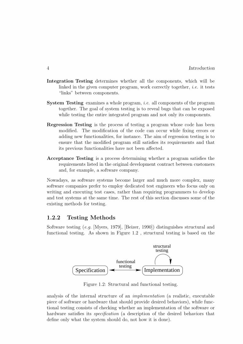
4 Introduction
Integration Testing determines whether all the components, which will belinked in the given computer program, work correctly together, i.e. it tests“links” between components.
System Testing examines a whole program, i.e. all components of the programtogether. The goal of system testing is to reveal bugs that can be exposedwhile testing the entire integrated program and not only its components.
Regression Testing is the process of testing a program whose code has beenmodified. The modification of the code can occur while fixing errors oradding new functionalities, for instance. The aim of regression testing is toensure that the modified program still satisfies its requirements and thatits previous functionalities have not been affected.
Acceptance Testing is a process determining whether a program satisfies therequirements listed in the original development contract between customersand, for example, a software company.
Nowadays, as software systems become larger and much more complex, manysoftware companies prefer to employ dedicated test engineers who focus only onwriting and executing test cases, rather than requiring programmers to developand test systems at the same time. The rest of this section discusses some of theexisting methods for testing.
1.2.2 Testing Methods
Software testing (e.g. [Myers, 1979], [Beizer, 1990]) distinguishes structural andfunctional testing. As shown in Figure 1.2 , structural testing is based on the
Specification Implementation
testing
testingfunctional
structural
Figure 1.2: Structural and functional testing.
analysis of the internal structure of an implementation (a realistic, executablepiece of software or hardware that should provide desired behaviors), while func-tional testing consists of checking whether an implementation of the software orhardware satisfies its specification (a description of the desired behaviors thatdefine only what the system should do, not how it is done).
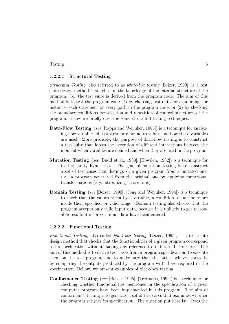
Testing 5
1.2.2.1 Structural Testing
Structural Testing, also referred to as white-box testing [Beizer, 1990], is a testsuite design method that relies on the knowledge of the internal structure of theprogram, i.e. the test suite is derived from the program code. The aim of thismethod is to test the program code (1) by choosing test data for examining, forinstance, each statement or every path in the program code; or (2) by checkingthe boundary conditions for selection and repetition of control structures of theprogram. Below we briefly describe some structural testing techniques.
Data-Flow Testing (see [Rapps and Weyuker, 1985]) is a technique for analyz-ing how variables of a program are bound to values and how these variablesare used. More precisely, the purpose of data-flow testing is to constructa test suite that forces the execution of different interactions between themoment when variables are defined and when they are used in the program.
Mutation Testing (see [Budd et al., 1980], [Howden, 1982]) is a technique fortesting faulty hypotheses. The goal of mutation testing is to constructa set of test cases that distinguish a given program from a mutated one,i.e. a program generated from the original one by applying mutationaltransformations (e.g. introducing errors to it).
Domain Testing (see [Beizer, 1990], [Jeng and Weyuker, 1994]) is a techniqueto check that the values taken by a variable, a condition, or an index areinside their specified or valid range. Domain testing also checks that theprogram accepts only valid input data, because it is unlikely to get reason-able results if incorrect input data have been entered.
1.2.2.2 Functional Testing
Functional Testing, also called black-box testing [Beizer, 1995], is a test suitedesign method that checks that the functionalities of a given program correspondto its specification without making any reference to its internal structures. Theaim of this method is to derive test cases from a program specification, to executethem on the real program and to make sure that the latter behaves correctlyby comparing the outputs produced by the program with these required in thespecification. Bellow, we present examples of black-box testing.
Conformance Testing (see [Beizer, 1995], [Tretmans, 1992]) is a technique forchecking whether functionalities mentioned in the specification of a givencomputer program have been implemented in this program. The aim ofconformance testing is to generate a set of test cases that examines whetherthe program satisfies its specification. The question put here is: “Does the
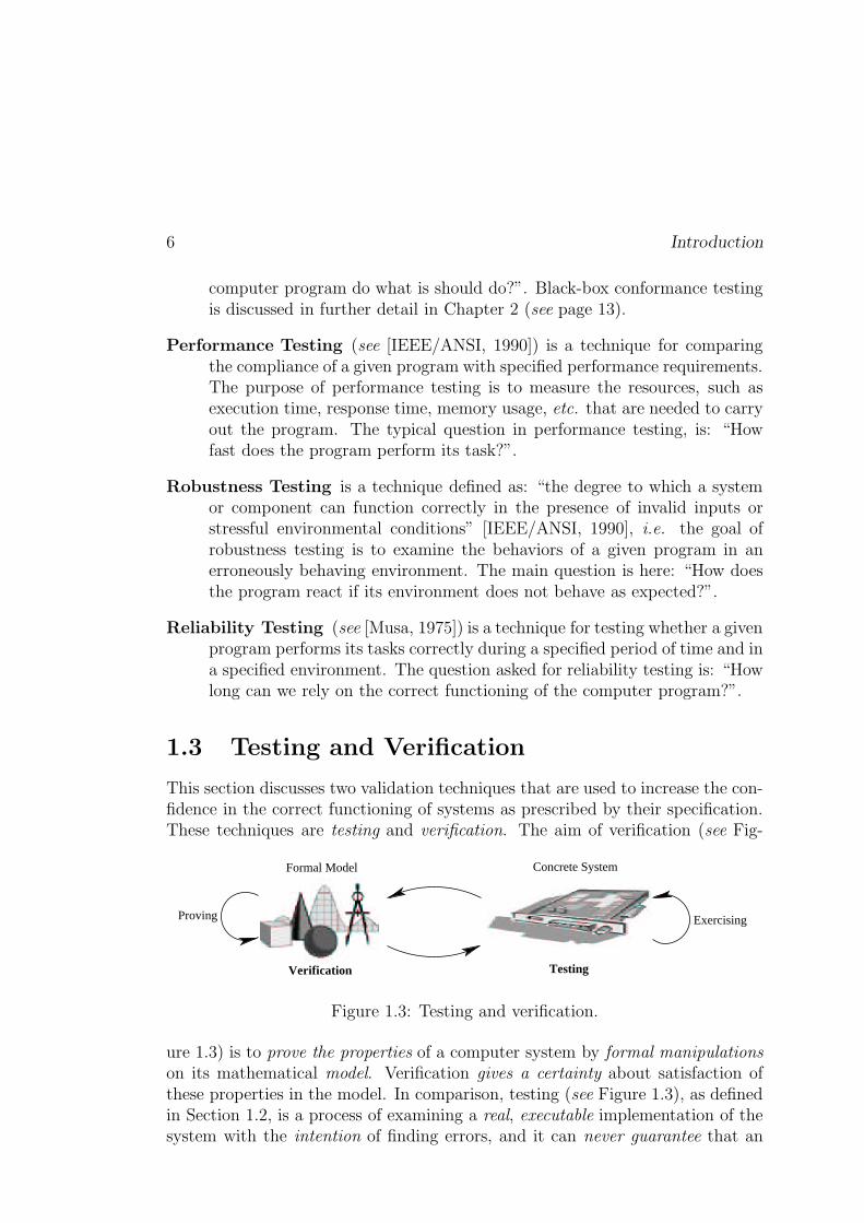
6 Introduction
computer program do what is should do?”. Black-box conformance testingis discussed in further detail in Chapter 2 (see page 13).
Performance Testing (see [IEEE/ANSI, 1990]) is a technique for comparingthe compliance of a given program with specified performance requirements.The purpose of performance testing is to measure the resources, such asexecution time, response time, memory usage, etc. that are needed to carryout the program. The typical question in performance testing, is: “Howfast does the program perform its task?”.
Robustness Testing is a technique defined as: “the degree to which a systemor component can function correctly in the presence of invalid inputs orstressful environmental conditions” [IEEE/ANSI, 1990], i.e. the goal ofrobustness testing is to examine the behaviors of a given program in anerroneously behaving environment. The main question is here: “How doesthe program react if its environment does not behave as expected?”.
Reliability Testing (see [Musa, 1975]) is a technique for testing whether a givenprogram performs its tasks correctly during a specified period of time and ina specified environment. The question asked for reliability testing is: “Howlong can we rely on the correct functioning of the computer program?”.
1.3 Testing and Verification
This section discusses two validation techniques that are used to increase the con-fidence in the correct functioning of systems as prescribed by their specification.These techniques are testing and verification. The aim of verification (see Fig-
Formal Model Concrete System
TestingVerification
ExercisingProving
Figure 1.3: Testing and verification.
ure 1.3) is to prove the properties of a computer system by formal manipulationson its mathematical model. Verification gives a certainty about satisfaction ofthese properties in the model. In comparison, testing (see Figure 1.3), as definedin Section 1.2, is a process of examining a real, executable implementation of thesystem with the intention of finding errors, and it can never guarantee that an
About this Thesis 7
implementation after testing is error-free. Moreover, testing and verification arecomplementary techniques. In this thesis, we demonstrate that some verificationtechniques are applicable to testing.
1.4 About this Thesis
In the previous sections of the introductory part of the thesis we briefly describedthe testing area and its problems. The rest of this thesis is devoted to the black-box conformance testing for reactive systems. In this section we present the maincontributions of our research and describe the structure of the thesis.
1.4.1 Motivation and Objectives
During the past years we have observed a continuous growth of software andhardware systems in size and complexity, which caused many erroneous systemsto appear. As the majority of reactive systems are often crucial, the importanceof error detection in these systems has increased. This has been one of the rea-sons for the current interest in testing reactive systems. During the last decades,testing theories and tools used for automatic test generation have been developed.In these theories and algorithms, the specifications of reactive systems are oftenmodeled by variants of the labeled transition systems (LTS). However, thesetheories and tools do not explicitly take into account the systems data, since theunderlying model of LTS does not allow to do that. This limitation of the modelcompels us to enumerate the values of the data before building the LTS model ofa system. This may result in the classical state-space explosion problem. More-over, this enumeration has also the effect of obtaining test cases, where all dataare instantiated. This contradicts with industrial practice, where test cases (ex-pressed, for instance, in TTCN [ISO/IEC/JTC1/SC21, 1992]) are real programswith variables and parameters. The generation of such test cases requires newmodels and techniques. In this thesis we have achieved two objectives.
First, we have introduced a new model called Input-Output Symbolic TransitionSystems (IOSTS) which explicitly includes all the data of a reactive system.
Second, we have proposed and implemented a new test generation techniquethat symbolically treats all the data of a system by combining the test gener-ation approach proposed by T. Jéron and his colleagues from IRISA/INRIARennes and the Verimag laboratory, Grenoble (see for instance, [Fernandezet al., 1996] and [Jéron, 2004]) with techniques of abstract interpretation(see [Cousot and Cousot, 1976], [Cousot and Cousot, 1977]).
8 Introduction
1.4.2 Plan of the Thesis
The rest of the thesis is separated into three parts organized as follows.
Part I consists in two chapters describing the state of the art for black-boxconformance testing. More precisely:
In Chapter 2 we describe the formal background used in the remaining chaptersof the thesis, i.e. we introduce the concepts presented in “Formal Methodsin Conformance Testing” [ISO/IEC, 1996], and briefly report on new de-velopments that have occurred in the field of formal conformance testing inthe last few years. In particular, we attempt at making the reader familiarwith the main concepts used in black-box conformance testing.
In Chapter 3 we focus on testing finite state machines and (input-output) la-beled transition systems. We present different kinds of conformance re-lations (e.g. conf, ioconf, ioco) for (IO)LTS, and different approaches forautomatic test generations. Finally, we describe some of existing tools usedin conformance testing of reactive systems.
Part II is the core of the thesis. It contains four chapters where we introducea symbolic model used to express the operational semantics of reactive systemsand a symbolic technique for test generation based on this model. The secondpart of our work begins with the motivations for symbolic test generation. Therest is organized as follows:
In Chapter 4 we define an extension of the input-output labeled transition sys-tem model (called IOLTS) that explicitly includes data of a reactive system.Then, we describe the syntax and semantics of IOSTS, and introduce somesubclasses of IOSTS used in symbolic test generation. The work containedin this chapter is an extended version of [Rusu et al., 2000].
In Chapter 5 we introduce the two main operations on IOSTS which are usedin our test generation technique and in the process of test execution. Theyare called product and parallel composition. In this chapter, we also presentseveral relationships concerning the set of traces of the IOSTS obtained afterthe product or parallel composition operations. The operations defined inthe chapter are inspired from those presented in [Rusu et al., 2000].
In Chapter 6 we describe the theory of conformance testing that serves as abasis for the symbolic test generation method described in the next chapterand realized as the Symbolic Test Generator (STG) tool. The work pre-sented in this chapter, is mainly inspired from the theory of conformance
About this Thesis 9
testing developed by J. Tretmans (see for example, [Tretmans, 1994], [Tret-mans, 1996b]) and from the research which has been done in the VerTeCsteam, IRISA (see [Rusu et al., 2000], [Morel, 2000], [Jard and Jéron, 2002]).In our theory of conformance testing, behaviors of specifications and imple-mentations under test are modeled with input-output symbolic transitionsystems, and the conformance relation is defined as a partial inclusion oftheir traces. At the end of the chapter, we define a notion of correct testcases with respect to specifications and test purposes.
In Chapter 7 we discuss the symbolic test generation method implemented inthe Symbolic Test Generator (STG) tool. The purpose of this methodis to compute a test suite starting from a given specification and a testpurpose. The three main steps of our symbolic test generation method are:(1) computing a synchronous product �� between the specification and thetest purpose, (2) eliminating internal action and nondeterminism from �� ,i.e. building the visible behaviors of �� denoted ����(-�� , and (3) eventually,selecting the behaviors of ��;� -�� that are accepted by the test purpose. Atthe end of the chapter, we show that the generated test case covers allbehaviors of the specification selected by the test purpose, and is correct.
Part III is devoted to the implementation of the symbolic test generationmethod proposed in the previous part of the thesis, and to a case study forwhich this implementation was used. More precisely:
In Chapter 8 we use the theory and algorithms presented in Part II, in orderto implement a prototype for automatic symbolic test case generation calledSTG (Symbolic Test Generator) [Clarke et al., 2002], [Clarke et al., 2001b],[Clarke et al., 2001c]. Then we describe the use of STG in the testingof a communication protocol that transfers a huge data file through lossychannels as a sequence of small packets. The protocol is based on thewell-known alternating bit protocol, but it only allows a bounded numberof retransmissions of each packet. Finally, we compare STG with otherexisting tools used for conformance test generation of reactive systems.
The thesis ends with a summary of the main results achieved during my PhDstudy at IRISA/INRIA Rennes, France, and a discussion on some perspectives(see Chapter 9, page 239).

10 Introduction
Part I
State of the Art in ConformanceTesting
11

Chapter 2
Formal Methods in ConformanceTesting
In this chapter we introduce the background for formal testing, whichserves as a fundamental basis for the work presented in this thesis thatallows the automatic generation of symbolic tests for reactive systems.We first briefly discuss new developments in the field of testing andmotivates the use of formal methods in automatic testing of reactivesystems. We then summarize the main concepts of conformance test-ing which are introduced in the standards IS-9646 [ISO, 1991] andFMCT [ISO/IEC, 1996], and formalized in [Tretmans, 1992]. Fi-nally, we present a test architecture in which a test suite is executed.It is important to notice that all concepts introduced in this chapterare given in generic level, i.e. they are independent of any particularformal method.
Nowadays, software and hardware are getting more and more complex. Theyusually consists of a variety of components which can be produced by differentmanufacturers. This leads to compatibility problems between different prod-ucts. In order to unify development processes and to define methods for testingconformance between a product and its specification, the International Orga-nization for Standardization (ISO) provided the international standard IS-9646[ISO, 1991] containing a methodology and a framework for testing of commu-nication protocols, for example SSCOP [Kahlouche et al., 1999]. It turned outthat this standard is also applicable to testing of other reactive systems, forexample, smart cards [Clarke et al., 2001a], and hardware [Kahlouche et al.,1999]. The IS-9646 standard has been mainly oriented towards practical needs.It incorporates practical experience of test experts who have been involved inconcrete testing. However, the formalism in IS-9646 is limited to definition of
13
14 Formal Methods in Conformance Testing
the TTCN [ISO/IEC/JTC1/SC21, 1992] language which is now widely used intelecommunication area for the description of test suites.
The increasing usability of formal methods in the software/hardware devel-opment processes, as well as new developments in the theory of testing, hasinfluenced the evolution of testing technology. This led to a joint project betweenthe International Organization for Standardization (ISO) and the InternationalTelecommunication Union (ITU) on “Formal Methods in Conformance Testing”(FMCT) [ISO/IEC, 1996]. The goal of this project was to “establish a theoryand framework [...] which may be used to assess conformance of an implementa-tion to behavior specified in a formal description”. The FMCT standard definesthe main concepts in conformance testing, which were formalized in [Tretmans,1992], and which are summarized in this chapter.
2.1 Conformance
The notion of conformance, according to [ISO/IEC, 1996], is linked to implemen-tations under test and specifications.
2.1.1 Specification
A specification of a reactive system is a formal description of behaviors that fixesthe properties of the system. In general, the specification is developed fromusers’ requirements and expressed using either natural language, such as Englishor French; or specialized description languages, such as SDL [ITU-T, 1994] orLOTOS [ISO/IEC, 1988]. The semantics of the specification can be represented,for example, by temporal logic [Pnueli, 1986], algebraic specifications [Dauchyet al., 1993], extended finite state machines [Petrenko et al., 1999], transitionsystems [Tretmans, 1992]. In this thesis, we use the following notations:
– ����� ��� for the universe of formal specifications, and
– ���� for a single specification that belongs to �����;��� .
2.1.2 Implementation
An implementation under test is a concrete executable system, that is, one of thegoals of a development process. The implementation can consist of, for instance,a single chip, hardware components or pieces of executable code. We denote by:
– � ��� – the universe of implementations, and
– <>=�9?��� ��� – a concrete implementation under test.

Conformance 15
In order to reason formally about an informal implementation <>=�9 � � ��� , it isassumed that each concrete implementation <>=�9 can be modeled by a formal object� ����� called a model of <>= 9 . The universe of the models of all implementations undertest is denoted by � � � � . In the literature on testing theory (see [Bernot, 1991]),this assumption is referred to as the “testing hypothesis”, and can be formulatedin a semi-formal manner as follows:
Testing Hypothesis� <>=�95� � ����� � � � �!� � � � � �! <>= 9 is modeled by � � � �>& (2.1)
�It is important to notice that the testing hypothesis does not imply that a modelof the implementation under test <>= 9 is known, it only assumes that such a modelexists.
2.1.3 Conformance as an Implementation Relation
To define conformance between an implementation under test <>= 9�� � ��� anda specification ���� �� ���� ��� , we use the notion of an implementation relation[Brinksma et al., 1990]. An implementation relation imp is a relation betweenthe set of implementation models � � � � and the set of specifications �����;��� , i.e.
����� 1 � � � � � ����� ��� (2.2)
Definition 2.1 (Conformance) An implementation <>=�9?� � ��� is conformantto a specification ���� � ����� ��� if the existing model � � � �!��� � � � of <>= 9 is ����� -related to ���� , i.e.
<>=�9 �.��� � � ���*� �(� ���� � � � � � ����� ���� �
The approach based on the implementation relation is shown on Figure 2.1. Theimplementation <>= 95��� ��� correctly implements the specification ���� � ����� ���if
(1) it is modeled by � � � � belonging to the set � ����� 1 � � � � of models, and
(2) the model � � � � implements ���� according to the implementation relation����� .
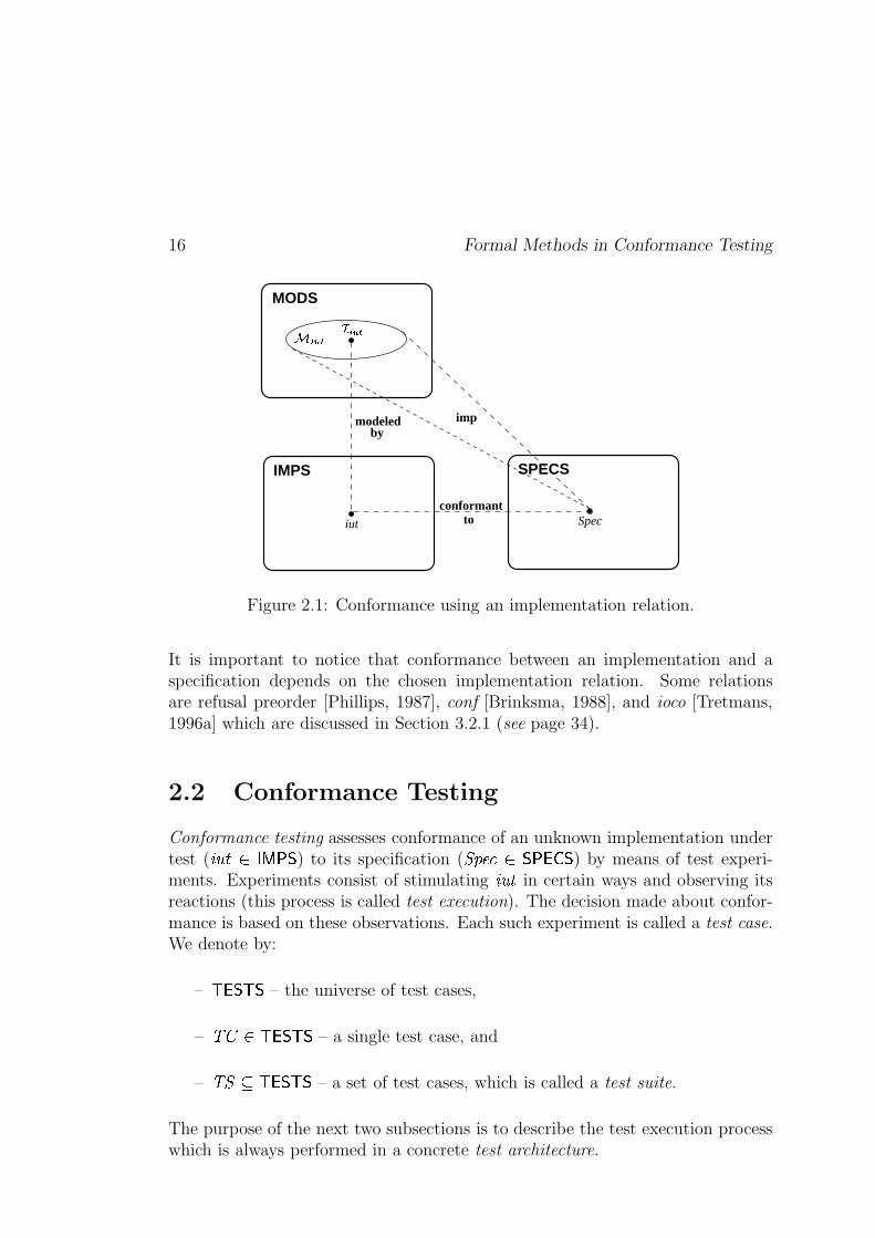
16 Formal Methods in Conformance Testing
SPECS
conformanttoiut
IMPS
modeled
Spec
MODS
impby
��� ��������
Figure 2.1: Conformance using an implementation relation.
It is important to notice that conformance between an implementation and aspecification depends on the chosen implementation relation. Some relationsare refusal preorder [Phillips, 1987], conf [Brinksma, 1988], and ioco [Tretmans,1996a] which are discussed in Section 3.2.1 (see page 34).
2.2 Conformance Testing
Conformance testing assesses conformance of an unknown implementation undertest ( <>= 9 � � ���� ) to its specification ( ���� � �����;��� ) by means of test experi-ments. Experiments consist of stimulating <>= 9 in certain ways and observing itsreactions (this process is called test execution). The decision made about confor-mance is based on these observations. Each such experiment is called a test case.We denote by:
– � �� � – the universe of test cases,
– � * �� � �� � – a single test case, and
– �� 1� � �� � – a set of test cases, which is called a test suite.
The purpose of the next two subsections is to describe the test execution processwhich is always performed in a concrete test architecture.
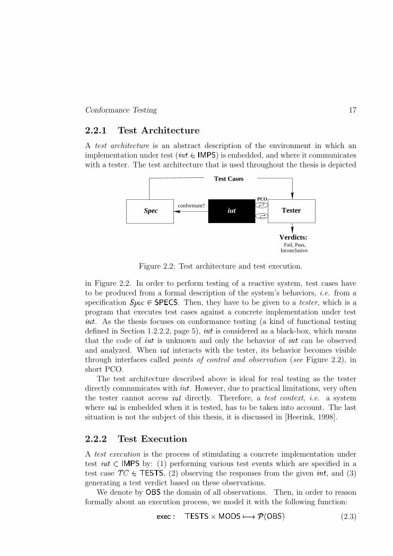
Conformance Testing 17
2.2.1 Test Architecture
A test architecture is an abstract description of the environment in which animplementation under test ( <>= 9?��� ���� ) is embedded, and where it communicateswith a tester. The test architecture that is used throughout the thesis is depicted
Test Cases
Tester
PCO
Fail, Pass,Verdicts:
Inconclusive
conformant?Spec iut
Figure 2.2: Test architecture and test execution.
in Figure 2.2. In order to perform testing of a reactive system, test cases haveto be produced from a formal description of the system’s behaviors, i.e. from aspecification ���� �� ����� ��� . Then, they have to be given to a tester, which is aprogram that executes test cases against a concrete implementation under test<>=�9 . As the thesis focuses on conformance testing (a kind of functional testingdefined in Section 1.2.2.2, page 5), <>=�9 is considered as a black-box, which meansthat the code of <>=�9 is unknown and only the behavior of <>=�9 can be observedand analyzed. When <>=�9 interacts with the tester, its behavior becomes visiblethrough interfaces called points of control and observation (see Figure 2.2), inshort PCO.
The test architecture described above is ideal for real testing as the testerdirectly communicates with <>=�9 . However, due to practical limitations, very oftenthe tester cannot access <>=�9 directly. Therefore, a test context, i.e. a systemwhere <>= 9 is embedded when it is tested, has to be taken into account. The lastsituation is not the subject of this thesis, it is discussed in [Heerink, 1998].
2.2.2 Test Execution
A test execution is the process of stimulating a concrete implementation undertest <>=�9 � � ���� by: (1) performing various test events which are specified in atest case � * � � �� � , (2) observing the responses from the given <>=�9 , and (3)generating a test verdict based on these observations.
We denote by � � � the domain of all observations. Then, in order to reasonformally about an execution process, we model it with the following function:
����� � � � �� � � � � � ���� ��� ��� � �:� (2.3)
18 Formal Methods in Conformance Testing
This function computes, for each test case ����������� and each real implemen-tation under test �� ���������� modeled by �����������! #"$ , a subset of observations%'&)(+*-,�. 0/132 .
The purpose of testing is to indicate whether observations obtained after atest execution are correct or not. For that, we introduce a verdict function whichassigns to each observation a pass or fail verdict.
46587:9; <>=@? +/1BAC�D E'FHG8�JIJK>LMG (�(ON (2.4)
A FPG8�JI verdict means that a divergence is detected between the implementation�� Q� and its specification RTSVU�W . A LMG (�( verdict 1 means that �� Q� behaves in con-formance to RTSVU�W for the given observation.
Finally, using Functions (2.3) and (2.4), we characterize situations where animplementation under test �� Q� (which is modeled with ���������X�! #"$ ) fails orpasses a test case ��� :
�� Q��YJZ ;\[ ] ��� ^ _a`b� 5�cO5d<T. ���eKf�H�g�h�h2jilk 465O7m9;n<o=p. `�2rqsFHG8�JI1t�� Q��u8Z ]v]w5d] ��� ^ x . �� ��YJZ ;\[ ] ���02
These notions can be generalized for a test suite �1R * �j�yQ�� as follows:
�� Q��YJZ ;\[ ] �1R ^ _z�����{�1R|ilkV�� ��YJZ ;\[ ] ����t�� Q��u8Z ]v]w5d] �1R ^ x . �� ��YJZ ;\[ ] �1R$2 ^ }~���s�{�1R-i�k3�� ��u8Z ]w]v5>] ����t
2.3 Test Suite Properties
This section studies the coherence between the notion of conformance (see Sec-tion 2.1.3, page 15) applied to concrete implementations of the reactive systemand its formal specification, and the notion of successful test suite execution whichwas defined in Section 2.2. It formalizes and discusses the properties of test suites,which we want to obtain while generating the test suites automatically.
Soundness. A test suite �1R * ����� is sound if all implementations �� Q�B������� which are conformant to a specification RTSVU�W��{��P�3�� pass all tests be-longing to this test suite �1R , i.e.
}��� �����������ilk . �� Q� <d�Q� Y ��7�� Z ��=�=�� RTSVU�W62�q�� . �� Q��u8Z ]w]v5>] �1R�2$t (2.5)
1Later in the thesis the notion of a �1���f� verdict is refined by the introduction of an���T�f�)���w��� �����h verdict. This verdict indicates the violation of a scenario (called test purpose)for which a test case is generated.
Test Suite Properties 19
The soundness property is achievable for practical testing, but it is not sufficientas the incorrect implementations, i.e. implementations that are non-conformantto a specification, can pass the test suite. Thus, a test suite accepting all imple-mentations is also sound.
Exhaustiveness. A test suite �1R * �j�yQ�� is exhaustive if all implementations�� �@�������� leading to Pass during the test execution of �1R , are conformant to aspecification RTSVU�W#������ �1 , i.e.
}��� Q�@�������� i�k . �� ��u8Z ]w]v5>] �1R$2�q�� . �� Q� <d�� Y �'7f� Z ��=�=�� RTSVU�W�2�t (2.6)
The exhaustiveness property of a test suite is achievable only in theory, as itis often the case when the test suite should be infinite, for instance, when aspecification of the system under test contains loops.
Completeness. A test suite �1Rzq E1��� � KpidipidK����� N * �j�y�� is called com-plete if it is sound and exhaustive, i.e.
}��� �@�������� iPk . �� Q� <d�� Y �'7�� Z ��=�=�� RTSVU�W�2�� � . �� Q��u8Z ]w]v5>] �1R�2$t (2.7)
It is important to note that a complete test suite distinguishes exactly betweenall conformant and non-conformant implementations.
Discussion. It is theoretically possible to construct complete test suites [Tret-mans, 1992], i.e. a test suite which is sound and exhaustive, but for practicaltesting the exhaustiveness property becomes a very strong requirement as it isnot possible to execute an infinite number of tests in a limited period of time.Thus, the standard IS-9646 [ISO, 1991] suggests to use a weaker requirement forreal testing, namely soundness.

20 Formal Methods in Conformance Testing

Chapter 3
Test Generation
In this chapter we present a brief overview of research and develop-ments that have been done in conformance testing in last 35-40 years.We first describe several test generation methods based on the modelof finite state machines. Then, we discuss some limitations of thesemethods that have activated the research on different kinds of tran-sition systems (e.g. labeled transition systems, input-output labeledtransition systems). Next, we present several testing relations definedon these transition systems, and used as correctness criteria in con-formance testing. Finally, we describe some existing techniques forautomatic test generation based on transition systems.
3.1 Test Generation based on Finite State Ma-
chines
A Finite State Machine (FSM) [Gill, 1962] is an abstract model which consists ofa set of states, an alphabet, and a transition function that maps symbols of alpha-bet and current states to a next state. Computation begins in some state withan input string. It changes to new states depending on the transition function.There exist many variants of FSM, for instance, Moore machines that produce anoutput for each state after receiving an input, or Mealy machines that producean output for each transition after receiving an input. The Mealy machines arewidly used for the purposes of testing.
This section gives a formal definition of a Mealy machine and briefly describesseveral methods for test generation based on this model. The detailed descriptionof all these methods is given in the survey [Lee and Yannakakis, 1996] written byD. Lee and M. Yanakakis.
21
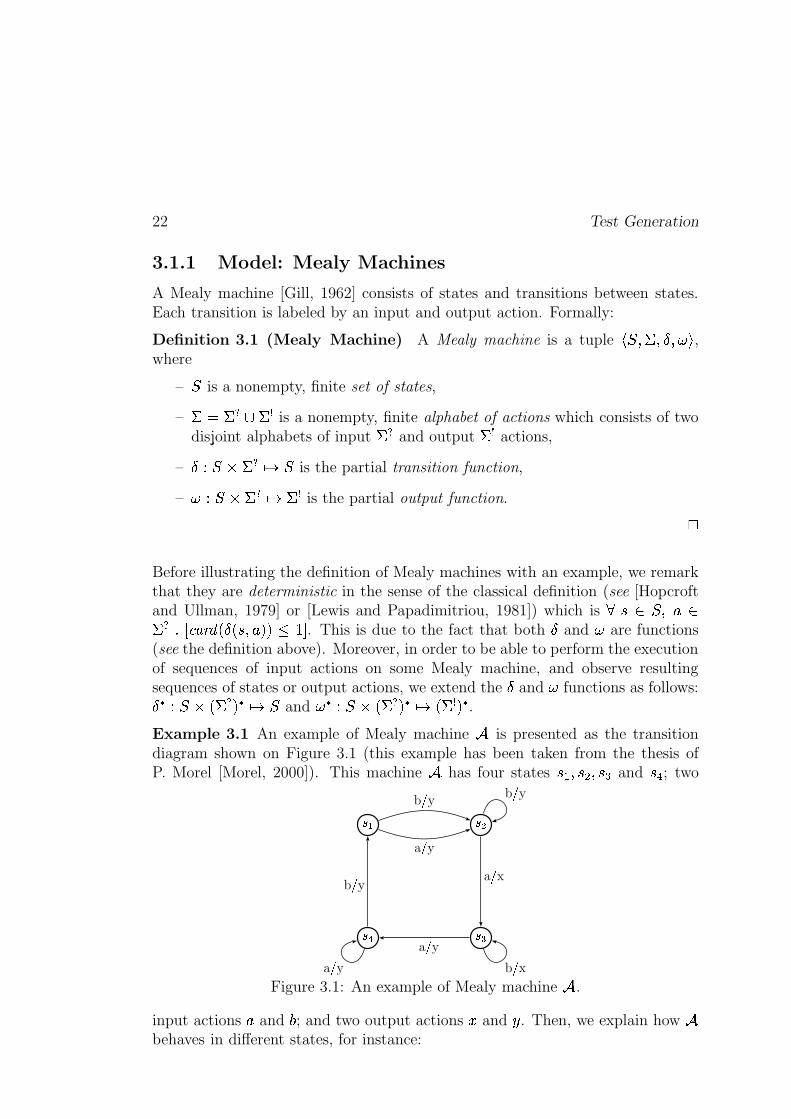
22 Test Generation
3.1.1 Model: Mealy Machines
A Mealy machine [Gill, 1962] consists of states and transitions between states.Each transition is labeled by an input and output action. Formally:
Definition 3.1 (Mealy Machine) A Mealy machine is a tuple��� K��+K�� K�� ,
where
–�
is a nonempty, finite set of states,
– �-q�� ������� is a nonempty, finite alphabet of actions which consists of twodisjoint alphabets of input � � and output � � actions,
– � ? ��� � � AD �is the partial transition function,
– � ? ��� ���$AD ��� is the partial output function. �
Before illustrating the definition of Mealy machines with an example, we remarkthat they are deterministic in the sense of the classical definition (see [Hopcroftand Ullman, 1979] or [Lewis and Papadimitriou, 1981]) which is }�� � � K����� � i�k�W�G���� . � . �TK��y2 2� "!>t . This is due to the fact that both � and � are functions(see the definition above). Moreover, in order to be able to perform the executionof sequences of input actions on some Mealy machine, and observe resultingsequences of states or output actions, we extend the � and � functions as follows:��# ? ��� . � � 2$#�AD �
and �%# ? ��� . � � 2$#�AD . � � 2$# .Example 3.1 An example of Mealy machine & is presented as the transitiondiagram shown on Figure 3.1 (this example has been taken from the thesis ofP. Morel [Morel, 2000]). This machine & has four states � � K��('pK��*) and �,+ ; two
-�. -0/
-01-$2
a 3 yb 3 y
a 3 x
a 3 y
b 3 y
b 3 y
b 3 xa 3 yFigure 3.1: An example of Mealy machine & .
input actions � and 4 ; and two output actions 5 and 6 . Then, we explain how &behaves in different states, for instance:
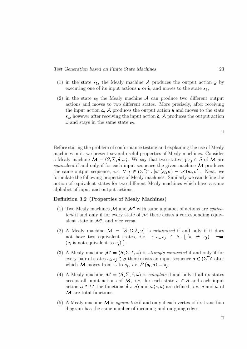
Test Generation based on Finite State Machines 23
(1) in the state � � , the Mealy machine & produces the output action 6 byexecuting one of its input actions � or 4 , and moves to the state ��' ,
(2) in the state �() the Mealy machine & can produce two different outputactions and moves to two different states. More precisely, after receivingthe input action � , & produces the output action 6 and moves to the state�,+ , however after receiving the input action 4 , & produces the output action5 and stays in the same state �*) . �
Before stating the problem of conformance testing and explaining the use of Mealymachines in it, we present several useful properties of Mealy machines. Considera Mealy machine � q � � K��eK���K0� . We say that two states ���fK���� � �
of � areequivalent if and only if for each input sequence the given machine � producesthe same output sequence, i.e. } `�� . � � 2 #+ilk �%# . ���fKh`�2eq �%# . ����Kh`P2 t . Next, weformulate the following properties of Mealy machines. Similarly we can define thenotion of equivalent states for two different Mealy machines which have a samealphabet of input and output actions.
Definition 3.2 (Properties of Mealy Machines)
(1) Two Mealy machines � and ��� with same alphabet of actions are equiva-lent if and only if for every state of � there exists a corresponding equiv-alent state in � � , and vice versa.
(2) A Mealy machine � q ��� K��+K�� K�� is minimized if and only if it doesnot have two equivalent states, i.e. }���fK���� � � ilk . ����q ����2 q��. �� is not equivalent to ���d2�t .
(3) A Mealy machine � q ��� K��+K�� K�� is strongly connected if and only if forevery pair of states ��� K������ � there exists an input sequence ` � . � � 2 # afterwhich � moves from ��� to ��� , i.e. � # . ��fKh`�2lq���� .
(4) A Mealy machine � q ��� K��eK�� K0� is complete if and only if all its statesaccept all input actions of � , i.e. for each state �b� �
and each inputaction � � � � the functions � . �TK��y2 and � . �'K �V2 are defined, i.e. � and � of� are total functions.
(5) A Mealy machine � is symmetric if and only if each vertex of its transitiondiagram has the same number of incoming and outgoing edges. �
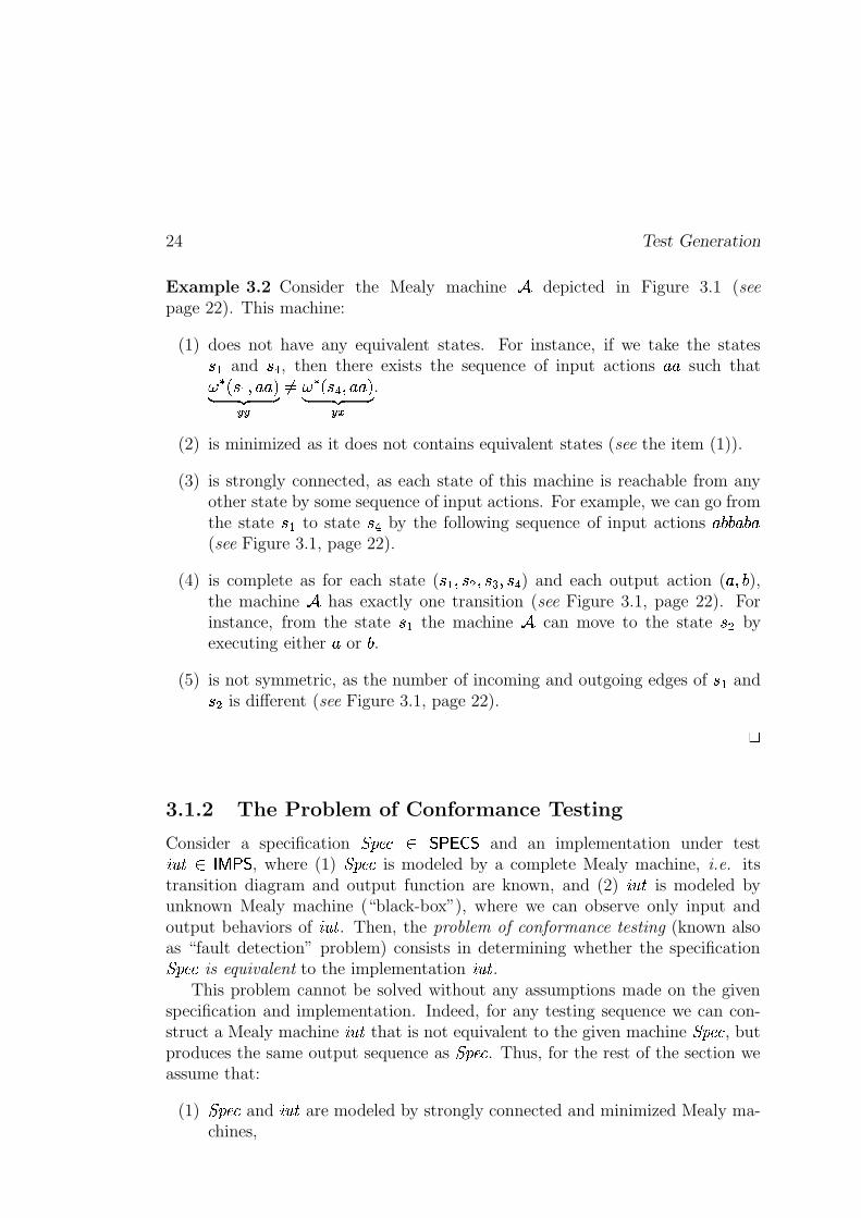
24 Test Generation
Example 3.2 Consider the Mealy machine & depicted in Figure 3.1 (seepage 22). This machine:
(1) does not have any equivalent states. For instance, if we take the states� � and �(+ , then there exists the sequence of input actions � � such that� # . � � K�� �y2� ��� �
���
�q � # . �(+6K � �y2� ��� �
��
.
(2) is minimized as it does not contains equivalent states (see the item (1)).
(3) is strongly connected, as each state of this machine is reachable from anyother state by some sequence of input actions. For example, we can go fromthe state � � to state �(+ by the following sequence of input actions � 4�4 � 4 �(see Figure 3.1, page 22).
(4) is complete as for each state ( � � K��('�K��()pK��(+ ) and each output action ( � K 4 ),the machine & has exactly one transition (see Figure 3.1, page 22). Forinstance, from the state � � the machine & can move to the state �*' byexecuting either � or 4 .
(5) is not symmetric, as the number of incoming and outgoing edges of � � and�(' is different (see Figure 3.1, page 22). �
3.1.2 The Problem of Conformance Testing
Consider a specification RTSVU�W � ���� �1 and an implementation under test�� Q� � ������ , where (1) RTSVU�W is modeled by a complete Mealy machine, i.e. itstransition diagram and output function are known, and (2) �� Q� is modeled byunknown Mealy machine (“black-box”), where we can observe only input andoutput behaviors of �� Q� . Then, the problem of conformance testing (known alsoas “fault detection” problem) consists in determining whether the specificationRTSVU�W is equivalent to the implementation �� Q� .
This problem cannot be solved without any assumptions made on the givenspecification and implementation. Indeed, for any testing sequence we can con-struct a Mealy machine �� � that is not equivalent to the given machine RTSVU�W , butproduces the same output sequence as RTSVU�W . Thus, for the rest of the section weassume that:
(1) RTSVU�W and �� Q� are modeled by strongly connected and minimized Mealy ma-chines,
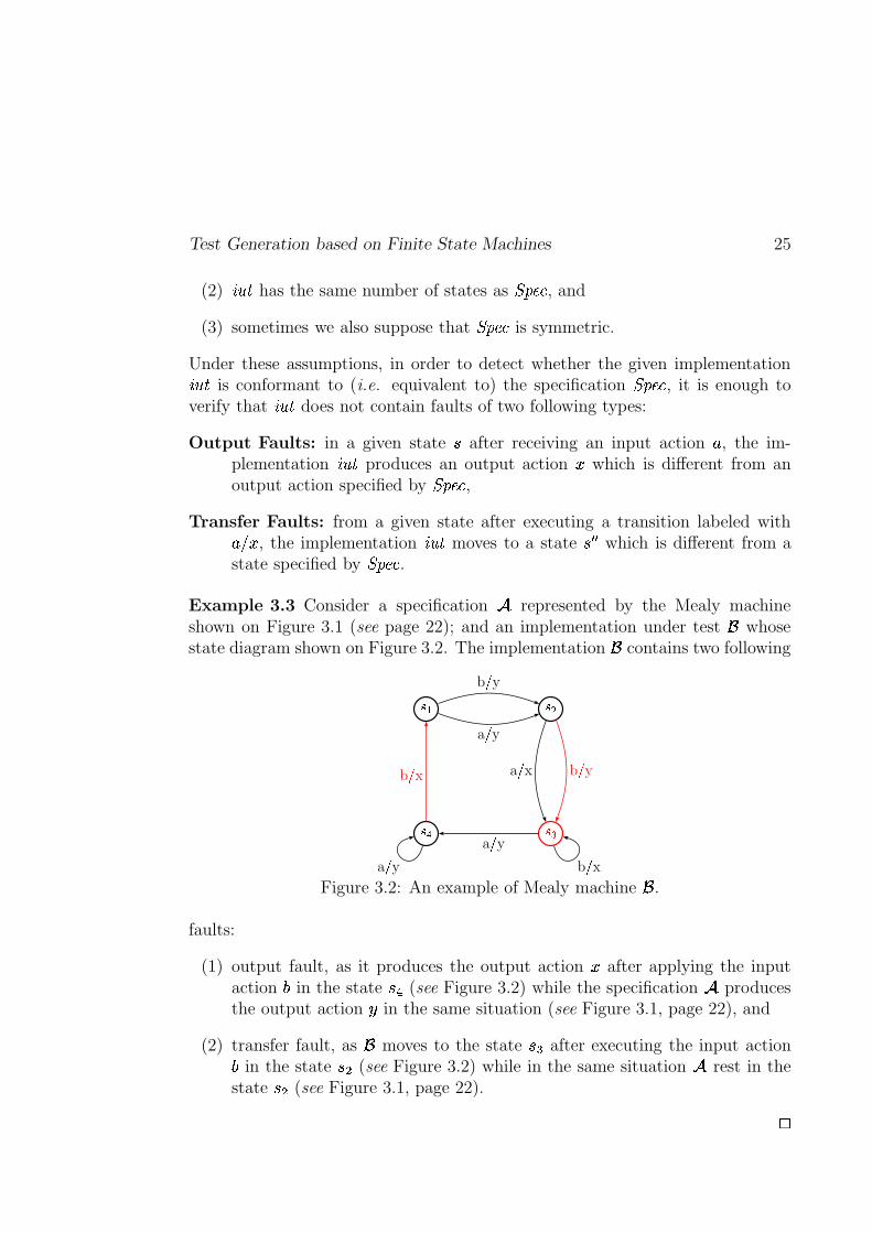
Test Generation based on Finite State Machines 25
(2) �� Q� has the same number of states as RTSVU�W , and
(3) sometimes we also suppose that RTSVU�W is symmetric.
Under these assumptions, in order to detect whether the given implementation�� � is conformant to (i.e. equivalent to) the specification RTSVU�W , it is enough toverify that �� � does not contain faults of two following types:
Output Faults: in a given state � after receiving an input action � , the im-plementation �� � produces an output action 5 which is different from anoutput action specified by RTSVU�W ,
Transfer Faults: from a given state after executing a transition labeled with� � 5 , the implementation �� � moves to a state � � � which is different from astate specified by RTSVU�W .
Example 3.3 Consider a specification & represented by the Mealy machineshown on Figure 3.1 (see page 22); and an implementation under test � whosestate diagram shown on Figure 3.2. The implementation � contains two following
-�. -0/
-01-�2
a 3 yb 3 y
a 3 x b 3 y
a 3 y
b 3 x
b 3 xa 3 yFigure 3.2: An example of Mealy machine � .
faults:
(1) output fault, as it produces the output action 5 after applying the inputaction 4 in the state �(+ (see Figure 3.2) while the specification & producesthe output action 6 in the same situation (see Figure 3.1, page 22), and
(2) transfer fault, as � moves to the state � ) after executing the input action4 in the state �*' (see Figure 3.2) while in the same situation & rest in thestate �(' (see Figure 3.1, page 22). �
26 Test Generation
Finally, we explain how to construct elementary tests that are able to detectoutput and transfer faults of the given implementation �� Q� . Each elementary testconsists in checking whether each transition of �� Q� works as it is described in the
specification RTSVU�W . Formally, for each transition ��� � �D � � of RTSVU�W it is necessaryfirst to drive �� Q� to the state � and to execute the required input action � in thisstate � ; and then:
– to verify the produced by �� � output (output faults testing), and
– to identify the target state of �� Q� by a sequence of input actions (transferfaults testing).
The purpose of the test generation based on Mealy machines is to put all ele-mentary tests together in order to obtain a test suite (i.e. a set of test cases) ofminimal size. Moreover, this test suite must be sound and exhaustive, meaningthat (1) it does not reject conformant implementation under test (soundness),and (2) non-conformant implementation is rejected by a test case belonging tothis test suite (exhaustiveness).
3.1.3 Test Generation Methods
The following section is addressed to the different methods that allows to generatetest cases starting from a specification modeled as a Mealy machines. Otherdetailed descriptions of these methods can be found in [Lee and Yannakakis,1996], [Morel, 2000], or [Jéron, 2004].
3.1.3.1 Transition Tour (TT)
A transition tour is a sequence of input actions that executes each transitionof a specification RTSVU�W that is modeled by a strongly connected, complete andminimized Mealy machine, at least once. It is important to notice that thetransition tour does not allow to identify a state in which the specification RTSVU�Wwill move after executing this sequence. Thus, in general this sequence cannotbe used for detecting transfer faults. However, this problem can be fixed by amodification of the Mealy machine, i.e. making it be able to report about itscurrent state.
The problem of finding a minimal transition tour is well-known problem ofgraph theory. It consists in computating of an Euler tour which is a sequenceof transitions that starts and ends at the same state and contains each transi-tion of a given Mealy machine exactly once. However, the Euler tour exists onlyin strongly connected and symmetric Mealy machines (see the items (3) and (5)of Definition 3.2, page 23). Therefore, any specification represented by a non-symmetric Mealy machine must be transformed into symmetric one. This can be
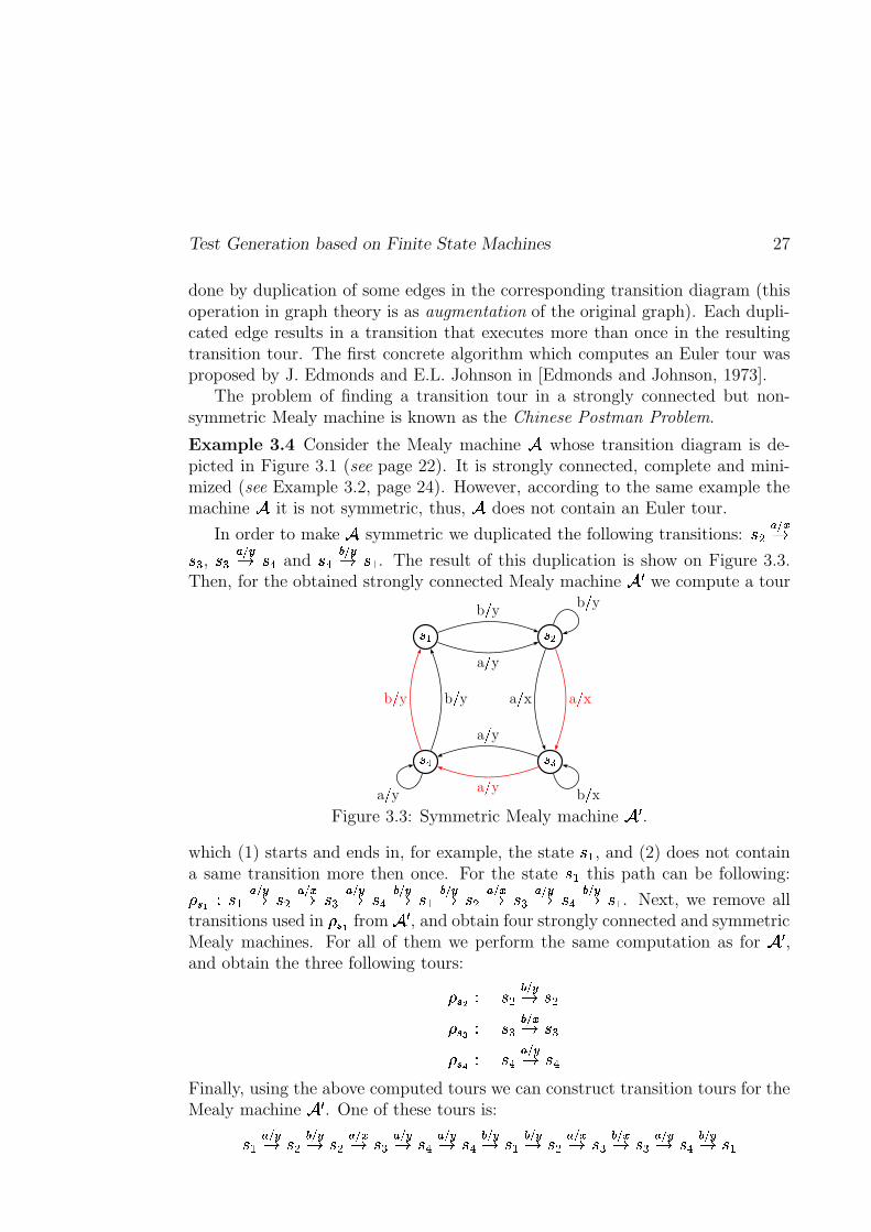
Test Generation based on Finite State Machines 27
done by duplication of some edges in the corresponding transition diagram (thisoperation in graph theory is as augmentation of the original graph). Each dupli-cated edge results in a transition that executes more than once in the resultingtransition tour. The first concrete algorithm which computes an Euler tour wasproposed by J. Edmonds and E.L. Johnson in [Edmonds and Johnson, 1973].
The problem of finding a transition tour in a strongly connected but non-symmetric Mealy machine is known as the Chinese Postman Problem.
Example 3.4 Consider the Mealy machine & whose transition diagram is de-picted in Figure 3.1 (see page 22). It is strongly connected, complete and mini-mized (see Example 3.2, page 24). However, according to the same example themachine & it is not symmetric, thus, & does not contain an Euler tour.
In order to make & symmetric we duplicated the following transitions: ��' � � �D�*) , �() � � �D �,+ and �(+ � � �D � � . The result of this duplication is show on Figure 3.3.Then, for the obtained strongly connected Mealy machine & � we compute a tour
-�. -0/
-01-�2
a 3 yb 3 y
a 3 x a 3 xa 3 ya 3 y
b 3 yb 3 y
b 3 y
b 3 xa 3 yFigure 3.3: Symmetric Mealy machine & � .
which (1) starts and ends in, for example, the state � � , and (2) does not containa same transition more then once. For the state � � this path can be following:����� ? � � � � �D �(' � � �D �() � � �D �,+ � � �D � � � � �D �(' � � �D �() � � �D �,+ � � �D � � . Next, we remove alltransitions used in ����� from & � , and obtain four strongly connected and symmetricMealy machines. For all of them we perform the same computation as for & � ,and obtain the three following tours:
�����j? �(' � � �D �('�����? �() � � �D �*)����? �,+ � � �D �(+
Finally, using the above computed tours we can construct transition tours for theMealy machine & � . One of these tours is:
� � � � �D �(' � � �D �*' � � �D �() � � �D �,+ � � �D �(+ � � �D � � � � �D �(' � � �D �*) � � �D �() � � �D �,+ � � �D � �
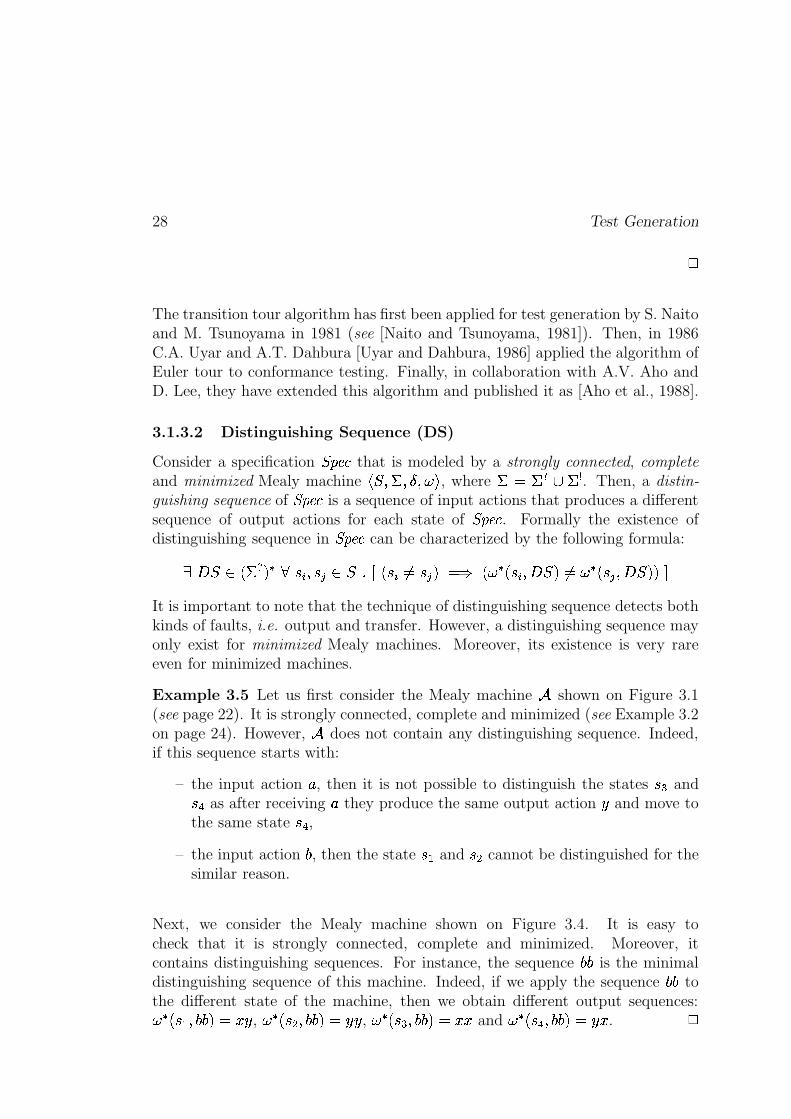
28 Test Generation�
The transition tour algorithm has first been applied for test generation by S. Naitoand M. Tsunoyama in 1981 (see [Naito and Tsunoyama, 1981]). Then, in 1986C.A. Uyar and A.T. Dahbura [Uyar and Dahbura, 1986] applied the algorithm ofEuler tour to conformance testing. Finally, in collaboration with A.V. Aho andD. Lee, they have extended this algorithm and published it as [Aho et al., 1988].
3.1.3.2 Distinguishing Sequence (DS)
Consider a specification RTSVU�W that is modeled by a strongly connected, completeand minimized Mealy machine
� � K��eK���K0� , where �sq"��� � ��� . Then, a distin-guishing sequence of RTSVU�W is a sequence of input actions that produces a differentsequence of output actions for each state of RTSVU�W . Formally the existence ofdistinguishing sequence in RTSVU�W can be characterized by the following formula:
_�� � � . � � 2 # } ��� K������ � iPk . �� �q ����2 q�� . � # . �� K�� � 2 �q � # . ���6K�� � 2 2rtIt is important to note that the technique of distinguishing sequence detects bothkinds of faults, i.e. output and transfer. However, a distinguishing sequence mayonly exist for minimized Mealy machines. Moreover, its existence is very rareeven for minimized machines.
Example 3.5 Let us first consider the Mealy machine & shown on Figure 3.1(see page 22). It is strongly connected, complete and minimized (see Example 3.2on page 24). However, & does not contain any distinguishing sequence. Indeed,if this sequence starts with:
– the input action � , then it is not possible to distinguish the states � ) and�,+ as after receiving � they produce the same output action 6 and move tothe same state �(+ ,
– the input action 4 , then the state � � and �(' cannot be distinguished for thesimilar reason.
Next, we consider the Mealy machine shown on Figure 3.4. It is easy tocheck that it is strongly connected, complete and minimized. Moreover, itcontains distinguishing sequences. For instance, the sequence 4�4 is the minimaldistinguishing sequence of this machine. Indeed, if we apply the sequence 4�4 tothe different state of the machine, then we obtain different output sequences:�%# . � � K 4�4 2$q 5 6 , �%# . �('pK 4�4 2$q 6 6 , �%# . �()pK 4�4 2$q 5 5 and �%# . �,+�K 4�4 2 q 6 5 .
�
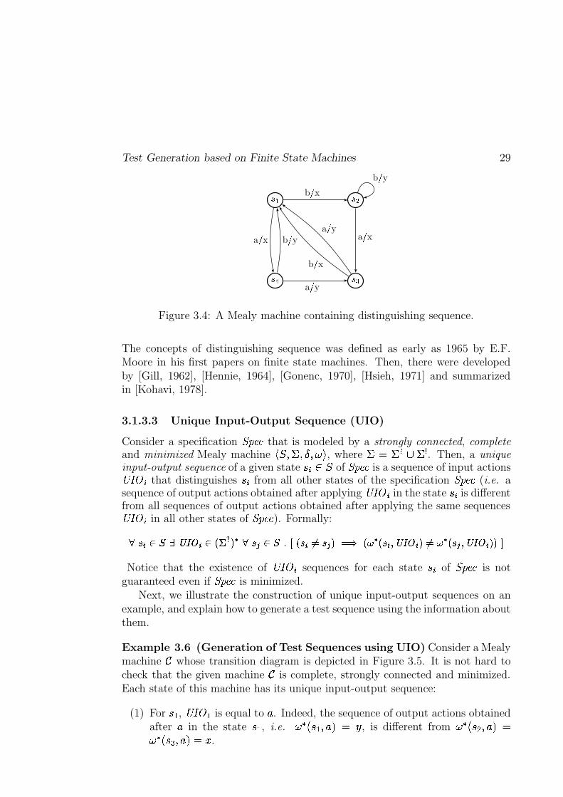
Test Generation based on Finite State Machines 29
-�. -0/
-01-�2
b 3 x b 3 y
a 3 xa 3 yb 3 x
a 3 y
b 3 ya 3 x
Figure 3.4: A Mealy machine containing distinguishing sequence.
The concepts of distinguishing sequence was defined as early as 1965 by E.F.Moore in his first papers on finite state machines. Then, there were developedby [Gill, 1962], [Hennie, 1964], [Gonenc, 1970], [Hsieh, 1971] and summarizedin [Kohavi, 1978].
3.1.3.3 Unique Input-Output Sequence (UIO)
Consider a specification RTSVU�W that is modeled by a strongly connected, completeand minimized Mealy machine
��� K��eK���K0� , where �sq ��� � ��� . Then, a uniqueinput-output sequence of a given state ��P� � of RTSVU�W is a sequence of input actions����� � that distinguishes �� from all other states of the specification RTSVU�W (i.e. asequence of output actions obtained after applying
����� � in the state ��� is differentfrom all sequences of output actions obtained after applying the same sequences����� � in all other states of RTSVU�W ). Formally:
��� ��� ������� ������ ��� # ��� ��������� � ��� � �!� �" �$# # � � �&%'�(��� �)�*� # # � � �+%'�(��� ���,�.-Notice that the existence of
��/� � sequences for each state ��� of RTSVU�W is notguaranteed even if RTSVU�W is minimized.
Next, we illustrate the construction of unique input-output sequences on anexample, and explain how to generate a test sequence using the information aboutthem.
Example 3.6 (Generation of Test Sequences using UIO) Consider a Mealymachine 0 whose transition diagram is depicted in Figure 3.5. It is not hard tocheck that the given machine 0 is complete, strongly connected and minimized.Each state of this machine has its unique input-output sequence:
(1) For � � , ��/� � is equal to � . Indeed, the sequence of output actions obtainedafter � in the state � � , i.e. �%# . � � K �V2aq 6 , is different from �%# . �('pK��y2aq�%# . �()pK �V2rq 5 .
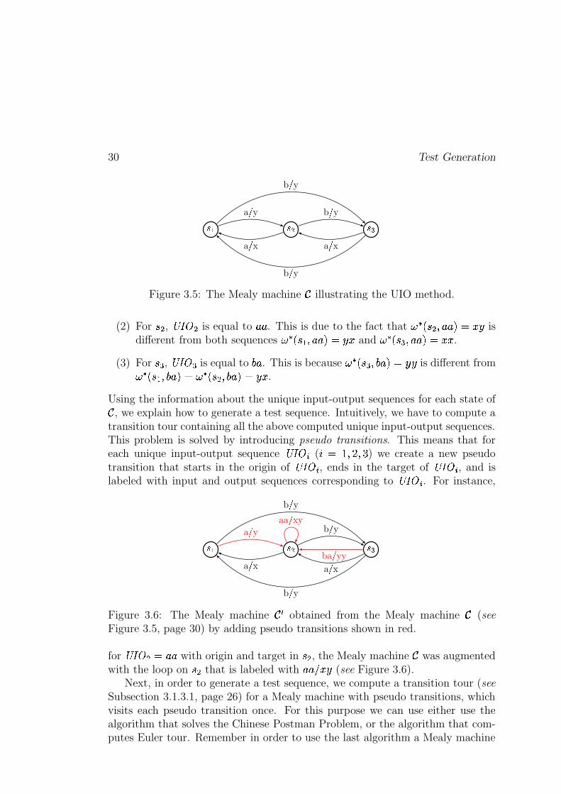
30 Test Generation
- . - / -01a 3 ya 3 x
b 3 ya 3 x
b 3 y
b 3 yFigure 3.5: The Mealy machine 0 illustrating the UIO method.
(2) For �*' , ��/� ' is equal to � � . This is due to the fact that �# . �('�K�� �y2rq 5 6 isdifferent from both sequences � # . � � K � �y2rq 6 5 and � # . �()�K�� �y2lq 5 5 .
(3) For �*) , ����� ) is equal to 4 � . This is because � # . �()pK 4 �y2 q 6 6 is different from� # . � � K 4 �y2rq � # . �('pK 4 �y2rq 6 5 .
Using the information about the unique input-output sequences for each state of0 , we explain how to generate a test sequence. Intuitively, we have to compute atransition tour containing all the above computed unique input-output sequences.This problem is solved by introducing pseudo transitions. This means that foreach unique input-output sequence
��/� � ( � q !OK��QK�� ) we create a new pseudotransition that starts in the origin of
��/� � , ends in the target of��/� � , and is
labeled with input and output sequences corresponding to��/� � . For instance,
- . - / -01a 3 ya 3 x
b 3 y
a 3 x
b 3 y
b 3 y
aa 3 xy
ba 3 yy
Figure 3.6: The Mealy machine 0 � obtained from the Mealy machine 0 (seeFigure 3.5, page 30) by adding pseudo transitions shown in red.
for��/� '�q � � with origin and target in �*' , the Mealy machine 0 was augmented
with the loop on �*' that is labeled with � � � 5 6 (see Figure 3.6).Next, in order to generate a test sequence, we compute a transition tour (see
Subsection 3.1.3.1, page 26) for a Mealy machine with pseudo transitions, whichvisits each pseudo transition once. For this purpose we can use either use thealgorithm that solves the Chinese Postman Problem, or the algorithm that com-putes Euler tour. Remember in order to use the last algorithm a Mealy machine
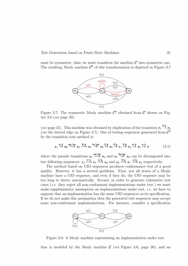
Test Generation based on Finite State Machines 31
must be symmetric, thus, we must transform the machine 0 � into symmetric one.The resulting Mealy machine 0 � � of this transformation is depicted in Figure 3.7
- . - / -�1a 3 ya 3 x
b 3 y
a 3 x
b 3 y
b 3 y
aa 3 xy
ba 3 yy
b 3 y
Figure 3.7: The symmetric Mealy machine 0 � � obtained from 0 � shown on Fig-ure 3.6 (see page 30).
(see page 31). This machine was obtained by duplication of the transition ��' � � �D �*)(see the dotted edge on Figure 3.7). One of testing sequences generated from 0 � �by the transition tour method is:
� � � � �D �(' � � � � �C�D �(' � � �C3D �*) ��� ���D �(' � � �D �() � � �D � � � � �D �() � � �D �(' � � �D � � (3.1)
where the pseudo transitions �*' � � � � �C�D �(' and �*) ��� ��D �(' can be decomposed into
two following sequences: �*' � � �C�D � � � � �C3D �*' and �() � � �C�D � � � � �C�D �*' respectively.The method based on UIO sequences produces conformance test of a good
quality. However, it has a several problems. First, not all states of a Mealymachine have a UIO sequence, and even if they do, the UIO sequence may betoo long to derive automatically. Second, in order to generate exhaustive testcases (i.e. they reject all non-conformant implementations under test ) we mustmake supplementary assumption on implementations under test, i.e. we have tosuppose that an implementation has the same UIO sequences as its specification.If we do not make this assumption then the generated test sequences may acceptsome non-conformant implementations. For instance, consider a specification
-�. -0/ - 1b 3 y
a 3 ya 3 x
b 3 ya 3 x
b 3 yFigure 3.8: A Mealy machine representing an implementation under test.
that is modeled by the Mealy machine 0 (see Figure 3.6, page 30), and an
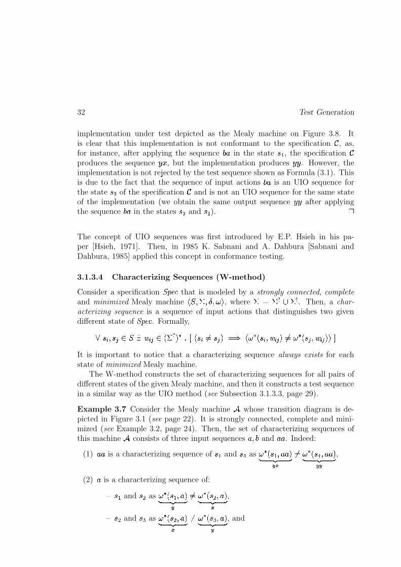
32 Test Generation
implementation under test depicted as the Mealy machine on Figure 3.8. Itis clear that this implementation is not conformant to the specification 0 , as,for instance, after applying the sequence 4 � in the state � � , the specification 0produces the sequence 6 5 , but the implementation produces 6 6 . However, theimplementation is not rejected by the test sequence shown as Formula (3.1). Thisis due to the fact that the sequence of input actions 4 � is an UIO sequence forthe state �() of the specification 0 and is not an UIO sequence for the same stateof the implementation (we obtain the same output sequence 6 6 after applyingthe sequence 4 � in the states �*) and � � ).
�
The concept of UIO sequences was first introduced by E.P. Hsieh in his pa-per [Hsieh, 1971]. Then, in 1985 K. Sabnani and A. Dahbura [Sabnani andDahbura, 1985] applied this concept in conformance testing.
3.1.3.4 Characterizing Sequences (W-method)
Consider a specification RTSVU�W that is modeled by a strongly connected, completeand minimized Mealy machine
��� K��eK���K0� , where � q � � � � � . Then, a char-acterizing sequence is a sequence of input actions that distinguishes two givendifferent state of RTSVU�W . Formally,
}��� K������ � _�� � ��� . � � 2 # i�k . ��� �q ���p2�q�� . � # . ���fK�� � �d2 �q � # . ���6K�� � �d2 2�tIt is important to notice that a characterizing sequence always exists for eachstate of minimized Mealy machine.
The W-method constructs the set of characterizing sequences for all pairs ofdifferent states of the given Mealy machine, and then it constructs a test sequencein a similar way as the UIO method (see Subsection 3.1.3.3, page 29).
Example 3.7 Consider the Mealy machine & whose transition diagram is de-picted in Figure 3.1 (see page 22). It is strongly connected, complete and mini-mized (see Example 3.2, page 24). Then, the set of characterizing sequences ofthis machine & consists of three input sequences �3K 4 and � � . Indeed:
(1) � � is a characterizing sequence of � � and �,+ as � # . � � K�� �y2� ��� �
���
�q � # . �,+6K�� �y2� ��� �
��
,
(2) � is a characterizing sequence of:
– � � and �(' as � # . � � K��y2� ��� �
�
�q � # . �('pK��y2� ��� �
�
,
– �*' and �() as � # . �('pK��y2� ��� �
�
�q � # . �()pK��y2� ��� �
�
, and
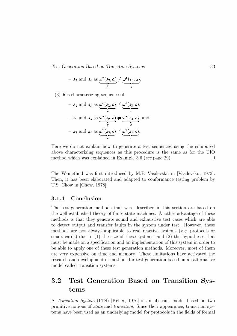
Test Generation Based on Transition Systems 33
– �(' and �,+ as � # . �('pK �V2� ��� �
�
�q � # . �,+�K��y2� ��� �
�
,
(3) 4 is characterizing sequence of:
– � � and �() as � # . � � K 4 2� ��� �
�
�q � # . �()�K 4 2� ��� �
�
,
– �(' and �() as � # . �('pK 4 2� ��� �
�
�q � # . �()�K 4 2� ��� �
�
, and
– �() and �,+ as � # . �()pK 4 2� ��� ��
�q � # . �,+6K 4 2� ��� ��
.
Here we do not explain how to generate a test sequences using the computedabove characterizing sequences as this procedure is the same as for the UIOmethod which was explained in Example 3.6 (see page 29).
�
The W-method was first introduced by M.P. Vasilevskii in [Vasilevskii, 1973].Then, it has been elaborated and adapted to conformance testing problem byT.S. Chow in [Chow, 1978].
3.1.4 Conclusion
The test generation methods that were described in this section are based onthe well-established theory of finite state machines. Another advantage of thesemethods is that they generate sound and exhaustive test cases which are ableto detect output and transfer faults in the system under test. However, thesemethods are not always applicable to real reactive systems (e.g. protocols orsmart cards) due to (1) the size of these systems, and (2) the hypotheses thatmust be made on a specification and an implementation of this system in order tobe able to apply one of these test generation methods. Moreover, most of themare very expensive on time and memory. These limitations have activated theresearch and development of methods for test generation based on an alternativemodel called transition systems.
3.2 Test Generation Based on Transition Sys-
tems
A Transition System (LTS) [Keller, 1976] is an abstract model based on twoprimitive notions of state and transition. Since their appearance, transition sys-tems have been used as an underlying model for protocols in the fields of formal
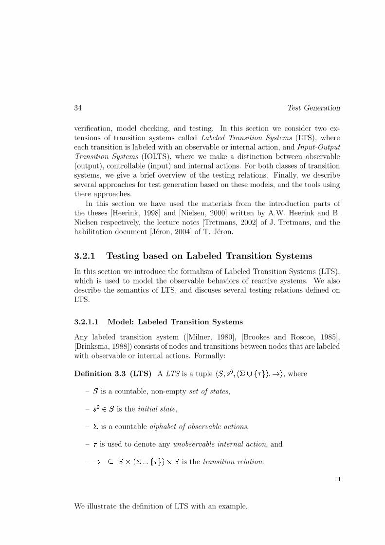
34 Test Generation
verification, model checking, and testing. In this section we consider two ex-tensions of transition systems called Labeled Transition Systems (LTS), whereeach transition is labeled with an observable or internal action, and Input-OutputTransition Systems (IOLTS), where we make a distinction between observable(output), controllable (input) and internal actions. For both classes of transitionsystems, we give a brief overview of the testing relations. Finally, we describeseveral approaches for test generation based on these models, and the tools usingthere approaches.
In this section we have used the materials from the introduction parts ofthe theses [Heerink, 1998] and [Nielsen, 2000] written by A.W. Heerink and B.Nielsen respectively, the lecture notes [Tretmans, 2002] of J. Tretmans, and thehabilitation document [Jéron, 2004] of T. Jéron.
3.2.1 Testing based on Labeled Transition Systems
In this section we introduce the formalism of Labeled Transition Systems (LTS),which is used to model the observable behaviors of reactive systems. We alsodescribe the semantics of LTS, and discuses several testing relations defined onLTS.
3.2.1.1 Model: Labeled Transition Systems
Any labeled transition system ([Milner, 1980], [Brookes and Roscoe, 1985],[Brinksma, 1988]) consists of nodes and transitions between nodes that are labeledwith observable or internal actions. Formally:
Definition 3.3 (LTS) A LTS is a tuple��� K�� � K . � � E�� N 2�K)D , where
–�
is a countable, non-empty set of states,
– � � � � is the initial state,
– � is a countable alphabet of observable actions,
– � is used to denote any unobservable internal action, and
– D * ��� . � ��E�� N 2 � � is the transition relation. �
We illustrate the definition of LTS with an example.
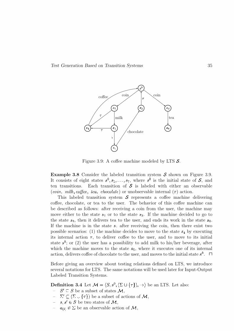
Test Generation Based on Transition Systems 35
-��
-�. -�/ - 1
- 2 -�� -��
-��
coin coin
�milk
�
tea
coffee
��
chocolate
Figure 3.9: A coffee machine modeled by LTS�
.
Example 3.8 Consider the labeled transition system�
shown on Figure 3.9.It consists of eight states � � K�� � Kpipipi>K�� , where � � is the initial state of
�, and
ten transitions. Each transition of�
is labeled with either an observable( W % ���PK� �JI�� K8W %�� U�UTK+� U�GyK W�� % W % I�GO��U ) or unobservable internal ( � ) action.
This labeled transition system�
represents a coffee machine deliveringcoffee, chocolate, or tea to the user. The behavior of this coffee machine canbe described as follows: after receiving a coin from the user, the machine maymove either to the state � � or to the state �*) . If the machine decided to go tothe state �() , then it delivers tea to the user, and ends its work in the state ��� .If the machine is in the state � � after receiving the coin, then there exist twopossible scenarios: (1) the machine decides to move to the state � + by executingits internal action � , to deliver coffee to the user, and to move to its initialstate � � ; or (2) the user has a possibility to add milk to his/her beverage, afterwhich the machine moves to the state ��� , where it executes one of its internalaction, delivers coffee of chocolate to the user, and moves to the initial state � � .
�
Before giving an overview about testing relations defined on LTS, we introduceseveral notations for LTS. The same notations will be used later for Input-OutputLabeled Transition Systems.
Definition 3.4 Let � q ��� K�� � K . ��� E�� N 2hK)D� be an LTS. Let also:
–� � * �
be a subset of states � ,– � � * . � � E�� N 2 be a subset of actions of � ,– �TK�� � � � be two states of � ,– ��� ��� � � be an observable action of � ,

36 Test Generation
– � � ��� � . ��� E�� N 2 be either an observable or internal action of � ,– `�q � � ipipi0� �!� . �j2 # be a sequence of observable actions,– �!q�� � ipipi����#� . � ��E�� N 2$# be a sequence of observable and internal actions, and– �0q �+ipidi ��� . E�� N 2 # be a sequence of internal actions.
Then,
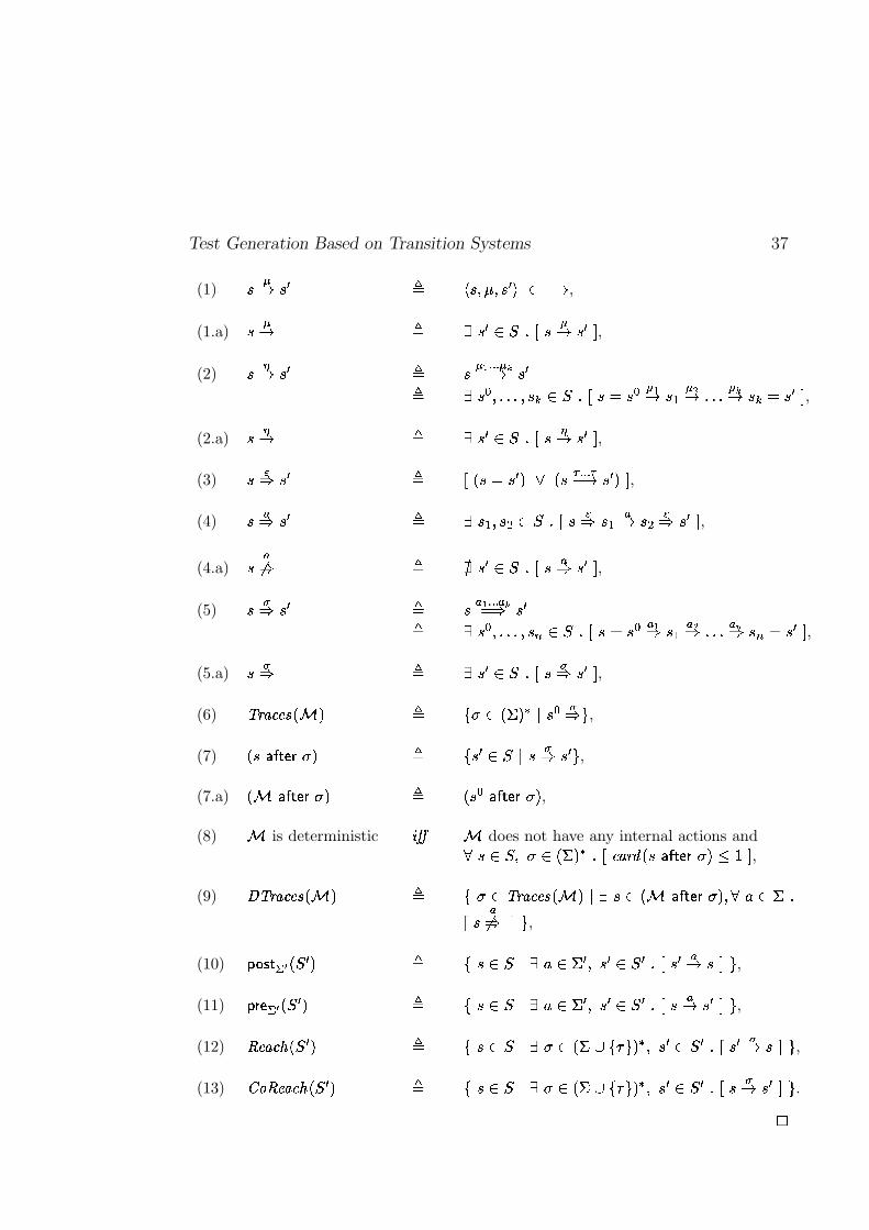
Test Generation Based on Transition Systems 37
(1)���� � � � � � %�� % � ��� � �
,
(1.a)���� � � � � � � � ��� � � - ,
(2)��� � � � � � ��� � � ���� � � �� � � � % � � �!% � � ���� � � � � � �� � � � �� � � � � �� �
� � � - ,
(2.a)� � � � � � � � � � � � � - ,
(3)���" � � � ��� � � � ��� � ���
� � � �� � � � � - ,
(4)��" � � � � � � % � ' ���� � � �" � � �� � ' �" � � - ,
(4.a)� ��" � � � � � � � � �" � � - ,
(5)���" � � � �
���� � ��� " � �� � � � % � � �!% � � �� � � � � �
��" � � �
�" � � � ���" �� � � - ,
(5.a)���" � � � � � � � ��" � � - ,
(6) �����! �"$# �&% � � ')( � ��� � #+* � � �"-, ,(7) � �/.103254�6 ( � � ' � � �� * � �" � � , ,(7.a) �&% .103254�6 ( � � � � � .107284�6 ( � ,(8) % is deterministic 9 : % does not have any internal actions and��� ��% ( ����� � # �� ;�<��= � �/.103254�6 ( �?>A@�- ,(9) BC�����D �"E# �&% � � '�( � �F���! E"E# �&% � * � � ���&% .103254�6 ( � % �HG ��� �
� � ��" - , ,(10) I!JLK 25M�N �� � � � ' � �� * � G ��� � % � � �� � � � � � �� � - , ,(11) I 6O41M�N �� � � � ' � �� * � G ��� � % � � �� � � � � �� � � - , ,(12) PQ"��! SR �� � � � ' � �� * � ( �����UT ')V , � # % � � �� � �� � � �� � - , ,(13) WYX1PZ"��! SR �� � � � ' � �� * � ( �����UT ')V , � # % � � �� � �� ��� � � - , .�
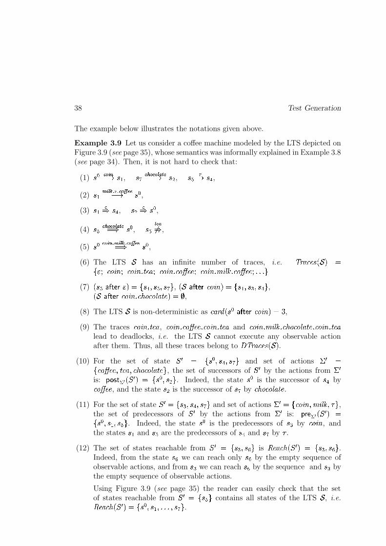
38 Test Generation
The example below illustrates the notations given above.
Example 3.9 Let us consider a coffee machine modeled by the LTS depicted onFigure 3.9 (see page 35), whose semantics was informally explained in Example 3.8(see page 34). Then, it is not hard to check that:
(1) � ����� ���C�D � � , �� ��������� � �� C�D �(' , � � �D �,+ ,(2) � � � � � � � � ����� � C�D � � ,(3) � � �� �,+ , �(' �� � � ,(4) �� ��������� � �� q�� � � , � � �� ��� ,
(5) � � ��� ��� � � � � � ����� � q�� � � ,(6) The LTS
�has an infinite number of traces, i.e. � ��G'W�U (T. � 2 q
E ��� W % ����� W % ���Pi���U�G�� W % ���Hi�W %�� U�U�� W % ���Pi �JI�� i�W %�� U�U��dipipi N(7) . � ��Z�Y =�5O7 �'2lq E �,+�K�� �pK�� N , . � Z�Y =�5O7 W % ���H2lqsE � � K��()pK��,+ N ,. � Z�Y =�5O7 W % ���Pi W�� % W % I�GO� UO2lq�� ,
(8) The LTS�
is non-deterministic as W�G���� . � � Z6Y =�587 W % ���12lq � ,
(9) The traces W % ���Pi���U�G , W % ����i�W %�� U�UOi W % ���Pi���U�G and W % ���Pi �JI�� i�W�� % W % I�GO��U�i�W % ����i���U�Glead to deadlocks, i.e. the LTS
�cannot execute any observable action
after them. Thus, all these traces belong to ��� ��G'W�U (�. � 2 .(10) For the set of state
� � q E � � K��,+�K�� N and set of actions � � qEyW %�� U�U�K�� U�GyK8W�� % W % I�GO��U N , the set of successors of
� � by the actions from � �is: u ��]w= M�N . � � 2 q E � � K��(' N . Indeed, the state � � is the successor of �(+ byW %�� U�U , and the state �(' is the successor of �� by W�� % W % I�GO��U .
(11) For the set of state� � qsE �()�K��,+�K�� N and set of actions � � qsEyW % ���PK �JI��VK � N ,
the set of predecessors of� � by the actions from � � is: u 7m5 M�N . � � 2 q
E � � K�� � K�� � N . Indeed, the state � � is the predecessors of �*) by W % ��� , andthe states � � and � � are the predecessors of �(+ and �� by � .
(12) The set of states reachable from� � q E �()pK�� � N is ��U�G'W�� . � � 2�q E �()�K�� � N .
Indeed, from the state �� we can reach only �� by the empty sequence ofobservable actions, and from �*) we can reach �� by the sequence and �*) bythe empty sequence of observable actions.
Using Figure 3.9 (see page 35) the reader can easily check that the setof states reachable from
� � q E � � N contains all states of the LTS�
, i.e.��U�G'W�� . � � 2rq�E � � K�� � KpipipioK�� N .
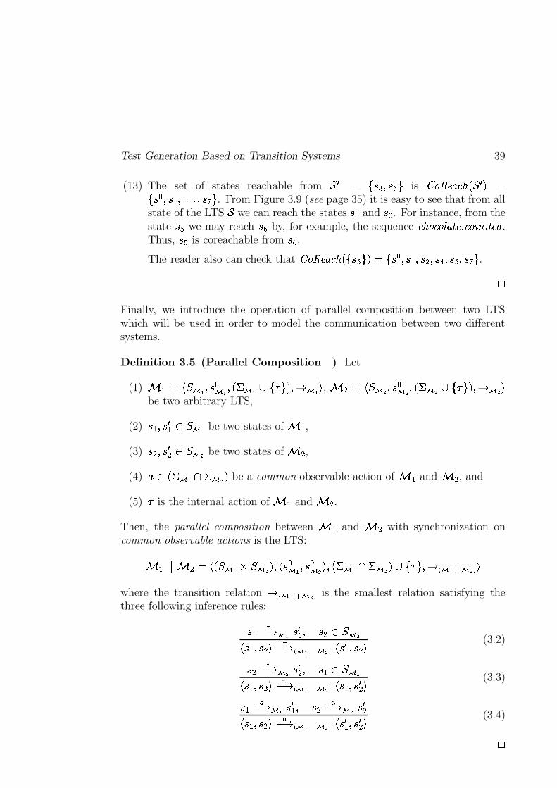
Test Generation Based on Transition Systems 39
(13) The set of states reachable from� � q E �()pK�� � N is � % ��U�G'W�� . � � 2 q
E � � K�� � KpipipioK�� N . From Figure 3.9 (see page 35) it is easy to see that from allstate of the LTS
�we can reach the states � ) and � � . For instance, from the
state �� we may reach �� by, for example, the sequence W�� % W % I�GO��UOi�W % ����i�� U�G .Thus, � � is coreachable from �� .The reader also can check that � % �MU�G'W�� . E ��� N 2rqsE � � K�� � K��('pK��,+6K�� �pK�� N . �
Finally, we introduce the operation of parallel composition between two LTSwhich will be used in order to model the communication between two differentsystems.
Definition 3.5 (Parallel Composition ��� ) Let
(1) � � q ������� K�� ���� K . � ��� � E�� N 2hK)D ��� , � '�q ������� K�� ���� K . � ��� � E�� N 2�K�D ��� be two arbitrary LTS,
(2) � � K�� � � � ����� be two states of � � ,
(3) �('�K�� � ' � ����� be two states of � ' ,(4) ��� . � ���� � ��� 2 be a common observable action of � � and � ' , and
(5) � is the internal action of � � and � ' .Then, the parallel composition between � � and � ' with synchronization oncommon observable actions is the LTS:
� � ��� � '@q � . �����%� ����� 2�K � � ���� K�� ���� oK . � ���� � ��� 2 ��E�� N K)D� ��� � ������� where the transition relation D� ��� � ������� is the smallest relation satisfying thethree following inference rules:
� � �C�D ��� � � � K �*'j� ������ � � K��('� �C3D� ��� � ������� � � � � K��*'� (3.2)
�*' �C�D ��� � � ' K � � � ������ � � K��('� �C3D� ��� � ������� � � � K�� � ' (3.3)
� � �C�D ��� � � � K �(' �C�D ��� � � '� � � K��('� �C3D� ��� � ������� � � � � K�� � ' (3.4)�
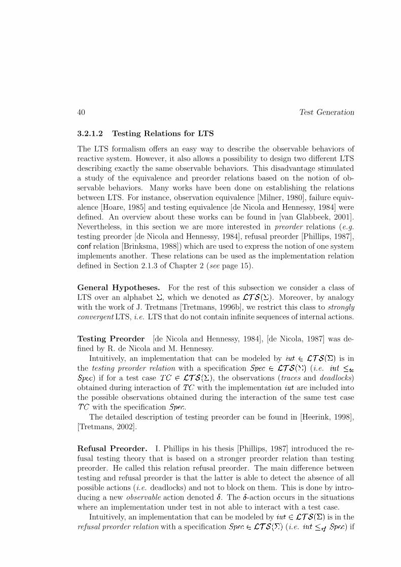
40 Test Generation
3.2.1.2 Testing Relations for LTS
The LTS formalism offers an easy way to describe the observable behaviors ofreactive system. However, it also allows a possibility to design two different LTSdescribing exactly the same observable behaviors. This disadvantage stimulateda study of the equivalence and preorder relations based on the notion of ob-servable behaviors. Many works have been done on establishing the relationsbetween LTS. For instance, observation equivalence [Milner, 1980], failure equiv-alence [Hoare, 1985] and testing equivalence [de Nicola and Hennessy, 1984] weredefined. An overview about these works can be found in [van Glabbeek, 2001].Nevertheless, in this section we are more interested in preorder relations (e.g.testing preorder [de Nicola and Hennessy, 1984], refusal preorder [Phillips, 1987],conf relation [Brinksma, 1988]) which are used to express the notion of one systemimplements another. These relations can be used as the implementation relationdefined in Section 2.1.3 of Chapter 2 (see page 15).
General Hypotheses. For the rest of this subsection we consider a class ofLTS over an alphabet � , which we denoted as ��� � . �j2 . Moreover, by analogywith the work of J. Tretmans [Tretmans, 1996b], we restrict this class to stronglyconvergent LTS, i.e. LTS that do not contain infinite sequences of internal actions.
Testing Preorder [de Nicola and Hennessy, 1984], [de Nicola, 1987] was de-fined by R. de Nicola and M. Hennessy.
Intuitively, an implementation that can be modeled by �� � ����� � . �j2 is inthe testing preorder relation with a specification RTSVU�W������ � . �j2 (i.e. �� � ����RTSVU�W ) if for a test case ���X���� � . �j2 , the observations (traces and deadlocks)obtained during interaction of ��� with the implementation �� Q� are included intothe possible observations obtained during the interaction of the same test case��� with the specification RTSVU�W .
The detailed description of testing preorder can be found in [Heerink, 1998],[Tretmans, 2002].
Refusal Preorder. I. Phillips in his thesis [Phillips, 1987] introduced the re-fusal testing theory that is based on a stronger preorder relation than testingpreorder. He called this relation refusal preorder. The main difference betweentesting and refusal preorder is that the latter is able to detect the absence of allpossible actions (i.e. deadlocks) and not to block on them. This is done by intro-ducing a new observable action denoted � . The � -action occurs in the situationswhere an implementation under test in not able to interact with a test case.
Intuitively, an implementation that can be modeled by �� Q����� � . �j2 is in therefusal preorder relation with a specification RTSVU�W ��� � . �j2 (i.e. �� Q� ��� +RTSVU�W ) if
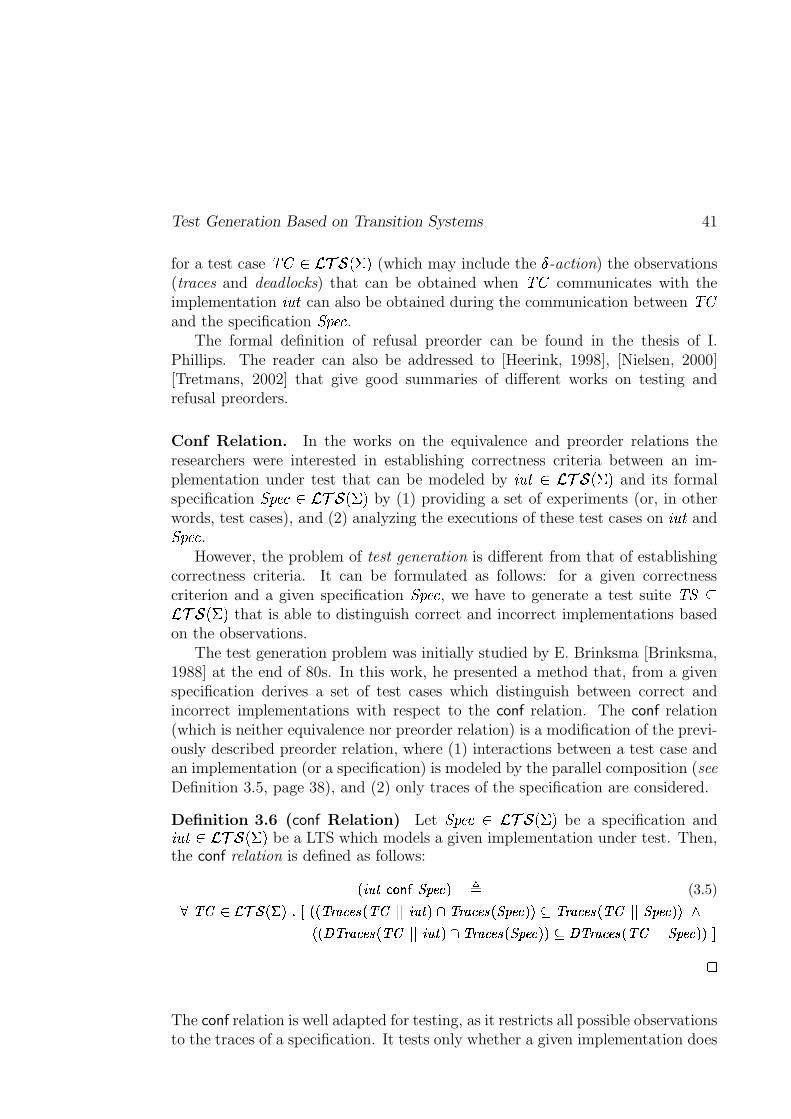
Test Generation Based on Transition Systems 41
for a test case ������������ �� (which may include the � -action) the observations(traces and deadlocks) that can be obtained when ��� communicates with theimplementation ����� can also be obtained during the communication between ���and the specification ������� .
The formal definition of refusal preorder can be found in the thesis of I.Phillips. The reader can also be addressed to [Heerink, 1998], [Nielsen, 2000][Tretmans, 2002] that give good summaries of different works on testing andrefusal preorders.
Conf Relation. In the works on the equivalence and preorder relations theresearchers were interested in establishing correctness criteria between an im-plementation under test that can be modeled by ������� �!�"#�� �� and its formalspecification ��������$���"��% �� by (1) providing a set of experiments (or, in otherwords, test cases), and (2) analyzing the executions of these test cases on ����� and������� .
However, the problem of test generation is different from that of establishingcorrectness criteria. It can be formulated as follows: for a given correctnesscriterion and a given specification ������� , we have to generate a test suite �&�('���#�� �� that is able to distinguish correct and incorrect implementations basedon the observations.
The test generation problem was initially studied by E. Brinksma [Brinksma,1988] at the end of 80s. In this work, he presented a method that, from a givenspecification derives a set of test cases which distinguish between correct andincorrect implementations with respect to the conf relation. The conf relation(which is neither equivalence nor preorder relation) is a modification of the previ-ously described preorder relation, where (1) interactions between a test case andan implementation (or a specification) is modeled by the parallel composition (seeDefinition 3.5, page 38), and (2) only traces of the specification are considered.
Definition 3.6 (conf Relation) Let �������)�*���"��% �� be a specification and�������+�!���� �� be a LTS which models a given implementation under test. Then,the conf relation is defined as follows:
,%-/.1032�4�576�8:91;=<?> @(3.5)ACB3DFEHGJILK ,NMO>�PRQ�,S, B1TSU <V;VWX, B3D�YZY -/.[0\>^] B�T=U <V;VWX,%8:9[;=<?>S>J_ B1TSU <V;VWX, B3D�YZY 8`91;=<?>S>ba
,S,Nc B1TSU <V;VWX, B3D�YZY -/.[0=>�] B�T=U <V;VWX,%8:9[;=<?>S>J_dc B�T=U <V;VWX, B3D�YZY 8:91;e<f>S>Jgh
The conf relation is well adapted for testing, as it restricts all possible observationsto the traces of a specification. It tests only whether a given implementation does
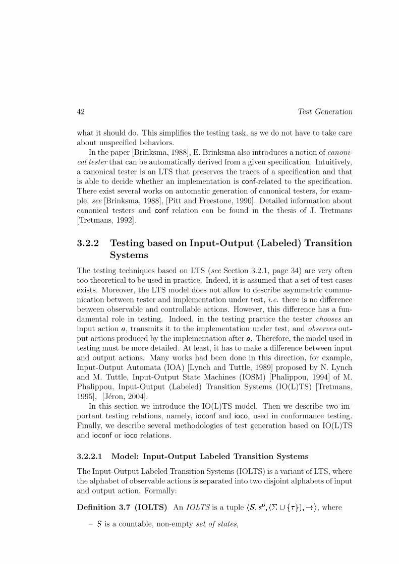
42 Test Generation
what it should do. This simplifies the testing task, as we do not have to take careabout unspecified behaviors.
In the paper [Brinksma, 1988], E. Brinksma also introduces a notion of canoni-
cal tester that can be automatically derived from a given specification. Intuitively,a canonical tester is an LTS that preserves the traces of a specification and thatis able to decide whether an implementation is conf-related to the specification.There exist several works on automatic generation of canonical testers, for exam-ple, see [Brinksma, 1988], [Pitt and Freestone, 1990]. Detailed information aboutcanonical testers and conf relation can be found in the thesis of J. Tretmans[Tretmans, 1992].
3.2.2 Testing based on Input-Output (Labeled) TransitionSystems
The testing techniques based on LTS (see Section 3.2.1, page 34) are very oftentoo theoretical to be used in practice. Indeed, it is assumed that a set of test casesexists. Moreover, the LTS model does not allow to describe asymmetric commu-nication between tester and implementation under test, i.e. there is no differencebetween observable and controllable actions. However, this difference has a fun-damental role in testing. Indeed, in the testing practice the tester chooses aninput action � , transmits it to the implementation under test, and observes out-put actions produced by the implementation after � . Therefore, the model used intesting must be more detailed. At least, it has to make a difference between inputand output actions. Many works had been done in this direction, for example,Input-Output Automata (IOA) [Lynch and Tuttle, 1989] proposed by N. Lynchand M. Tuttle, Input-Output State Machines (IOSM) [Phalippou, 1994] of M.Phalippou, Input-Output (Labeled) Transition Systems (IO(L)TS) [Tretmans,1995], [Jéron, 2004].
In this section we introduce the IO(L)TS model. Then we describe two im-portant testing relations, namely, ioconf and ioco, used in conformance testing.Finally, we describe several methodologies of test generation based on IO(L)TSand ioconf or ioco relations.
3.2.2.1 Model: Input-Output Labeled Transition Systems
The Input-Output Labeled Transition Systems (IOLTS) is a variant of LTS, wherethe alphabet of observable actions is separated into two disjoint alphabets of inputand output action. Formally:
Definition 3.7 (IOLTS) An IOLTS is a tuple��������� �� ��� ������ �����
, where
–�
is a countable, non-empty set of states,
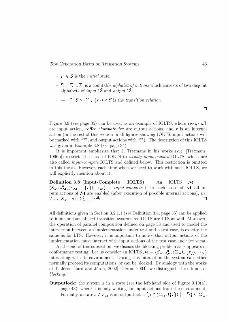
Test Generation Based on Transition Systems 43
–�� � � is the initial state,
– �� � � � is a countable alphabet of actions which consists of two disjointalphabets of input � and output � ,
–� ' ��� �� � ������ � � is the transition relation.
h
Figure 3.9 (see page 35) can be used as an example of IOLTS, where ��� �� �� � �� are input action, ����� ��� � �����:��� ��� �\� � �\� � are output actions, and � is an internalaction (in the rest of this section in all figures showing IOLTS, input actions willbe marked with “?”, and output actions with “!”). The description of this IOLTSwas given in Example 3.8 (see page 34).
It is important emphasize that J. Tretmans in his works (e.g. [Tretmans,1996b]) restricts the class of IOLTS to weakly input-enabled IOLTS, which arealso called input-compete IOLTS and defined below. This restriction is omittedin this thesis. However, each time when we need to work with such IOLTS, wewill explicitly mention about it.
Definition 3.8 (Input-Complete IOLTS) An IOLTS � ������ � � �� � �� � � �� ��� ����� �is input-complete if in each state of � all in-
puts actions of � are enabled (after execution of possible internal actions), i.e.� � � ��� � � � �� ��� ����� .
h
All definitions given in Section 3.2.1.1 (see Definition 3.4, page 35) can be appliedto input-output labeled transition systems as IOLTS are LTS as well. Moreover,the operation of parallel composition defined on page 38 and used to model theinteraction between an implementation under test and a test case, is exactly thesame as for LTS. However, it is important to notice that output actions of theimplementation must interact with input actions of the test case and vice versa.
At the end of this subsection, we discuss the blocking problem as is appears inconformance testing. Let us consider an IOLTS � � ���"! ���� ! � �% ! � ������ ����! �interacting with its environment. During this interaction the system can eithernormally proceed its computations, or can be blocked. By analogy with the worksof T. Jéron [Jard and Jéron, 2002], [Jéron, 2004], we distinguish three kinds ofblocking:
Outputlock: the system is in a state (see the left-hand side of Figure 3.10(a),page 43), where it is only waiting for input actions from the environment.
Formally, a state� � �#! is an outputlock if %$)� �� ! � ������'& �)(� �' �! .
44 Test Generation
a? b? a? b?
���
(a) Outputlock
x! x!
���
(b) Deadlock
�
�
�
�
�
����
���
���
(c) Livelock
Figure 3.10: Three possible blockings in IOLTS.
Test Generation Based on Transition Systems 45
Deadlock: the system cannot perform any action (see the left-hand side ofFigure 3.10(b), page 43). Formally, a state
� � �"!is a deadlock if
%$ � �% ! � ������'& � (� � ��� .Livelock: the system is in a cycle of internal actions (see the left-hand side
of Figure 3.10(c), page 43). Formally, a state� � �"!
is a livelock is� � ��� � � � � ��������� �� � � .
It is important to notice that a blocking of the given specification is not necessaryan error. It is evident for outputlocks, but it is also true for livelocks (that canbe obtained, for instance, as a consequence of the parallel composition betweenseveral systems) and, moreover, for deadlocks. Hence, a test case applied to animplementation under test ( ����� ) must distinguish between specified blockings of����� (i.e. ones that exist in the specification), and non-specified blockings of �����(i.e. ones that produced only by the implementation). Therefore, all possibleblockings of the specification have to be detected and marked with the specialoutput action � (see Figure 3.10, page 43).
Before giving the definition of an IOLTS in which all blockings are marked, wedenote the set of all quiescent states (i.e. outputlocks, deadlocks and livelocks)of an IOLTS � as �� �%��?��� � � � � � .Definition 3.9 (Suspension IOLTS) For an IOLTS � ���� ! ����! � �� ! � ������ � ��! �
, we define a suspension IOLTS �b� � � ���� ! ����! � �� � �� !�� �� ������ ��� �� !�� � , where
(1) the alphabet of action is augmented with the special output action � , i.e.
� �� !�� � ! �� � � , and
(2) the transition relation of � � � � is constructed as follows:
� �� !�� � ��! � ���� � & � ���� �%��?��� � �7� � � �h
The suspension traces of an IOLTS � (denoted � ��� � ������ � � ) are the traces ofits suspension IOLTS �b� � � , i.e. � ��� � ���� � � � � ��� � ����1���b� � � � .3.2.2.2 Testing Relations for IOLTS
Jan Tretmans and his colleagues from the University of Twente, Netherlands haveadapted the testing preorder ����� and refusal preorder �! #" , which were informallyintroduced on page 39, for the IOLTS model, and obtained input-output test-
ing preorder ��$&%'� and input-output refusal preorder �($#%*) (see [Tretmans, 1996b],
46 Test Generation
[Tretmans, 2002]). Analogously to ����� and �( #" the new defined preorder relations(1) allow implementations under test to do what is specified, and (2) does notallow them to do more than what is specified. This requirement is too strong forconformance testing. Indeed, in conformance testing we are only interested inchecking whether the implementation respects a specification, i.e. the questionthat is posed here is: does the implementation do what it should do. Using thisargumentation Tretmans et al. introduced two new testing relations which theycalled ���������� [Tretmans, 1995] and ������� [Tretmans, 1996a] that are well adaptedfor conformance testing and automatic test derivation. The original versions ofthe � ������� and ������� relations treat the problem of specified and unspecified out-putlocks and deadlocks (see page 42). T. Jéron and his colleagues have extendedthe conformance relations proposed by J. Tretmans (i.e. � ������� and ������� ) forlivelocks detection (see page 42).
In this subsection we give the formal definitions of the � ������� and ������� relationsand illustrate them with examples.
General Hypotheses. For the rest of this subsection we consider:
(1) a specification whose behaviors are modeled by a convergent IOLTS ������� �� � ������� ��� � ������� � �% ������� � ������ � ��������� �, where ������� �( � ������� � �������� .
We remind that an IOLTS is convergent if it does not contain an infinitesequence of internal actions which goes through infinite number of differentstates.
(2) an implementation under test whose possible behaviors are modeled by aninput-complete IOLTS ����� � ��������� ���� ����� � �� ����� � ������ ��������� �
with alphabets ofinput � ����� ' � ������� and output ������ ' �������� actions. The definition of aninput-complete IOLTS can be found on page 42.
Before describing the ioconf and ioco relations, we give an intermediate definitionof a set of output actions that can be generated by an IOLTS when it is in somestate. Formally, for an IOLTS � � ��� � ����� � �� � � �� ��� ����� �
with alphabet � � �� � �� , and a subset of states
� �� ' ��� , we define:
! ���f� � �� � � � �+ �� & � � � � � �� ��� � ��� ��� � � �� � � (3.6)
Ioconf Relation. Intuitively, the implementation under test ����� is conformantto the specification ������� (with the special output action � marking all possi-ble blockings in ������� ) according to ioconf-relation if for each trace of ������� , theimplementation produces only outputs and blockings which are allowed by thespecification. Formally:
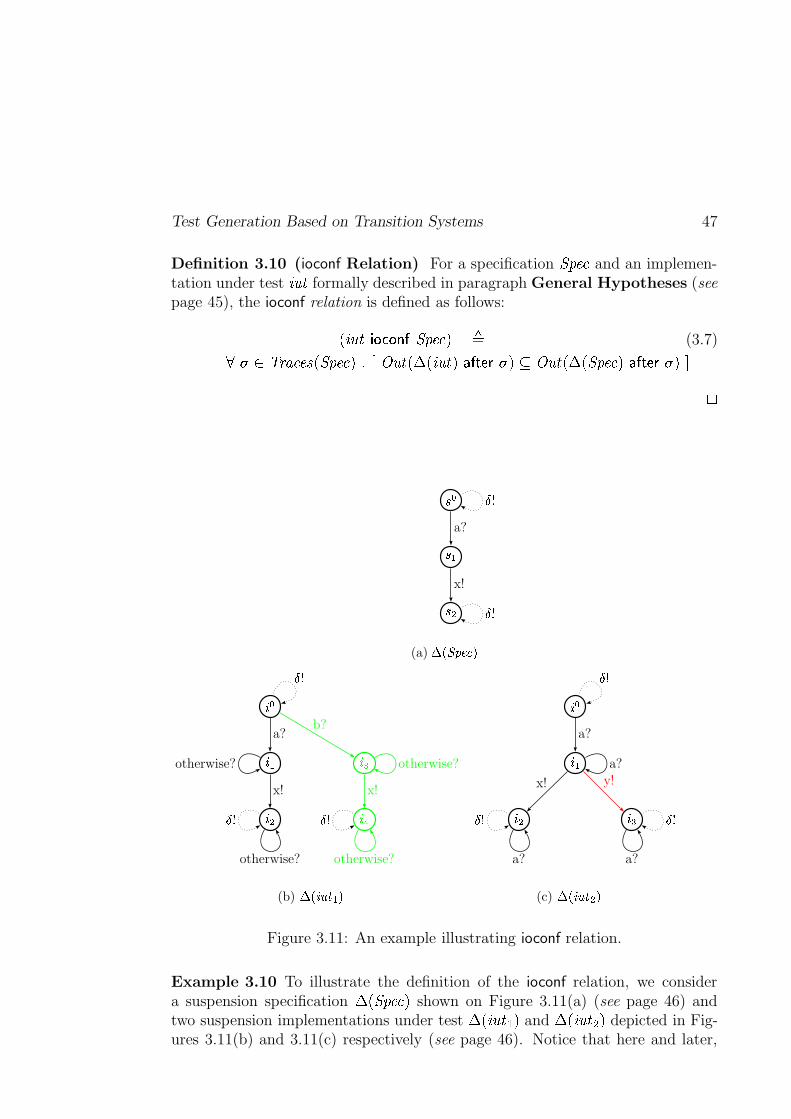
Test Generation Based on Transition Systems 47
Definition 3.10 (ioconf Relation) For a specification ������� and an implemen-tation under test ����� formally described in paragraph General Hypotheses (seepage 45), the ioconf relation is defined as follows:
�=����� � ������� �������:� �(3.7)� � � ��� � ������=�������:� ��� ! ���7�*�b�e��������������� � �O' ! ���f��� �S�������:�� ������� � � h
��
���
���
���
���
a?
x!
(a) �������������
�
� �
� �
� �
�"!
a?
x!
b?
x!
� �
��� ���
otherwise?
otherwise? otherwise?
otherwise?
(b) �#�%$'&�(*)+�
�
� �
� � � �
a?
x! y!
� �
��� ���
a?
a? a?
(c) ���,$'&�(%-��
Figure 3.11: An example illustrating ioconf relation.
Example 3.10 To illustrate the definition of the ioconf relation, we considera suspension specification �b�=�������:� shown on Figure 3.11(a) (see page 46) andtwo suspension implementations under test �b�=�����/.�� and �b�=������0f� depicted in Fig-ures 3.11(b) and 3.11(c) respectively (see page 46). Notice that here and later,
48 Test Generation
we use the abbreviation otherwise? to indicate all possible inputs of an imple-mentation under test.
It is not hard to see that the specification ������� (which can be obtained from�b�=�������`� by removing all loops on � ) only partially specifies the implementation������. (which can be obtained from �b�=������.�� by removing all dotted edges fromFigure 3.11(b)), as �����/. in its initial state can execute the unspecified input ac-tion � (see the green edges on Figure 3.11(b)). However, this implementation isconformant to the specification, i.e. �e�����/. ���������� �������:� . Indeed, after each traceof ������� (which are � , � and � ��� ), it produces the same outputs as the specifica-tion. For instance,
! ���f���b�e�����/.���������� � � � � ��' ! ���7�*�b�=�������:�������� ��� � � � or! ���f���b�e������.���������� � ��� � � � ��' ! ���f���b�=�������:��������� � ��� � � � � .Next, we consider the second implementation under test ������0 obtained from
�b�e������0 � by removing all loops on output action � . From Figure 3.11(c), page 46it is easy to see that after input action � , the implementation ������0 performsunspecified output action � (see the red edge on Figure 3.11(c)). Formally,! ���f���b�e�����+0f��������� � � � � � � ���' ! ���f���b�=�������:�� ������� � � � � � . Therefore, thisimplementation is not conformant to its specification, i.e. �L�e����� 0 ���������� ������� � . h
Ioco Relation. In this paragraph we introduce the ioco relation which treatsspecified and unspecified blockings. Intuitively, the implementation under test����� is ioco-conformant to the specification ������� if for each suspension trace � of������� , the outputs (including the � -action) produced by suspension ����� after thistrace are the outputs that can be produced by suspension ������� after � . Formally:
Definition 3.11 (ioco Relation) For a specification ������� and an implementa-tion under test ����� formally described in paragraph General Hypotheses (seepage 45), the ioco relation is defined as follows:
�=����� � ���� �������:� �(3.8)� � �d� ��� � ���� �S�������:� � � ! ���7�*�b�e����� � ������� � �O' ! ���7���b�=�������`��� ������� � � h
Then, we illustrate the definition given above with an example. This examplehad been taken from the habilitation document [Jéron, 2004] of T. Jéron.
Example 3.11 Consider Figure 3.12 (see page 49) which presents the suspensionIOLTS of a specification ������� and four suspension IOLTS of implementationsunder test ������. – ����� . Then,
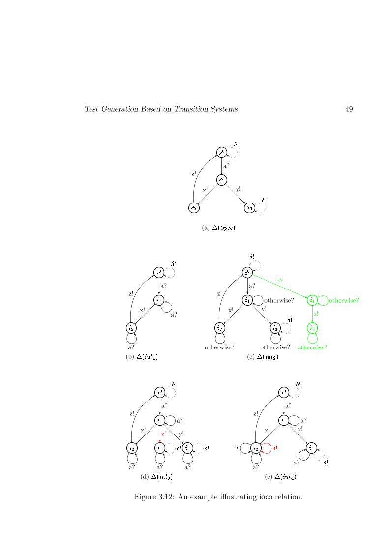
Test Generation Based on Transition Systems 49
��
� �
� � � �
a?
x! y!
z!
���
���
(a) �#�,���������
�
� �
� �
a?
x!
z!
���
a?
a?
(b) ���,$'&�( ) �
�
� �
� � � �
�"!
���
a?
x! y!
b?
z!
z!
���
���
otherwise?
otherwise? otherwise?
otherwise?
otherwise?
(c) ���,$'&�( - �
�
� �
� � � ��"!
a?
x!y!z!
z!
���
������
a?
a? a?a?
(d) ���%$'&�(�� �
�
� �
� � � �
a?
x! y!
z!
���
� �
����
a?
a?a?
(e) ���,$'&�(�� �
Figure 3.12: An example illustrating ioco relation.
50 Test Generation
(1) �e������. ������� �������:� as for all traces of the suspension specification ������� , theoutputs of �b�e������.�� are included into the outputs of �b�=�������`� . For instance,! ���7�*�b�e������.����������J� � � ���"��� � � � � � � � � � ��' ! ���f���b�=�������:�� �������3� � � ���"��� � � � � � � � � � � � � , where � � � ���"��� � � � � � � �d� ��� � ������=�������:� .
(2) �e�����+0 ������� �������:� as all suspension traces of � �S�������`� are traces of �b�=������07� .Thus, it is not hard to check that after all suspension traces of ������� , � �=������0f�produces exactly same outputs as �b�S������� � .Moreover, from the initial state
� �, �b�e������0f� can execute the input action
� (shown in green on Figure 3.12(c), page 49) which is not specified in�b�S�������:� . However, the ioco relation allows this input action, becauseioco checks only the inclusions of output actions after all possible tracesof �b�=�������:� . This observation gives us a possibility to describe partial spec-ifications.
(3) ���=������� � ����b�������:� as the output action�
of �b�e�������7� after the input action �is not allowed by �b�=�������:� (see the red edge of Figure 3.12(d), page 49). For-mally,
! ���f���b�e�������7��������� � � � � � � � � � �' ! ���f���b�=�������:�� ������� � � � � � � � .(4) ���=����� � ����b�������:� as the blocking � (here it is a livelock) of �b�e����� f� af-
ter the suspension trace � ��� of � �S�������:� is not allowed by the specifica-tion (see the loop shown in read in Figure 3.12(e), page 49). Indeed,! ���7�*�b�e����� ?��������� � ��� � � � � � � �' ! ���7�*�b�S�������:� ������� � � � � � .
h
Ioconf vs. Ioco. The aim of this paragraph is to compare the two implemen-tation relations ioconf and ioco (see Definitions 3.10 and 3.11, pages 45 and 47).
The ioconf and ioco conformance relations are quite similar. They both requirean implementation under test to react correctly to the traces that are explicitlyspecified in the specification. In the same time, they allow the implementation toreact in any possible way to traces that are not explicitly specified. This meansthat the ioconf and ioco relations permit the partial description of specifications,which significantly simplifies the testing tack.
Nevertheless, the ioconf and ioco relations are different. Indeed, the purposeof the ioco relation is to check whether after the execution of each suspension
trace (i.e. trace that may contain the � action marking all specified blockings) ofa specification, an implementation under test produces only specified outputs ornot. The ioconf relation checks the same things as ioco but for each proper trace(i.e. trace that does not contain any � action) of a specification. This differ-ence between the ioconf and ioco relations is illustrated on an example which is a
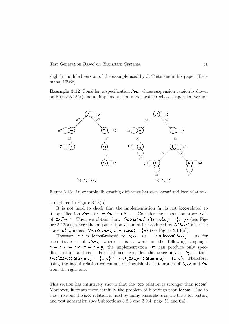
Test Generation Based on Transition Systems 51
slightly modified version of the example used by J. Tretmans in his paper [Tret-mans, 1996b].
Example 3.12 Consider, a specification ������� whose suspension version is shownon Figure 3.13(a) and an implementation under test ����� whose suspension version
��
��� � �
� � � !
� �
a? a?
x! a?
y!
a?
���
���
���
���
(a) ����� � ��� �
�
� � � �
� � �"!
� � ���
a? a?
x! a?
x! y!
a?
���
���
���
��� ���a?
a?
a? a?
(b) ���,$'&�(*�
Figure 3.13: An example illustrating difference between ioconf and ioco relations.
is depicted in Figure 3.13(b).It is not hard to check that the implementation ����� is not ioco-related to
its specification ������� , i.e. �L�e����� � ���� �������:� . Consider the suspension trace � � � � �of �b�=�������`� . Then we obtain that:
! ���f���b�e����� ��������� � � � � � � � � � � � (see Fig-ure 3.13(a)), where the output action
�cannot be produced by �b�S�������:� after the
trace � � � � � , indeed! ���f��� �S�������:�� ������� � � � � � � � � � (see Figure 3.13(a)).
However, ����� is ioconf-related to ������� , i.e. �e����� ���������� �������:� . As foreach trace � of ������� , where � is a word in the following language:� � � � ��� � � � ��� ��� � � � � � � , the implementation ����� can produce only spec-ified output actions. For instance, consider the trace � � � of ������� , then! ���7�*�b�e����� ��������� � � � � � � � � �C' ! ���7�*�b�=�������:�������� � � � � � � � � � . Therefore,using the ioconf relation we cannot distinguish the left branch of ������� and �����from the right one.
h
This section has intuitively shown that the ioco relation is stronger than ioconf.Moreover, it treats more carefully the problem of blockings than ioconf. Due tothese reasons the ioco relation is used by many researchers as the basis for testingand test generation (see Subsections 3.2.3 and 3.2.4, page 51 and 64).
52 Test Generation
Nevertheless, in this thesis we build the testing theory and test generationmethod based on a weaker variant of the ioconf relation (and, therefore, ioco)which (1) does not treat the problem of blockings at all, and (2) is adaptedfor the symbolic variant of input-output labeled transition systems (presented inChapter 4, page 77 and called IOSTS). The main reason for our choice is that theproblem of detecting when a system modeled by IOSTS is blocked is undecidable
in general. However, in the case of absence syntactical livelocks in a given IOSTS,it is possible to syntactically build its suspension IOSTS. Thus, in this case it ispossible to extend our conformance relation to ioco defined by J. Tretmans. Theidea of this extension has been proposed in [Rusu et al., 2004].
3.2.3 Ioco-Based Test Generation Algorithms
This subsection describes two test generation algorithms based on the IOLTSmodel and the ioco relation. Before describing these algorithms we consider(1) a specification a specification whose behaviors are modeled by a convergent
IOLTS ������� with the alphabets of input � ������� and output �������� actions, and (2)an implementation under test whose possible behaviors are modeled by an input-
complete IOLTS ����� � ��� ����� ���� ����� � �� ����� � �� ��� ��������� �with alphabets of input � ����� '
� ������� and output ������ ' �������� actions. Also we consider that the implementationrelation (see Section 2.1.3, page 15) relating ������� and ����� is instantiated with ioco
(see Definition 3.11, page 47). Then, by analogy with the habilitation documentdissertation [Jéron, 2004] of T. Jéron we formally define a test case as follows.
Definition 3.12 (Test Case) A test case is an IOLTS ��� ������ � � � � � � � � � ����� � � such that:
(1) The set of states��� � is equipped with three disjoint sets of states
� �����"'��� � , � ��[' ��� � and � � ����� � ���� � ��� ' ��� � that do not have any successor.
(2) The alphabet of actions � � consists of only input and output actions, i.e.
� � �( � � � �L � � � , where � � � is equipped with the special action � indicatingblockings detection in an implementation under test.
(3) ��� is controllable, i.e. for any state� � ��� � , ��� does not have the choice
neither between output actions, nor between input and output actions.Formally:
A���E�� � � PRQ���� E M � � � P Q � �� � � g���� A���E M � � P^Q , � ��!�1>"�#� , �%$& � � >Ng^g
(4) All states of ��� from which we can execute an input action are input-complete, i.e.
A'�LE�� � � P^Q(��� E M � � � P^Q � �� � � g��#� A'�!E M � � � PRQ � $� � � g g
Test Generation Based on Transition Systems 53
(5) The states belonging to the Fail or Inconclusive set of states are reachableonly by input actions, i.e.
A�� ��� � ��� ��� E � � � PRQ � � E ,������ �� 572�4�5f2������� ���:>"�#� � E M � � � g
(6) From each state of ��� a verdict ( � � � � , � � , or � � ��� � � � � ��� � ) is accessible:
A �LE'� � � � ��� E ,NM � � > � � � � E ,� !�����" ���#$�% �� 5f2�4�572������� ���:>!P^Q �'&� � � gh
Some examples of test cases are shown on Figures 3.14 and 3.16 (see pages 54and 62), where the abbreviation otherwise? is used to indicate all possibleinputs of a tester that are sent by an implementation under test, and are notspecified in a test case.
In order to model the execution of a test case ��� on an implementation undertest ����� we use the parallel composition defined on page 38. The aim of the testexecution is to produce a testing verdict which is either Pass, Fail or Inconclusive.Here, Pass means that no observable difference between a specification and an im-plementation is detected; Fail means that an implementation behaves differentlyfrom its specification; and Inconclusive (which is used only in testing based on atest purpose) means that no error is detected, but a test purpose is not satisfied.The formal definition of verdict can be found, for instance, in [Tretmans, 1996b],[Morel, 2000], [Jéron, 2004].
In the rest of this subsection we describe test generation algorithms whosemain purpose is to derive sound and exhaustive test cases. These properties of testcases permit to relate derived test cases with the notion of conformance. Remindthat a test case is (1) sound if it does not reject conformant implementations, and(2) exhaustive if implementations which do not conform to their specification maybe rejected by some test case. In this section we do not give the formal definitionsof soundness and exhaustiveness as they can be easily found in works of M.-C.Gaudel, T. Jéron, J. Tretmans and other researchers working in the testing area.
3.2.3.1 Blockings and Visible Behaviors of Specifications
Before describing the test generation algorithms, we remind that their aim is toderive a test case ��� from a specification ������� , that detects unspecified blockingsin an implementation under test ����� . For this we have to find all possible blockingsin ������� and mark them with the special output action � . In other words, the first
54 Test Generation
preliminary step for the test generation algorithms is to build a suspension IOLTS�b�=�������`� for the given specification ������� .
Next, notice that during test execution, the tester first observes all possi-ble reactions of the implementation ����� on its stimuli (i.e. the sequences of in-put/output actions or traces), and, then, compare them with the specified ones.For this it is useful to have a direct access to the set of traces of the specifica-tion ������� � ��� ������� ���� ������� � �� ����� � � ������ � ��������� �
, which can be characterized by thedeterministic IOLTS � ���f�=�������:� � ����� �*� ����� �*� � � ��� ����� �*� � , where
–��� ��� �������� �� is the set of states,
–� �� �*� �*� � � ������� ������� �1� is the initial state,
– � ��� � �� ��� �F �� �*� is the alphabet consisting of input �� �*� � � ������� andoutput �� ��� � �������� actions,
– the set of transitions is constructed as follows:
� ���� ��� � ��� � � � ��� � � ��� �*�%��� � � � � �*�\��� � � � �*� � � ������� � �V� �
This algorithm for transformation of a given IOLTS ������� into a deterministicone, i.e. � � �f�=�������:� , where ��� � ���� �S�������:� � ��� � �������� ���7�=�������:� � , is identical to theclassical algorithm for determinization of finite state automata (see [Hopcroftand Ullman, 1979]), which consists in two steps: (1) � -reduction, and (2) subsetconstruction. It is illustrated on Figures 3.14(a) and 3.14(b) (see page 54).
Finally, it is important to emphasize that if we extract visible behaviors ofa specification ������� before detecting blockings in it, then we risk to lose infor-mation about some blockings implicitly specified in ������� . For instance, if wedeterminize the specification ������� whose suspension IOLTS �b�=�������:� is shown onFigure 3.14(a) (see page 54), then in the resulting IOLTS � � �f�=�������:� we will notfind neither outputlock nor livelock in ������� , as information about them was lostduring determinization. Therefore, in the case when the problem of unspecifiedblockings must be treated, it is necessary first to construct � �S�������:� , and then toextract visible behaviors of �b�=�������:� , i.e. to build � � �f�*�b�=�������:� � .3.2.3.2 The Approach of J. Tretmans
In this section we describe a slightly modified version of test generation algorithmproposed by J. Tretmans in his PhD thesis [Tretmans, 1992]. The differencebetween the original algorithm and the algorithm proposed in this section is that:the problem of detection of outputlocks, deadlocks (livelocks are not consideredin the works of J. Tretmans), and visible behaviors of a specification ������� isincorporated into the original algorithm, but not in the proposed one. In the
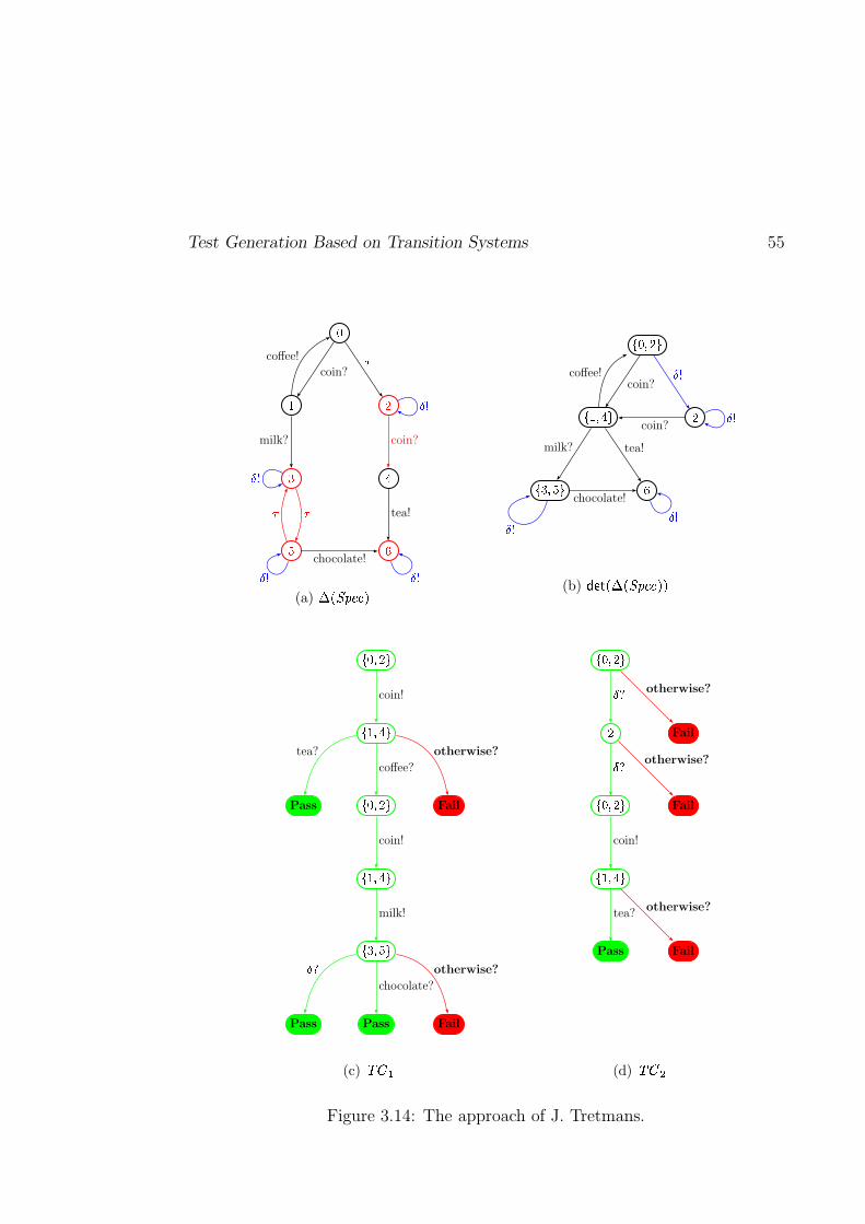
Test Generation Based on Transition Systems 55
�
�
�
�
�
� �
coin?�
milk?
coffee!
coin?
�� tea!
chocolate!
�
�
� �(a) � �����������
��������
�����! �� �
��"���#� $
coin? %&
milk? tea!
coffee!
coin?
chocolate!
%'&
%& %&
(b) (*),+'-/.0-�1�2�3547686
9�:�;�<=
9�>�;!?�=
Pass9�:�;�<=
Fail
9�>�;!?�=
9�@�;�A=
Pass Pass Fail
coin!
tea?
coffee?
otherwise?
coin!
milk!
B,Cchocolate?
otherwise?
(c) DFEHG
9�:�;�<=
<Fail
9�:�;�<=Fail
9�>�;!?�=
Pass Fail
BC otherwise?
BC otherwise?
coin!
tea?otherwise?
(d) DIEKJ
Figure 3.14: The approach of J. Tretmans.
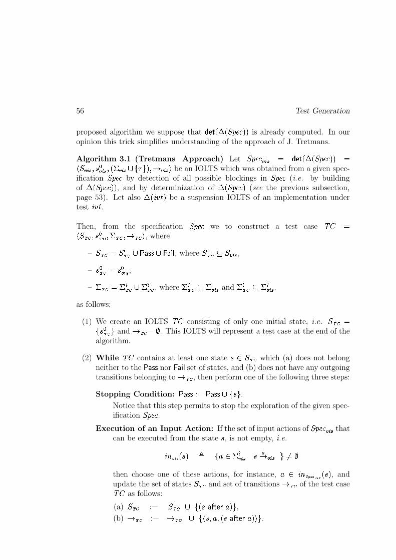
56 Test Generation
proposed algorithm we suppose that � � �7�*�b�S�������:�V� is already computed. In ouropinion this trick simplifies understanding of the approach of J. Tretmans.
Algorithm 3.1 (Tretmans Approach) Let ��������� $�� � � � �f�*�b�=�������:� � ����� $�� ��� �� $�� � �% � $�� � ������ ��� � $�� � be an IOLTS which was obtained from a given spec-
ification ������� by detection of all possible blockings in ������� (i.e. by buildingof �b�S�������:� ), and by determinization of �b�=�������:� (see the previous subsection,page 53). Let also �b�e������� be a suspension IOLTS of an implementation undertest ����� .Then, from the specification ������� we to construct a test case ��� ������ � � � � � � � � � ����� � � , where
–��� � � � � � � � � ����� � � �� , where
� � � � ' � � $�� ,–��� � � � ��
� $�� ,– � � �( � � � � � � � , where � � � ' �� $�� and � � � ' �� $�� .
as follows:
(1) We create an IOLTS ��� consisting of only one initial state, i.e.��� � �
� � � � � and��� � ��� . This IOLTS will represent a test case at the end of the
algorithm.
(2) While ��� contains at least one state� � ��� � which (a) does not belong
neither to the Pass nor Fail set of states, and (b) does not have any outgoingtransitions belonging to
� � � , then perform one of the following three steps:
Stopping Condition:� ����� � � � � ��� �� � � .
Notice that this step permits to stop the exploration of the given spec-ification ������� .
Execution of an Input Action: If the set of input actions of ������� � $�� thatcan be executed from the state
�, is not empty, i.e.
�������� � � � � � �� $�� & � ��� $�� � ����
then choose one of these actions, for instance, � � �� ��� ����� �� � � � , andupdate the set of states
��� � and set of transitions� � � of the test case
��� as follows:
(a)��� � � � ��� � � �� � ������� ��� � ,
(b)��� � � � ��� � � ��� � � � � � ������� ��� � � .
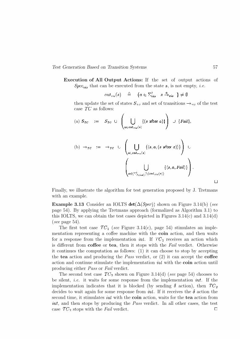
Test Generation Based on Transition Systems 57
Execution of All Output Actions: If the set of output actions of������� � $�� that can be executed from the state
�, is not empty, i.e.
� ��� ��� � � � � � � �� $�� & � ��� $�� � ����
then update the set of states��� � and set of transitions
� � � of the testcase ��� as follows:
(a)� � � � � � � �
�� ������ ��� � �� ���� , � � 6�� ��� �1>����� �� U -���� �
(b)� � � � � � � �
�� ������ ��� � ��� ���� � � � � � , � �76�� ��� ��> � ����
��� ���� ! #" ��%$ &(' � �*) � ��� ���� �+�,� � ��� � � � U -�� � �
�.-� Ph
Finally, we illustrate the algorithm for test generation proposed by J. Tretmanswith an example.
Example 3.13 Consider an IOLTS � � �7�*�b�S�������:�V� shown on Figure 3.14(b) (seepage 54). By applying the Tretmans approach (formalized as Algorithm 3.1) tothis IOLTS, we can obtain the test cases depicted in Figures 3.14(c) and 3.14(d)(see page 54).
The first test case ��� . (see Figure 3.14(c), page 54) stimulates an imple-mentation representing a coffee machine with the coin action, and then waitsfor a response from the implementation ����� . If ��� . receives an action whichis different from coffee or tea, then it stops with the Fail verdict. Otherwiseit continues the computation as follows: (1) it can choose to stop by acceptingthe tea action and producing the Pass verdict, or (2) it can accept the coffeeaction and continue stimulate the implementation ����� with the coin action untilproducing either Pass or Fail verdict.
The second test case ���#0 shown on Figure 3.14(d) (see page 54) chooses tobe silent, i.e. it waits for some response from the implementation ����� . If theimplementation indicates that it is blocked (by sending � action), then ��� 0decides to wait again for some response from ����� . If it receives the � action thesecond time, it stimulates ����� with the coin action, waits for the tea action from����� , and then stops by producing the Pass verdict. In all other cases, the testcase ���#0 stops with the Fail verdict.
h
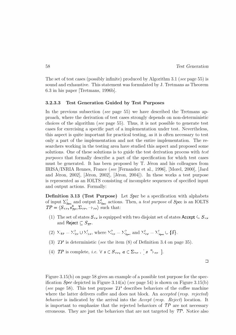
58 Test Generation
The set of test cases (possibly infinite) produced by Algorithm 3.1 (see page 55) issound and exhaustive. This statement was formulated by J. Tretmans as Theorem6.3 in his paper [Tretmans, 1996b].
3.2.3.3 Test Generation Guided by Test Purposes
In the previous subsection (see page 55) we have described the Tretmans ap-proach, where the derivation of test cases strongly depends on non-deterministicchoices of the algorithm (see page 55). Thus, it is not possible to generate testcases for exercising a specific part of a implementation under test. Nevertheless,this aspect is quite important for practical testing, as it is often necessary to testonly a part of the implementation and not the entire implementation. The re-searchers working in the testing area have studied this aspect and proposed somesolutions. One of these solutions is to guide the test derivation process with test
purposes that formally describe a part of the specification for which test casesmust be generated. It has been proposed by T. Jéron and his colleagues fromIRISA/INRIA Rennes, France (see [Fernandez et al., 1996], [Morel, 2000], [Jardand Jéron, 2002], [Jéron, 2002], [Jéron, 2004]). In these works a test purposeis represented as an IOLTS consisting of incomplete sequences of specified inputand output actions. Formally:
Definition 3.13 (Test Purpose) Let ������� be a specification with alphabetsof input � ��� �� and output ���� �� actions. Then, a test purpose of ������� is an IOLTS� � � ������� ���� ��� � ��� ������� � such that:
(1) The set of states�����
is equipped with two disjoint set of states� ��� ��� � ' �����
and � ��� ��� ��' ����� .
(2) ��� � � ��� � � ��� , where � ��� �( � ��� �� and � ��� �( � � �� �� � � .(3) � � is deterministic (see the item (8) of Definition 3.4 on page 35).
(4) � � is complete, i.e.� � � ����� � � �+ ��� � � ��������
.
h
Figure 3.15(b) on page 58 gives an example of a possible test purpose for the spec-ification ������� depicted in Figure 3.14(a) (see page 54) is shown on Figure 3.15(b)(see page 58). This test purpose � � describes behaviors of the coffee machinewhere the latter delivers coffee and does not block. An accepted (resp. rejected)behavior is indicated by the arrival into the Accept (resp. Reject) location. Itis important to emphasize that the rejected behaviors of � � are not necessaryerroneous. They are just the behaviors that are not targeted by � � . Notice also
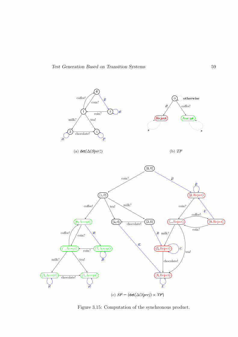
Test Generation Based on Transition Systems 59
�
� �
� �
coin?
�
milk? tea!
coffee!
coin?
chocolate!
�'
� �
(a) ������!� ��������� �8�
�
�������� ���������� %& coffee!
otherwise
**
(b) ���
� :�;!:��
�/>�;!:�� � <';Reject
�
� :�;Accept
� � ?�; :�� � @�;!:�� � >�;Reject
� � :�;Reject
�
�/>�;Accept
� � <';Accept
� � @�;Reject
�
� @�;Accept
� � ?�;Accept
� � ?�;Reject
�
coin?B��
coffee! tea! milk? coin?
coin?
B��B��
chocolate!
B��milk?
tea!
coffee!
coin?
B��
milk? tea!
coffee!
coin?
chocolate!
chocolate!
B��
B��B��
B�� B�� B��(c) �������! �"�#��%$&��('�)�*,+-+/. D��0+
Figure 3.15: Computation of the synchronous product.
60 Test Generation
that on Figure 3.15(b) (and later) we use the * abbreviation indicating a set oftransitions labeled with all possible actions of � � except those specified.
Finally, we describe the ioco-based test generation algorithm which uses a testpurpose in order to extract the part of a specification for which a test case shouldbe derived.
Algorithm 3.2 (Test Generation Guided by Test Purposes) Consider aspecification ������� and a test purpose � � of ������� . Then, a test case ��� can begenerated by the following steps:
Blockings and Visible Behaviors of ������� . The first step of the algorithmconsists in the detection of all blockings in the given specification ������� (i.e.
building of �b�=�������:� ) as well as extracting visible behaviors from �b�=�������`�(i.e. building of � ���f�*�b�=�������:� � ). This step was already explained in Subsec-tion 3.2.3.1 (see page 53).
Synchronous Product. The purpose of the second step is to identify somevisible behaviors of the specification as accepted using the given test purpose� � . In order to do this we compute a synchronous product between theIOLTS � � �7�*�b�S�������:�V� obtained at the previous step of the algorithm, andthe test purpose � � . Formally:
Definition 3.14 (Synchronous Product) Let ������� � $�� � � ���?���b�=�������:�V� �� �� $ � ����� $�� � � $�� � � � $ � � be the deterministic suspension IOLTS of a specifica-
tion ������� , and � � � � ����� � ��� ��� � ��� ������� � be a test purpose of ������� . Then,the IOLTS � � � ���
� ����
� � � � �
� �is the synchronous product between
������� � $�� and � � , where:
(1)�� � �
� $�� � ����� is the set of states equipped with two sets of acceptingand rejecting states which are defined as follows:
� ��� ��� � � � �
� $ � �� ��� ��� � ��� and � ��� ����� � � �
� $�� � � ��� ����� ��� ,
(2)���� � ����
� $ � ���� ��� � is the initial state,
(3) � �( �� �H � � is the alphabet of input and output actions such that
� � �( �� $�� � � ��� and � � �
�� $�� �( � ��� , and
(4) the transition relation��
is defined as follows:
� �� $�� ��� ��� � ��
� ��� �
� $�� � � � ��� � � � � � � $�� ��� $�� � �� $�� � � � � ��� �� ��� � � ��� �
h
Test Generation Based on Transition Systems 61
An example of the synchronous product computed from the deterministicsuspension IOLTS �������������� ������ (see Figure 3.15(a), page 58) and its testpurpose ��� (see Figure 3.15(b), page 58) is shown on Figure 3.15(c) (seepage 58).
Selection or Complete Test Graph Construction. Remind that the aim ofthis test generation algorithm is to construct a test case that examinesbehaviors of the specification ��� �� that are selected by the test purpose��� . Therefore, it is not necessary to keep all traces of the synchronousproduct �� computed at the previous step of the algorithm. It is enoughto choose behaviors of �� which (1) consist of only reachable states of�� , and (2) lead to accepting states of �� . (The notions of reachable andcoreachable states which will be used later, is given as the items (12) and(13) on page 35.) Formally, we construct a complete test graph which isdefined as follows:
Definition 3.15 (Complete Test Graph) Let �� ���������� �"!��� ��#$���%� &'�(�*)be the synchronous product computed from the
deterministic suspension specification ��� ���+-,/.0� �������������� ������ with al-phabet of input actions
#21+3,4. and a test purpose ��� . Let also 576%8 be animplementation under test with alphabet of output actions
#:9;=<?> .Then, a complete test graph is defined as an IOLTS @A�CB ����EDGF�HI� �"! D�FGH ��#JD�FGHK��&LD�FGH*)
selected from the synchronous product �� , where:
(1)�ED�FGH �NMPO*QSRUT4V�WYX%V�W[Z]\�^�_ `��CRbaPc�_]Z is the set of states, where:
(a) M*O*Qd�N�ef �g�� hi�-j �"! k�lnm �poq@sr�e$ �g�� ht�(QEW�WY�Puv� k�l �w�px2QyO*Q , where QyOPQ{zj �}| QEWYW��Puv� ����~ u[���v���j ��m �s����QEWYW��Puv� ��� R�� ����� xCef �g�� ht�j �v! k�l m ����� m , isthe set of states that are reachable from the initial state of �� andcoreachable from the accepting states of �� . Moreover, this setdoes not contain accepting states of �� that are direct successorsof either other accepting states of �� , or unreachable from
� ! ���states of �� .Next, we denote by ��c[^3^C��M*OPQ�o�QEWYW��Puv� ��� the set of pass states.
(b) T/V�W�X%V�WPZ=\�^ _ `��:��u�X�^-�3����(� �3M*O*QC��x�M*O*Q is the set of inconclusive states,
where each state belonging to T/V�W�X%V�WPZ=\�^ _ `�� : (1) is a direct successorof a state belonging to M*O*Q by an output action of �� , and (2)does not belong to MPO*Q .
(c) a*c�_�ZE��j���g[5(� m is the set consisting on only one new state called��g[5(� .
(2)�"! D�FGH � �"!���
is the initial state in the case when M*O*Q����� . Notice that ifM*O*Qd��� , then @A�CB is the empty IOLTS.
62 Test Generation
(3)# DGFGH � #21 D�FGH R #�9DGF�H
is the alphabet of input and output actions, where#�9DGFGH � #21��� � #21+-,/. and#21 DGF�H � #�9;=<?> Rbj � m .
It is important to notice that the alphabets of input and output actionsare inverted due to the fact that: in order to be able to communicatewith an implementation, (1) output actions and blockings of the im-plementation must be considered as input actions for a test case, and(2) input actions of the implementation must be interpreted as outputactions of the test case.
(4)& DGFGH � &������ R &� �� ������ ����� ��� R &������ �
is the transition relation, where:
(a) � ������� ���! #"%$&"' )(�*,+ � �(�.-/ 0+21436587:9<;>=@?4?'A>BC$D+FE$D�FGH,BG )(H+236587<Iis
the set of transitions leading to “lead to accept” states,
(b) � � ��J�K���� ����� ��� � ���! L"%$M"' N(O*P+ � �(�Q-> R+1436587S9C;>=@?4?'ATBU$V+WE 1 DGF�H BX N(Y+Z�[]\_^`[@\@acb ?'d e@fLI
is the set of transitions leading to inconclusive states,and labeled with input actions of @A�CB ,
(c) � ����� �g� ���! L"%$&"ihkj@lKmn*po+ � �(�q-/ r+W143658729s;>=]?4?'AtBu$v+wE 1 D�FGH BF yxz �(�>Iis the set of transitions leading to the �ng[5(� state, and labeled withinput actions of @A�CB .Notice that the introduction of the transitions leading to the �ng[5(�state makes @A�CB input-complete (with respect to input actionof the given implementation 576�8 ). Therefore, @A�CB can properlyreact on an incorrect input action and blocking incoming from thisimplementation.
{
We illustrate the complete test graph construction with an example below.
Example 3.14 The complete test graph obtained from the synchronousproduct shown on (see Figure 3.15(c), page 58) by the third step of thealgorithm is shown on Figure 3.16(a) (see page 62). The two crucial pointsin this computation are the construction of the states and transitions of@A�CB .
First, we need to construct the set of “leads to accept” states. For this weneed to compute:
– the set of states reachable from the initial state�}|%�_|�)
of �� , which isequal to the set of states of �� , i.e. e$ �g�� h��j �}|%�_|�) m � � �����
,
– the set of states from which it is possible to go to pass, which is@sr�e$ �g�� ht�(Q WYWY�[uv� �(� � ��QEW�WY�[uv� �(� Rbj �}|%�_|�)�����~*��|�)Gm , and
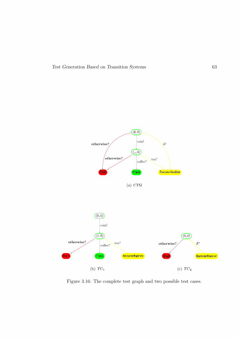
Test Generation Based on Transition Systems 63
���������
�������
� ����� � ����� ����������� ������� ��!
coin! "�#otherwise?
coffee?tea?otherwise?
(a) $&%('
)+*�,�*�-
)/.,�*�-
021�3�4 561�7�7 8�9�:�;�9�:�4�<�7�3>=�?
coin!
coffee?tea?otherwise?
(b) @(ACB
D+E�F�E�G
H I�J�K L�M�N�O�M�N�K�P�Q�J>R�S
T�Uotherwise?
(c) V(WYX
Figure 3.16: The complete test graph and two possible test cases.
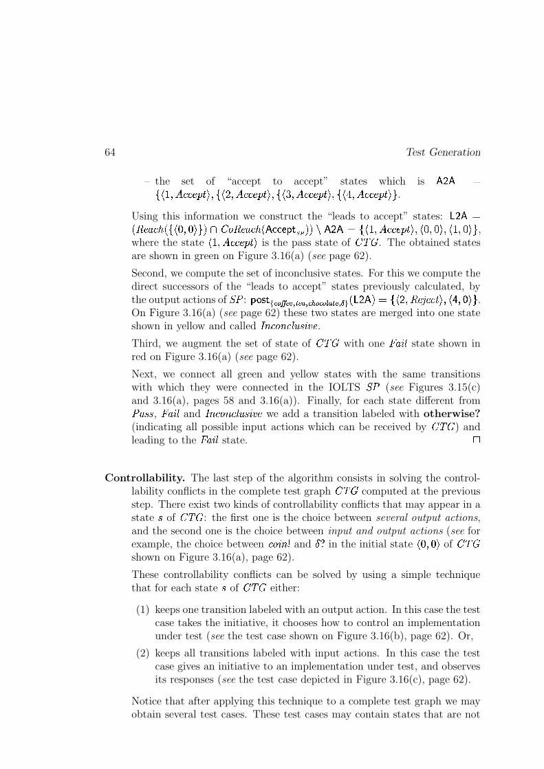
64 Test Generation
– the set of “accept to accept” states which is QyOPQ �j �i~*������������w)�� j ��K����������� �w)�� j ���%������������w)G� j ����������������w)Gm
.
Using this information we construct the “leads to accept” states: MPO*Q���e$ �g�� h��j �}|%�_|�) m �to�@sr�e$ �g�� ht�(Q WYWY�[uv� �(� �w��xAQEO*Q � j ��~*������������w)��v�}|%�_|�)G����~*�_|�)Gm
,where the state
��~*������������w)is the pass state of @A�CB . The obtained states
are shown in green on Figure 3.16(a) (see page 62).
Second, we compute the set of inconclusive states. For this we compute thedirect successors of the “leads to accept” states previously calculated, bythe output actions of �� : u�X*^3��������������� > �������� ��!���#" � > ��� $#%��wMPO*QC� ��j � O � e$ '&v ���8 )�����(%��)�)Gm .On Figure 3.16(a) (see page 62) these two states are merged into one stateshown in yellow and called *�+t��r,+t�Y�]6�- 5'.* .Third, we augment the set of state of @A�CB with one ��g[5(� state shown inred on Figure 3.16(a) (see page 62).
Next, we connect all green and yellow states with the same transitionswith which they were connected in the IOLTS �� (see Figures 3.15(c)and 3.16(a), pages 58 and 3.16(a)). Finally, for each state different from�$g/-�- , �ng[5(� and *�+t��r,+t�Y�]6�- 5'.* we add a transition labeled with otherwise?(indicating all possible input actions which can be received by @A�CB ) andleading to the ��g[5(� state.
{
Controllability. The last step of the algorithm consists in solving the control-lability conflicts in the complete test graph @A�CB computed at the previousstep. There exist two kinds of controllability conflicts that may appear in astate
�of @A�CB : the first one is the choice between several output actions,
and the second one is the choice between input and output actions (see forexample, the choice between ��r[5'+10 and
�32in the initial state
�}|%�_|�)of @A�CB
shown on Figure 3.16(a), page 62).
These controllability conflicts can be solved by using a simple techniquethat for each state
�of @A�CB either:
(1) keeps one transition labeled with an output action. In this case the testcase takes the initiative, it chooses how to control an implementationunder test (see the test case shown on Figure 3.16(b), page 62). Or,
(2) keeps all transitions labeled with input actions. In this case the testcase gives an initiative to an implementation under test, and observesits responses (see the test case depicted in Figure 3.16(c), page 62).
Notice that after applying this technique to a complete test graph we mayobtain several test cases. These test cases may contain states that are not
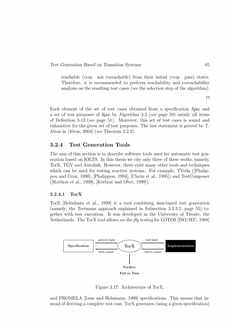
Test Generation Based on Transition Systems 65
reachable (resp. not coreachable) from their initial (resp. pass) states.Therefore, it is recommended to perform reachability and coreachabilityanalysis on the resulting test cases (see the selection step of the algorithm).
{
Each element of the set of test cases obtained from a specification ��� �� anda set of test purposes of ��� �� by Algorithm 3.2 (see page 59) satisfy all itemsof Definition 3.12 (see page 51). Moreover, this set of test cases is sound andexhaustive for the given set of test purposes. The last statement is proved by T.Jéron in [Jéron, 2004] (see Theorem 3.2.2).
3.2.4 Test Generation Tools
The aim of this section is to describe software tools used for automatic test gen-eration based on IOLTS. In this thesis we cite only three of these works, namely,TorX, TGV and Autolink. However, there exist many other tools and techniqueswhich can be used for testing reactive systems. For example, TVeda ([Phalip-pou and Groz, 1990], [Phalippou, 1994], [Clatin et al., 1995]) and TestComposer([Kerbrat et al., 1999], [Kerbrat and Ober, 1999]).
3.2.4.1 TorX
TorX [Belinfante et al., 1999] is a tool combining ioco-based test generation(namely, the Tretmans approach explained in Subsection 3.2.3.2, page 55) to-gether with test execution. It was developed in the University of Twente, theNetherlands. The TorX tool allows on-the-fly testing for LOTOS [ISO/IEC, 1988]
Specification TorX Implementation
generate input
check output
send input
observe output
Verdict:
Fail or Pass
Figure 3.17: Architecture of TorX.
and PROMELA [Leue and Holzmann, 1999] specifications. This means that in-stead of deriving a complete test case, TorX generates (using a given specification)
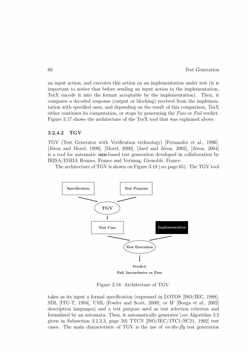
66 Test Generation
an input action, and executes this action on an implementation under test (it isimportant to notice that before sending an input action to the implementation,TorX encode it into the format acceptable by the implementation). Then, itcompares a decoded response (output or blocking) received from the implemen-tation with specified ones, and depending on the result of this comparison, TorXeither continues its computation, or stops by generating the Pass or Fail verdict.Figure 3.17 shows the architecture of the TorX tool that was explained above.
3.2.4.2 TGV
TGV (Test Generator with Verification technology) [Fernandez et al., 1996],[Jéron and Morel, 1999], [Morel, 2000], [Jard and Jéron, 2002], [Jéron, 2004]is a tool for automatic _ XKWYX -based test generation developed in collaboration byIRISA/INRIA Rennes, France and Verimag, Grenoble, France.
The architecture of TGV is shown on Figure 3.18 (see page 65). The TGV tool
Specification
TGV
Test Purpose
Test Case Implementation
Test Execution
Verdict:
Fail, Inconclusive or Pass
Figure 3.18: Architecture of TGV.
takes as its input a formal specification (expressed in LOTOS [ISO/IEC, 1988],SDL [ITU-T, 1994], UML [Fowler and Scott, 2000], or IF [Bozga et al., 2002]description languages) and a test purpose used as test selection criterion andformalized by an automata. Then, it automatically generates (see Algorithm 3.2given in Subsection 3.2.3.3, page 59) TTCN [ISO/IEC/JTC1/SC21, 1992] testcases. The main characteristic of TGV is the use of on-the-fly test generation
Test Generation Based on Transition Systems 67
technique [Fernandez et al., 1996] (i.e. the state space of the specification isnot completely stored). This technique allows to avoid the combinatorial stateexplosion problem which is often the problem in generation of test cases for large-size reactive systems. Finally, test cases derived by TGV are executed on a realsystem under test, and a test verdict is obtained. Notice that in test generationwhere selection of test cases is based on test purposes, there are possibly three(and not two) kinds of verdict. The additional verdict is called *�+t��r,+t�Y�]6�- 5'.* . Itmeans that during test execution no errors were detected but a given test purposewas not achieved.
The detailed information on the TGV tool and case studies where this tool wasused, could be found in [Morel, 2000], [Jard and Jéron, 2002], [Jéron, 2004] and[Fernandez et al., 1997], [Jard et al., 2000], [du Bousquet et al., 2000] respectively.
3.2.4.3 Autolink
Autolink [Koch et al., 1998], [Schmitt et al., 1998], [Telelogic, 1998] (as its prede-cessor SaMsTaG [Grabowski, 1994], [Grabowski et al., 1993]) is a tool for auto-matic test derivation, where the selection mechanism is based on test purposes.This tool is developed in collaboration by the University of Lüebeck, Germanyand the Swedish company Telelogic.
The Autolink tool takes as its inputs (1) a formal specification expressedin SDL, and (2) a test purpose formalized by a MSC [ITU-T, 1996] (MessageSequence Chart) that describes the complete sequence of specified input/outputactions (and not incomplete or abstract one as it is done in TGV) to be tested.Then, it automatically generates a TTCN [ISO/IEC/JTC1/SC21, 1992] test caseby state exploration simulating both SDL specification and MSC test purpose. Ifduring the state exploration we received an event which
– violates the test purpose, but is valid according to the specification, thenthe Autolink tool creates the TTCN *�+t��r,+t�Y�]6�- 5'.* verdict,
– violates both test purpose and specification, then the Autolink tool createsthe TTCN ��g[5(� verdict,
Otherwise, i.e. when the state exploration is not applicable, the Autolink stopsby producing a resulting TTCN test case.
The two principal critics which can be given for Autolink are: (1) the testgeneration method used by Autolink is not based on well-studied conformancerelations such as ioco or ioconf, and (2) state explosion problem which appearsduring the state exploration of large size reactive systems.
68 Test Generation
3.2.5 Conclusion
The test generation methods presented in this section are based on the hypothesisthat the operational semantics of reactive systems, which are expressed in high-level description languages (e.g. LOTOS, SDL or UML), can be modeled by(input-output) labeled transition systems ((IO)LTS). The reactive systems oftenmanipulate complex data structure. Moreover, they can exchange their datausing input and output actions. However, the underlying model of (IO)LTS doesnot allow to explicitly describe the data of these systems. Therefore, in orderto model a specification of such reactive system with (IO)LTS, it is necessary toenumerate values of each datum used by this system. This enumeration oftenleads to the combinatorial states explosion, moreover, in the case when a datumof the reactive system has an infinite domain, the enumeration is impossible. Thepossible solutions for this problem are briefly discussed in the next section.
3.3 Symbolic Test Generation Techniques
The purpose of this section is to present a brief description of the existing worksin the test generation that use symbolic techniques. In this thesis we cite onlysome of these works. Nevertheless, there exist many tools and techniques thatrelate to the our work described in the two next parts of the thesis.
3.3.1 Symbolic Testing for LOTOS
M.-C. Gaudel, P.R. James and G. Lestiennes in their works (see [Gaudel andJames, 1999], [Lestiennes and Gaudel, 2002]) proposed an approach that combinesthe test generation for algebraic specifications and the symbolic simulation forLOTOS [ISO/IEC, 1988].
The symbolic simulation for LOTOS was studied by E.H. Eertink in his the-sis [Eertink, 1994], and implemented in the SMILE [Eertink, 1993] tool that canbe used for the test generation. The algorithm proposed by E.H. Eertink firsttakes a LOTOS process and computes a set of symbolic transitions that canbe executed initially. Then, this algorithm is applied recursively to the rest ofthe process that was obtained after execution one of the previously computedsymbolic transitions. This technique is based on constraints propagation.
In 1999, M.-C. Gaudel and P.R. James published the paper [Gaudel andJames, 1999], where they suggest to combine symbolic simulation (see the pre-vious paragraph) with testing techniques that are based on abstract data types,where tests are selected according to one among several selection hypotheses whichare chosen depending on (1) some knowledge about an implementation, (2) somecoverage criteria of a specification, and (3) ultimately cost considerations. In
Symbolic Test Generation Techniques 69
this paper the authors emphasized that the test generation must be based notonly on the symbolic simulation (a kind of reachability analysis), but also on thebackward propagation of constraints (coreachability analysis). This work wasfollowed by another paper [Lestiennes and Gaudel, 2002], where G. Lestiennesand M.-C. Gaudel studies the same approach for the test derivation applied toInput-Output Transition Systems with data. In this work the authors use ioco asthe conformance relation. Their work is currently not implemented. However, atthe end of the paper [Lestiennes and Gaudel, 2002] the authors mentioned thatthey plan to automate the proposed method using existing test generation andconstraint propagation tools.
3.3.2 Agatha
Agatha [Lugato et al., 2002] is the automatic test generator developed in CEA(Commissariat à l’Energie Atomique), France. This tool supports three phasesdescribed below.
The first phase consists in transforming an Estelle [ISO/TC97/SC21, 1997],SDL [ITU-T, 1994] or UML [Fowler and Scott, 2000] specification into alow-level model called EIOLTS (Extended Input-Output Labeled Transi-tion System). EIOLTS are made up of locations and transitions betweenthe locations. Each transition is labeled with: (1) an input action, (2) aguard which is a Boolean expression over the variables and parameters car-ried by the input action, (3) an output action, and (4) a set of variables’assignments.
The second phase of Agatha is the test generation which is based on the sym-bolic simulation of the states space using the exhaustive symbolic pathcoverage. The symbolic simulation computes an execution tree. Each nodeof this tree is a constraint on the variables characterizing a path of thespecification that leads to this node. During the construction of an exe-cution tree, Agatha simplifies constraints using the rewriting engine calledBrute [Ishisone and Sawada, 2001]. Moreover, it uses the Omega [Kellyet al., 1995] tool for detecting the constraints inclusion, which is necessaryto stop the state exploration.
The final phase of Agatha consists in searching a possible instantiation of theexecution tree computed at the previous phase, which permits to choose thetest case and to execute it on implementation under test. During this phaseAgatha uses either the Omega, or Con’Flex [Rellier and Vardon, 1998] tools.

70 Test Generation
3.3.3 GATeL
GATeL [Marre and Arnould, 2000] is a tool used in order to derive test casesstarting from a specification and a test purpose represented in the synchronousdata flow language LUSTRE [Halbwachs et al., 1991]. A specification written inLUSTRE is a set of cyclic equations over variables, which allows to compute newvalues of the variables using their current values. A test purpose, which describessome important property to check, is an invariant or characterization of reachablestates of some implementation under test. The aim of the test derivation is tosearch for a sequence that permits to satisfy the test purpose (the length of a testsequence generated by GATeL is bounded). The GATeL test derivation methodis based on (1) computation of the product between the specification and thetest purpose, and (2) the backward propagation of constraints (also known ascoreachability analysis) from the goal state to an initial state of the computedproduct. GATeL is integrated with the ECLiPSe tool [Cheadle et al., 2003] inorder to perform the constraint propagation.
It is important to notice that the GATeL tool generates test sequences formonly deterministic specifications. Therefore, the conformance relation, that isused by GATeL, is to checks the equality between outputs obtained by the im-plementation during the test and outputs expected by the specification.
3.3.4 BZ-Testing-Tool
BZ-TT (BZ-Testing-Tool) [Ambert et al., 2002] is an environment for automaticboundary-value conformance and robustness testing from a formal specificationgiven in either B [Abrial, 1996] or Z [Spivey, 1992] notation. Its commer-cial version LTG (Leirios Test Generator) is based on the same principles asBZ-TT, but, in addition to the B notation, it allows to describe specificationsas Statecharts [Harel, 1987] or UML [Fowler and Scott, 2000] diagrams that arewidely-used in industry. Notice that BZ-TT, as well as LTG, treats only deter-ministic specifications, thus, the generated by them test cases are represented assequences.
The main principles of the BZ-Testing-Tool which takes as an input a sys-tem under the form of pre/post predicates over the system’s variables with finitedomains, are described below.
First, BZ-TT computes boundary states (i.e. states where at least one variablehas a value at an extremum of its domain) for a given system. This com-putation is realized by the use of the set-constraint solver CLIS [Bouquetet al., 2002] that is implemented on the base of the SICStus Prolog [Intel-ligent Systems Laboratory, 2004].
Symbolic Test Generation Techniques 71
Second, using a bounded symbolic simulation, BZ-TT takes the system undertest from its initial state to some boundary state computed above. Moreprecisely, this step consists in the exploration of the state-space of the givensystem starting from its initial state and using the best-first search algo-rithm.
Third, in the case when a bounded state is reached, BZ-TT tests all possibleoperations in this state. Notice that, if values of the state variables do notsatisfy pre-conditions of some operation, they are used for the robustnesstesting.
Finally, we remark that the BZ-Testing-Tool allows to concatenate several testsequences together. Indeed, after the derivation of one test sequence for a bound-ary state, it is able to return to this boundary or the initial state of the systemunder test.
3.3.5 Test Generation Tools for Structural Testing
From the discussion above, the reader can notice that the symbolic test gener-ation tools, used in functional (black-box) testing, are based on techniques ofconstraints propagation/solving. These techniques are also widely used in thestructural (white-box) testing. For instance, they are used in the INKA proto-type developed by A. Gotlieb et al. ([Gotlieb et al., 1998], [Gotlieb et al., 2000])which automatically derives test cases for the programs written in a subset of theC language; and in the ATGen tool of C. Meudec [Meudec, 2001] that generatestest cases for ADA programs [Barnes, 1984]. The main ideas of such tools are:
(1) to find a path in the control-flow graph of a given program that leads to agiven state. Notice that the length of this path is bounded. This allows tounfold cycles of the program under test.
(2) to generate inputs by solving the constraints through the computed abovepath. This permit to obtain expected outputs.
It is important to remark that such tools are often limited to deterministic pro-grams (here, we mean the observable determinism). This means that the outputsof a given program strictly depend on inputs, i.e. the tester has a full control onthis program. It permits to automatically generate inputs for expected outputs.
3.3.6 Conclusion
In this section we have briefly described some existing methods and tools used forthe symbolic derivation of test cases from a formal specification of a given system
72 Test Generation
under test. All of them use the constraint logic programming, moreover, they arelimited to deterministic specifications. These tools allow to generate precise testcases under the form of test sequences (or trees) whose length is bounded.
The second part of the thesis is devoted to another symbolic test generationmethod with selection guided by test purposes. This method is quite differentfrom ones mentioned in this section. It is based on a kind of transition system(called Input-Output Symbolic Transition System or IOSTS) that symbolicallymanipulates the data of a given system. It enables us (1) to avoid the state-space explosion problem, as instead of enumerating values of all variables, wemanipulate symbolic states of the system that are characterized by formulas overthe systems data, and (2) to generate symbolic test cases that have the form ofprograms and, therefore, are closer to the reality.
Moreover, our test generation method (more precisely, the mechanism of testcase selection) is based on a technique of abstract interpretation ([Cousot andCousot, 1976], [Cousot and Cousot, 1977]) instead of constraint solving. Thetest cases derived by our method have the form of a graph as we do not needto limit their length. They are less precise than the test cases generated by thetools described in this section. However, they permit to obtain a global view onthe “past” and the “future” of a system under test. Finally remark that we areable to treat non-deterministic specifications belonging to the non-trivial subclassdefined in Section A.2.4 (see page 304).
In the rest of this document we give the detailed description of the IOSTSmodel, the symbolic test generation method with selection guided by test pur-poses, and the tool implementing this method.
Part II
Symbolic Test Generation
73

Introduction
Motivation. In the last chapter of the introductory part of the thesis we sawthat in the last decades, testing theory and techniques for automatic test gen-eration of reactive systems have been developed. Some of these techniques arebased on the (input-output) labeled transition systems model (i.e. (IO)LTS) andefficient on-the-fly algorithms [Tretmans, 1992], [Jéron and Morel, 1999]. Therealready exist academic (e.g. TorX [Belinfante et al., 1999], TGV [Fernandez et al.,1996]) and industrial (e.g. Autolink [Telelogic, 1998], TestComposer [Kerbrat andOber, 1999]) tools that implement these algorithms and produce correct test casesin a formal framework. However, these theories and tools do not explicitly takeinto account the system data, since the underlying model of (IO)LTS does notallow to do that. Thus, in order to model a specification of reactive systems with(IO)LTS, it is necessary to enumerate the values of each data used by this sys-tem. This may result in the classical state-space explosion problem. Moreover,this enumeration also has the effect of obtaining test cases, where all data areinstantiated. This contradicts industrial practice, where test cases (written, forinstance, in the TTCN [ISO/IEC/JTC1/SC21, 1992] language) are real programswith data (variables, parameters). The generation of such test cases requires newmodels and techniques which we introduce in this part of the thesis.
Plan of Part II. The rest of this part is organized as follows.
In Chapter 4 we first present a new model that allows to explicitly introducethe data of a system. This model is called input-output symbolic transitionsystem (IOSTS). Then, we describe the syntax and semantics of IOSTS.Finally, we define some important subclasses of IOSTS, for instance, deter-ministic and complete IOSTS.
In Chapter 5 we introduce the product operation and the operation of parallelcomposition for IOSTS, which are extensions of the analogous operationdefined for IOLTS (see Definition 3.5 and 3.14, page 38 and 59). Theproduct operation will be used in the symbolic test generation process inorder to “intersect” behaviors of a specifications with behaviors of a test
75
76 Introduction
purpose, and the parallel composition will be used during test execution inorder to model the communication between an implementation under testand a derived test case.
In Chapter 6 we build a formal background for conformance testing based onthe IOSTS model and the ioc conformance relation that is a weaker variantof the standard ioconf and ioco conformance relations (it does not deal withthe problem of blockings because the detection of livelocks in IOSTS isundecidable). Moreover, we define the notion of a correct test case.
In Chapter 7 we describe our symbolic test generation method where the selec-tion of test cases is guided by test purposes. This method is very close tothe approach proposed by T. Jéron and his colleagues from IRISA/INRIARennes, France and described in Subsection 3.2.3.3 (see page 57). However,some steps of our symbolic test generation method are more complex thanthose proposed by T. Jéron et al. since they have to take into accountthe data of a given specification. For instance, the selection of a completetest graph must use a semantics-based analysis in order to select the setof states that are reachable from the initial state of a given IOSTS andfrom which it is possible to go towards some accepting state of this IOSTS.However, unlike the selection algorithm developed for IOLTS, the issue ofcomputing the exact set of reachable and coreachable states is undecidablefor IOSTS. Therefore, the selection algorithm for IOSTS is based on theover-approximation of reachable and coreachable sets of states. At the endof this chapter, we prove that our symbolic test generation method derivesa set of correct test cases.
The symbolic test generation method was implemented in the STG tool. Thedescription of this tool and a case study of the bounded retransmission protocolare given in Part III of the thesis.
The work described in the second and third parts of this thesis is the result ofthe collaboration with Vlad Rusu and Thierry Jéron, who have established theinitial theoretical framework for symbolic test generation [Rusu et al., 2000], aswell as Duncan Clarke, Bertrand Jannet and François-Xavier Ponscarme.
Chapter 4
Model: Input-Output SymbolicTransition Systems
In this chapter we introduce a model of reactive systems that we usefor conformance testing. This model is called Input-Output SymbolicTransition System (IOSTS). IOSTS is an extended version of IOLTSdefined in Subsection 3.2.2.1 of Chapter 3 (see page 41). It explicitlyincludes data of the reactive systems, and symbolically manipulateswith them. At the beginning of the chapter we present an example ofIOSTS which helps to understand the model and its semantics at anintuitive level. Then, we define the IOSTS formalism and discussesits syntax and semantics. Finally, we introduce some subclasses ofIOSTS used in symbolic test generation. The work contained in thischapter is an extended version of one presented in [Rusu et al., 2000].
4.1 Running Example
This section gives an intuitive explanation of IOSTS using the example of acoffee machine depicted in Figure 4.1. This example is the running example forthe current part of the thesis.
Syntax. The IOSTS � (see Figure 4.1) is made up of locations, e.g. Begin,Idle, Pay, where Begin is the initial location, and transitions. The transitions arelabeled with actions, guards and assignments. For example, the transition withorigin Idle and destination Pay has the guard �7� @sr[5'+���g*�]6� �� | � , the input actionCoin? carrying the data � @sr[5'+���g*�]6� from the environment, and the assignment."�fg[5������ ."�fg[5�� � @sr[5'+���g*�]6 . The set of actions is partitioned into three disjointsubsets of input, output and internal actions. The input/output actions interact
77
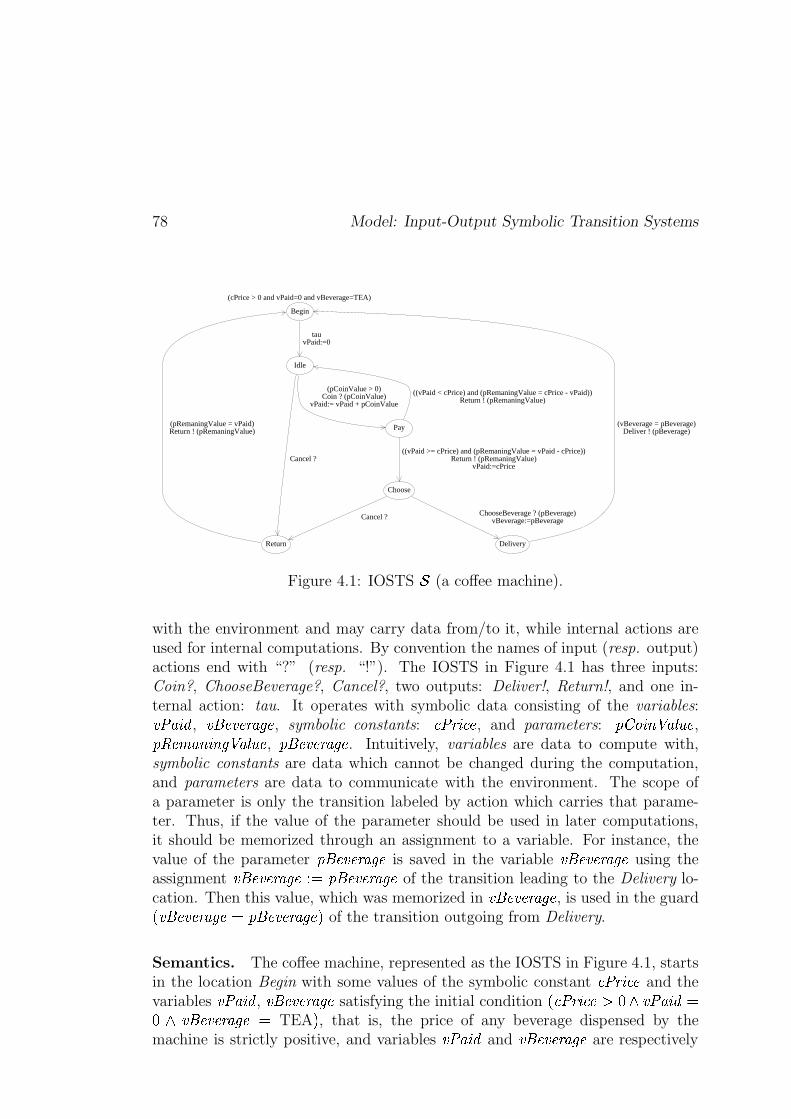
78 Model: Input-Output Symbolic Transition Systems
(cPrice > 0 and vPaid=0 and vBeverage=TEA)
tauvPaid:=0
(pCoinValue > 0)Coin ? (pCoinValue)
vPaid:= vPaid + pCoinValue
Cancel ?
(pRemaningValue = vPaid)Return ! (pRemaningValue)
((vPaid < cPrice) and (pRemaningValue = cPrice - vPaid))Return ! (pRemaningValue)
((vPaid >= cPrice) and (pRemaningValue = vPaid - cPrice))Return ! (pRemaningValue)
vPaid:=cPrice
ChooseBeverage ? (pBeverage)vBeverage:=pBeverageCancel ?
(vBeverage = pBeverage)Deliver ! (pBeverage)
Begin
Idle
Pay
Choose
Return Delivery
Figure 4.1: IOSTS � (a coffee machine).
with the environment and may carry data from/to it, while internal actions areused for internal computations. By convention the names of input (resp. output)actions end with “?” (resp. “!”). The IOSTS in Figure 4.1 has three inputs:Coin?, ChooseBeverage?, Cancel?, two outputs: Deliver!, Return!, and one in-ternal action: tau. It operates with symbolic data consisting of the variables:."�$g[5�� , .��: �.* ��?g��K , symbolic constants: � ��� 5 �� , and parameters: � @sr[5'+���g*�]6� ,� e$ �� g,+�5'+�� ��g*�]6� , ��A �.* ���g��K . Intuitively, variables are data to compute with,symbolic constants are data which cannot be changed during the computation,and parameters are data to communicate with the environment. The scope ofa parameter is only the transition labeled by action which carries that parame-ter. Thus, if the value of the parameter should be used in later computations,it should be memorized through an assignment to a variable. For instance, thevalue of the parameter ��: �.* ��?g��K is saved in the variable .��: �.* ��?g��K using theassignment .��: �.* ��?g��K �]�L��A �.* ���g��K of the transition leading to the Delivery lo-cation. Then this value, which was memorized in .��: �.* ��?g��K , is used in the guard� .��: �.* ��?g��K A�'��: �.* ��?g��K �� of the transition outgoing from Delivery.
Semantics. The coffee machine, represented as the IOSTS in Figure 4.1, startsin the location Begin with some values of the symbolic constant � ��� 5 �� and thevariables ."�$g[5�� , .��A �.* ���g��K satisfying the initial condition �?� ���G5 �� � |� ."�fg[5�� �|� .��: �.* ��?g��K � TEA � , that is, the price of any beverage dispensed by themachine is strictly positive, and variables ."�$g[5�� and .��: �.* ��?g��K are respectively
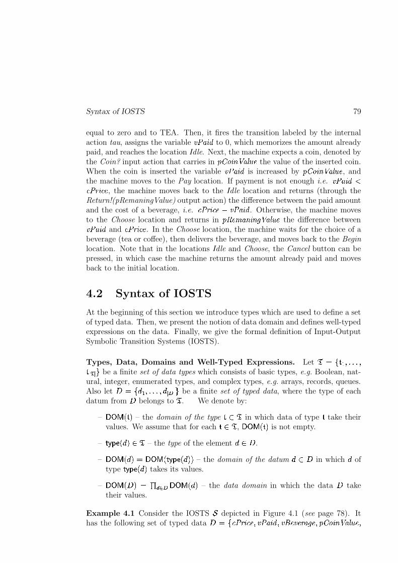
Syntax of IOSTS 79
equal to zero and to TEA. Then, it fires the transition labeled by the internalaction tau, assigns the variable ."�$g[5�� to 0, which memorizes the amount alreadypaid, and reaches the location Idle. Next, the machine expects a coin, denoted bythe Coin? input action that carries in � @sr[5'+���g*�]6� the value of the inserted coin.When the coin is inserted the variable ."�$g[5�� is increased by � @sr[5'+���g*�]6 , andthe machine moves to the Pay location. If payment is not enough i.e. ."�$g[5����� � � 5 �� , the machine moves back to the Idle location and returns (through theReturn!(pRemaningValue) output action) the difference between the paid amountand the cost of a beverage, i.e. � ��� 5 �� �� ."�$g[5�� . Otherwise, the machine movesto the Choose location and returns in � e$ �� g,+�5'+�� ��g*�]6 the difference between."�fg[5�� and � � � 5 �� . In the Choose location, the machine waits for the choice of abeverage (tea or coffee), then delivers the beverage, and moves back to the Beginlocation. Note that in the locations Idle and Choose, the Cancel button can bepressed, in which case the machine returns the amount already paid and movesback to the initial location.
4.2 Syntax of IOSTS
At the beginning of this section we introduce types which are used to define a setof typed data. Then, we present the notion of data domain and defines well-typedexpressions on the data. Finally, we give the formal definition of Input-OutputSymbolic Transition Systems (IOSTS).
Types, Data, Domains and Well-Typed Expressions. Let ��� j���� ������ � � m be a finite set of data types which consists of basic types, e.g. Boolean, nat-ural, integer, enumerated types, and complex types, e.g. arrays, records, queues.Also let � � j���� ��Y� � � ��� m be a finite set of typed data, where the type of eachdatum from � belongs to � . We denote by:
– ����� ���3� – the domain of the type � | � in which data of type � take theirvalues. We assume that for each � | � , ����� ���-� is not empty.
– ����u��I����� | � – the type of the element � | � .
– ����� ����� ������� ������u���������� – the domain of the datum � | � in which � oftype ����u�������� takes its values.
– ����� ����� ���� "! � ����� ����� – the data domain in which the data � taketheir values.
Example 4.1 Consider the IOSTS � depicted in Figure 4.1 (see page 78). Ithas the following set of typed data � � j�� ��� 5 �� � ."�$g[5�� � .��: �.* ��?g��K � � @sr[5'+���g*�]6 �
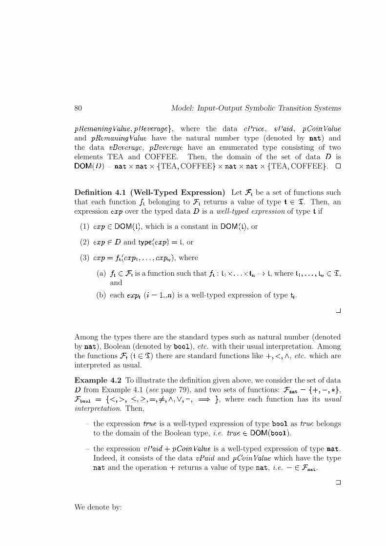
80 Model: Input-Output Symbolic Transition Systems
� e$ �� g,+�5'+�� ��g*�]6� � ��: �.* ��?g��K m , where the data � � � 5 �� , ."�fg[5�� , � @sr[5'+���g*�]6� and � e$ �� g,+�5'+�� ��g*�]6� have the natural number type (denoted by ����� ) andthe data .��: �.* ��?g��K , ��: �.* ��?g��K have an enumerated type consisting of twoelements TEA and COFFEE. Then, the domain of the set of data � is����� ����� ���������������� j TEA
�COFFEE
m ���������������� j TEA�COFFEE
m.
{
Definition 4.1 (Well-Typed Expression) Let �� be a set of functions suchthat each function ��� belonging to �� returns a value of type � | � . Then, anexpression
���3�over the typed data � is a well-typed expression of type � if
(1)���3��| ����� ���-� , which is a constant in ��� � ���3� , or
(2)���3��| � and ����u���� ���3� �E� � , or
(3)���3� ������� ���3� � �������3��� � , where
(a) ��� | �� is a function such that ��� � � ��� � � ���& � , where � � ��Y� � � | � ,and
(b) each���3� , ( �n� ~ ��
) is a well-typed expression of type � , .{
Among the types there are the standard types such as natural number (denotedby ����� ), Boolean (denoted by �! " "# ), etc. with their usual interpretation. Amongthe functions �� ( � | � ) there are standard functions like
� � � , etc. which are
interpreted as usual.
Example 4.2 To illustrate the definition given above, we consider the set of data� from Example 4.1 (see page 79), and two sets of functions: �$&%(':� j � � �*)Im
, ,+.-/-(0q� j � �
��21}��3}� � � �� � 2�542�562� �87 m
, where each function has its usualinterpretation. Then,
– the expression 8 � 6� is a well-typed expression of type �9 " "# as 8 �G6� belongsto the domain of the Boolean type, i.e. 8 � 6 | ����� �:�9 " "#�� .
– the expression ."�$g[5�� {� @sr[5'+���g*�]6 is a well-typed expression of type ����� .Indeed, it consists of the data ."�$g[5�� and � @sr[5'+���g*�]6� which have the type����� and the operation returns a value of type ����� , i.e.
| �$&%(' .{
We denote by:
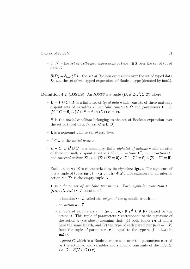
Syntax of IOSTS 81
– � � ����� – the set of well-typed expressions of type � | � over the set of typeddata � .
– �J�����E���"+.-/-(0������ – the set of Boolean expressions over the set of typed data� , i.e. the set of well-typed expressions of Boolean type (denoted by bool).
Definition 4.2 (IOSTS) An IOSTS is a tuple� � ��� ���$��� ! � #:�J)
where
– � ���{R� dR�� is a finite set of typed data which consists of three mutuallydisjoint sets of variables � , symbolic constants and parameters � , i.e.��� o� ������ ��� o�������� �� 'o�������� .
–�
is the initial condition belonging to the set of Boolean expression overthe set of typed data � , i.e.
��| �J��� � .–�
is a nonempty, finite set of locations.
–��!:|��
is the initial location.
–# � #21 R #�9 R #��
is a nonempty, finite alphabet of actions which consistsof three mutually disjoint alphabets of input actions
#f1, output actions
#A9and internal actions
#��, i.e. � #21 o #�9 ����� � #21 o #�� ����� � #�9 o #�� ����� .
Each action � | #is characterized by its signature ^ _ � ����� . The signature of
� is a tuple of types ^ _ �t����� � � � � ��Y� ��� )2| � � . The signature of an internalaction � | #��
is the empty tuple��)
.
–
is a finite set of symbolic transitions. Each symbolic transition� ����-� � ���y��� ��� ��� ( )2|�
consists of:
- a location�E|��
called the origin of the symbolic transition.
- an action � | #.
- a tuple of parameters� � � � � ��Y��� � )S| � � �� |"! � carried by the
action � . This tuple of parameters�
corresponds to the signature ofthe action � (see above) meaning that: (1) both tuples ^ _ � ����� and
�have the same length, and (2) the type of each parameter
� , ( � � ~ )from the tuple of parameters
�is equal to the type � , ( �}� ~ ) in
^ _ � ����� .- a guard
�which is a Boolean expression over the parameters carried
by the action � , and variables and symbolic constants of the IOSTS,i.e.
��| �J����R# 'R � � .
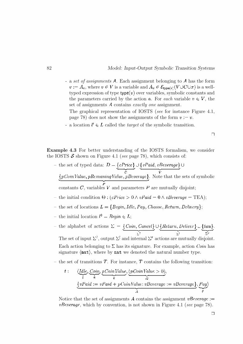
82 Model: Input-Output Symbolic Transition Systems
- a set of assignments � . Each assignment belonging to � has the form����� ��� , where ��� is a variable and ��� �� ���������� ����� ���� �"! is a well-typed expression of type #%$'&)()� �*! over variables, symbolic constants andthe parameters carried by the action + . For each variable �,�- , theset of assignments � contains exactly one assignment.
The graphical representation of IOSTS (see for instance Figure 4.1,page 78) does not show the assignments of the form ��.�/� .
- a location 021 ��3 called the target of the symbolic transition.
4
Example 4.3 For better understanding of the IOSTS formalism, we considerthe IOSTS 5 shown on Figure 4.1 (see page 78), which consists of:
– the set of typed data: 6 �87*9;:=<;>?9A@CBD E�F GH�I7KJL:�MN>?OQPLJLR�@SJT@S<UMWV�@NBD E�F GX
�7LY"Z=[N>]\ ^QMT_.`Q@CPaYcbd@SeMN\Q>]\�Vf^QMT_.`c@CPaYcR�@SJT@S<AMWV�@gBD E�F Gh . Note that the sets of symbolic
constants � , variables and parameters i are mutually disjoint;
– the initial condition j � � 9;:=<;>?9A@lknmpoqJL:dMN>?Or�/mposJLR�@SJT@S<UMWV�@p� TEA ! ;– the set of locations 3t�87'R�@?VT>]\uPwvWOx_y@CPW:dMNzcPKZ|{*[}[g~L@CPWbd@w�%`�<;\"PW��@W_.>]JT@S<Sz�B ;– the initial location 0%� ��R�@?VT>]\���3 ;
– the alphabet of actions � � 7�Z=[N>]\fPKZ=MN\�9A@W_%BD E�F G�K���7'bd@w�2`�<;\"Pw��@W_.>]JT@S<)BD E�F G�x�
�I7}� +K� BD E�F G�K� .
The set of input ��� , output �p� and internal ��� actions are mutually disjoint.
Each action belonging to � has its signature. For example, action Z=[N>]\ hassignature �2�*�T�*� , where by �*�)� we denoted the natural number type.
– the set of transitions � . For instance, � contains the following transition:
� � � vwOx_y@D E�F G�PKZ=[N>]\D E�F G�
PaY"Z=[N>]\ ^QMT_.`c@D E�F G�P � Y"Z=[N>]\ ^QMT_.`c@�knm�!D E�F G
P
7KJL:dMN>?O���¡JL:dMN>?O�¢tY"Z=[N>]\ ^QMT_.`Q@T£WJLR�@SJT@S<UMWV�@��.�¡JLR�@SJT@S<UMWV�@NBD E�F G¤PW:dMNzD E�F G�¦¥ �
Notice that the set of assignments � contains the assignment JLR�@SJT@S<UMWV�@§�.�JLR�@SJT@S<AMWV�@ , which by convention, is not shown in Figure 4.1 (see page 78).4
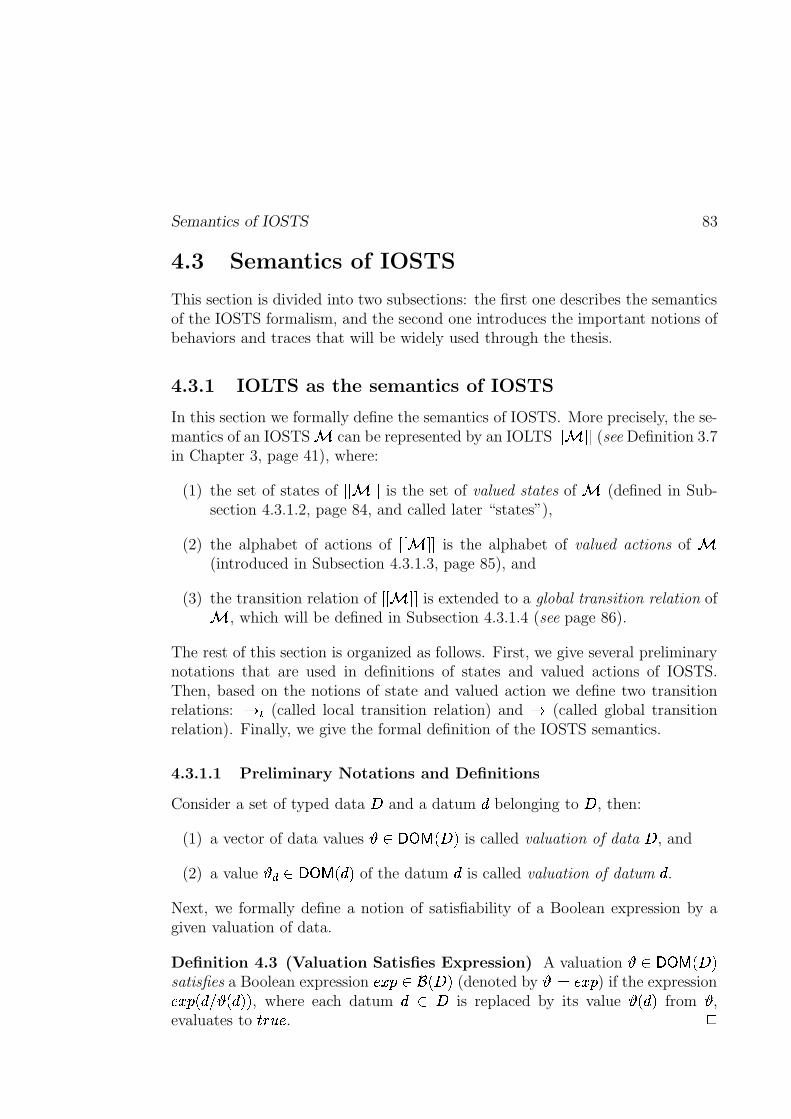
Semantics of IOSTS 83
4.3 Semantics of IOSTS
This section is divided into two subsections: the first one describes the semanticsof the IOSTS formalism, and the second one introduces the important notions ofbehaviors and traces that will be widely used through the thesis.
4.3.1 IOLTS as the semantics of IOSTS
In this section we formally define the semantics of IOSTS. More precisely, the se-mantics of an IOSTS � can be represented by an IOLTS ��� ����� (see Definition 3.7in Chapter 3, page 41), where:
(1) the set of states of ��� ����� is the set of valued states of � (defined in Sub-section 4.3.1.2, page 84, and called later “states”),
(2) the alphabet of actions of ��� ����� is the alphabet of valued actions of �(introduced in Subsection 4.3.1.3, page 85), and
(3) the transition relation of ��� ����� is extended to a global transition relation of� , which will be defined in Subsection 4.3.1.4 (see page 86).
The rest of this section is organized as follows. First, we give several preliminarynotations that are used in definitions of states and valued actions of IOSTS.Then, based on the notions of state and valued action we define two transitionrelations: ��� (called local transition relation) and � (called global transitionrelation). Finally, we give the formal definition of the IOSTS semantics.
4.3.1.1 Preliminary Notations and Definitions
Consider a set of typed data 6 and a datum belonging to 6 , then:
(1) a vector of data values ���� �� �%6 ! is called valuation of data 6 , and
(2) a value �� ���� �� �� ! of the datum is called valuation of datum .Next, we formally define a notion of satisfiability of a Boolean expression by agiven valuation of data.
Definition 4.3 (Valuation Satisfies Expression) A valuation ���� �� � 6 !satisfies a Boolean expression ����� ��� �%6 ! (denoted by �� � ����� ) if the expression�����f�����"�� !�! , where each datum � 6 is replaced by its value "�� ! from ,evaluates to �! ��� . 4
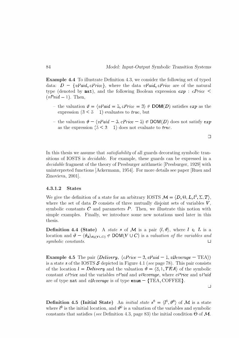
84 Model: Input-Output Symbolic Transition Systems
Example 4.4 To illustrate Definition 4.3, we consider the following set of typeddata: 6 � 7KJL:�MN>?O PN9;:�<;>?9A@NB , where the data JL:dMN>?OcPC9;:=<;>?9A@ are of the naturaltype (denoted by �*�)� ), and the following Boolean expression ����� � 9;:=<S>?9A@��� JL:�MN>?O����N! . Then,
– the valuation � � JL:�MN>?OI����PC9;:=<S> 9A@���� � � �� �� � 6 ! satisfies ����� as theexpression � �������N! evaluates to �%<;`Q@ , but
– the valuation � � JL:dMN>?O � �xPC9;:=<;>?9A@���� � ���� �� � 6 ! does not satisfy �����as the expression � ���������N! does not evaluate to �%<;`Q@ .
4
In this thesis we assume that satisfiability of all guards decorating symbolic tran-sitions of IOSTS is decidable. For example, these guards can be expressed in adecidable fragment of the theory of Presburger arithmetic [Presburger, 1929] withuninterpreted functions [Ackermann, 1954]. For more details see paper [Rusu andZinovieva, 2001].
4.3.1.2 States
We give the definition of a state for an arbitrary IOSTS � � �?6 P j PA3dP 0 � P � P � � ,where the set of data 6 consists of three mutually disjoint sets of variables ,symbolic constants � and parameters i . Then, we illustrate this notion withsimple examples. Finally, we introduce some new notations used later in thisthesis.
Definition 4.4 (State) A state � of � is a pair � 0 P �� , where 0 � 3 is alocation and � ����L�!��� � X�� H � ���� �� � /��� ! is a valuation of the variables and
symbolic constants.4
Example 4.5 The pair � 6 �L0�� � � �� P � 9;:=<;>?9A@ � �xPLJL:dMN>?Or���TPLJLR�@SJT@S<UMWV�@�� TEA �U�is a state � of the IOSTS 5 depicted in Figure 4.1 (see page 78). This pair consistsof the location 0 � 6 �L0�� � � �� and the valuation � � �xP��TP ����� � of the symbolicconstant 9;:=<;>?9A@ and the variables JL:�MN>?O and JLR�@SJT@S<UMWV�@ , where 9;:=<;>?9A@ and JL:dMN>?Oare of type nat and JLR�@SJT@S<UMWV�@ is of type �C�! #" � 7 TEA P COFFEE B . 4
Definition 4.5 (Initial State) An initial state � � � � 0 � P � � of � is a statewhere 0 � is the initial location, and � is a valuation of the variables and symbolicconstants that satisfies (see Definition 4.3, page 83) the initial condition j of � .
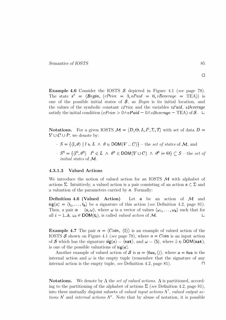
Semantics of IOSTS 85
4
Example 4.6 Consider the IOSTS 5 depicted in Figure 4.1 (see page 78).The state � � � ��� ��� ��� P � 9;:=<;>?9A@ � �xPLJL:dMN>?O � mxPWJLR�@SJT@S<UMWV�@ � TEA �U� isone of the possible initial states of 5 , as Begin is its initial location, andthe values of the symbolic constant 9;:=<;>?9A@ and the variables JL:dMN>?O , JLR�@SJT@S<UMWV�@satisfy the initial condition � 9;:=<;>?9A@lknmQo�� i�+!� �/m*o�JLR�@SJT@S<AMWV�@p� TEA ! of 5 .
4
Notations. For a given IOSTS � � �?6 P j PA3 P 0 � P � P � � with set of data 6 � � �n� i , we denote by:
– � ��7 � 0 P � �K0 ��3 o ���� �� � � � !UB – the set of states of � , and
– � � � 7 �%0 � P � � �K0 � �s3 o � � �� �� � �,� !qo � � � j B�� � – the set of
initial states of � .
4.3.1.3 Valued Actions
We introduce the notion of valued action for an IOSTS � with alphabet ofactions � . Intuitively, a valued action is a pair consisting of an action + � � anda valuation of the parameters carried by + . Formally:
Definition 4.6 (Valued Action) Let + be an action of � and� � �2+ !�� �� �� P������SP ��L� be a signature of this action (see Definition 4.2, page 81).Then, a pair � � � + P�� � , where � is a vector of values � � � P������WP�� �W� such that forall � � ������� , ���f���� �� �� �%! , is called valued action of � .
4
Example 4.7 The pair � � � ��� ��� P � � ��� is an example of valued action of theIOSTS 5 shown on Figure 4.1 (see page 78), where + ����� ��� is an input actionof 5 which has the signature � � �2+ ! � �]�Q�T�*� , and �t� � � � , where �r� �� �� � �Q�T� ! ,is one of the possible valuations of � � �2+ ! .
Another example of valued action of 5 is � � � � +K� P � �U� , where + � � +�� is theinternal action and � is the empty tuple (remember that the signature of anyinternal action is the empty tuple, see Definition 4.2, page 81).
4
Notations. We denote by ! the set of valued actions. ! is partitioned, accord-ing to the partitioning of the alphabet of actions � (see Definition 4.2, page 81),into three mutually disjoint subsets of valued input actions !p� , valued output ac-
tions !p� and internal actions ! � . Note that by abuse of notation, it is possible
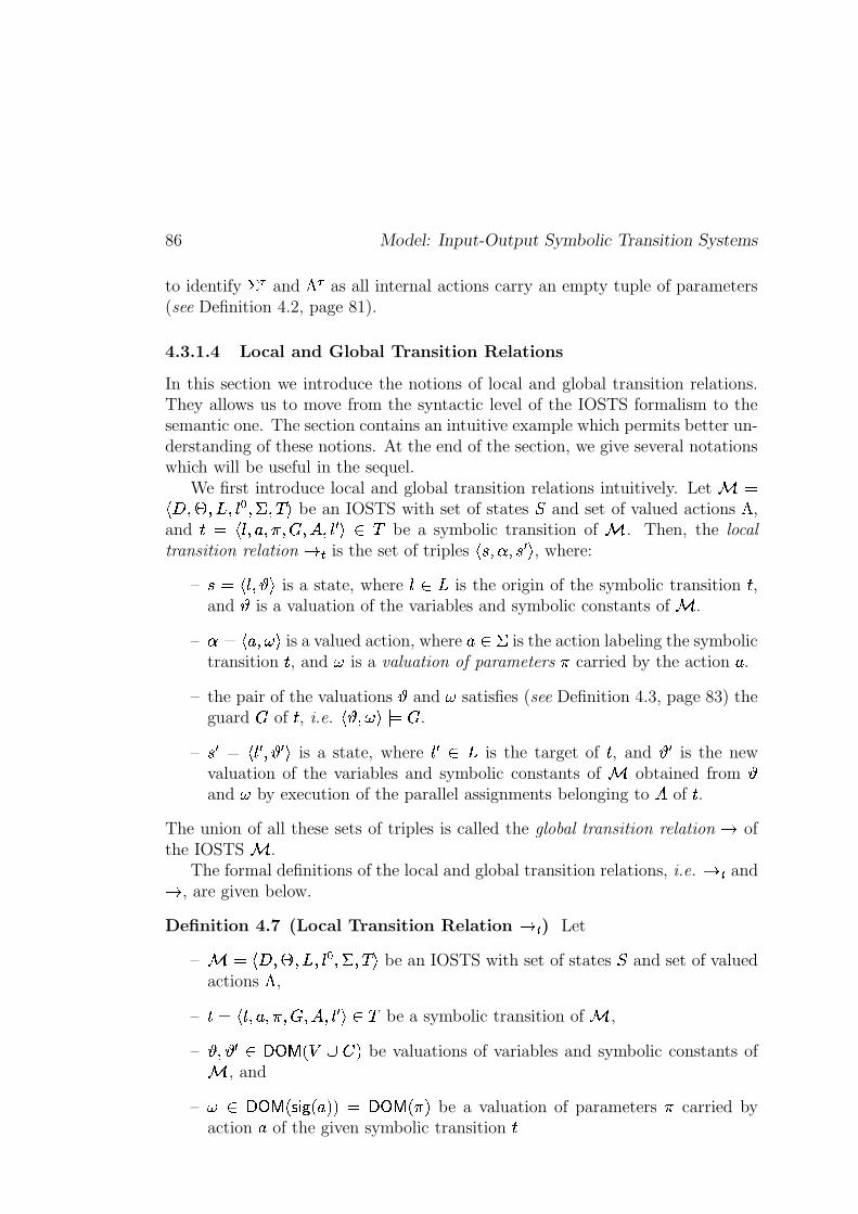
86 Model: Input-Output Symbolic Transition Systems
to identify ��� and !�� as all internal actions carry an empty tuple of parameters(see Definition 4.2, page 81).
4.3.1.4 Local and Global Transition Relations
In this section we introduce the notions of local and global transition relations.They allows us to move from the syntactic level of the IOSTS formalism to thesemantic one. The section contains an intuitive example which permits better un-derstanding of these notions. At the end of the section, we give several notationswhich will be useful in the sequel.
We first introduce local and global transition relations intuitively. Let � ��?6 P j PA3 P 02� P � P � � be an IOSTS with set of states � and set of valued actions ! ,and �� � 0 P + P�� P��rP � P 0 1 � � � be a symbolic transition of � . Then, the local
transition relation � � is the set of triples � � P � P �L1 � , where:
– � � �%0 P � is a state, where 0 � 3 is the origin of the symbolic transition � ,and is a valuation of the variables and symbolic constants of � .
– � � � + P�� � is a valued action, where + � � is the action labeling the symbolictransition � , and � is a valuation of parameters � carried by the action + .
– the pair of the valuations and � satisfies (see Definition 4.3, page 83) theguard � of � , i.e. � P�� � � ��� .
– �L1 � �%021 P c1y� is a state, where 021 ��3 is the target of � , and �1 is the newvaluation of the variables and symbolic constants of � obtained from and � by execution of the parallel assignments belonging to � of � .
The union of all these sets of triples is called the global transition relation � ofthe IOSTS � .
The formal definitions of the local and global transition relations, i.e. � � and� , are given below.
Definition 4.7 (Local Transition Relation � � ) Let
– � � �?6 P j PA3 P 0 � P � P � � be an IOSTS with set of states � and set of valuedactions ! ,
– � � � 0 P + P�� P�� P � P 0 1 � � � be a symbolic transition of � ,
– P 1 � �� �� � /�q� ! be valuations of variables and symbolic constants of� , and
– � � �� �� � � � �2+ !a!�� �� �� � �"! be a valuation of parameters � carried byaction + of the given symbolic transition �
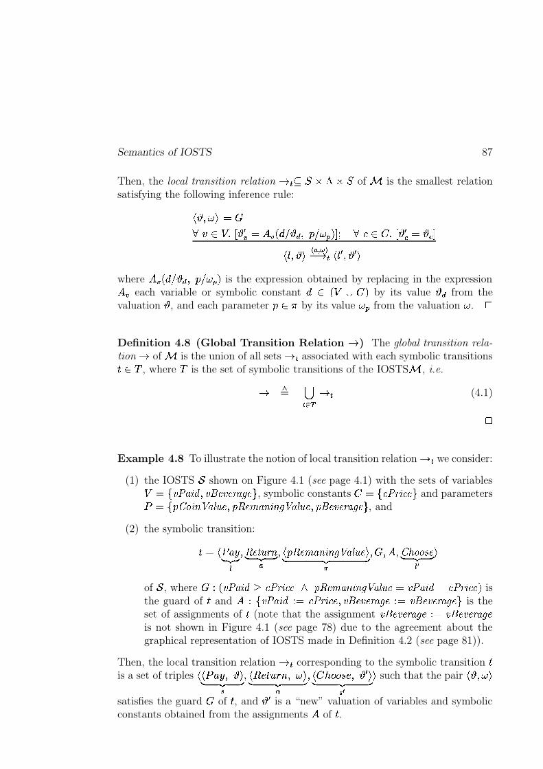
Semantics of IOSTS 87
Then, the local transition relation � � � ��� !�� � of � is the smallest relationsatisfying the following inference rule:
� P � � � � �� � �� � � 1� � ���T����� � P ��� ���T! � £ ��� ��� � � 1� � � �� 0 P ��
�� �� � ���"� 0 1 P 1 �where ���T����� � P ��� ���C! is the expression obtained by replacing in the expression��� each variable or symbolic constant � � �-� ! by its value � from thevaluation , and each parameter � �,� by its value ��� from the valuation � .
4
Definition 4.8 (Global Transition Relation � ) The global transition rela-
tion � of � is the union of all sets � � associated with each symbolic transitions��� � , where � is the set of symbolic transitions of the IOSTS � , i.e.
� � �� ��� ��� (4.1)
4
Example 4.8 To illustrate the notion of local transition relation � � we consider:
(1) the IOSTS 5 shown on Figure 4.1 (see page 4.1) with the sets of variables¡��7KJL:dMN>?O PLJLR�@SJT@S<UMWV�@gB , symbolic constants �8��7*9;:=<S>?9A@CB and parametersi � 7LY"Z=[N>]\ ^QMT_.`Q@CPaYcbd@SeMN\Q>]\�Vf^QMT_.`c@CPaYcR�@SJT@S<UMWV�@gB , and
(2) the symbolic transition:
� � � :dMNzD E�F G�PWbd@w�%`�<;\D E�F G�
P � Ycb�@SeMN\Q>]\�Vf^QMT_.`Q@ �D E�F G�P��rP � PKZ|{*[}[g~L@D E�F G��¥ �
of 5 , where � � � JL:dMN>?O�� 9;:=<;>?9A@no Ycbd@SeMN\Q>]\�Vf^QMT_.`Q@p�¡JL:dMN>?O��/9;:=<S>?9A@N! isthe guard of � and � � 7KJL:dMN>?O �.� 9;:=<;>?9A@)PWJLR�@SJT@S<UMWV�@���� JLR�@SJT@S<UMWV�@NB is theset of assignments of � (note that the assignment JLR�@SJT@S<UMWV�@r�.� JLR�@SJT@S<UMWV�@is not shown in Figure 4.1 (see page 78) due to the agreement about thegraphical representation of IOSTS made in Definition 4.2 (see page 81)).
Then, the local transition relation � � corresponding to the symbolic transition �is a set of triples �U�%i�+ � P �D E�F G�
P ��� � � � � P � �D E�F G�P � ��� � � � � P 1 �D E�F G� ¥
� such that the pair � P � �satisfies the guard � of � , and �1 is a “new” valuation of variables and symbolicconstants obtained from the assignments � of � .
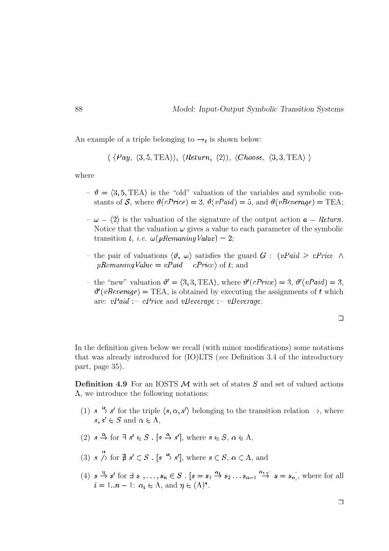
88 Model: Input-Output Symbolic Transition Systems
An example of a triple belonging to � � is shown below:
���%i�+ � P � �xP���P TEA �U� P � � � � � � P � � �U� P � � � � � � � P � �xP �xP TEA �p�where
– � � �xP���P TEA � is the “old” valuation of the variables and symbolic con-stants of 5 , where � 9;:=<S>?9A@N! �� , "� JL:dMN>?Oc!"��� , and "� JLR�@SJT@S<AMWV�@g! � TEA;
– � � � � � is the valuation of the signature of the output action + � b�@w�2`�<S\ .Notice that the valuation � gives a value to each parameter of the symbolictransition � , i.e. � � Ycbd@SeMN\Q>]\�Vf^QMT_.`c@}! � �
;
– the pair of valuations � P � � satisfies the guard � � � JL:dMN>?O � 9;:=<;>?9A@8oYcbd@SeMN\Q>]\�Vf^QMT_.`c@��¡JL:dMN>?O��/9;:=<;>?9A@N! of � ; and
– the “new” valuation 1 � � �xP ��P TEA � , where 12� 9;:=<S>?9A@N! � � , c1%� JL:dMN>?O*! � � ,c1%� JLR�@SJT@S<UMWV�@N!"� TEA, is obtained by executing the assignments of � whichare: JL:dMN>?O��� 9;:�<;>?9A@ and JLR�@SJT@S<UMWV�@§���8JLR�@SJT@S<UMWV�@ .
4
In the definition given below we recall (with minor modifications) some notationsthat was already introduced for (IO)LTS (see Definition 3.4 of the introductorypart, page 35).
Definition 4.9 For an IOSTS � with set of states � and set of valued actions! , we introduce the following notations:
(1) ��� �W1 for the triple � � P � P �L1�� belonging to the transition relation � , where
� P �W1 � � and � � ! ,
(2) ��� for � �W1 � � � � � �� �W1 � , where � � � , � � ! ,
(3) ���� for � �W1 � � � � � �� �W1 � , where � � � , � � ! , and
(4) ���� �W1 for � � � P������WP ��� � � � � � � � � �� ��� ����� ���� �������� � � ����� , where for all
� ��� � � � ��� : � �|� ! , and � � ��! !�� .4
Semantics of IOSTS 89
4.3.1.5 Formal Definition of the IOSTS Semantics
In this section we give a definition of the semantics of an arbitrary IOSTS whichcan be expressed in terms of IOLTS as follows:
Definition 4.10 (Semantics of IOSTS) For an IOSTS � ��?6 P j PA3 P 0 � P � P � � , the semantics of � is defined by an IOLTS ��� ����� �� � P � � P ! P �n� , where
– � is the set of states of � ,
– � � � � is the set of initial states of � ,
– ! � !�� � !p� � !=� is the set of valued actions of � , and
– � is the global transition relation of � .
4
4.3.2 Behaviors, Sequences and Traces
In this section we introduce the notions of behaviors, sequences and traces for anarbitrary IOSTS � with a set of states � , a set of initial states � � � � , and setof valued actions ! � ! � � ! � � ! � . These notions allow us to reason formallyabout the IOSTS � .
Definition 4.11 (Behavior) A behavior ��� of � is a sequence of statesand valued actions starting from an initial state �N� and following the transitionrelation, i.e.
� � � � � � � � � ���� ��� ����� ���� � � �� ��� (4.2)
where
– � is the global transition relation of � (see Definition 4.8, page 87),
– � ��� is the length of ��� ,
– � � � � � , and
– for all � � � � � � : � �f� � , � �f� ! .
4
90 Model: Input-Output Symbolic Transition Systems
Next, we define the notion of sequence. Informally, a sequence � of valued ac-tions � � ����� � � of � is a sequence obtained from a behavior ��� � � � �� � � � ����� ����� ��� � � �� ��� of � by dropping the states � � P������SP ��� . Formally:
Definition 4.12 (Set of Sequences) The set of sequences of � is the set:
� @��S`Q@S\�9A@;~ � � ! � 7 � � ��! ! � � � � � � � � P � � � � � � � �� � � B (4.3)
4
Example 4.9 For the IOSTS 5 depicted in Figure 4.1 (see page 78) the followingsequence:
� � � � +K� P � �U� P� Z=[N>]\fP � Y"Z=[N>]\ ^QMT_.`Q@p� � ��� P� bd@w�%`�<;\"P � Ycb�@SeMN\Q>]\�Vf^QMT_.`Q@p� � �U� P� Z|{*[}[g~L@;R�@SJT@S<UMWV�@NP � YcR�@SJT@S<AMWV�@�� COFFEE �U� P� ��@W_.>]JT@S<KP � YcR�@SJT@S<AMWV�@�� COFFEE �U�
is a sequence of valued actions belonging to� @��S`c@S\�9A@;~ �25 ! . 4
Next, we introduce a trace relation and based on this newly defined relation givea formal definition of a trace of the IOSTS � .
Definition 4.13 (Trace Relation � ) The trace relation � � � � � !�� � !�� ! � �� of � is obtained from the global transition relation � defined above (seeDefinition 4.8, page 87) by dropping internal actions:
- ���� �W1 � � � � �W1 !�� � � � � P������WP ��� � � � � � � � � � � ��� ����� ��� � � �� ��� � �W1 � ! ,where for all � ������� � : � �f� !=� , and is the empty sequence.
- ��� �W1 � � � � P ��� � � � � ��� � � �� ������ �L1 � , where � � � !�� � !�� ! .
- ���� �W1 � � � � P������WP ��� � � � � � � � � �� ��� ����� ��� ���� � � ��� � �W1 � , where for
all � � ��� � � ��� : � �|� ��!�� � !p� ! , and � ��! � � !�� ! � .4
Definition 4.14 (Set of Traces) The set of traces of � is defined as follows:� <UM'9A@;~ � � ! � 7 � ��! � � ! � ! � � � � � � � � P � � � � � � � �� � � B (4.4)
4
Subclasses of IOSTS 91
Example 4.10 The following sequence of valued input/output actions:
� � Z=[N>]\|P � Y"Z=[N>]\ ^QMT_.`c@�� � �U� P� b�@w�2`�<S\|P � Ycbd@SeMN\Q>]\�Vf^QMT_.`Q@p� � �U� P� Z|{*[}[g~L@;R�@SJT@S<UMWV�@NP � YcR�@SJT@S<UMWV�@p� COFFEE �U� P� ��@W_.>]JT@S<KP � YcR�@SJT@S<UMWV�@p� COFFEE �U�
represents one of the possible traces of the coffee machine depicted in Figure 4.1(see page 78). 4
Finally, we introduce the notion of reachable state, and define a set of states inwhich the IOSTS � can be after executing a given trace of � .
Definition 4.15 (Reachable State) A state � � � is reachable in� if there exists a sequence � � � @��S`Q@S\�9A@;~ ��� ! that ends in � , i.e.
� � � � @��S`Q@S\�9A@;~ � � !AP �L� � � � � � �L� �� � � . 4
Example 4.11 To illustrate the definition given above we considerthe IOSTS 5 shown in Figure 4.1 (see page 78). Then, the state� � � R�@?VT>]\fP � JL:dMN>?O � �TPLJLR�@SJT@S<UMWV�@ � COFFEE �U� of 5 is reachable, asthere exists the sequence � (see Example 4.9) which ends in this state � . Notethat the state � is also reachable by the trace � shown in Example 4.10.
4
Definition 4.16 ( � �� #�(�� ) The set of states in which an IOSTS � can be
after the trace � � <UM'9A@;~ ��� ! is defined as:
��� �� #�(�� ! � 7 � � � � � � � � � � � � � �� � B (4.5)
4
4.4 Subclasses of IOSTS
In the current section we define some subclasses of IOSTS which are used in thesymbolic test generation method presented later in the thesis.
92 Model: Input-Output Symbolic Transition Systems
4.4.1 Instantiated, Initialized and Deterministic IOSTS
In this subsection we introduce the subclasses of instantiated, initialized anddeterministic IOSTS, and illustrates them with simple examples. The main resultof the subsection, which will be exploit lated in the thesis, is: if an IOSTS isinitialized and deterministic, then each instance of this IOSTS moves to exactly
one state after each trace.
Definition 4.17 (Instantiated IOSTS) An IOSTS � is instantiated if itsset of symbolic constants � is empty.
4
Definition 4.18 (Instance of IOSTS) Let � be an IOSTS with the setof symbolic constants � and � � �� �� � � ! be a valuation of these symbolicconstants. Then, the instance � ��� ! of � and � is the IOSTS obtained byreplacing each symbolic constant
� � � by its value �'� � ! . Moreover, the set ofsymbolic constants of � ��� ! is empty, i.e. ��� ��� � ��� . 4
Observation 4.1 All instances of an IOSTS � are instantiated.4
Example 4.12 Consider the IOSTS 5 depicted in Figure 4.1 (see page 78),which has one symbolic constant 9;:=<;>?9A@ of type nat, i.e. � � 7*9;:=<;>?9A@CB . Let usalso consider one of the possible valuations of � , for example, � � � � � , where�)� 9;:=<;>?9A@T!�� � . Then, by replacing in 5 each instance of the symbolic constant9;:=<;>?9A@ by its value 3, we obtain the instance 5���� ! of the IOSTS 5 .
4
Definition 4.19 (Initialized IOSTS) An IOSTS � with the initial conditionj and the set of variables is initialized if for every instance � ��� ! , thereexists at most one valuation of its variables which satisfies j (see Definition 4.3,page 83).
4
Example 4.13 Let us consider an IOSTS with the following initial conditionj � � 9;:�<;>?9A@rk m�! o � JL:dMN>?O� 9;:=<S>?9A@N! , where 9;:=<;>?9A@ with #%$'&)('� 9;:=<S>?9A@N!�� �2�*�T�Q� isa symbolic constant of and JL:�MN> O with # $'&T('� JL:dMN>?OQ! � �]�Q�T�*� is a variable of .This IOSTS is initialized, as
– for all instances ��� ! , where � � �� �� � �Q�T� !� 7Nm�B , there exists exactlyexactly one valuation of variable JL:dMN>?O which satisfies j . For example, for �'� � �DUE�F�G�
! , the only one valuation satisfying � �rk m�!�o � JL:dMN>?Or� �K! is � � � � ,where "� JL:dMN>?OQ! �� .

Subclasses of IOSTS 93
– for the instance �'� m �D�E�F�G�! , there are no valuations of the variable JL:dMN>?O which
satisfies � mrk m�!�o � JL:�MN>?O � m�! .Next, if the initial condition of is the following j � � 9;:�<;>?9A@ k¡mK!|o � JL:dMN>?O �9;:�<;>?9A@N! , then is not initialized, as, for example, for �'� � �D�E�F�G�
! , there exist at least
valuations of variable JL:dMN>?O satisfying � �rk m�!�o � JL:�MN>?O � ��! , e.g. � JL:dMN>?OQ! ��� , � JL:�MN>?Oc!"��� � . 4
Next, we introduce the subclass of deterministic IOSTS. The definition of adeterministic IOSTS is inspired from that of a deterministic IOLTS (see the item(8) of Definition 3.4, page 35). Intuitively, an IOSTS is deterministic if it doesnot contain internal actions, and from each state at most one transition can befired. Formally:
Definition 4.20 (Deterministic IOSTS) An IOSTS � with a set of states� and a set of valued actions ! � !d� � !p� � !=� is deterministic if:
(1) ! � � � , and
(2) for all states � � � and valued actions � � ! � � ! � , 9AMN<UO � 7 � 1 � � � � ���W1 B)! � � , where 9AMN<UO ��� ! denotes the cardinality of a set � .
4
We illustrate the definition of a deterministic IOSTS with an example.
Example 4.14 In Figure 4.2 (see page 94) we depict a simple coffee machine.This machine accepts a strictly positive amount of money from the user, anddelivers either (1) only coffee if the user has paid less or equal to three units, or(2) coffee with milk in the case when the paid amount was three or more thanthree units. Note that if the user paid exactly three units, the outcome fromthe coffee machine is non-deterministic. Thus, due to the violation of the seconditem of Definition 4.20, the coffee machine shown on Figure 4.2 (see page 94) isnon-deterministic.
4
It is not hard to see that deterministic IOSTS are somewhat different from deter-ministic IOLTS as they can have several initial states (the definition above doesnot contain any restriction on the number of initial states of IOSTS). However,the testing theory prohibits to use a tester that can choose its initial state as the
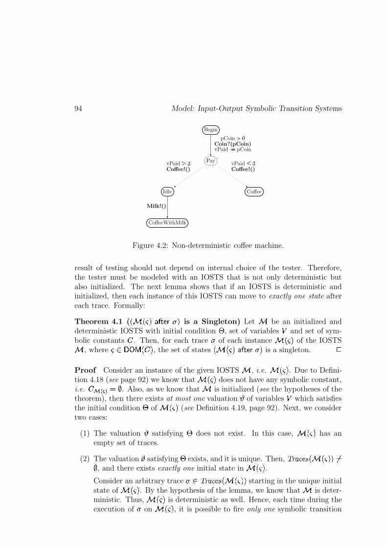
94 Model: Input-Output Symbolic Transition Systems
Pay
Begin
Idle
CoffeeWithMilk
Coffee
pCoin ���Coin?(pCoin)vPaid � � pCoin
vPaid ���Coffee!()
vPaid � �Coffee!()
Milk!()
Figure 4.2: Non-deterministic coffee machine.
result of testing should not depend on internal choice of the tester. Therefore,the tester must be modeled with an IOSTS that is not only deterministic butalso initialized. The next lemma shows that if an IOSTS is deterministic andinitialized, then each instance of this IOSTS can move to exactly one state aftereach trace. Formally:
Theorem 4.1 (� �����������������
is a Singleton) Let
be an initialized anddeterministic IOSTS with initial condition � , set of variables � and set of sym-bolic constants � . Then, for each trace
�of each instance
���of the IOSTS
, where�! #"%$!&' � � , the set of states
��(���(�������)�*�is a singleton. +
Proof Consider an instance of the given IOSTS
, i.e. ����
. Due to Defini-tion 4.18 (see page 92) we know that
��(�does not have any symbolic constant,
i.e. �-,/.10325476 . Also, as we know that
is initialized (see the hypotheses of thetheorem), then there exists at most one valuation 8 of variables � which satisfiesthe initial condition � of
���(see Definition 4.19, page 92). Next, we consider
two cases:
(1) The valuation 8 satisfying � does not exist. In this case, ���
has anempty set of traces.
(2) The valuation 8 satisfying � exists, and it is unique. Then, 9;:=<?>A@CB � ���D�FE46 , and there exists exactly one initial state in
��(�.
Consider an arbitrary trace�/ 9G:=<?>A@CB ��(�H�
starting in the unique initialstate of
���. By the hypothesis of the lemma, we know that
is deter-
ministic. Thus, ���
is deterministic as well. Hence, each time during theexecution of
�on
��(�, it is possible to fire only one symbolic transition
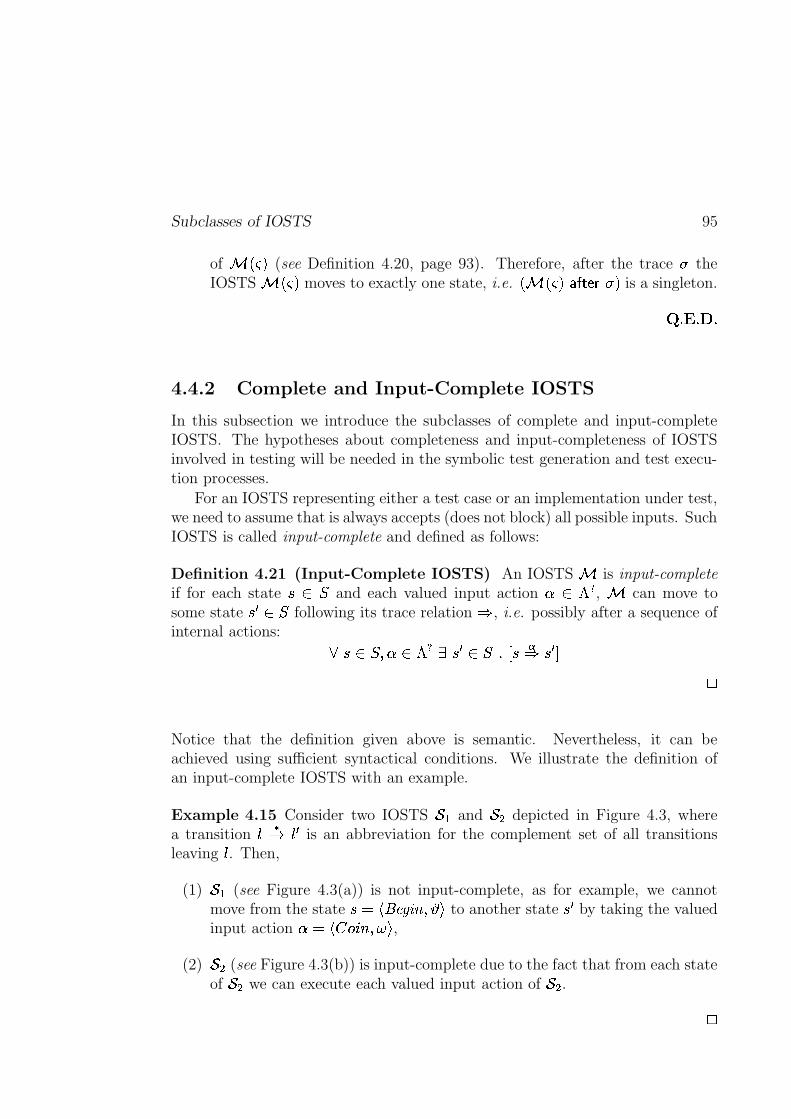
Subclasses of IOSTS 95
of � ��� ! (see Definition 4.20, page 93). Therefore, after the trace theIOSTS � ��� ! moves to exactly one state, i.e. � � ��� ! � � #�(�� ! is a singleton.
� ��� ��� �
4.4.2 Complete and Input-Complete IOSTS
In this subsection we introduce the subclasses of complete and input-completeIOSTS. The hypotheses about completeness and input-completeness of IOSTSinvolved in testing will be needed in the symbolic test generation and test execu-tion processes.
For an IOSTS representing either a test case or an implementation under test,we need to assume that is always accepts (does not block) all possible inputs. SuchIOSTS is called input-complete and defined as follows:
Definition 4.21 (Input-Complete IOSTS) An IOSTS � is input-complete
if for each state � � � and each valued input action � � !d� , � can move tosome state �L1 � � following its trace relation � , i.e. possibly after a sequence ofinternal actions: � � � � P � � ! � � � 1 � � � � � �� � 1 �
4
Notice that the definition given above is semantic. Nevertheless, it can beachieved using sufficient syntactical conditions. We illustrate the definition ofan input-complete IOSTS with an example.
Example 4.15 Consider two IOSTS 5 � and 5 � depicted in Figure 4.3, wherea transition 0 �� 0]1 is an abbreviation for the complement set of all transitionsleaving 0 . Then,
(1) 5 � (see Figure 4.3(a)) is not input-complete, as for example, we cannotmove from the state � � � R�@?VT>]\uP �� to another state �}1 by taking the valuedinput action � � � ��� ��� P�� � ,
(2) 5 � (see Figure 4.3(b)) is input-complete due to the fact that from each stateof 5 � we can execute each valued input action of 5 � .
4
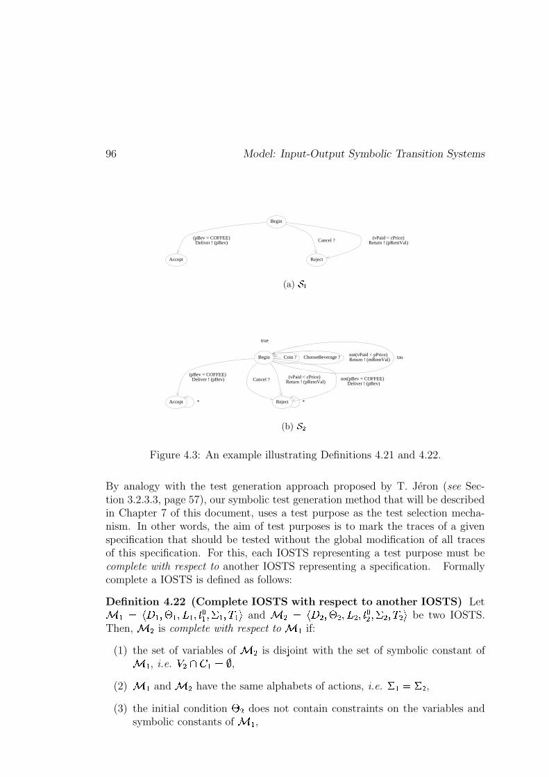
96 Model: Input-Output Symbolic Transition Systems
(pBev = COFFEE)Deliver ! (pBev) Cancel ? (vPaid < cPrice)
Return ! (pRemVal)
Start
Begin
Accept Reject
(a) ���
true
*
(pBev = COFFEE) Deliver ! (pBev)
Cancel ? (vPaid < cPrice)
Return ! (pRemVal)
Coin ? ChooseBeverage ? not(vPaid < pPrice) Return ! (mRemVal)
*
not(pBev = COFFEE) Deliver ! (pBev)
tau
PreInit_Start
Begin
Accept Reject
(b) ���
Figure 4.3: An example illustrating Definitions 4.21 and 4.22.
By analogy with the test generation approach proposed by T. Jéron (see Sec-tion 3.2.3.3, page 57), our symbolic test generation method that will be describedin Chapter 7 of this document, uses a test purpose as the test selection mecha-nism. In other words, the aim of test purposes is to mark the traces of a givenspecification that should be tested without the global modification of all tracesof this specification. For this, each IOSTS representing a test purpose must becomplete with respect to another IOSTS representing a specification. Formallycomplete a IOSTS is defined as follows:
Definition 4.22 (Complete IOSTS with respect to another IOSTS) Let� � � �?6 � P j � PA3 � P 0 � � P � � P � ��� and � � � �?6 � P j � PA3 � P 0 �� P � � P � �A� be two IOSTS.Then, � � is complete with respect to � � if:
(1) the set of variables of � � is disjoint with the set of symbolic constant of� � , i.e. ��� � � � � ,
(2) � � and � � have the same alphabets of actions, i.e. � � � � � ,(3) the initial condition j � does not contain constraints on the variables and
symbolic constants of � � ,
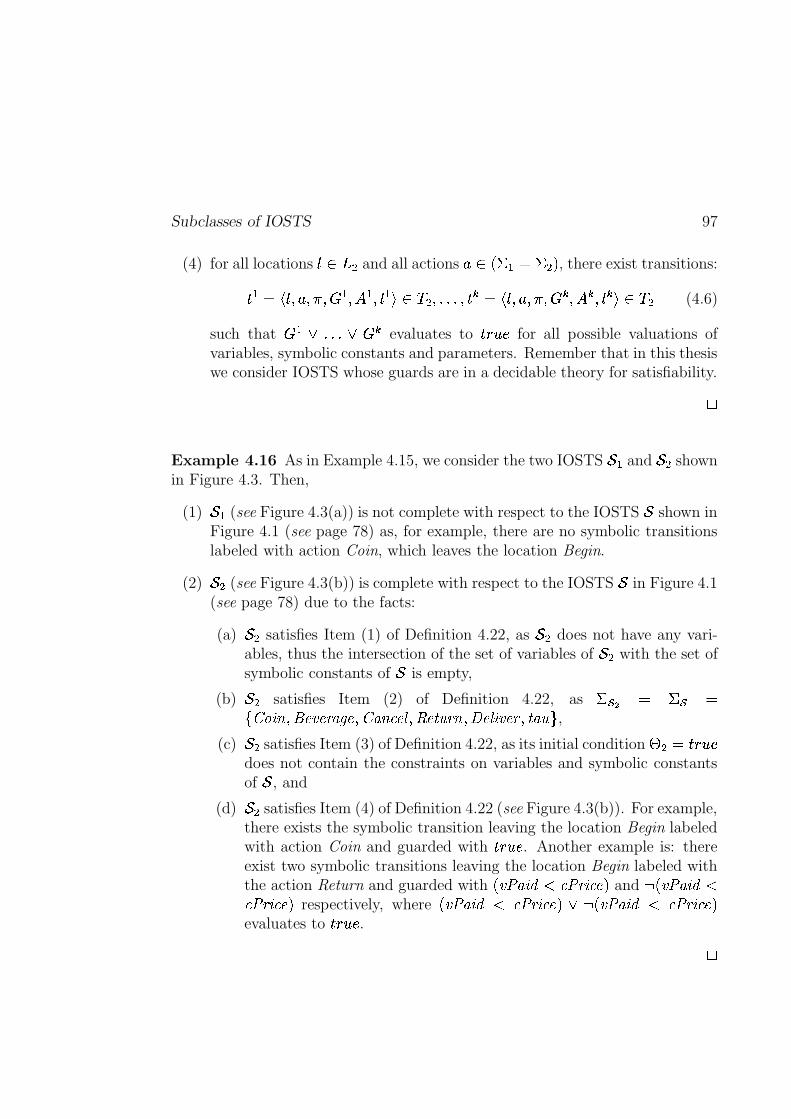
Subclasses of IOSTS 97
(4) for all locations 0 ��3 � and all actions + � �?� � � � � ! , there exist transitions:
� � � �%0 P + Pa� P�� � P � � P 0 � � � � � P������WPa� � � � 0 P + P�� P�� � P � � P 0 � � � � � (4.6)
such that �� � ����� � � �
evaluates to �! ��� for all possible valuations ofvariables, symbolic constants and parameters. Remember that in this thesiswe consider IOSTS whose guards are in a decidable theory for satisfiability.
4
Example 4.16 As in Example 4.15, we consider the two IOSTS 5 � and 5 � shownin Figure 4.3. Then,
(1) 5 � (see Figure 4.3(a)) is not complete with respect to the IOSTS 5 shown inFigure 4.1 (see page 78) as, for example, there are no symbolic transitionslabeled with action Coin, which leaves the location Begin.
(2) 5 � (see Figure 4.3(b)) is complete with respect to the IOSTS 5 in Figure 4.1(see page 78) due to the facts:
(a) 5 � satisfies Item (1) of Definition 4.22, as 5 � does not have any vari-ables, thus the intersection of the set of variables of 5 � with the set ofsymbolic constants of 5 is empty,
(b) 5 � satisfies Item (2) of Definition 4.22, as ��� � � ��� �7�Z=[N>]\uPWR�@SJT@S<UMWV�@CPKZ=MN\�9A@W_ PWbd@w�2`�<;\"Pw��@W_.>]JT@S<'P}� MN` B ,
(c) 5 � satisfies Item (3) of Definition 4.22, as its initial condition j � � �! � �does not contain the constraints on variables and symbolic constantsof 5 , and
(d) 5 � satisfies Item (4) of Definition 4.22 (see Figure 4.3(b)). For example,there exists the symbolic transition leaving the location Begin labeledwith action Coin and guarded with �! � � . Another example is: thereexist two symbolic transitions leaving the location Begin labeled withthe action Return and guarded with � JL:dMN>?O�� 9;:�<;>?9A@N! and ��� JL:dMN>?O��9;:=<S>?9A@N! respectively, where � JL:dMN>?O�� 9;:=<;>?9A@C! �
��� JL:dMN>?O�� 9;:=<S>?9A@N!evaluates to �! ��� .
4

98 Model: Input-Output Symbolic Transition Systems
Chapter 5
Operations with IOSTS
In this chapter we introduce several operations on IOSTS which are
used in the test generation technique and in the process of the test exe-
cution. They are called product and parallel composition. The product
operation is the main operation in the test generation as it allows to
“intersect” the behaviors of a specification and its test purpose, and
therefore, to select the part of the specification for which a test case
has to be generated. The operation of parallel composition is used in
the test execution on a system under test as this operation allows to
model an interaction between two processes represented by IOSTS. Fi-
nally, we present several relationships concerning the sets of traces of
IOSTS obtained after the product or parallel composition operations.
5.1 Parallel Composition
In this section we introduce the operation of parallel composition between twoIOSTS with synchronization on their common input and output actions. Thisoperation is inspired from the parallel composition between two processes modeledby either LTS or IOLTS (see Definition 3.5, page 38). As usual, the operation ofparallel composition is used to model the execution of a test case on a black-boximplementation (see Chapter 6, page 137).
Before giving the formal definition of the parallel composition, we describethe conditions under whose the parallel execution of two IOSTS is possible. In-tuitively, two IOSTS � � and � � are compatible for the operation of parallelcomposition if and only if:
– � � and � � do not share variables, symbolic constants and parameters.
– The alphabet of input (resp. output) actions of � � is equal to the alphabetof output (resp. input) actions of � � , and the alphabets of internal action
99
100 Operations on IOSTS
of � � and � � are disjoint. Moreover, the common actions must have thesame signature in both IOSTS.
Definition 5.1 (Compatible For Parallel Composition) Two IOSTS � � ��?6 � P j � PA3 � P 0 � � P � � P ���a� and � � � �?6 � P j � PA3 � P 0 �� P � � P � �A� with actions alphabets� � � � � � � � �� � � � � and � � � � �� � � �� � � � � are compatible for parallel composition
if and only if
(1) � � and � � have disjoint sets of data, i.e. 6 � �,6 � � � ; and
(2) (a) the alphabet of input (resp. output) actions of � � is the same as thealphabet of output (resp. input) actions of � � , i.e. ��� � � �p�� and�p�� � ���� ,
(b) the alphabets of internal actions of � � and � � are disjoint, i.e. � � � ���� � ��� , and
(c) each common action + , which is either input for � � and output for� � , or output for � � and input for � � , has the same signaturein both IOSTS � � and � � , i.e.
� � � �2+ !l� � � � �2+ ! . More precisely,the length of the tuples of types � � � �2+ !l� �� �� P������WP � � � and � � � �%+ !���� �� P������WP �� � is the same, and each type �� of � � � �2+ ! corresponds to thetype �� of � � � �2+ ! , i.e.
� � � ����� � � � �� �
�� � .
4
Next, we formulate the operation of parallel composition and explain it on asimple example.
Definition 5.2 (Parallel Composition ��� ) The parallel composition betweentwo IOSTS � � � �?6 � P j � P�3 � P 0 � � P � � P ���a� and � � � �?6 � P j � PU3 � P 0 �� P � � P � �S�which are compatible for parallel composition is an IOSTS � � � � � � ��?6 P j PA3dP 0 � P � P � � , where
– 6 �/ � �n� i , where 8� � �� � , ��� � � �,� � and i � i � .The set of parameters i of � � � ��� � is equal to the set of parametersi � of � � as during the synchronization of the symbolic transitions eachparameter of � � is replaced with the corresponding parameter of � � (seeRule (5.3));
– j � j � o j � ;– 3t� 3 � � 3 � ;
Parallel Composition 101
– 0 � � �%0 � � P 0 �� � ��3 is the initial location;
– � � ��� � �p� � ��� is the alphabet of actions, where �d� � � , �p� � �p�� � �p�� ,and ��� � ��� � � ��� � .The alphabet of input actions �d� is empty due to the following convention:the result of synchronization between two symbolic transitions labeled re-spectively with input and output actions is always a symbolic transitionlabeled with an output action (see below);
– the set of symbolic transitions � is constructed from � � and � � as follows:
- for each symbolic transition � � � � � with origin 0�� ��3 � and destination0]1 � ��3 � , which is labeled with an internal action + � � � � ; and a location0 � ��3 � , there exists a symbolic transition ��� � with origin � 0�� P 0 �;� anddestination � 021 � P 0 �;� , which is labeled with the same action + and definedby the following inference rule:
� 0�� P + Pa� P�� � P ��� P 0]1 � � � ���0 � ��3 �+ � ��� �
�U� 0�� P 0 �;� P + P�� P�� � P ��� � ��� � � X � � ��.�/�*!�!AP � 0 1 � P 0 �;�U� � � (5.1)
where in order to obtain a symbolic transition with well-formed setof assignments (i.e. each variable of � ��� � � � must be assigned),we assign each variable of � � with itself (i.e. � � � X � � �s��� �Q! ). Thissolution is reasonable as variables of � � should not change their valueswhile � � performs its internal action.
Similarly, a symbolic transition ��� � is obtained from a symbolictransition � � � � � labeled with + � � � � and a location 0�� � 3 � , byapplying the following rule:
� 0 � P + Pa� P�� � P � � P 0]1� � � � �0�� ��3 �+ � � � �
�U� 0�� P 0 �;� P + P�� P�� � P � � ��� X � �����/�*!a!�� � � P � 0�� P 0 1� �U� � � (5.2)
- for two symbolic transitions � � � � � and � � � � � , which are labeledwith a common action + that belongs to the set �?� � � � � �� ! � �?� �� � � �� ! ,a new symbolic transition ��� � is constructed using the inference rule:
�%0�� P + P�� � P�� � P � � P 0 1 � � � ����%0 � P + P�� � P�� � P � � P 0]1� � � � �+ � �?��� � � �p�� !"� �?�p�� � ���� !A£
�U�%0�� P 0 �A� P + P�� � P�� � o � ��� � � � � �!� P � � � � ��� � � � � �!� P � 0 1 � P 0 1� �U� � � (5.3)
102 Operations on IOSTS
where � ��� � � � � � � (resp. � ��� � � � � �!� ) is the guard (resp. the set of assign-ments) of the symbolic transition � � in which each parameter �
� � ��� �carried by the action + of � � is replaced by the corresponding parameter�
�� �,� � carried by the action + of � � .
4
Example 5.1 In order to explain the operation of parallel composition we con-sider two IOSTS � and � depicted in Figure 5.1 (see page 103).
The IOSTS � (see Figure 5.1(a)) either:
– receives the input action EnterNumber from its environment, increases theinteger value entered to � through this action, and returns some integervalue which is less or equal to the computed value through the output actionResult, or
– returns some negative integer value to the environment through the outputaction Result.
The IOSTS � (see Figure 5.1(b)) returns to the environment an integer valuewhich is negative or equal to zero, through the output action EnterNumber andmemorizes this value into the variable � . Then, it decreases the value of thevariable � by one while performing the internal action � � , and waits from theenvironment the input action Result carrying some integer value which is greateror equal to the value of � .
The IOSTS � and � are compatible for the operation of parallel composition(see Definition 5.1, page 100) as:
(1) � and � do not have common variables, symbolic constants and param-eters: 7 � BD E�F GX
� 7 �cBD E�F GX �� � , 7 � � BD E�F GH
� 7 � � BD E�F GH ���� and 7 � � BD E�F Gh
� 7 � � BD E�F Gh ���� .
(2) (a) The alphabet of input (resp. output) actions of � is equal to thealphabet of output (resp. input) actions of � , i.e. ��� � � �p�� �7��=\c� @S<���`�e��A@S<�B , � �� � � �� � 7'bd@;~;`*_��AB ; and the alphabets of internalactions of � and � are disjoint, i.e. � � � �l��� � �87 � � B � 7 � � B§� � . And,
(b) The signatures of actions shared by � and � are the same. Forinstance, the input action EnterNumber of � and the output actionEnterNumber of � have the same signature � � � � ��\c� @S<���`�e��A@S<'!��� � � � �=\c��@S<���`�e��A@S<'!"� ���L���x� , where �}��� denotes the integer type.
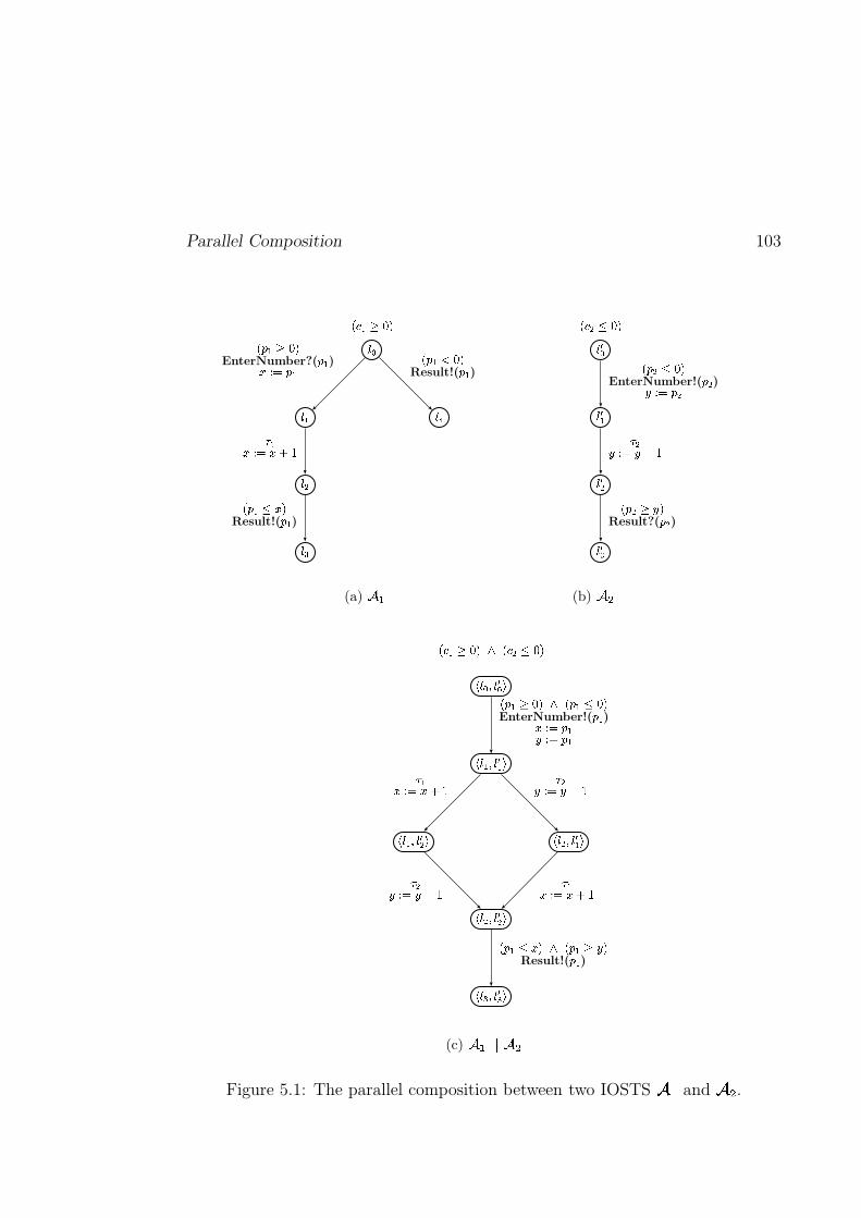
Parallel Composition 103
���
���
���
���
���
� � ��� � � � ��� �EnterNumber?(
� �)� � � � �
� �� � � �����
� � � � �Result!(
� �)
� ��� � �Result!(
� �)
(a) ���
����
��� �
����
���
!�" �$#�% &! ' �(#)% &
EnterNumber!(' � )*,+ - ' �
. �*,+ -/*10�2
! ' �$3 * &Result?(
' � )
(b) 465
7�8�9;:<8�=9?>
7�8�@A:<8�= @<>
7�8�BC:D8 = @ >7�8�@D:D8 =B >
7�8�B;:<8�=B >
7�8�E;:<8�=E?>
F�G;@�H�I J6KLF�GAB$M�I J
F NO@�H�I J6KPF NO@QM�I JEnterNumber!(
N @)RTS U NO@VWS U NO@
X BV,S U�V1Y/ZX @RTS U�R�[�Z
X @RTS U�R�[�ZX BV,S U�V1Y�Z
F N @ M R J6KPF N @ H V JResult!(
N\@)
(c) ]�^`_�_a]6b
Figure 5.1: The parallel composition between two IOSTS ced and cgf .
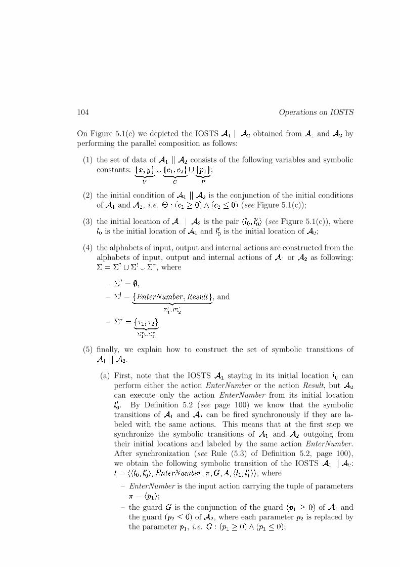
104 Operations on IOSTS
On Figure 5.1(c) we depicted the IOSTS ��� � � obtained from � and � byperforming the parallel composition as follows:
(1) the set of data of � ��� � consists of the following variables and symbolicconstants: 7 � P �cBD E�F GX
��7 � � P � � BD E�F GH��7 � � BD E�F Gh ;
(2) the initial condition of � ��� � is the conjunction of the initial conditionsof � and � , i.e. j � � � � � m�!�o � � � � m�! (see Figure 5.1(c));
(3) the initial location of ����� � is the pair � 0 � P 0 1� � (see Figure 5.1(c)), where0 � is the initial location of � and 0 1� is the initial location of � ;
(4) the alphabets of input, output and internal actions are constructed from thealphabets of input, output and internal actions of � or � as following:� � � � � � � � � � , where
– �d� � � ,– � � �87��=\c� @S<���`�e��A@S<�Pwb�@;~;`x_��ABD E�F G� � �C� ��
, and
– � � � 7 � � P � � BD E�F G� � �N� � �(5) finally, we explain how to construct the set of symbolic transitions of
� � � � .(a) First, note that the IOSTS � staying in its initial location 0 � can
perform either the action EnterNumber or the action Result, but �can execute only the action EnterNumber from its initial location0 1� . By Definition 5.2 (see page 100) we know that the symbolictransitions of � and � can be fired synchronously if they are la-beled with the same actions. This means that at the first step wesynchronize the symbolic transitions of � and � outgoing fromtheir initial locations and labeled by the same action EnterNumber.After synchronization (see Rule (5.3) of Definition 5.2, page 100),we obtain the following symbolic transition of the IOSTS � � � � :� � �U�%0 � P 0 1� �
P �=\c��@S<���`�e��A@S<�P�� P � P � P � 0�� P 0 1 � ��� , where
– EnterNumber is the input action carrying the tuple of parameters��� ��� ��� ;– the guard � is the conjunction of the guard � � � � m�! of � and
the guard � � � � mK! of � , where each parameter � � is replaced bythe parameter � � , i.e. � � � � � � m�!�o � � � � m�! ;
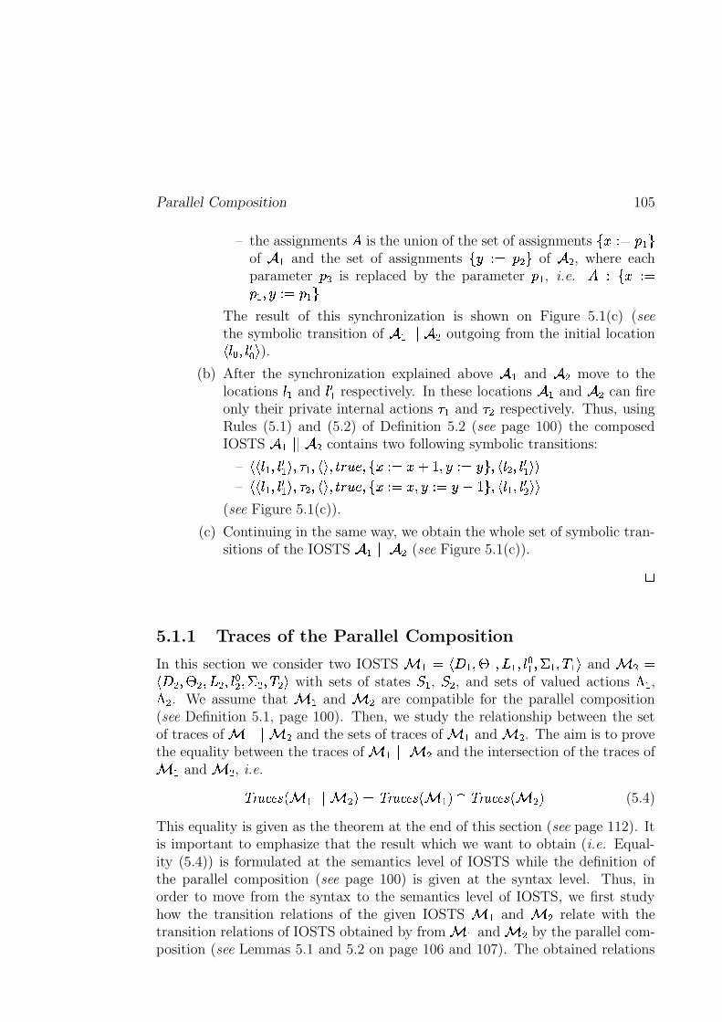
Parallel Composition 105
– the assignments � is the union of the set of assignments 7 � �.� � � Bof � and the set of assignments 7 � �.� � � B of � , where eachparameter � � is replaced by the parameter � � , i.e. � �l7 � �.�� � P ��.� � � B
The result of this synchronization is shown on Figure 5.1(c) (seethe symbolic transition of � ��� � outgoing from the initial location� 0 � P 0 1� � ).
(b) After the synchronization explained above � and � move to thelocations 0�� and 0]1 � respectively. In these locations � and � can fireonly their private internal actions � � and � � respectively. Thus, usingRules (5.1) and (5.2) of Definition 5.2 (see page 100) the composedIOSTS � � � � contains two following symbolic transitions:
– �U� 0�� P 0]1 � � P � � P � � Pa�! ��� PW7 � �.� � ¢ �TP ������cBKP � 0 � P 0]1 � �U�– �U� 0�� P 0 1 � � P � � P � � Pa�! ��� PW7 � �.� � P ��.�� ���CBKP � 0�� P 0 1� �U�
(see Figure 5.1(c)).
(c) Continuing in the same way, we obtain the whole set of symbolic tran-sitions of the IOSTS � ��� � (see Figure 5.1(c)).
4
5.1.1 Traces of the Parallel Composition
In this section we consider two IOSTS � � � �?6 � P j � PA3 � P 0 � � P � � P ���a� and � � ��?6 � P j � PA3 � P 0 �� P � � P � �;� with sets of states � � , � � , and sets of valued actions ! � ,! � . We assume that � � and � � are compatible for the parallel composition(see Definition 5.1, page 100). Then, we study the relationship between the setof traces of � � ��� � � and the sets of traces of � � and � � . The aim is to provethe equality between the traces of � � � � � � and the intersection of the traces of� � and � � , i.e.
� <UM'9A@;~ � � � ��� � � ! � � <AM'9A@;~ ��� � ! � � <UM'9A@;~ ��� � ! (5.4)
This equality is given as the theorem at the end of this section (see page 112). Itis important to emphasize that the result which we want to obtain (i.e. Equal-ity (5.4)) is formulated at the semantics level of IOSTS while the definition ofthe parallel composition (see page 100) is given at the syntax level. Thus, inorder to move from the syntax to the semantics level of IOSTS, we first studyhow the transition relations of the given IOSTS � � and � � relate with thetransition relations of IOSTS obtained by from � � and � � by the parallel com-position (see Lemmas 5.1 and 5.2 on page 106 and 107). The obtained relations
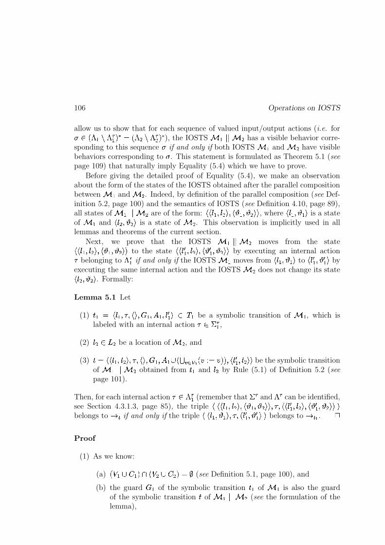
106 Operations on IOSTS
allow us to show that for each sequence of valued input/output actions (i.e. for � ��! � !=� � ! � � � ! � !=� � ! � ), the IOSTS � ��� � � � has a visible behavior corre-sponding to this sequence if and only if both IOSTS � � and � � have visiblebehaviors corresponding to . This statement is formulated as Theorem 5.1 (seepage 109) that naturally imply Equality (5.4) which we have to prove.
Before giving the detailed proof of Equality (5.4), we make an observationabout the form of the states of the IOSTS obtained after the parallel compositionbetween � � and � � . Indeed, by definition of the parallel composition (see Def-inition 5.2, page 100) and the semantics of IOSTS (see Definition 4.10, page 89),all states of � � � � � � are of the form: �U�%0�� P 0 �;� P �� � P �S�U� , where � 0�� P ��� is a stateof � � and � 0 � P �;� is a state of � � . This observation is implicitly used in alllemmas and theorems of the current section.
Next, we prove that the IOSTS � � � ��� � moves from the state�U�%0�� P 0 �S� P � � P �;�U� to the state �U� 021 � P 0 �;� P � c1 � P �S�U� by executing an internal action� belonging to !�� � if and only if the IOSTS � � moves from � 0�� P ��� to � 021 � P c1 � � byexecuting the same internal action and the IOSTS � � does not change its state� 0 � P �A� . Formally:
Lemma 5.1 Let
(1) � � � � 0�� P � P � � P�� � P � � P 0]1 � � � ��� be a symbolic transition of � � , which islabeled with an internal action � � ��� � ,
(2) 0 � ��3 � be a location of � � , and
(3) � � �U�%0�� P 0 �;� P � P �?� P�� � P � � � � � � � X � � ��.� �*!�!UP � 0]1 � P 0 �;�U� be the symbolic transitionof � � ��� � � obtained from � � and 0 � by Rule (5.1) of Definition 5.2 (seepage 101).
Then, for each internal action � � ! � � (remember that � � and !�� can be identified,see Section 4.3.1.3, page 85), the triple �|�U�%0 � P 0 �;� P � � P �S�U� P � P �U�%021 � P 0 �;� P � c1 � P �S�U�f�belongs to � � if and only if the triple �|� 0�� P ��� P � P � 0]1 � P 1 � �f� belongs to ��� . 4
Proof
(1) As we know:
(a) � � �,� � ! � � � �,� � !"��� (see Definition 5.1, page 100), and
(b) the guard � � of the symbolic transition � � of � � is also the guardof the symbolic transition � of � � � � � � (see the formulation of thelemma),
Parallel Composition 107
then we have that � � does not contain constraints on the variables andsymbolic constants of � � .Thus, the valuation � � � P �S� � �� �� � � � ! of � � ��� � � satisfiesthe guard � � of the symbolic transition � if and only if the valuation �� ��� �� � � �,� � ! of � � satisfies the guard � � of the symbolic transition � � .Note that we did not mention anything about the valuation of parametersdue to the fact that the symbolic transitions � � and � are labeled with theinternal action � which, by Definition 4.2 (see page 4.2), does not carry anyparameters.
(2) From Rule (5.1 )of Definition 5.2 (see page 101) we have that:
the “new” valuation 1 � �� �� � � � ! of � � ��� � � is obtained fromthe “old” one � �� �� � ���� ! by executing in parallel the assignmentsbelonging to ��� � � � � � X � � � �.� �*!�! of the symbolic transition � if and only if
– the “new” valuation 1 � � �� �� � � ��� � ! of � � is obtained from the“old” one � ���� �� � � � � � ! by executing in parallel the assignmentsbelonging to ��� of the symbolic transition � � , and
– the valuation � ���� �� � � �,� � ! of � � does not change.
The lemma follows directly from the items (1) and (2) above.� ��� ��� �
Remark 5.1 By switching � � and � � in Lemma 5.1 we obtain a symmetricalresult.
4
By analogy with the previous lemma, we prove that the IOSTS � � ��� � � movesfrom the state �U�%0�� P 0 �S� P � � P �;�U� to the state �U�%021 � P 021� � P �� 1 � P c1 � �U� by executing a valuedinput/output action � if and only if the IOSTS � � and � � move from � 0�� P ���(resp. � 0 � P �S� ) to � 0 1 � P 1 � � (resp. � 0 1� P 1 � � ) by executing the same valued action � .
Lemma 5.2 Let
(1) + � �?��� � � �p�� !�� �?���� � �p�� !�� �p� be a common action of � � , � � and� � ��� � � ,
(2) � � � � 0�� P + P�� � P � � P ��� P 0]1 � � � � � be a symbolic transition of � � ,(3) � � � � 0 � P + P�� � P � � P � � P 0 1� � � � � be a symbolic transition of � � , and
(4) � � �U�%0�� P 0 �;� P + P�� � P�� � o � � � � � � � � � P ��� � � � � � � � � � � P � 0]1 � P 0 �;�U� be the symbolictransition of � ��� � � � obtained from � � and � � by Rule (5.3) of Defini-tion 5.2 (see page 101).
108 Operations on IOSTS
Then, for each valued input or output action � � � + P�� � � ��!d� � � !p�� !"� � !p�� � !��� ! �!�� , the triple �|��� 0�� P 0 �;� P � � P �S�U� P � P �U� 0]1 � P 0]1� � P � c1 � P c1 � �U�|� belongs to ��� if and only if
– the triple �U�%0�� P ��� P � + P�� � P �%021 � P 1 � �U� belongs to � � , and
– the triple �U�%0 � P �S� P � + P�� � P �%0 1� P 1 � �U� belongs to � � � . 4
Proof First, notice that as � � and � � are compatible for composition, thenthe signature of each common action + of � � and � � is the same (see Defi-nition 5.1, page 100). Thus, we can replace each parameter carried by + of � �with the corresponding parameter carried by + of � � in the guard � � and theassignments � � of � � , i.e. � � � � � � � � � and � � � � � � � � � . Using this remark we provethe lemma as follows:
(1) Due to Definition 5.1 (see page 100), we have that � � ��� � ! � � � ��� � ! ��� .Thus, the guard � � (resp. � � ) of the symbolic transition � � (resp. � � )does not contain constraints on the variables and symbolic constants of � �(resp. � � ).Therefore, the pair of valuations �U���� P �S� P�� � satisfies the guard � � o� � � � � � � �!� of the symbolic transition � if and only if
– � � P � � satisfies the guard � � of the symbolic transition � � , and
– � � P � � satisfies the guard � � of the symbolic transition ��� .(2) From Rule (5.3) of Definition 5.2 (see page 101) we have that:
the “new” valuation 1 � �� �� � � � ! of � � � ��� � is obtained fromthe “old” one � �� �� � ��q� ! by executing in parallel the assignmentsbelonging to ��� � � � � � � � � � � of the symbolic transition � if and only if
– the “new” valuation 1 � � �� �� � � ��� � ! of � � is obtained from the“old” one � � �� �� � � � � � ! by executing in parallel the assignmentsbelonging to ��� of the symbolic transition � � , and
– the “new” valuation �1 � � �� �� � � ��� � ! of � � is obtained from the“old” one � � �� �� � � � � � ! by executing in parallel the assignmentsbelonging to � � of the symbolic transition � � .
The lemma follows directly from the items (1) and (2) above.� ��� ��� �
Before going forward we need to introduce the � �
-behaviors for a given IOSTS.
Parallel Composition 109
� �
-Behavior. Let � be an arbitrary IOSTS with alphabet of valued actions! � !�� � !�� � !�� , set of states � and set of initial states � � � � . Let also ���be a behavior of � (see Definition 4.11, page 89). Then, the element obtainedby the projection of � � on the set of states � and on the alphabet of valuedinput/output actions ��! � � ! � ! , is called � �
-behavior.Formally, a � �
-behavior is a sequence of states and valued input/outputactions � � �
� ��� � �� ��� ����� ���� � � �
� ��� , where (1) � is the trace relation de-fined on page 90, (2) � � � is the length of � �
, (3) � � � � � , and (4) for all� � ��� � � � � �u� � P � �f� ��! � � !�� ! .
Remark that a � �
-behavior permits to have a direct connection with a traceof the IOSTS � (see Definition 4.14, page 90). Indeed, as the sequence of valuedactions obtained from a given � �
-behavior by dropping all states is a trace of� .
Next, we prove that for each sequence of valued input/output actions, an IOSTS� � ��� � � has a � �
-behavior corresponding to if and only if � � and � � have� �
-behaviors corresponding to the given sequence . Formally:
Theorem 5.1 For each sequence of valued actions � � � ����� � � belonging to��! � � � ! �� ! � � � ! �� � ! �� ! � , the IOSTS � � � � � � has the following � �
-behavior:
� � � �U� 0 � � P 0 �� � P � � � P �� ��� �� �U� 0 �� P 0 �� � P � �� P �� �U�������U� 0 �� �� P 0 �� �� � P � � �� P �� �� ��� � �� �U� 0 � � P 0 �� � P � � � P � � �U�
if and only if
– � � has � �� � � 0 � � P � � � �� �%0 �� P �� � ����� � 0 �� �� P � �� � � �� � 0 � � P � � � , and
– � � has � �� � � 02�� P �� � � � �%0 �� P �� � ����� � 0 �� �� P � �� � � �� � 0 �� P � � � . 4
Proof The proof is done by induction on the length of the sequence of valuedactions belonging to � ! � � � ! �� ! � � ��! �� � ! �� ! � .Induction Basis. Consider the empty sequence of valued actions . We prove
that �U�%0%� � P 0%�� � P � � � P �� �U� is an initial state of � ��� � � � if and only if � 0%� � P �� � �and � 0 �� P �� � are initial states of � � and � � respectively.
Due to Definition 5.1 (see page 100), we have that � � ��� � ! �� � ��� � !"��� .Thus, the initial condition j � (resp. j � ) of � � (resp. � � ) does not containconstraints on the variables and symbolic constants of � � (resp. � � ).Thus, the valuation � � � P �� � � �� �� � � � ! of � � � � � � , satisfies theinitial condition j � o j � of � � ��� � � if and only if
110 Operations on IOSTS
– � � � �� �� � � � � � ! satisfies the initial condition j � of � � , and
– �� � �� �� � � � � � ! satisfies the initial condition j � of � � .Therefore, the induction basis is proved.
Induction Hypothesis. Assume that for a sequence of valued actions u1 �� � ����� � � � the length of which is � � � , the IOSTS � � � � � � has the� �
-behavior:
� � � �U� 0 � � P 0 �� � P � � � P �� ��� �� �U� 0 �� P 0 �� � P � �� P �� �U�������U� 0 �� �� P 0 �� �� � P �� � �� P �� �� �U� ��� � � ��� 0 �� �� P 0 � �� � P � �� �� P � �� �U�
if and only if � � and � � have the following � �
-behaviors:
� �� � � 0 � � P � � � �� �%0 �� P �� � ����� � 0 �� �� P � �� � ����� � � 0 �� �� P � �� �� �� � � 0 �� P �� � �� �%0 �� P �� � ����� � 0 �� �� P � �� � ����� � � 0 �� �� P � �� �
Induction Step. Consider a sequence of valued actions of length � , i.e. �� � ����� � � �D E�F G
�¥ � � . We prove that:
� � � �U� 0 � � P 0 �� � P � � � P �� �U� � � �U�%0 �� P 0 �� � P � �� P �� �U������ (5.5)
�U� 0 � �� P 0 �� �� � P � �� �� P �� �� �U� � �� �U� 0 � � P 0 �� � P � � � P � � �U�is a � �
-behavior of � ��� � � � if and only if
� �� � �%0 � � P � � � � � � 0 �� P �� � ����� �%0 � �� P �� �� � � �� �%0 � � P � � � (5.6)
� �� � �%0 �� P �� � � � � 0 �� P �� � ����� �%0 � �� P �� �� � � �� �%0 �� P � � � (5.7)
are � �
-behaviors of � � and � � respectively.
By using prefix closure and the induction hypothesis, we obtain that for thesequence 1 , the prefix of � �
(see Formula (5.5)) whose length is � � � , isa sequence of states and valued input/output actions of � � � � � � if and
only if the prefixes of � �� and � �� (see Formulas (5.6), (5.7)), whose lengthsare also equal to � � � , are sequences of states and valued input/outputactions of � � and � � respectively.
Next, we prove that the trace relation �U� 0 � �� P 0 �� �� � P � �� �� P �� �� �U� � ��
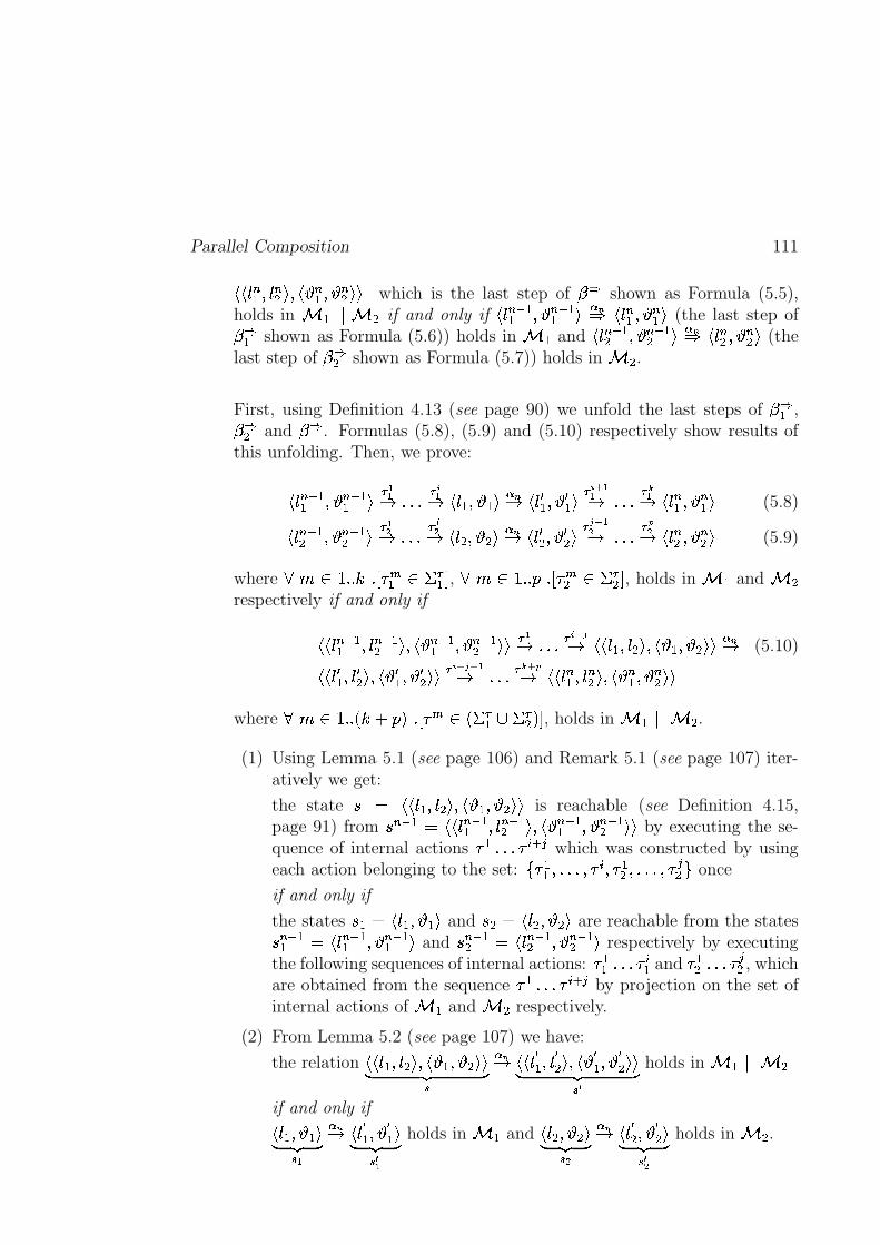
Parallel Composition 111
�U� 0 � � P 0 �� � P � � � P � � ��� which is the last step of � �
shown as Formula (5.5),holds in � ��� � � � if and only if � 0 � �� P �� �� � � �� � 0 � � P � � � (the last step of� �� shown as Formula (5.6)) holds in � � and �%0 � �� P �� �� � � �� � 0 �� P � � � (thelast step of � �� shown as Formula (5.7)) holds in � � .
First, using Definition 4.13 (see page 90) we unfold the last steps of � �� ,� �� and � �
. Formulas (5.8), (5.9) and (5.10) respectively show results ofthis unfolding. Then, we prove:
�%0 � �� P �� �� � �� ����� � �� � 0�� P ��� � �� �%0 1 � P 1 � � �
��� � ����� � �� � 0 � � P � � � (5.8)
� 0 �� �� P �� �� � ��� ����� � ��� � 0 � P �;� � �� � 0 1� P 1 � � �
��� �� ����� � ��� � 0 �� P � � � (5.9)
where��� ������� � � � � � � ��� � � , ��� ������� � � � � � � ��� � � , holds in � � and � �
respectively if and only if
��� 0 �� �� P 0 � �� � P � �� �� P � �� �U� �� ����� � ����� ��� 0�� P 0 �;� P � � P �S�U� � �� (5.10)
��� 0 1 � P 0 1� � P � 1 � P 1 � �U� ������� � ����� � � � �� �U� 0 � � P 0 �� � P � � � P � � �U�
where� � � ��� � � �§¢ � ! � � � � � � � � � � � � ! � , holds in � � � � � � .
(1) Using Lemma 5.1 (see page 106) and Remark 5.1 (see page 107) iter-atively we get:
the state � � �U� 0�� P 0 �A� P � � P �S�U� is reachable (see Definition 4.15,page 91) from � �� � � �U� 0 �� �� P 0 � �� � P �� � �� P �� �� �U� by executing the se-quence of internal actions � � ����� �
�����which was constructed by using
each action belonging to the set: 7 � �� P������WP � �� P � �� P������wP �
�
� B once
if and only if
the states ��� � � 0�� P ��� and � � � � 0 � P �A� are reachable from the states� �� �� � �%0 � �� P �� �� � and � � �� � � 0 � �� P �� �� � respectively by executingthe following sequences of internal actions: � �� ����� �
�� and � �� ����� �
�
� , whichare obtained from the sequence � � ����� �
�����by projection on the set of
internal actions of � � and � � respectively.
(2) From Lemma 5.2 (see page 107) we have:
the relation �U�%0�� P 0 �;� P �� � P �S�U�D E�F G�� �� �U� 0 ¥ � P 0 ¥� � P � ¥ � P ¥� ���D E�F G� ¥
holds in � � ��� � �if and only if
� 0�� P ���D E�F G��� �� �%0 ¥ � P ¥ � �D E�F G� ¥
holds in � � and � 0 � P �S�D E�F G� �� �� � 0 ¥� P ¥� �D E�F G� ¥ �
holds in � � .
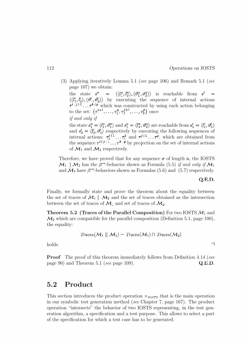
112 Operations on IOSTS
(3) Applying iteratively Lemma 5.1 (see page 106) and Remark 5.1 (seepage 107) we obtain:
the state � � � �U� 0 � � P 0 �� � P � � � P � � ��� is reachable from �L1 ���� 0]1 � P 0]1� � P � c1 � P c1 � �U� by executing the sequence of internal actions�
����� � � ����� � � � �which was constructed by using each action belonging
to the set: 7 � � � �� P������wP � �� P �� � �� P������WP �
�� B once
if and only if
the state � � � � � 0 � � P � � � and � � � � � 0 �� P � � � are reachable from �L1 � � �%021 � P c1 � �and �W1 � � �%021� P c1 � � respectively by executing the following sequences ofinternal actions: �
��� �� ����� � �� and �� � � ����� �
�, which are obtained from
the sequence ������ � � ����� � � � �
by projection on the set of internal actionsof � � and � � respectively.
Therefore, we have proved that for any sequence of length � , the IOSTS� � � � � � has the ��� -behavior shown as Formula (5.5) if and only if � �and � � have � � -behaviors shown as Formulas (5.6) and (5.7) respectively.
� ��� ��� �
Finally, we formally state and prove the theorem about the equality betweenthe set of traces of � ��� � � � and the set of traces obtained as the intersectionbetween the set of traces of � � and set of traces of � � .Theorem 5.2 (Traces of the Parallel Composition) For two IOSTS � � and� � which are compatible for the parallel composition (Definition 5.1, page 100),the equality:
� <UM'9A@;~ � � � ��� � � !"� � <AM'9A@;~ ��� � ! � � <UM'9A@;~ ��� � !holds.
4
Proof The proof of this theorem immediately follows from Definition 4.14 (seepage 90) and Theorem 5.1 (see page 109).
� ��� ��� �
5.2 Product
This section introduces the product operation � ��������� that is the main operationin our symbolic test generation method (see Chapter 7, page 167). The productoperation “intersects” the behavior of two IOSTS representing, in the test gen-eration algorithm, a specification and a test purpose. This allows to select a partof the specification for which a test case has to be generated.
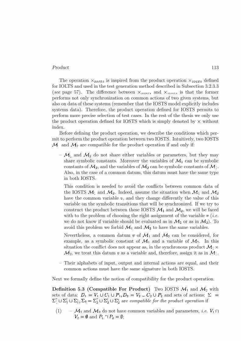
Product 113
The operation � � � � � � is inspired from the product operation � � ����� � definedfor IOLTS and used in the test generation method described in Subsection 3.2.3.3(see page 57). The difference between � � � � � � and � � ��� ��� is that the formerperforms not only synchronization on common actions of two given systems, butalso on data of these systems (remember that the IOSTS model explicitly includessystems data). Therefore, the product operation defined for IOSTS permits toperform more precise selection of test cases. In the rest of the thesis we only usethe product operation defined for IOSTS which is simply denoted by � withoutindex.
Before defining the product operation, we describe the conditions which per-mit to perform the product operation between two IOSTS. Intuitively, two IOSTS� � and � � are compatible for the product operation if and only if:
– � � and � � do not share either variables or parameters, but they mayshare symbolic constants. Moreover the variables of � � can be symbolicconstants of � � , and the variables of � � can be symbolic constants of � � .Also, in the case of a common datum, this datum must have the same typein both IOSTS.
This condition is needed to avoid the conflicts between common data ofthe IOSTS � � and � � . Indeed, assume the situation when � � and � �have the common variable � , and they change differently the value of thisvariable on the symbolic transitions that will be synchronized. If we try toconstruct the product between these IOSTS � � and � � , we will be facedwith to the problem of choosing the right assignment of the variable � (i.e.
we do not know if variable should be evaluated as in � � or as in � � ). Toavoid this problem we forbid � � and � � to have the same variables.
Nevertheless, a common datum � of � � and � � can be considered, forexample, as a symbolic constant of � � and a variable of � � . In thissituation the conflict does not appear as, in the synchronous product � � �� � , we treat this datum � as a variable and, therefore, assign it as in � � .
– Their alphabets of input, output and internal actions are equal, and theircommon actions must have the same signature in both IOSTS.
Next we formally define the notion of compatibility for the product operation.
Definition 5.3 (Compatible For Product) Two IOSTS � � and � � withsets of data: 6 � � � �q� � � i � P 6 � � � �q� � � i � and sets of actions: � � ���� � � �p�� � ��� � P � � � ���� � �p�� � ��� � are compatible for the product operation if
(1) – � � and � � do not have common variables and parameters, i.e. � � � � � and i � � i � � � ;
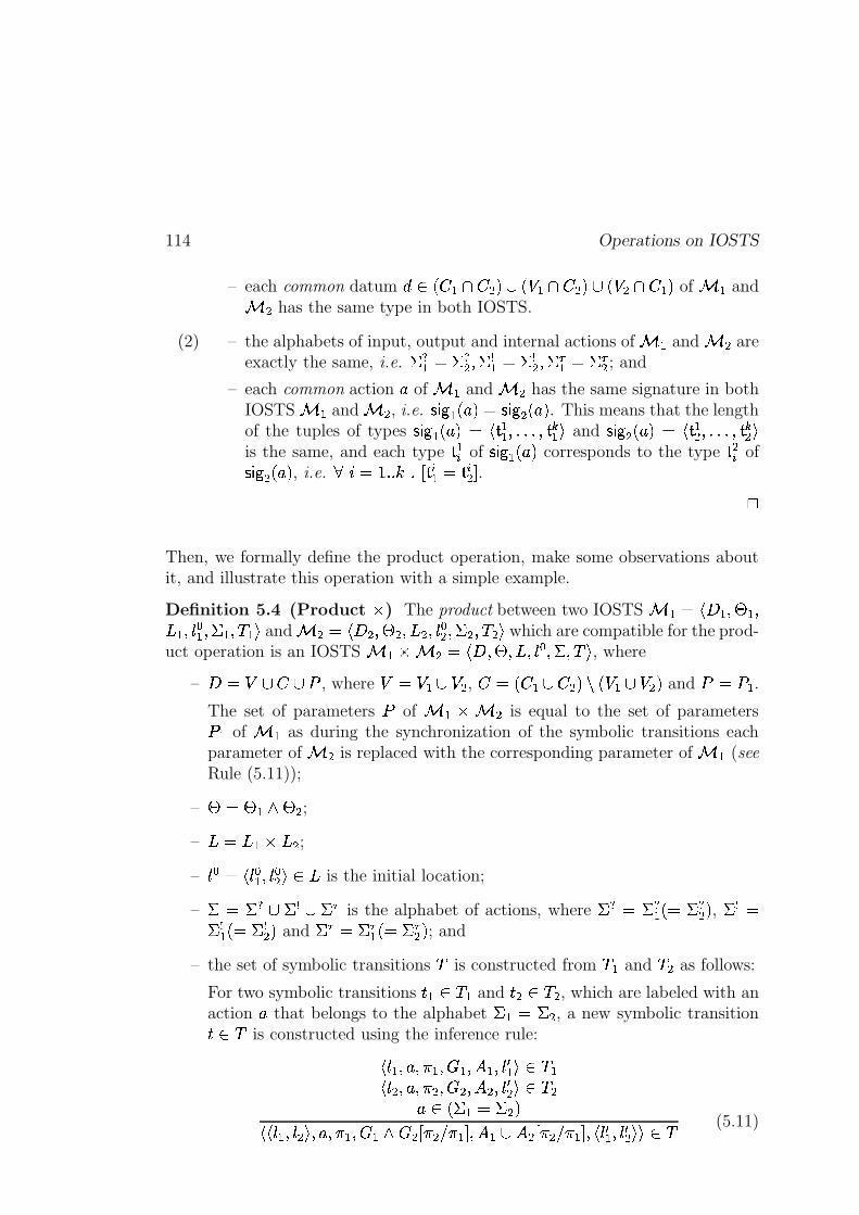
114 Operations on IOSTS
– each common datum � � � � � � � ! � � � � � � !�� � � � � � ! of � � and� � has the same type in both IOSTS.
(2) – the alphabets of input, output and internal actions of � � and � � areexactly the same, i.e. �d� � � ���� P �p�� � �p�� P ��� � � ��� � ; and
– each common action + of � � and � � has the same signature in bothIOSTS � � and � � , i.e.
� � � �%+ ! � � � � �2+ ! . This means that the lengthof the tuples of types � � � �%+ !�� �� �� P������wP � � � and � � � �%+ !�� �� �� P������wP �� �is the same, and each type �� of � � � �2+ ! corresponds to the type �� of� � � �2+ ! , i.e.
� � ������� � � � �� �
� � � .4
Then, we formally define the product operation, make some observations aboutit, and illustrate this operation with a simple example.
Definition 5.4 (Product � ) The product between two IOSTS � � � �?6 � P j � P3 � P 0 � � P � � P � �a� and � � � �?6 � P j � PA3 � P 0 �� P � � P � �A� which are compatible for the prod-uct operation is an IOSTS � � � � � � �?6 P j PA3dP 0 � P � P � � , where
– 6 �/ � � � i , where 8� � �I � , ��� � � � � � � ! � � �I � ! and i � i � .The set of parameters i of � � � � � is equal to the set of parametersi � of � � as during the synchronization of the symbolic transitions eachparameter of � � is replaced with the corresponding parameter of � � (seeRule (5.11));
– j � j � o j � ;– 3t� 3 � � 3 � ;– 0%� � � 02� � P 02�� � ��3 is the initial location;
– � � ��� � �p� � ��� is the alphabet of actions, where �d� � ��� � � � ���� ! , �p� �� �� � � � �� ! and � � � � � � � � � � � ! ; and
– the set of symbolic transitions � is constructed from � � and � � as follows:
For two symbolic transitions � � � ��� and � � � � � , which are labeled with anaction + that belongs to the alphabet � � � � � , a new symbolic transition� � � is constructed using the inference rule:
�%0�� P + P�� � P � � P ��� P 0 1 � � � � ��%0 � P + P�� � P � � P � � P 0]1� � � � �
+ � � � � � � � !��� 0�� P 0 �;� P + P�� � P�� � o � � � � � � � � � P ��� � � � � � � � � � � P � 0 1 � P 0 1� ��� � � (5.11)
Product 115
where � ��� � � � � � � (resp. � ��� � � � � �!� ) is the guard (resp. the set of assignments)of the symbolic transition � � in which each parameter �
� � � � � carried bythe action + of � � is replaced by corresponding parameter �
�� � � � carried
by the action + of � � .4
It is important to notice that the product operation is stable, i.e. the resultof this operation is indeed an IOSTS. This statement follows directly from theconstruction of the product (see Definition 5.4). The only one less trivial point isto show that the assignment of the symbolic transitions of the IOSTS obtainedafter the product operation are well-formed. This point is formulated and provedbelow.
Observation 5.1 (Well-Formedness of Symbolic Transitions) Let � � and� � be two IOSTS compatible for the product operation (see Definition 5.3,page 113). Then, each symbolic transition of the IOSTS � � � � � obtained bythe product operation from � � and � � (see Definition 5.4, page 114) containsexactly one assignment for each variable of � � � � � . 4
Proof Consider a variable � of � � � � � . Due to the fact that � � and � �are compatible for the product operation (see Definition 5.3, page 113), we canconsider the following cases:
(1) � is a variable of � � and a symbolic constant of � � . In this case, � canbe assigned with a new value in � � , but cannot be assigned in � � . Thus,if during the operation of parallel composition we synchronize a symbolictransition of � � , which contains an assignment to the variable � , with anyother symbolic transition of � � , we will obtain a symbolic transition in� � � � � containing only one assignment to � .Similarly, we consider the case where � is a variable of � � and symbolicconstant of � � .
(2) � is a private variable of � � or � � . In this case, the variable � can beassigned either in � � or in � � , thus each symbolic transition of � � � � �contains exactly one assignment to � .
� ��� ��� �
Example 5.2 To illustrate the product operation we consider two IOSTS �and � shown on Figure 5.2 (see page 116).
The IOSTS � (see Figure 5.2(a)),
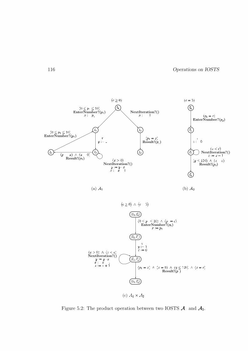
116 Operations on IOSTS
� �
���
� �� �
���
� �
� ��� � � � � � � � � �
EnterNumber?(� �
)� � � � �
�� � � �
� ��� �NextIteration?()� � � ���;�� � � �����
� � � � ��� � ��� �Result!(
� �)
� � � � � � � �EnterNumber?(
� �)
NextIteration?()� � � �1�
� � � � �Result!(
� �)
(a) � �
����
��� �
����
���
!�" -�� &
! ' � - " &EnterNumber?(
' � )
.�+ - %
! � " &NextIteration?()�+ -�� �2! * # 2�� % &�� ! - " &
Result!(' � )
(b) 4 5
7�8�9;:<8�=9?>
7�8 @ :<8�= @<>
7�8�B;:<8 =B >
7�8�E;:<8�=E >
F�G H�I J6KPF�G U�� J
F�I�M�NO@�M Z I J KPF NO@ U G;JEnterNumber?(
NO@)RTS U NO@
XVWS U Z��S U IF R�� I J6KPF ��� G;J
NextIteration?()VWS U�V��;RRTS U/RWY�Z� S U�� [�Z F NO@ U)R J KPF R U I J KLF V M Z�� I J KPF �1U G;J
Result!(NO@
)
(c) ] ^��)] b
Figure 5.2: The product operation between two IOSTS c d and cgf .
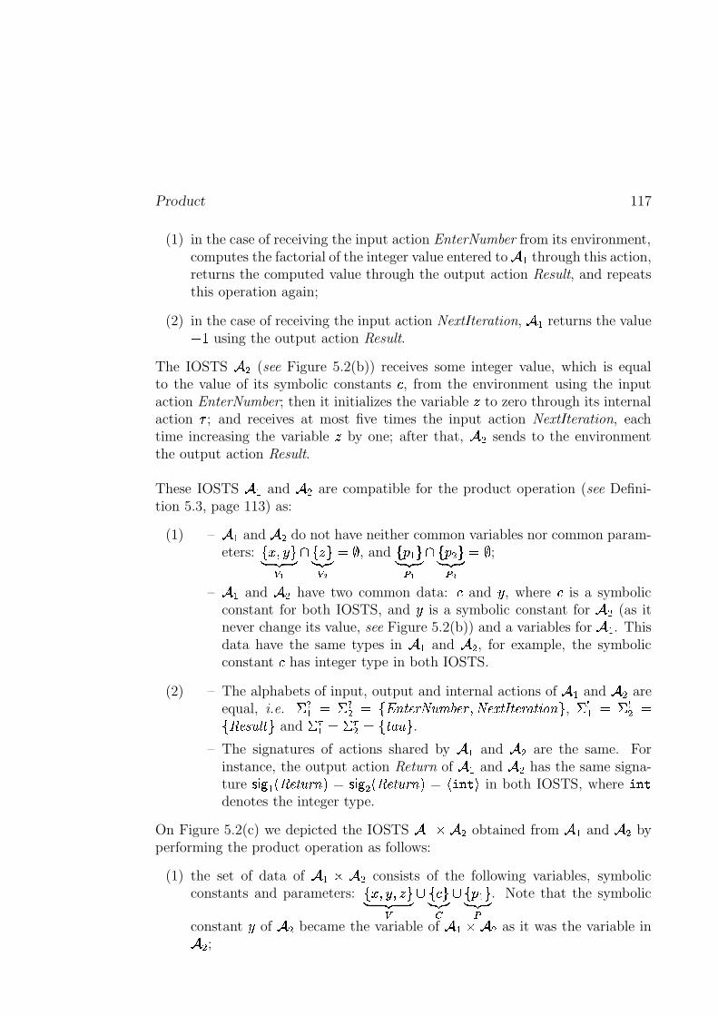
Product 117
(1) in the case of receiving the input action EnterNumber from its environment,computes the factorial of the integer value entered to � through this action,returns the computed value through the output action Result, and repeatsthis operation again;
(2) in the case of receiving the input action NextIteration, � returns the value��� using the output action Result.
The IOSTS � (see Figure 5.2(b)) receives some integer value, which is equalto the value of its symbolic constants
�, from the environment using the input
action EnterNumber; then it initializes the variable � to zero through its internalaction � ; and receives at most five times the input action NextIteration, eachtime increasing the variable � by one; after that, � sends to the environmentthe output action Result.
These IOSTS � and � are compatible for the product operation (see Defini-tion 5.3, page 113) as:
(1) – � and � do not have neither common variables nor common param-eters: 7 � P �cBD E�F GX
� 7 � BDUE�FUGX ���� , and 7 � � BD E�F Gh
� 7 � � BD E�F Gh ���� ;
– � and � have two common data:�
and � , where�
is a symbolicconstant for both IOSTS, and � is a symbolic constant for � (as itnever change its value, see Figure 5.2(b)) and a variables for � . Thisdata have the same types in � and � , for example, the symbolicconstant
�has integer type in both IOSTS.
(2) – The alphabets of input, output and internal actions of � and � areequal, i.e. ��� � � ���� � 7���\c� @S<���`�e��A@S<�P �l@��)� v;� @S<UMC�%>?[N\uB , �p�� � �p�� �7'bd@;~;`*_��AB and � � � � ��� � ��7���MN` B .
– The signatures of actions shared by � and � are the same. Forinstance, the output action Return of � and � has the same signa-ture � � � � bd@w�2`�<;\f!�� � � � � bd@w�%`�<;\u!�� ���L���*� in both IOSTS, where �L���denotes the integer type.
On Figure 5.2(c) we depicted the IOSTS � � � obtained from � and � byperforming the product operation as follows:
(1) the set of data of � � � consists of the following variables, symbolicconstants and parameters: 7 � P � P � BD E�F GX
��7 � BD�E�F�GH��7 � � BD E�F Gh . Note that the symbolic
constant � of � became the variable of � � � as it was the variable in � ;
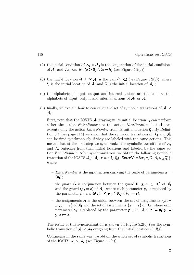
118 Operations on IOSTS
(2) the initial condition of � � � is the conjunction of the initial conditionsof � and � , i.e. j � � � � m�!�o � � ���K! (see Figure 5.2(c));
(3) the initial location of � � � is the pair � 0 � P 0]1� � (see Figure 5.2(c)), where0 � is the initial location of � and 0]1� is the initial location of � ;
(4) the alphabets of input, output and internal actions are the same as thealphabets of input, output and internal actions of � or � ;
(5) finally, we explain how to construct the set of symbolic transitions of � � � .First, note that the IOSTS � staying in its initial location 0 � can performeither the action EnterNumber or the action NextIteration, but � canexecute only the action EnterNumber from its initial location 0 1� . By Defini-tion 5.4 (see page 114) we know that the symbolic transitions of � and �can be fired synchronously if they are labeled with the same actions. Thismeans that at the first step we synchronize the symbolic transitions of �and � outgoing from their initial locations and labeled by the same ac-tion EnterNumber. After synchronization, we obtain the following symbolictransition of the IOSTS � � � : � � �U� 0 � P 0 1� �
P ��\c� @S<���`�e��A@S<�P�� P��rP � P � 0�� P 0 1 � �U� ,where
– EnterNumber is the input action carrying the tuple of parameters ���� � �a� ;
– the guard � is conjunction between the guard � m � � � � �Lm�! of �and the guard � � � � � ! of � , where each parameter � � is replaced bythe parameter � � , i.e. � � � m � � � � �Wm�!�o � � � � � ! ;
– the assignments � is the union between the set of assignments 7 � ���� � P � �.� �cB of � and the set of assignments 7 � �.� � B of � , where eachparameter � � is replaced by the parameter � � , i.e. � � 7 � ��� � � P ������ P � �.� � B
The result of this synchronization is shown on Figure 5.2(c) (see the sym-bolic transition of � � � outgoing from the initial location �%0 � P 0]1� � ).Continuing in the same way, we obtain the whole set of symbolic transitionsof the IOSTS � � � (see Figure 5.2(c)).
4
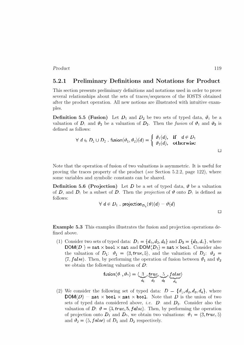
Product 119
5.2.1 Preliminary Definitions and Notations for Product
This section presents preliminary definitions and notations used in order to proveseveral relationships about the sets of traces/sequences of the IOSTS obtainedafter the product operation. All new notions are illustrated with intuitive exam-ples.
Definition 5.5 (Fusion) Let���
and���
be two sets of typed data, � � be avaluation of
���and � � be a valuation of
���. Then the fusion of � � and � � is
defined as follows:��� ��� ��������������������� � � � � �"!#� � !%$'& � �(� � !)�+*-, �� ���� �.� � !)�0/2143658749*-:"5 ;Note that the operation of fusion of two valuations is asymmetric. It is useful forproving the traces property of the product (see Section 5.2.2, page 122), wheresome variables and symbolic constants can be shared.
Definition 5.6 (Projection) Let�
be a set of typed data, � be a valuationof
�, and
���be a subset of
�. Then the projection of � onto
�<�is defined as
follows: �=�� ���>�@?BAC��D�E(F G)�����.H6I � � ! � � !%$ � � � ! ;Example 5.3 This examples illustrates the fusion and projection operations de-fined above.
(1) Consider two sets of typed data:�<�J$LK � �#� � �M� �ON"P
and�Q�R$SK �8N � �UTMP
, whereVXW�Y �-���)!Z$\[�]_^a`�b2c8c8de`�[�]f^and
VXWgY �h�Q�(!%$\[�]_^a`�b2c8c8d. Consider also
the valuation of���
: � �i$ jlk��nmpoBqsr_�#tfu, and the valuation of
���: � �v$jxw��#yszO{h|4r�u
. Then, by performing the operation of fusion between � � and � �we obtain the following valuation of
�:������������� � � � � �"!Z$}jk~)���)�� I �nmpo.q�r~ ��� ���� ��t~)���n���� �#y�z8{h|4r~ ��� ���� u
(2) We consider the following set of typed data:� $�K � �#� � �(� �ON � �UTMP
, whereVXW�Y �-��!�$�[�]f^�`�b2c8cOd�`�[�]f^�`�b2c8cOd. Note that
�is the union of two
sets of typed data considered above, i.e.�<�
and���
. Consider also thevaluation of
�: � $�jlk��nmpoBqsr_�#tO�#y�z8{h|�r�u
. Then, by performing the operationof projection onto
���and
���, we obtain two valuations: � ��$�jhk��nmpo.q�r_��t_u
and � ��$�jxtO�#y�z8{h|�r�uof
���and
���respectively.
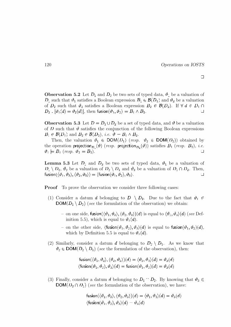
120 Operations on IOSTS;Observation 5.2 Let
���and
���be two sets of typed data, � � be a valuation of���
such that � � satisfies a Boolean expression � � �� �h����!and � � be a valuation
of�Q�
such that � � satisfies a Boolean expression � � �� �h�Q�"!. If
��� ������Q����� � �(� � !%$ � �.� � !� , then������������� � � � � �(!� $ � � � � �
.
;Observation 5.3 Let
�'$ �����Q�Q�be a set of typed data, and � be a valuation
of�
such that � satisfies the conjunction of the following Boolean expressions� � �� �-���)!
and � � �� �h�Q�(!, i.e. � $ � � � � �
.Then, the valuation � � VXWgY �h����!
(resp. � � VXWgY �h�Q�"!) obtained by
the operation?.A �)DpE"F"G)� ���.H I � � ! (resp.
?.A ��D�E(F G)�����.H � � � ! ) satisfies � �(resp. � �
), i.e.� �� $ � �(resp. � �� $ � �
).
;Lemma 5.3 Let
���and
���be two sets of typed data, � � be a valuation of����� ���
, � � be a valuation of���������
and � N be a valuation of����� �Q�
. Then,��������������j � � � � N u ��j � �M� � N u#!Z$�j-������������� � � � � � !�� � N u . ;Proof To prove the observation we consider three following cases:
(1) Consider a datum�
belonging to�<�����Q�
. Due to the fact that � � VXWgY �h����� ���(!(see the formulation of the observation) we obtain:
– on one side,�������������nj � � � � N u"��j � �M� � N u�! � � ! is equal to
j � �#� � N uM� � ! (see Def-inition 5.5), which is equal to � �(� � ! .
– on the other side,j-�����������O� � � � � �(!�� � N uM� � ! is equal to
�����#� ����� � � � � �(!#� � ! ,which by Definition 5.5 is equal to � �(� � ! .
(2) Similarly, consider a datum�
belonging to�a���Q���
. As we know that� � �VXW�Y �-����� ����!(see the formulation of the observation), then:��������������j � � � � N u"��j � �M� � N u#! � � !%$}j � �M� � N uM� � !%$ � �.� � !j-������������� � ��� � �(!)� � N uM� � !%$\������������� � � � � �(!#� � !%$ � �.� � !
(3) Finally, consider a datum�
belonging to�<�����Q�
. By knowing that � N�VXWgY �h�Q��� ���)!(see the formulation of the observation), we have:�����#� �����nj � �#� � N u"�4j � �(� � N u#! � � !%$�j � � � � N u(� � !%$ � N � � !j-�����������O� � � � � �(!)� � N uM� � !%$ � N � � !
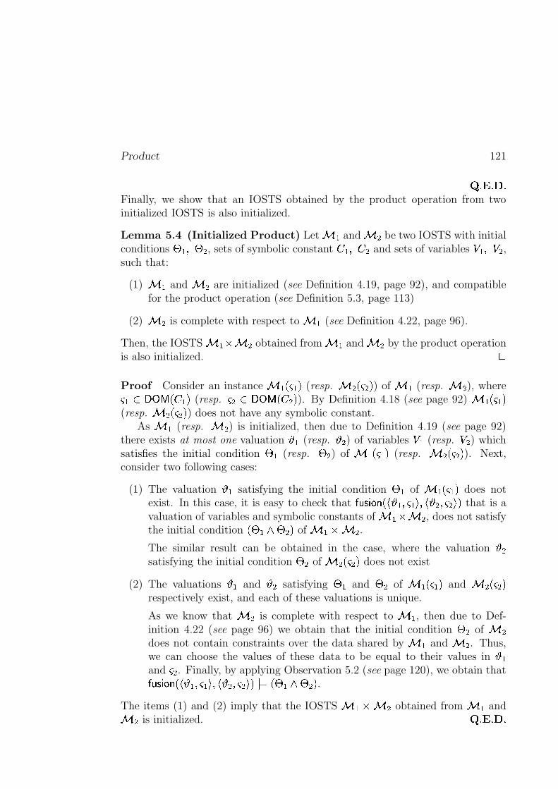
Product 121
� �������=�Finally, we show that an IOSTS obtained by the product operation from twoinitialized IOSTS is also initialized.
Lemma 5.4 (Initialized Product) Let � �and � �
be two IOSTS with initialconditions � ��� � �
, sets of symbolic constant � �#� � �and sets of variables � �#� � � ,
such that:
(1) � �and � �
are initialized (see Definition 4.19, page 92), and compatiblefor the product operation (see Definition 5.3, page 113)
(2) � �is complete with respect to � �
(see Definition 4.22, page 96).
Then, the IOSTS � ��` � �obtained from � �
and � �by the product operation
is also initialized.
;Proof Consider an instance � �"�n��!
(resp. � �����(!) of � �
(resp. � �), wheren� VXW�Y � � �)!
(resp.�� VXW�Y � � �"!
). By Definition 4.18 (see page 92) � � �n��!(resp. � ������(!
) does not have any symbolic constant.As � �
(resp. � �) is initialized, then due to Definition 4.19 (see page 92)
there exists at most one valuation � � (resp. � � ) of variables � � (resp. � � ) whichsatisfies the initial condition � �
(resp. � �) of � �"�n��!
(resp. � ������"!). Next,
consider two following cases:
(1) The valuation � � satisfying the initial condition � �of � �"�n��!
does notexist. In this case, it is easy to check that
�������������nj � � ��n��u ��j � �M���� u#! that is avaluation of variables and symbolic constants of � � ` � �
, does not satisfythe initial condition
� � � � � �(!of � �R` � �
.
The similar result can be obtained in the case, where the valuation � �satisfying the initial condition � �
of � �4���(!does not exist
(2) The valuations � � and � � satisfying � �and � �
of � �(��n�)!and � �4���(!
respectively exist, and each of these valuations is unique.
As we know that � �is complete with respect to � �
, then due to Def-inition 4.22 (see page 96) we obtain that the initial condition � �
of � �does not contain constraints over the data shared by � �
and � �. Thus,
we can choose the values of these data to be equal to their values in � �and
p�. Finally, by applying Observation 5.2 (see page 120), we obtain that�����#� �����nj � � ��n��u"��j � �M���� u#!� $}� � � � � � !
.
The items (1) and (2) imply that the IOSTS � � ` � �obtained from � �
and� �
is initialized.� �������=�
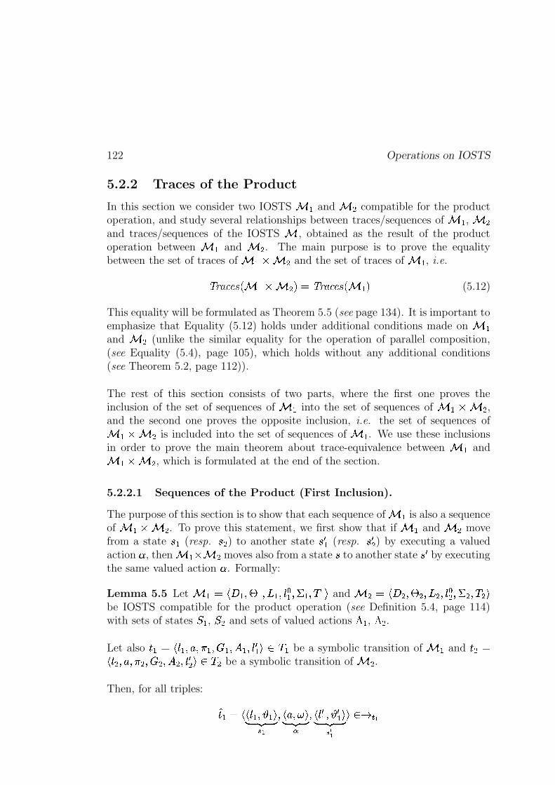
122 Operations on IOSTS
5.2.2 Traces of the Product
In this section we consider two IOSTS � �and � �
compatible for the productoperation, and study several relationships between traces/sequences of � �
, � �and traces/sequences of the IOSTS � , obtained as the result of the productoperation between � �
and � �. The main purpose is to prove the equality
between the set of traces of � �R` � �and the set of traces of � �
, i.e.
���������U� � �R` � �"!%$����������_� � �)!(5.12)
This equality will be formulated as Theorem 5.5 (see page 134). It is important toemphasize that Equality (5.12) holds under additional conditions made on � �and � �
(unlike the similar equality for the operation of parallel composition,(see Equality (5.4), page 105), which holds without any additional conditions(see Theorem 5.2, page 112)).
The rest of this section consists of two parts, where the first one proves theinclusion of the set of sequences of � �
into the set of sequences of � � ` � �,
and the second one proves the opposite inclusion, i.e. the set of sequences of� ��` � �
is included into the set of sequences of � �. We use these inclusions
in order to prove the main theorem about trace-equivalence between � �and
� ��` � �, which is formulated at the end of the section.
5.2.2.1 Sequences of the Product (First Inclusion).
The purpose of this section is to show that each sequence of � �is also a sequence
of � � ` � �. To prove this statement, we first show that if � �
and � �move
from a state|f�
(resp.|4�
) to another state| � �
(resp.| � �
) by executing a valuedaction � , then � ��` � �
moves also from a state|
to another state| �
by executingthe same valued action � . Formally:
Lemma 5.5 Let � � $�jl���#� � �#���R�#�){�� � �������� �nuand � �>$ jl�Q�M� � �M��� �(�){��� ��R�M���@� u
be IOSTS compatible for the product operation (see Definition 5.4, page 114)with sets of states � � , � � and sets of valued actions � �
, � �.
Let alsom)� $�jh{h�#�)z2��� � ���Q�#�����#�){ � � u � �
be a symbolic transition of � �and
mp� $jh{C�4�)z2���2�M���g�M��� �M�){ �� u �@�be a symbolic transition of � �
.
Then, for all triples:
�m)�J$�jnjh{h�#� � �nu~ ��� �� I ��j-zs���Ru~ ��� ����j-{ � � � � � � u~ ��� ��! I u #"%$ I
Product 123
and �mp��$�j)jh{ �M� � �#u~ �p� �� � ��jhz2���Ru~ �p� ����jh{ �� � � � � u~ �p� �� � u #"%$ �
of � �and � �
respectively, if:
(1) the values of the common variables and symbolic constants of � �and � �
in � �M� � � � are equal to their values in � � � � � � , i.e.� � � � � � � �)! � � � �R�
� �(!���� � �.� � !%$ � �(� � ! � � � � � � !%$ � � � � , and
(2) � $ jhz2���Ruis a valued action of � �
and � �, where
� � VXW�Y ��� ��!�$VXW�Y � �2�(!n!;
then, the triple:�m $ j)jh{p�n������������� � � � � �"!pu~ �p� ��
��jhz2���Ru~ �p� ����jh{ � �������#� ����� � � � � � � � !�u~ �p� ��
(5.13)
belongs to"%$
of � ��` � �, where
mis defined by Equation (5.11) of Definition 5.4
(see page 114).
;Proof From the hypotheses of the lemma and Definition 4.7 (see page 86) weobtain that:
(1)�m)��$0j)jh{h��� � �nu ��jhz2���Ru"��j-{ � � � � � � u)u #"%$ I
corresponds to the symbolic transitionm)��$ jh{h�#�)z2� � � ���e�#���g�#�){ � � u; and the pair of valuations
j � �#���Rusatisfies the
guard�Q�
ofm��
, and
(2)�mp�a$0j)jh{ �(� � � u ��jhz2���Ru"��j-{��� � � � � u)u #"%$ � corresponds to the symbolic transitionmp� $ jh{ �M�)z2� �2�4���g�M��� �M�){ �� u
; and the pair of valuationsj � �M���Ru
satisfies theguard
���of
m��.
By performing the product operation (see Definition 5.4, page 114), we obtainthe following symbolic transition in � ��` � �
:m $�j)jh{h�#�n{ �#u"�)z2��� �����Q��� �g� � �2� � � � �h����� � � � � �2� � � � �l��j-{ � � �){ �� u)uThen, we prove that the triple
�mdefined by Equation (5.13) belongs to
" $.
First, as we know that:
(1) the valuations � � , � � � over� � � � � �)!
of � �, and the valuations � � , � � � over� � �Z� � �"!
of � �exist, and
(2)� � � � !�$ � � � � � �n!X� � � � � � � !
which follows from Definition 5.4 (seepage 114),
124 Operations on IOSTS
then there exist the valuations������������� � � � � �(! and
������������� � � � � � � � ! over� � ���Q!
of � ��` � �. Therefore, by the definition of a state (see Definition 4.4,
page 84), � �g` � �has the following states:
|�$ j)jh{l���){ � u"�n�����������O� � � � � �(!�u and| � $}j)jh{ � � �){ �� u �n�����#� ���O� � � � � � � � !�u .Second, we prove that the symbolic transition
mobtained from
m#�and
mp�by
the product operation is executable in � �g` � �, i.e. the pair of valuationsj-������������� � � � � �(!)���Ru
satisfies the guard� �Q��� ��� � � � � �2� � !
ofm. Indeed, as we know
that:
(1)j � � ���Ru� $ �e�
,
(2)j � �4���Ru� $ �g� � �2� � � � �
as:
(a)j � �M���Ru� $ �g�
, and
(b)��� � �2� � � � �
is the Boolean expression obtained from� �
by substitu-tion of all its parameters
�s�carried by the action
zof
m��, with the
parameters� �
carried by the same actionz
ofm��
. Remember that����� � � z�!%$ �#� � � �-z�!.
(2)���\ � � �X� � �)!��\� � ��� � � !>��� � �.� � !a$ � �(� � !� (see the hypotheses of thelemma),
then by Observation 5.2 (see page 120) the valuations�������������nj � � ���Ru ��j � �(���Ru#!
satisfies the conjunction of the Boolean expressions�a�
and�g� � �2� � � � �
. More-over, due to Lemma 5.3 (see page 120) we obtain that
���4�#� �����nj � � ���Ru"��j � �(���Ru�! $j-������������� � � � � �(!)���Ru. Therefore,
j �����#� ����� � � � � �"!)���Ru $ �!�Q� � �g� � �2� � � � �-!, and the
symbolic transitionm
of � � ` � �is executable.
Third, we prove that the “new” valuation � � of the variables and symbolic con-stants of � ��` � �
obtained by execution of the symbolic transitionm, is equal
to������������� � � � � � � � ! .Indeed, � � is obtained from � $ ������������� � � � � �(! by parallel execution of the
assignments belonging to��� �%� �>� � �2� � � � � !
. More precisely, � � is constructed asfollows: for each datum
�� � � � � � ��!@��� � �%� � �"!of � �R` � �
,
� � � � !%$�������� �������
���(��j�?BAC��D�E(F G)������� I ����I�� � � !����Ru#! � � ! * , �� � ��>� � �2� � � � �x�nj�?.A �)DpE"F"G)� ����� � ��� � � � � !)���Ru#!#� � ! * , �� � �?BAC��D�E(F G)����� �� I ����I��p� � ! � � ! * , �� � ��� � � � � � �"!?BAC��D�E(F G)����� �� � ��� � � � � ! � � ! * , �� � ��� � � � � � �)!� � � ! * , �� � ��� � � (5.14)
Product 125
Remember that (1) � � � � �X$��and � � � � ��$��
due to the definition of IOSTS(see page 81), and (2) � � � � � $��
as � �and � �
are compatible for the productoperation.
Then, due to Definitions 5.5 and 5.6 (see pages 119) we have that:
(a)?.A ��D�E(F G)����� �� I ����I�� � ������������� � �#� � �(!~ ��� �
�
!J$ � � , and
(b) using the supplementary condition formulated as the lemma hypothesis,and saying that all common data of � �
and � �have the same val-
ues, i.e.�=�� � � � � � ��!�� � � � � � � !���� � �.� � !�$ � �(� � ! � , we have that?BAC��D�E(F G)����� �� � ��� � ��� ������������� � �#� � �(!~ ��� �
�
!J$ � � .Moreover, if a common datum
�of � �
, � �is a constant in both IOSTS, then (1)�
is a constant in � � ` � �, and (2) its value cannot be change during execution
of � �, � �
and � �g` � �. Next, due to the lemma hypothesis saying that:���� � � � � � �n! ��� � � � � �(!���� � �.� � !%$ � �(� � ! � , we obtain:���� � � � � � �"!���� � �(� � !%$ � �.� � !%$ � � � !�
Using this statement together with the items (a) and (b) above, we can rewriteFormula (5.14) as follows: for each datum
�of � � ` � �
,
� � � � !%$�������� �������
���(�nj � �#���Ru#! � � ! * , �� � ��>� � �2� � � � �x�nj � �4���Ru#!#� � ! * , �� � �� �(� � ! * , �� � ����� � �Z� � �"!� �.� � ! * , �� � ����� � � � � �)!� � � !Z$ � �(� � !Z$ � �.� � ! * , �� � ��� � � (5.15)
We also know that: for each datum�� � � � � � �)!
of � �,
� � � � � !%$'& �g�"�nj � � ���Ru�! � � ! * , �� � �� �(� � ! * , �� � � (5.16)
and for each datum�� � � �%� � �"!
of � �,
� � � � � !%$'& � ���nj � �4���Ru�! � � ! * , �� � �� �.� � ! * , �� � � (5.17)
Next, we remark that�>� � �2� � � � ����j � �M���Ru#! $ � �.�nj � �M���Ru#!
. Indeed, as signature ofthe actions
zlabeling symbolic transitions
m��and
m��, then we can substitute
�s�by
� �in the expression
�>�. This substitution does not change the semantics of
the expression� �
.
126 Operations on IOSTS
Using this observation together with Formulas (5.15), (5.16) and (5.17), we ob-tain: for each datum
�of � �R` � �
,
� � � � !%$ & � � � � � ! * , �� � � � � � �)!� � � � � ! /�1�3 58749�* :(5 (5.18)
Finally, from Formula (5.18) and Definition 5.5 (see page 119) we get that � � $������������� � � � � � � � ! .Therefore, the triple
�mJ$�jx|_� � �#| � uof � �O` � �
, where|>$�j)jh{h�#�){C�#u"�n�����������8� � � � � �(!pu
and| � $�j)j-{ � � �){ � u �n�����#� ���O� � � � � � �(!�u , belongs to
"%$of � �R` � �
. � ���������Remind that the aim of this subsection is to prove that if a given IOSTS� �
can fire a sequence � of valued actions, then the IOSTS � � ` � �, where
� �is a complete IOSTS with respect to � �
, can fire this sequence as well.In order to prove this statement, we first show that if there exists some be-
havior of � �corresponding to a sequence � belonging to � ����� ��� ���_� � �)!
(seeDefinition 4.12, page 90), then there exists a behavior of � ��` � �
correspond-ing to the same sequence � . It is important to notice that this statement holdsunder some additional condition made on � �
.
Theorem 5.3 (Behaviors of the Product) Consider two IOSTS � �and � �
such that:
(1) � �and � �
are compatible for the product operation (see Definition 5.3,page 113), and
(2) � �is complete with respect to � �
(see Definition 4.22, page 96).
If � �has the following behavior ���� jh{�� � � � � � u � I" jh{ �� � � �� u �M�M�(jh{ ��� �� � � ��� �� u ���" jh{ � � � � � � u
which corresponds to a sequence � $ � ���M�M� � � belonging to � ����� ��� ���U� � �)!.
Then, there exists a behavior:
� � jh{ � � � � u � I" j-{ � � � � u �M�(�Mjh{ ��� � � � ��� � u ���" jh{ � � � � uin � � ` � �
corresponding to the same sequence � , where for all � from � to� , there exist a location{��� � �
of � �and a valuation � � � VXWgY � � �X� � �(!
ofvariables and symbolic constants of � �
such that:
–{��@$}jh{ � � �){ �� u
,
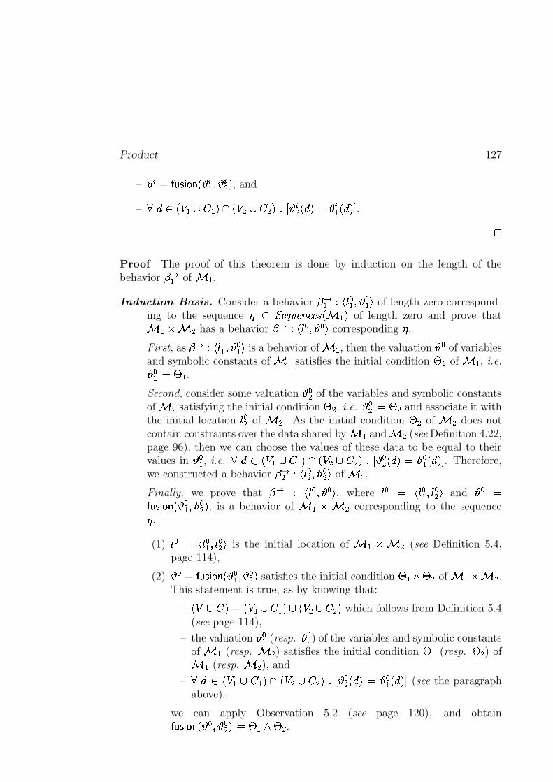
Product 127
– � � $\������������� � � � � � � � ! , and
–���� � � � � � �)! ��� � �%� � �(!���� � � � � � !%$ � � � � � !� . ;
Proof The proof of this theorem is done by induction on the length of thebehavior � �� of � �
.
Induction Basis. Consider a behavior ��� jh{�� � � � � � u of length zero correspond-ing to the sequence � � ����� ��� ���U� � �)!
of length zero and prove that� � ` � �
has a behavior � � jh{��4� � �#u corresponding � .
First, as � ��� jh{�� � � � � � u is a behavior of � �, then the valuation � � � of variables
and symbolic constants of � �satisfies the initial condition � �
of � �, i.e.� � � $ � �
.
Second, consider some valuation � �� of the variables and symbolic constantsof � �
satisfying the initial condition � �, i.e. � �� $ � �
and associate it withthe initial location
{!��of � �
. As the initial condition � �of � �
does notcontain constraints over the data shared by � �
and � �(see Definition 4.22,
page 96), then we can choose the values of these data to be equal to theirvalues in � � � , i.e.
��� � � � � � �)! � � � �Z� � �(!���� � �� � � !R$ � � � � � ! � . Therefore,we constructed a behavior � �� jh{��� � � �� u of � �
.
Finally, we prove that � � jh{ � � � � u , where{ � $ jh{ � � �){ �� u
and � � $�����#� ����� � � � � � �� ! , is a behavior of � �g` � �corresponding to the sequence
� .
(1){ � $ jh{ � � �n{ �� u
is the initial location of � ��` � �(see Definition 5.4,
page 114),
(2) � ��$\������������� � � � � � �� ! satisfies the initial condition � � � � �of � �Z` � �
.This statement is true, as by knowing that:
–� � � � !%$}� � ��� � �)!s��� � � � � �(!
which follows from Definition 5.4(see page 114),
– the valuation � � � (resp. � �� ) of the variables and symbolic constantsof � �
(resp. � �) satisfies the initial condition � �
(resp. � �) of
� �(resp. � �
), and
–���� � � �%� � ��! � � � �X� � �"! ��� � �� � � !>$ � � � � � ! � (see the paragraphabove).
we can apply Observation 5.2 (see page 120), and obtain�����#� ����� � � � � � �� ! $ � � � � �.
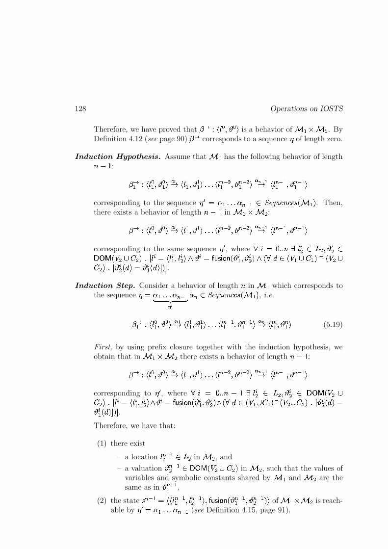
128 Operations on IOSTS
Therefore, we have proved that �� jh{��4� � ��u is a behavior of � � ` � �. By
Definition 4.12 (see page 90) � � corresponds to a sequence � of length zero.
Induction Hypothesis. Assume that � �has the following behavior of length� � � :
� �� j-{ � � � � � � u � I" jh{ �� � � �� u �M�M�4j-{���� �� � � ��� �� u � ��� I" jh{ ��� �� � � ��� �� ucorresponding to the sequence � �X$ � �@�(�M� � ��� � � ����� ��� ���_� � �)!
. Then,there exists a behavior of length � � �
in � �R` � �:
� � j-{ � � � � u � I" jh{ � � � � u �M�M�4j-{ ��� � � � ��� � u � ��� I" jh{ ��� � � � ��� � ucorresponding to the same sequence � � , where
� � $ � � � ��� { �� �J�4� � � � VXWgY � � �6� � �"! ��� { � $�j-{ � � �){ �� u � � � $\������������� � � � � � � � ! ��� �=�� � � �@� � ��! �i� � � �� � !>��� � � � � � !%$ � � � � � !� !� .
Induction Step. Consider a behavior of length � in � �which corresponds to
the sequence � $ � �@�M�M� � ��� �~ ��� ��
� � � ����� ��� ���U� � �)!, i.e.
� �� j-{ � � � � � � u � I" jh{ �� � � �� u �(�M�Mj-{ ��� �� � � ��� �� u ���" j-{ � � � � � � u (5.19)
First, by using prefix closure together with the induction hypothesis, weobtain that in � ��` � �
there exists a behavior of length � � �:
� � j-{ � � � � u � I" jh{ � � � � u �M�M�4j-{���� � � � ��� � u � ��� I" jh{ ��� � � � ��� � ucorresponding to � � , where
� � $ � � � � � � � {��� �J�4� � � � VXW�Y � � �g�� � !>��� { � $�jh{ � � �){ �� u � � �@$\������������� � � � � � � � ! � � �=�� � � �(� � �)! � � � �.� � �"! ��� � � � � � !Z$� � � � � ! �-! � .Therefore, we have that:
(1) there exist
– a location{���� �� �J�
in � �, and
– a valuation � ��� �� vVXW�Y � � � � � �(!in � �
, such that the values ofvariables and symbolic constants shared by � �
and � �are the
same as in � ��� ��,
(2) the state| ��� � $}j)j-{���� �� �){ ��� �� u"�n�����������O� � ��� �� � � ��� �� !pu
of � ��` � �is reach-
able by � � $ � � �M�(� � ��� � (see Definition 4.15, page 91).
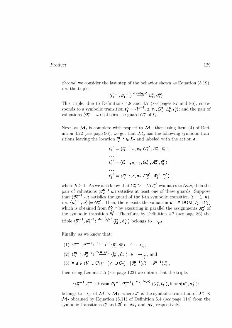
Product 129
Second, we consider the last step of the behavior shown as Equation (5.19),i.e. the triple: jh{ ��� �� � � ��� �� u ����������� �� " jh{ � � � � � � uThis triple, due to Definitions 4.8 and 4.7 (see pages 87 and 86), corre-sponds to a symbolic transition
m � � $�j-{ ��� �� �)z2��� � ��� � � ��� � � �){ � � u; and the pair of
valuationsj � ��� �� ���Ru
satisfies the guard� � �
ofm � �
.
Next, as � �is complete with respect to � �
, then using Item (4) of Defi-nition 4.22 (see page 96), we get that � �
has the following symbolic tran-sitions leaving the location
{���� �� �J�and labeled with the action
z:m � I� $}jh{ ��� �� �)z2���2�M��� � I� ��� � I� �){ � I� u"��M�M�m ���� $}jh{ ��� �� �nzs���2�M��� ���� ��� ���� �){ ���� u"��M�M�m �� � $ jh{ ��� �� �)z2���2�M��� �� � ��� �� � �){ �� � u"�
where ��� �. As we also know that
� �I��� �(�M� � � � �
evaluates tompoBqsr
, then thepair of valuations
j � ��� �� ���Rusatisfies at least one of these guards. Suppose
thatj � ��� �� ���Ru
satisfies the guard of the � -th symbolic transition ( � $ � � � � ),i.e.
j � ��� �� ���Ru $ � � ��. Then, there exists the valuation � � �� �VXW�Y � � �6� � �(!
which is obtained from � ��� ��by executing in parallel the assignments
� � ��of
the symbolic transitionm ����
. Therefore, by Definition 4.7 (see page 86) the
triplejh{ ��� �� � � ��� �� u � � ������� �� " jh{ ���� � � ���� u
belongs to" $ � �� .
Finally, as we know that:
(1)jh{ ��� �� � � ��� �� u ����������� �� " jh{ � � � � � � u "%$ � I ,
(2)jh{ ��� �� � � ��� �� u ����������� �� " jh{ ���� � � ���� u " $ � �� , and
(3)��� � � � � � �)! ��� � � � � �"! ��� � ��� �� � � !%$ � ��� �� � � !�
,
then using Lemma 5.5 (see page 122) we obtain that the triple:j)jh{ ��� �� �){ ��� �� u"�������#� ���O� � ��� �� � � ��� �� !�u � � ������� ��� " j)j-{�� � �){ ���� u �n�����#� ����� � � � � � ���� !�ubelongs to
" $ � of � ��` � �, where
m �is the symbolic transition of � ��`
� �obtained by Equation (5.11) of Definition 5.4 (see page 114) from the
symbolic transitionsm � �
andm � ��
of � �and � �
respectively.
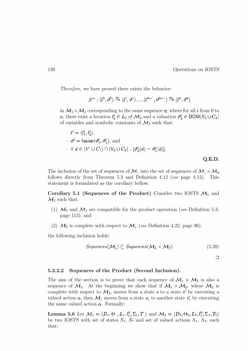
130 Operations on IOSTS
Therefore, we have proved there exists the behavior:
� � jh{ � � � � u � I" jh{ � � � � u �M�M�(jh{ ��� � � � ��� � u � �" jh{ ��� � �_uin � �s` � �
corresponding to the same sequence � , where for all � from � to� , there exist a location{ �� �J�
of � �and a valuation � � � �VXWgY � � � � � �(!
of variables and symbolic constants of � �such that:
–{��@$�j-{�� � �){ �� u
,
– � � $ ������������� � � � � � � � ! , and
–���� � � � � � �n! ��� � � � � �"! ��� � � � � � !%$ � � � � � ! � .
� ���������The inclusion of the set of sequences of � �
into the set of sequences of � �@` � �follows directly from Theorem 5.3 and Definition 4.12 (see page 4.12). Thisstatement is formulated as the corollary bellow.
Corollary 5.1 (Sequences of the Product) Consider two IOSTS � �and
� �such that:
(1) � �and � �
are compatible for the product operation (see Definition 5.3,page 113), and
(2) � �is complete with respect to � �
(see Definition 4.22, page 96).
the following inclusion holds:
� ����� ��� ���_� � �)!�� � ����� ��� ���U� � ��` � � !(5.20);
5.2.2.2 Sequences of the Product (Second Inclusion).
The aim of the section is to prove that each sequence of � ��` � �is also a
sequence of � �. At the beginning we show that if � ��` � �
, where � �is
complete with respect to � �, moves from a state
|to a state
| �by executing a
valued action � , then � �moves from a state
|f�to another state
| � �by executing
the same valued action � . Formally:
Lemma 5.6 Let � � $�jl���#� � �#���R�#�){�� � �������� �nuand � �>$ jl�Q�M� � �M��� �(�){��� ��R�M���@� u
be two IOSTS with set of states � � , � � and set of valued actions � �, � �
, suchthat:
Product 131
(1) � �and � �
are compatible for the product operation (see Definition 5.3,page 113), and
(2) � �is complete with respect to � �
(see Definition 4.22, page 96).
Let alsom $ j)jh{h�#�n{ �#u"�)z2��� � ���Q��� �g� � �2� � � � �l����� � �>� � �2� � � � �h��jh{ � � �){ �� u)u
be a symbolictransition of � � ` � �
, which is obtained from two symbolic transitionsm#�Q$jh{h� �)z2��� �#���Q�#�����#�){ � � u
andm��>$�j-{ �M�)z2���2�M�����M���>�4�){ �� u
of � �and � �
respectively byEquation 5.11 of Definition 5.4 (see page 114).
Then, for each triple�m $ j)j)jh{h���){ �#u"� � u~ �p� ��
��jhz2���Ru~ �p� ���4j)jh{ � � �){ �� u"� � � u~ ��� ��
belonging to" $
, there
exists a triple�m)� $�j)jh{h�#� � �nu~ �p� �� I ��jhz2���Ru~ �p� ��
�4jh{ � � � � � � u~ ��� �� I ubelonging to
" $ I, where � � and � � � are
obtained from � and � � by projection onto� � �f� � ��!
, i.e. � �J$S?.A ��D�E"F"G)����� �� I ��� I � � � !and � � � $L?.A ��D�E(F G)����� �� I ��� I � � � � ! . ;ProofFirst, from the hypothesis of the lemma we have that the given triple
�mbelonging
to"%$
corresponds tom $+j)j-{l�#�){C�#u"�)z2��� �#���Q��� �g� � �2� � � � �l�����Z� �>� � �2� � � � �h��jh{ � � �){ �� unu
.Then, from Definition 4.7 (see page 86) we obtain that the pair of valuation
j � ���Rusatisfies the guard
��� � �g� � �2� � � � �of
m.
Second, from the hypothesis of the lemma we also have that � �has a transitionm)�=$ jh{h���)z2��� �#���e� �������){ � � u
. Then, we prove that � �can move from the state|f� $�jh{-�#� � �nu to the state
| � � $}jh{ � � � � � � u by executing the valued action � $}jhz2���Ru.
Indeed, if we choose � � to be equal to?BAC��D�E(F"G)� ��� �� I ��� I � � � ! (see Definition 5.6,
page 119) then asj � ���Ru $ �Q���%��� � �2� � � � �
we can use Observation 5.3 (seepage 120) and obtain that the pair
j � � ���Rusatisfies
�Q�. Then, we compute the
new valuation of variables and symbolic constants of � �, i.e. � � � , from � � by
executing in parallel the assignments� �
. Due to the fact that symbolic constantsof � �
cannot be variables of � �, i.e. � � � � ��$��
(see Item (1) of Definition 4.22,page 96), we obtain that the values of variables and symbolic constants in � � � areexactly the same as their values in � � . Thus, � � � $L?BAC��D�E(F"G)� ����� I ����I�� � � � ! .Therefore, we have proved that there exists a triple
�m)� $}jnjh{h�#� � ��u~ ��� �� I �4jhz2���Ru~ ��� ����j-{ � � � � � � u~ ��� �� I u
belonging to" $ I
of � �, where � � $L?.A ��D�E"F"G)����� �� I ����I���� � ! and � � � $?BAC��D�E(F"G)� ��� �� I ����I�� � � � ! . � �������=�
132 Operations on IOSTS
Next, we prove that if there exists some behaviour of � �2` � �corresponding
to a sequence � belonging to � ����� ��� ���8� � �@` � �"!(see Definition 4.12, page 90),
then there exists a behaviour of � �corresponding to the same sequence � . This
statement holds under some additional condition made on � �.
Theorem 5.4 (Behaviors of the Product) Consider two IOSTS � �and � �
such that:
(1) � �and � �
are compatible for the product operation (see Definition 5.3,page 113), and
(2) � �is complete with respect to � �
(see Definition 4.22, page 96).
If � ��` � �has the behavior:
� � jh{ � � � � u � I" j-{ � � � � u �M�(�Mjh{ ��� � � � ��� � u ���" jh{ ��� � �Uuwhere for all � from � to � , there exist locations
{ � � �R�of � �
and{��� � �
of� �
such that{ � $ jh{ � � �){ �� u
. Moreover, this behavior corresponds to a sequence� $ � ���M�M� � � belonging to � ����� ��� ���_� � �R` � �"!
.
Then, � �has the behavior:
� �� jh{ � � � � � � u � I" j-{ �� � � �� u �M�(�Mjh{ ��� �� � � ��� �� u � �" jh{ � � � � � � ucorresponding to the sequence � and to the locations
{ ��( � $ � � � � ) of � �
. Here,for all � from � to � , � � � $ ?BAC��D�E(F G)����� �� I ����I�� � � � ! (see Definition 5.6, page 119).
;Proof This theorem is proved by induction on the length of the behavior � �of � ��` � �
.
Induction Basis. Consider a behavior �� jh{��4� � � u of length zero, where{!��$j-{ � � �n{ �� u
, corresponding to the empty sequence � � ����� ��� ���_� � � ` � �"!;
and prove that � �has a behavior � �� jh{�� � � � � � u corresponding to � , where� � � $ ?BAC��D�E(F G)����� �� I ����I���� � �"! .
Indeed, as we know that| ��$ jh{��M� � � u is the initial state of � � ` � �
,then by Definition 4.5 (see page 84) � � must satisfy the initial condition of� �R` � �
, i.e. � � $ � ��� � �. Then, as we know that:
–� � � � !Z$�� � �2� � ��!��=� � � � � �"!
which follows from Definition 5.4 (seepage 114), and
– � � � $S?BAC��D�E(F G)����� �� I ����I��p� � �(! ,
Product 133
then, from Observation 5.3 (see page 120) we obtain that � � � satisfies � �.
Therefore, we have constructed the behavior ��� jh{�� � � � � � u of � �, which by
Definition 4.12 correspond to the sequence � of length zero.
Induction Hypothesis. Assume that � �R` � �has the following behavior of
length � � � :� � jh{ � � � � u � I" jh{ � � � � u �M�M�(jh{ ��� � � � ��� � u � � � I" jh{ ��� � � � ��� � u
corresponding to the sequence � � $ � ���M�M� � ��� � � ����� ��� ���_� � �)!, where� � $ � � � � � � � { � � �R� �){ �� �J� ��� { � $�jh{ � � �){ �� u �
.
Then, � �contains the behavior:
� ��� jh{ � � � � � � u � I" jh{ �� � � �� u �M�M�(jh{ ��� �� � � ��� �� u � � � I" jh{ ��� �� � � ��� �� ucorresponding to the sequence � � and to the locations
{ ��( � $ � � � � � �
) of� �
. Here,� � $ � � � � � � ��� � � � $S?.A ��D�E(F G)����� �� I ����I�� � � �l! � .
Induction Step. Consider a behavior of length � :
� � jh{ � � � � u � I" jh{ � � � � u �M�M�(jh{ ��� � � � ��� � u ���" jh{ � � � � u (5.21)
of � ��` � �which corresponds to a sequence � $ � ���M�M� � ��� �~ ��� �
� � �
� ����� ��� ���_� � ��` � �"!, where
� � $ � � � � � { � � ��� �n{ �� � ����� { � $ jh{ � � �){ �� u �.
First, by using prefix closure together with the induction hypothesis, weobtain that � �
has the behavior:
� ��� jh{ � � � � � � u � I" jh{ �� � � �� u �M�M�(jh{ ��� �� � � ��� �� u � � � I" jh{ ��� �� � � ��� �� ucorresponding to the sequence � � and to the locations
{���( � $ � � � � � � ) of � �
.Here,
� � $ � � � � � � ��� � � � $�?.A ��D�E(F G)����� �� I ����I���� � �h! � . Thus, the state| ��� �� $jh{ ��� �� � � ��� �� u
of � �is reachable by � � $ � �@�M�M� � ��� � (see Definition 4.15,
page 91).
Second, we consider the last step of the behavior shown as Equation (5.21),i.e.
jh{ ��� � � � ��� � u � �" j-{ � � � � u , which, due to Definitions 4.8 and 4.7 (seepages 87 and 86), corresponds to a simbolic transition:m � $}jnjh{ ��� �� �){ ��� �� u"�)z2��� �#��� � � � � � � � �2� � � � �h��� � � � � � � � �2� � � � �h��jh{ � � �){ �� u)uThen, from Lemma 5.6 (see page 130) we get that � �
can move fromthe state
| ��� �� $ jh{ ��� �� � � ��� �� uto the state
| � � $ jh{ � � � � � � u by executing the
134 Operations on IOSTS
valued action � � $ jhz2���Ru. Moreover, � ��� �� $ ?.A ��D�E(F G)����� �� I ����I��p� � ��� � ! and� � � $S?.A ��D�E"F"G)����� �� I ����I�� � � � ! .
Therefore, we have proved � �has the behavior:
� ��� jh{ � � � � � � u � I" jh{ �� � � �� u �M�M�(jh{ ��� �� � � ��� �� u � �" jh{ � � � � � � ucorresponding to the same sequence � and to the locations
{ ��( � $ � � � � ) of
� �. Here, where for all � from
�to � , the valuation � � � is obtained from � �
by projection onto the set� � � � � �)!
.� ���������
The inclusion of the set of sequences of � �@` � �into the set of sequences of � �
follows from Theorem 5.3 and Definition 4.12 (see page 4.12). This statement isformulated as the corollary above.
Corollary 5.2 (Sequences of the Product) For two IOSTS � �and � �
suchthat:
(1) � �and � �
are compatible for the product operation (see Definition 5.3,page 113), and
(2) � �is complete with respect to � �
(see Definition 4.22, page 96),
the following inclusion holds:
� ����� ��� ���_� � �R` � �"!�� � ����� ��� ���_� � �n!(5.22);
Finally, we formally state and prove the theorem about the equality between theset of traces of � � ` � �
and the set of traces of � �under some additional
conditions made on � �and � �
.
Theorem 5.5 (Traces of the Product) For two IOSTS � �and � �
suchthat:
(1) � �and � �
are compatible for the product operation (see Definition 5.3,page 113), and
(2) � �is complete with respect to � �
(see Definition 4.22, page 96),
the following equality:
���������_� � �R` � �"!%$�� �������U� � �)!holds.
;

Product 135
Proof
(�
) The proof of the first inclusion which states that any trace of the IOSTS� � ` � �
is also a trace of � �, follows from Definitions 4.12, 4.14 (see
pages 90 and 90) and Corollary 5.1 (see page 130).
( � ) The second inclusion, i.e. each trace of � �is also a trace of � � ` � �
,trivially follows from Definitions 4.12, 4.14 (see pages 90 and 90) and Corol-lary 5.2 (see page 134).
� �������=�

136 Operations on IOSTS
Chapter 6
Conformance Testing with IOSTS
In this chapter we describe the theory of conformance testing whichserves as a basis for the symbolic test generation method described inthe next chapter. The work presented in this chapter is mainly inspiredfrom the theory of conformance testing developed by J. Tretmans (see[Tretmans, 1994], [Tretmans, 1996b], etc.) and the research done inthe VerTeCs team at IRISA (see [Rusu et al., 2000], [Morel, 2000],[Jard and Jéron, 2002]). In our theory of conformance testing, be-haviors of specifications and implementations under test are modeledwith Input-Output Symbolic Transition Systems, and the conformancerelation is defined as a partial inclusion of their traces.
The Plan of the Chapter. At the beginning of the chapter, we give theformal definitions of a specification and an implementation under test. Then, weintroduce the notion of conformance relation between them, and define test casesas well as their execution on implementations. Next, we link the notion of testcase with the notion of conformance relation, and formulate two first properties(soundness and exhaustiveness) which have to be satisfied by test cases. Then,we give the formal definition of a test purpose which is used as a mechanism fortest case selection. Finally, we redefine the conformance relation so that the testpurposes can be taken into account, and formulate a few other properties whichmust be satisfied by test cases.
6.1 Specification
A specification ( ��� ��� ��������, where the universe
������� �of the specifications
was introduced in Section 2.1.1, page 14 of Chapter 2) of a reactive system isa formal description of the system behaviors, which, in general, are expressed
137
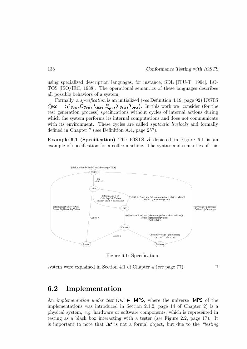
138 Conformance Testing with IOSTS
using specialized description languages, for instance, SDL [ITU-T, 1994], LO-TOS [ISO/IEC, 1988]. The operational semantics of these languages describesall possible behaviors of a system.
Formally, a specification is an initialized (see Definition 4.19, page 92) IOSTS��� ���Q$ jl���������"� � ������� ���������� �){ � ������� ���������(�����������nu . In this work we consider (for thetest generation process) specifications without cycles of internal actions duringwhich the system performs its internal computations and does not communicatewith its environment. These cycles are called syntactic livelocks and formallydefined in Chapter 7 (see Definition A.4, page 257).
Example 6.1 (Specification) The IOSTS�
depicted in Figure 6.1 is anexample of specification for a coffee machine. The syntax and semantics of this
(cPrice > 0 and vPaid=0 and vBeverage=TEA)
tauvPaid:=0
(pCoinValue > 0)Coin ? (pCoinValue)
vPaid:= vPaid + pCoinValue
Cancel ?
(pRemaningValue = vPaid)Return ! (pRemaningValue)
((vPaid < cPrice) and (pRemaningValue = cPrice - vPaid))Return ! (pRemaningValue)
((vPaid >= cPrice) and (pRemaningValue = vPaid - cPrice))Return ! (pRemaningValue)
vPaid:=cPrice
ChooseBeverage ? (pBeverage)vBeverage:=pBeverageCancel ?
(vBeverage = pBeverage)Deliver ! (pBeverage)
Begin
Idle
Pay
Choose
Return Delivery
Figure 6.1: Specification.
system were explained in Section 4.1 of Chapter 4 (see page 77).
;
6.2 Implementation
An implementation under test ( ��� �� Y ���, where the universe
� Y � �of the
implementations was introduced in Section 2.1.2, page 14 of Chapter 2) is aphysical system, e.g. hardware or software components, which is represented intesting as a black box interacting with a tester (see Figure 2.2, page 17). Itis important to note that ��� is not a formal object, but due to the “testing
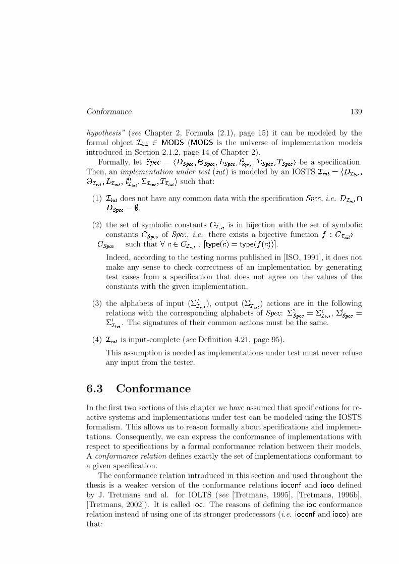
Conformance 139
hypothesis” (see Chapter 2, Formula (2.1), page 15) it can be modeled by theformal object ������� Y�W V �
(Y�W V �
is the universe of implementation modelsintroduced in Section 2.1.2, page 14 of Chapter 2).
Formally, let ��� ���$0jl� ������� � � ����� �"��� �������"�){�� ������� ���������(�����������nu be a specification.Then, an implementation under test ( � � ) is modeled by an IOSTS ������� $�jl��� �� ��� �� �� ������� �� p��{ ��� �� ����� �� ������� �� lu such that:
(1) ������� does not have any common data with the specification ��� ��� , i.e.���� �� ���������� $ �
.
(2) the set of symbolic constants � �� �� is in bijection with the set of symbolicconstants � ����� � of ��� ��� , i.e. there exists a bijective function
y � �� �� �"� ����� � such that
��� � �� �� ��� G��U?_EU� � !%$\G��U?fEU�ly%� � !n!�.
Indeed, according to the testing norms published in [ISO, 1991], it does notmake any sense to check correctness of an implementation by generatingtest cases from a specification that does not agree on the values of theconstants with the given implementation.
(3) the alphabets of input (����� ��
), output (����� ��
) actions are in the followingrelations with the corresponding alphabets of ��� ��� : ��� ������� $ ����� ��
,�������� � $
����� �� . The signatures of their common actions must be the same.
(4) ������� is input-complete (see Definition 4.21, page 95).
This assumption is needed as implementations under test must never refuseany input from the tester.
6.3 Conformance
In the first two sections of this chapter we have assumed that specifications for re-active systems and implementations under test can be modeled using the IOSTSformalism. This allows us to reason formally about specifications and implemen-tations. Consequently, we can express the conformance of implementations withrespect to specifications by a formal conformance relation between their models.A conformance relation defines exactly the set of implementations conformant toa given specification.
The conformance relation introduced in this section and used throughout thethesis is a weaker version of the conformance relations
���OF(���4�and
� ��F"�defined
by J. Tretmans and al. for IOLTS (see [Tretmans, 1995], [Tretmans, 1996b],[Tretmans, 2002]). It is called
���OF. The reasons of defining the
� ��Fconformance
relation instead of using one of its stronger predecessors (i.e.���OF(���4�
and���OF(�
) arethat:
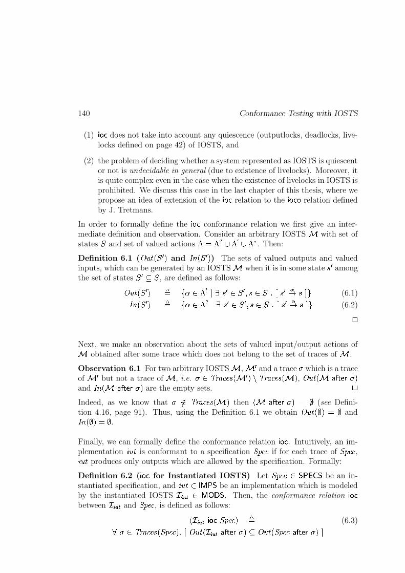
140 Conformance Testing with IOSTS
(1)���OF
does not take into account any quiescence (outputlocks, deadlocks, live-locks defined on page 42) of IOSTS, and
(2) the problem of deciding whether a system represented as IOSTS is quiescentor not is undecidable in general (due to existence of livelocks). Moreover, itis quite complex even in the case when the existence of livelocks in IOSTS isprohibited. We discuss this case in the last chapter of this thesis, where wepropose an idea of extension of the
���OFrelation to the
� ��F"�relation defined
by J. Tretmans.
In order to formally define the� ��F
conformance relation we first give an inter-mediate definition and observation. Consider an arbitrary IOSTS � with set ofstates � and set of valued actions � $ � � � � � � ��� . Then:
Definition 6.1 (� � �(� � � ! and � � � � � ! ) The sets of valued outputs and valued
inputs, which can be generated by an IOSTS � when it is in some state| �
amongthe set of states � � � � , are defined as follows:
� ���"� � � ! � K � � � � | � � � �#| � ����| � �" | � P(6.1)
� �%� � � ! � K � � � � | � � � �#| � ����| � �" |�� P(6.2);
Next, we make an observation about the sets of valued input/output actions of� obtained after some trace which does not belong to the set of traces of � .
Observation 6.1 For two arbitrary IOSTS � , � �and a trace � which is a trace
of � �but not a trace of � , i.e. �
���������_� � � ! � ���������_� � !,� ���"� � � � GpEBA � !
and � �Z� � � � GpEBA � ! are the empty sets.
;Indeed, as we know that �
� ���������_� � !then
� � � � GpEBA � ! $ �(see Defini-
tion 4.16, page 91). Thus, using the Definition 6.1 we obtain� � � � ��! $ �
and� �Z� ��!%$ �
.
Finally, we can formally define the conformance relation���OF
. Intuitively, an im-plementation � � is conformant to a specification ��� ��� if for each trace of ��� ��� , � � produces only outputs which are allowed by the specification. Formally:
Definition 6.2 (���OF
for Instantiated IOSTS) Let ��� ��� �������be an in-
stantiated specification, and ��� � Y � �be an implementation which is modeled
by the instantiated IOSTS � ����� 'Y�W V �. Then, the conformance relation
���OFbetween ������� and ��� ��� , is defined as follows:� ��� � � � ��F ��� ���4! �
(6.3)��
� �������_� ��� ����!)��� � ���"� � � � ��� � GpEBA � ! � � � �(� ��� ��� � � GpEBA � !��
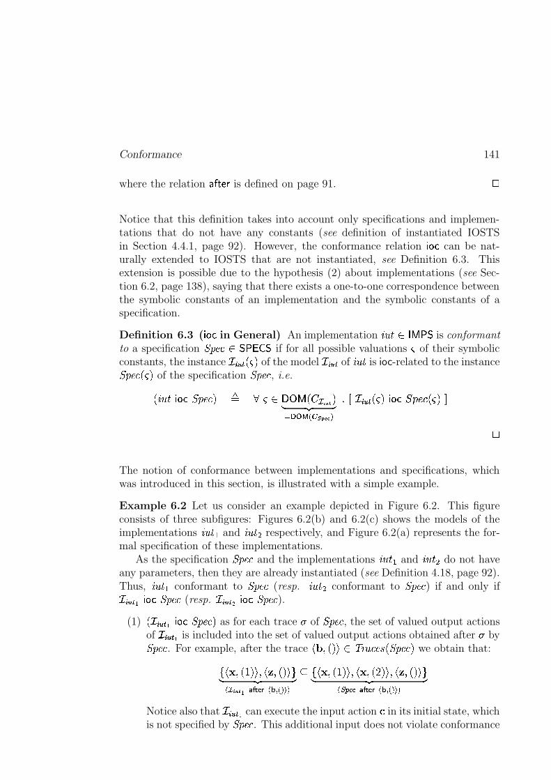
Conformance 141
where the relation �� GpE.A
is defined on page 91.
;Notice that this definition takes into account only specifications and implemen-tations that do not have any constants (see definition of instantiated IOSTSin Section 4.4.1, page 92). However, the conformance relation
���OFcan be nat-
urally extended to IOSTS that are not instantiated, see Definition 6.3. Thisextension is possible due to the hypothesis (2) about implementations (see Sec-tion 6.2, page 138), saying that there exists a one-to-one correspondence betweenthe symbolic constants of an implementation and the symbolic constants of aspecification.
Definition 6.3 (� ��F
in General) An implementation � � � Y ���is conformant
to a specification ��� ��� ������� �if for all possible valuations
of their symbolic
constants, the instance ��� � � ��! of the model ������� of ��� is ioc-related to the instance��� ���f�.! of the specification ��� ��� , i.e.� ��� � ��F ��� ���4! � � �VXW�Y � � �� �� �!~ �p� �
������� � � ����� ���� ������� ��.! ���OF �� r � �.!�� ;
The notion of conformance between implementations and specifications, whichwas introduced in this section, is illustrated with a simple example.
Example 6.2 Let us consider an example depicted in Figure 6.2. This figureconsists of three subfigures: Figures 6.2(b) and 6.2(c) shows the models of theimplementations � ��� and � ��� respectively, and Figure 6.2(a) represents the for-mal specification of these implementations.
As the specification ��� ��� and the implementations ���#� and ���p� do not haveany parameters, then they are already instantiated (see Definition 4.18, page 92).Thus, � ��� conformant to ��� ��� (resp. ����� conformant to ��� ��� ) if and only if��� � � I � ��F ��� ��� (resp. ��� � � � � ��F ��� ��� ).
(1)� ������� I ���OF ��� ���4! as for each trace � of ��� ��� , the set of valued output actionsof ������� I is included into the set of valued output actions obtained after � by��� ��� . For example, after the trace
j�X����!pu ���������U� ��� ���4! we obtain that:K�j��J��� � !�u ��j�����x!�u P~ �p� �� �� �� I���������� ���� � � �� K�j��Z��� � !pu"��j��Z�����8!pu"��j���4��!�u P~ ��� �� ������� ��������� ���� � � �
Notice also that ��� � � I can execute the input action � in its initial state, whichis not specified by ��� ��� . This additional input does not violate conformance
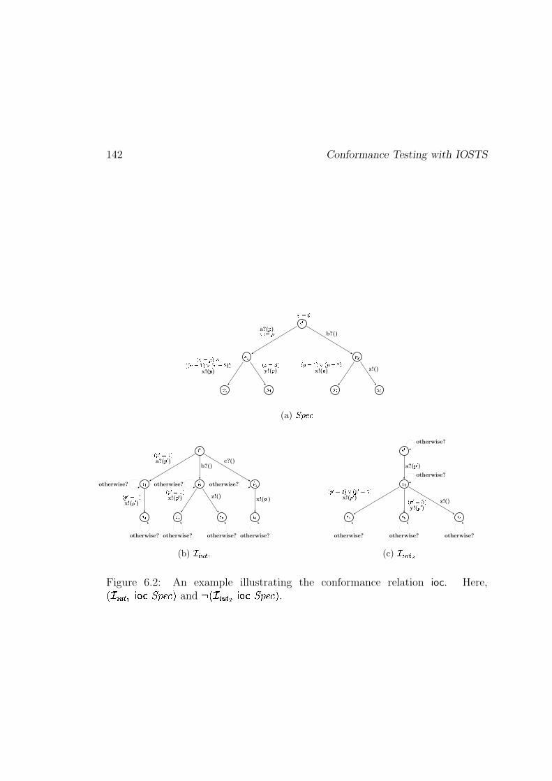
142 Conformance Testing with IOSTS
���
��� ���
��� ��� ��� ��
��� a?(� )�� � � b?()
� �� �������� ���� ��� � ���� ���x!(� )
� � ��� �y!(� )
� � ��� ��� � � � � �x!(� ) z!()
(a) !#"%$'&
( �
( � ( � ( �
( � ( � ( ( )
� �+* ��� �a?(�,* )
b?()c?()
� �+* ��� �x!(�+* )
� �+* ��� �x!(�+* ) z!()
x!(�+* )otherwise? otherwise? otherwise?
otherwise? otherwise? otherwise? otherwise?
(b) -�.0/21�3
( �
( �
( � ( � ( �
a?(�+* )
� �+* � � ��� � �+* ��� �x!(�,* ) � �+* ��� �
y!(�+* ) z!()
otherwise?
otherwise?
otherwise? otherwise? otherwise?
(c) -�.0/41+5
Figure 6.2: An example illustrating the conformance relation ioc. Here,� ��� � � I � ��F ��� ���4! and 6 � ��� � � � � ��F ��� ���4! .
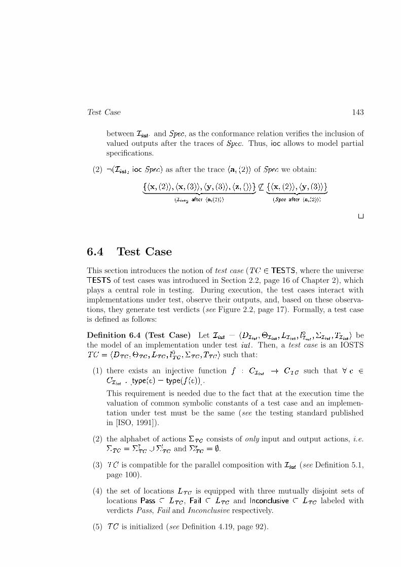
Test Case 143
between � ����� I and ��� ��� , as the conformance relation verifies the inclusion ofvalued outputs after the traces of ��� ��� . Thus, ioc allows to model partialspecifications.
(2) 6� ������� � ���OF ��� ���4! as after the trace
j��@�����8!puof ��� ��� we obtain:K�j��J����8!�u ��j��J���-kO!�u ��j��X���hk8!�u"��j�������!pu P~ �p� �� �� �� � �� ����� ����� � � � � �� K�j �J�����U!�u"��j�� �4�hkO!pu P~ ��� �� ������� ��������� ����� � � � � ;
6.4 Test Case
This section introduces the notion of test case (�� � � �� �
, where the universe � �� �of test cases was introduced in Section 2.2, page 16 of Chapter 2), which
plays a central role in testing. During execution, the test cases interact withimplementations under test, observe their outputs, and, based on these observa-tions, they generate test verdicts (see Figure 2.2, page 17). Formally, a test caseis defined as follows:
Definition 6.4 (Test Case) Let � ����� $ jl��� �� p� � �� �� p������ �� ��){ ��� �� ������ �� ���� �� �� hu bethe model of an implementation under test � � . Then, a test case is an IOSTS�� $}jh�� �� � � �� ���� ��6�){�� �� ���� �� ��� ��@u
such that:
(1) there exists an injective functiony � �� �� �" � ��
such that���
� �� �� >��� G��U?fEU� � !Z$\G��U?_EU�lyZ� � !�!�.
This requirement is needed due to the fact that at the execution time thevaluation of common symbolic constants of a test case and an implemen-tation under test must be the same (see the testing standard publishedin [ISO, 1991]).
(2) the alphabet of actions�� ��
consists of only input and output actions, i.e.�� ���$ ��� �� � ��� ��and
�� �� $ �
.
(3)��
is compatible for the parallel composition with ��� � � (see Definition 5.1,page 100).
(4) the set of locations�� ��
is equipped with three mutually disjoint sets oflocations
�� ��� � �� ��
, � � ��� � �� ��and
� ��F(����F�� ����� ��E � �� ��labeled with
verdicts Pass, Fail and Inconclusive respectively.
(5)��
is initialized (see Definition 4.19, page 92).
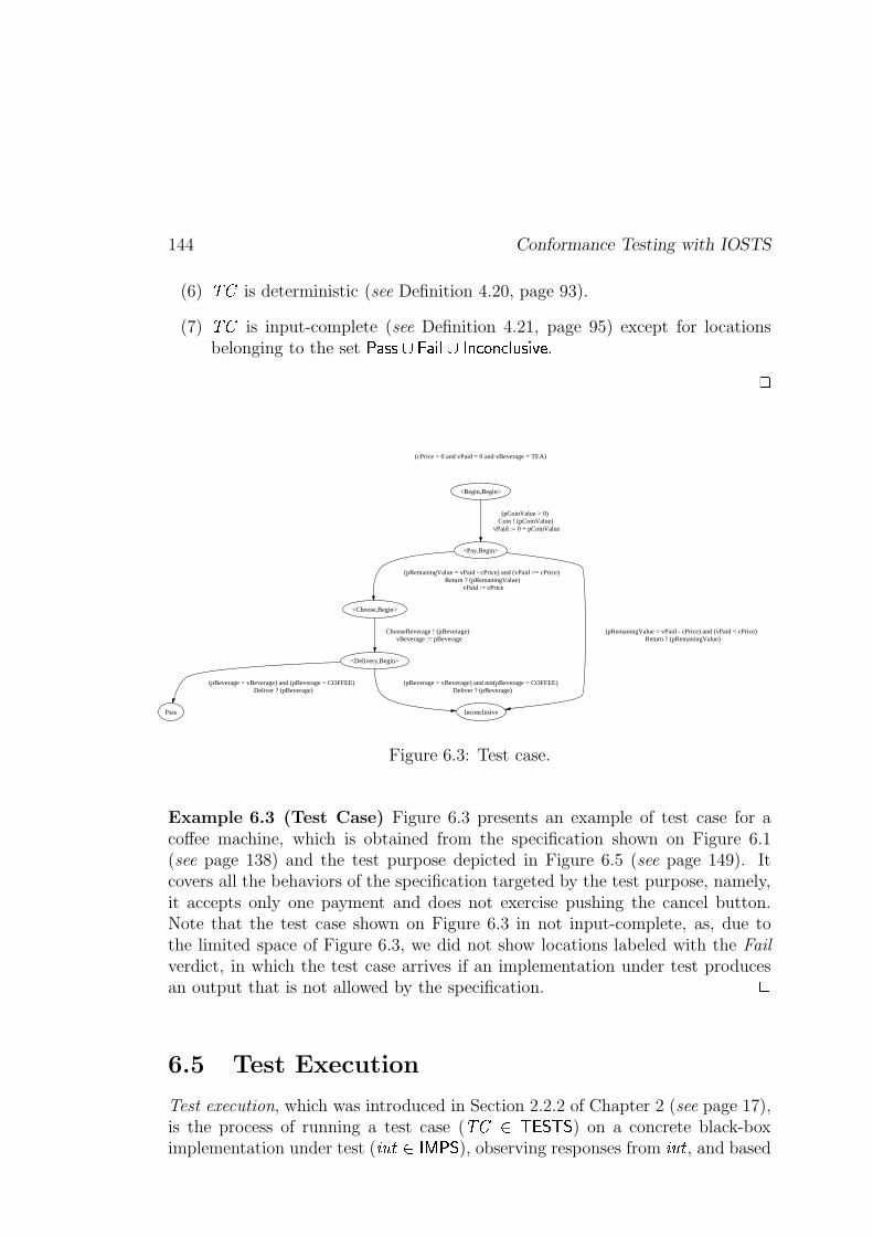
144 Conformance Testing with IOSTS
(6)��
is deterministic (see Definition 4.20, page 93).
(7)��
is input-complete (see Definition 4.21, page 95) except for locationsbelonging to the set
�����6� � � ���"� � ��F(����F � ����� ��E
. ;
(cPrice > 0 and vPaid = 0 and vBeverage = TEA)
<Begin,Begin>
<Pay,Begin>
(pCoinValue > 0) Coin ! (pCoinValue)
vPaid := 0 + pCoinValue
<Choose,Begin>
(pRemaningValue = vPaid - cPrice) and (vPaid >= cPrice) Return ? (pRemaningValue)
vPaid := cPrice
Inconclusive
(pRemaningValue = vPaid - cPrice) and (vPaid < cPrice) Return ? (pRemaningValue)
<Delivery,Begin>
ChooseBeverage ! (pBeverage) vBeverage := pBeverage
Pass
(pBeverage = vBeverage) and (pBeverage = COFFEE) Deliver ? (pBeverage)
(pBeverage = vBeverage) and not(pBeverage = COFFEE) Deliver ? (pBeverage)
Figure 6.3: Test case.
Example 6.3 (Test Case) Figure 6.3 presents an example of test case for acoffee machine, which is obtained from the specification shown on Figure 6.1(see page 138) and the test purpose depicted in Figure 6.5 (see page 149). Itcovers all the behaviors of the specification targeted by the test purpose, namely,it accepts only one payment and does not exercise pushing the cancel button.Note that the test case shown on Figure 6.3 in not input-complete, as, due tothe limited space of Figure 6.3, we did not show locations labeled with the Failverdict, in which the test case arrives if an implementation under test producesan output that is not allowed by the specification.
;
6.5 Test Execution
Test execution, which was introduced in Section 2.2.2 of Chapter 2 (see page 17),is the process of running a test case (
�� � �� �) on a concrete black-box
implementation under test ( ��� � Y � �), observing responses from � � , and based
Test Execution 145
on these responses, generating a test verdict (see Figure 2.2, page 17). In thethesis we model the test execution by the parallel composition (see Definition 5.2,page 100) between
��and the model � � � � of ��� , which exists due to the “testing
hypothesis” (see Formula 2.1 in Chapter 2, page 15).
Test Verdict. The this paragraph we formalize the notion of test verdict corre-sponding to each execution of a test case
�� $}jl� �� � � �� ���� ��6�){�� �� ��� ��6��� ��@uon an implementation under test � � . Before giving the formal definition of thetest verdict, we denote by:
–��� � � $LKB|>$�jh{p� � u � �� 8{ �
� ��� P ,– � � ��� $ KB| $�jh{p� � u � �� O{ � � � � P , and
–��� � W�� ������ �� � $SKB| $}jh{p� � u � �� 8{ � ��F(����F�� ����� ��E P
the sets of states of��
corresponding to the locations labeled with � � � , � ��and � � ����� � � � �� � .
Intuitively, a test verdict is defined as follows: consider an observable trace �of the parallel composition
� � ����� ��g!, where ��� � � is the model of an implemen-
tation under test ��� and��
is a test case; then,��
produces the � � � (resp. � �� , � � ����� � � � �� � ) verdict if the state in which the test case
��arrives after the
trace � belongs to��� � �
(resp. FAIL, INCONCLUSIVE). Formally:
Definition 6.5 (Verdict) Let � be a trace of ������� �� , then:����E.A���� F"G"��!J$ � � �B! * , � ��
�� GpE.A
�� ��� � � !����E.A���� F"G"� � !J$ � �� ! * , � �� � � GpE.A � � � � ��� !����E.A���� F"G"�
�!J$
�� ����� � � � �� ��! * , � ��
�� GpE.A
�� ��� � W�� ������ �� � ! ;
We remark that for a given implementation, a test case always produces a sametest verdict after several executions of a same trace on this implementation. Thisfollows directly from fact that any test case
��is an initialized and deterministic
IOSTS (see the items (5) and (6) of Definition 6.4, page 143), thus, it is not hardto show that for each trace �
���������_� � � � � ��g!(which is also a trace of��
due to Theorem 5.2, page 112), all states of��
belonging to� �� � � GpE.A � !
correspond to exactly one location of the test case��
.Nevertheless, due to the fact that an implementation under test can have sev-
eral reactions on an input from the tester, a test case can produce several possibleexecutions giving possibly different test verdicts for the same implementation.Thus, an implementation under test may be rejected, accepted, or may produce
146 Conformance Testing with IOSTS
the �� ����� � � � �� � verdict for the same test case while following different possible
traces of the parallel composition between the test case and the implementation.Formally:
Definition 6.6 ( � ��_
��� �) Let
�� � � �be a test case and ������� Y�W V �
be a model of an implementation � � � Y ���. Let also
��and � ����� be compatible
for the parallel composition (see Definition 5.1, page 100).Then,
��may fail ������� if there exists a trace � in the parallel composition
between ������� and��
after which��
produces the � �� verdict. Formally:� ��� � � _ � � ��� ������� ! �
(6.4)� �
���������U� ������� ��g!���� ��EBA���� F"G(� � !J$ � �� � ;The relations � � � _ ? � ��� and � � � _ � ��F(����F
can be defined in the same way as therelation of possible rejection � � � _ � � � � .6.6 Property of a Test Case: Soundness
In the previous sections of this chapter we have introduced two significant notionsused in conformance testing, namely, test case (see Definition 6.4, page 143) andconformance relation (see Definition 6.3, page 141). The aim of this section is toestablish the connection between these two independently defined notions. Weknow that this connection exists. Indeed, as the purpose of test cases is to informus about conformance of an implementation with respect to its specification, thenthe test cases must hold some properties relative to a conformance relation. Forinstance, producing the � �� verdict must imply detection of non-conformance inan implementation under test. This property is called soundness. It is formallydefined as follows:
Definition 6.7 (Soundness) A test case�� � �� �
with a set of symbolicconstants � is sound for a specification �� r � �������
and set of implementationsunder test � ��� � � Y � �
if:� � q�m � � ��f�� �VXW�Y � � !����_� ��� � � ��! ���OF ��� ���U��.!�!�$��
6 � ����.!� � � _ � � ��� ������� ��.!�! � (6.5);
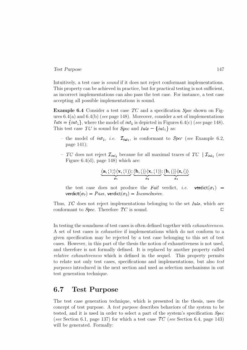
Test Purpose 147
Intuitively, a test case is sound if it does not reject conformant implementations.This property can be achieved in practice, but for practical testing is not sufficient,as incorrect implementations can also pass the test case. For instance, a test caseaccepting all possible implementations is sound.
Example 6.4 Consider a test case��
and a specification ��� ��� shown on Fig-ures 6.4(a) and 6.4(b) (see page 148). Moreover, consider a set of implementations� � ��>$SK � ��� P , where the model of � ��� is depicted in Figures 6.4(c) (see page 148).This test case
��is sound for ��� ��� and � ��� >$SK ����� P as:
– the model of ����� , i.e. ��� � � I , is conformant to ��� ��� (see Example 6.2,page 141);
–��
does not reject � ����� I because for all maximal traces of�� � � � � I (see
Figure 6.4(d), page 148) which are:j�� �4� � !puMj��J��� � !�u~ ��� ��I � j�X����!puMj��J�4� � !pu~ ��� �
� � � j�� ���x!�uMj�������!pu~ ��� �� �
the test case does not produce the � �� verdict, i.e.��EBA ����F"G(� � ��!�$
��EBA ����F"G(� � �(!%$ � � � , ��E.A�����F G(� � N !Z$ � � ����� � � � �� � .Thus,
��does not reject implementations belonging to the set �
��� , which are
conformant to ��� ��� . Therefore��
is sound.
;In testing the soundness of test cases is often defined together with exhaustiveness.A set of test cases is exhaustive if implementations which do not conform to agiven specification may be rejected by a test case belonging to this set of testcases. However, in this part of the thesis the notion of exhaustiveness is not used,and therefore is not formally defined. It is replaced by another property calledrelative exhaustiveness which is defined in the sequel. This property permitsto relate not only test cases, specifications and implementations, but also testpurposes introduced in the next section and used as selection mechanisms in outtest generation technique.
6.7 Test Purpose
The test case generation technique, which is presented in the thesis, uses theconcept of test purpose. A test purpose describes behaviors of the system to betested, and it is used in order to select a part of the system’s specification ��� ���(see Section 6.1, page 137) for which a test case
��(see Section 6.4, page 143)
will be generated. Formally:
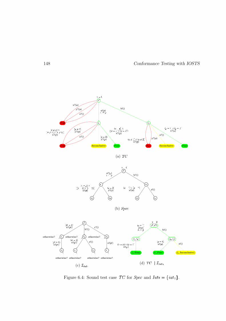
148 Conformance Testing with IOSTS
� �
Fail� � � �
Fail Inconclusive Pass Fail Inconclusive Pass
���
x?(� )y?(� )
z?()
a!(� )#� � �b!()
� ��� ���2�� � ����� ��� � ��� � � �x?(� )
� � ���� �y?(� )
z?()� � ��� �y?(� )
� �� ���2�� � #��� ��� � �� � � �x?(� )
� � ���� ��� � � �� � �x?(� )
y?(� )z?()
� � ��� ��� � � � � �x?(� )
(a) ���
���
��� ���
��� ��� ��� ��
��� a?(� )�� � � b?()
� �� �������� ���� ��� � ���� ���x!(� )
� � ��� �y!(� )
� � ��� ��� � � � � �x!(� ) z!()
(b) !�" $'&
( �
( � ( � ( �
( � ( � ( ( )
� � * ��� �a?(� * )
b?()c?()
� �+* ��� �x!(�+* )
� �+* ��� �x!(� * ) z!()
x!(�+* )otherwise? otherwise? otherwise?
otherwise? otherwise? otherwise? otherwise?
(c) -�.0/21�3
� ( �� � �
� ( � � � � � ( � � � �
� ( � � Pass � ( � � Pass � ( � Inconclusive
��� � � ��� �a!(� )#� � � b!()
� �� ����� � � ��� �x!(� )
� � � � �x!(� ) z!()
(d) ������ -�.0/21�3
Figure 6.4: Sound test case��
for ��� ��� and � � ��>$LK � �#� P .
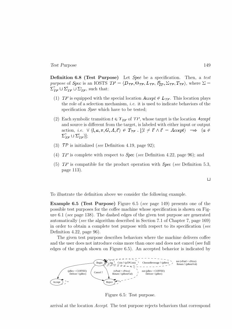
Test Purpose 149
Definition 6.8 (Test Purpose) Let ��� ��� be a specification. Then, a testpurpose of ��� ��� is an IOSTS
� � $'jl�� ��6� � ��6���� ��6��{�� �� ��� �� ��� �� u, where
� $��� �� � ��� �� � �
� �� , such that:
(1)� � is equipped with the special location
� ������� � ��
. This location playsthe role of a selection mechanism, i.e. it is used to indicate behaviors of thespecification ��� ��� which have to be tested;
(2) Each symbolic transitionm � ��
of� � , whose target is the location
� �������
and source is different from the target, is labeled with either input or outputaction, i.e.
� j-{��nzs���J���������){ � u � �� ��� �-{ �$ { � �i{ � $ � � � r m)! $�� � z ��� �� � ��� �� ! �
;
(3)� � is initialized (see Definition 4.19, page 92);
(4)� � is complete with respect to ��� ��� (see Definition 4.22, page 96); and
(5)� � is compatible for the product operation with ��� ��� (see Definition 5.3,page 113). ;
To illustrate the definition above we consider the following example.
Example 6.5 (Test Purpose) Figure 6.5 (see page 149) presents one of thepossible test purposes for the coffee machine whose specification is shown on Fig-ure 6.1 (see page 138). The dashed edges of the given test purpose are generatedautomatically (see the algorithm described in Section 7.1 of Chapter 7, page 169)in order to obtain a complete test purpose with respect to its specification (seeDefinition 4.22, page 96).
The given test purpose describes behaviors where the machine delivers coffeeand the user does not introduce coins more than once and does not cancel (see fulledges of the graph shown on Figure 6.5). An accepted behavior is indicated by
Begin tau Coin ? (pTPCoin) ChooseBeverage ? (pBev)not (vPaid < cPrice) Return ! (pRemVal)
Accept
(pBev = COFFEE) Deliver ! (pBev)
Reject
Cancel ? (vPaid < cPrice)
Return ! (pRemVal)not (pBev = COFFEE)
Deliver ! (pBev)
* *
Figure 6.5: Test purpose.
arrival at the location Accept. The test purpose rejects behaviors that correspond
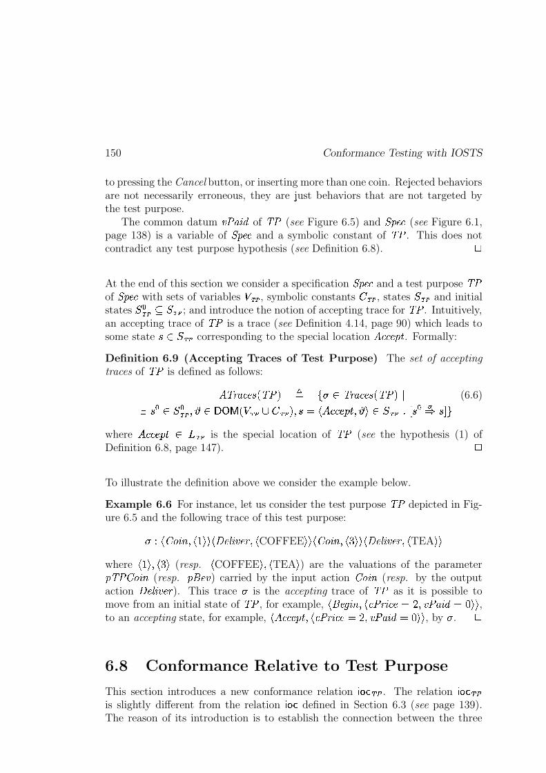
150 Conformance Testing with IOSTS
to pressing the Cancel button, or inserting more than one coin. Rejected behaviorsare not necessarily erroneous, they are just behaviors that are not targeted bythe test purpose.
The common datum � ������� of � � (see Figure 6.5) and � ��� (see Figure 6.1,page 138) is a variable of � ��� and a symbolic constant of � � . This does notcontradict any test purpose hypothesis (see Definition 6.8). �
At the end of this section we consider a specification � ��� and a test purpose � �of � ��� with sets of variables ����� , symbolic constants ����� , states ����� and initialstates �������� ����� ; and introduce the notion of accepting trace for � � . Intuitively,an accepting trace of � � is a trace (see Definition 4.14, page 90) which leads tosome state �! "����� corresponding to the special location #$�����%'& . Formally:
Definition 6.9 (Accepting Traces of Test Purpose) The set of acceptingtraces of � � is defined as follows:
#��)( � ���+*�,-� �/. 0 1-2 3�)( � ���+*�,-� �/.!4 (6.6)5 � � 6� ����87:9 <;>=�?@,��A����BC�/��� . 7 �EDGFIHKJLJLMON)P 7:9RQ 6�����TS�UV� �XWY �[Z]\where HKJLJLMON)P^ `_$��� is the special location of � � (see the hypothesis (1) ofDefinition 6.8, page 147). �
To illustrate the definition above we consider the example below.
Example 6.6 For instance, let us consider the test purpose � � depicted in Fig-ure 6.5 and the following trace of this test purpose:
26a Fcb>d �fe 7 FOg Q:Q F�hi�[j � �k�L( 7 F COFFEE Q:Q Fcb>d �fe 7 FIl Q:Q F�hm�[j � �k�L( 7 F TEA QOQwhere F�g Qn7 F�l Q (resp. F COFFEE Qn7 F TEA Q ) are the valuations of the parametero� � b>d �fe (resp. qpr�L� ) carried by the input action b>d �fe (resp. by the outputaction hi�[j � �k�L( ). This trace
2is the accepting trace of � � as it is possible to
move from an initial state of � � , for example, F�pr��s �fe 7 F+� � ( � ���rDut 7 � �v����� Dxw Q:Q ,to an accepting state, for example, Fy#$�����%'& 7 F+� � ( � ���EDxt 7 � �v����� Dzw Q:Q , by
2. �
6.8 Conformance Relative to Test Purpose
This section introduces a new conformance relation {V|8}�~c� . The relation { |�}�~c�is slightly different from the relation {V|8} defined in Section 6.3 (see page 139).The reason of its introduction is to establish the connection between the three
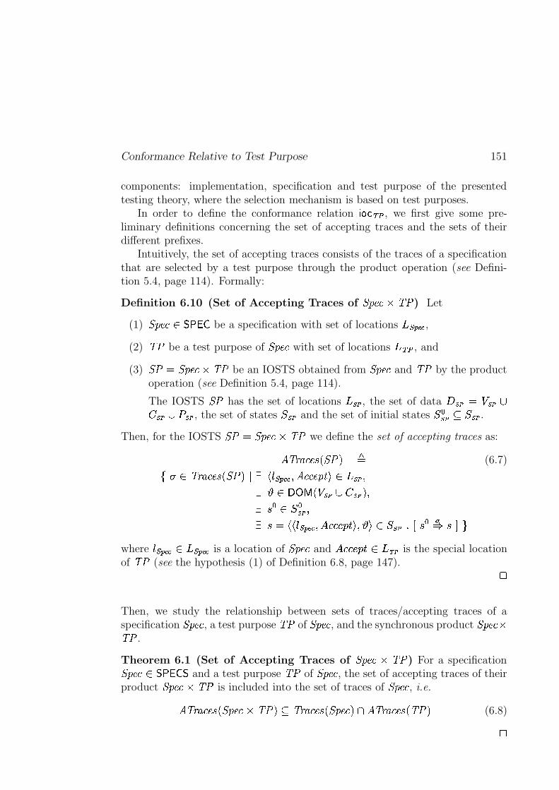
Conformance Relative to Test Purpose 151
components: implementation, specification and test purpose of the presentedtesting theory, where the selection mechanism is based on test purposes.
In order to define the conformance relation { |�}�~c� , we first give some pre-liminary definitions concerning the set of accepting traces and the sets of theirdifferent prefixes.
Intuitively, the set of accepting traces consists of the traces of a specificationthat are selected by a test purpose through the product operation (see Defini-tion 5.4, page 114). Formally:
Definition 6.10 (Set of Accepting Traces of � �����3� � ) Let
(1) � ���/ ������� be a specification with set of locations _��� �� ,(2) � � be a test purpose of � ��� with set of locations _/~c� , and
(3) � D � ����� � � be an IOSTS obtained from � ��� and � � by the productoperation (see Definition 5.4, page 114).
The IOSTS � has the set of locations _��]� , the set of data ���I� D ���]�/B���I�$B����I� , the set of states ���I� and the set of initial states ����I��� ���I� .
Then, for the IOSTS � D � �����3� � we define the set of accepting traces as:
#���( � ���+*�,% �!. 0(6.7)1 2 3�)( � ���+*�,y �/.!4 5 F������ �� 7 #$�����%'& Q 6_ �]� 75 9 <;>=�?T,��!�I�$B ���I� . 75 � � � ��I��75 �KD F:F������ �� 7 HKJLJLMON)P Qn7:9RQ 6���I�TS U�� �<WY ��Z�\
where ����� ��$ 6_���� �� is a location of � ��� and HrJnJLMON)Pv _$��� is the special locationof � � (see the hypothesis (1) of Definition 6.8, page 147).
�
Then, we study the relationship between sets of traces/accepting traces of aspecification � ��� , a test purpose � � of � ��� , and the synchronous product � ������ � .
Theorem 6.1 (Set of Accepting Traces of � ���"� � � ) For a specification� ���/ ���#�!�$� and a test purpose � � of � ��� , the set of accepting traces of theirproduct � ���%�3� � is included into the set of traces of � ��� , i.e.
#���( � ���+* ,%� ���%�3� �/. � �)( � ���+*�,y� ��� .�& #���( � ���+* , � ��. (6.8)
�
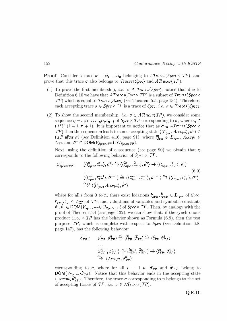
152 Conformance Testing with IOSTS
Proof Consider a trace2 D����'ScScS���� belonging to #��)( � ���+*�,y� ��� � � ��. , and
prove that this trace2
also belongs to �)( � ���+*�,y� ��� . and #���( � ���+*�,-� �/. .(1) To prove the first membership, i.e.
2 `�)( � ���+*�,y� ��� . , notice that due toDefinition 6.10 we have that #��)( � ���+*k,y� ��� � � �!. is a subset of ��( � ���+* ,%� ��� �� �/. which is equal to �)( � ���+* ,%� ��� . (see Theorem 5.5, page 134). Therefore,each accepting trace
2 � �����@� � is a trace of � ��� , i.e.2 x�)( � ���+* ,%� ��� . .
(2) To show the second membership, i.e.2 <#��)( � ���+*�,-� �/. , we consider some
sequence � D������'ScScS�� ������� ����� of � �����"� � corresponding to2
, where ���A ,���� .�� ( ��D gkS S����3g ). It is important to notice that as
2 X#���( � ���+* ,%� ��� �� �/. then the sequence � leads to some accepting state F:F �� � ��� �� 7 #E�����%'& Qn7 �9 � Q , � �! �"$#�%�&�2�.
(see Definition 4.16, page 91), where � � ��� �� _���� � , #E�����%'& _r~c� and 9 � <;>=�?@,������ ��(' ~c� B � ��� ��)' ~ � . .Next, using the definition of a sequence (see page 90) we obtain that �corresponds to the following behavior of � ����� � � :
*,+��� ��)' ~ � a FOF�� � ��� �� 7 � � ~c� Qn7:9 � Q.-0/Y FOF �� � ��� �� 7 �� � ~c� Qn7 �9 � Q213/4 FOF�� ���� �� 7 � � ~c� Qn7:9 � Q
S[ScS (6.9)
FOF�� ��56���� ��L7 � ��56�~c� Qn7O9 ��56� Q -87Y F:F �� ��56���� ��L7 �� ��56�~ �CQn7 �9 ��56� Q 1 74 F:F�� � ��� ��L7 � � ~c� Qn7O9 � Q- 7)9 /Y FOF �� � ��� ��L7 #E�����%'& Qn7 �9 � Q
where for all � from w to � , there exist locations � � ��� ��L7 �� � ��� �� _���� �� of � ��� ;� � ~ � 7 �� � ~c� _r~c� of � � ; and valuations of variables and symbolic constants
9 � 7 �9 � <;>=�?@,������ ��)' ~c��B$� ��� ��(' ~ � . of � �����@� � . Then, by analogy with theproof of Theorem 5.4 (see page 132), we can show that: if the synchronousproduct � ��� � � � has the behavior shown as Formula (6.9), then the testpurpose � � , which is complete with respect to � ��� (see Definition 6.8,page 147), has the following behavior:
* + ~c� a F�� � ~ � 7:9 � ~c� Q.- /Y F �� � ~c� 7 �9 � ~c� Q21 /4 F�� � ~c� 7O9 � ~c� QScS[SF�� ��56�~ �67:9 ��56�~ �@Q -:7Y F �� ��56�~c� 7 �9 ��56�~c� Q 1 74 F�� � ~c��7:9 � ~c� Q- 7)9 /Y F%#E�����%'& 7 �9 � ~ �RQ
corresponding to � , where for all �3D gkS S�� , 9 � ~c� and�9 � ~c� belong to
;>=�?@,�� ~c�CB �m~ � . . Notice that this behavior ends in the accepting stateF%#E�����%'& 7 �9 � ~ �RQ . Therefore, the trace
2corresponding to � belongs to the set
of accepting traces of � � , i.e.2 #��)( � ���+*�,-� �/. .
; S�<iS�=6S
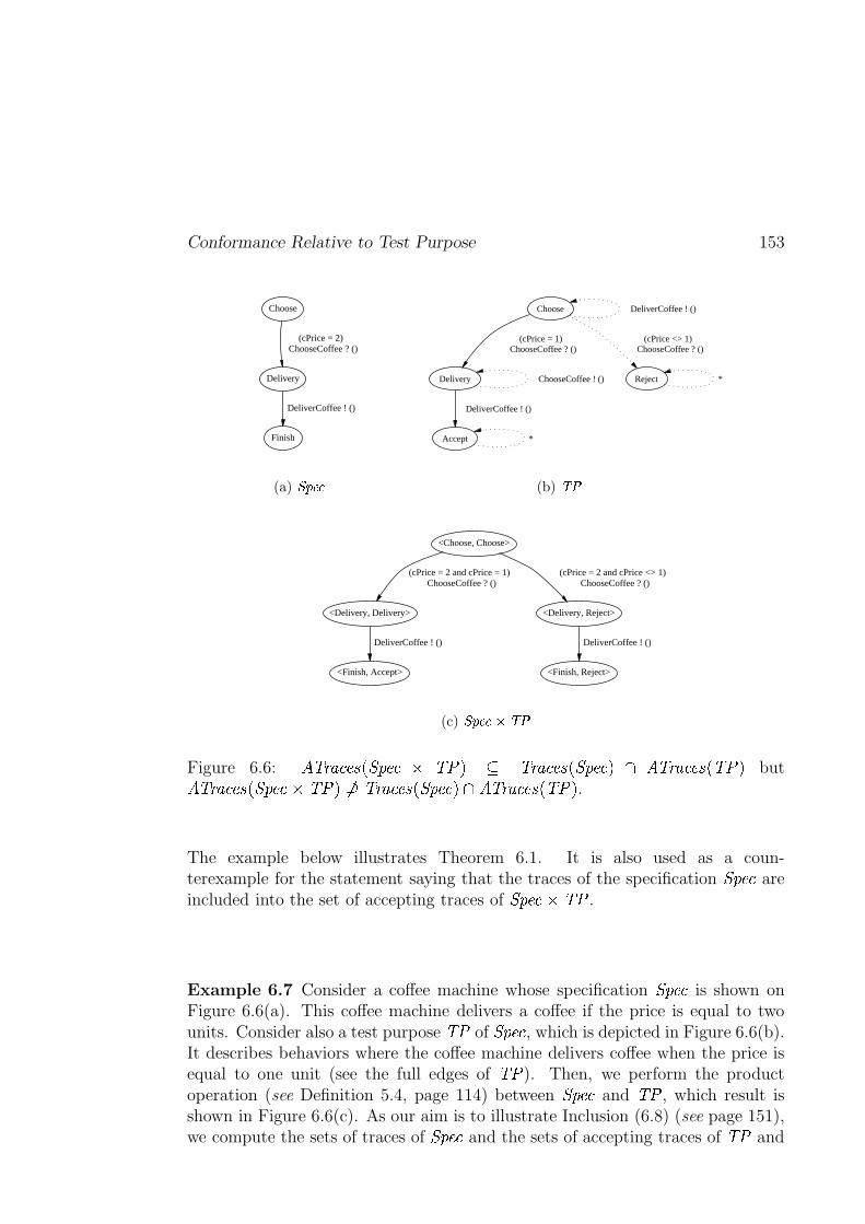
Conformance Relative to Test Purpose 153
Choose
Delivery
(cPrice = 2) ChooseCoffee ? ()
Finish
DeliverCoffee ! ()
(a) �������
Choose DeliverCoffee ! ()
Delivery
(cPrice = 1) ChooseCoffee ? ()
Reject
(cPrice <> 1) ChooseCoffee ? ()
ChooseCoffee ! ()
Accept
DeliverCoffee ! ()
*
*
(b) ��
<Choose, Choose>
<Delivery, Delivery>
(cPrice = 2 and cPrice = 1) ChooseCoffee ? ()
<Delivery, Reject>
(cPrice = 2 and cPrice <> 1) ChooseCoffee ? ()
<Finish, Accept>
DeliverCoffee ! ()
<Finish, Reject>
DeliverCoffee ! ()
(c) ������ ����
Figure 6.6: #���( � ���+* ,%� ��� � � ��. � ��( � ���+* ,%� ��� . & #���( � ���+*�,-� �/. but#��)( � ���+* ,%� ���%�3� �/.��� �)( � ���+*�,y� ��� .�& #���( � ���+*�, � �!. .
The example below illustrates Theorem 6.1. It is also used as a coun-terexample for the statement saying that the traces of the specification � ��� areincluded into the set of accepting traces of � �����3� � .
Example 6.7 Consider a coffee machine whose specification � ��� is shown onFigure 6.6(a). This coffee machine delivers a coffee if the price is equal to twounits. Consider also a test purpose � � of � ��� , which is depicted in Figure 6.6(b).It describes behaviors where the coffee machine delivers coffee when the price isequal to one unit (see the full edges of � � ). Then, we perform the productoperation (see Definition 5.4, page 114) between � ��� and � � , which result isshown in Figure 6.6(c). As our aim is to illustrate Inclusion (6.8) (see page 151),we compute the sets of traces of � ��� and the sets of accepting traces of � � and
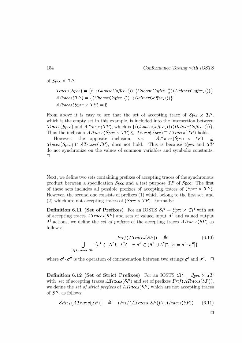
154 Conformance Testing with IOSTS
of � ���%� � � :
��( � ���+* ,%� ��� . D 1 ���cFcb��)d d-*c�kb>d��K��� 7 F QOQ � Fcb��)d d-*c�kb>d��K��� 7 F Q:Q F�hm�[j � �k�L(kb>d��K��� 7 F Q:Q \#���( � ���+* , � ��. D 1 F[b��)d d-*c�kb>d��K��� 7 F Q:Q � F�hi�[j � �k�L( b>d��K��� 7 F QOQ \#���( � ���+* ,%� ��� � � �/. D��
From above it is easy to see that the set of accepting trace of � ��� � � � ,which is the empty set in this example, is included into the intersection between��( � ���+*�,y� ��� . and #��)( � ���+*�,-� �/. , which is
1 F[b��)d d-*c�kb>d��K��� 7 F Q:Q Fyhi�[j � �k�L( b>d��K��� 7 F Q:Q \ .Thus the inclusion #���( � ���+*�,y� ���%� � �/. � �)( � ���+*�,y� ��� .�& #���( � ���+*�,-� �/. holds.
However, the opposite inclusion, i.e. #���( � ���+* ,%� ��� � � �/. �
��( � ���+*�,y� ��� . & #���( � ���+*�,-� �/. , does not hold. This is because � ��� and � �do not synchronize on the values of common variables and symbolic constants.�
Next, we define two sets containing prefixes of accepting traces of the synchronousproduct between a specification � ��� and a test purpose � � of � ��� . The firstof these sets includes all possible prefixes of accepting traces of ,y� ����� � �/. .However, the second one consists of prefixes (1) which belong to the first set, and(2) which are not accepting traces of ,y� ����� � �/. . Formally:
Definition 6.11 (Set of Prefixes) For an IOSTS � D � ��� � � � with setof accepting traces #��)( � ���+*�,y �/. and sets of valued input �� and valued output� actions, we define the set of prefixes of the accepting traces #���( � ���+* ,% ��. asfollows:
� (:��� ,%#���( � ���+*k,% ��.�. 0(6.10)
W���� ~���� � ���� O���1-2�� ,�� � B � . � 4 5 2�� � , � � B � . � S U 2 D 2���� 2�� � Z]\
where2 � �:2 � �
is the operation of concatenation between two strings2 �
and2 � �
. �
Definition 6.12 (Set of Strict Prefixes) For an IOSTS � D � ��� � � �with set of accepting traces #��)( � ���+*�,y �/. and set of prefixes
� (���� , #��)( � ���+*k,y ��.O. ,we define the set of strict prefixes of #��)( � ���+*�,y �/. which are not accepting tracesof � , as follows:
� (:��� ,%#��)( � ���+*�,y �/.O. 0 , � (:��� ,%#���( � ���+* ,% ��.�.� #���( � ���+* ,% ��.�. (6.11)
�
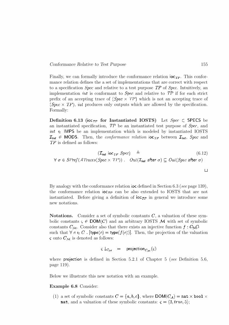
Conformance Relative to Test Purpose 155
Finally, we can formally introduce the conformance relation {V|8}�~c� . This confor-mance relation defines the a set of implementations that are correct with respectto a specification � ��� and relative to a test purpose � � of � ��� . Intuitively, animplementation
��� & is conformant to � ��� and relative to � � if for each strictprefix of an accepting trace of ,%� ��� � � �/. which is not an accepting trace of,y� ��� � � �/. , ��� & produces only outputs which are allowed by the specification.Formally:
Definition 6.13 ( {V|8}�~c� for Instantiated IOSTS) Let � ���x ���#�!�$�be
an instantiated specification, � � be an instantiated test purpose of � ��� , and��� & � ? ��� be an implementation which is modeled by instantiated IOSTS������ ? =/; � . Then, the conformance relation {V|8}�~ � between������
, � ��� and� � is defined as follows:
, ������ {V|8}�~c�<� ��� . 0(6.12) 2 � (:��� ,%#���( � ���+* ,%� ���%�3� �/.O. S U�� � &n, ������� �"$#�%�&�2�. � � � &n,y� ��� "$#�%�& 2 . Z
�
By analogy with the conformance relation { |�} defined in Section 6.3 (see page 139),the conformance relation {V|8}�~c� can be also extended to IOSTS that are notinstantiated. Before giving a definition of {V|8}�~ � in general we introduce somenew notations.
Notations. Consider a set of symbolic constants � , a valuation of these sym-bolic constants � ;>=!?@,]� . and an arbitrary IOSTS � with set of symbolicconstants ��� . Consider also that there exists an injective function � a �����4 �such that
J! 6�`S U #����3% ,]J . D #����3% ,���,IJ .O. Z . Then, the projection of the valuation� onto ��� is denoted as follows:
����� � D ��& |�! % } # {V|#" � � ,$� .
where��& |�! % } # {V|#" is defined in Section 5.2.1 of Chapter 5 (see Definition 5.6,
page 119).
Below we illustrate this new notation with an example.
Example 6.8 Consider:
(1) a set of symbolic constants � D 1&% 7('�7 J-\ , where ;>=!?@,]��) . D+*-,/. �103242�5 �*-, . , and a valuation of these symbolic constants: �rD F�l 7 P7698 M 7;:�Q ;
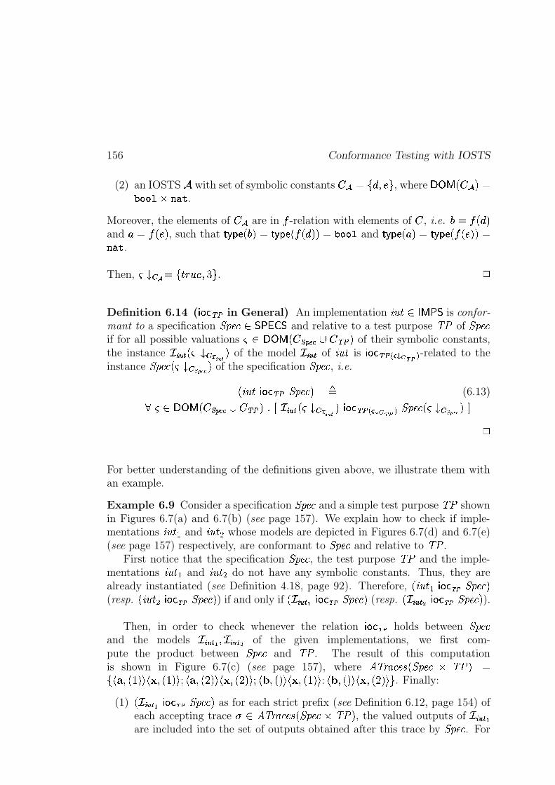
156 Conformance Testing with IOSTS
(2) an IOSTS � with set of symbolic constants ��)6D 1�� 7 Mk\ , where ;>=!?@,]��) . D0324245 � *-,/. .
Moreover, the elements of ��) are in � -relation with elements of � , i.e. ' D ��, �).and
% D ��,IM . , such that#���� % , ' . D #����3% , ��, � .�. D+03242�5 and
#���� % , %). D #����3% , ��,]M .O. D*-,/. .
Then, ������� D 1 P7698 M 7 l�\ . �
Definition 6.14 ( {V|8}8~ � in General) An implementation��� & � ? ��� is confor-
mant to a specification � ���� ���#�!�$� and relative to a test purpose � � of � ���if for all possible valuations � ;>=�?@,I� ��� ���B"�m~ � . of their symbolic constants,the instance
������ ,��1������� � . of the model������
of��� & is {V|8} ~c� � ����� ��� � -related to the
instance � ���k,���� � ������� . of the specification � ��� , i.e.
, ��� &E{ |�} ~c�X� ��� . 0(6.13) �� <;>=�?@,I� ��� ��ABC�m~ � . S U ������� ,$� ��� ��� � . {V|8} ~c� ������� ��� � � ���k,������ ����� � . Z
�
For better understanding of the definitions given above, we illustrate them withan example.
Example 6.9 Consider a specification � ��� and a simple test purpose � � shownin Figures 6.7(a) and 6.7(b) (see page 157). We explain how to check if imple-mentations
��� &(� and��� &�� whose models are depicted in Figures 6.7(d) and 6.7(e)
(see page 157) respectively, are conformant to � ��� and relative to � � .First notice that the specification � ��� , the test purpose � � and the imple-
mentations��� &(� and
��� &�� do not have any symbolic constants. Thus, they arealready instantiated (see Definition 4.18, page 92). Therefore, , ��� & �${V|8}���� � ��� .(resp. , ��� &���{ |�}k��� � ��� . ) if and only if , ������� / {V|8}k��� � ���
.(resp. , ��������� {V|8}���� � ��� . ).
Then, in order to check whenever the relation {V|8} ��� holds between � ���and the models
������/ 7������� �
of the given implementations, we first com-pute the product between � ��� and � � . The result of this computationis shown in Figure 6.7(c) (see page 157), where #��)( � ���+*�,y� ��� � � �/. D1 F�� 7 ,�g . Q F�� 7 ,�g . Q � F�� 7 ,�t . Q F�� 7 ,It . Q � F�� 7 , . Q F�� 7 ,�g . Q � F�� 7 , . Q F�� 7 ,�t . Q \ . Finally:
(1) , ������� / {V|8}k��� � ���.
as for each strict prefix (see Definition 6.12, page 154) ofeach accepting trace
2 #���( � ���+*�,y� ��� � � �/. , the valued outputs of� �����
/are included into the set of outputs obtained after this trace by � ��� . For
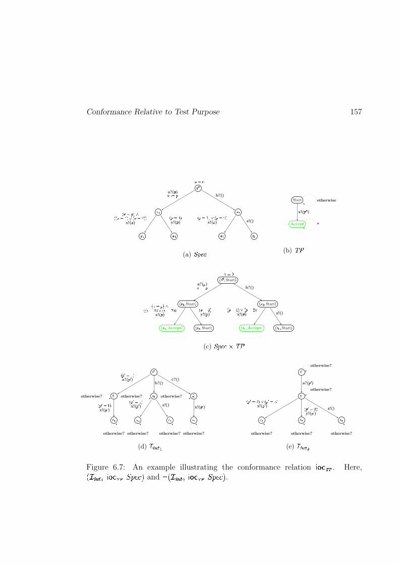
Conformance Relative to Test Purpose 157
���
��� ���
��� ��� �� ��
� ���a?(� )��� � � b?()
� � � ������ � � ��� ��� � � ��� � �x!(� )
� � ��� �y!(� )
� � ��� � � � � ��� �x!(� ) z!()
(a) ���� �
Start
Accept
x!(�"! ! )otherwise
*
(b) � �
# ����$ Start %
# �&�'$ Start % # ����$ Start %
# � � $ Accept % # � � $ Start % # � $ Accept % # � $ Start %
�(���a?(� )��� � � b?()
� �(� ���)�� � � ��� � � � �(�*� � �x!(� )
� � ��� �y!(� )
� � ��� � � � � ��� �x!(� ) z!()
(c) ������ ����
+ �
+ � + � + �
+ � + + + ,
� �"! ��� �a?(� ! )
b?()c?()
� �"! ��� �x!(�-! )
� �"! ��� �x!(�"! ) z!()
x!(�"! )otherwise? otherwise? otherwise?
otherwise? otherwise? otherwise? otherwise?
(d) .�/�0�1�2
+ �
+ �
+ � + � + �
a?(�"! )
� �"! �*� ��� � �"! ��� �x!(�"! ) � �"! ��� �
y!(�"! ) z!()
otherwise?
otherwise?
otherwise? otherwise? otherwise?
(e) .�/'0�1-3
Figure 6.7: An example illustrating the conformance relation {V|8} ��� . Here,, ������� / {V|8}���� � ���
.and 4 , ������� � {V|8}k��� � ��� . .
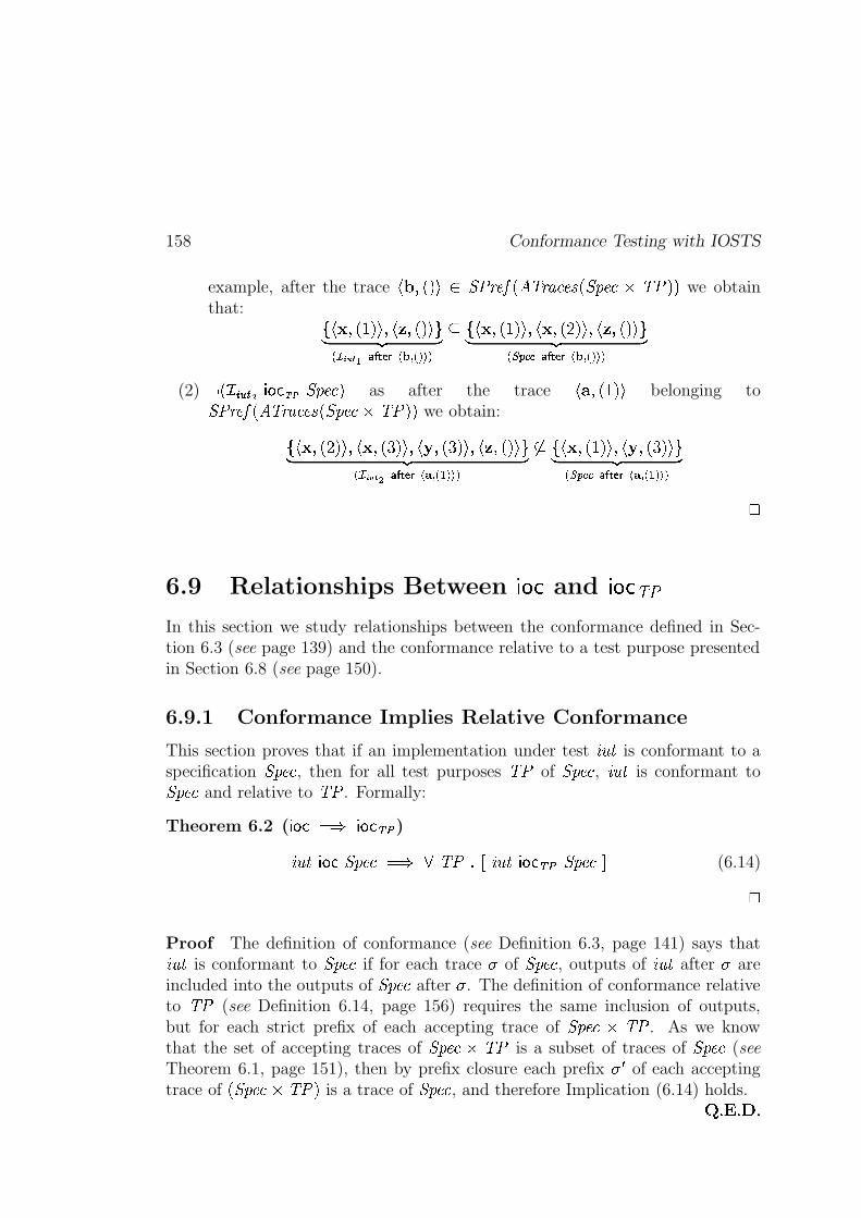
158 Conformance Testing with IOSTS
example, after the trace F�� 7 , . Q � (:����,%#��)( � ���+*�,y� ���"� � �!.�. we obtainthat: 1 F�� 7 ,�g . Qn7 F�� 7 , . Q \� ��� �
� � � �/���� ������� � �����
� 1 F�� 7 ,�g . QL7 F�� 7 ,It . QL7 F�� 7 , . Q \� ��� �� ��� �� ���� �������� � �����
(2) 4 , ������ � { |�}k��� � ��� . as after the trace F�� 7 ,�g . Q belonging to � (:��� ,%#���( � ���+*�,y� �����3� �/.O. we obtain:
1 F�� 7 ,�t . Qn7 F�� 7 ,Il . Qn7 F�� 7 ,Il . Qn7 F�� 7 , . Q \� ��� �� � � � � ���� ����� � � � �����
�� 1 F�� 7 ,�g . Qn7 F�� 7 ,]l . Q \� ��� �� ��� �� ���� ������ � � � �����
�
6.9 Relationships Between!#"%$
and!&"%$
� �
In this section we study relationships between the conformance defined in Sec-tion 6.3 (see page 139) and the conformance relative to a test purpose presentedin Section 6.8 (see page 150).
6.9.1 Conformance Implies Relative Conformance
This section proves that if an implementation under test��� & is conformant to a
specification � ��� , then for all test purposes � � of � ��� , ��� & is conformant to� ��� and relative to � � . Formally:
Theorem 6.2 ( {V|8} D Y { |�}8~c� )
��� &E{V|8} � ��� D Y � � S U ��� &${ |�}�~c�X� ���EZ (6.14)
�Proof The definition of conformance (see Definition 6.3, page 141) says that��� & is conformant to � ��� if for each trace
2of � ��� , outputs of
��� & after2
areincluded into the outputs of � ��� after
2. The definition of conformance relative
to � � (see Definition 6.14, page 156) requires the same inclusion of outputs,but for each strict prefix of each accepting trace of � ����� � � . As we knowthat the set of accepting traces of � ��� � � � is a subset of traces of � ��� (seeTheorem 6.1, page 151), then by prefix closure each prefix
2 �of each accepting
trace of ,y� �����3� ��. is a trace of � ��� , and therefore Implication (6.14) holds.; S�<iS�=6S
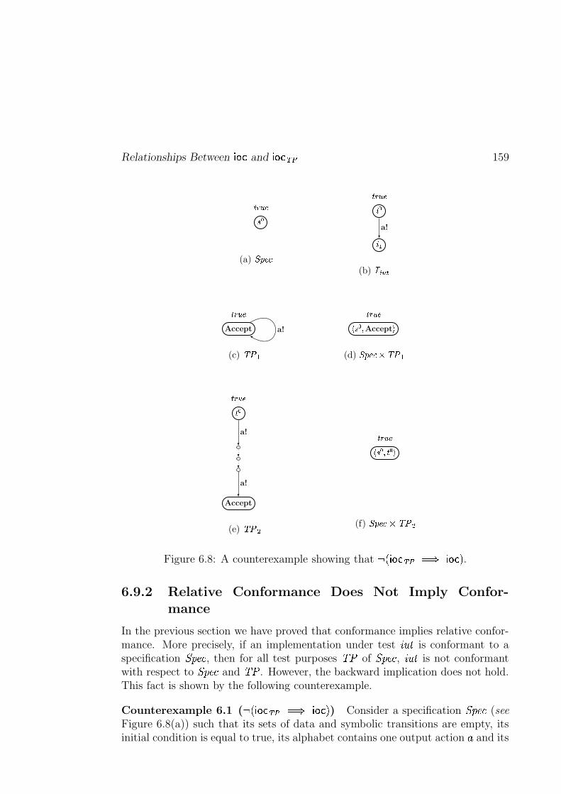
Relationships Between {V|8} and {V|8}�~c� 159
���������
(a)��� ��
���
���
������
a!
(b) �������
Accept
�!�"#a!
(c) $&%('
)+*-,�.Accept / �!�"#
(d) 02143�5768$&%('
,
Accept
�!�"#
a!
a!
(e) $&%:9
)+* , . , / �!�"#
(f) 02143�5;6<$&%:9
Figure 6.8: A counterexample showing that =?>A@ BDCDEGFIHKJ @LB�CNM .
6.9.2 Relative Conformance Does Not Imply Confor-mance
In the previous section we have proved that conformance implies relative confor-mance. More precisely, if an implementation under test OQPDR is conformant to aspecification S&TVUXW , then for all test purposes Y[Z of S&TVUXW , OQPDR is not conformantwith respect to S&TVUXW and Y[Z . However, the backward implication does not hold.This fact is shown by the following counterexample.
Counterexample 6.1 ( =?>�@LB�CDEGF\HKJ @ BDC4M ) Consider a specification S&TVUXW (seeFigure 6.8(a)) such that its sets of data and symbolic transitions are empty, itsinitial condition is equal to true, its alphabet contains one output action ] and its
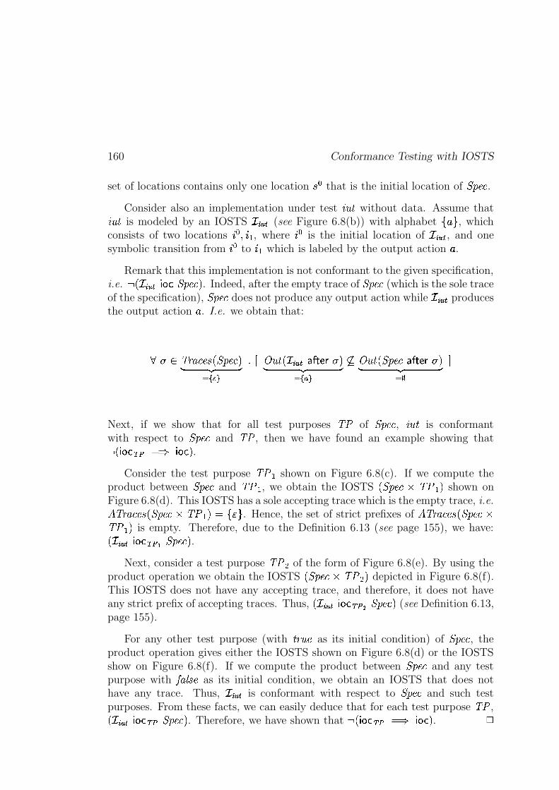
160 Conformance Testing with IOSTS
set of locations contains only one location �-� that is the initial location of � ��� .Consider also an implementation under test
��� & without data. Assume that��� & is modeled by an IOSTS������
(see Figure 6.8(b)) with alphabet1&% \ , which
consists of two locations ��� 7 ��� , where ��� is the initial location of������
, and onesymbolic transition from ��� to ��� which is labeled by the output action
%.
Remark that this implementation is not conformant to the given specification,i.e. 4 , ������ { |�} � ��� . . Indeed, after the empty trace of � ��� (which is the sole traceof the specification), � ��� does not produce any output action while
� �����produces
the output action%. I.e. we obtain that:
2 3�)( � ���+*�,y� ��� .� ��� ����-�
S U � � &n, ������� �"$#�%�&�2�.� ��� ������ �
�� � � &n,y� ��� "$#�%�& 2 .� ��� ����
Z
Next, if we show that for all test purposes � � of � ��� , ��� & is conformantwith respect to � ��� and � � , then we have found an example showing that4 ,%{ |�}�~c� D Y {V|8} . .
Consider the test purpose � � � shown on Figure 6.8(c). If we compute theproduct between � ��� and � � � , we obtain the IOSTS ,%� ��� � � � � . shown onFigure 6.8(d). This IOSTS has a sole accepting trace which is the empty trace, i.e.#���( � ���+*�,y� ���%�3� � � . D 1 ��\ . Hence, the set of strict prefixes of #���( � ���+* ,%� ��� �� � � . is empty. Therefore, due to the Definition 6.13 (see page 155), we have:, ������ {V|8}8~c����� ��� . .
Next, consider a test purpose � � � of the form of Figure 6.8(e). By using theproduct operation we obtain the IOSTS ,%� ���%�3� � � . depicted in Figure 6.8(f).This IOSTS does not have any accepting trace, and therefore, it does not haveany strict prefix of accepting traces. Thus, , � ����� {V|8}8~c�$� ��� . (see Definition 6.13,page 155).
For any other test purpose (with &]( � � as its initial condition) of � ��� , theproduct operation gives either the IOSTS shown on Figure 6.8(d) or the IOSTSshow on Figure 6.8(f). If we compute the product between � ��� and any testpurpose with � � j *c� as its initial condition, we obtain an IOSTS that does nothave any trace. Thus,
������is conformant with respect to � ��� and such test
purposes. From these facts, we can easily deduce that for each test purpose � � ,, ������ {V|8}8~c�X� ��� . . Therefore, we have shown that 4 ,%{ |�}�~c� D Y { |�} . . �
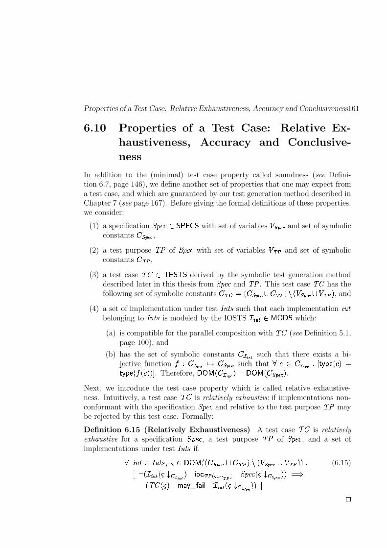
Properties of a Test Case: Relative Exhaustiveness, Accuracy and Conclusiveness161
6.10 Properties of a Test Case: Relative Ex-
haustiveness, Accuracy and Conclusive-
ness
In addition to the (minimal) test case property called soundness (see Defini-tion 6.7, page 146), we define another set of properties that one may expect froma test case, and which are guaranteed by our test generation method described inChapter 7 (see page 167). Before giving the formal definitions of these properties,we consider:
(1) a specification � ���K ���#�!�$� with set of variables ����� �� and set of symbolicconstants � ��� �� ,
(2) a test purpose � � of � ��� with set of variables ��~ � and set of symbolicconstants �i~c� ,
(3) a test case � b �� � � � � derived by the symbolic test generation methoddescribed later in this thesis from � ��� and � � . This test case � b has thefollowing set of symbolic constants � ~��TDG,I� ��� �� Bm�m~c� . ,������ �� Bi� ~c� . , and
(4) a set of implementation under test � � & * such that each implementation��� &
belonging to � � &f* is modeled by the IOSTS����� X? =�; � which:
(a) is compatible for the parallel composition with � b (see Definition 5.1,page 100), and
(b) has the set of symbolic constants � � � � such that there exists a bi-jective function � a � � � � �4 � ��� �� such that
J u� � � � S U #����3% ,IJ . D#���� % ,���,IJ .O. Z . Therefore, ;>=�?@,I� � � � . D ;>=!?@,]� ��� �� . .Next, we introduce the test case property which is called relative exhaustive-ness. Intuitively, a test case � b is relatively exhaustive if implementations non-conformant with the specification � ��� and relative to the test purpose � � maybe rejected by this test case. Formally:
Definition 6.15 (Relatively Exhaustiveness) A test case � b is relativelyexhaustive for a specification �RNqM J , a test purpose � � of � ��� , and a set ofimplementations under test � � &f* if:
��� & �� � &f* 7 �� <;>=�?@,O,I� ��� �� B �m~c� .� ,I�$��� �� B ��~c� .�. S (6.15)
U 4 , ������� ,�������� � � . {V|8}8~c� ������� ��� � � ���k,������ ����� � .�. D Y, � b ,�� . � �
_" {�� ������ ,���������� � .O. Z
�
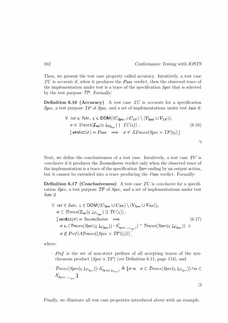
162 Conformance Testing with IOSTS
Then, we present the test case property called accuracy. Intuitively, a test case� b is accurate if, when it produces the
�v� *�* verdict, then the observed trace ofthe implementation under test is a trace of the specification � ��� that is selectedby the test purpose � � . Formally:
Definition 6.16 (Accuracy) A test case � b is accurate for a specification� ��� , a test purpose � � of � ��� , and a set of implementations under test � � &f* if:
��� & �� � &f* 7 �! ^;>=!?@,�,I� ��� ��AB �m~c� .� ,������ ��AB � ~c� .O. 72 3�)( � ���+*�, ������� ,���������� � .m4 4 � b�,�� .O. S (6.16)
U�� %�&�� {V} # , 2�. D �v� *�* D Y 2 #���( � ���+* ,%� ���%�3� �/. ,$� . Z�
Next, we define the conclusiveness of a test case. Intuitively, a test case � b isconclusive if it produces the � e ��d e �[j � * � �k� verdict only when the observed trace ofthe implementation is a trace of the specification � ��� ending by an output action,but it cannot be extended into a trace producing the
��� *�* verdict. Formally:
Definition 6.17 (Conclusiveness) A test case � b is conclusive for a specifi-cation � ��� , a test purpose � � of � ��� , and a set of implementations under test� � &f* if
��� & � � &f* 7 �� <;>=�?@,O,]� ��� �� B �m~c� .� ,������ �� B � ~ � .O. 72 x��( � ���+* , ������ ,$� ������� � .!4 4 � bi,�� .�. SU�� %�&�� { } # , 2 . D � e ��d e �[j � * � �k� D Y (6.17)2 , �)( � ���+*�,y� ���k,������ ����� � .O. � � ����� �������� �������� .�& ��( � ���+*�,y� ���k,$����� ����� � .�.��
2 � � (:��� ,%#���( � ���+*�,O,%� ���%�3� �/. ,�� .�.O. Zwhere:
–� (:��� is the set of non-strict prefixes of all accepting traces of the syn-chronous product ,y� ����� � ��. (see Definition 6.11, page 154), and
– �)( � ���+* ,%� ���k,������ ����� � .�.�� ������ �������� �������� 0 1-2 � � 4�2 3��( � ���+* ,%� ���k,������ ����� � .�.�� � ������ ������ � �������� \
�
Finally, we illustrate all test case properties introduced above with an example.
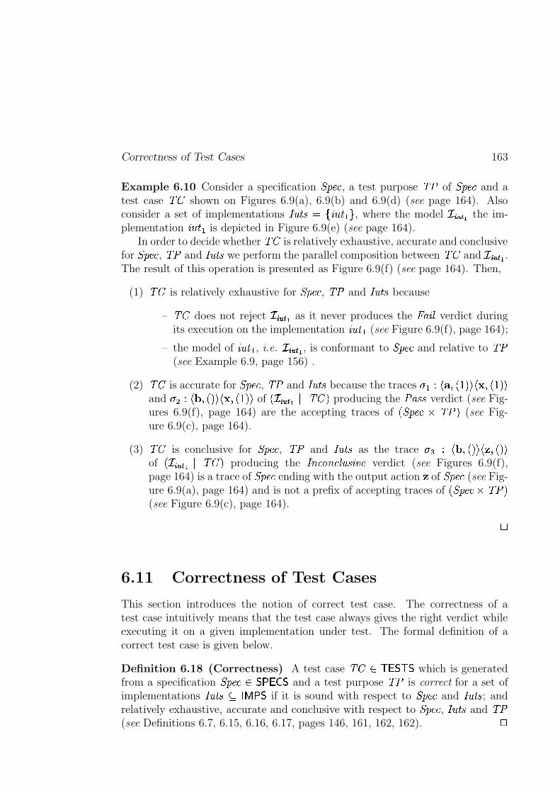
Correctness of Test Cases 163
Example 6.10 Consider a specification � ��� , a test purpose � � of � ��� and atest case � b shown on Figures 6.9(a), 6.9(b) and 6.9(d) (see page 164). Alsoconsider a set of implementations � � & * D 1���� &(��\ , where the model
������/ the im-
plementation��� & � is depicted in Figure 6.9(e) (see page 164).
In order to decide whether � b is relatively exhaustive, accurate and conclusivefor � ��� , � � and � � &f* we perform the parallel composition between � b and
� ����/ .The result of this operation is presented as Figure 6.9(f) (see page 164). Then,
(1) � b is relatively exhaustive for � ��� , � � and � � & * because
– � b does not reject������
/ as it never produces the � ��� j verdict duringits execution on the implementation
��� &(� (see Figure 6.9(f), page 164);
– the model of��� &(� , i.e.
�������/ , is conformant to � ��� and relative to � �
(see Example 6.9, page 156) .
(2) � b is accurate for � ��� , � � and � � & * because the traces2 � a F�� 7 ,�g . Q F�� 7 ,�g . Q
and2 � a F�� 7 , . Q F�� 7 ,�g . Q of , ������� /
4 4 � b . producing the��� *�* verdict (see Fig-
ures 6.9(f), page 164) are the accepting traces of ,%� ����� � ��. (see Fig-ure 6.9(c), page 164).
(3) � b is conclusive for � ��� , � � and � � &f* as the trace2�� a F�� 7 , . Q F�� 7 , . Q
of , ������� /4 4 � b . producing the � e ��d e �[j � * � �k� verdict (see Figures 6.9(f),
page 164) is a trace of � ��� ending with the output action � of � ��� (see Fig-ure 6.9(a), page 164) and is not a prefix of accepting traces of ,y� ���� � �/.(see Figure 6.9(c), page 164).
�
6.11 Correctness of Test Cases
This section introduces the notion of correct test case. The correctness of atest case intuitively means that the test case always gives the right verdict whileexecuting it on a given implementation under test. The formal definition of acorrect test case is given below.
Definition 6.18 (Correctness) A test case � b � � � � � which is generatedfrom a specification � ���i ��������� and a test purpose � � is correct for a set ofimplementations � � &f* � � ? ��� if it is sound with respect to � ��� and � � &f* ; andrelatively exhaustive, accurate and conclusive with respect to � ��� , � � & * and � �(see Definitions 6.7, 6.15, 6.16, 6.17, pages 146, 161, 162, 162). �
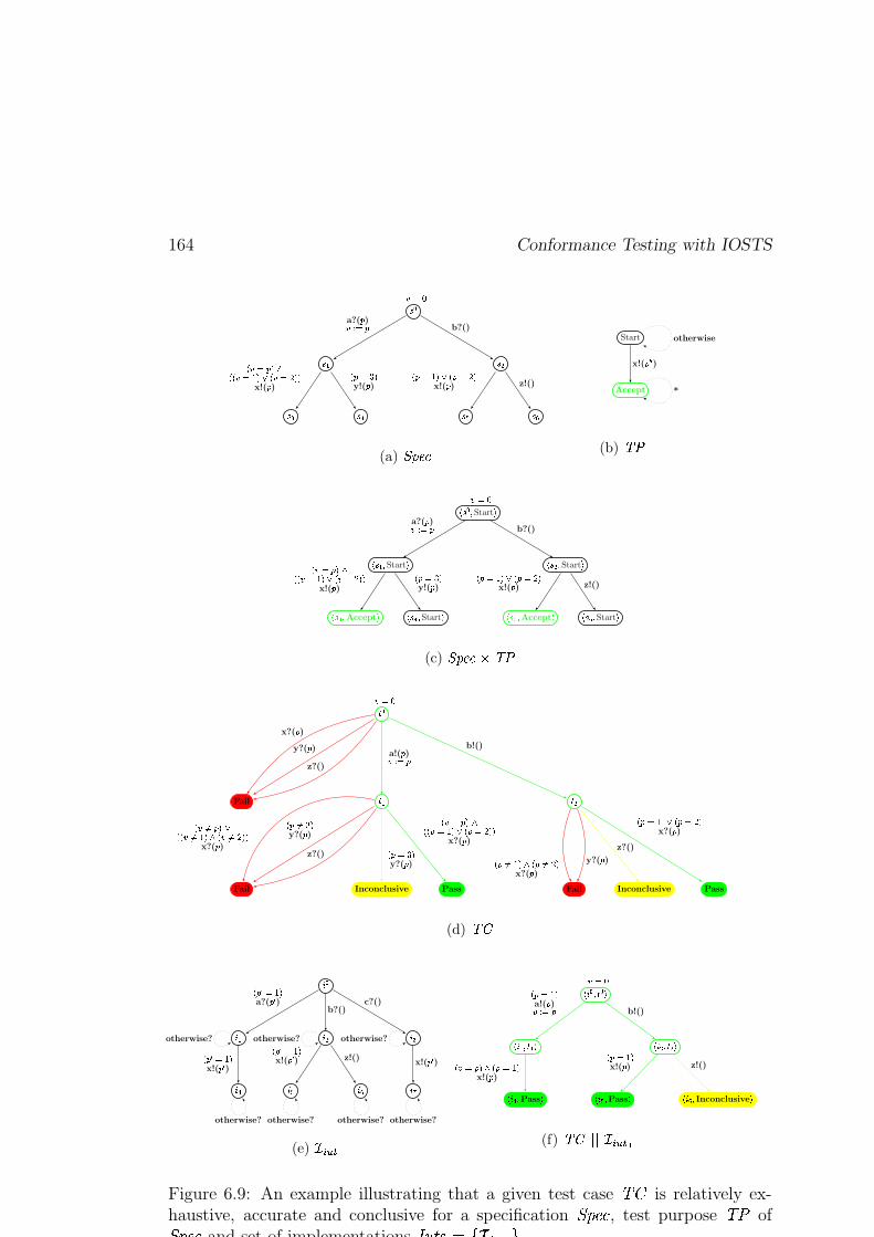
164 Conformance Testing with IOSTS
���
�&� ���
� � � � � �
� ���a?(� )��� � � b?()
� � � ��� �� � � ��� ��� � � �*� � �x!(� )
� � ��� �y!(� )
� � ��� ��� � � ��� �x!(� ) z!()
(a) ������
Start
Accept
x!(� ! ! )otherwise
*
(b) � �
# ����$ Start %
# �&�'$ Start % # ����$ Start %
# � � $ Accept % # � � $ Start % # � $ Accept % # � $ Start %
� ���a?(� )� � � � b?()
� � � ���)�� � �(��� � � � � ��� � �x!(� )
� � ��� �y!(� )
� � ��� ��� � � �*� �x!(� ) z!()
(c) ������� ��� �
� �
Fail� � � �
Fail Inconclusive Pass Fail Inconclusive Pass
� ���
x?(� )
y?(� )
z?()
a!(� )��� � �b!()
� ���� ������ � ������ ��� � ����*� � �x?(� )
� � ���� �y?(� )
z?()� � ��� �y?(� )
� � � ������ � ����� ��� � � �*� � �x?(� )
� � ���� ��� � � ��*� �x?(� )
y?(� )
z?()
� � ��� ��� � � �*� �x?(� )
(d) ���
+ �
+ � + � + �
+ � + + + ,
� �"! ��� �a?(�"! )
b?()c?()
� �"! ��� �x!(� ! )
� �"! ��� �x!(�"! ) z!()
x!(�"! )otherwise? otherwise? otherwise?
otherwise? otherwise? otherwise? otherwise?
(e) . /'0�1 2
# + ��$ � � %
# + �'$ � � % # + ��$ � � %
# + � $ Pass % # + $ Pass % # + $ Inconclusive %
� ���� � ��� �a!(� )��� � � b!()
� � � ��� � � � ��� �x!(� )
� � ��� �x!(� ) z!()
(f) ������ .�/'0 1�2
Figure 6.9: An example illustrating that a given test case � b is relatively ex-haustive, accurate and conclusive for a specification � ��� , test purpose � � of� ��� and set of implementations � � &f*KD 1����� \ .
Correctness of Test Cases 165
Example 6.11 The test case � b shown on Figure 6.9(d) (see page 164) whichis derived from a specification � ��� and a test purpose � � of � ��� (see Fig-ures 6.9(a), 6.9(b) on page 164), is correct for a set of implementations � � &f* D1���� &)�+\ (the model of
��� &(� is shown on Figure 6.9(e), page 164) as it is sound(see Example 6.4, page 147), relatively exhaustive, accurate and conclusive (seeExample 6.10, page 163).
�

166 Conformance Testing with IOSTS
Chapter 7
Symbolic Test Generation
The chapter describes our method for symbolic test generation imple-mented in the Symbolic Test Generator (STG) tool. The purpose ofthis method is to compute a test suite starting from a given specifica-tion and test purposes. The generated test cases must be correct inthe sense of Definition 6.18 (see page 163), in particular, they are allsound, relative exhaustive, accurate and conclusive. At the beginningof the chapter we present the main steps of the method, then we de-scribe them in more detail. Finally, we prove that the symbolic testgeneration method produces correct test cases.
Sketch of the Chapter. In this paragraph we briefly describe the main stepsof a symbolic test generation method presented in this section. These steps aresummarized in Figure 7.1 (see page 168) and explained below.
The symbolic test generation method takes as inputs a specification � ��� anda test purpose � � of � ��� . As incomplete test purposes are allowed (see explana-tions in Section 7.1), the first step of this method is to make them complete withrespect to their specifications. The second step of the method consists in com-puting the product between the given � ��� and completed � � in order to markbehaviors of � ��� as accepted or rejected by the test purpose, and obtaining thesynchronous product � (see Figure 7.1, page 168). The third step builds visibledeterministic behaviors of � , in other words, it consists in removing internalactions and possible non-deterministic choices from � . The result of this step isdenoted by ��� ��� (see Figure 7.1, page 168). The next step of the test generation,namely selection, extracts from ��� ��� its behaviors allowing to go from the initiallocation to the Pass or Inconclusive locations. The result of selection is calleda test graph and denoted by � � . Moreover, during the selection we invert thealphabets of input and output actions of � � making � � able to communicate
167

168 Symbolic Test Generation
Test Case � b with�v� *�* ,
� e ��d e �[j � * � �k� and � ��� j Locations
Making � �Input-Complete
Test Graph � � with�v� *�* and � e ��d e �[j � * � �k� Locations
Selection and InvertingInput/Output Actions of ��� ���
Deterministic ��� � �
Closure & Determinization(if possible)
Synchronous Product � with#$�����%'& and
� ��� ���n& Locations
Product
Specification � ��� Completed � �Making � � Complete
Test Purpose � �
Figure 7.1: Symbolic test generation method.
Making a Test Purpose Complete 169
with implementations under test during the test execution process. Finally, bymaking � � input-complete we obtain a test case � b .
7.1 Making a Test Purpose Complete
In the testing theory presented in this work, test purposes, playing the role ofselection mechanism, must be complete with respect to their specification (seeDefinition 6.8, page 147). In practice this requirement often complicates theprocess of writing test purposes. Thus, we decided to accept incomplete testpurposes from the system developer and complete them automatically at thefirst stage of the test generation process. This decision allows us to focus onthe intended behaviors of the system under test, and significantly simplifies theprocess of writing the test purposes.
Plan of the Section. The rest of this section is organized as follows: first,we give an intuitive idea for an algorithm whose aim is to complete a given testpurpose with respect to its specification. Then, we present the formal algorithm,and prove that this algorithm gives a correct result with respect to Definition 4.22(see page 96). Finally, we illustrate the algorithm with an example.
Intuitive Idea of the Algorithm. Remember that in order to test a givenspecification, the system developer should provide a test purpose. In this thesiswe require test purposes to be represented as IOSTS. This representation allowsto (partially) describe behaviors of a given specification that should be tested(sequences of actions leading to the Accept location), or should not be tested(sequences of actions leading to the deadlock location called here Reject).
As we have remarked above, the developer can provide an incomplete testpurpose which later will be completed with respect to its specification by Algo-rithm 7.1 (see page 170). The intuitive idea of this algorithm is that in eachlocation of a given test purpose � � we must be able to execute any valued actionof its specification � ��� . Therefore, each location of � � must be completed withall actions of � ��� as follows:
(1) Assume that an action%
of � ��� is not specified in a location � of � � .Hence, we suppose that in this location � , the developer does not care aboutpresence or absence of the action
%in an implementation under test � 8 P .
Thus, in the location � , we add a loop labeled by%.
(2) Assume that an action%
of � ��� is specified in a location � of � � . Moreover,the developer would like to test the presence of this action
%in��� & under
some condition � . Hence, we assume that he/she does not want to test
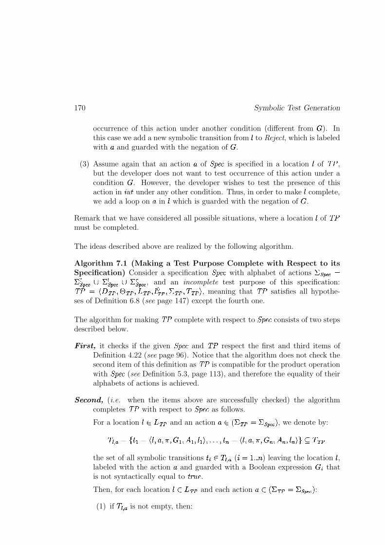
170 Symbolic Test Generation
occurrence of this action under another condition (different from � ). Inthis case we add a new symbolic transition from � to Reject, which is labeledwith
%and guarded with the negation of � .
(3) Assume again that an action%
of � ��� is specified in a location � of � � ,but the developer does not want to test occurrence of this action under acondition � . However, the developer wishes to test the presence of thisaction in
��� & under any other condition. Thus, in order to make � complete,we add a loop on
%in � which is guarded with the negation of � .
Remark that we have considered all possible situations, where a location � of � �must be completed.
The ideas described above are realized by the following algorithm.
Algorithm 7.1 (Making a Test Purpose Complete with Respect to itsSpecification) Consider a specification � ��� with alphabet of actions � ��� ��D� � ��� �� B�� ��� �� B�� � ��� �� , and an incomplete test purpose of this specification:� � D F � ~ � 7�� ~ � 7 _r~c� 7 � � ~c��7 �!~c� 7�� ~c� Q , meaning that � � satisfies all hypothe-ses of Definition 6.8 (see page 147) except the fourth one.
The algorithm for making � � complete with respect to � ��� consists of two stepsdescribed below.
First, it checks if the given � ��� and � � respect the first and third items ofDefinition 4.22 (see page 96). Notice that the algorithm does not check thesecond item of this definition as � � is compatible for the product operationwith � ��� (see Definition 5.3, page 113), and therefore the equality of theiralphabets of actions is achieved.
Second, (i.e. when the items above are successfully checked) the algorithmcompletes � � with respect to � ��� as follows.
For a location �� 6_K~c� and an action% ,��!~c� D�� ��� �� . , we denote by:
� � � D 1 P)��D F�� 7 % 7���7 �.� 7 H � 7 � � Qn7 ScS[S 7 P �mD F�� 7 % 7���7 � � 7 H � 7 � � Q \ � � ~c�the set of all symbolic transitions P��� �� � � ( ��D g S S � ) leaving the location � ,labeled with the action
%and guarded with a Boolean expression � � that
is not syntactically equal to &]( � � .Then, for each location �� "_K~c� and each action
% ,��m~c�CD�� ��� � . :(1) if �� � � is not empty, then:
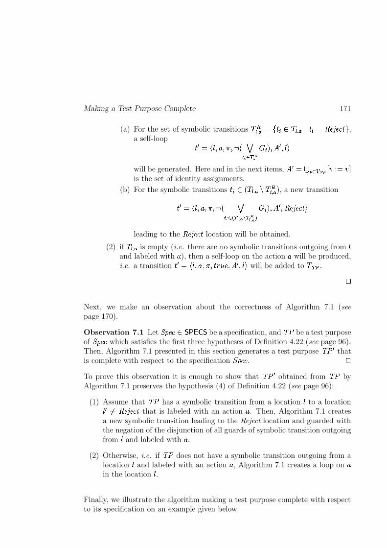
Making a Test Purpose Complete 171
(a) For the set of symbolic transitions ������ ������ �� � ��� ����� �������������� ,a self-loop ��!"�$# �&%(')%+*,%.-0/213�4�5.6879
: <; %(= ! %(�<>will be generated. Here and in the next items, = ! �@?BA�5DCFEHGJI KMLN�OKQPis the set of identity assignments.
(b) For the symbolic transitions �& J� / � ��� �SR �T���� �U; , a new transition
� ! �V# �&%(')%+*,%�-W/ 13�4X5FYZ6D[N\ 9�] 6 7[N\ 9.^: _; %(= ! % ����������� >
leading to the ����������� location will be obtained.
(2) if � ��� � is empty (i.e. there are no symbolic transitions outgoing from �and labeled with ' ), then a self-loop on the action ' will be produced,i.e. a transition � ! �$# �&%(')%+*,% �&`badc %(= ! %(�<> will be added to �feDg . h
Next, we make an observation about the correctness of Algorithm 7.1 (seepage 170).
Observation 7.1 Let ikj �����mlonqp)rsl be a specification, and tsu be a test purposeof ikj ��� which satisfies the first three hypotheses of Definition 4.22 (see page 96).Then, Algorithm 7.1 presented in this section generates a test purpose tsu ! thatis complete with respect to the specification ikj ��� .
h
To prove this observation it is enough to show that tsu ! obtained from tsu byAlgorithm 7.1 preserves the hypothesis (4) of Definition 4.22 (see page 96):
(1) Assume that tsu has a symbolic transition from a location � to a location� !Wv�w����������� that is labeled with an action ' . Then, Algorithm 7.1 createsa new symbolic transition leading to the Reject location and guarded withthe negation of the disjunction of all guards of symbolic transition outgoingfrom � and labeled with ' .
(2) Otherwise, i.e. if tsu does not have a symbolic transition outgoing from alocation � and labeled with an action ' , Algorithm 7.1 creates a loop on 'in the location � .
Finally, we illustrate the algorithm making a test purpose complete with respectto its specification on an example given below.
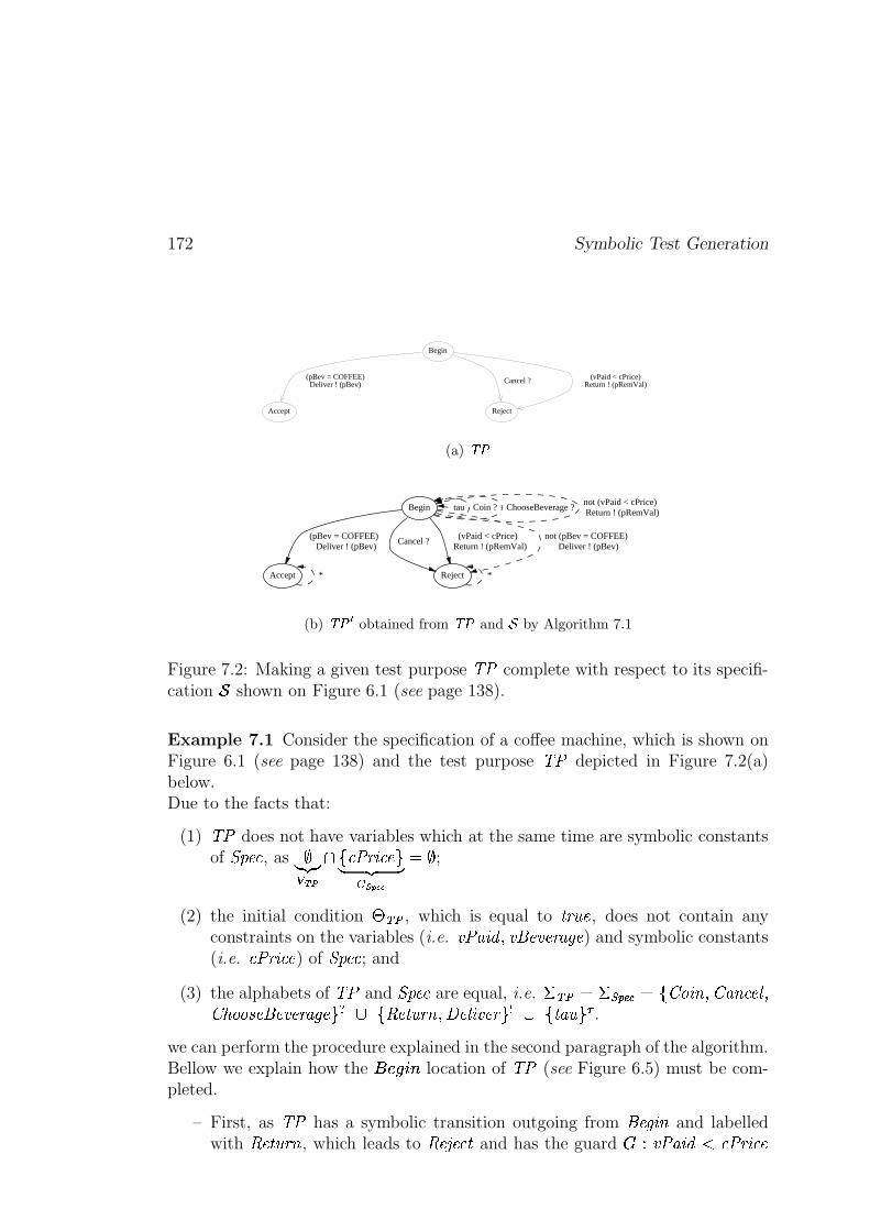
172 Symbolic Test Generation
(pBev = COFFEE)Deliver ! (pBev) Cancel ? (vPaid < cPrice)
Return ! (pRemVal)
Start
Begin
Accept Reject
(a) ���
Begin tau Coin ? ChooseBeverage ?not (vPaid < cPrice) Return ! (pRemVal)
Accept
(pBev = COFFEE) Deliver ! (pBev)
Reject
Cancel ? (vPaid < cPrice)
Return ! (pRemVal)not (pBev = COFFEE)
Deliver ! (pBev)
* *
(b) ����� obtained from ��� and � by Algorithm 7.1
Figure 7.2: Making a given test purpose tsu complete with respect to its specifi-cation � shown on Figure 6.1 (see page 138).
Example 7.1 Consider the specification of a coffee machine, which is shown onFigure 6.1 (see page 138) and the test purpose tsu depicted in Figure 7.2(a)below.Due to the facts that:
(1) tsu does not have variables which at the same time are symbolic constantsof ikj ��� , as ���� C EHG � 8� u���� ���b � �� ���������
� � ;
(2) the initial condition �MeDg , which is equal to � ��� � , does not contain anyconstraints on the variables (i.e. �Du! "�$# % �&% � � � �' )( � ) and symbolic constants(i.e. � u���� ��� ) of ikj ��� ; and
(3) the alphabets of tsu and ikj ��� are equal, i.e. * e�g � *,+�-/.10 � 32�4 �65 % 2 "5 ���)7 %298:4;4=<D� % � � � �> )( �U "?A@ Q����� �B��5 %)C �)7 �6� � � �DE@ � "� ;F .we can perform the procedure explained in the second paragraph of the algorithm.Bellow we explain how the G c)HBI$J location of tsu (see Figure 6.5) must be com-pleted.
– First, as tsu has a symbolic transition outgoing from % � (K�65 and labelledwith ����� �B��5 , which leads to ����������� and has the guard
: L �Du! "�$#ML � u���� ���
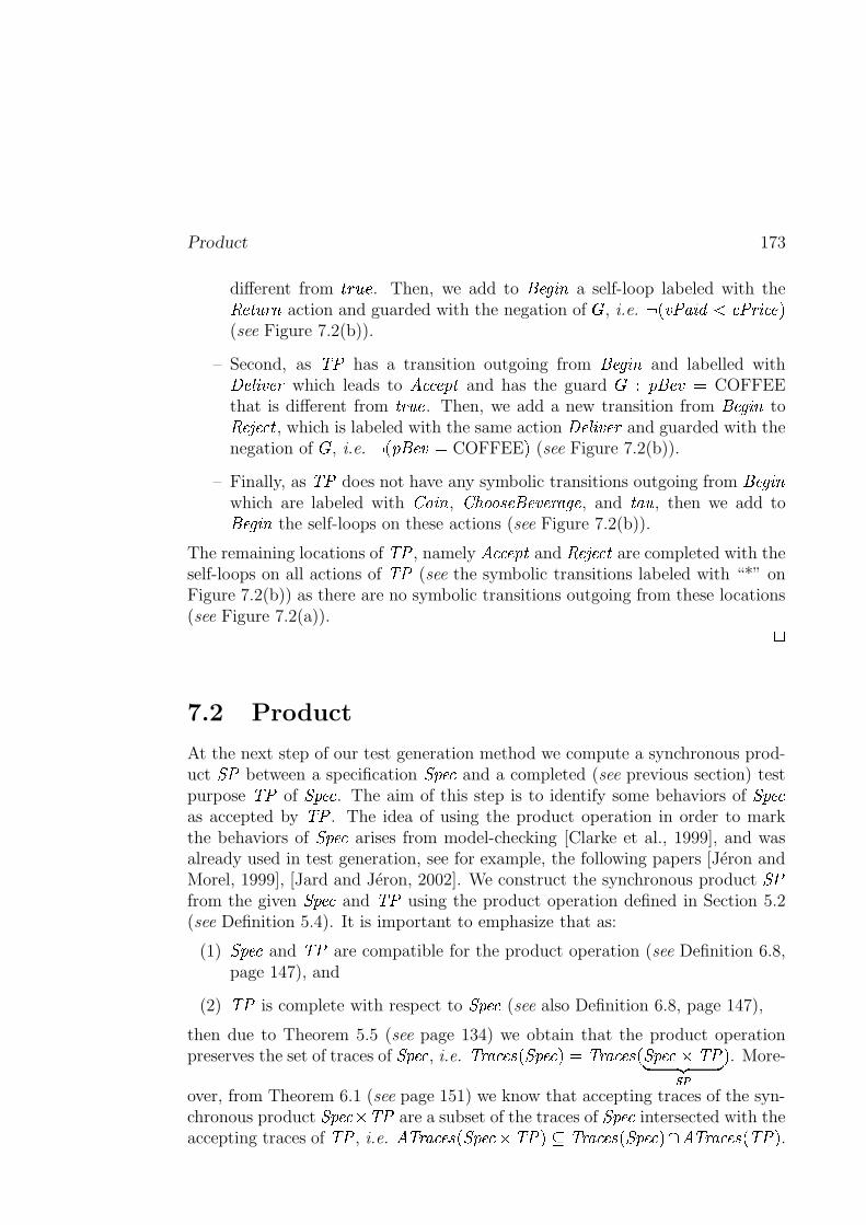
Product 173
different from �&`Fa c . Then, we add to % � (K�65 a self-loop labeled with the����� �B��5 action and guarded with the negation of:
, i.e. -0/ �Du! "�$# L � u ��� ���F;(see Figure 7.2(b)).
– Second, as tsu has a transition outgoing from % � (K�65 and labelled withC �)7 �6� � � which leads to� ����� j � and has the guard
: L j % � � � COFFEEthat is different from � ��� � . Then, we add a new transition from % � (K�65 to����������� , which is labeled with the same action C �)7 �6� � � and guarded with thenegation of
:, i.e. -0/ j % � � � COFFEE ; (see Figure 7.2(b)).
– Finally, as tsu does not have any symbolic transitions outgoing from % � (K�65which are labeled with 2�4 �65 , 298:4;4=<D� % � � � �' )( � , and � "� , then we add to% � (K�65 the self-loops on these actions (see Figure 7.2(b)).
The remaining locations of tsu , namely� ����� j � and ����������� are completed with the
self-loops on all actions of tsu (see the symbolic transitions labeled with “*” onFigure 7.2(b)) as there are no symbolic transitions outgoing from these locations(see Figure 7.2(a)).
h
7.2 Product
At the next step of our test generation method we compute a synchronous prod-uct i u between a specification ikj ��� and a completed (see previous section) testpurpose tsu of ikj ��� . The aim of this step is to identify some behaviors of ikj ���as accepted by tsu . The idea of using the product operation in order to markthe behaviors of ikj ��� arises from model-checking [Clarke et al., 1999], and wasalready used in test generation, see for example, the following papers [Jéron andMorel, 1999], [Jard and Jéron, 2002]. We construct the synchronous product i ufrom the given ikj ��� and tsu using the product operation defined in Section 5.2(see Definition 5.4). It is important to emphasize that as:
(1) ikj ��� and tsu are compatible for the product operation (see Definition 6.8,page 147), and
(2) tsu is complete with respect to ikj ��� (see also Definition 6.8, page 147),
then due to Theorem 5.5 (see page 134) we obtain that the product operationpreserves the set of traces of ikj ��� , i.e. t:�' ����< / ikj ����; � t:�' ����< / ikj ����� tsu� �� ++g ; . More-
over, from Theorem 6.1 (see page 151) we know that accepting traces of the syn-chronous product ikj ����� tsu are a subset of the traces of ikj ��� intersected with theaccepting traces of tsu , i.e.
� t:�' ����< / ikj ����� tsu ;�� t:�' ����< / ikj ����; � � t:�' ����< / tsu ; .
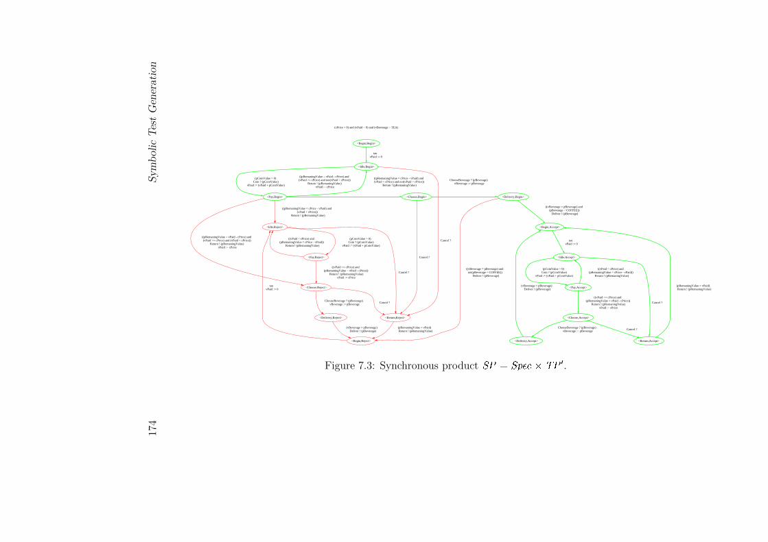
174
Sym
bolic
Tes
tG
ener
ati
on
(cPrice > 0) and (vPaid = 0) and (vBeverage = TEA)
<Begin,Begin>
<Idle,Begin>
tau vPaid := 0
<Pay,Begin>
(pCoinValue > 0) Coin ? (pCoinValue)
vPaid := (vPaid + pCoinValue)
<Return,Reject>
Cancel ?
((pRemaningValue = cPrice - vPaid) and (vPaid < cPrice) and not(vPaid < cPrice))
Return ! (pRemaningValue)
<Idle,Reject>
((pRemaningValue = cPrice - vPaid) and (vPaid < cPrice))
Return ! (pRemaningValue)
<Choose,Reject>
((pRemaningValue = vPaid - cPrice) and (vPaid >= cPrice) and (vPaid < cPrice))
Return ! (pRemaningValue) vPaid := cPrice
<Choose,Begin>
((pRemaningValue = vPaid - cPrice) and (vPaid >= cPrice) and not(vPaid < cPrice))
Return ! (pRemaningValue) vPaid := cPrice
<Begin,Reject>
(pRemaningValue = vPaid) Return ! (pRemaningValue)
Cancel ?
<Pay,Reject>
(pCoinValue > 0) Coin ? (pCoinValue)
vPaid := (vPaid + pCoinValue)
Cancel ?
<Delivery,Reject>
ChooseBeverage ? (pBeverage) vBeverage := pBeverage
Cancel ?
<Delivery,Begin>
ChooseBeverage ? (pBeverage) vBeverage := pBeverage
tau vPaid := 0
((vPaid < cPrice) and (pRemaningValue = cPrice - vPaid))
Return ! (pRemaningValue)
((vPaid >= cPrice) and (pRemaningValue = vPaid - cPrice))
Return ! (pRemaningValue) vPaid := cPrice
(vBeverage = pBeverage) Deliver ! (pBeverage)
((vBeverage = pBeverage) and not(pBeverage = COFFEE))
Deliver ! (pBeverage)
<Begin,Accept>
((vBeverage = pBeverage) and (pBeverage = COFFEE))
Deliver ! (pBeverage)
<Idle,Accept>
tau vPaid := 0
<Pay,Accept>
(pCoinValue > 0) Coin ? (pCoinValue)
vPaid := (vPaid + pCoinValue)
<Return,Accept>
Cancel ?
((vPaid < cPrice) and (pRemaningValue = cPrice - vPaid))
Return ! (pRemaningValue)
<Choose,Accept>
((vPaid >= cPrice) and (pRemaningValue = vPaid - cPrice))
Return ! (pRemaningValue) vPaid := cPrice
(pRemaningValue = vPaid) Return ! (pRemaningValue)
Cancel ?
<Delivery,Accept>
ChooseBeverage ? (pBeverage) vBeverage := pBeverage
(vBeverage = pBeverage) Deliver ! (pBeverage)
Figure 7.3: Synchronous product �� � � �� �� � � � .
Construction of Visible Behaviors 175
Example 7.2 Figure 7.3 (see page 174) shows the result of the productcomputation for the specification of a coffee machine (see Figure 6.1, page 138)and the test purpose of this specification, which is depicted in Figure 7.2(b) (seepage 172). This example does not describe how the product was computed, asthis computation was explained in Section 5.2 (see Example 5.2, page 115). Thepurpose of the example is to emphasize that the product operation marks somelocations of the given specification with
� ����� j � , making behaviors leading tothem accepted by the test purpose. The accepted behaviors of the computedproduct are printed in green in Figure 7.3 (see page 174). All other behaviors, i.e.
ones that are printed in red, are considered as rejected. The rejected behaviorsindicate the behaviors of the specification for which the test case will not be gener-ated. They will be eliminated on the next steps of the test generation method.
h
The next steps of the test generation method described in the rest of this chapterconsist in transforming and simplifying the product i u � / ikj ��� � tsu ; in order toobtain a test case which is correct in the sense of Definition 6.18 (see page 163).
7.3 Construction of Visible Behaviors
It is important to emphasize that nondeterminism is prohibited in testing, as testverdicts should not depend on internal choices of the tester. That is why thisstep of the test generation method is reserved for elimination of internal actionsfrom an IOSTS i u � / ikj ��� � tsu ; obtained at the previous step of our symbolictest generation method (i.e. construction of � � ������� / i u ; ), and resolution of non-deterministic choices that remain for input/output actions of � � ������� / i u ; (i.e.
construction of � �� / � � ������� / i u ;+; ). For this we propose two syntactical operationsclosure and determinization such that:
t:�' ����< / i u ; � t:�' ����< / � � ������� / i u ;+;�� t �> ����< / � �� / � � ������� / i u ;+;+; (7.1)� t:�' ����< / i u ; � � t �> ����< / � � ������� / i u ;+; � � t �> ����< / � �� / � � ������� / i u ;+;+; (7.2)
The syntactical procedures of closure and determinization and their propertiesare described in Appendixes A.1 and A.2 (see pages 246 and 274), and brieflysummarized in the two following subsections.
7.3.1 Closure: Eliminating Internal Actions
For eliminating internal actions from i u , the idea is to compute the effect of anysequence of internal actions that leads to an input- or output-labeled symbolictransition, and to encode this effect in the guard and assignments of the lastsymbolic transition.
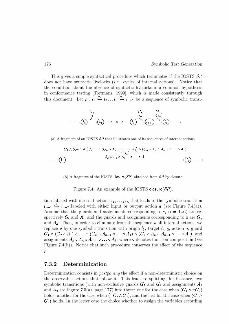
176 Symbolic Test Generation
This gives a simple syntactical procedure which terminates if the IOSTS i udoes not have syntactic livelocks (i.e. cycles of internal actions). Notice thatthe condition about the absence of syntactic livelocks is a common hypothesisin conformance testing [Tretmans, 1999], which is made consistently through
this document. Let � L ��� F��� � ����� � � F��� � � ����� be a sequence of symbolic transi-
��� ��� ��� ������� ���� �� � �
� �� � �� �!#"%$ �'& �
(a) A fragment of an IOSTS (;� that illustrates one of its sequences of internal actions.
�)� ���� �+* " � �-, ��&.*0/1/1/'* " � �, �324�+,5/1/1/�, �6&.* " � ��, �, �324�7,8/9/1/', �6&!#"%$ �'& ��, �, �324�+,8/9/1/�, �
(b) A fragment of the IOSTS :3; <>=1?A@CBADE(;�GF obtained from (=� by closure.
Figure 7.4: An example of the IOSTS � � ������� / i u ; .tion labeled with internal actions H � %����% H � that leads to the symbolic transition� ����� �� � � ���-� labeled with either input or output action ' (see Figure 7.4(a)).Assume that the guards and assignments corresponding to H ( IW�JI ) J ) are re-spectively
: and = ; and the guards and assignments corresponding to ' are: �
and =W� . Then, in order to eliminate from the sequence � all internal actions, wereplace � by one symbolic transition with origin �6� , target � ���-� , action ' , guard: �5K / : �GL =M� ; KN���K / : �OL�=P�RQS�5L0���L�=T� ; K / : �UL�=V�UL�=V�4QS�WL0���L�=T� ; , andassignments =T�8LB=V�XLf=V�4QS��LV��YLf=M� , where L denotes function composition (seeFigure 7.4(b)). Notice that such procedure conserves the effect of the sequence� .
7.3.2 Determinization
Determinization consists in postponing the effect if a non-deterministic choice onthe observable actions that follow it. This leads to splitting, for instance, twosymbolic transitions (with non-exclusive guards
: � and: � and assignments =T�
and =Z� see Figure 7.5(a), page 177) into three: one for the case when / : �[K - : � ;holds, another for the case when / - : �#K : � ; , and the last for the case when / : �.K: � ; holds. In the letter case the choice whether to assign the variables according
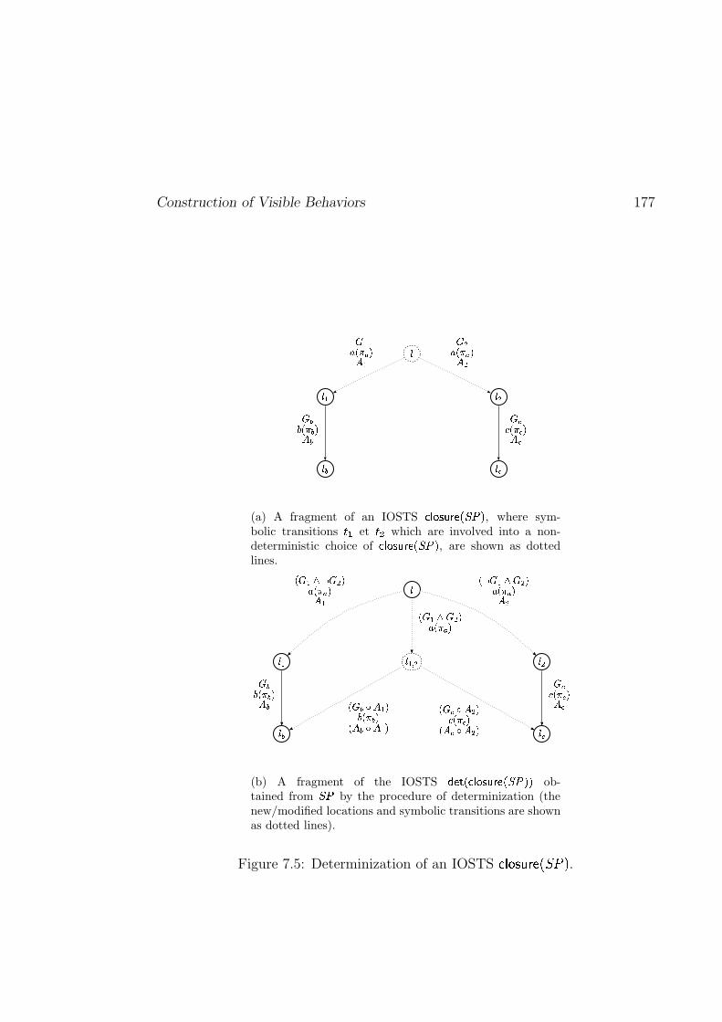
Construction of Visible Behaviors 177
�
��� ���
��� ���
����� ����� ������� ����� �
� �� �� � �� �� ����� � �� �
(a) A fragment of an IOSTS ��� ������ "!$#&%('*) , where sym-bolic transitions +-, et +/. which are involved into a non-deterministic choice of ��� ���0�$ "!�#/%1'2) , are shown as dottedlines.
3
3�4 3�5
3�6 3�7
3�4"8 5
9;: 4=<?> : 5A@B 9�C�D @E 49 > : 4=< : 5&@B 9�C�D @E 59�: 4=< : 5&@B 9�C�D @
9�: 6�F E 4 @G 9�C 6H@9 E 6 F E 4I@9�: 7 F E 5/@J 9�C 7I@9 E 7 F E 5&@
: 6G 9�C 6H@E 6: 7J 9�C 7I@E 7
(b) A fragment of the IOSTS K$LNMNOQP�R S�T0U$VWL=O/X1Y2ZAZ ob-tained from X(Y by the procedure of determinization (thenew/modified locations and symbolic transitions are shownas dotted lines).
Figure 7.5: Determinization of an IOSTS []\ ^`_�acbIdfeNgihkj .
178 Symbolic Test Generation
to =M� or =Z� is postponed until the observable action that follows. Thus, if � isthe next action, then the assignments = � should have been executed. Hence theassignments =T� is composed with the guard and the assignments corresponding to� . This results in the guard / :�� L =T� ; and the assignments = � L =T� . Similarly, if � isthe next action, then =Z� should be executed, which produces the guard / :�� L =Z� ;and the assignments = � L�=Z� . The result obtained from the IOSTS � � ������� / i u ;by the procedure explained above is shown on Figure 7.5(b) (see page 177)
It is important to notice that the procedure explained above may not ter-minate (e.g. if ' � � and � � � � , the postponing goes forever). However, it doesterminate for a non-trivial subclass IOSTS called IOSTS with lookahead � , whichis defined in Appendix A.2.4 (see page 304).
7.3.3 Example Illustrating Closure and Determinization
Figure 7.6 illustrates the IOSTS i u A ��B� � �� / � � ������� / i u ;+; obtained after extrac-tion of the observable behaviors from the IOSTS i u shown on Figure 7.3, page 174(i.e. after application of the closure and determinization procedures explainedin the previous two paragraphs). The blue edges on this figure indicate two newsymbolic transitions replacing the two sequences of internal actions of the IOSTSi u . For more details the reader can check Example A.7 (see page 261).
7.4 Selection of a Test Graph
In this section we consider an IOSTS i u A ��B� � �� / � � ������� / ikj ��� � tsu ; ++g ; obtainedfrom a specification ikj ����� lonJpdr and a test purpose tsu of ikj ��� by the productoperation (see Definition 5.4, page 114), the closure operation (see Definition A.7,page 260) and the procedure of global determinization (see page 304).
Due to the results given in Sections 7.2, A.1.5 and A.2.3 (see pages 173, 270and 299), we have that:
(1) i u A �� has the same set of traces as ikj ��� , i.e. t:�' ����< / i u A ��(; � t:�' ����< / ikj ���D; ;(2) moreover, the set t:�' ����< / i u A ��.; contains accepting traces of i u A �� (see Def-
inition A.12, page 300) which are the traces of ikj ��� selected by tsu .
Next, we remind that the main purpose of the symbolic test generation methodis to construct a test case that examines behaviors of the specification that areselected by the test purpose. Therefore, it is not necessary to keep all traces ofi u A �� which would make a test case huge and unreadable. It is enough to choosetraces of i u A � that (1) lead to the accepting states of i u A �� , i.e. satisfactionof a test purpose tsu , and (2) do not contain, or contain “fewer” (than i u A �� )unreachable states.
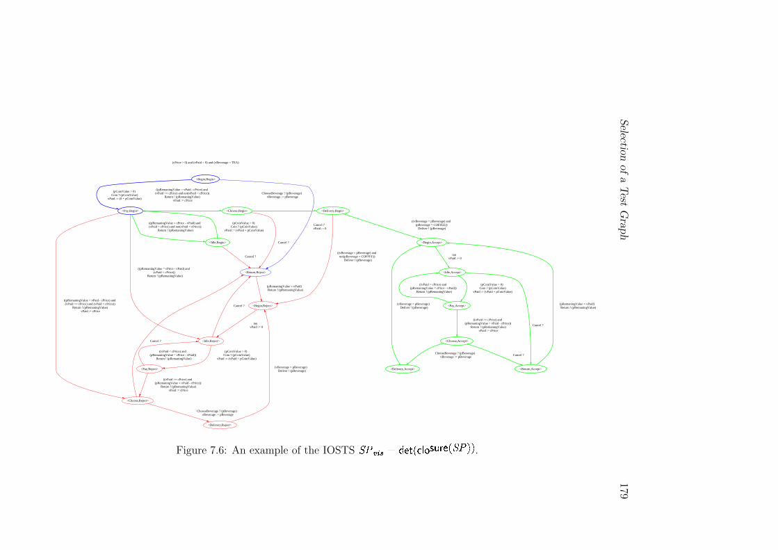
Selectio
nof
aT
estG
raph
179(cPrice > 0) and (vPaid = 0) and (vBeverage = TEA)
<Begin,Begin>
<Pay,Begin>
(pCoinValue > 0) Coin ? (pCoinValue)
vPaid := (0 + pCoinValue)
<Return,Reject>
Cancel ? vPaid := 0
<Idle,Begin>
(pCoinValue > 0) Coin ? (pCoinValue)
vPaid := (vPaid + pCoinValue)
Cancel ?
((pRemaningValue = cPrice - vPaid) and (vPaid < cPrice) and not(vPaid < cPrice))
Return ! (pRemaningValue)
<Idle,Reject>
((pRemaningValue = cPrice - vPaid) and (vPaid < cPrice))
Return ! (pRemaningValue)
<Choose,Reject>
((pRemaningValue = vPaid - cPrice) and (vPaid >= cPrice) and (vPaid < cPrice))
Return ! (pRemaningValue) vPaid := cPrice
<Choose,Begin>
((pRemaningValue = vPaid - cPrice) and (vPaid >= cPrice) and not(vPaid < cPrice))
Return ! (pRemaningValue) vPaid := cPrice
<Begin,Reject>
(pRemaningValue = vPaid) Return ! (pRemaningValue)
Cancel ?
<Pay,Reject>
(pCoinValue > 0) Coin ? (pCoinValue)
vPaid := (vPaid + pCoinValue)
Cancel ?
<Delivery,Reject>
ChooseBeverage ? (pBeverage) vBeverage := pBeverage
Cancel ?
<Delivery,Begin>
ChooseBeverage ? (pBeverage) vBeverage := pBeverage
tau vPaid := 0
((vPaid < cPrice) and (pRemaningValue = cPrice - vPaid))
Return ! (pRemaningValue)
((vPaid >= cPrice) and (pRemaningValue = vPaid - cPrice))
Return ! (pRemaningValue) vPaid := cPrice
(vBeverage = pBeverage) Deliver ! (pBeverage)
((vBeverage = pBeverage) and not(pBeverage = COFFEE))
Deliver ! (pBeverage)
<Begin,Accept>
((vBeverage = pBeverage) and (pBeverage = COFFEE))
Deliver ! (pBeverage)
<Idle,Accept>
tau vPaid := 0
<Pay,Accept>
(pCoinValue > 0) Coin ? (pCoinValue)
vPaid := (vPaid + pCoinValue)
<Return,Accept>
Cancel ?
((vPaid < cPrice) and (pRemaningValue = cPrice - vPaid))
Return ! (pRemaningValue)
<Choose,Accept>
((vPaid >= cPrice) and (pRemaningValue = vPaid - cPrice))
Return ! (pRemaningValue) vPaid := cPrice
(pRemaningValue = vPaid) Return ! (pRemaningValue)
Cancel ?
<Delivery,Accept>
ChooseBeverage ? (pBeverage) vBeverage := pBeverage
(vBeverage = pBeverage) Deliver ! (pBeverage)
Figure 7.6: An example of the IOSTS
�� � �� � ��� �� �� �� �� �� � �
.
180 Symbolic Test Generation
Plan of the Section. This section is organized as follows: at the beginning,we describe a methodology for symbolic analysis of IOSTS which is used in orderto select a test graph t�� from i u A �� . Then, we present the algorithm for thetest graph selection. Finally, we formulate some properties preserved by thisalgorithm, which are needed for proving the correctness of the generated testcases.
7.4.1 Symbolic Analysis for IOSTS
The aim of this subsection is to present a methodology for analyzing input-outputsymbolic transition systems. The methodology consists of reachability and core-achability analysis (which are also known as forward and backward reachabilityanalysis). It describes how to perform these analyses iteratively and emphasizesthat the reachability and coreachability problems are undecidable in the generalcase, i.e. when the state space of the transition system is unbounded. Thus, inorder to analyze IOSTS, we have to manipulate over-approximations of reachableand coreachable sets of states, rather than use the exact sets of reachable andcoreachable states. It is important to emphasize that in this thesis we do notexplain how to compute an over-approximation of the reachable/coreachable setof states. We make an assumption that this over-approximation can be computedby using, for instance, the control structure of an IOSTS, or intervals, or poly-hedra (see [Cousot and Cousot, 1976], [Cousot and Cousot, 1977], [Cousot andHalbwachs, 1978], [Jeannet, 2000b]).
7.4.1.1 Reachability and Coreachability Analyses.
In this subsection we consider:
(1) a specification ikj ����� l nqp)r with set of locations �!+�-/.10 ,(2) a test purpose tsu of ikj ��� with set of locations � eDg , and
(3) the IOSTS i u A �O� # /�� A � @�� A �� @�� A ���;� �� � 4 � % � A �� %+���A �� % � A �� %U/ * ?A �� @ * DA �� ;� �� �� 4 � % � A �� >without internal actions, which is obtained from ikj ��� and tsu by apply-ing the product and closure operations, and by performing the procedure ofglobal determinization, i.e. i u A ��T� � �� / � � ������� / ikj ��� � tsu ; ; . The IOSTSi u A �� has the set of valued actions � A ��S� � ?A �� @ � DA �� , set of states � A � , setof initial states � �A � � � A � . Moreover, for i u A � we define a set of acceptingstates � � � �A �� � � A � as follows:
� � � �A �� � (7.3)����� A ������ A �� �"! � A ��$#%� A ��&!('*),+.-0/ A ��2143 A ��6587� A ��:9 ����� �+�-.10 � � � e�g � �<;<;<;=� ��� +�-.10 � >�?@? A�BDC@� �<;<;<;=� ��� � +�-/.10 � � � eDg ���"!4E A ��6F
Selection of a Test Graph 181
where for all � from I to J�� I , ��� +�-. 0 � � +�-. 0 and ��� e�g � ��eDg , and� ����� j � is
the special location of tsu .
Then, in order to select a subgraph of i u A � (called test graph and denoted byt�� ) leading to the satisfaction of the test purpose tsu , and containing “fewer”unreachable states than i u A �� , we have to compute an intersection between thesets of reachable and coreachable states of given IOSTS i u A �� . We say that:
(1) a state � A �� � � A � is reachable in i u A �� if there exists a trace � �t:�' ����< / i u A ��.; that ends in � A �� , i.e. ��� � t �' ����< / i u A ��(; % � �A � �� �A �� I � �A ��� � A ���P , and
(2) a state � A �� � � A �� is coreachable in i u A �� if from � A �� we may go to someaccepting state �
� � �A �� � � � � �A �� , i.e. ��� � / � ? @ � D ;� % � � � �A � � � � � �A �� I � A �� � �� � �A �� P .
This means that we have to perform reachability and coreachability analyses forthe IOSTS i u A �� . These analyses are based on the predicate transformers � ��� �and � � which are used to compute successors and predecessors of some subset ofstates � !A �� � � A �� of the given IOSTS i u A �� .Predicate Transformers: � ��� � 3 /�� ; and � � 3 /�� ; . Before giving the formaldefinitions of predicate transformers, we introduce two intermediate notion thatare used later in this section.
First, let � � � A �� be a location of i u A �� , and � ! ��� /�� A ��B@ � A ��(; be a predicateover the variables � A �� and symbolic constants � A �� of i u A �� . Then, the Booleanexpression �q� L /�� � � � ; K�� ! , where � � is a special variable that indicates thecurrent location of the IOSTS i u A �� , is called the projection of � ! on � .
Second, we say that a state � � # �&%��o> � � A � of i u A �� satisfies the locationpredicate � ��� /�� A ���@ � A ���@ � � k; (denoted as � � � � ) if and only if (1) thevariable � � is equal to the location � , and (2) the valuation � of variables � A �� andsymbolic constants � A �� satisfies � ! .Definition 7.1 ( � ��� � 3 /�� ; ) Let � � # �H%+'d% *,% : %(= %(� ! > � � A �� be a symbolic transi-tion of the IOSTS i u A �� , and � be a predicate over the variables and symbolicconstants of i u A � .
Then, the predicate transformer � ��� � 3 /�� ; of � with respect to � is a predicatethat characterizes the set of states reachable in one step from a state � � � A ��satisfying the predicate � by executing the symbolic transition � , i.e.
� ��� � 3 /�� ; � ��� � � A �� %�� � / � ?A �� @ � DA �� ; I �� � 3 � ! K � � � � P (7.4)h
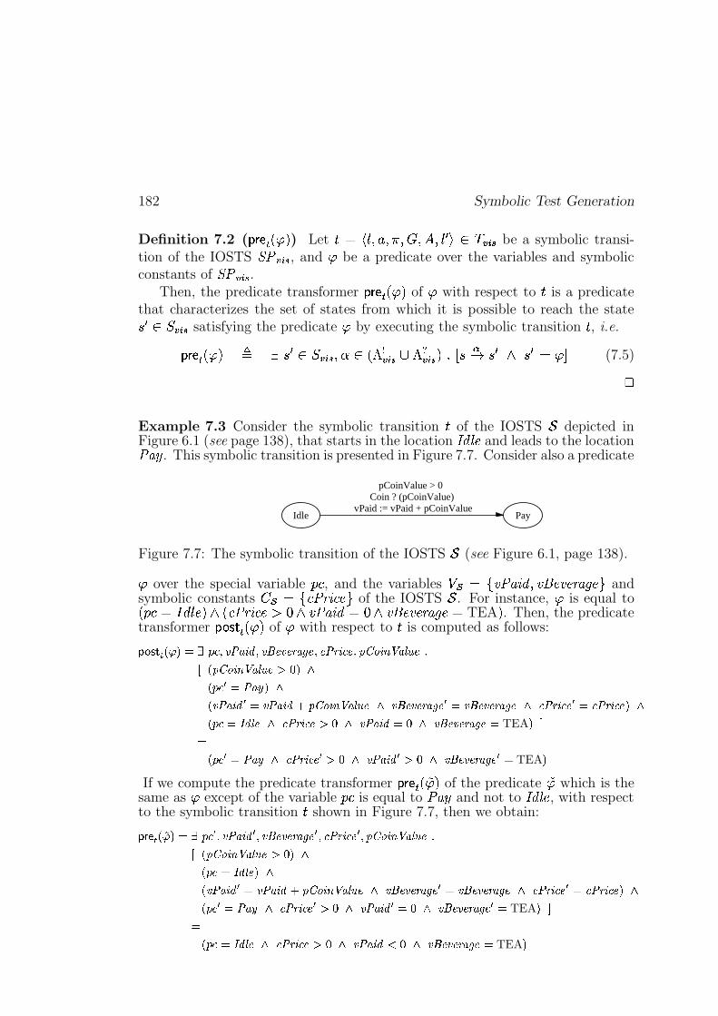
182 Symbolic Test Generation
Definition 7.2 ( � � 3 /�� ; ) Let ��� # �H%+'d% *,% : %(= %(� ! > � � A �� be a symbolic transi-tion of the IOSTS i u A � , and � be a predicate over the variables and symbolicconstants of i u A �� .
Then, the predicate transformer � � 3 /�� ; of � with respect to � is a predicatethat characterizes the set of states from which it is possible to reach the state� ! � � A �� satisfying the predicate � by executing the symbolic transition � , i.e.
� � 3 /�� ; � ��� !d� � A �� % � � / � DA �� @ � ?A �� ; I � � � � ! K � ! � � � P (7.5)h
Example 7.3 Consider the symbolic transition � of the IOSTS � depicted inFigure 6.1 (see page 138), that starts in the location
� # 7 � and leads to the locationu! �� . This symbolic transition is presented in Figure 7.7. Consider also a predicate
Idle Pay
pCoinValue > 0 Coin ? (pCoinValue)
vPaid := vPaid + pCoinValue
Figure 7.7: The symbolic transition of the IOSTS � (see Figure 6.1, page 138).
� over the special variable � � , and the variables ��� � �Du "�$# % �&% � � � �' )( �b andsymbolic constants � � � 8� u���� ��� of the IOSTS � . For instance, � is equal to/ � � ���� � cb; K / � u ��� ���� � K �Du! "�$# ��� K �&% � � � �> )( �W� TEA ; . Then, the predicatetransformer � ��� � 3 /�� ; of � with respect to � is computed as follows:
� <>=����6D�� F����������! ��#"%$'&(�! *),+* �+*-."!/0+1�32 �4-5$'26+0��798;:%$=<�>?"%@BA�+DCE D=7F8�:%$=<�>?"%@BA�+HGJI�FLKDB��� � � �#"�M FNKD� ��#"�$'& � �O ��#"%$'&�PQ7F8�:�$=<R>?"�@BA�+SKT *)U+! V+!-W"X/Y+ � �Z *)U+! �+*-W"X/Y+SK[2 �4-5$'26+ � �\2$�4-5$'26+AF]KDB���#�_^!&1@`+_Ka2 �4-5$'26+HGbIZKc ��#"�$'&d�_ISKa 5),+* �+!-W"!/0+e� TEA FLf
�DB��� � � �#"�MgK[2 �4-5$'26+ � GhI�Kc ��#"%$'& � GJI�Kc *)U+! V+!-W"X/Y+ � � TEA F
If we compute the predicate transformer � � 3 /Fi� ; of the predicate i� which is thesame as � except of the variable � � is equal to u! �� and not to
� # 7 � , with respectto the symbolic transition � shown in Figure 7.7, then we obtain:
� @CB*��D1j� F;���H�?� � �! ��#"%$'& � �! *)U+! �+*-W"X/Y+ � �V2$�4-5$'26+ � ��798;:%$=<�>?"%@BA�+DCE Dk7F8�:�$=<R>?"�@BA�+�GhI F]KDl�?�m�_^X&1@n+>FNKD� ��#"%$'& � �O ��#"�$'&HPo798;:%$=<�>?"%@BA�+pKa 5),+* �+!-W"!/0+ � �g 5),+! V+!-W"!/0+_K[2$�4-5$'26+ � �\2 �4-5$'26+>FLKDl�?� � � �#"%M\Ka2$�q-5$'2.+ � GbIZKc ��#"�$'& � �_I�KT *),+* �+*-."!/0+ � � TEA F�f
�Dl�?�m�_^X&1@n+pKr2$�q-5$'2.+�GhISKc ��#"%$'&tsJIZKT *)U+! V+!-W"X/Y+e� TEA F
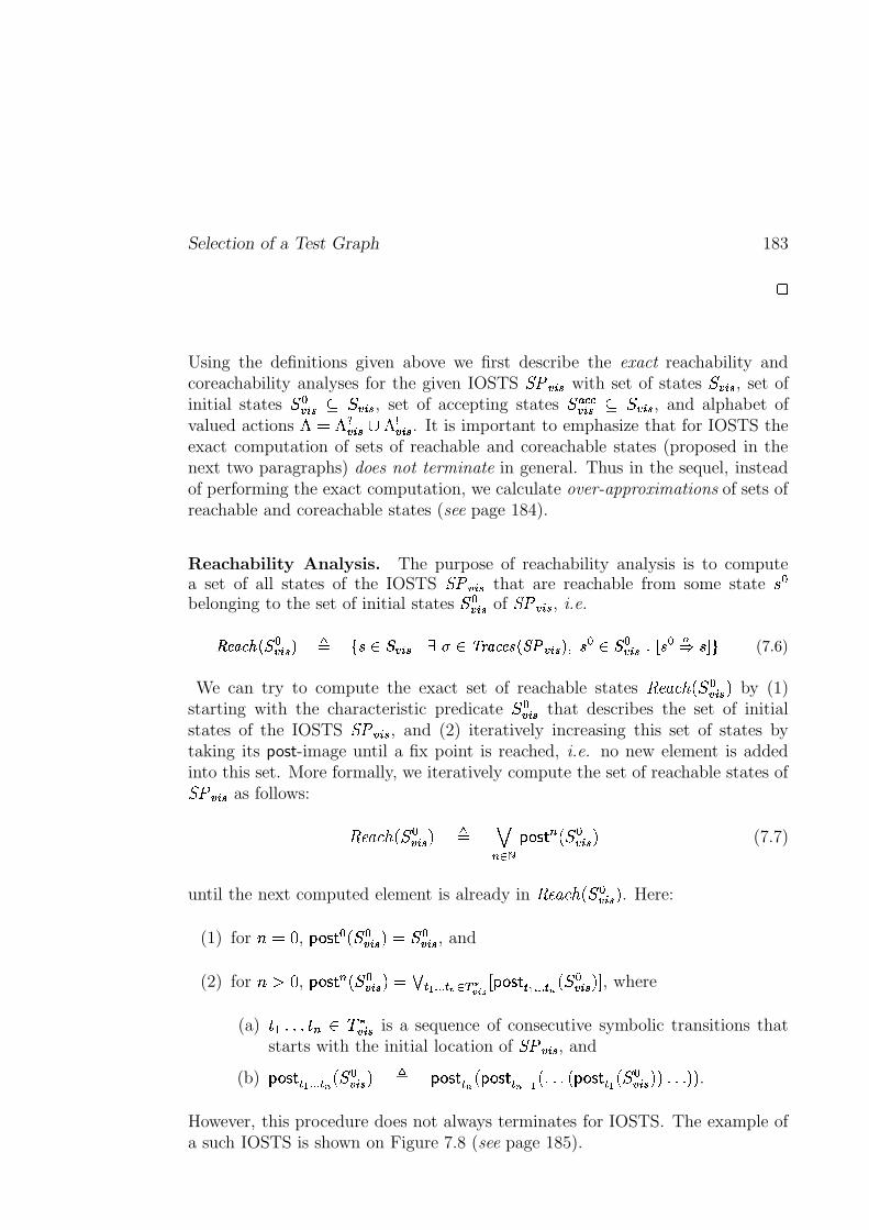
Selection of a Test Graph 183
�
Using the definitions given above we first describe the exact reachability andcoreachability analyses for the given IOSTS �������� with set of states ����� , set ofinitial states ������� ������ , set of accepting states ����������� ������ , and alphabet ofvalued actions ������������� � ����� . It is important to emphasize that for IOSTS theexact computation of sets of reachable and coreachable states (proposed in thenext two paragraphs) does not terminate in general. Thus in the sequel, insteadof performing the exact computation, we calculate over-approximations of sets ofreachable and coreachable states (see page 184).
Reachability Analysis. The purpose of reachability analysis is to computea set of all states of the IOSTS �������� that are reachable from some state !"�belonging to the set of initial states #����� of ��� ���� , i.e.
$#%�&"')(+*-, �����/. 0 132 4 , ����6587:9 4<;>= &"'/%/?@*BA>C ���� .EDF2 � 4 , ������ G�HI2 �KJL 2NMPO (7.6)
We can try to compute the exact set of reachable states QSRNT8UWV�XBY������WZ by (1)starting with the characteristic predicate #������ that describes the set of initialstates of the IOSTS ���[���� , and (2) iteratively increasing this set of states bytaking its post-image until a fix point is reached, i.e. no new element is addedinto this set. More formally, we iteratively compute the set of reachable states of�������� as follows:
QSRNT8UWV\XB �����)Z ] ^_@`3aSb>c>d�e_ Xf �����NZ (7.7)
until the next computed element is already in QSRNT8UWV�XB#������ Z . Here:
(1) for gh�ji , b>c>d�e �kXBl�����)Z ��l����� , and
(2) for gnmoi , b>c>d�e_ Xf ������WZ �qpYrtsvuIuIu rw `Wx�yzf{}|�~ b�c>d�e rtsvuIuIu r w Xfl�����NZB� , where
(a) �)�������E� _<���6������ is a sequence of consecutive symbolic transitions thatstarts with the initial location of ���6���� , and
(b) b>c�d�e r s uIuIu r w XB �����NZ ] b>c>d�e r w X b>c>d�e rw�� s X�������X b�c>d�e r s XB �����)Z/Z ����� ZEZ .However, this procedure does not always terminates for IOSTS. The example ofa such IOSTS is shown on Figure 7.8 (see page 185).
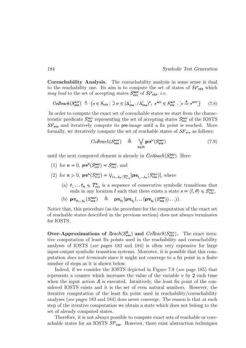
184 Symbolic Test Generation
Coreachability Analysis. The coreachability analysis in some sense is dualto the reachability one. Its aim is to compute the set of states of ���6���� whichmay lead to the set of accepting states �E������� of ���[���� , i.e.
��� $#%�&"')(+*-, �E��������>.n0 132 4 , �����5 7 9 4 *�� ������� � �����/. � DY2 ����� 4 , ��������� G+HI2 JL 2 ���-� MPO (7.8)
In order to compute the exact set of coreachable states we start from the charac-teristic predicate l�E������� representing the set of accepting states �E������� of the IOSTS��� ���� and iteratively compute its pre-image until a fix point is reached. Moreformally, we iteratively compute the set of reachable states of ���6���� as follows:
�� QSRNT8UWV\XB �E������� Z ] ^_k`�a�b ��_ Xf ���������� Z (7.9)
until the next computed element is already in�� QSRNT8UWV Xf ���-����� Z . Here:
(1) for gh�ji , b �� �"Xf �E������� Z �q ���-����� , and
(2) for gnmoi , b ��_ XB ���-�����8Z �jpYrtsvuIuIu rw `Wx yzB{ |�~ b �� rtsvuIuIu r w XB ��������� Z � , where
(a) �N�������E� _ ��� ����� is a sequence of consecutive symbolic transitions thatends in any location such that there exists a state !6���� ������ � #��������� ,
(b) b �� r s uIuIu r w Xf �E������� Z ] b �� r s X b �� r�� X�������X b �� r w XB �E������� ZEZ ����� Z/Z .Notice that, this procedure (as the procedure for the computation of the exact setof reachable states described in the previous section) does not always terminatesfor IOSTS.
Over-Approximations of QSRNT8UWV\Xf ����� Z and�� Q RNT8UWV�Xfl���������� Z . The exact itera-
tive computation of least fix points used in the reachability and coreachabilityanalyses of IOSTS (see pages 183 and 184) is often very expensive for largeinput-output symbolic transition systems. Moreover, it is possible that this com-putation does not terminate since it might not converge to a fix point in a finitenumber of steps as it is shown below.
Indeed, if we consider the IOSTS depicted in Figure 7.8 (see page 185) thatrepresents a counter which increases the value of the variable � by � each timewhen the input action � is executed. Intuitively, the least fix point of the con-sidered IOSTS exists and it is the set of even natural numbers. However, theiterative computation of the least fix point used in reachability/coreachabilityanalyses (see pages 183 and 184) does never converge. The reason is that at eachstep of the iterative computation we obtain a state which does not belong to theset of already computed states.
Therefore, it is not always possible to compute exact sets of reachable or core-achable states for an IOSTS ���6���� . However, there exist abstraction techniques
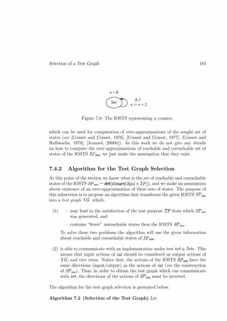
Selection of a Test Graph 185
v = 0
IncA ?
v := v + 2
Figure 7.8: The IOSTS representing a counter.
which can be used for computation of over-approximations of the sought set ofstates (see [Cousot and Cousot, 1976], [Cousot and Cousot, 1977], [Cousot andHalbwachs, 1978], [Jeannet, 2000b]). In this work we do not give any detailson how to compute the over-approximations of reachable and coreachable set ofstates of the IOSTS ���6���� , we just make the assumption that they exist.
7.4.2 Algorithm for the Test Graph Selection
At this point of the section we know what is the set of reachable and coreachablestates of the IOSTS ���[�����F��� � e X���� c>d � �� X�����RNU�� � Z/Z , and we make an assumptionabout existence of an over-approximation of these sets of states. The purpose ofthis subsection is to propose an algorithm that transforms the given IOSTS ���6����into a test graph �� which:
(1) – may lead to the satisfaction of the test purpose � � from which ���6����was generated, and
– contains “fewer” unreachable states then the IOSTS �������� .To solve these two problems the algorithm will use the given informationabout reachable and coreachable states of �������� .
(2) is able to communicate with an implementation under test ����� ��� ����� . Thismeans that input actions of ����� should be considered as output actions of�� , and vice versa. Notice that, the actions of the IOSTS ���6���� have thesame directions (input/output) as the actions of ����� (see the constructionof �������� ). Thus, in order to obtain the test graph which can communicatewith ����� , the directions of the actions of ���6���� must be inverted.
The algorithm for the test graph selection is presented below.
Algorithm 7.2 (Selection of the Test Graph) Let
186 Symbolic Test Generation
– ���[���� � �/X�� ����� ��� ���� ��� ���� Z ���6���� �� ������ ��l����� �"X�������� � [������WZ � � ���� � be an IOSTSwhich is obtained from a specification ����RNU and a test purpose � � of ����RNU byapplying the product and closure operations, and performing the procedureof global determinization,
– � �� ��� Xv�������� Z and � c ��� ��� X����[����� Z be two predicates characterizing over-
approximations of the sets of reachable and coreachable states of the IOSTS��� ���� , and
– for each location � � ���� of ���[���� , ��� ��� X Z and � c ��� ��� X Z be two predicatesthat characterize over-approximations of reachable and coreachable statesof the form �� ������ , where � ������� X������� ��� ���� Z .In the sequel, we also use the notation � c ��� ��� X Z ~ ��� � � , where � is a setof assignments for variables � and is a location. It denotes the predicatecharacterizing an over-approximation of coreachable states of the form �� ������ ,where each variable � � � is substituted with the right-hand side of thecorresponding assignments �6� � � .
Then, the test graph ��� is the IOSTS
� X����! ��� �! �"� �# Z �$�%�# � � �# �$�&�! � X� � �! � � �! Z � � �! �
obtained from ��� ����� as follows:
(1) ���! �'������ , � �! � � ���� and � �! � � ����� .
(2) �(�! �'�6����*)+� c � �� ��� X����[���� Z .
(3) If ����� �-,[UNUNR � � , then � �! � �ST � � . Otherwise, � �# � ����� .
(4)1 �� �! �.[����� and [� �! �'������ .1In order to obtain a test graph /10 that is able to communicate with an implementation
under test, we must invert the alphabets of input/output actions of the IOSTS 2436587:9 .
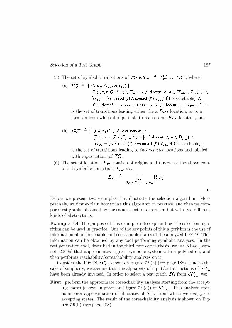
Selection of a Test Graph 187
(5) The set of symbolic transitions of �� is � �# ] ��� ����! � � � ��������# , where:
(a)� � ����# 0 1� �BD�� D��\D�� �! D���D�� �# ��[5* 7 �BD�� D��\D�� D��[D���� � 4 � ���� G+H ������ 'E'E% �"!$# � 4 *&% ����� � % ����� .-M . #
* � �# � * � #('*),+.-0/�* ��. #1-324'*),+.-0/8* � � .)H65 �! �7 �#M . is satisfiable . #* ��� ��� '�'/%8�"! � L � �# � CY&�?�? . # * ���9��:� 'E'E%8�;! � L � �# � �<�.FO
is the set of transitions leading either the a �ST � � location, or to a
location from which it is possible to reach some �ST � � location, and
(b)� � ���=������# 0 11 �BD�� D��\D�� �! D��[D�>@? ' � ? ',ACB>?�D<E"% �S5* 7 �BD�� D��\D�� D���D���� � 4 � ���� G+H �F���� '�'/%8�"!$# � 4 % ����� M . #
* � �! � * � #G'*),+.-0/>* ��. #IHJ-324'*),+.-0/�* � � .)H65 �# K7 �YM . is satisfiable .YOis the set of transitions leading to inconclusive locations and labeled
with input actions of �� .
(6) The set of locations � �# consists of origins and targets of the above com-puted symbolic transitions � �# , i.e.
�&�# ] LM=N�O � O PQO RSO TUO NVCW `�x �! X ��� �Y
�Bellow we present two examples that illustrate the selection algorithm. Moreprecisely, we first explain how to use this algorithm in practice, and then we com-pare test graphs obtained by the same selection algorithm but with two differentkinds of abstractions.
Example 7.4 The purpose of this example is to explain how the selection algo-rithm can be used in practice. One of the key points of this algorithm is the use ofinformation about reachable and coreachable states of the analyzed IOSTS. Thisinformation can be obtained by any tool performing symbolic analyses. In thetest generation tool, described in the third part of the thesis, we use NBac [Jean-net, 2000a] that approximates a given symbolic system with a polyhedron, andthen performs reachability/coreachability analyses on it.
Consider the IOSTS ��� � zB{ | shown on Figure 7.9(a) (see page 188). Due to thesake of simplicity, we assume that the alphabets of input/output actions of ��� � zf{}|have been already inversed. In order to select a test graph �� from ��� � zB{ | , we:
First, perform the approximate coreachability analysis starting from the accept-ing states (shown in green on Figure 7.9(a)) of ��� � zB{ | . This analysis givesus an over-approximation of all states of ��� � zf{}| from which we may go toaccepting states. The result of the coreachability analysis is shown on Fig-ure 7.9(b) (see page 188).
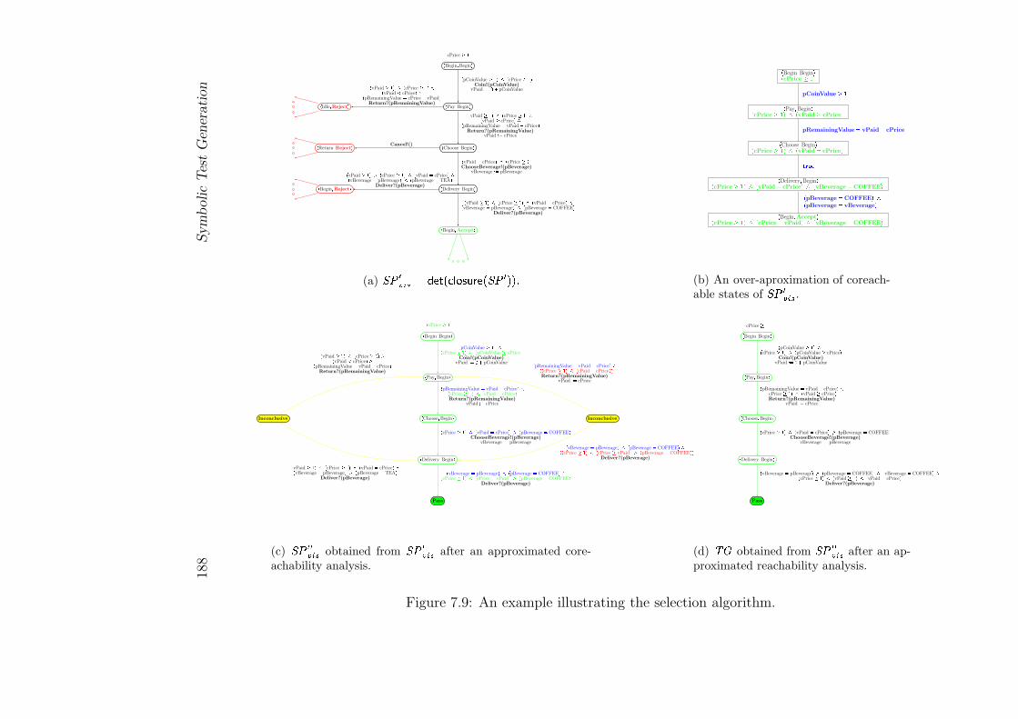
188
Sym
bolic
Tes
tG
ener
ati
on
� Begin � Begin �
� Pay � Begin �
� Choose � Begin �
� Delivery � Begin �
� Begin � Accept �
� Idle � Reject �
� Begin � Reject �
� Return � Reject �
cPrice � �� pCoinValue � � � � � cPrice � � �
Coin!(pCoinValue)vPaid � � pCoinValue
� vPaid � � � � � cPrice � � � �� vPaid � cPrice � �� pRemainingValue vPaid � cPrice �
Return?(pRemainingValue)vPaid � cPrice
� vPaid � � � � � cPrice � � � �� vPaid cPrice � �� pRemainingValue cPrice � vPaid �
Return?(pRemainingValue)
� vPaid cPrice � � � cPrice � � �
ChooseBeverage!(pBeverage)vBeverage � pBeverage
Cancel!()
� vPaid � � � � � cPrice � � � � � vPaid cPrice � �� vBeverage pBeverage � � � pBeverage COFFEE �
Deliver?(pBeverage)
� vPaid � � � � � cPrice � � � � � vPaid cPrice � �� vBeverage pBeverage � � � pBeverage TEA �
Deliver?(pBeverage)
(a) �� ���� � �� � ��� �� �� � � �� � � �!
" Begin # Begin $% cPrice &' (
" Pay # Begin $% cPrice &' () % vPaid & cPrice (
" Choose # Begin $% cPrice &' () % vPaid * cPrice (
" Delivery # Begin $% cPrice &' () % vPaid * cPrice () % vBeverage * COFFEE (
" Begin # Accept $% cPrice &' () % cPrice * vPaid () % vBeverage * COFFEE (
pCoinValue &'
pRemainingValue * vPaid + cPrice
,- ./% pBeverage * COFFEE ()% pBeverage * vBeverage (
(b) An over-aproximation of coreach-able states of �� �� �� .
� Begin � Begin �
� Pay � Begin �
� Choose � Begin �
� Delivery � Begin �
Pass
InconclusiveInconclusive� cPrice � � �
� pCoinValue � � � �� cPrice � � � � � pCoinValue � cPrice �
Coin!(pCoinValue)vPaid � � pCoinValue
� pRemainingValue vPaid � cPrice � �� cPrice � � � � � cPaid cPrice �
Return?(pRemainingValue)vPaid � cPrice
� vPaid � � � � � cPrice � � � �� vPaid cPrice � �� pRemainingValue vPaid � cPrice �Return?(pRemainingValue)
� pRemainingValue vPaid � cPrice � �0 � � cPrice � � � � � cPaid cPrice � �
Return?(pRemainingValue)vPaid � cPrice
� cPrice � � � � � vPaid cPrice � � � pBeverage COFFEE �
ChooseBeverage!(pBeverage)vBeverage � pBeverage
� vBeverage pBeverage � � � pBeverage COFFEE � �� cPrice � � � � � cPrice vPaid � � � pBeverage COFFEE �
Deliver?(pBeverage)
� vPaid � � � � � cPrice � � � � � vPaid cPrice � �� vBeverage pBeverage � � � pBeverage TEA �
Deliver?(pBeverage)
� vBeverage pBeverage � � � pBeverage COFFEE � �0 � � cPrice � � � � � cPrice � vPaid � � � pBeverage COFFEE � �
Deliver?(pBeverage)
(c) �� � ���� obtained from �� �� �� after an approximated core-achability analysis.
� Begin � Begin �
� Pay � Begin �
� Choose � Begin �
� Delivery � Begin �
Pass
cPrice � �� pCoinValue � � � �� cPrice � � � � � pCoinValue � cPrice �
Coin!(pCoinValue)vPaid � � pCoinValue
� pRemainingValue vPaid � cPrice � �� cPrice � � � � � vPaid � cPrice �
Return?(pRemainingValue)vPaid � cPrice
� cPrice � � � � � vPaid cPrice � � � pBeverage COFFEE �
ChooseBeverage!(pBeverage)vBeverage � pBeverage
� vBeverage pBeverage � � � pBeverage COFFEE � � � vBeverage COFFEE � �� cPrice � � � � � vPaid � � � � � vPaid cPrice �
Deliver?(pBeverage)
(d) 1 2 obtained from �� � ���� after an ap-proximated reachability analysis.
Figure 7.9: An example illustrating the selection algorithm.
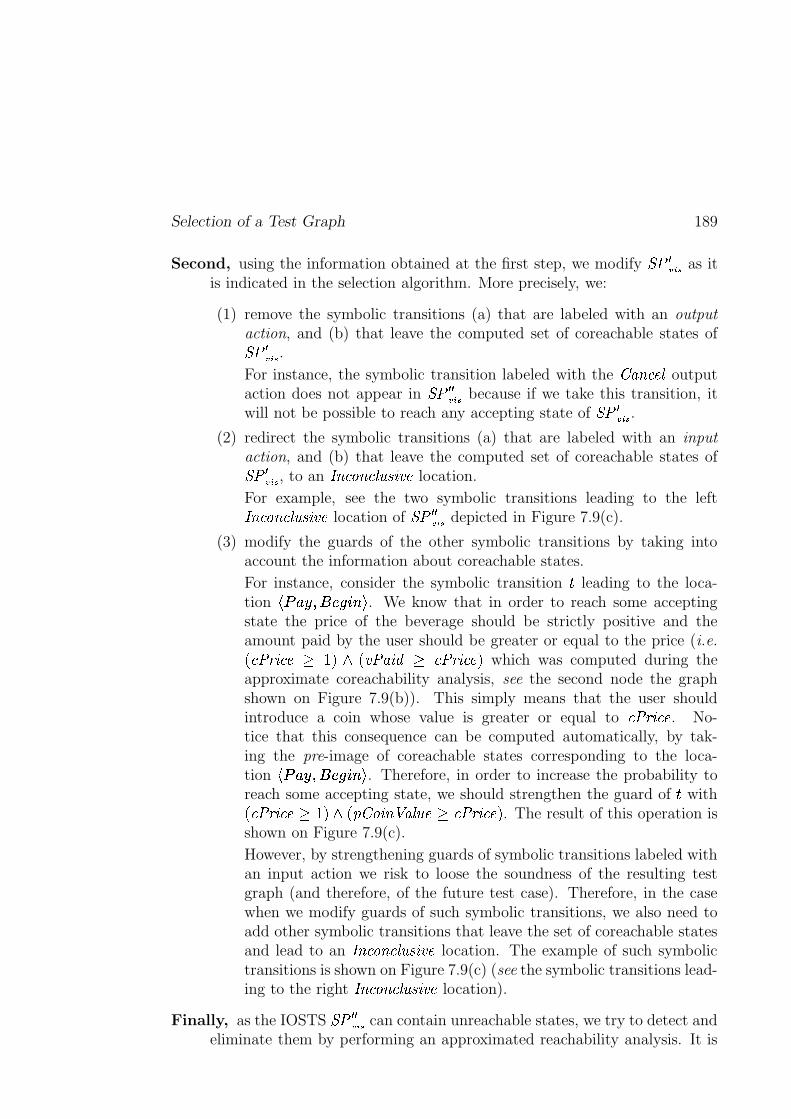
Selection of a Test Graph 189
Second, using the information obtained at the first step, we modify���������
as itis indicated in the selection algorithm. More precisely, we:
(1) remove the symbolic transitions (a) that are labeled with an output
action, and (b) that leave the computed set of coreachable states of��� �����.
For instance, the symbolic transition labeled with the �� �������� outputaction does not appear in
��� � �����because if we take this transition, it
will not be possible to reach any accepting state of���������
.
(2) redirect the symbolic transitions (a) that are labeled with an input
action, and (b) that leave the computed set of coreachable states of��� �����, to an ������������������ �!� location.
For example, see the two symbolic transitions leading to the left��������������"��� �!� location of��� � �����
depicted in Figure 7.9(c).
(3) modify the guards of the other symbolic transitions by taking intoaccount the information about coreachable states.
For instance, consider the symbolic transition # leading to the loca-tion $�%'&"(*)�+-,�.�/021 . We know that in order to reach some acceptingstate the price of the beverage should be strictly positive and theamount paid by the user should be greater or equal to the price (i.e.3 � ��4 ����65 7�8:9 3 � � ��;<5 � �=4 �����8 which was computed during theapproximate coreachability analysis, see the second node the graphshown on Figure 7.9(b)). This simply means that the user shouldintroduce a coin whose value is greater or equal to � ��4 ���� . No-tice that this consequence can be computed automatically, by tak-ing the pre-image of coreachable states corresponding to the loca-tion $�%'&"(*)�+>,�.?/�021 . Therefore, in order to increase the probability toreach some accepting state, we should strengthen the guard of # with3 � ��4 ����'5@7�8*9 3 A ����� �:B� !����C5D� ��4 �����8 . The result of this operation isshown on Figure 7.9(c).
However, by strengthening guards of symbolic transitions labeled withan input action we risk to loose the soundness of the resulting testgraph (and therefore, of the future test case). Therefore, in the casewhen we modify guards of such symbolic transitions, we also need toadd other symbolic transitions that leave the set of coreachable statesand lead to an ������������������ �!� location. The example of such symbolictransitions is shown on Figure 7.9(c) (see the symbolic transitions lead-ing to the right ������������������ �!� location).
Finally, as the IOSTS��� � �����
can contain unreachable states, we try to detect andeliminate them by performing an approximated reachability analysis. It is
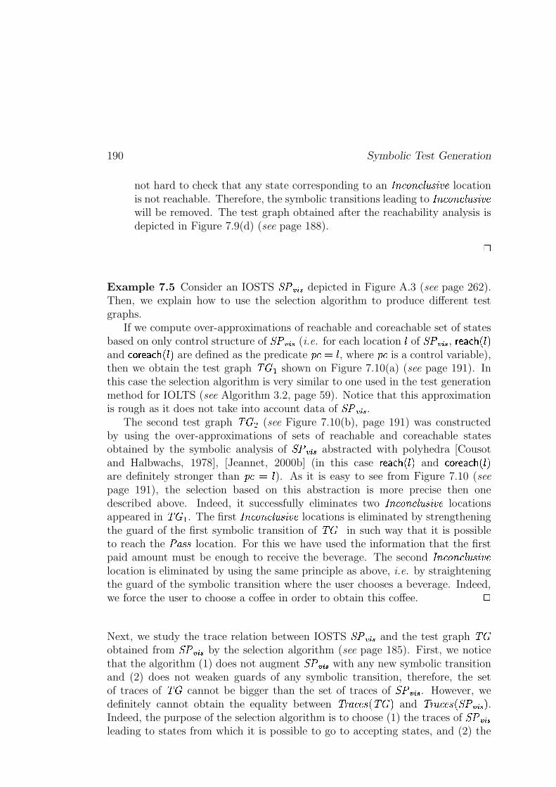
190 Symbolic Test Generation
not hard to check that any state corresponding to an ��������������"��� �!� locationis not reachable. Therefore, the symbolic transitions leading to ��������������"��� �!�will be removed. The test graph obtained after the reachability analysis isdepicted in Figure 7.9(d) (see page 188).
�
Example 7.5 Consider an IOSTS���������
depicted in Figure A.3 (see page 262).Then, we explain how to use the selection algorithm to produce different testgraphs.
If we compute over-approximations of reachable and coreachable set of statesbased on only control structure of
���������(i.e. for each location � of
�������, � ������� 3 � 8
and ������������� 3 � 8 are defined as the predicateA ����� , where
A � is a control variable),then we obtain the test graph ���! shown on Figure 7.10(a) (see page 191). Inthis case the selection algorithm is very similar to one used in the test generationmethod for IOLTS (see Algorithm 3.2, page 59). Notice that this approximationis rough as it does not take into account data of
���"�����.
The second test graph ����# (see Figure 7.10(b), page 191) was constructedby using the over-approximations of sets of reachable and coreachable statesobtained by the symbolic analysis of
���$�����abstracted with polyhedra [Cousot
and Halbwachs, 1978], [Jeannet, 2000b] (in this case � ������� 3 � 8 and ������������� 3 � 8are definitely stronger than
A �%�&� ). As it is easy to see from Figure 7.10 (seepage 191), the selection based on this abstraction is more precise then onedescribed above. Indeed, it successfully eliminates two ��������������"��� �!� locationsappeared in ���' . The first ��������������"��� �!� locations is eliminated by strengtheningthe guard of the first symbolic transition of ���! in such way that it is possibleto reach the
� ��� location. For this we have used the information that the firstpaid amount must be enough to receive the beverage. The second ��������������"��� �!�location is eliminated by using the same principle as above, i.e. by straighteningthe guard of the symbolic transition where the user chooses a beverage. Indeed,we force the user to choose a coffee in order to obtain this coffee.
�
Next, we study the trace relation between IOSTS���$�����
and the test graph ���obtained from
���$�����by the selection algorithm (see page 185). First, we notice
that the algorithm (1) does not augment���$�����
with any new symbolic transitionand (2) does not weaken guards of any symbolic transition, therefore, the setof traces of ��� cannot be bigger than the set of traces of
���������. However, we
definitely cannot obtain the equality between � 4 ����� 3 ���C8 and � 4 ����� 3 ���$��� 8 .Indeed, the purpose of the selection algorithm is to choose (1) the traces of
�������leading to states from which it is possible to go to accepting states, and (2) the
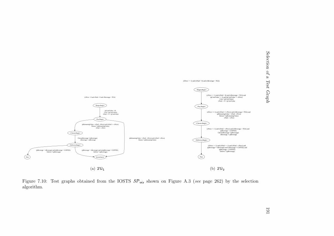
Selectio
nof
aT
estG
raph
191
(cPrice > 0 and vPaid = 0 and vBeverage = TEA)
<Begin,Begin>
<Pay,Begin>
(pCoinValue > 0) Coin ! (pCoinValue)
vPaid := 0 + pCoinValue
<Choose,Begin>
(pRemaningValue = vPaid - cPrice) and (vPaid >= cPrice) Return ? (pRemaningValue)
vPaid := cPrice
Inconclusive
(pRemaningValue = vPaid - cPrice) and (vPaid < cPrice) Return ? (pRemaningValue)
<Delivery,Begin>
ChooseBeverage ! (pBeverage) vBeverage := pBeverage
Pass
(pBeverage = vBeverage) and (pBeverage = COFFEE) Deliver ? (pBeverage)
(pBeverage = vBeverage) and not(pBeverage = COFFEE) Deliver ? (pBeverage)
(a)
� ���
(cPrice >= 1) and (vPaid = 0) and (vBeverage = TEA)
<Begin,Begin>
<Pay,Begin>
(cPrice >= 1) and (vPaid = 0) and (vBeverage = TEA) and (pCoinValue >= 1) and (pCoinValue >= cPrice)
Coin ! (pCoinValue) vPaid := 0 + pCoinValue
<Choose,Begin>
(cPrice >= 1) and (vPaid >= cPrice) and (vBeverage = TEA) and (pRemaningValue = vPaid - cPrice)
Return ? (pRemaningValue) vPaid := cPrice
<Delivery,Begin>
(cPrice >= 1) and (vPaid = cPrice) and (vBeverage = TEA) and (pBeverage = COFFEE)
ChooseBeverage ! (pBeverage) vBeverage := pBeverage
Pass
(cPrice >= 1) and (vPaid >= 1) and (vPaid = cPrice) and (pBeverage = vBeverage) and (vBeverage = COFFEE) and
(pBeverage = COFFEE) Deliver ? (pBeverage)
(b)
� ���
Figure 7.10: Test graphs obtained from the IOSTS
�� � � shown on Figure A.3 (see page 262) by the selectionalgorithm.
192 Symbolic Test Generation
traces of���������
ending with a valued input action and leading to states from whichis not possible to go to any accepting state, and whose strict prefixes are tracesleading to states from which it is possible to go to some accepting state. (In thelast case the test graph ��� should produce the ������������������ �!� verdict.) Thus, itis clear that the set of traces of ��� is included into the set of traces of
���������.
To prove this fact we first show the relation between behaviors of ��� and�������
given below.
Theorem 7.1 (Behaviors of ��� ) Let ����� $�� )������")�����) ��� )� �)������ 1 be a testgraph obtained from an IOSTS
��������� �D$�� )�� ����� )�� ����� ) ��� )� �)�� ����� 1 by Algorithm 7.2(see page 185). Then, for each sequence of valued actions � ���� ������������ 3��! "$#&%�' "$# 8)( � 3��! ��� %*�+'����� 8,( , if the test graph ��� has the behavior:
-/.���10 $ � � ��� )�2 � ��� 143657 $ � ��� )82 ��� 19������$ � �;: ��� )�2 �<: ��� 1 3>=7 $ � � ��� )�2 � ��� 1then there exists a location �/�?� ����� such that the IOSTS
���������has the behavior:
-/.����� 0 $ � ���� )�2 ������ 1&3657 $ � ����� )�2 ����� 19������$ � �;: ����� )�2 �;: ����� 1 3>=7 $ � )�2 ���� 1where @ /A�CB D )�0FE 7�GH�/B � � ��� ���
������ 9I2���� ��2
������ G and 2 � ��� �J2 ������ . �
Proof The proof is done by induction on the length of the sequence � of valuedactions belonging to
3�� ��� %K� ' ��� 8 ( � 3�� '����� %K� ����� 8 ( .Induction Basis. Consider the empty sequence of valued actions L , and a be-
havior of the test graph ��� corresponding to L , i.e.- .��� 0 $ � � ��� )�2 � ��� 1 , where
��� ��� is the initial location of ��� , and 2�� ��� is an initial valuation of the vari-ables and symbolic constants of ��� . Then, we prove that there exists aninitial location �������� such that
- .����� 0 $ �������� )�2M���� 1 is a behavior of���$�����
, where2M������ ��2M� ��� .(1) As the test graph ��� is obtained from the IOSTS
���$�����by Algo-
rithm 7.2 (see page 185), then due to the item (3) of this algorithm weknow that the initial location � ������ exists.
(2) Next, as $ ��� ��� )�2M� ��� 1 is an initial state of ��� , then 2�� ��� satisfies the initialcondition of ��� , i.e. 2�� ���*N �O�1��� which by construction (see the item(2) of Algorithm 7.2, page 185) is equal to
3 � ����� 9QP �SR ������� 3 ��������� 8 8 ,where � ��� is the initial condition of the IOSTS
���������. This implies
that the valuation 2�� ��� also satisfies � ����� , thus it can be used as aninitial valuation of the variables and symbolic constants of
���������(re-
member that TU��� �VT ��� and WX��� �YW ��� due to the item (1) of theselection algorithm).
Selection of a Test Graph 193
The items (1) and (2) imply that- .��� 0 $ �������� )82������� 1 , where 2M���� � 2�� ��� , is a
behavior of�������
corresponding to the empty trace L .Induction Hypothesis. Assume that for a sequence of valued actions � � �
� ������� �<: of length 0KE 7 , if the test graph ��� has the behavior:
- .���10 $ � � ��� )�2 � ��� 1&3 57 $ � ��� )�2 ��� 1������ $ � �<: #��� )�2 �;: #��� 1 3 = � 57 $ � �<: ��� )�2 �;: ��� 1 (7.10)
then there exists a location �1� � ����� such that the IOSTS���������
has thebehavior:
- .����� 0 $ � ������ )�2 ���� 1&3 57 $ � ��� )�2 ����� 19����� $ � �<: #��� )�2 �;: #��� 1 3 = � 57 $ � )�2 �;: ����� 1 (7.11)
where @ /A�CB D )�0FE � GH�/B ����� ���
������ 9 2���� �J2
������ G and 2 �<: ��� ��2 �<: �����.
Induction Step. Consider a sequence of valued actions of length 0 , i.e. � �� ������� �<: � ��� �
�� � . We prove that if:
- .���10 $ � � ��� )�2 � ��� 143 57 $ � ��� )82 ��� 19������$ � �;: ��� )82 �<: ��� 1 3 =7 $ � � ��� )�2 � ��� 1 (7.12)
is a behavior of ��� , then there exists �/�?� ����� such that
- .����� 0 $ � ���� )�2 ������ 1&3 57 $ � ����� )�2 ����� 19������$ � �;: ����� )�2 �;: ����� 1 3 =7 $ � )�2 ������ 1 (7.13)
is a behavior of���������
, where @ /A�CB D?)�0 E 7�GA� B � � ��� � ������� 9V2
���� � 2
������ G and2 � ��� � 2 ���� .By using prefix closure and the induction hypothesis, we obtain that for thesequence � �
, if the prefix of- .��� (see Formula (7.12)) whose length is 0 E 7 ,
is a behavior of ��� , then there exists � �;: ����� �J� ����� such that the prefix of- .����(see Formula (7.13)) whose length is also equal to 0*E 7 , is a behavior
of�������
. Moreover, we know that � �;: ����� ��� �;: ��� . Indeed, due to the selectionalgorithm (see page 185) � �<: �����
can be different from � �;: ��� only in the casewhere � �;: ��� is equal either to
� ��� , or to ��������������"��� �!� . Remember that byconstruction neither
� ��� nor ������������������ �!� has a successor. However, � �;: ���has at least one successor which is � � ��� (see the last transition relation ofFormula (7.12)). Thus, � �<: �����
is equal to � �<: ��� .
Finally, we prove that as the last transition relation of the behavior- .���
(see Formula (7.12)), i.e.
�# � ���10 $ � �<: ��� )�2 �;: ��� 1 3 = � ����� ���E 7 $ � � ��� )�2 � ��� 1
194 Symbolic Test Generation
holds in ��� , then there exists a location ��� � ����� such that the last transi-tion relation of the behavior
- .�����(see Formula (7.13), i.e.
�# ������ 0 $ � �;: ������ � � �
�� = � 5���
)Y2 �;: ������ ��� �
�� = � 5���
1 3>= � ����� ���E 7 $ � )�2 ������ 1
holds in���������
, and 2 ���� ��2 � ��� .Due to the definition of a transition relation (see page 86), we know that��� has a symbolic transition:
# � ��� �<$ � �<: ��� )�& )�� ) � ����)��>) � � ��� 1such that $�2 �;: ��� )��:1 N � � ��� and 2 � ��� �� 3 $�2 �;: ��� )�:1�8 .Next, as ��� is obtained from the IOSTS
���$�����by Algorithm 7.2 (see
page 185), then due to the item (5) of this algorithm,���$�����
has the fol-lowing symbolic transition:
# ������ �D$ � �<: ���� ��� �� = � 5���
)�& )�� ) � ����� )��>) ��1
Moreover, due to the item (5) of Algorithm 7.2 (see page 185), we knowthat the guard
� ��� is equal to either:
–3 �'����� 9 � ������� 3 � �;: ����� 8�9 ��� � ������� 3 � 8�B T ��� ���+G 8 , or
–3 �'����� 9 � ������� 3 � �;: ����� 8�9�� ������������� 3 � 8�B T ��� ��� G 8 .
Thus, as $�2 �;: ��� )�:1 N � � ��� and 2 �<: ��� � 2 �;: �����, then $�2 �;: ����� )�:1 satisfies
�'�����.
This means that the symbolic transition # ���� of���������
is executable. Also,as the symbolic transitions # � ��� and # ������ have the same set of assignments � ,then 2 ���� �� 3 $92 �;: �����
� ��� �
�� = � 5���
)�:1�8 � 2 � ��� .
Therefore, we obtain that the last transition relation�# ������ of the behavior- .�����
(see Formula (7.13)) holds in���������
. This proves the induction step ofthe theorem and the whole theorem.
� ��� ��� �Next, notice that the alphabets of the test graph ��� and the IOSTS
���������are
the same, and they consist of only input and output actions. Therefore, usingthe theorem above, we directly obtain the following corollary:
Selection of a Test Graph 195
Corollary 7.1 (Traces of ��� ) Let ��� be a test graph obtained from theIOSTS
�������by Algorithm 7.2 (see page 185). Then, all traces of ��� are included
in the set of traces of�������
, i.e.
� 4 ����� 3 ���C8�� � 4 ����� 3 ��������� 8 (7.14)
�
Finally, we prove that the selection algorithm (see page 185) produces a deter-ministic test graph. Formally:
Lemma 7.1 ( ��� is Deterministic) A test graph ��� obtained from an IOSTS���$�����by the selection algorithm presented above is deterministic in the sense of
Definition 4.20 (see page 93).�
Proof
(1) We show that the test graph ��� does not contain any internal actions.
Indeed, notice that the IOSTS���������
does not have any internal actions byconstruction (thanks to the closure operation defined on page 260). Thus,as ��� is obtained from
���������by the selection algorithm (see page 185),
then it also does not contain internal actions. Therefore,��� ��� .
(2) We prove that from each state of the test graph ��� at most one symbolictransition can be fired, i.e. @�����H����) � � 3�� ��� %C� ' ��� 8+�/B �� 4 ; 3� � � ������ N � 37 � � � 8��@7�G .Indeed, we know that:
(a) the IOSTS���$���
is deterministic by construction (thanks to the pro-cedure of the global determinization given on page 304), and
(b) the selection algorithm (see page 185) transforms the IOSTS���������
tothe test graph ��� either (1) by removing non-executable symbolictransitions and symbolic transitions starting in and leading to � ����� A��locations; or (2) by splitting each symbolic transitions of
���$���labeled
by action into two whose guards are disjoint.
Therefore, from the items (a) and (b) we can deduce the second statementof the lemma.
The items (1) and (2) imply that the test graph ��� is deterministic (seeDefinition 4.20, page 93).
� � � � �?�
196 Symbolic Test Generation
7.4.3 Traces of ��� Leading to Pass/Inconclusive States
Remember that in the previous subsection we proposed an algorithm which froma given IOSTS
��������� ��� ��� 3 ��� ��� � � 3 � A ���� � � 8 8 , where� A ��� is a specification and
� �is a test purpose of
� A ��� , generates a test graph ��� which contains� ���
and ������������������ �!� locations, and which can be executed on some implementationunder test. Therefore, a set of traces of ��� contains traces leading to
� ��� and������������������ �!� states. In this section we are interested in studying some proper-ties of such traces. In order to formally manipulate traces leading to
� ��� or������������������ �!� , we must give formal definitions for them.
Definition 7.3 (Traces of ��� Leading to Pass/Inconclusive) Let ��� bethe test graph with set of states � "$# , set of initial states �H�" # � � " # , and setof pass and inconclusive states, i.e. ������ � � " # and ���AP����AP�������� �"! � � "$# .Then, for ��� we define two sets of traces leading to states belonging to either������ or �#�HP$���AP�������� �"! , as follows:
� 4 �����&%('*)+) 3 ���C8 , � � � 4 ����� 3 ��� 8 N (7.15)- � � � � � "$# ) �/. � � � �0������ �/B � � �1 �/. � � � G �
� 4 �����(243�5+673�5 3 ���C8 , � � � 4 ����� 3 ���C8 N (7.16)- � � � � � " # ) � � �98;: ��8 �<�#�HP$���AP�������� �"! �/B � � �1 � � ��8;: �98 G �Notice that in the rest of the thesis any trace belonging to � 4 �����=%('*)+) 3 ��� 8 (resp.
to � 4 �����/243�5+673�5 3 ���C8 ) will be called pass trace (resp. inconclusive trace).�
Now that the pass and inconclusive traces of the test graph ��� are formallydefined, we can study the relationship between them and and the sets of tracesand accepting traces of the IOSTS
���$�����from which ��� was obtained by the
selection algorithm (see page 185).Before going forward it is important to notice that the test graph ��� is
initialized (by construction) and deterministic (see Lemma 7.1, page 195) IOSTS.Thus, due to Theorem 4.1 (see page 94), ��� cannot move to states correspondingto different locations after execution of a given trace, e.g. ��� cannot be in apass and inconclusive state after the same trace � . This statement will be usedimplicitly in proofs of the lemmas presented below.
Lemma 7.2 (Traces of ��� Leading to Pass) Let ��� be the test graphgenerated from
���������by Algorithm 7.2 (see page 185), where
���$���is the IOSTS
obtained from the synchronous product between a specification� A ��� and a test
purpose � �by closure and determinization. Then:
� 4 �����&%/'*)+) 3 ���C8����'� 4 ����� 3 � A ���> � � 8 (7.17)
Selection of a Test Graph 197
�
Proof Consider a pass trace � of ��� , and prove that this trace is an accepting
trace of� A ���� � �
.
At the beginning of the proof, notice that we have the two following properties:
(1) � is a trace of���������
, i.e. � � � 4 ����� 3 ��������� 8Indeed, as � is a pass trace of ��� , then due to Definition 7.3 (see page 196)it is a trace of ��� , i.e. �J�&� 4 ����� 3 ���C8 . Thus, using Corollary 7.1 (seepage 195) we obtain that � is also a trace of the IOSTS
���$���.
(1) The set of initial states of ��� is a subset of the set of initial states of���������
,i.e. ���" # � ������ ����
.
Indeed, if ��� � $ ��� )82�� 1 is an initial state of ��� , then the valuation 2 �satisfies the initial condition of ��� that is
3 � ����� 9 P �SR ������� 3 ��������� 8 8 , where� ��� is the initial condition of the IOSTS
���������and P �SR ������� 3 ��������� 8 is the
predicate characterizing an over-approximation of the set of all coreachablestates of
���������defined as Formula (7.8) (see page 184). Thus, 2 � satisfies
the initial condition � ��� of���������
. Moreover, due to Algorithm 7.2 (seepage 185) ��� is the initial location of ��� as well as
���$�����. Therefore, the
state ��� is also an initial state of���$�����
.
From the items (1) and (2) we deduce that the trace � can be executed in bothIOSTS ��� and
�������from a same initial state � � . It is important to notice that by
choosing the initial state � � , we fix values of all variables and symbolic constantsof ��� and
�������. Moreover, we know that ��� and
�������are deterministic.
Therefore, by analogy with the proof of the second item of Theorem 4.1 (seepage 94), we can show that by executing the trace � , ��� (resp.
���"�����) moves
from the state � � to exactly one state � (resp. � � ).Next, as � is a pass trace of ��� , then due to Definition 7.3 (see page 196) it
leads to the state � corresponding to a� ��� location of ��� . Thus, as all
� ���locations of ��� were obtained from the accepting locations of the IOSTS
���������(see Algorithm 7.2, page 185), then the trace � of
���"�����leads to the state � �
corresponding to an � ����� A�� location of���$�����
. Therefore, � is an accepting traceof
���������. � � � ���?�
It is important to emphasize that the opposite inclusion, i.e. �'� 4 ����� 3 � A ���� � � 8 � � 4 �����&%('*)+) 3 ���C8 , does not hold. Before showing this fact we notice thatthe set of accepting traces of
� A ��� � �is the same as the set of accepting traces
of �'� 4 ����� 3 � A ��� � � 8 � �'� 4 ����� 3 ��������� 8 , where��������� � � ��� 3 � � � � ��� 3 � A ��� � � 8 8
198 Symbolic Test Generation
(see Theorems A.4 and A.9, pages 303 and 271). Therefore, it is enough to showthat �'� 4 ����� 3 ��������� 8 �� � 4 �����&%/'*)+) 3 ���C8 . This demonstration is done with thefollowing example.
Example 7.6 Consider the IOSTS���������
shown on Figure 7.11(c) (see page 199)that was obtained form:
– the specification� A ��� of a coffee machine depicted on Figure 7.11(a) (see
page 199), and
– the test purpose � �of
� A ��� that is depicted on Figure 7.11(b) (seepage 199),
by the product and closure operations, and the procedure of determinization. Itis not hard to check that
���$�����has two accepting traces:
� 0 $������ � ) $ 1�1 $ ����� ����) $ 1�1 ) and
� # 0 $������ � ) $ 1�1 $ ����� ����) $ 1�1 $�� ���� �!� 4�� ) $ 1�1Then, by apply the selection algorithm to
���$�����, we obtain the test graph ���
shown on Figure 7.11(d) (see page 199). Indeed, the selection algorithm removed:
(1) the symbolic transition # labeled with the �*�� action, as (a) �*�� is theinput action of
���������, and (b) it does not lead to any state from which it is
possible to go to some accepting state,
(2) the symbolic transition ## labeled with the � ,�� /���, ( action and outgoingfrom the $��*�� ?)�� �� !� ��1 location, as it became in-executable after eliminatingthe symbolic transition ## , and
(3) the symbolic transition #�� labeled with the � ,�� /���, ( action and outgoingfrom the $ ����� ���!) � ����� A�� 1 location, as its origin is the accepting location of���������
.
From Figure 7.11(d) (see page 199) the reader can see that the resulting testgraph ��� has only one pass trace � 0 $������ � ) $ 1�1 $ ����� ��� ) $1�1 , which is anaccepting trace of
�������. Therefore, � 4 �����*%('*)+) 3 ��� 8 � �'� 4 ����� 3 ��������� 8� � � �
���"�� ' 5�� )�� � %��+5�� " ���
, but
�'� 4 ����� 3 ��������� 8� ��� ����"�� ' 5�� )�� � %��+5�� " ���
�� � 4 �����&%/'*)+) 3 ���C8 . �
Before characterizing the set of inconclusive traces of the given test graph ��� ,we make an observation about the form of these traces.
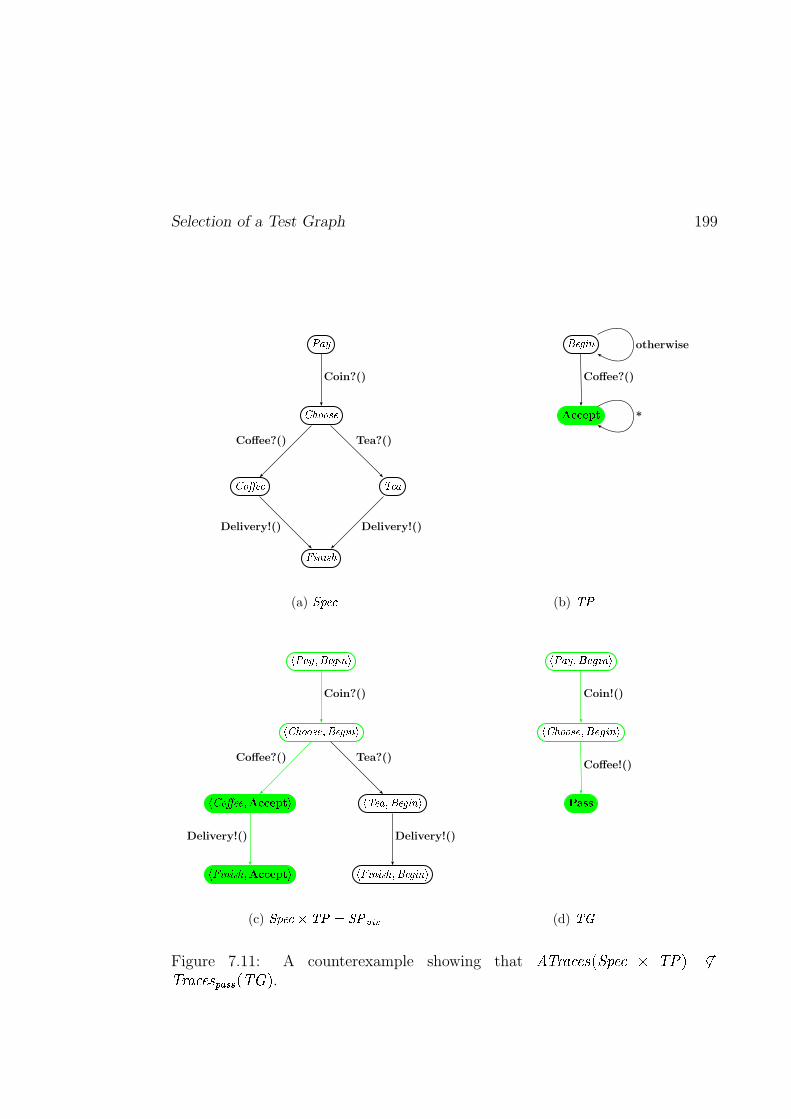
Selection of a Test Graph 199
�����
������ �
��������� ��� �
������ ���
Coin?()
Coffee?() Tea?()
Delivery!()Delivery!()
(a) �����!
"�#%$!&('
)+*,*.-0/21Coffee?()
otherwise
*
(b) 354
687:9�;=<?>A@%B�C�DFE
6HG�IJ JK @!<H>�@%B!C(D�E
6HG�J�LA@�@!<�MON,N.P0Q2R�E
6�S�C(DC(K�I�<�MON,N.P,Q2R�E
6T�@�9U<H>�@%B!C�DFE
68S�C�DC(K�I�<H>�@%B!C(D�E
Coin?()
Coffee?()
Delivery!()
Tea?()
Delivery!()
(c) VFWYX�Z\[^]5_a`bVY_dc.egf
6�7�9�;=<�hjiHkUlgm�E
6HG�IJ JK@�<�hni?kUlgm2E
oqpr r
Coin!()
Coffee!()
(d) ]nsFigure 7.11: A counterexample showing that tvuxwy�z={�|5},~5��{=z�� u+��� ��uxwy�z={�|!���.���F}Yu��v� .
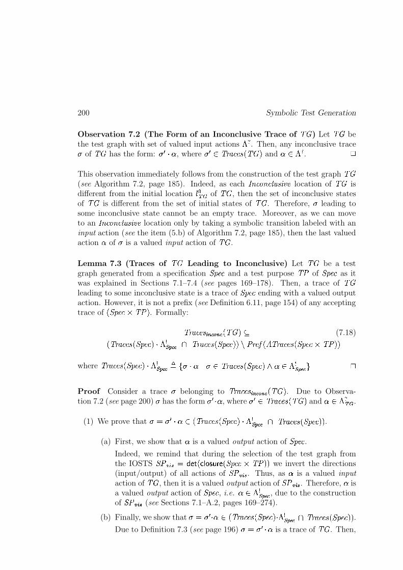
200 Symbolic Test Generation
Observation 7.2 (The Form of an Inconclusive Trace of ��� ) Let ��� bethe test graph with set of valued input actions ��� . Then, any inconclusive trace� of ��� has the form: ����� , where � ��� ������������������� and ��� ��� .
This observation immediately follows from the construction of the test graph ���(see Algorithm 7.2, page 185). Indeed, as each !�" ��#$" �&%(')��*,+-� location of ��� isdifferent from the initial location .0/ 1)2 of ��� , then the set of inconclusive statesof ��� is different from the set of initial states of ��� . Therefore, � leading tosome inconclusive state cannot be an empty trace. Moreover, as we can moveto an !�" ��#$" �&%(')��*,+-� location only by taking a symbolic transition labeled with aninput action (see the item (5.b) of Algorithm 7.2, page 185), then the last valuedaction � of � is a valued input action of ��� .
Lemma 7.3 (Traces of ��� Leading to Inconclusive) Let ��� be a testgraph generated from a specification 3�45��� and a test purpose �76 of 3�45��� as itwas explained in Sections 7.1–7.4 (see pages 169–178). Then, a trace of ���leading to some inconclusive state is a trace of 3�45��� ending with a valued outputaction. However, it is not a prefix (see Definition 6.11, page 154) of any acceptingtrace of �83�45���:9;�76�� . Formally:
�����������=<?>A@CBD>A@A�E������F (7.18)
���������������83�45���E� �HGIKJML @ON �������������83�45���E�=� PQ6R���TSU�KV��������������83�45���:9;�76Q�M�
where �������������83�45���E� � GIKJ=L @�WYX �Z��;[�\� �������������83�45���E� ] �^� � GIKJ=L @�_
Proof Consider a trace � belonging to �`����������<a>A@bBc>A@A������� . Due to Observa-tion 7.2 (see page 200) � has the form ���8T� , where � ��� ������������������� and �^� ��� 1)2 .
(1) We prove that �edf�����^� �E�������������K3�45���E� � GIKJ=L @ N �������������K3�45���E�M� .
(a) First, we show that � is a valued output action of 3�45��� .Indeed, we remind that during the selection of the test graph fromthe IOSTS 356Hg8hji dlk�mAn �Toqp r-sut�v m �83�45���w9x�76Q�=� we invert the directions(input/output) of all actions of 356yg8hji . Thus, as � is a valued input
action of ��� , then it is a valued output action of 356ygzh{i . Therefore, � isa valued output action of 3�45��� , i.e. �^� � GIKJML @ , due to the constructionof 356Hg8hji (see Sections 7.1–A.2, pages 169–274).
(b) Finally, we show that �|d}���,{��� �E�����������-�83�45���E� � GIKJML @ N �`�����������K3�45���E�M� .Due to Definition 7.3 (see page 196) �edf�7�&�� is a trace of ��� . Then,
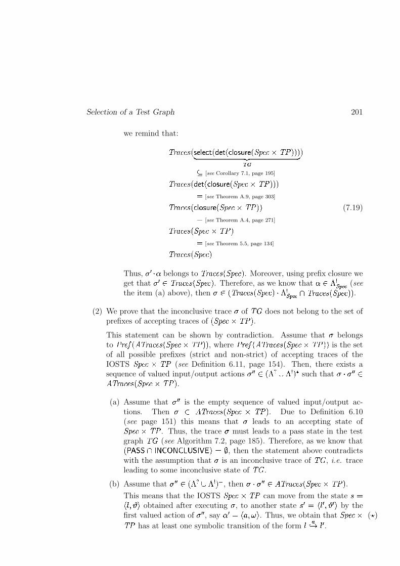
Selection of a Test Graph 201
we remind that:
�������������Ts m p m o n � k�mAn �Toqp r�sut�v m �83�45���:9;�76Q�M�=�� ��� �12�
F [see Corollary 7.1, page 195]
������������� k�mAn � o$p r�s�t�v m �83�45���:9;�76��=�M�d
[see Theorem A.9, page 303]
�������������Toqp r�sut�v m �83�45���:9;�76Q�M� (7.19)d
[see Theorem A.4, page 271]
�������������K3�45���Q9;�76Q�d
[see Theorem 5.5, page 134]
�������������K3�45���E�Thus, � � K� belongs to �������������83�45���E� . Moreover, using prefix closure weget that � ��� �������������83�45���E� . Therefore, as we know that �^� � GIKJML @ (seethe item (a) above), then � � �E�������������83�45���E� � GIKJML @ N �������������83�45���E�=� .
(2) We prove that the inconclusive trace � of ��� does not belong to the set ofprefixes of accepting traces of �K3�45���Q9;�76Q� .This statement can be shown by contradiction. Assume that � belongsto 6R���TSU�KV��������������83�45��� 9f�76Q�M� , where 6R���TSU�DV��������������K3�45��� 9f�76Q�M� is the setof all possible prefixes (strict and non-strict) of accepting traces of theIOSTS 3�45��� 9 �76 (see Definition 6.11, page 154). Then, there exists asequence of valued input/output actions �7� � � � � � � � G ��� such that �Z � � ���V��������������83�45���:9;�76�� .(a) Assume that ��� � is the empty sequence of valued input/output ac-
tions. Then � � V��`�����������K3�45���\9 �76�� . Due to Definition 6.10(see page 151) this means that � leads to an accepting state of3�45���w9x�76 . Thus, the trace � must leads to a pass state in the testgraph ��� (see Algorithm 7.2, page 185). Therefore, as we know that��� ��� N������������ ��� � ����� � d! , then the statement above contradictswith the assumption that � is an inconclusive trace of ��� , i.e. traceleading to some inconclusive state of ��� .
(b) Assume that ��� � � � � � � � G ��" , then �ZE� � ��� V��������������83�45���:9;�76Q� .This means that the IOSTS 3�45��� 9 �76 can move from the state # d$ .�%'&)( obtained after executing � , to another state # �7d $ . � %'& � ( by thefirst valued action of � � � , say � � d $+* %-,.( . Thus, we obtain that 3�45��� 9 (/ )
�76 has at least one symbolic transition of the form .102 3 . � .
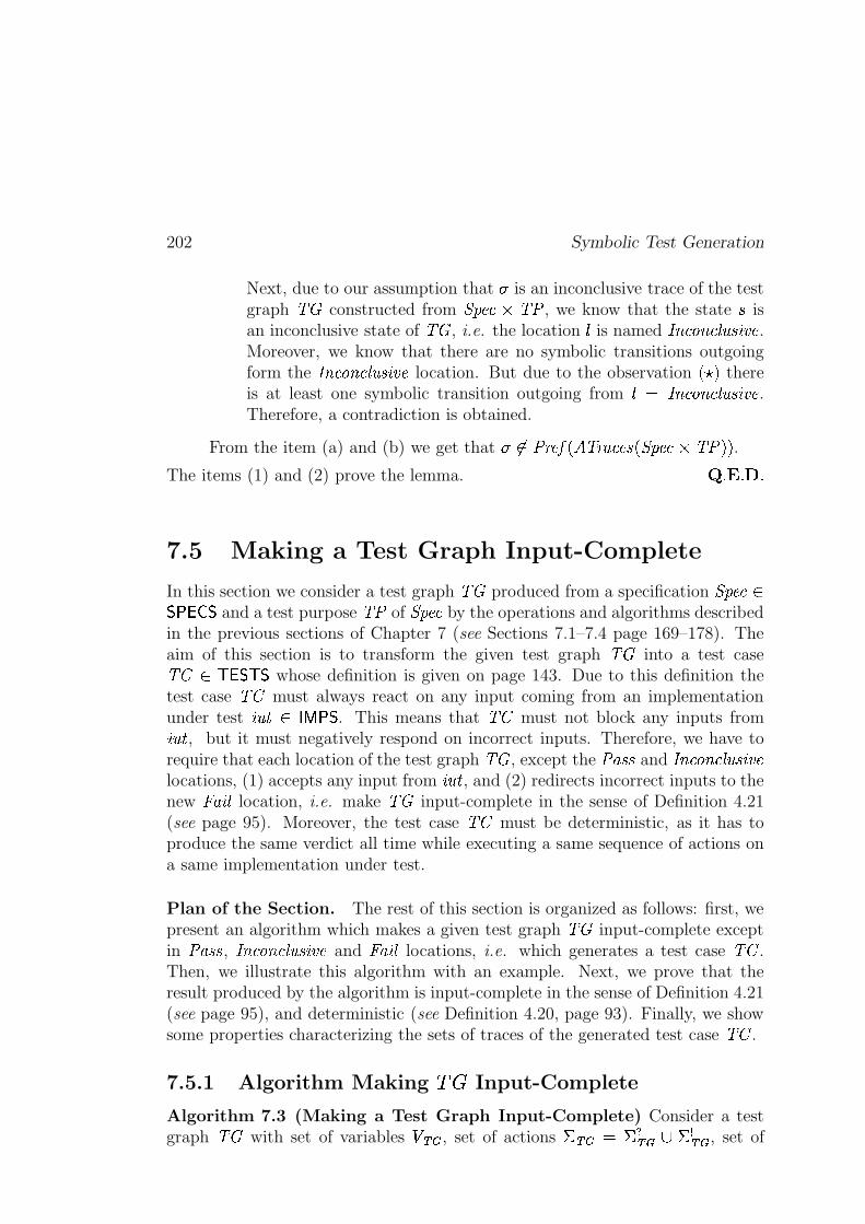
202 Symbolic Test Generation
Next, due to our assumption that � is an inconclusive trace of the testgraph ��� constructed from 3�45���w9x�76 , we know that the state # isan inconclusive state of ��� , i.e. the location . is named !�" ��#$" �&%('��*,+-� .Moreover, we know that there are no symbolic transitions outgoingform the !�" ��#$" �&%('��*,+-� location. But due to the observation � /�� thereis at least one symbolic transition outgoing from . d !�" ��#$" �&%('��*,+-� .Therefore, a contradiction is obtained.
From the item (a) and (b) we get that � �� 6R���TS �DV��������������83�45���:9;�76��=� .The items (1) and (2) prove the lemma. ���������
7.5 Making a Test Graph Input-Complete
In this section we consider a test graph ��� produced from a specification 3�45��� ��)� � � � and a test purpose �76 of 3�45��� by the operations and algorithms describedin the previous sections of Chapter 7 (see Sections 7.1–7.4 page 169–178). Theaim of this section is to transform the given test graph ��� into a test case��� �� � � � whose definition is given on page 143. Due to this definition thetest case ��� must always react on any input coming from an implementationunder test *,'�� � ��� �)� . This means that ��� must not block any inputs from*,'�� , but it must negatively respond on incorrect inputs. Therefore, we have torequire that each location of the test graph ��� , except the 6������ and !�" ��#$" �&%('��*,+-�locations, (1) accepts any input from *,'�� , and (2) redirects incorrect inputs to thenew � �$* % location, i.e. make ��� input-complete in the sense of Definition 4.21(see page 95). Moreover, the test case ��� must be deterministic, as it has toproduce the same verdict all time while executing a same sequence of actions ona same implementation under test.
Plan of the Section. The rest of this section is organized as follows: first, wepresent an algorithm which makes a given test graph ��� input-complete exceptin 6������ , !�" ��#$" �&%(')��*,+-� and � �$* % locations, i.e. which generates a test case ��� .Then, we illustrate this algorithm with an example. Next, we prove that theresult produced by the algorithm is input-complete in the sense of Definition 4.21(see page 95), and deterministic (see Definition 4.20, page 93). Finally, we showsome properties characterizing the sets of traces of the generated test case ��� .
7.5.1 Algorithm Making ��� Input-Complete
Algorithm 7.3 (Making a Test Graph Input-Complete) Consider a testgraph ��� with set of variables � 12 , set of actions � 12 d � � 12 � � G 12 , set of
Making a Test Graph Input-Complete 203
locations � 12 , and set of symbolic transitions � 12 . Then, ��� is completed withits input actions belonging to ��� 12 as it is described below.
First, for a location . � � 1�� and an action* � � � 1�� d � IKJML @u� , we denote by:
����� 0d X�� d $ .�% * % � %�� %�� %M. ( % � � � % ��� d $ .�% * % ��%�� � %�� � %�. � ( _ F�� 12
the set of all symbolic transitions of ��� outgoing from . and labeled with action*.
Then, for each location . � ��� 12 P X 6�������%A!�" ��#$" �&%(')��*,+-� _ � and each input action* � � � 12 :
(1) If (1) ����� 0 is not empty and (2) the disjunction of the gards of the symbolictransitions belonging to ����� 0 does not equal to � ��'5� , i.e. ��� �� � � � � ��� ����� ���?� �d� ��'5� , then we create a new symbolic transition:
� � d $ .�% * % ��%� �!� �� � � � � � � � %�� � % � �$* % (leading to the � �$* % location. Here and in the next item, � � d#" g�$%'&)(+* ,.- d ,0/is the set of identity assignments.
(2) If ����� 0 is empty, i.e. in the case when there are no symbolic transitions out-going from . and labeled with
*, we create the following symbolic transition:
� � d $ .% * %1��% �325476 % � � % � �$* % (which also leads to the � �$* % location.
Then, we prove that Algorithm 7.3 is correct, namely, it produces an input-complete and deterministic IOSTS.
Theorem 7.2 (Correctness of Algorithm 7.3, page 202) An IOSTS ��� � d$98 1)2;: %=< 12>: %�� 12;: %�.T/ 12 : % � 12?: %1� 12;: ( with set of states @ 12?: and set of valued inputactions � � 12 : , which is produced form the test graph ��� by Algorithm 7.3 (seepage 202), is:
(1) input-complete (see Definition 4.21, page 95), except, in the locations 6������ ,� �$* % and !�" ��#$" �&%(')��*,+-� , and
(2) deterministic (see Definition 4.20, page 93).
204 Symbolic Test Generation
Proof
(1) We show that ��� � is input-complete except in the locations 6������ , � �$* % and!�" ��#$" �&%(')��*,+-� .Indeed, due to Algorithm 7.3 we obtain that for each location . � ��� 1)2 : PX 6������ % � �$* % %A!�" ��#$" �&%('��*,+-� _ � and each input action
* � � � 12 : , the disjunc-tion of the guards � % � � � %�� � of all symbolic transitions �� % � � � % ��� � � 12 :outgoing from . and labeled with
*, is equal to � ��'5� . Thus, for each state
# d $ .�%'& ( � @ 12 : of ��� � , and each valued input action �^d $+* %-,.( � ��� 12 : ,there always exists a symbolic transition � h ( � d�� ����� ) outgoing from . andlabeled with
*, whose guard is satisfied by the pair of valuations
$ & %,.( .Due to Definition 4.21 (see page 95) this means that ��� � is input-completeexcept in the 6������ , � �$* % and !�" ��#$" �&%('��*,+-� locations.
(2) We prove that ��� � is deterministic in the sense of Definition 4.20 (seepage 93).
First, we show that ��� � does not contain any internal action.
Indeed, notice that the test graph ��� does not have any internal actionby construction (thanks to the closure operation defined on page 260).Thus, as ��� � is obtained from ��� by Algorithm 7.3 (see page 202),then it also does not contain internal action. Therefore, ��� d .
Second, we show that from each state of ��� � at most one symbolic tran-sition can be fired, i.e. � # � @ 12 : % �;� �T� � 12 : � � G 12 : � � * ���$�� � X # � �@ 12>: [ #�3 # � _ � � � / .To prove this statement we need to consider the two following cases.
(a) Let # be a state of ��� � , and � be a valued output action of ��� � .Then,
– as ��� � is obtained from the test case ��� by Algorithm 7.3(see page 202) which does not augment ��� with symbolictransitions labeled with output actions, and
– as ��� is deterministic by construction (thanks to the proce-dure of the global determinization given on page 304),
thus, we immediately obtain that ���$�� � X # ��� @ 12 : [ #�3 # � _ � � � .(b) Let # d $ .�%'&)( be a state of ��� � , and � d $+* %-,.( be a valued input
action of ��� � .First, notice that if the location . is equal to either 6������ ,!�" ��#$" �&%('��*,+-� or � �$* % , then ���$�� � X # � � @ 12 : [ # 3 # � _ � d�� . Thisstatement follows directly from the fact that the IOSTS ��� �
Making a Test Graph Input-Complete 205
does not contain any symbolic transition outgoing from 6������ ,!�" ��#$" �&%(')��*,+-� or � �$* % locations (see the construction of ��� � , ormore precisely, Algorithms 7.2 and 7.3 presented on pages 185and 202).
Second, suppose that the IOSTS ��� � obtained from the test graph��� by Algorithm 7.3 (see page 202), has ��� � symbolic transi-tions �� % � � � % ��� (a) outgoing from the location . which is differentfrom 6������ , !�" ��#$" �&%(')��*,+-� and � �$* % , (b) labeled with the input action*, and (c) guarded with Boolean expressions � % � � � %�� � . Then:
– If all symbolic transitions �� % � � � % ��� are also symbolic transi-tions of ��� , then due to Algorithm 7.3 (see page 202) we knowthat �!� � � � � � � � � d �3254 6 . Next, as ��� is deterministic, weget that ���$�� � X # � � @ 12 : [ #�3 # � _ � d � .
– Otherwise, there exists exactly one symbolic transition, say
� h ( � d � ��� � ), which was added to ��� � by Algorithm 7.3(see page 202). The rest of the symbolic transitions, i.e.
�� % � � � % � h�� % � h " % � � � % ��� are symbolic transitions of ��� suchthat:
(i) the disjunction of their guards is not equal to true (see Algo-rithm 7.3, page 202), i.e. �!� �� � � � � �Qh�� � �Qh " 5� � � � � � � � �d�32 4 6 , and
(ii) the guards of these symbolic transitions are mutually exclu-sive due to the fact that ��� is deterministic.
Next, as the symbolic transition � h was added to ��� � by Al-gorithm 7.3 (see page 202), then its guard � h is equal to H��� � � � � � ��h�� � ��h " �� � � � � � � � . Thus:
– the disjunction between ��� �� � � � � ��h�� � �Qh " � � � � � � � �and the guard ��h of the symbolic transition � h is triviallyequal to �32 4 6 ,
– moreover, the guard ��h of � h is disjoint with the guards ofthe symbolic transitions �� % � � � % � h�� % � h " % � � � % ��� , i.e. ��� �* � % � / � * ��� �d �8� d�� ���Qh�] � � d�� * .+# 6 / . Thus, using theitem (ii) we obtain that the guards of all symbolic transitions
�� % � � � % � h % � � � % ��� are mutually exclusive.
From the items above we deduce that ���$�� � X # � � @ 1)2 : [ # 3# � _ � d � .
���������
206 Symbolic Test Generation
At the end of the subsection we illustrate the algorithm producing an input-complete test graph with an example.
Example 7.7 Consider the test graph ����� shown on Figure 7.10(b) (seepage 191) obtained after the selection algorithm (see page 185). The alphabet ofinput actions of the given ����� consists of the two following elements:
� � � ')��" and� �&%(*,+-�u� . Notice that ����� is not input-complete in the sense of Definition 4.21(see page 95) as, for instance, in the location
$�� ��-*,"�% � ��-*," ( it does not acceptneither
� � �T' ��" nor� �&%(*,+-�u� input actions. Thus, we complete ����� with the input
actions as follows: we allow the test graph ����� to accept incorrect inputs in alllocations except the location 6������ , but we redirect them to the location � �$* % . Forexample,
(1) consider the location$ � �&%(*,+-�u�� % � ��-*," ( (see Figure 7.10(b), page 191). As
����� can receive the input action� �&%(*,+-�u� only when the guard
� - ����6R��*c��� � � � ]�z+ 6��$* � � � � ]�z+ 6��$* � d ��6R��*c���q� ]�,4 � �u+-�u��� �)� d + � �u+-�u��� �)����]�z+ � �u+-�u��� �)� d COFFEE �
is satisfied, then we create another symbolic transition accepting the in-put action
� �&%(*,+-�u� in the case when the guard � is not satisfied, howeverthis new symbolic transition must go to the � �$* % location (see Figure 7.12,page 207).
(2) consider the location$ � �&%(*,+-�u�� % � ��-*," ( of ����� (see Figure 7.10(b),
page 191). This location must be completed with the input action� � �T' ��"
by adding the new transition outgoing from$ � �&%(*,+-�u���% � ��-*," ( leading to
� �$* % , and labeled with the input action� � �T')�u" (see Figure 7.12, page 207).
The input-complete test case ��� obtained from ����� is shown in Figure 7.12(see page 207). Notice that, when this test case receives an incorrect input, e.g.� � �T' ��" in the location
$ � �&%(*,+-�u�� % � ��-*,")( , it does not block it, it produces the � �$* %verdict.
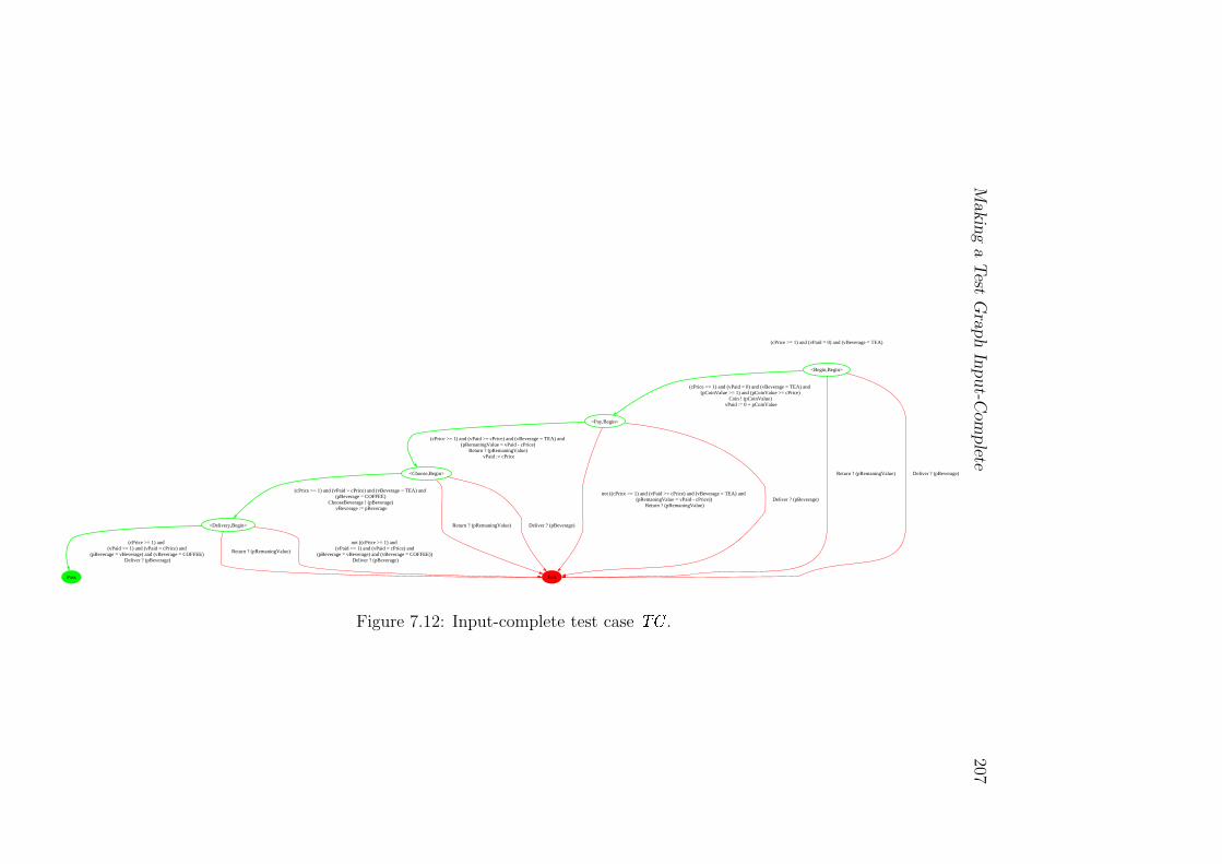
Makin
ga
Test
Gra
ph
Input-C
om
plete
207
(cPrice >= 1) and (vPaid = 0) and (vBeverage = TEA)
<Begin,Begin>
<Pay,Begin>
(cPrice >= 1) and (vPaid = 0) and (vBeverage = TEA) and (pCoinValue >= 1) and (pCoinValue >= cPrice)
Coin ! (pCoinValue) vPaid := 0 + pCoinValue
Fail
Return ? (pRemaningValue) Deliver ? (pBeverage)<Choose,Begin>
(cPrice >= 1) and (vPaid >= cPrice) and (vBeverage = TEA) and (pRemaningValue = vPaid - cPrice)
Return ? (pRemaningValue) vPaid := cPrice
not ((cPrice >= 1) and (vPaid >= cPrice) and (vBeverage = TEA) and (pRemaningValue = vPaid - cPrice))
Return ? (pRemaningValue)Deliver ? (pBeverage)
<Delivery,Begin>
(cPrice >= 1) and (vPaid = cPrice) and (vBeverage = TEA) and (pBeverage = COFFEE)
ChooseBeverage ! (pBeverage) vBeverage := pBeverage
Return ? (pRemaningValue) Deliver ? (pBeverage)
Pass
(cPrice >= 1) and (vPaid >= 1) and (vPaid = cPrice) and
(pBeverage = vBeverage) and (vBeverage = COFFEE) Deliver ? (pBeverage)
Return ? (pRemaningValue)
not ((cPrice >= 1) and (vPaid >= 1) and (vPaid = cPrice) and
(pBeverage = vBeverage) and (vBeverage = COFFEE)) Deliver ? (pBeverage)
Figure 7.12: Input-complete test case
� �
.

208 Symbolic Test Generation
7.5.2 Traces of a Test Case
In this subsection we consider a test case derived by the symbolic test genera-tion method described in Chapter 7 (see page 167). The main purpose of thissubsection is to characterize the set of traces of the given test case.
First, we notice that any test case ��� �� � � � has three kind of verdicts,namely, 6������ , !�" ��#$" �&%('��*,+-� and � �$* % . Therefore, its set of traces contains tracesleading to pass, inconclusive and fail states. We remind that the notions of tracesleading to 6������ and !�" ��#$" �&%('��*,+-� were already introduced for a test graph ��� (seeDefinition 7.3, page 196), and they are the same for the test case ��� . Therefore,we have to introduce only the notion of traces leading to fail states of ��� .
Definition 7.4 (Traces of ��� Leading to Fail) Let ��� be a test case withset of states @ 1�� , set of initial states @ / 1�� F @ 1�� , and set of fail states
� � � F @ 1�� .Then, the set of traces leading to states belonging to
� � � is defined as follows:
�������� ���� <���� ������� ����� �����!"�� � ���#�%$�&(' / �*) / 1��,+ '.- 0 h���0/21436587:9;' /=<> '?- 0 h���@�A (7.20)
In the rest of the thesis any trace belonging to �`��������� �B� <C� �����Q� is called a fail
trace.
Then, we consider the test case ��� derived from some test graph ��� by Algo-rithm 7.3 (see page 202), and make several observations/lemmas characterizingthe sets of fail, pass and inconclusive traces of ��� .
Lemma 7.4 (Pass Traces of ��� ) The set of pass traces of the test case ���is equal to the set of pass traces of the test graph ��� , i.e.
����������� J ��DED ������� d �`��������� J ��DED �������
Proof In order to prove the lemma we have to show the two following inclusions.
( F ) Consider a pass trace �\dY� � � � � � of the test graph ��� and prove that itis a pass trace of the test case ��� .
By Definition 7.3 (see page 196) we know that the trace � leads from aninitial state #E/ d $ .T/ %'&�/ ( � @ / 12 to some pass state #HG 0 ici
d $ 6������ %'&�G 0 ici(�
� ���� of ��� . Moreover, we know that the trace � corresponds to a sequenceof consecutive symbolic transitions: I - . / 0�J2 3 . � � �=. � � 0"K2 3 6������ where. % � � � %�. � � are locations of ��� , and
* % � � � % * � are input/output actions of��� corresponding to � % � � � % � � which constitute the trace � .
Making a Test Graph Input-Complete 209
Then, due to the last step of the test case construction (see Algorithm 7.3,page 202), we know that ��� and ��� have the same structure except ofnew symbolic transitions leading to the � �$* % location which were added to��� . Thus, ��� contains the sequence of symbolic transitions I .Finally, as ��� and ��� have the same initial condition (see Algorithm 7.3,page 202), and ��� is deterministic (see Theorem 7.2, page 203), then thetrace � executing on ��� from the same initial state # / as ��� leads to thesame pass state #2G 0 ici as ��� .
Therefore, � is a pass trace of the test case ��� (see Definition 7.3, page 196which is the same for ��� ).
( F ) The proof of the second inclusion is similar to one of the first inclusion � F�� .���������
Lemma 7.5 (Inconclusive Traces of ��� ) The set of inconclusive traces ofthe test case ��� is equal to the set of inconclusive traces of the test graph ��� ,i.e.
�`���������=<a>A@bBc>A@A�����:� d �����������=<a>A@bBc>A@u�������
Proof This lemma can be proved similarly as Lemma 7.4 on page 208. � ������
Before characterizing the set of traces and the set of fail traces of the given testcase ��� , we make an observation about the form of a fail trace.
Observation 7.3 (The Form of a Fail Trace of ��� ) Let ��� be a test casewith set of valued input actions � � . Then, any fail trace � of ��� has the form:� �)�� , where � ��� ������������������� and �^� � � . This observation follows directly from the construction of the test graph ��� (seeAlgorithm 7.3, page 202). Indeed, as an � �$* % location of ��� is different from theinitial location . / 1�� of ��� , then the set of fail states of ��� is different from theset of initial states of ��� . Therefore, � leading to some fail state cannot be anempty trace. Moreover, as ��� can move to an � �$* % location only by taking somesymbolic transition labeled with an input action (see Algorithm 7.3, page 202),then the last valued action � of � is a valued input action of ��� .
210 Symbolic Test Generation
Lemma 7.6 (Traces of ��� ) The set of traces of ��� is the union between theset of traces of ��� and the set of fail traces of ��� , i.e.
�`���������������Q� d ������������������� � �`��������� �B� <C� �����Q�
Proof The proof of this lemma follows from the two statements shown below.
(1) All traces of the test graph ��� are included into the set of traces of thetest case ��� , i.e. �`�����������E������F �������������E����� .Indeed, as the test case ��� is derived from ��� by adding new symbolictransitions leading to the � �$* % location (see Algorithm 7.3, page 202), thenit keeps the structure of ��� . Therefore, any trace of ��� will be a trace of��� .
(2) The trace � is a trace of the test case ��� and not a trace of the test graph��� if and only if it is a fail trace of ��� , i.e. ���`���������������Q�-PQ�`���������������Q�M� d�`��������� �B� <C� �����Q� .( F ) We show that �E�������������E����� P �������������E���Q�=��F �`��������� �B� <C� �E����� .
This inclusion can be proved by contradiction.
Consider a trace � d � � � � � � belonging to �E�������������E����� P�`�����������E�����M� . Assume that this trace � does not belong to�`��������� �B� <C� �����Q� . Thus, � leads to a state corresponding to a location .different from � �$* % .Next, we know that ��� has a sequence of consecutive symbolic transi-tions: I - . / 0 J2 3 . � � �M. � � 0 K2 3 . corresponding to � , where .0/ %M. % � � � %�. � � are locations of ��� and
* % � � � % * � are input/output actions of ���that correspond to � % � � � % � � . Moreover, . / �d � �$* % (see Algorithm 7.3,page 202), . �d � �$* % (due to the assumption that � is not a fail trace of��� ), and . �d � �$* % % � � � %�. � � �d � �$* % (due to the fact that there are nosymbolic transitions outgoing from the � �$* % location, see Algorithm 7.3on page 202).
Finally, as the sequence I of ��� does not contain any symbolic tran-sition leading to the � �$* % location, then due to Algorithm 7.3 (seepage 202) I is also a sequence of consecutive symbolic transitions of��� . Therefore, the trace � is the trace of ��� . This contradicts withthe assumption that �\� ���`�����������E����� P �`�����������E�����M� .
( F ) We show that �E�������������E����� P �������������E���Q�=��F �`��������� �B� <C� �E����� .Consider a trace � d ����`� belonging to ����������� ��� <��T������� . Then, bydefinition of a fail trace (see page 208), we obtain that:
Making a Test Graph Input-Complete 211
(a) � is a trace of ��� , and
(b) ����� ��� n8m v � � F � � � . Therefore, the last action of the trace � ,
i.e. � corresponds to a symbolic transition of the form . 02 3 � �$* % ,where . is a location of ��� and
*is an input action of ��� . Then,
we know that the symbolic transitions of this form were added to��� by Algorithm 7.3 (see page 202), thus � cannot be a trace of��� .
The items (a) and (b) imply ( F ).
Therefore, we have shown that ���`���������������Q�fP �������������E�����M� d����������� ��� <C� �E����� .
The proof of the lemma follows directly from the items (1) and (2). � ����� �
At the end of this subsection we study the relationship between the set of failtraces of the test case ��� , and the set of traces of the specification 3�45��� fromwhich ��� was generated.
Lemma 7.7 (Traces of ��� Leading to Fail) Let ��� be a test case generatedfrom a specification 3�45��� � �)� � � � and a test purpose �76 of 3�45��� as it wasexplained in Sections 7.1–7.5 (see pages 169–202). Then, a trace of ��� leadingto some fail state is a trace of 3�45��� concatenated with a valued output action,but it is not a trace of 3�45��� .
����������� �B� <C� �E�����RFx���`�����������83�45���E� � GIKJML @ � P �������������83�45���E� (7.21)
where �`�����������K3�45���E� � GIKJML @ WYX �Z��;[� � �`�����������K3�45���E� ] �^� � GIKJ=L @ _
Proof Consider a trace � belonging to ����������� �B� <C� �����Q� . Due to Observation 7.3(see page 209) � has the form ����� , where � ��� �`�����������E����� and ��� � � 1�� .
(1) We prove that �edf����� belongs to ���`���������-�K3�45���E� � GIKJML @ � .(a) First, we show that the last valued action of � , i.e. � is a valued output
action of 3�45��� .Indeed, as:
– � is a valued input action of the test case ��� derived from thespecification 3�45��� by the symbolic test generation method (seeSections 7.1–7.5, pages 169–202), and
– during selection (see Algorithm 7.2, page 185), the directions (in-put/output) of all actions were inverted,
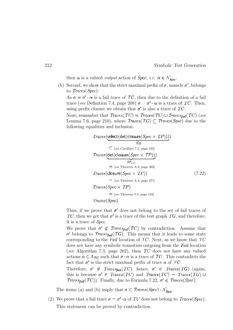
212 Symbolic Test Generation
then � is a valued output action of 3�45��� , i.e. �^� � GIKJML @ .(b) Second, we show that the strict maximal prefix of � , namely �7� , belongs
to �������������83�45���E� .As � d;� �)�� is a fail trace of ��� , then due to the definition of a failtrace (see Definition 7.4, page 208) �ed}��� � is a trace of ��� . Then,using prefix closure we obtain that ��� is also a trace of ��� .
Next, remember that �`�����������E����� d ������������������� � �`��������� �B� <C� �E����� (seeLemma 7.6, page 210), where ��������������������F �`�����������83�45���E� due to thefollowing equalities and inclusion:
�`����������� s m p m o n � k�mAn � o$p r�s�t�v m �83�45���:9;�76��=�M�� ��� �1)2�
F [see Corollary 7.1, page 195]
�`����������� k�mun � oqp r�s�t�v m �K3�45���Q9f�76��M�� ��� �I ��������
d[see Theorem A.9, page 303]
�`����������� o$p r�s�t�v m �83�45���:9;�76��=� (7.22)d
[see Theorem A.4, page 271]
�`�����������83�45���:9;�76Q�d
[see Theorem 5.5, page 134]
�`�����������83�45���E�Thus, if we prove that ��� does not belong to the set of fail traces of��� , then we get that ��� is a trace of the test graph ��� , and therefore,it is a trace of 3�45��� .We prove that ��� �� ����������� ��� <C� �E����� by contradiction. Assume that� � belongs to �`��������� ��� <��T������� . This means that it leads to some statecorresponding to the � �$* % location of ��� . Next, as we know that ���does not have any symbolic transition outgoing from the � �$* % location(see Algorithm 7.3, page 202), then ��� does not have any valuedactions ��� � 1�� such that � �� is a trace of ��� . This contradicts thefact that � � is the strict maximal prefix of trace � of ��� .
Therefore, � � �� ����������� ��� <��T������� , hence, � � � �`���������������Q� (again,this is because ����� �������������E����� and �������������E����� d �������������E���Q� ��`��������� �B� <C� �����Q� ). Finally, due to Formula 7.22, � � � �`�����������K3�45���E� .
The items (a) and (b) imply that �\� �������������83�45���E� � GIKJML @ .(2) We prove that a fail trace �edf����8� of ��� does not belong to �������������83�45��� � .
This statement can be proved by contradiction.
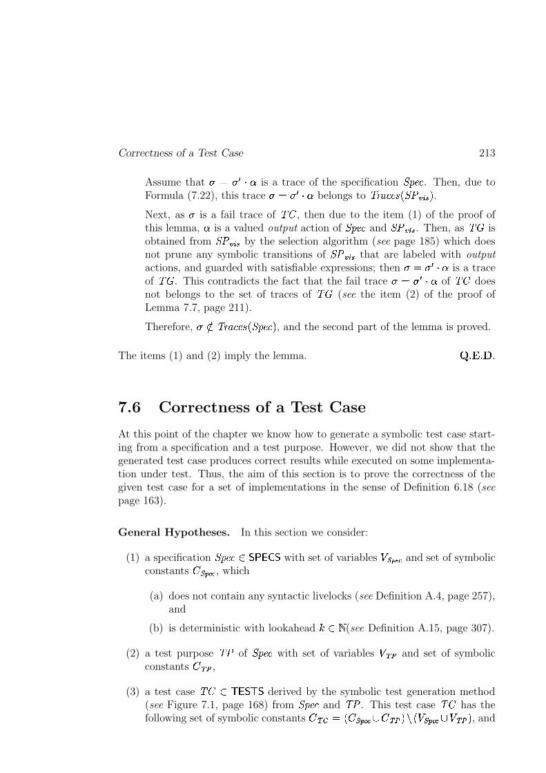
Correctness of a Test Case 213
Assume that � d � �5�� is a trace of the specification 3�45��� . Then, due toFormula (7.22), this trace �ed}����� belongs to �������������8356Hgzh{i�� .Next, as � is a fail trace of ��� , then due to the item (1) of the proof ofthis lemma, � is a valued output action of 3�45��� and 356yg8hji . Then, as ��� isobtained from 356 g8hji by the selection algorithm (see page 185) which doesnot prune any symbolic transitions of 356yg8hji that are labeled with output
actions, and guarded with satisfiable expressions; then �ed}��� � is a traceof ��� . This contradicts the fact that the fail trace � dx� � $� of ��� doesnot belongs to the set of traces of ��� (see the item (2) of the proof ofLemma 7.7, page 211).
Therefore, ���� �`�����������K3�45���E� , and the second part of the lemma is proved.
The items (1) and (2) imply the lemma. � ��� ����
7.6 Correctness of a Test Case
At this point of the chapter we know how to generate a symbolic test case start-ing from a specification and a test purpose. However, we did not show that thegenerated test case produces correct results while executed on some implementa-tion under test. Thus, the aim of this section is to prove the correctness of thegiven test case for a set of implementations in the sense of Definition 6.18 (seepage 163).
General Hypotheses. In this section we consider:
(1) a specification 3�45��� � �)� � � � with set of variables � IKJML @ and set of symbolicconstants � IKJ=L @ , which
(a) does not contain any syntactic livelocks (see Definition A.4, page 257),and
(b) is deterministic with lookahead � ��� (see Definition A.15, page 307).
(2) a test purpose �76 of 3�45��� with set of variables � 1� and set of symbolicconstants � 1�� ,
(3) a test case ��� �� � � � derived by the symbolic test generation method(see Figure 7.1, page 168) from 3�45��� and �76 . This test case ��� has thefollowing set of symbolic constants � 1�� d ��� IKJ=L @ � � 1�� �-PR� � IKJML @ � � 1�� � , and
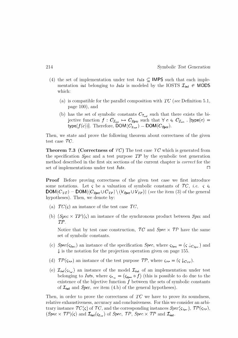
214 Symbolic Test Generation
(4) the set of implementation under test ������������ �� such that each imple-mentation ����� belonging to ������� is modeled by the IOSTS ������������� �!�which:
(a) is compatible for the parallel composition with "$# (see Definition 5.1,page 100), and
(b) has the set of symbolic constants %'&)( *,+ such that there exists the bi-jective function -/.!%'&)( *0+213 %547698;: such that <>=?�@%A&)( *0+CBED F0GIHKJIL0=NMPOF0GIHKJKLQ-AL0=NMRMTS . Therefore, �U�V�WL0%'&)( *0+9MAOX�U�Y�WLZ%5476R8[:�M .
Then, we state and prove the following theorem about correctness of the giventest case "$# .
Theorem 7.3 (Correctness of "$# ) The test case "$# which is generated fromthe specification \K]_^�` and a test purpose "ba by the symbolic test generationmethod described in the first six sections of the current chapter is correct for theset of implementations under test ������� . c
Proof Before proving correctness of the given test case we first introducesome notations. Let d be a valuation of symbolic constants of "$# , i.e. de��U�Y�WLZ%gfihbMEOj�U�Y��L9L0%547698;:�kP%gfNlbMimnLZop476R8[:qk2oEfrlsM9M (see the item (3) of the generalhypotheses). Then, we denote by:
(a) "$#PL0d)M an instance of the test case "$# ,
(b) Lt\K]_^�`Vu/"ba MvL,dwM an instance of the synchronous product between \K]_^�` and"ba .
Notice that by test case construction, "$# and \K]_^�`xuX"ba have the sameset of symbolic constants.
(c) \K]_^�`yL0d{z,|0}�~TM an instance of the specification \K]_^�` , where d9z�|Z}�~sO�L0d��q� z�|Z}�~ M and� is the notation for the projection operation given on page 155.
(d) "baPL,d��R�qM an instance of the test purpose "ba , where dv�R�VO�L,d��q� �{� M .(e) �������9L0dQ�R� ���0M an instance of the model ������� of an implementation under test
belonging to ������� , where dT�R� ���'O�L0d{z�|Z}�~��C-sM (this is possible to do due to theexistence of the bijective function - between the sets of symbolic constantsof ������� and \K]_^�` , see item (4.b) of the general hypotheses).
Then, in order to prove the correctness of "$# we have to prove its soundness,relative exhaustiveness, accuracy and conclusiveness. For this we consider an arbi-trary instance "$#PL,dwM of "$# , and the corresponding instances \K]_^�`yL,d9z,|0}�~7M , "baxL0d��{�iM ,L7\K]_^�` u�"ba MvL,dwM and �������RL,dQ�R� ���ZM of \K]_^�` , "ba , \K]_^�`�u�"ba and ������� .
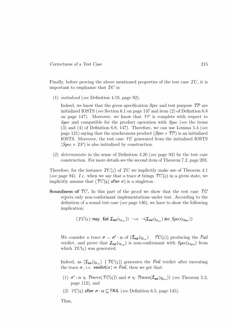
Correctness of a Test Case 215
Finally, before proving the above mentioned properties of the test case "$# , it isimportant to emphasize that "$# is:
(1) initialized (see Definition 4.19, page 92).
Indeed, we know that the given specification \K]_^�` and test purpose "ba areinitialized IOSTS (see Section 6.1 on page 137 and item (2) of Definition 6.8on page 147). Moreover, we know that "ba is complete with respect to\K]_^�` and compatible for the product operation with \K]_^�` (see the items(3) and (4) of Definition 6.8, 147). Therefore, we can use Lemma 5.4 (seepage 121) saying that the synchronous product L7\K]_^�`�u>"baYM is an initializedIOSTS. Moreover, the test case "$# generated from the initialized IOSTSLt\K]_^�`�u�"ba M is also initialized by construction.
(2) deterministic in the sense of Definition 4.20 (see page 93) by the test caseconstruction. For more details see the second item of Theorem 7.2, page 203.
Therefore, for the instance "$#PL,dwM of "$# we implicitly make use of Theorem 4.1(see page 94). I.e. when we say that a trace � brings "$#PL0d)M in a given state, weimplicitly assume that LN"$#PL0d)M�� � FtJ�����M is a singleton.
Soundness of "$# . In this part of the proof we show that the test case "$#rejects only non-conformant implementations under test. According to thedefinition of a sound test case (see page 146), we have to show the followingimplication:
L)"$#xL,dwM��� G _ � �� �N�������9L,dQ�R� ���ZMRM>O�� ��L �������9L0dQ�R� ���ZM�����P\K]_^�`yL0d{z�|Z}�~7M9M
We consider a trace � O�������� of L��������9L0dQ�R� ���0M����'"$#PL0d)M9M producing the �! w�#"verdict, and prove that �������9L,dQ�R� ���,M is non-conformant with \K]_^�`yL,dRz,|0}�~TM fromwhich "$#PL,dwM was generated.
Indeed, as L �������RL0dQ�R� ���ZM��$�A"$#xL0dwMRM generates the �! w�#" verdict after executingthe trace � , i.e. %)J&�(') � F L*��MAO+�! w�#" , then we get that:
(1) � � ���@� "),- I`�^��KL)"$#xL0dwMRM and � � ".,/ I`�^��KL��������RL,dQ�R� ���ZM9M (see Theorem 5.2,page 112), and
(2) "$#PL,dwM�� � FtJ����0�1� �3254�76 (see Definition 6.5, page 145).
Thus,
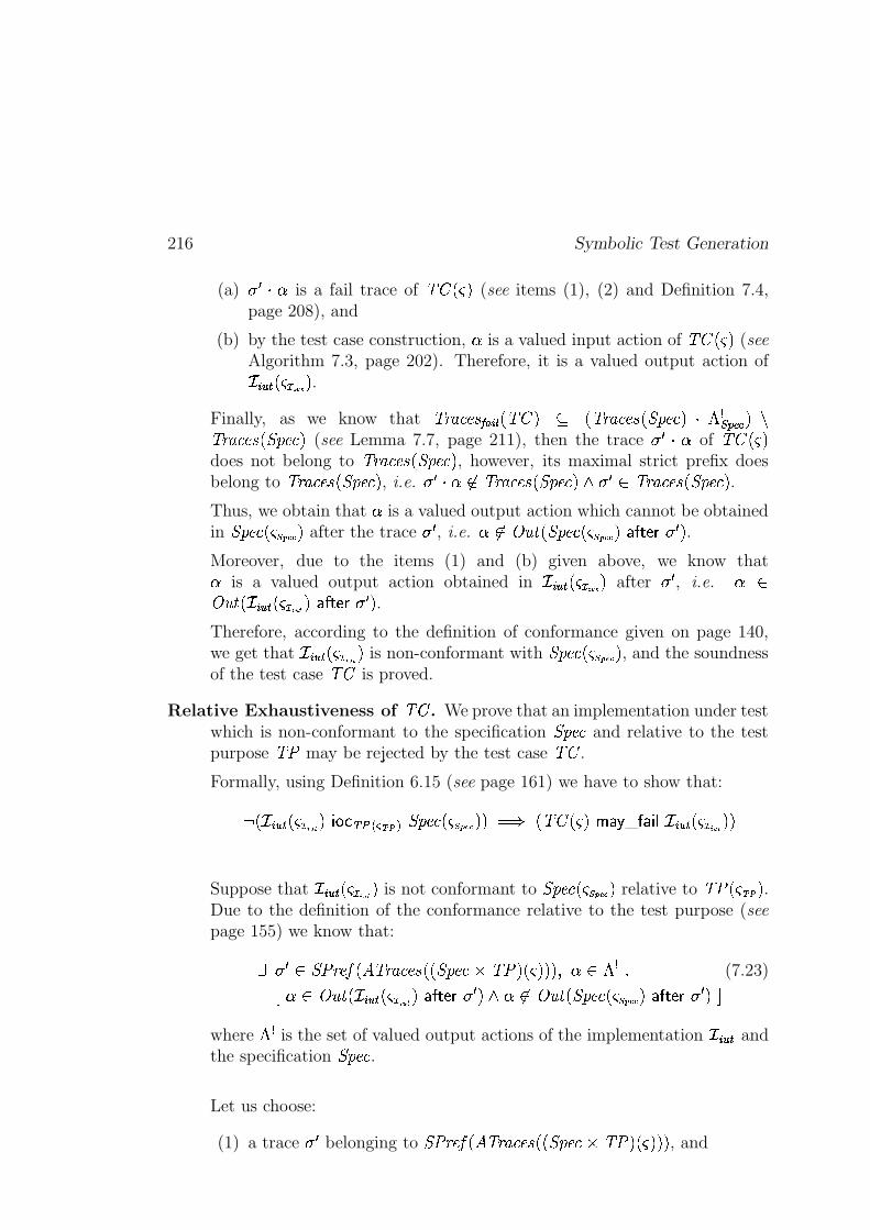
216 Symbolic Test Generation
(a) � � � � is a fail trace of "$#xL0dwM (see items (1), (2) and Definition 7.4,page 208), and
(b) by the test case construction, � is a valued input action of "$#PL0d)M (seeAlgorithm 7.3, page 202). Therefore, it is a valued output action of�s�����RL0dQ�R� ���ZM .
Finally, as we know that ".,/ I`�^�� ��� ���,L)"$#YM � L)"),/ I`�^��IL7\K]_^�`NM0���� 476R8[: M m"),/ I`�^��IL7\K]_^�`NM (see Lemma 7.7, page 211), then the trace � � �)� of "$#PL,dwMdoes not belong to ".,/ I`�^��KLt\K]_^�`NM , however, its maximal strict prefix doesbelong to ".,/ I`�^��IL7\K]_^�`NM , i.e. � � �1����".,/ I`�^��IL7\K]_^�`NM � � � ��"),- I`�^��KLt\K]_^�`NM .Thus, we obtain that � is a valued output action which cannot be obtainedin \K]_^�`yL0d{z,|0}�~TM after the trace � � , i.e. ����� ��� L7\K]_^�`yL0d{z,|0}�~TM�� � FtJ&� � � M .Moreover, due to the items (1) and (b) given above, we know that� is a valued output action obtained in �������9L0dQ�R� ���0M after � � , i.e. � �� ��� L��������RL,dQ�R� ���ZM � � FtJ&� � � M .Therefore, according to the definition of conformance given on page 140,we get that �������RL,dQ�R� ���ZM is non-conformant with \K]_^�`yL0d{z,|0}�~7M , and the soundnessof the test case "$# is proved.
Relative Exhaustiveness of "$# . We prove that an implementation under testwhich is non-conformant to the specification \K]_^�` and relative to the testpurpose "ba may be rejected by the test case "$# .
Formally, using Definition 6.15 (see page 161) we have to show that:
��L��������9L,dQ�R� ���,M� � �ifrl���� �{��� \K]_^�`yL,d{z,|0}�~7M9M O�� L)"$#xL0dwM��� G _ � �� �N�������{L0dQ�R� ���ZM9M
Suppose that �������RL,dQ�R� ���ZM is not conformant to \K]_^�`yL0dRz�|Z}�~TM relative to "baPL,dv�{�iM .Due to the definition of the conformance relative to the test purpose (seepage 155) we know that:
� � � � \_a ,�^��EL��Y".,/ I`�^��ILRLt\K]_^�`�u�"ba MvL0d)M9MRM���� ��� � B (7.23)
D � ��� ��� L��s�����9L0dQ�R� ���0M�� � FtJ���� � M � ����� ��� Lt\K]_^�`yL0d{z�|Z}�~TM�� � FtJ���� � MUSwhere � � is the set of valued output actions of the implementation �E����� andthe specification \K]_^�` .
Let us choose:
(1) a trace � � belonging to \_a ,�^���L��Y".,/ I`�^��KL9Lt\K]_^�`�u�"ba MvL,dwM9MRM , and
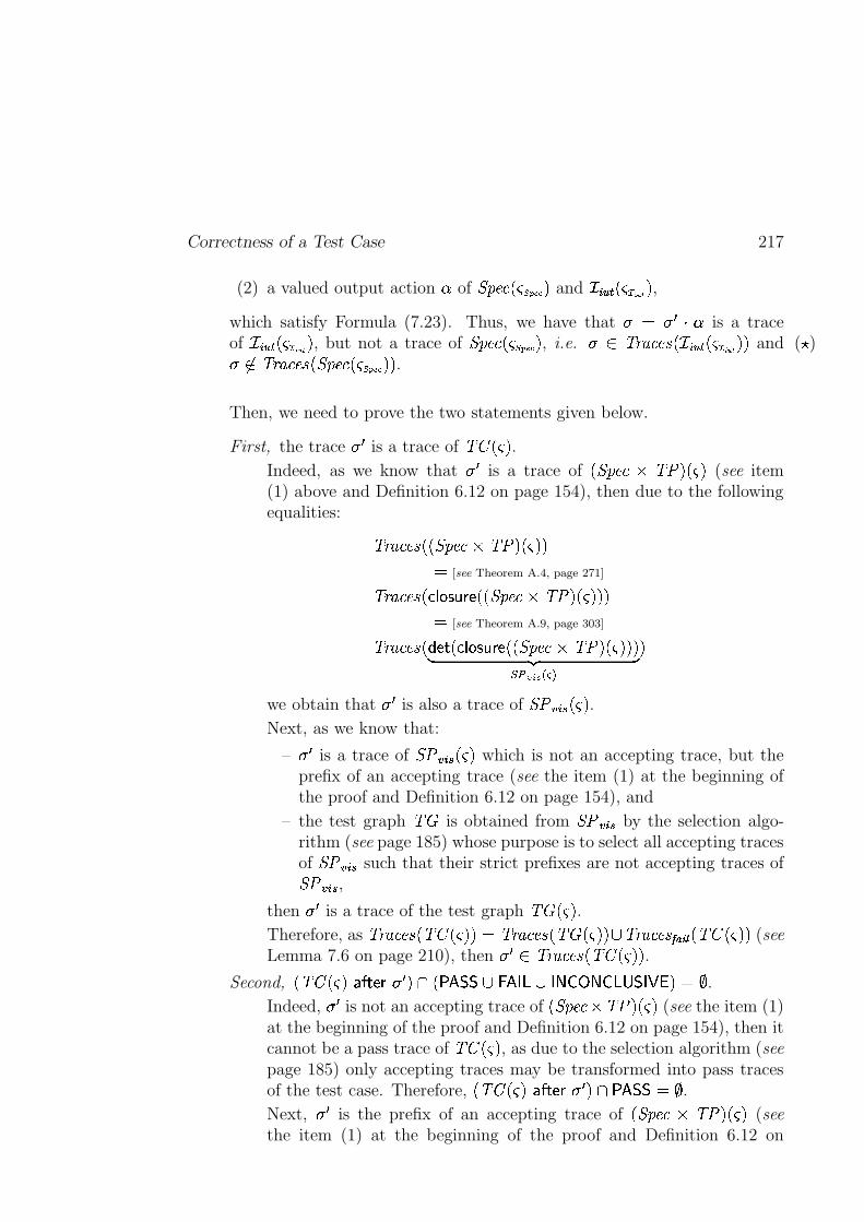
Correctness of a Test Case 217
(2) a valued output action � of \K]_^�`yL0dRz,|0}�~TM and �������{L0dQ�R� ���ZM ,which satisfy Formula (7.23). Thus, we have that � O � � �)� is a traceof �������9L,dQ�R� ���0M , but not a trace of \K]_^�`yL0dRz�|Z}�~TM , i.e. �/� "),/ I`�^��IL �������9L0dQ�R� ���0M9M and (� )� ��".,/ I`�^��IL7\K]_^�`yL0d{z�|Z}�~QM9M .
Then, we need to prove the two statements given below.
First, the trace � � is a trace of "$#PL,dwM .Indeed, as we know that ��� is a trace of Lt\K]_^�` u "ba MvL,dwM (see item(1) above and Definition 6.12 on page 154), then due to the followingequalities:
".,/ I`�^��KL9Lt\K]_^�`�u�"ba MvL,dwMRMO [see Theorem A.4, page 271]
".,/ I`�^��KL#�&� �������[JILRLt\K]_^�` u�"ba MvL0d)M9MRMO [see Theorem A.9, page 303]
".,/ I`�^��KL#'IJ F L*�&� �������;JiL9L7\K]_^�` u�"ba M�L0dwMRM9M� �� 49l��� �� � � �
M
we obtain that � � is also a trace of \_a������rL,dwM .Next, as we know that:
– � � is a trace of \_a������rL0d)M which is not an accepting trace, but theprefix of an accepting trace (see the item (1) at the beginning ofthe proof and Definition 6.12 on page 154), and
– the test graph " � is obtained from \_a������ by the selection algo-rithm (see page 185) whose purpose is to select all accepting tracesof \_a������ such that their strict prefixes are not accepting traces of\_a������ ,
then � � is a trace of the test graph " � L0d)M .Therefore, as "),- I`�^��yLN"$#PL0d)M9MAO ".,/ I`�^��KL)" � L,dwMRM kW".,/ I`�^�� ��� ���ZL)"$#PL,dwMRM (seeLemma 7.6 on page 210), then � � �/".,/ I`�^��KL)"$#gL0dwMRM .
Second, L)"$#PL,dwM�� � FtJ���� � M�� L{ �4A� �Vk 2 4n�6�k ��! b�"�! 6$#��p&%(' MEO*) .Indeed, � � is not an accepting trace of L7\K]_^�`Au "baVM�L0d)M (see the item (1)at the beginning of the proof and Definition 6.12 on page 154), then itcannot be a pass trace of "$#PL0d)M , as due to the selection algorithm (seepage 185) only accepting traces may be transformed into pass tracesof the test case. Therefore, L)"$#PL,dwM�� � FtJ���� � M��> �4'����O+) .Next, � � is the prefix of an accepting trace of Lt\K]_^�` u�"baYMvL,dwM (seethe item (1) at the beginning of the proof and Definition 6.12 on
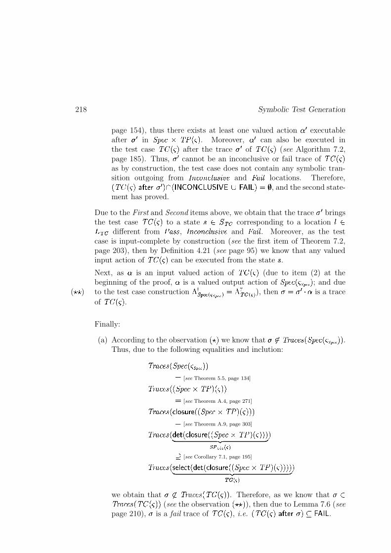
218 Symbolic Test Generation
page 154), thus there exists at least one valued action � � executableafter � � in \K]_^�`�u "baxL,dwM . Moreover, � � can also be executed inthe test case "$#PL0d)M after the trace � � of "$#PL0d)M (see Algorithm 7.2,page 185). Thus, ��� cannot be an inconclusive or fail trace of "$#PL0d)Mas by construction, the test case does not contain any symbolic tran-sition outgoing from ����`�����` "��q�����y^ and �! w�#" locations. Therefore,LN"$#PL0d)M � � FtJ�� � � M�� L{ � s�"�! 6$#��p&%(' k32 4�76iMAO*) , and the second state-ment has proved.
Due to the First and Second items above, we obtain that the trace � � bringsthe test case "$#PL,dwM to a state � � � fih corresponding to a location �� fih different from a� )��� , ����`�����` "��i�����y^ and �! w�#" . Moreover, as the testcase is input-complete by construction (see the first item of Theorem 7.2,page 203), then by Definition 4.21 (see page 95) we know that any valuedinput action of "$#PL,dwM can be executed from the state � .Next, as � is an input valued action of "$#PL0d)M (due to item (2) at thebeginning of the proof, � is a valued output action of \K]_^�`yL0d9z�|Z}�~7M ; and dueto the test case construction � �47698;: � � z,|0}�~ � O ��� fih � � � ), then � O � �&� � is a trace(��� )
of "$#xL0dwM .
Finally:
(a) According to the observation L � M we know that � ��".,/ I`�^��KLt\K]_^�`yL,d�z�|Z}�~7M9M .Thus, due to the following equalities and inclution:
".,/ I`�^��IL7\K]_^�`yL0d{z�|Z}�~QM9MO [see Theorem 5.5, page 134]
".,/ I`�^��ILRLt\K]_^�`�u�"ba MvL,dwM9MO [see Theorem A.4, page 271]
".,/ I`�^��IL*�&� �������;JiL9L7\K]_^�` u "baYM�L0d)M9M9MO [see Theorem A.9, page 303]
".,/ I`�^��IL*'IJ F L*�&� � �����;JiL9L7\K]_^�` u�"ba MvL,dwMRM9M� �� 49l��� �� ��� �
M
[see Corollary 7.1, page 195]
".,/ I`�^��IL �RJ�� J � F L#'IJvFrL*�&� �������;JiL9L7\K]_^�` u "baVM�L0dwMRM9MRM� ��� f�� � � �
M
we obtain that � ��"),- I`�^��KL)" � L0dwMRM . Therefore, as we know that � �"),/ I`�^��ILN"$#PL0d)M9M (see the observation L � � M ), then due to Lemma 7.6 (seepage 210), � is a fail trace of "$#PL,dwM , i.e. L)"$#xL0dwM � � FtJ&����MU�3254��6 .
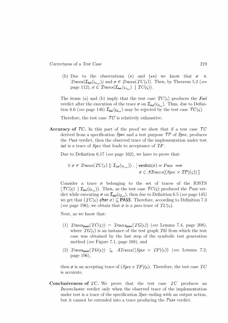
Correctness of a Test Case 219
(b) Due to the observations L�� M and L���� M we know that � �".,/ I`�^��KL��������RL,dQ�R� ���ZM9M and �>��".,/ I`�^��ILN"$#PL0d)M9M . Then, by Theorem 5.2 (seepage 112), �>��".,/ I`�^��KL��������9L0dQ�R� ���0M��$�'"$#xL0dwMRM .
The items (a) and (b) imply that the test case "$#PL,dwM produces the � w�#"verdict after the execution of the trace � on �E�����RL,dQ�R� ���ZM . Thus, due to Defini-tion 6.6 (see page 146) �������9L0dQ�R� ���ZM may be rejected by the test case "$#PL,dwM .Therefore, the test case "$# is relatively exhaustive.
Accuracy of "$# . In this part of the proof we show that if a test case "$#derived from a specification \K]_^�` and a test purpose "ba of \K]_^�` , producesthe a� )��� verdict, then the observed trace of the implementation under test����� is a trace of \K]_^�` that leads to acceptance of "ba .
Due to Definition 6.17 (see page 162), we have to prove that:
< �>��"),- I`�^��KL)"$#xL0dwM����N�������RL0dQ�R� ���ZMRM BED %)J&�(') � F L#��MEOXa� )��� O���>� �Y"),- I`�^��KL9L7\K]_^�` u�"ba M�L0dwMRM!S
Consider a trace � belonging to the set of traces of the IOSTSL)"$#PL,dwM��$�N�s�����RL0dQ�R� ���ZM9M . Then, as the test case "$#PL0d)M produced the a� )��� ver-dict while executing � on �������9L,dQ�R� ���ZM , then due to Definition 6.5 (see page 145)we get that L)"$#PL,dwM�� � FtJ&� ��M$�@ �4'� � . Therefore, according to Definition 7.3(see page 196), we obtain that � is a pass trace of "$#PL0d)M .Next, as we know that:
(1) ".,/ I`�^��T6 ����� L)"$#PL,dwMRM O "),/ I`�^��T6 ����� L)" � L,dwM9M (see Lemma 7.4, page 208),where " � L0d)M is an instance of the test graph " � from which the testcase was obtained by the last step of the symbolic test generationmethod (see Figure 7.1, page 168), and
(2) ".,/ I`�^��T6 ����� L)" � L,dwMRM � �Y".,/ I`�^��ILRLt\K]_^�` u "ba MvL,dwMRM (see Lemma 7.2,page 196),
then � is an accepting trace of Lt\K]_^�`'u "baVM�L0dwM . Therefore, the test case "$#is accurate.
Conclusiveness of "$# . We prove that the test case "$# produces an����`�����` "��i�����y^ verdict only when the observed trace of the implementationunder test is a trace of the specification \K]_^�` ending with an output action,but it cannot be extended into a trace producing the a� )��� verdict.
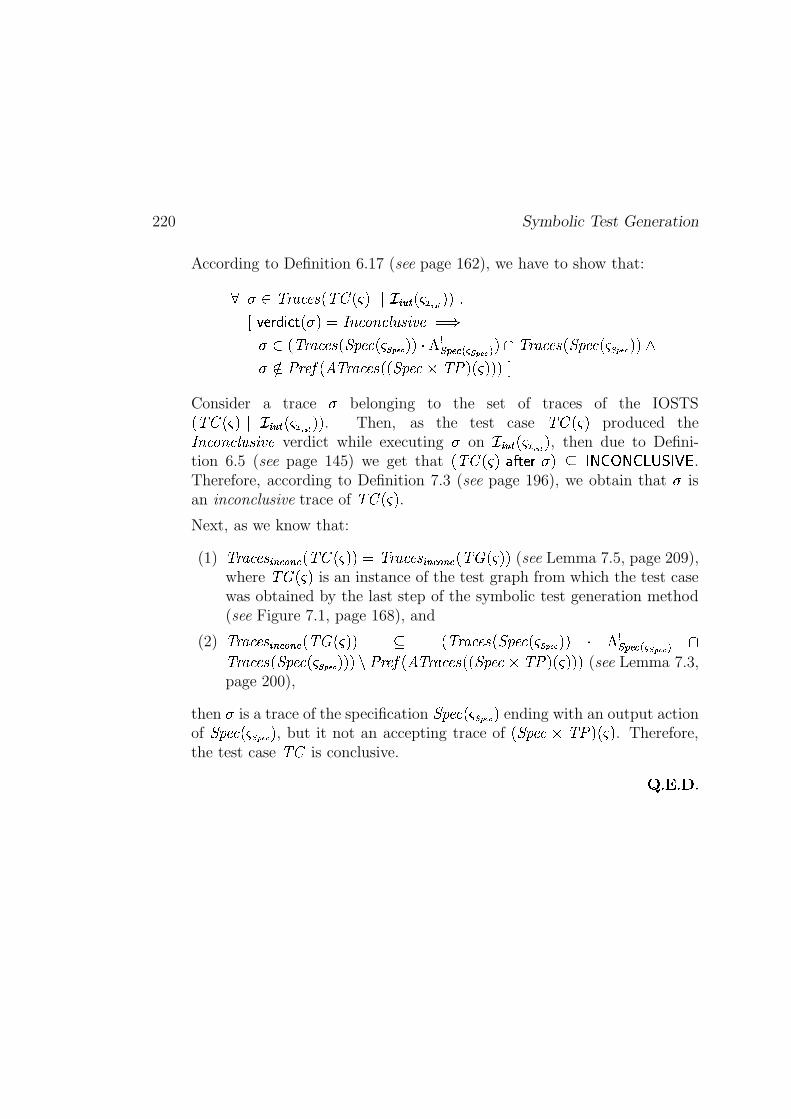
220 Symbolic Test Generation
According to Definition 6.17 (see page 162), we have to show that:
< � ��".,/ I`�^��KL)"$#PL,dwM��$�N�s�����RL0dQ�R� ���ZM9M BD�%)J��(')��vF L#��MEO ����`�����` "��q�����y^ O���>� L)"),- I`�^��KLt\K]_^�`yL,d{z,|0}�~TMRM � � �476R8[: � � z,|0}�~ � M�� ".,/ I`�^��KLt\K]_^�`yL,d{z,|0}�~TM9M �� �� a ,�^��EL��Y".,/ I`�^��ILRLt\K]_^�`�u�"ba MvL0d)M9MRM!S
Consider a trace � belonging to the set of traces of the IOSTSLN"$#PL0d)M��$�N�������RL,dQ�R� ���ZM9M . Then, as the test case "$#PL0d)M produced the����`�����` "��q�����y^ verdict while executing � on �������{L0dQ�R� ���ZM , then due to Defini-tion 6.5 (see page 145) we get that L)"$#PL,dwM�� � FtJ�����M>� � s�"�! 6$#��p&%(' .Therefore, according to Definition 7.3 (see page 196), we obtain that � isan inconclusive trace of "$#PL,dwM .Next, as we know that:
(1) ".,/ I`�^��R��� :���� : LN"$#PL0d)M9MEO "),- I`�^��R��� :���� : L)" � L0dwMRM (see Lemma 7.5, page 209),where " � L0d)M is an instance of the test graph from which the test casewas obtained by the last step of the symbolic test generation method(see Figure 7.1, page 168), and
(2) ".,/ I`�^��R��� :���� : LN" � L0d)M9M � LN".,/ I`�^��KLt\K]_^�`yL0d{z�|Z}�~7M9M � � �47698[: ��� z�|Z}�~ � �"),/ I`�^��IL7\K]_^�`yL0d{z,|0}�~TMRM9M_m a ,�^���L �Y".,/ I`�^��KL9L7\K]_^�` u "ba M�L0dwMRM9M (see Lemma 7.3,page 200),
then � is a trace of the specification \K]_^�`yL0dRz,|0}�~TM ending with an output actionof \K]_^�`yL,d{z,|0}�~TM , but it not an accepting trace of L7\K]_^�`guX"ba MvL,dwM . Therefore,the test case "$# is conclusive.
� B��xB� B
Conclusion
In the second part of the thesis we described the main principles of symbolic testgeneration. All along this part we were guided by the objectives listed below.
Choosing of a Model for Representation of Reactive Systems. In orderto automatically generate test cases for reactive systems, these systemsmust be modelized. As we showed it in the introductory part of the thesis,there exist many models that can be used for modelizing such systems, forexample, FSM or IOLTS. However, almost all of them are too limited:for instance, they do not allow the explicit representation of data. In thisthesis we propose a model, called Input-Output Symbolic Transition System(IOSTS), that enables us to describe reactive systems more precisely byexplicitly taking into account their data. This model allows us to generatetest cases under the form of programs with variables, symbolic constants andparameters (i.e. generic test cases, which are closer to industrial practice,for instance, to TTCN [ISO/IEC/JTC1/SC21, 1992] test cases), and toavoid the classical state-space explosion problem.
Introducing a New Test Generation Method. In Chapter 7 of the thesis,we proposed a method for automatic test generation that treats the dataof a given system symbolically by combining a test generation approachproposed earlier in our research group and described in Section 3.2.3.3 (seepage 57) with abstract interpretation [Cousot and Cousot, 1976], [Cousotand Cousot, 1977]. This method enables us to avoid the problem of state-space explosion and to derive generic test cases.
One of the points that confers originality to our symbolic test generationmethod is the selection step. The purpose of this step is to compute a testgraph from a given IOSTS \_a������ that consists in the states which are reach-able from some initial state of \_a ����� , and from which it is possible to gotowards some accepting states of \_a ����� . Remember that we cannot use theexact computation of reachable and coreachable states since, in general, thecomputation does not terminate. Therefore, we are compelled to computeonly over-approximations of such states. For this, we use abstract interpre-tation, which is a very powerful technique enabling us to calculate different
221
222 Conclusion
properties of the system statically, for instance, the over-approximationsof reachable and coreachable sets of states. However, one difficulty in theuse of such a technique is the choice of the best abstraction, i.e. we tryto make a compromise between a precise enough abstraction and the time-complexity of a technique using this abstraction. Moreover, we mentionthat in the STG tool that will be described in the next part of the thesis,we use an abstract interpretation technique as a black-box. This choice doesnot oblige us to know all theoretical details of abstract interpretation and,at the same time, it enables us to use and compare different existing kindsof abstractions. Up to now, we have connected STG with the NBac tool[Jeannet, 2000a] which, using the polyhedra abstraction, computes over-approximations of reachable and coreachable states. We believe that futureresearch in this direction can improve our test case generation method.
At the end of the second part of the thesis proved that the symbolic testgeneration method derives abstract test cases that are correct in the senseof Definition 6.18, page 163 (i.e. they are sound, relatively exhaustive,accurate and conclusive). These test cases can be easily translated intosome programming language (for example, C++ or Java) and executed ona real implementation under test (see [Clarke et al., 2001c] and [Ponscarme,2002]).
In the rest of the thesis we will present the prototype called STG (Symbolic TestGenerator) in which we have implemented the symbolic test generation algorithmproposed in the second part of the thesis. We will also describe the use of STG inthe testing of the bounded retransmission protocol [Helmink et al., 1994]. Finally,we will compare STG with other existing tools that generate symbolic test casesfor conformance testing of reactive systems.
Part III
Implementation andExperimental Results
223

Chapter 8
STG: Symbolic Test Generator
STG is a tool that implements the symbolic test generation methodpresented in Chapter 6 (see page 137) in order to automatically de-rive symbolic test cases from a formal specification of a system undertest and a test purpose which describes a set of the system’s behav-iors to be tested (see [Clarke et al., 2002], [Clarke et al., 2001b],[Clarke et al., 2001c]). We first present the architecture of the STGtool. Then, we describe the use of STG in testing of a communicationprotocol that transfers a data file though lossy channels as a sequenceof packets. The protocol is based on the well-known alternating bitprotocol, but it allows for only bounded number of retransmission ofeach packet. Finally, we compare STG with other tools used in thetesting community.
The first prototype of the STG tool has been developed by Duncan Clarke. Inthis prototype Duncan has implemented all steps of the symbolic test generationdescribed in Chapter 6 (see page 137) except of the determinization, moreover,the selection of test cases (i.e. the computation of over-approximations of thereachable and coreachable sets of states) has been based on the control structureof IOSTS of (for more details see the paper [Rusu et al., 2000]). Recently, theauthor of this thesis in the collaboration with Bertrand Jeannet has implementedthe semantic-based (or, data-based) selection of test cases (in order to computeover-approximations of the reachable and coreachsble sets of states of a givenIOSTS, we approximate this IOSTS with polyhedra). This work was publishedin the paper [Zinovieva, 2002].
225
226 STG: Symbolic Test Generator
8.1 Architecture of STG
This section describes an architecture of the STG tool shown on Figure 8.1 (seepage 227), and explains the connections of STG with other tools.
Currently the STG tool supports three phases that are briefly described innext paragraphs.
Parsing and Compiling. The phase of parsing and compiling takes as itsinput a file containing a formal specification and test purposes represented ina language similar to IF ([Bozga et al., 1999b], [Bozga et al., 2002]) whichis rather intermediate representation between low-level models as FSM, LTS,or IOSTS, and popular high-level description languages as SDL [ITU-T, 1994],Statecharts [Harel, 1987] or UML [Fowler and Scott, 2000] (where contraints arerepresented in OCL [Warmer and Kleppe, 1998]). Then, this file is parsed, andthe specification and test purposes are compiled into low-level IOSTS modelswhich are used in the symbolic test generation phase.
Symbolic Test Generation. The phase of the symbolic test generation (1)takes as its inputs a specification \K]_^�` and a test purpose "ba of \K]_^�` representedas IOSTS, and (2) derives from them a test case that covers all behaviors of thespecification selected by the test purpose. The symbolic test generation phasehas been presented in the details in Chapter 7 (see page 167). Below we remainthe main steps of this phase, as implemented in the current version of the STGtool.
(a) Product allows to intersect the behaviors of the given specification \K]_^�` withthe test purpose "ba which must be complete with respect to \K]_^�` . The aimof this operation is to mark behaviors of the specification which we want totest as accepting. For details you can see Section 7.2 on page 173.
(b) Closure and Determinization takes the synchronous product \_a from theprevious step, and produces a trace-equivalent IOSTS \_a������ that (1) hasno internal actions, and (2) is deterministic (see Sections A.1 and A.2,pages 246 and 274). Notice that in the current version of the STG tool thealgorithm for determinization is in the phase of implementation.
(c) Selection allows to select a subgraph of \_a ����� that leads to the satisfac-tion of the test purpose and contains fewer unreachable states as \_a������ .The detailed description of the selection step is given in Section 7.4 (seepage 178).
(d) Adding the � w�#" verdict. This step consists in making the IOSTS computedat the previous step input-complete by adding symbolic transitions leading
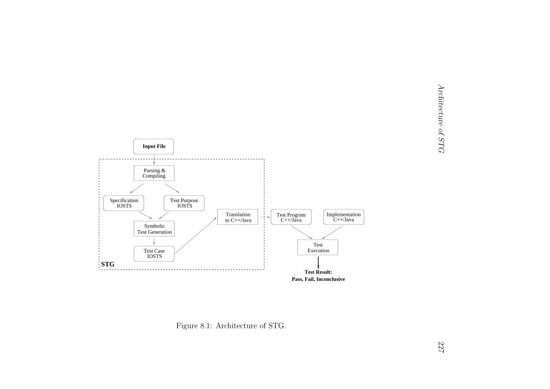
Arch
itecture
of
ST
G227
C++/JavaTest Program
ExecutionTest
Pass, Fail, InconclusiveTest Result:
to C++/JavaTranslation
C++/JavaImplementation
Specification Test Purpose
Test Case
SymbolicTest Generation
IOSTSIOSTS
IOSTS
STG
Input File
Parsing &Compiling
Figure 8.1: Architecture of STG.
228 STG: Symbolic Test Generator
to the new �! w�#" location. This step is needed as the generated test casemust properly react on all inputs outgoing from an implementation undertest. If some input is not specified in \K]_^�` , then the test case must producethe �! w�#" verdict (see Section 7.5, page 202).
After all these steps we obtain a correct (see Definition 6.18, page 163) testcase with three kinds of verdicts: a� )��� , ����`�����` "��i�����y^ and � w�#" . a� )��� meansthat no errors were detected and the test purpose was satisfied (i.e. there wereno observable difference between implementation and specification). ����`�����` "��i�����y^means that, although no errors were detected, the test purpose cannot be satisfiedany more. �! w�#" means that an error was detected.
Translation to C++/Java. The conversion phase translates the test caseobtained after symbolic test generation, into a concrete test program capableof interacting with an implementation interface-compatible with original IOSTSspecification. The test program is then ready to be compiled and linked with theblack-box implementation under test for the test case execution. The details ofthe conversion phase into C++ and Java languages can be found in [Clarke et al.,2001c] and [Ponscarme, 2002] respectively.
8.1.1 Connection of STG with Other Tools
The STG tool is integrated with three tools described below.
Dotty [Gansner and North, 2000] is used to view IOSTS in graphical form,fully decorated with locations names, guards, input/output/internal actions andassignments. For instance, Figures 6.1, 6.5 and 7.12 (see page 138, 149 andpage 207) which are the specification, the test purpose and the test case of asimple coffee machine, were produced by Dotty.
NBac [Jeannet, 2000a] is a tool for analyzing synchronous and deterministicreactive systems containing combination of Boolean and numerical variables. Itis used for computing an over-approximation of reachable and coreachable sets ofstates for IOSTS. The information about the reachable and coreachable states isused by the selection algorithm (see page 185).
Omega Calculator [Kelly et al., 1995] is a tool for analyzing formulas inPresburger arithmetic. It is used during the test execution phase, in order toevaluate the constraints and select specific values for outputs of the tester.
Case Study: Bounded Retransmission Protocol 229
8.2 Case Study: Bounded Retransmission Pro-
tocol
The Bounded Retransmission Protocol (BRP) is a simplified variant of a telecom-munication protocol used by Philips. The purpose of this protocol is to transfera large file across a lossy channel as a sequence of small packets (called chunks)within a limited amount of time. After the file transmission, the BRP indicateswhether this file was successful transmitted or not. Moreover, there are possiblesituations in which the protocol does not know whether the retransmission of thefile was a success. The BRP is parametrized by (1) the retransmission bound,and (2) the number of chunks.
The bounded retransmission protocol has attracted the interest of the researchcommunity due to the fact that it has interesting aspects to verify, to prove andto test. For instance, L. Helmink, M. Sellink and F. Vaandrager [Helmink et al.,1994] modeled the BRP as Input-Output Automata [Lynch and Tuttle, 1989]and proved its correctness using the COQ system [Dowek et al., 1993], [Bertotand Castéran, 2004]. R. Mateescu [Dowek et al., 1993] translated the � CRLrepresentation of the BRP protocol given in [Groote and van de Pol, 1993] intothe LOTOS [ISO/IEC, 1988] language and verified the correctness of this protocolusing model-checking rather than theorem-proving. K. Havelund and N. Shankar[Havelund and Shankar, 1996] used an abstracted version of the BRP obtainedby the PVS [Owre et al., 1992] theorem prover, and verified its correctness usingmodel-checking with MUR � [Melton et al., 1992] state exploration tool. V. Rusu,L. du Bousquet and T. Jéron [Rusu et al., 2000] proposed a theoretical approachto symbolic test generation, and illustrated it using the BRP protocol.
The aim of this section is to present the sender of the bounded retransmissionprotocol as an input-output symbolic transition system, and to generate a testcase that examines some behaviors of this protocol. For this we will use the STGtool presented in the previous section.
Plan of the Section. In this section we first describe the architecture of thebounded retransmission protocol. We then explain how to modelize the senderpart of this protocol as an IOSTS. We also present a particular test purpose forthe BRP. Finally, we show the test case that was automatically derived (usingthe STG tool) from the BRP specification and the given test purpose.
8.2.1 Architecture of the BRP
The two main purposes of the bounded retransmission protocol presented inthis section are (1) to receive a file from the user, and (2) to deliver this file
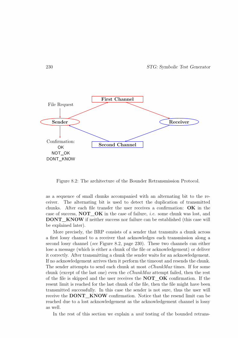
230 STG: Symbolic Test Generator
Sender Receiver
First Channel
Second Channel
File Request
Confirmation:OK
NOT_OK
DONT_KNOW
Figure 8.2: The architecture of the Bounder Retransmission Protocol.
as a sequence of small chunks accompanied with an alternating bit to the re-ceiver. The alternating bit is used to detect the duplication of transmittedchunks. After each file transfer the user receives a confirmation: OK in thecase of success, NOT_OK in the case of failure, i.e. some chunk was lost, andDONT_KNOW if neither success nor failure can be established (this case willbe explained later).
More precisely, the BRP consists of a sender that transmits a chunk acrossa first lossy channel to a receiver that acknowledges each transmission along asecond lossy channel (see Figure 8.2, page 230). These two channels can eitherlose a message (which is either a chunk of the file or acknowledgement) or deliverit correctly. After transmitting a chunk the sender waits for an acknowledgement.If no acknowledgement arrives then it perform the timeout and resends the chunk.The sender attempts to send each chunk at most cChunkMax times. If for somechunk (except of the last one) even the cChunkMax attempt failed, then the restof the file is skipped and the user receives the NOT_OK confirmation. If theresent limit is reached for the last chunk of the file, then the file might have beentransmitted successfully. In this case the sender is not sure, thus the user willreceive the DONT_KNOW confirmation. Notice that the resend limit can bereached due to a lost acknowledgement as the acknowledgement channel is lossyas well.
In the rest of this section we explain a unit testing of the bounded retrans-
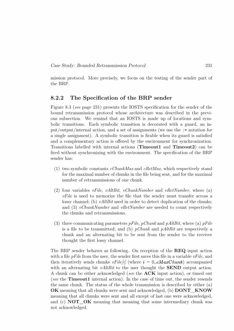
Case Study: Bounded Retransmission Protocol 231
mission protocol. More precisely, we focus on the testing of the sender part ofthe BRP.
8.2.2 The Specification of the BRP sender
Figure 8.3 (see page 231) presents the IOSTS specification for the sender of thebound retransmission protocol whose architecture was described in the previ-ous subsection. We remind that an IOSTS is made up of locations and sym-bolic transitions. Each symbolic transition is decorated with a guard, an in-put/output/internal action, and a set of assignments (we use the := notation fora single assignment). A symbolic transition is firable when its guard is satisfiedand a complementary action is offered by the environment for synchronization.Transitions labelled with internal actions (Timeout1 and Timeout2) can befired without synchronizing with the environment. The specification of the BRPsender has:
(1) two symbolic constants cChunkMax and cRetMax, which respectively standfor the maximal number of chunks in the file being sent, and for the maximalnumber of retransmissions of one chunk.
(2) four variables vFile, vAltBit, vChunkNumber and vRetNumber, where (a)vFile is used to memorize the file that the sender must transfer across alossy channel; (b) vAltBit used in order to detect duplication of the chunks;and (3) vChunkNumber and vRetNumber are needed to count respectivelythe chunks and retransmissions.
(3) three communicating parameters pFile, pChunk and pAltBit, where (a) pFileis a file to be transmitted; and (b) pChunk and pAltBit are respectively achunk and an alternating bit to be sent from the sender to the receiverthought the first lossy channel.
The BRP sender behaves as following. On reception of the REQ input actionwith a file pFile from the user, the sender first saves this file in a variable vFile, andthen iteratively sends chunks vFile[i] (where ��O���B B�=�������%��� �� ) accompaniedwith an alternating bit vAltBit to the user thought the SEND output action.A chunk can be either acknowledged (see the ACK input action), or timed out(see the Timeout1 internal action). In the case of time out, the sender resendsthe same chunk. The status of the whole transmission is described by either (a)OK meaning that all chunks were sent and acknowledged, (b) DONT_KNOWmeaning that all chunks were sent and all except of last one were acknowledged,and (c) NOT_OK meaning that meaning that some intermediary chunk wasnot acknowledged.
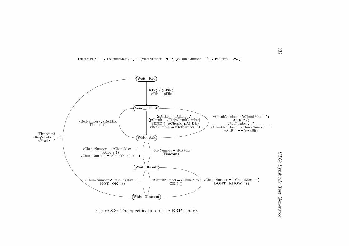
232ST
G:
Sym
bolic
Test
Gen
erato
r
Wait_Req
Send_Chunk
Wait_Ack
Wait_Result
Wait_Timeout
�
cRetMax
� � � � �
cChunkMax
� � � � �
vRetNumber � � � � �
vChunkNumber � � � � �
vAltBit � �� �
REQ ? (pFile)vFile � � pFile
�
pAltBit � vAltBit
� �
�
pChunk � vFile[vChunkNumber]
�
SEND ! (pChunk, pAltBit)vRetNumber � � vRetNumber
� �
vRetNumber
cRetMaxTimeout1
vChunkNumber
�
cChunkMax � � �
ACK ? ()vRetNumber � � �
vChunkNumber � � vChunkNumber
� �
vAltBit � � �(vAltBit)
vRetNumber � cRetMaxTimeout1
vChunkNumber � �
cChunkMax � � �
ACK ? ()vChunkNumber � � vChunkNumber
� �
vChunkNumber
�
cChunkMax � � �
NOT_OK ! ()vChunkNumber � cChunkMax
OK ! ()vChunkNumber � �
cChunkMax � � �
DONT_KNOW ! ()
Timeout2vReqNumber � � �
vHead � � �
Figure 8.3: The specification of the BRP sender.
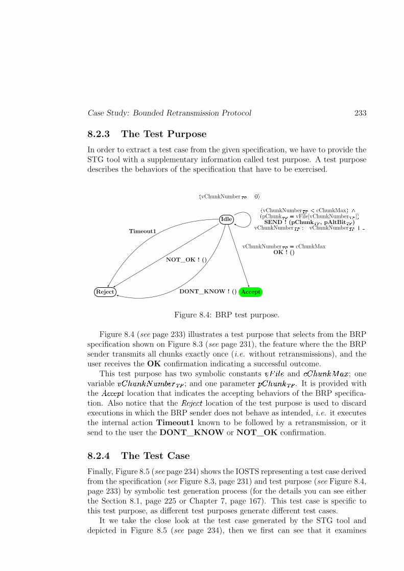
Case Study: Bounded Retransmission Protocol 233
8.2.3 The Test Purpose
In order to extract a test case from the given specification, we have to provide theSTG tool with a supplementary information called test purpose. A test purposedescribes the behaviors of the specification that have to be exercised.
Idle
Reject Accept
�vChunkNumber ��������
vChunkNumber ���� cChunkMaxOK ! ()
�vChunkNumber �� � cChunkMax ����pChunk �� � vFile[vChunkNumber ��� ] �SEND ! (pChunk ��� , pAltBit ��� )
vChunkNumber ����� � vChunkNumber ������
DONT_KNOW ! ()
Timeout1
NOT_OK ! ()
Figure 8.4: BRP test purpose.
Figure 8.4 (see page 233) illustrates a test purpose that selects from the BRPspecification shown on Figure 8.3 (see page 231), the feature where the the BRPsender transmits all chunks exactly once (i.e. without retransmissions), and theuser receives the OK confirmation indicating a successful outcome.
This test purpose has two symbolic constants ��������� and ��� �"!$#&%('*)�+ ; onevariable ���,�"!-#.%(/0!$132��547658 ; and one parameter 9$�,�:!$#.%�6;8 . It is provided withthe <>=?=?@BADC location that indicates the accepting behaviors of the BRP specifica-tion. Also notice that the EF@HG;@?=IC location of the test purpose is used to discardexecutions in which the BRP sender does not behave as intended, i.e. it executesthe internal action Timeout1 known to be followed by a retransmission, or itsend to the user the DONT_KNOW or NOT_OK confirmation.
8.2.4 The Test Case
Finally, Figure 8.5 (see page 234) shows the IOSTS representing a test case derivedfrom the specification (see Figure 8.3, page 231) and test purpose (see Figure 8.4,page 233) by symbolic test generation process (for the details you can see eitherthe Section 8.1, page 225 or Chapter 7, page 167). This test case is specific tothis test purpose, as different test purposes generate different test cases.
It we take the close look at the test case generated by the STG tool anddepicted in Figure 8.5 (see page 234), then we first can see that it examines
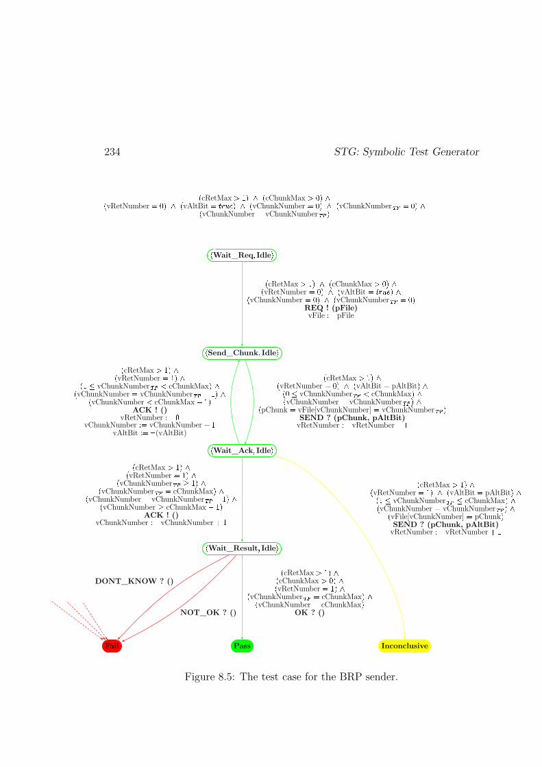
234 STG: Symbolic Test Generator
�Wait_Req � Idle �
�Send_Chunk � Idle �
�Wait_Ack � Idle �
�Wait_Result � Idle �
Pass InconclusiveFail
�cRetMax � � ��� � cChunkMax �>�� ��
vRetNumber � ���� � vAltBit ������� ��� � vChunkNumber � �� � � vChunkNumber ������� ��vChunkNumber � vChunkNumber ��� �
�cRetMax � � ��� � cChunkMax � �� ��
vRetNumber � ���� � vAltBit ������� � ��vChunkNumber � ���� � vChunkNumber ��� � ��
REQ ! (pFile)vFile � � pFile
�cRetMax � � � ��
vRetNumber � ���� � vAltBit � pAltBit � �� � � vChunkNumber ����� cChunkMax � ��vChunkNumber � vChunkNumber ���I� ��
pChunk � vFile[vChunkNumber] � vChunkNumber ���I�SEND ? (pChunk, pAltBit)
vRetNumber � � vRetNumber ���
�cRetMax � � � ��
vRetNumber ��� � �� ��� vChunkNumber ����� cChunkMax � ��vChunkNumber � vChunkNumber �����>� � ��
vChunkNumber � cChunkMax �>� �ACK ! ()
vRetNumber � � �vChunkNumber � � vChunkNumber ���
vAltBit � ��� (vAltBit)
�cRetMax � � � ��
vRetNumber � � � ��vChunkNumber ����� ��� ��
vChunkNumber ���� cChunkMax � ��vChunkNumber � vChunkNumber ���� � � ��
vChunkNumber � cChunkMax �>� �ACK ! ()
vChunkNumber � � vChunkNumber ���
�cRetMax � � � ��
cChunkMax �>�� ��vRetNumber ��� � ��
vChunkNumber ���� cChunkMax � ��vChunkNumber � cChunkMax �
OK ? ()
�cRetMax � � � ��
vRetNumber � � � � � vAltBit � pAltBit � �� ��� vChunkNumber ���� cChunkMax � ��vChunkNumber � vChunkNumber ��� � ��
vFile[vChunkNumber] � pChunk �SEND ? (pChunk, pAltBit)
vRetNumber � � vRetNumber ���
NOT_OK ? ()
DONT_KNOW ? ()
Figure 8.5: The test case for the BRP sender.
Case Study: Bounded Retransmission Protocol 235
the behaviors of the specification that were targeted by the test purpose. Moreprecisely, it starts by giving to the sender, a file �
� � �� to transmit. Then itexpects to receive the successive chunks of this file, and tries to acknowledgeeach chunk. If it succeeds and receives the OK confirmation, then the a )���verdict is generated (i.e. the test case moves to the a� )��� location shown ingreen on Figure 8.5, page 234). This means that the implementation behaved inconformance with its specification and the test purpose is satisfied, indeed, allchunks were sent without retransmission. If the test case gets another copy ofthe chunk that it has just received, then the sender performed a retransmission.In this case the ����`�����` "��i�����y^ verdict is generated (i.e. the test case moves tothe ����`�����` "��i�����y^ location shown in yellow on Figure 8.5, page 234). This mayhappen if the test execution did not immediately acknowledge the sent chunk(i.e. the sender did not receive an acknowledgement, and, therefore, it proceedsto resending the same chunk.) Finally, if some other input is received, the verdict� w�#" is generated (i.e. the test case moves to the �! w�#" location shown in red onFigure 8.5, page 234). Indeed, in this case the implementation emitted an outputthat is not allowed by specification. Due to the limited space Figure 8.5 (seepage 234) does not show all symbolic transitions leading to the �! w�#" location.
It is important to emphasize that the test case shown in Figure 8.5 (seepage 234), like all other test cases generated by our method, incorporates itsown oracle. All of the computation steps necessary to verify the correctness ofnumeric results are extracted from the specification and used by the tester toverify arguments as they are received.
8.2.5 Conclusion
This section has described an example of using STG for testing the sender of thebounded retransmission protocol. We have focused on the explanation of how togenerate a test case starting from specification and test purpose represented asIOSTS models. We did not explain the first and last phases of the STG tool,namely:
– parsing and compiling of specifications and test purposes written in a dialectof IF-language [Bozga et al., 1999a], into low-level IOSTS models, and
– translation of the IOSTS test cases to C++/Java programs which are readyto be compiled, linked to an interface-compatible implementation, and ex-ecuted.
as they are quite technical, and are described in [Clarke et al., 2001c] and [Pon-scarme, 2002].
The STG tool is also used in the development of larger case studies basedon the Common Electronic Purse System (CEPS) whose technical specification
236 STG: Symbolic Test Generator
is given in [CEPSCO, 2000]. In paper [Clarke et al., 2001a] we have already re-ported the first results obtained by testing the part of this specification which iscalled “CEP Inquiry – Slot Information” (see Section 8.7.1 of [CEPSCO, 2000]).Currently the STG tool is being used to incrementally test a prototype imple-mentation of the full CEPS specification.
8.3 Related Works
In this section we present the main aspects that show the difference between ourtest generation method described in the second part of the thesis and implementedin the STG tool, and the other symbolic techniques for automatic test generationwhich were presented in the last section of the introductory part of the thesis.
Non-Deterministic Specifications. One of the aspects making a differencebetween STG and the tools mentioned in Section 3.3 (see page 67) is that: theSTG tool is able to derive test cases from a subclass of non-deterministic specifica-tions (the theoretical work about this aspect is done in Section A.2 of this thesis,see page 274), while other tools are often limited to deterministic specifications.
Abstract Interpretation. The second remarkable aspect concerns methodsused for the test case selection and the form of generated test cases. It is nothard to notice that the techniques described in Section 3.3 (see page 67) are basedon the constraint technology which has been popular during the last few years. Itis also important to remark that these techniques are able to generate test casesin the form of test sequences (or trees) of a bounded length, while the STG toolderives test graphs.
Indeed, the GATeL [Marre and Arnould, 2000] tool derives test cases froma given LUSTRE formal specification by interpreting it as a set of constraintsover boolean and integer variables, and then solving this set of constraints. TheAgatha [Lugato et al., 2002] tool uses the symbolic simulation in order to generatea test execution tree, where each node is represented as a constraint over thevariables characterizing the path of a given specification leading to this node,and then searchs for a possible instantiation of this tree using some constraintsolver. The BZ-Testing-Tool [Ambert et al., 2002], developed by the researchers ofLIFC, University of Franche-Comté, in order to derive test sequences, computesfirst all boundary states for a given system using the CLPS constraint solver,then takes the system from the initial state to some boundary state using thesymbolic simulation, and finally tests all possible operations of the system in thisboundary state. Moreover, the test generation tools used for structural (white-box) testing also use the constraint logic programming technology. For instance,

Related Works 237
INKA [Gotlieb et al., 1998], based on the constraint solving, allows to generatea path in the control flow graph of a given C program leading to a specifiedpoint of this program. C. Meudec in his works on automatic test generation (e.g.[Meudec, 2001]) uses the CLP solver for symbolic execution of ADA programs inorder to generate test cases.
The method proposed in this thesis is quite different from the methods andtools mentioned above. Indeed, instead of the use of the constraint technology inorder to derive test cases, we choose to use a technique of abstract interpretation.This technique allows us to generate test cases under the form of test graphsinstead of bounded test sequences as the most of the tools described above do.This representation of test cases gives us a possibility to have a global view onthe “past” and the “future” of a system under test. Unfortunately, by obtainingthe “generality” we loose the precision of derived test cases.
Another important aspect that distinguishes our test generation method fromthe other ones concerns the labelling. The labelling is the process of the instanti-ation of some system’s variables with their values. This permits to activate someconstraints. More precisely, the labelling consists in unfolding a symbolic testsequence according to the values of some variables. Therefore, the labelling canbe considered as a kind of rough abstraction, where the system’s control structureis refined by the possible values of some variables. The technique of abstract in-terpretation is more precise. Indeed, the control structure of a system under testis refined only when it is really needed, i.e. in the case when behaviors describedthe past and the future of the system are divergent.
The technique of abstract interpretation becomes more and more popular inthe fields of verification and testing. For instance, commercial tools developed bythe PolySpace Technology company (see http://www.polyspace.com), widelyuse abstract interpretation in order to automatically detect run-time errors atthe compiling time of programs written in ADA, C and C++. The idea of suchtools is following: they first compute some abstraction of a given program, andthen solve the problem on this abstraction. If any error is not detected in theabstraction of the program, then it definitely does not exist in the program itself.However, if an error is detected in the abstraction, this means that the programmay contain this error as well.

238 STG: Symbolic Test Generator
Chapter 9
Conclusion
The work presented in the preceding chapters has been focusing on thedevelopment of testing techniques for reactive systems, from theory upto implementation. In this chapter we reassess the main objectivesthat have been fixed at the beginning of the thesis, and we summa-rize the work that has been done in order to achieve these objectives.Finally, we give some ideas and hints for future research.
9.1 Summary
Motivation. This thesis has been placed in the area of black-box conformancetesting for reactive systems. In the first chapter, we explained the importance ofreactive systems in daily life. Such systems are usually large and complex, andit is thus not so evident to implement them without any error. Even a smallerror may lead to serious disfunctioning of the system (see the examples givenon page 2). Therefore, it is important to develop techniques detecting errors inreactive systems and which make sure these systems are more error proof. In thisthesis we focused on the study of one of those techniques called testing.
In the second and third chapters we mentioned that during the last decadestesting theories and techniques for automatic test derivation have been developed.Some of these techniques have been based on the model of Finite State Machines(or FSM), and others on the model of (Input-Output) Labeled Transition Systems(or (IO)LTS). Since the model of IOLTS is more suitable for the testing of reac-tive systems than FSM, then we have focused on the study of the methods andalgorithms for the automatic test derivation based on IOLTS. We have partic-ularly reviewed two efficient on-the-fly algorithms proposed in [Tretmans, 1992],[Jéron and Morel, 1999]. We have also described already existing academic (e.g.TorX [Belinfante et al., 1999], TGV [Fernandez et al., 1996]) and industrial (e.g.Autolink [Telelogic, 1998], TestComposer [Kerbrat and Ober, 1999]) tools imple-
239
240 Conclusion
menting these algorithms and produce correct test cases, which means essentiallythat they always emit the correct verdict.
Nevertheless, the theories and tools based on IOLTS are somewhat limited.They do not explicitly take into account the system data because the under-lying model of IOLTS does not allow to do it. Thus, in order to derive testcases from a specification of the reactive system modeled by an IOLTS, it is nec-essary to enumerate the values of each datum used by the system. This mayresult in the classical state-space explosion problem. Moreover, this enumera-tion also has the effect of obtaining test cases, where all data are instantiated.This contradicts the industrial practice, where test cases (written, for instance, inthe TTCN [ISO/IEC/JTC1/SC21, 1992] language) are real programs with data(variables, symbolic constants and communication parameters).
Summary of the Thesis. In order to solve the issues mentioned above, we pro-posed a new approach for the automatic generation of symbolic test cases underthe form of extended labeled transition systems with variables, symbolic con-stants and communication parameters. These systems are called Input-OutputSymbolic Transition Systems (or IOSTS). In Chapter 4 we described the syntaxand semantics of the IOSTS model. We also introduced some subclasses of IOSTSthat are important for conformance testing (e.g. deterministic or input-completeIOSTS).
In Chapter 6 we presented the background for conformance testing based onIOSTS. Namely, we formally defined (1) the conformance relation ���� betweena specification and an implementation under test that are both modeled withIOSTS, (2) the notion of a test case and (3) the properties of test cases thatenable to establish the connection between test cases and the conformance rela-tion. The work presented in this chapter was mainly inspired from the theory ofconformance testing developed by J. Tretmans and his colleagues from the Uni-versity of Twente, Netherlands (see [Tretmans, 1994], [Tretmans, 1996b]) and theresearch done in the VerTeCs team at IRISA/INRIA Rennes, France (see [Rusuet al., 2000], [Jard and Jéron, 2002]).
Then, in Chapter 7 we described the symbolic test generation approach basedon the testing theory introduced above. This approach is a generalization ofthat proposed in earlier works of our group in collaboration with the Verimaglaboratory in Grenoble [Fernandez et al., 1996] and referred to in the introductorypart of the thesis. However, some steps of our symbolic test generation approach(especially concerning the selection of a test graph) are more complex than thoseproposed in [Fernandez et al., 1996], as they have to take into account the dataof a given system.
The symbolic test generation approach was implemented in the STG tool. Thedescription of this tool and a case study of the bounded retransmission protocol
Future Research 241
were given in the third part of our work.
At the end of the thesis, we compared our approach with other symbolicapproaches for automatic test generation. The majority of these are based onconstraint propagation and use constraint solving techniques. Moreover, they donot deal with the issue of non-determinism (remember that non-determinism ishighly prohibited in testing). The original points of our approach are: the use of atechnique of abstract interpretation at the moment of test case selection, and thepartial solution for non-determinism. Notice that we did not solve all problemswith respect to symbolic test generation. In particular, our approach also usesa constraint solving technique while instantiating symbolic test cases during atest execution. The technical details of test execution were not explained in thisdocument, but some of them can be found in [Clarke et al., 2001c].
We believe that our symbolic test generation approach deserves future atten-tion, and that research to come can improve its applicability to industrial reactivesystems.
9.2 Future Research
The following ideas for future research are inspired from the work presented inthis thesis.
From ioc to ioco. Before going into details of the perspective described in thisparagraph, we remind the difference between the � � � [Tretmans, 1996a] and���� (see Definition 6.3, page 141) relations. That is, in the first hand, theioco relation makes a connection between a suspended specification �WL7\K]_^�`wMand the suspended model of an implementation under test � L �E������M . It checkswhether after the execution of each suspension trace (i.e. trace that maycontain the special output action � ) of the specification, the implementationproduces only specified output actions or not. In the other hand, the ioc
relation links a specification \K]_^�` with an implementation under test �E����� ,and is checks the same thing as ���� � but for each proper trace (i.e. tracethat does not contain any � action) of the specification.
In this thesis, we have proposed an approach for symbolic test generationthat is based on the IOSTS model and the ioc relation. However, this ap-proach has some weaknesses. One of them is the problem of blockings thathas not been addressed in the symbolic test generation part of the thesis.Nevertheless, this has been described in the introductory part (see page 42).In order to improve our symbolic test generation in this direction, one mayattempt the following approach (published as the research report [Rusuet al., 2004]):
242 Conclusion
(1) Limit the IOSTS model to one that does not contain syntactic livelocks(cycles of internal actions) in it, and use the ioco relation [Tretmans,1996a] as a correctness criterion instead of the ioc relation.
(2) For a given specification, construct its suspension IOSTS by encodingall potential blockings (outputlocks and deadlocks) of a given specifi-cation with the special output action � .
Remark that the problem of blocking detection is undecidable for IOSTS ingeneral. However, in the case of absentce of syntactic livelocks in an IOSTS
�, it is possible to construct syntactically the suspension IOSTS of
�.
The classical solution for the detection of unspecified blockings in an im-plementation under test during a test experiment, is to equip each testerwith a timer indicating the amount of time that the tester has to wait foran output to occur. If the output does not occur before a certain amount oftime, then the tester may conclude that this output will no longer occur. Inthis case, it decides (maybe wrongly) that the implementation is blocked.
We believe that the suggestions given in this paragraph will help to improveour symbolic test generation method.
Safety Properties. The report [Rusu et al., 2004] proposes an approach forcombining verification and conformance testing techniques. In this re-port, the formal specification \K]_^�` of a given reactive system is modeledby IOSTS, and each safety property of \K]_^�` is represented in the samemanner as a test purpose used in the symbolic test generation method.Then,
First, each property is verified on \K]_^�` using automatic techniques (e.g.abstract interpretation) that are sound but not necessary complete forthe class of safety properties considered here.
Second, for each property, a test case is automatically generated from thespecification and this property and is executed on a black-box imple-mentation of the system.
If the verification step was successful, that is, it has established that thespecification satisfies the properties, then the execution may detect theviolation of the property by the implementation and the standard � � � con-formance relation [Tretmans, 1996a] between implementation and specifi-cation. Otherwise, i.e. if the verification step did not conclude, that is, itdid not allow to prove or to disprove the property, then the test executionmay additionally detect a violation of the property by the specification.
Future Research 243
Coverage Criteria. The STG tool (just as its predecessor TGV [Fernandezet al., 1996]) uses test purpose as the mechanism for test case selection.Each test purpose in STG is given under the form of a graph. This repre-sentation offers a software developer a natural way to (partially) describethe behaviors of a given specification to be tested. Nevertheless, the manualdesign of test purposes requires a good knowledge of the specification. Thismeans that the process of the test purpose designing is still quite difficultfor humans, in particular if a good coverage of the specification must betargeted. We believe that the classical structural coverage criteria [Rappsand Weyuker, 1985] combined with symbolic analysis may yield interestingtest purposes.
Case Studies. So far, we have only generated test cases from more or less clas-sical academic specifications of a coffee machine and the bounded retrans-mission protocol. The next important step is to apply our approach so asto test realistic industrial systems. We have already made the first steps inthis direction: we generated some test cases for Common Electronic PurseSystem (CEPS) [CEPSCO, 2000]. This case study gave us the promisingresults published in [Clarke et al., 2001a]. Thus, it would be interestingto continue such experiments. We also believe that future case studies willcontribute with essential information about the applicability of our symbolictest generation approach, and will help to improve our approach.

244 Conclusion
Appendix A
Appendix
245
246 Appendix
A.1 Closure: Eliminating Internal Actions
Motivation. A test case should react promptly to all inputs from the imple-mentation. A natural way to obtain this requirement is to make every locationof a test case (except the verdict locations) input-complete. However, the possi-ble inputs in some locations of the test case may be hidden by internal actions.For example, consider the location �� of the IOSTS
�shown in Figure A.1 (see
page 248). As you can see,�
can execute from �� the internal actions ��� and ��� ,but the input action = can be executed only after ��� . Then, if we make the loca-tion �� input-complete (see Definition 4.21, page 95), we obtain that the action =can also be executed before the internal action ��� , which leads to modification ofthe system’s behaviors. Thus, to make location �� input-complete we first haveto eliminate ��� . Therefore, in order to obtain the input-complete test case, all in-ternal actions have to be eliminated from the synchronous product \_a computedfrom a specification \K]_^�` and a test purpose "ba of \K]_^�` on the previous step ofthe test generation method (see Section 7.2, page 173).
One more reason for elimination of internal actions from \_a is that the re-sulting test case must be deterministic as a testing verdict must not depend oninternal choices of the test case. Therefore, if the reader takes a close look atthe definition of a deterministic IOSTS (see page 93), then he/she can see thatthe first requirement of being deterministic is to have the empty set of internalactions.
In the works of T. Jéron and his colleagues ([Jard and Jéron, 2002], [Jéron,2004], etc.) on the test generation based on the IOLTS model, the operation ofelimination of internal actions (called later closure) is incorporated directly intothe determinization algorithm. However, in this thesis we prefer to separate theclosure operation from the determinization algorithm as both of them are quitecomplex.
Sketch of the Section. The aim of the third step of the test generation methodis to build visible behaviors of \_a (i.e. to eliminate internal actions from \_a )leaving the visible semantics of \_a unchanged. However, the problem of theelimination of all internal actions from \_a is undecidable in general due to thepossible presents of syntactical livelocks in \_a , (see explanations in Section A.1.2,page 257). This section proposes the closure operation that eliminates all internalactions from an IOSTS \_a except of whose that are either directly leading to, orinvolved into, syntactic livelocks of \_a . This operation is based on the collapsingof all sequences of internal actions described in the first subsection of the currentsection. Finally, we prove that the closure operation does not change the visiblesemantics of \_a . In other words, we show that the IOSTS obtained after theclosure algorithm is trace-equivalent to the given IOSTS \_a .
Closure: Eliminating Internal Actions 247
A.1.1 The Collapsing Operation for a � -Sequence
This section introduces the collapsing operation for a contiguous sequence of sym-bolic transitions, called � -sequence, of some IOSTS. The aim of this operationis to encode the effect of such a sequence into one transition. It is important tohave a clear understanding of the collapsing operation as it is the main operationused in Section A.1.3 in order to define the closure operation for IOSTS (seeDefinition A.7, page 260).
Before giving the formal definition of the collapsing operation we consider anIOSTS
� O ��� ��� � � �� ��� ��� , where � O � � k����k���� is the alphabet of input,output and internal actions, and:
(1) call actions belonging to L�� m�� � M visible actions, and
(2) denote a symbolic transition �'O � � � ��� ��� ��� �� � �n�� by ��� 3 � .
Then, we introduce the notion of � -sequence for the IOSTS�
. Intuitively, a� -sequence is a contiguous sequence of symbolic transitions of the IOSTS
�such
that (1) all symbolic transitions involved into its maximal strict prefix are labeledwith internal actions, and (2) the last transition of this sequence can be labeledwith either a visible or internal action. Formally:
Definition A.1 (Set of � -Sequences) Let� O ��� ��� � ���� ��� ��� be an
IOSTS. Then, the set of � -sequences, denoted by \p^��v��^ ��`�^�� � L � M , is the setof all contiguous sequences of symbolic transitions:
. �"!� 3 $#sBrBrB &%(')# ��*,+(!� 3 &%-'/.0�� 3 &%
where 2143 ; ���. �rBrB B ��&%P� ; �5. �rBrBrB � �,%('/. �2��� ; and � �6� . c
Notice that � -sequences are prefix closed. This observation follows directly fromDefinition A.1, and it is formally stated below.
Observation A.1 (Prefix Closure of � -Sequence) Any prefix of a � -sequence, whose length is greater then zero, is also a � -sequence. c
For better understanding of the notion of � -sequence we propose the followingexample.
Example A.1 Consider the IOSTS�
shown in Figure A.1 (see page 248). To il-lustrate the notion of � -sequences we consider the following sequences of symbolic
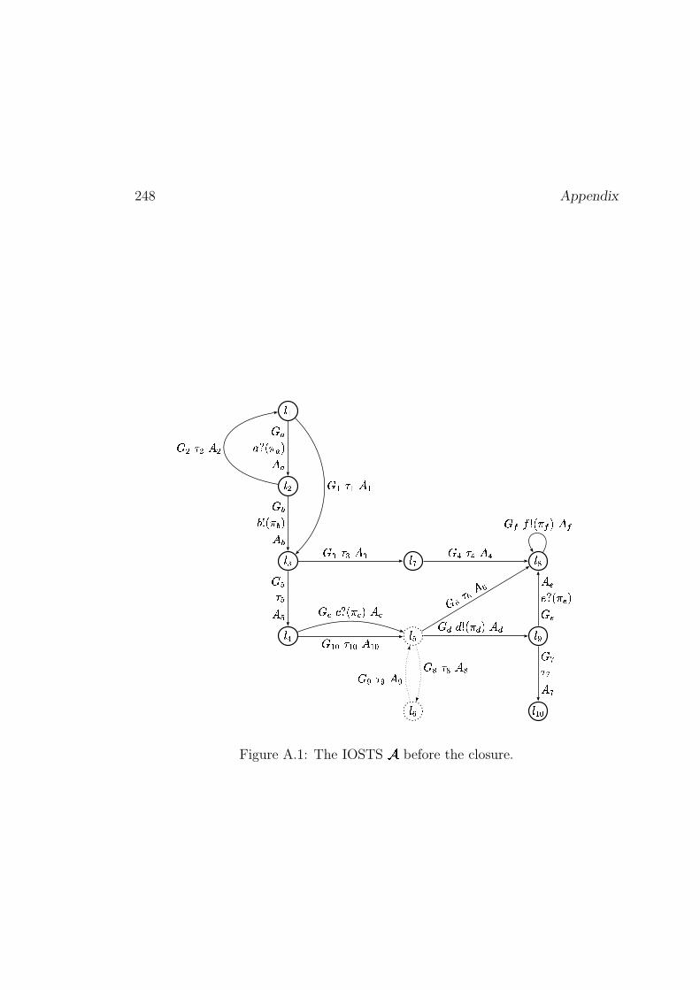
248 Appendix
���
���
���
��� ���
��
�� ���
��
� ���
���������� ���
� �
������ � � �!�
� �
� �" �
� � ��#$%��� � # ��&#
� � " � � � � � " � � �
��')( � � � ' � � '*,+�- +/. +
� � " � � �
� � " � � �
��021 ����� 0 � � 0
�,��� " ��� � ���
�43,5 � ��� 3 � � 3
� " �
� � " � � �� " �
Figure A.1: The IOSTS�
before the closure.
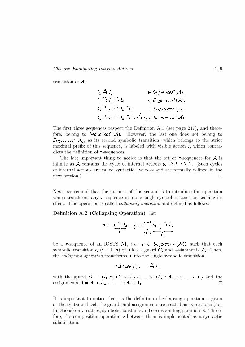
Closure: Eliminating Internal Actions 249
transition of�
:
�. �� 3 $# � \p^��v��^ ��`�^�� � L � M���. �"!� 3 �� ���� 3 �� � \p^��v�_^ ��`�^�� � L � M ��� � �� 3 �� � �� 3 �
�� 3 � � \p^��v�_^ ��`�^�� � L � M���� � �� 3 �
�� 3 � � �� 3 � �� 3 �
�� \p^��v��^ ��`�^�� � L � MThe first three sequences respect the Definition A.1 (see page 247), and there-fore, belong to \p^��v��^ ��`�^�� � L � M . However, the last one does not belong to\p^��v��^ ��`�^�� � L � M , as its second symbolic transition, which belongs to the strictmaximal prefix of this sequence, is labeled with visible action = , which contra-dicts the definition of � -sequences.
The last important thing to notice is that the set of � -sequences for�
isinfinite as
�contains the cycle of internal actions � � �� 3 �� � �� 3 �� . (Such cycles
of internal actions are called syntactic livelocks and are formally defined in thenext section.) c
Next, we remind that the purpose of this section is to introduce the operationwhich transforms any � -sequence into one single symbolic transition keeping itseffect. This operation is called collapsing operation and defined as follows:
Definition A.2 (Collapsing Operation) Let
. �"!� 3 $#� �� � !
BrBrB � �� � *�+ !
&%(')# ��*,+(!� 3 � ��� � *
&%-'/.0�� 3 &%
be a � -sequence of an IOSTS�
, i.e. � \p^��v�_^ ��`�^�� � L � M , such that eachsymbolic transition ��� ( �'O 3yB�B ) of has a guard �"� and assignments � � . Then,the collapsing operation transforms into the single symbolic transition:
� �)� � �iH �{JIL M$. ��� 3 &%with the guard � O � . �@L�� #�� � .�M ��BrBrB �@L�� % � � %('/.5�WBrBrB � � .9M and theassignments ��O ��% � ��%('/.p� BrBrB)� � #�� � . . c
It is important to notice that, as the definition of collapsing operation is givenat the syntactic level, the guards and assignments are treated as expressions (notfunctions) on variables, symbolic constants and corresponding parameters. There-fore, the composition operation � between them is implemented as a syntacticsubstitution.
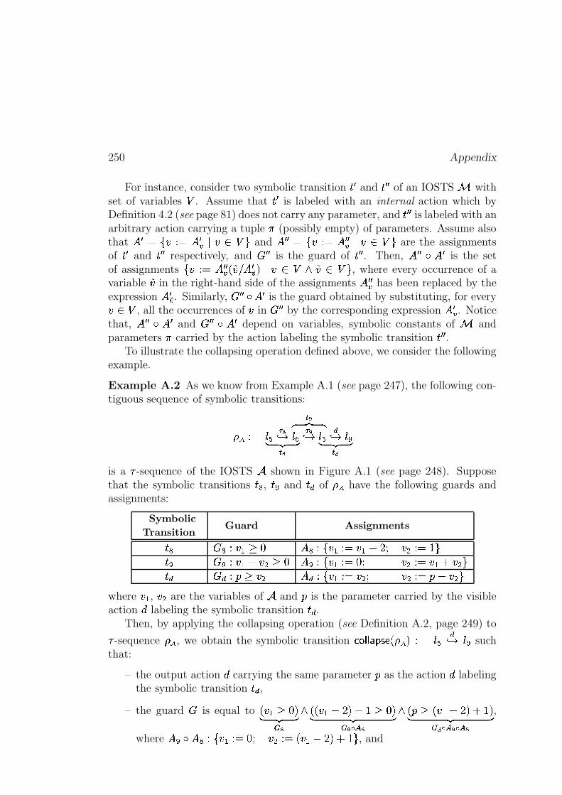
250 Appendix
For instance, consider two symbolic transition � � and � � � of an IOSTS�
withset of variables o . Assume that � � is labeled with an internal action which byDefinition 4.2 (see page 81) does not carry any parameter, and � � � is labeled with anarbitrary action carrying a tuple � (possibly empty) of parameters. Assume alsothat � � O�� ��. O � �� � ��� o�� and � � � O�� ��.�O � � �� � � � o�� are the assignmentsof � � and � � � respectively, and � � � is the guard of � � � . Then, � � � � � � is the setof assignments � � .�O � � �� L��� � � � �� M � � � o ���� � o�� , where every occurrence of avariable �� in the right-hand side of the assignments � � �� has been replaced by theexpression � � �� . Similarly, � � � � � � is the guard obtained by substituting, for every����o , all the occurrences of � in � � � by the corresponding expression � �� . Noticethat, � � � � � � and � � � � � � depend on variables, symbolic constants of
�and
parameters � carried by the action labeling the symbolic transition � � � .To illustrate the collapsing operation defined above, we consider the following
example.
Example A.2 As we know from Example A.1 (see page 247), the following con-tiguous sequence of symbolic transitions:
. � �� � �
�� � �� 3� �� � �
�� � �� 3 ���� 3 �� �� ���
is a � -sequence of the IOSTS�
shown in Figure A.1 (see page 248). Supposethat the symbolic transitions � , � and � � of have the following guards andassignments:
Symbolic
TransitionGuard Assignments
� � 5. � . 1 � � .�� � . . O � .������ �-#C.�O 3��� � 5. � .�� �-# 1 � � .�� � . . O ��� �-#5.�O � .�� �-#��� � � � .�� 1 �-# � � .�� � . . O �-#�� �(# . O���� �-#��
where � . , �-# are the variables of�
and � is the parameter carried by the visibleaction � labeling the symbolic transition � � .
Then, by applying the collapsing operation (see Definition A.2, page 249) to
� -sequence , we obtain the symbolic transition � �)� � �iH �{JiL M2. ���� 3 � such
that:
– the output action � carrying the same parameter � as the action � labelingthe symbolic transition � � ,
– the guard � is equal to L�� . 1 �qM� �� � �
� LRL�� .����IM � 3 1 �qM� ��� � �"!$# �
� L�� 1 L � .%���iM � 3wM� ��� � � !$# �"!$# �
,
where � E� � .�� � . . O ��� �(#5. OjL�� .&���IM'� 3�� , and
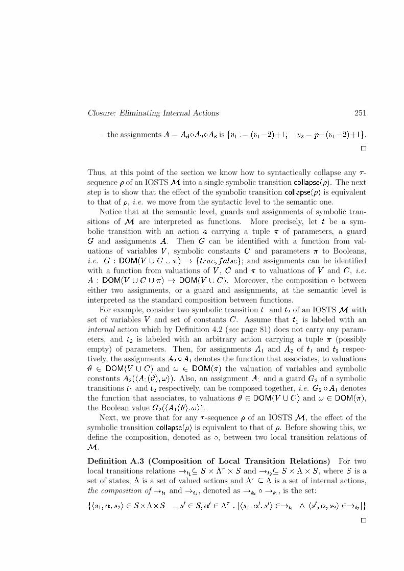
Closure: Eliminating Internal Actions 251
– the assignments ��O � � � � r�)� is � � . . O L�� .�� �iM���3 � �(# O���� L � .�� �iM ��3 � .c
Thus, at this point of the section we know how to syntactically collapse any � -sequence of an IOSTS
�into a single symbolic transition � �)� ���IH �RJIL M . The next
step is to show that the effect of the symbolic transition � � � ���IH �{JIL M is equivalentto that of , i.e. we move from the syntactic level to the semantic one.
Notice that at the semantic level, guards and assignments of symbolic tran-sitions of
�are interpreted as functions. More precisely, let � be a sym-
bolic transition with an action � carrying a tuple � of parameters, a guard� and assignments � . Then � can be identified with a function from val-uations of variables o , symbolic constants % and parameters � to Booleans,i.e. � . �U�Y�WLQo k %@k2�EMg13 � � � � ����- �� � � � ; and assignments can be identifiedwith a function from valuations of o , % and � to valuations of o and % , i.e.�. �U�Y��LQo k % k6��MV13 �U�V�WLZo k %2M . Moreover, the composition � betweeneither two assignments, or a guard and assignments, at the semantic level isinterpreted as the standard composition between functions.
For example, consider two symbolic transition ��. and � # of an IOSTS�
withset of variables o and set of constants % . Assume that ��. is labeled with aninternal action which by Definition 4.2 (see page 81) does not carry any param-eters, and � # is labeled with an arbitrary action carrying a tuple � (possiblyempty) of parameters. Then, for assignments � . and � # of ��. and � # respec-tively, the assignments � #�� � . denotes the function that associates, to valuations� � �U�Y�WLQo�k %2M and � � �U�V�WL �EM the valuation of variables and symbolicconstants � #wL � � .vL � M���� ��M . Also, an assignment � . and a guard � # of a symbolictransitions ��. and � # respectively, can be composed together, i.e. � #p��� . denotesthe function that associates, to valuations
� � �U�V�WLZo�k�%2M and �@� �U�Y�WL �EM ,the Boolean value � #)L � � . L � M ��� ��M .
Next, we prove that for any � -sequence of an IOSTS�
, the effect of thesymbolic transition � �)� � �iH �{JIL M is equivalent to that of . Before showing this, wedefine the composition, denoted as � , between two local transition relations of
�.
Definition A.3 (Composition of Local Transition Relations) For twolocal transitions relations 3 � ! �
� u ���xu �and 3 ��� � � u ��u �
, where�
is aset of states, � is a set of valued actions and � �x��� is a set of internal actions,the composition of 3 � ! and 3 � � , denoted as 3 � � �x3 � ! , is the set:
� � �(. �-� ��� #���� � u � u � � � � � � � �-� � � � � BED � �(. �-� � � � � �n��3 � ! � �� � �-� � � #��n��3 ��� S �
c

252 Appendix
Theorem A.1 (Preserving the Effect of � -Sequences by the CollapsingOperation) Let
. �"!� 3 $#� �� � !
BrBrB � ��� � *,+(!
%(')# ��*�+ !� 3 � �� � *
&%('/. �� 3 %
be a � -sequence of an IOSTS�
, i.e. � \p^��v�_^ ��`�^�� � L � M . Also, let 3 � ( ��O 3yB�B )and 3������ � ����� � � � be the local transition relations corresponding to the symbolictransition ��� of and to the symbolic transition � �)� � �iH �{JiL M . Then,
3������ � ����� ��� � O LQ3 � * � LQ3 � *�+ ! ��B BrBN�VLQ3 ��� �x3 � ! M BrBrB M9Mc
Proof The proof is done by induction on the length of the � -sequence �\p^��v�_^ ��`�^�� � L � M .Induction Basis. Consider a � -sequence . �� 3 �.� ��
� !� \p^��v��^ ��`�^�� � L � M of length
one, where the symbolic transition ��. has the guard � . and the assignments� . . Then trivially 3������ � ����� � � � O 3 � ! (see Definition A.2, page 249).
Induction Hypothesis. Assume that for the � -sequence
� . �"!� 3 �.� ��� � !
BrB B &%-')# �� 3 &%('/.� ��� � *,+(!
� \p^��v��^ ��`�^�� � L � M
which has length � 3 , the equality shown below holds.
3������ � ����� � ��� � O LQ3 � *�+ ! � LtBrBrB)�VLQ3 ��� �x3 � ! M BrBrB M9M
Induction Step. Consider a � -sequence of length
. � �� � �
� !� 3 �. BrBrB�&%-')# ��*�+ !� 3 � �� � *
&%('/. �� 3 &% � \p^��v�_^ ��`�^�� � L � M (A.1)
and prove that the equality below holds.
3 ����� � ������ � � � O LQ3 � * � LQ3 � *,+(! ��BrB B)�gLZ3 ��� �g3 � ! M B BrB M9M
Due to Observation A.1 (see page 247), the maximal strict prefix � of thegiven � -sequence (see Formula (A.1), page 252) is also a � -sequence of
�. Thus, � can be collapsed according to Definition A.2 (see page 249)
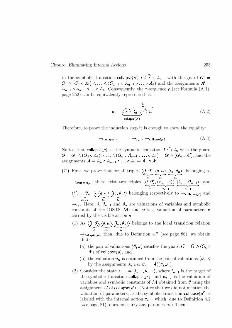
Closure: Eliminating Internal Actions 253
to the symbolic transition � �)� � �iH �{JIL � M . ��*,+(!� 3 %('/. with the guard � � O� . �eL�� #U� � .�M � BrB B��eL�� %('/.E� ��%-')#!�PBrBrBy� � .�M and the assignments � � O��%-'/.�� ��%(')#���BrB Br� � . . Consequently, the � -sequence (see Formula (A.1),page 252) can be equivalently represented as:
. � ��� � ��� � ����� ��� � � ��*,+(!� 3
� *� �� �&%-'/.0�� 3 &% (A.2)
Therefore, to prove the induction step it is enough to show the equality:
3������ � ������ � � � O 3 � * �g3�� ��� � ����� � ��� � (A.3)
Notice that � � � ���IH �{JIL M is the syntactic transition �� 3 &% with the guard� O � . � L�� #�� � .9M � B BrB � L�� %�� � %('/.���BrBrB � � .�MAO � � �>L�� %�� � � M , and theassignments ��O ��% � ��%-'/.b� BrBrBN� � .!O ��%5� � � .( � ) First, we prove that for all triples
��� � � �� �� �
� � � ��� �� ��� � *
� � &% � � % �� �� � *� belonging to
3������ � ����� � � � , there exist two triples��� � � �� �� �
� � �,%('/. � � ���� ��� � *,+(!
� � &%('/.�� � %-'/.�� ��� � *�+ !� and
���&%-'/. � � %('/.�� �� � *,+ !
� � � ��� �� ��� � *
� � &% � � % �� �� � *� belonging respectively to 3 ����� � ����� ��� � � and
3 � * . Here,�,
� %('/. and� % are valuations of variables and symbolic
constants of the IOSTS�
; and � is a valuation of parameters �carried by the visible action � .(1) As
��� � � �� �� �
� � � � � �� �� � *
� � % � � % �� �� � *� belongs to the local transition relation
3������ � ����� ��� � , then, due to Definition 4.7 (see page 86), we obtainthat:
(a) the pair of valuations� � ��� � satisfies the guard �@O � � ��L�� %A�
� � M of � �)� ���IH �RJIL M , and
(b) the valuation� % is obtained from the pair of valuations
� � ��� �by the assignments � , i.e.
� %gO �2L � � ��� ��M .(2) Consider the state � %-'/.!O �
&%('/. � � %-'/.� , where &%('/. is the target ofthe symbolic transition � � � ���IH �{JIL � M , and
� %-'/. is the valuation ofvariables and symbolic constants of
�obtained from
�using the
assignment � � of � � � ���IH �{JIL � M . (Notice that we did not mention thevaluation of parameters, as the symbolic transition � �)� ���IH �RJKL � M islabeled with the internal action � %('/. which, due to Definition 4.2(see page 81), does not carry any parameters.) Then,
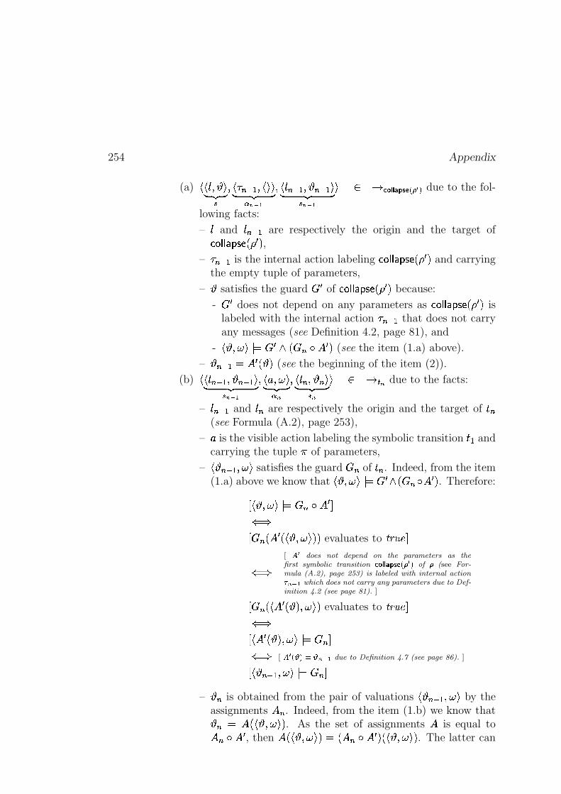
254 Appendix
(a)��� � � �� �� �
� � �,%('/.�� � ���� ��� � *�+ !
� � &%-'/.�� � %('/.��� �� � *�+ !� � 3 � ��� � ����� ����� � due to the fol-
lowing facts:
– and &%('/. are respectively the origin and the target of� �)� � �iH �{JIL � M ,
– �,%('/. is the internal action labeling � �)� ���IH �RJKL � M and carryingthe empty tuple of parameters,
–�
satisfies the guard � � of � � � ���IH �{JiL � M because:
- � � does not depend on any parameters as � �)� � �iH �{JIL � M islabeled with the internal action � %('/. that does not carryany messages (see Definition 4.2, page 81), and
-� � ��� �� O � � � L�� % � � � M (see the item (1.a) above).
–� %('/.'O � � L � M (see the beginning of the item (2)).
(b)���&%-'/. � � %('/.�� �� � *,+ !
� � � ��� �� ��� � *
� � &% � � % �� �� � *� � 3 � * due to the facts:
– &%-'/. and &% are respectively the origin and the target of � %(see Formula (A.2), page 253),
– � is the visible action labeling the symbolic transition ��. andcarrying the tuple � of parameters,
–� � %('/.���� � satisfies the guard � % of �"% . Indeed, from the item(1.a) above we know that
� � � � � � O � � �xL�� %p� � � M . Therefore:
D � � ��� � � O � % � � � S� �D � %_L � � L � � ��� ��M9M evaluates to �*,���^ S
� �[ # � does not depend on the parameters as thefirst symbolic transition ����� � ����� ��� � � of � (see For-mula (A.2), page 253) is labeled with internal action
��*�+ ! which does not carry any parameters due to Def-inition 4.2 (see page 81). ]
D � %_L � � � L � M���� ��M evaluates to �*,���^ S� �D � � � L � M�� � � � O � %wS� � [ # � ��� ��� � *,+(! due to Definition 4.7 (see page 86). ]
D � � %('/. � � � � O � %wS–
� % is obtained from the pair of valuations� � %('/. ��� � by the
assignments ��% . Indeed, from the item (1.b) we know that� % O �2L � � ��� ��M . As the set of assignments � is equal to� %5� � � , then �2L � � ��� ��MAO L���%5� � � M�L � � ��� ��M . The latter can
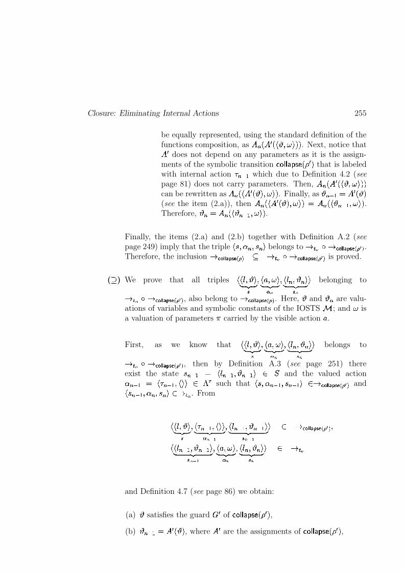
Closure: Eliminating Internal Actions 255
be equally represented, using the standard definition of thefunctions composition, as � % L�� � L � � ��� ��MRM . Next, notice that� � does not depend on any parameters as it is the assign-ments of the symbolic transition � �)� � �iH �{JIL � M that is labeledwith internal action � %('/. which due to Definition 4.2 (seepage 81) does not carry parameters. Then, � % L�� � L � � ��� ��MRMcan be rewritten as ��%_L � � � L � M���� ��M . Finally, as
� %-'/.!O � � L � M(see the item (2.a)), then � % L � � � L � M ��� ��MYO � %�L � � %-'/. ��� ��M .Therefore,
� %gO ��% L � � %('/. � � ��M .
Finally, the items (2.a) and (2.b) together with Definition A.2 (seepage 249) imply that the triple
����-� % � � % � belongs to 3 � * �g3������ � ����� � ��� � .
Therefore, the inclusion 3 ����� � ������ � � � � 3 � * �g3 ����� � ����� ��� � � is proved.
(
) We prove that all triples��� � � �� ��� �
� � � ��� �� �� � *
� � &% � � % �� ��� � *� belonging to
3 � * �x3������ � ����� ��� � � , also belong to 3������ � ����� � � � . Here,�
and� % are valu-
ations of variables and symbolic constants of the IOSTS�
; and � isa valuation of parameters � carried by the visible action � .
First, as we know that��� � � �� �� �
� � � ��� �� ��� � *
� � &% � � % �� �� � *� belongs to
3 � * �x3������ � ����� ����� � , then by Definition A.3 (see page 251) thereexist the state � %-'/. O �
&%('/. � � %-'/.�� � �and the valued action
� %-'/. O ��,%('/. � � ����� � � such that
����-� %-'/. � � %('/. ����3�� ��� � ����� ��� � � and�
� %('/. �/� % � � % ����3 � * . From
��� � � �� ��� �
� � � %-'/. � � ���� �� � *�+ !
� � &%-'/.�� � %('/.��� �� � *,+ !� � 3������ � ����� � � � � �
��� %('/. � � %('/. �� �� � *,+(!
� � � ��� �� ��� � *
� � &% � � % �� �� � *� � 3 � *
and Definition 4.7 (see page 86) we obtain:
(a)�
satisfies the guard � � of � � � ���IH �{JIL � M ,(b)
� %('/.!O � � L � M , where � � are the assignments of � �)� ���IH �RJKL � M ,
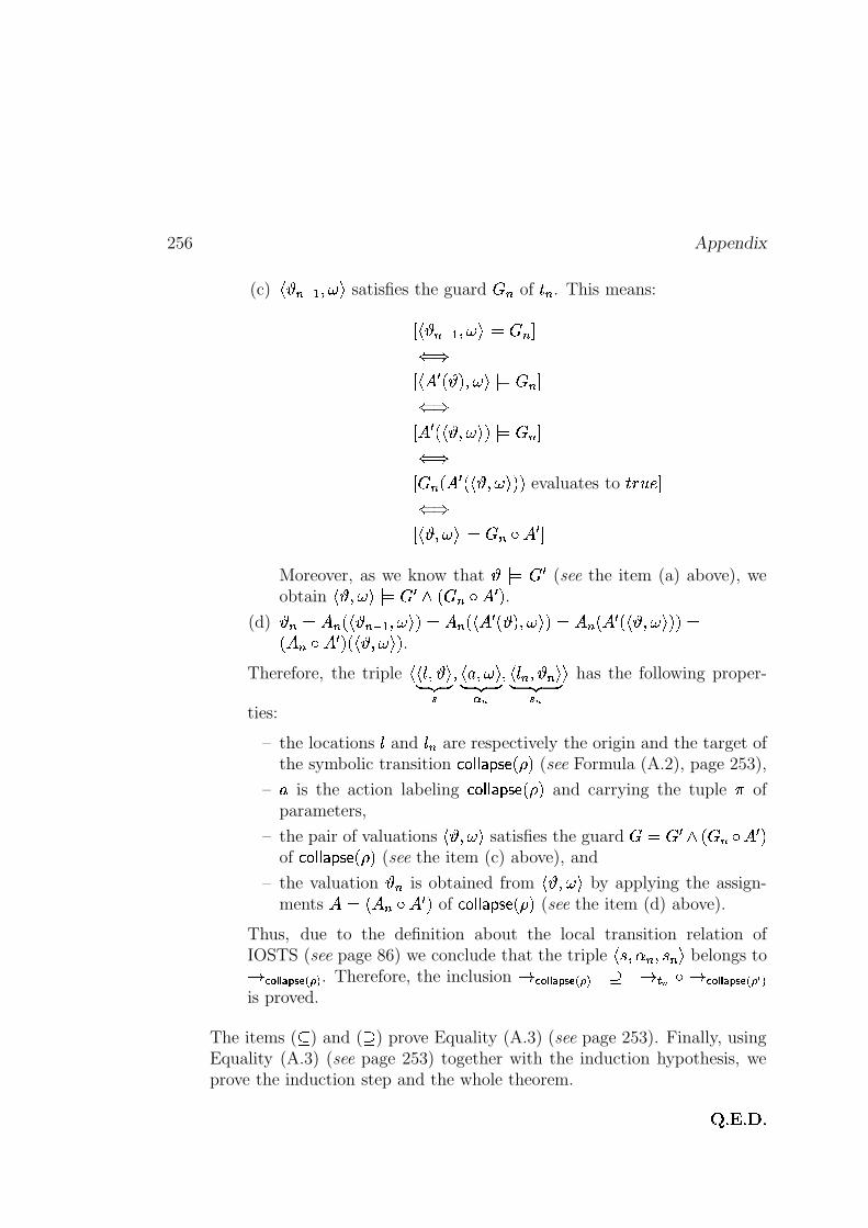
256 Appendix
(c)� � %('/. ��� � satisfies the guard � % of �"% . This means:
D � � %('/. ��� � � O � %wS� �D � � � L � M���� � � O � %wS� �D � � L � � ��� ��M�� O � %wS� �D � %_L � � L � � � � ��M9M evaluates to � � � � S� �D � � ��� �� O � %�� � � S
Moreover, as we know that� � O � � (see the item (a) above), we
obtain� � ��� � � O � � � L�� % � � � M .
(d)� %gO ��% L � � %('/.���� ��MEO � %_L � � � L � M���� ��MEO ��% L�� � L � � ��� ��M9MEOL�� % � � � M�L � � ��� ��M .
Therefore, the triple��� � � �� �� �
� � � ��� �� �� � *
� � % � � % �� �� � *� has the following proper-
ties:
– the locations and $% are respectively the origin and the target ofthe symbolic transition � � � ���IH �{JiL M (see Formula (A.2), page 253),
– � is the action labeling � �)� � �iH �{JiL M and carrying the tuple � ofparameters,
– the pair of valuations� � � � � satisfies the guard � O � � � L�� %!��� � M
of � � � ���IH �{JiL M (see the item (c) above), and
– the valuation� % is obtained from
� � � � � by applying the assign-ments ��O�L ��% � � � M of � �)� � �iH �{JIL M (see the item (d) above).
Thus, due to the definition about the local transition relation ofIOSTS (see page 86) we conclude that the triple
����-� % � � % � belongs to
3������ � ����� ��� � . Therefore, the inclusion 3�� ��� � ����� � � � 3 � * �P3������ � ����� ��� � �is proved.
The items ( � ) and (
) prove Equality (A.3) (see page 253). Finally, usingEquality (A.3) (see page 253) together with the induction hypothesis, weprove the induction step and the whole theorem.
� B��xB� B
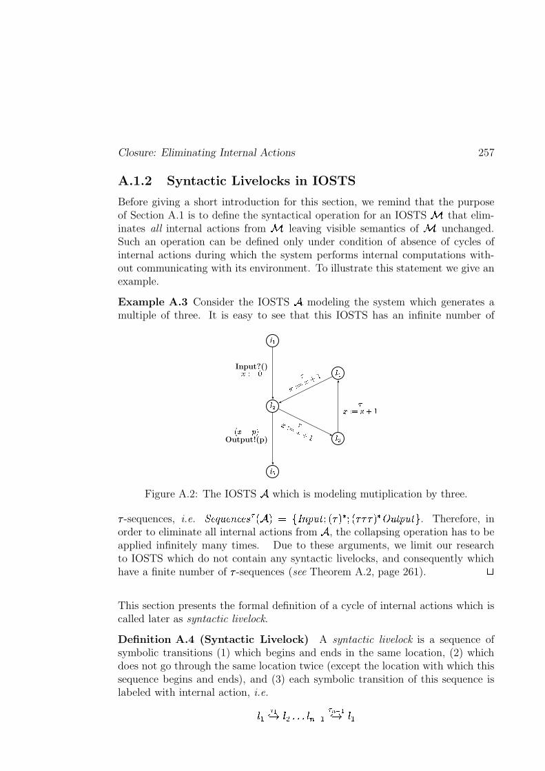
Closure: Eliminating Internal Actions 257
A.1.2 Syntactic Livelocks in IOSTS
Before giving a short introduction for this section, we remind that the purposeof Section A.1 is to define the syntactical operation for an IOSTS
�that elim-
inates all internal actions from�
leaving visible semantics of�
unchanged.Such an operation can be defined only under condition of absence of cycles ofinternal actions during which the system performs internal computations with-out communicating with its environment. To illustrate this statement we give anexample.
Example A.3 Consider the IOSTS�
modeling the system which generates amultiple of three. It is easy to see that this IOSTS has an infinite number of
���
���
���
���
���
Input?() � � �
� ����Output!(p)
� �� � ����� � � ���
���� � �����
Figure A.2: The IOSTS�
which is modeling mutiplication by three.
-sequences, i.e. ! @#"%$:@%&�=?@('*),+ �.-0/ 132 & A�$(C(45+ -76 45+ 8 9 -:6<; $(C A�$(C#= . Therefore, inorder to eliminate all internal actions from
�, the collapsing operation has to be
applied infinitely many times. Due to these arguments, we limit our researchto IOSTS which do not contain any syntactic livelocks, and consequently whichhave a finite number of -sequences (see Theorem A.2, page 261). >
This section presents the formal definition of a cycle of internal actions which iscalled later as syntactic livelock.
Definition A.4 (Syntactic Livelock) A syntactic livelock is a sequence ofsymbolic transitions (1) which begins and ends in the same location, (2) whichdoes not go through the same location twice (except the location with which thissequence begins and ends), and (3) each symbolic transition of this sequence islabeled with internal action, i.e.
�@? )7AB C �ED�FGFHF �EIKJL? )NM(OPAB C �N?
258 Appendix
where (1) ������������������� ������ , (2) for all � and � from � to ����� , if ���� � then��� �� �"! , and (3) #$������%#��� ��&�(' ) . *
We illustrate the notion of syntactic livelock with an example below.
Example A.4 Let us consider the IOSTS + depicted in Figure A.1. Consideralso the sequence of symbolic transition �-, )/.0 1 ��2 )/30 1 ��, . This sequence is thesyntactic livelock of + as (1) it begins and ends in the same location �/, , (2) theintermediate location �42 does not appear in this sequence more then ones, and(3) all symbolic transitions involved into the sequence are labeled with internalactions #65 and #67 . *
A.1.3 Closure for IOSTS without Syntactic Livelocks
The section introduces the closure operation for IOSTS that do not contain anysyntactic livelocks defined in Section A.1.2 (see page 257). The purpose of thisoperation is to eliminate all internal actions from an IOSTS by computing theeffect of any # -sequence that ends with a symbolic transition 8 labeled with avisible action, and by encoding it in 8 . The section ends with a proof that anIOSTS obtained after the closure operation is well-formed.
Before defining the closure operation, it is necessary to introduce two newnotations concerning an IOSTS 9 �;:�< �>=?�@�A���/B��>'C�EDGF . The first one is the setHJILKEMENPORQ �TS�U of locations that can be directly reached from a location belonging tosome subset �TS of � by an action from some subset '&S of ' . This notion is usedin the closure operation to define the set of locations for the resulting IOSTSV$W ILK>XPY�Z[Q 9 U . The second new notion is the set of #\^] -sequences for 9 . Thisset contains all # -sequences (see Definition A.1, page 247) of 9 ending with asymbolic transition labeled with a visible action of 9 . It is used to identifyall # -sequences of 9 that must be collapsed during the closure operation. Theformal definitions of HJILK_M NPO Q �TS�U and the set of #`a] -sequences are given below. Forbetter understanding these definitions are supported with examples.
Definition A.5 ( HJILKEM N ORQ �TS�U ) Let 9 be an IOSTS with set of locations � andalphabet of actions ' . Let also �GS be a subset of � and ' S be a subset of ' . Then,the set: HJILK_M%NPO�Q � S U �cb �T�d� egf�]h�i' S ��� S �i� S kj � Sml0 1 �4nGois the set of locations that are the successors of locations belonging to � S by anaction ]h�(' S . *
Closure: Eliminating Internal Actions 259
Example A.5 Consider the IOSTS + with set of locations ��� �b �����������%��������������, �����6����5�����7o depicted in Figure A.1 (see page 248). Notice that forthis example we do not take into account the symbolic transitions of + whichare shown as dotted lines in Figure A.1 (see page 248) as they correspond to asyntactic livelock.
Then, we compute the set of successors of the locations ��� by some visible actionbelonging to Q '� ' )� U �cb ] ���$�� $��� ���L��� o as follows:
Location Action Successor
��� ] ������ � ������ — —��� ��,��, � ��7��� — —��5 � ��5��7 � ��5
Thus, we obtain HLILK_M�� N���� N����� Q ���GU �cb �����%��� ����,��%��5�����76o . *
Next, as it has been announced at the beginning of the section, we formally definethe notion of #\^] -sequences.
Definition A.6 (Set of #\^] -Sequences) For an IOSTS 9 �:R< �>=?�@�A��� B �>' � DTF and a location � � � , the set of #`a] -sequences for � , de-noted by �����! ��!"$#��&% )�' l Q � U , is the set of all sequences of symbolic transitionsstarting in the location �
(*) � ),+0 1 ��� �� ���� � ).-!/0+0 1 ���$ �� l0 1 ���where �2143 , �_�������������� �i� , # �>����6�%#��� ��&�(' ) , and ]?� Q ' ' )JU . *It is not hard to see that the definitions of # -sequences and #\^] -sequences (seeDefinitions A.1 and A.6, pages 247 and 259) lead to the following observation:
Observation A.2 Let 9 � :R< �>=?���A��� B �>'C�EDGF be an IOSTS. Then, for eachlocation �T�i� , all #\^] -sequences starting in � are # -sequences of 9 , i.e.
5 �T�i��kj6�����! ��!"$#��&% )�' l Q � U�78�����! ��!"$#��&% ) Q 9 U n*
260 Appendix
We illustrate the definition about #`a] -sequences with an example.
Example A.6 Consider the IOSTS + shown in Figure A.1 (see page 248) with-out syntactic livelocks, i.e. without transitions shown as the dotted lines. Thenwe compute #\^] -sequences that start, for instance, in the locations � � and ��7 of + .
(1) For the location �R� the set �����! ��!"$#��&% )�' l Q ����U consists of the four following#`a] -sequences: ��������
�������
��� ),+0 1 ��� )��0 1 �����0 1 ��, ���� ) +0 1 ��� ) �0 1 ��� ) +�0 1 ��,�0 1 ��7 ���� ),+0 1 ��� )��0 1 ��� ) +�0 1 ��, ) �0 1 ��5��0 1 ��5����� ),+0 1 ��� ) �0 1 ��� )��0 1 ��5��0 1 ��5
� ��������������
For example, the first sequence, i.e. �R� ) +0 1 ��� ) �0 1 ��� �0 1 ��,�� belongs to�����! ��!"$#��&% )�' l Q ����U , as we can syntactically move from the location � � to thelocation ��� following the symbolic transitions labeled with internal actions# � and #6, , and then from the location ��� we can execute the visible action (see Figure A.1, page 248).
(2) For the locations �47 the sets of #\^] -sequences, i.e. �����! ��!"$#��&% )�' l Q ��76U , is empty.Indeed, the single symbolic transitions outgoing from this location is labeledonly with visible actions � .
Notice also that the sets �����! ��!"$#��&% )�' l Q ����U and �����! ��!"$#��&% )�' l Q ��76U are the subsets of�����! ��!"$#��&% ) Q +?U . (We explained how to compute �����! ��!"$#��&% ) Q +?U in Example A.1,page 247.) *
Now, using the notions of #\^] -sequences and HJILK_M%NPO Q �TS�U together with the col-lapsing operation (see Definition A.2, page 249), we can give the constructive
definition of the closure operation that eliminates all internal actions from anIOSTS that does not contain any syntactic livelocks.
Definition A.7 (Closure) Let 9 � :R< �>= � � ��� B �>' � DAF be an IOSTS with-out any syntactic livelocks (see Definition A.4, page 257). Then, the clo-
sure operation transforms the given IOSTS 9 into the IOSTS V�W ILK>XPY�Z[Q 9 U �:R< �>= �@�TS���� B �>' S�� D S F , where:
(1) ' S � ' ' ) .Thus, the alphabet of internal actions of V�W ILK�XPY�Z[Q 9 U is empty.
(2) �GS �cb � B o�� HLIJKEMEN � N � Q �&U�7 � .
Thus, the set of locations of V�W ILK>XPY�Z[Q 9 U consists of the initial location � Bof 9 and all the locations of 9 which are directly reachable from thelocations of 9 by visible actions.
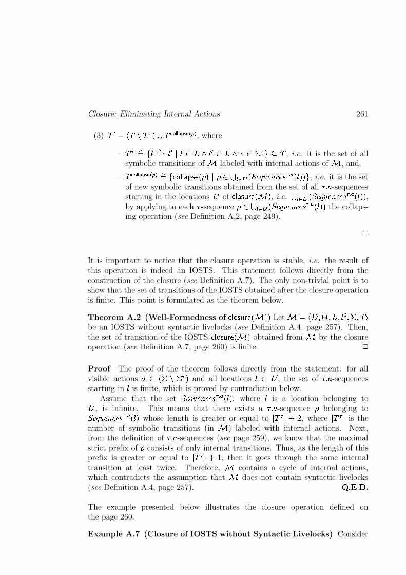
Closure: Eliminating Internal Actions 261
(3) D S � Q D D )�U � D ����� � ����� � � � , where
– D ) � b � )0 1 �-S e[� � ���d�4ST� ��� #�� ' )Lo 7 D , i.e. it is the set of allsymbolic transitions of 9 labeled with internal actions of 9 , and
– D ����� � ������ � � � b V I W W � H KEZPQ ( UCe ( ��������� O Q �����! ��!"$#��&% )�' l Q � U%U%o , i.e. it is the set
of new symbolic transitions obtained from the set of all #\^] -sequencesstarting in the locations �GS of V$W ILK>XPY�Z[Q 9 U , i.e. � ����� O Q �����! ��!"$#��&% )�' l Q � U U ,by applying to each # -sequence ( � � ����� O Q �����! ��!"$#��&% )�' l Q � U%U the collaps-ing operation (see Definition A.2, page 249).
*
It is important to notice that the closure operation is stable, i.e. the result ofthis operation is indeed an IOSTS. This statement follows directly from theconstruction of the closure (see Definition A.7). The only non-trivial point is toshow that the set of transitions of the IOSTS obtained after the closure operationis finite. This point is formulated as the theorem below.
Theorem A.2 (Well-Formedness of V$W ILK>XPY�Z[Q 9 U ) Let 9 � :R< �>=?���A����B �>'C� DTFbe an IOSTS without syntactic livelocks (see Definition A.4, page 257). Then,the set of transition of the IOSTS V�W IJK�XPY�Z[Q 9 U obtained from 9 by the closureoperation (see Definition A.7, page 260) is finite. *
Proof The proof of the theorem follows directly from the statement: for allvisible actions ] � Q ' ' )JU and all locations � � �GS , the set of #\^] -sequencesstarting in � is finite, which is proved by contradiction below.
Assume that the set �����! ��!"$#��&% )�' l Q � U , where � is a location belonging to� S , is infinite. This means that there exists a #`a] -sequence ( belonging to�����! ��!"$#��&% )�' l Q � U whose length is greater or equal to e D ) e � 3 , where e D ) e is thenumber of symbolic transitions (in 9 ) labeled with internal actions. Next,from the definition of #\^] -sequences (see page 259), we know that the maximalstrict prefix of ( consists of only internal transitions. Thus, as the length of thisprefix is greater or equal to e D�)`e!�;� , then it goes through the same internaltransition at least twice. Therefore, 9 contains a cycle of internal actions,which contradicts the assumption that 9 does not contain syntactic livelocks(see Definition A.4, page 257). " $# %iThe example presented below illustrates the closure operation defined onthe page 260.
Example A.7 (Closure of IOSTS without Syntactic Livelocks) Consider
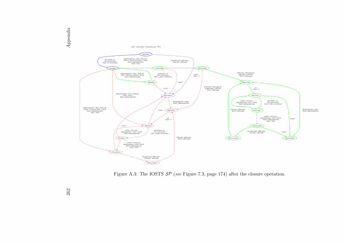
262
App
endix
(cPrice > 0) and (vPaid = 0) and (vBeverage = TEA)
<Begin,Begin>
<Pay,Begin>
(pCoinValue > 0) Coin ? (pCoinValue)
vPaid := (0 + pCoinValue)
<Return,Reject>
Cancel ? vPaid := 0
<Idle,Begin>
(pCoinValue > 0) Coin ? (pCoinValue)
vPaid := (vPaid + pCoinValue)
Cancel ?
((pRemaningValue = cPrice - vPaid) and (vPaid < cPrice) and not(vPaid < cPrice))
Return ! (pRemaningValue)
<Idle,Reject>
((pRemaningValue = cPrice - vPaid) and (vPaid < cPrice))
Return ! (pRemaningValue)
<Choose,Reject>
((pRemaningValue = vPaid - cPrice) and (vPaid >= cPrice) and (vPaid < cPrice))
Return ! (pRemaningValue) vPaid := cPrice
<Choose,Begin>
((pRemaningValue = vPaid - cPrice) and (vPaid >= cPrice) and not(vPaid < cPrice))
Return ! (pRemaningValue) vPaid := cPrice
<Begin,Reject>
(pRemaningValue = vPaid) Return ! (pRemaningValue)
Cancel ?
<Pay,Reject>
(pCoinValue > 0) Coin ? (pCoinValue)
vPaid := (vPaid + pCoinValue)
Cancel ?
<Delivery,Reject>
ChooseBeverage ? (pBeverage) vBeverage := pBeverage
Cancel ?
<Delivery,Begin>
ChooseBeverage ? (pBeverage) vBeverage := pBeverage
tau vPaid := 0
((vPaid < cPrice) and (pRemaningValue = cPrice - vPaid))
Return ! (pRemaningValue)
((vPaid >= cPrice) and (pRemaningValue = vPaid - cPrice))
Return ! (pRemaningValue) vPaid := cPrice
(vBeverage = pBeverage) Deliver ! (pBeverage)
((vBeverage = pBeverage) and not(pBeverage = COFFEE))
Deliver ! (pBeverage)
<Begin,Accept>
((vBeverage = pBeverage) and (pBeverage = COFFEE))
Deliver ! (pBeverage)
<Idle,Accept>
tau vPaid := 0
<Pay,Accept>
(pCoinValue > 0) Coin ? (pCoinValue)
vPaid := (vPaid + pCoinValue)
<Return,Accept>
Cancel ?
((vPaid < cPrice) and (pRemaningValue = cPrice - vPaid))
Return ! (pRemaningValue)
<Choose,Accept>
((vPaid >= cPrice) and (pRemaningValue = vPaid - cPrice))
Return ! (pRemaningValue) vPaid := cPrice
(pRemaningValue = vPaid) Return ! (pRemaningValue)
Cancel ?
<Delivery,Accept>
ChooseBeverage ? (pBeverage) vBeverage := pBeverage
(vBeverage = pBeverage) Deliver ! (pBeverage)
Figure A.3: The IOSTS �� (see Figure 7.3, page 174) after the closure operation.
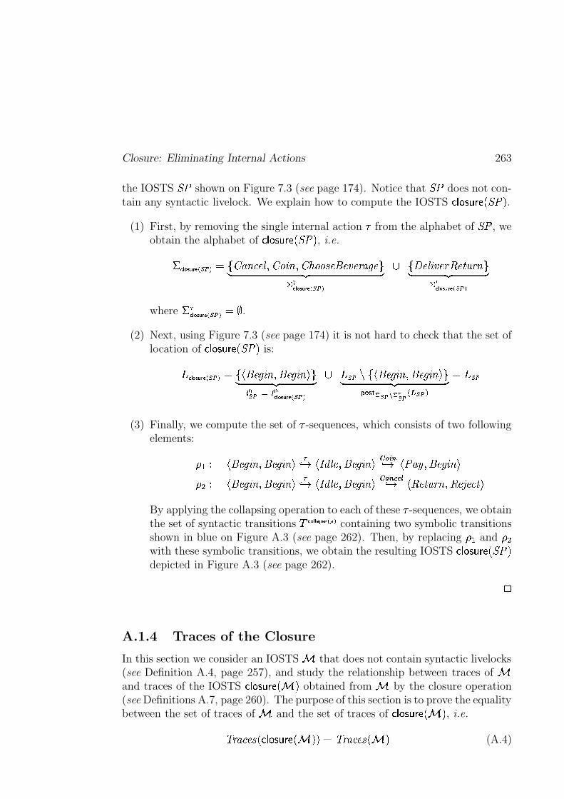
Closure: Eliminating Internal Actions 263
the IOSTS ��� shown on Figure 7.3 (see page 174). Notice that ��� does not con-tain any syntactic livelock. We explain how to compute the IOSTS V$W ILK>XPY�ZPQ ��� U .
(1) First, by removing the single internal action # from the alphabet of ��� , weobtain the alphabet of V$W ILK>XPY�Z[Q ��� U , i.e.
'���� ����� �������� �cb���� "$#����/� ����� " � � �!�"� % �$# �&% �&' ��( � o) *,+ -N/.��� ���0� 1������� b32 ��� � % �&'34 �65. 7'&" o) *,+ -N98��� ���0� 1������
where '&)�:� ���0� 1����"� �<; .
(2) Next, using Figure 7.3 (see page 174) it is not hard to check that the set oflocation of V�W ILK�XPY�Z[Q ��� U is:
�=��� ���0� 1������ � b : # � (>� " ��# � (>� " F>o) *,+ -� � ���@? � ���� ���0� 1������
� ����� b : # � (>� " ��# � (>� " F�o) *,+ -� � �0ACB ���ED B � ��� � � ��� �� �����
(3) Finally, we compute the set of # -sequences, which consists of two followingelements:
( � ) : # � (>� " ��# � (>� " F )0 1 :GF�H � ����# � (>� " FI�JLK�M0 1 : � ��N ��# � (>� " F
( � ) : # � (>� " ��# � (>� " F )0 1 :GF�H � ����# � (>� " FI�OLM6PCQ�R0 1 : 4 �65 7'!" ��4 �1S ��#65EF
By applying the collapsing operation to each of these # -sequences, we obtainthe set of syntactic transitions D �T��� � U0V:�W X�ZY�� containing two symbolic transitionsshown in blue on Figure A.3 (see page 262). Then, by replacing ( � and ( �with these symbolic transitions, we obtain the resulting IOSTS V�W ILK�XPY�Z[Q ��� Udepicted in Figure A.3 (see page 262).
*
A.1.4 Traces of the Closure
In this section we consider an IOSTS 9 that does not contain syntactic livelocks(see Definition A.4, page 257), and study the relationship between traces of 9and traces of the IOSTS V$W ILK>XPY�Z[Q 9 U obtained from 9 by the closure operation(see Definitions A.7, page 260). The purpose of this section is to prove the equalitybetween the set of traces of 9 and the set of traces of V$W ILK>XPY�ZPQ 9 U , i.e.
[ ' � #��&% Q V�W IJK�XPY�Z[Q 9 U U � [ ' � #��&% Q 9 U (A.4)
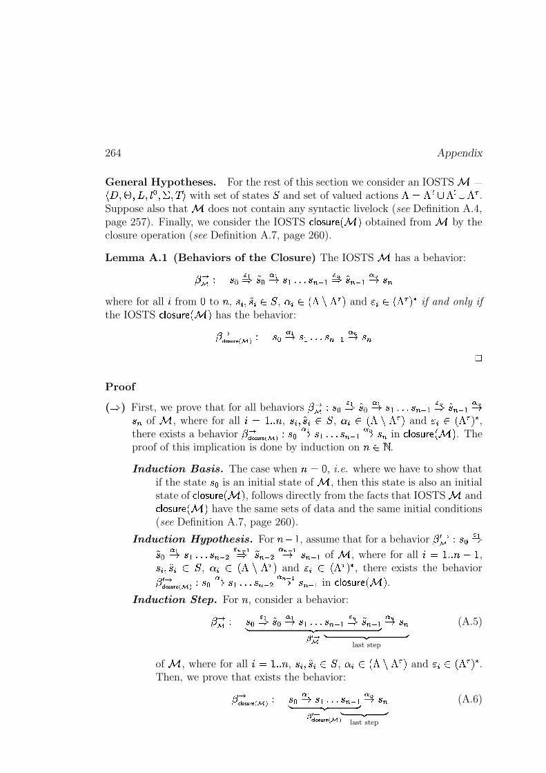
264 Appendix
General Hypotheses. For the rest of this section we consider an IOSTS 9 �:R< �@=?�@�A��� B �>'C� DTF with set of states � and set of valued actions � � ��� ����� ��� ) .Suppose also that 9 does not contain any syntactic livelock (see Definition A.4,page 257). Finally, we consider the IOSTS V$W ILK>XPY�ZPQ 9 U obtained from 9 by theclosure operation (see Definition A.7, page 260).
Lemma A.1 (Behaviors of the Closure) The IOSTS 9 has a behavior:
�� ) � B� + �� B
� +1 � � �� � �$ �� � - �� �� �� � -1 � �where for all � from � to � , � � � �� � ��� , � �k� Q � � )�U and � �k� Q � ) U�� if and only if
the IOSTS V$W ILK>XPY�ZPQ 9 U has the behavior:
���:� ���0� � � ) � B� +1 � � � � �� �� � -1 � �
*
Proof
(
) First, we prove that for all behaviors� � )�� B
� + �� B� +1 � � � � �� �� � - �� �� �� � -1� � of 9 , where for all � � ���^� , � � � �� � ��� , � � � Q � � )$U and �$� � Q � )�U�� ,
there exists a behavior� ���� ����� 1� � )�� B
� +1 � � �� � �� �� � -1 � � in V�W IJK�XPY�Z[Q 9 U . Theproof of this implication is done by induction on �(��� .
Induction Basis. The case when � � � , i.e. where we have to show thatif the state � B is an initial state of 9 , then this state is also an initialstate of V�W IJK�XPY�Z[Q 9 U , follows directly from the facts that IOSTS 9 andV$W ILK>XPY�ZPQ 9 U have the same sets of data and the same initial conditions(see Definition A.7, page 260).
Induction Hypothesis. For �A� � , assume that for a behavior� S � )�� B
� + �� B� +1 � � �� � �$ � � -&/ + �� �� � � -&/ +1 � �� �� of 9 , where for all � � �J a�d��� ,� �R� �� � ��� , � � � Q � � )�U and � � � Q � )�U�� , there exists the behavior� S ��:� ���0� 1� � )�� B
� +1 � � �� � �$ � � -&/ +1 � �$ �� in V�W IJK�XPY�Z[Q 9 U .Induction Step. For � , consider a behavior:
� � ) ) *,+ -� O �� B� + �� B
� +1 � � ��) *,+ -
last step
� �$ �� � - �� �� �� � -1 � � (A.5)
of 9 , where for all � � ���^� , � � � �� �T��� , � � � Q � � ) U and � �G� Q � ) U � .Then, we prove that exists the behavior:
� ���� ����� 1� � ) ) *,+ -� O ���� ���0� � �� B� +1 � � ��
) *,+ -last step
� �$ �� � -1 � � (A.6)
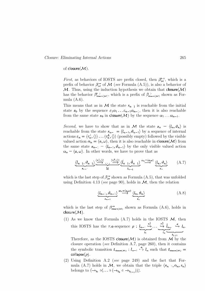
Closure: Eliminating Internal Actions 265
of V�W ILK�XPY�Z[Q 9 U .
First, as behaviors of IOSTS are prefix closed, then� S � , which is a
prefix of behavior� � of 9 (see Formula (A.5)), is also a behavior of
9 . Thus, using the induction hypothesis we obtain that V�W ILK>XPY�Z[Q 9 Uhas the behavior
� S ���� ����� 1� � , which is a prefix of� ��:� ���0� � � shown as For-
mula (A.6).
This means that as in 9 the state � �$ �� is reachable from the initialstate � B by the sequence �P� �G� �� � �� ���� �� �� , then it is also reachablefrom the same state � B in V$W ILK>XPY�Z[Q 9 U by the sequence �G� �� � �� �� .
Second, we have to show that as in 9 the state � � � : ��� � � �[F isreachable from the state � �$ �� � : ���� ��>� � �� ��EF by a sequence of internalactions � � � : # �� � : F%F � : #��� � : F�F (possibly empty) followed by the visiblevalued action � � � : ] ���&F , then it is also reachable in V�W IJK�XPY�Z[Q 9 U fromthe same state � �$ �� � : ���� ��>� � �� ��EF by the only visible valued action� � � : ] ���&F . In other words, we have to prove that as
: ���� ��>� � �� ��EF) *,+ -� -!/0+
� ) +- ��� �� 1 �� ) �-� ��� �� 1) *G+ -
� -�: ����� ��>� �� �� ��EF) *,+ -�� -!/0+
� - ? � l ��
� 1 : ��� � � �LF) *G+ -� -
(A.7)
which is the last step of� � shown as Formula (A.5), that was unfolded
using Definition 4.13 (see page 90), holds in 9 , then the relation
: ���$ ��>� � �� ��%F) *,+ -� -&/ +
� - ? � l ��
� 1 : ��� � � �[F) *,+ -� -
(A.8)
which is the last step of� ��:� ���0� 1� � shown as Formula (A.6), holds inV�W ILK�XPY�Z[Q 9 U .
(1) As we know that Formula (A.7) holds in the IOSTS 9 , then
this IOSTS has the #`a] -sequence ( ) ���$ �� ) +-0 1) *,+ -� +�� ) *G+ -� �
) �-0 1) *,+ -� ��� +
����� �� l0 1 ��� .
Therefore, as the IOSTS V$W ILK>XPY�ZPQ 9 U is obtained from 9 by theclosure operation (see Definition A.7, page 260), then it contains
the symbolic transition 8,��� ���0� 1� � ) ���� �� l0 1 ��� such that 8,��� ����� 1� � �V I W W � H KEZ[Q ( U .(2) Using Definition A.2 (see page 249) and the fact that For-
mula (A.7) holds in 9 , we obtain that the triple : � �$ ��>� � � � � �PFbelongs to Q 1 � + � Q �� � Q 1 � � � 1 � ��� + U U%U .
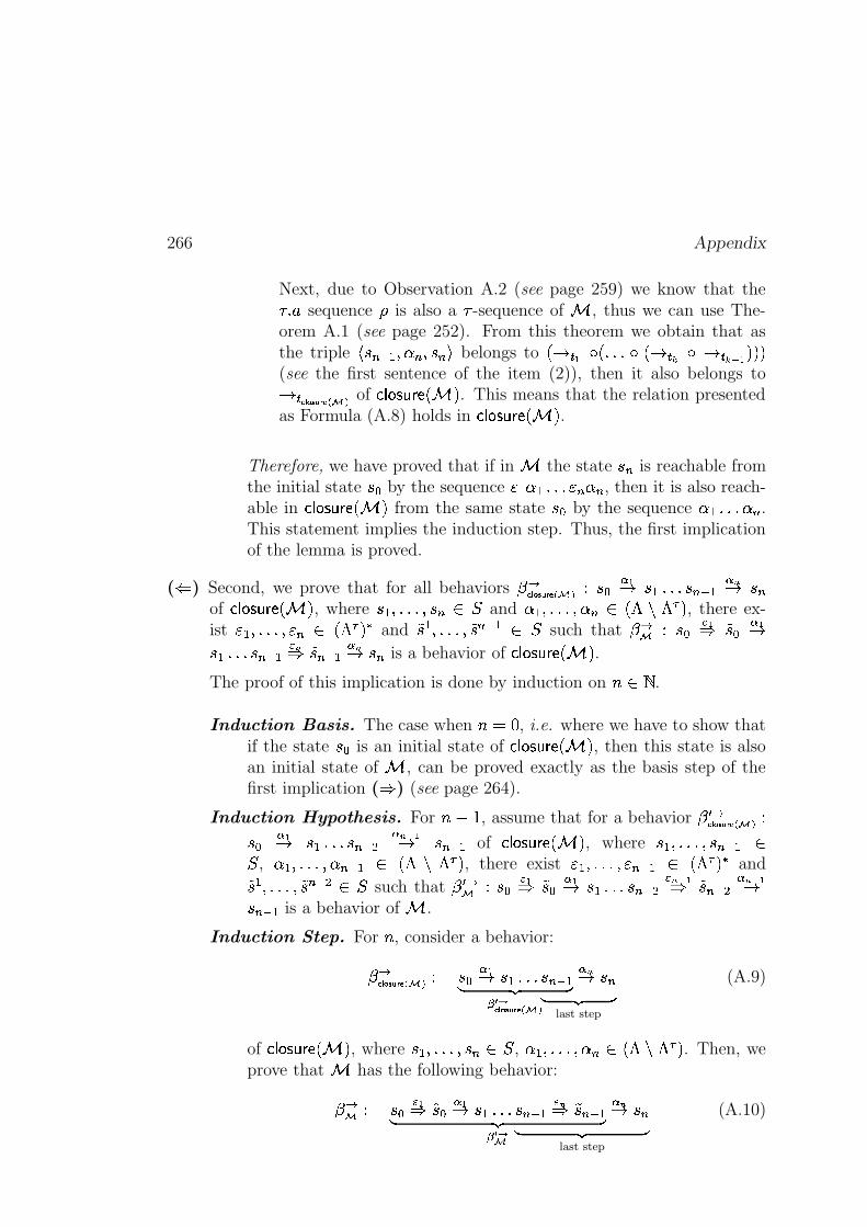
266 Appendix
Next, due to Observation A.2 (see page 259) we know that the#\^] sequence ( is also a # -sequence of 9 , thus we can use The-orem A.1 (see page 252). From this theorem we obtain that asthe triple : � �$ ��@� � � � � �PF belongs to Q 1 � + � Q �� � Q 1 � � � 1 � ��� + U%U U(see the first sentence of the item (2)), then it also belongs to1 � ��� ����� 1� � of V�W ILK>XPY�Z[Q 9 U . This means that the relation presentedas Formula (A.8) holds in V�W ILK>XPY�Z[Q 9 U .
Therefore, we have proved that if in 9 the state � � is reachable fromthe initial state � B by the sequence �[� �T� �� � � � � , then it is also reach-able in V$W ILK>XPY�Z[Q 9 U from the same state � B by the sequence �G� �� � � .This statement implies the induction step. Thus, the first implicationof the lemma is proved.
( � ) Second, we prove that for all behaviors� ��:� ���0� 1� � ) � B
� +1 � � � � �� �� � -1 � �of V�W ILK>XPY�Z[Q 9 U , where � �@����6� � � � � and �G�@����6� � � � Q � � )�U , there ex-ist �[�@����6� � � � Q � ) U � and
�� � ����6� �� �� �� � � such that� � ) � B
� + �� B� +1
� � �� � �� �� � - �� �� �� � -1 � � is a behavior of V$W ILK>XPY�ZPQ 9 U .The proof of this implication is done by induction on � � � .
Induction Basis. The case when � � � , i.e. where we have to show thatif the state � B is an initial state of V�W ILK�XPY�Z[Q 9 U , then this state is alsoan initial state of 9 , can be proved exactly as the basis step of thefirst implication (
) (see page 264).
Induction Hypothesis. For � � � , assume that for a behavior� S ���� ����� 1� � )
� B� +1 � � �� � �$ � � -!/0+1 � �$ �� of V�W ILK�XPY�Z[Q 9 U , where � ������6� � �� �� �
� , �T�>����6� � �� ���� Q � � )$U , there exist �[�>���� �$�$ �� � Q � ) U�� and�� � ���� �� �$ � � � such that� S � ) � B
� + �� B� +1 � � � � �� � � -!/ + �� �� � � -&/ +1
� �$ �� is a behavior of 9 .
Induction Step. For � , consider a behavior:
� ���� ����� 1� � ) ) *,+ -� O ���� ���0� � �� B� +1 � � ��
) *,+ -last step
� �$ �� � -1 � � (A.9)
of V�W ILK>XPY�Z[Q 9 U , where � �>���� � � � � , �G������ � � � Q � � )$U . Then, weprove that 9 has the following behavior:
� � ) ) *,+ -� O �� B� + �� B
� +1 � � ��) *,+ -
last step
� �$ �� � - �� �� �� � -1 � � (A.10)
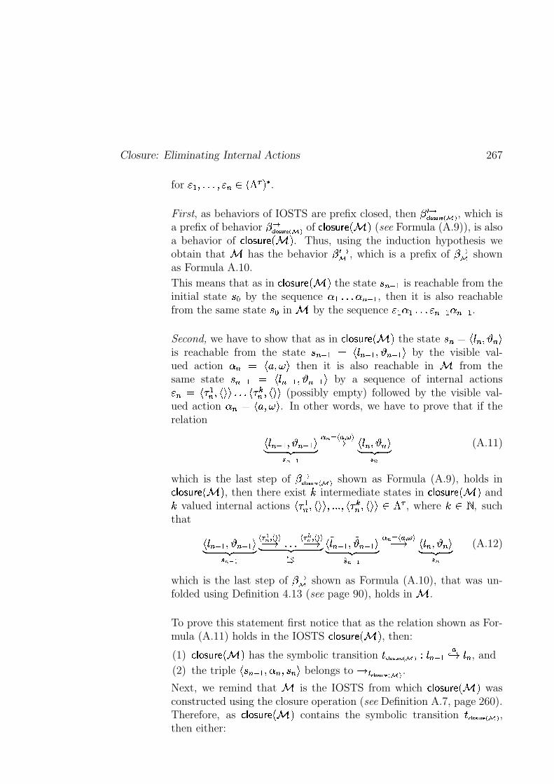
Closure: Eliminating Internal Actions 267
for �P�>���� � � � Q � )$U�� .
First, as behaviors of IOSTS are prefix closed, then� S ���� ����� 1� � , which is
a prefix of behavior� ���� ���0� 1� � of V�W ILK>XPY�Z[Q 9 U (see Formula (A.9)), is also
a behavior of V�W ILK�XPY�Z[Q 9 U . Thus, using the induction hypothesis weobtain that 9 has the behavior
� S � , which is a prefix of� � shown
as Formula A.10.
This means that as in V�W ILK�XPY�Z Q 9 U the state � �$ �� is reachable from theinitial state � B by the sequence �G� � � �� �� , then it is also reachablefrom the same state � B in 9 by the sequence �[� �T� �� � �$ �� � �$ �� .
Second, we have to show that as in V�W ILK�XPY�Z[Q 9 U the state � � � : ��� � � �PFis reachable from the state � �$ �� � : ���$ ��>� � �� ��%F by the visible val-ued action � � � : ] ���&F then it is also reachable in 9 from thesame state � �� �� � : ���� ��>� � �$ ��%F by a sequence of internal actions� � � : # �� � : F�F � : # �� � : F�F (possibly empty) followed by the visible val-ued action � � � : ] ���&F . In other words, we have to prove that if therelation
: ���$ ��>� � �� ��%F) *,+ -� -&/ +
� - ? � l ��
� 1 : ��� � � �[F) *,+ -� -
(A.11)
which is the last step of� ��:� ���0� 1� � shown as Formula (A.9), holds inV�W ILK�XPY�Z[Q 9 U , then there exist � intermediate states in V�W ILK>XPY�Z[Q 9 U and
� valued internal actions : # �� � : F�F6�� �� : #��� � : F�F � � ) , where �(� � , suchthat
: ���� ��>� � �� ��EF) *,+ -� -!/0+
� ) +- ��� �� 1 �� ) �- ��� �� 1) *G+ -
� -�: ����� ��>� �� �� ��EF) *,+ -
�� -!/0+
� - ? � l ��
� 1 : ��� � � �LF) *G+ -� -
(A.12)
which is the last step of� � shown as Formula (A.10), that was un-
folded using Definition 4.13 (see page 90), holds in 9 .
To prove this statement first notice that as the relation shown as For-mula (A.11) holds in the IOSTS V$W ILK>XPY�ZPQ 9 U , then:
(1) V�W IJK�XPY�Z[Q 9 U has the symbolic transition 8G��� �0�0� 1� � ) ���� �� l0 1 ��� , and
(2) the triple : � �� ��>� � � � � �PF belongs to 1 � �:� ���0� 1� � .Next, we remind that 9 is the IOSTS from which V�W ILK>XPY�Z[Q 9 U wasconstructed using the closure operation (see Definition A.7, page 260).Therefore, as V�W ILK>XPY�Z[Q 9 U contains the symbolic transition 8 ��� �0�0� 1� � ,then either:
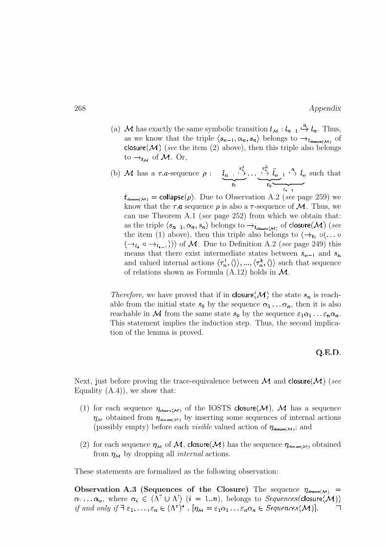
268 Appendix
(a) 9 has exactly the same symbolic transition 8 ) ���� �� l0 1 ��� . Thus,as we know that the triple : � �� ��>� � � � � �JF belongs to 1 � ��� ����� 1� � ofV�W ILK>XPY�Z[Q 9 U (see the item (2) above), then this triple also belongsto 1 � of 9 . Or,
(b) 9 has a #`a] -sequence ( ) ���� �� ) +-0 1) *G+ -� +�� ) *,+ -� �
) �-0 1) *G+ -� � � +
����$ �� l0 1 ��� such that
8,��� ����� 1� � � V I WaW � H K Z[Q ( U . Due to Observation A.2 (see page 259) weknow that the #`a] sequence ( is also a # -sequence of 9 . Thus, wecan use Theorem A.1 (see page 252) from which we obtain that:as the triple : � �$ ��>� � �`� � �LF belongs to 1 � ��� ���0� 1� � of V$W ILK>XPY�Z[Q 9 U (seethe item (1) above), then this triple also belongs to Q 1 � + � Q �� �Q 1 � � � 1 � ��� + U%U U of 9 . Due to Definition A.2 (see page 249) thismeans that there exist intermediate states between � �� �� and � �and valued internal actions : # �� � : F�F6�� �� : # �� � : F�F such that sequenceof relations shown as Formula (A.12) holds in 9 .
Therefore, we have proved that if in V$W ILK>XPY�ZPQ 9 U the state � � is reach-able from the initial state � B by the sequence �G� � � � , then it is alsoreachable in 9 from the same state � B by the sequence �[���G� �� � � � � .This statement implies the induction step. Thus, the second implica-tion of the lemma is proved.
" $# $%(
Next, just before proving the trace-equivalence between 9 and V�W IJK�XPY�Z[Q 9 U (seeEquality (A.4)), we show that:
(1) for each sequence � ��� ���0� 1� � of the IOSTS V$W ILK>XPY�ZPQ 9 U , 9 has a sequence� obtained from �>�:� ���0� 1� � by inserting some sequences of internal actions(possibly empty) before each visible valued action of �E��� ����� 1� � ; and
(2) for each sequence � of 9 , V�W IJK�XPY�Z[Q 9 U has the sequence � ��� ���0� 1� � obtainedfrom � by dropping all internal actions.
These statements are formalized as the following observation:
Observation A.3 (Sequences of the Closure) The sequence �E��� ����� 1� � ��T� �� � � , where � �h� Q � �������aU ( � � �J a� ), belongs to �����! ��!"$#��&% Q V�W ILK>XPY�Z[Q 9 U%Uif and only if f �[�>���� � � � Q � )$U��� j � � �[���G� �� �$� � � � �����! ��!"$#��&% Q 9 U n� *
Closure: Eliminating Internal Actions 269
This observation follows directly from the definition of a sequence (see page 90)and Lemma A.1 (see page 264).
Finally, we formally state and prove the theorem about the trace-equivalencebetween an IOSTS 9 and the IOSTS V�W ILK>XPY�Z[Q 9 U obtained from 9 by theclosure operation.
Theorem A.3 (Traces of the Closure) The result of the closure operation(see Definition A.7, page 260) applied to an IOSTS 9 without syntactic livelockshas the same set of traces as 9 , i.e.
[ ' � #��&% Q V�W ILK>XPY�Z[Q 9 U%U � [ ' � #��&% Q 9 U*
Proof
( 7 ) First, we show that each trace of V$W ILK>XPY�Z[Q 9 U is also a trace of 9 .
Consider an arbitrary trace � � � � �� � � belonging to[ ' � #��&% Q V�W ILK�XPY�Z[Q 9 U%U .
As the IOSTS V$W ILK>XPY�Z[Q 9 U does not have any internal action (seeDefinition A.7, page 260), then the set of traces of V$W ILK>XPY�ZPQ 9 U isequal to its set of sequences (see Definition 4.12, page 90) i.e.[ ' � #��&% Q V�W ILK>XPY�Z[Q 9 U%U � �����! ��!"$#��&% Q V�W IJK�XPY�Z[Q 9 U U . Thus, the trace � be-longs to �����! ��!"$#��&% Q V$W ILK>XPY�ZPQ 9 U U . Next, due to the first implication (
)
of Observation A.3 (see page 268) we obtain that there exist the sequence� � �[���G� �� �$� � � of 9 for some �[�>���� � � � Q � )�U�� , where � ) is the al-phabet of internal actions of 9 . Then, from the definitions of sequencesand traces (see pages 90 and 90 respectively), we know that if we drop allinternal action from the sequence � � �[� �G� �� � � � � of 9 , then we obtainthe trace �G� �� � � of 9 . Therefore, � � [ ' � #��&% Q 9 U .
(�
) Second, we prove that each trace of 9 is also a trace of V$W ILK>XPY�Z[Q 9 U .Consider a trace � � �G� �� � � belonging to
[ ' � #��&% Q 9 U . Due to Defini-tions 4.12 and 4.14 (see pages 90 and 90), this trace � corresponds to somesequence � � �P� �G� � � � � � of 9 , where �$�k� Q � )�U�� ( � � ���^� ). Next, usingthe second implication ( � ) of Observation A.3 (see page 268) we get thatthere exist the sequence � S � �G� � � � of V�W ILK>XPY�Z[Q 9 U . Finally, as �G�>���� � �are visible valued actions, then the sequence � S , which is exactly the sameas � , is the trace of V�W IJK�XPY�Z[Q 9 U . Therefore �(� [ ' � #��&% Q V$W ILK>XPY�Z[Q 9 U%U .
" # $%i
270 Appendix
A.1.5 Traces and Accepting Traces of ���������� �����������������
In this section we consider two IOSTS ������#�� [ � and V$W ILK>XPY�ZPQ ������# � [ � U . Thefirst one is obtained by the product operation (see Definition 5.4, page 114) from aspecification ������# and a test purpose
[ � of ������# . The second one is obtained from������#!� [ � by the closure operation (see Definition A.7, page 260). The purposeof this section is to study the relationships between traces (see Definition 4.14,page 90) and accepting traces (see Definition 6.10, page 151) of ������#"� [ � andV$W ILK>XPY�Z[Q ������#�� [ � U .
Before going into details we make an observation about absence of syntacticlivelocks (defined in Section A.1.2, page 257) in ������##� [ � with alphabet ofactions ' � ' � �d' � �d' ) and set of locations � � �%$�& Q P �i�('*) . Formally:
Lemma A.2 Let ������# be a specification without any syntactic livelock, and[ �
be a test purpose of ������# . Then, the result of the product operation between������# and
[ � , i.e. ������#!� [ � , is free of syntactic livelocks. *
Proof The proof of the observation is done by contradiction. Assume thatthe synchronous product ������#�� [ � has a syntactic livelock (see Definition A.4,page 257), for instance:
( $�& Q P,+ '�) ) : � �$�& Q P ��� � '*) F ),+0 1 : � � $�& Q P ��� � '*) F � : � �$ ��$�& Q P ��� �$ ��'�) F ).-&/ +0 1 : � �$�& QCP �%� � '*) F (A.13)
where5 � � ���^� � � j #��k�i' ) � : � � $�& Q P ��� � '*) F �i�Tn .
Then, due to Definition 5.4 (see page 114), we know that the product ������#-�[ � is obtained from ������# and[ � by synchronization on all their actions, which
are the same as the actions of ������#.� [ � . Thus, as ������#.� [ � has the sequence ofsymbolic transitions ( $�& Q P/+ '*) shown as Formula (A.13), then ������# and
[ � havethe following sequences of symbolic transitions:
( $�& Q P ) � �$�& Q P ) +0 1 � � $�& QCP ��%� �$ ��$�& QCP ).-!/ +0 1 � �$�& Q P (A.14)
( '*) ) � � '*) ),+0 1 � � '*) �� � �$ ��'*) ).-&/ +0 1 � � '�)Now, from Formula (A.14) we see that ������# contains a syntactic livelock (see Def-inition A.4, page 257). This contradicts with the hypothesis made in Section 6.1(see page 137), which says that ������# does not contain syntactic livelocks. " # $%i
Then, using Lemma A.2 and Theorem A.3 (see page 269) we obtain that theclosure operation preserves the set of traces of ������#!� [ � , i.e.
[ ' � #��&% Q V�W ILK>XPY�Z[Q ������#�� [ � U%U � [ ' � #��&% Q ������#�� [ � U (A.15)
Closure: Eliminating Internal Actions 271
Finally, we show equality between sets of accepting traces of V�W ILK�XPY�Z[Q ������#!� [ � Uand ������#�� [ � .
Theorem A.4 (Accepting Traces of V�W ILK>XPY�Z[Q ������# � [ � U ) The result of theclosure operation (see Definition A.7, page 260) applied to a synchronous product������#�� [ � (where ������# does not contain any syntactic livelock) has the same setof accepting traces as ������#!� [ � , i.e.
� [ ' � #��&% Q V�W ILK�XPY�Z[Q ������#!� [ � U%U � � [ ' � #��&% Q ������#�� [ � U*
Proof
( 7 ) First, we show that each accepting trace of V�W ILK>XPY�Z[Q ������# � [ � U is also anaccepting trace of ������#!� [ � .
Consider an arbitrary accepting trace � � � � �� � � belongingto
� [ ' � #��&% Q V$W ILK>XPY�ZPQ ������# � [ � U U and leading to an accepting state��� P P Q &�� � :�: �E� � #�#�����5EF6� � F , where : �E� � #�#�����5EF � � �� � ���� � $�& Q P,+ '*) � and� ���� Q�� � � � ����� � $�& Q P,+ '*) � ��� � � � ���� � $�& Q P + '�) � U .
Due to Definition A.7 (see page 260), the IOSTS V�W IJK�XPY�Z[Q ������#"� [ � U doesnot have any internal actions. Thus, the given accepting trace � is also asequence (see Definition 4.12, page 90) of V�W ILK�XPY�Z[Q ������# � [ ��U leading to thesame accepting state ��� PCP Q &�� .Next, due to Lemma A.2 (see page 270) about the absence of syntacticlivelocks in ������#"� [ � , we can use Observation A.3 (see page 268). Fromthe first implication (
) of this observation we obtain that there exist the
sequence � � �[� �T� �� � � � � of ������#�� [ � for some �P�>����6� � � � Q � ) $�& Q P,+ '*) U�� ,where � ) $�& Q P + '*) is the alphabet of internal actions of ������# � [ � . Moreover,notice that the first implication of the Observation A.3 (see page 268) followsfrom the second implication ( � ) of Lemma A.1 (see page 264). If we makeattention to the proof of the latter implication (see page 266), we obtainthat the accepting state ��� PCP Q &�� is reachable in ������# � [ � by � .
Then, from the definitions of sequences, traces and accepting traces (seepages 90, 90 and 151 respectively), we know that if we drop all internalaction from the sequence � � �[� �G� � � � � � of ������# � [ � , then we obtain theaccepting trace � � � � � of ������# � [ � . Therefore, � � � [ ' � #��&% Q ������# � [ ��U .
(�
) Second, we prove that each accepting trace of ������# � [ � is also an acceptingtrace of V$W ILK>XPY�Z[Q ������#�� [ � U .
272 Appendix
Consider an accepting trace � � � � �� � � belonging to� [ ' � #��&% Q ������# � [ � U ,
and leading to some accepting state ��� P P Q &�� .First, we make an observation which says that ������# � [ � can move(� )from a non-accepting location to an accepting location only by taking asymbolic transition labeled with an input/output action, i.e. formally:5 :�: � $�& Q P ��� '*) F���] ���G� � ��� � : �4S $�& Q P ���4S '*) F�F � D $�& Q P,+ '�)�kj Q � '*) �� �4S '�) � �4S '*) �� #�#�����5�U � Q ] � ' � $�& QCP/+ '*) � '��$�& Q P,+ '*) URn , where � '*) ���4S '�) are locations of[ � and � $�& Q P ���4S $�& Q P are locations of ������# . This observation follows from thehypotheses (2) and (4) made on
[ � (see Definition 6.8, page 147), and theproduct construction between ������# and
[ � (see Definition 5.4, page 114).
Second, using Definitions 4.12 and 4.14 (see pages 90 and 90) we havethat there exists a sequence � � � � �T� �� � � � � � ��� � of ������# � [ � corre-sponding to the trace � and leading to the same accepting state ��� P P Q &�� .Here, �P�>���� � ��� � � Q � ) $�& Q P + '�) U�� . Next, due to definition of a sequence (seepage 90) we obtain that � corresponds to the following behavior
� �:
:�: � B $�& Q P ��� B '*) F6� � B F � + :�: �� B $�& Q P � �� B '*) F6� �� B F � +1 :�: � �$�& Q P ��� � '*) F6� � � F�� (A.16):�: �� �� ��$�& Q P � �� �� ��'*) F6� �� �$ �� F � -1 :�: � � $�& QCP �%� � '*) F6� � � F
� - � + :�: �� � $�& QCP � � #�#�����5 F6� �� � F) *,+ -����� ����
where for all � from � to � , : � � '*) ��� � $�& Q P F6� : �� � $�& QCP � �� � '*) FC� �%$�& Q P + '*) and� � � �� � ��� Q � $�& Q P,+ '*) � �-$�& Q P + '�) U .
Then, we show that the state :%: � � $�& QCP �%� � '*) F6� � � F of� �
(see Formula (A.16))is an accepting state of ������# � [ � , i.e. � � '*) � � #�#�����5 . This statementcan be proved by contradiction. First, we unfold the last step of
� �(see
Formula A.16) according to Definition 4.13 (see page 90) as follows:
:%: � � $�& Q P ��� � '*) F6� � � F� ) +- ��� �� 1 �
� ) �- ��� �� 1) *G+ -� - � +�
:%: �� � $�& Q P � � #�#�����5EF6� �� � F) *G+ -����� ����
Then, we assume that :�: � � $�& Q P ��� � '�) F6� � � F is an non-accepting state of ������#��[ � , i.e. � � '*) �� � #�#�����5 . Next, using Observation (� ) the state reachable fromthe non-accepting state :�: � � $�& Q P ��� � '*) F6� � � F by # �� (i.e. the first internal actionof � ��� � ) is also non-accepting. Repeating this argument �?� � times (i.e.
for all remaining internal actions of �$��� � ) we obtain that the state ��� P P Q &�� isnon-accepting. This contradicts with the fact that � corresponding to
� �is an accepting sequence of ������# � [ � . Therefore, :�: � � $�& Q P ��� � '*) F6� � � F is theaccepting state, where � � '*) � � #�#�����5 .
Closure: Eliminating Internal Actions 273
Next, consider the sequence � S � �P� �T� � � � � � of ������# � [ � obtainedfrom the sequence � by eliminating its last sequence of internal actions,i.e. � ��� � . From above we know that � S leads to the accepting state� S � P P Q &�� � :�: � � $�& QCP ��� � '*)) *,+ -� P P Q &��
F6� � � F .
Then, as we know that ������# � [ � does not have any syntactic livelocks(see Lemma A.2), and � Sk� �����! ��!"$#��&% Q ������# � [ � U , we can use the secondimplication ( � ) of Observation A.3 (see page 268). From this implicationwe obtain that there exists the sequence � S S � �T� �� � � of V�W ILK>XPY�Z[Q ������# �[ � U . Moreover, notice that the second implication of the Observation A.3(see page 268) follows from the first implication (
) of Lemma A.1 (see
page 264). If we make attention to the proof of the latter implication (seepage 264), then we obtain that the accepting state � S � P P Q &�� is reachable inV�W ILK�XPY�Z[Q ������#!� [ � U by � S S .Finally, (1) as �G�>����6� � � are visible valued actions, then the sequence
� S S , which is exactly the same as � , is a trace of V�W ILK>XPY�Z[Q ������# � [ � U ,and (2) as � S S leads to the accepting state � S � P P Q &�� , then the trace � ofV�W ILK�XPY�Z[Q ������# � [ ��U is an accepting trace (see Definition 6.10, page 151),i.e. � � � [ ' � #��&% Q V$W ILK>XPY�ZPQ ������#!� [ ��U U .
" # $%i
274 Appendix
A.2 Determinization
This section is devoted to the determinization of an IOSTS V�W ILK�XPY�Z[Q ��� U ob-tained from the previous step of our test generation algorithm (see Section A.1,page 246). This IOSTS may be non-deterministic due to several cause, for in-stance, we have considered a sub specification of the initially deterministic spec-ification, or a specification obtained from the parallel composition of two deter-ministic systems executed in parallel where some communications are hidden. Itis important to emphasize that nondeterminism is prohibited in testing, as testverdicts should not depend on internal choices of the tester. That is why thisstep of the test generation method is reserved for elimination of the nondetermin-ism from the IOSTS V�W ILK>XPY�Z[Q ����U . This means building another IOSTS, denoted
� Z�M�Q V�W ILK�XPY�Z[Q ��� U U , which has the same traces as V$W ILK>XPY�Z[Q ��� U , and therefore thesame traces as the product ��� � ������# � [ � (see Theorem A.3, page A.3), butwithout non-deterministic choices. Notice that elimination of nondeterminismfrom symbolic input/output transition systems is a difficult problem in general.In this section we propose a procedure that treats some typical situations ofnondeterminism like one presented in Figures A.4(a) and A.7(a) (see pages 276and 288).
Plan of the Section. The section is separated into three parts.For the first two parts we consider an IOSTS 9 without internal actions
which has � 1 3 symbolic transitions 8@������6�%8 � outgoing from the same location� , labeled with the same action ] and guarded with Boolean expressions that arenot mutually exclusive. This means that 9 has a non-deterministic choice inthe location � .
In the first part of this section, we study the particular case of IOSTS witha sole non-deterministic choice, such that the symbolic transitions 8��@����6�%8 � in-volved into the non-deterministic choice of 9 have the same set of assignments.In order to solve non-determinism in 9 , we introduce the operation of localdeterminization, which syntactically transforms the non-deterministic IOSTS 9into a deterministic one leaving the trace semantics of 9 unchanged.
In the second part of the section, we generalize the particular case mentionedabove, i.e. we consider the situation, where the symbolic transitions 8�������%8 �involved into the non-deterministic choice of 9 have different sets of assignments.In this section we first show that the general case of local determinization ofIOSTS can be reduced to the particular one, and then we propose an algorithmwhich (1) syntactically solves the local non-determinism in 9 and (2) preservesthe semantics of 9 .
In the third part, we propose a procedure that transforms general non-deterministic IOSTS 9 without internal action into a deterministic one
� Z�M�Q 9 U
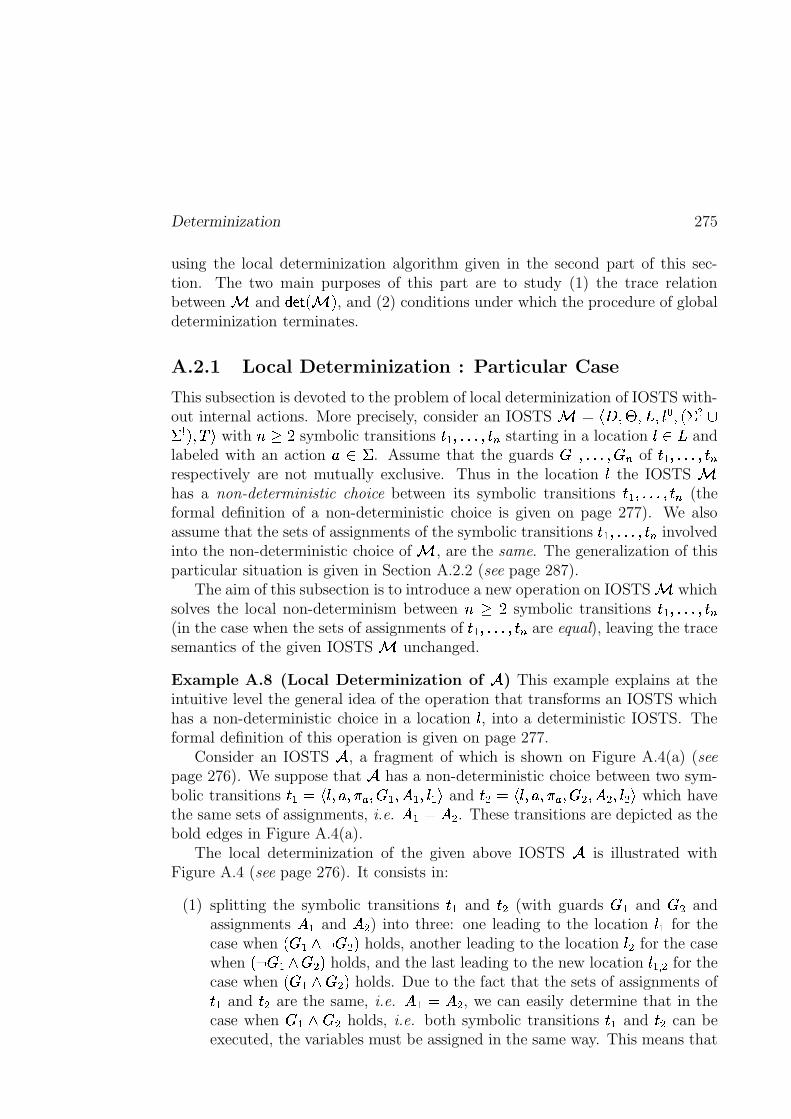
Determinization 275
using the local determinization algorithm given in the second part of this sec-tion. The two main purposes of this part are to study (1) the trace relationbetween 9 and
� Z�M6Q 9 U , and (2) conditions under which the procedure of globaldeterminization terminates.
A.2.1 Local Determinization : Particular Case
This subsection is devoted to the problem of local determinization of IOSTS with-out internal actions. More precisely, consider an IOSTS 9 � :R< �>= �@� ��� B � Q ' � �'�� U@� DAF with � 1 3 symbolic transitions 8@�@����6�%8 � starting in a location �k�(� andlabeled with an action ]�� ' . Assume that the guards
� ������ � � of 8�������6�%8 �respectively are not mutually exclusive. Thus in the location � the IOSTS 9has a non-deterministic choice between its symbolic transitions 8��>���� 8 � (theformal definition of a non-deterministic choice is given on page 277). We alsoassume that the sets of assignments of the symbolic transitions 8>������%8 � involvedinto the non-deterministic choice of 9 , are the same. The generalization of thisparticular situation is given in Section A.2.2 (see page 287).
The aim of this subsection is to introduce a new operation on IOSTS 9 whichsolves the local non-determinism between �81 3 symbolic transitions 8>������6�%8 �(in the case when the sets of assignments of 8>������6�%8 � are equal), leaving the tracesemantics of the given IOSTS 9 unchanged.
Example A.8 (Local Determinization of + ) This example explains at theintuitive level the general idea of the operation that transforms an IOSTS whichhas a non-deterministic choice in a location � , into a deterministic IOSTS. Theformal definition of this operation is given on page 277.
Consider an IOSTS + , a fragment of which is shown on Figure A.4(a) (seepage 276). We suppose that + has a non-deterministic choice between two sym-bolic transitions 8@� �;: �_��] ��� l �
� ����� �>���/� F and 8_� � : �_��] ��� l �� ����� �������>F which have
the same sets of assignments, i.e. �C� � ��� . These transitions are depicted as thebold edges in Figure A.4(a).
The local determinization of the given above IOSTS + is illustrated withFigure A.4 (see page 276). It consists in:
(1) splitting the symbolic transitions 8@� and 8E� (with guards� � and
� � andassignments � � and ��� ) into three: one leading to the location �R� for thecase when Q � � ��� � �U holds, another leading to the location �-� for the casewhen Q
�� � � � �6U holds, and the last leading to the new location �R� � for the
case when Q � � � � �6U holds. Due to the fact that the sets of assignments of8�� and 8_� are the same, i.e. �C� � � � , we can easily determine that in thecase when
� � � � � holds, i.e. both symbolic transitions 8>� and 8_� can beexecuted, the variables must be assigned in the same way. This means that
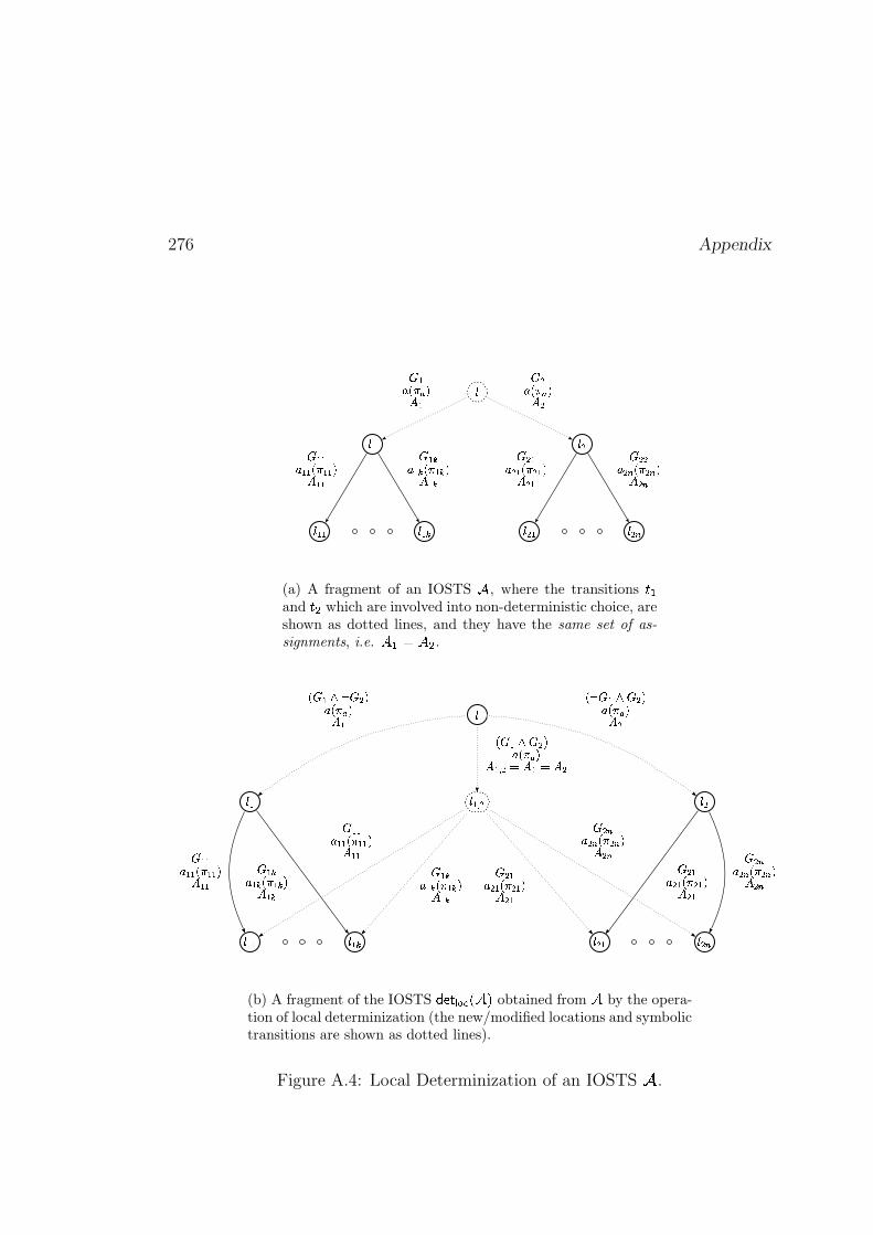
276 Appendix
�
��� ���
� ��� � ��� � ��� � �
��� ��������� ���� ��������� �
� ��� ��� ��� ��� �� ���� ��� ��� ��� ��� �� ���
� ��� ��� ��� ��� �� ���� ��� � ��� � �� ��
(a) A fragment of an IOSTS � , where the transitions ���and ��� which are involved into non-deterministic choice, areshown as dotted lines, and they have the same set of as-
signments, i.e. � �"!#�$� .
%
%�& %�'
%�&�& %�&�( %)'�& %�'*
%�&�+ '
,�- &/.10 - '�23 ,�4�5 26 &, 0 - &/. - '723 ,�485 26 '
,�- &9. - ':23 ,�4 5 26 &�+ '<; 6 &=; 6 '
- &�&3 &�& ,�4 &�& 26 &�&- &�(3 &�( ,�4 &�(>26 &�(
- '�&3 '�& ,�4 '�&?26 '�&
- '*3 '* ,�4 '*@26 '*- &�&3 &�& ,�4 &�&A26 &�& - &�(3 &�( ,�4 &�( 26 &�(- '�&3 '�& ,�4 '�& 26 '�&
- '*3 '* ,�4 '*@26 '*
(b) A fragment of the IOSTS B9CEDGF HGIKJ�LNM obtained from L by the opera-tion of local determinization (the new/modified locations and symbolictransitions are shown as dotted lines).
Figure A.4: Local Determinization of an IOSTS O .
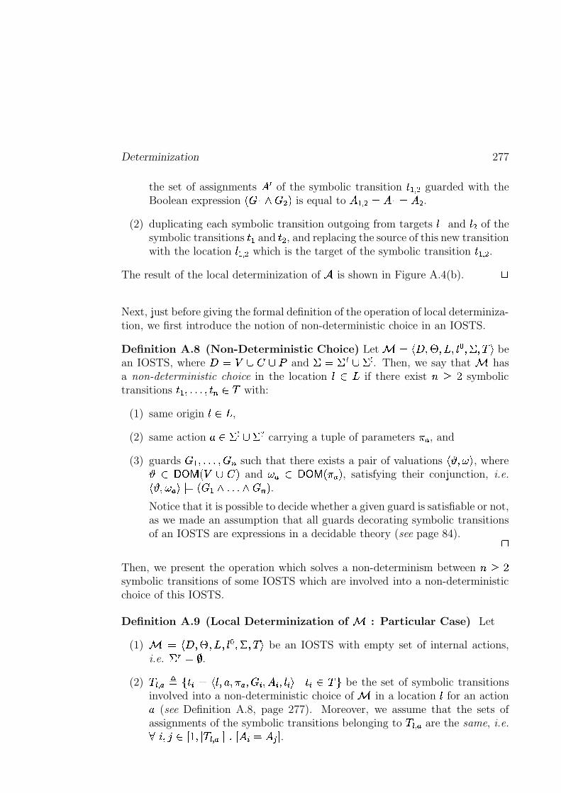
Determinization 277
the set of assignments ��� of the symbolic transition ����� � guarded with theBoolean expression ���� ����� is equal to ����� ������������� .
(2) duplicating each symbolic transition outgoing from targets ��� and ��� of thesymbolic transitions ��� and ��� , and replacing the source of this new transitionwith the location ����� � which is the target of the symbolic transition ����� � .
The result of the local determinization of � is shown in Figure A.4(b). �
Next, just before giving the formal definition of the operation of local determiniza-tion, we first introduce the notion of non-deterministic choice in an IOSTS.
Definition A.8 (Non-Deterministic Choice) Let �"!$#&%�'(%�)*%+��,-%�.�%0/21 bean IOSTS, where #3�54�687�6:9 and .;�5.*<=6>.@? . Then, we say that hasa non-deterministic choice in the location �BAC) if there exist DCEGF symbolictransitions �+�H%-I-I-IH%J��KLA&/ with:
(1) same origin �MA:) ,
(2) same action NOA8.�?P6&.�< carrying a tuple of parameters QSR , and
(3) guards ���%-I�I-I�%�TK such that there exists a pair of valuations !�UV%0WX1 , whereUYA[Z]\_^`$4"6a7(� and WVRbA[Z]\_^cdQeRP� , satisfying their conjunction, i.e.
!�UV%0WVRf1�g�5�(�h iI-I-I- jTKk� .Notice that it is possible to decide whether a given guard is satisfiable or not,as we made an assumption that all guards decorating symbolic transitionsof an IOSTS are expressions in a decidable theory (see page 84). �
Then, we present the operation which solves a non-determinism between DlE"Fsymbolic transitions of some IOSTS which are involved into a non-deterministicchoice of this IOSTS.
Definition A.9 (Local Determinization of : Particular Case) Let
(1) �m!$#:%�'n%�)2%J� , %�.�%0/M1 be an IOSTS with empty set of internal actions,i.e. .po��;q .
(2) /hrs� RLt[uf��v]�w!��x%+NS%JQeRy%�Tv$%+�@v�%+�zv�1(g{��v*Aa/�| be the set of symbolic transitionsinvolved into a non-deterministic choice of in a location � for an actionN (see Definition A.8, page 277). Moreover, we assume that the sets ofassignments of the symbolic transitions belonging to /�rs� R are the same, i.e.}�~ %��nA�����%�g /hrs� R{g ��I=� ��v����X��� .
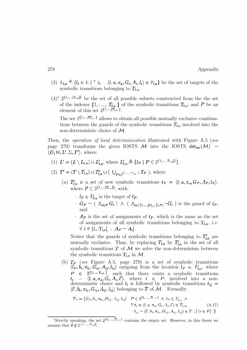
278 Appendix
(3) )�rs� R2t uP�zvVA�) g � ��vh�5!��x%+NS%JQeRy%�Tv�%+�@v�%+�zv 1 Aj/�rs� R | be the set of targets of thesymbolic transitions belonging to / rs� R .
(4)1 F�� ��������� ��� ��� �� � be the set of all possible subsets constructed from the the setof the indexes uk��%�I-I-IH%�g /hrs� R g | of the symbolic transitions /hrs� R ; and 9 be anelement of this set F � ��������� ��� ��� �� � .The set F�� ��������� ��� � �� � � allows to obtain all possible mutually exclusive combina-tions between the guards of the symbolic transitions / r � R involved into thenon-deterministic choice of .
Then, the operation of local determinization illustrated with Figure A.5 (seepage 279) transforms the given IOSTS into the IOSTS ������� ���- � �!$#&%�'(%�)M��%�.�%0/@�s1 , where:
(1) )�� �" )��*)�rs� RP��6j)M�r � R , where )M�r � R t uP��� g 95A8F�� ��������� ��� � �� � � | .(2) /�� �"�/��X/hrs� Rf�h6c/@�r � R 6 �� �! -�#"%$ � & & & ��' ( �� ' ) /!� � , where
(a) /��rs� R is a set of new symbolic transitions ���[� !��x%+NS%JQeR %�*� %+�+�=%+����1 ,where 95A8F � ��������� ��� ��� � � , with:
– ���>A8)M�r � R is the target of �,� ,
– -� � /. v0 � _v�� �. v0 21 � ��������� ��� � �� � �43%�65�7 Tv�� is the guard of �,� ,and
– �+� is the set of assignments of �,� , which is the same as the setof assignments of all symbolic transitions belonging to /�rs� R , i.e.}�~ A�����%�g /hrs� R g ��I � �+�&���@vz� .
Notice that the guards of symbolic transitions belonging to /��rs� R aremutually exclusive. Thus, by replacing / rs� R by /@�rs� R in the set of allsymbolic transitions / of we solve the non-determinism betweenthe symbolic transitions /hr � R in .
(b) /8� (see Figure A.5, page 279) is a set of symbolic transitions! ��� %�9�v�%0Q;:=<�%�_v � %+�@v �f%+�zv �H1 outgoing from the location �=� A )M�r � R , where
9 A F�� ��������� ��� � �� � � , such that there exists a symbolic transitions��v � !��x%+NS%JQeR %�Tv�%J��v�%J�d�s1 , where
~ A 9 , involved into a non-deterministic choice and �xv is followed by symbolic transitions ��v �j�! �d�z%�9�v�%JQ;:=<x%�Tv �f%+�@v � %J�zv �H1 belonging to / of . Formally:
>@?BA�CDFEG?IHKJ4LMHMNPOFQ#HSRTLVU�HSWXL�UYHKEZL�U\[T]_^a`cb�d%e4f�g�g�g f�h ikjml n�h oqprEG?s`ct6uv f w pxzy L@AaDGEMHS{�HMN w HSRTLSHSWXL|HSEFu�[!`}> v f w H (A.17)y L�UXAaDGEGuFHKJ#L|HMNPO0Q4HSRTLVUYHSWXL�U�HKEZL�U\[~`z>��������I`c^����0�
1Strictly speaking, the setb d%e%f�g�g�g f�h i jml n h o
contains the empty set. However, in this thesis weassume that �z�`}b d%e4f�g�g�g f�h ikjml n�h o .
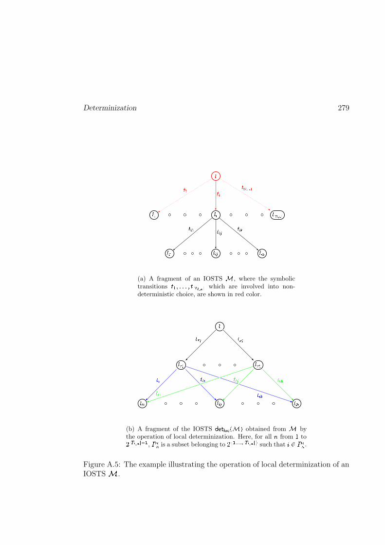
Determinization 279
�
��� � � ��� ��� � �
� �� �� � � � �
� � � ��� � �
��� � � � �
(a) A fragment of an IOSTS � , where the symbolictransitions ����������������� ����� ��� which are involved into non-deterministic choice, are shown in red color.
�
�! #"$ �! �"%
�&�' �& ( �& )
* "$ * "%
* &�' * & (* & )* &�'
* & ( * & )
(b) A fragment of the IOSTS +-,/.#0 1�243�576 obtained from 5 bythe operation of local determinization. Here, for all 8 from 9 to:<; =?>�@ AB; CED
, FHGI is a subset belonging to:KJ�D�LMMM L!; =?>�@ A?; N
such that OQPRFHGI .
Figure A.5: The example illustrating the operation of local determinization of anIOSTS S .
280 Appendix
�
Next, we illustrate the operation of local determinization defined above with aconcrete example.
Example A.9 Consider a coffee machine depicted as the IOSTS � in Fig-ure A.6(a) (see page 281). This coffee machine delivers either a coffee with milkor a coffee with sugar when the paid amount is strictly positive. Notice that inthe location ��������� (shown in red) the IOSTS � has a non-deterministic choicebetween two symbolic transitions (shown in red) labeled with the same outputaction ��� ��� . It is important to notice that these symbolic transitions have thesame set of assignments.
Then, in order to make � deterministic we first enumerate all symbolic tran-sitions outgoing from the location �*������� and labeled with the action Coffee,i.e. we obtain the set:
/������ �����������p� ui�+���5!������S%���� ���y%P!$1 % � ����!�" E$#% &(' )* $%�u,+ 9BN ~.-0/ �1+ 9BN ~.- | %324��!65879!;:=< 1H%
�x���5!������S%���� ���y%P!$1 % � ����!�"?>$#% &(' )*A@ %�u,+ 9BN ~.-0/ �1+ 9BN ~.- | %324��!658BDCFE���Gy1�|
This enumeration also gives the numbers to the targets of the symbolic transitionsbelonging to /H�����-�����I�J��� , i.e.
)�K�L�������I�J���]� uP� ���M24��!65879!;:=< %+�z���N2O��!658BDCFE���G |Next, we the compute the set of possible subsets from the set of indexes uk��%�F |used to enumerate the symbolic transitions involved into non-deterministic choiceof the IOSTS � :
F � ��� �#� � u{uk�y| %�uyFk| %�uk�y%�Fk|{|
Second, we modify the IOSTS � as follows:
(1) From the set of locations of � (see Figure A.6(a), page 281) we remove alllocations belonging to )P����� �����I�J��� and insert the following locations:
) � �K�L�������I�J��� � uP� ���M24��!65879!;:=< %+�z���N2O��!658BDCFE���Gk%+����� �X�"!�2O��!65879!;:=< %Q2O��!656BDCRE���G�1H|which is computed from the sets FP� ��� �#� and )����� ���S�I�J��� (see the item (1)of Definition A.9 on page 277 for the detailed explanation). After thisprocedure we obtain that �����\� ���-6�X� has the same set of locations as � exceptof the location �$��� �X�5!�2O��!65674!;:=< %Q2O��!656BDCRE���Gy1 (see the location shown in blueon Figure A.6(b), page 281).
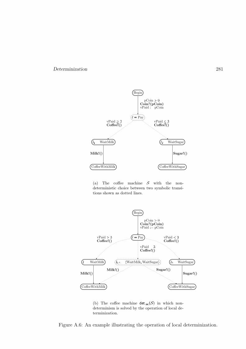
Determinization 281
���Pay
Begin
� � �WaitMilk
CoffeeWithMilk
� � � WaitSugar
CoffeeWithSugar
pCoin ���Coin?(pCoin)vPaid � � pCoin
vPaid ��Coffee!()
vPaid �Coffee!()
Milk!() Sugar!()
(a) The coffee machine � with the non-deterministic choice between two symbolic transi-tions shown as dotted lines.
� ' � �����WaitMilk � WaitSugar �
� �Pay
Begin
� '��WaitMilk
CoffeeWithMilk
� ���WaitSugar
CoffeeWithSugar
vPaid ���Coffee!()
vPaid ���Coffee!()
vPaid� �
Coffee!()
Milk!() Sugar!()
pCoin ���Coin?(pCoin)vPaid � � pCoin
Milk!() Sugar!()
(b) The coffee machine +K, . 0 1�2 3 � 6 in which non-determinism is solved by the operation of local de-terminization.
Figure A.6: An example illustrating the operation of local determinization.
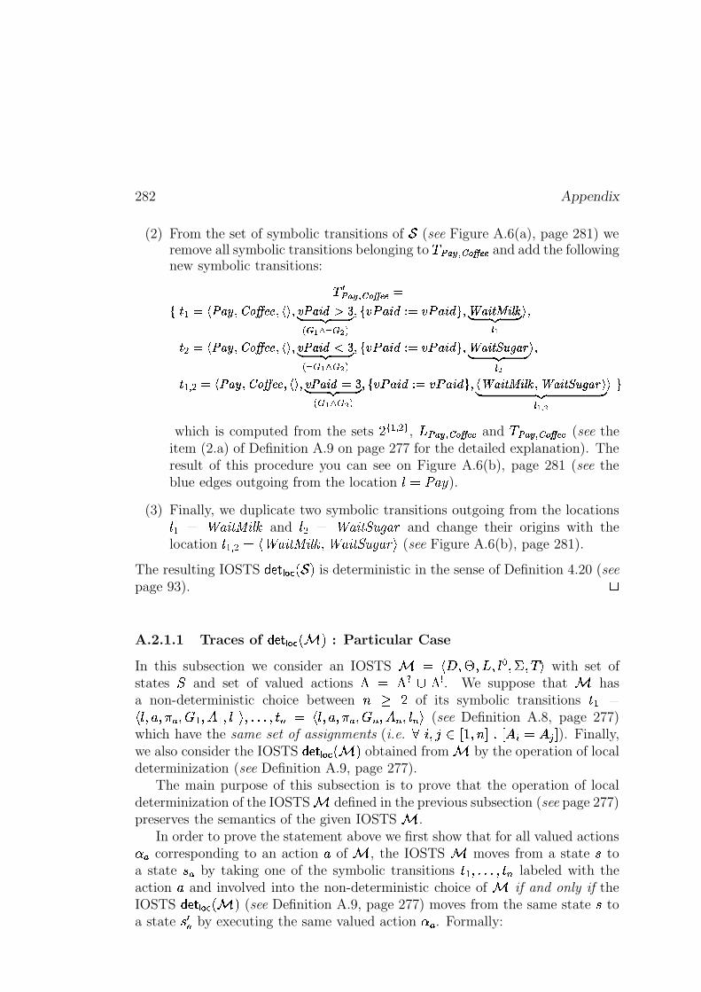
282 Appendix
(2) From the set of symbolic transitions of � (see Figure A.6(a), page 281) weremove all symbolic transitions belonging to / �K���������I�J��� and add the followingnew symbolic transitions:
� ��K���������I�J�������� � ����� ������������������������� !#"%$& '�( )1 * $+*�, *A@ 5� ��-�.0/�13254 � -�.6/�13287 �89: <;>=? A@CB& '�( )
r $���
� � ����� ������������������������� !#D%$& '�( )1 , * $+* *A@ 5� ��-�.0/�13254 � -�.6/�13287 �89: <;FE8G�H� I& '�( )
r @���
� ��� � ����� ����������������������J�� !K�L$& '�( )1 * $ * * @ 5� ��-�.0/�132K4 � -�.6/�13287 ���M9: <;>=? A@CBN�89: <;FE8G�H�MIO�& '�( )
r $ � @� 7
which is computed from the sets FP� ��� �#� , )�K�L�������I�J��� and /H����� �����I�J��� (see theitem (2.a) of Definition A.9 on page 277 for the detailed explanation). Theresult of this procedure you can see on Figure A.6(b), page 281 (see theblue edges outgoing from the location � � ����� ).
(3) Finally, we duplicate two symbolic transitions outgoing from the locations� � � 2O��!65879!;:=< and ���a� 2O��!656BDCRE���G and change their origins with thelocation �$��� �X�5!�2O��!65879!;:=< %Q2O��!656BDCRE���G�1 (see Figure A.6(b), page 281).
The resulting IOSTS �����\� �,��6�X� is deterministic in the sense of Definition 4.20 (seepage 93). �
A.2.1.1 Traces of ���Y��� ���- � : Particular Case
In this subsection we consider an IOSTS � !�#:%�'n%�)2%+� , %�.B%0/M1 with set ofstates P and set of valued actions Q � Q*<�6RQ@? . We suppose that hasa non-deterministic choice between D E F of its symbolic transitions �H� �!��x%+NS%JQeRy%�(��%+�_��%+���01H%-I-I-I %J��K�� ! ��%JN %0QeRy%+_K %+��K %+�zK�1 (see Definition A.8, page 277)which have the same set of assignments (i.e.
}�~ %��cA �s��%JD ��I � �2v � ����� ). Finally,we also consider the IOSTS ������� ���- � obtained from by the operation of localdeterminization (see Definition A.9, page 277).
The main purpose of this subsection is to prove that the operation of localdeterminization of the IOSTS defined in the previous subsection (see page 277)preserves the semantics of the given IOSTS .
In order to prove the statement above we first show that for all valued actionsS R corresponding to an action N of , the IOSTS moves from a state T toa state T�R by taking one of the symbolic transitions ����%-I-I-I %J��K labeled with theaction N and involved into the non-deterministic choice of if and only if theIOSTS �����,� ���- � (see Definition A.9, page 277) moves from the same state T toa state T��R by executing the same valued action S R . Formally:
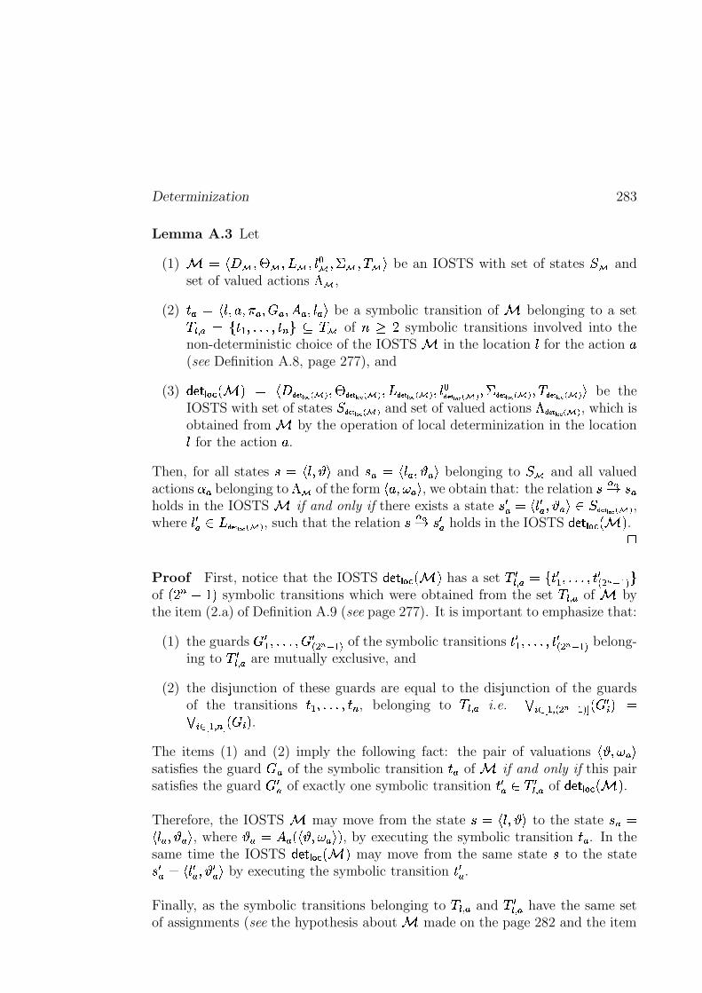
Determinization 283
Lemma A.3 Let
(1) �w!$#��c%�'��O%�)��O%+� ,� %�.��c%0/��L1 be an IOSTS with set of states P�� andset of valued actions Q�� ,
(2) ��R �G!��x%+NS%JQeR %�_Ry%+�@Ry%J�zRf1 be a symbolic transition of belonging to a set/hrs� R�� uf�+��%-I-I-I %J��Kk| � /�� of DCEGF symbolic transitions involved into thenon-deterministic choice of the IOSTS in the location � for the action N(see Definition A.8, page 277), and
(3) ������� ���- �;� !$#��� �� ���������$%�'���� �� ����������%�)���� �� ����������%+� ,��� �� ��������� %�.���� �� ���������$%0/���� � ��� �����z1 be theIOSTS with set of states P���� � ��� ����� and set of valued actions Q���� � ��� ����� , which isobtained from by the operation of local determinization in the location� for the action N .
Then, for all states T � !��x%+U�1 and T-RL� !��zR %+USRf1 belonging to P�� and all valuedactions S R belonging to Q�� of the form !�NS%0WVR-1 , we obtain that: the relation T�! " T�Rholds in the IOSTS if and only if there exists a state Tf�R �5!�� �R %+USRf1*A P���� �� ��������� ,where � �R A:)���� �� ��� ����� , such that the relation T! " T��R holds in the IOSTS ���Y�\� ����d � .
�
Proof First, notice that the IOSTS ������� ���- � has a set / �rs� R �5uf� � � %-I-I-I %J� � 1��$#&%e�K5 |of $F K(' �P� symbolic transitions which were obtained from the set / rs� R of bythe item (2.a) of Definition A.9 (see page 277). It is important to emphasize that:
(1) the guards � � %-I-I-I %� � 1��$#)%e�K5 of the symbolic transitions � � � %�I-I-IH%J� � 1��$#*%e�K5 belong-ing to / �rs� R are mutually exclusive, and
(2) the disjunction of these guards are equal to the disjunction of the guardsof the transitions ����%-I-I�I�%J��K , belonging to /hr � R i.e. + v0 -, ����1 �$#*%e�K5�. �T�v �Y�+ v0 -, ��� K/. _v � .
The items (1) and (2) imply the following fact: the pair of valuations !�UV%0WMR�1satisfies the guard _R of the symbolic transition �xR of if and only if this pairsatisfies the guard ��R of exactly one symbolic transition �x�R A&/@�rs� R of ���Y�\� �,�-d � .
Therefore, the IOSTS may move from the state T�� !��x%+U�1 to the state TPR �!��zRy%+U R-1 , where USR�� �@R 0!�UV%0WVRf1�� , by executing the symbolic transition ��R . In thesame time the IOSTS ���Y�\� �,�� � may move from the same state T to the stateT-�R � !�� �R %+US�R 1 by executing the symbolic transition ���R .
Finally, as the symbolic transitions belonging to / r � R and /@�r � R have the same setof assignments (see the hypothesis about made on the page 282 and the item
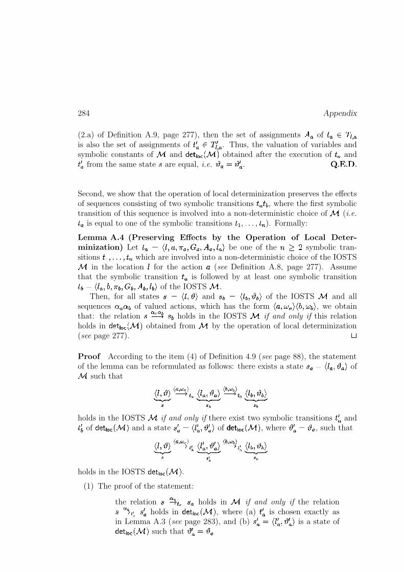
284 Appendix
(2.a) of Definition A.9, page 277), then the set of assignments �2R of ��R>A�/�r � Ris also the set of assignments of ���R A /@�r � R . Thus, the valuation of variables andsymbolic constants of and �����\� ����d � obtained after the execution of �xR and� �R from the same state T are equal, i.e. U R���U �R . �`I�� I���I
Second, we show that the operation of local determinization preserves the effectsof sequences consisting of two symbolic transitions �0R��#: , where the first symbolictransition of this sequence is involved into a non-deterministic choice of (i.e.
��R is equal to one of the symbolic transitions ���H%-I�I-I�%J��K ). Formally:
Lemma A.4 (Preserving Effects by the Operation of Local Deter-minization) Let ��R8� !��x%+NS%JQeRy%�TR %+��Ry%+�zR�1 be one of the D"E3F symbolic tran-sitions �+��%-I-I-I %J��K which are involved into a non-deterministic choice of the IOSTS in the location � for the action N (see Definition A.8, page 277). Assumethat the symbolic transition �xR is followed by at least one symbolic transition�#:M�"!��zRy%�9P%JQ;:+%+*:+%J�+:+%+�0:x1 of the IOSTS .
Then, for all states T�� !��x%+U�1 and T :�� !���:J%+UI:�1 of the IOSTS and allsequences S R S : of valued actions, which has the form ! N %�W R�1-!S9P%0WX:x1 , we obtainthat: the relation T ! !��' " T : holds in the IOSTS if and only if this relationholds in ������� ����d � obtained from by the operation of local determinization(see page 277). �
Proof According to the item (4) of Definition 4.9 (see page 88), the statementof the lemma can be reformulated as follows: there exists a state TPR��"!��zR %+USRf1 of such that
!��x%+U�1% &�' )�� R�� � ' "�� !��zRy%+USR�1% &(' )�
� :$� � � ' " �� ! ��:+%+U6:x1% &(' )� �
holds in the IOSTS if and only if there exist two symbolic transitions �0�R and��� : of �����,� ���- � and a state T-�R �"!�� �R %+US�R 1 of ������� ���- � , where U �R ��U R , such that
!��x%+U�1% &�' )�� R�� � ' "���� !�� �R %+U �R 1% &(' )� �
� :$� � � ' " � �� ! ��:+%+U6:x1% &(' )� �
holds in the IOSTS �����,� �,�- � .(1) The proof of the statement:
the relation T ! "�� T�R holds in if and only if the relationT ! "�� � T��R holds in ���Y�,� �,�- � , where (a) ���R is chosen exactly asin Lemma A.3 (see page 283), and (b) Tf�R � !�� �R %+US�R 1 is a state of���Y�,� ���- � such that US�R ��USR
Determinization 285
is similar to the proof of Lemma A.3 (see page 283).
(2) Next, we know that the symbolic transition ��R involved into the non-deterministic choice of is followed by the symbolic transition �\: . Then,due to the item (2.b) of Definition A.9 (see page 277) the symbolic transi-tion �x�R of ������� ����d � is also followed by the symbolic transition ��� : which wasobtained from �,: by replacing its source ��R with the target of �x�R , i.e. by � �R .This means that �x�R is equal to !��d�R %\9 %0Q;:+%�-:+%+�+:J%+��:x1 .Thus, the pair of valuations !�U R�%0WX:x1 satisfies the guard *: of the symbolictransition �#: of the IOSTS if and only if the pair of valuations !�U �R %�W :�1 ,where US�R �CU R (see the item (1)), satisfies the guard of the symbolic tran-sition ��� : of the IOSTS �����,� �,�- � , which is exactly the same as the guard of�#: , i.e. *: .Finally, as �,: and �x� : have the same set of assignments �}: and the sametarget ��: , then both IOSTS and ���Y��� �,�fd � will be found in the samestate T : �w!���:J%+UI:�1 after the execution of the symbolic transitions ��: and � � :from the states T-R and T �R respectively.
The items (1) and (2) imply the statement formulated at the beginning of theproof. Therefore, the lemma is proved. �`I�� I �8I
Finally, we consider an IOSTS with a non-deterministic choice between D�E�Fsymbolic transitions which have the same set of assignments; and show that theoperation of local determinization presented on page 277 preserves the semanticsof . Formally:
Theorem A.5 (Traces of ���Y�\� �,�fd � : Particular Case) Let �!$#j%�'(%�)*%+� , %P�.�<f6�.@? ��%0/21 be an IOSTS with a non-deterministic choice (see Defini-tion A.8, page 277) between D>E�F symbolic transitions / r � R�� uf�+��%-I-I-I %J��K | whichhave a same set of assignments. Let also ������� �,�fd � be the IOSTS obtained from by the operation of the local determinization (see Definition A.9, page 277).Then, these IOSTS and ���Y��� ���- � have the same sets of traces, i.e.
� G�������� M���Y�,� ���- �0� � � G ������� � (A.18)
�
Proof At the beginning of the proof we formulate and show the following threestatements.
(1) For all sequences of valued actions �L� S � I-I�I S�� :� / T , �' " T � � T , ! $' "� � $ Ty� I-I-IJT � %e� !��' "� �
�T � (A.19)
where
286 Appendix
(a) T , is an initial state of , and T��H%-I-I�I %�T � are states of , and
(b) for all~
from � to � , ���v is a symbolic transition of which does not
belong to /hr � R ,is a behavior of the IOSTS if and only if Formula (A.20) is also abehavior of the IOSTS ���Y�\� �,�� � .
This statement follows directly from the fact that the operation of local de-terminization defined on page 277 does not modify the symbolic transitionsof that are not involved into a non-deterministic choice of .
(2) For every sequence of valued actions � � S R , where S R is a valued actioncorresponding to a symbolic transition ��R involved into the non-deterministic
choice of (i.e. �xR2Aj/hrs� R ), the IOSTS has the behavior:
� / T , ��' " T � %e� ! ' "�� T �
where T , is an initial state of , and T��H%�I-I-I�%JT � are states of , if and only
if the IOSTS ���Y�\� ����d � has the following behavior:
���� �� ��� ����� / T , ��' " T � %e� ! ' "���� T � �
where T-� � is a state of ���Y�\� ���� � which has the same valuation of variablesand symbolic constants as the state T � of .
The statement follows from the item (1) above and Lemma A.3 (seepage 283).
(3) For every sequence of valued actions � � S R S : � � � such that S R S : is a sequenceof two valued actions corresponding to a sequence of consecutive symbolictransitions ��R �#: , where �xR is involved into the non-deterministic choice of (i.e. ��R_A&/�rs� R ),
� / T , ��' " T�v ! !��' " T�v�� � �
� �' " T � (A.20)
where T-, is an initial state of , and T���%�I-I-I�%JT � are states of , is abehavior of the IOSTS if and only if Formula (A.20) is the behavior ofthe IOSTS �����,� �,�- � .
This statement follows from the item (1) above and Lemma A.4 (seepage 284).
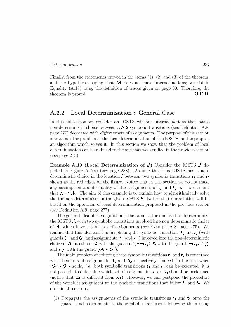
Determinization 287
Finally, from the statements proved in the items (1), (2) and (3) of the theorem,and the hypothesis saying that does not have internal actions; we obtainEquality (A.18) using the definition of traces given on page 90. Therefore, thetheorem is proved. �`I�� I��8I
A.2.2 Local Determinization : General Case
In this subsection we consider an IOSTS without internal actions that has anon-deterministic choice between D�E�F symbolic transitions (see Definition A.8,page 277) decorated with different sets of assignments. The purpose of this sectionis to attack the problem of the local determinization of this IOSTS, and to proposean algorithm which solves it. In this section we show that the problem of localdeterminization can be reduced to the one that was studied in the previous section(see page 275).
Example A.10 (Local Determinization of � ) Consider the IOSTS � de-picted in Figure A.7(a) (see page 288). Assume that this IOSTS has a non-deterministic choice in the location � between two symbolic transitions �H� and ���shown as the red edges on the figure. Notice that in this section we do not makeany assumption about equality of the assignments of ��� and ��� , i.e. we assumethat ���������� . The aim of this example is to explain how to algorithmically solvethe the non-determinism in the given IOSTS � . Notice that our solution will bebased on the operation of local determinization proposed in the previous section(see Definition A.9, page 277).
The general idea of the algorithm is the same as the one used to deteterminizethe IOSTS � with two symbolic transitions involved into non-deterministic choiceof � , which have a same set of assignments (see Example A.8, page 275). Weremind that this idea consists in splitting the symbolic transitions ��� and �x� (withguards �� and �� and assignments ��� and ��� ) involved into the non-deterministicchoice of � into three: � � � with the guard ���� 7 ���� , � � � with the guard 7 ��- ���� ,and �+��� � with the guard ��h j��H� .
The main problem of splitting these symbolic transitions ��� and �x� is concernedwith their sets of assignments �B� and ��� respectively. Indeed, in the case when�(� >_��� holds, i.e. both symbolic transitions ��� and ��� can be executed, it isnot possible to determine which set of assignments � � or ��� should be performed(notice that ��� is different from ��� ). However, we can postpone the procedureof the variables assignment to the symbolic transitions that follow �H� and �x� . Wedo it in three steps:
(1) Propagate the assignments of the symbolic transitions �H� and �x� onto theguards and assignments of the symbolic transitions following them using
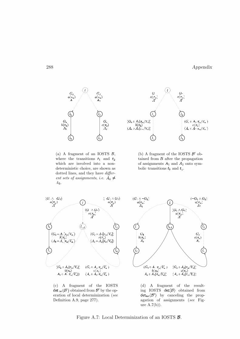
288 Appendix
�
��� ���
��� ���
� ����� ��� �������� ��� �
���� �� � ����������� � ����
(a) A fragment of an IOSTS � ,where the transitions ��� and �! which are involved into a non-deterministic choice, are shown asdotted lines, and they have differ-
ent sets of assignments, i.e. " �$#%" .
&
&�' &�(
&�) &�*
+ ',.-�/�0�12�3+ (,.-�/ 0 12 3
- +�465 2 '87 / 0�9;:<0!= 1> -�/ 4 1- 2 465 2 '?7 / 0�9;:@0!= 1- +�AB5 2 (�7 / 0�9;:@0!= 1C�-�/ A 1- 2 AB5 2 (�7 / 0�9;:<0!= 1
(b) A fragment of the IOSTS DFE ob-tained from D after the propagationof assignments GIH and GKJ onto sym-bolic transitions L?M and L8N .
O
O�P O�Q
O�R O�S
O�PUT Q
V�W P6XIY W Q8Z[ V�\�] Z^`_V Y W PBX W Q8Z[ V�\�] Z^`_VaW PbX W Q8Z[ V�\ ] Z^`_
VaW�c6d ^ P?e \�]�f;g@]!h Zi V�\jc Z^ c6d ^ P?e \�]�f;g@]!h ZV�W�k6d ^ Q�e \�]�f;g@]!h Zl V�\�k ZV ^ kBd ^ Q�e \�]�f;g<]mh Z
V�W�c6d ^ P8e \j]�f;g<]!h Zi V�\jc ZV ^ c6d ^ P?e \�]�f;g@]!h ZV�W�kBd ^ Q�e \�]�f;g@]!h Zl V�\�k ZV ^ kBd ^ Q�e \�]�f;g@]mh Z
(c) A fragment of the IOSTSn6oqp�r s�t@uwvFx�yobtained from
vFxby the op-
eration of local determinization (seeDefinition A.9, page 277).
O
O�P O�Q
O�R O S
O�PUT Q
V�W PBXzY W Q8Z[ V�\�] Z^ PV Y W PBX W Q!Z[ V�\�] Z^ Q
W�ci V�\jc Z^ cW�kl V�\�k Z^ k
V�W P6X W Q8Z[ V�\�] Z^�_
V�W�c�d ^ P?e \�]�f;g@]mh Zi V�\jc Z^ c�d ^ P?e \�]�f;g@]mh ZV�W�k6d ^ Q�e \j]?f;g@]mh Zl V�\�k ZV ^ kBd ^ Q;e \�]�f;g@]mh Z
(d) A fragment of the result-ing IOSTS
nBo;p{u|v}yobtained fromnBo;p?r s�t@uwvFx~y
by canceling the prop-agation of assignments (see Fig-ure A.7(b)).
Figure A.7: Local Determinization of an IOSTS � .
Determinization 289
the operation of assignments propagation (see page 291). After this proce-dure, we obtain an IOSTS ��� (see Figure A.7(b), page 288) in which thesymbolic transitions corresponding to ��� and ��� are still involved into thenon-deterministic choice (see the red edges of the figure), but they have thesame set of assignments � � . This set of assignments � � is used to save thevalues of the parameters � carried by the action � into some new “obser-vation variables”, and keep the rest of the variables unchanged.
(2) Apply the operation of local determinization (see Definition A.9, page 277)to the IOSTS � � , and obtain the IOSTS ������� ����������� (see Figure A.7(c),page 288).
(3) In the IOSTS ������� ������� � � , cancel the propagation of the assignments whichwas done at the first step, and obtain the resulting IOSTS ����� ���!� shown onFigure A.7(d) (see page 288).
Notice that in practice the decomposition in the three steps explained above isnot relevant as it is possible to transform directly the IOSTS � into the resultingIOSTS ������� ��� ��� � � . Thus, in practice the local determinization (general case)should be done in one step. However, in theory we prefer to keep all these steps asthey simplify very much the proof of the fact that the local determinization pre-serves the trace semantics of the given IOSTS � (see Theorem A.7, page 298). "
Plan of the Subsection. The aim of this subsection is to introduce an algo-rithm which allows to transform an IOSTS # with a non-deterministic choice be-tween $&%(' symbolic transitions ����)�* *�* )+�-, with different sets of assignments, intothe IOSTS �������.# � in which this non-determinism between ����)�*�*�*�)+�-, is solved.
For this purpose we first define the operation transforming a given IOSTSinto the IOSTS that contains variables used to memorize values of parameterscarried by the actions of the given IOSTS (see Subsection A.2.2.1, page 290). Thereason of introducing this operation is that, while performing the determinizationof a given IOSTS, we need to conserve values of parameters in order to be ableto postpone the effects of symbolic transitions involved into non-deterministicchoices of IOSTS to symbolic transitions that follow them (see Subsection A.2.2.2,page 291). Next, we present the formal algorithm used for determinization of theIOSTS memorizing parameters that has a non-deterministic choice between $symbolic transitions with different sets of assignments (see Subsection A.2.2.3,page 295). Finally, we show that this algorithm preserves the trace semantics ofthe given IOSTS (see Theorem A.7, page 298).
290 Appendix
A.2.2.1 IOSTS Memorizing Parameters
This subsection introduces the operation that allows to transform a given IOSTS�# into the IOSTS # conserving the values of all parameters carried by theactions of
�# . Formally:
Definition A.10 (IOSTS Memorizing Parameters) For an IOSTS�# with
set of data�����������
and set of symbolic transitions , we define the IOSTS# that memorize parameters
�of
�# , as follows:
(1) For each parameter ��� �we create a new variable ������ �
such that����� � ��� � � ����� � ����� � .
(2) For each symbolic transition � ����� ) � )+ ) � ) � ) � �"! �# and each parameter�$� �
, if � is a parameter carried by the action � , i.e. �� , then the setof assignments � is augmented with the new assignment ���&% � � , where �'�is the variable corresponding to the parameter � .
This means that the value of each parameter from the tuple � is memorizedin the variable corresponding to this parameter.
"
Observation A.4 (Sequences and Traces of the IOSTS # MemorizingParameters of the IOSTS
�# ) Two IOSTS
�# and # , where # is the
IOSTS memorizing parameters of�# (see Definition A.10), have the same sets of
sequences and traces, i.e.
(*) +',-)'.0/ )�1 � � # � � (*) +',2)'.0/ )�1 ��# � (A.21)35476 / )�1 � � # � �835476 / )�1 �.# � (A.22)
"
Indeed, the IOSTS # is obtained from the given IOSTS�# by introducing new
variables that are observation variables, as they are only defined in # and neverused. I.e. they do not occur either (1) in the initial condition of # and in theguards of the symbolic transitions of # (notice that the initial condition as wellas guards of # are the same as the initial condition and guards of
�# ), or (2) on
the right-hand sides of the assignments of the symbolic transitions of # . Hence,these observation variables cannot influence the sets of sequences and traces of�# .
Determinization 291
A.2.2.2 Propagation of Assignments
In this subsection we consider a sequence � consisting of two consecutive symbolictransitions of the IOSTS # . The main purposes of the subsection are (1) tointroduce the operation which postpones the effect of the first symbolic transitionof � to the symbolic transition that follows it, and (2) to show that this operationdoes not change the semantics of the sequence � .Definition A.11 (Propagation of Assignments) Let
� % ��� � ) � )+ ) � ) � ) � � !� ��� ������� ��) )+�� )7� � )+����) ��� !� ��� ����
be a sequence of two consecutive symbolic transitions of the IOSTS # . Then, theoperation of propagation of assignments transforms � into the following sequenceof symbolic transitions:
����� ������� �� ������� � % ��� ��)+��)� )7� ) � � ) � � !� ��� ��� ���� ��) )+��+) ���!�#" �!%$ '& � )(.��) �.���*" �!+$ ,& � -(.��) ��� !� ��� �� �
such that:
– � � �/. � % � �10 � � � �32 � ��4 �5. � 6 % � 6 0 � 6 � � 87 6 � �4 , where�
is the set of variables used to memorize values of parameters carried bythe action � (see Definition A.10, page 290);
– ���!�)" � +$ '& � )(�� is the composition of the guard �9� of ��� and the assignments� of �- in which each occurrence of any parameter from � is replaced withits corresponding variable from the set
� ;– ���:�;" � +$ ,& � -(.� is the composition between the assignments �<� of ��� and
the assignments � of �- , where each occurrence of any parameter from �in the right-hand side of � is replaced with its corresponding variable fromthe set
� ."
Next, we denote by ����� �����=����>�?�A@ �.# � the IOSTS obtained from the IOSTS #by replacing the sequence � of two consecutive transitions with the sequence����� ������� �� ������� � .
Finally, we show that the operation of propagation of assignments preservesthe effect of the sequence � . Formally:
292 Appendix
Theorem A.6 (Preserving Effects by Propagation of Assignments) Let
� % ��� ��)+��)� )7� ) �! ) � � !� ��� ������� ��) )+��+) � �+) ��� ) ��� !� ��� ���� (A.23)
where� � ���� � �� ���
, be a sequence of two consecutive symbolic transitions of theIOSTS # that was obtained from the IOSTS
�# by memorizing its parameters
(see Definition A.10, page 290). Let also
����� ������� �� ��� � ��� %��� � ) � )+ ) � ) � � ) � � !� ��� ��� ���� ��) )+���) ��� �#" � =$ '& � -(�� ) ���:�*" � +$ '& � )(�� ) ��� !� ��� �� �
(A.24)
where � � � . � % � � 0 ��� � � 2 � �� 4 � . � 6 % � 6 0 � 6 � � !7 6 � �4 , bethe sequence of the IOSTS ����� ���A�=����>��� @ ��# � , i.e. ����� ���A�=� �� ����� ��� is the result ofpropagation of assignments in � (see Definition A.11, page 291).
Then, for all states � � and � � of the IOSTS # , and for all sequences of valuedactions of the form � % � � )�� !� ��� �� �
� )�� � !� ��� �� � we have that:
the relation � � �� � � (see the item (4) of Definition 4.9, page 88) holds in # if
and only if the same relation holds in ����� ���A�=����>��� @ �.# � . "
Proof In order to prove the theorem we have to show that there exists a state� � of # such that � � � �� � � � � � �� � � � � holds in the IOSTS # if and only if there(� )
exists a state � � � of ����� ������� �� ��� @ �.# � such that � � � �� �� � � � �� �� � � � � holds in the
IOSTS ����� ���A�=����>���,@���# � . For more details see the item (4) of Definition 4.9 onpage 88.
To show this statement ���� we create an intermediate IOSTS # � which is thesame as the IOSTS # except that:
(a) the set of locations of # is augmented with a new location� �� ��� ,
(b) the alphabet of actions � of # is augmented with the internal action ���� ,and
(c) instead of the sequence � of # the intermediate IOSTS # � has the followingsequence of three consecutive symbolic transitions:
� ������� ��������� ���� ���� � � � �! " #%$ &�� ���� �'��()� � ��+*-,'.0/1��� 32 � 54'6 !78� � �� " #%$ &�:9 ������ �<;!��� � ��� � ��� � � � � " #%$ &� �
(A.25)
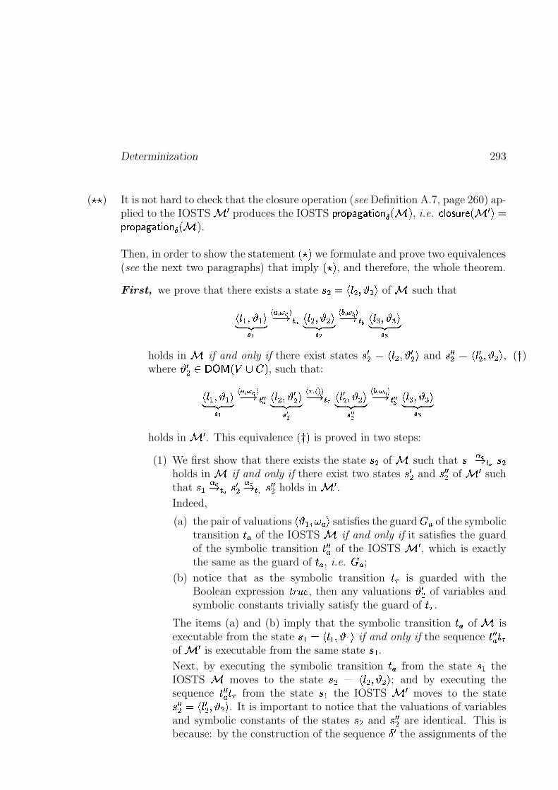
Determinization 293
It is not hard to check that the closure operation (see Definition A.7, page 260) ap-(�)� )plied to the IOSTS # � produces the IOSTS ����� ���A�=����>��� @ ��# � , i.e. � � �����=� � �.# � � ������ ������� �� ���'@ �.# � .
Then, in order to show the statement � ��� we formulate and prove two equivalences(see the next two paragraphs) that imply ���� , and therefore, the whole theorem.
First, we prove that there exists a state � � � ��� � )�� � ! of # such that
��� � )�� � !� ��� ��� �� ���� � � � ��� ��)�� � !� ��� ����
� ��� ���� � � � ����� )�� � !� ��� ����
holds in # if and only if there exist states � � � � ��� ��)�� � � ! and � � �� � ��� �� )���� ! , ( � )where ���� ������� � � �$� � , such that:
��� � )�� � !� ��� �� � �� ���� � �� � ��� � )�� � � !� ��� �� �
��� � � ���� � �:9 ��� �� )�� � !� ��� �� �� ��� � �� � � � ����� )�� � !� ��� �� �
holds in # � . This equivalence ��� � is proved in two steps:
(1) We first show that there exists the state � � of # such that � � � �� � � � �holds in # if and only if there exist two states � � � and � � �� of # � suchthat � � � �� ��� � � � � 9� � 9 � � �� holds in # � .Indeed,
(a) the pair of valuations� � ��)�� ! satisfies the guard � of the symbolic
transition � of the IOSTS # if and only if it satisfies the guardof the symbolic transition � � � of the IOSTS # � , which is exactlythe same as the guard of � , i.e. � ;
(b) notice that as the symbolic transition � � is guarded with theBoolean expression ! 4 ,-) , then any valuations � � � of variables andsymbolic constants trivially satisfy the guard of � � .
The items (a) and (b) imply that the symbolic transition �� of # isexecutable from the state � � � ��� � )�� � ! if and only if the sequence � � � � �of # � is executable from the same state � � .Next, by executing the symbolic transition �� from the state � � theIOSTS # moves to the state � � � ��� ��)�� � ! ; and by executing thesequence � � � � � from the state � � the IOSTS # � moves to the state� � �� � ��� �� )�� � ! . It is important to notice that the valuations of variablesand symbolic constants of the states � � and � � �� are identical. This isbecause: by the construction of the sequence � � the assignments of the
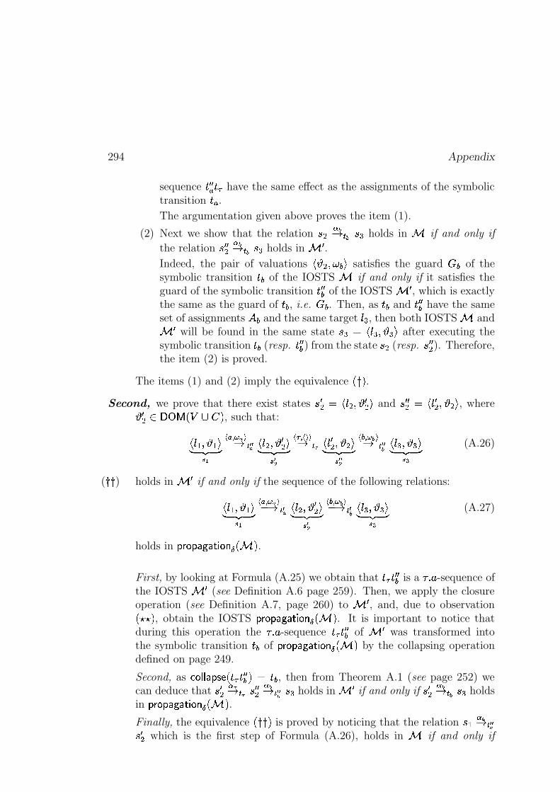
294 Appendix
sequence �-� � � � have the same effect as the assignments of the symbolictransition � .The argumentation given above proves the item (1).
(2) Next we show that the relation � � � �� � � � � holds in # if and only if
the relation � � ��� �� � � � � holds in # � .
Indeed, the pair of valuations� � ��)�� � ! satisfies the guard � � of the
symbolic transition � � of the IOSTS # if and only if it satisfies theguard of the symbolic transition � � �� of the IOSTS # � , which is exactlythe same as the guard of � � , i.e. � � . Then, as � � and � � �� have the sameset of assignments ��� and the same target
� �, then both IOSTS # and
# � will be found in the same state � � � ����� )�� � ! after executing thesymbolic transition � � (resp. �-� �� ) from the state � � (resp. � � �� ). Therefore,the item (2) is proved.
The items (1) and (2) imply the equivalence ��� � .Second, we prove that there exist states � � � � ��� ��)����� ! and � � �� � ��� �� )���� ! , where
� � � ������� � � �$� � , such that:
��� � )�� � !� ��� ��� � � �� � � � ��� ��)�� � � !� ��� �� �
� � � � ���� � 9 ��� �� )���� !� ��� �� �� ��� � �� � � ����� )�� � !� ��� ����
(A.26)
holds in # � if and only if the sequence of the following relations:( � � )��� ��)�� � !� ��� ��
� � � �� � � � ��� ��)�� � � !� ��� �� �� ��� � �� � � � ����� )�� � !� ��� �� �
(A.27)
holds in ����� ���A�=� �� ��� @ �.# � .
First, by looking at Formula (A.25) we obtain that � � �-� �� is a * � -sequence ofthe IOSTS # � (see Definition A.6 page 259). Then, we apply the closureoperation (see Definition A.7, page 260) to # � , and, due to observation��)��� , obtain the IOSTS ����� �����=����>�?�A@ �.# � . It is important to notice thatduring this operation the * � -sequence � � � � �� of # � was transformed intothe symbolic transition � � of ����� �����=����>�?� @ ��# � by the collapsing operationdefined on page 249.
Second, as � � � � � � ��� � � � � � �� � � ��� , then from Theorem A.1 (see page 252) wecan deduce that � � �
� 9� �:9 � � ��� �� � � � � holds in # � if and only if � � �
� �� � � � � holdsin ����� ������� �� ��� @ �.# � .Finally, the equivalence ��� � � is proved by noticing that the relation � � � �� � �� � � which is the first step of Formula (A.26), holds in # if and only if
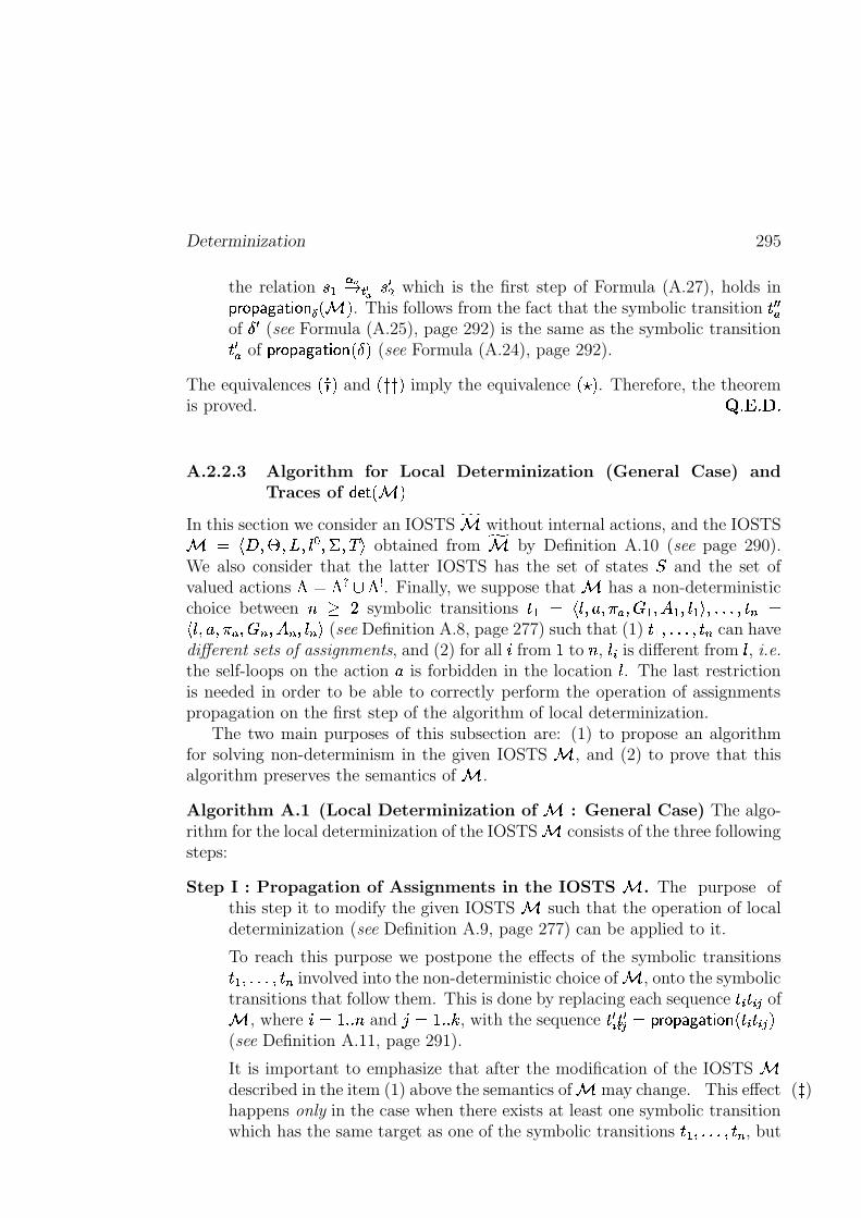
Determinization 295
the relation � � � �� �� � � � � which is the first step of Formula (A.27), holds in����� ���A�=� �� ��� @ �.# � . This follows from the fact that the symbolic transition ��� �of � � (see Formula (A.25), page 292) is the same as the symbolic transition� � of ����� ���A�=� �� ��� � ��� (see Formula (A.24), page 292).
The equivalences ��� � and ��� � � imply the equivalence � ��� . Therefore, the theoremis proved.
� *�� *�� *
A.2.2.3 Algorithm for Local Determinization (General Case) andTraces of ��������# �
In this section we consider an IOSTS�# without internal actions, and the IOSTS
# � � � )�� ) ) ��� )�� ) ! obtained from�# by Definition A.10 (see page 290).
We also consider that the latter IOSTS has the set of states and the set ofvalued actions � �� � � . Finally, we suppose that # has a non-deterministicchoice between $ % ' symbolic transitions � � � ��� )+��)� ) � � ) � � ) � � ! )�*�*�*�)+�-, ���� ) � )+ )7� , ) � , ) � , ! (see Definition A.8, page 277) such that (1) � ��)�*�*�*�)+�-, can havedifferent sets of assignments, and (2) for all � from � to $ ,
� 6 is different from�, i.e.
the self-loops on the action � is forbidden in the location�. The last restriction
is needed in order to be able to correctly perform the operation of assignmentspropagation on the first step of the algorithm of local determinization.
The two main purposes of this subsection are: (1) to propose an algorithmfor solving non-determinism in the given IOSTS # , and (2) to prove that thisalgorithm preserves the semantics of # .
Algorithm A.1 (Local Determinization of # : General Case) The algo-rithm for the local determinization of the IOSTS # consists of the three followingsteps:
Step I : Propagation of Assignments in the IOSTS # . The purpose ofthis step it to modify the given IOSTS # such that the operation of localdeterminization (see Definition A.9, page 277) can be applied to it.
To reach this purpose we postpone the effects of the symbolic transitions� ��)�*�*�*�)+�-, involved into the non-deterministic choice of # , onto the symbolictransitions that follow them. This is done by replacing each sequence � 6 � 6�� of# , where � � � * * $ and � � � * *�� , with the sequence � �6 �-�6�� � ����� ���A�=����>����� � 6 � 6�� �(see Definition A.11, page 291).
It is important to emphasize that after the modification of the IOSTS #described in the item (1) above the semantics of # may change. This effect ( � )happens only in the case when there exists at least one symbolic transitionwhich has the same target as one of the symbolic transitions ����)�*�*�*�)+�-, , but
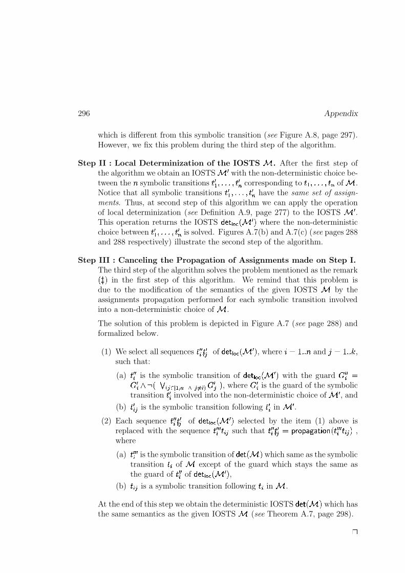
296 Appendix
which is different from this symbolic transition (see Figure A.8, page 297).However, we fix this problem during the third step of the algorithm.
Step II : Local Determinization of the IOSTS # . After the first step ofthe algorithm we obtain an IOSTS # � with the non-deterministic choice be-tween the $ symbolic transitions � � � ) *�*�* )��-�, corresponding to ����)�*�*�*�)+�-, of # .Notice that all symbolic transitions ��� � ) *�*�* )��-�, have the same set of assign-
ments. Thus, at second step of this algorithm we can apply the operationof local determinization (see Definition A.9, page 277) to the IOSTS # � .This operation returns the IOSTS �����+� �����.# � � where the non-deterministicchoice between � � � )�* *�* )+�-�, is solved. Figures A.7(b) and A.7(c) (see pages 288and 288 respectively) illustrate the second step of the algorithm.
Step III : Canceling the Propagation of Assignments made on Step I.The third step of the algorithm solves the problem mentioned as the remark� � � in the first step of this algorithm. We remind that this problem isdue to the modification of the semantics of the given IOSTS # by theassignments propagation performed for each symbolic transition involvedinto a non-deterministic choice of # .
The solution of this problem is depicted in Figure A.7 (see page 288) andformalized below.
(1) We select all sequences � � �6 �-�6�� of ������� ������# � � , where � � � * * $ and � � � * *�� ,such that:
(a) � � �6 is the symbolic transition of �����+� ��� ��# � � with the guard � � �6 �� �6 7 � � ��� ����� � � ,�� �� � 6�� � �� � , where � �6 is the guard of the symbolictransition � �6 involved into the non-deterministic choice of # � , and
(b) � �6�� is the symbolic transition following � �6 in # � .(2) Each sequence � � �6 �-�6�� of �����+� �����.# � � selected by the item (1) above is
replaced with the sequence � � � �6 � 6�� such that �-� �6 �-�6�� � ����� ���A�=� �� ����� �-� � �6 � 6�� � ,where
(a) �-� � �6 is the symbolic transition of ����� ��# � which same as the symbolictransition � 6 of # except of the guard which stays the same asthe guard of � � �6 of ������� ��� ��# � � ,
(b) � 6�� is a symbolic transition following � 6 in # .
At the end of this step we obtain the deterministic IOSTS ����� ��# � which hasthe same semantics as the given IOSTS # (see Theorem A.7, page 298).
"
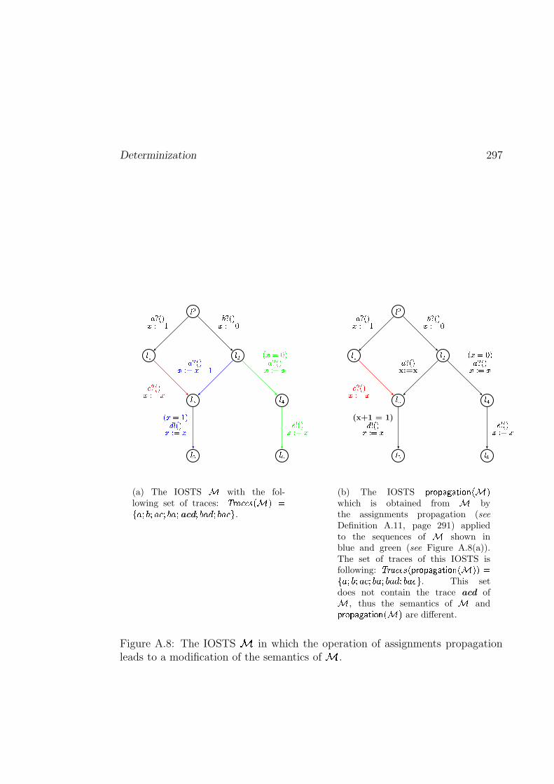
Determinization 297
���
��� ���
��� ���
��� ���
��q~�� � � � �q~�� ���
���;U��� ���
��;U�� �������
����������� ~�� ���
������{���;U�� ���
� � ~�� ���
(a) The IOSTS � with the fol-lowing set of traces: � �"!$#&%('$)*�,+ %-�.0/21�/2.43�/21(.0/
acd/&1(.456/&1(.47$8
.
&�9
&�' &�(
&�) &�*
&�: &�;
,�<q-~1=> ?�@ > <q-~1=> ?�A
C�<;-U1=�> ?B=
,�<q-~1x:=x
(x+1 = 1)C�D -~1=�> ?�=
-�=�?�A{1,�<;-U1=> ?�=
E D -U1=> ?B=
(b) The IOSTS FHGJI FHK�LMKON2P IRQ6S*T,Uwhich is obtained from T bythe assignments propagation (seeDefinition A.11, page 291) appliedto the sequences of T shown inblue and green (see Figure A.8(a)).The set of traces of this IOSTS isfollowing: VRW"XZY&[]\MS^FHG_IRF�K�L4KON2P IRQ6S*T`U"U�ab�c0d2e�d"c4f�d2e]cgd&e(c4h6d&e(c4i$j
. This setdoes not contain the trace acd ofT , thus the semantics of T andFHGJI FHK�LMKON2P IRQ6S*T,U are different.
Figure A.8: The IOSTS k in which the operation of assignments propagationleads to a modification of the semantics of k .
298 Appendix
Finally, we state and prove the theorem about trace-equivalence between thegiven IOSTS # and the IOSTS ����� ��# � obtained from # by the algorithm forthe local determinization described above.
Theorem A.7 (Traces of ��������# � : General Case) Let # be the IOSTSwithout internal actions, wchich is obtained from an IOSTS
�# by mem-
orizing its parameters (see Definition A.10, page 290). Suppose that #has a non-deterministic choice between $ % ' symbolic transitions � � ���� ) � )+ ) � � ) � � ) � � ! )�*�*�*�)+�-, � ��� )+��)� )7� , ) � , ) � , ! (see Definition A.8, page 277)such that:
(1) ����) *�*�* )��-, can have different sets of assignments, and
(2) for all � from � to $ ,� 6 is different from
�, i.e. the self-loops on the action �
is forbidden in the location�. This restriction is needed in order to be able
to correctly perform the operation of assignments propagation on the firststep of Algorithm A.1 (see page 295) .
Then, the resulting IOSTS ����� ��# � obtained from the IOSTS # by the algorithmof local determinization given on page 295 has the same set of traces as # , i.e.
3 476 / )�1 �.����� ��# ��� � 35476 / )�1 ��# �
"
Proof We assume that each symbolic transition � 6 ( � � � * * $ ) involved intothe non-deterministic choice of # is followed by symbolic transitions � 6 ��)�*�*�*�)+� 6�� .Then,
(1) During Step I of the algorithm for local determinization of # we re-place each sequence � 6 � 6�� ( � � � * * $ and � � � * *�� ) with the sequence� �6 � �6�� � ����� ���A�=����>��� �.� 6 � 6�� � and obtain the new IOSTS # � . Then, due to The-orem A.6 (see page 292), we obtain that these replacements preserve theeffects of the sequences � 6 � 6�� . Therefore, the semantics of these sequences isremining unchanged, but the semantics of the whole IOSTS # may change,i.e. it is possible that
35476 / )�1 ��# � �� 3 476 / )�1 �.# � �(2) During Step II of the algorithm we apply the operation of local deter-
minization defined on page 277 to # � and obtain the IOSTS �����+� �����.# � � .Then, due to Lemma A.3 (see page 283), we have that this operation pre-serves the effects of each sequences of symbolic transitions ���6 �-�6�� of the IOSTS# � , where � � � * * $ and � � � * *�� . By Theorem A.5 (see page 285) we alsoget that
35476 / )�1 �������+� ��� �.# � �+� �835476 / )�1 �.# � � .
Determinization 299
(3) During Step III of the algorithm we cancel the propagation of assignmentsmade on Step I and obtain the IOSTS �������.# � . Then, due to Theorem A.6(see page 292) we have that the effect of any sequences of two consecutivesymbolic transitions is preserved by the operation of propagation of as-signments. Thus, if in ������� ��� ��# � � we replace each sequence of symbolictransitions � � �6 � �6�� � ����� �����=����>�?� �.� � � �6 � 6�� � with the sequences � � � �6 � 6�� (see StepIII of Algorithm A.1), then the semantics of # will be preserved, i.e.35476 / )�1 ������� �.# �+� � 3 476 / )�1 �.# � .
� *�� *�� *
A.2.3 Traces and Accepting Traces of����������� ��������������������� �"!#!
In this section we consider an IOSTS � � ��� �=��� � (%$ � � with set of data������ �$���
and set of actions � � ��� � �� , which was computed from the synchronous product(%$ � ('&-) /)( 3 $by the closure operation as it is explained in Section A.1 (see
page 246).Then, we augment the set of variables
�of � � � � �=��� � (%$ �-� with some observa-
tion variables used to memorize values of parameters�
carried by the actions� of � � �����=� � � (%$ � � . I.e. we create an IOSTS � � �����=� ��� (%$ � memorizing parame-ters
�of the IOSTS � � �����=� ��� (%$ � � (see Definition A.10, page 290). According
to Observation A.4 (see page 290) the semantics of the IOSTS � � � � �=��� � (%$ � � and� � � � �=��� � (%$ � is the same, i.e.
3 4 6 / )�1 ��� � �����=� ��� (%$ � � � � 35476 / )�1 ��� � �����=� � � (%$ ��� . More-over, it is not hard to check that the IOSTS � � ��� �=��� � (%$ � � and � � ��� �=��� � (%$ � havethe same set of accepting traces. (Notice that the accepting traces of � � � � �=��� � (%$ ���and � � �����=� ��� (%$ � are defined similarly as the accepting traces of the synchronousproduct
(%$, see Definition 6.10 on page 151).
Finally, we consider an IOSTS ��������� � �����=� � � (%$ �+� computed from � � �����=� � � (%$ �by the algorithm of local determinization presented in the previous subsection(see page 295). The aim of this section is to study the relationships betweentraces and accepting traces of � � �����=� � � (%$ � and ��������� � �����=� ��� (%$ �+� .
Traces of ����� ��� � �����=� � � (%$ �+� . Using Theorem A.7 (see page 298) we obtain thatthe algorithm of local determinization preserves the set of traces of the IOSTS� � � � �=��� � (%$ � , i.e.
35476 / )�1 ������� � � � � � �=��� � (%$ �+��� � 35476 / )�1 ��� � �����=� � � (%$ �+� (A.28)
Accepting Traces of ����� ��� � �����=� ��� (%$ �+� . In this paragraph we first make an ob-servation about the form of the locations of the IOSTS ������� � � ��� �=��� � (%$ ��� . Then
300 Appendix
we use this observation in order to define the notion of accepting trace for������� � � ��� �=��� � (%$ ��� . Finally, we prove that the IOSTS ������� � � ��� �=��� � (%$ ��� has thesame set of accepting traces as the IOSTS � � �����=� � � (%$ � .Observation A.5 (The Form of Locations of ����� ��� � �����=� � � ('&-) / ( 3 $ ��� ) Alllocation of an IOSTS ������� � � � � �=��� � ('&-) / ( 3 $ �+� are of the form:
�7��� �������� ) � � � ! ) *�*�*�) ��� , ������� ) � , � !7!where for all � from � to $ % � , � 6 ������� and
� 6 � � are locations of a specification('&-) /
and a test purpose3 $
of('&-) /
respectively. "Intuitively, the set of accepting traces of the IOSTS ��������� � �����=� � � (%$ ��� consists ofthe traces leading to states that correspond to the locations containing the word� / / )�& ! in their names. Formally:
Definition A.12 (Set of Accepting Traces of ����� ��� � �����=� ��� ('&-) / ( 3 $ �+� ) Let
(1)('&-) / ��������� be a specification with set of locations ������� ,
(2)3 $
be a test purpose of('&-) /
with set of locations ��� , and
(3) ����� ��� � �����=� � � (%$ �+� be an IOSTS obtained from the synchronous product(%$ �
('&-) / ( 3 $by the closure operation (see Definition A.7, page 260) and the
algorithm of local determinization (see Algorithm A.1, page 295).
The IOSTS ����� ��� � �����=� � � (%$ �+� has the set of locations , the set of data����� � � � �, the set of states and the set of initial states ��� .
Then, for the IOSTS ����� ��� � �����=� ��� (%$ �+� we define the set of accepting traces asfollows:
� 35476 / )�1 ��������� � � ��� �=��� � (%$ ���+� � (A.29).�� � 35476 / )�1 ������� � � � � � �=��� � (%$ �+���!0 � � � � � )��� ��)�*�*�*�) ��� ������� ) � / / )�& ! !� ��� �!#" )�*�*�*�) � , ! � )
��� ��� � � � �$� ��)� � �7��� � ) *�*�* ) ��� ������� ) �%$&$&' � � !� ��� �!(" )�*�* * ) � , ! )�� ! � (*
$ � �*)+ � ( 4where
� ������� � ������� is a location of('&-) /
and �%$&$&' � � � �� is the special locationof
3 $(see the hypothesis (1) of Definition 6.8, page 147). "
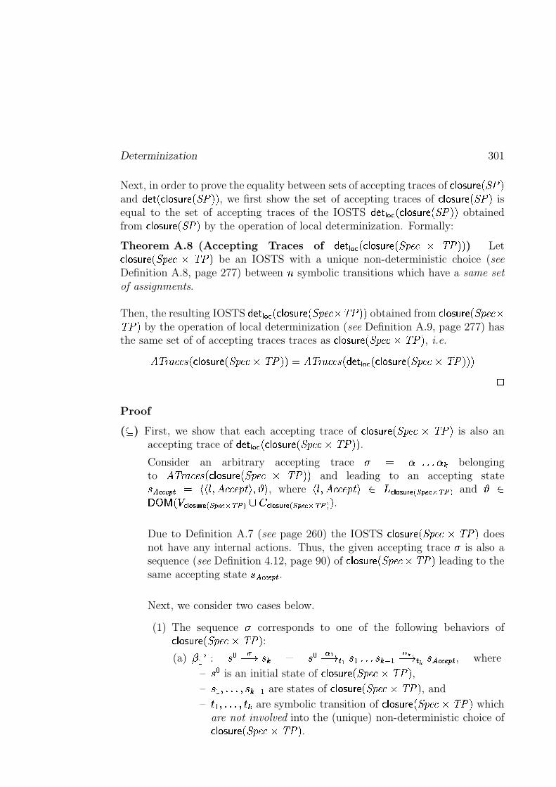
Determinization 301
Next, in order to prove the equality between sets of accepting traces of � � ���������� ����and � ���� � � ����������� ������
, we first show the set of accepting traces of � � ���������� ����is
equal to the set of accepting traces of the IOSTS � ���� ��� � � � ����������� ������obtained
from � � ����������� ����by the operation of local determinization. Formally:
Theorem A.8 (Accepting Traces of � ���� ��� � � � ����������� �!�"$#&% '(�����) Let
� � ����������� �!�"$#)%*'(���be an IOSTS with a unique non-deterministic choice (see
Definition A.8, page 277) between + symbolic transitions which have a same setof assignments.
Then, the resulting IOSTS � ���� ���,� � � ���������� �!�"$#-%.'(�����obtained from � � ���������� �!�"$#/%'(�0�
by the operation of local determinization (see Definition A.9, page 277) hasthe same set of of accepting traces traces as � � ����������� �!�"$#�%1'(���
, i.e.2 '4365�#$"�7�� � � ����������� �!�"$#8%1'(�����:9 2 '43$5�#$"�7�� � ���� �;�<� � � ���������� �!�"$#�%='(���;���
>
Proof
( ? ) First, we show that each accepting trace of � � ���������� �!�"$#@%A'(���is also an
accepting trace of � ��;� ��� � � � ����������� �!�"$#8%B'(�����.
Consider an arbitrary accepting trace C 9 DFEHG<G<G6DJIbelonging
to2 '43$5�#$"�7�� � � ���������� �!�"$#K% '(���;�
and leading to an accepting stateL MONNPRQ�S 9 T6TVU�W 2 #$#$"�!HX�Y�W6Z[Y, where
TVU�W 2 #$#$"�!HX�Y]\ ^ �_� ��`a�bdc�eRf Q�PN$gih<j/k andZ \
lnm0op�rq��r� ��`a�bsc;eRf Q�PN$gih<j�k/tvu �r� ��`wa�bdc;exf Q;PN6gih j�k � .Due to Definition A.7 (see page 260) the IOSTS � � ����������� �!�"$#y%K'(���
doesnot have any internal actions. Thus, the given accepting trace C is also asequence (see Definition 4.12, page 90) of � � ����������� �!�"$#z%{'(���
leading to thesame accepting state L|MON�NPxQ�S .Next, we consider two cases below.
(1) The sequence C corresponds to one of the following behaviors of� � ����������� �!�"$#8%B'(���
:
(a) }�~EA� L<����[� L I 9 L<�&����H��� � L EHG<G<G L I���E ����H��� � L MONNPRQ�S , where
– L � is an initial state of � � ���������� �!�"$#�%='(���,
– L E�W<G<G,G�W L I���E are states of � � ����������� �!�"$#8%1'(���, and
– � E�W<G,G<G,W � I are symbolic transition of � � ����������� �!�"$#8%1'(���which
are not involved into the (unique) non-deterministic choice of� � ���������� �!�"$#�%B'(���
.
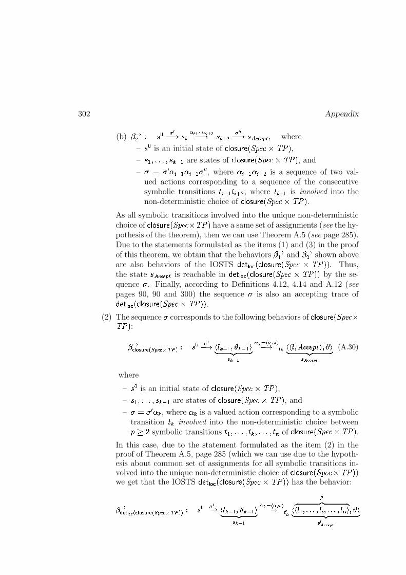
302 Appendix
(b) }:~� � L<� � ��i� L�� ����� � ������[� L�� � � � � ��H� L MONN�PxQ�S , where
– L � is an initial state of � � ���������� �!�"$#�%1'(���,
– L E�W<G<G<G�W L I���E are states of � � ���������� �!�"$#�%='(���, and
– C 9 C � D � � E;D � � � C � � , whereD � � E;D � � � is a sequence of two val-
ued actions corresponding to a sequence of the consecutivesymbolic transitions � � � E � � � � , where � � � E is involved into thenon-deterministic choice of � � ���������� �!�"$#8%1'(�0�
.
As all symbolic transitions involved into the unique non-deterministicchoice of � � ���������� �!�"$#i%)'(�0�
have a same set of assignments (see the hy-pothesis of the theorem), then we can use Theorem A.5 (see page 285).Due to the statements formulated as the items (1) and (3) in the proofof this theorem, we obtain that the behaviors } ~E and }:~� shown aboveare also behaviors of the IOSTS � ��;� �;�<� � � ���������� �!�"$#)% '(���;�
. Thus,the state L|MON�NPxQ�S is reachable in � ���� �;�<� � � ���������� �!�"$#@%&'(���;�
by the se-quence C . Finally, according to Definitions 4.12, 4.14 and A.12 (seepages 90, 90 and 300) the sequence C is also an accepting trace of� ���� �;�<� � � ���������� �!�"$#�%B'(���;�
.
(2) The sequence C corresponds to the following behaviors of � � ����������� �!�"$#O%'(���:
� ~�r� ��`wa�bdc;exf Q;PN�gih<j�k�� � � � �������� I���E�����I���E�� !#" $% �'& ����#(*)�+-, .0/��� � � ����� ��132�2�465879�����:� !#" $%<;>=�=@?�A6B
(A.30)
where
– L<� is an initial state of � � ���������� �!�"$#�%1'(���,
– L E�W<G<G<G�W L I���E are states of � � ���������� �!�"$#8%1'(���, and
– C 9 C � D I , whereD I
is a valued action corresponding to a symbolictransition � I involved into the non-deterministic choice betweenCEDGF symbolic transitions � E�W,G<G<G,W � I�W<G<G,G,W ��H of � � ���������� �!�"$# %�'(���
.
In this case, due to the statement formulated as the item (2) in theproof of Theorem A.5, page 285 (which we can use due to the hypoth-esis about common set of assignments for all symbolic transitions in-volved into the unique non-deterministic choice of � � ����������� �!�"$#n% '(���
)we get that the IOSTS � ��;� ��� � � � ����������� �!�"$#8%B'(�����
has the behavior:
� ~I cKJ�L MON_e �r� ��`a�bsc�exf Q;PN6gih<j�kxkP� � � � �������� I���E#����I���E�� !#" $% �9& ����Q(*)�+-, .0/��� � � � �
R �" $# !��� E ��S�S�ST� � � ��S�S�ST� � H �Q���U� !�" $% � ;>=V=@?WA6B
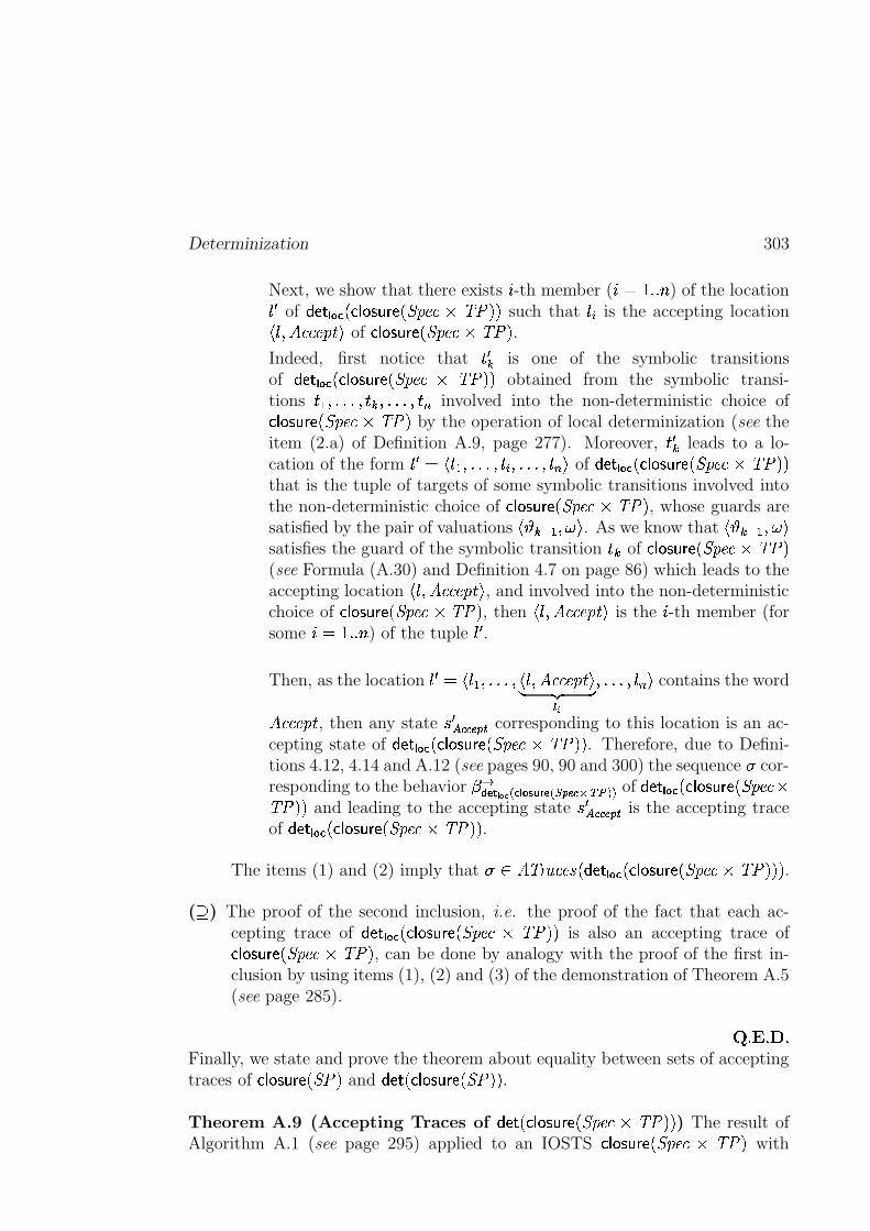
Determinization 303
Next, we show that there exists � -th member ( � 9�� GxG + ) of the locationU �of � ���� �;�<� � � ���������� �!�"$#y% '(���;�
such thatU � is the accepting locationTrU�W 2 #$#$"�!HX;Y
of � � ���������� �!�"$#�%1'(���.
Indeed, first notice that � � I is one of the symbolic transitionsof � ���� ���,� � � ���������� �!�"$#�% '(���;�
obtained from the symbolic transi-tions � E�W,G<G<G,W � I�W<G<G,G,W ��H involved into the non-deterministic choice of� � ����������� �!�"$#�%B'(���
by the operation of local determinization (see theitem (2.a) of Definition A.9, page 277). Moreover, � � I leads to a lo-cation of the form
U � 9 TrUrE�W<G,G<G,W6U � W<G<G,G,W6U H Y of � ���� ���,� � � ���������� �!�"$#�% '(�����that is the tuple of targets of some symbolic transitions involved intothe non-deterministic choice of � � ����������� �!�"$#0% '(���
, whose guards aresatisfied by the pair of valuations
TrZ[I���E$W�� Y. As we know that
TVZ[I���E�W�� Ysatisfies the guard of the symbolic transition � I of � � ���������� �!�"$#�%B'(���(see Formula (A.30) and Definition 4.7 on page 86) which leads to theaccepting location
TrU�W 2 #$#$"�!HX�Y, and involved into the non-deterministic
choice of � � ���������� �!�"$#0%B'(���, then
TVU�W 2 #$#$"�!HX�Yis the � -th member (for
some � 9���GRG + ) of the tupleU �.
Then, as the locationU � 9]TrUrE�W<G,G<G�W TrU�W 2 #$#$"�!HX�Y
� ��� R �W,G<G<G,W�U H Y contains the word
2 #$#$"�!HX, then any state L � MON�NPxQ�S corresponding to this location is an ac-
cepting state of � ���� ���<� � � ���������� �!�"$# %K'(�����. Therefore, due to Defini-
tions 4.12, 4.14 and A.12 (see pages 90, 90 and 300) the sequence C cor-responding to the behavior } ~I c J L M N e �r� ��`wa�bdc�eRf Q;PN$gih<j�kRk of � ���� ���<� � � ���������� �!�"$# %'(�����
and leading to the accepting state L � MON�NPxQ�S is the accepting traceof � ��;� �;�,� � � ���������� �!�"$#8%B'(���;�
.
The items (1) and (2) imply that C \ 2 '4365�#$"�7�� � ��;� �;�<� � � ���������� �!�"$# %1'(�������.
( ) The proof of the second inclusion, i.e. the proof of the fact that each ac-cepting trace of � ���� ���,� � � ���������� �!�"$#p% '(�����
is also an accepting trace of� � ����������� �!�"$#�% '(���
, can be done by analogy with the proof of the first in-clusion by using items (1), (2) and (3) of the demonstration of Theorem A.5(see page 285).
� G �yG�� GFinally, we state and prove the theorem about equality between sets of acceptingtraces of � � ���������� ����
and � ��,� � � ���������� ������.
Theorem A.9 (Accepting Traces of � ���� � � ���������� �!�"$# %&'(�����) The result of
Algorithm A.1 (see page 295) applied to an IOSTS � � ���������� �!�"$#p% '(���with
304 Appendix
unique non-deterministic choice (see Definition A.8, page 277), has the same setof accepting traces traces as � � ���������� �!�"$#�%1'(���
, i.e.
2 '43$5�#$"�7�� � � ���������� �!�"$#8%B'(���;��9 2 '/365�#$"�7�� � ��<� � � ����������� �!�"$#8%1'(�����;�>
Proof The proof of the theorem is similar to that of Theorem A.7 (see page 298)except of (a) reasoning about accepting traces and not traces; and (b) usingTheorem A.8 instead of Theorem A.5 in the item (2) of the proof (see page 298).�pG��yG�� G
A.2.4 Global Determinization
This section describes a simple procedure for the global determinization of anIOSTS without internal actions. The general idea is to iterate through all loca-tions of the IOSTS, and each time when a non-deterministic choice (see Defini-tion A.8, page 277) is detected, to apply the algorithm of local determinizationdefined in previous section (see Algorithm A.1, page 295). Formally:
Procedure A.1 (Global Determinization of � ) Let�� be an IOSTS with-
out internal actions, and � 9 T�� W��@W6^ W�U � W|����� t � �$W��8Ybe the IOSTS memorizing
parameters of�� (see Definition A.10, page 290). Then, in order to make the
IOSTS � deterministic in the sense of Definition 4.20 (see page 93), we performthe following steps:
(1) From the set of locations^
of � construct the subset^ � ? ^
of all lo-cations
U \ ^which are origins of symbolic transitions involved into non-
deterministic choices (see Definition A.8, page 277).
(2) While the set^ �
is not empty, do:
(a) For each locationU
belonging to^ �
, perform the algorithm of localdeterminization presented on page 295.
(b) At the end of the loop described in the item (a), we obtain a new(possibly non-deterministic) IOSTS �
�for which we recompute
^ �.
>It is important to notice that Procedure A.1 presented above does not alwaysterminate. However, if this procedure does terminate, it clearly produces anIOSTS without non-deterministic choices, i.e. a deterministic IOSTS in sense of
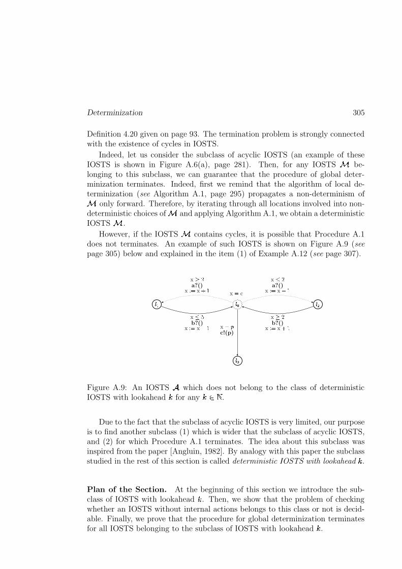
Determinization 305
Definition 4.20 given on page 93. The termination problem is strongly connectedwith the existence of cycles in IOSTS.
Indeed, let us consider the subclass of acyclic IOSTS (an example of theseIOSTS is shown in Figure A.6(a), page 281). Then, for any IOSTS � be-longing to this subclass, we can guarantee that the procedure of global deter-minization terminates. Indeed, first we remind that the algorithm of local de-terminization (see Algorithm A.1, page 295) propagates a non-determinism of� only forward. Therefore, by iterating through all locations involved into non-deterministic choices of � and applying Algorithm A.1, we obtain a deterministicIOSTS � .
However, if the IOSTS � contains cycles, it is possible that Procedure A.1does not terminates. An example of such IOSTS is shown on Figure A.9 (seepage 305) below and explained in the item (1) of Example A.12 (see page 307).
������ ���
���
x � c
x �a?()
x � � x �� x �a?()
x � � x ��
x ��b?()
x � � x �� x �b?()
x � � x �� x ���c!(p)
Figure A.9: An IOSTS�
which does not belong to the class of deterministicIOSTS with lookahead � for any ����� .
Due to the fact that the subclass of acyclic IOSTS is very limited, our purposeis to find another subclass (1) which is wider that the subclass of acyclic IOSTS,and (2) for which Procedure A.1 terminates. The idea about this subclass wasinspired from the paper [Angluin, 1982]. By analogy with this paper the subclassstudied in the rest of this section is called deterministic IOSTS with lookahead � .
Plan of the Section. At the beginning of this section we introduce the sub-class of IOSTS with lookahead � . Then, we show that the problem of checkingwhether an IOSTS without internal actions belongs to this class or not is decid-able. Finally, we prove that the procedure for global determinization terminatesfor all IOSTS belonging to the subclass of IOSTS with lookahead � .
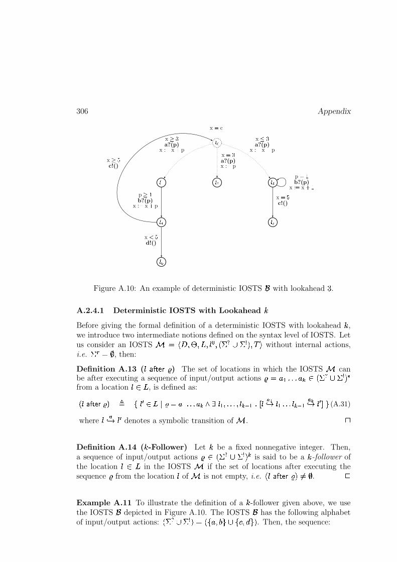
306 Appendix
� �
� � � � � �
� � ���
���
x � c
x � �a?(p)
x � � x � px � �a?(p)x � � p
x � �a?(p)
x � � x � p
p � b?(p)
x � � x � p
x � �c!()
x � �d!()
x ��c!()
p � b?(p)
x � � x ��
Figure A.10: An example of deterministic IOSTS�
with lookahead � .
A.2.4.1 Deterministic IOSTS with Lookahead �Before giving the formal definition of a deterministic IOSTS with lookahead � ,we introduce two intermediate notions defined on the syntax level of IOSTS. Letus consider an IOSTS ��� ��������������������! #"$�&%('��*),+ without internal actions,i.e. �.-,0/ , then:
Definition A.13 ( �!132547698&: ) The set of locations in which the IOSTS canbe after executing a sequence of input/output actions :�<;>=@?�?A?�;CB � ���! D"E�&%F'7Gfrom a location � � � , is defined as:
H5IKJMLONQPARKS�T U V&IOWYX[Z]\^S�_a` =cb�b�b ` Bedgf I =ih�b�b�bih I BMjc= blk I.monp q I =>b�b�b I BMjc= m�rp q IOWFsut(A.31)
where � mv w � W denotes a symbolic transition of . x
Definition A.14 ( � -Follower) Let � be a fixed nonnegative integer. Then,a sequence of input/output actions : � ��� "$� % ' B is said to be a � -follower ofthe location � � � in the IOSTS if the set of locations after executing thesequence : from the location � of is not empty, i.e. ���D1�25476y8.:z'|{}/ . x
Example A.11 To illustrate the definition of a � -follower given above, we usethe IOSTS
�depicted in Figure A.10. The IOSTS
�has the following alphabet
of input/output actions: ���~ K"��&%('e��7��;>���3�!"��y�����c�z' . Then, the sequence:
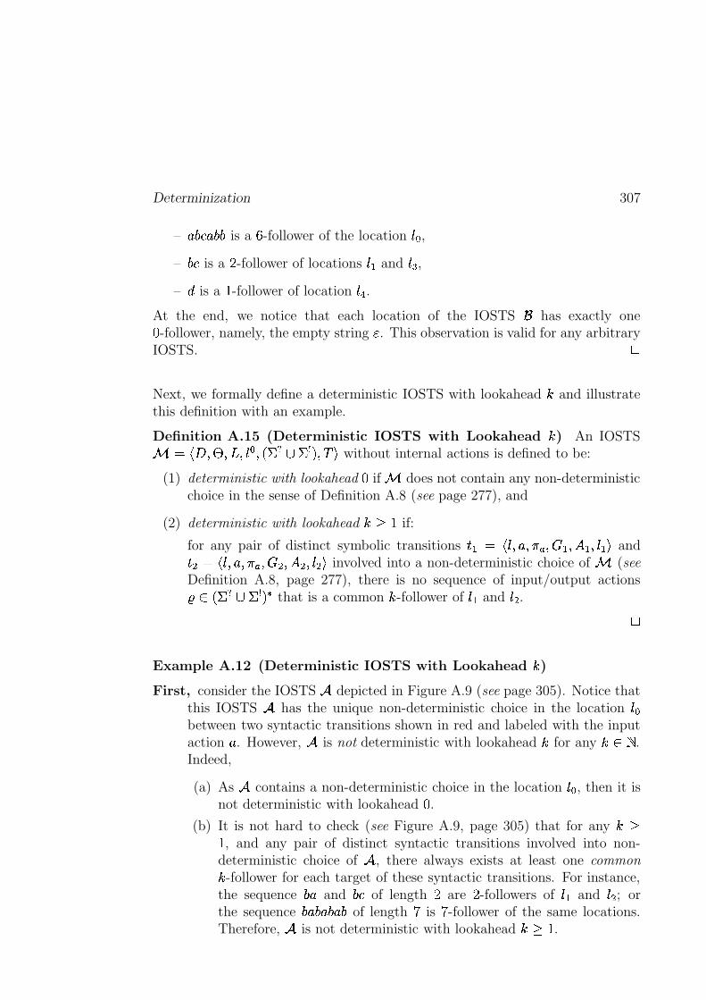
Determinization 307
– � ��� � ��� is a � -follower of the locationU � ,
–���
is a F -follower of locationsU_E
andU��
,
– � is a�-follower of location
U�.
At the end, we notice that each location of the IOSTS has exactly one�-follower, namely, the empty string � . This observation is valid for any arbitrary
IOSTS.>
Next, we formally define a deterministic IOSTS with lookahead and illustratethis definition with an example.
Definition A.15 (Deterministic IOSTS with Lookahead ) An IOSTS� 9]T�� W � W$^ W6U � W|� � � t � �6W��8Y
without internal actions is defined to be:
(1) deterministic with lookahead�
if � does not contain any non-deterministicchoice in the sense of Definition A.8 (see page 277), and
(2) deterministic with lookahead D �if:
for any pair of distinct symbolic transitions � E)9 TrU�W � W�� + W�� E�W���E�W6UrE;Yand
� � 9 TrU�W � W�� + W�� � W�� � W�U � Y involved into a non-deterministic choice of � (seeDefinition A.8, page 277), there is no sequence of input/output actions� \ � � � t � ���
that is a common -follower ofU_E
andU � . >
Example A.12 (Deterministic IOSTS with Lookahead )
First, consider the IOSTS � depicted in Figure A.9 (see page 305). Notice thatthis IOSTS � has the unique non-deterministic choice in the location
U �between two syntactic transitions shown in red and labeled with the inputaction � . However, � is not deterministic with lookahead for any \��
.Indeed,
(a) As � contains a non-deterministic choice in the locationU � , then it is
not deterministic with lookahead�.
(b) It is not hard to check (see Figure A.9, page 305) that for any D�, and any pair of distinct syntactic transitions involved into non-
deterministic choice of � , there always exists at least one common -follower for each target of these syntactic transitions. For instance,the sequence
� � and���
of length F are F -followers ofU E
andU � ; or
the sequence� � � � � � � of length � is � -follower of the same locations.
Therefore, � is not deterministic with lookahead D �.

308 Appendix
Second, consider the IOSTS shown on Figure A.10 (see page 306). ThisIOSTS is deterministic with lookahead � .Indeed, for each pair of distinct syntactic transitions � E�W � � and � � (withtargets respectively
U_E�W6U � andU��
) shown in red and involved into the uniquenon-deterministic choice of , the IOSTS does not have any sequencethat is a common � -follower of the targets of these syntactic transitions.More precisely:
(a) The locationsU_E
andU � (which are the targets of � E and � � respectively)
as well as the locationsU � and
U��(which are the targets of � E and � �
respectively) do not have a common follower other than the emptysequence (see Figure A.10).
(b) However, the locationsU_E
andU��
(which are the targets of � E and � �respectively) have:
– a common�-follower which is the empty sequence � ,
– a common�-follower which is the string
�, and
– a common F -follower which is the string���
.
But, they do not have any common � -follower (see Figure A.10).
Therefore, according to Definition A.15 the IOSTS is deterministic withlookahead � .It is interesting to notice that the IOSTS is deterministic not only for 9
� , but for all D � . This observation, which is generalized below, leadsto the definition of the IOSTS with smallest lookahead .
>
Observation A.6 If the IOSTS � is deterministic with lookahead then it isdeterministic with lookahead
� �� C � , where C \ �.
>
Definition A.16 (Deterministic IOSTS with Smallest Lookahead ) AnIOSTS � is deterministic with smallest lookahead if:
(1) it is deterministic with lookahead (see Definition A.15), but
(2) it is not deterministic with lookahead� � �|�
.
>
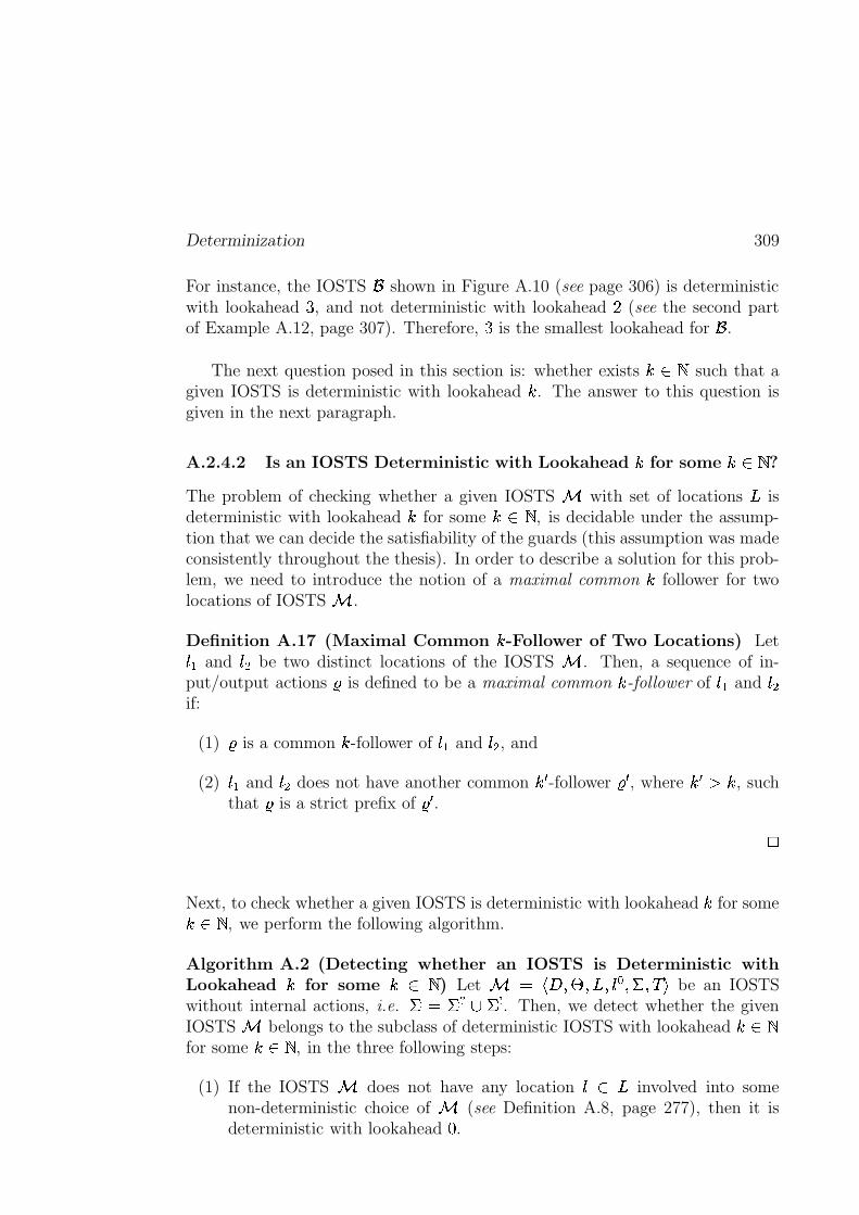
Determinization 309
For instance, the IOSTS shown in Figure A.10 (see page 306) is deterministicwith lookahead � , and not deterministic with lookahead F (see the second partof Example A.12, page 307). Therefore, � is the smallest lookahead for .
The next question posed in this section is: whether exists \ �such that a
given IOSTS is deterministic with lookahead . The answer to this question isgiven in the next paragraph.
A.2.4.2 Is an IOSTS Deterministic with Lookahead for some \ �?
The problem of checking whether a given IOSTS � with set of locations^
isdeterministic with lookahead for some \ �
, is decidable under the assump-tion that we can decide the satisfiability of the guards (this assumption was madeconsistently throughout the thesis). In order to describe a solution for this prob-lem, we need to introduce the notion of a maximal common follower for twolocations of IOSTS � .
Definition A.17 (Maximal Common -Follower of Two Locations) LetUrEand
U � be two distinct locations of the IOSTS � . Then, a sequence of in-put/output actions � is defined to be a maximal common -follower of
U�Eand
U �if:
(1) � is a common -follower ofU_E
andU � , and
(2)UrE
andU � does not have another common � -follower � � , where ��� , such
that � is a strict prefix of � � .>
Next, to check whether a given IOSTS is deterministic with lookahead for some \ �
, we perform the following algorithm.
Algorithm A.2 (Detecting whether an IOSTS is Deterministic withLookahead for some \ �
) Let � 9 T�� W � W$^8W�U � W�� W���Ybe an IOSTS
without internal actions, i.e.�&9 � � t �
. Then, we detect whether the givenIOSTS � belongs to the subclass of deterministic IOSTS with lookahead \ �for some \ �
, in the three following steps:
(1) If the IOSTS � does not have any locationUv\ ^
involved into somenon-deterministic choice of � (see Definition A.8, page 277), then it isdeterministic with lookahead
�.
310 Appendix
(2) Otherwise, for each pair of distinct locationsU � W�U�� \ ^
belonging to� U����w�� � � � , where the locationU
and the action � are involved into a non-deterministic choice of � , we try to detect whether there exists an integer such that
U � andU��
have a maximal common -follower for some \ �. In
the case of existence of we add it into an initially empty set of integers � ,otherwise the algorithm stops. Formally, we perform the following steps:
(2.1) We create the two following sets:
– � ��� + ��� � 9 �,
– � H � � 9��OTrU � W6U���Y�� (i.e. at the beginning of each iteration the set� H � must contain exactly one pair for which we try to compute ).
We also initialize the integer to zero.
(2.2) While� � H ���9��O�
do:
If� � H ��� � ��� + ��� ��9��
, then
– � ���� + ���� � 9 � ��� + ��� t � H �� ,
– � �H � � 9 � H � ,
– � H � � 9 �OTVU �� W6U �� Y=\ �V^ %B^ ����� TrU � W6U���Y=\ � �H � W � \ ����� t� � G � U � +! � U �� \ ��"vU�� +! � U �� \ �$#%�
, and
– � 9 � �.
Else, there exists an identical infinite sequence starting in the locationsU � andU��
. Thus, the locationsU � and
U��do not have a maximal
common successor. Therefore, the algorithm stops with the resultthat the IOSTS does not belong to the subclass of deterministicIOSTS with lookahead .
(2.3) Add computed to the set � .
(3) Finally, we choose the maximal integer among all integers belonging to theset � . This integer corresponds to a longest maximal common -follower.Thus, we conclude that � is deterministic with lookahead
� �� ���.
>
Theorem A.10 (Termination of Algorithm A.2, page 309) The algorithmdetecting whether an IOSTS � 9 T�� W � W6^8W6U � W � W���Y
without internal actions isdeterministic with lookahead for some \ �
, terminates.>
Determinization 311
Proof
First, we show that the inner loop represented as the item (2.2) of Algorithm A.2,terminates.
The proof is done by the contradiction. Suppose that this inner loop doesnot terminate. This means that the set � H �� is never empty. Thus, at eachiteration of this loop the size of the set � ���� + ���� is increased at least by one. (� )Indeed, � ��� + ��� is augmented only in the case when the intersection between� ���� + ���� and � H � is empty. Hence, the size of � ���� + ���� grows beyond anybound (see the observation
���), but in the same time � ���� + ��� ? �V^=% ^ �
,where
^is the finite set of location of � (see Definition 4.2, page 81). We
obtain contradiction, therefore, the inner loop of Algorithm A.2 terminates.
Second, we notice that the outer loop of Algorithm A.2 (see the item (2),page 309) also terminates.
The proof of this statement follows directly from the fact that the set oflocations
^of the IOSTS � is finite; and therefore the set of the pairs
of distinct locationsU � W6U��0\{^
belonging to� U�� �w���� � � , where the location
Uand the action � are involved into a non-deterministic choice of � , is alsofinite.
Finally, the two items above imply the termination of Algorithm A.2 (seepage 309).
�pG��yG�� G
A.2.4.3 Termination of the Procedure of Global Determinization
The purpose of this paragraph and the whole section is to show that for any \ �
, the procedure of global determinization (see page 304) terminates for allIOSTS belonging to the class of deterministic IOSTS with lookahead introducedin Subsection A.2.4.1 (see page 306). Formally:
Theorem A.11 (Termination of Procedure A.1, page 304) If there exists \ �
for which an IOSTS � 9 T��vW � W$^ W6U � W|� ��� t � �$W��8Yis deterministic with
smallest lookahead then Procedure A.1 (see page 304) applied to � terminates.>
Proof The proof of this theorem is done by induction on \ �.
Induction Basis. Consider a deterministic IOSTS � with lookahead�. Due
to Definition A.15 (see page 307) this means the set of locations^ �
involvedinto non-deterministic choices of � , which is computed at the first stepof Procedure A.1 (see page 304), is empty. Thus, the procedure of globaldeterminization trivially terminates.
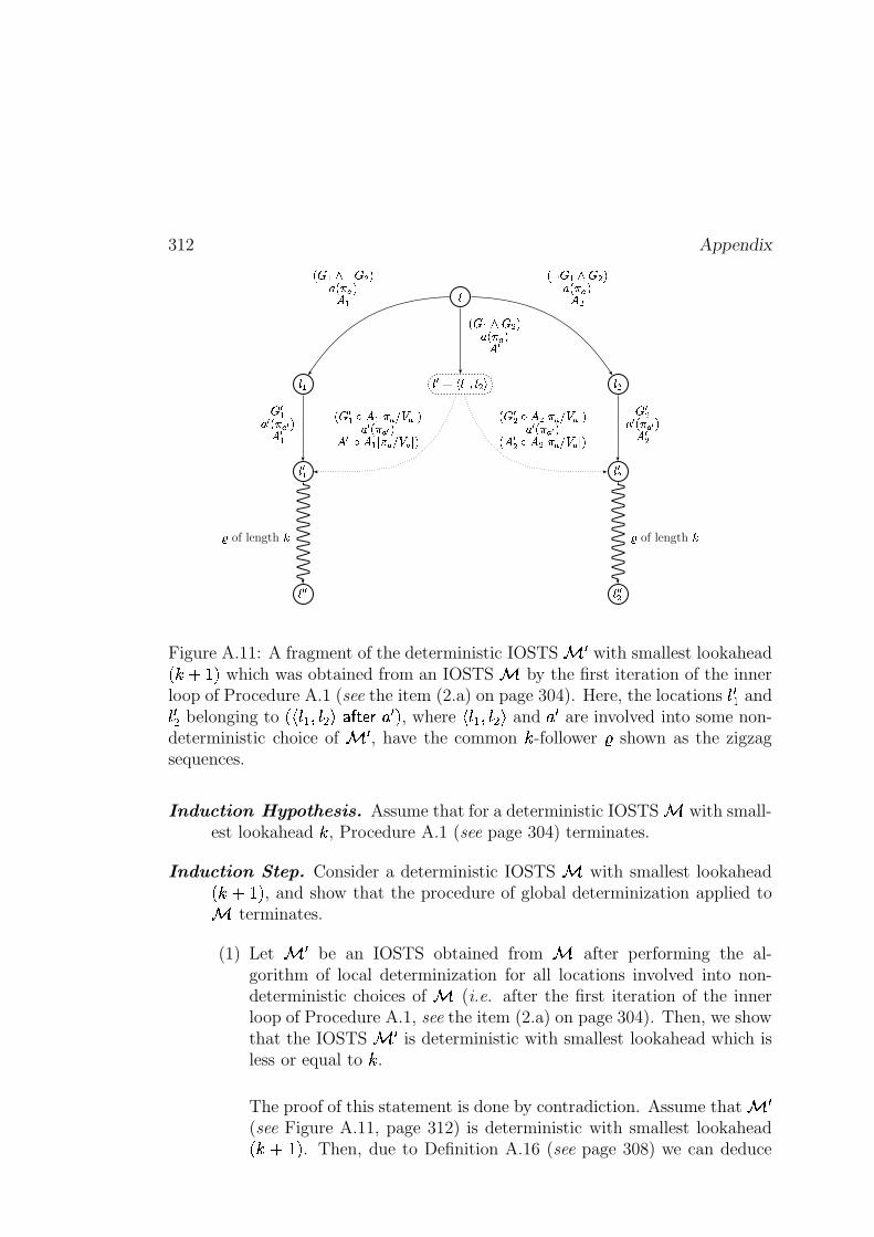
312 Appendix
�
� � ������ � � � ��� �����
��� � ����
��� �� ��� ��
�� �� � � ���� ����� �� �
� � � �� � ���� ����� �� �
� � �� � ������� �� � �� � �� � ������� �� � �
��� �� � ���� ����� �� �
�� � ��� � ��� ���������� �� � �����!� �� � � � � ��� ���������� ���� � �"� � �#� ���������� �� � ������� �� � � � � � �#� ���������� �
$ of length % $ of length %
Figure A.11: A fragment of the deterministic IOSTS Wwith smallest lookahead
� �'&)( ' which was obtained from an IOSTS by the first iteration of the innerloop of Procedure A.1 (see the item (2.a) on page 304). Here, the locations � W = and� W* belonging to ������=i��� * +&132547698 ; W ' , where ����=i��� * + and ; W are involved into some non-deterministic choice of W
, have the common � -follower : shown as the zigzagsequences.
Induction Hypothesis. Assume that for a deterministic IOSTS with small-est lookahead � , Procedure A.1 (see page 304) terminates.
Induction Step. Consider a deterministic IOSTS with smallest lookahead� �+&,( ' , and show that the procedure of global determinization applied to terminates.
(1) Let Wbe an IOSTS obtained from after performing the al-
gorithm of local determinization for all locations involved into non-deterministic choices of (i.e. after the first iteration of the innerloop of Procedure A.1, see the item (2.a) on page 304). Then, we showthat the IOSTS W
is deterministic with smallest lookahead which isless or equal to � .
The proof of this statement is done by contradiction. Assume that W(see Figure A.11, page 312) is deterministic with smallest lookahead� �-&.( ' . Then, due to Definition A.16 (see page 308) we can deduce
Determinization 313
that there exist locationsU � E W6U �� \ ^����
such that:
(a)U � E
andU �� belong to
�VU � ���w�� � � � � for some locationU � \ ^�� �
and someaction � � \�� ��� t � �
, which are involved into a non-deterministicchoice of �
�, and
(b)U � E
andU �� have a common -follower, but they do not have any
common� �� ���
-follower.
Next, asU �
is involved into a non-deterministic choice of ��, and as
��has been obtained from the IOSTS � by solving non-determinism
in all its locations involved into non-deterministic choices; thenU �
is anewly created location, i.e.
U � \ ^����but
U ���\ ^.
Finally, asU �
is a new location obtained by the algorithm of local de-terminization (see page 295), then there exists at least two locationsUrE
andU � in � such that:
(c)U � 9 T;G,G<G,W6UVE�W<G<G<G�W6U � W,G<G<G Y ,
(d)UrE
andU � belongs to
� U����w�� � � � for some locationU \�^
and someaction � \ ����� t � �
, which are involved into a non-deterministicchoice of � , and
(e)UrE
(resp.U � ) is the direct predecessor of
U � E(resp.
U �� ) by the action� � . For better understanding look at Figure A.11 (see page 312).
Thus, as we know thatU � E
andU �� of �
�have a common -follower,
but do not have any common� � �|�
-follower (see item (a)), then dueto the item (e) we obtain that the locations
U_Eand
U � of � have thecommon
� � ���-follower, but do not have any common
� � F � -follower.This statement together with the item (d) and Definition A.16 (seepage 308), imply that the IOSTS � is deterministic with smallestlookahead
� � F � , which contradicts to the assumption that � is thedeterministic IOSTS with smallest lookahead
� �� ���.
Therefore, at the end of the first iteration of the inner loop of Pro-cedure A.1 (see page 304), we obtain a deterministic IOSTS �
�with
smallest lookahead which is less or equal to .
(2) Using the induction hypothesis, we conclude that Procedure A.1 (seepage 304) terminates.
� G �yG�� GHence, in this section we have located the class of IOSTS with lookahead forwhich the procedure of global determinization (see page 304) terminates, andproduces a deterministic IOSTS in sense of Definition 4.20 given on page 93.

314 Appendix
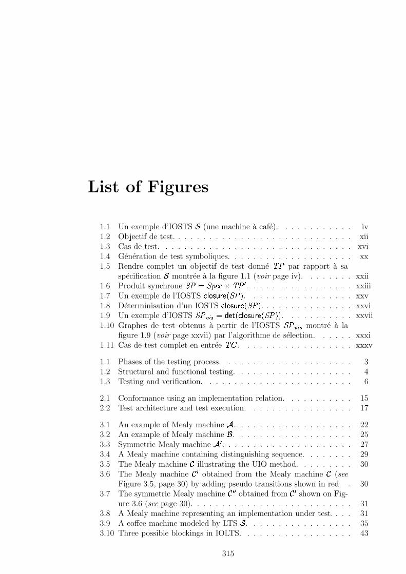
List of Figures
1.1 Un exemple d’IOSTS � (une machine à café). . . . . . . . . . . . iv1.2 Objectif de test. . . . . . . . . . . . . . . . . . . . . . . . . . . . . xii1.3 Cas de test. . . . . . . . . . . . . . . . . . . . . . . . . . . . . . . xvi1.4 Génération de test symboliques. . . . . . . . . . . . . . . . . . . . xx1.5 Rendre complet un objectif de test donné
'(�par rapport à sa
spécification � montrée à la figure 1.1 (voir page iv). . . . . . . . xxii1.6 Produit synchrone
�� 9& �!�"$#8%B'(� �. . . . . . . . . . . . . . . . . xxiii
1.7 Un exemple de l’IOSTS � � ����������� ����. . . . . . . . . . . . . . . . . xxv
1.8 Déterminisation d’un IOSTS � � ����������� ����. . . . . . . . . . . . . . . xxvi
1.9 Un exemple d’IOSTS ���� � % 9 � ��,� � � ���������� ����;�
. . . . . . . . . . . xxvii1.10 Graphes de test obtenus à partir de l’IOSTS
���� � % montré à lafigure 1.9 (voir page xxvii) par l’algorithme de sélection. . . . . . xxxi
1.11 Cas de test complet en entrée'��
. . . . . . . . . . . . . . . . . . xxxv
1.1 Phases of the testing process. . . . . . . . . . . . . . . . . . . . . 31.2 Structural and functional testing. . . . . . . . . . . . . . . . . . . 41.3 Testing and verification. . . . . . . . . . . . . . . . . . . . . . . . 6
2.1 Conformance using an implementation relation. . . . . . . . . . . 152.2 Test architecture and test execution. . . . . . . . . . . . . . . . . 17
3.1 An example of Mealy machine � . . . . . . . . . . . . . . . . . . . 223.2 An example of Mealy machine . . . . . . . . . . . . . . . . . . . 253.3 Symmetric Mealy machine � �
. . . . . . . . . . . . . . . . . . . . . 273.4 A Mealy machine containing distinguishing sequence. . . . . . . . 293.5 The Mealy machine � illustrating the UIO method. . . . . . . . . 303.6 The Mealy machine � � obtained from the Mealy machine � (see
Figure 3.5, page 30) by adding pseudo transitions shown in red. . 303.7 The symmetric Mealy machine � � � obtained from � � shown on Fig-
ure 3.6 (see page 30). . . . . . . . . . . . . . . . . . . . . . . . . . 313.8 A Mealy machine representing an implementation under test. . . . 313.9 A coffee machine modeled by LTS � . . . . . . . . . . . . . . . . . 353.10 Three possible blockings in IOLTS. . . . . . . . . . . . . . . . . . 43
315
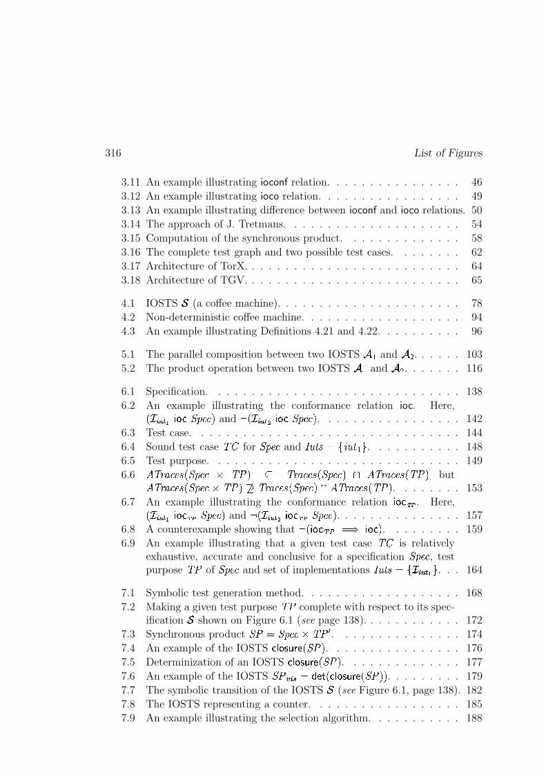
316 List of Figures
3.11 An example illustrating ioconf relation. . . . . . . . . . . . . . . . 46
3.12 An example illustrating ioco relation. . . . . . . . . . . . . . . . . 49
3.13 An example illustrating difference between ioconf and ioco relations. 50
3.14 The approach of J. Tretmans. . . . . . . . . . . . . . . . . . . . . 54
3.15 Computation of the synchronous product. . . . . . . . . . . . . . 58
3.16 The complete test graph and two possible test cases. . . . . . . . 62
3.17 Architecture of TorX. . . . . . . . . . . . . . . . . . . . . . . . . . 64
3.18 Architecture of TGV. . . . . . . . . . . . . . . . . . . . . . . . . . 65
4.1 IOSTS � (a coffee machine). . . . . . . . . . . . . . . . . . . . . . 78
4.2 Non-deterministic coffee machine. . . . . . . . . . . . . . . . . . . 94
4.3 An example illustrating Definitions 4.21 and 4.22. . . . . . . . . . 96
5.1 The parallel composition between two IOSTS � Eand � � . . . . . . 103
5.2 The product operation between two IOSTS � Eand � � . . . . . . . 116
6.1 Specification. . . . . . . . . . . . . . . . . . . . . . . . . . . . . . 138
6.2 An example illustrating the conformance relation ioc. Here,������� S � � � � �!�"$# �and � ������ S � � � �!�"$# �
. . . . . . . . . . . . . . . . . 142
6.3 Test case. . . . . . . . . . . . . . . . . . . . . . . . . . . . . . . . 144
6.4 Sound test case'��
for �!�"$#
and �� X 7 9 �� � X�E � . . . . . . . . . . . 148
6.5 Test purpose. . . . . . . . . . . . . . . . . . . . . . . . . . . . . . 149
6.62 '43$5�#$"�7��� �!�"$# % '(��� ? '/365�#$"�7��� �!�"$# � � 2 '4365�#$"�7�� '(���
but2 '/365�#$"�7��� �!�"$#8%B'(��� � '4365�#$"�7��� �!�"$# � � 2 '/365�#$"�7��|'(���. . . . . . . . 153
6.7 An example illustrating the conformance relation� � ����� . Here,������� S � � � ����� �!�"$# �
and � ������ S � � ����� �!�"$# �. . . . . . . . . . . . . . . 157
6.8 A counterexample showing that � ��� � � h<j 9�� � � � � . . . . . . . . . 159
6.9 An example illustrating that a given test case'��
is relativelyexhaustive, accurate and conclusive for a specification
�!�"$#, test
purpose'(�
of �!�"$#
and set of implementations �� Xw789 ������� S � � . . . 164
7.1 Symbolic test generation method. . . . . . . . . . . . . . . . . . . 168
7.2 Making a given test purpose'(�
complete with respect to its spec-ification � shown on Figure 6.1 (see page 138). . . . . . . . . . . . 172
7.3 Synchronous product ��=9& �!�"$#8%B'(� �
. . . . . . . . . . . . . . . 174
7.4 An example of the IOSTS � � ����������� ����. . . . . . . . . . . . . . . . 176
7.5 Determinization of an IOSTS � � ����������� ����. . . . . . . . . . . . . . 177
7.6 An example of the IOSTS �� � � % 9 � ��,� � � ���������� ����;�
. . . . . . . . . 179
7.7 The symbolic transition of the IOSTS � (see Figure 6.1, page 138). 182
7.8 The IOSTS representing a counter. . . . . . . . . . . . . . . . . . 185
7.9 An example illustrating the selection algorithm. . . . . . . . . . . 188
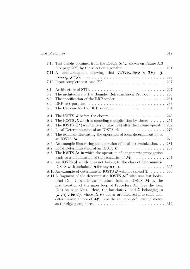
List of Figures 317
7.10 Test graphs obtained from the IOSTS ���� � % shown on Figure A.3
(see page 262) by the selection algorithm. . . . . . . . . . . . . . . 1917.11 A counterexample showing that
2 '4365�#$"�7��� �!�"$# % '(��� �?'4365�#$"�7 Q������ � '����. . . . . . . . . . . . . . . . . . . . . . . . . . . . . 199
7.12 Input-complete test case'��
. . . . . . . . . . . . . . . . . . . . . 207
8.1 Architecture of STG. . . . . . . . . . . . . . . . . . . . . . . . . . 2278.2 The architecture of the Bounder Retransmission Protocol. . . . . 2308.3 The specification of the BRP sender. . . . . . . . . . . . . . . . . 2318.4 BRP test purpose. . . . . . . . . . . . . . . . . . . . . . . . . . . 2338.5 The test case for the BRP sender. . . . . . . . . . . . . . . . . . . 234
A.1 The IOSTS � before the closure. . . . . . . . . . . . . . . . . . . 248A.2 The IOSTS � which is modeling mutiplication by three. . . . . . 257A.3 The IOSTS
��(see Figure 7.3, page 174) after the closure operation.262
A.4 Local Determinization of an IOSTS � . . . . . . . . . . . . . . . . 276A.5 The example illustrating the operation of local determinization of
an IOSTS � . . . . . . . . . . . . . . . . . . . . . . . . . . . . . . 279A.6 An example illustrating the operation of local determinization. . . 281A.7 Local Determinization of an IOSTS . . . . . . . . . . . . . . . . 288A.8 The IOSTS � in which the operation of assignments propagation
leads to a modification of the semantics of � . . . . . . . . . . . . 297A.9 An IOSTS � which does not belong to the class of deterministic
IOSTS with lookahead for any \ �. . . . . . . . . . . . . . . . 305
A.10 An example of deterministic IOSTS with lookahead � . . . . . . 306A.11 A fragment of the deterministic IOSTS �
�with smallest looka-
head� � ���
which was obtained from an IOSTS � by thefirst iteration of the inner loop of Procedure A.1 (see the item(2.a) on page 304). Here, the locations
U � Eand
U �� belonging to�;TrUrE�W�U � Y � �w���� � � � , whereTrUrE�W6U � Y and � � are involved into some non-
deterministic choice of ��, have the common -follower � shown
as the zigzag sequences. . . . . . . . . . . . . . . . . . . . . . . . 312

318 List of Figures

Bibliography
Abrial, J.-R. (1996). The B-Book: Assigning Programs to Meanings. CambridgeUniversity Press.
Ackermann, W. (1954). Solvable Cases of the Decision Problem. North-HollandPublishing Company.
Aho, A., Dahbura, A., Lee, D., and Uyar, M. (1988). An optimization techniquefor protocol conformance test generation based on UIO sequences and ruralchinese postman tours. In Aggrawal, S. and Sabnani, K., editors, ProtocolSpecification, Verification, and Testing.
Ambert, F., Bouquet, F., Chemin, S., Guenaud, S., Legeard, B., Peureux, F.,Vacelet, N., and Utting, M. (2002). Bz-tt: A tool-set for test generationfrom Z and B using contraint logic programming. In Hierons, R. and Jéron,T., editors, Proceedings of the Formal Approaches to Testing of Software,FATES’02 workshop of CONCOUR’02, pages 105–120.
Angluin, D. (1982). Inference of reversible languages. Journal of the Associationfor Computing Machinery, 29(3):741–765.
Barnes, J. (1984). Programming in Ada. Addison-Wesley, Second Edition.
Beizer, B. (1990). Software Testing Techniques. New York: Van Nostrand Rein-hold.
Beizer, B. (1995). Black-Box Testing. John Wiley and Sons.
Belinfante, A., Feenstra, J., de Vries, R., Tretmans, J., Goga, N., Feijs, L., andMauw, S. (1999). Formal test automation: a simple experiment. In Csopaki,G., Dibuz, S., and Tarnay, K., editors, International Workshop on the Testingof Communication Systems (IWTCS’99), pages 179–196. Kluwer AcademicPublishers.
Bernot, G. (1991). Testing against formal specifications: A theoretical view.In Abramsky, S. and Maibaum, T., editors, TAPSOFT’91, volume 2-494 ofLecture Notes in Computer Science, pages 99–119. Springer-Verlag.
319
320 BIBLIOGRAPHY
Bertot, Y. and Castéran, P. (2004). Coq’Art: The Calculus of Inductive Con-structions. EATCS Series.
Bouquet, F., Legeard, B., and Peureux, F. (2002). Clps-b: A constraint solver forB. In Proceedings of the International Conference on Tools and Algorithmsfor the Construction and Analysis of Systemsw (TACAS’02), volume 2280 ofLNSC, pages 188–204, Grenoble, France.
Bozga, M., Fernandez, J.-C., Ghirvu, L., Graf, S., Krimm, J.-P., and Mounier,L. (1999a). IF: An intermediate representation and validation environmentfor timed asynchronous systems. In Wing, J., Woodcock, J., and Davies,J., editors, Proceedings of World Conference on Formal Methods, FM’99,volume 1708 of LNCS, pages 307–327, Toulouse, France. Springer-Verlag.
Bozga, M., Fernandez, J.-C., Ghirvu, L., Graf, S., Krimm, J.-P., Mounier, L.,and Sifakis, J. (1999b). IF: An intermediate representation for SDL and itsapplications. In Dssouli, R., Bochmann, G., and Lahav, Y., editors, SDLFORUM’99, Montreal, Canada. Elsevier Science Publishers B.V.(North-Holland).
Bozga, M., Graf, S., and Mounier, L. (2002). IF-2.0: A validation environment forcomponent-based real-time systems. In Brinksma, E. and Larsen, K., editors,CAV’02, volume 2404 of LNCS, Copenhagen, Denmark. Springer-Verlag.
Brinksma, E. (1988). A theory for the derivation of tests. In Aggarwal, S. andSabnani, K., editors, Protocol Specification, Testing, and Verification (PSTVVIII), pages 63–74. Elsevier Science Publishers B.V.(North-Holland).
Brinksma, E., Alderden, R., Langerak, J., de Lagemaat, R. V., and Tretmans, J.(1990). A formal approach to conformance testing. In Meer, J. D., Mackert,L., and Effelsberg, W., editors, Second International Workshop on ProtocolTest Systems, pages 349–363. North Holland.
Brookes, S. and Roscoe, A. (1985). An improved failures model for communicatingsequential processes. In Proceedings of NSF-SERC Seminar on Concurrency,volume 197 of LNCS. Springer-Verlag.
Budd, T., DeMillo, R., Lipton, R., and Sayward, F. (1980). Theoretical and em-pirical studies on using program mutation to test the functional correctness ofprogram. 7th ACM Symp. on Princ. of Programming Languages (POPL’80),pages 220–233.
CEPSCO (2000). Common Electronic Purse Specifications - Technical Specifica-tion (http://www.cepsco.org).
BIBLIOGRAPHY 321
Cheadle, A., Harvey, W., Sadler, A., Schimpf, J., Shen, K., and Wallace, M.(2003). ECLiPSe: An introduction. Technical report, IC-Parc, ImperialCollege London.
Chow, T. (1978). Testing software design modelled by finite state machines. IEEETransactions on Software Engineering, SE-4(3):178–187.
Clarke, D., Jéron, T., Rusu, V., and Zinovieva, E. (2001a). Automated testand oracle generation for smart-card applications. In Proceedings of theInternational Conference on Research in Smart Cards, volume 2140 of LNCS,pages 58–70, Cannes, France. Springer-Verlag.
Clarke, D., Jéron, T., Rusu, V., and Zinovieva, E. (2001b). STG: A tool for gen-erating symbolic test programs and oracles from operational specifications.In Gruhn, V., editor, Proceedings of the joint 8th ESEC and 9th FSE, ACMPress, pages 301–302, Vienna, Austria.
Clarke, D., Jéron, T., Rusu, V., and Zinovieva, E. (2001c).STG: A tool for generating symbolic test programs and ora-cles from operational specifications (long version). Available athttp://www.irisa.fr/prive/lenaz/research/papers/esec-full.ps.
Clarke, D., Jéron, T., Rusu, V., and Zinovieva, E. (2002). STG: A SymbolicTest Generation tool. In The 8th International Conference on Tools and Al-gorithms for the Construction and Analysis of System (TACAS’02), volume2280 of LNCS, pages 470–475, Grenoble, France. Springer-Verlag.
Clarke, E. M., Grumberg, O., and Peled, D. (1999). Model Checking. MIT Press.
Clatin, M., Groz, R., Phalippou, M., and Thummel, R. (1995). Two approcheslinking a test generation tool with verification techniques. In InternationalWorkshop on Protocol Test Systems (IWPTS’95), Ervy, France.
CNET (2000). 10 great bugs of history. Available athttp://www.bus.tu.ac.th/usr/angsana/IS301-1-42/Outline/
greatbug.htm.
Cousot, P. and Cousot, R. (1976). Static determination of dynamic properties ofprograms. In The 2nd International Symposium on Programming. Dunod,Paris.
Cousot, P. and Cousot, R. (1977). Abstract interpretation: a unified latticemodel for static analysis of programs by construction or approximation offixpoints. Conference Record of the Fourth Annual ACM SIGPLAN-SIGACTSymposium on Principles of Programming Languages, pages 238–252.
322 BIBLIOGRAPHY
Cousot, P. and Halbwachs, N. (1978). Automatic discovery of linear restraintsamong variables of a program. In The 5th ACM Symposium on Principles ofProgramming Languages (POPL’78), Tucson, Arizona, USA. Dunod, Paris.
Dauchy, P., Gaudel, M.-C., and Marre, B. (1993). Using algebraic specificationsin software testing: a case study on the software of an automatic subway.Journal of Systems and Software, 21(3):229–244.
de Nicola, R. (1987). Extensional equivalences for transition systems. Acta In-formatica, 24:211–237.
de Nicola, R. and Hennessy, M. (1984). Testing equivalences for processes. The-oretical Computer Science, 34:83–133.
Dowek, G., Felty, A., Herbelin, H., Huet, G., Murthy, C., Parent, C., Paulin-Mohring, C., and Werner, B. (1993). The COQ proof assistant: User’sguide. Technical report, INRIA – Rocquencourt.
du Bousquet, L., Ramangalahy, S., Simon, S., Viho, C., Belinfante, A., andde Vries, R. G. (2000). Formal test automation: The conference protocolwith TGV/TorX. In Ural, H., Probert, R., and Bochmann, G., editors,IFIP 13th International Conference on Testing of Communication Systems(TestCom2000). Kluwer Academic Publishers.
Edmonds, J. and Johnson, E. (1973). Matching Euler tours and the chinesepostman. Mathematical Programming, 5:88–124.
Eertink (1993). SMILE: User manual, relise 4.0. University of Twente, TheNetherlands.
Eertink, E. (1994). Simulation Thechniques For the Validation of LOTOS Speci-fication. PhD thesis, University of Twente, the Netherlands.
Fernandez, J.-C., Jard, C., Jéron, T., and Viho, C. (1996). Using on-the-flyverification techniques for the generation of test suites. In Alur, T. andHenzinger, A., editors, Comuter-Aided Verification (CAV’96), volume 1102of LNCS, New Brunswick, New Jersey, USA. Springer-Verlag.
Fernandez, J.-C., Jard, C., Jéron, T., and Viho, C. (1997). An experiment inautomatic generation of test suites for protocols with verification technology.Science of Computer Programming, 29(1-2):123–146.
Fowler, M. and Scott, K. (2000). UML Distilled: a Brief Guide to the StandardObject Modeling Language. 2nd Edition.
BIBLIOGRAPHY 323
Gansner, E. R. and North, S. C. (2000). An open graph visualization system andits applications to software engineering. Software: Practice and Experience,30(11):1203–1233.
Gaudel, M.-C. and James, P. (1999). Testing algebraic data types and processes:a unifyin theory. Formal Acpects of Computing, 10(5-6):436–451.
Gill, A. (1962). Introduction to the Theory of Finite State Machine. New York,McGraw-Hill.
Gonenc, G. (1970). A method for the design of fault detection experiments. IEEETransactions on Computing, C-19.
Gotlieb, A., Botella, B., and Rueher, M. (1998). Automatic test data generationusing constraint solving techniques. ACM SIGSOFT Software EngineeringNotes, 23(2):53–62.
Gotlieb, A., Botella, B., and Rueher, M. (2000). A CLP framework for computingstructural test data. In Proceedings of the Conference on ComputationalLogic (CL’00), pages 399–413, Imperial College, London, UK.
Grabowski, J. (1994). SDL and MSC based test case generation: An overallview of the SaMsTaG method. Technical Report IAM-94-005, University ofBerne, Institute for Informatics, Berne, Switzerland.
Grabowski, J., Hogrefe, D., and Nahm, R. (1993). A method for the generation oftest cases based on SDL and MSCs. Technical Report IAM-93-010, Universityof Berne, Institute for Informatics, Berne, Switzerland.
Groote, J.-F. and van de Pol, J. (1993). A bounded retransmission protocol forlarge data packets. Technical report, Logic Group, Utrecht University.
Halbwachs, N., Caspi, P., Raymond, P., and Pilaud, D. (1991). The synchronousdata flow programming language LUSTRE. In Proceeding of the IEEE, vol-ume 79-9, pages 1305–1320.
Harel, D. (1987). Statecharts: A visual formalism for complex systems. Scienceof Computer Programming, 8(3):231–274.
Harel, D. and Pnueli, A. (1985). On the development of reactive systems. In Apt,K., editor, Logics and Models of Concurrent Systems, volume F-13 of NATOASI Series, pages 477–498, New York. Springer-Verlag.
Havelund, K. and Shankar, N. (1996). Experiments in theorem proving and modelchecking for protocol verification. In FME’02.
324 BIBLIOGRAPHY
Heerink, A. W. (1998). Ins and Outs in Refusal Testing. PhD thesis, Universityof Twente, the Netherlands.
Helmink, L., Sellink, M., and Vaandrager, F. (1994). Proof-checking a data linkprotocol. In Barendregt, H. and Nipkow, T., editors, Proceedings of the 1stInternatioanl Workshop on Types for Proofs and Programs, volume 806 ofLNCS, pages 127–165, Berlin. Springer-Verlag.
Hennie, F. (1964). Fault detecting experiments for sequential circuits. In The 5thAnn. Symp. Switching Circuit Theory and Logical Design, pages 95–110.
Hoare, C. (1985). Communicating Sequential Processes. Prentice Hall Interna-tional.
Hopcroft, J. E. and Ullman, J. D. (1979). Introduction to Automata Theory,Languages, and Computation. Addison-Wesley Publishing Company, Inc.
Howden, W. (1982). Weak mutation testing and completeness of test sets. IEEETransactions on Software Engineering, SE-8(4):371–379.
Hower, R. (1996-2003). Software quality assurance and testing resource center.Available at http://www.softwareqatest.com/.
Hsieh, E. (1971). Checking experiments for sequential machines. IEEE Transac-tions on Computers, C-20(10):1156–1166.
IEEE/ANSI (1990). IEEE Standard Glossary of Software Engineering Terminol-ogy. IEEE Std 610.12. IEEE Press, New York, NY, USA.
Intelligent Systems Laboratory (2004). SICStus Prolog User’s Manual. IntelligentSystems Laboratory, Swedish Institute of Computer Science, Kista, Sweden.
Isbell, D. and Savage, D. (1999). Mars climate orbiter failure board re-leases report, numerous nasa actiona underway in rerponse. Available athttp://mars.jpl.nasa.gov/msp98/news/mco991110.html.
Ishisone, M. and Sawada, T. (2001). Brute: brute force rewriting engine. Availableat http://www.theta.ro/cafeobj.
ISO (1991). Information Technology, Open Systems Interconnection, Confor-mance Testing Methodology and Framework. International Standard IS-9646. Geneve.
BIBLIOGRAPHY 325
ISO/IEC (1988). LOTOS - a formal description technique based on the temporalordering of observational behaviour. Technical Report 8807, InternationalOrganization for Standards - Information Processing Systems - Open Sys-tems Interconnection.
ISO/IEC (1992). International Standard 9646-1/2/3, OSI-Open Systems Inter-connection, Information Technology - Open Systems Interconnection Con-formance Testing Methodology and Framework.
ISO/IEC (1996). ISO/IEC JTC1/SC21 WG7, ITU-T SG 10/Q.8. Proposed ITU-T Z.500 and Committee Draft on “Formal Methods in Conformance Testing”.CD 13245-1. ISO – ITU-T. Geneve.
ISO/IEC/JTC1/SC21 (1992). Information technology – open systems intercon-nection – conformance testing methodology and framework – part 3: TheTree and Tabular Combined Notation.
ISO/TC97/SC21 (1997). Estelle – a formal description thechnique based on anextended state transition model.
ITU-T (1994). Recommendation Z-100. Specification and Description Language(SDL).
ITU-T (1996). ITU-T recommendation Z-120: Message Sequence Chart (MSC).
Jard, C. and Jéron, T. (2002). TGV: Theory, principles and algorithms. The SixthWorld Conference on Integrated Design and Process Technology (IDPT’02).
Jard, C., Jéron, T., and Morel, P. (2000). Verification of test suites. In TestCom2000, IFIP TC 6 / WC 6.1, the IFIP 13th International Conference onTesting of Communicating Systems, volume 2477 of LNCS, Ottawa, Ontario,Canada. Kluwer Academic Publishers.
Jeannet, B. (2000a). Dynamic partitioning in linear relation analysis. TechnicalReport RS-00-38, BRICS.
Jeannet, B. (2000b). Dynamic partitioning in linear relation analysis. Applicationto verification of reactive systems. Formal Methods in System Design.
Jeng, B. and Weyuker, E. J. (1994). A simplified domain-testing strategy. ACMTransactions on Software Engineering and Methodology, 3(3):254–270.
Jéron, T. and Morel, P. (1999). Test generation derived from model-checking.In Computer Aided Verification (CAV ’99), volume 1633 of LNCS, pages108–122.
326 BIBLIOGRAPHY
Jéron, T. (2002). TGV: Théorie, principles et algorithmes. Techniques et SciencesInformatiques, numéro spécial Test de Logiciels.
Jéron, T. (2004). Contribution à la génération automatique de tests pour les sys-tèmes réactifs. Habilitation à Diriger des Recherches, Université de RennesI, France.
Kahlouche, H., Viho, C., and Zendri, M. (1999). Hardware testing using a com-munication protocol conformance testing tool. In The International Work-shop on Tools and Algorithms for the Construction and Analysis of Systems(TACAS’99).
Keller, R. (1976). Formal verification of parallel programs. Commun. ACM,19:561–572.
Kelly, W., Maslov, V., Pugh, W., Rosser, E., Shpiesman, T., and Wonnacott, D.(1995). The omega library interface guide. Technical Report CS-TR-3445,Department of Computer Science, University of Maryland, College Park.
Kerbrat, A., Jéron, T., and Groz, R. (1999). Automated test genration from SDLspecifications. In SDL’99 The Next Millenium, 9th SDL Forum, pages 135–152, Montréal, Canada. Elsevier Science Publishers B.V.(North-Holland).
Kerbrat, A. and Ober, I. (1999). Automated test generation from SDL/UMLspecifications. In 12th International Software Quality Week, San Jose CA,USA.
Koch, B., Grabowski, J., Hogrefe, D., and Schmitt, M. (1998). Autolink - atool for automatic test generation from SDL specifications. In IEEE Inter-national Workshop on Industrial Strength Formal Specification Techniques(WIFT’98), Boca Raton FL, USA.
Kohavi, Z. (1978). Switching and Finite Automata Theory. 2nd Edition McGraw-Hill.
Lee, D. and Yannakakis, M. (1996). Principles and methods of testing finite statemachines - a survey. IEEE, 84(8):1090–1123.
Lestiennes, G. and Gaudel, M.-C. (2002). Testing processes from formal specifica-tions with inputs, outputs and data types. In The 13th International Sympo-sium on Software Reliability Engineering (ISSRE’02), Annapolis, Maryland,USA. IEEE Computer Society Press.

BIBLIOGRAPHY 327
Leue, S. and Holzmann, G. (1999). V-promela: A visual, object-oriented languagefor spin. In ObjectOriented Real-Time Distributed Computing (ISORC’99),pages 14–23, Houston, Texas, USA. IEEE Computer Society Press.
Leveson, N. and Turner, C. (1993). An investigation of the therac-25 accidents.IEEE Computer, 26(7):18–41.
Lewis, H. R. and Papadimitriou, C. H. (1981). Elements of the Theory of Com-putation. Prentice-Hall Software. Prentice-Hall, Inc., Englewood Cliffs, NewJersey.
Lugato, D., Bigot, C., and Valot, Y. (2002). Validation and automatic testgeneration on UML models: Agata approch. Electronics Notes in TheoreticalComputer Science, 66(2).
Lynch, N. and Tuttle, M. (1989). An introduction to input/output automata.CWI-Quarterly, 2(3):219–246.
Marre, B. and Arnould, A. (2000). Test sequence generation from LUSTREdescription: GATeL. In Proceedings of the Automated Software EngineeringConference, pages 229–237. IEEE Computer Society.
Melton, R., Dill, D., and Ip, C. N. (1992). Murphi annotated reference manual.Technical report, Stanford University.
Meudec, C. (2001). ATGen: Automatic test data generation using constraintlogic programming and symbolic execution. Software Testing, Verificationand Reliability Journal.
Milner, R. (1980). A calculus of communicating systems. In Lecture Notes inComputer Science, volume 92 of LNCS. Springer-Verlag.
Morel, P. (2000). Une Algorithmique Efficace pour la Génération Automatique deTests de Conformité. PhD thesis, Université de Rennes I, France.
Musa, J. (1975). A theory of software reliability and its application. IEEETransactions on Software Engineering, SE-1(3):312–327.
Myers, G. (1976). Software Reliability: Principles and Practice. McGraw-Hill,New York.
Myers, G. (1979). The Art of Software Testing. John Wiley & Sons.
Naito, S. and Tsunoyama, M. (1981). Fault detection for sequential machines bytransition tours. In The 11th IEEE Fault Tolerant Computing Conference,pages 238–243.
328 BIBLIOGRAPHY
Nielsen, B. (2000). Specification and Test of Real-Time System. PhD thesis,Aalborg University, Denmark.
Owre, S., Rashby, J., and Shankar, N. (1992). PVS: A prototype verificationsystem. In Proceedings of the 11st Internatioanl Conference on AutomatedDeduction (CADE), volume 607 of Lecture Notes in Artificial Intelligence,pages 748–752, Saratoga - NY.
Petrenko, A., Boroday, S., and Groz, R. (1999). Confirming configuration in efsm.In Formal Methods for Protocol Engeneering and Distributed Systems, pages5–24, Beijing, China. Kluwer Academic Publisher.
Phalippou, M. (1994). Relations d’Implantations et Hypothèses de Test sur lesAutomates à Entreées et Sorties. PhD thesis, Université de Bordeaux, France.
Phalippou, M. and Groz, R. (1990). Evaluation of an empirical approach forcomputer-aided test case generation. In Davidson, I., editor, 3rd Interna-tional Workshop on Protocol Test Systems (IWPTS’90), McLean VA, USA.
Phillips, I. (1987). Refusal testing. Theoretical Computer Science, 50(2):241–284.
Pitt, H. and Freestone, D. (1990). The deriviation of conformance tests from LO-TOS specifications. In IEEE Transactions on Software Engineering, volume16-12, pages 1337–1343.
Pnueli, A. (1986). Applications of temporal logic to the specification and verifi-cation of reactive systems: a survey of current trends. In Current Trends inConcurrency. Overviews and Tutorials, pages 510–584, New York. Springer-Verlag.
Ponscarme, F.-X. (2002). Contributions au développement et à l’utilisation del’outil STG. Technical report, Université de Rennes 1.
Presburger, M. (1929). Uber die vollstandigkeit eines gewissen systems der arith-metik ganzer zahlen in welchem die addition als einzige operation hervortritt.In Sprawozdanie z I Kongresu Matematykow Krajow Slowcanskich Warszawa,pages 92–101, Poland.
Rapps, S. and Weyuker, E. J. (1985). Selecting software test data using data flowinformation. IEEE Transactions on Software Engineering, SE-11(4):367–375.
Rellier, J.-P. and Vardon, F. (1998). Con’Flex version 1.2: Manuel de l’utilisateur.Available at http://www-bia.inra.fr.
BIBLIOGRAPHY 329
Rusu, V., du Bousquet, L., and Jéron, T. (2000). An approach to symbolictest generation. In International Conference on Integrating Formal Methods,volume 1945 of LNCS, pages 338–357, Dagstuhl, Germany. Springer-Verlag.
Rusu, V., Marchand, H., and Jéron, T. (2004). Verification and symbolic testgeneration for safety properties. Technical Report Internal Publication 5285,INRIA – Rennes.
Rusu, V. and Zinovieva, E. (2001). Analyzing automata with presburger arith-metic and uninterpreted function symbols. Electronic Notes in TheoreticalComputer Science, 50(4):329–343.
Sabnani, K. and Dahbura, A. (1985). A new technique for generating protocoltests. ACM Computer Communications, 15(4).
Schmitt, M., Ek, A., Grabowski, J., Hogrefe, D., and Koch, B. (1998). Au-tolink - putting SDL-based test generation into practice. In Petrenko, A. andYevtuschenko, N., editors, Testing of Communicating Systems, volume 11.Kluwer Academic Publishers.
Spivey, J. (1992). The Z Notation: A Reference Manual. Prentice-Hall, SecondEdition.
Telelogic (1998). Autolink tutorial. Technical report, Telelogic AB Malm �� , Swe-
den.
Tretmans, G. J. (1992). A Formal Approach to Conformance Testing. PhD thesis,University of Twente, the Netherlands.
Tretmans, J. (1994). A formal approach to conformance testing. In The 6th In-ternational Workshop on Protocol Test Systems, number C-19 in IFIP Trans-actions, pages 257–276.
Tretmans, J. (1995). Testing labeled transition systems with inputs and outputs.In Cavalli, A. and Budkowski, S., editors, The 8th International Workshopon Protocol Test Systems, pages 461–476, Ervy, France.
Tretmans, J. (1996a). Test generation with inputs, outputs, and quiescence.In Margaria, T. and Steffen, B., editors, The 2nd International Work-shop on Tools and Algorithms for the Construction and Analysis of Systems(TACAS’96), volume 1055 of LNCS. Springer-Verlag.
Tretmans, J. (1996b). Test generation with inputs, outputs and repetative qui-escence. Software – Concepts and Tools, 17(3):103–120.
330 BIBLIOGRAPHY
Tretmans, J. (1999). Testing concurrent systems: a formal approach. In CON-CUR’99, volume 1664 of LNCS. Springer-Verlag.
Tretmans, J. (2002). Testing techniques. Lecture Notes.
Uyar, C. and Dahbura, A. (1986). Optimal test sequence generation for pro-tocols: The chinese postman algorith applied to Q.931. In IEEE GlobalTelecommunication Conference.
van Glabbeek, R. (2001). The Linear Time - Branching Time Spectrum I, chapter1 of Handbook of Process Algebra, pages 3–99. Elsevier Science PublishersB.V.(North-Holland).
Vasilevskii, M. (1973). Failure diagnosis of automata. Kibernetika, 4:98–108.
Warmer, J. and Kleppe, A. (1998). The Object Constraint Language: PreciseModeling with UML. Addison-Wesley.
Zinovieva, E. (2002). Symbolic test generation for reactive systems. In TheSummer School on Modelling and Verifying Parallel Processes (MOVEP’02),pages 429–434, Nantes, France.
Index
Symbols�. . . . . . . . . . . .see set of assignmentsu . . . . .see set of symbolic constants�. . . . see set of typed data, or data�. . . . . . . . . . . . . . . . . . . . . . . . see guard^. . . . . . . . . . . . . . . see set of locations
� . . . . . . . . . . . . see set of parameters�. . . . . . . . . . . . . . . . . . see set of states� � . . . . . . . . . . see set of initial states�. . . .see set of symbolic transitionsq. . . . . . . . . . . . . . .see set of variables
� . . . . . . . . . . . . . . . . . . . . . . . . see actionU. . . . . . . . . . . . . . . . . . . . . . .see locationU � . . . . . . . . . . . . . . . see initial locationL . . . . . . . . . . . . . . . . . . . . . . . . . see stateL � . . . . . . . . . . . . . . . . . . see initial state
� . . . . . . . . . . . see symbolic transition�. . . . . . . . . see set of valued actions� . see set of valued output actions� �. . .see set of valued input actions���see set of valued internal actions��� � �
see alphabet of visible actions�. . . . . . . . . . .see alphabet of actions� . . .see alphabet of output actions� �. . . . see alphabet of input actions� �. see alphabet of internal actions�
. . . . . . . . . . . . . . see initial conditionD. . . . . . . . . . . . . . . . .see valued action
}�� . . . . . . . . . . . . . . . . . . . . . . . . . . . . .109}�~ . . . . . . . . . . . . . . . . . . . .see behavior� . . . . . . . . . . . . . . . . . . . . . see sequence�
. . . . . . . . . . see tuple of parametersC . . . . . . . . . . . . . . . . . . . . . . . . . see trace
Z. . . . . . . . . . . . . see valuation of data
or valuation of variables andsymbolic constantsZ � . . . . . . . . . . see valuation of datum
� � �see set of boolean expressions� � �p�. . . . . . . . . see set of well-typedexpressions
� � �|�. . . . . . . see instance of IOSTS�
. . . . . . . . . . . . . see set of data types�. . . . . . . . . . . . . . see type of a datum � X . . see implementation under test�� � S . . . . . see implementation model �!�"$#
. . . . . . . . . . . . . . .see specification'��. . . . . . . . . . . . . . . . . . . see test case'��. . . . . . . . . . . . . . . . . .see test graph'(�. . . . . . . . . . . . . . . .see test purpose'( . . . . . . . . . . . . . . . . . . . see test suitelnm�op� � �
. . . . . . . see domain of datalnm�op� � �. . . . . . . . see domain of typelnm�op� � � . . . . . . see domain of datum�Ro����
. . . . . . . . . . . . . . . see universe ofimplementationso m�l��. . . . . . . . . . . . . . see universe ofimplementations modelsm����
. . . see universe of observations���������see universe of specifications��� �����. . . see universe of test cases2 '/365�#$"�7�� � �
. . . see set of acceptingtraces'/365�#$"�7 ! � �#" � � �
. . see set of fail traces'/365�#$"�7��%$ N'& $ N � � �. . . . . . . . . . see set of
inconclusive traces
)( � � � � . . . . . . . . . . . . . . . . . . . . . . . . . .140
331
332 Index
�����������. . . . . . . . . . . . . . . . . . . . . . . . 140 ������
. . . . . . . . . . . . . see set of prefixes����� ��������� ��� � �. .see set of quiescent
states! ������. . . . . . see set of strict prefixes! ��" � ���#����� ���$�
. see set of sequences%&��'(�����*),+.-/- ��� �see set of pass traces! %&��'(����� � � �
. . see set of suspension
traces! ��" � ���#������0�1 2 � 3*�. . . . . . . . . . . see set of46587 -sequences! ��" � ���#����� 0 � 3*�
see set of 4 -sequences%&��'(����� � � �. . . . . . . . see set of traces9;: <>=�?(@/A ��� �.see operation of closure9B<&:C: DFEG=HA � I&�. see collapsing operationJ ?G=�KL<&M ��NPO�QRNTS��
. . . . . . . . . . . . see fusionEU<>=HVHW � XYZ�. . . . . . . . . . . . . . . . . . . . . . 258E;@/<�[.AB9BV�KL<�M]\P^ � N_�
. . . . . . .see projectionD J V`A]@. . . . . . . . . . . . . . . . . . . . . . . .91, 305A�a]A�9. . . . . . . . . . . . . . . . . . . . . . . . . . . . . 17J D>Kb: =. . . . . . . . . . . . . . . . . . . . . . . . . . . . . 18KCcdE. . . . see implementation relationceDBf
_J D>Kb:
. . . . . . . . . . . . . . . . . . . . . . . 146ceDBf_
KbMG9B<&MG9. . . . . . . . . . . . . . . . . . . . 146ceDBf
_E;DG=,=
. . . . . . . . . . . . . . . . . . . . . . 146E;DG=,=HA�=. . . . . . . . . . . . . . . . . . . . . . . . . . . 18=�KLg � 7 �. . . . . . . see signature of actionV f(E>A ��h6�
. . . . . . . . . . . . . . . . . . . . see typei A;@/j&KL9�V. . . . . . . . . . . . . . . . . . see verdictj(A�VRk lHm ��� �
. . . . see operation of local
determinizationn. . . . . . . . . . . . . . . .see trace relationo p. . . . . . . . . . . . . . . . . . . . . .see satisfiesq. . . . see global transition relationqsrZtvudqsr ^
. . . . . . . . . . . . . . . . . . . . . .251qsr. . . . . see local transition relationw
. . . . . . . . . . . .see product operationx q. . . . . . . . . .see symbolic transitiono�o
. . . . . . . . . . see operation of parallel
composition
A
action . . . . . . . . . . . . . . . . . . . . . . . . . . . 81
alphabet of
– actions . . . . . . . . . . . . .22, 34, 41, 81
– input actions . . . . . . . . . . 22, 41, 81
– internal actions . . . . . . . . . . . . . . . 81
– output actions . . . . . . . . . 22, 41, 81
– visible actions . . . . . . . . . . . . . . . . 247
B
behavior . . . . . . . . . . . . . . . . . . . . . . . . 89
blocking . . . . . . . . . . . . . . . . . . . . . . . . .42
– deadlock . . . . . . . . . . . . . . . . . . . . . . 42
– livelock . . . . . . . . . . . . . . . . . . . . . . . 42
– outputlock . . . . . . . . . . . . . . . . . . . . 42
C
compatible for
– parallel composition . . . . . . . . . . 100
– product . . . . . . . . . . . . . . . . . . . . . . 113
complete test graph . . . . . . . . . . . . . 60
conformance . . . . . . . . . . . . . . . 16, 141
– relative to test purpose . . . . . . .156
conformance relation
–9B<&M J
. . . . . . . . . . . . . . . . . . . . . . . . . . . 40
–K <�9B<&M J
. . . . . . . . . . . . . . . . . . . . . . . . . 45
–K <�9B<
. . . . . . . . . . . . . . . . . . . . . . . . . . . 47
–K <�9
. . . . . . . . . . . . . . . . . . . . . . . . . . . 140
–K <�9�y�z
. . . . . . . . . . . . . . . . . . . . . . . . 155
correct test case . . . . . . . . . . . . . . . .163
D
domain of
– data . . . . . . . . . . . . . . . . . . . . . . . . . . 79
– datum . . . . . . . . . . . . . . . . . . . . . . . . 79
– type . . . . . . . . . . . . . . . . . . . . . . . . . . .79
E
elementary test . . . . . . . . . . . . . . . . . .26
environment . . . . . . . . . . . . . . . . . . . . . .1
Euler tour . . . . . . . . . . . . . . . . . . . . . . .26
F
Index 333
fault detection . . . . . . . . . . . . . . . . . . 24
faults in Mealy machines
– output . . . . . . . . . . . . . . . . . . . . . . . . 25
– transfer . . . . . . . . . . . . . . . . . . . . . . . 25
finite state machine
– Moore machine . . . . . . . . . . . . . . . .21
finite state machine . . . . . . . . . . . . . 21
– Mealy machine . . . . . . . . . . . . . . . . 22
FSM . . . . . . . see finite state machine
fusion . . . . . . . . . . . . . . . . . . . . . . . . . . 119
G
guard . . . . . . . . . . . . . . . . . . . . . . . . . . . 81
I
implementation model . . . . . . . . . . .15
implementation relation . . . . . . . . . 15
implementation under test . . . 4, 14,
138
initial condition . . . . . . . . . . . . . . . . . 81
initial location . . . . . . . . . . . . . . . . . . 81
initial state . . . . . . . . . . . . . . . . . . 34, 41
input-output labeled transition sys-
tem . . . . . . . . . . . . . . . . . . . . . 41
input-output symbolic transition sys-
tem . . . . . . . . . . . . . . . . . . . . . 81
IOLTS . . . . see input-output labeled
transition system
– input-complete . . . . . . . . . . . . . . . . 42
– suspension . . . . . . . . . . . . . . . . . . . . 44
IOSTS . . see input-output symbolic
transition system
– complete with respect to another
IOSTS . . . . . . . . . . . . . . . . . . . . . . . . 96
– deterministic . . . . . . . . . . . . . . . . . . 93
– deterministic with lookahead � 306
– deterministic with smallest looka-
head � . . . . . . . . . . . . . . . . . . . . . . . 308
– initialized . . . . . . . . . . . . . . . . . . . . . 92
– input-complete . . . . . . . . . . . . . . . . 95
– instance . . . . . . . . . . . . . . . . . . . . . . . 92
– instantiated . . . . . . . . . . . . . . . . . . . 92
– memorizing parameters . . . . . . 289
K
� -follower . . . . . . . . . . . . . . . . . . . . . . 305
– maximal common . . . . . . . . . . . . 308
L
labeled transition system . . . . . . . . 34
length of
– behavior . . . . . . . . . . . . . . . . . . . . . . 89
LTS . . see labeled transition system
O
observation variables . . . . . . . . . . . 290
operation
– closure . . . . . . . . . . . . . . . . . . . . . . . 260
– collapsing . . . . . . . . . . . . . . . . . . . . 249
– composition of local transition re-
lations . . . . . . . . . . . . . . . . . . . . . . . 251
– local determinization . . . . . . . . . 277
– parallel composition . . . . . . 38, 100
– product . . . . . . . . . . . . . . . . . . . . . . 114
– propagation of assignments . . .290
origin . . . . . . . . . . . . . . . . . . . . . . . . . . . 81
output function . . . . . . . . . . . . . . . . . 22
P
PCO . . . . . .see points of control and
observation
points of control and observation 17
postcondition . . . . . . . . . see predicate
transformerEU<>=`V r ���Y�
precondition . . . . . . . . . . see predicate
transformerE;@/A r ���Y�
predicate transformers
–E><>=`V r ��� �
. . . . . . . . . . . . . . . . . . . . . . 181
–E]@ A r ��� �
. . . . . . . . . . . . . . . . . . . . . . . 182
projection . . . . . . . . . . . . . . . . . . . . . .119
properties of Mealy machines
– completeness . . . . . . . . . . . . . . . . . . 23
– machine equivalence . . . . . . . . . . . 23
– minimized . . . . . . . . . . . . . . . . . . . . .23
334 Index
– strongly connected . . . . . . . . . . . . 23
– symmetric . . . . . . . . . . . . . . . . . . . . .23
S
satisfies . . . . . . . . . . . . . . . . . . . . . . . . . 83
– boolean expression . . . . . . . . . . . . 83
semantics of IOSTS . . . . . . . . . . . . . 89
sequence . . . . . . . . . . . . . . . . . . . . . . . . 90
set of
– 4 -sequences . . . . . . . . . . . . . . . . . . 247
– 46587 -sequences . . . . . . . . . . . . . . . . 259
– accepting traces of
– –j(A�V � 9]: <>=�?(@ A �`!�� ��� w %_ �R�
, 299
– – synchronous product, 151
– – test purpose, 150
– assignments . . . . . . . . . . . . . . . . . . . 82
– boolean expressions . . . . . . . . . . . 81
– data types . . . . . . . . . . . . . . . . . . . . 79
– fail traces . . . . . . . . . . . . . . . . . . . . 207
– inconclusive traces . . . . . . . . . . . 196
– initial states . . . . . . . . . . . . . . . . . . .85
– locations . . . . . . . . . . . . . . . . . . . . . . 81
– parameters . . . . . . . . . . . . . . . . . . . . 81
– pass traces . . . . . . . . . . . . . . . . . . . 196
– prefixes . . . . . . . . . . . . . . . . . . . . . . 154
– quiescent states . . . . . . . . . . . . . . . 44
– sequences . . . . . . . . . . . . . . . . . . . . . 90
– states . . . . . . . . . . . . . . 22, 34, 41, 85
– strict prefixes . . . . . . . . . . . . . . . . 154
– suspension traces . . . . . . . . . . . . . . 44
– symbolic constants . . . . . . . . . . . . 81
– symbolic transitions . . . . . . . . . . . 81
– traces . . . . . . . . . . . . . . . . . . . . . . . . . 90
– typed data . . . . . . . . . . . . . . . . 79, 81
– valued
– – actions, 85
– – input actions, 85
– – internal actions, 85
– – output actions, 85
– variables . . . . . . . . . . . . . . . . . . . . . . 81
– well-typed expressions . . . . . . . . . 81
signature of action . . . . . . . . . . . . . . 81
specification . . . . . . . . . . . . 4, 14, 137
state . . . . . . . . . . . . . . . . . . . . . . . . . . . . 84
– initial . . . . . . . . . . . . . . . . . . . . . . . . . 84
– reachable . . . . . . . . . . . . . . . . . . . . . .91
state equivalence . . . . . . . . . . . . . . . . 23
symbolic transition . . . . . . . . . . . . . . 81
syntactic livelock . . . . . . . . . . . . . . . 257
system
– reactive . . . . . . . . . . . . . . . . . . . . . . . . 1
– transformational . . . . . . . . . . . . . . . .1
T
target . . . . . . . . . . . . . . . . . . . . . . . . . . . 82
test execution . . . . . . . . . . . . . . . . . . . 17
test architecture . . . . . . . . . . . . . . . . .17
test case . . . . . . . . . . . . . . . 16, 51, 143
test context . . . . . . . . . . . . . . . . . . . . . 17
test execution . . . . . . . . . . . . . .17, 144
test generation methods for
– FSM
– – distinguishing sequence, 28
– – transition tour, 26
– – unique input-output sequence, 29
– – w-method, 32
– IOLTS
– – approach of J. Tretmans, 55
– – guided by test purposes, 57
test graph . . . . . . . . . . . . . . . . . . . . . .185
test purpose . . . . . . . . . . . . . . . 57, 147
test suite . . . . . . . . . . . . . . . . . . . . . . . . 16
test suite properties
– accuracy . . . . . . . . . . . . . . . . . . . . .162
– completeness . . . . . . . . . . . . . . . . . . 19
– conclusiveness . . . . . . . . . . . . . . . 162
– correctness . . . . . . . . . . . . . . . . . . . 163
– exhaustiveness . . . . . . . . . . . . . . . . 19
– relative exhaustiveness . . . . . . .161
– soundness . . . . . . . . . . . . . . . . 18, 146
test verdict . . . . . . . . . . . . . see verdict
tester . . . . . . . . . . . . . . . . . . . . . . . . . . . 17
Index 335
testing . . . . . . . . . . . . . . . . . . . . . . . . .3, 6
– acceptance . . . . . . . . . . . . . . . . . . . . . 4
– black-box . . see functional testing
– functional . . . . . . . . . . . . . . . . . . . . . . 5
– – conformance, 5, 16
– – performance, 6
– – reliability, 6
– – robustness, 6
– structural . . . . . . . . . . . . . . . . . . . . . . 5
– – data-flow, 5
– – domain, 5
– – mutation, 5
– white-box . . see structural testing
testing hypothesis . . . . . . . . . . . . . . . 15
testing phases
– component testing . . . . . . . . . . . . . . 3
– integration testing . . . . . . . . . . . . . . 4
– regression testing . . . . . . . . . . . . . . . 4
– system testing . . . . . . . . . . . . . . . . . . 4
trace . . . . . . . . . . . . . . . . . . . . . . . . . . . . 90
trace relation . . . . . . . . . . . . . . . . . . . .90
transition function . . . . . . . . . . . . . . 22
transition relation . . . . . . . . . . . 34, 41
– global . . . . . . . . . . . . . . . . . . . . . . . . .87
– local . . . . . . . . . . . . . . . . . . . . . . . . . . 86
tuple of parameters . . . . . . . . . . . . . 81
type . . . . . . . . . . . . . . . . . . . . . . . . . . . . 79
type of a datum . . . . . . . . . . . . . . . . . 79
U
universe of
– implementations . . . . . . . . . . . . . . .14
– implementations models . . . . . . . 15
– observations . . . . . . . . . . . . . . . . . . .17
– specifications . . . . . . . . . . . . . . . . . . 14
– test cases . . . . . . . . . . . . . . . . . . . . . 16
V
valuation of
– variables and symbolic constants
84
– action’s signature . . . . . . . . . . . . . 85
– data . . . . . . . . . . . . . . . . . . . . . . . . . . 83
– datum . . . . . . . . . . . . . . . . . . . . . . . . 83
– parameters . . . . . . . . . . . . . . . . . . . . 86
valued action . . . . . . . . . . . . . . . . . . . .85
verdict . . . . . . . . . . . . . . . . . . . . . 18, 145
– Pass . . . . . . . . . . . . . . . . . . . . . . . . . . 18
– Fail . . . . . . . . . . . . . . . . . . . . . . 18, 145
– Inconclusive . . . . . . . . . . . . . . . . . .145
– Pass . . . . . . . . . . . . . . . . . . . . . . . . . 145
verification . . . . . . . . . . . . . . . . . . . . . . . 6
W
well-typed expression . . . . . . . . . . . .80


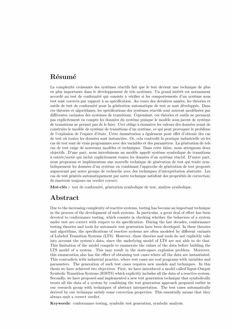
Résumé
La complexité croissante des systèmes réactifs fait que le test devient une technique de plusen plus importante dans le développement de tels systèmes. Un grand intérêt est notammentaccordé au test de conformité qui consiste à vérifier si les comportements d’un système soustest sont corrects par rapport à sa spécification. Au cours des dernières années, les théories etoutils de test de conformité pour la génération automatique de test se sont développés. Dansces théories et algorithmes, les spécifications des systèmes réactifs sont souvent modélisées pardifférentes variantes des systèmes de transitions. Cependant, ces théories et outils ne prennentpas explicitement en compte les données du système puisque le modèle sous-jacent de systèmede transitions ne permet pas de le faire. Ceci oblige à énumérer les valeurs des données avant deconstruire le modèle de système de transitions d’un système, ce qui peut provoquer le problèmede l’explosion de l’espace d’états. Cette énumération a également pour effet d’obtenir des casde test où toutes les données sont instanciées. Or, cela contredit la pratique industrielle où lescas de test sont de vrais programmes avec des variables et des paramètres. La génération de telscas de test exige de nouveaux modèles et techniques. Dans cette thèse, nous atteignons deuxobjectifs. D’une part, nous introduisons un modèle appelé système symbolique de transitionsà entrée/sortie qui inclut explicitement toutes les données d’un système réactif. D’autre part,nous proposons et implémentons une nouvelle technique de génération de test qui traite sym-boliquement les données d’un système en combinant l’approche de génération de test proposéeauparavant par notre groupe de recherche avec des techniques d’interprétation abstraite. Lescas de test générés automatiquement par notre technique satisfont des propriétés de correction:ils émettent toujours un verdict correct.
Mot-clés : test de conformité, génération symbolique de test, analyse symbolique.
Abstract
Due to the increasing complexity of reactive systems, testing has become an important techniquein the process of the development of such systems. In particular, a great deal of effort has beendevoted to conformance testing, which consists in checking whether the behaviors of a systemunder test are correct with respect to its specification. During the last decades, conformancetesting theories and tools for automatic test generation have been developed. In these theoriesand algorithms, the specifications of reactive systems are often modeled by different variantsof Labeled Transition Systems (LTS). However, these theories and tools do not explicitly takeinto account the system’s data, since the underlying model of LTS are not able to do that.This limitation of the model compels to enumerate the values of the data before building theLTS model of a system. This may result in the state-space explosion problem. Moreover,this enumeration also has the effect of obtaining test cases where all the data are instantiated.This contradicts with industrial practice, where test cases are real programs with variables andparameters. The generation of such test cases requires new models and techniques. In thisthesis we have achieved two objectives. First, we have introduced a model called Input-OutputSymbolic Transition Systems (IOSTS) which explicitly includes all the data of a reactive system.Secondly, we have proposed and implemented a new test generation technique that symbolicallytreats all the data of a system by combining the test generation approach proposed earlier inour research group with techniques of abstract interpretation. The test cases automaticallyderived by our technique satisfy some correction properties. This essentially means that theyalways emit a correct verdict.
Keywords: conformance testing, symbolic test generation, symbolic analysis.


