Embed Size (px)
Citation preview
Prosiding Seminar Nasional Teknologi Energi Nuklir 2016 Batam, 4-5 Agustus 2016
865
ISSN: 2355-7524
THERMODYNAMIC ANALYSIS ON RANKINE CYCLE STEAM FOR COGENERATION SYSTEMS RGTT200K
Ign. Djoko Irianto, Sukmanto Dibyo, Djati H. Salimy, Jupiter S. Pane
Pusat Teknologi Keselamatan Reaktor Nuklir – BATAN :
ABSTRACT THERMODYNAMIC ANALYSIS ON RANKINE CYCLE STEAM FOR COGENERATION SYSTEMS RGTT200K. Energy conversion systems are built in the Rankine cycle configuration can be considered as an alternative to building an energy conversion system for RGTT200K. With the configuration of the Rankine cycle, the cooling system is divided into primary cooling systems and secondary cooling systems with different cooling media. In the primary cooling system which cools the reactor core using helium cooling medium, while the secondary system using water as a cooling medium. In this paper was described the results of thermodynamic analysis of the design of energy conversion system in the Rankine cycle configuration for RGTT200K reactor. The purpose of this research was to analyze the potential implementation of the Rankine cycle to develop cogeneration systems for RGTT200K. The analysis was performed by means of simulation for performance calculation of RGTT200K cogeneration systems using CHEMCAD computer code. In this simulation, the secondary coolant mass flow rate was varied to obtain the optimum performance on RGTT200K cogeneration systems. The simulation results showed that the optimum performance of cogeneration systems for RGTT200K can be obtained in the secondary coolant mass flow rate at 370 kg/s. At the secondary coolant mass flow rate 370 kg/s, the thermal power for electricity generation amounted to 50.44 MW, the thermal power for hydrogen production amounted to 79.00 MW and the thermal power for desalination to 80.92 MW with the value of the thermal efficiency of 25.21% and the value of EUF 78.3%. Keywords: Thermodynamic analysis, Rankine cycle, cogeneration systems, thermal efficiency, EUF.
ABSTRAK ANALISIS TERMODINAMIKA UNTUK SISTEM KOGENERASI MENGGUNAKAN SIKLUS RANKINE PADA REAKTOR RGTT200K. Sistem konversi energi yang dibangun dalam konfigurasi siklus Rankine dapat dipertimbangkan sebagai alternatif dalam membangun sistem konversi energi untuk RGTT200K. Dengan konfigurasi siklus Rankine, sistem pendingin dibagi menjadi sistem pendingin primer dan sistem pendingin sekunder dengan masing-masing media pendingin yang berbeda. Dalam sistem pendingin primer yang berfungsi mendinginkan teras reaktor digunakan media pendingin helium, sedangkan pada sistem pendingin sekunder digunakan media pendingin air. Dalam makalah ini dibahas hasil analisis termodinamik desain sistem kogenerasi pada reaktor RGTT200K menggunakan siklus Rankine. Tujuan penelitian ini adalah untuk menganalisis potensi implementasi siklus Rankine untuk menyusun desain sistem kogenerasi untuk reaktor RGTT200K. Analisis dilakukan dengan cara simulasi untuk perhitungan kinerja sistem kogenerasi RGTT200K menggunakan kode komputer CHEMCAD. Dalam simulasi ini laju alir massa pendingin sekunder divariasi untuk memperoleh kinerja optimum pada sistem kogenerasi RGTT200K. Hasil simulasi menunjukkan bahwa kinerja sistem kogenerasi RGTT200K yang optimum diperoleh pada laju alir massa pendingin sekunder sebesar 370 kg/s. Dengan laju alir massa pendingin sekunder sebesar 370 kg/s, diperoleh daya termal untuk pembangkit listrik sebesar 50,44 MW, daya termal untuk produksi hidrogen sebesar 79,00 MW dan daya termal untuk desalinasi sebesar 80,92 MW dengan nilai efisiensi termal 25,21% dan nilai EUF 78,3%. Kata kunci: Analisis termodinamik, siklus Rankine, sistem kogenerasi, efisiensi termal, EUF. INTRODUCTION
The role of nuclear technology as a global energy supplier has increased along with the development of the reactor system technology. The development trend of the reactor system technology, especially in the concept of Nuclear Energy Systems (NES) for the generation IV reactor is directed not only to generate electricity but also to the use of more diverse that often called as hybrid energy system [1,2]. Implementation of the hybrid energy system is placed on the energy conversion systems which are designed in a cogeneration configuration as electricity generation and thermal energy provider for various industrial purposes, e.g. for the production of hydrogen gas [3,4]. There are several types of generation IV reactors are nowadays widely developed in several countries. High temperature Gas-cooled Reactor (HTGR) is one of the various types of generation IV reactors are considered most suitable for the application of the concept of cogeneration because the coolant temperature coming out of the reactor is very high. Various development of the cogeneration concept has also been done, such as Yan, X. [5] reported the development of GTHTR300C reactors for power generation, hydrogen production and the production of drinking water for the Middle East region. While
Thermodynamic Analysis of A Rankine Cycle… Ign. Djoko Irianto, dkk
866
ISSN: 2355-7524
Gustavo Alonso et al. [6] reported that the cogeneration system at the Pebble Bed Modular Reactor (PBMR) able to generate electricity and provide thermal energy to produce petrol (gasoline) in the refinery.
Selection of the cogeneration system configuration becomes important in the design of cogeneration energy conversion system. Some research and studies on the configuration of cogeneration energy conversion system have been widely reported. The implementation of a closed Brayton cycle has been one alternative because by applying a closed Brayton cycle can improve the thermal efficiency of the system [7,8]. The examples of cogeneration systems developed in a closed Brayton cycle, such as cogeneration systems at GTHTR300C and cogeneration systems in the PBMR [8]. In addition to the cogeneration system in the configuration of a closed Brayton cycle, also has made the development of the implementation of cogeneration systems in the Rankine steam cycle [8]. While Colin F. McDonald [8] proposed an energy conversion system in a combined cycle cogeneration small modular based on the coupling between the Brayton cycle and the Rankine cycle. Another study, as reported by Po-Jui Li [9] is to integrate the organic Rankine cycle (ORC = Organic Rankine Cycle) and Brayton cycle in the Very-High-Temperature Reactor (VHTR) could increase the total thermal efficiency of up to 8.6%.
National Nuclear Energy Agency (BATAN) as a research and development institute in the field of nuclear technology is currently developing NES based on HTGR system named RGTT200K. Energy conversion system for RGTT200K is designed in a cogeneration configuration for electricity generation, for hydrogen gas production and for seawater desalination process. To support the design of cogeneration energy conversion systems or cogeneration systems for RGTT200K, some research and development of cogeneration systems for RGTT200K have been done. Some research on cogeneration systems for RGTT200K such as the research for looking the performance optimization of cogeneration system by comparing various configurations of cogeneration systems in the direct cycle [10], studied the effect of coolant mass flow rate on the performance of the cogeneration systems [11], and the performance optimization of Intermediate Heat Exchanger (IHX) on the cogeneration systems of RGTT200K [12] .
This paper describes the results of thermodynamic analysis of the design of cogeneration systems in the Rankine cycle configuration for RGTT200K reactor. The analysis was performed with the simulation calculations using a computer program package CHEMCAD. CHEMCAD has been widely used for the calculation of energy balance and mass balance in the cogeneration system [13] and is also used in the conceptual design of cogeneration cycle for hydrogen production and gasification process [14]. In this paper, in addition to discussed the analysis of thermodynamic parameters, it also describes the performance analysis of energy conversion systems that include thermal efficiency and energy utilization factor (EUF) in cogeneration systems of RGTT200K.
CONFIGURATION OF THE COGENERATION SYSTEM IN RANKINE CYCLE
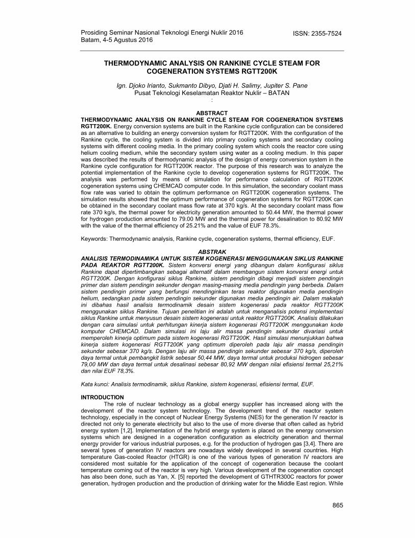
Conceptually, the model configurations considered for the design of cogeneration energy conversion systems or cogeneration systems for design RGTT200K in the Rankine cycle configuration as shown in the flowchart in Figure 1. In this configuration model, RGTT200K cooling system is divided into two cycles namely the primary cooling system and the secondary cooling system. Between the primary cooling system and the secondary cooling system is mediated by a heat exchanger which also serves as the steam generators (SG). The primary cooling system serves as the primary coolant in the reactor core which is filled with helium as a coolant and circulated by a circulator which is mounted on the inlet of the reactor. The primary cooling system will take the heat which is generated by the reactor and flows to the SG to generate steam that will be circulated in the secondary cooling system. The secondary cooling system is filled with water as cooling medium (steam). Steam which is generated from the SG is passed through a secondary heat exchanger (SHX). The thermal energy that is used for hydrogen production is transferred from the secondary cooling systems to the installation of hydrogen production through SHX. The steam from SHX in the secondary cooling system is passed through a steam turbine, recuperator, precooler, compressors, recuperator and returned to SG. Steam turbines and compressors are installed one shaft with an electric generator for electricity generation. Thermal energy is wasted from the precooler can still be used for seawater desalination process.
Figure 1. The system configuration Rankine cycle cogeneration RGTT200K
Prosiding Seminar Nasional Teknologi Energi Nuklir 2016 Batam, 4-5 Agustus 2016
867
ISSN: 2355-7524
For RGTT200K design, nuclear reactor as a source of thermal energy is an HTGR with a thermal power of 200 MW. This reactor is designed to have an outlet coolant temperature or coolant temperature coming out of the reactor at 950 °C and pressure 5 MPa. The pressure in the secondary cooling system is designed lower than the pressure of primary cooling system with a view to anticipating the ingress of air and steam so that no air or steam can entry into the primary cooling system. The entry of air or steam from the secondary cooling system into the primary cooling system feared would be able to corrode the graphite structure which in turn can result in damage to the structure of the fuel [14].
METHODOLOGY
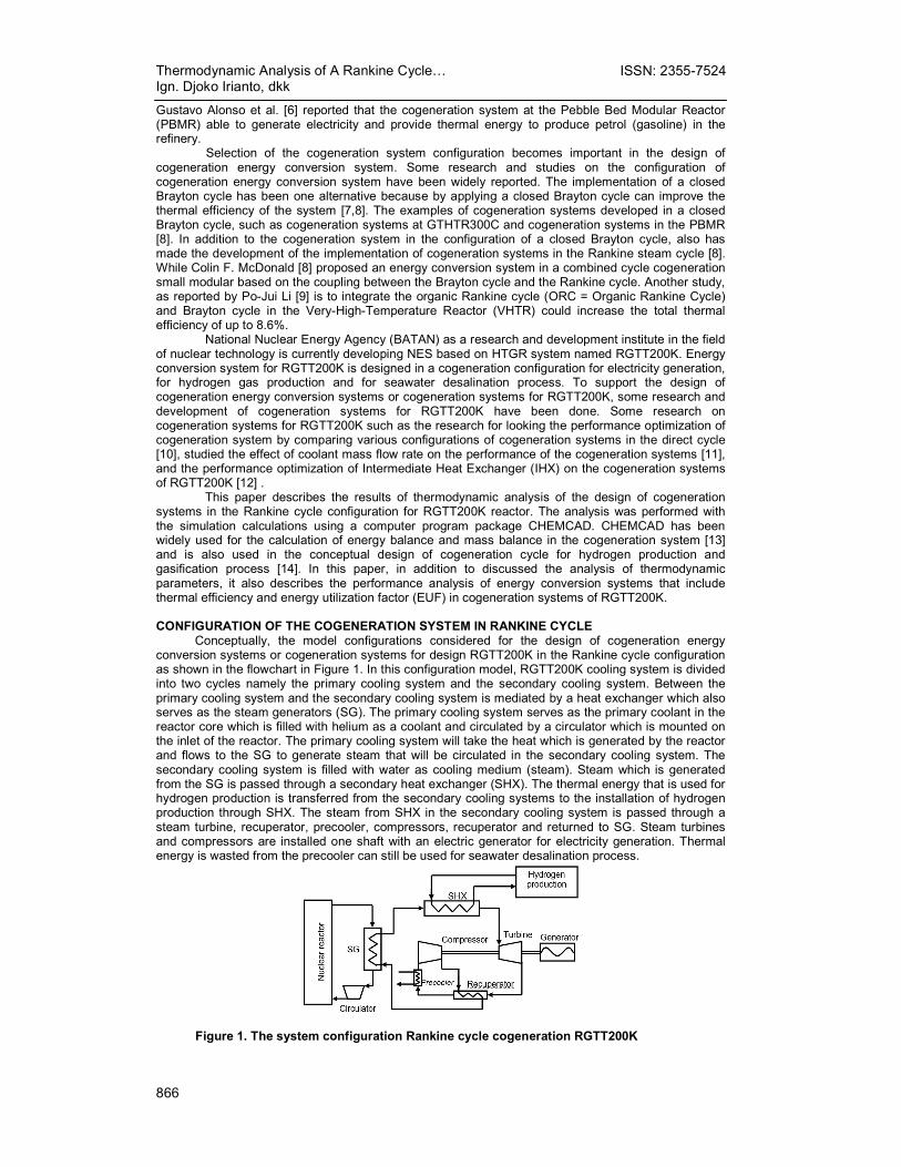
Thermodynamic analysis of Rankine cycle for RGTT200K cogeneration system have been done using a computer program package CHEMCAD 6.1.4. The first step in the simulation process is to create a model of cogeneration systems using CHEMCAD 6.1.4. The diagram of cogeneration systems as shown in Figure 1 was modeled using the computer program CHEMCAD 6.1.4 to be a model as shown in Figure 2. Circulation of the reactor primary coolant actuated using a circulator which is mounted on the inlet of the reactor. Average power needed to drive the compressor is equal to 9.6 MW thermal power. Thermal power of the reactor is set at 200 MW with the coolant temperature and pressure at the outlet point of each are set at 950 °C and 5.0 MPa.
The performance of the cogeneration systems for RGTT200K are calculated by simulating the coolant mass flow rate of the secondary cooling system that varies. Variations of secondary coolant mass flow rate are ranging from 250 kg/s up to 550 kg/s. The variation of mass flow rate is based on the steam temperature at the outlet of SG and the coolant temperature in SHX. At the coolant mass flow rate of 250 kg/s, the temperature of steam at SG outlet approached 950 oC. While at the coolant mass flow rate of 550 kg/s, the temperature at the outlet SHX has been below 750 oC so it is not enough to supply thermal energy for hydrogen production. Each parameter in the major component of cogeneration systems that is used as input data for performance calculation is set same with the previous research [12]. The main parameter values of RGTT200K cogeneration systems component in the Rankine cycle were shown in Table 1.
Table 1. System component parameter of RGTT200K cogeneration in the configuration of
Rankine cycle [12] Parameters Value
Pressure drop in reactor 0.120 MPa Pressure drop at the shell side of SHX 0.040 MPa Pressure drop at the tube side of SHX 0.070 MPa Heat transfer área of SHX (A) 1448 m2 Total heat transfer coefficient of SHX (U) 700 W/m2.K U A factor in steam generator 2.032 MW/K Polytropic efficiency of gas turbine 0.960 Polytropic Efficiency of compressor 0.960 Pressure drop at the hot side of recuperator 0.060 MPa Pressure drop at the cold side of recuperator 0.060 MPa U A factor in recuperator 59.942 MW/K Pressure drop in the shell side of precooler 0.040 MPa Pressure drop in the tube side of precooler 0.060 MPa U A factor in precooler 1.303 MW/K
2
2
1
1
3
3
T 950.0
P 5.00
W 150.0
T 680.5 P 4.96 W 150.0
T 693.2
P 5.12
W 150.0
T 500.0 P 5.00
W 110.0
T 617.20 P 2.70 W 370.00
17
18
T 183.27
P 2.64
W 370.00
T 30.00
P 3.00
W 160.00
T 149.59
P 2.96
W 160.00
T 133.22
P 2.60
W 370.00 T 159.79
P 5.06 W 370.00
ElectricityGeneration
SHX
Precooler
5
6
7
8
6
7
8
9
4
5
4
11
12
T 809.09
P 4.93
W 110.00 T 823.14
P 5.00
W 370.00 T 732.86 P 4.96 W 370.00
10 T 580.00 P 5.00 W 370.00
Recuperator
CompressorS G
TurbineReactor
Desalination
ProductionHydrogen
Circulator
Thermodynamic Analysis of A Rankine Cycle… Ign. Djoko Irianto, dkk
868
ISSN: 2355-7524
Figure 2. Model of RGTT200K cogeneration systems using CHEMCAD 6.1.4 The performance parameters of the cogeneration systems which are considered are thermal
efficiency and Energy Utilization Factor (EUF). Thermal efficiency is the parameter into account only the amount of thermal energy that can be converted into electrical energy. While the EUF is a parameter describe the amount of thermal energy that can be utilized for each unit utilization [16]. Therefore, thermal efficiency in energy conversion system is same as EUF in cogeneration system if the utilization of thermal energy only for electricity generation. The value of the overall thermal efficiency is the result of the division between the thermal power for electricity generation by thermal energy are generated by the thermal energy source, namely the reactor. The amount of thermal efficiency (η) can be calculated with the following equation:
reactortheofpowerThermal
generationyelectricitforpowerThermal (1)
or
th
CIRSCT
Q
WWWW (2)
In cogeneration systems, the performance of cogeneration systems is not only determined by
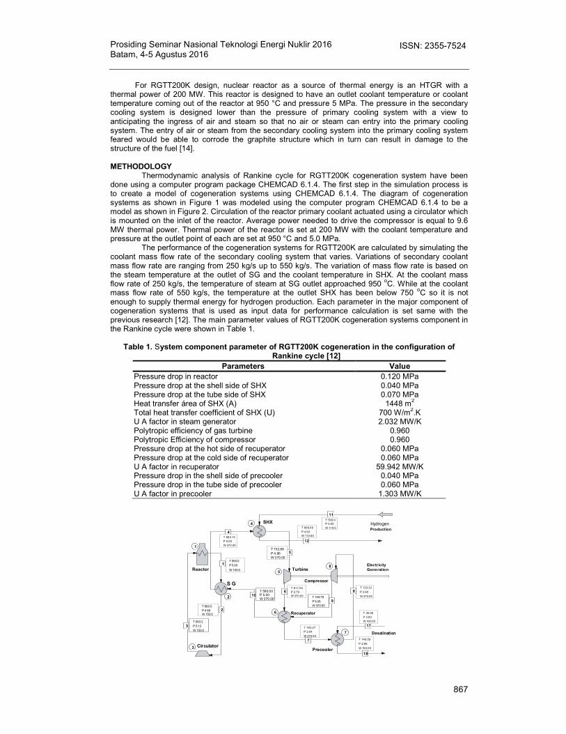
the value of thermal efficiency but is also determined by the value of the EUF which covers the entire unit that utilizes the thermal energy from the reactor. EUF value gives an overview of how much the percentage of thermal energy from the thermal energy source that can be utilized and not wasted into the environment. EUF parameters are parameters that take into account the efficiency of the entire unit utilization of energy conversion systems in the form of electricity generation or in the form of work or other energy utilization. In principal, the difference between the thermal efficiency (ther) and EUF [16] is shown in Figure 3.
(a) (b)
Figure 3. The difference of (a) thermal efficiency, and (b) energy utilization factor [10]
As shown in Figure 3, by applying the concept of cogeneration in energy conversion systems,
the value of EUF of the systems can be improved. With the implementation of cogeneration systems, thermal energy that released into the environment can be minimized. The higher value of EUF will increase the economic value of cogeneration systems and improve the efficiency of utilization of fuel reserves.
EUF value of cogeneration system can be defined using equation (3) :
in
u
Q
QWEUF
(3)
RESULT AND DISCUSSION
The cogeneration systems of energy conversion systems for RGTT200K has 3 units of thermal energy utilization, namely: production of hydrogen gas, electricity generation, and seawater desalination. The performance of RGTT200K cogeneration system can be expressed with the distribution of thermal power and thermal efficiency value and also the value of the EUF on the overall system.
For this simulation, the thermal power of the reactor is set 200 MW. The primary coolant pressure and the coolant mass flow rate of the primary cooling systems at the outlet side of the reactor are set respectively at 5.00 MPa and 150 kg/s. In the primary cooling system has installed a compressor at the inlet of the reactor to circulate the fluid flow in the primary cooling system with a thermal power equivalent to 9.60 MWt. The amount of coolant mass flow rate in the secondary coolant system that drives the turbine, in a simulation of cogeneration energy conversion system is varied from 250 kg/s up to 550 kg/s.
The simulation results for the calculation of the thermodynamic parameters of cogeneration energy conversion system for RGTT200K in indirect cycles are shown in Table 2 and Figure 4. In Figure 4 is shown the thermal power for each user unit in the system of cogeneration as a function of
inther Q
W
inQ
outQ
Win
u
Q
QWEUF
W
inQ
outQ
uQ
Prosiding Seminar Nasional Teknologi Energi Nuklir 2016 Batam, 4-5 Agustus 2016
869
ISSN: 2355-7524
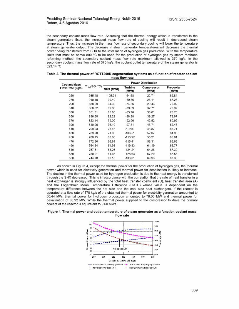
the secondary coolant mass flow rate. Assuming that the thermal energy which is transferred to the steam generators fixed, the increased mass flow rate of cooling will result in decreased steam temperature. Thus, the increase in the mass flow rate of secondary cooling will lower the temperature at steam generator output. The decrease in steam generator temperatures will decrease the thermal power being transferred from SHX to the installation of hydrogen gas production. With the temperature limits that must be above 800 °C to be used for the production of hydrogen gas by steam methane reforming method, the secondary coolant mass flow rate maximum allowed is 370 kg/s. In the secondary coolant mass flow rate of 370 kg/s, the coolant outlet temperature of the steam generator is 823.14 °C
Table 2. The thermal power of RGTT200K cogeneration systems as a function of reactor coolant
mass flow rate
Coolant Mass Flow Rate (kg/s)
T out SG (oC) Power Distribution
SHX (MWt) Turbine (MWt)
Compressor (MWt)
Precooler (MWt)
250 935.48 105.21 -64.68 22.71 62.84
270 910.10 99.40 -69.56 26.11 67.26
290 888.09 94.30 -74.36 29.43 70.92
310 868.82 89.80 -79.09 32.71 73.97
330 851.81 85.80 -83.76 36.01 76.70
350 836.68 82.22 -88.38 39.27 78.97
370 823.14 79.00 -92.96 42.52 80.92
390 810.96 76.10 -97.51 45.71 82.43
410 799.93 73.46 -10202 48.87 83.71
430 789.90 71.06 -106.51 52.07 84.96
450 780.75 68.86 -110.97 55.21 85.91
470 772.36 66.84 -115.41 58.31 86.66
490 764.64 64.98 -119.83 61.19 86.77
510 757.51 63.26 -124.24 64.28 87.39
530 750.91 61.66 -128.63 67.20 87.56
550 744.78 60.18 -133.01 69.93 87.30
As shown in Figure 4, except the thermal power for the production of hydrogen gas, the thermal
power which is used for electricity generation and thermal power for desalination is likely to increase. The decline in the thermal power used for hydrogen production is due to the heat energy is transferred through the SHX decreased. This is in accordance with the correlation that the rate of heat transfer in a heat exchanger is strongly influenced by the total heat transfer coefficient (U), heat transfer area (A) and the Logarithmic Mean Temperature Difference (LMTD) whose value is dependent on the temperature difference between the hot side and the cool side heat exchangers. If the reactor is operated at a flow rate of 370 kg/s of the obtained thermal power for electricity generation amounted to 50.44 MW, thermal power for hydrogen production amounted to 79.00 MW and thermal power for desalination of 80.92 MW. While the thermal power supplied to the compressor to drive the primary coolant of the reactor is equivalent to 9.60 MWt.
Figure 4. Thermal power and outlet temperature of steam generator as a function coolant mass
flow rate
The optimum performance of
Thermodynamic Analysis of A Rankine Cycle… Ign. Djoko Irianto, dkk
870
ISSN: 2355-7524
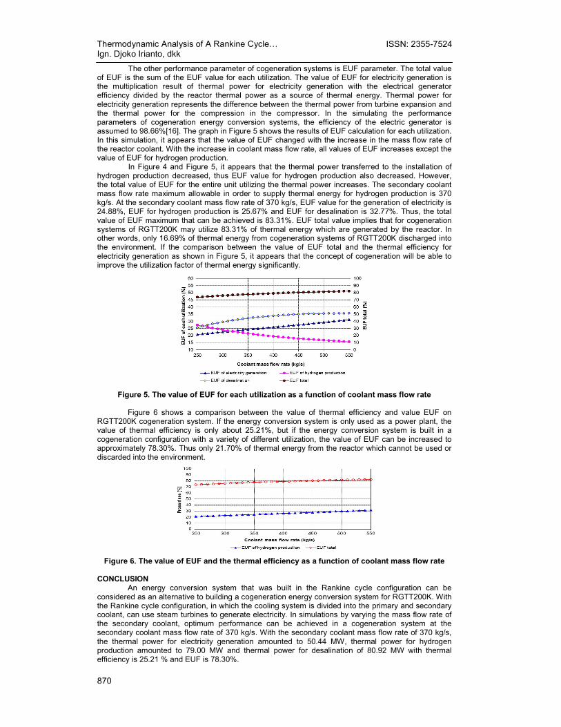
The other performance parameter of cogeneration systems is EUF parameter. The total value of EUF is the sum of the EUF value for each utilization. The value of EUF for electricity generation is the multiplication result of thermal power for electricity generation with the electrical generator efficiency divided by the reactor thermal power as a source of thermal energy. Thermal power for electricity generation represents the difference between the thermal power from turbine expansion and the thermal power for the compression in the compressor. In the simulating the performance parameters of cogeneration energy conversion systems, the efficiency of the electric generator is assumed to 98.66%[16]. The graph in Figure 5 shows the results of EUF calculation for each utilization. In this simulation, it appears that the value of EUF changed with the increase in the mass flow rate of the reactor coolant. With the increase in coolant mass flow rate, all values of EUF increases except the value of EUF for hydrogen production.
In Figure 4 and Figure 5, it appears that the thermal power transferred to the installation of hydrogen production decreased, thus EUF value for hydrogen production also decreased. However, the total value of EUF for the entire unit utilizing the thermal power increases. The secondary coolant mass flow rate maximum allowable in order to supply thermal energy for hydrogen production is 370 kg/s. At the secondary coolant mass flow rate of 370 kg/s, EUF value for the generation of electricity is 24.88%, EUF for hydrogen production is 25.67% and EUF for desalination is 32.77%. Thus, the total value of EUF maximum that can be achieved is 83.31%. EUF total value implies that for cogeneration systems of RGTT200K may utilize 83.31% of thermal energy which are generated by the reactor. In other words, only 16.69% of thermal energy from cogeneration systems of RGTT200K discharged into the environment. If the comparison between the value of EUF total and the thermal efficiency for electricity generation as shown in Figure 5, it appears that the concept of cogeneration will be able to improve the utilization factor of thermal energy significantly.
Figure 5. The value of EUF for each utilization as a function of coolant mass flow rate
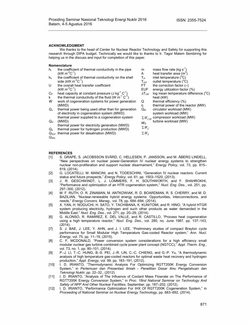
Figure 6 shows a comparison between the value of thermal efficiency and value EUF on
RGTT200K cogeneration system. If the energy conversion system is only used as a power plant, the value of thermal efficiency is only about 25.21%, but if the energy conversion system is built in a cogeneration configuration with a variety of different utilization, the value of EUF can be increased to approximately 78.30%. Thus only 21.70% of thermal energy from the reactor which cannot be used or discarded into the environment.
Figure 6. The value of EUF and the thermal efficiency as a function of coolant mass flow rate
CONCLUSION
An energy conversion system that was built in the Rankine cycle configuration can be considered as an alternative to building a cogeneration energy conversion system for RGTT200K. With the Rankine cycle configuration, in which the cooling system is divided into the primary and secondary coolant, can use steam turbines to generate electricity. In simulations by varying the mass flow rate of the secondary coolant, optimum performance can be achieved in a cogeneration system at the secondary coolant mass flow rate of 370 kg/s. With the secondary coolant mass flow rate of 370 kg/s, the thermal power for electricity generation amounted to 50.44 MW, thermal power for hydrogen production amounted to 79.00 MW and thermal power for desalination of 80.92 MW with thermal efficiency is 25.21 % and EUF is 78.30%.
Prosiding Seminar Nasional Teknologi Energi Nuklir 2016 Batam, 4-5 Agustus 2016
871
ISSN: 2355-7524
ACKNOWLEDGMENT
We thanks to the head of Center for Nuclear Reactor Technology and Safety for supporting this research through DIPA budget. Technically we would like to thanks to Ir. Tagor Malem Sembiring for helping us in the discuss and input for completion of this paper.
Nomenclature ht
hs U CP k W Qu Qin Qe Qhyd
Qdes
the coefficient of thermal conductivity in the pipe (kW.m-2C-1) the coefficient of thermal conductivity on the shell side (kW.m-2C-1) the overall heat transfer coefficient (kW.m-2C-1) heat capacity at constant pressure (J kg-1 C-1) the thermal conductivity of the fluid (W m-1 C-1) work of cogeneration systems for power generation (MWD) thermal power being used other than for generation of electricity in cogeneration system (MWD) thermal power supplied to a cogeneration system (MWD) thermal power for electricity generation (MWD) thermal power for hydrogen production (MWD) thermal power for desalination (MWD)
m A Tin Tout FT EUF ∆TLM Q η Qth
CIRW
WS
CW
TW
mass flow rate (kg s-1) heat transfer area (m2) inlet temperature (oC) outlet temperature (oC) the correction factor (–) energy utilization factor (%) log mean temperature difference (oC) heat (kW) thermal efficiency (%) thermal power of the reactor (MW) circulator workload (MW) system workload (MW) compressor workload (MW) turbine workload (MW)
REFERENCES [1] S. GRAPE, S. JACOBSSON SVÄRD, C. HELLESEN, P. JANSSON, and M. ÅBERG LINDELL,
“New perspectives on nuclear power-Generation IV nuclear energy systems to strengthen nuclear non-proliferation and support nuclear disarmament,” Energy Policy, vol. 73, pp. 815–819, (2014).
[2] G. LOCATELLI, M. MANCINI, and N. TODESCHINI, “Generation IV nuclear reactors: Current status and future prospects,” Energy Policy, vol. 61, pp. 1503–1520, (2013).
[3] J. R. GESCHWINDT, L. J. LOMMERS, F. H. SOUTHWORTH, and F. SHAHROKHI, “Performance and optimization of an HTR cogeneration system,” Nucl. Eng. Des., vol. 251, pp. 297–300, (2012).
[4] M. F. RUTH, O. R. ZINAMAN, M. ANTKOWIAK, R. D. BOARDMAN, R. S. CHERRY, and M. D. BAZILIAN, “Nuclear-renewable hybrid energy systems: Opportunities, interconnections, and needs,” Energy Convers. Manag., vol. 78, pp. 684–694, (2014).
[5] X. YAN, H. NOGUCHI, H. SATO, Y. TACHIBANA, K. KUNITOMI, and R. HINO, “A hybrid HTGR system producing electricity, hydrogen and such other products as water demanded in the Middle East,” Nucl. Eng. Des., vol. 271, pp. 20–29, (2014).
[6] G. ALONSO, R. RAMIREZ, E. DEL VALLE, and R. CASTILLO, “Process heat cogeneration using a high temperature reactor,” Nucl. Eng. Des., vol. 280, no. June 1987, pp. 137–143, (2014).
[7] S. J. BAE, J. LEE, Y. AHN, and J. I. LEE, “Preliminary studies of compact Brayton cycle performance for Small Modular High Temperature Gas-cooled Reactor system,” Ann. Nucl. Energy, vol. 75, pp. 11–19, (2015).
[8] C. F. MCDONALD, “Power conversion system considerations for a high efficiency small modular nuclear gas turbine combined cycle power plant concept (NGTCC),” Appl. Therm. Eng., vol. 73, no. 1, pp. 80–101, (2014).
[9] P.-J. LI, T.-C. HUNG, B.-S. PEI, J.-R. LIN, C.-C. CHIENG, and G.-P. Yu, “A thermodynamic analysis of high temperature gas-cooled reactors for optimal waste heat recovery and hydrogen production,” Appl. Energy, vol. 99, pp. 183–191, (2012).
[10] I. D. IRIANTO, “Thermodynamic Analysis For Optimizing RGTT200K Energy Conversion System,” in Pertemuan dan Presentasi Ilmiah - Penelitian Dasar Ilmu Pengetahuan dan Teknologi Nuklir, pp. 22–32., (2012)
[11] I. D. IRIANTO, “Analysis of The Influence of Coolant Mass Flowrate on The Performance of RGTT200K Energy Conversion System,” in Proc. 18nd National Seminar on Technology And Safety of NPP And Other Nuclear Facilities, September, pp. 187–202, (2012).
[12] I. D. IRIANTO, “Performance Optimization For IHX Of RGTT200K Cogeneration System,” in Proceeding of National Seminar on Nuclear Energy Technology, pp. 683–692, (2014).

Thermodynamic Analysis of A Rankine Cycle… Ign. Djoko Irianto, dkk
872
ISSN: 2355-7524
[13] A. M. CORMOS and C. C. CORMOS, “Investigation of hydrogen and power co-generation based on direct coal chemical looping systems,” Int. J. Hydrogen Energy, vol. 39, no. 5, pp. 2067–2077, (2014).
[14] C.-C. CORMOS, “Hydrogen and power co-generation based on coal and biomass/solid wastes co-gasification with carbon capture and storage,” Int. J. Hydrogen Energy, vol. 37, no. 7, pp. 5637–5648, (2012).
[15] C. H. OH and E. S. KIM, “Conceptual study on air ingress mitigation for VHTRs,” Nucl. Eng. Des., vol. 250, pp. 448–464, (2012).
[16] E. JANNELLI, M. MINUTILLO, R. COZZOLINO, and G. FALCUCCI, “Thermodynamic performance assessment of a small size CCHP (combined cooling heating and power) system with numerical models,” Energy, vol. 65, pp. 240–249, (2014).


