Embed Size (px)
Citation preview
STEAM POWER PLANT Contents:1. Working principle of steam power plant.2. Purpose of draught.3. Types of draught.4. Economizer.5. Advantage of economizer.6. Air pre-heater.7. Types of air pre-heater.8. Super Heater.9. Type of Super Heater.10. Advantages of Super-heater.11. Feed water Treatment. 12. PH value of water.13. Stem condenser.14.Feed water Heaters.15.Types of steam condenser.16.Advantages disadvantages of a source condenser.17.Types of cooling Tower.18.Factors of cooling Tower.19.Maintenance of cooling Tower
1
STEAM POWER PLANT
Working principle of steam power plant:A steam power plant using steam as working substation works basically cycle. Coal received in coal storage yard of power station is transferred in the furnace by coal handling unit. Heat produced due to burning of coal is utilized in converting water contained in boiler drum into steam at suitable pressure and temperature . The steam generated is passed through the super heater. Superheated steam then flows through the turbine. After doing work in the turbine the pressure of the steam is reduced. Steam leaving the turbine passes through the condenser which maintain the low pressure of steam at the exhaust of turbine. Steam pressure in the condenser depends upon flow rate and temperature of the cooling water and on effectiveness of air removal equipment water circulating through the condenser may be taken from the various sources, such as- river, take or sea. 2
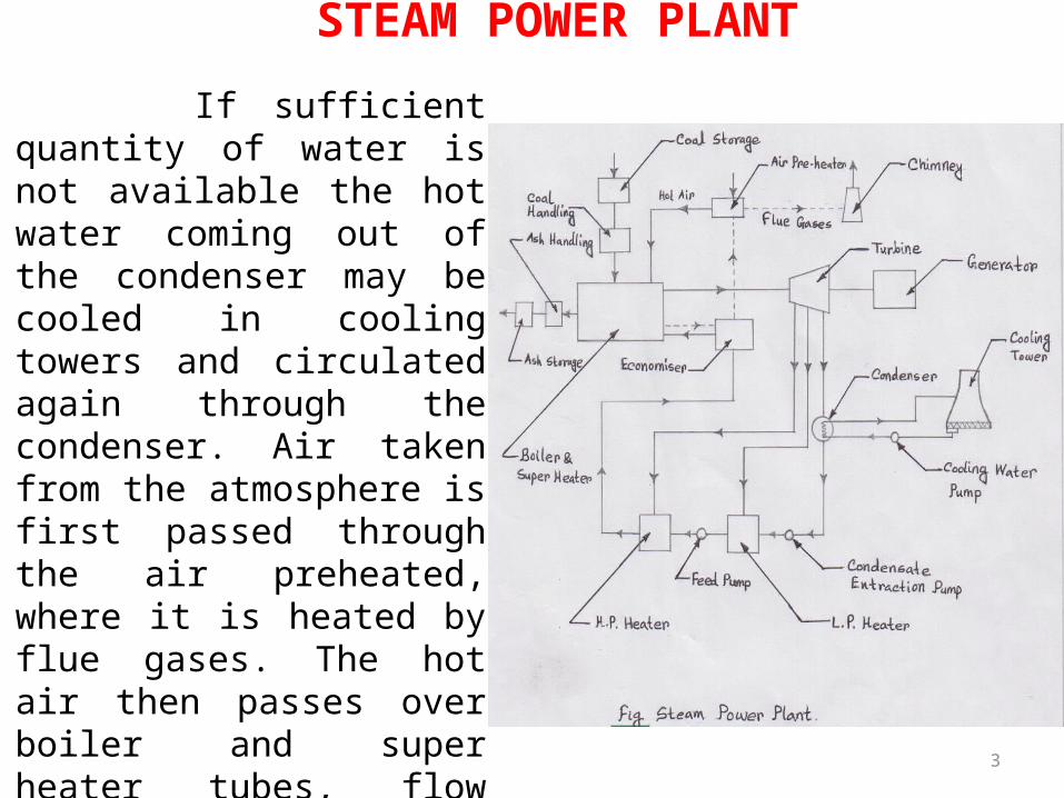
STEAM POWER PLANT If sufficient quantity of water is not available the hot water coming out of the condenser may be cooled in cooling towers and circulated again through the condenser. Air taken from the atmosphere is first passed through the air preheated, where it is heated by flue gases. The hot air then passes over boiler and super heater tubes, flow through the dust collector and then through –economizer, air preheated and they are exhausted to the atmosphere through the chimney.
3
Purpose of Draught: 1. The purpose of draught is as follows- To
supply require amount of air to the furnace for the combustion of
fuel. 2. To remove the gaseous of combustion.
Types of draught:1. Natural draught.2. Mechanical draught.3. Steam- jet draught.
STEAM POWER PLANT
4

STEAM POWER PLANT
1. Natural draught: If only a chimney is used to create the necessary draught, the system is called natural draught system. It is used in boiler of smaller capacities. Natural draught is created by the difference in weight of a column of cold eternal air and that of similar column of hot gases in the chimney. This system is dependent upon the height of chimney and average temperature of the gases in the chimney.
2. Mechanical draught: If in addition to chimney a forced draught (F.D) fan or an induced draught (I.D) fan or both are used. The system is called mechanical draught system .In boiler of larger capacities, fans are employed to create the necessary draught in order to reduce the height of chimney. To obtained draught that is independent of weather conditions and control the draught easily.
5
STEAM POWER PLANT
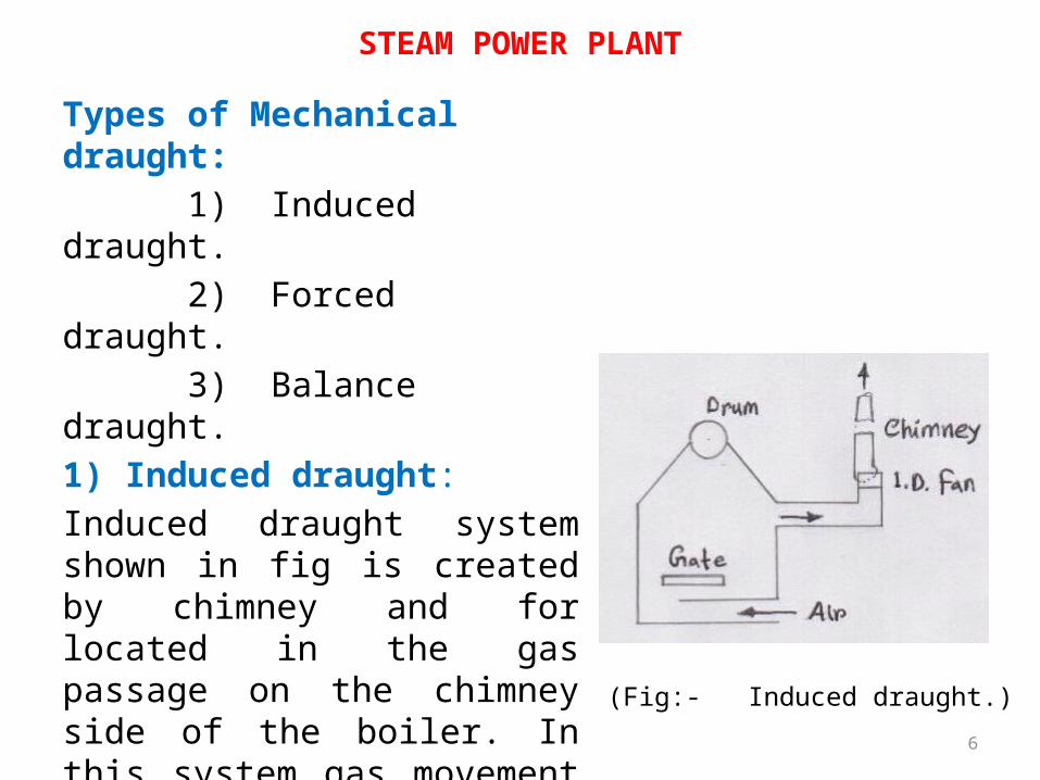
Types of Mechanical draught: 1) Induced draught. 2) Forced draught. 3) Balance draught.1) Induced draught:Induced draught system shown in fig is created by chimney and for located in the gas passage on the chimney side of the boiler. In this system gas movement is achieved as result of a vacuum. The far sucks in gas from the boiler side and discharge it to the chimney.
(Fig:- Induced draught.)6
STEAM POWER PLANT
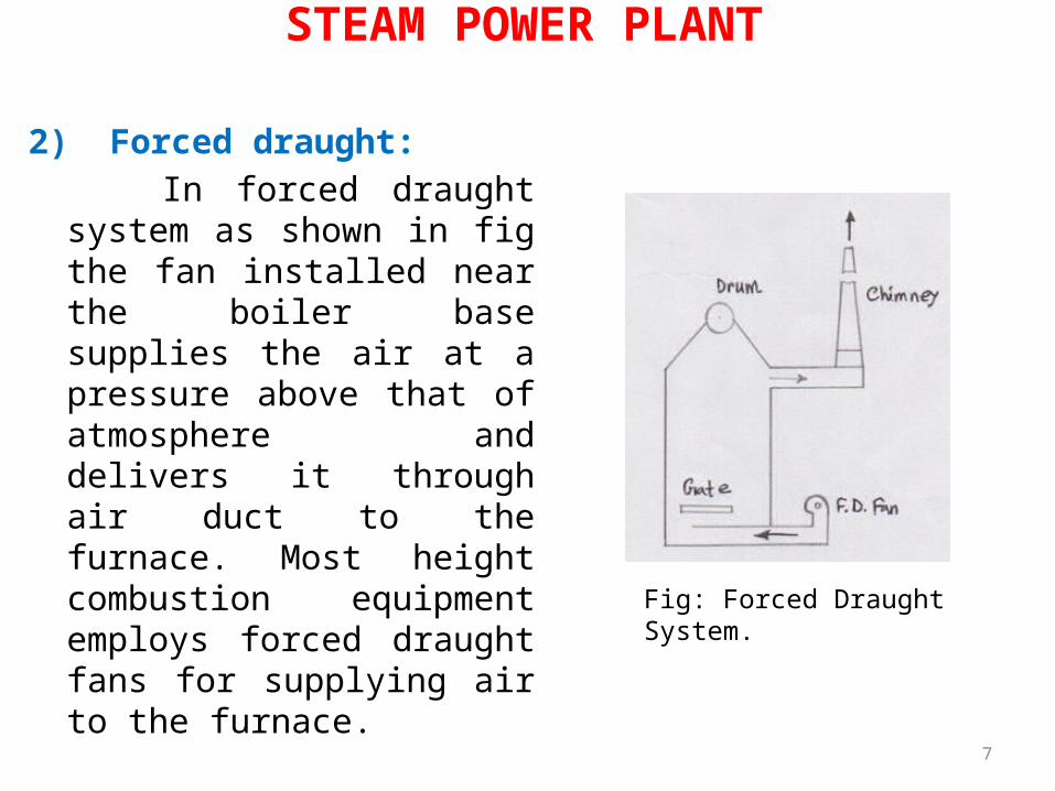
2) Forced draught: In forced draught system as shown in fig the fan installed near the boiler base supplies the air at a pressure above that of atmosphere and delivers it through air duct to the furnace. Most height combustion equipment employs forced draught fans for supplying air to the furnace.
7
Fig: Forced Draught System.
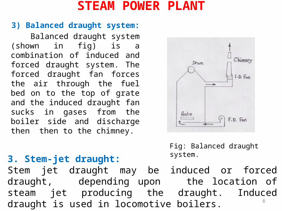
STEAM POWER PLANT 3) Balanced draught system: Balanced draught system (shown in fig) is a combination of induced and forced draught system. The forced draught fan forces the air through the fuel bed on to the top of grate and the induced draught fan sucks in gases from the boiler side and discharge then then to the chimney.
3. Stem-jet draught:Stem jet draught may be induced or forced draught, depending upon the location of steam jet producing the draught. Induced draught is used in locomotive boilers. 8
Fig: Balanced draught system.
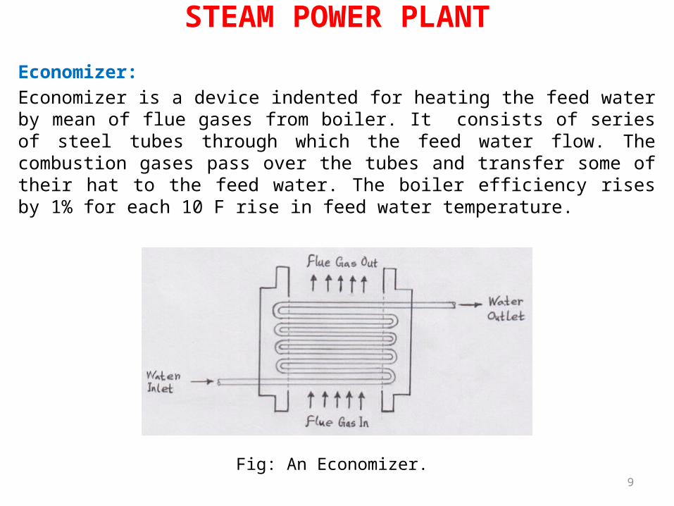
STEAM POWER PLANTEconomizer: Economizer is a device indented for heating the feed water by mean of flue gases from boiler. It consists of series of steel tubes through which the feed water flow. The combustion gases pass over the tubes and transfer some of their hat to the feed water. The boiler efficiency rises by 1% for each 10 F rise in feed water temperature.
9Fig: An Economizer.
There are two type of Economizer: 1. Parallel flow: When the gas and water flow are in the same direction, then it is called parallel flow. 2. Counter flow: When the gas and water flow are in opposite direction, then it is called counter flow.
Advantages of Economizer: The advantage of an economizer are as follows, 1. It is reduce the losses of heat with the flue gases. 2. It reduces the consumption of fuel. 3. It improves the efficiency of the boiler installation.
STEAM POWER PLANT
10
STEAM POWER PLANT
Air-Preheater:The heat carried with the flue gases coming out of the economizer are further utilized for preheating the air before supplying to the combustion chamber. It has been found that an increase of 20c in the air temperature increases the boiler efficiency by 1%.In air preheated air passes through the tubes and flue gases pass over the tubes and transfer the heat to the air.Types of air preheater : There are two types of air preheater Such as, 1. Tubelar type air preheater. 2. Plate type air preheater.
11

1. Tubelar type air preheater:Typical arrangement of tubelar air pre-heater is shown in fig . The flue gases flow through the tubes and air is passed over the outer surface of the tubes. The horizontal baffles are pro-vided to increase time of contact which will help for higher heat transfer. The steel tubes 3m to 10m. In height and 6 cm to 8 cm in diameter are commonly used.
STEAM POWER PLANT
12
Fig: Tubelar type air preheater.

2. Plate type air preheater:A plate type heater is shown in fig. It consists of rectangular flat plates spaced from 1.5 to 2.5 cm a part leaving alternative air and gas passages. In plate type air preheater the air absorbs heat from the hot gases being swept through the heater at high velocity on the opposite side of a plate. This type of air pre heater is not used in modern installations as it is more expensive both as to first cost and maintenance cost.
STEAM POWER PLANT
13
Fig: Plate type air preheater.
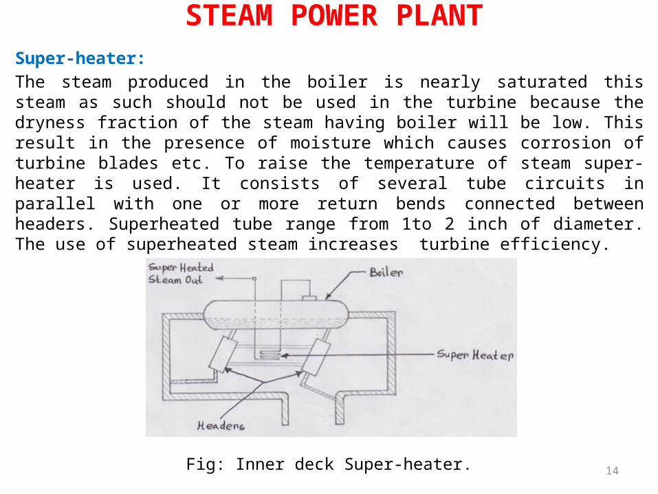
Super-heater:The steam produced in the boiler is nearly saturated this steam as such should not be used in the turbine because the dryness fraction of the steam having boiler will be low. This result in the presence of moisture which causes corrosion of turbine blades etc. To raise the temperature of steam super-heater is used. It consists of several tube circuits in parallel with one or more return bends connected between headers. Superheated tube range from 1to 2 inch of diameter. The use of superheated steam increases turbine efficiency.
STEAM POWER PLANT
14Fig: Inner deck Super-heater.
Advantages of Super-heated steam:1. Super-heated steam has an increased capacity
to work due to a higher heat contact.2. Super-heating raises the over all efficiency
of the plant.3. Super-heating of steam avoids the erosion of
turbine blades.
STEAM POWER PLANT
Types of Super heater:
1.Convective super heater.2.Radiant Super heater.3.Combination of the two.
15
Feed water Treatment:Natural water supplies are contain solid , liquid and gaseous impurities and this water can not be used for the generation of steam in the boilers .The various impurities present in the natural may be in the following forms-
STEAM POWER PLANT
16
1. Dissolved salts; such as:- carbonate, sulphates, chlorides of calcium, sodium and magnesium.
2. Sometimes some iron, aluminum or silica salts are also present.
3. Dissolved gases; such as:- CO2 , O2 and SO2 Mineral acids.
4. Suspended matter; such as:- alumina and silica may be present as mud and salt.
These impurities may cause the following troubles:1. Scale formation.2. Corrosion.3. Foaming & Priming.4. Embrittlement.
STEAM POWER PLANT
Scale Formation: Impurities present in the water may cause scale formation in the boiler drums of header tubes and feed water piping system. This will reduce the heat transfer rate and will cause over-heating of tubes which may result in blistering and rupturing. Scale is due mainly to salt of calcium and magnesium, when scale has formed the tubes should be cleaned with water or electric powered rotary brushes and cutters. Which are pushed through the tubes during boiler overhauls.
17
Corrosion: Corrosion may occur in the boiler shell, tubes plates due to acidity present in water. This reduces the life of construction materials. Corrosion takes place due to the presence of oxygen carbon-die-oxide or chlorides dissolved in water. Corrosion due to oxygen produces small pits.
STEAM POWER PLANT
Foaming & priming: A layer of foam is caused in the boiler sand insoluble salts and other
organic impurities, oil and other impurities, which may be present in
boiler water may cause forming. To prevent foaming and priming the
following precautions should be observed.1. Oil soap and other suspended impurities
should not be present in the boiler water.2. Various valve should not be opened suddenly
to maximum.3. Water in the boiler should be at its minimum
possible level.
18

Embrittlement: Presence of certain concentration of sodium hydro-oxide cause embrittlement. Due to this the boiler metal becomes brittle and inner cracks appear along the seams below the water level.
Methods of Feed water Treatment:It is desirable that the water to be in the boiler should be free from various impurities. The different treatments adopted to remove the various impurities are as follows-
STEAM POWER PLANT
1. Mechanical Treatment.2. Thermal Treatment.3. Chemical Treatment.4. Demineralization.5. Blow-down.
19
Blow- down:If Water entering the boiler may contain some dissolved solids. The concentration, of these solids goes increasing as the water is vaporized. Beyond a certain limit of these solids may cause foaming and priming. The concentration of these solids can be reduced by drawing off some of the quantity of the boiler water from the bottom of boiler drum. Draining off some of the boiling water carrying excessive concentration solids and replacing it with fresh water keeps the solid. Concentration with in safe limits. This process is know as bowling down and discharged water is called blow down. The blow down mainly curtains the undesirable impurities which concentrate at the bottom of drum. As a result of blow down concentration of these impurities inside the boiler drum can be temporarily reduced. Therefore a boiler may have periodical blow down so that of impurities can be kept within permissible limits.
20
STEAM POWER PLANT
PH value of water:It is the logarithm of the reciprocal of hydrogen ion concentration in water. I.e. = log 1/HIn water either (OH-) or H predominates causing either an alkaline or acidic condition. Acidity or al kali-nifty is measured in value ranging from 1to 14. value.1 is strongly acidic; and value 14 is strongly basic . value 7 indicates a neutral solution.
21
STEAM POWER PLANT
Feed water Heaters:Feed water are used to heat the feed water before it is supplied to the boiler. Heating of boiler feed water serves the following purposes-1. It causes scale forming dissolved salts to
precipitate outside that boiler.2. It removes dissolved gases; such as- O2 and
co2 which corroded boiler metal.

3. By using preheated feed water the steaming capacity of boiler is increased.
4. It avoid the thermal stresses which can be induced in the boiler surface by cold water entering a hot drum.
22
STEAM POWER PLANT
Steam condenser:A steam condenser is meant to receive the exhaust steam from the turbine or engine, condense it and maintain a pressure at the exhaust lower than atoms- phonic .Air inside the condenser should be pumped out continuously in order to maintain the vacuum. Steam pressure in condenser depends mainly on the flow rate and temperature of the cooling water and on the effectiveness of air removal equipment.
Types of steam condenser: 1. Surface condenser.2. Jet condenser.
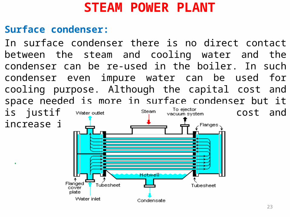
Surface condenser: In surface condenser there is no direct contact between the steam and cooling water and the condenser can be re-used in the boiler. In such condenser even impure water can be used for cooling purpose. Although the capital cost and space needed is more in surface condenser but it is justified byte saving in running cost and increase in efficiency of plant.
.
23
STEAM POWER PLANT

Jet condenser :In jet condenser the exhaust steam and cooling water come in direct contact with each other. The temperature of cooling water and condensate is same when leaving the condensers.
24
STEAM POWER PLANT

Disadvantages of a surface condenser: The various disadvantages of the surface condenser are as follows-1. The capital cost is more.2. The maintenance cost and running cost of the
condenser is high.3. It is bulky and require more space.
Advantages of a surface condenser: The various advantages of a surface condenser are as follows-1. The condensate can be used as boiler feed
water.2. Cooling water of even poor quality can be
used because the cooling water does not come in direct contact with steam.
3. High vacuum can be obtained in the surface condenser. This increases the thermal efficiency of the plant.
25
STEAM POWER PLANT
Cooling Tower: The different type of cooling tower are as follows-1. Atmospheric cooling tower.2. Natural draught cooling tower 3. Forced or induced draught cooling tower.
26
STEAM POWER PLANT
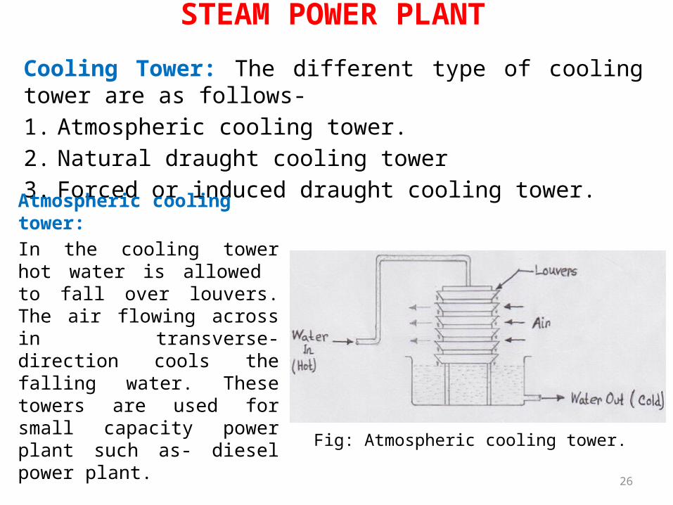
Atmospheric cooling tower: In the cooling tower hot water is allowed to fall over louvers. The air flowing across in transverse- direction cools the falling water. These towers are used for small capacity power plant such as- diesel power plant.
Fig: Atmospheric cooling tower.
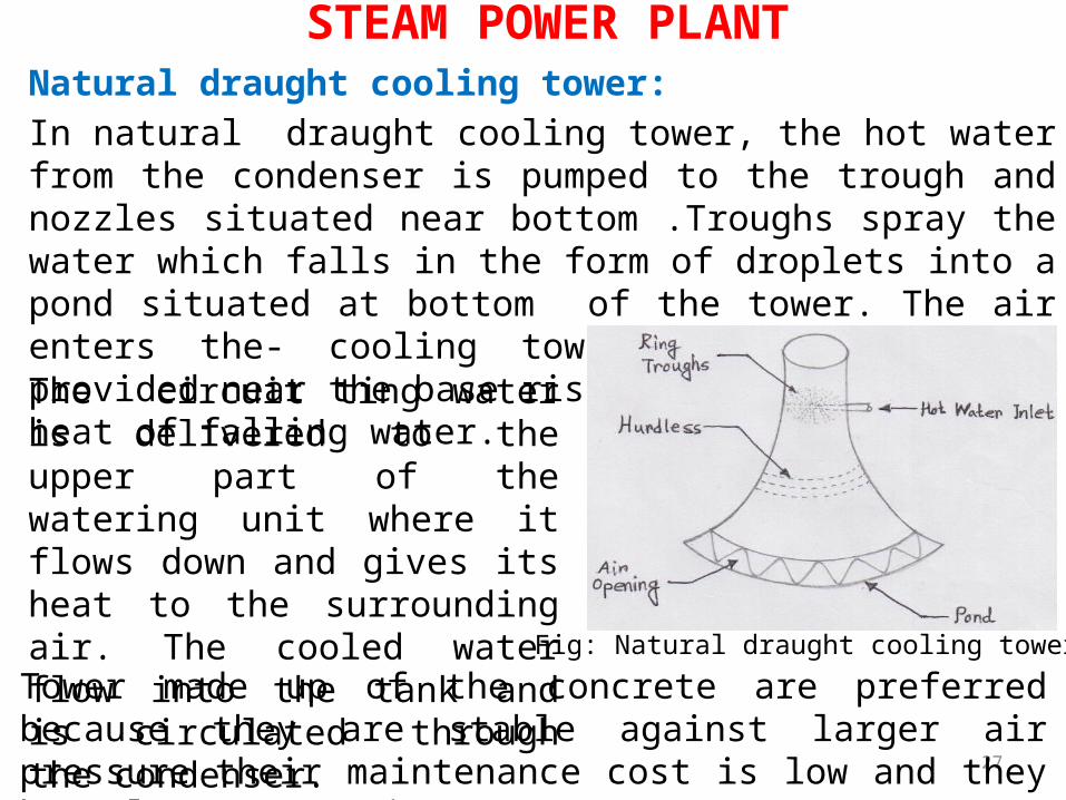
Natural draught cooling tower:In natural draught cooling tower, the hot water from the condenser is pumped to the trough and nozzles situated near bottom .Troughs spray the water which falls in the form of droplets into a pond situated at bottom of the tower. The air enters the- cooling tower from air opening provided near the base rises upward and take up heat of falling water.
27
STEAM POWER PLANT
The circuit ting water is delivered to the upper part of the watering unit where it flows down and gives its heat to the surrounding air. The cooled water flow into the tank and is circulated through the condenser.
Tower made up of the concrete are preferred because they are stable against larger air pressure their maintenance cost is low and they have larger capacity.
Fig: Natural draught cooling tower.

28
STEAM POWER PLANTForced or induced draught cooling tower: In this tower draught fan is installed at the bottom of tower. The hot water from the condenser enter the nozzles. The water is sprayed over the tower filling stats and the rising air cools the water.
Fig: Forced or induced draught cooling tower.

Factors of the cooling tower: The various factors that affect cooling water in a cooling tower are as follows-1. Size and height of cooling tower2. Velocity of air entering the tower.3. Temperature of hot water coming out of
condenser .4. Temperature of air .5. Humidity of air.
29
Maintenance of cooling tower: In order to achieve the desired cooling and to reduce the depreciation costs the regular maintenance of cooling tower is essential. The fans motor housing etc. should be inspected from time to time. Motor bearing should be greased and gear blues oiled. Any unusual noise or vibrations in then should be checked for structural weakness. The circulating water should be tested for hardness- and should kept from impurities to avoid scale formations and avoid corrosive action of water. The water spraying nozzles should be inspected regularly for cooling.
STEAM POWER PLANT

STEAM POWER PLANTBoilers:Boiler is a closed vessel in which water is
converted into steam by theapplication of heat produced by the combustion
of fuel (solid, liquid,gaseous).Classification of Boiler:According to the contents in the tube:
1. Fire tube boiler2. Water tube boiler
According to the position of the furnace:3. Internally fire boiler4. Externally boiler
According to the axis of the shell:5. Vertical boiler6. Horizontal boiler
According to the number of tube:7. Single tube boiler8. Multi tube boiler

STEAM POWER PLANTAccording to application:
1. Stationary boiler2. Mobile boiler
According to the method of circulation of water & steam:3. Natural circulation boiler4. Forced circulation boiler
Water Tube Boiler: In water tube boiler, water circulation through the tubes and hot products of combustion flow over the tube. Example of water tube boilers are Babcock and Wilcox , Stirling boiler, Benson boiler etc.
Fire Tube Boiler: In fire tube boiler the hot products of combustion pass through the tubes which are surrounding by water. Examples of fire tube boilers are Cornish boiler, Locomotive Boiler and Cochran boiler etc.
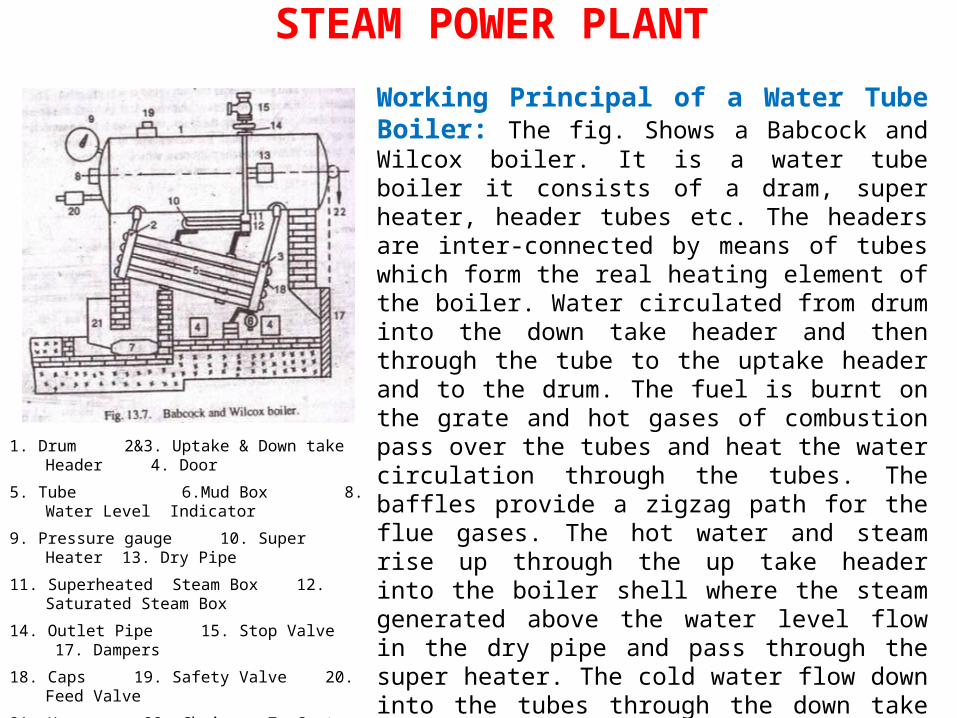
STEAM POWER PLANTWorking Principal of a Water Tube Boiler: The fig. Shows a Babcock and Wilcox boiler. It is a water tube boiler it consists of a dram, super heater, header tubes etc. The headers are inter-connected by means of tubes which form the real heating element of the boiler. Water circulated from drum into the down take header and then through the tube to the uptake header and to the drum. The fuel is burnt on the grate and hot gases of combustion pass over the tubes and heat the water circulation through the tubes. The baffles provide a zigzag path for the flue gases. The hot water and steam rise up through the up take header into the boiler shell where the steam generated above the water level flow in the dry pipe and pass through the super heater. The cold water flow down into the tubes through the down take header. Thus steam separates from water and collects in the steam space. Super heater is used to superheated the steam. The superheated steam can be taken out to the steam stop valve. Any sediment or mud in water gets collected in mud box and in blown off from time to time through the blow off valve.
1. Drum 2&3. Uptake & Down take Header 4. Door
5. Tube 6.Mud Box 8. Water Level Indicator
9. Pressure gauge 10. Super Heater 13. Dry Pipe
11. Superheated Steam Box 12. Saturated Steam Box
14. Outlet Pipe 15. Stop Valve 17. Dampers
18. Caps 19. Safety Valve 20. Feed Valve
21. Hopper 22. Chain 7. Grate

Comparison between Water Tube and Fire Tube Boiler:
Water tube Boiler
Fire Tube Boiler
1.The water circulates inside the tubes which are surrounded by hot gases from the furnace.
1. The hot gases from the furance pass through the tubes which are surround by water.
2. It generates steam at a higher pressure up to 165 bar
2.It can generate steam only up
to 24.5 bar 3.The rate of generation of steam is high, i.e. up to 450 tones per hour
3.The rate of generation of steam is low i.e. unto 9 tonnes per hour.
4.Overall efficiency with economizer
is up to 90% 4.Its overall efficiency is
only 75% 5.It can be transported and erected easily as its various parts can be separated.
5.The transportation and
erection is difficult. 6.The operating cost is high 6.The operating cost is less 7.The bursting chances are more 7.The bursting chances are less 8.The bursting does not produce any destruction to the whole boiler
8The bursting produces greater risk to the damage of the property .
9.It is used for large power plants. .
9. It is not suitable for large plants.
STEAM POWER PLANT
STEAM POWER PLANTBoiler Mountings: These are the fittings, which are mounted on
the boiler for its properand safe functioning. Though there are many
types of boilermountings, yet the following are important
from the subject point ofview.
Feed check valve: The function of a feed check valve is to prevent the return of water from the boiler.Steam stop valve: The function of a steam stop valve is to regulate the flow of steam from the boiler.Safety valve: The function of a safety valve is to prevent the boiler from pressures higher than the desired valve.Blow of valve: The function of a blow off valve is to empty the boiler when needed and to discharge the mud and sediments that collect in the boiler

STEAM POWER PLANTWater level indicator: The function of a water level indicator is to show the water level inside the boiler.Pressure gauge: The function of a pressure gauge is to indicate the pressure of steam in the boiler Fusible plugs: its function is to putt off the fire in the furnace of the boiler when the level of water in the boiler falls to an unsafe limit.
STEAM POWER PLANTBoiler Accessories:These are the devices which are used as integral parts of a boiler
and help in running efficiency. Though there are many types of
boiler accessories, yet the following are important from the subject
point of view.
1. Feed pump: The function of a feed pump is to supply water in the boiler.
2. Economizer: The function of a economizer is to heat the feed water before enters the boiler.
3. Air pre-Heater: The function of a Air pre-heater is to heat the air before it enter the furnace.
4. Super Heater: The function of a super heater is to heat the steam above saturation temperature.
5. Draft: The function of a draft is to supply air to the furnace.

Boiler Maintenance: The various factors which should be carefully
observed for the propermaintenance of the boiler are as follows: The combustion equipment should be so adjusted that the temperature in the furnace does not exceed the designed value.
The water level in the boiler should not be allowed to fall beyond the minimum level. The temperature should change slowly and uniformly in the various part of the boiler, Rapid changes in temperature cause unequal expansion.
The water used for steam generation should be freeform scale forming impurities.
Soot and ash deposited in tubes on gas side should be removed regularly.
Bearings of pumps, stokers, pulverizes and farms etc. lubricated regularly.
At least once in a year the internal inspection of boiler is necessary. The boiler should be inspected for corrosion , cracks, leads and other irregularities
Piping system joints and valve should be checked for leakage.
STEAM POWER PLANT

Problem: 1 A boiler evaporates 3.6 kg of water per Kg of coal into dry saturated steam of 10
bar. The temperature of feed water is 32c, Find the equivalent evaporation “from
and at 100 0c” as well as the factor of evaporation.
Solution: (1) Equivalent evaporation from and at 100 C
(2) Factor of evaporation :
Given, me = 3.6 Kg/ Kg of coal, P= 10 bar, t1 = 32C
From steam tables, corresponding to a feed water temperature of 32C, we find that, hfl = 134 KJ/KG
and corresponding to a steam pressure of 10 bar, we find that (Just for Dry h=hg)h = hg = 2776.2 KJ/Kg
\we know that equivalent evaporation from and at 100 C
/kg of coal
Again, we know that factor of evaporation
=
2257)1( fhhemE
22571fhh
17.122571342.2776
22571
fhh
2257)1( fhhemE
Kj2.42257
)1342.2776(6.3 ( h = hf +xhfg )
STEAM POWER PLANT

Problem: 2The following observations are made in a boiler trial:• Coal used 250 kg of calorific value 29800 KJ/ Kg, water
evaporated 2000 kg. Steam pressure 11.5 bar, dryness fraction of steam 0.95 and feed water temperature 34 C . Calculate the equivalent evaporation from and at 100C per Kg of coal and the efficiency of the boiler.
• Soln: Equivalent evaporation,
• and boiler efficiency
• Given , mf = 250 Kg ;C = 29800 KJ/Kg; ms = 2000 Kg• P = 11.5 bar; x = 0.95; t1 = 34C • From Steam Tables, corresponding to a feed water temperature
of 34C , • we find that hfl = 142.4 KJ/Kg• and corresponding to a steam pressure of 11.5 bar, we find
that • h f = 790 KJ/kg • h fg = 1991.4 KJ/KG• We know that enthalpy or total heat of steam• h = hf +xhfg =790+0.951991.4 = 2681.8 KJ/ Kg of CoalEquivalent evaporation from and at 100C, and efficiency of the boiler
2257)1( fhhemE
Cfhhem )1(
2257)1( fhhemE
coalofkgkj/682.02257
)4.1428.2681(8
Chhm fe )( 1
68.2%or 682.029800)4.1428.2681(8
82502000
kgkgf
se m
mm
STEAM POWER PLANT


