Embed Size (px)
Citation preview

Page 1/23
Electronic thermodynamics part 1: Thermo-electromechanical system modeling,instrumentation, and simulationIrving Morgado-González
Universidad Autónoma del Estado de HidalgoJose Angel Cobos-Murcia ( [email protected] )
Universidad Autónoma del Estado de Hidalgo https://orcid.org/0000-0002-9946-5785Marco Antonio Marquez-Vera
Universidad Politécnica de PachucaOmar Arturo Dominguez-Ramirez
Universidad Autónoma del Estado de Hidalgo
Article
Keywords:
Posted Date: January 13th, 2022
DOI: https://doi.org/10.21203/rs.3.rs-1247394/v1
License: This work is licensed under a Creative Commons Attribution 4.0 International License. Read Full License

Page 2/23
AbstractThis research proposes to obtain a mathematical model that describes the dynamic operation of abrushed DC motor, to obtain a state function considering the electrical, mechanical, and thermal effectsof the DC motor. The dynamic evolution of the proposed function is evaluated by simulation usingMatlab software, and by applying different values of the step type inputs for the brushed motor excitationemploying pulse width modulation (PWM) to obtain a wide range of operations. Experimental resultsshow that the developed state function, provides a reliable approximation to estimate the voltage,armature current, mechanical torque, and temperature of the brushed DC motor, showing an errorpercentage of 0.2%.
1. IntroductionBrushed DC motors are the simplest and most popular electric machines widely used in industrialapplications, electric vehicles, biomedical technologies, training and entertainment platforms, androbotics [1–7]. Easy speed and torque regulation, position control and uniform bearing tribology arecharacteristics of this electric machine; and from here, its multiple applications on experimentalplatforms. Nowadays, different authors have proposed many mathematical models by describing thebrushed DC motor behavior that is crucial for: i) design of the electromechanical system, ii) theapplication as a source of torque, iii) design of electrical and mechanical protections, iv) fault diagnosissystem, and v) design of the control law depending or not on the mathematical model [8–14]. Napoli [15]presented a general approach to DC motor modeling, using the nite element technique for magneticanalysis, in conjunction with tensor manipulation of the network parameters to simulate a desired degreeof complexity. In addition, Suriano et al. [16] presented an article, they applied the tensor method tosimulate the time-varying circuit topology of the armature winding of a DC motor, while Alvarado [8]modeled with non-homogeneous linear rst-order differential equations with constant coecients forspeed control by armature current. Martinez [17] obtained mathematical models through transferfunctions for velocity and position. Other attractive techniques for modeling DC motors were developedby Padre-Ñonthe et al. [18]. They proposed Takagi-Sugeno (T-S) type fuzzy modeling techniques based onthe aggregation of linear sub-models from transfer functions that dene the system dynamics at differentoperating points. In this context, the brushed motor is modeled as an RL series circuit with a voltagesource generated in the motor armature [19, 20]. However, the performance of a DC motor depends notonly on the load torque and the structure of the control law; also, of the parametric changes that occurwith the operating time. A determining factor is temperature, both due to the Joule effect and the dynamicfriction in bearings [21–26]. To this end, adaptive control techniques are considered to regulate theoutput, despite the parametric uncertainty [27]; nevertheless, the precision of the control depends on themathematical model, partially dened in its structure [28].
In the present work, a new mathematical model approach is proposed to estimate the thermo-electromechanical behavior of a brushed DC motor through a state function formulation. Based on theelectronic thermodynamic properties of the motor. The following sections introduce the basic structure of

Page 3/23
the brushed DC motor and, at the same time, a state function is proposed that considers the equivalentelectrical, mechanical and thermal action. This thermo-electromechanical state function was used as astarting point to evaluate the dynamic system of the brushed DC motor for different operating ranges.The validation of the state function experimentally is also presented.
2. Material And Methods
2.1. Variables in the thermodynamic system of a brushedDC motorAs thermodynamic variables in the electrical conduction of a conducting wire in a brushed DC motor(BDCM); the electric potential (V) and temperature (T), which are considered intensive variables, while theelectric current of the armature (Ia), and the mechanical torque (Tm) as extensive variables. Starting withthe equation of Kirchhoff's voltage law (equation 1), which indicates that the sum of voltages around apath or closed circuit must be zero and mathematically is expressed as:
∑ ni=1vi = 0 (1)
Wherenis the total number of voltages measured in a closed-loop.
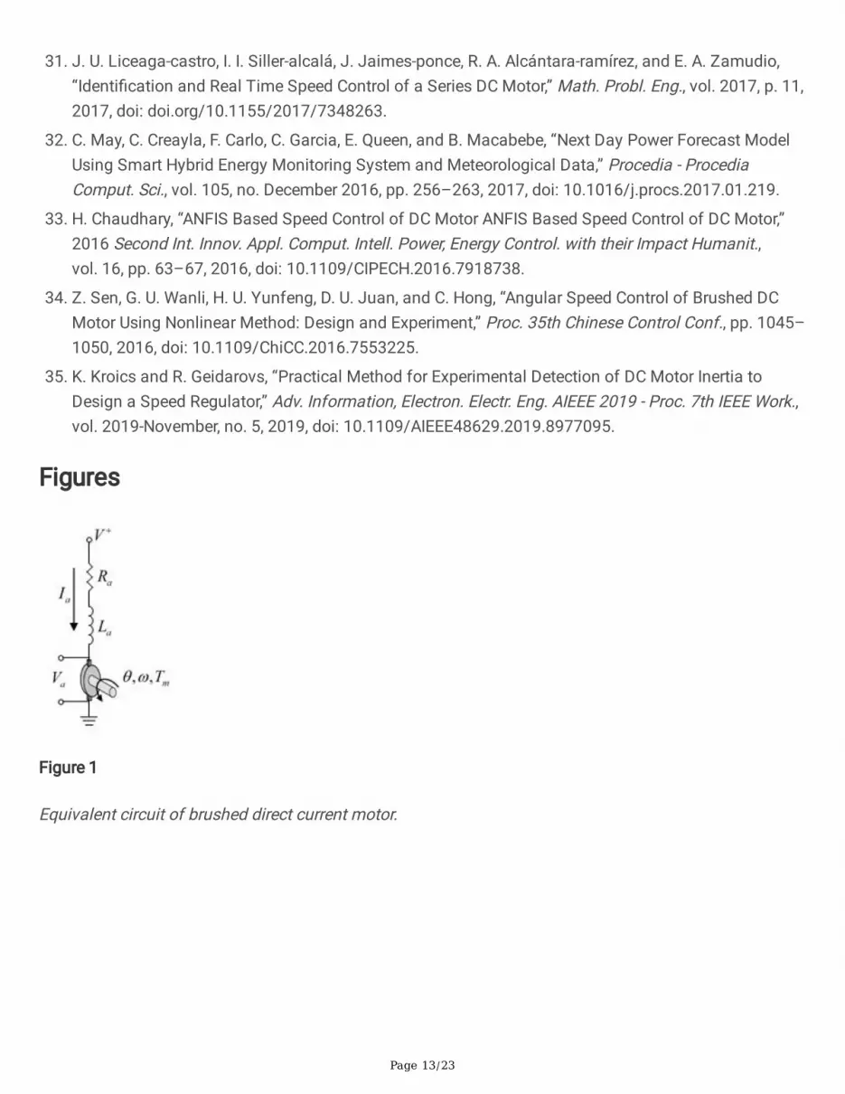
2.2. Mathematical modeling of a BCDMFigure 1 shows the basic circuit of a BDCM. It describes a series circuit consisting of an armatureresistance Ra, an armature inductance La, and the counter-electromotive force Va generated in thearmature when the rotor turns.
By analyzing the equivalent circuit mesh of the series BDCM, considering Equation 1 and Ohm's law, wecan express the voltage drop terms of the circuit components. Where V is the supplied voltage, VRa
is the
voltage across a resistor, VLa is the voltage across an inductor, and Va is the counter-electromotive force.
V − VRa− VLa
− Va = 0 (2)
The voltage across a resistor VRa is expressed according to Equation 3, where Ia is the armature current
and Ra is the armature resistance. The voltage on an inductor VLa is expressed according to Equation 4,
where La is the armature inductance. Here, the counter-electromotive force Va is expressed according to
Equation 5, where Kbis the torque constant, and θ is the angular velocity [20].

Page 4/23
VRa= IaRa (3)
VLa= La
d Iadt
(4)
Va = Kbθ (5)
2.3. Equations to describe the behavior of the BDCM.To establish a state function that provides for the thermodynamic variables considered, it is necessary toestablish that the electric torque Tm developed by the motor, which is expressed by Equation 6, where Kaand Ia represent the torque constant, and the armature current. Whereas Kb ≈ Ka in steady-state, solvingand equating with Equation 5, we obtain the counter-electromotive force Va (Equation 7) expressed interms of the electric torque Tm and the armature current Ia [20].
Tm = KaIa (6)
Va =TmθIa
(7)
On the other hand, to express the armature resistance Ra in terms of temperature [29], we use Equation 8,
which can be expressed in its differential form in Equation 9, and nally, obtain a function in (Equation10) that expresses the dependence on the resistance on the temperature.
Ra = R0 1 + α(Tf − Ti) (8)
dRa = αR0dT (9)
Ra = αR0T (10)
Where α is the thermal constant of the BDCM armature copper (0.004°C−1) [29], T is the roomtemperature at 20°C, and R0=115𝛺 the resistance of the motor armature copper measured attemperature T.
2.4 Power (P) and Work (W) of the BDCM system.The power P is the amount of work WElec done per unit time (Equation 11), taking into consideration thatthe charge of an electric current is: q = Iat and integrating, we obtain the equation for electric workdescribed in Equation 12. Finally, WElec is considered to be the sum of all work contributions (Equation13).
( )
[ ]

Page 5/23
PElec =dWElec
dt = VIa(11)
WElec = Vq (12)
WElec = WMag + WThermal + WMec (13)
2.5 Implementation of the adiabatic BDCM system for studyand data acquisition.The verication of the theoretical model developed was carried out by validating it with practicalexperimental data, which were acquired through an adiabatic system that also allows obtaining thethermo-electromechanical parameters of the BDCM.
The system is presented in Fig. 2 and consists as shown in Fig. <link rid="g2">2</link>a, 1, and 2, a boxand its lid made of expanded polystyrene (EPS). Due to its insulating properties, it is suitable to avoidheat exchanges between the inside and outside [30]. Into the box of Fig. 2a, 3 is the power supply, 4 anArduino Uno microcontroller board, 5 a BDCM controller system (H-bridge), which are the simplestmodules that provide the power amplication for the low-level control signals, such as PWM and directionsupplied by the user.
Moreover, for current measurement (Figure 2a), point 6 shows the Allegro ACS711LC bidirectional Hall-effect current sensor to record the motor current by issuing an analog voltage that is linearly proportionalto the input current. This type of sensor is used in several applications such as closed-loop torque, speed,and position control for BDCM as shown in [31–34].
Whereas, inside the box (Figure 2b); 7, metal gearbox; 8, brushed DC motor; 9, quadrature encoder; 10,motor temperature sensor, and 11, a sensor to measure the internal temperature of the box, is placedinside the box.
Finally, on the outside of the box, point 12 is a sensor for external temperature monitoring. In all cases,the temperature is measured by a resistive sensor HMZ-433A1.
Data acquisition from the temperature and current sensors are processed using an "Arduino Uno"microcontroller from analog signals. Therefore, three functions are programmed for each temperature(internal, external, and motor). Likewise, functions of the motor current and the pulse reading of the motorencoder are assigned. In addition, the control signal for pulse width modulation (PWM) is programmed inthe "Arduino Uno" microcontroller, using ve different PWM percentage conditions; 20, 40, 60, 80, and 100.It is sent to the motor controller with a data acquisition time of 15 min for each PWM percentage value.
Figure 3 shows the general scheme proposed for this study. The power supply voltage of the motor is 12Vand 5V for all the sensors employed, which is provided from a xed linear voltage AC-DC switched-powersupply. The BDCM used for this study is a 37D metal gear-motor, with a gear-ratio of 131:1. An encoder

Page 6/23
integrated on the motor shaft consisting of two Hall-effect sensors used to sense the rotation of amagnetic disk, with a resolution of 64 CPR. Although the measurement of the armature resistance andarmature inductance of the BDCM can be obtained by the method shown in [35], in this work, they wereobtained directly with a DE-5000 LCR device (not shown in Figure 2) that allowed to obtain valuesbetween 9.20Ω and 1.803mH, respectively.
Programming for data acquisition was performed in a script using MATLAB 13.0 software, within a script,using loops in certain sections of the code to perform iterative calculations, with which it is possible tosimultaneously determine both recorded and calculated variables.
3. Thermal, Mechanical, And Electronic Properties Of A Bcdm
3.1. Equation of stateEquation (14) shows the mathematical model that is proposed in this work, which represents an equationof state that relates the variables that are considered in this study of a BDCM system. With thismathematical model, it is possible to determine the contribution of each element that has beenconsidered within the circuit, both for the electrical power P (Equation 15) and for the work W (Equation16).
V = αTR0Ia + 12qLaI2
a + 1qT
mθ (14)
PElec = VIa = αI2aR0T + IaLa
d Iadt + Tmθ
(15)
WElec = Vq = αTR0Iaq + 12LaI2
a + Tmθ (16)
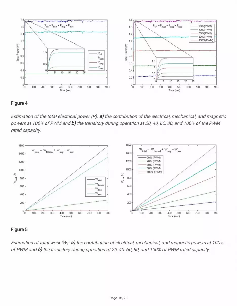
Figure 4 shows the value of the electrical power calculated using Equation (15). It can be observed (Fig.4a) the three contributions and the total calculated power which presents a value of 1.7649 W, while theelectrical, magnetic, and mechanical contributions show values of 0.2981 W, 0.0 W, and 1.4669 W. Themechanical contribution is the largest followed by the electrical supply, and nally, the magnetic is null insteady state. Likewise, it is possible to obtain the electrical power values by operating the PWM atdifferent percentages of its nominal capacity. Fig. 4b shows the power transients at ve different PWM%values, and it is observed that the power presents a rst-order dependence to the PWM%.
Figure 5 shows the calculated work value using Equation (16), and Fig. 5a shows the three contributionsduring operation at 100% of the PWM rated capacity. The total calculated work is 1,582.7 kW, while thethermal, magnetic, and mechanical contributions show values of 267.79 W, 29.2 µW, and 1,315 kW,during the 100% operation of the PWM. The mechanical contribution is the largest, followed by theelectrical and nally the magnetic. Likewise, it is possible to obtain the electrical work values when
( )

Page 7/23
operating the PWM at different percentages of its nominal capacity. Fig. 5b shows the work transitory,and it can be observed that the work presents a rst-order dependence to the PWM%.
3.2. Estimation of thermo-electromechanical variables ofthe BDCM.Given that the state function represents the dependence of the electric potential (V)on changes in electric
current Ia , temperature (T) and torque Tm . It is established that V = V Ia, T, Tm which gives
the total differential (Equation 17). In the same way, Ia = Ia V, T, Tm (Equation 18),
T = T V, Ia, Tm (Equation 19) and Tm = Tm V, Ia, T (Equation 20) can be expressed.
dV =∂V∂Ia
T ,Tm
dIa +∂V∂T
Ia ,TmdT +
∂V∂Tm
T , Ia
dTm
(17)
dIa =∂Ia∂V
T ,TmdV +
∂Ia∂T
V,TmdT +
∂Ia∂Tm
T ,VdTm
(18)
dT =∂T∂V
Ia ,TmdV +
∂T∂Ia
V,Tm
dIa +∂T
∂TmV, Ia
dTm
(19)
dTm =∂Tm∂V
Ia ,TdV +
∂Tm∂Ia
V,TdIa +
∂Tm∂T
V, IadT
(20)
To obtain the corresponding values of the electrical material properties from the partial derivatives. Thederivatives for each variable are obtained using the equation of state (see Equation 14), andsubsequently using Maxwell's equations, the values of the partial derivatives of Equations (18), (19), and(20) are obtained.
With the differential equations solutions is possible to establish the values of each of the variables, asshown in Fig. 6, where the values were obtained using the adiabatic BDCM system, and the valuecalculated using the mathematical model of the variables: Voltage (3a), Current (3b), Temperature (3c)and Torque (3d), during the operation at 20, 40, 60, 80 and 100% of the nominal capacity of the PWM.
Figure 7 shows the percentage accuracy of the mathematical model for all the parameters evaluated. Thevoltage presents a higher variability during the rst moments due to the motor start impulse and thenstabilizes, reaching a 0.2% error in the measured signal. Current, temperature, and torque, on the otherhand, present a better response with an average value of 100±0.1%.
( ) ( ) ( )( )
( ) ( )
( ) ( ) ( )( ) ( ) ( )( ) ( ) ( )( ) ( ) ( )

Page 8/23
The equations to obtain the values of the thermo-electromechanical variables are shown below.
3.2.1 Voltage calculationFrom the solution of Equation 17, we obtain Equation 21, which represents the variation of the electricpotential as a function of changes in current, temperature, and torque.
ΔV =La2q Ia2
2 − Ia12 + αR0T Ia2
− Ia1+ αR0T T2 − T1 +
θq Tm2
− Tm1(21)
The BDCM system voltage operates as expected with a rst-order linear increase between PWM% andVoltage (Figure 6a), presenting a rate of change of 91.62 mV/PWM% and a correlation (r2) of 0.9922. Thevalues obtained by the model t the measured voltage values, with an average coecient of variation of0.9855 (Fig. 7).
Figure 8 shows the voltage value estimated using Equation (14), showing the three contributions, duringoperation at 100% of the PWM rated capacity. The total calculated voltage is 9.7876 V, while theelectrical, magnetic, and mechanical contributions show values of 1.656 V, 48.67 µV, and 8.132 V. Themechanical contribution is the highest followed by the electrical and nally the magnetic contribution.
3.2.2 Current calculationFrom the solution of Equation (18), we obtain Equation (22), which represents the variation of current asa function of changes in voltage, temperature, and torque.
ΔIa =q
IaLa+αR0T V2 − V1 − IalnIaLa+αR0T2IaLa+αR0T1
−θ
IaLa+αR0T Tm2 − Tm1
(22)
The current of the BDCM system operating as expected with a rst-order linear increase between PWM%and current (Fig. 6b), presenting a rate of change of 1.04 mA/PWM% and a correlation (r2) of 0.9991. Thevalues obtained by the model t the measured current values, with an average coecient of variation of1.0002 (Fig. 7 and 9).
3.2.3 Temperature calculationThe solution of Equation 19 gives Equation 23, which represents the variation of temperature as afunction of changes in voltage, current, and torque.
[ ] [ ] [ ] [ ]
[ ] [ ] [ ]

Page 9/23
ΔT =V2−V1αR0Ia
−La
αR0q Ia2 − Ia1 − TlnIa2Ia1
−θ
αR0Iaq Tm2 − Tm1
(23)
Figure 6c shows the comparison between the temperature records using the adiabatic BDCM system andthe value calculated using the mathematical model of equation 23. It is observed that the values obtainedby the model t the measured temperature values, with an average variability coecient of 0.99913between the measured value and the modeled one. However, they do not present a rst-order dependenceconcerning the PWM%. Nevertheless, it is possible to observe two regions of average temperature.
It is possible to observe in Fig. 10, the BDCM system operates in two conditions, in low conditions forvalues lower than 40 of PWM%, with a recorded temperature of 31.85±0.29°C and an average calculatedtemperature of 31.90±0.21°C. While at values above 60 of PWM% a temperature of 37.74±0.90 and acalculated temperature of 37.75±0.91°C are recorded.
Figure 11 shows the value of the temperature calculated using Equation (23). Although, it would bepossible to show the contributions to the temperature since the mathematical expression allows it. It hasno physical representation, so the temperature cannot be considered in this way, being an intensiveproperty that reaches quasi-stationary states, and the different heat capacities and heat transfer rate ofthe materials.
On the other hand, the heat given depends on each contribution of the given amount of heat, but thatanalysis will be left pending for a later part of this series of articles.
3.2.4 Torque calculationSolving Equation (20) results in Equation (24), which represents the variation of torque as a function ofchanges in voltage, temperature, and current.
ΔTm =qθ V2 − V1 −
La2θ Ia2
2 − Ia12 −
αR0Tqθ Ia2
− Ia1−
αR0Iaqθ T2 − T1
(24)
Figure 12 shows the comparison between the torque records using the adiabatic BDCM system and thevalue calculated using the mathematical model of Equation (24). It can be observed that the valuesobtained by the model t the measured torque values, with an average variability coecient of 1.00021between the measured value and the modeled one. Furthermore, it can be observed that the current of theCD Brushed system operates as expected with a rst-order linear increase, presenting a rate of change of1.04 µNm/PWM% and a correlation (r2) of 0.9579.
Finally, this work does not consider a load connected to the motor shaft. Although, the model considersthat the systems are in an equilibrium system under static conditions. Therefore, when a load is
[ ] [ ] [ ] [ ]
[ ] [ ] [ ] [ ]

Page 10/23
connected to the brushed DC motor system, the other variables must change to keep the required torqueconstant.
ConclusionsThe main purpose of this rst part is the mathematical model development that describes therelationship between all the variables, which allows it to be a thermodynamic state function of the BDCMsystem. Also, to establish the denitions of work and power, establishing the contribution of themagnetic, mechanical, and thermal components in these denitions. With this, it was possible to record,iteratively simulate and validate the values of the operating variables, such as current, voltage, torque,and temperature, which are estimated by the mathematical model with an error coecient of less than0.2% concerning those evaluated experimentally. Likewise, it was determined that the motor operateseciently by showing a linear dependence of the voltage, current, and torque with the PWM supply.
Furthermore, it is understood the importance that the mathematical model can have in robotics control,automation, and fault diagnostics. In addition, the methodology used for the mathematical modeldevelopment can be used to evaluate other electronic components and circuits in a similar way to thebrushed DC motor.
Although, in future works, it is planned to present thermo-electromechanical coecients and heat, asproperties that establish the operating characteristics of this system, as well as, to present laterthermodynamic properties such as enthalpy, entropy, and free energies of this system.
It is also contemplated that is possible to study other parameters related to the studied variables toevaluate their application in systems in realistic environments.
References1. A. Muetze and Y. C. Tan, “Modeling and analysis of the technical performance of DC-motor electric
bicycle drives based on bicycle road test data,” Proc. IEEE Int. Electr. Mach. Drives Conf. IEMDC 2007,vol. 2, pp. 1574–1581, 2007, doi: 10.1109/IEMDC.2007.383663.
2. A. A. A. Emhemed and R. Bin Mamat, “Modelling and simulation for Industrial DC Motor usingIntelligent control,” Procedia Eng., vol. 41, no. Iris, pp. 420–425, 2012, doi:10.1016/j.proeng.2012.07.193.
3. S. M. Orozco-Soto, J. C. Ramos-Fernández, and A. García-Barrientos, “Parametric Identication of a 3DOF Robot Manipulator Using a DSP,” 1st Int. Congr. Instrum. Appl. Sci., no. March 2015, pp. 1–9,2010.
4. Lugo-Villeda M.A., Ruiz-Sanchez F.J., Dominguez-Ramirez O.A., Parra-Vega V. “Robotic Design of anUpper Limb Exoskeleton for Motion Analysis and Rehabilitation of Paediatric NeuromuscularDisorders,” In: Pons J., Torricelli D., Pajaro M. (eds) Converging Clinical and Engineering Research on

Page 11/23
Neurorehabilitation. Biosystems & Biorobotics, vol 1. Springer, Berlin, Heidelberg., 2013, doi:doi.org/10.1007/978-3-642-34546-3_42
5. Guo, H., Sun, Q., Wang, C., Wang, Q., & Lu, S. “A systematic design and optimization method oftransmission system and power management for a plug-in hybrid electric vehicle,” Energy, vol. 148,pp. 1006–1017, 2018, doi: doi.org/10.1016/j.energy.2018.01.152
. Gao, B., Chen, H., Liu, Q., & Chu, H. “Position control of electric clutch actuator using a triple-stepnonlinear method,” IEEE Transactions on Industrial Electronics, vol. 61, no. 12, pp. 6995–7003, 2014doi: 10.1109/TIE.2014.2317131
7. Picaza, C. A., Pisarello, M. I., & Monzón, J. E., “Analysis of the stability control of motors used inbiomechanical prostheses”. In VII Latin American Congress on Biomedical Engineering CLAIB 2016,Bucaramanga, Santander, Colombia, October 26th-28th, pp. 561-564, 2016. Springer, Singapore., doi:doi.org/10.1007/978-981-10-4086-3_141
. M. Sebastian and A. Alvarado, “Modelo matemático de un motor de corriente continuaseparadamente excitado: Control de velocidad por corriente de armadura,” Lat. Am. J. Phys. Educ,vol. 6, no. 1, pp. 155–161, 2012.
9. S. C. Maheriya and P. A. Parikh, “A Review: Modelling of Brushed DC Motor and Various Type ofControl Methods,” J. Res., vol. 1, no. 12, pp. 18–23, 2016.
10. J. Chotai and K. Narwekar, “Laboratory: Modelling and Position Control of a Brushed DC Motor,” IEEEProc. Electr. Power Appl., pp. 1–8, 2017, doi: 10.1109/ICAC3.2017.8318792
11. X. Wang, W. Wang, L. Li, J. Shi and B. Xie, “Adaptive Control of DC Motor Servo System WithApplication to Vehicle Active Steering,” IEEE/ASME Transactions on Mechatronics, vol. 24, no. 3,pp. 1054–1063, June 2019, doi: 10.1109/TMECH.2019.2906250.
12. J. Scott, J. McLeish and W. H. Round, “Speed Control With Low Armature Loss for Very SmallSensorless Brushed DC Motors,” in IEEE Transactions on Industrial Electronics, vol. 56, no. 4,pp. 1223–1229, April 2009, doi: 10.1109/TIE.2008.2007046.
13. Ghosh, M., Ghosh, S., Saha, P. K., and Panda, G. K., “Semi-analytical dynamic model of permanent-magnet direct current brushed motor considering slotting effect, commutation, and PWM-operatedterminal voltage,” IEEE Transactions on industrial electronics, vol. 64, no. 4, pp. 2654–2662, 2016,doi: 10.1109/TIE.2016.2637303
14. Gaiceanu, M., Solea R., Codres, B., and Eni, C., “Ecient DC drive system by using adaptive control,” In2014 International Conference on Optimization of Electrical and Electronic Equipment (OPTIM),pp. 381-388. IEEE, 2014, doi: 10.1109/OPTIM.2014.6850961.
15. A. D. I. Napoli, “An approach to dc motor modeling and parameter calculation using nite elementanalysis and tensor mathematics,” IEEE Trans. Power Appar. Syst., vol. PAS-102, no. 8, pp. 2799–2804, 1983, doi: 10.1109/TPAS.1983.317963.
1. J. Suriano and C. M. Ong, “Modeling of electromechanical and electromagnetic disturbances in DCmotors,” Natl. Symp. Electromagn. Compat., pp. 258-, 1989, doi: 10.1109/isemc.1965.7565338.

Page 12/23
17. Héctor Vicente Martínez Martínez, “Análisis, modelado y simulación en computadora del motor decorriente directa tipo serie,” Universidad Tecnológica de la Mixteca, 2009.
1. PADRE-ÑONTHE, Juan David, RAMOS-FERNÁNDEZ, Julio Cesar, MÁRQUEZ-VERA Marco Antonio,“Modelado difuso T-S de un motor de CD y diseño de una estrategia de control PI difuso conganancias programables,” Rev. del Diseño Innov., vol. 1, no. 1, pp. 44–52, 2017.
19. I. Gottlieb, “Practical Electric Motor Handbook”. Butterworth-Heinemann, 1997.
20. S. J., Chapman, “Máquinas eléctricas,” Quinta ed. Mc Graw Hill. 2012.
21. Kaye, J., and Gouse, S. W., “Thermal Analysis of a Small DC Motor; Part I. Dimensional Analysis ofCombined Thermal and Electrical Processes [includes discussion]”, Transactions of the AmericanInstitute of Electrical Engineers. Part III: Power Apparatus and Systems, vol. 75, no. 3, pp. 1463–1467,1956, doi: 10.1109/AIEEPAS.1956.4499460.
22. Kaye, J., Gouse, S. W., and Elgar, E. C., “Thermal Analysis of a Small DC Motor; Part II. ExperimentalStudy of Steady-State Temperature Distribution in a DC Motor with Correlations Based onDimensional Analysis [includes discussion]”. Transactions of the American Institute of ElectricalEngineers. Part III: Power Apparatus and Systems, vol. 75, no. 3, pp. 1468–1486, 1956, doi:10.1109/AIEEPAS.1956.4499461.
23. Acarnley, P. P., and Al-Tayie, J. K., “Estimation of speed and armature temperature in a brushed DCdrive using the extended Kalman lter,” IEEE Proceedings-Electric Power Applications, vol. 144, no. 1,pp. 13-20, 1997, doi: 10.1049/ip-epa:19970927.
24. Lin, C. J., Yau, H., T., and Tian, Y., C., “Identication and compensation of nonlinear frictioncharacteristics and precision control for a linear motor stage,” IEEE/ASME Transactions onMechatronics, vol. 18, no. 4, pp. 1385–1396, 2012, doi: 10.1109/TMECH.2012.2202679.
25. Maeda, Y., and Iwasaki, M., “Initial friction compensation using rheology-based rolling friction modelin fast and precise positioning,” IEEE Transactions on Industrial Electronics, vol. 60, no. 9, pp. 3865–3876, 2012, doi: 10.1109/TIE.2012.2205350.
2. Ahmad, S., Zhang, H., & Liu, G. (2012). Multiple working mode control of door-opening with a mobilemodular and recongurable robot. IEEE/ASME Transactions on Mechatronics, vol. 18, no. 3, pp. 833-844, 2013, doi: 10.1109/TMECH.2012.2191301.
27. S. Jatsun, A. Malchikov and A. Yatsun, “Adaptive Control System for DC Electric Drive underUncertainty,” 2020 International Conference on Industrial Engineering, Applications andManufacturing (ICIEAM), pp. 1-5, 2020, doi: 10.1109/ICIEAM48468.2020.9111876.
2. M. A. Taut, G. Chindris, A. C. Taut and D. Pitica, “Model-in-the-Loop for Determining the Speed andPosition of a DC Motor,” 2018 41st International Spring Seminar on Electronics Technology (ISSE),pp. 1-7, 2018, doi: 10.1109/ISSE.2018.8443767.
29. Gieck, K., “Manual de fórmulas técnicas” 33 ed. México: Alfaomega. 2017.
30. ChemicalSafetyFacts, “Poliestireno,” Get chemical safety information on the products you use everyday, 2021. [Online]. Available: https://www.chemicalsafetyfacts.org/es/poliestireno/. [Accessed: 02-Apr-2021].
Page 13/23
31. J. U. Liceaga-castro, I. I. Siller-alcalá, J. Jaimes-ponce, R. A. Alcántara-ramírez, and E. A. Zamudio,“Identication and Real Time Speed Control of a Series DC Motor,” Math. Probl. Eng., vol. 2017, p. 11,2017, doi: doi.org/10.1155/2017/7348263.
32. C. May, C. Creayla, F. Carlo, C. Garcia, E. Queen, and B. Macabebe, “Next Day Power Forecast ModelUsing Smart Hybrid Energy Monitoring System and Meteorological Data,” Procedia - ProcediaComput. Sci., vol. 105, no. December 2016, pp. 256–263, 2017, doi: 10.1016/j.procs.2017.01.219.
33. H. Chaudhary, “ANFIS Based Speed Control of DC Motor ANFIS Based Speed Control of DC Motor,”2016 Second Int. Innov. Appl. Comput. Intell. Power, Energy Control. with their Impact Humanit.,vol. 16, pp. 63–67, 2016, doi: 10.1109/CIPECH.2016.7918738.
34. Z. Sen, G. U. Wanli, H. U. Yunfeng, D. U. Juan, and C. Hong, “Angular Speed Control of Brushed DCMotor Using Nonlinear Method: Design and Experiment,” Proc. 35th Chinese Control Conf., pp. 1045–1050, 2016, doi: 10.1109/ChiCC.2016.7553225.
35. K. Kroics and R. Geidarovs, “Practical Method for Experimental Detection of DC Motor Inertia toDesign a Speed Regulator,” Adv. Information, Electron. Electr. Eng. AIEEE 2019 - Proc. 7th IEEE Work.,vol. 2019-November, no. 5, 2019, doi: 10.1109/AIEEE48629.2019.8977095.
Figures
Figure 1
Equivalent circuit of brushed direct current motor.

Page 14/23
Figure 2
Adiabatic system of a BDCM: a) front view of the instrumented system, b) top internal view of the case,and c) right external side view of the case.

Page 15/23
Figure 3
Data acquisition scheme of the adiabatic system of a BDCM.
Page 16/23
Figure 4
Estimation of the total electrical power (P): a) the contribution of the electrical, mechanical, and magneticpowers at 100% of PWM and b) the transitory during operation at 20, 40, 60, 80, and 100% of the PWMrated capacity.
Figure 5
Estimation of total work (W): a) the contribution of electrical, mechanical, and magnetic powers at 100%of PWM and b) the transitory during operation at 20, 40, 60, 80, and 100% of PWM rated capacity.

Page 17/23
Figure 6
Comparison between the response of the adiabatic BDCM system and the value estimated by themathematical model of the voltage (a), current (b), temperature (c) and torque (d). During operation at 20,40, 60, 80, and 100% of the PWM rated capacity.

Page 18/23
Figure 7
Percentage accuracy of the measured variables and the calculated mathematical model of voltage (Blue),current (Green), temperature (Red), and torque (Cyan), during operation at 100% of the PWM ratedcapacity.

Page 19/23
Figure 8
Comparison between voltage and electrical, magnetic, and mechanical contribution, during operation at100% of the PWM rated capacity.

Page 20/23
Figure 9
Comparison between the measured and calculated current using the mathematical model, as well as theelectrical, magnetic, and mechanical contribution, during operation at 100% of the PWM rated capacity.

Page 21/23
Figure 10
Comparison between the calculated and measured BDCM operating temperature at two possibleoperating conditions of the PWM rated capacity: Low for PWM% values < 40 and High for PWM% values> 60.

Page 22/23
Figure 11
Comparison between the calculated temperature of the BDCM using the mathematical model and themeasured one, during operation at 100% of the PWM rated capacity.

Page 23/23
Figure 12
Comparison between the measured and calculated torque using the mathematical model, as well as theelectrical, magnetic, and mechanical contribution, during operation at 100% of the PWM rated capacity.
![Education in instrumentation and measurement: the information and communication technology trends [Instrumentation notes]](https://img.dokumen.tips/doc/110x75/63355377a25de9cc4a061fa8/education-in-instrumentation-and-measurement-the-information-and-communication.jpg)


