Embed Size (px)
Citation preview

ARTICLE IN PRESS
0168-9002/$ - se
doi:10.1016/j.ni
�CorrespondiE-mail addre
Nuclear Instruments and Methods in Physics Research A 552 (2005) 513–521
www.elsevier.com/locate/nima
The simulation of ultracold neutron experimentsusing GEANT4
F. Atchisona, T. Brysa,d, M. Dauma, P. Fierlingera,�, A. Fominb, R. Hennecka,K. Kircha, M. Kuzniaka,c, A. Pichlmaiera
aPaul Scherrer Institut, Villigen, SwitzerlandbPetersburg Nuclear Physics Institute, Gatchina, Russia
cJagellonian University, Cracow, PolanddETH Zurich, Switzerland
Received 28 September 2004; received in revised form 15 March 2005; accepted 24 June 2005
Available online 20 July 2005
Abstract
The GEANT4 code has been adapted to include the influence of gravity and inhomogeneous, slowly time-varying
magnetic fields on neutrons. Ultracold neutrons (UCN) are introduced as a new class of particles. All relevant processes
for the interactions at material boundaries and inside materials are implemented. The GEANT4 environment allows for
an effective handling of complicated geometries.
r 2005 Elsevier B.V. All rights reserved.
PACS: 07.05.T; 28.20.C
Keywords: Ultracold neutrons; MC-simulation; GEANT4
1. Introduction
Neutrons with kinetic energies less than about300 neV can be stored in material bottles and arereferred to as ultracold neutrons (UCN). Theirstorage allows for studying fundamental problemsof particle physics, concerning, e.g. the freeneutron decay or the electric dipole moment of
e front matter r 2005 Elsevier B.V. All rights reserve
ma.2005.06.065
ng author.
ss: [email protected] (P. Fierlinger).
the neutron (for reviews, see Refs. [1,2]). Modelingof such experiments is indispensable if one wantsto link an experimental observable, e.g. the storagetime of an UCN trap to a material parameter likethe loss probability per wall collision m. The link isprovided by the wall collision frequency and has tobe calculated. UCN are strongly affected bygravitation and the codes have to take this intoaccount. It is mainly for this reason that earlyefforts using kinetic gas theory or diffusion-typemodels have been abandoned and replaced by
d.

ARTICLE IN PRESS
F. Atchison et al. / Nuclear Instruments and Methods in Physics Research A 552 (2005) 513–521514
Monte Carlo (MC) calculations, which explicitlytrack single UCN trajectories and derive thequantity of interest from a high-statistics sample(see, Refs. [1, p. 99], [2, p. 95]). It is clear that theprocedure can become extremely involved andtime consuming when complex geometries andscattering conditions are to be handled. Therequirement for the ballistic, analytical calculationof the trajectory from one wall collision to the nextmakes the introduction of realistic geometricalboundaries practically unmanageable. To ourknowledge, existing simulations for UCN applica-tions (e.g. see, Refs. [1, p. 99], [2, p. 95], [3,4]) areusually tailored and limited to simple and sym-metric situations in order to give answers tospecific questions. These codes are referred to as‘conventional’ codes in the following.
We have chosen a different approach with thegoal to implement UCN in an universal trackingcode. GEANT4 [5] is a versatile, widely usedtoolkit for the simulation of the passage ofparticles through matter. Its application areasinclude high-energy and nuclear physics experi-ments, medical, accelerator and space physicsstudies. As such, it can handle many physicallypossible processes, including decay and particleproduction. The latter property is particularlyinteresting since it allows to combine the trajectorytracking of both, the ‘parent’ UCN as well as the‘daughter’ decay products, e.g. in neutron decayexperiments. It therefore appeared very temptingto exploit the GEANT4 advantages—versatility,completeness, easy geometry implementation andprofessional maintenance—and extend it to thecase of UCN. The modified code will be referred toas GEANT4-UCN in the course of the paper andcan be downloaded from the corresponding authoron request via email.
In this paper the modifications of the code, itsperformance and an example application aregiven.
2. GEANT4 modifications
The additions to the code concern mainly thefollowing areas: Section 2.1, new forces (gravityand time-varying, inhomogeneous magnetic fields),
Section 2.2, new processes (UCN-specific reflectionand scattering) and Section 2.3, new geometries.
2.1. Forces
Forces can be included easily, since GEANT4makes provision for new forces through thespecification of potentials. Although neutrons areof course treated in the standard GEANT4package we have nevertheless introduced UCNas a new type of particle, being affected by gravityand magnetic fields. Gravity is implementedanalogous to a constant homogeneous electricfield for charged particles and is normalized suchthat the gravitational energy is Eg ¼ mgh ¼
102 ðneV=mÞ h. The magnetic interaction ismediated by the magnetic moment of the neutron,Em ¼ �mB ¼ �60 ðneV=TÞB, where the sign isdetermined by the relative direction of themagnetic moment and the field. Thus, the forceacting on the neutron can be written as F ¼
�mrjBðrÞj [6].Arbitrary fields can be user defined and entered
using functions for the calculation of the fieldstrength in space and time. This allows fieldgradients to change arbitrarily and can causeinaccuracies if the field changes strongly withinone step. If one uses field coordinates as an input,the interpolation between the field points is donelinearly in space and time. An application for suchfields is a magnetic shutter, as discussed in theexample application given in Section 4, where theinhomogeneous field is switched from a valueclose to 0–1.5 T within several seconds as definedby the user.
2.2. Processes
UCN have long wavelengths with l \50 nm.For material interactions it is therefore necessaryto average over a large number of scatteringcenters. Coherent and incoherent scattering effectscan be observed. The main implemented processescan in principle be separated into materialboundary processes (reflection) and bulk materialprocesses (scattering and absorption).We first discuss reflection. Whether a UCN is
reflected from the material depends on the neutron
ARTICLE IN PRESS
F. Atchison et al. / Nuclear Instruments and Methods in Physics Research A 552 (2005) 513–521 515
energy E, its angle of incidence y and the Fermipotential V. The Fermi potential is a materialproperty depending on its density and the aver-aged bound coherent scattering length [1, p. 19],which is either calculated from the chemicalcomposition of the material or implemented as aparameter. From this the critical velocity vc of thematerial is calculated (corresponding to the max-imum velocity for total reflection at normalincidence) and compared to the normal velocitycomponent vn. If vnovc, the neutron will bereflected and different reflection models can beapplied. We have implemented specular anddiffuse reflection and the user can specify theprobability for either process to happen (it shouldbe noted that this is a simple practical approach,other models describing the influence of surfaceroughness are discussed, e.g., in [1, p. 31], [2, p. 100and 184], which can be implemented by the user).For diffuse reflection we employ the usualcosine distribution for the reflected intensity,e.g. [1, p. 101]. The fact that even for totalreflection there is a tiny probability for the neutronto get ‘lost’ is implemented via the material-dependent loss factor Z. The latter is connectedto the loss probability per wall collision m which isa function of E, y and V and is here written interms of the normal component of the velocity onthe surface vn:
mðvnÞ ¼ 2Zvn=vcffiffiffiffiffiffiffiffiffiffiffiffiffiffiffiffiffiffiffiffiffiffiffiffi
1� ðvn=vcÞ2
q0B@
1CA (1)
(see, e.g. Ref. [1, p. 25]). Also other parametersuseful for the simulation of storage experimentslike e.g. the probability for ‘spin-flip per wallreflection’ b (independent of E, y and V) have beenimplemented. Of course, b could also be madeenergy and angle dependent. The loss and spin-flipprobability parameters are material properties andhave to be implemented explicitly since theoreticalapproaches for the description of these phenom-ena could not be verified experimentally so far.
If the normal velocity component is larger thanvc, the particle can be reflected or it enters thematerial and can be elastically scattered, absorbedor up-scattered, i.e. inelastically scattered to
energies above the UCN regime. Over barrierreflection is treated following Ref. [1, p. 21], withthe amplitude of the reflected wave
R ¼
ffiffiffiffiffiffiffiE?
p�
ffiffiffiffiffiffiffiffiffiffiffiffiffiffiffiffiffiE? � V
p
ffiffiffiffiffiffiffiE?
pþ
ffiffiffiffiffiffiffiffiffiffiffiffiffiffiffiffiffiE? � V
p (2)
with E? ¼ mv2n=2 and the probability for reflectionjRj2. The absorption is calculated in the usual wayvia an exponential attenuation law with theabsorption cross-sections proportional to 1=v0.Here v0 is the velocity inside a material, wherethe normal component of the velocity vector ischanged due to the index of refraction. Forcesacting on a particle inside a material change itsvelocity and direction, which affects e.g. the meanfree path inside the material. Thermal up-scatter-ing is neglected here (but easily implemented),since for storage in material bottles the observedlosses are not consistent with theoretical predic-tions [1], nevertheless user-defined scattering lawscan be implemented. Elastic scattering is treated bycalculating a mean-free path for the particle usinguser-defined scattering cross-sections. The indexof refraction in the material is calculated bychanging the component of the velocity normalto the surface using energy conservation (see,Ref. [1, p. 24]).
2.3. Geometries
The new implemented features are geometriesthat have time varying properties. An example isthe definition of shutters, which are volumes thatcan change their material composition, as specifiedin a macro file. For instance, an arbitrary volumemade of massive beryllium can change its proper-ties to ‘vacuum’ and in this way simulate amechanical UCN valve, a shutter or a chopper.
3. Code tests
3.1. Comparison with analytical trajectory
calculations
A stringent test for the accuracy of the tra-jectory calculation is the comparison with analy-tical calculations. Within GEANT4, a particle is
ARTICLE IN PRESS
10 cmB = 0
B = 0
B = 1.5 T
B = 1.5 T
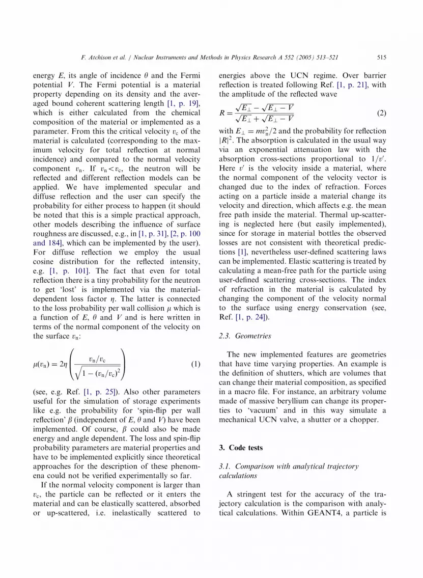
Fig. 1. UCN reflected by horizontal surfaces. The upper
trajectory shows a neutron subject to gravity and to an
inhomogeneous magnetic field (15T/m) and being reflected
from a horizontal surface above (case (b) in the text). The
particle is started with a kinetic energy of 60 neV at a 45� angle
in downward direction. Since both forces are independent of the
vertical position the combined effect causes parabolic trajec-
tories. For case (c) (lower trajectory) the reflecting surface is
outside the magnetic field region and therefore the neutron sees
two different force fields: one is due to gravity and the other due
to the superposition of gravity and an anti-parallel magnetic
field. Along the line B ¼ 0 (thin dotted line) the field gradient
changes abruptly from 0 to 15T/m.
F. Atchison et al. / Nuclear Instruments and Methods in Physics Research A 552 (2005) 513–521516
propagated inside a field by integrating theequation of motion using a stepping algorithm.The advantage of such a method is that manyproblems that are difficult to integrate analyticallycan be solved much easier and it is therefore muchmore versatile. Examples are the propagation of aparticle in a complex geometry, in a complicatedfield, or the proper behavior inside a materialwhen forces are taken into account. The cost forthe versatility is a longer calculation time com-pared to fully analytical trajectory calculation. Ofthe various algorithms provided in GEANT4,Runge–Kutta 4 turned out to be reasonably fastand stable. In order to optimize the trackingaccuracy inside complicated geometries we use the‘miss-distance’ parameter, Dmiss, which is one ofthe standard accuracy parameters in the GEANT4package. The trajectory of the particle is brokenup into short linear segments with the length of thesegments constrained by Dmiss, which is themaximum allowed deviation of the linear tracksegment from the ‘real’ trajectory. The ‘real’trajectory is estimated using the convergence ofthe stepping algorithm. For a given Dmiss the linearpath segment becomes shorter if the curvature ofthe trajectory is strong. A smaller Dmiss increasesthe accuracy, but leads to longer calculation times.
We discuss three test-cases concerning theaccuracy of the trajectory calculation: (a) in thegravity-only case a UCN with kinetic energyEkin ¼ 60 neV bounces on a horizontal mirror;(b) in the ‘gravity with magnetic field’ case a UCNexperiences in addition to gravity an inhomoge-neous magnetic field with a constant gradient of15T/m acting against gravity (see, Fig. 1, upperpanel); (c) the neutron periodically enters andleaves the magnetic field, still in the presence ofgravity (lower panel of Fig. 1). It should be notedthat case (c) is a very stringent test which is almostimpossible to prepare in reality since at the fieldboundary the gradient changes abruptly from 0 to15T/m. As mentioned above, the field boundary isnot at a volume boundary and therefore thegradient change can occur within one step causingan additional position deviation.
Fig. 2 shows the accumulated position deviationin millimeter per meter flight-path as a function ofthe miss-distance parameter Dmiss. The position
deviation is defined as the absolute value of thedifference between the positions calculated byGEANT4 and analytically (for cases (b) and (c)the ‘analytic’ calculation was replaced by aGEANT4 calculation, where Dmiss was set to10�20 mm). To be useful for practical applications,the position deviation was determined fromtrajectory simulations with flight-times typicallyencountered in storage experiments, i.e. about100 s, corresponding to about 1500 bounces for thecase shown in Fig. 1. For a flight time of 5 s theposition deviation is about five times smaller. Thisis because the position deviation caused by thecurvature also leads to an angle deviation whichaccumulates over the periodic mirror reflectionsand produces a non-linear behavior with flight-time, depending on the gradient of the field. Theposition deviation is larger for case (c), where theUCN periodically enters/leaves the magnetic fieldregion with a corresponding additional positiondeviation due to the finite segment length at the

ARTICLE IN PRESS
Fig. 2. Position deviation (left scale) and calculation time (right
scale) per meter flight path as a function of the miss-distance
parameter Dmiss. The position deviation in millimeter per meter
flight path is given for the cases discussed in the text: ‘gravity-
only’, case a (squares), ‘magnetic field with gravity’, case (b)
(triangles) and ‘periodic magnetic field with gravity’, case (c)
(circles). The calculated data points are connected by solid lines
to guide the eye. The calculation time (in seconds per meter
flight path for—in this case—60neV neutrons) also depends on
the miss-distance and is given by the dotted curve without
symbols and the right-hand scale.
F. Atchison et al. / Nuclear Instruments and Methods in Physics Research A 552 (2005) 513–521 517
field boundary. The calculation times given by theright ordinate are typical for a single CPU PC with2.4GHz. For comparison: tracking 104 particles inthe standard GEANT4 example N02 took 50 susing minimum screen output. In order to achievesufficient accuracy for extensive calculations withcomplicated magnetic field distributions the com-puting time may become a problem. To someextent the problem can be alleviated by approx-imating a measured field map by an analyticalmodel with continuous functions.
It should be noted that tests a and b represent‘average’ cases. Since the accuracy depends on thetrajectory curvature and on the field inhomogene-ity one would expect better accuracy for less-curved trajectories and less accuracy for highlycurved trajectories. In that sense the positiondeviation estimates based on incidence angles of45� are considered applicable to typical UCNstorage and transport experiments.
As a final remark concerning accuracy, oneshould bear in mind that UCN experiments ingeneral deal with statistical processes and onlytime-averaged or probabilistic quantities like
storage time, wall collision frequency, spin-flipprobability per wall collision, etc. are determined.As long as one does not deal with UCN ‘range’spectrometers or UCN microscopy, inaccuraciesfor individual particle trajectories on the milli-meter level are in most cases irrelevant. Whatcounts is the statistical behavior of an ensemble ofUCN streaming along a guide or moving atrandom in a storage vessel. It has to be surmisedthat the deviations mentioned are easily offset byinaccuracies introduced by the limited knowledgeof the real reflecting surface morphology (see, alsoRef. [1]) or of the geometry on a microscopic level.
3.2. Tests against conventional MC codes
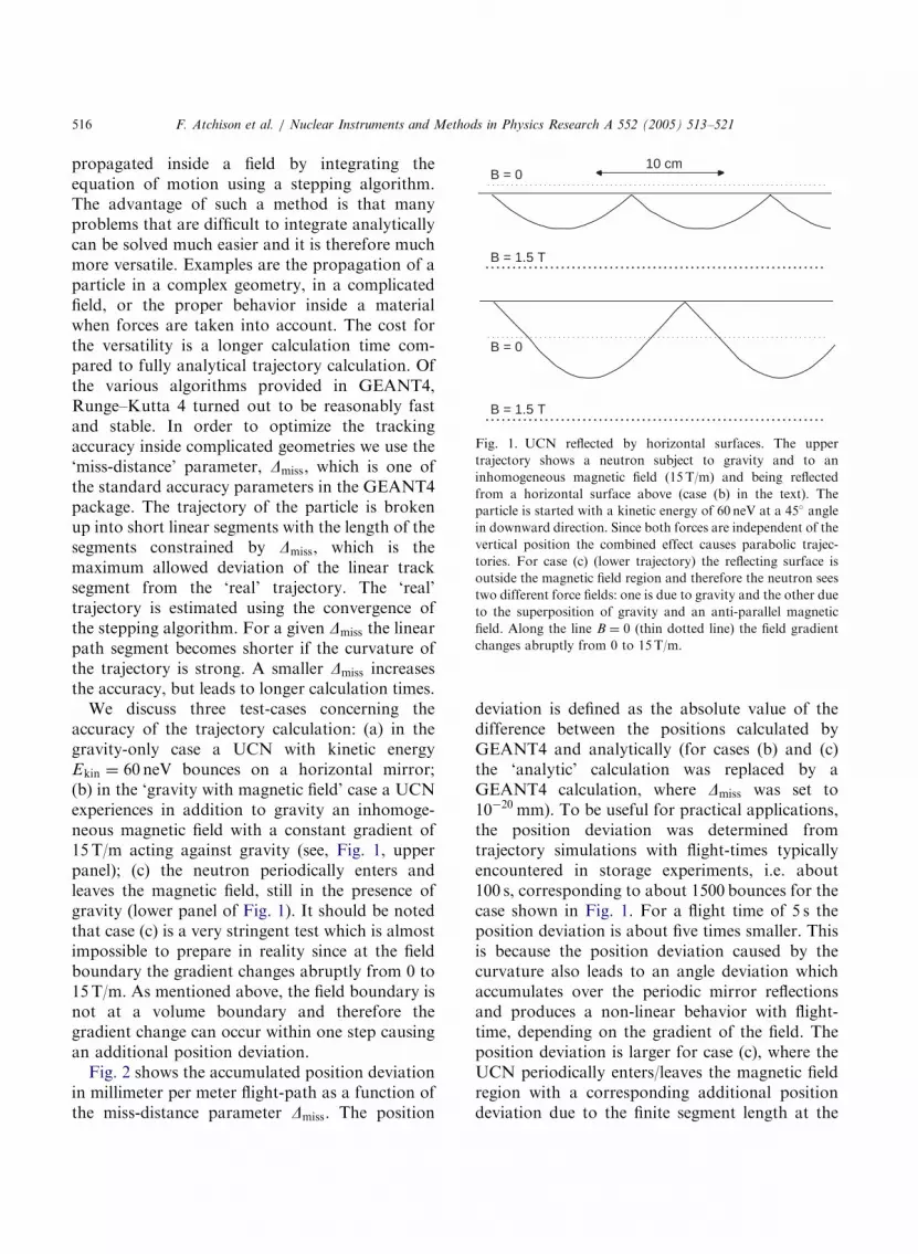
Here, we discuss the comparison with conven-tional MC codes. Since there is no widely usedstandard conventional code we compare with thecode of one member of our collaboration (A.Fomin) which has been used in many applications.This code starts from an initial distribution ofneutrons and calculates the track of each particleanalytically until it reaches a material boundary.At each wall collision the loss and reflectionprobability is calculated, resulting in a newdirection to calculate the trajectory until the nextboundary is reached. The surfaces are limited toflat, cylindrical and ellipsoidal. The neutron decayswith a lifetime of 888 s. For the tests we used thesame initial distributions, diffusion- and lossparameters. In the first test case we compare thevelocity spectrum transformation through a simpleguide system with 140 140mm2 cross-section. Itconsists of a 2m straight, horizontal section,followed by a 90� bend (1m radius) and a 2mstraight, vertical section. The relevant parametersare: vc ¼ 7:8m=s with no loss for vnpvc and totalloss for vn4vc, 0.7% diffuse reflection probability,incident velocity components vaxial are distributedwith a linearly increasing probability from 0 to15m/s and vradial has a constant probabilitybetween 0 and 7.8m/s normal to the guide wallat the entrance. The results are shown in Fig. 3.The velocity spectrum transformation was definedas the number of UCN in a given total velocity bin(e.g. at 5m/s) after transmission through thesystem divided by the number of UCN in the
ARTICLE IN PRESS
Fig. 3. Comparison of two guide ‘transmission’ calculations.
The total velocity spectrum transformation through the guide is
described in the text, calculated by GEANT4-UCN (open
circles) and by the code of A. Fomin (squares).
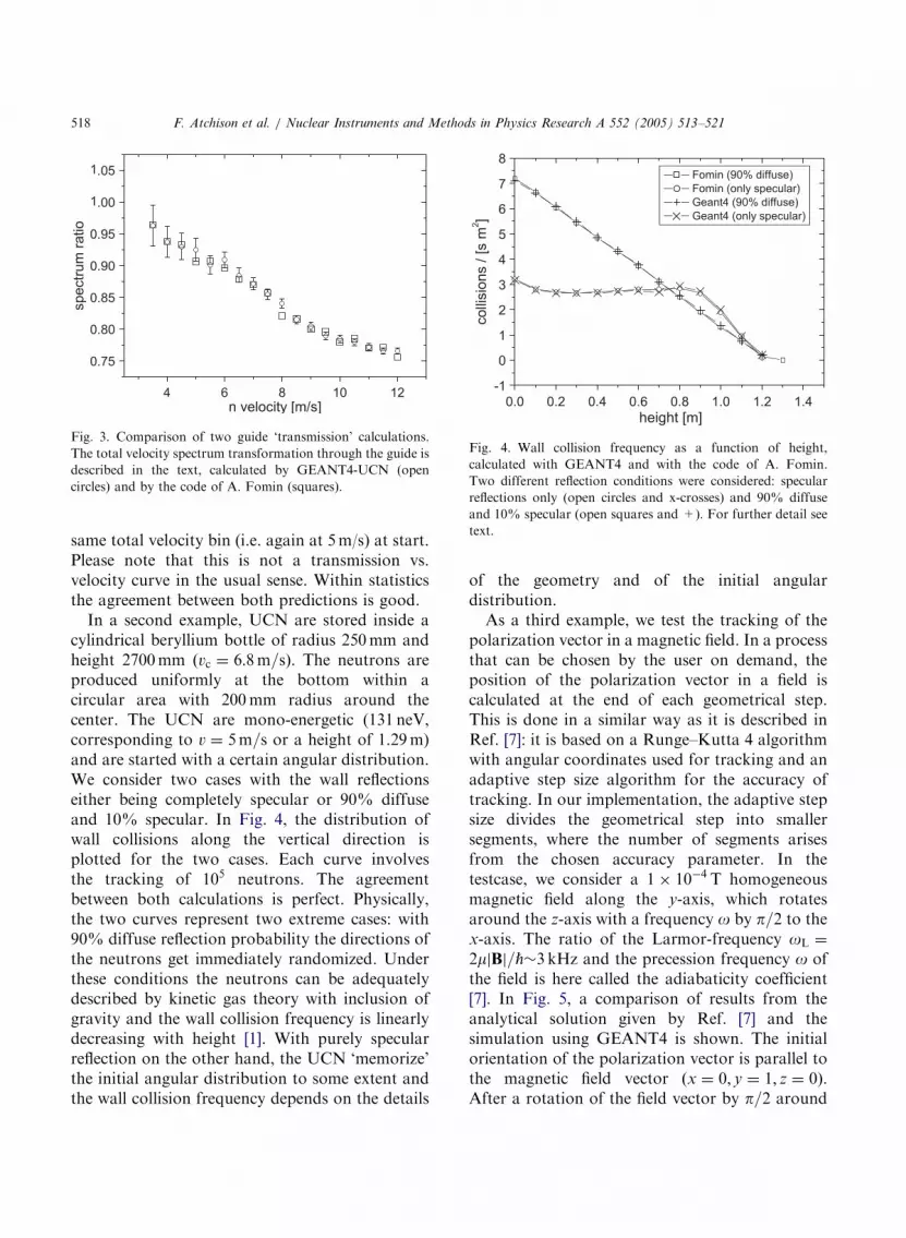
Fig. 4. Wall collision frequency as a function of height,
calculated with GEANT4 and with the code of A. Fomin.
Two different reflection conditions were considered: specular
reflections only (open circles and x-crosses) and 90% diffuse
and 10% specular (open squares and +). For further detail see
text.
F. Atchison et al. / Nuclear Instruments and Methods in Physics Research A 552 (2005) 513–521518
same total velocity bin (i.e. again at 5m/s) at start.Please note that this is not a transmission vs.velocity curve in the usual sense. Within statisticsthe agreement between both predictions is good.
In a second example, UCN are stored inside acylindrical beryllium bottle of radius 250mm andheight 2700mm ðvc ¼ 6:8m=sÞ. The neutrons areproduced uniformly at the bottom within acircular area with 200mm radius around thecenter. The UCN are mono-energetic (131 neV,corresponding to v ¼ 5m=s or a height of 1.29m)and are started with a certain angular distribution.We consider two cases with the wall reflectionseither being completely specular or 90% diffuseand 10% specular. In Fig. 4, the distribution ofwall collisions along the vertical direction isplotted for the two cases. Each curve involvesthe tracking of 105 neutrons. The agreementbetween both calculations is perfect. Physically,the two curves represent two extreme cases: with90% diffuse reflection probability the directions ofthe neutrons get immediately randomized. Underthese conditions the neutrons can be adequatelydescribed by kinetic gas theory with inclusion ofgravity and the wall collision frequency is linearlydecreasing with height [1]. With purely specularreflection on the other hand, the UCN ‘memorize’the initial angular distribution to some extent andthe wall collision frequency depends on the details
of the geometry and of the initial angulardistribution.As a third example, we test the tracking of the
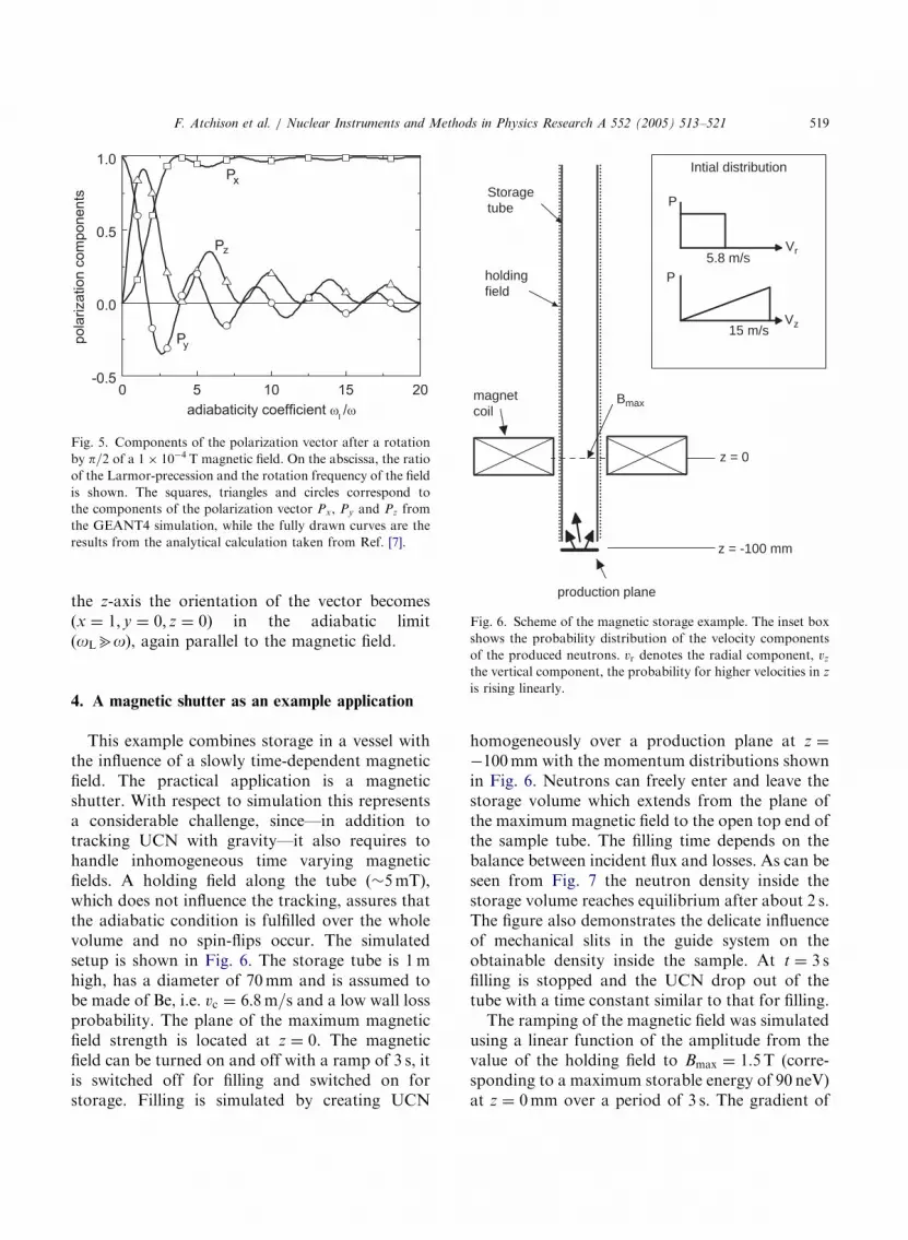
polarization vector in a magnetic field. In a processthat can be chosen by the user on demand, theposition of the polarization vector in a field iscalculated at the end of each geometrical step.This is done in a similar way as it is described inRef. [7]: it is based on a Runge–Kutta 4 algorithmwith angular coordinates used for tracking and anadaptive step size algorithm for the accuracy oftracking. In our implementation, the adaptive stepsize divides the geometrical step into smallersegments, where the number of segments arisesfrom the chosen accuracy parameter. In thetestcase, we consider a 1 10�4 T homogeneousmagnetic field along the y-axis, which rotatesaround the z-axis with a frequency o by p=2 to thex-axis. The ratio of the Larmor-frequency oL ¼
2mjBj=_�3 kHz and the precession frequency o ofthe field is here called the adiabaticity coefficient[7]. In Fig. 5, a comparison of results from theanalytical solution given by Ref. [7] and thesimulation using GEANT4 is shown. The initialorientation of the polarization vector is parallel tothe magnetic field vector ðx ¼ 0; y ¼ 1; z ¼ 0Þ.After a rotation of the field vector by p=2 around
ARTICLE IN PRESS
Fig. 5. Components of the polarization vector after a rotation
by p=2 of a 1 10�4 T magnetic field. On the abscissa, the ratio
of the Larmor-precession and the rotation frequency of the field
is shown. The squares, triangles and circles correspond to
the components of the polarization vector Px, Py and Pz from
the GEANT4 simulation, while the fully drawn curves are the
results from the analytical calculation taken from Ref. [7].
Storagetube
holdingfield
magnetcoil
production plane
z = -100 mm
z = 0
Bmax
Intial distribution
P
Vr
Vz
5.8 m/sP
15 m/s
Fig. 6. Scheme of the magnetic storage example. The inset box
shows the probability distribution of the velocity components
F. Atchison et al. / Nuclear Instruments and Methods in Physics Research A 552 (2005) 513–521 519
the z-axis the orientation of the vector becomesðx ¼ 1; y ¼ 0; z ¼ 0Þ in the adiabatic limit(oLbo), again parallel to the magnetic field.
of the produced neutrons. vr denotes the radial component, vz
the vertical component, the probability for higher velocities in z
is rising linearly.
4. A magnetic shutter as an example applicationThis example combines storage in a vessel withthe influence of a slowly time-dependent magneticfield. The practical application is a magneticshutter. With respect to simulation this representsa considerable challenge, since—in addition totracking UCN with gravity—it also requires tohandle inhomogeneous time varying magneticfields. A holding field along the tube ð�5mTÞ,which does not influence the tracking, assures thatthe adiabatic condition is fulfilled over the wholevolume and no spin-flips occur. The simulatedsetup is shown in Fig. 6. The storage tube is 1mhigh, has a diameter of 70mm and is assumed tobe made of Be, i.e. vc ¼ 6:8m=s and a low wall lossprobability. The plane of the maximum magneticfield strength is located at z ¼ 0. The magneticfield can be turned on and off with a ramp of 3 s, itis switched off for filling and switched on forstorage. Filling is simulated by creating UCN
homogeneously over a production plane at z ¼
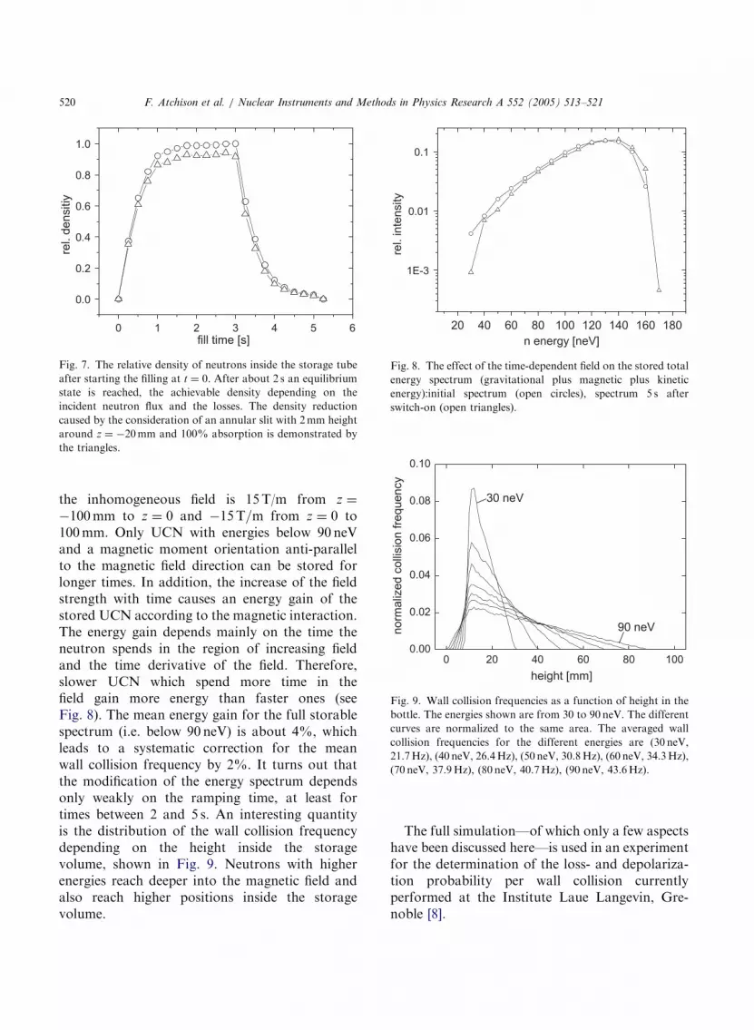
�100mm with the momentum distributions shownin Fig. 6. Neutrons can freely enter and leave thestorage volume which extends from the plane ofthe maximum magnetic field to the open top end ofthe sample tube. The filling time depends on thebalance between incident flux and losses. As can beseen from Fig. 7 the neutron density inside thestorage volume reaches equilibrium after about 2 s.The figure also demonstrates the delicate influenceof mechanical slits in the guide system on theobtainable density inside the sample. At t ¼ 3 sfilling is stopped and the UCN drop out of thetube with a time constant similar to that for filling.The ramping of the magnetic field was simulated
using a linear function of the amplitude from thevalue of the holding field to Bmax ¼ 1:5T (corre-sponding to a maximum storable energy of 90 neV)at z ¼ 0mm over a period of 3 s. The gradient of
ARTICLE IN PRESS
Fig. 7. The relative density of neutrons inside the storage tube
after starting the filling at t ¼ 0. After about 2 s an equilibrium
state is reached, the achievable density depending on the
incident neutron flux and the losses. The density reduction
caused by the consideration of an annular slit with 2mm height
around z ¼ �20mm and 100% absorption is demonstrated by
the triangles.
Fig. 8. The effect of the time-dependent field on the stored total
energy spectrum (gravitational plus magnetic plus kinetic
energy):initial spectrum (open circles), spectrum 5 s after
switch-on (open triangles).
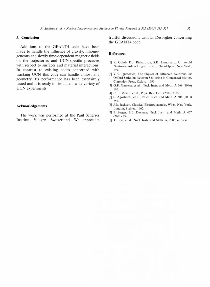
Fig. 9. Wall collision frequencies as a function of height in the
bottle. The energies shown are from 30 to 90 neV. The different
curves are normalized to the same area. The averaged wall
collision frequencies for the different energies are (30 neV,
21.7Hz), (40 neV, 26.4Hz), (50 neV, 30.8Hz), (60 neV, 34.3Hz),
(70 neV, 37.9Hz), (80 neV, 40.7Hz), (90 neV, 43.6Hz).
F. Atchison et al. / Nuclear Instruments and Methods in Physics Research A 552 (2005) 513–521520
the inhomogeneous field is 15T/m from z ¼
�100mm to z ¼ 0 and �15T=m from z ¼ 0 to100mm. Only UCN with energies below 90 neVand a magnetic moment orientation anti-parallelto the magnetic field direction can be stored forlonger times. In addition, the increase of the fieldstrength with time causes an energy gain of thestored UCN according to the magnetic interaction.The energy gain depends mainly on the time theneutron spends in the region of increasing fieldand the time derivative of the field. Therefore,slower UCN which spend more time in thefield gain more energy than faster ones (seeFig. 8). The mean energy gain for the full storablespectrum (i.e. below 90 neV) is about 4%, whichleads to a systematic correction for the meanwall collision frequency by 2%. It turns out thatthe modification of the energy spectrum dependsonly weakly on the ramping time, at least fortimes between 2 and 5 s. An interesting quantityis the distribution of the wall collision frequencydepending on the height inside the storagevolume, shown in Fig. 9. Neutrons with higherenergies reach deeper into the magnetic field andalso reach higher positions inside the storagevolume.
The full simulation—of which only a few aspectshave been discussed here—is used in an experimentfor the determination of the loss- and depolariza-tion probability per wall collision currentlyperformed at the Institute Laue Langevin, Gre-noble [8].
ARTICLE IN PRESS
F. Atchison et al. / Nuclear Instruments and Methods in Physics Research A 552 (2005) 513–521 521
5. Conclusion
Additions to the GEANT4 code have beenmade to handle the influence of gravity, inhomo-geneous and slowly time-dependent magnetic fieldson the trajectories and UCN-specific processeswith respect to surfaces and material interactions.In contrast to existing codes concerned withtracking UCN this code can handle almost anygeometry. Its performance has been extensivelytested and it is ready to simulate a wide variety ofUCN experiments.
Acknowledgements
The work was performed at the Paul ScherrerInsititut, Villigen, Switzerland. We appreciate
fruitful discussions with L. Desorgher concerningthe GEANT4 code.
References
[1] R. Golub, D.J. Richardson, S.K. Lamoreaux, Ultra-cold
Neutrons, Adam Hilger, Bristol, Philadelphia, New York,
1991.
[2] V.K. Ignatovich, The Physics of Ultracold Neutrons, in:
Oxford Series on Neutron Scattering in Condensed Matter,
Clarendon Press, Oxford, 1990.
[3] G.F. Gareeva, et al., Nucl. Instr. and Meth. A 369 (1996)
180.
[4] C. L. Morris, et al., Phys. Rev. Lett. (2002) 272501.
[5] S. Agostinelli, et al., Nucl. Instr. and Meth. A 506 (2003)
250.
[6] J.D. Jackson, Classical Electrodynamics, Wiley, New York,
London, Sydney, 1962.
[7] P. Seeger, L.L. Daemen, Nucl. Instr. and Meth. A 457
(2001) 338.
[8] T. Brys, et al., Nucl. Instr. and Meth. A, 2005, in press.


