Embed Size (px)
Citation preview

The rotation characteristicsof steel wire ropes


The rotation characteristicsof steel wire ropes
by Dipl.- Ing. Roland Verreet
1 Introduction ............................................................................................ 2
2 The moment of non-rotation-resistant ropes............................................ 4
3 The angular rotation of non-rotation-resistant ropes ............................... 6
4 Why do rotation-resistant ropes not rotate under applied axial load?....... 8
5 The moment of rotation-resistant ropes ................................................... 9
6 The rotation angle of rotation-resistant ropes ........................................ 10
7 The angular rotation of rotation-free ropes ............................................ 12
8 Intermezzo: Why are Casar hoist ropes so rotation-resistant? ................ 12
9 The stability of the hook blocks of cranes .............................................. 15
10 The stability of twin-drum systems ........................................................ 20
11 Twin-drum systems: One left-hand lay and one right-hand lay rope
or two rotation-resistant ropes?............................................................. 22
12 The change of moments of wire ropes by enforced rotation .................... 23
13 The twisting of wire ropes enforced by sheaves ...................................... 25
14 The twisting of wire ropes enforced by drums ........................................ 27
15 The twisting of wire ropes during installation ........................................ 30
16 Why must non-rotation-resistant wire ropes not be
operated with a swivel? ......................................................................... 31
17 Why should 17x7, 18x7 and 19x7 ropes not be fitted with a swivel? ...... 31
18 Twist in the reeving system caused by an open swivel ........................... 32
19 Why may rotation-resistant ropes be fitted with a swivel? ...................... 34
20 Why should rotation-resistant ropes be fitted with a swivel? .................. 35
21 What can be done if twist is built up in the reeving system
despite the use of a swivel? ................................................................... 35
22 First Aid ................................................................................................ 38
23 Casar Info: How to connect grab ropes .................................................. 39
24 The right rope for tower cranes .............................................................. 42
25 The right rope for telescopic cranes ....................................................... 43
26 The right rope for lattice boom cranes ................................................... 44
27 The right rope for coal and iron unloaders ............................................. 45
28 The right rope for electrical hoists ......................................................... 46
29 Closing remarks .................................................................................... 47
1

1 Introduction
In order to determine why a wire ropetends to rotate under load, let us firstlook at a bundle of six parallelstrands which have been arrangedround a fibre core (Fig. 1).
By way of example, when lifting aload of six tonnes by means of sucha bundle, each strand will be loadedand stretched by one tonne. The fi-bre core is virtually unstrained.
When running over a sheave, thebundle is bent round its neutralfibre – its axis. The strands pos-itioned at the outside are lengthenedand consequently additionally load-ed; whereas the strands positionedon the inside are shortened and ei-ther partially or even completely un-loaded (Fig. 2).
1 • 6t
6 • 1t
Fig. 1: Bundle of strands
Let us now examine a wire rope withsix outer strands closed helicallyaround a fibre core (Fig. 3).
When the closed rope is bent arounda sheave, each strand along itslength comes to lie alternately on theoutside of the bend, where it islengthened, and on the inside, whereit is shortened. Within one and thesame strand, bending thereforecauses lengthening (and pullingforces) in one place and – a fewmillimeters further on – shortening(and compression forces) in another.By slightly shifting the strands fromthe area of compression (where thereis too much material) to the area oflengthening (where there is a short-age of material) a large part of the
Fig. 2: The change of lengths whenbending a bundle of strands
During this process, enormous pull-ing forces and tremendous changesof load occur within the strands. Thiswill lead to a quick failure of the bun-dle.
Lengthening
Shortening
Same lengths
Same lengths
2

changes in lengths and forcescaused by bending can be reduced(Fig. 4).
When bent around the same sheave,a rope with a helical arrangement ofstrands will therefore be subjectedto much lower bending stress thana rope with a parallel, bundle-likearrangement of strands. This is thereason why a closed wire rope run-ning over sheaves will have a con-siderably longer service life than asimple bundle of strands.
6 • 1t
Fig. 3: Closed wire rope
1 • 6t
However, this improvement of thebending characteristics will cost theuser dearly. When lifting a load ofsix tonnes with the help of the closedrope (Fig. 3), a force Fa will be gen-erated in each strand because of its
l-δl l-δl l-δl l-δl
l-δl
l-δl
l+δl l+δl
l+δl l+δl l+δl
l
l
l ll l
l l l l
inclination against the rope axis.This force Fa amounts to approxi-mately 1.06 tonnes (Fig. 5).
Result: In the closed rope the sameouter load will therefore create stres-ses in every single strand which areapproximately 6% higher than thestresses in the strands of the bun-dle.
Fig. 5: Force components of the strands
Fig. 4: Reduction of tension in a wire rope
Fc=0,35t
Fb=1t
Fa=
1,0
6t
3

by experiment. These experimentsare carried out at Casar Drahtseil-werk Saar in the following way:
The one end of the rope to be testedis firmly fixed in a pull tester. Theother end is attached to a measur-ing device which can record the mo-ment as a function of the load. Theconstruction of the measuring deviceand the circuit arrangement of thegauges will compensate for anypotential influences of temperatureand bending.
During the whole experiment thedata for load, moment, rope elonga-tion and other values of interest,such as rope diameter or the stressin individual wires, are recorded andfed into a computer. They are partlyplotted during the test in the depend-ence required.
The construction of the measuringdevice permits a defined twist of therope before the start of the test, inorder that curves for different gradesof twist can also be determined.
The most important factors of influ-ence on the moment of a wire ropeare illustrated by the following twoexamples:
Example 1:
Two ropes of the same constructionof 10mm and 20mm diameter re-spectively, are both stressed withidentical loads. Which of the tworopes will develop the greater mo-ment?
At first one might guess that the20mm rope would show the lowermoment since it has a breaking loadapproximately four times greaterthan the smaller rope and that its
Even more serious than that is thefact that in each strand a force com-ponent Fc is generated in the tan-gential direction of the rope. In con-nection with lever arm R to the cen-tre of the rope, this force componentbuilds up a moment which will tendto rotate the rope round its own axis(Fig. 6). This brochure will analysethe problems resulting from thisphenomenon.
2 The moment of non-rotation-resistant ropes
The total of the products consistingof the tangential force componentsof the strand forces Fc and theirlever arms R equals the moment ofa wire rope. Given the six-strandrope of Fig. 6, the moment of the ropeis calculated as:
M = 6 • Fc • R
In the case of multi-layer wire ropes,the calculation of the moment can-not be carried out with satisfactoryaccuracy, because our knowledge ofthe load distribution as a functionof the load is insufficient. Conse-quently, the moments as functionsof the loads have to be determined
Fig. 6: The moment of the wire rope
Fc
R
4

stress was considerably less. In re-ality, however, the stronger rope willexert a moment exactly twice as greatas the moment of the thinner rope.
The explanation is fairly simple. Be-cause of the identical constructionof the ropes and their identical angleof lay, the outer load causes thesame force components Fc in tan-gential direction. Yet, in the 20mmrope this force component Fc has alever arm of double the length (Fig. 7).
Same force • double lever arm= double moment.
The following rule can be deducedfrom these facts:
The moment of a rope construc-tion increases proportionally tothe diameter of the rope.
In practice this means:
The smaller the rope, the more re-sistant the system will be to rota-tion.
This is a definite advantage of steelwire ropes with a large metalliccross-sectional area and high tensilestrength wires.
Example 2:
Two ropes of the same diameter arestressed by loads of one tonne andtwo tonnes respectively. How will thedifferent loads influence the mo-ments of the ropes?
The double outer load causes a forcecomponent Fc in the second ropethat is exactly twice as high as theone in the first rope (Fig. 8). Withlever arm R of the same length, themoment of the rope with the double
Fig. 7: The influence of the nominal ropediameter on the moment
force will be exactly twice as high.The following rule can be deducedfrom this:
The moment of a non-rotation-resistant rope increases propor-tionally to the load applied.
These simple examples show that themoment of a steel wire rope is pro-portionally dependent on rope diam-eter and the load applied to it.
The moment is proportional to theproduct load • diameter.
Furthermore, the moment of therope depends on its construction, i.e.on the number of strands and theirdesign, on the lay lengths and thetype of lay (regular or Langs lay). Forinstance, in a single-layer wire ropethe force component Fc = Fa x sin α
Fc
2R
Fc
R
5

grows with the increasing angle oflay α, i.e. with decreasing lay lengthof the rope.
The influence of these data can besummarized in one factor which wecall torque factor k. This factor k isa characteristic feature of a particu-lar rope construction. Our equationfor the moment of a rope now lookslike this:
Moment of the rope =k • load • nominal rope diameter
Fig. 9 shows the factor k of differentCasar Special Wire Ropes. Even inan unloaded condition many Langslay ropes have a strong tendency tounlay if the rope ends are not se-
cured against rotation. This may leadto the assumption that these ropeswill also develop a greater momentunder load with their rope ends fixed,but this is not always true.
Generally speaking, the moments ofCasar Langs lay ropes are lower thanthe moments of Casar regular layropes of the same construction. Thisis in contrast to many standardropes which frequently display theopposite property. Langs lay ropeswith one loose end tend to unlay con-siderably, even when they are un-loaded. This, however, must not leadto the general assumption thatLangs lay ropes develop a highermoment when under load with bothends fixed.
3 The angular rotation of non-rotation-resistant ropes
A non-rotation-resistant rope underload will always tend to reduce itsinternal moment by lengthening itslay, i.e. by unlaying. A pull test inwhich one rope end is allowed to ro-tate freely can determine the exactangle at which the moment causedby the load is reduced to zero. CasarDrahtseilwerk Saar has developed atesting device with special ability.Throughout the test, apart fromother important data such as stressand elongation, the values of angu-lar rotation are measured continu-ously by a precision potentiometerand are fed into a computer. Duringor after the test, diagrams of theangular rotation can be plottedagainst load or elongation.
Fig. 10 illustrates the angular rota-tion per length unit for different ropeconstructions with one rope end be-ing allowed to rotate freely (pull teston a swivel).
Fig. 8: The influence of the load on themoment of the rope
2 Fc
R
Fc
R
6

Fig. 9: Torque factor k for different Casar special wire ropes
Fig. 10: Angular rotation of different wire rope designs when under load
0.06
0.04
0.02
0
Casa
r S
uper
pla
st
Casa
r Tu
rbop
last
Casa
r S
uper
lift
re
gula
r la
y
Casa
r Tu
rbol
ift
reg
ula
r la
y
Casa
r S
trato
lift
re
gula
r la
y
Casa
r S
trato
pla
st
Casa
r S
tarl
ift
Casa
r A
lph
alift
re
gula
r la
y
Tor
qu
e fa
ctor
k [–
]
0.10
0.08
Casa
r Q
uadro
lift
0 10 20 30 40 50 60 70
40 000
30 000
20 000
10 000
0
Load [% of MBL]
Spec
ific
rop
e tw
ist
[deg
rees
• m
m/m
]
8x36 IWRC
Stratoplast
Superplast
Quadrolift
Powerlift
Starlift
Powerplast
Eurolift +
7

When comparing a regular lay ropeCasar Stratolift with a Langs lay ropeCasar Stratolift, the result of theirrotation characteristics is, onceagain, clearly in favour of the Langslay rope. If these two ropes rotatedfreely, as the attachment to a swivelwould allow them to, both ropeswould break at loads below theirminimum breaking loads.
The regular lay rope would break atabout 75% of its minimum breakingload, the Langs lay rope at only 40%.This is one of the reasons why non-rotation-resistant ropes must not befitted with a swivel. The actual de-sign factor of the reeving system isdangerously reduced by the use of aswivel in combination with theserope constructions.
In addition, these ropes would con-tinually rotate forwards and back-wards when being stressed and un-stressed. They would inevitably besubject to extreme internal wear andenormous material fatigue. This isanother reason why non-rotation-resistant ropes should never be fit-ted with a swivel.
4 Why do rotation-resistantropes not rotate under appliedaxial load?
The fundamental principle of rota-tion-resistant ropes is that an inde-pendent wire rope core (IWRC) iscovered with an outer strand layerclosed in the opposite direction. Themoment of the outer layer is in theopposite direction of the moment ofthe IWRC and, in the ideal case, itwill compensate it completely.
Fig. 11 shows the cross section ofan 18x7 rope. The following state-
ments also apply to 17x7 ropes witheleven outer strands, to 19x7 ropeswith a core strand, as well as to18x19, 17x19 and 19x19 ropeswhere the seven-wire strands arereplaced by 19-wire Seale strands.This also applies to compactedstrand versions of all these construc-tions.
In an 18x7 rope, an outer load gen-erates tangential forces in the sixstrands of the IWRC, tending to ro-tate the rope with lever arm R in onedirection. The tangential forces cre-ated in the twelve outer strands workwith lever arm 2 x R in the oppositedirection.
Fig. 11: 18x7 wire rope
Providing the strands are evenlyloaded (and they should be!) andtherefore the force components Fc intangential direction of the IWRC andof the outer layer are even, the pro-portion of moments results in:
8

6 • Fc • R : 12 • Fc • 2R
The proportion of moments amountsto:
6 : 24
If the IWRC was closed in the samedirection as the outer strands, themoment of the rope would amountto:
12 • Fc • 2R + 6 • Fc • R= 30 • Fc • R
Since the moments subtract, how-ever, due to their opposite direction,the actual moment results in:
12 • Fc • 2R - 6 • Fc • R= 18 • Fc • R
Evidently, closing the IWRC in theopposite direction reduces the mo-ment to 60% of the amount it wouldproduce if the IWRC rope was closedin the same direction.
It is self-evident that a wire rope withsuch a high residual moment can atbest be rotation-resistant, but neverrotation-free.
Fig. 12 shows the cross section of aCasar Powerlift. Here twenty-onestrands in the IWRC generate a mo-ment in one direction, whereas onlyeighteen strands in the outer layercreate a counteracting moment.
The disadvantage for the IWRCstrands of having shorter lever armsis compensated in this rope by theadvantage of having a greater me-tallic area, and consequently by hav-ing greater force components Fc. Thenumerical superiority of the strandsin the IWRC accounts for the rest.
This design makes it possible to com-pensate the moments of the IWRCand the outer strands for an ex-tremely extensive load spectrum.Only if they are stressed to approxi-mately 60% of their minimum brea-king load do Casar Powerlift ropesshow a slight tendency to unlay.Casar Starlift, Casar Eurolift andCasar Powerplast display similarcharacteristics.
5 The moment of rotation-resistant ropes
As deduced above, the equation thatdetermines the moment of a ropereads
Moment = k • load • diameter .
The left hand side of the equation –the moment – will become zero if oneof the three factors on the right handside becomes zero.
Fig. 12: Casar Powerlift
9
This means that the moment is zeroif the load is zero – that is evident.Moreover, the moment becomes zeroif the rope diameter is zero. Since inthis case the breaking load wouldalso be zero, this is not a very help-ful condition.
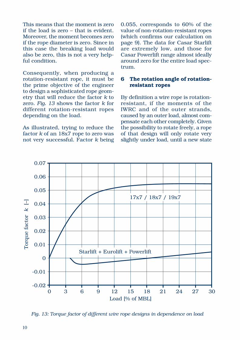
Consequently, when producing arotation-resistant rope, it must bethe prime objective of the engineerto design a sophisticated rope geom-etry that will reduce the factor k tozero. Fig. 13 shows the factor k fordifferent rotation-resistant ropesdepending on the load.
As illustrated, trying to reduce thefactor k of an 18x7 rope to zero wasnot very successful. Factor k being
0.055, corresponds to 60% of thevalue of non-rotation-resistant ropes(which confirms our calculation onpage 9). The data for Casar Starliftare extremely low, and those forCasar Powerlift range almost ideallyaround zero for the entire load spec-trum.
6 The rotation angle of rotation-resistant ropes
By definition a wire rope is rotation-resistant, if the moments of theIWRC and of the outer strands,caused by an outer load, almost com-pensate each other completely. Giventhe possibility to rotate freely, a ropeof that design will only rotate veryslightly under load, until a new state
Fig. 13: Torque factor of different wire rope designs in dependence on load
0
0.07
Load [% of MBL]
Tor
que
fact
or
k
[–]
0.06
0.05
0.04
0.03
0.02
0.01
0
-0.01
-0.023 6 9 12 15 18 21 24 27 30
17x7 / 18x7 / 19x7
Starlift + Eurolift + Powerlift
10

of equilibrium between the IWRCand the outer layer is established.
If, for instance, the moment of theouter layer is predominant, the ropewill unlay and lengthen the lay of itsouter layer. At the same time theIWRC - closed in the opposite direc-tion - will close and shorten its laylength. The lengthening of the outerlayer will take some of its stress awayand reduce its moment, whereas thesimultaneous shortening of the ropecore will lead to additional stress andto the increase of the moment of theIWRC.
Progressive twisting of the rope willdecrease the moment of the outerlayer and increase the moment of the
IWRC until an equilibrium of the twomoments is established.
If twisting of the rope is requireduntil the equilibrium of moments isachieved, the lengthening of theouter layer and the simultaneousshortening of the IWRC will lead to aredistribution of forces and mo-ments. In the new equilibrium therope core will take an overproporti-onal part of the load.
Therefore, even ropes which are notcompletely rotation-free, such as17x7, 18x7, 17x19 and 18x19 ropes,will find an equilibrium of momentsafter a certain twist, despite theirgreat moment when unlayed. But,as we have seen, this equilibrium is
Fig. 14: Breaking loads of different wire rope designs in a break test with an openswivel
120
100
80
60
40
20
Bre
akin
g lo
ad w
hen
tes
ted a
ttach
ed t
o a s
wiv
el[ %
of
MB
L ]
6-
stra
nd r
ope
8-
stra
nd r
ope
18x7
Casa
r S
tarl
ift
Casa
r Pow
erlift
Casa
r R
am
mbol
ift
Casa
r Q
uadro
lift
Casa
r E
uro
lift
40–6
0%
60–8
0%
90–1
10%
Casa
r Pow
erpla
st
90–1
10%
90–1
10%
90–1
10%
90–1
10%
90–1
10%
40–6
0%
11

only possible if the IWRC is stressedoverproportionally and the outerstrands are stressed underpropor-tionally.
The consequences of disproportionalstressing in practical operation areserious. Ropes with 17x7, 18x7,17x19 and 18x19 constructions andtheir compacted versions tend toshow greater wear and more wirebreaks in the highly strained ropecore, particularly in those placeswhere the outer strands cross overthe strands of the IWRC and imposeadditional high pressure on them.This means that the deteriorationof the ropes in the course of progres-sive fatigue occurs in those areaswhich are not accessible to visual in-spection.
The only strands that can be in-spected visually are the barelystressed outer strands. They will al-ways give the impression that therope is in good shape. Consequently,within the ropes of these designsrope failures occur quite often be-fore the discard number of visiblewire breaks is reached.
When allowed to rotate freely, a ropewhich is not completely rotation-freecan only establish an equilibrium ofmoments by overtwisting its IWRC.Therefore, in a pull test with ropeends allowed to rotate freely, theoverproportionally loaded IWRC willbreak prematurely.
This is why 17x7, 18x7, 19x7 ropesand their 19-wire strand and com-pacted versions, when attached to aswivel, achieve only 70% of theirminimum breaking loads. Fig 14shows the breaking loads of differ-ent ropes when tested with a freelyrotating swivel.
7 The angular rotation ofrotation-free ropes
A wire rope is rotation-free if themoments of the IWRC and the outerstrands generated in the rope by anouter load add up to exactly zero. Arope of that design will not rotateunder load when allowed to rotatefreely. With the cross-sections andthe lever arm proportions in balance,as is the case in Casar Starlift, CasarEurolift and Casar Powerlift ropes,there is no tendency to twist what-soever, even up to very high loads.
Only minimal moments are gener-ated which can be reduced to zeroby the slightest rotations that arebarely measurable. The homogeneityof the load distribution is not dis-turbed in these ropes, so that evenwhen attached to a swivel in a breaktest they will produce their full mini-mum breaking load. Fig. 15 showsthe angular rotation of different ropeconstructions in a break test attachedto an unlocked swivel.
It must be stressed emphatically thatropes of the type Casar Starlift,Casar Eurolift and Casar Powerliftcan be used with a swivel withoutany loss of safety. On the contrary,the use of a swivel is even recom-mended with these ropes. The swivelenables twist that has been built upby the reeving system and by otherfactors of influence to be released.
8 Intermezzo: Why are Casarhoist ropes so rotation-resistant?
The strands of a wire rope are ar-ranged at a certain angle to the ropeaxis. Under load the strands try toget in line with the rope axis (straigh-ten) by twisting the rope round itsown axis.
12

The rope manufacturer tries to makethe rope rotation-resistant by clos-ing the outer strands in the oppos-ite direction to the inner strands,such that the outer strands will tryto twist the rope in the one direc-tion, whereas the inner ones will tryto twist it in the other.
The outer strands have a clear ad-vantage with respect to the rope twistbecause they are further away fromthe centre of the rope and conse-quently have the longer lever arm.
This can be compared with a com-petition in which two teams try topush a turnstile in opposite direc-tions. The competition is not exactlyfair because the one team pushes the
turnstile at the end of its bars andthus benefits from the considerablylonger lever arm, whilst their oppo-nents are pushing it near the centre(Fig. 16).
If those pushing the turnstile nearthe centre do not stand a chancewhen the number of competitors ofboth teams is equal, how muchharder must it be when they areoutnumbered by twice as manypushers at the outer end of the bars(Fig. 17)?
This is exactly what happens in 18x7or 18x19 ropes. These constructionscontain six inner strands whichmust compete with twelve outerstrands of the same diameter, and
Fig. 15: Angular rotation of different rope constructions in a break testwith an open swivel
3(1080°)
0 20 40 60 80 100Load [% of MBL]
17x718x7
Casar StarliftCasar EuroliftCasar Powerlift
Rot
ati
on [t
urn
s/m
] (deg
rees
/m
)
2(720°)
1(360°)
0(0°)
6-
or 8
-str
and r
ope
13

Fig. 17: In an 18x7 rope the metallic cross-section of the outer strands is twice thatof the IWRC.
Fig. 16: Due to their longer lever arms the outer strands have an advantage.
Outside Inside
Outside Inside
14

Fig. 18: In the rotation-free Casar hoist ropes the metallic cross-section of the IWRCis considerably greater than that of the outer strands. Because of this an equilibriumis established.
Outside Inside
with lever arms twice as long. Ropesof that design can only be reasonab-ly rotation-resistant if the innerstrands are hopelessly overloaded.
Being well aware of these problems,the Casar engineers have given ex-tra support to the inner strands ofCasar Starlift and Casar Eurolift.During manufacture, a large numberof strands are densely packed byparallel closing.
By applying additional compaction,a process for which Casar holds in-ternational patents (US Patent No.4454708), the IWRC is reinforcedeven further. The result is that themetallic cross section of the IWRC isnow considerably greater than thatof the outer strands. Or, if applied
to our turnstile example, many ath-letes on the inside with the short le-ver arm fight against a few on theoutside with a long lever arm (Fig.18). The result is excellent stabilityagainst rotation.
9 The stability of the hook blocksof cranes
The stability or the extent of the ro-tation of a hook block does not onlydepend on the design of the wirerope. The geometry of the reeving isalso of considerable influence. In thefollowing, the influencing factors areconsidered by reference to a two-part-reeving system.
A wire rope will always tend to re-duce its moment by rotating round
15

its own axis. With two- and multi-ple-part reevings, however, this ro-tation will act to lift the load (Figs.19 and 20). The internal energy ofthe rope is transformed into poten-tial energy of the load. The systemwill rotate until the equilibrium ofmoments is established.
The higher the load must be lifted inorder to create the same angulartwist of the block, the more energythe must rope expend. The higherthe load must be lifted for generat-ing the same angular twist, the morestable the block will be against twist-ing.
Fig. 19 shows two blocks of differentwidth, i.e. of different distances be-tween the two falls. In Fig 19a – nar-row width – the load has lifted only
slightly when the block is twisted,for example, by 180°. Little liftingenergy is required before the ropecables – the system has little stabil-ity.
In Fig. 19b – greater width – the loadhas lifted considerably higher whenthe block is twisted by the same180°. A much greater lifting energyis required before the rope cables.Therefore, the system with the grea-ter hook block width is much morestable.
Fig. 20 shows two blocks of equalwidth but different free rope lengths,i.e. different lifting heights. In Fig.20a – great lifting height – the loadis lifted only slightly when the blockis twisted by 180°. Only little energyis needed before the rope cables.
Fig. 19: The influence of width on the stability of the block. If the width is great, thereeving system must expend a lot of lifting energy when twisting.
a
b
16

Therefore, the system with great lift-ing height has little stability.
In Fig. 20b – smaller lifting heightand the same twist of block by 180° -the load is lifted considerably higher.Much greater lifting energy is re-quired before the rope cables. There-fore, the system with a lower liftingheight is considerably more stable.
If there are no additional influences,such as wind pressure or slewing ofthe crane, the stability of the reev-ing system against rotation can bedetermined by means of a fairly sim-ple formula. The prerequisite is thatthe lifting height is much greaterthan the width of the block.
The maximum permissible value forthe torque factor of the rope, before
the block cables, can be determinedby the following formula (in conjunc-tion with Fig. 21):
where
k is the torque factor of the wire rope
b the spacing of the ropes at the block
t the spacing of the ropes at the top
d the nominal rope diameter
h the lifting height
The torque factors k of the most im-portant Casar Special Wire Ropes areillustrated in Fig. 9.
Fig. 20: The influence of the lifting height on the stability of the block. If the freerope length is small, the system must expend a lot of energy when twisting.
k ≤ b • t4.8 • d • h
a
b
17

It is noteworthy that the rope loaddoes not appear in the formula. Thatmeans that the stability of the blockis the same under a load of one tonneas it is under a load of two tonnes.
At first this might sound illogical,because doubling the load willdouble the moment of the rope whichwill try to twist the block. However,this twist would require lifting twicethe amount of load and consequentlytwice the lifting energy would benecessary.
The formula for the permissible fac-tor k can be rearranged to allow thecalculation of the maximum liftingheight h before cabling must be ex-pected:
For calculating the minimum widthb of the basis (same distance at thetop and at the bottom), for which areeving system is stable, the formulareads as follows:
What we have so far explained fortwo-part reeving systems naturallyapplies to three- and multiple-partreevings as well. Here the calcula-tion follows the formulae in Fig. 22.
Usually the stability of a reeving sys-tem against rotation increases withthe number of parts. A numericalexample: The permissible liftingheight of 141 metres for four-partblocks with square basis is consid-erably higher than the permissiblelifting height of 100 metres for a two-part block (Fig. 23).
Fig. 21: Dimensioning the reeving
If k is considerably below the calcu-lated value, there is no danger ofcabling. If the factor k is less thanbut very close to the permissiblevalue, cabling may be possible be-cause of destabilising influencessuch as wind pressure or additionalmoments caused by slewing the crane.
As can be seen from the formula, thestability of the block is the greater:
• the smaller the torque factor k ofthe rope
• the greater the spacing t at the top• the greater the spacing b at the
bottom• the smaller the lifting height h and• the smaller the nominal rope dia-
meter d
The formula shows that a reevingsystem is increasingly more stableagainst rotation with decreasing ropediameter. For the crane designer thisis yet another good argument forchoosing the smallest rope diameterpossible.
h
U
d
O
h ≤ b • t4.8 • d • k
b ≥ 4.8 • d • h • k
18

Fig. 22: The calculation of the stability of a block for two-, four-, six-, and three-partreeving systems. Subscripts: t = top and b = bottom.
b or t
Two-part line:
Ab or At
Bb or Bt
Bb or Bt
Bb or Bt
b/2ort/2
k <b • t
4.8 • h • d
Four-part line:
k <b • t
4.8 • h • d
t = (At2+Bt2)1/2
Six-part line:
k <b • t
4.8 • h • d
Three-part line:
k <b • t
7.2 • h • d
b = (Ab2+Bb2)1/2
Ab or At
b/2ort/2
t = (At2+Bt2•8/3)1/2
b = (Ab2+Bb2•8/3)1/2
19

Fig. 25: Crane with left-hand lay andright-hand lay wire ropes
Fig. 23: The influence of the number ofparts on the maximum permissible liftingheight
Fig. 24: A comparatively unstable three-part reeving
If a third part is attached to the blockof a two-part reeving system, the re-sult will be a three-part arrangementas illustrated in Fig. 24. The permis-sible lifting height of 67 metres isdecisively lower than that for a blockwith a two-part line (Fig. 23).
however, there are now three insteadof previously two parts attemptingto twist the block.
10 The stability of twin-drumsystems
Compared to single-drum systemswith one drum only, twin-drum sys-tems have quite a few advantages.For instance, the same number oflines allows twice the lifting speed.In many cases only the use of a twin-drum system can guarantee single-layer spooling. In the case of a left-hand and a right-hand drum with aright-hand lay and a left-hand layrope, the moments of the ropes willneutralize each other. Therefore, alifting system of this kind is very re-sistant to rotation, even if non-rota-tion-resistant ropes are used (Fig.25).
The reason for this is that the thirdpart, compared to the two part-reev-ing, does not widen the spacing;
For constructional reasons it is oftennecessary to operate a twin-drumsystem with only one rope with bothits ends fastened to the drum. In thiscase it is essential that the pitch of
2-
par
t lin
e
3-
par
t
4-
par
t lin
e
0
50
100
150
Lifti
ng
hei
ght
[m]
20

should – if possible – be replacedwith a balance. This opens up thepossibility of installing a left-handlay and a right-hand lay rope. Thereeving will be the same as shownin Fig. 25.
In cases where there is no designchange possible, the use of a CasarQuadrolift rope construction canproove very helpful. On the one handthis rope construction is compara-tively rotation-resistant, but in con-trast to other rotation-resistant con-structions it has no IWRC and isconsequently very tolerant to en-forced twisting.
For the sake of completeness it mustbe mentioned that an arrangementas shown in Fig. 26 can be moreadvantageous, as it keeps the fleetangle between the drum and the firstsheave in the block low. This is whyit is occasionally preferred in prac-tice.
Fig. 26: Crane with two left-hand layrope drums
the drum is in the opposite direc-tion to the lay of the rope. With re-gard to the pitch of the drum, Fig.26 illustrates the correct arrange-ment of a left-hand grooved drumand a right-hand lay rope. The dis-advantage of this arrangement is theslight travelling of the load in thedirection of the spooling during thelifting operation.
Fig. 27 shows a twin drum, half ofwhich is grooved left-handed, theother half right-handed. During thelifting operation there is no travel-ling of the load, but the rope is enor-mously strained on twist by the“wrong” grooving of one side of thedrum.
Whichever direction of lay is chosen,it will never be suitable for bothdrums. One of the drums will alwaysseverely twist the rope. In unitswhere this arrangement causesproblems, the compensating sheave
Fig. 27: Crane with one left-hand lay andone right-hand lay drum
21

11 Twin-drum systems: One left-and one right-hand lay rope ortwo rotation-resistant ropes?
As to the stability of the hook blockagainst rotation, it seems that lift-ing devices with one right-hand layand one left-hand lay non-rotation-resistant rope are as good as liftingdevices with two rotation-resistantropes.
In lifting devices with left-hand layand right-hand lay non-rotation-re-sistant ropes, great moments aregenerated in both ropes when liftingthe load. As these moments have thesame value and are in opposite di-rections they neutralize each other.Therefore, the block will not rotate.In lifting devices with two rotation-
resistant ropes (preferably theyshould be left-hand lay and right-hand lay, too) the moments of theIWRC and the outer layer neutralizeeach other within the ropes; likewise,the hook block will not rotate.
We now consider the enforced changeto these equilibria by either slewingthe crane round its axis or by mo-ments caused by wind pressure orany other destabilising factors. Howstrong, then, are the counteractingmoments in the reeving, which –caused by enforced rotation – stabi-lize the system?
Fig. 28 illustrates the change of mo-ments of the non-rotation-resistantrope construction Casar Stratoplastin comparison to Casar Powerlift.
Fig. 28: When, for instance, rotation is enforced by slewing the crane, rotation-resistant ropes develop much greater counteracting moments than non-rotation-resistant ropes.
1.2
0.8
0.4
0
-0.4
-0.8 0
Specific rope twist [ degrees • mm / m ]
500 500 10001000
Casar Powerlift
un
layin
gclo
sin
g
Torq
ue f
acto
r k [ -
]
Rope unlayed Rope closed
Casar Stratoplast
22

Fig. 29: Twisting a wire rope by force...
Fig. 30: ...causes lay shortening on theone side (left) and lay lengthening on theother (right).
The disturbances in the rope con-struction Casar Powerlift causechanges of the moment considerablyhigher than in Casar Stratoplast.The counteracting moments in therotation-resistant rope are four tofive times higher than in the non-rotation-resistant rope. Conse-quently, when simply lifting a loadand transporting it in a straight lineand without any other destabilisingmoments, both systems are equallygood. If, however, there are disturb-ing moments, such as slewing thecrane round, a lifting device with tworotation-resistant ropes is distinctlysuperior to one fitted with a left-handand a right-hand lay rope.
12 The change of moments ofwire ropes by enforced rotation
So far we have tried to analyse thetendency of ropes and reeving sys-tems to rotate when under load. Fre-quently, however, there is also a ten-dency to rotate when unloaded. Thisphenomenon is discussed in the fol-lowing section.
If a rope which is fixed and securedagainst rotation at both ends istwisted by force, the result will belay lengthening on the one side andlay shortening on the other side ofthe rotation. A numerical examplemay illustrate this effect:
A rope of 200 lay lengths is fixed andsecured against rotation at bothends (Fig. 29). The rope is grabbedexactly in the middle, so that thereare one hundred lay lengths on theleft and one hundred lay lengths onthe right. Then the rope is twistedby force through five turns. This re-sults in 100 plus 5 lays which havebeen added by force on the left side,i.e. that is 105 shortened lay lengths.
On the right side there are now 100minus the 5 lay lengths which havebeen subtracted, i.e. 95 (lengthened)lay lengths (Fig. 30). The total num-ber of lays will remain constant pro-vided both ends of the rope are fixedand secured against rotation.
The lay shortening in the closingsense on the left side of the rope hasbuilt up an enormous moment ef-fective in the unlaying sense. Theextremely unlayed right side of therope has built up a strong momentin the closing sense.
How great are the moments causedby enforced rotation? It will becomeevident that non-rotation-resistantropes and rotation-resistant ropeswill react very differently to enforcedrotation.
Fig. 31 illustrates the influence ofenforced rotation on the moment ofa non-rotation-resistant rope (CasarStratoplast). It is obvious that the
23

Fig. 32: The changes of the torque factor of a rotation-resistant rope, caused byenforced rotation. The factor k is changed considerably.
Fig. 31: The changes of the torque factor of a non-rotation-resistant wire rope causedby enforced rotation. The factor k is hardly changed.
0 20 40 60 80 100 120 140
0.10
0.08
0.06
0.04
0.02
0
0.02
0.04
0.06
0.08
0.10
10°/m
20°/m
40°/m
-10°/m
-20°/m
-40°/mCasar Starlift
diameter 19 mm
Load [kN]
Tor
que
fact
or k
[-]
unlayed
closed
0.16
0.14
0.12
0.10
0.08
0.06
0.040 20 40 60 80 100 120 140
Load [kN]
Torq
ue facto
r [-
]
unlayed
-40°/m
-20°/m-10°/m
10°/m
20°/m
40°/m
0°/m
Casar Stratoplastdiameter 19 mm
closed
24

change of the moment is not exces-sively great and that it rapidlydecreases in percentage with in-crease in the loading.
The following rule can be deduced:
The change of the moment of non-rotation-resistant ropes by en-forced rotation is rather small.
Fig. 32 shows the change of the mo-ment by enforced rotation of a rota-tion-resistant rope (Casar Starlift).Whereas the moment of the non-twisted rope is nearly zero, twistingit in the lay lengthening or lay short-ening sense causes the moment toincrease rapidly.
The reason for this phenomenon isthe different influence of enforcedrotation on the IWRC and the outerstrands respectively:
When the rope is unlayed, the laylength of the outer layer is length-ened and that of the IWRC is short-ened. When the rope is twisted in thelay shortening sense, the lay lengthof the outer layer is shortened andthat of the IWRC is lengthened.
In both cases, however, the IWRC willreact exactly in the opposite way tothe outer strands.
The following rule can be deduced:
The change of the moment of ro-tation-resistant ropes by enforcedrotation is extreme.
This theoretical analysis determinesthe consequences for practical op-eration. When using rotation-resist-ant ropes it must be ensured thatthese ropes are not twisted by force.In a twisted state, a rope that is oth-
erwise rotation-resistant can possesshigher moments than a non-rota-tion-resistant rope.
The following section will discuss themechanisms that lead to the twist-ing of a rope and how this can beavoided.
13 The twisting of wire ropesenforced by sheaves
In order to guarantee the correctoperation of the rope, the reeving hasto be designed in a way that the ropeparts will enter the sheaves in exactalignment with them. In practice,however, a slight fleet angle betweenthe rope and the plane of the sheavecannot always be avoided. This isparticularly the case in multiple-partreeving systems, where the rope en-ters the successive sheaves under acertain fleet angle.
Fig. 33: The wire rope rolls into thebottom of the groove.
25

201030
4050
60708090
201030
4050
60
8090
201030
4050
60
8090
201030
4050
60708090
201030
4050
60708090
201030
4050
60708090
5
4
32
1
Fig. 34: Slight twist of a rope when thefleet angle is 1°
Fig. 35: Great twist of a rope when thefleet angle is 5°
Fig. 36: Change of rope lay lengthcaused by a sheave
20 1030
4050
60708090
201030
4050
60708090
201030
4050
60708090
201030
4050
60708090
2010 0
0
3040
5060
708090
5
4
32
1
This fleet angle has the effect thatthe rope does not enter the sheavesat the lowest point of the groove. Itfirst touches the groove on the flangeand then rolls into the bottom of thegroove (Fig. 33). This rolling actiontwists the rope.
Fig. 34 shows the contact of the ropeat the flange and the twisted posi-tion at the bottom of the groove for afleet angle of 1°. It is recognizablethat for small angular deflections thetwist of the rope is also small. Fig. 35shows the contact of the rope at theflange and the twisted position at thebottom of the groove for a fleet angleof 5°. It is obvious that for great fleetangles the twist of the rope is over-proportionally great.
Due to the greater friction at thepoint of contact this effect is moresevere when plastic sheaves areused. With steel sheaves it is easier
for the rope to slide into the bottomof the groove. The negative effect ofthe friction adds up when multi-partreeving systems are used with sev-eral deflection sheaves in a row.
If the cause of rope damage cannotbe found, it is often helpful to exam-ine the discarded rope with regardto potential changes of its lay length.
110
100
900 117
Rope length [m]
Lay
len
gth
[%
]
200
26

extremely dangerous. Therefore, themaximum permissible fleet angle inany reeving system is generallylimited to 4°.
Because of the different reactions ofIWRC and outer strands, rotation-resistant and rotation-free wire ropeswith a steel core that is closed in theopposite direction react much moresensitively to rotation by force thanconventional ropes do. Therefore DIN15 020 limits the maximum permis-sible fleet angle for those ropes to1.5°. The revised text of ISO 4308limits the same to 2°.
Crane designers and users are well-advised to stay within these values.
14 The twisting of wire ropes en-forced by drums
The rope is wound on the drums atthe angle α, which is the gradientangle of the drum (Fig. 37).
The fleet angle β between the ropeand the lead sheave is variable. InFig. 37, for instance, the angle wouldbe exactly zero if the drum was halffull.
If the drum is full, angle β will be atits maximum.
At both flanges of the drum the ropeis deflected from the groove at anangle of β+α and β−α respectively.
The maximum permissible fleet an-gle β+α on drums is generally limit-ed to 4°, for rotation-resistant androtation-free wire ropes to only 1.5°(DIN 15020) or 2° (revised text of ISO4308). Crane designers and usersare well-advised to stay within thesevalues.
Either prints are taken of the rope’ssurface over equal distances, in or-der to measure the lay length onpaper, or the lay length is measureddirectly on the rope.
A diagram showing the lay lengthversus the rope length will clearlydifferentiate between rope zonestwisted in the lay lengthening senseand those twisted in the lay short-ening sense.
Fig. 36 shows the lay length of adiscarded rope along the rope length.For most parts of the rope the laylength corresponds with the desiredvalue of 100%. However, in the areaof 117 metres a very distinct devia-tion from the desired value can berecognized. To the left of that point,approximately 20 metres of the ropehave been unlayed and the lay lengthhas been lengthened. To the right ofthat point, about 20 metres of therope have been closed and the laylength has been shortened. One mayconclude that the rope zone 117m ±20m passes one of the sheaves at alarge fleet angle. By means of a reev-ing diagram it is usually quite easyto pinpoint the sheave responsible.
We have seen that the twisting of arope caused by an excessive fleetangle brings the danger of changesto the structure of the rope. Addi-tionally, twist of that kind may unlayand totally unload the outer strandsof a wire rope so that the whole loadends up being carried by the IWRC.
It is quite possible that the IWRC,which is now totally overstressed,will fail prematurely, although theouter strands on inspection wouldsuggest that the rope is in perfectcondition. A situation like this is
2a7

Fig. 38: The change of the lay lengthcaused by a drum with the wrongdirection of grooving
The deflection of the rope on thedrum leads – in the same way as thedeflections on sheaves – to the roperolling into the bottom of the groove,which results in a continuous twist-ing of the rope. In order to minimisethat twist and stop the natural ten-dency of the rope to unlay, the fol-lowing rule must be observed:
A left-hand drum must be operatedwith a right-hand lay rope,a right-hand drum must be operatedwith a left-hand lay rope.
A violation of this rule will lead tosevere unlaying of the rope on thedrum in the opening sense (increaseof lay length) and – on the other hand– to an equally severe twisting of therest of the rope in the closing sense(decrease of lay length) (Fig. 38).
Exceeding this twist will causeirrepairable damage to the rope,
such as the formation of bird cagesin the unlayed zone, or parts of theIWRC protruding in the closed zoneof the rope (termed ‘popped cores’).
Quite often both defects occur withinthe same rope: Fig. 39 shows thedamage along the unlayed zone of arope and Fig. 40 shows the damagein the closed zone of the same rope.
β+α β−α
α β
α
β β
Fig. 37: Fleet angles at the drum and the sheave
110
100
900
Rope length [m]
Lay
len
gth
[%
]
200
28

maximum of α+β is distinctly re-duced by this solution (Fig. 41).
Fig. 39: Surplus length of the outerstrands caused by unlaying the rope
Fig. 40: Surplus length of the innerstrands caused by closing the same rope
Apart from choosing the correctdirection of lay, the conditions of thelifting device can also be improvedby its design. It is evident that theangle β decreases with the growingdistance between lead sheave anddrum (Fig. 37).
The maximum possible angle β+αcan be reduced by shifting the sheaveor the drum sideways. Of course, thismakes sense only with single-layerdrums. It must be remembered,however, that this measure increa-ses the fleet angle on the sheave.
If the diameter of the drum is in-creased, its width becomes morenarrow for a given rope length. Thissolution, however, is more expensivebecause of the higher driving mo-ments required.
But increasing the drum diameternot only diminishes β. It also reducesα considerably, because the shift ofthe rope on the drum can now bedistributed over a much wider cir-cumference. Consequently, the
Fig. 41: Reducing the angles by increas-ing the diameter of the drum
β+αβ−α
α β
β β
29

Further advantages can be gained byusing specially designed drum sys-tems (e.g. Lebus), in which, for largesections of the circumference, theangle α is zero and the shift into theneighbouring windings can be man-aged within short zones.
With multiple-layer spooling the ropeis wound on the drum, alternatingfrom layer to layer in a right-handedand a left-handed helix. Accordingto the rule of the opposite directionof lay it would be necessary tochange the direction of the rope layfrom layer to layer. As this is notpossible, the direction of lay shouldbe chosen according to the rope layerwhich is working the most, or evenaccording to the direction of the reev-ing, because the influence of the di-rection of lay decreases with the in-creasing numbers of layers.
15 The twisting of wire ropesduring installation
One of the most frequent causes forthe twisting of ropes is incorrectinstallation. When installing wireropes, particularly rotation-resistantones, meticulous care must be takento ensure that the ropes are installedwithout any twist. Great care mustalso be taken not to unwind the ropeat the side of the reel or coil duringinstallation as this will introduce oneturn per length of the circumferenceof the reel or coil.
As described above, rotation-resist-ant ropes are particularly sensitiveto these incorrect procedures due tothe counteraction of the inner andouter layers. In reeving systems thatuse rotation-resistant ropes attachedto a swivel, any twist that waspossibly introduced during theinstallation can unlay.
Quite often, especially with largecranes, new ropes are attached to theold ones and are pulled by them intothe reeving system. When installingropes in this way, it is vital that theconnection of the rope ends is notrigid. A rigid connection would allowa twisted old rope to pass on its twistto the new rope by unlaying duringthe installation process. In this casethe new rope would be damaged tosuch an extent that it would failwithin a very short period of time.
Instead, the ropes can be connectedby Chinese Fingers with a welded-inswivel, or by two or more strandswhich serve as connecting elementsbetween the two rope ends.
The latter case has one distinctadvantage: after the installation ofthe new rope the strands will revealhow many turns the discarded ropehas unlayed (Fig. 42).
When installing Langs lay ropes,rotation of the rope ends must beavoided.
Even the slightest twist will lead togreat differences in length betweenexternal and internal rope com-ponents. Later these differences willbe accumulated by the drums andsheaves at one point, where they willeventually appear as birdcages.
In many cases it is advisable to painta straight line on the rope parallelto the axis during the productionprocess. This will make it easier todetect any twist after installation.
If necessary, this twist can be com-pensated by twisting the rope endback at the fixed point. However,operations like these should alwaysonly be carried out by specialists.
30

rope to twist, thereby providing aproblem-free installation.
In all cases where absolute securityagainst twist cannot be guaranteedduring installation, the use of ropes withplastic infill is highly recommended.
16 Why must non-rotation-resistant wire ropes not beoperated with a swivel?
If a non-rotation resistant rope isattached to a swivel, it will unlayunder load. The twist leads to anenormous shift of the forces withinthe rope: the outer strands will beunloaded, internal components willbe overloaded. The breaking load andwith it the safety of non-rotation-resistant ropes is severely reduced,if the rope is allowed to rotate freely.
When the rope is unloaded, the linemoving towards the swivel maypossibly rotate back to its originalnon-twisted state. The more oftenthese ropes are loaded and un-loaded, the greater the internal wearand the fatigue of inner strands willbe by continually opening andclosing at the swivel. As these defectscannot be detected by visual inspec-tion of their interior, they representan additional safety risk.
Non-rotation-resistant ropes, suchas the six- and eight-strand types,must be attached in such a way thatthey are secured against twist. Theymust never be fitted with a swivel.
17 Why should 17x7, 18x7 and19x7 ropes not be fitted witha swivel?
As mentioned above, 17x7, 18x7,and 19x7 ropes lose more than 30%of their breaking load when under-
Fig. 42 : Rope connection by means ofChinese Fingers. Before (left) and afterinstallation (right).
With reference to installation, theLangs lay versions of Casar SpecialWire Ropes with a plastic layerbetween the IWRC and the outerstrands (such as Casar Stratoplast,Casar Turboplast, Casar Superplastetc.) are much safer than conven-tional Langs lay ropes. The indenta-tions of the plastic coating with theIWRC and the outer strands coun-teract any tendency of the unloaded
31

going a break test with a swivel. Thisreduction of safety would alreadyprohibit the use of a swivel. What ismore, even under minimal loads,ropes of this construction showconsiderable twists. Attaching theseropes to a swivel would thereforecause permanent twisting andunlaying - as it does with 6- and 8-strand ropes. This mechanism wouldinevitably lead to increasinglydangerous internal wear and topremature fatigue of the innerstrands, which are not accessiblewhen inspecting the rope’s exterior.
18 Twist in the reeving systemcaused by an open swivel
All the arguments so far prohibit theuse of a swivel with non-rotation-resistant ropes and 17x7, 18x7,19x7 ropes and their variations forsafety reasons. In many casesanother problem crops up when aswivel is used with these ropes: twistis built up in the reeving system. Anexample may illustrate this:
A new, non-rotation-resistant ropehas been installed on a simple cranewith one sheave and one drum (Fig.43). We have made sure that the ropehas not been twisted during instal-lation. The wire rope is attached tothe hook by means of a swivel.
When lifting a load, the swivel willrotate until the entire rope lengthbetween the swivel and the firstsheave is completely unlayed.Fig. 44 shows that in our examplethe swivel has completed eightrevolutions, represented by eightdots on the rope.
When lifting the load further, part ofthe twisted rope length – in ourexample half of it – will move over
the sheave. After this operation, halfof the revolutions induced by theswivel, represented by four dots, willbe found between the sheave and thedrum (Fig. 45). In this area a rela-tively strongly twisted rope zonemeets non-twisted rope.
The twisted zones will transfer partof their twist to the as yet non-twisted zones, i.e. the four revolu-tions will be spread evenly across thewhole rope length between sheaveand drum (Fig. 46).
Now the crane is moved into a diffe-rent position or just slews, and theload is set down. When lowering thehook, part of the twisted rope length(in our case half of it) will travel fromthe stretch between the sheave andthe drum into the line to the swivel.
In our example, two revolutions leavethe section between sheave anddrum (Fig. 47). At the same time non-twisted rope spools off the drum intothe same stretch. The two revolu-tions remaining between the drumand sheave now spread evenly inthat section, while the line attachedto the swivel returns to its non-twisted state once the load is putdown (Fig. 48).
We have now returned to the startingposition, and the process describedabove could start all over again.
We started with a non-twisted rope,but after only one lifting operationtwo complete revolutions haveentered the rope. The twisted zonesare trapped between the sheave andthe drum and cannot unlay at theswivel to regain their initial, non-twisted state. On the contrary, withevery additional lift, the amount ofrope twist will increase.
32

Fig. 48: After one lifting operation tworevolutions remain within the reevingsystem.
Fig. 43: Before lifting the load the wirerope is non-twisted.
Fig. 44: When the load is lifted, theswivel carries out eight complete revo-lutions.
Fig. 47: Part of the twisted rope lengthruns back over the sheave.
Fig. 46: The twist spreads evenly alongthe rope length.
Fig. 45: While lifting the load, half of thetwisted rope length passes over thesheave.
33

It is a fallacy to believe that twistintroduced into the rope by loadingit, will be eliminated when the ropeis unloaded. Due to the ‘mixingphenomenon’, part of the twist willalways remain in the system. Afterpoisoning a barrel of wine with aglass of arsenic, it cannot be ex-pected to become drinkable againjust by skimming off a glass of themixture from the barrel.
The increase of twist within thesystem in the course of further liftingoperations may lead to differentconsequences for the rope. The twistmight overstress some elements ofthe rope and lead to their prematurefailure. More often, however, thetwist will lead to differences in thelengths of strands in different layers,which then results in the formationof birdcages or corkscrews.
Fig. 49 illustrates an example ofbirdcaging on the drum.
Fig. 49: Birdcaging on the rope drum
is unloaded it manages to rid itselfof part of the twist by forming a loop(Fig. 50). When the rope is loadedagain, the loop might tighten andform a kink. This can happen withina split second and might not benoticed in time by the crane operator– the consequence could well be abroken rope.
Fig. 50: Formation of a loop when atwisted rope is sagging or slack
When a twisted rope is unloaded ab-ruptly, a very dangerous situationcalled ‘slack-rope formation’ mayoccur. What actually happens is,that when the heavily twisted rope
19 Why may rotation-resistantropes be fitted with a swivel?
The problems we dealt with abovedo not exist when using rotation-resistant ropes such as CasarStarlift, Casar Eurolift, Casar Power-lift and Casar Powerplast. Neither isthe breaking load reduced when theyare used with a swivel, nor do theseropes tend to twist and unlay whenthe load changes. These ropes areextremely resistant to rotation, sothat the swivel – under normalcircumstances – does not turn whenthe rope is being loaded or unloaded.Consequently these ropes do notsuffer from the wear and prematurefatigue that occur in the other casesdescribed above.
34

Casar Starlift, Casar Eurolift,Casar Powerlift and Casar Power-plast can be fitted with a swivel.
20 Why should rotation-resistantropes be fitted with a swivel?
Rotation-resistant wire ropes will notunlay under outer loads. However,we have discussed situations whereexternal forces attack the ropetangentially and twist it. For ex-ample, a wire rope will be twisted byforce when running into the bottomof the groove on a sheave or a drumat a certain fleet angle.
This twist will cause a very highmoment in a rotation-resistant rope.If the rope is attached to a swivel,the enforced twist can unlay andreduce the built-up moment – in theideal case to zero.
The use of a swivel with ropes likeCasar Starlift, Casar Eurolift, CasarPowerlift and Casar Powerplast doesnot have any adverse effects. If therope works as it should, the swivelis dispensable. If, however, the ropeis twisted by force, the swivel willserve as a valve through which thetwist can escape.
Casar Starlift, Casar Eurolift,Casar Powerlift and Casar Power-plast should be fitted with aswivel.
One solution that is frequently used,is the attachment of a locked swivelwhich, in order to allow a twistedrope to rotate back to its non-twistedstate, is only opened from time to timefor a certain number of load cycles.
For rotation-free ropes the swivel hasno disadvantages whatsoever. On thecontrary, twists which were intro-
duced by external influences canunlay. On the other hand, with non-rotation-resistant ropes, the swivelbrings nothing but disadvantages. Itreduces the breaking load, speeds upfatigue and allows twists to enter thereeving system.
21 What can be done if twist isbuilt up in the reeving systemdespite the use of a swivel?
As we have demonstrated above,every drum tends to twist the in-coming rope. This mechanism al-ways builds up twist in the reevingsystem. Using a swivel as an endconnection will make it possible toreduce the twist that was caused bythe drum or by some other mech-anisms. To achieve this end the twistmust travel from its origin via all thesheaves until it arrives at the swivel.This can only happen if twisted ropecan move over every single sheave.Under certain working conditions ofcranes it may occur that a singlesheave in the reeving system doesnot rotate at all, so that the twistcannot travel any further andconsequently does not arrive at theswivel. The reeving system of thetower crane (Fig. 51) may illustratethe problem.
If, over a long period, only liftingoperations are carried out withoutany trolley motions, sheave A doesnot rotate at all. So, twist that wasintroduced into the reeving by thedrum or by other mechanismscannot travel beyond this sheave andunlay at the swivel.
After a time, the twist would becomeapparent by a rotation of the hookblock, particularly if the rope is un-loaded. The fact that the twist showsitself when the rope is unloaded, is
35

Fig. 51: When lifting and lowering the hook, sheave A does not rotate. Sheave Aonly rotates if distance D changes
a clear indication that it is not lackof rotation resistance of the rope thatis responsible for the twist, butaccumulated twist that cannot travelon to the swivel. This problem canbe solved by moving twisted ropebeyond sheave A.
To achieve this end, the trolley mustbe moved along the whole length ofthe boom several times, if necessary,in combination with simultaneous
lifting operations. During this pro-cedure, the swivel will usually turnand allow the rope to regain its non-twisted state.
Normally, after several turns of theswivel, the twist will have disap-peared. If, however, the swivel doesnot turn, it will be necessary to checkwhether it is working properly. Theswivel should turn easily by hand.It must also be hinge-mounted to the
A
D
36

Fig. 54: Wedge socket with a built-inswivel
jib so that even a sagging rope canturn the swivel.
Fig. 52 shows a swivel fixed rigidlyto the jib. It is impossible for asagging rope to turn this swivel. Fig.53 shows the correct solution ofusing a hinge-mounted swivel.
The swivel must be hinge-mountedso that it can stay in line withthe rope. The swivel is part of thereeving system and not part of theconstruction.
The swivel is not always popularbecause it can reduce the lifting
Fig. 53: Hinge-mounted swivel. Theswivel is in line with the sagging rope.
Fig. 52: Fixed swivel with limitedworking ability
height of the crane. This disadvan-tage can be eliminated by using ropeend connections with a built-inswivel. These are much shorter thanthe combination of a conventionalend connection with a separateswivel, and in addition to that theyhave the advantage of being in linewith the rope at any time.
Fig. 54 shows a wedge socket with abuilt-in swivel.
37

22 First Aid
If a hook block rotates, it should firstbe checked to see whether therotation occurs under load or onlywhen the rope is unloaded (Fig. 55).
Apart from a few exceptions thefollowing rule applies:
If the hook block rotates underload, there is a problem with therope.
In this case the wire rope is notsufficiently rotation-resistant.
Again, with only a few exceptions,the following rule applies:
If the hook block rotates withoutbeing loaded, there is a problemwith the crane.
The wire rope has been twisted bythe crane. It now twists the block inorder to regain its non-twisted state.
Fig. 55: First aid - What to do in the event of a rotating hook block.
The problem: The hook block of the crane twists.
Check for other possible causes of enforced rope twistby the machine: Fleet angles on sheaves or drum,
direction of rope lay with respect to drum and reeving.
Question: Does the block twist with or without load?
Twist without load,no or only slight twist
with load.
The rope has been twistedduring installationor by the machine.
Rope with low rotationor non- rotation-
resistant rope
Rotation-resistant rope
If attached to a swivel:Remove swivel
or lock it.
If necessary use swivel.
Loosen fix point, let twist out,eventually twist the rope inthe same sense. Caution!
The rope is not sufficientlyrotation- resistant: Use rope with
lower torque factor.
Twist with load,no or only little twist
without load.
Question: Is the rope rotation resistant?
38

Fig. 56: Four-rope grab with two holdingand two closing ropes
23 Casar Info: How to connectgrab ropes
Cranes with four-rope grabs areoperated with two holding ropes andtwo closing ropes (Fig. 56). In orderto prevent the rotation of the grabunder load, the holding ropes as wellas the closing ropes are both fittedwith right-hand and left-hand laydesigns.
When connecting the closing ropesto the grab ropes, it must be ensuredthat the left-hand lay closing rope isconnected to the left-hand lay grabrope, and the right-hand lay closingrope to the right-hand lay grab rope(Fig. 57). If a left-hand lay grab ropewas connected to a right-hand layclosing rope, both ropes would tryto twist the connecting link in thesame direction: the ropes wouldtherefore unlay each other underload (Fig. 58).On the one hand this would con-siderably reduce the breaking loadof the wire ropes; and on the other,the disturbed geometry might leadto structural changes in the rope,such as wavy deformations or bird-cages. Additionally, the continualunlaying and closing of the ropeswould lead to torsion fatigue neartheir end connections.
There is also the danger that the ropecomposition within the grab willdisintegrate when the ropes areunloaded, so that coal or ore dust,for example, could enter the rope. Itis true that the rope would closeagain under the next load, but itwould also have a clearly enlargeddiameter, so that it might not passthe sheaves in the way it should. Sothere is the danger that in lateroperations the grab will not openautomatically, or that the rope must Fig. 57: Correctly connected grab ropes
M-
M+
M+
M-
39

Fig. 59: Connection of wire ropes withequal direction of lay but differentdiameters
M-
M+
M+
M-
be pulled through the sheaves withundue force.
A similar danger occurs when theconnected ropes do have the samedirection of lay but are of differentdesign or have different diameters(Fig. 59). As desired, the momentswork against each other, but never-theless, their values are different.
The rope with the greater moment(in cases where the ropes havedifferent diameters, this will usuallybe the larger one) will unlay underload and close the rope with thesmaller moment (usually the smallerone). Unfortunately, connectingropes of different diameters cannotalways be avoided. Many craneswork with different grab sizes whenunloading vessels of different sizes.
Quite often the different grabs arefitted with closing ropes of differentdiameters.
Sometimes four-rope cranes alsooperate without a grab. In such casesthe four ropes should be connectedby an equaliser. Frequently the left-hand lay and the right-hand layholding ropes, as well as the left-hand lay and right-hand lay closingropes, are connected by a piece ofrope and fitted with a hook block(Fig. 60).
Naturally, the direction of lay of thebalancing rope can correspond withthe direction of lay of only one of theropes to which it is connected. Inevi-tably, the other one has a differentdirection of lay so that the ropes willalways tend to unlay each other.
Fig. 58: Incorrect connection of grabropes. The ropes unlay each other.
M+
M+
M-
M-
40

Fig. 60: Connection not secured againstrotation between two ropes with diffe-rent directions of lay
Fig. 61: Connection secured againstrotation between two ropes with diffe-rent directions of lay
As a consequence of the slight move-ments of the hook block, part of thetwisted piece of rope will repeatedlytravel along the sheave into the otherline, so that after a certain workingperiod a connection of this kind willcause the mutual destruction of thethree ropes. A rotation resistantbalancing rope would not performthe job any better.
Connections of this kind may onlybe carried out if their rotation aroundtheir longitudinal axes is prevented
by means of a mechanical device.Fig. 61 illustrates an example of howthis can be achieved: a crossbarprevents the connection from rota-ting.
As, however, the distances betweenthe connections can change, thecrossbar must not be fixed rigidly atboth sides. A sliding joint on one sidemust allow the relative shift of theconnections.
M-
M+
M+
M+
M- M+
M+ M+
41

* Langs lay construction, especially suitable for multiple layer spooling.
rotation-resistant
nonrotation-resistant
nonrotation-resistant
nonrotation-resistant
Hoistrope
Trolleyrope
Installationrope
Holdingrope
Flexible rotation- resistant rope with a high breaking load and an excellent service life.
Casar Starlift
Flexible rotation- resistant rope with a high breaking load and a long service life.
Casar Eurolift *
Eight strand, double parallel lay rope formed with compacted strands. Very high breaking load and low stretch.
Casar Turbolift
Eight strand double parallel lay rope formed with conventional strands. Very high breaking load, great flexibility and low stretch.
Casar Unilift
Eight strand double parallel lay rope formed with conventional strands. Very high breaking load, great flexibility and low stretch.
Casar Alphalift
Eight strand double parallel lay rope formed with conventional strands. Very high breaking load, excellent flexibility and low stretch.
Casar Stratolift
Eight strand, double parallel lay rope formed with compacted strands. Very high breaking load and low stretch.
Casar Turbolift
The right rope for tower cranes
42

Hoistrope
rotation-resistant
* Langs lay construction, especially suitable for multiple layer spooling.
Suspensionrope for
fly jib
nonrotation-resistant
Eight strand, double parallel lay rope formed with compacted strands. Very high breaking load and low stretch.
Casar Turbolift
Flexible rotation- resistant rope with a high breaking load and a long service life.
Casar Eurolift *
Flexible rotation- resistant rope with a high breaking load and an excellent service life.
Casar Starlift
The right rope for telescopic cranes
43

Auxiliaryhoist rope
rotation-resistant
Boomhoist rope
nonrotation-resistant
nonrotation-resistant
* Langs lay construction, especially suitable for multiple layer spooling.
Mainhoist rope
rotation-resistant
Holdingrope
Flexible rotation- resistant rope with a high breaking load and a long service life.
Casar Eurolift *
Flexible rotation- resistant rope with a high breaking load and an excellent service life.
Casar Starlift
Flexible rotation- resistant rope with a high breaking load and an excellent service life.
Casar Starlift
Flexible rotation- resistant rope with a high breaking load and a long service life.
Casar Eurolift *
Eight strand rope with internal plastic layer formed with compacted strands. Very high breaking load and structural stability. Long service life.
Casar Turboplast Langs lay
Ten strand rope with internal plastic layer formed with compacted strands. Very high breaking load and structural stabi-lity. Long service life.
Casar Superplast Langs lay
Eight strand, double parallel lay rope formed with compacted strands. Very high breaking load and low stretch.
Casar Turbolift
The right rope for lattice boom cranes
44

nonrotation-resistant
* Same construction, same diameter and same direction of lay as closing ropes.
nonrotation-resistant
nonrotation-resistant
nonrotation-resistant
nonrotation-resistant
Casar TurboplastEight strand rope with internal plastic layer formed with compacted strands. Very high breaking load and structural stability. Long service life.
Casar Stratoplast Eight strand rope with internal plastic layer formed with conventional strands. High breaking load and structural stability. Long service life.Hoist
rope
Closingrope
Grabrope
Trolleyrope
Boomhoist rope
Casar Turboplast *Eight strand rope with internal plastic layer formed with compacted strands. Very high breaking load and structural stability. Long service life.
Casar Stratoplast Eight strand rope with internal plastic layer formed with conventional strands. High breaking load and structural stability. Long service life.
Casar Stratoplast * Eight strand rope with internal plastic layer formed with conventional strands. High breaking load and structural stability. Long service life.
Casar Stratoplast Eight strand rope with internal plastic layer formed with conventional strands. High breaking load and structural stability. Long service life.
Casar Stratoplast Eight strand rope with internal plastic layer formed with conventional strands. High breaking load and structural stability. Long service life.
Casar TurboplastEight strand rope with internal plastic layer formed with compacted strands. Very high breaking load and structural stability. Long service life.
Casar TurboplastEight strand rope with internal plastic layer formed with compacted strands. Very high breaking load and structural stability. Long service life.
Casar TurboplastEight strand rope with internal plastic layer formed with compacted strands. Very high breaking load and structural stability. Long service life.
The right rope for coal and iron unloaders
45

One-part Operation
Two-part OperationNon-rotation-resistant ropes may be used when operating a two-part system with smaller liftingheights. With greater lifting heights, however, rotation-resistant ropes are compulsory. The directionof lay must be chosen contrary to the pitch of the drum. When operating with one left hand grooveddrum and one right hand grooved drum, either left hand or right hand lay ropes can be used. As onerope end will always be twisted by one of the drums, a rope with plastic layer between the steel coreand the outer strands (Casar Stratoplast or Turboplast) must be used when the lifting heights aresmall. Casar Quadrolift is recommended for greater lifting heights.
CASAR StarliftCASAR EuroliftCASAR PowerliftCASAR Powerplast
When lifting a load with one part, onlyrotation-resistant ropes must be used.The direction of lay must be chosencontrary to the pitch of the drum.
Both rope ends wind-ing on two left hand ortwo right hand grooveddrums: cf. 2/1. Onerope end winding on aleft hand, the otherwinding on a right handgrooved drum:
Greater lifting heights:CASAR Quadrolift
Small lifting heights:CASAR StratoplastCASAR Turboplast
Both rope ends wind-ing on two left hand ortwo right hand grooveddrums: cf. 2/1. Onerope end winding on aleft hand, the otherwinding on a right handgrooved drum:
Greater lifting heights:CASAR Quadrolift
Small lifting heights:CASAR StratoplastCASAR Turboplast
2/1 1 drum, 2/2 2 drums, 2/2 2/2 - 2
Greater lifting heights:CASAR StarliftCASAR EuroliftCASAR PowerliftCASAR PowerplastCASAR Quadrolift
Smalllifting heights:CASAR StratoplastCASAR TurboplastCASAR AlphaliftCASAR BetaliftCASAR Superplast
Greater lifting heights:CASAR StarliftCASAR EuroliftCASAR PowerliftCASAR PowerplastCASAR Quadrolift
Smalllifting heights:CASAR StratoplastCASAR TurboplastCASAR AlphaliftCASAR BetaliftCASAR Superplast
The right rope for electric hoists
1/1
46

29 Closing remarks
The subject of the rotation charac-teristics of steel wire ropes is a com-plex one. This brochure can onlycover some of the most fundamen-tal questions. Should you have anyspecific problems or queries thathave not been dealt with in thisbrochure, please do not hesitate tocontact:
Casar Drahtseilwerk Saar GmbHCasarstr. 1D- 66459 KirkelTel. +49 6841- 80910Fax +49 6841- 8694
© 1984-1997 PR GmbH, Aachen. Cartoons: Rolf Bunse, PR GmbH, Aachen. Diagrams bythe author. Layout and typesetting: PR GmbH, Aachen. Translation: Dieter Theissen,Aachen and Mark Sparrow, Bath. The author is very grateful to Dr. Isabel Ridge, Universityof Reading, Dept. of Engineering, for proof-reading the text and making helpful sug-gestions. Reproduction, in whole or part, only with written permission of the author.
The author would appreciate anycomments, additions or amend-ments to the contents of this bro-chure. These should be addressedto:
Wire Rope Technology AachenDipl.- Ing. Roland VerreetGrünenthaler Str. 40aD- 52072 AachenTel. +49 241- 173147Fax +49 241- 12982e-Mail: [email protected]
“In the future I will only use rotation-resistant Casar Special Wire Ropes.”
47

CASAR DRAHTSEILWERK SAAR GMBHCasarstrasse 1 • D-66459 Kirkel • GermanyP.O. Box 187 • D-66454 Kirkel • GermanyPhone: ++ 49-6841 / 8091-0Phone Sales Dept.: ++ 49-6841 / 8091-350Fax Sales Dept.: ++ 49-6841 / 8091-359E-mail: [email protected]://www.casar.de 10
00 -
06/
04


