Embed Size (px)
Citation preview
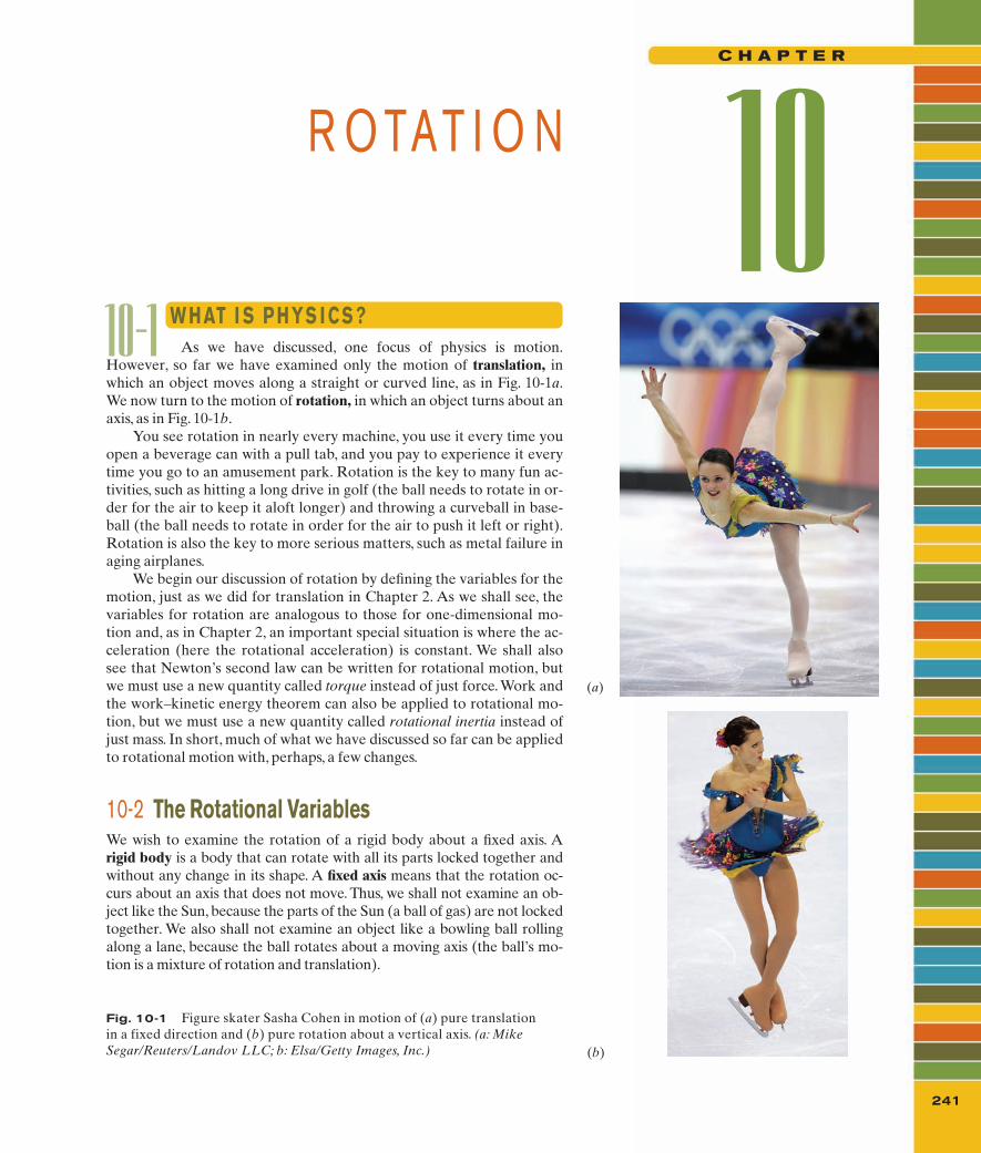
10-1 As we have discussed, one focus of physics is motion.However, so far we have examined only the motion of translation, inwhich an object moves along a straight or curved line, as in Fig. 10-1a.We now turn to the motion of rotation, in which an object turns about anaxis, as in Fig. 10-1b.
You see rotation in nearly every machine, you use it every time youopen a beverage can with a pull tab, and you pay to experience it everytime you go to an amusement park. Rotation is the key to many fun ac-tivities, such as hitting a long drive in golf (the ball needs to rotate in or-der for the air to keep it aloft longer) and throwing a curveball in base-ball (the ball needs to rotate in order for the air to push it left or right).Rotation is also the key to more serious matters, such as metal failure inaging airplanes.
We begin our discussion of rotation by defining the variables for themotion, just as we did for translation in Chapter 2. As we shall see, thevariables for rotation are analogous to those for one-dimensional mo-tion and, as in Chapter 2, an important special situation is where the ac-celeration (here the rotational acceleration) is constant. We shall alsosee that Newton’s second law can be written for rotational motion, butwe must use a new quantity called torque instead of just force. Work andthe work–kinetic energy theorem can also be applied to rotational mo-tion, but we must use a new quantity called rotational inertia instead ofjust mass. In short, much of what we have discussed so far can be appliedto rotational motion with, perhaps, a few changes.
10-2 The Rotational VariablesWe wish to examine the rotation of a rigid body about a fixed axis. Arigid body is a body that can rotate with all its parts locked together andwithout any change in its shape. A fixed axis means that the rotation oc-curs about an axis that does not move. Thus, we shall not examine an ob-ject like the Sun, because the parts of the Sun (a ball of gas) are not lockedtogether. We also shall not examine an object like a bowling ball rollingalong a lane, because the ball rotates about a moving axis (the ball’s mo-tion is a mixture of rotation and translation).
R O TAT I O N 10C H A P T E R
W H AT I S P H YS I C S ?
241
(a)
(b)
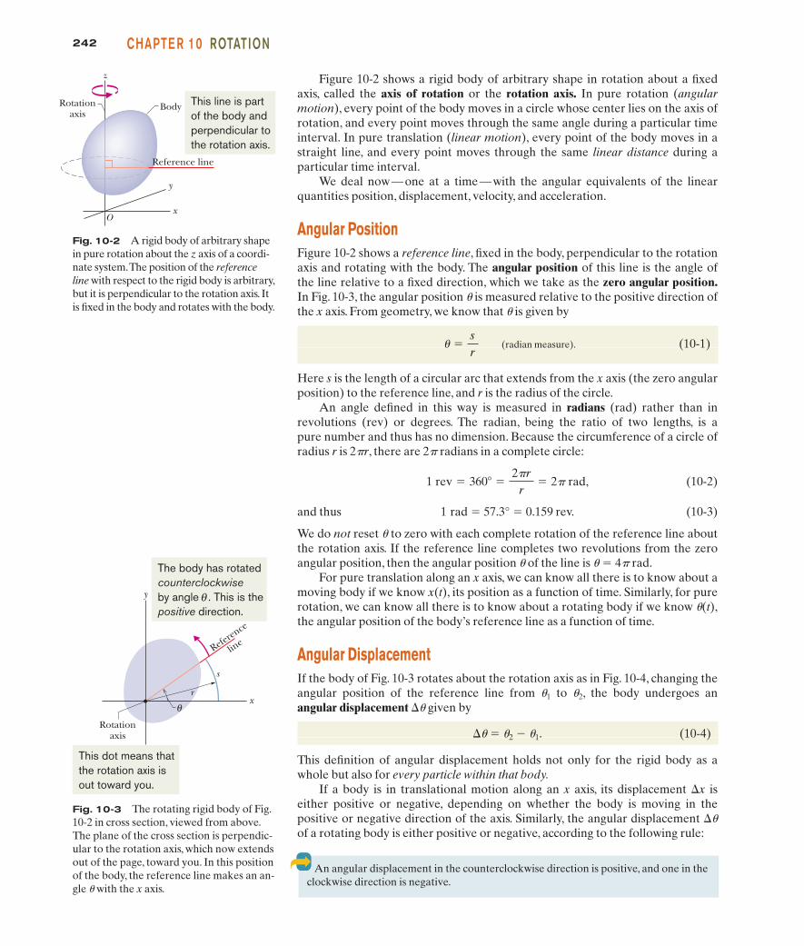
Fig. 10-1 Figure skater Sasha Cohen in motion of (a) pure translationin a fixed direction and (b) pure rotation about a vertical axis. (a: MikeSegar/Reuters/Landov LLC; b: Elsa/Getty Images, Inc.)
halliday_c10_241-274hr.qxd 17-09-2009 12:50 Page 241
242 CHAPTE R 10 ROTATION
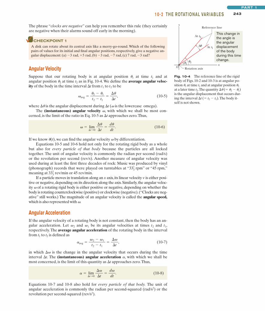
Fig. 10-2 A rigid body of arbitrary shapein pure rotation about the z axis of a coordi-nate system.The position of the referenceline with respect to the rigid body is arbitrary,but it is perpendicular to the rotation axis. Itis fixed in the body and rotates with the body.
z
O
Reference line
Rotation axis
x
y
Body This line is part of the body and perpendicular to the rotation axis.
Fig. 10-3 The rotating rigid body of Fig.10-2 in cross section, viewed from above.The plane of the cross section is perpendic-ular to the rotation axis, which now extendsout of the page, toward you. In this positionof the body, the reference line makes an an-gle u with the x axis.
x
y
Reference
line
θr
s
Rotationaxis
The body has rotatedcounterclockwiseby angle . This is thepositive direction.
θ
This dot means that the rotation axis is out toward you.
An angular displacement in the counterclockwise direction is positive, and one in theclockwise direction is negative.
Figure 10-2 shows a rigid body of arbitrary shape in rotation about a fixedaxis, called the axis of rotation or the rotation axis. In pure rotation (angular motion), every point of the body moves in a circle whose center lies on the axis ofrotation, and every point moves through the same angle during a particular timeinterval. In pure translation (linear motion), every point of the body moves in astraight line, and every point moves through the same linear distance during aparticular time interval.
We deal now—one at a time—with the angular equivalents of the linearquantities position, displacement, velocity, and acceleration.
Angular PositionFigure 10-2 shows a reference line, fixed in the body, perpendicular to the rotationaxis and rotating with the body. The angular position of this line is the angle ofthe line relative to a fixed direction, which we take as the zero angular position.In Fig. 10-3, the angular position u is measured relative to the positive direction ofthe x axis. From geometry, we know that u is given by
(radian measure). (10-1)
Here s is the length of a circular arc that extends from the x axis (the zero angularposition) to the reference line, and r is the radius of the circle.
An angle defined in this way is measured in radians (rad) rather than inrevolutions (rev) or degrees. The radian, being the ratio of two lengths, is apure number and thus has no dimension. Because the circumference of a circle ofradius r is 2pr, there are 2p radians in a complete circle:
(10-2)
and thus 1 rad � 57.3° � 0.159 rev. (10-3)
We do not reset u to zero with each complete rotation of the reference line aboutthe rotation axis. If the reference line completes two revolutions from the zeroangular position, then the angular position u of the line is u � 4p rad.
For pure translation along an x axis, we can know all there is to know about amoving body if we know x(t), its position as a function of time. Similarly, for purerotation, we can know all there is to know about a rotating body if we know u(t),the angular position of the body’s reference line as a function of time.
Angular DisplacementIf the body of Fig. 10-3 rotates about the rotation axis as in Fig. 10-4, changing theangular position of the reference line from u1 to u2, the body undergoes an angular displacement �u given by
�u � u2 � u1. (10-4)
This definition of angular displacement holds not only for the rigid body as awhole but also for every particle within that body.
If a body is in translational motion along an x axis, its displacement �x iseither positive or negative, depending on whether the body is moving in thepositive or negative direction of the axis. Similarly, the angular displacement �uof a rotating body is either positive or negative, according to the following rule:
1 rev � 360� �2�r
r� 2� rad,
� �sr
halliday_c10_241-274hr.qxd 17-09-2009 12:50 Page 242
24310-2 TH E ROTATIONAL VAR IAB LE SPART 1
The phrase “clocks are negative” can help you remember this rule (they certainlyare negative when their alarms sound off early in the morning).
CHECKPOINT 1
A disk can rotate about its central axis like a merry-go-round. Which of the followingpairs of values for its initial and final angular positions, respectively, give a negative an-gular displacement: (a) �3 rad, �5 rad, (b) �3 rad, �7 rad, (c) 7 rad, �3 rad?
Angular VelocitySuppose that our rotating body is at angular position u1 at time t1 and at angular position u2 at time t2 as in Fig. 10-4. We define the average angular veloc-ity of the body in the time interval �t from t1 to t2 to be
(10-5)
where �u is the angular displacement during �t (v is the lowercase omega).The (instantaneous) angular velocity v, with which we shall be most con-
cerned, is the limit of the ratio in Eq. 10-5 as �t approaches zero.Thus,
(10-6)
If we know u(t), we can find the angular velocity v by differentiation.Equations 10-5 and 10-6 hold not only for the rotating rigid body as a whole
but also for every particle of that body because the particles are all lockedtogether. The unit of angular velocity is commonly the radian per second (rad/s)or the revolution per second (rev/s). Another measure of angular velocity wasused during at least the first three decades of rock: Music was produced by vinyl(phonograph) records that were played on turntables at “ ” or “45 rpm,”meaning at or 45 rev/min.
If a particle moves in translation along an x axis, its linear velocity v is either posi-tive or negative, depending on its direction along the axis. Similarly, the angular veloc-ity v of a rotating rigid body is either positive or negative, depending on whether thebody is rotating counterclockwise (positive) or clockwise (negative).(“Clocks are neg-ative” still works.) The magnitude of an angular velocity is called the angular speed,which is also represented with v.
Angular AccelerationIf the angular velocity of a rotating body is not constant, then the body has an an-gular acceleration. Let v2 and v1 be its angular velocities at times t2 and t1,respectively.The average angular acceleration of the rotating body in the intervalfrom t1 to t2 is defined as
(10-7)
in which �v is the change in the angular velocity that occurs during the timeinterval �t. The (instantaneous) angular acceleration a, with which we shall bemost concerned, is the limit of this quantity as �t approaches zero.Thus,
(10-8)
Equations 10-7 and 10-8 also hold for every particle of that body. The unit ofangular acceleration is commonly the radian per second-squared (rad/s2) or therevolution per second-squared (rev/s2).
� � lim�t:0
�
�t�
d
dt.
�avg � 2 � 1
t2 � t1�
�
�t,
3313 rev/min
3313 rpm
� lim�t:0
��
�t�
d�
dt.
avg ��2 � �1
t2 � t1�
��
�t,
Fig. 10-4 The reference line of the rigidbody of Figs. 10-2 and 10-3 is at angular po-sition u1 at time t1 and at angular position u2
at a later time t2.The quantity �u (� u2 � u1)is the angular displacement that occurs dur-ing the interval �t (� t2 � t1).The body it-self is not shown.
x
y
Rotation axis O θ 1
θ 2
∆ θ
At t2
At t1
Reference line
This change in the angle is the angulardisplacement of the body during this timechange.
halliday_c10_241-274hr.qxd 17-09-2009 12:50 Page 243
244 CHAPTE R 10 ROTATION
Zeroangularposition
Referenceline
Rotation axis
(a)
(b)
2
0
–20 2 4 6
(rad)
(1) (2) (3) (4) (5)
t (s)
θ
–2
The angular positionof the disk is the anglebetween these two lines.
Now, the disk isat a zero angle.
θ
At t = −2 s, the diskis at a positive(counterclockwise)angle. So, a positive value is plotted.
This is a plot of the angleof the disk versus time.
Now, it is at anegative (clockwise)angle. So, a negative value is plotted.θ
It has reversedits rotation andis again at azero angle.
Now, it isback at apositiveangle.
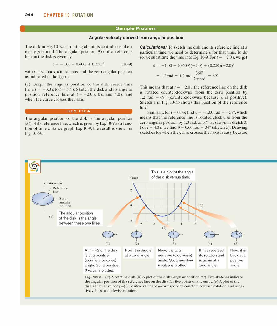
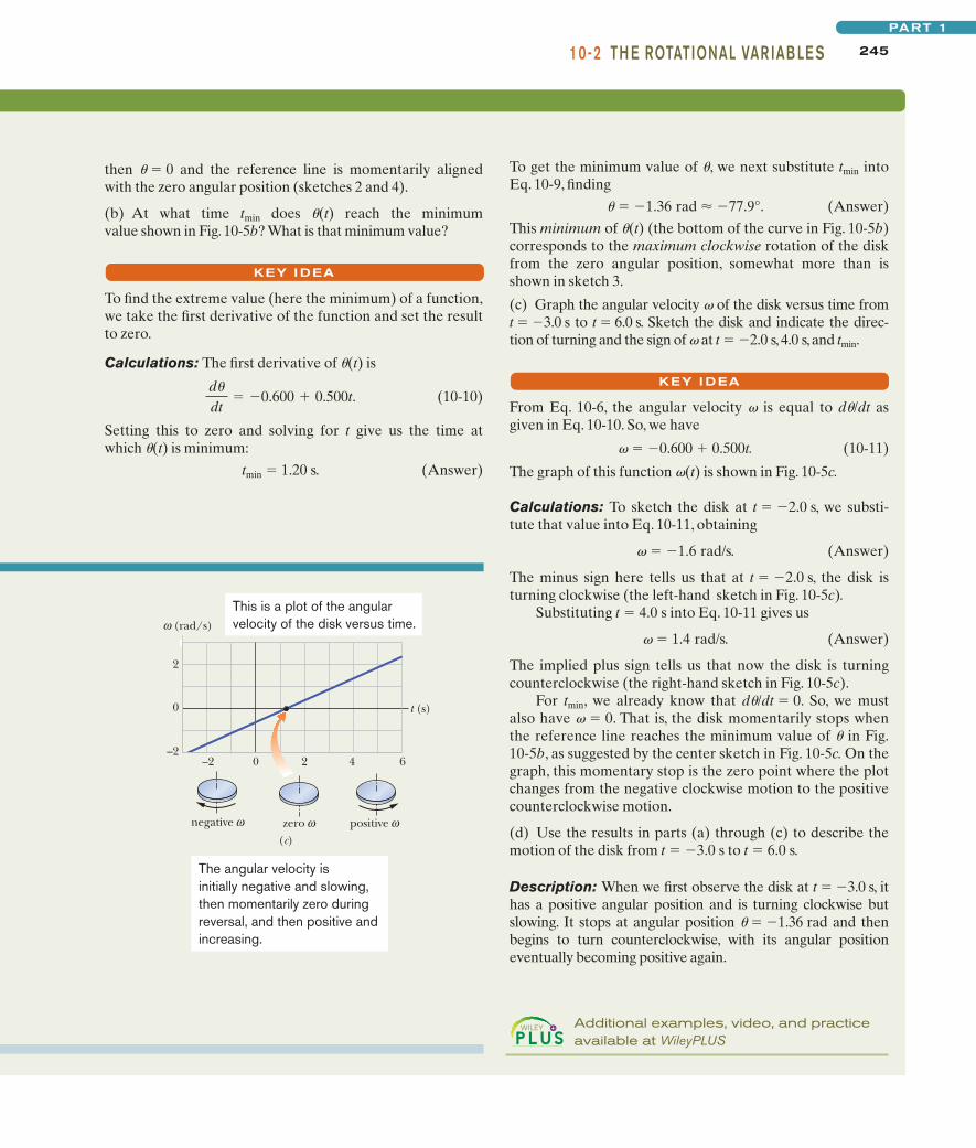
Fig. 10-5 (a) A rotating disk. (b) A plot of the disk’s angular position u(t). Five sketches indicatethe angular position of the reference line on the disk for five points on the curve. (c) A plot of thedisk’s angular velocity v(t). Positive values of v correspond to counterclockwise rotation, and nega-tive values to clockwise rotation.
Sample Problem
Angular velocity derived from angular position
Calculations: To sketch the disk and its reference line at aparticular time, we need to determine u for that time. To doso, we substitute the time into Eq. 10-9. For t � �2.0 s, we get
This means that at t � �2.0 s the reference line on the diskis rotated counterclockwise from the zero position by1.2 rad � 69° (counterclockwise because u is positive).Sketch 1 in Fig. 10-5b shows this position of the referenceline.
Similarly, for t � 0, we find u � �1.00 rad � �57°, whichmeans that the reference line is rotated clockwise from thezero angular position by 1.0 rad, or 57°, as shown in sketch 3.For t � 4.0 s, we find u � 0.60 rad � 34° (sketch 5). Drawingsketches for when the curve crosses the t axis is easy, because
� 1.2 rad � 1.2 rad 360�
2� rad� 69�.
� � �1.00 � (0.600)(�2.0) � (0.250)(�2.0)2
The disk in Fig. 10-5a is rotating about its central axis like amerry-go-round. The angular position u(t) of a referenceline on the disk is given by
u � �1.00 � 0.600t � 0.250t2, (10-9)
with t in seconds, u in radians, and the zero angular positionas indicated in the figure.
(a) Graph the angular position of the disk versus timefrom t � �3.0 s to t � 5.4 s. Sketch the disk and its angularposition reference line at t � �2.0 s, 0 s, and 4.0 s, andwhen the curve crosses the t axis.
KEY I DEA
The angular position of the disk is the angular position u(t) of its reference line, which is given by Eq. 10-9 as a func-tion of time t. So we graph Eq. 10-9; the result is shown inFig. 10-5b.
A
halliday_c10_241-274hr.qxd 17-09-2009 12:50 Page 244
24510-2 TH E ROTATIONAL VAR IAB LE SPART 1
Additional examples, video, and practiceavailable at WileyPLUS
then u � 0 and the reference line is momentarily alignedwith the zero angular position (sketches 2 and 4).
(b) At what time tmin does u(t) reach the minimum value shown in Fig. 10-5b? What is that minimum value?
KEY I DEA
To find the extreme value (here the minimum) of a function,we take the first derivative of the function and set the resultto zero.
Calculations: The first derivative of u(t) is
(10-10)
Setting this to zero and solving for t give us the time atwhich u(t) is minimum:
tmin � 1.20 s. (Answer)
d�
dt� �0.600 � 0.500t.
To get the minimum value of u, we next substitute tmin intoEq. 10-9, finding
u � �1.36 rad � �77.9°. (Answer)
This minimum of u(t) (the bottom of the curve in Fig. 10-5b)corresponds to the maximum clockwise rotation of the diskfrom the zero angular position, somewhat more than isshown in sketch 3.
(c) Graph the angular velocity v of the disk versus time from t � �3.0 s to t � 6.0 s. Sketch the disk and indicate the direc-tion of turning and the sign of v at t � �2.0 s,4.0 s,and tmin.
KEY I DEA
From Eq. 10-6, the angular velocity v is equal to du/dt asgiven in Eq. 10-10. So, we have
v � �0.600 � 0.500t. (10-11)
The graph of this function v(t) is shown in Fig. 10-5c.
Calculations: To sketch the disk at t � �2.0 s, we substi-tute that value into Eq. 10-11, obtaining
v � �1.6 rad/s. (Answer)
The minus sign here tells us that at t � �2.0 s, the disk isturning clockwise (the left-hand sketch in Fig. 10-5c).
Substituting t � 4.0 s into Eq. 10-11 gives us
v � 1.4 rad/s. (Answer)
The implied plus sign tells us that now the disk is turningcounterclockwise (the right-hand sketch in Fig. 10-5c).
For tmin, we already know that du/dt � 0. So, we mustalso have v � 0. That is, the disk momentarily stops whenthe reference line reaches the minimum value of u in Fig.10-5b, as suggested by the center sketch in Fig. 10-5c. On thegraph, this momentary stop is the zero point where the plotchanges from the negative clockwise motion to the positivecounterclockwise motion.
(d) Use the results in parts (a) through (c) to describe themotion of the disk from t � �3.0 s to t � 6.0 s.
Description: When we first observe the disk at t � �3.0 s, ithas a positive angular position and is turning clockwise butslowing. It stops at angular position u � �1.36 rad and thenbegins to turn counterclockwise, with its angular positioneventually becoming positive again.
(c)
2
0
–2–2 0 2 4 6
(rad/s)ω
t (s)
negative ω zero ω positive ω
This is a plot of the angularvelocity of the disk versus time.
The angular velocity isinitially negative and slowing,then momentarily zero duringreversal, and then positive andincreasing.
halliday_c10_241-274hr.qxd 17-09-2009 12:50 Page 245
Sample Problem
To evaluate the constant of integration C, we note that v � 5rad/s at t � 0. Substituting these values in our expression forv yields
,
so C � 5 rad/s.Then
. (Answer)
(b) Obtain an expression for the angular position u(t) of thetop.
By definition, v(t) is the derivative of u(t) with respect totime. Therefore, we can find u(t) by integrating v(t) with respect to time.
Calculations: Since Eq. 10-6 tells us that
du � v dt,we can write
(Answer)
where C has been evaluated by noting that u � 2 rad at t � 0.
� 14 t5 � 2
3 t3 � 5t � 2,
� 14 t5 � 2
3 t3 � 5t � C
� � � dt � � (54 t4 � 2t2 � 5) dt
� 54 t4 � 2t2 � 5
5 rad/s � 0 � 0 � C
Angular velocity derived from angular acceleration
A child’s top is spun with angular acceleration
,
with t in seconds and a in radians per second-squared. Att � 0, the top has angular velocity 5 rad/s, and a referenceline on it is at angular position u � 2 rad.
(a) Obtain an expression for the angular velocity v(t) of thetop.That is, find an expression that explicitly indicates how theangular velocity depends on time. (We can tell that there issuch a dependence because the top is undergoing an angularacceleration,which means that its angular velocity is changing.)
By definition, a(t) is the derivative of v(t) with respect totime. Thus, we can find v(t) by integrating a(t) with respectto time.
Calculations: Equation 10-8 tells us
,
so .
From this we find
. � �(5t3 � 4t) dt � 54t
4 � 42t
2 � C
� d � �� dt
d � � dt
� � 5t3 � 4t
KEY I DEA
KEY I DEA
Additional examples, video, and practice available at WileyPLUS
246 CHAPTE R 10 ROTATION
10-3 Are Angular Quantities Vectors?We can describe the position, velocity, and acceleration of a single particle bymeans of vectors. If the particle is confined to a straight line, however, we do notreally need vector notation. Such a particle has only two directions available to it,and we can indicate these directions with plus and minus signs.
In the same way, a rigid body rotating about a fixed axis can rotate onlyclockwise or counterclockwise as seen along the axis, and again we can selectbetween the two directions by means of plus and minus signs.The question arises:“Can we treat the angular displacement, velocity, and acceleration ofa rotating body as vectors?” The answer is a qualified “yes” (see the cautionbelow, in connection with angular displacements).
Consider the angular velocity. Figure 10-6a shows a vinyl record rotating on aturntable. The record has a constant angular speed in theclockwise direction. We can represent its angular velocity as a vector pointingalong the axis of rotation, as in Fig. 10-6b. Here’s how: We choose the length ofthis vector according to some convenient scale, for example, with 1 cm corre-sponding to 10 rev/min. Then we establish a direction for the vector by using a:
: (� 331
3 rev/min)
halliday_c10_241-274hr.qxd 17-09-2009 12:50 Page 246
24710-3 AR E ANG U LAR QUANTITI E S VECTORS?PART 1
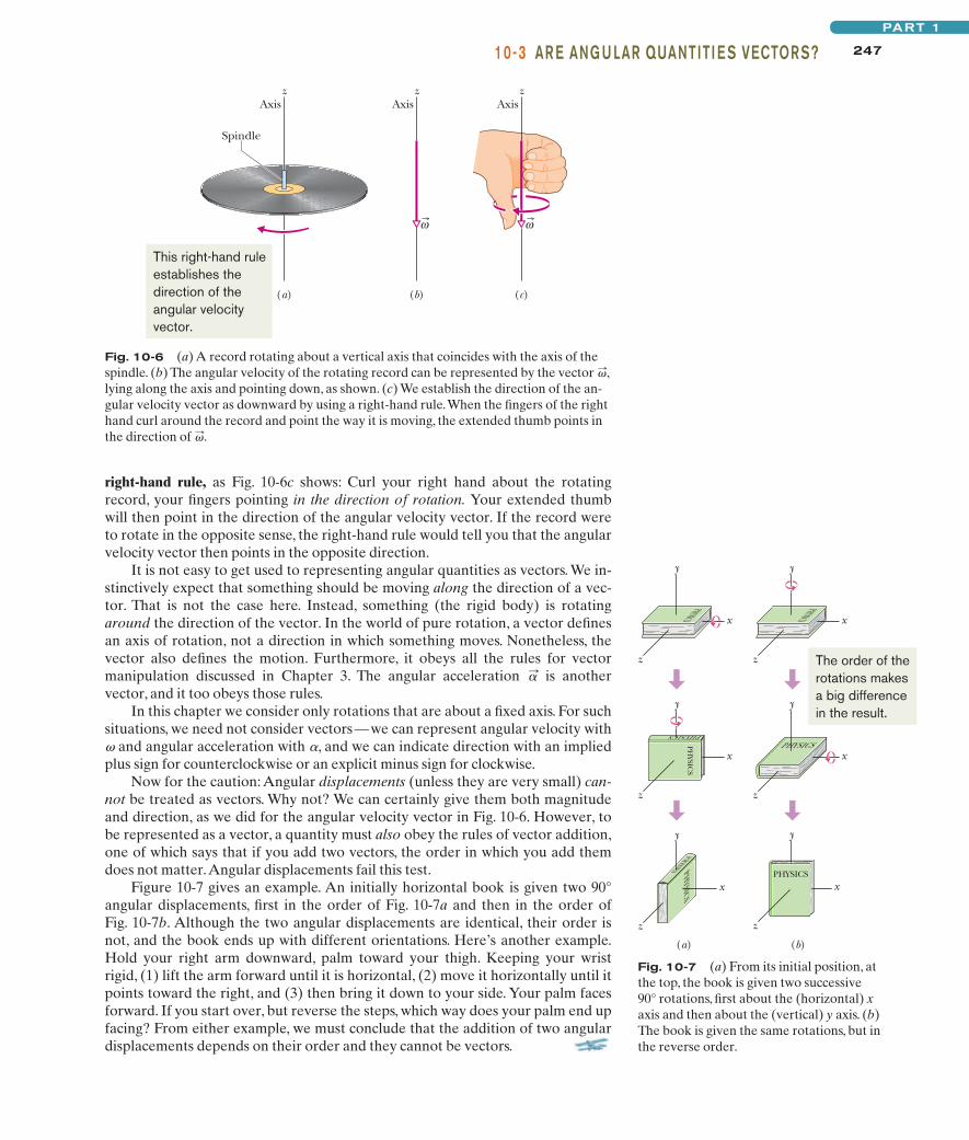
right-hand rule, as Fig. 10-6c shows: Curl your right hand about the rotatingrecord, your fingers pointing in the direction of rotation. Your extended thumbwill then point in the direction of the angular velocity vector. If the record wereto rotate in the opposite sense, the right-hand rule would tell you that the angularvelocity vector then points in the opposite direction.
It is not easy to get used to representing angular quantities as vectors. We in-stinctively expect that something should be moving along the direction of a vec-tor. That is not the case here. Instead, something (the rigid body) is rotatingaround the direction of the vector. In the world of pure rotation, a vector definesan axis of rotation, not a direction in which something moves. Nonetheless, thevector also defines the motion. Furthermore, it obeys all the rules for vectormanipulation discussed in Chapter 3. The angular acceleration is anothervector, and it too obeys those rules.
In this chapter we consider only rotations that are about a fixed axis. For suchsituations, we need not consider vectors—we can represent angular velocity withv and angular acceleration with a, and we can indicate direction with an impliedplus sign for counterclockwise or an explicit minus sign for clockwise.
Now for the caution: Angular displacements (unless they are very small) can-not be treated as vectors. Why not? We can certainly give them both magnitudeand direction, as we did for the angular velocity vector in Fig. 10-6. However, tobe represented as a vector, a quantity must also obey the rules of vector addition,one of which says that if you add two vectors, the order in which you add themdoes not matter.Angular displacements fail this test.
Figure 10-7 gives an example. An initially horizontal book is given two 90°angular displacements, first in the order of Fig. 10-7a and then in the order ofFig. 10-7b. Although the two angular displacements are identical, their order isnot, and the book ends up with different orientations. Here’s another example.Hold your right arm downward, palm toward your thigh. Keeping your wristrigid, (1) lift the arm forward until it is horizontal, (2) move it horizontally until itpoints toward the right, and (3) then bring it down to your side. Your palm facesforward. If you start over, but reverse the steps, which way does your palm end upfacing? From either example, we must conclude that the addition of two angulardisplacements depends on their order and they cannot be vectors.
�:
Fig. 10-6 (a) A record rotating about a vertical axis that coincides with the axis of thespindle. (b) The angular velocity of the rotating record can be represented by the vector ,lying along the axis and pointing down, as shown. (c) We establish the direction of the an-gular velocity vector as downward by using a right-hand rule.When the fingers of the righthand curl around the record and point the way it is moving, the extended thumb points inthe direction of .:
:
z z z
(a) (b) (c)
Axis Axis Axis
ω
Spindle
ω
This right-hand ruleestablishes thedirection of theangular velocityvector.
Fig. 10-7 (a) From its initial position, atthe top, the book is given two successive90° rotations, first about the (horizontal) xaxis and then about the (vertical) y axis. (b)The book is given the same rotations, but inthe reverse order.
PHYSICS
PHYSICS
PHYSICS
PHYSICS
PHYSICS
PHYSIC
S
PHYSICS
(a) (b)
PHYSICS
y
x
z
y
x
z
y
x
z z
y
x
z
y
x
y
x
z The order of therotations makesa big differencein the result.
halliday_c10_241-274hr.qxd 17-09-2009 12:50 Page 247
248 CHAPTE R 10 ROTATION
10-4 Rotation with Constant Angular AccelerationIn pure translation, motion with a constant linear acceleration (for example, thatof a falling body) is an important special case. In Table 2-1, we displayed a seriesof equations that hold for such motion.
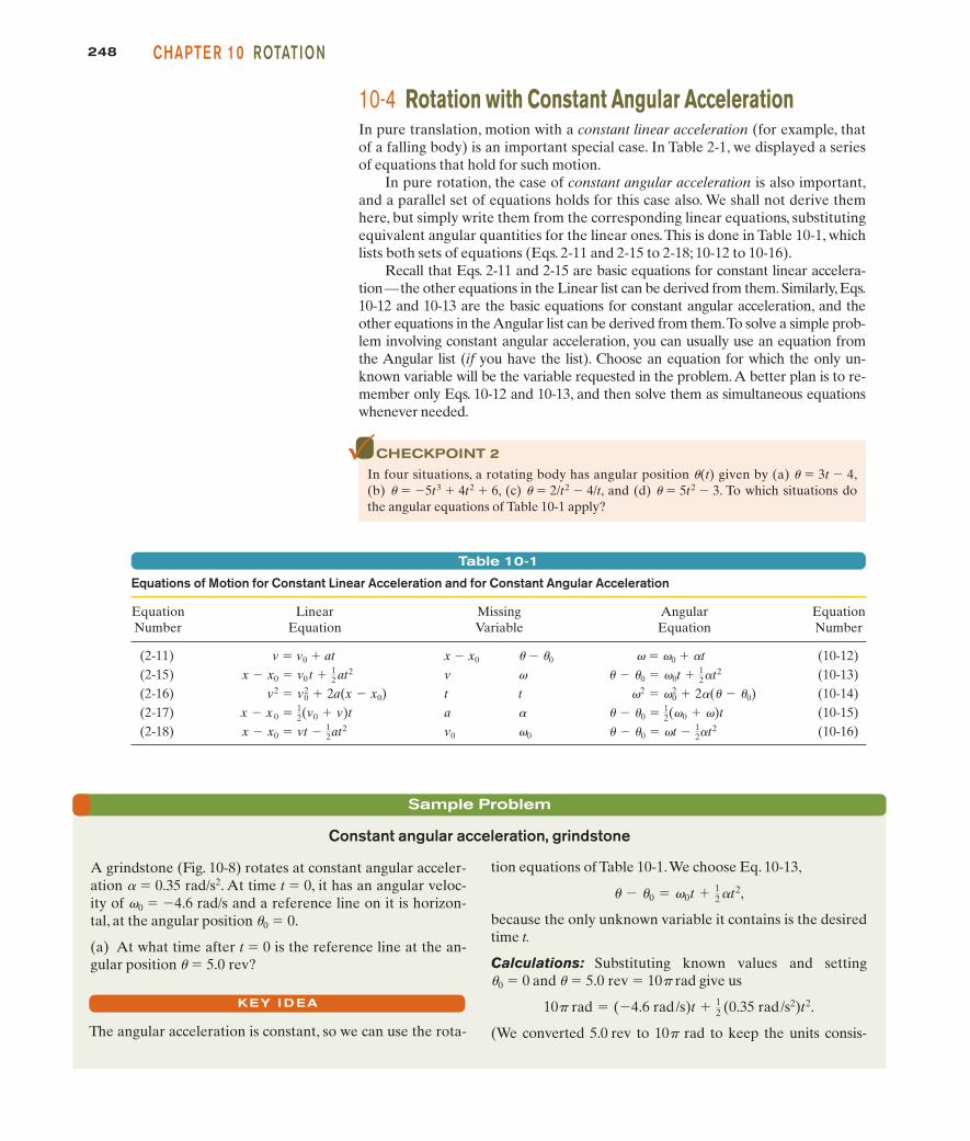
In pure rotation, the case of constant angular acceleration is also important,and a parallel set of equations holds for this case also. We shall not derive themhere, but simply write them from the corresponding linear equations, substitutingequivalent angular quantities for the linear ones.This is done in Table 10-1, whichlists both sets of equations (Eqs. 2-11 and 2-15 to 2-18; 10-12 to 10-16).
Recall that Eqs. 2-11 and 2-15 are basic equations for constant linear accelera-tion—the other equations in the Linear list can be derived from them. Similarly, Eqs.10-12 and 10-13 are the basic equations for constant angular acceleration, and theother equations in the Angular list can be derived from them.To solve a simple prob-lem involving constant angular acceleration, you can usually use an equation fromthe Angular list (if you have the list). Choose an equation for which the only un-known variable will be the variable requested in the problem.A better plan is to re-member only Eqs. 10-12 and 10-13, and then solve them as simultaneous equationswhenever needed.
Table 10-1
Equations of Motion for Constant Linear Acceleration and for Constant Angular Acceleration
Equation Linear Missing Angular EquationNumber Equation Variable Equation Number
(2-11) v � v0 � at x � x0 u � u0 v � v0 � at (10-12)(2-15) v v (10-13)(2-16) t t (10-14)(2-17) a a (10-15)(2-18) v0 v0 (10-16)� � �0 � �t � 1
2�t2x � x0 � vt � 12at2
� � �0 � 12(�0 � �)tx � x 0 � 1
2(v0 � v)t
�2 � �02 � 2�(� � �0)v2 � v0
2 � 2a(x � x0)� � �0 � �0t � 1
2�t2x � x0 � v0 t � 12 at2
CHECKPOINT 2
In four situations, a rotating body has angular position u(t) given by (a) u � 3t � 4,(b) u � �5t3 � 4t2 � 6, (c) u � 2/t2 � 4/t, and (d) u � 5t2 � 3. To which situations dothe angular equations of Table 10-1 apply?
Sample Problem
Constant angular acceleration, grindstone
A grindstone (Fig. 10-8) rotates at constant angular acceler-ation a � 0.35 rad/s2. At time t � 0, it has an angular veloc-ity of v0 � �4.6 rad/s and a reference line on it is horizon-tal, at the angular position u0 � 0.
(a) At what time after t � 0 is the reference line at the an-gular position u � 5.0 rev?
KEY I DEA
The angular acceleration is constant, so we can use the rota-
tion equations of Table 10-1.We choose Eq. 10-13,
,
because the only unknown variable it contains is the desiredtime t.
Calculations: Substituting known values and setting u0 � 0 and u � 5.0 rev � 10p rad give us
.
(We converted 5.0 rev to 10p rad to keep the units consis-
10� rad � (�4.6 rad/s)t � 12 (0.35 rad/s2)t2
� � �0 � �0t � 12 �t2
halliday_c10_241-274hr2.qxd 29-09-2009 13:12 Page 248
24910-4 ROTATION WITH CON STANT ANG U LAR ACCE LE RATIONPART 1
Sample Problem
To eliminate the unknown t, we use Eq. 10-12 to write
which we then substitute into Eq. 10-13 to write
Solving for a, substituting known data, and converting 20rev to 125.7 rad, we find
(Answer)
(b) How much time did the speed decrease take?
Calculation: Now that we know a, we can use Eq. 10-12 tosolve for t:
(Answer) � 46.5 s.
t � � 0
��
2.00 rad/s � 3.40 rad/s�0.0301 rad/s2
� �0.0301 rad/s2.
� �2 � 0
2
2(� � �0)�
(2.00 rad/s)2 � (3.40 rad/s)2
2(125.7 rad)
� � �0 � 0� � 0
� � � 12 �� � 0
� �
2
.
t � � 0
�,
Additional examples, video, and practice available at WileyPLUS
Constant angular acceleration, riding a Rotor
While you are operating a Rotor (a large, vertical, rotatingcylinder found in amusement parks), you spot a passengerin acute distress and decrease the angular velocity of thecylinder from 3.40 rad/s to 2.00 rad/s in 20.0 rev, at constantangular acceleration. (The passenger is obviously more of a“translation person” than a “rotation person.”)
(a) What is the constant angular acceleration during thisdecrease in angular speed?
KEY I DEA
Because the cylinder’s angular acceleration is constant, wecan relate it to the angular velocity and angular displace-ment via the basic equations for constant angular accelera-tion (Eqs. 10-12 and 10-13).
Calculations: The initial angular velocity is v0 � 3.40rad/s, the angular displacement is u � u0 � 20.0 rev, and theangular velocity at the end of that displacement is v � 2.00rad/s. But we do not know the angular acceleration a andtime t, which are in both basic equations.
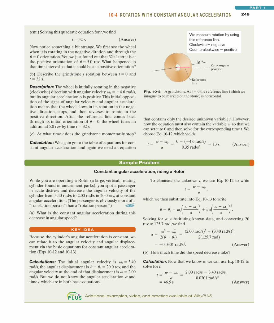
Fig. 10-8 A grindstone.At t � 0 the reference line (which weimagine to be marked on the stone) is horizontal.
Axis
Referenceline
Zero angularposition
We measure rotation by usingthis reference line.Clockwise = negativeCounterclockwise = positive
tent.) Solving this quadratic equation for t, we find
t � 32 s. (Answer)
Now notice something a bit strange. We first see the wheelwhen it is rotating in the negative diretion and through theu � 0 orientation.Yet, we just found out that 32 s later it is atthe positive orientation of u � 5.0 rev. What happened inthat time interval so that it could be at a positive orientation?
(b) Describe the grindstone’s rotation between t � 0 and t � 32 s.
Description: The wheel is initially rotating in the negative(clockwise) direction with angular velocity v0 � �4.6 rad/s,but its angular acceleration a is positive. This initial opposi-tion of the signs of angular velocity and angular accelera-tion means that the wheel slows in its rotation in the nega-tive direction, stops, and then reverses to rotate in thepositive direction. After the reference line comes backthrough its initial orientation of u � 0, the wheel turns anadditional 5.0 rev by time t � 32 s.
(c) At what time t does the grindstone momentarily stop?
Calculation: We again go to the table of equations for con-stant angular acceleration, and again we need an equation
that contains only the desired unknown variable t. However,now the equation must also contain the variable v, so that wecan set it to 0 and then solve for the corresponding time t. Wechoose Eq. 10-12, which yields
(Answer)t � � 0
��
0 � (�4.6 rad/s)0.35 rad/s2 � 13 s.
halliday_c10_241-274hr.qxd 17-09-2009 12:50 Page 249
250 CHAPTE R 10 ROTATION
10-5 Relating the Linear and Angular VariablesIn Section 4-7, we discussed uniform circular motion, in which a particle travels atconstant linear speed v along a circle and around an axis of rotation.When a rigidbody, such as a merry-go-round, rotates around an axis, each particle in the bodymoves in its own circle around that axis. Since the body is rigid, all the particlesmake one revolution in the same amount of time; that is, they all have the sameangular speed v.
However, the farther a particle is from the axis, the greater the circumferenceof its circle is, and so the faster its linear speed v must be. You can notice this on amerry-go-round. You turn with the same angular speed v regardless of your dis-tance from the center, but your linear speed v increases noticeably if you move tothe outside edge of the merry-go-round.
We often need to relate the linear variables s, v, and a for a particular point ina rotating body to the angular variables u, v, and a for that body. The two sets ofvariables are related by r, the perpendicular distance of the point from therotation axis. This perpendicular distance is the distance between the point andthe rotation axis, measured along a perpendicular to the axis. It is also the radius rof the circle traveled by the point around the axis of rotation.
The PositionIf a reference line on a rigid body rotates through an angle u, a point within thebody at a position r from the rotation axis moves a distance s along a circular arc,where s is given by Eq. 10-1:
s � ur (radian measure). (10-17)
This is the first of our linear–angular relations. Caution: The angle u here must bemeasured in radians because Eq. 10-17 is itself the definition of angular measurein radians.
The SpeedDifferentiating Eq. 10-17 with respect to time—with r held constant—leads to
However, ds/dt is the linear speed (the magnitude of the linear velocity) of thepoint in question, and du/dt is the angular speed v of the rotating body. So
v � vr (radian measure). (10-18)
Caution: The angular speed v must be expressed in radian measure.Equation 10-18 tells us that since all points within the rigid body have the
same angular speed v, points with greater radius r have greater linear speed v.Figure 10-9a reminds us that the linear velocity is always tangent to the circularpath of the point in question.
If the angular speed v of the rigid body is constant, then Eq. 10-18 tells usthat the linear speed v of any point within it is also constant. Thus, each pointwithin the body undergoes uniform circular motion. The period of revolution Tfor the motion of each point and for the rigid body itself is given by Eq. 4-35:
. (10-19)
This equation tells us that the time for one revolution is the distance 2pr traveledin one revolution divided by the speed at which that distance is traveled.
T �2�r
v
dsdt
�d�
dt r.
halliday_c10_241-274hr.qxd 17-09-2009 12:50 Page 250
25110-5 R E LATI NG TH E LI N EAR AN D ANG U LAR VAR IAB LE SPART 1
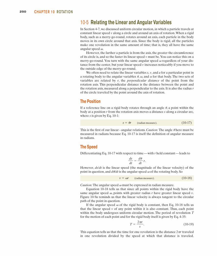
Fig. 10-9 The rotating rigid bodyof Fig. 10-2, shown in cross sectionviewed from above. Every point ofthe body (such as P) moves in a cir-cle around the rotation axis. (a) Thelinear velocity of every point istangent to the circle in which thepoint moves. (b) The linear acceler-ation of the point has (in general)two components: tangential at andradial ar.
a:
v:
Substituting for v from Eq. 10-18 and canceling r, we find also that
(radian measure). (10-20)
This equivalent equation says that the time for one revolution is the angular dis-tance 2p rad traveled in one revolution divided by the angular speed (or rate) atwhich that angle is traveled.
The AccelerationDifferentiating Eq. 10-18 with respect to time—again with r held constant—leads to
(10-21)
Here we run up against a complication. In Eq. 10-21, dv/dt represents only thepart of the linear acceleration that is responsible for changes in the magnitude vof the linear velocity . Like , that part of the linear acceleration is tangent tothe path of the point in question. We call it the tangential component at of the lin-ear acceleration of the point, and we write
at � ar (radian measure), (10-22)
where a � dv/dt. Caution: The angular acceleration a in Eq. 10-22 must beexpressed in radian measure.
In addition, as Eq. 4-34 tells us, a particle (or point) moving in a circular pathhas a radial component of linear acceleration, ar � v2/r (directed radially inward),that is responsible for changes in the direction of the linear velocity . By substi-tuting for v from Eq. 10-18, we can write this component as
(radian measure). (10-23)
Thus, as Fig. 10-9b shows, the linear acceleration of a point on a rotating rigidbody has, in general, two components. The radially inward component ar (givenby Eq. 10-23) is present whenever the angular velocity of the body is not zero.The tangential component at (given by Eq. 10-22) is present whenever the angu-lar acceleration is not zero.
ar �v2
r� 2r
v:
v:v:
dvdt
�d
dt r.
T �2�
x
y
r
Rotation axis
P
Circle traveled by P
(a)
x
y
ar
P
(b)
at
Rotationaxis
v
The velocity vector isalways tangent to thiscircle around therotation axis.
The acceleration alwayshas a radial (centripetal)component and may havea tangential component.
halliday_c10_241-274hr.qxd 17-09-2009 12:50 Page 251
252 CHAPTE R 10 ROTATION
Sample Problem
Linear and angular variables, roller coaster speedup
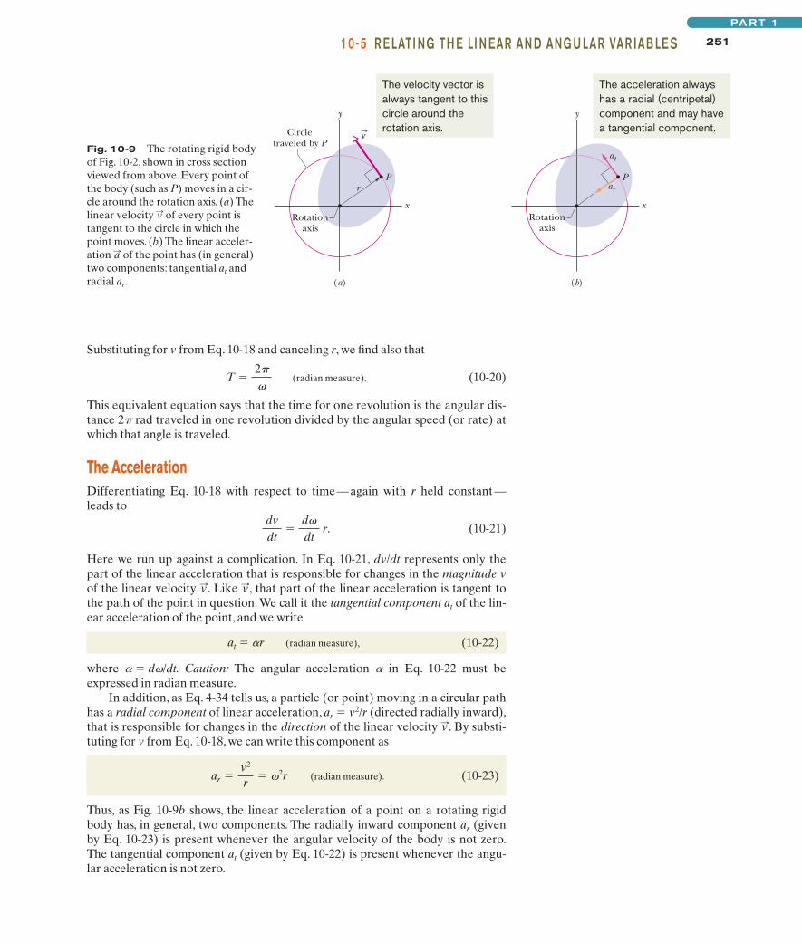
In spite of the extreme care taken in engineering a rollercoaster, an unlucky few of the millions of people who rideroller coasters each year end up with a medical conditioncalled roller-coaster headache. Symptoms, which might notappear for several days, include vertigo and headache, bothsevere enough to require medical treatment.
Let’s investigate the probable cause by designing thetrack for our own induction roller coaster (which can be ac-celerated by magnetic forces even on a horizontal track). Tocreate an initial thrill, we want each passenger to leave theloading point with acceleration g along the horizontal track.To increase the thrill, we also want that first section of trackto form a circular arc (Fig. 10-10), so that the passenger alsoexperiences a centripetal acceleration. As the passenger accelerates along the arc, the magnitude of this centripetalacceleration increases alarmingly. When the magnitude a ofthe net acceleration reaches 4g at some point P and angle uP
along the arc, we want the passenger then to move in astraight line, along a tangent to the arc.
(a) What angle uP should the arc subtend so that a is 4g atpoint P?
(1) At any given time, the passenger’s net acceleration isthe vector sum of the tangential acceleration along thetrack and the radial acceleration toward the arc’s centerof curvature (as in Fig. 10-9b). (2) The value of at anygiven time depends on the angular speed v according to Eq.10-23 ( , where r is the radius of the circular arc). (3)An angular acceleration a around the arc is associated withthe tangential acceleration along the track according toEq. 10-22 ( ). (4) Because and r are constant, so isa and thus we can use the constant angular-accelerationequations.
Calculations: Because we are trying to determine a valuefor angular position u, let’s choose Eq. 10-14 from amongthe constant angular-acceleration equations:
(10-24)
For the angular acceleration a, we substitute from Eq. 10-22:
(10-25)� �at
r.
2 � 20 � 2�(� � �0).
atat � �rat
ar � 2r
ar
a:r
a:t
a:
Fig. 10-10 An overhead view of a horizontal track for a rollercoaster.The track begins as a circular arc at the loading point andthen,at point P, continues along a tangent to the arc.
P
P θ
Loading point
Along here, thepassenger hasboth tangentialand radialaccelerations.
Along here, thepassenger hasonly tangentialacceleration.
KEY I DEAS
We also substitute and , and we find
(10-26)
Substituting this result for into
(10-27)
gives a relation between the radial acceleration, the tangen-tial acceleration, and the angular position u:
(10-28)
Because and are perpendicular vectors, their sum hasthe magnitude
(10-29)
Substituting for from Eq.10-28 and solving for u lead to
. (10-30)
When a reaches the design value of 4g, angle u is the angleuP we want. Substituting a � 4g, u � uP, and at � g into Eq.10-30, we find
(Answer)
(b) What is the magnitude a of the passenger’s net accelera-tion at point P and after point P?
�P � 12 A
(4g)2
g2 � 1 � 1.94 rad � 111�.
� � 12 A
a2
a2t
� 1
ar
a � 2at2 � ar
2.
a:ra:t
ar � 2at�.
ar � 2r
2
2 �2at�
r.
�0 � 00 � 0
CHECKPOINT 3
A cockroach rides the rim of a rotating merry-go-round. If the angular speed of thissystem (merry-go-round � cockroach) is constant, does the cockroach have (a) radialacceleration and (b) tangential acceleration? If v is decreasing, does the cockroachhave (c) radial acceleration and (d) tangential acceleration?
halliday_c10_241-274hr.qxd 17-09-2009 12:50 Page 252
25310-6 KI N ETIC E N E RGY OF ROTATIONPART 1
Additional examples, video, and practice available at WileyPLUS
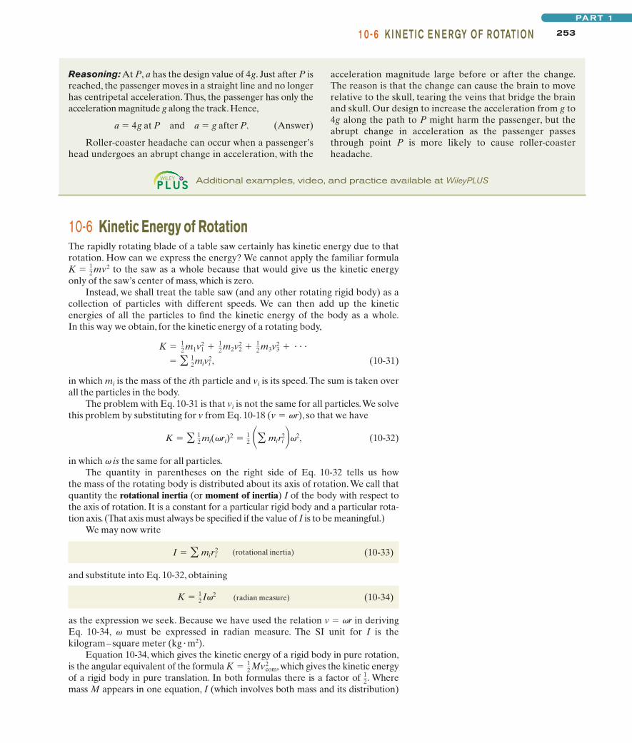
10-6 Kinetic Energy of RotationThe rapidly rotating blade of a table saw certainly has kinetic energy due to thatrotation. How can we express the energy? We cannot apply the familiar formula
to the saw as a whole because that would give us the kinetic energyonly of the saw’s center of mass, which is zero.
Instead, we shall treat the table saw (and any other rotating rigid body) as acollection of particles with different speeds. We can then add up the kineticenergies of all the particles to find the kinetic energy of the body as a whole.In this way we obtain, for the kinetic energy of a rotating body,
(10-31)
in which mi is the mass of the ith particle and vi is its speed.The sum is taken overall the particles in the body.
The problem with Eq. 10-31 is that vi is not the same for all particles.We solvethis problem by substituting for v from Eq. 10-18 (v � vr), so that we have
(10-32)
in which v is the same for all particles.The quantity in parentheses on the right side of Eq. 10-32 tells us how
the mass of the rotating body is distributed about its axis of rotation. We call thatquantity the rotational inertia (or moment of inertia) I of the body with respect tothe axis of rotation. It is a constant for a particular rigid body and a particular rota-tion axis. (That axis must always be specified if the value of I is to be meaningful.)
We may now write
(rotational inertia) (10-33)
and substitute into Eq. 10-32, obtaining
(radian measure) (10-34)
as the expression we seek. Because we have used the relation v � vr in derivingEq. 10-34, v must be expressed in radian measure. The SI unit for I is thekilogram–square meter (kg � m2).
Equation 10-34, which gives the kinetic energy of a rigid body in pure rotation,is the angular equivalent of the formula , which gives the kinetic energyof a rigid body in pure translation. In both formulas there is a factor of . Wheremass M appears in one equation, I (which involves both mass and its distribution)
12
K � 12 Mvcom
2
K � 12 I2
I � � miri2
K � � 12 mi(ri)2 � 12 �� miri
2�2,
� � 12 mivi2,
K � 12 m1v2
1 � 12 m2v2
2 � 12 m3v2
3 � � � �
K � 12 mv2
Reasoning: At P, a has the design value of 4g. Just after P isreached, the passenger moves in a straight line and no longerhas centripetal acceleration. Thus, the passenger has only theacceleration magnitude g along the track. Hence,
a � 4g at P and a � g after P. (Answer)
Roller-coaster headache can occur when a passenger’shead undergoes an abrupt change in acceleration, with the
acceleration magnitude large before or after the change.The reason is that the change can cause the brain to moverelative to the skull, tearing the veins that bridge the brainand skull. Our design to increase the acceleration from g to4g along the path to P might harm the passenger, but theabrupt change in acceleration as the passenger passesthrough point P is more likely to cause roller-coasterheadache.
halliday_c10_241-274hr.qxd 17-09-2009 12:50 Page 253
254 CHAPTE R 10 ROTATION
appears in the other. Finally, each equation contains as a factor the square of aspeed—translational or rotational as appropriate. The kinetic energies of transla-tion and of rotation are not different kinds of energy. They are both kinetic energy,expressed in ways that are appropriate to the motion at hand.
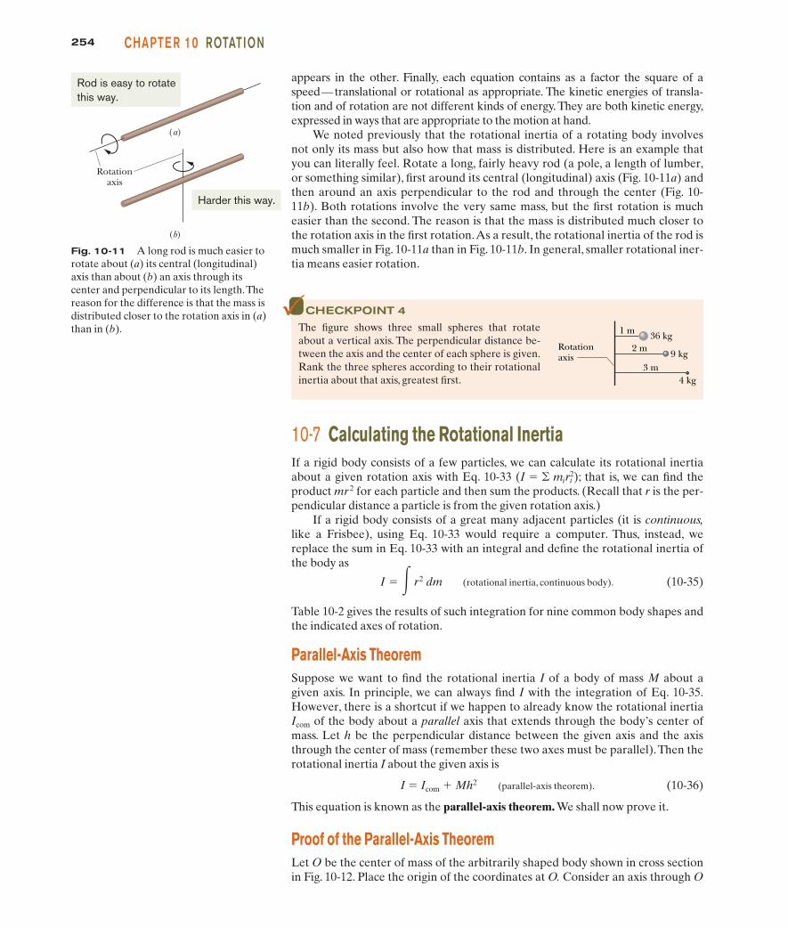
We noted previously that the rotational inertia of a rotating body involvesnot only its mass but also how that mass is distributed. Here is an example thatyou can literally feel. Rotate a long, fairly heavy rod (a pole, a length of lumber,or something similar), first around its central (longitudinal) axis (Fig. 10-11a) andthen around an axis perpendicular to the rod and through the center (Fig. 10-11b). Both rotations involve the very same mass, but the first rotation is mucheasier than the second. The reason is that the mass is distributed much closer tothe rotation axis in the first rotation.As a result, the rotational inertia of the rod ismuch smaller in Fig. 10-11a than in Fig. 10-11b. In general, smaller rotational iner-tia means easier rotation.
CHECKPOINT 4
The figure shows three small spheres that rotateabout a vertical axis. The perpendicular distance be-tween the axis and the center of each sphere is given.Rank the three spheres according to their rotationalinertia about that axis, greatest first.
Rotationaxis
4 kg3 m
2 m
1 m
9 kg
36 kg
Fig. 10-11 A long rod is much easier torotate about (a) its central (longitudinal)axis than about (b) an axis through its center and perpendicular to its length.Thereason for the difference is that the mass isdistributed closer to the rotation axis in (a)than in (b).
Rotation axis
(a)
(b)
Rod is easy to rotatethis way.
Harder this way.
10-7 Calculating the Rotational InertiaIf a rigid body consists of a few particles, we can calculate its rotational inertiaabout a given rotation axis with Eq. 10-33 ; that is, we can find theproduct mr 2 for each particle and then sum the products. (Recall that r is the per-pendicular distance a particle is from the given rotation axis.)
If a rigid body consists of a great many adjacent particles (it is continuous,like a Frisbee), using Eq. 10-33 would require a computer. Thus, instead, wereplace the sum in Eq. 10-33 with an integral and define the rotational inertia ofthe body as
(rotational inertia, continuous body). (10-35)
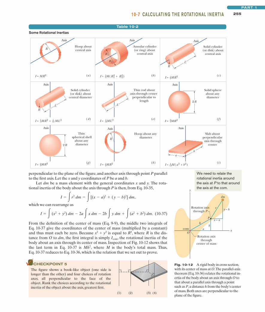
Table 10-2 gives the results of such integration for nine common body shapes andthe indicated axes of rotation.
Parallel-Axis TheoremSuppose we want to find the rotational inertia I of a body of mass M about agiven axis. In principle, we can always find I with the integration of Eq. 10-35.However, there is a shortcut if we happen to already know the rotational inertiaIcom of the body about a parallel axis that extends through the body’s center ofmass. Let h be the perpendicular distance between the given axis and the axisthrough the center of mass (remember these two axes must be parallel).Then therotational inertia I about the given axis is
I � Icom � Mh2 (parallel-axis theorem). (10-36)
This equation is known as the parallel-axis theorem. We shall now prove it.
Proof of the Parallel-Axis TheoremLet O be the center of mass of the arbitrarily shaped body shown in cross sectionin Fig. 10-12. Place the origin of the coordinates at O. Consider an axis through O
I � � r2 dm
(I � � miri2)
halliday_c10_241-274hr.qxd 17-09-2009 12:50 Page 254
25510-7 CALCU LATI NG TH E ROTATIONAL I N E RTIAPART 1
Table 10-2
Some Rotational Inertias
Axis
Hoop about central axis
Axis
Annular cylinder (or ring) about
central axis
R
I = MR 2 (b) (a) I = M(R 12 + R 2
2)
R 2
R 1
Thin rod about axis through center
perpendicular to length
(e) I = ML 2
L
Axis
Axis Axis
Hoop about any diameter
Slab about perpendicular axis through
center
(i) (h) I = MR 2 I = M(a 2 + b 2)
R
b a
Axis
Solid cylinder (or disk) about
central axis
(c) I = MR 2
R L
Axis
Solid cylinder (or disk) about
central diameter
(d) I = MR 2 + ML 2
R L
Axis
Thin spherical shell
about any diameter
(g) I = MR 2
2R
Solid sphere about any diameter
(f) I = MR 2
2R
Axis
1 __ 2 1 __
2
2 __ 5
1 __ 4
2 __ 3
1 __ 2
1 __ 12
1 __ 12
1 __ 12
perpendicular to the plane of the figure, and another axis through point P parallelto the first axis. Let the x and y coordinates of P be a and b.
Let dm be a mass element with the general coordinates x and y. The rota-tional inertia of the body about the axis through P is then, from Eq. 10-35,
which we can rearrange as
(10-37)
From the definition of the center of mass (Eq. 9-9), the middle two integrals ofEq. 10-37 give the coordinates of the center of mass (multiplied by a constant)and thus must each be zero. Because x2 � y2 is equal to R2, where R is the dis-tance from O to dm, the first integral is simply Icom, the rotational inertia of thebody about an axis through its center of mass. Inspection of Fig. 10-12 shows thatthe last term in Eq. 10-37 is Mh2, where M is the body’s total mass. Thus,Eq. 10-37 reduces to Eq. 10-36, which is the relation that we set out to prove.
I � � (x2 � y2) dm � 2a � x dm � 2b � y dm � � (a2 � b2) dm.
I � � r2 dm � � [(x � a)2 � ( y � b)2] dm,
Fig. 10-12 A rigid body in cross section,with its center of mass at O.The parallel-axistheorem (Eq. 10-36) relates the rotational in-ertia of the body about an axis through O tothat about a parallel axis through a pointsuch as P, a distance h from the body’s centerof mass. Both axes are perpendicular to theplane of the figure.
dm
r
P
h
a b
x – a
y – b
com O
Rotation axis through
center of mass
Rotation axis through P
y
x
We need to relate therotational inertia aroundthe axis at P to that aroundthe axis at the com.
CHECKPOINT 5
The figure shows a book-like object (one side islonger than the other) and four choices of rotationaxes, all perpendicular to the face of theobject. Rank the choices according to the rotationalinertia of the object about the axis, greatest first.
(1) (2) (3) (4)
halliday_c10_241-274hr2.qxd 29-09-2009 13:12 Page 255
256 CHAPTE R 10 ROTATION
KEY I DEAS
Sample Problem
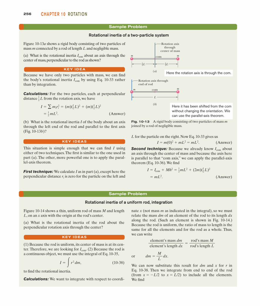
nate x (not mass m as indicated in the integral), so we mustrelate the mass dm of an element of the rod to its length dxalong the rod. (Such an element is shown in Fig. 10-14.)Because the rod is uniform, the ratio of mass to length is thesame for all the elements and for the rod as a whole. Thus,we can write
or
We can now substitute this result for dm and x for r inEq. 10-38. Then we integrate from end to end of the rod(from x � �L/2 to x � L/2) to include all the elements.We find
dm �ML
dx.
element’s mass dmelement’s length dx
�rod’s mass Mrod’s length L
Rotational inertia of a uniform rod, integration
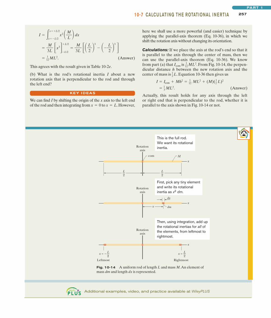
Figure 10-14 shows a thin, uniform rod of mass M and lengthL, on an x axis with the origin at the rod’s center.
(a) What is the rotational inertia of the rod about theperpendicular rotation axis through the center?
(1) Because the rod is uniform, its center of mass is at its cen-ter. Therefore, we are looking for Icom. (2) Because the rod isa continuous object, we must use the integral of Eq. 10-35,
(10-38)
to find the rotational inertia.
Calculations: We want to integrate with respect to coordi-
I � � r 2 dm,
KEY I DEAS
Sample Problem
Rotational inertia of a two-particle system
Figure 10-13a shows a rigid body consisting of two particles ofmass m connected by a rod of length L and negligible mass.
(a) What is the rotational inertia Icom about an axis through thecenter of mass,perpendicular to the rod as shown?
Because we have only two particles with mass, we can findthe body’s rotational inertia Icom by using Eq. 10-33 ratherthan by integration.
Calculations: For the two particles, each at perpendiculardistance from the rotation axis, we have
(Answer)
(b) What is the rotational inertia I of the body about an axisthrough the left end of the rod and parallel to the first axis(Fig. 10-13b)?
This situation is simple enough that we can find I using either of two techniques.The first is similar to the one used inpart (a). The other, more powerful one is to apply the paral-lel-axis theorem.
First technique: We calculate I as in part (a), except here theperpendicular distance ri is zero for the particle on the left and
� 12 mL2.
I � � miri2 � (m)(1
2 L)2 � (m)(12 L)2
12 L
L for the particle on the right. Now Eq. 10-33 gives us
I � m(0)2 � mL2 � mL2. (Answer)
Second technique: Because we already know Icom aboutan axis through the center of mass and because the axis hereis parallel to that “com axis,” we can apply the parallel-axistheorem (Eq. 10-36).We find
(Answer) � mL2.
I � Icom � Mh2 � 12 mL2 � (2m)(1
2 L)2
KEY I DEA
m m
(a)
L L
com
Rotation axis through
center of mass
m m
(b)
L
com
Rotation axis through end of rod
1 __ 2
1 __ 2
Here the rotation axis is through the com.
Here it has been shifted from the com without changing the orientation. We can use the parallel-axis theorem.
Fig. 10-13 A rigid body consisting of two particles of mass mjoined by a rod of negligible mass.
halliday_c10_241-274hr.qxd 17-09-2009 12:50 Page 256
25710-7 CALCU LATI NG TH E ROTATIONAL I N E RTIAPART 1
A
Fig. 10-14 A uniform rod of length L and mass M.An element ofmass dm and length dx is represented.
x
Rotationaxis
x dm
dx
x
x = −
Rotationaxis
Leftmost Rightmost
L__2
x = L__2
x
Rotationaxis
L__2
L__2
com M
This is the full rod.We want its rotationalinertia.
First, pick any tiny elementand write its rotationalinertia as x2 dm.
Then, using integration, add upthe rotational inertias for all ofthe elements, from leftmost torightmost.
KEY I DEAS
(Answer)
This agrees with the result given in Table 10-2e.
(b) What is the rod’s rotational inertia I about a newrotation axis that is perpendicular to the rod and throughthe left end?
We can find I by shifting the origin of the x axis to the left endof the rod and then integrating from to . However,x � Lx � 0
� 112 ML2.
�M3L
�x3��L/2
�L/2
�M3L
�� L2
�3
� ��L2 �
3
�
I � �x��L/2
x��L/2x2 � M
L � dxhere we shall use a more powerful (and easier) technique byapplying the parallel-axis theorem (Eq. 10-36), in which weshift the rotation axis without changing its orientation.
Calculations: If we place the axis at the rod’s end so that itis parallel to the axis through the center of mass, then wecan use the parallel-axis theorem (Eq. 10-36). We knowfrom part (a) that Icom is . From Fig. 10-14, the perpen-dicular distance h between the new rotation axis and thecenter of mass is . Equation 10-36 then gives us
(Answer)
Actually, this result holds for any axis through the leftor right end that is perpendicular to the rod, whether it isparallel to the axis shown in Fig. 10-14 or not.
� 13 ML2.
I � Icom � Mh2 � 112 ML2 � (M)(1
2 L)2
12 L
112 ML2
Additional examples, video, and practice available at WileyPLUS
halliday_c10_241-274hr.qxd 17-09-2009 12:50 Page 257
258 CHAPTE R 10 ROTATION
Sample Problem
Calculations: We can find K with Eq. 10-34 , butfirst we need an expression for the rotational inertia I.Because the rotor was a disk that rotated like a merry-go-round, I is given by the expression in Table 10-2c
.Thus, we have
The angular speed of the rotor was
Now we can use Eq. 10-34 to write
(Answer)
Being near this explosion was quite dangerous.
� 2.1 � 107 J.
K � 12 I2 � 1
2(19.64 kg �m2)(1.466 � 103 rad/s)2
� 1.466 � 103 rad/s.
� (14 000 rev/min)(2� rad/rev)� 1 min60 s �
I � 12 MR2 � 1
2 (272 kg)(0.38 m)2 � 19.64 kg �m2.
(I � 12 MR2)
(K � 12 I2)
Rotational kinetic energy, spin test explosion
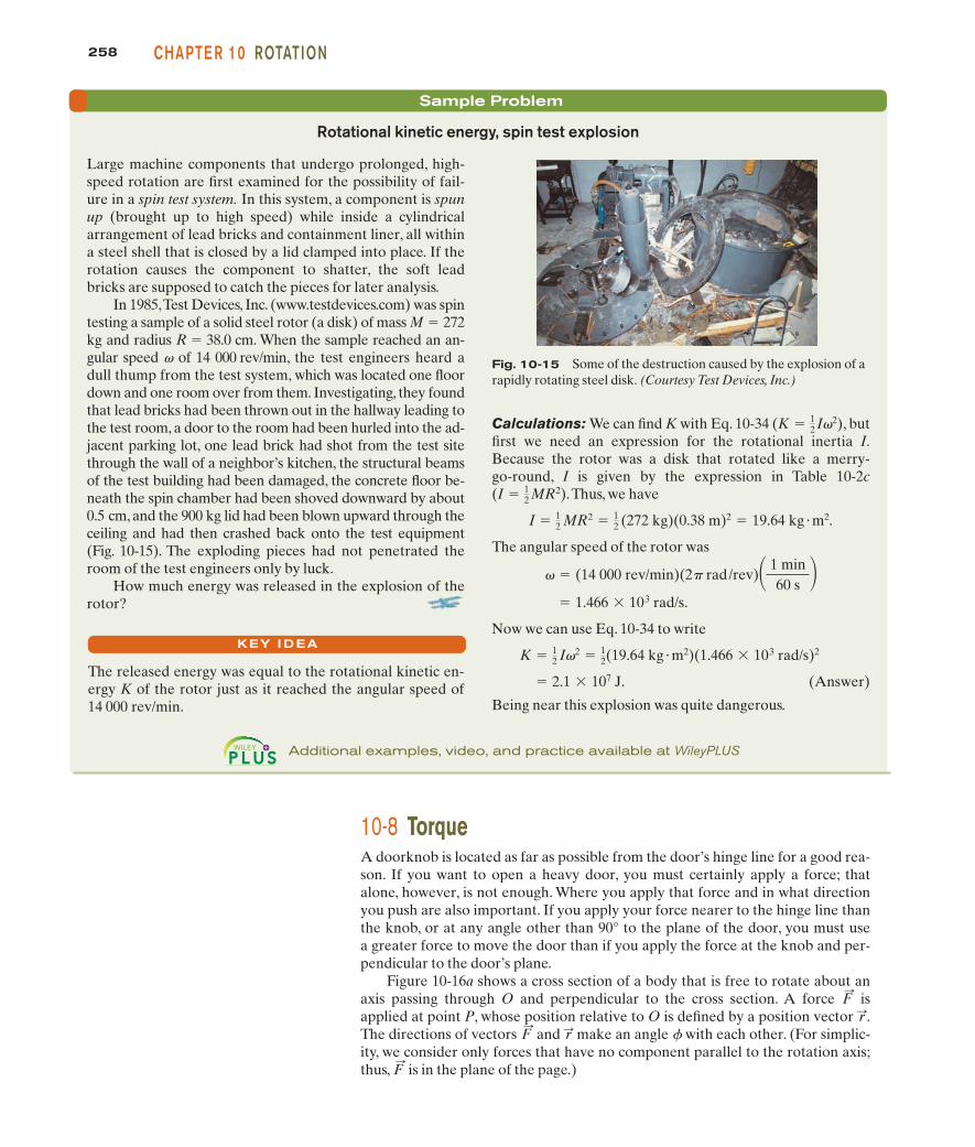
Large machine components that undergo prolonged, high-speed rotation are first examined for the possibility of fail-ure in a spin test system. In this system, a component is spunup (brought up to high speed) while inside a cylindricalarrangement of lead bricks and containment liner, all withina steel shell that is closed by a lid clamped into place. If therotation causes the component to shatter, the soft leadbricks are supposed to catch the pieces for later analysis.
In 1985,Test Devices, Inc. (www.testdevices.com) was spintesting a sample of a solid steel rotor (a disk) of mass M � 272kg and radius R � 38.0 cm. When the sample reached an an-gular speed v of 14 000 rev/min, the test engineers heard adull thump from the test system, which was located one floordown and one room over from them. Investigating, they foundthat lead bricks had been thrown out in the hallway leading tothe test room, a door to the room had been hurled into the ad-jacent parking lot, one lead brick had shot from the test sitethrough the wall of a neighbor’s kitchen, the structural beamsof the test building had been damaged, the concrete floor be-neath the spin chamber had been shoved downward by about0.5 cm, and the 900 kg lid had been blown upward through theceiling and had then crashed back onto the test equipment(Fig. 10-15). The exploding pieces had not penetrated theroom of the test engineers only by luck.
How much energy was released in the explosion of therotor?
Fig. 10-15 Some of the destruction caused by the explosion of arapidly rotating steel disk. (Courtesy Test Devices, Inc.)
Additional examples, video, and practice available at WileyPLUS
10-8 TorqueA doorknob is located as far as possible from the door’s hinge line for a good rea-son. If you want to open a heavy door, you must certainly apply a force; thatalone, however, is not enough. Where you apply that force and in what directionyou push are also important. If you apply your force nearer to the hinge line thanthe knob, or at any angle other than 90° to the plane of the door, you must usea greater force to move the door than if you apply the force at the knob and per-pendicular to the door’s plane.
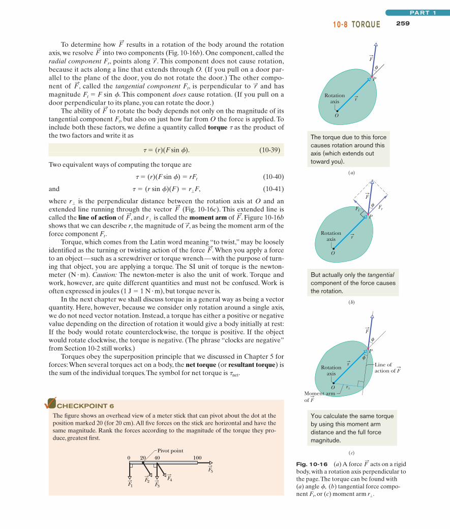
Figure 10-16a shows a cross section of a body that is free to rotate about anaxis passing through O and perpendicular to the cross section. A force isapplied at point P, whose position relative to O is defined by a position vector .The directions of vectors and make an angle f with each other. (For simplic-ity, we consider only forces that have no component parallel to the rotation axis;thus, is in the plane of the page.)F
:
r:F:
r:F:
KEY I DEA
The released energy was equal to the rotational kinetic en-ergy K of the rotor just as it reached the angular speed of14 000 rev/min.
halliday_c10_241-274hr.qxd 17-09-2009 12:50 Page 258
25910-8 TORQU EPART 1
To determine how results in a rotation of the body around the rotationaxis, we resolve into two components (Fig. 10-16b). One component, called theradial component Fr, points along . This component does not cause rotation,because it acts along a line that extends through O. (If you pull on a door par-allel to the plane of the door, you do not rotate the door.) The other compo-nent of , called the tangential component Ft, is perpendicular to and hasmagnitude Ft � F sin f. This component does cause rotation. (If you pull on adoor perpendicular to its plane, you can rotate the door.)
The ability of to rotate the body depends not only on the magnitude of itstangential component Ft, but also on just how far from O the force is applied. Toinclude both these factors, we define a quantity called torque t as the product ofthe two factors and write it as
t � (r)(F sin f). (10-39)
Two equivalent ways of computing the torque are
t � (r)(F sin f) � rFt (10-40)
and (10-41)
where is the perpendicular distance between the rotation axis at O and anextended line running through the vector (Fig. 10-16c). This extended line iscalled the line of action of , and is called the moment arm of . Figure 10-16bshows that we can describe r, the magnitude of , as being the moment arm of theforce component Ft.
Torque, which comes from the Latin word meaning “to twist,” may be looselyidentified as the turning or twisting action of the force . When you apply a forceto an object—such as a screwdriver or torque wrench—with the purpose of turn-ing that object, you are applying a torque. The SI unit of torque is the newton-meter (N � m). Caution: The newton-meter is also the unit of work. Torque andwork, however, are quite different quantities and must not be confused. Work isoften expressed in joules (1 J � 1 N � m), but torque never is.
In the next chapter we shall discuss torque in a general way as being a vectorquantity. Here, however, because we consider only rotation around a single axis,we do not need vector notation. Instead, a torque has either a positive or negativevalue depending on the direction of rotation it would give a body initially at rest:If the body would rotate counterclockwise, the torque is positive. If the objectwould rotate clockwise, the torque is negative. (The phrase “clocks are negative”from Section 10-2 still works.)
Torques obey the superposition principle that we discussed in Chapter 5 forforces:When several torques act on a body, the net torque (or resultant torque) isthe sum of the individual torques.The symbol for net torque is tnet.
F:
r:F:
r�F:
F:
r�
� (r sin �)(F) � r�F,
F:
r:F:
r:F:
F:
CHECKPOINT 6
The figure shows an overhead view of a meter stick that can pivot about the dot at theposition marked 20 (for 20 cm). All five forces on the stick are horizontal and have thesame magnitude. Rank the forces according to the magnitude of the torque they pro-duce, greatest first.
0 20 40Pivot point
100
F1F2
F3
F4
F5
Fig. 10-16 (a) A force acts on a rigidbody, with a rotation axis perpendicular tothe page.The torque can be found with(a) angle f, (b) tangential force compo-nent Ft, or (c) moment arm .r�
F:
O
P
φ
(a)
O
P
φ
(b)
FrFt
O
P
φ
Rotationaxis
(c)
φLine ofaction of F
rMoment armof F
Rotationaxis
Rotationaxis
F
F
F
r
r
r
The torque due to this forcecauses rotation around thisaxis (which extends outtoward you).
You calculate the same torqueby using this moment armdistance and the full forcemagnitude.
But actually only the tangentialcomponent of the force causesthe rotation.
halliday_c10_241-274hr.qxd 17-09-2009 12:50 Page 259
260 CHAPTE R 10 ROTATION
10-9 Newton’s Second Law for RotationA torque can cause rotation of a rigid body, as when you use a torque to rotatea door. Here we want to relate the net torque tnet on a rigid body to the angularacceleration a that torque causes about a rotation axis. We do so by analogy withNewton’s second law (Fnet � ma) for the acceleration a of a body of mass m dueto a net force Fnet along a coordinate axis.We replace Fnet with tnet, m with I, and awith a in radian measure, writing
tnet � Ia (Newton’s second law for rotation). (10-42)
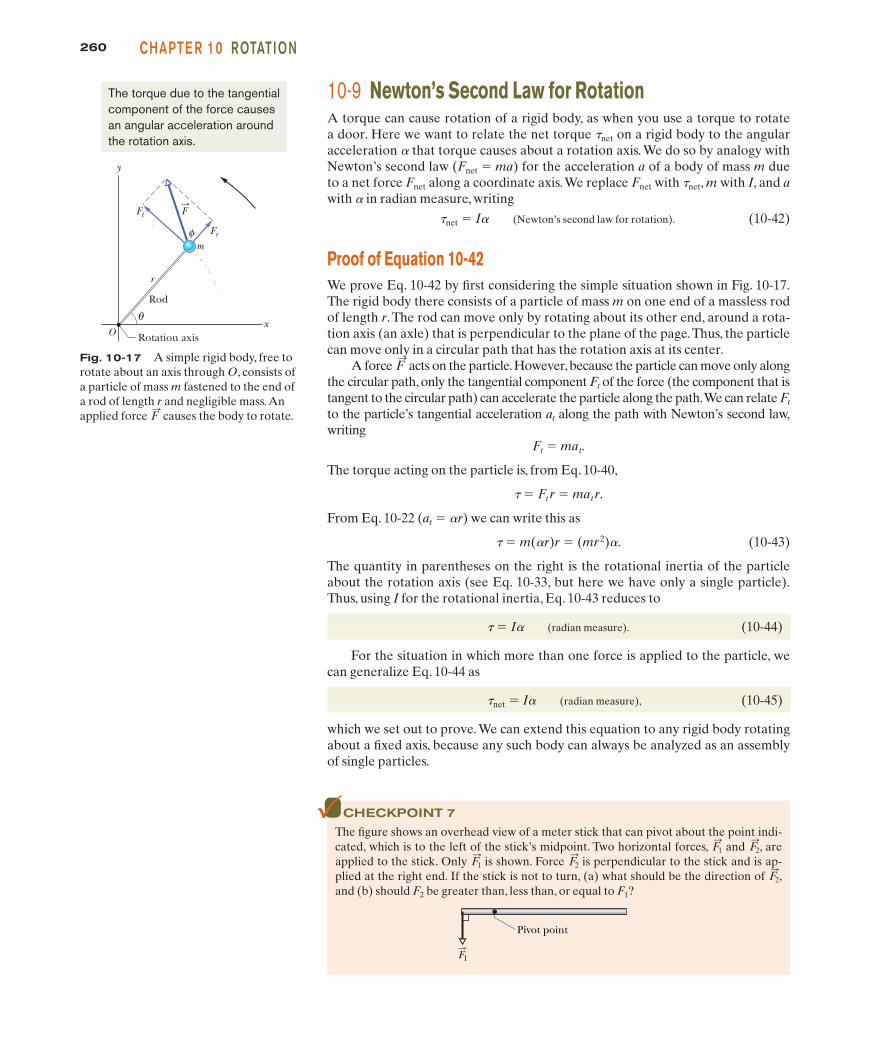
Proof of Equation 10-42We prove Eq. 10-42 by first considering the simple situation shown in Fig. 10-17.The rigid body there consists of a particle of mass m on one end of a massless rodof length r. The rod can move only by rotating about its other end, around a rota-tion axis (an axle) that is perpendicular to the plane of the page.Thus, the particlecan move only in a circular path that has the rotation axis at its center.
A force acts on the particle.However,because the particle can move only alongthe circular path, only the tangential component Ft of the force (the component that istangent to the circular path) can accelerate the particle along the path.We can relate Ft
to the particle’s tangential acceleration at along the path with Newton’s second law,writing
Ft � mat.
The torque acting on the particle is, from Eq. 10-40,
t � Ftr � matr.
From Eq. 10-22 (at � ar) we can write this as
t � m(ar)r � (mr 2)a. (10-43)
The quantity in parentheses on the right is the rotational inertia of the particleabout the rotation axis (see Eq. 10-33, but here we have only a single particle).Thus, using I for the rotational inertia, Eq. 10-43 reduces to
t � Ia (radian measure). (10-44)
For the situation in which more than one force is applied to the particle, wecan generalize Eq. 10-44 as
tnet � Ia (radian measure), (10-45)
which we set out to prove. We can extend this equation to any rigid body rotatingabout a fixed axis, because any such body can always be analyzed as an assemblyof single particles.
F:Fig. 10-17 A simple rigid body, free to
rotate about an axis through O, consists ofa particle of mass m fastened to the end ofa rod of length r and negligible mass.Anapplied force causes the body to rotate.F
:
O x
y
Rod
θ
Rotation axis
r
m Fr
Ft
φ
F
The torque due to the tangentialcomponent of the force causesan angular acceleration aroundthe rotation axis.
CHECKPOINT 7
The figure shows an overhead view of a meter stick that can pivot about the point indi-cated, which is to the left of the stick’s midpoint. Two horizontal forces, and , areapplied to the stick. Only is shown. Force is perpendicular to the stick and is ap-plied at the right end. If the stick is not to turn, (a) what should be the direction of ,and (b) should F2 be greater than, less than, or equal to F1?
F:
2
F:
2F:
1
F:
2F:
1
F1
Pivot point
halliday_c10_241-274hr.qxd 17-09-2009 12:50 Page 260
26110-9 N EWTON’S S ECON D LAW FOR ROTATIONPART 1
Sample Problem
Newton’s 2nd law, rotation, torque, disk
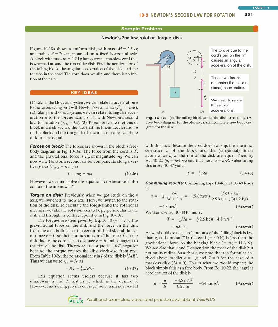
Figure 10-18a shows a uniform disk, with mass M � 2.5 kgand radius R � 20 cm, mounted on a fixed horizontal axle.A block with mass m � 1.2 kg hangs from a massless cord thatis wrapped around the rim of the disk. Find the acceleration ofthe falling block, the angular acceleration of the disk, and thetension in the cord.The cord does not slip, and there is no fric-tion at the axle.
KEY I DEASm
M
M R O
Fg
(b) (a)
(c)
m
T
T
The torque due to the cord's pull on the rim causes an angular acceleration of the disk.
These two forces determine the block's (linear) acceleration.
We need to relate those twoaccelerations.
y
Fig. 10-18 (a) The falling block causes the disk to rotate. (b) Afree-body diagram for the block. (c) An incomplete free-body dia-gram for the disk.
with this fact: Because the cord does not slip, the linear ac-celeration a of the block and the (tangential) linearacceleration at of the rim of the disk are equal. Then, byEq. 10-22 (at � ar) we see that here a � a /R. Substitutingthis in Eq. 10-47 yields
(10-48)
Combining results: Combining Eqs. 10-46 and 10-48 leadsto
. (Answer)We then use Eq. 10-48 to find T:
(Answer)
As we should expect, acceleration a of the falling block is lessthan g, and tension T in the cord (� 6.0 N) is less than thegravitational force on the hanging block (� mg � 11.8 N).We see also that a and T depend on the mass of the disk butnot on its radius. As a check, we note that the formulas de-rived above predict a � �g and T � 0 for the case of amassless disk (M � 0). This is what we would expect; theblock simply falls as a free body. From Eq. 10-22, the angularacceleration of the disk is
(Answer)� �aR
��4.8 m/s2
0.20 m� �24 rad/s2.
� 6.0 N.
T � �12 Ma � �1
2(2.5 kg)(�4.8 m/s2)
� �4.8 m/s2
a � �g 2m
M � 2m� �(9.8 m/s2)
(2)(1.2 kg)2.5 kg � (2)(1.2 kg)
T � �12 Ma.
(1) Taking the block as a system,we can relate its acceleration ato the forces acting on it with Newton’s second law ( ).(2) Taking the disk as a system, we can relate its angular accel-eration a to the torque acting on it with Newton’s secondlaw for rotation (tnet � Ia). (3) To combine the motions ofblock and disk, we use the fact that the linear acceleration aof the block and the (tangential) linear acceleration of thedisk rim are equal.
Forces on block: The forces are shown in the block’s free-body diagram in Fig. 10-18b: The force from the cord is ,and the gravitational force is , of magnitude mg. We cannow write Newton’s second law for components along a ver-tical y axis (Fnet,y � may) as
T � mg � ma. (10-46)
However, we cannot solve this equation for a because it alsocontains the unknown T.
Torque on disk: Previously, when we got stuck on the yaxis, we switched to the x axis. Here, we switch to the rota-tion of the disk. To calculate the torques and the rotationalinertia I, we take the rotation axis to be perpendicular to thedisk and through its center, at point O in Fig. 10-18c.
The torques are then given by Eq. 10-40 (t � rFt). Thegravitational force on the disk and the force on the diskfrom the axle both act at the center of the disk and thus atdistance r � 0, so their torques are zero. The force on thedisk due to the cord acts at distance r � R and is tangent tothe rim of the disk. Therefore, its torque is �RT, negativebecause the torque rotates the disk clockwise from rest.From Table 10-2c, the rotational inertia I of the disk is .Thus we can write tnet � Ia as
(10-47)
This equation seems useless because it has twounknowns, a and T, neither of which is the desired a.However, mustering physics courage, we can make it useful
�RT � 12 MR2�.
12MR2
T:
F:
g
T:
at
F:
net� m:a
Additional examples, video, and practice available at WileyPLUS
halliday_c10_241-274hr.qxd 17-09-2009 12:50 Page 261
262 CHAPTE R 10 ROTATION
10-10 Work and Rotational Kinetic EnergyAs we discussed in Chapter 7, when a force F causes a rigid body of mass m to ac-celerate along a coordinate axis, the force does work W on the body. Thus, thebody’s kinetic energy can change. Suppose it is the only energy of thebody that changes.Then we relate the change �K in kinetic energy to the work Wwith the work–kinetic energy theorem (Eq. 7-10), writing
(work–kinetic energy theorem). (10-49)
For motion confined to an x axis, we can calculate the work with Eq. 7-32,
(work, one-dimensional motion). (10-50)
This reduces to W � Fd when F is constant and the body’s displacement is d.The rate at which the work is done is the power, which we can find with Eqs. 7-43and 7-48,
(power, one-dimensional motion). (10-51)
Now let us consider a rotational situation that is similar. When a torqueaccelerates a rigid body in rotation about a fixed axis, the torque does work Won the body. Therefore, the body’s rotational kinetic energy canchange. Suppose that it is the only energy of the body that changes. Then wecan still relate the change �K in kinetic energy to the work W with thework – kinetic energy theorem, except now the kinetic energy is a rotational ki-netic energy:
(work–kinetic energy theorem). (10-52)
Here, I is the rotational inertia of the body about the fixed axis and vi and vf arethe angular speeds of the body before and after the work is done, respectively.
Also, we can calculate the work with a rotational equivalent of Eq. 10-50,
(work, rotation about fixed axis), (10-53)
where t is the torque doing the work W, and ui and uf are the body’s angularpositions before and after the work is done, respectively. When t is constant,Eq. 10-53 reduces to
W � t(uf � ui) (work, constant torque). (10-54)
The rate at which the work is done is the power, which we can find with the rota-tional equivalent of Eq. 10-51,
(power, rotation about fixed axis). (10-55)
Table 10-3 summarizes the equations that apply to the rotation of a rigid bodyabout a fixed axis and the corresponding equations for translational motion.
Proof of Eqs. 10-52 through 10-55Let us again consider the situation of Fig. 10-17, in which force rotates a rigidbody consisting of a single particle of mass m fastened to the end of a masslessrod. During the rotation, force does work on the body. Let us assume that theF
:
F:
P �dWdt
�
W � ��f
�i
d�
�K � Kf � Ki � 12 If
2 � 12�i
2 � W
(K � 12 I2)
P �dWdt
� Fv
W � �xf
xi
F dx
�K � Kf � Ki � 12 mvf
2 � 12 mvi
2 � W
(K � 12 mv2)
halliday_c10_241-274hr.qxd 17-09-2009 12:50 Page 262
26310-10 WOR K AN D ROTATIONAL KI N ETIC E N E RGYPART 1
only energy of the body that is changed by is the kinetic energy. Then we canapply the work–kinetic energy theorem of Eq. 10-49:
�K � Kf � Ki � W. (10-56)
Using and Eq. 10-18 (v � vr), we can rewrite Eq. 10-56 as
(10-57)
From Eq. 10-33, the rotational inertia for this one-particle body is I � mr2.Substituting this into Eq. 10-57 yields
which is Eq. 10-52.We derived it for a rigid body with one particle, but it holds forany rigid body rotated about a fixed axis.
We next relate the work W done on the body in Fig. 10-17 to the torque ton the body due to force . When the particle moves a distance ds along itscircular path, only the tangential component Ft of the force accelerates the parti-cle along the path. Therefore, only Ft does work on the particle. We write thatwork dW as Ft ds. However, we can replace ds with r du, where du is the anglethrough which the particle moves.Thus we have
dW � Ft r du. (10-58)
From Eq. 10-40, we see that the product Ft r is equal to the torque t, so we canrewrite Eq. 10-58 as
dW � t du. (10-59)
The work done during a finite angular displacement from ui to uf is then
which is Eq. 10-53. It holds for any rigid body rotating about a fixed axis.Equation 10-54 comes directly from Eq. 10-53.
We can find the power P for rotational motion from Eq. 10-59:
which is Eq. 10-55.
P �dWdt
� d�
dt� �,
W � ��f
�i
d�,
F:
�K � 12 I�f
2 � 12 �i
2 � W,
�K � 12 mr 2�f
2 � 12 mr 2�i
2 � W.
K � 12 mv2
F:
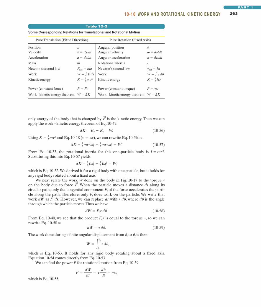
Table 10-3
Some Corresponding Relations for Translational and Rotational Motion
Pure Translation (Fixed Direction) Pure Rotation (Fixed Axis)
Position x Angular position u
Velocity v � dx/dt Angular velocity v � du/dt
Acceleration a � dv/dt Angular acceleration a � dv/dt
Mass m Rotational inertia I
Newton’s second law Fnet � ma Newton’s second law tnet � Ia
Work W � � F dx Work W � � t du
Kinetic energy Kinetic energy
Power (constant force) P � Fv Power (constant torque) P � tv
Work–kinetic energy theorem W � �K Work–kinetic energy theorem W � �K
K � 12 I�2K � 1
2 mv2
halliday_c10_241-274hr2.qxd 29-09-2009 13:12 Page 263
264 CHAPTE R 10 ROTATION
Sample Problem
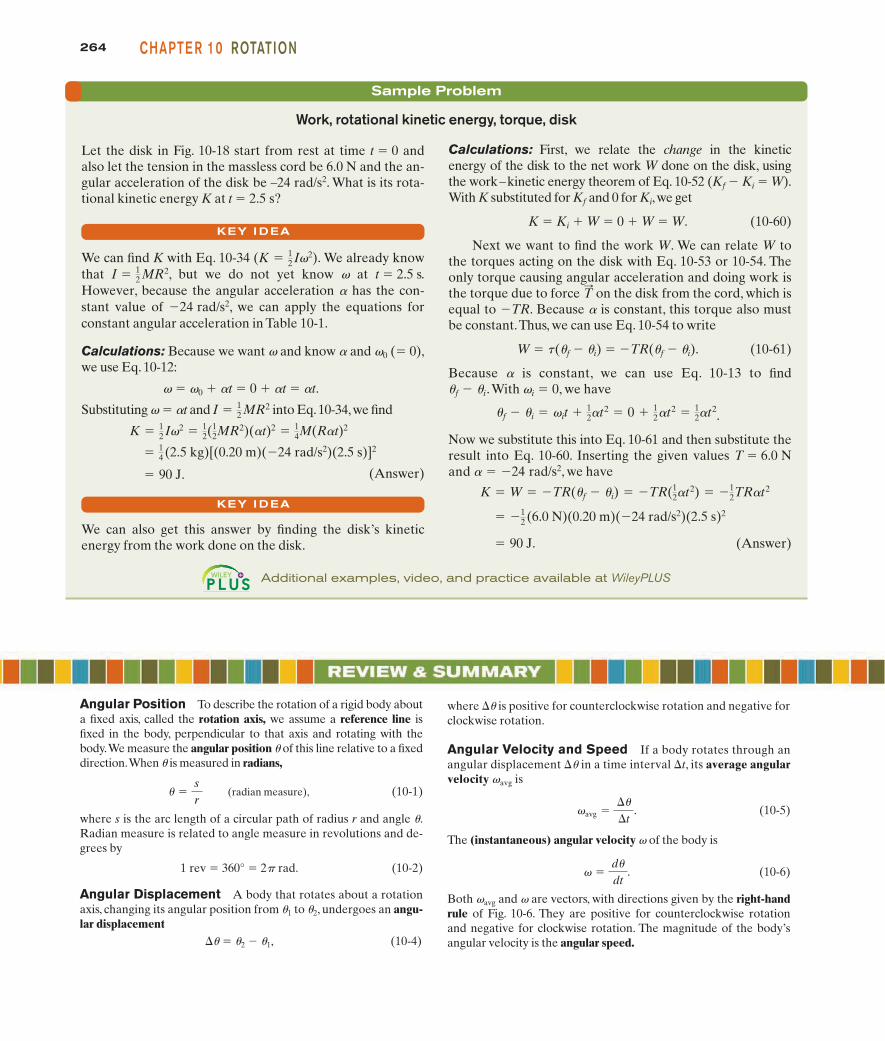
Calculations: First, we relate the change in the kinetic energy of the disk to the net work W done on the disk, usingthe work–kinetic energy theorem of Eq. 10-52 (Kf � Ki � W).With K substituted for Kf and 0 for Ki,we get
K � Ki � W � 0 � W � W. (10-60)
Next we want to find the work W. We can relate W tothe torques acting on the disk with Eq. 10-53 or 10-54. Theonly torque causing angular acceleration and doing work isthe torque due to force on the disk from the cord, which isequal to �TR. Because a is constant, this torque also mustbe constant.Thus, we can use Eq. 10-54 to write
W � t(uf � ui) � �TR(uf � ui). (10-61)
Because a is constant, we can use Eq. 10-13 to finduf � ui.With vi � 0, we have
.
Now we substitute this into Eq. 10-61 and then substitute theresult into Eq. 10-60. Inserting the given values T � 6.0 Nand a � �24 rad/s2, we have
(Answer) � 90 J.
� �12 (6.0 N)(0.20 m)(�24 rad/s2)(2.5 s)2
K � W � �TR(�f � �i) � �TR(12�t2) � �1
2TR�t2
�f � �i � it � 12�t2 � 0 � 1
2�t2 � 12�t2
T:
Work, rotational kinetic energy, torque, disk
Let the disk in Fig. 10-18 start from rest at time t � 0 andalso let the tension in the massless cord be 6.0 N and the an-gular acceleration of the disk be –24 rad/s2. What is its rota-tional kinetic energy K at t � 2.5 s?
We can find K with Eq. 10-34 We already knowthat , but we do not yet know v at t � 2.5 s.However, because the angular acceleration a has the con-stant value of �24 rad/s2, we can apply the equations forconstant angular acceleration in Table 10-1.
Calculations: Because we want v and know a and v0 (� 0),we use Eq. 10-12:
v � v0 � at � 0 � at � at.
Substituting v � at and into Eq.10-34,we find
(Answer)
We can also get this answer by finding the disk’s kinetic energy from the work done on the disk.
� 90 J.
� 14 (2.5 kg)[(0.20 m)(�24 rad/s2)(2.5 s)]2
K � 12 I2 � 1
2(12MR2)(�t)2 � 1
4M(R�t)2
I � 12 MR2
I � 12 MR2
(K � 12 I2).
KEY I DEA
KEY I DEA
Additional examples, video, and practice available at WileyPLUS
Angular Position To describe the rotation of a rigid body abouta fixed axis, called the rotation axis, we assume a reference line isfixed in the body, perpendicular to that axis and rotating with thebody.We measure the angular position u of this line relative to a fixeddirection.When u is measured in radians,
(radian measure), (10-1)
where s is the arc length of a circular path of radius r and angle u.Radian measure is related to angle measure in revolutions and de-grees by
1 rev � 360° � 2p rad. (10-2)
Angular Displacement A body that rotates about a rotationaxis, changing its angular position from u1 to u2, undergoes an angu-lar displacement
�u � u2 � u1, (10-4)
� �sr
where �u is positive for counterclockwise rotation and negative forclockwise rotation.
Angular Velocity and Speed If a body rotates through anangular displacement �u in a time interval �t, its average angularvelocity vavg is
(10-5)
The (instantaneous) angular velocity v of the body is
(10-6)
Both vavg and v are vectors, with directions given by the right-handrule of Fig. 10-6. They are positive for counterclockwise rotationand negative for clockwise rotation. The magnitude of the body’sangular velocity is the angular speed.
�d�
dt.
avg ���
�t.
halliday_c10_241-274hr.qxd 17-09-2009 12:50 Page 264
265R EVI EW & S U M MARYPART 1
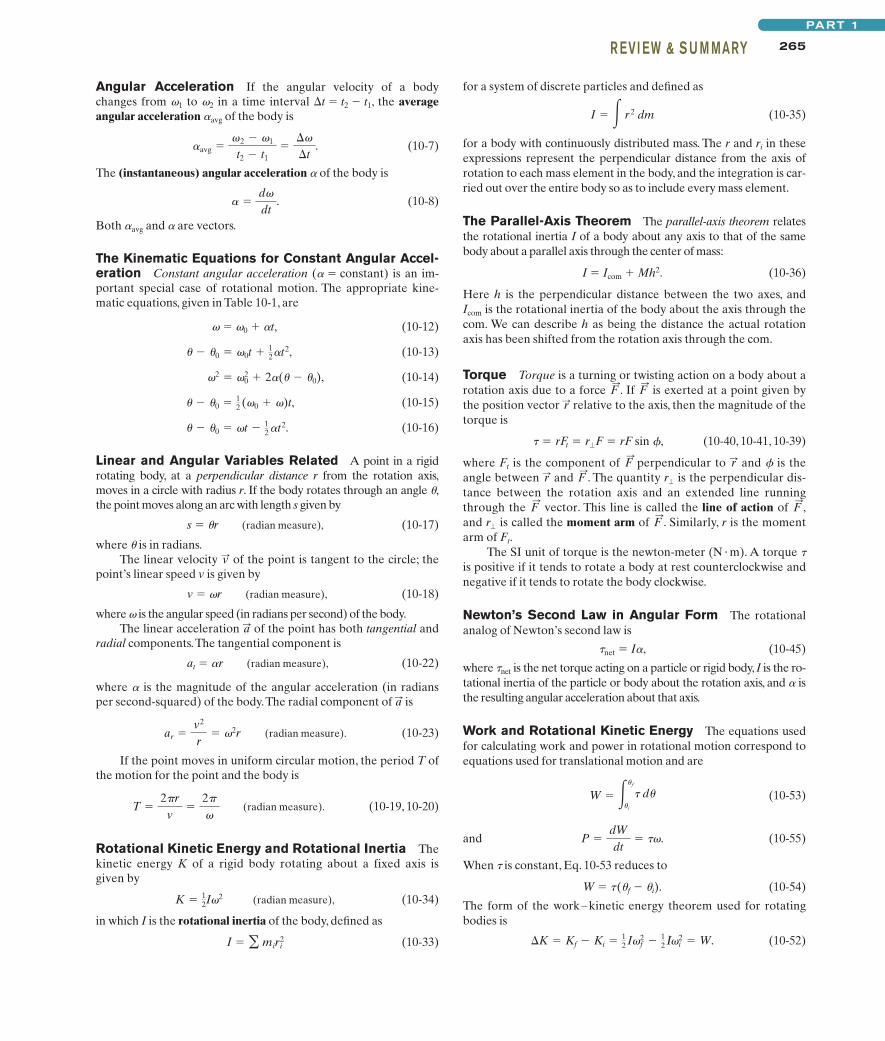
Angular Acceleration If the angular velocity of a bodychanges from v1 to v2 in a time interval �t � t2 � t1, the averageangular acceleration aavg of the body is
(10-7)
The (instantaneous) angular acceleration a of the body is
(10-8)
Both aavg and a are vectors.
The Kinematic Equations for Constant Angular Accel-eration Constant angular acceleration (a � constant) is an im-portant special case of rotational motion. The appropriate kine-matic equations, given in Table 10-1, are
v � v0 � at, (10-12)
(10-13)
(10-14)
(10-15)
(10-16)
Linear and Angular Variables Related A point in a rigidrotating body, at a perpendicular distance r from the rotation axis,moves in a circle with radius r. If the body rotates through an angle u,the point moves along an arc with length s given by
s � ur (radian measure), (10-17)
where u is in radians.The linear velocity of the point is tangent to the circle; the
point’s linear speed v is given by
v � vr (radian measure), (10-18)
where v is the angular speed (in radians per second) of the body.The linear acceleration of the point has both tangential and
radial components.The tangential component is
at � ar (radian measure), (10-22)
where a is the magnitude of the angular acceleration (in radiansper second-squared) of the body.The radial component of is
(radian measure). (10-23)
If the point moves in uniform circular motion, the period T ofthe motion for the point and the body is
(radian measure). (10-19, 10-20)
Rotational Kinetic Energy and Rotational Inertia Thekinetic energy K of a rigid body rotating about a fixed axis isgiven by
(radian measure), (10-34)
in which I is the rotational inertia of the body, defined as
(10-33)I � � miri2
K � 12I2
T �2�r
v�
2�
ar �v2
r� 2r
a:
a:
v:
� � �0 � t � 12 �t2.
� � �0 � 12 (0 � )t,
2 � 02 � 2�(� � �0),
� � �0 � 0t � 12�t2,
� �d
dt.
�avg �2 � 1
t2 � t1�
�
�t.
for a system of discrete particles and defined as
(10-35)
for a body with continuously distributed mass. The r and ri in theseexpressions represent the perpendicular distance from the axis ofrotation to each mass element in the body, and the integration is car-ried out over the entire body so as to include every mass element.
The Parallel-Axis Theorem The parallel-axis theorem relatesthe rotational inertia I of a body about any axis to that of the samebody about a parallel axis through the center of mass:
I � Icom � Mh2. (10-36)
Here h is the perpendicular distance between the two axes, andIcom is the rotational inertia of the body about the axis through thecom. We can describe h as being the distance the actual rotationaxis has been shifted from the rotation axis through the com.
Torque Torque is a turning or twisting action on a body about arotation axis due to a force . If is exerted at a point given bythe position vector relative to the axis, then the magnitude of thetorque is
(10-40, 10-41, 10-39)
where Ft is the component of perpendicular to and f is theangle between and . The quantity is the perpendicular dis-tance between the rotation axis and an extended line runningthrough the vector. This line is called the line of action of ,and is called the moment arm of . Similarly, r is the momentarm of Ft.
The SI unit of torque is the newton-meter (N � m). A torque tis positive if it tends to rotate a body at rest counterclockwise andnegative if it tends to rotate the body clockwise.
Newton’s Second Law in Angular Form The rotationalanalog of Newton’s second law is
tnet � Ia, (10-45)
where tnet is the net torque acting on a particle or rigid body, I is the ro-tational inertia of the particle or body about the rotation axis, and a isthe resulting angular acceleration about that axis.
Work and Rotational Kinetic Energy The equations usedfor calculating work and power in rotational motion correspond toequations used for translational motion and are
(10-53)
and (10-55)
When t is constant, Eq. 10-53 reduces to
W � t(uf � ui). (10-54)
The form of the work–kinetic energy theorem used for rotatingbodies is
(10-52)�K � Kf � Ki � 12 If
2 � 12�i
2 � W.
P �dWdt
� .
W � ��f
�i
d�
F:
r�
F:
F:
r�F:
r:r:F
:
� rFt � r�F � rF sin �,
r:F:
F:
I � � r 2 dm
halliday_c10_241-274hr.qxd 17-09-2009 12:50 Page 265
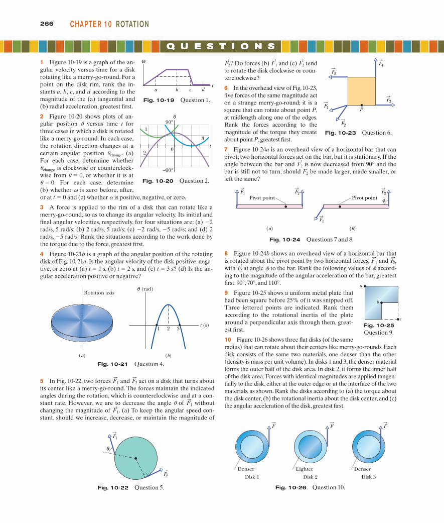
5 In Fig. 10-22, two forces and act on a disk that turns aboutits center like a merry-go-round. The forces maintain the indicatedangles during the rotation, which is counterclockwise and at a con-stant rate. However, we are to decrease the angle u of withoutchanging the magnitude of . (a) To keep the angular speed con-stant, should we increase, decrease, or maintain the magnitude of
F:
1
F:
1
F:
2F:
1
266 CHAPTE R 10 ROTATION
1 Figure 10-19 is a graph of the an-gular velocity versus time for a diskrotating like a merry-go-round. For apoint on the disk rim, rank the in-stants a, b, c, and d according to themagnitude of the (a) tangential and(b) radial acceleration, greatest first.
2 Figure 10-20 shows plots of an-gular position u versus time t forthree cases in which a disk is rotatedlike a merry-go-round. In each case,the rotation direction changes at acertain angular position uchange. (a)For each case, determine whetheruchange is clockwise or counterclock-wise from u � 0, or whether it is atu � 0. For each case, determine(b) whether v is zero before, after,or at t � 0 and (c) whether a is positive, negative, or zero.
3 A force is applied to the rim of a disk that can rotate like amerry-go-round, so as to change its angular velocity. Its initial andfinal angular velocities, respectively, for four situations are: (a) �2rad/s, 5 rad/s; (b) 2 rad/s, 5 rad/s; (c) �2 rad/s, �5 rad/s; and (d) 2rad/s, �5 rad/s. Rank the situations according to the work done bythe torque due to the force, greatest first.
4 Figure 10-21b is a graph of the angular position of the rotatingdisk of Fig. 10-21a. Is the angular velocity of the disk positive, nega-tive, or zero at (a) t � 1 s, (b) t � 2 s, and (c) t � 3 s? (d) Is the an-gular acceleration positive or negative?
? Do forces (b) and (c) tendto rotate the disk clockwise or coun-terclockwise?
6 In the overhead view of Fig.10-23,five forces of the same magnitude acton a strange merry-go-round; it is asquare that can rotate about point P,at midlength along one of the edges.Rank the forces according to themagnitude of the torque they createabout point P, greatest first.
7 Figure 10-24a is an overhead view of a horizontal bar that canpivot; two horizontal forces act on the bar, but it is stationary. If theangle between the bar and is now decreased from 90° and thebar is still not to turn, should F2 be made larger, made smaller, orleft the same?
F:
2
F:
2F:
1F:
2ω
ta b c d
1
2
3
0
–90°
90°θ
t
Fig. 10-20 Question 2.
Rotation axis
t (s)
(rad) θ
1 2 3
(a) (b)
Fig. 10-21 Question 4.
F1
θ
F2
Fig. 10-22 Question 5.
Fig. 10-23 Question 6.
F5
F4
F3
F2
F1 P
Pivot pointF1 F2
Pivot point
(a) (b)
φ
F1
F2
Fig. 10-24 Questions 7 and 8.
F
Denser
Disk 1
Denser
Disk 3
F F
Lighter
Disk 2
Fig. 10-26 Question 10.
8 Figure 10-24b shows an overhead view of a horizontal bar thatis rotated about the pivot point by two horizontal forces, and ,with at angle f to the bar. Rank the following values of f accord-ing to the magnitude of the angular acceleration of the bar, greatestfirst: 90°, 70°, and 110°.
9 Figure 10-25 shows a uniform metal plate thathad been square before 25% of it was snipped off.Three lettered points are indicated. Rank themaccording to the rotational inertia of the platearound a perpendicular axis through them, great-est first.
10 Figure 10-26 shows three flat disks (of the sameradius) that can rotate about their centers like merry-go-rounds. Eachdisk consists of the same two materials, one denser than the other(density is mass per unit volume). In disks 1 and 3, the denser materialforms the outer half of the disk area. In disk 2, it forms the inner halfof the disk area. Forces with identical magnitudes are applied tangen-tially to the disk, either at the outer edge or at the interface of the twomaterials, as shown. Rank the disks according to (a) the torque aboutthe disk center, (b) the rotational inertia about the disk center, and (c)the angular acceleration of the disk,greatest first.
F:
2
F:
2F:
1
Fig. 10-19 Question 1.
a
b
cFig. 10-25Question 9.
halliday_c10_241-274hr.qxd 17-09-2009 12:50 Page 266
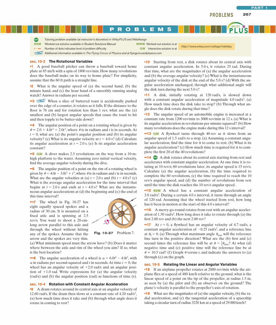
267PROB LE M SPART 1
sec. 10-2 The Rotational Variables•1 A good baseball pitcher can throw a baseball toward homeplate at 85 mi/h with a spin of 1800 rev/min. How many revolutionsdoes the baseball make on its way to home plate? For simplicity,assume that the 60 ft path is a straight line.
•2 What is the angular speed of (a) the second hand, (b) theminute hand, and (c) the hour hand of a smoothly running analogwatch? Answer in radians per second.
••3 When a slice of buttered toast is accidentally pushedover the edge of a counter, it rotates as it falls. If the distance to thefloor is 76 cm and for rotation less than 1 rev, what are the (a)smallest and (b) largest angular speeds that cause the toast to hitand then topple to be butter-side down?
••4 The angular position of a point on a rotating wheel is given byu � 2.0 � 4.0t 2 � 2.0t 3, where u is in radians and t is in seconds. At t � 0, what are (a) the point’s angular position and (b) its angularvelocity? (c) What is its angular velocity at t � 4.0 s? (d) Calculateits angular acceleration at t � 2.0 s. (e) Is its angular accelerationconstant?
••5 A diver makes 2.5 revolutions on the way from a 10-m-high platform to the water. Assuming zero initial vertical velocity,find the average angular velocity during the dive.
••6 The angular position of a point on the rim of a rotating wheel isgiven by u � 4.0t � 3.0t2 � t3, where u is in radians and t is in seconds.What are the angular velocities at (a) t � 2.0 s and (b) t � 4.0 s? (c)What is the average angular acceleration for the time interval thatbegins at t � 2.0 s and ends at t � 4.0 s? What are the instanta-neous angular accelerations at (d) the beginning and (e) the end ofthis time interval?
•••7 The wheel in Fig. 10-27 haseight equally spaced spokes and aradius of 30 cm. It is mounted on afixed axle and is spinning at 2.5rev/s. You want to shoot a 20-cm-long arrow parallel to this axle andthrough the wheel without hittingany of the spokes. Assume that thearrow and the spokes are very thin.(a) What minimum speed must the arrow have? (b) Does it matterwhere between the axle and rim of the wheel you aim? If so, whatis the best location?
•••8 The angular acceleration of a wheel is a � 6.0t4 � 4.0t2, witha in radians per second-squared and t in seconds.At time t � 0, thewheel has an angular velocity of �2.0 rad/s and an angular posi-tion of �1.0 rad. Write expressions for (a) the angular velocity(rad/s) and (b) the angular position (rad) as functions of time (s).
sec. 10-4 Rotation with Constant Angular Acceleration•9 A drum rotates around its central axis at an angular velocity of12.60 rad/s. If the drum then slows at a constant rate of 4.20 rad/s2,(a) how much time does it take and (b) through what angle does itrotate in coming to rest?
ILW
Fig. 10-27 Problem 7.
•10 Starting from rest, a disk rotates about its central axis withconstant angular acceleration. In 5.0 s, it rotates 25 rad. Duringthat time, what are the magnitudes of (a) the angular accelerationand (b) the average angular velocity? (c) What is the instantaneousangular velocity of the disk at the end of the 5.0 s? (d) With the an-gular acceleration unchanged, through what additional angle willthe disk turn during the next 5.0 s?
•11 A disk, initially rotating at 120 rad/s, is slowed down with a constant angular acceleration of magnitude 4.0 rad/s2. (a)How much time does the disk take to stop? (b) Through what an-gle does the disk rotate during that time?
•12 The angular speed of an automobile engine is increased at aconstant rate from 1200 rev/min to 3000 rev/min in 12 s. (a) What isits angular acceleration in revolutions per minute-squared? (b) Howmany revolutions does the engine make during this 12 s interval?
••13 A flywheel turns through 40 rev as it slows from anangular speed of 1.5 rad/s to a stop. (a) Assuming a constant angu-lar acceleration, find the time for it to come to rest. (b) What is itsangular acceleration? (c) How much time is required for it to com-plete the first 20 of the 40 revolutions?
••14 A disk rotates about its central axis starting from rest andaccelerates with constant angular acceleration. At one time it is ro-tating at 10 rev/s; 60 revolutions later, its angular speed is 15 rev/s.Calculate (a) the angular acceleration, (b) the time required tocomplete the 60 revolutions, (c) the time required to reach the 10rev/s angular speed, and (d) the number of revolutions from restuntil the time the disk reaches the 10 rev/s angular speed.
••15 A wheel has a constant angular acceleration of3.0 rad/s2. During a certain 4.0 s interval, it turns through an angleof 120 rad. Assuming that the wheel started from rest, how longhas it been in motion at the start of this 4.0 s interval?
••16 A merry-go-round rotates from rest with an angular acceler-ation of 1.50 rad/s2. How long does it take to rotate through (a) thefirst 2.00 rev and (b) the next 2.00 rev?
••17 At t � 0, a flywheel has an angular velocity of 4.7 rad/s, aconstant angular acceleration of �0.25 rad/s2, and a reference lineat u0 � 0. (a) Through what maximum angle umax will the referenceline turn in the positive direction? What are the (b) first and (c)second times the reference line will be at ? At what (d)negative time and (e) positive time will the reference line be at
10.5 rad? (f) Graph u versus t, and indicate the answers to (a)through (e) on the graph.
sec. 10-5 Relating the Linear and Angular Variables•18 If an airplane propeller rotates at 2000 rev/min while the air-plane flies at a speed of 480 km/h relative to the ground, what is thelinear speed of a point on the tip of the propeller, at radius 1.5 m,as seen by (a) the pilot and (b) an observer on the ground? Theplane’s velocity is parallel to the propeller’s axis of rotation.
•19 What are the magnitudes of (a) the angular velocity, (b) the ra-dial acceleration, and (c) the tangential acceleration of a spaceshiptaking a circular turn of radius 3220 km at a speed of 29 000 km/h?
� �
� � 12�max
SSM
ILW
Tutoring problem available (at instructor’s discretion) in WileyPLUS and WebAssign
SSM Worked-out solution available in Student Solutions Manual
• – ••• Number of dots indicates level of problem difficulty
Additional information available in The Flying Circus of Physics and at flyingcircusofphysics.com
WWW Worked-out solution is at
ILW Interactive solution is at http://www.wiley.com/college/halliday
halliday_c10_241-274hr.qxd 17-09-2009 12:50 Page 267
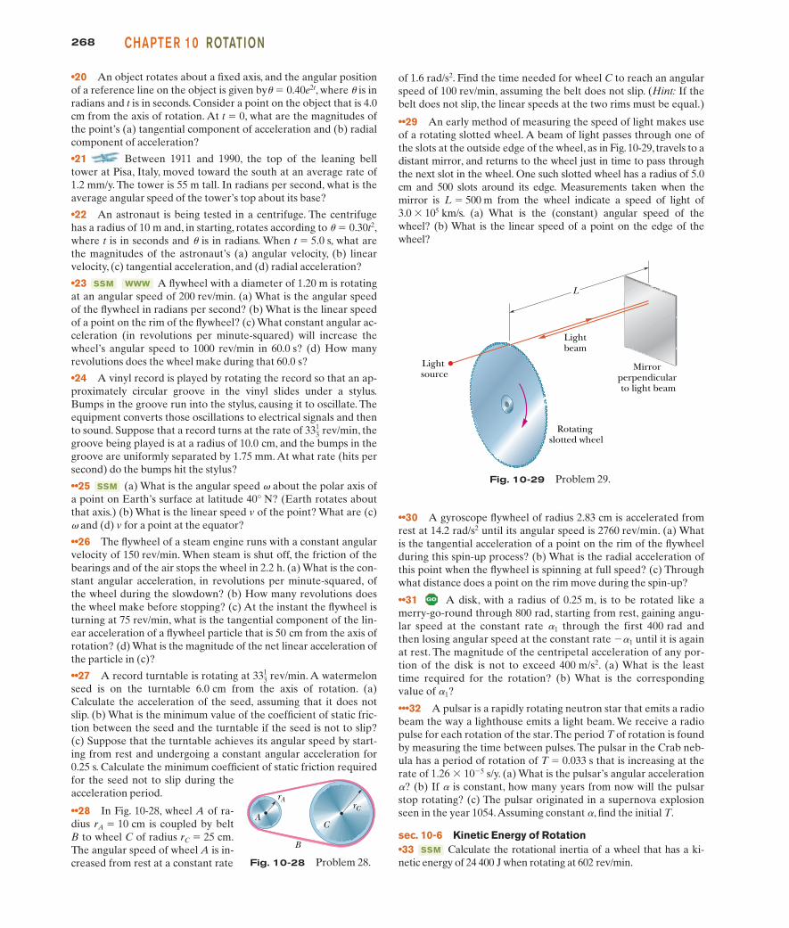
268 CHAPTE R 10 ROTATION
•20 An object rotates about a fixed axis, and the angular positionof a reference line on the object is given byu � 0.40e2t, where u is inradians and t is in seconds. Consider a point on the object that is 4.0cm from the axis of rotation. At t � 0, what are the magnitudes ofthe point’s (a) tangential component of acceleration and (b) radialcomponent of acceleration?
•21 Between 1911 and 1990, the top of the leaning belltower at Pisa, Italy, moved toward the south at an average rate of1.2 mm/y. The tower is 55 m tall. In radians per second, what is theaverage angular speed of the tower’s top about its base?
•22 An astronaut is being tested in a centrifuge. The centrifugehas a radius of 10 m and, in starting, rotates according to u � 0.30t2,where t is in seconds and u is in radians. When t � 5.0 s, what arethe magnitudes of the astronaut’s (a) angular velocity, (b) linearvelocity, (c) tangential acceleration, and (d) radial acceleration?
•23 A flywheel with a diameter of 1.20 m is rotatingat an angular speed of 200 rev/min. (a) What is the angular speedof the flywheel in radians per second? (b) What is the linear speedof a point on the rim of the flywheel? (c) What constant angular ac-celeration (in revolutions per minute-squared) will increase thewheel’s angular speed to 1000 rev/min in 60.0 s? (d) How manyrevolutions does the wheel make during that 60.0 s?
•24 A vinyl record is played by rotating the record so that an ap-proximately circular groove in the vinyl slides under a stylus.Bumps in the groove run into the stylus, causing it to oscillate. Theequipment converts those oscillations to electrical signals and thento sound. Suppose that a record turns at the rate of , thegroove being played is at a radius of 10.0 cm, and the bumps in thegroove are uniformly separated by 1.75 mm. At what rate (hits persecond) do the bumps hit the stylus?
••25 (a) What is the angular speed v about the polar axis ofa point on Earth’s surface at latitude 40° N? (Earth rotates aboutthat axis.) (b) What is the linear speed v of the point? What are (c)v and (d) v for a point at the equator?
••26 The flywheel of a steam engine runs with a constant angularvelocity of 150 rev/min. When steam is shut off, the friction of thebearings and of the air stops the wheel in 2.2 h. (a) What is the con-stant angular acceleration, in revolutions per minute-squared, ofthe wheel during the slowdown? (b) How many revolutions doesthe wheel make before stopping? (c) At the instant the flywheel isturning at 75 rev/min, what is the tangential component of the lin-ear acceleration of a flywheel particle that is 50 cm from the axis ofrotation? (d) What is the magnitude of the net linear acceleration ofthe particle in (c)?
••27 A record turntable is rotating at . A watermelonseed is on the turntable 6.0 cm from the axis of rotation. (a)Calculate the acceleration of the seed, assuming that it does notslip. (b) What is the minimum value of the coefficient of static fric-tion between the seed and the turntable if the seed is not to slip?(c) Suppose that the turntable achieves its angular speed by start-ing from rest and undergoing a constant angular acceleration for0.25 s. Calculate the minimum coefficient of static friction requiredfor the seed not to slip during theacceleration period.
••28 In Fig. 10-28, wheel A of ra-dius rA � 10 cm is coupled by beltB to wheel C of radius rC � 25 cm.The angular speed of wheel A is in-creased from rest at a constant rate
3313 rev/min
SSM
3313 rev/min
WWWSSM
of 1.6 rad/s2. Find the time needed for wheel C to reach an angularspeed of 100 rev/min, assuming the belt does not slip. (Hint: If thebelt does not slip, the linear speeds at the two rims must be equal.)
••29 An early method of measuring the speed of light makes useof a rotating slotted wheel. A beam of light passes through one ofthe slots at the outside edge of the wheel, as in Fig. 10-29, travels to adistant mirror, and returns to the wheel just in time to pass throughthe next slot in the wheel. One such slotted wheel has a radius of 5.0cm and 500 slots around its edge. Measurements taken when themirror is L � 500 m from the wheel indicate a speed of light of 3.0 � 105 km/s. (a) What is the (constant) angular speed of thewheel? (b) What is the linear speed of a point on the edge of thewheel?
Lightbeam
Light source
Rotating slotted wheel
Mirror perpendicular to light beam
L
Fig. 10-29 Problem 29.
Fig. 10-28 Problem 28.
B
C
rA
ArC
••30 A gyroscope flywheel of radius 2.83 cm is accelerated fromrest at 14.2 rad/s2 until its angular speed is 2760 rev/min. (a) Whatis the tangential acceleration of a point on the rim of the flywheelduring this spin-up process? (b) What is the radial acceleration ofthis point when the flywheel is spinning at full speed? (c) Throughwhat distance does a point on the rim move during the spin-up?
••31 A disk, with a radius of 0.25 m, is to be rotated like amerry-go-round through 800 rad, starting from rest, gaining angu-lar speed at the constant rate a1 through the first 400 rad andthen losing angular speed at the constant rate �a1 until it is againat rest. The magnitude of the centripetal acceleration of any por-tion of the disk is not to exceed 400 m/s2. (a) What is the leasttime required for the rotation? (b) What is the correspondingvalue of a1?
•••32 A pulsar is a rapidly rotating neutron star that emits a radiobeam the way a lighthouse emits a light beam. We receive a radiopulse for each rotation of the star.The period T of rotation is foundby measuring the time between pulses. The pulsar in the Crab neb-ula has a period of rotation of T � 0.033 s that is increasing at therate of 1.26 � 10�5 s/y. (a) What is the pulsar’s angular accelerationa? (b) If a is constant, how many years from now will the pulsarstop rotating? (c) The pulsar originated in a supernova explosionseen in the year 1054.Assuming constant a, find the initial T.
sec. 10-6 Kinetic Energy of Rotation•33 Calculate the rotational inertia of a wheel that has a ki-netic energy of 24 400 J when rotating at 602 rev/min.
SSM
halliday_c10_241-274hr.qxd 17-09-2009 12:50 Page 268
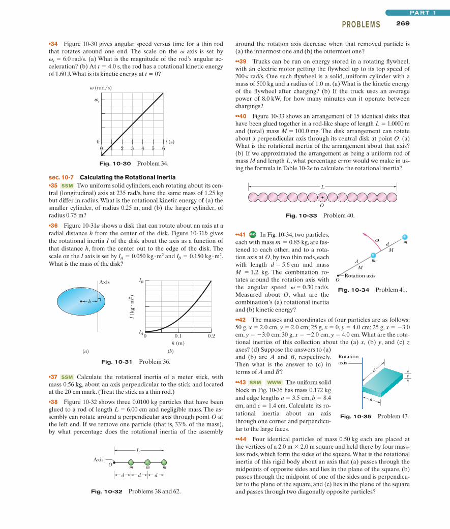
••41 In Fig. 10-34, two particles,each with mass m 0.85 kg, are fas-tened to each other, and to a rota-tion axis at O, by two thin rods, eachwith length d � 5.6 cm and massM � 1.2 kg. The combination ro-tates around the rotation axis withthe angular speed v � 0.30 rad/s.Measured about O, what are thecombination’s (a) rotational inertiaand (b) kinetic energy?
••42 The masses and coordinates of four particles are as follows:50 g, x � 2.0 cm, y � 2.0 cm; 25 g, x � 0, y � 4.0 cm; 25 g, x � �3.0cm, y � �3.0 cm; 30 g, x � �2.0 cm, y � 4.0 cm.What are the rota-tional inertias of this collection about the (a) x, (b) y, and (c) zaxes? (d) Suppose the answers to (a)and (b) are A and B, respectively.Then what is the answer to (c) interms of A and B?
••43 The uniform solidblock in Fig. 10-35 has mass 0.172 kgand edge lengths a � 3.5 cm, b � 8.4cm, and c � 1.4 cm. Calculate its ro-tational inertia about an axisthrough one corner and perpendicu-lar to the large faces.
••44 Four identical particles of mass 0.50 kg each are placed atthe vertices of a 2.0 m � 2.0 m square and held there by four mass-less rods, which form the sides of the square. What is the rotationalinertia of this rigid body about an axis that (a) passes through themidpoints of opposite sides and lies in the plane of the square, (b)passes through the midpoint of one of the sides and is perpendicu-lar to the plane of the square, and (c) lies in the plane of the squareand passes through two diagonally opposite particles?
WWWSSM
�
269PROB LE M SPART 1
•34 Figure 10-30 gives angular speed versus time for a thin rodthat rotates around one end. The scale on the v axis is set by
(a) What is the magnitude of the rod’s angular ac-celeration? (b) At t 4.0 s, the rod has a rotational kinetic energyof 1.60 J.What is its kinetic energy at t � 0?
�s � 6.0 rad/s.
around the rotation axis decrease when that removed particle is(a) the innermost one and (b) the outermost one?
••39 Trucks can be run on energy stored in a rotating flywheel,with an electric motor getting the flywheel up to its top speed of200p rad/s. One such flywheel is a solid, uniform cylinder with amass of 500 kg and a radius of 1.0 m. (a) What is the kinetic energyof the flywheel after charging? (b) If the truck uses an averagepower of 8.0 kW, for how many minutes can it operate betweenchargings?
••40 Figure 10-33 shows an arrangement of 15 identical disks thathave been glued together in a rod-like shape of length L � 1.0000 mand (total) mass M � 100.0 mg. The disk arrangement can rotateabout a perpendicular axis through its central disk at point O. (a)What is the rotational inertia of the arrangement about that axis?(b) If we approximated the arrangement as being a uniform rod ofmass M and length L, what percentage error would we make in us-ing the formula in Table 10-2e to calculate the rotational inertia?
00 1 2 3 4 5 6
t (s)
◊ (rad/s)
sω
Fig. 10-30 Problem 34.
I (k
g • m
2 )
IB
IA 0 0.1h (m)
0.2
(b)(a)
Axis
h
Fig. 10-31 Problem 36.
Fig. 10-33 Problem 40.
L
O
Rotation axis
md
md
M
M
O
ω
Fig. 10-34 Problem 41.
sec. 10-7 Calculating the Rotational Inertia•35 Two uniform solid cylinders, each rotating about its cen-tral (longitudinal) axis at 235 rad/s, have the same mass of 1.25 kgbut differ in radius. What is the rotational kinetic energy of (a) thesmaller cylinder, of radius 0.25 m, and (b) the larger cylinder, of radius 0.75 m?
•36 Figure 10-31a shows a disk that can rotate about an axis at aradial distance h from the center of the disk. Figure 10-31b givesthe rotational inertia I of the disk about the axis as a function ofthat distance h, from the center out to the edge of the disk. Thescale on the I axis is set by and What is the mass of the disk?
IB � 0.150 kg �m2.IA � 0.050 kg �m2
SSM
•37 Calculate the rotational inertia of a meter stick, withmass 0.56 kg, about an axis perpendicular to the stick and locatedat the 20 cm mark. (Treat the stick as a thin rod.)
•38 Figure 10-32 shows three 0.0100 kg particles that have beenglued to a rod of length L � 6.00 cm and negligible mass. The as-sembly can rotate around a perpendicular axis through point O atthe left end. If we remove one particle (that is, 33% of the mass),by what percentage does the rotational inertia of the assembly
SSM
Fig. 10-32 Problems 38 and 62.
Axis
L
mO
d d d
m m
b
a
c
Rotationaxis
Fig. 10-35 Problem 43.
halliday_c10_241-274hr.qxd 17-09-2009 12:50 Page 269
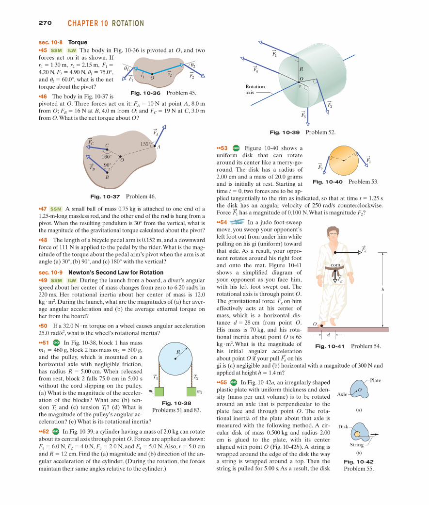
270 CHAPTE R 10 ROTATION
sec. 10-8 Torque•45 The body in Fig. 10-36 is pivoted at O, and twoforces act on it as shown. Ifr1 � 1.30 m, r2 � 2.15 m, F1 �
4.20 N, F2 � 4.90 N, u1 � 75.0°,and u2 � 60.0°, what is the nettorque about the pivot?
•46 The body in Fig. 10-37 ispivoted at O. Three forces act on it: FA � 10 N at point A, 8.0 mfrom O; FB � 16 N at B, 4.0 m from O; and FC � 19 N at C, 3.0 mfrom O.What is the net torque about O?
ILWSSM
••53 Figure 10-40 shows auniform disk that can rotatearound its center like a merry-go-round. The disk has a radius of2.00 cm and a mass of 20.0 gramsand is initially at rest. Starting attime t � 0, two forces are to be ap-plied tangentially to the rim as indicated, so that at time t � 1.25 sthe disk has an angular velocity of 250 rad/s counterclockwise.Force has a magnitude of 0.100 N.What is magnitude F2?
••54 In a judo foot-sweepmove, you sweep your opponent’sleft foot out from under him whilepulling on his gi (uniform) towardthat side. As a result, your oppo-nent rotates around his right footand onto the mat. Figure 10-41shows a simplified diagram ofyour opponent as you face him,with his left foot swept out. Therotational axis is through point O.The gravitational force on himeffectively acts at his center ofmass, which is a horizontal dis-tance d � 28 cm from point O.His mass is 70 kg, and his rota-tional inertia about point O is 65kg �m2.What is the magnitude ofhis initial angular accelerationabout point O if your pull on hisgi is (a) negligible and (b) horizontal with a magnitude of 300 N andapplied at height h � 1.4 m?
••55 In Fig. 10-42a, an irregularly shapedplastic plate with uniform thickness and den-sity (mass per unit volume) is to be rotatedaround an axle that is perpendicular to theplate face and through point O. The rota-tional inertia of the plate about that axle ismeasured with the following method. A cir-cular disk of mass 0.500 kg and radius 2.00cm is glued to the plate, with its centeraligned with point O (Fig. 10-42b). A string iswrapped around the edge of the disk the waya string is wrapped around a top. Then thestring is pulled for 5.00 s. As a result, the disk
F:
a
F:
g
F:
1
FC C
FB
B
160°
90°O
FA
A135°
Fig. 10-37 Problem 46.
F1
F4 R
rO
Rotationaxis
F2
F3
F2
F1
Fig. 10-40 Problem 53.
Fig. 10-41 Problem 54.
O
d
com
Fg
Fa
h
Fig. 10-36 Problem 45.
Or1
θ1
F1
r2
θ2
F2
•47 A small ball of mass 0.75 kg is attached to one end of a1.25-m-long massless rod, and the other end of the rod is hung from apivot. When the resulting pendulum is 30° from the vertical, what isthe magnitude of the gravitational torque calculated about the pivot?
•48 The length of a bicycle pedal arm is 0.152 m, and a downwardforce of 111 N is applied to the pedal by the rider.What is the mag-nitude of the torque about the pedal arm’s pivot when the arm is atangle (a) 30°, (b) 90°, and (c) 180° with the vertical?
sec. 10-9 Newton’s Second Law for Rotation•49 During the launch from a board, a diver’s angularspeed about her center of mass changes from zero to 6.20 rad/s in220 ms. Her rotational inertia about her center of mass is 12.0kg � m2. During the launch, what are the magnitudes of (a) her aver-age angular acceleration and (b) the average external torque onher from the board?
•50 If a 32.0 N � m torque on a wheel causes angular acceleration25.0 rad/s2, what is the wheel’s rotational inertia?
••51 In Fig. 10-38, block 1 has mass, block 2 has mass ,
and the pulley, which is mounted on ahorizontal axle with negligible friction,has radius . When releasedfrom rest, block 2 falls 75.0 cm in 5.00 swithout the cord slipping on the pulley.(a) What is the magnitude of the acceler-ation of the blocks? What are (b) ten-sion and (c) tension ? (d) What isthe magnitude of the pulley’s angular ac-celeration? (e) What is its rotational inertia?
••52 In Fig. 10-39, a cylinder having a mass of 2.0 kg can rotateabout its central axis through point O. Forces are applied as shown:F1 � 6.0 N, F2 � 4.0 N, F3 � 2.0 N, and F4 � 5.0 N. Also, r � 5.0 cmand R � 12 cm. Find the (a) magnitude and (b) direction of the an-gular acceleration of the cylinder. (During the rotation, the forcesmaintain their same angles relative to the cylinder.)
T1T2
R � 5.00 cm
m2 � 500 gm1 � 460 g
ILWSSM
SSM
m1
T1 T2
m2
R
Fig. 10-38Problems 51 and 83.
Fig. 10-39 Problem 52.
(b)
(a)
OAxle
Plate
Disk
String
Fig. 10-42Problem 55.
halliday_c10_241-274hr.qxd 17-09-2009 12:50 Page 270
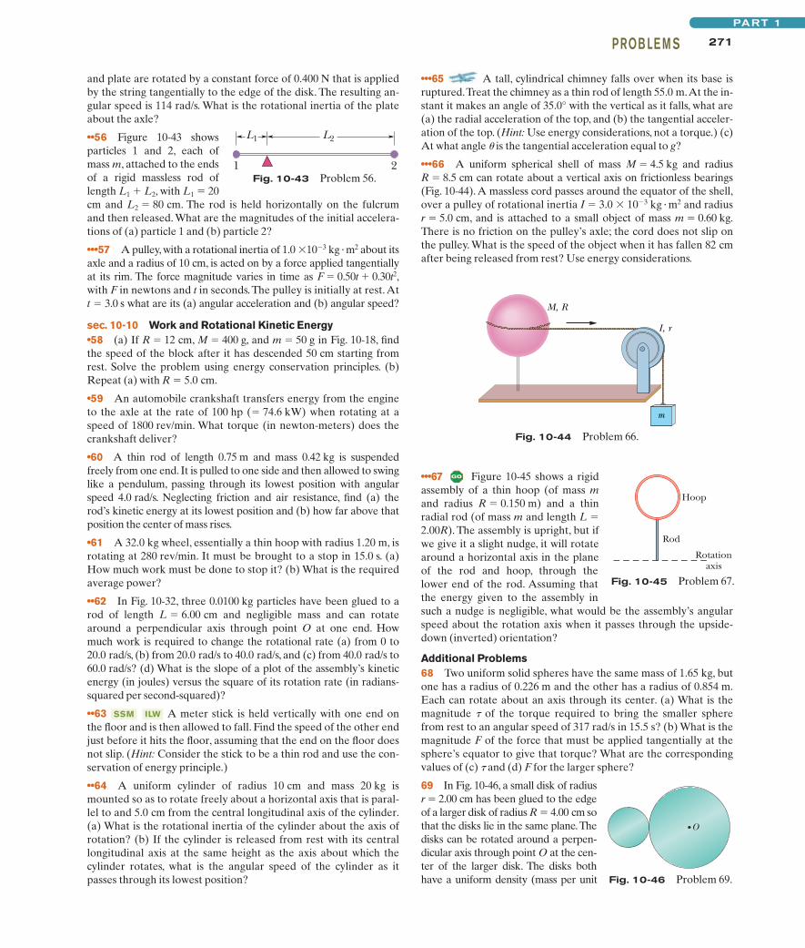
271PROB LE M SPART 1
and plate are rotated by a constant force of 0.400 N that is appliedby the string tangentially to the edge of the disk. The resulting an-gular speed is 114 rad/s. What is the rotational inertia of the plateabout the axle?
••56 Figure 10-43 showsparticles 1 and 2, each ofmass m, attached to the endsof a rigid massless rod oflength L1 � L2, with L1 � 20cm and L2 � 80 cm. The rod is held horizontally on the fulcrumand then released. What are the magnitudes of the initial accelera-tions of (a) particle 1 and (b) particle 2?
•••57 A pulley, with a rotational inertia of 1.0 �10�3 kg �m2 about itsaxle and a radius of 10 cm, is acted on by a force applied tangentiallyat its rim. The force magnitude varies in time as F � 0.50t � 0.30t2,with F in newtons and t in seconds.The pulley is initially at rest.Att � 3.0 s what are its (a) angular acceleration and (b) angular speed?
sec. 10-10 Work and Rotational Kinetic Energy•58 (a) If R � 12 cm, M � 400 g, and m � 50 g in Fig. 10-18, findthe speed of the block after it has descended 50 cm starting fromrest. Solve the problem using energy conservation principles. (b)Repeat (a) with R � 5.0 cm.
•59 An automobile crankshaft transfers energy from the engineto the axle at the rate of 100 hp (� 74.6 kW) when rotating at aspeed of 1800 rev/min. What torque (in newton-meters) does thecrankshaft deliver?
•60 A thin rod of length 0.75 m and mass 0.42 kg is suspendedfreely from one end. It is pulled to one side and then allowed to swinglike a pendulum, passing through its lowest position with angularspeed 4.0 rad/s. Neglecting friction and air resistance, find (a) therod’s kinetic energy at its lowest position and (b) how far above thatposition the center of mass rises.
•61 A 32.0 kg wheel, essentially a thin hoop with radius 1.20 m, isrotating at 280 rev/min. It must be brought to a stop in 15.0 s. (a)How much work must be done to stop it? (b) What is the requiredaverage power?
••62 In Fig. 10-32, three 0.0100 kg particles have been glued to arod of length L � 6.00 cm and negligible mass and can rotatearound a perpendicular axis through point O at one end. Howmuch work is required to change the rotational rate (a) from 0 to20.0 rad/s, (b) from 20.0 rad/s to 40.0 rad/s, and (c) from 40.0 rad/s to60.0 rad/s? (d) What is the slope of a plot of the assembly’s kineticenergy (in joules) versus the square of its rotation rate (in radians-squared per second-squared)?
••63 A meter stick is held vertically with one end onthe floor and is then allowed to fall. Find the speed of the other endjust before it hits the floor, assuming that the end on the floor doesnot slip. (Hint: Consider the stick to be a thin rod and use the con-servation of energy principle.)
••64 A uniform cylinder of radius 10 cm and mass 20 kg ismounted so as to rotate freely about a horizontal axis that is paral-lel to and 5.0 cm from the central longitudinal axis of the cylinder.(a) What is the rotational inertia of the cylinder about the axis ofrotation? (b) If the cylinder is released from rest with its centrallongitudinal axis at the same height as the axis about which thecylinder rotates, what is the angular speed of the cylinder as itpasses through its lowest position?
ILWSSM
•••65 A tall, cylindrical chimney falls over when its base isruptured.Treat the chimney as a thin rod of length 55.0 m.At the in-stant it makes an angle of 35.0° with the vertical as it falls, what are(a) the radial acceleration of the top, and (b) the tangential acceler-ation of the top. (Hint: Use energy considerations, not a torque.) (c)At what angle u is the tangential acceleration equal to g?
•••66 A uniform spherical shell of mass M � 4.5 kg and radius R � 8.5 cm can rotate about a vertical axis on frictionless bearings(Fig. 10-44). A massless cord passes around the equator of the shell,over a pulley of rotational inertia I � 3.0 � 10�3 kg � m2 and radiusr � 5.0 cm, and is attached to a small object of mass m � 0.60 kg.There is no friction on the pulley’s axle; the cord does not slip onthe pulley. What is the speed of the object when it has fallen 82 cmafter being released from rest? Use energy considerations.
1 2
L1 L2
Fig. 10-43 Problem 56.
M, R
I, r
m
•••67 Figure 10-45 shows a rigidassembly of a thin hoop (of mass mand radius R � 0.150 m) and a thinradial rod (of mass m and length L �2.00R). The assembly is upright, but ifwe give it a slight nudge, it will rotatearound a horizontal axis in the planeof the rod and hoop, through thelower end of the rod. Assuming thatthe energy given to the assembly insuch a nudge is negligible, what would be the assembly’s angularspeed about the rotation axis when it passes through the upside-down (inverted) orientation?
Additional Problems68 Two uniform solid spheres have the same mass of 1.65 kg, butone has a radius of 0.226 m and the other has a radius of 0.854 m.Each can rotate about an axis through its center. (a) What is themagnitude t of the torque required to bring the smaller spherefrom rest to an angular speed of 317 rad/s in 15.5 s? (b) What is themagnitude F of the force that must be applied tangentially at thesphere’s equator to give that torque? What are the correspondingvalues of (c) t and (d) F for the larger sphere?
69 In Fig. 10-46, a small disk of radiusr � 2.00 cm has been glued to the edgeof a larger disk of radius R � 4.00 cm sothat the disks lie in the same plane.Thedisks can be rotated around a perpen-dicular axis through point O at the cen-ter of the larger disk. The disks bothhave a uniform density (mass per unit
Fig. 10-44 Problem 66.
Fig. 10-45 Problem 67.
Rotationaxis
Hoop
Rod
O
Fig. 10-46 Problem 69.
halliday_c10_241-274hr.qxd 17-09-2009 12:50 Page 271
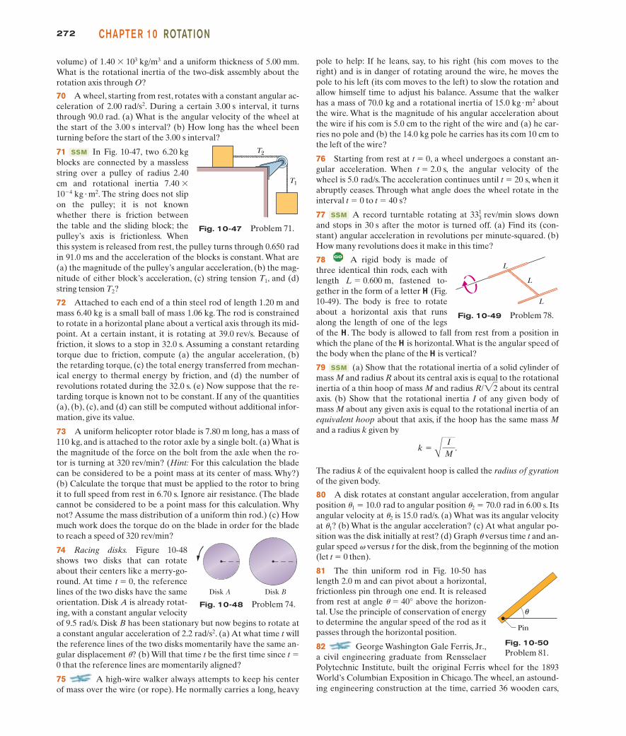
272 CHAPTE R 10 ROTATION
volume) of 1.40 � 103 kg/m3 and a uniform thickness of 5.00 mm.What is the rotational inertia of the two-disk assembly about therotation axis through O?
70 A wheel, starting from rest, rotates with a constant angular ac-celeration of 2.00 rad/s2. During a certain 3.00 s interval, it turnsthrough 90.0 rad. (a) What is the angular velocity of the wheel atthe start of the 3.00 s interval? (b) How long has the wheel beenturning before the start of the 3.00 s interval?
71 In Fig. 10-47, two 6.20 kgblocks are connected by a masslessstring over a pulley of radius 2.40cm and rotational inertia 7.40 �
10�4 kg � m2. The string does not slipon the pulley; it is not knownwhether there is friction betweenthe table and the sliding block; thepulley’s axis is frictionless. Whenthis system is released from rest, the pulley turns through 0.650 radin 91.0 ms and the acceleration of the blocks is constant. What are(a) the magnitude of the pulley’s angular acceleration, (b) the mag-nitude of either block’s acceleration, (c) string tension T1, and (d)string tension T2?
72 Attached to each end of a thin steel rod of length 1.20 m andmass 6.40 kg is a small ball of mass 1.06 kg. The rod is constrainedto rotate in a horizontal plane about a vertical axis through its mid-point. At a certain instant, it is rotating at 39.0 rev/s. Because offriction, it slows to a stop in 32.0 s. Assuming a constant retardingtorque due to friction, compute (a) the angular acceleration, (b)the retarding torque, (c) the total energy transferred from mechan-ical energy to thermal energy by friction, and (d) the number ofrevolutions rotated during the 32.0 s. (e) Now suppose that the re-tarding torque is known not to be constant. If any of the quantities(a), (b), (c), and (d) can still be computed without additional infor-mation, give its value.
73 A uniform helicopter rotor blade is 7.80 m long, has a mass of110 kg, and is attached to the rotor axle by a single bolt. (a) What isthe magnitude of the force on the bolt from the axle when the ro-tor is turning at 320 rev/min? (Hint: For this calculation the bladecan be considered to be a point mass at its center of mass. Why?)(b) Calculate the torque that must be applied to the rotor to bringit to full speed from rest in 6.70 s. Ignore air resistance. (The bladecannot be considered to be a point mass for this calculation. Whynot? Assume the mass distribution of a uniform thin rod.) (c) Howmuch work does the torque do on the blade in order for the bladeto reach a speed of 320 rev/min?
74 Racing disks. Figure 10-48shows two disks that can rotateabout their centers like a merry-go-round. At time t � 0, the referencelines of the two disks have the sameorientation. Disk A is already rotat-ing, with a constant angular velocityof 9.5 rad/s. Disk B has been stationary but now begins to rotate ata constant angular acceleration of 2.2 rad/s2. (a) At what time t willthe reference lines of the two disks momentarily have the same an-gular displacement u? (b) Will that time t be the first time since t �0 that the reference lines are momentarily aligned?
75 A high-wire walker always attempts to keep his centerof mass over the wire (or rope). He normally carries a long, heavy
SSM
pole to help: If he leans, say, to his right (his com moves to theright) and is in danger of rotating around the wire, he moves thepole to his left (its com moves to the left) to slow the rotation andallow himself time to adjust his balance. Assume that the walkerhas a mass of 70.0 kg and a rotational inertia of aboutthe wire. What is the magnitude of his angular acceleration aboutthe wire if his com is 5.0 cm to the right of the wire and (a) he car-ries no pole and (b) the 14.0 kg pole he carries has its com 10 cm tothe left of the wire?
76 Starting from rest at t � 0, a wheel undergoes a constant an-gular acceleration. When t � 2.0 s, the angular velocity of thewheel is 5.0 rad/s. The acceleration continues until t � 20 s, when itabruptly ceases. Through what angle does the wheel rotate in theinterval t � 0 to t � 40 s?
77 A record turntable rotating at slows downand stops in 30 s after the motor is turned off. (a) Find its (con-stant) angular acceleration in revolutions per minute-squared. (b)How many revolutions does it make in this time?
78 A rigid body is made ofthree identical thin rods, each withlength L � 0.600 m, fastened to-gether in the form of a letter H (Fig.10-49). The body is free to rotateabout a horizontal axis that runsalong the length of one of the legsof the H. The body is allowed to fall from rest from a position inwhich the plane of the H is horizontal.What is the angular speed ofthe body when the plane of the H is vertical?
79 (a) Show that the rotational inertia of a solid cylinder ofmass M and radius R about its central axis is equal to the rotationalinertia of a thin hoop of mass M and radius about its centralaxis. (b) Show that the rotational inertia I of any given body ofmass M about any given axis is equal to the rotational inertia of anequivalent hoop about that axis, if the hoop has the same mass Mand a radius k given by
The radius k of the equivalent hoop is called the radius of gyrationof the given body.
80 A disk rotates at constant angular acceleration, from angularposition u1 � 10.0 rad to angular position u2 � 70.0 rad in 6.00 s. Itsangular velocity at u2 is 15.0 rad/s. (a) What was its angular velocityat u1? (b) What is the angular acceleration? (c) At what angular po-sition was the disk initially at rest? (d) Graph u versus time t and an-gular speed v versus t for the disk, from the beginning of the motion(let t � 0 then).
81 The thin uniform rod in Fig. 10-50 haslength 2.0 m and can pivot about a horizontal,frictionless pin through one end. It is releasedfrom rest at angle u � 40° above the horizon-tal. Use the principle of conservation of energyto determine the angular speed of the rod as itpasses through the horizontal position.
82 George Washington Gale Ferris, Jr.,a civil engineering graduate from RensselaerPolytechnic Institute, built the original Ferris wheel for the 1893World’s Columbian Exposition in Chicago. The wheel, an astound-ing engineering construction at the time, carried 36 wooden cars,
k �A
IM
.
R/22
SSM
3313 rev/minSSM
15.0 kg �m2
T2
T1
Fig. 10-47 Problem 71.
Fig. 10-48 Problem 74.
Disk A Disk B
L
L
L
Fig. 10-49 Problem 78.
θ
Pin
Fig. 10-50Problem 81.
halliday_c10_241-274hr.qxd 17-09-2009 12:50 Page 272
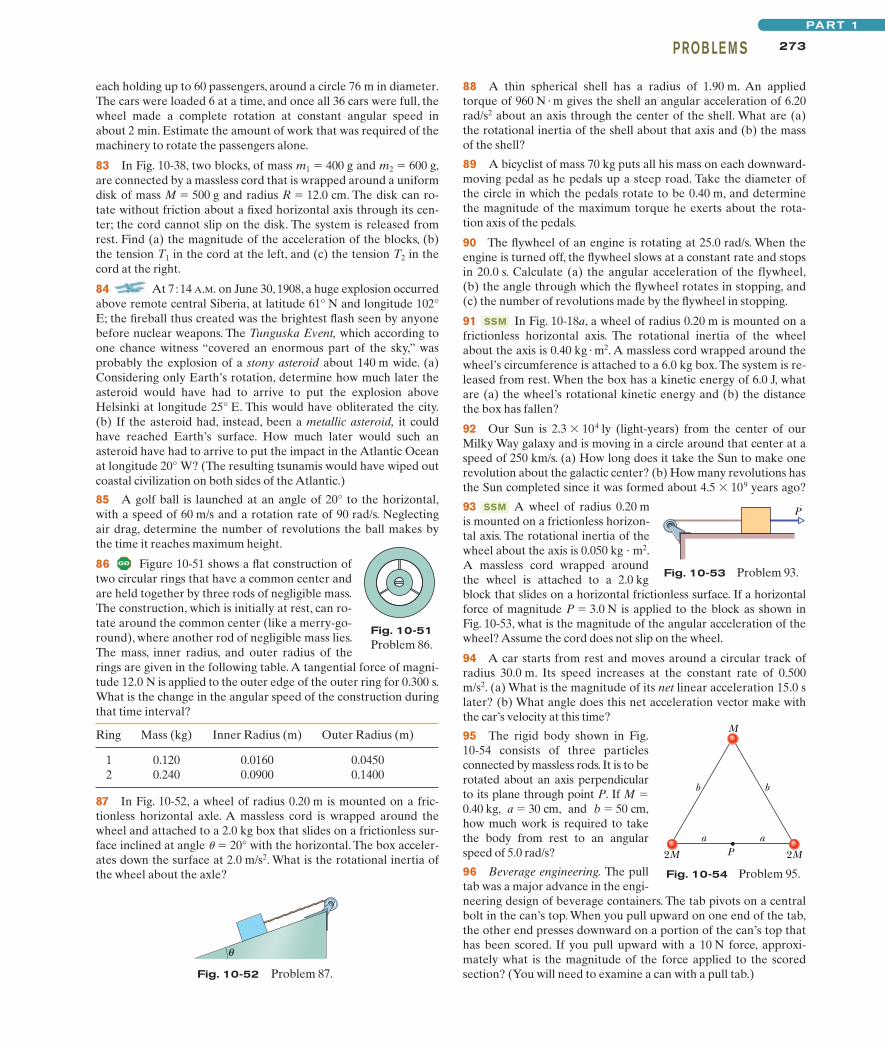
273PROB LE M SPART 1
each holding up to 60 passengers, around a circle 76 m in diameter.The cars were loaded 6 at a time, and once all 36 cars were full, thewheel made a complete rotation at constant angular speed inabout 2 min. Estimate the amount of work that was required of themachinery to rotate the passengers alone.
83 In Fig. 10-38, two blocks, of mass m1 � 400 g and m2 � 600 g,are connected by a massless cord that is wrapped around a uniformdisk of mass M � 500 g and radius R � 12.0 cm. The disk can ro-tate without friction about a fixed horizontal axis through its cen-ter; the cord cannot slip on the disk. The system is released fromrest. Find (a) the magnitude of the acceleration of the blocks, (b)the tension T1 in the cord at the left, and (c) the tension T2 in thecord at the right.
84 At 7�14 A.M. on June 30, 1908, a huge explosion occurredabove remote central Siberia, at latitude 61° N and longitude 102°E; the fireball thus created was the brightest flash seen by anyonebefore nuclear weapons. The Tunguska Event, which according toone chance witness “covered an enormous part of the sky,” wasprobably the explosion of a stony asteroid about 140 m wide. (a)Considering only Earth’s rotation, determine how much later theasteroid would have had to arrive to put the explosion aboveHelsinki at longitude 25° E. This would have obliterated the city.(b) If the asteroid had, instead, been a metallic asteroid, it couldhave reached Earth’s surface. How much later would such anasteroid have had to arrive to put the impact in the Atlantic Oceanat longitude 20° W? (The resulting tsunamis would have wiped outcoastal civilization on both sides of the Atlantic.)
85 A golf ball is launched at an angle of 20° to the horizontal,with a speed of 60 m/s and a rotation rate of 90 rad/s. Neglectingair drag, determine the number of revolutions the ball makes bythe time it reaches maximum height.
86 Figure 10-51 shows a flat construction oftwo circular rings that have a common center andare held together by three rods of negligible mass.The construction, which is initially at rest, can ro-tate around the common center (like a merry-go-round), where another rod of negligible mass lies.The mass, inner radius, and outer radius of therings are given in the following table. A tangential force of magni-tude 12.0 N is applied to the outer edge of the outer ring for 0.300 s.What is the change in the angular speed of the construction duringthat time interval?
Ring Mass (kg) Inner Radius (m) Outer Radius (m)
1 0.120 0.0160 0.04502 0.240 0.0900 0.1400
87 In Fig. 10-52, a wheel of radius 0.20 m is mounted on a fric-tionless horizontal axle. A massless cord is wrapped around thewheel and attached to a 2.0 kg box that slides on a frictionless sur-face inclined at angle u � 20° with the horizontal. The box acceler-ates down the surface at 2.0 m/s2. What is the rotational inertia ofthe wheel about the axle?
88 A thin spherical shell has a radius of 1.90 m. An appliedtorque of 960 N � m gives the shell an angular acceleration of 6.20rad/s2 about an axis through the center of the shell. What are (a)the rotational inertia of the shell about that axis and (b) the massof the shell?
89 A bicyclist of mass 70 kg puts all his mass on each downward-moving pedal as he pedals up a steep road. Take the diameter ofthe circle in which the pedals rotate to be 0.40 m, and determinethe magnitude of the maximum torque he exerts about the rota-tion axis of the pedals.
90 The flywheel of an engine is rotating at 25.0 rad/s. When theengine is turned off, the flywheel slows at a constant rate and stopsin 20.0 s. Calculate (a) the angular acceleration of the flywheel,(b) the angle through which the flywheel rotates in stopping, and(c) the number of revolutions made by the flywheel in stopping.
91 In Fig. 10-18a, a wheel of radius 0.20 m is mounted on africtionless horizontal axis. The rotational inertia of the wheelabout the axis is 0.40 kg � m2. A massless cord wrapped around thewheel’s circumference is attached to a 6.0 kg box. The system is re-leased from rest. When the box has a kinetic energy of 6.0 J, whatare (a) the wheel’s rotational kinetic energy and (b) the distancethe box has fallen?
92 Our Sun is 2.3 � 104 ly (light-years) from the center of ourMilky Way galaxy and is moving in a circle around that center at aspeed of 250 km/s. (a) How long does it take the Sun to make onerevolution about the galactic center? (b) How many revolutions hasthe Sun completed since it was formed about 4.5 � 109 years ago?
93 A wheel of radius 0.20 mis mounted on a frictionless horizon-tal axis. The rotational inertia of thewheel about the axis is 0.050 kg � m2.A massless cord wrapped aroundthe wheel is attached to a 2.0 kgblock that slides on a horizontal frictionless surface. If a horizontalforce of magnitude P � 3.0 N is applied to the block as shown inFig. 10-53, what is the magnitude of the angular acceleration of thewheel? Assume the cord does not slip on the wheel.
94 A car starts from rest and moves around a circular track ofradius 30.0 m. Its speed increases at the constant rate of 0.500m/s2. (a) What is the magnitude of its net linear acceleration 15.0 slater? (b) What angle does this net acceleration vector make withthe car’s velocity at this time?
95 The rigid body shown in Fig.10-54 consists of three particlesconnected by massless rods. It is to berotated about an axis perpendicularto its plane through point P. If M �0.40 kg, a � 30 cm, and b � 50 cm,how much work is required to takethe body from rest to an angularspeed of 5.0 rad/s?
96 Beverage engineering. The pulltab was a major advance in the engi-neering design of beverage containers. The tab pivots on a centralbolt in the can’s top. When you pull upward on one end of the tab,the other end presses downward on a portion of the can’s top thathas been scored. If you pull upward with a 10 N force, approxi-mately what is the magnitude of the force applied to the scoredsection? (You will need to examine a can with a pull tab.)
SSM
SSM
Fig. 10-53 Problem 93.
P
Fig. 10-51Problem 86.
Fig. 10-52 Problem 87.
θ
P
b b
M
2M 2M
a a
Fig. 10-54 Problem 95.
halliday_c10_241-274hr.qxd 17-09-2009 12:50 Page 273
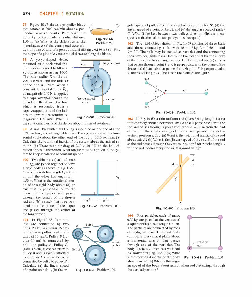
103 In Fig. 10-60, a thin uniform rod (mass 3.0 kg, length 4.0 m)rotates freely about a horizontal axis A that is perpendicular to therod and passes through a point at distance d � 1.0 m from the endof the rod. The kinetic energy of the rod as it passes through thevertical position is 20 J. (a) What is the rotational inertia of the rodabout axis A? (b) What is the (linear) speed of the end B of the rodas the rod passes through the vertical position? (c) At what angle uwill the rod momentarily stop in its upward swing?
274 CHAPTE R 10 ROTATION
97 Figure 10-55 shows a propeller bladethat rotates at 2000 rev/min about a per-pendicular axis at point B. Point A is at theouter tip of the blade, at radial distance1.50 m. (a) What is the difference in themagnitudes a of the centripetal accelera-tion of point A and of a point at radial distance 0.150 m? (b) Findthe slope of a plot of a versus radial distance along the blade.
98 A yo-yo-shaped devicemounted on a horizontal fric-tionless axis is used to lift a 30kg box as shown in Fig. 10-56.The outer radius R of the de-vice is 0.50 m, and the radius rof the hub is 0.20 m. When aconstant horizontal force of magnitude 140 N is appliedto a rope wrapped around theoutside of the device, the box,which is suspended from arope wrapped around the hub,has an upward acceleration ofmagnitude 0.80 m/s2. What isthe rotational inertia of the device about its axis of rotation?
99 A small ball with mass 1.30 kg is mounted on one end of a rod0.780 m long and of negligible mass. The system rotates in a hori-zontal circle about the other end of the rod at 5010 rev/min. (a)Calculate the rotational inertia of the system about the axis of ro-tation. (b) There is an air drag of 2.30 � 10�2 N on the ball, di-rected opposite its motion.What torque must be applied to the sys-tem to keep it rotating at constant speed?
100 Two thin rods (each of mass0.20 kg) are joined together to forma rigid body as shown in Fig. 10-57.One of the rods has length L1 � 0.40m, and the other has length L2 �0.50 m. What is the rotational iner-tia of this rigid body about (a) anaxis that is perpendicular to theplane of the paper and passesthrough the center of the shorterrod and (b) an axis that is perpen-dicular to the plane of the paperand passes through the center ofthe longer rod?
101 In Fig. 10-58, four pul-leys are connected by twobelts. Pulley A (radius 15 cm)is the drive pulley, and it ro-tates at 10 rad/s. Pulley B (ra-dius 10 cm) is connected bybelt 1 to pulley A. Pulley B(radius 5 cm) is concentric withpulley B and is rigidly attachedto it. Pulley C (radius 25 cm) isconnected by belt 2 to pulley B.Calculate (a) the linear speedof a point on belt 1, (b) the an-
F:
app
gular speed of pulley B, (c) the angular speed of pulley B, (d) thelinear speed of a point on belt 2, and (e) the angular speed of pulleyC. (Hint: If the belt between two pulleys does not slip, the linearspeeds at the rims of the two pulleys must be equal.)
102 The rigid object shown in Fig. 10-59 consists of three ballsand three connecting rods, with and
. The balls may be treated as particles, and the connectingrods have negligible mass. Determine the rotational kinetic energyof the object if it has an angular speed of 1.2 rad/s about (a) an axisthat passes through point P and is perpendicular to the plane of thefigure and (b) an axis that passes through point P, is perpendicularto the rod of length 2L, and lies in the plane of the figure.
� � 30�M � 1.6 kg, L � 0.60 m,
R
r
RopeYo-yo shapeddevice
Rigid mount
Hub
Fapp
Fig. 10-56 Problem 98.
A
B Belt 1
Drivepulley
Belt 2
B'
C
Fig. 10-58 Problem 101.
Fig. 10-57 Problem 100.
BA
Fig. 10-55Problem 97.
Fig. 10-60 Problem 103.
θ
A
B
d
L1
L2
1__2 L1
1__2
θθ
2M
2M
M2L
L
L
P
Fig. 10-59 Problem 102.
104 Four particles, each of mass,0.20 kg, are placed at the vertices ofa square with sides of length 0.50 m.The particles are connected by rodsof negligible mass. This rigid bodycan rotate in a vertical plane abouta horizontal axis A that passesthrough one of the particles. Thebody is released from rest with rodAB horizontal (Fig. 10-61). (a) Whatis the rotational inertia of the bodyabout axis A? (b) What is the angu-lar speed of the body about axis A when rod AB swings throughthe vertical position?
Fig. 10-61 Problem 104.
A B
Rotationaxis
halliday_c10_241-274hr.qxd 17-09-2009 12:50 Page 274


