Embed Size (px)
Citation preview
Argonne National Laboratory
Argonne, IL 60439
ANL/CGC-007-0401
The Model Coupling Toolkit
by
J. Walter Larson,1 Robert L. Jacob,1 Ian Foster,1 and Jing Guo2
Mathematics and Computer Science Division
Climate and Global Change Series
No. ANL/CGC-007-0401
April 2001
1Argonne National Laboratory, Mathematics and Computer Science Division, 9700 S. Cass Ave., Argonne, IL
60439, USA
2Data Assimilation O�ce, NASA Goddard Space Flight Center, Greenbelt, MD 20771, USA
This work is part of the Accelerated Climate Prediction Avant Garde project and is supported by the
Department of Energy, O�ce of Biological and Environmental Research, under Field Work Proposal
66204, KP1201020, under Contract W-31-109-Eng-38.
c Springer-Verlag
Contents
Abstract 1
1 Introduction 1
2 The Community Climate System Model Next-Generation Coupler 2
3 The Model Coupling Toolkit 4
3.1 Description and Underlying Assumptions . . . . . . . . . . . . . . . . . . . . . . . . 5
3.2 Toolkit Components . . . . . . . . . . . . . . . . . . . . . . . . . . . . . . . . . . . . 5
4 Usage 7
5 Performance 7
6 Conclusions and Future Work 10
Acknowledgments 10
References 10
iii
The Model Coupling Toolkit
J. Walter Larson, Robert L. Jacob, Ian Foster, and Jing Guo
Abstract
The advent of coupled earth system models has raised an important question in parallel
computing: What is the most e�ective method for coupling many parallel models to form a
high-performance coupled modeling system? We present our solution to this problem|The
Model Coupling Toolkit (MCT). We explain how our e�ort to construct the Next-Generation
Coupler for NCAR Community Climate System Model motivated us to create this toolkit.
We describe in detail the conceptual design of the MCT and explain its usage in constructing
parallel coupled models. We present preliminary performance results for the toolkit's parallel
data transfer facilities. Finally, we outline an agenda for future development of the MCT.
1 Introduction
In recent years, climate modeling has evolved from the use of atmospheric general circulation models
(GCMs) to coupled earth system models. These coupled models comprise an atmospheric GCM, an
ocean GCM, a dynamic-thermodynamic sea ice model, a land-surface model, and a ux coupler
that coordinates data transfer between the other component models and governs the overall execu-
tion of the coupled model (Figure 1). Coupled models present a considerable increase in terms of
computational and software complexity over their atmospheric model counterparts.
The ux coupler typically serves the following functions: overall command and control of the
coupled model, including syncronization, error/exception handling, and intitialization and shutdown
of the system; communication of data between component models; time averaging and accumulation
of data from one component for use in subsequent transmission of data to other components; com-
putation of interfacial uxes for a component given state data from other components; interpolation
of ux and state data between the various component model grids; and merging of ux and state
data from multiple components for delivery to yet another component.
The computational demands of each of the component models are su�cient to require message-
passing parallelism (and in some cases hybrid parallelism) in each component model to achieve high
performance on microprocessor-based distributed-memory computers. This creates a formidable
challenge in coupling these models. The challenge manifests itself in a potentially high degree
of computational and software complexity in the ux coupler. The coupler must be aware of all
the component models, the grids on which they present and require data, and their repsective data
1
decompositions. The coupler must be able to handle all of this information and serve the information
required by the component models in a timely fashion, lest it cause the coupled system to hang.
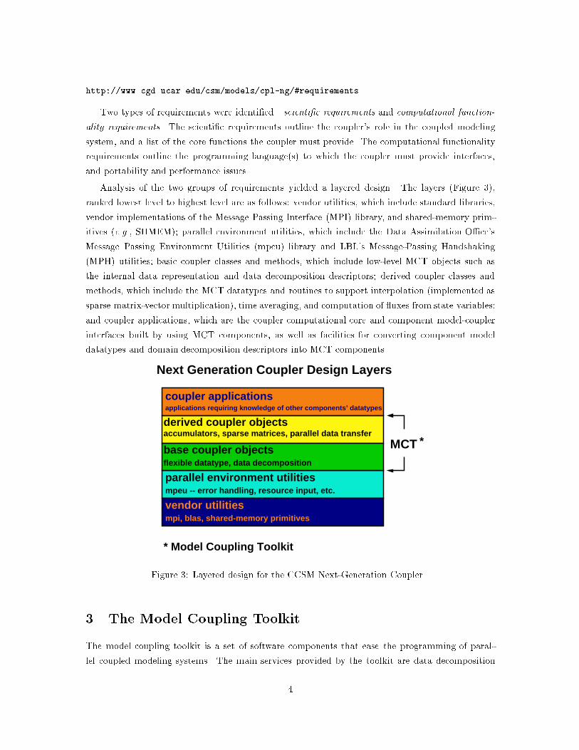
Various coupled model and coupler architectures have been created in the attempt to meet these
challenges. A general diagram for coupled model architecture is given in Figure 2, which shows
the main parts of a coupled model with four component models as a wheel: the synchronization
and command/control apparatus (the rim of the wheel); the coupler computatonal core (the hub
and spokes of the wheel); the component models (e.g., atmosphere, ocean, sea ice, and land); the
component model-coupler interfaces.
There are �ve main architectural approaches for coupled models:
1. A single-executable event loop coupled model, in which a single pool of processers is used
for the coupled model, with each of the component models and the coupler running in turn.
Execution of the model under this architecture can be viewed as a sweep second-hand revolving
around the wheel diagram in Figure 2. An example of this architecture is the Parallel Climate
Model (PCM).
2. A single-executable asynchronous coupled model, with each of the component models and
coupler running simultaneously and exchanging data as needed.
3. A multiple-executable asynchronous coupled model, with each of the component models and
coupler running simultaneously and exchanging data as needed. An example of this architec-
ture is the current version of the NCAR Community Climate System Model (CCSM).
4. A single-executable asynchronous model in which the functions of the ux coupler are dis-
tributed among the various component models. In terms of Figure 2, the ux coupler (the
hub and the spokes of the wheel) disappear. An example of this coupling strategy is the Fast
Ocean-Atmosphere Model (FOAM).
5. A multiple-executable asynchronous model in which the functions of the ux coupler are dis-
tributed among the various component models.
We took as our primary coupler design requirement the ability to support each of these �ve
coupled model architectures.
2 The Community Climate System Model Next-Generation
Coupler
The problem that motivated the creation of the model coupling toolkit was the Accelerated Cli-
mate Prediction Initiative (ACPI) Avant Garde project, whose goal is the creation of a modular,
performance-portable CCSM. One major task in this project is the design and implementation of a
modular, extensible, high-performance Next-Generation Coupler (NGC) for the CCSM.
A full statement of the requirements for the NGC is given at the Web site
2
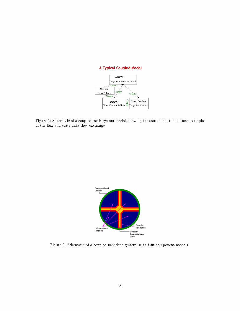
Figure 1: Schematic of a coupled earth system model, showing the component models and examplesof the ux and state data they exchange.
Command andControl
ComponentModels Coupler
ComputationalCore
CouplerInterfaces
Figure 2: Schematic of a coupled modeling system, with four component models.
3
http://www.cgd.ucar.edu/csm/models/cpl-ng/#requirements
Two types of requirements were identi�ed|scienti�c requirements and computational function-
ality requirements. The scienti�c requirements outline the coupler's role in the coupled modeling
system, and a list of the core functions the coupler must provide. The computational functionality
requirements outline the programming language(s) to which the coupler must provide interfaces,
and portability and performance issues.
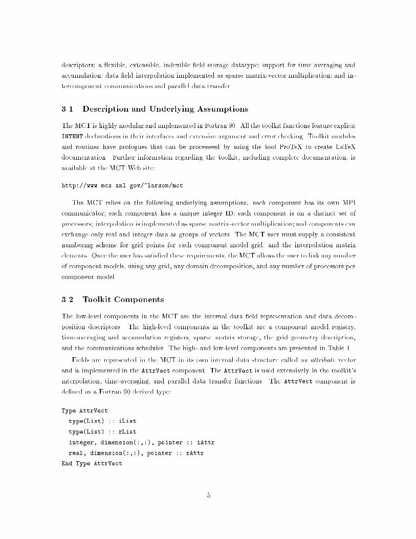
Analysis of the two groups of requirements yielded a layered design. The layers (Figure 3),
ranked lowest level to highest level are as follows: vendor utilities, which include standard libraries,
vendor implementations of the Message Passing Interface (MPI) library, and shared-memory prim-
itives (e.g., SHMEM); parallel environment utilities, which include the Data Assimilation O�ce's
Message Passing Environment Utilities (mpeu) library and LBL's Message-Passing Handshaking
(MPH) utilities; basic coupler classes and methods, which include low-level MCT objects such as
the internal data representation and data decomposition descriptors; derived coupler classes and
methods, which include the MCT datatypes and routines to support interpolation (implemented as
sparse matrix-vector multiplication), time averaging, and computation of uxes from state variables;
and coupler applications, which are the coupler computational core and component model-coupler
interfaces built by using MCT components, as well as facilities for converting component model
datatypes and domain decomposition descriptors into MCT components.
mpi, blas, shared-memory primitivesvendor utilitiesmpeu -- error handling, resource input, etc.parallel environment utilities
base coupler objects
derived coupler objects
flexible datatype, data decomposition
accumulators, sparse matrices, parallel data transfer
applications requiring knowledge of other components’ datatypes
coupler applications
MCT
* Model Coupling Toolkit
*
Next Generation Coupler Design Layers
Figure 3: Layered design for the CCSM Next-Generation Coupler.
3 The Model Coupling Toolkit
The model coupling toolkit is a set of software components that ease the programming of paral-
lel coupled modeling systems. The main services provided by the toolkit are data decomposition
4
descriptors; a exible, extensible, indexible �eld storage datatype; support for time averaging and
accumulation; data �eld interpolation implemented as sparse matrix-vector multiplication; and in-
tercomponent communications and parallel data transfer.
3.1 Description and Underlying Assumptions
The MCT is highly modular and implemented in Fortran 90. All the toolkit functions feature explicit
INTENT declarations in their interfaces and extensive argument and error checking. Toolkit modules
and routines have prologues that can be processeed by using the tool ProTeX to create LaTeX
documentation. Further information regarding the toolkit, including complete documentation, is
available at the MCT Web site:
http://www.mcs.anl.gov/~larson/mct
The MCT relies on the following underlying assumptions: each component has its own MPI
communicator; each component has a unique integer ID; each component is on a distinct set of
processors; interpolation is implemented as sparse matrix-vector multiplication; and components can
exchange only real and integer data as groups of vectors. The MCT user must supply a consistent
numbering scheme for grid points for each component model grid, and the interpolation matrix
elements. Once the user has satis�ed these requirements, the MCT allows the user to link any number
of component models, using any grid, any domain decomposition, and any number of processors per
component model.
3.2 Toolkit Components
The low-level components in the MCT are the internal data �eld representation and data decom-
position descriptors. The high-level components in the toolkit are a component model registry,
time-averaging and accumulation registers, sparse matrix storage, the grid geometry description,
and the communications scheduler. The high- and low-level components are presented in Table 1.
Fields are represented in the MCT in its own internal data structure called an attribute vector
and is implemented in the AttrVect component. The AttrVect is used extensively in the toolkit's
interpolation, time-averaging, and parallel data transfer functions. The AttrVect component is
de�ned as a Fortran 90 derived type:
Type AttrVect
type(List) :: iList
type(List) :: rList
integer, dimension(:,:), pointer :: iAttr
real, dimension(:,:), pointer :: rAttr
End Type AttrVect
5
The List components iList and rList list the integer and real attributes (�elds) of the AttrVect,
respectively. A List is a string, with substrings delimited by colons. Suppose we wish to store the
real �elds for surface zonal and meridonal winds and temperature in an AttrVect component. We
�rst de�ne string tags for each �eld: us for surface zonal wind; vs for surface meridional wind; ts
for surface temperature. For this example, the rList component would be rList = 'us:vs:ts'.
These �elds can be accessed by using an AttrVect inquiry, and by supplying the string tag to
reference the desired �eld.
The AttrVect is a fundamental data type in the toolkit. In addition to its use for �eld storage, it
is used for time averaging and accumulation registers in the Accumulator component, sparse matrix
element storage in the SparseMatrix component, and grid point coordinate and area/volume weight
storage in the GeneralGrid component.
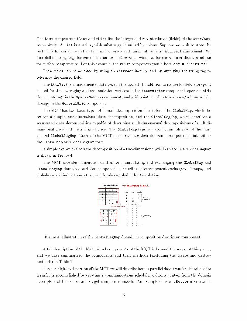
The MCT has two basic types of domain decomposition descriptors: the GlobalMap, which de-
scribes a simple, one-dimensional data decomposition, and the GlobalSegMap, which describes a
segmented data decomposition capable of describing multidimensional decompositions of multidi-
mensional grids and unstructured grids. The GlobalMap type is a special, simple case of the more
general GlobalSegMap. Users of the MCT must translate their domain decompositions into either
the GlobalMap or GlobalSegMap form.
A simple example of how the decomposition of a two-dimensional grid is stored in a GlobalSegMap
is shown in Figure 4.
The MCT provides numerous facilities for manipulating and exchanging the GlobalMap and
GlobalSegMap domain descriptor components, including intercomponent exchanges of maps, and
global-to-local index translation, and local-to-global index translation.
Figure 4: Illustration of the GlobalSegMap domain decomposition descriptor component.
A full description of the higher-level components of the MCT is beyond the scope of this paper,
and we have summarized the components and their methods (excluding the create and destroy
methods) in Table 1.
The one high-level portion of the MCT we will describe here is parallel data transfer. Parallel data
transfer is accomplished by creating a communications scheduler called a Router from the domain
descriptors of the source and target component models. An example of how a Router is created is
6
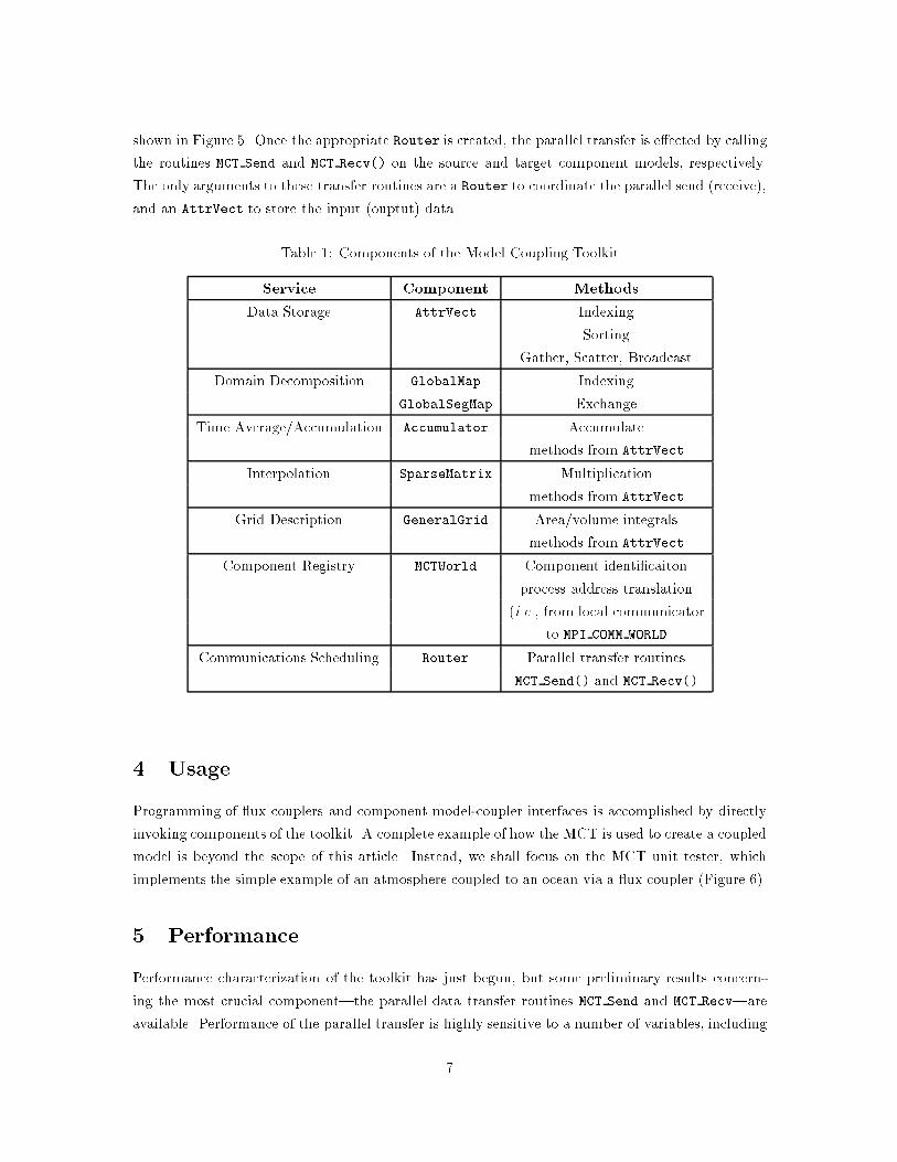
shown in Figure 5. Once the appropriate Router is created, the parallel transfer is e�ected by calling
the routines MCT Send and MCT Recv() on the source and target component models, respectively.
The only arguments to these transfer routines are a Router to coordinate the parallel send (receive),
and an AttrVect to store the input (ouptut) data.
Table 1: Components of the Model Coupling Toolkit
Service Component Methods
Data Storage AttrVect Indexing
Sorting
Gather, Scatter, Broadcast
Domain Decomposition GlobalMap Indexing
GlobalSegMap Exchange
Time Average/Accumulation Accumulator Accumulate
methods from AttrVect
Interpolation SparseMatrix Multiplication
methods from AttrVect
Grid Description GeneralGrid Area/volume integrals
methods from AttrVect
Component Registry MCTWorld Component identi�caiton
process address translation
(i.e., from local communicator
to MPI COMM WORLD
Communications Scheduling Router Parallel transfer routines
MCT Send() and MCT Recv()
4 Usage
Programming of ux couplers and component model-coupler interfaces is accomplished by directly
invoking components of the toolkit. A complete example of how the MCT is used to create a coupled
model is beyond the scope of this article. Instead, we shall focus on the MCT unit tester, which
implements the simple example of an atmosphere coupled to an ocean via a ux coupler (Figure 6).
5 Performance
Performance characterization of the toolkit has just begun, but some preliminary results concern-
ing the most crucial component|the parallel data transfer routines MCT Send and MCT Recv|are
available. Performance of the parallel transfer is highly sensitive to a number of variables, including
7
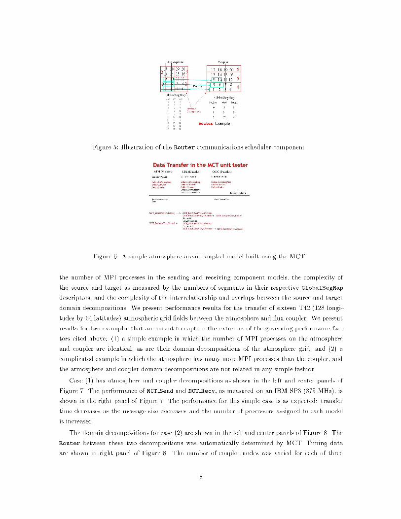
Figure 5: Illustration of the Router communications scheduler component.
Figure 6: A simple atmosphere-ocean coupled model built using the MCT.
the number of MPI processes in the sending and receiving component models, the complexity of
the source and target as measured by the numbers of segments in their respective GlobalSegMap
descriptors, and the complexity of the interrelationship and overlaps between the source and target
domain decompositions. We present performance results for the transfer of sixteen T42 (128 longi-
tudes by 64 latitudes) atmospheric grid �elds between the atmosphere and ux coupler. We present
results for two examples that are meant to capture the extremes of the governing performance fac-
tors cited above: (1) a simple example in which the number of MPI processes on the atmosphere
and coupler are identical, as are their domain decompositions of the atmosphere grid; and (2) a
complicated example in which the atmosphere has many more MPI processes than the coupler, and
the atmosphere and coupler domain decompositions are not related in any simple fashion.
Case (1) has atmosphere and coupler decompositions as shown in the left and center panels of
Figure 7. The performance of MCT Send and MCT Recv, as measured on an IBM SP3 (375 MHz), is
shown in the right panel of Figure 7. The performance for this simple case is as expected: transfer
time decreases as the message size decreases and the number of processors assigned to each model
is increased.
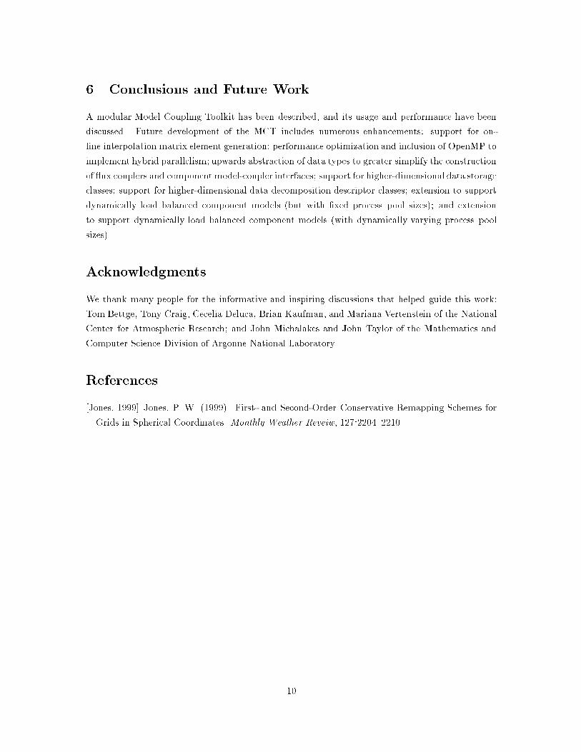
The domain decompositions for case (2) are shown in the left and center panels of Figure 8. The
Router between these two decompositions was automatically determined by MCT. Timing data
are shown in right panel of Figure 8. The number of coupler nodes was varied for each of three
8
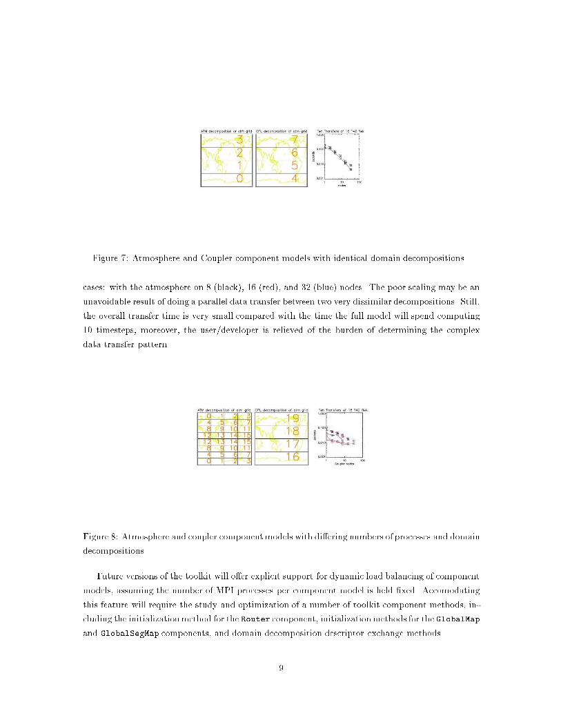
Figure 7: Atmosphere and Coupler component models with identical domain decompositions.
cases: with the atmosphere on 8 (black), 16 (red), and 32 (blue) nodes. The poor scaling may be an
unavoidable result of doing a parallel data transfer between two very dissimilar decompositions. Still,
the overall transfer time is very small compared with the time the full model will spend computing
10 timesteps; moreover, the user/developer is relieved of the burden of determining the complex
data transfer pattern.
Figure 8: Atmosphere and coupler componentmodels with di�ering numbers of processes and domain
decompositions.
Future versions of the toolkit will o�er explicit support for dynamic load balancing of component
models, assuming the number of MPI processes per component model is held �xed. Accomodating
this feature will require the study and optimization of a number of toolkit component methods, in-
cluding the initializationmethod for the Router component, initializationmethods for the GlobalMap
and GlobalSegMap components, and domain decomposition descriptor exchange methods.
9
6 Conclusions and Future Work
A modular Model Coupling Toolkit has been described, and its usage and performance have been
discussed. Future development of the MCT includes numerous enhancements: support for on-
line interpolation matrix element generation; performance optimization and inclusion of OpenMP to
implement hybrid parallelism; upwards abstraction of data types to greater simplify the construction
of ux couplers and component model-coupler interfaces; support for higher-dimensional data storage
classes; support for higher-dimensional data decomposition descriptor classes; extension to support
dynamically load balanced component models (but with �xed process pool sizes); and extension
to support dynamically load balanced component models (with dynamically varying process pool
sizes).
Acknowledgments
We thank many people for the informative and inspiring discussions that helped guide this work:
Tom Bettge, Tony Craig, Cecelia Deluca, Brian Kaufman, and Mariana Vertenstein of the National
Center for Atmospheric Research; and John Michalakes and John Taylor of the Mathematics and
Computer Science Division of Argonne National Laboratory.
References
[Jones, 1999] Jones, P. W. (1999). First- and Second-Order Conservative Remapping Schemes for
Grids in Spherical Coordinates. Monthly Weather Reveiw, 127:2204{2210.
10