Embed Size (px)
Citation preview
DEPP functionally graded piezoceramics via micro-fabricationby co-extrusion
Paul W. Alexander Æ Diann Brei Æ John W. Halloran
Received: 15 August 2005 / Accepted: 15 June 2006 / Published online: 26 May 2007
� Springer Science+Business Media, LLC 2007
Abstract This paper introduces the Dual Electro/Piezo
Property (DEPP) gradient technique via Micro-Fabrication
through Co-eXtrusion (MFCX) which pairs a high dis-
placement lead zirconate titanate (PZT) piezoceramic with
a high permittivity barium titanate (BT) dielectric. By
grading with this material combination spatially across an
actuator, the electric field is concentrated in the more active
region for improved efficiency, higher displacements, and
complex motions. To aid in synthesis and analysis of any
gradient profile, compositional maps are provided for key
material properties (density, stiffness, permittivity, and
piezoelectric coefficients). The DEPP technique was vali-
dated, independent of the MFCX process, by powder
pressing a conventional bimodal gradient beam which
demonstrated through experiments high displacement
capabilities at lower driving potentials than comparable
functionally graded piezoceramic actuators. For more
complex gradients, the MFCX process was adapted to the
DEPP gradient technique and illustrated by the fabrication
of a linearly graded prototype whose monolithic nature and
gradual material variation significantly reduces internal
stresses, improves reliability, and extends service lifetime.
Introduction
Functionally graded materials have been widely utilized in
passive materials to eliminate thermal stresses and fracture
[1–4], enhance fracture toughness [5], as well as to im-
prove wear resistance [6, 7]. Only recently has this concept
been extended to active materials such as piezoceramics to
increase reliability and generate higher-order motions in
actuators [8, 9]. By grading the material properties across
the piezoceramic structure to create a Functionally Graded
Piezoceramic (FGP), complex motions such as bending,
twisting or warping can be realized as opposed to the
strictly axial strains exhibited by homogeneous piezoce-
ramics. These higher-order motions are created by stress/
strain gradients within the structure, with more severe
gradients leading to increased motion. Unfortunately,
drastic gradients also result in higher stress levels and
discontinuities that significantly increase the failure rates of
these devices. Conventional layered bonding fabrication
processes tend to further exacerbate the problem with peak
stresses and discontinuities located at material interfaces,
typically resulting in delamination. All these problems
limit the lifetime of piezoceramic actuators to 105–106
cycles [10, 11], which is not acceptable for many industrial
applications. FGP are monolithic ceramics that automati-
cally overcome delamination problems because they
eliminate the bonding layers; however, to achieve the
material property variations necessary for higher-order
motions, sophisticated grading techniques and fabrication
processes are required. This paper outlines a synergistic
gradient technique coupled with an advanced fabrication
process that results in extended-life, high-performance
FGP actuators suitable for industrial use.
Key to the success of FGP is the gradient technique. One
of the earliest FGP was the RAINBOW (Reduced And
P. W. Alexander � D. Brei (&)
Mechanical Engineering Department, University of Michigan,
G.G. Brown Bldg., 2350 Hayward St., Ann Arbor,
MI 48109-2125, USA
e-mail: [email protected]
J. W. Halloran
Materials Science and Engineering Department, University of
Michigan, H.H. Dow Bldg., 2300 Hayward St., Ann Arbor,
MI 48109-2136, USA
123
J Mater Sci (2007) 42:5805–5814
DOI 10.1007/s10853-007-1793-5
INternally Biased Oxide Wafer) actuator [8, 12–14], which
varies the piezoelectric response of the material through
selective reduction of one surface of the actuator to a
metallic composition. This gradient technique is difficult to
precisely control and typically results in bowed actuator
shapes. Others have adapted composite techniques to grade
piezoceramics [15, 16], but these actuators suffer from the
original problems of delamination at material interfaces
and the electric field losses inherent to powering active
composites. Recent research has concentrated on producing
monolithic FGP through doping the base piezoceramic
materials to affect property variations in the resistivity [9],
conductivity [17, 18], piezoelectric coefficient [19–23],
permittivity [24], porosity [25], or a combination of these
properties [26, 27]. The monolithic nature of many of these
FGP require that the driving potentials be applied across
the entire specimen thickness where power may be
squandered in less active material, thereby reducing actu-
ator performance and efficiency. The Dual Electro/Piezo
Property (DEPP) grading technique, introduced in this
paper, varies both the piezoelectric coefficients and the
electrical permittivity, concentrating the applied electric
field in the material with a larger piezoelectric effect. This
increases the actuator deflection and lowers the required
driving electric potentials. To accurately account for the
material property variations and resulting complex electric
fields during actuator synthesis and analysis, the constitu-
ent materials selected for this technique and maps detailing
the compositional effects on relevant material properties
are provided. As validation of the DEPP technique inde-
pendent of fabrication process, a conventional bimodal
actuator was fabricated using a traditional powder pressing
method and was evaluated for its deflection response and
material quality.
The DEPP technique uses material doping because of its
versatility, which allows for fabrication through several
processes: powder pressing [17–20, 24, 28], tape casting [9,
29], centrifugal casting [30], and electrophoretic deposition
[26]. These processes can be adapted to grade most
material properties, but typically are restricted to simple,
discretely layered gradients in one dimension which may
still form internal stress discontinuities. Micro-Fabrication
by Co-eXtrusion (MFCX), developed by Crumm and
Halloran [31], promises to overcome these limitations and
allow for precise spatial control of material variations to
produce more complex gradient profiles in one, two, and
three dimensions. This process uses a thermoplastic media
composed of ceramic powder and polymeric binders that
can be easily formed into complex gradients and shapes
then reduced in scale via extrusion. While MFCX naturally
limits the material gradient to the two dimensions per-
pendicular to the extrusion direction, three dimensionally
graded actuators can be realized through assembling and
hot pressing co-extruded building blocks together prior to
sintering. Co-extrusion has proved successful for high-
yield, low-cost fabrication of piezoceramic artifacts such as
hydrophones [32] and hollow piezofibers [33, 34]. For
DEPP FGP, the general MFCX process had to be adapted
to accommodate the variety of material compositions
necessary for generic profiles and to eliminate warping of
the FGP during firing. To demonstrate the gradient control
and precision of the DEPP modified MFCX process, a
more complex, linearly graded FGP was fabricated and
evaluated for its deflection response and material quality in
the same manner as the bimodal FGP actuator. Gradients,
such as this linear profile, can lead to significant
improvements in the lifetime of piezoceramics; yet, even
this simple linear profile can be difficult to produce with
most other fabrication techniques given their lack of pre-
cise gradient control. This synergistic coupling of the
DEPP gradient technique and the MFCX process provides
a powerful FGP methodology for the production of effi-
cient, high displacement actuators with improved reliabil-
ity, and paves the road for innovative multi-dimensionally
graded piezoceramics.
Dual Electro/Piezo Property (DEPP) gradient technique
To generate motions beyond simple axial strains as in
monolithic piezoceramics, select material properties must
vary spatially. For example, a bimodal gradient in material
composition across one dimension produces bending
(Fig. 1a), alternating the gradient in two dimensions cre-
ates rippling (Fig. 1b), and further alternating it across the
entire plane of the actuator generates dimples (Fig. 1c).
While most methods vary only one material property [9,
17–25], the DEPP gradient technique targets both the
piezoelectric coefficients and electrical permittivity. This
exploits the synergism between the two to increase the
electric field in the region where the piezoelectric coeffi-
cients are higher, resulting in larger displacements, lower
electric fields, and enabling multi-dimensional grading
without potential shorting issues as with other techniques
[9, 17, 18].
Many different dopant materials could be used to gen-
erate these material gradients, but most combinations are
not compatible with required steps in piezoceramic fabri-
cation. The combination of APC’s 856 composition
(PZT)—large piezoelectric effect d33 = 620 pm/V [35],
and Ferro’s Z9500 barium titanate based dielectric com-
position (BT)—with a high relative permittivity or
dielectric constant er = 10,000 [36], produces the dual
property variation while maintaining a high level of com-
patibility. This is evident in the high tolerance of both the
PZT and BT constituents of the lead positive atmosphere
5806 J Mater Sci (2007) 42:5805–5814
123

required during firing process as well as in the identical
sintering temperatures (Table 1) that enable fully dense
specimens regardless of composition. While the sintering
rates and the degree of shrinkage do differ for the indi-
vidual gradient constituents, mixtures of the percentages
used in this study produced nominally flat specimens with
the refined burnout and sintering schedules. This section
describes the effects of PZT/BT composition on relevant
material properties and verifies the capabilities of the
DEPP gradient through the fabrication and experimental
testing of a bimodally graded FGP using traditional powder
pressing techniques.
DEPP compositional property maps
To properly synthesize or analyze an FGP actuator, details
of the composition’s effect on material properties are re-
quired. This database of material property gradients was
assembled by testing 1/2’’ diameter powder pressed pellets
of PZT/BT. Specimens ranged in composition from pure
PZT to approximately 77/23 vol% PZT/BT. Four different
pellets at each material composition were tested for their
density, stiffness, relative permittivity, and piezoelectric
coefficients to generate maps of the variations with respect
to the volume percentage of BT (Fig. 2). These maps can
be utilized either for: (a) the selection of proper material
composition in the gradient profile necessary to generate a
given actuator performance (synthesis) or (b) the identifi-
cation of the relevant material property gradient across a
fabricated sample for substitution into theoretical models
that predict performance and internal stresses/reliability
(analysis).
Density (q)
While the density variation of the material has an insig-
nificant impact on the quasi-static performance of an
actuator, it is necessary to accurately mix the powders into
the desired material compositions used to fabricate a spe-
cific gradient profile within an FGP. The sample densities
(q) were measured using a Mettler AE1000 digital balance
and density determination kit. The material density de-
creases fairly linearly from 7.58 g/cm3 to 7.12 g/cm3 as the
amount of BT rises (Fig. 2a).
Young’s modulus (Y)
The variation in the stiffness of the graded material was
measured using a J.W. Lemmens, Inc. Grindo-Sonic non-
destructive material testing system that uses a specimen’s
vibratory response to calculate the stiffness properties (Y)
using their EMOD software. The specimen geometry is
extremely important for these tests and is limited to beams
and discs, requiring the fabrication of 3 mm square beams
of the 100 vol% PZT and 80/20 vol% PZT/BT materials.
There was only a slight variation in the material Young’s
Modulus (55.5–54.5 GPa, <2%) across the DEPP compo-
sition range (Fig. 2b). Though controlled stiffness variation
can slightly increase actuation performance, large dis-
crepancies can lead to greater stress discontinuities within
the FGP, limiting actuator lifetimes. Because of this, FGP
Fig. 1 Functionally Graded
Piezoceramic (FGP) gradient
types and their corresponding
deformations
Table 1 Manufacturer supplied
data for DEPP gradient
technique constituent materials
Supplier Material Modulus
Young’s (GPa)
Density (kg/m3) d33 (pm/V) d31 (pm/V) Dielectric constant
APC PZT-856 58.0 7,500 620 –260 4,100
Ferro Z9500 n/a 5,600 – – 10,000
J Mater Sci (2007) 42:5805–5814 5807
123

constituent materials should be chosen so that stiffness
variation is minimal.
Permittivity (er)
The material permittivity is crucial to the performance of
DEPP FGP and was a target property for variation during
material selection because material with a higher permit-
tivity will experience lower activating electric fields while
adjacent material with a lower permittivity will see higher
fields. This improves electrical efficiency during activation.
The relative permittivity (er) of the samples was calculated
by measuring the capacitance (C) with a Fluke 79 III
multimeter and basic capacitor equations:
C ¼ eA
tð1Þ
and
er ¼ee0
ð2Þ
where A is the sample area, t its thickness, e0 the permit-
tivity of free space and e its permittivity. The dramatic,
nonlinear rise in permittivity from 4,022 for pure PZT to a
plateau of approximately 9,642 at 20 vol% BT (Fig. 2c) is
exactly the trend desired. The 20 vol% change in material
composition accounts for a 140% increase in the dielectric
properties. Because of this large permittivity range over
such a small composition change, 80/20 vol% PZT/BT is
an effective lower bound for the materials used in the
DEPP gradient technique.
Piezoelectric strain coefficient (d)
Variation of the piezoelectric strain coefficients (d) across
the specimen thickness results in strain gradient(s) that
produce higher-order deformations rather than the simple
axial strains exhibited by homogeneous piezoceramics. The
piezoelectric coefficients of the various material samples
were measured using an APC 8000 Pennebaker d33 tester.
For this material, the d33 and d31 values are related
according to the relation [35]:
d31 ¼d33
2:2: ð3Þ
The tests show a dramatic reduction of 96% in piezoelec-
tric activity across the tested composition range (Fig. 2d),
with the d31 coefficient dropping from 283 pm/V to 6 pm/V.
The variation plateaus at approximately 80 vol% PZT,
similar to the permittivity, which further justifies the rec-
ommended composition range. When the resulting piezo-
electric strain gradient is coupled with the variation in
permittivity, the two gradients work synergistically to in-
crease the deformations and electric efficiency of the FGP
actuator.
7.0
7.1
7.2
7.3
7.4
7.5
7.6
75 80 85 90 95 100% PZT
ρρmc/
g(3)
0
2000
4000
6000
8000
10000
75 80 85 90 95 100% PZT
εεr
Relative permittivity
Density
0
20
40
60
80
75 80 85 90 95 100
% PZT
)aP
G(Y
0
100
200
300
75 80 85 90 95 100% PZT
d13
)V/
mp(
Piezoelectric coefficient
Stiffness
(a)
(c) (d)
(b)Fig. 2 Dual Electro/Piezo
Property (DEPP) gradient
material property variations
with composition
5808 J Mater Sci (2007) 42:5805–5814
123
Bimodal gradient prototype
To compare the capabilities of the DEPP gradient tech-
nique to other established FGP doping methods, a simple
bimodally graded FGP specimen was powder pressed using
two material compositions: pure PZT and 80/20 vol%
PZT/BT. The two powder compositions used for the bi-
modal gradient were each mixed according to the density
map (Fig. 2a). A lubricated steel die with a 50.8 ·25.4 mm cavity was filled approximately 1 mm deep with
the first powder composition (100 vol% PZT) and an equal
volume of the second powder (80/20 vol% PZT/BT) was
evenly distributed on top of the first and then pressed at
10 MPa. The green specimens were sealed in an alumina
crucible with a PZT powder bed that ensures a positive lead
atmosphere. The samples were sintered at 180 �C/h in a
high temperature furnace to a soaking temperature of
1320 �C for 2 h. Cooled specimens were lightly sanded
before plating opposite faces with a sputtered AuPd elec-
trode and poling at a 2,000 V. The final test specimen was
32.66 mm long, 2.29 mm wide, and 2.31 mm thick after
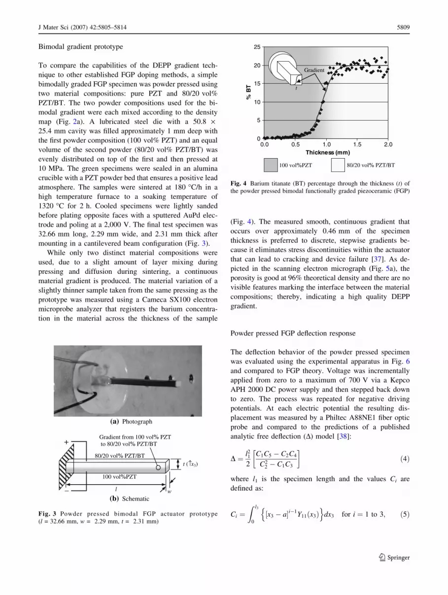
mounting in a cantilevered beam configuration (Fig. 3).
While only two distinct material compositions were
used, due to a slight amount of layer mixing during
pressing and diffusion during sintering, a continuous
material gradient is produced. The material variation of a
slightly thinner sample taken from the same pressing as the
prototype was measured using a Cameca SX100 electron
microprobe analyzer that registers the barium concentra-
tion in the material across the thickness of the sample
(Fig. 4). The measured smooth, continuous gradient that
occurs over approximately 0.46 mm of the specimen
thickness is preferred to discrete, stepwise gradients be-
cause it eliminates stress discontinuities within the actuator
that can lead to cracking and device failure [37]. As de-
picted in the scanning electron micrograph (Fig. 5a), the
porosity is good at 96% theoretical density and there are no
visible features marking the interface between the material
compositions; thereby, indicating a high quality DEPP
gradient.
Powder pressed FGP deflection response
The deflection behavior of the powder pressed specimen
was evaluated using the experimental apparatus in Fig. 6
and compared to FGP theory. Voltage was incrementally
applied from zero to a maximum of 700 V via a Kepco
APH 2000 DC power supply and then stepped back down
to zero. The process was repeated for negative driving
potentials. At each electric potential the resulting dis-
placement was measured by a Philtec A88NE1 fiber optic
probe and compared to the predictions of a published
analytic free deflection (D) model [38]:
D ¼ l212
C1C5 � C2C4
C22 � C1C3
� �ð4Þ
where l1 is the specimen length and the values Ci are
defined as:
Ci ¼Z l3
0
x3 � a½ �i�1Y11 x3ð Þn o
dx3 for i ¼ 1 to 3; ð5Þ
(a) Photograph
(b) Schematic
+
_
100 vol%PZT
80/20 vol% PZT/BT
l
t (↑x3)
w
Gradient from 100 vol% PZT to 80/20 vol% PZT/BT
Fig. 3 Powder pressed bimodal FGP actuator prototype
(l = 32.66 mm, w = 2.29 mm, t = 2.31 mm)
0
5
10
15
20
25
0.0 0.5 1.0 1.5 2.0Thickness (mm)
TB
%
100 vol%PZT 80/20 vol% PZT/BT
t
Gradient
Fig. 4 Barium titanate (BT) percentage through the thickness (t) of
the powder pressed bimodal functionally graded piezoceramic (FGP)
J Mater Sci (2007) 42:5805–5814 5809
123

Ci ¼Z l3
0
x3 � a½ �i�4d31 x3ð ÞE3 x3ð ÞY11 x3ð Þn o
dx3
for i ¼ 4 and 5;
ð6Þ
with x3 denoting the thickness coordinate, l3 the specimen
thickness, and a the location of the actuator neutral axis.
The varying electric field (E) is defined as:
E3 x3ð Þ ¼�DV
e33 x3ð ÞR l3
01
e33 x3ð Þ
� �dx3
; ð7Þ
where DV is the applied electric potential. This model
differs from conventional models by accounting for vari-
ations, either continuous or discrete, in the material stiff-
ness, permittivity, piezoelectric coefficients, and activating
electric field strength. These parameters are constants
inhomogeneous piezoceramics and can traditionally be
factored out of the integrals in Eqs. 5 and 6. But for FGP,
these parameters vary through the material in complex
ways (as seen in the material property maps), especially the
nonlinear electric field (Eq. 7) that depends of the re-
ciprocal of the permittivity profile. By measuring the BT
concentration across a specimen (Fig. 4), all of the material
property variations within an FGP can be determined using
the maps of Fig. 2 and substituted into Eq. 4 to predict the
FGP’s deflection.
The analytic prediction and experimental performance
of the powder pressed FGP are given in Fig. 7. The spec-
imen generated ±43.5 lm of motion when subjected to
±700 V. The specimen outperformed by 5.6% the model
which predicts ±41.2 lm of motion for these conditions.
Though the linear model does not capture the hysteresis of
Increasing %PZT
(a) Powder pressed specimen (bimodal gradient)
(b) MFCX specimen (linear gradient)
Fig. 5 Polished surface of the
functionally graded
piezoceramic (FGP) specimens
Cooper load cell
Philco fiber optic displacement probe
FGP test specimen
Fiber optic probe
Specimen
Stage
Power Supply Voltmeter
Voltmeter
Voltmeter
Stage
Vise
Load cell
Fig. 6 Functionally graded
piezoceramic (FGP)
experimental test apparatus
-50
-40
-30
-20
-10
0
10
20
30
40
50
-800 -400 0 400 800
Voltage (V)
(n
oitcelfeD
µ)
m
Experimental Test
Analytic Model
∆
Fig. 7 Deflection–voltage performance of the powder pressed
bimodal functionally graded piezoceramic (FGP)
5810 J Mater Sci (2007) 42:5805–5814
123

the actuator which reaches a maximum of 13.4 lm, this is
very good correlation considering slight variations in the
specimen thickness along its length and some minimal
curvature within the FGP. The performance is on par with
comparable FGP that are driven at electric potentials in
excess of double those applied here [9, 19, 20, 26, 28].
These results validate the DEPP gradient technique and
demonstrate that it can be used in conjunction with powder
pressing to produce simple, one-dimensionally graded FGP.
Co-extrusion of DEPP gradient piezoceramics
Production of more complex higher-order gradients than
those easily achieved through powder pressing requires the
precision and resolution of Micro-Fabrication by Co-
eXtrusion (MFCX). While this process has proven effec-
tive in fabricating complex piezoceramics [31–34], it had
to be tailored to deal with the demands of the DEPP gra-
dient technique that requires the use of many different
material compositions.
MFCX fabrication process
The basic procedure for MFCX of FGP (Fig. 8) consists of
five steps: media preparation, feedrod formation, extrusion,
burnout and sintering, and post processing.
• Step 1: Media preparation: Once the desired material
compositions needed to form a specific gradient are
selected, the constituent powders (mixed according to
the data in Fig. 2a) are ball milled in water for 24 h
using zirconia media. The powders are incorporated
into a thermoplastic media with ethylene ethyle acry-
late (EEA), isobutyl methacrylate (B67), polyethylene
glycol (PEG 1000), stearic acid, and heavy mineral oil
[39] in a 120 �C C.W. Brabender Instruments, Inc.
PL2100 shear mixer. Mixing continues until all ingre-
dients are thoroughly incorporated and a stable input
torque is reached, which directly correlates to the media
viscosity. It is crucial that the viscosities match—ensur-
ing no cross-sectional distortion during co-extrusion.
The viscosity of the mixture can be adjusted either by
adding ceramic powder (increasing viscosity) or min-
eral oil (lowering viscosity). The ceramic/polymer
media hardens when cooled, and in this state can either
be machined or reheated and plastically formed into
any desired shape.
• Step 2: Feedrod formation: A desired material gradient
is produced by making a larger scale feedrod with a
low-resolution gradient analogous to the target profile.
Individual feedrods of each material composition that is
to be used are first compacted in a 25 mm square die at
120 �C under 770 kg load with a Bradford University
Research Ltd. Extruder. A single batch of extrusion
media produces a solid feedrod approximately three
inches long which can be cut and reassembled with
other media compositions to create the scaled-up
gradient in the final feedrod. Voids can be achieved
in the structure with the MFCX process by including a
fugitive carbon-based media that is eliminated during
the firing procedure. The final feedrod is again heated
and compacted to eliminate gaps between its assembled
components.
• Step 3: Extrusion: Once the desired layout of the
gradient profile is assembled, the final size of the FGP is
achieved by extruding the heated feedrod at 120 �C,
reducing the cross-section in both dimensions to a
smaller, square configuration or in one dimension to
produce a flattened tape. A single extrusion run (from
7 Segment Burnout Schedule
Activation
1. Media Preparation
Shear Mixing at 120 oC
Hot Pressing
2. Feedrod Formation
Assembly
Cutting(5mm thick)
80/20
4. Burnout & Sintering
5. Post Processing
3. Extrusion Polymers Ceramic
5 Compositions: 100 vol% PZT 95/5 vol% PZT/BT 90/10 vol% PZT/BT 85/15 vol% PZT/BT 80/20 vol% PZT/BT
85/15
90/10
95/5
100
25 mm Square Rod fed at 1 mm/min
25 mm x 1mm Tape extruded at 25 mm/min
120 oC
Sintered at 180 oC/hr to 1320 oC for 2 hrs
Poled at 2000 V for 6 hrs
Electroded with 1500 Å AuPd
+
_
Fig. 8 Overview of the Micro-
Fabrication through Co-
eXtrusion (MFCX) process for
DEPP FGP
J Mater Sci (2007) 42:5805–5814 5811
123

one media batch or 75 mm feedrod) produces a large
quantity of FGP tape (approximately 1.2 m depending
on the size reduction). The extruded material can
subsequently be machined into the final actuator shape
(e.g. beam or patches) or reheated and rebundled into
another feedrod with repeated extrusions yielding FGP
on a variety of scales, down to the micron level [31, 33].
• Step 4: Burnout and sintering: Once the final FGP form
is achieved, the polymers and other ingredients in the
media are removed from the green ceramic in a two
step firing process. First, the polymers are burned-out in
a Thermolyne F48015 bench-top muffle furnace using a
carefully controlled, slow heating schedule reaching
520 �C over 14 h [39]. Prior to the second sintering
phase, the specimens are placed on an alumina plate
with a fine coating of the loose ceramic powder
between them. A second dusting of powder was placed
on top of the specimens followed by a thin ceramic
plate that eliminates warping of the specimen. In the
second step, the specimens are sintered in a Micropy-
retics Heaters International (MHI) HIPAN-Series high
temperature furnace to the manufacturer specified
temperature of 1320 �C by heating at a rate of
180 �C per hour and allowing the material to soak for
2 h, then ramping the temperature back down at the
same rate before post processing.
• Post processing: The post processing of the FGP
specimens consists of two separate steps: electroding
and poling. Two opposing sides of the FGP actuators
are electroded with 1,500 A of AuPd using a Technics
Hummer 6 sputtering system. The specimens are then
poled at room temperature in a peanut oil bath, slowly
ramping the applied electric potential (via the Kepko
DC power supply) to 2,000 V over 2 h, maintaining
this voltage for 6 h before it is reduced back down to
zero. Since the applied electric field is no longer simply
the voltage divided by the specimen thickness, the
electric field strength experienced by the lower permit-
tivity material can be dramatically higher than what
would be expected for normal, homogenous piezoce-
ramics, and should be closely monitored.
Linear gradient prototype
While the modified MFCX process can be applied to any
gradient profile, the general process was demonstrated by
fabrication and experimental characterization of a linearly
graded FGP using the DEPP technique. This more gentle
profile, compared to abrupt bimodal gradients or layered
actuators, reduces the internal stress levels [37], extending
the actuator lifetime. In this case, to generate a linear
gradient, five different material compositions were used—
pure PZT, 95/5, 90/10, 85/15, and 80/20 vol% PZT/BT.
Each individual composition was compressed into a 6 mm
feedrod and machined down to a thickness of 5 mm using a
Roland Modela MDX-15 3-D plotter. The five individual
layers were assembled in the die in order of increasing BT,
heated, and compressed into a final feedrod. The feedrod
was reduced in the layered dimension from a 25 mm
square rod to a 1 · 25 mm tape by extrusion at a ram speed
of 1 mm/min. Green ceramic beams were cut from the co-
extruded tape and sintered and polished into a 24.68 mm
long and 2.87 mm wide linearly graded FGP beam (Fig. 9)
which is dramatically thinner (t = 0.84 mm) than the
powder pressed specimen.
The co-extruded FGP specimen’s material composition
was analyzed for barium content using the electron
microprobe analyzer. The same smoothing of the compo-
sitional variation observed in the powder pressed specimen
was once again present (Fig. 10), with the original layered
gradient giving way to a continuous linear gradient because
of the finer resolution of the co-extrusion process and
diffusion during sintering. Material samples from the same
fabrication run were used for these tests and the polished
surface (Fig. 5b) once again shows acceptable porosity
(95% density) and no discernable material interfaces. Be-
cause of the thickness reduction from extrusion and the
compatibility of the DEPP constituent materials, the
MFCX process requires only five different material com-
positions to obtain a linear material gradient.
MFCX FGP deflection response
The experimental deflection–voltage testing was imple-
mented in the same manner as for the powder pressed FGP,
+
_
Linear gradient from 100 vol% PZT to 80/20 vol% PZT/BT
l
t (↑x3)
w
(a) Photograph
(b) Schematic
Fig. 9 Co-extruded linear functionally graded piezoceramic (FGP)
actuator prototype (l = 24.68 mm, w = 2.87 mm, t = 0.84 mm)
5812 J Mater Sci (2007) 42:5805–5814
123
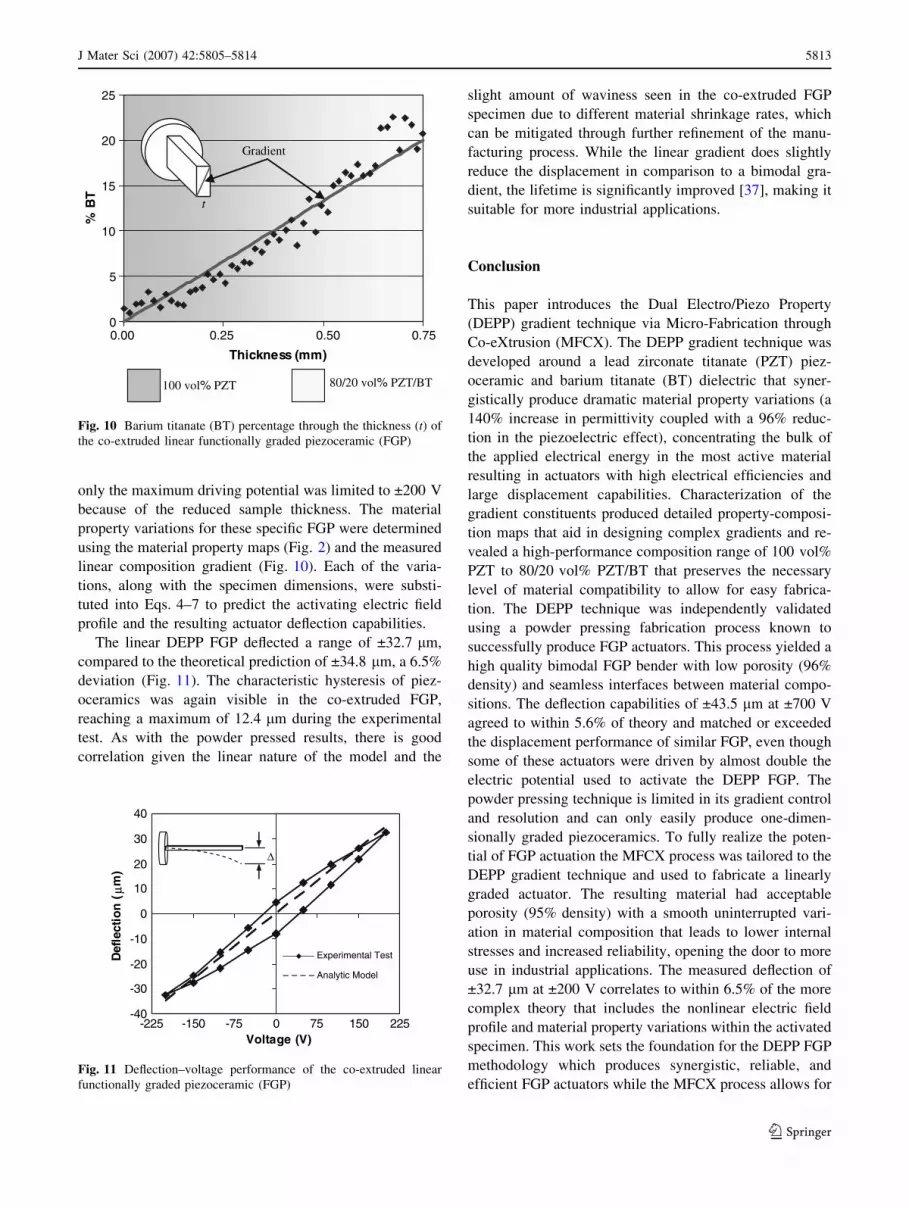
only the maximum driving potential was limited to ±200 V
because of the reduced sample thickness. The material
property variations for these specific FGP were determined
using the material property maps (Fig. 2) and the measured
linear composition gradient (Fig. 10). Each of the varia-
tions, along with the specimen dimensions, were substi-
tuted into Eqs. 4–7 to predict the activating electric field
profile and the resulting actuator deflection capabilities.
The linear DEPP FGP deflected a range of ±32.7 lm,
compared to the theoretical prediction of ±34.8 lm, a 6.5%
deviation (Fig. 11). The characteristic hysteresis of piez-
oceramics was again visible in the co-extruded FGP,
reaching a maximum of 12.4 lm during the experimental
test. As with the powder pressed results, there is good
correlation given the linear nature of the model and the
slight amount of waviness seen in the co-extruded FGP
specimen due to different material shrinkage rates, which
can be mitigated through further refinement of the manu-
facturing process. While the linear gradient does slightly
reduce the displacement in comparison to a bimodal gra-
dient, the lifetime is significantly improved [37], making it
suitable for more industrial applications.
Conclusion
This paper introduces the Dual Electro/Piezo Property
(DEPP) gradient technique via Micro-Fabrication through
Co-eXtrusion (MFCX). The DEPP gradient technique was
developed around a lead zirconate titanate (PZT) piez-
oceramic and barium titanate (BT) dielectric that syner-
gistically produce dramatic material property variations (a
140% increase in permittivity coupled with a 96% reduc-
tion in the piezoelectric effect), concentrating the bulk of
the applied electrical energy in the most active material
resulting in actuators with high electrical efficiencies and
large displacement capabilities. Characterization of the
gradient constituents produced detailed property-composi-
tion maps that aid in designing complex gradients and re-
vealed a high-performance composition range of 100 vol%
PZT to 80/20 vol% PZT/BT that preserves the necessary
level of material compatibility to allow for easy fabrica-
tion. The DEPP technique was independently validated
using a powder pressing fabrication process known to
successfully produce FGP actuators. This process yielded a
high quality bimodal FGP bender with low porosity (96%
density) and seamless interfaces between material compo-
sitions. The deflection capabilities of ±43.5 lm at ±700 V
agreed to within 5.6% of theory and matched or exceeded
the displacement performance of similar FGP, even though
some of these actuators were driven by almost double the
electric potential used to activate the DEPP FGP. The
powder pressing technique is limited in its gradient control
and resolution and can only easily produce one-dimen-
sionally graded piezoceramics. To fully realize the poten-
tial of FGP actuation the MFCX process was tailored to the
DEPP gradient technique and used to fabricate a linearly
graded actuator. The resulting material had acceptable
porosity (95% density) with a smooth uninterrupted vari-
ation in material composition that leads to lower internal
stresses and increased reliability, opening the door to more
use in industrial applications. The measured deflection of
±32.7 lm at ±200 V correlates to within 6.5% of the more
complex theory that includes the nonlinear electric field
profile and material property variations within the activated
specimen. This work sets the foundation for the DEPP FGP
methodology which produces synergistic, reliable, and
efficient FGP actuators while the MFCX process allows for
0
5
10
15
20
25
0.00
Thickness (mm)
TB
%
t
100 vol% PZT 80/20 vol% PZT/BT
Gradient
0.25 0.50 0.75
Fig. 10 Barium titanate (BT) percentage through the thickness (t) of
the co-extruded linear functionally graded piezoceramic (FGP)
-40
-30
-20
-10
0
10
20
30
40
-225 -150 -75 0 75 150 225Voltage (V)
(n
oitcelfeD
µ)
m
Experimental Test
Analytic Model
∆
Fig. 11 Deflection–voltage performance of the co-extruded linear
functionally graded piezoceramic (FGP)
J Mater Sci (2007) 42:5805–5814 5813
123

precisely controlled material gradients, potentially posi-
tioning FGP technology to exploit the untapped capabilities
of multi-dimensionally graded piezoceramics.
Acknowledgements This research was made possible through a
grant from the National Science Foundation (Grant #: CMS 0201031).
References
1. Choules BD, Kokini K (1996) J Eng Mater Technol 118:522
2. Grujicic M, Zhao H (1998) Mater Sci Eng A A252:117
3. Hofinger I, Bahr HA, Balke H, Kirchhoff G, Haeusler C, Weiss
HJ (1999) Mater Sci Forum: Funct Grad Mater 308–311:450
4. Kawasaki A, Watanabe R (1999) Mater Sci Forum: Funct Grad
Mater 308–311:402
5. Jessen TL, Lewis D III (1990) J Am Ceram Soc 75:1405
6. Cokeram BV, Wilson WL (2001) Surf Coat Technol 139:161
7. Tsuda K, Ikegaya A, Miyagawa T, Suehiro Y (2000) J Jpn Soc
Powder Powder Metall 47:564
8. Heartling GH (1994) Am Ceram Soc Bull 73:93
9. Wu CCM, Kahn M, Moy W (1996) J Am Ceram Soc 79:809
10. Uchino K (1996) In: Proceedings of IEEE international sympo-
sium on applications of ferroelectrics, East Brunswick, August
1996, vol 2, p 736
11. Uchino K (1990) In: Proceedings of IEEE international sympo-
sium on applications of ferroelectrics, Champaign, June 1990, p
153
12. Furman E, Li G, Heartling GH (1995) In: IEEE international
symposium on applications of ferroelectrics, p 146
13. Elissalde C, Cross LE (1995) J Am Ceram Soc 78:2233
14. Wang QM, Cross LE (1999) Mater Chem Phys 58:20
15. Hudnut S, Almajid A, Taya M (2000) In: Proceedings of SPIE
smart structures and materials: behavior and mechanics, Newport
beach, March 2000, vol 3992, p 376
16. Hirsekorn S, Gebhardt W, Arnold W (1999) Mater Sci Forum:
Funct Grad Mater 308–311:521
17. Takagi K, Li JF, Yokoyama S, Watanabe R, Almajid A, Taya M
(2002) Sci Technol Adv Ceram 3:217
18. Takagi K, Li JF, Yokoyama S, Watanabe R (2003) J Euro Ceram
Soc 23:1577
19. Zhu X, Wang Q, Meng Z (1995) J Mater Sci Lett 14:516
20. Zhu X, Meng Z (1995) Sens Actuators A Phys 48:169
21. Zhu X, Zhu J, Zhou S, Li Q, Liu Z (1999) Sens Actuators A Phys
74:198
22. Xu J, Zhu X, Meng Z (1999) IEEE Trans Comp Pack Technol
22:11
23. Zhu X, Zhu J, Zhou S, Li Q, Liu Z, Ming N, Meng Z (2000) J
Mater Sci 35:1031
24. Li X, Vartuli JS, Milius DJ, Aksay IA, Shih WY, Shih WH
(2001) J Am Ceram Soc 84:996
25. Li JF, Takagi K, Ono M, Pan W, Watanabe R (2003) J Am Ceram
Soc 86:1094
26. Chen YH, Ma J, Li T (2004) Ceram Int 30:683
27. Qui J, Tani J, Ueno T, Morita T, Takahashi H, Du H (2003) Smart
Mater Struct 12:115
28. Jin D, Meng Z (2003) J Mater Sci Lett 22:971
29. Nieto E, Fernandez JF, Moure C, Duran P (1996) J Mater Sci
Mater Electron 7:55
30. Shelley WF, Wan S, Bowman KJ (1999) Mater Sci Forum: Funct
Grad Mater 308–311:515
31. Crumm AT, Halloran JW (1998) J Am Ceram Soc 81:1053
32. Crumm AT, Silva ECN, Kikuchi N, Brei D, Halloran JW (1998)
In: Proceedings of SPIE smart structures and materials, San
Diego, February 1998, 3324, p 20
33. Brei D, Cannon BJ (2004) Compos Sci Technol 64:245
34. Cannon BJ, Brei D (2000) J Intell Mater Sys Struct 11:659
35. Apc International Ltd, Duck Run, PO Box 180, Mackeyville, PA
17750 USA, http://www.americanpiezo.com
36. Ferro Corporation, 1000 Lakeside Avenue, Cleveland, Ohio
44114–7000 USA, http://www.ferro.com
37. Alexander P, Brei D (2003) In: Proceedings of ASME interna-
tional mechanical engineering congress and exposition, Wash-
ington DC, November 2003, 68, p 171
38. Alexander PW, Brei D, Halloran JW (2005) In: Proceedings of
AIAA/ASME/AHS adaptive structures conference, Austin, April
2005
39. Alexander PW, Brei D, Halloran JW (2005) In: Proceedings of
SPIE smart materials and structures conference, San Diego,
March 2005
5814 J Mater Sci (2007) 42:5805–5814
123


