Embed Size (px)
Citation preview

DESIGN MANUAL FOR ROADS AND BRIDGES
November 1996 ELECTRONIC COPY NOT FOR USE OUTSIDE THE AGENCY.PAPER COPIES OF THIS ELECTRONIC DOCUMENT ARE UNCONTROLLED
DESIGN MANUAL FOR ROADS AND BRIDGES
VOLUME 3 HIGHWAYSTRUCTURES:INSPECTION ANDMAINTENANCE
SECTION 4 ASSESSMENT
PART 11
BD 56/96
THE ASSESSMENT OF STEELHIGHWAY BRIDGES ANDSTRUCTURES
SUMMARY
This Standard gives requirements for the assessment ofexisting steel highway bridges and structures onmotorways and other trunk roads.
INSTRUCTIONS FOR USE
BD 56/96 is a new document in the Design Manual forRoads and Bridges.
1. Insert BD 56/96 into Volume 3, Section 4,at Part 11.
2. Archive this sheet as appropriate.
Note: A quarterly Index with a full set of VolumeContents Pages is available separately from HMSO.

BD 56/96
The Assessment ofSteel Highway
Bridges and Structures
THE HIGHWAYS AGENCY
THE SCOTTISH OFFICE DEVELOPMENT DEPARTMENT
THE WELSH OFFICEY SWYDDFA GYMREIG
THE DEPARTMENT OF THE ENVIRONMENT FORNORTHERN IRELAND
Summary: This Standard gives requirements for the assessment of existing steel highwaybridges and structures on motorways and other trunk roads.
ELECTRONIC COPY NOT FOR USE OUTSIDE THE AGENCY.PAPER COPIES OF THIS ELECTRONIC DOCUMENT ARE UNCONTROLLED

November 1996
REGISTRATION OF AMENDMENTS
Amend Page No Signature & Date of Amend Page No Signature & Date ofNo incorporation of No incorporation of
amendments amendments
Volume 3 Section 4Part 11 BD 56/96 Registration of Amendments
ELECTRONIC COPY NOT FOR USE OUTSIDE THE AGENCY.PAPER COPIES OF THIS ELECTRONIC DOCUMENT ARE UNCONTROLLED

REGISTRATION OF AMENDMENTS
Amend Page No Signature & Date of Amend Page No Signature & Date ofNo incorporation of No incorporation of
amendments amendments
Registration of AmendmentsVolume 3 Section 4
Part 11 BD 56/96
November 1996ELECTRONIC COPY NOT FOR USE OUTSIDE THE AGENCY.PAPER COPIES OF THIS ELECTRONIC DOCUMENT ARE UNCONTROLLED
DESIGN MANUAL FOR ROADS AND BRIDGES
November 1996
VOLUME 3 HIGHWAYSTRUCTURES:INSPECTION ANDMAINTENANCE
SECTION 4 ASSESSMENT
PART 11
BD 56/96
THE ASSESSMENT OF STEELHIGHWAY BRIDGES ANDSTRUCTURES
Contents
Chapter
1. Introduction
2. Assessment of Strength
3. Use of Annex A, BS 5400 Part 3 and BD 13
4. References
5. Enquiries
Annex A Amendments to BS 5400: Part 3: 1982and Appendix A of BD 13/90
ELECTRONIC COPY NOT FOR USE OUTSIDE THE AGENCY.PAPER COPIES OF THIS ELECTRONIC DOCUMENT ARE UNCONTROLLED

November 1996
Chapter 1Introduction
Volume 3 Section 4Part 11 BD 56/96
1/1
1. INTRODUCTION
General
1.1 This Standard, which for assessment purposesreplaces BD 13 (DMRB 1.3), gives requirements forthe assessment of existing steel structures andstructural elements, and shall be used in conjunctionwith BD 21 (DMRB 3.4.3).
1.2 Annex A of this Standard contains the relevantassessment clauses and appendices which have beenpresented as additions and amendments to the designclauses and appendices in BS 5400: Part 3 as amendedby the Appendix A of BD 13 (DMRB 1.3). Theseadditions and amendments have been specificallydeveloped to suit assessment conditions and, therefore,must not be used in new design or construction.
1.3 BA 56 (DMRB 3.4.12) accompanies thisStandard, giving the necessary backgroundinformation and also guidance on the application ofthis Standard. It is recommended that the Advice Noteshould be used in conjunction with this Standard.
1.4 Where there is no assessment addition to aclause in Annex A, the existing design clause asamended by this Standard shall be applicable forassessment.
Scope
1.5 This Standard gives requirements for theassessment of existing steel highway bridges andstructures on motorways and other trunk roads. Foruse in Northern Ireland, this Standard will beapplicable to those roads so designated by theOverseeing Organisation.
Implementation
1.6 This Standard shall be used forthwith for theassessment of steel highway bridges and structures.The requirements shall be applied to assessmentsalready in progress provided that, in the opinion of theOverseeing Organisation, this would not result insignificant additional expense or delay. Its applicationto particular assessments shall be confirmed with theOverseeing Organisation.
ELECTRONIC COPY NOT FOR USE OUTSIDE THE AGENCY.PAPER COPIES OF THIS ELECTRONIC DOCUMENT ARE UNCONTROLLED

Volume 3 Section 4Part 11 BD 56/96
November 1996
Chapter 2Assessment of Strength
2. ASSESSMENT OF STRENGTH
2/1
General
2.1 The objective of this Standard is to produce amore realistic assessment of the strength of steelelements than has previously been possible using therequirements of the existing design code. This in partis achieved by taking advantage of the informationavailable to an assessing engineer in respect of thematerial strength, geometrical properties andimperfections etc which can only be predicted at thedesign stage.
2.2 Many of the criteria given in the design code arebased on experimental evidence which in some caseshave been either conservatively interpreted for use indesign or updated by later evidence allowing a lessconservative interpretation. For assessment purposessuch criteria have been reviewed and amended whereappropriate.
2.3 The assessment additions will enable anycombination of the following aspects to be dealt within assessment:
a) measured imperfections and sizesdifferent from those assumed in the code;
b) structural steelwork components andconnections not fabricated or erected inaccordance with the Specification forHighway Works (MCHW 1);
c) structural steel material not complyingwith the relevant standards;
d) general configurations and shapelimitations not complying with thelimitation in BS 5400 Part 3;
e) restraint stiffnesses and strengths notcomplying with BS 5400 Part 3; and
f) outmoded forms of construction notcomplying with BS 5400 Part 3.
Global Analysis
2.4 Plastic analysis of load effects at ultimate limitstate for beams and slabs may be permitted providedthat the components are both compact and stocky andthat serviceability criteria are met.Requirements are given when plastic global analysis isto be used.
Partial Factor for Loads, γγγγγ fL
2.5 Assessment loads QA
* shall be obtained bymultiplying the nominal loads, Q
K by γ
fL, the partial
safety factor for loads. The relevant values of γ fL
aregiven in BD 21 (DMRB 3.4.3). The assessment loadeffects, S
A*shall be obtained by the relation:
SA
* = γ f3
(effects of QA
*)
where γ f3
is a factor that takes account of inaccurateassessment of the effects of loading, unforeseen stressdistribution in the structure and variations indimensional accuracy in construction. γ
f3 shall be
taken as 1.1 for the ultimate limit state and 1.0 for theserviceabilty limit state.
Partial Safety Factor for Materials, γγγγγ m
2.6 An important feature of the design code is theapplication of the partial safety factor for materialstrength, γ
m, to the characteristic values. In
assessment, a reduced value of γ m
may be used as analternative based on the results of laboratory tests.
Limit State
2.7 Although BD 21 (DMRB 3.4.3) specifies thatassessments shall be carried out at the ultimate limitstate, this Standard requires that serviceability limitstate checks be carried out in a number of cases.However certain seviceability checks required by thedesign rules may be waived when permanentdeformations are acceptable.
ELECTRONIC COPY NOT FOR USE OUTSIDE THE AGENCY.PAPER COPIES OF THIS ELECTRONIC DOCUMENT ARE UNCONTROLLED

November 19962/2
Volume 3 Section 4Part 11 BD 56/96
Chapter 2Assessment of Strength
Fatigue
2.8 In assessment, fatigue analysis is not normallynecessary. Where the configuration of the bridge issuch that fatigue assessment is essential the loadingand the method of analysis shall be as given in BS5400 Part 10 as implemented by BD 9 (DMRB 1.3)
Condition Factor in BD 21
2.9 While the application of the condition factor Fc
in paragraph 3.18 of BD 21 (DMRB 3.4.3) is notaffected in principle by the requirements of thisStandard, care should be taken to ensure that theestimated values of F
c do not allow for deficiencies of
the materials in a structure which are separatelyallowed for by using the amended values of γ
m.
ELECTRONIC COPY NOT FOR USE OUTSIDE THE AGENCY.PAPER COPIES OF THIS ELECTRONIC DOCUMENT ARE UNCONTROLLED

Volume 3 Section 4Part 11 BD 56/96
November 1996
Chapter 3Use of Annex A, BS 5400 Pt 3 & BD 13
3/1
3. USE OF ANNEX A, BS 5400 PART 3 ANDBD 13
3.1 Annex A is presented in the form of newclauses, amendments or add-ons to the design clausesin BS 5400 Part 3 as amended by BD 13 (DMRB1.3). For the benefit of engineers existing clauses inBS 5400 Part 3 as amended by BD 13 (DMRB 1.3)have been included on the facing pages of thedocument. To facilitate this, the appropriate sectionsof BS 5400 Part 3 have been highlighted. The pagenumbers centred above the footer are the pagenumbers of BS 5400 Part 3.
3.2 Some clauses in BS 5400 Part 3 and AppendixA of BD 13 (DMRB 1.3) are expressed in amandatory form using the word ‘shall’, whereas someother clauses are expressed in the form ofrecomendations using the word ‘should’. However,even the latter requirements shall be considered asmandatory. In Annex A the word ‘shall’ is usedthroughout.
3.3 Where reference is made to any part of BS5400, this shall be taken as a reference to that part asimplemented by the Overseeing Organisation.
ELECTRONIC COPY NOT FOR USE OUTSIDE THE AGENCY.PAPER COPIES OF THIS ELECTRONIC DOCUMENT ARE UNCONTROLLED

November 1996 4/1
4. REFERENCES
1
Volume 3 Section 4Part 11 BD 56/96
Chapter 4References
1. Design Manual for Roads and Bridges (DMRB)
Volume 1: Section 3: General Design
BD 13 Design of Steel Bridges. Use of BS 5400: Part 3: 1982. (DMRB 1.3)
BD 37 Loads for Highway Bridges. (DMRB 1.3)
BD 9 Implementation of BS 5400: Part 10: 1980, Code of Practice for Fatigue. (DMRB 1.3)
Volume 3: Section 4: Assessment
BD 21 The Assessment of Highway Bridges and Structures. (DMRB 3.4.3)
BA 56 The Assessment of Steel Highway Bridges and Structures. (DMRB 3.4.12)
BD 61 The Assessment of Composite Highway Bridges and Structures. (DMRB 3.4.16)
BA 61 The Assessment of Composite Highway Bridges and Structures. (DMRB 3.4.17)
2. Manual of Contract Documents for Highway Works (MCHW)
Volume 1: Specification for Highway Works (MCHW 1)
3. British Standards Institution
BS 5400: Part 3: 1982. Steel, Concrete and Composite Bridges. Code of Practice for Design of SteelBridges.
BS 5400: Part 10: 1980. Steel, Concrete and Composite Bridges. Code of Practice forFatigue.
4. The Bridge Inspection Guide, 1984 (HMSO)
ELECTRONIC COPY NOT FOR USE OUTSIDE THE AGENCY.PAPER COPIES OF THIS ELECTRONIC DOCUMENT ARE UNCONTROLLED
November 1996 5/1
5. ENQUIRIES
All technical enquiries or comments on this Standard should be sent in writing as appropriate to:
The Chief Highway EngineerThe Highways AgencySt Christopher HouseSouthwark Street T A ROCHESTERLondon SE1 0TE Chief Highway Engineer
The Deputy Chief EngineerNational Roads DirectorateThe Scottish Office Development DepartmentFloor 2C, Victoria Quay N B MACKENZIEEdinburgh EH6 6QQ Deputy Chief Engineer
The Director of HighwaysWelsh OfficeCrown BuildingsCathays Park K THOMASCardiff CF1 3NQ Director of Highways
The Director of Roads ServiceDepartment of the Environment forNorthern IrelandRoads Service HeadquartersClarence Court10-18 Adelaide Street W J McCOUBREYBelfast BT2 8GB Director of Roads Service
Volume 3 Section 4Part 11 BD 56/96
Chapter 5Enquiries
ELECTRONIC COPY NOT FOR USE OUTSIDE THE AGENCY.PAPER COPIES OF THIS ELECTRONIC DOCUMENT ARE UNCONTROLLED

Volume 3 Section 4Part 11 BD 56/96 Annex A
November 1996 A/1ELECTRONIC COPY NOT FOR USE OUTSIDE THE AGENCY.PAPER COPIES OF THIS ELECTRONIC DOCUMENT ARE UNCONTROLLED
AMENDMENTS TO BS 5400 : PART 3 : 1982 ANDAPPENDIX A OF BD13/90
BS 5400 Part 3 has been reproduced in Annex A with the kind permission of theBritish Standards Institution.
Annex AVolume 3 Section 4
Part 11 BD 56/96
A/2 November 1996ELECTRONIC COPY NOT FOR USE OUTSIDE THE AGENCY.PAPER COPIES OF THIS ELECTRONIC DOCUMENT ARE UNCONTROLLED

Volume 3 Section 4Part 11 BD 56/96 Annex A
November 1996 A/3ELECTRONIC COPY NOT FOR USE OUTSIDE THE AGENCY.PAPER COPIES OF THIS ELECTRONIC DOCUMENT ARE UNCONTROLLED
This page is blank
0

Annex AVolume 3 Section 4
Part 11 BD 56/96
A/4 November 1996ELECTRONIC COPY NOT FOR USE OUTSIDE THE AGENCY.PAPER COPIES OF THIS ELECTRONIC DOCUMENT ARE UNCONTROLLED

Volume 3 Section 4Part 11 BD 56/96 Annex A
November 1996 A/5ELECTRONIC COPY NOT FOR USE OUTSIDE THE AGENCY.PAPER COPIES OF THIS ELECTRONIC DOCUMENT ARE UNCONTROLLED
This page is blank
1
Annex AVolume 3 Section 4
Part 11 BD 56/96
A/6 November 1996ELECTRONIC COPY NOT FOR USE OUTSIDE THE AGENCY.PAPER COPIES OF THIS ELECTRONIC DOCUMENT ARE UNCONTROLLED

Volume 3 Section 4Part 11 BD 56/96 Annex A
November 1996 A/7ELECTRONIC COPY NOT FOR USE OUTSIDE THE AGENCY.PAPER COPIES OF THIS ELECTRONIC DOCUMENT ARE UNCONTROLLED
This page is blank
2
Annex AVolume 3 Section 4
Part 11 BD 56/96
A/8 November 1996ELECTRONIC COPY NOT FOR USE OUTSIDE THE AGENCY.PAPER COPIES OF THIS ELECTRONIC DOCUMENT ARE UNCONTROLLED

Volume 3 Section 4Part 11 BD 56/96 Annex A
November 1996 A/9ELECTRONIC COPY NOT FOR USE OUTSIDE THE AGENCY.PAPER COPIES OF THIS ELECTRONIC DOCUMENT ARE UNCONTROLLED
This page is blank
3
Annex AVolume 3 Section 4
Part 11 BD 56/96
A/10 November 1996ELECTRONIC COPY NOT FOR USE OUTSIDE THE AGENCY.PAPER COPIES OF THIS ELECTRONIC DOCUMENT ARE UNCONTROLLED

Volume 3 Section 4Part 11 BD 56/96 Annex A
November 1996 A/11ELECTRONIC COPY NOT FOR USE OUTSIDE THE AGENCY.PAPER COPIES OF THIS ELECTRONIC DOCUMENT ARE UNCONTROLLED
This page is blank
4
Annex AVolume 3 Section 4
Part 11 BD 56/96
A/12 November 1996ELECTRONIC COPY NOT FOR USE OUTSIDE THE AGENCY.PAPER COPIES OF THIS ELECTRONIC DOCUMENT ARE UNCONTROLLED
Volume 3 Section 4Part 11 BD 56/96 Annex A
November 1996 A/13ELECTRONIC COPY NOT FOR USE OUTSIDE THE AGENCY.PAPER COPIES OF THIS ELECTRONIC DOCUMENT ARE UNCONTROLLED
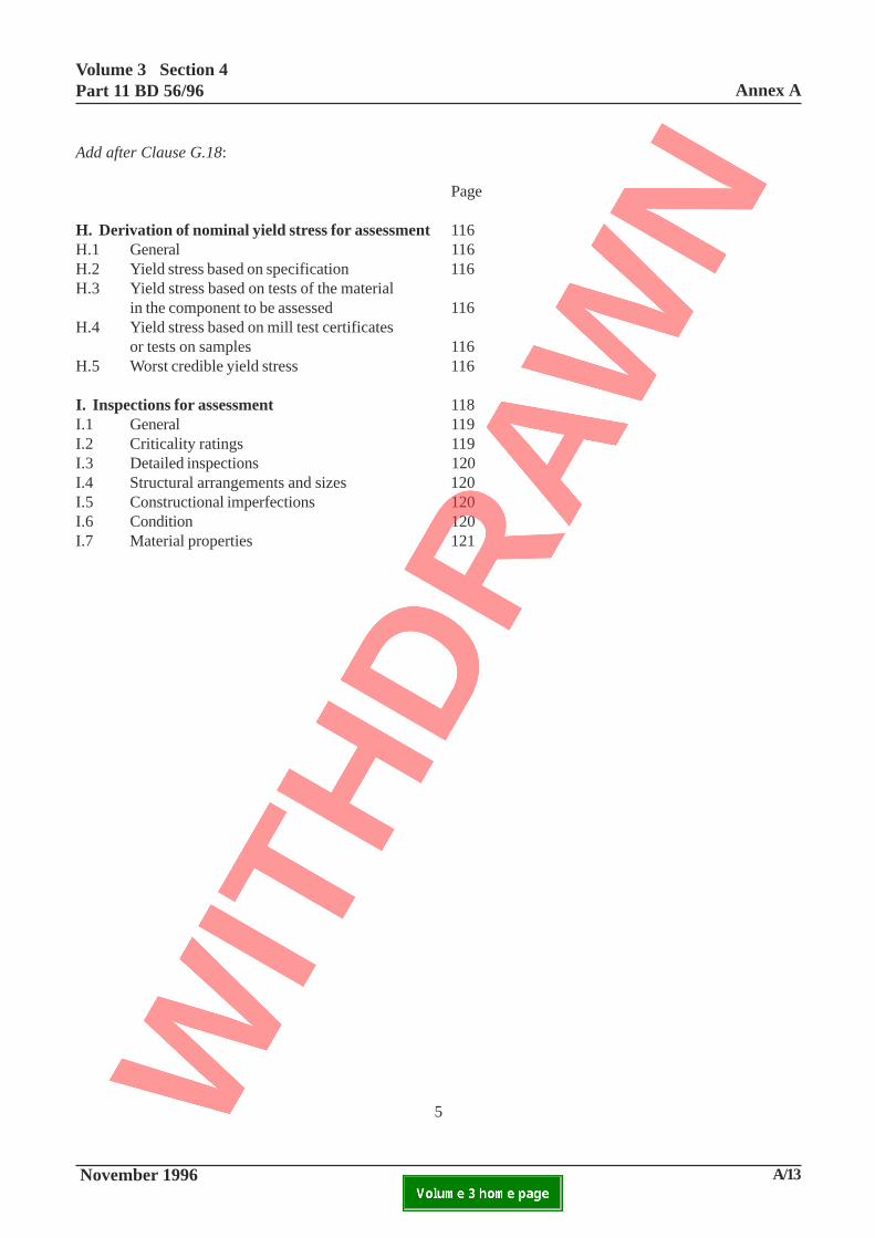
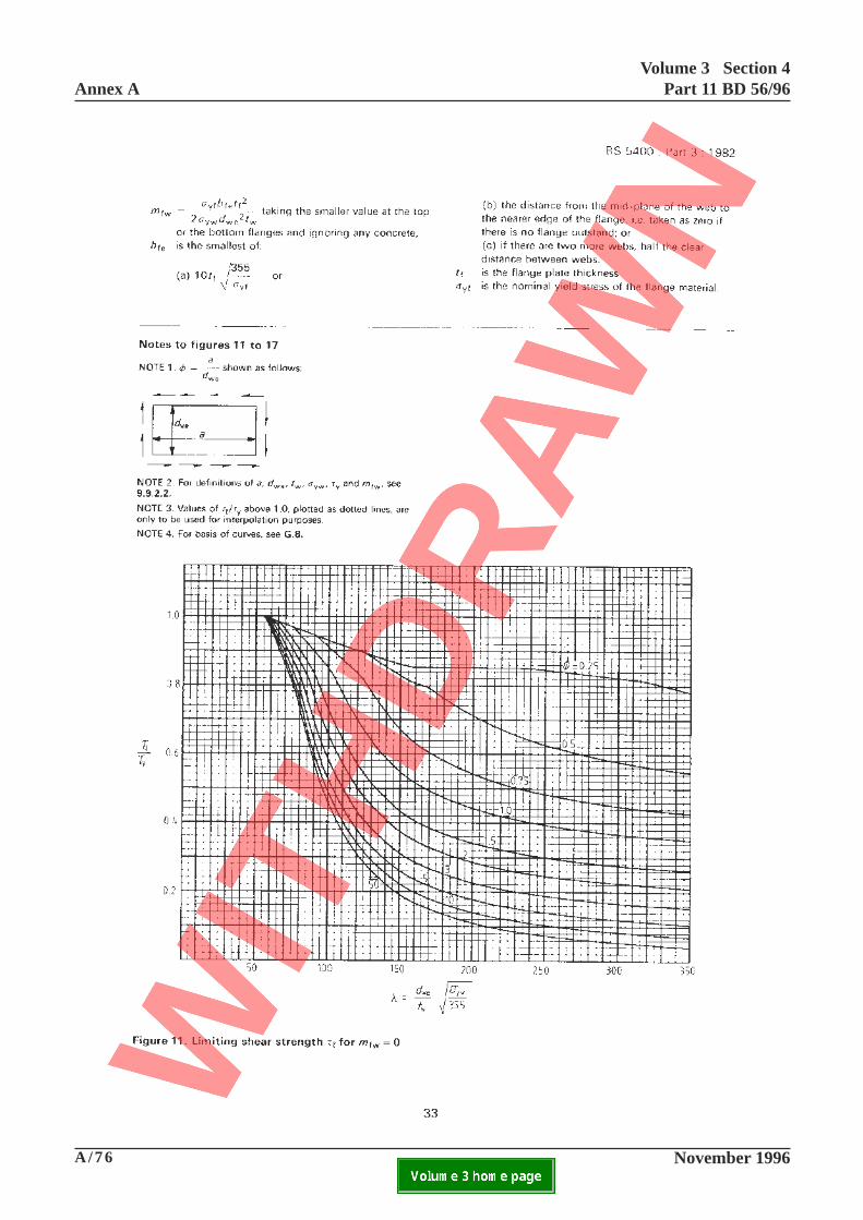
Add after Clause G.18:
Page
H. Derivation of nominal yield stress for assessment 116H.1 General 116H.2 Yield stress based on specification 116H.3 Yield stress based on tests of the material
in the component to be assessed 116H.4 Yield stress based on mill test certificates
or tests on samples 116H.5 Worst credible yield stress 116
I. Inspections for assessment 118I.1 General 119I.2 Criticality ratings 119I.3 Detailed inspections 120I.4 Structural arrangements and sizes 120I.5 Constructional imperfections 120I.6 Condition 120I.7 Material properties 121
5
Annex AVolume 3 Section 4
Part 11 BD 56/96
A/14 November 1996ELECTRONIC COPY NOT FOR USE OUTSIDE THE AGENCY.PAPER COPIES OF THIS ELECTRONIC DOCUMENT ARE UNCONTROLLED

Volume 3 Section 4Part 11 BD 56/96 Annex A
November 1996 A/15ELECTRONIC COPY NOT FOR USE OUTSIDE THE AGENCY.PAPER COPIES OF THIS ELECTRONIC DOCUMENT ARE UNCONTROLLED
This page is blank
6
Annex AVolume 3 Section 4
Part 11 BD 56/96
A/16 November 1996ELECTRONIC COPY NOT FOR USE OUTSIDE THE AGENCY.PAPER COPIES OF THIS ELECTRONIC DOCUMENT ARE UNCONTROLLED

Volume 3 Section 4Part 11 BD 56/96 Annex A
November 1996 A/17ELECTRONIC COPY NOT FOR USE OUTSIDE THE AGENCY.PAPER COPIES OF THIS ELECTRONIC DOCUMENT ARE UNCONTROLLED
BD 56/94 THE ASSESSMENT OF STEEL HIGHWAY BRIDGES AND STRUCTURES
ANNEX A AMENDMENTS TO BS 5400: PART 3: 1982 AND APPENDIX A OF BD 13/90
1. Scope
Delete the existing text and substitute the following:
This Standard shall be used for the assessment of steelhighway bridges and their structural components. Theassessment additions contained in this documentextend the existing Code to cater for the majority ofexisting steel highway bridges.
In assessment, hybrid construction shall be dealt withby taking due account of the different levels of yieldstress in all aspects of the assessment.
2. References
Add at end:
Additional references are given in Appendix Z of theaccompanying Advice Note BA 56 (DMRB 3.4.11).These relate to specific references called up in theadded text, as well as listing other references useful forthe general interpretation of Part 3 in the context ofassessment.
7

Annex AVolume 3 Section 4
Part 11 BD 56/96
A/18 November 1996ELECTRONIC COPY NOT FOR USE OUTSIDE THE AGENCY.PAPER COPIES OF THIS ELECTRONIC DOCUMENT ARE UNCONTROLLED

Volume 3 Section 4Part 11 BD 56/96 Annex A
November 1996 A/19ELECTRONIC COPY NOT FOR USE OUTSIDE THE AGENCY.PAPER COPIES OF THIS ELECTRONIC DOCUMENT ARE UNCONTROLLED
Add new Clause 3.2.4:
3.2.4 Symbols used in assessment
The main symbols and subscripts used for assessmentare generally in accordance with 3.2.3 and 3.2.4.However, some additional symbols are needed forassessment which are defined in the text as they occur.
4.1 General
Add at end:
The loading for assessment of existing bridges shall bein accordance with BD 21 (DMRB 3.4.3).
The objectives and procedures for assessment ofexisting bridges shall be in accordance with BD 21(DMRB 3.4.3). The compliance criteria forassessment of structural steelwork in existing bridgesshall be in accordance with this part as supplementedby the clause additions for assessment. Where otherdocuments are used for derivation of load effects,analysis or other objectives, the principles andrequirements of this Part shall still be applied unlessspecifically stated otherwise. Further guidance noteson assessment objectives and procedures are given inthe accompanying Advice Note BA 56(DMRB 3.4.11).
Inspections for assessment shall follow therecommendations of Appendix I as well as “TheBridge Inspection Guide” (HMSO 1984).
4.2.2 Serviceability limit state
In Table 1, against 9.2.3.1 delete ‘1.67’ and insert ‘
1/ψR’
’.
Add the following NOTE under Table 1:
NOTE 1. Clauses 14.2.3 and 14.5.4.1.2When calculated deflections due to bolt slip do notcause unserviceability as defined in 4.2.2, theserviceability limit criterion need not apply.
NOTE 2. GENERALFurther cases, where additional serviceability checksare required according to individual assessmentcircumstances, are set out in the relevant clauses.
8
Annex AVolume 3 Section 4
Part 11 BD 56/96
A/20 November 1996ELECTRONIC COPY NOT FOR USE OUTSIDE THE AGENCY.PAPER COPIES OF THIS ELECTRONIC DOCUMENT ARE UNCONTROLLED
Volume 3 Section 4Part 11 BD 56/96 Annex A
November 1996 A/21ELECTRONIC COPY NOT FOR USE OUTSIDE THE AGENCY.PAPER COPIES OF THIS ELECTRONIC DOCUMENT ARE UNCONTROLLED
8 1. 8 8(L / r + 5)
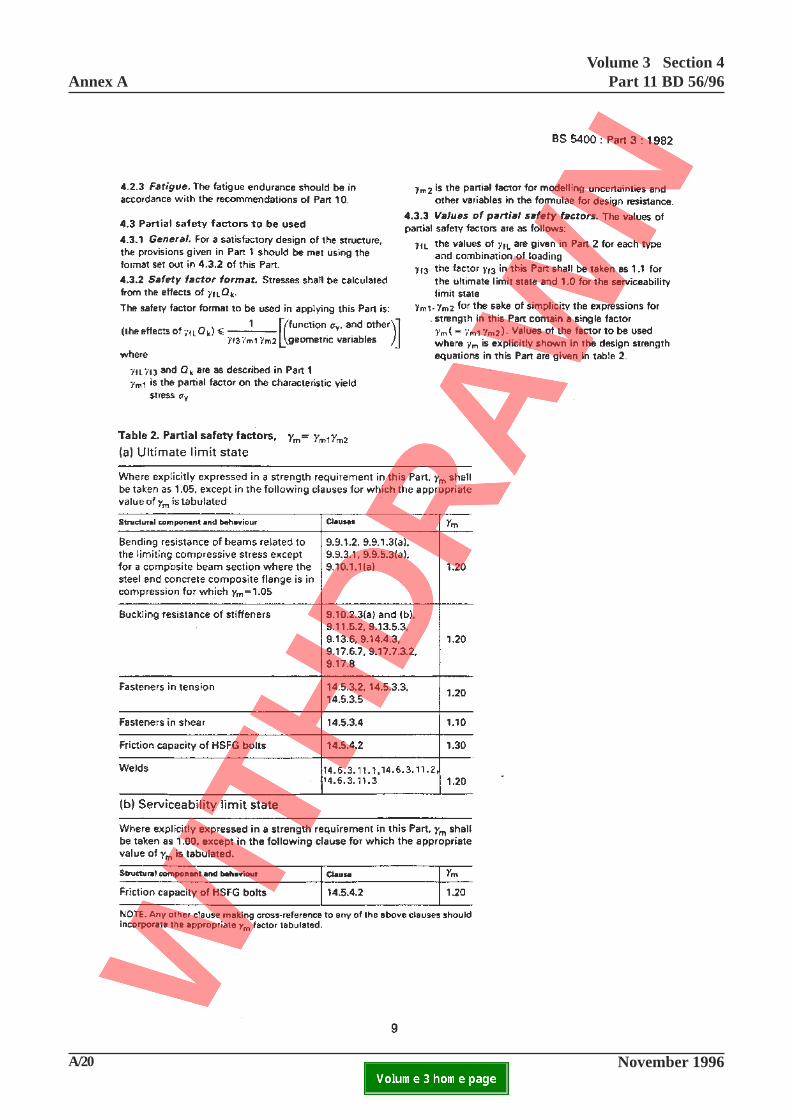
4.3 Partial safety factors to be used
Add the following text under (a) in Table 2:
Structural Components and Clauses γm
Behaviour
Compression members 10.6.1.110.6.3
but not greater than 1.05
4.3.3 Values of partial safety factors
Add at end:
Where alternative methods of calculating strengthor resistance are used the value of resistance shall betaken as:
[the predicted resistance]/ γ m
γf3
where
γ m
in Table 2 is replaced by:
γ m
= (1.05 + 26.5 mcv
2) mmean
mmean
= mtests
+ mst.k
mcv
= mst/m
tests
mtests
= The mean value of the ratiosfor each test between the resistancepredicted using the proposed method andthe measured resistance
mst
= The standard deviation of the ratios foreach test between the resistance predictedusing the proposed method and themeasured resistance
k = A correction factor obtained fromTable 4.3A in which n is the number oftests.
n 2* 3* 4* 5 6 7 8 9 10 11k 4.47 1.69 1.18 0.95 0.82 0.73 0.67 0.62 0.58 0.55
n 12 13 14 15 16 17 18 19 20 21k 0.52 0.49 0.47 0.45 0.44 0.42 0.41 0.40 0.39 0.38
n 22 23 24 25 31 41 61 121 ∞k 0.37 0.36 0.35 0.34 0.31 0.26 0.21 0.15 0.00
NOTE: * The use of less than five tests is not recommended.
Table 4.3A. Sample standard deviation correction factor k
9
0.95 +

Annex AVolume 3 Section 4
Part 11 BD 56/96
A/22 November 1996ELECTRONIC COPY NOT FOR USE OUTSIDE THE AGENCY.PAPER COPIES OF THIS ELECTRONIC DOCUMENT ARE UNCONTROLLED

Volume 3 Section 4Part 11 BD 56/96 Annex A
November 1996 A/23ELECTRONIC COPY NOT FOR USE OUTSIDE THE AGENCY.PAPER COPIES OF THIS ELECTRONIC DOCUMENT ARE UNCONTROLLED
4.5.1 General
Add at end:
Where an existing bridge has inaccessible surfaces anddoes not comply with 4.5.5.1 or 4.5.5.2 as appropriatean assessment of any existing corrosion losses at theinaccessible surfaces shall be made in accordance withAppendix I and either allowance be made in strengthassessment for existing and future losses in accordancewith 8.7 or remedial action taken to reinforce thedamaged part and to reliably protect it againstcorrosion.
No allowance need normally be made for corrosion incarrying out the global analysis to determine themoments and forces in the structures.
4.5.2 Provision of drainage
Add at end:
In assessment of existing sealed box members andother hollow sections checks shall be undertaken todetermine whether water has collected in them. Ifnecessary water shall be drained.
4.5.3 Sealing
The first two paragraphs are not applicable toassessment.
4.5.4 Narrow gaps and spaces
Not applicable to assessment.
5.1 Workmanship
Add at end:
In the assessment of existing structures allowanceshall be made for geometric and other imperfections inaccordance with 8.5.
5.2 Robustness
Not applicable to assessment.
5.4 Composite steel/concrete construction
Add at end:
In assessment of bridges of such construction
composite action shall be assumed only when thestrength of the shear connection between the materialscomplies with the relevant ultimate limit stateprovisions of BD 16 (DMRB 1.3) and the strength ofthe concrete parts using BD 44 (DMRB 3.4). Nocomposite action shall be assumed when the details ofshear connection are not known except as described in8.8.
Where plastic methods of global analysis are used inassessment (see 7.4) of structures in which all or someof the members are of composite construction theassessor shall satisfy himself that the concrete has asufficient strain plateau to permit the development andsustaining of yield line plastic moments in reinforcedconcrete slabs, or plastic moments in composite beamsin which the concrete is in compression. Bridgesconstructed with concrete complying with theworkmanship clauses of the Specification for HighwayWorks (MCHW 1) will satisfy this requirement.
5.5 Built-up members
Add at end:
In assessment of such members which do not complywith the design standard the connections of theirelements shall comply with section 14.
5.6 Diaphragms and fixings required duringconstruction
Add at end:
In assessment of existing structures the possible effectsof any residual defect or other permanent changeresulting from the removal of temporary attachmentsshall be taken into account.
5.7 Camber
Not applicable to assessment.
5.9 Support cross beams
Add at end:
Where in an existing bridge a deck is supported oncross beams and also directly on one or more supportsat a pier or abutment due account shall be taken in theanalysis of the total support system and any restraintswhich it provides.
10
Annex AVolume 3 Section 4
Part 11 BD 56/96
A/24 November 1996ELECTRONIC COPY NOT FOR USE OUTSIDE THE AGENCY.PAPER COPIES OF THIS ELECTRONIC DOCUMENT ARE UNCONTROLLED
Volume 3 Section 4Part 11 BD 56/96 Annex A
November 1996 A/25ELECTRONIC COPY NOT FOR USE OUTSIDE THE AGENCY.PAPER COPIES OF THIS ELECTRONIC DOCUMENT ARE UNCONTROLLED
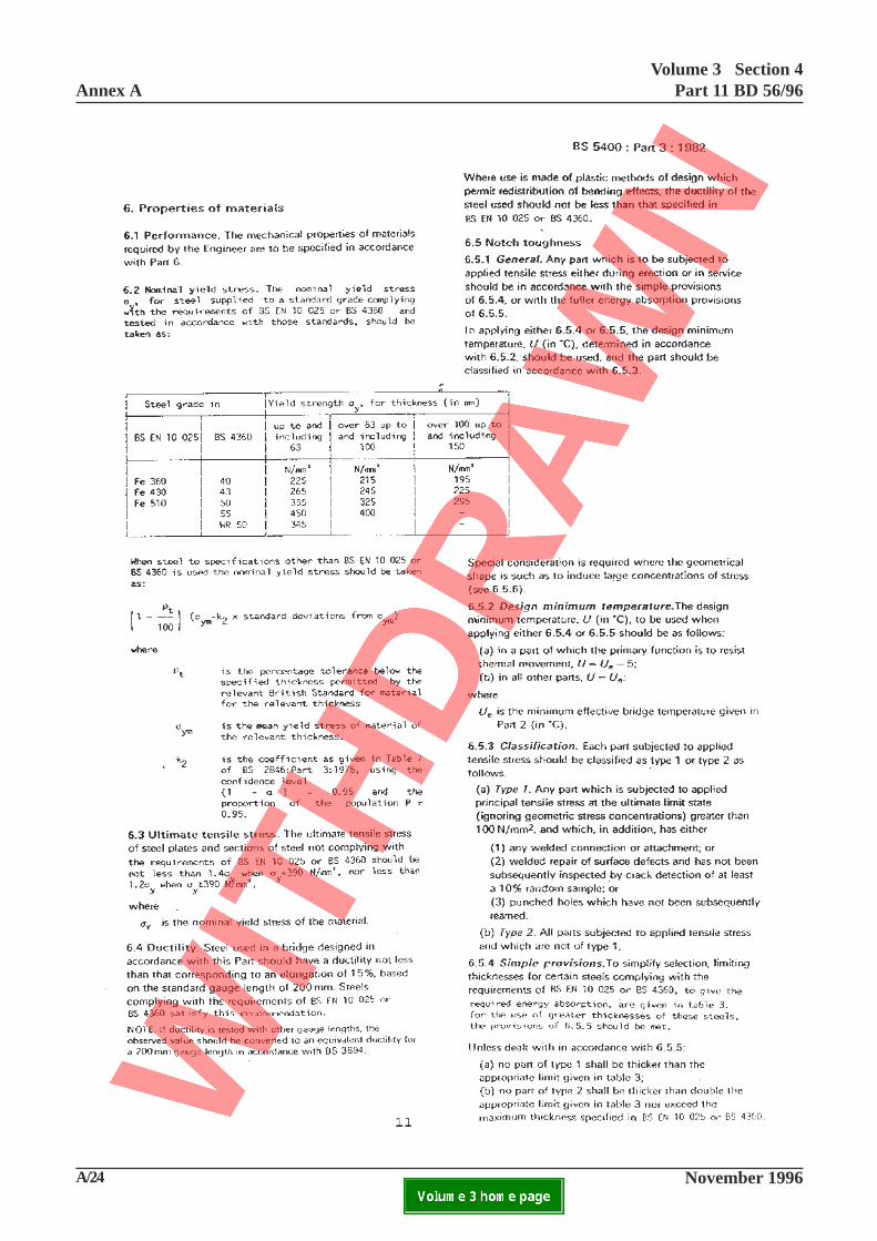
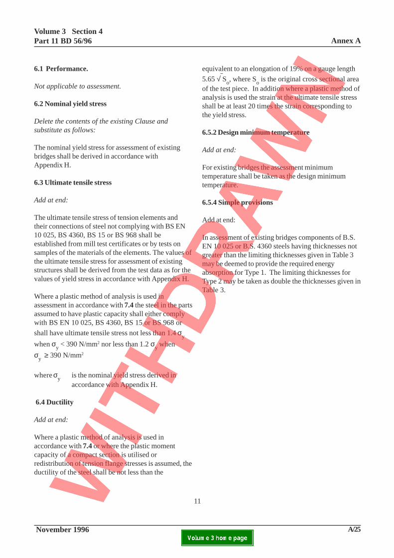
6.1 Performance.
Not applicable to assessment.
6.2 Nominal yield stress
Delete the contents of the existing Clause andsubstitute as follows:
The nominal yield stress for assessment of existingbridges shall be derived in accordance withAppendix H.
6.3 Ultimate tensile stress
Add at end:
The ultimate tensile stress of tension elements andtheir connections of steel not complying with BS EN10 025, BS 4360, BS 15 or BS 968 shall beestablished from mill test certificates or by tests onsamples of the materials of the elements. The values ofthe ultimate tensile stress for assessment of existingstructures shall be derived from the test data as for thevalues of yield stress in accordance with Appendix H.
Where a plastic method of analysis is used inassessment in accordance with 7.4 the steel in the partsassumed to have plastic capacity shall either complywith BS EN 10 025, BS 4360, BS 15 or BS 968 or
shall have ultimate tensile stress not less than 1.4 σy
when σy < 390 N/mm2 nor less than 1.2 σ
y when
σy
≥ 390 N/mm2
where σy
is the nominal yield stress derived inaccordance with Appendix H.
6.4 Ductility
Add at end:
Where a plastic method of analysis is used inaccordance with 7.4 or where the plastic momentcapacity of a compact section is utilised orredistribution of tension flange stresses is assumed, theductility of the steel shall be not less than the
equivalent to an elongation of 19% on a gauge length
5.65 √ So, where S
o is the original cross sectional area
of the test piece. In addition where a plastic method ofanalysis is used the strain at the ultimate tensile stressshall be at least 20 times the strain corresponding tothe yield stress.
6.5.2 Design minimum temperature
Add at end:
For existing bridges the assessment minimumtemperature shall be taken as the design minimumtemperature.
6.5.4 Simple provisions
Add at end:
In assessment of existing bridges components of B.S.EN 10 025 or B.S. 4360 steels having thicknesses notgreater than the limiting thicknesses given in Table 3may be deemed to provide the required energyabsorption for Type 1. The limiting thicknesses forType 2 may be taken as double the thicknesses given inTable 3.
11
Annex AVolume 3 Section 4
Part 11 BD 56/96
A/26 November 1996ELECTRONIC COPY NOT FOR USE OUTSIDE THE AGENCY.PAPER COPIES OF THIS ELECTRONIC DOCUMENT ARE UNCONTROLLED

Volume 3 Section 4Part 11 BD 56/96 Annex A
November 1996 A/27ELECTRONIC COPY NOT FOR USE OUTSIDE THE AGENCY.PAPER COPIES OF THIS ELECTRONIC DOCUMENT ARE UNCONTROLLED
12
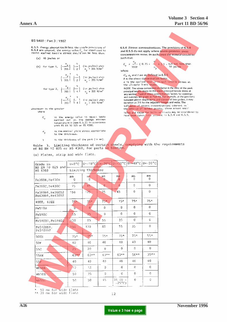
6.5.5 Energy Absorption
Add at end:
When Charpy tests have been undertaken at test
temperature Ut differing from the assessment minimum
temperature (U) the results shall be extrapolated usingthe temperature-impact-value relation in Note 4 toTable 3, where T is redefined as the appropriatetemperature for the extrapolation, subject to thefollowing limitations:
(a) linear interpolation may be used withinthe table,
(b) maximum effective Cv is 67 joules,
(c) If Ut-U exceeds 10oC, C
v is 0 joules,
(d) U-Ut not to exceed 30 C.
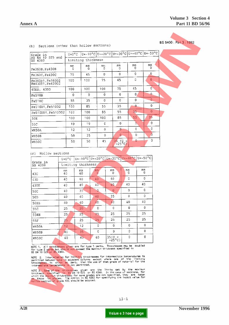
Table 3 Limiting thickness of certain steels,complying with the requirements of BS EN 10 025or BS 4360, for parts in tension
(a) Plates, strip and wide flats
Delete ‘*’ appended to the limiting thickness for grade50EE and insert ‘**’
Delete ‘**’ appended to the limiting thickness forgrade 55EE and insert ‘*’.
Add new clause 6.5.7
6.5.7 Assessment of notch toughness
Where in the assessment of the adequacy of the bridgeeither the tensile components do not satisfy theprovisions of 6.5.4 or the impact energy absorptionvalues for the tensile components are unknown thenotch toughness of the material may be determined bytesting samples taken from non-critical parts of thecomponents and compliance demonstrated with 6.5.5or 6.5.6 as appropriate.
Where the notch toughness of the steel does not meetthe requirements of 6.5.5 or 6.5.6 the service andloading history of the bridge may be taken intoconsideration with the agreement of the OverseeingOrganisation. Further guidelines are given in theaccompanying Advice Note.
Annex AVolume 3 Section 4
Part 11 BD 56/96
A/28 November 1996ELECTRONIC COPY NOT FOR USE OUTSIDE THE AGENCY.PAPER COPIES OF THIS ELECTRONIC DOCUMENT ARE UNCONTROLLED

Volume 3 Section 4Part 11 BD 56/96 Annex A
November 1996 A/29ELECTRONIC COPY NOT FOR USE OUTSIDE THE AGENCY.PAPER COPIES OF THIS ELECTRONIC DOCUMENT ARE UNCONTROLLED
13-1
This page is blank

Annex AVolume 3 Section 4
Part 11 BD 56/96
A/30 November 1996ELECTRONIC COPY NOT FOR USE OUTSIDE THE AGENCY.PAPER COPIES OF THIS ELECTRONIC DOCUMENT ARE UNCONTROLLED

Volume 3 Section 4Part 11 BD 56/96 Annex A
November 1996 A/31ELECTRONIC COPY NOT FOR USE OUTSIDE THE AGENCY.PAPER COPIES OF THIS ELECTRONIC DOCUMENT ARE UNCONTROLLED
13-2
This page is blank
Annex A
Volume 3 Section 4
Part 11 BD 56/96
A/32 November 1996ELECTRONIC COPY NOT FOR USE OUTSIDE THE AGENCY.PAPER COPIES OF THIS ELECTRONIC DOCUMENT ARE UNCONTROLLED
Volume 3 Section 4Part 11 BD 56/96 Annex A
November 1996 A/33ELECTRONIC COPY NOT FOR USE OUTSIDE THE AGENCY.PAPER COPIES OF THIS ELECTRONIC DOCUMENT ARE UNCONTROLLED
14
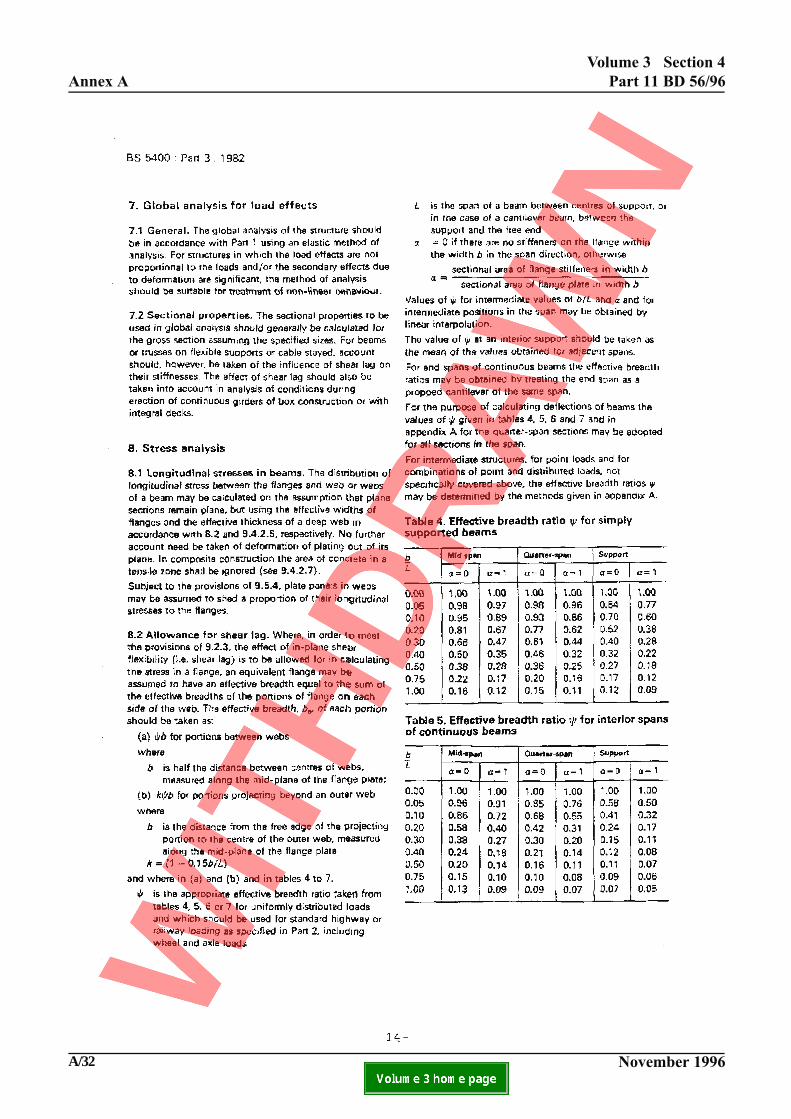
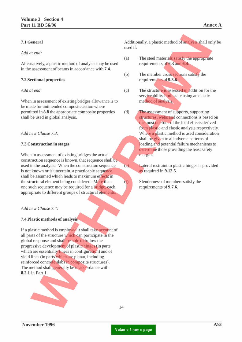
7.1 General
Add at end:
Alternatively, a plastic method of analysis may be usedin the assessment of beams in accordance with 7.4.
7.2 Sectional properties
Add at end:
When in assessment of existing bridges allowance is tobe made for unintended composite action wherepermitted in 8.8 the appropriate composite propertiesshall be used in global analysis.
Add new Clause 7.3:
7.3 Construction in stages
When in assessment of existing bridges the actualconstruction sequence is known, that sequence shall beused in the analysis. When the construction sequenceis not known or is uncertain, a practicable sequenceshall be assumed which leads to maximum effects inthe structural element being considered. More thanone such sequence may be required for a bridge, eachappropriate to different groups of structural elements.
Add new Clause 7.4:
7.4 Plastic methods of analysis
If a plastic method is employed it shall take account ofall parts of the structure which can participate in theglobal response and shall be able to follow theprogressive development of plastic hinges (in partswhich are essentially linear in configuration) and ofyield lines (in parts which are planar, includingreinforced concrete slabs in composite structures).The method shall generally be in accordance with8.2.1 in Part 1.
Additionally, a plastic method of analysis shall only beused if:
(a) The steel materials satisfy the appropriaterequirements of 6.3 and 6.4.
(b) The member cross sections satisfy therequirements of 9.3.8.
(c) The structure is assessed in addition for theserviceability limit state using an elasticmethod of analysis.
(d) The assessment of supports, supportingstructures, webs and connections is based onthe most onerous of the load effects derivedfrom plastic and elastic analysis respectively.Where a plastic method is used considerationshall be given to all adverse patterns ofloading and potential failure mechanisms todetermine those providing the least safetymargins.
(e) Lateral restraint to plastic hinges is providedas required in 9.12.5.
(f) Slenderness of members satisfy therequirements of 9.7.6.

Annex AVolume 3 Section 4
Part 11 BD 56/96
A/34 November 1996ELECTRONIC COPY NOT FOR USE OUTSIDE THE AGENCY.PAPER COPIES OF THIS ELECTRONIC DOCUMENT ARE UNCONTROLLED
15-1
Volume 3 Section 4Part 11 BD 56/96 Annex A
November 1996 A/35ELECTRONIC COPY NOT FOR USE OUTSIDE THE AGENCY.PAPER COPIES OF THIS ELECTRONIC DOCUMENT ARE UNCONTROLLED
15-1
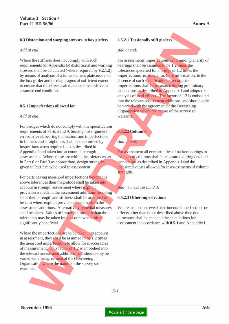
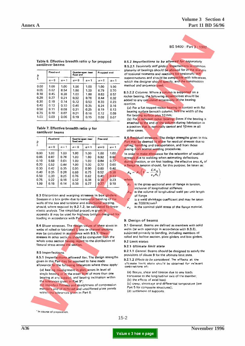
8.3 Distortion and warping stresses in box girders
Add at end:
Where the stiffness does not comply with suchrequirements (of Appendix B) distortional and warpingstresses shall be calculated (where required by 9.2.1.2)by means of analysis of a finite element plate model ofthe box girder and its diaphragms of sufficient extentto ensure that the effects calculated are insensitive toassumed end conditions.
8.5.1 Imperfections allowed for
Add at end:
For bridges which do not comply with the specificationrequirements of Parts 6 and 9, bearing misalignment,errors in level, bearing inclination, and imperfectionsin flatness and straightness shall be determined byinspections when required and as described inAppendix I and taken into account in strengthassessments. Where these are within the tolerances setin Part 6 or Part 9 as appropriate, design strengthsgiven in Part 3 may be used in assessment.
For parts having measured imperfections beyond theabove tolerances their magnitude shall be taken intoaccount in strength assessment where explicitprovision is made in the assessment additions for doingso or their strength and stiffness shall be assumed tobe zero where explicit provision is not made in theassessment additions. Alternatively remedial measuresshall be taken. Values of imperfections less than thetolerances may be taken into account when this issignificantly beneficial.
Where the imperfections are to be taken into accountin assessment, they shall be assumed to be 1.2 timesthe measured imperfections to allow for inaccuraciesof measurement. This factor of 1.2 is embodied intothe relevant assessment additions, and should only bevaried with the agreement of the OverseeingOrganisation where the nature of the survey sowarrants.
8.5.2.1 Torsionally stiff girders
Add at end:
For assessments imperfections in common planarity ofbearings shall be assumed to be 1.2 times thetolerances specified for a bridge or 1.2 times theimperfections recorded in as-built information. In theabsence of such specification or records theimperfections shall be measured during preliminaryinspections as described in Appendix I and adopted inanalysis of load effects. The factor of 1.2 is embodiedinto the relevant assessment additions, and should onlybe varied with the agreement of the OverseeingOrganisation where the nature of the survey sowarrants.
8.5.2.2 Columns
Add at end:
For assessment all eccentricities of rocker bearings tothe axes of columns shall be measured during detailedinspections as described in Appendix I and themeasured values allowed for in assessments of columnstrengths.
Add new Clause 8.5.2.3:
8.5.2.3 Other imperfections
Where inspection reveals detrimental imperfections oreffects other than those described above then dueallowance shall be made in the calculations forassessment in accordance with 8.5.1 and Appendix I.
Annex AVolume 3 Section 4
Part 11 BD 56/96
A/36 November 1996ELECTRONIC COPY NOT FOR USE OUTSIDE THE AGENCY.PAPER COPIES OF THIS ELECTRONIC DOCUMENT ARE UNCONTROLLED
15-2

Volume 3 Section 4Part 11 BD 56/96 Annex A
November 1996 A/37ELECTRONIC COPY NOT FOR USE OUTSIDE THE AGENCY.PAPER COPIES OF THIS ELECTRONIC DOCUMENT ARE UNCONTROLLED
15-2
Add new Clause 8.7:
8.7 Variations in structural dimensions
Measured section sizes shall be used in assessment ofstrength of all critical sections, see Appendix I. Dueaccount shall be taken of any existing or projectedfuture losses of section due to corrosion in accordancewith 4.5.5. No changes are to be made to partialsafety factors when using the measured dimensions.
Add new Clause 8.8:
8.8 Originally unintended composite action
8.8.1 General
Stiffnesses and strengths calculated for steel sectionsnot originally intended as acting compositely can beenhanced by consideration of composite action withadjacent or surrounding structure with appropriatereference to Part 5 where conditions are achieved asgiven in 8.8.2 or 8.8.3.
8.8.2 Cased beams or filler beams or jack archdecks
For cased beams and concrete filler beams the stressanalysis shall be based on composite properties toClauses 8.1, 8.2, 8.3, 8.4, 8.5.1 and 8.5.2 of Part 5where there is no evidence of excessive corrosion,fretting action or cracking sufficient to adversely affectthe achievement of composite action. Sections can beassumed to be compact where the compression flangeand webs are cased on both sides, and any uncasedsection remaining is also compact. Where therequirements for resistance to longitudinal shear arenot met then the beams shall be assessed on the basisof the properties of the steel section only, and may beassumed to be compact carrying the entire load.
Alternatively where attachments to the beams aresufficent to prevent relative longitudinal slip (such asrivet or bolt heads or other transverse elements) asdemonstrated by push-out tests or by appropriateevidence then these may be assumed to transmit the
longitudinal shear forces. For dense brickwork fillerbeam or jack arch decks global and stress analysisshall be based on composite properties provided thatthe bending resistance of the composite section shallnot be taken as greater than 30% in excess of thecalculated resistance of the steel section alone.
8.8.3 Concrete slab and steel beam decks
For concrete slab and steel beam decks global andstress analysis using composite properties can be usedprovided:
(a) At the steel/concrete interfaces there is no evidenceof corrosion, fretting action, relative longitudinal slipor cracking sufficient to affect the required compositeaction.
(b) The attachments to the beams at the interface aresufficient to prevent relative slip (such as rivet or boltheads or other transverse elements) as demonstrated bypush-out tests or by appropriate evidence.
(c) Appropriate site testing is carried out todemonstrate that the live load : stiffness relationship issupportive of the composite action achieved, where theamount of composite action is required to increase thedesign strength by 30% or more. Normally loadingapproximately equivalent to the nominal calculatedlive load capacity of the steel section only shall beapplied.
9.2.1.2 Effects to be considered
Add at end:
(e) the effects of restraint of distortional warping andtransverse distortional bending.
Annex AVolume 3 Section 4
Part 11 BD 56/96
A/38 November 1996ELECTRONIC COPY NOT FOR USE OUTSIDE THE AGENCY.PAPER COPIES OF THIS ELECTRONIC DOCUMENT ARE UNCONTROLLED
16-1
Volume 3 Section 4Part 11 BD 56/96 Annex A
November 1996 A/39ELECTRONIC COPY NOT FOR USE OUTSIDE THE AGENCY.PAPER COPIES OF THIS ELECTRONIC DOCUMENT ARE UNCONTROLLED
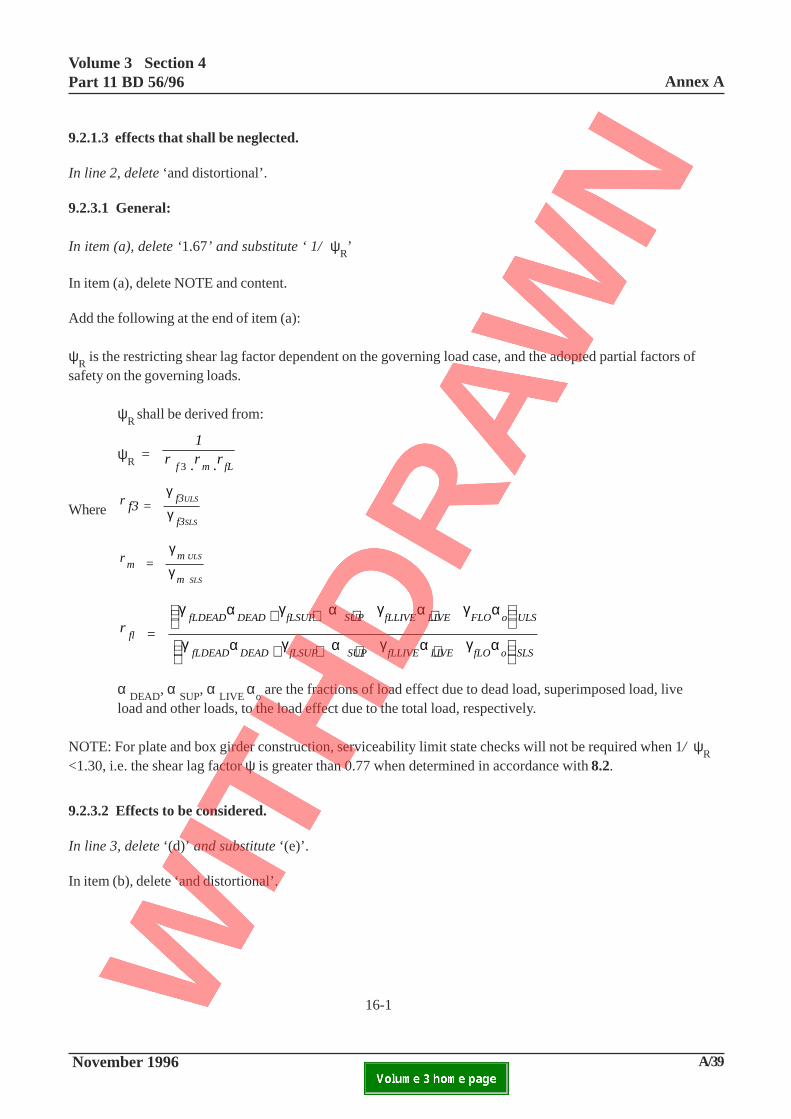
9.2.3.2 Effects to be considered.
In line 3, delete ‘(d)’ and substitute ‘(e)’.
In item (b), delete ‘and distortional’.
9.2.1.3 effects that shall be neglected.
In line 2, delete ‘and distortional’.
9.2.3.1 General:
In item (a), delete ‘1.67’ and substitute ‘ 1/ ψR’
In item (a), delete NOTE and content.
Add the following at the end of item (a):
ψR is the restricting shear lag factor dependent on the governing load case, and the adopted partial factors of
safety on the governing loads.
ψR
shall be derived from:
ψR
=
1r .r .rf m fL3
Wherer f3 =
f3
f3
ULS
SLS
γ
γ
r = m m
m
ULS
SLS
γ
γ
r = fl
fLDEAD DEAD fLSUP SUP fLLIVE LIVE FLO o ULS
fLDEAD DEAD fLSUP SUP fLLIVE LIVE fLO o SLS
γ α γ α γ α γ α
γ α γ α γ α γ α
+ + + +
+ + + +
α DEAD
, α SUP
, α LIVE
αo are the fractions of load effect due to dead load, superimposed load, live
load and other loads, to the load effect due to the total load, respectively.
NOTE: For plate and box girder construction, serviceability limit state checks will not be required when 1/ ψR
<1.30, i.e. the shear lag factor ψ is greater than 0.77 when determined in accordance with 8.2.
16-1
Annex AVolume 3 Section 4
Part 11 BD 56/96
A/40 November 1996ELECTRONIC COPY NOT FOR USE OUTSIDE THE AGENCY.PAPER COPIES OF THIS ELECTRONIC DOCUMENT ARE UNCONTROLLED
16-2

Volume 3 Section 4Part 11 BD 56/96 Annex A
November 1996 A/41ELECTRONIC COPY NOT FOR USE OUTSIDE THE AGENCY.PAPER COPIES OF THIS ELECTRONIC DOCUMENT ARE UNCONTROLLED
16-2
9.3.1 General
Delete the existing clause and substitute thefollowing:-
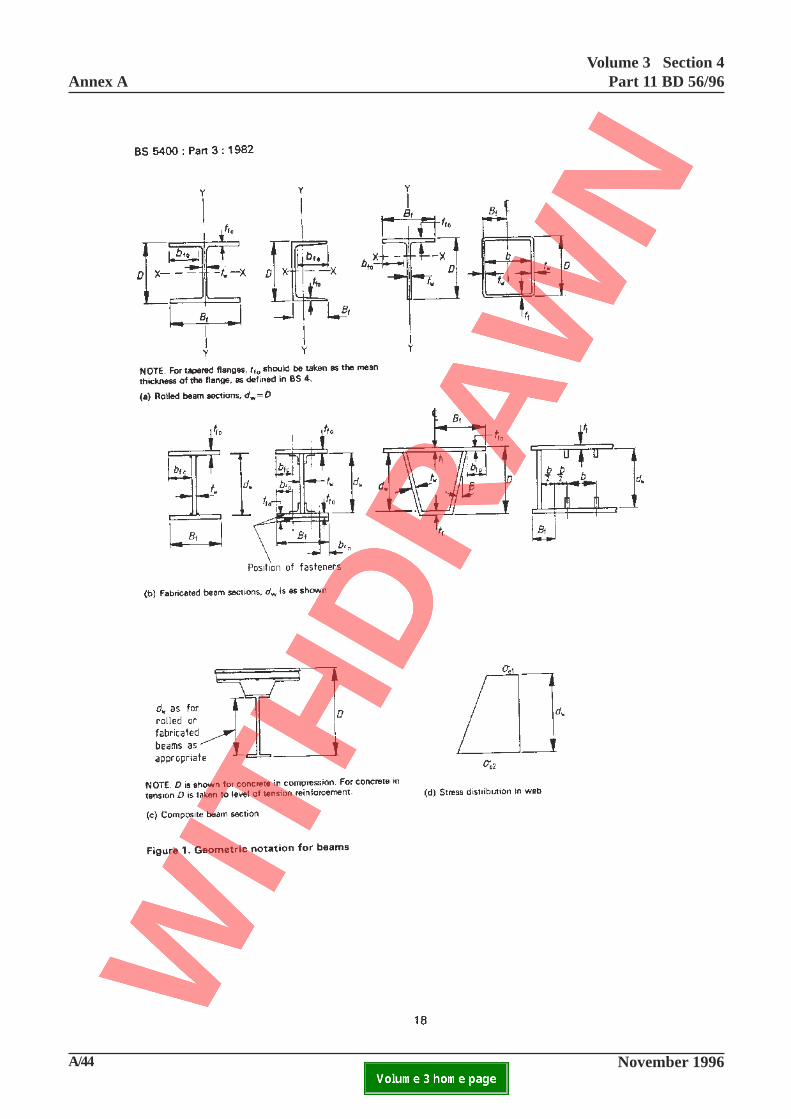
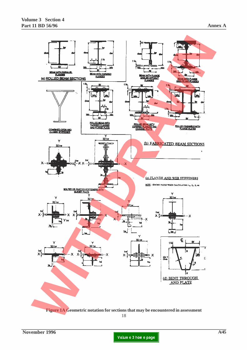
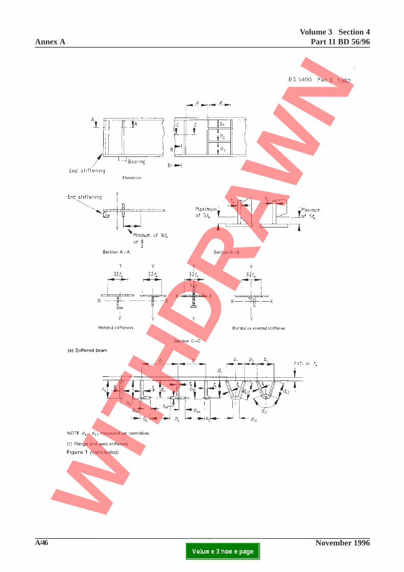
Figures 1 and 1A sets out the geometric notation usedthroughout this section.
Where the proportions of flanges, stiffeners or hollowsections comply with the requirements of 9.3.2.1, 9.3.4and 9.3.6, taking σ
ys or σ
y as the yield stress of the
material as defined in 6.2, the strength of the sectionsshall be determined as specified in the appropriateclauses of this standard relating to assessment of
strength, using this value of σys
or σy
where:
σ ys
relates to the stiffener
σ y
relates to the flange, the web or thecircular hollow sections, as appropriate.
Where the proportions do not thus comply, a lower
value of σ ys
or σ y
shall be determined such thatcompliance with 9.3.2.1, 9.3.4 or 9.3.6 as appropriate
is achieved, and this lower value of σ ys
or σ y shall
be used in all subsequent assessments of strength.
9.3.2.1 Outstands in compression.
On the third and fourth lines, delete ‘or 16 whicheveris the lesser’.
Add at end:
See 9.3.1 for assessment of non-complying outstandsin compression.
9.3.2.2 Outstands in tension.
Not applicable to assessment.
9.3.3.1 General
Add at end:
Openings rounded with a radius of less than ¼ of theleast dimension of the hole, or any openings notcomplying with any of the requirements of 9.3.3.2,shall be inspected individually for evidence ofcracking. They shall be assessed for the effects onfatigue life and brittle fracture propensity of stressconcentrations. Detailed local analyses, e.g. finiteelement analysis, shall be carried out whereappropriate.
Annex AVolume 3 Section 4
Part 11 BD 56/96
A/42 November 1996ELECTRONIC COPY NOT FOR USE OUTSIDE THE AGENCY.PAPER COPIES OF THIS ELECTRONIC DOCUMENT ARE UNCONTROLLED
Volume 3 Section 4Part 11 BD 56/96 Annex A
November 1996 A/43ELECTRONIC COPY NOT FOR USE OUTSIDE THE AGENCY.PAPER COPIES OF THIS ELECTRONIC DOCUMENT ARE UNCONTROLLED
17
9.3.4.1.1. General.
Add at end:
See 9.3.1 and Appendix S of the accompanyingAdvice Note for the assessment of non-complyingstiffener configurations. Other shapes of stiffenersother than those specified shall be assessed on thebasis of the nearest standard shape.
9.3.4.1.3 Bulb flat stiffeners
Add at end:
For assessment, the requirement in this subclause maybe omitted.
9.3.4.1.4 Angle stiffeners
Add at end:
For assessment, the requirement in this subclause maybe omitted.
9.3.4.1.5 Tee stiffeners
In item (c) (2), delete σys / 355 and substitute
σy / 355
9.3.4.2 Closed stiffeners to webs and compressionflanges.
Add at end:
See 9.3.1 and Appendix S of the accompanyingAdvice Note BA 56 for the assessment of non-complying stiffener configurations. Shapes ofstiffeners other than those specified shall be assessedon the basis of the nearest standard shape.
Add new Clause 9.3.4.3:
9.3.4.3 Combinations of closed and open stiffener
A stiffener fabricated from a combination of closedand open sections shall be proportioned such thatindividual components meet the requirements of9.3.4.1 or 9.3.4.2 as appropriate.
When an element is not connected directly to theparent plate, no benefit shall be assumed from therestraining effect of the parent plate when usingAppendix S or any other method.
Annex AVolume 3 Section 4
Part 11 BD 56/96
A/44 November 1996ELECTRONIC COPY NOT FOR USE OUTSIDE THE AGENCY.PAPER COPIES OF THIS ELECTRONIC DOCUMENT ARE UNCONTROLLED
Volume 3 Section 4Part 11 BD 56/96 Annex A
November 1996 A/45ELECTRONIC COPY NOT FOR USE OUTSIDE THE AGENCY.PAPER COPIES OF THIS ELECTRONIC DOCUMENT ARE UNCONTROLLED
Figure 1A Geometric notation for sections that may be encountered in assessment18
Annex AVolume 3 Section 4
Part 11 BD 56/96
A/46 November 1996ELECTRONIC COPY NOT FOR USE OUTSIDE THE AGENCY.PAPER COPIES OF THIS ELECTRONIC DOCUMENT ARE UNCONTROLLED

Volume 3 Section 4Part 11 BD 56/96 Annex A
November 1996 A/47ELECTRONIC COPY NOT FOR USE OUTSIDE THE AGENCY.PAPER COPIES OF THIS ELECTRONIC DOCUMENT ARE UNCONTROLLED
This page is blank
19
Annex AVolume 3 Section 4
Part 11 BD 56/96
A/48 November 1996ELECTRONIC COPY NOT FOR USE OUTSIDE THE AGENCY.PAPER COPIES OF THIS ELECTRONIC DOCUMENT ARE UNCONTROLLED

Volume 3 Section 4Part 11 BD 56/96 Annex A
November 1996 A/49ELECTRONIC COPY NOT FOR USE OUTSIDE THE AGENCY.PAPER COPIES OF THIS ELECTRONIC DOCUMENT ARE UNCONTROLLED
This page is blank
20
Annex AVolume 3 Section 4
Part 11 BD 56/96
A/50 November 1996ELECTRONIC COPY NOT FOR USE OUTSIDE THE AGENCY.PAPER COPIES OF THIS ELECTRONIC DOCUMENT ARE UNCONTROLLED
21-1
A/51 November 1996
Volume 3 Section 4Part 11 BD 56/96 Annex A
ELECTRONIC COPY NOT FOR USE OUTSIDE THE AGENCY.PAPER COPIES OF THIS ELECTRONIC DOCUMENT ARE UNCONTROLLED
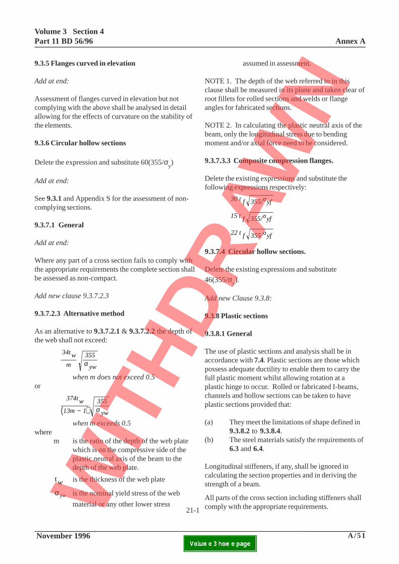
9.3.5 Flanges curved in elevation
Add at end:
Assessment of flanges curved in elevation but notcomplying with the above shall be analysed in detailallowing for the effects of curvature on the stability ofthe elements.
9.3.6 Circular hollow sections
Delete the expression and substitute 60(355/σy)
Add at end:
See 9.3.1 and Appendix S for the assessment of non-complying sections.
9.3.7.1 General
Add at end:
Where any part of a cross section fails to comply withthe appropriate requirements the complete section shallbe assessed as non-compact.
Add new clause 9.3.7.2.3
9.3.7.2.3 Alternative method
As an alternative to 9.3.7.2.1 & 9.3.7.2.2 the depth ofthe web shall not exceed:
34tw
m
355
ywσ
when m does not exceed 0.5or
( )374tw
13m 1
355
yw− σ
when m exceeds 0.5where
m is the ratio of the depth of the web platewhich is on the compressive side of theplastic neutral axis of the beam to thedepth of the web plate.
tw is the thickness of the web plate
σ yw is the nominal yield stress of the web
material or any other lower stress
assumed in assessment.
NOTE 1. The depth of the web referred to in thisclause shall be measured in its plane and taken clear ofroot fillets for rolled sections and welds or flangeangles for fabricated sections.
NOTE 2. In calculating the plastic neutral axis of thebeam, only the longitudinal stress due to bendingmoment and/or axial force need to be considered.
9.3.7.3.3 Composite compression flanges.
Delete the existing expressions and substitute thefollowing expressions respectively:
30 t f 355/ yfσ
15 t f 355/ yfσ
22 t f 355/ yfσ
9.3.7.4 Circular hollow sections.
Delete the existing expressions and substitute
46(355/σy).
Add new Clause 9.3.8:
9.3.8 Plastic sections
9.3.8.1 General
The use of plastic sections and analysis shall be inaccordance with 7.4. Plastic sections are those whichpossess adequate ductility to enable them to carry thefull plastic moment whilst allowing rotation at aplastic hinge to occur. Rolled or fabricated I-beams,channels and hollow sections can be taken to haveplastic sections provided that:
(a) They meet the limitations of shape defined in9.3.8.2 to 9.3.8.4.
(b) The steel materials satisfy the requirements of6.3 and 6.4.
Longitudinal stiffeners, if any, shall be ignored incalculating the section properties and in deriving thestrength of a beam.
All parts of the cross section including stiffeners shallcomply with the appropriate requirements.21-1

Annex AVolume 3 Section 4
Part 11 BD 56/96
A/52 November 1996ELECTRONIC COPY NOT FOR USE OUTSIDE THE AGENCY.PAPER COPIES OF THIS ELECTRONIC DOCUMENT ARE UNCONTROLLED
21-2
A/53 November 1996
Volume 3 Section 4Part 11 BD 56/96 Annex A
ELECTRONIC COPY NOT FOR USE OUTSIDE THE AGENCY.PAPER COPIES OF THIS ELECTRONIC DOCUMENT ARE UNCONTROLLED
21-2
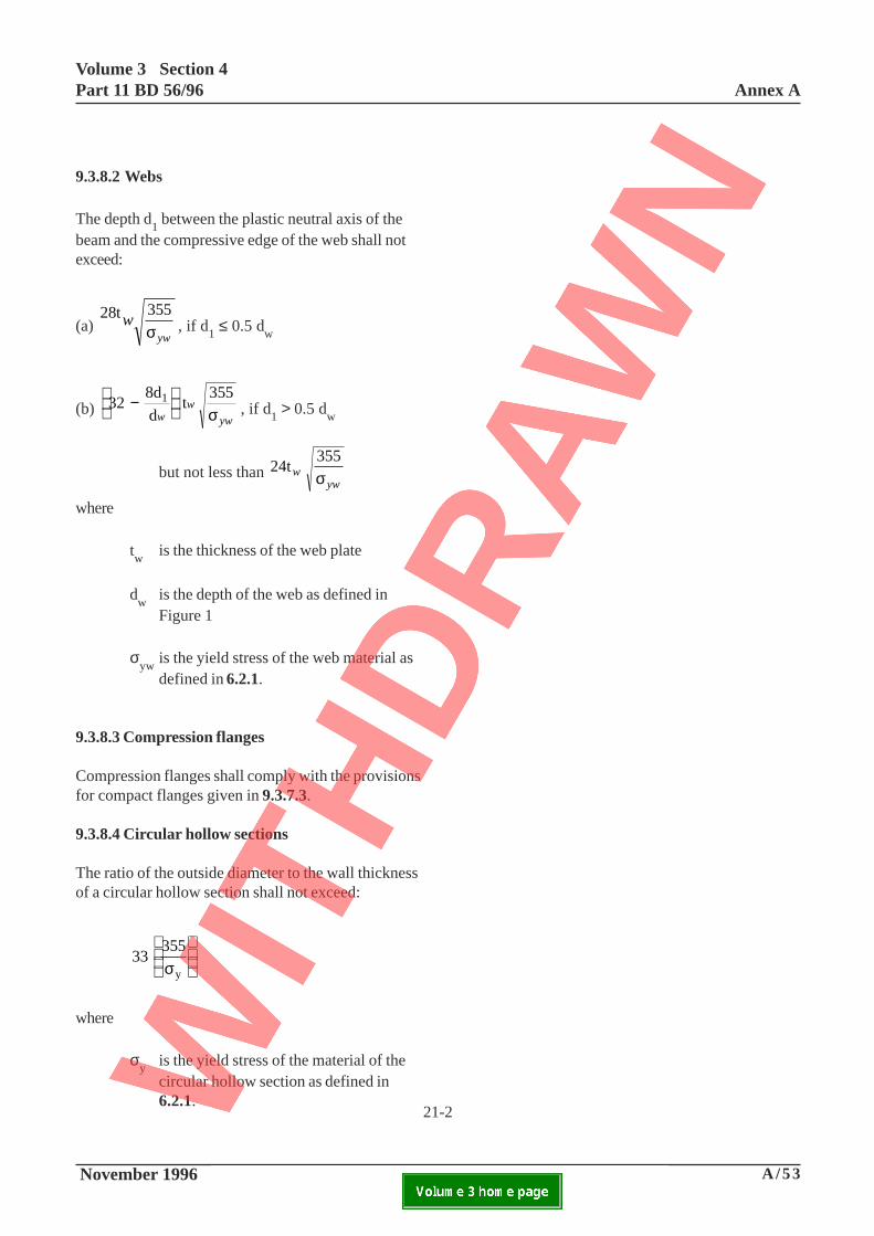
9.3.8.2 Webs
The depth d1 between the plastic neutral axis of the
beam and the compressive edge of the web shall notexceed:
(a) 28t 355
wywσ , if d1 ≤ 0.5 dw
(b) 328d
d t
3551 −
w
w
ywσ , if d1 > 0.5 dw
but not less than 24t355
w ywσ
where
tw
is the thickness of the web plate
dw
is the depth of the web as defined inFigure 1
σyw
is the yield stress of the web material asdefined in 6.2.1.
9.3.8.3 Compression flanges
Compression flanges shall comply with the provisionsfor compact flanges given in 9.3.7.3.
9.3.8.4 Circular hollow sections
The ratio of the outside diameter to the wall thicknessof a circular hollow section shall not exceed:
33 355
yσ
where
σy
is the yield stress of the material of thecircular hollow section as defined in6.2.1.
Annex AVolume 3 Section 4
Part 11 BD 56/96
A/54 November 1996ELECTRONIC COPY NOT FOR USE OUTSIDE THE AGENCY.PAPER COPIES OF THIS ELECTRONIC DOCUMENT ARE UNCONTROLLED

A/55 November 1996
Volume 3 Section 4Part 11 BD 56/96 Annex A
ELECTRONIC COPY NOT FOR USE OUTSIDE THE AGENCY.PAPER COPIES OF THIS ELECTRONIC DOCUMENT ARE UNCONTROLLED
22
9.4.2.4 Effective compression flange
In line 3, delete ‘Kcbt’ and substitute ‘K
ck
hA
c’
Delete definitions for b and t
Add the following definitions:
kh = 1.0 for a part free from holes or for a part
with one or more holes greater than40 mm in diameter, or 1.2 for a part inwhich holes do not exceed 40 mm in
diameter, provided that khA
c in no case
exceeds the gross area of the part.
Ac
is the net area of each part, derived fromthe gross area, less a deduction across asection perpendicular to the centre line ofthe part for open holes or clearance holesfor pins, black bolts or countersunk bolts.Holes carrying rivets, HSFG, closetolerance or turned barrel bolts, or fullyfilled plug holes, need not be deducted.
Delete the entire ‘NOTE 2’ and substitute thefollowing ‘NOTE 2’:
NOTE 2: The values of λ for plating given in 9.10.2.2may be adopted when assessing the adequacy oflongitudinal flange stiffeners complying with (a) abovein accordance with 9.10.2.3 and 9.10.3.3.2.
Annex AVolume 3 Section 4
Part 11 BD 56/96
A/56 November 1996ELECTRONIC COPY NOT FOR USE OUTSIDE THE AGENCY.PAPER COPIES OF THIS ELECTRONIC DOCUMENT ARE UNCONTROLLED

A/57 November 1996
Volume 3 Section 4Part 11 BD 56/96 Annex A
ELECTRONIC COPY NOT FOR USE OUTSIDE THE AGENCY.PAPER COPIES OF THIS ELECTRONIC DOCUMENT ARE UNCONTROLLED
This page is blank
23
Annex AVolume 3 Section 4
Part 11 BD 56/96
A/58 November 1996ELECTRONIC COPY NOT FOR USE OUTSIDE THE AGENCY.PAPER COPIES OF THIS ELECTRONIC DOCUMENT ARE UNCONTROLLED
A/59 November 1996
Volume 3 Section 4Part 11 BD 56/96 Annex A
ELECTRONIC COPY NOT FOR USE OUTSIDE THE AGENCY.PAPER COPIES OF THIS ELECTRONIC DOCUMENT ARE UNCONTROLLED
9.5.4 Redistribution of web stresses in alongitudinally stiffened beam.
Add at end:
The effective longitudinal stiffness of the web panels,from which stress is assumed to be redistributed, shall
be reduced by a fraction ρw (equivalent to using a
modular ratio for the panels of (1- ρw)). The modified
properties of the cross section shall be used tocalculate the revised longitudinal stress distributioneither from the load effects calculated by use of thegross section properties in the global analysis or byuse of those calculated using the modified propertiesfor those portions of the beam in which redistributionis assumed. Due account shall be taken of any changein bending moment due to longitudinal loads resultingfrom change in effective centroid position.
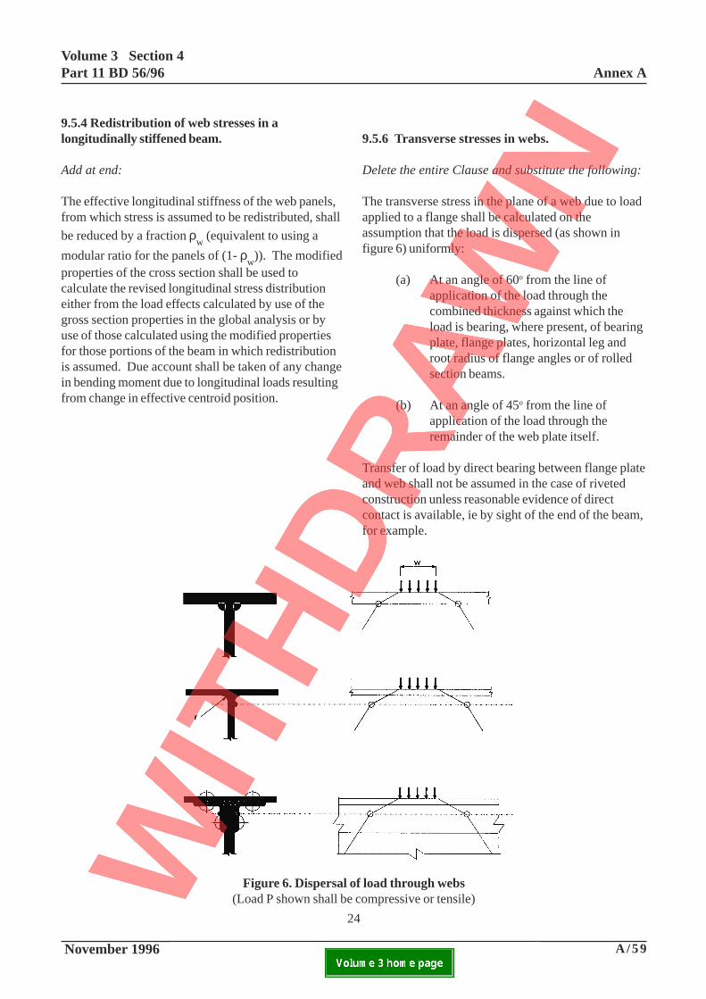
9.5.6 Transverse stresses in webs.
Delete the entire Clause and substitute the following:
The transverse stress in the plane of a web due to loadapplied to a flange shall be calculated on theassumption that the load is dispersed (as shown infigure 6) uniformly:
(a) At an angle of 60o from the line ofapplication of the load through thecombined thickness against which theload is bearing, where present, of bearingplate, flange plates, horizontal leg androot radius of flange angles or of rolledsection beams.
(b) At an angle of 45o from the line ofapplication of the load through theremainder of the web plate itself.
Transfer of load by direct bearing between flange plateand web shall not be assumed in the case of rivetedconstruction unless reasonable evidence of directcontact is available, ie by sight of the end of the beam,for example.
24
Figure 6. Dispersal of load through webs(Load P shown shall be compressive or tensile)
Annex AVolume 3 Section 4
Part 11 BD 56/96
A/60 November 1996ELECTRONIC COPY NOT FOR USE OUTSIDE THE AGENCY.PAPER COPIES OF THIS ELECTRONIC DOCUMENT ARE UNCONTROLLED
A/61 November 1996
Volume 3 Section 4Part 11 BD 56/96 Annex A
ELECTRONIC COPY NOT FOR USE OUTSIDE THE AGENCY.PAPER COPIES OF THIS ELECTRONIC DOCUMENT ARE UNCONTROLLED
25
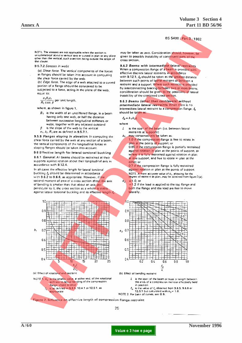
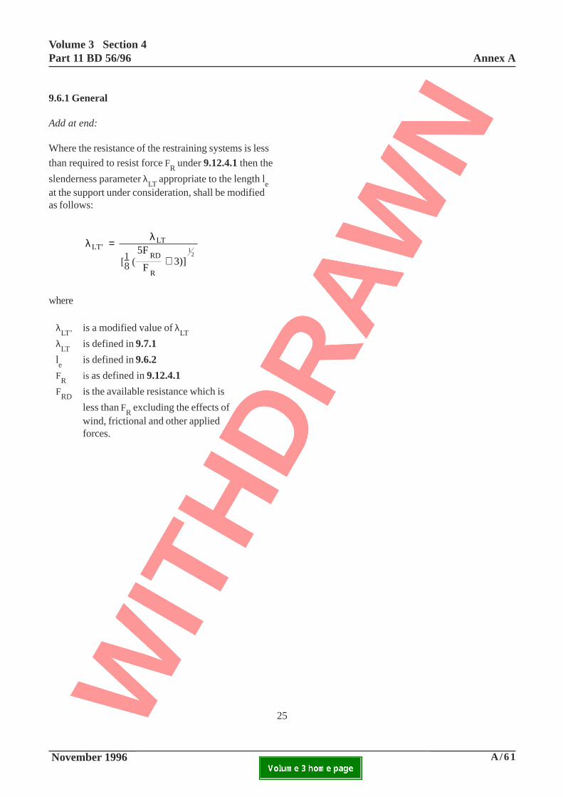
9.6.1 General
Add at end:
Where the resistance of the restraining systems is less
than required to resist force FR under 9.12.4.1 then the
slenderness parameter λLT
appropriate to the length le
at the support under consideration, shall be modifiedas follows:
λ λLT
LT
RD
R
5F
F3)]
12
′ =
+[ (18
where
λLT’
is a modified value of λLT
λLT
is defined in 9.7.1
le
is defined in 9.6.2
FR
is as defined in 9.12.4.1
FRD
is the available resistance which is
less than FR excluding the effects of
wind, frictional and other appliedforces.
[1 ( 8
Annex AVolume 3 Section 4
Part 11 BD 56/96
A/62 November 1996ELECTRONIC COPY NOT FOR USE OUTSIDE THE AGENCY.PAPER COPIES OF THIS ELECTRONIC DOCUMENT ARE UNCONTROLLED
A/63 November 1996
Volume 3 Section 4Part 11 BD 56/96 Annex A
ELECTRONIC COPY NOT FOR USE OUTSIDE THE AGENCY.PAPER COPIES OF THIS ELECTRONIC DOCUMENT ARE UNCONTROLLED
26
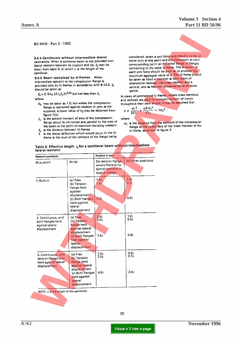
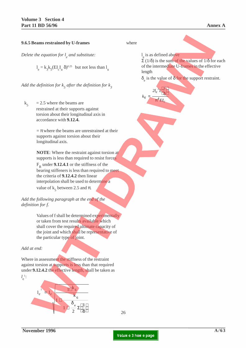
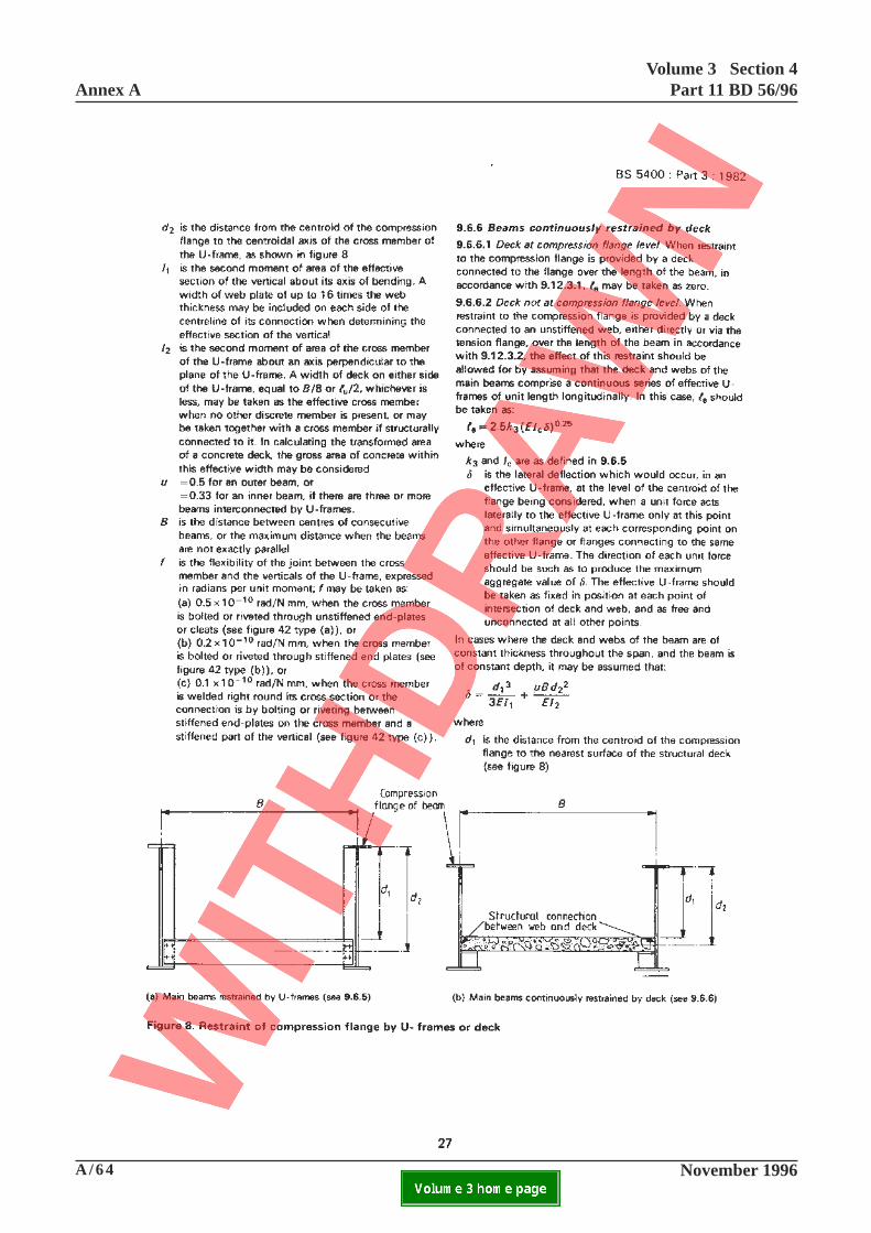
9.6.5 Beams restrained by U-frames
Delete the equation for le and substitute:
le = k
3k
5(EI
cIu δ)0.25 but not less than l
u
Add the definition for k5 after the definition for k
3
k5
= 2.5 where the beams arerestrained at their supports againsttorsion about their longitudinal axis inaccordance with 9.12.4.
= π where the beams are unrestrained at theirsupports against torsion about theirlongitudinal axis.
NOTE: Where the restraint against torsion atsupports is less than required to resist forces
FR under 9.12.4.1 or the stiffness of the
bearing stiffeners is less than required to meetthe criteria of 9.12.4.2 then linearinterpolation shall be used to determine a
value of k5 between 2.5 and π.
Add the following paragraph at the end of thedefinition for f.
Values of f shall be determined experimentallyor taken from test results available whichshall cover the required ultimate capacity ofthe joint and which shall be representative ofthe particular type of joint.
Add at end:
Where in assessment the stiffness of the restraintagainst torsion at supports is less than that requiredunder 9.12.4.2 the effective length, shall be taken as
le
1:
l l1 k
1k
12
1
6
6
e
e e
1
= +
+
+
δ
δΣ
where
le is as defined above
Σ (1/δ) is the sum of the values of 1/δ for eachof the intermediate U-frames in the effectivelength
δe is the value of δ for the support restraint.
k2l
1
EI6
e3
=
Σδ
π4c
Annex AVolume 3 Section 4
Part 11 BD 56/96
A/64 November 1996ELECTRONIC COPY NOT FOR USE OUTSIDE THE AGENCY.PAPER COPIES OF THIS ELECTRONIC DOCUMENT ARE UNCONTROLLED

A/65 November 1996
Volume 3 Section 4Part 11 BD 56/96 Annex A
ELECTRONIC COPY NOT FOR USE OUTSIDE THE AGENCY.PAPER COPIES OF THIS ELECTRONIC DOCUMENT ARE UNCONTROLLED
27
9.6.6.2 Deck not at compression flange level
Add at end:
Where in assessment the stiffness of the restraint againsttorsion at supports is less than that required under
9.12.4.2 the effective length shall be taken as le
1 asdefined in 9.6.5.
Annex AVolume 3 Section 4
Part 11 BD 56/96
A/66 November 1996ELECTRONIC COPY NOT FOR USE OUTSIDE THE AGENCY.PAPER COPIES OF THIS ELECTRONIC DOCUMENT ARE UNCONTROLLED
A/67 November 1996
Volume 3 Section 4Part 11 BD 56/96 Annex A
ELECTRONIC COPY NOT FOR USE OUTSIDE THE AGENCY.PAPER COPIES OF THIS ELECTRONIC DOCUMENT ARE UNCONTROLLED
28
for flanged beamssymmetrical aboutthe minor axis
for flanged beamssymmetrical aboutthe major axis
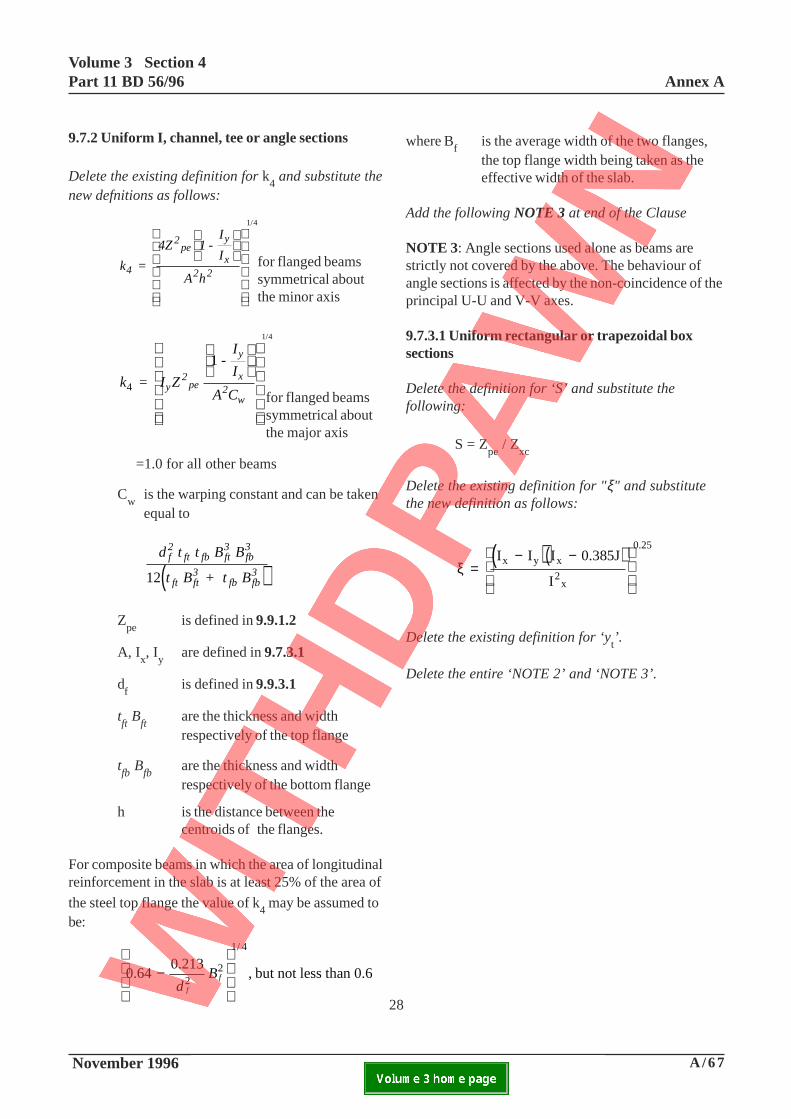
where Bf
is the average width of the two flanges,the top flange width being taken as theeffective width of the slab.
Add the following NOTE 3 at end of the Clause
NOTE 3: Angle sections used alone as beams arestrictly not covered by the above. The behaviour ofangle sections is affected by the non-coincidence of theprincipal U-U and V-V axes.
9.7.3.1 Uniform rectangular or trapezoidal boxsections
Delete the definition for ‘S’ and substitute thefollowing:
S = Zpe
/ Zxc
Delete the existing definition for "ξ" and substitutethe new definition as follows:
( )( )ξ =
− −
I I I 0.385J
I
x y x
2x
0.25
Delete the existing definition for ‘yt’.
Delete the entire ‘NOTE 2’ and ‘NOTE 3’.
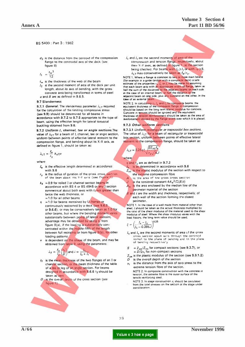
9.7.2 Uniform I, channel, tee or angle sections
Delete the existing definition for k4 and substitute the
new defnitions as follows:
k =
4Z 1 -I
I
A h4
2pe
y
x2 2
1 4/
k I Z
I
I
A Cy
2pe
y
x2
w4 =
1 -
1 4/
=1.0 for all other beams
Cw
is the warping constant and can be takenequal to
( )d t t B B
t B + t B
f2
ft fb ft3
fb3
ft ft3
fb fb312
Zpe
is defined in 9.9.1.2
A, Ix, I
yare defined in 9.7.3.1
df
is defined in 9.9.3.1
tft B
ftare the thickness and widthrespectively of the top flange
tfb B
fbare the thickness and widthrespectively of the bottom flange
h is the distance between thecentroids of the flanges.
For composite beams in which the area of longitudinalreinforcement in the slab is at least 25% of the area of
the steel top flange the value of k4 may be assumed to
be:
0.640.213
, but not less than 0.6
1/ 4
−
d
Bf
f22
Annex AVolume 3 Section 4
Part 11 BD 56/96
A/68 November 1996ELECTRONIC COPY NOT FOR USE OUTSIDE THE AGENCY.PAPER COPIES OF THIS ELECTRONIC DOCUMENT ARE UNCONTROLLED

A/69 November 1996
Volume 3 Section 4Part 11 BD 56/96 Annex A
ELECTRONIC COPY NOT FOR USE OUTSIDE THE AGENCY.PAPER COPIES OF THIS ELECTRONIC DOCUMENT ARE UNCONTROLLED
This page is blank
29
Annex AVolume 3 Section 4
Part 11 BD 56/96
A/70 November 1996ELECTRONIC COPY NOT FOR USE OUTSIDE THE AGENCY.PAPER COPIES OF THIS ELECTRONIC DOCUMENT ARE UNCONTROLLED
A/71 November 1996
Volume 3 Section 4Part 11 BD 56/96 Annex A
ELECTRONIC COPY NOT FOR USE OUTSIDE THE AGENCY.PAPER COPIES OF THIS ELECTRONIC DOCUMENT ARE UNCONTROLLED
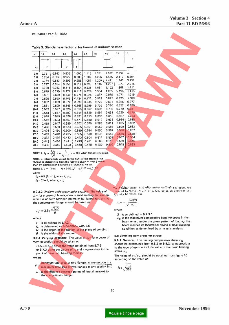
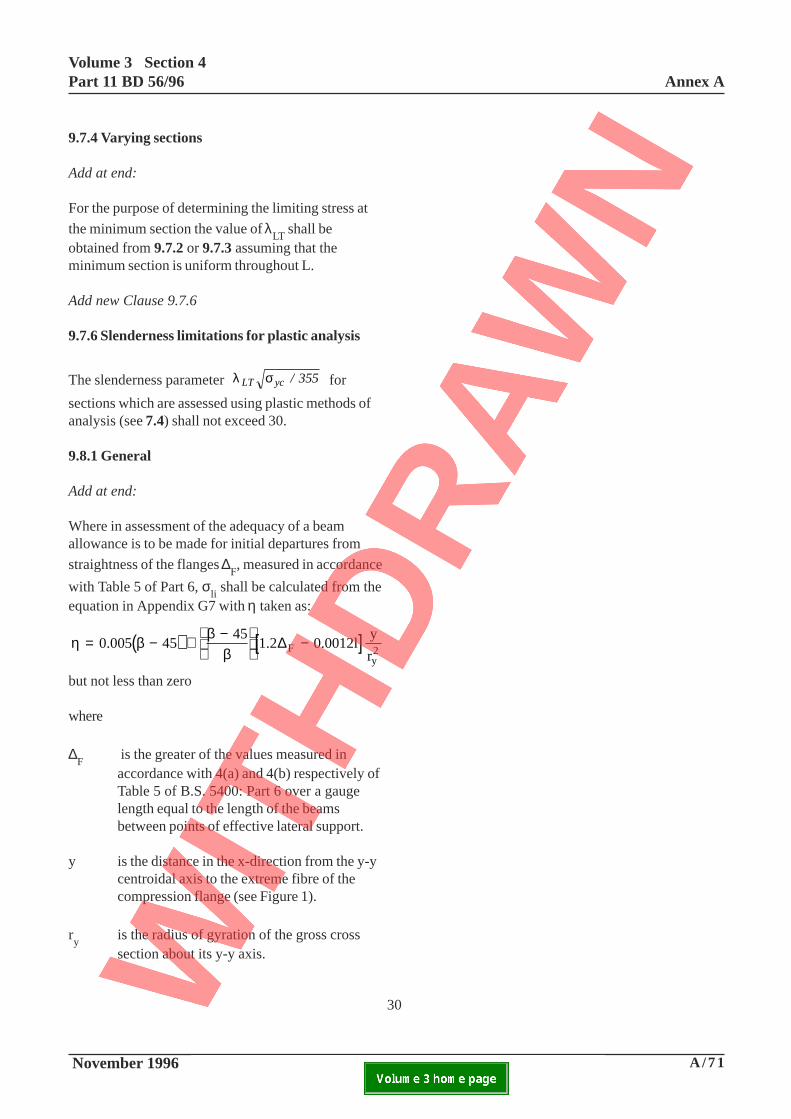
9.7.4 Varying sections
Add at end:
For the purpose of determining the limiting stress at
the minimum section the value of λLT
shall beobtained from 9.7.2 or 9.7.3 assuming that theminimum section is uniform throughout L.
Add new Clause 9.7.6
9.7.6 Slenderness limitations for plastic analysis
The slenderness parameter λ σLT yc / 355 for
sections which are assessed using plastic methods ofanalysis (see 7.4) shall not exceed 30.
9.8.1 General
Add at end:
Where in assessment of the adequacy of a beamallowance is to be made for initial departures from
straightness of the flanges ∆F, measured in accordance
with Table 5 of Part 6, σli shall be calculated from the
equation in Appendix G7 with η taken as:
( ) [ ]η β ββ
= − + −
−0.005 45
451.2 0.0012l
y
rF
y2
∆
but not less than zero
where
∆F
is the greater of the values measured inaccordance with 4(a) and 4(b) respectively ofTable 5 of B.S. 5400: Part 6 over a gaugelength equal to the length of the beamsbetween points of effective lateral support.
y is the distance in the x-direction from the y-ycentroidal axis to the extreme fibre of thecompression flange (see Figure 1).
ry
is the radius of gyration of the gross crosssection about its y-y axis.
30
Annex AVolume 3 Section 4
Part 11 BD 56/96
A/72 November 1996ELECTRONIC COPY NOT FOR USE OUTSIDE THE AGENCY.PAPER COPIES OF THIS ELECTRONIC DOCUMENT ARE UNCONTROLLED

A/73 November 1996
Volume 3 Section 4Part 11 BD 56/96 Annex A
ELECTRONIC COPY NOT FOR USE OUTSIDE THE AGENCY.PAPER COPIES OF THIS ELECTRONIC DOCUMENT ARE UNCONTROLLED
This page is blank
31

Annex AVolume 3 Section 4
Part 11 BD 56/96
A/74 November 1996ELECTRONIC COPY NOT FOR USE OUTSIDE THE AGENCY.PAPER COPIES OF THIS ELECTRONIC DOCUMENT ARE UNCONTROLLED
A/75 November 1996
Volume 3 Section 4Part 11 BD 56/96 Annex A
ELECTRONIC COPY NOT FOR USE OUTSIDE THE AGENCY.PAPER COPIES OF THIS ELECTRONIC DOCUMENT ARE UNCONTROLLED
32
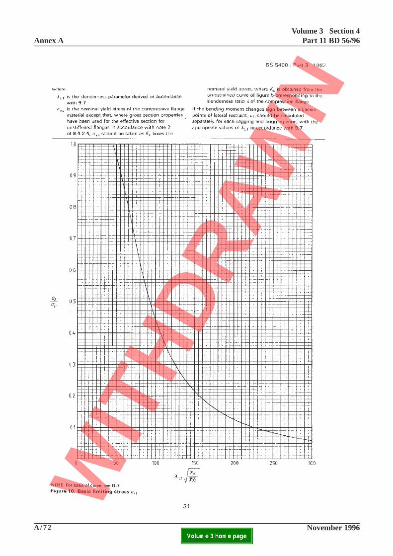
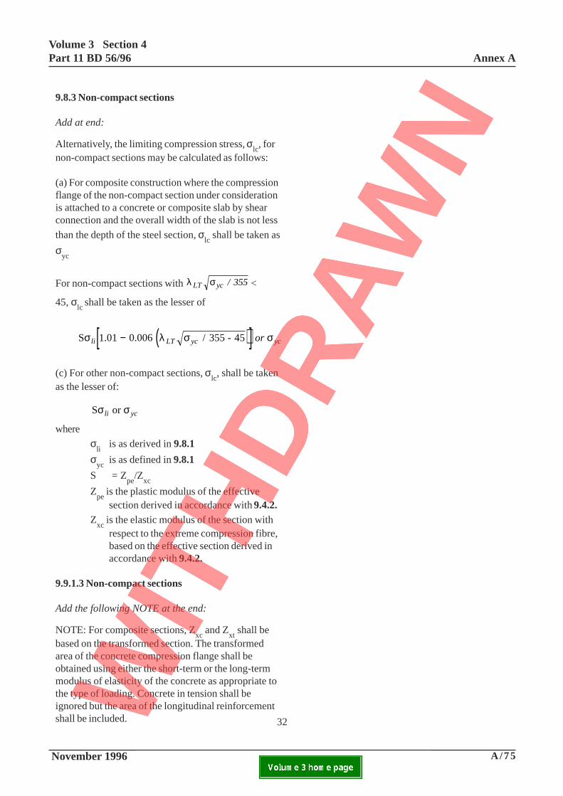
9.8.3 Non-compact sections
Add at end:
Alternatively, the limiting compression stress, σlc, for
non-compact sections may be calculated as follows:
(a) For composite construction where the compressionflange of the non-compact section under considerationis attached to a concrete or composite slab by shearconnection and the overall width of the slab is not less
than the depth of the steel section, σlc shall be taken as
σyc
For non-compact sections with λ σLT yc / 355 <
45, σlc
shall be taken as the lesser of
( )[ ]S 1.01 0.006 / 355 - 45 σ λ σ σli LT yc ycor−
(c) For other non-compact sections, σlc, shall be taken
as the lesser of:
S or σ σli yc
where
σli
is as derived in 9.8.1
σyc
is as defined in 9.8.1
S = Zpe
/Zxc
Zpe
is the plastic modulus of the effectivesection derived in accordance with 9.4.2.
Zxc
is the elastic modulus of the section withrespect to the extreme compression fibre,based on the effective section derived inaccordance with 9.4.2.
9.9.1.3 Non-compact sections
Add the following NOTE at the end:
NOTE: For composite sections, Zxc
and Zxt
shall bebased on the transformed section. The transformedarea of the concrete compression flange shall beobtained using either the short-term or the long-termmodulus of elasticity of the concrete as appropriate tothe type of loading. Concrete in tension shall beignored but the area of the longitudinal reinforcementshall be included.
Annex AVolume 3 Section 4
Part 11 BD 56/96
A/76 November 1996ELECTRONIC COPY NOT FOR USE OUTSIDE THE AGENCY.PAPER COPIES OF THIS ELECTRONIC DOCUMENT ARE UNCONTROLLED

A/77 November 1996
Volume 3 Section 4Part 11 BD 56/96 Annex A
ELECTRONIC COPY NOT FOR USE OUTSIDE THE AGENCY.PAPER COPIES OF THIS ELECTRONIC DOCUMENT ARE UNCONTROLLED
This page is blank
33
Annex AVolume 3 Section 4
Part 11 BD 56/96
A/78 November 1996ELECTRONIC COPY NOT FOR USE OUTSIDE THE AGENCY.PAPER COPIES OF THIS ELECTRONIC DOCUMENT ARE UNCONTROLLED

A/79 November 1996
Volume 3 Section 4Part 11 BD 56/96 Annex A
ELECTRONIC COPY NOT FOR USE OUTSIDE THE AGENCY.PAPER COPIES OF THIS ELECTRONIC DOCUMENT ARE UNCONTROLLED
This page is blank
34
Annex AVolume 3 Section 4
Part 11 BD 56/96
A/80 November 1996ELECTRONIC COPY NOT FOR USE OUTSIDE THE AGENCY.PAPER COPIES OF THIS ELECTRONIC DOCUMENT ARE UNCONTROLLED

A/81 November 1996
Volume 3 Section 4Part 11 BD 56/96 Annex A
ELECTRONIC COPY NOT FOR USE OUTSIDE THE AGENCY.PAPER COPIES OF THIS ELECTRONIC DOCUMENT ARE UNCONTROLLED
This page is blank
35
Annex AVolume 3 Section 4
Part 11 BD 56/96
A/82 November 1996ELECTRONIC COPY NOT FOR USE OUTSIDE THE AGENCY.PAPER COPIES OF THIS ELECTRONIC DOCUMENT ARE UNCONTROLLED

A/83 November 1996
Volume 3 Section 4Part 11 BD 56/96 Annex A
ELECTRONIC COPY NOT FOR USE OUTSIDE THE AGENCY.PAPER COPIES OF THIS ELECTRONIC DOCUMENT ARE UNCONTROLLED
This page is blank
36
Annex AVolume 3 Section 4
Part 11 BD 56/96
A/84 November 1996ELECTRONIC COPY NOT FOR USE OUTSIDE THE AGENCY.PAPER COPIES OF THIS ELECTRONIC DOCUMENT ARE UNCONTROLLED
A/85 November 1996
Volume 3 Section 4Part 11 BD 56/96 Annex A
ELECTRONIC COPY NOT FOR USE OUTSIDE THE AGENCY.PAPER COPIES OF THIS ELECTRONIC DOCUMENT ARE UNCONTROLLED
37
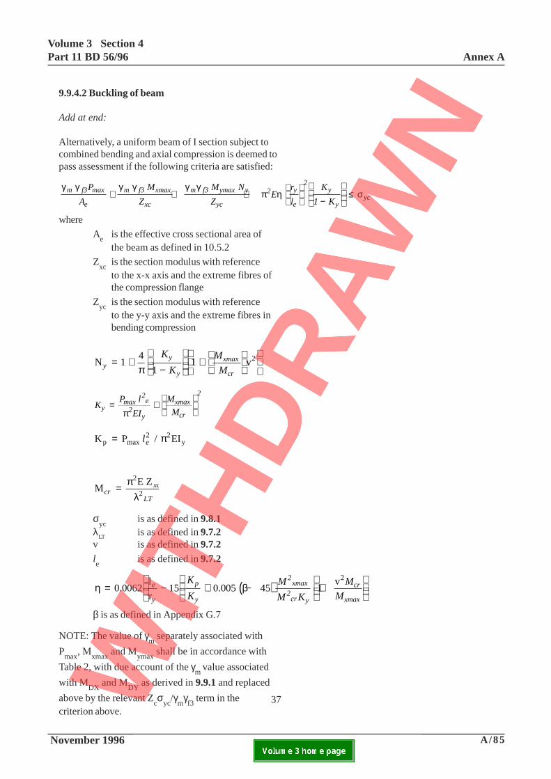
9.9.4.2 Buckling of beam
Add at end:
Alternatively, a uniform beam of I section subject tocombined bending and axial compression is deemed topass assessment if the following criteria are satisfied:
γ γ γ γ γ γπ η σm f3 max
e
m f3 xmax
xc
m f3 ymax y
yc
2 y
e
2y
yyc
P
A
M
Z
M N
ZE
r
l
K
1 K+ + +
−
≤
where
Ae is the effective cross sectional area ofthe beam as defined in 10.5.2
Zxc is the section modulus with referenceto the x-x axis and the extreme fibres ofthe compression flange
Zyc is the section modulus with referenceto the y-y axis and the extreme fibres inbending compression
N 14
11 v2
yy
y
xmax
cr
K
K
M
M= +
−
+
π
KP l
EI
M
Mymax
2e
2y
xmax
cr
2
= +
π
K P EIp max y= l e2 2/π
ME Z2
2crxc
LT=
πλ
σyc
is as defined in 9.8.1λ
LTis as defined in 9.7.2
v is as defined in 9.7.2le
is as defined in 9.7.2
( )η β= −
+ − +
0.0062
l
r15 0.005 45 1
v2e
y
p
y
2xmax
2cr y
cr
xmax
K
K
M
M K
M
M
β is as defined in Appendix G.7
NOTE: The value of γm
separately associated with
Pmax
, Mxmax
and Mymax
shall be in accordance with
Table 2, with due account of the γm
value associated
with MDX
and MDY
as derived in 9.9.1 and replaced
above by the relevant Zcσ
yc/γ
mγf3
term in thecriterion above.
Annex AVolume 3 Section 4
Part 11 BD 56/96
A/86 November 1996ELECTRONIC COPY NOT FOR USE OUTSIDE THE AGENCY.PAPER COPIES OF THIS ELECTRONIC DOCUMENT ARE UNCONTROLLED

A/87 November 1996
Volume 3 Section 4Part 11 BD 56/96 Annex A
ELECTRONIC COPY NOT FOR USE OUTSIDE THE AGENCY.PAPER COPIES OF THIS ELECTRONIC DOCUMENT ARE UNCONTROLLED
9.9.7 Differential temperature and concreteshrinkage.
In the last paragraph, insert the following after ‘from(b)’:
taking into account the effect of shear lag.
9.9.8 Serviceability check for unsymmetriccross-sections
Add at end:
However in assessment where
( )ρ ρft2 k
kk
≥ +0.016 0.16
D
the section need not be checked for the serviceabilitylimit state when the partial load factors as given inBD 37/88 have been used.
In this expression
k = 2 for steel beams; or 1 for compositebeams
ρft
is the proportion of the sectional area ofthe tension flange of the beam to the totalarea of the beam
ρD
is the proportion of unfactored dead load(ie not including superimposed) momentsto unfactored total moments.
Where the compression flange area is less than thetension flange area, ea. in a non-composite stage of
construction, ρft shall be based on the ratio of the
compression flange area to the total area of the beam.
NOTE: For composite beams the transformed sectionappropriate to live load shall be used for the relevantsectional area, ie short term modulus.
38
Annex AVolume 3 Section 4
Part 11 BD 56/96
A/88 November 1996ELECTRONIC COPY NOT FOR USE OUTSIDE THE AGENCY.PAPER COPIES OF THIS ELECTRONIC DOCUMENT ARE UNCONTROLLED

A/89 November 1996
Volume 3 Section 4Part 11 BD 56/96 Annex A
ELECTRONIC COPY NOT FOR USE OUTSIDE THE AGENCY.PAPER COPIES OF THIS ELECTRONIC DOCUMENT ARE UNCONTROLLED
This page is blank
39
Annex AVolume 3 Section 4
Part 11 BD 56/96
A/90 November 1996ELECTRONIC COPY NOT FOR USE OUTSIDE THE AGENCY.PAPER COPIES OF THIS ELECTRONIC DOCUMENT ARE UNCONTROLLED

A/91 November 1996
Volume 3 Section 4Part 11 BD 56/96 Annex A
ELECTRONIC COPY NOT FOR USE OUTSIDE THE AGENCY.PAPER COPIES OF THIS ELECTRONIC DOCUMENT ARE UNCONTROLLED
This page is blank
40
Annex AVolume 3 Section 4
Part 11 BD 56/96
A/92 November 1996ELECTRONIC COPY NOT FOR USE OUTSIDE THE AGENCY.PAPER COPIES OF THIS ELECTRONIC DOCUMENT ARE UNCONTROLLED

A/93 November 1996
Volume 3 Section 4Part 11 BD 56/96 Annex A
ELECTRONIC COPY NOT FOR USE OUTSIDE THE AGENCY.PAPER COPIES OF THIS ELECTRONIC DOCUMENT ARE UNCONTROLLED
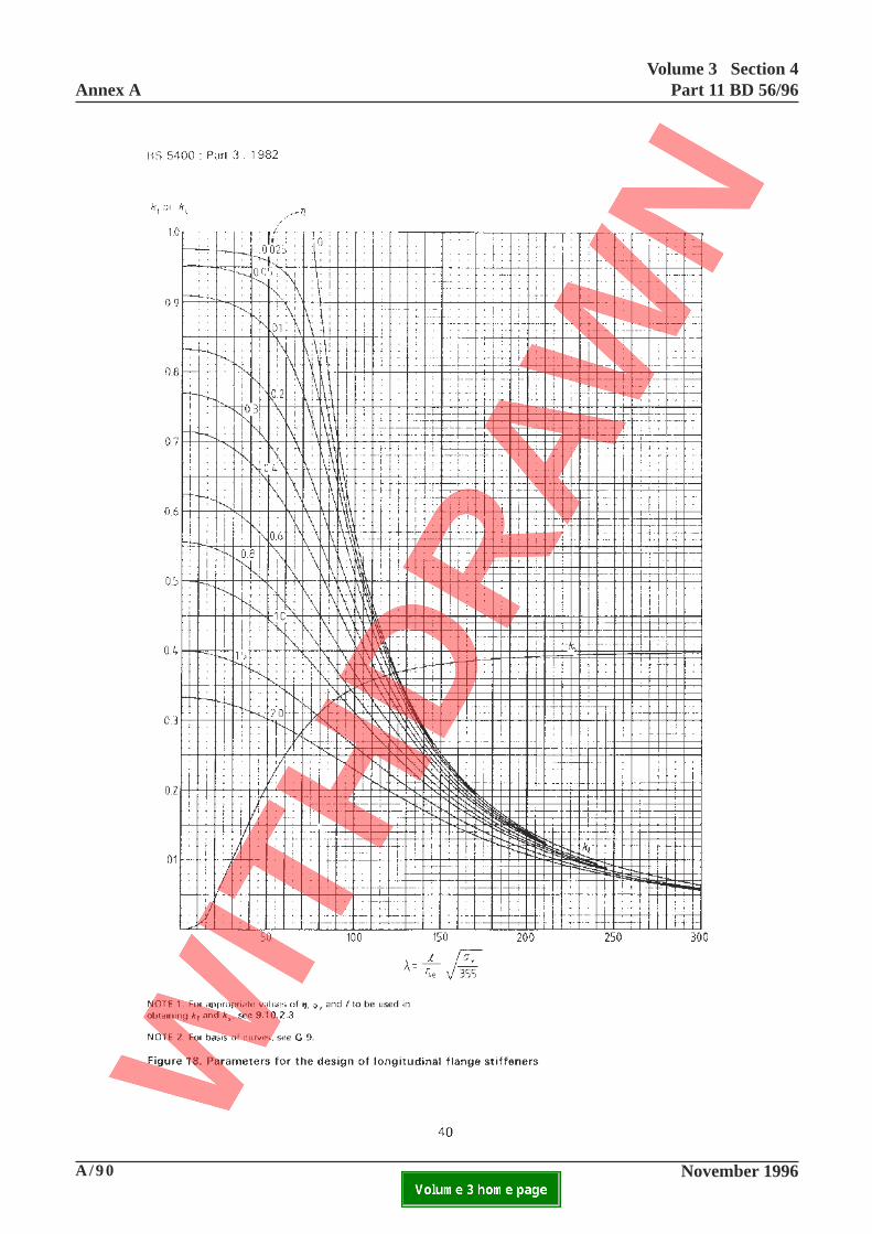
9.10.5 Curtailment of longitudinal flange stiffeners
Add at end:
In assessment, where longitudinal flange stiffeners arecurtailed prematurely beyond the theoretical cut offpoint, due account of this shall be taken in applicationof the foregoing clauses. The arrangement shall alwaysbe checked to ensure the extension beyond anyassumed cut off point is sufficient to develop theassessment loads in the stiffener. The assessmentprocedure shall take due account of the actual end ofthe stiffener in deriving the capacity of thearrangement, by working back to the point where thestiffener can be assumed to be effective. The resultingextension shall be ignored for calculating stresses andother strength checks.
9.11.1 General
Add at end:
Webs not complying with the requirements of 9.3.3(with respect to openings) or of 9.11.6 (with respect topartly extended/curtailed stiffeners) shall be assessedfor the effects of stress concentrations and detailedlocal analyses shall be used in all such cases.
41
Annex AVolume 3 Section 4
Part 11 BD 56/96
A/94 November 1996ELECTRONIC COPY NOT FOR USE OUTSIDE THE AGENCY.PAPER COPIES OF THIS ELECTRONIC DOCUMENT ARE UNCONTROLLED

A/95 November 1996
Volume 3 Section 4Part 11 BD 56/96 Annex A
ELECTRONIC COPY NOT FOR USE OUTSIDE THE AGENCY.PAPER COPIES OF THIS ELECTRONIC DOCUMENT ARE UNCONTROLLED
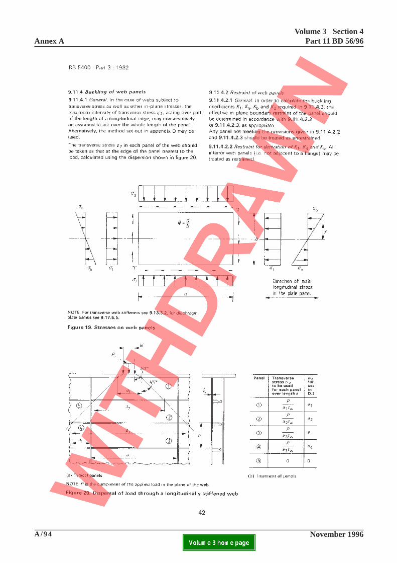
Figure 20. Dispersal of load through alongitudinally stiffened web.
At the end of the ‘NOTE’, add ‘and shall becompressive or tensile.’
42
Annex AVolume 3 Section 4
Part 11 BD 56/96
A/96 November 1996ELECTRONIC COPY NOT FOR USE OUTSIDE THE AGENCY.PAPER COPIES OF THIS ELECTRONIC DOCUMENT ARE UNCONTROLLED

A/97 November 1996
Volume 3 Section 4Part 11 BD 56/96 Annex A
ELECTRONIC COPY NOT FOR USE OUTSIDE THE AGENCY.PAPER COPIES OF THIS ELECTRONIC DOCUMENT ARE UNCONTROLLED
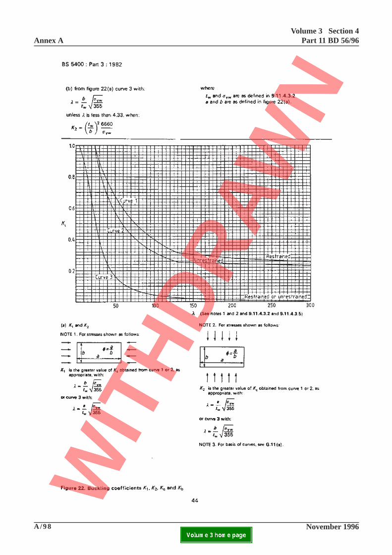
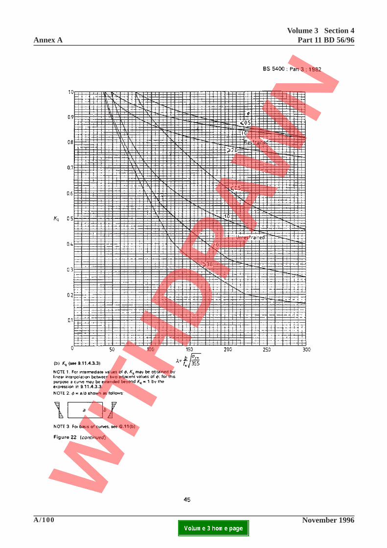
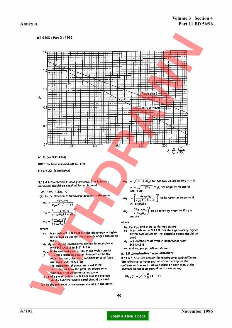
9.11.4.3.1 General.
Add at end:
Where the out-of-flatness of the plate panels exceedthe tolerance in Part 6, allowance shall be made forthis in deriving the buckling coefficients and theirinteraction. A method for this is included in theaccompanying Advice Note.
Where the out-of-flatness of the plate panels is lessthan the tolerance in Part 6, allowance may be madefor this in deriving the buckling coefficients and theirinteractions.
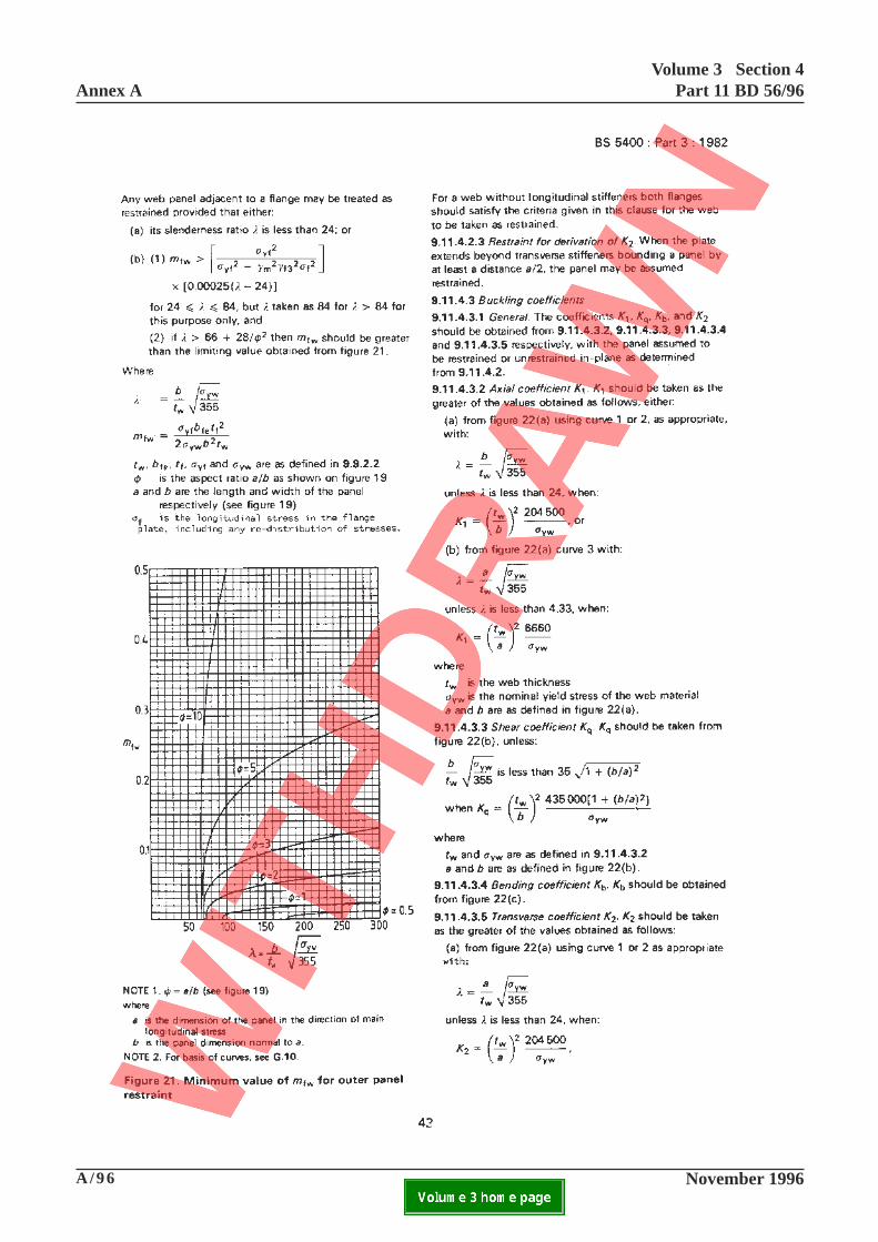
9.11.4.3.2 Axial coefficient K1
Add at end:
If stress is tensile then K1 = 1.0.
9.11.4.3.5 Transverse coefficient K2
Add at end:
If stress is tensile then K2 = 1.0.
43
Annex AVolume 3 Section 4
Part 11 BD 56/96
A/98 November 1996ELECTRONIC COPY NOT FOR USE OUTSIDE THE AGENCY.PAPER COPIES OF THIS ELECTRONIC DOCUMENT ARE UNCONTROLLED

A/99 November 1996
Volume 3 Section 4Part 11 BD 56/96 Annex A
ELECTRONIC COPY NOT FOR USE OUTSIDE THE AGENCY.PAPER COPIES OF THIS ELECTRONIC DOCUMENT ARE UNCONTROLLED
This page is blank
44
Annex AVolume 3 Section 4
Part 11 BD 56/96
A/100 November 1996ELECTRONIC COPY NOT FOR USE OUTSIDE THE AGENCY.PAPER COPIES OF THIS ELECTRONIC DOCUMENT ARE UNCONTROLLED

A/101 November 1996
Volume 3 Section 4Part 11 BD 56/96 Annex A
ELECTRONIC COPY NOT FOR USE OUTSIDE THE AGENCY.PAPER COPIES OF THIS ELECTRONIC DOCUMENT ARE UNCONTROLLED
This page is blank
45
Annex A
Volume 3 Section 4
Part 11 BD 56/96
A/102 November 1996ELECTRONIC COPY NOT FOR USE OUTSIDE THE AGENCY.PAPER COPIES OF THIS ELECTRONIC DOCUMENT ARE UNCONTROLLED

A/103 November 1996
Volume 3 Section 4Part 11 BD 56/96 Annex A
ELECTRONIC COPY NOT FOR USE OUTSIDE THE AGENCY.PAPER COPIES OF THIS ELECTRONIC DOCUMENT ARE UNCONTROLLED
This page is blank
46
Annex AVolume 3 Section 4
Part 11 BD 56/96
A/104 November 1996ELECTRONIC COPY NOT FOR USE OUTSIDE THE AGENCY.PAPER COPIES OF THIS ELECTRONIC DOCUMENT ARE UNCONTROLLED
47-1

Volume 3 Section 4Part 11 BD 56/96 Annex A
November 1996 A/105ELECTRONIC COPY NOT FOR USE OUTSIDE THE AGENCY.PAPER COPIES OF THIS ELECTRONIC DOCUMENT ARE UNCONTROLLED
47-1
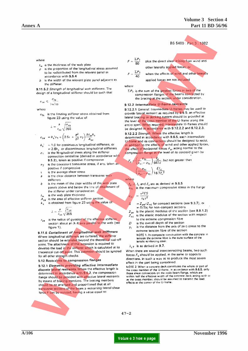
9.11.5.2 Strength of longitudinal web stiffeners
Add at end:
Where in assessment of the adequacy of a longitudinal web stiffener allowance is to be made for initial
departures from straightness, ∆sx
, measured in accordance with Part 6 over a gauge length taken as a, σls
and ks shall be calculated from the equations in Appendix G12 with η taken as:-
( ) ( )η λ λ
λ= − + −
−
0.0083 15
15 1.2 0.0016∆sx2se
a y
r
but not less than zero.
in this expressiony is the distance from the neutral axis of the effective stiffener to the extreme fibre under
consideration
∆sx
is taken as positive when the bowing is in a direction away from the extreme fibre underconsideration.
The strength shall be checked for both the extreme fibres in the outstand and in the associated web plate
They may, however, be used in assessing the stabilityof the web under shear and/or compression providedthey are terminated not more than four times the webthickness from the transverse stiffeners. In carryingout such stability checks the longitudinal stiffenersshall be assumed to carry a compressive stress equalto that in the web plate calculated in accordance withthe above.
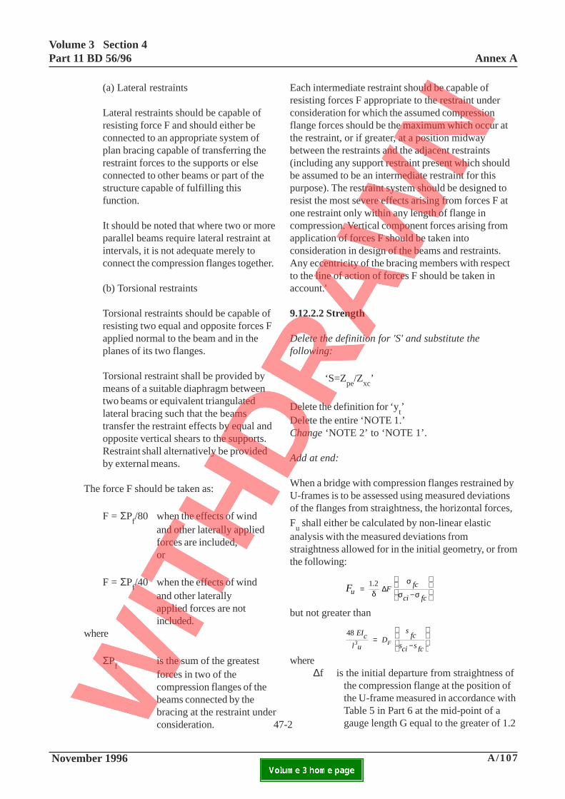
9.12.1 Elements providing effective intermediatediscrete lateral restraints
Delete the whole clause and substitute the following-
Where the effective length is determined in accordancewith 9.6.2, the beam shall be provided with aneffective restraint system which has sufficient strengthand stiffness to inhibit lateral movement of thecompression flange relative to the supports. This shallbe provided by (a) lateral restraints or (b) torsionalrestraints.
9.11.6 Curtailment of longitudinal web stiffeners
Add at end:
In assessment, where longitudinal web stiffeners arecurtailed prematurely beyond the theoretical cut offpoint, due account of this shall be taken in applicationof the foregoing clauses. The arrangement shall alwaysbe checked to ensure the extension beyond anyassumed cut off point is sufficient to develop theassessment loads in the stiffener. The assessmentprocedure shall take due account of the actual end ofthe stiffener in deriving the capacity of thearrangement, by working back to the point where thestiffener can be assumed to be effective. The resultingextension shall be ignored for calculating stresses andother strength checks, but may be used in assessingstability in accordance with 9.11.7.
Add New Clause 9.11.7:
9.11.7 Discontinuous longitudinal stiffeners not connected to transverse stiffeners
Where longitudinal stiffeners are discontinuous, i.e.they are fitted between transverse stiffeners and arenot adequately connected to them, their area shall beignored in calculating the stresses in the cross section.
Annex AVolume 3 Section 4
Part 11 BD 56/96
A/106 November 1996ELECTRONIC COPY NOT FOR USE OUTSIDE THE AGENCY.PAPER COPIES OF THIS ELECTRONIC DOCUMENT ARE UNCONTROLLED
47-2
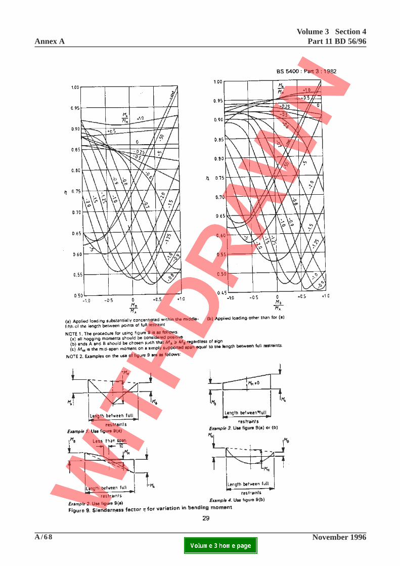
Volume 3 Section 4Part 11 BD 56/96 Annex A
November 1996 A/107ELECTRONIC COPY NOT FOR USE OUTSIDE THE AGENCY.PAPER COPIES OF THIS ELECTRONIC DOCUMENT ARE UNCONTROLLED
47-2
(a) Lateral restraints
Lateral restraints should be capable ofresisting force F and should either beconnected to an appropriate system ofplan bracing capable of transferring therestraint forces to the supports or elseconnected to other beams or part of thestructure capable of fulfilling thisfunction.
It should be noted that where two or moreparallel beams require lateral restraint atintervals, it is not adequate merely toconnect the compression flanges together.
(b) Torsional restraints
Torsional restraints should be capable ofresisting two equal and opposite forces Fapplied normal to the beam and in theplanes of its two flanges.
Torsional restraint shall be provided bymeans of a suitable diaphragm betweentwo beams or equivalent triangulatedlateral bracing such that the beamstransfer the restraint effects by equal andopposite vertical shears to the supports.Restraint shall alternatively be providedby external means.
The force F should be taken as:
F = ΣPf/80 when the effects of wind
and other laterally appliedforces are included,or
F = ΣPf/40 when the effects of wind
and other laterallyapplied forces are notincluded.
where
ΣPf
is the sum of the greatestforces in two of thecompression flanges of thebeams connected by thebracing at the restraint underconsideration.
Each intermediate restraint should be capable ofresisting forces F appropriate to the restraint underconsideration for which the assumed compressionflange forces should be the maximum which occur atthe restraint, or if greater, at a position midwaybetween the restraints and the adjacent restraints(including any support restraint present which shouldbe assumed to be an intermediate restraint for thispurpose). The restraint system should be designed toresist the most severe effects arising from forces F atone restraint only within any length of flange incompression. Vertical component forces arising fromapplication of forces F should be taken intoconsideration in design of the beams and restraints.Any eccentricity of the bracing members with respectto the line of action of forces F should be taken inaccount.'
9.12.2.2 Strength
Delete the definition for 'S' and substitute thefollowing:
‘S=Zpe/Zxc’
Delete the definition for ‘yt’
Delete the entire ‘NOTE 1.’Change ‘NOTE 2’ to ‘NOTE 1’.
Add at end:
When a bridge with compression flanges restrained byU-frames is to be assessed using measured deviationsof the flanges from straightness, the horizontal forces,
Fu shall either be calculated by non-linear elastic
analysis with the measured deviations fromstraightness allowed for in the initial geometry, or fromthe following:
Fu F fc
ci fc=
−
1.2δ
σ
σ σ∆
but not greater than
48 EIcl u
D s
fcsci sfc
3 F=−
where ∆f is the initial departure from straightness of
the compression flange at the position ofthe U-frame measured in accordance withTable 5 in Part 6 at the mid-point of agauge length G equal to the greater of 1.2
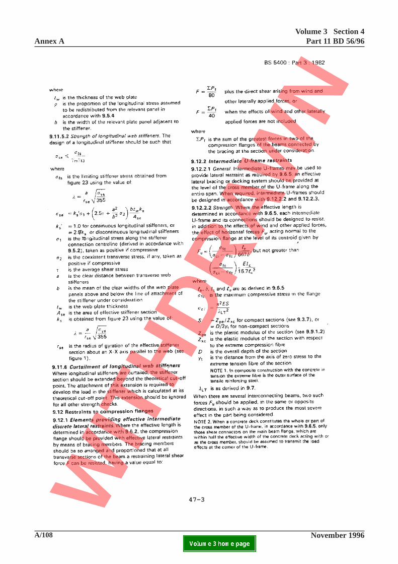
Annex AVolume 3 Section 4
Part 11 BD 56/96
A/108 November 1996ELECTRONIC COPY NOT FOR USE OUTSIDE THE AGENCY.PAPER COPIES OF THIS ELECTRONIC DOCUMENT ARE UNCONTROLLED
47-3

Volume 3 Section 4Part 11 BD 56/96 Annex A
November 1996 A/109ELECTRONIC COPY NOT FOR USE OUTSIDE THE AGENCY.PAPER COPIES OF THIS ELECTRONIC DOCUMENT ARE UNCONTROLLED
47-3
times the effective length le determined in accordance
with 9.6.5 or 9.6.6 as appropriate or twice the spacingof the U-frames along the beam.
Where a beam with intermediate U-frames is not
rigidly restrained at its supports (see 9.12.4.2) Fu shall
be factored by:
1
16
1+
n eδ
δΣ
with le taken as l
e1 in accordance with 9.6.5
where
δ, lu, I
care as defined in 9.6.5
δe
is the value of δ for an end support
Σ 1/δ is the sum of the value of 1/δ foreach of the intermediate U-frames
within a length le adjacent to the
support
n is the number of supports adjacentto the half-wavelength.
NOTE: In assessment of a beam for which le is greater
than lu, σ
ci shall be taken as π2E(r
yc/l
e)2
where
le
is determined in accordance with9.6.5 or 9.6.6.2 as appropriate
ryc
is the radius of gyration of thecompression flange about itscentroidal axis parallel to theweb at the point of maximumbending moment.
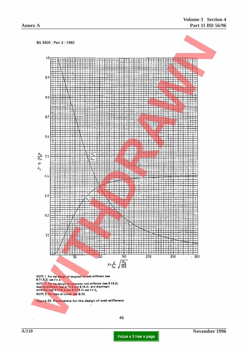
Annex AVolume 3 Section 4
Part 11 BD 56/96
A/110 November 1996ELECTRONIC COPY NOT FOR USE OUTSIDE THE AGENCY.PAPER COPIES OF THIS ELECTRONIC DOCUMENT ARE UNCONTROLLED

Volume 3 Section 4Part 11 BD 56/96 Annex A
November 1996 A/111ELECTRONIC COPY NOT FOR USE OUTSIDE THE AGENCY.PAPER COPIES OF THIS ELECTRONIC DOCUMENT ARE UNCONTROLLED
48
This page is blank
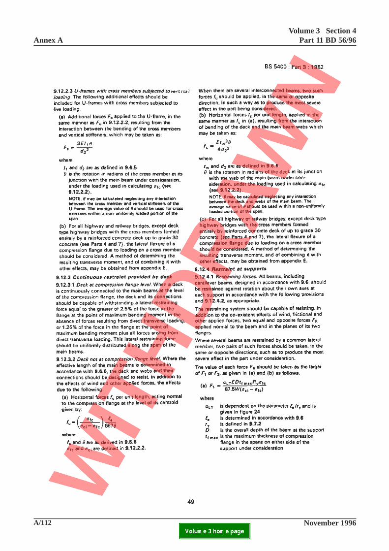
Annex AVolume 3 Section 4
Part 11 BD 56/96
A/112 November 1996ELECTRONIC COPY NOT FOR USE OUTSIDE THE AGENCY.PAPER COPIES OF THIS ELECTRONIC DOCUMENT ARE UNCONTROLLED

Volume 3 Section 4Part 11 BD 56/96 Annex A
November 1996 A/113ELECTRONIC COPY NOT FOR USE OUTSIDE THE AGENCY.PAPER COPIES OF THIS ELECTRONIC DOCUMENT ARE UNCONTROLLED
49
9.12.2.3 U-frames with cross members subjected tovertical loading
In item (a), delete the expression for 'Fc' and the
definitions for I1, d
2 and θ’and substitute the
following:
Fd
l
EI
c23u
c
=+
θ
δ15
where
d2, δ, 1
u and I
c are as defined in 9.6.5
θ is the rotation in radians of the crossmember at its junction with the mainbeam under consideration assuming thatthe cross member is simply supported,
under the loading used in calculating σfc
(see 9.12.2.2). The average value of θshould be used for cross members withina non-uniformly loaded portion of thespan.
9.12.3.2 Deck not at compression flange level
Add at end of (a):-
When a bridge with compression flanges restrained bythe webs is to be assessed using measured deviationsof the flanges from straightness, the horizontal forces,
per unit length fu shall be calculated either by non-
linear elastic analysis with the measured deviationsallowed for in the initial geometry or from the above
equation with 1.2 ∆Fmax
replacing le/667
where
∆Fmax
is the maximum value of ∆F
obtained in accordance with Table 5in Part 6 with a gauge length G
equal to le traversed along the
critical parts of the flange.
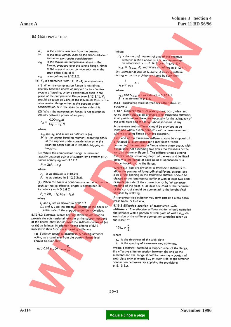
Annex AVolume 3 Section 4
Part 11 BD 56/96
A/114 November 1996ELECTRONIC COPY NOT FOR USE OUTSIDE THE AGENCY.PAPER COPIES OF THIS ELECTRONIC DOCUMENT ARE UNCONTROLLED
50-1
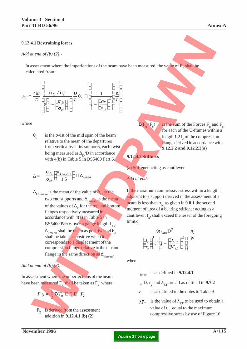
Volume 3 Section 4Part 11 BD 56/96 Annex A
November 1996 A/115ELECTRONIC COPY NOT FOR USE OUTSIDE THE AGENCY.PAPER COPIES OF THIS ELECTRONIC DOCUMENT ARE UNCONTROLLED
9.12.4.1 Restraining forces
Add at end of (b) (2):-
In assessment where the imperfections of the beam have been measured, the value of F2 shall be
calculated from:-
FM
D
/ D
L L2fc ci
fc
ci
2 ofc
ci
2=
−
+
−
4
2 1
1
1
σ σ
σσ
θσσ
∆
where
θo
is the twist of the mid span of the beamrelative to the mean of the departuresfrom verticality at its supports, each twist
being measured as ∆D/D in accordance
with 4(b) in Table 5 in BS5400 Part 6.
∆ =σσ
fc
ci
DSmeanFmean
∆∆
1.5
+
∆DSmean is the mean of the value of ∆D at the
two end supports and ∆Fmean is the mean
of the values of ∆F for the top and bottomflanges respectively measured inaccordance with 4(a) in Table 5 in
BS5400 Part 6 over a gauge length LG.
∆Fmean shall be taken as positive and θoshall be taken as positive when itcorresponds to a displacement of thecompression flange relative to the tension
flange in the same direction as ∆Fmean.
Add at end of (b) (3):-
In assessment where the imperfections of the beam
have been measured F2 shall be taken as F21 where:
F F F ) F12 u c= + +1
2( 2Σ
F2
is derived from the assessmentaddition in 9.12.4.1 (b) (2)
Σ(Fu+F
c) is the sum of the Forces F
u and F
cfor each of the U-frames within a
length 1.2 le of the compression
flange derived in accordance with9.12.2.2 and 9.12.2.3(a)
9.12.4.2 Stiffness
(a) Stiffener acting as cantilever
Add at end:
If the maximum compressive stress within a length le
adjacent to a support derived in the assessment of a
beam is less than σlc as given in 9.8.1 the second
moment of area of a bearing stiffener acting as a
cantilever, Ix, shall exceed the lesser of the foregoing
limit or
9 D
1
t
l
rv
.R
Wfmax
3
e
y
3
4 LT
LT
2v
−
λλ"
where
tfmax
is as defined in 9.12.4.1
le, D, r
y and λ
LT are all as defined in 9.7.2
v is as defined in the notes to Table 9
′′λLT is the value of λ
LT to be used to obtain a
value of σlc equal to the maximum
compressive stress by use of Figure 10.
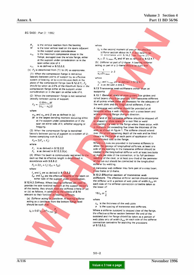
Annex AVolume 3 Section 4
Part 11 BD 56/96
A/116 November 1996ELECTRONIC COPY NOT FOR USE OUTSIDE THE AGENCY.PAPER COPIES OF THIS ELECTRONIC DOCUMENT ARE UNCONTROLLED
50-2

Volume 3 Section 4Part 11 BD 56/96 Annex A
November 1996 A/117ELECTRONIC COPY NOT FOR USE OUTSIDE THE AGENCY.PAPER COPIES OF THIS ELECTRONIC DOCUMENT ARE UNCONTROLLED
(b) Stiffener as part of U-frame
Add at end:-
If the maximum compressive stress within a length leadjacent to a support derived in the assessment of abeam restrained by U-frames at its supports is less
than σlc as given in 9.8.1 the value of α
LT may be
taken as:-
27
v4
3 2l
re
y
LT
LT
−
′′
1 λλ
but not greater than the value obtained from Figure 24
factored by l/v4, where v, le, r
y, λ
LT and λ"
LT are as
defined in (a) above.
Add new item (c)
(c) Other support stiffeners
If the bearing stiffeners are not rigidly supported ontheir bearings or of a type other than a cantilever therequirements of 9.12.4.2(b) shall be met, with δcalculated as for U-frames.
Add new clause 9.12.5:
9.12.5 Restraint to plastic hinges
All structures which are assessed using plasticmethods of analysis in accordance with 7.4 shallprovide lateral restraint close to all locations ofplastic hinges which may occur under the variousload cases. Such restraint shall be provided withina distance along the member from the theoreticalplastic hinge locations not exceeding half the depthof the member.
9.13.1 General
Add at end:
In the assessment of existing arrangements wheretransverse stiffeners are not provided in accordancewith the above, local effects shall be considered.Detailed analyses shall be carried out to cater forlocal effects resulting from the following:-
a) absence of web stiffeners where cross beamsconnect to the web;
b) absence of web stiffeners where a slopingflange changes direction;
c) where the stiffener does not extend over thewhole depth of the web or is not fitted closelyto the flange at a point of application of aconcentrated load to the flange;
d) where cut outs are not properly connected tothe longitudinal stiffener
The assessment may utilise the relevant aspects of9.14.6 and 9.15.6.
As an alternative to the provisions of 9.13.3 to 9.13.6,the adequacy of the transverse stiffeners or deep webswith longitudinal stiffeners may be assessed using themethods of 9.15.6. In this case the longitudinalstiffeners shall also be checked at the serviceabilitylimit state as for the flanges in accordance with9.10.3.3.
50-2
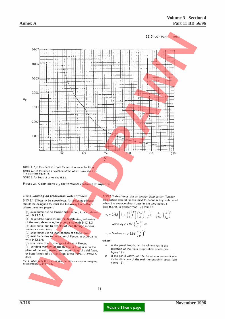
Annex AVolume 3 Section 4
Part 11 BD 56/96
A/118 November 1996ELECTRONIC COPY NOT FOR USE OUTSIDE THE AGENCY.PAPER COPIES OF THIS ELECTRONIC DOCUMENT ARE UNCONTROLLED

Volume 3 Section 4Part 11 BD 56/96 Annex A
November 1996 A/119ELECTRONIC COPY NOT FOR USE OUTSIDE THE AGENCY.PAPER COPIES OF THIS ELECTRONIC DOCUMENT ARE UNCONTROLLED
This page is blank
51
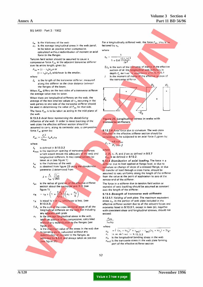
Annex AVolume 3 Section 4
Part 11 BD 56/96
A/120 November 1996ELECTRONIC COPY NOT FOR USE OUTSIDE THE AGENCY.PAPER COPIES OF THIS ELECTRONIC DOCUMENT ARE UNCONTROLLED

Volume 3 Section 4Part 11 BD 56/96 Annex A
November 1996 A/121ELECTRONIC COPY NOT FOR USE OUTSIDE THE AGENCY.PAPER COPIES OF THIS ELECTRONIC DOCUMENT ARE UNCONTROLLED
52
9.13.3.3 Axial force representing the destabilisinginfluence of the web
Add at end:
In the assessment of the adequacy of a transverse webstiffener, where allowance is to be made for initial
departures from straightness, ∆sx
, measured in
accordance with Part 6, ks shall be calculated as
described in 9.11.5.2
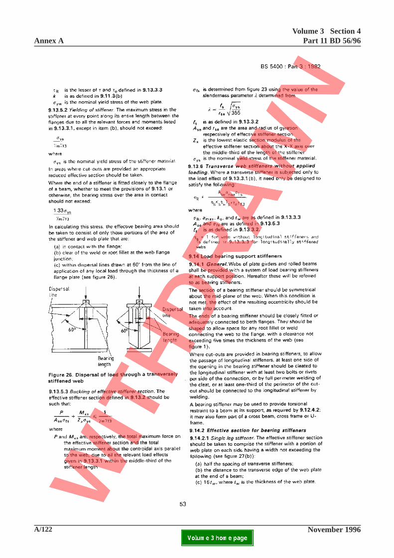
Annex AVolume 3 Section 4
Part 11 BD 56/96
A/122 November 1996ELECTRONIC COPY NOT FOR USE OUTSIDE THE AGENCY.PAPER COPIES OF THIS ELECTRONIC DOCUMENT ARE UNCONTROLLED

Volume 3 Section 4Part 11 BD 56/96 Annex A
November 1996 A/123ELECTRONIC COPY NOT FOR USE OUTSIDE THE AGENCY.PAPER COPIES OF THIS ELECTRONIC DOCUMENT ARE UNCONTROLLED
53
9.13.5.3 Buckling of effective stiffener section.
Add at end:
Where in assessment of the adequacy of a transverseweb stiffener allowance is to be made for initial
departures from straightness, ∆sx
, measured in
accordance with Part 6, σls shall be calculated as
described in 9.11.5.2.
9.14.1 General
Add at end:
In the assessment of existing arrangements wherebearing stiffeners are not provided in accordance withthe above, local effects shall be considered. Detailedanalyses shall be carried out to cater for local effectsresulting from the following as appropriate:
a) where the stiffener does not extend over the whole depth of the web or is not fitted closely to the flange;
b) where cut outs are not properly connected to the longitudinal stiffener.
Where bearing stiffeners are not provided, inaccordance with the above, the adequacy of the webunder transverse loading shall be checked inaccordance with 9.14.6.
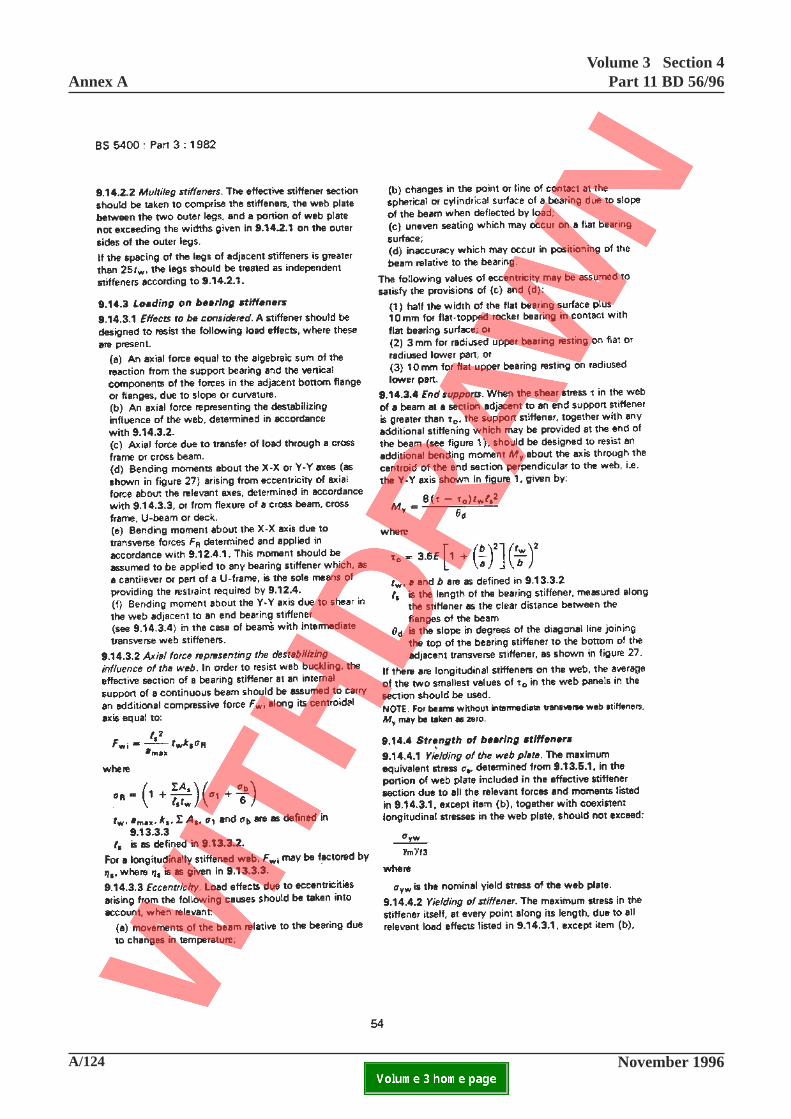
Annex AVolume 3 Section 4
Part 11 BD 56/96
A/124 November 1996ELECTRONIC COPY NOT FOR USE OUTSIDE THE AGENCY.PAPER COPIES OF THIS ELECTRONIC DOCUMENT ARE UNCONTROLLED

Volume 3 Section 4Part 11 BD 56/96 Annex A
November 1996 A/125ELECTRONIC COPY NOT FOR USE OUTSIDE THE AGENCY.PAPER COPIES OF THIS ELECTRONIC DOCUMENT ARE UNCONTROLLED
54
9.14.3.3 Eccentricity.
Add at end:
In assessing the adequacy of an existing stiffener,where any error in positioning and any unevennessof seating on a flat bearing is measured, the followingvalues of eccentricity shall be taken into account inrespect of (c) and (d) above.
(1) half the width of the flat bearing surface plus the measured error in positioning for flat topped rocker bearing in contact with flat bearing surface: or
(2) the measured error in positioning for radiused upper bearing resting on flat or radiused lower part or for flat upper bearing resting on radiused lower part.
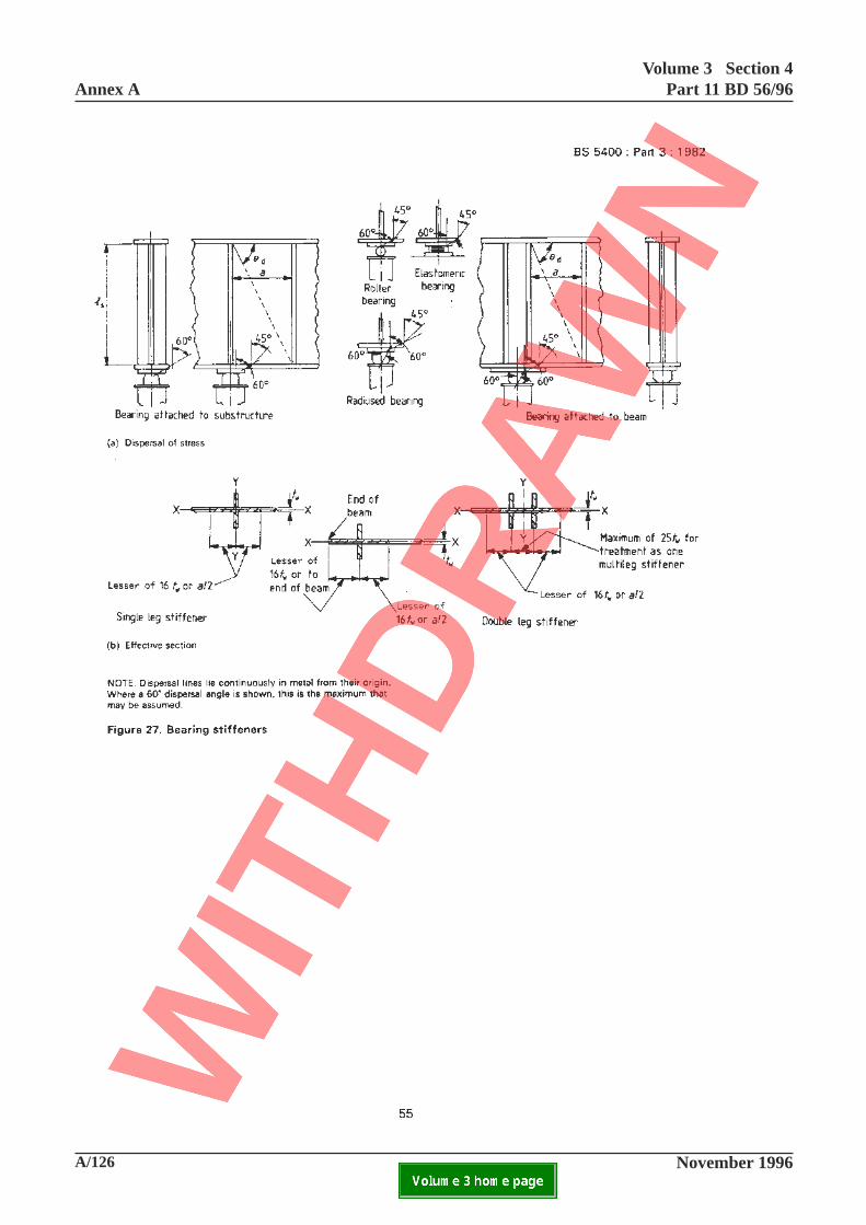
Annex AVolume 3 Section 4
Part 11 BD 56/96
A/126 November 1996ELECTRONIC COPY NOT FOR USE OUTSIDE THE AGENCY.PAPER COPIES OF THIS ELECTRONIC DOCUMENT ARE UNCONTROLLED

Volume 3 Section 4Part 11 BD 56/96 Annex A
November 1996 A/127ELECTRONIC COPY NOT FOR USE OUTSIDE THE AGENCY.PAPER COPIES OF THIS ELECTRONIC DOCUMENT ARE UNCONTROLLED
This page is blank
55
Annex AVolume 3 Section 4
Part 11 BD 56/96
A/128 November 1996ELECTRONIC COPY NOT FOR USE OUTSIDE THE AGENCY.PAPER COPIES OF THIS ELECTRONIC DOCUMENT ARE UNCONTROLLED
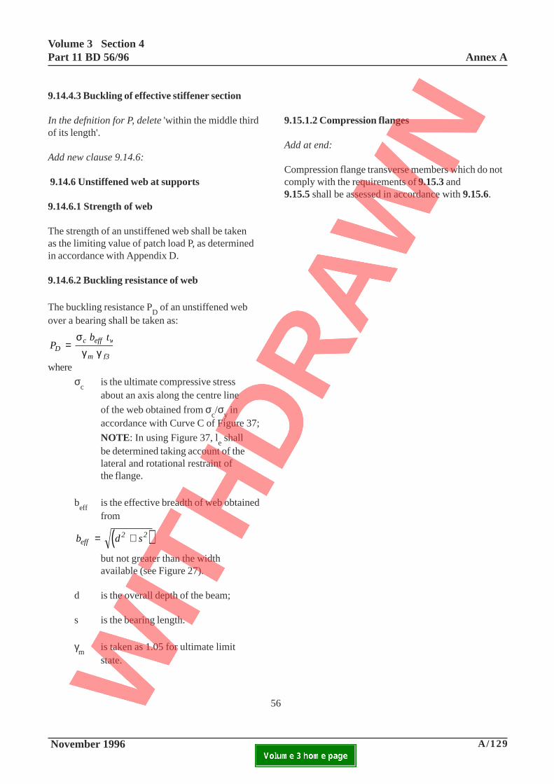
Volume 3 Section 4Part 11 BD 56/96 Annex A
November 1996 A/129ELECTRONIC COPY NOT FOR USE OUTSIDE THE AGENCY.PAPER COPIES OF THIS ELECTRONIC DOCUMENT ARE UNCONTROLLED
9.14.4.3 Buckling of effective stiffener section
In the defnition for P, delete 'within the middle thirdof its length'.
Add new clause 9.14.6:
9.14.6 Unstiffened web at supports
9.14.6.1 Strength of web
The strength of an unstiffened web shall be takenas the limiting value of patch load P, as determinedin accordance with Appendix D.
9.14.6.2 Buckling resistance of web
The buckling resistance PD of an unstiffened web
over a bearing shall be taken as:
P b t
Dc eff w
m f3
=σ
γ γwhere
σc
is the ultimate compressive stressabout an axis along the centre line
of the web obtained from σc/σ
y in
accordance with Curve C of Figure 37;
NOTE: In using Figure 37, le shall
be determined taking account of thelateral and rotational restraint ofthe flange.
beff
is the effective breadth of web obtainedfrom
( )b d seff2 2= +
but not greater than the widthavailable (see Figure 27).
d is the overall depth of the beam;
s is the bearing length.
γm
is taken as 1.05 for ultimate limitstate.
9.15.1.2 Compression flanges
Add at end:
Compression flange transverse members which do notcomply with the requirements of 9.15.3 and9.15.5 shall be assessed in accordance with 9.15.6.
56
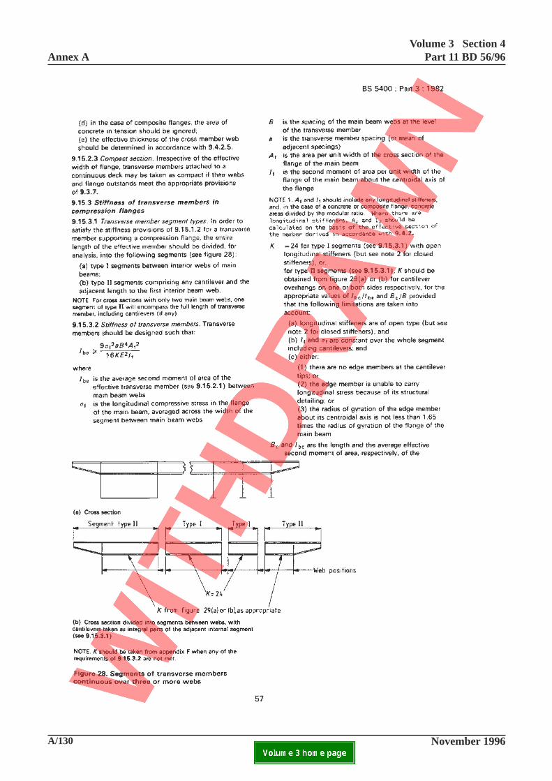
Annex AVolume 3 Section 4
Part 11 BD 56/96
A/130 November 1996ELECTRONIC COPY NOT FOR USE OUTSIDE THE AGENCY.PAPER COPIES OF THIS ELECTRONIC DOCUMENT ARE UNCONTROLLED

Volume 3 Section 4Part 11 BD 56/96 Annex A
November 1996 A/131ELECTRONIC COPY NOT FOR USE OUTSIDE THE AGENCY.PAPER COPIES OF THIS ELECTRONIC DOCUMENT ARE UNCONTROLLED
57
This page is blank
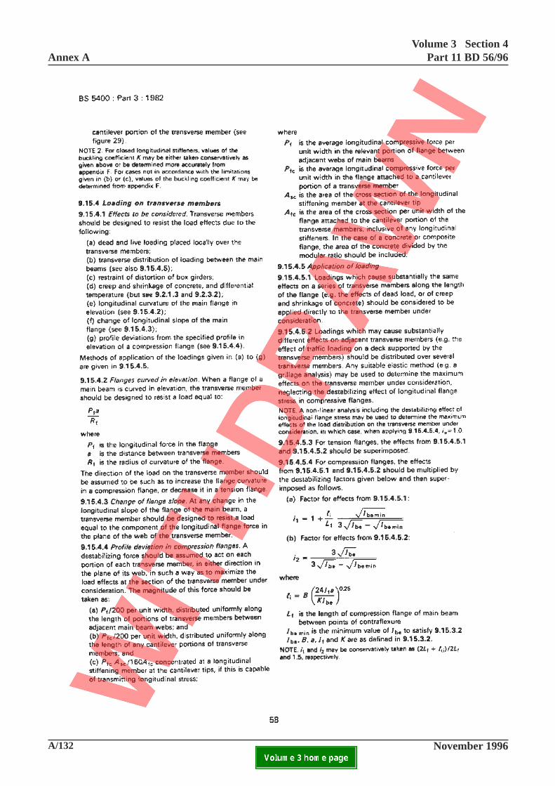
Annex AVolume 3 Section 4
Part 11 BD 56/96
A/132 November 1996ELECTRONIC COPY NOT FOR USE OUTSIDE THE AGENCY.PAPER COPIES OF THIS ELECTRONIC DOCUMENT ARE UNCONTROLLED

Volume 3 Section 4Part 11 BD 56/96 Annex A
November 1996 A/133ELECTRONIC COPY NOT FOR USE OUTSIDE THE AGENCY.PAPER COPIES OF THIS ELECTRONIC DOCUMENT ARE UNCONTROLLED
9.15.4.4 Profile deviation in compression flanges
Add at end:
When a survey of the deflections of the transversemembers has been carried out, the factors of 200 and160 in the denominator of (a), (b) and (c) above shallbe replaced by
G
3and
G
3.75c c∆ ∆
respectively where G and ∆c are defined in Table 5
of Part 6. The actual value of ∆c to be used shall
be the largest measured value at any point of thespan of the transverse member being considered andshall not be taken as less than 3mm. in anycircumstances.
58
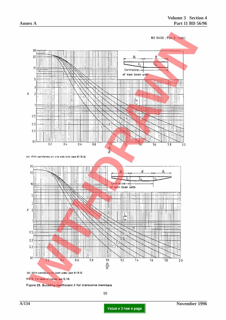
Annex AVolume 3 Section 4
Part 11 BD 56/96
A/134 November 1996ELECTRONIC COPY NOT FOR USE OUTSIDE THE AGENCY.PAPER COPIES OF THIS ELECTRONIC DOCUMENT ARE UNCONTROLLED

Volume 3 Section 4Part 11 BD 56/96 Annex A
November 1996 A/135ELECTRONIC COPY NOT FOR USE OUTSIDE THE AGENCY.PAPER COPIES OF THIS ELECTRONIC DOCUMENT ARE UNCONTROLLED
59
This page is blank
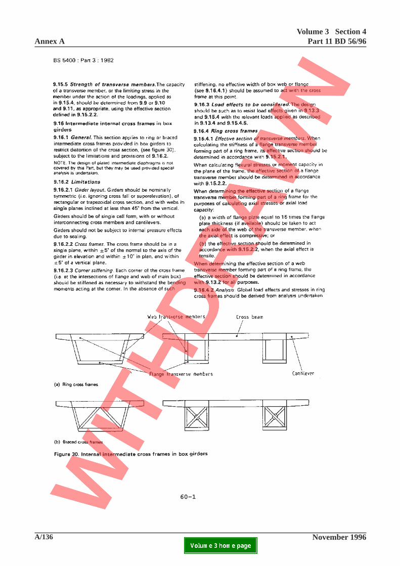
Annex AVolume 3 Section 4
Part 11 BD 56/96
A/136 November 1996ELECTRONIC COPY NOT FOR USE OUTSIDE THE AGENCY.PAPER COPIES OF THIS ELECTRONIC DOCUMENT ARE UNCONTROLLED
60-1
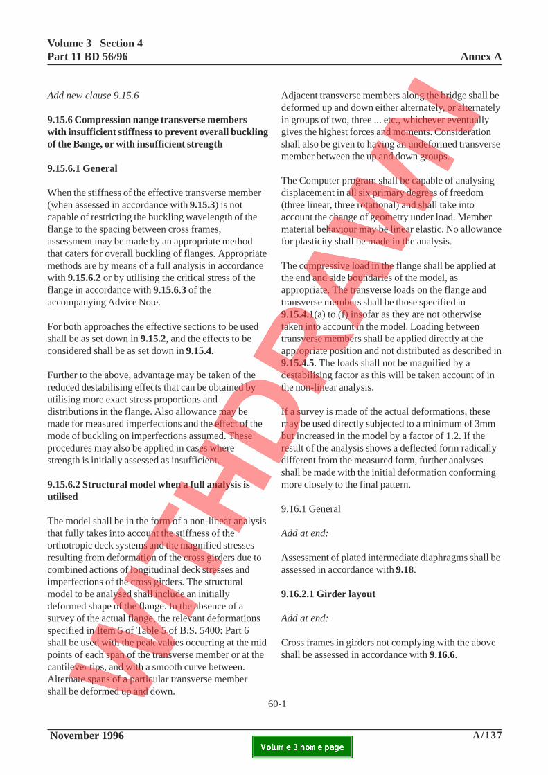
Volume 3 Section 4Part 11 BD 56/96 Annex A
November 1996 A/137ELECTRONIC COPY NOT FOR USE OUTSIDE THE AGENCY.PAPER COPIES OF THIS ELECTRONIC DOCUMENT ARE UNCONTROLLED
Add new clause 9.15.6
9.15.6 Compression nange transverse memberswith insufficient stiffness to prevent overall bucklingof the Bange, or with insufficient strength
9.15.6.1 General
When the stiffness of the effective transverse member(when assessed in accordance with 9.15.3) is notcapable of restricting the buckling wavelength of theflange to the spacing between cross frames,assessment may be made by an appropriate methodthat caters for overall buckling of flanges. Appropriatemethods are by means of a full analysis in accordancewith 9.15.6.2 or by utilising the critical stress of theflange in accordance with 9.15.6.3 of theaccompanying Advice Note.
For both approaches the effective sections to be usedshall be as set down in 9.15.2, and the effects to beconsidered shall be as set down in 9.15.4.
Further to the above, advantage may be taken of thereduced destabilising effects that can be obtained byutilising more exact stress proportions anddistributions in the flange. Also allowance may bemade for measured imperfections and the effect of themode of buckling on imperfections assumed. Theseprocedures may also be applied in cases wherestrength is initially assessed as insufficient.
9.15.6.2 Structural model when a full analysis isutilised
The model shall be in the form of a non-linear analysisthat fully takes into account the stiffness of theorthotropic deck systems and the magnified stressesresulting from deformation of the cross girders due tocombined actions of longitudinal deck stresses andimperfections of the cross girders. The structuralmodel to be analysed shall include an initiallydeformed shape of the flange. In the absence of asurvey of the actual flange, the relevant deformationsspecified in Item 5 of Table 5 of B.S. 5400: Part 6shall be used with the peak values occurring at the midpoints of each span of the transverse member or at thecantilever tips, and with a smooth curve between.Alternate spans of a particular transverse membershall be deformed up and down.
Adjacent transverse members along the bridge shall bedeformed up and down either alternately, or alternatelyin groups of two, three ... etc., whichever eventuallygives the highest forces and moments. Considerationshall also be given to having an undeformed transversemember between the up and down groups.
The Computer program shall be capable of analysingdisplacement in all six primary degrees of freedom(three linear, three rotational) and shall take intoaccount the change of geometry under load. Membermaterial behaviour may be linear elastic. No allowancefor plasticity shall be made in the analysis.
The compressive load in the flange shall be applied atthe end and side boundaries of the model, asappropriate. The transverse loads on the flange andtransverse members shall be those specified in9.15.4.1(a) to (f) insofar as they are not otherwisetaken into account in the model. Loading betweentransverse members shall be applied directly at theappropriate position and not distributed as described in9.15.4.5. The loads shall not be magnified by adestabilising factor as this will be taken account of inthe non-linear analysis.
If a survey is made of the actual deformations, thesemay be used directly subjected to a minimum of 3mmbut increased in the model by a factor of 1.2. If theresult of the analysis shows a deflected form radicallydifferent from the measured form, further analysesshall be made with the initial deformation conformingmore closely to the final pattern.
9.16.1 General
Add at end:
Assessment of plated intermediate diaphragms shall beassessed in accordance with 9.18.
9.16.2.1 Girder layout
Add at end:
Cross frames in girders not complying with the aboveshall be assessed in accordance with 9.16.6.
60-1
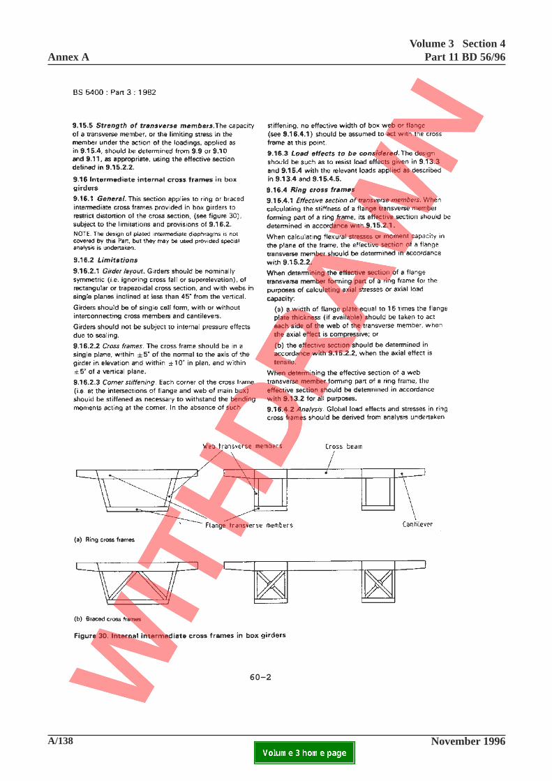
Annex AVolume 3 Section 4
Part 11 BD 56/96
A/138 November 1996ELECTRONIC COPY NOT FOR USE OUTSIDE THE AGENCY.PAPER COPIES OF THIS ELECTRONIC DOCUMENT ARE UNCONTROLLED
60-2

Volume 3 Section 4Part 11 BD 56/96 Annex A
November 1996 A/139ELECTRONIC COPY NOT FOR USE OUTSIDE THE AGENCY.PAPER COPIES OF THIS ELECTRONIC DOCUMENT ARE UNCONTROLLED
9.16.2.2 Cross frames
Add at end:
Cross frames not complying with these limitationsshall be assessed in accordance with this Standardwith the exception of Appendix B, provided that theanalytical models used fully account for the planedirection of the frames and interconnection betweenthe frames and longitudinal members.
9.16.3 Load effects to be considered
Add at end:
The forces and stresses due to torsion to be carriedby a frame shall be determined from elastic analysis(see 9.16.4.2) or, for boxes with any web inclinationand provided that the cross frames comply with9.16.2.2, shall be derived in accordance withAppendix B.3.4.
Where the webs of the box girder are inclined tothe vertical, horizontal components of load induced intop and bottom transverse members shall also beconsidered.
60-2
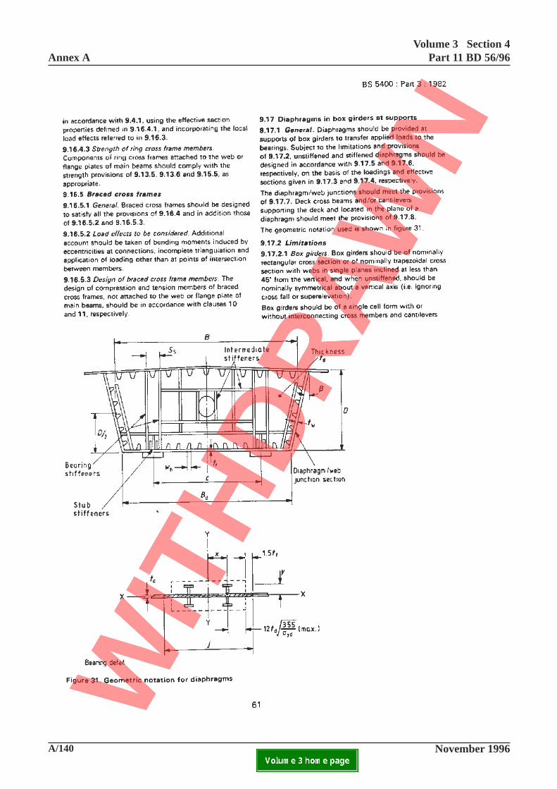
Annex AVolume 3 Section 4
Part 11 BD 56/96
A/140 November 1996ELECTRONIC COPY NOT FOR USE OUTSIDE THE AGENCY.PAPER COPIES OF THIS ELECTRONIC DOCUMENT ARE UNCONTROLLED

Volume 3 Section 4Part 11 BD 56/96 Annex A
November 1996 A/141ELECTRONIC COPY NOT FOR USE OUTSIDE THE AGENCY.PAPER COPIES OF THIS ELECTRONIC DOCUMENT ARE UNCONTROLLED
Add new clause 9.16.4.4:
9.16.4.4 Ring frame corners
The strength of the connection between web transversemembers and flange transverse members shall beadequate to transfer the forces and moments from onemember to the other. In determining the strength of theconnection, the web and flange shall only beconsidered to act with the transverse member if thecorner is stiffened, see 9.16.2.3
Add new clauses 9.16.6 and 9.16. 7:
9.16.6 Cross frames not complying with limitations
Where the adequacy of cross frames to girders notcomplying with the limitations defined in 9.16.2 is tobe assessed, the strengths of the components of theframes shall be determined from this Standard subjectto the following requirements: Global analysis shall beundertaken in accordance with 7.1 and 7.2. Thestructure shall be analysed either by a finite elementmethod with all its primary components modelled oran equivalent grillage provided that the elasticproperties of the equivalent members are derived fromfinite element analysis of the box girders.
Analysis to determine load effects from local loads andreactions including distortional effects shall beundertaken using a finite element method on a modelof sufficient extent to ensure that the effects calculatedare insensitive to assumed end conditions.
9.16.7 Cross girder stiffness
Where distortional and warping stresses in the boxgirders are calculated in accordance with Appendix Bthe stiffness of a cross girder shall comply with therequirements of B.3.4. Where the stiffnessrequirements are not complied with, the stresses shallbe derived in accordance with 8.3.
9.17 Diaphragms in box girders at supports
9.17.1 General
Add at end:
Where the adequacy of a stiffened diaphragm notcomplying with the limitations given in 9.17.2 is to beassessed, the assessment shall be undertaken inaccordance with Appendix L.
Alternatively, diaphragms may be assessed inaccordance with Appendix L.
61
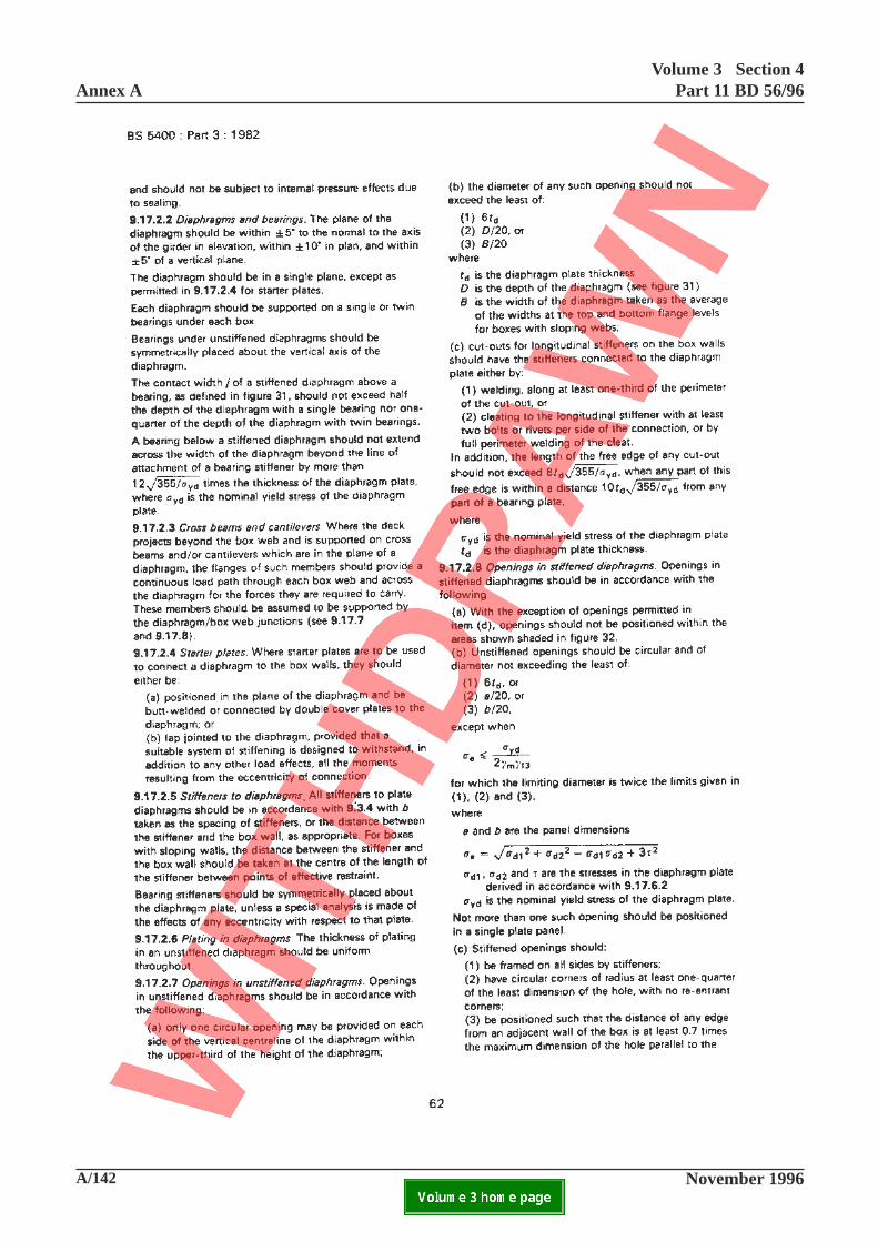
Annex AVolume 3 Section 4
Part 11 BD 56/96
A/142 November 1996ELECTRONIC COPY NOT FOR USE OUTSIDE THE AGENCY.PAPER COPIES OF THIS ELECTRONIC DOCUMENT ARE UNCONTROLLED

Volume 3 Section 4Part 11 BD 56/96 Annex A
November 1996 A/143ELECTRONIC COPY NOT FOR USE OUTSIDE THE AGENCY.PAPER COPIES OF THIS ELECTRONIC DOCUMENT ARE UNCONTROLLED
62
This page is blank
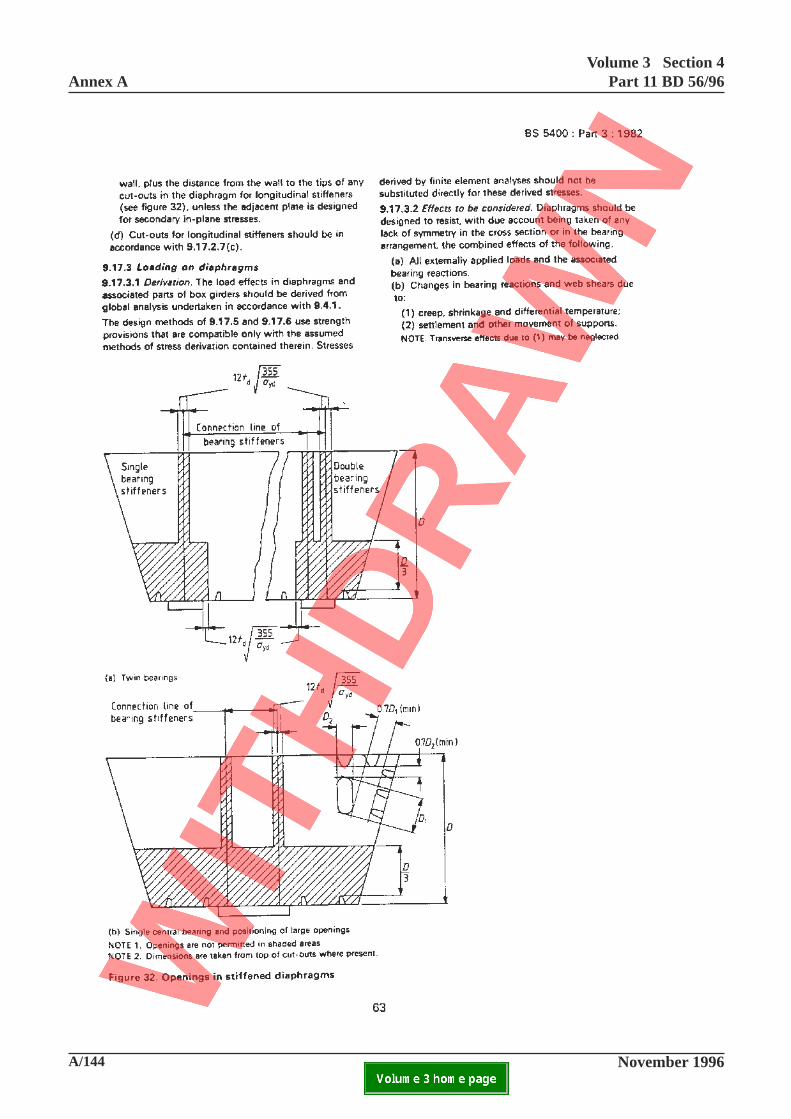
Annex AVolume 3 Section 4
Part 11 BD 56/96
A/144 November 1996ELECTRONIC COPY NOT FOR USE OUTSIDE THE AGENCY.PAPER COPIES OF THIS ELECTRONIC DOCUMENT ARE UNCONTROLLED

Volume 3 Section 4Part 11 BD 56/96 Annex A
November 1996 A/145ELECTRONIC COPY NOT FOR USE OUTSIDE THE AGENCY.PAPER COPIES OF THIS ELECTRONIC DOCUMENT ARE UNCONTROLLED
63
This page is blank
Annex AVolume 3 Section 4
Part 11 BD 56/96
A/146 November 1996ELECTRONIC COPY NOT FOR USE OUTSIDE THE AGENCY.PAPER COPIES OF THIS ELECTRONIC DOCUMENT ARE UNCONTROLLED

Volume 3 Section 4Part 11 BD 56/96 Annex A
November 1996 A/147ELECTRONIC COPY NOT FOR USE OUTSIDE THE AGENCY.PAPER COPIES OF THIS ELECTRONIC DOCUMENT ARE UNCONTROLLED
64
This page is blank
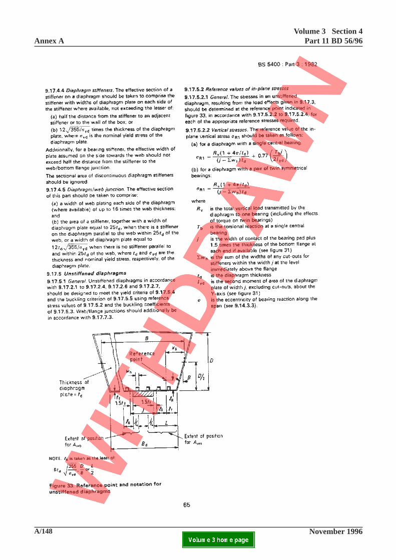
Annex AVolume 3 Section 4
Part 11 BD 56/96
A/148 November 1996ELECTRONIC COPY NOT FOR USE OUTSIDE THE AGENCY.PAPER COPIES OF THIS ELECTRONIC DOCUMENT ARE UNCONTROLLED

Volume 3 Section 4Part 11 BD 56/96 Annex A
November 1996 A/149ELECTRONIC COPY NOT FOR USE OUTSIDE THE AGENCY.PAPER COPIES OF THIS ELECTRONIC DOCUMENT ARE UNCONTROLLED
65
This page is blank
Annex AVolume 3 Section 4
Part 11 BD 56/96
A/150 November 1996ELECTRONIC COPY NOT FOR USE OUTSIDE THE AGENCY.PAPER COPIES OF THIS ELECTRONIC DOCUMENT ARE UNCONTROLLED

Volume 3 Section 4Part 11 BD 56/96 Annex A
November 1996 A/151ELECTRONIC COPY NOT FOR USE OUTSIDE THE AGENCY.PAPER COPIES OF THIS ELECTRONIC DOCUMENT ARE UNCONTROLLED
66
This page is blank
Annex AVolume 3 Section 4
Part 11 BD 56/96
A/152 November 1996ELECTRONIC COPY NOT FOR USE OUTSIDE THE AGENCY.PAPER COPIES OF THIS ELECTRONIC DOCUMENT ARE UNCONTROLLED

Volume 3 Section 4Part 11 BD 56/96 Annex A
November 1996 A/153ELECTRONIC COPY NOT FOR USE OUTSIDE THE AGENCY.PAPER COPIES OF THIS ELECTRONIC DOCUMENT ARE UNCONTROLLED
67
This page is blank
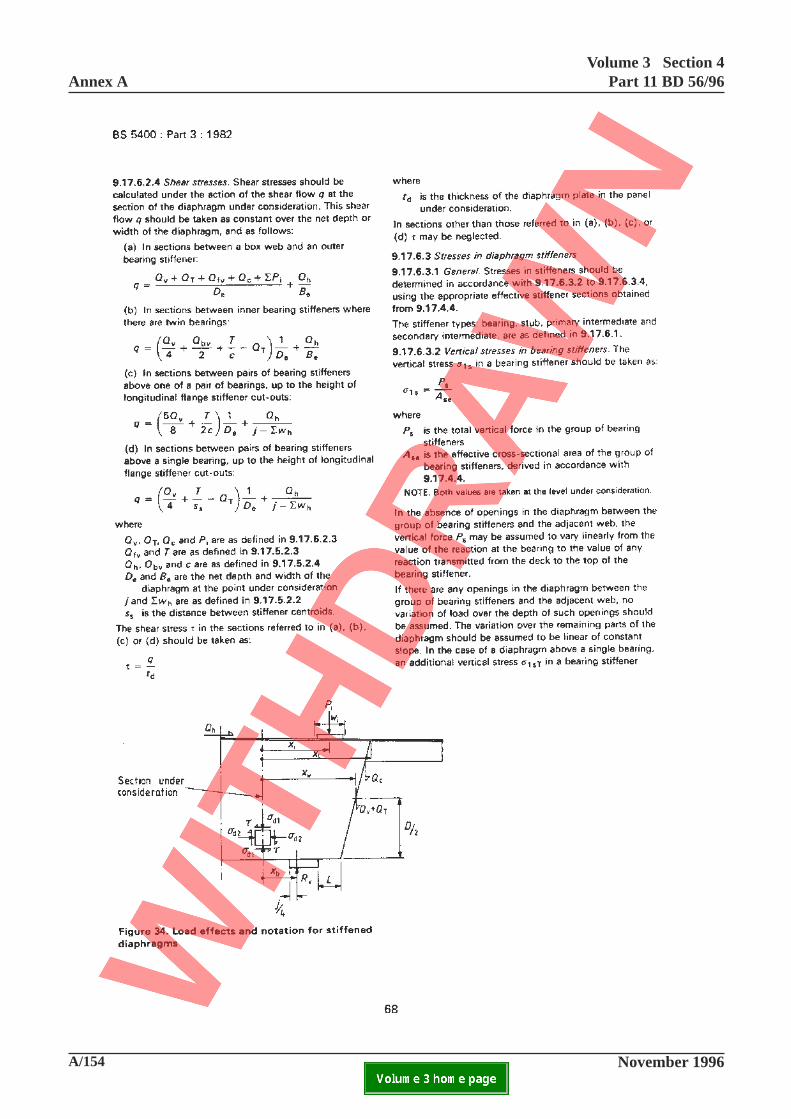
Annex AVolume 3 Section 4
Part 11 BD 56/96
A/154 November 1996ELECTRONIC COPY NOT FOR USE OUTSIDE THE AGENCY.PAPER COPIES OF THIS ELECTRONIC DOCUMENT ARE UNCONTROLLED

Volume 3 Section 4Part 11 BD 56/96 Annex A
November 1996 A/155ELECTRONIC COPY NOT FOR USE OUTSIDE THE AGENCY.PAPER COPIES OF THIS ELECTRONIC DOCUMENT ARE UNCONTROLLED
68
This page is blank
Annex AVolume 3 Section 4
Part 11 BD 56/96
A/156 November 1996ELECTRONIC COPY NOT FOR USE OUTSIDE THE AGENCY.PAPER COPIES OF THIS ELECTRONIC DOCUMENT ARE UNCONTROLLED

Volume 3 Section 4Part 11 BD 56/96 Annex A
November 1996 A/157ELECTRONIC COPY NOT FOR USE OUTSIDE THE AGENCY.PAPER COPIES OF THIS ELECTRONIC DOCUMENT ARE UNCONTROLLED
69
This page is blank
Annex AVolume 3 Section 4
Part 11 BD 56/96
A/158 November 1996ELECTRONIC COPY NOT FOR USE OUTSIDE THE AGENCY.PAPER COPIES OF THIS ELECTRONIC DOCUMENT ARE UNCONTROLLED

Volume 3 Section 4Part 11 BD 56/96 Annex A
November 1996 A/159ELECTRONIC COPY NOT FOR USE OUTSIDE THE AGENCY.PAPER COPIES OF THIS ELECTRONIC DOCUMENT ARE UNCONTROLLED
70
This page is blank
Annex AVolume 3 Section 4
Part 11 BD 56/96
A/160 November 1996ELECTRONIC COPY NOT FOR USE OUTSIDE THE AGENCY.PAPER COPIES OF THIS ELECTRONIC DOCUMENT ARE UNCONTROLLED
71-1

Volume 3 Section 4Part 11 BD 56/96 Annex A
November 1996 A/161ELECTRONIC COPY NOT FOR USE OUTSIDE THE AGENCY.PAPER COPIES OF THIS ELECTRONIC DOCUMENT ARE UNCONTROLLED
Add new clause 9.18:
9.18 Intermediate diaphragms in box girders
9.18.1 General
This section shall apply to intermediate plateddiaphragms provided in box girders to transfer deckloads to the webs, to resist forces due to local changesin slope of the flanges and to restrict distortion of thecross-section.
9.18.2 Limitations
The limitations given in 9.17.2 other than those relatedto bearings shall be applicable to intermediatediaphragms. Assessment of unstiffened and stiffenedintermediate diaphragms shall be carried out inaccordance with 9.18.5 and 9.18.6 respectively.
9.18.3 Loading on diaphragms
9.18.3.1 Derivation
The load effects in intermediate diaphragms andassociated parts of box girders shall be derived fromglobal and local analysis in accordance with 7.1, 7.2and 9.4.1.
9.18.3.2 Effects to be considered
Intermediate diaphragms shall be assessed with dueaccount taken of the application of the load effectsgiven in 9.13.3 and 9.15.4.
In this context the diaphragm/web junction shall beconsidered to be equivalent to a web stiffener.
9.18.4 Effective sections
The effective sections of intermediate diaphragms tobe used in deriving stresses shall be in accordance with9.17.4.
9.18.5 Unstiffened intermediate diaphragms
9.18.5.1 General
Unstiffened diaphragms complying with the
limitations of 9.18.2 shall be assessed to the yieldcriterion of 9.18.5.4 and the buckling criterion of9.18.5.3 using reference stress values of 9.18.5.2 andbuckling coefficients of 9.18.5.3. Web/diaphragmjunctions shall be assessed in accordance with 9.18.7.Diaphragm stiffness shall be assessed in accordancewith 9.18.8, to ascertain the relevant distribution ofwarping and distortional stresses in the box girder ordiaphragm.
9.18.5.2 Reference values of in-plane stresses
9.18.5.2.1 General
The stresses in an unstiffened diaphragm resultingfrom the load effects given in 9.18.3 shall bedetermined in accordance with 9.18.5.2.2 to9.18.5.2.4.
9.18.5.2.2 Vertical stresses
The reference value of the in-plane vertical stress σR1
shall be taken as the greater of σR1T
and σR1B
where
σR1T
is the maximum value of compressivevertical stress on the effective horizontalsection of the diaphragm plating beneaththe top flange due to deck loading
σR1B
is the maximum value of compressivevertical stress on the effective horizontalsection of the diaphragm plating abovethe bottom flange due to change in slopeof the flange or other applied verticalloading
9.18.5.2.3 Horizontal stresses
By reference to Figure 9.18.5A the reference value ofthe in-plane horizontal stress at a section distance S
from the centre of the web, σR2
, shall be taken as thegreater of:
[ ][ ]σ σR2T 2+
or
[ ][ ]σ σR2B 2+71-1
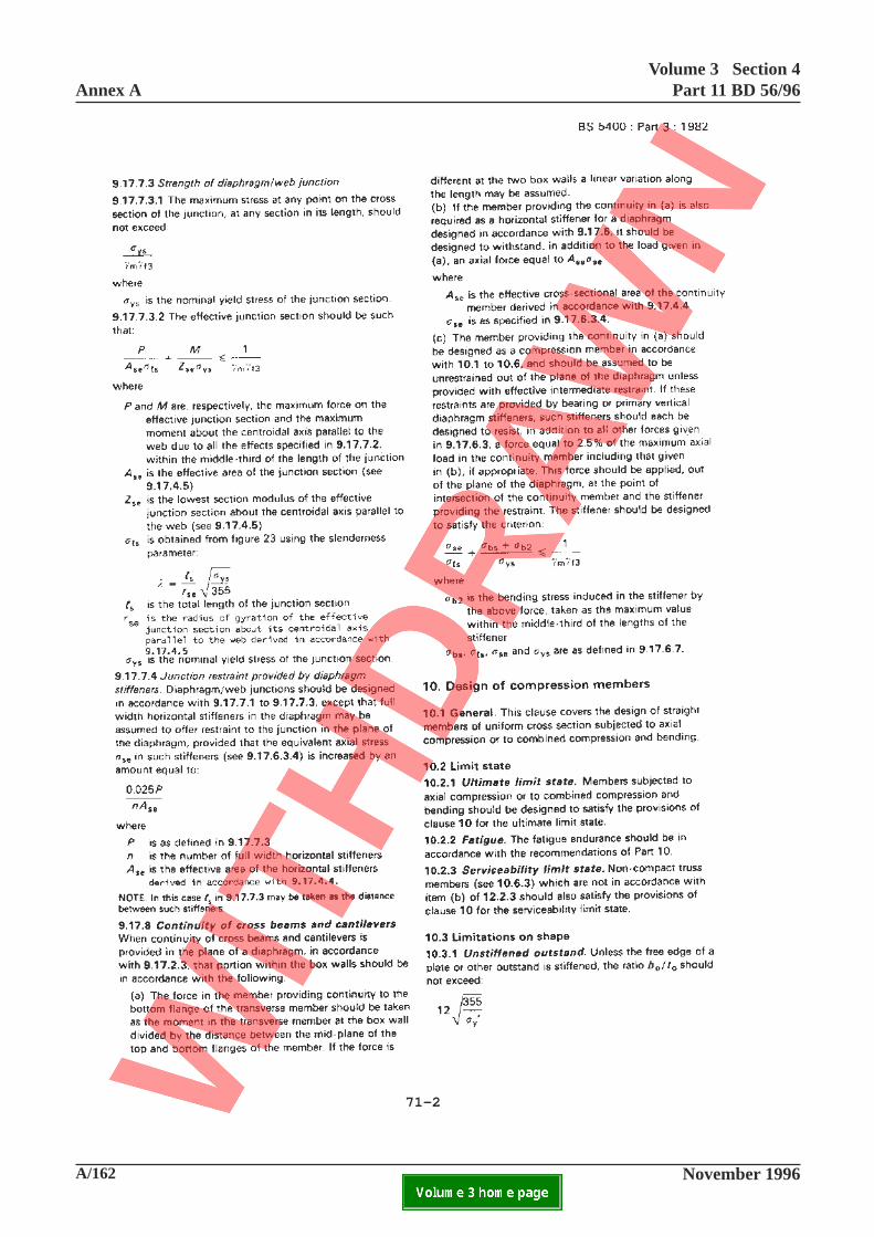
Annex AVolume 3 Section 4
Part 11 BD 56/96
A/162 November 1996ELECTRONIC COPY NOT FOR USE OUTSIDE THE AGENCY.PAPER COPIES OF THIS ELECTRONIC DOCUMENT ARE UNCONTROLLED
71-2
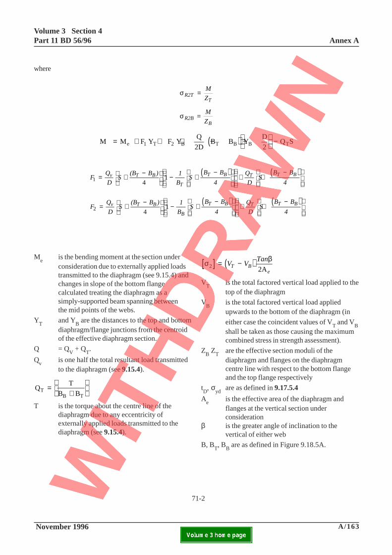
Volume 3 Section 4Part 11 BD 56/96 Annex A
November 1996 A/163ELECTRONIC COPY NOT FOR USE OUTSIDE THE AGENCY.PAPER COPIES OF THIS ELECTRONIC DOCUMENT ARE UNCONTROLLED
where
σ R2TT
M
Z=
σ R2BB
M
Z=
( )M M F Y F YQ
2D B B Y
D
2Q Se 1 T 2 B T B B T= + + + − −
−
( ) ( )F
Q
DS
(B B ) 1
BS
B B
4
Q
DS
B B
4v T B
T
T B T T B1 4
1= + −
− +−
+ +
−
( ) ( )F
Q
DS
(B B ) 1
BS
B B
4
Q
DS
B B
4v T B
B
T B T T B2 4
1= +−
− +−
+ +
−
Me
is the bending moment at the section underconsideration due to externally applied loadstransmitted to the diaphragm (see 9.15.4) andchanges in slope of the bottom flangecalculated treating the diaphragm as asimply-supported beam spanning betweenthe mid points of the webs.
YT
and YB are the distances to the top and bottom
diaphragm/flange junctions from the centroidof the effective diaphragm section.
Q = QV + Q
T.
Qv
is one half the total resultant load transmittedto the diaphragm (see 9.15.4).
QT
B BTB T
=+
T is the torque about the centre line of thediaphragm due to any eccentricity ofexternally applied loads transmitted to thediaphragm (see 9.15.4).
[ ] ( )σ β2 2A
= −V VTan
T Be
VT
is the total factored vertical load applied to thetop of the diaphragm
VB
is the total factored vertical load appliedupwards to the bottom of the diaphragm (in
either case the coincident values of VT and V
Bshall be taken as those causing the maximumcombined stress in strength assessment).
ZB Z
Tare the effective section moduli of thediaphragm and flanges on the diaphragmcentre line with respect to the bottom flangeand the top flange respectively
tD, σ
ydare as defined in 9.17.5.4
Ae
is the effective area of the diaphragm andflanges at the vertical section underconsideration
β is the greater angle of inclination to thevertical of either web
B, BT, B
B are as defined in Figure 9.18.5A.
71-2

Annex AVolume 3 Section 4
Part 11 BD 56/96
A/164 November 1996ELECTRONIC COPY NOT FOR USE OUTSIDE THE AGENCY.PAPER COPIES OF THIS ELECTRONIC DOCUMENT ARE UNCONTROLLED
71-3
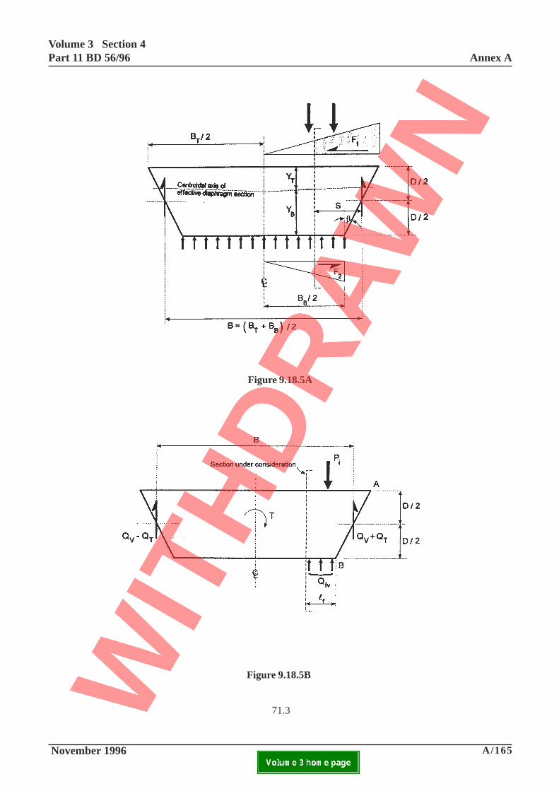
Volume 3 Section 4Part 11 BD 56/96 Annex A
November 1996 A/165ELECTRONIC COPY NOT FOR USE OUTSIDE THE AGENCY.PAPER COPIES OF THIS ELECTRONIC DOCUMENT ARE UNCONTROLLED
Figure 9.18.5A
Figure 9.18.5B
71.3

Annex AVolume 3 Section 4
Part 11 BD 56/96
A/166 November 1996ELECTRONIC COPY NOT FOR USE OUTSIDE THE AGENCY.PAPER COPIES OF THIS ELECTRONIC DOCUMENT ARE UNCONTROLLED
71-4
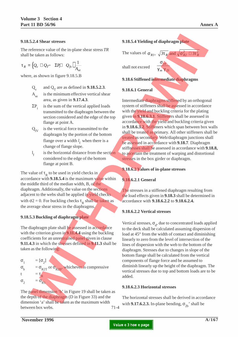
Volume 3 Section 4Part 11 BD 56/96 Annex A
November 1996 A/167ELECTRONIC COPY NOT FOR USE OUTSIDE THE AGENCY.PAPER COPIES OF THIS ELECTRONIC DOCUMENT ARE UNCONTROLLED
9.18.5.2.4 Shear stresses
The reference value of the in-plane shear stress TRshall be taken as follows:
( )τR v T i fvve
Q Q P QA
= + − +Σ 1
where, as shown in figure 9.18.5.B
Qv
and QT are as defined in 9.18.5.2.3.
Ave
is the minimum effective vertical sheararea, as given in 9.17.4.3.
ΣPi
is the sum of the vertical applied loadstransmitted to the diaphragm between thesection considered and the edge of the topflange at point A.
QfV
is the vertical force transmitted to thediaphragm by the portion of the bottom
flange over a width lf when there is a
change of flange slope.
lf
is the horizontal distance from the sectionconsidered to the edge of the bottomflange at point B.
The value of τR to be used in yield checks in
accordance with 9.18.5.4 is the maximum value withinthe middle third of the median width, B, of thediaphragm. Additionally, the value on the sectionsadjacent to the webs shall be applied in yield checks
with σ2 = 0. For buckling checks τR shall be taken as
the average shear stress in the diaphragms.
9.18.5.3 Buckling of diaphragm plate
The diaphragm plate shall be assessed in accordancewith the criterion given in 9.11.4.4 using the bucklingcoefficients for an unrestrained panel given in clause9.11.4.3 in which the stresses defined in 9.11.3 shall betaken as the following:
σ1
= [σ2]
σb
= σR2T
or σR2B
, whichever is compressive
t = τR
σ2
= σR1
The panel dimension ‘b’ in Figure 19 shall be taken asthe depth of the diaphragm (D in Figure 33) and thedimension ‘a’ shall be taken as the maximum widthbetween box webs.
9.18.5.4 Yielding of diaphragm plate
The values of σ τ σ τR1 R R22
R, 3 and 3 2+
shall not exceedσ
γ γyd
m f3
9.18.6 Stiffened intermediate diaphragms
9.18.6.1 General
Intermediate diaphragms stiffened by an orthogonalsystem of stiffeners shall be assessed in accordancewith the yield and buckling criteria for the platinggiven in 9.18.6.3.1. Stiffeners shall be assessed inaccordance with the yield and buckling criteria givenin 9.18.6.3.2. Stiffeners which span between box wallsshall be treated as primary. All other stiffeners shall betreated as secondary. Web/diaphragm junctions shallbe assessed in accordance with 9.18.7. Diaphragmstiffnesses shall be assessed in accordance with 9.18.8,to ascertain the treatment of warping and distortionalstresses in the box girder or diaphragm.
9.18.6.2 Values of in-plane stresses
9.18.6.2.1 General
The stresses in a stiffened diaphragm resulting fromthe load effects given in 9.18.3 shall be determined inaccordance with 9.18.6.2.2 to 9.18.6.2.4.
9.18.6.2.2 Vertical stresses
Vertical stresses, σd, due to concentrated loads appliedto the deck shall be calculated assuming dispersion ofload at 45° from the width of contact and diminishinglinearly to zero from the level of intersection of thelines of dispersion with the web to the bottom of thediaphragm. Stresses due to changes in slope of thebottom flange shall be calculated from the verticalcomponents of flange force and be assumed todiminish linearly up the height of the diaphragm. Thevertical stresses due to top and bottom loads are to beadded.
9.18.6.2.3 Horizontal stresses
The horizontal stresses shall be derived in accordance
with 9.17.6.2.3. In-plane bending, σ2b’ shall be71-4
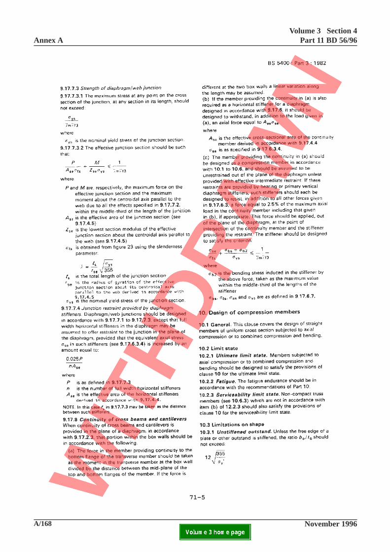
Annex AVolume 3 Section 4
Part 11 BD 56/96
A/168 November 1996ELECTRONIC COPY NOT FOR USE OUTSIDE THE AGENCY.PAPER COPIES OF THIS ELECTRONIC DOCUMENT ARE UNCONTROLLED
71-5

Volume 3 Section 4Part 11 BD 56/96 Annex A
November 1996 A/169ELECTRONIC COPY NOT FOR USE OUTSIDE THE AGENCY.PAPER COPIES OF THIS ELECTRONIC DOCUMENT ARE UNCONTROLLED
calculated by treating the diaphragm with theassociated effective widths of flanges as a simplysupported beam spanning between the box webs
(span B) and horizontal stresses, σ2q
, due toinclination of webs to the vertical shall be calculated inaccordance with 9.18.5.2.3.
9.18.6.2.4 Shear stresses
The values of the in-plane shear stresses, τ, on any
section shall be taken as the reference value τR as
defined in 9.18.5.2.4.
9.18.6.2.5 Stresses in diaphragm stiffeners
The equivalent stress in a stiffener for buckling checkshall be determined from 9.17.6.3.4 as appropriate for
intermediate stiffeners with σ2b
, σ2q
and τ calculatedin accordance with 9.18.6.2.3 and 9.18.6.2.4. Except
that σa for vertical intermediate stiffeners is not
necessarily zero but shall include loading effects due totension field in accordance with 9.13.3.2 and 9.13.4.Loading from clause 9.13.3.3 shall be excluded. Alladditional load effects as defined in 9.18.3.2 shall beconsidered.
9.18.6.3 Strength criteria
9.18.6.3.1 Diaphragm plating
Plate panels between stiffeners or between stiffenersand box walls shall be assessed inaccordance with thecriteria in 9.17.6.4 and 9.17.6.5.
9.18.6.3.2 Stiffeners
Diaphragm stiffeners shall be assessed in accordancewith the criterion given in 9.17.6.7.
9.18.7 Intermediate diaphragmAveb junctions
The intermediate diaphragm web junction shall beassessed as a stiffener to the box web spanningbetween box flanges, unsupported in the plane of thediaphragm, in accordance with 9.17.7.2 to 9.17.7.4using effective sections derived in accordance with9.17.4.5.
9.18.8 Intermediate diaphragm stiffness
Where distortional and warping stresses in the boxgirders are calculated in accordance with Appendix Bthe stiffness of an intermediate diaphragm shallcomply with the requirements of B.3.4 Where thestiffness requirements are not complied with, the stressshall be derived in accordance with 8.3.
10.3.1 Unstiffened OutstandDelete the existing definition for σ
y' and substitute
following definition:-
σy' is the lesser of the nominal yield stress
of the material or such lower value ofyield stress as would be necessary to meetthe strength criteria of the subsequentclauses.
71-5
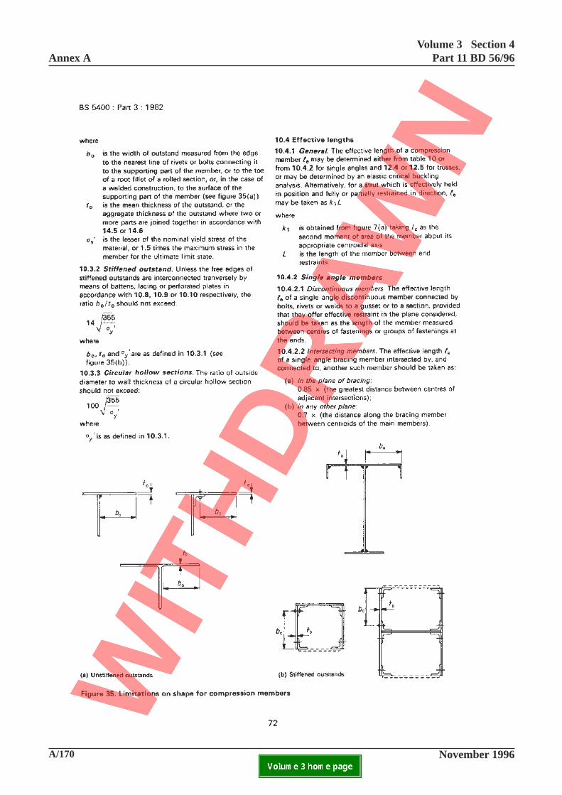
Annex AVolume 3 Section 4
Part 11 BD 56/96
A/170 November 1996ELECTRONIC COPY NOT FOR USE OUTSIDE THE AGENCY.PAPER COPIES OF THIS ELECTRONIC DOCUMENT ARE UNCONTROLLED

Volume 3 Section 4Part 11 BD 56/96 Annex A
November 1996 A/171ELECTRONIC COPY NOT FOR USE OUTSIDE THE AGENCY.PAPER COPIES OF THIS ELECTRONIC DOCUMENT ARE UNCONTROLLED
10.3.3 Circular Hollow Section
Delete the expression and substitute
60 355
yσ
Add new sub-clause 10.3.4:
10.3.4 Assessment of sections not complying withshape limitations
Outstands not complying with 10.3.1 or 10.3.2 shallbe assessed in accordance with 9.3.2. Circular hollowsections not complying with 10.3.3 shall be assessed inaccordance with 9.3.6. This means that a lower valueof yield stress shall be determined such thatcompliance with the strength criteria of 10.6 and10.3.1, 10.3.2 or 10.3.3 as appropriate is achieved.This lower value of yield stress shall be used in allsubsequence assessment of strength, in accordancewith 9.3.1.
72
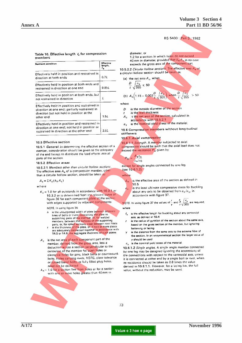
Annex AVolume 3 Section 4
Part 11 BD 56/96
A/172 November 1996ELECTRONIC COPY NOT FOR USE OUTSIDE THE AGENCY.PAPER COPIES OF THIS ELECTRONIC DOCUMENT ARE UNCONTROLLED
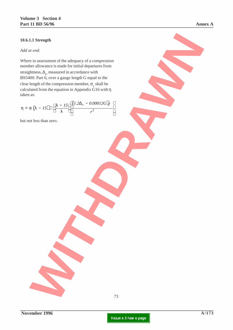
Volume 3 Section 4Part 11 BD 56/96 Annex A
November 1996 A/173ELECTRONIC COPY NOT FOR USE OUTSIDE THE AGENCY.PAPER COPIES OF THIS ELECTRONIC DOCUMENT ARE UNCONTROLLED
10.6.1.1 Strength
Add at end:
Where in assessment of the adequacy of a compressionmember allowance is made for initial departures from
straightness, ∆s, measured in accordance with
BS5400: Part 6, over a gauge length G equal to the
clear length of the compression member, σc shall be
calculated from the equation in Appendix G16 with ηtaken as:
( )( )
η α λ λλ
= − + −
−
1515 1.2 0.00012G y
r
s
2
∆
but not less than zero.
73
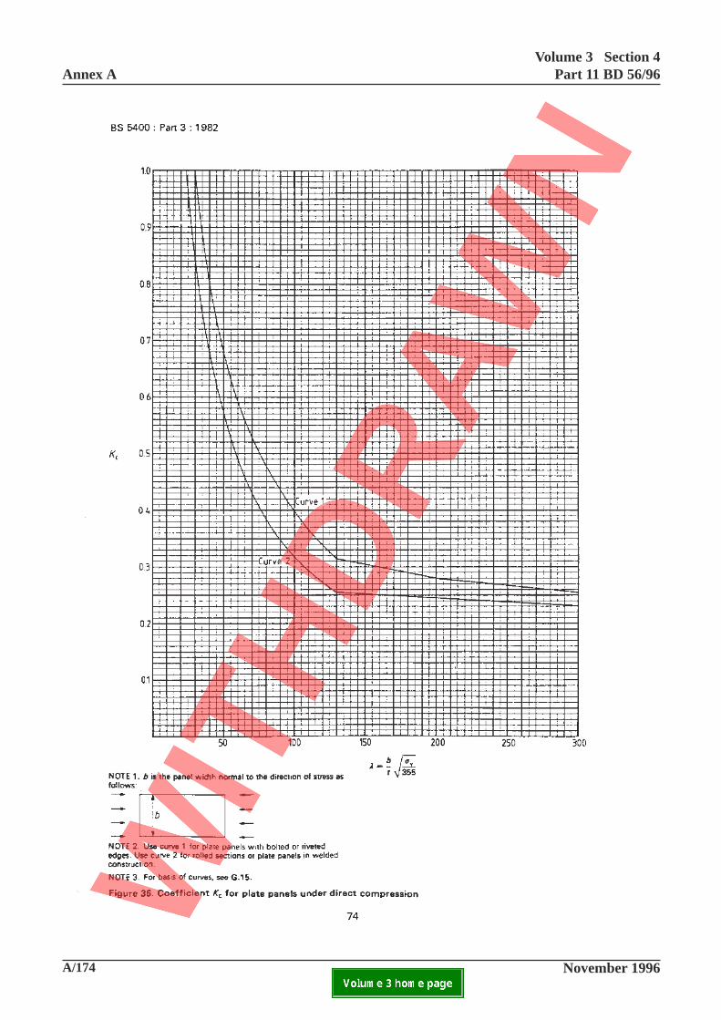
Annex AVolume 3 Section 4
Part 11 BD 56/96
A/174 November 1996ELECTRONIC COPY NOT FOR USE OUTSIDE THE AGENCY.PAPER COPIES OF THIS ELECTRONIC DOCUMENT ARE UNCONTROLLED

Volume 3 Section 4Part 11 BD 56/96 Annex A
November 1996 A/175ELECTRONIC COPY NOT FOR USE OUTSIDE THE AGENCY.PAPER COPIES OF THIS ELECTRONIC DOCUMENT ARE UNCONTROLLED
This page is blank
74
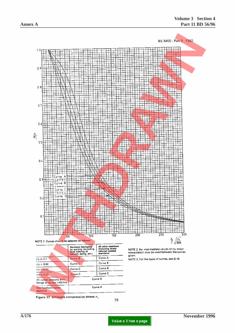
Annex AVolume 3 Section 4
Part 11 BD 56/96
A/176 November 1996ELECTRONIC COPY NOT FOR USE OUTSIDE THE AGENCY.PAPER COPIES OF THIS ELECTRONIC DOCUMENT ARE UNCONTROLLED

Volume 3 Section 4Part 11 BD 56/96 Annex A
November 1996 A/177ELECTRONIC COPY NOT FOR USE OUTSIDE THE AGENCY.PAPER COPIES OF THIS ELECTRONIC DOCUMENT ARE UNCONTROLLED
This page is blank
75
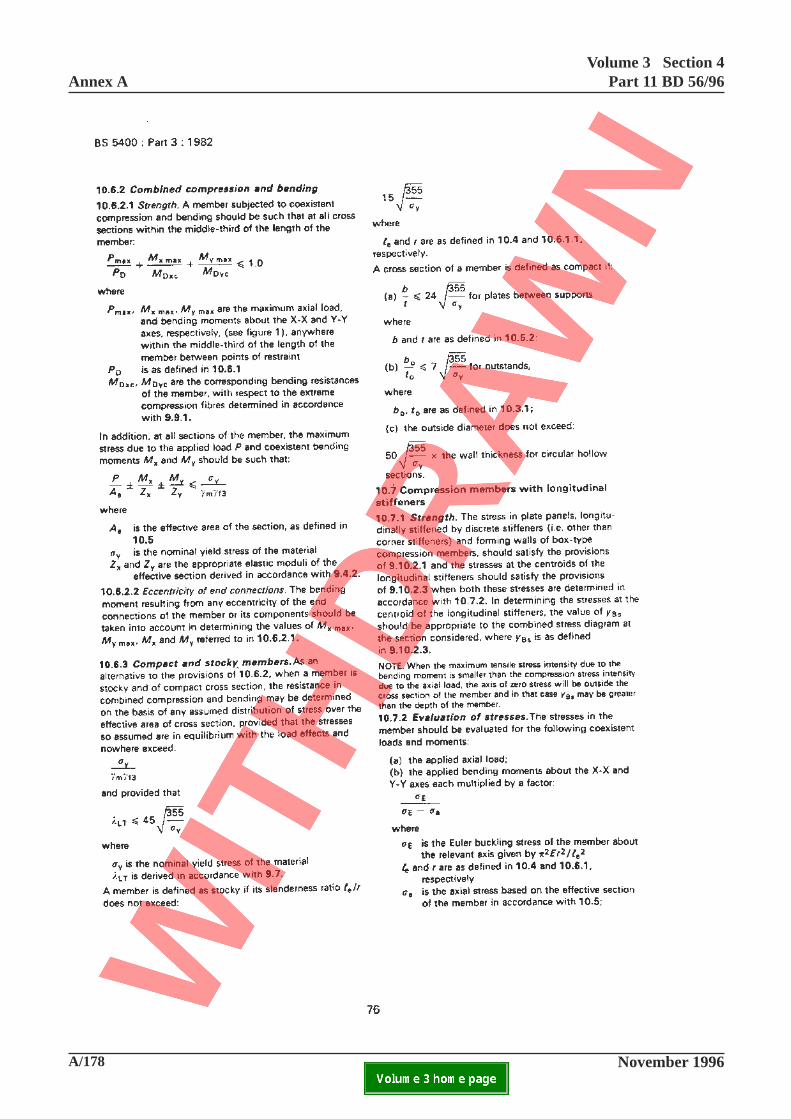
Annex AVolume 3 Section 4
Part 11 BD 56/96
A/178 November 1996ELECTRONIC COPY NOT FOR USE OUTSIDE THE AGENCY.PAPER COPIES OF THIS ELECTRONIC DOCUMENT ARE UNCONTROLLED
Volume 3 Section 4Part 11 BD 56/96 Annex A
November 1996 A/179ELECTRONIC COPY NOT FOR USE OUTSIDE THE AGENCY.PAPER COPIES OF THIS ELECTRONIC DOCUMENT ARE UNCONTROLLED
10.6.2.1 Strength
Add at end:
For assessment of the adequacy of a uniform memberof I-section subject to combined bending and axialcompression, the buckling criterion above shall bereplaced by the alternative criterion given in 9.9.4.2.
10.7.2 Evaluation of stresses
Add at end of (c):
Where in assessment of the adequacy of a compressionmember with longitudinal stiffeners allowance is to bemade for measured initial departures from
straightness, ∆i shall be taken as:
∆i
= 1.2 ∆s determined separately for the X-X
and Y-Y axes where ∆s is the departure
from straightness measured in accordancewith BS5400: Part 6 over a gauge length Gequal to the distance between appropriatepoints of restraint.
76
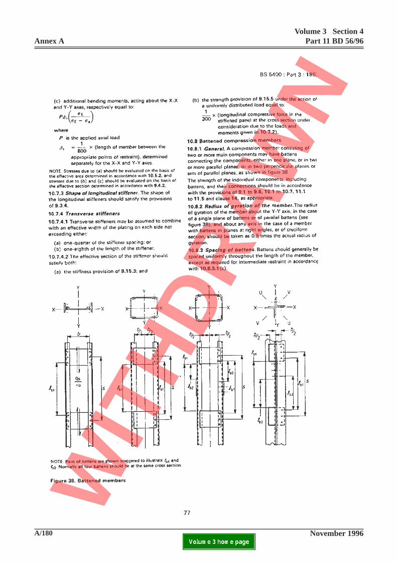
A/180 November 1996
Annex AVolume 3 Section 4
Part 11 BD 56/96
ELECTRONIC COPY NOT FOR USE OUTSIDE THE AGENCY.PAPER COPIES OF THIS ELECTRONIC DOCUMENT ARE UNCONTROLLED

Volume 3 Section 4Part 11 BD 56/96 Annex A
November 1996 A/181ELECTRONIC COPY NOT FOR USE OUTSIDE THE AGENCY.PAPER COPIES OF THIS ELECTRONIC DOCUMENT ARE UNCONTROLLED
77
10.7.3 Limitations of stiffener shape
Add at end:
Stiffener shapes not complying with 9.3.4 shall beassessed in accordance with 9.3.1 and Appendix S.Stiffeners of shapes other than those specified shall beassessed on the basis of the nearest standard shape.
10.8.1 General
Add at end:
For assessment, where the arrangements of themember do not comply with any of the aboverequirements, the strengths of the battens and of thebattened member shall be assessed in accordance withClauses 10.8.5.3 and l0.8.5.4 respectively.
10.8.2 Radius of gyration of the member
Add at end:
For assessment, where the battened member does notcomply with the requirements of 10.8.1, the radius ofgyration of the member shall be taken as √φ times theactual radius of gyration where φ is as defined in10.8.5.4.
10.8.3 Spacing of battens
Add at end:
When the spacings of the battens exceed the limitsderived from the above requirements, the strengths ofthe battened member shall be assessed as described inl0.8.5.4.
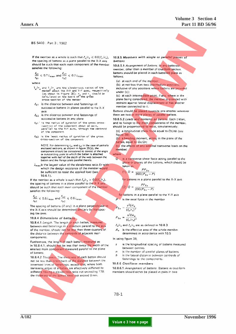
A/182 November 1996
Annex AVolume 3 Section 4
Part 11 BD 56/96
ELECTRONIC COPY NOT FOR USE OUTSIDE THE AGENCY.PAPER COPIES OF THIS ELECTRONIC DOCUMENT ARE UNCONTROLLED
78-1

Volume 3 Section 4Part 11 BD 56/96 Annex A
November 1996 A/183ELECTRONIC COPY NOT FOR USE OUTSIDE THE AGENCY.PAPER COPIES OF THIS ELECTRONIC DOCUMENT ARE UNCONTROLLED
For members with battens and their arrangements notcomplying with the limits given 10.8.1, 10.8.4 or10.8.5.1, the lowest values of the elastic critical
buckling loads PIEY
and P1EX
shall be determined as
described in 10.8.5.4 and shall be used instead of PEY
and PEX
.
Where in assessment of the adequacy of a battenedmember, account is to be taken of measured departurefrom straightness exceeding that permitted by BS5400:Part 6, the number 200 in the denominator ofequations (1) and (2) above shall be reduced to
where
∆s
is the departure from straightnessmeasured over a gauge length equal to
le.
Add new Clause 10.8.5.3:
10.8.5.3 Strength assessment of non-complyingbattens
Where the arrangements and sizes of the battenedmember do not comply with the requirements 10.8.1,10.8.4 or 10.8.5.1, the battens shall be of such sizesthat:
(a) the maximum bending stress does not exceed
σγ γ
y
m f3
(b) the maximum average shear stress =
longitudinal shear force
Abnet
does not exceed
σ
γ γy
m f31.5 3
where Abnet
= Net cross sectional area of the batten;
78
10.8.4.1 Length.
Add at end:
Where the length of each batten is less than specifiedabove, the strength of the battened member shall beassessed in accordance with 10.8.5.4.
10.8.4.2 Thickness.
Add at end:
Where the thickness of any batten is less than thatspecified above the adequacy of such batten shall beassessed in accordance with 10.8.5.3.
10.8.5.1 Arrangement of battens.
Add at end:
Where the arrangement of battens does not complywith the recommendations above the battenedcompression member shall be assessed in accordancewith 10.8.5.4.
10.8.5.2 Loads and moments on battens.
Add at end:
For assessment, (a) and (b) shall be modified to read:
(a) a longitudinal shear force equal to KbQs/nb
(b) a bending moment, acting in the plane of
the batten, equal to KbQs/2n
where
Kb
= l/2 for end battens,for intermediate battens
=1
2 1 2cos cosπ πl
xl
x+
l is the overall length of the battenedmember;
x1,x
2are the respective distances fromone end of the member to points adistance s/2 either side of thecentre line of the batten underconsideration.
1 2cos cosπ πl
xl
x+
3.8 ∆s
+ 1
le
8151/

A/184 November 1996
Annex AVolume 3 Section 4
Part 11 BD 56/96
ELECTRONIC COPY NOT FOR USE OUTSIDE THE AGENCY.PAPER COPIES OF THIS ELECTRONIC DOCUMENT ARE UNCONTROLLED
78-2
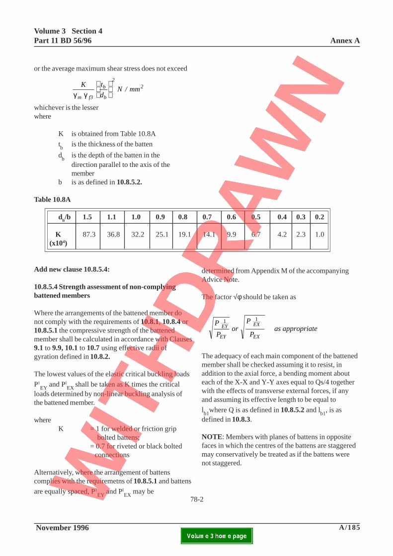
Volume 3 Section 4Part 11 BD 56/96 Annex A
November 1996 A/185ELECTRONIC COPY NOT FOR USE OUTSIDE THE AGENCY.PAPER COPIES OF THIS ELECTRONIC DOCUMENT ARE UNCONTROLLED
78-2
or the average maximum shear stress does not exceed
K
t
d N / mm
m f3
b
b
22
γ γ
whichever is the lesserwhere
K is obtained from Table 10.8A
tb
is the thickness of the batten
db
is the depth of the batten in thedirection parallel to the axis of themember
b is as defined in 10.8.5.2.
Add new clause 10.8.5.4:
10.8.5.4 Strength assessment of non-complyingbattened members
Where the arrangements of the battened member donot comply with the requirements of 10.8.1, 10.8.4 or10.8.5.1 the compressive strength of the battenedmember shall be calculated in accordance with Clauses9.1 to 9.9, 10.1 to 10.7 using effective radii ofgyration defined in 10.8.2.
The lowest values of the elastic critical buckling loads
P1EY
and PIEX
shall be taken as K times the criticalloads determined by non-linear buckling analysis ofthe battened member.
whereK = 1 for welded or friction grip
bolted battens;= 0.7 for riveted or black bolted connections
Alternatively, where the arrangement of battenscomplies with the requiremetns of 10.8.5.1 and battens
are equally spaced, P1EY
and PIEX
may be
Table 10.8A
db/b 1.5 1.1 1.0 0.9 0.8 0.7 0.6 0.5 0.4 0.3 0.2
K 87.3 36.8 32.2 25.1 19.1 14.1 9.9 6.7 4.2 2.3 1.0(x104)
determined from Appendix M of the accompanyingAdvice Note.
The factor √φ should be taken as
P
P or
P
P as appropriateEY
EY
EX
EX
1 1
The adequacy of each main component of the battenedmember shall be checked assuming it to resist, inaddition to the axial force, a bending moment abouteach of the X-X and Y-Y axes equal to Qs/4 togetherwith the effects of transverse external forces, if anyand assuming its effective length to be equal to
lb1where Q is as defined in 10.8.5.2 and lb1, is asdefined in 10.8.3.
NOTE: Members with planes of battens in oppositefaces in which the centres of the battens are staggeredmay conservatively be treated as if the battens werenot staggered.

A/186 November 1996
Annex AVolume 3 Section 4
Part 11 BD 56/96
ELECTRONIC COPY NOT FOR USE OUTSIDE THE AGENCY.PAPER COPIES OF THIS ELECTRONIC DOCUMENT ARE UNCONTROLLED
79-1
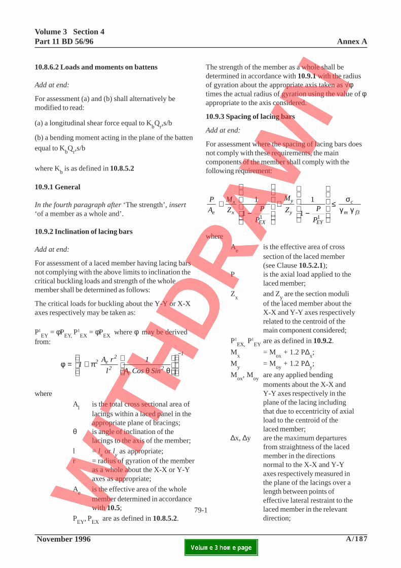
Volume 3 Section 4Part 11 BD 56/96 Annex A
November 1996 A/187ELECTRONIC COPY NOT FOR USE OUTSIDE THE AGENCY.PAPER COPIES OF THIS ELECTRONIC DOCUMENT ARE UNCONTROLLED
79-1
10.8.6.2 Loads and moments on battens
Add at end:
For assessment (a) and (b) shall alternatively bemodified to read:
(a) a longitudinal shear force equal to KbQr,s/b
(b) a bending moment acting in the plane of the batten
equal to KbQr,s/b
where Kb is as defined in 10.8.5.2
10.9.1 General
In the fourth paragraph after ‘The strength’, insert‘of a member as a whole and’.
10.9.2 Inclination of lacing bars
Add at end:
For assessment of a laced member having lacing barsnot complying with the above limits to inclination thecritical buckling loads and strength of the wholemember shall be determined as follows:
The critical loads for buckling about the Y-Y or X-Xaxes respectively may be taken as:
P1EY = φPEY, P
1EX = φPEX where φ may be derived
from:
φ πθ θ
= +
−
1A r
l
1
A Cos Sin 2 e
2
2l
2
1
where
Al is the total cross sectional area oflacings within a laced panel in theappropriate plane of bracings;
θ is angle of inclination of thelacings to the axis of the member;
l = lx or l
y as appropriate;
r = radius of gyration of the memberas a whole about the X-X or Y-Yaxes as appropriate;
Ae is the effective area of the wholemember determined in accordancewith 10.5;
PEY, PEX are as defined in 10.8.5.2.
The strength of the member as a whole shall bedetermined in accordance with 10.9.1 with the radiusof gyration about the appropriate axis taken as √φtimes the actual radius of gyration using the value of φappropriate to the axis considered.
10.9.3 Spacing of lacing bars
Add at end:
For assessment where the spacing of lacing bars doesnot comply with these requirements, the maincomponents of the member shall comply with thefollowing requirement:
P
A
M
Z P
P
M
Z P
P e
x
x
EX
y
y
EY
c
m f3
+−
+−
≤1
1
1
11 1
σγ γ
where
Ae
is the effective area of crosssection of the laced member(see Clause 10.5.2.1);
P is the axial load applied to thelaced member;
Zx
and Zy are the section moduli
of the laced member about theX-X and Y-Y axes respectivelyrelated to the centroid of themain component considered;
P1EX,
P1EY
are as defined in 10.9.2.
Mx
= Mox
+ 1.2 P∆x;
My
= Moy
+ 1.2 P∆y;
Mox
, Moy
are any applied bendingmoments about the X-X andY-Y axes respectively in theplane of the lacing includingthat due to eccentricity of axialload to the centroid of thelaced member;
∆x, ∆y are the maximum departuresfrom straightness of the lacedmember in the directionsnormal to the X-X and Y-Yaxes respectively measured inthe plane of the lacings over alength between points ofeffective lateral restraint to thelaced member in the relevantdirection;
A/188 November 1996
Annex AVolume 3 Section 4
Part 11 BD 56/96
ELECTRONIC COPY NOT FOR USE OUTSIDE THE AGENCY.PAPER COPIES OF THIS ELECTRONIC DOCUMENT ARE UNCONTROLLED
79-2

Volume 3 Section 4Part 11 BD 56/96 Annex A
November 1996 A/189ELECTRONIC COPY NOT FOR USE OUTSIDE THE AGENCY.PAPER COPIES OF THIS ELECTRONIC DOCUMENT ARE UNCONTROLLED
σc is the ultimate compressive stressfor buckling of the main componentabout its centroidal axis perpendicularto the plane of lacing obtained from
σc/σy in accordance with Figure 37
using le equal to the spacing of the
lacing bar intersections along thecomponent;
r is the least radius of gyration of thesection of the main component;
y is the distance from the axis of leastradius of gyration to the extremefibre of the section of the maincomponent;
σy is the nominal yield stress of thematerial.
79-2
A/190 November 1996
Annex AVolume 3 Section 4
Part 11 BD 56/96
ELECTRONIC COPY NOT FOR USE OUTSIDE THE AGENCY.PAPER COPIES OF THIS ELECTRONIC DOCUMENT ARE UNCONTROLLED

Volume 3 Section 4Part 11 BD 56/96 Annex A
November 1996 A/191ELECTRONIC COPY NOT FOR USE OUTSIDE THE AGENCY.PAPER COPIES OF THIS ELECTRONIC DOCUMENT ARE UNCONTROLLED
80
11.1 Tension Members - General
Add at end:
This section shall cover the assessment of nominallystraight members subjected to axial tension or tocombined tension and bending. Where members act ascompression members under defined assessmentloading then they shall be assessed under section 10unless it can be shown that sufficient redundancy oralterative load path exists in which case suchcompression may be ignored.
11.3.2 Effective area
Add at end:
For assessment the value of k2 shall be taken as
follows: -1.2 where the member is B.S. 4360 grade 43 or
B.S. 15 steel;1.1 where the member is B.S. 4360 grade 50 or
B.S. 968 steel;1.0 where the member is B.S. 4360 grade 55 or
Thirty Oak steel;or
1.0 0.5 1.2y
+ −
σσULT
but not exceeding 1.2 where the member is of steel notcomplying with BS4360, BS15, BS548 or BS968
where σy and σ
ULT are the nominal yield stress and
ultimate stress derived in accordance with 6.2 and 6.3respectively.
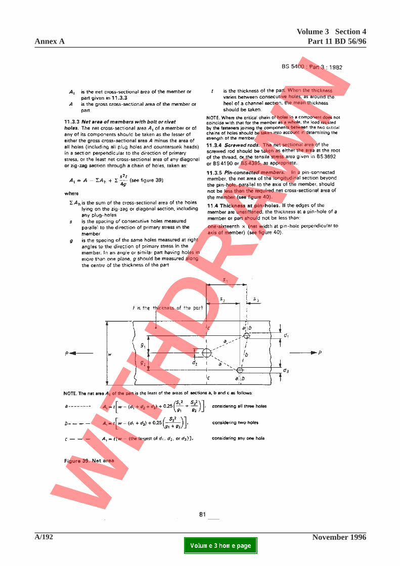
A/192 November 1996
Annex AVolume 3 Section 4
Part 11 BD 56/96
ELECTRONIC COPY NOT FOR USE OUTSIDE THE AGENCY.PAPER COPIES OF THIS ELECTRONIC DOCUMENT ARE UNCONTROLLED

Volume 3 Section 4Part 11 BD 56/96 Annex A
November 1996 A/193ELECTRONIC COPY NOT FOR USE OUTSIDE THE AGENCY.PAPER COPIES OF THIS ELECTRONIC DOCUMENT ARE UNCONTROLLED
11.3.5 Pin connected members
Add at end:
Where this requirement is not met, it shall be checkedthat tearing will not occur beyond the pin hole.
11.4 Thickness at pin holes
Add at end:
Where this requirement is not complied with, it shallbe checked that local buckling will not occur beyondthe pin hole.
81
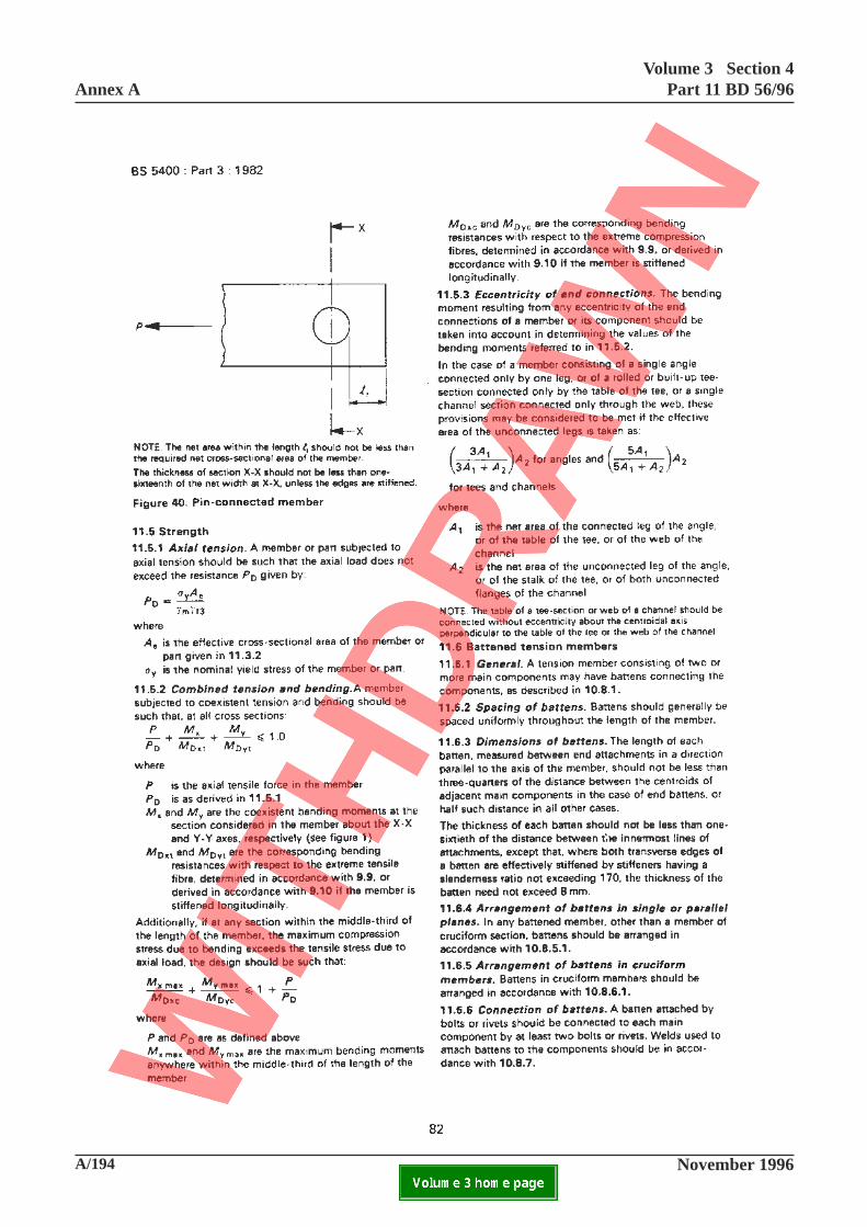
A/194 November 1996
Annex AVolume 3 Section 4
Part 11 BD 56/96
ELECTRONIC COPY NOT FOR USE OUTSIDE THE AGENCY.PAPER COPIES OF THIS ELECTRONIC DOCUMENT ARE UNCONTROLLED

Volume 3 Section 4Part 11 BD 56/96 Annex A
November 1996 A/195ELECTRONIC COPY NOT FOR USE OUTSIDE THE AGENCY.PAPER COPIES OF THIS ELECTRONIC DOCUMENT ARE UNCONTROLLED
11.6.1 Genera1
Add at end:
Where battens have been incorporated to cater forlateral loading or vibration (or for erection andhandling during construction), and the requirements of11.6.2 to 11.6.7 are not complied with, the battens andtheir fixings shall be assessed to resist the effects ofall-loading to which they are subjected, includingwind.
82

A/196 November 1996
Annex AVolume 3 Section 4
Part 11 BD 56/96
ELECTRONIC COPY NOT FOR USE OUTSIDE THE AGENCY.PAPER COPIES OF THIS ELECTRONIC DOCUMENT ARE UNCONTROLLED

Volume 3 Section 4Part 11 BD 56/96 Annex A
November 1996 A/197ELECTRONIC COPY NOT FOR USE OUTSIDE THE AGENCY.PAPER COPIES OF THIS ELECTRONIC DOCUMENT ARE UNCONTROLLED
11.7.1 General
Add at end:
Where lacing has been incorporated to cater for lateralloading or vibration (or for erection and handlingduring construction), and the requirements of 11.7.2 to11.7.5 are not complied with, the lacing bars and theirfixings shall be assessed to resist the effects of allloading to which they are subjected including wind.
11.8.1 General
Add at end:
Where the above requirements are not met, theperforated plate shall be assessed to resist the effectsof all loading to which it is subjected including wind.
11.9 Tension members with components back toback
Add at end:
Where the requirements of 10.11.1 and 10.11.3 are notcomplied with, the members and their fixings shall beassessed to resist the effects of all loading to whichthey are subjected including wind.
12.1 General
Add at end:
Bending effects shall be ignored in 12.2.2 and 12.2.3where these are solely due to axial deformation ofmembers where the joints are formed usinguntensioned bolts or rivets in clearance holes and anysecondary bending developed can be relieved by jointmovement.
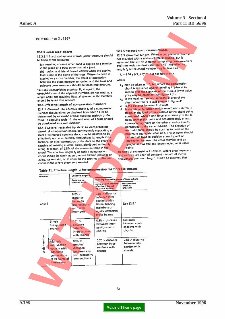
A/198 November 1996
Annex AVolume 3 Section 4
Part 11 BD 56/96
ELECTRONIC COPY NOT FOR USE OUTSIDE THE AGENCY.PAPER COPIES OF THIS ELECTRONIC DOCUMENT ARE UNCONTROLLED
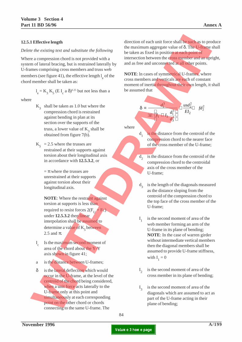
Volume 3 Section 4Part 11 BD 56/96 Annex A
November 1996 A/199ELECTRONIC COPY NOT FOR USE OUTSIDE THE AGENCY.PAPER COPIES OF THIS ELECTRONIC DOCUMENT ARE UNCONTROLLED
12.5.1 Effective length
Delete the existing text and substitute the following
Where a compression chord is not provided with asystem of lateral bracing, but is restrained laterally byU-frames comprising cross members and truss web
members (see figure 41), the effective length le of the
chord member shall be taken as:
le = K
3 K
5 (E I
c a δ)0.25 but not less than a
where
K3
shall be taken as 1.0 but where thecompression chord is restrainedagainst bending in plan at itssection over the supports of the
truss, a lower value of K3 shall be
obtained from figure 7(b).
K5
= 2.5 where the trusses arerestrained at their supports againsttorsion about their longitudinal axisin accordance with 12.5.3.2, or
= π where the trusses areunrestrained at their supportsagainst torsion about theirlongitudinal axis.
NOTE: Where the restraint againsttorsion at supports is less than
required to resist forces 2(FU + Fc)
under 12.5.3.2 then linearinterpolation shall be assumed to
determine a value of K5 between
2.5 and π.
Ic
Is the maximum second moment ofarea of the chord about the Y-Yaxis shown in figure 41;
a is the distance between U-frames;
δ is the lateral deflection which wouldoccur in the U-frame, at the level of thecentroid of the chord being considered,when a unit force acts laterally to theU-frame only at this point andsimultaneously at each correspondingpoint on the other chord or chordsconnecting to the same U-frame. The
direction of each unit force shall be such as to producethe maximum aggregate value of δ. The U-frame shallbe taken as fixed in position at each point ofintersection between the cross member and an upright,and as free and unconnected at all other points.
NOTE: ln cases of symmetrical U-frames, wherecross members and verticals are each of constantmoment of inertia throughout their own length, it shallbe assumed that
δ =+
+ +d
E I Id
d
usd
EIfd1
3
1 313
33
22
222
3
where
d1
is the distance from the centroid of thecompression chord to the nearer faceof the cross member of the U-frame;
d2
is the distance from the centroid of thecompression chord to the centroidalaxis of the cross member of theU-frame;
d3
is the length of the diagonals measuredas the distance sloping from thecentroid of the compression chord tothe top face of the cross member of theU-frame;
I1
is the second moment of area of theweb member forming an arm of theU-frame in its plane of bending;NOTE: In the case of warren girderwithout intermediate vertical membersthen the diagonal members shall beassumed to provide U-frame stiffness,
with I1 = 0
I2
is the second moment of area of thecross member in its plane of bending;
I3
is the second moment of area of thediagonals which are assumed to act aspart of the U-frame acting in theirplane of bending;
84
3E
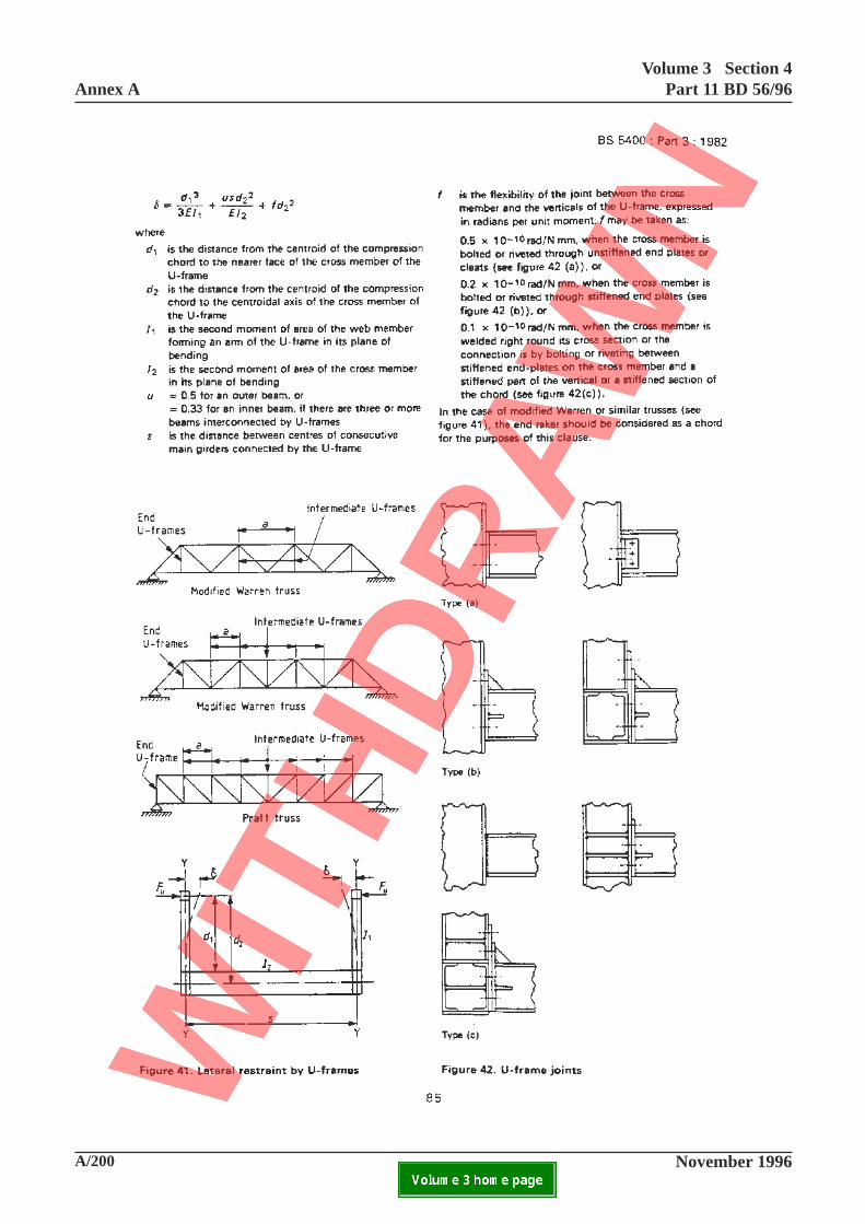
A/200 November 1996
Annex AVolume 3 Section 4
Part 11 BD 56/96
ELECTRONIC COPY NOT FOR USE OUTSIDE THE AGENCY.PAPER COPIES OF THIS ELECTRONIC DOCUMENT ARE UNCONTROLLED

Volume 3 Section 4Part 11 BD 56/96 Annex A
November 1996 A/201ELECTRONIC COPY NOT FOR USE OUTSIDE THE AGENCY.PAPER COPIES OF THIS ELECTRONIC DOCUMENT ARE UNCONTROLLED
u = 0.5 for an outer beam, or= 0.33 for an inner beam, if thereare three or more beamsinterconnected by U-frames;
s is the distance between centres ofconsecutive main girders connectedby the U-frame;
f is the flexibility of the joint betweenthe cross member and the verticalsof the U-frame, expressed inradians per unit moment: f shall betaken as 0.5 x 10⁻¹⁰ rad/N mm, whenthe cross member is bolted orriveted through unstiffened endplates or cleats (see Figure 42(a))or
0.2 x 10⁻¹⁰ rad/Nmm. when the cross member is boltedor riveted through stiffened end plates (see Figure42(b)) or
0.1 x 10⁻¹⁰ rad/N mm, when the cross member iswelded right round its cross section or the connectionis by bolting or riveting between stiffened end-plateson the cross member and a stiffened part of the verticalor stiffened section of the chord (see Figure 42(c)).
NOTE: Values of f may be determined experimentallyor taken from test results available which shall coverthe required ultimate capacity of the joint.
In the case of the modified warren or similar trusses(see Figure 41) the end diagonal shall be considered aschord for the purposes of this clause.
Figure 41. Lateral restraint by U-frames
Delete the existing fgure and substitute the following
85
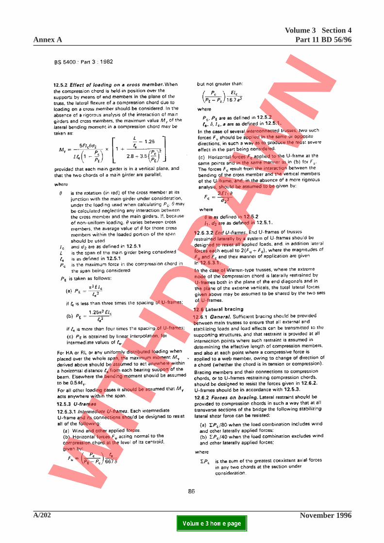
A/202 November 1996
Annex AVolume 3 Section 4
Part 11 BD 56/96
ELECTRONIC COPY NOT FOR USE OUTSIDE THE AGENCY.PAPER COPIES OF THIS ELECTRONIC DOCUMENT ARE UNCONTROLLED

Volume 3 Section 4Part 11 BD 56/96 Annex A
November 1996 A/203ELECTRONIC COPY NOT FOR USE OUTSIDE THE AGENCY.PAPER COPIES OF THIS ELECTRONIC DOCUMENT ARE UNCONTROLLED
12.5.3.1 Intermediate U-frames
In item (c), delete the expression for ‘Fc’ and the
definitions for ‘θ, I, and d2’ and substitute the
following:
Fd
a15EI
c2
3
c
=+
θ
δ
where
d2, δ, a and I
c are as defined in 12.5.1
θ is as defined in 12.5.2 except that it shouldbe calculated assuming the cross member issimply supported.’
Add at end:
Where in assessment of the adequacy of anintermediate U-frame allowance is to be made forinitial departures from straightness of a compression
chord Fu shall be calculated in accordance with
9.12.2.2 with le in accordance with 12.5.1.
Add new Clause 12.6.3:
12.6.3 Lateral bracing not providing adequaterestraint
In cases where any of the provisions of 12.6.1 or12.6.2 are not met in assessment, such bracing shall beignored and assumed to provide no restraint. However,in cases where partial restraint may be available fromany lateral bracing provided, this may be utilisedproviding it can be verified by a rigorous non-linearanalysis of the complete system. Alternatively, the
values of ΣPC in 12.6.2 could be restricted such that
the requirements of 12.6.2 are complied with.
86
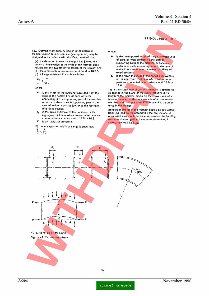
A/204 November 1996
Annex AVolume 3 Section 4
Part 11 BD 56/96
ELECTRONIC COPY NOT FOR USE OUTSIDE THE AGENCY.PAPER COPIES OF THIS ELECTRONIC DOCUMENT ARE UNCONTROLLED

Volume 3 Section 4Part 11 BD 56/96 Annex A
November 1996 A/205ELECTRONIC COPY NOT FOR USE OUTSIDE THE AGENCY.PAPER COPIES OF THIS ELECTRONIC DOCUMENT ARE UNCONTROLLED
12.7 Curved members
Add at end:
Where members do not comply with requirements (a)to (d) consideration shall be given to the following:
(1) The forces and stresses according to9.5.7;
(2) The effects of the change in neutralaxis position due to curvature;
(3) The buckling resistance of the sectionwhere it does not satisfy the criteria for acompact section;
(4) Flanges must be adequate to resistthe radial component of the flangeforce. Assuming the axial force inthe flange is distributed uniformlyacross the width, the line loadradial force per unit width acrossthe flange per unit length of theflange may be expressed as:
σ f fo
f
t
R in a flange outstand, or
in a plate panelbetween longitudinalstiffeners and/or webs
where σf, t
fo, t
f and R
fare all as defined in9.5.7.1.
σ ft
f
fR
87
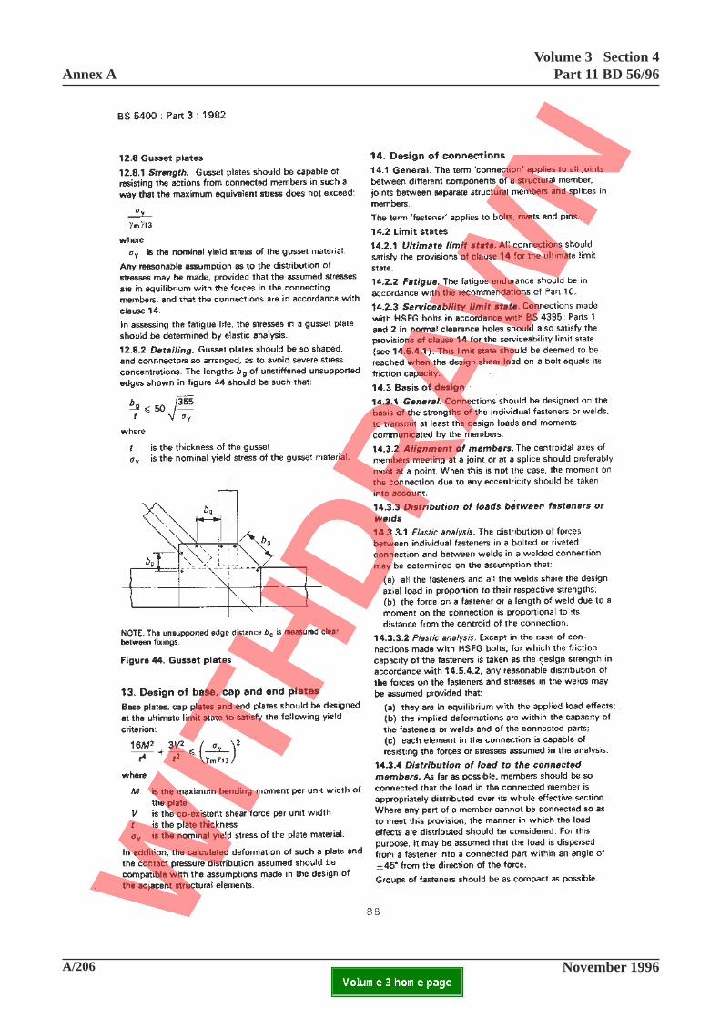
A/206 November 1996
Annex AVolume 3 Section 4
Part 11 BD 56/96
ELECTRONIC COPY NOT FOR USE OUTSIDE THE AGENCY.PAPER COPIES OF THIS ELECTRONIC DOCUMENT ARE UNCONTROLLED
Volume 3 Section 4Part 11 BD 56/96 Annex A
November 1996 A/207ELECTRONIC COPY NOT FOR USE OUTSIDE THE AGENCY.PAPER COPIES OF THIS ELECTRONIC DOCUMENT ARE UNCONTROLLED
12.8.2 Detailing
Add at end:
In the case of severe changes in geometric shape suchas the presence of sharp re-entrant cuts then stressconcentration factors shall be applied.
Where bg/t exceeds the above limit then local buckling
of the gusset plates shall be checked, either by meansof a detailed analysis or by means of reducing the yield
stress, σy, given in 12.8.1 to a value given by
0.9 106
2
×
t
bg
14.1 General
Add at end:
For assessment the term ‘fastener’ also applies to thecomponents of members such as screwed tie rods andturnbuckles.
14.2.3 Serviceability limit state
Add at end:
Where, in assessment, such connections are calculatedto slip under serviceability factored loading inaccordance with 14.5.4.1.2 and no distress is apparentat the joints (see Note 3 in 4.2.2) they shall be checkedunder ultimate factored loading in accordance with14.5.4.1.1(b) and the fatigue endurance of the jointshall be checked assuming the fasteners to be blackbolts. If there is evidence of loose rivets in rivettedconnections then the fatigue endurance of the jointshall also be checked assuming the fasteners to beblack bolts. Fatigue endurance shall be assessed inaccordance with 14.2.2.
Add new Clause 14.3.3.3:
14.3.3.3 Assessment
For assessment elastic analysis shall be used inaccordance with 14.3.3.1 for H.S.F.G bolts checkedfor the serviceability limit state when adopted under14.2.3, and when considering the fatigue
endurance of welds as required under 14.2.2. In otherases, plastic analysis shall be used in accordance with14.3.3.2.
It may normally be assumed that for the assessment ofconnections in beams, all the bending is resisted by theflanges along with any associated flange angles, and:hat shear only is resisted by the web, provided thatthis is compatible with the basis of the assessment ofthe member.
14.3.4 Distabution of load to the connectedmembers
Add at end:
For assessment where any part of a member isconnected so that the load is not distributed over itseffective section, then it shall be assumed that the loadis dispersed from a fastener onto a connected partwithin an angle of ± 45° from the direction of theforce, unless a detailed analysis is carried out whichcan substantiate an improved distribution.
88
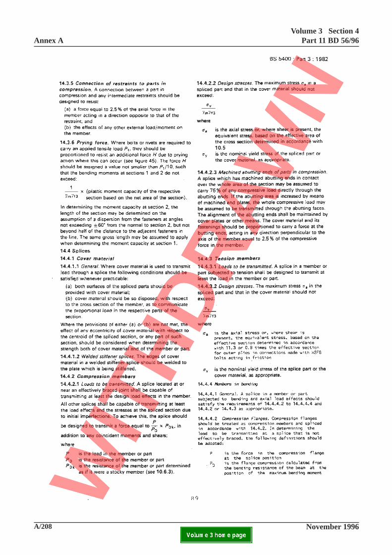
A/208 November 1996
Annex AVolume 3 Section 4
Part 11 BD 56/96
ELECTRONIC COPY NOT FOR USE OUTSIDE THE AGENCY.PAPER COPIES OF THIS ELECTRONIC DOCUMENT ARE UNCONTROLLED
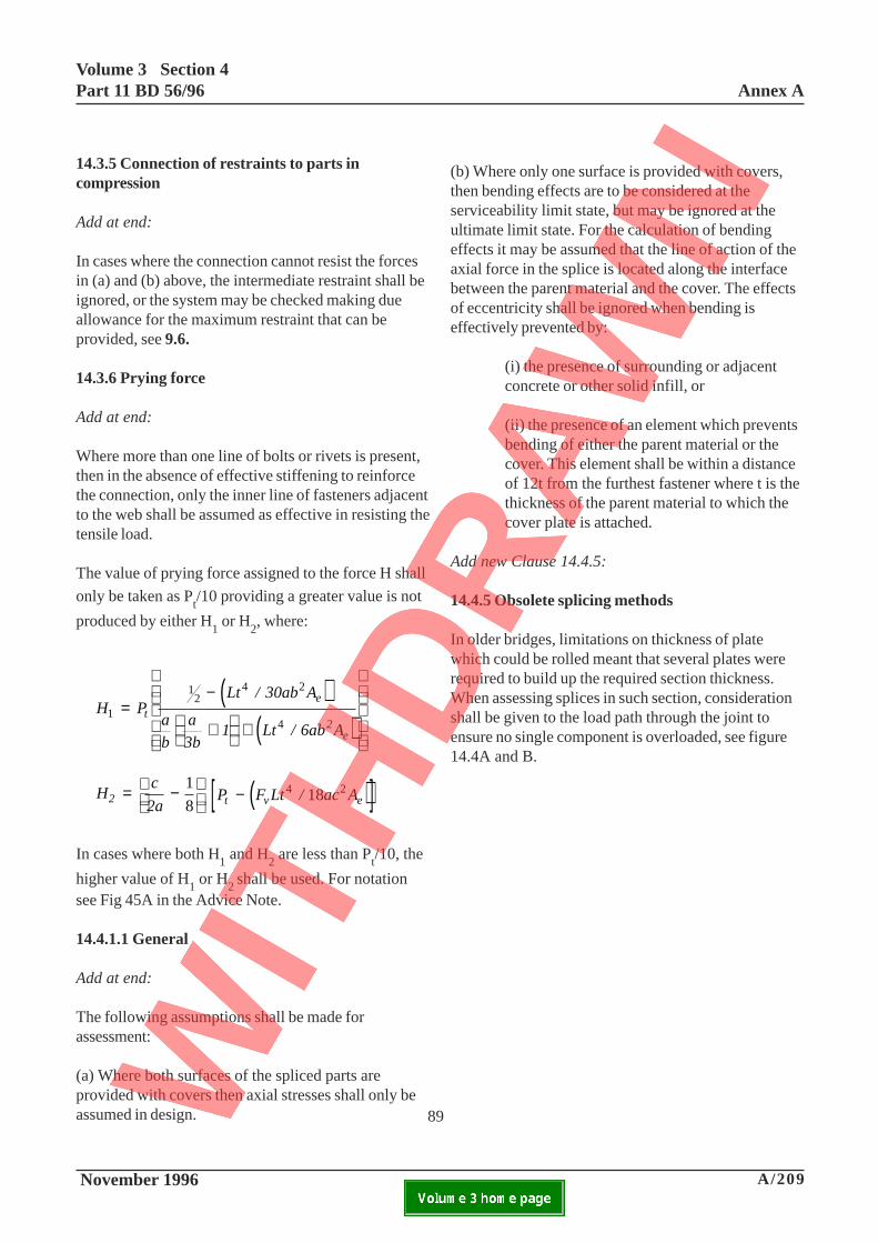
Volume 3 Section 4Part 11 BD 56/96 Annex A
November 1996 A/209ELECTRONIC COPY NOT FOR USE OUTSIDE THE AGENCY.PAPER COPIES OF THIS ELECTRONIC DOCUMENT ARE UNCONTROLLED
14.3.5 Connection of restraints to parts incompression
Add at end:
In cases where the connection cannot resist the forcesin (a) and (b) above, the intermediate restraint shall beignored, or the system may be checked making dueallowance for the maximum restraint that can beprovided, see 9.6.
14.3.6 Prying force
Add at end:
Where more than one line of bolts or rivets is present,then in the absence of effective stiffening to reinforcethe connection, only the inner line of fasteners adjacentto the web shall be assumed as effective in resisting thetensile load.
The value of prying force assigned to the force H shall
only be taken as Pt/10 providing a greater value is not
produced by either H1 or H
2, where:
( )( )
H PLt / 30ab A
a
b
a
3b1 Lt / 6ab A
te
2e
1
4 2
4=
−
+
+
12
Hc
2a2 = −
1
8 ( )[ ]P F Lt / ac At v e− 4 218
In cases where both H1 and H2 are less than Pt/10, the
higher value of H1 or H2 shall be used. For notationsee Fig 45A in the Advice Note.
14.4.1.1 General
Add at end:
The following assumptions shall be made forassessment:
(a) Where both surfaces of the spliced parts areprovided with covers then axial stresses shall only beassumed in design.
(b) Where only one surface is provided with covers,then bending effects are to be considered at theserviceability limit state, but may be ignored at theultimate limit state. For the calculation of bendingeffects it may be assumed that the line of action of theaxial force in the splice is located along the interfacebetween the parent material and the cover. The effectsof eccentricity shall be ignored when bending iseffectively prevented by:
(i) the presence of surrounding or adjacentconcrete or other solid infill, or
(ii) the presence of an element which preventsbending of either the parent material or thecover. This element shall be within a distanceof 12t from the furthest fastener where t is thethickness of the parent material to which thecover plate is attached.
Add new Clause 14.4.5:
14.4.5 Obsolete splicing methods
In older bridges, limitations on thickness of platewhich could be rolled meant that several plates wererequired to build up the required section thickness.When assessing splices in such section, considerationshall be given to the load path through the joint toensure no single component is overloaded, see figure14.4A and B.
89
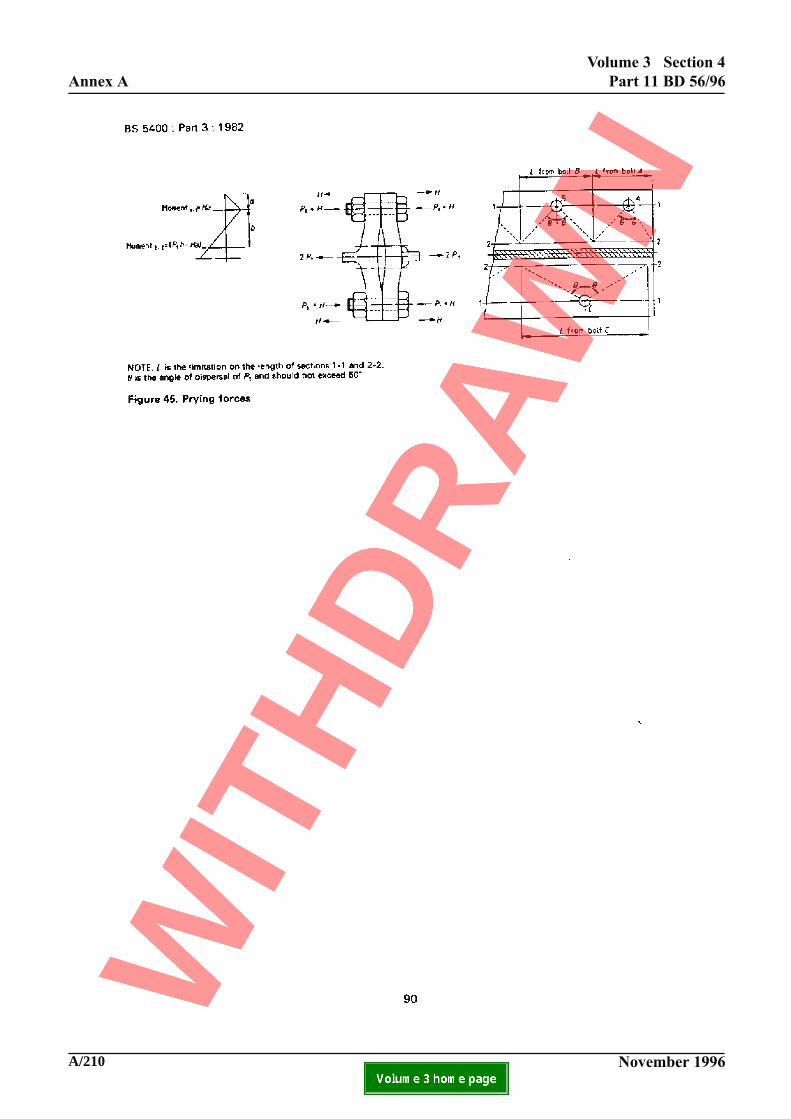
A/210 November 1996
Annex A
Volume 3 Section 4
Part 11 BD 56/96
ELECTRONIC COPY NOT FOR USE OUTSIDE THE AGENCY.PAPER COPIES OF THIS ELECTRONIC DOCUMENT ARE UNCONTROLLED
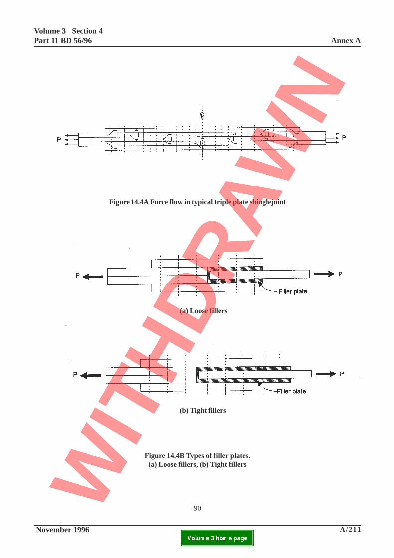
Volume 3 Section 4Part 11 BD 56/96 Annex A
November 1996 A/211ELECTRONIC COPY NOT FOR USE OUTSIDE THE AGENCY.PAPER COPIES OF THIS ELECTRONIC DOCUMENT ARE UNCONTROLLED
Figure 14.4A Force flow in typical triple plate shinglejoint
(a) Loose fillers
(b) Tight fillers
Figure 14.4B Types of filler plates.(a) Loose fillers, (b) Tight fillers
90
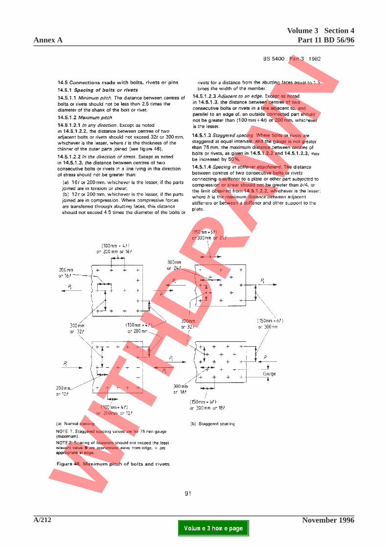
A/212 November 1996
Annex AVolume 3 Section 4
Part 11 BD 56/96
ELECTRONIC COPY NOT FOR USE OUTSIDE THE AGENCY.PAPER COPIES OF THIS ELECTRONIC DOCUMENT ARE UNCONTROLLED

Volume 3 Section 4Part 11 BD 56/96 Annex A
November 1996 A/213ELECTRONIC COPY NOT FOR USE OUTSIDE THE AGENCY.PAPER COPIES OF THIS ELECTRONIC DOCUMENT ARE UNCONTROLLED
Add new Clause 14.5.1.5:
14.5.1.5 Assessment of non-complying arrangements
Where any of the limits in 14.5.1.1, 14.5.1.2, 145.1.3or 145.1.4 are not complied with, allowance shall bemade for a reduced strength of the fasteners or plate inassessment. Guidance is given in the accompanyingAdvice Note.
91
A/214 November 1996
Annex AVolume 3 Section 4
Part 11 BD 56/96
ELECTRONIC COPY NOT FOR USE OUTSIDE THE AGENCY.PAPER COPIES OF THIS ELECTRONIC DOCUMENT ARE UNCONTROLLED

Volume 3 Section 4Part 11 BD 56/96 Annex A
November 1996 A/215ELECTRONIC COPY NOT FOR USE OUTSIDE THE AGENCY.PAPER COPIES OF THIS ELECTRONIC DOCUMENT ARE UNCONTROLLED
14.5.2 Edge and end distance
Add at end:
Where any of the above limits are not complied with,the strength of the fastener or plate shall be reduced forassessment purposes. Guidance is given in theaccompanying Advice Note.
14.5.3.1 General
Add at end:
Where any of the general or specific requirements ofthis or any of the following sub-clauses are not met inassessment, due allowance shall be made on thestrength of the fasteners. Guidance is given in theaccompanying Advice Note. Where black bolts havebeen used in permanent main structural connections,their assessment shall include a fatigue check, iegenerally as Class G detail. Bolts shall be assumed tobe black bolts and rivets shall be assumed to be handdriven, unless there is evidence to the contrary.
92
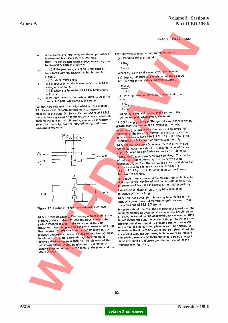
A/216 November 1996
Annex AVolume 3 Section 4
Part 11 BD 56/96
ELECTRONIC COPY NOT FOR USE OUTSIDE THE AGENCY.PAPER COPIES OF THIS ELECTRONIC DOCUMENT ARE UNCONTROLLED

Volume 3 Section 4Part 11 BD 56/96 Annex A
November 1996 A/217ELECTRONIC COPY NOT FOR USE OUTSIDE THE AGENCY.PAPER COPIES OF THIS ELECTRONIC DOCUMENT ARE UNCONTROLLED
This page is blank
93
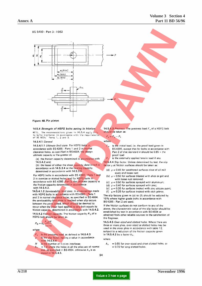
A/218 November 1996
Annex AVolume 3 Section 4
Part 11 BD 56/96
ELECTRONIC COPY NOT FOR USE OUTSIDE THE AGENCY.PAPER COPIES OF THIS ELECTRONIC DOCUMENT ARE UNCONTROLLED

Volume 3 Section 4Part 11 BD 56/96 Annex A
November 1996 A/219ELECTRONIC COPY NOT FOR USE OUTSIDE THE AGENCY.PAPER COPIES OF THIS ELECTRONIC DOCUMENT ARE UNCONTROLLED
14.5.4.1 General
Add at end:
Friction grips bolts of types, arrangements ortightening not in accordance with this or any of thefollowing sub clauses shall be assessed by reference to14.2 and published data relating to the bolt type or bytests on selected bolts in the structure. Guidance isgiven in the accompanying Advice Note.
94
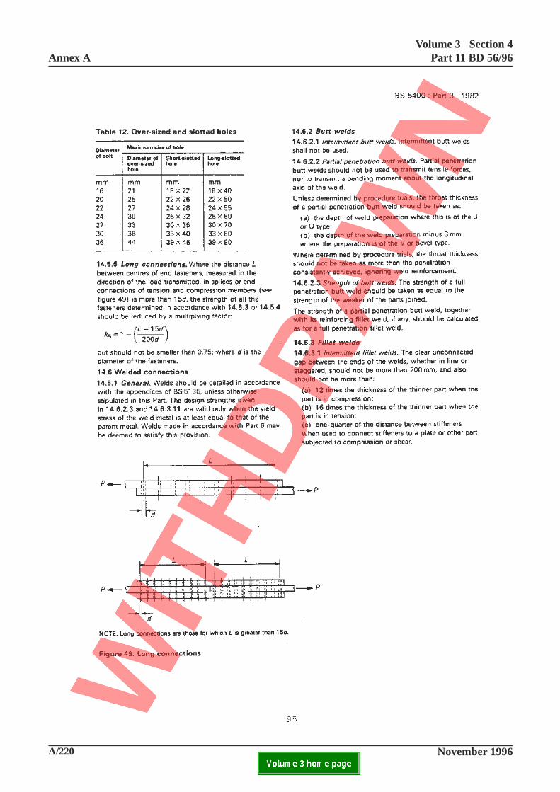
A/220 November 1996
Annex AVolume 3 Section 4
Part 11 BD 56/96
ELECTRONIC COPY NOT FOR USE OUTSIDE THE AGENCY.PAPER COPIES OF THIS ELECTRONIC DOCUMENT ARE UNCONTROLLED

Volume 3 Section 4Part 11 BD 56/96 Annex A
November 1996 A/221ELECTRONIC COPY NOT FOR USE OUTSIDE THE AGENCY.PAPER COPIES OF THIS ELECTRONIC DOCUMENT ARE UNCONTROLLED
95
14.6.1 General
Add at end:
In assessment of bridges known to have been welded inaccordance with Part 6 or BS5135: 1974 (or 1981),the strength of the welds shall be determined as givenby 14.6.2.3 and 14.6.3.11. In assessment of bridgesnot known to have been welded in accordance withPart 6 nor with BS5135: 1984 (or 1981) the strengthsof the welds shall be derived in accordance with (a) to(d) as follows.
(a) For butt welds in compression and butt welds intension or shear demonstrated to comply with BS5135:table 18 quality A, the strengths may be taken asdefined in 14.6.2.3.
(b) For butt welds in tension or shear free from surfacecracks but not known to comply with BS5135: table18 quality A the strengths shall be taken as 85% ofthose derived from 14.6.2.3.
(c) For fillet welds in bridges constructed to BS153:Part 1: 1958 or 1972 and free from surface cracks thestrengths shall be taken as 90% of those derived from14.6.3.11 in the absence of demonstration of theircompliance with BS5135: Table 19 quality A or equalto those strengths when such compliance has beendemonstrated.
(d) For other fillet welds free from visible surfacecracks the strengths shall be calculated in accordance
with 14.6.3.11, but replacing σW
=[1/2 (σy + 455)] by
0.4(400 + σymin
) in the absence of demonstration oftheir compliance with BS5135: Table 19 quality A, or
by 0.5(400 + σymin
) when such compliance has been
demonstrated, where σymin
is the yield stress of theweaker of the parts connected by the welds.
Where any of the general or specific requirements ofthis or any of the following sub-clauses are not met,due allowance shall be made in the assessment of thestrength of welds. Guidance is given in theaccompanying Advice Note.
14.6.2.1 Intermittent butt welds
Delete the existing clause and substitute thefollowing:
In the assessment of intermittent butt welds anycontribution to strength of the weld at each end of anyintermittent length, a length equal to three times thethroat thickness shall be ignored.
14.6.2.2 Partial penetration butt welds
Add at end:
The strength of partial penetration butt welds shall becalculated as for fillet welds. For single sided jointswhere transverse bending causes tension across theroot then the yield stress of the weld metal shall betaken as 50% of the weaker of the parts joined inassessing the resistance to transverse bending.However, partial penetration butt welds in non-fatigueprone connections could be assessed by reference toBS5950. Eccentric welds need to be speciallyconsidered.
Unless known to have been tested through proceduretrials at the time of construction or demonstrated bytesting, the throat thickness of a partial penetrationbutt weld shall be taken as 90% of the nominal.
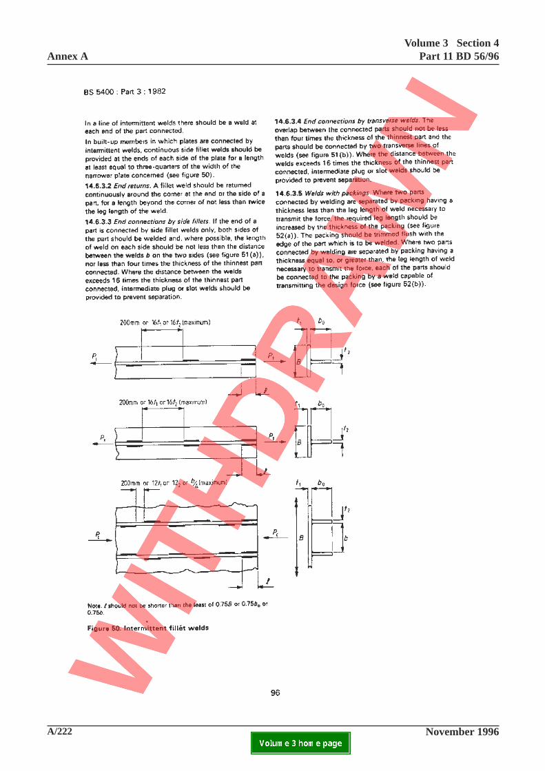
A/222 November 1996
Annex AVolume 3 Section 4
Part 11 BD 56/96
ELECTRONIC COPY NOT FOR USE OUTSIDE THE AGENCY.PAPER COPIES OF THIS ELECTRONIC DOCUMENT ARE UNCONTROLLED

Volume 3 Section 4Part 11 BD 56/96 Annex A
November 1996 A/223ELECTRONIC COPY NOT FOR USE OUTSIDE THE AGENCY.PAPER COPIES OF THIS ELECTRONIC DOCUMENT ARE UNCONTROLLED
This page is blank
96
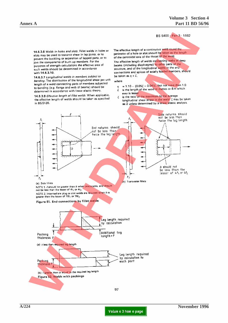
A/224 November 1996
Annex AVolume 3 Section 4
Part 11 BD 56/96
ELECTRONIC COPY NOT FOR USE OUTSIDE THE AGENCY.PAPER COPIES OF THIS ELECTRONIC DOCUMENT ARE UNCONTROLLED

Volume 3 Section 4Part 11 BD 56/96 Annex A
November 1996 A/225ELECTRONIC COPY NOT FOR USE OUTSIDE THE AGENCY.PAPER COPIES OF THIS ELECTRONIC DOCUMENT ARE UNCONTROLLED
This page is blank
97
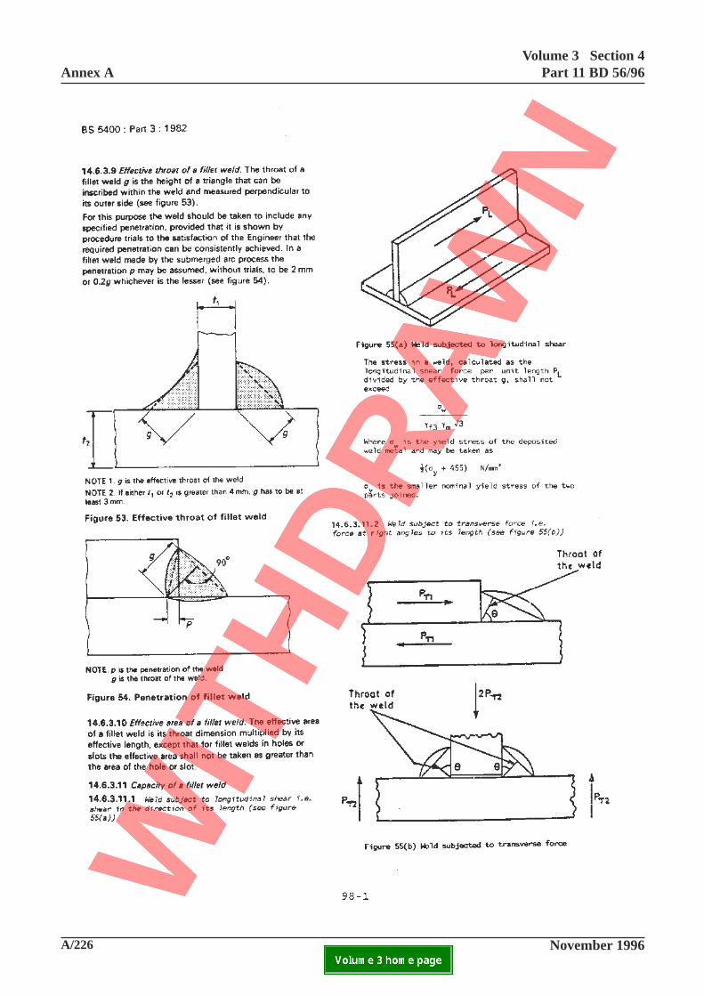
A/226 November 1996
Annex AVolume 3 Section 4
Part 11 BD 56/96
ELECTRONIC COPY NOT FOR USE OUTSIDE THE AGENCY.PAPER COPIES OF THIS ELECTRONIC DOCUMENT ARE UNCONTROLLED

Volume 3 Section 4Part 11 BD 56/96 Annex A
November 1996 A/227ELECTRONIC COPY NOT FOR USE OUTSIDE THE AGENCY.PAPER COPIES OF THIS ELECTRONIC DOCUMENT ARE UNCONTROLLED
This page is blank
98-1
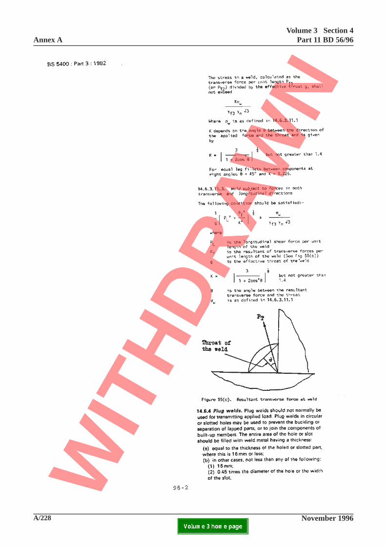
A/228 November 1996
Annex AVolume 3 Section 4
Part 11 BD 56/96
ELECTRONIC COPY NOT FOR USE OUTSIDE THE AGENCY.PAPER COPIES OF THIS ELECTRONIC DOCUMENT ARE UNCONTROLLED

Volume 3 Section 4Part 11 BD 56/96 Annex A
November 1996 A/229ELECTRONIC COPY NOT FOR USE OUTSIDE THE AGENCY.PAPER COPIES OF THIS ELECTRONIC DOCUMENT ARE UNCONTROLLED
This page is blank
98-2

A/230 November 1996
Annex AVolume 3 Section 4
Part 11 BD 56/96
ELECTRONIC COPY NOT FOR USE OUTSIDE THE AGENCY.PAPER COPIES OF THIS ELECTRONIC DOCUMENT ARE UNCONTROLLED
99-1
Volume 3 Section 4Part 11 BD 56/96 Annex A
November 1996 A/231ELECTRONIC COPY NOT FOR USE OUTSIDE THE AGENCY.PAPER COPIES OF THIS ELECTRONIC DOCUMENT ARE UNCONTROLLED
Add new Clause 15.
15 Outmoded forms of construction
15.1 General
Some outmoded forms of construction cannot bedirectly assessed even by the assessment clausesabove. This section gives guidance and methods ofassessment for certain specific outmoded forms ofconstruction. Any outmoded forms not covered withinthis section shall be assessed by the relevant section ofthe standard where possible. Where necessaryadditional studies, special analyses and tests may bebeneficial to the type and form of outmodedconstruction encountered, to supplement theassessment checks carried out.
15.2 Buckle plates
15.2.1 General
Buckle plates consisting of vertically curved steelplates supporting non-structural filling beneathroadways or footways and spanning betweensupporting steel members shall be assessed by 15.2.2or 15.2.3 as appropriate.
15.2.2 Spans of 1.2 m. or less
Where the clear span measured between edges ofsupporting members is 1.2 m. or less and complieswith the following:
(a) rise between 112 th and 118 th of the clear
span, and(b) plate thickness is at least 6 mm,
the strength shall be assessed assuming arch orcatenary action where the horizontal thrust may betaken as:
wL
8
2
rper unit width
wherew = pressure on surface of plate due
to dead loads and distributed wheelload. The wheel pressurecalculated is resumed to occupy thefull area of the plate, (see theAdvice Note).
L = spans of buckle plate betweensupporting members
r = rise of buckle plate.
Arched (ie concave downward) buckle plates may bechecked as straight compression members inaccordance with 10.6 with η taken as a (λ - 15) when
calculating the value of σc with an appropriate
effective length of not less than 0.25L. Suspended (ieconcave upward) buckle plates may be checked astension members under axial load in accordance with11.5.1. The fixings and the supporting members shallbe capable of resisting the horizontal thrust.Concentrated wheel loads over the plate may bedispersed at 1:1 through solid filling and at 1(horizontal) to 2 (vertical) through loose filling.Alternatively, the buckle plate may be considered as anencastre flat plate in which case the effects ofhorizontal thrust may be ignored.
15.2.3 Spans of more than 1.2 m.
When the clear span exceeds 1.2 m. or does otherwisenot comply with 15.2.2, then the strength shall beassessed assuming that the plate behaves as a flatmember without benefit from arch action unless testingor other information is made available to demonstratethe strength under traffic loading.
15.3 Joggled stiffeners
15.3.1 Joggled stiffeners acting as transverse webstiffeners other than at supports
Joggled or knee type stiffeners may be considered astransverse web stiffeners. Where an axial forceresulting from application of 9.13.3.1 (c), (d), (e) and(f) can be applied to joggled or knee type stiffenersother than within the straight portion between joggles,then the additional bending stress introduced by theshape of the stiffener shall be included within thejoggle height when checking yielding of the stiffenerunder 9.13.5.2.
(a) For joggled stiffeners the bending stress may becalculated assuming that a bending moment is appliedto each stiffener leg equivalent to its axial loadmultiplied by an eccentricity equal to one half of thejoggle offset.
The joggle height over which the bending stress can beincluded shall be taken as at the level of the joggle and
A/232 November 1996
Annex AVolume 3 Section 4
Part 11 BD 56/96
ELECTRONIC COPY NOT FOR USE OUTSIDE THE AGENCY.PAPER COPIES OF THIS ELECTRONIC DOCUMENT ARE UNCONTROLLED
99-2

Volume 3 Section 4Part 11 BD 56/96 Annex A
November 1996 A/233ELECTRONIC COPY NOT FOR USE OUTSIDE THE AGENCY.PAPER COPIES OF THIS ELECTRONIC DOCUMENT ARE UNCONTROLLED
extending to the first fastener either side whichconnects the stiffener to the web.
(b) For knee stiffeners the bending stress may becalculated assuming that a bending moment is appliedto each stiffener leg equivalent to its axial loadmultiplied by an eccentricity equal to one half of thehorizontal distance from the centroid of the stiffener tothe point of intersection of its flange with the beamflange.
The height over which the bending stress should beincluded shall be taken as from the flange in contactwith the stiffener to the first fastener where thestiffener is connected to the web.
15.3.2 Joggled stiffeners acting as load bearingsupport stiffeners
Gusseted joggled, or gusseted knee stiffeners may alsobe considered as load bearing support stiffeners.Joggled or knee type stiffeners as considered arepotentially unsuitable, but where they occur thenadditional bending stress may be introduced due to theshape of the stiffener and shall be assessed whenapplying 9.14.4.1. The additional bending stress maybe calculated in accordance with 15.3.1.
15.3.3 Assessment of joggled stiffeners
9.13 and 9.14 have only been addressed above as faras specific criteria for the assessment of joggledstiffeners is concerned. The criteria for assessment ofsuch stiffeners shall use the relevant sub-clauses of9.13 or 9.14 as appropriate to derive effective sectionsand loading and assess the strength. In addition,consideration of limitations on shape shall beaddressed in accordance with 9.3. Further guidance onthe typical form of joggled stiffeners is given in theAdvice Note.
Add new Clause 16.
16 Bearings and bearing areas
16.1 General
Bearings shall be assessed to B.S. 5400 Part 9 whereappropriate. Steel bearings of types outside the scopeof B.S. 5400 Part 9 shall be assessed using B.S. 5400
Part 3, where Part 9 is not applicable. Dueconsideration shall be given in allowance for loadeffects resulting from movement restraint wherefreedom of the bearing is restricted or impaired.
16.2 Beams without bearings
Where beams do not have discrete bearings and beardirectly on concrete, brickwork, or masonrysubstructures with or without a bearing plate or otherdistributive layer then the local distribution of load tothe substructure shall be assessed taking due accountof any rotation or movement. Patch loading to the webof the beam shall be assessed in accordance with 9.9.6where appropriate.
16.3 Pressure distribution under bearing areas
Where the end of a beam bears directly on asubstructure without bearings a linear pressuredistribution may be assumed varying from a maximumat the inner face of the contact area down to zero at thefar face or free end of the girder. The assumed lengthof the contact area shall not exceed the length of girderin contact, or the depth of the beam if less. Fordistribution transversely or in other directions asappropriate, a dispersal angle of 2 horizontal to 1vertical shall be assumed through any flange angles,flange plate(s) and bearing plate (s) present onto thesurface of concrete, brickwork, masonry or othermaterial of the substructure. The effective span of thebeam shall be assumed to extend from the centroid ofthe contact area determined. See further guidance inthe Advice Note.
16.4 Maximum pressures under bearing areas
For concrete substructures the compressive stress inthe contact area shall not exceed those given by B.S.5400 Part 4. Where inspection shows no evidence oflocal spalling, cracking or similar distress beneathbearing areas then the limiting strength in compressionfor unreinforced concrete may be increased by amaximum of 50%.
For masonry bedstones, stresses shall not exceed
0.4 fcu
where fcu
is the characteristic compressivestrength of the masonry. This value may be increased
to 0.6 fcu
where inspection shows no evidence of localspalling, cracking or other distress. Bearing loads shallbe assumed to disperse at an angle of 1: 1 down tosupporting coursed masonry or brickwork.
99-2

A/232 November 1996
Annex AVolume 3 Section 4
Part 11 BD 56/96
ELECTRONIC COPY NOT FOR USE OUTSIDE THE AGENCY.PAPER COPIES OF THIS ELECTRONIC DOCUMENT ARE UNCONTROLLED
99-2
Volume 3 Section 4Part 11 BD 56/96 Annex A
November 1996 A/233ELECTRONIC COPY NOT FOR USE OUTSIDE THE AGENCY.PAPER COPIES OF THIS ELECTRONIC DOCUMENT ARE UNCONTROLLED
extending to the first fastener either side whichconnects the stiffener to the web.
(b) For knee stiffeners the bending stress may becalculated assuming that a bending moment is appliedto each stiffener leg equivalent to its axial loadmultiplied by an eccentricity equal to one half of thehorizontal distance from the centroid of the stiffener tothe point of intersection of its flange with the beamflange.
The height over which the bending stress should beincluded shall be taken as from the flange in contactwith the stiffener to the first fastener where thestiffener is connected to the web.
15.3.2 Joggled stiffeners acting as load bearingsupport stiffeners
Gusseted joggled, or gusseted knee stiffeners may alsobe considered as load bearing support stiffeners.Joggled or knee type stiffeners as considered arepotentially unsuitable, but where they occur thenadditional bending stress may be introduced due to theshape of the stiffener and shall be assessed whenapplying 9.14.4.1. The additional bending stress maybe calculated in accordance with 15.3.1.
15.3.3 Assessment of joggled stiffeners
9.13 and 9.14 have only been addressed above as faras specific criteria for the assessment of joggledstiffeners is concerned. The criteria for assessment ofsuch stiffeners shall use the relevant sub-clauses of9.13 or 9.14 as appropriate to derive effective sectionsand loading and assess the strength. In addition,consideration of limitations on shape shall beaddressed in accordance with 9.3. Further guidance onthe typical form of joggled stiffeners is given in theAdvice Note.
Add new Clause 16.
16 Bearings and bearing areas
16.1 General
Bearings shall be assessed to B.S. 5400 Part 9 whereappropriate. Steel bearings of types outside the scopeof B.S. 5400 Part 9 shall be assessed using B.S. 5400
Part 3, where Part 9 is not applicable. Dueconsideration shall be given in allowance for loadeffects resulting from movement restraint wherefreedom of the bearing is restricted or impaired.
16.2 Beams without bearings
Where beams do not have discrete bearings and beardirectly on concrete, brickwork, or masonrysubstructures with or without a bearing plate or otherdistributive layer then the local distribution of load tothe substructure shall be assessed taking due accountof any rotation or movement. Patch loading to the webof the beam shall be assessed in accordance with 9.9.6where appropriate.
16.3 Pressure distribution under bearing areas
Where the end of a beam bears directly on asubstructure without bearings a linear pressuredistribution may be assumed varying from a maximumat the inner face of the contact area down to zero at thefar face or free end of the girder. The assumed lengthof the contact area shall not exceed the length of girderin contact, or the depth of the beam if less. Fordistribution transversely or in other directions asappropriate, a dispersal angle of 2 horizontal to 1vertical shall be assumed through any flange angles,flange plate(s) and bearing plate (s) present onto thesurface of concrete, brickwork, masonry or othermaterial of the substructure. The effective span of thebeam shall be assumed to extend from the centroid ofthe contact area determined. See further guidance inthe Advice Note.
16.4 Maximum pressures under bearing areas
For concrete substructures the compressive stress inthe contact area shall not exceed those given by B.S.5400 Part 4. Where inspection shows no evidence oflocal spalling, cracking or similar distress beneathbearing areas then the limiting strength in compressionfor unreinforced concrete may be increased by amaximum of 50%.
For masonry bedstones, stresses shall not exceed
0.4 fcu
where fcu
is the characteristic compressivestrength of the masonry. This value may be increased
to 0.6 fcu
where inspection shows no evidence of localspalling, cracking or other distress. Bearing loads shallbe assumed to disperse at an angle of 1: 1 down tosupporting coursed masonry or brickwork.
99-2
A/234 November 1996
Annex AVolume 3 Section 4
Part 11 BD 56/96
ELECTRONIC COPY NOT FOR USE OUTSIDE THE AGENCY.PAPER COPIES OF THIS ELECTRONIC DOCUMENT ARE UNCONTROLLED

Volume 3 Section 4Part 11 BD 56/96 Annex A
November 1996 A/235ELECTRONIC COPY NOT FOR USE OUTSIDE THE AGENCY.PAPER COPIES OF THIS ELECTRONIC DOCUMENT ARE UNCONTROLLED
This page is blank
100
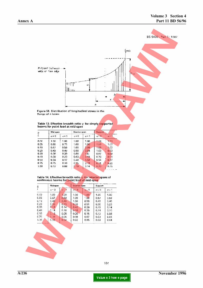
A/236 November 1996
Annex A
Volume 3 Section 4
Part 11 BD 56/96
ELECTRONIC COPY NOT FOR USE OUTSIDE THE AGENCY.PAPER COPIES OF THIS ELECTRONIC DOCUMENT ARE UNCONTROLLED

Volume 3 Section 4Part 11 BD 56/96 Annex A
November 1996 A/237ELECTRONIC COPY NOT FOR USE OUTSIDE THE AGENCY.PAPER COPIES OF THIS ELECTRONIC DOCUMENT ARE UNCONTROLLED
This page is blank
101
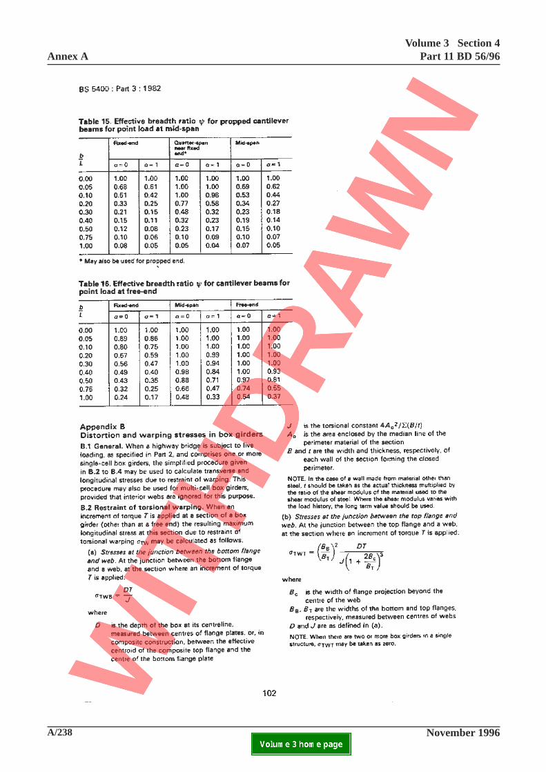
A/238 November 1996
Annex AVolume 3 Section 4
Part 11 BD 56/96
ELECTRONIC COPY NOT FOR USE OUTSIDE THE AGENCY.PAPER COPIES OF THIS ELECTRONIC DOCUMENT ARE UNCONTROLLED

Volume 3 Section 4Part 11 BD 56/96 Annex A
November 1996 A/239ELECTRONIC COPY NOT FOR USE OUTSIDE THE AGENCY.PAPER COPIES OF THIS ELECTRONIC DOCUMENT ARE UNCONTROLLED
B.2 Restraint of torsional warping
In the definition for J, delete "B" and replace by "W".
In the definition for B, delete "B" and replace by "W".
102
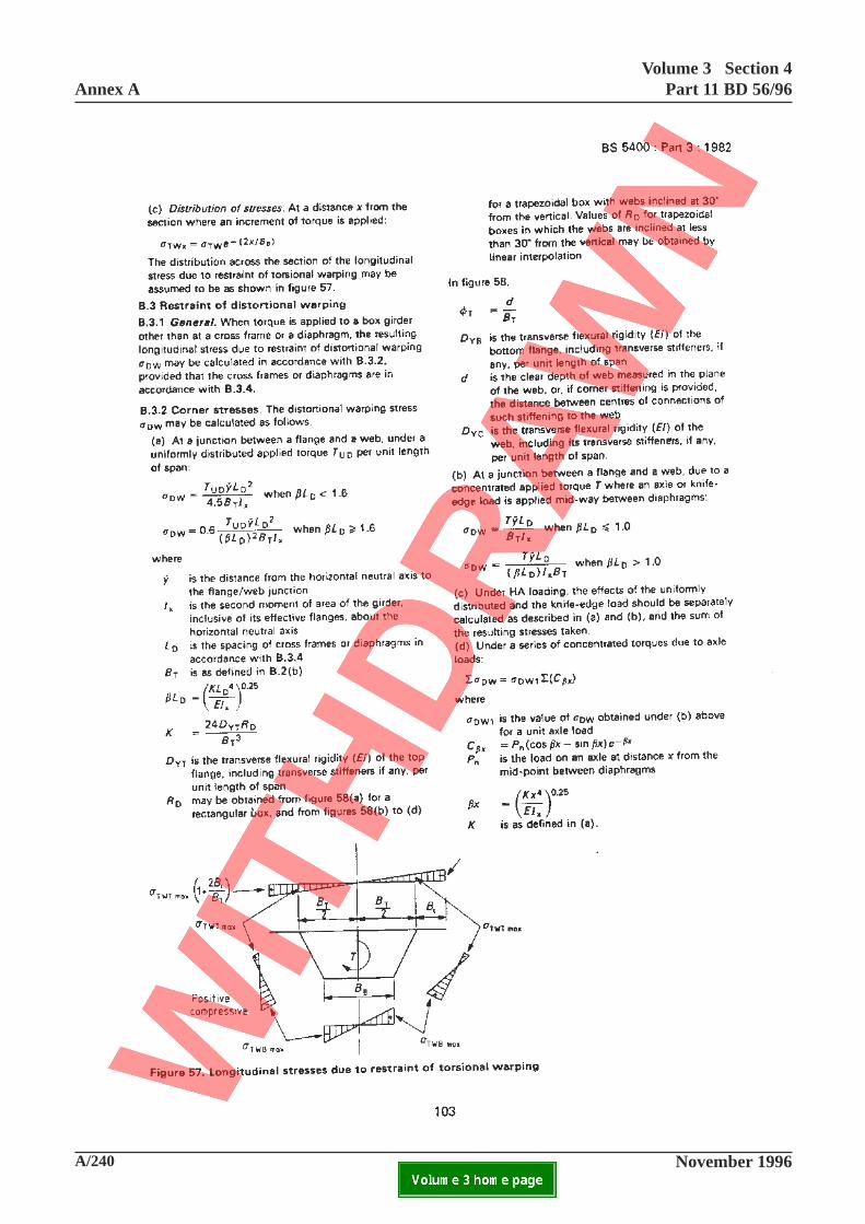
A/240 November 1996
Annex AVolume 3 Section 4
Part 11 BD 56/96
ELECTRONIC COPY NOT FOR USE OUTSIDE THE AGENCY.PAPER COPIES OF THIS ELECTRONIC DOCUMENT ARE UNCONTROLLED

Volume 3 Section 4Part 11 BD 56/96 Annex A
November 1996 A/241ELECTRONIC COPY NOT FOR USE OUTSIDE THE AGENCY.PAPER COPIES OF THIS ELECTRONIC DOCUMENT ARE UNCONTROLLED
B.3.2 Corner stresses
Add the following at the end of the definition for RD:
"or from
R
1B
B
D
D
d
B
2B
B B
B
B BV 2
B
B
D
D
d
B
D
T
B
YT
YC T
B
T B
B
T BD
B
T
YT
YC T
=+
+
+
+
− +
+
1
where VD is as defined in B.42"
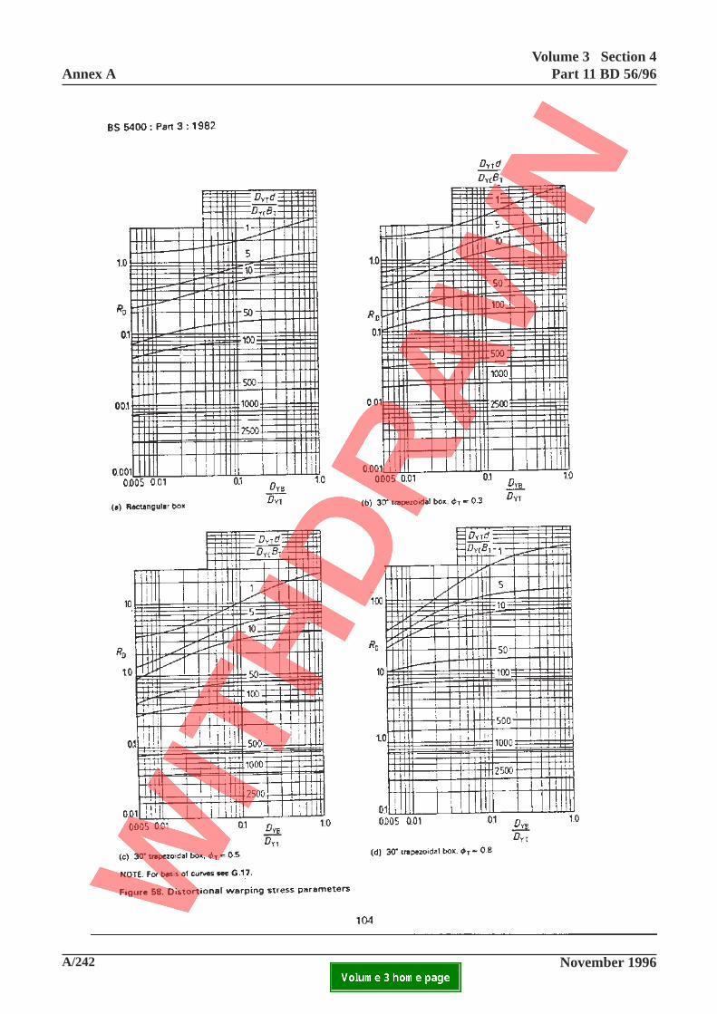
A/242 November 1996
Annex AVolume 3 Section 4
Part 11 BD 56/96
ELECTRONIC COPY NOT FOR USE OUTSIDE THE AGENCY.PAPER COPIES OF THIS ELECTRONIC DOCUMENT ARE UNCONTROLLED

Volume 3 Section 4Part 11 BD 56/96 Annex A
November 1996 A/243ELECTRONIC COPY NOT FOR USE OUTSIDE THE AGENCY.PAPER COPIES OF THIS ELECTRONIC DOCUMENT ARE UNCONTROLLED
This page is blank
104
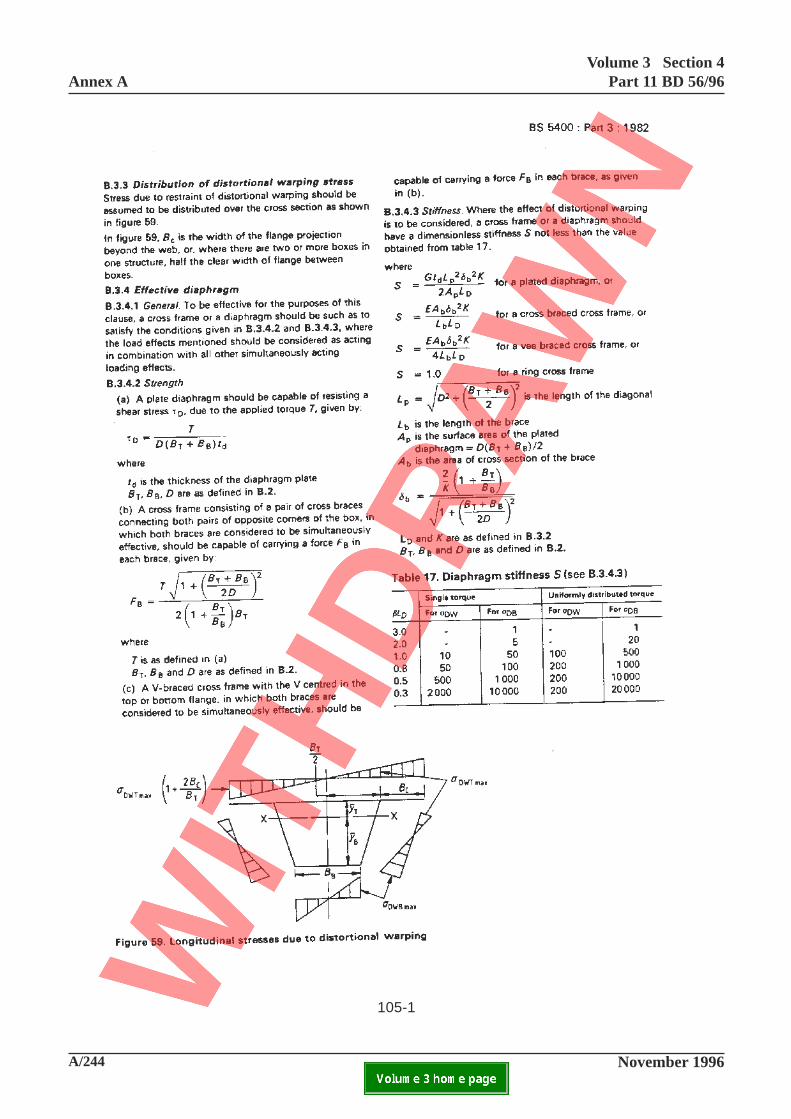
A/244 November 1996
Annex AVolume 3 Section 4
Part 11 BD 56/96
ELECTRONIC COPY NOT FOR USE OUTSIDE THE AGENCY.PAPER COPIES OF THIS ELECTRONIC DOCUMENT ARE UNCONTROLLED
105-1
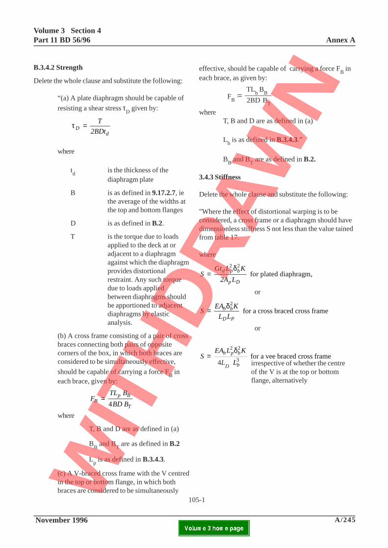
Volume 3 Section 4Part 11 BD 56/96 Annex A
November 1996 A/245ELECTRONIC COPY NOT FOR USE OUTSIDE THE AGENCY.PAPER COPIES OF THIS ELECTRONIC DOCUMENT ARE UNCONTROLLED
B.3.4.2 Strength
Delete the whole clause and substitute the following:
“(a) A plate diaphragm should be capable of
resisting a shear stress τD given by:
τDd
T
2BDt=
where
td
is the thickness of thediaphragm plate
B is as defined in 9.17.2.7, iethe average of the widths atthe top and bottom flanges
D is as defined in B.2.
T is the torque due to loadsapplied to the deck at oradjacent to a diaphragmagainst which the diaphragmprovides distortionalrestraint. Any such torquedue to loads appliedbetween diaphragms shouldbe apportioned to adjacentdiaphragms by elasticanalysis.
(b) A cross frame consisting of a pair of crossbraces connecting both pairs of oppositecorners of the box, in which both braces areconsidered to be simultaneously effective,
should be capable of carrying a force FB in
each brace, given by:
FTL B
BD BBp B
T
=4
where
T, B and D are as defined in (a)
BB and B
T are as defined in B.2
Lp is as defined in B.3.4.3.
(c) A V-braced cross frame with the V centredin the top or bottom flange, in which bothbraces are considered to be simultaneously
effective, should be capable of carrying a force FB in
each brace, as given by:
whereT, B and D are as defined in (a)
Lb is as defined in B.3.4.3.”
BB and B
T are as defined in B.2.
3.4.3 Stiffness
Delete the whole clause and substitute the following:
"Where the effect of distortional warping is to beconsidered, a cross frame or a diaphragm should havedimensionless stiffness S not less than the value tainedfrom table 17.
where
SGt L K
2A L d p b
p D
=2 2δ
for plated diaphragm,
or
SEA K
L L b b
D P
=δ2
for a cross braced cross frame
or
SEA L K
L L b p b
D b
=2 2
34δ
for a vee braced cross frame
105-1
irrespective of whether the centreof the V is at the top or bottomflange, alternatively
FB = TL
b B
B
2BD B
T
4LD

A/246 November 1996
Annex AVolume 3 Section 4
Part 11 BD 56/96
ELECTRONIC COPY NOT FOR USE OUTSIDE THE AGENCY.PAPER COPIES OF THIS ELECTRONIC DOCUMENT ARE UNCONTROLLED
105-2
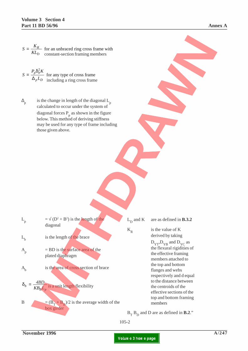
Volume 3 Section 4Part 11 BD 56/96 Annex A
November 1996 A/247ELECTRONIC COPY NOT FOR USE OUTSIDE THE AGENCY.PAPER COPIES OF THIS ELECTRONIC DOCUMENT ARE UNCONTROLLED
SK
KL R=
D
for an unbraced ring cross frame with
SP K
L p b
p D
=δ2
∆for any type of cross frame
∆p
is the change in length of the diagonal Lp
calculated to occur under the system of
diagonal forces Pp as shown in the figure
below. This method of deriving stiffnessmay be used for any type of frame includingthose given above.
Lp
= √ (D2 + B2) is the length of thediagonal
Lb
is the length of the brace
Ap
= BD is the surface area of theplated diaphragm
Ab
is the area of cross section of brace
δbB p
BD
KB L= 4
is a unit length flexibility
B = (BT + B
B)/2 is the average width of the
box girder
constant-section framing members
including a ring cross frame
LD and K are as defined in B.3.2
KR
is the value of Kderived by taking
DYT
,DYB
and DYC
asthe flexural rigidities ofthe effective framingmembers attached tothe top and bottomflanges and websrespectively and d equalto the distance betweenthe centroids of theeffective sections of thetop and bottom framingmembers
BT B
D and D are as defined in B.2.”
105-2
4BD
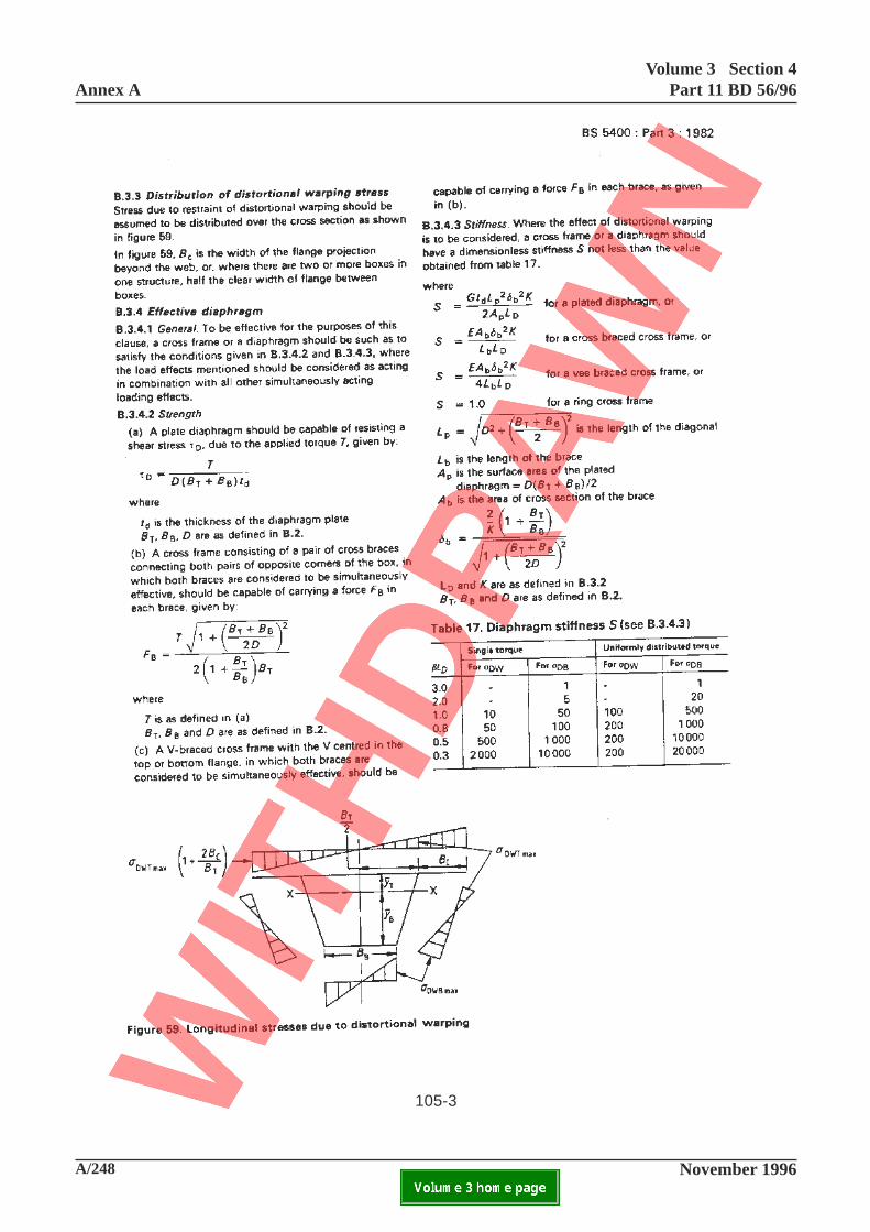
A/248 November 1996
Annex AVolume 3 Section 4
Part 11 BD 56/96
ELECTRONIC COPY NOT FOR USE OUTSIDE THE AGENCY.PAPER COPIES OF THIS ELECTRONIC DOCUMENT ARE UNCONTROLLED
105-3
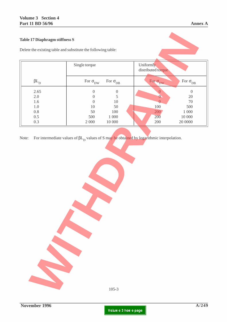
Volume 3 Section 4Part 11 BD 56/96 Annex A
November 1996 A/249ELECTRONIC COPY NOT FOR USE OUTSIDE THE AGENCY.PAPER COPIES OF THIS ELECTRONIC DOCUMENT ARE UNCONTROLLED
105-3
Table 17 Diaphragm stiffness S
Delete the existing table and substitute the following table:
Single torque Uniformlydistributed torque
βLD
For σDW
For σDB
For σDW
For σDB
2.65 0 0 0 02.0 0 5 0 201.6 0 10 0 701.0 10 50 100 5000.8 50 100 200 1 0000.5 500 1 000 200 10 0000.3 2 000 10 000 200 20 0000
Note: For intermediate values of βLD values of S may be obtained by logarithmic interpolation.
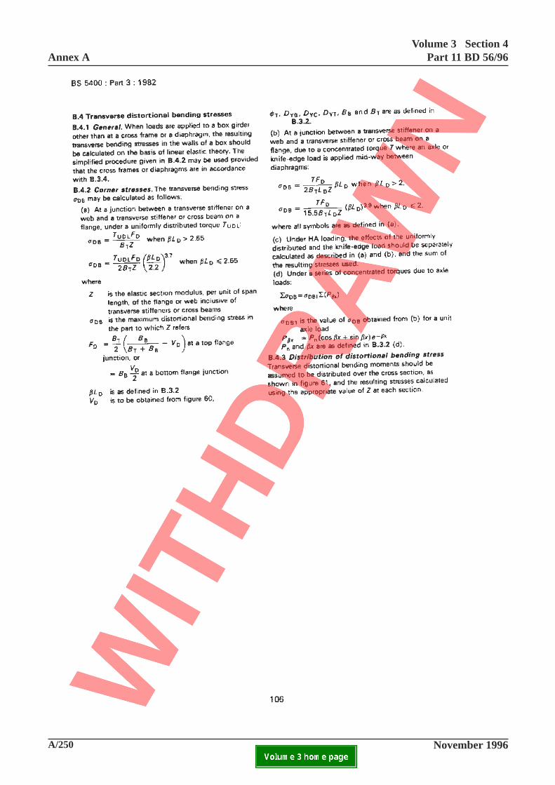
A/250 November 1996
Annex AVolume 3 Section 4
Part 11 BD 56/96
ELECTRONIC COPY NOT FOR USE OUTSIDE THE AGENCY.PAPER COPIES OF THIS ELECTRONIC DOCUMENT ARE UNCONTROLLED

Volume 3 Section 4Part 11 BD 56/96 Annex A
November 1996 A/251ELECTRONIC COPY NOT FOR USE OUTSIDE THE AGENCY.PAPER COPIES OF THIS ELECTRONIC DOCUMENT ARE UNCONTROLLED
B.4.2 Corner stresses
Add the following at the end of the definition for VD:
"or from
V
D
D
d
B
B
B
B
B
D
D
d
B
B
B
B
B
D
D
B
B
D
YT
YC T
B
T
T
B
YT
YC T
B
T
B
T
YT
YB
B
T
=+
+
+
+ + +
+
2 1
1 1 2 12 3
106
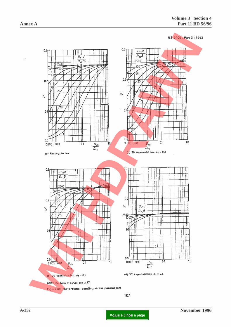
A/252 November 1996
Annex AVolume 3 Section 4
Part 11 BD 56/96
ELECTRONIC COPY NOT FOR USE OUTSIDE THE AGENCY.PAPER COPIES OF THIS ELECTRONIC DOCUMENT ARE UNCONTROLLED

Volume 3 Section 4Part 11 BD 56/96 Annex A
November 1996 A/253ELECTRONIC COPY NOT FOR USE OUTSIDE THE AGENCY.PAPER COPIES OF THIS ELECTRONIC DOCUMENT ARE UNCONTROLLED
This page is blank
107
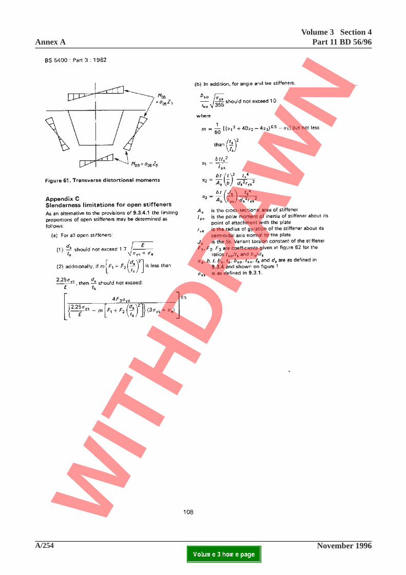
A/254 November 1996
Annex AVolume 3 Section 4
Part 11 BD 56/96
ELECTRONIC COPY NOT FOR USE OUTSIDE THE AGENCY.PAPER COPIES OF THIS ELECTRONIC DOCUMENT ARE UNCONTROLLED

Volume 3 Section 4Part 11 BD 56/96 Annex A
November 1996 A/255ELECTRONIC COPY NOT FOR USE OUTSIDE THE AGENCY.PAPER COPIES OF THIS ELECTRONIC DOCUMENT ARE UNCONTROLLED
This page is blank
108
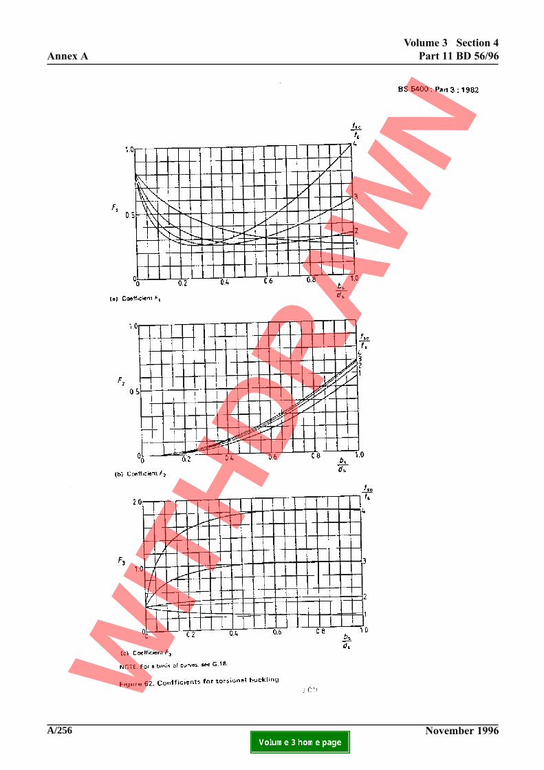
A/256 November 1996
Annex A
Volume 3 Section 4
Part 11 BD 56/96
ELECTRONIC COPY NOT FOR USE OUTSIDE THE AGENCY.PAPER COPIES OF THIS ELECTRONIC DOCUMENT ARE UNCONTROLLED

Volume 3 Section 4Part 11 BD 56/96 Annex A
November 1996 A/257ELECTRONIC COPY NOT FOR USE OUTSIDE THE AGENCY.PAPER COPIES OF THIS ELECTRONIC DOCUMENT ARE UNCONTROLLED
This page is blank
109
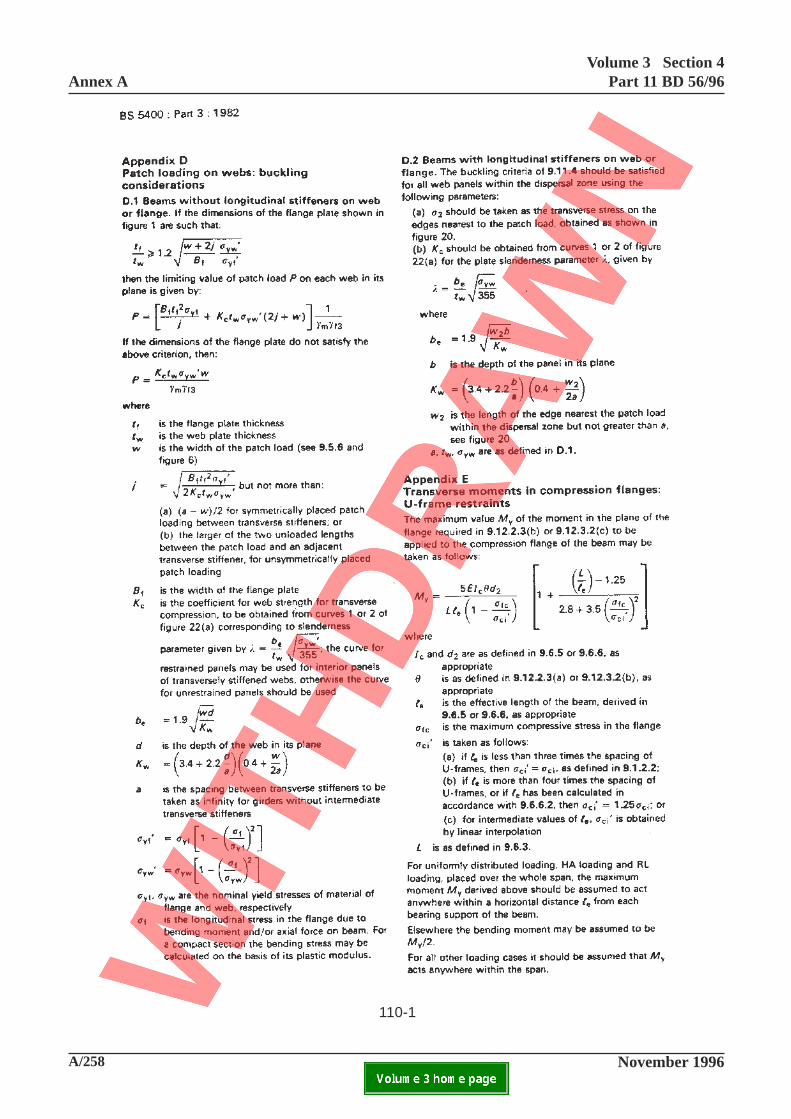
A/258 November 1996
Annex AVolume 3 Section 4
Part 11 BD 56/96
ELECTRONIC COPY NOT FOR USE OUTSIDE THE AGENCY.PAPER COPIES OF THIS ELECTRONIC DOCUMENT ARE UNCONTROLLED
110-1

Volume 3 Section 4Part 11 BD 56/96 Annex A
November 1996 A/259ELECTRONIC COPY NOT FOR USE OUTSIDE THE AGENCY.PAPER COPIES OF THIS ELECTRONIC DOCUMENT ARE UNCONTROLLED
Appendix D
Patch loading on webs: buckling consideration
Delete the contents of the existing appendix andsubstitute as follows:
D.1 Beams without longitudinal stiffeners on web.
The limiting value of patch load P on each web in itsplane should be taken as the lesser of
(a) web buckling criterion
0.5 Et
t 1
3w
d
t
t 1
1tw
2yw
f
w
w
f
1.5f
yw
2 0.5
m f3
0.5
σ σσ γ γ
+
−
(b) web yielding criterion
( ) 2t B t t w 11
f yf yw f w0.5
yw wf
yw
2 0.5
m f3σ σ σ σ
σ γ γ+
−
where
tf
is the flange plate thickness
tw
is the web plate thicknessw is the width of the patch load (see 9.5.6
and figure 6) but to be taken not greaterthan 0.2d
Bf
is the width of the flange plated is the depth of the web in its plane
σyf
and σyw
are the nominal yield stresses of thematerial of flange and web, respectively
σf
is the longitudinal stress in the flange due tobending moment and/or axial force on thebeam. For a compact section the bendingstress may be calculated on the basis of itsplastic modulus
γm
is taken as 1.05 for the ultimatelimit state.
D.2 Beams with longitudinal stiffeners on web.
The limiting value of patch load P on each web in itsplane should be taken as the lesser of the limiting valuesgiven in D.1(a) multiplied by a factor K or D.1(b)
where
K = 1.28 - 0.7 (b/d) but not less than1.0 or greater than 1.21
b is the clear distance between theflange and the longitudinal webstiffener nearest to the flange,which complies with 9.11.5.
110-1
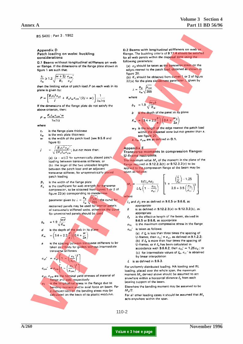
A/260 November 1996
Annex AVolume 3 Section 4
Part 11 BD 56/96
ELECTRONIC COPY NOT FOR USE OUTSIDE THE AGENCY.PAPER COPIES OF THIS ELECTRONIC DOCUMENT ARE UNCONTROLLED
110-2

Volume 3 Section 4Part 11 BD 56/96 Annex A
November 1996 A/261ELECTRONIC COPY NOT FOR USE OUTSIDE THE AGENCY.PAPER COPIES OF THIS ELECTRONIC DOCUMENT ARE UNCONTROLLED
Appendix E Transverse moments in compressionflanges: U-frame restraints
In the definition for σci, item (a), replace "9.1.2.2"
with "9.12.2.2"
110-2
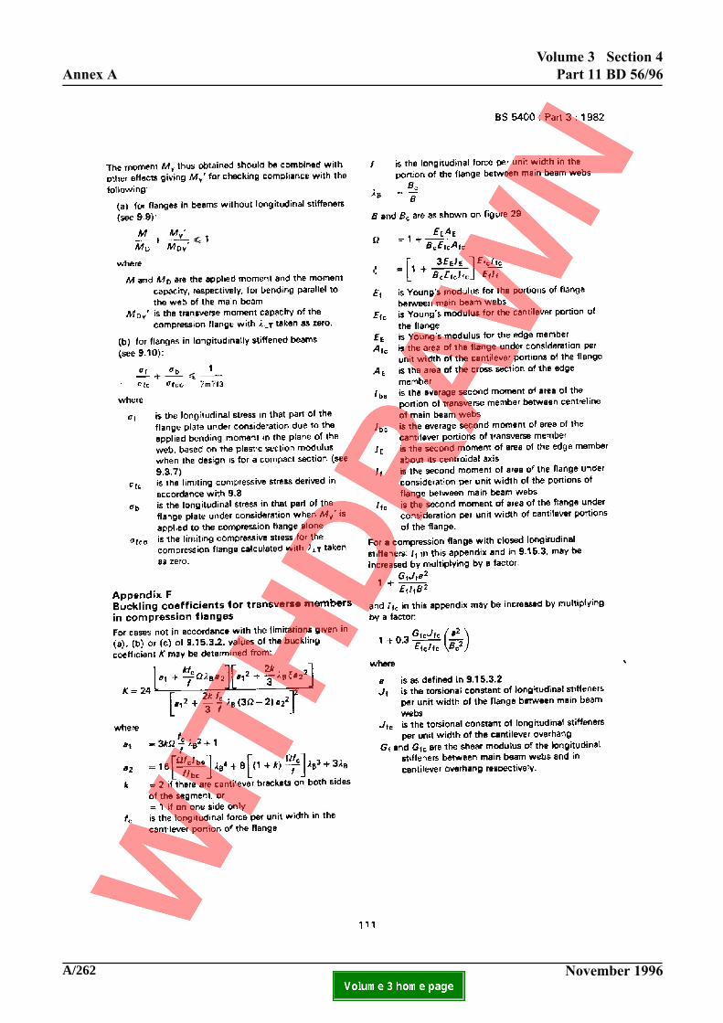
A/262 November 1996
Annex A
Volume 3 Section 4
Part 11 BD 56/96
ELECTRONIC COPY NOT FOR USE OUTSIDE THE AGENCY.PAPER COPIES OF THIS ELECTRONIC DOCUMENT ARE UNCONTROLLED

Volume 3 Section 4Part 11 BD 56/96 Annex A
November 1996 A/263ELECTRONIC COPY NOT FOR USE OUTSIDE THE AGENCY.PAPER COPIES OF THIS ELECTRONIC DOCUMENT ARE UNCONTROLLED
This page is blank
111
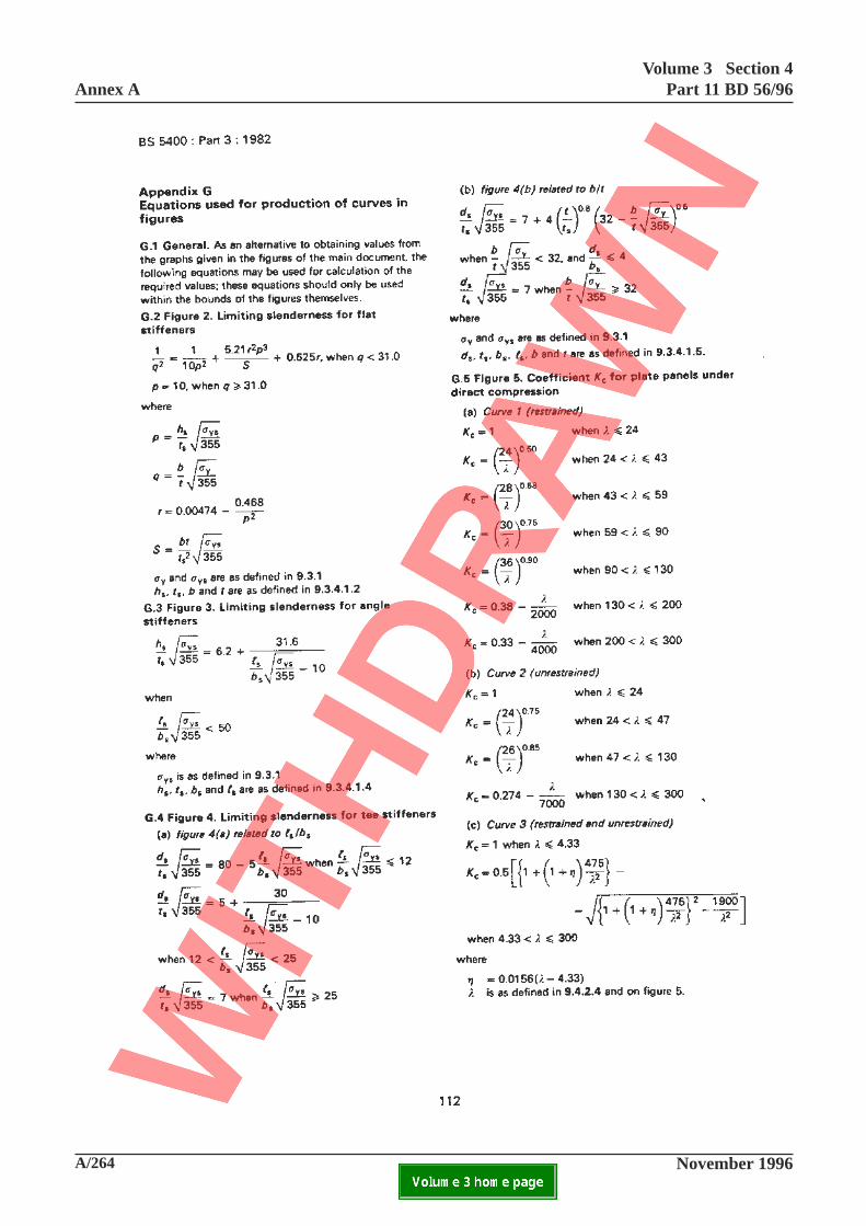
A/264 November 1996
Annex AVolume 3 Section 4
Part 11 BD 56/96
ELECTRONIC COPY NOT FOR USE OUTSIDE THE AGENCY.PAPER COPIES OF THIS ELECTRONIC DOCUMENT ARE UNCONTROLLED

Volume 3 Section 4Part 11 BD 56/96 Annex A
November 1996 A/265ELECTRONIC COPY NOT FOR USE OUTSIDE THE AGENCY.PAPER COPIES OF THIS ELECTRONIC DOCUMENT ARE UNCONTROLLED
This page is blank
112
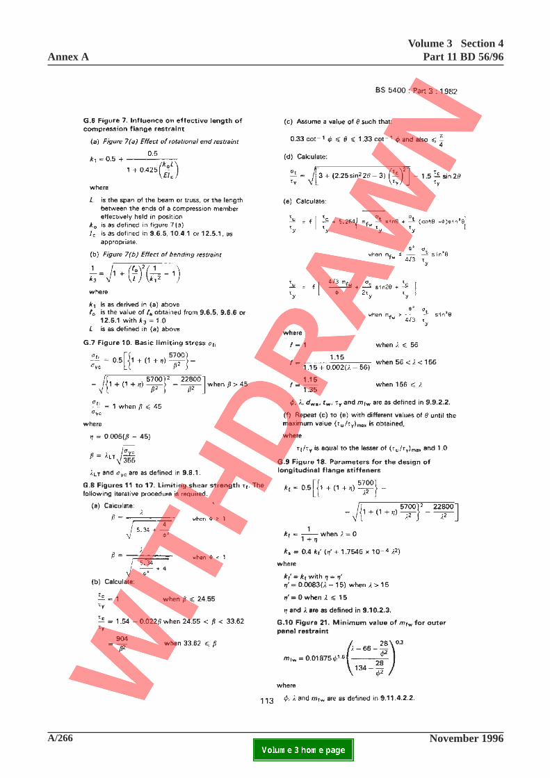
A/266 November 1996
Annex AVolume 3 Section 4
Part 11 BD 56/96
ELECTRONIC COPY NOT FOR USE OUTSIDE THE AGENCY.PAPER COPIES OF THIS ELECTRONIC DOCUMENT ARE UNCONTROLLED

Volume 3 Section 4Part 11 BD 56/96 Annex A
November 1996 A/267ELECTRONIC COPY NOT FOR USE OUTSIDE THE AGENCY.PAPER COPIES OF THIS ELECTRONIC DOCUMENT ARE UNCONTROLLED
This page is blank
113
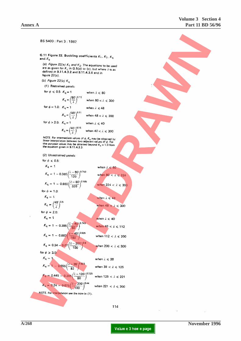
A/268 November 1996
Annex AVolume 3 Section 4
Part 11 BD 56/96
ELECTRONIC COPY NOT FOR USE OUTSIDE THE AGENCY.PAPER COPIES OF THIS ELECTRONIC DOCUMENT ARE UNCONTROLLED

Volume 3 Section 4Part 11 BD 56/96 Annex A
November 1996 A/269ELECTRONIC COPY NOT FOR USE OUTSIDE THE AGENCY.PAPER COPIES OF THIS ELECTRONIC DOCUMENT ARE UNCONTROLLED
This page is blank
114
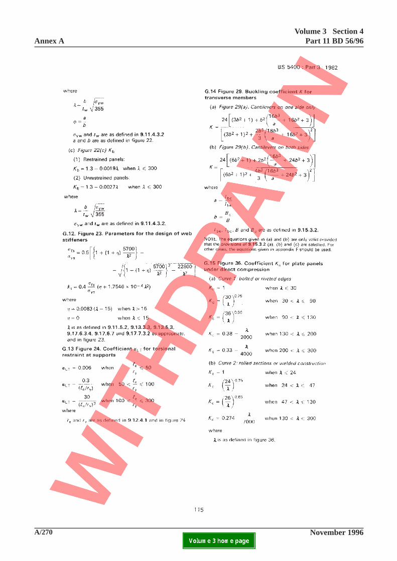
A/270 November 1996
Annex AVolume 3 Section 4
Part 11 BD 56/96
ELECTRONIC COPY NOT FOR USE OUTSIDE THE AGENCY.PAPER COPIES OF THIS ELECTRONIC DOCUMENT ARE UNCONTROLLED

Volume 3 Section 4Part 11 BD 56/96 Annex A
November 1996 A/271ELECTRONIC COPY NOT FOR USE OUTSIDE THE AGENCY.PAPER COPIES OF THIS ELECTRONIC DOCUMENT ARE UNCONTROLLED
This page is blank
115
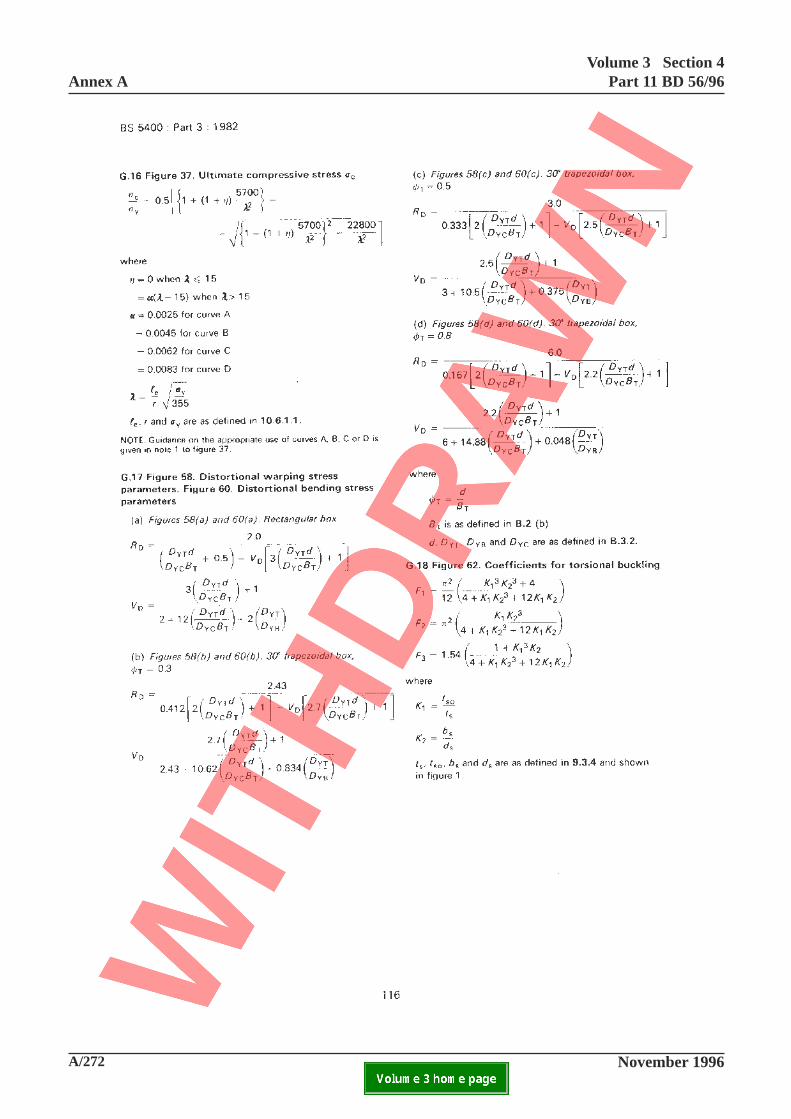
A/272 November 1996
Annex AVolume 3 Section 4
Part 11 BD 56/96
ELECTRONIC COPY NOT FOR USE OUTSIDE THE AGENCY.PAPER COPIES OF THIS ELECTRONIC DOCUMENT ARE UNCONTROLLED
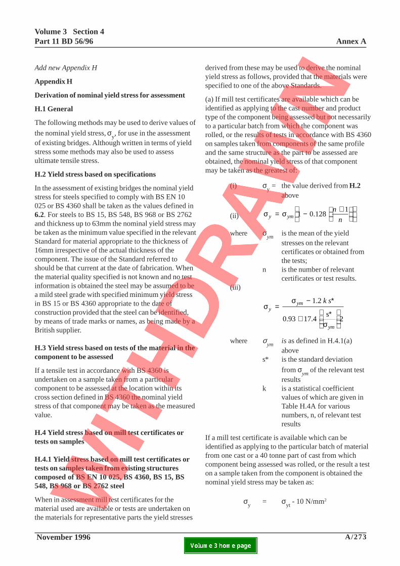
Volume 3 Section 4Part 11 BD 56/96 Annex A
November 1996 A/273ELECTRONIC COPY NOT FOR USE OUTSIDE THE AGENCY.PAPER COPIES OF THIS ELECTRONIC DOCUMENT ARE UNCONTROLLED
Add new Appendix H
Appendix H
Derivation of nominal yield stress for assessment
H.1 General
The following methods may be used to derive values of
the nominal yield stress, σy, for use in the assessment
of existing bridges. Although written in terms of yieldstress some methods may also be used to assessultimate tensile stress.
H.2 Yield stress based on specifications
In the assessment of existing bridges the nominal yieldstress for steels specified to comply with BS EN 10025 or BS 4360 shall be taken as the values defined in6.2. For steels to BS 15, BS 548, BS 968 or BS 2762and thickness up to 63mm the nominal yield stress maybe taken as the minimum value specified in the relevantStandard for material appropriate to the thickness of16mm irrespective of the actual thickness of thecomponent. The issue of the Standard referred toshould be that current at the date of fabrication. Whenthe material quality specified is not known and no testinformation is obtained the steel may be assumed to bea mild steel grade with specified minimum yield stressin BS 15 or BS 4360 appropriate to the date ofconstruction provided that the steel can be identified,by means of trade marks or names, as being made by aBritish supplier.
H.3 Yield stress based on tests of the material in thecomponent to be assessed
If a tensile test in accordance with BS 4360 isundertaken on a sample taken from a particularcomponent to be assessed at the location within itscross section defined in BS 4360 the nominal yieldstress of that component may be taken as the measuredvalue.
H.4 Yield stress based on mill test certificates ortests on samples
H.4.1 Yield stress based on mill test certificates ortests on samples taken from existing structurescomposed of BS EN 10 025, BS 4360, BS 15, BS548, BS 968 or BS 2762 steel
When in assessment mill test certificates for thematerial used are available or tests are undertaken onthe materials for representative parts the yield stresses
derived from these may be used to derive the nominalyield stress as follows, provided that the materials werespecified to one of the above Standards.
(a) If mill test certificates are available which can beidentified as applying to the cast number and producttype of the component being assessed but not necessarilyto a particular batch from which the component wasrolled, or the results of tests in accordance with BS 4360on samples taken from components of the same profileand the same structure as the part to be assessed areobtained, the nominal yield stress of that componentmay be taken as the greatest of:
(i) σy = the value derived from H.2
above
(ii) σ σy ymn
n= − +
1 0.128 1
where σym
is the mean of the yieldstresses on the relevantcertificates or obtained fromthe tests;
n is the number of relevantcertificates or test results.
(iii)
σσ
σ
yym
ym
k s=
− ∗
+ ∗
1.2
0.93 17.4 s
2
where σym
is as defined in H.4.1(a)above
s* is the standard deviation
from σym
of the relevant testresults
k is a statistical coefficientvalues of which are given inTable H.4A for variousnumbers, n, of relevant testresults
If a mill test certificate is available which can beidentified as applying to the particular batch of materialfrom one cast or a 40 tonne part of cast from whichcomponent being assessed was rolled, or the result a teston a sample taken from the component is obtained thenominal yield stress may be taken as:
σy
= σyt
- 10 N/mm2

A/274 November 1996
Annex AVolume 3 Section 4
Part 11 BD 56/96
ELECTRONIC COPY NOT FOR USE OUTSIDE THE AGENCY.PAPER COPIES OF THIS ELECTRONIC DOCUMENT ARE UNCONTROLLED
This page is blank
117
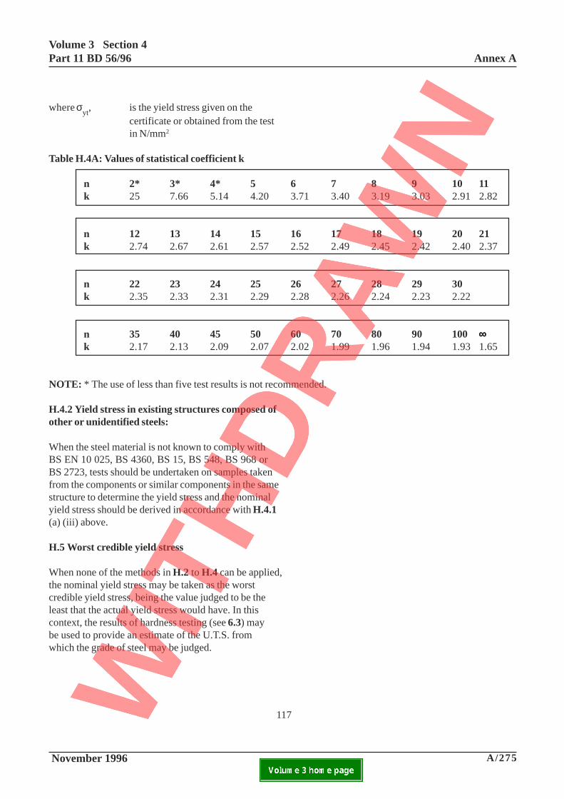
Volume 3 Section 4Part 11 BD 56/96 Annex A
November 1996 A/275ELECTRONIC COPY NOT FOR USE OUTSIDE THE AGENCY.PAPER COPIES OF THIS ELECTRONIC DOCUMENT ARE UNCONTROLLED
where σyt
, is the yield stress given on thecertificate or obtained from the testin N/mm2
Table H.4A: Values of statistical coefficient k
n 2* 3* 4* 5 6 7 8 9 10 11k 25 7.66 5.14 4.20 3.71 3.40 3.19 3.03 2.91 2.82
n 12 13 14 15 16 17 18 19 20 21k 2.74 2.67 2.61 2.57 2.52 2.49 2.45 2.42 2.40 2.37
n 22 23 24 25 26 27 28 29 30k 2.35 2.33 2.31 2.29 2.28 2.26 2.24 2.23 2.22
n 35 40 45 50 60 70 80 90 100∞∞∞∞∞k 2.17 2.13 2.09 2.07 2.02 1.99 1.96 1.94 1.93 1.65
NOTE: * The use of less than five test results is not recommended.
H.4.2 Yield stress in existing structures composed ofother or unidentified steels:
When the steel material is not known to comply withBS EN 10 025, BS 4360, BS 15, BS 548, BS 968 orBS 2723, tests should be undertaken on samples takenfrom the components or similar components in the samestructure to determine the yield stress and the nominalyield stress should be derived in accordance with H.4.1(a) (iii) above.
H.5 Worst credible yield stress
When none of the methods in H.2 to H.4 can be applied,the nominal yield stress may be taken as the worstcredible yield stress, being the value judged to be theleast that the actual yield stress would have. In thiscontext, the results of hardness testing (see 6.3) maybe used to provide an estimate of the U.T.S. fromwhich the grade of steel may be judged.
117

A/276 November 1996
Annex AVolume 3 Section 4
Part 11 BD 56/96
ELECTRONIC COPY NOT FOR USE OUTSIDE THE AGENCY.PAPER COPIES OF THIS ELECTRONIC DOCUMENT ARE UNCONTROLLED
This page is blank
118

Volume 3 Section 4Part 11 BD 56/96 Annex A
November 1996 A/277ELECTRONIC COPY NOT FOR USE OUTSIDE THE AGENCY.PAPER COPIES OF THIS ELECTRONIC DOCUMENT ARE UNCONTROLLED
Add new Appendix I
Appendix I
Inspections for assessment
I.1 General
Inspections for Assessment should comply with theaims and provisions of BD21 and with therecommendations given below.
I.2 Criticality ratings
The nature and extent of inspections should be relatedto:
(a) the prior knowledge of the construction of thebridge, including as-built drawings, constructionprocedures, dimensional surveys and material propertydata; and
(b) the criticality of each part of the bridge in relationto its overall and local structural adequacy.
A preliminary inspection should be undertaken toestablish the following:
(1) In the absence of drawings or previous dimensionalsurveys of any part of the whole of a bridge, the layoutdimensions and nominal component sizes should berecorded. Details of all accessible connections shouldbe measured and the locations of any inaccessibleparts or connections should be noted. Locations ofsignificant visible damage, deterioration or crackingshould be recorded.
(2) If design drawings but no as-built drawings orprevious dimensional surveys are available, the layoutdimensions should be checked against the designdrawings and nominal component sizes used should beverified. Connections should be visually inspected forcompliance with the drawings and any variation inlocation or arrangement noted. Locations of significantdamage, deterioration or cracking should be recorded.
(3) For bridges in which the load effects are sensitiveto errors in level inclination or common planarity ofbearings and for which no as built records of these areavailable the bearings should be surveyed and theerrors recorded.
(4) If as-built drawings and/or previous surveys areavailable no preliminary inspection is needed.
Following any preliminary inspection an initialassessment of the adequacy of the structure should beundertaken using the best information then available.This should be used to establish the relative criticalityof each part and to identify what further information isrequired to enable the final assessment to beundertaken. At this stage pessimistic assumptionsshould be made with respect to any relevantparameters for which information is lacking (egmaterial properties, or constructional imperfections).Those parts shown as likely to be inadequate should beidentified on drawings to be used for reference in adetailed inspection. They should include parts shownby the preliminary inspection to be significantlycorroded or deteriorated.
I.3 Detailed inspections
The detailed inspection of a bridge should supplementthe information concerning the details and conditionsobtained in the preliminary survey as set out in I.4 toI.6.
I.4 Structural arrangements and sizes
The section dimensions of components at criticallocations should be measured. Dimensions ofconnections and their connectors should be recorded,including weld sizes.
I.5 Constructional imperfections
All components should be visually inspected for grossdeformations from intended flatness or straightness.Additionally for all critical parts, the strengths ofwhich are related to geometric imperfections, detailedmeasurement of deviations should be made inaccordance with Clause 5.6 of BS5400 Part 6 or asotherwise defined in the assessment addenda toBS5400 Part 3.

A/278 November 1996
Annex AVolume 3 Section 4
Part 11 BD 56/96
ELECTRONIC COPY NOT FOR USE OUTSIDE THE AGENCY.PAPER COPIES OF THIS ELECTRONIC DOCUMENT ARE UNCONTROLLED
This page is blank
119
Volume 3 Section 4Part 11 BD 56/96 Annex A
November 1996 A/279ELECTRONIC COPY NOT FOR USE OUTSIDE THE AGENCY.PAPER COPIES OF THIS ELECTRONIC DOCUMENT ARE UNCONTROLLED
119
The alignments of all bearings in relation to loadbearing stiffeners and/or diaphragms should bemeasured. The coincident ambient temperature of themain bridge members should be recorded andappropriate adjustment made to the eccentricities oralignment to allow for the differences between theobserved and the effective bridge temperature relativeto the assessments required.
I.6 Condition
At all locations where corrosion, deterioration ordamage is apparent, its significance should be assessedby reference to the criticality ratings and whereappropriate detailed measurements should be made ofloss of section and/or investigations should beundertaken of potential influences on fatigue life orfracture propensity.
Connections in critical regions should be subjected todetailed inspection. Paint should be removed fromwelds and the welds subjected to 100% MPIinspection. For fatigue critical connections the weldsshould be also subjected to full ultrasonic examination.All bolted and riveted connections should be inspectedfor loss or looseness of connectors. Friction gripbolted connections should be tested for tightness byapplication of the appropriate torque to arepresentative sample of nuts.
I.7 Material properties
Where there is inadequate information concerningmaterial properties for critical parts, samples shouldbe taken for mechanical testing. To make use of resultsof such tests in accordance with Section 6, the samplesshould be taken in the same structure and consideredto be likely to have been supplied from the same batchof material. Where possible such samples should betaken from a position on a member remote from itscritical region. The locations of the samples within asection should be relevant to the strength criteria beingused (e.g. within a flange of a beam when consideringbending capacity) and in accordance with BS 4360.
Test specimens and tensile testing should beaccordance with BS 4360. Strain rates in testingshould be similar to those used in mill testing. Intaking samples great care must be exercised to avoidthe introduction of unacceptable stress concentrationsin the structure and the modifications of the propertiesof the samples due to any heat input.


