Embed Size (px)
Citation preview
THE ARIES-CS COMPACT STELLARATORFUSION POWER PLANTF. NAJMABADI* and A. R. RAFFRAY Center for Energy ResearchUniversity of California, San Diego, MC 0417, La Jolla, California 92093-0417
ARIES-CS TEAM: S. I. ABDEL-KHALIK,a L. BROMBERG,b L. CROSATTI,a L. EL-GUEBALY,c
P. R. GARABEDIAN,d A. A. GROSSMAN,e D. HENDERSON,c A. IBRAHIM,c T. IHLI,f
T. B. KAISER,g B. KIEDROWSKI,c L. P. KU,h J. F. LYON,i R. MAINGI,i S. MALANG,j C. MARTIN,c
T. K. MAU,e B. MERRILL,k R. L. MOORE,k R. J. PEIPERT, Jr.,l D. A. PETTI,k D. L. SADOWSKI,a
M. SAWAN,c J. H. SCHULTZ,b R. SLAYBAUGH,c K. T. SLATTERY,l G. SVIATOSLAVSKY,c
A. TURNBULL,m L. M. WAGANER,l X. R. WANG,e J. B. WEATHERS,a P. WILSON,c
J. C. WALDROP III,l M. YODA,a and M. ZARNSTORFFh
Received January 22, 2008Accepted for Publication May 2, 2008
An integrated study of compact stellarator powerplants, ARIES-CS, has been conducted to explore attrac-tive compact stellarator configurations and to define keyresearch and development (R&D) areas. The large sizeand mass predicted by earlier stellarator power plantstudies had led to cost projections much higher thanthose of the advanced tokamak power plant. As such, thefirst major goal of the ARIES-CS research was to inves-tigate if stellarator power plants can be made to be com-parable in size to advanced tokamak variants whilemaintaining desirable stellarator properties. As stellar-ator fusion core components would have complex shapesand geometry, the second major goal of the ARIES-CS
study was to understand and quantify, as much as pos-sible, the impact of the complex shape and geometry offusion core components. This paper focuses on the direc-tions we pursued to optimize the compact stellarator as afusion power plant, summarizes the major findings fromthe study, highlights the key design aspects and con-straints associated with a compact stellarator, and iden-tifies the major issues to help guide future R&D.
KEYWORDS: fusion power plant, compact stellarator
Note: The figures in this paper are in color only in the electronicversion.
I. INTRODUCTION
ARIES research aims at establishing the economic,safety, and environmental potential of fusion power plants
and at identifying physics and technology areas with thehighest leverage for achieving attractive and competitivefusion power in order to guide fusion research and de-velopment ~R&D!. The ARIES Team is a U.S. nationaleffort with participation from national laboratories, uni-versities, and the industry and with strong internationalcollaborations. The Team performs detailed physics and*E-mail: [email protected]
aGeorge W. Woodruff School of Mechanical Engineering, Geor-gia Institute of Technology, Atlanta, Georgia 30332-0405
b Massachusetts Institute of Technology, Plasma Science andFusion Center, 167 Albany Street, Cambridge, Massachusetts02139
c University of Wisconsin, Fusion Technology Institute, 1500Engineering Drive, Madison, Wisconsin 53706-1687
d New York University, Courant Institute of Mathematical Sci-ences, New York 10012
e Center for Energy Research, University of California, SanDiego, MC 0417, La Jolla, California 92093-0417
f Forschungszentrum Karlsruhe, IKET, P.O. Box 3640, 76012Karlsruhe, Germany
g Lawrence Livermore National Laboratory, Livermore,California
h Princeton Plasma Physics Laboratory, Princeton University,Princeton, New Jersey 08520
iOak Ridge National Laboratory, Oak Ridge, Tennessee 37831jConsultant, Fliederweg 3, D 76351 Linkenheim-Hochstetten,Germany
k Idaho National Laboratory, Idaho Falls, Idahol The Boeing Company, P.O. Box 516, St. Louis, Missouri63166
m General Atomics, San Diego, California 92186
FUSION SCIENCE AND TECHNOLOGY VOL. 54 OCT. 2008 655
engineering analyses using the most current and detailedmodels available and then uses the results to performoptimization and trade studies via a cost-based systemscode. Our latest study, ARIES-CS, explores attractivecompact stellarator configurations as fusion power plantsand identifies key R&D areas.
In a stellarator, most of the confining field is pro-duced by external coils ~the poloidal field is generated bythe external coils as well as the bootstrap current!. Theabsence of a large externally driven plasma current leadsto many attractive features: Stellarators are inherentlysteady state, stable against external kink and axisymmet-ric modes, and resilient to plasma disruptions.
Earlier stellarator power plant studies led to de-vices with large sizes compared to tokamaks. The He-lias Reactor ~HSR! study is based on the Wendelstein7-X ~W7-X! plasma configuration ~linked mirrors!. Ithas an average major radius ^R& � 22 m for a five-field-period configuration ~HSR-5!, and ^R& � 18 m for arecent four-field-period ~HSR-4! configuration.1 TheForce-Free Helical Reactor2 ~FFHR! is a ten-field-period heliotron0torsatron ~l � 2 stellarator!. FFHR-1and several variants @MHR-S ~Ref. 3! and FFHR2m2~Ref. 4!# have ^R& � 10 to 20 m. The ARIES StellaratorPower Plant Study ~SPPS!, completed in 1996, was basedon a four-field-period Modular Helias-like Heliac ~MHH!configuration and led to an ^R& � 14 m device that wasthe first step toward a smaller stellarator power plant.5
The major radii of these earlier stellarator designs aretypically two to four times larger than those of recenttokamak power plant studies, ARIES-RS ~Ref. 6! andARIES-AT ~Ref. 7!, which have R ; 5.5 m.
The large size and mass predicted by earlier stellar-ator power plant studies had led to cost projections muchhigher than those of the advanced tokamak power plant.As such, the first major goal of the ARIES-CS researchwas to investigate if stellarator power plants can be madeto be comparable in size to advanced tokamak variantswhile maintaining desirable stellarator properties. Stel-larator fusion core components would have complexshapes and geometry. This complexity imposes severeconstraints on fusion core components such as nonuni-form heat, particle, and neutron fluxes; accessibility forassembly and maintenance; and feasibility and cost ofmanufacturing. The second major goal of the ARIES-CSstudy was to understand and quantify, as much as possi-ble, the impact of the complex shape and geometry offusion core components.
In Sec. II, we explore the design directions that wepursued to optimize the compact stellarator as a fusionpower plant. Sections III and IV present overviews of ourdetailed physics and engineering design and analysis andhighlight the key design aspects and constraints associ-ated with a compact stellarator. Section V examines theextent to which ARIES-CS has met the top-level require-ments for fusion power plants and describes the key R&Dtopics. A complete discussion of ARIES-CS systems can
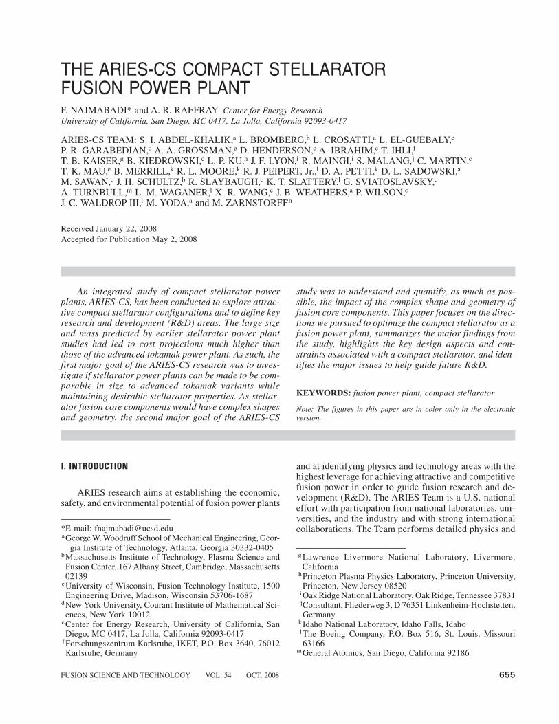
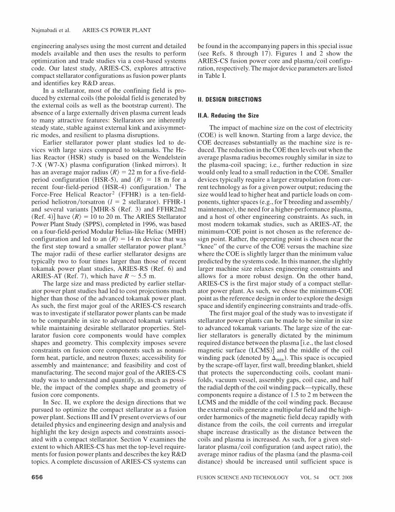
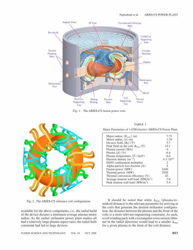
be found in the accompanying papers in this special issue~see Refs. 8 through 17!. Figures 1 and 2 show theARIES-CS fusion power core and plasma0coil configu-ration, respectively. The major device parameters are listedin Table I.
II. DESIGN DIRECTIONS
II.A. Reducing the Size
The impact of machine size on the cost of electricity~COE! is well known. Starting from a large device, theCOE decreases substantially as the machine size is re-duced. The reduction in the COE then levels out when theaverage plasma radius becomes roughly similar in size tothe plasma-coil spacing; i.e., further reduction in sizewould only lead to a small reduction in the COE. Smallerdevices typically require a larger extrapolation from cur-rent technology as for a given power output; reducing thesize would lead to higher heat and particle loads on com-ponents, tighter spaces ~e.g., for T breeding and assembly0maintenance!, the need for a higher-performance plasma,and a host of other engineering constraints. As such, inmost modern tokamak studies, such as ARIES-AT, theminimum-COE point is not chosen as the reference de-sign point. Rather, the operating point is chosen near the“knee” of the curve of the COE versus the machine sizewhere the COE is slightly larger than the minimum valuepredicted by the systems code. In this manner, the slightlylarger machine size relaxes engineering constraints andallows for a more robust design. On the other hand,ARIES-CS is the first major study of a compact stellar-ator power plant. As such, we chose the minimum-COEpoint as the reference design in order to explore the designspace and identify engineering constraints and trade-offs.
The first major goal of the study was to investigate ifstellarator power plants can be made to be similar in sizeto advanced tokamak variants. The large size of the ear-lier stellarators is generally dictated by the minimumrequired distance between the plasma @i.e., the last closedmagnetic surface ~LCMS!# and the middle of the coilwinding pack ~denoted by Dmin!. This space is occupiedby the scrape-off layer, first wall, breeding blanket, shieldthat protects the superconducting coils, coolant mani-folds, vacuum vessel, assembly gaps, coil case, and halfthe radial depth of the coil winding pack—typically, thesecomponents require a distance of 1.5 to 2 m between theLCMS and the middle of the coil winding pack. Becausethe external coils generate a multipolar field and the high-order harmonics of the magnetic field decay rapidly withdistance from the coils, the coil currents and irregularshape increase drastically as the distance between thecoils and plasma is increased. As such, for a given stel-larator plasma0coil configuration ~and aspect ratio!, theaverage minor radius of the plasma ~and the plasma-coildistance! should be increased until sufficient space is
Najmabadi et al. ARIES-CS POWER PLANT
656 FUSION SCIENCE AND TECHNOLOGY VOL. 54 OCT. 2008
available for the above components; i.e., the radial buildof the device dictates a minimum average plasma minorradius. As the earlier stellarator power plant studies allhad a relatively large plasma aspect ratio, the radial builtconstraint had led to large devices.
It should be noted that while Dmin ~plasma-to-midcoil distance! is the relevant parameter for arriving atthe coils that generate the desired stellarator configura-tion, the distance between the plasma and the front of thecoils is a more relevant engineering constraint. As such,a coil winding pack with a rectangular cross section ~thin-ner in the radial direction! would lead to a smaller Dminfor a given plasma to the front of the coil distance.
Fig. 1. The ARIES-CS fusion power core.
Fig. 2. The ARIES-CS reference coil configuration.
TABLE I
Major Parameters of 1-GW~electric! ARIES-CS Power Plant
Major radius, ^Raxis& ~m! 7.75Minor radius, ^a& ~m! 1.70On-axis field, ^B0& ~T! 5.7Peak field on the coil, Bmax ~T! 15.1Plasma current ~MA! 4Plasma ^b& ~%! 6.4Plasma temperature, ^T & ~keV! 6.6Electron density ~m�3 ! 4 � 1020
ISS95 confinement multiplier 2Alpha-particle loss fraction ~%! 5Fusion power ~MW! 2440Thermal power ~MW! 2920Thermal conversion efficiency ~%! 43Average neutron wall load ~MW0m2 ! 2.6Peak neutron wall load ~MW0m2 ! 5.4
Najmabadi et al. ARIES-CS POWER PLANT
FUSION SCIENCE AND TECHNOLOGY VOL. 54 OCT. 2008 657
Based on the above observation, three avenues werepursued to reduce the size:
1. Develop stellarator configuration with lower as-pect ratios.
2. For a given stellarator configuration ~i.e., plasmaaspect ratio!, increase the coil-plasma spacing by devel-oping a coil design with a lower coil aspect ratio andoptimizing the coil cross section.
3. Develop engineering options to reduce the re-quired minimum distance between the plasma and themidpoint of the coil ~Dmin!.
II.A.1. Quasi-Axisymmetric Configuration
In recent years drift orbit optimization techniqueshave been widely used to develop stellarator configura-tions. In particular, the ability to achieve topologicalsymmetry as seen by particles can be exploited to opti-mize the properties of the configuration such as quasi-helical symmetry18 utilized in the Helically SymmetricExperiment19 ~HSX!; quasi-axisymmetry20 ~QAS! uti-lized in the National Compact Stellarator Experiment21
~NCSX!, which is under construction in the United States;quasi-isodynamicity and linked mirrors utilized in W7-Xunder construction in Germany22; and quasi-poloidal sym-metry utilized in the proposed Quasi-Poloidal Stellarator~QPS! experiment.23 In addition to the desired symmetry,these techniques can be utilized to optimize other plasmaproperties ~such as magnetic shear, magnetic well depth,and the amount of external rotational transform!, mea-sures of magnetohydrodynamic ~MHD! stability ~suchas external kinks, vertical displacement, and infinite-nballooning modes!, and figures of merit for transport~such as the effective ripple or diffusion coefficientevaluations!.
We focused our analysis on QAS configurations asthey are able to operate at a lower plasma aspect ratio~;4 to 5! compared to other stellarator configurations.Some efforts on optimizing a configuration with quasi-helical symmetry were made; however, we could notachieve desirable low-aspect-ratio configurations. We didnot investigate quasi-poloidal-symmetric configurationsbecause of the lack of resources.
The particle drift orbits in a QAS configuration aresimilar to that of a tokamak. As such, it is argued that aQAS configuration would have good confinement simi-lar to tokamaks. Also, because of the quasi-axisymmetry,the neoclassical bootstrap current is also similar totokamaks, but the magnitude is reduced by the higherrotational transform. The low-aspect-ratio QAS config-urations, therefore, tend to be like hybrids between toka-maks and conventional stellarators.
Because of the large research effort spent in devel-oping the NCSX configuration, the ARIES-CS configu-rations naturally evolved from NCSX equilibrium. The
major critical issue of the NCSX configuration for afusion plasma is its high alpha-particle loss rate. Ourefforts to reduce the alpha-particle loss rate led to newcriteria for optimizing the QAS configuration and led tothe baseline plasma configuration used for engineeringanalysis and trade-off studies, N3ARE ~see Fig. 3 andSec. III!.
We also developed two new classes of the QAS con-figuration in which strict adherence to linear, ideal MHDstability constraints was relaxed. This was due to therecent experimental results from the Wendelstein 7-AS~W7-AS! and Large Helical Device ~LHD! stellarators.Average beta values of 3.2 and 4.2% have been achievedon W7-AS and LHD, respectively, limited only by theavailable heating power and perhaps the integrity of theequilibrium flux surfaces. These beta values were main-tained for 80 to 100 energy confinement times, and whileMHD activity apparently existed and was active in somecases, the plasmas nevertheless were quiescent and re-mained quasi-stationary. In both cases, the achievedexperimental values were higher than those predictedfrom linear stability theory ~e.g., 3.2% achieved beta inW7-AS versus 2% for the theoretical prediction!.24,25
The first class of the new configurations is MHH2,which aims at developing a very low-aspect-ratio geom-etry with relatively simpler coils ~see Sec. III.B!. Thesecond class, SNS, is aimed at developing a configura-tion with excellent flux surface quality and nearly flatrotational transform ~Sec. III.C!.
II.A.2. Coil Design
Coils that produce the designed target plasma shapemay be constructed by requiring that the normal compo-nent of the magnetic field on the LCMS produced by thecoils cancels that due to the plasma current. Several coildesigns with different coil aspect ratios were produced inorder to provide scaling of the system size for trade-offstudies.8,9 In addition to different aspect ratios, the coilcross section ~shape and size! was varied.8 These coildesigns included certain additional constraints of coilseparation ratio and minimum radius of curvature. Asdiscussed before, reducing the coil aspect ratio wouldincrease the available space for fusion core components.However, as the coil aspect ratio defined as Ac � ^R&0Dmin is reduced ~i.e., Dmin is increased for a given ^R&!,the coils generally become more complicated, and thepeak field on the superconducting coil ~Bmax! is in-creased ~for a given field in the plasma center ^B&!. Forexample, we found that for the N3ARE configuration,Bmax0^B& increases rapidly if the coil aspect ratio is re-duced below ;5.8 ~see Fig. 9 of Ref. 8!. The baselinecoil design has a coil aspect ratio of 5.8 with rectangularcross-section conductors ~;0.19 m radially and;0.74 mtoroidally!. The maximum field in the winding pack ofthe coils is ;15 T for an on-axis plasma field of 5.7 T~see Fig. 2!.
Najmabadi et al. ARIES-CS POWER PLANT
658 FUSION SCIENCE AND TECHNOLOGY VOL. 54 OCT. 2008
II.A.3. Reducing Required Dmin
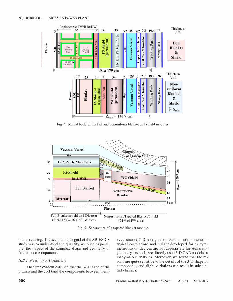
A key parameter is the minimum required plasma-to-midcoil distance ~Dmin!. This space accommodatesthe scrape-off layer, first wall, blanket, shield, mani-folds, vacuum vessel, assembly gaps, coil case, and halfof the winding pack. Typically, the distance betweenthe plasma and the front of the coils is set by the re-quirements of adequate breeding and shielding of thecoils ~the coil radial thickness is optimized separatelyas discussed in Sec. III.B!. An innovative approach wasdeveloped to downsize the blanket and utilize a highlyefficient tungsten-carbide ~WC!–based shield in thespace-constrained regions where plasma is close to thecoil. The special modules in these regions utilize a non-uniform blanket and a WC shield, optimized to provideshielding comparable to a regular breeding module butwith a much reduced module radial thickness, as shownin Fig. 4. From Fig. 4, the typical plasma-to-midcoilradial thickness for a regular breeding module is;1.79 mbut is only 1.31 m for an optimized module with areduced breeding zone but with similar shielding prop-erties.11 The final design of the blanket modules in those
regions with minimum plasma-to-midcoil distances ~forexample, see the “midplane” inboard region in Fig. 1!consists of a tapered breeding region with a thicknessranging from 25 cm at the minimum space location to54 cm in regions where more space is available as isshown in Fig. 5. The total tritium breeding ratio includ-ing all modules is ;1.1, found from detailed three-dimensional ~3-D! neutronics analysis of the computer-aided design ~CAD! model of ARIES-CS ~see Sec. II.B.1and Ref. 11!. Using a tapered blanket has had a majorimpact on the machine size: A device with a uniformblanket and shield at all locations would have a majorradius .10 m compared to 7.75 m for ARIES-CS ~seeSec. V.A.2!.
II.B. Complex Shape and Geometry
Stellarator fusion core components will have complexshapes and geometry. This complexity imposes severeconstraints on fusion core components such as nonuni-form heat, particle, and neutron fluxes; accessibility forassembly and maintenance; and feasibility and cost of
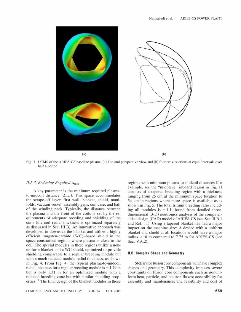
Fig. 3. LCMS of the ARIES-CS baseline plasma. ~a! Top and perspective view and ~b! four cross sections at equal intervals overhalf a period.
Najmabadi et al. ARIES-CS POWER PLANT
FUSION SCIENCE AND TECHNOLOGY VOL. 54 OCT. 2008 659
manufacturing. The second major goal of the ARIES-CSstudy was to understand and quantify, as much as possi-ble, the impact of the complex shape and geometry offusion core components.
II.B.1. Need for 3-D Analysis
It became evident early on that the 3-D shape of theplasma and the coil ~and the components between them!
necessitates 3-D analysis of various components—typical correlations and insight developed for axisym-metric fusion devices are not appropriate for stellaratorgeometry. As such, we directly used 3-D CAD models inmany of our analyses. Moreover, we found that the re-sults are quite sensitive to the details of the 3-D shape ofcomponents, and slight variations can result in substan-tial changes.
Fig. 4. Radial build of the full and nonuniform blanket and shield modules.
Fig. 5. Schematics of a tapered blanket module.
Najmabadi et al. ARIES-CS POWER PLANT
660 FUSION SCIENCE AND TECHNOLOGY VOL. 54 OCT. 2008

For example, nuclear assessment of the system ~breed-ing, shielding, blanket thermal recovery! requires utili-zation of 3-D neutron transport codes such as the MCNPXMonte Carlo code. We developed a new tool that usesCAD information to provide 3-D source terms for bothfusion neutrons generated in the plasma and radiationfrom the plasma ~bremsstrahlung and impurity line radi-ation!. This CAD0MCNPX interface also uses CAD mod-els for in-vessel components ~i.e., first wall, blanket, etc.!to generate various zones for MCNPX ~Ref. 11!.
An important result from exercising this tool is thedistribution of the neutron and heat loads on the firstwall, which greatly influence the thermal performanceand lifetime of the blanket. Figure 6 shows the contoursof neutron wall loading on the first wall of the referenceARIES-CS design ~the first wall follows the LCMS shapeand accommodates a uniform 5-cm scrape-off-layer thick-ness!. For this case, the peak neutron wall loading is 5.3MW0m2, and its location is denoted by a white circle inFig. 6. Similar to other toroidal devices ~e.g., tokamaks!,the neutron wall loading is lowest at the top and thebottom ~around 690-deg poloidal angle! and highest on
the midplane with the peak value located at the outboardlocation ~0 poloidal angle! rather than the inboard loca-tion ~6180-deg poloidal angle!. However, Fig. 6 alsoshows a large spatial variation in the neutron wall load-ing ~e.g., compared to that of a tokamak! and underlinesthe need for 3-D analysis of nuclear components. Simi-larly, we have found large spatial variation in the heatflux incident on the first wall11 but with a different pro-file compared to that of the neutron load. For example,the heat flux on the inboard side ~6180-deg poloidalangle! is comparable to that of the outboard side in manylocations.
Of particular importance is the large peaking factorof ;2 in the neutron wall loading ~peak value of 5.3MW0m2 and average value 2.6 MW0m2!, which is con-siderably larger than tokamaks ~1.5 for ARIES-AT!. Thisrather large peaking factor and the similarly large peak-ing factor for heat fluxes have a dramatic impact on theengineering design of the system. For a given power, thesize of the device sets the average power loading onthe components. However, components should be de-signed to withstand the peak loadings, which typicallyleads to a lower performance for these components ~e.g.,the radiation lifetime of the component is set by the peakneutron flux!.
II.B.2. Configuration, Assembly, and Maintenance
We have found that the engineering configurationand the assembly and maintenance procedure are keyelements in optimizing a compact stellarator; in somecases, these issues determine the choice of technologiesthat can be utilized.
We considered several assembly and maintenanceprocedures early in the study. Sector-based maintenance,similar to that envisioned for ARIES-AT, was ruled outbecause of the irregular shape of the coils. A field-periodmaintenance scheme, i.e., the replacement of integral unitsbased on a field period including disassembly of the mod-ular coil system, was also considered.26 We judged thisscheme not to be feasible because it involves movementof massive cryogenic structures as well as the need forfine realignment during reassembly. As such, port-basedmaintenance, i.e., the replacement of the blanket and otherin-vessel components through a number of designatedports, appears to be the only feasible assembly and main-tenance scheme. This is a complicated and time-consumingprocedure as the size of the ports as well as the weightlimit of the maintenance boom limits the size of a typicalblanket module to ;3 to 4 m2 on the side facing theplasma ~about 200 such modules in ARIES-CS!. Further-more, module removal and replacement require the cut-ting and rewelding of the coolant pipes, which necessitatesremoval of a neighboring module first ~as discussed inSec. IV and Ref. 10!.
The need for a large number of modules with cool-ant pipes that can be cut and rewelded in a relatively
Fig. 6. Contour maps of the neutron wall load ~in MW0m2 ! ofARIES-CS. The approximate location of the peak isindicated with a circle. The toroidal angle is measuredfrom the beginning of the field period while the poloi-dal angle is measured from the outboard midplane atthe level of the magnetic axis.
Najmabadi et al. ARIES-CS POWER PLANT
FUSION SCIENCE AND TECHNOLOGY VOL. 54 OCT. 2008 661
short time drove us toward the choice of a ferritic steel–based blanket as a reference option instead of a higher-performance blanket utilizing SiC composite as structuralmaterial @e.g., SiC0Pb-17Li blanket of ARIES-AT~Ref. 7!# , which was kept as a possible backup. Thereference blanket concept is a dual-coolant concept withself-cooled Pb-17Li zones and a He-cooled ferritic steelstructure.
The choice and design of superconducting magnetsare another example of the impact of the configuration onthe choice of available technologies. The candidate su-perconductor materials for operation at high field ~up to16 T! are variants of Nb3Sn or MgB2. Both are glassymaterials, and their current-carrying capability is drasti-cally reduced with induced strain. For these types ofsuperconductors, the superconductor material is woundaround a large spool ~with roughly the same radius ofcurvature as the coil itself ! and is heat treated ~7008C fora few hundred hours! to attain superconducting proper-ties. The resultant cable is then gently unwound from thespool, insulated, and wound onto the coil. The reason forthis two-step process is that organic insulators cannotsurvive the heat treatment process and need to be addedafterward. Because of the irregular shape of the coils, thismethod cannot be used in a compact stellarator becauseof excessive strain induced during the winding process.In order to keep the strain down, the superconductormaterial should be wound as a complete cable ~includingthe insulator! on the coil and then heat treated. This methodrequires development of inorganic insulators that canwithstand the heat treatment process. These issues arediscussed in more detail in Ref. 14. It should be notedthat the strain induced during the winding process is notan issue for ductile NbTi superconductors. However, themaximum field Bmax is limited to ;7 to 8 T for 4 Koperation ~up to 9 T can be achieved by operation at 2 K,although there are issues with temperature margin!. Thisreduction in maximum field strength will lead to a sub-stantial increase in the machine size.
II.B.3. Costing and Manufacturing Feasibility
As most of the cost of various components in a fu-sion system is due to the manufacturing process ~and notthe cost of the raw material!, it is expected that there willbe additional costs associated with the irregular and com-plex shape of the stellarator components. Our attempts toget guidance from industry on cost penalties associatedwith the complexity of components were unsuccessfulbecause of the lack of industrial experience in manufac-turing complex components on a large scale. It was gen-erally reported that manufacturing of these componentswith conventional techniques would be quite expensiveand challenging. However, advanced manufacturing tech-niques, under development, would allow for the compo-nent size not to be a limiting factor and the process to behighly automated with minimal labor. In principle, ad-
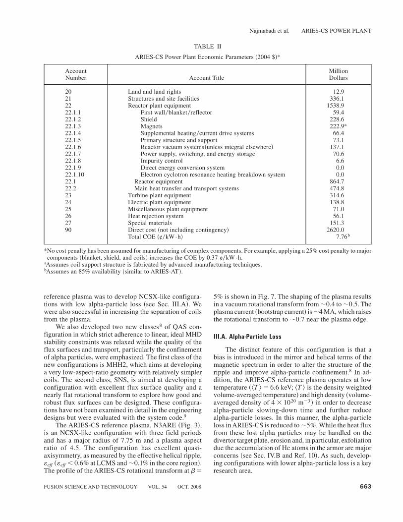
vanced manufacturing techniques would result in a muchlower additional cost for complex components. Theseadvanced manufacturing techniques are more suitablefor a monolithic structure such as the superconductingcoil structure as opposed to heterogeneous structures suchas blanket modules. As such, we have assumed such anadvanced manufacturing technique in designing our coilsupport structure17 and in estimating the COE. In addi-tion, we did not include any cost penalties for manufac-turing of other components or for machine assembly.While this approach still allows us to use the COE as agood optimization parameter for understanding the trade-off among stellarator features and optimizing the design,care should be taken in cross-comparison with other fu-sion concepts and0or other sources of energy. Table IIprovides a cost estimate of various components ofARIES-CS. The parametric dependence of the COE on addi-tional cost penalties to complexity for heterogeneouscomponents ~e.g., blankets! is reported in Ref. 9. Forexample, applying a 25% cost penalty to each major com-ponent separately increases the COE by 0.37 ¢0kW{h~0.1 ¢0kW{h for the blankets, 0.14 ¢0kW{h for the shields,and 0.13 ¢0k{Wh for the coils and support structure!.
III. PLASMA PHYSICS
We have found that in many cases, a slight increasein the major radius ~to ;8.25 m! would lead to a morerobust engineering design for the components.
In recent years, the technique of drift-orbit optimi-zation has been widely used to arrive at modern stellar-ator configurations. These techniques are based on theobservation that particle drift trajectories in “Boozer”coordinates depend on only the strength of the local mag-netic field ~and not on the vector components of thefield!.27 These extra degrees of freedom mean that many3-D plasma geometries with well-confined particle tra-jectories can be constructed and they can be optimized tohave other described properties. For example, QAS con-figurations aim at achieving an axially symmetric fieldstrength ~in Boozer coordinates! that leads to particleorbits being similar to those in a tokamak. As such, thisclass of configurations has the potential to combine thedesirable features of tokamaks ~good confinement andmoderate aspect ratio! with those of large-aspect-ratiostellarators ~steady-state operation, stability against ex-ternal kinks and axisymmetric modes, and resilience todisruptions!.
Because of the desire to reduce the size of a stellar-ator power plant and the need to reduce the plasma aspectratio, the ARIES-CS study focused on the QAS config-uration. As a large research effort has been spent indeveloping the NCSX configuration, the ARIES-CS con-figurations naturally evolved from NCSX equilibrium.21
The most important issue in developing the ARIES-CS
Najmabadi et al. ARIES-CS POWER PLANT
662 FUSION SCIENCE AND TECHNOLOGY VOL. 54 OCT. 2008
reference plasma was to develop NCSX-like configura-tions with low alpha-particle loss ~see Sec. III.A!. Wewere also successful in increasing the separation of coilsfrom the plasma.
We also developed two new classes8 of QAS con-figuration in which strict adherence to linear, ideal MHDstability constraints was relaxed while the quality of theflux surfaces and transport, particularly the confinementof alpha particles, were emphasized. The first class of thenew configurations is MHH2, which aims at developinga very low-aspect-ratio geometry with relatively simplercoils. The second class, SNS, is aimed at developing aconfiguration with excellent flux surface quality and anearly flat rotational transform to explore how good androbust flux surfaces can be designed. These configura-tions have not been examined in detail in the engineeringdesigns but were evaluated with the system code.9
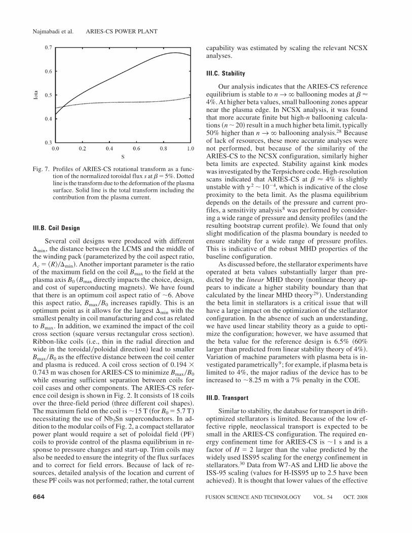
The ARIES-CS reference plasma, N3ARE ~Fig. 3!,is an NCSX-like configuration with three field periodsand has a major radius of 7.75 m and a plasma aspectratio of 4.5. The configuration has excellent quasi-axisymmetry, as measured by the effective helical ripple,«eff ~«eff , 0.6% at LCMS and;0.1% in the core region!.The profile of the ARIES-CS rotational transform at b�
5% is shown in Fig. 7. The shaping of the plasma resultsin a vacuum rotational transform from;0.4 to;0.5. Theplasma current ~bootstrap current! is;4 MA, which raisesthe rotational transform to ;0.7 near the plasma edge.
III.A. Alpha-Particle Loss
The distinct feature of this configuration is that abias is introduced in the mirror and helical terms of themagnetic spectrum in order to alter the structure of theripple and improve alpha-particle confinement.8 In ad-dition, the ARIES-CS reference plasma operates at lowtemperature ~^T & � 6.6 keV; ^T & is the density weightedvolume-averaged temperature! and high density ~volume-averaged density of 4 � 1020 m�3! in order to decreasealpha-particle slowing-down time and further reducealpha-particle losses. In this manner, the alpha-particleloss in ARIES-CS is reduced to;5%. While the heat fluxfrom these lost alpha particles may be handled on thedivertor target plate, erosion and, in particular, exfoliationdue the accumulation of He atoms in the armor are majorconcerns ~see Sec. IV.B and Ref. 10!. As such, develop-ing configurations with lower alpha-particle loss is a keyresearch area.
TABLE II
ARIES-CS Power Plant Economic Parameters ~2004 $!*
AccountNumber Account Title
MillionDollars
20 Land and land rights 12.921 Structures and site facilities 336.122 Reactor plant equipment 1538.922.1.1 First wall0blanket0reflector 59.422.1.2 Shield 228.622.1.3 Magnets 222.9a
22.1.4 Supplemental heating0current drive systems 66.422.1.5 Primary structure and support 73.122.1.6 Reactor vacuum systems~unless integral elsewhere! 137.122.1.7 Power supply, switching, and energy storage 70.622.1.8 Impurity control 6.622.1.9 Direct energy conversion system 0.022.1.10 Electron cyclotron resonance heating breakdown system 0.022.1 Reactor equipment 864.722.2 Main heat transfer and transport systems 474.823 Turbine plant equipment 314.624 Electric plant equipment 138.825 Miscellaneous plant equipment 71.026 Heat rejection system 56.127 Special materials 151.390 Direct cost ~not including contingency! 2620.0
Total COE ~¢0kW{h! 7.76b
*No cost penalty has been assumed for manufacturing of complex components. For example, applying a 25% cost penalty to majorcomponents ~blanket, shield, and coils! increases the COE by 0.37 ¢0kW{h.
aAssumes coil support structure is fabricated by advanced manufacturing techniques.bAssumes an 85% availability ~similar to ARIES-AT!.
Najmabadi et al. ARIES-CS POWER PLANT
FUSION SCIENCE AND TECHNOLOGY VOL. 54 OCT. 2008 663
III.B. Coil Design
Several coil designs were produced with differentDmin, the distance between the LCMS and the middle ofthe winding pack ~parameterized by the coil aspect ratio,Ac � ^R&0Dmin!. Another important parameter is the ratioof the maximum field on the coil Bmax to the field at theplasma axis B0 ~Bmax directly impacts the choice, design,and cost of superconducting magnets!. We have foundthat there is an optimum coil aspect ratio of ;6. Abovethis aspect ratio, Bmax0B0 increases rapidly. This is anoptimum point as it allows for the largest Dmin with thesmallest penalty in coil manufacturing and cost as relatedto Bmax. In addition, we examined the impact of the coilcross section ~square versus rectangular cross section!.Ribbon-like coils ~i.e., thin in the radial direction andwide in the toroidal0poloidal direction! lead to smallerBmax0B0 as the effective distance between the coil centerand plasma is reduced. A coil cross section of 0.194 �0.743 m was chosen for ARIES-CS to minimize Bmax0B0while ensuring sufficient separation between coils forcoil cases and other components. The ARIES-CS refer-ence coil design is shown in Fig. 2. It consists of 18 coilsover the three-field period ~three different coil shapes!.The maximum field on the coil is;15 T ~for B0 � 5.7 T!necessitating the use of Nb3Sn superconductors. In ad-dition to the modular coils of Fig. 2, a compact stellaratorpower plant would require a set of poloidal field ~PF!coils to provide control of the plasma equilibrium in re-sponse to pressure changes and start-up. Trim coils mayalso be needed to ensure the integrity of the flux surfacesand to correct for field errors. Because of lack of re-sources, detailed analysis of the location and current ofthese PF coils was not performed; rather, the total current
capability was estimated by scaling the relevant NCSXanalyses.
III.C. Stability
Our analysis indicates that the ARIES-CS referenceequilibrium is stable to nr ` ballooning modes at b'4%. At higher beta values, small ballooning zones appearnear the plasma edge. In NCSX analysis, it was foundthat more accurate finite but high-n ballooning calcula-tions ~n;20! result in a much higher beta limit, typically50% higher than nr ` ballooning analysis.28 Becauseof lack of resources, these more accurate analyses werenot performed, but because of the similarity of theARIES-CS to the NCSX configuration, similarly higherbeta limits are expected. Stability against kink modeswas investigated by the Terpsichore code. High-resolutionscans indicated that ARIES-CS at b ' 4% is slightlyunstable with g2;10�4, which is indicative of the closeproximity to the beta limit. As the plasma equilibriumdepends on the details of the pressure and current pro-files, a sensitivity analysis8 was performed by consider-ing a wide range of pressure and density profiles ~and theresulting bootstrap current profile!. We found that onlyslight modification of the plasma boundary is needed toensure stability for a wide range of pressure profiles.This is indicative of the robust MHD properties of thebaseline configuration.
As discussed before, the stellarator experiments haveoperated at beta values substantially larger than pre-dicted by the linear MHD theory ~nonlinear theory ap-pears to indicate a higher stability boundary than thatcalculated by the linear MHD theory29!. Understandingthe beta limit in stellarators is a critical issue that willhave a large impact on the optimization of the stellaratorconfiguration. In the absence of such an understanding,we have used linear stability theory as a guide to opti-mize the configuration; however, we have assumed thatthe beta value for the reference design is 6.5% ~60%larger than predicted from linear stability theory of 4%!.Variation of machine parameters with plasma beta is in-vestigated parametrically9; for example, if plasma beta islimited to 4%, the major radius of the device has to beincreased to ;8.25 m with a 7% penalty in the COE.
III.D. Transport
Similar to stability, the database for transport in drift-optimized stellarators is limited. Because of the low ef-fective ripple, neoclassical transport is expected to besmall in the ARIES-CS configuration. The required en-ergy confinement time for ARIES-CS is ;1 s and is afactor of H � 2 larger than the value predicted by thewidely used ISS95 scaling for the energy confinement instellarators.30 Data from W7-AS and LHD lie above theISS-95 scaling ~values for H-ISS95 up to 2.5 have beenachieved!. It is thought that lower values of the effective
Fig. 7. Profiles of ARIES-CS rotational transform as a func-tion of the normalized toroidal flux s at b� 5%. Dottedline is the transform due to the deformation of the plasmasurface. Solid line is the total transform including thecontribution from the plasma current.
Najmabadi et al. ARIES-CS POWER PLANT
664 FUSION SCIENCE AND TECHNOLOGY VOL. 54 OCT. 2008

helical ripple ~«eff ! may play a role in the improved con-finement. This correlation suggests that large H-ISSfactors should be possible for the very low «eff quasi-symmetric compact stellarators. Assuming ISS95 scalingfor energy confinement ~with H � 2!, ARIES-CS re-quires;20 MW of auxiliary heating to achieve ignition.
We focused on an operation with high density be-cause of the Ine
0.51 dependence in ISSS95 scaling and alsothe belief that high-density operation would help in re-ducing the heat flux on the divertor plates. The designpoint was chosen to be thermally stable ~via POPCONplots! but very close to the thermal stability limit. Assuch, the ARIES-CS plasma density is 1.5 times higherthan the Sudo density limit31 but is consistent with recentexperimental results.32 Toward the end of the study withthe engineering design of the component completed, wefound that the plasma is thermally unstable ~slightly! forH � 2 constraints ~mainly due to the field on axis beingslightly lower than estimated!. The ARIES-CS plasmacan be made thermally stable either by assuming a slightlylarger H ~.2.1! and0or slightly increasing the size of thedevice ~;8 m!.
III.E. Divertor
The heat and particle load on the divertor plateswere calculated by adding the contributions of the ther-malized particles crossing the LCMS and the escapingfast alpha particles. The analysis was based on tracingfield lines from the plasma edge to the divertor platesand assuming that the parallel transport can be repre-sented by field-line mapping and that cross-field trans-port can be modeled with a prescribed field-line diffusionscheme.12 In ARIES-CS ~similar to NCSX!, the fieldlines outside the LCMS make a transition from ergodi-cally covering a volume to becoming moderately sto-chastic as one moves away from the LCMS. As there isa significant flux expansion at the top and bottom of thebean-shaped cross section, target plates are located mainlyin these regions. The ARIES-CS divertor concept con-sists of two pairs of target plates per field period, onepair each at the top and bottom of the plasma ~seeFigs. 1 and 8!. The poloidal and toroidal extent of theplates and their shape and distance to the plasma aredesigned to intercept all the heat flux and to minimizethe peak thermal heat load.
Similar to advanced tokamaks, a large portion ofplasma power should be radiated in order to obtain areasonable heat flux on the divertors. In the absence of adetailed physics model for stellarator edge plasma andthe complexity of 3-D analysis, we assumed that 75% ofthe core plasma is radiated by the addition of impurities~e.g., 0.0008% iron!. In addition, 75% of power enteringthe scrape-off layer is also radiated through impurity in-jection similar to methods proposed for tokamaks. In thismanner, only 5% of plasma power ~23.6 MW! appears asconduction power on divertor plates ~in addition to an
alpha-particle loss power of 23.6 MW!. An engineeringdesign of the divertor plates was also produced that canhandle 10 MW0m2 of heat flux ~see Sec. IV.B and Ref. 10!.
To assess the divertor heat flux due to thermalizedparticles crossing the LCMS, an iterative process was usedin which for a given divertor geometry, the STELLAfield-line tracing code was utilized to find the distributionof the heat load on the divertor plates. The divertor plategeometry was adjusted, and the process was repeated tofurther reduce the peaking factor of the heat flux on thedivertor plates. This is a complex procedure as a largenumber of field lines ~e.g., 128 000! should be traced inorder to achieve good statistics. Furthermore, because of
Fig. 8. The ARIES-CS reference divertor plate design. ~a! Iso-metric view ~only one field period is shown! and~b! cross section at f� 0 plane.
Najmabadi et al. ARIES-CS POWER PLANT
FUSION SCIENCE AND TECHNOLOGY VOL. 54 OCT. 2008 665

the 3-D nature of the LCMS, many iterations of divertorplate location, orientation, and plate topology are neededto find an optimum position.
To assess the divertor heat flux due to the escapingenergetic alpha particles, we first used the ORBIT3Dcode to determine the footprint and the energy distribu-tion of the alpha particles leaving the LCMS ~Ref. 8!.The STELLA field-line tracing code was then used tofollow these energetic alpha particles and compute theresultant heat flux on the divertor plates.12
Because of the lack of resources, only a limited num-ber of cases were examined.12 By tailoring the divertorplate, we were able to reduce the peak combined con-ducted plasma and escaping energetic alpha particle to;18 MW0m2, which far exceeds the design limit of di-vertor plates of ;10 MW0m2. However, we believe thatfurther refinement of divertor target shapes can reducethe peak heat flux to the desired value.
IV. FUSION TECHNOLOGIES
The engineering design of the fusion power core com-ponents and the coil structural design are briefly de-scribed in the next sections, and key stellarator-specificchallenges affecting the design are highlighted. Theseinclude the impact of the minimum plasma-coil distance,the coil design requirements, and the need for alpha-particle power accommodation. More details on the en-gineering design and analysis can be found in Refs. 10through 17.
IV.A. Blanket
A dual-coolant configuration with a self-cooled Pb-17Li zone and He-cooled reduced-activation ferritic steel~RAFS! structure was selected as the reference conceptbased on its relatively good combination of performance,design simplicity, safety features, and modest R&Dneeds.10 Amodular concept was adapted for theARIES-CScompact stellarator geometry compatible with the port-based maintenance scheme. Figure 9 shows details of themodule layout.10 The helium coolant is routed to firstcool the first wall and then all other structural walls ~seeFig. 10!. The Pb-17Li flows slowly in the large innerchannels in a two-pass poloidal configuration ~see Fig. 11!.The Pb-17Li channels ~and manifolds! are lined with aSiC insulating layer. This insulating layer together withHe cooling of the structure maintains the Pb-17Li0FSinterface temperature below its compatibility limit whileallowing for a higher Pb-17Li temperature in the chan-nel. This SiC layer also provides the electrical insulationneeded to minimize the MHD effects on the Pb-17Lipressure drop. Cooling of the first-wall region of theblanket ~where the heat load is highest! with He ~insteadof Pb-17Li! avoids the need for an electrically insulatingcoating in this high coolant velocity region. Such an in-sulating coating would be needed in order to prevent the
large MHD pressure drop associated with liquid metalflow. In addition, the He coolant allows for preheating ofthe blanket and serves as an independent and redundantafterheat removal method and enhances the safety per-formance of the blanket.
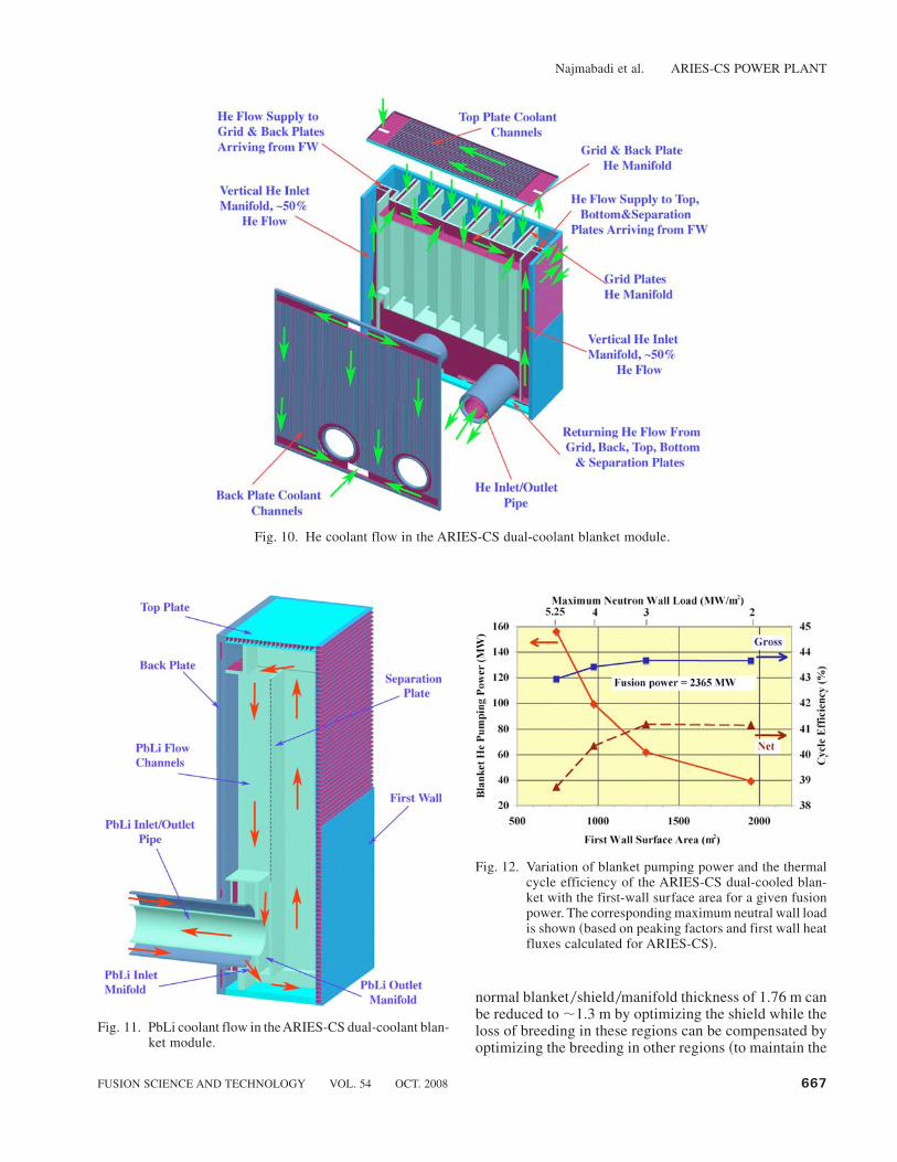
The blanket is coupled to a Brayton cycle through aheat exchanger where both coolants ~He and Pb-17Li!transfer their energy to the cycle working fluid ~He!.Detailed thermal-hydraulic analyses were performed tooptimize the power production within the given materialconstraints ~including a maximum Pb-17Li0FS interfacetemperature ,5008C and an RAFS maximum tempera-ture,5508C!. These are described in Ref. 10, along withall the supporting design and analysis results for the blan-ket. As an illustration of the parametric analysis results,Fig. 12 shows the variation of the cycle efficiency withthe first-wall surface area for a given fusion power. Alsoshown are the blanket He pumping power and the corre-sponding net efficiency ~based on the gross electricalpower minus the coolant pumping power!. The corre-sponding maximum neutron wall load is indicated onthe upper x-axis. Stress analyses, described in detail inRef. 10, indicate that the design has been pushed to itslimit and that it would be beneficial to relax the heat loadto provide more margin ~for example, by increasing themachine size!. Some of the major blanket parameters forthe reference design case are listed in Table III.
A key engineering parameter affecting the size of acompact stellarator is the minimum coil-plasma distance.A novel approach has been developed where a highly ef-ficient WC shield is used in the critical area to minimizethis distance, as discussed in Sec. II.A.3. In this way, the
Fig. 9. Details of ARIES-CS dual-coolant blanket modulelayout.
Najmabadi et al. ARIES-CS POWER PLANT
666 FUSION SCIENCE AND TECHNOLOGY VOL. 54 OCT. 2008
normal blanket0shield0manifold thickness of 1.76 m canbe reduced to;1.3 m by optimizing the shield while theloss of breeding in these regions can be compensated byoptimizing the breeding in other regions ~to maintain the
Fig. 10. He coolant flow in the ARIES-CS dual-coolant blanket module.
Fig. 11. PbLi coolant flow in the ARIES-CS dual-coolant blan-ket module.
Fig. 12. Variation of blanket pumping power and the thermalcycle efficiency of the ARIES-CS dual-cooled blan-ket with the first-wall surface area for a given fusionpower. The corresponding maximum neutral wall loadis shown ~based on peaking factors and first wall heatfluxes calculated for ARIES-CS!.
Najmabadi et al. ARIES-CS POWER PLANT
FUSION SCIENCE AND TECHNOLOGY VOL. 54 OCT. 2008 667

3-D tritium breeding ratio at ;1.1!. More details on theneutronics analysis in support of the power plant designcan be found in Ref. 11.
IV.B. Plasma-Facing Components
A concerted effort on the divertor has been launchedas part of the ARIES-CS study. On the physics side, itinvolves adapting and using codes to better assess thelocation of the divertor and to estimate the correspondingheat loads.12 On the engineering side, the effort focusedon evolving a design well suited to the compact stellaratorwith the capability to accommodate a heat flux of10 MW0m2 ~as a reasonable initial goal in anticipation ofthe physics modeling results! and that can be integrated
with the in-reactor component design.10,16 In addition, thealpha-particle loss fraction is fairly high,;5%, and con-cerns exist as to the accommodation of the resulting heatload and particle flux on local regions of the first wall.
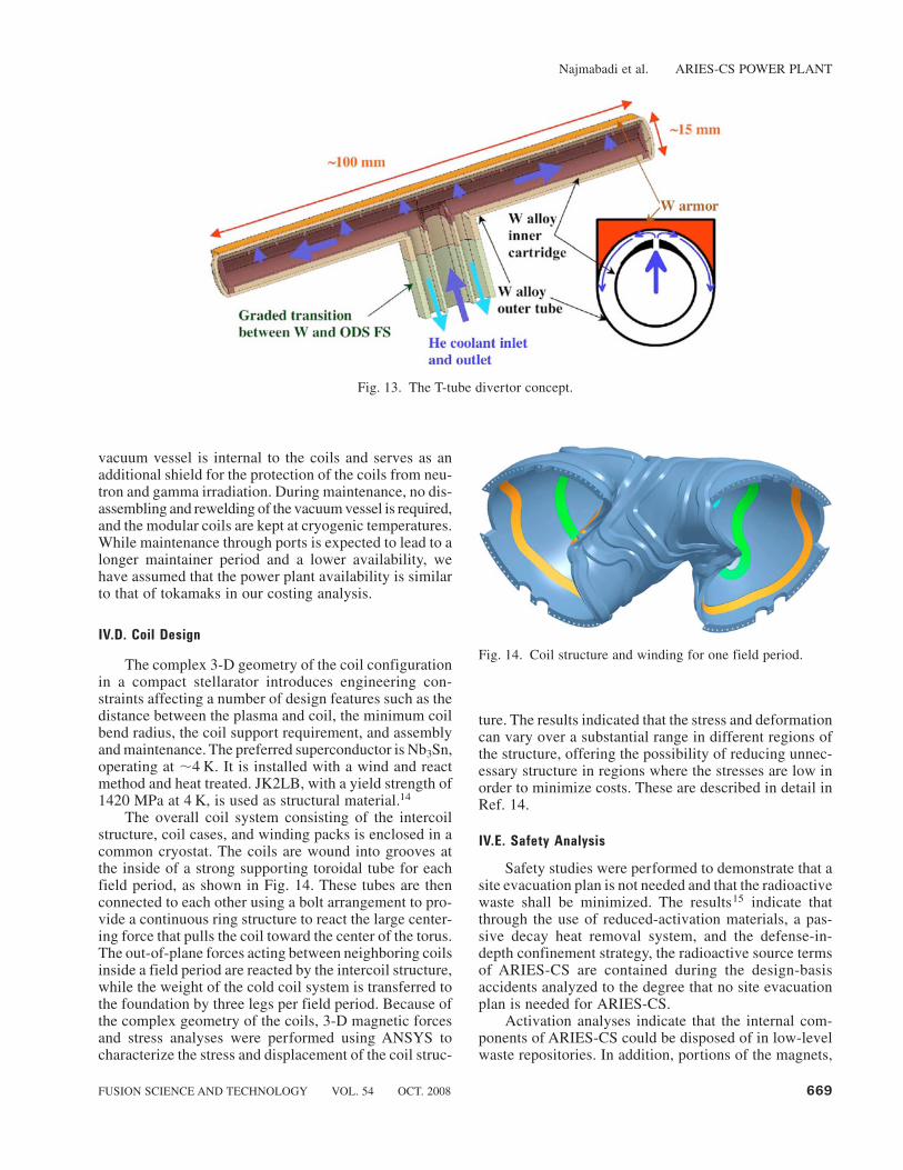
The divertor configuration consists of a He-cooled“T-tube” illustrated in Fig. 13. The T-tube is ;15 mm indiameter and;100 mm long and is made up of a W-alloyinner cartridge and outer tube. A W armor layer is at-tached to the top of the outer tube. The design providessome flexibility in accommodating the divertor area sincea variable number of such T-tubes can be connected to acommon manifold to form the desired divertor target.
As illustrated in Fig. 13, the helium coolant ~10 MPa!is routed through the inner cartridge first and then pushesthrough thin slots ~;0.4 mm! to cool the heat-loadedouter tube surface. A two-dimensional–shaped imping-ing slot jet is created, leading to high heat transfer atreasonable pressure drop. After impingement, the cool-ant flows as a highly turbulent wall jet along the largeinside surface of the tube and then returns in the lowersection of the annular gap between the tube and car-tridge. The inlet and outlet He temperatures are ;573and;7008C, which fit within the overall heat exchangerand Brayton cycle scheme. A stress analysis was alsoperformed indicating that the total stress intensity ~pri-mary and secondary stresses! is,370 MPa for the entiregeometry, which is assumed to be less than the 3Sm limitof an anticipated W alloy at the corresponding tempera-tures and is considered to be acceptable.10 Some of themajor divertor parameters for the reference design arealso listed in Table III. The thermal-hydraulic perfor-mance of the concept has been verified through laboratory-scale experiments.16 Other R&D issues include thedevelopment of the W-alloy and fabrication techniques.
The peak heat flux due on the divertor plate due tothe combined conduction and alpha-particle power isestimated at ;18 MW0m2, far exceeding the design limitfor the T-tube divertor design. We believe that furtherwork on shaping the divertor plates may be able toreduce the peak heat flux to an acceptable level. How-ever, a major concern is the possible erosion due to theenergetic He flux, in particular, any exfoliation that couldresult from the accumulation of He atoms in the armor.A possible solution would be to use an engineered Warmor with a low-porosity nanostructure that could en-hance the release of He. Clearly, this is a key issue forcompact stellarators.
IV.C. Maintenance Scheme and Machine Layout
A port-based maintenance scheme has been selecteddue in great part to the 3-D geometry constraints associatedwith a compact stellarator. The scheme involves the re-placement of blanket modules and divertor plates usingan articulated boom through designated ports ~one majorport and one auxiliary port per field period for the three-field-period configuration!.13 As illustrated in Fig. 1, the
TABLE III
Major ARIES-CS Power Core Parameters
BlanketNumber of modules 198Tritium breeding ratio 1.1Fusion thermal power in blanket~MW!
2 496
Pb-17Li inlet0outlet temperatures~8C!
4510738
Pb-17Li inlet pressure ~MPa! 1Fusion thermal power removed by
Pb-17Li ~MW!a1 444
Pb-17Li total mass flow rate ~kg0s! 26 860Pb-17Li pressure drop ~kPa! ; 0.1 to 1Pb-17Li pumping power ~kW! ; 1 to 10He inlet0outlet temperatures ~8C! 3860456He inlet pressure ~MPa! 10Total blanket � heat exchanger He
pressure drop ~MPa!0.30
Thermal power removed by He ~MW! 1 192Total mass flow rate of blanket He~kg0s!b
3 261
Blanket He pumping power ~MW! 156Brayton cycle gross efficiency 0.43
DivertorDivertor T-tube unit dimensions 9 cm ~toroidal!
� 1.6 cm ~poloidal!Divertor surface coverage ~%! 10.6He inlet0outlet temperatures ~8C! 5730700He inlet pressure ~MPa! 10He pressure drop ~MPa! 0.45Conducted power to divertor ~MW! 23.6Alpha-particle loss power to divertor~MW!
23.6
Radiated power to divertor ~MW! 48Thermal power removed by He~MW!c
186
Total mass flow rate ~kg0s! 283Pumping power ~MW! ;27
aIncluding ;111-MW reduction due to conducted power to He.bIncluding 141 MW of friction power �111 MW of conducted powerfrom Pb-17Li.
cIncluding 23.6 MW of alpha-particle loss power and 24 MW of fric-tion power.
Najmabadi et al. ARIES-CS POWER PLANT
668 FUSION SCIENCE AND TECHNOLOGY VOL. 54 OCT. 2008
vacuum vessel is internal to the coils and serves as anadditional shield for the protection of the coils from neu-tron and gamma irradiation. During maintenance, no dis-assembling and rewelding of the vacuum vessel is required,and the modular coils are kept at cryogenic temperatures.While maintenance through ports is expected to lead to alonger maintainer period and a lower availability, wehave assumed that the power plant availability is similarto that of tokamaks in our costing analysis.
IV.D. Coil Design
The complex 3-D geometry of the coil configurationin a compact stellarator introduces engineering con-straints affecting a number of design features such as thedistance between the plasma and coil, the minimum coilbend radius, the coil support requirement, and assemblyand maintenance. The preferred superconductor is Nb3Sn,operating at ;4 K. It is installed with a wind and reactmethod and heat treated. JK2LB, with a yield strength of1420 MPa at 4 K, is used as structural material.14
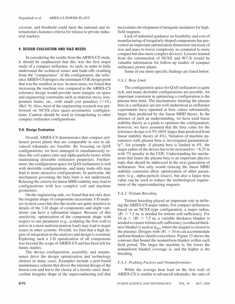
The overall coil system consisting of the intercoilstructure, coil cases, and winding packs is enclosed in acommon cryostat. The coils are wound into grooves atthe inside of a strong supporting toroidal tube for eachfield period, as shown in Fig. 14. These tubes are thenconnected to each other using a bolt arrangement to pro-vide a continuous ring structure to react the large center-ing force that pulls the coil toward the center of the torus.The out-of-plane forces acting between neighboring coilsinside a field period are reacted by the intercoil structure,while the weight of the cold coil system is transferred tothe foundation by three legs per field period. Because ofthe complex geometry of the coils, 3-D magnetic forcesand stress analyses were performed using ANSYS tocharacterize the stress and displacement of the coil struc-
ture. The results indicated that the stress and deformationcan vary over a substantial range in different regions ofthe structure, offering the possibility of reducing unnec-essary structure in regions where the stresses are low inorder to minimize costs. These are described in detail inRef. 14.
IV.E. Safety Analysis
Safety studies were performed to demonstrate that asite evacuation plan is not needed and that the radioactivewaste shall be minimized. The results15 indicate thatthrough the use of reduced-activation materials, a pas-sive decay heat removal system, and the defense-in-depth confinement strategy, the radioactive source termsof ARIES-CS are contained during the design-basisaccidents analyzed to the degree that no site evacuationplan is needed for ARIES-CS.
Activation analyses indicate that the internal com-ponents of ARIES-CS could be disposed of in low-levelwaste repositories. In addition, portions of the magnets,
Fig. 13. The T-tube divertor concept.
Fig. 14. Coil structure and winding for one field period.
Najmabadi et al. ARIES-CS POWER PLANT
FUSION SCIENCE AND TECHNOLOGY VOL. 54 OCT. 2008 669
cryostat, and bioshield could meet the national and in-ternational clearance criteria for release to private indus-trial markets.
V. DESIGN EVALUATION AND R&D NEEDS
In considering the results from the ARIES-CS study,it should be emphasized that this was the first majorstudy of a compact stellarator. As such, in order to fullyunderstand the technical issues and trade-offs resultingfrom the “compactness” of the configuration, the refer-enceARIES-CS design is the minimum-COE design pointthat was the smallest in size. In most areas, we found thatincreasing the machine size compared to the ARIES-CSreference design would provide more margins on spaceand engineering constraints such as material stress, tem-perature limits, etc., with small cost penalties ~,1%!~Ref. 9!. Also, most of the engineering research was per-formed on NCSX-class quasi-asymmetric configura-tions. Caution should be used in extrapolating to othercompact stellarator configurations.
V.A. Design Evaluation
Overall, ARIES-CS demonstrates that compact stel-larator power plants that are comparable in size to ad-vanced tokamaks are feasible. By focusing on QASconfigurations, we have managed to simultaneously re-duce the coil aspect ratio and alpha-particle losses whilemaintaining desirable stellarator properties. Further-more, the configuration space for QAS stellarators is richwith desirable configurations, and many trade-offs maylead to more attractive configurations. In particular, themechanism governing the beta limit is not understood.Relaxing the criteria for linear MHD stability may lead toconfigurations with less complex coil and machinegeometries.
On the engineering side, we found that not only doesthe irregular shape of components necessitate 3-D analy-ses in most cases but also the results are quite sensitive todetails of the 3-D shape of components and slight vari-ations can have a substantial impact. Because of thissensitivity, optimization of the component shape withrespect to one parameter ~e.g., sculpting the first wall toarrive at a more uniform neutron load!may lead to majorissues in other systems. Overall, we find that a high de-gree of integration in the analyses and design is essential.Exploring such a 3-D optimization of all componentswas beyond the scope of ARIES-CS and has been left forfuture studies.
The device configuration, assembly, and mainte-nance drive the design optimization and technologychoices in many cases. Examples include a port-basedmaintenance scheme that drives the internal design of thefusion core and led to the choice of a ferritic-steel, dual-coolant irregular shape of the superconducting coil that
necessitates development of inorganic insulators for high-field magnets.
Lack of industrial guidance on feasibility and cost ofmanufacturing of irregularly shaped components has pre-vented an important optimization dimension ~increase ofsize and mass to lower complexity as compared to morecompact but also more complex devices!. Lessons learnedfrom the construction of NCSX and W7-X would bevaluable information for follow-up studies of compactstellarator power plants.
Some of our more specific findings are listed below.
V.A.1. Beta Limit
The configuration space for QAS stellarators is quiterich, and many desirable configurations are possible. Animportant constraint in optimizing a configuration is theplasma beta limit. The mechanisms limiting the plasmabeta in a stellarator are not well understood as stellaratorexperiments have operated at beta values substantiallylarger than predicted by the linear MHD theory. In theabsence of such an understanding, we have used linearstability theory as a guide to optimize the configuration;however, we have assumed that the beta value for thereference design is 6.5% ~60% larger than predicted fromlinear stability theory of 4%!. Variation of machine pa-rameters with plasma beta is investigated parametrical-ly9; for example, if plasma beta is limited to 4%, themajor radius of the device has to be increased to;8.25 mwith 7% penalty in the COE. Understanding the mecha-nism that limits the plasma beta is an important physicstopic that should be addressed in the next generation ofstellarators. Not only would relaxing the linear MHDstability constraint allow optimization of other param-eters ~e.g., alpha-particle losses!, but also a larger betavalue can be used to reduce the technological require-ment of the superconducting magnets.
V.A.2. Tritium Breeding
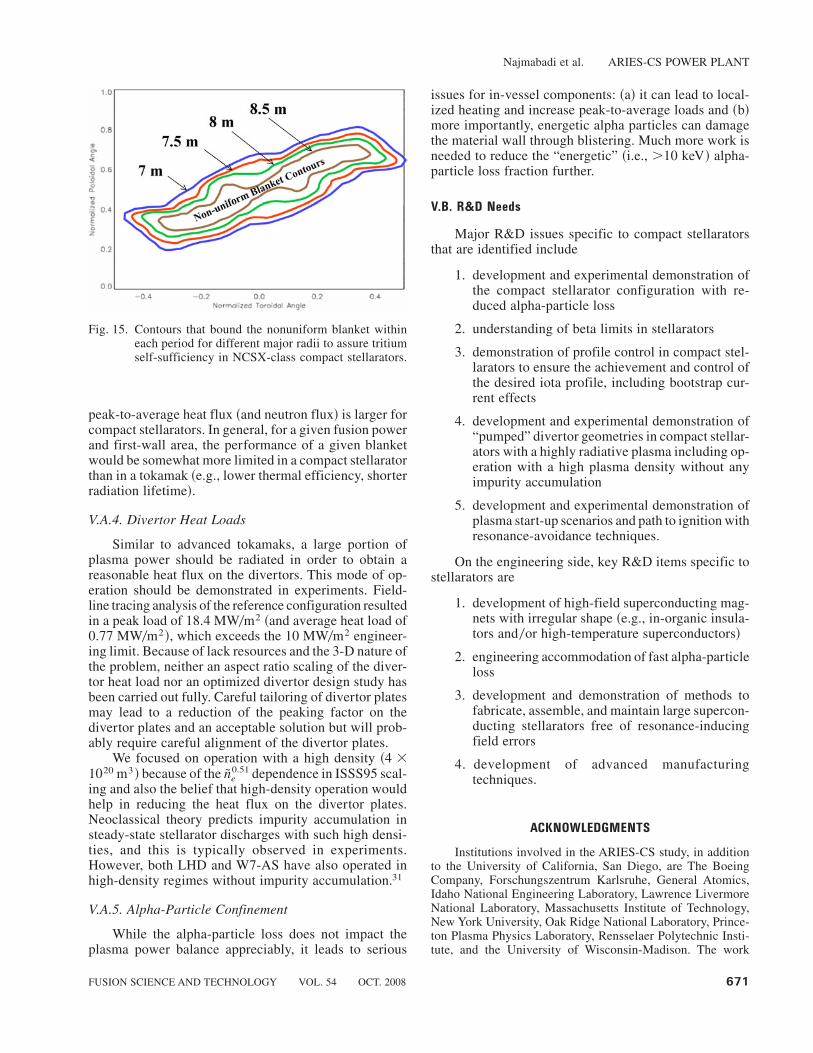
Tritium breeding played an important role in defin-ing the ARIES-CS major radius. For compact stellaratorsbased on an NCSX-type configuration, a major radius,^R& . 7.5 m, is needed for tritium self-sufficiency. For10 m . ^R& . 7.5 m, a variable thickness blanket isneeded to ensure tritium self-sufficiency ~a reduced thick-ness blanket is used at Dmin where the magnet is closest tothe plasma!. Designs with ^R& . 10 m can accommodateuniform blanket0shield everywhere. Figure 15 shows thecontours that bound the nonuniform blanket within eachfield period. The larger the machine is, the lower thenonuniform blanket coverage is, and the higher is thebreeding.
V.A.3. Peaking Factors and Nonuniformities
While the average heat load on the first wall ofARIES-CS is similar to advanced tokamaks, the ratio of
Najmabadi et al. ARIES-CS POWER PLANT
670 FUSION SCIENCE AND TECHNOLOGY VOL. 54 OCT. 2008
peak-to-average heat flux ~and neutron flux! is larger forcompact stellarators. In general, for a given fusion powerand first-wall area, the performance of a given blanketwould be somewhat more limited in a compact stellaratorthan in a tokamak ~e.g., lower thermal efficiency, shorterradiation lifetime!.
V.A.4. Divertor Heat Loads
Similar to advanced tokamaks, a large portion ofplasma power should be radiated in order to obtain areasonable heat flux on the divertors. This mode of op-eration should be demonstrated in experiments. Field-line tracing analysis of the reference configuration resultedin a peak load of 18.4 MW0m2 ~and average heat load of0.77 MW0m2!, which exceeds the 10 MW0m2 engineer-ing limit. Because of lack resources and the 3-D nature ofthe problem, neither an aspect ratio scaling of the diver-tor heat load nor an optimized divertor design study hasbeen carried out fully. Careful tailoring of divertor platesmay lead to a reduction of the peaking factor on thedivertor plates and an acceptable solution but will prob-ably require careful alignment of the divertor plates.
We focused on operation with a high density ~4 �1020 m3! because of the Ine
0.51 dependence in ISSS95 scal-ing and also the belief that high-density operation wouldhelp in reducing the heat flux on the divertor plates.Neoclassical theory predicts impurity accumulation insteady-state stellarator discharges with such high densi-ties, and this is typically observed in experiments.However, both LHD and W7-AS have also operated inhigh-density regimes without impurity accumulation.31
V.A.5. Alpha-Particle Confinement
While the alpha-particle loss does not impact theplasma power balance appreciably, it leads to serious
issues for in-vessel components: ~a! it can lead to local-ized heating and increase peak-to-average loads and ~b!more importantly, energetic alpha particles can damagethe material wall through blistering. Much more work isneeded to reduce the “energetic” ~i.e., .10 keV! alpha-particle loss fraction further.
V.B. R&D Needs
Major R&D issues specific to compact stellaratorsthat are identified include
1. development and experimental demonstration ofthe compact stellarator configuration with re-duced alpha-particle loss
2. understanding of beta limits in stellarators
3. demonstration of profile control in compact stel-larators to ensure the achievement and control ofthe desired iota profile, including bootstrap cur-rent effects
4. development and experimental demonstration of“pumped” divertor geometries in compact stellar-ators with a highly radiative plasma including op-eration with a high plasma density without anyimpurity accumulation
5. development and experimental demonstration ofplasma start-up scenarios and path to ignition withresonance-avoidance techniques.
On the engineering side, key R&D items specific tostellarators are
1. development of high-field superconducting mag-nets with irregular shape ~e.g., in-organic insula-tors and0or high-temperature superconductors!
2. engineering accommodation of fast alpha-particleloss
3. development and demonstration of methods tofabricate, assemble, and maintain large supercon-ducting stellarators free of resonance-inducingfield errors
4. development of advanced manufacturingtechniques.
ACKNOWLEDGMENTS
Institutions involved in the ARIES-CS study, in additionto the University of California, San Diego, are The BoeingCompany, Forschungszentrum Karlsruhe, General Atomics,Idaho National Engineering Laboratory, Lawrence LivermoreNational Laboratory, Massachusetts Institute of Technology,New York University, Oak Ridge National Laboratory, Prince-ton Plasma Physics Laboratory, Rensselaer Polytechnic Insti-tute, and the University of Wisconsin-Madison. The work
Fig. 15. Contours that bound the nonuniform blanket withineach period for different major radii to assure tritiumself-sufficiency in NCSX-class compact stellarators.
Najmabadi et al. ARIES-CS POWER PLANT
FUSION SCIENCE AND TECHNOLOGY VOL. 54 OCT. 2008 671
at the University of California, San Diego was supported bythe U.S. Department of Energy, Office of Fusion Energy,DE-FC03-95ER54299.
REFERENCES
1. C. D. BEIDLER et al., “The Helias Reactor HSR4018,” Nucl.Fusion, 41, 1759 ~2001!.
2. A. SAGARA et al., “Design and Development of the Flibe Blan-ket for Helical-Type Fusion Reactor FFHR,” Fusion Eng. Des., 49,661 ~2000!.
3. K. YAMAZAKI et al., “Helical Reactor Design Studies Based onNew Confinement Scalings,” Proc. 18th Fusion Energy Conf., Sor-rento, Italy, 2000, IAEA-CN-770FTP02-12, International Atomic En-ergy Agency.
4. A. SAGARA et al., “Conceptual Design Activities and Key Issueson LHD-Type Reactor FFHR,” Fusion Eng. Des., 81, 2703 ~2006!.
5. R. MILLER et al., “The Stellarator Power Plant Study,” UCSD-ENG-004, University of California, San Diego ~1996!.
6. F. NAJMABADI and ARIES TEAM, “Overview of the ARIES-RSReversed-Shear Tokamak Power Plant Study,” Fusion Eng. Des., 38,3 ~1997!.
7. F. NAJMABADI and ARIES TEAM, “The ARIES-AT AdvancedTokamak Advanced Technology Fusion Power Plant,” Fusion Eng.Des., 80, 3 ~2005!.
8. L. P. KU et al., “Physics Design for ARIES-CS,” Fusion Sci.Technol., 54, 673 ~2008!.
9. J. F. LYON, L. P. KU, L. EL-GUEBALY, L. BROMBERG, L. M.WAGANER, M. C. ZARNSTORFF, and ARIES-CS TEAM, “SystemsStudies and Optimization of the ARIES-CS Power Plant,” Fusion Sci.Technol., 54, 694 ~2008!.
10. A. R. RAFFRAY et al., “Engineering Design and Analysis of theARIES-CS Power Plant,” Fusion Sci. Technol., 54, 725 ~2008!.
11. L. EL-GUEBALY et al., “Designing ARIES-CS Compact RadialBuild and Nuclear System: Neutronics, Shielding, and Activation,”Fusion Sci. Technol., 54, 747 ~2008!.
12. T. K. MAU et al., “Divertor Configuration and Heat Load Studiesfor the ARIES-CS Fusion Power Plant,” Fusion Sci. Technol., 54, 771~2008!.
13. L. M. WAGANER, R. J. PEIPERT, Jr., X. R. WANG, S. MA-LANG, and ARIES TEAM, “ARIES-CS Maintenance System Defini-tion and Analysis,” Fusion Sci. Technol., 54, 787 ~2008!.
14. X. R. WANG et al., “ARIES-CS Magnet Conductor and StructureEvaluation,” Fusion Sci. Technol., 54, 818 ~2008!.
15. B. J. MERRILL, L.A. EL-GUEBALY, C. MARTIN, R. L. MOORE,A. R. RAFFRAY, D. A. PETTI, and ARIES-CS TEAM, “Safety As-sessment of the ARIES Compact Stellarator Design,” Fusion Sci. Tech-nol., 54, 838 ~2008!.
16. S. I. ABDEL-KHALIK, L. CROSATTI, D. L. SADOWSKI,S. SHIN, J. B. WEATHERS, M. YODA, and ARIES TEAM, “Thermal-Hydraulic Studies in Support of the ARIES-CS T-Tube Divertor De-sign,” Fusion Sci. Technol., 54, 864 ~2008!.
17. L. M. WAGANER, K. T. SLATTERY, J. C. WALDROP III, andARIES TEAM, “ARIES-CS Coil Structure Advanced Fabrication Ap-proach,” Fusion Sci. Technol., 54, 878 ~2008!.
18. J. NUHRENBERG and R. ZILLE, Phys. Lett, 129A, 2, 113 ~1988!.
19. P. G. MATHEWS et al., Proc. 10th Int. Conf. Stellartors, Madrid,Spain, 1995.
20. J. NUHRENBERG, W. LOTZ, and S. GORI, Theory of FusionPlasma, Editrice Compositori, Varenna ~1994!.
21. G. H. NEILSON et al., Proc. 19th Fusion Energy Conf., Lyon,France, October 14–19, 2002, International Atomic Energy Agency~2002!.
22. C. BEIDLER et al., Fusion Technol., 17, 148 ~1990!.
23. A. S. WARE et al., Phys. Rev. Lett., 89, 125003 ~2002!.
24. A. WELLER, Max-Planck Institute, Personal Communications~2002!; see also A. WELLER et al., “Investigation of the b-Limit inthe W7-AS Stellarator”; see also Proc. Fusion Energy Conf., Lyon,France, October 14–19, 2002, International Atomic Energy Agency~2002!.
25. M. ZARNSTORFF et al., Proc. 20th Fusion Energy Conf., EX03-4, Vilamoura, Portugal, November 1– 6, 2004, International AtomicEnergy Agency ~2004!.
26. A. R. RAFFRAY, L. EL-GUEBALY, S. MALANG, X. WANG,and ARIES TEAM, “Attractive Design Approaches for a CompactStellarator Power Plant,” Fusion Sci. Technol., 47, 422 ~2005!.
27. A. BOOZER, Phys. Fluids, 24, 11, 1999 ~1981!.
28. G. Y. FU et al., Proc. 18th Fusion Energy Conf., Sorrento, Italy,October 4–10, 2000, International Atomic Energy Agency ~2000!.
29. P. R. GARABEDIAN and L. P. KU, Phys. Plasmas, 6, 645 ~1999!.
30. U. STROTH et al., Nucl. Fusion, 39, 11 ~1996!.
31. S. SUDO et al., Nucl. Fusion, 30, 11 ~1990!.
32. J. MIYAZAWA et al., Nucl. Fusion, 46, 532 ~2006!.
Najmabadi et al. ARIES-CS POWER PLANT
672 FUSION SCIENCE AND TECHNOLOGY VOL. 54 OCT. 2008