Embed Size (px)
Citation preview

3P4W POWER ANALYZER
TES - 3600
INSTRUCTION MANUAL
3 4
1 2
I4
U3 m-sU12 Y-M U23 D-h
£c
NO.
Q
P
S
TES ELECTRICAL ELECTRONIC CORP.
www. .com [email protected]

CONTENTS Title Page
I. SAFETY INFORMATION ........................................................................................... 1
II. INTRODUCTION FEATURE ..................................................................................... 4
III. SPECIFICATIONS ........................................................................................................ 4
3-1 Environment Conditions ....................................................................................... 4
3-2 Safety Specifications ............................................................................................. 5
3-3 General Specification ............................................................................................ 5
3-4 Electrical Specification ......................................................................................... 7
IV. PARTS & CONTROLS ............................................................................................... 10
4-1 Description of Parts & Control keys ................................................................... 10
4-2 Description of Display ........................................................................................ 12
V. OPERATING INSTRUCTION ................................................................................. 15
5-1 AC Current Adaptor ............................................................................................ 15
5-2 Single-Phase 2-Wire (1P2W) Power System Measurement ............................... 17
5-3 Single-Phase 3-Wire (1P3W) Power System Measurement ............................... 20
5-4 Three-Phase 3-Wire (3P3W) Power System Measurement ................................ 23
5-5 Three-Phase 4-Wire (3P4W) Power System Measurement ................................ 26
5-6 Only One Current I4 Measurement ..................................................................... 29
5-7 Manual Data Memory and Read Function Operation ......................................... 29
5-8 Auto Datalogging Function Operation ................................................................ 30
5-9 Phase Sequence Measurement ............................................................................ 31
5-10 Voltage, Current Waveform and Harmonic Analyzer ........................................ 31
5-11 Disable Auto Power Off Function ..................................................................... 31
VI. MAINTENANCE ......................................................................................................... 32
6-1 General Maintenance .......................................................................................... 32
6-2 Battery Replacement ........................................................................................... 32
VII. RS-232 INTERFACE, SOFTWARE INSTALLATION AND OPERATION.... 33
www. .com [email protected]

I. SAFETY INFORMATION
This Instruction Manual provides information and warnings essential for operating
this meter in a safe manner and for maintaining it in safe operating condition. Before
using this meter, be sure to carefully read the following safety information.
DANGER
During high voltage measurement, incorrect measurement procedures could
result in injury or death, as well as damage to the meter. Please read this
manual carefully and be sure that you understand its contents before using the
meter.
DANGER
Do not use the meter or test leads if they look damaged.
Use extreme caution when working around bare conductors or bus bars,
Accidental contact with the conductor could result in electric shock.
To avoid damages to the meter, do not exceed the maximum limits of the input
values shown in the specifications.
Use the meter only as specified in this manual, otherwise, the protection
provided by the meter may be impaired.
SAFETY SYMBOLS
Caution refer to this manual before using the meter.
This symbol is affixed to the meter where the operator should consult
corresponding topics before using relevant functions of the meter.
This mark indicates explanation, which is particularly important that the
user should read before using the meter.
Dangerous voltages.
Meter is protected throughout by double insulation or reinforced insulation.
When servicing, use only specified replacement parts.
Comply with IEC61010-1, 2nd edition
www. .com [email protected]

2
DANGER : Indicates that incorrect operation presents extreme danger of
accident resulting in death or serious injury to the user.
WARNING : Indicates that incorrect operation presents significant danger of
accident resulting in death or serious injury to the user.
CAUTION : Indicates that incorrect operation presents possibility of injury to
the user or damage to the meter.
NOTE : Denotes items of advice related to performance of the meter or to its
correct operation.
NOTES ON USE
In order to ensure safe operation and to obtain maximum performance from the
meter, observe the caution listed below.
Installation
CAUTION
The meter is designed for indoor use and can be safely used at temperatures
ranging from 0℃ to 40℃.
Do not store or use the meter where it will be exposed to direct sunlight, high
temperature, high humidity, or condensation, if exposed to such conditions, the
meter may be damaged, the insulation may deteriorate, and the meter may no
longer satisfy its specifications.
The meter does not construct to be waterproof or dustproof, so do not use it in
a very dusty environment or in one where will get wet.
Do not use the unit where it may be exposed to corrosive or explosive gas. The
meter may be damaged, or may occur explosion.
Before use
WARNING
To prevent electric shock, do not allow the meter to become wet and do not use
the unit when your hands are wet.
When working with live circuits, take all suitable precautions against
accidents, including the use of electrical safety gear such as rubber gloves,
rubber boots, and safety helmets.
www. .com [email protected]
3
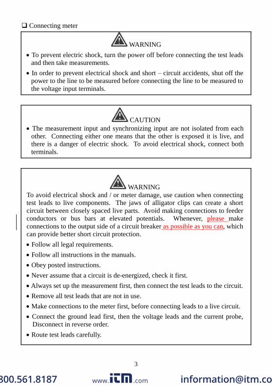
Connecting meter
WARNING
To prevent electric shock, turn the power off before connecting the test leads
and then take measurements.
In order to prevent electrical shock and short – circuit accidents, shut off the
power to the line to be measured before connecting the line to be measured to
the voltage input terminals.
CAUTION
The measurement input and synchronizing input are not isolated from each
other. Connecting either one means that the other is exposed it is live, and
there is a danger of electric shock. To avoid electrical shock, connect both
terminals.
WARNING
To avoid electrical shock and / or meter damage, use caution when connecting
test leads to live components. The jaws of alligator clips can create a short
circuit between closely spaced live parts. Avoid making connections to feeder
conductors or bus bars at elevated potentials. Whenever, please make
connections to the output side of a circuit breaker as possible as you can, which
can provide better short circuit protection.
Follow all legal requirements.
Follow all instructions in the manuals.
Obey posted instructions.
Never assume that a circuit is de-energized, check it first.
Always set up the measurement first, then connect the test leads to the circuit.
Remove all test leads that are not in use.
Make connections to the meter first, before connecting leads to a live circuit.
Connect the ground lead first, then the voltage leads and the current probe, Disconnect in reverse order.
Route test leads carefully.
www. .com [email protected]

4
II. INTRODUCTION FEATURE
The symptoms of poor power quality include intermittent lock-ups and resets,
corrupted data, premature equipment failure, over-heating of components for no
apparent cause, etc. The ultimate cost is in downtime, decreased productivity and
frustrated personnel.
Use power analyzer to power quality trouble shooting can help you keep your
power system up and running, troubleshoot problems quickly, improve power
efficient, manage energy costs, zero in on harmonics, optimize power system
performance, improve power quality and analyze system data to design optimal
upgrades.
10 display Easy-to-view LCD screen, and is capable of showing many power
quality parameters at the same time.
4 current probe including for measuring a neutral line current.
Measures single-phase 2-wire, single-phase 3-wire, three-phase 3-wire and
three-phase 4-wire systems.
All True-RMS sensing , V, A, KW, KVAR, KVA, PF, θ, Hz, KWh, KVARh and
KVAh measurements.
Phase sequence indicator function.
Backlight display function.
Manual Data Memory and Read (99 sets).
Data logging (504K byte memory, 12,000 sets per block, total 20,000 sets).
RS-232 optical interface with three phase voltage / current waveform display and
harmonic analysis.
Easy-to-use key operation.
Light weight and portable design.
III. SPECIFICATIONS
3-1 Environment Conditions:
Altitude up to 2000 meters
Indoor use only
Relatively humidity 80% max.
Operation ambient 0~40℃
www. .com [email protected]

5
3-2 Safety Specifications Category Rating : 1000V Measurement Category III, Pollution Degree 2.
: IEC 61010-1 2nd Edition
CAT III : Measurement category in which measurements performed in the
building installation.
Safety Characteristics :
Current Clamps, Model TES AC3600, to be used only with the Three-Phase
Power Analyzer, Model TES-3600.
This manual contains information and warning that must be followed by the user
to ensure safe operation and to keep the meter and its accessories in a safe
condition.
Use of this meter and its accessories in a manner not specified by the
manufacturer may impair the protection provided by the equipment.
Equipment operation, the responsible body shall be made aware that, if the
equipment is used in a manner not specified by the manufacturer, the protection
provided by the probe assembly may be impaired.
3-3 General Specification
Maximum voltage between voltage input terminals and earth ground :
1000 Vrms
Maximum rated working voltage for current input : 0.35 Vrms
Maximum current for current probe : 1000 Arms
Numerical 10 display : 10 display 4 digit LCD maximum reading 9999.
Battery life : approx. 50 hours.
Auto power off : approx. 30 minutes.
Low battery indication : The BT is displayed when the battery voltage drops
below the operating voltage.
Backlight display time : Auto off approx. 30 seconds.
Sampling rate : Approx. 1 time per 2 seconds (Digital display).
Waveform and harmonic analyzer : 64 samples per period.
Current probe jaw opening diameter : Cables ψ40mm.
Operating temperature : 0℃ to 40℃
Operating humidity : Maximum relative humidity of 80% for temperatures up to
31℃ decrease linearly to 50% relative humidity at
40℃ (non-condensed).
Temperature coefficient : 0.1 (specified accuracy)/℃ (<18 or >28℃)
www. .com [email protected]

6
Storage temperature and humidity : -10℃ to 60℃
R.H. < 70% non-condensed.
Dimensions : Meter → 235(L)117(W)54(H)mm.
Current probe → 193(L)88(W)40(H)mm.
Weight : Meter including battery → approx. 730g
Current probe → approx. 333g
Accessories :
1. TES 3600 AC CURRENT ADAPTOR x 4pcs
Category Rating : CAT III 600V per IEC61010-1, Pollution Degree2.
: IEC 61010-1 2nd Edition and IEC61010-2-032
Input : AC 1000A maximum.
Output : 0.35mV/A
2. Voltage test lead x 4pcs
Model no : TL 202I
Manufacturer : Hong Kai Co., Ltd.
Category Rating : CAT III, 1000V, AC 10A Max.
3. Alligator clip x 4pcs
Model no : FC-A23
Manufacturer : Fu Chyi Enterprise CO., Ltd.
Category Rating : CAT III, 1000V, AC 10A Max.
4. AC Adaptor (IN-OUT Isolated type, Input 120V AC 60Hz
Model : MW35-1200300
Input : 120V AC 60Hz 6.1W
Output : 12V DC 300mA
Manufacturer : MAW WOEI Enterprise CO., Ltd.
AC Adaptor (IN-OUT Isolated type, Input 230V AC 50Hz
Model : MWD48-1200300GS
Input : 230V AC 50Hz
Output : 12V DC 300mA
Manufacturer : MAW WOEI Enterprise CO., Ltd.
5. Battery 1.5V “AA” 8
6. Instruction manual 1
7. PC software CD-R 1
8. Carrying case 1
9. Optical RS232 interface 1
www. .com [email protected]
7
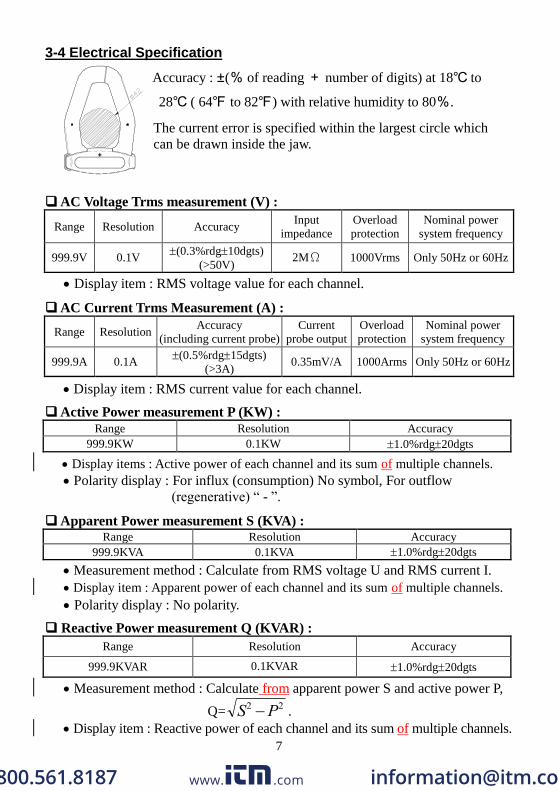
3-4 Electrical Specification
Accuracy : ±(% of reading + number of digits) at 18℃ to
28℃ ( 64℉ to 82℉) with relative humidity to 80%.
The current error is specified within the largest circle which
can be drawn inside the jaw.
AC Voltage Trms measurement (V) :
Range Resolution Accuracy Input
impedance
Overload
protection
Nominal power
system frequency
999.9V 0.1V (0.3%rdg10dgts)
(>50V) 2MΩ 1000Vrms Only 50Hz or 60Hz
Display item : RMS voltage value for each channel.
AC Current Trms Measurement (A) :
Range Resolution Accuracy
(including current probe)
Current
probe output
Overload
protection
Nominal power
system frequency
999.9A 0.1A (0.5%rdg15dgts)
(>3A) 0.35mV/A 1000Arms Only 50Hz or 60Hz
Display item : RMS current value for each channel.
Active Power measurement P (KW) :
Range Resolution Accuracy
999.9KW 0.1KW 1.0%rdg20dgts
Display items : Active power of each channel and its sum of multiple channels.
Polarity display : For influx (consumption) No symbol, For outflow
(regenerative) “ - ”.
Apparent Power measurement S (KVA) : Range Resolution Accuracy
999.9KVA 0.1KVA 1.0%rdg20dgts
Measurement method : Calculate from RMS voltage U and RMS current I.
Display item : Apparent power of each channel and its sum of multiple channels.
Polarity display : No polarity.
Reactive Power measurement Q (KVAR) :
Range Resolution Accuracy
999.9KVAR 0.1KVAR 1.0%rdg20dgts
Measurement method : Calculate from apparent power S and active power P,
Q= S P2 2 .
Display item : Reactive power of each channel and its sum of multiple channels.
www. .com [email protected]
8
Polarity display : For phase lag (LAG : current is slower than voltage) :
No symbol.
For lead phase (LEAD : current is faster than voltage) : “-”
Power Factor measurement (COSψ) :
Range Resolution Calculated Accuracy
0 ~ +1 0.001 3dgt
Measurement method : Calculate from apparent power S and active power P,
PF = COSψ= P S/
Display item : Power factor of each channel and its sum of multiple channels.
Phase angle measurement (ψ) :
Range Resolution Calculated Accuracy
+90°~ 0°~ -90° 0.1° 3dgt
Measurement method : Calculate from power factor COSψ,ψ= COS-1
PF.
Display item : Phase angle of each channel and its sum of multiple channels.
Polarity display : For phase lag (LAG : current is slower than voltage) :
No symbol.
For phase lead (LEAD : current is faster than voltage) : “-”.
Frequency measurement (Hz) :
Range Resolution Accuracy Measurement source
60HZ 0.1Hz 0.1%rdg2dgt Voltage U1 > 50V
Measurable input range : > 50V
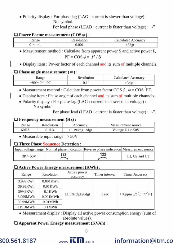
Three Phase Sequence Detection :
Input voltage range Normal phase indication Reverse phase indication Measurement source
3P > 50V
U1, U2 and U3
Active Power Energy measurement (KWh) :
Range Resolution Active power
accuracy Timer interval Timer Accuracy
3.999KWh 0.001KWh
1.0%rdg20dgt 1 sec ±50ppm (25℃, 77℉)
39.99KWh 0.01KWh
399.9KWh 0.1KWh
3.999MWh 0.001MWh
39.99MWh 0.01MWh
119.3MWh 0.1MWh
Measurement display : Display all active power consumption energy (sum of
absolute values).
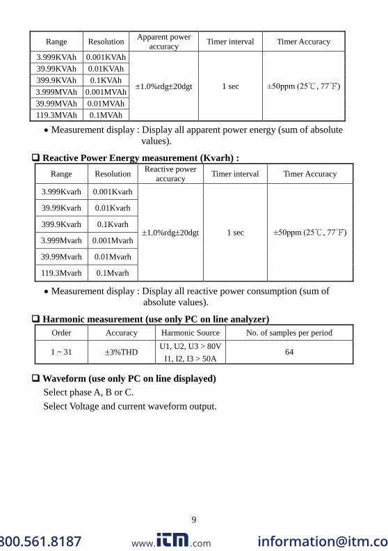
Apparent Power Energy measurement (KVAh) :
www. .com [email protected]
9
Range Resolution Apparent power
accuracy Timer interval Timer Accuracy
3.999KVAh 0.001KVAh
1.0%rdg20dgt 1 sec ±50ppm (25℃, 77℉)
39.99KVAh 0.01KVAh
399.9KVAh 0.1KVAh
3.999MVAh 0.001MVAh
39.99MVAh 0.01MVAh
119.3MVAh 0.1MVAh
Measurement display : Display all apparent power energy (sum of absolute
values).
Reactive Power Energy measurement (Kvarh) :
Range Resolution Reactive power
accuracy Timer interval Timer Accuracy
3.999Kvarh 0.001Kvarh
1.0%rdg20dgt 1 sec ±50ppm (25℃, 77℉)
39.99Kvarh 0.01Kvarh
399.9Kvarh 0.1Kvarh
3.999Mvarh 0.001Mvarh
39.99Mvarh 0.01Mvarh
119.3Mvarh 0.1Mvarh
Measurement display : Display all reactive power consumption (sum of
absolute values).
Harmonic measurement (use only PC on line analyzer)
Order Accuracy Harmonic Source No. of samples per period
1 ~ 31 3%THD U1, U2, U3 > 80V
I1, I2, I3 > 50A 64
Waveform (use only PC on line displayed)
Select phase A, B or C.
Select Voltage and current waveform output.
www. .com [email protected]
10
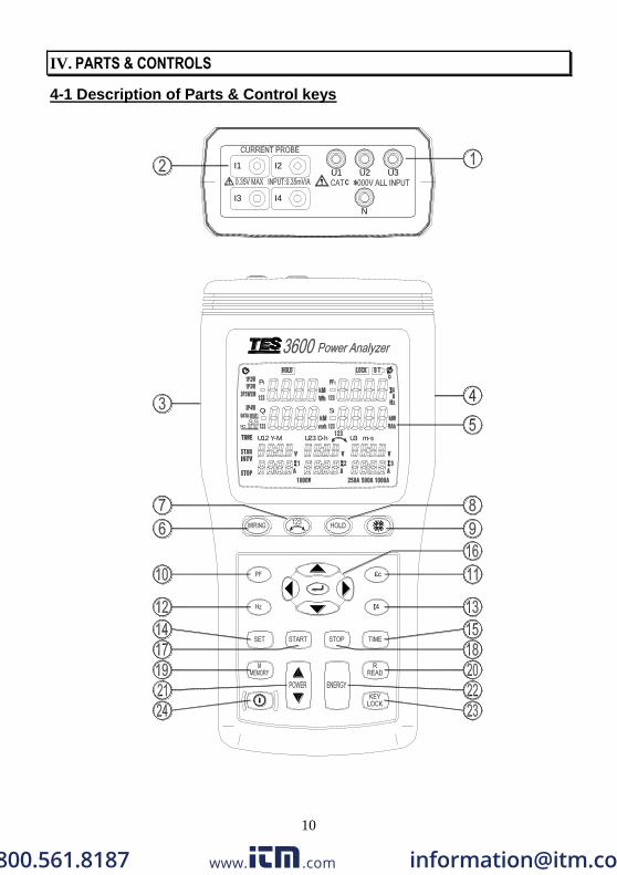
IV. PARTS & CONTROLS
4-1 Description of Parts & Control keys
U12 Y-M
Q
NO.
P
£c
I4
U3 m-s
S
U23 D-h
I3
I1
I4
I2
N
¢ »U1 U2 U3
www. .com [email protected]
11
1. Input for voltage terminals (U1, U2, U3, N).
2. Input for current probe jacks (I1, I2, I3, I4).
3. Plug for external AC adaptor power supply input.
4. Optical RS232 interface output.
5. LCD display.
6. WIRING key : Select the type of electrical system under test, press WIRING
key to select 1P2W (To measure signal-phase two-wire power
lines), 1P3W (To measure signal-phase three-wire power lines),
3P3W2M (To measure three-phase three-wire power line
without neutral, using the two power meter method, use this
when measuring three-phase power with 2-current probe
measurement only.) and 3P4W (To measure three-phase
four-wire power lines with neutral) electrical system in cycles.
7. key : Phase sequence detection function key. In a 3P4W mode, press and hold
down this key, it will display phase detection results as follows :
Normal phase
Reverse phase
8. HOLD key : Data hold function key, press HOLD key to hold data, the HOLD
annunciator is displayed, press HOLD key again to exit Hold
function.
Press and hold down HOLD key then press key turn on the
meter, the “ ” mark disappear, exit auto power off function.
9. key : Backlight function key, press key to turn on and off of backlight.
The backlight will switch off automatically after 30 seconds.
10. PF key : Display measured power factor value control key, the PF annunciator
is displayed.
11. Θ key : Display measured phase angle value control key, the ψ annunciator is
displayed.
12. Hz key : Display measured frequency value control key, the Hz annunciator is
displayed.
13. I4 key : Display measured I4 current probe value control key, the I4
annunciator is displayed.
14. SET key : Setting current date and time function key, press SET key to enter
current time setting mode and interval time setting mode for auto
datalogging use.
15 TIME key : Display current date and time control key, press and hold down
www. .com [email protected]

12
TIME key display current data and time.
16. Keys : Setting current date and time, or recall manual data
memory to read memory data in cycles control keys.
17. START key : Start auto datalogging function.
18. STOP key : Stop auto datalogging function. Press START key to resume
recording in current data sets.
19. MEMORY key : Manual data memory control key. Press MEMORY key each
time to store one set current display reading into the
memory, the M annunciator and the memory address
number is displayed, total memory size is 99 sets.
20. READ key : Read manual memory data control key.
21. POWER Key : Display measured power value control key, the Pt123,
Qt123 and St123 annunciators will be displayed in cycles.
22. ENERGY key : Display total integrated power energy value control key, the
three h annunciators will be displayed.
23. KEY Lock key : Lock all the functions key, except and keys, the
LOCK annunciator is displayed.
24. key : Power on-off control key.
4-2 Description of Display
U23 D-hU12 Y-M U3 m-s
Q
NO.
P
S
: Auto power off indication.
HOLD : Display hold mode.
LOCK : Set key lock mode.
www. .com [email protected]
13
BT : Low battery indication.
ψ: Phase angle display.
: Phase angle unit.
1P2W : Measure signal-phase two-wire power line indication.
1P3W : Measure signal-phase three-wire power line indication.
3P3W2M : Measure three-phase three-wire power line indication.
3P4W : Measure three-phase four-wire power line indication.
P1 : Phase 1 active power measured display indication.
P2 : Phase 2 active power measured display indication.
P3 : Phase 3 active power measured display indication.
Pt : Total active power measured display indication and total active energy
measured display indication.
KW : Active power unit.
KWh, MWh : Active energy unit.
PF1 : Phase 1 power factor measured display.
PF2 : Phase 2 power factor measured display.
PF3 : Phase 3 power factor measured display.
PFt : Total power factor measured display.
I4 : Current probe 4 current measured display.
Hz : Frequency unit.
DATA No. : Last manual datalogged memory address number indication
(01~99).
M : Manual datalogged indication, M displays one time store one sets data into
the memory.
DATA R No. : Recall manual datalogged address number indication, the
memory data displayed for read.
DATA M : Auto datalogging indication, M disappears one time store one sets
data into the memory .
01 ~ 10 : Maximum 10 memory blocks can be use, only 12,000
sets data can be stored in one block.
Maximum 20,000 sets data can be stored.
FF : Memory full indication, if exceed 10 memory blocks or
exceed 20,000 stored data.
Q1 : Phase 1 reactive power measured display indication.
Q2 : Phase 2 reactive power measured display indication.
www. .com [email protected]
14
Q3 : Phase 3 reactive power measured display indication.
Qt : Total reactive power measured display indication and total reactive energy
measured display indication.
Kvar : Reactive power unit.
Kvarh, Mvarh : Reactive energy unit.
S1 : Phase 1 apparent power measured display indication.
S2 : Phase 2 apparent power measured display indication.
S3 : Phase 3 apparent power measured display indication.
St : Total apparent power measured display indication and total apparent energy
measured display indication.
KVA : Apparent power unit.
KVAh : Apparent energy unit.
MVAh : Apparent energy unit.
TIME : Current data and time indication.
Y-M D-h m-s : Date and time displayed.
INTV : Auto datalogging interval time setting indication.
START : Energy calculating start time indication.
STOP : Energy calculating stop time indication.
U1, V, A : 1P2W phase U1 voltage and current prove I1 measured display
indication.
U1, V, A, U2, V, A : 1P3W phase U1, U2 voltage and current probe I1, I2
measured display indication.
U12, V, I1, A, U23, V, I2, A : 3P3W2M phase U12, U23 voltage and current
probe I1, I2 measured display indication.
U1, V, A, U2, V, A, U3, V, A : 3P4W phase U1, U2, U3 voltage and current
probe I1, I2, I3 measured display indication.
V : Voltage unit.
A : Current unit.
1000V : Voltage range indication.
250A, 500A, 1000A : Current range indication (Autoranging)
www. .com [email protected]

15
V. OPERATING INSTRUCTION
CAUTION
If possible, before connecting the meter to the electrical equipment to be
tested, take off the electrical equipment’s power.
DANGER
Voltage input connectors U1 to U3 are common for input connector N, each
input connectors are not insulated.
Do not connect the unnecessary number of cords.
WARNING
Always set up the measurement first, then connect the test leads to the circuit.
Make connections to the instrument first, before connecting leads to a live
circuit.
Connect the ground lead first, then the voltage leads and the current probe,
Disconnect in reverse order.
Remove all test leads that are not in use.
※ U1 must be connected to voltage source during the measurement of U2, U3,
I1, I2 and I3, because U1 is the main signal source of the whole meter
measuring system. Otherwise you could not have any measurement from
U2, U3, I1, I2 and I3.
5-1 AC Current Adaptor
Safety Information
Read First: Safety Information
To ensure safe operation and service of the current clamp, follow these instructions:
Read the operating instructions before use and follow all safety instructions.
Use the Current Clamp only as specified in the operating instructions,
otherwise the clamp’s safety features may not protect you.
Adhere to local and national safety codes. Individual protective equipment
must be used to prevent shock and arc blast injury where hazardous live
conductors are exposed.
Do not hold the Current Clamp anywhere beyond the tactile barrier, see Figure 1.
www. .com [email protected]

16
Before each use, inspect the Current Clamp. Look for cracks or missing
portions of the clamp housing or output cable insulation. Also look for loose
or weakened components. Pay particular attention to the insulation
surrounding the jaws.
Never use the clamp on a circuit with voltages higher than 600V CAT III.
Use extreme caution when working around bare conductor or bus bars. Contact
with the conductor could result in electric shock.
Use caution when working with voltages above 60V or 30V ac. Such voltages
pose a shock hazard.
Warning
To avoid possible electric shock or personal injury:
Before each use, inspect the Current Clamp. Look for cracks or missing
portions of the clamp housing and output cable insulating cover and for loose
or weakened components. Pay particular attention to the insulation
surrounding the clamp jaws.
Do not use a damaged Current Clamp. If a clamp is damaged, tape it shut to
prevent unintended operation.
Measurement Considerations
Center the conductor inside the Current Clamp jaw.
Make sure the clamp is perpendicular to the conductor.
For optimal reading, make sure the conductor is positioned between the
alignment marks on the jaws of the Current Clamp.
Observe the following guidelines when making measurements :
Avoid taking measurements close to other current carrying conductors.
Operation
To use the AC Current Adaptor, refer to “Measurement Considerations” and
Figure 1.
1. Connect the clamp cable to the instrument.
2. The arrow on the top of the clamp must face towards the load of the circuit.
3. Connect the current clamp jaws around the conductor to be measured.
www. .com [email protected]
17
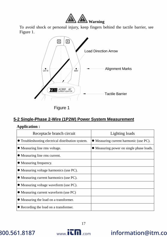
Warning
To avoid shock or personal injury, keep fingers behind the tactile barrier, see
Figure 1.
Load Direction Arrow
Alignment Marks
Tactile Barrier
Figure 1
5-2 Single-Phase 2-Wire (1P2W) Power System Measurement
Application :
Receptacle branch circuit Lighting loads
Troubleshooting electrical distribution system. Measuring current harmonic (use PC).
Measuring line rms voltage. Measuring power on single phase loads.
Measuring line rms current.
Measuring frequency.
Measuring voltage harmonics (use PC).
Measuring current harmonics (use PC).
Measuring voltage waveform (use PC).
Measuring current waveform (use PC)
Measuring the load on a transformer.
Recording the load on a transformer.
www. .com [email protected]
18
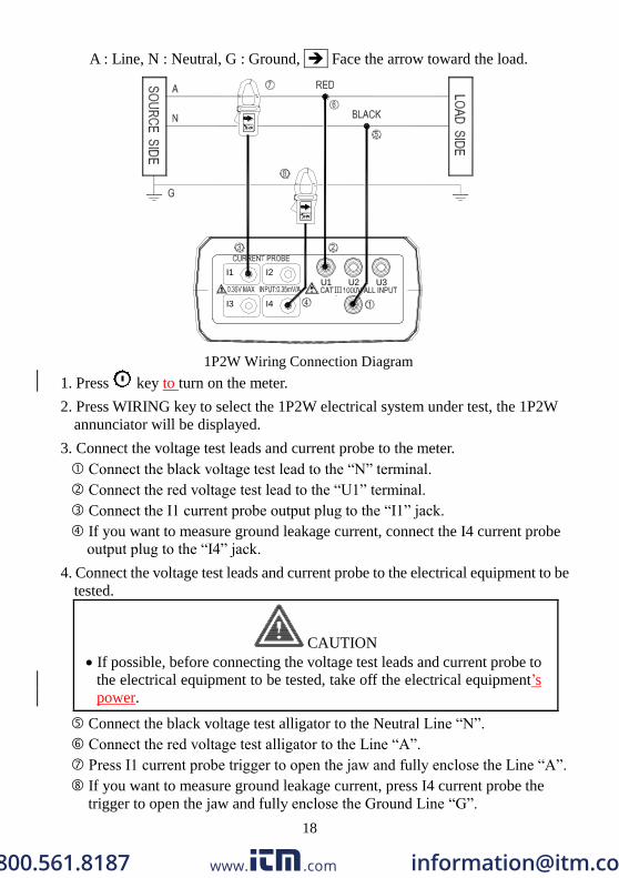
A : Line, N : Neutral, G : Ground, Face the arrow toward the load.
U2
N
I3 I4
I1 I2U1
Ⅲ?
U3
1P2W Wiring Connection Diagram
1. Press key to turn on the meter.
2. Press WIRING key to select the 1P2W electrical system under test, the 1P2W
annunciator will be displayed.
3. Connect the voltage test leads and current probe to the meter.
Connect the black voltage test lead to the “N” terminal.
Connect the red voltage test lead to the “U1” terminal.
Connect the I1 current probe output plug to the “I1” jack.
If you want to measure ground leakage current, connect the I4 current probe
output plug to the “I4” jack.
4. Connect the voltage test leads and current probe to the electrical equipment to be
tested.
CAUTION
If possible, before connecting the voltage test leads and current probe to
the electrical equipment to be tested, take off the electrical equipment’s
power.
Connect the black voltage test alligator to the Neutral Line “N”.
Connect the red voltage test alligator to the Line “A”.
Press I1 current probe trigger to open the jaw and fully enclose the Line “A”.
If you want to measure ground leakage current, press I4 current probe the
trigger to open the jaw and fully enclose the Ground Line “G”.
www. .com [email protected]
19
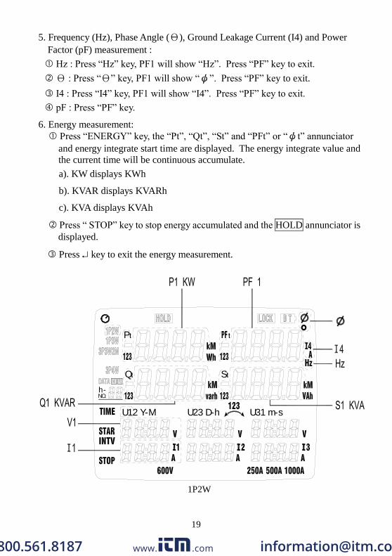
5. Frequency (Hz), Phase Angle (Θ), Ground Leakage Current (I4) and Power
Factor (pF) measurement :
Hz : Press “Hz” key, PF1 will show “Hz”. Press “PF” key to exit.
Θ : Press “Θ” key, PF1 will show “ψ”. Press “PF” key to exit.
I4 : Press “I4” key, PF1 will show “I4”. Press “PF” key to exit.
pF : Press “PF” key.
6. Energy measurement:
Press “ENERGY” key, the “Pt”, “Qt”, “St” and “PFt” or “ψt” annunciator
and energy integrate start time are displayed. The energy integrate value and
the current time will be continuous accumulate.
a). KW displays KWh
b). KVAR displays KVARh
c). KVA displays KVAh
Press “ STOP” key to stop energy accumulated and the HOLD annunciator is
displayed.
Press key to exit the energy measurement.
U31 m-s
S
U23 D-h
Q
U12 Y-M
h-NO.
P
1P2W
www. .com [email protected]
20
※ U1 must be connected to voltage source during the measurement of U2, U3,
I1, I2 and I3, because U1 is the main signal source of the whole meter
measuring system. Otherwise you could not have any measurement from
U2, U3, I1, I2 and I3.
5-3 Single-Phase 3-Wire (1P3W) Power System Measurement
Application : Same as 1P2W power system measurement.
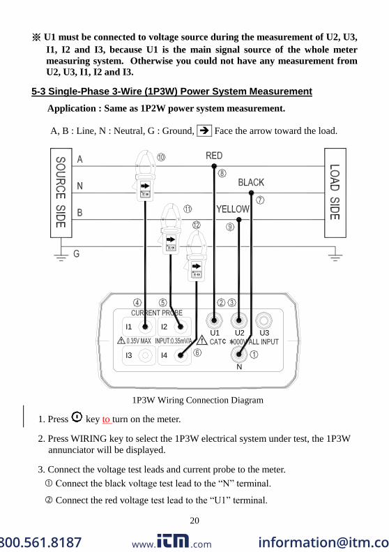
A, B : Line, N : Neutral, G : Ground, Face the arrow toward the load.
I3 I4
I1 I2
N
U2U1¢ »
U3
1P3W Wiring Connection Diagram
1. Press key to turn on the meter.
2. Press WIRING key to select the 1P3W electrical system under test, the 1P3W
annunciator will be displayed.
3. Connect the voltage test leads and current probe to the meter.
Connect the black voltage test lead to the “N” terminal.
Connect the red voltage test lead to the “U1” terminal.
www. .com [email protected]
21
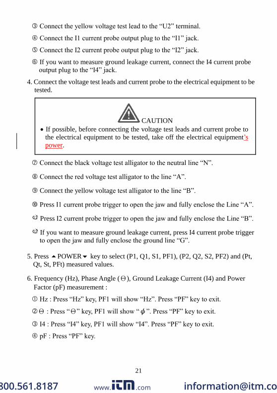
Connect the yellow voltage test lead to the “U2” terminal.
Connect the I1 current probe output plug to the “I1” jack.
Connect the I2 current probe output plug to the “I2” jack.
If you want to measure ground leakage current, connect the I4 current probe
output plug to the “I4” jack.
4. Connect the voltage test leads and current probe to the electrical equipment to be
tested.
CAUTION
If possible, before connecting the voltage test leads and current probe to
the electrical equipment to be tested, take off the electrical equipment’s
power.
Connect the black voltage test alligator to the neutral line “N”.
Connect the red voltage test alligator to the line “A”.
Connect the yellow voltage test alligator to the line “B”.
Press I1 current probe trigger to open the jaw and fully enclose the Line “A”.
11 Press I2 current probe trigger to open the jaw and fully enclose the Line “B”.
12 If you want to measure ground leakage current, press I4 current probe trigger
to open the jaw and fully enclose the ground line “G”.
5. Press POWER key to select (P1, Q1, S1, PF1), (P2, Q2, S2, PF2) and (Pt,
Qt, St, PFt) measured values.
6. Frequency (Hz), Phase Angle (Θ), Ground Leakage Current (I4) and Power
Factor (pF) measurement :
Hz : Press “Hz” key, PF1 will show “Hz”. Press “PF” key to exit.
Θ : Press “Θ” key, PF1 will show “ψ”. Press “PF” key to exit.
I4 : Press “I4” key, PF1 will show “I4”. Press “PF” key to exit.
pF : Press “PF” key.
www. .com [email protected]
22
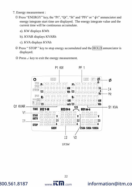
7. Energy measurement :
Press “ENERGY” key, the “Pt”, “Qt”, “St” and “PFt” or “ψt” annunciator and
energy integrate start time are displayed. The energy integrate value and the
current time will be continuous accumulate.
a). KW displays KWh
b). KVAR displays KVARh
c). KVA displays KVAh
Press “ STOP ” key to stop energy accumulated and the HOLD annunciator is
displayed.
Press key to exit the energy measurement.
U12 Y-M
Q
U23 D-h
S
U31 m-s
P
NO.-h
1P3W
www. .com [email protected]
23
※ U1 must be connected to voltage source during the measurement of U2, U3,
I1, I2 and I3, because U1 is the main signal source of the whole meter
measuring system. Otherwise you could not have any measurement from
U2, U3, I1, I2 and I3.
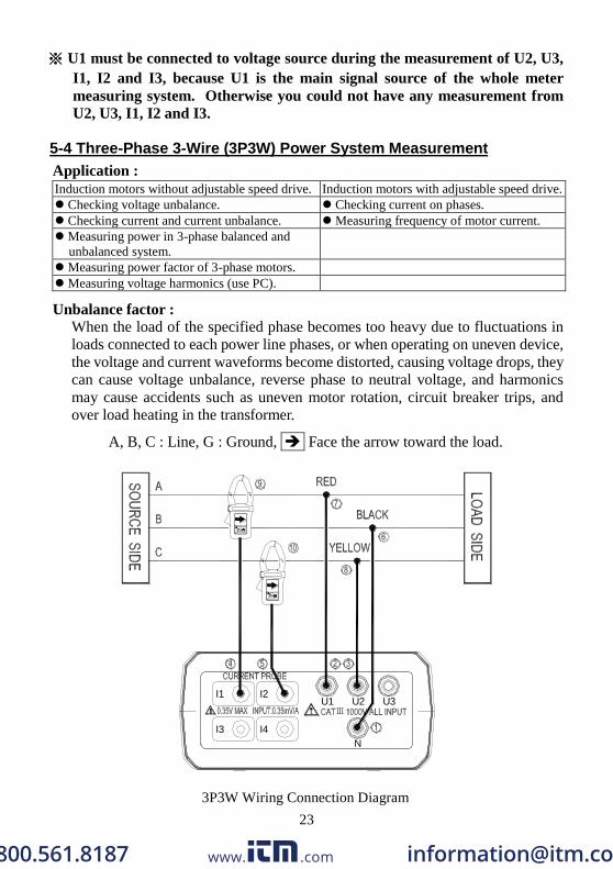
5-4 Three-Phase 3-Wire (3P3W) Power System Measurement
Application :
Induction motors without adjustable speed drive. Induction motors with adjustable speed drive.
Checking voltage unbalance. Checking current on phases.
Checking current and current unbalance. Measuring frequency of motor current.
Measuring power in 3-phase balanced and
unbalanced system.
Measuring power factor of 3-phase motors.
Measuring voltage harmonics (use PC).
Unbalance factor :
When the load of the specified phase becomes too heavy due to fluctuations in
loads connected to each power line phases, or when operating on uneven device,
the voltage and current waveforms become distorted, causing voltage drops, they
can cause voltage unbalance, reverse phase to neutral voltage, and harmonics
may cause accidents such as uneven motor rotation, circuit breaker trips, and
over load heating in the transformer.
A, B, C : Line, G : Ground, Face the arrow toward the load.
U2
I4I3
N
I1 I2U1
ⅢU3
3P3W Wiring Connection Diagram
www. .com [email protected]
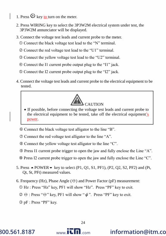
24
1. Press key to turn on the meter.
2. Press WIRING key to select the 3P3W2M electrical system under test, the
3P3W2M annunciator will be displayed.
3. Connect the voltage test leads and current probe to the meter.
Connect the black voltage test lead to the “N” terminal.
Connect the red voltage test lead to the “U1” terminal.
Connect the yellow voltage test lead to the “U2” terminal.
Connect the I1 current probe output plug to the “I1” jack.
Connect the I2 current probe output plug to the “I2” jack.
4. Connect the voltage test leads and current probe to the electrical equipment to be
tested.
CAUTION
If possible, before connecting the voltage test leads and current probe to
the electrical equipment to be tested, take off the electrical equipment’s
power.
Connect the black voltage test alligator to the line “B”.
Connect the red voltage test alligator to the line “A”.
Connect the yellow voltage test alligator to the line “C”.
Press I1 current probe trigger to open the jaw and fully enclose the Line “A”.
Press I2 current probe trigger to open the jaw and fully enclose the Line “C”.
5. Press POWER key to select (P1, Q1, S1, PF1), (P2, Q2, S2, PF2) and (Pt,
Qt, St, PFt) measured values.
6. Frequency (Hz), Phase Angle (Θ) and Power Factor (pF) measurement:
Hz : Press “Hz” key, PF1 will show “Hz”. Press “PF” key to exit.
Θ : Press “Θ” key, PF1 will show “ψ”. Press “PF” key to exit.
pF : Press “PF” key.
www. .com [email protected]
25
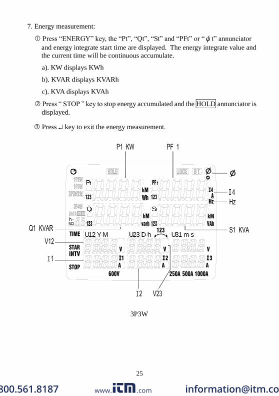
7. Energy measurement:
Press “ENERGY” key, the “Pt”, “Qt”, “St” and “PFt” or “ψt” annunciator
and energy integrate start time are displayed. The energy integrate value and
the current time will be continuous accumulate.
a). KW displays KWh
b). KVAR displays KVARh
c). KVA displays KVAh
Press “ STOP ” key to stop energy accumulated and the HOLD annunciator is
displayed.
Press key to exit the energy measurement.
U31 m-s
S
U23 D-h
Q
U12 Y-M
h-NO.
P
3P3W
www. .com [email protected]
26
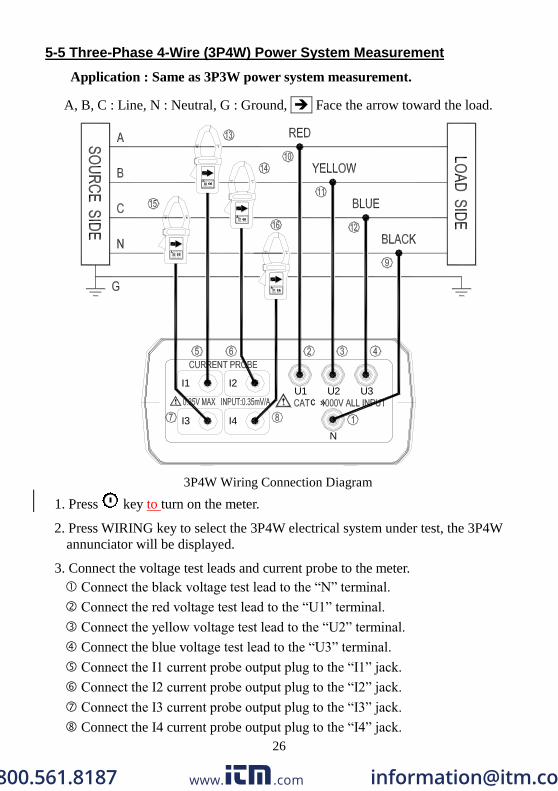
5-5 Three-Phase 4-Wire (3P4W) Power System Measurement
Application : Same as 3P3W power system measurement.
A, B, C : Line, N : Neutral, G : Ground, Face the arrow toward the load.
I4I3
I1 I2
N
U1 U2¢ »
U3
3P4W Wiring Connection Diagram
1. Press key to turn on the meter.
2. Press WIRING key to select the 3P4W electrical system under test, the 3P4W
annunciator will be displayed.
3. Connect the voltage test leads and current probe to the meter.
Connect the black voltage test lead to the “N” terminal.
Connect the red voltage test lead to the “U1” terminal.
Connect the yellow voltage test lead to the “U2” terminal.
Connect the blue voltage test lead to the “U3” terminal.
Connect the I1 current probe output plug to the “I1” jack.
Connect the I2 current probe output plug to the “I2” jack.
Connect the I3 current probe output plug to the “I3” jack.
Connect the I4 current probe output plug to the “I4” jack.
www. .com [email protected]

27
4. Connect the voltage test leads and current probe to the electrical equipment to be
tested.
CAUTION
If possible, before connecting the voltage test leads and current probe to
the electrical equipment to be tested, take off the electrical equipment’s
power.
Connect the black voltage test alligator to the neutral line “N”.
Connect the red voltage test alligator to the line “A”.
11 Connect the yellow voltage test alligator to the line “B”.
12 Connect the blue voltage test alligator to the line “C”.
13 Press I1 current probe trigger to open the jaw and fully enclose the Line “A”.
14 Press I2 current probe trigger to open the jaw and fully enclose the Line “B”.
15 Press I3 current probe trigger to open the jaw and fully enclose the Line “C”.
16 Press I4 current probe trigger to open the jaw and fully enclose neutral line “N”.
5. Press POWER key to select (P1, Q1, S1, PF1), (P2, Q2, S2, PF2), (P3, Q3,
S3, PF3) and (Pt, Qt, St, PFt) measured values.
6. Frequency (Hz), Phase Angle (Θ), Neutral Line Current (I4) and Power Factor
(pF) measurement :
Hz : Press “Hz” key, PF1 will show “Hz”. Press “PF” key to exit.
Θ: Press “Θ” key, PF1 will show “ψ”. Press “PF” key to exit.
I4 : Press “I4” key, PF1 will show “I4”. Press “PF” key to exit.
pF : Press “PF” key.
www. .com [email protected]
28
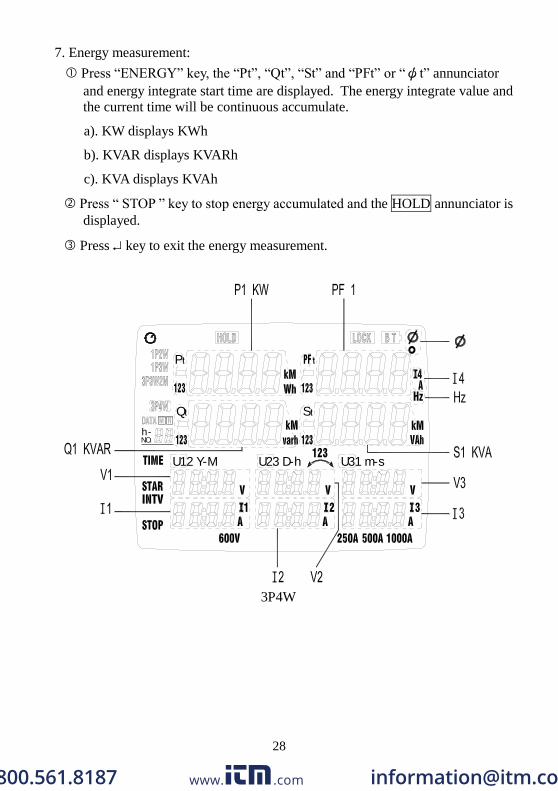
7. Energy measurement:
Press “ENERGY” key, the “Pt”, “Qt”, “St” and “PFt” or “ψt” annunciator
and energy integrate start time are displayed. The energy integrate value and
the current time will be continuous accumulate.
a). KW displays KWh
b). KVAR displays KVARh
c). KVA displays KVAh
Press “ STOP ” key to stop energy accumulated and the HOLD annunciator is
displayed.
Press key to exit the energy measurement.
P
NO.-h
U12 Y-M
Q
U23 D-h
S
U31 m-s
3P4W
www. .com [email protected]
29
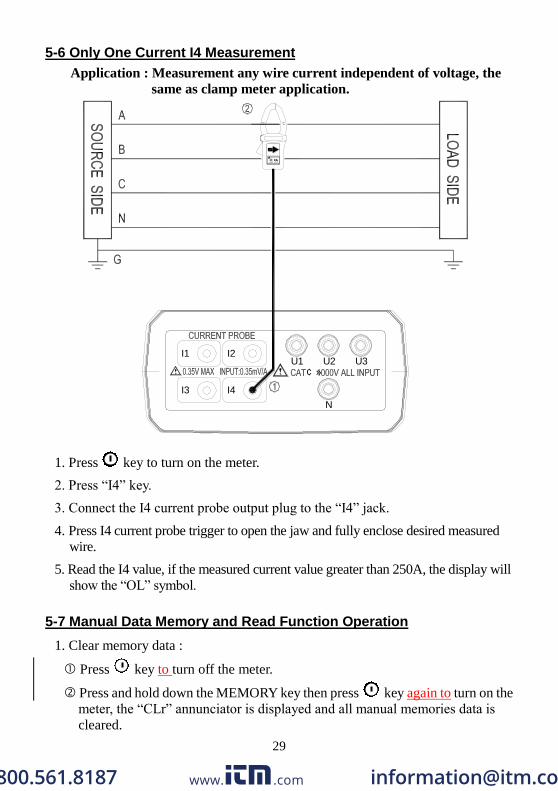
5-6 Only One Current I4 Measurement
Application : Measurement any wire current independent of voltage, the
same as clamp meter application.
I3
I1
I4
I2
N
U1 U2¢ »
U3
1. Press key to turn on the meter.
2. Press “I4” key.
3. Connect the I4 current probe output plug to the “I4” jack.
4. Press I4 current probe trigger to open the jaw and fully enclose desired measured
wire.
5. Read the I4 value, if the measured current value greater than 250A, the display will
show the “OL” symbol.
5-7 Manual Data Memory and Read Function Operation
1. Clear memory data :
Press key to turn off the meter.
Press and hold down the MEMORY key then press key again to turn on the
meter, the “CLr” annunciator is displayed and all manual memories data is
cleared.
www. .com [email protected]

30
2. Store Manual data to memory :
Press MEMORY key one time store one sets displayed data to memory, the M
annunciator display one time and the stored memory address will be
displayed.
Maximum store memory capacity size is 99 sets.
3. Read the manual stored data :
Press READ key to enter the read mode, the R annunciator is displayed.
Press key to read the memories data, the memories data address will be
displayed.
Press “ ” key to exit the read mode.
5-8 Auto Datalogging Function Operation
1. Clear memory data :
Please refer to software manual (CD-ROM), use PC to clear memories data, the
meter can not clear memories data free from lost memories data.
2. Store Auto datalogging data to memory :
Setting the current time and Auto datalogging interval time.
Press SET key to enter current time setting mode.
Press keys to set actual current YEAR-month, DAY-hour,
minute-second.
Press key to enter auto datalogging interval time setting, the “INTV”
annunciator is displayed.
Press keys cycle select the interval time, you can select 5 seconds, 30
seconds, 1 minute or 2 minutes.
Press key to exit TIME setting mode.
Enter Auto datalogging mode.
Press START key to start Auto data logging, the DATA M will be displayed,
the M annunciator, according to the interval time disappear one time store one
sets data into the memory.
Press STOP key to stop data record, press START key will resume data record,
but maximum can be divide to 10 memory blocks, only 12,000 sets data can be
stored in one block, the current block number will be displayed, total maximum
record capacity size is 20,000 sets data.
When maximum block or maximum capacity is full, the “FF” annunciator
will be displayed, the data record is auto stopped.
Download data to PC
Please refer to the software manual (CD-ROM) to download the data.
www. .com [email protected]
31
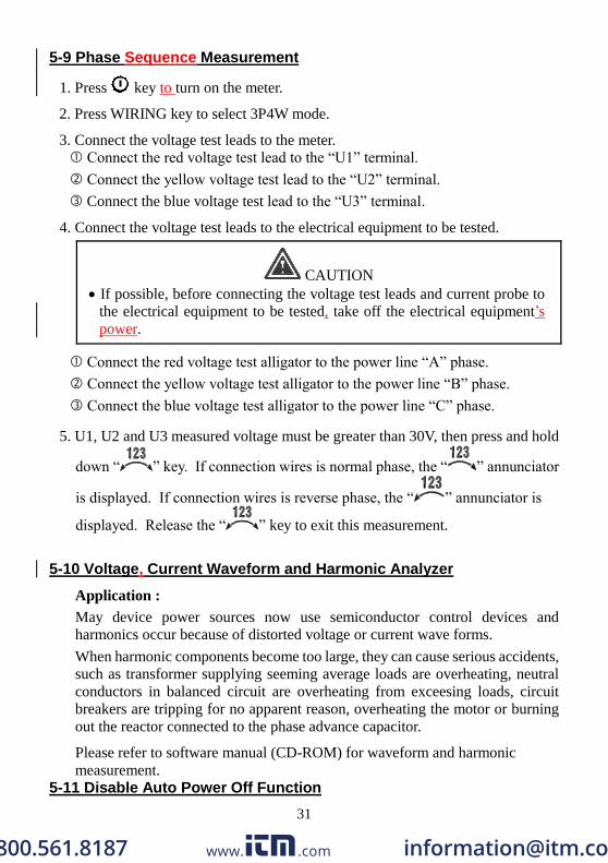
5-9 Phase Sequence Measurement
1. Press key to turn on the meter.
2. Press WIRING key to select 3P4W mode.
3. Connect the voltage test leads to the meter.
Connect the red voltage test lead to the “U1” terminal.
Connect the yellow voltage test lead to the “U2” terminal.
Connect the blue voltage test lead to the “U3” terminal.
4. Connect the voltage test leads to the electrical equipment to be tested.
CAUTION
If possible, before connecting the voltage test leads and current probe to
the electrical equipment to be tested, take off the electrical equipment’s
power.
Connect the red voltage test alligator to the power line “A” phase.
Connect the yellow voltage test alligator to the power line “B” phase.
Connect the blue voltage test alligator to the power line “C” phase.
5. U1, U2 and U3 measured voltage must be greater than 30V, then press and hold
down “ ” key. If connection wires is normal phase, the “ ” annunciator
is displayed. If connection wires is reverse phase, the “ ” annunciator is
displayed. Release the “ ” key to exit this measurement.
5-10 Voltage, Current Waveform and Harmonic Analyzer
Application :
May device power sources now use semiconductor control devices and
harmonics occur because of distorted voltage or current wave forms.
When harmonic components become too large, they can cause serious accidents,
such as transformer supplying seeming average loads are overheating, neutral
conductors in balanced circuit are overheating from exceesing loads, circuit
breakers are tripping for no apparent reason, overheating the motor or burning
out the reactor connected to the phase advance capacitor.
Please refer to software manual (CD-ROM) for waveform and harmonic
measurement.
5-11 Disable Auto Power Off Function
www. .com [email protected]
32
The meter will automatically enter sleep mode approx. 30 minutes to save
power consumption.
1. Disable auto power off procedure :
Press key to turn off the meter.
Press and hold down HOLD key, then press key to turn on the meter, the
auto power function will be disabled, and the auto power off symbol “ ”
will be disappear.
2. Auto power off mode is enabled each time you turn on the meter and is
automatically disabled as the follow modes.
ENERGY function is active.
Auto datalogging function is active.
PC linked.
VI. MAINTENANCE
6-1 General Maintenance
1. Repairs or services that are not covered in this manual should only be performed
by qualified personnel.
2. Clean the meter and accessories with a damp cloth and a mild soap. Do not use
abrasives, solvent, or alcohol. These may damage the text.
3. Additional to this it is recommended to open the jaws of the Current Clamp and
to wipe the magnetic pole pieces with a lightly oiled cloth. This in order to
avoid rust or corrosion to form on the magnetic poles.
6-2 Battery Replacement
WARNING
To AVOID electrical shock, remove the test leads and current probe before
replacing the batteries.
1. As battery power is not sufficient, LCD will display BT annunciator, replace
new battery is required.
2. Disconnect all test leads and current probe from any power electrical source,
press key to turn off the meter, and remove the test leads from the jacks.
3. The battery cover is secured to the bottom case by two screws. Using a screw
drive to remove the two screws from the bottom case.
4. Remove battery cover, take out the batteries and replace with new batteries.
(Please note battery polarity)
www. .com [email protected]

33
VII. RS-232 INTERFACE, SOFTWARE INSTALLATION AND OPERATION
For the detailed instruction, please refer to the content of attached CD disk,
which has the complete instruction of RS-232 interface, software operation
and relevant information.
www. .com [email protected]

TES ELECTRICAL ELECTRONIC CORP. 7F, No. 31, Lane 513, Rui Guang Road, Neihu Dist. Taipei. Taiwan, R. O. C.
Tel : (02) 2799-3660 Fax : 886-2-2799-5099
E-Mail : [email protected] http://www.tes.com.tw Jan-2008-9
www. .com [email protected]


