Embed Size (px)
Citation preview
Procedia Engineering 63 ( 2013 ) 922 – 930
Available online at www.sciencedirect.com
1877-7058 © 2013 The Authors. Published by Elsevier Ltd. Open access under CC BY-NC-ND license.
Selection and peer-review under responsibility of Universidad de Zaragoza, Dpto Ing Diseño y Fabricacion
doi: 10.1016/j.proeng.2013.08.216
ScienceDirect
The Manufacturing Engineering Society International Conference, MESIC 2013
Temperature and strain measurement during chip formation in
orthogonal cutting conditions applied to Ti-6Al-4V
M. Cotterella, E. Ares
b,*, J. Yanes, F. López, P. Hernandez, G. Peláez
aMechanical and Manufacturing Engineering Department, Cork Institute of Technology, Bishopstown, Cork, Ireland. bEscuela de Ingeniería Industrial, Campus Lagoas-Marcosende 36310, Vigo, Spain
Abstract
This work presents simplified models for strain and temperature measurement during orthogonal cutting process applying
Ernst-Merchant theory and considering a 2-D steady state heat conduction problem. In order to validate the thermal model
experiments with high speed imaging and with Infrared imaging were performed. The results of the infrared thermal
measurements were compared with the outputs of the temperature model, considering the average temperature on the shear
plane and temperature distribution. Also video analysis technique was developed to obtain shear strain in a precise way
compared with Ernst-Merchant classical analysis. Experiments were conducted in a specially adapted milling machine for
different low cutting velocities and feedrates.
© 2013 The Authors. Published by Elsevier Ltd.
Selection and peer-review under responsibility of Universidad de Zaragoza, Dpto Ing Diseño y Fabricacion.
Keywords: Temperature measurement; Strain measurement; Infrared thermal camera; High speed camera; Chip formation.
1. Introduction
Temperature and normal stress generated at the tool/chip interface are critical parameters for the tool wear and
the workpiece material damage (Madalina Calamaz, 2012). The primary effect of temperature is on tool wear.
Although there are various tool wear mechanisms, it is generally known that increases of temperature produce
progressive tool wear (Wanigarathne, 2005). Apart from the tool, the maximum temperature and the temperature
gradient influences subsurface deformation, metallurgical structural alterations in the machined surface, and
* Corresponding author. Tel.: +34 986 812 189
E-mail address: [email protected]
© 2013 The Authors. Published by Elsevier Ltd. Open access under CC BY-NC-ND license.
Selection and peer-review under responsibility of Universidad de Zaragoza, Dpto Ing Diseño y Fabricacion

923 M. Cotterell et al. / Procedia Engineering 63 ( 2013 ) 922 – 930
residual stresses in the finished part (Komanduri, 2001). Another well-known problem occurs in the cutting of low
thermal conductivity materials; such as titanium, where the heat, generated during the cutting process, flows much
more in the tool than the chip due to the low conductivity of the workpiece material and this causes thermal stresses
to occur in the tool. As a result of the thermal stresses, tool fatigue, failures due to fracture and wear occur more
frequently (Lazoglu, 2002).
The metal cutting is a coupled thermo-mechanical process. During the process, the heat generation occurs as a
result of plastic deformation and friction along the tool–chip and the tool-work piece interface. It is a
comprehensive assumption that almost all the energy required for cutting is converted to heat in the cutting domain
(Tay, 1974).
Is difficult to develop a precise temperature prediction model in machining due to the complicated contact
phenomenon; metal cutting is very highly localized and non-linear, occurs at high temperatures, high pressures and
strains. Therefore, accurate and repeatable temperature prediction still remains challenging due to the complexity
of the contact phenomena in the metal cutting process (Abukhshim, 2006). Apart from the temperature prediction,
temperature measurement is even more challenging in this research area, because it is very difficult to make
temperature measurement very close to the cutting edge.
Numerous attempts have been made to measure the temperature in the machining operations. One of the most
extensively used experimental techniques to measure the temperature in machining is the use of thermocouples. In
addition to thermocouples, the infrared (IR) radiation techniques are probably the second most used method for
temperature measurement in machining. In the IR technique, the surface temperature of the body is measured based
on its emitted thermal energy. The IR technique is applied for the temperature field measurements with the use of
cameras with films or chips sensitive to IR radiation (Ali Fata, 2011), (Dinca, 2008),( O’Sullivan, 2001).
The strain and stress state in the chip formation zone determines the chip formation. However, it is difficult to
obtain experimental data about the strain/stress fields during machining. For this reason, present chip formation
models highly simplify the chip formation process. Previous attempts were made trying to determine the shear
strain based on X-ray diffraction. Later investigations focused on video analysis were performed (Uhlmann, 2011),
(Cotterell, 2008).
The aim of this research is to find the stress and temperature fields during orthogonal cutting of titanium alloy
Ti-6Al-4V in order to know more about the cutting process, material behavior and all the circumstances that
happen around it.
The use of a high-speed imaging has enabled characteristics of the deformation field such as velocity, strain rate,
and strain in and around the cutting edge and primary deformation zone. Segmented chips are observed throughout
and parameters of chip geometry are measured.
A simplified thermal model is presented which estimates the temperatures occurring during cutting and the
energy partition ratios for the process. Temperature measurements with IR experiments were performed to validate
it.
2. Theoretical models
Classical Mechanical Models give an overall appreciation of process behavior which can be difficult to obtain
with computational models. We propose procedures inside the model that should be used in conjunction with Finite
Element Models to obtain more detailed information for a specific set of conditions and it is capable of handling
more elaborate material models and cutting geometries and so to calculate shear strain and temperature values,
theoretical models based in Strain Trigonometric Formulas (1, 2, 3 and 4) and Heat Conduction Equations were
defined (5, 6 and 7).
2.1. Continuous Chip Formation Model
The classical model of continuous chip formation in orthogonal cutting (Uhlmann, 2011) envisages a thin shear
zone inclined at an angle � to the direction of cut. The chip compression ratio h is defined as:

924 M. Cotterell et al. / Procedia Engineering 63 ( 2013 ) 922 – 930
(1)
If side flow can be neglected, then the ratio of the deformed chip thickness hc to the undeformed chip thickness
h or the ratio of the cutting speed vc to the chip velocity vch can be used to calculate the shear angle � for a given
tool rake angle ne. If this method is applied to segmented chips very high values of shear angle are obtained and
they are not representative of the process. The shear strain encountered in the primary shear zone is given by:
(2)
2.2. Segmented Chip Formation Model
Segmented chip formation is a two stage process in which workpiece material is plastically deformed ahead of
the tool causing it to bulge. When a critical strain level is reached catastrophic failure occurs and a shear band is
formed extending from the tool tip to the workpiece surface. The resulting chips consist of moderately deformed
chip segments separated by narrow bands of intensely sheared material (Uhlmann, 2011).
The direction of this localised shear seg is obtained from measurements on micrographs of chip cross-sections.
The instantaneous value of the shear angle may vary during the upsetting phase but reaches a value of seg for
the catastrophic shear phase. At higher cutting speeds this variation reduces so it can be assumed that seg and
hence the segment thickness dc = d remains constant during the upsetting phase. For this condition shear within
each segment occurs along planes parallel to the adjacent shear bands. The critical shear to initiate shear band
formation can be determined from the angle seg by which the workpiece surface bulges at the end of the upsetting
phase (Gente, 2001), (Turley, 1982). The shear within the segment is given by:
(3)
The shear strain within the shear band sb is the sum of the homogeneous strain seg during the upsetting phase
and the catastrophic shear strain c, which is the ratio of the shear band projection psb to the shear band thickness
sb.
(4)
2.3. Thermal model
In orthogonal cutting the temperature distribution in the cutting zone for continuous chip formation can be
idealized by treating it as a 2-D steady state heat conduction problem (Cotterell, 2008). If a perfectly sharp tool is
assumed there are two heat sources to be considered; Qs is the heat generated per unit time by plastic deformation
on the shear plane and Qf is the frictional heat generated per unit time over the contact zone on the tool rake face.
The following solution was used to obtain the average temperature s along the shear plane where the 0, , s, , ,
Cp, k1 are the initial workpiece temperature, the proportion of work input converted into heat (assumed to be
cos
sin cos( )
ne
ne
cos( )
sin( )
c c neh
ch
h v
h v
sintan
sin sin( )
seg
seg seg
seg seg seg
sb
sbc
p
sb seg c

925 M. Cotterell et al. / Procedia Engineering 63 ( 2013 ) 922 – 930
unity), the average shear stress on the shear plane, the average shear strain in the primary deformation zone, the
workpiece material density, the specific heat capacity and the thermal diffusivity respectively.
(5)
These properties were determined at a temperature halfway between and 0. The partition ratio R1 was solved
iteratively until a converged solution for s was obtained.
The mean temperature rise t of the tool at the tool-chip interface was calculated using the following
relationship where b, , lc, , t, k2, are the width of the workpiece, the shape factor based on the geometry of the
tool-chip contact zone, tool-chip contact length , the workpiece thermal conductivity, the tool thermal conductivity
and the workpiece thermal diffusivity.
(6)
The workpiece thermal conductivity , tool thermal conductivity t and workpiece thermal diffusivity k2 were
evaluated at temperature t.
The partition ratio R2 was calculated iteratively until a converged solution for t was obtained.
(7)
3. Experiment design for model validation
In order to validate the models studied a specialized equipment was required to perform the experimental stage.
A brief description of the components involved is shown.
3.1. Workpiece material, machine tool and tooling
The experiments are carried out for dry and orthogonal machining condition. Prepared specimens of Ti-6Al-4V
were machined in a series of continuous orthogonal cutting tests on a specially adapted milling machine. The
material was received in the annealed state from a 60 mm bar stock. It was an extra low interstitial (ELI) wrought
alloy grade normally used in biomedical applications with a hardness of 340HV an equiaxed - microstructure
with a 10 m grain size. Rectangular shape specimens were prepared with a nominal thickness of 1.9 mm in the
p
ss
CR10
hv
kR
c
1
1
328.11
1
t
f
s
Ab
Q
R )1( 20
2
0
2754.0
)(
k
hlv
A
b
Q
Ab
Q
R
cct
f
s
t
f

926 M. Cotterell et al. / Procedia Engineering 63 ( 2013 ) 922 – 930
thinnest part of the specimen. The specimens were secured with a specific piece holder not to allow movements
and vibrations of the workpiece during the cutting tests.
The test were conducted in an adapted milling machine Adcock-Shipley 2S. Special mount device were used to
hold the force dynamometer pieceholder/piece assembly. This device was bolted to the T slots of the milling
machine worktable establishing the cutting direction on X-axis. High speed steel HSS 090-018 were used to carry
the experiments inserted in a tool holder performed to prevent vibrations also. The rake angle of the tool was
determined to be 4°. High speed camera and IR camera were connected to the overarm throughout an assembly
specifically made for these tests allowing the imaging system to follow the cutting edge of the tool as it plunged
into the piece.
Figure 1. Milling machine (left), dynamometer set- up and acquisition data (right).
3.2. High speed camera and Infrared thermal camera features
As A high speed monochrome camera based on a 1024 x 1024 CMOS sensor array was used for all the tests,
Photron FASTCAM SA 1.1. The images in this project were captured at a framing rate of 3,000 fps and a
resolution of 1024 x 1024 pixels. A long-distance microscope lens with manual focus adjustment and a close-up
objective was attached to the camera. Illumination was necessary. It was provided by two white light sources
Everest VIT ELSV-60. The light was driven by a fiber optic cable from the source and needs a magnetic holder to
move with the worktable and follow the camera and needs also a few clamps or braces to get the right light to get
good images and videos.
An IR camera Flir SC5000 was used for the temperature measurement, InSb Detector, 320x256 pixel,
microscope lens giving 10 micron spatial resolution, +/- 2 degrees C temperature resolution for measurement range
used. The setting up of the Infrared camera was similar to the high speed camera. The videos were recorded with
duration of seven seconds and 100 frames.
Figure 2. High speed camera and IR camera set-up.
Special Holder
Illumination system

927 M. Cotterell et al. / Procedia Engineering 63 ( 2013 ) 922 – 930
4. Validation procedure
A video analysis technique was developed to allow the direct determination of adiabatic shear strain comparing
with classical analysis to validate the model developed. IR imaging was used to validate thermal model.
Series of tests were conducted varying feed and cutting speed. Value ranges are listed on Table 1.
Table 1. Cutting parameters for different tests
Cutting Speed (Vc) 300,470,600,750 [mm/min]
Feedrate (f) 0.05, 0.1, 0.15 [mm]
Depth of Cut (w) 1.9 [mm]
4.1. Forces analysis
By a The cutting force Fc and feed force Ff were measured using a 4-axis tool force dynamometer (Figure 1)
and charge amplifier. The force signals were recorded with a separate PC-based data acquisition system. The data
collected was input into Ernst-Merchant equations.
4.2. Shear strain
Subsequent image analysis of recorded video sequences allowed the on-screen calculation of displacements,
velocities and chip geometry over time. Shear band projection and segment spacing were calculated using SEM
imaging.
Figure 3. PIV software parameters and SEM chip analysis.
With this data and approximating the cutting process by a series of parallel plates sliding against one another to
form the chip, shear strain was calculated using trigonometric angle relation.
4.3. Temperature
For calculate the temperature with the equations was necessary a data from a preview study of the chip. The
video analysis results obtained with the High Speed Camera were used. Other values were taken from the
microscope analysis. Using an excel program the average temperature on the shear plane and the main temperature
rise for each cutting parameter were obtained.
In order to validate the model experiments with IR camera were performed for the same values of velocity but
with feedrates of 0.1 and 0.15mm.
Different previous areas were defined to obtain the solution trough analysis of the videos with the IR camera
software. The average temperature on the shear plane can be directly obtained taken different measurements in
928 M. Cotterell et al. / Procedia Engineering 63 ( 2013 ) 922 – 930
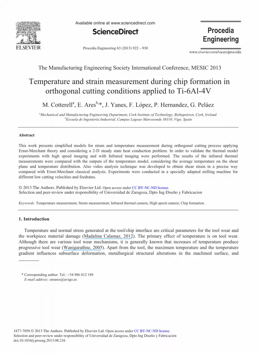
different pictures of the recording. Also the maximum temperature on the shear plane and on the chip-tool
interface can be calculated.
Figure 4. The IR image captured during the orthogonal cutting, Vc = 750mm/min; feedrate = 0.1mm (left), and the colored final version of the
image, together with a fitted temperature scale in C 0 (right).
5. Results evaluation
Once the tests were performed the next step is to evaluate the results given by each model.
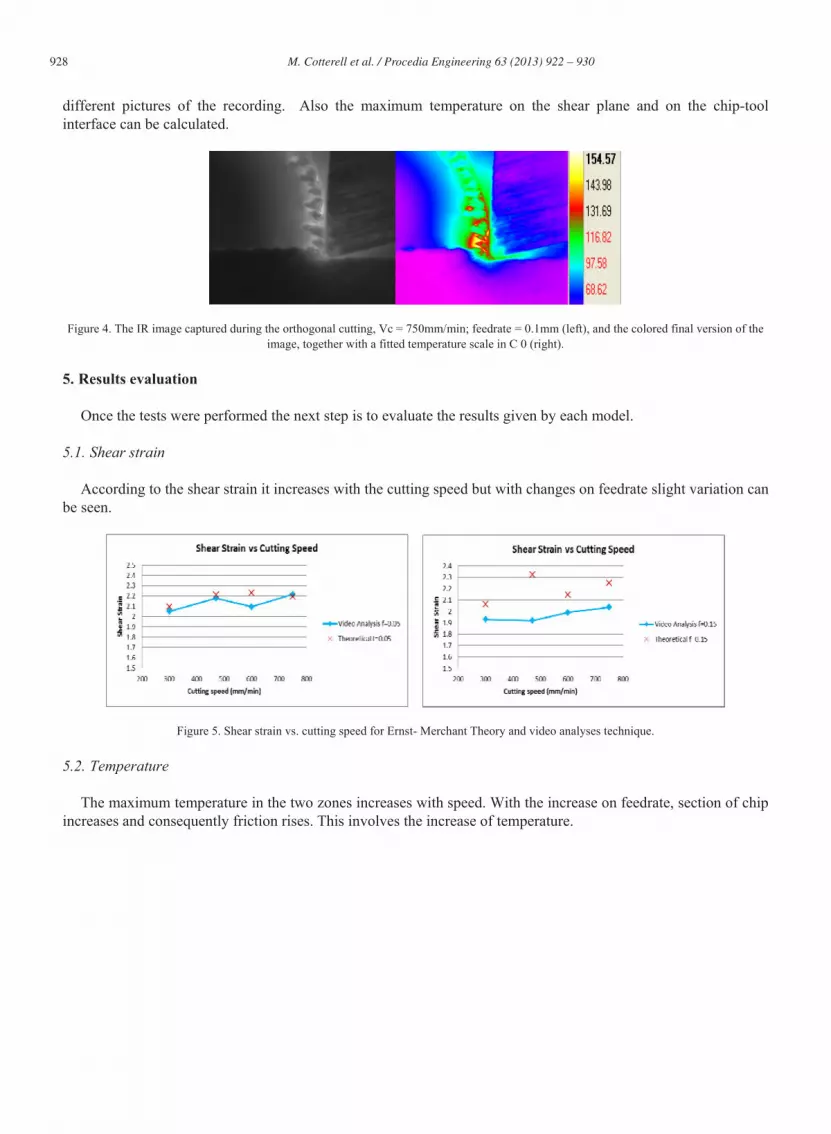
5.1. Shear strain
According to the shear strain it increases with the cutting speed but with changes on feedrate slight variation can
be seen.
Figure 5. Shear strain vs. cutting speed for Ernst- Merchant Theory and video analyses technique.
5.2. Temperature
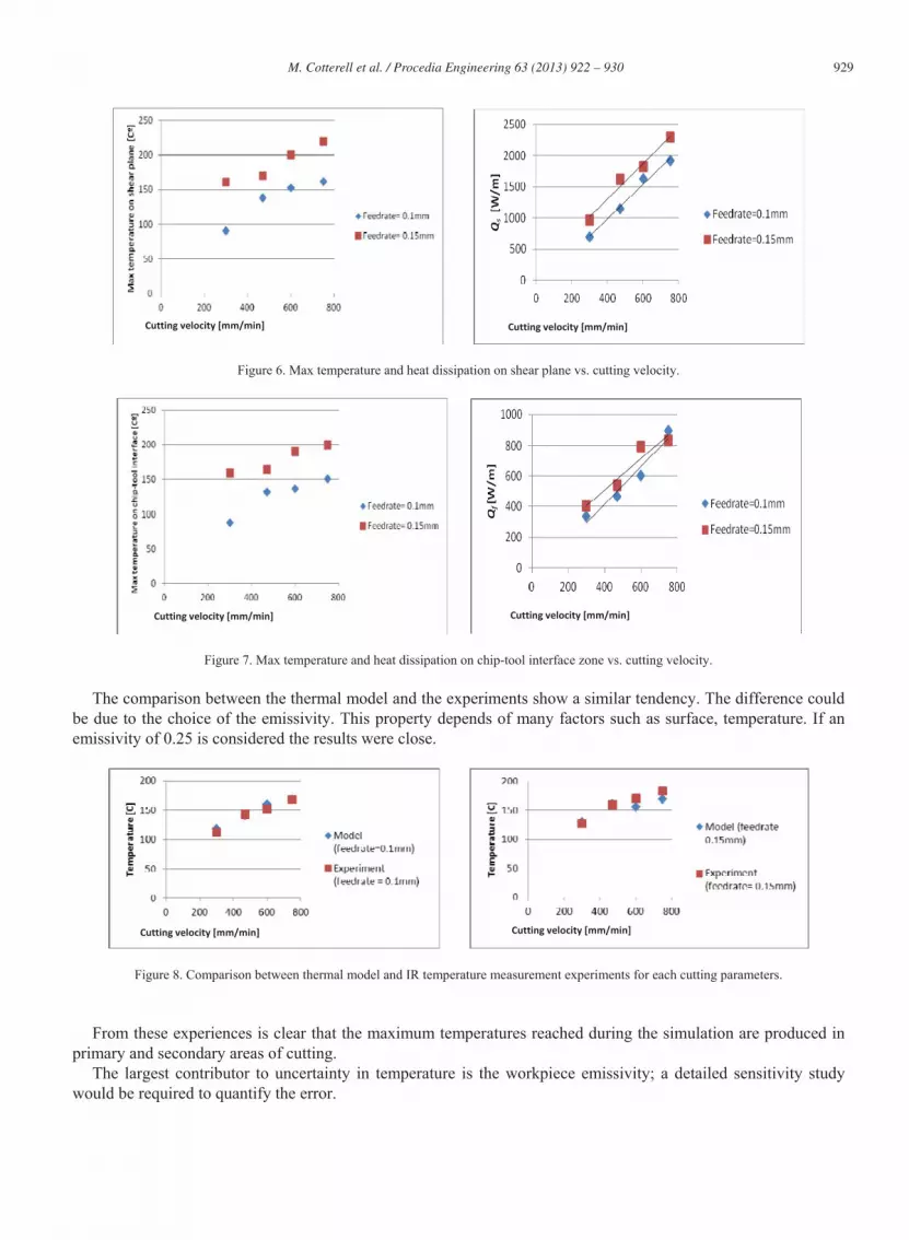
The maximum temperature in the two zones increases with speed. With the increase on feedrate, section of chip
increases and consequently friction rises. This involves the increase of temperature.
929 M. Cotterell et al. / Procedia Engineering 63 ( 2013 ) 922 – 930
Figure 6. Max temperature and heat dissipation on shear plane vs. cutting velocity.
Figure 7. Max temperature and heat dissipation on chip-tool interface zone vs. cutting velocity.
The comparison between the thermal model and the experiments show a similar tendency. The difference could
be due to the choice of the emissivity. This property depends of many factors such as surface, temperature. If an
emissivity of 0.25 is considered the results were close.
Figure 8. Comparison between thermal model and IR temperature measurement experiments for each cutting parameters.
From these experiences is clear that the maximum temperatures reached during the simulation are produced in
primary and secondary areas of cutting.
The largest contributor to uncertainty in temperature is the workpiece emissivity; a detailed sensitivity study
would be required to quantify the error.
Cutting velocity [mm/min] Cutting velocity [mm/min]
Cutting velocity [mm/min] Cutting velocity [mm/min]
Cutting velocity [mm/min] Cutting velocity [mm/min]

930 M. Cotterell et al. / Procedia Engineering 63 ( 2013 ) 922 – 930
6. Conclusions and future research
The comparison between classical theory and video analysis technique show a similar pattern. The video
analysis offers a good technique to measure strain.
The results of the IR experiments conducted for different cutting velocities and feedrates show a good
agreement with the thermal model.
The thermal model based on Ernst-Merchant and heat conduction equations and the video analysis technique are
very useful to predict temperature and shear strain. The methods can be used for further studies of segmented chip
formation during different cutting processes around shear plane area.
The model developed in this research provides parameters in a fastest, easiest and cheapest way than previous
methods such as microscope, thermocouples, dynamometer, etc. The main contribution of the conjunction of
mechanical models and computational models is the increase of the analytical capacity of the classical models to
evaluate simultaneously temperature and strain.
A complementary study using FEM analysis is under experimentation. This software based analysis, allow us to
simulate different set of parameters, by validating the methodology using the experimental test results presented in
this contribution. The commercial software used is AdvantEdgeTM , that is a finite element modelling package
especially for metal cutting processes such as: turning, drilling, milling, etc., in both two and three dimensions.
7. References
Abukhshim, N.A., Mativenga, P.T., Sheikh, M.A., Heat generation and temperature prediction in metal cutting: areview and implications for
high speed machining, international. J. Mach. Tools Manufacture 46 (7-8), 782–800, 2006
Ali Fata, G. J., Temperature Measurement During Machining Depending On Cutting Conditions, P&A Sc and Tech., v01i2 (16-21), 2011
Cotterell, M., Byrne,G., Characterization of chip formation during orthogonal cutting of titanium alloy Ti–6Al–4V,CIRP Journal of
Manufacturing Science and Technology, Volume 1, Issue 2, 2008, Pages 81–85
Cotterell, M., Byrne,G., Dynamics of chip formation during orthogonal cutting of titanium alloy Ti–6Al–4V, CIRP Annals - Manufacturing
Technology, Volume 57-Issue 1, p 93–96, 2008
Dinca C., Lazoglua I., Serpenguzel A., Analysis of thermal fields in orthogonal machining with infrared imaging, Journal of materials
processing technology, 198, 147–154, 2008
Gente, A., Hoffmeister, H.-W., Chip Formation in Machining Ti6Al4V at Extremely High Cutting Speeds, Annals of the CIRP, 50(1), 49-52,
2001
Komanduri, R., Hou, Z.B., A Review of the experimental techniques for the measurement of heat and temperatures generated in some
manufacturing processes and tribology, Tribol. Int. Vol.34, 653–682, 2001
Lazoglu, I., Altintas, Y., Prediction of tool and chip temperature in continuous and interrupted machining. Int. J. Mach. Tools Manufacture
Vol.42, 1011–1022, 2002
Madalina Calamaz, D., Coupard, F., Girot, Strain Field Measurement in Orthogonal Machining of a Titanium Alloy, Advanced Materials
Research, Volume 498, 237-242, 2012.
O’Sullivan,D., Coterrell, M., Temperature measurement in single point turning, Journal of Material Procesing Technology, 118, 301-308, 2001
Tay, A.O. Stevenson, M.G. Vahl Davis, G. Using the finite element method to determine temperature distributions in orthogonal machinin.
proc. Inst. Mech. Eng. 188 (55) 627- 638, 1974
Turley, D.M., Doyle, E.D., Calculation of shear strains in chip formation of titanium, Matl. Sci. and Eng.,55, 45-48, 1982
Uhlmann, E., Gerstenberger R., Herter S., Hoghé, T., Reimers,W., Camin, B., Martins, R. V., Schreyer, A., Fischer,T., In situ strain
measurement in the chip formation zone during orthogonal cutting, Production Engineering, Volume 5, Issue 1, pp 1-8, February 2011
Wanigarathne, P.C., Kardekar, A. D., Dillon, O.W., Poulachon, G., Jawahir, I.S., Progressive tool-wear in machining with coated grooved tools
and its correlation with cutting temperature, Wear Vol.259, 1215–1224, 2005


