Embed Size (px)
Citation preview

29/9/2015
Na
National Technical University of Athens
Technical Specification
for a luxury Cruise Vessel
GKOTSIS KIMONAS
Supervisor: Papanikolaou Apostolos


TECHNICAL SPECIFICATION FOR A LUXURY CRUISE VESSEL
1
ABSTRACT
The aim of this dissertation was to provide a detailed analysis and
presentation of the technical specifications for building a new luxury cruise
ship. Technical specifications are important for clarifying what sellers are able
and expected to offer, as well as what buyers are expected to receive.
International Maritime Organization’s (IMO) SOLAS Convention represents
the main regulatory framework surrounding the technical specifications of
ships, whose determination strongly takes into consideration safety of ships,
cargos, the environment and human life. The proposal of the mini technical
specification for building a new luxury cruise ship, carrying up to 36
passengers and performing international voyages, was based on SOLAS
directives, as well as their amendments during the 90s. It also took into
consideration the need to offer comfort and luxury services to its passengers.
Building the new ships following the proposed detailed technical specifications
will save time and money both to the ship owner(s) and the constructor
(shipyard owner), while also making it clear who to blame for violated terms
and conditions of the contracting agreement in case of deficiencies At the
same time, it will ensure construction accuracy, which is very important for the
compliance of the new cruise ship with SOLAS Convention.

TECHNICAL SPECIFICATION FOR A LUXURY CRUISE VESSEL
2
ACKNOWLEDGMENTS
I would like to thank a number of people regarding the completion of this
dissertation. First of all, I would like to thank my tutor for his help and
guidelines throughout the dissertation conduction process, which were very
valuable for me, in order to be able to accomplish this academic target.
Moreover, I would like to thank all my lecturers, who provided me with the
necessary knowledge to carry out this dissertation. Additionally, I would like to
thank my classmates for their help and cooperation they provided me
throughout this year, when I found them necessary. Last but not least, I would
like to thank my family and friends for their support and motivation, which led
me at the point of submitting my dissertation.

TECHNICAL SPECIFICATION FOR A LUXURY CRUISE VESSEL
3
TABLE OF CONTENTS
1. INTRODUCTION ................................................................................................................. 1
1.1. DISSERTATION AIMS AND OBJECTIVES .............................................................. 1
1.2. CONTEXT AND BACKGROUND .............................................................................. 1
1.3. RATIONALE OF TOPIC SELECTION ....................................................................... 2
1.4. DISSERTATION STRUCTURE ................................................................................... 2
2. THEORETICAL FRAMEWORK ......................................................................................... 4
2.1. DEFINING TECHNICAL SPECIFICATIONS............................................................. 4
2.2. THE IMPORTANCE OF TECHNICAL SPECIFICATIONS ....................................... 7
2.3. SHIPS’ TECHNICAL SPECIFICATIONS ................................................................. 12
2.3.1. GENERAL FRAMEWORK ................................................................................. 12
2.4.2. REGULATORY FRAMEWORK-ALL TYPES OF SHIPS ................................ 13
2.4.3. REGULATORY FRAMEWORK – PASSENGER SHIPS .................................. 13
3. DESCRIPTION ................................................................................................................... 15
3.1. GENERAL DESCRIPTION ........................................................................................ 15
3.2. SPECIFIC DESCRIPTION .......................................................................................... 16
3.2.1. Double Bottom &Tanks .................................................................................. 16
3.2.2. Tanktop Deck .................................................................................................. 19
3.2.3. Lower Deck ....................................................................................................... 21
3.2.4. Main Deck ....................................................................................................... 24
3.2.5. Upper Deck ........................................................................................................ 26
3.2.6. Bridge Deck ..................................................................................................... 29
3.2.7. Sun Deck ......................................................................................................... 30
4. HULL .................................................................................................................................. 32
4.1. HULL DESIGN ........................................................................................................... 32
4.1.1. Drawings Accompanying this Specification ......................................................... 32
4.1.2. Principal Dimensions ............................................................................................ 32
4.1.3. Tank Capacities ............................................................................................... 33
4.1.4. Lines Design ......................................................................................................... 33
4.1.4. Trim & Stability, Damage Stability ...................................................................... 33
4.1.5. Model Tests .......................................................................................................... 34
4.1.6. Hull Machinery and Equipment ............................................................................ 36
4.1.7. Windows, Sidelights and Doors ............................................................................ 40

TECHNICAL SPECIFICATION FOR A LUXURY CRUISE VESSEL
4
5. LIFE SAVING APPLIANCES ........................................................................................... 41
5.1. GENERAL ................................................................................................................... 41
5.2. LIFEBOATS & DAVITS ............................................................................................ 41
5.3. LIFERAFTS ................................................................................................................. 41
5.4. PERSONAL LIFE SAVING APPLIANCES, BUOYANT APPARATUS ................. 41
5.5. VISUAL SIGNALS, LINE THROWING APPARATUS ........................................... 42
5.6. TENDERS .................................................................................................................... 42
6. FIRE PROTECTION .......................................................................................................... 43
6.1. GENERAL ................................................................................................................... 43
6.2. FIRE DOORS .............................................................................................................. 43
6.3. FIRE DAMPERS AND SMOKE OUTLETS .............................................................. 44
6.4. EMERGENCY SHUTDOWN SYSTEMS .................................................................. 44
6.5. FIRE AND WASH DECK SYSTEM .......................................................................... 45
6.6. FIRE ALARM & DETECTOR SYSTEM ................................................................... 45
6.7. HI-FOG SYSTEM ....................................................................................................... 46
6.8. PORTABLE EXTINGUISHERS, MISCELLANEOUS FIRE FIGHTING
EQUIPMENT ...................................................................................................................... 46
6.9. MUSTERING .............................................................................................................. 46
6.10. FIRE & SAFETY PLAN, DAMAGE CONTROL PLAN ......................................... 47
7. CATHODIC PROTECTION ............................................................................................... 48
7.1. GENERAL ................................................................................................................... 48
8. MACHINERY ..................................................................................................................... 49
8.1. INSTALLATION DESIGN ...................................................................................... 49
8.1.1. General .................................................................................................................. 49
8.1.2 Machinery and Equipment Installation Requirements ........................................... 49
8.1.3. Special Operational Requirements ........................................................................ 49
8.1.4. Economic Maintenance......................................................................................... 50
8.1.5. Machinery Installation .......................................................................................... 50
8.1.6. Pollution ................................................................................................................ 50
8.1.7. Machinery and Tank list ....................................................................................... 51
8.2. MAIN PROPULSION MACHINERY ........................................................................ 53
8.2.1. Main Engines and Gearing ................................................................................... 53
8.2.2. Gearing ................................................................................................................. 54
8.2.3. Shafting System .................................................................................................... 55
8.2.4. Propeller – Propeller Blades ................................................................................. 56

TECHNICAL SPECIFICATION FOR A LUXURY CRUISE VESSEL
5
8.3. HEATING SERVICES ................................................................................................ 56
8.4. GENERATORS ......................................................................................................... 57
8.4.1. Alternator Sizing ................................................................................................... 57
8.4.2. Diesel Alternator Sets ........................................................................................... 57
8.4.3. Emergency Diesel Alternator Set ......................................................................... 58
8.5. EQUIPMENT AND MATERIALS .......................................................................... 58
8.6. ENGINE SERVICE SYSTEMS .................................................................................. 59
8.6.1. General .................................................................................................................. 59
8.6.2. Cooling Systems – General ................................................................................... 60
8.6.3.Sea Water Cooling System .................................................................................... 60
8.6.4. Fresh Water Cooling Systems............................................................................... 61
8.6.5. Lubricating Oil Systems ....................................................................................... 61
8.6.6. Compressed Air System ....................................................................................... 62
8.6.7. Exhaust Systems ................................................................................................... 62
8.7. POLLUTION CONTROL ....................................................................................... 62
8.7.1. General .................................................................................................................. 63
8.7.2. Oily Water Treatment ........................................................................................... 63
8.7.3. Waste Oil and Sludge Disposal ............................................................................ 63
8.7.4.Sewage Treatment ................................................................................................. 63
8.7.5. Galley Waste ......................................................................................................... 63
8.7.6. Garbage Treatment ............................................................................................... 64
8.8. CONTROLS AND INSTRUMENTATION ................................................................ 64
8.8.1. General .................................................................................................................. 64
8.8.2. Control Consoles .................................................................................................. 65
8.8.4. Machinery Alarm and Monitoring System ........................................................... 66
9. PIPING ................................................................................................................................ 67
9.1. GENERAL ................................................................................................................... 67
9.2. BILGE & SEAWATER BALLAST PIPING SYSTEMS ......................................... 68
9.3. FUEL OIL FILLING &TRANSFER PIPING SYSTEMS .......................................... 69
9.4. AIR VENT, SOUNDING AND OVERFLOW PIPING SYSTEMS ........................... 69
9.5. FRESH WATER FILLING AND TRANSFER PIPING SYSTEMS - FRESH
WATER PIPING SYSTEMS .............................................................................................. 70
9.6. FIRE LINE PIPING SYSTEM .................................................................................. 71
9.7. GRAY WATER PIPING SYSTEM ........................................................................... 71
9.8. SEA WATER COOLING PIPING SYSTEM FOR MAIN ENGINES ................ 71

TECHNICAL SPECIFICATION FOR A LUXURY CRUISE VESSEL
6
7.9. FRESH WATER COOLING PIPING SYSTEM FOR MAIN ENGINES .................. 73
9.10. FUEL OIL CONSUMPTION PIPING SYSTEM ............................................... 74
9.11. LUBRICATION OIL PIPING SYSTEM .................................................................. 75
9.12. FUEL OIL PURIFICATION PIPING SYSTEM ................................................ 76
9.13. BILGE OILY WATER SEPARATOR PIPING SYSTEM ....................................... 77
9.14. STARTING & COMPRESSED AIR PIPING SYSTEMS ........................................ 77
10. ELECTRICAL ................................................................................................................... 79
10.1. GENERAL ................................................................................................................. 79
10.2. POWER SYSTEMS ................................................................................................... 79
10. 3. ELECTRIC POWER SOURCES .............................................................................. 81
10.4. POWER DISTRIBUTION ......................................................................................... 83
10.4.1. Main Power 380V ac 3 phase ............................................................................. 83
10.4.2. The Emergency Power ........................................................................................ 83
10.5. LIGHTING ................................................................................................................. 83
10.5.1. General ................................................................................................................ 83
11. AIR CONDITIONING, VENTILATION, INSULATION ............................................... 86
11.1. AIR CONDITIONING ........................................................................................ 86
11.1.1. Air Conditioning Systems – Description ............................................................ 86
11.1.2. Description of the Air Conditioning Plant .......................................................... 89
11.1.3. Air Handling Units (AHUs) ................................................................................ 89
11.1.4. Single Fans .......................................................................................................... 90
11.1.5. Fan Coil Units (FCUs) ........................................................................................ 90
11.1.6. Fire & Shut-Off Dampers ................................................................................... 90
11.1.7.Electric Heaters .................................................................................................... 90
11.2. WATER SYSTEMS .................................................................................................. 91
11.2.1. Cooling/Heating Water System .......................................................................... 91
11.2.2. Re-Heating Water System .................................................................................. 92
11.2.3. Steam Humidification System ............................................................................ 92
11.2.4. Condensed Water Drainage Piping ..................................................................... 92
11.3. CONTROL PHILOSOPHY ....................................................................................... 92
11.3.1. Guest Staterooms ................................................................................................ 92
11.3.2. Crew Cabins ........................................................................................................ 93
11.3.3. Public Areas ........................................................................................................ 94
11.3.4 Stairs ................................................................................................................ 94
11.3.5. Galley .................................................................................................................. 94

TECHNICAL SPECIFICATION FOR A LUXURY CRUISE VESSEL
7
11.3.6. Enthalpy Exchanger ......................................................................................... 95
11.3.7. Shut-Off Dampers ............................................................................................... 96
Shut-off Dampers controls and position indicators are to be installed throughout. ............ 96
11.3.8. Fire Dampers ...................................................................................................... 96
Fire Dampers controls and position indicators are to be installed throughout. ................... 96
11.3.9. Smoke Dampers .................................................................................................. 96
11.3.10. Freeze Guard ..................................................................................................... 96
11.4. CLIMATIC CONDITIONS ....................................................................................... 96
Solar heat gain ..................................................................................................................... 97
11.5. DESIGN CRITERIA ........................................................................................... 97
11.6. MINIMUM AIR CHANGE RATES (in times per hour) .................................... 98
11.7. VENTILATION GENERAL ............................................................................... 98
11.7.1. Calculation of Air Flow Rates ............................................................................ 98
11.7.2. Air Intake/Outlet Grids, Ducts and Air Distribution. ......................................... 99
11.8. VENTILATION DESCRIPTION ....................................................................... 99
11.9. CONTROLS ...................................................................................................... 100
11.10. INSULATION ................................................................................................... 100
11.10.1. Fire Insulation ................................................................................................. 100
11.10.2. Heat Insulation ................................................................................................ 101
11.10.3. Vibration and Noise Insulation ....................................................................... 101
12. ELECTRONIC – COMMUNICATION – NAVIGATION EQUIPMENT ................... 102
12.1. ELECTRONIC ENTERTAINMENT EQUIPMENT........................................ 102
12.1.2. Public address and Entertainment systems (PA) .............................................. 102
12.1.2. Central Antenna system .................................................................................... 104
12.1.3. Electronic Entertainment Equipment ................................................................ 104
12.1.4. Internal Data systems ........................................................................................ 104
12.2. COMMUNICATION EQUIPMENT ................................................................ 104
12.2.1. Sound powered telephones ............................................................................... 105
12.2.2. Command talk-back telephones ........................................................................ 105
12.2.3. Automatic telephone system ............................................................................. 105
12.2.4. Paging system ................................................................................................ 106
12.2.5. UHF-telephones ................................................................................................ 106
12.2.6. GMDSS for A3 Area with one Inmarsat – C and one Telex unit comprising: . 107
12.2.7. VHF Radios ................................................................................................... 107

TECHNICAL SPECIFICATION FOR A LUXURY CRUISE VESSEL
8
12.2.8. Other equipment (in order to fulfill the requirements of SOLAS and GMDSS
functions) ...................................................................................................................... 107
12.2.9. Antennas ........................................................................................................... 108
12.2.10. Satellite Communication System .................................................................... 108
12.2.11. Radio Console ................................................................................................. 108
12.3. NAVIGATION EQUIPMENT ................................................................................ 109
12.3.1. One Magnetic steering compass with periscope and fluxgate transmitter off
course alarm. ................................................................................................................. 109
12.3.2. One Gyro Compass ........................................................................................... 109
12.3.3. Auto Pilot .......................................................................................................... 110
12.3.4. Rudder Angle Indicators ................................................................................... 110
12.3.5. Electromagnetic speed log: ............................................................................... 111
12.3.6. Echo Sounder: ................................................................................................... 111
12.3.7. Radar: ................................................................................................................ 111
12.3.8. Satellite Navigator: ........................................................................................... 111
12.3.9. Weather Facsimile ............................................................................................ 112
12.3.10. Wind Speed and Direction Indicator (Walker type) ....................................... 112
12.3.11. Voyage Data Recorder (VDR) ........................................................................ 112
12.3.12. Automatic Identification System .................................................................... 112
12.4. SECURITY EQUIPMENT ...................................................................................... 112
12.4.1. Cameras and Monitoring Stations ..................................................................... 113
12.4.2. Security Alarm Systems .................................................................................... 113
13. INTERIORS .................................................................................................................... 114
13.1. GENERAL ............................................................................................................... 114
13.2. FABRICS AND MATERIALS ................................................................................ 116
13.2.1. Guest Suites ...................................................................................................... 116
13.2.2. Guest Suits - Bathrooms ................................................................................... 117
13.2.3. Owner's Suite/Guest State Room ...................................................................... 118
13.2.4. Owner's Suite - Guest Bathrooms ..................................................................... 120
13.2.5. Lighting ............................................................................................................. 120
13.2.6. Guest Saloons & Dining Areas ......................................................................... 121
13.2.7. Wheelhouse ....................................................................................................... 122
13.2.8. Guest Recreation Facilities ............................................................................... 123
13.2.9. Crew cabins ...................................................................................................... 124
11.2.10. Crew Bathrooms ............................................................................................. 124

TECHNICAL SPECIFICATION FOR A LUXURY CRUISE VESSEL
9
13.2.11. Lighting ........................................................................................................... 125
13.2.12. Library ............................................................................................................ 125
13.2.13. Lobby .............................................................................................................. 126
13.3. GALLEY - LAUNDRY - PANTRIES - REFRIGERATION.................................. 127
13.3.1. General .............................................................................................................. 127
13.3.2. Galley - Equipment List .................................................................................... 127
13.3.3. Laundry - Equipment List ................................................................................. 131
13.3.4. Pantries - Equipment List ................................................................................. 131
13.3.5. Refrigeration - Equipment List ......................................................................... 133
14. PAINT SYSTEM ............................................................................................................ 134
14.1. GENERAL ............................................................................................................... 134
14.2. DESCRIPTION OF THE SYSTEM ........................................................................ 134
14.2.2. Hull Underwater ............................................................................................... 135
14.2.3. Hull (Waterline and Over) ................................................................................ 135
14.2.4. Superstructure ................................................................................................... 135
14.2.5. Aluminum Structures ........................................................................................ 136
14.2.6. Internals (All except Tanks Bilges and Engine Room) .................................... 136
14.2.7. Oil Tanks .......................................................................................................... 136
14.2.8. Fresh Water Tanks ............................................................................................ 136
14.2.9. Engine Room .................................................................................................... 136
14.2.10. Bilges, Gray and Black Tanks and Ballast tanks ............................................ 137
15. TEAK DECKS, DECK FITTINGS ................................................................................. 138
15.1. TEAK DECKS ......................................................................................................... 138
15.1.1. Teak Quality ..................................................................................................... 138
15.1.2. Mode of Fitting ................................................................................................. 138
15.2. DECK FITTINGS .................................................................................................... 139
16. TESTS & TRIALS .......................................................................................................... 141
16.1. GENERAL ............................................................................................................... 141
16.2. DOCK TRIALS ....................................................................................................... 141
16.2.1. Stability Test/Inclining Experiment .................................................................. 141
16.3. SEA TRIALS ........................................................................................................... 141
17. CONCLUSION ............................................................................................................... 143
18. REFERENCES ................................................................................................................ 146

TECHNICAL SPECIFICATION FOR A LUXURY CRUISE VESSEL
1 ATHENS 2014
0B1. INTRODUCTION
18B1.1. DISSERTATION AIMS AND OBJECTIVES
The aim of this dissertation is to provide a mini technical specification for the
building of a new luxury cruise ship. More specifically, the dissertation has the
following objectives:
- To analyze the elements and importance of technical specification
- To outline a detailed mini specification for the building of a new cruise
ship, which will be a twin screw, luxury passenger vessel, meeting
SOLAS ’90 regulations and its amendments issued in 2000, for
passenger vessels carrying up to 36 for international voyages.
- To provide implications for shipping companies and other bodies
involved in ship building regarding the importance of correct technical
specifications in terms of cost, time, and ship-building accuracy
19B1.2. CONTEXT AND BACKGROUND
Technical specifications refer to all technical standards and requirements that
materials, products and services need to meet. They include specifications
regarding every single technical aspect of products and services, such as raw
materials to be used, manufacturing or design processes to be followed, as
well as safety requirements that need to be satisfied. They are developed
either between sellers and purchasers as part of contracting agreements,
while they may also be developed by official private corporations or public
authorities (Langenberg, 2005). Their importance lies in that they act as a
means of communication between the parties involved, clarifying what sellers
can and shall offer, as well as what purchasers can and shall expect in terms
of materials, products, and services (Dickson et al., 2008). In the shipping
industry, technical specifications are very important not only for ship design

TECHNICAL SPECIFICATION FOR A LUXURY CRUISE VESSEL
2 ATHENS 2014
and attributes, but also for safety of ships, cargos, and humans at sea. All
ships’ specifications are determined by SOLAS. Increased attention during the
last two decades has been devoted to human life protection, the result of
which was the adoption of IMO’s ISM Code. As far as ships carrying over 12
passengers are concerned, technical specifications are further determined by
amendments made to SOLAS after 1990, as well as MARPOL, the latter
determining fuel consumption specifications for large vessels and passenger
ships that cause excessive environmental pollution (IMO, 2014).
20B1.3. RATIONALE OF TOPIC SELECTION
The rationale behind selecting the particular dissertation topic lies in that
technical specification is of vital importance for ship-building, since it gives the
necessary guidelines to shipyards regarding how to build a ship. Moreover,
the strict regulations regarding how ships shall operate at sea, especially as
far as safety of ships, cargos, and human life are concerned, makes the
conduction of correct technical specification indispensable. Next to the above,
the case of luxury cruise ships is even more interesting, given that, except for
safety, passengers shall also enjoy all services and comforts characterizing
luxury cruise shipping, thereby making technical specification even more
important.
21B1.4. DISSERTATION STRUCTURE
Chapter 2 provides the theoretical framework regarding technical specification
in general, and technical specification of ships in specific, while also paying
attention to the legal framework surrounding the determination of technical
specifications for all ships in general, and passenger ships in specific. Chapter
3 gives a general description of the new vessel to be built, mainly referring to
the tanks and decks the vessel will consist. Chapter 4 provides the
specification of hull, while Chapter 5 outlines the life-saving appliances and

TECHNICAL SPECIFICATION FOR A LUXURY CRUISE VESSEL
3 ATHENS 2014
equipment that the new cruise ship will have. The fire protection to be
installed on the new ship is specified in Chapter 6, while Chapter 7 is
occupied with describing the cathodic protection the vessel will be subject to.
Chapter 8 provides a thorough outline of the machinery to be installed in the
new cruise ship, namely propulsion machinery, machinery for heating services
and purposes, engine systems, pollution control systems, as well as further
control and instrumentation. Chapter 9 outlines the specification regarding the
new piping system of the vessel, while Chapter 10 is occupied with specifying
the electric power and the systems and sources of the new vessel. Chapter
11 outlines in detail the specification regarding the air conditioning, ventilation
and insulation system of the vessel, while electronic, communication and
navigation equipment are presented in Chapter 12. Chapter 13 provides the
specifications of the interiors of the ship, while Chapter 14 outlines the paint
system of the ship. Chapter 15 is dedicated to describing teak decks and deck
fittings, while Chapter 16 provides an analysis of the tests and trials that need
to be made, so that all technical specifications are evaluated in practice.
Finally, Chapter 17 provides important conclusions regarding the importance
of designing correct technical specifications for ship owners, as well as
implications for all the parties involved in the process.

TECHNICAL SPECIFICATION FOR A LUXURY CRUISE VESSEL
4 ATHENS 2014
1B2. THEORETICAL FRAMEWORK
22B2.1. DEFINING TECHNICAL SPECIFICATIONS
Specification is the term used to define the set of requirements that need to
be satisfied by a material, a product, or service, in terms of their design and
construction (where applicable). Material, products, or services that do not
meet these requirements are said to be out of specification. Due to the fact
that specification mainly refers to technical aspects, it is normally also referred
to as technical standard. Both public and private organizations may be
authorized to develop technical specifications, such as private corporations,
professional associations, national governments, international industry
associations, or purpose-made standards organizations. Technical
specifications are normally accompanied by data sheets, the two concepts
often overlapping (Stefanovic et al., 2009). Technical specifications involve
any single aspect regarding the manufacturing and design of materials,
products, and services. Detailed description of products or services, raw
materials to be used, how to be used, processes to be followed, the sequence
of processes to be followed, safety issues, as well as any other technical
aspect that product manufacturing, material supplying, or service design are
subject to are embodied in technical specifications (Langenberg, 2005).
As Figure 1 indicates, technical specifications are developed in terms of three
functions. The first is the level. More specifically, technical specifications and
standards may be applied at an individual level, whereby each individual
product manufacturer or service provider develops the technical specifications
of the products or services offered by the company, as a means of actually
describing them and listing their components. Technical specifications may
also be developed by trade associations, which refer to products and services
offered by companies operating in certain industrial or service sectors. Next to
the above, materials, products, and services may be subject to technical

TECHNICAL SPECIFICATION FOR A LUXURY CRUISE VESSEL
5 ATHENS 2014
specifications that are applied within a regional, national, or international
context (UNIDO, 2006).
The second function is that of the subject. This function actually defines the
industry or sector within which products and services are offered and used.
The third function is that of the aspect. This function involves the actual
elements of technical specifications, such as the symbols that products need
to carry, their grading and classification, their actual technical standards and
specifications (actual product or service description, and description of
components and how they are used or what they offer), the tests and
analyses that products and services need to undergo, in order to be able to be
marketed, product packaging and labelling, the forms and contracts that the
use of products and services need to be subject to, as well as codes of
practice. Despite this general outline, the content of technical specifications
may vary in terms of the different levels within which they are developed, as
these levels were previously outlined (UNIDO, 2006).

TECHNICAL SPECIFICATION FOR A LUXURY CRUISE VESSEL
6 ATHENS 2014
Figure 1: Technical standardization: Level, subject, and aspects
(UNIDO, 2006)
It is necessary for technical specifications to be developed in any type of
business that involves purchasing and selling of materials, products, and
services. Specifications in most cases are often confirmed by signing
contracts between purchasers and sellers. Violation in terms of compliance to
specifications normally gives the right to purchasers to withdraw from a
purchase (always depending on contracts’ terms and conditions) (Ping, 2011).
An important issue that needs to be addressed here is that products or
services covered produced in line with the pre-defined technical specifications
are not necessarily products and services that fit for any use. Rather, product
or specification designers may need to alter initial specifications to fit for
certain uses, which they can follow during construction, after agreeing with the
rest of the parties involved in contractual agreements, and after taking the

TECHNICAL SPECIFICATION FOR A LUXURY CRUISE VESSEL
7 ATHENS 2014
necessary confirmation from the relevant governing bodies (Shapiro & Varian,
1999). In other words, products and services rarely meet 100% their initial
technical specification; rather, a certain percentage of variation, depending on
the importance of each specification, is expected. For this reason, formal
specifications normally list alternative options, so that manufacturers fit them
with their manufacturing processes and capabilities. In this way, it is ensured
that specifications are met to the maximum possible point (Dickson et al.,
2008).
23B2.2. THE IMPORTANCE OF TECHNICAL SPECIFICATIONS
There are a number of reasons that make technical specifications important.
First of all, technical specifications act as the means of communication
between purchasers and sellers, users and manufacturers. In other words,
technical specifications make know to sellers what purchasers require from
them, and what they expect from the products or services they will receive
and use (Ostwald & Muñoz, 1997). At the same time, technical specifications
makes known to purchasers what sellers are able to offer, what purchasers
should expect from what they will purchase, and how every attribute of the
product or service they purchase functions and operates (Shapiro & Varian,
1999). Except for the above parties, when technical specifications are
developed by official public authorities or official private corporations, they act
as the means of communication between these bodies and purchasers and
sellers. Purchasers get to know what exactly they can order and use, in order
to comply with official specifications and the legal framework surrounding
them, while sellers know exactly what they can design or manufacture, in
order to be subject to the same level of compliance as well. The above
advantages lead to the additional advantage of reducing uncertainty; by
running through technical specifications, purchasers are able to compare
products, while also ensuring that they have not selected the wrong product or
service (Christensen & Raynor, 2003).

TECHNICAL SPECIFICATION FOR A LUXURY CRUISE VESSEL
8 ATHENS 2014
During the bidding process, sellers (or/and manufacturers) have the
opportunity to make their quote based exactly on the required specifications
by purchasers, having the ability to precisely calculate their material,
manufacturing, labour, and other forms of operating costs. At the same time,
purchasers also have the ability to make a more precise estimation of the
costs they have to bear (Hopp & Spearman, 2011). During the construction,
manufacturing, or service development process, technical specifications
actually act as the instruction manuals of the manufacturers and designers.
Having these specifications gives the ability to manufacturers and designers
to know exactly the processes to be followed, while also providing necessary
system documentation (Craig & Douglas, 2000).
Since the beginning of the era of globalization, the development of technical
specifications has attracted even more increased interest. As World Trade
Organization (WTO) states, cited by United Nations Industrial Development
Organization (UNIDO) (2006), the main challenge that export-oriented
companies have faced for many decades has been to find ways to overcome
technical barriers for trading the products and services to foreign countries.
This has been more evident in the case of developing countries, whose
manufacturing and design capacities had been inferior to those of Western
countries, thereby characterizing their products as out of specification and
unable to operate within developed national contexts. In order to reach the
point of dominating world trade and economic growth, as it happened before
with Japan, and today with China and India, to name a few, developing
economies had to develop institutional infrastructure determining the technical
and quality standards that would allow them to operate within a global context.
Towards this end, WTO adopted two agreements, the Agreement on
Technical Barriers to Trade and the Agreement on Sanitary and Phytosanitary
Measures, as a means to provide manufacturers of developing countries with
the necessary technical standards to follow, so that their products are
accepted for use in the rest of the world. As UNIDO (2006) supports, the
development of official guidelines and technical specifications has indeed

TECHNICAL SPECIFICATION FOR A LUXURY CRUISE VESSEL
9 ATHENS 2014
been the main reason for growth and development in developing countries,
which gained the opportunity to take advantage of their lower manufacturing
costs to offer products and services of identical (or even better) quality to
those of their Western counterparts in more competitive prices (ibid, 2006).
Of course, except for general provisions provided by WTO, as well as other
official international organizations, each country has its own regulations that
determine the use of design and use of products and services. Companies
that wish to compete within an international context need to be aware of
technical specifications applied in each country, and follow them precisely.
Failing to do so will cause their products and services being unaccepted to be
used, which means that companies will be subject to failure in entering foreign
countries. It follows that technical specifications have also given the
opportunity to export-oriented companies to identify what it takes to expand to
foreign countries, as well as decide which foreign countries to target, based
on their manufacturing and design capacities and capabilities (UNIDO, 2006).
Figure 2 illustrates the phases that products pass through, in order to enter a
target market.
Figure 2: Phases followed by products entering a market
(UNIDO, 2006)
Companies that are more compliant with technical specifications that are
effected within industrial, national, or international contexts are more likely to

TECHNICAL SPECIFICATION FOR A LUXURY CRUISE VESSEL
10 ATHENS 2014
be more competitive than non-compliant ones. For manufacturers, the
existence of technical specifications in the industries or countries within which
they operate gives them the opportunity to follow the strategy of product
standardization, thereby also giving them the ability to pursue mass
production, which helps manufacturers in saving from research and
development (R&D) costs, improve their productivity, while at the same time
enjoying economies of scale through higher productivity and better utilization
of resources (Keegan & Schlegelmilch, 2001). Standardization also offers the
ability to manufacturers to further reduce their operating and production costs,
since it reduces the variety of products and services that can be manufactured
and designed, thereby reducing R&D, inventory, and overall production costs.
What is more, companies become more competitive, given that, instead of
competing in terms of integrated systems, they competitive in terms of product
or service components (Theodosiou-Leonidou & Leonidou, 2002). This also
gives the ability to sell parts and components to other companies in the form
of outsourcing, while they may also decide to outsource part(s) of their
production processes themselves (Murphy & Yates, 2008).
In general terms, and in consistency with the previous argument, the
development of detailed technical specifications contributes to the reduction in
time and costs involved in manufacturing products or designing services. In
the absence of certain technical specifications, it normally takes much more
time for manufacturers (or designers, in the case of services) to take decision
regarding what materials and equipment to use, how to proceed and with how
many people, as well as other technical issues related to each project
(Buzacott & Shanthikumar, 1993). The time and costs become even higher,
when mistakes or omissions are identified at a late stage of the manufacturing
process, and manufacturers need to have part of the job redone, so as to
correct the identified defects. It also takes more time for users of products or
services to identify how what they have purchased operates, and what it
eventually consists of (Theodosiou-Leonidou & Leonidou, 2002).

TECHNICAL SPECIFICATION FOR A LUXURY CRUISE VESSEL
11 ATHENS 2014
Under no doubt, environmental protection is another issue that is safeguarded
through the existence of and compliance with technical standards and
specifications. Specifically, and as it was also mentioned before, official
industrial, national, and international technical specifications determine
production process to be followed, as well as materials to be used, also taking
into consideration their impact on their environment (McWilliams & Siegel,
2001). Environmental pollution, excessive use of scarce resources, and
animal abuse are the main functions to be prevented when developing
technical specifications within the context of environmental protection (Chase,
et al., 2011).
The results of technical specifications on technology are ambiguous. On the
one hand, the stricter technical specifications are, the less the room for
developing innovative technologies is, since technologists need to conform to
certain standards, thereby limiting their innovativeness. On the other hand,
though, technical specifications are also likely to foster technological and
overall business innovativeness (Hill, 2000). Given that all companies in a
sector or region have to compete in terms of identical technological standards,
they need to find new ways to be more competitive within the context of the
standards they have to comply with. Developing and using innovative
technologies is certainly one of the ways to achieve this aim (Buzacott &
Shanthikumar, 1993).
Last but not least, the existence of technical specifications is also important
for legal reasons. In case purchasers and sellers are engaged in conflict
regarding product or service specifications that purchasers are unsatisfied
with, technical specifications indicate whether purchasers made a wrong initial
decision, or sellers violated technical specifications that were agreed and
signed. In fact, technical specifications lead to elimination of conflicts between
the two parties involved, since they make it clear which side has violated
them. The most important part, though, is that technical specifications
safeguard product manufacturers and service designers from not being liable

TECHNICAL SPECIFICATION FOR A LUXURY CRUISE VESSEL
12 ATHENS 2014
for cases regarding human health and safety. In other words, when
manufacturers fully comply with technical specifications, there is no one to
blame them in case of negative effects of product or service use on human
health and safety. Rather, such cases will be attributed to product or service
misuse by users themselves (Malakooti, 2013).
24B2.3. SHIPS’ TECHNICAL SPECIFICATIONS
99B2.3.1. GENERAL FRAMEWORK
Talking about the specific case of the shipping sector that this dissertation is
occupied with, as it happens in all other sectors, technical specifications
describe the requirements of ship owners regarding the new ships and
vessels to be built in shipyards worldwide (Stopford, 2009). Given that the
shipping industry is one of the most globalized ones, technical specifications
mainly apply within an international context (the next sections outline the
international regulatory framework surrounding ship and vessel
specifications). Of course, Flag States have also developed their own ship
specifications, which are, though, mostly concentrated on operating
specifications, rather than technical ones (Soyer & Tettenborn, 2013).
Ships’ technical specifications normally include the type of the ship
(containership, bulk carrier, tanker, cruise ships, ferry or any other type), her
design and dimensions, the materials from which to be constructed, her
machinery, equipment, engine, and other systems, her loading capacity, as
well as any other design feature that ship owners may wish to include in their
ships. Except for the above, technical specifications also involve any systems,
devices, and areas of the ship that contribute to safety at sea (Alexopoulos &
Fournarakis, 2003).
There are a number of reasons for which ships’ technical specifications are
important. As it happens with other industrial sectors as well, ships technical

TECHNICAL SPECIFICATION FOR A LUXURY CRUISE VESSEL
13 ATHENS 2014
specifications also define what constructors need to do and are allowed to do,
while also defining what ship owners shall expect from their newbuildings.
Moreover, ship owners and shipyards use technical specifications in order to
construct ships and vessels that conform with international shipping
standards, as these have been developed by IMO. The development of
unified technical standards for ships and vessels has also contributed to the
homogenization of the shipping industry, and, thus, the development of its
international nature (United Nations, 2013).
100B2.4.2. REGULATORY FRAMEWORK-ALL TYPES OF SHIPS
Ships’ technical specifications are mainly determined by the “International
Convention for the Safety of Life at Sea” (SOLAS). This convention was
adopted in 1974 and up-to-date it has been into force as amended in 1978,
1990, 1991-1992, and 1994. The aim of SOLAS is to determine the minimum
construction, operating, equipment, design, and machinery standards that
ships and vessels across the world need to have, so as to ensure safety of
ships, cargos, and human lives at sea. According to SOLAS, it is the
responsibility of flag states to ensure that ships are seaworthy and compliant
with the technical and safety specifications provided by SOLAS, mainly
through informed or uninformed inspections. It also gives the right to flag
states to monitor ships of other Contracting States, if there is the suspicion
that they do not comply with SOLAS provisions.
101B2.4.3. REGULATORY FRAMEWORK – PASSENGER SHIPS
The regulatory framework regarding the technical specifications of passenger
ships mainly involves the SOLAS Convention and its amendments after 1990.
It also involves the implementation of the ISM Code, which emphasizes on the
safety of the human elements, and, among others, states that ship masters

TECHNICAL SPECIFICATION FOR A LUXURY CRUISE VESSEL
14 ATHENS 2014
and inspectors need to ensure the seaworthiness of ships in terms of crew
training, safety management procedures, and correct use and maintenance of
safety management equipment (IMO, 2014).
SOLAS’ regulations regarding technical specifications of ships are embodied
in an Annex that consists of 12 chapters. The scope of the most important
chapters of this convention, which are applicable to the case of passenger
ships, like the one that this dissertation is occupied with, is briefly outlined in
what follows:
Chapter II-1: This chapter determines the degree of subdivision for all ships,
the higher of which are applied to passenger ships. In general, passengers
need to be watertight compartments, and when damage is identified at their
hull, they need to remain steady and stable at sea. Great emphasis is given
on the construction materials. The same chapter also states that ships need
to be equipped with the necessary electronic installations and materials to
ensure safety of ships, passengers, and crews. Strength, integrity and stability
of ships are necessary to prevent loss of human life, ships, and cargos, as
well as environmental pollution (IMO, 2014).
Chapter II-2: This chapter suggests that ships need to take all preventive
measures to prevent or fight fire incidents. As such, ships need to be divided
into zones by thermal and structural boundaries, such as fire doors. At the
same time, fire exhaustion and detection systems need to be installed to all
ships, depending on their size and the areas that need to be protected. Last
but not least, fire and emergency exits also need to be evident on ships (IMO,
2014)
Chapter III: This chapter is occupied with life-saving appliances and
arrangements that ships must develop. Such appliances and arrangements
include the existence and number of life boats and life jackets, which also
vary according to the type of ships. More specific technical requirements

TECHNICAL SPECIFICATION FOR A LUXURY CRUISE VESSEL
15 ATHENS 2014
regarding life-saving appliances are provided by the International Life-Saving
Appliance (LSA) Code. Regulation 34 of this chapter of SOLAS states that all
life-saving appliances of ships need to be in accordance with the
aforementioned in terms of type, size, amount, and material. Arrangements
like escape routes also need to have been taken into consideration in the
initial design of ship, especially passenger ones (IMO, 2014).
Chapter IV: This chapter provides technical specifications regarding ships’
radio communication systems. Specifically, passenger ships with a gross
tonnage of 300 or above, performing international voyages, need to be
equipped with Emergency Position-Indicating Radio Beacons (EPIRBs), as
well as Search And Rescue Transponders (SARTs) (IMO, 2014).
Numerous amendments to SOLAS have been adopted by The Maritime
Safety Committee (MSC) since 2006, aiming at further ensuring passenger
safety at sea. One of these amendments referred to Chapters I and II, setting
criteria for ship design to determine the amount of damage that passenger
ships can bear, so that they are able to return passengers safely back to port.
Moreover, the aim of the amendments was to offer greater flexibility in ship
design, so that ship designers are able to anticipate changing safety
requirements that may prevail in the years following the amendments (IMO,
2014).
2B3. DESCRIPTION
25B3.1. GENERAL DESCRIPTION
The new vessel will be a twin screw, luxury passenger vessel, meeting
SOLAS ’90 regulations and its amendments issued in 2000, for passenger

TECHNICAL SPECIFICATION FOR A LUXURY CRUISE VESSEL
16 ATHENS 2014
vessels carrying up to 36 for international voyages. It is to have an exterior
finish, interior joinery works, furnishings and fittings of first class standards as
a luxury Mega Yacht. The vessel consists of a steel hull and superstructure,
except for the top deck deckhouses, which will be of aluminum. It is designed
to meet SOLAS one- compartment standards of subdivision, and is intended
to carry passengers on "international voyages". The vessel is to have DNV
Classification +1A1 Passenger Ship. It is intended to carry up to 36
passengers. The vessel has a bulbous bow, Mediterranean - transom and is
fitted with a double bottom with the tank top at 1.7 meters above the baseline.
There are two (2) decks below the bulkhead deck, and three (3) decks above
the bulkhead deck for a total of five (5) decks.
The vessel is transversely framed, with the transverse frame spacing from
frame 21 aft @ 500mm between frames 21-92 @ 700 mm and from frame 92
forward @ 500mm. (Frame 0 is at the rudder stock). Modified frame spacing
may be agreed during the final stages of the project development always in
agreement with the Classification Society requirements.
Below the bulkhead deck the vessel is divided into seven (7) watertight
compartments, by six (6) watertight bulkheads. The watertight bulkheads are
located at frame 108, 101, 83, 52, 47, 21. (Note: the aft bulkhead of the Bow
Thruster room is a watertight bulkhead from the baseline to the underside of
the Lower Deck, however it does not contain a watertight door).
The General Arrangement (dwg. # 172-02a & b) and Tank Capacity Plan
(#172-25) should be utilized at this time to follow along with the description of
the vessel as listed below.
26B3.2. SPECIFIC DESCRIPTION
102B3.2.1. Double Bottom &Tanks
TECHNICAL SPECIFICATION FOR A LUXURY CRUISE VESSEL
17 ATHENS 2014
Frame 108 is the collision bulkhead, forward of this bulkhead are two (2)
Forepeak Ballast Tanks with the tank top at the Lower Deck Level. Frame
101 to 108 is the Bow Thruster Room, with the top of the compartment at the
Lower Deck Level. There is a 1400mm wide by 700mm deep pipe tunnel that
runs from the forward engine room bulkhead, frame 39 to frame 101.
Frame 101-108 & 93-100 are the Technical Fresh Water Tank integral with
the hull and the tank top 1700mm above the baseline.
Frame 91-92 is the Grey Water Collecting Tank.
Frame 83-91 are the Diesel Oil Tanks No. 1 Port, Center and Starboard.
Frame 70-82 are the Diesel Oil Tanks No. 2 Port-Center, Center and
Starboard-Center with outer tank boundaries 3500 mm & 2100 mm off
centerline.
Frame 70-82 of Diesel Oil Tanks No. 2 Port-Center and Starboard-Center are
the Sea Water Ballast Tanks No. 1 Wing-Port and Wing-Starboard.
Frame 58-70 are the Diesel Oil Tanks No. 3 Port-Center, Center and
Starboard-Center with outer tank boundaries 3500 mm & 2100 mm off
centerline.
Frame 58-70 outboard of Diesel Oil Tanks No. 3 Port-Center and Starboard-
Center are the Sea Water Ballast Tanks No. 2 Wing-Port and Wing-Starboard.
Frame 48-57 are the Diesel Oil Tanks No. 4 Port-Center and Starboard-
Center with outer tank boundaries 3500 mm & 2100 mm off centerline.
Frame 48-57 is the Grey Water collecting tank Center with outer tank
boundaries at 2100 mm off centerline.

TECHNICAL SPECIFICATION FOR A LUXURY CRUISE VESSEL
18 ATHENS 2014
Frame 48-57 outboard of Diesel Oil Tanks No. 4 Port-Center and Starboard-
Center are the Sea Water Ballast Tanks No. 3 Wing-Port and Wing-Starboard.
Frame 41-47 is the Diesel Oil Overflow Tank Center with outer tank
boundaries at 2100 mm off CL.
Frame 39-41 are the Dirty Lub Oil Collecting Tank Center Port-Center and the
Diesel Oil Drain Tank Starboard-Center with outer tank boundaries at 2100
mm off Centerline.
Frame 39-47 outboard of Center Tanks are the Sludge Tank Port-Center and
the Bilge Collecting Tank Starboard Center with outer boundaries at 3500 mm
off Centerline.
Frame 39-47 outboard of Bilge Collecting Tank and Sludge Tank are the Sea
Water Ballast Tanks No. 4 Wing-Port and Wing-Starboard.
Frame 32-38 are the Sea Water Ballast Tanks No. 5 Port, Center and
Starboard.
Frame 21-24 is the Sea Water Ballast Tank No. 6 Center with Tank
boundaries at 2100 mm off Centerline and Tank Top at 2100 mm above
Baseline.
Frame 17-21 are the Technical Water Tanks Port-Center and Starboard-
Center with Tank boundaries at 3500 mm off centerline and Tank Top at 3500
mm above Baseline.
Frame 14-17 are the Sea Water Ballast Tanks No. 7 Port-Center and
Starboard-Center with tank boundaries at 2100 mm off Centerline and Tank
Top at 3500 mm above Baseline.

TECHNICAL SPECIFICATION FOR A LUXURY CRUISE VESSEL
19 ATHENS 2014
Frame 05-21 with Tank Top at Lower Deck, Frames 47-48, 57-58, 82-83, 92-
93 and 100-101 with Tank Top at 1700 mm above Baseline are void spaces.
103B3.2.2. Tanktop Deck
Frame 108 forward are the Forepeak Ballast Tanks. The bulbous bow is
incorporated as part of the Forepeak Tanks.
Frame 101-108 is the Bowthruster Room with access from the Lower Deck.
Frame 93-101 Port is an "A class" emergency escape trunk with a normally
closed "A class" fire door, extending up to the Main Deck, with access from
Lower Deck.
Frame 83-101 are the Laundry and Ironing rooms.
Frame 83-88 ½ Port is a 2-person crew cabin, with bathroom, bunk beds, and
locker.
Frame 88½ -91 Port is a storage locker for china, cutlery & miscellaneous
domestic stores.
Frame 79-83 P&S contains two (2) crew cabins, each for 2 persons, with
bathrooms, bunk beds, desk, chair and lockers.
Frame 75-79 Port is an "A class" emergency escape trunk with a normally
closed "A class" fire door, extending up to the Main Deck, with access from
Lower Deck.

TECHNICAL SPECIFICATION FOR A LUXURY CRUISE VESSEL
20 ATHENS 2014
Outboard of the staircase is the Wine Cellar. It shall be equipped with
shelves, as well as temperature and humidity controls ensuring proper
treatment of vintage wines
Frame 75-79 Starboard is a 2-person crew cabin, with bathroom, bunk beds,
desk, chair, and locker.
Frame 71-75 Port & Starboard are two (2) three-bed crew cabins with
bathroom, bunk beds, desk, chair, and locker.

TECHNICAL SPECIFICATION FOR A LUXURY CRUISE VESSEL
21 ATHENS 2014
Frame 67-71 Port & Starboard are two (2) four-bed crew cabins with
bathroom, bunk beds, desk, chair, and locker.
Frame 59½-67 Port & Starboard are two (2) four-bed crew cabins with
bathroom, bunk beds, desk, chair, and locker.
Frame 57-67 Port and Starboard are the Stabilizer Equipment compartments.
Frame 47-57 Starboard is the crew mess area with access to main service
staircase (Fr. 52-57 Port), crew accommodation & Engine Room.
Frame 47-52 Port is the Fire Fighting Equipment room containing Hi-Fog
Plant and a day head serving the engine room.
Frame 52-57 Port is the main crew staircase. Within this space is the main
elevator (lift), and a food service lift at Frames 50½-52, sized to take warming
ovens from the Tank-top Deck up to the Sun Deck, with access to the pantries
on Main, Upper & Bridge Decks.
Frame 48½-50½ Port is a day head for the crew public areas.
Frame 21-39 is the Main Engine Room Lower Level. There is an 'A class'
emergency escape trunk with a normally closed "A class" fire door, extending
up to the Main Deck, with access from the Lower Deck at Frame 21-22½
Stbd.
The space aft of the aft engine room bulkhead at frame 05 will contain the
steering gear, and some engine parts stores, with access through hatches on
the Lower Deck.
104B3.2.3. Lower Deck
The Port & Starboard chain lockers are situated forward of frame 112.

TECHNICAL SPECIFICATION FOR A LUXURY CRUISE VESSEL
22 ATHENS 2014
Frame 95-108 contains storerooms as well as an "A class" staircase to the
Main Deck above, and an "A class" trunk for access to the Bow Thruster
Room below. There will be a hinged watertight hatch with coaming in this
area for access to the Bow Thruster Room below. Frame 95-108 is the
emergency escape trunk leading from Tank-top Deck to Main Deck.
Frame 91-102 Starboard is the Air Conditioning Plant Room.
Frame 91-100 Port is a single berth cabin for an officer with bathroom, bunk
desk, chair, bed, and locker.
Frame 87-91 are two (2) cabins for one (1) officer each, complete with private
head, double size bed, desk and clothing locker.
Frame 83-87 is the Passengers Gym area.
Frame 75-80 Port is an "A class" emergency escape trunk with a normally
closed "A class" fire door, extending up to the Main Deck, with access from
the Lower Deck.
The Spa is a major focal point of the vessel. The functions and decor are
meant to rival that of any world class Spa. Frame 57-83 of the Lower Deck is
dedicated to the Spa facilities. Watertight bulkheads bound the Roman Bath,
which is to serve as the central focal point of the Spa. The area is to have
marble floors. Port and Starboard of the Roman Bath are mirror image Men's
& Women's changing facilities, including a sauna, steam room, Jacuzzi,
lavatory, clothes lockers and showers. The area will have a beauty salon to
starboard and a wet treatment and mud treatment area to port.

TECHNICAL SPECIFICATION FOR A LUXURY CRUISE VESSEL
23 ATHENS 2014
The reception area from Frame 57-60 will be bound to the main staircase.
Frame 52-57 Port contains the main crew staircase, the main elevator, food
lift and a hydraulic watertight shell door.
Frame 53-57 Starboard is the Main Passengers Staircase with direct access
to Main Deck above.
Frame 47-57 Port is a refrigerated garbage space, which is to be constructed
to meet VSPHS regulations.
Frame 47-57 Starboard is the refrigerated food storage area. The space is to
be divided into separate storage areas.
Frame 39-47 is the Main Galley area. It is separated from adjacent spaces
with "A" Class bulkheads and appropriate fire doors. The Galley shall have a
tiled floor. Bulkheads and ceilings will be provided with stainless steel lining.
Frame 45½-47 Starboard is an "A class" emergency escape trunk with a
normally closed fire door and direct access from the Main Deck.
Frame 21-39 is the upper main engine room. It will have a complete steel
deck with an open platform deck in way of the Main Engines. The Starboard
aft section is to be used as a workshop with access into the "A class" escape
trunk that extends from Tank-top Deck to Main Deck. The aft port section of
this space is the Engine Control area. The Control area will have air
conditioning, sound insulation and windows for viewing the engine room and
also a watertight door on Frame 19.
Frame 11-19 Port & Starboard will be the independent Potable Water Tanks.
Except for the potable water tanks, Frame 2-9 also includes at starboard side
a guest changing room with W.C. and shower, diving equipment storage area

TECHNICAL SPECIFICATION FOR A LUXURY CRUISE VESSEL
24 ATHENS 2014
and at port side it includes an area for the central Hi-Fog system units, an
area for storage of the engine room spare parts and a bunker station.
Between these and at Frame 2-11, there is a small bar, which will serve the
guests in this area in combination with the watertight hydraulic door on the
transom of the vessel (width: 2.5 m and height: 1.8 m approx.) and the
swimming platform.
105B3.2.4. Main Deck
Main Deck is the Bulkhead Deck and Embarkation Deck. Frame 57 is a Main
Vertical Zone bulkhead and divides the vessel into MVZ #1 forward and MVZ
#2 aft.
Frame 112 - forward will serve as the anchor and line handling station. The
deck will be covered with teak, fitted with stainless steel bits and hawse holes,
and complete with two (2) anchor windlasses and mooring line winches.
Frame 105-112 Starboard is the boatswain locker. The aft bulkhead will have
a manually closed fire door that will allow for emergency escape from the
accommodation area to the open deck forward by way of the hatch on the
Centerline of the vessel. There will be a hatch in this area for access to the
bow thruster compartment.
A Fire Equipment Locker will be located in this area, as well as the "A class"
enclosed staircase leading from the Lower Deck.
Frame 57-105 is the guest accommodation area with ten (10) guest
staterooms for two (2) persons each. This section of the vessel will
encompass the full beam. Each stateroom will have a king size bed, a flat
screen television, desk & chair, sofa, built in cabinetry, walk in closet, head
with shower, toilet bidet, tub, Jacuzzi tub and double sink. The decor will be

TECHNICAL SPECIFICATION FOR A LUXURY CRUISE VESSEL
25 ATHENS 2014
specified by the interior designer, however it is to be of first class standard
and is to meet SOLAS fire regulations. Bathroom floors, counters tubs &
shower bulkheads will be marble or equivalent stone. Stateroom carpets shall
be delivered with SOLAS Certificates.
Frame 73-80 Starboard will be space utilized for air conditioning components,
and the "A class" enclosed staircase from the Spa area terminates at frame
75-80 Port.
Frame 47-57 contains the main entrance foyer. The foyer is part of the main
guest staircase that leads from the Lower Deck Spa area all the way up to the
Bridge. There is a public head in the forward starboard section of the foyer.
The port side of this area includes the guest lift, and the crew staircase. Also
on the port side is a pantry, which will give access to the outside deck for the
crew during normal operating conditions.
Frame 35-45½ Port & Starboard is the formal dining room, which will
accommodate 36 guests.
Frame 45½ -47 Port & Starboard will house the engine room supply
ventilation fans.
These fans will require a fire damper and the intake louvers will be fitted with
weather-tight closing appliances to meet Load Line Regulations.
There is an exit from the emergency escape trunk at frame 45½-47 starboard.
The Main Salon is located from frame 17½-35 and will have a bar in the
forward port section.

TECHNICAL SPECIFICATION FOR A LUXURY CRUISE VESSEL
26 ATHENS 2014
Frames 13-22½ outboard Port & Starboard will contain the staircase to the
upper deck, the emergency escape trunk from the engine room and the
engine room’s ventilation exhaust ducts.
Frames 13-22½ outboard Port & Starboard will have deck lockers. The
starboard locker will be a Fire Equipment Locker and have an International
Shore Connection to the fire main.
The aft deck will have mooring equipment, including polished stainless steel
bits and hawse holes, and capstans port and starboard.
The aft deck will serve as the embarkation deck and therefore the house side
bulkheads from frame 57 aft. Note that the glass in these bulkheads can be
"A-O" class with a dedicated hi-fog head for each window.
There are exterior stairs P&S leading down to the transom swim platform and
also two exterior staircases P&S at frames 52-58 leading to the upper deck.
A built in seating arrangement on the centerline from Frame 2-3 shall be
provided.
A boarding ladder is incorporated into the bulwarks at Frame 23-33, there is a
boarding gate at the forward end of the ladder.
There is one (1) passerelle located in the transom, with boarding gate located
in the Main Deck transom bulwark.
All exterior decks are to be covered with teak.
106B3.2.5. Upper Deck
Frame 100-111 Centerline is built-in exterior seating.

TECHNICAL SPECIFICATION FOR A LUXURY CRUISE VESSEL
27 ATHENS 2014
The Master Suite extends from frame 80-100. It includes a sitting room to
port with desks, computers, furniture and a flat screen plasma television. The
master bathroom is to Port and is finished in marble with elevated Jacuzzi tub,
two vanity style sinks, a large shower, toilet and bidet. There are his & hers
walk in closets at the entrance to the bathroom. The Master stateroom has
panoramic windows encompassing the rounded house front. There is one (1)
weather-tight door located at Frame 94 P. The master bed is a raised
platform California King size. At the foot of the bed is a cabinet that contains
a stereo, DVD and a flat screen plasma television. A remote controlled
mechanism raises the TV set out of the top cabinet for viewing. Various
seating and cabinetry will be as per interior designers details.
There is an emergency exit corridor at frame 75-76½ port side, to eliminate
the dead end corridor as required by SOLAS regulations and a staircase exit
on the Starboard side.
Frame 75½-84 Starboard and 57-75 contains five (5) guest staterooms for two
(2) persons each. They are to be finished identical to the Main Deck guest
staterooms, as per interior designer.
Frame 52-57 contains the Main Passenger staircase, the lift and the crew
stairs, all bounded by "A class" bulkheads. Frame 48-52 Port is a service
pantry and the food service lift. Opposite this space on the starboard side is a
storage locker for cabin steward stores.
Frame 39-53 has lockers P&S for air conditioning equipment, engine room
ventilation fans and deck lockers with manual watertight doors outboard.
Frame 27-39 contains a VIP guest stateroom for two persons with seating
areas, desk, computer, furniture and a flat plasma screen TV. The bathroom
is to Port side finished with marble with Jacuzzi tub, two vanity style sinks, a

TECHNICAL SPECIFICATION FOR A LUXURY CRUISE VESSEL
28 ATHENS 2014
large shower, toilet and bidet. There are walk-in closets at the entrance to the
bathroom. The bed is a raised platform, king size. Various seating and
cabinetry will be as per interiors designer's details.
There are two SOLAS approved Life Boats located Port and Starboard on
frames 30-47. They will be launched by SOLAS approved double arm davits.
Also fitted on the aft deck P&S (frame 20-30) are the two open speedboats of
the vessel. These will be launched by means of 2 pairs of telescopic type
davits fitted on the lower side of the bridge deck.
There will be four (4) personal watercrafts with storage chocks located at
frames 6 - 9.
Four (4) twelve-person SOLAS approved inflatable Life rafts are located at
Frames 24-27 port and starboard. Life rafts will be equipped with hydrostatic
release mechanisms and bulwarks in way will be hinged to fall down to
facilitate launching.
There is a port centerline exterior stair at frame 20-25 leading to the Bridge
Deck.
All exterior decks will be sheathed with teak.

TECHNICAL SPECIFICATION FOR A LUXURY CRUISE VESSEL
29 ATHENS 2014
107B3.2.6. Bridge Deck
Frame 75-84 is the Navigation Bridge. Combined with the port side Radio
Room, the enclosed space is a SOLAS Control Station and will require the aft
bulkhead to have appropriate "A class" insulation. In addition to navigation
equipment, it will have the fire alarm, fire door, watertight door and sprinkler
system panels, and controls for ventilation fans shut-off and the Public
Address system. The console is to be situated forward for easy walk around
access. There is an interior centerline fire door and two wing doors leading to
the open deck. The wings are to be equipped with steering, throttle and bow
thruster controls.
Frame 68-72 Port is the Chief Engineer's cabin with a queen size bed, head,
shower, sink, locker desk and chair, finished as per interior designer.
Frame 68-72 Starboard is the Captain's cabin and office. The cabin is to be
finished in a style similar to the Chief Engineer's cabin.
Frame 72-75 Starboard is the vessel's office and on the Port side a daily head
for the bridge watch.
Frame 57-67 is the guest library with furniture, including also a separate
business center, seating and cabinetry as per interior designer specifications.
Frame 52-57 is the Main passenger staircase, the crew staircase, (this is the
upper termination of the crew staircase), and the lift.
Frame 46-52 Port is the main pantry used for serving full meals on the aft
deck, by way of the port side deck. Alongside, there is a day head for guests'
use.

TECHNICAL SPECIFICATION FOR A LUXURY CRUISE VESSEL
30 ATHENS 2014
Frame 32-52 is the Sky Lounge, with a bar in the aft starboard section, and it
is to be finished as per interior designer specifications.
There is one (1) longitudinal exterior stair at the aft end of this area,
connecting to the Sun Deck.
There are to be two (2) tables that are fitted with removable leaves
accommodating eighteen (18) guests each. The tables can be broken down
to have four (4) circular tables seating six (6) guests each.
All exterior decks will be sheathed with teak, except for the helicopter landing
area.
108B3.2.7. Sun Deck
Frame 33-37 is a sunbathing area with a raised platform forward,
accommodating two (2) Jacuzzis. Fixed seating is to be built in port and
starboard.
Frame 52-57 is the upper termination of the Main guest staircase as well as
the guest lift.
Frame 47-52 is the bar and the barbecue. The space is to be finished as per
interior designer. There is a day head located at frame 52-55 Starboard.
The emergency diesel is located at frame 57-66 Port, with access from the
open deck by way of a weather-tight door. The emergency switchboard is
also located in this compartment.
There are two (2) lockers containing air-conditioning equipment on the
starboard side at frame 49-66, with access from the open deck through a
manual watertight door.

TECHNICAL SPECIFICATION FOR A LUXURY CRUISE VESSEL
31 ATHENS 2014
The aft deck has one (1) longitudinal exterior staircase leading down to the
Bridge Deck.
All exterior decks will be sheathed with teak.
A circular raised deck located on the Centerline from frame 12½-25½ will
serve as a helicopter landing area.

TECHNICAL SPECIFICATION FOR A LUXURY CRUISE VESSEL
32 ATHENS 2014
3B4. HULL
27B4.1. HULL DESIGN
109B4.1.1. Drawings Accompanying this Specification
The layout of the vessel is to be in accordance with the following drawings,
which accompany this specification:
DRG NO. TITLE
172-02a/02b General Arrangement Plan
172-25 Capacity Plan
110B4.1.2. Principal Dimensions
The vessel is to have the following principal dimensions:
Length overall (LOA) 85.30m
Length between perpendiculars (LBP) 72.06m
Breadth (mld) 14.00m
Breadth (extreme) 14.44m
Depth (mld) to main Deck (amidships) 8.00m
Design draught 3.70m
Scantling draught (mld) 4.00m
The tween deck heights of the vessel are to be as shown in the
accompanying General Arrangement Plan (dwg. # 172-02a & b). The
minimum clear height in accommodation spaces below all obstructions is to
be 2200mm and the max 2750mm.

TECHNICAL SPECIFICATION FOR A LUXURY CRUISE VESSEL
33 ATHENS 2014
111B4.1.3. Tank Capacities
The following tank capacities are to be provided:
Diesel Oil 280.28 m3
Potable Fresh water 55.00 m3
Technical Fresh Water 55.55 m3
Grey Water 39.07 m3
Lub Oil 2.34 m3
Sludge 9.92 m3
Seawater Ballast 224.87 m3
112B4.1.4. Lines Design
The hull form is to be designed in line with the following parameters:
- The flare forward is not to be continuous. A knuckle is to be
incorporated at Main deck level.
- No fo’c’sle is to be fitted.
- A transom stern and centreline skeg are to be fitted.
- The propeller clearance from the hull is to be approx. 500mm but in any
event not less than 0.1 x propeller diameter.
- In view of the required position of the LCB, particular attention is to be
paid to the flow at the aft end.
- Optimisation of resistance within the speed range, based on owner’s
requirements (15-19 knots) and of the alteration of the trim during
sailing (10 – 20 knots).
113B4.1.4. Trim & Stability, Damage Stability

TECHNICAL SPECIFICATION FOR A LUXURY CRUISE VESSEL
34 ATHENS 2014
The following Trim & Stability conditions are to be forwarded for approval as
preliminary conditions in the early stages of the design, and as final conditions
following the inclining experiment.
Full load departure and arrival
Arrival and departure with liquid cargo only
Arrival and departure – according to regulations
Ballast departure and arrival
Docking
Wind heeling calculations, in accordance with the latest IMO method are to
be submitted.
Subdivision calculations and floodable length curves are to be submitted.
The vessel is to be constructed to a one-compartment standard of damage
stability. Calculations covering the anticipated range of drafts and trims using
the maximum permissible KG method are to be submitted.
Equivalent flooding calculations using IMO Regulations.
114B4.1.5. Model Tests
Model tests, which will take place in an established test tank, will be
performed and their results will be delivered.
The tests to be performed are the following:
Naked hull resistance.
Resistance with appendages and openings.
Propulsion with agreed model and stock propellers. Three-dimensional
wake distribution.

TECHNICAL SPECIFICATION FOR A LUXURY CRUISE VESSEL
35 ATHENS 2014
Wake field measurements.
Aft part stream lines definition.
Optimisation of V-brackets position.

TECHNICAL SPECIFICATION FOR A LUXURY CRUISE VESSEL
36 ATHENS 2014
115B4.1.6. Hull Machinery and Equipment
a. Watertight Doors & Controls
Hydraulically operated sliding watertight doors are to be fitted in the locations
shown on the General Arrangement Plan (dwg. # 172-02a & b).
Locally, operation from both sides and remotely from the wheelhouse with
open-close indication in a mimic diagram.
b. Steering Gear
For details of the design criteria for the steering gear see below.
The steering gear is to be of the rotary vane type having two hydraulic
steering motors mounted one on each rudderstock with electrical
synchronization. The motors are to be powered by electrically driven pumps.
The main steering gear is to be arranged so as to obviate the requirement for
an auxiliary system. Closing off selective hydraulic circuitry in the event of
failure is to be automatic.
All instrumentation, alarms and control buttons are to be provided locally and
in the wheelhouse. In the machinery control area only instrumentation and
alarms are to be provided.
Provision is to be made for isolation, centring and locking amidships of each
rudder independently. Stops are to be provided to limit rudder angles to 35
degrees each way.
Control of the steering gear is to be from:
- the auto pilot (2 channels)
- hand follow up control in wheelhouse console
- semi-manual control at the steering gear flat

TECHNICAL SPECIFICATION FOR A LUXURY CRUISE VESSEL
37 ATHENS 2014
- helm angle indicators are to be provided in the wheelhouse, bridge wings,
machinery control area and steering gear flat.
c. Anchors, Cables and Stoppers
Two high holding power anchors are to be provided. They are to be stowed in
shell anchor recesses covered by stainless steel 316.
Two stud link chain anchor cables of U2 grade steel, each of eight shackles in
length are to be provided.
Each chain cable is to be led from the windlass through a chain stopper to the
hawse pipe.
d. Deck Machinery
Deck machinery is to be electro-hydraulically operated with analogue power
control.
The following items of equipment are to be fitted:
Forward
Two vertical spindle windlasses with declutching warping heads
(bronze-stainless steel).
Aft:
Two mooring capstans (Bronze-stainless steel).
Bow thrust unit
The thrust unit is to be electrically driven with four-bladed controllable
pitch propeller.

TECHNICAL SPECIFICATION FOR A LUXURY CRUISE VESSEL
38 ATHENS 2014
The power is 300 KW and control is to be effected from the
wheelhouse and wing control consoles (P&S).
Stabilizers
Retractable fin type stabilizers are to be fitted. They are to be
designed with the following parameters:
Ship Speed: 16 knots
Wave Slope Capacity: 1.3 – 5.0 degrees
EWS: 88%
GM: 1.5 m
Design Draught: 3.70 m
Ship’s Tender Davits
On each side of the vessel, at the position of the tenders (upper
deck), there will be installed 2 double pairs of tender davits (1 pair on
each side). These will have electric motion and lifting capacity 2.5
tons at an opening of 2.0 m (from the side of the vessel).
All the equipment specified here is to meet the operational criteria of
the DNV Code for sea state 2 or 3, wind state 4 Beaufort.
Inflatable Tender Crane
One electro-hydraulic crane of compact design is to be installed on
the bow deck.
It is to have a lifting capacity of 0.6 tonnes SWL at 3.6m derrick
opening.
It will be telescopic (2.5 m closed position, 3.6 m open position), it will
have rotation capacity 180º, lifting angle 60º and hoisting speed
approx. 10m/min. at full load

TECHNICAL SPECIFICATION FOR A LUXURY CRUISE VESSEL
39 ATHENS 2014
Lifts
The accommodation lifts are to meet the operational criteria of DNV
for sea state 2 – 3, wind Beaufort 4.
The following lifts are to be fitted within the accommodation:
Guest lift suitable also for handicapped individuals
1 Galley to pantries food lift
Side Accommodation Ladder, Passarelle Ladder
One hydraulic side accommodation ladder is to be supplied and fitted,
installed so as to be stowed in a recess in the hull under the main
deck.
The ladder is to be of sufficient length to reach a position 900mm
above the ballast arrival waterline at an angle of 55 degrees to the
horizontal with an ability to rotate by 90 degrees.
The net ladder width is to be minimum 750mm.
One hydraulic passarelle ladder is to be supplied and fitted, installed
so as to be stowed in the aft compartment. It will have a watertight
door on the vessel’s transom.
Its net width will be minimum 750 mm and it will have an ability to
rotate 90 degrees port or starboard with respect to the centreline.
Its length will be such that it will allow access in case of berthing
alongside by means of rotating.
It will also have the ability of being lowered up to 20 degrees with
respect to the horizontal.

TECHNICAL SPECIFICATION FOR A LUXURY CRUISE VESSEL
40 ATHENS 2014
Both ladders will be manufactured of stainless steel and teak.
116B4.1.7. Windows, Sidelights and Doors
Window sizes are to be in accordance with the General Arrangement Plan.
Sidelights below the main deck are to be fitted with deadlights.
Windows and sidelights are to have steel frames welded to the ship’s
structure and the deadlights are to be made of stainless steel or chrome-
covered bronze.
Window shutters and deadlights are to be provided in accordance with
regulatory requirements.
External weather-tight doors will be of steel with safety mechanisms and
stainless steel hinges.
All guest exits will have a porthole or a window.
The external door of the upper saloon will be sliding with stainless steel frame,
“Securit” glass and automatic operation.

TECHNICAL SPECIFICATION FOR A LUXURY CRUISE VESSEL
41 ATHENS 2014
4B5. LIFE SAVING APPLIANCES
28B5.1. GENERAL
Life saving appliances will be provided for a certified complement of 72
persons.
29B5.2. LIFEBOATS & DAVITS
Two SEL-R 7,4 FASSMER Life Boats, semi-enclosed type, 27 persons each
will be installed together with davit system type D-NP 50.
According to regulations, the lifeboats can also be used as rescue boats and
as vessel’s service boats.
The will be equipped with diesel engines, with a maximum speed of 30 knots.
30B5.3. LIFERAFTS
2 x 12-person life rafts are to be provided on each side of the vessel.
31B5.4. PERSONAL LIFE SAVING APPLIANCES, BUOYANT
APPARATUS
Lifebuoys are to be of the rigid polyurethane type. Two of the lifebuoys on the
bridge wings are to be fitted with a quick release mechanism.
Personal lifejackets are to be stowed under the beds in the cabins. Excess
lifejackets are to be stowed loose or in GRP boxes (according to their

TECHNICAL SPECIFICATION FOR A LUXURY CRUISE VESSEL
42 ATHENS 2014
location) to regulatory approval. Boxes are to have hinged lids with quick
release catches.
32B5.5. VISUAL SIGNALS, LINE THROWING APPARATUS
Signal pyrotechnics and a line throwing appliance to rule requirements are to
be supplied and stowed in ventilated and weather tight lockers.
33B5.6. TENDERS
Two approx. 7.00 LOA GRP – Diesel engine driven tenders will be supplied
(Owner’s supply).

TECHNICAL SPECIFICATION FOR A LUXURY CRUISE VESSEL
43 ATHENS 2014
5B6. FIRE PROTECTION
34B6.1. GENERAL
The vessel is to be protected in accordance with the SOLAS regulations. No
material used for fire protection purposes is to contain asbestos. Additionally,
all loose furnishings, floor coverings, draperies, curtains and other suspended
textile materials are to have qualities of resistance to the propagation of flame
to the satisfaction of the Flag Authority. The vessel accommodation is to be
subdivided into two fire zones divided at Frame 57 from tank-top to sun deck.
35B6.2. FIRE DOORS
A system of fire doors is to be provided throughout the vessel located as
shown on the General Arrangement plan (dwg. # 172-02a & b). Principal fire
doors in alleyways and stairways are normally to be held open on a magnetic
catch electrically operated.
Fire doors are to be grouped in the vertical fire zones and are to be capable of
operation locally from both sides of the door and remote closure from the
wheelhouse. The remote closing operation is to result in all doors in a
particular zone operating together. Doors closed from a remote position are to
be capable of being opened locally. All fire doors are to be fitted with
self/closers.
Open/closed indicators for fire doors are to be provided in the wheelhouse.

TECHNICAL SPECIFICATION FOR A LUXURY CRUISE VESSEL
44 ATHENS 2014
36B6.3. FIRE DAMPERS AND SMOKE OUTLETS
Fire dampers are to be fitted to all ventilation systems as required by the
regulations. These dampers are to be arranged on fusible links. The dampers
are to be operable (i.e. opening and closing) from both sides of the fire
division in every case and indication as to whether a damper is open or closed
is to be fitted at each operating position.
Where dampers are hidden behind linings or ceilings an easily removable,
identified hinged cover is to be provided in way of each damper manual
operating position.
Where practicable all dampers are to be within reach from the deck.
Operating positions are not to be obstructed by furniture, shelves, etc.
Covers within the accommodation are to be identified by IMO nameplates.
Manual dampers to main inlets and outlets are to have their operating position
well identified and easily accessible. If flaps have wire, pneumatic or other
forms of remote operation the mechanism is to be as simple as possible with
a minimum number of pulleys, bends etc and are to be designed for easy
maintenance. Remote positions are to be provided with damper position
indicators and means of opening the damper.
37B6.4. EMERGENCY SHUTDOWN SYSTEMS
Emergency shutdown of fans providing ventilation to the machinery spaces
and accommodation is to be provided. Control of the shutdown is to be from
two separate locations, namely the wheelhouse and the emergency
headquarters.

TECHNICAL SPECIFICATION FOR A LUXURY CRUISE VESSEL
45 ATHENS 2014
The necessary emergency stops and fuel shut-off valve controls for the
machinery systems are also to be arranged outside the E/R.
38B6.5. FIRE AND WASH DECK SYSTEM
A pressurised fire and wash line main with a suitable number of valves and
hydrants is to be provided throughout the vessel. Screw-down valves and
cross over lines are to be fitted in suitable positions to allow sections to be
closed down for maintenance and to ensure that failure of one part of the
main does not render the system inoperative. Hydrants in accommodation
spaces are to be recessed into the bulkhead boxes capable of carrying the
hose and other local fire-fighting equipment.
Steel boxes are to be fitted adjacent to hydrants on the open deck for stowage
of hoses and nozzles. All boxes are to have drainage holes and all doors are
to be fitted with quick release catches
An international shore connection, port and starboard, is to be fitted in the fire
and wash deck main.
Hawse pipe chain and anchor wash facilities with screw down isolating valves
are to be arranged off this system. The chain lockers are to be drained by an
ejector system driven by the fire and wash deck system.
Dual purposes nozzles, jet/spray, are to be provided throughout the vessel.
Brass nozzles are to be provided in accommodation, machinery spaces and
decks. All couplings are to be instantaneous.
Hoses are to be according to the Classification requirements.
39B6.6. FIRE ALARM & DETECTOR SYSTEM
An addressable type system to rule requirements is to be fitted. The system is
to be zoned with detector panels located in the wheelhouse.

TECHNICAL SPECIFICATION FOR A LUXURY CRUISE VESSEL
46 ATHENS 2014
40B6.7. HI-FOG SYSTEM
A complete hi-fog system according to regulations will be installed.
The system will also fully cover the engine room.
41B6.8. PORTABLE EXTINGUISHERS, MISCELLANEOUS FIRE
FIGHTING EQUIPMENT
A comprehensive outfit of fire fighting equipment is to be provided according
to rule requirement and of a standard and quality consistent with the duties of
the vessel. The equipment is to be stored on fitted racks and shelves in the
emergency headquarters and other safety centres.
In accommodation spaces portable fire extinguishers are to be stored in
recesses. In other areas extinguishers are to be placed in conspicuous
positions and protected from the weather as far as possible.
42B6.9. MUSTERING
The mustering arrangement is to be approved by the regulatory authorities.
Information concerning mustering is to be provided by notices fitted in each
cabin, public area, corridor and in other locations, previous agreement with
the competent authorities.
Framed plans providing full mustering information are to be provided in the
wheelhouse, and the emergency headquarters in addition to those required by
the regulatory authorities.

TECHNICAL SPECIFICATION FOR A LUXURY CRUISE VESSEL
47 ATHENS 2014
43B6.10. FIRE & SAFETY PLAN, DAMAGE CONTROL PLAN
A fire & safety plan showing the position of all fire extinguishers, fire safety
centres, emergency shut down valves, fire alarms etc, suitably colour coded
and showing fire bulkheads and emergency escape routes is to be submitted.
In addition a separate damage control plan is to be provided in accordance
with rules and regulations.

TECHNICAL SPECIFICATION FOR A LUXURY CRUISE VESSEL
48 ATHENS 2014
6B7. CATHODIC PROTECTION
44B7.1. GENERAL
The cathodic protection of the vessel is going to be by zinc anodes. Special
care must be taken in protecting efficiently propellers / rudders / bow thruster
tunnel / stabilizer recesses-fins / sea chests.
Zinc anodes shall be attached with 316 St. Steel studs to the hull.

TECHNICAL SPECIFICATION FOR A LUXURY CRUISE VESSEL
49 ATHENS 2014
7B8. MACHINERY
45B8.1. INSTALLATION DESIGN
117B8.1.1. General
The machinery installation and that of the outfitting is to be in keeping with the
overall standard of this luxury vessel. Machinery spaces are to be in
accordance with the best modern practice. The main engine room in particular
is to be regarded as a showpiece of the vessel.
The geared diesel propulsion machinery is to consist of two main engines
burning diesel oil and connected through single-input, single-output
gearboxes to controllable pitch propellers.
118B8.1.2 Machinery and Equipment Installation Requirements
The Builder is to ensure that the design and installation of the systems
associated with all equipment and machinery throughout the vessel fully meet
the requirements of the machinery and equipment designers.
119B8.1.3. Special Operational Requirements
Attention is to be given to the selection and design of equipment and systems
to ensure that the machinery installation is well suited to the particular
requirements of the intended service.

TECHNICAL SPECIFICATION FOR A LUXURY CRUISE VESSEL
50 ATHENS 2014
8.1.4. Economic Maintenance
To avoid unnecessary maintenance work, high quality standards are to be
applied when selecting machinery, equipment and materials throughout the
vessel.
Special attention is to be given to the arrangement of machinery, piping,
ducting, cabling, light fittings, ladders, handrails, floor plates, gratings, alarms,
fire detectors, control panels, starters and other such fittings so that all routine
In-service inspection, maintenance and the majority of survey requirements
can be carried out by the ship’s staff with the minimum expenditure of
manpower and minimum requirements for external assistance within practical
limits. In particular materials handling systems are to be designed and
provided so that heavy machinery parts can be readily moved around the
machinery spaces, Including workshops and storage areas, and to and from
the quayside using the ships own gear.
121B8.1.5. Machinery Installation
The machinery installation is to be designed, constructed, installed and
commissioned to satisfy the requirements of DNV.
122B8.1.6. Pollution
All arrangements will be provided for achieving compliance with the specified
pollution regulations for oily bilge water, oil sludge, sewage, gray water and
garbage.
Special attention is to be given to the reduction of smoke emission from the
main and auxiliary engines and from the hot water boiler under all operating
conditions. Proposals from the manufacturers of these Items of equipment for
reducing or eliminating smoke and particle emissions are to be obtained and

TECHNICAL SPECIFICATION FOR A LUXURY CRUISE VESSEL
51 ATHENS 2014
discussed with the Owner before ordering equipment. The requirements of
Annex VI of MARPOL 73/78 shall apply to all gaseous emissions.
123B8.1.7. Machinery and Tank list
The list below summarizes the main machinery items and tanks. Similar
equipment attached to items of machinery, e.g. pumps, filters, coolers are not
included separately in this list. Additional items of equipment, systems and
tanks may be required as a result of design development.
Principal Machinery:
Main engines
Gearboxes
Diesel alternators
Propellers
Emergency alternator
Pumps, Compressors and Fans:
1 Bilge and ballast pump
1 Bilge/ballast and fire pump
1 Bilge and fire pump
1 Emergency bilge pump
1 Emergency fire pump
2 F.O. transfer pumps
1 Main sludge pump
Oil/Water separator
2 Chilled FW pumps
2 SW A/C pumps
1 Aux. SW M/E/GS pump
1 SW cooling pump for provisions plant
2 SW cooling pumps for gear cooling
2 Sludge pumps for sewage system

TECHNICAL SPECIFICATION FOR A LUXURY CRUISE VESSEL
52 ATHENS 2014
1 Grey water transfer pump
2 Hydrophore pressure unit pumps (for potable water)
2 Hydrophore pressure unit pumps (for technical water)
3 Hot water circulating pumps for potable and technical water
2 Diesel oil separator pumps
1 Pressure keeping pump for fire line
2 Pre-Lub pumps
2 Stand-by Lub oil pumps
2 Stand-by Jacket water cooling pumps
2 Stand-by A/C cooler pumps
1 Oil-water separator
2 Reverse osmosis plants
1 Hydrophore pressure tank for potable water
1 Hydrophore pressure tank for technical water
1 Boiler for FW
2 FO separators
2 Air compressors
4 Air receivers
1 Vacuum collecting tank
1 Pressure vessel for fire system
2 F.W. heat exchangers
2 Jacket water heater modules
2 Expansion tanks
1 High fog system pump
2 F.W. pumps for SPA
Miscellaneous:
2 Main engine exhaust silencers
3 Auxiliary engine exhaust silencers
1 Emergency alternator silencer

TECHNICAL SPECIFICATION FOR A LUXURY CRUISE VESSEL
53 ATHENS 2014
1 Sewage treatment plant
1 Vacuum sewage transport system
1 Twin wheel grinder
1 Bench drilling machine
1 Electrical test panel
1 Arc welding set
1 Oxy-acetylene welding set
1 Heavy duty vice
1 Compactor
1 Shredder
1 Bottle crusher
3 Hand operated hoists and trolleys
Tanks:
AC plant chilled water header tank
FW cooling systems header tanks
Diesel oil service tank
Diesel oil overflow tank
Waste oil tank
Oil fuel sludge tank
Lubricating oil storage tank
Stern tube oil header tanks
Galley waste tank
46B8.2. MAIN PROPULSION MACHINERY
124B8.2.1. Main Engines and Gearing
2 x CATERPILLAR 3606 diesel engines with power 2030 KW at 1000 RPM.

TECHNICAL SPECIFICATION FOR A LUXURY CRUISE VESSEL
54 ATHENS 2014
- On 3.50 m Draft estimated for full loaded condition without ballast:
RPM 900 Power 2 x 1850 KW speed 16 Knots
RPM 1000 Power 2 x 2030 KW speed 17 Knots
- On 3.77 m Draft estimated for full loaded condition with full ballast:
RPM 900 Power 2 x 1850 KW speed 15.5 Knots
RPM 1000 Power 2 x 2030 KW speed 16.3 Knots
The main engines will be installed with flexible couplings. Between the main
engines and the gearboxes there will also be flexible couplings.
The engine and gearbox isolation systems are to include suitable flexible
elements in all connecting pipe work.
125B8.2.2. Gearing
The gearing is to be single input, single output configuration. Each gearbox
mounting system is to be designed to isolate gear frequencies but meet thrust
transmission requirements.
Gear elements are to be single helical, hardened and ground and all output
shaft bearings are to be plain bush type.
The gearing is to incorporate the following, per set:
- Thrust bearing to absorb the propeller thrust
- Integral oil sump
- Directly driven oil pump
- Oil cooler
- Duplex oil filters with magnetic inserts
- Friction clutch: The clutch is to be provided with local and remote
control. The clutch engagement time is to be adjustable.
Suitable Interlocks are to be provided to prevent inadvertent

TECHNICAL SPECIFICATION FOR A LUXURY CRUISE VESSEL
55 ATHENS 2014
operation of the clutch. The clutch is to disengage automatically
on low pressure of the operating fluid.
Special attention is to be given to the provision of quiet gearing including high
quality gear cutting and finishing, provision of cast iron, rather than fabricated
casings and the selection of oil pumps with low noise characteristics.
126B8.2.3. Shafting System
It will be a controllable pitch propeller system (KAMEWA).
Its length will be approx. 12 m and the diameter of the propeller approx. 2600
mm.
Details of shaft alignment calculations and procedure, torsional, axial and
lateral vibration calculations are to be carried out and submitted. The extent of
vibration calculations is to be verified by measurements taken during sea-
trials.
Shafting
Each shaft system is to consist of a forged steel propeller shaft in accordance
with the Classification Society requirements with an oil sleeve type hydraulic
coupling at its forward end.
Stern tubes
The propeller shafts are to run in oil filled fabricated steel stern tubes.
A white metal bearing is to be fitted in each V bracket. A steel cover is to be
fitted between each V bracket and bossing. The aft end of the steel cover tube
is to be bolted direct to the V bracket and the forward end is to be located at
the aft end of the bossing by a detachable retaining ring.

TECHNICAL SPECIFICATION FOR A LUXURY CRUISE VESSEL
56 ATHENS 2014
Bearing bushes are to be white metal lined cast iron and are to be fitted with
anti-rotation dowels.
Stern Seals and Lubrication System
Inner and outer stern tube seals are to be fitted. They are to be of a split type
IHCSIMPLEX which eliminate the possibility of pollution of the sea by oil from
the stern tube. The lubricating oil system for the stern tubes is to be
pressurised by means of header tanks, one for each shaft system, in
accordance with the seal manufacturers recommendations.
127B8.2.4. Propeller – Propeller Blades
The system incorporates quantity 4 propeller blades in each shaft system
complete with a set of blade bolts with sealing rings to give a propeller
diameter of approximately 2,700mm.
The blades will be of a high skew profile tailor made for the ship in
accordance with modern hydrodynamic theory for optimum efficiency,
minimum cavitation and low noise level. Blade design is optimised for the
vessel’s operating service profile, which is required from the shipyard or
owner within three weeks of order confirmation.
The propeller is designed for operation in open water i.e. without a nozzle.
47B8.3. HEATING SERVICES
All water and air heating will be effected by hot water.
Preheating heat exchangers will be installed that will use the generator
cooling water, as well as electric boiler and water heating.

TECHNICAL SPECIFICATION FOR A LUXURY CRUISE VESSEL
57 ATHENS 2014
48B8.4. GENERATORS
128B8.4.1. Alternator Sizing
The diesel alternator sets and all associated equipment are to be designed
such that they can fulfil the following duties:
NO. OF SETS DUTY
IN USE
2 All loads
1 Stand-by
1 Emergency generator
An automatic load bank is to be provided of about 500 Kw capacity to
maintain the load.
129B8.4.2. Diesel Alternator Sets
The diesel alternator sets are CATERPILLAR type 3412 TA.
The diesel alternator sets are to be driven by turbocharged, in line, marine
diesel engines having a maximum speed of 1,500 rpm.
The engines are to be provided with electronic governors and the engine
manufacturers recommendations for minimising engine fouling problems due
to low load running are to be incorporated. Engines are to be selected with
special regard to minimising smoke and particle emissions when required to
run at low loads for protracted periods.
Engines are to be provided with hand pumps to discharge oil from the engine
sumps to the waste oil tank.

TECHNICAL SPECIFICATION FOR A LUXURY CRUISE VESSEL
58 ATHENS 2014
130B8.4.3. Emergency Diesel Alternator Set
The engine driving the emergency alternator set is to be a four stroke turbo
charged diesel, radiator cooled, running at 1500 rpm maximum.
The alternator set is to be installed on flexible mounts. All piping connections
to the set are to be provided with flexible sections.
The alternator set is to be provided with means for automatic starting in the
event of mains power failure. Two approved methods of starting to be
provided.
49B8.5. EQUIPMENT AND MATERIALS
These general requirements are to be applied as relevant to all equipment
and materials throughout the vessel recognizing their limited application to
standard components of package units.
All pumps; compressors, filters, heat exchangers, auxiliary machinery and
other equipment are to be fitted with engraved brass name plates giving
principal data such as manufacturer, capacity, head, pressure, temperature,
volume, surface area, rpm, type number and serial number as appropriate.
These name plates are not to be obscured by paint, Insulation, structure or
other equipment.
It is the responsibility of the Builder to ensure that the suppliers of any
equipment which may affect the noise and vibration characteristics of the
vessel are aware of and can comply with the relevant section of the
specification concerning Noise and Vibration before an order is placed.

TECHNICAL SPECIFICATION FOR A LUXURY CRUISE VESSEL
59 ATHENS 2014
The above sector includes:
Pumps
Compressors
Purifiers, filters, strainers
Water makers (R.O. plant)
Heat exchangers
Fuel Oil Tanks Equipment
Fans
50B8.6. ENGINE SERVICE SYSTEMS
131B8.6.1. General
This section describes the systems associated directly with the main and
auxiliary engines. The Builder is required to ensure that the design and
installation of these systems fully meets the requirements of the equipment
designers.
Diesel
The main engines are to be suitable for and arranged to operate on distillate
diesel oil.
The auxiliary engines and the incinerator are also to be arranged to run on
distillate diesel oil.
The emergency alternator engine is to be arranged to run on diesel oil.

TECHNICAL SPECIFICATION FOR A LUXURY CRUISE VESSEL
60 ATHENS 2014
Connections are to be provided throughout the fuel systems to facilitate the
taking of representative samples of oil.
Storage and Transfer
Diesel oil is to be taken on board through one oil fuel filling stations located at
the aft part of the vessel, provided with deep drip-trays of a minimum capacity
25 lts.
Treatment
Two diesel oil purifier and are to be arranged in a well lit and well ventilated
area of the engine room.
Fuel Supply Systems
Separate supplies of diesel oil are to be provided from the diesel oil service
tank for the main engines, auxiliary engines.
132B8.6.2. Cooling Systems – General
Two fresh water cooling systems are to be provided. A main engine fresh
water cooling system is to provide cooling to each main engine. An auxiliary
cooling system is to provide cooling for the auxiliary engines and other
auxiliary machinery, e.g. Gearboxes, shaft bearings, hydraulic power packs.
The main engine system is to comprise two sea water/fresh water coolers,
each sized to meet the cooling requirements of one main engine. The fresh
water cooling pumps are to be engine driven.
133B8.6.3. Sea Water Cooling System
Two main sea water cooling pumps and two air conditioning chiller sea water
pumps are to be fitted.

TECHNICAL SPECIFICATION FOR A LUXURY CRUISE VESSEL
61 ATHENS 2014
The main sea water pumps are to circulate both main engine and the auxiliary
IT coolers. In port the auxiliary LT coolers are to be normally circulated by a
bilge and OS pump with the other bilge and GS pump acting as standby.
Sea suctions are to be provided on each side of the vessel. Each inlet is to be
sized to pass 100% of the maximum flow through the suction main. The size
of the main is to be capable of meeting the demand with the relative pumps in
use simultaneously.
The number of shell penetrations for sea chests and overboard discharges is
to be kept to a minimum
134B8.6.4. Fresh Water Cooling Systems
Main Engine Cooling System
Each main engine is to have its own independent cooling system. Each
system is to include one engine driven circulating pump and one seawater
cooler mounted off the engine.
Auxiliary Cooling System
Each auxiliary engine is to have Its own independent cooling system
connected to two sea water/fresh water coolers which are common with the
auxiliary cooling system. Each system is to comprise one engine driven
circulating pump, one lubricating oil cooler and one charge air cooler.
135B8.6.5. Lubricating Oil Systems
Each main engine is to be provided with its own engine driven main
lubricating oil pump and a hand pump to transfer the contents of the sump to
the waste oil tank.

TECHNICAL SPECIFICATION FOR A LUXURY CRUISE VESSEL
62 ATHENS 2014
136B8.6.6. Compressed Air System
See adjoining compressed air system schematic.
The compressed air system is to provide a supply at 120 PSI for engine
starting, ship services and control air. The two air compressors are to be
screw type and resiliently mounted in acoustic enclosures.
The systems are to be supplied from two air receivers, connected on the
discharge side and either compressor is to be capable of filling either receiver.
Each air receiver is to be sized to provide a minimum of twelve main engine
starts.
137B8.6.7. Exhaust Systems
Main Engine Exhaust System
The main engines are to be provided with underwater exhaust systems, which
are to be water cooled via sea water cooling spray rings fed from the main
sea water pumps.
Auxiliary Exhaust Systems
Exhaust gas lines for the three auxiliary diesel engines are to be provided with
exhaust system on waterline level.
For the two out of the three auxiliary diesel engines, there will be given an
alternative solution for exhaust system on the main mast on the flying bridge
deck and at the highest possible position.
51B8.7. POLLUTION CONTROL

TECHNICAL SPECIFICATION FOR A LUXURY CRUISE VESSEL
63 ATHENS 2014
138B8.7.1. General
The Shipbuilder is to be aware and is to make allowance in the design that, in
addition to IMO [Marpol] and USCG requirements regarding liquid effluent
discharge, various local authorities in the Vessel’s planned trading areas,
particularly the Caribbean and USA Eastern Seaboard, operate “Zero
Discharge” policies, which include black water, grey water, laundry discharge,
galley discharge and oily bilge discharge. Adequate storage capacity for both
treated and untreated effluent is to be provided so that the Vessel may exist
for several days without discharging.
139B8.7.2. Oily Water Treatment
Oily bilge water is to be treated by an IMO and USCG approved separator
system designed to treat 5.0 m3 of oily bilge water per hour.
140B8.7.3. Waste Oil and Sludge Disposal
Waste oil and sludge is to be discharged by the waste oil pump to deck
connections at the bunkering station for disposal ashore.
141B8.7.4.Sewage Treatment
A sewage system is to be provided to serve Owner’s, Guest and Crew
accommodation comprising approximately 43 toilets of the super silent type
and 18 bidets.
142B8.7.5. Galley Waste
Organic Waste

TECHNICAL SPECIFICATION FOR A LUXURY CRUISE VESSEL
64 ATHENS 2014
Organic waste is to be macerated in the galley prior to gravitating to a galley
waste holding tank. The tank is to be provided with a macerating type
discharge pump and water jetting connections. The tank is to be independent
of the ship’s structure, manufactured in stainless steel or GRP. Discharge is to
be arranged on the port side aft of the main sea water inlet.
Inorganic Waste
Combustible waste is to be collected in plastic bags in the galley and
delivered to the garbage handling room.
Garbage to be compacted and held in a suitable storage area in the garbage
room, which is to be chilled to a temperature of about 5oC.
Bulky garbage from the stores area is to be shredded in the garbage handling
room then bagged and if necessary stored before transfer ashore.
A compactor, shredder and bottle crusher are to be provided in the garbage
handling room.
143B8.7.6. Garbage Treatment
A special area with garbage compactors (for wood, cardboard, fresh garbage)
and refrigeration chamber for the fresh garbage on lower deck.
52B8.8. CONTROLS AND INSTRUMENTATION
144B8.8.1. General
All machinery spaces and services are to be operated as per Classification
rule requirements.

TECHNICAL SPECIFICATION FOR A LUXURY CRUISE VESSEL
65 ATHENS 2014
Control and instrumentation equipment is to meet the relevant requirements of
the current DNV Environmental Test Specifications. Wherever possible
equipment having a DNV Type Approval Certificate is to be used.
All alarms, instrumentation and control systems are to be supplied by a
voltage stabilised power source. The power supply units are to be duplicated
to give an uninterrupted supply and an alarm on failure of an individual unit.
Electrical supply to these units is to be duplicated with two separate dedicated
supplies from the emergency switchboard. An emergency battery for these
systems with an automatic charger is to provide an uninterrupted power
supply.
All signals brought to the console in the MCR for data presentation and alarm
purposes are to be transmitted by electrical or pneumatic means only.
145B8.8.2. Control Consoles
They will be installed in:
Machinery control room
Wheelhouse
8.8.3. Remote Control Systems
They will include:
Propulsion System Controls
Bow thrusters Control
Alternator Control
Emergency Alternator Control

TECHNICAL SPECIFICATION FOR A LUXURY CRUISE VESSEL
66 ATHENS 2014
Pumps Controls
Valves Controls
Steering Gear Control
Bow Thruster Control
Stabilizers Control
Process Controls
Steering Gear Controls
146B8.8.4. Machinery Alarm and Monitoring System
A comprehensive alarm, monitoring and control system is to be provided
incorporating digital, analogue and switched sensors. The system will have
approx. 1200 control and monitoring points, with central stations on the ERC
and on the bridge of the vessel.
Alarm System Printer
An alarm system printer is to be provided for event recording and data logging
purposes.
An alarm channel tally plate is to be located next to the printer.
Engineers Extension Alarm System
An extension of the machinery alarm system is to be provided for periods
when the machinery spaces are unmanned.
Engineers Emergency Call System
A switch with protective hinged cover is to be provided on the MCR console,
to enable the watch keeper to summon assistance in an emergency by
sounding a distinctive audible alarm in the wheelhouse, crew accommodation
and throughout the machinery spaces.

TECHNICAL SPECIFICATION FOR A LUXURY CRUISE VESSEL
67 ATHENS 2014
8B9. PIPING
53B9.1. GENERAL
The present specification concerns the construction and fitting of the Piping
systems mentioned here bellow:
1. BILGE & S.W. BALLAST PIPING SYSTEMS
2. FUEL OIL FILLING & TRANSFER PIPING SYSTEMS
3. AIR VENT, SOUNDING AND OVERFLOW PIPING SYSTEMS
4. FRESH WATER FILLING AND TRANSFER PIPING SYSTEMS
FRESH WATER PIPING SYSTEMS
5. FIRE LINE PIPING SYSTEM
6. GREY WATER PIPING SYSTEM
7. SEA WATER COOLING PIPING SYSTEM FOR MAIN ENGINES
8. FRESH WATER COOLING PIPING SYSTEM FOR MAIN ENGINES
9. FUEL OIL CONSUMPTION PIPING SYSTEM
10. LUBRICATION OIL PIPING SYSTEM
11. FUEL OIL PURIFICATION PIPING SYSTEM
12. BILGE OILY WATER SEPARATOR PIPING SYSTEM
13. STARTING & COMPRESSED AIR PIPING SYSTEMS
The works for the construction of the above mentioned piping systems will be
executed in accordance with the relevant diagrammatic plans, the
requirements of DNV, the standing SOLAS ‘74 requirements together with the
recommendations of the engineers in charge based upon common shipyard
practice.
The pipes, the type of the fittings and the kind of material to be used will
comply with the European standards according to DIN and they will be of

TECHNICAL SPECIFICATION FOR A LUXURY CRUISE VESSEL
68 ATHENS 2014
marine type as described in detail in the system specifications and the
relevant diagrammatic plans.
The system pipes, which are specified to be galvanized, will be hot deep
galvanized after being formed and welded (on the spot welding on galvanized
pipes will not be accepted).
The butt welds of the pipes will be realized on shaped ends, which will be 2.0
mm apart with a 30-degree shaping machine.
The penetration of the watertight bulkheads and decks by the pipes will be
realized by means of welded pipe pieces with doubling and welded flanges or,
where applicable, by means of rubber plug system.
The arrangement of the piping through the PIPE TUNNEL in the double
bottom should be so as to take into consideration all the piping passing
through it.
The piping systems will be installed in such a way as to facilitate their
dismantling, their proper operation and the easy maintenance of the vessel.
All piping systems will be pressure tested at a pressure equivalent to 1,5 times
the system operating pressure.
54B9.2. BILGE & SEAWATER BALLAST PIPING SYSTEMS
The BILGE & BALLAST system will be constructed in accordance with the
Diagrammatic Drawings.
The pipes will be black seamless (According to DIN standards) 2448/1629/3
st.37 with the thickness as mentioned on the drawing.

TECHNICAL SPECIFICATION FOR A LUXURY CRUISE VESSEL
69 ATHENS 2014
All pipes will be deep hot galvanized after their shaping and welding (welding
of galvanized pumps are not allowed).
All stop valves gate valves, swing check valves, filters, mud box, will be of
European type, made of recognized manufacturers and in accordance with
DIN standards.
The butterfly valves will be pneumatically remote operated and the ones fitted
in the engine room will be equipped with a mechanism for on the spot
operation.
The arrangement of the pipes will be realized in such a way as to make all
areas accessible and their dismantling possible.
All piping systems will undergo a hydraulic test equivalent to 1,5 times the
system operating pressure.
55B9.3. FUEL OIL FILLING &TRANSFER PIPING SYSTEMS
The FUEL OIL FILLING & TRANSFER piping system will be constructed
according to the drawings.
The pipes will be seamless black steel (According to DIN standards)
2448/1629/3 st.37 with the thickness as mentioned on the drawing.
The valves, filters etc. will be European type made of cast or forged iron with
stainless steel internal parts (cast iron / stainless steel or Nodular cast iron /
stainless steel) except for the Quick closing valves which must be made of
steel (Cast steel / stainless steel).
56B9.4. AIR VENT, SOUNDING AND OVERFLOW PIPING

TECHNICAL SPECIFICATION FOR A LUXURY CRUISE VESSEL
70 ATHENS 2014
SYSTEMS
The tanks AIR VENT, SOUNDING AND OVERFLOW PIPING SYSTEMS will
be constructed according to drawings.
The fuel oil tank overflow and sounding system line pipes will be seamless
black steel pipes (seamless steel tubes acc. To DIN standards) 2448/1629/3
st.37 with thickness as mentioned on the drawing.
The fuel oil tanks are ventilated through the overflow system.
The air vent and sounding system line pipes from the ballast, potable fresh
water tanks, the cofferdams and void spaces will be seamless black steel
(according to DIN standards) 2448/1629/3 st.37 with the thickness reported on
the drawings.
These pipes will be hot galvanized after forming and bending (welding of
galvanized pipes is not allowed).
57B9.5. FRESH WATER FILLING AND TRANSFER PIPING
SYSTEMS - FRESH WATER PIPING SYSTEMS
The FRESH WATER FILLING AND TRANSFER piping systems and the
FRESH WATER piping systems will be constructed according to drawings.
The pipes in way of the Engine Room and the pipe tunnel will be stainless
steel and in accommodation spaces they will be polypropylene random
copolymer pipes and fittings.
All other pipes will be hot galvanized after their forming and welding (welding
of galvanized pipes is not allowed).

TECHNICAL SPECIFICATION FOR A LUXURY CRUISE VESSEL
71 ATHENS 2014
The butterfly valves will be remotely operated (pneumatic operated) and those
which are fitted in the engine room will have a mechanism for local operation.
58B9.6. FIRE LINE PIPING SYSTEM
The Fire main line piping system will be constructed according to the drawings.
The pipes will be seamless black steel (acc. to DIN standards 2448/1629/3
st.37), with the thickness mentioned on the drawing.
All pipes will be hot galvanized after their forming and welding (welding of
galvanized pipes is not allowed).
The butterfly valves will be remotely operated (pneumatically) and those which
will fitted in the engine room will bear a mechanism for local operation.
59B9.7. GRAY WATER PIPING SYSTEM
The Gray and Black water systems will be constructed according to the
drawings.
The pipes are to be hot galvanized seamless black steel.
The butterfly valves will be remotely operated.
60B9.8. SEA WATER COOLING PIPING SYSTEM FOR MAIN
ENGINES

TECHNICAL SPECIFICATION FOR A LUXURY CRUISE VESSEL
72 ATHENS 2014
The SEA WATER COOLING piping system will be constructed according to the
drawings.
The pipes will be made of CuNi10Fe1Mn according to DIN 86087, except for the
pipes which will be connected to the sea chests and the cross-over tunnel, for the
suction necks from the cross-over tunnel and for the overboard discharges, which
will be of heavy type black steel pipes according to DIN 2448/ St 37.0 with
thickness as reported on the drawings.
All steel pipes will be deep hot galvanized after their shaping and welding (welding
of pipes after their galvanization is not allowed).
The connection of the steel pipes will be realized by means of welded flanges
according to DIN 2576, PN 10 Atm. For the CuNiFe1Mn pipes, the connection will
be by means of CuNiFe1Mn necks and roll steel flanges according to DIN 86037
PN10.
On the CuNiFe1Mn pipelines, except for the cases where valves, filters etc. are to
be fitted by means of flanges, the connections of lines may also be carried out by
means of “STRAUB GRIP METAL couplings”.
The welding of the CuNiFe1Mn pipes will be carried out by applying the TIG
welding procedure and with the use of inert gas for the filling of the pipe during the
welding.
All valves will be of European type, in accordance to DIN standards, produced by
recognized manufacturers. Globe valves and gate valves will be of bronze, ball
valves will be AISI 316 and the overboard discharge valves will be of steel with
stainless steel interiors (Cast steel/stainless steel). The butterfly valves will be cast
iron or nodular cast iron, interior lining (NBR) and Al.-Bronze flap.

TECHNICAL SPECIFICATION FOR A LUXURY CRUISE VESSEL
73 ATHENS 2014
The arrangement of the pipes will be done in order to make their dismantling
possible and all areas accessible.
The piping system will undergo a hydraulic test equivalent to 1,5 times the system
operating pressure.
All flange connections including screws and nuts, between steel and copper-nickel
iron pipes should be bridged with conventional isolating joints in order to avoid
wear due to electrolysis.
The pipes supports will be fabricated with double shell type supports, double
galvanized clamps and 2 mm thick flexible gaskets. The distance between the
supports is determined in relation with the diameter of the pipe.
61B7.9. FRESH WATER COOLING PIPING SYSTEM FOR MAIN
ENGINES
The FRESH WATER COOLING piping system will be constructed according to the
drawings.
The pipes will be made of CuNi10Fe1Mn, according to DIN 86087.
The pipes will be connected by means of CuNiFe1Mn necks and roll steel flanges
DIN 86037, PN10.
On the CuNiFe1Mn pipelines, except for the cases that valves, filters etc. are to be
fitted connected by means of flanges, the connections of lines may also be
realized by “STRAUB GRIP METAL couplings”.
The welding of the CuNiFe1Mn pipes will be carried out using the TIG welding
procedure with the use of inert gas for the filling of the pipe during the welding.

TECHNICAL SPECIFICATION FOR A LUXURY CRUISE VESSEL
74 ATHENS 2014
All valves will be of European type, in accordance with the DIN standards,
produced by recognized manufacturers. Globe valves will be made of Bronze and
gate valves as well as ball valves will be of AISI 316. Butterfly valves will be made
of cast iron or nodular cast iron with interior lining (NBR lining) and Al.-Bronze flap.
The arrangement of the pipes will be carried out in such a way as to make all
areas accessible and their dismantling possible.
The piping system will undergo a hydraulic test equivalent to 1,5 times the system
operating pressure.
All flange connections including screws and nuts, between steel and copper nickel
iron pipes should be bridged with conventional isolating joints in order to avoid
wear due to electrolysis.
The pipes supports will be realized with double shell type supports, double
galvanized clamps and 2 mm thick flexible gaskets. The distance between the
supports will be in accordance to the diameter of the pipe.
62B9.10. FUEL OIL CONSUMPTION PIPING SYSTEM
The FUEL OIL CONSUMPTION piping system will be constructed according to the
drawings.
The pipes will be seamless black steel pipes according to DIN standards
2448/1629/3 St.37, with thickness mentioned on the drawings.
Flanges according to DIN 2576 will be used for the connection of pipes in the
engine room.

TECHNICAL SPECIFICATION FOR A LUXURY CRUISE VESSEL
75 ATHENS 2014
Care must be taken so that pipe connections will not be fitted above electric
boards, electric motors and in general near sources of heat.
63B9.11. LUBRICATION OIL PIPING SYSTEM
The LUBRICATION OIL piping system will be constructed according to the
drawings.
The pipes, which are bigger than DN 40, will be seamless black steel pipes
according to DIN2448/1629/3 st.37. Those that are smaller than DN 32 will be
precision pipes according to DIN 2391. All will have thickness as specified on the
drawings.
For the pipes connections there will be used:
- For the simple steel pipes: flanges according to DIN 2576
- For the precision pipes: “ERMETO” type connections
Care must be taken so that pipe connections will not be fitted above electric
boards, electric motors and in general near sources of heat.
The valves, filters etc. will be of European type. Those smaller than DN 40 will be
bronze and those bigger than DN 50 will be of cast or forged iron with stainless
steel internal parts (cast iron / stainless steel or Nodular cast iron / stainless Steel),
except for the quick closing valves on the storage tanks, which must be steel (cast
steel / stainless steel).
The length of the pipes should be as small and with as few curves as possible and
continuous upward direction in front of the pumps, so as to avoid cavitation of the
pumps and to keep the pressure drop low in the suction.

TECHNICAL SPECIFICATION FOR A LUXURY CRUISE VESSEL
76 ATHENS 2014
After their construction and welding, the pipes will undergo internal cleaning with
acid, they will be flushed, oiled and then plugged with protective plugs until the
time that they will be fitted onboard at which time they are unplugged.
After completion of its installation and before the commencement of its operation,
the lubrication oil system will undergo internal flushing with separate re-circulation
pump and filter for thorough cleansing of the system.
Care must be taken so that pipes will not be fitted above electric boards, electric
motors and in general near sources of heat.
64B9.12. FUEL OIL PURIFICATION PIPING SYSTEM
The FUEL OIL PURIFICATION piping system will be constructed according to
drawings
The pipes will be black seamless pipes according to DIN standards 2448/1629/3
st.37 with the thickness mentioned on the drawings.
The valves, filters etc. will be European type, made of cast or forged iron with
stainless steel internal parts (cast iron / stainless steel or Nodular cast iron /
stainless steel).
Flanges according to DIN 2576 will be used for the connection of pipes inside the
engine room.
Care must be taken so that pipe connections will not be fitted above electric
boards, electric motors and in general near sources of heat.

TECHNICAL SPECIFICATION FOR A LUXURY CRUISE VESSEL
77 ATHENS 2014
65B9.13. BILGE OILY WATER SEPARATOR PIPING SYSTEM
The BILGE OILY WATER SEPARATOR piping system will be constructed
according to the drawings.
The pipes will be black seamless pipes according to DIN standards 2448/1629/3
st.37 with the thickness mentioned in the drawing.
The valves, filters etc. will be of European type, made of cast or forged iron with
stainless steel internal parts (cast iron / stainless steel or Nodular cast iron /
stainless Steel).
Flanges according to DIN 2576 will be used for the connection of pipes inside the
engine room.
Care must be taken so that pipe connections will not be fitted above electric
boards, electric motors and in general near sources of heat.
66B9.14. STARTING & COMPRESSED AIR PIPING SYSTEMS
The STARTING & COMPRESSED AIR piping systems will be constructed
according to the drawings.
The pipes which are larger than DN 32 will be seamless black steel (according to
DIN standard 2448/1629/3 st.37). Those that are smaller than DN 25 will be
precision pipes and will have thickness as mentioned in the drawings.
The valves, filters etc. will be European type, made of cast or forged iron with
stainless steel internal parts (cast iron / stainless steel or Nodular cast iron /
stainless Steel).

TECHNICAL SPECIFICATION FOR A LUXURY CRUISE VESSEL
78 ATHENS 2014
For the connection of the pipes there will be used:
- For the simple steel pipes: flanges according to DIN 2576 PN 40 AΤΜ.
- For the precision pipes: “ERMETO” type connections
TECHNICAL SPECIFICATION FOR A LUXURY CRUISE VESSEL
79 ATHENS 2014
9B10. ELECTRICAL
67B10.1. GENERAL
The Electrical Installation complies with the DET NORSKE VERITAS rules,
the SOLAS 74 in force and the Statutory Requirements.
The Electrical System will be insulated from the ship’s hull.
Continuous Earth Monitoring System shall be installed in the 380V and 220V
Main and Emergency systems, giving audible and visual alarm through the
Engine Room Monitoring and Alarm System.
The installation of all the electrical equipment shall be designed for
unrestricted parallel operation of all the vessel’s Main Generators and rated to
withstand the thermal and mechanical stresses of the maximum short circuit
fault currents at the Main and Emergency Switchboards.
The system protection devices shall be coordinated to give adequate
discrimination for all essential circuits.
All electrical equipment shall be constructed in such way as to prevent
accidental touching of live parts.
68B10.2. POWER SYSTEMS
The electrical power systems used, are as follows:
Main power 380 V ac 3 phase 50 Hz
Emergency Power 380 V ac 3 phase 50 Hz
Main & Emergency Lighting 220 V ac 3 phase 50Hz
Main & Emergency Lighting
Final sub-circuits 220 V ac 2 phase 50Hz
TECHNICAL SPECIFICATION FOR A LUXURY CRUISE VESSEL
80 ATHENS 2014
Heaters
i. Large capacity 380 V ac 3 phases
ii. Low capacity 380 V ac 2 phases
Automation and Alarms 220 V ac 3 or 2 phases, or 24 V dc
Internal Communication 220 V ac 2 phases or 24 V dc
Navigation Equipment 380 V ac 3 phases, 220 V ac 3 or 2
Phases or 24 V dc

TECHNICAL SPECIFICATION FOR A LUXURY CRUISE VESSEL
81 ATHENS 2014
Radio Equipment 380 V ac 3 phases, 220 V ac 2
Phases, 24 V dc
Small passenger appliances 110 V ac 60 Hz through converter
Distribution. The distribution shall be as follows:
i. For 380 V 3 phase: three or four wire. The fourth being used for
earth.
ii. For 220 V 3 phase: three or four wire. The fourth being used for
earth
iii. For 220 V 2 phase: three wires. The third being used for earth.
iv. For 110 V ac 60 Hz: three wires. The third being used for earth.
v. For 24 V dc: two wire.
All cables for power and lighting purposes, unless otherwise specified shall be
with stranded conductors Ethylene Propylene Rubber insulated and Halogen
free sheathing (Ethylene copolymers), temperature class 85C. In spaces
where mechanical protection is required the cables shall be with wire braiding
and overall sheathing.
All special cables required for various equipment shall be in accordance with
the relevant equipment manufacturer’s requirements.
Earthing
All electrical equipment enclosures shall be earthed in accordance with the
Rules and Regulations.
69B10. 3. ELECTRIC POWER SOURCES
The main power shall be generated from three Diesel Alternators each 500
kW continuous rating, 380 V, 0.8pf ac., 50 Hz, 3 phase, insulated neutral and
with static type Automatic Voltage Regulators (AVR). The three main Diesel
Alternators shall be suitable for continuous parallel operation. They shall be of
the brush-less type, Class “F” insulated.

TECHNICAL SPECIFICATION FOR A LUXURY CRUISE VESSEL
82 ATHENS 2014
The Alternators shall be fitted with anti-condensation heaters, and winding
temperature sensors connected to the machinery monitoring and alarm
system.
Two of the Main Diesel Alternators working in parallel at 85% load shall be
capable of taking the load in “Normal at Sea”, Maneuvering without Bow
thruster” and “At Anchor” conditions.
The third Diesel alternator shall be a spare one.
For the condition “Maneuvering with Bow Thruster”, the third Main Diesel
Alternator (spare) shall be required to be paralleled with the other two.
239BMain Lighting Transformer
The Main Lighting Transformers 180 KVA, 380V/220V are of the dry type and
consist of four 3-phase transformers.
240BEmergency Lighting Transformer
The Emergency Lighting Transformer 45 KVA, 380V/220V are of the dry type
and consist of four 3-phase transformers.
Shore supply
One Shore power connection box shall be installed on the Aft part of the
vessel, for 265kW 3 phase 380V, 50Hz shore supply.
24V dc supplied from batteries
Systems requiring 24V dc for operation under Emergency conditions, shall
incorporate their own battery/charger systems (unless otherwise mentioned)
with sufficient power to maintain their operation for the time required by the
Rules and Regulations.
241B380V ac 50Hz to 110V ac 60Hz through power converter
The converter shall supply sockets in the passenger cabins for small
passenger appliances.

TECHNICAL SPECIFICATION FOR A LUXURY CRUISE VESSEL
83 ATHENS 2014
70B10.4. POWER DISTRIBUTION
147B10.4.1. Main Power 380V ac 3 phase
The Main 380V ac 3 phase electric power is distributed through the Main
Switchboard’s power distribution section, the motor group starter section, the
local motor starters and the distribution boards.
148B10.4.2. The Emergency Power
The Emergency power is distributed through the Emergency Switchboard
located in the emergency Diesel–generator compartment and the Emergency
distribution boards situated in various compartments. The Emergency
Switchboard shall be interconnected to the Main Switchboard. The
interconnection is so arranged through interlock that during Main Power
failure, the Emergency Diesel Generator cannot supply the Main Switchboard.
All equipment requiring emergency power are permanently connected to the
Emergency Switchboard and shall be supplied with power during normal
operation from the Main Switchboard through the interconnection.
71B10.5. LIGHTING
149B10.5.1. General
The lighting (lighting levels, type of fittings, types of control and positioning) in
the guest accommodation areas and public spaces shall be in accordance to
the Interior Designer’s requirements, however the Rules and Regulations
requirements will be in any case exceeded.
The GA of the Interior Designer will be the guiding plan.
Main lighting

TECHNICAL SPECIFICATION FOR A LUXURY CRUISE VESSEL
84 ATHENS 2014
The main lighting shall be installed in all areas and shall cover 70% of the
required total lighting. The main lighting shall be supplied from the main
switchboard’s 220V section through the main lighting distribution boards. The
Main Lighting in public areas shall be supplied from at least two separate
circuits.
Emergency lighting
The emergency lighting shall be installed in all areas and it shall form part of
the overall general lighting scheme covering approximately 30% of the
required total lighting. During normal operation the emergency lighting shall
be supplied from the main alternators through the emergency switchboard’s
220V section and through the emergency lighting distribution boards. The
Emergency Lighting in public areas shall be supplied from at least two
separate circuits.
In all the guest staterooms and the crew cabins at least one lighting fitting
shall be supplied from the emergency lighting system.
Transitional Lighting System
The transitional lighting system shall be installed in all areas required by the
Rules and Regulations. The Transitional Lighting Fittings are of the electronic
type and they are equipped with one 18W fluorescent lamp supplied during
Emergency situations by a rechargeable nickel/cadmium battery incorporated
in the fitting.
Iluminated Sign system
Emergency illuminated exit signs shall be installed at all emergency routes,
stairways and muster stations throughout the accommodation areas, public
areas, working areas, lift, etc.
Low location lights

TECHNICAL SPECIFICATION FOR A LUXURY CRUISE VESSEL
85 ATHENS 2014
The Low Location Lights shall be supplied from the Emergency Distribution
Boards. During emergency conditions the LLL shall be supplied from the
rechargeable Gel type batteries, contained in the local power units.

TECHNICAL SPECIFICATION FOR A LUXURY CRUISE VESSEL
86 ATHENS 2014
10B11. AIR CONDITIONING, VENTILATION, INSULATION
72B11.1. AIR CONDITIONING
A complete Air Conditioning Plant will be installed onboard the vessel in order to
guarantee the indoor climate in the accommodation areas as per the
requirements of the design.
The Air Conditioning Plant will comprise different types of Air Conditioning
systems as follows:
150B11.1.1. Air Conditioning Systems – Description
Category A: Guest Staterooms
(AC-EC.1.01, AC-EC.2.03 & AC-EC.2.04)
Single pipe A/C System with Enthalpy Exchanger, VAV & Electric re-heat in the
cabin units will be installed.
During the summer period the fresh outside air is centrally treated in the AHU
(Air Handling Unit), the outside air is filtered, pre-cooled and pre-dehumidified in
the enthalpy recovery unit and then further cooled and de-humidified by the
common cooling/heating coil.
During the winter period the fresh outside air is centrally treated in the AHU,
The outside air is filtered, pre-heated and pre-humidified in the enthalpy
recovery unit and then further pre-heated and humidified by the common
cooling/heating coil.
The enthalpy recovery unit recovers part of the energy in the exhaust air.
To maintain constant static pressure in the pipe system, the supply and exhaust
fans are provided with frequency converters controlled via a static pressure
sensor in the discharge box of the air-handling unit.

TECHNICAL SPECIFICATION FOR A LUXURY CRUISE VESSEL
87 ATHENS 2014
All main supply and exhaust ducts will be fitted with silencers.
Fresh air intake and outlet ducts will be connected to corresponding grids and
fitted with shut-off dampers.
Category B: Crew Cabins
(AC.2.01 & single fan EC.2.01)
Single pipe A/C System with air re-circulation (max. 50%) and manual airflow
regulation in the cabin units will be installed.
During the summer period the fresh outside air is centrally treated in the AHU.
The outside air is filtered, pre-cooled by mixing with re-circulated air and then
further cooled and de-humidified by the common cooling/heating coil.
During the winter period the fresh outside air is centrally treated in the AHU.
The outside air is filtered, pre-heated and pre-humidified by mixing it with re-
circulated air and then fully heated and humidified by the common
cooling/heating coil.
To maintain constant static pressure in the pipe system, the supply and exhaust
fans are provided with frequency converters controlled via a static pressure
sensor in the discharge box of the air-handling unit.
All main supply and exhaust ducts will be fitted with silencers.
Fresh air intake and outlet ducts will be connected to corresponding grids and
fitted with shut-off dampers.
Category C: Public Areas
(AC-EC.1.02 & AC-EC.2.02)
A single duct, low/medium pressure A/C System with Enthalpy Exchanger and
zone re-heaters will be installed for all public rooms and public spaces.
During the summer period the fresh outside air is centrally treated in the AHU,
that is filtered, pre-cooled and pre-dehumidified in the enthalpy recovery unit
TECHNICAL SPECIFICATION FOR A LUXURY CRUISE VESSEL
88 ATHENS 2014
and then further cooled and de-humidified by the common cooling/heating coil
and then, if necessary, reheated in the reheating zone.
During the winter period the fresh outside air is centrally treated in the AHU,
that is filtered, pre-heated and pre-humidified in the enthalpy recovery unit and
then further pre-heated up to the base temperature by the common
cooling/heating coil and then reheated in the reheating zone.
The enthalpy recovery unit recovers part of the energy in the exhaust air.
AHU’s supply and exhaust fan will be provided with two speed motors.
All main supply and exhaust ducts will be fitted with silencers.
Fresh air intake and outlet ducts will be connected to corresponding grids and
fitted with shut-off dampers.
Category D: Staircases
(AC.1.03 & single fan EC.1.03)
A single duct, low/medium pressure A/C System with air re-circulation (max.
50%) will be installed in the Main Staircase.
During the summer period the fresh outside air is centrally treated in the AHU.
The outside air is filtered, pre-cooled by mixing it with re-circulated air and then
further cooled and de-humidified by the common cooling/heating coil.
During the winter period the fresh outside air is centrally treated in the AHU.
The outside air is filtered, pre-heated and pre-humidified by mixing it with re-
circulated air and then fully heated by the common cooling/heating coil.
All main supply and exhaust ducts will be fitted with silencers.
Fresh air intake and outlet ducts will be connected to corresponding grids and
fitted with shut-off dampers.
Category E: Galley

TECHNICAL SPECIFICATION FOR A LUXURY CRUISE VESSEL
89 ATHENS 2014
(AC.1.04 & single fan EC.1.04)
A single duct, low/medium pressure A/C System with 100% fresh air is installed
for the Galley.
The system will provide conditioned air to working areas. For comfort reasons,
the supply air temperature is selected 10°C below outdoor temperature,
minimum 20°C.
During the summer period the fresh outside air is centrally treated in the AHU.
The outside air is filtered and then cooled and de-humidified by the common
cooling/heating coil.
During the winter period the fresh outside air is centrally treated in the AHU,
where is filtered and then fully heated.
Supply & exhaust fans will be provided with two speed motors.
151B11.1.2. Description of the Air Conditioning Plant
For the location of AHUs and single fans, the serviced areas and the proposed
distribution and duct routing and sizing please refer to the One Line Diagrams of
the Air Conditioning Plant (1st issue).
152B11.1.3. Air Handling Units (AHUs)
The Air Handling Units will be of marine type with frame and panels of
stainless steel. Panels will be manufactured of double skin steel sheet with
interposed mineral wool. The AHU will have soft rounded edges. The casing
will be smooth on the inside, which will make it easy to clean.
Sections that require maintenance will have wide access doors for inspection
and maintenance.

TECHNICAL SPECIFICATION FOR A LUXURY CRUISE VESSEL
90 ATHENS 2014
153B11.1.4. Single Fans
EC.1.03, EC.1.05, EC.2.05 & EC-2.06:
Centrifugal fan, single inlet, V-belt, electric motor – single speed,
EC.1.04:
Centrifugal fan, single inlet, V-belt, cleaning hatch, drain plug, electric motor –
2 speed,
EC.2.01:
Centrifugal fan, single inlet, V-belt, electric motor – single speed (to be
controlled by frequency inverter).
154B11.1.5. Fan Coil Units (FCUs)
In areas where high and varying heat gradients appear (due to solar radiation,
crowding of people, lights, installed equipment) the supply from the A/C
Systems will be supplemented by FCUs (one or two in each case).
155B11.1.6. Fire & Shut-Off Dampers
Fire & Shut-off dampers will be installed in accordance with the Rule
requirements.
Fire dampers will be made of galvanised steel, with Shut-off dampers of
Stainless steel (AISI 316).
156B11.1.7. Electric Heaters
Electric Heaters will be installed.

TECHNICAL SPECIFICATION FOR A LUXURY CRUISE VESSEL
91 ATHENS 2014
73B11.2. WATER SYSTEMS
157B11.2.1. Cooling/Heating Water System
242BChilled water
Two (2), R134A water chiller units (of 500kW cooling capacity each) will be
installed in the Main Engine Room in order to supply with chilled water the
cooling coils (air coolers) of the AHUs (8 pieces) and FCUs (6 pieces) via a two
pipe Hydronic system.
At outside conditions 380C/95%RH, the total cooling capacity of the cooling
coils has been calculated to approx. 960kW.
At outside conditions 350C/75%RH, the total cooling capacity of the cooling
coils has been calculated to approx. 460kW.
236BOperation
The water is cooled down by the chiller units and supplied to the cooling coils,
controlled by three-way valves.
The cooling coils are working with chilled water of approx. 6-12 0C.
Hot water
For heating, three (3) hot water heaters (with heating capacity of approx. 410
kW) equipped with oil burner will be installed in order to heat the water.
The hot water utilises the same piping and pumps by-passing the chillers units.
Heating water temperature approx. 40-35°C.
Operation
During winter mode when there is no demand for cooling the chiller units shut
down and the water circulating through the Heater warms up.
The hot water (approx. 40°C) utilises the same piping system and serves the
common cooling/heating coils of the AHUs and FCUs.

TECHNICAL SPECIFICATION FOR A LUXURY CRUISE VESSEL
92 ATHENS 2014
The switch over between summer/winter modes can be performed manually via
corresponding butterfly valves.
158B11.2.2. Re-Heating Water System
Reheating water system has a separate circulating system.
159B11.2.3. Steam Humidification System
Steam suitable for humidification will be provided for the AHUs serving cabins.
160B11.2.4. Condensed Water Drainage Piping
Each cooling coil (AHU and FCU) will produce condensed water through the
de-humidification of treated air.
74B11.3. CONTROL PHILOSOPHY
Each AC system is provided with a dedicated PLC (Programmable Logic
Controller) built into the Starter Panel for the system.
Each controller locally controls and monitors the air handling process
including the separate fans and dampers related to the system.
The controller can work autonomously in case of failure in the bus-system.
161B11.3.1. Guest Staterooms
(AC-EC.1.01, AC-EC.2.03 & AC-EC.2.04)
a) Cooling operation
The fresh outside air is centrally cooled and de-humidified in the enthalpy
exchanger and the cooling coil of the AHU.
b) Heating operation

TECHNICAL SPECIFICATION FOR A LUXURY CRUISE VESSEL
93 ATHENS 2014
The fresh outside air is centrally pre-heated and humidified in the enthalpy
exchanger, the preheating coil and the humidification sector of the AHU
(common coil for cooling and preheating).
c) Pressure regulation
In order to keep constant static pressure in the pipe system, the speed of
supply and exhaust fans is controlled via frequency converters.
d) Flow adjustment
During commissioning the basic settings of the design flow for each cabin unit
will be adjusted by a hand-held terminal via a plug-in connection at the UP.
162B11.3.2. Crew Cabins
(AC.2.01 & single fan EC.2.01)
a) Cooling operation
The fresh outside air is centrally pre-treated by mixing it with re-circulated air
and then cooled and the de-humidified in the cooling coil of the AHU.
b) Heating operation
The fresh outside air is centrally pre-treated by mixing it with re-circulated air
and then fully heated and humidified in the heating coil and the humidification
section of the AHU (common coil for cooling and heating).
c) Pressure regulation
In order to keep constant static pressure in the pipe system, the speed of
supply and exhaust fans is controlled via frequency converters.
d) Flow adjustment
During commissioning the basic settings of the design flow for each cabin unit
will be performed by the manual regulation damper built in the unit.

TECHNICAL SPECIFICATION FOR A LUXURY CRUISE VESSEL
94 ATHENS 2014
163B11.3.3. Public Areas
(AC-EC.1.02 & AC-EC.2.02)
a) Cooling Operation
The fresh outside air is centrally cooled and de-humidified in the enthalpy
exchanger and the cooling coil of the AHU.
b) Heating Operation
The fresh outside air is centrally heated and humidified in the enthalpy
exchanger and the heating coil of the AHU.
164B11.3.4 Stairs
(AC.1.03 & single fan EC.1.03)
a) Cooling operation
The fresh outside air is centrally pre-treated by mixing with re-circulated air and
then cooled and de-humidified in the cooling coil of the AHU.
b) Heating operation
The fresh outside air is centrally pre-treated by mixing with re-circulated air and
then fully heated in the heating coil of the AHU.
165B11.3.5. Galley
(AC.1.04 & single fan EC.1.04)
a) Cooling operation
100% fresh air is cooled by the cooling coil, provided with a 3-way automatic
control valve to approx. 10°C below outdoor temperature, min. 20°C.

TECHNICAL SPECIFICATION FOR A LUXURY CRUISE VESSEL
95 ATHENS 2014
b) Heating operation
The air will be fully heated by the common cooling/heating coil up to the
necessary supplied air temperature.
c) Air flow control
The fans can be switched on 1/1 – 2/3 speed, manually, directly from the room
served.
166B11.3.6. Enthalpy Exchanger
a) Cooling operation
The exchanger will start pre-cooling the air when the outdoor air is 2°C warmer
than the exhaust air.
b) Heating operation
The exchanger will start up at a pre-set temperature between approx. –5°C and
+12°C in order to recover the grow of heat from persons, sun, and lighting
before the preheating exchanger is switched on.
c) Speed guard relay
The exchanger has a time delay function of 20s in order to obviate alarm
activation during start-up.
d) Purging
During periods when the exchanger is turned off, a time relay will start it up for
3 minutes each 6 hours.

TECHNICAL SPECIFICATION FOR A LUXURY CRUISE VESSEL
96 ATHENS 2014
167B11.3.7. Shut-Off Dampers
75BShut-off Dampers controls and position indicators are to be
installed throughout.
168B11.3.8. Fire Dampers
76BFire Dampers controls and position indicators are to be installed
throughout.
Local control, LED’s, Remote control, Hardwired control and Interlocks from
Fire Dampers are to be installed throughout.
169B11.3.9. Smoke Dampers
Each main duct (for supply or exhaust air) leaving the AC Station is provided
with a manually regulating damper.
170B11.3.10. Freeze Guard
The pre-treatment coil is equipped with a temperature gauge signalling the
low temperature of the water in the coil.
77B11.4. CLIMATIC CONDITIONS
Summer conditions:
Outside temperature 38.0 o C
Relative humidity 95.0 %
Inside temperature 24.0 o C
Relative humidity 50.0 %

TECHNICAL SPECIFICATION FOR A LUXURY CRUISE VESSEL
97 ATHENS 2014
In the galley the supply air temperature will be 10°C lower than the outside
temperature. Minimum supply temperature will be 20°C.
Winter conditions:
Outside temperature -10.0 o C
Inside temperature 24.0 o C
In the galley the supply air temperature will be 22°C.
Ref. 101325 Pa, 20oC, 50%R.H., RHO = 1.2 kg/m3
78BSolar heat gain
Temperature difference due to solar radiation
Time Deckhead Bulkhead
Light
Bulkhead
Dark
Glass
o C o C o C W/m2
8.00 12 16 29 240
10.00 12 16 29 240
12.00 12 16 29 240
79B11.5. DESIGN CRITERIA
Air Volume Ratio Outdoor Air Recirculated Air
Guest Staterooms 100% 0%
Crew cabins 50% 50%
Public spaces 100% 0%
Main stairs 50% 50%
Galley 100% 0%
Cooling Media : Chilled water 6/12 o C

TECHNICAL SPECIFICATION FOR A LUXURY CRUISE VESSEL
98 ATHENS 2014
(Pre)-Heating media: Hot water 40/35 o C
Re-Heating media : Hot water 80/60 o C
Fresh air per person: 30 m3/h
80B11.6. MINIMUM AIR CHANGE RATES (in times per hour)
Supply Exhaust
Public spaces 15 15
Passenger cabins 8 15
Officers and crew cabins 8 15
Stairways 8 8
Public toilets - 20
Lockers - 5
Lounges, saloons, bars, cafes 15 15
Pantries 15 15
Galley 50 50
Laundry 20 22
Stores 10 10
81B11.7. VENTILATION GENERAL
171B11.7.1. Calculation of Air Flow Rates
The capacity of the ventilation plant has been designed in order to provide
comfortable working conditions, to supply the necessary combustion air (where
applicable) and to prevent heat sensitive apparatus overheating in the Main
Engine room and the other Machinery spaces.

TECHNICAL SPECIFICATION FOR A LUXURY CRUISE VESSEL
99 ATHENS 2014
The calculation of Ventilation airflow rates has been performed according to ISO
8861 standard, based on manufacturer data for Main and Auxiliary engines and
dissipated heat of other installed machinery.
172B11.7.2. Air Intake/Outlet Grids, Ducts and Air Distribution.
Air intake and outlet chambers to be equipped with sufficient drainage.
The thickness of air ducts to be abt. 2mm for main ducts depending on actual
duct size.
Generally the air distribution inside machinery spaces will be arranged in way
that acceptable air changes per hour can be reached in all areas and local hot /
gas pockets be avoided.
The air shall be distributed in the engine room by ducts and rat proof meshes
with manual regulating dampers (wherever necessary).
82B11.8. VENTILATION DESCRIPTION
Adequate ventilation will apply to all spaces stated below:
Main Engine Room
Engine Control
Stabilizer Compartments (PS & SB)
Bow Thruster Room

TECHNICAL SPECIFICATION FOR A LUXURY CRUISE VESSEL
100 ATHENS 2014
Motorboat Garage
Garbage Treatment Plant
Lockers
Boatswain’s Stores
Hydraulic Unit Room
Emergency Generator
Stairs
Elevators
83B11.9. CONTROLS
The fans will be controlled in engine spaces locally.
84B11.10. INSULATION
173B11.10.1. Fire Insulation
Fire insulation for all accommodation, machinery, service and special category
spaces as indicated in the G.A. plan (dwg. # 172-02a & b) will be according to
SOLAS requirements for passenger vessels carrying not more than 36
passengers. All materials used will be type approved by class.

TECHNICAL SPECIFICATION FOR A LUXURY CRUISE VESSEL
101 ATHENS 2014
In conjunction with the construction method which will apply to all the above
reported spaces.
174B11.10.2. Heat Insulation
All areas facing outwards will be insulated against heat transfer according to the
standards required by the A/C installation. All materials to be used will be of
approved type.
Special attention to be given for all enclosed spaces directly exposed to heat ,
taking into account extreme weather conditions (tropical zones, etc.).
175B11.10.3. Vibration and Noise Insulation
All spaces will be insulated according to the results of the noise and vibration
analysis as well as DNV requirements for Passenger Noise and Comfort level
V3.
Materials to be of approved type.

TECHNICAL SPECIFICATION FOR A LUXURY CRUISE VESSEL
102 ATHENS 2014
11B12. ELECTRONIC – COMMUNICATION – NAVIGATION
EQUIPMENT
85B12.1. ELECTRONIC ENTERTAINMENT EQUIPMENT
The builder is to supply and install electronic entertainment equipment such as
receivers, tuners, flat screen plasma televisions, computers and stereo equipment
up to the value of EURO 460.000. Any excess amount shall be paid by the Owner.
176B12.1.2. Public address and Entertainment systems (PA)
The system shall be used for:
Public address / general alarm distribution system
Transmission of alarm and mute signals (SOLAS)
Self surveillance of the broadcast system and failure indication
Transmission of public address announcements
Broadcast of ship’s program and background music.
On the bridge there is an alarm unit connected to General Alarm and Fire
Alarm, which has priority over all other units to give signals to PA
loudspeakers and also to fire alarm bells. The override priorities of the system
shall be as follows:
Fire alarm
General alarm
Wheelhouse microphone broadcast
Loudspeakers shall be installed throughout the ship and shall be grouped
according to the owner’s specification and arranged to cover all guests and
crew public and living areas (including alleyways and WCs), to broadcast
announcements and alarms and background music, as well as technical and
service areas where only announcements and alarms shall be broadcast.
Loudspeakers shall be installed in boxes integrated to ceiling panels (not
above from panels), the positioning shall be such as to supply adequate levels

TECHNICAL SPECIFICATION FOR A LUXURY CRUISE VESSEL
103 ATHENS 2014
of sound. PA/GA sound levels shall meet regulations. The loudspeakers shall
be of high quality.
The system shall be safeguarded against loss of any parts through provision
of at least two separate loops in all areas covered and by incorporating two
separate and independent amplifiers.
Local music systems shall be muted while GA signals and announcements
are broadcasted.
The public address system shall be connected to the emergency source of
power.
Broadcast equipment:
Equipment shall be arranged in racks and/or on consoles and shall include all
necessary equipment such as:
audio sources (autoreverse cassette players, multiple CD players,
radio world receiver.)
audio and audio / video matrix(xes) and/or patch panels
public address distribution center
power amplifiers with surveillance units,
monitor units giving visual and audible failure alarms in the
Wheelhouse, Reception desk and the ECR.
About 3 public address call stations shall be provided (wheelhouse, reception
desk, ECR,) for announcements.
The system shall be so arranged that announcements can be made only to
the following zones:
All areas
Ship’s staff
Owner and Guest areas (protected against accidental operation)
Muster stations
Exterior Deck Areas

TECHNICAL SPECIFICATION FOR A LUXURY CRUISE VESSEL
104 ATHENS 2014
177B12.1.2. Central Antenna system
A central TV- and radio antenna system for distribution of antenna signals to
the crew and officers cabins, messes, wheelhouse, ECR, and public areas.
The distribution network to be of the branch type so that a defect in one outlet
does not effect the others.
Signal levels at antenna outlets to be between 66dBu and 80 dBu,
The antenna system consists of AM and FM antennas, one omnidirectional TV
antenna, amplifiers and distribution network.
TV-sets
- 20” color sets for officers cabins
- 26” PAL color sets for the guests public areas
- 20” flat screen color sets for the guests rooms.
178B12.1.3. Electronic Entertainment Equipment
237BThe receivers, tuners, and stereo equipment is to be of high quality
179B12.1.4. Internal Data systems
(a)
An Internal Data System shall be installed. The computer and peripheral
devices shall be connected through a Local Area Network (LAN).
The Internal Data System shall include Computer with UPS, terminals and
printers. The system shall provide various administrative functions, including
inventory control.
(b)
A number of portable computers are to be supplied for the guests. The Portable
computers should be capable of being connected to the LAN system.
86B12.2. COMMUNICATION EQUIPMENT

TECHNICAL SPECIFICATION FOR A LUXURY CRUISE VESSEL
105 ATHENS 2014
The builder is to supply (in accordance to SOLAS regulations) the equipment
(Communication and Navigation Equipment) up to the value of EURO 290.000.
180B12.2.1. Sound powered telephones
181B12.2.2. Command talk-back telephones
182B12.2.3. Automatic telephone system
A digital PBX telephone system shall be installed. The system shall be
equipped with the latest release of software, ISDN compatible, and shall be
interfaced with the ship computer system. The capacity of the exchange
shall be:
- seventy (70) extension lines for digital telephones
- five (5) extension lines for analogue telephones, telex, telefax and
data connection
- two (2) shore connection lines
- five (5) satellite connection lines
- one (1) paging connection line
- one (1) operator console with printers
- one (1) line to public address system
Offices, Service areas, etc.:
Telephones will vary depending on the role of the person utilizing the set. The
telephone system shall have the capability to tailor the Features and Service
to the user’s requirements.
System Features:
The telephone exchange shall be equipped with the hardware and software
for the following functions:
- Recorded announcement
- Call Transfer
- Emergency Override capability

TECHNICAL SPECIFICATION FOR A LUXURY CRUISE VESSEL
106 ATHENS 2014
- Battery back- up (1 hours)
- Station hunting/forwarding
Recorded announcements:
Recorded announcements will be given to guests and public areas.
Telephones in the wheelhouse shall be suitable for console mounting and
equipped with illuminated dial buttons.
A telephone shore connection box shall be installed at the aft part of the
Lower Deck and shall be connected through permanent cable to the
telephone exchange.
183B12.2.4. Paging system
A paging system (consisting of 12 pagers) shall be installed. The
system shall be arranged for display paging.
The paging systems shall be supported by a UHF repeater system.
The radio paging system shall have 100 % coverage of the vessel with
watertight door closed.
Hardwired paging phone for programming and direct paging calls shall be
provided for the Bridge and the Engine control room.
The system shall be powered from the emergency switchboard.
184B12.2.5. UHF-telephones
A UHF Base station with antenna network shall be installed
All officers, (approx. 10) to be supplied with multi-channel UHF walkie-talkies,
with charging facilities.
Two (2) Smoke masks equipped with microphone and “push to talk” shall be
supplied.

TECHNICAL SPECIFICATION FOR A LUXURY CRUISE VESSEL
107 ATHENS 2014
185B12.2.6. GMDSS for A3 Area with one Inmarsat – C and one Telex unit
comprising:
250W MH/HF GMDSS Transceiver with DSC Controller, including telex-
teletype 24VDC
Antenna for MH/HF Transmitting Whip
Antenna for MH/MF Receiving Whip.
Inmarsat C system with integrated GPS card, Antenna, Telex terminal
24VDC
Two (2) simplex/semiduplex VHF with DSC
Remote Distress Alarm Unit
186B12.2.7. VHF Radios
Three (3) GMDSS Portable Maritime VHF waterproof Transceivers,
complying with IMO / SOLAS / GMDSS regulations
Eleven (11) Channels including emergency channel 16.
One (1) portable VHF air band waterproof Transceiver, complying with
IMO / SOLAS / GMDSS regulations
238BTwo (2) Channels 121,5 and 123,1 Mhz
187B12.2.8. Other equipment (in order to fulfill the requirements of
SOLAS and GMDSS functions)
One (1) NAVTEX receiver
One (1) GMDSS alarm distress panel at the main navigation position
Two (2) 1,6 Ghz EPIRB (one with hydrostatic release)
Two (2) Radar Transponders
One (1) Battery Power Supply
Emergency light
Radio room clock
One (1) set of special cables, connectors and installation material,
One (1) set of service tools and spares according to the rules.

TECHNICAL SPECIFICATION FOR A LUXURY CRUISE VESSEL
108 ATHENS 2014
One (1) set of Instruction Manuals
One (1) set of Radio Station Publications.
188B12.2.9. Antennas
The transmitter antennas shall be located to obtain optimum transmission and
to avoid electromagnetic interface (EMI) distribution in the bridge
superstructure. To reduce the impact of in - band or cross - band interface, all
receiver antennas shall be installed according to the manufacturer’s
specifications, with optimum clearance from each other, preferably in the
same vertical axle. Antenna cables shall be of the double screened and low-
loss coaxial type.
189B12.2.10. Satellite Communication System
Inmarsat Stb-B SES
One (1) Complete Inmarsat Standard B Ship to Earth Station.
One (1) mufti-channel (4) or four (4) separate lines for telephone
communication.
One (1) Laser type Group 3 telefax using normal sheet paper shall be
provided.
With dual ID:
First ID interfaced with PAX
Second ID connected to FAX
The local Data Network shall be possible to integrate the Inmarsat B SES
arrangement, previous approval of Yard, Owner and competent
Authorities.
190B12.2.11. Radio Console

TECHNICAL SPECIFICATION FOR A LUXURY CRUISE VESSEL
109 ATHENS 2014
The Radio Console shall have all necessary equipment, control units,
displays, printers and VDUs ready installed.
The console shall be equipped with necessary power distribution panels,
battery chargers, lights and instruments needed in GMDSS radio station.
87B12.3. NAVIGATION EQUIPMENT
191B12.3.1. One Magnetic steering compass with periscope and fluxgate
transmitter off course alarm.
192B12.3.2. One Gyro Compass
One (1) Master compass which may be integrated into the
steering stand
One (1) Power unit
One (1) Repeater transmission amplifier
One (1) Alarm unit
One (1) Pelorus stand c/w bearing repeater and azimuth ring at
conning position at centerline in Wheelhouse.
Two (2) Pedestals or bulwark mounted brackets incorporating
bearing repeater and azimuth bearing sights for port and
starboard wing.
One (1) Heading / rate of turn indicator at wheelhouse front
One (1)Repeater at Steering flat
Chartroom (digital)
Captain’s Cabin (digital)
Staff Cabin (digital)
ECR (digital)
The system shall feed data to the Auto pilot
Radar (2)
Satellite navigator
Satellite communications
terminal

TECHNICAL SPECIFICATION FOR A LUXURY CRUISE VESSEL
110 ATHENS 2014
Satellite tv terminal
Radio console
VDR
Three spares
193B12.3.3. Auto Pilot
One combined electric steering control and auto pilot incorporating automatic
follow-up and non-follow-up controls for steering equipment.
194B12.3.4. Rudder Angle Indicators
Rudder angle indicator equipment is to be installed in accordance with the
Hull section of the Specification. This system is to include:
1. Selsyn type transmitter located in the steering gear room
2. Watertight bulkhead mounting analogue indicators for the bridgewings
(port and starboard) with internal illumination and integral dimming
facilities
3. Deckhead mounted three-faced analogue indicator for the wheelhouse
with internal illumination and remote dimming facility.
4. Flush mounting indicator mounted on the wheelhouse console with
internal illumination and dimming facility (incorporated in the auto pilot
console)
5. Flush mounting analogue Indicator in the machinery control console
6. Watertight bulkhead mounting analogue indicator with internal
illumination in the steering gear compartment.
The system is to be supplied from the emergency switchboard. Indicators are
to show clearly the angular position of the rudder in single degrees up to the
maximum rudder angle, port and starboard.

TECHNICAL SPECIFICATION FOR A LUXURY CRUISE VESSEL
111 ATHENS 2014
195B12.3.5. Electromagnetic speed log:
One (1) flush – fitting transducer
One (1) sea valve/gate valve assembly
One (1) main display unit mounted in the chart room
One (1) output unit, capable of supplying all necessary
navigation equipment
One (1) digital repeater at Wheelhouse console
Captain’s cabin
Port & Stbd bridge wings
ECR
VDR
Three spares
196B12.3.6. Echo Sounder:
One (1) main graphics display unit in the chart room
Two (2) electronic units
Two (2) transducers with sea chests (1 forward & 1 aft)
One (1) digital repeater located at the wheelhouse console
197B12.3.7. Radar:
“X” band scanner to be mounted incorporating “X” band
transceiver
One (1) radar with 12” display unit
One (1) radar with 16” ARPA color display unit
198B12.3.8. Satellite Navigator:
One (1) global positioning satellite navigator receiver.
One (1) active antenna for inconspicuous mounting.

TECHNICAL SPECIFICATION FOR A LUXURY CRUISE VESSEL
112 ATHENS 2014
The system shall be capable of connection to various navigation
aids, through interfaces.
199B12.3.9. Weather Facsimile
One (1) weather facsimile machine complete with internal fully
synthesized solid state receiver and pre-programmable
frequency memory
One (1) receiver protection unit
One (1) antenna
200B12.3.10. Wind Speed and Direction Indicator (Walker type)
One (1) wind speed sensor on mast
One (1) wind speed indicator in wheelhouse
201B12.3.11. Voyage Data Recorder (VDR)
The VDR shall be connected (through interfaces) to the
equipment foreseen by the Rules and Regulations.
202B12.3.12. Automatic Identification System
Comprising 8/12 channel D-GPS receiver
VHF data link transceiver
88B12.4. SECURITY EQUIPMENT
The builder is to supply the security equipment up to the value of EURO
115.000.

TECHNICAL SPECIFICATION FOR A LUXURY CRUISE VESSEL
113 ATHENS 2014
The above mentioned equipment includes:
203B12.4.1. Cameras and Monitoring Stations
Modern technology cameras will be installed at the stern of the vessel and
also at the bow, on the main mast, in the side passageways of the main deck
(P & S), in the engine room and in the lazaret area in order to monitor the aft
door leading to the swimming platform.
Three (3) monitoring stations will be installed. One at the bridge, one in the
crew mess room and the last at a position to be designated by the Owner.
204B12.4.2. Security Alarm Systems
An underwater surveillance system with indication of size-shape of the
approaching object and alarm on the bridge will be installed for the monitoring
of objects which approach the vessel underwater when she is not in motion.
Alarms and communication system at the entrances of the vessel (passarelle
and side ladder) will also be installed.

TECHNICAL SPECIFICATION FOR A LUXURY CRUISE VESSEL
114 ATHENS 2014
12B13. INTERIORS
89B13.1. GENERAL
The layout of the vessel’s interiors is to follow the drawings of the interior
designer, which are attached. The drawings will include flooring, ceiling,
paneling, furniture, loose furniture etc.
All bulkheads shall meet the structural fire protection regulations as
specified in SOLAS.
All joiner bulkheads shall be of non-combustible material and delivered
with SOLAS certificates.
The quality of the interior of the entire vessel shall be of top quality.
No space shall be left unused. Where reasonably possible the Contractor
shall make all "dead" space suitable to be used for bookshelves, storage
lockers, etc.
The minimum headroom shall be 2200 mm for all spaces.
The shipyard will ensure that the accommodation joinery shall be in no
way stressed by flexing of the hull structure.
All locker doors and drawers will have push-pull catches.
Where glass is used in the joinery it will be tempered.
Care will be taken that the joinery does not obstruct any equipment or

TECHNICAL SPECIFICATION FOR A LUXURY CRUISE VESSEL
115 ATHENS 2014
systems that require access.
All upholstery and fabrics throughout shall comply with SOLAS
regulations.
Owner and Guests Accommodation
Rooms shall be decorated according to the selections of the interior
designer and as per the general arrangement plan (dwg. # 172-02a & b).
Crew Quarters
Rooms shall be decorated according to the selections of the interior
designer and as per the general arrangement (dwg. # 172-02a & b).

TECHNICAL SPECIFICATION FOR A LUXURY CRUISE VESSEL
116 ATHENS 2014
90B13.2. FABRICS AND MATERIALS
205B13.2.1. Guest Suites
I. Bulkhead Surfaces:
A. Extrusions or sculptural forms are to be placed on each
corner or the bulkheads. These are to be made of:
1. ROYAL
2. ROSSO PORTOGALLO
3. ISRAELI
4. CORIAN etc.
B. The bulkhead surfaces are to be made of:
i. Brushed Oak
ii. Painted Surfaces
C. Sandblasted panels with silver leaf patterns and Corian
details.
II. Floor:
A. Carpet with exclusive patterns
B. Marble with borders
C. Corian with borders
III. Ceiling:
A. The ceiling will consist of painted surfaces, recessed ceilings
covered with Alcandara, leather and wooden surfaces.
IV. Furniture:
A. Combination of classical and modern furniture will
enhance the interior of the cabins.

TECHNICAL SPECIFICATION FOR A LUXURY CRUISE VESSEL
117 ATHENS 2014
* Furniture: These are to be made of brushed oak.
Some consoles will be decorated with corian.
V. Fabrics:
A. A great selection of fabrics will be used to enhance the
interior. These will have to comply with the regulations.
206B13.2.2. Guest Suits - Bathrooms
I. Bulkheads:
Marble with borders corian
Mirror
Glass Doors
II. Floor:
Marble with borders
Royal
Rosso Portogallo
Israeli
Corian
etc.
III. Ceiling:
Painted Panels
Mirrored Surfaces
IV. Vanities:
Covered with marble and corian
* Lighting: All types of lighting will be used for the interior of the
Guest Cabins such as:
Floor lighting

TECHNICAL SPECIFICATION FOR A LUXURY CRUISE VESSEL
118 ATHENS 2014
Spots
P.L.
Fiber Optics
Fluorescent
207B13.2.3. Owner's Suite/Guest State Room
I. Bulkhead Surfaces:
A. Extrusions or sculptural forms are to be placed on each
corner or the bulkheads. These are to be made of:
1. MAGAUBA
2. SILVER LEAF
3. CORIAN
The doors are to be covered with wood.
B. The bulkhead surfaces are to be made of:
i. Brushed Oak
ii. Fabrics
iii. Mirrors
iv. Sandblasted panels with silver leaf motives
II. Floor:
Britons fine carpets with exclusive patterns
Areas covered with marble and marble borders
III. Ceiling:
The ceiling will be enriched with alcandara surfaces, recessed
lacquered panels and wooden elements.
IV. Furniture:
Classical and modern furniture will decorate the interior of the
suite. These are to be made of brushed oak, corian and marble.

TECHNICAL SPECIFICATION FOR A LUXURY CRUISE VESSEL
119 ATHENS 2014
V. Fabrics:
A great selection of fabrics will be used to enhance the interior
of the suite. These will have to comply with the regulations.
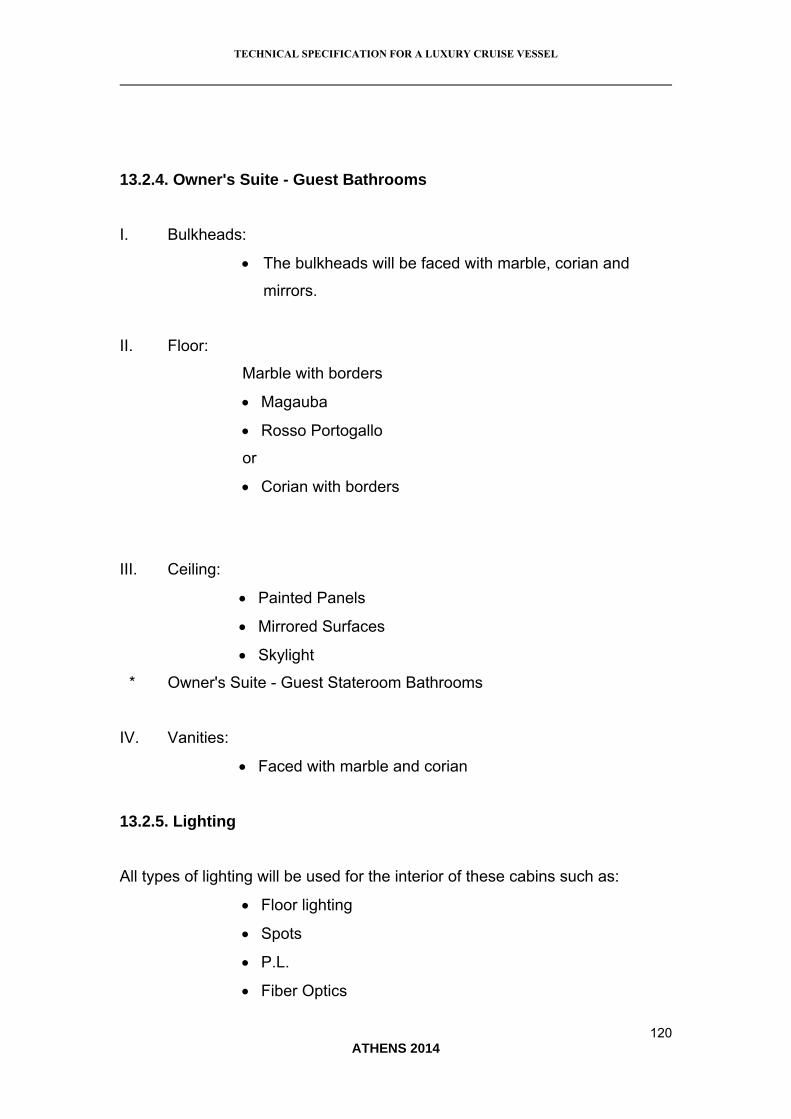
TECHNICAL SPECIFICATION FOR A LUXURY CRUISE VESSEL
120 ATHENS 2014
208B13.2.4. Owner's Suite - Guest Bathrooms
I. Bulkheads:
The bulkheads will be faced with marble, corian and
mirrors.
II. Floor:
Marble with borders
Magauba
Rosso Portogallo
or
Corian with borders
III. Ceiling:
Painted Panels
Mirrored Surfaces
Skylight
* Owner's Suite - Guest Stateroom Bathrooms
IV. Vanities:
Faced with marble and corian
209B13.2.5. Lighting
All types of lighting will be used for the interior of these cabins such as:
Floor lighting
Spots
P.L.
Fiber Optics

TECHNICAL SPECIFICATION FOR A LUXURY CRUISE VESSEL
121 ATHENS 2014
Fluorescent
210B13.2.6. Guest Saloons & Dining Areas
I. Bulkhead Surfaces:
Extrusions or sculptural forms are to be placed on each corner
or the bulkheads. These will be made of:
Marble
Corian
Silver leaf
Perspex
Sliding glass panels with rich motives.
Bulkheads made of brushed oak.
Sand blasted doors.
II. Floor:
Britons fine carpets with exclusive patterns
Parquet flooring - Amtico etc.
III. Ceiling:
The ceiling will be enriched with alcandara surfaces, recessed
lacquered, wooded, mirrored and glass elements.
IV. Furniture:
Classical and modern furniture will decorate the interior of the
suite. These are to be made of brushed oak and decorate the
interior plexiglas and corian will also be used.
V. Fabrics:

TECHNICAL SPECIFICATION FOR A LUXURY CRUISE VESSEL
122 ATHENS 2014
A selection of exclusive fabrics will enhance the guest and
dining saloons.
VI. Lighting:
Recessed fluorescent
Lighting
Spots
P.l.
Fiber optics
Floor lighting
211B13.2.7. Wheelhouse
I. Bulkhead Surfaces:
1. Brushed oak veneers
2. Wooden extrusions
3. Stainless steel panel / column and accessories
Doors with brushed oak veneers
External glass doors.
Floor:
II. Teak flooring: It must comply with the regulation
III. Ceiling: Painted or alcandara panels
IV. Furniture: The consoles are to be made of wood and
Stainless steel
V. Fabrics: The sofas are to be made of leather

TECHNICAL SPECIFICATION FOR A LUXURY CRUISE VESSEL
123 ATHENS 2014
VII. Lighting:
Spots,
Floor lighting
Fiber optics
P.L.
212B13.2.8. Guest Recreation Facilities
I. Bulkheads:
The bulkhead will faced with marble corian, mirrors, brushed oak
Veneer, sandblasted class and smoked glass.
II. Floor:
Marble flooring
Parquet flooring - Amtico etc.
III. Ceiling:
Painted panels, recessed mirrored skylights are to be
applied on the ceiling.
IV. Furniture:
Marble vanities, marble benches, wooden benches, gym.
equipment, lazy chairs.
V. Lighting:
Under water lighting.
Floor lighting
Fluorescent lighting
Fiber optics
Spots

TECHNICAL SPECIFICATION FOR A LUXURY CRUISE VESSEL
124 ATHENS 2014
P.l.
213B13.2.9. Crew cabins
I. Bulkheads:
Painted panels.
Veneer panels.
Mirrors.
II. Floor:
Carpet
III. Ceiling:
Painted panels
IV. Furniture:
Modern furniture faced with veneer.
V. Fabrics:
Selection of fabrics to enrich the interior.
214B11.2.10. Crew Bathrooms
I. Bulkheads:
Formica- corian
Sandblasted glass
II. Ceiling:
Painted ceiling
III. Floor:

TECHNICAL SPECIFICATION FOR A LUXURY CRUISE VESSEL
125 ATHENS 2014
Tiled floor
IV. Vanities:
Lacquered with corian tops
215B13.2.11. Lighting
Spots
P.L.
216B13.2.12. Library
I. Bulkheads:
The bulkheads are to be faced with brushed oak veneers
The doors will be solid wood and their frames lacing marble.
II. Floor:
Parquet flooring with exclusive hand made carpets.
III. Ceiling:
Painted ceiling with wooded beams.
IV. Furniture:
Classical furniture made of solid wood & brushed oak veneers.
The fireplace will be faced with marble & wood
V. Fabrics:
Exclusive fabrics will enrich the interior, leather will also be
used.
VI. Lighting:

TECHNICAL SPECIFICATION FOR A LUXURY CRUISE VESSEL
126 ATHENS 2014
Wall lighting.
Floor lighting spots.
217B13.2.13. Lobby
I. Bulkheads:
Extrusions or sculptural forms are to be placed on each corner
of the bulkheads.
The bulkheads will be faced with marble and brushed oak
veneers.
II. Floor:
Marble with borders
Types: Royal
Dionisos
Israeli
III. Ceiling:
Painted panels with recessed areas and wooden
details.
IV. Furniture:
Consoles made of marble and wood.
V. Lighting:
Floor lighting
Fluorescent
Spots

TECHNICAL SPECIFICATION FOR A LUXURY CRUISE VESSEL
127 ATHENS 2014
91B13.3. GALLEY - LAUNDRY - PANTRIES - REFRIGERATION
218B13.3.1. General
Vessel should be outfitted with 220V and 380V 50 Hz appliances. Electricity
will be used for cooking. All equipment installed shall be easily accessible and
removable for cleaning, maintenance and servicing. All equipment and
installation should be USCG approved. Care shall be taken that sufficient
ventilation is provided for all equipment.
219B13.3.2. Galley - Equipment List
i. Meat Preparation Area
Sink
Work table
Refrigerator
Chopping block
Band saw
Meat mincing machine
Hand wash basin
Cleaning locker
ii. Vegetable preparation
Sink
Work table
Refrigerator
Potato peeler
Vegetable cutter
Hand wash basin

TECHNICAL SPECIFICATION FOR A LUXURY CRUISE VESSEL
128 ATHENS 2014
Cleaning locker
iii. Fish preparation
Sink
Work table
Refrigerator
Hand wash basin
Cleaning locker
iv. Hot Galley
Electric ranges
Griddle plate
Electric fryer
Boiling pan
Cupboards
Combi oven
Refrigerators
Mixing machine
Blast cheeler
Bain Marie on heated cupboard
Salamander
Microwave oven
Plate dispenser on castors
Canopies
Hand wash basin
Cleaning locker
v. Cold Galley
Refrigerators
Sink
Work table

TECHNICAL SPECIFICATION FOR A LUXURY CRUISE VESSEL
129 ATHENS 2014
Cupboards
Slicing machine
Hand wash basin
Cleaning locker
vi. Bakery
Dough mixing machine
Sink
Work table
Mixing machine
Refrigerators
Pastry oven
Proover
Ice cream machine
Hand wash basin
Cleaning locker

TECHNICAL SPECIFICATION FOR A LUXURY CRUISE VESSEL
130 ATHENS 2014
vii. Steward's Area
Counter
Coffee machine
Toaster
Ice cube machines
Hand wash basin
Cleaning locker
viii. Pot washing area
Sink with 3 bowls (one with heating element)
Tubular pot racks with 3 levels
Waste disposer
Work table
Hand wash basin
Cleaning locker
ix. Scullery
Dish receiving table
Waste disposer
Sink
Dish washing machines
Glass washing machines
Rack stand
Plate storage racks
Storage locker
Hand wash basin
Cleaning locker
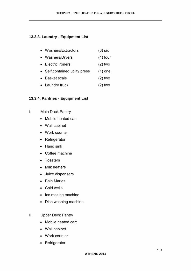
TECHNICAL SPECIFICATION FOR A LUXURY CRUISE VESSEL
131 ATHENS 2014
220B13.3.3. Laundry - Equipment List
Washers/Extractors (6) six
Washers/Dryers (4) four
Electric ironers (2) two
Self contained utility press (1) one
Basket scale (2) two
Laundry truck (2) two
221B13.3.4. Pantries - Equipment List
i. Main Deck Pantry
Mobile heated cart
Wall cabinet
Work counter
Refrigerator
Hand sink
Coffee machine
Toasters
Milk heaters
Juice dispensers
Bain Maries
Cold wells
Ice making machine
Dish washing machine
ii. Upper Deck Pantry
Mobile heated cart
Wall cabinet
Work counter
Refrigerator

TECHNICAL SPECIFICATION FOR A LUXURY CRUISE VESSEL
132 ATHENS 2014
Hand sink
Coffee machine
Toasters
Milk heaters
Juice dispensers
Bain Maries
Cold wells
Ice making machine
Dish washing machine
iii. Top Deck Pantry
Work counter
Refrigerator
Hand sink
Coffee machine
Toasters
Milk heaters
Juice dispensers
Cold wells
Ice making machine
BBQ
Glass washing machine
iv. Officer & Crew Mess Pantry
Mobile heated cart
Wall cabinet
Work counter
Refrigerator
Hand sink
Coffee machine
Toasters

TECHNICAL SPECIFICATION FOR A LUXURY CRUISE VESSEL
133 ATHENS 2014
Milk heaters
Juice dispensers
Bain Maries
Cold wells
Ice making machine
Dish washing machine
222B13.3.5. Refrigeration - Equipment List
The refrigeration system will comply with the General Arrangement plan (dwg.
# 172-02a & b) with regard to space and internal construction. Sanitary and
draining system will be USCG approved and electrically powered by 220 or
380 V - 50 Hz.
Meat refrigerator (walk-in space). Temp.: -20ºC (approx.)
Fish refrigerator (walk-in space). Temp.: -20ºC (approx.)
Vegetable refrigerator (walk-in space). Temp.: +2ºC up to +6ºC (approx.)
Cheese-Milk refrigerator. Temp.: +2ºC up to +6ºC (approx.)
Wine Cellar area.
Garbage freezer (as described previously).

TECHNICAL SPECIFICATION FOR A LUXURY CRUISE VESSEL
134 ATHENS 2014
13B14. PAINT SYSTEM
92B14.1. GENERAL
The Contractor shall utilize a complete system to ensure that the products
used are totally compatible. The Contractor shall be wholly responsible for the
painting and fairing. All color schemes, styling lines and special features shall
be detailed by the Naval Architect. The manufacturer's instructions will be
strictly followed with regard to the stowage of all the material, the preparation
of the surfaces and the application of the system. Particular consideration will
be paid to climatic conditions, mixing ratios, dry-film thickness and
overcoating times. Fairing is to be of the highest possible accuracy and quality
finishing prior to paint application. The Contractor shall consult closely with
the manufacturer and arrange inspections by a representative of the
manufacturer. The paint will be applied by spray, and during the application
and drying of the final finishes there shall be no other activity taking place in
the vicinity which may cause undue dust. Burnishing of the paint is required to
achieve the high standard of the final finish. All due care shall be exercised in
eliminating unevenness in the superstructure sides, with suitable fairing
compounds. The hull from waterline to sheer line shall be faired to remove
any major unevenness. Exterior finish will be of good marine practice with
finish coat to have a smooth, high gloss surface.
93B14.2. DESCRIPTION OF THE SYSTEM
235B14.2.1. General All Steel (External)
i. Blast to SA 2,5
ii. Shopprimer (Epoxy)
iii. Epoxy Anticorrosive to 150 m DFT

TECHNICAL SPECIFICATION FOR A LUXURY CRUISE VESSEL
135 ATHENS 2014
223B14.2.2. Hull Underwater
i. Epoxy Anticorrosive to 150 m DFT
ii. Epoxy Tie Coat to 100 m
iii. Antifouling SPC type to 250 m
224B14.2.3. Hull (Waterline and Over)
i. Epoxy Anticorrosive to 150 m DFT
ii. LW Epoxy Fairing Compound (as needed)
iii. Refinish Epoxy Filler
iv. Epoxy Primer
v. Sprayable Fairing Compound
vi. Epoxy Primer
vii. P/U Undercoat
viii. P/U Topcoat
Remark: All above mentioned stages are considering that the above system
will be applied 80 cm below waterline excluding steps 7,8 and applied steps 2,
3 of underwater area.
225B14.2.4. Superstructure
i. LW Epoxy Fairing Compound (as needed)
ii. Refinish Epoxy Filler
iii. Epoxy Primer
iv. Sprayable Fairing Compound
v. Epoxy Primer
vi. P/U Undercoat
vii. P/U Topcoat

TECHNICAL SPECIFICATION FOR A LUXURY CRUISE VESSEL
136 ATHENS 2014
226B14.2.5. Aluminum Structures
i. Primer for Light Alloys
ii. Epoxy Primer
iii. LW Epoxy Fairing Compound (as needed)
iv. Refinish Epoxy Filler
v. Epoxy Primer
vi. Sprayable Fairing Compound
vii. Epoxy Primer
viii. P/U Undercoat
ix. P/U Topcoat
227B14.2.6. Internals (All except Tanks Bilges and Engine Room)
For the internals as already described sandblasting of SA 2 ½ is
required prior using the following paints.
i. Water based Acrylic Primer 2 x 60 m DFT
ii. Water based Topcoat 50 m DFT
228B14.2.7. Oil Tanks
i. Epoxy Base Tank Coating 3 x 100 m DFT
14.2.8. Fresh Water Tanks
i. Epoxy Primer 100 m DFT
ii. Epoxy Base Potable Water Primer 100 m DFT
iii. Epoxy Base Potable Water Topcoat 50 m DFT
230B14.2.9. Engine Room
As per external topside excluding the fairing.

TECHNICAL SPECIFICATION FOR A LUXURY CRUISE VESSEL
137 ATHENS 2014
231B14.2.10. Bilges, Gray and Black Tanks and Ballast tanks
i. Epoxy Primer 2 x 150 m DFT

TECHNICAL SPECIFICATION FOR A LUXURY CRUISE VESSEL
138 ATHENS 2014
14B15. TEAK DECKS, DECK FITTINGS
94B15.1. TEAK DECKS
232B15.1.1. Teak Quality
The teak to be used will be:
“Decking” quality for all margins and bulwarks
“Super decking” quality for the rest of the teak decks and the steps.
Wood humidity before fitting to be not more than 10%.
233B15.1.2. Mode of Fitting
The plates will be totally cleaned to SA 2.5 sandblasting level in all areas to
be welded and cut and in all other areas that are corroded.
If it is a large-scale corrosion (more than 50%) the decks will be totally
sandblasted (SA 2.5) and painted with epoxy primer.
Afterwards, the decks will be leveled with special epoxy materials and then
the teak will be fitted completely glued with special rubber glue.
The length of the boards will not be less than 4m and their width will not
exceed 65 mm with joints 5mm wide and 6 mm deep.
The thickness of the boards will be:
Main deck and fore deck: 20 mm net
On all the rest of the decks: 16 mm net

TECHNICAL SPECIFICATION FOR A LUXURY CRUISE VESSEL
139 ATHENS 2014
Special foundations of teak will be fitted on all deck fittings such as
bollards/bitts, capstans and wherever else necessary.
The teak deck will circle all the above with margins according to the drawings
and the recommendations of the Naval Architect.
The special drawings of the Naval Architect will be followed precisely.
The vertical floor side rails will be glued and all curved parts will be laminated
with moulds.
The rubber of the joints will be fitted according to the instructions of the
manufacturer, whereas the final sanding of the decks will be effected after
sufficient time has elapsed and always according to supplier's instructions.
The bulwarks will be constructed and fitted according to the plans of the Naval
Architect, special attention will be given to joint areas.
Wherever wood bulwarks are fitted on top of metal bulwarks, there will be
suitable slots made on the bulwarks.
Stainless steel screws will be glued on the metal bulwarks. Then special
rubber glue will be applied, the bulwarks will be joined with stainless steel
nuts, so that the surplus rubber glue can be removed. Wooden cups will be
fitted in the holes.
Immediately after fitting and after they are thoroughly sanded, the bulwarks
will be coated with protective varnish and painted according to supplier's
instructions.
95B15.2. DECK FITTINGS

TECHNICAL SPECIFICATION FOR A LUXURY CRUISE VESSEL
140 ATHENS 2014
The following items which will be made of Stainless Steel 316, will be either
constructed or purchased: bollards - hawse pipes, special foundation
accessories, anchor hawse pipe jackets, external anchor plates, windlass and
capstan foundations, gutter scuppers, non-fixed staircase frames, rails,
handrails, flying bridge deck windscreen frame, foundations for antennas and
mast instruments, foundations of navigation lighting, clamps and accessories
of exterior metal furniture, frames of deck hatch openings, foundations for
storm covers, etc. All elements that are visible will be perfectly polished.
The screws/nuts will also be of stainless steel where required.
The Contractor will follow strictly the special drawings and the
recommendations of the Naval Architect.

TECHNICAL SPECIFICATION FOR A LUXURY CRUISE VESSEL
141 ATHENS 2014
15B16. TESTS & TRIALS
96B16.1. GENERAL
The Contractor shall develop a complete schedule of all test and trials and
shall be responsible for scheduling the involvement of any of the equipment
supplier and vendors.
97B16.2. DOCK TRIALS
The Contractor shall conduct dock trials of all the vessel's systems prior to
sea trials. The Contractor shall ensure the involvement of any equipment
suppliers. The Contractor shall make detailed reports of the status of the
various systems and keep complete records of all trials.
234B16.2.1. Stability Test/Inclining Experiment
ALPHA MARINE Ltd. shall conduct an inclining experiment on the vessel
upon completion of the building works. The determination of the suitability of
the conditions (weather or otherwise) for the test remain with ALPHA MARINE
Ltd. and Classification Society surveyor. The Contractor shall be required to
re-schedule the test if the conditions are deemed unsuitable. The Contractor
shall supply all equipment including but not limited to certified test weights,
and equipment for their handling. The test shall be conducted in accordance
with the Class standards, the United States Coast Guard Navigation
standards where applicable and the requirements of the Flag State. The
results shall be used to develop the required stability information booklet for
the vessel's master.
98B16.3. SEA TRIALS

TECHNICAL SPECIFICATION FOR A LUXURY CRUISE VESSEL
142 ATHENS 2014
Sea trials shall be conducted on the vessel to insure that the vessel is
operating correctly.
The trials shall be conducted in general accordance with the Sea Trial Code
C-2 (SNAME, 1973) and shall include the following tests:
• Compass calibration • Speed trials
• Turning circles • Z-maneuver
• Ahead steering test • Emergency steering test
• Crash ahead from astern • Crash astern from ahead
• Astern run • Astern steering test
• Anchor handling test • Fin stabilizer test
• Bow thruster test
There will be also performed any additional tests required by the regulatory
bodies or the equipment manufacturers.
The trials shall not be conducted if the true wind exceeds 2 B or the significant
wave height exceeds 0,5 m. The main engine manufacturer's guide for sea
trials shall also be consulted. Speed trials shall be conducted for at least
three well-documented loading conditions of the vessel one of which shall be
full load. The documentation of the loading conditions shall include:
Draft at the forward perpendicular
Draft at the after perpendicular
Trim angle
Number and weight of persons aboard
Summary of test equipment abroad
Summary of any missing equipment
Summary of the tank loading conditions

TECHNICAL SPECIFICATION FOR A LUXURY CRUISE VESSEL
143 ATHENS 2014
The Contractor shall bear the cost of the trials including the cost of any
instrumentation required to conduct the tests.
16B17. CONCLUSION
The aim of this dissertation was to provide a mini technical specification for
the building of a new luxury cruise ship. More specifically, the dissertation has
the following objectives:
- To analyze the elements and importance of technical specification
- To outline a detailed mini specification for the building of a new cruise
ship, which will be a twin screw, luxury passenger vessel, meeting
SOLAS ’90 regulations and its amendments issued in 2000, for
passenger vessels carrying up to 36 for international voyages.
- To provide implications for shipping companies and other bodies
involved in ship building regarding the importance of correct technical
specifications in terms of cost, time, and ship-building accuracy
As the analysis indicated, technical specifications include all the materials,
elements, and processes that are embodied in the production or design of
products and services. Depending on the nature of products and services,
different specifications apply within company, national, regional, or
international contexts. The existence of technical specifications is very
important for manufacturers, designers, sellers, and purchasers-users, since
they define how products and services shall be produced and designed, as
well as what purchasers shall expect from them. The case of the shipping
industry is a special one, due to its international nature and the obligation of
ship owners to fully company with international shipping standards, in order to
enhance and maintain safety of ships, crews, cargos, and passengers, while
also safeguarding environmental protection (Stopford, 2009).

TECHNICAL SPECIFICATION FOR A LUXURY CRUISE VESSEL
144 ATHENS 2014
The detailed mini-specification that was outlined in this dissertation
regarding the construction of a new luxury cruise ship, carrying up to 36
passengers and performing international voyage, was designed in a way that
it complies with SOLAS Convention and its amendments, while at the same
ensuring that the new ship will have all comforts and facilities to reflect that it
is a luxury cruise ship. Indeed, every chapter outlined the specifications of
every single element, part, and function of the new cruise ship, being
compliant with the chapters and provisions of the SOLAS Convention at the
maximum possible point.
The proposed technical specification that was outlined in the main body
of this dissertation provides several implications for the bodies involved. First
of all, by following the detailed technical specifications that were outlined the
shipyard that will be occupied with the construction of the vessel will have the
opportunity to control its production and operating costs. It will know in
advance what the costs of its part and component of the new vessel will be,
how many resources need to be allocated and how, as well as what it takes to
construct a vessel that will fully comply with the obligations implied by SOLAS
and other IMO conventions. The construction company will also ensure that it
will not face any liabilities in case of a maritime accident, or in case the ship
owners argue that components or facilities of the vessels were not
constructed based on their needs and requests, a point that is closely linked
to the opinion of Buzacott & Shanthikumar (1993), who also support that
technical specifications safeguard constructors from liabilities.
At the same time, the ship owners of the new vessel will also ensure
that they fully comply with international shipping standards, thereby being able
to acquire the necessary certifications for the vessel to operate in international
seas. They will also maintain the high quality and luxury attributes of the
vessel to be built, so as to be consistent with the luxury cruise services that
will be meant to provide. Most importantly, ship owners will ensure that they
will have taken all necessary measures to ensure safety at sea for the ship
itself, her crew, and her passengers, while at the same time not polluting and
damaging the environment beyond what is accepted by IMO regulations.

TECHNICAL SPECIFICATION FOR A LUXURY CRUISE VESSEL
145 ATHENS 2014
Another advantage for the ship owner will be that the company that will be
assigned to construct the vessel will examine the applicability of the proposed
technical specifications, and will probably make the necessary changes, so
that both parties know in advance what they will have to expect, avoiding the
emergence of technical conditions that will request more time and effort to be
dealt with, as this is also suggested by Langenberg (2005). In this way, the
ship owners will also have the opportunity to identify what each component is
likely to cost, and probably omit or upgrade some of them, in order to fit the
final construction cost to the initially decided budget. New budget
arrangements may also emerge instead, in case of upgrades in the quality of
one or more of the components of the new cruise ship. By developing and
following the proposed technical specification for the new cruise ship that was
outlined in this dissertation, it will also be easier for the flag state (Greece in
this case) to monitor the new vessel and check whether it complies with IMO
and flag-state regulations as well.
As a whole, the importance of developing a correct and detailed
technical specification, as this has also been supported Murphy & Yates
(2008) is indicated through the analysis of this dissertation. Indeed, following
the outlined technical specification will benefit all the parties involved in the
new vessel’s construction process. Ideally, the technical specification
proposed will lead to the operation of a new cruise ship, which will be
operationally efficient and safe for crews, passengers, and the environment,
while at the same time serving its commercial aim of offering luxury cruise
services to its passengers.

TECHNICAL SPECIFICATION FOR A LUXURY CRUISE VESSEL
146 ATHENS 2014
17B18. REFERENCES
Alexopoulos, A. B., & Fournarakis, N. G. (2003), Conventions-
Regulations-Codes, 1st edition, Evyenidio Foundation Publishers.
Berg, C., French, D., & Wilson, B. (1983), Efficiency of Manufacturing
Systems New York, Plenum Press 1983
Buzacott, J. A., & Shanthikumar, J. G. (1993), Stochastic models of
manufacturing systems, Prentice Hall Publications.
Chase, R. B., Jacobs, F. R., Aquilano, N. J. (2011), Operations
Management for Competitive Advantage, 11th edition, McGraw-Hill
Publications.
Christensen, C. M., & Raynor, M. E. (2003), The Innovator's Solution:
Creating and Sustaining Successful Growth, Boston, Mass: Harvard
Business School Press.
Craig, C. S., & Douglas, S. P. (2000), “Configural advantage in global
markets”, Journal of International Marketing, 8(1): 6-25.
Dickson, E. W., Singh, S., Cheung, D. S., Wyatt, C. C., & Nugent, A. S.
(2008), "Application of Lean Manufacturing Techniques in the
Emergency Department", Journal of Emergency Medicine, 37 (2): 177–
182.
Hill, T. (2000), Manufacturing Strategy-Text and Cases, 3rd edition, Mc-
Graw Hill Publications.

TECHNICAL SPECIFICATION FOR A LUXURY CRUISE VESSEL
147 ATHENS 2014
Hopp, W., & Spearman, M. (2011), Factory Physics, 3rd edition,
Waveland Press.
International Maritime Organization (IMO), (2014), “International
Convention for the Safety of Life at Sea (SOLAS) 1974”, available at
<http://www.imo.org/About/Conventions/ListOfConventions/Pages/Inter
national-Convention-for-the-Safety-of-Life-at-Sea-%28SOLAS%29,-
1974.aspx>, accessed on 30-08-2014.
International Maritime Organization (IMO) (2014), “Passenger ships”,
available at
<http://www.imo.org/OurWork/Safety/Regulations/Pages/PassengerShi
ps.aspx>, accessed on 02-09-2014.
Keegan, J. K., & Schlegelmilch, B. B. (2001), Global marketing
management – A European Perspective, Gosport: Ashford Colour
Press Ltd.
Langenberg, T. (2005), Standardization and Expectations, Berlin:
Springer-Verlag Publications.
Malakooti, B. (2013), Operations and Production Systems with Multiple
Objectives, John Wiley & Sons Publications.
McWilliams, A., & Siegel, D. (2001), "Corporate social responsibility: A
theory of the firm perspective", Academy of Management Review, 26:
117–127.
Murphy, C. N., & Yates, J. (2008), The International Organization for
Standardization (ISO): Global Governance Through Voluntary
Consensus, New York: Routledge Publications.

TECHNICAL SPECIFICATION FOR A LUXURY CRUISE VESSEL
148 ATHENS 2014
Ostwald, P., & Muñoz, J. (1997), Manufacturing Processes and
Systems, 9th Edition, John Wiley & Sons Publications.
Ping, W. (2011), A Brief History of Standards and Standardization
Organizations: A Chinese Perspective, East-West Center of Working
Papers.
Shapiro, C., & Varian, H. R. (1999), Information Rules: A Strategic
Guide to the Network Economy, Boston, Mass: Harvard Business
School Press.
Soyer, B., & Tettenborn, A. (2013), Pollution at Sea: Law and Liability,
Taylor & Francis Publications.
Stefanovic, M., Matijević, M., Milan, E., & Simic, V (2009), "Method of
design and specification of web services based on quality system
documentation", Information Systems Frontiers, 11 (1): 75–86.
Stopford, M. (2009), Maritime Economics, 3rd edition. Taylor & Francis
group Publications.
Theodosiou-Leonidou, M. & Leonidou, L. (2002). “Standardization
versus adaptation of international marketing strategy: an interactive
assessment of the empirical research”, International Business Review,
12, 141-177.
United Nations (2013), “Review of maritime transport 2013”, available
at <http://unctad.org/en/PublicationsLibrary/rmt2013_en.pdf>,
accessed on 02/09/2014.
United Nations Industrial Development Organization (UNIDO) (2006),
“Role of standards: A guide for small and medium-sized enterprises”,

TECHNICAL SPECIFICATION FOR A LUXURY CRUISE VESSEL
149 ATHENS 2014
available at
<http://www.unido.org/fileadmin/media/documents/pdf/tcb_role_standar
ds.pdf>, accessed on 02-09-2014.


