Embed Size (px)
Citation preview

TCP/IP Demonstrations Help
MPLAB Harmony Integrated Software Framework
© 2013-2018 Microchip Technology Inc. All rights reserved.

Volume I: Getting Started With MPLAB Harmony Libraries and Applications This volume introduces the MPLAB® Harmony Integrated Software Framework.
Description
MPLAB Harmony is a layered framework of modular libraries that provide flexible and interoperable software "building blocks" for developing embedded PIC32 applications. MPLAB Harmony is also part of a broad and expandable ecosystem, providing demonstration applications, third-party offerings, and convenient development tools, such as the MPLAB Harmony Configurator (MHC), which integrate with the MPLAB X IDE and MPLAB XC32 language tools.
Legal Notices
Please review the Software License Agreement prior to using MPLAB Harmony. It is the responsibility of the end-user to know and understand the software license agreement terms regarding the Microchip and third-party software that is provided in this installation. A copy of the agreement is available in the <install-dir>/doc folder of your MPLAB Harmony installation.
The OPENRTOS® demonstrations provided in MPLAB Harmony use the OPENRTOS evaluation license, which is meant for demonstration purposes only. Customers desiring development and production on OPENRTOS must procure a suitable license. Please refer to one of the following documents, which are located in the <install-dir>/third_party/rtos/OPENRTOS/Documents folder of your MPLAB Harmony installation, for information on obtaining an evaluation license for your device:
• OpenRTOS Click Thru Eval License PIC32MXxx.pdf
• OpenRTOS Click Thru Eval License PIC32MZxx.pdf
TIP!Throughout this documentation, occurrences of <install-dir> refer to the default MPLAB Harmony installation path:
• Windows: C:/microchip/harmony/<version>
• Mac OS/Linux: ~/microchip/harmony/<version>
Volume I: Getting Started With MPLAB Harmony
© 2013-2017 Microchip Technology Inc. MPLAB Harmony v2.06 2

Applications Help
This section provides information on the various application demonstrations that are included in MPLAB Harmony.
Description
Applications determine how MPLAB Harmony libraries (device drivers, middleware, and system services) are used to do something useful. In a MPLAB Harmony system, there may be one main application, there may be multiple independent applications or there may be one or more Operating System (OS) specific applications. Applications interact with MPLAB Harmony libraries through well defined interfaces. Applications may operate in a strictly polling environment, they may be interrupt driven, they may be executed in OS-specific threads, or they may be written so as to be flexible and easily configured for any of these environments. Applications generally fit into one of the following categories.
Demonstration Applications
Demonstration applications are provided (with MPLAB Harmony or in separate installations) to demonstrate typical or interesting usage models of one or more MPLAB Harmony libraries. Demonstration applications can demonstrate realistic solutions to real-life problems.
Sample Applications
Sample applications are extremely simple applications provided with MPLAB Harmony as examples of how to use individual features of a library. They will not normally accomplish anything useful on their own. They are provided primarily as documentation to show how to use a library.
TCP/IP Demonstrations
This section provides descriptions of the TCP/IP demonstrations.
MPLAB Harmony is available for download from the Microchip website by visiting: http://www.microchip.com/mplabharmony. Once you are on the site, click the Downloads tab to access the appropriate download for your operating system. For additional information on this demonstration, refer to the “Applications Help” section in the MPLAB Harmony Help.
Introduction
TCP/IP and Wi-Fi® Demonstration Applications Help
Description
Important!
1. The TCP/IP demonstration applications assume that IPv4 is enabled. If IPv4 is disabled in MHC, the app.c code will no longer build and needs to be updated to remove the IPv4 dependencies.
2. The Ethernet Controller requires a minimum clock frequency to be able to keep up with 100 Mbps traffic. Currently, this frequency must be at least 40 MHz for PIC32MX/PIC3MZ platforms. This is a minimum value, and depending on the system bus load, the actual running frequency may need to be higher than this.
TCP/IP Demonstrations
This section describes Microchip's TCP/IP Demonstration projects, including information about demonstration-hardware compatibility and also provides the information about how to configure and run the demonstrations.
Wi-Fi Demonstrations
This distribution package contains a variety of Wi-Fi-based firmware projects that demonstrate the capabilities of the MPLAB Harmony Wi-Fi services and TCP/IP Stack running on PIC32 devices. This section describes the hardware requirements and procedures to run these firmware projects on Microchip demonstration and development boards.
Wi-Fi Console Commands
This section describes the demonstration support commands available for the Wi-Fi Web Server and EasyConfig demonstrations.
Description
Both the Web Server and the EasyConfig demonstrations support Wi-FI Console commands, which enable control over the Wi-Fi settings.
Command: eraseconf
Parameters Description
None. Wi-Fi console command to erase saved Wi-Fi configuration in memory.
Command: iwconfig
Volume I: Getting Started With MPLAB Harmony Applications Help TCP/IP Demonstrations
© 2013-2017 Microchip Technology Inc. MPLAB Harmony v2.06 3

Parameters Description
[ ssid <name>] name: Specifies the name of the SSID (1-32 ASCII characters).
[ mode <idle | managed> ]
idle: Disconnected from the current configuration.
managed: Connects in infrastructure mode to the currently set SSID.
[ power <enable | disable> ]
enable: Enables all Power-Saving features (PS_POLL). Will wake up to check for all types of traffic (unicast, multicast, and broadcast).
disable: Disables any Power-Saving features. Will always be in an active power state.
[ security <mode> ] mode: open/wep40/wep104/wpa/wpa2/pin/pbc. For example:iwconfig security open
iwconfig security wep40 <key>
iwconfig security wep104 <key>
iwconfig security wpa <key>
iwconfig security wpa2 <key>
iwconfig security pin <pin>
iwconfig security pbc
[ scan ] Starts a Wi-Fi scan.
[ scanget <scan_index> ]
scan_index: Retrieves the scan result after the scan completes (1 - n).
Command: mac
Parameters Description
None. Wi-Fi console command to retrieve the MAC address of the Wi-Fi module.
Command: readconf
Parameters Description
None. Wi-Fi console command to read saved Wi-Fi configuration in memory.
Command: saveconf
Parameters Description
None. Wi-Fi console command to save Wi-Fi configuration to memory.
Demonstrations
Description of TCP/IP Stack Library Demonstration Application.
Description
PHY Driver Support
All of the PIC32MX and PIC32MZ projects that are part of the distribution and use the Microchip reference development boards are preconfigured with specific PHY Drivers. Where the board supports different PHY daughter boards, the default PHY could be changed. To use a different PHY for a specific board the following must be done:
1. Use the MHC to configure your project to use the correct PHY and make sure that both the correct PHY address and configuration flags are used for the particular PHY daughter board. The MII/RMII and I/O configuration flags for the PHY board should match the project configuration fuses.
2. Regenerate the project and make sure that the new PHY driver is selected for the configuration that you're using.
Alternatively, you can manually set up your project, as follows:
• The project should select the PHY driver that corresponds to the PHY Daughter Board (i.e, LAN8720, LAN8740, LAN9303, etc.) in use for the selected configuration
• Modify for the TCPIP_EMAC_PHY_ADDRESS and TCPIP_EMAC_PHY_CONFIG_FLAGS to have the correct PHY address (the PHY address for both the SMSC PHY Daughter Boards is usually zero, for example) and the configuration flags (MII/RMII, I/O pin configuration, etc.)
• Or update directly the tcpip_stack_init.c:: tcpipMACPIC32INTInitData structure to have the correct PHY address and the configuration flags
• Make sure that the configuration fuses are properly selected to match your hardware and PHY board
• Rebuild the project
Volume I: Getting Started With MPLAB Harmony Applications Help TCP/IP Demonstrations
© 2013-2017 Microchip Technology Inc. MPLAB Harmony v2.06 4

berkeley_tcp_client
Before using this demonstration, please see the important notes in the TCP/IP Demonstrations > Introduction.
This configuration demonstrates creating an Internet client that uses the Berkeley API to create a TCP/IP connection to a web server.
Building the Application
This section identifies the MPLAB X IDE project name and location and lists and describes the available configurations for the Berkeley TCP Client Demonstration.
Description
To build this project, you must open the berkeley_tcp_client.X project in MPLAB X IDE, and then select the desired configuration.
The following tables list and describe the project and supported configurations. The parent folder for these files is <install-dir>/apps/tcpip/berkeley_tcp_client.
Warning
When using the Microchip Harmony Configurator (MHC), care must be taken when generating the code to not erase the USB descriptors in the system_init.c file.
MPLAB X IDE Project
This table lists the name and location of the MPLAB X IDE project folder for the demonstration.
Project Name Location
berkeley_tcp_client.X <install-dir>/apps/tcpip/berkeley_tcp_client/firmware
MPLAB X IDE Project Configurations
This table lists and describes the supported configurations of the demonstration, which are located within ./firmware/src/system_config.
Project Configuration Name
BSP Used Description
pic32mx_eth_sk pic32mx_eth_sk Demonstrates the Berkeley TCP Client on the PIC32 Ethernet Starter Kit.
pic32mx_eth_sk2 pic32mx_eth_sk2 Demonstrates the Berkeley TCP Client on the PIC32 Ethernet Starter Kit II.
pic32mz_ec_sk pic32mz_ec_sk Demonstrates the Berkeley TCP Client on the PIC32MZ EC Starter Kit.
pic32mz_ef_sk pic32mz_ef_sk Demonstrates the Berkeley TCP Client on the PIC32MZ EF Starter Kit.
Configuring the Hardware
Describes how to configure the supported hardware.
Description
PIC32 Ethernet Starter Kit
No hardware related configuration or jumper setting changes are necessary.
PIC32 Ethernet Starter Kit II
No hardware related configuration or jumper setting changes are necessary.
PIC32MZ EC Starter Kit
No hardware related configuration or jumper setting changes are necessary.
PIC32MZ EF Starter Kit
No hardware related configuration or jumper setting changes are necessary.
Running the Demonstration
This section provides instructions on how to build and run the demonstration.
Volume I: Getting Started With MPLAB Harmony Applications Help TCP/IP Demonstrations
© 2013-2017 Microchip Technology Inc. MPLAB Harmony v2.06 5

Description
For PIC32M-based Starter Kits
1. Connect a USB cable from the computer to the micro-B USB connector on the bottom of the starter kit in use.
2. When the demonstration runs, it will create a virtual com with USB CDC device on the USB bus.
3. Open a standard terminal application on the computer (such as HyperTerminal or Tera Term).
4. Set the baud rate to 921600 baud in the terminal application.
5. Establish a connection between the router or switch with the PIC32M Starter Kit using the RJ45 connector.
For all hardware, ensure the router or switch is connected to the Internet.
There is only one command available in the demonstration from the serial port:
openurl <url> - The <url> argument must be a fully formed URL; for instance, http://www.microchip.com/
After that one command is input, the demonstration will make a DNS query, and then open a connection to the requested URL and perform a simple HTTP PUT command. The results will be sent to the serial port.
berkeley_tcp_server
Before using this demonstration, please see the important notes in the TCP/IP Demonstrations > Introduction.
This configuration demonstrates creating an Internet server that uses the Berkeley API to create a TCP/IP echo server on port 9764.
Building the Application
This section identifies the MPLAB X IDE project name and location and lists and describes the available configurations for the Berkeley TCP Server Demonstration.
Description
To build this project, you must open the berkeley_tcp_server.X project in MPLAB X IDE, and then select the desired configuration.
The following tables list and describe the project and supported configurations. The parent folder for these files is <install-dir>/apps/tcpip/berkeley_tcp_server.
Warning
When using the Microchip Harmony Configurator (MHC), care must be taken when generating the code to not erase the USB descriptors in the system_init.c file.
MPLAB X IDE Project
This table lists the name and location of the MPLAB X IDE project folder for the demonstration.
Project Name Location
berkeley_tcp_server.X <install-dir>/apps/tcpip/berkeley_tcp_server/firmware
MPLAB X IDE Project Configurations
This table lists and describes the supported configurations of the demonstration, which are located within ./firmware/src/system_config.
Project Configuration Name
BSP Used Description
pic32mx_eth_sk pic32mx_eth_sk Demonstrates the Berkeley TCP Server on the PIC32 Ethernet Starter Kit.
pic32mx_eth_sk2 pic32mx_eth_sk2 Demonstrates the Berkeley TCP Server on the PIC32 Ethernet Starter Kit II.
pic32mz_ec_sk pic32mz_ec_sk Demonstrates the Berkeley TCP Server on the PIC32MZ EC Starter Kit.
pic32mz_ef_sk pic32mz_ef_sk Demonstrates the Berkeley TCP Server on the PIC32MZ EF Starter Kit.
Configuring the Hardware
Describes how to configure the supported hardware.
Description
PIC32 Ethernet Starter Kit
No hardware related configuration or jumper setting changes are necessary.
Volume I: Getting Started With MPLAB Harmony Applications Help TCP/IP Demonstrations
© 2013-2017 Microchip Technology Inc. MPLAB Harmony v2.06 6

PIC32 Ethernet Starter Kit II
No hardware related configuration or jumper setting changes are necessary.
PIC32MZ EC Starter Kit
No hardware related configuration or jumper setting changes are necessary.
PIC32MZ EF Starter Kit
No hardware related configuration or jumper setting changes are necessary.
Running the Demonstration
This section provides instructions on how to build and run the demonstration.
Description
For PIC32M-based Starter Kits
1. Connect a USB cable from the computer to the micro-B USB connector on the bottom of the starter kit in use.
2. When the demonstration runs, it will create a virtual com with USB CDC device on the USB bus.
3. Open a standard terminal application on the computer (such as HyperTerminal or Tera Term).
4. Set the baud rate to 921600 baud in the terminal application.
5. Establish a connection between the router or switch with the PIC32M Starter Kit using the RJ45 connector.
The demonstration does not offer any additional functionality through the serial port; however, the current IP can be checked. As soon as a valid IP has been assigned through DHCP to the demonstration, it is then ready to accept a TCP/IP connection on 9760. The demonstration will echo back everything it receives along the connection.
berkeley_udp_client
Before using this demonstration, please see the important notes in the TCP/IP Demonstrations > Introduction.
This configuration demonstrates creating an Internet client that uses the Berkeley API to create a UDP/IP connection to a specified port.
Building the Application
This section identifies the MPLAB X IDE project name and location and lists and describes the available configurations for the Berkeley UDP Client Demonstration.
Description
To build this project, you must open the berkeley_udp_client.X project in MPLAB X IDE, and then select the desired configuration.
The following tables list and describe the project and supported configurations. The parent folder for these files is <install-dir>/apps/tcpip/berkeley_udp_client.
Warning
When using the Microchip Harmony Configurator (MHC), care must be taken when generating the code to not erase the USB descriptors in the system_init.c file.
MPLAB X IDE Project
This table lists the name and location of the MPLAB X IDE project folder for the demonstration.
Project Name Location
berkeley_udp_client.X <install-dir>/apps/tcpip/berkeley_udp_client/firmware
MPLAB X IDE Project Configurations
This table lists and describes the supported configurations of the demonstration, which are located within ./firmware/src/system_config.
Project Configuration Name
BSP Used Description
pic32mx_eth_sk pic32mx_eth_sk Demonstrates the Berkeley UDP Client on the PIC32 Ethernet Starter Kit.
pic32mx_eth_sk2 pic32mx_eth_sk2 Demonstrates the Berkeley UDP Client on the PIC32 Ethernet Starter Kit II.
pic32mz_ec_sk pic32mz_ec_sk Demonstrates the Berkeley UDP Client on the PIC32MZ EC Starter Kit.
Volume I: Getting Started With MPLAB Harmony Applications Help TCP/IP Demonstrations
© 2013-2017 Microchip Technology Inc. MPLAB Harmony v2.06 7

pic32mz_ef_sk pic32mz_ef_sk Demonstrates the Berkeley UDP Client on the PIC32MZ EF Starter Kit.
Configuring the Hardware
Describes how to configure the supported hardware.
Description
PIC32 Ethernet Starter Kit
No hardware related configuration or jumper setting changes are necessary.
PIC32 Ethernet Starter Kit II
No hardware related configuration or jumper setting changes are necessary.
PIC32MZ EC Starter Kit
No hardware related configuration or jumper setting changes are necessary.
PIC32MZ EF Starter Kit
No hardware related configuration or jumper setting changes are necessary.
Running the Demonstration
This section provides instructions on how to build and run the demonstration.
Description
For PIC32M-based Starter Kits
1. Connect a USB cable from the computer to the micro-B USB connector on the bottom of the starter kit in use.
2. When the demonstration runs, it will create a virtual com with USB CDC device on the USB bus.
3. Open a standard terminal application on the computer (such as HyperTerminal or Tera Term).
4. Set the baud rate to 921600 baud in the terminal application.
5. Establish a connection between the router or switch with the PIC32M Starter Kit using the RJ45 connector.
There are three sequential commands that can be used from the console:
• setudppacketoptions <hostname> <port> <message> - This command specifies where to send the UDP packet and what to have in the message
• getudppacketoptions - This command displays the current options
• sendudppacket - This command sends a UDP packet
After the sendudppacket command is input, the demonstration will make a DNS query to look up the host name and send a UDP packet to that host.
The output message will be received by the UDP server and by the UDP port that is configured by the command setudppacketoptions.
berkeley_udp_relay
Before using this demonstration, please see the important notes in the TCP/IP Demonstrations > Introduction.
This application demonstrates the use of multiple sockets for both sending and receiving. There are three different sub-functions of this application:
• UDP Relay, which accepts UDP packets on one socket, and sends the packets out on a different socket
• UDP Relay Client, which generates UDP traffic that is compatible with the UDP Relay Server
• UDP Relay Server, which receives and checks traffic for a packet count and reports is any packets are dropped
Building the Application
This section identifies the MPLAB X IDE project name and location and lists and describes the available configurations for the Berkeley UDP Relay Demonstration.
Description
To build this project, you must open the berkeley_udp_relay.X project in MPLAB X IDE, and then select the desired configuration.
The following tables list and describe the project and supported configurations. The parent folder for these files is <install-dir>/apps/tcpip/berkeley_udp_relay.
Volume I: Getting Started With MPLAB Harmony Applications Help TCP/IP Demonstrations
© 2013-2017 Microchip Technology Inc. MPLAB Harmony v2.06 8

Warning
When using the Microchip Harmony Configurator (MHC), care must be taken when generating the code to not erase the USB descriptors in the system_init.c file.
MPLAB X IDE Project
This table lists the name and location of the MPLAB X IDE project folder for the demonstration.
Project Name Location
berkeley_udp_relay.X <install-dir>/apps/tcpip/berkeley_udp_relay/firmware
MPLAB X IDE Project Configurations
This table lists and describes the supported configurations of the demonstration, which are located within ./firmware/src/system_config.
Project Configuration Name
BSP Used Description
pic32mx_eth_sk pic32mx_eth_sk Demonstrates the Berkeley UDP Relay on the PIC32 Ethernet Starter Kit.
pic32mx_eth_sk2 pic32mx_eth_sk2 Demonstrates the Berkeley UDP Relay on the PIC32 Ethernet Starter Kit II.
pic32mz_ec_sk pic32mz_ec_sk Demonstrates the Berkeley UDP Relay on the PIC32MZ EC Starter Kit.
pic32mz_ef_sk pic32mz_ef_sk Demonstrates the Berkeley UDP Relay on the PIC32MZ EF Starter Kit.
Configuring the Hardware
Describes how to configure the supported hardware.
Description
PIC32 Ethernet Starter Kit
No hardware related configuration or jumper setting changes are necessary.
PIC32 Ethernet Starter Kit II
No hardware related configuration or jumper setting changes are necessary.
PIC32MZ EC Starter Kit
No hardware related configuration or jumper setting changes are necessary.
PIC32MZ EF Starter Kit
No hardware related configuration or jumper setting changes are necessary.
Running the Demonstration
This section provides instructions on how to build and run the demonstration.
Description
For PIC32M-based Starter Kits
1. Connect a USB cable from the computer to the micro-B USB connector on the bottom of the starter kit in use.
2. When the demonstration runs, it will create a virtual com with USB CDC device on the USB bus.
3. Open a standard terminal application on the computer (such as HyperTerminal or Tera Term).
4. Set the baud rate to 921600 baud in the terminal application.
5. Establish a connection between the router or switch with the PIC32M Starter Kit using the RJ45 connector.
This application demonstrates a simple UDP packet relay. Functionality has also been put in place to generate packets and to receive packets on the same device. IPv6 has not been tested.
Demonstration Commands
There is are several different commands available in the demonstration from the console port:
General Application Commands:
• current - Displays the current configuration
• start - Starts the packet relay service
Volume I: Getting Started With MPLAB Harmony Applications Help TCP/IP Demonstrations
© 2013-2017 Microchip Technology Inc. MPLAB Harmony v2.06 9

• stop - Stops the packet relay service
• reportinterval <seconds> - Sets the interval between reports to the console
Relay Service Configuration:
• relayhost <host name> - Sets the host to which packets are to be relayed
• relayport <port number> - Sets the port to which packets are to be relayed
• ipv4port <port number> - Sets the IPv4 port that the relay server will listen to for packets to relay
• ipv6port <port number> - Sets the IPv6 port that the relay server will listen to for packets to relay
Relay Client Configuration and Commands:
• relayclienthost <host name> - Sets the host to which packets are to be sent
• relayclientport <port number> - Sets the port to which packets are to be sent
• relayclientiter <number> - The number of packets to generate
• relayclientstart - Starts the relay client. This command must be used after the general application start. After a start is called, and the first packet is received by either the relay or the relay server, periodic updates will be sent to the console with information about the number of packets and bytes received.
berkeley_udp_server
Before using this demonstration, please see the important notes in the TCP/IP Demonstrations > Introduction.
This configuration demonstrates creating an Internet server that uses the Berkeley API to create a UDP/IP echo server on port 9764.
Building the Application
This section identifies the MPLAB X IDE project name and location and lists and describes the available configurations for the Berkeley UDP Server Demonstration.
Description
To build this project, you must open the berkeley_udp_server.X project in MPLAB X IDE, and then select the desired configuration.
The following tables list and describe the project and supported configurations. The parent folder for these files is <install-dir>/apps/tcpip/berkeley_udp_server.
Warning
When using the Microchip Harmony Configurator (MHC), care must be taken when generating the code to not erase the USB descriptors in the system_init.c file.
MPLAB X IDE Project
This table lists the name and location of the MPLAB X IDE project folder for the demonstration.
Project Name Location
berkeley_udp_server.X <install-dir>/apps/tcpip/berkeley_udp_server/firmware
MPLAB X IDE Project Configurations
This table lists and describes the supported configurations of the demonstration, which are located within ./firmware/src/system_config.
Project Configuration Name
BSP Used Description
pic32mx_eth_sk pic32mx_eth_sk Demonstrates the Berkeley UDP Server on the PIC32 Ethernet Starter Kit.
pic32mx_eth_sk2 pic32mx_eth_sk2 Demonstrates the Berkeley UDP Server on the PIC32 Ethernet Starter Kit II.
pic32mz_ec_sk pic32mz_ec_sk Demonstrates the Berkeley UDP Server on the PIC32MZ EC Starter Kit.
pic32mz_ef_sk pic32mz_ef_sk Demonstrates the Berkeley UDP Server on the PIC32MZ EF Starter Kit.
Configuring the Hardware
Describes how to configure the supported hardware.
Description
PIC32 Ethernet Starter Kit
No hardware related configuration or jumper setting changes are necessary.
Volume I: Getting Started With MPLAB Harmony Applications Help TCP/IP Demonstrations
© 2013-2017 Microchip Technology Inc. MPLAB Harmony v2.06 10
PIC32 Ethernet Starter Kit II
No hardware related configuration or jumper setting changes are necessary.
PIC32MZ EC Starter Kit
No hardware related configuration or jumper setting changes are necessary.
PIC32MZ EF Starter Kit
No hardware related configuration or jumper setting changes are necessary.
Running the Demonstration
This section provides instructions on how to build and run the demonstration.
Description
For PIC32M-based Starter Kits
1. Connect a USB cable from the computer to the micro-B USB connector on the bottom of the starter kit in use.
2. When the demonstration runs, it will create a virtual com with USB CDC device on the USB bus.
3. Open a standard terminal application on the computer (such as HyperTerminal or Tera Term).
4. Set the baud rate to 921600 baud in the terminal application.
5. Establish a connection between the router or switch with the PIC32M Starter Kit using the RJ45 connector.
The demonstration does not offer any additional functionality through the serial port; however, the current IP can be checked. As soon as a valid IP has been assigned through DHCP to the demonstration, it is then ready to accept a UDP/IP connection on 9760. The demonstration will echo back everything it receives along the connection.
snmpv3_nvm_mpfs
Before using this demonstration, please see the important notes in the TCP/IP Demonstrations > Introduction.
SNMPv3 NVM MPFS demonstration.
Building the Application
This section identifies the MPLAB X IDE project name and location and lists and describes the available configurations for the SNMPv3 NVM MPFS Demonstration.
Description
To build this project, you must open the snmpv2_nvm_mpfs.X project in MPLAB X IDE, and then select the desired configuration.
The Non-Volatile Memory (NVM) Microchip Proprietary File System (MPFS) has the snmp.bib file along with other web page files stored in internal Flash and are accessed through the MPFS API.
The following tables list and describe the project and supported configurations. The parent folder for these files is <install-dir>/apps/tcpip/snmpv3_nvm_mpfs.
MPLAB X IDE Project
This table lists the name and location of the MPLAB X IDE project folder for the demonstration.
Project Name Location
snmpv3_nvm_mpfs.X <install-dir>/apps/tcpip/snmpv3_nvm_mpfs/firmware
MPLAB X IDE Project Configurations
This table lists and describes the supported configurations of the demonstration, which are located within ./firmware/src/system_config.
Project Configuration Name
BSP Used Description
pic32mx_eth_sk pic32mx_eth_sk2 Demonstrates the SNMPv3 NVM MPFS on the PIC32 Ethernet Starter Kit II in Interrupt mode and dynamic operation.
pic32mz_ef_sk pic32mz_ef_sk Demonstrates the SNMPv3 NVM MPFS on the PIC32MZ EF Starter Kit in Interrupt mode and dynamic operation.
Volume I: Getting Started With MPLAB Harmony Applications Help TCP/IP Demonstrations
© 2013-2017 Microchip Technology Inc. MPLAB Harmony v2.06 11

Configuring the Hardware
Describes how to configure the supported hardware.
Description
PIC32MZ EF Starter Kit
No hardware related configuration or jumper setting changes are necessary.
PIC32 Ethernet Starter Kit II
No hardware related configuration or jumper setting changes are necessary.
Running the Demonstration
This section provides instructions on how to build and run the demonstration.
Description
Use the following procedure to run the demonstration:
1. Load the demonstration project into MPLAB X IDE.
2. Connect the mini-B debugger port on-board the starter kit in use to a USB port on the development computer using the USB cable provided in the kit.
3. Connect the RJ-45 Ethernet port on the starter kit board to a network hub or an Ethernet port on the development computer using the Ethernet patch cord provided in the kit.
4. Build, download, and run the demonstration project on the target board.
5. A SNMP and SNMPv3 server is hosted by the demonstration application.
6. Run tcpip_discoverer to get the IPv4 and IPv6 address for the board.
7. Open a SNMP manager (iREASONING SNMP manager is recommended) and configure the IPv4 or IPv6 address.
Notes:1. Refer to the iREASONING Networks MIB Browser section in the Third-Party help for complete details on using and
configuring the application using the iREASONING SNMP Manager.
For PIC32M-based Starter Kits
1. Connect a USB cable from the computer to the micro-B USB connector on the bottom of the starter kit in use.
2. When the demonstration runs, it will create a virtual com with USB CDC device on the USB bus.
3. Open a standard terminal application on the computer (such as HyperTerminal or Tera Term).
4. Set the baud rate to 921600 baud in the terminal application.
SNMP MIB Browser
Several SNMP MIB browsers are available. Users can also install a customized MIB browser specific to their application.
SNMP Get, GetNext, GetBulk, Set request and response are working as expected for SNMP v1/v2/v3 versions.
• For SNMP v2c , the Agent is configured with three Read communities ("public", "read", " ") and three Write communities ("private","write","public").
• For SNMP v3, the Agent is configured as per the following table:
Type USER 1 USER 2 USER 3
USM User microchip SnmpAdmin root
Security Level auth, priv auth, no priv no auth, no priv
Auth Algorithm MD5 SHA1 N/A
Auth Password auth12345 ChandlerUS N/A
Privacy Algorithm AES N/A N/A
Privacy Password priv12345 N/A N/A
The Microchip SNMP Stack supports both TRAP version 1 and TRAP version 2. This demonstration trap output is a multi-varbind SNMPv3 TRAP version 2. Users may be required to configure the Trap receiver as per the SNMP browser selection.
HTTP Configuration for SNMPv2c Community
It is possible to dynamically configure the Read and Write community names through the SNMP Configuration web page. Access the web page using http://mchpboard_e/mpfsupload or http://<Board IP address>(for IPv6 it should be http://<Ipv6 address>:80/index.html), and then access the
Volume I: Getting Started With MPLAB Harmony Applications Help TCP/IP Demonstrations
© 2013-2017 Microchip Technology Inc. MPLAB Harmony v2.06 12

SNMP Configuration web page through the navigation bar. Use "admin" for the username and "microchip" for the password.
Warning
When using the Microchip Harmony Configurator (MHC), care must be taken when generating the code to not erase the USB descriptors in the system_init.c file.
snmpv3_sdcard_fatfs
Before using this demonstration, please see the important notes in the TCP/IP Demonstrations > Introduction.
SNMPv3 SD Card FAT File System demonstration.
Building the Application
This section identifies the MPLAB X IDE project name and location and lists and describes the available configurations for the SNMPv3 SD Card FAT FS Demonstration.
Description
To build this project, you must open the snmpv3_sdcard_fatfs.X project in MPLAB X IDE, and then select the desired configuration.
The SD Card FAT FS has the snmp.bib file with other web pages stored in an external SD card and is accessed through a FAT FS API.
The following tables list and describe the project and supported configurations. The parent folder for these files is <install-dir>/apps/tcpip/snmpv3_sdcard_fatfs.
MPLAB X IDE Project
This table lists the name and location of the MPLAB X IDE project folder for the demonstration.
Project Name Location
snmpv3_sdcard_fatfs.X <install-dir>/apps/tcpip/snmpv3_sdcard_fatfs/firmware
MPLAB X IDE Project Configurations
This table lists and describes the supported configurations of the demonstration, which are located within ./firmware/src/system_config.
Volume I: Getting Started With MPLAB Harmony Applications Help TCP/IP Demonstrations
© 2013-2017 Microchip Technology Inc. MPLAB Harmony v2.06 13

Project Configuration Name BSP Used Description
pic32mx_eth_sk2_sd_mmc_pictail pic32mx_eth_sk2 Demonstrates the access of a SNMP file on a microSD card through the FAT file system on the PIC32 Ethernet Starter Kit using the Starter Kit I/O Expansion Board with the PICtail daughter board for SD and MMC cards. The demonstration runs in Interrupt mode and dynamic operation.
pic32mz_ef_sk pic32mz_ef_sk+meb2 Demonstrates the access of a SNMP file on a microSD card through the FAT file system on the PIC32MZ EF Starter Kit and the MEB II board combination. The demonstration runs in Interrupt mode and dynamic operation.
Configuring the Hardware
Describes how to configure the supported hardware.
Description
PIC32MZ EC Starter Kit or PIC32MZ EF Starter Kit with the MEB II
1. Connect the starter kit to the application board connector on the MEB II.
2. Make sure a microSD card is formatted and loaded with the snmp.bib file along with the web pages provided in the <install-dir>/apps/tcpip/web_server_sdcard_fatfs/firmware/src/web_pages folder.
3. Insert the microSD card with the web pages into the microSD card slot (J8) on the MEB II.
PIC32 Ethernet Starter Kit II with the Starter Kit Expansion Board
1. Connect the PIC32 Ethernet Starter Kit II to the I/O expansion board.
2. Make sure a SD card is formatted and loaded with the snmp.bib file along with the web pages provided within the <install-dir>apps/tcpip/snmpv3_sdcard_fatfs/firmware/src/web_pages folder.
3. Insert the SD card into the PICtail Daughter Board for SD and MMC cards with the snmp.bib file along with web pages into the SPI1 slot (J4 - starts slot count from 1) of the PIC32 I/O Expansion Board.
Note:The SD card on the PICtail daughter board should face the PIC32 Ethernet Starter Kit II.
Running the Demonstration
This section provides instructions on how to build and run the demonstration.
Description
Please refer to the Running the Demonstration section for the snmpv3_nvm_mpfs configuration, as the process is the same for this configuration.
Note:Ensure that the SD card with the snmp.bib file and the Web pages is inserted as detailed in Configuring the Hardware.
tcpip_tcp_client
Before using this demonstration, please see the important notes in the TCP/IP Demonstrations > Introduction.
This configuration demonstrates creating an Internet client that uses the MPLAB Harmony TCP API to create a TCP/IP connection to a web server.
Building the Application
This section identifies the MPLAB X IDE project name and location and lists and describes the available configurations for the TCP/IP TCP Client Demonstration.
Description
To build this project, you must open the tcpip_tcp_client.X project in MPLAB X IDE, and then select the desired configuration.
The following tables list and describe the project and supported configurations. The parent folder for these files is <install-dir>/apps/tcpip/tcpip_tcp_client.
Warning
When using the Microchip Harmony Configurator (MHC), care must be taken when generating the code to not erase the USB descriptors in the system_init.c file.
Volume I: Getting Started With MPLAB Harmony Applications Help TCP/IP Demonstrations
© 2013-2017 Microchip Technology Inc. MPLAB Harmony v2.06 14

MPLAB X IDE Project
This table lists the name and location of the MPLAB X IDE project folder for the demonstration.
Project Name Location
tcpip_tcp_client.X <install-dir>/apps/tcpip/tcpip_tcp_client/firmware
MPLAB X IDE Project Configurations
This table lists and describes the supported configurations of the demonstration, which are located within ./firmware/src/system_config.
Project Configuration Name BSP Used Description
pic32mx_eth_sk2 pic32mx_eth_sk2 Demonstrates the TCP/IP TCP Client on the PIC32 Ethernet Starter Kit II.
pic32mz_ef_sk pic32mz_ef_sk Demonstrates the TCP/IP TCP Client on the PIC32MZ EF Starter Kit.
pic32mx_eth_sk2_enc28j60 pic32mx_eth_sk2 Demonstrates the TCP/IP TCP Client on the PIC32 Ethernet Starter Kit II connected to the 10 Mbps Ethernet PICtail Plus Daughter Board and Starter Kit I/O Expansion Board using the ENC28J60 Driver Library.
pic32mx_eth_sk2_encx24j600 pic32mx_eth_sk2 Demonstrates the TCP/IP TCP Client on the PIC32 Ethernet Starter Kit II connected to the Fast 100Mbps Ethernet PICtail Plus Daughter Board and Starter Kit I/O Expansion Board using the ENCx24J600 Driver Library.
pic32mz_da_sk_intddr pic32mz_da_sk_intddr Demonstrates the TCP/IP TCP Client on the PIC32MZ Embedded Graphics with Internal DRAM (DA) Starter Kit.
Configuring the Hardware
Describes how to configure the supported hardware.
Description
PIC32 Ethernet Starter Kit II
No hardware related configuration or jumper setting changes are necessary.
PIC32MZ EF Starter Kit
No hardware related configuration or jumper setting changes are necessary.
PIC32 Ethernet Starter Kit II, Fast 100Mbps Ethernet PICtail Plus Daughter Board, and Starter Kit I/O Expansion Board
The Fast 100Mbps Ethernet PICtail Plus Daughter Board is connected to J4 on the Starter Kit I/O Expansion Board board by sliding the J2 PICtail Plus (SPI) card edge into the top of the connector so that the white arrows on the two boards line up. The PICtail daughter board is inserted so that it uses SPI1. Pins 26 and 47 on J11 need to be jumpered to allow the CS line to be controlled by the PIC32. ThePIC32 Ethernet Starter Kit II is connected to J1 on the Starter Kit I/O Expansion board. Please refer to the following figure for more detail.
Volume I: Getting Started With MPLAB Harmony Applications Help TCP/IP Demonstrations
© 2013-2017 Microchip Technology Inc. MPLAB Harmony v2.06 15
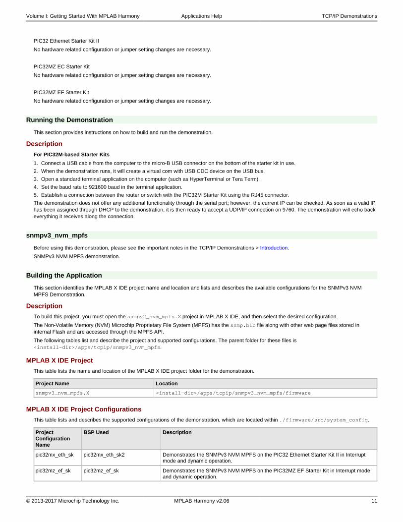
PIC32 Ethernet Starter Kit II, Ethernet PICtail Plus Daughter Board, and Starter Kit I/O Expansion Board
The 10 Mbps Ethernet PICtail Plus Daughter Board is connected to J4 on the Starter Kit I/O Expansion Board board by sliding the J2 PICtail Plus (SPI) card edge into the top of the connector. The PICtail daughter board is inserted so that it uses SPI1. Pins 26 and 47 on J11 need to be jumpered to allow the CS line to be controlled by the PIC32. The PIC32 Ethernet Starter kit II is connected to J1 on the Starter Kit I/O Expansion board.
Using the previous figures as a reference, replace the Fast 100 Mbps Ethernet PICtail Plus Daughter Board with the Ethernet PICtail Plus Daughter Board for this configuration. The RJ45 of the PICtail should be towards the edge connectors of the Starter Kit I/O Expansion Board.
Running the Demonstration
This section provides instructions on how to build and run the demonstration.
Description
For PIC32M-based Starter Kits
1. Connect a USB cable from the computer to the micro-B USB connector on the bottom of the starter kit in use.
2. When the demonstration runs, it will create a virtual com with USB CDC device on the USB bus.
3. Open a standard terminal application on the computer (such as HyperTerminal or Tera Term).
4. Set the baud rate to 921600 baud in the terminal application.
5. Establish a connection between the router or switch with the PIC32M Starter Kit using the RJ45 connector.
For all hardware, ensure that the router or switch is connected to the Internet.
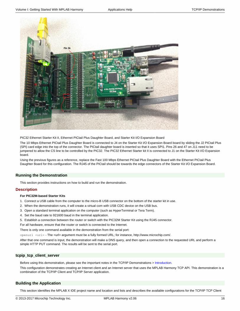
There is only one command available in the demonstration from the serial port:
openurl <url> - The <url> argument must be a fully formed URL; for instance, http://www.microchip.com/.
After that one command is input, the demonstration will make a DNS query, and then open a connection to the requested URL and perform a simple HTTP PUT command. The results will be sent to the serial port.
tcpip_tcp_client_server
Before using this demonstration, please see the important notes in the TCP/IP Demonstrations > Introduction.
This configuration demonstrates creating an Internet client and an Internet server that uses the MPLAB Harmony TCP API. This demonstration is a combination of the TCP/IP Client and TCP/IP Server application.
Building the Application
This section identifies the MPLAB X IDE project name and location and lists and describes the available configurations for the TCP/IP TCP Client
Volume I: Getting Started With MPLAB Harmony Applications Help TCP/IP Demonstrations
© 2013-2017 Microchip Technology Inc. MPLAB Harmony v2.06 16

Server Demonstration.
Description
To build this project, you must open the tcpip_tcp_client_server.X project in MPLAB X IDE, and then select the desired configuration.
The following tables list and describe the project and supported configurations. The parent folder for these files is <install-dir>/apps/tcpip/tcpip_tcp_client_server.
Warning
When using the Microchip Harmony Configurator (MHC), care must be taken when generating the code to not erase the USB descriptors in the system_init.c file.
MPLAB X IDE Project
This table lists the name and location of the MPLAB X IDE project folder for the demonstration.
Project Name Location
tcpip_tcp_client_server.X <install-dir>/apps/tcpip/tcpip_tcp_client_server/firmware
MPLAB X IDE Project Configurations
This table lists and describes the supported configurations of the demonstration, which are located within ./firmware/src/system_config.
Project Configuration Name
BSP Used Description
pic32mx_eth_sk2 pic32mx_eth_sk2 Demonstrates the TCP/IP TCP Client Server on the PIC32 Ethernet Starter Kit II.
pic32mz_ef_sk pic32mz_ef_sk Demonstrates the TCP/IP TCP Client Server on the PIC32MZ EF Starter Kit.
pic32mz_ef_curiosity pic32mz_ef_curiosity Demonstrates the TCP/IP TCP Client Server on the PIC32MZ EF Curiosity Development Board, with the PIC32MZ2048EFM100 microcontroller. This configuration is generated for standalone mode. All necessary files are copied under its configuration folder, and so it can be built and run without the MPLAB Harmony framework.
Configuring the Hardware
Describes how to configure the supported hardware.
Description
PIC32 Ethernet Starter Kit II
No hardware related configuration or jumper setting changes are necessary.
PIC32MZ EF Starter Kit
No hardware related configuration or jumper setting changes are necessary.
PIC32MZ EF Curiosity Development Board
1. Ensure that a jumper is placed at 4-3 on J8, to select supply from debug USB connector.
2. Power the PIC32MZ EF Curiosity Development Board from a Host PC through a Type-A male to micro-B USB cable connected to micro-B port (J3).
3. Ensure that jumper is not present in the J13 header to use the Curiosity board in device mode.
4. Plug in a USB cable with a micro-B type connector to Micro-B port (J12), and plug the other end into your computer.
5. Ensure that you have a LAN8740 Ethernet PHY DB installed on the PIC32MZ EF Curiosity Development Board (header J18).
Volume I: Getting Started With MPLAB Harmony Applications Help TCP/IP Demonstrations
© 2013-2017 Microchip Technology Inc. MPLAB Harmony v2.06 17

Running the Demonstration
This section provides instructions on how to build and run the demonstration.
Description
For the purpose of this demo, both the Target board and the Host PC should be in the same network. The host PC can be connected to a router via an Ethernet cable or Wi-Fi. The target board should be connected to the router via an Ethernet cable. Please refer to the following connection diagram.
Volume I: Getting Started With MPLAB Harmony Applications Help TCP/IP Demonstrations
© 2013-2017 Microchip Technology Inc. MPLAB Harmony v2.06 18

For PIC32M-based Starter Kits
1. Connect a USB cable from the computer to the micro-B USB connector on the bottom of the starter kit in use.
2. When the demonstration runs, it will create a virtual com with USB CDC device on the USB bus.
3. Open a standard terminal application on the computer (such as HyperTerminal or Tera Term).
4. Set the baud rate to 921600 baud in the terminal application.
5. Establish a connection between the router or switch with the PIC32M Starter Kit using the RJ45 connector.
For all hardware, ensure that the router or switch is connected to the Internet.
There is only one command available in the demonstration from the serial port:
openurl <url> - The <url> argument must be a fully formed URL; for instance, http://www.microchip.com/
After that one command is input, the demonstration will make a DNS query, and then open a connection to the requested URL and perform a simple HTTP PUT command. The results will be sent to the serial port.
Volume I: Getting Started With MPLAB Harmony Applications Help TCP/IP Demonstrations
© 2013-2017 Microchip Technology Inc. MPLAB Harmony v2.06 19
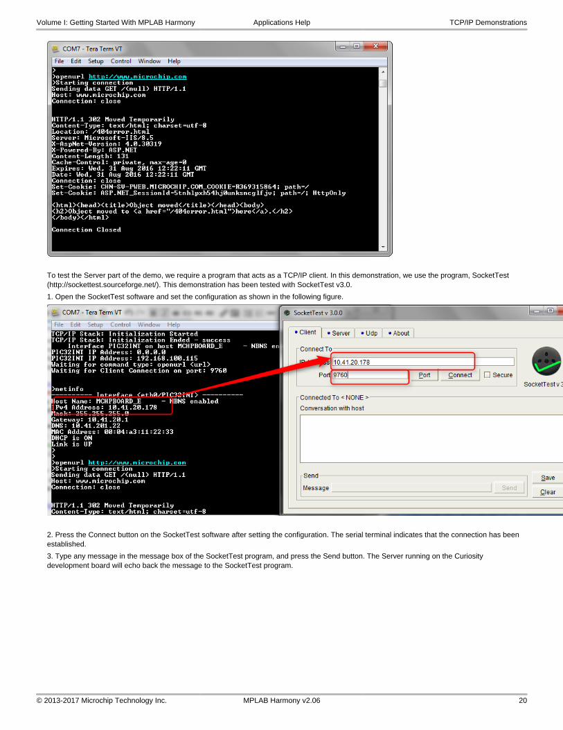
To test the Server part of the demo, we require a program that acts as a TCP/IP client. In this demonstration, we use the program, SocketTest (http://sockettest.sourceforge.net/). This demonstration has been tested with SocketTest v3.0.
1. Open the SocketTest software and set the configuration as shown in the following figure.
2. Press the Connect button on the SocketTest software after setting the configuration. The serial terminal indicates that the connection has been established.
3. Type any message in the message box of the SocketTest program, and press the Send button. The Server running on the Curiosity development board will echo back the message to the SocketTest program.
Volume I: Getting Started With MPLAB Harmony Applications Help TCP/IP Demonstrations
© 2013-2017 Microchip Technology Inc. MPLAB Harmony v2.06 20

tcpip_tcp_server
Before using this demonstration, please see the important notes in the TCP/IP Demonstrations > Introduction.
This configuration demonstrates creating an Internet server that uses the MPLAB Harmony TCP API to create a TCP/IP echo server on port 9764.
Building the Application
This section identifies the MPLAB X IDE project name and location and lists and describes the available configurations for the TCP/IP TCP Server Demonstration.
Description
To build this project, you must open the tcpip_tcp_server.X project in MPLAB X IDE, and then select the desired configuration.
The following tables list and describe the project and supported configurations. The parent folder for these files is <install-dir>/apps/tcpip/tcpip_tcp_server.
Warning
When using the Microchip Harmony Configurator (MHC), care must be taken when generating the code to not erase the USB descriptors in the system_init.c file.
MPLAB X IDE Project
This table lists the name and location of the MPLAB X IDE project folder for the demonstration.
Project Name Location
tcpip_tcp_server.X <install-dir>/apps/tcpip/tcpip_tcp_server/firmware
MPLAB X IDE Project Configurations
This table lists and describes the supported configurations of the demonstration, which are located within ./firmware/src/system_config.
Project Configuration Name
BSP Used Description
pic32mx_eth_sk2 pic32mx_eth_sk2 Demonstrates the TCP/IP TCP Server on the PIC32 Ethernet Starter Kit II.
pic32mz_ef_sk pic32mz_ef_sk Demonstrates the TCP/IP TCP Server on the PIC32MZ EF Starter Kit.
Configuring the Hardware
Describes how to configure the supported hardware.
Volume I: Getting Started With MPLAB Harmony Applications Help TCP/IP Demonstrations
© 2013-2017 Microchip Technology Inc. MPLAB Harmony v2.06 21

Description
PIC32 Ethernet Starter Kit II
No hardware related configuration or jumper setting changes are necessary.
PIC32MZ EF Starter Kit
No hardware related configuration or jumper setting changes are necessary.
Running the Demonstration
This section provides instructions on how to build and run the demonstration.
Description
For PIC32M-based Starter Kits
1. Connect a USB cable from the computer to the micro-B USB connector on the bottom of the starter kit in use.
2. When the demonstration runs, it will create a virtual com with USB CDC device on the USB bus.
3. Open a standard terminal application on the computer (such as HyperTerminal or Tera Term).
4. Set the baud rate to 921600 baud in the terminal application.
5. Establish a connection between the router or switch with the PIC32M Starter Kit using the RJ45 connector.
The demonstration does not offer any additional functionality through the serial port; however, the current IP can be checked. As soon as a valid IP has been assigned through DHCP to the demonstration, it is then ready to accept a TCP/IP connection on 9764. The demonstration will echo back everything it receives along the connection.
tcpip_udp_client
Before using this demonstration, please see the important notes in the TCP/IP Demonstrations > Introduction.
This configuration demonstrates creating an Internet client that uses the MPLAB Harmony UDP API to create a UDP/IP connection to a specified port.
Building the Application
This section identifies the MPLAB X IDE project name and location and lists and describes the available configurations for the TCP/IP UDP Client Demonstration.
Description
To build this project, you must open the tcpip_udp_client.X project in MPLAB X IDE, and then select the desired configuration.
The following tables list and describe the project and supported configurations. The parent folder for these files is <install-dir>/apps/tcpip/tcpip_udp_client.
Warning
When using the Microchip Harmony Configurator (MHC), care must be taken when generating the code to not erase the USB descriptors in the system_init.c file.
MPLAB X IDE Project
This table lists the name and location of the MPLAB X IDE project folder for the demonstration.
Project Name Location
tcpip_udp_client.X <install-dir>/apps/tcpip/tcpip_udp_client/firmware
MPLAB X IDE Project Configurations
This table lists and describes the supported configurations of the demonstration, which are located within ./firmware/src/system_config.
Project Configuration Name
BSP Used Description
pic32mx_eth_sk2 pic32mx_eth_sk2 Demonstrates the TCP/IP UDP Client on the PIC32 Ethernet Starter Kit II.
pic32mz_ef_sk pic32mz_ef_sk Demonstrates the TCP/IP UDP Client on the PIC32MZ EF Starter Kit.
Volume I: Getting Started With MPLAB Harmony Applications Help TCP/IP Demonstrations
© 2013-2017 Microchip Technology Inc. MPLAB Harmony v2.06 22

Configuring the Hardware
Describes how to configure the supported hardware.
Description
PIC32 Ethernet Starter Kit II
No hardware related configuration or jumper setting changes are necessary.
PIC32MZ EF Starter Kit
No hardware related configuration or jumper setting changes are necessary.
Running the Demonstration
This section provides instructions on how to build and run the demonstration.
Description
For PIC32M-based Starter Kits
1. Connect a USB cable from the computer to the micro-B USB connector on the bottom of the starter kit in use.
2. When the demonstration runs, it will create a virtual com with USB CDC device on the USB bus.
3. Open a standard terminal application on the computer (such as HyperTerminal or Tera Term).
4. Set the baud rate to 921600 baud in the terminal application.
5. Establish a connection between the router or switch with the PIC32M Starter Kit using the RJ45 connector.
Ensure a UDP Server is running on the network that can respond to client requests.
There are three commands that can be used from the console:
• setudppacketoptions <hostname> <port> <message> - This command specifies where to send the UDP packet and what to have in the message
• getudppacketoptions - This command displays the current options
• sendudppacket - This command sends a UDP packet
After the sendudppacket command is input, the demonstration will make a DNS query to look up the host name and send a UDP packet to that host.
tcpip_udp_client_server
Before using this demonstration, please see the important notes in the TCP/IP Demonstrations > Introduction.
This configuration demonstrates creating an Internet client and an Internet server that uses the MPLAB Harmony UDP API. This demonstration shows how the UDP/IP loopback works, and is a combination of the TCP/IP UDP Client and TCP/IP UDP Server application.
Building the Application
This section identifies the MPLAB X IDE project name and location and lists and describes the available configurations for the TCP/IP UDP Client Server Demonstration.
Description
To build this project, you must open the tcpip_udp_client_server.X project in MPLAB X IDE, and then select the desired configuration.
The following tables list and describe the project and supported configurations. The parent folder for these files is <install-dir>/apps/tcpip/tcpip_udp_client_server.
Warning
When using the Microchip Harmony Configurator (MHC), care must be taken when generating the code to not erase the USB descriptors in the system_init.c file.
MPLAB X IDE Project
This table lists the name and location of the MPLAB X IDE project folder for the demonstration.
Project Name Location
tcpip_udp_client_server.X <install-dir>/apps/tcpip/tcpip_udp_client_server/firmware
Volume I: Getting Started With MPLAB Harmony Applications Help TCP/IP Demonstrations
© 2013-2017 Microchip Technology Inc. MPLAB Harmony v2.06 23

MPLAB X IDE Project Configurations
This table lists and describes the supported configurations of the demonstration, which are located within ./firmware/src/system_config.
Project Configuration Name
BSP Used Description
pic32mx_eth_sk2 pic32mx_eth_sk2 Demonstrates the TCP/IP UDP Client Server on the PIC32 Ethernet Starter Kit II.
pic32mz_ef_sk pic32mz_ef_sk Demonstrates the TCP/IP UDP Client Server on the PIC32MZ EF Starter Kit.
Configuring the Hardware
Describes how to configure the supported hardware.
Description
PIC32 Ethernet Starter Kit II
No hardware related configuration or jumper setting changes are necessary.
PIC32MZ EF Starter Kit
No hardware related configuration or jumper setting changes are necessary.
Running the Demonstration
This section provides instructions on how to build and run the demonstration.
Description
For PIC32M-based Starter Kits
1. Connect a USB cable from the computer to the micro-B USB connector on the bottom of the starter kit in use.
2. When the demonstration runs, it will create a virtual com with USB CDC device on the USB bus.
3. Open a standard terminal application on the computer (such as HyperTerminal or Tera Term).
4. Set the baud rate to 921600 baud in the terminal application.
5. Establish a connection between the router or switch with the PIC32M Starter Kit using the RJ45 connector.
There are three commands that can be used from the console:
• setudppacketoptions <hostname> <port> <message> - This command specifies where to send the UDP packet and what to have in the message
• getudppacketoptions - This command displays the current options
• sendudppacket - This command sends a UDP packet
After the sendudppacket command is input, the demonstration will make a DNS query to look up the host name and send a UDP packet to that host.
The UDP Client can be configured to send UDP data to the host, configured using the commands previously described.
The UDP server in this demonstration waits for the client connection and data at port 9760.
As the server receives the data from the external UDP client, the data is shared to the UDP Client to transmit back to the external UDP Server.
The data received over UDP by the server is looped backed using the UDP Client.
tcpip_udp_server
Before using this demonstration, please see the important notes in the TCP/IP Demonstrations > Introduction.
This configuration demonstrates creating an Internet server that uses the MPLAB Harmony UDP API to create a UDP/IP echo server on port 9760.
Building the Application
This section identifies the MPLAB X IDE project name and location and lists and describes the available configurations for the TCP/IP UDP Server Demonstration.
Description
To build this project, you must open the tcpip_udp_server.X project in MPLAB X IDE, and then select the desired configuration.
The following tables list and describe the project and supported configurations. The parent folder for these files is <install-dir>/apps/tcpip/tcpip_udp_server.
Volume I: Getting Started With MPLAB Harmony Applications Help TCP/IP Demonstrations
© 2013-2017 Microchip Technology Inc. MPLAB Harmony v2.06 24

Warning
When using the Microchip Harmony Configurator (MHC), care must be taken when generating the code to not erase the USB descriptors in the system_init.c file.
MPLAB X IDE Project
This table lists the name and location of the MPLAB X IDE project folder for the demonstration.
Project Name Location
tcpip_udp_server.X <install-dir>/apps/tcpip/tcpip_udp_server/firmware
MPLAB X IDE Project Configurations
This table lists and describes the supported configurations of the demonstration, which are located within ./firmware/src/system_config.
Project Configuration Name
BSP Used Description
pic32mx_eth_sk2 pic32mx_eth_sk2 Demonstrates the TCP/IP UDP Server on the PIC32 Ethernet Starter Kit II.
pic32mz_ef_sk pic32mz_ef_sk Demonstrates the TCP/IP UDP Server on the PIC32MZ EF Starter Kit.
Configuring the Hardware
Describes how to configure the supported hardware.
Description
PIC32 Ethernet Starter Kit II
No hardware related configuration or jumper setting changes are necessary.
PIC32MZ EF Starter Kit
No hardware related configuration or jumper setting changes are necessary.
Running the Demonstration
This section provides instructions on how to build and run the demonstration.
Description
For PIC32M-based Starter Kits
1. Connect a USB cable from the computer to the micro-B USB connector on the bottom of the starter kit in use.
2. When the demonstration runs, it will create a virtual com with USB CDC device on the USB bus.
3. Open a standard terminal application on the computer (such as HyperTerminal or Tera Term).
4. Set the baud rate to 921600 baud in the terminal application.
5. Establish a connection between the router or switch with the PIC32M Starter Kit using the RJ45 connector.
The demonstration does not offer any additional functionality through the serial port; however, the current IP can be checked. As soon as a valid IP has been assigned through DHCP to the demonstration, it is then ready to accept a UDP/IP connection on 9760. The demonstration will echo back everything it receives along the connection.
web_net_server_nvm_mpfs
Before using this demonstration, please see the important notes in the TCP/IP Demonstrations > Introduction.
Web Net Server Non-volatile Memory (NVM) MPFS TCP/IP demonstration.
Building the Application
This section identifies the MPLAB X IDE project name and location and lists and describes the available configurations for the TCP/IP Web Net Server Demonstration.
Description
To build this project, you must open the pic32_eth_web_server.X project in MPLAB X IDE, and then select the desired configuration.
The following tables list and describe the project and supported configurations. The parent folder for these files is <install-dir>/apps/tcpip/web_net_server_nvm_mpfs.
Volume I: Getting Started With MPLAB Harmony Applications Help TCP/IP Demonstrations
© 2013-2017 Microchip Technology Inc. MPLAB Harmony v2.06 25

Warning
When using the Microchip Harmony Configurator (MHC), care must be taken when generating the code to not erase the USB descriptors in the system_init.c file.
MPLAB X IDE Project
This table lists the name and location of the MPLAB X IDE project folder for the demonstration.
Project Name Location
pic32_eth_web_server.X <install-dir>/apps/tcpip/web_net_server_nvm_mpfs/firmware
pic32_eth_wifi_web_server.X <install-dir>/apps/tcpip/web_net_server_nvm_mpfs/firmware
pic32_wifi_web_server.X <install-dir>/apps/tcpip/web_net_server_nvm_mpfs/firmware
MPLAB X IDE Project Configurations
This table lists and describes the supported configurations of the demonstration, which are located within ./firmware/src/system_config.
Project Configuration Name BSP Used Description
pic32mx_eth_sk2 pic32mx_eth_sk2 Demonstrates the web server hosted on internal Flash through the Microchip Proprietary File System (MPFS) on the PIC32 Ethernet Starter Kit II.
pic32mz_ef_sk pic32mz_ef_sk Demonstrates the web server hosted on internal Flash through the MPFS on the PIC32MZ EF Starter Kit.
pic32mz_ef_sk_16b pic32mz_ef_sk Demonstrates the web net server hosted on internal Flash through the MPFS on the PIC32MZ EF Starter Kit.
pic32mz_ef_sk_ioexp_winc_freertos pic32mz_ef_sk Demonstrates the web server hosted on internal Flash through the MPFS on the PIC32MZ EF Starter Kit and the WINC1500 PICtail/PICtail Plus Daughter Board.
pic32mx795_pim_e16_winc_freertos pic32mx795_pim+e16 Demonstrates the web net server hosted on internal Flash through the MPFS on the PIC32MX795F512L CAN-USB PIM with the Explorer 16/32 Development Board and the WINC1500 PICtail/PICtail Plus Daughter Board.
pic32mx795_pim_e16_wincclick_freertos pic32mx795_pim+e16 Demonstrates the web net server hosted on internal Flash through the MPFS on the PIC32MX795F512L CAN-USB PIM with the Explorer 16/32 Development Board and the MIKROE-2046 Wi-Fi 7 Click Board.
Configuring the Hardware
Describes how to configure the supported hardware.
Description
PIC32 Ethernet Starter Kit
No hardware related configuration or jumper setting changes are necessary.
PIC32 Ethernet Starter Kit II
No hardware related configuration or jumper setting changes are necessary.
PIC32MZ EF Starter Kit
No hardware related configuration or jumper setting changes are necessary.
PIC32MZ EF Starter Kit with the Starter Kit I/O Expansion Board, WINC1500 Wi-Fi PICtail/PICtail Plus Daughter Board, and PIC32MZ Starter Kit Adapter Board
The following figures show the necessary configuration.
Volume I: Getting Started With MPLAB Harmony Applications Help TCP/IP Demonstrations
© 2013-2017 Microchip Technology Inc. MPLAB Harmony v2.06 26

Explorer 16/32 Development Board with the PIC32MX795F512L CAN-USB PIM and the MikroElektronika WiFi 7 Click Board (with on-board WINC1500 Wi-Fi module
The following figure shows the necessary configuration.
Volume I: Getting Started With MPLAB Harmony Applications Help TCP/IP Demonstrations
© 2013-2017 Microchip Technology Inc. MPLAB Harmony v2.06 27

Explorer 16 Development Board with the PIC32MX795F512L CAN-USB PIM and WINC1500 Wi-Fi PICtail/PICtail Plus Daughter Board
The following figure shows the necessary configuration.
Explorer 16/32 Development Board with the PIC32MX795F512L CAN-USB PIM, PICtail Plus Expansion Board, and WINC1500 Wi-Fi PICtail/PICtail Plus Daughter Board
• Connect the WINC1500 Wi-FI PICtail/PICtail Daughter Board into the PICtail Plus slot (J63). The module should face into the main board and
Volume I: Getting Started With MPLAB Harmony Applications Help TCP/IP Demonstrations
© 2013-2017 Microchip Technology Inc. MPLAB Harmony v2.06 28

be placed all the way to the end on the pin 1 side of the connector.
• The console output uses the mini_USB/Serial connector on the board (J40) at 115200 baud, 8-bit data, No parity, 1 Stop bit, with No Flow Control.
The following figure shows the hardware configuration.
Explorer 16/32 Development Board with the PIC32MX795F512L CAN-USB PIM, PICtail Plus Expansion Board, and the MikroElektronika WiFi 7 Click Board (with on-board WINC1500 Wi-Fi module).
The following figure shows the hardware configuration.
Volume I: Getting Started With MPLAB Harmony Applications Help TCP/IP Demonstrations
© 2013-2017 Microchip Technology Inc. MPLAB Harmony v2.06 29

Configuring the MHC
Provides information on the MHC configuration for the demonstration.
Description
MHC Configuration:
1. From Harmony Framework Configuration > TCPIP Stack select HTTP NET Server.
2. Leave the default settings. The HTTP server listening port should be already set to 443 for encrypted connections, as shown in the following figure; however, change this value to 80 if unencrypted connection is required:
3. Enable the MPLAB Harmony Networking Presentation Layer, as follows:
• Ensure that the TCP/IP stack is used as transport layer
Volume I: Getting Started With MPLAB Harmony Applications Help TCP/IP Demonstrations
© 2013-2017 Microchip Technology Inc. MPLAB Harmony v2.06 30

• Select Support Stream Connections? (for TCP support)
• Select Support Server Connections? (for HTTPS support)
• Select Support Client Connections? (for encrypted SMTP support)
• Select Support Client Certificate? and Support Server Certificate? (as appropriate)
4. Enable Third Party Libraries > TCPIP > wolfSSL > Use wolfSSL. Ensure that the wolfSSL client and wolfSSL server are enabled depending on your HTTP and SMTP selection, as shown in the following figure:
5. As shown in the following figure, select HTTP Net Server from Harmony Framework Configuration >TCPIP Stack. Ensure that the “Enable the Processing SSI Commands” is enabled. Leave the default settings or expand the item and adjust to your application needs.
Volume I: Getting Started With MPLAB Harmony Applications Help TCP/IP Demonstrations
© 2013-2017 Microchip Technology Inc. MPLAB Harmony v2.06 31

6. This version of the HTTP Net MHC configuration allows for the explicit selection of the dynamic variables processing. Ensure that this option is also selected.
Note:For demonstrations that use SSI, the file inclusion is now done in a standard way using .htm files.
For example, <!--#include virtual="header.htm">. These files may contain dynamic variables, other SSI commands, or include other files. As shown in the following figure, ensure that when using the mpfs2.jar image generation tool that *.htm is added using Advanced Settings > Do Not Compress.
7. Set the following MHC configuration to enable Wi-Fi network connection.
Volume I: Getting Started With MPLAB Harmony Applications Help TCP/IP Demonstrations
© 2013-2017 Microchip Technology Inc. MPLAB Harmony v2.06 32

Running the Demonstration
This section provides instructions on how to build and run the PIC32 Ethernet Web Net Server demonstration.
Description
To view the web page hosted by the demonstration application, open a web browser and direct it to the board running the HTTP server by typing the URL in the address bar (for example, http://mchpboard_e or http://mchpboard_c), and then pressing Enter.
Notes:1. The NetBIOS name of the TCP/IP application is specified at the time the TCP/IP stack is initialized, which is usually in the
hostName member of the tcpip_stack_init.c:: TCPIP_HOSTS_CONFIGURATION structure. The NetBIOS service must be enabled for the PIC32 demonstration to respond to NetBIOS queries. Alternatively, you can use the IPv4 or IPv6 address (if IPv6 is enabled) of the board directly, for example, http://192.168.1.131 or http://[fdfe:dcba:9876:1:204:a3ff:fe12:128e].
2. The IPv4 and IPv6 addresses can be obtained from running the TCP/IP Discovery application on the PC side. It requires that the TCP/IP Announce module is enabled when building the stack.
3. With Wi-Fi network connection, the HTTP NET Server demonstration is accessible in duo-port mode (i.e., Ethernet and Wi-Fi). To access the HTTP NET Server pages on a web browser through the Wi-Fi connection, use the IPv4/IPv6 address assigned to the Wi-Fi connection.
Demonstration Process
Please use the following procedure to run the demonstration:
1. Load the demonstration project into MPLAB X IDE.
2. Connect the USB debugger port on-board the starter kit in use to a USB port on the Development computer using the USB cable provided in the kit.
3. Connect the RJ-45 Ethernet port on the starter kit board to a network hub or an Ethernet port on the development computer using the Ethernet patch cord provided in the kit.
4. Build, download, and run the demonstration project on the target board.
5. A HTTP server is hosted by the demonstration application. Open_a web browser and direct it to the board running the HTTP server by typing the URL in the address bar (for example, http://mchpboard_e or http://mchpboard_c), and then pressing Enter.
The demonstration application features following:
• Real-time Hardware Control and Dynamic Variables - On the Overview page the LEDs can be clicked to toggle the LEDs on the PIC32 Ethernet Starter Kit. The buttons on the PIC32 Ethernet Starter Kit can be pressed to toggle the Buttons on the web page. The dynamic variables can be updated in real-time on the HTTP server.
Note:The LED functionality portion of the demonstration is somewhat limited due to issue related to the functional multiplexing on GPIO and Ethernet pins on different supported hardware.
• Form Processing - Input can be handled from the client by using GET and POST methods (this functionality controls the on-board LEDs and will be operational only on Explorer 16 Development Board)
• Authentication - Shows an example of the commonly used restricted access feature
Volume I: Getting Started With MPLAB Harmony Applications Help TCP/IP Demonstrations
© 2013-2017 Microchip Technology Inc. MPLAB Harmony v2.06 33

• Cookies - Shows an example of storing small text stings on the client side
• File Uploads - Shows an example of file upload using the POST method. The HTTP server can_accept_a user-defined MPFS/MPFS2 image file for web pages.
• Send E-mail - Shows simple SMTP POST methods
• Dynamic DNS - Exercises Dynamic DNS capabilities
• Network Configuration - The MAC address, host name, and IP address of the PIC32 Ethernet Starter Kit can be viewed in the Network Configuration page and some configurations can be updated
• MPFS Upload - A new set of web pages can be uploaded to the web server using this feature, which is accessed through http://mchpboard_e/mpfsupload.
Notes:1. The location of the MPFS image is fixed at the beginning of the Flash page (aligned to the page boundary). The size of the
MPFS upload is limited to 64K in the demonstration, which it can be expanded by changing NVM_MEDIA_SIZE to the desired size (restricted based on the available size) and overriding the EBASE address using the following linker command:
• --defsym=_ebase_address=0x9D0xxxx (where, xxxx = 9D000000+NVM_MEDIA_SIZE)
2. The MPFS UPLOAD functionality has to be enabled when the project is built.
web_photoframe_demo
Before using this demonstration, please see the important notes in the TCP/IP Demonstrations > Introduction.
The demonstration application creates a Web Photoframe that displays images, in the form of a slideshow on a web browser by connecting to a web server hosted on PIC32 Development board, over Ethernet or Wi-Fi interface. The images are stored on a micro SDCARD connected to the PIC32 development board.
Volume I: Getting Started With MPLAB Harmony Applications Help TCP/IP Demonstrations
© 2013-2017 Microchip Technology Inc. MPLAB Harmony v2.06 34

Building the Application
This section identifies the MPLAB X IDE project name and location and lists and describes the available configurations for the PIC32 Web Photoframe Demonstration.
Description
To build this project, you must open the pic32_eth_wifi_photoframe.X project in MPLAB X IDE, and then select the desired configuration.
The following tables list and describe the project and supported configurations. The parent folder for these files is <install-dir>/apps/tcpip/web_photoframe.
Warning
When using the Microchip Harmony Configurator (MHC), care must be taken when generating the code to not erase the USB descriptors in the system_init.c file.
MPLAB X IDE Project
This table lists the name and location of the MPLAB X IDE project folder for the demonstration.
Project Name Location
pic32_eth_web_server.X <install-dir>/apps/tcpip/web_photoframe/firmware
MPLAB X IDE Project Configurations
This table lists and describes the supported configurations of the demonstration, which are located within ./firmware/src/system_config.
Project Configuration Name
BSP Used Description
pic32mz_ef_curiosity pic32mz_ef_curiosity FreeRTOS version of the demonstration running on the PIC32MZ EF Curiosity Development board with the on-board MRF24WN module.
Configuring the Hardware
Describes how to configure the supported hardware.
Description
PIC32MZ EF Curiosity Development Board with on-board MRF24WN0MA module
• Ensure that a jumper is placed at 4-3 on J8, to select supply from debug USB connector.
• Power the PIC32MZ EF Curiosity Development Board from a Host PC through a Type-A male to micro-B USB cable connected to Micro-B port (J3)
• Ensure that a jumper is not present in the J13 header to use the PIC32MZ EF Curiosity Board in Device mode
• Connect a USB cable with a micro-B type connector to Micro-B port (J12), and connect the other end to your computer
• Ensure that you have a LAN8740 Ethernet PHY DB installed on the PIC32MZ EF Curiosity Development Board (header J18)
• Ensure that you have a microSD click board on the microBUS1 (J5) connector of the PIC32MZ EF Curiosity Development Board
Volume I: Getting Started With MPLAB Harmony Applications Help TCP/IP Demonstrations
© 2013-2017 Microchip Technology Inc. MPLAB Harmony v2.06 35

Running the Demonstration
This section provides instructions on how to build and run the demonstration.
Description
For the purpose of this demo, both the Target board and the Host PC should be in the same network.
The host PC can be connected to a router via an Ethernet cable or WiFi. The Target board should be connected to the router via an Ethernet cable. Please refer to the connection diagram shown below.
The SDCARD should be loaded with index.htm and the images folder with .jpg images. The index.htm and the images folder can be found at the following location: <install-dir>/apps/tcpip/web_photoframe/firmware/src/web_pages.
1. Load the demonstration project into MPLAB X IDE.
2. Connect the USB debugger port on-board the starter kit to a USB port on the development computer using the USB cable provided in the kit.
3. A USB cable needs to be connected to the micro-B USB connector on the bottom of the starter kit in use. When the demonstration runs, it will create a USB CDC device on the USB bus. The demonstration can be executed once you have connected to this device through a standard terminal program, set the baud rate to 921,600 baud, and a valid IP address has been received by the device.
4. Copy the files index.htm.
5. Build, download, and run the demonstration project on the board.
6. Connect to the board through a standard terminal program.
Volume I: Getting Started With MPLAB Harmony Applications Help TCP/IP Demonstrations
© 2013-2017 Microchip Technology Inc. MPLAB Harmony v2.06 36

7. In the previous image we can see that the board scans for local Access Points and outputs the results to the serial console. After the scan results, the MRF24WN goes into SoftAP mode.
8. To run the demonstration on an Ethernet Interface, open a web browser on the host PC and type the IP address for the Ethernet Interface (PIC32INT IPv4 Address) obtained from the output of the serial terminal.
9. The web browser will load the application web page hosted by the SDCARD. And the .jpg images stored in the SDCARD will be displayed on the web page in a scrolling fashion. Press the “Pause” button to pause the slideshow.
10. From the host PC, connect to the MCHPSoftAP access point, which is the SoftAP network started by the demonstration. Then, bring up a web page by entering the IP address of the SoftAP network into the browser. This is the IP address displayed in step 6 (e.g., 192.168.1.1). The application web page will be displayed with the slideshow of the images.
web_server_nvm_mpfs
Before using this demonstration, please see the important notes in the TCP/IP Demonstrations > Introduction.
Web Server Non-volatile Memory (NVM) MPFS TCP/IP demonstrations.
pic32_eth_web_server
This section describes the steps necessary to begin using the PIC32 Ethernet Web Server Demonstration Application.
Volume I: Getting Started With MPLAB Harmony Applications Help TCP/IP Demonstrations
© 2013-2017 Microchip Technology Inc. MPLAB Harmony v2.06 37

Description
This demonstration exercises the HTTP web server running on PIC32 devices. The Non-Volatile Memory (NVM) Microchip Proprietary File System (MPFS) web server demonstration has the web pages stored in internal Flash and are accessed through the MPFS API.
Building the Application
This section identifies the MPLAB X IDE project name and location and lists and describes the available configurations for the TCP/IP Web Server Demonstration.
Description
To build this project, you must open the pic32_eth_web_server.X project in MPLAB X IDE, and then select the desired configuration.
The following tables list and describe the project and supported configurations. The parent folder for these files is <install-dir>/apps/tcpip/web_server_nvm_mpfs.
Warning
When using the Microchip Harmony Configurator (MHC), care must be taken when generating the code to not erase the USB descriptors in the system_init.c file.
MPLAB X IDE Project
This table lists the name and location of the MPLAB X IDE project folder for the demonstration.
Project Name Location
pic32_eth_web_server.X <install-dir>/apps/tcpip/web_server_nvm_mpfs/firmware
MPLAB X IDE Project Configurations
This table lists and describes the supported configurations of the demonstration, which are located within ./firmware/src/system_config.
Project Configuration Name
BSP Used Description
pic32mx_eth_sk2 pic32mx_eth_sk2 Demonstrates the web server hosted on internal Flash through Microchip proprietary file system on the PIC32 Ethernet Starter Kit II.
pic32mz_ef_sk pic32mz_ef_sk Demonstrates the web server hosted on internal Flash through Microchip proprietary file system on the PIC32MZ EF Starter Kit.
pic32mz_ef_sk_16b pic32mz_ef_sk Demonstrates the web server hosted on internal Flash through the MPFS on the PIC32MZ EF Starter Kit.
Configuring the Hardware
Describes how to configure the supported hardware.
Description
PIC32 Ethernet Starter Kit
No hardware related configuration or jumper setting changes are necessary.
PIC32 Ethernet Starter Kit II
No hardware related configuration or jumper setting changes are necessary.
PIC32MZ EF Starter Kit
No hardware related configuration or jumper setting changes are necessary.
Running the Demonstration
This section provides instructions on how to build and run the PIC32 Ethernet Web Server demonstration.
Description
To view the web page hosted by the demonstration application, open a web browser and direct it to the board running the HTTP server by typing the URL in the address bar (for example, http://mchpboard_e or http://mchpboard_c), and then pressing Enter.
Volume I: Getting Started With MPLAB Harmony Applications Help TCP/IP Demonstrations
© 2013-2017 Microchip Technology Inc. MPLAB Harmony v2.06 38

Notes:1. The NetBIOS name of the TCP/IP application is specified at the time the TCP/IP stack is initialized, which is usually in the
hostName member of the tcpip_stack_init.c:: TCPIP_HOSTS_CONFIGURATION structure. The NetBIOS service must be enabled for the PIC32 demonstration to respond to NetBIOS queries. Alternatively, you can use the IPv4 or IPv6 address (if IPv6 is enabled) of the board directly, for example, http://192.168.1.131 or http://[fdfe:dcba:9876:1:204:a3ff:fe12:128e].
2. The IPv4 and IPv6 addresses can be obtained from running the TCP/IP Discovery application on the PC side. It requires that the TCP/IP Announce module is enabled when building the stack.
Demonstration Process
Please use the following procedure to run the demonstration:
1. Load the demonstration project into MPLAB X IDE.
2. Connect the USB debugger port on-board the starter kit in use to a USB port on the Development computer using the USB cable provided in the kit.
3. Connect the RJ-45 Ethernet port on the starter kit board to a network hub or an Ethernet port on the development computer using the Ethernet patch cord provided in the kit.
4. Build, download, and run the demonstration project on the target board.
5. A HTTP server is hosted by the demonstration application. Open_a web browser and direct it to the board running the HTTP server by typing the URL in the address bar (for example, http://mchpboard_e or http://mchpboard_c), and then pressing Enter.
The demonstration application features following:
• Real-time Hardware Control and Dynamic Variables - On the Overview page the LEDs can be clicked to toggle the LEDs on the PIC32 Ethernet Starter Kit. The buttons on the PIC32 Ethernet Starter Kit can be pressed to toggle the Buttons on the web page. The dynamic variables can be updated in real-time on the HTTP server.
Note:The LED functionality portion of the demonstration is somewhat limited due to issue related to the functional multiplexing on GPIO and Ethernet pins on different supported hardware.
• Form Processing - Input can be handled from the client by using GET and POST methods (this functionality controls the on-board LEDs and will be operational only on Explorer 16 Development Board)
• Authentication - Shows an example of the commonly used restricted access feature
• Cookies - Shows an example of storing small text stings on the client side
• File Uploads - Shows an example of file upload using the POST method. The HTTP server can_accept_a user-defined MPFS/MPFS2 image file for web pages.
• Send E-mail - Shows simple SMTP POST methods
• Dynamic DNS - Exercises Dynamic DNS capabilities
• Network Configuration - The MAC address, host name, and IP address of the PIC32 Ethernet Starter Kit can be viewed in the Network Configuration page and some configurations can be updated
• MPFS Upload - A new set of web pages can be uploaded to the web server using this feature, which is accessed through http://mchpboard_e/mpfsupload.
Notes:1. The location of the MPFS image is fixed at the beginning of the Flash page (aligned to the page boundary). The size of the
MPFS upload is limited to 64K in the demonstration, which it can be expanded by changing NVM_MEDIA_SIZE to the desired size (restricted based on the available size) and overriding the EBASE address using the following linker command:
• --defsym=_ebase_address=0x9D0xxxx (where, xxxx = 9D000000+NVM_MEDIA_SIZE)
2. The MPFS UPLOAD functionality has to be enabled when the project is built.
Volume I: Getting Started With MPLAB Harmony Applications Help TCP/IP Demonstrations
© 2013-2017 Microchip Technology Inc. MPLAB Harmony v2.06 39

pic32_eth_wifi_web_server
This section describes the steps necessary to begin using the PIC32 Ethernet Wi-Fi Web Server Demonstration Application.
Description
The Wi-Fi Web Server demonstration (apps\tcpip\web_server_nvm_mpfs\firmware) exercises the HTTP web server running on PIC32 devices. The Non-Volatile Memory (NVM) Microchip Proprietary File System (MPFS) web server demonstration has the web pages stored in internal Flash and are accessed through the MPFS API.
Building the Application
This section identifies the MPLAB X IDE project name and location and lists and describes the available configurations for the PIC32 Ethernet Wi-Fi Web Server Demonstration.
Description
To build this project, you must open the pic32_eth_wifi_web_server.X project in MPLAB X IDE, and then select the desired configuration.
The following tables list and describe the project and supported configurations. The parent folder for these files is <install-dir>/apps/tcpip/web_server_nvm_mpfs.
MPLAB X IDE Project
This table lists the name and location of the MPLAB X IDE project folder for the demonstration.
Volume I: Getting Started With MPLAB Harmony Applications Help TCP/IP Demonstrations
© 2013-2017 Microchip Technology Inc. MPLAB Harmony v2.06 40

Project Name Location
pic32_eth_wifi_web_server.X <install-dir>/apps/tcpip/web_server_nvm_mpfs/firmware
MPLAB X IDE Project Configurations
This table lists and describes the supported configurations of the demonstration, which are located within ./firmware/src/system_config.
Project Configuration Name BSP Used Description
pic32mx_eth_sk_ioexp_11n_freertos pic32mx_eth_sk Demonstrates the web server hosted on internal Flash through the MPFS on the PIC32 Ethernet Starter Kit and the MRF24WN0MA PICtail/PICtail Plus Daughter Board.
pic32mx_eth_sk_ioexp_winc_freertos pic32mx_eth_sk Demonstrates the web server hosted on internal Flash through the MPFS on the PIC32 Ethernet Starter Kit and the WINC1500 PICtail/PICtail Plus Daughter Board.
Configuring the Hardware
Describes how to configure the supported hardware.
Description
PIC32 Ethernet Starter Kit with PIC32MX795F512L, MRF24WN0MA Wi-Fi PICtail/PICtail Plus Daughter Board, and Starter Kit I/O Expansion Board
(shown in the following figure below)
Note:For use with the WINC1500 module, replace the MRF24WN module shown in the following figure with the WINC1500 Wi-Fi PICtail/PICtail Plus Daughter Board.
Configure the Starter Kit I/O Expansion Board jumper modifications, as described in the following figure:
On-board Jumpers: J10/pin 12 to J11/pin 8 (red jumper cable), and J10/pin 56 to J10/pin 37 (orange jumper cable).
PIC32MZ EF Starter Kit with PIC32MX2048EFM144, WINC1500 Wi-Fi PICtail/PICtail Plus Daughter Board, and Starter Kit I/O Expansion Board.
Configure the hardware, as shown in the following figure.
On-board jumpers: JP10/pin 12 to JP11/pin 8 (red jumper cable), and JP1 between pin PMD11 and pin EBID11 (blue jumper cable)
Volume I: Getting Started With MPLAB Harmony Applications Help TCP/IP Demonstrations
© 2013-2017 Microchip Technology Inc. MPLAB Harmony v2.06 41

Running the Demonstration
This section provides instructions on how to build and run the PIC32 Ethernet Wi-Fi Web Server demonstration.
Description
To view the web page hosted by the demonstration application, open a web browser and direct it to the board running the HTTP server by typing the URL in the address bar (for example, http://mchpboard_w), and then pressing Enter.
This demonstration runs on two interfaces, Ethernet and Wi-Fi. A second web browser tab could be opened pointing to the other interface (http://mchpboard_e) to have both interfaces running simultaneously.
Notes:1. The NetBIOS name of the TCP/IP application is specified at the time the TCP/IP stack is initialized, which is usually in the
hostName member of the tcpip_stack_init.c:: TCPIP_HOSTS_CONFIGURATION structure. The NetBIOS service must be enabled for the PIC32 demonstration to respond to NetBIOS queries. Alternatively, you can use the IPv4 or IPv6 address (if IPv6 is enabled) of the board directly, for example, http://192.168.1.131 or http://[fdfe:dcba:9876:1:204:a3ff:fe12:128e].
2. The IPv4 and IPv6 addresses can be obtained from running the TCP/IP Discovery application on the PC side. It requires that the TCP/IP Announce module is enabled when building the stack.
Please refer to the Demonstration Process in the Running the Demonstration section for the pic32_eth_web_server configuration, as the process is the same for this configuration.
Note:Refer to Wi-Fi Console Commands for information on the commands that enable control over the Wi-Fi settings.
Volume I: Getting Started With MPLAB Harmony Applications Help TCP/IP Demonstrations
© 2013-2017 Microchip Technology Inc. MPLAB Harmony v2.06 42

pic32_wifi_web_server
This section describes the steps necessary to begin using the PIC32 Wi-Fi Web Server Demonstration Application.
Description
The Wi-Fi Web Server demonstration (<install-dir>\apps\tcpip\web_server_nvm_mpfs\firmware) exercises the HTTP Web Server running on PIC32 devices. The Non-Volatile Memory (NVM) Microchip Proprietary File System (MPFS) Web Server demonstration has the Web pages stored in internal Flash and are accessed through the MPFS API.
Building the Application
This section identifies the MPLAB X IDE project name and location and lists and describes the available configurations for the PIC32 Wi-Fi Web Server Demonstration.
Description
To build this project, you must open the pic32_wifi_web_server.X project in MPLAB X IDE, and then select the desired configuration.
The following tables list and describe the project and supported configurations. The parent folder for these files is <install-dir>/apps/tcpip/web_server_nvm_mpfs.
MPLAB X IDE Project
This table lists the name and location of the MPLAB X IDE project folder for the demonstration.
Volume I: Getting Started With MPLAB Harmony Applications Help TCP/IP Demonstrations
© 2013-2017 Microchip Technology Inc. MPLAB Harmony v2.06 43

Project Name Location
pic32_wifi_web_server.X <install-dir>/apps/tcpip/web_server_nvm_mpfs/firmware
MPLAB X IDE Project Configurations
This table lists and describes the supported configurations of the demonstration, which are located within ./firmware/src/system_config.
Project Configuration Name BSP Used Description
pic32mx795_pim_e16_11n_freertos pic32mx795_pim+e16 Demonstrates the web server hosted on internal Flash through the MPFS on the PIC32MX795F512L CAN-USB PIM with the Explorer 16/32 Development Board and the MRF24WN0MA PICtail/PICtail Plus Daughter Board.
pic32mx795_pim_e16_winc_freertos pic32mx795_pim+e16 Demonstrates the web server hosted on internal Flash through the MPFS on the PIC32MX795F512L CAN-USB PIM with the Explorer 16/32 Development Board and the WINC1500 PICtail/PICtail Plus Daughter Board.
pic32mx795_pim_e16_wincclick_freertos pic32mx795_pim+e16 Demonstrates the web server hosted on internal Flash through the MPFS on the PIC32MX795F512L CAN-USB PIM with the Explorer 16/32 Development Board and the MIKROE-2046 Wi-Fi 7 Click Board.
Configuring the Hardware
Describes how to configure the supported hardware.
Description
PIC32MX795F512L PIM with the Explorer 16 Development Board and MRF24WN PICtail Daughter Board
• Connect the MRF24WN PICtail Daughter Board into the PICtail Plus slot closest to the MCU. The module should face into the board and be placed all the way to the end on the pin 1 side of the connector.
• The console output uses the DB9 connector on the board at 115200 baud, 8-bit data, No parity, 1 Stop bit, with No Flow Control
The following figure shows the hardware configuration.
PIC32MX795F512L PIM with the Explorer 16 Development Board and WINC1500 PICtail/PICtail Plus Daughter Board
• Connect the WINC1500 PICtail Daughter Board into the PICtail Plus slot closest to the MCU. The module should face into the board and be placed all the way to the end on the pin 1 side of the connector.
• The console output uses the DB9 connector on the board at 115200 baud, 8-bit data, No parity, 1 Stop bit, with No Flow Control
The following figure shows the hardware configuration.
Volume I: Getting Started With MPLAB Harmony Applications Help TCP/IP Demonstrations
© 2013-2017 Microchip Technology Inc. MPLAB Harmony v2.06 44

Explorer 16/32 Development Board with the PIC32MX795F512L CAN-USB PIM, PICtail Plus Expansion Board, and WINC1500 Wi-Fi PICtail/PICtail Plus Daughter Board
• Connect the WINC1500 Wi-FI PICtail/PICtail Plus Daughter Board into the PICtail Plus slot (J63) . The module should face into the main board and be placed all the way to the end on the pin 1 side of the connector.
• The console output uses the mini_USB/Serial connector on the board (J40) at 115200 baud, 8-bit data, No parity, 1 Stop bit, with No Flow Control.
The following figure shows the hardware configuration.
Explorer 16/32 Development Board with the PIC32MX795F512L CAN-USB PIM, PICtail Plus Expansion Board, and the MikroElektronika WiFi 7 Click Board (with on-board WINC1500 Wi-Fi module).
• Connect the WINC1500 Wi-Fi PICtail/PICtail Plus Daughter Board into the PICtail Plus slot (J63) . The module should face into the main board and be placed all the way to the end on the pin 1 side of the connector.
• The console output uses the mini_USB/Serial connector on the board (J40) at 115200 baud, 8-bit data, No parity, 1 Stop bit, with No Flow Control
The following figure shows the hardware configuration.
Volume I: Getting Started With MPLAB Harmony Applications Help TCP/IP Demonstrations
© 2013-2017 Microchip Technology Inc. MPLAB Harmony v2.06 45

Explorer 16/32 Development Board with the PIC32MX795F512L CAN-USB PIM and the MikroElektronika WiFi 7 Click Board (with on-board WINC1500 Wi-Fi module).
• Connect the WINC1500 Wi-Fi PICtail/PICtail Plus Daughter Board into the PICtail Plus slot. The module should face into the main board and be placed all the way to the end on the pin 1 side of the connector.
• The console output uses the mini_USB/Serial connector on the board (J40) at 115200 baud, 8-bit data, No parity, 1 Stop bit, with No Flow Control
The following figure shows the hardware configuration.
Volume I: Getting Started With MPLAB Harmony Applications Help TCP/IP Demonstrations
© 2013-2017 Microchip Technology Inc. MPLAB Harmony v2.06 46

Running the Demonstration
This section provides instructions on how to build and run the PIC32 Wi-Fi Web Server demonstration.
Description
To view the web page hosted by the demonstration application, open a web browser and direct it to the board running the HTTP server by typing the URL in the address bar (for example, http://mchpboard_w), and then pressing Enter.
Notes:1. The NetBIOS name of the TCP/IP application is specified at the time the TCP/IP stack is initialized, which is usually in the
hostName member of the tcpip_stack_init.c:: TCPIP_HOSTS_CONFIGURATION structure. The NetBIOS service must be enabled for the PIC32 demonstration to respond to NetBIOS queries. Alternatively, you can use the IPv4 or IPv6 address (if IPv6 is enabled) of the board directly, for example, http://192.168.1.131 or http://[fdfe:dcba:9876:1:204:a3ff:fe12:128e].
2. The IPv4 and IPv6 addresses can be obtained from running the TCP/IP Discovery application on the PC side. It requires that the TCP/IP Announce module is enabled when building the stack.
Please refer to the Demonstration Process in the Running the Demonstration section for the pic32_eth_web_server configuration, as the process is the same for this configuration.
Note:Refer to Wi-Fi Console Commands for information on the commands that enable control over the Wi-Fi settings.
Volume I: Getting Started With MPLAB Harmony Applications Help TCP/IP Demonstrations
© 2013-2017 Microchip Technology Inc. MPLAB Harmony v2.06 47

web_server_sdcard_fatfs
Before using this demonstration, please see the important notes in the TCP/IP Demonstrations > Introduction.
Web Server SD Card FAT File System TCP/IP demonstration.
Building the Application
This section identifies the MPLAB X IDE project name and location and lists and describes the available configurations for the Web Server SD Card FAT FS Demonstration.
Description
To build this project, you must open the pic32_eth_web_server.X project in MPLAB X IDE, and then select the desired configuration.
The following tables list and describe the project and supported configurations. The parent folder for these files is <install-dir>/apps/tcpip/web_server_sdcard_fatfs.
Warning
When using the Microchip Harmony Configurator (MHC), care must be taken when generating the code to not erase the USB descriptors in the system_init.c file.
MPLAB X IDE Project
This table lists the name and location of the MPLAB X IDE project folder for the demonstration.
Volume I: Getting Started With MPLAB Harmony Applications Help TCP/IP Demonstrations
© 2013-2017 Microchip Technology Inc. MPLAB Harmony v2.06 48

Project Name Location
pic32_eth_web_server.X <install-dir>/apps/tcpip/web_server_sdcard_fatfs/firmware
MPLAB X IDE Project Configurations
This table lists and describes the supported configurations of the demonstration, which are located within ./firmware/src/system_config.
Project Configuration Name BSP Used Description
pic32mx_eth_sk2_sd_mmc_pictail pic32mx_eth_sk2 Demonstrates the Web Server hosted on a microSD card through the FAT file system on the PIC32 Ethernet Starter Kit II and the PICtail Daughter Board for SD and MMC.
pic32mz_ef_sk_meb2 pic32mz_ef_sk+meb2 Demonstrates the Web Server hosted on a microSD card through the FAT file system on the PIC32MZ EF Starter Kit and the MEB II combination.
Configuring the Hardware
Describes how to configure the supported hardware.
Description
PIC32 Ethernet Starter Kit with the Starter Kit I/O Expansion Board and PICtail Daughter Board for SD and MMC
• Plug the PIC32 Ethernet Starter Kit into application board connector (J1) on the Starter Kit I/O Expansion Board
• Plug the PICtail Daughter Board for SD and MMC into the PICtail connector (J4) on the Starter Kit I/O Expansion Board
• Make sure a SD card is formatted and loaded with the web pages provided within the apps/tcpip/web_server_sdcard_fatfs/firmware/src/web_pages2_sdcard folder
• Insert the SD card with the web pages into the SD card slot (J1) on the PICtail Daughter Board for SD and MMC into the PICtail connector
• Connect a USB cable to the micro-B USB connector on the bottom of the PIC32 Ethernet Starter Kit. When the demonstration runs, it will create a USB CDC device on the USB bus. Connect to this device though a standard terminal program, and set the baud rate to 921,600 baud. You can observe the IP address details and query the stack using the console interface.
PIC32 Ethernet Starter Kit II with the Starter Kit I/O Expansion Board and PICtail Daughter Board for SD and MMC
• Plug the PIC32 Ethernet Starter Kit II into application board connector (J1) on the Starter Kit I/O Expansion Board
• Plug the PICtail Daughter Board for SD and MMC into the PICtail connector (J4) on the Starter Kit I/O Expansion Board
• Make sure a SD card is formatted and loaded with the web pages provided within the apps/tcpip/web_server_sdcard_fatfs/firmware/src/web_pages2_sdcard folder
• Insert the SD card with the web pages into the SD card slot (J1) on the PICtail Daughter Board for SD and MMC into the PICtail connector
• Connect a USB cable to the micro-B USB connector on the bottom of the PIC32 Ethernet Starter Kit II. When the demonstration runs, it will create a USB CDC device on the USB bus. Connect to this device though a standard terminal program, and set the baud rate to 921,600 baud. You can observe the IP address details and query the stack using the console interface.
PIC32MZ EC Starter Kit or PIC32MZ EF Starter Kit with the MEB II
• Plug the desired starter kit into the application board connector on the MEB II
• Ensure a microSD card is formatted and loaded with the web pages provided within the apps/tcpip/web_server_sdcard_fatfs/firmware/src/web_pages2_sdcard directory.
• Insert the microSD card with the web pages into the microSD card slot (J8) on the MEB II
• Connect a USB cable to the micro-B USB connector on the bottom of the PIC32MZ EC Starter Kit
• When the demonstration runs, it will create a USB CDC device on the USB bus. Connect to this device though a standard terminal program, and set the baud rate to 921600 baud. You can observe the IP address details and query the stack using the console interface.
Running the Demonstration
This section provides instructions on how to build and run the TCP/IP SD Card FAT FS Web Server demonstration.
Description
To view the web page hosted by the demonstration application, open a web browser and direct it to the board running the HTTP server by typing the URL in the address bar (for example, http://mchpboard_e or http://mchpboard_e), and then pressing Enter.
Volume I: Getting Started With MPLAB Harmony Applications Help TCP/IP Demonstrations
© 2013-2017 Microchip Technology Inc. MPLAB Harmony v2.06 49

Notes:1. The NetBIOS name of the TCP/IP application is specified at the time the TCP/IP stack is initialized, which is usually in the
hostName member of the tcpip_stack_init.c:: TCPIP_HOSTS_CONFIGURATION structure. The NetBIOS service must be enabled for the PIC32 demonstration to respond to NetBIOS queries. Alternatively, you can use the IPv4 or IPv6 address (if IPv6 is enabled) of the board directly, for example, http://192.168.1.131 or http://[fdfe:dcba:9876:1:204:a3ff:fe12:128e].
2. The IPv4 and IPv6 addresses can be obtained from running the TCP/IP Discovery application on the PC side. It requires that the TCP/IP Announce module is enabled when building the stack.
Please refer to the Demonstration Process in the Running the Demonstration section for the pic32_eth_web_server configuration of the web_server_nvm_mpfs demonstration, as the process is the same for this configuration.
wifi_ap_demo
Before using this demonstration, please see the important notes in the TCP/IP Demonstrations > Introduction.
The Wi-Fi AP mode demonstration showcases how to start a PIC32WK Wi-Fi module in AP mode and connect with a third-party STA.
Building the Application
This section identifies the MPLAB X IDE project name and location and lists and describes the available configurations for the PIC32WK Wi-Fi AP mode demonstration.
Description
To build this project, you must open the wifi_ap_demo.X project in MPLAB X IDE, and then select the desired configuration. The following tables list and describe the project and supported configurations. The parent folder for these files is
<install-dir>/apps/tcpip/wifi_ap_demo.
MPLAB X IDE Project
This table lists the name and location of the MPLAB X IDE project folder for the demonstration.
Project Name Location
wifi_ap_demo.X <install-dir>/apps/tcpip/wifi_ap_demo/firmware
MPLAB X IDE Project Configurations
This table lists and describes the supported configurations of the demonstration, which are within
./firmware/src/system_config.
Project Configuration Name
BSP(s) Used Description
pic32wk_ap pic32wk_gpb_gpd_sk+module Demonstrates the AP functionality with WM32 Wi-Fi Starter Kit.
Configuring the Hardware
This section describes how to configure the supported hardware.
Description
The following is the PIC32WK Wi-Fi Starter Kit mounted with Wi-Fi module (WM32S2057GXEAS-I/RM)
Volume I: Getting Started With MPLAB Harmony Applications Help TCP/IP Demonstrations
© 2013-2017 Microchip Technology Inc. MPLAB Harmony v2.06 50

The Starter Kit has a UART to USB converter (MCP2200) that enables communication between a host PC and the Wi-Fi module. This is done by connecting a mini-B USB cable from the host PC to the USB port (J306) in the Starter Kit.
The console output uses the UART to USB converter on the board at 230400 baud, 8-bit data, No parity, 1 Stop bit, with No Flow Control.
Running the Demonstration
This section provides instructions about how to build and run the PIC32WK Wi-Fi AP mode demonstration with the WM32 module.
Description
The demonstration does the following:
• Starts the device in AP mode, with the configuration stored in flash memory.
• PIC32WK Wi-Fi AP accepts connections from another third-party STA and accepts up to eight connections.
• The AP can be started in different modes: Open and Security (WPA and WPA2)
• The default configuration of the AP is stored in flash memory, and this configuration can be updated with console commands.
• The connected STA can verify the connection status by using PING process.
• In the connected STA, you can access the AP IP-address in any browser that serves the Web pages.
• That web page will display the Welcome screen along with a random seed number on the page.
• From the connected STA, you can scan for the wireless networks to see the list of APs in the BSS.
Use the following procedure to run the demonstration:
1. Load the demonstration project into MPLAB X IDE.
2. Connect the mini-B debugger port on-the starter kit to a USB port on the development computer by using the USB cable provided in the kit.
3. Build, download, and run the demonstration project on the board.
• The demonstration starts an AP, sends beacons in the given channel, and responds with the Probe Response for the Probe Request received from other STA devices.
4. Run netinfo to display the following network details.
---------- Interface <wlan0/PIC32WK> ----------
Host Name: MCHPBOARD_WK - NBNS disabled
IPv4 Address: 192.168.3.1
Mask: 255.255.255.0
Gateway: 192.168.3.1
DNS: 192.168.3.1
MAC Address: 54:8c:a0:00:f3:4e
dhcps is ON
dhcp is disabled
Link is UP
5. Run wlan open to open the access to give Wi-Fi commands, and then run wlan macinfo to see the Wi-Fi module status.
----WIFI MAC configuration----
BootMode: AP
HTTP: Enable
OTA: Enable
Volume I: Getting Started With MPLAB Harmony Applications Help TCP/IP Demonstrations
© 2013-2017 Microchip Technology Inc. MPLAB Harmony v2.06 51

SSID: AP_PINGDEMO
Security: NONE
The above Configuration is Saved in Flash
****************************************************
----MAC Started as AP with following Details----
SSID from MAC: AP_PINGDEMO
Security: NONE
• The AP starts with IP address as 192.168.3.1
6. Use console commands to update the AP details.
7. After connecting the third-party personal computer/laptop to the DUT AP, run ping to verify the simple data connection process between the DUT and the computer/laptop.
8. Enter the IP-address of the AP in the browser to get served with Web pages.
• The default Web-page as shown below gives firmware build details and a random number.
• The Network Configuration page gives the option to trigger the scan in the Wi-Fi module. After a successful scan, the page updates with the scan results.
Volume I: Getting Started With MPLAB Harmony Applications Help TCP/IP Demonstrations
© 2013-2017 Microchip Technology Inc. MPLAB Harmony v2.06 52

wifi_easy_configuration
Wi-Fi Easy Configuration TCP/IP demonstration.
Description
This demonstration shows how to connect a MRF24WN or WINC1500 Wi-Fi device with no keyboard or display to a wireless network.
Before using this demonstration, please see the important notes in the TCP/IP Demonstrations > Introduction.
Building the Application
This section identifies the MPLAB X IDE project name and location and lists and describes the available configurations for the PIC32 Wi-Fi Easy Configuration Demonstration.
Description
To build this project, you must open the wifi_easy_configuration.X project in MPLAB X IDE, and then select the desired configuration.
The following tables list and describe the project and supported configurations. The parent folder for these files is
<install-dir>/apps/tcpip/wifi_easy_configuration.
MPLAB X IDE Project
This table lists the name and location of the MPLAB X IDE project folder for the demonstration.
Project Name Location
wifi_easy_configuration.X <install-dir>/apps/tcpip/wifi_easy_configuration/firmware
MPLAB X IDE Project Configurations
This table lists and describes the supported configurations of the demonstration, which are located within ./firmware/src/system_config.
Project Configuration Name BSP Used Description
pic32mx795_pim_e16_11n_freertos pic32mx795_pim+e16 FreeRTOS version of the demonstration running on the Explorer 16 Development Board with PIC32MX795F512L CAN-USB PIM and the MRF24WN PICtail Daughter Board.
pic32mx795_pim__e16__winc__freertos pic32mx795_pim+e16 FreeRTOS version of the demonstration running on the Explorer 16 or Explorer 16/32 Development Board, or the Explorer 16/32 Development Board with the PIC32MX795F512L CAN-USB PIM, PICtail Plus Expansion Board, and the WINC1500 Wi-Fi PICtail/PICtail Plus Daughter Board.
Volume I: Getting Started With MPLAB Harmony Applications Help TCP/IP Demonstrations
© 2013-2017 Microchip Technology Inc. MPLAB Harmony v2.06 53

pic32mz_ef_sk_winc_freertos pic32mz_ef_sk FreeRTOS version of the demonstration running on the PIC32MZ EF Starter Kit connected to the I/O Expansion board with the WINC1500 PICtail Daughter Board.
pic32mz_ef_sk_ioexp_11n_freertos pic32mz_ef_sk FreeRTOS version of the demonstration running on the PIC32MZ EF Starter Kit connected to the I/O Expansion board with the MRF24WN PICtail Daughter Board.
pic32mz_ef_curiosity pic32mz_ef_curiosity FreeRTOS version of the demonstration running on the PIC32MZ EF Curiosity Development board, with on-board MRF24WN module. This configuration is generated for standalone mode. All necessary files are copied under its configuration folder, and so it can be built and run without the MPLAB Harmony framework.
pic32mx795_pim__e16__wincclick__freertos pic32mx795_pim+e16 FreeRTOS version of the demonstration running on the Explorer 16 or Explorer 16/32 Development Board, or the Explorer 16/32 Development, PIC32MX795F512L CAN-USB PIM, and PICtail Plus Expansion Board with the MikroElektronica WiFi 7 Click Board (with on-board WINC1500 Wi-Fi module).
Configuring the Hardware
Describes how to configure the supported hardware.
Description
PIC32MX795F512L CAN-USB PIM with the Explorer 16 Development Board and MRF24WN PICtail Daughter Board
• Connect the MRF24WN PICtail Daughter Board into the PICtail Plus slot closest to the MCU. The module should face into the board and be placed all the way to the end on the pin 1 side of the connector.
• The console output uses the DB9 connector on the board at 115200 baud, 8-bit data, No parity, 1 Stop bit, with No Flow Control
The following figure shows the hardware configuration.
PIC32MX795F512L CAN-USB PIM with theExplorer 16 Development Board and WINC1500 Wi-Fi PICtail/PICtail Plus Daughter Board
• Connect the WINC1500 PICtail Daughter Board into the PICtail Plus slot closest to the MCU. The module should face into the board and be placed all the way to the end on the pin 1 side of the connector.
• The console output uses the DB9 connector on the board at 115200 baud, 8-bit data, No parity, 1 Stop bit, with No Flow Control
The following figure shows the hardware configuration.
Volume I: Getting Started With MPLAB Harmony Applications Help TCP/IP Demonstrations
© 2013-2017 Microchip Technology Inc. MPLAB Harmony v2.06 54

PIC32MZ EF Starter Kit with PIC32MZ2048ECH144, MRF24WN0MA Wi-Fi PICtail/PICtail Plus Daughter Board, and Starter Kit I/O Expansion Board
Configure the hardware, as shown in the following figure:
PIC32MZ EF Curiosity Development Board with on-board MRF24WN0MA module.
• Ensure that a jumper is placed at 4-3 on J8, to select supply from debug USB connector.
• Power the PIC32MZ EF Curiosity Development Board from a Host PC through a Type-A male to micro-B USB cable connected to Micro-B port (J3).
• Ensure that jumper is not present in the J13 header to use the Curiosity board in device mode.
• Plug in a USB cable with a micro-B type connector to Micro-B port (J12), and plug the other end into your computer.
Volume I: Getting Started With MPLAB Harmony Applications Help TCP/IP Demonstrations
© 2013-2017 Microchip Technology Inc. MPLAB Harmony v2.06 55

Explorer 16/32 Development Board with the PIC32MX795F512L CAN-USB PIM, PICtail Plus Expansion Board, and WINC1500 Wi-Fi PICtail/PICtail Plus Daughter Board
• Connect the WINC1500 Wi-FI PICtail/PICtail Plus Daughter Board into the PICtail Plus slot (J63) . The module should face into the main board and be placed all the way to the end on the pin 1 side of the connector.
• The console output uses the mini_USB/Serial connector on the board (J40) at 115200 baud, 8-bit data, No parity, 1 Stop bit, with No Flow Control.
The following figure shows the hardware configuration.
Volume I: Getting Started With MPLAB Harmony Applications Help TCP/IP Demonstrations
© 2013-2017 Microchip Technology Inc. MPLAB Harmony v2.06 56

Explorer 16/32 Development Board with the PIC32MX795F512L CAN-USB PIM, PICtail Plus Expansion Board, and the MikroElektronika WiFi 7 Click Board (with on-board WINC1500 Wi-Fi module).
• Connect the WINC1500 Wi-Fi PICtail/PICtail Plus Daughter Board into the PICtail Plus slot (J63) . The module should face into the main board and be placed all the way to the end on the pin 1 side of the connector.
• The console output uses the mini_USB/Serial connector on the board (J40) at 115200 baud, 8-bit data, No parity, 1 Stop bit, with No Flow Control
The following figure shows the hardware configuration.
Volume I: Getting Started With MPLAB Harmony Applications Help TCP/IP Demonstrations
© 2013-2017 Microchip Technology Inc. MPLAB Harmony v2.06 57
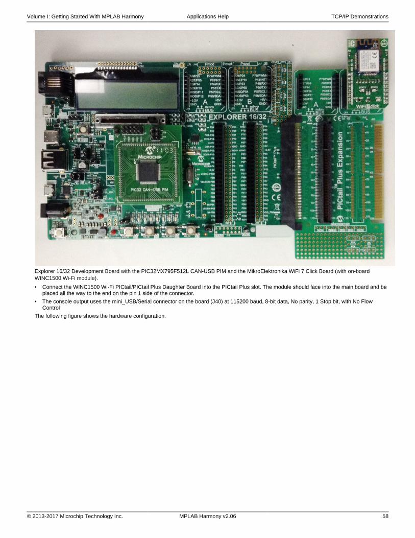
Explorer 16/32 Development Board with the PIC32MX795F512L CAN-USB PIM and the MikroElektronika WiFi 7 Click Board (with on-board WINC1500 Wi-Fi module).
• Connect the WINC1500 Wi-Fi PICtail/PICtail Plus Daughter Board into the PICtail Plus slot. The module should face into the main board and be placed all the way to the end on the pin 1 side of the connector.
• The console output uses the mini_USB/Serial connector on the board (J40) at 115200 baud, 8-bit data, No parity, 1 Stop bit, with No Flow Control
The following figure shows the hardware configuration.
Volume I: Getting Started With MPLAB Harmony Applications Help TCP/IP Demonstrations
© 2013-2017 Microchip Technology Inc. MPLAB Harmony v2.06 58

Running the Demonstration
This section provides instructions on how to build and run the Wi-Fi Easy Configuration demonstration with the MRF24WN or WINC1500 Wi-Fi module.
Description
Notes:1. Refer to Wi-Fi Console Commands for information on the commands that enable control over the Wi-Fi settings.
2. WINC1500 SoftAP mode can support only one Station client connection.
The demonstration does the following:
• Scans the area and stores the list of Access Points in memory
• Switches to SoftAP mode allowing another device to_connect_to it (smartphone or personal computer)
• After a smartphone or personal computer wirelessly connects to the MRF24WN or WINC1500, a web page is served to it
• That web page will display the access point (AP) list (from step 1).
• From the smartphone you can select the desired AP and command the MRF24WN or WINC1500 to_connect_to that AP
• The MRF24WN or WINC1500 will_connect_to the selected AP and store the configuration information in non-volatile memory
Use the following procedure to run the demonstration:
1. Load the demonstration project into MPLAB X IDE.
2. Connect the mini-B/micro B debugger port on-board the starter kit to a USB port on the development computer by using the USB cable provided in the kit.
3. Build, download, and run the demonstration project on the board.
4. When the demonstration runs, it scans for local access points and outputs the results to the serial console. After the scan results, the MRF24WN or WINC1500 goes into SoftAP mode (it behaves like an access point) and outputs the following to the serial console:
Volume I: Getting Started With MPLAB Harmony Applications Help TCP/IP Demonstrations
© 2013-2017 Microchip Technology Inc. MPLAB Harmony v2.06 59

The output of the serial console for the MRF24WN module is shown as follows:
5. From a smartphone or personal computer,_connect_to the ’MCHPSoftAP’ network, which is the SoftAP network started by the demonstration. Then, bring up a web page by entering the IP address of the SoftAP network into the smartphone browser. This is the IP address displayed in step 4 (e.g., 192.168.1.1). When the web page is displayed, on the right top corner of the page, there are three widgets to verify connectivity with the board.
• LED - This is in blinking mode.
• Button - This changes position when the buttons on the target board is pressed.
• Random Number - This displays random numbers generated by the target board.
On the web page:
a. Select Network Configuration, and then Scan for Wireless Networks. The MRF24WN or WINC1500 will display the list of wireless networks on the web page.
b. Select the desired AP to which the MRF24WN or WINC1500 should_connect_by clicking the name of the AP.
c. The MRF24WN or WINC1500 will then_connect_to that Access Point and write the configuration information to non-volatile memory.
Volume I: Getting Started With MPLAB Harmony Applications Help TCP/IP Demonstrations
© 2013-2017 Microchip Technology Inc. MPLAB Harmony v2.06 60

d. The console output will show the new connection taking place.
6. If you rerun the demonstration, it will automatically connect the selected AP, as the configuration data stored in non-volatile memory will be used to reconnect to the desired AP.
a. Connect the PC to the same AP to which the board is connected.
b. Open the serial terminal as described in step 2, and get the IP address that the board had gotten from the newly selected AP.
c. Type this IP address into the browser and the demo web page should come up on the browser.
d. Try monitoring the LED and Switch through the newly established connection.
7. To reset and run the demonstration from the beginning:
a. Erase the stored configuration by bringing up the demonstration.
b. At the command line type deleteconf
Volume I: Getting Started With MPLAB Harmony Applications Help TCP/IP Demonstrations
© 2013-2017 Microchip Technology Inc. MPLAB Harmony v2.06 61

wifi_rgb_easy_configuration
Before using this demonstration, please see the important notes in the TCP/IP Demonstrations > Introduction.
The WiFi RGB Easy Configuration demo showcases how to configure an embedded WiFi device that does not have a natural keyboard and screen. By using the internal Web server that accompanies the Microchip TCP/IP stack, end-users can use their browser as a conduit for programming the WiFi device with the correct network parameters.
Building the Application
This section identifies the MPLAB X IDE project name and location and lists and describes the available configurations for the PIC32 Wi-Fi RGB
Volume I: Getting Started With MPLAB Harmony Applications Help TCP/IP Demonstrations
© 2013-2017 Microchip Technology Inc. MPLAB Harmony v2.06 62

Easy Configuration Demonstration.
Description
To build this project, you must open the wifi_rgb_easy_configuration.X project in MPLAB X IDE, and then select the desired configuration.
The following tables list and describe the project and supported configurations. The parent folder for these files is
<install-dir>/apps/tcpip/wifi_rgb_easy_configuration.
MPLAB X IDE Project
This table lists the name and location of the MPLAB X IDE project folder for the demonstration.
Project Name Location
wifi_rgb_easy_configuration.X <install-dir>/apps/tcpip/wifi_rgb_easy_configuration/firmware
MPLAB X IDE Project Configurations
This table lists and describes the supported configurations of the demonstration, which are located within ./firmware/src/system_config.
Project Configuration Name
BSP Used Description
pic32mz_ef_curiosity pic32mz_ef_curiosity FreeRTOS version of the demonstration running on the PIC32MZ EF Curiosity Development board, with on-board MRF24WN module. This configuration is generated for standalone mode. All necessary files are copied under its configuration folder, and so it can be built and run without the MPLAB Harmony framework.
Configuring the Hardware
Describes how to configure the supported hardware.
Description
PIC32MZ EF Curiosity Development Board with on-board MRF24WN0MA module.
• Ensure that a jumper is placed at 4-3 on J8, to select supply from debug USB connector.
• Power the PIC32MZ EF Curiosity Development Board from a Host PC through a Type-A male to micro-B USB cable connected to Micro-B port (J3).
• Ensure that jumper is not present in the J13 header to use the Curiosity board in device mode.
• Plug in a USB cable with a micro-B type connector to Micro-B port (J12), and plug the other end into your computer.
Volume I: Getting Started With MPLAB Harmony Applications Help TCP/IP Demonstrations
© 2013-2017 Microchip Technology Inc. MPLAB Harmony v2.06 63

Running the Demonstration
This section provides instructions on how to build and run the Wi-Fi RGB Easy Configuration demonstration with the MRF24WN Wi-Fi module.
Description
1. Load the demonstration project into MPLAB X IDE.
2. Connect the USB debugger port on-board the starter kit to a USB port on the development computer using the USB cable provided in the kit.
3. Build, download, and run the demonstration project on the board.
4. When the demonstration runs, it scans for local access points and outputs the results to the serial console. After the scan results, the MRF24WN goes into SoftAP mode (it behaves as an access point) and outputs the following to the serial console:
5. From a smartphone or personal computer, connect to the Curiosity_RGBLED_AP network, which is the SoftAP network started by the demonstration. Then, bring up a web page by entering the IP address of the SoftAP network into the smartphone browser. This is the IP address displayed in step 2 (e.g., 192.168.1.1). When the web page is displayed:
a. On the right top corner of the page, there is a widget through which we can change the color of the RGB LED which is on the Curiosity board.
Volume I: Getting Started With MPLAB Harmony Applications Help TCP/IP Demonstrations
© 2013-2017 Microchip Technology Inc. MPLAB Harmony v2.06 64

Note:Click the text box to display a pop-up for selecting the color of the RGB LED. Click the Submit button to set the color of the RGB LED on the Curiosity board.
b. Select Network Configuration, and then Scan for Wireless Networks. The MRF24WN will display the list of wireless networks on the web page.
c. Select the desired access point (AP) to which the MRF24WN should connect by clicking the name of the AP. The MRF24WN will then connect to that AP and write the configuration information to non-volatile memory.
Note:This demo does not support connection to Secured APs. Make sure that the AP that you want to connect is unsecured.
d. The console output will show the new connection taking place.
Volume I: Getting Started With MPLAB Harmony Applications Help TCP/IP Demonstrations
© 2013-2017 Microchip Technology Inc. MPLAB Harmony v2.06 65

wifi_sta_demo
Before using this demonstration, please see the important notes in the TCP/IP Demonstrations > Introduction.
The Wi-Fi Station (STA) mode demonstration showcases how to connect a PIC32WK Wi-Fi module with Home AP, checking connection status using PING process and discovering PIC32WK Wi-Fi module.
Building the Application
This section identifies the MPLAB X IDE project name and location and lists and describes the available configurations for the PIC32WK Wi-Fi STA mode configuration demonstration.
Description
To build this project, you must open the wifi_sta_demo.X project in MPLAB X IDE, and then select the desired configuration. The following tables list and describe the project and supported configurations. The parent folder for these files is
<install-dir>/apps/tcpip/wifi_sta_demo.
MPLAB X IDE Project
This table lists the name and location of the MPLAB X IDE project folder for the demonstration.
Project Name Location
wifi_sta_demo.X <install-dir>/apps/tcpip/wifi_sta_demo/firmware
MPLAB X IDE Project Configurations
This table lists and describes the supported configurations of the demonstration, which are within
./firmware/src/system_config.
Project Configuration Name
BSP(s) Used Description
pic32wk_sta pic32wk_gpb_gpd_sk+module Demonstrates basic STA functionality.
pic32wk_sta_freertos pic32wk_gpb_gpd_sk+module FreeRTOS version of the demonstration with basic STA functionality.
Configuring the Hardware
This section describes how to configure the supported hardware.
Description
The following is the PIC32WK Wi-Fi Starter Kit mounted with Wi-Fi module (WM32S2057GXEAS-I/RM)
Volume I: Getting Started With MPLAB Harmony Applications Help TCP/IP Demonstrations
© 2013-2017 Microchip Technology Inc. MPLAB Harmony v2.06 66

The Starter Kit has a UART to USB converter (MCP2200) that enables communication between a host PC and the Wi-Fi module. This is done by connecting a mini-B USB cable from the host PC to the USB port (J306) in the Starter Kit.
The console output uses the UART to USB converter on the board at 230400 baud, 8-bit data, No parity, 1 Stop bit, with No Flow Control.
Running the Demonstration
This section provides instructions about how to build and run the PIC32WK Wi-Fi STA mode demonstration with the WM32 module.
Description
The demonstration does the following:
• Scans the area and triggers the connection with the Home AP.
• The default configuration of the home AP is stored in the Flash and this can be updated with console commands or by using the Web page.
• After connecting with the Home AP, connection status can be verified by running ping.
• After connecting the DUT and the third-party personal computer/laptop to the Home AP, the DUT can ping the third-party computer/laptop, and the computer/laptop can ping the DUT.
• The DUT also supports TCP/IP discovery, in which the WM32 module can be discovered by the Microchip TCPIP Discoverer tool on the third-party personal computer/laptop.
Use the following procedure to run the demonstration:
1. Load the demonstration project into MPLAB X IDE.
2. Connect the mini-B debugger port on the starter kit to a USB port on the development computer by using the USB cable provided in the kit.
3. Build, download, and run the demonstration project on the board.
• When the demonstration runs, it scans for APs and connects with the Home AP saved configuration. If the configured AP is not available in the scan list, the device will be in the scanning phase only.
• After connecting with the Home AP, the DUT (PIC32WK Wi-Fi) gets the IP-address from AP (if DHCP is enabled) or default IP-address, 192.168.1.150
4. Use console commands to get the connection status details. Run netinfo to display these connection details.
---------- Interface <wlan0/PIC32WK> ----------
Host Name: MCHPBOARD_WK - NBNS disabled
IPv4 Address: 192.168.1.101
Mask: 255.255.255.0
Gateway: 192.168.1.1
DNS: 192.168.1.1
MAC Address: 54:8c:a0:00:f3:82
dhcp is ON
Link is UP
5. Run wlan open to open the access to give Wi-Fi commands, and then run wlan macinfo to see the Wi-Fi module status.
----WIFI MAC configuration----
BootMode: STA
HTTP: Disable
OTA: Disable
SSID: PINGD
Volume I: Getting Started With MPLAB Harmony Applications Help TCP/IP Demonstrations
© 2013-2017 Microchip Technology Inc. MPLAB Harmony v2.06 67

Security: NONE
The above Configuration is Saved in Flash
****************************************************
----MAC Connected to AP with following Details----
SSID from MAC:PINGD
Security: NONE
6. After connecting the third-party computer/laptop to the same Home AP, run ping to verify the simple data connection process between the DUT and the computer/laptop.
7. To discover the DUT from the third-party computer/laptop, run the Microchip TCPIP Discoverer tool before the DUT connects to the Home AP. This tool is located in the MPLAB Harmony code base path on the computer/laptop: <install-dir>/utilities/tcpip_discoverer/tcpip_discoverer.jar.
8. After the DUT connects to the Home AP, Click Discover Devices on the Microchip TCPIP Discoverer tool to discover the DUT. The third-party computer/laptop shows above result for discovered DUT.
Volume I: Getting Started With MPLAB Harmony Applications Help TCP/IP Demonstrations
© 2013-2017 Microchip Technology Inc. MPLAB Harmony v2.06 68

wifi_staap_demo
Before using this demonstration, please see the important notes in the TCP/IP Demonstrations > Introduction.
The WiFi AP mode (Out Of Box) and STA mode support demonstration helps to perform the out-of-box configuration of the Home AP using the DUT as the out-of-box access point (OOBAP). On reboot, the DUT switches to station mode and automatically connects to the configured Home AP.
Building the Application
This section identifies the MPLAB X IDE project name and location and lists and describes the available configurations for the PIC32WK Wi-Fi OOBAP and STA mode demonstration.
Description
To build this project, you must open the wifi_staap_demo.X project in MPLAB X IDE, and then select the desired configuration. The following tables list and describe the project and supported configurations. The parent folder for these files is:<install-dir>/apps/tcpip/wifi_staap_demo.
MPLAB X IDE Project
This table lists the name and location of the MPLAB X IDE project folder for the demonstration.
Project Name Location
wifi_staap_demo.X <install-dir>/apps/tcpip/wifi_staap_demo/firmware
MPLAB X IDE Project Configurations
This table lists and describes the supported configurations of the demonstration, which are within
./firmware/src/system_config.
Volume I: Getting Started With MPLAB Harmony Applications Help TCP/IP Demonstrations
© 2013-2017 Microchip Technology Inc. MPLAB Harmony v2.06 69

Project Configuration Name
BSP(s) Used Description
pic32wk_staap pic32wk_gpb_gpd_sk+module Demonstrates OOBAP and STA functionality with WM32 Wi-Fi Starter Kit.
Configuring the Hardware
This section describes how to configure the supported hardware.
Description
The following is the PIC32WK Wi-Fi Starter Kit mounted with Wi-Fi module (WM32S2057GXEAS-I/RM)
The Starter Kit has a UART to USB converter (MCP2200) that enables communication between a host PC and the Wi-Fi module. This is done by connecting a mini-B USB cable from the host PC to the USB port (J306) in the Starter Kit.
The console output uses the UART to USB converter on the board at 230400 baud, 8-bit data, No parity, 1 Stop bit, with No Flow Control.
Running the Demonstration
This section provides instructions about how to build and run the PIC32WK Wi-Fi OOBAP and STA mode demonstration with the WM32 module.
Description
The demonstration does the following:
The PIC32WK Wi-Fi DUT starts as OOBAP (out-of-box Access Point) for configuring the Home AP credentials (such as SSID and password), and then switches to STA mode for automatically connecting to the configured Home Access Point (AP) without any user trigger.
AP (OOBAP) mode
• Starts the device in OOBAP mode, with the configuration stored in flash memory, or with the default configuration if the flash configuration is not available.
• The PIC32WK Wi-Fi OOBAP accepts connections from another third-party STA and accepts only one connection.
• The OOBAP can be started only in Open mode.
• The default configuration of the AP is stored in flash memory, and this configuration can also be updated with console commands.
• The connection status can be verified by the connected STA by running ping.
• In connected STA, the user can access the OOBAP IP address in any browser that will serve the Web pages.
• From the Web pages, the user can configure the Home AP credentials.
• The configuration details are stored in in-package flash (IPF).
STA mode
• Scans the area and triggers the connection with the Home AP stored in flash memory.
• The default configuration of the Home AP is stored in flash memory, and this configuration can be updated with console commands or by using the Web page.
• After connecting with the Home AP, connection status can be verified by running ping.
• After connecting the DUT (PIC32WK) and the third-party personal computer/laptop to the Home AP, the demonstration can be verified.
• The third-party personal computer/laptop can access the DUT IP-address in any browser that will serve the Web pages. That Web page will
Volume I: Getting Started With MPLAB Harmony Applications Help TCP/IP Demonstrations
© 2013-2017 Microchip Technology Inc. MPLAB Harmony v2.06 70

display the Welcome screen along with a random seed number on the page.
• From the third-party personal computer/laptop, you can scan for the wireless networks and select the desired AP, or directly give the desired AP configuration and request the Wi-Fi module to connect to that AP. The DUT will connect to that AP and store the configuration information in flash memory.
Use the following procedure to run the demonstration:
1. Load the demonstration project into MPLAB X IDE.
2. Connect the mini-B debugger port on-the starter kit to a USB port on the development computer by using the USB cable provided in the kit.
3. Build, download, and run the demonstration project on the board.
• When the demonstration runs, the DUT boots-up in OOBAP mode for configuring the Home AP credential.
4. Run netinfo to display the network details as shown below
---------- Interface <wlan0/PIC32WK> ----------
Host Name: MCHPBOARD_WK - NBNS disabled
IPv4 Address: 192.168.3.1
Mask: 255.255.255.0
Gateway: 192.168.3.1
DNS: 192.168.3.1
MAC Address: 54:8c:a0:00:f3:4e
dhcps is ON
dhcp is disabled
Link is UP
5. Run wlan open to open the access to give Wi-Fi commands, and then run wlan macinfo to see the Wi-Fi module status.
----WIFI MAC configuration----
BootMode: AP
HTTP: Enable
OTA: Enable
SSID: AP_PINGDEMO
Security: NONE
The above Configuration is Saved in Flash
****************************************************
----MAC Started as AP with following Details----
SSID from MAC: AP_PINGDEMO
Security: NONE
• OOBAP default SSID is “microchip” and IP address is “192.168.3.1”.
6. Connect the third-party personal computer/laptop (STA) to the PIC32WK OOBAP.
7. In the third-party personal computer/laptop, enter the IP-address of the OOBAP in the browser to get served with Web pages.
• The following default web-page displays firmware build details and a random number.
Volume I: Getting Started With MPLAB Harmony Applications Help TCP/IP Demonstrations
© 2013-2017 Microchip Technology Inc. MPLAB Harmony v2.06 71

• The Network Configuration page, shown in the following, gives the option to configure the OOBAP manually.
8. Enter the Home AP Wi-Fi configuration details (SSID and Security) and click OK to save the details in in-package flash(IPF). The DUT OOBAP will automatically trigger a soft reboot.
9. If the user wants to scan to get the Home AP availability in the vicinity of the DUT, trigger the scan from Scan for Wireless Networks. After a successful scan, the Web page updates the scan results. In the scan results list, click the Home AP. This will send the configuration details (SSID and Security) and save the details in in-package flash (IPF). The DUT OOBAP will automatically trigger a soft reboot.
Volume I: Getting Started With MPLAB Harmony Applications Help TCP/IP Demonstrations
© 2013-2017 Microchip Technology Inc. MPLAB Harmony v2.06 72

• After the reboot, the DUT starts in STA mode and starts the connection procedure to the above configured Home AP. The DUT scans for the configured Home AP. If the Home AP is available in the scan results, the DUT will then connect to it. Otherwise the device will be in scanning phase only.
• After connecting with the Home AP, the DUT will get the IP address from the AP (if DHCP is enabled) or the default IP address, 192.168.1.150.
10. Use console commands to get the connection status details. Run netinfo to show these connection details.
---------- Interface <wlan0/PIC32WK> ----------
Host Name: MCHPBOARD_WK - NBNS disabled
IPv4 Address: 192.168.1.101
Mask: 255.255.255.0
Gateway: 192.168.1.1
DNS: 192.168.1.1
MAC Address: 54:8c:a0:00:f3:82
dhcp is ON
Link is UP
11. Run wlan open to open the access to give Wi-Fi commands, and then run wlan macinfo to see the Wi-Fi module status.
----WIFI MAC configuration----
BootMode: STA
HTTP: Enable
OTA: Enable
SSID: PINGD
Security: NONE
The above Configuration is Saved in Flash
****************************************************
----MAC Connected to AP with following Details----
SSID from MAC:PINGD
Security: NONE
12. After connecting the third-party personal computer/laptop to the same Home AP, run ping to verify the simple data connection process between the DUT and the computer/laptop.
13. Enter the IP-address of the DUT in the browser to get served with Web pages.
Volume I: Getting Started With MPLAB Harmony Applications Help TCP/IP Demonstrations
© 2013-2017 Microchip Technology Inc. MPLAB Harmony v2.06 73

• The following default web-page displays firmware build details and a random number.
• The Network Configuration page gives the option to trigger the scan in the Wi-Fi module. After a successful scan, the page updates with scan results.
14. On the Network Configuration page, click Scan for Wireless Networks to start the scan. After a successful scan, the Web page updates the scan results. You can choose the desired AP from the scan list to connect the DUT, or click Other Network to enter the AP configuration manually.
Volume I: Getting Started With MPLAB Harmony Applications Help TCP/IP Demonstrations
© 2013-2017 Microchip Technology Inc. MPLAB Harmony v2.06 74

• The DUT will connect with the given configuration and save the configuration information in flash memory.
Note:When rerunning the demonstration, the Wi-Fi module connects with the last saved configuration.
wifi_sta_http_demo
Before using this demonstration, please see the important notes in the TCP/IP Demonstrations > Introduction.
The WiFi STA mode with HTTP support demonstration shows how to connect a PIC32WK Wi-Fi module with Home AP and also to open the Web page using HTTP for accessing Wi-Fi module for Scan and updating configuration.
Building the Application
This section identifies the MPLAB X IDE project name and location and lists and describes the available configurations for the PIC32WK Wi-Fi STA mode with HTTP configuration demonstration.
Description
To build this project, you must open the wifi_sta_http_demo.X project in MPLAB X IDE, and then select the desired configuration. The following tables list and describe the project and supported configurations. The parent folder for these files is
<install-dir>/apps/tcpip/wifi_sta_http_demo.
MPLAB X IDE Project
This table lists the name and location of the MPLAB X IDE project folder for the demonstration.
Project Name Location
wifi_sta_http_demo.X <install-dir>/apps/tcpip/wifi_sta_http_demo/firmware
MPLAB X IDE Project Configurations
This table lists and describes the supported configurations of the demonstration, which are within
./firmware/src/system_config.
Project Configuration Name
BSP(s) Used Description
pic32wk_sta_http pic32wk_gpb_gpd_sk+module Demonstrates STA functionality and Web page support for Scan and Connect with Home AP with WM32 Wi-Fi Starter Kit.
Volume I: Getting Started With MPLAB Harmony Applications Help TCP/IP Demonstrations
© 2013-2017 Microchip Technology Inc. MPLAB Harmony v2.06 75

Configuring the Hardware
This section describes how to configure the supported hardware.
Description
The following is the PIC32WK Wi-Fi Starter Kit mounted with Wi-Fi module (WM32S2057GXEAS-I/RM)
The Starter Kit has a UART to USB converter (MCP2200) that enables communication between a host PC and the Wi-Fi module. This is done by connecting a mini-B USB cable from the host PC to the USB port (J306) in the Starter Kit.
The console output uses the UART to USB converter on the board at 230400 baud, 8-bit data, No parity, 1 Stop bit, with No Flow Control.
Running the Demonstration
This section provides instructions about how to build and run the PIC32WK Wi-Fi STA mode with HTTP demonstration with the WM32 module.
Description
The demonstration does the following:
• Scans the area and triggers the connection with the Home Access Point (AP).
• The default configuration of the Home AP is stored in flash memory. This configuration can be updated through console commands or the Web page.
• After connecting with the Home AP, the connection status can be verified by running ping.
• After connecting the DUT and the third-party personal computer/laptop to the Home AP, the demonstration can be verified.
• In the third-party personal computer/laptop, you can access the DUT IP-address in any browser that serves the Web pages.
• That web page will display the Welcome screen along with a random seed number on the page.
• From the third-party personal computer/laptop, you can scan for the wireless networks and select the desired AP, or directly give the desired AP configuration and command the Wi-Fi module to connect to that AP. The WM32 module will connect to that AP and store the configuration information in flash memory.
Use the following procedure to run the demonstration:
1. Load the demonstration project into MPLAB X IDE.
2. Connect the mini-B debugger port on the starter kit to a USB port on the development computer by using the USB cable provided in the kit.
3. Build, download, and run the demonstration project on the board.
• When demonstration runs, it scans for APs and connects with the saved configuration of the Home AP. If the configured AP is not available in the scan list, the device will be in scanning phase only.
• After connecting with the Home AP, the DUT (PIC32WK Wi-Fi) gets the IP-address from the AP (if DHCP is enabled) or the default IP-address, 192.168.1.150
4. Use console commands to get the connection status details. Run netinfo to display these connection details.
---------- Interface <wlan0/PIC32WK> ----------
Host Name: MCHPBOARD_WK - NBNS disabled
IPv4 Address: 192.168.1.101
Mask: 255.255.255.0
Gateway: 192.168.1.1
Volume I: Getting Started With MPLAB Harmony Applications Help TCP/IP Demonstrations
© 2013-2017 Microchip Technology Inc. MPLAB Harmony v2.06 76

DNS: 192.168.1.1
MAC Address: 54:8c:a0:00:f3:82
dhcp is ON
Link is UP
5. Run wlan open to open the access to give Wi-Fi commands, and then run wlan macinfo to see the Wi-Fi module status.
----WIFI MAC configuration----
BootMode: STA
HTTP: Enable
OTA: Enable
SSID: PINGD
PSK: 12345678
Mode: 0x79
The above Configuration is Saved in Flash
****************************************************
----MAC Connected to AP with following Details----
SSID from MAC:PINGD
PSK: 12345678
Mode: 0x79
6. After connecting the third-party personal computer/laptop to the same Home AP, run ping to verify the simple data connection process between the DUT and the computer/laptop.
7. Enter the IP-address of the DUT in the browser to get served with web pages.
• The following default web-page gives firmware build details and a random number.
• The “Network Configuration” page gives the option to trigger the scan in the Wi-Fi module. After a successful scan, the page updates with scan results.
8. On the Network Configuration page, click Scan for Wireless Networks to start the scan. After a successful scan, the Web page updates the scan results. You can choose the desired AP from the scan list to connect the DUT, or click Other Network to enter the AP configuration manually.
Volume I: Getting Started With MPLAB Harmony Applications Help TCP/IP Demonstrations
© 2013-2017 Microchip Technology Inc. MPLAB Harmony v2.06 77

• The DUT will connect with the given configuration and save the configuration information in flash memory.
Note:When rerunning the demonstration, the Wi-Fi module connects with the last saved configuration.
wifi_sta_ota_demo
Before using this demonstration, please see the important notes in the TCP/IP Demonstrations > Introduction.
The WiFi STA mode with OTA support demonstration shows how to connect a PIC32WK Wi-Fi module with Home AP and also open the Web page by using HTTP for OTA (Over the Air) update.
Building the Application
This section identifies the MPLAB X IDE project name and location and lists and describes the available configurations for the PIC32WK Wi-Fi STA mode with OTA support demonstration.
Volume I: Getting Started With MPLAB Harmony Applications Help TCP/IP Demonstrations
© 2013-2017 Microchip Technology Inc. MPLAB Harmony v2.06 78

Description
To build this project, you must open the wifi_sta_ota_demo.X project in MPLAB X IDE, and then select the desired configuration. The following tables list and describe the project and supported configurations. The parent folder for these files is
<install-dir>/apps/tcpip/wifi_sta_ota_demo.
MPLAB X IDE Project
This table lists the name and location of the MPLAB X IDE project folder for the demonstration.
Project Name Location
wifi_sta_ota_demo.X <install-dir>/apps/tcpip/wifi_sta_ota_demo/firmware
MPLAB X IDE Project Configurations
This table lists and describes the supported configurations of the demonstration, which are within
./firmware/src/system_config.
Project Configuration Name
BSP(s) Used Description
pic32wk_sta_http_ota pic32wk_gpb_gpd_sk+module Demonstrates STA functionality and Web page support for demonstration of how to update the device over OTA using HTTP.
Configuring the Hardware
This section describes how to configure the supported hardware.
Description
The following is the PIC32WK Wi-Fi Starter Kit mounted with Wi-Fi module (WM32S2057GXEAS-I/RM)
The Starter Kit has a UART to USB converter (MCP2200) that enables communication between a host PC and the Wi-Fi module. This is done by connecting a mini-B USB cable from the host PC to the USB port (J306) in the Starter Kit.
The console output uses the UART to USB converter on the board at 230400 baud, 8-bit data, No parity, 1 Stop bit, with No Flow Control.
Running the Demonstration
This section provides instructions about how to build and run the PIC32WK Wi-Fi STA mode with OTA demonstration with the WM32 module.
Description
The demonstration does the following:
• Scans the area and triggers the connection with the Home Access Point (AP) stored in flash memory.
• The default configuration of the Home AP is stored in flash memory, and this configuration can be updated through console commands or the Web page.
Volume I: Getting Started With MPLAB Harmony Applications Help TCP/IP Demonstrations
© 2013-2017 Microchip Technology Inc. MPLAB Harmony v2.06 79

• After connecting with the Home AP, connection status can be verified by running ping.
• After connecting the DUT and the third-party personal computer/laptop to the Home AP, the OTA demonstration can be verified.
• In the third-party personal computer/laptop, the DUT IP-address for starting OTA procedure can be accessed in any browser that serves the Web pages.
• That web page gives the option to upload the file.
• OTA updates through the HTTP server.
Use the following procedure to run the demonstration:
1. Load the demonstration project into MPLAB X IDE.
2. Connect the mini-B debugger port on-the starter kit to a USB port on the development computer by using the USB cable provided in the kit.
3. Build, download, and run the demonstration project on the board.
• When demonstration runs, it scans for APs and connects with the saved configuration of the Home AP. If the configured AP is not available in the scan list, the device will be in scanning phase only.
• After connecting with the Home AP, the DUT (PIC32WK Wi-Fi) will get the IP-address from the AP (if DHCP is enabled) or the default IP-address, 192.168.1.150
4. Use console commands to get the connection status details. Run netinfo to display these connection details.
---------- Interface <wlan0/PIC32WK> ----------
Host Name: MCHPBOARD_WK - NBNS disabled
IPv4 Address: 192.168.1.101
Mask: 255.255.255.0
Gateway: 192.168.1.1
DNS: 192.168.1.1
MAC Address: 54:8c:a0:00:f3:82
dhcp is ON
Link is UP
5. Run wlan open to open the access to give Wi-Fi commands, and then run wlan macinfo to see the Wi-Fi module status.
----WIFI MAC configuration----
BootMode: STA
HTTP: Enable
OTA: Enable
SSID: PINGD
PSK: 12345678
Mode: 0x79
The above Configuration is Saved in Flash
****************************************************
----MAC Connected to AP with following Details----
SSID from MAC:PINGD
PSK: 12345678
Mode: 0x79
6. After connecting the third-party personal computer/laptop to the same Home AP, run ping to verify the simple data connection process between the DUT and the computer/laptop.
7. Enter the IP-address of the DUT in the browser to get served with web pages.
• The default web-page as shown below gives firmware build details and a random number.
Volume I: Getting Started With MPLAB Harmony Applications Help TCP/IP Demonstrations
© 2013-2017 Microchip Technology Inc. MPLAB Harmony v2.06 80

8. In the browser, type the IP address appended with "/mpfsupload" to get the upload page. Refer to the following.
9. In local storage, browse to and select the hex file to be uploaded, and then click Upload.
Volume I: Getting Started With MPLAB Harmony Applications Help TCP/IP Demonstrations
© 2013-2017 Microchip Technology Inc. MPLAB Harmony v2.06 81

• When the upload starts, you can observe the progress in the command console. After upload is complete, the command console outputs “Done” followed by “OTA Completed”.
• The browser displays a message that the OTA completion is successful.
10. Click the Site main page link to be redirected to the home page. After successful upload of the firmware image, you can see the new build details on the home page.
Volume I: Getting Started With MPLAB Harmony Applications Help TCP/IP Demonstrations
© 2013-2017 Microchip Technology Inc. MPLAB Harmony v2.06 82

wifi_sta_wolfssl_demo
Before using this demonstration, please see the important notes in the TCP/IP Demonstrations > Introduction.
This Wi-Fi STA and wolfSSL TCP/IP Client demonstration.showcases how to connect a PIC32WK Wi-Fi module with Home AP and access a secure Web site using wolfSSL.
Building the Application
This section identifies the MPLAB X IDE project name and location and lists and describes the available configurations for the PIC32WK Wi-Fi STA mode with SSL demonstration.
Description
To build this project, you must open the wifi_sta_wolfssl_demo.Xproject in MPLAB X IDE, and then select the desired configuration. The following tables list and describe the project and supported configurations. The parent folder for these files is
<install-dir>/apps/tcpip/wifi_sta_wolfssl_demo.
MPLAB X IDE Project
This table lists the name and location of the MPLAB X IDE project folder for the demonstration.
Project Name Location
wifi_sta_wolfssl_demo.X <install-dir>/apps/tcpip/wifi_sta_wolfssl_demo/firmware
MPLAB X IDE Project Configurations
This table lists and describes the supported configurations of the demonstration, which are within
./firmware/src/system_config.
Project Configuration Name
BSP(s) Used Description
pic32wk_sta_wolfssl pic32wk_gpb_gpd_sk+module Demonstrates STA with SSL functionality with WM32 Wi-Fi Starter Kit.
Configuring the Hardware
This section describes how to configure the supported hardware.
Description
The following is the PIC32WK Wi-Fi Starter Kit mounted with Wi-Fi module (WM32S2057GXEAS-I/RM)
The Starter Kit has a UART to USB converter (MCP2200) that enables communication between a host PC and the Wi-Fi module. This is done by connecting a mini-B USB cable from the host PC to the USB port (J306) in the Starter Kit.
The console output uses the UART to USB converter on the board at 230400 baud, 8-bit data, No parity, 1 Stop bit, with No Flow Control.
Volume I: Getting Started With MPLAB Harmony Applications Help TCP/IP Demonstrations
© 2013-2017 Microchip Technology Inc. MPLAB Harmony v2.06 83

Running the Demonstration
This section provides instructions about how to build and run the PIC32WK Wi-Fi STA mode SSL demonstration with the WM32 module.
Description
The demonstration does the following:
• Scans the area and triggers the connection with the Home AP stored in flash memory.
• The default configuration of the Home AP is stored in flash memory, and this configuration can be updated with console commands.
• After connecting with the Home AP, the connection status can be verified by running ping.
• Opens the secure web page by running the wolfSSL command.
Use the following procedure to run the demonstration:
1. Load the demonstration project into MPLAB X IDE.
2. Connect the mini-B debugger port on- the starter kit to a USB port on the development computer using the USB cable provided in the kit.
3. Build, download, and run the demonstration project on the board.
• When the demonstration runs, it scans for APs and connects with the saved configuration of the Home AP. If the configured AP is not available in the scan list, the device will be in scanning phase only.
• After connecting with the Home AP, the DUT (PIC32WK Wi-Fi) will get the IP address from the AP (if DHCP is enabled) or the default IP-address, 192.168.1.150.
4. Use console commands to get the connection status details. Run netinfo to display these connection details.
---------- Interface <wlan0/PIC32WK> ----------
Host Name: MCHPBOARD_WK - NBNS disabled
IPv4 Address: 192.168.1.101
Mask: 255.255.255.0
Gateway: 192.168.1.1
DNS: 192.168.1.1
MAC Address: 54:8c:a0:00:f3:82
dhcp is ON
Link is UP
5. Run wlan open to open the access to give Wi-Fi commands, and then run wlan macinfo to see the Wi-Fi module status.
----WIFI MAC configuration----
BootMode: STA
HTTP: Enable
OTA: Enable
SSID: PINGD
PSK: 12345678
Mode: 0x79
The above Configuration is Saved in Flash
****************************************************
----MAC Connected to AP with following Details----
SSID from MAC:PINGD
PSK: 12345678
Mode: 0x79
6. After connecting the third-party personal computer/laptop to the same Home AP, run ping to verify the simple data connection process between the DUT and the computer/laptop.
7. To access the content of the Web page, run openurl <url>, where <url> must be a fully formed URL.
• Example: openurl http://google.com/ or openurl https://google.com/
• The following shows an example of accessing a secure and a non-secure Web page by running the openurl command.
Volume I: Getting Started With MPLAB Harmony Applications Help TCP/IP Demonstrations
© 2013-2017 Microchip Technology Inc. MPLAB Harmony v2.06 84

8. Run stats to retrieve the statistics from running the previous openurl command. Examples of statistics are how long each phase of the connection took, and how many bytes were transferred.
9. After running the openurl command, the demonstration makes a DNS query. Open a connection to the requested URL and run an http PUT command.
• The results are sent to the serial port. If an https URL is specified, the connection will first undergo SSL negotiation before running the http PUT command.
wifi_wilc1000
This section describes how to use a simple Wi-Fi application using the WILC1000 firmware.
Description
This application demonstrates a simple Wi-Fi Application using the WILC1000 firmware on the WINC1500 Wi-Fi PICtail/PICtail Plus Daughter Board, with different configurations; STA mode, AP mode, and the wolfSSL Client. The ping from DUT to Home AP works in STA mode, and ping from DUT to a connected Station works in AP mode.
Libraries Used
Other than the common libraries used, following are the libraries have been used for the demonstration:
Volume I: Getting Started With MPLAB Harmony Applications Help TCP/IP Demonstrations
© 2013-2017 Microchip Technology Inc. MPLAB Harmony v2.06 85

• MPLAB Harmony TCP/IP Stack
• FreeRTOS
• WILC1000 Wi-Fi Driver Library
Building the Application
This section identifies the MPLAB X IDE project name and location and lists and describes the available configurations for the wifi_wilc1000 Demonstration.
Description
To build this project, you must open the wifi_wilc1000.X project in MPLAB X IDE, and then select the desired configuration. The following tables list and describe the project and supported configurations. The parent folder for these files is <install-dir>/apps/tcpip/wifi_wilc1000.
MPLAB X IDE Project
The following table lists the name and location of the MPLAB X IDE project folder for the demonstration.
Project Name Location
wifi_wilc1000.X <install-dir>/apps/tcpip/wifi_wilc1000/firmware
MPLAB X IDE Project Configurations
The following table describes the supported configurations of the demonstration, which are within ./firmware/src/system_config.
Project Configuration Name BSP(s) Used Description
pic32mx795_pim_e16_wilc_freertos_sta pic32mx795_pim + e16
FreeRTOS version of demonstration running STA Mode with on WILC1000 firmware running on the WINC1500 Wi-Fi PICtail/PICtail Plus Daughter Board on the Explorer 16 Development Board with PIC32MX795F512L CAN-USB Plug-in Module (PIM).
pic32mx795_pim_e16_wilc_freertos_ap pic32mx795_pim + e16
FreeRTOS version of demonstration running AP Mode with on WILC1000 firmware running on WINC1500 Wi-Fi PICtail/PICtail Plus Daughter Board on the Explorer 16 Development Board with PIC32MX795F512L CAN-USB Plug-in Module (PIM).
pic32mz_ef_sk__ioexp__wilc__freertos_wolfssl_client pic32mz_ef_sk FreeRTOS version of demonstration running the wolfSSL Client with the WILC1000 firmware running on WINC1500 Wi-Fi PICtail/PICtail Plus Daughter Board on the PIC32MZ EF Starter Kit with a PIC32MZ2048 device.
pic32mx795_pim__e16__wilc__sta pic32mx795_pim + e16
Non-OS version of demonstration running STA Mode on PIC32 PIM with WILC1000 firmware running on the WINC1500 Wi-Fi PICtail/PICtail Plus Daughter Board on the Explorer 16 Development Board. This demo is similar to the demo pic32mx795_pim__e16__wilc__freertos_sta in terms of running it.
pic32mx795_pim__e16__wilc__freertos_ap_scan pic32mx795_pim + e16
FreeRTOS version of Demonstration Scanning APs on PIC32 PIM with WILC1000 firmware running on the WINC1500 Wi-Fi PICtail/PICtail Plus Daughter Board on the Explorer 16 Development Board.The demo scans for the APs and prints the list of scanned APs, on the console.
pic32mx795_pim__e16__wilc__freertos_mac_address_chip_info pic32mx795_pim + e16
FreeRTOS version of demonstration for getting MAC Address and Chip Info on PIC32 PIM with WILC1000 firmware running on the WINC1500 Wi-Fi PICtail/PICtail Plus Daughter Board on the Explorer 16 Development Board. The demo prints the MAC Address and Chip Info, on the console.
pic32mx795_pim__e16__wilc__freertos_p2p_client pic32mx795_pim + e16
FreeRTOS version of Demonstration running P2P Client on PIC32 PIM with WILC1000 firmware running on the WINC1500 Wi-Fi PICtail/PICtail Plus Daughter Board on the Explorer 16 Development Board.
pic32mx795_pim__e16__wilc__freertos_mode_change pic32mx795_pim + e16
FreeRTOS version of demonstration Changing Mode from AP to P2P Client on PIC32 PIM with WILC1000 firmware running on the WINC1500 Wi-Fi PICtail/PICtail Plus Daughter Board on the Explorer 16 Development Board.
Volume I: Getting Started With MPLAB Harmony Applications Help TCP/IP Demonstrations
© 2013-2017 Microchip Technology Inc. MPLAB Harmony v2.06 86

pic32mx795_pim__e16__wilc__freertos_tcp_client pic32mx795_pim + e16
FreeRTOS version of demonstration running TCP Client on PIC32 PIM with WILC1000 firmware running on the WINC1500 Wi-Fi PICtail/PICtail Plus Daughter Board on the Explorer 16 Development Board.
pic32mx795_pim__e16__wilc__freertos_tcp_server pic32mx795_pim + e16
FreeRTOS version of demonstration running TCP Server on PIC32 PIM with WILC1000 firmware running on the WINC1500 Wi-Fi PICtail/PICtail Plus Daughter Board on the Explorer 16 Development Board.
pic32mx795_pim__e16__wilc__freertos_udp_server pic32mx795_pim + e16
FreeRTOS version of Demonstration running UDP Server on PIC32 PIM with WILC1000 firmware running on the WINC1500 Wi-Fi PICtail/PICtail Plus Daughter Board on the Explorer 16 Development Board.
pic32mz_ef_sk__ioexp__wilc__freertos_wolfmqtt_client pic32mz_ef_sk FreeRTOS version of demonstration running WolfMqtt Client on PIC32 EF Starter Kit with WILC1000 firmware running on the WINC1500 Wi-Fi PICtail/PICtail Plus Daughter Board.
pic32mx795_pim__e16__wilc__freertos_wps pic32mx795_pim + e16
FreeRTOS version of Demonstration running WPS on PIC32 PIM with WILC1000 firmware running on the WINC1500 Wi-Fi PICtail/PICtail Plus Daughter Board on the Explorer 16 Development Board. The Demo runs WPS Push Button Mode by default, and if one needs to run WPS PIN, he needs to make MAIN_WPS_PUSH_BUTTON_FEATURE as ‘false’ in wifi_wilc1000\firmware\src\wps.c file
pic32mx795_pim__e16__wilc__freertos_udp_client pic32mx795_pim + e16
FreeRTOS version of Demonstration UDP Client on PIC32 PIM with WILC1000 firmware running on the WINC1500 Wi-Fi PICtail/PICtail Plus Daughter Board on the Explorer 16 Development Board.
Configuring the Hardware
This section describes how to configure the hardware using the WINC1500 PICtail Daughter Board and the PICtail Plus slot.
Description
The hardware is configured with the following steps:
1. Connect the WINC1500 PICtail Daughter Board into the PICtail Plus slot closest to the MCU. The module should face into the board and be placed all the way to the end on the pin 1 side of the connector.
2. The console output uses the DB9 connector on the board at 115200 baud, 8-bit data, No parity, 1 Stop bit, with No Flow Control.
The following figure shows the hardware configuration.
Explorer 16 Development Board with PIC32MX795512L PIM
Volume I: Getting Started With MPLAB Harmony Applications Help TCP/IP Demonstrations
© 2013-2017 Microchip Technology Inc. MPLAB Harmony v2.06 87

WINC1500 Wi-Fi PICtail/PICtail Plus Daughter Board
Running the Demonstration
This section provides instructions on how to run the wifi_wilc1000 demonstration.
Volume I: Getting Started With MPLAB Harmony Applications Help TCP/IP Demonstrations
© 2013-2017 Microchip Technology Inc. MPLAB Harmony v2.06 88

Description
This demonstration exercises various encryption, decryption, hashing, and random number functions.
1. After compiling and programming the target device, select the configuration as pic32mx795_pim_e16_wilc_freertos_sta.
2. When the UART is connected by the serial to the USB cable, configure the Home AP configuration using the iwconfig console command. Refer to DRV WILC1000 WIFI Library Interface for additional information.
3. When receiving the IP from the Home AP, ping the Home AP.
Volume I: Getting Started With MPLAB Harmony Applications Help TCP/IP Demonstrations
© 2013-2017 Microchip Technology Inc. MPLAB Harmony v2.06 89

4. When creating the device to act as the AP, to compile and program the target device, select the configuration as pic32mx795_pim_e16_wilc_freertos_ap.
5. When the device appears as Soft AP, the AP can be found in the scan with SSID as ‘MCHPSoftAP.'
6. The SSID ‘MCHPSoftAP’ can be found in the scan list.
Volume I: Getting Started With MPLAB Harmony Applications Help TCP/IP Demonstrations
© 2013-2017 Microchip Technology Inc. MPLAB Harmony v2.06 90

7. Any station can connect, and ping on the AP IP address, 192.168.1.1.
8. When the device serves as a wolfSSL client, to compile and program the target device, select the configuration pic32mz_ef_sk__ioexp__wilc__freertos_wolfssl_client.
9. For this configuration, the hardware is different. In this case, use the WINC1500 PICtail with the starter kit containing PIC32MZ2048. The highlighted red box is the WINC1500 Wi-Fi PICtail/PICtail Plus Daughter Board. The highlighted blue box is the PIC32MZ2048 Processor.
Volume I: Getting Started With MPLAB Harmony Applications Help TCP/IP Demonstrations
© 2013-2017 Microchip Technology Inc. MPLAB Harmony v2.06 91

10. For serial communication and console output connect a mini-USB cable between the PIC32MZ Embedded Connectivity with Floating Point Unit (EF) Family Starter Kit and laptop. The serial connection is configured for 115200 baud, 8-bit data, No parity, 1 Stop bit, with No Flow Control. Configure the home AP using the iwconfig console command. Refer to DRV WILC1000 WIFI Library Interface for additional information.
11. When receiving the IP from the home AP, the device makes a DNS query to resolve the IP address for the host, “https://www.google.com."
12. The device then proceeds with SSL negotiations as the URL is secured (https).
13. The UART displays the contents of the web page.
Volume I: Getting Started With MPLAB Harmony Applications Help TCP/IP Demonstrations
© 2013-2017 Microchip Technology Inc. MPLAB Harmony v2.06 92

Running the Demonstration Using Various Configurations
This section demonstrates how to run the wifi_wilc1000 Demonstrations using other configurations.
Description
pic32mx795_pim__e16__wilc__freertos_wps
1. The demonstration comes as WPS in Push Button Mode.
2. The user needs to push the WPS Button on the AP for the device to connect to it.
Volume I: Getting Started With MPLAB Harmony Applications Help TCP/IP Demonstrations
© 2013-2017 Microchip Technology Inc. MPLAB Harmony v2.06 93

3. In case the user wants to use the WPS PIN Mode, changes need to be made in the wifi_wilc1000\firmware\src\wps.c file
• Macro MAIN_WPS_PUSH_BUTTON_FEATURE should be changed to false
• Macro MAIN_WPS_PIN_NUMBER needs to be set
pic32mx795_pim__e16__wilc__freertos_p2p_client
1. The P2P client comes up with the device name as WILC1000_P2P.
2. The other device can scan and find the same in its list.
3. The other device needs to initiate the connection.
Volume I: Getting Started With MPLAB Harmony Applications Help TCP/IP Demonstrations
© 2013-2017 Microchip Technology Inc. MPLAB Harmony v2.06 94

4. The Logs on the device will be as follows:
pic32mx795_pim__e16__wilc__freertos_mode_change
1. The device comes up in AP Mode with SSID WILC1000_AP.
2. The device remains in AP Mode for around a minute, and then changes the mode to P2P Client.
Volume I: Getting Started With MPLAB Harmony Applications Help TCP/IP Demonstrations
© 2013-2017 Microchip Technology Inc. MPLAB Harmony v2.06 95

pic32mx795_pim__e16__wilc__freertos_tcp_client
1. When the device comes up, connect it to the AP using the command iwconfig mode managed.
2. Once connected, the demonstration will make a DNS query, and then open a TCP connection to microchip.com, and perform a simple HTTP GET command.
pic32mx795_pim__e16__wilc__freertos_tcp_server
1. When the device comes up, connect it to the AP using the command iwconfig mode managed.
2. Once connected, the demonstration starts a TCP Server on port 9760 with the IP assigned by the AP.
Volume I: Getting Started With MPLAB Harmony Applications Help TCP/IP Demonstrations
© 2013-2017 Microchip Technology Inc. MPLAB Harmony v2.06 96

3. Start a TCP Client on another device (SocketTest3 in this example), and connect to this TCP Server.
4. The TCP server running on the device shall send back the string received from the Client in CAPS. Therefore, if the TCP Client sends the Server “Hello”, the Server shall send “HELLO” back to the Client.
pic32mx795_pim__e16__wilc__freertos_udp_server
1. When the device comes up, connect it to the AP using the command iwconfig mode managed.
2. Once connected, the demonstration starts a UDP Server on port 9760 with the IP assigned by the AP.
Volume I: Getting Started With MPLAB Harmony Applications Help TCP/IP Demonstrations
© 2013-2017 Microchip Technology Inc. MPLAB Harmony v2.06 97

3. Start a UDP Client on another device (SocketTest3 in this example), and connect to this UDP Server.
4. The UDP server running on the device shall send back the string received from the Client in CAPS. Therefore, if the UDP Client sends the Server “Hello," the Server shall send “HELLO” back to the Client.
pic32mx795_pim__e16__wilc__freertos_udp_client
1. When the device comes up, connect it to the AP using the command iwconfig mode managed.
2. Start a UDP Server on another device (SocketTest3 in this example).
Volume I: Getting Started With MPLAB Harmony Applications Help TCP/IP Demonstrations
© 2013-2017 Microchip Technology Inc. MPLAB Harmony v2.06 98

3. This demonstration has three commands:
• setudppacketoptions - Sets the current hostname, port, and message
• getudppacketoptions - Gets the hostname, port and message
• sendudppacket - Sends the UDP Packet
4. Use “setudppacketoptions” to set the IP, port of the UDP Server and the message to be sent to the UDP Server. In this example, setudppacketoptions 192.168.1.101 1212 hello.
5. After setting the options, send the packet to the server using the command sendudppacket.
pic32mz_ef_sk__ioexp__wilc__freertos_wolfmqtt_client
1. Connect the device to the Access Point using the command iwconfig mode managed.
2. After connecting to the AP, the MQTT Protocol gets triggered automatically and Client connects to the Server.
Volume I: Getting Started With MPLAB Harmony Applications Help TCP/IP Demonstrations
© 2013-2017 Microchip Technology Inc. MPLAB Harmony v2.06 99

wifi_winc1500_socket
This section provides information on the WINC1500 Socket Mode Driver demonstrations.
Description
Before using this demonstration, please see the important notes in the TCP/IP Demonstrations > Introduction.
This demonstration has many examples that can be configured and run individually and demonstrate the features support by the WINC1500 Wi-Fi module. The examples are defined in the file app.h, and the detail for each example is described in their related .c files.
Demo Example Configurations (app.h) Description .c file
#define AP_SCAN_EXAMPLE Scans APs around you and displays the results, and then connects to the target AP.
ap_scan.c
#define CHIP_INFO_GET_EXAMPLE Gets the chip information of WINC1500. chip_info_get.c
#define EMAIL_SEND_EXAMPLE Demonstrates email sending. email_send.c
#define HTTP_DOWNLOAD_EXAMPLE Demonstrates file downloading by HTTP client. http_download.c
#define IP_ADDR_LOCATE_EXAMPLE Gets current location where my IP is used. ip_addr_locate.c
#define MAC_ADDRESS_GET_EXAMPLE Gets the MAC address of WINC150. mac_address_get.c
#define MDNS_EXAMPLE Demonstrates mDNS server with service discovery support. mdns.c
#define MODE_AP_EXAMPLE Demonstrates starting SoftAP with WPA, WEP or open security. mode_ap.c
#define MODE_CLIENT_STA_EXAMPLE Demonstrates client mode connection with WPA. mode_client_sta.c
#define MULTI_SOCKET_EXAMPLE Demonstrates running multiple TCP clients at the same time. multi_socket_example.c
#define P2P_EXAMPLE Demonstrates Wi-Fi Direct GC function. p2p.c
#define POWER_SAVE_EXAMPLE Demonstrates power save features. power_save.c
#define PROVISION_AP_EXAMPLE Demonstrates provisioning using SoftAP function through Android application.
provision_ap.c
#define PROVISION_HTTP_EXAMPLE Demonstrates provisioning using SoftAP function through webpage. provision_http.c
#define PUBNUB_CLOUD_EXAMPLE Demonstrates publishing and subscribing using PubNub. pubnub_cloud.c
#define SECURITY_WEP_WPA_EXAMPLE Demonstrates infrastructure network connection with WPA, WEP or open security.
security_wep_wpa.c
#define SIMPLE_GROWL_EXAMPLE Demonstrates notification transmitting among WINC1500, public remote server and smartphone application.
simple_growl.c
Volume I: Getting Started With MPLAB Harmony Applications Help TCP/IP Demonstrations
© 2013-2017 Microchip Technology Inc. MPLAB Harmony v2.06 100

#define SSL_CLIENT_EXAMPLE Demonstrates SSL client. ssl_client.c
#define SSL_SERVER_EXAMPLE Demonstrates SSL server. ssl_server.c
#define TCP_CLIENT_EXAMPLE Demonstrates TCP client. tcp_client.c
#define TCP_SERVER_EXAMPLE Demonstrates TCP server. tcp_server.c
#define TIME_CLIENT_EXAMPLE Demonstrates SNTP client. time_client.c
#define UDP_EXAMPLE Demonstrates UDP server and client. udp.c
#define UDP_CLIENT_EXAMPLE Demonstrates UDP client. udp_client.c
#define UDP_SERVER_EXAMPLE Demonstrates UDP server. udp_server.c
#define WEATHER_CLIENT_EXAMPLE Weather client retrieves weather information of the target location using HTTP query.
weather_client.c
#define WPS_CONNECT_EXAMPLE Demonstrates WPS security in client mode. wps_connect.c
#define FW_UPDATE_OTA Supports FW update over the air (OTA). fw_update_ota.c
#define FW_UPDATE_OVER_SERIAL Supports FW update over serial port. fw_update_over_serial.c
WINC1500 Socket Examples Guide
This section introduces the WINC1500 Socket examples and describes how to run each example on the Explorer 16 Development Board.
Organization of WINC1500 Socket Examples
Provides information on the organization of the socket examples for the WINC1500 Wi-Fi Demonstration.
Description
Basic Examples
These examples describe basic Wi-Fi operation in a ‘how-to’ manner:
• How to read chip ID (to identify WINC1500 H/W revision)
• How to get MAC address of the Wi-Fi module
• How to start Wi-Fi in specific operation mode, such as:
• STA Mode (Station mode, known as a Wi-Fi client)
• AP mode (Access Point mode)
• P2P mode (Peer-to-Peer mode, also known as Wi-Fi Direct®)
• How to switch mode among STA, AP, and P2P modes during the runtime
• How to scan APs that are nearby
• How to set deep sleep mode
• How to connect to secure Wi-Fi using WEP or WPA/WPA2 personal security
• How to connect to WPA/WPA2 enterprise security network
• How to connect to security WPS
• How to get RF signal status by reading RSSI value
• How to set AP provision
• How to set HTTP provision
Protocol Examples
After basic code examples, user may want to explore how to send and receive network packets. Here are protocol examples that can be extended for IoT application.
• UDP protocol example
• Server and Client
• Client
• Server
• TCP protocol example
• Client
• Server
• NTP Time client – retrieve network time for IoT application
• Send email – send an email through SMTP server
Volume I: Getting Started With MPLAB Harmony Applications Help TCP/IP Demonstrations
© 2013-2017 Microchip Technology Inc. MPLAB Harmony v2.06 101

Advanced Examples
These examples demonstrate more complex functions like:
• Weather client – get the current weather information of the network provider and utilize the IO1 sensor device
• SSL connection - Set up an SSL connection
• Multi-Socket - Use Ethernet and Wi-Fi sockets
• PubNub cloud – Access cloud device
• Zeroconfig or mDNS – Service or Device discovery
MPLAB Harmony WINC1500 Socket Examples
Provides information on the socket examples provided in your installation of MPLAB Harmony.
Description
The MPLAB Harmony WINC1500 socket demonstration project provides many example configurations, but only one example at a time can be configured and run. The following table lists the available examples in MPLAB Harmony, which can be located in the file, app.h.
WINC1500 Demonstration Examples
Example Configuration Description
AP_SCAN_EXAMPLE Scans APs around you and displays the results, and then connects to the target AP
CHIP_INFO_GET_EXAMPLE Gets the chip information of WINC1500
EMAIL_SEND_EXAMPLE Demonstrates email sending
HTTP_DOWNLOAD_EXAMPLE Demonstrates file downloading by HTTP client
IP_ADDR_LOCATE_EXAMPLE Gets current location where my IP is used
MAC_ADDRESS_GET_EXAMPLE Gets the MAC address of WINC1500
MDNS_EXAMPLE Demonstrates mDNS server with service discovery support
MODE_AP_EXAMPLE Demonstrates starting SoftAP with WPA, WEP or open security
MODE_CLIENT_STA_EXAMPLE Demonstrates client mode connection with WPA
MULTI_SOCKET_EXAMPLE Demonstrates running multiple TCP clients at the same time
P2P_EXAMPLE Demonstrates Wi-Fi Direct GC function
POWER_SAVE_EXAMPLE Demonstrates power save features
PROVISION_AP_EXAMPLE Demonstrates provisioning using SoftAP function
PUBNUB_CLOUD_EXAMPLE Demonstrates publish and subscribe using PubNub
SECURITY_WEP_WPA_EXAMPLE Demonstrates client mode connection with WPA
SSL_CLIENT_EXAMPLE Demonstrates SSL client
SSL_SERVER_EXAMPLE Demonstrates SSL server
TCP_CLIENT_EXAMPLE Demonstrates TCP client
TCP_SERVER_EXAMPLE Demonstrates TCP server
TIME_CLIENT_EXAMPLE Demonstrates SNTP client
UDP_EXAMPLE Demonstrates UDP server and client
UDP_CLIENT_EXAMPLE Demonstrates UDP client
UDP_SERVER_EXAMPLE Demonstrates UDP server
WEATHER_CLIENT_EXAMPLE Weather clients retrieves weather information of the target location using HTTP query
WPS_CONNECT_EXAMPLE Demonstrates WPS security in client mode
IOT_SUPPORT Enables additional IOT supporting features, for instance, HTTP client
Prerequisites
Provides information on the WINC1500 socket example prerequisites.
Volume I: Getting Started With MPLAB Harmony Applications Help TCP/IP Demonstrations
© 2013-2017 Microchip Technology Inc. MPLAB Harmony v2.06 102

Description
Development Platform
Development Platforms MCU WINC1500 Comment
Option 1:
• Microchip Explorer 16 Development Board (DM240001)
• MPLAB ICD3 In-Circuit Debugger (DV164035)
• 9V Power supply (AC002014)
• DB9 Serial Cable or USB/Serial Cable
• Windows7 PC or laptop
• Wi-Fi Access Point (AP)
• Android 5.0 or later smart device
• Internet Access
PIC32MX795F512L USB/CAN Plug-in Module (MA320003)
WINC1500 PICtail Plus module
Hardware Platform support in MPLAB Harmony v2.03b for Windows.
MPLAB Harmony WINC1500 Development Platform with a Laptop Running Windows
WINC1500 Wi-Fi PICtail Module Connected to the Explorer 16 Development Board
Software Prerequisites for Windows
• WINC1500 MPLAB Harmony v2.0.4b or later
• MPLAB X IDE v4.0 or later
• MPLAB XC32 C/C++ Compiler v1.43 or later
• A Terminal console, such as TeraTerm
Internet Services
• Cloud Service
• Weather Server
• NDP Server
Assigning the IDC and XC32 Compilers
Provides information on assigning the IDC and compiler.
Volume I: Getting Started With MPLAB Harmony Applications Help TCP/IP Demonstrations
© 2013-2017 Microchip Technology Inc. MPLAB Harmony v2.06 103

Description
Refer to the following diagram to assign the IDC and XC32 compiler to the active demonstration project, wifi_winc1500_socket. The MPLAB X IDE detects your IDC automatically.
Building the Application
This section identifies the MPLAB X IDE project name and location and lists and describes the available configurations for the PIC32 WINC1500 Socket demonstration.
Description
The WINC1500 socket demonstration contains many examples and only one example can be built and run at a time. The example can be selected from the app.h file. For example, to run the demonstration with the AP_SCAN_EXAMPLE, edit the app.h file and set: #define AP_SCAN_EXAMPLE 1
To build this project, you must open the wifi_winc1500_socket.X project in MPLAB X IDE, and then select the desired configuration. The following tables list and describe the project and supported configurations. The parent folder for these files is
<install-dir>/apps/tcpip/wifi_winc1500_socket.
MPLAB X IDE Project
This table lists the name and location of the MPLAB X IDE project folder for the demonstration.
Project Name Location
wifi_winc1500_socket.X <install-dir>/apps/tcpip/wifi_winc1500_socket/firmware
MPLAB X IDE Project Configurations
This table lists and describes the supported configurations of the demonstration, which are within
./firmware/src/system_config.
Project Configuration Name BSP(s) Used Description
pic32mx795_pim_e16_winc_freertos pic32mx795_pim+e16 FreeRTOS version of the demonstration running on the Explorer 16 or Explorer 16/32 Development Board, or the Explorer 16/32 Development Board with the PICtail Plus Expansion Board, PIC32MX795F512L CAN-USB PIM and the WINC1500 Wi-Fi PICtail/PICtail Plus Daughter Board.
pic32mz_ef_sk_ioexp_winc_freertos pic32mz_ef_sk FreeRTOS version of the demonstration running on the PIC32MZ EF Starter Kit connected to an I/O Expansion board with the WINC1500 PICtail Daughter Board.
pic32mx795_pin_e16_wincclick_freertos pic32mx795_pim+e16 FreeRTOS version of the demonstration running on the Explorer 16/32 Development Board, or the Explorer 16/32 Development board with the PIC32MX795F512L CAN-USB PIM, PICtail Plus Expansion Board, and the MikroElektronika WiFi 7 Click Board (with on-board WINC1500 Wi-Fi module).
Volume I: Getting Started With MPLAB Harmony Applications Help TCP/IP Demonstrations
© 2013-2017 Microchip Technology Inc. MPLAB Harmony v2.06 104

Configuring the Hardware
This section describes how to configure the supported hardware.
Description
PIC32MX795F512L CAN-USB PIM with the Explorer 16 Development Board and WINC1500 Wi-Fi PICtail Daughter Board
• Connect the WINC1500 PICtail Daughter Board into the PICtail Plus slot closest to the MCU. The module should face into the board and be placed all the way to the end on the pin 1 side of the connector.
• The console output uses the DB9 connector on the board at 115200 baud, 8-bit data, No parity, 1 Stop bit, with No Flow Control
The following figure shows the hardware configuration.
PIC32MZ EF Starter Kit connected to an Starter Kit I/O Expansion Board with the WINC1500 Wi-Fi PICtail Daughter Board
• Connect the WINC1500 PICtail Daughter Board into the J2 PICtail Plus slot on the IO Expansion board. The module should face into the board and be placed all the way to the end on the pin 1 side of the connector.
• Connect a jump cable (yellow cable in the picture below) between J10/Pin12 to J11/Pin8 on the I/O Expansion board. This jumper is required for reset of the WINC1500 module.
• Connect the AC adapter to the I/O Expansion board. This external power is required as power supply from USB host connection may not be efficient.
• Remove the JP1 jump on the PIC32MZ EF Starter Kit board.
• For serial communication and console output connect a mini-USB cable between the PIC32MZ EF Starter Kit board and laptop. The serial connection is configured for 115200 baud, 8-bit data, No parity, 1 Stop bit, with No Flow Control.
The following figure shows the hardware configuration.
Volume I: Getting Started With MPLAB Harmony Applications Help TCP/IP Demonstrations
© 2013-2017 Microchip Technology Inc. MPLAB Harmony v2.06 105

Explorer 16/32 Development Board with the PIC32MX795F512L CAN-USB PIM, PICtail Plus Expansion Board, and WINC1500 Wi-Fi PICtail/PICtail Plus Daughter Board
• Connect the WINC1500 Wi-FI PICtail/PICtail Plus Daughter Board into the PICtail Plus slot (J63). The module should face into the main board and be placed all the way to the end on the pin 1 side of the connector.
• The console output uses the mini_USB/Serial connector on the board (J40) at 115200 baud, 8-bit data, No parity, 1 Stop bit, with No Flow Control.
The following figure shows the hardware configuration.
Volume I: Getting Started With MPLAB Harmony Applications Help TCP/IP Demonstrations
© 2013-2017 Microchip Technology Inc. MPLAB Harmony v2.06 106

Explorer 16/32 Development Board with the PIC32MX795F512L CAN-USB PIM, PICtail Plus Expansion Board, and the MikroElektronika WiFi 7 Click Board (with on-board WINC1500 Wi-Fi module).
• Connect the WINC1500 Wi-Fi PICtail/PICtail Plus Daughter Board into the PICtail Plus slot (J63) . The module should face into the main board and be placed all the way to the end on the pin 1 side of the connector.
• The console output uses the mini_USB/Serial connector on the board (J40) at 115200 baud, 8-bit data, No parity, 1 Stop bit, with No Flow Control
The following figure shows the hardware configuration.
Volume I: Getting Started With MPLAB Harmony Applications Help TCP/IP Demonstrations
© 2013-2017 Microchip Technology Inc. MPLAB Harmony v2.06 107

Explorer 16/32 Development Board with the PIC32MX795F512L CAN-USB PIM and the MikroElektronika WiFi 7 Click Board (with on-board WINC1500 Wi-Fi module).
• Connect the WINC1500 Wi-Fi PICtail/PICtail Plus Daughter Board into the PICtail Plus slot. The module should face into the main board and be placed all the way to the end on the pin 1 side of the connector.
• The console output uses the mini_USB/Serial connector on the board (J40) at 115200 baud, 8-bit data, No parity, 1 Stop bit, with No Flow Control
The following figure shows the hardware configuration.
Volume I: Getting Started With MPLAB Harmony Applications Help TCP/IP Demonstrations
© 2013-2017 Microchip Technology Inc. MPLAB Harmony v2.06 108
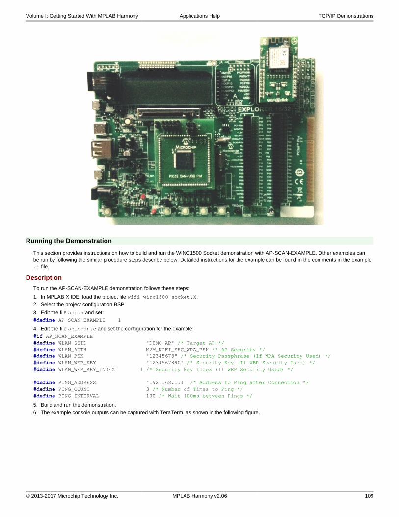
Running the Demonstration
This section provides instructions on how to build and run the WINC1500 Socket demonstration with AP-SCAN-EXAMPLE. Other examples can be run by following the similar procedure steps describe below. Detailed instructions for the example can be found in the comments in the example .c file.
Description
To run the AP-SCAN-EXAMPLE demonstration follows these steps:
1. In MPLAB X IDE, load the project file wifi_winc1500_socket.X.
2. Select the project configuration BSP.
3. Edit the file app.h and set:#define AP_SCAN_EXAMPLE 1
4. Edit the file ap_scan.c and set the configuration for the example:#if AP_SCAN_EXAMPLE#define WLAN_SSID "DEMO_AP" /* Target AP */#define WLAN_AUTH M2M_WIFI_SEC_WPA_PSK /* AP Security */#define WLAN_PSK "12345678" /* Security Passphrase (If WPA Security Used) */#define WLAN_WEP_KEY "1234567890" /* Security Key (If WEP Security Used) */#define WLAN_WEP_KEY_INDEX 1 /* Security Key Index (If WEP Security Used) */ #define PING_ADDRESS "192.168.1.1" /* Address to Ping after Connection */#define PING_COUNT 3 /* Number of Times to Ping */#define PING_INTERVAL 100 /* Wait 100ms between Pings */
5. Build and run the demonstration.
6. The example console outputs can be captured with TeraTerm, as shown in the following figure.
Volume I: Getting Started With MPLAB Harmony Applications Help TCP/IP Demonstrations
© 2013-2017 Microchip Technology Inc. MPLAB Harmony v2.06 109

wolfssl_tcp_server
wolfSSL TCP Server demonstration.
Description
This configuration demonstrates creating a simple Internet Web server, that operates with clear text (TCP Port 80), and with encrypted text (TCP Port 443). If IPv6 is enabled than the demonstration also serves both types of connections on IPv6. The Web server only serves one page with the text 'Nothing Here' to all Web clients.
Before using this demonstration, please see the important notes in the TCP/IP Demonstrations > Introduction.
Building the Application
This section identifies the MPLAB X IDE project name and location and lists and describes the available configurations for the wolfSSL TCP Client Demonstration.
Description
To build this project, you must open the wolfssl_tcp_server.X project in MPLAB X IDE, and then select the desired configuration.
The following tables list and describe the project and supported configurations. The parent folder for these files is <install-dir>/apps/tcpip/wolfssl_tcp_server.
Warning
When using the Microchip Harmony Configurator (MHC), care must be taken when generating the code to not erase the USB descriptors in the system_init.c file.
MPLAB X IDE Project
This table lists the name and location of the MPLAB X IDE project folder for the demonstration.
Project Name Location
wolfssl_tcp_server.X <install-dir>/apps/tcpip/wolfssl_tcp_server/firmware
Volume I: Getting Started With MPLAB Harmony Applications Help TCP/IP Demonstrations
© 2013-2017 Microchip Technology Inc. MPLAB Harmony v2.06 110

MPLAB X IDE Project Configurations
This table lists and describes the supported configurations of the demonstration, which are located within ./firmware/src/system_config.
Project Configuration Name
BSP Used Description
pic32mx_eth_sk pic32mx_eth_sk Demonstrates the wolfSSL TCP Server on the PIC32 Ethernet Starter Kit.
pic32mx_eth_sk2 pic32mx_eth_sk2 Demonstrates the wolfSSL TCP Server on the PIC32 Ethernet Starter Kit II.
pic32mz_ec_sk pic32mz_ec_sk Demonstrates the wolfSSL TCP Server on the PIC32MZ EC Starter Kit.
pic32mz_ef_sk pic32mz_ef_sk Demonstrates the wolfSSL TCP Server on the PIC32MZ EF Starter Kit.
Configuring the Hardware
Describes how to configure the supported hardware.
Description
PIC32 Ethernet Starter Kit
No hardware related configuration or jumper setting changes are necessary.
PIC32 Ethernet Starter Kit II
No hardware related configuration or jumper setting changes are necessary.
PIC32MZ EC Starter Kit
No hardware related configuration or jumper setting changes are necessary.
PIC32MZ EF Starter Kit
No hardware related configuration or jumper setting changes are necessary.
Running the Demonstration
This section provides instructions on how to build and run the demonstration.
Description
For PIC32M-based Starter Kits
1. Connect a USB cable from the computer to the micro-B USB connector on the bottom of the starter kit in use.
2. When the demonstration runs, it will create a virtual com with USB CDC device on the USB bus.
3. Open a standard terminal application on the computer (such as HyperTerminal or Tera Term).
4. Set the baud rate to 921600 baud in the terminal application.
5. Establish a connection between the router or switch with the PIC32M Starter Kit using the RJ45 connector.
The demonstration does not offer any additional functionality through the serial port; however, the current IP can be checked. As soon as a valid IP has been assigned through DHCP to the demonstration, it is ready to serve Web pages. Use any Web browser (i.e., Chrome, Internet Explorer, Firefox, etc.) to connect to the Web server with either http:// or https://.
wolfssl_tcp_client
wolfSSL TCP Client demonstration.
Description
This configuration demonstrates creating an Internet client that uses the MPLAB Harmony TCP API to create a TCP/IP connection to a Web server. The connection can either be clear text, or it can use SSL to encrypt the connection with wolfSSL. The demonstration can use either IPv4 or IPv6.
Before using this demonstration, please see the important notes in the TCP/IP Demonstrations > Introduction.
Building the Application
This section identifies the MPLAB X IDE project name and location and lists and describes the available configurations for the wolfSSL TCP Client Demonstration.
Volume I: Getting Started With MPLAB Harmony Applications Help TCP/IP Demonstrations
© 2013-2017 Microchip Technology Inc. MPLAB Harmony v2.06 111

Description
To build this project, you must open the wolfssl_tcp_client.X project in MPLAB X IDE, and then select the desired configuration.
The following tables list and describe the project and supported configurations. The parent folder for these files is <install-dir>/apps/tcpip/wolfssl_tcp_client.
Warning
When using the Microchip Harmony Configurator (MHC), care must be taken when generating the code to not erase the USB descriptors in the system_init.c file.
MPLAB X IDE Project
This table lists the name and location of the MPLAB X IDE project folder for the demonstration.
Project Name Location
wolfssl_tcp_client.X <install-dir>/apps/tcpip/wolfssl_tcp_client/firmware
MPLAB X IDE Project Configurations
This table lists and describes the supported configurations of the demonstration, which are located within ./firmware/src/system_config.
Project Configuration Name
BSP Used Description
pic32mx_eth_sk pic32mx_eth_sk Demonstrates the wolfSSL TCP Client on the PIC32 Ethernet Starter Kit.
pic32mx_eth_sk2 pic32mx_eth_sk2 Demonstrates the wolfSSL TCP Client on the PIC32 Ethernet Starter Kit II.
pic32mz_ec_sk pic32mz_ec_sk Demonstrates the wolfSSL TCP Client on the PIC32MZ EC Starter Kit.
pic32mz_ef_sk pic32mz_ef_sk Demonstrates the wolfSSL TCP Client on the PIC32MZ EF Starter Kit.
Configuring the Hardware
Describes how to configure the supported hardware.
Description
PIC32 Ethernet Starter Kit
No hardware related configuration or jumper setting changes are necessary.
PIC32 Ethernet Starter Kit II
No hardware related configuration or jumper setting changes are necessary.
PIC32MZ EC Starter Kit
No hardware related configuration or jumper setting changes are necessary.
PIC32MZ EF Starter Kit
No hardware related configuration or jumper setting changes are necessary.
Running the Demonstration
This section provides instructions on how to build and run the demonstration.
Description
For PIC32M-based Starter Kits
1. Connect a USB cable from the computer to the micro-B USB connector on the bottom of the starter kit in use.
2. When the demonstration runs, it will create a virtual com with USB CDC device on the USB bus.
3. Open a standard terminal application on the computer (such as HyperTerminal or Tera Term).
4. Set the baud rate to 921600 baud in the terminal application.
5. Establish a connection between the router or switch with the PIC32M Starter Kit using the RJ45 connector.
There are three commands available in the demonstration from the serial port:
• openurl <url> - The <url> argument must be a fully formed URL; for instance, http://www.microchip.com/
• ipmode <mode> - The <mode> argument selects the IP version. 0 - Any IP version, 4 - IPv4 only, 6 - IPv6 only
Volume I: Getting Started With MPLAB Harmony Applications Help TCP/IP Demonstrations
© 2013-2017 Microchip Technology Inc. MPLAB Harmony v2.06 112

• stats - Output the statistics of the previous openurl run. Statistics such as how long each phase of the connection took, and how many bytes were transferred.
After the openurl command is input, the demonstration will make a DNS query, and then open a connection to the requested URL and perform a simple HTTP PUT command. The results will be sent to the serial port. If a https URL is specified, the connection will first undergo SSL negotiation before sending the HTTP PUT command.
If ipmode is set to '0' (Any), the demonstration will favor IPv6 over IPv4, which means it will look for the IPv6 address before the IPv4 address.
Volume I: Getting Started With MPLAB Harmony Applications Help TCP/IP Demonstrations
© 2013-2017 Microchip Technology Inc. MPLAB Harmony v2.06 113

Index
A
Applications Help 3
Assigning the IDC and XC32 Compilers 103
B
berkeley_tcp_client 5
berkeley_tcp_server 6
berkeley_udp_client 7
berkeley_udp_relay 8
berkeley_udp_server 10
Building the Application 5, 6, 7, 8, 10, 11, 13, 14, 16, 21, 22, 23, 24, 25, 35, 38, 40, 43, 48, 50, 53, 62, 66, 69, 75, 78, 83, 86, 104, 110, 111
C
Configuring the Hardware 5, 6, 8, 9, 10, 12, 14, 15, 17, 21, 23, 24, 25, 26, 35, 38, 41, 44, 49, 50, 54, 63, 66, 70, 76, 79, 83, 87, 105, 111, 112
Configuring the MHC 30
D
Demonstrations 4
TCPIP 4
I
Introduction 3
M
MPLAB Harmony WINC1500 Socket Examples 102
O
Organization of WINC1500 Socket Examples 101
P
pic32_eth_web_server 37
pic32_eth_wifi_web_server 40
pic32_wifi_web_server 43
Prerequisites 102
R
Running the Demonstration 5, 7, 8, 9, 11, 12, 14, 16, 18, 22, 23, 24, 25, 33, 36, 38, 42, 47, 49, 51, 59, 64, 67, 70, 76, 79, 84, 88, 109, 111, 112
Running the Demonstration Using Various Configurations 93
S
snmpv3_nvm_mpfs 11
snmpv3_sdcard_fatfs 13
T
TCP/IP Demonstrations 3
tcpip_tcp_client 14
tcpip_tcp_client_server 16
tcpip_tcp_server 21
tcpip_udp_client 22
tcpip_udp_client_server 23
tcpip_udp_server 24
V
Volume I: Getting Started With MPLAB Harmony Libraries and Applications 2
W
web_net_server_nvm_mpfs 25
web_photoframe_demo 34
web_server_nvm_mpfs 37
web_server_sdcard_fatfs 48
Wi-Fi Console Commands 3
wifi_ap_demo 50
wifi_easy_configuration 53
wifi_rgb_easy_configuration 62
wifi_sta_demo 66
wifi_sta_http_demo 75
wifi_sta_ota_demo 78
wifi_sta_wolfssl_demo 83
wifi_staap_demo 69
wifi_wilc1000 85
wifi_winc1500_socket 100
WINC1500 Socket Examples Guide 101
wolfssl_tcp_client 111
wolfssl_tcp_server 110
Index
© 2013-2017 Microchip Technology Inc. MPLAB Harmony v2.06 114