Embed Size (px)
Citation preview
WORLDLONG TUNNELS
2005
1
ABSTRACT
The paper gives a short discussion of the negative consequences on TBM performances caused
by an insufficiently complete and detailed “geo” characterization of the rock masses that have to
be bored. A discussion of the possible ground probing operations in a TBM bored tunnel and the
ground treatment techniques to be carried out ahead of the face that can be applied to make the
construction of a bored tunnel feasible when limiting or prohibitive conditions for a TBM, must
be faced is presented. Some relevant and inspiring projects of TBM bored tunnels in rock are also
discussed.
Keywords: Rock TBM, probing, grouting, ground treatment, risk management, core drilling
TBM TUNNELLING IN ROCK: GROUND PROBING AND TREATMENTSSebastiano PELIZZA1 and Daniele PEILA2
1. Professor, Tunnelling and Underground Space Center, Dept. of Land, Environment and Geoingeneering, Politecnico di Torino (Turin University of Technology), Corso Duca degli Abruzzi 24, 10129 Torino, Italy, E-mail: [email protected]
2. Professor, Tunnelling and Underground Space Center, Dept. of Land, Environment and Geoingeneering, Politecnico di Torino (Turin University of Technology), E-mail: [email protected]
INTRODUCTION
Tunnel design and construction requires a complex set of decisions, which should be taken by the Owner, the Designer and the Construction Company, each of which has a great influence on the final result. These decisions are conditioned by many factors which are neither under the total nor the partial control of the various “actors” and which can vary in time in function of the preliminary knowledge and the development of the various design stages and construction.
The experience gained from various projects and the evolution of the methods and criteria for investigations, des ign and cons t ruc t ion a l low the fo l lowing considerations to be made:
* the construction of tunnels in the past was based, more than any other construction method, on observational methods because the most important aspect in tunnelling is the changes in ground conditions. Observation methods are based on “experience” and they allow the design to be adapthed to the geological-geotechnical conditions that are encountered during the excavation. These flexibility and adaptability in themselves go against the guarantee of the prevision of construction times and costs and can give rise to difficult problems for the Owner in relation to the prevision of the expences;
* the always increasing improvements in the feasibility of investigation techniques and elaboration of the preliminary “geo” data allow data to be obtained that
are consistent and feasible. We should not, however, forget that the preliminary, complete and deterministic knowledge of the geological-geotechnical tunnel profile and the geotechnical data are but “a dream” in many cases and in particular in long and deep tunnels;
* the construction of the tunnels is increasingly “a science” in construction engineering and therefore it should be the subject of a technical and structural design;
* the design should, from necessity, evaluate the influence of the construction method which should be necessary based on the optimization of the various alternatives, since the instability aspects are influenced by the excavation operations (mechanized or traditional), by the types of supports , by the ground reinforcements and by the sequence of operations;
* full face TBM excavation is undergoing great development throughout the world and this sector is moving towards the use of machines:
- larger and more powerful, easier to install, disassemble and transport;
- able to operate in “mixed face” conditions or able to operate in different geological conditions;
- able to operate in tunnels with sections of different sizes;
WORLDLONG TUNNELS
2005
2
- able to apply increasingly greater pressure to the face.
Mechanised excavations require specific surveying, investigations and studies which must be precisely designed and calibrated due to the larger “rigidity” of the tunnel-machine system tahan with
conventional tunnelling;
* tunnel construction reality has always been of a not deterministic type due to (Einstein, 1996, Pelizza, 1999; Muir Wood, 2000; Clayton, 2001; Della Valle, 2002):
- t h e g e o l o g i c a l , h y d r o g e o l o g i c a l , geomechanical uncertainties (Parker, 1996);
- the uncertainties in the construction development, as foreseeen in the theoretical design phase, even if they were developed using the most precise numerical modelling;
- the uncertainties concerning the feasibility of the used machines, taking into account their availability: for example, new or already used machines;
- the uncertainties in the choice of the best excavation and construction techniques taking into account the external constraints;
- the uncertainties concerning the workers abilities and of their learning curve with reference to the specific technologies;
- the uncertainties determined by the land and environmental constraints and the connected administrative procedures;
- the uncertainties linked to the skill of the Construction Company and its technical staff .
Therefore between the design and the construction phase there are (and always will be) risks of various degrees and entities and which should always be evaluated during in the preliminary phase in such a way that the Designer can reduce the probability of an event occurring, the Owner can find an adequate financial amount, request a more detailed investigation level (if necessary) or prepare contractual documents which would allow a reasonable risk sharing between the various actors involved in the construction, and finally the Construction company can make a reasonable offer
during the tender (Oggeri, 2004; BTS, 2004).
The Designer must therefore find the best solution among the various construction hypothesis, each of which has different consequences in terms of technical, operational and economical risks. Consequently the Designer must always work following a “doubt philosophy” (Pelizza, 1998, 1999; Pelizza and Grasso, 1998) since, in the majority of the tunnels, there is always more than one construction method. The great importance of both the preliminary surveying and the risk analysis is therefore evident. The risk analysis should allow the risks which could be encountered to be understood and the measurements which should be implemented to face them to be taken (Kalamaras, 1996; Chiriotti et al., 2003; Peila, 2005).This last aspect should not be left only to the Designer’s and Construction Company’s experience; today it is necessary to evaluate quantitatively using statistical tools and no longer just qualitatively as was normal procedure in the past as is clearly stated in the “Geotecnical Baseline Reports for Underground Construction. Guidelines and Practices” (1997) written by the Technical Committee on Geotechnical Reports of the Underground Technology Research Council (USA): “Occasionally, when explaining the basis for design, preditioners described the uncertainties, involved, and appropriately used “fuzzy” terms appropriate for their discussion but vague when considered as a baseline. This vagueness in turn led to disputes” and then “Improvements are needed to overcome the following shortcomings in contractual interpretative reports:
- baselines may not adequately describe the condition to be expected;
- baseline statements are often indefinite, too broad, ambiguous or qualitative, resulting in disputes over what was indicated in the contract;
- baselines may present conditions that are more adverse than indicated by data, or be just plain arbitrary and unrealistic, without discussion or explanations for such apparent discrepancies;
- the effect of means and methods of construction on ground behaviour are not well described”.
The above discussed concepts are of great relevance for long and deep tunnels which are today under construction, to cross mountainous areas or relevant straits. In these conditions, very little is in fact known about the detailed geological, hydrogeological and geotechnical
WORLDLONG TUNNELS
2005
3
conditions that can be encountered: the deeper the tunnel, the greater are the uncertainties, the higher are the probability of encountering unforeseen and adverse conditions for tunnelling, the greater are the efforts and the costs for site investigations to reduce the uncertainties (ITA WG. 17, 2003).
The geological, hydrogeological and geotechnical local conditions could become unpredictable to a reasonable level, due to the extreme difficulties that can effect the drillability of deep boreholes or underground investigations. The lack of “geo” knowledge is one of the most critical points since the tunnel has to be excavated without precise knowledge of the type of ground that will be encountered and the various situations the excavation will have to deal with.
ROCK TBM LIMIT WORKING CONDITION
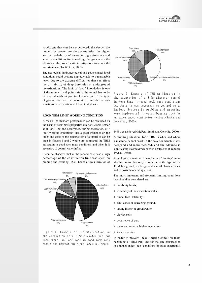
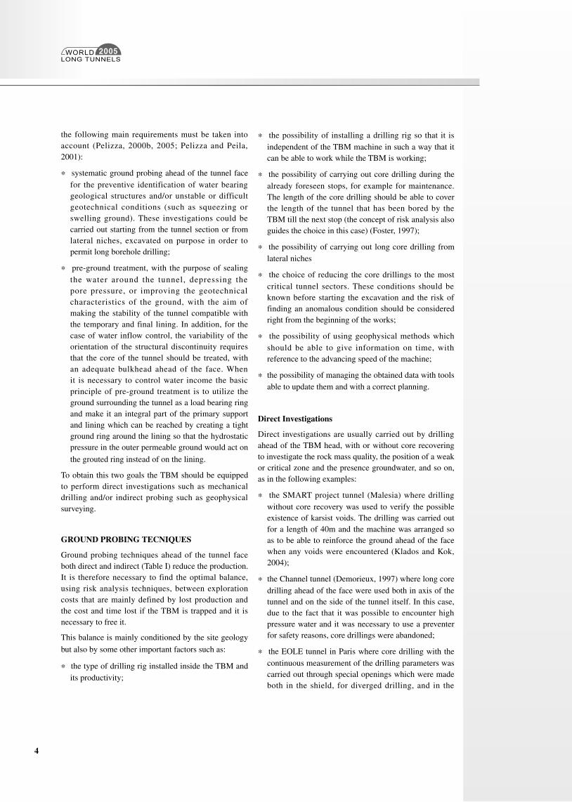
A rock TBM standard performance can be evaluated on the basis of rock mass properties (Barton, 2000; Bethaz at al. 2001) but the occurrence, during excavation, of “limit working conditions” has a great influence on the times and costs of the construction of a tunnel as can be seen in figures 1 and 2 where are compared the TBM utilization in good rock mass conditions and when it is necessary to control water inflow.
It can be observed that in the second case case a high percentage of the construction time was spent on probing and grouting (25%) hence a low utilization of
14% was achieved (McFeat-Smith and Concilia, 2000).
A “limiting situation” for a TBM is when and where a machine cannot work in the way for which it was designed and manufactured, and the advance is significantly slowed down or even obstructed (Grandori, 1996a, 1996b).
A geological situation is therefore not “limiting” in an absolute sense, but only in relation to the type of the TBM being used, its design and special characteristics, and to possible operating errors.
The most important and frequent limiting conditions that should be considered are:
* borability limits;
* instability of the excavation walls;
* tunnel face instability;
* fault zones or squeezing ground;
* strong inflow of groundwater;
* clayley soils;
* occurrence of gas;
* rocks and water at high temperatures
* karstic cavities.
In order to prevent these limiting condition from becoming a “TBM trap” and for the safe construction of a tunnel under “geo” conditions of great uncertainty,
Figure 1: Example of TBM utilization in
the excavation of a 3.5m diameter and 7km
long tunnel in Hong Kong in good rock mass
conditions (McFeat-Smith and Concilia, 2000).
Figure 2: Example of TBM utilization in
the excavation of a 3.5m diameter tunnel
in Hong Kong in good rock mass conditions
but where it was necessary to control water
inflow. Systematic probing and grouting
were implemented in water bearing rock by
an experienced contractor (McFeat-Smith and
Concilia, 2000).
WORLDLONG TUNNELS
2005
4
the following main requirements must be taken into account (Pelizza, 2000b, 2005; Pelizza and Peila, 2001):
* systematic ground probing ahead of the tunnel face for the preventive identification of water bearing geological structures and/or unstable or difficult geotechnical conditions (such as squeezing or swelling ground). These investigations could be carried out starting from the tunnel section or from lateral niches, excavated on purpose in order to permit long borehole drilling;
* pre-ground treatment, with the purpose of sealing the water around the tunnel, depressing the pore pressure, or improving the geotechnical characteristics of the ground, with the aim of making the stability of the tunnel compatible with the temporary and final lining. In addition, for the case of water inflow control, the variability of the orientation of the structural discontinuity requires that the core of the tunnel should be treated, with an adequate bulkhead ahead of the face. When it is necessary to control water income the basic principle of pre-ground treatment is to utilize the ground surrounding the tunnel as a load bearing ring and make it an integral part of the primary support and lining which can be reached by creating a tight ground ring around the lining so that the hydrostatic pressure in the outer permeable ground would act on
the grouted ring instead of on the lining.
To obtain this two goals the TBM should be equipped to perform direct investigations such as mechanical drilling and/or indirect probing such as geophysical surveying.
GROUND PROBING TECNIQUES
Ground probing techniques ahead of the tunnel face both direct and indirect (Table I) reduce the production. It is therefore necessary to find the optimal balance, using risk analysis techniques, between exploration costs that are mainly defined by lost production and the cost and time lost if the TBM is trapped and it is necessary to free it.
This balance is mainly conditioned by the site geology
but also by some other important factors such as:
* the type of drilling rig installed inside the TBM and its productivity;
* the possibility of installing a drilling rig so that it is independent of the TBM machine in such a way that it can be able to work while the TBM is working;
* the possibility of carrying out core drilling during the already foreseen stops, for example for maintenance. The length of the core drilling should be able to cover the length of the tunnel that has been bored by the TBM till the next stop (the concept of risk analysis also guides the choice in this case) (Foster, 1997);
* the possibility of carrying out long core drilling from lateral niches
* the choice of reducing the core drillings to the most critical tunnel sectors. These conditions should be known before starting the excavation and the risk of finding an anomalous condition should be considered right from the beginning of the works;
* the possibility of using geophysical methods which should be able to give information on time, with reference to the advancing speed of the machine;
* the possibility of managing the obtained data with tools able to update them and with a correct planning.
Direct Investigations
Direct investigations are usually carried out by drilling ahead of the TBM head, with or without core recovering to investigate the rock mass quality, the position of a weak or critical zone and the presence groundwater, and so on, as in the following examples:
* the SMART project tunnel (Malesia) where drilling without core recovery was used to verify the possible existence of karsist voids. The drilling was carried out for a length of 40m and the machine was arranged so as to be able to reinforce the ground ahead of the face when any voids were encountered (Klados and Kok, 2004);
* the Channel tunnel (Demorieux, 1997) where long core drilling ahead of the face were used both in axis of the tunnel and on the side of the tunnel itself. In this case, due to the fact that it was possible to encounter high pressure water and it was necessary to use a preventer for safety reasons, core drillings were abandoned;
* the EOLE tunnel in Paris where core drilling with the continuous measurement of the drilling parameters was carried out through special openings which were made both in the shield, for diverged drilling, and in the
WORLDLONG TUNNELS
2005
5
head for axial drilling. The exploration drillings were carried out during the already foreseen TBM stops for example during the week end stops. The axial coring was also used for geophysical explorations (Leca, 2000);
* the Kunming Zhangjiuhe Water Diversion and Water Supply Project, where the Robbins Double Shield TMB was equipped with an Atlas Copco COP type probe drilling unit and was designed with several probe pipes in the gripper shield. Due to the high clay content and the plastic behavior of most of the schist, the probeholes did not reach the requested length (most of the holes stopped after a few meters or reached the length of 10-15m) and the contractor was obliged to install a more powerfull drilling machine;
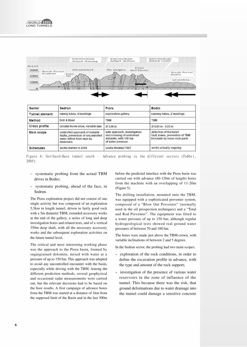
* in the Gotthard-Base tunnel, drillings and systematic probing were frequently applied in advance of the headings (Fabbri, 2005K Kovari and Descoeudres, 2001). The probing systems which were and are applied in the longer and regular running headings
are:
- the Piora investigation system, carried out during 1993 and 1997;
Table I Ground probing ahead the head of a TBM (Carrieri, 2000)
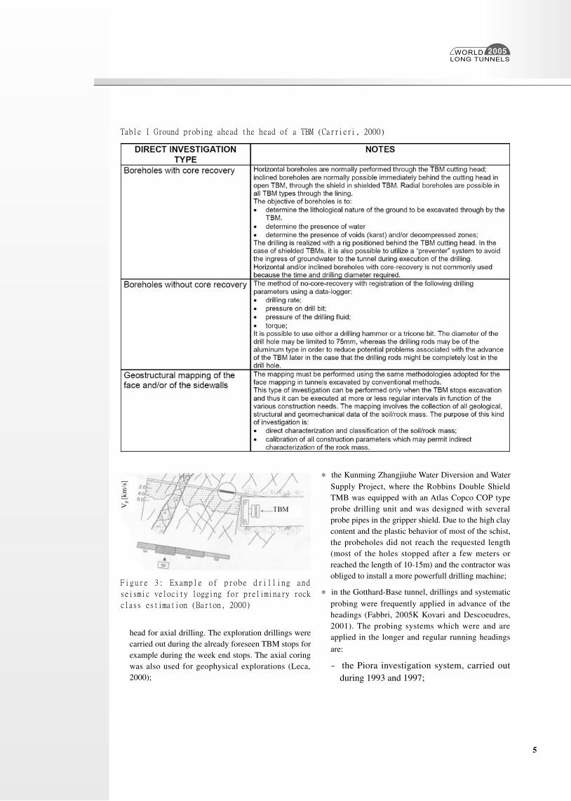
Figure 3: Example of probe drilling and
seismic velocity logging for preliminary rock
class estimation (Barton, 2000)
WORLDLONG TUNNELS
2005
6
- systematic probing from the actual TBM drives in Bodio;
- systematic probing, ahead of the face, in Sedrun.
The Piora exploration project did not consist of one single activity but was composed of an exploration 5,5km in length tunnel, driven in fairly good rock with a 5m diameter TBM, extended accessory works at the end of the gallery, a series of long and deep investigation bores and related tests, and of a vertical 350m deep shaft, with all the necessary accessory works and the subsequent exploration activities on
the future tunnel level.
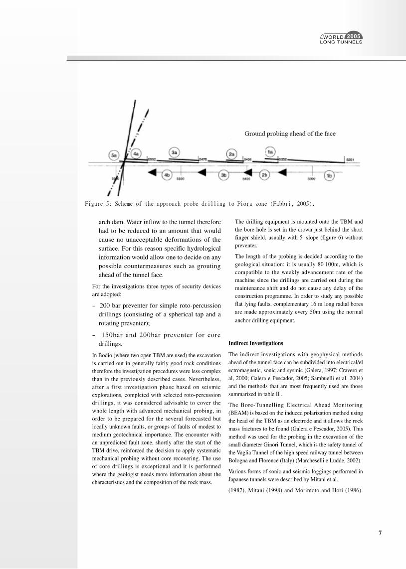
The critical and most interesting working phase was the approach to the Piora basin, formed by sugargrained dolomite, mixed with water at a pressure of up to 150 bar. This approach was adopted to avoid any uncontrolled encounter with the basin, especially while driving with the TBM. Among the different prediction methods, several geophysical and occasional radar measurements were carried out, but the relevant decisions had to be based on the bore results. A first campaign of advance bores from the TBM was started at a distance of 1km from the supposed limit of the Basin and in the last 300m
Figure 4: Gotthard-Base tunnel south – Advance probing in the different sectors (Fabbri,
2005)
before the predicted interface with the Piora basin was carried out with advance (80-120m of length) bores from the machine with an overlapping of 11-20m (Figure 5).
The drilling installation, mounted onto the TBM, was equipped with a sophisticated preventer system, composed of a “Blow Out Preventer” (normally used in the oil prospection techniques) and a “Total and Rod Preventer”. The equipment was fitted to a water pressure of up to 150 bar, although regular hydrogeological tests showed real ground water pressures of between 70 and 100 bar.
The bores were made just above the TBM-crown, with variable inclinations of between 2 and 5 degrees.
In the Sedrun sector, the probing had two main scopes:
- exploration of the rock conditions, in order to define the excavation profile in advance, with the type and amount of the rock support;
- investigation of the presence of various water reservoirs in the zone of influence of the tunnel. This because there was the risk, that ground deformations due to water drainage into the tunnel could damage a sensitive concrete
WORLDLONG TUNNELS
2005
7
arch dam. Water inflow to the tunnel therefore had to be reduced to an amount that would cause no unacceptable deformations of the surface. For this reason specific hydrological information would allow one to decide on any possible countermeasures such as grouting ahead of the tunnel face.
For the investigations three types of security devices are adopted:
- 200 bar preventer for simple roto-percussion drillings (consisting of a spherical tap and a rotating preventer);
- 150bar and 200bar preventer for core drillings.
In Bodio (where two open TBM are used) the excavation is carried out in generally fairly good rock conditions therefore the investigation procedures were less complex than in the previously described cases. Nevertheless, after a first investigation phase based on seismic explorations, completed with selected roto-percussion drillings, it was considered advisable to cover the whole length with advanced mechanical probing, in order to be prepared for the several forecasted but locally unknown faults, or groups of faults of modest to medium geotechnical importance. The encounter with an unpredicted fault zone, shortly after the start of the TBM drive, reinforced the decision to apply systematic mechanical probing without core recovering. The use of core drillings is exceptional and it is performed where the geologist needs more information about the characteristics and the composition of the rock mass.
The drilling equipment is mounted onto the TBM and the bore hole is set in the crown just behind the short finger shield, usually with 5° slope (figure 6) without preventer.
The length of the probing is decided according to the geological situation: it is usually 80÷100m, which is compatible to the weekly advancement rate of the machine since the drillings are carried out during the maintenance shift and do not cause any delay of the construction programme. In order to study any possible flat lying faults, complementary 16 m long radial bores are made approximately every 50m using the normal
anchor drilling equipment.
Indirect Investigations
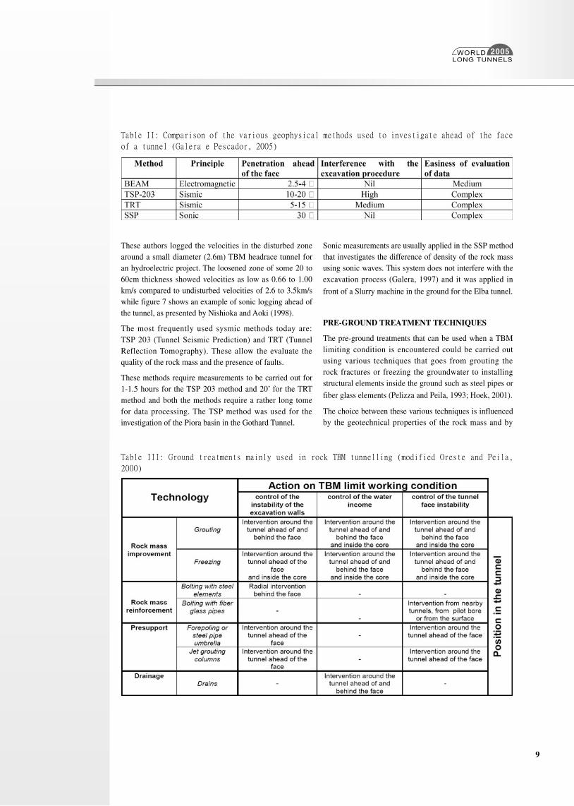
The indirect investigations with geophysical methods ahead of the tunnel face can be subdivided into electrical/electromagnetic, sonic and sysmic (Galera, 1997; Cravero et al, 2000; Galera e Pescador, 2005; Sambuelli et al. 2004) and the methods that are most frequently used are those summarized in table II .
The Bore-Tunnelling Electrical Ahead Monitoring (BEAM) is based on the induced polarization method using the head of the TBM as an electrode and it allows the rock mass fractures to be found (Galera e Pescador, 2005). This method was used for the probing in the excavation of the small diameter Ginori Tunnel, which is the safety tunnel of the Vaglia Tunnel of the high speed railway tunnel between Bologna and Florence (Italy) (Marcheselli e Ludde, 2002).
Various forms of sonic and seismic loggings performed in Japanese tunnels were described by Mitani et al.
(1987), Mitani (1998) and Morimoto and Hori (1986).
Figure 5: Scheme of the approach probe drilling to Piora zone (Fabbri, 2005).
WORLDLONG TUNNELS
2005
8
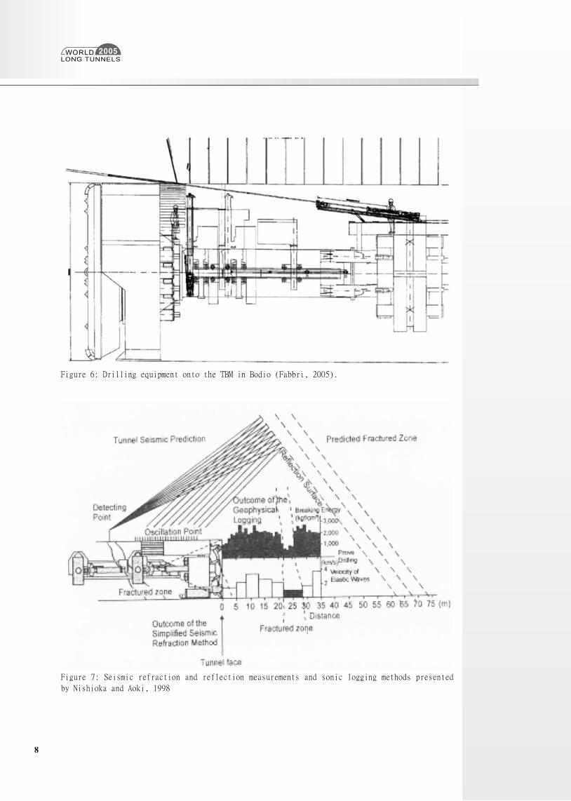
Figure 6: Drilling equipment onto the TBM in Bodio (Fabbri, 2005).
Figure 7: Seismic refraction and reflection measurements and sonic logging methods presented
by Nishioka and Aoki, 1998
WORLDLONG TUNNELS
2005
9
These authors logged the velocities in the disturbed zone around a small diameter (2.6m) TBM headrace tunnel for an hydroelectric project. The loosened zone of some 20 to 60cm thickness showed velocities as low as 0.66 to 1.00 km/s compared to undisturbed velocities of 2.6 to 3.5km/s while figure 7 shows an example of sonic logging ahead of the tunnel, as presented by Nishioka and Aoki (1998).
The most frequently used sysmic methods today are: TSP 203 (Tunnel Seismic Prediction) and TRT (Tunnel Reflection Tomography). These allow the evaluate the quality of the rock mass and the presence of faults.
These methods require measurements to be carried out for 1-1.5 hours for the TSP 203 method and 20’ for the TRT method and both the methods require a rather long tome for data processing. The TSP method was used for the investigation of the Piora basin in the Gothard Tunnel.
Sonic measurements are usually applied in the SSP method that investigates the difference of density of the rock mass using sonic waves. This system does not interfere with the excavation process (Galera, 1997) and it was applied in
front of a Slurry machine in the ground for the Elba tunnel.
PRE-GROUND TREATMENT TECHNIQUES
The pre-ground treatments that can be used when a TBM limiting condition is encountered could be carried out using various techniques that goes from grouting the rock fractures or freezing the groundwater to installing structural elements inside the ground such as steel pipes or
fiber glass elements (Pelizza and Peila, 1993; Hoek, 2001).
The choice between these various techniques is influenced by the geotechnical properties of the rock mass and by
Table II: Comparison of the various geophysical methods used to investigate ahead of the face
of a tunnel (Galera e Pescador, 2005)
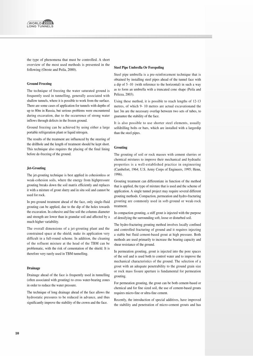
Table III: Ground treatments mainly used in rock TBM tunnelling (modified Oreste and Peila,
2000)
WORLDLONG TUNNELS
2005
10
the type of phenomena that must be controlled. A short overview of the most used methods is presented in the following (Oreste and Peila, 2000).
Ground Freezing
The technique of freezing the water saturated ground is frequently used in tunnelling, generally associated with shallow tunnels, where it is possible to work from the surface. There are some cases of application for tunnels with depths of up to 80m in Russia, but serious problems were encountered during excavation, due to the occurrence of strong water inflows through defects in the frozen ground.
Ground freezing can be achieved by using either a large portable refrigeration plant or liquid nitrogen.
The results of the treatment are influenced by the steering of the drillhole and the length of treatment should be kept short. This technique also requires the placing of the final lining before de-freezing of the ground.
Jet-Grouting
The jet-grouting technique is best applied in cohesionless or weak-cohesion soils, where the energy from highpressure grouting breaks down the soil matrix efficiently and replaces it with a mixture of grout slurry and in situ soil and cannot be used for rock.
In pre-ground treatment ahead of the face, only single-fluid grouting can be applied, due to the dip of the holes towards the excavation. In cohesive and fine soil the columns diameter and strength are lower than in granular soil and affected by a much higher variability.
The overall dimensions of a jet-grouting plant and the constrained space at the shield, make its application very difficult in a full-round scheme. In addition, the cleaning of the refluent mixture at the head of the TBM can be problematic, with the risk of cementation of the shield. It is
therefore very rarely used in TBM tunnelling.
Drainage
Drainage ahead of the face is frequently used in tunnelling (often associated with grouting) to cross water-bearing zones
in order to reduce the water pressure.
The technique of long drainage ahead of the face allows the hydrostatic pressures to be reduced in advance, and thus
significantly improve the stability of the crown and the face.
Steel Pipe Umbrella Or Forepoling
Steel pipe umbrella is a pre-reinforcement technique that is obtained by installing steel pipes ahead of the tunnel face with a dip of 5°-10° (with reference to the horizontal) in such a way as to form an umbrella with a truncated cone shape (Peila and Pelizza, 2003).
Using these method, it is possible to reach lengths of 12-13 metres, of which 9- 10 metres are actual excavationand the last 3m are the necessary overlap between two sets of tubes, to guarantee the stability of the face.
It is also possible to use shorter steel elements, usually selfdrilling bolts or bars, which are installed with a largerdip than the steel pipes.
Grouting
The grouting of soil or rock masses with cement slurries or chemical mixtures to improve their mechanical and hydraulic properties is a well-established practice in engineering (Cambefort, 1964; U.S. Army Corps of Engineers, 1995; Henn, 1996).
Grouting treatment can differentiate in function of the method that is applied, the type of mixture that is used and the scheme of application. A single tunnel project may require several different grouting methods. Compaction, permeation and hydro-fracturing grouting are commonly used in soft-ground or weak-rock treatment.
In compaction grouting, a stiff grout is injected with the purpose of densifying the surrounding soft, loose or disturbed soil.
The hydro-fracturing grouting method involves locally confined and controlled fracturing of ground and it requires injecting a stable but fluid cement-based grout at high pressure. Both methods are used primarily to increase the bearing capacity and shear resistance of the ground.
In permeation grouting, grout is injected into the pore spaces of the soil and is used both to control water and to improve the mechanical characteristics of the ground. The selection of a grout with an adequate penetrability to the ground grain size or rock mass fissure aperture is fundamental for permeation grouting.
For permeation grouting, the grout can be both cement-based or chemical and for fine sized soil, the use of cement-based grouts requires micro-fine or ultra-fine cement.
Recently, the introduction of special additives, have improved the stability and penetration of micro-cement grouts and has
WORLDLONG TUNNELS
2005
11
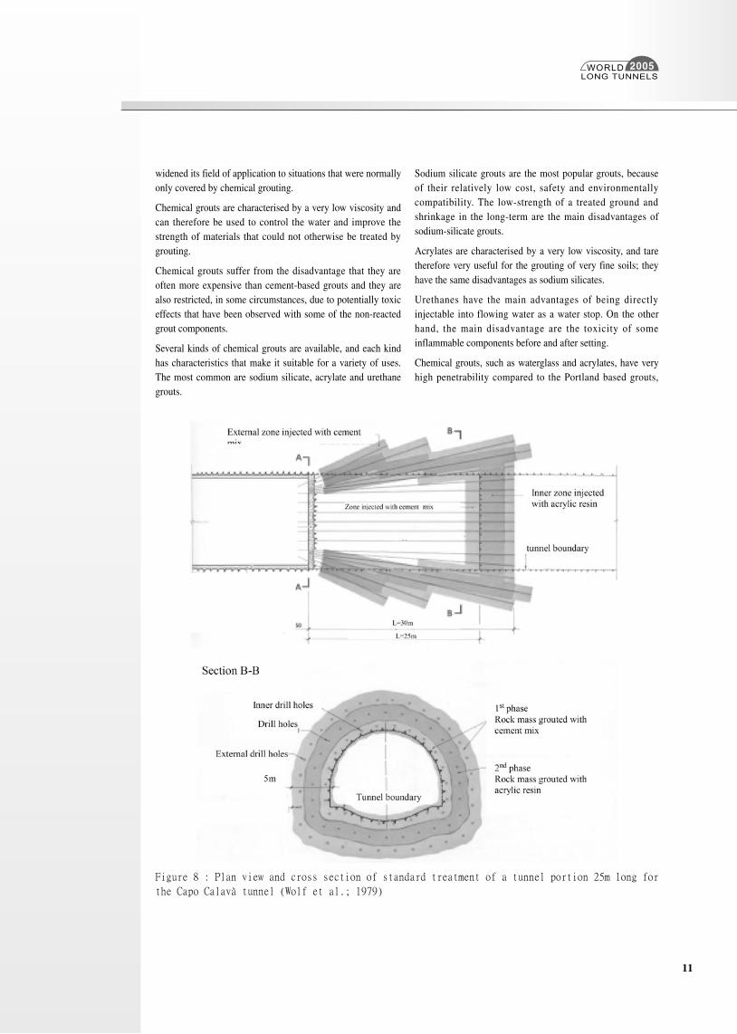
Figure 8 : Plan view and cross section of standard treatment of a tunnel portion 25m long for
the Capo Calavà tunnel (Wolf et al.; 1979)
widened its field of application to situations that were normally only covered by chemical grouting.
Chemical grouts are characterised by a very low viscosity and can therefore be used to control the water and improve the strength of materials that could not otherwise be treated by grouting.
Chemical grouts suffer from the disadvantage that they are often more expensive than cement-based grouts and they are also restricted, in some circumstances, due to potentially toxic effects that have been observed with some of the non-reacted grout components.
Several kinds of chemical grouts are available, and each kind has characteristics that make it suitable for a variety of uses. The most common are sodium silicate, acrylate and urethane grouts.
Sodium silicate grouts are the most popular grouts, because of their relatively low cost, safety and environmentally compatibility. The low-strength of a treated ground and shrinkage in the long-term are the main disadvantages of sodium-silicate grouts.
Acrylates are characterised by a very low viscosity, and tare therefore very useful for the grouting of very fine soils; they have the same disadvantages as sodium silicates.
Urethanes have the main advantages of being directly injectable into flowing water as a water stop. On the other hand, the main disadvantage are the toxicity of some inflammable components before and after setting.
Chemical grouts, such as waterglass and acrylates, have very high penetrability compared to the Portland based grouts,
WORLDLONG TUNNELS
2005
12
and can therefore ensure sufficient sealing also as far as gas is concerned, as documented by Balossi Restelli (1978) and Wolf at al. (1979) for the Capo Calavà tunnel in Sicily (Italy) (figure 8) and improve the properties of the rock mass without the necessity of high grouting pressure.
Nevertheless, chemical grouts are associated with lower elastoplastic properties and low strength, so the effective rock mass improvement is not very significant. A good compromise between penetrability and final strength is offered by microcements based grouts, which also offer good durability and no toxicity.
Grouting standards and procedures are well established (ISRM, 1995) and very interesting developments concerning the application of dam grouting techniques to tunnelling are at present being investigated (e.g. the GIN method, Lombardi and Deere, 1993; Brantberger et al., 2000).
Full scale testing are however fundamental for grouting design, as well as for the other ground treatment techniques, in order to define the right processes and materials that have to be applied.
Pressure grouting (or injection) in rock is carried out by drilling boreholes of a suitable diameter, length and direction into the rock material, placing packers near the borehole opening, connecting the ground conveying hose or pipe between a pump and the packer and pumping a prepared grout into the cracks and joints of the rock surrounding the boreholes.
Two fundamentally different approaches may be applied in tunnelling grouting (Grov, 2002; Blindheim
and Ovstedal, 2002; Fredriksen and Broch, 1984) :
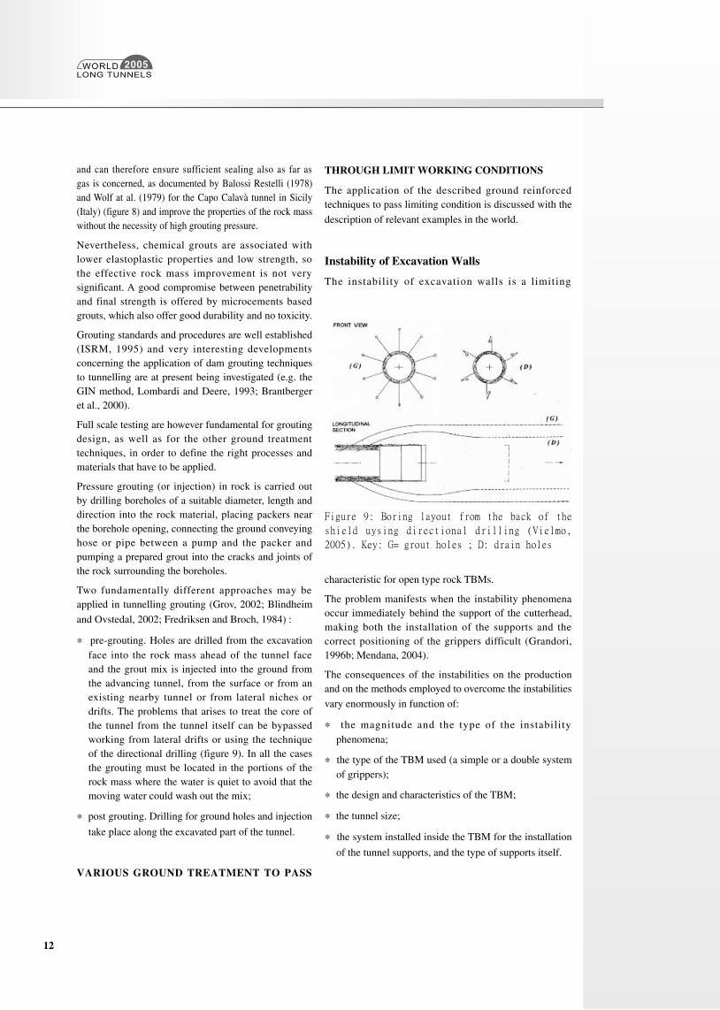
* pre-grouting. Holes are drilled from the excavation face into the rock mass ahead of the tunnel face and the grout mix is injected into the ground from the advancing tunnel, from the surface or from an existing nearby tunnel or from lateral niches or drifts. The problems that arises to treat the core of the tunnel from the tunnel itself can be bypassed working from lateral drifts or using the technique of the directional drilling (figure 9). In all the cases the grouting must be located in the portions of the rock mass where the water is quiet to avoid that the moving water could wash out the mix;
* post grouting. Drilling for ground holes and injection
take place along the excavated part of the tunnel.
VARIOUS GROUND TREATMENT TO PASS
THROUGH LIMIT WORKING CONDITIONS
The application of the described ground reinforced techniques to pass limiting condition is discussed with the
description of relevant examples in the world.
Instability of Excavation Walls
The instability of excavation walls is a limiting
Figure 9: Boring layout from the back of the
shield uysing directional drilling (Vielmo,
2005). Key: G= grout holes ; D: drain holes
characteristic for open type rock TBMs.
The problem manifests when the instability phenomena occur immediately behind the support of the cutterhead, making both the installation of the supports and the correct positioning of the grippers difficult (Grandori, 1996b; Mendana, 2004).
The consequences of the instabilities on the production and on the methods employed to overcome the instabilities
vary enormously in function of:
* the magnitude and the type of the instability phenomena;
* the type of the TBM used (a simple or a double system of grippers);
* the design and characteristics of the TBM;
* the tunnel size;
* the system installed inside the TBM for the installation
of the tunnel supports, and the type of supports itself.
WORLDLONG TUNNELS
2005
13
Single or double shielded rock TBMs are not very sensitive to the instability phenomena of the excavation walls since it is possible to install a precast-concrete or steel lining inside and under the protection of the shield. It is thus possible for the TBMs to advance by pushing
against the lining.
In the case of medium to large diameter tunnels (from 6 to 12m) the difference in the behavior and productivity between open and shielded TBMs, under excavation wall instability conditions, increases considerably with the shielded TBM being more advantaged.
With open TBMs, the possibility of counteracting against the instability phenomena effectively at the excavation walls depends on the following interventions:
* stabilization and reconstruction of the walls, carried out immediately behind the support of the cutting head using steel arches, wood lagging and shotcrete. The installation of these supporting elements, particularly the shotcrete, in this delicate zone of the machine, requires a long time and there is also the risk of the excavation equipment being damaged;
* traditional excavation ahead of the TBM head, often top heading;
* pre-treatment ahead of the tunnel face with injection at low pressure;
* forepoling or steel pipe umbrella.
Instability of the Tunnel Face
If the fracturing and/or alteration or the rock mass is such that important instabilities of the excavation face can occur, with the detachment of rock, there is the risk that the machine could become entrapped, blocking the head, or that the over-excavation created by the slide reaches such dimensions that it can no longer be controlled. This problem involves all types of TBMs (open or shielded). In this case the most frequently used reinforcements are:
* injection of the fractured portions of the rock mass with mixtures of cement and resins.
With this intervention it is necessary to find a design equilibrium between the possibility of intensive reinforcement, before advancement but with the consequent high costs and long
times, and the use of limited interventions for which it is however difficult to define the acceptable lower limit. In this latter case serious consequences can in fact occur whenever the reinforcement has not been carried out properly and the problem of stability again appears (Barla and Pelizza, 2000).
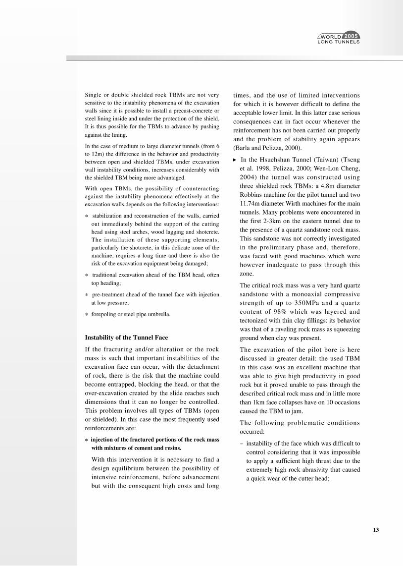
In the Hsuehshan Tunnel (Taiwan) (Tseng et al. 1998, Pelizza, 2000; Wen-Lon Cheng, 2004) the tunnel was constructed using three shielded rock TBMs: a 4.8m diameter Robbins machine for the pilot tunnel and two 11.74m diameter Wirth machines for the main tunnels. Many problems were encountered in the first 2-3km on the eastern tunnel due to the presence of a quartz sandstone rock mass. This sandstone was not correctly investigated in the preliminary phase and, therefore, was faced with good machines which were however inadequate to pass through this zone.
The critical rock mass was a very hard quartz sandstone with a monoaxial compressive strength of up to 350MPa and a quartz content of 98% which was layered and tectonized with thin clay fillings: its behavior was that of a raveling rock mass as squeezing ground when clay was present.
The excavation of the pilot bore is here discussed in greater detail: the used TBM in this case was an excellent machine that was able to give high productivity in good rock but it proved unable to pass through the described critical rock mass and in little more than 1km face collapses have on 10 occasions caused the TBM to jam.
The following problematic conditions occurred:
- instability of the face which was difficult to control considering that it was impossible to apply a sufficient high thrust due to the extremely high rock abrasivity that caused a quick wear of the cutter head;
WORLDLONG TUNNELS
2005
14
- instability of the tunnel circumference (crown and walls), which made it difficult to grout the annular gap between the lining and the tunnel profile;
- the ground water which was linked with very important reservoirs was increasing the instability conditions with water pressure and large water incomes.
In this example it is important to highlight that due to the fact that the machine was not equipped from the beginning for drilling ahead of the face, to investigate and to grout the rock mass in this case it was necessary to use lateral excavations and small tunnel.
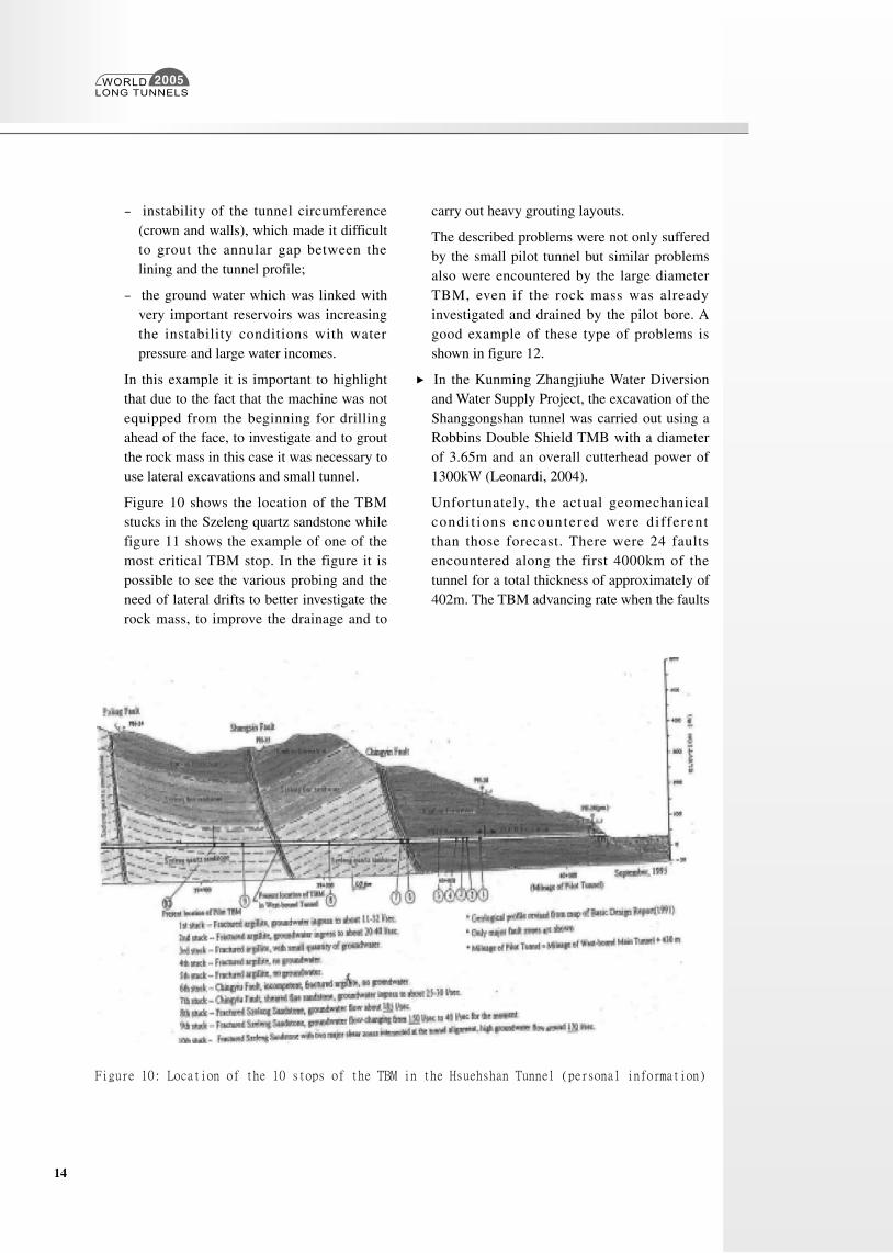
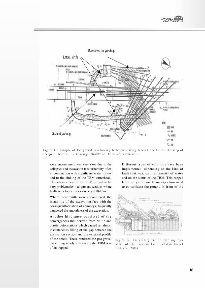
Figure 10 shows the location of the TBM stucks in the Szeleng quartz sandstone while figure 11 shows the example of one of the most critical TBM stop. In the figure it is possible to see the various probing and the need of lateral drifts to better investigate the rock mass, to improve the drainage and to
carry out heavy grouting layouts.
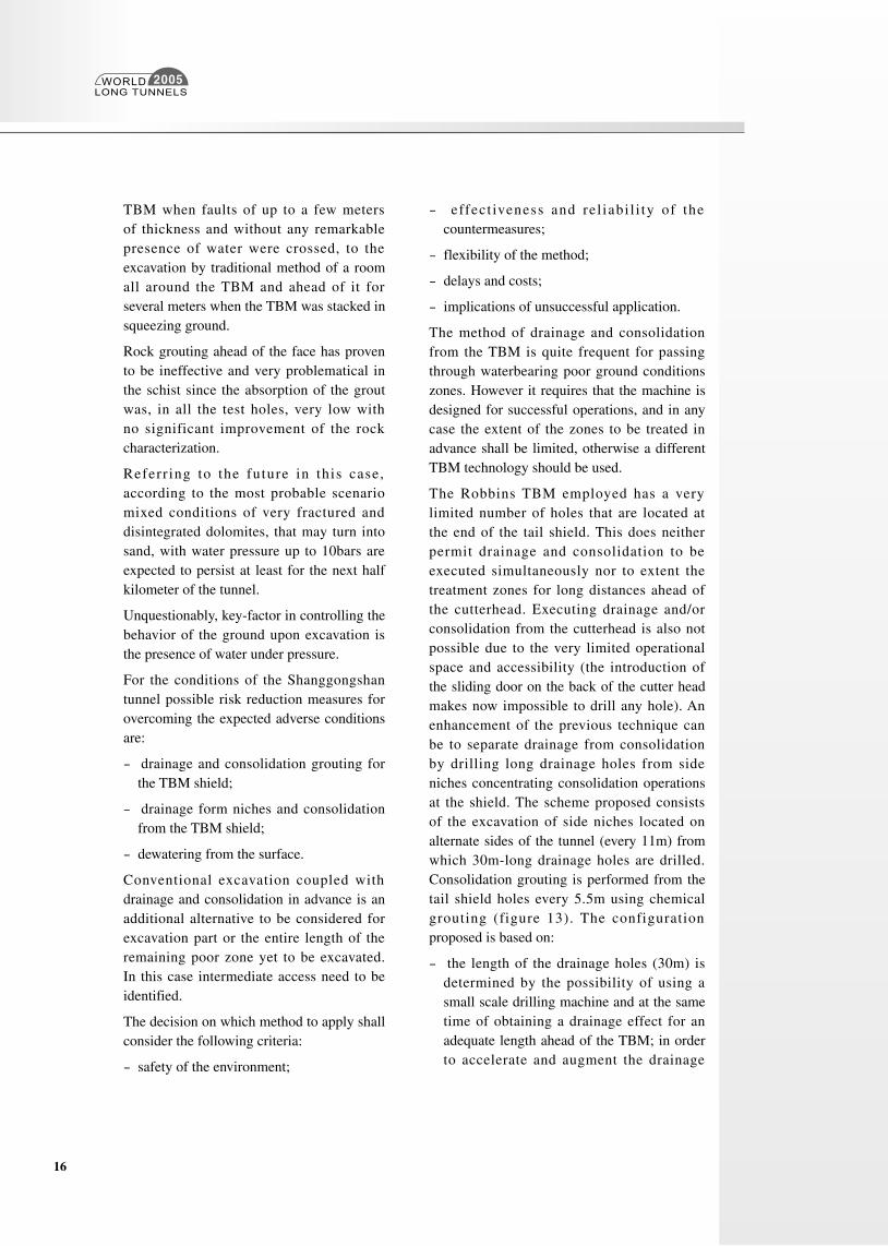
The described problems were not only suffered by the small pilot tunnel but similar problems also were encountered by the large diameter TBM, even if the rock mass was already investigated and drained by the pilot bore. A good example of these type of problems is shown in figure 12.
In the Kunming Zhangjiuhe Water Diversion and Water Supply Project, the excavation of the Shanggongshan tunnel was carried out using a Robbins Double Shield TMB with a diameter of 3.65m and an overall cutterhead power of 1300kW (Leonardi, 2004).
Unfortunately, the actual geomechanical condit ions encountered were different than those forecast. There were 24 faults encountered along the first 4000km of the tunnel for a total thickness of approximately of 402m. The TBM advancing rate when the faults
Figure 10: Location of the 10 stops of the TBM in the Hsuehshan Tunnel (personal information)
WORLDLONG TUNNELS
2005
15
were encountered, was very slow due to the collapses and excavation face instability often in conjunction with significant water inflow and to the sinking of the TBM cutterhead. The advancement of the TBM proved to be very problematic in alignment sections where faults or deformed rock exceeded 10-15m.
Where these faults were encountered, the instability of the excavation face with the consequentformation of chimneys, frequently hampered the smoothness of the excavation.
Ano the r h ind rance cons i s t ed o f t he convergences that derived from brittle and plastic deformations which caused an almost instantaneous filling of the gap between the excavation section and the external profile of the shield. These rendered the pea-gravel backfilling nearly unfeasible; the TBM was often trapped.
Different types of solutions have been implemented, depending on the kind of fault that was, on the quantity of water and on the status of the TBM. This ranged from polyurethane foam injection used to consolidate the ground in front of the
Figure 11: Example of the ground reinforcing techniques using lateral drifts for the stop of
the pilot bore at the Chainage 39k+079 of the Hsuehshan Tunnel.
Figure 12: Instability due to raveling rock
ahead of the face in the Hsuehshan Tunnel
(Pelizza, 2000)
WORLDLONG TUNNELS
2005
16
TBM when faults of up to a few meters of thickness and without any remarkable presence of water were crossed, to the excavation by traditional method of a room all around the TBM and ahead of it for several meters when the TBM was stacked in squeezing ground.
Rock grouting ahead of the face has proven to be ineffective and very problematical in the schist since the absorption of the grout was, in all the test holes, very low with no significant improvement of the rock characterization.
Referr ing to the future in this case, according to the most probable scenario mixed conditions of very fractured and disintegrated dolomites, that may turn into sand, with water pressure up to 10bars are expected to persist at least for the next half kilometer of the tunnel.
Unquestionably, key-factor in controlling the behavior of the ground upon excavation is the presence of water under pressure.
For the conditions of the Shanggongshan tunnel possible risk reduction measures for overcoming the expected adverse conditions are:
- drainage and consolidation grouting for the TBM shield;
- drainage form niches and consolidation from the TBM shield;
- dewatering from the surface.
Conventional excavation coupled with drainage and consolidation in advance is an additional alternative to be considered for excavation part or the entire length of the remaining poor zone yet to be excavated. In this case intermediate access need to be identified.
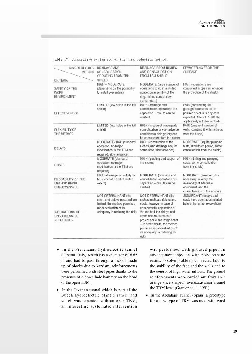
The decision on which method to apply shall consider the following criteria:
- safety of the environment;
- effect iveness and rel iabi l i ty of the countermeasures;
- flexibility of the method;
- delays and costs;
- implications of unsuccessful application.
The method of drainage and consolidation from the TBM is quite frequent for passing through waterbearing poor ground conditions zones. However it requires that the machine is designed for successful operations, and in any case the extent of the zones to be treated in advance shall be limited, otherwise a different TBM technology should be used.
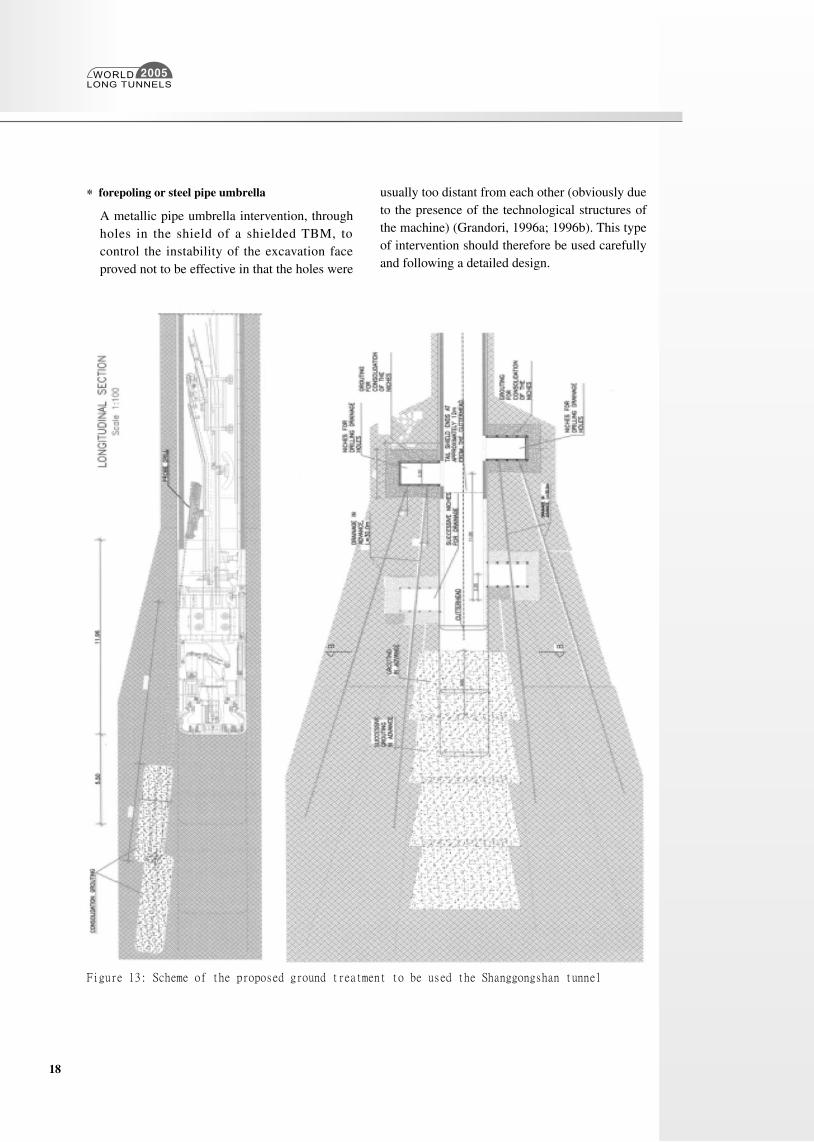
The Robbins TBM employed has a very limited number of holes that are located at the end of the tail shield. This does neither permit drainage and consolidation to be executed simultaneously nor to extent the treatment zones for long distances ahead of the cutterhead. Executing drainage and/or consolidation from the cutterhead is also not possible due to the very limited operational space and accessibility (the introduction of the sliding door on the back of the cutter head makes now impossible to drill any hole). An enhancement of the previous technique can be to separate drainage from consolidation by drilling long drainage holes from side niches concentrating consolidation operations at the shield. The scheme proposed consists of the excavation of side niches located on alternate sides of the tunnel (every 11m) from which 30m-long drainage holes are drilled. Consolidation grouting is performed from the tail shield holes every 5.5m using chemical grouting (figure 13). The configuration proposed is based on:
- the length of the drainage holes (30m) is determined by the possibility of using a small scale drilling machine and at the same time of obtaining a drainage effect for an adequate length ahead of the TBM; in order to accelerate and augment the drainage
WORLDLONG TUNNELS
2005
17
effect drainage holes can be equipped with suction pumps (well-point type).
In addition inclining towards the bottom the drainage holes results theoretically in an augmented drawdown effect and finally using a blow-up preventer device at the head of the drainage hole and equipping the rod with a non-return valve minimizes the risk of inrushes during the drilling operation;
- grouting drillholes afe shorter in length due to their inclination that is imposed by the shield holes. Repeating the grouting twice for every drainage sector results in an optimized coverage of the tunnel crown area;
- chemical grouting as opposed to the cement one reduces the risk of TBM blocking due to feedback of cement slurry below the TBM shield; In addition, far the expected ground conditions low-pressure permeation grouting assigns to the ground cohesion and at the same time reduces its permeability.
Silicagel grouting is suggested due to their good penetrability even for fine soils and possibility of adjusting their setting time, reasonable costs (possible availability of local products) and demonstrated record of effectiveness in similar conditions but the use of colloidal silica was already foreseen as a possibility.
- Polyurethane resins, as the ones used, maybe proved necessary for stopping localized inrushes and/or the filling of voids.
This alternative requires implementation of some additional measures:
o replacement of two concrete segments (per ring) by removable steel segments;
o grouting of the niche area before their excavation.
This risk-reduction alternative results in a significant incidence of downtime with respect to the boring operations. In order to reduce it, high efficiency drilling rigs should be used, compatibly with the space constraints in the work areas.
As opposed to the previous alternatives where the drainage was performed form the tunnel, this riskreduction solution consists of drilling wells from the surface equipped with such suction pumps for lowering the groundwater table. The wells will have a minimum depth of 150m and located at a distance of 10m form each side of the tunnel.
Based on a first elimination of the aquifer parameters, the water level can be reduced by 50m in the first two months, while four additional months of pumping will be needed for an alignment length in the range of 350m. The probable aquifer structure is inhomogeneous, in the sense that vertical bands of different permeability, may limit the horizontal extent of drawdown and therefore reduce the efficiency of the method. Therefore, it is reasonable to assume that some grouting in advance will be required to deal with the residual risk resulting from a localized, still high water level.
In the following table IV, the three methods for ground treatment are compared.. For concluding the analyses on the proposed risk-reduction alternatives for the remaining part of the tunnel to be excavated, it is considered very important to evaluate in quantitative way the factor “delays”. In effect, the more reliable solution to be adopted might satisfy the requirement of acceptable delay (with reference to the current project schedule). The evaluation of the time needed to complete the excavation of the tunnel that follows are obviously affected by a number of uncertainties, but they provide in any case a useful tool for comparing different alternatives in relative terms.
WORLDLONG TUNNELS
2005
18
* forepoling or steel pipe umbrella
A metallic pipe umbrella intervention, through holes in the shield of a shielded TBM, to control the instability of the excavation face proved not to be effective in that the holes were
usually too distant from each other (obviously due to the presence of the technological structures of the machine) (Grandori, 1996a; 1996b). This type of intervention should therefore be used carefully and following a detailed design.
Figure 13: Scheme of the proposed ground treatment to be used the Shanggongshan tunnel
WORLDLONG TUNNELS
2005
19
In the Presenzano hydroelectric tunnel (Caserta, Italy) which has a diameter of 6.65 m and had to pass through a massif made up of blocks due to karsism, reinforcements were performed with steel pipes thanks to the presence of a down-hole hammer on the head of the open TBM.
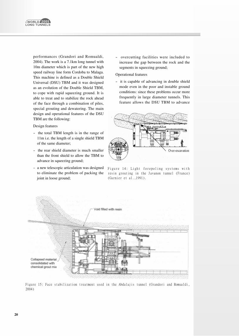
In the Javanon tunnel which is part of the Buech hydroelectric plant (France) and which was exacated with an open TBM, an interesting systematic intervention
was performed with grouted pipes in advancement injected with polyurethane resins, to solve problems connected both to the stability of the face and the walls and to the control of high water inflows. The ground reinforcements were carried out from an “orange slice shaped” overexcavation around the TBM head (Garnier et al., 1991).
In the Abdalajis Tunnel (Spain) a prototype for a new type of TBM was used with good
Table IV: Comparative evaluation of the risk reduction methods
WORLDLONG TUNNELS
2005
20
performances (Grandori and Romualdi, 2004). The work is a 7.1km long tunnel with 10m diameter which is part of the new high speed railway line form Cordoba to Malaga. This machine is defined as a Double Shield Universal (DSU) TBM and it was designed as an evolution of the Double Shield TBM, to cope with rapid squeezing ground. It is able to treat and to stabilize the rock ahead of the face through a combination of piles, special grouting and dewatering. The main design and operational features of the DSU TBM are the following:
Design features
- the total TBM length is in the range of 11m i.e. the length of a single shield TBM of the same diameter;
- the rear shield diameter is much smaller than the front shield to allow the TBM to advance in squeezing ground;
- a new telescopic articulation was designed to eliminate the problem of packing the joint in loose ground;
- overcutting facilities were included to increase the gap between the rock and the segments in squeezing ground;
Operational features
- it is capable of advancing in double shield mode even in the poor and instable ground conditions: since these problems occur more frequently in large diameter tunnels. This feature allows the DSU TBM to advance
Figure 15: Face stabilization treatment used in the Abdalajis tunnel (Grandori and Romualdi,
2004)
Figure 14: Light forepoling systems with
resin grouting in the Javanon tunnel (France)
(Garnier et al.,1991).
WORLDLONG TUNNELS
2005
21
with maximum productivity in a larger range of ground conditions;
- it is capable of treating and stabilizing the ground ahead of the TBM head thanks to the execution of grouted piles all around the tunnel section.
In this tunnel, when the over excavation at the face in the argillite formation increased above a couple of meters in front and above the cutterhead, the TBM advancement was stopped, the void filled with resin foams and the collapsed material in front of the face was consolidated with a chemical grout mix. The TBM was then advanced for a few strokes until the treatment had to be repeated (figure 15).
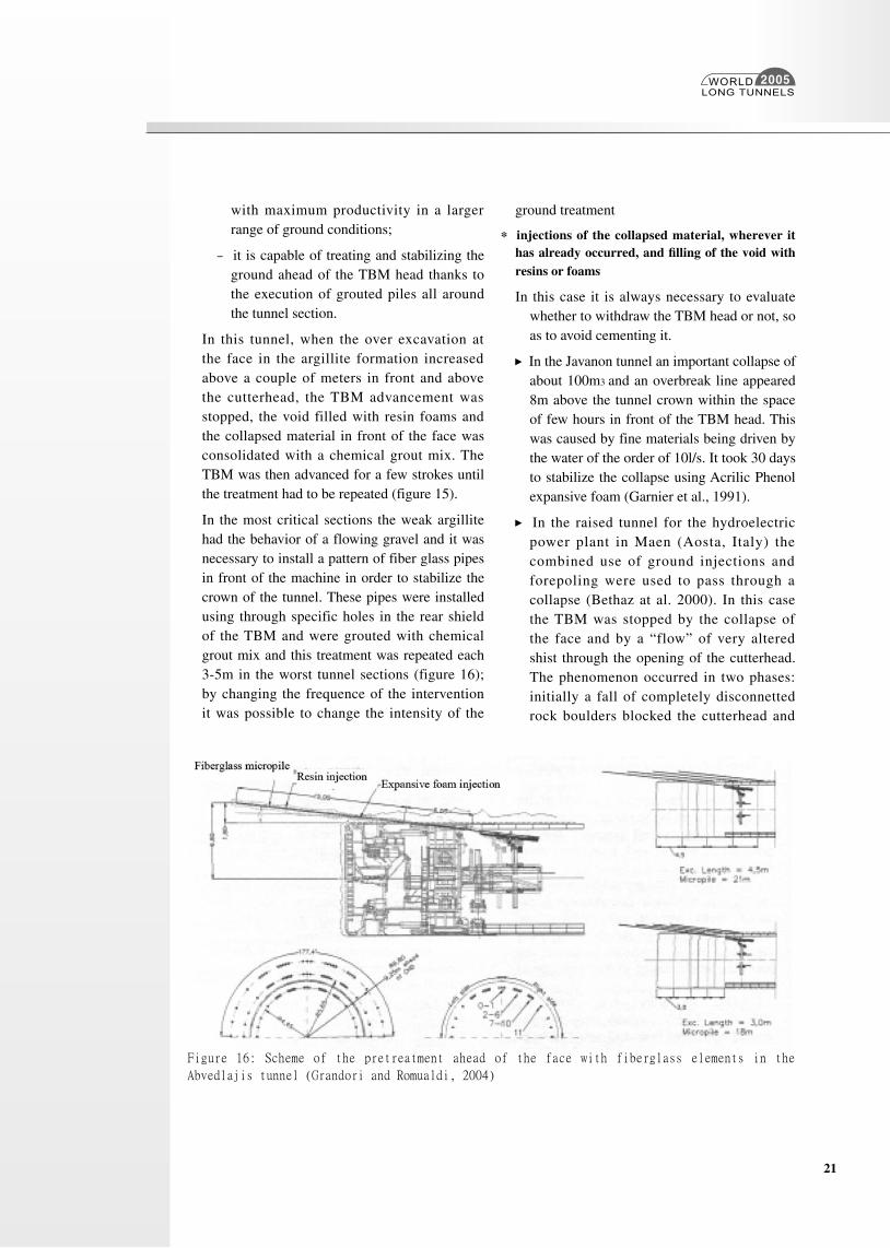
In the most critical sections the weak argillite had the behavior of a flowing gravel and it was necessary to install a pattern of fiber glass pipes in front of the machine in order to stabilize the crown of the tunnel. These pipes were installed using through specific holes in the rear shield of the TBM and were grouted with chemical grout mix and this treatment was repeated each 3-5m in the worst tunnel sections (figure 16); by changing the frequence of the intervention it was possible to change the intensity of the
ground treatment
* injections of the collapsed material, wherever it has already occurred, and filling of the void with resins or foams
In this case it is always necessary to evaluate whether to withdraw the TBM head or not, so as to avoid cementing it.
In the Javanon tunnel an important collapse of about 100m3 and an overbreak line appeared 8m above the tunnel crown within the space of few hours in front of the TBM head. This was caused by fine materials being driven by the water of the order of 10l/s. It took 30 days to stabilize the collapse using Acrilic Phenol expansive foam (Garnier et al., 1991).
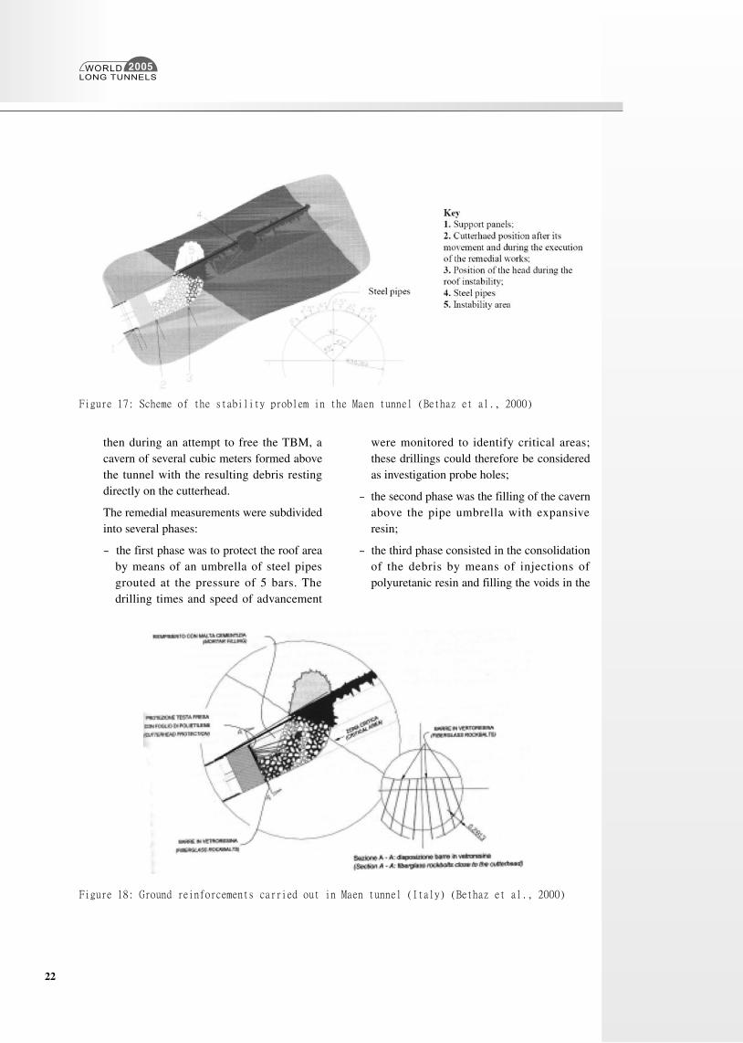
In the raised tunnel for the hydroelectric power plant in Maen (Aosta, Italy) the combined use of ground injections and forepoling were used to pass through a collapse (Bethaz at al. 2000). In this case the TBM was stopped by the collapse of the face and by a “flow” of very altered shist through the opening of the cutterhead. The phenomenon occurred in two phases: initially a fall of completely disconnetted rock boulders blocked the cutterhead and
Figure 16: Scheme of the pretreatment ahead of the face with fiberglass elements in the
Abvedlajis tunnel (Grandori and Romualdi, 2004)
WORLDLONG TUNNELS
2005
22
then during an attempt to free the TBM, a cavern of several cubic meters formed above the tunnel with the resulting debris resting directly on the cutterhead.
The remedial measurements were subdivided into several phases:
- the first phase was to protect the roof area by means of an umbrella of steel pipes grouted at the pressure of 5 bars. The drilling times and speed of advancement
were monitored to identify critical areas; these drillings could therefore be considered as investigation probe holes;
- the second phase was the filling of the cavern above the pipe umbrella with expansive resin;
- the third phase consisted in the consolidation of the debris by means of injections of polyuretanic resin and filling the voids in the
Figure 17: Scheme of the stability problem in the Maen tunnel (Bethaz et al., 2000)
Figure 18: Ground reinforcements carried out in Maen tunnel (Italy) (Bethaz et al., 2000)
WORLDLONG TUNNELS
2005
23
debris with cement mix. At the end of the grouting of the debris fiberglass bolts were inserted to nail the blocks immediately in front of the cutterhead;
- the forth phase involved the final grouting of the cavern with cement mix.
* making a small by-pass tunnel to free the head from the blocks, to stabilize the collapsed material, to excavate a tract of the tunnel in a traditional way or to treat the ground with injections (using low pressure or jet grouting) and grouted pipes.
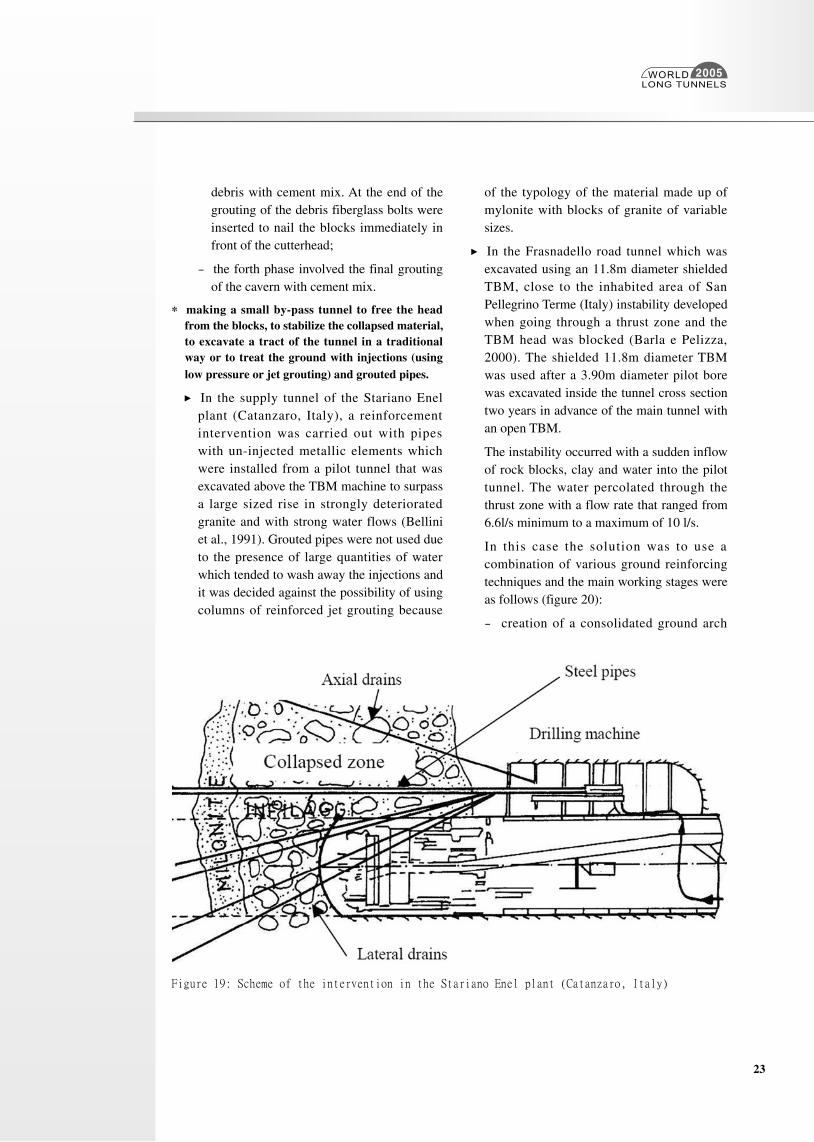
In the supply tunnel of the Stariano Enel plant (Catanzaro, Italy), a reinforcement intervention was carried out with pipes with un-injected metallic elements which were installed from a pilot tunnel that was excavated above the TBM machine to surpass a large sized rise in strongly deteriorated granite and with strong water flows (Bellini et al., 1991). Grouted pipes were not used due to the presence of large quantities of water which tended to wash away the injections and it was decided against the possibility of using columns of reinforced jet grouting because
of the typology of the material made up of mylonite with blocks of granite of variable sizes.
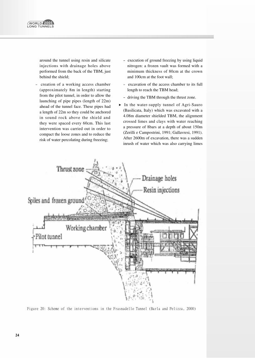
In the Frasnadello road tunnel which was excavated using an 11.8m diameter shielded TBM, close to the inhabited area of San Pellegrino Terme (Italy) instability developed when going through a thrust zone and the TBM head was blocked (Barla e Pelizza, 2000). The shielded 11.8m diameter TBM was used after a 3.90m diameter pilot bore was excavated inside the tunnel cross section two years in advance of the main tunnel with an open TBM.
The instability occurred with a sudden inflow of rock blocks, clay and water into the pilot tunnel. The water percolated through the thrust zone with a flow rate that ranged from 6.6l/s minimum to a maximum of 10 l/s.
In this case the solution was to use a combination of various ground reinforcing techniques and the main working stages were as follows (figure 20):
- creation of a consolidated ground arch
Figure 19: Scheme of the intervention in the Stariano Enel plant (Catanzaro, Italy)
WORLDLONG TUNNELS
2005
24
around the tunnel using resin and silicate injections with drainage holes above performed from the back of the TBM, just behind the shield;
- creation of a working access chamber (approximately 8m in length) starting from the pilot tunnel, in order to allow the launching of pipe pipes (length of 22m) ahead of the tunnel face. These pipes had a length of 22m so they could be anchored in sound rock above the shield and they were spaced every 60cm. This last intervention was carried out in order to compact the loose zones and to reduce the risk of water percolating during freezing;
- execution of ground freezing by using liquid nitrogen: a frozen vault was formed with a minimum thickness of 80cm at the crown and 100cm at the foot wall;
- excavation of the access chamber to its full length to reach the TBM head;
- driving the TBM through the thrust zone.
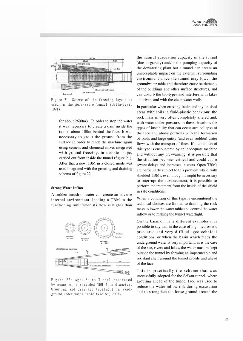
In the water-supply tunnel of Agri-Sauro (Basilicata, Italy) which was excavated with a 4.08m diameter shielded TBM, the alignment crossed limes and clays with water reaching a pressure of 8bars at a depth of about 150m (Zerilli e Campostrini, 1991; Gallavresi, 1991). After 2600m of excavation, there was a sudden inrush of water which was also carrying limes
Figure 20: Scheme of the interventions in the Frasnadello Tunnel (Barla and Pelizza, 2000)
WORLDLONG TUNNELS
2005
25
for about 2600m3 . In order to stop the water it was necessary to create a dam inside the tunnel about 100m behind the face. It was necessary to grout the ground from the surface in order to reach the machine again using cement and chemical mixes integrated with ground freezing, in a conic shape, carried out from inside the tunnel (figure 21). After that a new TBM in a closed mode was used integrated with the grouting and draining schema of figure 22.
Strong Water Inflow
A sudden inrush of water can create an adverse internal environment, leading a TBM to the functioning limit when its flow is higher than
the natural evacuation capacity of the tunnel (due to gravity) and/or the pumping capacity of the dewatering plant but a tunnel can create an unacceptable impact on the external, surrounding environment since the tunnel may lower the groundwater table and therefore cause settlements of the buildings and other surface structures, and can disturb the bio-types and interfere with lakes and rivers and with the clean water wells.
In particular when crossing faults and mylonitised areas with soils in fluid-plastic behaviour, the rock mass is very often completely altered and, with water under pressure, in these situations the types of instability that can occur are: collapse of the face and above portions with the formation of voids and large entity (and even sudden) water flows with the transport of fines. If a condition of this type is encountered by an inadequate machine and without any pre-warning, it is possible that the situation becomes critical and could cause severe delays and increases in costs. Open TBMs are particularly subject to this problem while, with shielded TBMs, even though it might be necessary to interrupt the advancement, it is possible to perform the treatment from the inside of the shield in safe conditions.
When a condition of this type is encountered the technical choices are limited to draining the rock mass to lower the water table and control the water inflow or to making the tunnel watertight.
On the basis of many different examples it is possible to say that in the case of high hydrostatic pressures and very difficult geotechnical conditions, or when the basin which feeds the underground water is very important, as is the case of the see, rivers and lakes, the water must be kept outside the tunnel by forming an impermeable and resistant shell around the tunnel profile and ahead of the face.
This i s p rac t ica l ly the scheme tha t was successfully adopted for the Seikan tunnel, where grouting ahead of the tunnel face was used to reduce the water inflow risk during excavation and to strengthen the loose ground around the
Figure 21: Scheme of the freezing layout as
used in the Agri-Sauro Tunnel (Gallavresi,
1991)
Figure 22: Agri-Sauro Tunnel excavated
by means of a shielded TBM 4.1m diameter,
Grouting and drainage treatment in sandy
ground under water table (Vielmo, 2005)
WORLDLONG TUNNELS
2005
26
Figure 23: Scheme of the ground grouting as preliminary proposed for crossing the Piora zone
(Lombardi, 1997a, 1997b)
Figure 24: Grouting scheme used for crossing the Val Fredda fault encountered during the
excavation of Gran Sasso Tunnel (ANAS and COGEFAR, 1979)
WORLDLONG TUNNELS
2005
27
excavation, aiming at crating a long-term bearing ring.
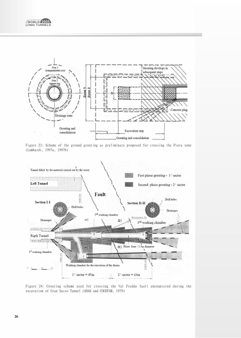
This is also the solution which was designed by Lombardi (Lombardi 1997a, 1997b) to go through the Piora fault when it was supposed that the tunnel had to face a milled dolomite and the high water pressure. This design scheme, from which the times and construction costs were evaluated, was necessary to demonstrate the need and utility of a careful, detailed and exhaustive investigations (figure 23).
A similar solution was also used to go through the important fault of Valle Fredda crossed by the Gran Sasso Tunnel (Italy) with a water pressure till 60 bar coupled with weak rock mass. A complex layout of drains and drilled holes for cement and chemical injections was created from some drifts (figure 24) (ANAS and COGEFAR, 1979)
In these cases the drainage of water inside the tunnel should be avoided because of the risks of creating preferential ways for water inflow (without real or effective control) is too high and can irremediably compromise the tunnel excavation, if inrushes of water cannot be properly controlled. In addition, the drainage efficiency is highly uncertain.
The possibility of a long-term drainage inside the treated ring should be evaluated, but any assumption on its functionality should be associated with a predefined maintenance plan, especially if the lining design only accounts for reduced water loads. Watertightness can be achieved by the use of probe-drilling ahead of the face followed by pre-grouting of the rock mass. The primary purpose of a pre-grouting scheme is to establish an impervious zone around the tunnel periphery by reducing the permeability of the most conductive feature in the rock mass. The impervious zone ensures that the full hydrostatic pressure is distanced from the tunnel periphery to the outskirt of the pre-grouted zone. The water pressure is gradually reduced through the grouted zone and the water pressure acting on the tunnel contour and the tunnel lining can be close to nil.
In addition the pre-grouting will have the effect of improving the stability situation in the grouted zone.
Pre-grouting is the only technique that is able to prevent water inflow if it is carried out in a correct way and only if it offers complete coverage. The presence of a full cover fan can be able to reduce the risk of an sudden and unexpected inflow.
This means that the pre-grouting must be efficient and correctly carried out: during the TBM advancement no ungrouted joint should be encountered and the coverage of the grout fan ahead of the TBM face (before a new grouting stage) should be of a sufficient length to ensure that the tunnelling face does not recall water from ahead.
As a consequence, the design should be focused on the creation of a continuous grouting curtain around the tunnel and a very good quality control (on the injection procedure, injected quantities, geometry of the perforation etc.) should be set up in the job site. An incorrect injection of a hole can cause an unacceptable water inflow and require the TBM excavation to b stopped and a further injection procedure to be performed with an increase in costs and times. Probe-drilling and pre-grouting may be performed continuously along the tunnel advance In areas highly sensitive to groundwater fluctuations, e.g. every 20 to 30m. A pre-grouting round can include a trumped shaped barrier in the rock mass. The length of the ground holes can vary form 15m to 35m with an overlap of 6m to 10m between each grouting round (Grov, 2002).
On the basis of the geotechnical and hydrogeology studies, the designer should define the number of grouting holes and the injection procedure.
Two of the drilling holes for the grouting fan should be considered as probe holes and the grout curtain should be designed in a way that in critical (anomalous) conditions it would be possible to improve it.
In order to reduce the drilling length it is necessary
WORLDLONG TUNNELS
2005
28
to start drilling as close to the tunnel face as is influenced by the quality of the pre-grouting. It should be stressed that post-grouting drilling should be carried out paying a great attention to the orientation. The holes should not be parallel to the water bearing joints but should cross them to obtain an optimal injection results.
In order to reduce the post-grouting requirements and to make the site safer if an incorrect pre-grouting is performed, it is also possible to use a shielded TBM, and to carry out the injection very close to the tunnel face if the tunnel has a certain diameter (no less than 3.6m). The same type of injection scheme cannot be carried out
possible and to use rigid drilling rods to avoid deviation of the holes.
The use of a systematic grouting scheme (drilling pattern and injection procedure) should also reduce the possibility of an erroneous evaluation of the grouting requirements in the site.
It is also important to remark that if the pre-grouting is carried out in a correct way and with a sufficient quantity of grout, the post grouting amount can be reduced in quantity.
The post grouting can also be used to reduce water inflow but the injected quantities and number of holes
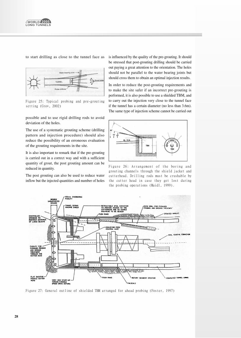
Figure 25: Typical probing and pre-grouting
setting (Grov, 2002)
Figure 27: General outline of shielded TBM arranged for ahead probing (Foster, 1997)
Figure 26: Arrangement of the boring and
grouting channels through the shield jacket and
cutterhead. Drilling rods must be crushable by
the cutter head in case they get lost during
the probing operations (Maidl, 1999).
WORLDLONG TUNNELS
2005
29
with the same easyness using an open TBM.
It is necessary to limit the probe drilling and drilling for grouting in the core to be excavated to a minimum (it is necessary to use tools that the TBM tools can destroy during advancement, for example in alluminium and not in steel).
The other possible scheme (to be used in conjunction with pre-grouting) to control and minimise water inflow and post grouting is to use a shielded TBM with pre-cast lining segments and install the lining just behind the face. If an accurate grouting anulus is made with this scheme, it is possible to prevent limited inflow. (obviously the lining must be designed to be able to stand up to the water pressure).
Furthermore if the lining structure is installed just after the tunnel face it is possible to make pre-grouting holes (for integration if necessary) not exactly behind the face because, due to the presence of an impermeable lining, water inflow is limited and it is some time before the drainage become dangerous for the settlements.
The problem of water inflow and pre-ground treatment is of great importance when a under see tunnel has to be excavated. The analysis of relevant examples of probing and the pre-ground
treatment selected applied during the design or the construction of some deep tunnels are discussed and analysed with the purpose of defining some basic rationales for the techniques to be applied for new deep tunnels in the following.
Japan and Norway undoubtedly hold the record in undersea tunnels constructed over the past 30 years.
The Seikan Tunnel (Adachi, 1986; Matsuo, 1986; Ilda and Girono, 1992), which was broken through in 1985, 18 years after the pilot bore excavation was started still represents a milestone in deep tunnelling in terms of length and challenges, through it was excavated with conventional Drill and Blast method. The Seikan tunnel testifies that the art of tunnelling can overcome very serious problems such as seawater flooding into a tunnel. This tunnel was excavated through complex geological volcanic and sedimentary rocks, and very severe problems such as water inflow, ground squeezing and unconsolidated soil, under 170m of water and 100m maximum of overburden were resolved. Advance boring and ground treatment played a key role in completing the excavation.
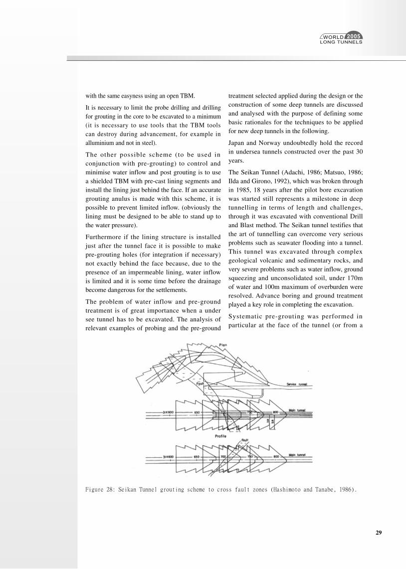
Systematic pre-grouting was performed in particular at the face of the tunnel (or from a
Figure 28: Seikan Tunnel grouting scheme to cross fault zones (Hashimoto and Tanabe, 1986).
WORLDLONG TUNNELS
2005
30
side-drift that preceded the excavation) along difficult zones with the aim of creating a water-seal ahead of the tunnel and improving the geotechnical characteristics of the ground in the short and the long term (Hashimoto and Tanabe, 1986).
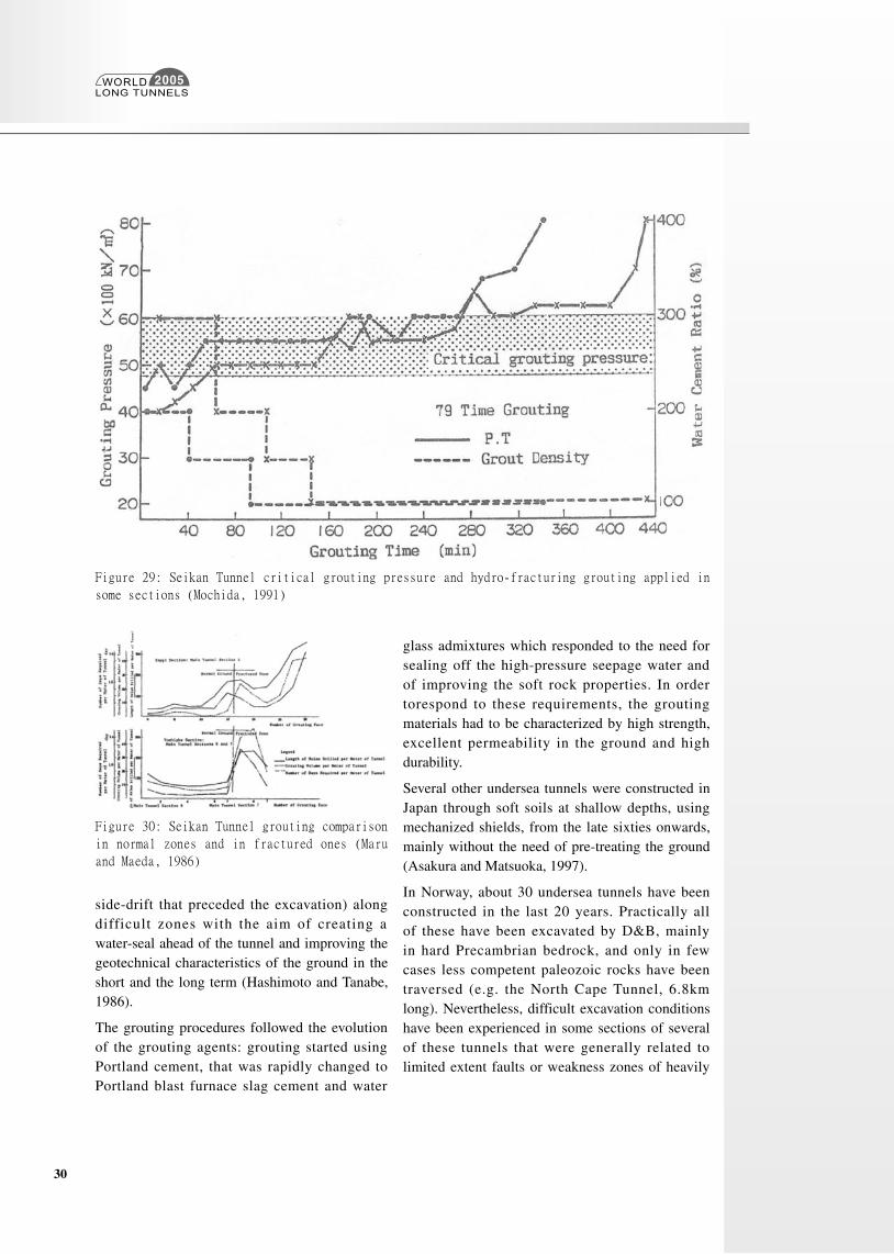
The grouting procedures followed the evolution of the grouting agents: grouting started using Portland cement, that was rapidly changed to Portland blast furnace slag cement and water
glass admixtures which responded to the need for sealing off the high-pressure seepage water and of improving the soft rock properties. In order torespond to these requirements, the grouting materials had to be characterized by high strength, excellent permeability in the ground and high durability.
Several other undersea tunnels were constructed in Japan through soft soils at shallow depths, using mechanized shields, from the late sixties onwards, mainly without the need of pre-treating the ground (Asakura and Matsuoka, 1997).
In Norway, about 30 undersea tunnels have been constructed in the last 20 years. Practically all of these have been excavated by D&B, mainly in hard Precambrian bedrock, and only in few cases less competent paleozoic rocks have been traversed (e.g. the North Cape Tunnel, 6.8km long). Nevertheless, difficult excavation conditions have been experienced in some sections of several of these tunnels that were generally related to limited extent faults or weakness zones of heavily
Figure 29: Seikan Tunnel critical grouting pressure and hydro-fracturing grouting applied in
some sections (Mochida, 1991)
Figure 30: Seikan Tunnel grouting comparison
in normal zones and in fractured ones (Maru
and Maeda, 1986)
WORLDLONG TUNNELS
2005
31
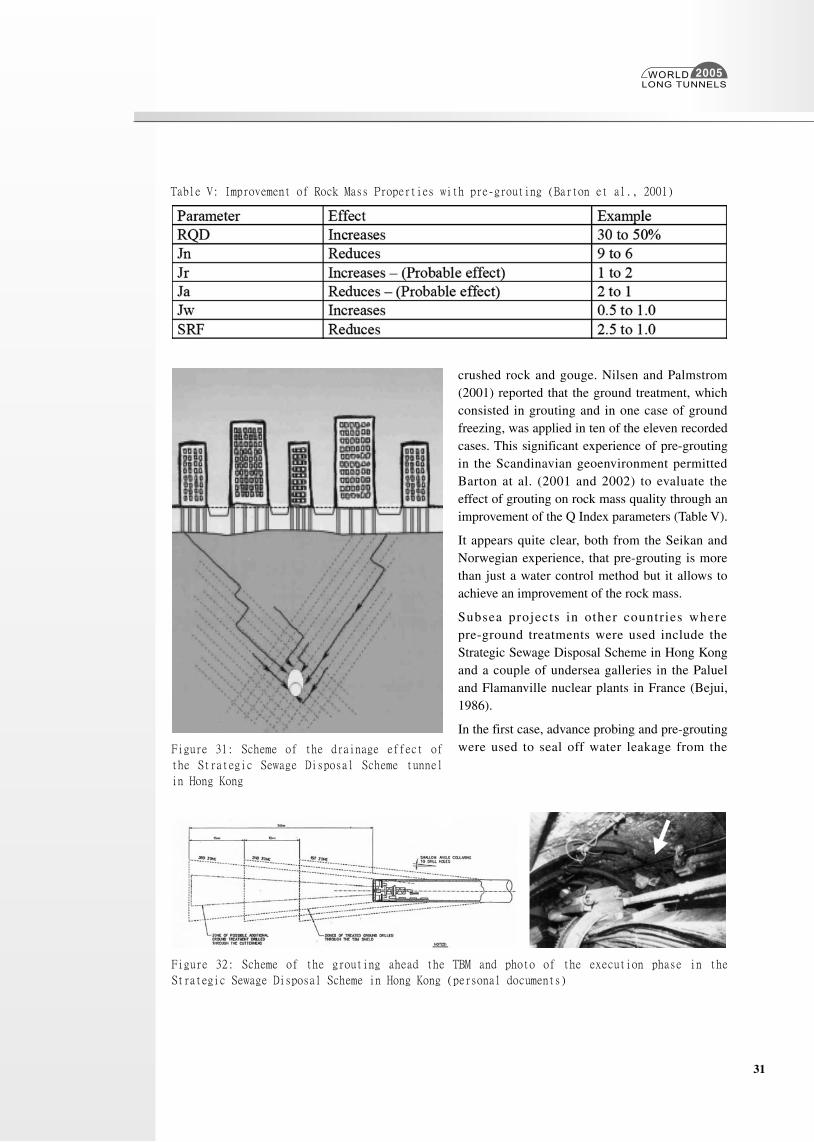
crushed rock and gouge. Nilsen and Palmstrom (2001) reported that the ground treatment, which consisted in grouting and in one case of ground freezing, was applied in ten of the eleven recorded cases. This significant experience of pre-grouting in the Scandinavian geoenvironment permitted Barton at al. (2001 and 2002) to evaluate the effect of grouting on rock mass quality through an improvement of the Q Index parameters (Table V).
It appears quite clear, both from the Seikan and Norwegian experience, that pre-grouting is more than just a water control method but it allows to achieve an improvement of the rock mass.
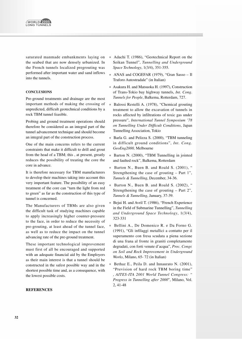
Subsea projects in other countries where pre-ground treatments were used include the Strategic Sewage Disposal Scheme in Hong Kong and a couple of undersea galleries in the Paluel and Flamanville nuclear plants in France (Bejui, 1986).
In the first case, advance probing and pre-grouting were used to seal off water leakage from the
Table V: Improvement of Rock Mass Properties with pre-grouting (Barton et al., 2001)
Figure 31: Scheme of the drainage effect of
the Strategic Sewage Disposal Scheme tunnel
in Hong Kong
Figure 32: Scheme of the grouting ahead the TBM and photo of the execution phase in the
Strategic Sewage Disposal Scheme in Hong Kong (personal documents)
WORLDLONG TUNNELS
2005
32
saturated manmade embankments laying on the seabed that are now densely urbanized. In the French tunnels localized pregrouting was performed after important water and sand inflows into the tunnels.
CONCLUSIONS
Pre-ground treatments and drainage are the most important methods of making the crossing of unpredicted, difficult geotechnical conditions by a rock TBM tunnel feasible.
Probing and ground treatment operations should therefore be considered as an integral part of the tunnel advancement technique and should become an integral part of the construction process.
One of the main concerns refers to the current constraints that make it difficult to drill and grout from the head of a TBM; this , at present, greatly reduces the possibility of treating the core the core in advance.
It is therefore necessary for TBM manufacturers to develop their machines taking into account this very important feature. The possibility of an easy treatment of the core can “turn the light from red to green” as far as the construction of this type of tunnel is concerned.
The Manufacturers of TBMs are also given the difficult task of studying machines capable to apply increasingly higher counter-pressure to the face, in order to reduce the necessity of pre-grouting, at least ahead of the tunnel face, as well as to reduce the impact on the tunnel advancing rate of the pre-ground treatment.
These important technological improvement must first of all be encouraged and supported with an adequate financial aid by the Employers as their main interest is that a tunnel should be constructed in the safest possible way and in the shortest possible time and, as a consequence, with the lowest possible costs.
REFERENCES
* Adachi T. (1986), “Geotechnical Report on the Seikan Tunnel”, Tunnelling and Underground Space Technology, 1(3/4), 351-355.
* ANAS and COGEFAR (1979), “Gran Sasso – Il Traforo Autostradale” (in Italian)
* Asakura H. and Matsuoka H. (1997), Construction of Trans-Tokio bay highway tunnels, Int. Cong. Tunnels for People, Balkema, Rotterdam, 727.
* Balossi Restelli A. (1978), “Chemical grouting treatment to allow the excavation of tunnels in rocks affected by infiltrations of toxic gas under pressure”, International Tunnel Symposium ’78 on Tunnelling Under Difficult Conditions, Japan Tunnelling Association, Tokio
* Barla G. and Pelizza S. (2000), “TBM tunneling in difficult ground conditions”, Int. Cong. GeoEng2000, Melbourne
* Barton N. (2000), “TBM Tunnelling in jointed and faulted rock”, Balkema, Rotterdam
* Barton N., Buen B. and Roald S. (2001), “Strengthening the case of grouting – Part 1”, Tunnels & Tunnelling, December, 34-36.
* Barton N., Buen B. and Roald S. (2002), “Strengthening the case of grouting – Part 2”, Tunnels & Tunnelling, January, 37-39.
* Bejui H. and Avril T. (1986), “French Experience in the Field of Submarine Tunnelling”, Tunnelling and Underground Space Technology, 1(3/4), 323-331
* Bellini A., De Domenico R. e Da Forno G. (1991), “Gli infilaggi metallici a contatto per il superamento con fresa scudata a piena sezione di una frana al fronte in graniti completamente degradati, con forti venute d’acqua”, Proc. Congr. on Soil and Rock Improvement in Underground Works, Milano, 65- 72 (in Italian)
* Bethaz E., Peila D. and Innaurato N. (2001), “Prevision of hard rock TBM boring time”, AITES-ITA 2001 World Tunnel Congress: “Progress in Tunnelling after 2000”, Milano, Vol. 2, 41-48
WORLDLONG TUNNELS
2005
33
* Bethaz E., fuoco S., Mariani S., Porcari P. and Rosazza Bondibene E. (2000) “Risere tunnel excavation with TBM: the experience of the maen tunnel”, Gallerie e Grandi opere sotterranee, 61, 67-80
* Blindheim O.T. and Ovstedal E. (2002), “Design principles and construction methods for water control in subsea road tunnels in rock”., Water Control in Norvegian Tunnelling, Norvegian Tunnelling Society, 2002
* Brantberger M., Stille H. and Eriksson M. (2000), “Controlling Grout Spreading in Tunnel Grouting- Analyses and Developments of the GIN-method”, Tunnelling and Underground Space Technology, 15(4), 343-352
* BTS (2004), “Tunnel Lining Design Guide”, Thomas Telford, London
* Carrieri G. (2000), “Italian Report on guidelines for the selection of TBM’s”, Recomendation and guidelines for TBMs, ITA-AITES WG. 14, Lausanne
* Cambefort H. (1964), “Injection des Sols” ,
Eyrolles, Paris
* Chiriotti E., Grasso P. and Xu S. (2003), “Analysis of tunnelling risks: state-of-the-art and examples”, Gallerie e Grandi Opere Sotterranee , 69, 20-44
* Clayton C. (2001), “Managing Geotechnical Rock. Improving Productivity in UK Building and Construction”, ICE, Thomas Telford, London
* Cravero M., Iabichino G., Godio A. and Sambuelli N. (2000), “Metodologia per controlli e misure di tipo geomeccanico e geofisico per lo scavo meccanizzato di gallerie”, MIR 2000, Torino (in Italian)
* Demorieux J.M. (1997), “Reconnaissances a l’advancement a partir du TBM”, UN/ITA Workshop on Gibraltar strait fixed link: “Characterisation on TBM for tunnelling flysches”, Tarifa
* Del la Val le N. (2002) , “Cons t ruc t ion
management for bored tunneld, Gallerie e grandi opere sotterranee, 20-30
* Einstein H.H., (1996), “Risk and Risk Analysis in Rock Engineering”, Tunneling and Underground Space Technology, 11(2), 141-155.
* Fabbri D. (2005), “Experiences from the ground probing in the Gotthard-Base tunnel”, ITA Training course:Tunnel Engineering ITA/AITES, Istanbul
* Fredriksen U. and Broch E. (1984), “Grouting of Sewer Tunnels in Oslo”, Advances in Tunnelling Technology and Subsurface Use, 4 (4), 185-189.
* Foster J.R. (1997), “Gibraltar Strait Crossing. Characterization of TBM”, UN/ITA Workshop on “Characterization for tunnelling flysches”, Tarifa
* Galera J.M. and Pescador S. (2005), “Métodos geofìsicos no destructivos para predecir el terreno por delante de las tuneladoras”, IV UN-ITA Workshop on “Gibraltar Strait crossing”, Madrid (in Spanish)
* Galera J.M. (1997), “Sonic soft ground probe system adapted to TBM”, UN/ITA Workshop on “Characterization of TBM for tunnelling flysches”, Tarifa
* Gallavresi F. (1991), “Il congelamento artificiale del terreno. L’esperienza italiana”, Proc. Congr. on Soil and Rock Improvement in Underground Works, Milano, Vol II, 401-415 (in Italian)
* Garnier, Pierron, Botte, Lebert, Giafferi, Vaskou (1991), “Javanon Tunnel. Buetch development. Exceptional geological Difficulties encountered when boring with a tunnel boring machine and adopted provisions, Proc. Congr. on Soil and Rock Improvement in Underground Works, Milano, Vol II, 357-365
* Grandori R. (1996a), “Avanzamento meccanico in condizioni estreme. Scelta del tipo di TBM e sue caratteristiche”, 3° Symp. Européen de la construction des tunnels, Berna, 50-57 (in
WORLDLONG TUNNELS
2005
34
Italian)
* Grandori R. (1996b), “The universal TBM in the year 2000. Technical aspects and contractor consideration”, Gallerie e grandi opere sotterranee, SIG, 50, 38-48.
* Grandori R. and Romualdi P. (2004), “The Abdalajis tunnel (Malaga-Spain).The new Double Shield Universal TBM challenge”, Int. Congress on Mechanized Tunnelling: “Challenging case histories”, GEAM/SIG, Torino
* Grov E. (2002), “Introduction to water control in Norwegian tunnelling”, Water control in Norwegian tunnelling, Norwegian Tunnelling Society, 12
* Kalamaras G.S. (1996), “A probabilistic approach to rock engineer ing des ign: application to tunnelling”, Milestones in Rock Engineering –The Bieniawski Jubilee Collection, Balkema, Rotterdam, 113-135
* Klados G. and Kok Y.H. (2004), Selection and performance of TBM in Karstic Limestone – SMART case, Int. Congress on Mechanized Tunnelling: challenging case histories, Torino, 151-164
* Kovari K. and Descoeuders F. (2001), “Tunnelling Switzerland”, Swiss Tunnelling Society, Zurich
* Hashimoto K. and Tanabe Y. (1986), “Construction of the Seikan Undersea Tunnel - II. Execution of the Most Difficult Sections”, Tunnel l ing and Underground Space Technology, 1(3/4), 373-379
* Henn R.W.(1996), “Practical Guide to grouting of underground structures”, Thomas Telford, London, 6-23
* Hoek E. (2001), “Big tunnels in bad rock”,Journal of geotechnical and geoenvironmental engineering,726-740
* IIda H. and Girono M. (1992), “The Seikan Tunne l ” , S impos io Grandes Tune l e s , Madrid,135-144.
* ISRM (1995), “Final Report”, ISRM Commission on Rock Grouting, 1-51
* ITA/AITES WG. 14 (2000), “Recommendations and Guidelines for Tunnel Boring Machine”, ITA/AITES, Lausanne
* ITA/AITES WG 16 (2004, “Quality in tunnelling. Final Report”, Tunnel and Underground Space Technology,19
* ITA/AITES WG 17 (2003), “Long tunnel at great depth - Final Report”, ITA/AITES, Lausanne
* Leca E. (2000), “Investigation ahead of the face”, EUPALINOS 2000 General Report, AFTES
* Leonardi R. 2004), “Kunming Zhangjiuhe Water Diversion and Water Supply project. The influence of geological adversities on TBM performances, Int. Congress on Mechanized Tunnelling: “Challenging case histories”, GEAM/SIG, Torino, 43-51
* Lombardi G. (1997a), “Galleria di base del San Gottardo. Progetto della tratta meridionale”, Giornata di studio “Scavi in Sotterraneo”, Dipartimento del territorio- Istituto geologico ed idrogeologico cantonale, Lugano (in Italian)
* Lombardi G. (1997b), “Die Piora-Mulde. Gotthard_Basistunnel Sud”, Delegation der Tessiner Parlamentarier, Lo, Minusio (CH) (in German)
* Lombardi G. and Deere D. (1993), “Grouting design and control using the GIN principle”, Water Power & Dam Construction, June
* Maidl W. (1999), “Developments in machanized tunnelling during the past two decades”, Underground Construction in Germany 2000, Ed. A. Haack, STUVA and DAUB, 41-52
* Marcheselli P.P. and Ludde M. (2002), “Esplorazione geologico-tecnica in tempo reale davanti alla testa fresante di TBM”, Convegno su: “Le indagini geologiche e geotecniche propedeutiche alla costruzione delle opere sotterranee sia civile che minerarie”, GEAM, Modena (in Italian)
WORLDLONG TUNNELS
2005
35
* McFeat-Smith and Concil ia , (2000), “Investigation, prediction and management of TBM preformance in adverse geological conditions”, Gallerie e grandi opere in sotterranee, 62, 21-28
* Mendaña F. (2004), “Double shield tunnellers in the construction of the Guadarrama tunnels”, Int. Congress on Mechanized Tunnelling: “Challenging case histories”, GEAM/SIG, Torino, 207-224
* Mitani S. (1989), “State of the art of TBM excavation and probing ahead technique”, Proc. 8th IAEG congress, Vancouver, 3501-3512
* Mitani S., Iwai T., and Isahai H. (1987), “Relations between conditions of rock mass and TBM’s feasibility”, Proc. 6th ISRM Congress, Montreal, Vol. 1, 701-704
* Morimoto T. and Hori M. (1986), “Performance characteristics of tunnel boring machine from the geomechanical viewpoint”, Int. Journal Rock Mechanics and Min. Sci. , 23(1),55-66
* M u i r Wo o d A . ( 2 0 0 0 ) , “ Tu n n e l l i n g : Management by design”, E&FN Spon, Lonson
* Mochida Y. (1991),”Rock Mechanics in the Seikan Tunnel”, Rock Mechanics in Japan, Japanese Committee for ISRM, Tokio, 85-87.
* Maru Y. and Maeda T. (1986), “Construction of the Seikan Undersea Tunnel. General Scheme of Execution”, Tunnelling and Underground Space Technology, 1(3/4), 357-371
* Matsuo S. (1986), “An Overview of the Seikan Tunnel Project”, Tunnelling and Underground Space Technology, 1(3/4), 323-331
* Nilsen B. and Palmstrøm A. (2001), “Stability and water leakage of hard rock subsea tunnels”, Cong. on “Modern Tunneling Science and Technology”, Kyoto (Japan) 497-502.
* Nishioka K. and Aoki K. (1998), “Hard rock tunnel boring prediction and field performance”, Proc. RETEC, Boston, 833-852
* Oggeri C. (2004), “Relevant features for
tunnelling control by quality procedures”, Gallerie e Grandi Opere Sotterranee, 73, 44-50
* Ores te P.P. and Pei la D. (2000) , “ I consolidamenti come mezzo per permettere lo scavo meccanizzato di gallerie”, MIR 2000, Torino, 217-274 (in Italian)
* Parker H. (1996), “Geotechnical Investigations”, Tunnel Engineering Handbook, Kluwer Pub., Boston, 46-79
* Pelizza S. and Peila D. (1993), “Soil and rock reinforcements in tunnelling”, Tunnelling and Underground Space Technology, n.3, Pergamon Press, 357-372
* Pelizza S. (1998), “Selection of TBMs”, Workshop on Selection of Tunnelling Methods, ITA World Tunnel Congress ‘98, Sao Paulo (Brazil)
* Pelizza S. and Grasso P. (1998), “Tunnel collapses: are they unavoidable?”, World Tunnelling, March, 71-73
* Pelizza S. (1999), “Engineering risk in tunnelling”, Underground Construction in Germany , Underground Construction in Germany 2000, Ed. A. Haack, STUVA and DAUB, 103-106
* Pelizza S. (2000), “Long TBM drives in rock formation”, Seminar on “Design, construction, operation and other aspects of tunnels”, Petaling Java, Malaysia
* Pelizza S. and Peila D. (2001), “Rock TBM Tunnelling”, Jubilee Volume in celebration o f 75 th anniversary o f K . Terzaghi ’s “Erdbaumechanik”, Ed. Technische Universitat Wien.
* Pelizza S. (2005), “Position Paper n. 3 Ground Treatment”, IV UN-ITA Workshop: “Gibraltar Strait Crossing”, Madrid
* Peila D. and Pelizza S. (2003), “Ground Reinforcing and Steel Pipe umbrella system in Tunnelling”, Advances in Geotechnical Engineering and Tunnell ing - Rational Tunnelling, Logos Verlag, Berlin, 93-132
WORLDLONG TUNNELS
2005
36
* Peila D. (2005), “Indagini preliminari nella costruzione di gallerie”, Workshop “L’innovazione tecnologica nella costruzione e realizzazione di gallerie”, SIG, Infrastructura 2005, Torino, 2-41 (in Italian)
* Sambuelli L., Godio A., Socco V., Dall’Ara A., Vaira G. and Deidda G. (2004), “Metodi Geofisici per la caratterizzazione degli ammassi rocciosi”, MIR 2004, Torino, 47-89 (in Italian)
* Tseng Y.Y., Wong S.L., Chu B. and Wong C.H. (1998), “The Pinglin Mechanized Tunneling in difficult ground”, 8th Congr. of IAEG, Vancouver
* TCGR/UTRC (1997), “Geotechnical Baseline Reports of Underground Construction. Guidelines and Practices”, Underground N a t i o n a l R e s e a rc h C o u n c i l , A S C E , Washington, D.C.
* U.S. Army Corps of Engineers (1995), “Chemical Grouting”, Engineer Manual , 1110-1-3500.
* Vielmo I. (2005), “Grouting ad drainage treatment with relevant boring layouts”, IV UN-ITA Workshop: “Gibraltar strait crossing”, Madrid
* Wen-Lon Cheng (2004), “Hsuean Tunnel and TBM”, Int. Congress on Mechanized Tunnelling: challenging case histories , GEAM/SIG, Torino, 13-20
* Wolf E., Collini R., Balossi Restelli A. (1979),”Attraversamento di una tratta della galleria Capo Calavà (Autostrada Messina-Palermo) in presenza di gas tossici in pressione”, Gallerie e grandi opere sotterranee, 9, 35-51 (in Italian)
* Zerilli F. and Campostrini S. (1991), “Scavo di una galleria in sabbie fluenti. Interventi speciali di consolidamento e drenaggio”, Convegno “Il consolidamento del suolo e delle rocce nelle realizzazioni in sotterraneo” – Vol. II., Milano, 373-397 (in Italian)


