Embed Size (px)
Citation preview
Materials and Design 203 (2021) 109575
Contents lists available at ScienceDirect
Materials and Design
j ourna l homepage: www.e lsev ie r .com/ locate /matdes
Tailoring cold spray additive manufacturing of steel 316 L for static andcyclic load-bearing applications
Sara Bagherifard a,⁎, Jan Kondas a,b, Stefano Monti a, Jan Cizek c, Fabrizio Perego a, Ondrej Kovarik d,Frantisek Lukac c, Frank Gaertner e, Mario Guagliano a
a Department of Mechanical Engineering, Politecnico di Milano, Milan, Italyb Impact Innovations GmbH, Bürgermeister-Steinberger-Ring 1, 84431, Haun/Rattenkirchen, Germanyc Institute of Plasma Physics of the Czech Academy of Sciences, Prague, Czech Republicd Faculty on Nuclear Sciences and Physical Engineering, Czech Technical University, Prague, Czech Republice Helmut Schmidt University - University of the Federal Armed Forces Hamburg, Hamburg, Germany
H I G H L I G H T S G R A P H I C A L A B S T R A C T
• CSAM parts exhibited <1% porosity andstrengths similar to bulk material.
• As-sprayed and heat treated samplesshowed fatigue strength comparable tocast material.
• As-sprayed samples exhibited aniso-tropic crack growth behavior.
• Heat treated samples showed identicalcrack growth rates to the cold rolledsheets.
• Cold spray showed significant potentialfor AM of structural components.
⁎ Corresponding author.E-mail address: [email protected] (S. Bagherif
https://doi.org/10.1016/j.matdes.2021.1095750264-1275/© 2021 The Authors. Published by Elsevier Ltd
a b s t r a c t
a r t i c l e i n f oArticle history:Received 29 October 2020Received in revised form 8 January 2021Accepted 7 February 2021Available online 13 February 2021
Keywords:Kinetic deposition3D-printingFreestandingFatigueCrack propagation
Thanks to the low working temperature, less product size limitations and one order of magnitude higher depo-sition rates compared to the established additive manufacturing techniques, more attention has been brought tothe potential of cold spraying for additivemanufacturing . As a process dealingwith deformation of solid particlespossibly leaving non-bonded interfaces and causing work hardening, any optimization should (i) adjust sprayparameters to obtain high performance as-sprayed parts and (ii) tune ductility and internal stresses by post-treatments. The present study first deals with strategies to optimize spray parameters for fabrication of high per-formance steel 316 L deposits. Next, the performances of deposits are further adjusted by various heat treat-ments. The structural strength of the freestanding samples before and after the heat treatments is evaluatedunder static and cyclic axial loading and supported by fatigue crack growth rate analysis. The results highlightthe feasibility of obtaining high quality steel 316 L deposits using N2 as process gas, rather than the costly Hethat is commonly suggested. This study demonstrates the potential of cold spraying to be used for depositionof freeform structural components with a static strength comparable to that of bulk and laser-based additivemanufactured materials and a fatigue strength similar to that of bulk cast material.© 2021 The Authors. Published by Elsevier Ltd. This is an open access article under the CC BY-NC-ND license (http://
creativecommons.org/licenses/by-nc-nd/4.0/).
ard).
. This is an open access article under
1. Introduction
Cold spraying (CS) is an emerging deposition techniquemostly usedfor mass production of high electrical and thermal conductive layers,
the CC BY-NC-ND license (http://creativecommons.org/licenses/by-nc-nd/4.0/).
Nomenclature
a0 Initial crack lengthda/dN Crack propagation rateΔKeff Effective stress intensity factor rangeη Impact to critical velocity ratioKmax Maximum stress intensity factorpgas Gas pressureR Stress ratioTgas Gas temperatureTm Particle melting temperatureTp Particle impact temperaturevcrit Critical velocityvp Particle impact velocityAM Additive manufacturingCDD Coherently diffracting domainsCS Cold sprayDD Ductile dimplesEDM Wire-electro discharge machiningHIP Hot isostatic pressingIP Inter-particle decohesionLPBF laser powder bed fusionOM Optical microscopyPSD Particle size distributionSEM Scanning electron microscopySENB Single edge notched sampleSF Striation fieldsTG Trans-granularUTS Ultimate tensile strengthXRD X-ray diffraction
S. Bagherifard, J. Kondas, S. Monti et al. Materials and Design 203 (2021) 109575
corrosion resistant coatings, dimensional restoration and spot repair[1–4]. Based on experimental investigations, efficient bonding isattained upon impact at a velocity superior to a critical value [5] that de-pends on the thermo-mechanical properties of the spray material [6].The low working temperature minimizes tensile thermal stresses, oxi-dation, and grain growth; besides, the outstandingly high depositionrate and, as no controlled atmosphere chambers are needed, less limita-tions on the deposit dimensions, have lately brought significant atten-tion to the application of CS for additive manufacturing (AM) [7–10].Themain shortcomings of CS as compared to common AM technologiesconcern the lower resolution and geometrical precision. A detailed com-parison between CS and laser-based AM technologies is elaborated else-where [11].
Material strength, in particular under cyclic loading, is a crucial prop-erty to be considered in promoting the use of CS for AM. Sufficient struc-tural integrity under cyclic loading can pave the way for CS to berecognized by the ASTM and ISO International societies as an AM tech-nology. Any deposit development in CS for AMhas to address combinedpoints of (i) deposit optimization with respect to intrinsic propertiessuch as strength or conductivity, and (ii) application of post treatmentsto further adjust the deposit properties. During CS deposition, voids canform due to inadequate kinetic energy, too low particle temperature toenforce thermal softening, surface imperfections or inadequate packingof powder particles [6]. Even at low or zero porosity, there could besome non-bonded interfaces acting as planar 2D defects that could re-strict the deposit strength. The presence of the imperfections can be ef-fectively diminished by post heat treatments, which, aside from closingthe non-bonded interfaces by surface diffusion along the planar defects,could further bring the benefit of restoring the deposit ductility throughrecrystallization. Nevertheless, to maintain the post-deposition anneal-ing treatment technically realistic (considering the time scales and thetemperatures needed for the diffusion), the quantity and size of the ini-tial defects and porosity should be minimized by a thorough
2
optimization of deposition parameters. For meeting thresholds ofneeded initial deposit properties, only data on strength or electrical con-ductivity in comparison to bulk material can provide sufficiently exactinformation. Correlation of in-plane electrical conductivity and tensilestrength has been used in the past to provide an insight towards thepresence and density of non-bonded interfaces, microstructural defects,and pores [12,13].
To make the process cost-competitive, the spray conditions shouldbe tuned for N2 (less costly compared to He) as process gas; at thesame time, the post treatments must be also selected under economicconsiderations. The strategy for developing CS as a competitive AMtechnique separately addresses optimization of deposition parametersand investigates the effects of post treatments to provide a comprehen-sive understanding. Due to high deposition rates and large depositionsize, CS can operate at significantly competitive costs, if N2 can beused as process gas. According to detailed internal cost calculations sup-plied by Impact Innovations, the CS deposit serial production cost for316 L was estimated to be 40 €/kg, 57% of which counts for the powder.Performing a detailed comparison between CS and other commonlyused AM technologies is not themain focal point of this study. However,based on the provided cost estimate, it is safe to state that the CS tech-nology possesses a notable economic advantage when compared tothe laser-based AM technologies, especially for the production of me-dium/large size parts without intricate geometries [14,15].
Herein, we focus on 316 L stainless steel as an attractive option forbiomedical, petrochemical, marine and architectural applicationsthanks to biocompatibility, high corrosion and high temperature oxida-tion resistance. 316 L has been deposited by CS in the past on multiplemetallic substrates, using a variety of particle size distributions (PSD)[16], different crystallite sizes and phase contents [17] or multi-material powders [18,19] to enhance the density of the coating, aswell as corrosion and wear resistance. Substrate pre-heating was usedto enhance the quality of 316 L coatings; the results indicated enhancedadhesion strength but no significant effect on the coating porosity [20].Multiple studies have been performed to analyze the effect of processparameters and particle morphology on the properties of cold spray316 L deposits [21–23]. These studies have shown that bulk materialproperties cannot be easily achieved for 316 L CS deposits using N2 asprocess gas [24], leading to the conclusion that dense 316 L deposits ofhigh quality can only be attained by utilizing He [25]. One of the high-lights of the present work is demonstrating that an equally good or bet-ter performance can be reached by using N2. In the literature, also laserpost re-melting was adopted to decrease the 3–8% porosity of 316 L de-posits to <1%, but without reporting consequences for deposit tensilestrength [26]. To develop an industrially sustainable process, herein,we successfully demonstrate the possibility to optimize the sprayingpa-rameters for obtaining high performance deposits by using N2 and com-mercially established annealing techniques.
Regarding process parameter optimization, the main influences onthe deposit quality are given by the CS gas pressure and temperature[27,28]. For alloys that show thermal softening, the deposit quality canbe estimated by a quality parameter η= vp(Tp)/vcrit(Tp) as the ratio be-tween particle impact velocity vp and critical velocity vcrit for bonding atattained particle impact temperature Tp [29]. The η-parameter is consid-ered to supply an all-inclusive dimensionless description for CS deposi-tion to consider contributions of material properties and impactconditions of different particle sizes under various process parameters.It is correlated with the cohesive strength of the CS deposits, as longas the temperature is far from the melting temperature of the powders[4]. The key issue for deposit optimization is to find the right match ofpowder size and spray parameter sets. Respective concepts are incorpo-rated in a commercial software [30]; however, the practical realizationof high-end parameter sets is often challenging and limited by theinput data. In a first approach, usually bulk material data is taken asinput. More reliable input can be gained by experimentally measuringthe powder strength for considering possible effects by the powder
S. Bagherifard, J. Kondas, S. Monti et al. Materials and Design 203 (2021) 109575
production process or oxygen contents [31,32]. Reaching or exceedingthresholds of coating quality in the as-sprayed state are the prerequisitefor the success after post-processing.
The second stage of this study deals with the other typical concernfor CS deposits, the limited ductility caused by the notable workhardening of the deformed particles (splats) and possibly remainingnon-bonded interfaces acting as crack nuclei [33,34]. To address thisdrawback, annealing has been widely used for 316 L CS coatings,reporting enhanced bonding between the particles and improvedductility by uniform recrystallization at temperatures >1000 °C[25,35–37]. In the present study, in addition to annealing, hot isostaticpressing (HIP) is also considered as a high-end technology commonlyused to uphold powder consolidation and porosity reduction in castparts. This process involves applications of high isostatic pressure athigh temperatures (generally higher than 0.7Tm) to reduce, if not elim-inate, internal porosity. The application of HIP to CS 316 L deposits wasrecently reported to considerably improve deposit density and enhancetensile strength and ductility [38]. Comparison of both post treatmentswould allow for identifying the more suitable and possibly more eco-nomical heat treatment.
Studying the crack growth behavior is also necessary for evaluatingthe functionality of AM materials [39]. Despite the importance of thesubject, there is a considerably limited number of studies in the litera-ture on fatigue strength and crack growth behavior of freestanding CSdeposits and [40], demonstrating that CS application for AM is stillunder development. One study on fatigue strength of CS 316 L depositafter 1 h annealing at 1100 °C, reported lower axial fatigue strength ascompared to conventionally prepared 316 L samples.Weak interparticlebonding and presence of pores were mentioned as the primary sourcesof crack initiation [41]. On the general topic of fatigue crack growth in CSdeposits, Gavras et al. performed a series of systematic studies on the ef-fect of post heat treatments on small and large crack propagation ratesin Al6061 alloy deposits [42,43]. In these studies the differences be-tween crack initiation threshold values for the rolled bulk materialand the CS deposits were justifiedmainly by the role of grain size in dif-ferent series [42,43]. Freestanding deposits of cold sprayed pure metalsincluding Cu, Al, Ni, and Ti represented significantly lower fracturetoughness as compared to their bulk material counterparts [44].
Considering the limited data available on structural integrity of free-standing CS deposit and the importance of the topic in promoting therecognition of CS as an AM technology, this work aims to provide a sys-tematic study on static strength, fatigue endurance and fatigue crackpropagation behavior of bulk 316 L parts. Herein, the strategy to develophigh performance steel 316 L bulk parts by CS is described in twomajorsections. Part one deals with CS parameter optimization for best depositqualities in as-sprayed state at reduced costs by employing N2 as pro-cess gas. The optimization process is supported by analyzing the corre-lation between impact condition and the resulting tensile strength andelectrical conductivity. Part two contains detailed experimentsconcerning the influence of post heat treatments to further improvethe properties of optimum deposits with respect to microstructure, po-rosity, microhardness, phase content, residual stresses and microstrain.Major focus is then given on mechanical properties of the deposits in-cluding tensile static and axial fatigue strength aswell as crack propaga-tion behavior. The results reveal the high potential of CS to obtain 316 Ldeposit with characteristics comparable to those reported for laser-based AM and bulk cast/forged materials.
2. Materials and methods
2.1. Feedstock powder
Commercially available gas atomized 316 L stainless steel powder(Sandvik Osprey LTD) with two different particle size distributions(PSD) were used to find the most promising spray parameters. Particlesize analysis was performed using Mastersizer2000 instrument
3
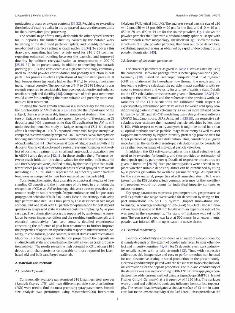
(Malvern PANalytical Ltd., UK). The analyses reveal particle size of d10= 12 μm, d50 = 18 μm, d90 = 29 μm for the fine, and d10 = 19 μm,d50 = 29 μm, d90 = 44 μm for the coarse powders. Fig. 1 shows thepowder particles that illustrate a predominantly spherical shape withrather smooth surfacemorphology. The inserts in Fig. 1 show themicro-structures of single powder particles, that turn out to be defect free,exhibiting equiaxed grains as obtained by rapid undercooling duringpowder atomization [45].
2.2. Selection of deposition parameters
The choice of parameters, as given in Table 1, was assisted by usingthe commercial software package from Kinetic Spray Solutions (KSS,Germany) [30]. Based on isentropic computational fluid dynamic(CFD) simulations of the two-phase flow through the nozzle and thefree jet, the software calculates the particle impact conditions with re-spect to temperature and velocity for a range of particle sizes. Detailson the CFD-calculation procedures are given in literature [28,29]. Ac-cording to the KSS manual and the reference to the previous work, pa-rameters of the CFD calculations are calibrated with respect toexperimentally determined particle velocities for varied cold spray con-ditions using particle image velocimetry, aswell asmore detailed calcu-lations by full 2D and 3D-CFD modelling using Ansys-Fluent software(ANSYS, Inc., Canonsburg, USA). As stated in [28,29], the respective cal-culations over-estimate the measured particle velocities by less than5–10%. With respect to velocity analyses, it might be noted here thatall optical methods such as particle image velocimetry as well as laserDoppler anemometry by higher intensity preferably provide data forlarger particles of a given size distribution. Thus, considering all givenuncertainties, the calibrated, isentropic calculations can be consideredas a rather good estimate of individual particle velocities.
In addition, the KSS software calculates the critical velocities thatneed to be exceeded for bonding, and thus provides an estimation ofthe deposit quality parameter η. Details of respective procedures aregiven in literature [28,29]. Such pre-investigations were needed to ex-plore whether suitable deposit qualities can be established by usingN2 as process gas within the available parameter range. As input datafor the spray material, properties of soft annealed steel 316 L weretaken from theKSS database. Such common reference for the two differ-ent powders would not count for individual impurity contents ormicrostructures.
Key spray parameters as process gas temperature, gas pressure, aswell as powder size range, were varied for deposition by using an Im-pact Innovations ISS 5/11 CS system (Impact Innovations Inc.,Germany). A convergent-divergent (de-Laval) SiC-Out1 (Impact Inno-vation GmbH) nozzle of 160 mm length with an expansion ratio of 5.6was used in the experiments. The stand-off distance was set to 30mm. The gun travel speed was kept at 500 mm/s. In all experiments,powder was injected 65 mm up-stream the nozzle throat.
2.3. Electrical conductivity
Electrical conductivity is considered as an index of a deposit quality;it mainly depends on the extent of bonded interfaces, besides other de-fect and impurity densities [46,47]. For CS deposits, electrical conductiv-ity usually scales with tensile strength [12]. Thus, with respectivecalibration, this inexpensive and easy to perform method can be usedfor non-destructive testing in serial production. In the present study,electrical conductivity is pairedwith the tensile tests to develop individ-ual correlations for the deposit properties. The in-plane conductivity ofthe deposits was assessed according to DIN EN16813 by applying a non-destructive eddy current method using a SigmaScope SMP10 (HelmutFischer GmbH, Germany) at a frequency of 1250 kHz. The surfaceswere ground and polished to avoid any influence from surface topogra-phy. The sensor head investigated a circular surface of 13 mm in diam-eter. Due to the low conductivity of the 316 L steel, it is expected that the
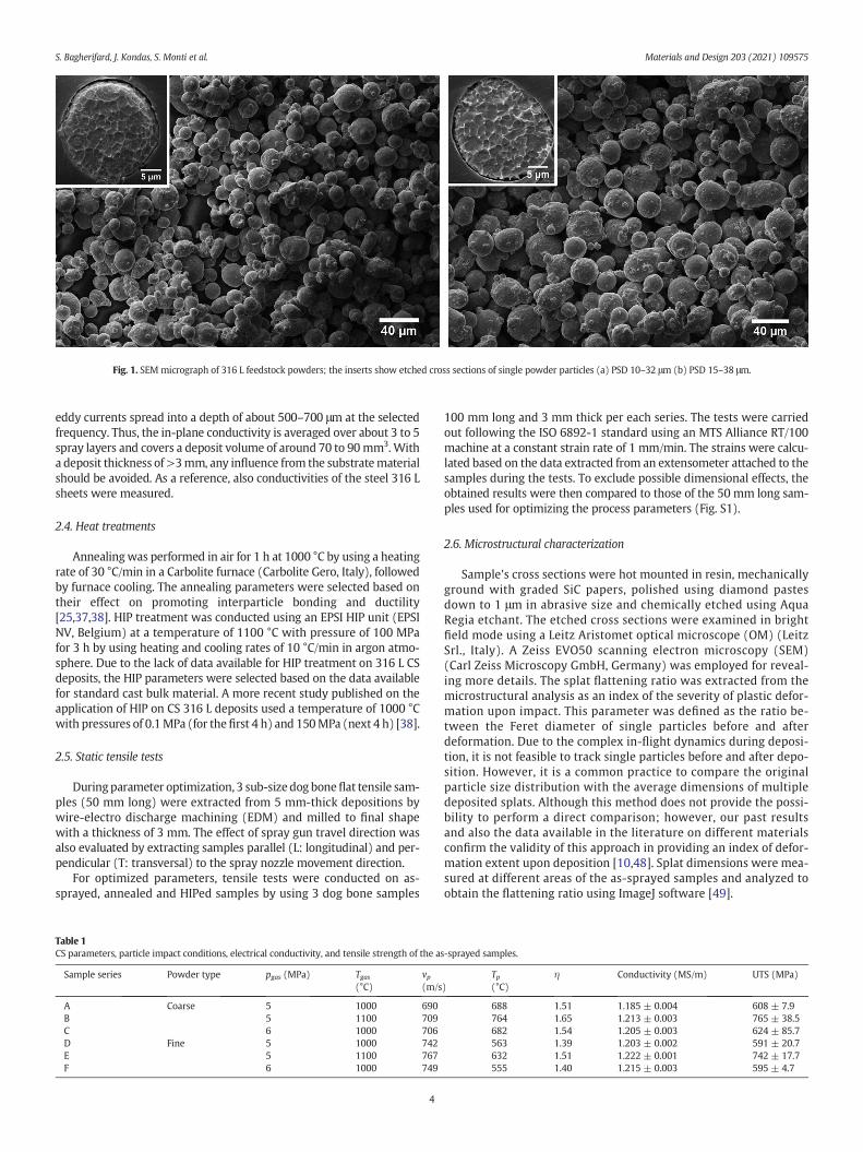
Fig. 1. SEM micrograph of 316 L feedstock powders; the inserts show etched cross sections of single powder particles (a) PSD 10–32 μm (b) PSD 15–38 μm.
S. Bagherifard, J. Kondas, S. Monti et al. Materials and Design 203 (2021) 109575
eddy currents spread into a depth of about 500–700 μm at the selectedfrequency. Thus, the in-plane conductivity is averaged over about 3 to 5spray layers and covers a deposit volume of around 70 to 90mm3.Witha deposit thickness of >3mm, any influence from the substratematerialshould be avoided. As a reference, also conductivities of the steel 316 Lsheets were measured.
2.4. Heat treatments
Annealingwas performed in air for 1 h at 1000 °C by using a heatingrate of 30 °C/min in a Carbolite furnace (Carbolite Gero, Italy), followedby furnace cooling. The annealing parameters were selected based ontheir effect on promoting interparticle bonding and ductility[25,37,38]. HIP treatment was conducted using an EPSI HIP unit (EPSINV, Belgium) at a temperature of 1100 °C with pressure of 100 MPafor 3 h by using heating and cooling rates of 10 °C/min in argon atmo-sphere. Due to the lack of data available for HIP treatment on 316 L CSdeposits, the HIP parameters were selected based on the data availablefor standard cast bulk material. A more recent study published on theapplication of HIP on CS 316 L deposits used a temperature of 1000 °Cwith pressures of 0.1MPa (for thefirst 4 h) and 150MPa (next 4 h) [38].
2.5. Static tensile tests
Duringparameter optimization, 3 sub-size dog boneflat tensile sam-ples (50 mm long) were extracted from 5 mm-thick depositions bywire-electro discharge machining (EDM) and milled to final shapewith a thickness of 3 mm. The effect of spray gun travel direction wasalso evaluated by extracting samples parallel (L: longitudinal) and per-pendicular (T: transversal) to the spray nozzle movement direction.
For optimized parameters, tensile tests were conducted on as-sprayed, annealed and HIPed samples by using 3 dog bone samples
Table 1CS parameters, particle impact conditions, electrical conductivity, and tensile strength of the a
Sample series Powder type pgas (MPa) Tgas(°C)
vp(m/s
A Coarse 5 1000 690B 5 1100 709C 6 1000 706D Fine 5 1000 742E 5 1100 767F 6 1000 749
4
100 mm long and 3 mm thick per each series. The tests were carriedout following the ISO 6892-1 standard using an MTS Alliance RT/100machine at a constant strain rate of 1 mm/min. The strains were calcu-lated based on the data extracted from an extensometer attached to thesamples during the tests. To exclude possible dimensional effects, theobtained results were then compared to those of the 50 mm long sam-ples used for optimizing the process parameters (Fig. S1).
2.6. Microstructural characterization
Sample's cross sections were hot mounted in resin, mechanicallyground with graded SiC papers, polished using diamond pastesdown to 1 μm in abrasive size and chemically etched using AquaRegia etchant. The etched cross sections were examined in brightfield mode using a Leitz Aristomet optical microscope (OM) (LeitzSrl., Italy). A Zeiss EVO50 scanning electron microscopy (SEM)(Carl Zeiss Microscopy GmbH, Germany) was employed for reveal-ing more details. The splat flattening ratio was extracted from themicrostructural analysis as an index of the severity of plastic defor-mation upon impact. This parameter was defined as the ratio be-tween the Feret diameter of single particles before and afterdeformation. Due to the complex in-flight dynamics during deposi-tion, it is not feasible to track single particles before and after depo-sition. However, it is a common practice to compare the originalparticle size distribution with the average dimensions of multipledeposited splats. Although this method does not provide the possi-bility to perform a direct comparison; however, our past resultsand also the data available in the literature on different materialsconfirm the validity of this approach in providing an index of defor-mation extent upon deposition [10,48]. Splat dimensions were mea-sured at different areas of the as-sprayed samples and analyzed toobtain the flattening ratio using ImageJ software [49].
s-sprayed samples.
)Tp(°C)
η Conductivity (MS/m) UTS (MPa)
688 1.51 1.185 ± 0.004 608 ± 7.9764 1.65 1.213 ± 0.003 765 ± 38.5682 1.54 1.205 ± 0.003 624 ± 85.7563 1.39 1.203 ± 0.002 591 ± 20.7632 1.51 1.222 ± 0.001 742 ± 17.7555 1.40 1.215 ± 0.003 595 ± 4.7
S. Bagherifard, J. Kondas, S. Monti et al. Materials and Design 203 (2021) 109575
2.7. Porosity measurements
Two different approaches were considered for these tests including:(i) volumetric measurement by using the Archimedes buoyancy princi-ple, and (ii) cross sectional image analyses of backscatter SEM observa-tions. The volumetric measurements were conducted on four samplesper series using a Precisa 100A–300Melectronic balance (PrecisaGravi-metrics AG, Switzerland). This density kit evaluated the closed porosityof thematerial from the difference of samples' weight in air and distilledwater. As a reference, a density of 7.9 g/cm3was considered for bulk 316L [50]. 2D cross sectional image analysis was performed on eight SEMimages from various areas of each sample's cross section.
2.8. Microhardness measurements
A Leica VMHT30A Vickers microhardness tester (M/S Leica,Germany) was used to conduct the measurements using a load of 100gf and dwell time of 15 s on several positions across the samples' crosssections to inspect possible microhardness variations between thecore and the surface. The reported data were averages of ninemeasurements.
2.9. Crystallographic phase and microstrain analyses
Prior to the measurements, the sample surfaces were mechanicallypolished down to 1-μm diamond paste to remove possible oxides andloosely bonded particles from the top layer. X-ray diffraction (XRD)phase analysis was then carried out using a D8 Discover vertical powderθ-θ diffractometer (Bruker AXS, Germany) with CoKα radiation (λ =1.78897 Å) and a FeKβ filter. Bragg-Brentano geometry was employedwith a 0.4° fixed divergent slit in the primary beam. The diffractedbeam was detected by a 1D detector of type LynxEye. The 2θ angleranged from 20° to 130°, with a step size of 0.03° and the total time ofeach step of 192 s.
Phase identification was performed by using Diffrac.Eva and X'PertHighScore programs, both accessing the PDF-2 crystalline phases data-base from ICDD (International center for diffraction data). QuantitativeRietveld refinement was performed by TOPAS V5 software, where thesize of coherently diffracting domains (CDD, crystallite sizes) andmicrostrainswere determined from the width of Lorentzian and Gauss-ian components of the pseudo-Voigt profile functions, respectively[51,52]. Standard calibration samples were used for calculation of theprofile broadening due to instrumental effects [53]. A preferred orienta-tion (texture) correction according to the March-Dollase approach [54]was included to improve the intensities of the reflections.
2.10. Axial fatigue strength test and fractography analysis
Force-controlled constant amplitude axial fatigue tests with a stressratio of R=0.1were conducted at room temperature following the pro-cedure described in ASTM E466–15 using a Universal MTS test system(MTS, US) at a frequency of 30 Hz on as-sprayed, annealed and HIPtreated series. The up and down staircase method presented by Dixonand Massey [55] was used to perform the tests considering a step sizeof 20 MPa. A statistical analysis approach according to ISO 12107 wasused to analyze the fatigue test data and to calculate the fatigue strengthcorresponding to 2million cycles. Fractographic analysiswas performedon the fracture surfaces using Zeiss-Evo 50 SEM microscope.
2.11. Fatigue crack growth rate tests
Fatigue crack growth rates were measured in resonance bending onsub-sized (4×3×32mm3) single edge notched samples (SENB type ac-cording to ISO 12108 standard) with the notch depth of a0 ~ 0.5 mm.Such bending sub-sized specimens are gaining popularity due to easymanufacturing, low amount ofmaterial required and an easy adaptation
5
for combined loading [56]. The tests were performed on as-sprayed andannealed samples in two crack growth directions, parallel and perpen-dicular to the respective spray lines during deposition. Samples takenfrom annealed cold rolled sheets of 316 L (Matezex, Czech Republic)were used as reference. The samples were tested in resonance bendingconfiguration shown in Fig. 2. The system consisted of two stiff yokes at-tached to the compliant sample forming a rotated H-shaped assemblysuspended by a system of nylon strings. The first bending mode of theassembly was excited electromagnetically using air core coils actingon neodymium magnets located at the ends of the yokes (Fig. 2). Thetests were performed in a rate-controlled mode [57]. In this mode, theexponential relation of the crack growth rate to the crack length da/dN(a) is prescribed and the loading is adjusted accordingly. Theresulting loading resembles the K-control mode recommended byASTM 647, but brings several advantages, such as the explicit knowl-edge of the experiment duration and no risk of crack arrest. The sampleswere fatigue pre-cracked to a= 1.1mm at a crack growth rate decreas-ing from 1 × 10⁻⁹ m/cycle to 5 × 10⁻¹¹ m/cycle, i.e., at a stress intensityfactor very close to its threshold value.
After pre-cracking, the main crack growth rate test was carriedout in a load increase mode up to a crack length of a = 2.4 mm. Inthe used resonance setup, the stress ratio is directly related to thecrack length based on the energy balance [57]. During the experi-ment, R decreases from R = −1 to −1.4. Following the formulas ofNewman [58], the effect of this decrease should be rather small.However, in the scope of the present paper we follow the recom-mendation of ASTM 647 and do not consider the negative part ofthe cycle by using the maximum value Kmax and the effective rangeΔKeff to characterize the loading. During the test, the resonant (load-ing) frequency decreased from ~260 Hz to ~200 Hz. The crack lengthmeasurement was based on differential compliance, e.g., on compli-ance difference of a sample with an open and a closed crack. Bothcompliances were in-situ evaluated by fitting the vibration wave-form measured by accelerometer with piecewise harmonic functionderived from the model of the vibrating H assembly. The model as-sumes small scale yielding and uses standard shape functions [59]to relate the crack-added compliance to the crack length and thestress intensity factor. This approach eliminates the influence ofthe sample clamping and changes in its mechanical properties.Moreover, the compliance changes sharply at the crack openingload, enabling to estimate the effective stress intensity factor rangeΔKeff. This “remotely sensed” opening stress ensures that most ofthe crack is open; however, it does not guarantee opening of themost important part directly behind the crack tip. That said, the ob-tained ΔKeff values need to be interpreted carefully. More detaileddescription of the fatigue crack growth rate test method and set-upcan be found in [57]. The differential compliance method was al-ready validated for aluminum alloy and steel in [60]. After thecrack growth rate test, the samples were ruptured using staticthree-point bending tests to allow fractographic analysis of thecrack surfaces.
2.12. Statistical analysis
For all the tests, the reported data refer to averages of minimumthree independent measurements and the corresponding standard de-viations. Two-tailed unpaired T-student test was used to determinethe statistical significance between different series (*p < 0.05, **p <0.01, ***p < 0.001).
3. Results and discussion
The presentation of results and discussion is divided in two mainparts, optimization of process parameters and mechanical propertiesof the deposits after post heat treatments.

Fig. 2. Left: schematic drawing of the resonance bending fatigue crack growth test layout. Right: a typicalmeasured (dots) and fitted (lines) vibrationwaveform in a phase (time) domain.Here, €α is the yoke angular acceleration describing the specimen bending moment, τ = 2πt/T is the phase of vibration, and τOC corresponds to the crack opening.
S. Bagherifard, J. Kondas, S. Monti et al. Materials and Design 203 (2021) 109575
3.1. Optimization of as-sprayed deposits
This section elucidates the strategies used in the present study to de-velop 316 L deposits that exceed quality thresholds for building free-standing parts and allow for further improvement by heat treatmentto obtain high structural integrity. Moreover, this section explores cor-relations between calculated quality parameters and different proper-ties as strength and electrical conductivity to allow for guidelines onhow to experimentally tune deposit development by non-destructiveon-site part testing. Respective strategies should be transferable to thedevelopment of any other material utilized in CS for AM.
3.1.1. Cold spray parameter selectionBased on the calculations using the KSS software, Fig. 3 shows the
particle impact velocities and temperatures for the two different pow-der sizes according to the corresponding PSDs under different spray pa-rameter sets. The critical velocities to be exceeded for successful impactsare given by solid and dashed lines for the fine and coarse powder sizes,respectively. For the spray parameters under investigation, the particleimpact conditions by far exceeded the critical velocities. However, foreach spray parameter set, the individual particle impact condition cansignificantly depend on the size. Smaller particles by their lower mo-mentum accelerate to higher velocities as compared to the larger
Fig. 3. Calculated particle impact conditions and critical velocities for CS of the two steel316 L powders.
6
ones. Despite reaching high temperatures before the nozzle throat, thesmaller particles impact at lower temperatures than the larger ones.This is due to the smaller thermal momentum of small particles andthus more effective cooling by the gas jet in the expanding regime ofthe nozzle and the free jet. For obtaining homogeneous deposit quality,spray conditions must be tuned for a similar excess of impact velocityagainst critical velocity. The calculations show that such is appropriatelyvalid for the selected spray conditions. According to the calculation re-sults, using an injection distance of 65 mm upstream nozzle throatseemed to be sufficient to pre-heat also larger particles.
The increase of gas temperature at constant pressure of 5 MPa from1000 °C to 1100 °C results in overall higher particle velocities and tem-peratures, and thus higher excess to critical conditions for bonding(Fig. 3). In contrast, at constant process gas temperature of 1000 °C ris-ing the gas pressure from 5 to 6MPa only slightly increased particle ve-locities, associated with small losses in impact temperature. Based onthe calculated impact conditions, the deposits quality parameters η asa ratio between impact velocities and critical velocities are approxi-mated, as given in Table 1. It has to be noted that the particle is exposedto the hot process gas only for less than about 5 ms. Due to cooling bythe expanding gas in the diverging nozzle regime and the free jet, parti-cle impact temperatures are significantly lower than the initial gas tem-perature and, depending on size and thermal history, typically rangebetween 300 and 800 °C [61]. Due to their higher thermal momentum,larger particles retain more heat and have higher temperatures uponimpact as compared to the smaller ones (Fig. S2). By their lower inertia,smaller particles are accelerated to higher velocities than bigger ones(Fig. S3). This explains why larger particles under ideal CS conditionsshould have lower impact velocity and higher impact temperaturethan smaller ones. This allows bigger particles to compensate theirlack in velocity by less needed energy for causing thermal softeningand adiabatic shear instabilities.
3.1.2. Experimental validation of as-sprayed propertiesThe numerical resultswere experimentally explored by applying the
suggested range of parameter sets. Tensile testing and analyses of elec-trical conductivitywere considered asmeasures of deposit quality for allapplied parameter sets in the as-sprayed state. As given in Table 1 andFig. 4, the tensile tests confirm that the gas temperature is the mostinfluential parameter on the deposit quality in the as-sprayed state.Similar trends were observed in the electrical conductivities of the as-sprayed samples. The tensile strength improved by almost 26% forboth powder types as the gas temperature increased, while particlesize had a less significant effect on the mechanical strength of the sam-pleswithin the studied range. Nonotable differencewas observed in thetensile test data of samples extracted parallel (L) and perpendicular
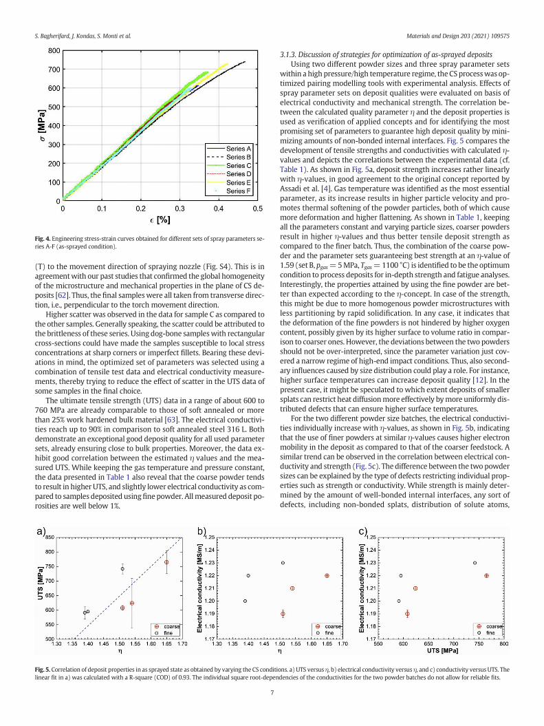
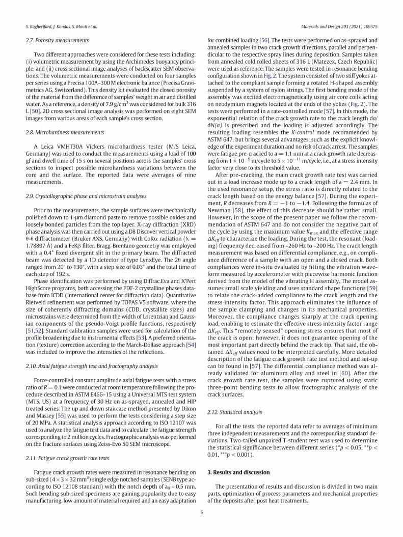
Fig. 4. Engineering stress-strain curves obtained for different sets of spray parameters se-ries A-F (as-sprayed condition).
S. Bagherifard, J. Kondas, S. Monti et al. Materials and Design 203 (2021) 109575
(T) to the movement direction of spraying nozzle (Fig. S4). This is inagreementwith our past studies that confirmed the global homogeneityof the microstructure and mechanical properties in the plane of CS de-posits [62]. Thus, the final sampleswere all taken from transverse direc-tion, i.e., perpendicular to the torch movement direction.
Higher scatter was observed in the data for sample C as compared tothe other samples. Generally speaking, the scatter could be attributed tothe brittleness of these series. Using dog-bone sampleswith rectangularcross-sections could have made the samples susceptible to local stressconcentrations at sharp corners or imperfect fillets. Bearing these devi-ations in mind, the optimized set of parameters was selected using acombination of tensile test data and electrical conductivity measure-ments, thereby trying to reduce the effect of scatter in the UTS data ofsome samples in the final choice.
The ultimate tensile strength (UTS) data in a range of about 600 to760 MPa are already comparable to those of soft annealed or morethan 25% work hardened bulk material [63]. The electrical conductivi-ties reach up to 90% in comparison to soft annealed steel 316 L. Bothdemonstrate an exceptional good deposit quality for all used parametersets, already ensuring close to bulk properties. Moreover, the data ex-hibit good correlation between the estimated η values and the mea-sured UTS. While keeping the gas temperature and pressure constant,the data presented in Table 1 also reveal that the coarse powder tendsto result in higher UTS, and slightly lower electrical conductivity as com-pared to samples deposited usingfinepowder. Allmeasured deposit po-rosities are well below 1%.
Fig. 5. Correlation of deposit properties in as sprayed state as obtained by varying the CS conditilinear fit in a) was calculated with a R-square (COD) of 0.93. The individual square root-depen
7
3.1.3. Discussion of strategies for optimization of as-sprayed depositsUsing two different powder sizes and three spray parameter sets
within a high pressure/high temperature regime, theCSprocesswas op-timized pairing modelling tools with experimental analysis. Effects ofspray parameter sets on deposit qualities were evaluated on basis ofelectrical conductivity and mechanical strength. The correlation be-tween the calculated quality parameter η and the deposit properties isused as verification of applied concepts and for identifying the mostpromising set of parameters to guarantee high deposit quality by mini-mizing amounts of non-bonded internal interfaces. Fig. 5 compares thedevelopment of tensile strengths and conductivities with calculated η-values and depicts the correlations between the experimental data (cf.Table 1). As shown in Fig. 5a, deposit strength increases rather linearlywith η-values, in good agreement to the original concept reported byAssadi et al. [4]. Gas temperature was identified as the most essentialparameter, as its increase results in higher particle velocity and pro-motes thermal softening of the powder particles, both of which causemore deformation and higher flattening. As shown in Table 1, keepingall the parameters constant and varying particle sizes, coarser powdersresult in higher η-values and thus better tensile deposit strength ascompared to the finer batch. Thus, the combination of the coarse pow-der and the parameter sets guaranteeing best strength at an η-value of1.59 (set B, pgas=5MPa, Tgas=1100 °C) is identified to be the optimumcondition to process deposits for in-depth strength and fatigue analyses.Interestingly, the properties attained by using the fine powder are bet-ter than expected according to the η-concept. In case of the strength,this might be due to more homogenous powder microstructures withless partitioning by rapid solidification. In any case, it indicates thatthe deformation of the fine powders is not hindered by higher oxygencontent, possibly given by its higher surface to volume ratio in compar-ison to coarser ones. However, the deviations between the two powdersshould not be over-interpreted, since the parameter variation just cov-ered a narrow regime of high-end impact conditions. Thus, also second-ary influences caused by size distribution could play a role. For instance,higher surface temperatures can increase deposit quality [12]. In thepresent case, it might be speculated to which extent deposits of smallersplats can restrict heat diffusionmore effectively bymore uniformly dis-tributed defects that can ensure higher surface temperatures.
For the two different powder size batches, the electrical conductivi-ties individually increase with η-values, as shown in Fig. 5b, indicatingthat the use of finer powders at similar η-values causes higher electronmobility in the deposit as compared to that of the coarser feedstock. Asimilar trend can be observed in the correlation between electrical con-ductivity and strength (Fig. 5c). The difference between the two powdersizes can be explained by the type of defects restricting individual prop-erties such as strength or conductivity. While strength is mainly deter-mined by the amount of well-bonded internal interfaces, any sort ofdefects, including non-bonded splats, distribution of solute atoms,
ons. a) UTS versus η, b) electrical conductivity versus η, and c) conductivity versus UTS. Thedencies of the conductivities for the two powder batches do not allow for reliable fits.

S. Bagherifard, J. Kondas, S. Monti et al. Materials and Design 203 (2021) 109575
internal grain boundaries or dislocation densities, can influence theelectrical conductivity. Comparatively higher conductivities of the de-posits formed from the smaller powder might be interpreted in termsof overall lower dislocation density. Despite above explained limits,the comparison demonstrates that for each PSD, the electrical conduc-tivity correlates well with deposit tensile strength. Thus, conductivityanalyses could be used during deposit development as a fast, low costlyand non-destructive tool in serial production in comparison to tensiletesting.
3.2. Influence of post treatments for improving deposit characteristics
Section 3.1 described how to obtain optimum deposit quality. How-ever, even under optimum conditions, deposit performance can be stillrestricted by (i) residual amounts of non-bonded interfaces acting ascrack nuclei and (ii) low plasticity due to work hardening. Both can beresolved by post deposition heat treatments. Section 3.2 explores theachievements reachable by heat treatments as isothermal annealing orHIP.With respect to load-bearing parts,major focus is given to improve-ments of the fatigue resistance. The comparison of annealing and HIP isprovided to leave a choice for amore economical solution for final parts,if possible.
3.2.1. Tensile behavior of optimized depositsFig. 6 shows the stress-strain plots for the optimized set of parame-
ters (series B) before and after heat treatments. Table 2 summarizes themechanical properties of this series. While the yield strength of the as-sprayed samples (assumed for these samples as the stress causing a de-viation from linearity equal to 0.02%) was about 64% and 98% higherthan that of annealed and HIPed series, respectively, the UTS of the as-sprayed samples was about 4 to 8% higher than that of heat treatedones. The results indicate quite brittle behavior of the as-sprayed sam-ples and a significantly higher elongation to failurewith over 10-fold in-crease to a strain of about 50% after the heat treatments. From theinserts in Fig. 6, it can be seen that the as-sprayed samples failed atthe section corresponding to the fillet radius without changing shape,while the annealed ones show notable elongation, reduced cross sec-tional areas, and even necking in the elongated regime, confirming thehigh ductility after heat treatments. The elongation to failure of theheat treated samples is rather similar to that of soft annealed bulk ma-terial. The fracture surfaces of the tensile test samples (Fig. S5) confirm
Fig. 6. Engineering stress-strain curves for samples sprayed using optimumparameters (Bseries) before and after heat treatments; arrows indicate the fraction section (AS: as-sprayed).
8
the role of heat treatments in recovering ductility and pronounced dim-ple failure.
3.2.2. Deposit microstructure, porosity and microhardnessDeposits microstructures, as obtained under optimum spray param-
eters, are displayed in Fig. 7. Image analysis of the micrographs indi-cated a particle flattening ratio of 0.36 ± 0.09 that designates the highextent of deformation in the deposition process as confirmed by thegreatly flattened splat shapes observed in Fig. 7a. The dispersed porosi-ties, highlighted in the SEM images of the as-sprayed and annealed sam-ples, are often concentrated at the interface between the splats. Thatmight be attributed to limited deformability unable to close small gapsand to the remnants frommaterial jets [6], with locally higher impurityor oxide contents getting removed during sample preparation. Only inrather rare cases, some large pores were observed in the cross sectionof the as-sprayed samples (see Fig. S6) that could be attributed todetaching of loosely bonded splats during metallographic preparation.
Both heat treated samples present amore homogeneousmicrostruc-ture that barely allows to distinguish original splat boundaries. Atomicdiffusion, associated recrystallization and grain growth heal out the de-fects present in the as-sprayed state. The examples demonstrate thatthe microstructure reorganization is growing over particle-particle in-terfaces, not being influenced by possible impurities on the original par-ticle surfaces. This is evident by comparing the grain sizes, and theincrease from the as-sprayed to the heat treated cases. Particularly,the HIPed sample shows a regular, completely recrystallized micro-structure with polygonal geometries and typical 120° angles betweenmultiple grains referring to a lower grain boundary energy configura-tion [68]. In addition, annealing twins dominated the microstructuredue to the atomic structure reorganization during the heat treatments.
The last row in Fig. 7a-c shows the SEM micrographs in back-scattering contrast mode illustrating the evolution of porosity fromthe as-sprayed state to the heat treated ones. The very low porosity ofthe as-sprayed samples confirms the efficiency of the spray parameteroptimization in stage 1. Porosity results shown in Fig. 7d indicate thatboth heat treatments reduce the bulk porosity from about 0.8% to0.1%. The HIP treatment resulted in a more efficient porosity decreasethanks to the increased atomic diffusion at splat interfaces activatedby the high temperature accompanied by the effect of isostatic pressure.
The micro-hardness of the as-sprayed samples is higher than that ofthe reference bulk material [26] (see Fig. 7e). This is attributed to workhardening generated by the plastic deformation upon impact. Anneal-ing and HIP treatments resulted in hardness reduction of about 50%and 54% with respect to as-sprayed sample, respectively.
3.2.3. Deposit crystallographic structure and microstrainAs shown in Fig. 8, thediffractionpattern of the as-sprayed, annealed
and HIP treated samples reveal the FCC structure of austenitic steel 316L (PDF# 00–033-0397). The Rietveld refinement plots of all series areshown in Fig. S7. No secondary phase precipitates were identified. Thetexture varied among the samples and was somewhat different to amodel γ-Fe material. The as-sprayed material exhibited moderate tex-ture (preferential orientation) that was diminished after annealing.We cannot easily assess the influence of such texture on themechanicalproperties as its effect is superimposed with the overall effect of theplastic deformation experienced by the sprayedmaterial. Peakswith in-creased intensity compared with model γ-Fe are indexed in the spectra(Fig. 8). A detailed mutual comparison of the spectra for the threesample types revealed significantly broader peaks in the spectrum ofthe as-sprayed state. As opposed to the annealed and HIPed series,this indicates a higher amount of defects being present by the deforma-tion of the as-sprayedmaterial. Such could be due to the smaller crystal-lite sizes (coherent diffraction domains, CDD) and local microstrains.The quantification of the former by Rietveld analyses provided CDDvalues of 59 nm for the as-sprayed and 236 nm and 253 nm for theannealed and HIPed states, respectively. Themicrostrain was calculated

Table 2Mechanical properties of the CS samples as obtained under optimumparameter sets (coarse powder, pgas=5MPa, Tgas=1100 °C, η=1.59) in as-sprayed and heat treated states in com-parison to conventionally fabricated bulk materials.
As-sprayed Annealed HIPed ASM annealed AISI316 L sheet [64,65]
Hot rolled/forged bulk material [66,67]{Kempen, 2012 #872}
Young modulus (GPa) 173.9 ± 3 190 ± 10 186 ± 12 193 –Yield stress (MPa) 687 ± 52 418 ± 3 347 ± 0.6 290 258 ± 41Ultimate stress (MPa) 723 ± 33 696 ± 6 672 ± 2.5 580 617 ± 35Elongation (%) 0.47 ± 0.02 49 ± 2 53 ± 1.2 50 72 ± 9
Fig. 7. Cross sectional microstructures of a) as-sprayed b) annealed and c) HIPed samples as obtained by light microscopy (top row) and SEM (middle row). Highlighted areas illustrateaccumulation of pores at splat boundaries in the middle image in (a) and (b), whereas the arrow refer to twins in (c). The bottom row corresponds to the SEMmicrographs in back scat-teringmode showing the distribution of pores; d) Porosity data obtained through image and density analysis;N=8 (image analysis),N=4 (density), e)microhardness data obtained onthe cross section of samples (reference data in d) and e) refer to: *bulk material;● as-sprayed and ► heat treated).
S. Bagherifard, J. Kondas, S. Monti et al. Materials and Design 203 (2021) 109575
9
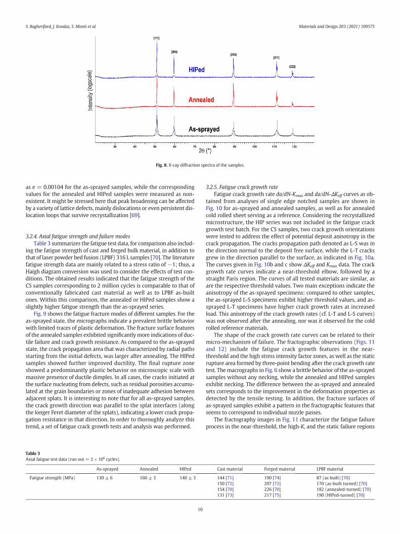
Fig. 8. X-ray diffraction spectra of the samples.
S. Bagherifard, J. Kondas, S. Monti et al. Materials and Design 203 (2021) 109575
as e = 0.00104 for the as-sprayed samples, while the correspondingvalues for the annealed and HIPed samples were measured as non-existent. It might be stressed here that peak broadening can be affectedby a variety of lattice defects, mainly dislocations or even persistent dis-location loops that survive recrystallization [69].
3.2.4. Axial fatigue strength and failure modesTable 3 summarizes the fatigue test data, for comparison also includ-
ing the fatigue strength of cast and forged bulk material, in addition tothat of laser powder bed fusion (LPBF) 316 L samples [70]. The literaturefatigue strength data are mainly related to a stress ratio of −1; thus, aHaigh diagram conversion was used to consider the effects of test con-ditions. The obtained results indicated that the fatigue strength of theCS samples corresponding to 2 million cycles is comparable to that ofconventionally fabricated cast material as well as to LPBF as-builtones. Within this comparison, the annealed or HIPed samples show aslightly higher fatigue strength than the as-sprayed series.
Fig. 9 shows the fatigue fracture modes of different samples. For theas-sprayed state, the micrographs indicate a prevalent brittle behaviorwith limited traces of plastic deformation. The fracture surface featuresof the annealed samples exhibited significantlymore indications of duc-tile failure and crack growth resistance. As compared to the as-sprayedstate, the crack propagation area that was characterized by radial pathsstarting from the initial defects, was larger after annealing. The HIPedsamples showed further improved ductility. The final rupture zoneshowed a predominantly plastic behavior on microscopic scale withmassive presence of ductile dimples. In all cases, the cracks initiated atthe surface nucleating from defects, such as residual porosities accumu-lated at the grain boundaries or zones of inadequate adhesion betweenadjacent splats. It is interesting to note that for all as-sprayed samples,the crack growth direction was parallel to the splat interfaces (alongthe longer Feret diameter of the splats), indicating a lower crack propa-gation resistance in that direction. In order to thoroughly analyze thistrend, a set of fatigue crack growth tests and analysis was performed.
Table 3Axial fatigue test data (run out = 2 × 10⁶ cycles).
As-sprayed Annealed HIPed
Fatigue strength (MPa) 130 ± 6 160 ± 3 140 ± 3
10
3.2.5. Fatigue crack growth rateFatigue crack growth rate da/dN-Kmax and da/dN-ΔKeff curves as ob-
tained from analyses of single edge notched samples are shown inFig. 10 for as-sprayed and annealed samples, as well as for annealedcold rolled sheet serving as a reference. Considering the recrystallizedmicrostructure, the HIP series was not included in the fatigue crackgrowth test batch. For the CS samples, two crack growth orientationswere tested to address the effect of potential deposit anisotropy in thecrack propagation. The cracks propagation path denoted as L-S was inthe direction normal to the deposit free surface, while the L-T cracksgrew in the direction parallel to the surface, as indicated in Fig. 10a.The curves given in Fig. 10b and c show ΔKeff and Kmax data. The crackgrowth rate curves indicate a near-threshold elbow, followed by astraight Paris region. The curves of all tested materials are similar, asare the respective threshold values. Two main exceptions indicate theanisotropy of the as-sprayed specimens: compared to other samples,the as-sprayed L-S specimens exhibit higher threshold values, and as-sprayed L-T specimens have higher crack growth rates at increasedload. This anisotropy of the crack growth rates (cf. L-T and L-S curves)was not observed after the annealing, nor was it observed for the coldrolled reference materials.
The shape of the crack growth rate curves can be related to theirmicro-mechanism of failure. The fractographic observations (Figs. 11and 12) include the fatigue crack growth features in the near-threshold and the high stress intensity factor zones, as well as the staticrupture area formed by three-point bending after the crack growth ratetest. Themacrographs in Fig. 6 show a brittle behavior of the as-sprayedsamples without any necking, while the annealed and HIPed samplesexhibit necking. The difference between the as-sprayed and annealedsets corresponds to the improvement in the deformation properties asdetected by the tensile testing. In addition, the fracture surfaces ofas-sprayed samples exhibit a pattern in the fractographic features thatseems to correspond to individual nozzle passes.
The fractography images in Fig. 11 characterize the fatigue failureprocess in the near-threshold, the high-K, and the static failure regions
Cast material Forged material LPBF material
144 [71]150 [72]154 [70]131 [73]
190 [74]207 [72]226 [70]217 [75]
87 (as built) [70]170 (as-built turned) [70]182 (annealed-turned) [70]190 (HIPed-turned) [70]
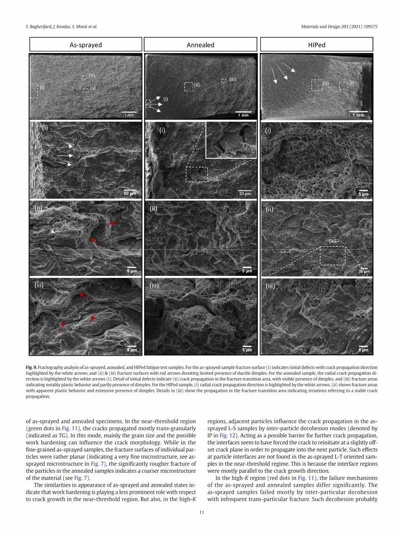
Fig. 9. Fractography analysis of as-sprayed, annealed, andHIPed fatigue test samples. For the as-sprayed sample fracture surface (i) indicates initial defectswith crack propagation directionhighlighted by the white arrows, and (ii) & (iii) fracture surfaces with red arrows denoting limited presence of ductile dimples. For the annealed sample, the radial crack propagation di-rection is highlighted by thewhite arrows (i). Detail of initial defects indicate (ii) crack propagation in the fracture transition area, with visible presence of dimples, and (iii) fracture areasindicating notably plastic behavior and partly presence of dimples. For theHIPed sample, (i) radial crack propagation direction is highlighted by thewhite arrows. (ii) shows fracture areaswith apparent plastic behavior and extensive presence of dimples. Details in (iii) show the propagation in the fracture transition area indicating striations referring to a stable crackpropagation.
S. Bagherifard, J. Kondas, S. Monti et al. Materials and Design 203 (2021) 109575
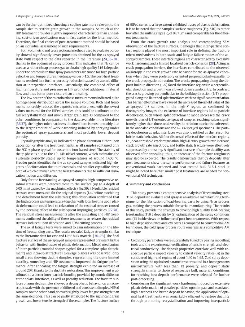
of as-sprayed and annealed specimens. In the near-threshold region(green dots in Fig. 11), the cracks propagated mostly trans-granularly(indicated as TG). In this mode, mainly the grain size and the possiblework hardening can influence the crack morphology. While in thefine-grained as-sprayed samples, the fracture surfaces of individual par-ticles were rather planar (indicating a very fine microstructure, see as-sprayed microstructure in Fig. 7), the significantly rougher fracture ofthe particles in the annealed samples indicates a coarser microstructureof the material (see Fig. 7).
The similarities in appearance of as-sprayed and annealed states in-dicate that work hardening is playing a less prominent role with respectto crack growth in the near-threshold region. But also, in the high-K
11
regions, adjacent particles influence the crack propagation in the as-sprayed L-S samples by inter-particle decohesion modes (denoted byIP in Fig. 12). Acting as a possible barrier for further crack propagation,the interfaces seem to have forced the crack to reinitiate at a slightly off-set crack plane in order to propagate into the next particle. Such effectsat particle interfaces are not found in the as-sprayed L-T oriented sam-ples in the near-threshold regime. This is because the interface regionswere mostly parallel to the crack growth direction.
In the high-K region (red dots in Fig. 11), the failure mechanismsof the as-sprayed and annealed samples differ significantly. Theas-sprayed samples failed mostly by inter-particular decohesionwith infrequent trans-particular fracture. Such decohesion probably
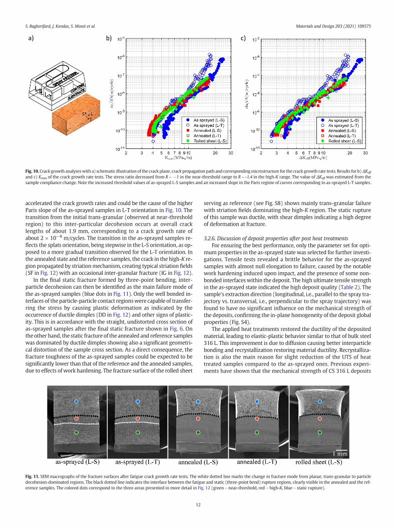
Fig. 10. Crack growth analyseswith a) schematic illustration of the crack plane, crack propagation path and correspondingmicrostructure for the crack growth rate tests. Results for b)ΔKeff
and c) Kmax of the crack growth rate tests. The stress ratio decreased from R ~ −1 in the near-threshold range to R ~ -1.4 in the high-K range. The value of ΔKeff was estimated from thesample compliance change. Note the increased threshold values of as-sprayed L-S samples and an increased slope in the Paris regime of curves corresponding to as-sprayed L-T samples.
S. Bagherifard, J. Kondas, S. Monti et al. Materials and Design 203 (2021) 109575
accelerated the crack growth rates and could be the cause of the higherParis slope of the as-sprayed samples in L-T orientation in Fig. 10. Thetransition from the initial trans-granular (observed at near-thresholdregion) to this inter-particular decohesion occurs at overall cracklengths of about 1.9 mm, corresponding to a crack growth rate ofabout 2 × 10⁻⁸ m/cycles. The transition in the as-sprayed samples re-flects the splats orientation, being stepwise in the L-S orientation, as op-posed to a more gradual transition observed for the L-T orientation. Inthe annealed state and the reference samples, the crack in the high-K re-gion propagated by striationmechanism, creating typical striation fields(SF in Fig. 12) with an occasional inter-granular fracture (IG in Fig. 12).
In the final static fracture formed by three-point bending, inter-particle decohesion can then be identified as the main failure mode ofthe as-sprayed samples (blue dots in Fig. 11). Only the well bonded in-terfaces of the particle-particle contact regionswere capable of transfer-ring the stress by causing plastic deformation as indicated by theoccurrence of ductile dimples (DD in Fig. 12) and other signs of plastic-ity. This is in accordance with the straight, undistorted cross section ofas-sprayed samples after the final static fracture shown in Fig. 6. Onthe other hand, the static fracture of the annealed and reference sampleswas dominated by ductile dimples showing also a significant geometri-cal distortion of the sample cross section. As a direct consequence, thefracture toughness of the as-sprayed samples could be expected to besignificantly lower than that of the reference and the annealed samples,due to effects of work hardening. The fracture surface of the rolled sheet
Fig. 11. SEM macrographs of the fracture surfaces after fatigue crack growth rate tests. The whdecohesion-dominated regions. The black dotted line indicates the interface between the fatiguerence samples. The colored dots correspond to the three areas presented in more detail in Fig
12
serving as reference (see Fig. S8) shows mainly trans-granular failurewith striation fields dominating the high-K region. The static ruptureof this sample was ductile, with shear dimples indicating a high degreeof deformation at fracture.
3.2.6. Discussion of deposit properties after post heat treatmentsFor ensuring the best performance, only the parameter set for opti-
mumproperties in the as-sprayed state was selected for further investi-gations. Tensile tests revealed a brittle behavior for the as-sprayedsamples with almost null elongation to failure, caused by the notablework hardening induced upon impact, and the presence of some non-bonded interfaceswithin the deposit. The high ultimate tensile strengthin the as-sprayed state indicated the high deposit quality (Table 2). Thesample's extraction direction (longitudinal, i.e., parallel to the spray tra-jectory vs. transversal, i.e., perpendicular to the spray trajectory) wasfound to have no significant influence on the mechanical strength ofthe deposits, confirming the in-plane homogeneity of the deposit globalproperties (Fig. S4).
The applied heat treatments restored the ductility of the depositedmaterial, leading to elastic-plastic behavior similar to that of bulk steel316 L. This improvement is due to diffusion causing better interparticlebonding and recrystallization restoringmaterial ductility. Recrystalliza-tion is also the main reason for slight reduction of the UTS of heattreated samples compared to the as-sprayed ones. Previous experi-ments have shown that the mechanical strength of CS 316 L deposits
ite dotted line marks the change in fracture mode from planar, trans-granular to particlee and static (three-point bend) rupture regions, clearly visible in the annealed and the ref-. 12 (green – near-threshold, red – high-K, blue – static rupture).

Fig. 12. SEMmicrographs of fracture surfaces of fatigue crack growth rate samples in the regions of near-threshold, high-K and static rupture (corresponding to colored dots from Fig. 11).The white arrows indicate the crack growth direction. Nomenclature: IP – inter-particle decohesion, TP – trans-particle fracture, TG – trans-granular fracture, IG – inter-granular fracture,SF – striation field, DD – ductile dimples.
S. Bagherifard, J. Kondas, S. Monti et al. Materials and Design 203 (2021) 109575
is more affected by the improved characteristics of inter-particle bond-ing than by the influence of reduced porosity [38]. The associated elon-gation to failure reaches 49% for annealed and 53% for HIPed samples.This rather ductile behavior is not only due to recrystallization, butalso due to the excessive grain growth induced by HIP treatment. It isnoted that the mechanical properties in all conditions here out-perform previously published data on steel 316 L CS deposits [37,38].The larger statistical scatter of the results for the as-sprayed seriesindicates that the heat treatments promote homogenization of the mi-crostructure and therefore ensuremore uniformmechanical properties.
Microstructural analysis of the as-sprayed samples showed highlydeformed splats. The extent of the plastic deformation was evaluatedby quantifying the flattening ratio. Within the resolution of OM/SEMmicrographs, apart from deformation, only minor microstructural rear-rangements were detected in as-sprayed samples. The microstructuresshow no obvious traces of thermal recrystallization. Only in the vicinity
13
of the particle-particle interfaces smaller grain sizes are obtained, obvi-ously due to dynamic recrystallization during the rapid deformation[69,76]. Thus, the global microstructural appearance of the as-sprayedsamples indicates that the spray process did not notably change theoriginal features of the powders. The interparticle boundaries and theresulting local porosities could be clearly distinguished in the as-sprayed samples' cross sections. In contrast, the annealed samples ap-pear rather homogenous, showing no deformation features and lessnon-bonded particle-particle interfaces. This is attributed to the atomicdiffusion causing recrystallization and to the high surfacemobility clos-ing the initiallyweakly bonded interfaces. The HIPed samples revealed astrongly homogeneous microstructure with fully recrystallized andreorganized crystalline grains. There were no traces of the originalsplats, and the full reorganization was confirmed by the formation of120° angles formed between adjacent grains to reach lower grainboundary energy configurations. We postulate that the HIP parameters
S. Bagherifard, J. Kondas, S. Monti et al. Materials and Design 203 (2021) 109575
can be further optimized choosing a cooling rate more relevant to thesample size to restrict grain growth in the samples. As much as theHIP treatment provides slightly improved characteristics than anneal-ing, cost-driven applications may in fact aspire for the latter method.Therefore, the final choice of post-treatment method should be basedon an individual assessment of such requirements.
Both volumetric and cross sectionalmethods used to evaluate poros-ity showed significantly lower porosities obtained for the as-sprayedstate with respect to the data reported in the literature [24,36–38],thanks to the optimized spray process. This indicates that N2 can beused as a rather cheap process gas to obtain high quality 316 L deposits,under the prerequisite that spray parameters are tuned for high particlevelocities and temperaturesmeeting η-values>1,5. The post-heat treat-ments resulted in a further porosity reduction caused by atomic diffu-sion at interparticle interfaces. Particularly, the combined effect ofhigh temperature and pressure in HIP promoted additional materialflow and thus better pore closure than annealing.
The low scatter of themicrohardness measurements indicated quitehomogeneous distribution across the sample volumes. Both heat treat-ments noticeably reduced the deposits' microhardness, with the lowestvalues measured for the HIPed samples; this could be attributed to thefull recrystallization and much larger grain size as compared to theother conditions. In comparison to the data available in the literature[36,37], the higher microhardness obtained here is most probably dueto the larger amount of work hardening induced by spraying underthe optimized spray parameters, and most probably lower depositporosity.
Crystallographic analysis indicated no phase alteration either upondeposition or after the heat treatments, as all samples contained onlythe FCC γ-phase typical for austenitic iron-based steel. The stability ofthe γ-phase is due to the 10–14% nickel content, which maintains theaustenite perfectly stable up to temperatures of around 1400 °C.Broader peaks identified for the as-sprayed samples indicated high de-grees of deformation due to microstrain and smaller crystallite sizes;both of which diminish after the heat treatments due to sufficient dislo-cation motion and diffusion.
Only for the freestanding as-sprayed samples, high compressive re-sidual stresses were detected close to the surface (up to a depth of0.05mm) caused by themachining effects (Fig. S9a). Negligible residualstresses were measured for the original deposits (i.e., before machiningand detachment from the substrate); this observation confirmed thatthe high process gas temperature togetherwith local heating upon plas-tic deformation could lead to relaxation of the residual stresses causedby the peening effect of the subsequent impinging particles [77,78].The residual stress measurements after the annealing and HIP treat-ments confirmed the ability of these treatments to release the residualstresses induced upon deposition and EDM cutting process.
The axial fatigue tests were aimed to gain information on the life-time of freestanding parts. The results revealed fatigue strengths similarto the literature data for cast and LPBF bulk material [70–73]. The finalfracture surface of the as-sprayed samples represented prevalent brittlebehavior with limited traces of plastic deformation. Mixed mechanismof inter-particle (rounded shapes typical for a complete splat detach-ment) and intra-splat fracture (cleavage planes) was observed; onlysmall areas showing ductile dimples, representing the quite limitedductility. Annealing and HIP treatments improved the fatigue perfor-mance. After annealing, the fatigue strength exhibited an increase ofaround 20%, thanks to the ductility restoration. This improvement is at-tributed to a better inter-particle bonding provided by atomic diffusionat the splats' interfaces, as well as porosity reduction. The fracture sur-faces of annealed samples showed a strong plastic behavior on a micro-scopic scalewith the presence of diffused and consistent dimples. HIPedsamples, on the other hand, showed slightly lower fatigue strength thanthe annealed ones. This can be partly attributed to the significant graingrowth and lower tensile strength of these samples. The fracture surface
14
of HIPed series to a large extent exhibited traces of plastic deformation.It is to be noted that the samples' surface roughness (Fig. S10) is ratherlow after themilling steps (Ra of 0.67 μm)and comparable for the differ-ent treatments.
From the crack growth rate analysis and corresponding SEMobservation of the fracture surfaces, it emerges that inter-particle con-tact regions played the most important role in defining the fracturemicro-mechanisms in both static and fatigue failure modes of the as-sprayed samples. These interface regions are characterized by excessivework hardening and a limited localized particle cohesion [28]. Acting ascrack propagation barriers, the interfaces contributed to the observedanisotropy in the crack growth rate behavior for the as-sprayed condi-tion when they were preferably oriented perpendicularly/parallel tothe crack propagation direction. The cracks propagating along the de-posit buildup direction (L-S) faced the interface regions in a perpendic-ular direction and growth was slowed down significantly. In contrast,the cracks growing perpendicular to the buildup direction (L-T) propa-gated along theflattened splat interfaceswithno significant retardation.This barrier effect may have caused the increased threshold value of theas-sprayed L-S samples. In the high-K region, as confirmed byfractography images, the existence of interface regions led to particledecohesion. Such whole splat detachment mode increased the crackgrowth rates of L-T oriented as-sprayed samples, reaching values signif-icantly higher than those achieved by the striationmechanism observedin the annealed conditions and the L-S as-sprayed specimens. The parti-cle decohesion at splat interfaces was also identified as the reason forbrittle static behavior. All four discussed effects of the interface regions,i.e., near-threshold crack retardation, high-K crack growth rate increase,crack growth rate anisotropy, and brittle static fracture were effectivelysuppressed by annealing. A significant increase of sample ductility wasobserved after annealing; thus, an increase of the fracture toughnessmay also be expected. The results demonstrate that CS deposits afterpost treatments show the same performance and failure features asconventional work hardened and heat treated bulk 316 L steel. Itmight be noted here that similar post treatments are needed for con-ventional AM techniques.
4. Summary and conclusions
This study presents a comprehensive analysis of freestanding steel316 L deposits to evaluate cold spray as an additivemanufacturing tech-nique for the fabrication of load-bearing parts by using N2 as processgas, making the process suitable for serial manufacturing. The resultsof this study provide the strategy to develop high quality load-bearingfreestanding 316 L deposits by (i) optimization of the spray conditionsand (ii) inside views on influence of post heat treatments. With respectto high deposition rates and low costs as compared to conventional AMtechniques, the cold spray process route emerges as a competitive AMtechnique.
- Cold spray parameters were successfully tuned by pairingmodellingtools and the experimental verification of tensile strength and elec-trical conductivity. The deposit properties correlate well with re-spective particle impact velocity to critical velocity ratios (η) in theconsidered high-end regime of about 1.40 to 1.65. Cold spray depo-sition using the optimized parameter set resulted in a homogeneousmicrostructure with less than 1% porosity, and deposit staticstrengths similar to those of respective bulk material. Conditionsfor reaching best deposit performance were selected for furtherpost-processing.
- Considering the significant work hardening induced by extensiveplastic deformation of powder particles upon impact and associatedhigh hardness and brittle deposit behavior, the application of opti-mal heat treatments was remarkably efficient to restore ductilitythrough promoting recrystallization and improving interparticle
S. Bagherifard, J. Kondas, S. Monti et al. Materials and Design 203 (2021) 109575
bonding. Moreover, heat treatments reduced the remaining poros-ity, improved microstructure homogeneity and released residualstresses.
- Fatigue test data indicated outstanding room temperature axial fa-tigue strength corresponding to two million cycles for cold sprayedsamples in the as-sprayed and heat treated configurations, thatwas found to be comparable to that of cast bulk material.
- Both heat treatments enhanced fatigue performance; the slightlylower fatigue data obtained after HIP could be addressed to thelow cooling rate of the process resulting in excessive recrystalliza-tion and grain growth. Based on the results, standard annealing ap-pears as a more suitable and more economical post treatment.
- The as-sprayed samples exhibited anisotropic crack growth behav-ior and deviated from the baseline defined by a reference cold-rolled sheet. This deviation can be attributed to planar defects atinter-particle contact areas and was efficiently removed by anneal-ing. The annealed samples showed isotropic crack growth behaviorwith rates identical to that of the reference cold rolled sheet samples.
The obtained results highlight the notable mechanical strength,under static and cyclic loading, of freestanding cold sprayed 316 L de-posits to be used as load-bearing components. The results enlightenthe high potential of cold spray additivemanufacturing as a competitivetechnique to overcome someof the shortcomings of the commonly usedadditive manufacturing routes comprising high working temperature,product size limitations and low deposition rates.
Data availability statement
The raw/processed data required to reproduce these findings can beshared upon request.
Declaration of Competing Interest
The authors declare that they have no known competing financialinterests or personal relationships that could have appeared to influ-ence the work reported in this paper.
Acknowledgements
Valuable support and input of Ing. Kai-Uwe Volker (HIP PM Volker)regarding HIP treatment is gratefully appreciated. The authors alsothankMarion Kollmeier formHSU for performing the conductivity tests.The crack growth rate testing was supported by ERDF project Centre ofAdvanced Applied Sciences (No. CZ.02.1.01/0.0/0.0/16_019/0000778).
Appendix A. Supplementary data
Supplementary data to this article can be found online at https://doi.org/10.1016/j.matdes.2021.109575.
References
[1] V. Champagne, D. Helfritch, The unique abilities of cold spray deposition, Int. Mater.Rev. 61 (2016) 437–455.
[2] R.N. Raoelison, Y. Xie, T. Sapanathan,M.P. Planche, R. Kromer, S. Costil, et al., Cold gasdynamic spray technology: a comprehensive review of processing conditions forvarious technological developments till to date, Additive Manufacturing. 19(2018) 134–159.
[3] R. Ghelichi, M. Guagliano, Coating by the cold spray process: a state of the art,Frattura ed Integrità Strutturale. 3 (2009) 30–44.
[4] H. Assadi, H. Kreye, F. Gärtner, T. Klassen, Cold spraying – a materials perspective,Acta Mater. 116 (2016) 382–407.
[5] D. Gilmore, R. Dykhuizen, R. Neiser, M. Smith, T. Roemer, Particle velocity and depo-sition efficiency in the cold spray process, J. Therm. Spray Technol. 8 (1999)576–582.
[6] H. Assadi, F. Gärtner, T. Stoltenhoff, H. Kreye, Bonding mechanism in cold gasspraying, Acta Mater. 51 (2003) 4379–4394.
15
[7] A. Sova, S. Grigoriev, A. Okunkova, I. Smurov, Potential of cold gas dynamic spray asadditive manufacturing technology, Int. J. Adv. Manuf. Technol. 69 (2013)2269–2278.
[8] F. Gaertner, T. Schmidt, H. Kreye, Present status and future prospects of coldspraying, Materials science forum: Trans Tech Publ (2007) 433–436.
[9] W. Li, K. Yang, S. Yin, X. Yang, Y. Xu, R. Lupoi, Solid-state additive manufacturing andrepairing by cold spraying: a review, Journal of Materials Science & Technology. 34(2018) 440–457.
[10] S. Bagherifard, A.H. Astaraee, M. Locati, A. Nawaz, S. Monti, J. Kondas, et al., Designand analysis of additive manufactured bimodal structures obtained by cold spraydeposition, Additive Manufacturing. 101131 (2020).
[11] S. Bagherifard, S. Monti, M.V. Zuccoli, M. Riccio, J. Kondás, M. Guagliano, Cold spraydeposition for additive manufacturing of freeform structural components comparedto selective laser melting, Mater. Sci. Eng. A 721 (2018) 339–350.
[12] Z. Arabgol, M.V. Vidaller, H. Assadi, F. Gärtner, T. Klassen, Influence of thermal prop-erties and temperature of substrate on the quality of cold-sprayed deposits, ActaMater. 127 (2017) 287–301.
[13] Y.-Y. Wang, Y. Liu, G.-J. Yang, J.-J. Feng, K. Kusumoto, Effect of microstructure on theelectrical properties of nano-structured TiN coatings deposited by vacuum coldspray, J. Therm. Spray Technol. 19 (2010) 1231–1237.
[14] L. Rickenbacher, A. Spierings, K. Wegener, An integrated cost-model for selectivelaser melting (SLM), Rapid Prototyp. J. 19 (3) (2013) 208–214.
[15] H. Piili, A. Happonen, T. Väistö, V. Venkataramanan, J. Partanen, A. Salminen, Cost es-timation of laser additive manufacturing of stainless steel, Phys. Procedia 78 (2015)388–396.
[16] K. Spencer, M.-X. Zhang, Optimisation of stainless steel cold spray coatings usingmixed particle size distributions, Surf. Coat. Technol. 205 (2011) 5135–5140.
[17] L. Brewer, J. Schiel, E. Menon, D. Woo, The connections between powder variabilityand coating microstructures for cold spray deposition of austenitic stainless steel,Surf. Coat. Technol. 334 (2018) 50–60.
[18] K. Spencer, D. Fabijanic, M.-X. Zhang, The influence of Al2O3 reinforcement on theproperties of stainless steel cold spray coatings, Surf. Coat. Technol. 206 (2012)3275–3282.
[19] A.-M. Bandar, R. Mongrain, E. Irissou, S. Yue, Improving the strength and corrosionresistance of 316L stainless steel for biomedical applications using cold spray, Surf.Coat. Technol. 216 (2013) 297–307.
[20] Y. Xie, M.-P. Planche, R. Raoelison, H. Liao, X. Suo, P. Hervé, Effect of substratepreheating on adhesive strength of SS 316L cold spray coatings, J. Therm. SprayTechnol. 25 (2016) 123–130.
[21] J. Huang, W. Ma, Y. Xie, H. Fukanum, K. Zhang, G. Wang, et al., Influence of cold gasspray processing conditions on the properties of 316L stainless steel coatings, Surf.Eng. 35 (2019) 784–791.
[22] H. Fukanuma, N. Ohno, B. Sun, R. Huang, In-flight particle velocity measurementswith DPV-2000 in cold spray, Surf. Coat. Technol. 201 (2006) 1935–1941.
[23] M. Villa, S. Dosta, J.M. Guilemany, Optimization of 316L stainless steel coatings onlight alloys using cold gas spray, Surf. Coat. Technol. 235 (2013) 220–225.
[24] R. Cortés, M. Garrido, A. Rico, C. Múnez, P. Poza, A. Martos, et al., Effect of processingconditions on the mechanical performance of stainless steel cold sprayed coatings,Surf. Coat. Technol. 125874 (2020).
[25] B. Dikici, H. Yilmazer, I. Ozdemir, M. Isik, The effect of post-heat treatment on micro-structure of 316L cold-sprayed coatings and their corrosion performance, J. Therm.Spray Technol. 25 (2016) 704–714.
[26] A. Sova, S. Grigoriev, A. Okunkova, I. Smurov, Cold spray deposition of 316L stainlesssteel coatings on aluminium surface with following laser post-treatment, Surf. Coat.Technol. 235 (2013) 283–289.
[27] T. Schmidt, F. Gärtner, H. Assadi, H. Kreye, Development of a generalized parameterwindow for cold spray deposition, Acta Mater. 54 (2006) 729–742.
[28] T. Schmidt, H. Assadi, F. Gärtner, H. Richter, T. Stoltenhoff, H. Kreye, et al., From par-ticle acceleration to impact and bonding in cold spraying, J. Therm. Spray Technol.18 (2009) 794.
[29] H. Assadi, T. Schmidt, H. Richter, J.O. Kliemann, K. Binder, F. Gärtner, et al., On pa-rameter selection in cold spraying, J. Therm. Spray Technol. 20 (2011) 1161–1176.
[30] http://kinetic-spray-solutions.com/ (2018).[31] H. Assadi, I. Irkhin, H. Gutzmann, F. Gärtner, M. Schulze, M. Villa Vidaller, et al., De-
termination of plastic constitutive properties of microparticles through single parti-cle compression, Adv. Powder Technol. 26 (2015) 1544–1554.
[32] H. Assadi, F. Gärtner, Particle compression test: a key step towards tailoring of feed-stock powder for cold spraying, Coatings. 10 (2020) 458.
[33] T. Stoltenhoff, C. Borchers, F. Gärtner, H. Kreye, Microstructures and key propertiesof cold-sprayed and thermally sprayed copper coatings, Surf. Coat. Technol. 200(2006) 4947–4960.
[34] F. Gärtner, T. Stoltenhoff, J. Voyer, H. Kreye, S. Riekehr, M. Kocak, Mechanical prop-erties of cold-sprayed and thermally sprayed copper coatings, Surf. Coat. Technol.200 (2006) 6770–6782.
[35] B. Dikici, M. Topuz, Production of annealed cold-sprayed 316L stainless steel coat-ings for biomedical applications and their in-vitro corrosion response, Protectionof Metals and Physical Chemistry of Surfaces. 54 (2018) 333–339.
[36] G. Sundararajan, P.S. Phani, A. Jyothirmayi, R.C. Gundakaram, The influence of heattreatment on the microstructural, mechanical and corrosion behaviour of coldsprayed SS 316L coatings, J. Mater. Sci. 44 (2009) 2320–2326.
[37] A.-M. Bandar, P. Vo, R. Mongrain, E. Irissou, S. Yue, Effect of heat treatment on themicrostructure and mechanical properties of stainless steel 316L coatings producedby cold spray for biomedical applications, J. Therm. Spray Technol. 23 (2014)641–652.
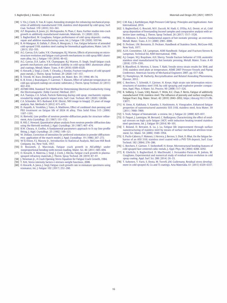
S. Bagherifard, J. Kondas, S. Monti et al. Materials and Design 203 (2021) 109575
[38] S. Yin, J. Cizek, X. Yan, R. Lupoi, Annealing strategies for enhancing mechanical prop-erties of additively manufactured 316L stainless steel deposited by cold spray, Surf.Coat. Technol. 370 (2019) 353–361.
[39] A.P. Iliopoulos, R. Jones, J.G. Michopoulos, N. Phan, C. Rans, Further studies into crackgrowth in additively manufactured materials, Materials. 13 (2020) 2223.
[40] S. Bagherifard, M. Guagliano, Fatigue performance of cold spray deposits: coating,repair and additive manufacturing cases, Int. J. Fatigue 139 (2020) 105744.
[41] B. Al-Mangour, R. Dallala, F. Zhim, R. Mongrain, S. Yue, Fatigue behavior of annealedcold-sprayed 316L stainless steel coating for biomedical applications, Mater. Lett. 91(2013) 352–355.
[42] A.G. Gavras, D.A. Lados, V.K. Champagne, R.J. Warren, Effects of processing onmicro-structure evolution and fatigue crack growthmechanisms in cold-spray 6061 alumi-num alloy, Int. J. Fatigue 110 (2018) 49–62.
[43] A.G. Gavras, D.A. Lados, V.K. Champagne, R.J. Warren, D. Singh, Small fatigue crackgrowth mechanisms and interfacial stability in cold-spray 6061 aluminum alloysand coatings, Metall. Mater. Trans. A 49 (2018) 6509–6520.
[44] O. Kovarik, J. Siegl, J. Cizek, T. Chraska, J. Kondas, Fracture toughness of cold sprayedpure metals, J. Therm. Spray Technol. 29 (2020) 147–157.
[45] R. Trivedi, W. Kurz, Dendritic growth, Int. Mater. Rev. 39 (1994) 49–74.[46] K.-R. Ernst, J. Braeutigam, F. Gaertner, T. Klassen, Effect of substrate temperature on
cold-gas-sprayed coatings on ceramic substrates, J. Therm. Spray Technol. 22 (2013)422–432.
[47] ASTME1004, Standard Test Method for Determining Electrical Conductivity Usingthe Electromagnetic (Eddy Current) Method, 2017.
[48] A.A. Tiamiyu, C.A. Schuh, Particle flattening during cold spray: mechanistic regimesrevealed by single particle impact tests, Surf. Coat. Technol. 403 (2020) 126386.
[49] C.A. Schneider, W.S. Rasband, K.W. Eliceiri, NIH image to ImageJ: 25 years of imageanalysis, Nat. Methods 9 (2012) 671–675.
[50] D. Asquith, A. Yerokhin, J. Yates, A. Matthews, Effect of combined shot-peening andPEO treatment on fatigue life of 2024 Al alloy, Thin Solid Films 515 (2006)1187–1191.
[51] H. Rietveld, Line profiles of neutron powder-diffraction peaks for structure refine-ment, Acta Crystallogr. 22 (1967) 151–152.
[52] R. Hill, C. Howard, Quantitative phase analysis from neutron powder diffraction datausing the Rietveld method, J. Appl. Crystallogr. 20 (1987) 467–474.
[53] R.W. Cheary, A. Coelho, A fundamental parameters approach to X-ray line-profilefitting, J. Appl. Crystallogr. 25 (1992) 109–121.
[54] W. Dollase, Correction of intensities for preferred orientation in powder diffractom-etry: application of the march model, J. Appl. Crystallogr. 19 (1986) 267–272.
[55] W-fj Dixon, F.J. Massey Jr., Introduction to Statistical Analysis, McCraw-Hill BookCompany. Inc, New York, 1957.
[56] D. Rozumek, Z. Marciniak, Fatigue crack growth in AlCu4Mg1 undernonproportional bending-with-torsion loading, Mater. Sci. 46 (2011) 685–694.
[57] O. Kovarik, A. Materna, J. Siegl, J. Cizek, J. Klecka, Fatigue crack growth in plasma-sprayed refractory materials, J. Therm. Spray Technol. 28 (2019) 87–97.
[58] J. Newman Jr., A Crack Opening Stress Equation for Fatigue Crack Growth, 1984.[59] T. Fett, Stress intensity factors-t-stresses-weight functions, 2008.[60] O. Kovarik, A. Janca, J. Siegl, Fatigue crack growth rate in miniature specimens using
resonance, Int. J. Fatigue 102 (2017) 252–260.
16
[61] C.M. Kay, J. Karthikeyan, High Pressure Cold Spray: Principles and Applications: AsmInternational, 2016.
[62] S. Bagherifard, G. Roscioli, M.V. Zuccoli, M. Hadi, G. D’Elia, A.G. Demir, et al., Coldspray deposition of freestanding Inconel samples and comparative analysis with se-lective laser melting, J. Therm. Spray Technol. 26 (2017) 1517–1526.
[63] H. Atkinson, S. Davies, Fundamental aspects of hot isostatic pressing: an overview,Metall. Mater. Trans. A 31 (2000) 2981–3000.
[64] D. Peckner, I.M. Bernstein, D. Peckner, Handbook of Stainless Steels, McGraw-Hill,New York, 1977.
[65] A.I.H. Committee, S.R. Lampman, ASM Handbook: Fatigue and Fracture/Steven R.Lampman, Technical Ed, ASM International, 1996.
[66] A.J. Cooper, W.J. Brayshaw, A.H. Sherry, Tensile fracture behavior of 316L austeniticstainless steel manufactured by hot Isostatic pressing, Metall. Mater. Trans. A 49(2018) 1579–1591.
[67] R. Blandford, D. Morton, S. Snow, T. Rahl, Tensile stress-strain results for 304L and316L stainless steel plate at temperature, ASME 2007 Pressure Vessels and PipingConference, American Society of Mechanical Engineers 2007, pp. 617–628.
[68] F.J. Humphreys, M. Hatherly, Recrystallization and Related Annealing Phenomena,Elsevier, 2012.
[69] C. Borchers, T. Schmidt, F. Gärtner, H. Kreye, High strain rate deformation micro-structures of stainless steel 316L by cold spraying and explosive powder compac-tion, Appl. Phys. A Mater. Sci. Process. 90 (2008) 517–526.
[70] K. Solberg, S. Guan, S.M.J. Razavi, T. Welo, K.C. Chan, F. Berto, Fatigue of additivelymanufactured 316L stainless steel: The influence of porosity and surface roughness,Fatigue Fract. Eng. Mater. Struct. 42 (2019) 2043–2052, https://doi.org/10.1111/ffe.13077.
[71] H. Ueno, K. Kakihata, Y. Kaneko, S. Hashimoto, A. Vinogradov, Enhanced fatigueproperties of nanostructured austenitic SUS 316L stainless steel, Acta Mater. 59(2011) 7060–7069.
[72] S. Teoh, Fatigue of biomaterials: a review, Int. J. Fatigue 22 (2000) 825–837.[73] D. Paquet, J. Lanteigne, M. Bernard, C. Baillargeon, Characterizing the effect of resid-
ual stresses on high cycle fatigue (HCF) with induction heating treated stainlesssteel specimens, Int. J. Fatigue 59 (2014) 90–101.
[74] T. Roland, D. Retraint, K. Lu, J. Lu, Fatigue life improvement through surfacenanostructuring of stainless steel by means of surface mechanical attrition treat-ment, Scr. Mater. 54 (2006) 1949–1954.
[75] E. Puchi-Cabrera, F. Matınez, I. Herrera, J. Berrıos, S. Dixit, D. Bhat, On the fatigue be-havior of an AISI 316L stainless steel coated with a PVD TiN deposit, Surf. Coat.Technol. 182 (2004) 276–286.
[76] C. Borchers, F. Gärtner, T. Stoltenhoff, H. Kreye, Microstructural bonding features ofcold sprayed face centered cubic metals, J. Appl. Phys. 96 (2004) 4288–4292.
[77] R. Ghelichi, S. Bagherifard, D. MacDonald, I. Fernandez-Pariente, B. Jodoin, M.Guagliano, Experimental and numerical study of residual stress evolution in coldspray coating, Appl. Surf. Sci. 288 (2014) 26–33.
[78] T. Suhonen, T. Varis, S. Dosta, M. Torrell, J.M. Guilemany, Residual stress develop-ment in cold sprayed Al, Cu and Ti coatings. Acta Materialia. 61 (2013) 6329–6337.


