Embed Size (px)
Citation preview
System Design of Automated Test Equipment for Electrical
Control Units in Trucks
ANNA BLADH
Degree project inElectrical Measurement Technology
Advanced level, 30 ects creditsStockholm, Sweden 2014
XR-EE-MST 2014:004

System Design of Automated
Test Equipment for Electrical
Control Units in Trucks
Anna Bladh
Master Thesis Electrical Measurement Technology
KTH Electrical Engineering
October 19, 2014
I
Sammanfattning
Komplexiteten i dagens elektroniska system ställer höga krav på verifierings- och
valideringsmetoder. Testautomatisering underlättar och förbättrar regressionstestning
(upprepning av tidigare utförda testfall för att upptäcka och spåra nya buggar) med ökad
testtäckning och reducerade kostnader som följd.
I ett fordon sitter ett flertal styrenheter vars ansvarsområden varierar: styrning utav motor,
bromsar, växellåda osv. För att säkra att dessa enheter fungerar som de ska måste de testas
noggrant - dels under normala förhållanden men också då de utsätts för påfrestningar såsom
elektriska fel (kortslutning, avbrott osv.). En breakout box, BOB, är en typ av testutrustning
vars syfte är att inducera fel på kablaget till styrenheter. Den sköts vanligtvis manuellt. Syftet
med det här projektet är att ta fram en automatiserad breakout box, en ABOB.
En prototyp som kunde inducera ett antal olika fel på godtyckliga kablar kopplade till en
styrenhet togs fram. Felen var: kortslutning mot en variabel spänningskälla, simulering av en
felaktig signal samt avbrott på kabel. Systemet hade också en återkopplingsmekanism som
informerade användaren om huruvida ett testfall hade exekverats på korrekt sätt eller ej. Ett
flertal generationer av hård- och mjukvarulösningar utvecklades, där den slutgiltiga produkten
hade hårdvarustöd för upp till sex inkopplade ECU-portar och möjlighet att via en
datorbaserad applikation samt ett nät av kommunicerande mikroprocessorer distribuera
styrsignaler till upp till 256 ECU-portar.
Detta examensarbete behandlar framtagningen av mjukvara för systemet. Den intresserade
läsaren rekommenderas att även ta del av rapporten Hardware Synthesis of Automated
Electrical Fault Testing in Trucks av Martin Orre, för kompletterande information om
hårdvaran.
II
Abstract
The high level of complexity in today’s electronic systems increases the demands on an
advanced validation and verification process. Automated testing facilitates and improves
regression testing (rerun of previously executed test cases to uncover and track new bugs)
with increased coverage and reduced costs as a result.
A vehicle contains multiple control units, each responsible for a specific part: the engine,
brakes, gearbox etc. These intelligent systems must be tested thoroughly to ensure correct
behavior - both under normal circumstances and when the vehicle is exposed to unexpected
events such as electrical failure (short circuit, broken cables etc.). A breakout box, BOB, is a
piece of testing equipment that can be used to induce electrical faults on the wiring of the
control units. It is typically operated manually. The objective of this project is to develop an
automated version, an ABOB.
A prototype that could induce various faults on arbitrary cables of a control unit was
developed. The faults were: short circuit to a variable voltage source with connected or
disconnected load, replacement of real signals with simulated ones and open load. The
breakout box also performed internal measurements and supplied the user with feedback
information about whether or not the test case was successfully executed. Several generations
of the system were developed, where the final product had hardware support for up to six
connected ECU ports and the possibility to distribute control signals to 256 different ECU
ports via a computer based application and a set of communicating microprocessors.
This thesis project focuses on the software design of the ABOB. For further explanation of the
hardware, the reader is advised to consult the report Hardware Synthesis of Automated
Electrical Fault Testing in Trucks by Martin Orre.

III
Acknowledgements
I would like to express my great appreciation to the people who have made this thesis project
possible: Hans Sohlström at KTH and Peter Samuelsson, head of NEVE at Scania. Special
thanks to the supervisor Daniel Frykman at Scania, who has dedicated time and thought into
the project and contributed with many valuable tips and ideas, and not to forget - my co-
worker and good friend Martin Orre with whom I worked together on the project.
At last, I would like to thank my companion My for support and encouragement throughout
the work.
IV
NOMENCLATURE
Abbreviations
ABOB Automated breakout box
BOB Breakout Box
CAN Controller Area Network
DTC Diagnostic Trouble Code
DVM Digital Voltage Meter
ECU Electronic Control Unit
EMS Engine Management System
HIL Hardware-in-the-Loop
I2C Inter-Integrated Circuit
ISR Interrupt Service Routine
MCU Microcontroller unit
OBD On-board Diagnostics
PCB Printed Circuit Board
PWM Pulse Width Modulation
UART Universal Asynchronous Receiver/Transmitter
USB Universal Serial Bus
Table of contents
1 INTRODUCTION 1
1.1 Background 1
1.2 Purpose 1
1.3 Problem formulation 2
1.4 Delimitations 3
1.5 Method 3
2 FRAME OF REFERENCE 4
2.1 Automotive control systems 4
2.1.1 ECU 4
2.1.2 Diagnostics 6
2.1.3 ECU testing 6
2.1.4 Fault injection 7
2.1.5 HIL testing 7
2.1.6 Breakout box 8
2.1.7 Breakout box automation 9
2.2 Embedded software development 14
2.2.1 Interrupt-driven applications 14
2.2.2 Timers 15
2.2.3 Watchdog timer 16
2.2.4 UART communication 16
2.2.5 I2C communication 17
3 HARDWARE ARCHITECTURE 19
3.1 The fault inducing units 20
3.2 Fault inducing unit, type 1 20
3.3 Fault inducing unit, type 2 21
3.4 The system level 27
3.5 System I 27
3.5.1 Microcontroller 27
3.5.2 Shared data bus 28
3.5.3 External memory 28
3.5.4 Groups of fault units 30
3.5.5 Enable system 33
3.5.6 Measurements 34
3.5.7 Robustness 34
3.6 System II 34
3.6.1 Microcontroller 35
3.6.2 Master node 35
3.6.3 Slave node 36
3.6.4 Robustness 37
4 SOFTWARE IMPLEMENTATION 38
4.1 The computer based software 39
4.1.1 Programming environment 39
4.1.2 Classes and modules 40
4.2 System I 42
4.2.1 Interrupt service routine 43
4.2.2 Measurements 44
4.2.3 Communication 45
4.2.4 Fault induction 49
4.3 System II 51
4.3.1 Master node 51
4.3.2 Slave node 53
5 RESULTS 55
5.1 System I 55
5.2 System II 56
5.3 The computer interface 57
6 DISCUSSION 58
6.1 Future work 59
7 REFERENCES 60

1
1 INTRODUCTION
1.1 Background
Vehicles of today are far from only mechanical constructions. Advanced electrical systems
are used to monitor and control various parts - the engine, gearbox, brakes etc. As the
complexity of control systems in vehicles increases, the need for rigorous testing becomes
crucial for the validation of the design.
An ECU, (Electronic Control Unit), is a device which task is to control a part of the vehicle. It
monitors sensor values (oil pressure, temperature etc.) and manages actuators. It can transmit
messages to other intelligent systems over the CAN bus. Within Scania there are more than 20
different ECUs, specialized on engines, gearboxes etc. [1].
What would happen if a wire connected to the ECU becomes short circuited or breaks? If the
hardware and software in the ECU are functioning as intended, a dangerous situation should
not occur. To ensure proper behavior, testing is needed whenever a modification of the ECU
has been made. While methodologies such as software unit testing are powerful, they are not
sufficient to cover unexpected electrical faults. To simulate malfunctioning hardware, it is
necessary to induce the possible faults. One way of doing this is to use a breakout box, BOB.
It is a manually maneuvered device which can generate the desired errors by using switches,
potentiometers etc. However, conducting a manual test is a time consuming process,
potentially vulnerable to mistakes caused by the human factor. Could an automated process be
used to perform the tests? In this project the advantages and drawbacks of an automated
breakout box were investigated and a design of it was proposed. Finally, a prototype was
realized its performance evaluated.
Scania is a company that develops and manufactures trucks, buses and industrial and marine
engines. It was founded in 1900 in Malmö, Sweden, and eleven years later merged with the
railcar, car and truck manufacturer Vabis (founded 1891) with headquarters in Södertälje,
Sweden. It is owned by Volkswagen since 2014.
The thesis project is carried out at Scania, Södertälje at the department NE (Powertrain
Control System) within the division NEVE. This unit is responsible for testing of the gearbox
and development of PC-tools for diagnostics of electronic control systems in vehicles.
1.2 Purpose
The objective of the project is to develop a device that can facilitate the testing process of
electrical control units in vehicles. Test equipment that is reliable and that offers a high degree
of coverage is desirable not only for ensuring the well-functioning of the vehicle but also,
more importantly, for the safety of the driver and other road-users exposed to it.
2
By applying standardized test sequences each time an update of the control system has been
made (typically in software), the chances of catching unwanted bugs increases. With
automatized methods - computer controlled testing - the tests are guaranteed to be executed in
a structured manner. This diminishes the risk of missing a case and allows comparison
between identical tests that have been carried out on different ECU software and hardware
versions.
Automatized tests allow engineering resources to be put on developing test cases and/or
algorithms for auto-generation of tests rather than on manual management of tests.
1.3 Problem formulation
The objective of the thesis project is to design test equipment for the electrical control units in
a truck, a so called automatized breakout box, ABOB. It will be a computer controlled
hardware device which can induce a predefined set of electrical faults - simulating a real
situation when a wire is short circuited or broken or when a sensor gives a faulty value.
The requirements are set to guarantee an automated and robust system which can be used as a
complement to today’s testing techniques and to partially replace manual testing.
The device should be portable and possible to plug in between an electrical control
unit and the sensors/actuators/communication buses connected to it.
All pins on the ECU should be reachable and controllable simultaneously and
independently of each other.
The device should be compatible with all Scania’s ECUs.
The faults that should be possible to generate are: short circuit to a variable voltage
source (0-24 V), open load and simulation of a faulty analog sensor value.
The system must run autonomously without the need for human supervision, except
during startup. Only the vehicle ignition needs to be turned on. (No driver required,
the system can operate during night time.)
The system must do measurements (of currents/voltages) to ensure that the faults that
were supposed to be induced actually were.
The system should act as a number of passive wires when not in operation (no faults
induced), i.e. it should not affect the nominal environment of the ECU.
The system should be manageable from computer based test scripts.
The system should be modularized, which makes it easy to replace parts and to extend
the design.

3
1.4 Delimitations
The ABOB is a computer aided testing device which can be used as a supplement to manual
testing. It is automatized, but not intelligent - i.e. it executes faults specified in a manually
written test script. It is particularly well suited for long test runs (e.g. during night time) on a
vehicle that is not in motion. However, many other tests still require human interaction - an
example could be “bad choice of gear when ascending a hill”. For a realistic testing of this,
driving up a hill is obviously preferable!
There are numerous faults that can occur on the wiring connected to the ports of the ECU and
all of them are not covered in this thesis. Focus is put on on common errors such as a loose
cable (generating a short circuit or an open load) or a broken sensor. The concept is tested on
only one of Scania’s ECUs and its performance evaluated. However, the design is duplicable
(only a remapping of the ports and the changing of contacts should be necessary when
switching ECU).
The verification of the design is limited. If considering full coverage when all the faults that
can be induced are executed in all different combinations, the number of test cases will
exceed what is reasonable to achieve (~140 pins, several errors per pin). A smaller set of test
cases are used to evaluate the prototype.
1.5 Method
The design of the ABOB consists mainly of two parts: one is the construction of the hardware
that induces faults and the second is the software that controls the system. This report
describes the software architecture of the automated breakout box. The thesis Hardware
Synthesis of Automated Electrical Fault Testing in Trucks by Martin Orre describes the same
product but from a hardware point of view. Some chapters with information that is important
to understand the whole picture will be common for both reports (1. Introduction and 2.1
Automotive Control Systems are written together, with some minor differences between the
two reports).
The approach applied is to base the ABOB functionality on a pre-study, which contains a
practical part and a literature part. The practical part is to participate in a test drive with a
manual breakout box, operated by the driver of the truck. From this, the strengths and the
weaknesses of the manual testing concept can be identified and the desired functionality of
the ABOB will be stated. The literature part covers topics such as: previous models with focus
on automation and general descriptions of relevant systems needed for the understanding of
the problem (the ECU is one example).
When the model of the ABOB is ready the hardware design and the implementation of the
control system remains. Several different systems were developed during the project and will
be presented in chronological order in the thesis - starting from a simple system and ending
with the last design which also became the final product. As the software implementation
highly depends on the underlying hardware, one chapter of the report is dedicated to the
hardware level descriptions of the systems and a separate chapter to the software
implementation.
4
2 FRAME OF REFERENCE
2.1 Automotive control systems
From the early days of automotive industry until today’s vehicles, the on-board systems have
grown to be numerous and complex - from being strictly mechanical/electrical constructions
to containing intelligent control systems for many types of functionalities. A modern car has
at least 30 microprocessors, which are used for various purposes: to increase safety and
comfort, reduce emissions, to monitor and keep diagnostics of the state of the vehicle or to
supply the driver with entertainment and other luxuries to further improve the trip experience
[2-4]. The intelligence is embedded in electronic control units, ECUs, each one responsible
for a part of the vehicle (brakes, gearbox, engine, lights etc.). Although controlled by their
unique ECU, the parts cannot be considered as isolated but instead as integrated in a larger
system and in need for a network to communicate information between each other. The CAN
bus, Controller Area Network, is a communication link used for distributing information
between ECUs and devices connected to it, allowing for example the gearbox to receive
knowledge about activated brakes or an accelerating engine etc.
2.1.1 ECU
The number of ECUs in an automotive system and the functionality they provide differ
between vehicles. The EMS, Engine Management System, is a control unit that concerns the
engine. It controls fuel injection, ignition timing, emission levels, cooling fan etc. It directly
monitors airflow, engine temperature, oil pressure and throttle position through different
sensors [5, 6]. Brakes, airbags, cruise control, battery, automatic transmission, seats and doors
are other examples of components in a modern car that are monitored and controlled by ECUs
[5].
The ECU has a set of inputs given by sensor values and switches etc., through which it
monitors the current state of the vehicle. It produces output in form of signals to actuators,
switches and messages on the CAN bus. Typical outputs are [4, 5]:
Digital signals (switching a cooling fan on/off, open/close fuel injectors)
Supply voltage to analog sensors
PWM/analog voltages (variable duty cycle for fuel injection etc.)
Frequency (stepper motors etc.)
Typical inputs are [4, 5]:
Analog inputs (oil pressure, coolant temperature etc.)
Digital inputs (switches)
Frequency (camshaft/crankshaft position etc.)
5
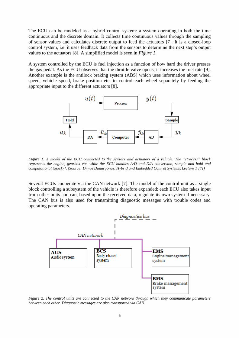
The ECU can be modeled as a hybrid control system: a system operating in both the time
continuous and the discrete domain. It collects time continuous values through the sampling
of sensor values and calculates discrete output to feed the actuators [7]. It is a closed-loop
control system, i.e. it uses feedback data from the sensors to determine the next step’s output
values to the actuators [8]. A simplified model is seen in Figure 1.
A system controlled by the ECU is fuel injection as a function of how hard the driver presses
the gas pedal. As the ECU observes that the throttle valve opens, it increases the fuel rate [9].
Another example is the antilock braking system (ABS) which uses information about wheel
speed, vehicle speed, brake position etc. to control each wheel separately by feeding the
appropriate input to the different actuators [8].
Figure 1. A model of the ECU connected to the sensors and actuators of a vehicle. The “Process” block
represents the engine, gearbox etc. while the ECU handles A/D and D/A conversion, sample and hold and
computational tasks[7]. (Source: Dimos Dimargonas, Hybrid and Embedded Control Systems, Lecture 1 [7])
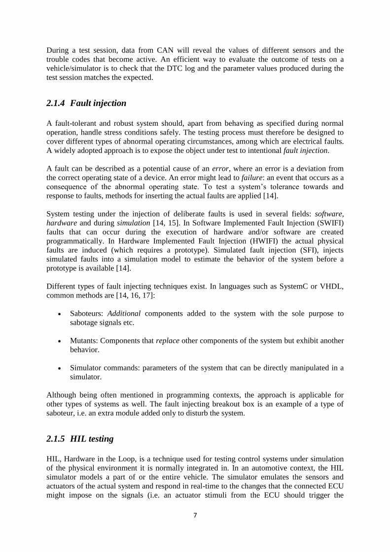
Several ECUs cooperate via the CAN network [7]. The model of the control unit as a single
block controlling a subsystem of the vehicle is therefore expanded: each ECU also takes input
from other units and can, based upon the received data, regulate its own system if necessary.
The CAN bus is also used for transmitting diagnostic messages with trouble codes and
operating parameters.
Figure 2. The control units are connected to the CAN network through which they communicate parameters
between each other. Diagnostic messages are also transported via CAN.

6
2.1.2 Diagnostics
When the oil level is too low or the ABS is not working properly, a light pops up on the
dashboard to inform the driver that something is wrong. Since the 1980’s a vehicle contains
an On-Board Diagnostic system, OBD, built out of a library of DTCs, Diagnostic Trouble
Codes. Whenever an error is detected by a control unit, the code is transmitted via the
communication network - with the possibility to not only convey the information to the
dashboard and other internal components of the vehicle, but also to an off-board diagnostic
tool (if activated/plugged in). This gives a technician the possibility to access diagnostics
reports and efficiently troubleshoot the system [4].
The diagnostic system was originally limited to displaying an error code once a failure had
already occurred, i.e. a sensor outputs a value that is out of range of what is acceptable or
similar. However, this implies that the damage might already be done. The first OBD system
was upgraded to be more extensive and complex: OBD-II. In the second version, the system is
continuously surveyed and the gradual degradation of components can be noticed before a
severe fault actually occurs [10]. The format of the DTCs in OBD-II follows the standard
SAE J2012[10-12] : a five character long code with separate fields for deciding the character
of the error. The fields are divided into: type of error (powertrain, communication network,
chassis, body), indication if the error code is generic or manufacturer specific, the system
from which the error origins (fuel and air metering, transmission etc.) and at last the
identification number of the specific fault [9, 10].
2.1.3 ECU testing
To ensure a safe and predictable behavior of the vehicle, it is necessary that the control units
are working properly - the hardware and software need to deliver the intended behavior. An
important part in the development of new functionality for the ECU is testing. Before the
release of new software, thorough testing must be conducted to confirm that requirements are
met, that previous functionality remains intact and that the new features do not jeopardize the
safety of the ride. The verification process includes pure software testing (such as unit
testing), tests in vehicles and/or simulators and stress tests. The latter means to expose the
ECU to harsh conditions - extreme temperatures, vibration, short circuits, communication
failure etc. [13]. The ECU passes the tests when both hardware and software behave as
supposed to and that no safety critical incidents happened during the process.
During a vehicle ride, the inputs and outputs of the ECU will vary with factors such as speed,
temperature, terrain, driving style, time in motion etc. The input values fed to the controller
will continuously change and the algorithms in charge of the feedback should hence update
output signals with suitable values for the actuators. If an unexpected error occurs, such as an
electrical fault (two wires of different polarity causing a short circuit, a wire breaking etc.),
the vehicle should respond in a controlled manner to avoid safety issues and permanent
damage to the hardware. To realistically be able to test the ECU behavior under both normal
and abnormal conditions, physical input and output that act like the real vehicle must be
provided. A simulator or the vehicle itself can be used for this purpose. To test the ECUs
response when exposed to electrical faults, test equipment that can induce the faults should be
used.
7
During a test session, data from CAN will reveal the values of different sensors and the
trouble codes that become active. An efficient way to evaluate the outcome of tests on a
vehicle/simulator is to check that the DTC log and the parameter values produced during the
test session matches the expected.
2.1.4 Fault injection
A fault-tolerant and robust system should, apart from behaving as specified during normal
operation, handle stress conditions safely. The testing process must therefore be designed to
cover different types of abnormal operating circumstances, among which are electrical faults.
A widely adopted approach is to expose the object under test to intentional fault injection.
A fault can be described as a potential cause of an error, where an error is a deviation from
the correct operating state of a device. An error might lead to failure: an event that occurs as a
consequence of the abnormal operating state. To test a system’s tolerance towards and
response to faults, methods for inserting the actual faults are applied [14].
System testing under the injection of deliberate faults is used in several fields: software,
hardware and during simulation [14, 15]. In Software Implemented Fault Injection (SWIFI)
faults that can occur during the execution of hardware and/or software are created
programmatically. In Hardware Implemented Fault Injection (HWIFI) the actual physical
faults are induced (which requires a prototype). Simulated fault injection (SFI), injects
simulated faults into a simulation model to estimate the behavior of the system before a
prototype is available [14].
Different types of fault injecting techniques exist. In languages such as SystemC or VHDL,
common methods are [14, 16, 17]:
Saboteurs: Additional components added to the system with the sole purpose to
sabotage signals etc.
Mutants: Components that replace other components of the system but exhibit another
behavior.
Simulator commands: parameters of the system that can be directly manipulated in a
simulator.
Although being often mentioned in programming contexts, the approach is applicable for
other types of systems as well. The fault injecting breakout box is an example of a type of
saboteur, i.e. an extra module added only to disturb the system.
2.1.5 HIL testing
HIL, Hardware in the Loop, is a technique used for testing control systems under simulation
of the physical environment it is normally integrated in. In an automotive context, the HIL
simulator models a part of or the entire vehicle. The simulator emulates the sensors and
actuators of the actual system and respond in real-time to the changes that the connected ECU
might impose on the signals (i.e. an actuator stimuli from the ECU should trigger the
8
simulator to update sensor values accordingly) [8, 18]. A well-made simulator closely imitates
reality and can be used to replace tests that otherwise would have to be performed on the
actual hardware. It can be used to, apart from simulating the hardware under normal
conditions, also simulate electrical failure or similar malfunction of the system [19].
HIL simulators are widely used in the automotive industry - almost all manufacturers apply
the test method. The automation of test cases and the simplicity of reproducing the same test
sequence repeatedly make the equipment a powerful tool for finding errors in the ECU design
[20].
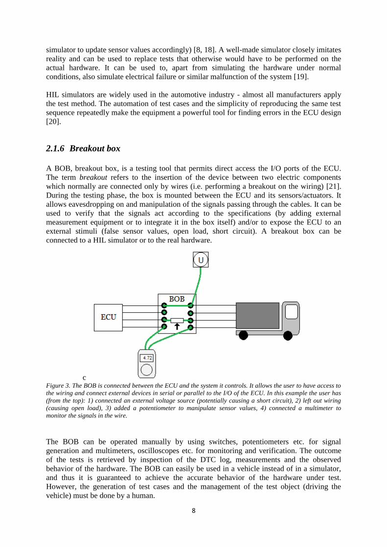
2.1.6 Breakout box
A BOB, breakout box, is a testing tool that permits direct access the I/O ports of the ECU.
The term breakout refers to the insertion of the device between two electric components
which normally are connected only by wires (i.e. performing a breakout on the wiring) [21].
During the testing phase, the box is mounted between the ECU and its sensors/actuators. It
allows eavesdropping on and manipulation of the signals passing through the cables. It can be
used to verify that the signals act according to the specifications (by adding external
measurement equipment or to integrate it in the box itself) and/or to expose the ECU to an
external stimuli (false sensor values, open load, short circuit). A breakout box can be
connected to a HIL simulator or to the real hardware.
c Figure 3. The BOB is connected between the ECU and the system it controls. It allows the user to have access to
the wiring and connect external devices in serial or parallel to the I/O of the ECU. In this example the user has
(from the top): 1) connected an external voltage source (potentially causing a short circuit), 2) left out wiring
(causing open load), 3) added a potentiometer to manipulate sensor values, 4) connected a multimeter to
monitor the signals in the wire.
The BOB can be operated manually by using switches, potentiometers etc. for signal
generation and multimeters, oscilloscopes etc. for monitoring and verification. The outcome
of the tests is retrieved by inspection of the DTC log, measurements and the observed
behavior of the hardware. The BOB can easily be used in a vehicle instead of in a simulator,
and thus it is guaranteed to achieve the accurate behavior of the hardware under test.
However, the generation of test cases and the management of the test object (driving the
vehicle) must be done by a human.
9
The breakout box can also be automated, i.e. controlled from a computer application. By
letting the test cases be script based, the BOB can operate autonomously and without human
supervision. This is typically useful when performing long test runs (e.g. night time) without
the need for the vehicle to be in motion. Some of the tests normally executed in a HIL
simulator could be replaced by an automated breakout box (electrical failure, faulty sensor
values). Compatibility with scripting frameworks used for HIL testing facilitates the use of
both techniques.
2.1.7 Breakout box automation
The automation of breakout boxes for automobile applications has previously been studied,
with a set of different designs as outcome. As earlier mentioned, the term breakout box refers
to a device which gives access to the signals of normally isolated/intact wires, but its usage is
more ambiguous. Automated, just like manual, BOBs can be used for different purposes:
often fault injection or voltage measurements. Some earlier designs of both types will be
presented in this chapter, where the first type is closely related to the core of the thesis’
problem formulation (how to induce faults), and the second type to the verification of the
system (how to verify that a fault was induced).
A fault injecting breakout box is a unit added to the system to sabotage the signals from/to the
ECU. There already exist studies on these types of BOBs. This thesis project is a continuation
of another breakout box automation project, also conducted at Scania. The previous prototype
was designed to induce electrical faults on the ECU wiring from a computer based Python
script. The faults that could be induced were: open load and short circuit to a variable voltage
source with connected or disconnected load (with the possibility to limit the short circuit
current by the use of a potentiometer).
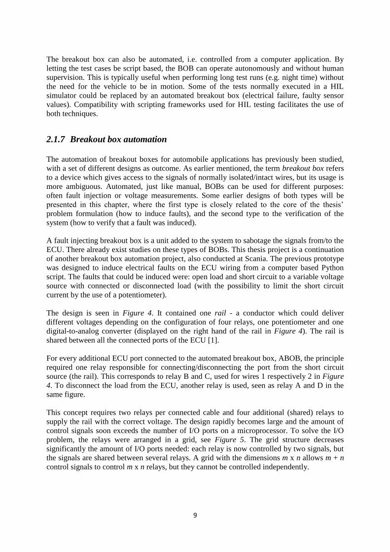
The design is seen in Figure 4. It contained one rail - a conductor which could deliver
different voltages depending on the configuration of four relays, one potentiometer and one
digital-to-analog converter (displayed on the right hand of the rail in Figure 4). The rail is
shared between all the connected ports of the ECU [1].
For every additional ECU port connected to the automated breakout box, ABOB, the principle
required one relay responsible for connecting/disconnecting the port from the short circuit
source (the rail). This corresponds to relay B and C, used for wires 1 respectively 2 in Figure
4. To disconnect the load from the ECU, another relay is used, seen as relay A and D in the
same figure.
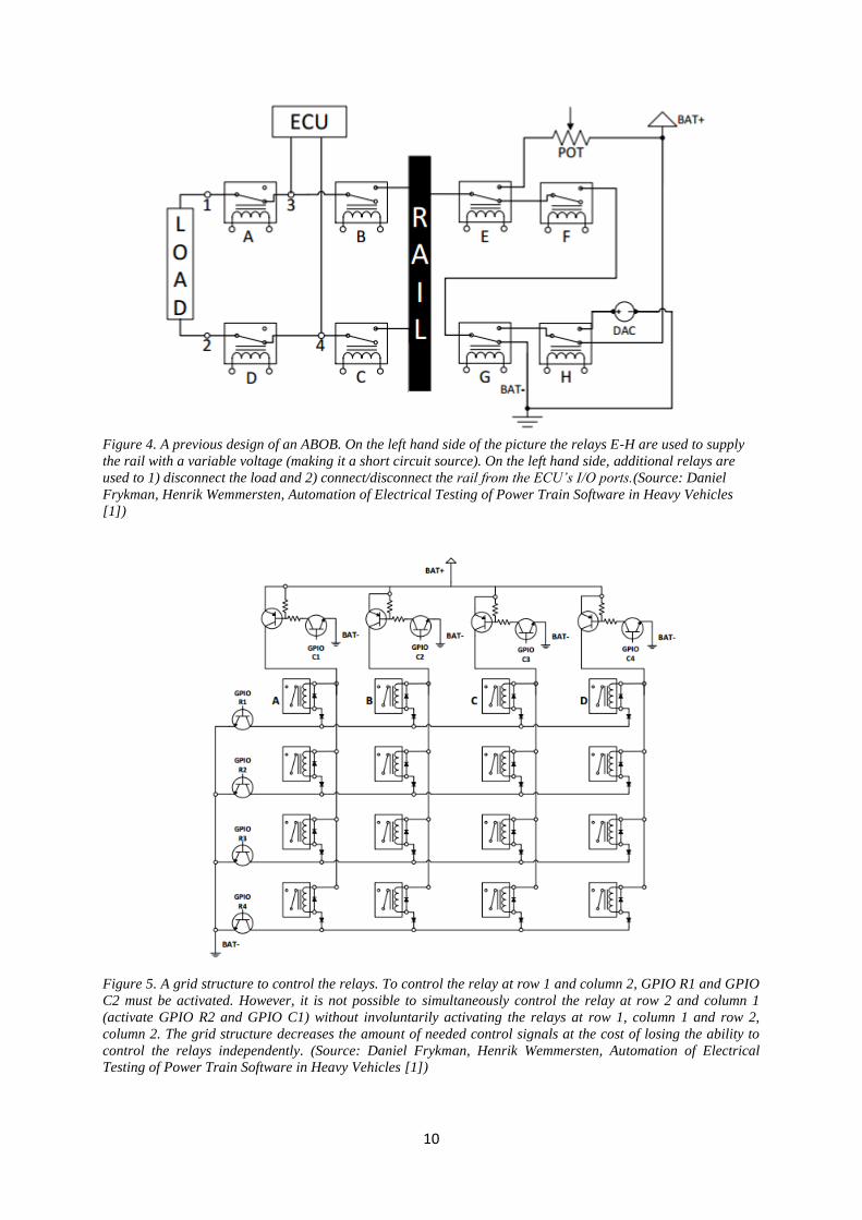
This concept requires two relays per connected cable and four additional (shared) relays to
supply the rail with the correct voltage. The design rapidly becomes large and the amount of
control signals soon exceeds the number of I/O ports on a microprocessor. To solve the I/O
problem, the relays were arranged in a grid, see Figure 5. The grid structure decreases
significantly the amount of I/O ports needed: each relay is now controlled by two signals, but
the signals are shared between several relays. A grid with the dimensions m x n allows m + n
control signals to control m x n relays, but they cannot be controlled independently.
10
Figure 4. A previous design of an ABOB. On the left hand side of the picture the relays E-H are used to supply
the rail with a variable voltage (making it a short circuit source). On the left hand side, additional relays are
used to 1) disconnect the load and 2) connect/disconnect the rail from the ECU’s I/O ports.(Source: Daniel
Frykman, Henrik Wemmersten, Automation of Electrical Testing of Power Train Software in Heavy Vehicles
[1])
Figure 5. A grid structure to control the relays. To control the relay at row 1 and column 2, GPIO R1 and GPIO
C2 must be activated. However, it is not possible to simultaneously control the relay at row 2 and column 1
(activate GPIO R2 and GPIO C1) without involuntarily activating the relays at row 1, column 1 and row 2,
column 2. The grid structure decreases the amount of needed control signals at the cost of losing the ability to
control the relays independently. (Source: Daniel Frykman, Henrik Wemmersten, Automation of Electrical
Testing of Power Train Software in Heavy Vehicles [1])

11
From the first version of the ABOB some strengths and weaknesses were identified and later
used to form a basis for this thesis project. Clear strengths were the diversity of faults the
BOB could induce (covering well the requested behavior) and the robustness it offered (using
components for high power applications). A drawback of the clever mechanism used for
accessing many relays with few I/O ports of the microcontroller was the limitation it put on
the number of faults that could be induced simultaneously (one or possibly several, where the
latter requires that the corresponding relays are placed in the same row or column of the grid
structure). The same holds for the variable voltage source - since the rail is shared between all
relays, only one voltage can be supplied per test case. If something goes wrong during the
induction of a fault (due to a defective component, a communication error etc.) the user of the
system will not be informed. Two new requirements were added for the second version of the
ABOB, i.e. this thesis project: 1) the connected ECU cables should be controllable
independently; 2) a verification system to confirm that faults are actually executed should be
implemented. The functionality of the BOB should however remain similar.
Another type of breakout box is one that allows eavesdropping on signals in order to provide
diagnostics information to for example a technician. A manual BOB would require equipment
such as multimeters and oscilloscopes, while the ABOB could do the measurements
automatically and either return the raw data to the operator or perform the analysis itself and
return a report. Several ABOBs with the purpose of facilitating the process of troubleshooting
vehicles have been patented. Two examples are the patents US 5177447 A (1993) [22] and
US 5214582 A (1993) [23] which both touch the same idea: to allow a script to execute test
cases on selected points in the wiring.
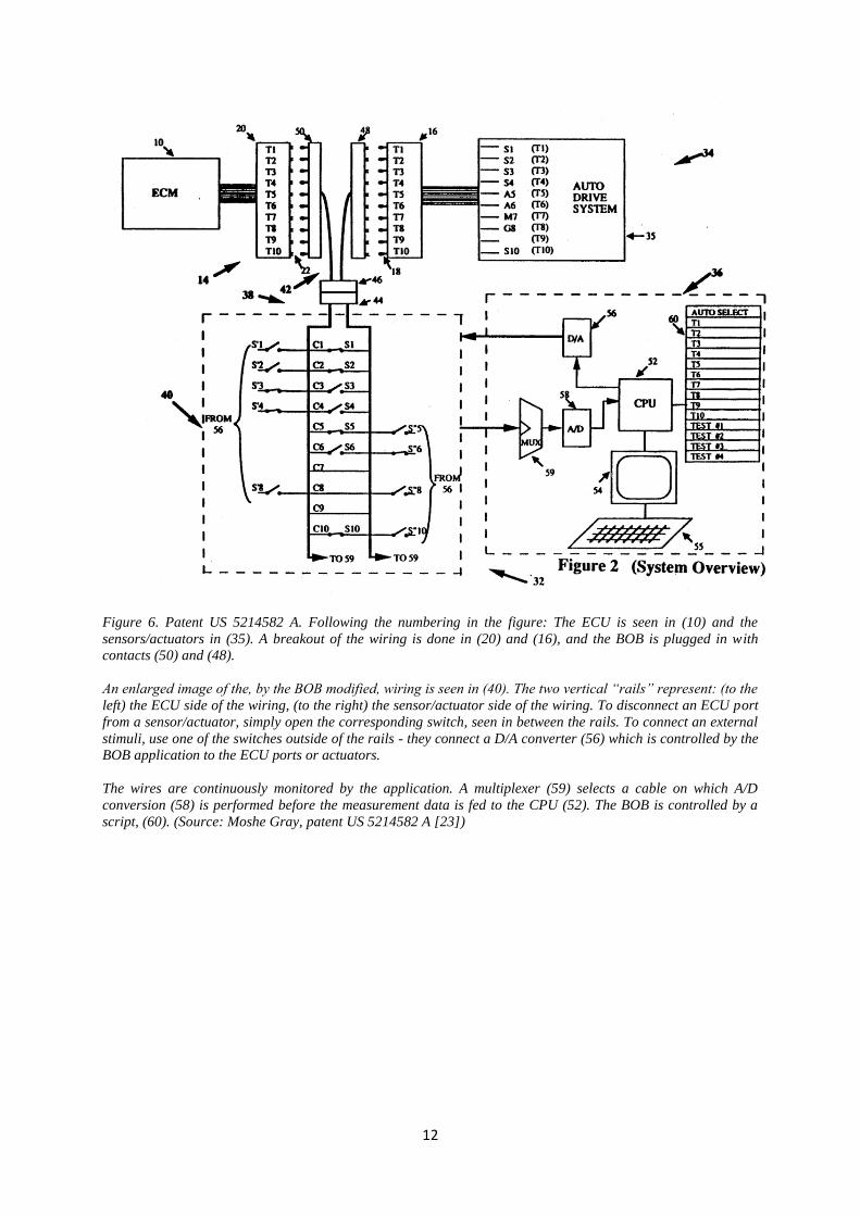
The breakout box in patent US 5214582 A is described as an active BOB. It consists primarily
of two parts: surveillance of the signals passing through the wiring and a system for actively
controlling the network of sensors/actuators of the vehicle. The BOB can, except for
measuring voltages in the normal operating state of the vehicle, also manipulate the inputs of
the ECU and actuators. It can provide false ECU input by disconnecting a regular sensor and
replacing its output by a generated signal or false input to actuators by disconnecting the ECU
and generating fake stimuli. The behavior of the ECU can thus be tested and diagnosed under
both real circumstances (when the ECU and sensors/actuators work as intended and the BOB
only performs measurements) and under a partly simulated test sequence (a sensor value is
replaced by a fake one etc.) [23]. The breakout box is seen in Figure 6.
Another BOB, in the patent US 5177447 A is constructed to strictly perform measurements of
voltages and resistance. It accesses different points in the ECU wiring by the use of script
controlled multiplexers. When scanning a vehicle for errors, it can be of importance to
measure the resistance between a pair of pins on the ECU (detecting short circuits, open
circuits etc.) as well as voltage measurements of signals [22]. The circuitry for performing
these measurements is seen in Figure 7.
12
Figure 6. Patent US 5214582 A. Following the numbering in the figure: The ECU is seen in (10) and the
sensors/actuators in (35). A breakout of the wiring is done in (20) and (16), and the BOB is plugged in with
contacts (50) and (48).
An enlarged image of the, by the BOB modified, wiring is seen in (40). The two vertical “rails” represent: (to the
left) the ECU side of the wiring, (to the right) the sensor/actuator side of the wiring. To disconnect an ECU port
from a sensor/actuator, simply open the corresponding switch, seen in between the rails. To connect an external
stimuli, use one of the switches outside of the rails - they connect a D/A converter (56) which is controlled by the
BOB application to the ECU ports or actuators.
The wires are continuously monitored by the application. A multiplexer (59) selects a cable on which A/D
conversion (58) is performed before the measurement data is fed to the CPU (52). The BOB is controlled by a
script, (60). (Source: Moshe Gray, patent US 5214582 A [23])
13
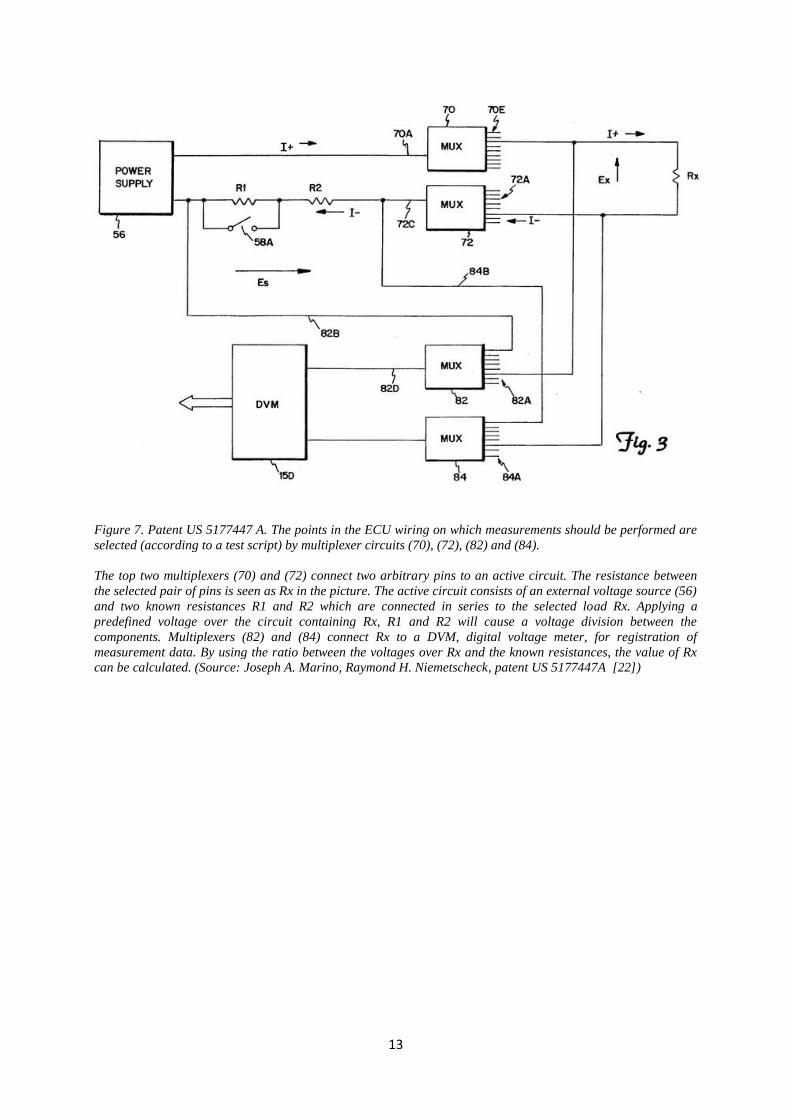
Figure 7. Patent US 5177447 A. The points in the ECU wiring on which measurements should be performed are
selected (according to a test script) by multiplexer circuits (70), (72), (82) and (84).
The top two multiplexers (70) and (72) connect two arbitrary pins to an active circuit. The resistance between
the selected pair of pins is seen as Rx in the picture. The active circuit consists of an external voltage source (56)
and two known resistances R1 and R2 which are connected in series to the selected load Rx. Applying a
predefined voltage over the circuit containing Rx, R1 and R2 will cause a voltage division between the
components. Multiplexers (82) and (84) connect Rx to a DVM, digital voltage meter, for registration of
measurement data. By using the ratio between the voltages over Rx and the known resistances, the value of Rx
can be calculated. (Source: Joseph A. Marino, Raymond H. Niemetscheck, patent US 5177447A [22])
14
2.2 Embedded software development
An embedded system is a system controlled by one or several processing cores, often in the
form of microprocessors or DSPs [24]. It has typically a well-defined task and is constrained
by factors such as a limited processing power, memory and timing requirements [24, 25].
Within a large system, multiple embedded systems can be contained and in need to share data
between each other. Communication protocols such as SPI and I2C and CAN are used for
such purposes [26, 27].
The breakout box is controlled by one or several microcontrollers, as will be explained in the
following chapters. To be able to operate reliably, they make use of some features commonly
provided by microcontrollers: serial communication via UART, multiprocessor
communication with I2C, hardware interrupts, in-built timers and a watchdog. In this chapter,
explanations to the features just mentioned will be given.
2.2.1 Interrupt-driven applications
Interrupts are widely used in programming. An interrupt is an event which causes the normal
execution of a program to stop and re-directs the processor to another piece of code: the
interrupt handler. After completion of the instructions defined in the handler, the processor re-
enters the program where it once was interrupted and continues the execution [28]. Interrupts
can be triggered by either a software instruction or external hardware. In software, they are
typically used to communicate with kernel software (making a system call to the operating
system) [29]. Hardware interrupts are commonly seen in microcontroller applications - an
external hardware event such as a button press [30] or timer expiration [31] alerts the
processor and allows it to immediately take the necessary actions. This is one of the clear
strengths of interrupts – the possibility to handle events at the moment they occur. Interrupt
handlers should be held short to not block the reception of other events and to not keep the
processor occupied for too long (stopping it from running its main program) [32].
An alternative to interrupt-driven computing is polling: sequential and continuous checking if
an event has happened [28] (which can be seen as a change of the value of an internal register
or the state of an I/O-port). This can be just as reliable, provided that the processor and the
program are sufficiently fast to always discover a pressed button or to notice a timer
expiration within a reasonable amount of time from when it actually happened. For smaller
applications polling is often unproblematic, but as the program grows and the tasks of the
processor become numerous, it is necessary to assign priority to some events and interrupt
handling becomes a better choice.

15
2.2.2 Timers
Timers are, just like the name implies, modules that can be used for measuring time. They are
software accessible hardware counters, which use the pulses received from the processor’s
program clock, an internal oscillator or from external logic together with pre- and postscalers
to increase the counter value. Microcontrollers often contain multiple timers, which can have
different capabilities in terms of resolution and maximum time between an overflow of the
counter [33] [33].
A prescaler divides the clock frequency of the processor before it reaches the timer. The
division factor is typically a power of two (1, 8, 64, 256, 1024 e.g.). The higher the value of
the prescaler, the slower the counter is incremented. The postscaler divides the frequency of
the output from the timer.
A timer can be set to trigger an interrupt when its counter reaches a specified value. It can
either be on overflow or on compare match. An overflow occurs when the counter restarts
after having reached its maximum count (when it switches from 255 to 0 for an 8-bit counter).
Compare match requires a register to be loaded with a value to which the counter is
continuously compared. Whenever the two values are identical a compare match occurs [33,
34]. The setup is seen in Figure 8.
Figure 8. An interrupt is triggered whenever the counter reaches its specified period, here stored in register
PR2. The prescaler divides the input frequency of the timer, while the postscaler divides the output frequency,
i.e. the rate of generated interrupt flags. (Source: Richard H. Barnett, Larry O'Cull, Sarah Alison Cox,
Embedded C Programming and the Microchip PIC, Volume 1[35] )
Equation (1) shows how to calculate the time between two timer interrupts [33]. The
frequency of the timer, fTMR, could be the program clock (for example fOSC/4, where fOSC is the
system clock and the resulting program clock is four times slower due to a non-pipelined
processor). The counter period can is either the maximum value of the counter (interrupt on
overflow) or a value in between (interrupt on compare match).
16
𝑇 =𝑁𝑃𝑅𝐸 ∙ 𝑁𝑃𝑂𝑆𝑇 ∙ 𝑁𝑃𝐸𝑅𝐼𝑂𝐷
𝑓𝑇𝑀𝑅 (1)
𝑇 : Time between two timer interrupts
𝑁𝑃𝑅𝐸 : Prescale ratio
𝑁𝑃𝑂𝑆𝑇 : Postscale ratio
𝑁𝑃𝐸𝑅𝐼𝑂𝐷 : Period of the counter
𝑓𝑇𝑀𝑅 : Frequency of the timer
2.2.3 Watchdog timer
A watchdog timer is a mechanism used for decreasing the negative effects of a deadlock
situation or software/system issues that cause the processor to hang (infinite loops caused by a
never fulfilled condition for example) during run-time [36, 37]. A deadlock is a state when the
program is blocked and unable to continue execution since it is waiting for a resource it can
never gain. The resource is held by another program/thread which in its turn also is locked,
waiting for something else [37]. This is typically seen in threaded applications/real-time
systems. Common for the types of unwanted behavior described are the consequences – the
program gets blocked forever. By using a watchdog timer, this is avoided.
The watchdog monitors that a program is running freely, or else it resets it. The principle is
relatively simple: as indicated by the title, the watchdog is a timer. Every time it is reset, it is
filled with a (software configurable) value. As time passes, the value of the timer is gradually
decreased until it – if not refilled – reaches zero. By this time, the software is considered as
non-responsive and a reset signal is asserted and the program is restarted. For the watchdog to
function as intended, it is necessary to reload the timer repeatedly to prevent it from reaching
zero [36]. By doing so in an often visited code area of the program (typically the main loop),
the liveness of the execution is continuously signaled to the watchdog.
2.2.4 UART communication
UART (Universal Asynchronous Receiver/Transmitter) is a feature that allows
microcontrollers to communicate with a PC through serial transmission of data. Parallel data,
such as a byte, is converted into a serial bit stream before it is sent sequentially over the
communication line [38]. The asynchronous transmission permits the sender and receiver to
work with different clocks. To synchronize the transfer of data, it is necessary that the actors
on both sides of the communication link have knowledge about timing parameters (at which

17
rate the data is sent) and that special bits for organizing the transfer are used (start bit, stop bit,
parity). To send a byte, the transmitter outputs a start bit, informing the receiver that a
transmission is about to take place. The byte is then sent as bits, with the least significant bit
first. At the end of the transmission, a stop bit is added (and possibly a parity bit for error
detection) [39].
The microprocessor has buffers dedicated for holding the incoming and outgoing characters.
Interrupts can be used to discover that a character is added to the buffer, which implies that it
is either waiting for transmission or that it has been received and is waiting for
storage/treatment [38]. The use of interrupt based checking (compared to polling) allows fast
processing upon reception of data and decreases the risk of filling the buffer and missing
characters.
2.2.5 I2C communication
Inter-integrated Circuit (I2C) is a communication protocol for transmission of data between
one or multiple masters and peripheral units. It is can be used for communication between a
microcontroller and components such as sensors, SD-cards, displays etc., but also between
multiple processors [40]. An advantage of the protocol is its sparse use of connections - only
two wires are needed regardless of the number of connected units on the I2C bus. Transfer
speeds up to 100 kbit/s can be achieved in standard mode [40, 41].
The data is transferred over the I2C bus, which consists of the wires: SDA and SCL. SDA is
the data line and SCL the clock used for synchronization of the transfers [40]. Each device on
the bus can be accessed by a unique address and is either a master or a slave. The master can
initiate communication with a slave, but the latter can only answer upon request. The
maximum number of units that can be connected on the bus is limited by the number of bits
used for address decoding - in I2C this can be either 7 or 10 bits [40, 42].
Figure 9. The principle of the physical setup for the I2C protocol. The masters and slaves are connected to the
data and clock line.

18
A transmission is initiated by a master which outputs a start signal and the synchronization
clock signal. All slave devices are alerted that an action will take place. Secondly, the master
sends the address of the device it wishes to communicate with. Data can either be transmitted
to or requested from a slave. During the transmission, data is sent as bytes, each terminated by
an acknowledgement bit to confirm the reception of characters on the receiver side. The
master ends a sequence by sending a stop signal which releases the I2C bus [40, 42].
19
3 HARDWARE ARCHITECTURE
This chapter is hardware oriented. It describes the hardware architecture of the ABOB on a
simplified level for better understanding of the software implementation in the next chapter.
It will not bring up design choices or detailed component descriptions unless they are closely
related to the functionality of the software. Further explanations about the hardware are found
in the thesis Hardware Synthesis of Automated Electrical Fault Testing in Trucks by Martin
Orre.
Throughout the work of the thesis project, several methods for designing the breakout box
have been proposed and tested. While most of them only have been slight modifications of an
initial idea (change of some component, software updates etc.), there has also been some
major changes in the design. However, all the developed systems share some basic principles.
The ABOB is controlled by a script running on a computer. It contains a system for collecting
commands from the computer via USB and converting the information into control signals
which are distributed to the hardware that induces the faults. The fault units contain non-
intelligent hardware that acts upon received control signals to induce the desired faults. The
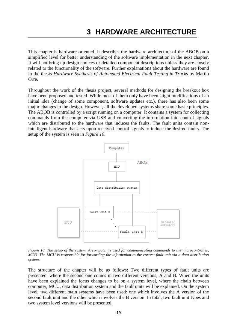
setup of the system is seen in Figure 10.
Figure 10. The setup of the system. A computer is used for communicating commands to the microcontroller,
MCU. The MCU is responsible for forwarding the information to the correct fault unit via a data distribution
system.
The structure of the chapter will be as follows: Two different types of fault units are
presented, where the second one comes in two different versions, A and B. When the units
have been explained the focus changes to be on a system level, where the chain between
computer, MCU, data distribution system and the fault units will be explained. On the system
level, two different main systems have been used: one which involves the A version of the
second fault unit and the other which involves the B version. In total, two fault unit types and
two system level versions will be presented.

20
To describe the different hardware setups, block diagrams will be used. To easier follow the
data travelling through the design, a color scheme is presented. Each color represents a type of
signal. The reader might notice the slight ambiguity of the representation of an input to a fault
unit and an output from a peripheral unit, considering that a signal can be both. To clarify, an
input to a fault unit will always be represented with its proper color, and the source generating
the input will be described in text.
Color Functionality
Direct input to a fault unit.
Output from a fault unit. (Measurement data)
Shared data bus.
Direct control signal from microcontroller.
Output from a peripheral unit.
3.1 The fault inducing units
Two different types of units for inducing faults on ECU pins were constructed during the
thesis project. Both of them will be described in this chapter. They will be presented as blocks
with input signals. The input signals are direct or indirect output from a microcontroller. The
system used to control the units will be described later on.
3.2 Fault inducing unit, type 1
The first version of the fault inducing unit had very limited features. It had the possibility to
induce a short circuit to ground and an open load on a wire. It had only two control signals.
The design was early abandoned due to its limitations concerning the customizability.
Figure 11. The first design had only two control signals.
21
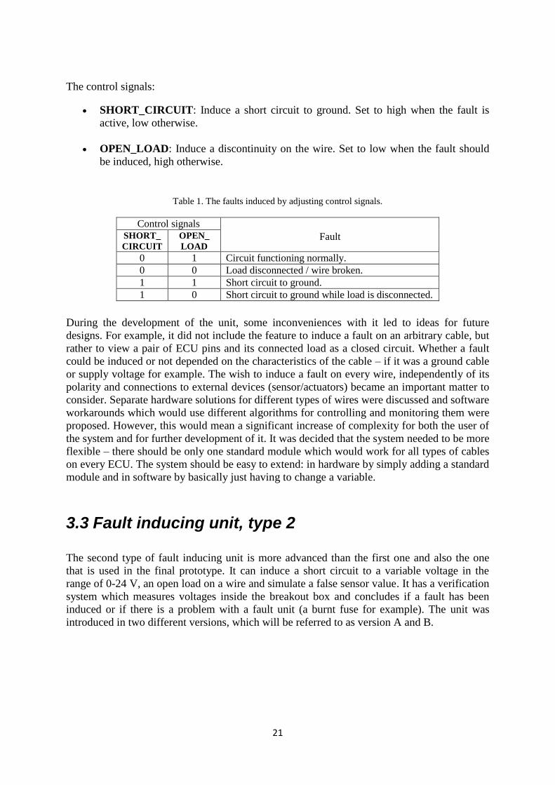
The control signals:
SHORT_CIRCUIT: Induce a short circuit to ground. Set to high when the fault is
active, low otherwise.
OPEN_LOAD: Induce a discontinuity on the wire. Set to low when the fault should
be induced, high otherwise.
Table 1. The faults induced by adjusting control signals.
Control signals Fault SHORT_
CIRCUIT
OPEN_
LOAD
0 1 Circuit functioning normally. 0 0 Load disconnected / wire broken. 1 1 Short circuit to ground. 1 0 Short circuit to ground while load is disconnected.
During the development of the unit, some inconveniences with it led to ideas for future
designs. For example, it did not include the feature to induce a fault on an arbitrary cable, but
rather to view a pair of ECU pins and its connected load as a closed circuit. Whether a fault
could be induced or not depended on the characteristics of the cable – if it was a ground cable
or supply voltage for example. The wish to induce a fault on every wire, independently of its
polarity and connections to external devices (sensor/actuators) became an important matter to
consider. Separate hardware solutions for different types of wires were discussed and software
workarounds which would use different algorithms for controlling and monitoring them were
proposed. However, this would mean a significant increase of complexity for both the user of
the system and for further development of it. It was decided that the system needed to be more
flexible – there should be only one standard module which would work for all types of cables
on every ECU. The system should be easy to extend: in hardware by simply adding a standard
module and in software by basically just having to change a variable.
3.3 Fault inducing unit, type 2
The second type of fault inducing unit is more advanced than the first one and also the one
that is used in the final prototype. It can induce a short circuit to a variable voltage in the
range of 0-24 V, an open load on a wire and simulate a false sensor value. It has a verification
system which measures voltages inside the breakout box and concludes if a fault has been
induced or if there is a problem with a fault unit (a burnt fuse for example). The unit was
introduced in two different versions, which will be referred to as version A and B.
22
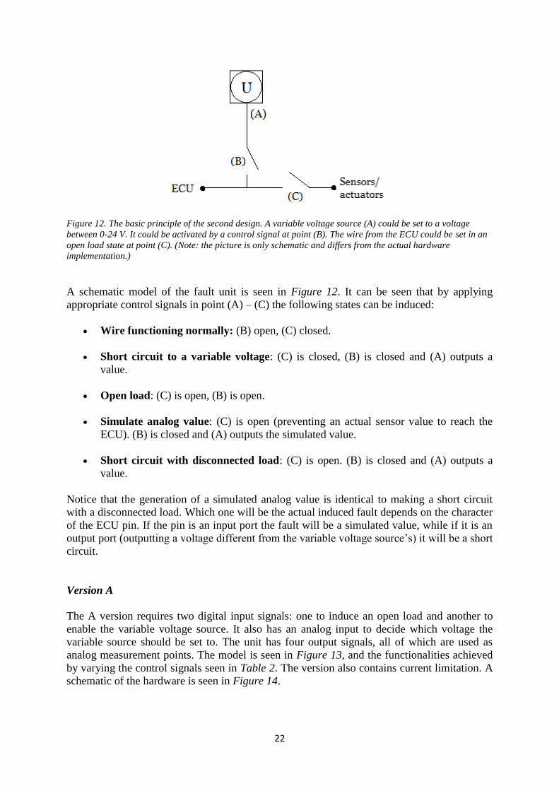
Figure 12. The basic principle of the second design. A variable voltage source (A) could be set to a voltage
between 0-24 V. It could be activated by a control signal at point (B). The wire from the ECU could be set in an
open load state at point (C). (Note: the picture is only schematic and differs from the actual hardware
implementation.)
A schematic model of the fault unit is seen in Figure 12. It can be seen that by applying
appropriate control signals in point (A) – (C) the following states can be induced:
Wire functioning normally: (B) open, (C) closed.
Short circuit to a variable voltage: (C) is closed, (B) is closed and (A) outputs a
value.
Open load: (C) is open, (B) is open.
Simulate analog value: (C) is open (preventing an actual sensor value to reach the
ECU). (B) is closed and (A) outputs the simulated value.
Short circuit with disconnected load: (C) is open. (B) is closed and (A) outputs a
value.
Notice that the generation of a simulated analog value is identical to making a short circuit
with a disconnected load. Which one will be the actual induced fault depends on the character
of the ECU pin. If the pin is an input port the fault will be a simulated value, while if it is an
output port (outputting a voltage different from the variable voltage source’s) it will be a short
circuit.
Version A
The A version requires two digital input signals: one to induce an open load and another to
enable the variable voltage source. It also has an analog input to decide which voltage the
variable source should be set to. The unit has four output signals, all of which are used as
analog measurement points. The model is seen in Figure 13, and the functionalities achieved
by varying the control signals seen in Table 2. The version also contains current limitation. A
schematic of the hardware is seen in Figure 14.
23
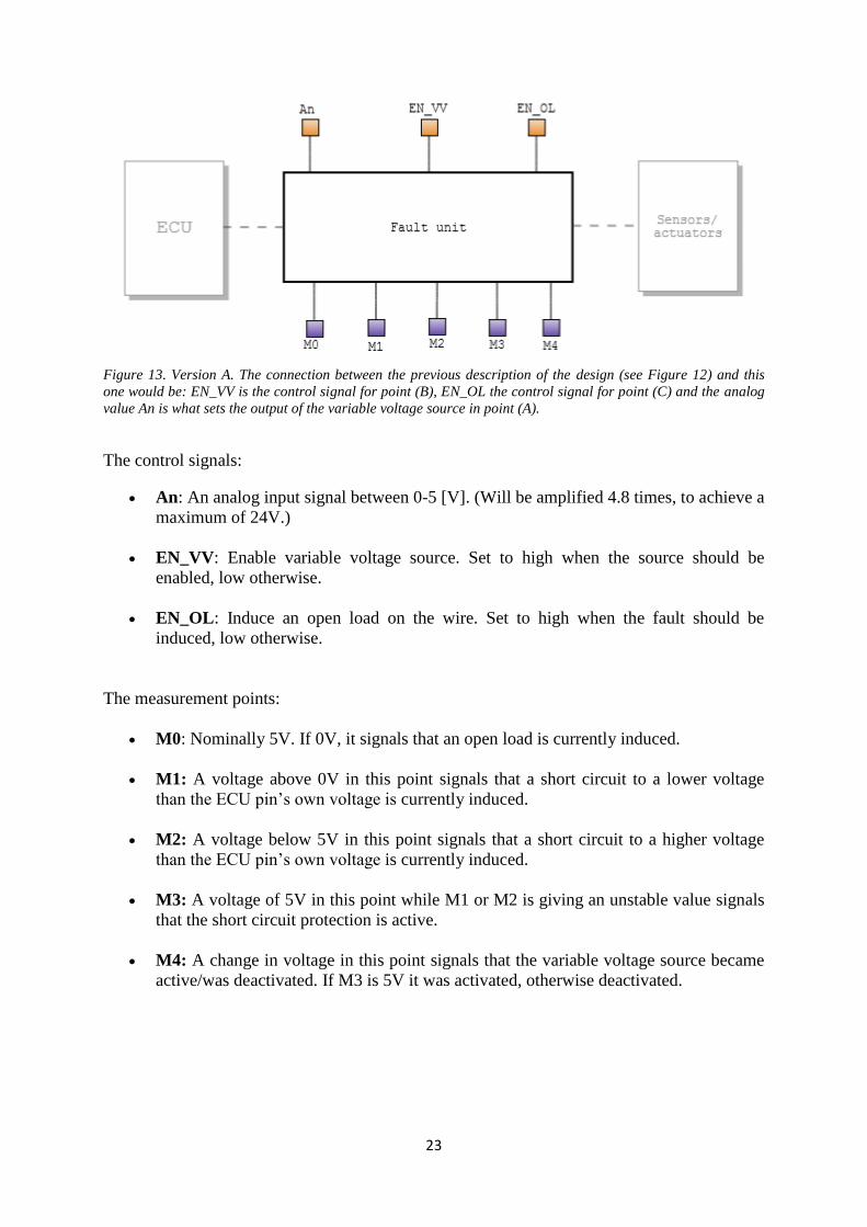
Figure 13. Version A. The connection between the previous description of the design (see Figure 12) and this
one would be: EN_VV is the control signal for point (B), EN_OL the control signal for point (C) and the analog
value An is what sets the output of the variable voltage source in point (A).
The control signals:
An: An analog input signal between 0-5 [V]. (Will be amplified 4.8 times, to achieve a
maximum of 24V.)
EN_VV: Enable variable voltage source. Set to high when the source should be
enabled, low otherwise.
EN_OL: Induce an open load on the wire. Set to high when the fault should be
induced, low otherwise.
The measurement points:
M0: Nominally 5V. If 0V, it signals that an open load is currently induced.
M1: A voltage above 0V in this point signals that a short circuit to a lower voltage
than the ECU pin’s own voltage is currently induced.
M2: A voltage below 5V in this point signals that a short circuit to a higher voltage
than the ECU pin’s own voltage is currently induced.
M3: A voltage of 5V in this point while M1 or M2 is giving an unstable value signals
that the short circuit protection is active.
M4: A change in voltage in this point signals that the variable voltage source became
active/was deactivated. If M3 is 5V it was activated, otherwise deactivated.
24
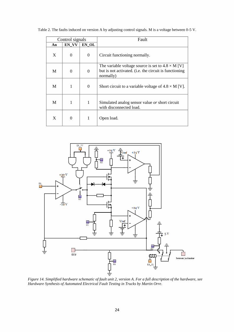
Table 2. The faults induced on version A by adjusting control signals. M is a voltage between 0-5 V.
Control signals Fault An EN_VV EN_OL
X
0
0
Circuit functioning normally.
M
0
0
The variable voltage source is set to 4.8 × M [V]
but is not activated. (i.e. the circuit is functioning
normally)
M
1
0
Short circuit to a variable voltage of 4.8 × M [V].
M
1
1
Simulated analog sensor value or short circuit
with disconnected load.
X
0
1
Open load.
Figure 14. Simplified hardware schematic of fault unit 2, version A. For a full description of the hardware, see
Hardware Synthesis of Automated Electrical Fault Testing in Trucks by Martin Orre.
25
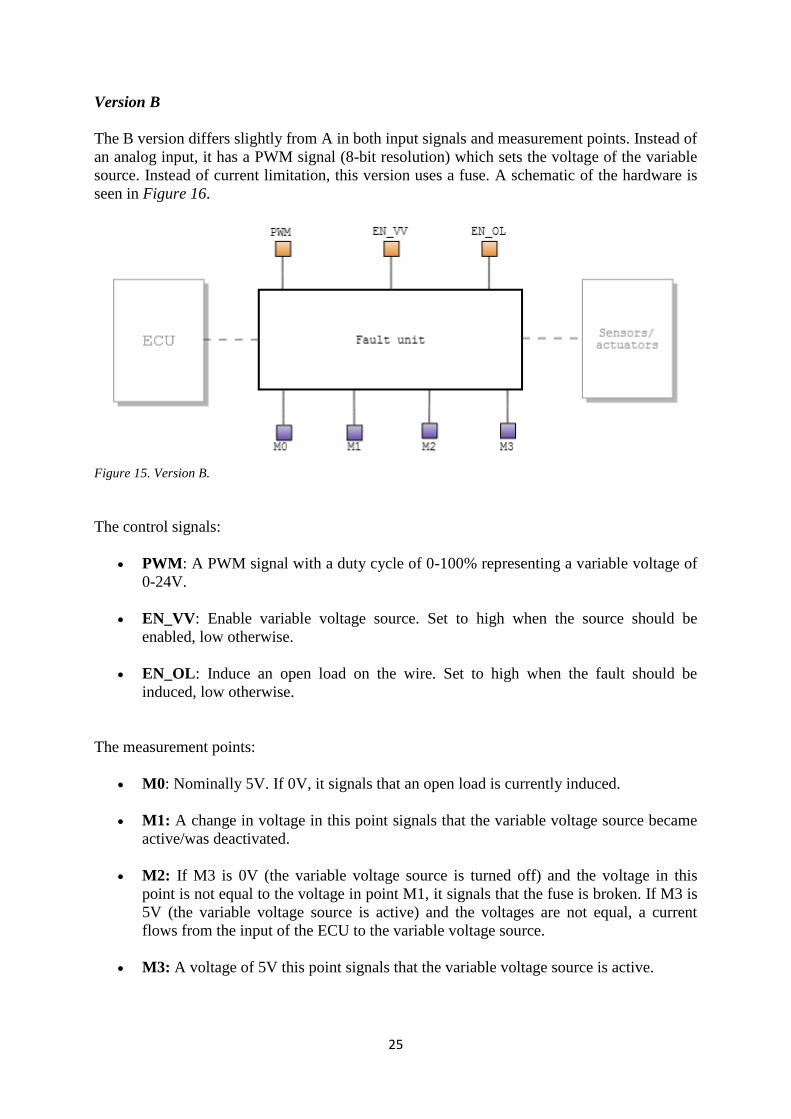
Version B
The B version differs slightly from A in both input signals and measurement points. Instead of
an analog input, it has a PWM signal (8-bit resolution) which sets the voltage of the variable
source. Instead of current limitation, this version uses a fuse. A schematic of the hardware is
seen in Figure 16.
Figure 15. Version B.
The control signals:
PWM: A PWM signal with a duty cycle of 0-100% representing a variable voltage of
0-24V.
EN_VV: Enable variable voltage source. Set to high when the source should be
enabled, low otherwise.
EN_OL: Induce an open load on the wire. Set to high when the fault should be
induced, low otherwise.
The measurement points:
M0: Nominally 5V. If 0V, it signals that an open load is currently induced.
M1: A change in voltage in this point signals that the variable voltage source became
active/was deactivated.
M2: If M3 is 0V (the variable voltage source is turned off) and the voltage in this
point is not equal to the voltage in point M1, it signals that the fuse is broken. If M3 is
5V (the variable voltage source is active) and the voltages are not equal, a current
flows from the input of the ECU to the variable voltage source.
M3: A voltage of 5V this point signals that the variable voltage source is active.
26
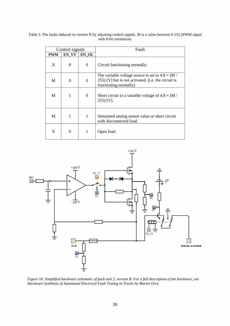
Table 3. The faults induced on version B by adjusting control signals. M is a value between 0-255 (PWM signal
with 8-bit resolution).
Control signals Fault PWM EN_VV EN_OL
X
0
0
Circuit functioning normally.
M
0
0
The variable voltage source is set to 4.8 × (M /
255) [V] but is not activated. (i.e. the circuit is
functioning normally)
M
1
0
Short circuit to a variable voltage of 4.8 × (M /
255) [V].
M
1
1
Simulated analog sensor value or short circuit
with disconnected load.
X
0
1
Open load.
Figure 16. Simplified hardware schematic of fault unit 2, version B. For a full description of the hardware, see
Hardware Synthesis of Automated Electrical Fault Testing in Trucks by Martin Orre.
27
3.4 The system level
The system level of the design includes, apart from the fault units, the intelligence (computer,
microcontroller) and the structure for distributing commands/data to and from all the
hardware units. Two systems that differ widely from each other have been designed, and will
be explained separately. Both of them use the second type of the fault unit, but different
versions of it.
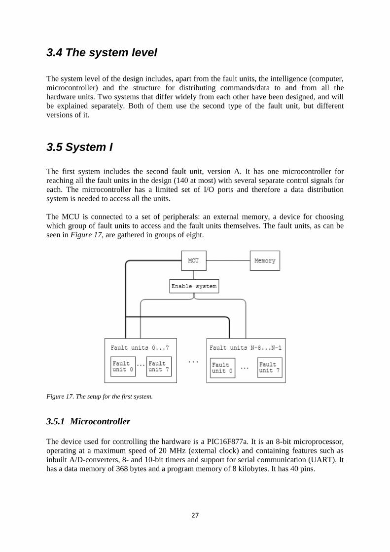
3.5 System I
The first system includes the second fault unit, version A. It has one microcontroller for
reaching all the fault units in the design (140 at most) with several separate control signals for
each. The microcontroller has a limited set of I/O ports and therefore a data distribution
system is needed to access all the units.
The MCU is connected to a set of peripherals: an external memory, a device for choosing
which group of fault units to access and the fault units themselves. The fault units, as can be
seen in Figure 17, are gathered in groups of eight.
Figure 17. The setup for the first system.
3.5.1 Microcontroller
The device used for controlling the hardware is a PIC16F877a. It is an 8-bit microprocessor,
operating at a maximum speed of 20 MHz (external clock) and containing features such as
inbuilt A/D-converters, 8- and 10-bit timers and support for serial communication (UART). It
has a data memory of 368 bytes and a program memory of 8 kilobytes. It has 40 pins.
28
For the breakout box application an external clock signal with the frequency of 4 MHz is
used. It is sufficient for the execution of non-time critical tasks. To ensure the functionality of
tasks which need to be run frequently and with strict deadlines, they are interrupt based.
Due to the relatively large number of peripherals that need to be accessed during operation,
the level of utilization of the microprocessor’s pins is high. The pins are distributed over
various areas, which will further be described in the following chapters:
8-bit data bus
External memory access
Enable register control
A/D converters
UART communication, Tx/Rx
D/A-converters control
Control signals for inducing faults
Multiplexer control
3.5.2 Shared data bus
The design contains a large set of registers. To write to them, a data bus of 8 bits is used. The
bus is shared between all the registers and it is therefore necessary to have a system for
controlling which one of them should be written to at each time instance. In this chapter,
numerous enable signals used for making registers susceptible to input from the shared data
bus will be seen.
3.5.3 External memory
The microcontroller contains a limited amount of on-chip RAM memory, 368 bytes. This is
not sufficient for the application, so an external SRAM memory of 32 kilobytes is therefore
added. It needs fifteen bits for address decoding and eight bits for the data. It has three
different control inputs: write enable (WE#), output enable (OE#) and chip enable (CE#). In
this application, only the first two signals are software controllable (i.e. the chip is by default
always enabled).
To function as intended, the SRAM needs in total 25 input signals. To save pins of the
microcontroller, the shared data bus is used for both address and data input. This is made
possible by the use of registers which are sequentially updated with the address. Two control
signals are used for enabling/disabling write operations to the registers holding the address
(see Figure 18).
For the application to obtain correct functionality, the following requirements must be
fulfilled: the SRAM should be writeable, readable and its data output must be possible to set
to high impedance. While the necessity of the first two functionalities is obvious, the last one
is explained by the wish to disable the memory’s output / protect it from polluted input when
being connected on the shared data bus. (Briefly clarified, the memory should not output a
value simultaneously with another unit on the bus, causing short circuits etc., nor should it
store arbitrary values from the data bus).
29
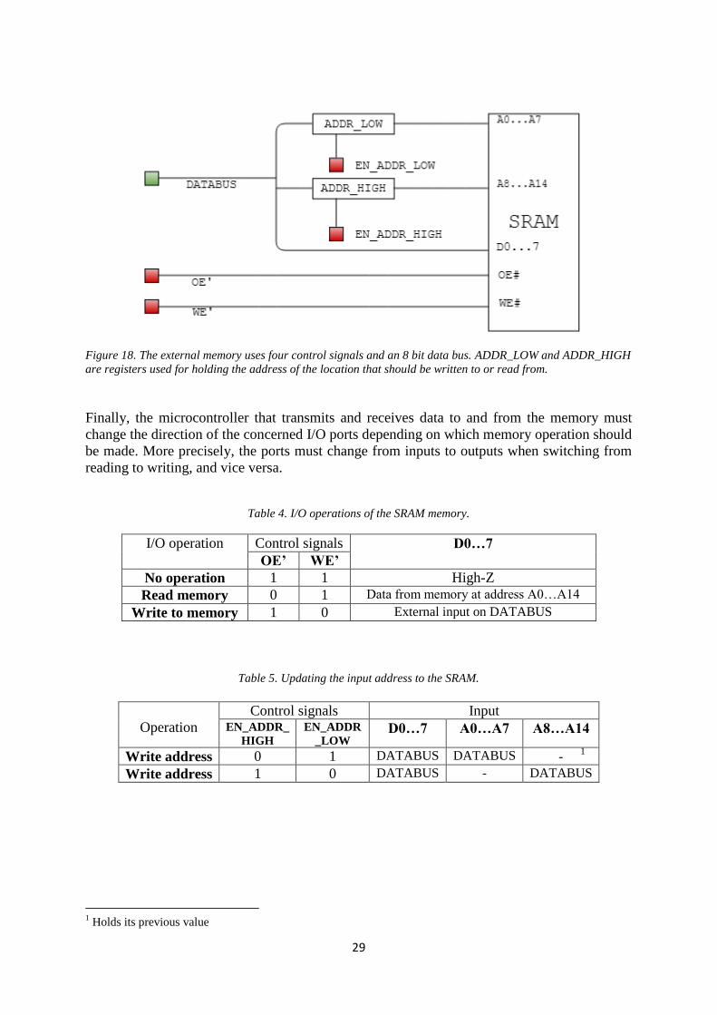
Figure 18. The external memory uses four control signals and an 8 bit data bus. ADDR_LOW and ADDR_HIGH
are registers used for holding the address of the location that should be written to or read from.
Finally, the microcontroller that transmits and receives data to and from the memory must
change the direction of the concerned I/O ports depending on which memory operation should
be made. More precisely, the ports must change from inputs to outputs when switching from
reading to writing, and vice versa.
Table 4. I/O operations of the SRAM memory.
I/O operation Control signals D0…7
OE’ WE’
No operation 1 1 High-Z
Read memory 0 1 Data from memory at address A0…A14
Write to memory 1 0 External input on DATABUS
Table 5. Updating the input address to the SRAM.
Operation
Control signals Input EN_ADDR_
HIGH
EN_ADDR
_LOW D0…7 A0…A7 A8…A14
Write address 0 1 DATABUS DATABUS - 1
Write address 1 0 DATABUS - DATABUS
1 Holds its previous value
30
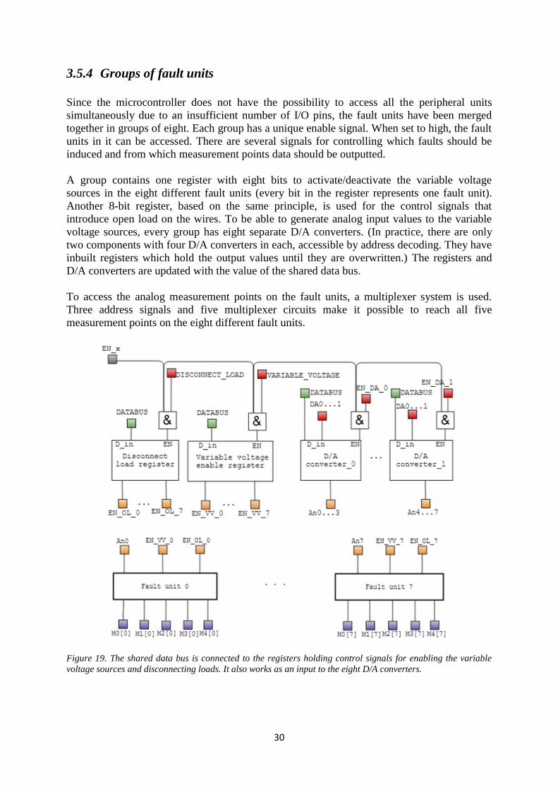
3.5.4 Groups of fault units
Since the microcontroller does not have the possibility to access all the peripheral units
simultaneously due to an insufficient number of I/O pins, the fault units have been merged
together in groups of eight. Each group has a unique enable signal. When set to high, the fault
units in it can be accessed. There are several signals for controlling which faults should be
induced and from which measurement points data should be outputted.
A group contains one register with eight bits to activate/deactivate the variable voltage
sources in the eight different fault units (every bit in the register represents one fault unit).
Another 8-bit register, based on the same principle, is used for the control signals that
introduce open load on the wires. To be able to generate analog input values to the variable
voltage sources, every group has eight separate D/A converters. (In practice, there are only
two components with four D/A converters in each, accessible by address decoding. They have
inbuilt registers which hold the output values until they are overwritten.) The registers and
D/A converters are updated with the value of the shared data bus.
To access the analog measurement points on the fault units, a multiplexer system is used.
Three address signals and five multiplexer circuits make it possible to reach all five
measurement points on the eight different fault units.
Figure 19. The shared data bus is connected to the registers holding control signals for enabling the variable
voltage sources and disconnecting loads. It also works as an input to the eight D/A converters.
31
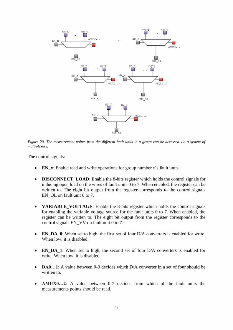
Figure 20. The measurement points from the different fault units in a group can be accessed via a system of
multiplexers.
The control signals:
EN_x: Enable read and write operations for group number x’s fault units.
DISCONNECT_LOAD: Enable the 8-bits register which holds the control signals for
inducing open load on the wires of fault units 0 to 7. When enabled, the register can be
written to. The eight bit output from the register corresponds to the control signals
EN_OL on fault unit 0 to 7.
VARIABLE_VOLTAGE: Enable the 8-bits register which holds the control signals
for enabling the variable voltage source for the fault units 0 to 7. When enabled, the
register can be written to. The eight bit output from the register corresponds to the
control signals EN_VV on fault unit 0 to 7.
EN_DA_0: When set to high, the first set of four D/A converters is enabled for write.
When low, it is disabled.
EN_DA_1: When set to high, the second set of four D/A converters is enabled for
write. When low, it is disabled.
DA0…1: A value between 0-3 decides which D/A converter in a set of four should be
written to.
AMUX0…2: A value between 0-7 decides from which of the fault units the
measurements points should be read.
32
The data input:
DATABUS: The shared data bus. Used for updating the fault registers and the D/A
converters. To which component the data bus’ value will be written depends on the
previously described enable signals.
The measurement points:
MUX_M0: The value of measurement point M0 on the fault unit decided by the
control signals AMUX0…2. (Example: if AMUX0…2 = 0 1 0, MUX_M0 will output
measurement point M0 on fault unit 2.)
MUX_M1: The value of measurement point M1 in the fault unit decided by the
control signals AMUX0…2.
MUX_M2: The value of measurement point M2 in the fault unit decided by the
control signals AMUX0…2.
MUX_M3: The value of measurement point M3 in the fault unit decided by the
control signals AMUX0…2.
MUX_M4: The value of measurement point M4 in the fault unit decided by the
control signals AMUX0…2.
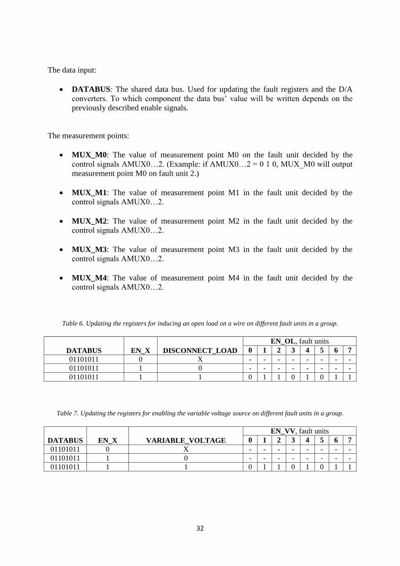
Table 6. Updating the registers for inducing an open load on a wire on different fault units in a group.
DATABUS
EN_X
DISCONNECT_LOAD
EN_OL, fault units 0 1 2 3 4 5 6 7
01101011 0 X - - - - - - - - 01101011 1 0 - - - - - - - - 01101011 1 1 0 1 1 0 1 0 1 1
Table 7. Updating the registers for enabling the variable voltage source on different fault units in a group.
DATABUS
EN_X
VARIABLE_VOLTAGE
EN_VV, fault units 0 1 2 3 4 5 6 7
01101011 0 X - - - - - - - - 01101011 1 0 - - - - - - - - 01101011 1 1 0 1 1 0 1 0 1 1
33
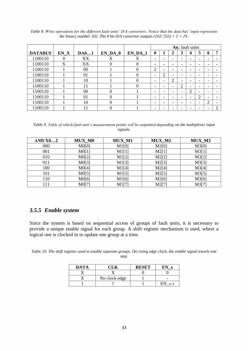
Table 8. Write operations for the different fault units’ D/A converters. Notice that the data bus’ input represents
the binary number 102. The 8 bit D/A converter outputs (102/ 255) × 5 = 2V.
DATABUS
EN_X
DA0…1
EN_DA_0
EN_DA_1
An, fault units 0 1 2 3 4 5 6 7
1100110 0 XX X X - - - - - - - - 1100110 X XX 0 0 - - - - - - - - 1100110 1 00 1 0 2 - - - - - - - 1100110 1 01 1 0 - 2 - - - - - - 1100110 1 10 1 0 - - 2 - - - - - 1100110 1 11 1 0 - - - 2 - - - - 1100110 1 00 0 1 - - - - 2 - - - 1100110 1 01 0 1 - - - - - 2 - - 1100110 1 10 0 1 - - - - - - 2 - 1100110 1 11 0 1 - - - - - - - 2
Table 9. Table of which fault unit’s measurement points will be outputted depending on the multiplexer input
signals.
AMUX0…2 MUX_M0 MUX_M1 MUX_M2 MUX_M3 000 M0[0] M1[0] M2[0] M3[0] 001 M0[1] M1[1] M2[1] M3[1] 010 M0[2] M1[2] M2[2] M3[2] 011 M0[3] M1[3] M2[3] M3[3] 100 M0[4] M1[4] M2[4] M3[4] 101 M0[5] M1[5] M2[5] M3[5] 110 M0[6] M1[6] M2[6] M3[6] 111 M0[7] M1[7] M2[7] M3[7]
3.5.5 Enable system
Since the system is based on sequential access of groups of fault units, it is necessary to
provide a unique enable signal for each group. A shift register mechanism is used, where a
logical one is clocked in to update one group at a time.
Table 10. The shift register used to enable separate groups. On rising edge clock, the enable signal travels one
step.
DATA CLK RESET EN_x X X 0 0 X No clock edge 1 - 1 ↑ 1 EN_x-1

34
Figure 21. A shift register is used to enable the different groups of fault units.
3.5.6 Measurements
To verify that the script based test case actually is executed, i.e. that the faults are induced, a
measurement system is implemented. It uses the PIC-processor’s inbuilt ADC converters. It
hoovers over all the fault units’ measurement points to conclude if there is an ongoing open
load, an active overcurrent protection or if the variable voltage source is turned on.
3.5.7 Robustness
Safety measures have been taken to be able to securely operate the breakout box. This
includes an overcurrent protection of 2A and a watchdog timer in software. It will restart the
processor after five seconds of not responding.
3.6 System II
The second system uses fault unit 2, version B. While the fault inducing unit is similar to the
one used in the first system, the data distribution method differs widely. Instead of having one
microprocessor which distributes data via external hardware such as registers, shift registers
and multiplexers, several microprocessors that communicate with each other are used. Each
processor is in charge of controlling and monitoring a small set of fault inducing units. It is a
master/slave setup, with one master node controlling a large set of slave nodes. The master is
in its turn controlled by a computer. The modest amount of two fault units per slave
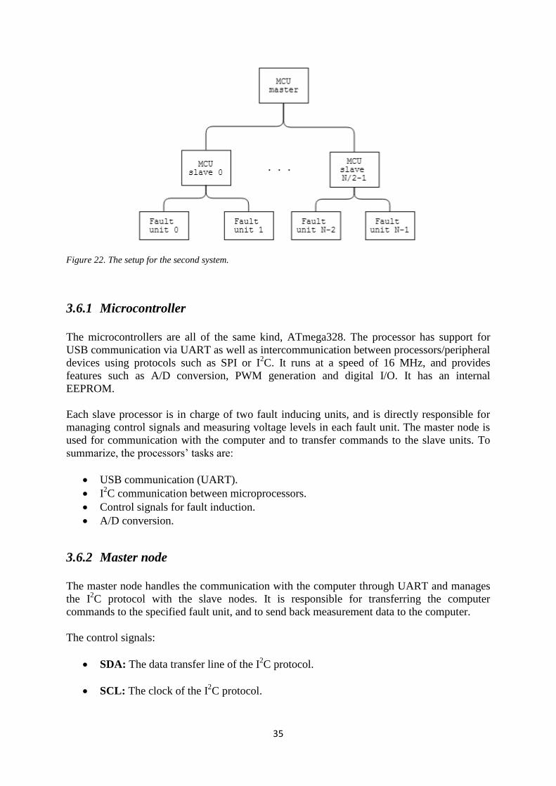
microcontroller is used in this application.
35
Figure 22. The setup for the second system.
3.6.1 Microcontroller
The microcontrollers are all of the same kind, ATmega328. The processor has support for
USB communication via UART as well as intercommunication between processors/peripheral
devices using protocols such as SPI or I2C. It runs at a speed of 16 MHz, and provides
features such as A/D conversion, PWM generation and digital I/O. It has an internal
EEPROM.
Each slave processor is in charge of two fault inducing units, and is directly responsible for
managing control signals and measuring voltage levels in each fault unit. The master node is
used for communication with the computer and to transfer commands to the slave units. To
summarize, the processors’ tasks are:
USB communication (UART).
I2C communication between microprocessors.
Control signals for fault induction.
A/D conversion.
3.6.2 Master node
The master node handles the communication with the computer through UART and manages
the I2C protocol with the slave nodes. It is responsible for transferring the computer
commands to the specified fault unit, and to send back measurement data to the computer.
The control signals:
SDA: The data transfer line of the I2C protocol.
SCL: The clock of the I2C protocol.
36
EXT_INT: The master sends a signal to inform the slave nodes that it is time to
execute or reset faults.
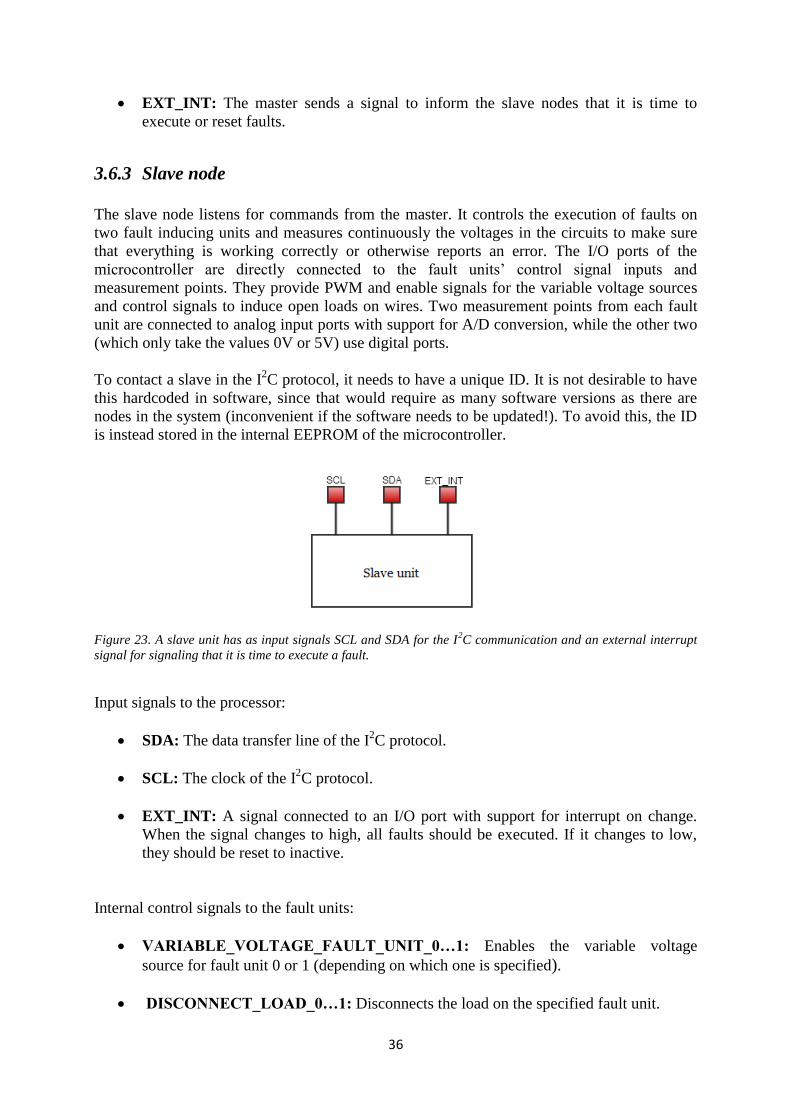
3.6.3 Slave node
The slave node listens for commands from the master. It controls the execution of faults on
two fault inducing units and measures continuously the voltages in the circuits to make sure
that everything is working correctly or otherwise reports an error. The I/O ports of the
microcontroller are directly connected to the fault units’ control signal inputs and
measurement points. They provide PWM and enable signals for the variable voltage sources
and control signals to induce open loads on wires. Two measurement points from each fault
unit are connected to analog input ports with support for A/D conversion, while the other two
(which only take the values 0V or 5V) use digital ports.
To contact a slave in the I2C protocol, it needs to have a unique ID. It is not desirable to have
this hardcoded in software, since that would require as many software versions as there are
nodes in the system (inconvenient if the software needs to be updated!). To avoid this, the ID
is instead stored in the internal EEPROM of the microcontroller.
Figure 23. A slave unit has as input signals SCL and SDA for the I
2C communication and an external interrupt
signal for signaling that it is time to execute a fault.
Input signals to the processor:
SDA: The data transfer line of the I2C protocol.
SCL: The clock of the I2C protocol.
EXT_INT: A signal connected to an I/O port with support for interrupt on change.
When the signal changes to high, all faults should be executed. If it changes to low,
they should be reset to inactive.
Internal control signals to the fault units:
VARIABLE_VOLTAGE_FAULT_UNIT_0…1: Enables the variable voltage
source for fault unit 0 or 1 (depending on which one is specified).
DISCONNECT_LOAD_0…1: Disconnects the load on the specified fault unit.

37
PWM_0…1: Outputs a PWM signal for the variable voltage source of the specified
fault unit.
The measurement points:
M0_0...1: Measurement point M0 of the specified fault unit (0 or 1).
M1_0…1: Measurement point M1 of the specified fault unit (0 or 1).
M2_0…1: Measurement point M2 of the specified fault unit (0 or 1).
M3_0…1: Measurement point M3 of the specified fault unit (0 or 1).
3.6.4 Robustness
Just like the first system, this model also contains a watchdog timer. It is implemented in all
the nodes together with a reporting system to make sure that the user is informed if a timeout
has occurred. The same thing holds for the fuse used in each fault unit – if broken, this is
reported to the main node.
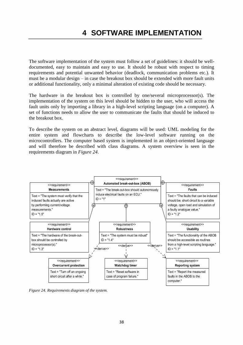
38
4 SOFTWARE IMPLEMENTATION
The software implementation of the system must follow a set of guidelines: it should be well-
documented, easy to maintain and easy to use. It should be robust with respect to timing
requirements and potential unwanted behavior (deadlock, communication problems etc.). It
must be a modular design – in case the breakout box should be extended with more fault units
or additional functionality, only a minimal alteration of existing code should be necessary.
The hardware in the breakout box is controlled by one/several microprocessor(s). The
implementation of the system on this level should be hidden to the user, who will access the
fault units only by importing a library in a high-level scripting language (on a computer). A
set of functions needs to allow the user to communicate the faults that should be induced to
the breakout box.
To describe the system on an abstract level, diagrams will be used: UML modeling for the
entire system and flowcharts to describe the low-level software running on the
microcontrollers. The computer based system is implemented in an object-oriented language
and will therefore be described with class diagrams. A system overview is seen in the
requirements diagram in Figure 24.
Figure 24. Requirements diagram of the system.
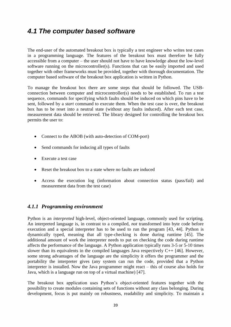
39
4.1 The computer based software
The end-user of the automated breakout box is typically a test engineer who writes test cases
in a programming language. The features of the breakout box must therefore be fully
accessible from a computer – the user should not have to have knowledge about the low-level
software running on the microcontroller(s). Functions that can be easily imported and used
together with other frameworks must be provided, together with thorough documentation. The
computer based software of the breakout box application is written in Python.
To manage the breakout box there are some steps that should be followed. The USB-
connection between computer and microcontroller(s) needs to be established. To run a test
sequence, commands for specifying which faults should be induced on which pins have to be
sent, followed by a start command to execute them. When the test case is over, the breakout
box has to be reset into a neutral state (without any faults induced). After each test case,
measurement data should be retrieved. The library designed for controlling the breakout box
permits the user to:
Connect to the ABOB (with auto-detection of COM-port)
Send commands for inducing all types of faults
Execute a test case
Reset the breakout box to a state where no faults are induced
Access the execution log (information about connection status (pass/fail) and
measurement data from the test case)
4.1.1 Programming environment
Python is an interpreted high-level, object-oriented language, commonly used for scripting.
An interpreted language is, in contrast to a compiled, not transformed into byte code before
execution and a special interpreter has to be used to run the program [43, 44]. Python is
dynamically typed, meaning that all type-checking is done during runtime [45]. The
additional amount of work the interpreter needs to put on checking the code during runtime
affects the performance of the language. A Python application typically runs 3-5 or 5-10 times
slower than its equivalents in the compiled languages Java respectively C++ [46]. However,
some strong advantages of the language are the simplicity it offers the programmer and the
portability the interpreter gives (any system can run the code, provided that a Python
interpreter is installed. Now the Java programmer might react – this of course also holds for
Java, which is a language run on top of a virtual machine) [47].
The breakout box application uses Python’s object-oriented features together with the
possibility to create modules containing sets of functions without any class belonging. During
development, focus is put mainly on robustness, readability and simplicity. To maintain a
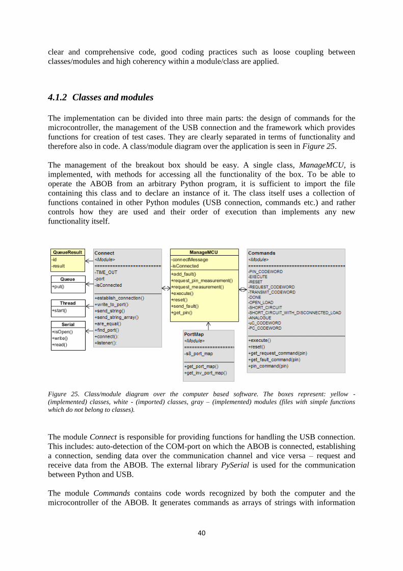
40
clear and comprehensive code, good coding practices such as loose coupling between
classes/modules and high coherency within a module/class are applied.
4.1.2 Classes and modules
The implementation can be divided into three main parts: the design of commands for the
microcontroller, the management of the USB connection and the framework which provides
functions for creation of test cases. They are clearly separated in terms of functionality and
therefore also in code. A class/module diagram over the application is seen in Figure 25.
The management of the breakout box should be easy. A single class, ManageMCU, is
implemented, with methods for accessing all the functionality of the box. To be able to
operate the ABOB from an arbitrary Python program, it is sufficient to import the file
containing this class and to declare an instance of it. The class itself uses a collection of
functions contained in other Python modules (USB connection, commands etc.) and rather
controls how they are used and their order of execution than implements any new
functionality itself.
Figure 25. Class/module diagram over the computer based software. The boxes represent: yellow -
(implemented) classes, white - (imported) classes, gray – (implemented) modules (files with simple functions
which do not belong to classes).
The module Connect is responsible for providing functions for handling the USB connection.
This includes: auto-detection of the COM-port on which the ABOB is connected, establishing
a connection, sending data over the communication channel and vice versa – request and
receive data from the ABOB. The external library PySerial is used for the communication
between Python and USB.
The module Commands contains code words recognized by both the computer and the
microcontroller of the ABOB. It generates commands as arrays of strings with information

41
about which fault unit to access, the type of fault that should be induced or if the command is
a request for measurement data.
To offer flexibility to a user of the system, the module PortMap contains dictionaries which
map the names of the ECU’s pins to their corresponding fault units of the breakout box. If a
new type of ECU (not previously defined in software) is connected to the breakout box, the
only change necessary is to add a new map to the module.
To achieve good structure, the modules are loosely coupled (the creation of commands are
separated from the USB connection etc.) and each module has a clear theme (every function
in the module Connect is related to the communication between the computer and
microcontroller e.g.). This enhances readability, facilitates debugging and opens for the
possibility of code replacement (if a future developer decides to re-write a module, it is
convenient to not have to make changes in every file of the project). Since the computer based
software mainly is used for transferring commands to the microcontroller(s), it is re-usable in
case of changes in the hardware design (depending of course on the nature of the changes). A
proof of this is the change from System I to System II – while the hardware and
microcontroller software were modified, the computer application remained the same.
A test case should be possible to run as a standalone application, but also as an integrated part
of another program. The latter could typically be a test script which uses another framework
than the breakout box’s own. The functions of the ABOB should be straightforward to use
and the measurement data log should be simple to retrieve (and possible to add to other logs if
desired). An example of a test case is seen in Figure 26.
Figure 26. Test case. Two faults are added, a short circuit to 4V on the ECU pin named IGNITION and an open
load on the pin GND. The faults are simultaneously executed when an execute command is sent, then run for 15
second until the breakout box is reset and measurement data is gathered.
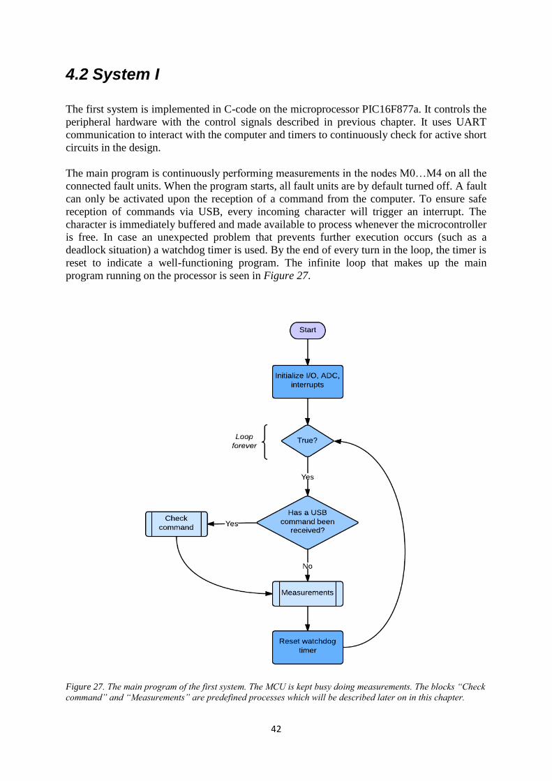
42
4.2 System I
The first system is implemented in C-code on the microprocessor PIC16F877a. It controls the
peripheral hardware with the control signals described in previous chapter. It uses UART
communication to interact with the computer and timers to continuously check for active short
circuits in the design.
The main program is continuously performing measurements in the nodes M0…M4 on all the
connected fault units. When the program starts, all fault units are by default turned off. A fault
can only be activated upon the reception of a command from the computer. To ensure safe
reception of commands via USB, every incoming character will trigger an interrupt. The
character is immediately buffered and made available to process whenever the microcontroller
is free. In case an unexpected problem that prevents further execution occurs (such as a
deadlock situation) a watchdog timer is used. By the end of every turn in the loop, the timer is
reset to indicate a well-functioning program. The infinite loop that makes up the main
program running on the processor is seen in Figure 27.
Figure 27. The main program of the first system. The MCU is kept busy doing measurements. The blocks “Check
command” and “Measurements” are predefined processes which will be described later on in this chapter.

43
4.2.1 Interrupt service routine
When an interrupt is registered, the normal execution of the software stops and the program
jumps to a specified location in memory – the interrupt handler. It is a routine which will
check which type of interrupt has occurred, perform the necessary actions (the desired
functionality that should follow an interrupt) and clear the flags indicating that an interrupt
has been observed.
The breakout box’s interrupt service routine (ISR) is responsible for handling the reception of
characters in the UART buffer. The routine is deliberately held short to minimize the time the
MCU is locked up from performing other tasks and serving other interrupts. The execution of
the service routine makes the application temporarily uninterruptible (an optional feature,
which is strongly recommended to avoid unexpected behavior and debugging difficulties).
Figure 28. The interrupt service routine handles two types of interrupts: reception of a character in the UART
buffer (Rx interrupt) and timer interrupt. The connectors A, B, C, D are explained in other diagrams on the
following pages.
The communication between the computer and the MCU uses a bit rate of 9600 bps. It is
necessary that the characters sent by the computer are received at the correct rate – therefore
the reception is configured to trigger an interrupt. The microprocessor has inbuilt support for
UART communication. It uses a register, RCREG, to store an incoming character, and signals
its presence by setting the interrupt flag RCIF to high [48]. This allows the software to notice
an incoming character as soon as it arrives and to start the necessary actions.
The characters sent over USB make up command words. Every reception over UART
contains only one ASCII character. To be able to conclude if a whole command has been
received, an end character is used (here newline). The ISR will specifically look for the end
character and when it is discovered it will signal to the main program that a command has
been received.
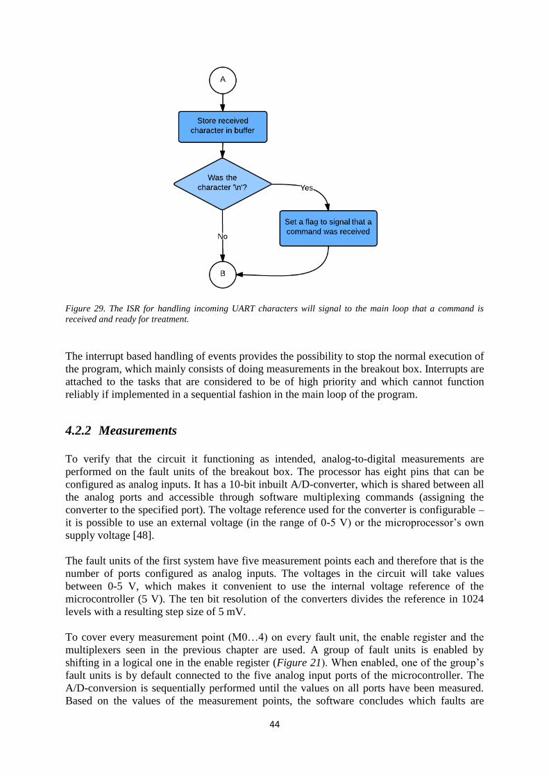
44
Figure 29. The ISR for handling incoming UART characters will signal to the main loop that a command is
received and ready for treatment.
The interrupt based handling of events provides the possibility to stop the normal execution of
the program, which mainly consists of doing measurements in the breakout box. Interrupts are
attached to the tasks that are considered to be of high priority and which cannot function
reliably if implemented in a sequential fashion in the main loop of the program.
4.2.2 Measurements
To verify that the circuit it functioning as intended, analog-to-digital measurements are
performed on the fault units of the breakout box. The processor has eight pins that can be
configured as analog inputs. It has a 10-bit inbuilt A/D-converter, which is shared between all
the analog ports and accessible through software multiplexing commands (assigning the
converter to the specified port). The voltage reference used for the converter is configurable –
it is possible to use an external voltage (in the range of 0-5 V) or the microprocessor’s own
supply voltage [48].
The fault units of the first system have five measurement points each and therefore that is the
number of ports configured as analog inputs. The voltages in the circuit will take values
between 0-5 V, which makes it convenient to use the internal voltage reference of the
microcontroller (5 V). The ten bit resolution of the converters divides the reference in 1024
levels with a resulting step size of 5 mV.
To cover every measurement point (M0…4) on every fault unit, the enable register and the
multiplexers seen in the previous chapter are used. A group of fault units is enabled by
shifting in a logical one in the enable register (Figure 21). When enabled, one of the group’s
fault units is by default connected to the five analog input ports of the microcontroller. The
A/D-conversion is sequentially performed until the values on all ports have been measured.
Based on the values of the measurement points, the software concludes which faults are
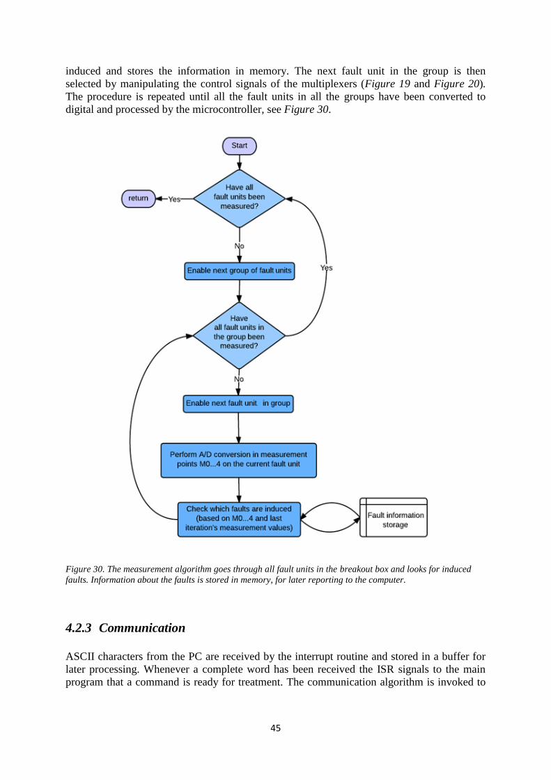
45
induced and stores the information in memory. The next fault unit in the group is then
selected by manipulating the control signals of the multiplexers (Figure 19 and Figure 20).
The procedure is repeated until all the fault units in all the groups have been converted to
digital and processed by the microcontroller, see Figure 30.
Figure 30. The measurement algorithm goes through all fault units in the breakout box and looks for induced
faults. Information about the faults is stored in memory, for later reporting to the computer.
4.2.3 Communication
ASCII characters from the PC are received by the interrupt routine and stored in a buffer for
later processing. Whenever a complete word has been received the ISR signals to the main
program that a command is ready for treatment. The communication algorithm is invoked to
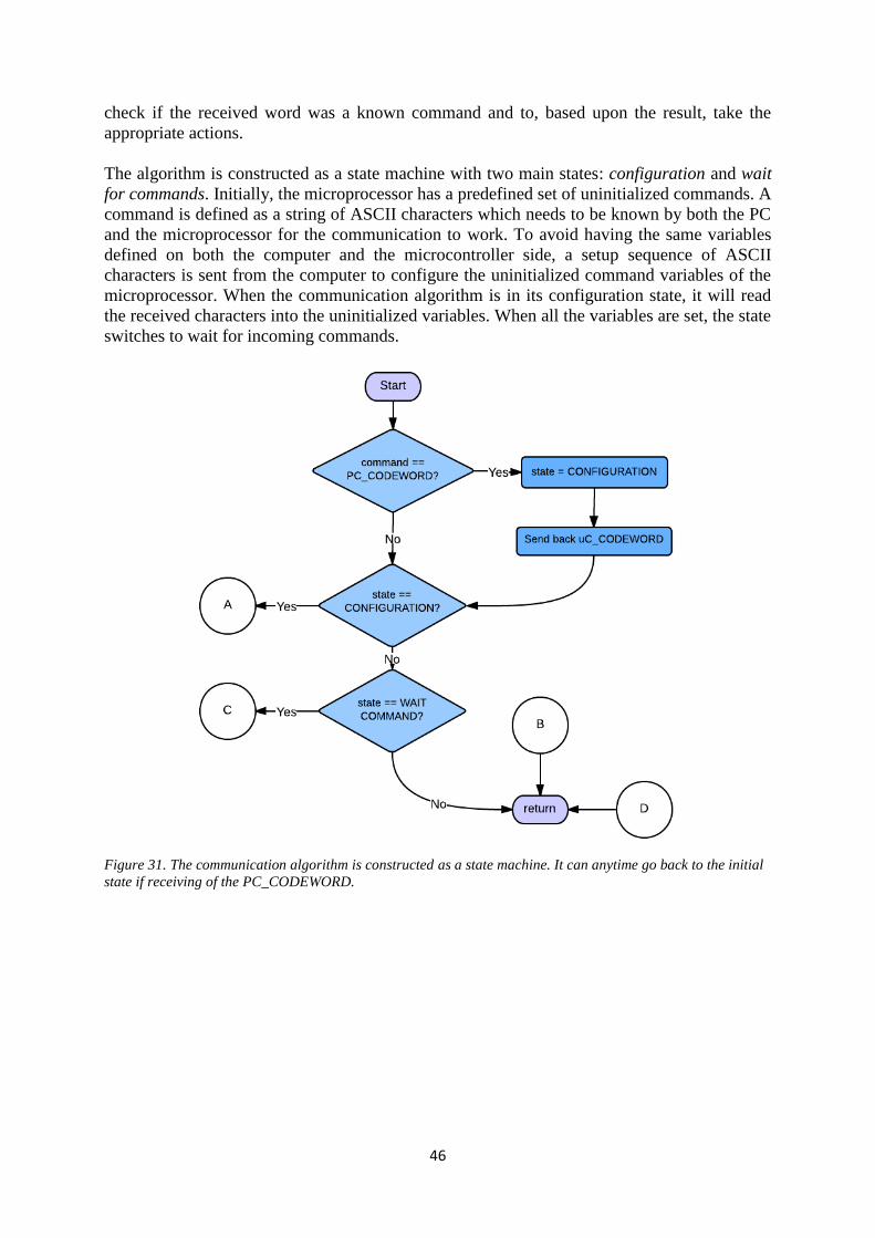
46
check if the received word was a known command and to, based upon the result, take the
appropriate actions.
The algorithm is constructed as a state machine with two main states: configuration and wait
for commands. Initially, the microprocessor has a predefined set of uninitialized commands. A
command is defined as a string of ASCII characters which needs to be known by both the PC
and the microprocessor for the communication to work. To avoid having the same variables
defined on both the computer and the microcontroller side, a setup sequence of ASCII
characters is sent from the computer to configure the uninitialized command variables of the
microprocessor. When the communication algorithm is in its configuration state, it will read
the received characters into the uninitialized variables. When all the variables are set, the state
switches to wait for incoming commands.
Figure 31. The communication algorithm is constructed as a state machine. It can anytime go back to the initial
state if receiving of the PC_CODEWORD.
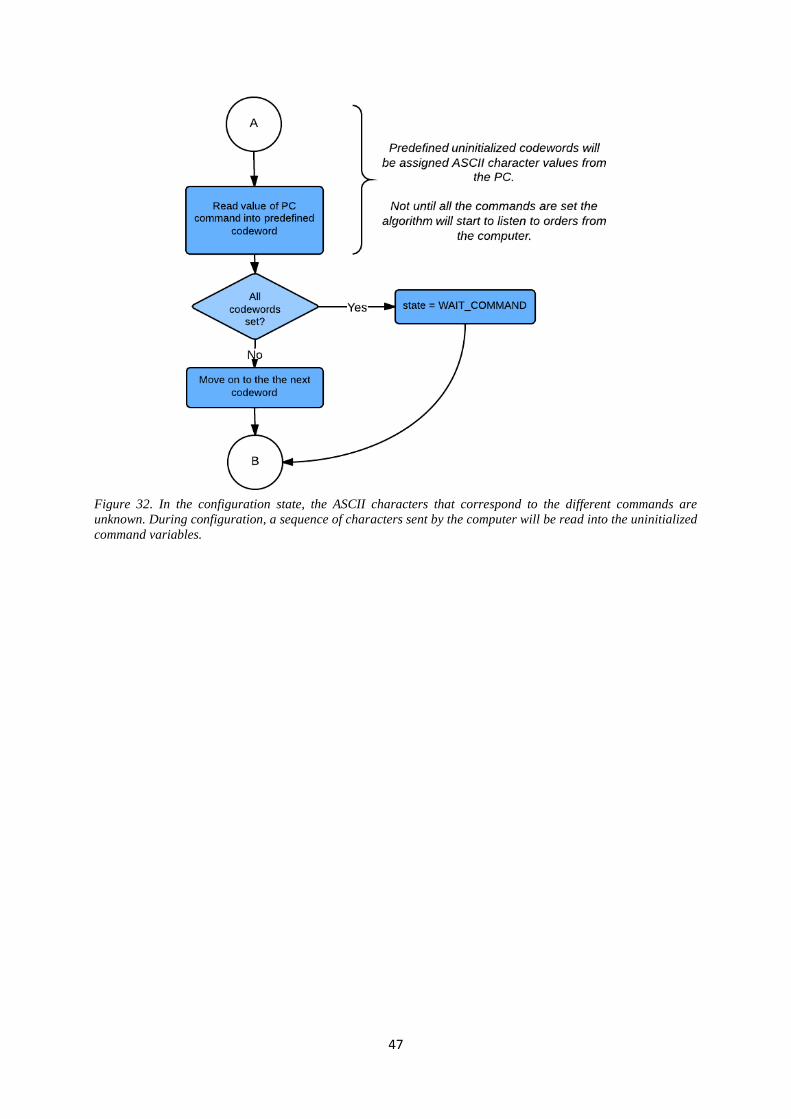
47
Figure 32. In the configuration state, the ASCII characters that correspond to the different commands are
unknown. During configuration, a sequence of characters sent by the computer will be read into the uninitialized
command variables.
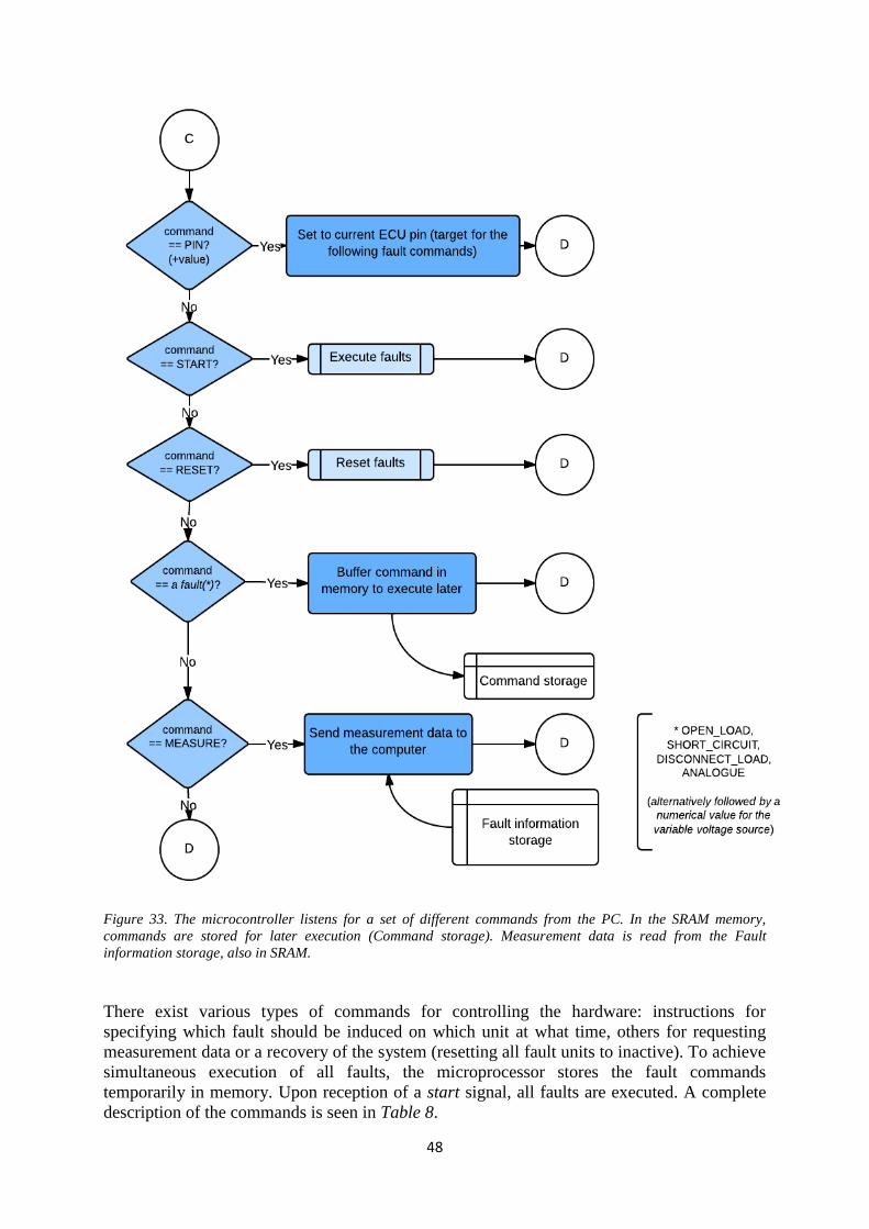
48
Figure 33. The microcontroller listens for a set of different commands from the PC. In the SRAM memory,
commands are stored for later execution (Command storage). Measurement data is read from the Fault
information storage, also in SRAM.
There exist various types of commands for controlling the hardware: instructions for
specifying which fault should be induced on which unit at what time, others for requesting
measurement data or a recovery of the system (resetting all fault units to inactive). To achieve
simultaneous execution of all faults, the microprocessor stores the fault commands
temporarily in memory. Upon reception of a start signal, all faults are executed. A complete
description of the commands is seen in Table 8.
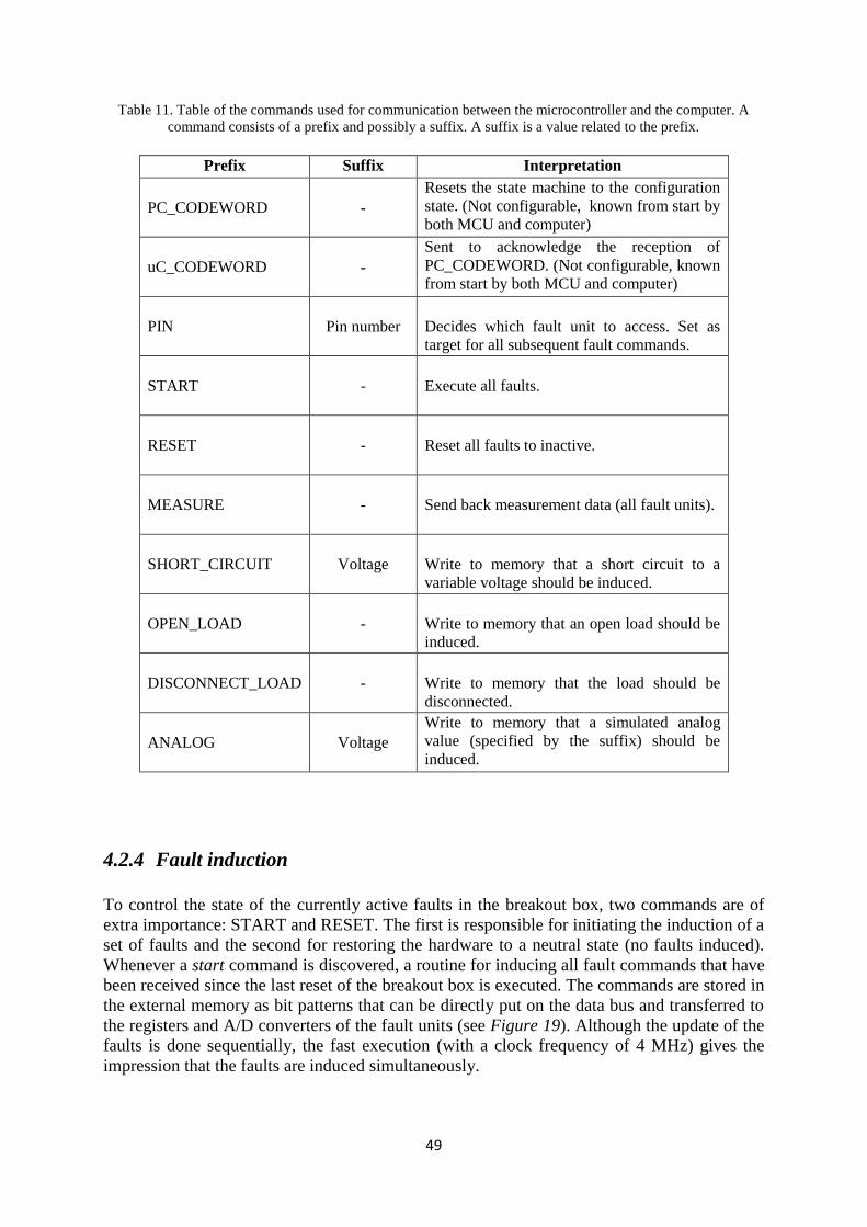
49
Table 11. Table of the commands used for communication between the microcontroller and the computer. A
command consists of a prefix and possibly a suffix. A suffix is a value related to the prefix.
Prefix Suffix Interpretation
PC_CODEWORD
-
Resets the state machine to the configuration
state. (Not configurable, known from start by
both MCU and computer)
uC_CODEWORD
-
Sent to acknowledge the reception of
PC_CODEWORD. (Not configurable, known
from start by both MCU and computer)
PIN
Pin number
Decides which fault unit to access. Set as
target for all subsequent fault commands.
START
-
Execute all faults.
RESET
-
Reset all faults to inactive.
MEASURE
-
Send back measurement data (all fault units).
SHORT_CIRCUIT
Voltage
Write to memory that a short circuit to a
variable voltage should be induced.
OPEN_LOAD
-
Write to memory that an open load should be
induced.
DISCONNECT_LOAD
-
Write to memory that the load should be
disconnected.
ANALOG
Voltage
Write to memory that a simulated analog
value (specified by the suffix) should be
induced.
4.2.4 Fault induction
To control the state of the currently active faults in the breakout box, two commands are of
extra importance: START and RESET. The first is responsible for initiating the induction of a
set of faults and the second for restoring the hardware to a neutral state (no faults induced).
Whenever a start command is discovered, a routine for inducing all fault commands that have
been received since the last reset of the breakout box is executed. The commands are stored in
the external memory as bit patterns that can be directly put on the data bus and transferred to
the registers and A/D converters of the fault units (see Figure 19). Although the update of the
faults is done sequentially, the fast execution (with a clock frequency of 4 MHz) gives the
impression that the faults are induced simultaneously.
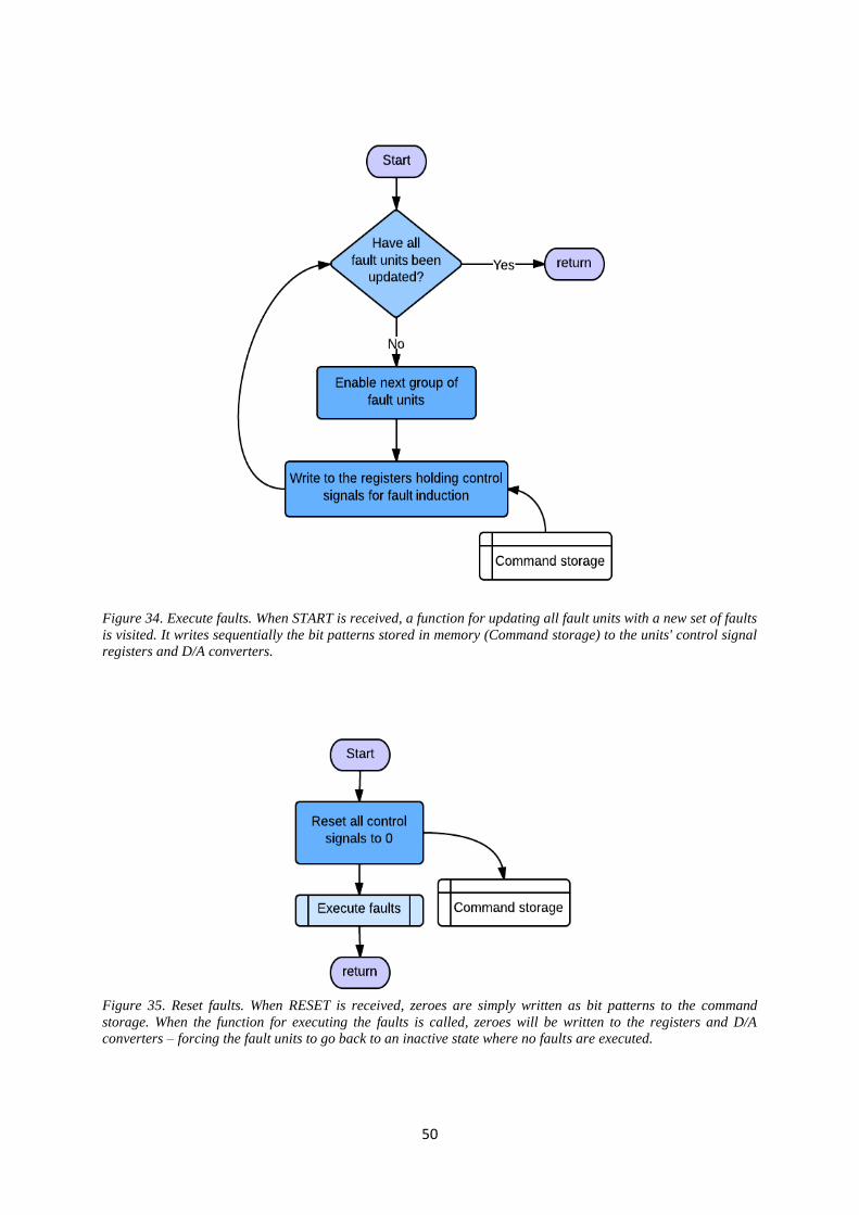
50
Figure 34. Execute faults. When START is received, a function for updating all fault units with a new set of faults
is visited. It writes sequentially the bit patterns stored in memory (Command storage) to the units' control signal
registers and D/A converters.
Figure 35. Reset faults. When RESET is received, zeroes are simply written as bit patterns to the command
storage. When the function for executing the faults is called, zeroes will be written to the registers and D/A
converters – forcing the fault units to go back to an inactive state where no faults are executed.
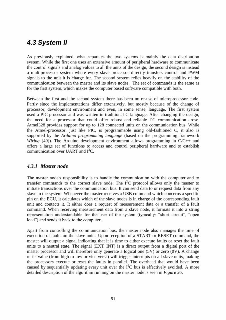
51
4.3 System II
As previously explained, what separates the two systems is mainly the data distribution
system. While the first one uses an extensive amount of peripheral hardware to communicate
the control signals and analog values to all the units of the design, the second design is instead
a multiprocessor system where every slave processor directly transfers control and PWM
signals to the unit it is charge for. The second system relies heavily on the stability of the
communication between the master and its slave nodes. The set of commands is the same as
for the first system, which makes the computer based software compatible with both.
Between the first and the second system there has been no re-use of microprocessor code.
Partly since the implementations differ extensively, but mostly because of the change of
processor, development environment and even, in some sense, language. The first system
used a PIC-processor and was written in traditional C-language. After changing the design,
the need for a processor that could offer robust and reliable I2C communication arose.
Atmel328 provides support for up to 128 connected units on the communication bus. While
the Atmel-processor, just like PIC, is programmable using old-fashioned C, it also is
supported by the Arduino programming language (based on the programming framework
Wiring [49]). The Arduino development environment allows programming in C/C++ and
offers a large set of functions to access and control peripheral hardware and to establish
communication over UART and I2C.
4.3.1 Master node
The master node's responsibility is to handle the communication with the computer and to
transfer commands to the correct slave node. The I2C protocol allows only the master to
initiate transactions over the communication bus. It can send data to or request data from any
slave in the system. Whenever the master receives a USB command which concerns a specific
pin on the ECU, it calculates which of the slave nodes is in charge of the corresponding fault
unit and contacts it. It either does a request of measurement data or a transfer of a fault
command. When receiving measurement data from a slave node, it formats it into a string
representation understandable for the user of the system (typically: “short circuit”, “open
load”) and sends it back to the computer.
Apart from controlling the communication bus, the master node also manages the time of
execution of faults on the slave units. Upon reception of a START or RESET command, the
master will output a signal indicating that it is time to either execute faults or reset the fault
units to a neutral state. The signal (EXT_INT) is a direct output from a digital port of the
master processor and will therefore only generate a logical one (5V) or zero (0V). A change
of its value (from high to low or vice versa) will trigger interrupts on all slave units, making
the processors execute or reset the faults in parallel. The overhead that would have been
caused by sequentially updating every unit over the I2C bus is effectively avoided. A more
detailed description of the algorithm running on the master node is seen in Figure 36.
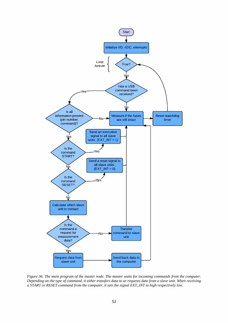
52
Figure 36. The main program of the master node. The master waits for incoming commands from the computer.
Depending on the type of command, it either transfers data to or requests data from a slave unit. When receiving
a START or RESET command from the computer, it sets the signal EXT_INT to high respectively low.
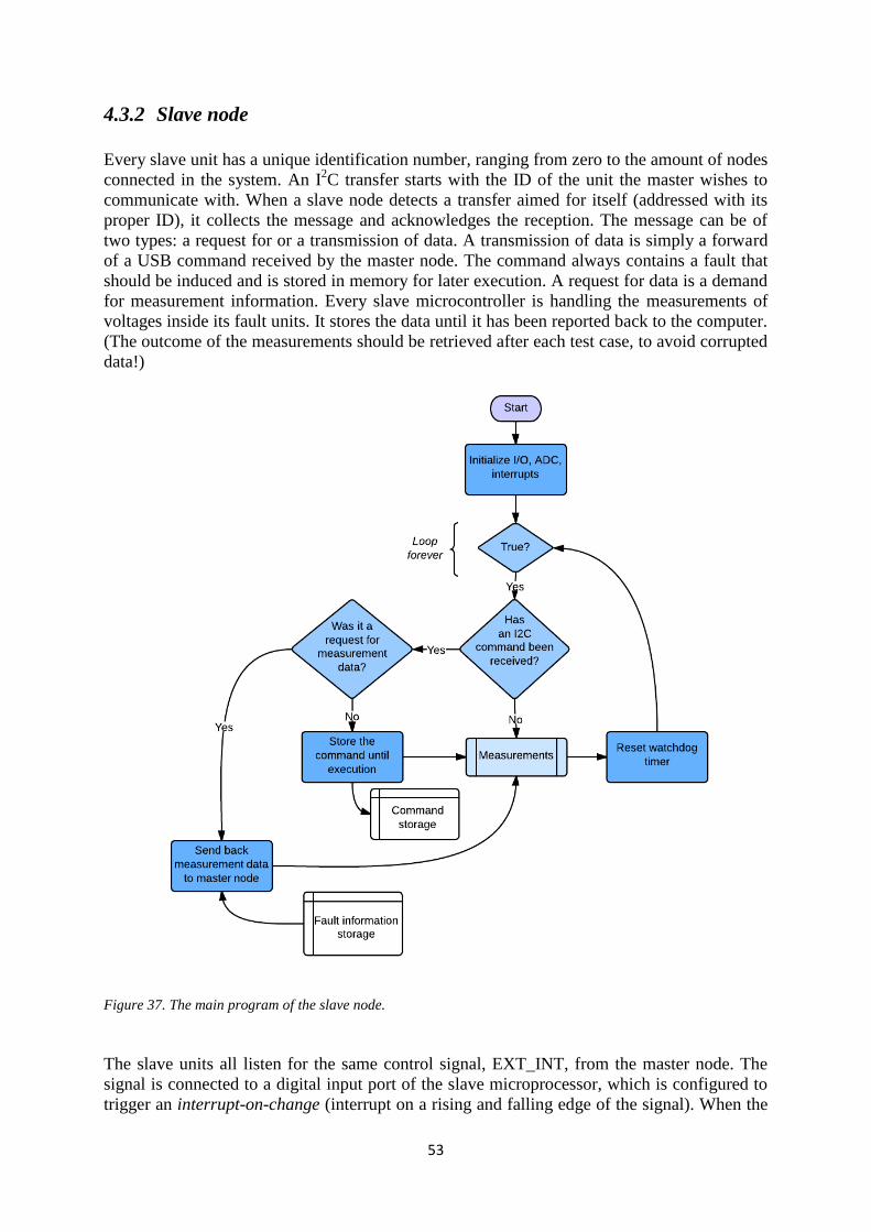
53
4.3.2 Slave node
Every slave unit has a unique identification number, ranging from zero to the amount of nodes
connected in the system. An I2C transfer starts with the ID of the unit the master wishes to
communicate with. When a slave node detects a transfer aimed for itself (addressed with its
proper ID), it collects the message and acknowledges the reception. The message can be of
two types: a request for or a transmission of data. A transmission of data is simply a forward
of a USB command received by the master node. The command always contains a fault that
should be induced and is stored in memory for later execution. A request for data is a demand
for measurement information. Every slave microcontroller is handling the measurements of
voltages inside its fault units. It stores the data until it has been reported back to the computer.
(The outcome of the measurements should be retrieved after each test case, to avoid corrupted
data!)
Figure 37. The main program of the slave node.
The slave units all listen for the same control signal, EXT_INT, from the master node. The
signal is connected to a digital input port of the slave microprocessor, which is configured to
trigger an interrupt-on-change (interrupt on a rising and falling edge of the signal). When the
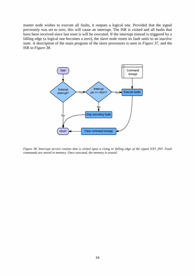
54
master node wishes to execute all faults, it outputs a logical one. Provided that the signal
previously was set to zero, this will cause an interrupt. The ISR is visited and all faults that
have been received since last reset is will be executed. If the interrupt instead is triggered by a
falling edge (a logical one becomes a zero), the slave node resets its fault units to an inactive
state. A description of the main program of the slave processors is seen in Figure 37, and the
ISR in Figure 38.
Figure 38. Interrupt service routine that is visited upon a rising or falling edge of the signal EXT_INT. Fault
commands are stored in memory. Once executed, the memory is erased.
55
5 RESULTS
The two systems described in previous chapters were both implemented in some form and the
second one became the final prototype. The majority of time was spent on the first system. It
was not until late during the PCB design that critical problems occurred. Due to practical
issues, the hardware of System I became delayed. Another solution had to be found to finish
the project on time and therefore some significant changes of the design were made: the
extensive amount of hardware used for the distribution of control signals in System I was
replaced by a set of communicating microcontrollers in System II. The fault inducing unit was
also upgraded from type 2, version A to type 2, version B.
5.1 System I
The first system was implemented in software and proved functional on small hardware
prototypes (hardwired on breadboard and/or prototype boards). The data distribution system
could deliver control signals for all specified faults to four fault units (limited by the small set
of hardware registers in use). A single fault unit was made. The prototype was tested on an
ECU connected to simulated sensors (resistances) and an external power supply (i.e. not in
truck) with satisfactory results.
The final prototype of system I contained:
One fault unit
A data distribution system with capacity to deliver control signals to four fault units
Electronic overcurrent protection of 2 A (in each fault unit)
It could:
Induce short circuit (with or without load) and open load
Simulate an analog value
Verify that a fault was induced
Control all peripheral units as described in chapter 3 (the components were only tested
separately)
The design worked well for the small set of components, but its functionality could never be
verified in a larger scale. Several factors contributed to the decision to change strategy, but
mainly: 1) The PCBs’ level of complexity was considered too high (which complicated and
extended the validation process). 2) The microprocessor will become heavily loaded as more
fault units are added. Issues concerning timing, missed measurements etc. might occur. 3)
56
Components prone to disturbances (such as shift registers and latches) might prove to be
troublesome once tested in a truck (a non-ideal environment).
5.2 System II
The second system was developed to be modular. The design required one master unit, and a
number of slave units corresponding to half the amount of connected ECU pins. The entire
breakout box was never made, but instead a smaller set of fault inducing units.
The final prototype contained:
Three slave units (i.e. six fault inducing units), PCB
One master unit, PCB
Overcurrent protection with a 2 A fuse (in each fault unit)
A Python framework for control of the ABOB
It could:
Induce short circuit (with or without load) and open load
Simulate an analog value
Verify that a fault was induced and report the results back to the computer
The functionality is very similar to the one presented for System I, but has one major
difference: this version was proven to work on a larger set of units and as an entire system.
The design reached a state where an extension of the setup only required a few steps to be
done. The procedure for expanding the design with more ECU ports was made easy. Simply
create a new slave unit and connect it to the previous ones. Give the new slave unit an ID
(used by I2C) by entering its number in the series of connected slave units in the serial
terminal. Finally, add the two new connected ports in the Python structure that maps
sensor/actuator names to fault unit numbers, T_AIR to 2 etc.
The design however has a drawback; the prototype can only be used on bench and connected
to a current limited power supply (tested with up to 10 A). The lack of instantaneous current
limitation (a fuse always has some inertia) could make potential short circuits in a truck cause
serious damage to the hardware of the ABOB. An ongoing short circuit below the fuse’s
threshold current would also eventually be harmful due to heating. This could be fixed with
proper cooling or software regulated overcurrent protection (turn off the short circuit source
after a while), but it was never implemented.
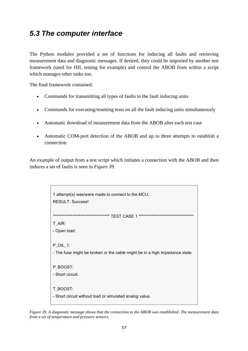
57
5.3 The computer interface
The Python modules provided a set of functions for inducing all faults and retrieving
measurement data and diagnostic messages. If desired, they could be imported by another test
framework (used for HIL testing for example) and control the ABOB from within a script
which manages other tasks too.
The final framework contained:
Commands for transmitting all types of faults to the fault inducing units
Commands for executing/resetting tests on all the fault inducing units simultaneously
Automatic download of measurement data from the ABOB after each test case
Automatic COM-port detection of the ABOB and up to three attempts to establish a
connection
An example of output from a test script which initiates a connection with the ABOB and then
induces a set of faults is seen in Figure 39.
1 attempt(s) was/were made to connect to the MCU.
RESULT: Success!
*********************************** TEST CASE 1 **********************************
T_AIR:
- Open load.
P_OIL_1:
- The fuse might be broken or the cable might be in a high impedance state.
P_BOOST:
- Short circuit.
T_BOOST:
- Short circuit without load or simulated analog value.
Figure 39. A diagnostic message shows that the connection to the ABOB was established. The measurement data
from a set of temperature and pressure sensors.
58
6 DISCUSSION
In retrospect, some design choices of the ABOB could have been made differently. The
elevated complexity of the system for accessing all ECU ports could have been predicted
earlier and a modified version been developed under less stressful circumstances. However,
the combination of limited time and issues during the PCB design forced the development in
another direction; towards a more software oriented design. The idea came after numerous
hours spent on CAD design, trying to route copper traces onto a 2-sided PCB and later
watching the same traces being destroyed by the cruelty of a malfunctioning CNC mill.
“Hardware is inflexible; once an error is discovered or something breaks, it is difficult to fix.
The repair of the old or manufacturing of a new PCB is time consuming - what if a great deal
of functionality could be moved to software instead and just be flashed onto a chip in case a
change has to be made?”. The data distribution system made out of multiplexer circuits, shift
registers and logical gates was thus replaced with a setup of multiple microprocessors which
communicated over I2C. Each processor was responsible for a small set of fault inducing
units, which permitted it to directly distribute control signals and access measurement points
without bypassing any intermediate hardware. The use of one microprocessor per two fault
units might seem exaggerated, but it brought indisputably some improvement to the design: 1)
It became highly modular and easy to extend. 2) No account had to be taken to time related
issues that might occur due to many connected units, since the fault induction and
measurements now were done locally on each slave unit. 3) It had less hardware that could be
affected by electrical disturbances in a truck. 4) Further development was made simple: if for
example wishing to add more functionality in terms of control signals and/or measurement
points, the framework for distributing commands was already available - just complement the
slave unit software with new functions and add the hardware of your choice! A mixture of
System I and System II, where a smaller setup of hardware registers and multiplexers is used
to increase the number of fault units per slave processor, could have been a possible
compromise.
As earlier mentioned the design was in need for instantaneous overcurrent protection to avoid
damage to the hardware. This was implemented in System I, but skipped in the final
prototype, System II (replaced by a fuse, again for lack of time reasons). It also needed
cooling in case a short circuit current below the fuse’s threshold current flows through the
circuitry. This would soon become cumbersome, which is unwanted for an ABOB that should
be portable. A solution could have been to implement short circuit protection in software that
continuously measures the current flowing through a resistor and eventually turns off the short
circuit source in case it is too high. The methods for limiting the current could save the ABOB
from damage, but at the same time they interfere with the test cases. Normally, the ECU’s
own overcurrent protection should get activated if a short circuit occurs - what happens if the
ABOB’s enters before that? etc. If the consequences of limited current are considered
acceptable, the design of the ABOB could be a possible solution, otherwise it needs
modification.
In comparison to the automated breakout boxes described in the pre-study, this ABOB had
advantages and disadvantages. One advantage was the possibility to manipulate all ECU ports
simultaneously and independently, another was the feature of performing and reporting
measurements. A disadvantage was the lack of robustness towards high currents, which the
previous ABOB developed at Scania handled better.

59
6.1 Future work
A mixture of the previously developed ABOB and this one could be a possible future project.
The robustness of the earlier model and the data distribution and measurement system of this
one could be joined and possibly complemented with additional features. For instance, the
measurement system of today could be extended to implement a verification module that
checks “Did the detected faults match what was specified in the test case?”
60
7 REFERENCES
1. Frykman, D. and H. Wemmersten, Automation of Electrical Testing of Power Train
Software in Heavy Vehicles. 2013, KTH: Stockholm.
2. Motavalli, J., The Dozens of Computers That Make Modern Cars Go (and Stop). New
York Times, 2010.
3. Charette, R.N., This Car Runs on Code. IEEE Spectrum, 2009.
4. Nice, K. How Car Computer Works. [cited 2014 29 June]; Available from:
http://auto.howstuffworks.com/under-the-hood/trends-innovations/car-computer.htm.
5. ECU Designing and Testing using National Instruments Products. [cited 2014 29
July]; Available from: http://www.ni.com/white-paper/3312/en/#toc2.
6. Scania Engine Management. [cited 2014 30 June]; Available from:
http://www.scania.com/products-services/trucks/main-components/engines/engine-
technology/scania-engine-management/.
7. Dimarogonas, D. Hybrid and Embedded Control Systems, Lecture 1. [cited 2014 1
August]; Available from:
https://www.kth.se/social/upload/52d66e1af276543ce7f42c63/lec01_VT14.pdf.
8. Chris Washington, N.I., HIL simulation boosts automotive design efficiency. EE
Times, 2007.
9. Nice, K. How Fuel Injection Systems Work. [cited 2014 1 August]; Available from:
http://auto.howstuffworks.com/fuel-injection2.htm.
10. McCord, K., Automotive Diagnostic Systems: Understanding OBD I and OBD II.
2011, North Branch: CarTech.
11. Santini, A., OBD-II: Functions, Monitors and Diagnostic Techniques, 1st Edition.
2010: Delmar, Cengage Learning.
12. Anatomy of the DTC [cited 2014 30 July]; Available from:
http://www.obdii.com/dtcanatomy.html.
13. Babin, S. How to automate stress tests [cited 2014 1 August]; Available from:
http://www.embedded.com/design/prototyping-and-development/4024894/How-to-
automate-stress-tests.
14. Perez, J., A. Perez, and M. Azkarate-askasua, Codesign and Simulated Fault Injection
of Safety-Critical Embedded Systems Using SystemC. Technology Research Centre
Mondragon, Spain.
15. Svenningsson, R., Model-Implemented Fault Injection for Robustness Assessment.
2011, KTH: Stockholm.
16. Misera, S., H.T. Vierhaus, and A. Sieber, Fault Injection Techniques and their
Accelerated Simulation in SystemC. IEEE Spectrum, 2007.
17. Benso, A. and P. Prinetto, Fault Injection Techniques and Tools for Embedded
Systems Reliability Evaluation. 2004, Dordrecht: Kluwer Academic Publishers.
18. What is HIL Testing? [cited 2014 3 August ]; Available from: http://www.hil-
simulation.com/home/hil-testing.html.
19. ECU Testing with dSPACE HIL Systems. [cited 2014 3 August]; Available from:
https://www.dspace.com/en/pub/home/products/systems/ecutest.cfm.
20. HIL testing [cited 2014 3 August]; Available from:
https://www.dspace.com/en/pub/home/applicationfields/automotive/ecu_testing.cfm.
21. Hollembeak., B., Automotive Fuels and Emissions. 2005 New York: Thompson
Delmar Learning.

61
22. Marino, J.A. and R.H. Niemetschek, Automated breakout box for automotive testing.
1993, Google Patents.
23. Gray, M., Interactive diagnostic system for an automotive vehicle, and method. 1993,
Google Patents.
24. Embedded System. [cited 2014 28 July]; Available from:
http://www.princeton.edu/~achaney/tmve/wiki100k/docs/Embedded_system.html.
25. Embedded Computer Systems. [cited 2014 28 July]; Available from:
http://www.ece.ncsu.edu/research/cas/ecs.
26. Corrigan, S. Introduction to the Controller Area Network (CAN). [cited 2014 28
June]; Available from: http://www.ti.com/lit/an/sloa101a/sloa101a.pdf.
27. Ho, E. Serial Interfaces, Part Deux. 2002 [cited 2014 17 August]; Available from:
http://web.stanford.edu/class/ee281/presentations/aut2002/.
28. Sandqvist, W. Polling och Interrupt. [cited 2014 18 August]; Available from:
http://www.ict.kth.se/courses/IL131V/kursproght13.htm.
29. Basics of How Operating System Works. [cited 2014 18 August]; Available from:
http://www.sal.ksu.edu/faculty/tim/ossg/Introduction/OSworking.html.
30. Schmid, T., et al. EECS 373 Lab 4: Interrupts. 2010-2011; Available from:
https://web.eecs.umich.edu/~prabal/teaching/eecs373-f11/labs/lab4/index.html.
31. Lecture 6 – ATmega328 Timers and Interrupts. [cited 2014 18 August]; Available
from: http://courses.cs.washington.edu/courses/csep567/10wi/lectures/Lecture7.pdf.
32. Evelyn, R., W. Jiao, and T. Nghiem. Problems in Interrupt-Driven Software. [cited
2014 18 August]; Available from: http://www.cis.upenn.edu/~lee/06cse480/lec-
emsoft-analysis-p1.pdf.
33. Smith, J.R., Programming the PIC Microcontroller with MBasic. 2005 Burlington:
Newnes.
34. Sandqvist, W. PIC16F628 Timers. [cited 2014 17 August]; Available from:
http://www.ict.kth.se/courses/IL131V/kursproght13.htm.
35. Cox, R.H.B.L.O.C.S.A., Embedded C Programming and the Microchip PIC. 2003,
New York: Thomson, Delmar Learning.
36. Altera. Watchdog Timer. 2014 [cited 2014 18 August]; Available from:
http://www.altera.com/literature/hb/arria-v/av_54024.pdf.
37. Oshana, R., Real-Time Operating Systems for DSP, part 4. 2007, Elsevier: Burlington.
38. Instruments, T., KeyStone Architecture Universal Asynchronous Receiver/Transmitter
(UART), User Guide. 2010.
39. Durda, F. Serial and UART Tutorial. 2014 [cited 2014 18 August]; Available from:
https://www.freebsd.org/doc/en/articles/serial-uart/.
40. NXP. I2C-bus specification and user manual, Rev. 6 — 4 April 2014 User manual.
[cited 2014 28 June]; Available from:
http://www.nxp.com/documents/user_manual/UM10204.pdf, .
41. I2C-Bus: What's that?, . [cited 2014 28 June]; Available from: http://www.i2c-
bus.org/.
42. Using the I2C bus. [cited 2014 28 June]; Available from: http://www.robot-
electronics.co.uk/acatalog/I2C_Tutorial.html.
43. Haas, J. Interpreted Language. [cited 2014 17 August]; Available from:
http://linux.about.com/cs/linux101/g/interpretedlang.htm.
44. Brown, K. Interpreted Language. [cited 2014 17 August]; Available from:
http://perl.about.com/od/programmingglossary/g/interpretedlang.htm.
45. Dynamic vs. static typing. Available from:
http://courses.cs.washington.edu/courses/cse341/04wi/lectures/13-dynamic-vs-static-
types.html.

62
46. Comparing Python to other languages. [cited 2014 23 July]; Available from:
https://www.python.org/doc/essays/comparisons/
47. Li, Y. Object-oriented Design with Python. [cited 2014 23 June]; Available from:
http://www.cs.colorado.edu/~kena/classes/5448/f12/presentation-materials/li.pdf.
48. Microchip. Datasheet, PIC16F87XA. [cited 2014 15 June]; Available from:
http://ww1.microchip.com/downloads/en/DeviceDoc/39582C.pdf.
49. Arduino/Processing Language Comparison. [cited 2014 18 August]; Available from:
http://arduino.cc/en/Reference/Comparison?from=Main.ComparisonProcessing.


