Embed Size (px)
Citation preview
Power and productivity
for a better world™
System 800xAConfiguration
System Version 6.0

System 800xAConfiguration
System Version 6.0
NOTICEThis document contains information about one or more ABB products and may include a descriptionof or a reference to one or more standards that may be generally relevant to the ABB products. Thepresence of any such description of a standard or reference to a standard is not a representation thatall of the ABB products referenced in this document support all of the features of the described or ref-erenced standard. In order to determine the specific features supported by a particular ABB product,the reader should consult the product specifications for the particular ABB product.
ABB may have one or more patents or pending patent applications protecting the intellectual propertyin the ABB products described in this document.
The information in this document is subject to change without notice and should not be construed asa commitment by ABB. ABB assumes no responsibility for any errors that may appear in this document.
Products described or referenced in this document are designed to be connected, and to communicateinformation and data via a secure network. It is the sole responsibility of the system/product owner toprovide and continuously ensure a secure connection between the product and the system networkand/or any other networks that may be connected.
The system/product owners must establish and maintain appropriate measures, including, but not lim-ited to, the installation of firewalls, application of authentication measures, encryption of data, installa-tion of antivirus programs, and so on, to protect the system, its products and networks, against securitybreaches, unauthorized access, interference, intrusion, leakage, and/or theft of data or information.
ABB verifies the function of released products and updates. However system/product owners are ulti-mately responsible to ensure that any system update (including but not limited to code changes, con-figuration file changes, third-party software updates or patches, hardware change out, and so on) iscompatible with the security measures implemented. The system/product owners must verify that thesystem and associated products function as expected in the environment they are deployed.
In no event shall ABB be liable for direct, indirect, special, incidental or consequential damages of anynature or kind arising from the use of this document, nor shall ABB be liable for incidental or conse-quential damages arising from use of any software or hardware described in this document.
This document and parts thereof must not be reproduced or copied without written permission fromABB, and the contents thereof must not be imparted to a third party nor used for any unauthorized pur-pose.
The software or hardware described in this document is furnished under a license and may be used,copied, or disclosed only in accordance with the terms of such license. This product meets the require-ments specified in EMC Directive 2004/108/EC and in Low Voltage Directive 2006/95/EC.
TRADEMARKSAll rights to copyrights, registered trademarks, and trademarks reside with their respective owners.
Copyright © 2003-2016 by ABB.All rights reserved.
Release: September 2016Document number: 3BDS011222-600 C
3BDS011222-600 C 5
Table of Contents
About this User ManualIntended User...................................................................................................................19
Version Described in this User Manual ...........................................................................19
User Manual Conventions ...............................................................................................19
Warning, Caution, Information, and Tip Icons ....................................................19
Terminology.....................................................................................................................20
Released User Manuals and Release Notes.....................................................................21
Section 1 - IntroductionSystem Overview.............................................................................................................23
Prerequisites and Requirements ......................................................................................23
Section 2 - ConfigurationEntities, Reservation and Environments..........................................................................27
Automation Solution .......................................................................................................29
Control Structure..................................................................................................29
Create Control Network, Control Project and Controller ...................30
Configure OPC Data Source ...............................................................32
Create Control Application .................................................................33
Insert Application Libraries ................................................................33
Connect Application Libraries ............................................................34
Create and Configure Controller .........................................................34
Create and Configure Task ..................................................................35
Connect Application to Task ...............................................................36
Insert Hardware Libraries....................................................................36
Connect Hardware Libraries to Controller..........................................39
Create Hardware Units ........................................................................40
Open Project ......................................................................................41
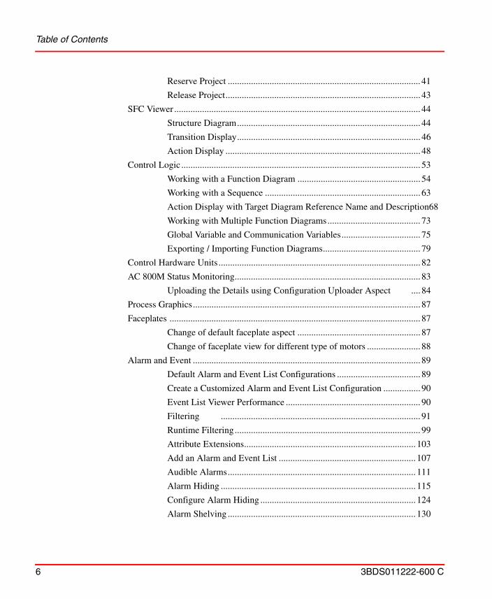
Table of Contents
6 3BDS011222-600 C
Reserve Project ................................................................................... 41
Release Project.................................................................................... 43
SFC Viewer .......................................................................................................... 44
Structure Diagram............................................................................... 44
Transition Display............................................................................... 46
Action Display .................................................................................... 48
Control Logic ....................................................................................................... 53
Working with a Function Diagram ..................................................... 54
Working with a Sequence ................................................................... 63
Action Display with Target Diagram Reference Name and Description68
Working with Multiple Function Diagrams........................................ 73
Global Variable and Communication Variables.................................. 75
Exporting / Importing Function Diagrams.......................................... 79
Control Hardware Units ....................................................................................... 82
AC 800M Status Monitoring................................................................................ 83
Uploading the Details using Configuration Uploader Aspect .... 84
Process Graphics.................................................................................................. 87
Faceplates ............................................................................................................ 87
Change of default faceplate aspect ..................................................... 87
Change of faceplate view for different type of motors ....................... 88
Alarm and Event .................................................................................................. 89
Default Alarm and Event List Configurations .................................... 89
Create a Customized Alarm and Event List Configuration ................ 90
Event List Viewer Performance .......................................................... 90
Filtering ...................................................................................... 91
Runtime Filtering................................................................................ 99
Attribute Extensions.......................................................................... 103
Add an Alarm and Event List ........................................................... 107
Audible Alarms................................................................................. 111
Alarm Hiding .................................................................................... 115
Configure Alarm Hiding ................................................................... 124
Alarm Shelving ................................................................................. 130
Table of Contents
3BDS011222-600 C 7
Alarm Grouping ................................................................................134
Enabling Alarm Grouping.................................................................135
Configuring Alarm Grouping............................................................136
Adding Alarm Conditions to an Alarm Group..................................140
Opening the Alarm Group Definition ...............................................141
Alarm Analysis..................................................................................143
Creating an Alarm Band....................................................................154
Creating a Sequence Bar Aspect .......................................................156
Alarm Expression..............................................................................157
Expression Rules and Examples .......................................................168
Valid Operators..................................................................................169
Item Syntaxes ....................................................................................171
Creation of a Separate Expression List .............................................172
Alarm Conditions aspect ...................................................................174
External Alarm - Sounds, Lights.......................................................176
Configuring the External Alarm service ...........................................177
SMS and e-mail Messaging ...............................................................................182
Setup and Configuration Workflow...................................................183
Setup and Configuration Worksheets ................................................184
Hardware Setup .................................................................................184
GSM Hardware (SMS/GSM) ............................................................185
Modem Hardware (TAP/Modem) .....................................................188
System Setup ....................................................................................196
Configuration ....................................................................................216
System Status .....................................................................................................232
Topology Status Viewer ....................................................................232
Device Management & Fieldbusses ..............................................................................235
Device Library Wizard .......................................................................................235
Prerequisites ....................................................................................235
Source for Device Types ...................................................................236
Extract Device Type Files .................................................................237
Read Release Notes of the Device Types..........................................240
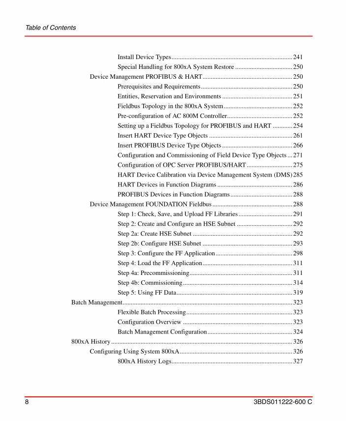
Table of Contents
8 3BDS011222-600 C
Install Device Types.......................................................................... 241
Special Handling for 800xA System Restore ................................... 250
Device Management PROFIBUS & HART....................................................... 250
Prerequisites and Requirements........................................................ 250
Entities, Reservation and Environments ........................................... 251
Fieldbus Topology in the 800xA System.......................................... 252
Pre-configuration of AC 800M Controller........................................ 252
Setting up a Fieldbus Topology for PROFIBUS and HART ............ 254
Insert HART Device Type Objects ................................................... 261
Insert PROFIBUS Device Type Objects ........................................... 266
Configuration and Commissioning of Field Device Type Objects ... 271
Configuration of OPC Server PROFIBUS/HART............................ 275
HART Device Calibration via Device Management System (DMS)285
HART Devices in Function Diagrams .............................................. 286
PROFIBUS Devices in Function Diagrams...................................... 288
Device Management FOUNDATION Fieldbus ................................................. 288
Step 1: Check, Save, and Upload FF Libraries ................................. 291
Step 2: Create and Configure an HSE Subnet .................................. 292
Step 2a: Create HSE Subnet ............................................................. 292
Step 2b: Configure HSE Subnet ....................................................... 293
Step 3: Configure the FF Application............................................... 298
Step 4: Load the FF Application....................................................... 311
Step 4a: Precommissioning............................................................... 311
Step 4b: Commissioning................................................................... 314
Step 5: Using FF Data....................................................................... 319
Batch Management........................................................................................................ 323
Flexible Batch Processing................................................................. 323
Configuration Overview ................................................................... 323
Batch Management Configuration.................................................... 324
800xA History ............................................................................................................... 326
Configuring Using System 800xA..................................................................... 326
800xA History Logs.......................................................................... 327
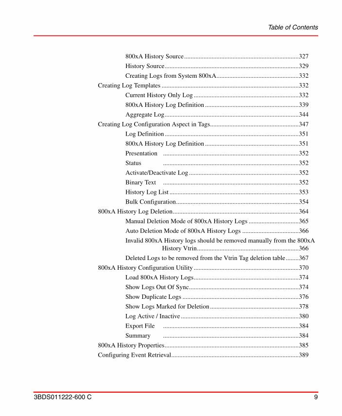
Table of Contents
3BDS011222-600 C 9
800xA History Source.......................................................................327
History Source...................................................................................329
Creating Logs from System 800xA...................................................332
Creating Log Templates .....................................................................................332
Current History Only Log .................................................................332
800xA History Log Definition ..........................................................339
Aggregate Log...................................................................................344
Creating Log Configuration Aspect in Tags.......................................................347
Log Definition ...................................................................................351
800xA History Log Definition ..........................................................351
Presentation ....................................................................................352
Status ....................................................................................352
Activate/Deactivate Log ....................................................................352
Binary Text ....................................................................................352
History Log List ................................................................................353
Bulk Configuration............................................................................354
800xA History Log Deletion..............................................................................364
Manual Deletion Mode of 800xA History Logs ...............................365
Auto Deletion Mode of 800xA History Logs ...................................366
Invalid 800xA History logs should be removed manually from the 800xA History Vtrin...............................................................366
Deleted Logs to be removed from the Vtrin Tag deletion table ........367
800xA History Configuration Utility .................................................................370
Load 800xA History Logs.................................................................374
Show Logs Out Of Sync....................................................................374
Show Duplicate Logs ........................................................................376
Show Logs Marked for Deletion .......................................................378
Log Active / Inactive .........................................................................380
Export File ....................................................................................384
Summary ....................................................................................384
800xA History Properties...................................................................................385
Configuring Event Retrieval...............................................................................389
Table of Contents
10 3BDS011222-600 C
Create Alarm and Event List Configuration Aspect ......................... 389
Retrieve Based on Event Type .......................................................... 392
Retrieve Events Based on Category.................................................. 393
Retrieve Events Based on Attributes................................................. 394
Retrieval Events Based on Event Time............................................. 394
Retrieval Events Based on PPA Object ID........................................ 395
Configuring Archives......................................................................................... 396
Configuring Event Archiving............................................................ 396
Manual Archiving for Archive Groups ............................................. 400
Creating Alarm and Event List Configuration.................................. 406
Retrieving Archived Event List ........................................................ 409
History Supervision ........................................................................................... 410
Information Management.............................................................................................. 411
Historical Process Data ...................................................................................... 411
History Configuration ........................................................................................ 411
Log Template .................................................................................... 412
Log Configuration............................................................................. 418
Log Configuration Details ................................................................ 422
Log Summary ................................................................................... 440
Archive Tool .................................................................................... 442
Bulk Configuration ........................................................................... 443
Extended Configuration Data ............................................................................ 445
Parameter Management .................................................................... 445
Softpoint Configuration Workflow ................................................... 447
Importing and Exporting Softpoint Configuration Data................... 449
Document Management ..................................................................................... 450
Information Access Aspects .............................................................................. 453
How to use the File Viewer............................................................... 454
How to use the Bookmark Aspect .................................................... 466
How to use the Web Page Aspect ..................................................... 470
How to use the ActiveX Wrapper Aspect ......................................... 471
How to use the Windows Application Aspect .................................. 474
Table of Contents
3BDS011222-600 C 11
How to use the Help Aspect ..............................................................476
How to add and configure CAD Drawing Aspect.............................479
Asset Optimization ........................................................................................................481
Asset Monitoring................................................................................................481
Maximo Integration............................................................................................482
SAP/PM Integration ...........................................................................................483
PC, Network and Software Monitoring.........................................................................483
Configuration Change and Access Management...........................................................484
Authorization......................................................................................................484
Access Control ...................................................................................................484
Log Over ...........................................................................................................485
Electronic Signature ...........................................................................................485
Configuration Change Management ..................................................................486
System Configuration Version ..........................................................486
Synchronizing Changes Between Systems .......................................486
Engineering Repository......................................................................................487
Permissions ....................................................................................488
User Interface ....................................................................................489
Menus ....................................................................................493
Toolbar ....................................................................................496
Plant Explorer Context Menu............................................................496
Configuration ....................................................................................497
Filters ....................................................................................499
Application Change Management......................................................................500
Import / Export tool............................................................................................501
Synchronizing Changes Between Environments ...............................................502
Audit Trail ..........................................................................................................504
Archive ...........................................................................................................505
System and Device Checks ................................................................................505
Data Access ...................................................................................................................505
Accessing 800xA via OPC.................................................................................505
Hardware Setup .................................................................................506
Table of Contents
12 3BDS011222-600 C
Accessing the 800xA OPC DA Server ............................................. 506
Accessing the 800xA OPC AE Server.............................................. 508
Accessing the 800xA OPC HDA Server........................................... 509
Integrating OPC Servers into 800xA ................................................................. 509
Hardware Setup................................................................................. 510
Integrating OPC DA Servers............................................................. 510
Alarm Coloring in Trend Display ..................................................... 522
Integrating OPC AE Servers ............................................................. 537
Integrating OPC HDA Servers.......................................................... 549
DCOM Security Settings for OPC.................................................... 549
Accessing 800xA via OLE DB.......................................................................... 557
OLE DB Provider for DA ................................................................. 557
Example Command Line .................................................................. 559
Short References ............................................................................... 560
OLE DB Provider for HDA .............................................................. 560
Property Transfer ............................................................................................... 571
Purpose .................................................................................... 571
Property Transfer Definition Aspect................................................. 571
Property Transfer Service ................................................................. 574
Security Handling ............................................................................. 575
Property Expression ........................................................................................... 575
Property Expression Manager Service.............................................. 576
Configure Property Expression Aspect............................................. 576
Reference Scope ............................................................................... 578
Timestamp and Quality..................................................................... 578
Redundancy .................................................................................... 579
Configuration Rules .......................................................................... 579
Writing Expressions.......................................................................... 579
Libraries ........................................................................................................................ 580
Building Versioned Object Type Libraries ........................................................ 580
Using Versioned Object Type Libraries ............................................................. 580
Object Types.................................................................................................................. 581
Table of Contents
3BDS011222-600 C 13
Building Object Types........................................................................................581
Object Type Group Creation .............................................................582
Object Type Creation ........................................................................582
Subtype Creation and Object Type Extensions .................................589
Composite Object Type Creation ......................................................592
Examples of Object Types..................................................................................597
Control Object Types / Composite Control Object Types.................597
Process Object Type with Signals .....................................................599
Process Object Type Built in Function Designer ..............................603
Signal Group ....................................................................................607
Building Reuse Instructions ...............................................................................611
Appendix A - Object TypesReference Information for Object Types .......................................................................615
Object Type Groups ...........................................................................................615
Object Types.......................................................................................................615
Aspect Groups ....................................................................................................616
Aspects ...........................................................................................................617
Object Type Definition Aspect..........................................................617
Object Type Reference Aspect ..........................................................617
Super Type Reference Aspect ...........................................................617
Object Type Extension Definition Aspect.........................................618
Object Factory Aspect .......................................................................618
Object Type Group Reference Aspect...............................................618
Aspect Category Definition Aspect...................................................619
Formal Instance List Definition Aspect ............................................619
Formal Instance Definition Aspect ...................................................619
Formal Instance Reference Aspect....................................................619
Aspect Group Definition Aspect .......................................................619
Aspect Group Reference Aspect .......................................................620
Configuration Dialogs ........................................................................................620
Type Info Tab ....................................................................................620
Create Info Tab..................................................................................621
Table of Contents
14 3BDS011222-600 C
Aspect Control Tab ........................................................................... 623
Category Control Tab........................................................................ 624
Child Control Tab ............................................................................. 626
Composite Info Tab........................................................................... 629
Consistency Tab ................................................................................ 629
Formal Instance List Definition Aspect ............................................ 631
Composite Object Types .................................................................................... 631
Terminology .................................................................................... 633
Instantiation of Composite Types ..................................................... 634
Structure Propagation ....................................................................... 635
Aspect Propagation ........................................................................... 635
Relative References in Composite Types.......................................... 636
Creating an Object Icon Aspect ......................................................................... 636
Creating Other Aspects ...................................................................................... 638
Appendix B - Library HandlingBase Libraries................................................................................................................ 639
Creating a New Base Library............................................................................. 639
Adding Data to a Base Library Version ............................................................. 642
Generating a Library Archive ............................................................................ 643
Releasing a Library Version............................................................................... 645
Creating a New Minor Version or Revision....................................................... 646
Creating a New Major Version .......................................................................... 647
Library Definition Aspect .................................................................................. 648
Library Version Definition Aspect..................................................................... 649
Library Member Aspect..................................................................................... 658
Deleting a Library .............................................................................................. 660
Renaming a Library ........................................................................................... 661
Moving a Library Version.................................................................................. 661
Extension Libraries ....................................................................................................... 661
Extending Object Type Definitions.................................................................... 662
Creating a New Extension Library .................................................................... 662
Adding Data to an Extension Library Version................................................... 664
Table of Contents
3BDS011222-600 C 15
Creating a New Extension Library Version........................................................666
Extension Library Definition Aspect .................................................................668
Extension Library Version Definition Aspect ....................................................668
Appendix C - SMS and E-Mail MessagingSetup and Configuration Worksheets ............................................................................671
GSM Service Providers and Hardware Devices ............................................................678
Revision History
Index

Table of Contents
16 3BDS011222-600 C
3BDS011222-600 C 17
About this User Manual
This User Manual gives you an overview on engineering and configuration workflow steps of the System 800xA in the context of an engineering project. It is an introductory manual with system scope containing short descriptions of step by step instructions.
Typically an engineering project that automates a plant is seen to cover the phases plant design, software production and test, installation and commissioning. The term configuration is mainly used for the concrete tool based activities to bring the the results of all engineering tasks performed in software production and test into the system.
Concepts important for engineering of System 800xA are described in System 800xA System Guide, Functional Description (3BSE038018*).
Engineering planning considerations are described in System 800xA System Planning (3BSE041389*).
The control system connectivity for AC 800M is presumed. Generic OPC connectivity is described also. Other connectivity options are not covered in this User Manual.
Building the automation solution is described with focus on the process oriented Functional Planning approach, based on Function Designer, including Library
Any security measures described in this document, for example, for user access, password security, network security, firewalls, virus protection, and so on, represent possible steps that a user of an 800xA System may want to consider based on a risk assessment for a particular application and installation. This risk assessment, as well as the proper implementation, configuration, installation, operation, administration, and maintenance of all relevant security related equipment, software, and procedures, are the responsibility of the user of the 800xA System.
About this User Manual
18 3BDS011222-600 C
Structure, Object Type Structure, Functional Structure and Control Structure. It is described in more detail in System 800xA Engineering, Engineering Studio Function Designer Getting Started (3BDS100968*) and System 800xA Engineering, Engineering Studio, Function Designer (3BDS011224*).
To build the automation solution based on IEC 61131 Function Block programming or on ABB´s Control Module programming or Diagrams, including Library Structure, Object Type Structure and Control Structure is described in System 800xA Control AC 800M Getting Started, (3BSE041880*) and System 800xA Control AC 800M Configuration (3BSE035980*).
In Control Builder M, if Diagrams are used, it is possible to include the entire object-oriented design in a single diagram as it allows mixing control modules, function blocks, diagrams, and functions by graphical connections. Diagrams also allow communication from a lower SIL application to a higher SIL application, if required.
Furthermore all three approaches to build an automation solution are also supported by Bulk Data Management and pre-configured Bulk Data Management templates and applications described here and in System 800xA Engineering, Engineering Studio (3BDS011223*).
You will find System 800xA configuration topics related to basic functions described in more detail than those related to the options of System 800xA. Where applicable topics are handled by references to corresponding other manuals.
Section 1, Introduction introduces you to the main features of the system.
Section 2, Configuration contains step by step workflow instructions and reference information.
Appendix A, Object Types contains reference information for configuration of object types.
Appendix B, Library Handling contains reference information for configuration of versioned object type libraries.
Appendix C, SMS and E-Mail Messaging contains configuration worksheets and reference information to be used when configuring SMS and e-mail messaging.
About this User Manual Intended User
3BDS011222-600 C 19
Intended UserThis User Manual is written for application engineers performing the tasks to engineer and configure the automation solution in the software production and test phase of an engineering project.
As a reader of this User Manual you should have basic knowledge of engineering and configuration of process automation systems in general. Additionally you should have read System 800xA, System Guide, Functional Description (3BSE038018*) and System 800xA System Planning (3BSE041389*).
For more information on system set up for an engineering system refer to System 800xA, Administration and Security (3BSE037410*) and System 800xA Installation and Upgrade Getting Started (2PAA111708*) instructions.
Reading can be minimized according to the concrete task profile of an application engineer in an engineering project.
Prior to engineering and configuring a system, read the applicable System 800xA release notes. The release notes contain important information not included in the ordinary user documentation.
It is recommended that you have participated in introductory ABB training courses for System 800xA.
Version Described in this User ManualUnless otherwise noted, the versions of all 800xA Base System and Functional Area software described in this user manual are the latest release of 800xA 6.0.
User Manual ConventionsMicrosoft Windows conventions as defined in the Microsoft Manual of Style are normally used for the standard presentation of material when entering text, key sequences, prompts, messages, menu items, screen elements, and so on.
Warning, Caution, Information, and Tip Icons
This User Manual includes Warning, Caution, and Information where appropriate to point out safety related or other important information. It also includes Tip to
Terminology About this User Manual
20 3BDS011222-600 C
point out useful hints to the reader. The corresponding symbols should be interpreted as follows:
Although Warning hazards are related to personal injury, and Caution hazards are associated with equipment or property damage, it should be understood that operation of damaged equipment could, under certain operational conditions, result in degraded process performance leading to personal injury or death. Therefore, fully comply with all Warning and Caution notices.
TerminologyA complete and comprehensive list of terms is included in System 800xA System Guide Functional Description (3BSE038018*). The listing includes terms and definitions that apply to the 800xA System where the usage is different from commonly accepted industry standard definitions and definitions given in standard dictionaries such as Webster’s Dictionary of Computer Terms.
Electrical warning icon indicates the presence of a hazard which could result in electrical shock.
Warning icon indicates the presence of a hazard which could result in personal injury.
Caution icon indicates important information or warning related to the concept discussed in the text. It might indicate the presence of a hazard which could result in corruption of software or damage to equipment/property.
Information icon alerts the reader to pertinent facts and conditions.
Tip icon indicates advice on, for example, how to design your project or how to use a certain function
About this User Manual Released User Manuals and Release Notes
3BDS011222-600 C 21
Released User Manuals and Release NotesA complete list of all User Manuals and Release Notes applicable to System 800xA is provided in System 800xA Released User Documents (3BUA000263*).
System 800xA Released User Documents (3BUA000263*) is updated each time a document is updated or a new document is released.
It is in PDF format and is provided in the following ways:
• Included on the documentation media provided with the system and published to ABB SolutionsBank when released as part of a major or minor release, Service Pack, Feature Pack, or System Revision.
• Published to ABB SolutionsBank when a User Manual or Release Note is updated in between any of the release cycles listed in the first bullet.
A product bulletin is published each time System 800xA Released User Documents (3BUA000263*) is updated and published to ABB SolutionsBank.

Released User Manuals and Release Notes About this User Manual
22 3BDS011222-600 C
3BDS011222-600 C 23
Section 1 Introduction
System OverviewThe Extended Automation System 800xA, System Version 6.0, covers operation as well as engineering and configuration of continuous and batch automation applications and supports FDA 21 CFR part 11 compliance of these applications.
An overview of the system functions and system infrastructure of System 800xA is given in System 800xA, System Guide, Functional Description (3BSE038018*).
The foundation of System 800xA is the Aspect Object architecture. Introductory information on Aspect ObjectsTM technology as well as conceptual information on engineering and configuration of the system functions you find in System 800xA System Planning (3BSE041389*).
Prerequisites and RequirementsFor hardware and software requirements, refer to the System 800xA Installation and Upgrade Getting Started (2PAA111708*).

Prerequisites and Requirements Section 1 Introduction
24 3BDS011222-600 C
3BDS011222-600 C 25
Section 2 Configuration
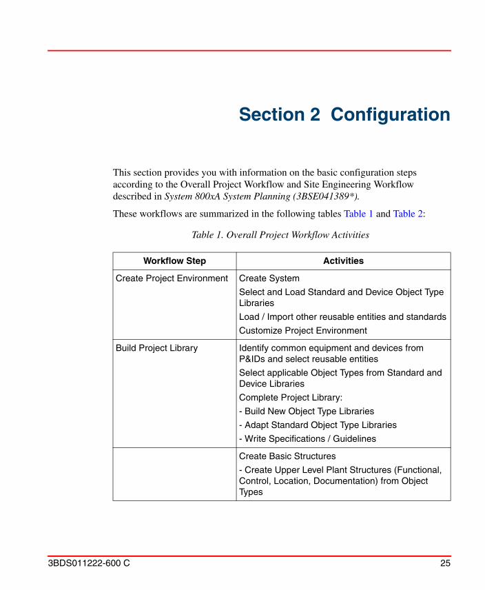
This section provides you with information on the basic configuration steps according to the Overall Project Workflow and Site Engineering Workflow described in System 800xA System Planning (3BSE041389*).
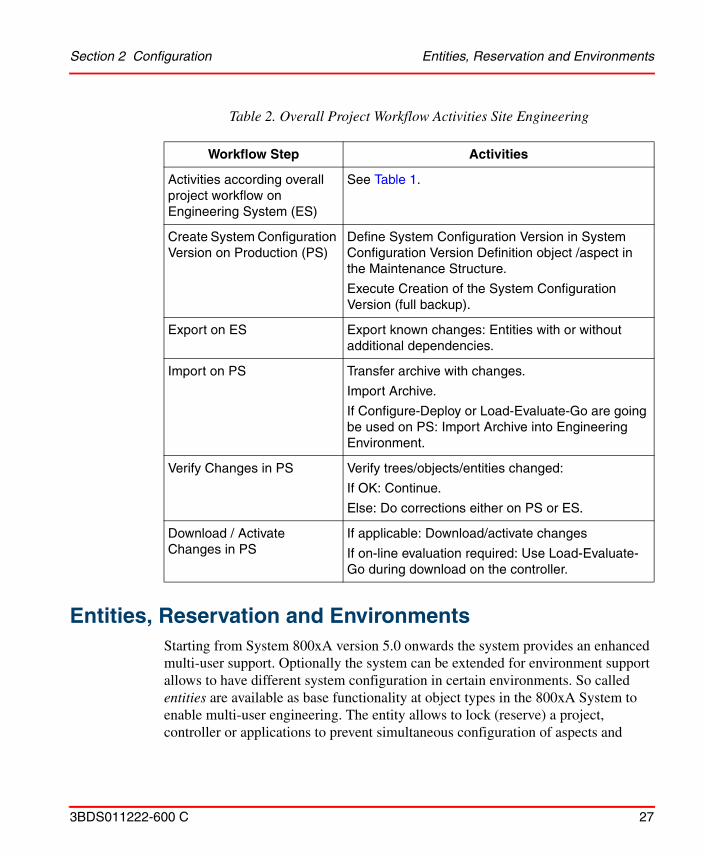
These workflows are summarized in the following tables Table 1 and Table 2:
Table 1. Overall Project Workflow Activities
Workflow Step Activities
Create Project Environment Create System
Select and Load Standard and Device Object Type Libraries
Load / Import other reusable entities and standards
Customize Project Environment
Build Project Library Identify common equipment and devices from P&IDs and select reusable entities
Select applicable Object Types from Standard and Device Libraries
Complete Project Library:
- Build New Object Type Libraries
- Adapt Standard Object Type Libraries
- Write Specifications / Guidelines
Create Basic Structures
- Create Upper Level Plant Structures (Functional, Control, Location, Documentation) from Object Types
Section 2 Configuration
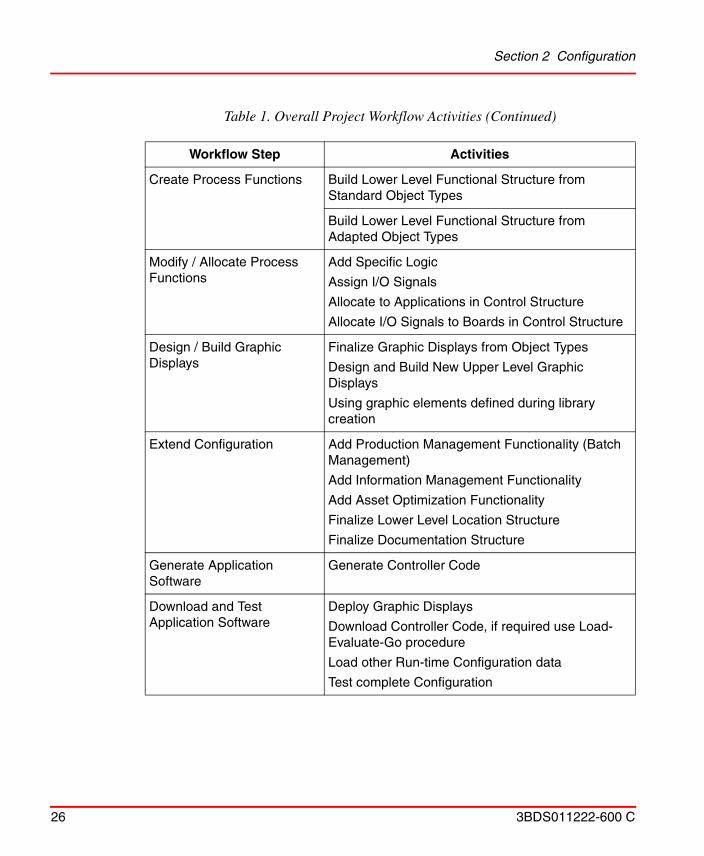
26 3BDS011222-600 C
Create Process Functions Build Lower Level Functional Structure from Standard Object Types
Build Lower Level Functional Structure from Adapted Object Types
Modify / Allocate Process Functions
Add Specific Logic
Assign I/O Signals
Allocate to Applications in Control Structure
Allocate I/O Signals to Boards in Control Structure
Design / Build Graphic Displays
Finalize Graphic Displays from Object Types
Design and Build New Upper Level Graphic Displays
Using graphic elements defined during library creation
Extend Configuration Add Production Management Functionality (Batch Management)
Add Information Management Functionality
Add Asset Optimization Functionality
Finalize Lower Level Location Structure
Finalize Documentation Structure
Generate Application Software
Generate Controller Code
Download and Test Application Software
Deploy Graphic Displays
Download Controller Code, if required use Load-Evaluate-Go procedure
Load other Run-time Configuration data
Test complete Configuration
Table 1. Overall Project Workflow Activities (Continued)
Workflow Step Activities
Section 2 Configuration Entities, Reservation and Environments
3BDS011222-600 C 27
Entities, Reservation and EnvironmentsStarting from System 800xA version 5.0 onwards the system provides an enhanced multi-user support. Optionally the system can be extended for environment support allows to have different system configuration in certain environments. So called entities are available as base functionality at object types in the 800xA System to enable multi-user engineering. The entity allows to lock (reserve) a project, controller or applications to prevent simultaneous configuration of aspects and
Table 2. Overall Project Workflow Activities Site Engineering
Workflow Step Activities
Activities according overall project workflow on Engineering System (ES)
See Table 1.
Create System Configuration Version on Production (PS)
Define System Configuration Version in System Configuration Version Definition object /aspect in the Maintenance Structure.
Execute Creation of the System Configuration Version (full backup).
Export on ES Export known changes: Entities with or without additional dependencies.
Import on PS Transfer archive with changes.
Import Archive.
If Configure-Deploy or Load-Evaluate-Go are going be used on PS: Import Archive into Engineering Environment.
Verify Changes in PS Verify trees/objects/entities changed:
If OK: Continue.
Else: Do corrections either on PS or ES.
Download / Activate Changes in PS
If applicable: Download/activate changes
If on-line evaluation required: Use Load-Evaluate-Go during download on the controller.
Entities, Reservation and Environments Section 2 Configuration
28 3BDS011222-600 C
objects in the 800xA system. Reservation functionality is available with right mouse click at the object in 800xA Plant Explorers Control Structure.
The following kind of objects and aspects available in the Control Structure and Object Type Structure can be used to make a reservation for underlaying objects and aspects:
• Projects, Applications, Controllers, Diagrams, Single Control Module (SCM)
• Libraries, libraries with hardware types
• Control modules types, except hidden control module types
• Function block types, except hidden function block types
• Diagrams types. except hidden diagram types
Activities of the workflow outlined in Table 1 and Table 2 are covered according the areas:
• Automation Solution on page 29
• Batch Management on page 323
• 800xA History on page 326
• Information Management on page 411
• Device Management & Fieldbusses on page 235
• Asset Optimization on page 481
• Configuration Change and Access Management on page 484
• Data Access on page 505
• Libraries on page 580
• Object Types on page 581
The configuration steps are described either as general instruction steps or as example based instruction steps. Some areas such as Object Types and SMS and e-mail Messaging contain information as detailed as reference information whereas other subsections reference the corresponding detail information given in other System 800xA instructions.
Section 2 Configuration Automation Solution
3BDS011222-600 C 29
Automation Solution
Control Structure
To start implementing an automation solution you need a Control Network and a Control Project in the Control Structure. The Control Project is structured in Libraries, Applications and Controllers.
Main activities to build up the required Control Structure are:
• Create Control Network, Control Project and Controller on page 30
• Open Project on page 41
• Reserve Project on page 41
• Release Project on page 43
• Configure OPC Data Source on page 32
• Create Control Application on page 33
• Insert Application Libraries on page 33
• Connect Application Libraries on page 34
• Create and Configure Controller on page 34
• Create and Configure Task on page 35
• Connect Application to Task on page 36
• Insert Hardware Libraries on page 36
• Connect Hardware Libraries to Controller on page 39
• Create Hardware Units on page 40 (I/O boards, communication boards).
All activities except for the first two in the list above require Control Builder M Professional to be opened on the corresponding project.
You can perform these basic activities starting from objects in Plant Explorer as described here. Alternatively you can start from objects in Project Explorer of Control Builder M Professional. Many activities can also be performed from Bulk Data Manager worksheets or from Reuse Instructions using Reuse Assistant.
Control Structure Section 2 Configuration
30 3BDS011222-600 C
Create Control Network, Control Project and Controller
1. Switch to Control Structure in Plant Explorer.
2. Select the root node.
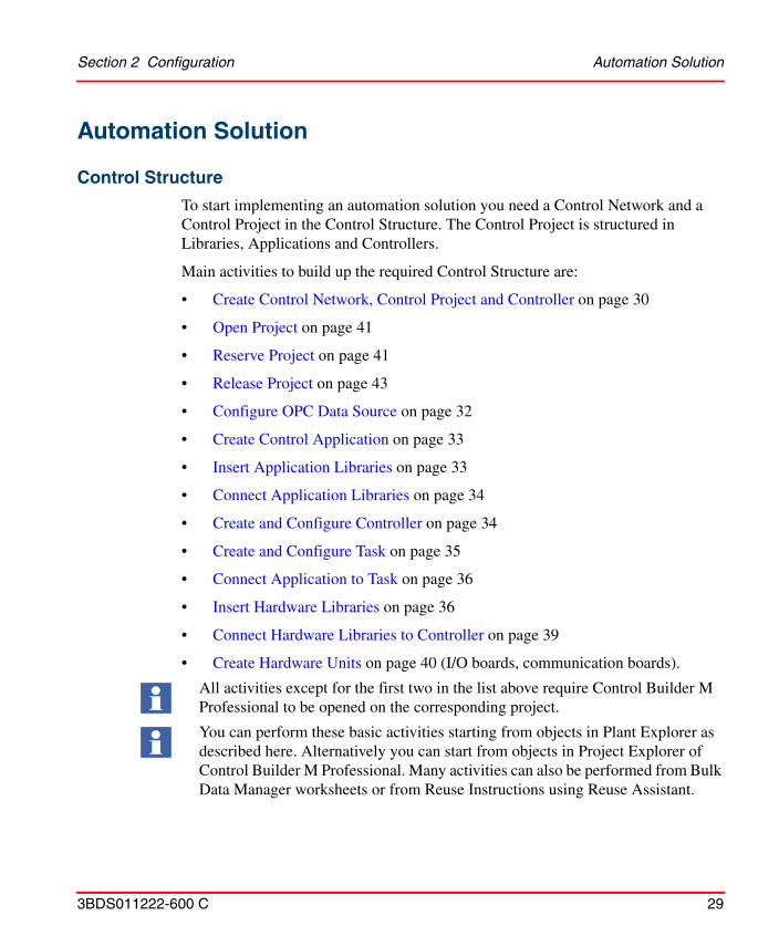
3. Click with the right mouse button and select New Object.
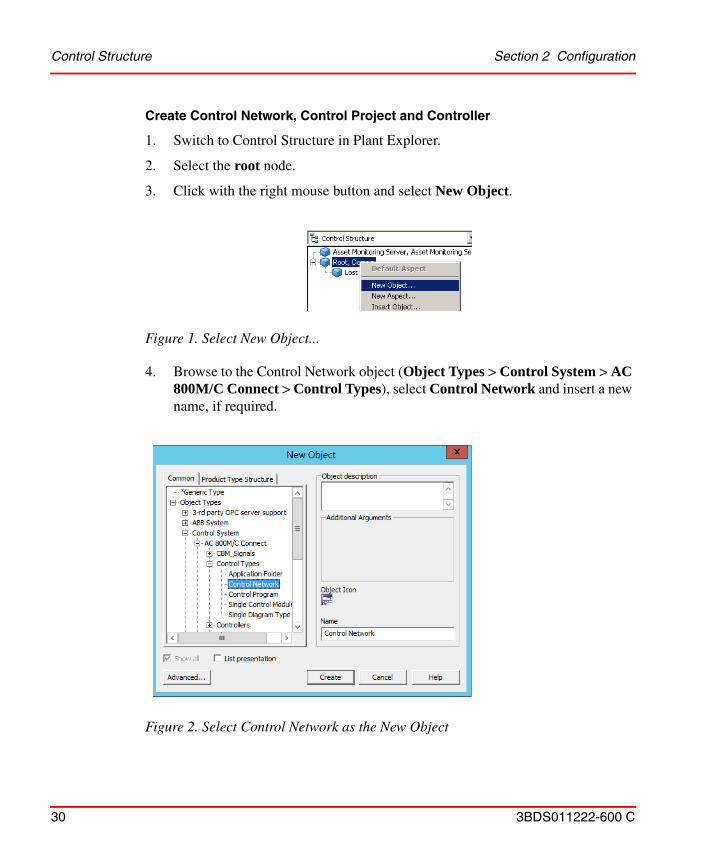
4. Browse to the Control Network object (Object Types > Control System > AC 800M/C Connect > Control Types), select Control Network and insert a new name, if required.
Figure 1. Select New Object...
Figure 2. Select Control Network as the New Object
Section 2 Configuration Control Structure
3BDS011222-600 C 31
5. Click Create.
6. Select the newly created Control Network object and click with the right mouse button.
7. Select New Object in the context menu.
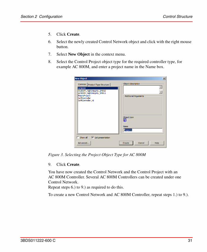
8. Select the Control Project object type for the required controller type, for example AC 800M, and enter a project name in the Name box.
9. Click Create.
You have now created the Control Network and the Control Project with an AC 800M Controller. Several AC 800M Controllers can be created under one Control Network. Repeat steps 6.) to 9.) as required to do this.
To create a new Control Network and AC 800M Controller, repeat steps 1.) to 9.).
Figure 3. Selecting the Project Object Type for AC 800M
Control Structure Section 2 Configuration
32 3BDS011222-600 C
Configure OPC Data Source
1. Switch to Control Structure in Plant Explorer.
2. Select the control network object.
3. Select the OPC Data Source Definition aspect.
4. Select the Connectivity tab.
5. Click New….
6. Change the name of the service group, if required.
7. Click Add....
8. Select the Connectivity Server on which the OPC Server is installed and running.
9. Click the OK button in the main window.
10. The OPC Server is now configured for data access to device internal data through OPC communication .
The following steps shall be done on every control network, placed in the system and containing the OPC Data Source Definition aspect.
The service group name can be found under Service Structure > Services > OpcDA_Connector.
Example of a service group name: OPC_ControlNetwork1
Each control network needs a unique service group name.
If redundant Connectivity Servers are used in the system they have to be assigned to the same Control Network. To do this the steps 1 to 10 have to be repeated for each redundant Connectivity Server.
For the case that not only one Control Network is instantiated, the steps 1 to 10 have to be repeated also for these Control Networks.
Different service group names as well as different Connectivity Servers shall be used.
Section 2 Configuration Control Structure
3BDS011222-600 C 33
The AC 800M OPC Server needs to be configured separately. For more information on configuration of AC 800M OPC Server, see AC 800M, OPC Server (3BSE035983*).
Create Control Application
The project created according to Create Control Network, Control Project and Controller on page 30 provides one control application by default. To add an additional application object to this project:
1. In Plant Explorer switch to the Control Structure.
2. Right click the Applications object below the corresponding Project object.
3. Click New Object....
4. In the New Object dialog accept the selection Control Application, change / edit Name and Object Description.
5. Press Create to create the new application object.
Insert Application Libraries
To be able to use a certain standard (or user defined) control application library you have to insert it into your project:
1. In Plant Explorer switch to the Control Structure.
2. Select the project object.
3. In the aspect list of the project object right click the Project aspect.
4. Click Config View.
5. In the <projectname>:Project dialog select the Libraries tab.
6. Press Insert.
7. In the structure browser of the Select a Library dialog browse to the required library, for example Object Types\Control System\AC 800M/C Connect\Libraries\ProjectObjExtLib 2.3-4 and select it.
8. Press OK to insert this library and all libraries it depends on into your project.
9. Click Apply.
Control Structure Section 2 Configuration
34 3BDS011222-600 C
10. Press Close on window level leave the dialog.
Repeat Step 6 to Step 9 to insert other libraries needed.
Connect Application Libraries
To be able to use a standard (or user defined) control application library inserted into your project in an application you have to connect it your application:
1. In Plant Explorer switch to the Control Structure.
2. Select the application object.
3. In the aspect list of the application object right click the Application aspect.
4. Click Config View.
5. In the <applicationname>:Application dialog select the Libraries tab.
6. Press Connect.
7. From the list of libraries in the Select a Library to Connect dialog, select the required library, for example ProjectObjExtLib 2.3-4.
8. Press OK to insert this library.
9. Click Apply.
10. Press Close on window level leave the dialog.
Repeat Step 6 to Step 8 to connect other libraries needed.
Create and Configure Controller
The project created according to Create Control Network, Control Project and Controller on page 30 provides one controller by default. To add an additional controller to this project:
1. In Plant Explorer switch to the Control Structure.
2. Right click the Controllers object below the corresponding project object.
3. Click New Object....
4. In the New Object dialog select the controller type, change / edit Name and Object Description.
Section 2 Configuration Control Structure
3BDS011222-600 C 35
5. Press Create to create the new controller object.
6. Right click on the Hardware object below the new controller object.
7. Click New Object....
8. In the New Object dialog browse to Object Types\Control System\ AC 800M/C Connect\Libraries\Hardware\BasicHWLib 6.0-0, select the processor module type (for example PM860 / TP830), change / edit Name and Object Description.
9. Press Create to create the new processor module object.
To give a controller a unique system identity as required:
1. In Plant Explorer switch to the Control Structure.
2. Right click the corresponding controller object below the corresponding project object.
3. Click Project Explorer.
4. In the Control Builder M Professional project window right click the already selected controller.
5. Click Properties > System Identity.
6. Enter the required TCP/IP address of the controller.
7. Press OK.
Create and Configure Task
By default a controller is configured with three Control Tasks: Fast, Normal, Slow.
To add an own task:
1. In Plant Explorer switch to the Control Structure.
2. Right click the Tasks object below the corresponding controller object.
3. Click New Object....
4. In the New Object dialog accept selected type Control Task, change / edit Name and Object Description.
5. Press Create to create the new task object.
Control Structure Section 2 Configuration
36 3BDS011222-600 C
To configure the task’s properties:
1. Right-click on the task object.
2. Click Task Properties.
3. In the Task Properties dialog edit the required properties and click Apply.
4. Click OK.
Connect Application to Task
To connect an application to a controller and a task:
1. In Plant Explorer switch to the Control Structure.
2. Right click the Applications object below the corresponding controller object.
3. Click Insert Object....
4. In the Insert Object dialog browse to the existing application child object of the Applications object below the project object and select it.
5. Press Insert.
6. Press Close to leave the dialog.
7. Right click the inserted application object.
8. Click Project Explorer.
9. In the Control Builder M Professional project window right click the already selected application.
10. Click Task Connection.
11. From the offered list of tasks select an appropriate task.
12. Press OK.
Insert Hardware Libraries
Hardware libraries are standard hardware libraries, device hardware libraries, user created libraries. Standard hardware libraries are included in the AC 800M Connect system extensions.
Section 2 Configuration Control Structure
3BDS011222-600 C 37
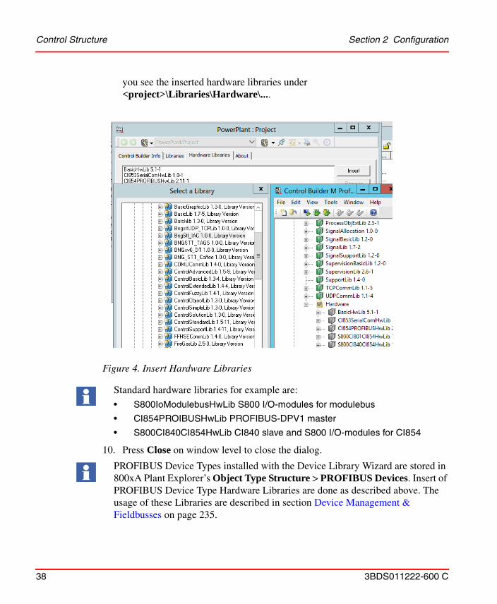
1. In Plant Explorer switch to the Control Structure.
2. Select the Control Project object.
3. In the aspect list right click on the Project aspect.
4. Click Config View.
5. In the <project>:Project dialog select the Hardware Libraries tab.
6. Press Insert.
7. In the Object Type Structure shown in the Select a Library dialog navigate to and select the required hardware library, for example S800IoModuleBusHwLib 1.0-7.
8. Press OK.
9. In the Hardware Libraries tab of the <project>:Project dialog press Apply. If the project is not already open this actions also opens the project and starts Control Builder M Professional. In the Project Explorer of Control Builder M
Only when the project is reserved it is possible to insert hardware libraries in the project. See Reserve Project on page 41
Control Structure Section 2 Configuration
38 3BDS011222-600 C
you see the inserted hardware libraries under <project>\Libraries\Hardware\....
10. Press Close on window level to close the dialog.
Figure 4. Insert Hardware Libraries
Standard hardware libraries for example are:
• S800IoModulebusHwLib S800 I/O-modules for modulebus
• CI854PROIBUSHwLib PROFIBUS-DPV1 master
• S800CI840CI854HwLib CI840 slave and S800 I/O-modules for CI854
PROFIBUS Device Types installed with the Device Library Wizard are stored in 800xA Plant Explorer’s Object Type Structure > PROFIBUS Devices. Insert of PROFIBUS Device Type Hardware Libraries are done as described above. The usage of these Libraries are described in section Device Management & Fieldbusses on page 235.
Section 2 Configuration Control Structure
3BDS011222-600 C 39
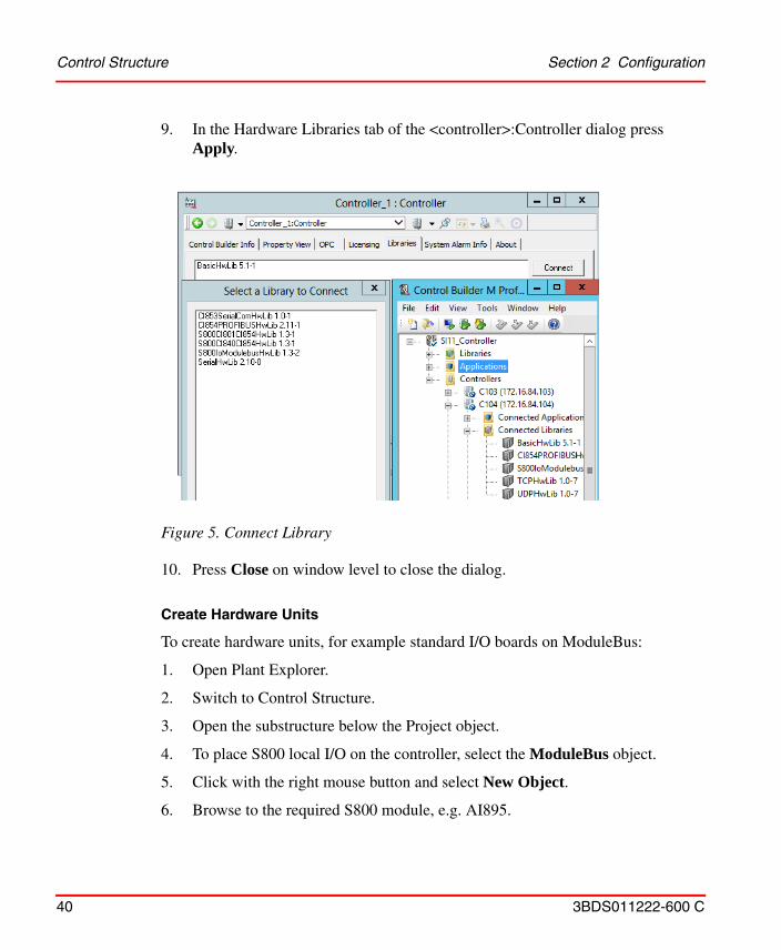
Connect Hardware Libraries to Controller
1. In Plant Explorer switch to the Control Structure.
2. Select the Control Project object, if not already opened: Open the project.
3. Select the Controller object.
4. In the aspect list right click on the Controller aspect.
5. Click Config View.
6. In the <controller>:Controller dialog select the Libraries tab.
7. Press Connect.
8. From the hardware libraries in the Select a Library to Connect dialog select a required one and press OK.
Only when the controller is reserved it is possible to connect hardware libraries in the project.
Control Structure Section 2 Configuration
40 3BDS011222-600 C
9. In the Hardware Libraries tab of the <controller>:Controller dialog press Apply.
10. Press Close on window level to close the dialog.
Create Hardware Units
To create hardware units, for example standard I/O boards on ModuleBus:
1. Open Plant Explorer.
2. Switch to Control Structure.
3. Open the substructure below the Project object.
4. To place S800 local I/O on the controller, select the ModuleBus object.
5. Click with the right mouse button and select New Object.
6. Browse to the required S800 module, e.g. AI895.
Figure 5. Connect Library
Section 2 Configuration Control Structure
3BDS011222-600 C 41
7. Enter the slot number of the module placed, e.g. 1, in the Name box.
8. Click Create.
The module is instantiated with the slot number in Control Structure of Plant Explorer as well as in Project Explorer of Control Builder M Professional.
Repeat steps 4 to 8 until the needed modules are created.
Bulks of hardware units you can create using Bulk Data Manager.
Open Project
To open a Control Builder M on a Project:
1. Open Plant Explorer.
2. Switch to the Control Structure.
3. Browse to the Control Project object.
4. Select the Control Project object.
5. Right-click on the mouse and select Open Project.
Reserve Project
1. Open Plant Explorer.
2. Switch to Control Structure.
3. Browse to the Control Project object.
4. Select the Control Project object.
5. Right click on the object.
S800 local I/Os always start at slot 1.
For more information on S800 modules and their instantiation, refer to System 800xA Control, AC 800M Configuration (3BSE035980*) and the hardware related manuals on S800 I/O.
Reserve Project gives exclusive modify access for the project entity to the reserving user.
Control Structure Section 2 Configuration
42 3BDS011222-600 C
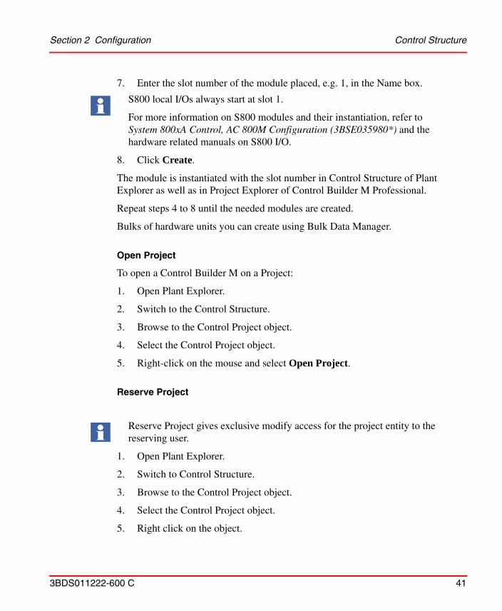
6. Click Reserve... in the context menu.
7. In the Reserve <project> dialog all entities (project, application, controller) shown are by default marked. Unmark the check boxes you want to exclude.
8. Click the Reserve icon.
9. Press Close on window level to close the dialog.
Figure 6. Reserve Project
To reserve an application is required if changes to the application shall be done. To reserve a controller is required e.g. to add CI854 communication interface, I/O modules, HART or PROFIBUS devices to the AC 800M Controller.
Section 2 Configuration Control Structure
3BDS011222-600 C 43
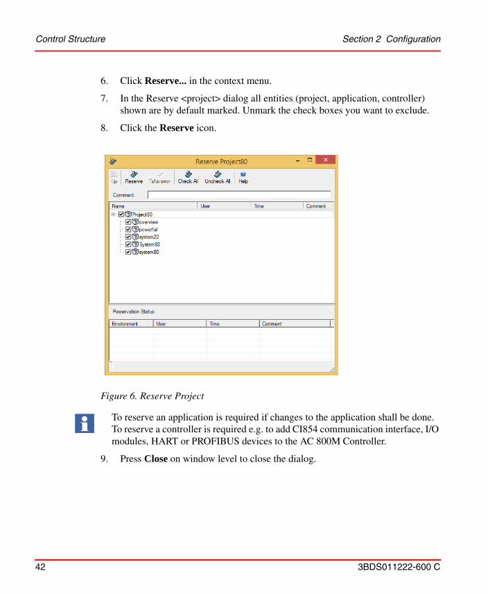
Release Project
1. Perform Step 1 to Step 5 as in Reserve Project on page 41
2. Click Release... in the context menu.
3. In the Release <project> dialog all entities (project, application, controller) shown are by default marked. Unmark the check boxes you want to exclude.
4. Click the Release icon.
5. Press Close on window level to close the dialog.
Release Project cancels modify access for the releasing user. Another user now can reserve the project to modify it.
Figure 7. Release Project
SFC Viewer Section 2 Configuration
44 3BDS011222-600 C
For more information on these activities see System 800xA Control AC 800M Getting Started (3BSE041880*) and System 800xA Control AC 800M Configuration (3BSE035980*).
SFC Viewer
The Sequential Function Chart (SFC) Viewer is a tool in the 800xA System that allows the Operator to display SFC structures with active steps and live data for active transitions on Operator workplaces without additional installation of a controller configuration tool.
Structure Diagram
The structure diagram in the 800xA System is used for visual tracking of sequential control processes and to display details of steps, actions, and transitions. The general display of the sequence control is based on the IEC 61131-3 standard. The default colors for the SFC Viewer animation can be changed workplace-specific for customer needs.
For more information, refer to System 800xA Operations (3BSE036904*).
Configuration Settings for Displaying the Whole Structure for Transition
The WholeStructure property of the SFCViewerSettings aspect is used to set the default view of SFC diagram:
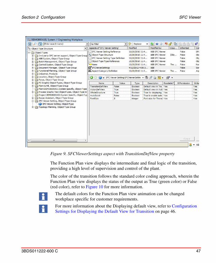
1. Open Object Type Structure > SFC Viewer Setting > SFC Viewer Setting > SFCViewerSettings aspect. See Figure 9.
2. Set the Value of WholeStructure property:
– True – to display the whole SFC overview diagram
– False – to display the SFC overview diagram based on the set of calculated rules with respect to Aspect view size.
The recommended count of SFC Viewer Aspects in the System must be less than 10,000.
The default value of the WholeStructure property is false.
Section 2 Configuration SFC Viewer
3BDS011222-600 C 45
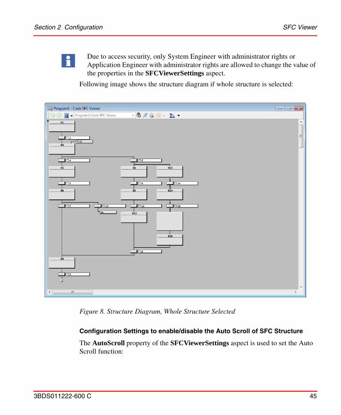
Following image shows the structure diagram if whole structure is selected:
Configuration Settings to enable/disable the Auto Scroll of SFC Structure
The AutoScroll property of the SFCViewerSettings aspect is used to set the Auto Scroll function:
Due to access security, only System Engineer with administrator rights or Application Engineer with administrator rights are allowed to change the value of the properties in the SFCViewerSettings aspect.
Figure 8. Structure Diagram, Whole Structure Selected
SFC Viewer Section 2 Configuration
46 3BDS011222-600 C
1. Open Object Type Structure > SFC Viewer Setting > SFC Viewer Setting> SFCViewerSettings aspect. See Figure 9.
2. Set the Value of AutoScroll property:
– True – to enable the Auto Scroll by default
– False – to disable the Auto Scroll
Transition Display
The transition display can be opened by clicking the transition button in the Structure Display. The transition display shows the stepping criteria for the selected transition in a Function Plan view perspective or a List view perspective.
Configuration Settings for Displaying the Default View for Transition
The TransitionDefView property of the SFCViewerSettings aspect is used to set the default view of the transition window:
1. Open Object Type Structure > SFC Viewer Setting > SFC Viewer Setting > SFCViewerSettings aspect. See Figure 9.
2. Set the Value of TransitionDefView property:
– True – to display the List View as the default view
– False – to display the Function Plan View as the default view
The default value of the AutoScroll property is true.
FontSize property of SFCViewerSettings aspect can be used to change the font size for the transition window and list view in the action window. Default value of this property is 10. For proper view, it is advised to set the font size in the range of 5 to 15.
Section 2 Configuration SFC Viewer
3BDS011222-600 C 47
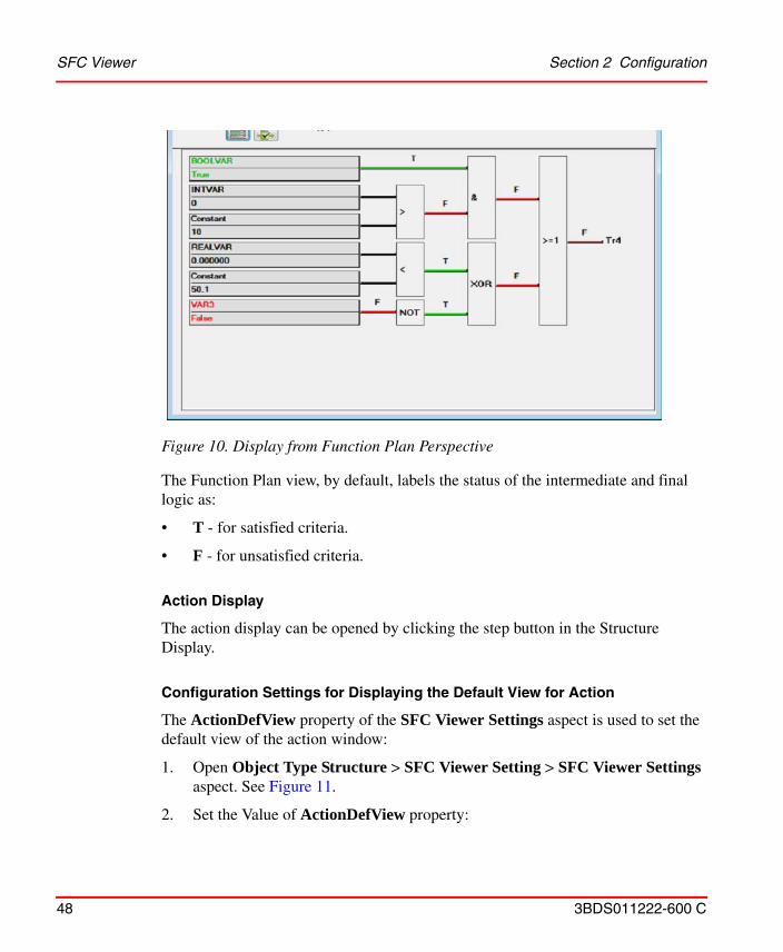
The Function Plan view displays the intermediate and final logic of the transition, providing a high level of supervision and control of the plant.
The color of the transition follows the standard color coding approach, wherein the Function Plan view displays the status of the output as True (green color) or False (red color), refer to Figure 10 for more information.
Figure 9. SFCViewerSettings aspect with TransitionDefView property
The default colors for the Function Plan view animation can be changed workplace specific for customer requirements.
For more information about the Displaying default view, refer to Configuration Settings for Displaying the Default View for Transition on page 46.
SFC Viewer Section 2 Configuration
48 3BDS011222-600 C
The Function Plan view, by default, labels the status of the intermediate and final logic as:
• T - for satisfied criteria.
• F - for unsatisfied criteria.
Action Display
The action display can be opened by clicking the step button in the Structure Display.
Configuration Settings for Displaying the Default View for Action
The ActionDefView property of the SFC Viewer Settings aspect is used to set the default view of the action window:
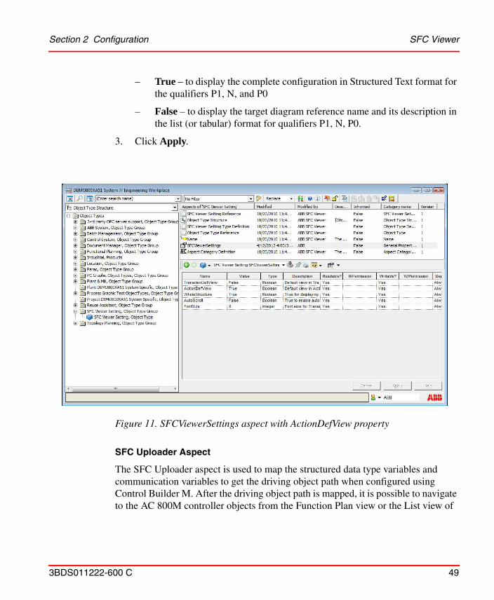
1. Open Object Type Structure > SFC Viewer Setting > SFC Viewer Settings aspect. See Figure 11.
2. Set the Value of ActionDefView property:
Figure 10. Display from Function Plan Perspective
Section 2 Configuration SFC Viewer
3BDS011222-600 C 49
– True – to display the complete configuration in Structured Text format for the qualifiers P1, N, and P0
– False – to display the target diagram reference name and its description in the list (or tabular) format for qualifiers P1, N, P0.
3. Click Apply.
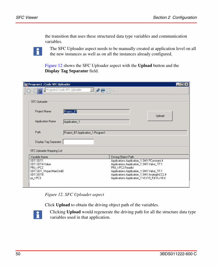
SFC Uploader Aspect
The SFC Uploader aspect is used to map the structured data type variables and communication variables to get the driving object path when configured using Control Builder M. After the driving object path is mapped, it is possible to navigate to the AC 800M controller objects from the Function Plan view or the List view of
Figure 11. SFCViewerSettings aspect with ActionDefView property
SFC Viewer Section 2 Configuration
50 3BDS011222-600 C
the transition that uses these structured data type variables and communication variables.
Figure 12 shows the SFC Uploader aspect with the Upload button and the Display Tag Separator field.
Click Upload to obtain the driving object path of the variables.
The SFC Uploader aspect needs to be manually created at application level on all the new instances as well as on all the instances already configured.
Figure 12. SFC Uploader aspect
Clicking Upload would regenerate the driving path for all the structure data type variables used in that application.
Section 2 Configuration SFC Viewer
3BDS011222-600 C 51
The Display Tag Separator field is used to specify how the tag names of structured data type variables are displayed in the transition window, based on the maximum number of dots (path of the sub-components of the variable):
1. Enter an integer value in the range 1 to 6 in the Display Tag Separator field.
2. Click Upload.
The transition window displays the tag name of the structured data type variables with the sub-components (dot notation) upto the integer value entered. For example, for a Display Tag Separator value 2, the tag name displayed is Var1.PidAdv; and for a value 3, it is Var1.PidAdv.StartAT.
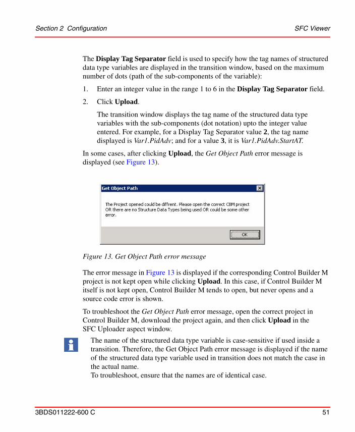
In some cases, after clicking Upload, the Get Object Path error message is displayed (see Figure 13).
The error message in Figure 13 is displayed if the corresponding Control Builder M project is not kept open while clicking Upload. In this case, if Control Builder M itself is not kept open, Control Builder M tends to open, but never opens and a source code error is shown.
To troubleshoot the Get Object Path error message, open the correct project in Control Builder M, download the project again, and then click Upload in the SFC Uploader aspect window.
Figure 13. Get Object Path error message
The name of the structured data type variable is case-sensitive if used inside a transition. Therefore, the Get Object Path error message is displayed if the name of the structured data type variable used in transition does not match the case in the actual name.To troubleshoot, ensure that the names are of identical case.
SFC Viewer Section 2 Configuration
52 3BDS011222-600 C
In the List View or Function Plan View:
• Right click the structured data type variable to display context menu with respect to the CMs/FBs.
• Double-click the structured data type variable to open the default aspect of CMs/FBs.
Object Navigation feature is supported based on the usage of SFC Uploader Aspect
SFC Viewer supports navigation to the AC 800M controller objects from the transition Function Plan view and the List view. The object navigation feature is enabled for the transition criteria that are linked to specific controller objects. When the user right-clicks a particular transition criterion, a context menu is displayed showing all the aspects of the object.
If SFC Uploader Aspect is not used
• Only for the AC 800M Libraries. It works only for those criteria that are configured in Control Builder and are linked to the objects.
• Only for tags or variables declared in the <object name>_<xxx> format and <xxx> must not contain an “_” (underscore) character.
• Only for object with structured data type variables referred in the sequence, only if this object is the child object of a single control module / Diagram / Program, where SFC is configured.
• Even if structured data type variable is connected through communication variable in the same application.
If SFC Uploader Aspect is used
• For a structured data type variable, even when the respective control modules or function blocks are not direct child elements of the object with SFC viewer aspect.
• For a structured data type variable connected through Communication Variable in same or different application within the project.
• For a variable declared in <objectname>_<xxx> format and when that variable does not have corresponding driving object path in SFC Uploader aspect. In
Section 2 Configuration Control Logic
3BDS011222-600 C 53
this case, the variable description is displayed in the transition window list view.
Control Logic
This subsection details about implementing control logic according to the functional planning approach using Function Designer, Bulk Data Manager, Allocation of Function Diagrams to Applications, and I/O Allocation. The activities described here correspond to workflow steps Create Process Functions, Modify / Allocate Process Functions, Generate Application Software, Download and Test Application Software of Table 1.
Using existing standard control libraries and, if needed, having prepared control libraries with own object types, you build your project’s control logic in Function Diagrams. Examples for own object types are shown in Process Object Type with Signals on page 599 or Process Object Type Built in Function Designer on page 603.
How to implement control logic using Control Builder M Professional only refer to System 800xA Control AC 800M Configuration (3BSE035980*) and in Control Builder M Professional Help.
Function Designer is not certified for building SIL-certified applications. It can be used to configure non-SIL-certified applications for the AC 800M High Integrity controller. SIL stands for Safety Integrity Level, as specified in the standard IEC-61508.
The certified tool to configure SIL certified applications is Control Builder M Professional. To run SIL certified AC 800M applications, you need the SIL certified AC 800M High Integrity controller.
For information on guidelines and safety considerations related to all safety life-cycle phases of an AC 800M High Integrity controller refer to System 800xA Safety AC 800M High Integrity Safety Manual (3BNP004865*). This manual also lists the available SIL certified library object types.
SIL-application related configuration procedures to perform with Control Builder M Professional are described in System 800xA Control AC 800M Configuration (3BSE035980*).
Control Logic Section 2 Configuration
54 3BDS011222-600 C
Working with a Function Diagram
The following steps shows the principal workflow when working on a simple Function Diagram. In an engineering project for a whole plant many such diagrams are needed to implement the complete control logic of an automation solution. The workflow steps summarized in Working with Multiple Function Diagrams on page 73 take care of Bulk Data Management support and bulk handling functions in Function Designer which increase engineering efficiency.
Creating a new Function Diagram
To create an object that shall hold a Function Diagram for a process function or sequence you can use a ready-made diagram template object type:
1. In Plant Explorer navigate to a parent object in the Functional Structure
2. Right click on the parent object to open the context menu.
3. Click on New Object... to open the New Object dialog.
4. In the structure browser of this dialog navigate and to and click on an appropriate pre-configured diagram object type under Object Types\Functional Planning\Diagram Types\Based on Diagram Templates, for example Function Diagram A3 Landscape.
5. Enter a name in the Name field, for example 1T1FC1.
6. Enter a description in the Object description field.
7. Press Create.
An instance of the object type is created with the object name you have entered. This object contains a Function aspect with an empty Function Diagram, derived from the A3 Landscape template.
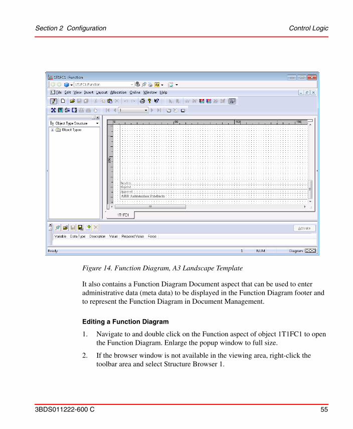
Section 2 Configuration Control Logic
3BDS011222-600 C 55
It also contains a Function Diagram Document aspect that can be used to enter administrative data (meta data) to be displayed in the Function Diagram footer and to represent the Function Diagram in Document Management.
Editing a Function Diagram
1. Navigate to and double click on the Function aspect of object 1T1FC1 to open the Function Diagram. Enlarge the popup window to full size.
2. If the browser window is not available in the viewing area, right-click the toolbar area and select Structure Browser 1.
Figure 14. Function Diagram, A3 Landscape Template
Control Logic Section 2 Configuration
56 3BDS011222-600 C
Reserve the diagram by selecting File > Reserve Diagram to get exclusive modify access to the diagram, and then insert the required Function Components listed in Table 3 into the Function Diagram.
a. Navigate to a Functional Component Object Type in Object Type Structure, for example to Object Types\Control System\AC 800M/C Connect\Libraries\ProcessObjExtLib 2.2-1\Control Module Types\PidCC.
b. Drag and drop the PidCC into the Function Designer drawing area.
c. In the New Component Name dialog box, enter a valid name and description. Keep the given Data Flow Order defaults. For information about data flow order, refer to Configuring the Data Flow Order on page 60.
d. Click OK. The graphical block symbol for this Function Component appears on the diagram. Name and Description ports are connected to the strings you have entered. Other ports are still hidden.
3. Connect the Function Components according to column Additional Action of Table 3.
a. Press the left mouse button on the source port.
b. Move the mouse on the sink port or on an already existing connection to the sink port.
c. Release the mouse button.The graphical connection link gets automatically routed.
Function Designer inserts the required application libraries into the control project and connects them to the applications as far as possible automatically. User needs to do this manually (refer to Insert Application Libraries on page 33 and Connect Application Libraries on page 34) only if, after configuration data generation, red triangles appear in Control Builder M for objects resulting from Function Designer.
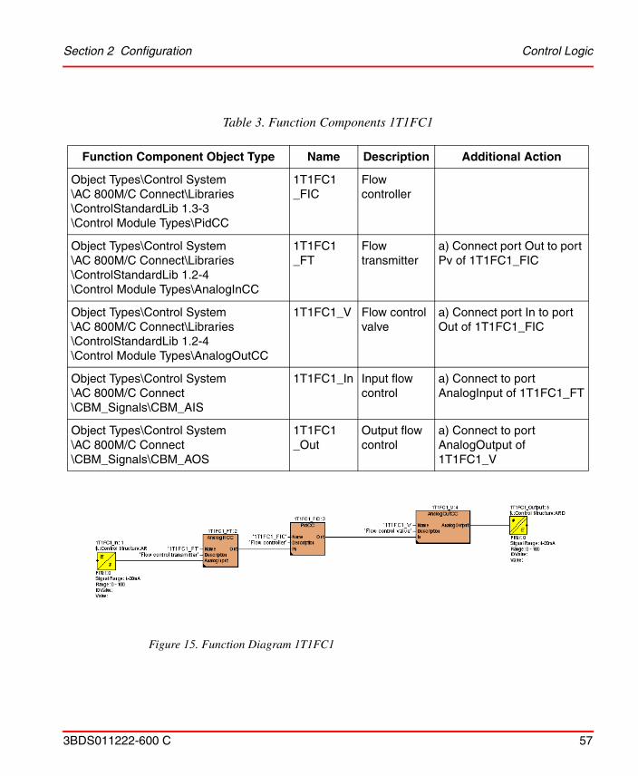
Section 2 Configuration Control Logic
3BDS011222-600 C 57
Table 3. Function Components 1T1FC1
Function Component Object Type Name Description Additional Action
Object Types\Control System\AC 800M/C Connect\Libraries\ControlStandardLib 1.3-3\Control Module Types\PidCC
1T1FC1_FIC
Flow controller
Object Types\Control System\AC 800M/C Connect\Libraries\ControlStandardLib 1.2-4\Control Module Types\AnalogInCC
1T1FC1_FT
Flow transmitter
a) Connect port Out to port Pv of 1T1FC1_FIC
Object Types\Control System\AC 800M/C Connect\Libraries\ControlStandardLib 1.2-4\Control Module Types\AnalogOutCC
1T1FC1_V Flow control valve
a) Connect port In to port Out of 1T1FC1_FIC
Object Types\Control System\AC 800M/C Connect\CBM_Signals\CBM_AIS
1T1FC1_In Input flow control
a) Connect to port AnalogInput of 1T1FC1_FT
Object Types\Control System\AC 800M/C Connect\CBM_Signals\CBM_AOS
1T1FC1_Out
Output flow control
a) Connect to port AnalogOutput of 1T1FC1_V
Figure 15. Function Diagram 1T1FC1
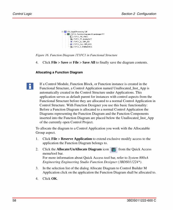
Control Logic Section 2 Configuration
58 3BDS011222-600 C
4. Click File > Save or File > Save All to finally save the diagram contents.
Allocating a Function Diagram
To allocate the diagram to a Control Application you work with the Allocatable Group aspect.
1. Click File > Reserve Application to extend exclusive modify access to the application the Function Diagram belongs to.
2. Click the Allocate/UnAllocate Diagram icon from the Quick Access menu/tool bar. For more information about Quick Access tool bar, refer to System 800xA Engineering Engineering Studio Function Designer (3BDS011224*).
3. In the selection list of the dialog Allocate Diagram to Control Builder M Application click on the application the Function Diagram shall be allocated to.
4. Click OK.
Figure 16. Function Diagram 1T1FC1 in Functional Structure
If a Control Module, Function Block, or Function instance is created in the Functional Structure, a Control Application named Unallocated_Inst_App is automatically created in the Control Structure under Applications. This application serves as default parent for instances with control aspects from the Functional Structure before they are allocated to a normal Control Application in Control Structure. With Function Designer you use this basic functionality: Before a Function Diagram is allocated to a normal Control Application the Diagrams representing the Function Diagram and the Function Components inserted into the Function Diagram are placed below the Unallocated_Inst_App of the currently open Control Project.
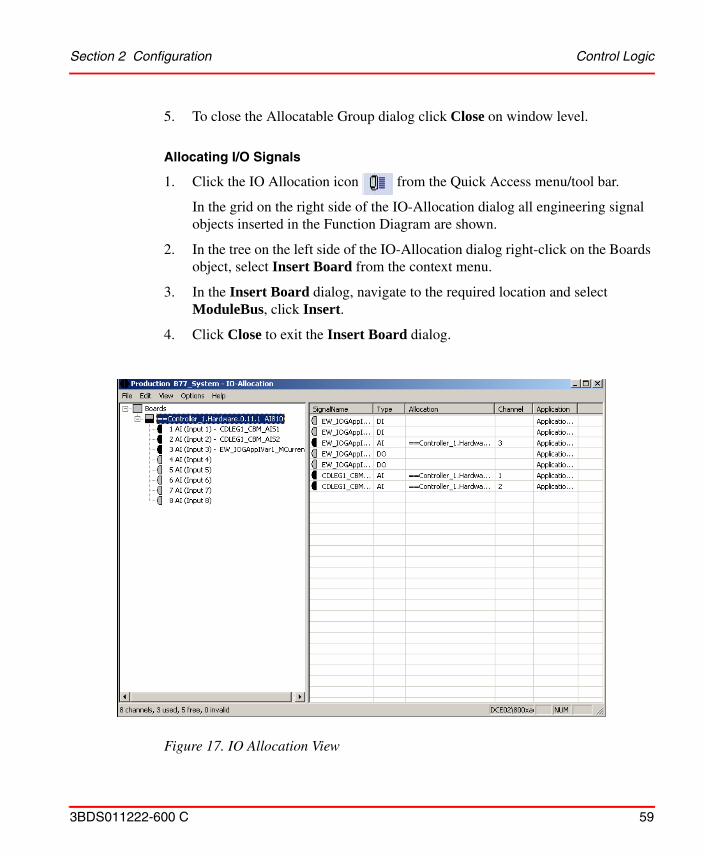
Section 2 Configuration Control Logic
3BDS011222-600 C 59
5. To close the Allocatable Group dialog click Close on window level.
Allocating I/O Signals
1. Click the IO Allocation icon from the Quick Access menu/tool bar.
In the grid on the right side of the IO-Allocation dialog all engineering signal objects inserted in the Function Diagram are shown.
2. In the tree on the left side of the IO-Allocation dialog right-click on the Boards object, select Insert Board from the context menu.
3. In the Insert Board dialog, navigate to the required location and select ModuleBus, click Insert.
4. Click Close to exit the Insert Board dialog.
Figure 17. IO Allocation View
Control Logic Section 2 Configuration
60 3BDS011222-600 C
5. Drag and drop one or several signal objects from the grid on the right side of the IO-Allocation dialog to the Boards object or to an I/O board object or to a channel stub of an I/O board object on the left side. After Drop the allocation is shown on both sides.
6. Click File > Exit to close the IO-Allocation dialog.
Configuring the Data Flow Order
The Data Flow Order can be used to generate Function Designer configuration data for Control Builder M. When instantiating a new function component, a default Data Flow Order number is assigned. If the Extended Name dialog or the Variable Properties dialog pops up during instantiation this default number is changeable.
Click Auto Sort Order icon from the Quick Access toolbar to automatically sort the function components according to the default Data Flow Order.
Alternatively, user can follow the steps below to manually assign the Data Flow Order:
1. Open the required Function Diagram.
2. Click Allocation > Define Data Flow Order... to open the Data Flow Order in Allocatable Group dialog.
3. Modify the Data Flow Order by selecting a function component from the Data Flow Order list and move it to the required location using the Up or Down arrow buttons.
IO Allocation supports allocating signal objects and HART devices (represented as signal objects) to channels of I/O boards. From SV 5.0 SP2 onwards, IO Allocation also supports allocating signal objects to channels of modules of PROFIBUS devices.
HART and PROFIBUS specific device libraries can be installed through Device Library Wizard. You have to prepare the object types of these libraries using the HWDProcessor utility to use instances of these object types in IO Allocation of Engineering Studio.
For further information about preparation of HART and PROFIBUS devices refer to System 800xA Engineering, Engineering Studio (3BDS011223*).
Section 2 Configuration Control Logic
3BDS011222-600 C 61
4. Click Apply to assign the new Data Flow Order to the respective function components.
5. Click Close to exit.
Refer to System 800xA Engineering, Engineering Studio Function Designer (3BDS011224*), Section 2 - Configuration for more information on the data flow order.
Generating Configuration Data
Click the Code Generation / Code Generation (Full Build) icon from the Quick Access menu/tool bar.
Message windows show the progress during generation.
Alternatively use File > Generate Configuration Data (Full Build) or open the Config View of the Allocatable Group aspect from the context menu of the aspect in Engineering Workplace and click Generate Configuration Data (Full Build).
Downloading and Testing the Function Diagram
1. To download the loop in Control Builder M Professional:
a. Ensure that the Control Project, the affected applications and the affected controllers are reserved.
The Data Flow Order of blocks on a diagram is crucial for execution. It is suggested to ensure that the order is as intended, for example, by clicking the Generate button in the Data Flow Order in Allocatable Group dialog.
The Generate button can be used to sort the function components available in the Function Diagram according to the default Data Flow Order. The default order is calculated according to the rule “left up to right down”. After generating the default Data Flow Order, click Apply to assign the Data Flow Order accordingly.
If DisplayDetailsOnGenerateConfigData is set to True in the Function Settings aspect of: Object Type Structure\Object Types\Functional Planning\Settings, and if errors occur, the message window stays open to allow the user to inspect the error messages. Click Close to continue.
Control Logic Section 2 Configuration
62 3BDS011222-600 C
b. Click on Tools > Download Project and Go Online to start the download procedure.
2. To display online value of a port in Function Diagram:
a. Click on the port in Function Diagram to select it.
b. Click on Online > Add Links to Current Page.
c. Click on Online > Subscribe for Live DataNow the value is displayed at the port and updated.
3. To display and force online values in Watch Window:
a. Click on Online > Watch Window to insert the Watch Window into Function Designers main window.
b. In the Watch Window tool bar press Add variables to the Watch Window.
c. In the structure selection (left) pane of the Add Variable to the Watch Window dialog navigate to the object for which you want to display an online value.
d. Click on the variable in the grid of the right pane of the dialog to select it.
e. Press Apply.
f. Press Close.
g. Enter the force value in the Prepared Value field for the variable in the Watch Window grid.
h. Press Activate to force the variable value.
4. Click File > Release Reservation if you want to cancel exclusive modify access (both for the diagram and the application).
Further means to test the configuration in the context of a Function Diagram are:
• Control Builder M Professional online editors (and interaction windows, if available) on Control Modules, Function Blocks, Diagrams or Functions called up using the context menu on the representing symbol in Function Diagram.
• Faceplates of Control Modules, Function Blocks or Diagrams called up using the context menu on the representing symbol in Function Diagram.
Section 2 Configuration Control Logic
3BDS011222-600 C 63
Printing the Function Diagram
1. Open the diagram to print.
2. Click File > Print.
3. Press OK to accept the defaults in the Print dialog.
4. Press OK in the Print dialog of Windows to print.
Working with a Sequence
Function Designer supports the design of sequences with steps, transitions and actions. A sequence can be inserted in a Function Diagram or in a Function Diagram type. Two sequence components can be used: Either IEC 61131-3 Sequence or Sequence2D (based on library SeqStartLib).
Inserting Sequence Component
To insert a IEC 61131-3 sequence into a Function Diagram:
1. Open the Function Diagram, example 1TT2SeqCtrl. Enlarge the popup window to full size.
2. Press <Insert>. In the Insert Objects dialog, select the SPL tab and user can select the sequence obj.
3. Click on object type Sequence, keep the mouse button pressed and drag the object type on to the Function Diagram drawing area, then release the mouse button.
4. In the New Component Name dialog box shown enter a valid name, for example 1TT2SeqCtrl_Seq1 and description and keep the given Data Flow Order defaults.
To start the SFCViewer from the faceplate (SFC2DHeader) for a sequence2D, the user must:1. Allot the fixed name SFC, to the Sequence2D object.
2. Assign the diagram name to the ExtSFCObjectName port of SFC2DHeader.
In a Function Diagram, only one Sequence2D can exist with the fixed name SFC.
Control Logic Section 2 Configuration
64 3BDS011222-600 C
5. Press OK.The graphical block symbol for this Function Component appears on the diagram. Ports are still hidden.
6. To show the hidden ports:
a. Right-click on the symbol.
b. Click Show Hidden Ports....
c. In the dialog Show Hidden Ports select the ports to show or mark check box All Hidden Ports.
d. Press OK.The visible ports can now be connected to control and supervise the sequence.
Alternative to Step 2 and Step 3: Use Insert > Object, tab Sequences.
Overview Diagram
For a sequence a grid-structured overview diagram is supported. Each cell in the (virtual) grid of a sequence overview diagram can contain one of the following elements:
• Empty
• Normal transition/step.This cell is related to a detail diagram containing transition logic, a transition symbol, a step symbol and optional action diagrams or a diagram reference.
• Step only.Required as starting step for simultaneous branches. This cell is related to a detail diagram containing a step symbol and optional action diagrams or a diagram reference, but no transition logic and no transition symbol.
• Transition only.Required as last transition for alternative branches. This cell is related to a detail diagram containing transition logic and a transition symbol, but no step symbol and optional action diagrams.
• Transition/jump.This cell is related to a detail diagram containing transition logic and a
Section 2 Configuration Control Logic
3BDS011222-600 C 65
transition symbol, but no step symbol and optional action diagrams. The jump symbol defines the step name to jump to. A step, which is a jump target, displays an additional arrow. Even if the step is target for multiple jumps, there is only one arrow displayed. At the step itself there is no indication, where the jump comes from.
• Simultaneous Sequence.The divergence and convergence of simultaneous sequences is indicated by a double horizontal line. Only one common transition symbol is possible, above and below the double horizontal line of synchronization.
Editing Overview Diagram
To open and edit the Overview Diagram of the sequence:
1. Right-click on the sequence symbol.
2. Click on Goto Child Diagram. The grid-structured Overview Diagram opens and is shown as a workbook tab. (If workbook mode, as given by default, is switched on). A first step symbol inserted.
3. Click on the Step1 symbol and Drag it into another cell, for example B2.
4. To rename Step1 to Fill:
a. Right click on the step symbol.
b. Click Aspect Properties....
c. In the Component tab of the Aspect Properties dialog edit the name and press OK.
5. To add the transition to follow step Fill:
a. Select the required port.
b. Right-click and select Insert Transition from the available context menu.
c. In the New Component Name dialog enter transition Name, for example Filled, Number and Description or accept the given defaults.
d. Press <Esc> to quit insertion mode.
6. To add the next step to follow the transition Filled:
Control Logic Section 2 Configuration
66 3BDS011222-600 C
a. Select the required port.
b. Right-click and select Insert Step from the available context menu.
c. In the New Component Name dialog enter step Name, for example Agitate, Number and Description or accept the given defaults.
d. Press <Esc> to quit insertion mode.
7. Repeat steps Step 5 and Step 6 to add a transition Agitated and a step Drain and repeat Step 5 to add a final transition Drained.
8. Connect the output port of each step to the input port of the next transition and connect the output port of the final transition to the input port of the first step:
a. Click on the output port, keep the mouse button pressed.
b. Drag the mouse pointer to the input port.
c. Release the mouse button.
9. Press Save.
As an alternative to editing single steps and transitions you can use the Create multiple transitions/steps button of the Sequences toolbar. As an alternative to connecting steps and transitions by mouse you can right click on a step or transition and click on Goto/Connect..., and connect using the Goto / Connect to dialog.
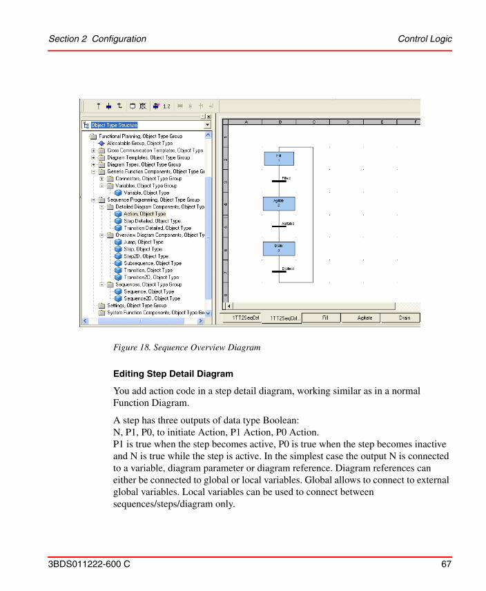
Section 2 Configuration Control Logic
3BDS011222-600 C 67
Editing Step Detail Diagram
You add action code in a step detail diagram, working similar as in a normal Function Diagram.
A step has three outputs of data type Boolean:N, P1, P0, to initiate Action, P1 Action, P0 Action. P1 is true when the step becomes active, P0 is true when the step becomes inactive and N is true while the step is active. In the simplest case the output N is connected to a variable, diagram parameter or diagram reference. Diagram references can either be connected to global or local variables. Global allows to connect to external global variables. Local variables can be used to connect between sequences/steps/diagram only.
Figure 18. Sequence Overview Diagram
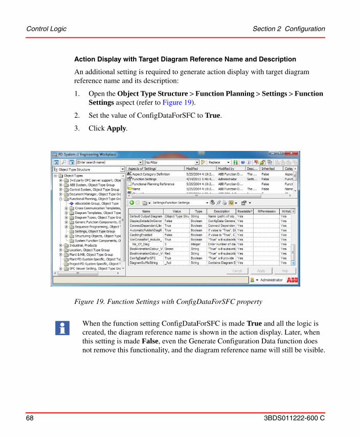
Control Logic Section 2 Configuration
68 3BDS011222-600 C
Action Display with Target Diagram Reference Name and Description
An additional setting is required to generate action display with target diagram reference name and its description:
1. Open the Object Type Structure > Function Planning > Settings > Function Settings aspect (refer to Figure 19).
2. Set the value of ConfigDataForSFC to True.
3. Click Apply.
Figure 19. Function Settings with ConfigDataForSFC property
When the function setting ConfigDataForSFC is made True and all the logic is created, the diagram reference name is shown in the action display. Later, when this setting is made False, even the Generate Configuration Data function does not remove this functionality, and the diagram reference name will still be visible.
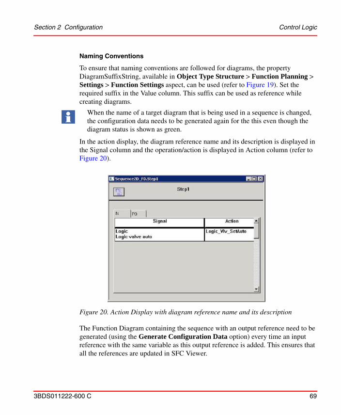
Section 2 Configuration Control Logic
3BDS011222-600 C 69
Naming Conventions
To ensure that naming conventions are followed for diagrams, the property DiagramSuffixString, available in Object Type Structure > Function Planning > Settings > Function Settings aspect, can be used (refer to Figure 19). Set the required suffix in the Value column. This suffix can be used as reference while creating diagrams.
In the action display, the diagram reference name and its description is displayed in the Signal column and the operation/action is displayed in Action column (refer to Figure 20).
The Function Diagram containing the sequence with an output reference need to be generated (using the Generate Configuration Data option) every time an input reference with the same variable as this output reference is added. This ensures that all the references are updated in SFC Viewer.
When the name of a target diagram that is being used in a sequence is changed, the configuration data needs to be generated again for the this even though the diagram status is shown as green.
Figure 20. Action Display with diagram reference name and its description
Control Logic Section 2 Configuration
70 3BDS011222-600 C
The Function Diagram containing the sequence with a project constant need to be generated (using the Generate Configuration Data option) every time the value of the project constant is changed. This ensures that the project constant value is updated in SFC Viewer.
When a child (nested) diagram is modified with any reference that is used in a sequence, both the child diagram and the diagram containing the sequence with this reference need to be generated again (using the Generate Configuration Data option). This should be done even though the status of the child (nested) diagram appears as green after the reference modification.
Restrictions: Action code is generated into Control Builder M Structured Text (ST) code. In all kinds of detailed diagrams implicit type casts are not allowed.
For action code in detail diagrams the only the following components are allowed:
• Diagram Reference
• Variable
• (N) Action
• P0 Action
• P1 Action
To create and edit a detail diagram of a step:
1. Right-click the menubar/toolbar area of the Function Diagram and click SFC OverView from the available context menu. A sequence tree structure appears, and user can click the desired sequence component to access it directly.
2. Either edit the diagram by inserting and connecting components.
3. Or insert and connect action diagram components from Object Type Structure: Object Types\Functional Planning\Sequence Programming\Sequences\Detailed Diagram Components\Action, ...\P0 Action and/or ...\P1 Action.Within these diagrams you can create logic for the different step phases.
For information regarding SFC OverView menu option, refer to System 800xA Engineering, Engineering Studio Function Designer (3BDS011224*).
Section 2 Configuration Control Logic
3BDS011222-600 C 71
Data flow order within a detail diagram is not supported and is not displayed. This order is calculated automatically and cannot be modified.
Editing Action Diagram
You add action code in an action diagram, working similar as in a normal Function Diagram.
Restrictions: Action code is generated into Control Builder M Structured Text (ST) code. Action diagrams are sub-diagrams. Restrictions for components on such diagrams:
• No Aspect Objects (only Symbol objects)
• No CBM_Signals
• No Control Modules
To create and edit an action diagram:
1. User can click the desired action diagram component from the sequence tree structure to access it directly (refer Editing Step Detail Diagram on page 67). Double-click the action diagram component to open an empty Function Diagram named according to step and action component, for example Fill_Action.
2. In this Function Diagram you then can edit the control logic for this action, for example the N action of step Fill.The action code to follow the same restrictions as when the action code is editing in the parent step detail diagram.
Editing Transition Detail Diagram
You add transition logic a transition detail diagram, working similar as in a normal Function Diagram.
Restrictions: In the detail diagram graphical symbols are used for the transition logic, but the allowed set of components is limited due to the fact that transition logic has to result in a Boolean expression, which is defined in Control Builder M as ST code.
To create and edit a detail diagram of a transition:
Control Logic Section 2 Configuration
72 3BDS011222-600 C
1. User can click the desired transition from the sequence tree structure to open an empty Function Diagram named.
2. Double click on the corresponding transition symbol in the overview diagram.A diagram named according to the transition is opened and shown as further workbook tab. It initially contains the transition symbol.
3. Insert and connect allowed components from Object Type Structure: Object Types\Control System\AC 800M/C Connect\System Functions\Functions.If you try to insert a not allowed component an error message is shown.
Navigating Between the Sequence Diagrams
To navigate to the different diagrams:
• Right-click the menubar/toolbar area of the Function Diagram and click SFC OverView from the available context menu. A sequence tree structure appears, and user can click the desired sequence component to access it directly.
• Use the workbook tabs in the set of the opened diagrams.
• Or right click on the white space of a diagram and click Goto Parent Diagram to switch to the parent diagram.
• Or right click on a component on the diagram representing a child diagram and click Goto Child Diagram to switch to the child diagram.
• Or follow Diagram References by right clicking on the reference and clicking on Goto Reference.
Allocating, Generating Configuration Data, Testing
The complete sequence is available in the Function Diagram. Allocate, generate and download configuration data, and test the configuration of the Function Diagram containing the sequence as described in earlier sections.
You do allocation of the Function Diagram containing the sequence as described in Allocating a Function Diagram on page 58.
You generate configuration data of the Function Diagram containing the sequence into Control Builder M Professional SFC codeblocks as described in Generating Configuration Data on page 61.
Section 2 Configuration Control Logic
3BDS011222-600 C 73
In addition to the functions available to download and test Function Diagrams (see Downloading and Testing the Function Diagram on page 61 you use additional sequence test functions available in the Sequences toolbar:
• Disable actions
• Block transition
• Force forward
• Force backward
Printing
Normal Function Diagram print functions are used. Step detail and transition detail are printed together in one diagram.
Working with Multiple Function Diagrams
The following workflow lists the principal steps to build your project’s control logic in Function Diagrams using Bulk Data Management support and bulk handling functions in Function Designer, for example for instantiation and parametrization of object instances, allocation, configuration data generation, cross communication, and diagram printing:
1. Configure a Bulk Data Management worksheet for instantiation and basic parametrization of the objects representing process functions from Object Types\Functional Planning\Diagram Types\Based on Diagram Templates, for example Function Diagram A3 Landscape.
2. Create and parameterize the instances in Functional Structure using the Bulk Data Management workbook.
3. Configure a Bulk Data Management worksheet for instantiation and basic parametrization of the object types from the control libraries (the Function Component object types) below the process function objects.
4. Create and parameterize the instances in Functional Structure using the Bulk Data Management worksheet.
Control Logic Section 2 Configuration
74 3BDS011222-600 C
5. In the objects representing the process functions in Functional Structure open a Function Diagram by double click on Function aspect. The Function Components of the levels below show up in the diagram automatically.
6. Connect the component ports on the current diagram graphically as required.
7. If needed add additional glue or interlock control logic by inserting and connecting further Function Components.
8. Add Diagram References as required to connect to other Function Diagrams and connect them to ports on the current diagram.
9. Create Diagram Variables for the Diagram References respectively connect them to existing Diagram Variables. Besides implementing the connections between the control logic of the diagrams this implements horizontal navigation between the connected diagrams of the process function objects.
10. Allocate the Function Diagrams to Applications in the corresponding Control Project. Use the pre-configured Bulk Data Management workbook BDM_for_Function_Diagrams, worksheet Allocate FuD. This workbook is available in the Engineering Templates folder on the desktop of your workplace.
11. Allocate the I/O Signal objects to (channels of) board hardware units assigned to the controller running the application. Use the IO Allocation tool in the context of a controller and drop in I/O Signal objects from Functional Structure.
12. Generate Configuration Data for the Function Diagrams belonging to the Control Project. Use the pre-configured Bulk Data Management workbook BDM_for_Function_Diagrams, worksheet Generate Code.
13. In Control Builder M Professional go into Test-Mode or Download Project and Go Online with simulated hardware and Softcontroller to test.
14. Test in Function Designer online mode and in Control Builder M Professional.
15. Print a complete documentation package with Contents diagram and all Function Diagrams below the object holding the Contents diagram:
a. In the parent object of the process function objects create a Function aspect. In this aspect create and generate a Contents diagram.
Section 2 Configuration Control Logic
3BDS011222-600 C 75
b. In the open Contents diagram click File > Print, in the Print dialog set the options to print the Contents and the Diagrams and then finish the print action.
If plant modelling to the level of process functions has been done before, steps Step 1 and Step 2 have already been done.
In Step 11 the I/O Signal objects are assumed to exist already:
• Either the I/O Signal objects have been instantiated before with own object types like shown in Process Object Type with Signals on page 599.
• Or, if you use the standard object type libraries of AC 800M you have created, parameterized and assigned the needed I/O Signal objects for functional planning in a separate steps, for example with an own Bulk Data Management worksheet.
As an alternative to Step 3 and Step 4 you can create the required instances of the Function Component object types by editing in Function Designer,using Insert > Symbol in or using Drag and Drop of an object type from the corresponding library on to the Function Diagram. See the control loop example in Working with a Function Diagram on page 54. The instances are created in Functional Structure below the object that holds the Function Diagram and represents the process function.
Depending on the project requirements also inserting and connecting Diagram Variables can be done using a Bulk Data Management worksheet. Even complete Function diagrams can be created using a worksheet configured accordingly.
How to configure Bulk Data management worksheets in general is described in System 800xA Engineering, Engineering Studio (3BDS011223*).
Global Variable and Communication Variables
The global variable facilitates communication between restored diagrams (created upto System Version 5.0 SP2).
The communication variable facilitates communication between:
• Newly created Function Diagrams in System Version 5.1 or later.
• A restored diagram (created upto System Version 5.0 SP2) and a newly created diagram in System Version 5.1 or later.
Control Logic Section 2 Configuration
76 3BDS011222-600 C
In effect, diagram references consist of an input/output reference and communication variable.
Diagram references can be connected using Function Designer or Bulk Data Manager. For more information, refer to System 800xA Engineering, Engineering Studio Function Designer (3BDS011224*).
Copy Function Diagrams
An existing Function Diagram can be used as a typical and copied several times with Bulk Data Management as required. You either can configure a worksheet for your own specific needs or use the pre-configured workbook BDM_for_Function_Diagrams, worksheet Copy FuD. This workbook is available in the Engineering Templates folder on the desktop of your workplace.
1. Ensure that in the Function Settings aspect in the Object Type Structure under Object Types\Functional Planning\Settings the value of the property Naming is set to Pattern and the value of the property NamePattern is set to *.
In the sense of a structural programming language, diagram references and diagram variables refer to global or communication variables.
The global variable and the communication variable takes the name, description, data type, initial value and attributes of the diagram variable.
Two engineering templates named BDM_DiagramRef_Var_Basic and BDM_DiagramRef_Var_Advanced are used to modify diagram references and diagram variables represented as symbol objects.
For details on configuring and generating MMS Cross Communication for diagrams created prior to Engineering Studio System Version 5.1, refer to System 800xA Engineering, Engineering Studio Function Designer (3BDS011224*).
For details on configuring the communication between a restored Function Diagram and a newly created System Version 5.1 Function Diagram, refer to Connection between Restored Diagrams (created upto SV5.0 SP2) and New Diagrams created from SV5.1 onwards) in System 800xA Engineering, Engineering Studio Function Designer (3BDS011224*).
Copy/paste or move Function Diagrams between different projects is not supported through Bulk Data Manager.
Section 2 Configuration Control Logic
3BDS011222-600 C 77
2. Open and attach workbook BDM_for_Function_Diagrams for start object 1T1 in Function Structure.
3. Drag and Drop the object 1T1FC1 from the Functional Structure into the Excel worksheet Typical. This gives you the correct Template path to be used in the Copy FuD worksheet.
4. Switch to worksheet Copy FuD.
5. In the row Typical insert n times the template path from the picklist if you require n copies of the diagram.
6. In the row FuD Name edit the names of the diagram copies, for example 1T1FC2, 1T1FC3, ... 1T1FC<n>.
7. To insert the path to the Functional Structure Parent for all intended copies edit the corresponding cells:
a. Right-click on the first cell to open the context menu.
b. Click Insert Object Path....
c. In the Insert Object Path dialog navigate to an already existing parent object.
d. Press Object Path.
e. To insert the same path for the second and further instance press Object Path again.
f. Press Cancel.
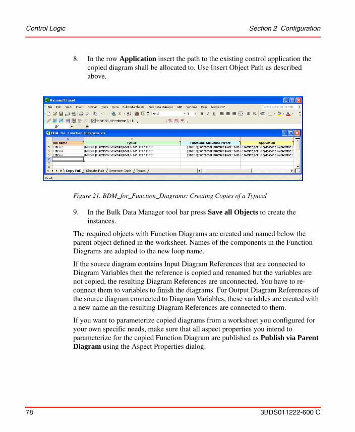
Control Logic Section 2 Configuration
78 3BDS011222-600 C
8. In the row Application insert the path to the existing control application the copied diagram shall be allocated to. Use Insert Object Path as described above.
9. In the Bulk Data Manager tool bar press Save all Objects to create the instances.
The required objects with Function Diagrams are created and named below the parent object defined in the worksheet. Names of the components in the Function Diagrams are adapted to the new loop name.
If the source diagram contains Input Diagram References that are connected to Diagram Variables then the reference is copied and renamed but the variables are not copied, the resulting Diagram References are unconnected. You have to re-connect them to variables to finish the diagrams. For Output Diagram References of the source diagram connected to Diagram Variables, these variables are created with a new name an the resulting Diagram References are connected to them.
If you want to parameterize copied diagrams from a worksheet you configured for your own specific needs, make sure that all aspect properties you intend to parameterize for the copied Function Diagram are published as Publish via Parent Diagram using the Aspect Properties dialog.
Figure 21. BDM_for_Function_Diagrams: Creating Copies of a Typical
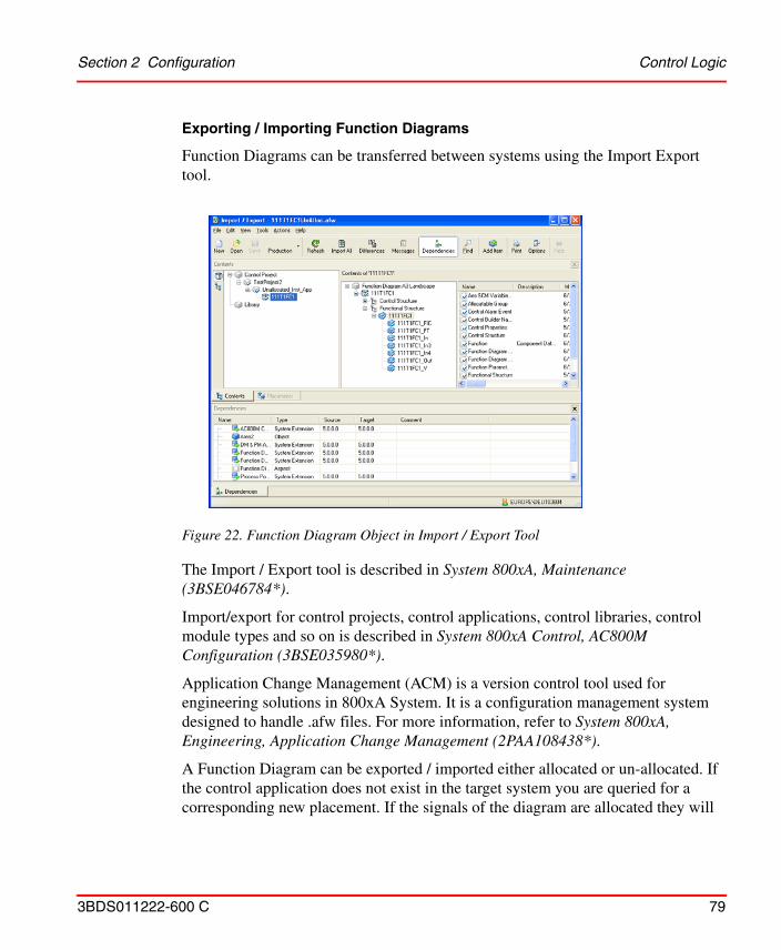
Section 2 Configuration Control Logic
3BDS011222-600 C 79
Exporting / Importing Function Diagrams
Function Diagrams can be transferred between systems using the Import Export tool.
The Import / Export tool is described in System 800xA, Maintenance (3BSE046784*).
Import/export for control projects, control applications, control libraries, control module types and so on is described in System 800xA Control, AC800M Configuration (3BSE035980*).
Application Change Management (ACM) is a version control tool used for engineering solutions in 800xA System. It is a configuration management system designed to handle .afw files. For more information, refer to System 800xA, Engineering, Application Change Management (2PAA108438*).
A Function Diagram can be exported / imported either allocated or un-allocated. If the control application does not exist in the target system you are queried for a corresponding new placement. If the signals of the diagram are allocated they will
Figure 22. Function Diagram Object in Import / Export Tool
Control Logic Section 2 Configuration
80 3BDS011222-600 C
lose the allocation to boards during export and have to be re-allocated in the target system.
The following procedure assumes that the dependencies of the Function Diagram are already fulfilled except for new placements to be done on the target system: All required system extensions are loaded, all user defined libraries and object types are available, the target Control Project is available and the needed libraries are connected to the target Control Application.
1. Launch the Import / Export tool from the toolbar of Plant Explorer.
2. Drag and drop the Function Diagram object into the left pane of the Contents tab of the Import / Export tool window.
3. Accept the check-marked contents shown in the Add Items dialog and press OK. By default export is done without dependencies.
4. In the toolbar press Save.
5. In the Save import/export-file dialog navigate to an appropriate folder, enter a file name and press Save.
The Function Diagram is now available as .afw archive file. Remember that you have not added the parent objects of the Function Diagram object. Neither you have added other dependencies.
To import a single, not yet existing Function Diagram:
1. Transfer (or give access to) the stored .afw file to the workstation where you want to do the import.
2. Ensure that the required system extensions and user-defined libraries are loaded.
3. Launch the Import / Export tool from toolbar of Plant Explorer.
4. In the toolbar press Open.
5. In the Open import/export-file dialog navigate to the stored .afw archive file and press Open.
6. If the parent object hierarchy given in the Functional Structure and in the Control Structure of the source system is not available in the Functional Structure and in the Control Structure of the target system: Provide corresponding substitutions by editing new placements in the Placements tab.
Section 2 Configuration Control Logic
3BDS011222-600 C 81
Or rely on the Import Export tool querying you for new parent objects during import.This includes placements in Control Structure that assign the Function Diagram to a new Control Project and a new Control Application.
7. In the toolbar press Import All.
8. A progress dialog pops up. Wait until an end message like “Import succeeded” is shown in the grid area of this dialog.
9. If no further error messages are shown in the grid area of the progress dialog: Press Done to exit.
10. To complete the imported diagram:
a. Re-connect the diagram references to appropriate diagram variables.
b. If not allocated: Allocate the diagram to an application.
c. (Re-)Allocate the signals to I/O boards.
d. Perform Write Allocation into Control Builder M.
e. Perform Generate Configuration Data. This is required in any case.
f. Download the corresponding application to make this new diagram work in the controller.
If the Function Diagram object already exists in the target system you are queried for replacement of this object. If you press Yes the diagram will be replaced completely by the imported one.
In a similar way you can export / import a control application with all its Function Diagrams, a control application and the controller to transfer the complete I/O allocation of the diagrams too or a complete control project. Due to technical reasons it can be necessary to split the contents to be exported / imported into several afw-files.
Replacing the Function Diagram overwrites changes of the same diagram the in target system done in parallel to the changes in the engineering system.
Always disable function Automatic Write Allocation into CBM in IO Allocation tool before performing import operation.
Control Hardware Units Section 2 Configuration
82 3BDS011222-600 C
For more information on export / import of Function Diagrams and related entities, refer to System 800xA Engineering, Engineering Studio, Function Designer (3BDS011224*).
For more information on working with Function Diagrams, refer to System 800xA Engineering, Engineering Studio Function Designer Getting Started (3BDS100968*) and System 800xA Engineering, Engineering Studio, Function Designer (3BDS011224*).
Detailed Difference Report
Difference report provides the differences between Function Diagrams in the system and Diagrams present in the .afw file to be imported. If there are any modifications between the Function Diagrams, the difference report provides a report for the Function aspect indicating the additions, deletions, or modifications between the Function Diagrams. For more details, refer to System 800xA, Maintenance (3BSE046784*).
Control Hardware Units
You add the needed hardware units, typically the I/O boards, to your control project with the following principle steps. The steps assume use of Bulk Data Management worksheets. For low quantities you also can do this object by object in Plant Explorer or in Project Explorer of Control Builder M Professional, as already described in Create Hardware Units on page 40. The steps correspond to the workflow steps Build Lower Level Control Structure, (Assign I/O Signals) and Allocate I/O Signals to Boards in Control Structure of Table 1:
1. Configure a Bulk Data Management workbook/worksheet for instantiation (and, if needed for basic parametrization) of the hardware unit object types of the standard hardware libraries into Control Structure.
2. Make sure that you have inserted the required hardware libraries into your project and that you have connected them to the target controllers. See Insert Hardware Libraries on page 36 and Connect Hardware Libraries to Controller on page 39.
Import/Export of a large configuration reserves a lot of memory that may cause the system to respond in an unexpected behavior. Divide any large configuration into several small configurations to avoid this problem.
Section 2 Configuration AC 800M Status Monitoring
3BDS011222-600 C 83
3. Create and parametrize the hardware unit objects in Control Structure using your Bulk Data Management worksheet.
4. Allocate bulks of I/O Signals (for example Signal objects created and /or parameterized with Bulk Data Manager and assigned to process objects) to channels of hardware units (boards) with the smart I/O Allocation function available using the IO Allocation icon from the tool bar.
5. Do channel parameterization from the I/O Signal objects to I/O board hardware unit objects either explicitly through Engineering Workplace object context menu item Advanced > Write Allocation into CBM or implicitly performing Generate Configuration Data in Function Designer or from the Config View of an Allocatable Group aspect.
How to configure Bulk Data Management worksheets and how to use I/O Allocation is described in System 800xA Engineering, Engineering Studio (3BDS011223*).
AC 800M Status Monitoring
AC 800M Status Monitoring is used to collect diagnostics information for analysis (trouble shooting the hardware errors and maintenance of the IO Modules) and to provide navigation between the Input Output (IO) modules and the corresponding Control Applications.
The specific details of the Control Builder M configuration can be uploaded to the 800xA system using AC 800M Status Monitoring. AC 800M Status Monitoring displays the hardware status and the errors or warnings if any, for the Hardware Units, Communication Interfaces, and Module Bus.
AC 800M Status Monitoring also displays additional information for S800 IO Modules such as number of channels in an IO module, the status and value of the channel. The user can also navigate from an IO Channel to the associated objects.
The user with an Application Engineer role must perform an upload to view the errors and warnings, and the status and navigation details in Hardware Status and Tag Navigation aspect.
You need to use Generate Configuration Data in Function Designer if the Name of a Signal object used in a Function Diagram was changed.
AC 800M Status Monitoring Section 2 Configuration
84 3BDS011222-600 C
For more information on viewing the diagnostic information, refer to System 800xA Operations (3BSE036904*).
Uploading the Details using Configuration Uploader Aspect
The Configuration Uploader aspect uploads the details of the Controller hardware unit and its associated objects in the Hardware Status and Tag Navigation aspect.
Create the Configuration Uploader aspect on the Control Network or Control Project objects depending on size of the Control Project. This aspect displays the Control Network structure or Control Project structure consisting of Controller hardware units hierarchy. This hierarchy is selected by default; it is possible to select or clear the specific hardware units to be uploaded.
An Upload not performed message appears in the Last Upload for newly created Configuration Uploader aspects.
Save all data in the Control Project. When an upload is performed, the Control Project that is being uploaded opens in Control Builder M. During this time, the
If user-defined Control Modules (CM) or Function Blocks (FB) having their own faceplates are used, disable the Aspect Object property of all the standard CM/ FBs from which these are created. This ensures that object navigation results in opening of the user-defined faceplate, and not the standard faceplate of the CM/ FB.
Before configuration uploader starts to upload, make sure that no instances of the Control Builder M is running and start the Control Builder M as administrator.
It is recommended not to create Hardware Status and Tag Navigation aspect manually in the system.
Upload must be performed from an Engineering client node, where Control Builder M is installed.
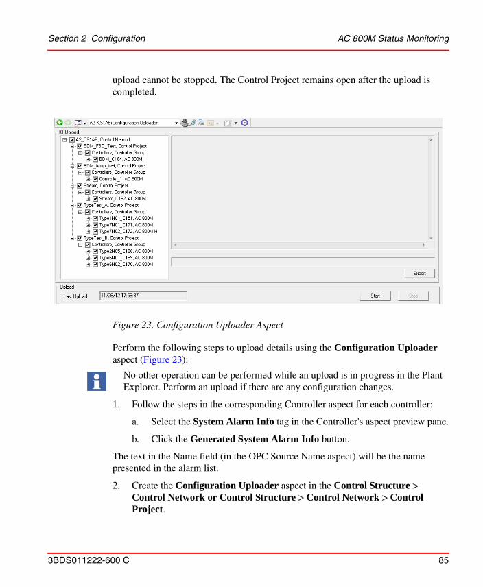
Section 2 Configuration AC 800M Status Monitoring
3BDS011222-600 C 85
upload cannot be stopped. The Control Project remains open after the upload is completed.
Perform the following steps to upload details using the Configuration Uploader aspect (Figure 23):
1. Follow the steps in the corresponding Controller aspect for each controller:
a. Select the System Alarm Info tag in the Controller's aspect preview pane.
b. Click the Generated System Alarm Info button.
The text in the Name field (in the OPC Source Name aspect) will be the name presented in the alarm list.
2. Create the Configuration Uploader aspect in the Control Structure > Control Network or Control Structure > Control Network > Control Project.
Figure 23. Configuration Uploader Aspect
No other operation can be performed while an upload is in progress in the Plant Explorer. Perform an upload if there are any configuration changes.
AC 800M Status Monitoring Section 2 Configuration
86 3BDS011222-600 C
3. Identify the hardware unit and click Start to upload the details.
If required, click Stop to stop the upload operation.
4. Click Export to save the log files to the selected location and use them later.
Last Upload displays the time once the upload is performed.
Process Graphics
3BDS011222-600 C 87
Process Graphics
Typically you build a graphic display per process function modelled by an object in Functional Structure.
The principal steps, corresponding to workflow steps Design / Build Graphic Displays and also to Download and Test Application Software, are:
1. Create a Graphic Display aspect.
2. Edit it with Graphics Builder.
3. Draw / adapt the background picture.
4. Insert and configure the Graphic Elements provided with the instances of the Process Objects and Signal Objects. (Typically these are inherited from the corresponding object types.)
5. Test the Graphic Display In the Graphics Builder, test the graphic display and save it.
6. Test the Graphic Display with downloaded an running application software on the controller.
How to build and use Graphic Displays, Graphic Elements and Faceplates is described in detail in System 800xA Engineering, Process Graphics (3BSE049230*).
Faceplates
The object types of the AC 800M Connect libraries contain default faceplates. The following steps show a solution to change the default faceplate in the released libraries of AC 800M:
Change of default faceplate aspect
1. Create the desired new faceplate in the Object Type Structure. Set the default view for this faceplate and call it MyFaceplate.
2. Add a key object in the Admin Structure (Admin Structure/Inventory Objects/Keys/Key Aspect Type) and call it for example, MyKey.
3. Add the same key into the Aspect Default Precedence List. This list defines what aspects will appear at a left-click on an object in for example a process
Faceplates
88 3BDS011222-600 C
display. The aspect placed at the top in the default precedence list will appear instead of an aspect which has a lower position in the precedence list in the case that both these aspects are available for the object left-clicked on.
4. Library Structure/Preferences&Customization/Default Precedence List; push the button Add key and find the key MyKey in the list. Move MyKey to the top of the default precedence list by using the arrows.
5. Add this key to MyFaceplate by going to the locked library and the actual object type in the Object Type Structure.
6. Right-click on the aspect MyFaceplate and select Properties. Under the tab Aspect Details, select MyKey in the pull down list Overrides.
7. Each time an object instance of this object type is selected, the key MyKey will cause the faceplate MyFaceplate to come up with the selected wanted view layout.
Change of faceplate view for different type of motors
1. Create two object types, one for the small motor and one for the big motor.
2. Use the technique described in Change of default faceplate aspect above.
It is recommended to create an extension library (connected to the released library) and assign all new faceplate aspects to this library. Refer to Extension Libraries on page 661 for information about how to use the extension libraries. Use the Aspects tab of the Extension Library Version Definition aspect to assign the faceplates to a new library. If a new standard library version is received, create a new version of the extension library to copy the faceplates to the new base library version.
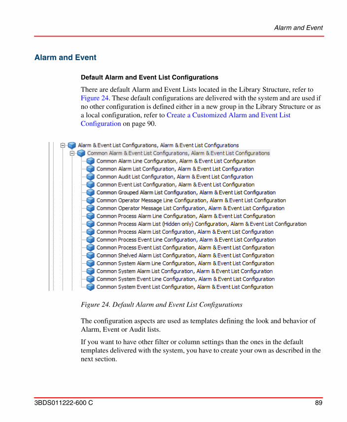
Alarm and Event
3BDS011222-600 C 89
Alarm and Event
Default Alarm and Event List Configurations
There are default Alarm and Event Lists located in the Library Structure, refer to Figure 24. These default configurations are delivered with the system and are used if no other configuration is defined either in a new group in the Library Structure or as a local configuration, refer to Create a Customized Alarm and Event List Configuration on page 90.
The configuration aspects are used as templates defining the look and behavior of Alarm, Event or Audit lists.
If you want to have other filter or column settings than the ones in the default templates delivered with the system, you have to create your own as described in the next section.
Figure 24. Default Alarm and Event List Configurations
Alarm and Event
90 3BDS011222-600 C
The configuration view of the Alarm and Event List Configuration aspects (Alarm and Event list templates) defines the layout and filter parameters of a list and may be associated with a number of Alarm and Event List aspects.
A customized list can be created with a descriptive name in the Library Structure with other default configurations or within another structure (usually where it is used).
The configuration view has eight tabs. The Filter tab and the Runtime Filters tab set the type of alarms or events that should be visible in the list, refer to Filtering on page 91. The other tabs set the look and presentation of the list. For more information refer to System 800xA, Operations, Operator Workplace Configuration (3BSE030322*).
Create a Customized Alarm and Event List Configuration
This example shows how to create a customized Alarm and Event List Configuration for later use as template for alarm and event list.
You perform this task as described below:
1. Expand the Library Structure.
2. Add a new Alarm & Event List Configuration object to the existing defaults by selecting Alarm and Event List Configurations (start another object grouping for other customized configurations).
3. Select the new object, Customized Alarm List.
4. Open the Config View, and configure the aspect to meet your needs.
Event List Viewer Performance
Four basic criteria listed below have to be used efficiently while configuring Alarm and Event List, to make Event list Viewer perform faster.
• Event Time filtering.
In an Event Configuration aspect, the Event time is from newest to oldest by default. Keep the time interval always less.
• Category filtering.
Alarm and Event
3BDS011222-600 C 91
By default all categories are selected in an Event Configuration aspect. Select only required categories.
• Viewable Page.
Default setting of viewable page in Event Configuration aspect is 500 events (max value). Always keep the value less than 500.
• Object and Descendant.
In an Event List Viewer aspect, Alarm filter has four options such as:
– All Alarms– Object Alarms– Object and Descendants– Object and Descendants in structure
For best performance select either All Alarms or Object Alarms option. Object and Descendants in Structure option gives better performance than Object and Descendants option. Object and Descendants option gives comparatively lesser performance among all the four options.
Filtering
With the filtering function, under the Filter tab in the configuration view of the Alarm and Event List Configuration object, you decide which type of alarms or events that will be shown in your alarm and event list using this specific customized configuration (template).
You can for example choose which type of messages and from which process area and what type of alarm state that you want to show in the alarm and event lists using your configuration.
When you create your own alarm and event list aspect for a process area, you refer to your customized alarm and event list configuration in the Library Structure.
Event List shows a yellow bar above the updating list, while applying a filter. The yellow bar disappears after updating the event.
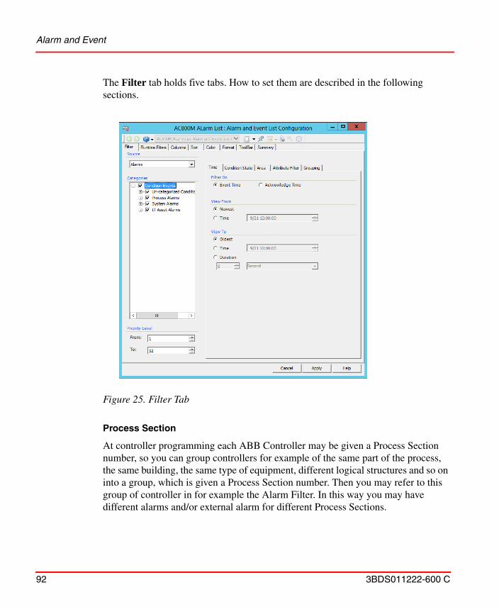
Alarm and Event
92 3BDS011222-600 C
The Filter tab holds five tabs. How to set them are described in the following sections.
Process Section
At controller programming each ABB Controller may be given a Process Section number, so you can group controllers for example of the same part of the process, the same building, the same type of equipment, different logical structures and so on into a group, which is given a Process Section number. Then you may refer to this group of controller in for example the Alarm Filter. In this way you may have different alarms and/or external alarm for different Process Sections.
Figure 25. Filter Tab
Alarm and Event
3BDS011222-600 C 93
When you filter an alarm, you may choose which Process Section this alarm list will cover. This is configured below the Area tab, in the Process Section area.
If you do not use Process Sectioning or your controllers do not support it the default All setting shall be used.
Class.
In the Class area you may select if you want:
• All - all classes will be selected.
• Range - all classes in the chosen interval will be shown.
• Range Expressions - chosen classes and/or class ranges will be shown. (Enter them separated by commas, for example, 10,20,30-60).
Filtering Alarm Messages
To filter Alarm Messages, follow the steps below:
1. Select Alarms in the Source area.
2. Select the alarm message states, below the Condition State tab, to be included in the list.
– Active StateChoose to show Active/Inactive alarms or both.
– Enable StateChoose to show Enabled/Disabled alarms or both.
– Acknowledge StateChoose to show alarms that are acknowledged or not, or both.
– Auto Disable StateChoose to see all auto disabled alarms (alarms that are disabled in the controller), or Not Auto Disabled.
Observe that the used controller(s) must support Process Sectioning. For more information, refer to the controller documentation.
Alarm and Event
94 3BDS011222-600 C
– Hiding StateChoose to show alarms that are in a hidden or in a not hidden state, or both.
3. Select either Event Time or Acknowledge Time in the Filter On area below the Time tab and then set the view range. Newest Event and Oldest Event apply no time filter. To apply a time filter:
a. Select Time in the View From or View To area.
b. Select the month, day, year, hour, minute or second segment of the Time area and use the up and down arrows to the right of the area to adjust the time. The actual format of the Time area depends upon how the Format tab was set.
4. Enter a number (1-32) for the From and To in the Priority Level area. Only messages with priority levels that are included this interval are displayed. Number 1 is the highest priority and 32 the lowest.
Filtering Alarm Categories
Use the Categories area to select message category filters. You can filter on the Category groups, Process Alarms and System Alarms, and their sub-categories.
To filter Alarm Categories, follow the steps below:
1. Select the categories to be included in the list from the tree structure.
2. Click Apply.
Filtering Event Messages
To filter Event Messages, follow the steps below:
1. Select Events in the Source area.
2. Set the view range for Message Time below the Time tab. First Event and Last Event apply no time filter. To apply a time filter:
a. Select Time in either the View From or View To area.
Select the appropriate categories before changing the Source from Alarms to Events, or vice versa.
Alarm and Event
3BDS011222-600 C 95
b. Select the month, day, year, hour, minute or second segment of the Time area and use the up and down arrows to the right of the area to adjust the time. The actual format of the Time area depends upon how the Format tab was set.
3. Enter a number (1-32) for the From and To in the Priority Level area. Only messages with priority levels that are included in this interval are displayed.
Filtering Event Categories
Use the Categories area to select message category filters. You can filter on the Category groups (Condition Events, Simple Events and Tracking Events), and their sub-categories.
To filter Event Categories, follow the steps below:
1. Select the categories to be included in the list from the tree structure.
2. Click Apply1.
1. The categories are defined in the controller. This gives that you have to read the controller information to get a complete information about the descriptions of categories.
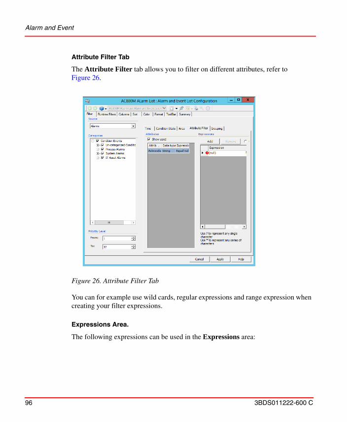
Alarm and Event
96 3BDS011222-600 C
Attribute Filter Tab
The Attribute Filter tab allows you to filter on different attributes, refer to Figure 26.
You can for example use wild cards, regular expressions and range expression when creating your filter expressions.
Expressions Area.
The following expressions can be used in the Expressions area:
Figure 26. Attribute Filter Tab
Alarm and Event
3BDS011222-600 C 97
Table 4. Expressions
Character Meaning
. Matches any single character. Same as “?” in a simple query.
[] A character class that will match all character inside the brackets. [AB] will match all strings containing the character A or B.
^ [^AB] will match all characters except A and B.
- Specifies a range of character or digits if used inside a character class. Example [A-D] matches all characters in the range A to D and [2-6] matches all digits in the range 2 to 6.
? Indicates that the preceding expression is optional, i.e [0-9][0-9]? matches both one and two digits.
+ Indicates that the preceding expression matches one or more times, for example [2]+ matches 2, 22, 222 and so on.
* Indicates that the preceding expression matches zero or more times.
??, +?, *? Tries to match as little as possible. Example the expression <.*?> on the string “<abc><def>” will match <abc> while the expression <.*> will match the whole string “<abc><def>”.
( ) Grouping operator. For example ([0-9]_)* will match 0 a string of digits separated with underscores, like 0_ , 0_1, or 0_1_1.
{} Indicates a match group.
\ Escape character, used to be able to match character with other special meaning in an expression. Example: [0-9]\+ matches a digit followed by a plus sign and not one or more digits.
$ At the end of a regular expression, this character matches the end of the input. Example: [0-9]$ matches a digit at the end of the input.
Alarm and Event
98 3BDS011222-600 C
There are some abbreviations that could simplify an expression if used. The following exist:
Grouping
The Alarm and Event lists can be configured to display the group alarms. The alarms included in a group will then not appear individually in the Alarm Lists. The configuration to display the group alarms is done in the Grouping tab, refer to Figure 27. Refer to Configuring Alarm Grouping on page 136 for information about
| Separates two expressions, for example AI|O in a character class matches both AI and AO
! Negation operator. A!B matches a string starting with A and not followed by a B.
Table 5. Abbreviations
Abbreviation Matches
\a Any alphanumeric character: ([a-zA-Z0-9])
\b White space (blank): ([ \\t])
\c Any alphabetic character: ([a-zA-Z])
\d Any decimal character: ([0-9])
\h Any hexadecimal digit: ([0-9a-fA-F])
\n Newline: (\r|(\r?\n))
\q A quoted string: (\”[^\”]*\”)|(\’[^\’]*\’)
\w A simple word: ([a-zA-Z]+)
\z An integer: ([0-9]+)
Table 4. Expressions (Continued)
Character Meaning
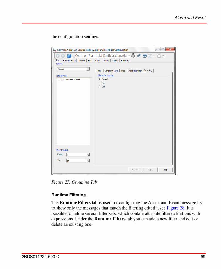
Alarm and Event
3BDS011222-600 C 99
the configuration settings.
Runtime Filtering
The Runtime Filters tab is used for configuring the Alarm and Event message list to show only the messages that match the filtering criteria, see Figure 28. It is possible to define several filter sets, which contain attribute filter definitions with expressions. Under the Runtime Filters tab you can add a new filter and edit or delete an existing one.
Figure 27. Grouping Tab
Alarm and Event
100 3BDS011222-600 C
The operator can select different filters during runtime through the Select Attribute Filter Set drop-down menu in the Alarm and Event list toolbar.
Relative Time Filters.
To provide consistent and deterministic alarm and event call-up times a time range is applied to the event filters. On initial call-up the filter is configured with a Duration filter. The Duration filter defines how far back in time from the current
Figure 28. Runtime Filters Tab
This technique applies best to IM or empty lists or lists with less than a page of events.
Alarm and Event
3BDS011222-600 C 101
time to get events from. Therefore, if an alarm and event page with a Duration filter of 1 week were called up it would show all data from now to now minus 7 days.
Once the initial alarm and event page is launched with the Duration filter a Runtime filter using relative time is used to select additional time windows. Runtime filters is used to retrieve events further back in time using relative time criteria.
For example building on the prior example where we launched the alarm and event page to show the prior week of data, we can apply a Runtime filter to show the data
Figure 29. Alarm and Event List - Duration Filter
Alarm and Event
102 3BDS011222-600 C
from two weeks in the past (start = now -7 d, end = now - 14 d). Make sure that the quotes around the filter as shown in Figure 30 are required.
Figure 30. Alarm and Event List - Runtime Filter
Only support for the keyword "now" has been implemented. Refer to Keywords on page 559 and The Time Definition on page 564 for more information about keywords and offsets.
Alarm and Event
3BDS011222-600 C 103
Attribute Extensions
Defining the Event Attributes.
Create an Event Attribute Definition aspect in the Library Structure or modify an existing Event Attribute Definition aspect. Refer to the steps given in the System Administrator and Security (3BSE037410*) to create and define the attribute.
Setting Instance Specific Values for Event Attributes on Objects.
The extended attributes on each object can be set to instance specific values using an Event Attribute Object Extension aspect (Figure 32). Following are two ways to set the attributes:
– Using Bulk Data Manager Tool
In the Attribute Definition select the Extension check box, and select All categories as Event Category Name to add the custom attribute.
Figure 31. Attribute Definition
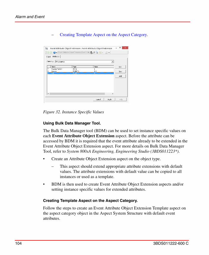
Alarm and Event
104 3BDS011222-600 C
– Creating Template Aspect on the Aspect Category.
Using Bulk Data Manager Tool.
The Bulk Data Manager tool (BDM) can be used to set instance specific values on each Event Attribute Object Extension aspect. Before the attribute can be accessed by BDM it is required that the event attribute already to be extended in the Event Attribute Object Extension aspect. For more details on Bulk Data Manager Tool, refer to System 800xA Engineering, Engineering Studio (3BDS011223*).
• Create an Attribute Object Extension aspect on the object type.
– This aspect should extend appropriate attribute extensions with default values. The attribute extensions with default value can be copied to all instances or used as a template.
• BDM is then used to create Event Attribute Object Extension aspects and/or setting instance specific values for extended attributes.
Creating Template Aspect on the Aspect Category.
Follow the steps to create an Event Attribute Object Extension Template aspect on the aspect category object in the Aspect System Structure with default event attributes.
Figure 32. Instance Specific Values
Alarm and Event
3BDS011222-600 C 105
1. On the Aspect System structure, navigate to the Event Attribute Object Extension aspect.
2. Create an Event Attribute Object Extension aspect on the aspect category object.
3. On the Attributes tab, add the attribute extensions and give them default values.For Example: Sub, Process Section, System
4. Right-click Event Attribute Object Extension aspect.
5. Select Details on the context menu and then Aspect Info.
6. Add Template Aspect key and click OK.
7. Click Apply.
Filtering the Alarm List in Runtime on Columns .
Perform the following steps to include the event attributes as columns in the alarm list.
Figure 33. Details - Aspect Info
Alarm and Event
106 3BDS011222-600 C
1. On the Alarm and Event List Configuration aspect, click the Columns tab.
2. Select the columns to be displayed in the alarm list.
Figure 34. Including the Event Attributes as Columns
Alarm and Event
3BDS011222-600 C 107
This allows to filter the alarm list in runtime (Figure 35).
1. In the Alarm List, right-click the column to filter the list.
2. Enter the value in Runtime Attribute Filter dialog and click OK.
Add an Alarm and Event List
Create an Alarm and Event List aspect in a Plant Explorer structure as described below:
1. Select the object in the Plant Explorer, to which you want to add an Alarm and Event List.
2. Select New Aspect from the context menu.
3. Select the Alarm and Event List aspect.
Figure 35. Filtering the Alarm List
Figure 36. Filtered Alarm List
Alarm and Event
108 3BDS011222-600 C
4. Click on the Alarm and Event List aspect and select the configuration view.
5. The Library Structure drop-down menu shows all the available Alarm and Event List configurations in the Library Structure, default or custom configurations. The Object drop-down menu shows the available Alarm and Event List configurations on the same object as the list.
6. If you want to make a copy of the list configuration, click the Copy Template button. This will create a copy of the selected list configuration and place it on the same object as the list.
7. Go to the Alarm Filter area and select the object filter function:
– Select the All alarms to allow this aspect to display alarms and events for all objects.
Figure 37. Alarm and Event List Configuration View
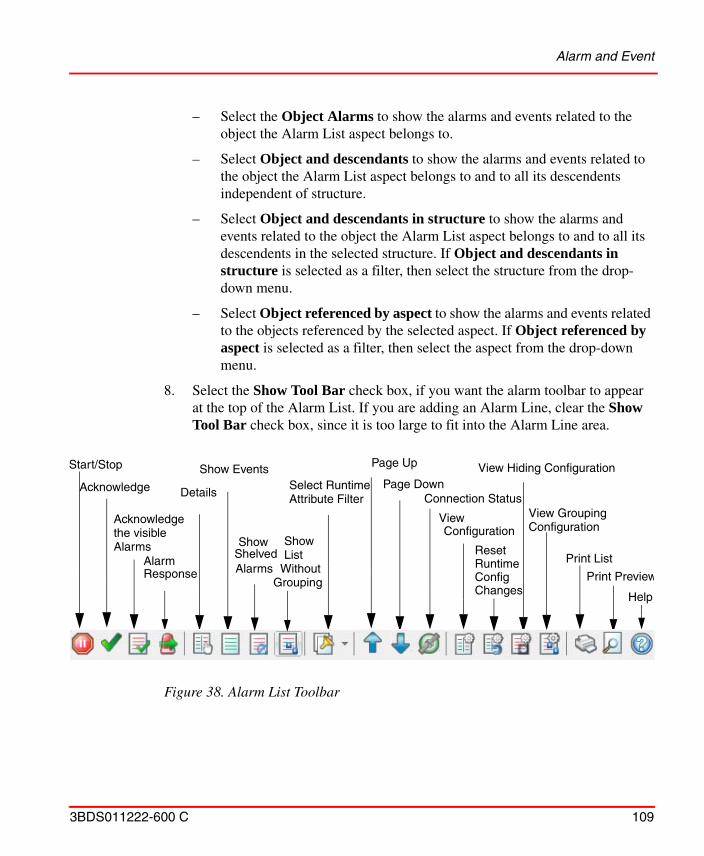
Alarm and Event
3BDS011222-600 C 109
– Select the Object Alarms to show the alarms and events related to the object the Alarm List aspect belongs to.
– Select Object and descendants to show the alarms and events related to the object the Alarm List aspect belongs to and to all its descendents independent of structure.
– Select Object and descendants in structure to show the alarms and events related to the object the Alarm List aspect belongs to and to all its descendents in the selected structure. If Object and descendants in structure is selected as a filter, then select the structure from the drop-down menu.
– Select Object referenced by aspect to show the alarms and events related to the objects referenced by the selected aspect. If Object referenced by aspect is selected as a filter, then select the aspect from the drop-down menu.
8. Select the Show Tool Bar check box, if you want the alarm toolbar to appear at the top of the Alarm List. If you are adding an Alarm Line, clear the Show Tool Bar check box, since it is too large to fit into the Alarm Line area.
Figure 38. Alarm List Toolbar
Start/Stop
Acknowledge Details Connection Status
Print List
Print Preview
Help
View Hiding ConfigurationPage Up
ResetRuntimeConfigChanges
Show ShelvedAlarms
Page Down
ViewConfiguration
Acknowledgethe visibleAlarms
Select RuntimeAttribute Filter
AlarmResponse
ShowList
WithoutGrouping
Show Events
View GroupingConfiguration
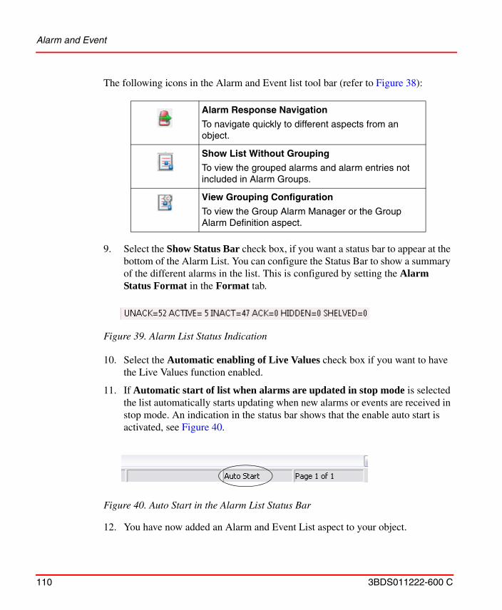
Alarm and Event
110 3BDS011222-600 C
The following icons in the Alarm and Event list tool bar (refer to Figure 38):
9. Select the Show Status Bar check box, if you want a status bar to appear at the bottom of the Alarm List. You can configure the Status Bar to show a summary of the different alarms in the list. This is configured by setting the Alarm Status Format in the Format tab.
10. Select the Automatic enabling of Live Values check box if you want to have the Live Values function enabled.
11. If Automatic start of list when alarms are updated in stop mode is selected the list automatically starts updating when new alarms or events are received in stop mode. An indication in the status bar shows that the enable auto start is activated, see Figure 40.
12. You have now added an Alarm and Event List aspect to your object.
Alarm Response Navigation
To navigate quickly to different aspects from an object.
Show List Without Grouping
To view the grouped alarms and alarm entries not included in Alarm Groups.
View Grouping Configuration
To view the Group Alarm Manager or the Group Alarm Definition aspect.
Figure 39. Alarm List Status Indication
Figure 40. Auto Start in the Alarm List Status Bar
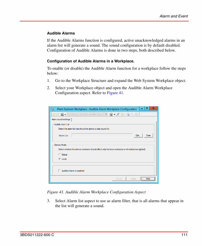
Alarm and Event
3BDS011222-600 C 111
Audible Alarms
If the Audible Alarms function is configured, active unacknowledged alarms in an alarm list will generate a sound. The sound configuration is by default disabled. Configuration of Audible Alarms is done in two steps, both described below.
Configuration of Audible Alarms in a Workplace.
To enable (or disable) the Audible Alarm function for a workplace follow the steps below:
1. Go to the Workplace Structure and expand the Web System Workplace object.
2. Select your Workplace object and open the Audible Alarm Workplace Configuration aspect. Refer to Figure 41.
3. Select Alarm list aspect to use as alarm filter, that is all alarms that appear in the list will generate a sound.
Figure 41. Audible Alarm Workplace Configuration Aspect
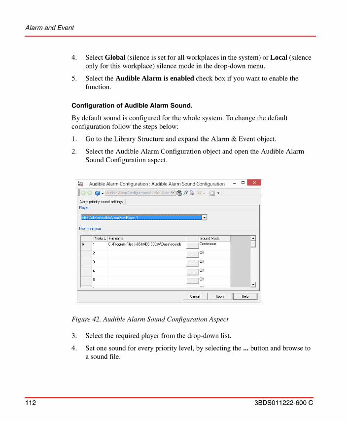
Alarm and Event
112 3BDS011222-600 C
4. Select Global (silence is set for all workplaces in the system) or Local (silence only for this workplace) silence mode in the drop-down menu.
5. Select the Audible Alarm is enabled check box if you want to enable the function.
Configuration of Audible Alarm Sound.
By default sound is configured for the whole system. To change the default configuration follow the steps below:
1. Go to the Library Structure and expand the Alarm & Event object.
2. Select the Audible Alarm Configuration object and open the Audible Alarm Sound Configuration aspect.
3. Select the required player from the drop-down list.
4. Set one sound for every priority level, by selecting the ... button and browse to a sound file.
Figure 42. Audible Alarm Sound Configuration Aspect
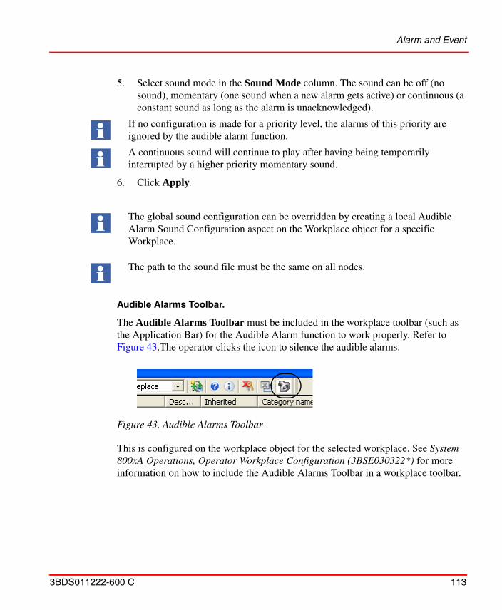
Alarm and Event
3BDS011222-600 C 113
5. Select sound mode in the Sound Mode column. The sound can be off (no sound), momentary (one sound when a new alarm gets active) or continuous (a constant sound as long as the alarm is unacknowledged).
6. Click Apply.
Audible Alarms Toolbar.
The Audible Alarms Toolbar must be included in the workplace toolbar (such as the Application Bar) for the Audible Alarm function to work properly. Refer to Figure 43.The operator clicks the icon to silence the audible alarms.
This is configured on the workplace object for the selected workplace. See System 800xA Operations, Operator Workplace Configuration (3BSE030322*) for more information on how to include the Audible Alarms Toolbar in a workplace toolbar.
If no configuration is made for a priority level, the alarms of this priority are ignored by the audible alarm function.
A continuous sound will continue to play after having being temporarily interrupted by a higher priority momentary sound.
The global sound configuration can be overridden by creating a local Audible Alarm Sound Configuration aspect on the Workplace object for a specific Workplace.
The path to the sound file must be the same on all nodes.
Figure 43. Audible Alarms Toolbar
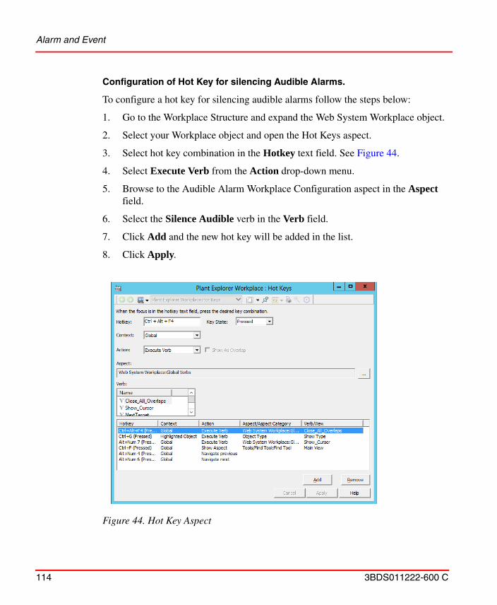
Alarm and Event
114 3BDS011222-600 C
Configuration of Hot Key for silencing Audible Alarms.
To configure a hot key for silencing audible alarms follow the steps below:
1. Go to the Workplace Structure and expand the Web System Workplace object.
2. Select your Workplace object and open the Hot Keys aspect.
3. Select hot key combination in the Hotkey text field. See Figure 44.
4. Select Execute Verb from the Action drop-down menu.
5. Browse to the Audible Alarm Workplace Configuration aspect in the Aspect field.
6. Select the Silence Audible verb in the Verb field.
7. Click Add and the new hot key will be added in the list.
8. Click Apply.
Figure 44. Hot Key Aspect
Alarm and Event
3BDS011222-600 C 115
Alarm Hiding
Hiding is a way of avoiding alarm situations where numerous sequential alarms make it hard to determine the root cause of a problem. By using the hiding function in 800xA, it is possible to hide non-relevant equal alarms. The hiding of alarms is initiated by hiding rules, which can be process conditions or logical expressions. All the hiding rules are kept in the Hiding Mask Manager.
Hiding affects the presentation of the alarm list. If an alarm is irrelevant it should not be shown in an alarm list. An alarm is irrelevant if it does not require an action from the operator. The Hiding alarm function will help the operator to get the alarm lists clearer from irrelevant alarms.
During a specific operational mode, for example a start-up or a shut-down, it is common that alarms, which are relevant during a normal operation, are totally irrelevant.
With Hiding Rules it is possible to define which alarms that will be hidden during a specific operation. Single alarms can be hidden as well as alarms from an object and its descendants. An exception to the above mentioned is that the hiding functionality does not affect some of the Alarm Categories, i.e. alarms for the categories “System Alarms” (defined by the Operator Workplace), “IM History” (defined by Information Management), “System Alarm” (defined by 800xA for Advant Master) and “System Condition Event” (defined by 800xA for AC 800M) will never be hidden. The reason for this is that alarms of these categories are considered system alarms, which can be too severe to hide.
A configurable indication in the Alarm Band shows that hidden alarms exist. Refer to Hidden Alarms in the Alarm Band. The hidden status of alarms will also be indicated in Faceplates.
A hidden alarm also has a hiding indication in its context menu. Select hiding and the Hiding Rules dialog box will be displayed. Refer to Alarm Hiding on page 116.
A hidden alarm is automatically acknowledged when the alarm is cleared, that is the alarm goes from active to inactive state.
Alarm and Event
116 3BDS011222-600 C
Hiding Mask.
A Hiding mask is a collection of Hiding Rules that will be evaluated at the same time. The rules are valid when the activating condition for a the mask is true. A mask is invoked according to a Boolean condition or an OPC Property.
Applying a Hiding Mask will only affect new alarms that appear after the state change. The conditions are configured in the Hiding Mask Manager located in the Library Structure.
Hiding Rules.
Hiding rules define conditions under which alarms from a specific object will be hidden. The condition can be an expression containing any boolean OPC Property or alarm condition. One hiding rule can only hold one condition. Logic expressions are possible to create directly in the rules.
If you want more complex conditions, these can be made by defining for example soft alarms using Alarm Expressions (refer to Alarm Expression on page 157). Refer to Configure Alarm Hiding on page 124 for more information.
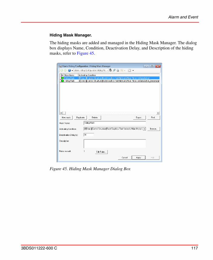
Alarm and Event
3BDS011222-600 C 117
Hiding Mask Manager.
The hiding masks are added and managed in the Hiding Mask Manager. The dialog box displays Name, Condition, Deactivation Delay, and Description of the hiding masks, refer to Figure 45.
Figure 45. Hiding Mask Manager Dialog Box
Alarm and Event
118 3BDS011222-600 C
The Hiding Mask Manager has the following options:
The A column shows whether an activating condition is true or not. The list also shows the Name, Activating Condition, Deactivation Delay, and Description of all hiding mask.
The buttons in the dialog box are used as follows:
• New Mask - Select New Mask to create a new Hiding mask. To edit a Hiding Mask, double-click on the Mask or select a Mask and click Edit Rules (refer to Edit Rules). This opens the Hiding Mask Definition dialog box, refer to Figure 46.
• Duplicate - Click Duplicate to create a new Hiding mask by copying the selected one.
• Delete - Click Delete to remove selected mask from the list.
• Find - Click Find to open the Find/Replace dialog box. Use the dialog box to find hiding rules in selected mask (or all masks).
• Export - Click Export to export the selected mask to an Microsoft Excel spreadsheet for documentation. After clicking Export, Excel will open and show selected mask and its rules. Export is only enabled if Excel is installed on the machine.
Click Apply on the new created mask and then Edit Rules to add a Hiding Rule. The Hiding Mask Definition dialog appears, refer to Figure 46.
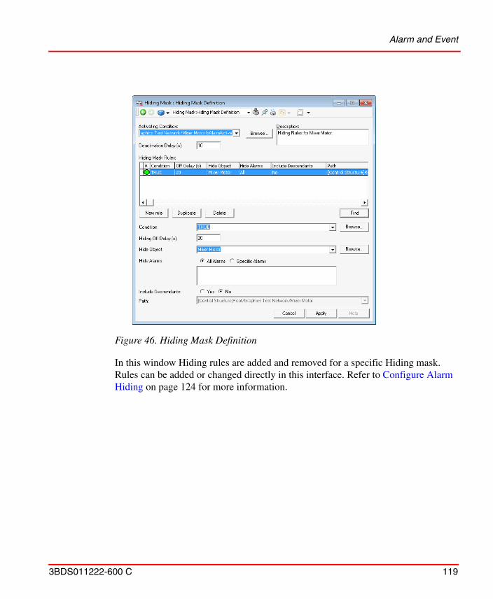
Alarm and Event
3BDS011222-600 C 119
In this window Hiding rules are added and removed for a specific Hiding mask. Rules can be added or changed directly in this interface. Refer to Configure Alarm Hiding on page 124 for more information.
Figure 46. Hiding Mask Definition
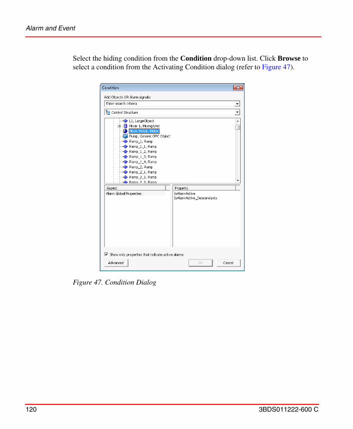
Alarm and Event
120 3BDS011222-600 C
Select the hiding condition from the Condition drop-down list. Click Browse to select a condition from the Activating Condition dialog (refer to Figure 47).
Figure 47. Condition Dialog
Alarm and Event
3BDS011222-600 C 121
Click Advanced to write your own expressions, Figure 48. See also Alarm Expression on page 157 and Item Syntaxes on page 171.
Edit Condition
An Edit Condition dialog is launched from the Browse button to the right of Activity Condition for a mask, and Condition for a rule. The expression for the row is automatically entered in the Expression field.
Expression Field
The conditions follow C++ syntax, which means that the following operators can be used: &&, AND, ||, OR, ! and NOT. In special cases TRUE and FALSE can be used. TRUE makes the activating condition true at all times. FALSE makes the activating
Figure 48. Advanced Activating Condition

Alarm and Event
122 3BDS011222-600 C
condition false at all times. Add a description after you have built the condition in the browser.
When defining hiding conditions, the time required for an alarm to be hidden can be longer than the time the actual hiding condition is active. To achieve this, a Hiding Off Delay can be defined. When a Hiding Off Delay is defined, alarms will remain hidden during the delay even if the hiding condition is inactive. The off delay can be applied to both the hiding mask (deactivation delay) and hiding rules (hiding off delay).
The Hiding Off Delay in the Hiding rule aspect view indicates the hiding delay in seconds for hidden alarms.
The Deactivation Delay in the Hiding mask aspect view (refer to Figure 45) indicates the delay in seconds for disabling the containing rules after deactivation of the mask activating condition.
Figure 49. Description Area
Alarm and Event
3BDS011222-600 C 123
Find
The Find dialog box can be launched from the Hiding Mask Manager window and from the Hiding Mask window. It has two option buttons with which you can limit your search.
• In selected mask
This option delimits the searching to selected mask(s). This is the default option. If the Find dialog was opened from the Mask Manager, one or more of the masks was probably selected. If the dialog box was opened from a single hiding mask, that mask is selected.
• In all masks
This option enables searching in all masks. This is the default option if no masks were selected when the find dialog box was opened from the Mask manager.
Figure 50. Find Mask dialogs
Alarm and Event
124 3BDS011222-600 C
Save Hiding Configurations.
To save an application (normally objects in the Control Structure) including hiding configurations, select the application and drag it into the Import/Export Tool.
Configure Alarm Hiding
To configure Alarm Hiding, a Hiding Mask and a Hiding Rule that defines a Hidden Alarm must be created.
In order for the masks (affecting the rules in the application) to be exported, the Include Dependencies check box in the Add Items dialog box must be selected.
A mask may be exported from the Library Structure (see Configure Alarm Hiding on page 124). However, you can not save the rules in a mask by exporting the mask, even if the Include Dependencies check box is selected. Rules can only be saved by exporting them explicitly, either by exporting the rule aspects themselves or by exporting the objects that hold the rule aspects.
Alarm and Event
3BDS011222-600 C 125
1. Navigate to the Library Structure > Alarm & Event > Alarm Hiding Configuration, refer to Figure 51.
2. Select the Hiding Mask Manager aspect.
3. Click New mask to create a new mask.
4. Enter a name in the Mask Name field.
5. Define a condition that activates the Hiding Mask. Select a condition for the activating condition from the Activating Condition drop-down box or click Browse to display the Activating Condition dialog box
Figure 51. Alarm Hiding Configuration
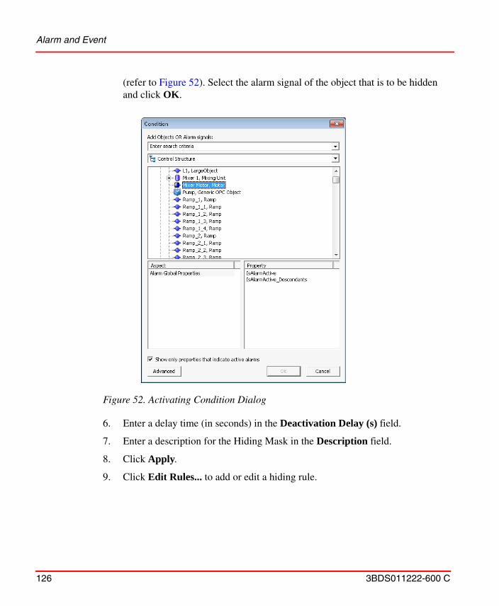
Alarm and Event
126 3BDS011222-600 C
(refer to Figure 52). Select the alarm signal of the object that is to be hidden and click OK.
6. Enter a delay time (in seconds) in the Deactivation Delay (s) field.
7. Enter a description for the Hiding Mask in the Description field.
8. Click Apply.
9. Click Edit Rules... to add or edit a hiding rule.
Figure 52. Activating Condition Dialog
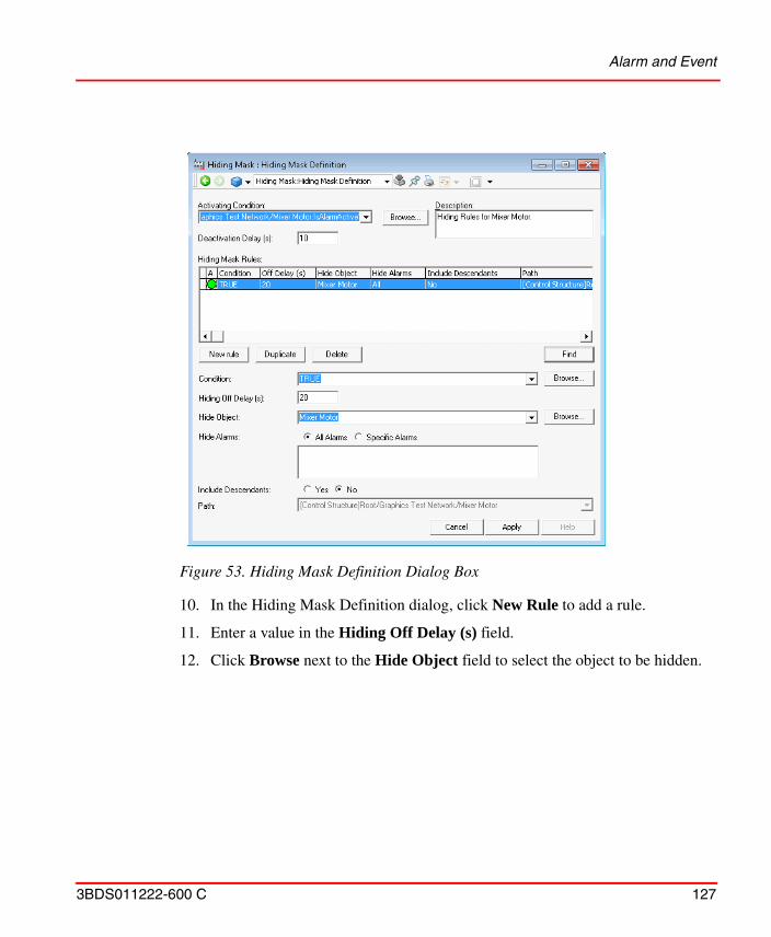
Alarm and Event
3BDS011222-600 C 127
10. In the Hiding Mask Definition dialog, click New Rule to add a rule.
11. Enter a value in the Hiding Off Delay (s) field.
12. Click Browse next to the Hide Object field to select the object to be hidden.
Figure 53. Hiding Mask Definition Dialog Box
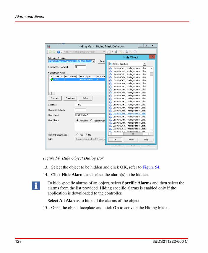
Alarm and Event
128 3BDS011222-600 C
13. Select the object to be hidden and click OK, refer to Figure 54.
14. Click Hide Alarms and select the alarm(s) to be hidden.
15. Open the object faceplate and click On to activate the Hiding Mask.
Figure 54. Hide Object Dialog Box
To hide specific alarms of an object, select Specific Alarms and then select the alarms from the list provided. Hiding specific alarms is enabled only if the application is downloaded to the controller.
Select All Alarms to hide all the alarms of the object.
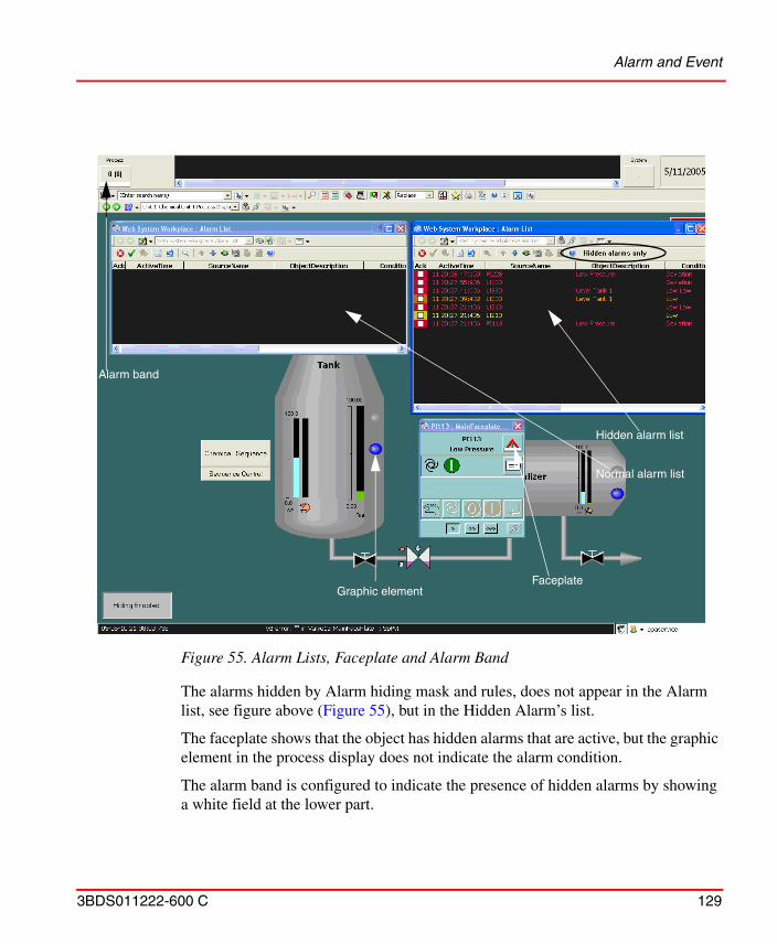
Alarm and Event
3BDS011222-600 C 129
The alarms hidden by Alarm hiding mask and rules, does not appear in the Alarm list, see figure above (Figure 55), but in the Hidden Alarm’s list.
The faceplate shows that the object has hidden alarms that are active, but the graphic element in the process display does not indicate the alarm condition.
The alarm band is configured to indicate the presence of hidden alarms by showing a white field at the lower part.
Figure 55. Alarm Lists, Faceplate and Alarm Band
Hidden alarm list
Normal alarm list
Faceplate
Alarm band
Graphic element
Alarm and Event
130 3BDS011222-600 C
Alarm Shelving
Alarm Shelving is an integrated component of the Alarm & Event function in the 800xA system. Alarm shelving allows the operators to temporarily remove standing or nuisance alarms from the main alarm list and places it on the shelve list.
The alarm does not reappear on the main list until it is removed from the shelf.
Unlike alarm disabling, where alarms are disabled for infinite time, shelving occurs for a specified time and demands operator attention when the predefined time has elapsed.
Shelving configuration defines how operators can shelve the alarms. There are two ways to shelve the alarms:
• Standard Shelving.
Standard shelving allows the operators to shelve the alarms temporarily for a specified time. Recurrences of the alarm because of a state change will not appear in the main list until the specified time has elapsed.
• One-shot Shelving.
One-shot shelving will place the alarm in the shelf only once. When the state of the alarm changes, the alarm is automatically removed from the shelf. Further instances of the alarm will appear in the main list.
The shelving configuration includes configuring the following parameters in the Alarm Shelving Configuration object under the Library Structure (refer to Figure 56).
Alarm Shelving is a license-protected feature.
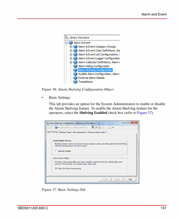
Alarm and Event
3BDS011222-600 C 131
• Basic Settings.
This tab provides an option for the System Administrators to enable or disable the Alarm Shelving feature. To enable the Alarm Shelving feature for the operators, select the Shelving Enabled check box (refer to Figure 57).
Figure 56. Alarm Shelving Configuration Object
Figure 57. Basic Settings Tab
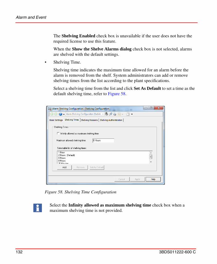
Alarm and Event
132 3BDS011222-600 C
The Shelving Enabled check box is unavailable if the user does not have the required license to use this feature.
When the Show the Shelve Alarms dialog check box is not selected, alarms are shelved with the default settings.
• Shelving Time.
Shelving time indicates the maximum time allowed for an alarm before the alarm is removed from the shelf. System administrators can add or remove shelving times from the list according to the plant specifications.
Select a shelving time from the list and click Set As Default to set a time as the default shelving time, refer to Figure 58.
Figure 58. Shelving Time Configuration
Select the Infinity allowed as maximum shelving time check box when a maximum shelving time is not provided.
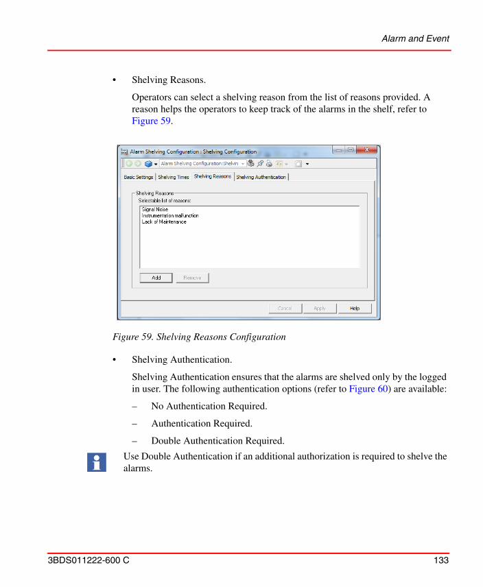
Alarm and Event
3BDS011222-600 C 133
• Shelving Reasons.
Operators can select a shelving reason from the list of reasons provided. A reason helps the operators to keep track of the alarms in the shelf, refer to Figure 59.
• Shelving Authentication.
Shelving Authentication ensures that the alarms are shelved only by the logged in user. The following authentication options (refer to Figure 60) are available:
– No Authentication Required.
– Authentication Required.
– Double Authentication Required.
Figure 59. Shelving Reasons Configuration
Use Double Authentication if an additional authorization is required to shelve the alarms.
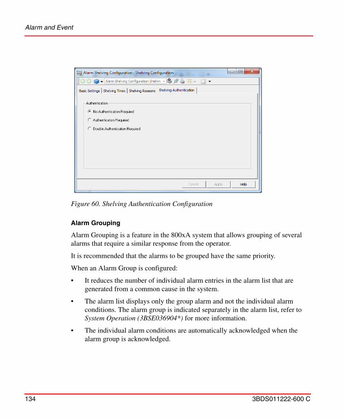
Alarm and Event
134 3BDS011222-600 C
Alarm Grouping
Alarm Grouping is a feature in the 800xA system that allows grouping of several alarms that require a similar response from the operator.
It is recommended that the alarms to be grouped have the same priority.
When an Alarm Group is configured:
• It reduces the number of individual alarm entries in the alarm list that are generated from a common cause in the system.
• The alarm list displays only the group alarm and not the individual alarm conditions. The alarm group is indicated separately in the alarm list, refer to System Operation (3BSE036904*) for more information.
• The individual alarm conditions are automatically acknowledged when the alarm group is acknowledged.
Figure 60. Shelving Authentication Configuration
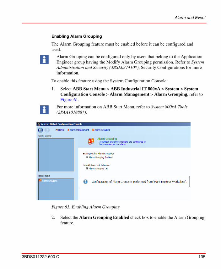
Alarm and Event
3BDS011222-600 C 135
Enabling Alarm Grouping
The Alarm Grouping feature must be enabled before it can be configured and used.
To enable this feature using the System Configuration Console:
1. Select ABB Start Menu > ABB Industrial IT 800xA > System > System Configuration Console > Alarm Management > Alarm Grouping, refer to Figure 61.
2. Select the Alarm Grouping Enabled check box to enable the Alarm Grouping feature.
Alarm Grouping can be configured only by users that belong to the Application Engineer group having the Modify Alarm Grouping permission. Refer to System Administration and Security (3BSE037410*), Security Configurations for more information.
For more information on ABB Start Menu, refer to System 800xA Tools (2PAA101888*).
Figure 61. Enabling Alarm Grouping
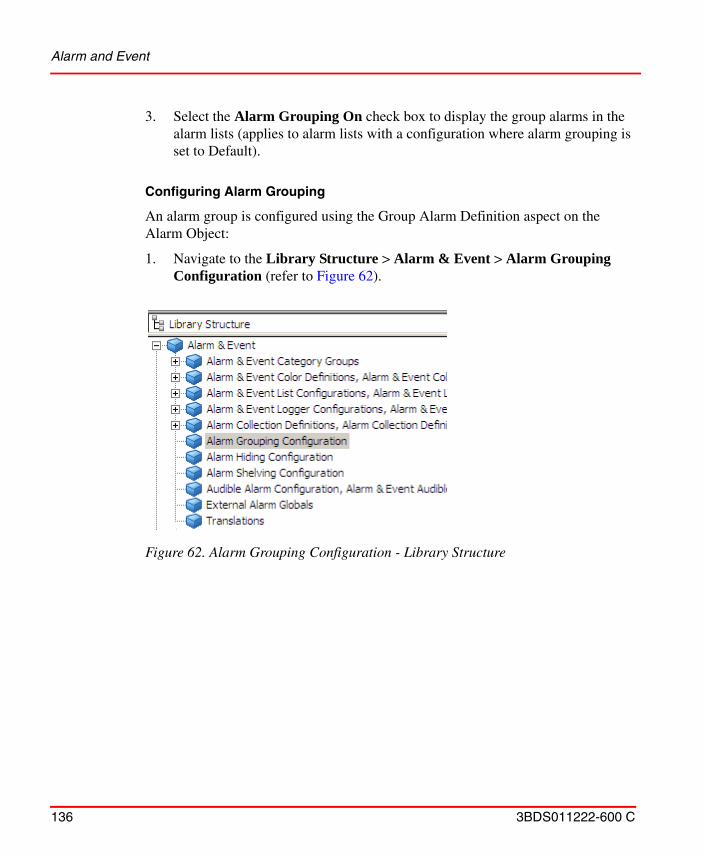
Alarm and Event
136 3BDS011222-600 C
3. Select the Alarm Grouping On check box to display the group alarms in the alarm lists (applies to alarm lists with a configuration where alarm grouping is set to Default).
Configuring Alarm Grouping
An alarm group is configured using the Group Alarm Definition aspect on the Alarm Object:
1. Navigate to the Library Structure > Alarm & Event > Alarm Grouping Configuration (refer to Figure 62).
Figure 62. Alarm Grouping Configuration - Library Structure
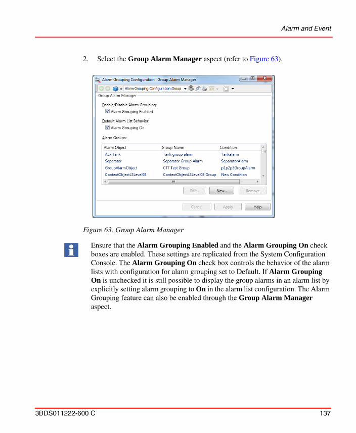
Alarm and Event
3BDS011222-600 C 137
2. Select the Group Alarm Manager aspect (refer to Figure 63).
Figure 63. Group Alarm Manager
Ensure that the Alarm Grouping Enabled and the Alarm Grouping On check boxes are enabled. These settings are replicated from the System Configuration Console. The Alarm Grouping On check box controls the behavior of the alarm lists with configuration for alarm grouping set to Default. If Alarm Grouping On is unchecked it is still possible to display the group alarms in an alarm list by explicitly setting alarm grouping to On in the alarm list configuration. The Alarm Grouping feature can also be enabled through the Group Alarm Manager aspect.
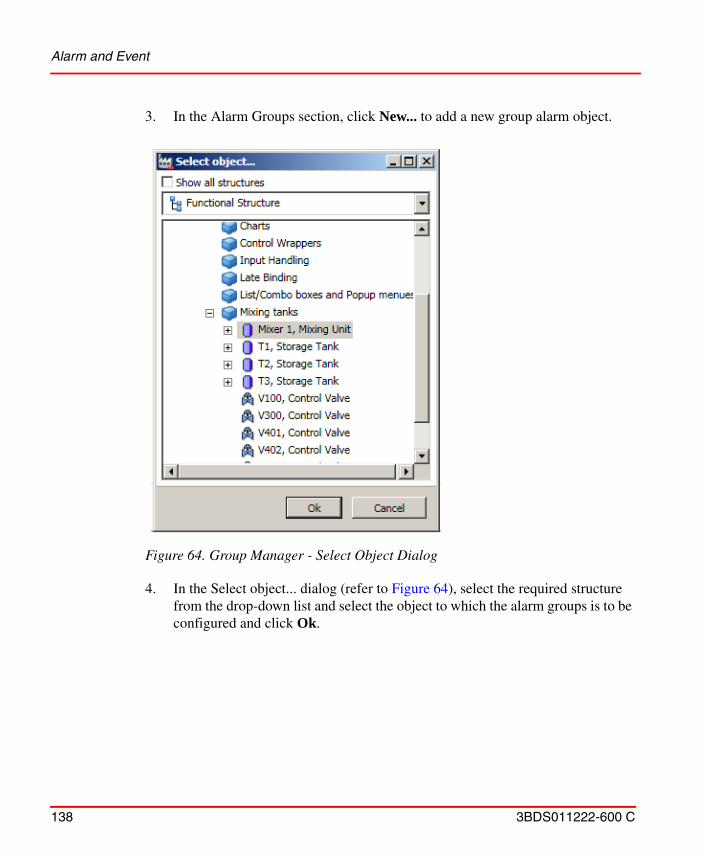
Alarm and Event
138 3BDS011222-600 C
3. In the Alarm Groups section, click New... to add a new group alarm object.
4. In the Select object... dialog (refer to Figure 64), select the required structure from the drop-down list and select the object to which the alarm groups is to be configured and click Ok.
Figure 64. Group Manager - Select Object Dialog
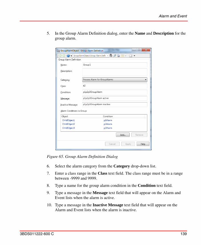
Alarm and Event
3BDS011222-600 C 139
5. In the Group Alarm Definition dialog, enter the Name and Description for the group alarm.
6. Select the alarm category from the Category drop-down list.
7. Enter a class range in the Class text field. The class range must be in a range between -9999 and 9999.
8. Type a name for the group alarm condition in the Condition text field.
9. Type a message in the Message text field that will appear on the Alarm and Event lists when the alarm is active.
10. Type a message in the Inactive Message text field that will appear on the Alarm and Event lists when the alarm is inactive.
Figure 65. Group Alarm Definition Dialog
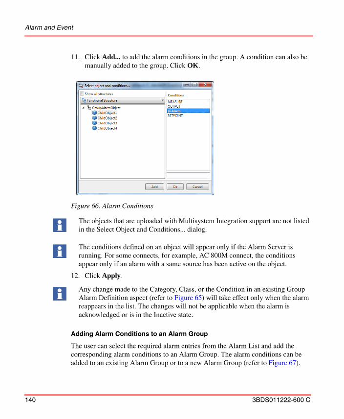
Alarm and Event
140 3BDS011222-600 C
11. Click Add... to add the alarm conditions in the group. A condition can also be manually added to the group. Click OK.
12. Click Apply.
Adding Alarm Conditions to an Alarm Group
The user can select the required alarm entries from the Alarm List and add the corresponding alarm conditions to an Alarm Group. The alarm conditions can be added to an existing Alarm Group or to a new Alarm Group (refer to Figure 67).
Figure 66. Alarm Conditions
The objects that are uploaded with Multisystem Integration support are not listed in the Select Object and Conditions... dialog.
The conditions defined on an object will appear only if the Alarm Server is running. For some connects, for example, AC 800M connect, the conditions appear only if an alarm with a same source has been active on the object.
Any change made to the Category, Class, or the Condition in an existing Group Alarm Definition aspect (refer to Figure 65) will take effect only when the alarm reappears in the list. The changes will not be applicable when the alarm is acknowledged or is in the Inactive state.
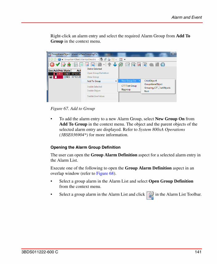
Alarm and Event
3BDS011222-600 C 141
Right-click an alarm entry and select the required Alarm Group from Add To Group in the context menu.
• To add the alarm entry to a new Alarm Group, select New Group On from Add To Group in the context menu. The object and the parent objects of the selected alarm entry are displayed. Refer to System 800xA Operations (3BSE036904*) for more information.
Opening the Alarm Group Definition
The user can open the Group Alarm Definition aspect for a selected alarm entry in the Alarm List.
Execute one of the following to open the Group Alarm Definition aspect in an overlap window (refer to Figure 68).
• Select a group alarm in the Alarm List and select Open Group Definition from the context menu.
• Select a group alarm in the Alarm List and click in the Alarm List Toolbar.
Figure 67. Add to Group
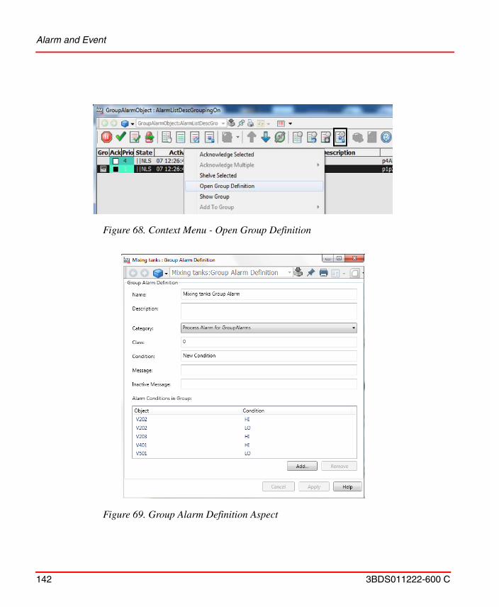
Alarm and Event
142 3BDS011222-600 C
Figure 68. Context Menu - Open Group Definition
Figure 69. Group Alarm Definition Aspect
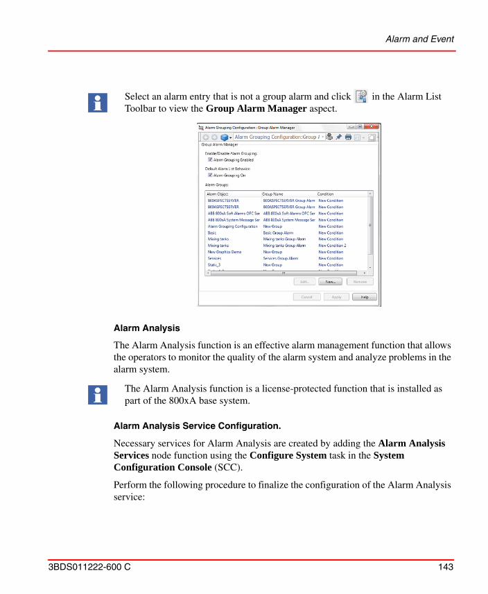
Alarm and Event
3BDS011222-600 C 143
Alarm Analysis
The Alarm Analysis function is an effective alarm management function that allows the operators to monitor the quality of the alarm system and analyze problems in the alarm system.
Alarm Analysis Service Configuration.
Necessary services for Alarm Analysis are created by adding the Alarm Analysis Services node function using the Configure System task in the System Configuration Console (SCC).
Perform the following procedure to finalize the configuration of the Alarm Analysis service:
Select an alarm entry that is not a group alarm and click in the Alarm List Toolbar to view the Group Alarm Manager aspect.
The Alarm Analysis function is a license-protected function that is installed as part of the 800xA base system.
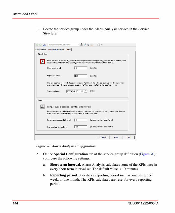
Alarm and Event
144 3BDS011222-600 C
1. Locate the service group under the Alarm Analysis service in the Service Structure.
2. On the Special Configuration tab of the service group definition (Figure 70), configure the following settings:
a. Short term interval. Alarm Analysis calculates some of the KPIs once in every short term interval set. The default value is 10 minutes.
b. Reporting period. Specifies a reporting period such as, one shift, one week, or one month. The KPIs calculated are reset for every reporting period.
Figure 70. Alarm Analysis Configuration
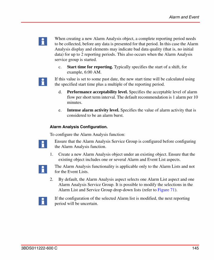
Alarm and Event
3BDS011222-600 C 145
c. Start time for reporting. Typically specifies the start of a shift, for example, 6:00 AM.
d. Performance acceptability level. Specifies the acceptable level of alarm flow per short term interval. The default recommendation is 1 alarm per 10 minutes.
e. Intense alarm activity level. Specifies the value of alarm activity that is considered to be an alarm burst.
Alarm Analysis Configuration.
To configure the Alarm Analysis function:
1. Create a new Alarm Analysis object under an existing object. Ensure that the existing object includes one or several Alarm and Event List aspects.
2. By default, the Alarm Analysis aspect selects one Alarm List aspect and one Alarm Analysis Service Group. It is possible to modify the selections in the Alarm List and Service Group drop-down lists (refer to Figure 71).
When creating a new Alarm Analysis object, a complete reporting period needs to be collected, before any data is presented for that period. In this case the Alarm Analysis display and elements may indicate bad data quality (that is, no initial data) for up to 2 reporting periods. This also occurs when the Alarm Analysis service group is started.
If this value is set to some past date, the new start time will be calculated using the specified start time plus a multiple of the reporting period.
Ensure that the Alarm Analysis Service Group is configured before configuring the Alarm Analysis function.
The Alarm Analysis functionality is applicable only to the Alarm Lists and not for the Event Lists.
If the configuration of the selected Alarm list is modified, the next reporting period will be uncertain.
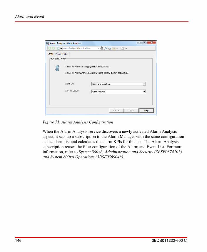
Alarm and Event
146 3BDS011222-600 C
When the Alarm Analysis service discovers a newly activated Alarm Analysis aspect, it sets up a subscription to the Alarm Manager with the same configuration as the alarm list and calculates the alarm KPIs for this list. The Alarm Analysis subscription reuses the filter configuration of the Alarm and Event List. For more information, refer to System 800xA, Administration and Security (3BSE037410*) and System 800xA Operations (3BSE036904*).
Figure 71. Alarm Analysis Configuration
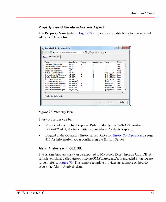
Alarm and Event
3BDS011222-600 C 147
Property View of the Alarm Analysis Aspect.
The Property View (refer to Figure 72) shows the available KPIs for the selected Alarm and Event list.
These properties can be:
• Visualized in Graphic Displays. Refer to the System 800xA Operations (3BSE036904*) for information about Alarm Analysis Reports.
• Logged in the Operator History server. Refer to History Configuration on page 411 for information about configuring the History Server.
Alarm Analysis with OLE DB.
The Alarm Analysis data can be exported to Microsoft Excel through OLE DB. A sample template, called AlarmAnalysisOLEDBSample.xls, is included in the Demo folder, refer to Figure 73. This sample template provides an example on how to access the Alarm Analysis data.
Figure 72. Property View
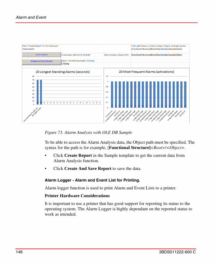
Alarm and Event
148 3BDS011222-600 C
To be able to access the Alarm Analysis data, the Object path must be specified. The syntax for the path is for example, [Functional Structure]<Root>/<Object>.
• Click Create Report in the Sample template to get the current data from Alarm Analysis function.
• Click Create And Save Report to save the data.
Alarm Logger - Alarm and Event List for Printing.
Alarm logger function is used to print Alarm and Event Lists to a printer.
Printer Hardware Considerations
It is important to use a printer that has good support for reporting its status to the operating system. The Alarm Logger is highly dependant on the reported status to work as intended.
Figure 73. Alarm Analysis with OLE DB Sample
Alarm and Event
3BDS011222-600 C 149
When using a line printer, the recommendation is to connect the printer to a parallel or USB port. If the printer is connected to the serial port the Alarm Logger will not detect when the printer is powered off.
Alarm Logger Service Configuration
Necessary services for Alarm Logger are created by adding the Alarm Logger Services node function using the Configure System task in the System Configuration Console (SCC).
Setting up an Alarm Printer with the Delivered Default Aspects
To create an Alarm Logger configuration for printing you can use the delivered default aspects created for this purpose. The Alarm Logger Configuration aspects are defined in the Library Structure (the Common Alarm & Event Logger Configuration, Alarm & Event Logger Configuration).
Here we will setup a printer to function as an alarm printer with help of the delivered default aspects. The alarms might be lost if the printer is not working. Follow the steps below:
1. Install the printer as a local printer in the Windows platform in your System node. See Alarm Analysis on page 153.
2. Expand the Alarm Logger Service in the Service Structure.
3. Select Basic, Service Group and open the Service Group Definition aspect and its configuration view, refer to Figure 74.
The following configurations (some of them described in System 800xA Operations, Operator Workplace Configuration, 3BSE030322*) are not available for the Alarm Logger: All settings under the Sort tab and settings for showing row headers, showing column headers, viewable messages under the Columns tab.
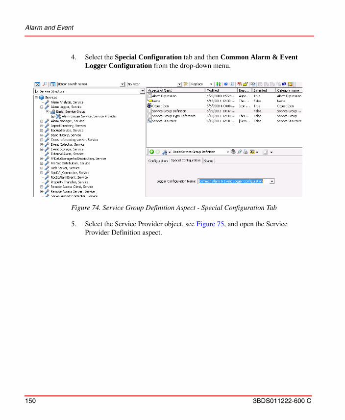
Alarm and Event
150 3BDS011222-600 C
4. Select the Special Configuration tab and then Common Alarm & Event Logger Configuration from the drop-down menu.
5. Select the Service Provider object, see Figure 75, and open the Service Provider Definition aspect.
Figure 74. Service Group Definition Aspect - Special Configuration Tab
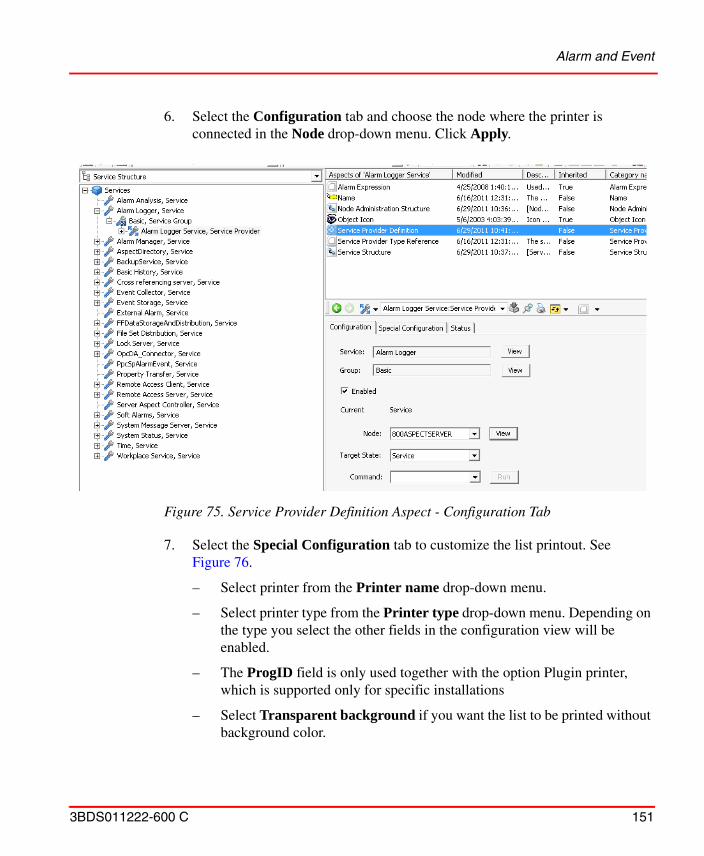
Alarm and Event
3BDS011222-600 C 151
6. Select the Configuration tab and choose the node where the printer is connected in the Node drop-down menu. Click Apply.
7. Select the Special Configuration tab to customize the list printout. See Figure 76.
– Select printer from the Printer name drop-down menu.
– Select printer type from the Printer type drop-down menu. Depending on the type you select the other fields in the configuration view will be enabled.
– The ProgID field is only used together with the option Plugin printer, which is supported only for specific installations
– Select Transparent background if you want the list to be printed without background color.
Figure 75. Service Provider Definition Aspect - Configuration Tab
Alarm and Event
152 3BDS011222-600 C
– Select Enable printing for the list to be printed.
– Set the number of lines to be printed on each page in the Max number of printed lines field.The Alarm Logger will buffer alarms until this limit is reached and then print a page.
– Set interval for the printouts in the Time interval between printouts field. A page will be printed when the time interval has elapsed even if the Max number of printed lines has not been reached.
– If you want another color definition, select it from the Override color definition drop-down menu.
– Set values for margins in mm, in the Margins area.
– Click the Preview button if you want to see a page in the print preview area.
– The Information area shows detailed information about the printer, such as status and errors.
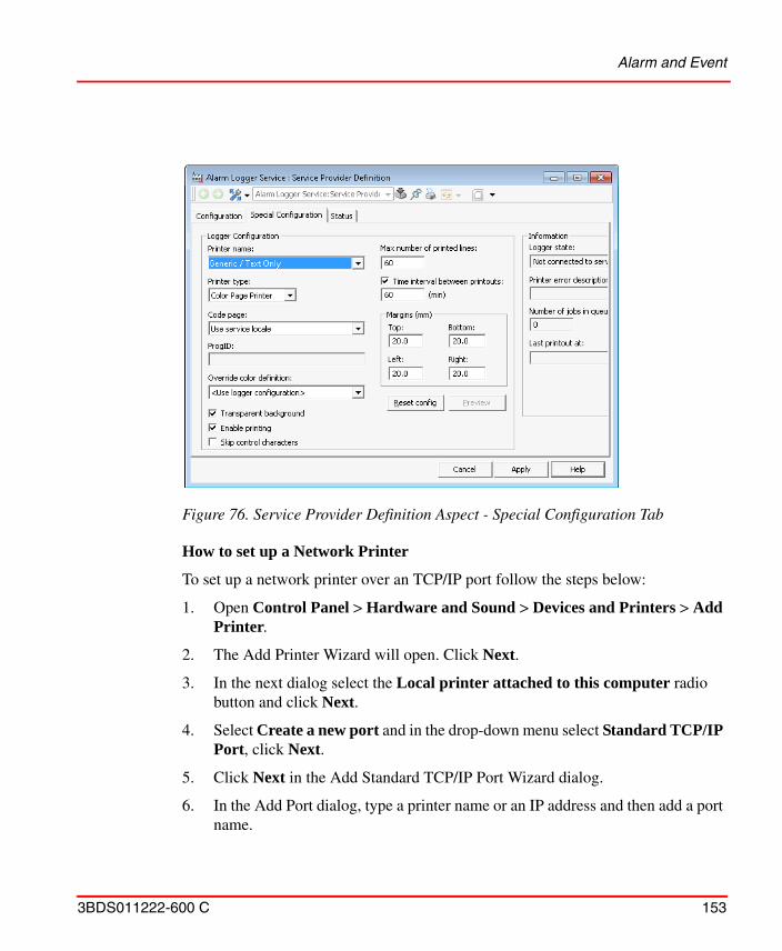
Alarm and Event
3BDS011222-600 C 153
How to set up a Network Printer
To set up a network printer over an TCP/IP port follow the steps below:
1. Open Control Panel > Hardware and Sound > Devices and Printers > Add Printer.
2. The Add Printer Wizard will open. Click Next.
3. In the next dialog select the Local printer attached to this computer radio button and click Next.
4. Select Create a new port and in the drop-down menu select Standard TCP/IP Port, click Next.
5. Click Next in the Add Standard TCP/IP Port Wizard dialog.
6. In the Add Port dialog, type a printer name or an IP address and then add a port name.
Figure 76. Service Provider Definition Aspect - Special Configuration Tab
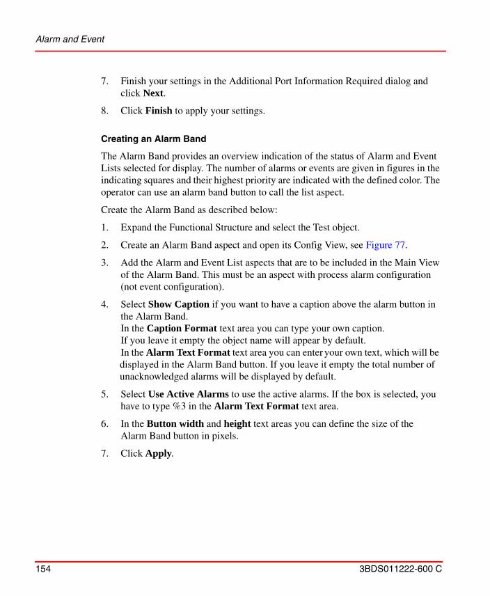
Alarm and Event
154 3BDS011222-600 C
7. Finish your settings in the Additional Port Information Required dialog and click Next.
8. Click Finish to apply your settings.
Creating an Alarm Band
The Alarm Band provides an overview indication of the status of Alarm and Event Lists selected for display. The number of alarms or events are given in figures in the indicating squares and their highest priority are indicated with the defined color. The operator can use an alarm band button to call the list aspect.
Create the Alarm Band as described below:
1. Expand the Functional Structure and select the Test object.
2. Create an Alarm Band aspect and open its Config View, see Figure 77.
3. Add the Alarm and Event List aspects that are to be included in the Main View of the Alarm Band. This must be an aspect with process alarm configuration (not event configuration).
4. Select Show Caption if you want to have a caption above the alarm button in the Alarm Band. In the Caption Format text area you can type your own caption. If you leave it empty the object name will appear by default.In the Alarm Text Format text area you can enter your own text, which will be displayed in the Alarm Band button. If you leave it empty the total number of unacknowledged alarms will be displayed by default.
5. Select Use Active Alarms to use the active alarms. If the box is selected, you have to type %3 in the Alarm Text Format text area.
6. In the Button width and height text areas you can define the size of the Alarm Band button in pixels.
7. Click Apply.
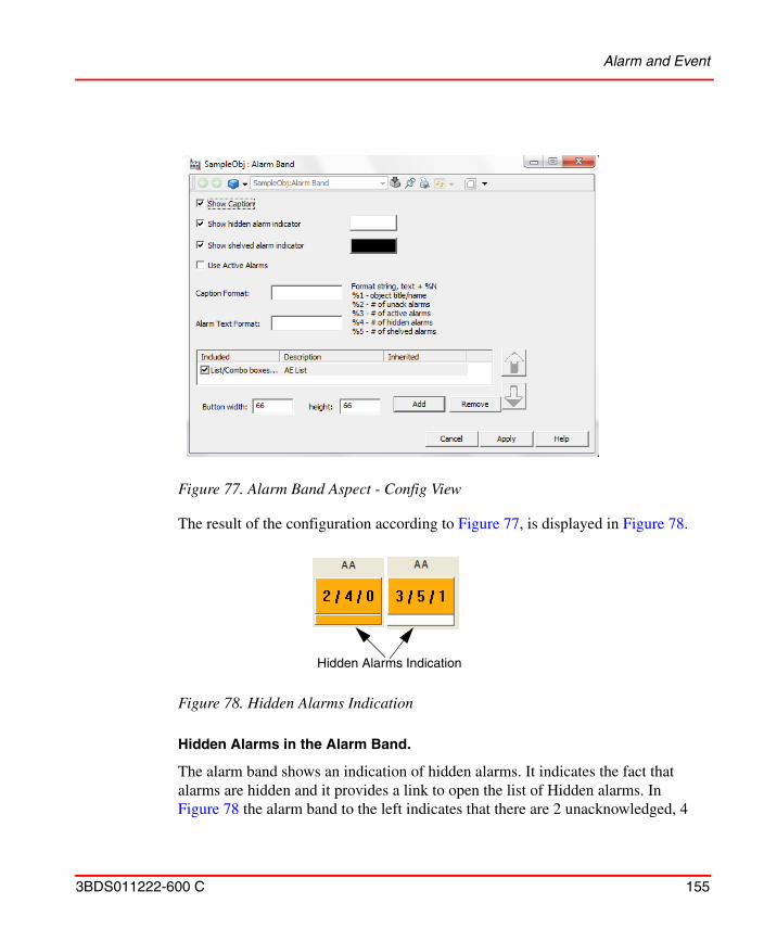
Alarm and Event
3BDS011222-600 C 155
The result of the configuration according to Figure 77, is displayed in Figure 78.
Hidden Alarms in the Alarm Band.
The alarm band shows an indication of hidden alarms. It indicates the fact that alarms are hidden and it provides a link to open the list of Hidden alarms. In Figure 78 the alarm band to the left indicates that there are 2 unacknowledged, 4
Figure 77. Alarm Band Aspect - Config View
Figure 78. Hidden Alarms Indication
Hidden Alarms Indication
Alarm and Event
156 3BDS011222-600 C
active and 0 hidden alarms and the band to the right indicates 3 unacknowledged, 5 active and 1 hidden alarm. Read more about Alarm Hiding on page 115. Refer to System 800xA Operations (3BSE036904*) for description of operation of the Alarm Band.
Creating a Sequence Bar Aspect
The Sequence Bar provides an overview indication of the status of the Alarm List selected for display. The number of alarms is set at configuration, and may be between zero and ten.The operator may select a band button to call the default aspect for the associated object. See Figure 79.
Create the Sequence Bar as described below:
1. Expand the Functional Structure, and select the Test object.
2. Create an Alarm Sequence Bar aspect and open the Config View.
3. Select the Alarm List aspect that is to be displayed in the Sequence Bar.
4. Enter a number from zero to ten in the Alarms to display text area.
5. Click Apply.
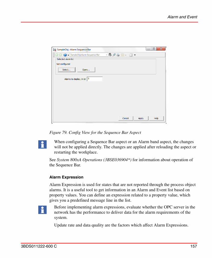
Alarm and Event
3BDS011222-600 C 157
See System 800xA Operations (3BSE036904*) for information about operation of the Sequence Bar.
Alarm Expression
Alarm Expression is used for states that are not reported through the process object alarms. It is a useful tool to get information in an Alarm and Event list based on property values. You can define an expression related to a property value, which gives you a predefined message line in the list.
Figure 79. Config View for the Sequence Bar Aspect
When configuring a Sequence Bar aspect or an Alarm band aspect, the changes will not be applied directly. The changes are applied after reloading the aspect or restarting the workplace.
Before implementing alarm expressions, evaluate whether the OPC server in the network has the performance to deliver data for the alarm requirements of the system.
Update rate and data quality are the factors which affect Alarm Expressions.
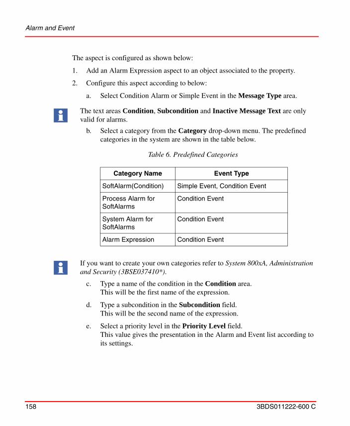
Alarm and Event
158 3BDS011222-600 C
The aspect is configured as shown below:
1. Add an Alarm Expression aspect to an object associated to the property.
2. Configure this aspect according to below:
a. Select Condition Alarm or Simple Event in the Message Type area.
b. Select a category from the Category drop-down menu. The predefined categories in the system are shown in the table below.
c. Type a name of the condition in the Condition area. This will be the first name of the expression.
d. Type a subcondition in the Subcondition field.This will be the second name of the expression.
e. Select a priority level in the Priority Level field.This value gives the presentation in the Alarm and Event list according to its settings.
The text areas Condition, Subcondition and Inactive Message Text are only valid for alarms.
Table 6. Predefined Categories
Category Name Event Type
SoftAlarm(Condition) Simple Event, Condition Event
Process Alarm for SoftAlarms
Condition Event
System Alarm for SoftAlarms
Condition Event
Alarm Expression Condition Event
If you want to create your own categories refer to System 800xA, Administration and Security (3BSE037410*).
Alarm and Event
3BDS011222-600 C 159
f. Enter a message in the Message Text field.Here you type the message which will be display in the Alarm and Event list.
g. Enter a message in the Inactive Message Text field.This message is displayed when the alarm is inactive.
h. Enter an expression in the Expression field.This is the expression that gives if the message will be displayed.
If an Alarm Expression property received with a bad quality then relevant condition gets activated, the Active Message and Inactive Message fields will be overridden with the new message that the alarm expression was activated due to bad data quality.
To avoid the bad qualities generated during the failure of OPC Server, two subscriptions for each property (parallel redundancy) are added to the OPC network where ever redundant OPC Servers are present. In this situation bad quality alarm will not be created unless both subscriptions show bad quality.
To avoid unnecessary alarms, allowable tolerance is given to bad qualities directly after the startup of Soft Alarm service provider and after the modification or creation of an Alarm Expression.
Each aspect can have multiple conditions. Each condition uses one or more properties and it can be inherited to multiple instances. If Parallel Redundancy is used then all properties will be subscribed twice.
Avoid adding several alarm expression aspects with the same condition name on the same object. This situation is ambiguous and will result in unpredictable alarm states. Running a consistency check will detect this situation. For more information about consistency check, refer to System 800xA Tools (2PAA101888*).
OPC servers should have the capacity to handle the number of subscriptions a solution with Alarm Expression might require.
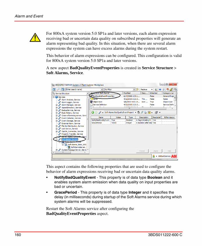
Alarm and Event
160 3BDS011222-600 C
For 800xA system version 5.0 SP1a and later versions, each alarm expression receiving bad or uncertain data quality on subscribed properties will generate an alarm representing bad quality. In this situation, when there are several alarm expressions the system can have excess alarms during the system restart.
This behavior of alarm expressions can be configured. This configuration is valid for 800xA system version 5.0 SP1a and later versions.
A new aspect BadQualityEventProperties is created in Service Structure > Soft Alarms, Service.
This aspect contains the following properties that are used to configure the behavior of alarm expressions receiving bad or uncertain data quality alarms.
• NotifyBadQualityEvent - This property is of data type Boolean and it enables system alarm emission when data quality on input properties are bad or uncertain.
• GracePeriod - This property is of data type Integer and it specifies the delay (in milliseconds) during startup of the Soft Alarms service during which system alarms will be suppressed.
Restart the Soft Alarms service after configuring the BadQualityEventProperties aspect.
Alarm and Event
3BDS011222-600 C 161
For 800xA system version 6.0.3 and later versions, UseBulkSubscription and BulkOperationSize options are available in the Soft Alarms Service object in the Service Structure to configure the subscription behavior of the Soft alarms.
UseBulkSubscription (default true) - If this option is set to true it makes Soft Alarms combine all properties in all Alarm Expression aspects to add them to the OPC server in large operations instead of aspect per aspect. A property used in multiple expressions will be subscribed on once.
BulkOperationSize - If bulk subscription is enabled, BulkOperationSize (default 500) can be changed to set the maximum number of items added to the OPC server in one operation. A system restart is required to change the bulk subscription settings.
Bulk subscription option has no effect on properties used in Property Translations or String Builder aspects, which in turn are used by Alarm Expressions.
When bulk subscription is used, a data subscription error on Soft Alarm startup or Alarm Expression creation results in an alarm with the message “the data has bad quality” instead of the alarm with the message “subscription failed”.
Configure Alarm Condition Filter.
Alarm Condition Filter functionality is used to avoid temporary signal changes to generate alarms and events. The condition has to evaluate to true for a preset time, the Active Filter Time, before an alarm is generated. When the condition changes to false it has to evaluate to false for a preset time, the Inactive Filter Time, before the alarm becomes inactive.
Both Inactive and Active Filter Time must be configured with at least 1s for Soft alarm to work properly.
Alarm and Event
162 3BDS011222-600 C
Condition Alarm
When the Message Type is set to Condition Alarm an event is generated to indicate that the alarm becomes active and another event is generated to indicate that the alarm becomes inactive, see Figure 80
Active Filter Time
The Alarm Condition Filter implements the following logic when the Active Filter Time is specified:
• When the condition becomes true, the filter evaluation will be started. An alarm is generated after the preset time delay if the condition stays true during the whole filter time.
• If the condition becomes false while there is pending alarm activation, the pending alarm activation will be cancelled.
Figure 80. Configuration of Alarm Condition Filters
Alarm and Event
3BDS011222-600 C 163
• The alarm will be active as long as the condition is true.
If no Active Filter Time is specified an alarm will be generated with no delay when the condition becomes true.
Inactive Filter Time
The Alarm Condition Filter implements the following logic when the Inactive Filter Time is specified:
• When the condition becomes false the filter evaluation will be started. The alarm becomes inactive after a preset time delay if the condition stays true during the whole filter time.
• The alarm remains inactive as long as the condition evaluates to false.
If the Inactive Filter Time is not specified the alarm becomes inactive with no delay when the condition becomes false.
Simple Event
When the Message Type is set to Simple Event, events are only generated when the condition becomes true. Hence only the Active Filter Time is not applicable for simple events.
The Alarm Condition Filter implements the following logic when the Message Type is set to Simple Event.
When the condition becomes true, an event is generated after a preset time delay if the condition stays true during the whole filter time.
If condition is not stable during a time delay period, no event will be generated. The time delay is restarted with every change in condition.
Alarm and Event
164 3BDS011222-600 C
Examples
In Figure 81 when condition becomes true the alarm activates after the Active Filter Time has elapsed and when the condition becomes false the alarm becomes inactive after the Inactive Filter Time has elapsed.
In Figure 82 the condition becomes true for a time period that is shorter than the Active Filter Time, and therefore no alarm/event is generated.
Figure 81. Delayed Activation and Deactivation of Alarm
Figure 82. No Activation of Alarm
Alarm and Event
3BDS011222-600 C 165
Figure 83 shows an example where the condition is true and an alarm is activated. The condition becomes false for a time period that is shorter than the Off Delay, and therefore the alarm stays active (no event is generated).
Figure 84 shows an example where the condition becomes true repeatedly for a time period.
Figure 83. Active Alarm
Figure 84. Inactive Alarm
Alarm and Event
166 3BDS011222-600 C
Expression Examples.
The expression can be more or less complicated, below are some examples:
Example 1 - Boiler Temperature
Say, for example, that you have a boiler and you want to have an indication when the temperature goes above 80 and one indication when above 90 degrees centigrade. You do this as follows:
1. Add an Alarm Expression aspect to a propriety Aspect Object.
2. Select Condition Alarm in the Message Type area.
3. Select Process Alarms for SoftAlarms in the Category drop-down menu.
4. In the Condition field, enter a name to identify the expression, in this case “High Level“.
5. In the Subcondition field, enter a second description for identification, in this case “Level above 80“.
6. Select a priority level. The value will give the color of the alarm list line according to the setting in the Alarm and Event list definition. For the temperature of 80 degrees we choose priority 2.
7. In the Message field, enter the message you want to have in the Alarm and Event list, in this case “+High Level”.
8. In the Inactive Message field, enter the message you want to have when the alarm is inactive, in this case “-High Level”.
9. Give an expression in the Expression field, in this example Value > 80.
10. Click Apply.
11. To create another limit for above 90 degrees, enter in the Condition field a name to identify the expression, in this case “Very High Level“.
12. In the Subcondition field, enter a second description for identification, in this case “Level above 90“.
13. Select a priority level. The value will give the color of the alarm list line according to the setting in the Alarm and Event list definition. For the temperature of 90 degrees we choose priority 1.
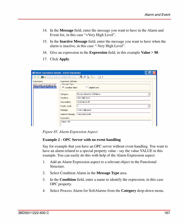
Alarm and Event
3BDS011222-600 C 167
14. In the Message field, enter the message you want to have in the Alarm and Event list, in this case “+Very High Level”.
15. In the Inactive Message field, enter the message you want to have when the alarm is inactive, in this case “-Very High Level”.
16. Give an expression in the Expression field, in this example Value > 90.
17. Click Apply.
Example 2 - OPC Server with no event handling
Say for example that you have an OPC server without event handling. You want to have an alarm related to a special property value - say the value VALUE in this example. You can easily do this with help of the Alarm Expression aspect.
1. Add an Alarm Expression aspect to a relevant object in the Functional Structure.
2. Select Condition Alarm in the Message Type area.
3. In the Condition field, enter a name to identify the expression, in this case OPC property.
4. Select Process Alarm for SoftAlarms from the Category drop-down menu.
Figure 85. Alarm Expression Aspect
Alarm and Event
168 3BDS011222-600 C
5. In the Subcondition field, enter a second description for identification, in this case Property #1.
6. Select a priority level. The value will give the color of the alarm list line according to the setting in the Alarm and Event list definition. In this case we choose priority level 1.
7. In the Message field, enter the message you want to have in the Alarm and Event list, in this case “Alarm from the OPC server”.
8. Give an expression in the Expression field, in this example OPC_Property_1==true.
9. Click Apply.
10. You now have an alarm expression that will indicate when the OPC_Property_1 is true.
Expression Rules and Examples
As a basic rule, the expression shall follow the syntax rules given by the C programming language.
When operands in an expression refer to aspect objects, make sure your syntax is according to Item Syntaxes on page 171.
If you use a system defined delimiter as a part of a name, you have to type an escape character “\” ahead of it.
For example, an aspect object that is named Objectgroup1.Object2 has to be quoted with an escape character like this $’Objectgroup1\.Object2:value’ otherwise the “.” character will be interpreted as an object delimiter.
If a symbolic string is used as a value in an Expression, you must use “ “ around it.
For example: objetc:level == “Down”.
If an aspect object name contains characters that could be misinterpreted as operators or separators and so on. You must use quote $’ ’ around the name.
If you are using a division sign in the Expression area, it is required to have a space before and after the sign. Otherwise it is misinterpreted.
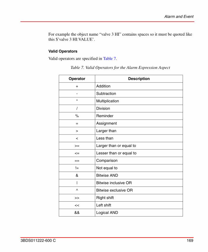
Alarm and Event
3BDS011222-600 C 169
For example the object name “valve 3 HI” contains spaces so it must be quoted like this $’valve 3 HI:VALUE’.
Valid Operators
Valid operators are specified in Table 7.
Table 7. Valid Operators for the Alarm Expression Aspect
Operator Description
+ Addition
- Subtraction
* Multiplication
/ Division
% Reminder
= Assignment
> Larger than
< Less than
>= Larger than or equal to
<= Lesser than or equal to
== Comparison
!= Not equal to
& Bitwise AND
| Bitwise inclusive OR
^ Bitwise exclusive OR
>> Right shift
<< Left shift
&& Logical AND
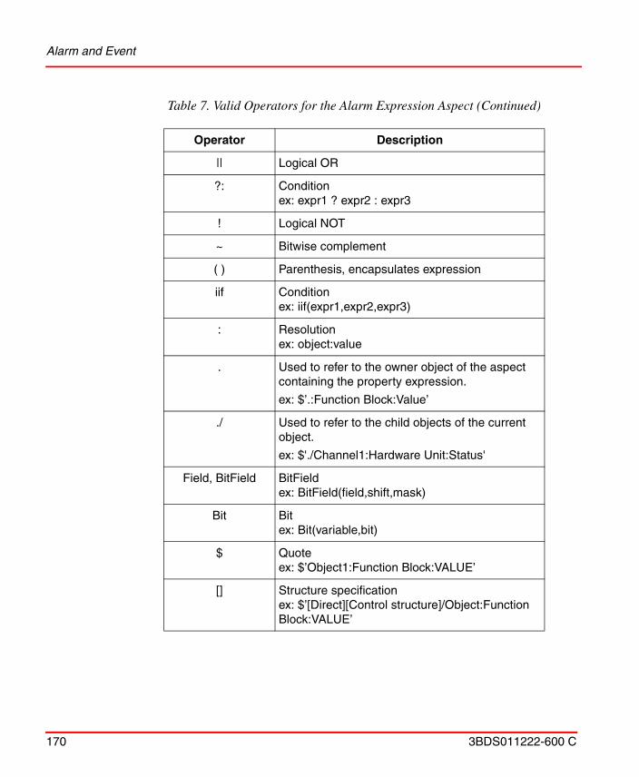
Alarm and Event
170 3BDS011222-600 C
|| Logical OR
?: Conditionex: expr1 ? expr2 : expr3
! Logical NOT
~ Bitwise complement
( ) Parenthesis, encapsulates expression
iif Conditionex: iif(expr1,expr2,expr3)
: Resolutionex: object:value
. Used to refer to the owner object of the aspect containing the property expression.
ex: $’.:Function Block:Value’
./ Used to refer to the child objects of the current object.
ex: $'./Channel1:Hardware Unit:Status'
Field, BitField BitFieldex: BitField(field,shift,mask)
Bit Bitex: Bit(variable,bit)
$ Quoteex: $’Object1:Function Block:VALUE’
[] Structure specificationex: $’[Direct][Control structure]/Object:Function Block:VALUE’
Table 7. Valid Operators for the Alarm Expression Aspect (Continued)
Operator Description
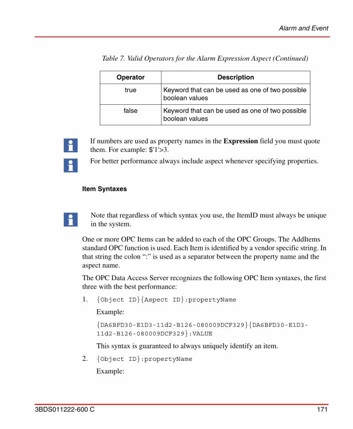
Alarm and Event
3BDS011222-600 C 171
Item Syntaxes
One or more OPC Items can be added to each of the OPC Groups. The AddItems standard OPC function is used. Each Item is identified by a vendor specific string. In that string the colon “:” is used as a separator between the property name and the aspect name.
The OPC Data Access Server recognizes the following OPC Item syntaxes, the first three with the best performance:
1. {Object ID}{Aspect ID}:propertyName
Example:
{DA6BFD30-E1D3-11d2-B126-080009DCF329}{DA6BFD30-E1D3-11d2-B126-080009DCF329}:VALUE
This syntax is guaranteed to always uniquely identify an item.
2. {Object ID}:propertyName
Example:
true Keyword that can be used as one of two possible boolean values
false Keyword that can be used as one of two possible boolean values
If numbers are used as property names in the Expression field you must quote them. For example: $’1’>3.
For better performance always include aspect whenever specifying properties.
Note that regardless of which syntax you use, the ItemID must always be unique in the system.
Table 7. Valid Operators for the Alarm Expression Aspect (Continued)
Operator Description
Alarm and Event
172 3BDS011222-600 C
{DA6BFD30-E1D3-11d2-B126-080009DCF329}:VALUE
3. {Object ID}:Aspect Name:propertyName
Example:
{DA6BFD30-E1D3-11d2-B126-080009DCF329}:Control Connection:VALUE
For the syntaxes listed below, the “Object Path” is translated to an Object ID with help of the name resolving mechanism in the system. The path can be anything that the name server can translate into an Object ID. These syntaxes should be used when a more user friendly syntax is required. Note that these syntaxes can reduce the performance, since it may take some time to resolve the object path.
4. {Object ID}Object Path:propertyName
Example:
{DA6BFD30-E1D3-11d2-B126-080009DCF329}Net1/BUS2/ST1/AC110_73_AIS3:VALUE
5. {Object ID}Object Path:AspectName:propertyName
6. Object Path:Aspect Name:propertyName
Object Path:propertyName
Creation of a Separate Expression List
You may easily create a special Expression List for the presentation of the expressions created by the Alarm Expression aspect.
You do this as described below:
When using relative or absolute references, the path to the object should include the [Direct] keyword. By using this keyword, the platform’s name server will resolve the object reference more efficiently.
Examples:
[Direct][Control Structure]Area_51/Motor_1/On
[Direct][Functional Structure]Sector_7G/Pump_1/On
[Direct][Control Structure]Signal5
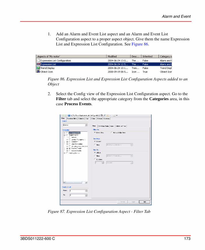
Alarm and Event
3BDS011222-600 C 173
1. Add an Alarm and Event List aspect and an Alarm and Event List Configuration aspect to a proper aspect object. Give them the name Expression List and Expression List Configuration. See Figure 86.
2. Select the Config view of the Expression List Configuration aspect. Go to the Filter tab and select the appropriate category from the Categories area, in this case Process Events.
Figure 86. Expression List and Expression List Configuration Aspects added to an Object
Figure 87. Expression List Configuration Aspect - Filter Tab
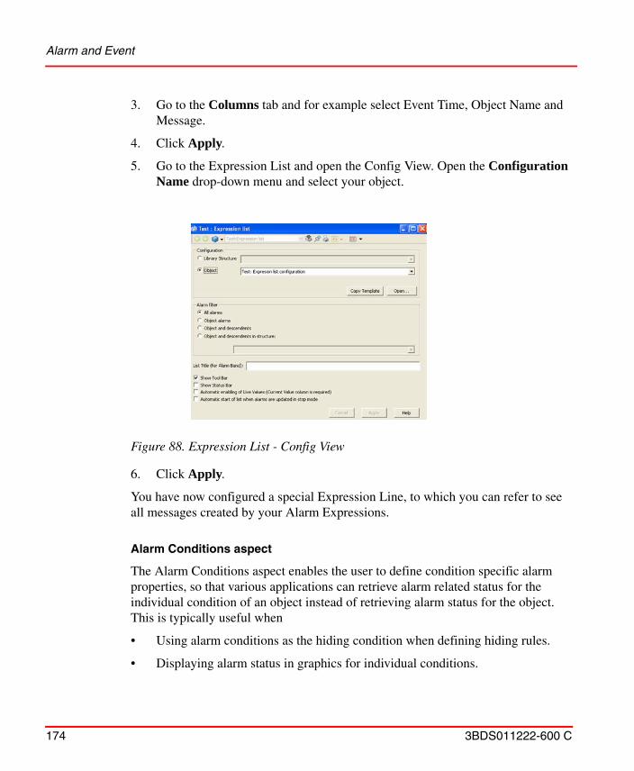
Alarm and Event
174 3BDS011222-600 C
3. Go to the Columns tab and for example select Event Time, Object Name and Message.
4. Click Apply.
5. Go to the Expression List and open the Config View. Open the Configuration Name drop-down menu and select your object.
6. Click Apply.
You have now configured a special Expression Line, to which you can refer to see all messages created by your Alarm Expressions.
Alarm Conditions aspect
The Alarm Conditions aspect enables the user to define condition specific alarm properties, so that various applications can retrieve alarm related status for the individual condition of an object instead of retrieving alarm status for the object. This is typically useful when
• Using alarm conditions as the hiding condition when defining hiding rules.
• Displaying alarm status in graphics for individual conditions.
Figure 88. Expression List - Config View
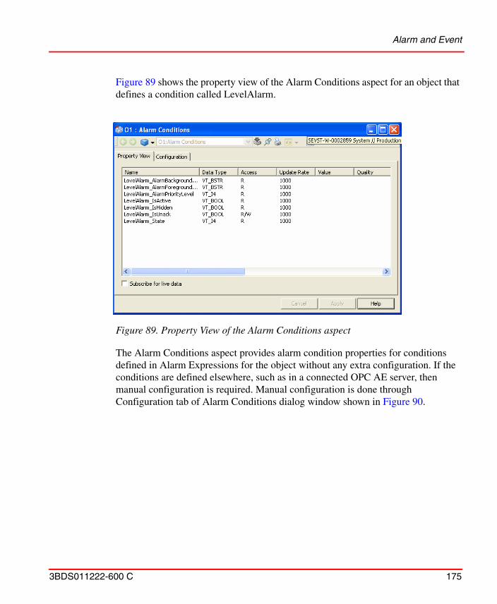
Alarm and Event
3BDS011222-600 C 175
Figure 89 shows the property view of the Alarm Conditions aspect for an object that defines a condition called LevelAlarm.
The Alarm Conditions aspect provides alarm condition properties for conditions defined in Alarm Expressions for the object without any extra configuration. If the conditions are defined elsewhere, such as in a connected OPC AE server, then manual configuration is required. Manual configuration is done through Configuration tab of Alarm Conditions dialog window shown in Figure 90.
Figure 89. Property View of the Alarm Conditions aspect
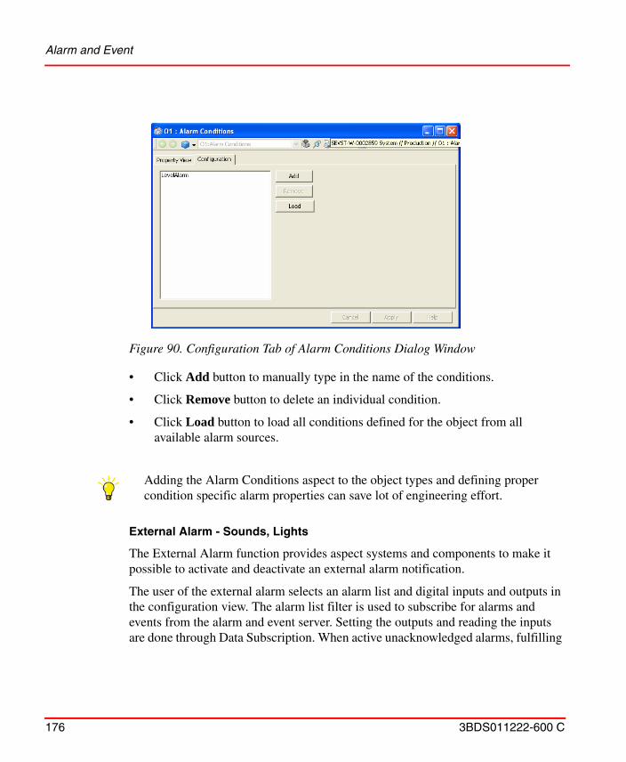
Alarm and Event
176 3BDS011222-600 C
• Click Add button to manually type in the name of the conditions.
• Click Remove button to delete an individual condition.
• Click Load button to load all conditions defined for the object from all available alarm sources.
External Alarm - Sounds, Lights
The External Alarm function provides aspect systems and components to make it possible to activate and deactivate an external alarm notification.
The user of the external alarm selects an alarm list and digital inputs and outputs in the configuration view. The alarm list filter is used to subscribe for alarms and events from the alarm and event server. Setting the outputs and reading the inputs are done through Data Subscription. When active unacknowledged alarms, fulfilling
Figure 90. Configuration Tab of Alarm Conditions Dialog Window
Adding the Alarm Conditions aspect to the object types and defining proper condition specific alarm properties can save lot of engineering effort.
Alarm and Event
3BDS011222-600 C 177
the filtering criteria, are received by the external alarm function the Audible Alarm output is set.
The operator can silence the external alarm (resetting the Audible Alarm output) through the silence view. Silence can be done for all configured alarms or for one explicit external alarm.
Configuring the External Alarm service
The External Alarm services are configured using the Configure System task in the System Configuration Console (SCC).
Configuring External Alarm.
The External Alarm consists of two views, the External Alarm Configuration View and the External Alarm Silence View.
External Alarm Configuration View
In the External Alarm Configuration View (refer to Figure 91) select the Alarm List and the filter criteria the external alarm uses to subscribe alarms from. Users can also configure the digital inputs and outputs.
To create a basic External Alarm Configuration aspect follow the procedure below:
1. Select the object to add an External Alarm Configuration aspect to.
2. Right-click in an empty part of the aspect list and select New Aspect.
3. Select External Alarm Configuration.
4. Type a name in the Name text field and an aspect description in the Aspect description field and click Create.
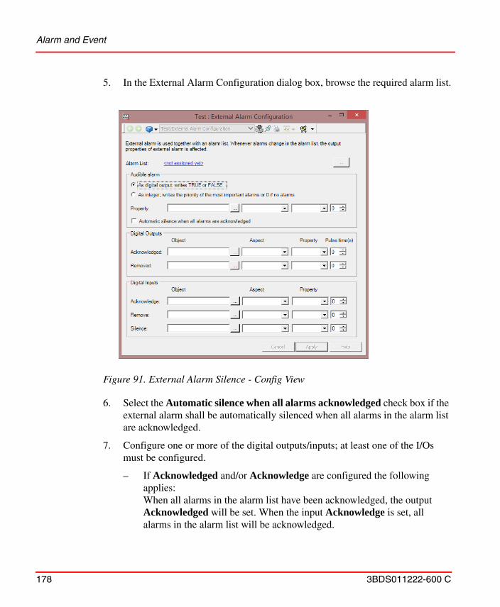
Alarm and Event
178 3BDS011222-600 C
5. In the External Alarm Configuration dialog box, browse the required alarm list.
6. Select the Automatic silence when all alarms acknowledged check box if the external alarm shall be automatically silenced when all alarms in the alarm list are acknowledged.
7. Configure one or more of the digital outputs/inputs; at least one of the I/Os must be configured.
– If Acknowledged and/or Acknowledge are configured the following applies:When all alarms in the alarm list have been acknowledged, the output Acknowledged will be set. When the input Acknowledge is set, all alarms in the alarm list will be acknowledged.
Figure 91. External Alarm Silence - Config View
Alarm and Event
3BDS011222-600 C 179
– If Removed and/or Remove are configured the following applies:When all alarms in the alarm list have been removed, the output Removed will be set. When the input Remove is set, all inactive and acknowledged alarms in the alarm list will be removed, that is all active and all unacknowledged alarms will still appear in the list.
– If the Silence input is configured the Audible Alarm output must be configured.When the Silence input is set, the external alarm is silenced, that is the Audible Alarm output is reset.
8. Click Apply.
Table 8. Examples of Digital Output for 800xA for AC 800M
Application variable: Application_5:Application:ExternalAlarm2
Function Block variable: MyBlock_1:Function Block:InL
Control Module variable: Tank1:Control Module:ExtAlarm
When an active unacknowledged alarm is received in the selected alarm list, the Audible Alarm output is set. The External Alarm functionality provides various options to reset this output as listed below:• External Alarm Silence View.
• Silence digital input (if configured).
• Reset automatically (if selected and all alarms in the Alarm List are acknowledged).
• Reset automatically after the configured Pulse Time.
Generally, all outputs will reset automatically after Pulse Time only if the Pulse Time is greater than 0.
If the Pulse Time is zero for acknowledged or removed outputs, external alarm do not reset the signals. In this case the signal needs to be reset by another function, typically a controller.
To remove a specific signal right-click on the row and select Delete from the context menu.
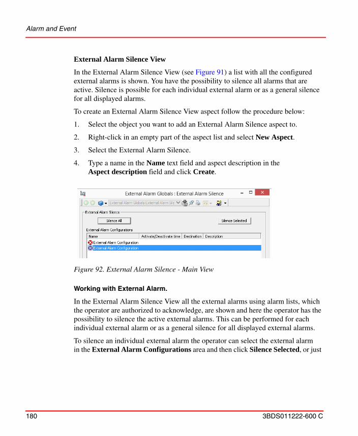
Alarm and Event
180 3BDS011222-600 C
External Alarm Silence View
In the External Alarm Silence View (see Figure 91) a list with all the configured external alarms is shown. You have the possibility to silence all alarms that are active. Silence is possible for each individual external alarm or as a general silence for all displayed alarms.
To create an External Alarm Silence View aspect follow the procedure below:
1. Select the object you want to add an External Alarm Silence aspect to.
2. Right-click in an empty part of the aspect list and select New Aspect.
3. Select the External Alarm Silence.
4. Type a name in the Name text field and aspect description in the Aspect description field and click Create.
Working with External Alarm.
In the External Alarm Silence View all the external alarms using alarm lists, which the operator are authorized to acknowledge, are shown and here the operator has the possibility to silence the active external alarms. This can be performed for each individual external alarm or as a general silence for all displayed external alarms.
To silence an individual external alarm the operator can select the external alarm in the External Alarm Configurations area and then click Silence Selected, or just
Figure 92. External Alarm Silence - Main View
Alarm and Event
3BDS011222-600 C 181
double-click on the external alarm. To silence all the displayed active external alarms the operator clicks Silence All.
External Alarm is not Point of Control aware.
Since External Alarm is not Point of Control aware one of the following methods can be used depending on the situation to implement the required functionality:
• If required to have an alarm function that integrates with Point of Control, meaning that the alarm only sound when the user is responsible, then it is recommended to use the Audible Alarm function instead since Audible Alarm fully supports Point of Control.
• If instead it is required to always sound an alarm irrespective on responsibility, then it is recommended to create a specific alarm list which does not filter on responsibility and point the External Alarm configuration to this list.
The consistency check (Consistency Tab on page 629) shall be run on all External Alarm Configurations, especially after changes to the system which may have affected the control objects corresponding to the digital inputs and outputs.
SMS and e-mail Messaging
182 3BDS011222-600 C
SMS and e-mail Messaging
The following subsections describe how you extend basic Alarm and Event handling with SMS and e-mail Messaging.
Throughout the SMS and e-mail Messaging procedures, unless otherwise specified, access to aspect views is accomplished by right-clicking on the object and selecting the aspect from the context menu. This opens the aspect in a new window. It is also possible to double-click an aspect in the Aspect List Area to open the aspect in a new window. To view the aspect in the Aspect Preview Area of the Plant Explorer Workplace, select the aspect in the Aspect List Area.
When creating aspects, it is possible to add a description and name to the aspect as desired. If the aspect is not named, the aspect category name is used and displayed in the Aspect List Area. Unless otherwise specified, the SMS and e-mail Messaging procedures use the aspect category name.
When the various structures are set up as desired, it may become necessary to move some SMS and e-mail Messaging aspects to other areas in the structures by using the drag and drop method. Attempting to use the drag and drop method on SMS and e-mail Messaging aspects while they are active will result in the following loss of configuration:
Alarm and Event Message Source: loses reference to Alarm and Event List and resets it to blank.
Message Handler: loses reference to Alarm and Event Message Source.
Message Subscriber: loses reference to TAP/Modem, SMS/GSM, and/or SMTP/Email Device.
TAP/Modem, SMTP/Email, and/or SMS/GSM Device: Message Subscriber loses reference to device.
Message Schedule: No effect.
To avoid these problems, copy and paste the aspects to the desired location, and then delete them from the original location.
SMS and e-mail Messaging will not stop acting on the previous configuration until the service is disabled and then enabled. Refer to Enabling/Disabling SMS and e-mail Messaging on page 215.
SMS and e-mail Messaging
3BDS011222-600 C 183
Setup and Configuration Workflow
The following is a typical setup and configuration workflow for SMS and e-mail Messaging.
1. Set up hardware (one, two, or all).
a. Set up GSM hardware (SMS/GSM).
b. Set up Hayes compatible modem (TAP/Modem) hardware and run test utility.
c. Run e-mail test utility.
2. Set up system.
a. Define default telephone number for Central Paging Terminal of paging service provider.
b. Define default e-mail address that appears in from field when users receive messages and where error messages may be sent.
c. Create User Groups and add users to groups if required.
d. Set up message subscriber for each user:
Add devices.
Configure devices.
Assign priority.
e. Set up Message Schedule for each user.
f. Set up Messenger Event Log.
g. Check status of SMS and e-mail Messaging service.
3. Configure system.
a. Configure Alarm and Event Message Source:
Select Alarm and Event List to monitor.
Set message content and length.
b. Configure Message Handler:
Select Alarm and Event Message Source and enable/disable source.
SMS and e-mail Messaging
184 3BDS011222-600 C
Select users and/or groups to send messages to and assign priority.
Configure timeout before resending the message and number of attempts before changing destinations.
Enable/disable destinations.
c. Configure Alarm and Event Service Groups if required.
Setup and Configuration Worksheets
Appendix C, SMS and E-Mail Messaging, subsection Setup and Configuration Worksheets on page 671 contains worksheets to help in setting up and configuring SMS and e-mail Messaging.
• Table 40: GSM Hardware Setup Worksheet.
• Table 41: Aspect System Structure Setup Worksheet.
• Table 42: Users Worksheet.
• Table 43: User Setup Worksheet.
• Table 44: Configuration Worksheet.
The worksheets are also designed to be used as configuration records. Each one starts on a new page for ease of copying. Keep these records in a safe place for future backup/restore or upgrade activities.
It is very important to read, understand, and follow the setup and configuration procedures before filling in the worksheets.The following procedures, which the worksheets are designed to be used with, are divided into three major categories:
• Hardware Setup.• System Setup.• Configuration.
Hardware Setup
Perform the following procedures before setting up and configuring the SMS and e-mail Messaging aspects in the Plant Explorer Workplace:
• GSM Hardware (SMS/GSM).• Modem Hardware (TAP/Modem)
SMS and e-mail Messaging
3BDS011222-600 C 185
• Modem Hardware Test Utility (optional)• E-mail Test Utility (optional)
GSM Hardware (SMS/GSM)
GSM hardware (GSM modem or a telephone with a built-in GSM modem) supporting the AT+C command set (GSM 07.05 and GSM 07.07) are compatible with the SMS/GSM Device.
1. Connect the GSM hardware to an available COM port and turn on the power.
2. Open Aspect System Structure.
3. Navigate to: Messenger, Aspect System > SMS Device, Aspect Type > SMS Device, Aspect Category.
Configuration of each individual personal GSM telephone number occurs while setting up the Message Subscriber, refer to Message Subscriber on page 201.
The SMS Device Configuration must be performed by a user with administrative privileges on the operating system. SMS Device Configuration is not supported for a logged-over user.
The GSM hardware is set up using the Aspect System Structure. This procedure requires that the Messenger Server be disabled before configuring the SMS device (refer to Enabling/Disabling SMS and e-mail Messaging on page 215).
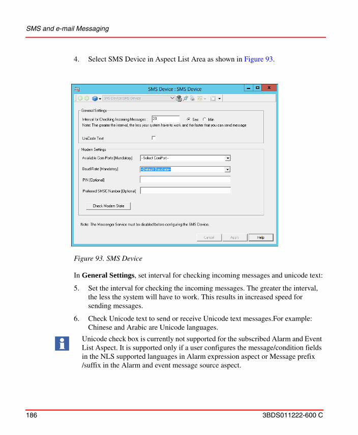
SMS and e-mail Messaging
186 3BDS011222-600 C
4. Select SMS Device in Aspect List Area as shown in Figure 93.
In General Settings, set interval for checking incoming messages and unicode text:
5. Set the interval for checking the incoming messages. The greater the interval, the less the system will have to work. This results in increased speed for sending messages.
6. Check Unicode text to send or receive Unicode text messages.For example: Chinese and Arabic are Unicode languages.
Figure 93. SMS Device
Unicode check box is currently not supported for the subscribed Alarm and Event List Aspect. It is supported only if a user configures the message/condition fields in the NLS supported languages in Alarm expression aspect or Message prefix /suffix in the Alarm and event message source aspect.
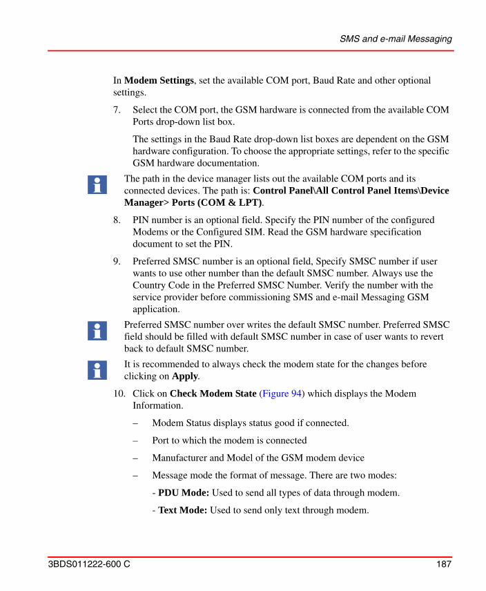
SMS and e-mail Messaging
3BDS011222-600 C 187
In Modem Settings, set the available COM port, Baud Rate and other optional settings.
7. Select the COM port, the GSM hardware is connected from the available COM Ports drop-down list box.
The settings in the Baud Rate drop-down list boxes are dependent on the GSM hardware configuration. To choose the appropriate settings, refer to the specific GSM hardware documentation.
8. PIN number is an optional field. Specify the PIN number of the configured Modems or the Configured SIM. Read the GSM hardware specification document to set the PIN.
9. Preferred SMSC number is an optional field, Specify SMSC number if user wants to use other number than the default SMSC number. Always use the Country Code in the Preferred SMSC Number. Verify the number with the service provider before commissioning SMS and e-mail Messaging GSM application.
10. Click on Check Modem State (Figure 94) which displays the Modem Information.
– Modem Status displays status good if connected.
– Port to which the modem is connected
– Manufacturer and Model of the GSM modem device
– Message mode the format of message. There are two modes:
- PDU Mode: Used to send all types of data through modem.
- Text Mode: Used to send only text through modem.
The path in the device manager lists out the available COM ports and its connected devices. The path is: Control Panel\All Control Panel Items\Device Manager> Ports (COM & LPT).
Preferred SMSC number over writes the default SMSC number. Preferred SMSC field should be filled with default SMSC number in case of user wants to revert back to default SMSC number.
It is recommended to always check the modem state for the changes before clicking on Apply.
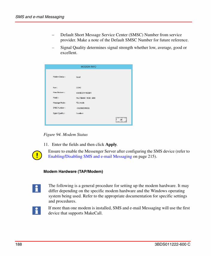
SMS and e-mail Messaging
188 3BDS011222-600 C
– Default Short Message Service Center (SMSC) Number from service provider. Make a note of the Default SMSC Number for future reference.
– Signal Quality determines signal strength whether low, average, good or excellent.
11. Enter the fields and then click Apply.
Modem Hardware (TAP/Modem)
Figure 94. Modem Status
Ensure to enable the Messenger Server after configuring the SMS device (refer to Enabling/Disabling SMS and e-mail Messaging on page 215).
The following is a general procedure for setting up the modem hardware. It may differ depending on the specific modem hardware and the Windows operating system being used. Refer to the appropriate documentation for specific settings and procedures.
If more than one modem is installed, SMS and e-mail Messaging will use the first device that supports MakeCall.
SMS and e-mail Messaging
3BDS011222-600 C 189
1. Connect the modem hardware to an available COM port.
2. Right-click on My Computer on the desktop.
3. Select Properties from the context menu that appears.
4. Click the Hardware tab in the System Properties dialog box.
5. Click Hardware Wizard and the Hardware Wizard appears.
6. Click Next and the Choose a Hardware Task dialog box appears.
7. Select Add/Troubleshoot a Device and click Next.
8. The Search for New Hardware dialog box appears, followed by the Choose a Hardware Device dialog box.
9. Verify that the modem hardware installed in Step 1 appears in the list.
10. Click Cancel.
11. Click Device Manager under the Hardware tab in the System Properties dialog box and the Device Manager appears.
12. Right-click on the modem and select Properties from the context menu that appears.
13. The Modem Properties dialog box appears. Click the Driver tab.
14. Install or update the driver if necessary.
TAP/Modem device aspect will not work with a ZOOM USB modem.
For messenger to work reliably with a TAP service, the following should be considered when selecting a modem:
1) The modem selected should be fully supported by the operating system that is running the Messenger Server. Some modems may be partially supported by an operating system but may not correctly implement all of the required functions.
2) The modem and driver must be at least TAPI 2.2 compliant.
3) Only internal or RS-232 serial external modems should be used. USB modems or RS-232 modems being accessed through a USB/Serial converter should not be used. The USB drivers do not implement all of the modem control features necessary to communicate with the TAP provider.
SMS and e-mail Messaging
190 3BDS011222-600 C
15. Click the Advanced tab in the Modem Properties dialog box.
16. Click Change Default Preferences.
17. Under the General tab in the Default Preferences dialog box, set the following fields to:
– Port speed: 9,600 or greater.– Flow control: Xon/Xoff.
18. Under the Advanced tab in the Default Preferences dialog box, set the following fields to:
– Data bits: 7.– Parity: Even.– Stop bits: 1.
19. Click OK in the Default Preferences and Modem Properties dialog boxes.
Modem Port Assignment
If there is only one TAP Modem device in the 800xA system, no TAP Modem port assignment is necessary. The configured TAP modem for SMS and e-mail Messaging is initially "First Available Modem".
However, to configure a specific TAP modem to be used by SMS and e-mail Messaging, a configuration step must be performed on the node where the Messenger Service is running. The utility TapModemCfg provides the mechanism for selecting a specific TAP modem. This utility program lists the TAP modem devices detected by Microsoft's TAPI (Telephony API) and allows the user to configure the specific device to be used by SMS and Email messaging. Using Windows Explorer navigate to:
…\Program Files (x86)\ABB 800xA\Messenger\bin and launch TapModemCfg.exe.
The parameters of the General tab and the Advanced tab are the most common used by TAP providers, however specific setting should be verified with the provider as they may be different and are subject to change.
If the communication settings are changed after the Modem Device has been configured to use the port, the machine must be rebooted for the new settings to take affect.
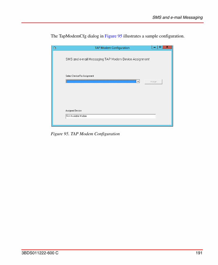
SMS and e-mail Messaging
3BDS011222-600 C 191
The TapModemCfg dialog in Figure 95 illustrates a sample configuration.
Figure 95. TAP Modem Configuration
SMS and e-mail Messaging
192 3BDS011222-600 C
This dialog is comprised of:
1. A pick-list (combo box) that contains the names of the modems that support TAP communication.
2. An Assign button that will assign the selected modem to be used by SMS and Email Messaging.
3. A “read only" text box that shows the currently assigned modem device.
The default Assigned Device is "First Available Modem" and is just as the name implies.
Modem Hardware Test Utility
This utility requires that the modem hardware under test and a pager to send the test message to are available. It is used to verify the compliant functionality of the modem.
1. Use Windows Explorer to navigate to:
...\Program Files (x86)\ABB 800xA\Messenger\Bin
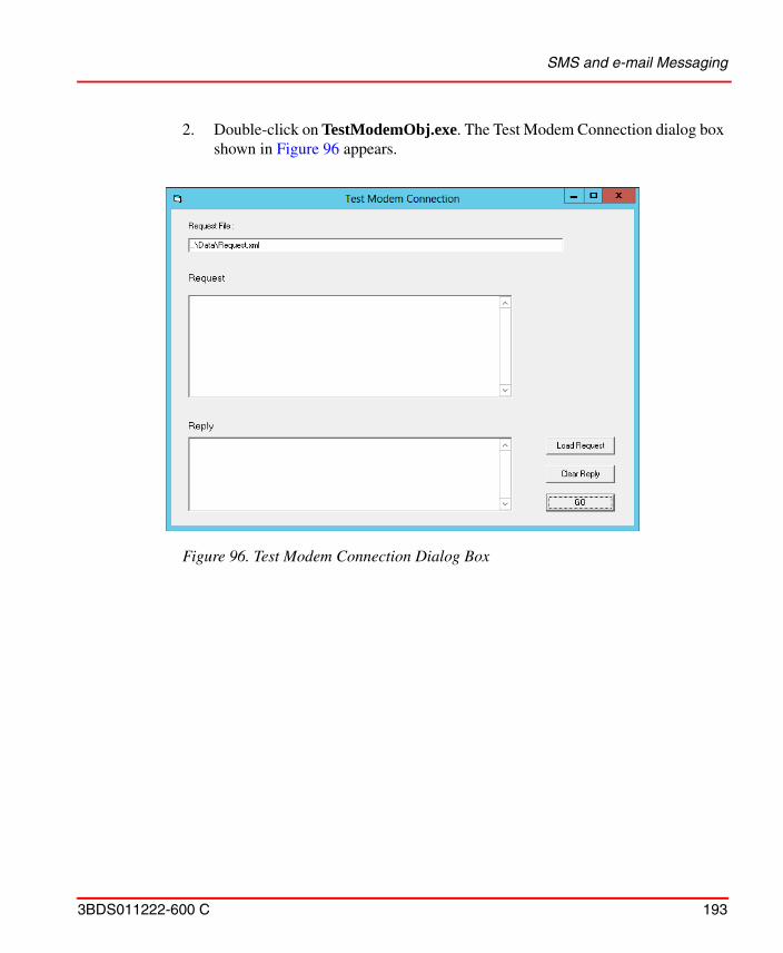
SMS and e-mail Messaging
3BDS011222-600 C 193
2. Double-click on TestModemObj.exe. The Test Modem Connection dialog box shown in Figure 96 appears.
Figure 96. Test Modem Connection Dialog Box
SMS and e-mail Messaging
194 3BDS011222-600 C
3. Click Load Request and the modem test utility code appears in the Request field as shown in Figure 97.
4. If an access number is required to access an outside line, insert it between the T and the 1 in the PhoneNumber line of the code. For example, a 9 might be required to access an outside line. Commas can be used after the access number if a pause is required to access the outside line. The comma usually creates a pause of one second; however it can vary by modem. Refer to the modem hardware documentation for the exact duration. It may also be necessary to change the T. Refer to the modem hardware documentation for the appropriate code.
5. Enter a valid PIN for the pager used in the test in the PIN line of the code.
6. Click GO.
7. Verify that the message in the Reply field indicates that the message was sent and that the pager receives the message Test Msg 1.
E-mail Test Utility
This utility requires:
Figure 97. Modem Hardware Test Utility
SMS and e-mail Messaging
3BDS011222-600 C 195
• Valid sender e-mail address.
• Valid receiver e-mail address.
• If necessary, the IP address or host name of an SMTP server with permissions to relay outgoing e-mail messages, from other internal SMTP servers, directly to the internet. The SMTP server is needed if it is necessary to bypass the local SMTP service pickup directory if, for example, a firewall blocks direct SMTP traffic through port 25, enter the IP address or Host Name of an SMTP server with the required port in the format <IP Address/Hostname>:< Port Number>
1. Use Windows Explorer to navigate to:
...\Program Files (x86)\ABB 800xA\Messenger\Bin
2. Double-click on TestEmailObj.exe. The Test E-mail dialog box shown in Figure 98 appears.
Figure 98. Test E-Mail Dialog Box

SMS and e-mail Messaging
196 3BDS011222-600 C
3. Fill in the fields with the required information identified at the beginning of this procedure.
4. Click Send e-mail and verify that the message in the Result field says Email sent and that the e-mail recipient receives the message.
5. To repeat the test, click Clear Result before clicking Send e-mail.
System Setup
This section contains procedures for setting up the following:
• Aspect System Structure.– Modem Device.– Email Device.– SMS Device.
• User Structure.– Creating User Groups and Adding Users.– Message Subscriber.– Message Schedule.
• Operational (Functional, Control, Location, and so on) Structures.– Messenger Event Log.
• Service Structure.– Enabling/Disabling SMS and e-mail Messaging.– Checking SMS and e-mail Messaging Status.
Modem Device
Setting up the Modem Device (TAP/Modem) in the Aspect System Structure provides the default telephone number for the Central Paging Terminal of the paging
It is very important to verify that the e-mail recipient receives the message. Email sent in the Result field only indicates that the e-mail was sent to the queue in the root:Inetpub\mailroot directory.
SMS and e-mail Messaging
3BDS011222-600 C 197
service provider for each instance of it applied to individual objects in the Operational (Functional, Control, Location, and so on) Structures.
Table 9 lists the paging service providers and their telephone numbers that have been tested and verified by ABB as functional for use with SMS and e-mail Messaging as of the original publication of this instruction. The communication method used is Telocator Alphanumeric Protocol (TAP). There are literally hundreds of numbers that support TAP, but tests have only been performed using the paging service providers listed in the table.
Working and properly set up modem hardware must be connected to an available COM port in order for the Modem Device to function. Refer to Modem Hardware (TAP/Modem) on page 188 for more information.
Configuration of each individual personal pager number and/or mobile telephone number occurs while setting up the Message Subscriber. Refer to Message Subscriber on page 201 for more information.
Table 9. Paging Service Providers
Paging Service Provider1 Central Paging Terminal Telephone Number
Arch Wireless™ 18002506325
Cingular® 18004774550
SkyTel 18006792778
Verizon 18668230501
NOTE:1. The paging service providers listed in this table are only
those tested and verified by ABB as of the original publication of this instruction. The exclusion of paging service provider information is not intended to imply that the paging service provider is not compatible with SMS and e-mail Messaging. ABB recommends all paging service providers, whether or not they appear in this table, be tested and verified before using SMS and e-mail Messaging.
SMS and e-mail Messaging
198 3BDS011222-600 C
To change the factory default Central Paging Terminal telephone number:
1. Use the Structure Selector to open the Aspect System Structure.
2. Use the Object Browser to navigate to:
Aspect System Structure, Aspect Category > Messenger, Aspect System > Modem Device, Aspect Type > Modem Device, Aspect Category
3. Right-click Modem Device, Aspect Category and select Modem Device from the context menu that appears. This opens the Modem Device shown in Figure 99.
The factory default is set to the telephone number shown in the table for the SkyTel Central Paging Terminal. It is set for tone dialing and without the need for a digit to access an outside line. If the default is acceptable, there is no need to perform the following procedure.
Figure 99. Modem Device
SMS and e-mail Messaging
3BDS011222-600 C 199
4. Delete everything in the Phone Number: field to the right of the T (T is for tone) and the 1. It may also be necessary to change the T. Refer to the specific modem hardware documentation for the appropriate code.
5. If an access number is needed to access an outside line, enter it to the immediate right of the T. For example, a 9 might be required to access an outside line. Commas can be used after the access number if a pause is required to access the outside line. The comma usually creates a pause of one second; however it can vary by modem. Refer to the modem hardware documentation for the exact duration.
6. Enter the new Central Paging Terminal telephone number to the right of the 1.
7. Click Apply.
8. Close the Modem Device.
Email Device
Setting up the Email Device (SMTP/Email) in the Aspect System Structure provides default values for each instance of the aspect applied to individual objects in the Operational (Functional, Control, Location, and so on) Structures.
The Email Device contains the default e-mail address that appears in the From: field when the user receives the message and where error messages may be sent (for example, delivery failure).
It also contains the SMTP relay server name if it is desired to use one and bypass the local SMTP service pickup directory.
1. Use the Structure Selector to open the Aspect System Structure.
2. Use the Object Browser to navigate to:
For Windows server operating system, the local SMTP server is not automatically configured. The SMTP server must be manually configured on Windows server operating system if the user decides not to use a relay server.
For Windows client operating system, a local SMTP service is not part of the OS. In this case, SMTP Relay server must be configured to access a valid server running the SMTP service. Contact the network administrator for details on how to do this activity.
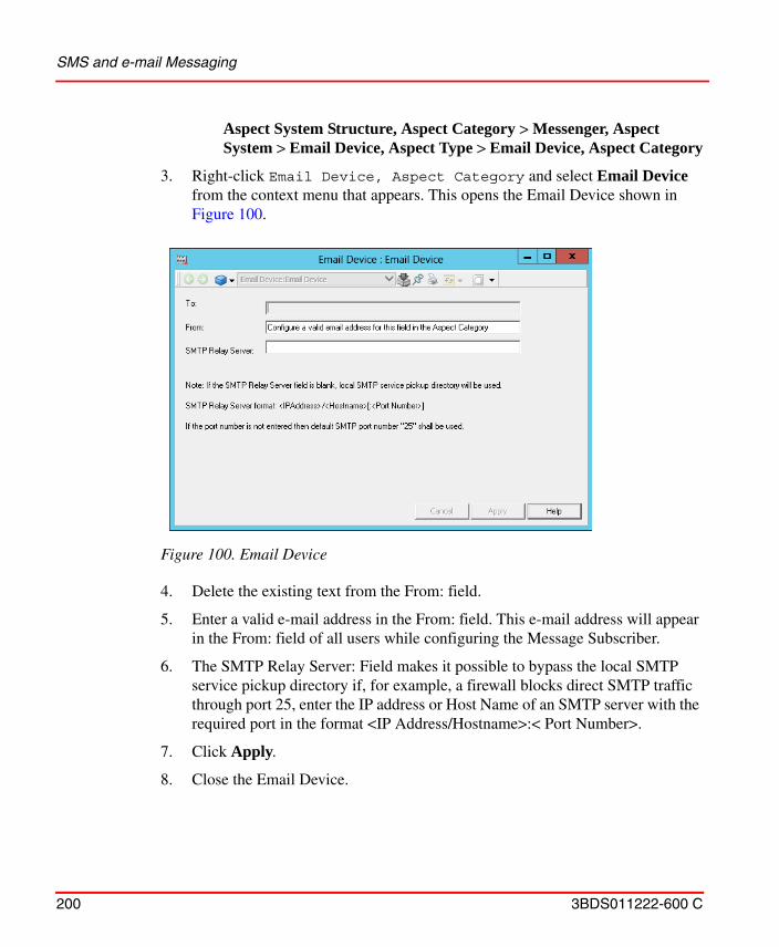
SMS and e-mail Messaging
200 3BDS011222-600 C
Aspect System Structure, Aspect Category > Messenger, Aspect System > Email Device, Aspect Type > Email Device, Aspect Category
3. Right-click Email Device, Aspect Category and select Email Device from the context menu that appears. This opens the Email Device shown in Figure 100.
4. Delete the existing text from the From: field.
5. Enter a valid e-mail address in the From: field. This e-mail address will appear in the From: field of all users while configuring the Message Subscriber.
6. The SMTP Relay Server: Field makes it possible to bypass the local SMTP service pickup directory if, for example, a firewall blocks direct SMTP traffic through port 25, enter the IP address or Host Name of an SMTP server with the required port in the format <IP Address/Hostname>:< Port Number>.
7. Click Apply.
8. Close the Email Device.
Figure 100. Email Device
SMS and e-mail Messaging
3BDS011222-600 C 201
Creating User Groups and Adding Users
The User Structure holds the defined users and user groups allowed to work in the system. Adding users and defining user roles is performed using the Configuration Wizard. All users must have a related Windows user account. The User object contains information about a user and what the user is allowed to do within the system. It also contains data specific to the user, such as profile configuration values.
The User Structure contains two levels under the root object: the first level holds User Groups, and the second holds Users. The Everyone, IndustrialITUser User Group contains all Users. Users can be added to the system and to User Groups using the Configuration Wizard. Refer to the appropriate 800xA system documentation for detailed information on creating User Groups, adding Users, and the User Structure.
Message Subscriber
The Message Subscriber identifies users who receive event messages, specifies devices available to each user, and configures those devices.
1. Add a Message Subscriber aspect to the Everyone - IndustrialIT User, User Group in the User Structure.
This example configures a Message Subscriber for a single user who subscribes to the SMS/GSM, SMTP/Email, and TAP/Modem Devices.
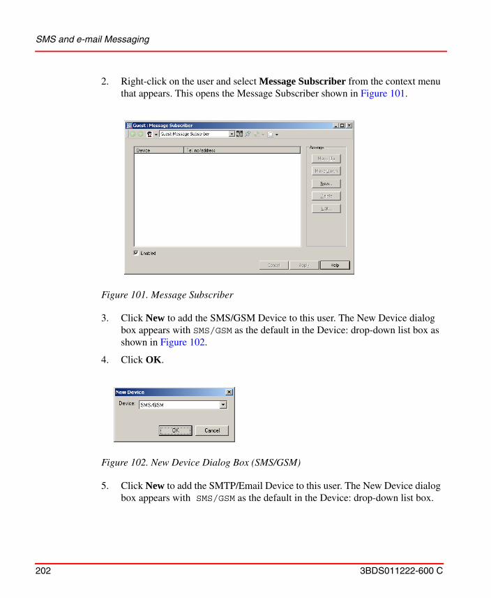
SMS and e-mail Messaging
202 3BDS011222-600 C
2. Right-click on the user and select Message Subscriber from the context menu that appears. This opens the Message Subscriber shown in Figure 101.
3. Click New to add the SMS/GSM Device to this user. The New Device dialog box appears with SMS/GSM as the default in the Device: drop-down list box as shown in Figure 102.
4. Click OK.
5. Click New to add the SMTP/Email Device to this user. The New Device dialog box appears with SMS/GSM as the default in the Device: drop-down list box.
Figure 101. Message Subscriber
Figure 102. New Device Dialog Box (SMS/GSM)
SMS and e-mail Messaging
3BDS011222-600 C 203
6. Click the down arrow and select SMTP/Email from the list that appears in the Device: drop-down list box.
7. Click OK.
8. Click New to add the TAP/Modem Device to this user. The New Device dialog box appears with SMS/GSM as the default in the Device: drop-down list box.
9. Click the down arrow and select TAP/Modem from the list that appears in the Device: drop-down list box.
10. Click OK.
11. Figure 103 shows the Message Subscriber at this point in the procedure. Select SMS/GSM in the Message Subscriber and click Edit to access the SMS/GSM Device.
Working and properly set up GSM hardware must be connected to an available COM port in order for the SMS/GSM Device to function. Refer to GSM Hardware (SMS/GSM) on page 185 for more information.
Figure 103. Message Subscriber with Added Devices
SMS and e-mail Messaging
204 3BDS011222-600 C
12. Click the down arrow in the Service: drop-down list box and select the desired GSM service provider.
13. Enter this user’s GSM telephone number to produce a view similar to the one shown in Figure 104. Enter the GSM telephone number without spaces and always include the Country Code.
14. Click Apply and then close the SMS/GSM Device.
15. Select SMTP/Email in the Message Subscriber and click Edit to access the SMTP/Email Device.
16. Enter the e-mail address for the user in the To: field to produce a view similar to the one shown in Figure 105. The information in the From: and SMTP Relay Server: (if desired) fields were configured in the Aspect System Structure under Email Device on page 199.
Figure 104. SMS/GSM Device
SMS and e-mail Messaging
3BDS011222-600 C 205
17. Click Apply and then close the SMTP/Email Device.
18. Select TAP/Modem in the Message Subscriber and click Edit to access the TAP/Modem Device.
19. Either accept the default in the Phone Number: field that was entered in the Aspect System Structure under Modem Device on page 196, or change it to the desired telephone number.
Figure 105. SMTP/Email Device
Working and properly set up modem hardware must be connected to an available COM port in order for the TAP/Modem Device to function. Refer to Modem Hardware (TAP/Modem) on page 188 for more information.
SMS and e-mail Messaging
206 3BDS011222-600 C
20. Enter a valid PIN for this user in the PIN: field to produce a view similar to the one shown in Figure 106.
21. Click Apply and then close the TAP/Modem Device.
22. The list in the Message Subscriber shows the configured devices. The top device has the highest priority, followed by the rest in top-down order. To change the order in the list, and thus the priority order, select the device and click Move Up or Move Down.
Figure 106. TAP/Modem Device
The PIN is the 10-digit personal pager and/or mobile telephone number for the current user.
Although the list in the Message Subscriber has priority assigned to it, The device used is dependent on the configuration of the Message Handler (refer to Message Handler on page 222). If this user is a member of a user group that messages are being sent to (selected during Message Handler configuration), messages are only sent to the highest priority device in the list for each user in the user group. If the messages are being sent to this user, the user device selected in the Message Handler configuration is used. In order to send the same message to multiple devices for the same user, multiple Alarm and Event Message Sources and Message Handlers pointing to the same Alarm and Event List must be set up and configured.
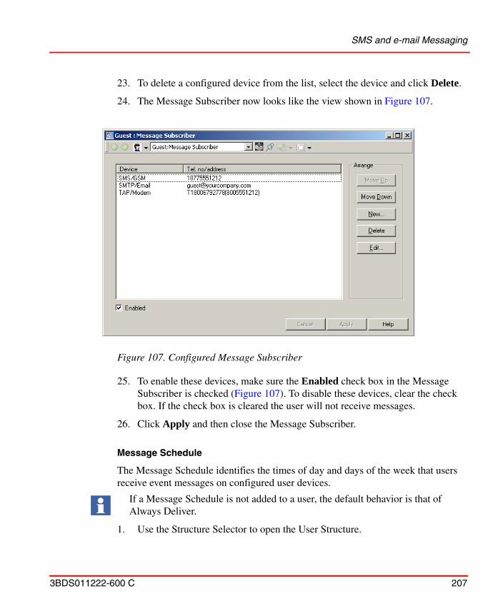
SMS and e-mail Messaging
3BDS011222-600 C 207
23. To delete a configured device from the list, select the device and click Delete.
24. The Message Subscriber now looks like the view shown in Figure 107.
25. To enable these devices, make sure the Enabled check box in the Message Subscriber is checked (Figure 107). To disable these devices, clear the check box. If the check box is cleared the user will not receive messages.
26. Click Apply and then close the Message Subscriber.
Message Schedule
The Message Schedule identifies the times of day and days of the week that users receive event messages on configured user devices.
1. Use the Structure Selector to open the User Structure.
Figure 107. Configured Message Subscriber
If a Message Schedule is not added to a user, the default behavior is that of Always Deliver.
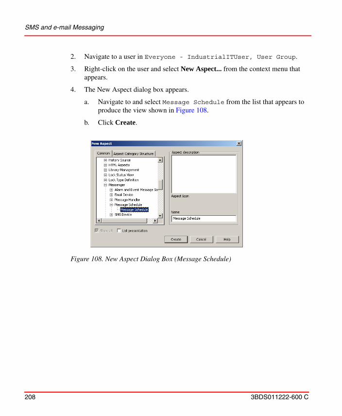
SMS and e-mail Messaging
208 3BDS011222-600 C
2. Navigate to a user in Everyone - IndustrialITUser, User Group.
3. Right-click on the user and select New Aspect... from the context menu that appears.
4. The New Aspect dialog box appears.
a. Navigate to and select Message Schedule from the list that appears to produce the view shown in Figure 108.
b. Click Create.
Figure 108. New Aspect Dialog Box (Message Schedule)
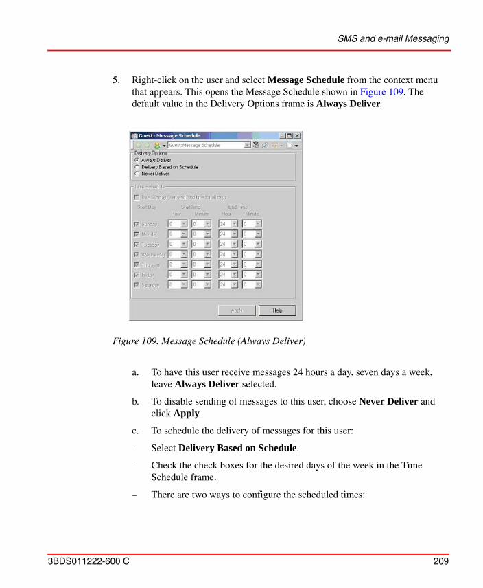
SMS and e-mail Messaging
3BDS011222-600 C 209
5. Right-click on the user and select Message Schedule from the context menu that appears. This opens the Message Schedule shown in Figure 109. The default value in the Delivery Options frame is Always Deliver.
a. To have this user receive messages 24 hours a day, seven days a week, leave Always Deliver selected.
b. To disable sending of messages to this user, choose Never Deliver and click Apply.
c. To schedule the delivery of messages for this user:
– Select Delivery Based on Schedule.
– Check the check boxes for the desired days of the week in the Time Schedule frame.
– There are two ways to configure the scheduled times:
Figure 109. Message Schedule (Always Deliver)
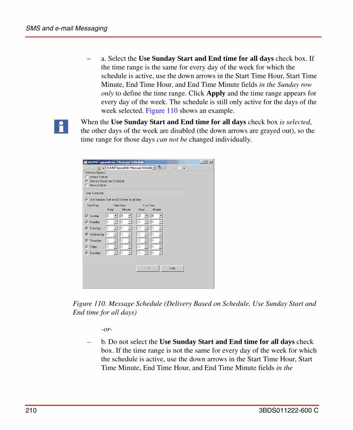
SMS and e-mail Messaging
210 3BDS011222-600 C
– a. Select the Use Sunday Start and End time for all days check box. If the time range is the same for every day of the week for which the schedule is active, use the down arrows in the Start Time Hour, Start Time Minute, End Time Hour, and End Time Minute fields in the Sunday row only to define the time range. Click Apply and the time range appears for every day of the week. The schedule is still only active for the days of the week selected. Figure 110 shows an example.
-or-
– b. Do not select the Use Sunday Start and End time for all days check box. If the time range is not the same for every day of the week for which the schedule is active, use the down arrows in the Start Time Hour, Start Time Minute, End Time Hour, and End Time Minute fields in the
When the Use Sunday Start and End time for all days check box is selected, the other days of the week are disabled (the down arrows are grayed out), so the time range for those days can not be changed individually.
Figure 110. Message Schedule (Delivery Based on Schedule, Use Sunday Start and End time for all days)
SMS and e-mail Messaging
3BDS011222-600 C 211
applicable rows to define the time range for each day. Click Apply. Figure 111 shows an example.
6. Click Apply and then close the Message Schedule.
7. To perform message configuration for other users, repeat the procedures under Message Subscriber on page 201 and Message Schedule sections for each user.
When the Use Sunday Start and End time for all days check box is not selected, the other days of the week are enabled, so the time range for those days can be changed individually.
Figure 111. Message Schedule (Delivery Based on Schedule)
If the start time is equal to the end time, the messages will always be active for the days of the week selected. If the start time is later than the end time, the delivery schedule assumes that the schedule goes past midnight and the active day list corresponds to the day the schedule starts.
SMS and e-mail Messaging
212 3BDS011222-600 C
Messenger Event Log
The Messenger Event Log is a preconfigured Alarm and Event List that filters out everything but SMS and e-mail Messaging activity. This pre-configured Alarm and Event list is automatically loaded with the SMS and e-mail Messaging system extension as Messenger Event Log aspect on the SMS and e-mail Messaging object in the Control Structure. Multiple instances of the Messenger object, which includes the Messenger Even Log aspect, can be created. Also, additional instances of just the Messenger Even Log may be copied and pasted from the preconfigured Messenger Event Log aspect from the SMS and e-mail Messaging object in the Control Structure.
The Messenger Event Log contains information on Messenger service initialization, how many messages were successful.
Figure 112. Example Messenger Event Log showing Successful Modem Initialization
SMS and e-mail Messaging
3BDS011222-600 C 213
It displays the modem initialization errors if any (modem not turned on or SIM not inserted).
Refer to Table 10 for possible modem initialization errors and its description.
It displays the reasons why a message was not successfully sent (for example, they were not on schedule or network out of order).
Figure 113. Example Messenger Event Log showing Modem Initialization Error
Figure 114. Delivery Failure Notification
Message receipt confirmation is a simple event in the Messenger Event Log. It is not audited.
Table 10. Errors of Modem Initialization
Error IDs Description
36101 PIN required
36102 PUK required
36103 Device does not support preferred message format
SMS and e-mail Messaging
214 3BDS011222-600 C
36104 Out of memory
36105 No device opened.
36106 Device does not support sending SMS messages
36107 Invalid response from device
36108 Response timed out
36109 Data coding in SMS message should be 'Default (0)' when sending in Text mode
36110 Device does not support receiving SMS messages
36111 Invalid parameter
36113 Unknown error
36120 No SIM card inserted or the GSM command set is not supported
36121 Unknown equipment error
36122 Unknown network error
36131 SIM not inserted
36132 SIM PIN required
36133 SIM PUK required
36134 SIM failure
36135 SIM busy
36136 SIM wrong
36137 Incorrect password
36138 SIM PIN2 required
36139 SIM PUK2 required
Table 10. Errors of Modem Initialization
Error IDs Description
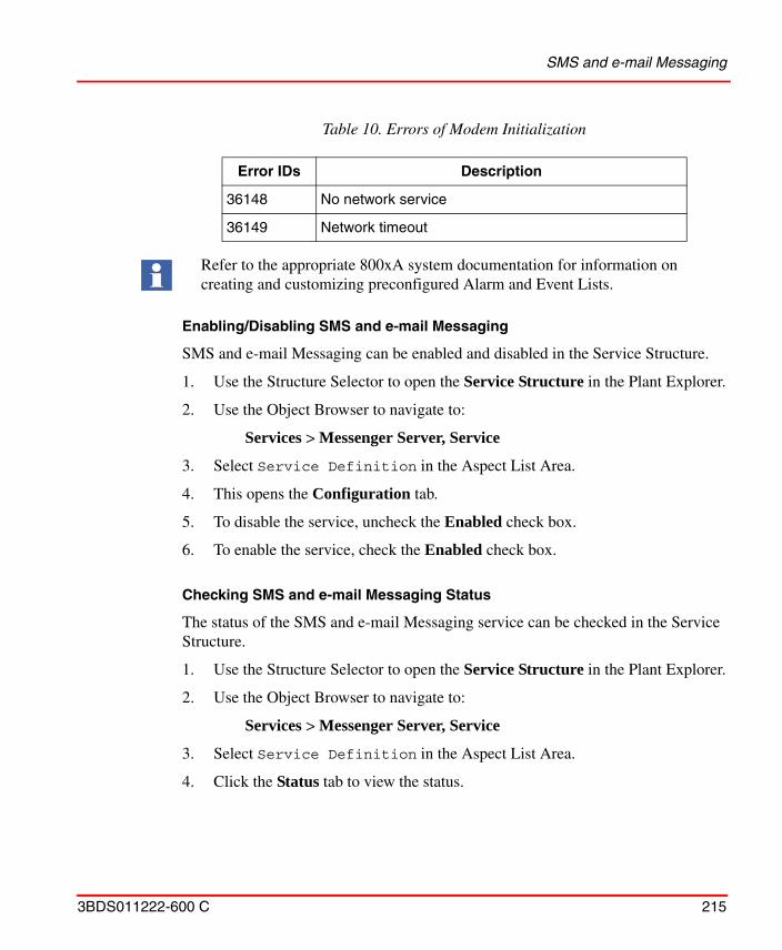
SMS and e-mail Messaging
3BDS011222-600 C 215
Enabling/Disabling SMS and e-mail Messaging
SMS and e-mail Messaging can be enabled and disabled in the Service Structure.
1. Use the Structure Selector to open the Service Structure in the Plant Explorer.
2. Use the Object Browser to navigate to:
Services > Messenger Server, Service
3. Select Service Definition in the Aspect List Area.
4. This opens the Configuration tab.
5. To disable the service, uncheck the Enabled check box.
6. To enable the service, check the Enabled check box.
Checking SMS and e-mail Messaging Status
The status of the SMS and e-mail Messaging service can be checked in the Service Structure.
1. Use the Structure Selector to open the Service Structure in the Plant Explorer.
2. Use the Object Browser to navigate to:
Services > Messenger Server, Service
3. Select Service Definition in the Aspect List Area.
4. Click the Status tab to view the status.
36148 No network service
36149 Network timeout
Refer to the appropriate 800xA system documentation for information on creating and customizing preconfigured Alarm and Event Lists.
Table 10. Errors of Modem Initialization
Error IDs Description
SMS and e-mail Messaging
216 3BDS011222-600 C
Configuration
In order to make the SMS and e-mail Messaging operational, it is necessary to perform the following procedures:• Alarm and Event List (Alarm Grouping).• Alarm and Event Message Source.• Message Handler.
Alarm and Event List (Alarm Grouping)
Alarm and Event Lists are part of the 800xA system and are added to objects when building the various structures. Building the various structures is beyond the scope of this instruction. Refer to the appropriate 800xA system documentation for detailed information on the various structures.
The Alarm and Event Lists are used to group alarm points together. They define the group of events being sent to the same group of people. For ease of use, take advantage of the defined structures to group the assets. All child objects in the structure can be defined as being included. For more details see Alarm and Event on page 89.
Alarm and Event Message Source
The Alarm and Event Message Source allows the user to select the Alarm and Event list to monitor, the content of alarm and event messages, and edit the message field length.
1. Use the Object Browser to navigate to the desired object.
2. Right-click on the object and select New Aspect... from the context menu that appears.
3. The New Aspect dialog box appears.
a. Check the Show all check box and uncheck the List presentation check box.
b. Navigate to and select Alarm and Event Message Source from the list that appears to produce the view shown in Figure 115.
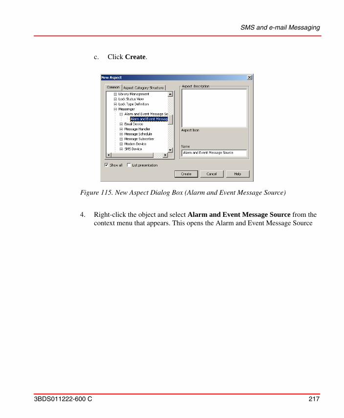
SMS and e-mail Messaging
3BDS011222-600 C 217
c. Click Create.
4. Right-click the object and select Alarm and Event Message Source from the context menu that appears. This opens the Alarm and Event Message Source
Figure 115. New Aspect Dialog Box (Alarm and Event Message Source)
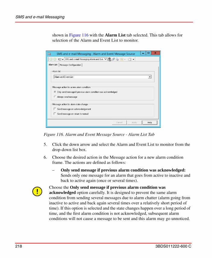
SMS and e-mail Messaging
218 3BDS011222-600 C
shown in Figure 116 with the Alarm List tab selected. This tab allows for selection of the Alarm and Event List to monitor.
5. Click the down arrow and select the Alarm and Event List to monitor from the drop-down list box.
6. Choose the desired action in the Message action for a new alarm condition frame. The actions are defined as follows:
– Only send message if previous alarm condition was acknowledged: Sends only one message for an alarm that goes from active to inactive and back to active again (once or several times).
Figure 116. Alarm and Event Message Source - Alarm List Tab
Choose the Only send message if previous alarm condition was acknowledged option carefully. It is designed to prevent the same alarm condition from sending several messages due to alarm chatter (alarm going from inactive to active and back again several times over a relatively short period of time). If this option is selected and the state changes happen over a long period of time, and the first alarm condition is not acknowledged, subsequent alarm conditions will not cause a message to be sent and this alarm may go unnoticed.
SMS and e-mail Messaging
3BDS011222-600 C 219
– Always send message: Sends a new message every time the alarm condition changes from inactive to active.
7. Choose the desired action in the Message action for alarm state change frame. The actions are defined as follows:
– Send message on acknowledgement: Sends a new message every time the alarm is acknowledged.
– Send message on return to normal: Sends a new message every time the alarm condition changes from active to inactive.
8. Click Apply.
9. Click the Message Configuration tab and check the check box next to the field in the Name column if the field is to be part of the message. This produces a
Choosing Only send message if previous alarm condition was acknowledged also requires configuration of the Alarm Manager Service Group in the Service Structure. Refer to Alarm Manager Service Group Configuration on page 229.
SMS and e-mail Messaging
220 3BDS011222-600 C
view similar to the one shown in Figure 117. The Message Configuration tab is where the messages are formatted for user devices.
10. The checked fields in the Name column are in the order they will appear in the message, with the top field at the beginning of the message (after the prefix, if configured) and the bottom field at the end (before the suffix, if configured). Click Move Up or Move Down to change the position of the field.
Figure 117. Alarm and Event Message Source - Message Configuration Tab
Alarm and Event Message Source aspects created by Bulk Data Manager tool will have empty Message Configuration information. The Message Configuration information must be configured independent of Bulk Data Manager tool.
If the Priority is selected, the Severity, and not the Priority will be written to the message.
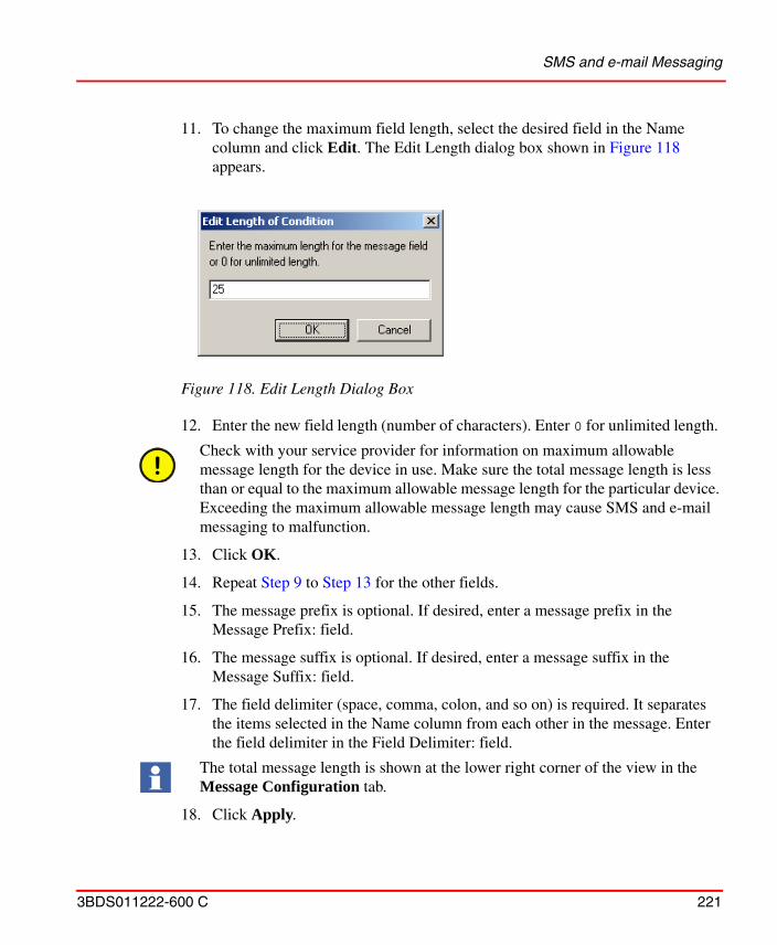
SMS and e-mail Messaging
3BDS011222-600 C 221
11. To change the maximum field length, select the desired field in the Name column and click Edit. The Edit Length dialog box shown in Figure 118 appears.
12. Enter the new field length (number of characters). Enter 0 for unlimited length.
13. Click OK.
14. Repeat Step 9 to Step 13 for the other fields.
15. The message prefix is optional. If desired, enter a message prefix in the Message Prefix: field.
16. The message suffix is optional. If desired, enter a message suffix in the Message Suffix: field.
17. The field delimiter (space, comma, colon, and so on) is required. It separates the items selected in the Name column from each other in the message. Enter the field delimiter in the Field Delimiter: field.
18. Click Apply.
Figure 118. Edit Length Dialog Box
Check with your service provider for information on maximum allowable message length for the device in use. Make sure the total message length is less than or equal to the maximum allowable message length for the particular device. Exceeding the maximum allowable message length may cause SMS and e-mail messaging to malfunction.
The total message length is shown at the lower right corner of the view in the Message Configuration tab.
SMS and e-mail Messaging
222 3BDS011222-600 C
19. Repeat this procedure for each other object with Alarm and Event Lists to monitor.
Message Handler
The Message Handler specifies the destinations of the messages.
1. Use the Object Browser to navigate to the desired object.
2. Right-click the object and select New Aspect... from the context menu that appears.
3. The New Aspect dialog box appears.
a. Check the Show all check box and uncheck the List presentation check box.
b. Navigate to and select Message Handler from the list that appears to produce the view shown in Figure 119.
A separate Message Handler is required for each Alarm and Event Message Source.
The Log tab in the Message Handler contains a message directing the user to the Messenger Event Log. It has no other functionality. Refer to Messenger Event Log on page 212.
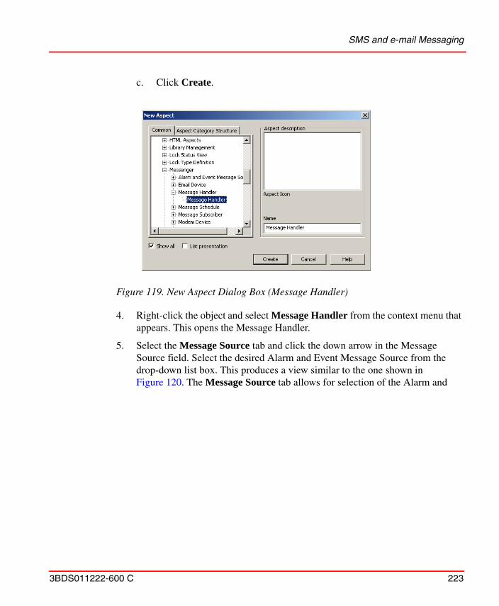
SMS and e-mail Messaging
3BDS011222-600 C 223
c. Click Create.
4. Right-click the object and select Message Handler from the context menu that appears. This opens the Message Handler.
5. Select the Message Source tab and click the down arrow in the Message Source field. Select the desired Alarm and Event Message Source from the drop-down list box. This produces a view similar to the one shown in Figure 120. The Message Source tab allows for selection of the Alarm and
Figure 119. New Aspect Dialog Box (Message Handler)
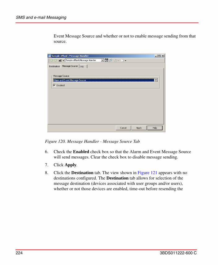
SMS and e-mail Messaging
224 3BDS011222-600 C
Event Message Source and whether or not to enable message sending from that source.
6. Check the Enabled check box so that the Alarm and Event Message Source will send messages. Clear the check box to disable message sending.
7. Click Apply.
8. Click the Destination tab. The view shown in Figure 121 appears with no destinations configured. The Destination tab allows for selection of the message destination (devices associated with user groups and/or users), whether or not those devices are enabled, time-out before resending the
Figure 120. Message Handler - Message Source Tab
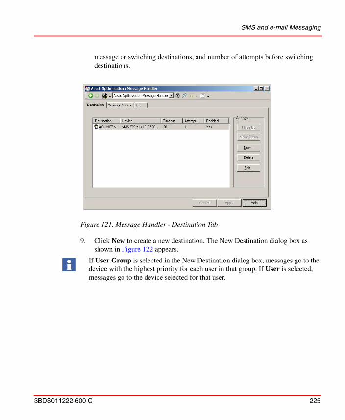
SMS and e-mail Messaging
3BDS011222-600 C 225
message or switching destinations, and number of attempts before switching destinations.
9. Click New to create a new destination. The New Destination dialog box as shown in Figure 122 appears.
Figure 121. Message Handler - Destination Tab
If User Group is selected in the New Destination dialog box, messages go to the device with the highest priority for each user in that group. If User is selected, messages go to the device selected for that user.
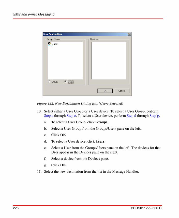
SMS and e-mail Messaging
226 3BDS011222-600 C
10. Select either a User Group or a User device. To select a User Group, perform Step a through Step c. To select a User device, perform Step d through Step g.
a. To select a User Group, click Groups.
b. Select a User Group from the Groups/Users pane on the left.
c. Click OK.
d. To select a User device, click Users.
e. Select a User from the Groups/Users pane on the left. The devices for that User appear in the Devices pane on the right.
f. Select a device from the Devices pane.
g. Click OK.
11. Select the new destination from the list in the Message Handler.
Figure 122. New Destination Dialog Box (Users Selected)
SMS and e-mail Messaging
3BDS011222-600 C 227
12. Click Edit and the Edit Destination dialog box shown in Figure 123 appears.
13. Check the Enabled check box so that messages will be sent to the destination. Clear the check box to disable the destination.
14. The Timeout (s.): field contains the number of seconds SMS and e-mail Messaging waits for the user to acknowledge the alarm line corresponding to the message before the message is resent to that destination. If it is the last attempt, it is the number of seconds before switching to the next destination. Enter a time-out in seconds in the Timeout (s.): field.
15. The Attempts: field contains the number of times SMS and e-mail Messaging sends a message to the destination before switching to the next destination. Enter the number of attempts in the Attempts: field.
16. Click OK.
17. Repeat Step 9 to Step 16 for each additional destination.
18. The message is sent to the top destination first. If the message is successfully sent and the user acknowledges the alarm, or confirms receipt of the message (messages sent through SMS/GSM Device only), within the configured time limit and/or number of attempts, the rest of the destinations do not receive the message. If the user does not acknowledge the alarm line corresponding to the message, or confirm receipt of the message (messages sent via SMS/GSM Device only), within the timeout interval, the message is sent again provided the attempts parameter is greater than one. If the attempts count on the first
Figure 123. Edit Destination Dialog Box
SMS and e-mail Messaging
228 3BDS011222-600 C
destination is exhausted without acknowledgement or receipt confirmation, the Message Handler moves to the next destination in the list (if there is one). If the destination is a group, the message is sent to the device with the highest priority for every group member before timing begins; however, the lower priority devices do not receive messages. Acknowledgement of the alarm, or receipt confirmation (messages sent via SMS/GSM Device only), by one member of the group is considered successful notification of the group.
19. To change the order in the list, and thus the send order, select a destination and click Move Up or Move Down.
20. To delete a destination from the list, select it and click Delete.
21. Figure 124 shows a completed message destination configuration with two user groups (Page Sample ePlant and Operators) and a TAP/Modem Device for an individual user (Guest) configured.
22. Repeat this procedure for each Alarm and Event Message Source.
For example, using the configuration shown in Figure 124, the sequence of events is illustrated in Figure 125.
Figure 124. Configured Destinations Tab
SMS and e-mail Messaging
3BDS011222-600 C 229
Alarm Manager Service Group Configuration
The Only send message if previous alarm condition was acknowledged in the Alarm and Event Message Source is designed to prevent the same alarm condition from sending several messages due to alarm chatter (alarm going from inactive to active and back again several times over a relatively short period of time). However,
Figure 125. Sequence of Events for Message Handler in Figure 124
PAGE SAMPLE EPLANT USER GROUP
USER 1 USER 2 HIGHEST PRIORITY DEVICEUSER 3 HIGHEST PRIORITY DEVICEUSER 4 HIGHEST PRIORITY DEVICE
HIGHEST PRIORITY DEVICEALARM ACKNOWLEDGED
WITHIN TIME OUT PERIOD?
LAST ATTEMPT?
NO
YES
NO
YES
OPERATOR USER GROUP
OPER 1 OPER 2 HIGHEST PRIORITY DEVICEOPER 3 HIGHEST PRIORITY DEVICEOPER 4 HIGHEST PRIORITY DEVICE
HIGHEST PRIORITY DEVICE
LAST ATTEMPT?
NO
YES
NO
YES
LAST ATTEMPT?
ALARM ACKNOWLEDGEDWITHIN TIME OUT
PERIOD?
GUEST USER
TAP/MODEM DEVICEYES
NO
YES
NO
DONETIME OUT RECORDED INMESSENGER EVENT LIST
T05073B
ALARM ACKNOWLEDGEDWITHIN TIME OUT
PERIOD?
NOTE:ALARM ACKNOWLEDGE INCLUDESCONFIRMING RECEIPT OF MESSAGEVIA GSM COMPATIBLE DEVICE (ONLYWHEN MESSAGE WAS SENT VIA SMS/GSM DEVICE).
SMS and e-mail Messaging
230 3BDS011222-600 C
this option also requires configuration of the Alarm Manager Basic Service Group in the Service Structure.
The Alarm Manager can be configured so that the changes on Event attribute object extensions will be published to active alarms. When the function is enabled, any changes made on attributes provided by Event Attribute Object Extension aspects will be reflected on any active alarms for the object, and made visible on any alarm lists.
Perform the following steps to enable the functionality:
1. Use the Structure Selector to open the Service Structure in Plant Explorer.
2. Use the Object Browser to navigate to:
Services > Alarm Manager, Service > Basic Service, Service Group
3. Select Service Group Definition in the Aspect List Area.
4. Click the Special Configuration tab.
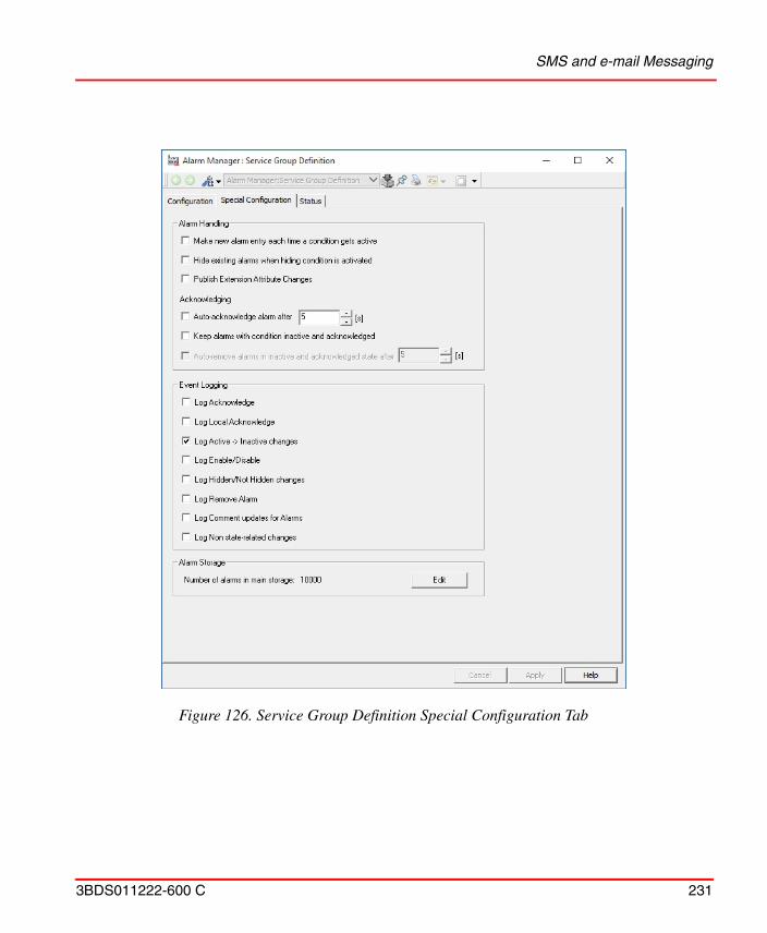
SMS and e-mail Messaging
3BDS011222-600 C 231
Figure 126. Service Group Definition Special Configuration Tab
System Status
232 3BDS011222-600 C
Configure Alarm Handling
5. Uncheck the Make new alarms entry each time a condition gets active check box.
6. Click Apply to save the entered data.
System Status
Topology Status Viewer
To configure a Topology Diagram to view status for the whole plant you perform the following principal steps. They correspond to workflow steps Create Process Functions, Build Lower Level Control Structure and also to Download and Test Application Software:
1. On every Controller object: Open the Topology aspect, open Diagram view and add a new Diagram based on the skeleton for the Controller level (AC 800M Single / AC 800M Redundant). Processor Modules and the Hardware Units below by default have Topology aspects with pre-configured Component views. The symbols of these Topology components are placed by default on the diagram. Save the diagram.
2. Insert / create objects representing clients, servers and eventually other network components in the Control Structure above the Control Network level.
3. Create Topology aspects and configure the Component view for the objects to represent in the hierarchy above the controllers.
4. If applicable add texts/labels to the new Components with aspect property references that subscribe to status information. Or include other elements with access to and representation of status information, for example ActiveX controls.
5. On the object representing the plant add a Topology aspect and create a new Topology Diagram from the skeleton Plant Network. It is populated automatically with the Topology components in the Control Structure hierarchy below your plant object down to the Controller objects.
If this check box is selected, each change from the inactive to active state will result in a new alarm.
System Status
3BDS011222-600 C 233
6. Arrange the symbols of the Topology components and connect them as required. Add additional labels/ texts / graphical symbols as required. Save the diagram.
7. Switch on Subscribe for Live Data in the View menu. Live Data status information is shown. Prerequisites are: OPC servers are operating and Controllers are running.
8. To view and navigate such Topology Diagrams from a Graphic Display on Operator Workplaces you include an Aspect Link to the top Topology aspect in Control Structure into this Graphic Display.
To view and navigate such Topology Diagrams (as you can see in System 800xA, System Planning (3BSE041389*) from a Graphic Display on Operator Workplaces you include an Aspect Link to the top Topology aspect in Control Structure into this Graphic Display. As an operator or a maintenance person (with Operator Role) you can inspect the live status information in the diagrams and navigate in the hierarchy of diagrams:
1. Press the Aspect Link button in the Graphic Display to open the pop-up window with the Topology Diagram.
2. Set Window > Workbook Mode for the pop-up window.(Workbook mode is set by default.)
3. Switch on View > Subscribe for Live Data.
4. Use the object context menu item Goto Child Diagram (for example on a controller object shown in the diagram) to navigate to a child diagram.
5. Use the object context menu item Goto Parent Diagram (for example on an object shown in the diagram) to navigate to the parent diagram.
6. Navigate through the collection of opened Topology Diagrams using the Workbook tabs.
Additionally you can print out the Topology Diagrams.

System Status
234 3BDS011222-600 C
Device Management & Fieldbusses
3BDS011222-600 C 235
Device Management & FieldbussesThis section describes how to use Device Management software for efficient planning, operation and monitoring of field devices within the 800xA System.
As part of the Device Management PROFIBUS & HART and Device Management FOUNDATION Fieldbus the Device Library Wizard is a required tool to create and extend System 800xA Device Integration Libraries.
Details on the Device Library Wizard can be found in System 800xA Device Management, Device Library Wizard (2PAA102573*).
Details on PROFIBUS and HART device configuration can be found in System 800xA Device Management, PROFIBUS and HART Configuration (3BDD011934*).
Details on FOUNDATION Fieldbus device configuration can be found in System 800xA Device Management, FOUNDATION Fieldbus Configuration (3BDD012902*).
Device Library Wizard
A range of pre-configured device types for System 800xA are available for the fieldbus protocols FOUNDATION Fieldbus, PROFIBUS and HART.
The Device Library Wizard is a tool that is used for adding these separately delivered device types to the device libraries of an 800xA system.
This section describes the process of adding these device types to an 800xA system using Device Library Wizard.
Prerequisites
The following requirements must be met to allow adding device types to the Device Integration Libraries of an 800xA system using the Device Library Wizard.
Before starting to work with the specific Device Management section, follow the instructions of Device Library Wizard.
Detailed information about the Device Library Wizard and further functionality is described in System 800xA Device Management, Device Library Wizard (2PAA102573*).
Device Library Wizard
236 3BDS011222-600 C
• The Device Library Wizard has been installed and configured according 800xA Installation and Post-installation guideline.
• An 800xA system has been created and started.
• The system extensions for the corresponding fieldbus protocols have been added.
• The user has Windows administrator privileges, e.g. System Engineer role.
Source for Device Types
ABB provides a continuously increasing portfolio of 800xA system tested and certified ABB and third party device types. They are available from System 800xA Media from ABB SolutionsBank.
Use the Device Library Wizard to extract the device type files on the system nodes.
Starting from System 800xA version 5.0 onwards, the device types available are stored on the delivered System 800xA Media.
Download from the ABB SolutionsBank.
1. Login to ABB SolutionsBank.
2. Open Downloads > Downloads Explorer.
3. Browse to
– Control Products and Systems / 800xA / Device Management - FOUNDATION Fieldbus / Device Library - <category>for FOUNDATION Fieldbus device types or
– Control Products and Systems / 800xA / Device Management - HART / Device Library - <category>for HART device types or
– Control Products and Systems / 800xA / Device Management - PROFIBUS / Device Library - <category>for PROFIBUS device types
and download device type files to your local machine or media.
Device Library Wizard
3BDS011222-600 C 237
Extract Device Type Files
Execute the steps below to extract device type files on all 800xA system nodes of the following types starting with the Aspect Server:
• Aspect Server
• Connectivity Server
• Application Server
• Clients
Extract the device type files in the following sequence:
1. Open the Device Library Wizard: ABB Start Menu > ABB Industrial IT 800xA > Device Mgmt > ABB Device Library Wizard or double-click the ABB Device Library Wizard shortcut on the Desktop.
2. When the Device Library Wizard opens with main window select Extract Device Types and click Next.
3. Click Browse button and navigate to the corresponding folder that contains the device type files. See also Source for Device Types on page 236.
For more information on ABB Start Menu, refer to System 800xA Tools (2PAA101888*).
Device type files exist as zip files (.zip) or self extracting zip files (.exe).
The location where device type files are stored can be different from the currently used system node. It is not required to copy all the device type files to local disk.
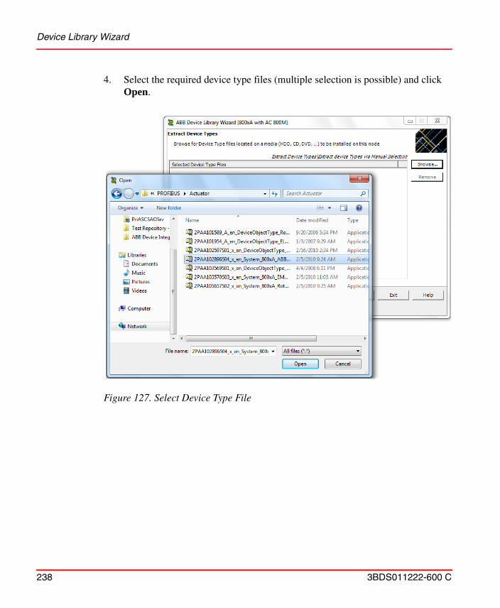
Device Library Wizard
238 3BDS011222-600 C
4. Select the required device type files (multiple selection is possible) and click Open.
Figure 127. Select Device Type File
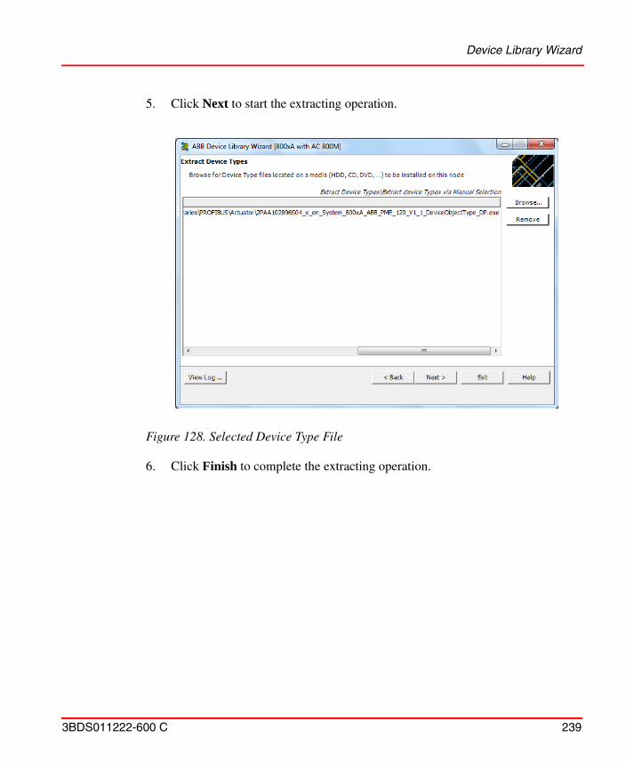
Device Library Wizard
3BDS011222-600 C 239
5. Click Next to start the extracting operation.
6. Click Finish to complete the extracting operation.
Figure 128. Selected Device Type File
Device Library Wizard
240 3BDS011222-600 C
Successful extracting operation will be shown in the logger area.
7. Repeat step 3 to 6 in this chapter for all required device types. Use Main Menu button to navigate directly to the main window. Click Exit to close the program if no more operations are required.
Read Release Notes of the Device Types
Each device type file includes a release note for the corresponding device type. Please read the release note carefully for detailed information or limitations.
The release notes are stored in the root folder of the specific device type.
For FOUNDATION Fieldbus browse to:<Installation path>\ABB Industrial IT\Engineer IT\ABB Device Integration Library\FF Device Integration Library\<Device Type>
Figure 129. Extraction successful window
Device Library Wizard
3BDS011222-600 C 241
For HART browse to:<Installation path>\ABB Industrial IT\Engineer IT\ABB Device Integration Library\HART Device Integration Library\<Device Type>
For PROFIBUS browse to:<Installation path>\ABB Industrial IT\Engineer IT\ABB Device Integration Library\PROFIBUS Device Integration Library\<Device Type>
Install Device Types
Execute the installation of device types on all 800xA system nodes, where 800xA Device Management software has been installed. Starting with the Aspect Server the following sequence of system nodes shall be considered for installation:
• Aspect Server
• Connectivity Server
• Application Server
• Clients
Right-click on the extracted device type in DLW window to access the release note of a device type.
License for device-specific DTMs are not subject to the 800xA system licensing arrangements and are not included in the 800xA system installation.
Device specific DTMs have to be installed on every 800xA system node that runs with Device Management PROFIBUS & HART. The DTM specific license agreements have to be observed here.
Device Library Wizard
242 3BDS011222-600 C
Prepare System Node for Device Type Installation.
Device Management PROFIBUS & HART:
If DMS Connect system extension is loaded and the software Device Management System is installed and used, please do not work with this tool during device type installation on this particular node.
Asset Optimization Server System Nodes (if applicable):
Device Type Objects using device asset monitors, which have been installed already and may be updated with a new minor version device type, shall be checked for new updated asset monitors. Refer to the device specific release notes, if the new minor version device type will replace an existing asset monitor. In this case the loaded asset monitors of the particular device type object must be disabled in the Asset Optimization Server (AO Server).
Start Device Type Installation.
1. Open the Device Library Wizard: ABB Start Menu > ABB Industrial IT 800xA > Device Mgmt > ABB Device Library Wizard or double-click ABB Device Library Wizard shortcut on the desktop.
2. Select Install Device Types to install new device types or re-install device type to the 800xA System. Click Next.
Loaded device asset monitors in the Asset Optimization Server may show bad communication and invalid data during the time of Device Type installation. This can result in alarms and events in the particular system message list. Before installing device types it is recommended to inform plant personal.
For more information on ABB Start Menu, refer to System 800xA Tools (2PAA101888*).
Windows and 800xA System administrator rights are required to execute the Device Library Wizard on the node.
Device Library Wizard
3BDS011222-600 C 243
3. Select the fieldbus protocol used in the system. The following fieldbus
protocols are currently supported, depending on the 800xA System:
– FOUNDATION Fieldbus (HSE and H1)
– HART
– PROFIBUS (PROFIBUS DP and PA)
Figure 130. Action Selection Dialog
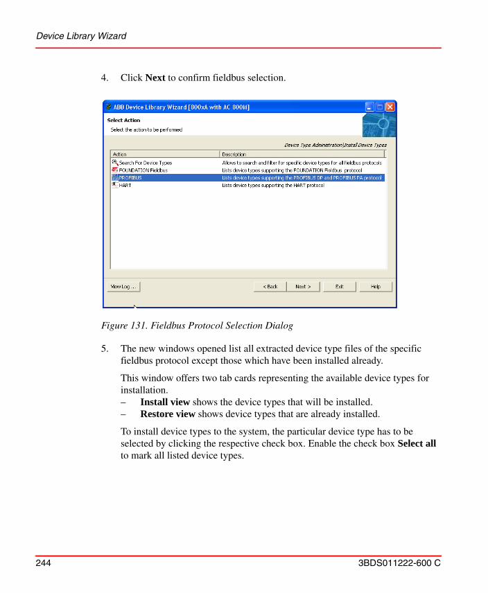
Device Library Wizard
244 3BDS011222-600 C
4. Click Next to confirm fieldbus selection.
5. The new windows opened list all extracted device type files of the specific fieldbus protocol except those which have been installed already.
This window offers two tab cards representing the available device types for installation. – Install view shows the device types that will be installed.– Restore view shows device types that are already installed.
To install device types to the system, the particular device type has to be selected by clicking the respective check box. Enable the check box Select all to mark all listed device types.
Figure 131. Fieldbus Protocol Selection Dialog
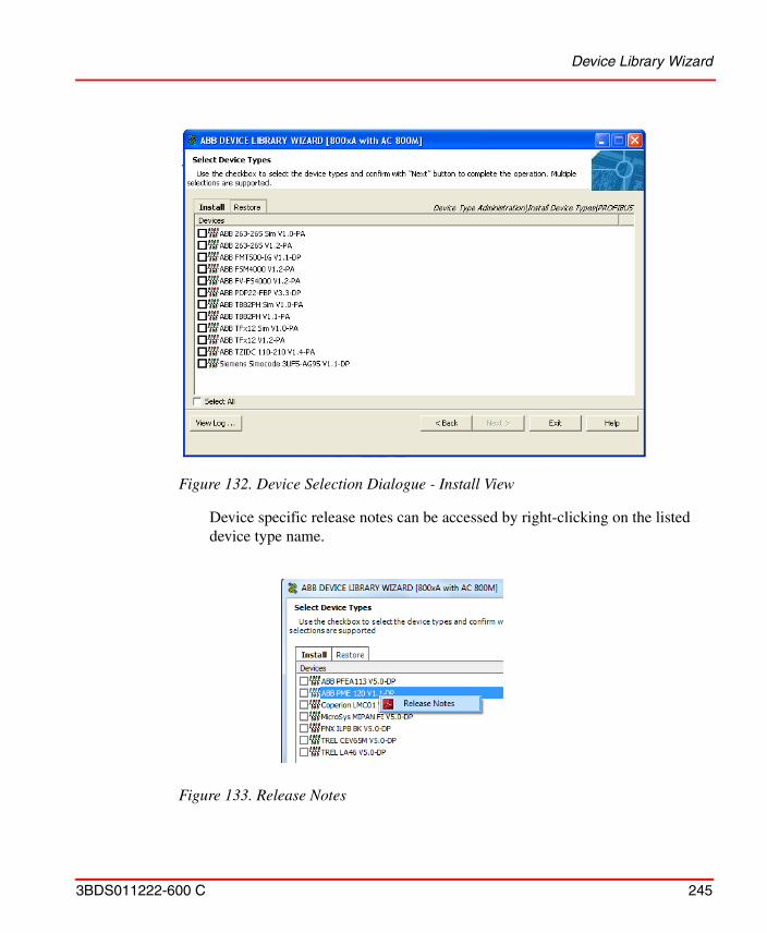
Device Library Wizard
3BDS011222-600 C 245
Device specific release notes can be accessed by right-clicking on the listed device type name.
Figure 132. Device Selection Dialogue - Install View
Figure 133. Release Notes
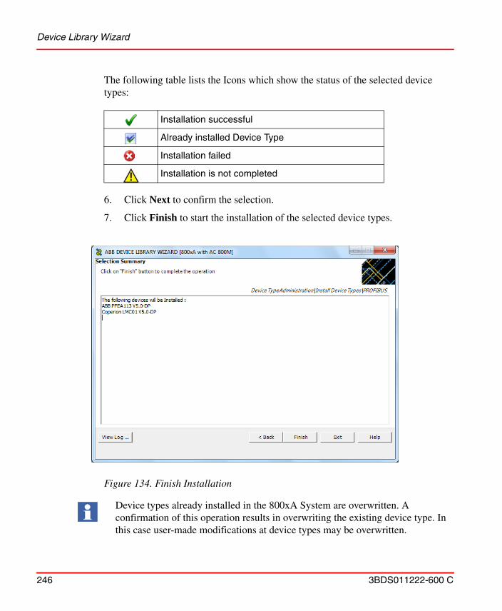
Device Library Wizard
246 3BDS011222-600 C
The following table lists the Icons which show the status of the selected device types:
6. Click Next to confirm the selection.
7. Click Finish to start the installation of the selected device types.
Installation successful
Already installed Device Type
Installation failed
Installation is not completed
Figure 134. Finish Installation
Device types already installed in the 800xA System are overwritten. A confirmation of this operation results in overwriting the existing device type. In this case user-made modifications at device types may be overwritten.
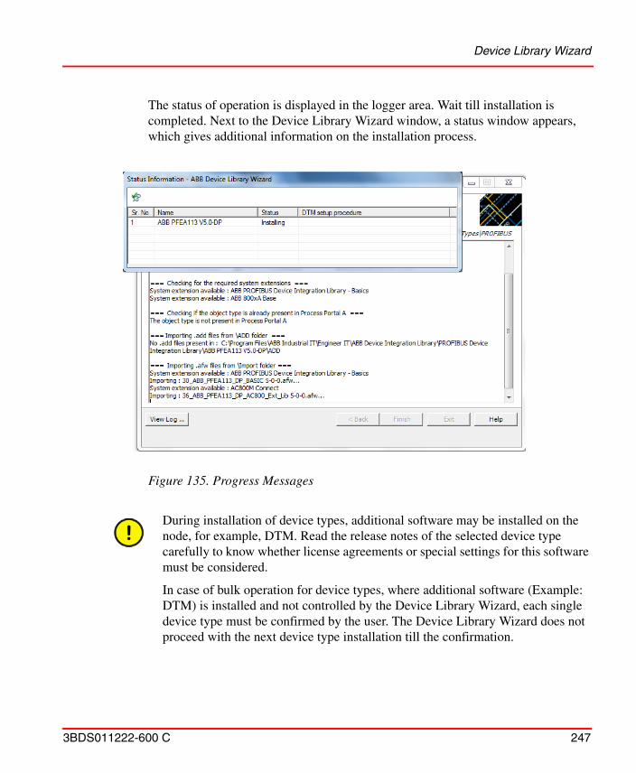
Device Library Wizard
3BDS011222-600 C 247
The status of operation is displayed in the logger area. Wait till installation is completed. Next to the Device Library Wizard window, a status window appears, which gives additional information on the installation process.
Figure 135. Progress Messages
During installation of device types, additional software may be installed on the node, for example, DTM. Read the release notes of the selected device type carefully to know whether license agreements or special settings for this software must be considered.
In case of bulk operation for device types, where additional software (Example: DTM) is installed and not controlled by the Device Library Wizard, each single device type must be confirmed by the user. The Device Library Wizard does not proceed with the next device type installation till the confirmation.
Device Library Wizard
248 3BDS011222-600 C
While installing ABB Instruments device types with device specific DTMs, the DLW installation window may stop responding.
Execute the following steps to continue the installation process:
1. Open Windows Task Manager.
2. In the Applications tab, select the device type(s) for which the DTM installation stopped responding.
3. Click the Processes tab and select launcher.exe.
4. Click End Process.
5. In the Task Manager Warning window, click Yes.
DLW proceeds with the installation of the next device type.
6. The device types for which the installation process ended, install the device type DTM(s) manually from the path:
<Installation Drive>:\Program Files\ABB Industrial IT\Engineer IT\<Protocol> Device Integration Library\DTM\DTM\<DTM Name>\setup.exe.
Installation issues can stop the operation. In this case error messages are visible in the logger area. Retry the installation or contact your local ABB representative for further assistance.
During device type installation product documentation and other software will be copied and installed to the local disk.
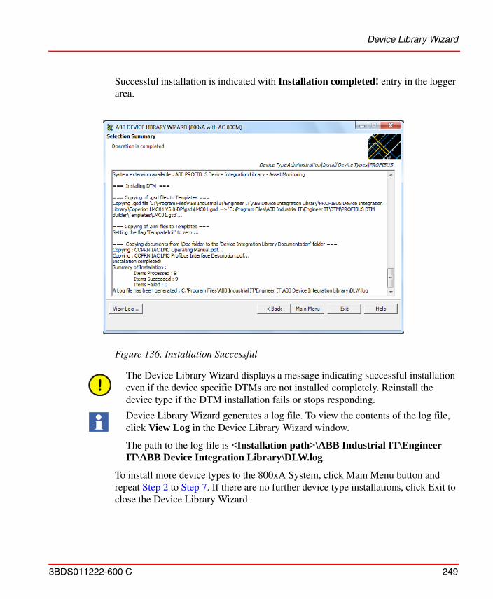
Device Library Wizard
3BDS011222-600 C 249
Successful installation is indicated with Installation completed! entry in the logger area.
To install more device types to the 800xA System, click Main Menu button and repeat Step 2 to Step 7. If there are no further device type installations, click Exit to close the Device Library Wizard.
Figure 136. Installation Successful
The Device Library Wizard displays a message indicating successful installation even if the device specific DTMs are not installed completely. Reinstall the device type if the DTM installation fails or stops responding.
Device Library Wizard generates a log file. To view the contents of the log file, click View Log in the Device Library Wizard window.
The path to the log file is <Installation path>\ABB Industrial IT\Engineer IT\ABB Device Integration Library\DLW.log.
Device Management PROFIBUS & HART
250 3BDS011222-600 C
Special Handling for 800xA System Restore
Device Management PROFIBUS & HART
This section uses step by step examples to describe how to create and work with PROFIBUS and HART Device Type Objects in 800xA systems,
Prerequisites and Requirements
The following requirements must be met, in order to be able to carry out the actions described in this section.
• An 800xA system has been created and started.
• The following system extensions have been loaded:
– AC800M Connect
– AC800M Connect Hi
– Fieldbus Builder PROFIBUS/HART
Additional system restore activities to be performed after restore of a system backup are described in System 800xA Administration and Security (3BSE037410*), sub-section Recover Function-Specific Information.
System upgrade from previous to new versions is described in System 800xA, System Upgrade (3BSE036342*).
Special handlings for PROFIBUS & HART device types in different system environments are described in System 800xA Engineering, Engineering and Production Environments (3BSE045030*).
This section does not include configuration parts of HART Multiplexer Connect. HART Multiplexer Connect is described in System 800xA Device Management, PROFIBUS and HART Configuration (3BDD011934*).
Additional information and special configuration can be found in the particular section of System 800xA Device Management, PROFIBUS and HART Configuration (3BDD011934*).
For details of installed and used device types refer to the specific device type release notes, described in Read Release Notes of the Device Types.

Device Management PROFIBUS & HART
3BDS011222-600 C 251
– HART Device Integration Library - Basics
– PROFIBUS Device Integration Library - Basics
– optional HART Device Library - Asset Monitoring (if Asset Optimization related system extensions have been loaded)
– optional PROFIBUS Device Library - Asset Monitoring (if Asset Optimization related system extensions have been loaded)
– optional Function Designer for AC800M Connect, Function Designer for FBB P/H (if engineering related system extensions (Function Designer) have been loaded)
• The user has permissions for 800xA system engineering.
• All required device types have been installed via Device Library Wizard.
• Control Network, Control Builder M project and OPC Server configuration for AC 800M Controller have been created.
Entities, Reservation and Environments
Starting from System 800xA version 5.0 onwards the system provides an enhanced multi-user support. Optionally the system can be extended for environment support allowing to have different system configuration in certain environments. So called entities are available as base functionality at object types in the 800xA System to enable multi-user engineering. The entity allows to lock (reservation) a project, controller or applications to prevent simultaneous configuration of aspects and objects in the 800xA system. Reservation functionality is available with right mouse click at the device type object in 800xA Plant Explorers Control Structure.
The following kind of objects available in the Control Structure can be used to make a reservation for underlaying objects and aspects:
• Projects, Applications, Controllers, Diagrams, Single Control Module (SCM)
• Libraries, libraries with hardware types
• Control modules types, except hidden control module types
• Function block types, except hidden function block types
• Diagrams types. except hidden diagram types

Device Management PROFIBUS & HART
252 3BDS011222-600 C
Details of entities and reservation are described in System 800xA Engineering, Engineering and Production Environments (3BSE045030*).
Fieldbus Topology in the 800xA System
Once an 800xA system has been started, a fieldbus topology starting at the controller and ending at the field device can be created in the Control Structure of Plant Explorer workplace. Starting with the root node, the simplest example of a fieldbus system for PROFIBUS and HART is set up as follows:
Control Network > Control Project > Controller Group > Controller Hardware Group > (ModuleBus or CI854) > Field Devices
Pre-configuration of AC 800M Controller
To enable communication for a field device with a (Device Type Manager) DTM, an additional setting must be made for each AC 800M controller in Plant Explorer Control Structure.
Online and offline engineering for PROFIBUS and HART devices requires a reservation of the main entity object in the 800xA Plant Explorer Control Structure.
As the Operator user role does not have permissions to reserve an entity, it may not be possible to open certain DTMs with the Operator user role. Set a higher access right to the Operator role, if applicable.
PROFIBUS and HART device types installed in an enabled environment supported 800xA system, are located in the Production Environment only. To have installed device types also available in Engineering Environments, they have to be synchronized by the user manually.
PROFIBUS and HART device types in an Engineering Environment can be accessed in offline configuration only.
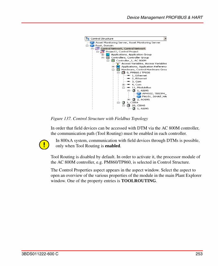
Device Management PROFIBUS & HART
3BDS011222-600 C 253
In order that field devices can be accessed with DTM via the AC 800M controller, the communication path (Tool Routing) must be enabled in each controller.
Tool Routing is disabled by default. In order to activate it, the processor module of the AC 800M controller, e.g. PM860/TP860, is selected in Control Structure.
The Control Properties aspect appears in the aspect window. Select the aspect to open an overview of the various properties of the module in the main Plant Explorer window. One of the property entries is TOOLROUTING.
Figure 137. Control Structure with Fieldbus Topology
In 800xA system, communication with field devices through DTMs is possible, only when Tool Routing is enabled.
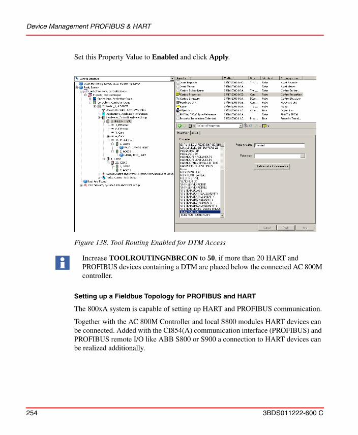
Device Management PROFIBUS & HART
254 3BDS011222-600 C
Set this Property Value to Enabled and click Apply.
Setting up a Fieldbus Topology for PROFIBUS and HART
The 800xA system is capable of setting up HART and PROFIBUS communication.
Together with the AC 800M Controller and local S800 modules HART devices can be connected. Added with the CI854(A) communication interface (PROFIBUS) and PROFIBUS remote I/O like ABB S800 or S900 a connection to HART devices can be realized additionally.
Figure 138. Tool Routing Enabled for DTM Access
Increase TOOLROUTINGNBRCON to 50, if more than 20 HART and PROFIBUS devices containing a DTM are placed below the connected AC 800M controller.
Device Management PROFIBUS & HART
3BDS011222-600 C 255
PROFIBUS devices are connected directly to the CI854(A) communication interface linked to the AC 800M controller or to PROFIBUS DP/PA Linking Devices placed between CI854(A) and the PROFIBUS PA field device.
This section describes a sample set-up for local and remote S800 I/O modules with HART Device Type Objects connected below as well as for PROFIBUS Devices Type Objects.
The following steps have been performed in 800xA Plant Explorers Control Structure, whereas S900/S800 I/O modules and PROFIBUS device types can also be inserted in Control Builder M projects using Control Builder M Professional.
HART devices can be inserted in Plant Explorers Control Structure only.
Bulk Data Manager operations are supported for both the fieldbus protocols.
PROFIBUS and HART Fieldbus Preparation in Control Builder M.
Before device types in the form of hardware units can be used, the corresponding hardware libraries have to be inserted in the Control Builder M project. The inserted hardware libraries have to be connected to a specific controller afterwards.
Hardware libraries represents the physical device type in the 800xA system. During installation of Control Builder M the following libraries are installed necessary for PROFIBUS and HART device engineering:
• S800IoModulebusHwLib This library contains the S800 I/O-modules, which can be used at AC 800M ModuleBus only. This library is mandatory to configure HART device types on AC 800M ModuleBus.
• S800CI801CI854HwLibThis library contains S800 I/O modules and the CI801 PROFIBUS gateway. It can be used with the PROFIBUS DP master CI854(A) only. This library is mandatory to configure HART Device Type Objects at S800 PROFIBUS Remote I/O.
Do not copy paste communication DTM objects such as CI854, S800 Modules, S900 modules. Instead create them manually or use Bulk Data Manager.
However, copy / paste of the device object type instances is supported.
Device Management PROFIBUS & HART
256 3BDS011222-600 C
• S800CI840CI854HwLib This library contains S800 I/O modules and the CI840 PROFIBUS gateway. It can be used with the PROFIBUS DP master CI854(A) only. This library is mandatory to configure HART Device Type Objects at S800 PROFIBUS Remote I/O.
• S900IoCI854HwLibThis library contains S900 I/O modules and the S900 PROFIBUS gateway. It can be used with the PROFIBUS DP master CI854(A) only. This library is mandatory to configure HART Device Type Objects at S900 PROFIBUS Remote I/O.
• CI854PROFIBUSHwLib This library contains the PROFIBUS-DPV1 master, which can be used at AC 800M CEX bus. This library is mandatory to configure PROFIBUS device types on PROFIBUS networks.
Pre-setting before inserting of Field Device Type Object .
Two different network areas are available at each AC 800M Controller object:
• ModuleBus at AC 800M• Each CI854(A) at AC 800M
Instantiation of field devices is possible with the Fieldbus Builder PROFIBUS/HART in Communication disabled mode only. If Communication enabled mode is active, it MUST be deactivated (Communication disabled). Each area must be separately set to Communication disabled mode.
Two possibilities are available on the device type objects to set the Fieldbus Builder in Communication disabled:
• Via context menu of the Fieldbus Management aspect.• Via Device Functions... context menu in Control Structure of Plant Explorer.
Insert of hardware Libraries, connect them to a specific controller, open and release projects and create new instance based on hardware libraries is described in this document in Insert Hardware Libraries on page 36 and the following.
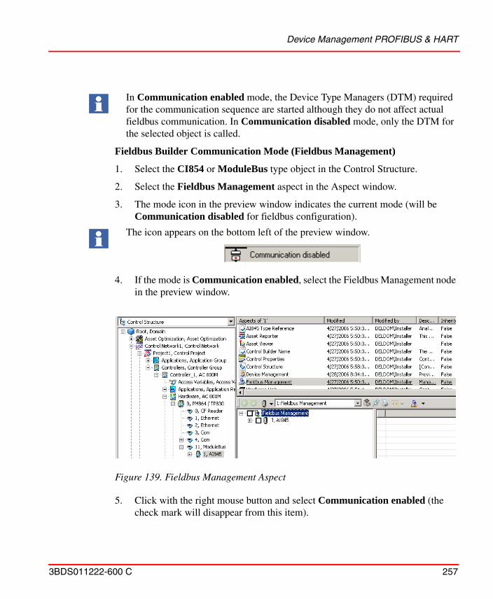
Device Management PROFIBUS & HART
3BDS011222-600 C 257
Fieldbus Builder Communication Mode (Fieldbus Management)
1. Select the CI854 or ModuleBus type object in the Control Structure.
2. Select the Fieldbus Management aspect in the Aspect window.
3. The mode icon in the preview window indicates the current mode (will be Communication disabled for fieldbus configuration).
4. If the mode is Communication enabled, select the Fieldbus Management node in the preview window.
5. Click with the right mouse button and select Communication enabled (the check mark will disappear from this item).
In Communication enabled mode, the Device Type Managers (DTM) required for the communication sequence are started although they do not affect actual fieldbus communication. In Communication disabled mode, only the DTM for the selected object is called.
The icon appears on the bottom left of the preview window.
Figure 139. Fieldbus Management Aspect
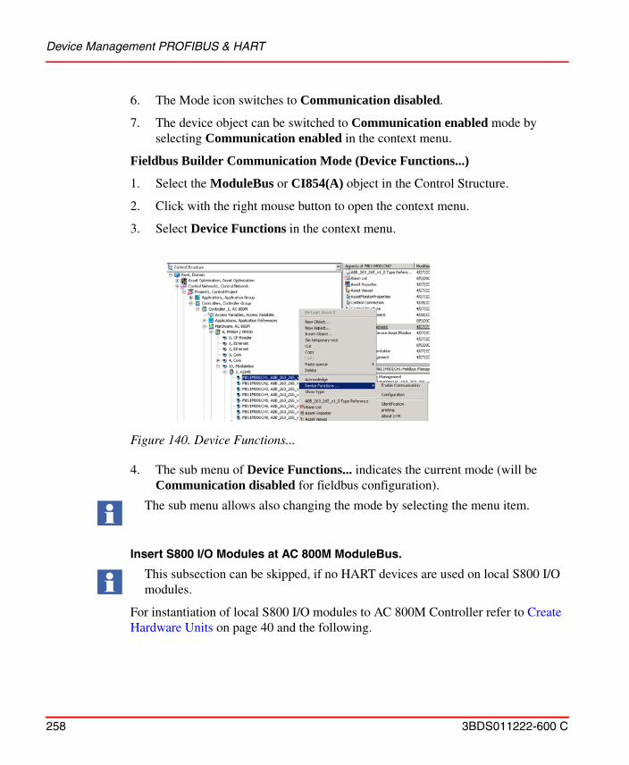
Device Management PROFIBUS & HART
258 3BDS011222-600 C
6. The Mode icon switches to Communication disabled.
7. The device object can be switched to Communication enabled mode by selecting Communication enabled in the context menu.
Fieldbus Builder Communication Mode (Device Functions...)
1. Select the ModuleBus or CI854(A) object in the Control Structure.
2. Click with the right mouse button to open the context menu.
3. Select Device Functions in the context menu.
4. The sub menu of Device Functions... indicates the current mode (will be Communication disabled for fieldbus configuration).
Insert S800 I/O Modules at AC 800M ModuleBus.
For instantiation of local S800 I/O modules to AC 800M Controller refer to Create Hardware Units on page 40 and the following.
Figure 140. Device Functions...
The sub menu allows also changing the mode by selecting the menu item.
This subsection can be skipped, if no HART devices are used on local S800 I/O modules.
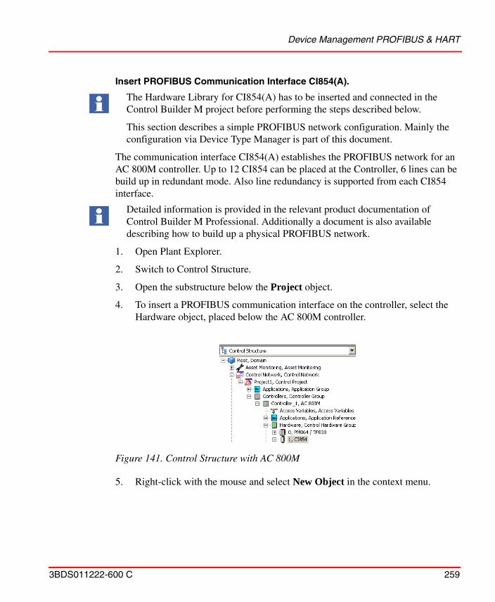
Device Management PROFIBUS & HART
3BDS011222-600 C 259
Insert PROFIBUS Communication Interface CI854(A).
The communication interface CI854(A) establishes the PROFIBUS network for an AC 800M controller. Up to 12 CI854 can be placed at the Controller, 6 lines can be build up in redundant mode. Also line redundancy is supported from each CI854 interface.
1. Open Plant Explorer.
2. Switch to Control Structure.
3. Open the substructure below the Project object.
4. To insert a PROFIBUS communication interface on the controller, select the Hardware object, placed below the AC 800M controller.
5. Right-click with the mouse and select New Object in the context menu.
The Hardware Library for CI854(A) has to be inserted and connected in the Control Builder M project before performing the steps described below.
This section describes a simple PROFIBUS network configuration. Mainly the configuration via Device Type Manager is part of this document.
Detailed information is provided in the relevant product documentation of Control Builder M Professional. Additionally a document is also available describing how to build up a physical PROFIBUS network.
Figure 141. Control Structure with AC 800M
Device Management PROFIBUS & HART
260 3BDS011222-600 C
6. Browse to the required communication interface, e.g. CI854 for PROFIBUS.
7. Enter the CEX bus number of the module placed, for example 1, in the name box.
8. Click Create.
9. Repeat steps 5 to 8 until all of the desired modules have been placed.
PROFIBUS Remote I/O with HART Modules.
1. Open Plant Explorer.
2. Switch to Control Structure.
3. Open the substructure below the Project object.
4. To insert a Remote I/O communication interface on the PROFIBUS, select the CI854 object.
5. Click with the right mouse button and select New Object.
6. Browse to the required PROFIBUS Remote I/O gateway, e.g. S800’s CI840.
DTMs exchange data with field devices using acyclic communication (DPV1).
The CEX bus is the internal communication bus for data transmission between AC 800M controller and the connected communication interfaces. The communication interfaces are located on the left side of the controller and are numbered from right to left. Starting number is 1.
Example:If the CI854 module is the second module on this bus, the number 2 must be entered in the name box.
The settings for the PROFIBUS master are listed in the product documentation of CI854, AC 800M, PROFIBUS DP Configuration (3BDS009030*).
Do not use the Replace Unit function for the units which have a DTM assignment. Use “MoveDown” and “MoveUp” in Control Builder M to adapt the slave address. Otherwise, online operation with DTM may not be possible for this unit.
DTMs exchange data with field devices using acyclic communication (DPV1). CI840 and CI801 supports this type of communication, although CI830 does not.
Device Management PROFIBUS & HART
3BDS011222-600 C 261
7. Enter the PROFIBUS address of the gateway placed, e.g. 20, in the Name box.
8. Click Create.
9. To place I/O modules on the Remote I/O gateway, select the gateway object, e.g. CI840.
10. Click with the right mouse button and select New Object.
11. Browse to the required I/O module, for example AI895.
12. Enter the slot number of the module placed, for example 1, in the Name box.
13. Click Create.
The module for Remote I/O is inserted in Plant Explorers Control Structure and in the Control Builder M project.
14. Repeat steps 9 to 13 until the required modules are created for Remote I/O.
Insert HART Device Type Objects
HART Device Type Objects are installed with the Device Library Wizard. Only the device types Generic HART Transmitter and Generic HART Actuator are part of the Device Integration Library - Basics system extension, which allows basic configuration, operation and diagnosis of HART devices.
HART Device Types are available as standard Object Types in 800xA Plant Explorers Object Type Structure. They are not based on Hardware Libraries and can not be used in Control Builder M projects. Therefore HART Device Type Objects
Local I/Os always start at slot 1. For more information on I/O modules, refer to the device specific product documentation.
To create or delete an instance of the HART device types with an Application Engineer user role, either of following setting has to be done:• Change the security definition for Application Engineers to the permissions
Operate and Operator Configure.
• Add the Operator role also to the Application Engineer role.
The Generic HART Device Objects are assigned to the Basic HART DTM using HARTs universal and common practise commands. Only device specific HART Type Objects installed via Device Library Wizard have the full capability of configuration, operation, maintenance and diagnosis.
Device Management PROFIBUS & HART
262 3BDS011222-600 C
can be exclusively used with Fieldbus Builder PROFIBUS/HART included in the Device Management PROFIBUS & HART package. Insert of HART Device Types Objects can be performed in the Plant Explorers Control Structure only.
HART Device Type Objects are integrated into the fieldbus topology as follows:
1. Open Plant Explorer.
2. Switch to Control Structure.
3. Open the substructure below the Project object.
4. Select the I/O module (e.g. at ModuleBus or Remote I/O), where the HART Device Type Object shall be inserted, for example S800’s AI895.
5. Click with the right mouse button to open the context menu.
HART field devices are managed exclusively by the Fieldbus Builder PROFIBUS/HART in the Control Structure of Plant Explorer and not be visible in the Control Builder M project.Cyclic data communication must have been started already by Control Builder M Professional.
Field devices support the HART protocol can only be placed below I/O modules that support this protocol in hardware and software (DTM) technology.
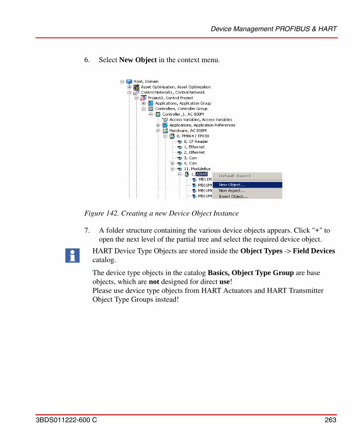
Device Management PROFIBUS & HART
3BDS011222-600 C 263
6. Select New Object in the context menu.
7. A folder structure containing the various device objects appears. Click "+" to open the next level of the partial tree and select the required device object.
Figure 142. Creating a new Device Object Instance
HART Device Type Objects are stored inside the Object Types -> Field Devices catalog.
The device type objects in the catalog Basics, Object Type Group are base objects, which are not designed for direct use! Please use device type objects from HART Actuators and HART Transmitter Object Type Groups instead!
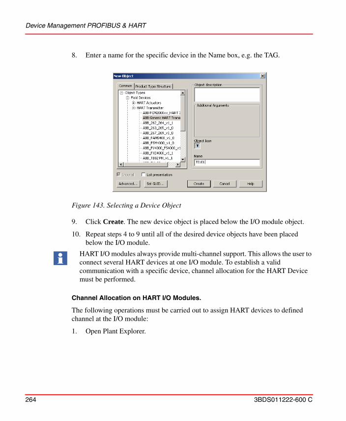
Device Management PROFIBUS & HART
264 3BDS011222-600 C
8. Enter a name for the specific device in the Name box, e.g. the TAG.
9. Click Create. The new device object is placed below the I/O module object.
10. Repeat steps 4 to 9 until all of the desired device objects have been placed below the I/O module.
Channel Allocation on HART I/O Modules.
The following operations must be carried out to assign HART devices to defined channel at the I/O module:
1. Open Plant Explorer.
Figure 143. Selecting a Device Object
HART I/O modules always provide multi-channel support. This allows the user to connect several HART devices at one I/O module. To establish a valid communication with a specific device, channel allocation for the HART Device must be performed.
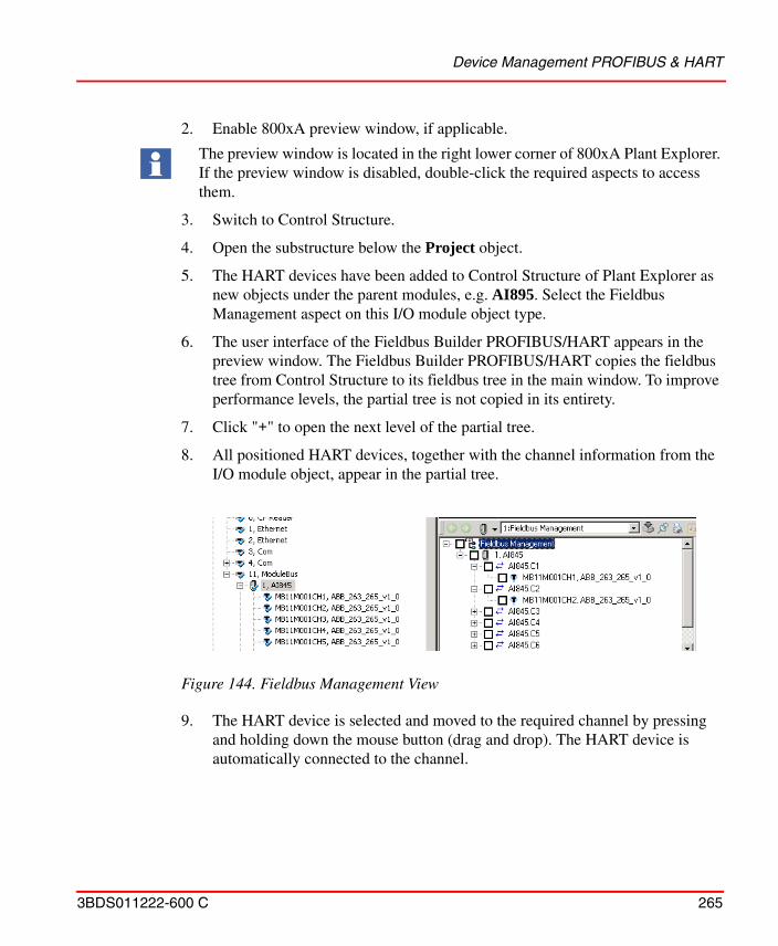
Device Management PROFIBUS & HART
3BDS011222-600 C 265
2. Enable 800xA preview window, if applicable.
3. Switch to Control Structure.
4. Open the substructure below the Project object.
5. The HART devices have been added to Control Structure of Plant Explorer as new objects under the parent modules, e.g. AI895. Select the Fieldbus Management aspect on this I/O module object type.
6. The user interface of the Fieldbus Builder PROFIBUS/HART appears in the preview window. The Fieldbus Builder PROFIBUS/HART copies the fieldbus tree from Control Structure to its fieldbus tree in the main window. To improve performance levels, the partial tree is not copied in its entirety.
7. Click "+" to open the next level of the partial tree.
8. All positioned HART devices, together with the channel information from the I/O module object, appear in the partial tree.
9. The HART device is selected and moved to the required channel by pressing and holding down the mouse button (drag and drop). The HART device is automatically connected to the channel.
The preview window is located in the right lower corner of 800xA Plant Explorer. If the preview window is disabled, double-click the required aspects to access them.
Figure 144. Fieldbus Management View
Device Management PROFIBUS & HART
266 3BDS011222-600 C
10. If the check box next to the device object is selected, the status window is updated and the object information is displayed.
11. Repeat channel allocation for all HART Device Type Objects, which have been inserted and not assigned to I/O module channels.
Insert PROFIBUS Device Type Objects
Inserting PROFIBUS Device Type Objects can be performed either in Plant Explorers Control Structure or in Control Builder M. This sections describes both configuration possibilities.
Insert PROFIBUS Device Type Objects in 800xA Plant Explorer.
1. Open Plant Explorer.
2. Switch to Control Structure.
Figure 145. Assigned Device Objects with DTM Information
It is recommended to know the device addresses of each PROFIBUS device, located on the PROFIBUS line, before starting device configuration. If the devices are already connected to the PROFIBUS network, download the created basic project with CI854(A) object first. Then start the PROFIBUS CI854 Web Server to get the live list of connected PROFIBUS devices. The Web Server is described in AC 800M, PROFIBUS DP Configuration (3BDS009030*).
It is recommended to always use Control Builder M to create instances of PROFIBUS device types. For details, refer to Insert PROFIBUS Device Type Objects on page 268.
Device Management PROFIBUS & HART
3BDS011222-600 C 267
3. Open the substructure below the Project object.
4. To insert a PROFIBUS Device Type Object on the CI854, select the CI854 Hardware object.
5. Right-click on the mouse and select New Object in the context menu.
6. Browse to the required PROFIBUS master object in the hardware library catalog, e.g. ABB_TFx12_YP0_v1_0.
7. Enter the PROFIBUS address of the object inserted, e.g. 20, in the name box.
8. Click Create.
9. To insert a device specific module below the PROFIBUS master object, select the PROFIBUS master object.
10. Right-click on the mouse and select New Object.
Master and Module Objects are described in the related release notes of each Device Type Object installed via device Library Wizard.
Figure 146. Select PROFIBUS master object
Device Management PROFIBUS & HART
268 3BDS011222-600 C
11. Browse to the required device module in the hardware library, e.g. ABB_TFx12_Temp1.
12. Enter the position number of the module placed, e.g. 0, in the name box.
13. Click Create.
14. Repeat steps 9 to 13 until all of the desired modules have been inserted on the master object, if applicable.
The device modules are inserted both in Plant Explorers Control Structure and in the Control Builder M project.
Insert PROFIBUS Device Type Objects in Control Builder M Project.
1. Open the Control Project and switch to the Control Builder M project window.
2. Browse to and select the CI854 object.
Figure 147. Select PROFIBUS specific device module
Position number 0 means slot number 1. Specific device module to be related to the slot number. Additional information about slot number can be found in corresponding Device Type release notes.
Device Management PROFIBUS & HART
3BDS011222-600 C 269
3. Right-click on the mouse and select Insert Unit.
4. Browse to the required PROFIBUS master object in the connected hardware library catalog, e.g. ABB_TFx12_YP0_v1_0.
5. Select the PROFIBUS address of the object inserted, e.g. 20, from the pull down menu.
6. Click Insert.
7. To insert a device specific module below the PROFIBUS master object, select the PROFIBUS master object.
8. Right-click on the mouse and select Insert Unit.
Figure 148. Select PROFIBUS master object in Control Builder M Project
Device Management PROFIBUS & HART
270 3BDS011222-600 C
9. Browse to the required device module, e.g. ABB_TFx12_Temp1.
10. Select the position number of the module placed, e.g. 0, in the pull down menu.
11. Click Insert.
12. Repeat steps 9 to 11 until all of the desired modules have been inserted on the master object, if applicable.
13. Close the library dialog.
The device modules are inserted both in Plant Explorers Control Structure and in the Control Builder M project.
Figure 149. Select PROFIBUS specific device module in Control Builder M Project
Position number 0 means slot number 1. Specific device module to be related to the slot number. Additional information about slot number can be found in corresponding Device Type Release Notes.
Device Management PROFIBUS & HART
3BDS011222-600 C 271
Configuration and Commissioning of Field Device Type Objects
After inserting the HART or PROFIBUS Device Type Objects can be configured for application by means of Device Type Manager (DTM).
A configuration describes the creation of a set of parameters for the particular device in the database (Aspect Directory) of Aspect Server. For this task Fieldbus Management has to be switched to Communication disabled mode.
The configuration of the device using a DTM is described in the associated DTM documentation and is not included in this documentation.
Once the configuration phase is complete for all field device objects the data sets for the particular devices or for a selection of the devices can be
• verified• loaded to the devices / selection of devices• saved into one or more export file(s).
These functions are performed on the Fieldbus Management aspect and its sub-conditions.
HART Device Type Objects are not handled by Control Builder M.
Higher-level assemblies such as PROFIBUS devices, Remote I/Os and CI854 are mainly handled in the Control builder M project. It is mandatory to download the Control Builder M project first before starting online configuration for HART devices.
There is no synchronization of device configuration data between Control Builder M project and the Device Type Manager (DTM). Device parameter, which may be necessary for both parts, must be configured twice - in the Control Builder M project and the DTM.
For example:The device modules, which are configured in the Control Builder M project, are not automatically available in the DTM. The used device module must be configured also in DTM, if applicable.
It is recommended to first upload the default device parameters to the Device Type Manager (DTM).
Device Management PROFIBUS & HART
272 3BDS011222-600 C
Instance data can be verified and exported with the Fieldbus Management in Communication disabled mode, but loading is only possible in Communication enabled mode. To load fieldbus lines, select the line through the context menu of the Fieldbus Management and then click on Download selection to start.
Verify.
Selecting the verify option in the Fieldbus Management menu compares the online device data with the offline configuration data set stored in System 800xA. If the data set is equal, the result is true, else it is false.
Download and Upload.
When several devices are selected, the Fieldbus Builder PROFIBUS/HART starts a batch process for up- or download, which is processed sequentially. Execution of the batch process continues even if errors occur for individual DTMs. Each event (faulty/successful execution) is documented in the Fieldbus Management status window. If an error occurs, an error message is displayed after the end of the batch process to indicate that the batch process is faulty.
Export and Import.
The export file of an instance data record is saved with a time stamp in a folder which is specific to the Device Object. This makes it possible to build up a device configuration history. Exported device data set can be imported again by selecting the specific export file. The export and import process is carried out manually by the user.
Starting the Device Type Manager (DTM).
In addition to the Fieldbus Management aspect, field device objects for PROFIBUS and HART provide a Device Management aspect. The Device Management aspect opens the associated DTM (Device Definition) in the preview window or opens a new window with the device instance data record.
If the verification result is false, an up- or download is recommended for data synchronization.
Loading errors can arise if this function is not supported by the DTM, e.g. S800 modules, or if the DTM cannot establish a connection to the device.
Device Management PROFIBUS & HART
3BDS011222-600 C 273
DTMs can be started in Communication disabled mode to configure field device objects offline or, if changes are to be made directly in the device, in online mode by changing the mode to Communication enabled.
Depending on the mode, the DTM will appear with various functional windows. The various modes are selected via the Fieldbus Management aspect of the relevant device object.
Two possibilities are available on the device type object to open a DTM:
• Via Device Management aspect in the aspect window.• Via Device Functions... context menu in Control Structure of Plant Explorer.
Open DTM via Device Management Aspect
1. Open Plant Explorers Control Structure.
2. Open the project sub-structure and select the field device type object.
3. Select the Device Management aspect in the aspect window.
4. The DTM appears either in Plant Explorers preview window or in its own window, depending if the DTM supports 800xA preview window functionality.
Communication enabled mode starts all DTMs required for the communication sequence. Individual DTMs in this connection sequence can then not switch to Communication disabled mode without affecting other DTMs started in this sequence.
Double-click on an aspect in the aspect window, to additionally open new windows.
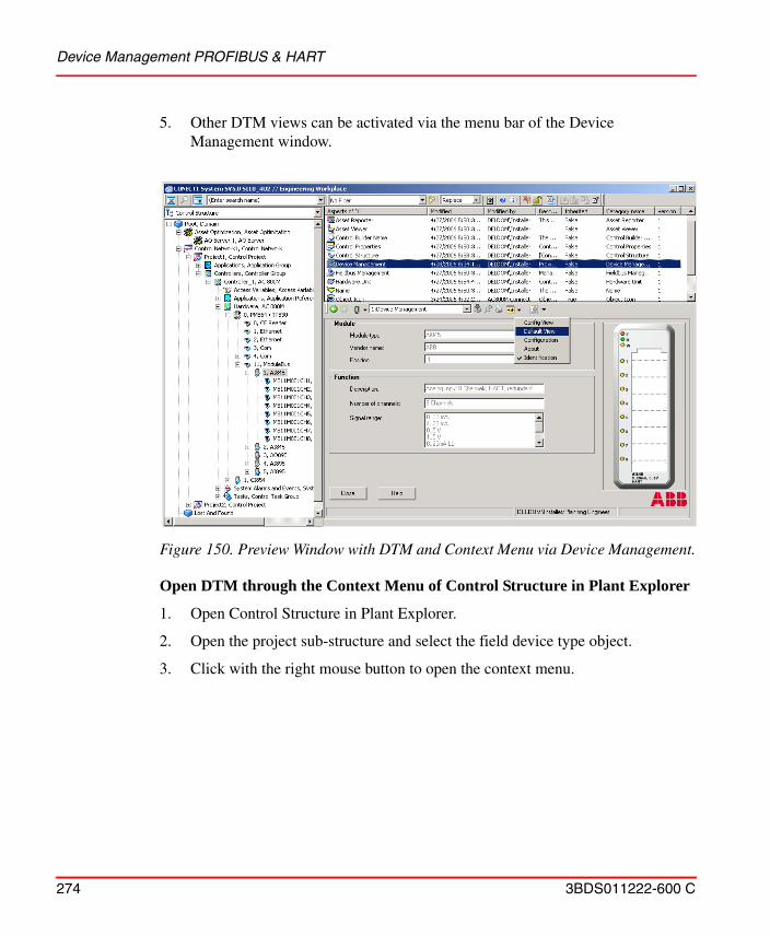
Device Management PROFIBUS & HART
274 3BDS011222-600 C
5. Other DTM views can be activated via the menu bar of the Device Management window.
Open DTM through the Context Menu of Control Structure in Plant Explorer
1. Open Control Structure in Plant Explorer.
2. Open the project sub-structure and select the field device type object.
3. Click with the right mouse button to open the context menu.
Figure 150. Preview Window with DTM and Context Menu via Device Management.
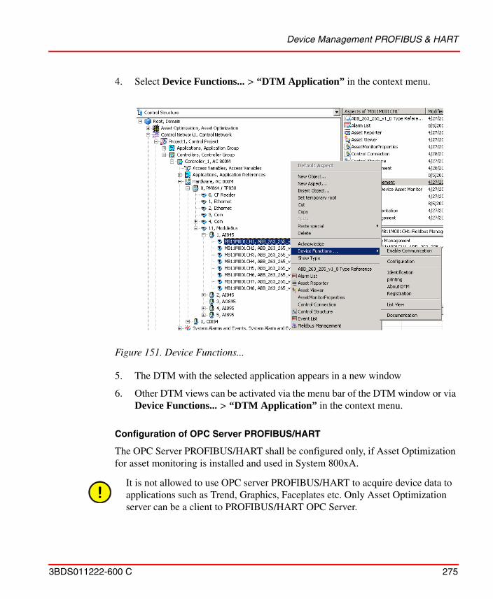
Device Management PROFIBUS & HART
3BDS011222-600 C 275
4. Select Device Functions... > “DTM Application” in the context menu.
5. The DTM with the selected application appears in a new window
6. Other DTM views can be activated via the menu bar of the DTM window or via Device Functions... > “DTM Application” in the context menu.
Configuration of OPC Server PROFIBUS/HART
The OPC Server PROFIBUS/HART shall be configured only, if Asset Optimization for asset monitoring is installed and used in System 800xA.
Figure 151. Device Functions...
It is not allowed to use OPC server PROFIBUS/HART to acquire device data to applications such as Trend, Graphics, Faceplates etc. Only Asset Optimization server can be a client to PROFIBUS/HART OPC Server.
Device Management PROFIBUS & HART
276 3BDS011222-600 C
The OPC Server PROFIBUS/HART enables access to field device data without requiring additional field wiring and provides these data to the Asset Optimization Server.
Asset Monitors delivered with Device Types and installed via Device Library Wizard are designed to read these device data from the OPC Server PROFIBUS/HART and provide them to Asset Reporter and Asset Viewer. Operators and maintenance personnel will be notified when an abnormal device condition calls for maintenance action.
After completing the engineering work for HART and PROFIBUS devices in the 800xA system, the OPC Server PROFIBUS/HART can be configured to access field device data for e.g. Asset Monitoring. Depending on the number of devices and its device data accessed by the OPC Server special configurations might be required.
OPC Server Assignment to a Connectivity Server.
A Connectivity Server on which the OPC Server PROFIBUS/HART can be executed is assigned to each Control Network.
1. Open 800xA Plant Explorers Workplace and switch to the Control Structure.
2. Select the control network in the fieldbus topology.
Only one OPC Server PROFIBUS/HART per Connectivity Server can be started. OPC Servers of other software options, for example the AC 800M OPC Server, can be executed on the same Connectivity Server.
This section describes the default configuration for the number of devices released for the OPC Server PROFIBUS/HART. Please read System 800xA Device Management, PROFIBUS and HART Configuration (3BDD011934*), whether special configuration may be required to run the OPC Server properly.
The following steps shall be done on every control network, placed in the system and containing the FBB-OPC Data Source Definition aspect.
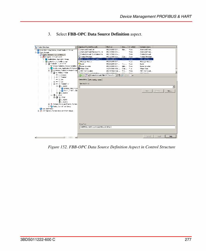
Device Management PROFIBUS & HART
3BDS011222-600 C 277
3. Select FBB-OPC Data Source Definition aspect.
Figure 152. FBB-OPC Data Source Definition Aspect in Control Structure
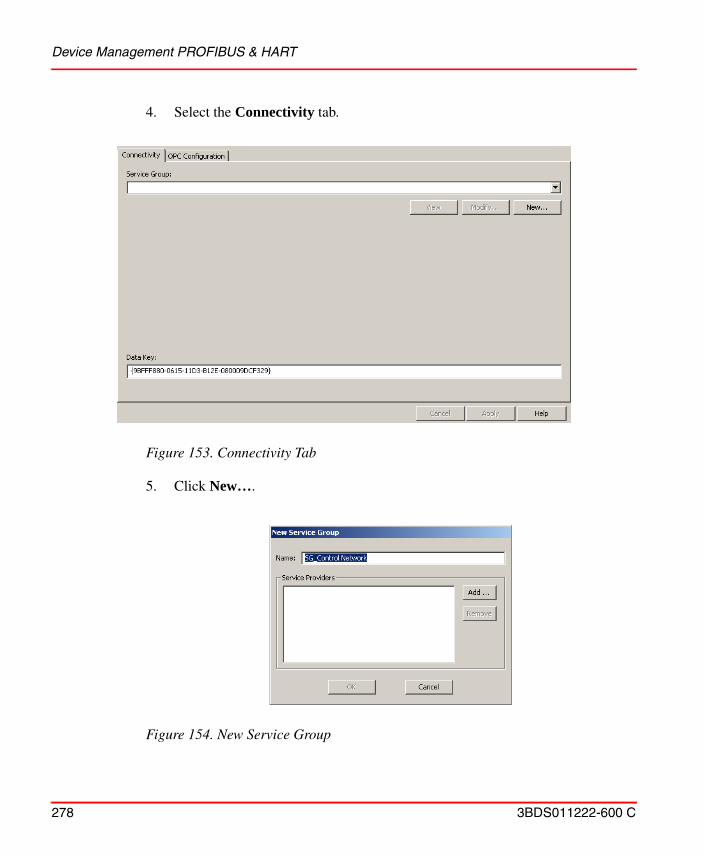
Device Management PROFIBUS & HART
278 3BDS011222-600 C
4. Select the Connectivity tab.
5. Click New….
Figure 153. Connectivity Tab
Figure 154. New Service Group
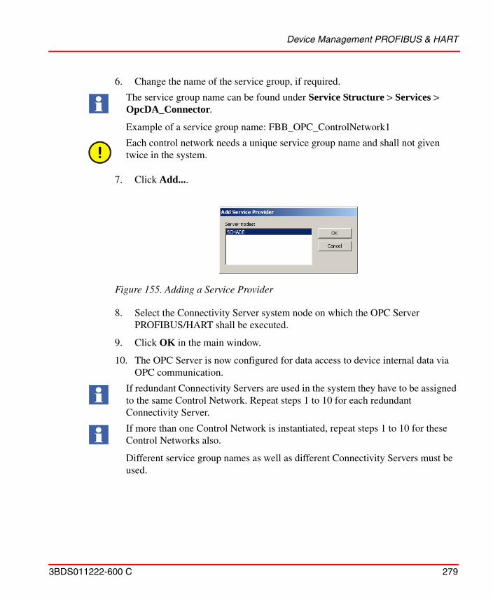
Device Management PROFIBUS & HART
3BDS011222-600 C 279
6. Change the name of the service group, if required.
7. Click Add....
8. Select the Connectivity Server system node on which the OPC Server PROFIBUS/HART shall be executed.
9. Click OK in the main window.
10. The OPC Server is now configured for data access to device internal data via OPC communication.
The service group name can be found under Service Structure > Services > OpcDA_Connector.
Example of a service group name: FBB_OPC_ControlNetwork1
Each control network needs a unique service group name and shall not given twice in the system.
Figure 155. Adding a Service Provider
If redundant Connectivity Servers are used in the system they have to be assigned to the same Control Network. Repeat steps 1 to 10 for each redundant Connectivity Server.
If more than one Control Network is instantiated, repeat steps 1 to 10 for these Control Networks also.
Different service group names as well as different Connectivity Servers must be used.
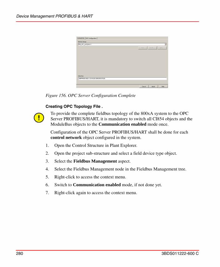
Device Management PROFIBUS & HART
280 3BDS011222-600 C
Creating OPC Topology File .
1. Open the Control Structure in Plant Explorer.
2. Open the project sub-structure and select a field device type object.
3. Select the Fieldbus Management aspect.
4. Select the Fieldbus Management node in the Fieldbus Management tree.
5. Right-click to access the context menu.
6. Switch to Communication enabled mode, if not done yet.
7. Right-click again to access the context menu.
Figure 156. OPC Server Configuration Complete
To provide the complete fieldbus topology of the 800xA system to the OPC Server PROFIBUS/HART, it is mandatory to switch all CI854 objects and the ModuleBus objects to the Communication enabled mode once.
Configuration of the OPC Server PROFIBUS/HART shall be done for each control network object configured in the system.
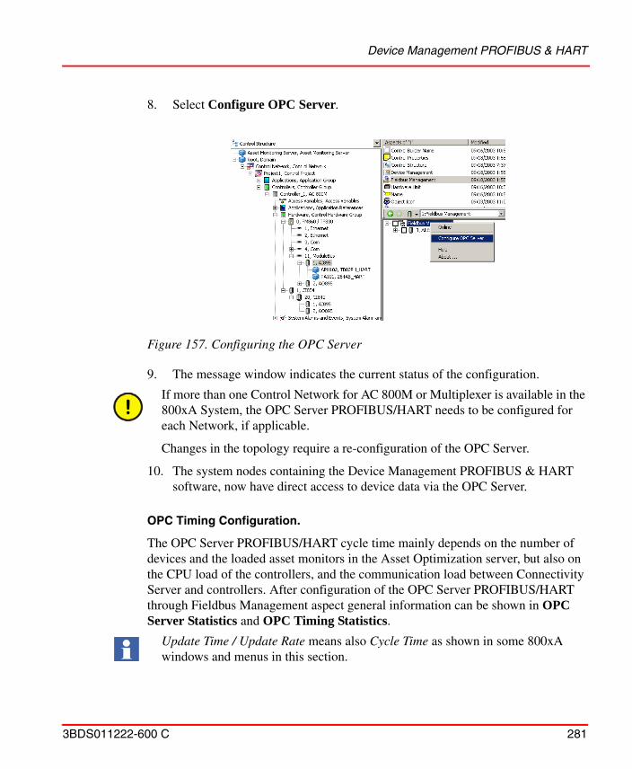
Device Management PROFIBUS & HART
3BDS011222-600 C 281
8. Select Configure OPC Server.
9. The message window indicates the current status of the configuration.
10. The system nodes containing the Device Management PROFIBUS & HART software, now have direct access to device data via the OPC Server.
OPC Timing Configuration.
The OPC Server PROFIBUS/HART cycle time mainly depends on the number of devices and the loaded asset monitors in the Asset Optimization server, but also on the CPU load of the controllers, and the communication load between Connectivity Server and controllers. After configuration of the OPC Server PROFIBUS/HART through Fieldbus Management aspect general information can be shown in OPC Server Statistics and OPC Timing Statistics.
Figure 157. Configuring the OPC Server
If more than one Control Network for AC 800M or Multiplexer is available in the 800xA System, the OPC Server PROFIBUS/HART needs to be configured for each Network, if applicable.
Changes in the topology require a re-configuration of the OPC Server.
Update Time / Update Rate means also Cycle Time as shown in some 800xA windows and menus in this section.
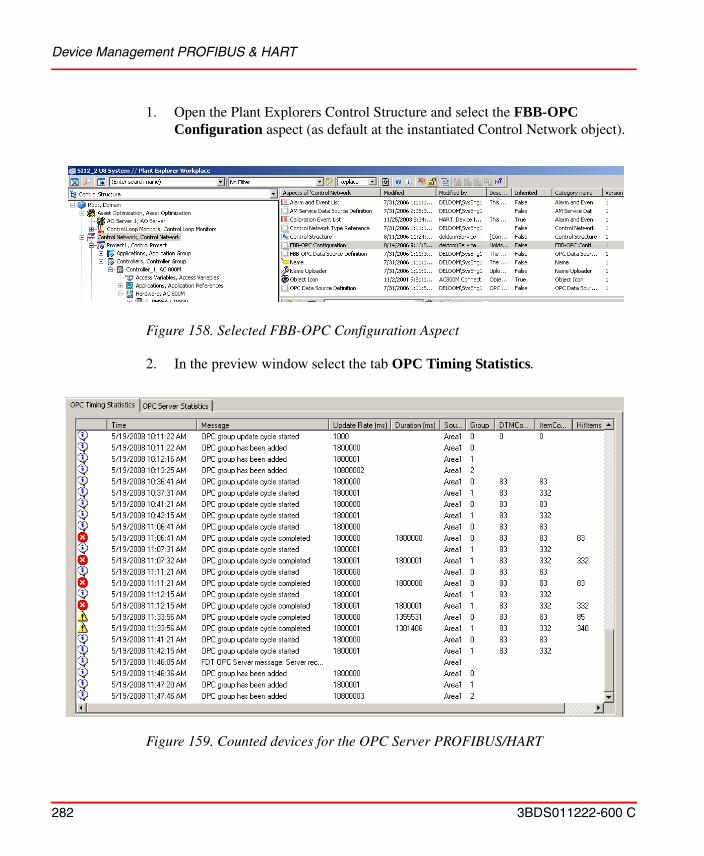
Device Management PROFIBUS & HART
282 3BDS011222-600 C
1. Open the Plant Explorers Control Structure and select the FBB-OPC Configuration aspect (as default at the instantiated Control Network object).
2. In the preview window select the tab OPC Timing Statistics.
Figure 158. Selected FBB-OPC Configuration Aspect
Figure 159. Counted devices for the OPC Server PROFIBUS/HART
Device Management PROFIBUS & HART
3BDS011222-600 C 283
The cycle time of the OPC Server is set to a default value in the following aspects at the Asset Optimization node in Plant Explorers Control Structure:
– DIP HART Asset Monitor Data Source aspect (HART devices) – DIP PROFIBUS Asset Monitor Data Source aspect (PROFIBUS
devices)
By rule of thumb the following timings should be configured in the specific aspect for the particular fieldbus protocol:
– 1800000 ms (0.5 h) = < 200 devices – 7200000 ms (2.0 h) = 201 - 500 devices– 9000000 ms (2.5 h) = 501 - 800 devices– 10800000 ms(3.0 h) = 801 - 1000 devices.
If more devices are counted and displayed in the OPC Timing Statistics tab, refer to the related release nodes, if more device types (incl. timings) are supported by the OPC Server PROFIBUS/HART.
3. Select the Asset Optimization node in the Control Structure.
4. Select in Aspect Window of this node the DIP HART Asset Monitor Data Source aspect or DIP PROFIBUS Asset Monitor Data Source aspect, depending on the fieldbus protocol.
5. Configure OPC Group Update Rate in the displayed table according to the rule described above.
The default cycle times mentioned below are only indicative numbers. These cycle times need to be increased further (2 to 5 times) in situations like redundant AO configuration, larger plant areas, distributed controllers or field devices.
If more devices are used for OPC access as released by the 800xA system, the OPC Server must be split to sub-level nodes in the Plant Explorers Control Structure. Follow first the instructions in System 800xA Device Management PROFIBUS and HART Configuration (3BDD011934*) before continuing the steps described below.
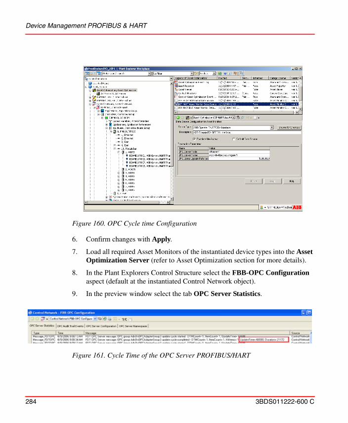
Device Management PROFIBUS & HART
284 3BDS011222-600 C
6. Confirm changes with Apply.
7. Load all required Asset Monitors of the instantiated device types into the Asset Optimization Server (refer to Asset Optimization section for more details).
8. In the Plant Explorers Control Structure select the FBB-OPC Configuration aspect (default at the instantiated Control Network object).
9. In the preview window select the tab OPC Server Statistics.
Figure 160. OPC Cycle time Configuration
Figure 161. Cycle Time of the OPC Server PROFIBUS/HART
Device Management PROFIBUS & HART
3BDS011222-600 C 285
10. Wait according to the configured Update Time, till the Duration Time is displayed next to the Update Time entry as shown in Figure 161. If the Duration Time is less than the Update Time, the OPC Server is able to call all configured OPC items in one cycle. The OPC Server cycle time configured in DIP HART Asset Monitor Data Source aspect or DIP PROFIBUS Asset Monitor Data Source aspect (see above) shall be configured according the following rule:
Update Time = Duration Time x 2
If the Duration Time is equal the Update time, not all OPC items may be accessed in the cycle. In this case it is recommended to set the update time twice the duration time. Repeat this section till the OPC Server cycle time is optimized according the rules.
11. Repeat the steps described in this section till all OPC Server PROFIBUS/HART are configured and running according instructions and rules.
New inserted device type objects as well as changed topologies have to be transferred as configuration into OPC Server PROFIBUS/HART.
HART Device Calibration via Device Management System (DMS)
Device Management System (DMS) is delivered and installed with 800xA Asset Optimization package.
DMS Connectivity integrates the calibration Device Management System (DMS) from Meriam Instruments into the 800xA System and allows plant personnel to monitor field devices for calibration information and streamlines the maintenance workflow.
If device type objects are only deleted from an existing topology, then the OPC Server does not necessarily need to be configured again. Configuration is only essential if topologies are changed and new device instances are created.
For more information and integration, contact ABB Technical Support.
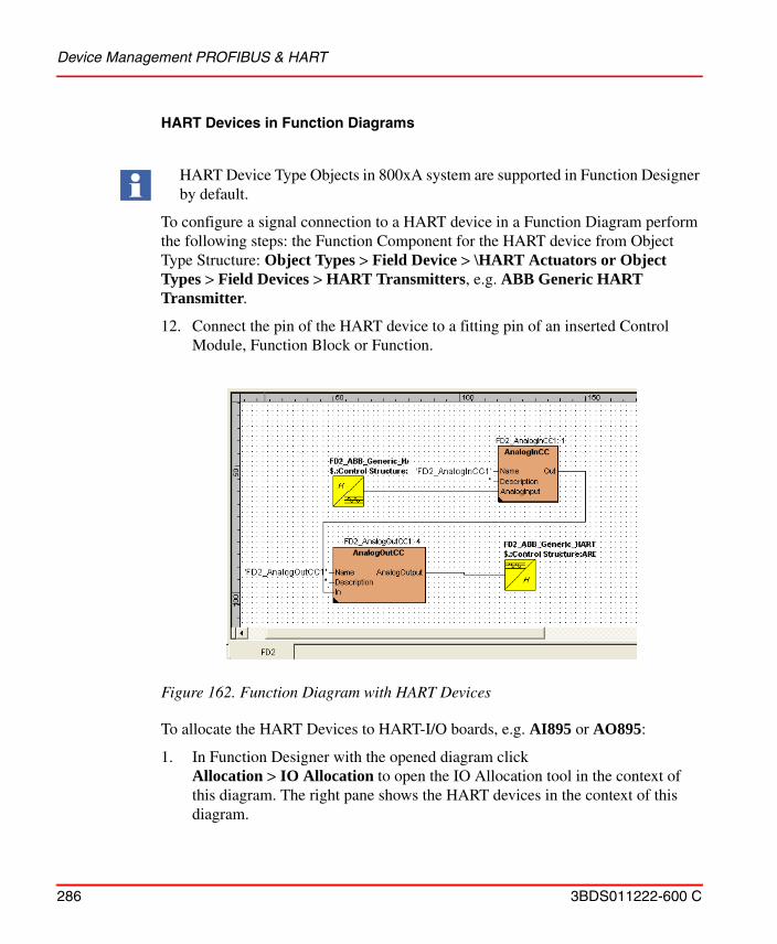
Device Management PROFIBUS & HART
286 3BDS011222-600 C
HART Devices in Function Diagrams
To configure a signal connection to a HART device in a Function Diagram perform the following steps: the Function Component for the HART device from Object Type Structure: Object Types > Field Device > \HART Actuators or Object Types > Field Devices > HART Transmitters, e.g. ABB Generic HART Transmitter.
12. Connect the pin of the HART device to a fitting pin of an inserted Control Module, Function Block or Function.
To allocate the HART Devices to HART-I/O boards, e.g. AI895 or AO895:
1. In Function Designer with the opened diagram click Allocation > IO Allocation to open the IO Allocation tool in the context of this diagram. The right pane shows the HART devices in the context of this diagram.
HART Device Type Objects in 800xA system are supported in Function Designer by default.
Figure 162. Function Diagram with HART Devices
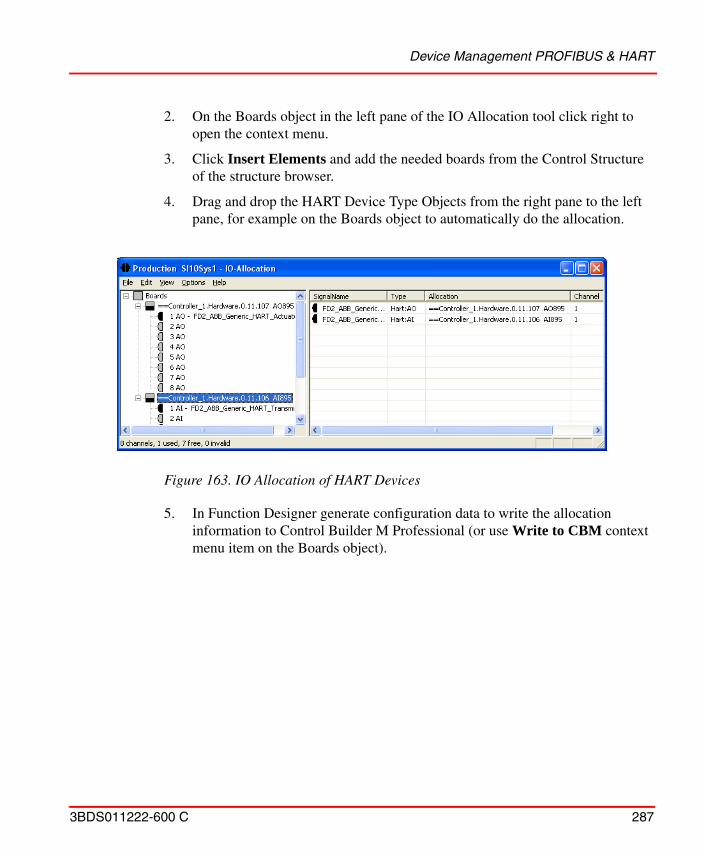
Device Management PROFIBUS & HART
3BDS011222-600 C 287
2. On the Boards object in the left pane of the IO Allocation tool click right to open the context menu.
3. Click Insert Elements and add the needed boards from the Control Structure of the structure browser.
4. Drag and drop the HART Device Type Objects from the right pane to the left pane, for example on the Boards object to automatically do the allocation.
5. In Function Designer generate configuration data to write the allocation information to Control Builder M Professional (or use Write to CBM context menu item on the Boards object).
Figure 163. IO Allocation of HART Devices
Device Management FOUNDATION Fieldbus
288 3BDS011222-600 C
PROFIBUS Devices in Function Diagrams
Device Management FOUNDATION Fieldbus
To create FF topology objects, as there are HSE subnets, FF linking devices, FF Host objects CI860s, FF H1 devices, FF applications etc., predefined FF objects have to be instantiated within the Control Structure. These predefined FF objects are located within the FF Libraries in the Object Type Structure.
The editing of the libraries, e.g. the change of block class parameters, is executed in Fieldbus Builder FF. After the changed library contents have been uploaded to 800xA system, the changes are available in the Object Type Structure.
The configuration of an FF HSE subnet typically begins in Plant Explorer with the insertion of an HSE Subnet object in the Control Structure. The insertion of new objects can be done in Fieldbus Builder FF as well as in Plant Explorer. Special FF configuration settings as Parameter settings etc. are provided by Fieldbus Builder FF only. When the configuration is done and saved in the Fieldbus Builder FF, the configuration data of the HSE Subnet is automatically uploaded to the Plant Explorer Workplace and appear in the Control Structure.
In Fieldbus Builder FF precisely one HSE subnet can be configured. The structure of the hardware used (H1 and HSE devices as well as OPC Server FF) is set up, the functionality of the application configured and loaded into the devices and stations. Working on the same or other subnet with different Fieldbus Builder FF instances is simultaneously possible. Objects that shall be edited have to be reserved by the user and then are locked for all other users.
There are two possibilities to support documentation and navigation needs for a PROFIBUS device in Function Diagrams of Function Designer:
• Referencing the IO variable representing the device in the control application using a diagram reference.
• Adding an own Function aspect with a Function Component to the device type.
Refer to System 800xA Engineering, Engineering Studio Function Designer (3BDS011224*).
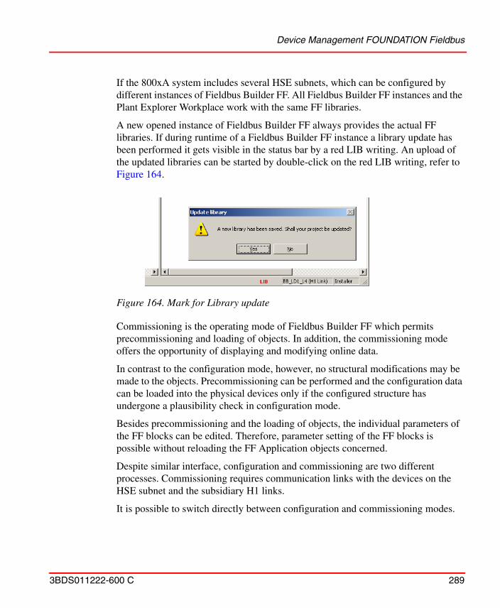
Device Management FOUNDATION Fieldbus
3BDS011222-600 C 289
If the 800xA system includes several HSE subnets, which can be configured by different instances of Fieldbus Builder FF. All Fieldbus Builder FF instances and the Plant Explorer Workplace work with the same FF libraries.
A new opened instance of Fieldbus Builder FF always provides the actual FF libraries. If during runtime of a Fieldbus Builder FF instance a library update has been performed it gets visible in the status bar by a red LIB writing. An upload of the updated libraries can be started by double-click on the red LIB writing, refer to Figure 164.
Commissioning is the operating mode of Fieldbus Builder FF which permits precommissioning and loading of objects. In addition, the commissioning mode offers the opportunity of displaying and modifying online data.
In contrast to the configuration mode, however, no structural modifications may be made to the objects. Precommissioning can be performed and the configuration data can be loaded into the physical devices only if the configured structure has undergone a plausibility check in configuration mode.
Besides precommissioning and the loading of objects, the individual parameters of the FF blocks can be edited. Therefore, parameter setting of the FF blocks is possible without reloading the FF Application objects concerned.
Despite similar interface, configuration and commissioning are two different processes. Commissioning requires communication links with the devices on the HSE subnet and the subsidiary H1 links.
It is possible to switch directly between configuration and commissioning modes.
Figure 164. Mark for Library update
Device Management FOUNDATION Fieldbus
290 3BDS011222-600 C
The following steps give you instructions how to configure and commission an FF Application using Fieldbus Builder FF:
• Step 1: Check, Save, and Upload FF Libraries
• Step 2: Create and Configure an HSE Subnet
– Step 2a: Create HSE Subnet
– Step 2b: Configure HSE Subnet
• Step 3: Configure the FF Application
• Step 4: Load the FF Application
– Step 4a: Precommissioning
– Step 4b: Commissioning
• Step 5: Using FF Data
Prerequisites and Requirements
The following requirements must be met, in order to be able to carry out the steps described here.
• An 800xA system has been created and started.
• The following system extensions have been added:
– AC 800M Connect,
– Fieldbus Builder FF,
– FF Device Integration Library - Basics.
• Device object types for those field devices intended to be used in the project have been added to the FF device library. Refer to Device Library Wizard on page 235.
• The Plant Explorer of Engineering Workplace or Plant Explorer Workplace has been started.
• The user has Configure and Download permissions.
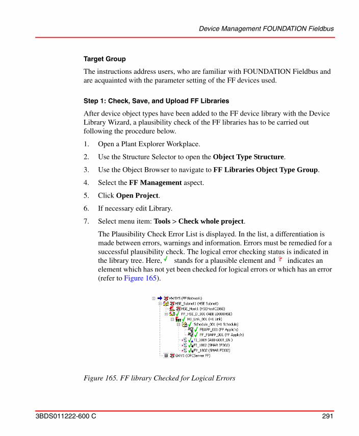
Device Management FOUNDATION Fieldbus
3BDS011222-600 C 291
Target Group
The instructions address users, who are familiar with FOUNDATION Fieldbus and are acquainted with the parameter setting of the FF devices used.
Step 1: Check, Save, and Upload FF Libraries
After device object types have been added to the FF device library with the Device Library Wizard, a plausibility check of the FF libraries has to be carried out following the procedure below.
1. Open a Plant Explorer Workplace.
2. Use the Structure Selector to open the Object Type Structure.
3. Use the Object Browser to navigate to FF Libraries Object Type Group.
4. Select the FF Management aspect.
5. Click Open Project.
6. If necessary edit Library.
7. Select menu item: Tools > Check whole project.
The Plausibility Check Error List is displayed. In the list, a differentiation is made between errors, warnings and information. Errors must be remedied for a successful plausibility check. The logical error checking status is indicated in the library tree. Here, stands for a plausible element and indicates an element which has not yet been checked for logical errors or which has an error (refer to Figure 165).
Figure 165. FF library Checked for Logical Errors
Device Management FOUNDATION Fieldbus
292 3BDS011222-600 C
8. After a successful check for plausibility, save the FF libraries by means of FF Object editor > Save.
9. Exit Fieldbus Builder FF by FF Object editor > Exit
10. Return to the Plant Explorer Workplace and select the FFUpload aspect.
11. Click Upload.
The upload mirrors the FF class objects checked in Fieldbus Builder FF to the Object Type Structure in the Plant Explorer Workplace.
12. After a successful upload, the green traffic light symbol indicates that the FF libraries have been synchronized.
Step 2: Create and Configure an HSE Subnet
An FF network consists of at least one HSE subnet, HSE linking devices and any number of H1 links as well as one OPC Server FF for communication of System 800xA objects with the FF network. An HSEHostCI860 device enables data exchange between the FF network and an AC800M controller.
HSE linking devices, HSEHostCI860 Devices and OPC Server FF will be connected directly to the HSE subnet. HSE linking devices connect the H1 links to the HSE subnet. The H1 devices are connected to the H1 links.
An HSE subnet is created in Plant Explorer Control Structure. It can be edited by means of Fieldbus Builder FF as well as within Plant Explorer Workplace.
To create an HSE subnet, follow the procedure below.
Step 2a: Create HSE Subnet
1. Use the Structure Selector in the Plant Explorer Workplace to open the Control Structure.
2. Select the Root object and insert a new object with New Object.
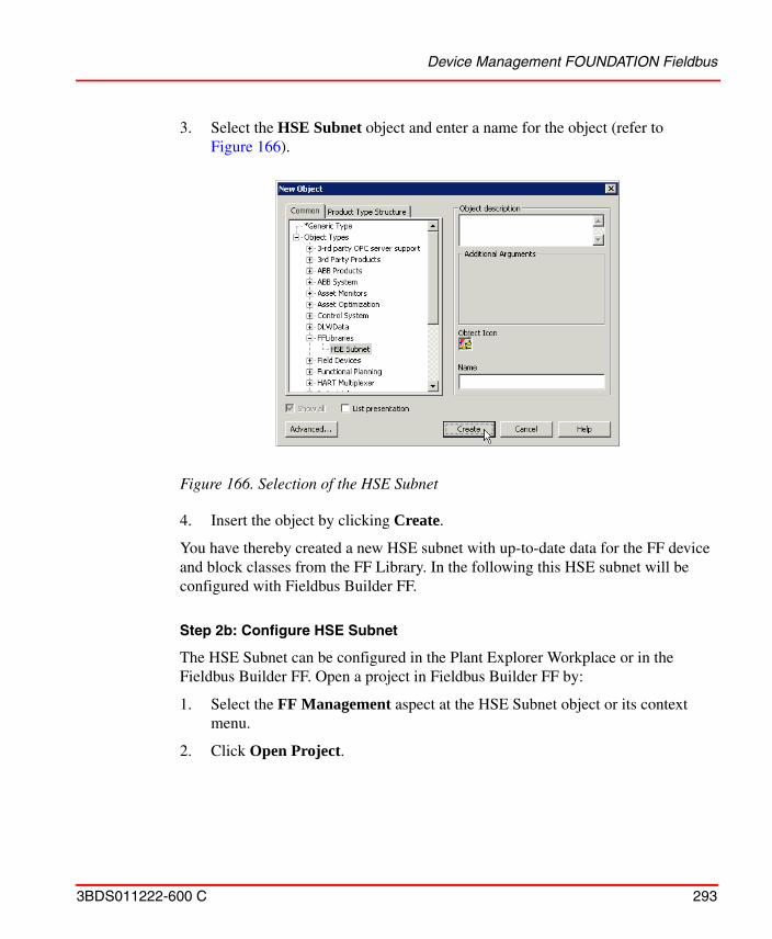
Device Management FOUNDATION Fieldbus
3BDS011222-600 C 293
3. Select the HSE Subnet object and enter a name for the object (refer to Figure 166).
4. Insert the object by clicking Create.
You have thereby created a new HSE subnet with up-to-date data for the FF device and block classes from the FF Library. In the following this HSE subnet will be configured with Fieldbus Builder FF.
Step 2b: Configure HSE Subnet
The HSE Subnet can be configured in the Plant Explorer Workplace or in the Fieldbus Builder FF. Open a project in Fieldbus Builder FF by:
1. Select the FF Management aspect at the HSE Subnet object or its context menu.
2. Click Open Project.
Figure 166. Selection of the HSE Subnet
Device Management FOUNDATION Fieldbus
294 3BDS011222-600 C
3. Fieldbus Builder FF starts with an empty HSE subnet.
Create HSE Subnet Structure
4. Configure your desired FF network by successively inserting objects in the sub-level of an object by means of
5. a) In Plant Explorer Workplace:Context menu > New Object...b) In Fieldbus Builder FF:Edit > Insert
as per Table 11.
Only a new and empty HSE subnet does not need to be reserved for editing in Fieldbus Builder FF. In this case the reservation will be set automatically.
Table 11. Structuring of FF Objects
FF Object FF object types of the subordinate level
FF Network HSE Subnet
OPC Server FF
HSE Subnet Linking Device Module
HSE Host CI860 (HSEHostCI860)
HSE Linking Device H1 Link
H1 Link H1 Schedule
H1 Devices
H1 Schedule FF Applic’n (FF Application)
H1 Link and H1 Schedule are always inserted together when created with Fieldbus Builder FF.
Device Management FOUNDATION Fieldbus
3BDS011222-600 C 295
An HSE subnet with all the FF objects listed in Table 11 is shown in the example in Figure 167 (displayed in Fieldbus Builder FF).
Set Parameters
After the FF devices have been inserted into the FF Application, their parameters must be set following the procedure below.
6. Define the IP addresses and network settings for all stations in the HSE Subnet:
a. HSE Linking DeviceSelect the HSE linking device object > Edit > PropertiesorContext menu > Properties.
a. HSEHostCI860 DeviceSelect the HSEHostCI860 object > Edit > PropertiesorContext menu > Properties.
7. OPC Server FFFF Object Editor > Network Configuration Select the OPC Server FF and enter IP address in the Client/Server network as well as IP address in the HSE subnet.
Figure 167. Example of a Configured H1 Link
The properties dialogs will appear automatically while creating the new objects. All network settings are condensed displayed in the Network Configuration dialog and can be edited there as well.
Device Management FOUNDATION Fieldbus
296 3BDS011222-600 C
Instantiate Function Blocks (optional)
Some H1 devices do not display any function blocks after the insertion. These are H1 devices with instantiable function blocks, into which the required number of different block types can be inserted.
8. Open the context menu in the graphic view of the H1 device > Create Function Block.
All the available block types are displayed in the following dialog (refer to Figure 168).
9. Select a block and insert it in the H1 device with Create.
The number of created instances is displayed in the Created Instances column and the available number of function blocks for each type is displayed in the Available Instances column.
Check and Save Project
10. After all the FF objects have been edited, check the whole project for plausibility by means of Tools > Check whole project or Check button.
Figure 168. Instantiation of Function Blocks
Device Management FOUNDATION Fieldbus
3BDS011222-600 C 297
After the logical error checking has been carried out, the Plausibility Check Error List is displayed. In the list, a differentiation is made between errors, warnings and information. Errors must be remedied for a successful plausibility check. The engineering status comprising the logical error checking status and the commissioning status is indicated in the tree. Here, stands for a plausible element, for a plausible element which has not yet been loaded, for a plausible element which has not yet been precommissioned, for a plausible element for which download information has not been generated completely, and indicates an element which has not yet been checked for logical errors or which has an error (refer to Figure 169).
11. After a successful check for plausibility, store the HSE Subnet by means of FF Object editor > Save or Check button.
12. Exit Fieldbus Builder FF.
Upload HSE Subnet
13. Return to the Plant Explorer Workplace. An Upload of the HSE Subnet is performed when the project is saved. If there occurred any problems in the FF Management aspect of the HSE Subnet a red traffic light indicates a problem during upload. The Available Subnet Version and the Uploaded Version are different. This is also indicated by a red traffic light. In the bottom of the preview details concerning the upload
Figure 169. HSE Subnet Partially Checked for Logical Errors
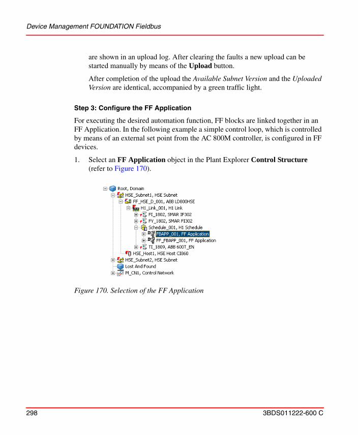
Device Management FOUNDATION Fieldbus
298 3BDS011222-600 C
are shown in an upload log. After clearing the faults a new upload can be started manually by means of the Upload button.
After completion of the upload the Available Subnet Version and the Uploaded Version are identical, accompanied by a green traffic light.
Step 3: Configure the FF Application
For executing the desired automation function, FF blocks are linked together in an FF Application. In the following example a simple control loop, which is controlled by means of an external set point from the AC 800M controller, is configured in FF devices.
1. Select an FF Application object in the Plant Explorer Control Structure (refer to Figure 170).
Figure 170. Selection of the FF Application
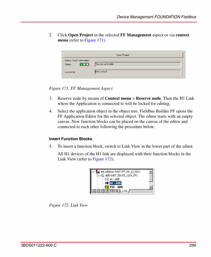
Device Management FOUNDATION Fieldbus
3BDS011222-600 C 299
2. Click Open Project in the selected FF Management aspect or via context menu (refer to Figure 171).
3. Reserve node by means of Context menu > Reserve node. Then the H1 Link where the Application is connected to will be locked for editing.
4. Select the application object in the object tree. Fieldbus Builder FF opens the FF Application Editor for the selected object. The editor starts with an empty canvas. Now function blocks can be placed on the canvas of the editor and connected to each other following the procedure below.
Insert Function Blocks
5. To insert a function block, switch to Link View in the lower part of the editor.
All H1 devices of the H1 link are displayed with their function blocks in the Link View (refer to Figure 172).
Figure 171. FF Management Aspect
Figure 172. Link View
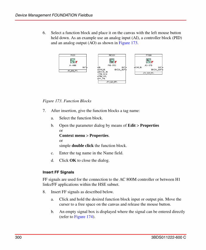
Device Management FOUNDATION Fieldbus
300 3BDS011222-600 C
6. Select a function block and place it on the canvas with the left mouse button held down. As an example use an analog input (AI), a controller block (PID) and an analog output (AO) as shown in Figure 173.
7. After insertion, give the function blocks a tag name:
a. Select the function block.
b. Open the parameter dialog by means of Edit > PropertiesorContext menu > Properties.orsimple double click the function block.
c. Enter the tag name in the Name field.
d. Click OK to close the dialog.
Insert FF Signals
FF signals are used for the connection to the AC 800M controller or between H1 links/FF applications within the HSE subnet.
8. Insert FF signals as described below.
a. Click and hold the desired function block input or output pin. Move the curser to a free space on the canvas and release the mouse button.
b. An empty signal box is displayed where the signal can be entered directly (refer to Figure 174).
Figure 173. Function Blocks
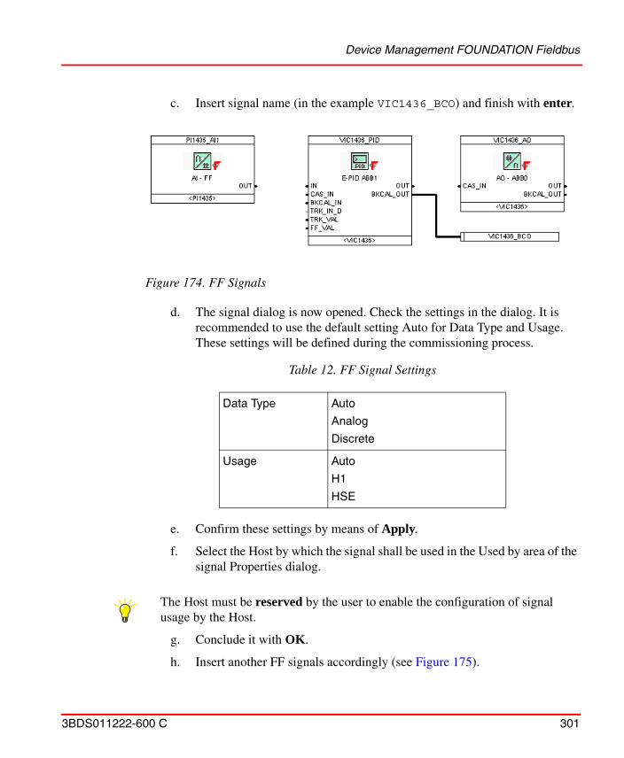
Device Management FOUNDATION Fieldbus
3BDS011222-600 C 301
c. Insert signal name (in the example VIC1436_BCO) and finish with enter.
d. The signal dialog is now opened. Check the settings in the dialog. It is recommended to use the default setting Auto for Data Type and Usage. These settings will be defined during the commissioning process.
e. Confirm these settings by means of Apply.
f. Select the Host by which the signal shall be used in the Used by area of the signal Properties dialog.
g. Conclude it with OK.
h. Insert another FF signals accordingly (see Figure 175).
Figure 174. FF Signals
Table 12. FF Signal Settings
Data Type Auto
Analog
Discrete
Usage Auto
H1
HSE
The Host must be reserved by the user to enable the configuration of signal usage by the Host.
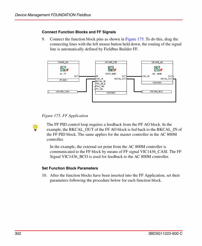
Device Management FOUNDATION Fieldbus
302 3BDS011222-600 C
Connect Function Blocks and FF Signals
9. Connect the function block pins as shown in Figure 175. To do this, drag the connecting lines with the left mouse button held down, the routing of the signal line is automatically defined by Fieldbus Builder FF.
In the example, the external set point from the AC 800M controller is communicated to the FF block by means of FF signal VIC1436_CASI. The FF Signal VIC1436_BCO is used for feedback to the AC 800M controller.
Set Function Block Parameters
10. After the function blocks have been inserted into the FF Application, set their parameters following the procedure below for each function block.
Figure 175. FF Application
The FF PID control loop requires a feedback from the FF AO block. In the example, the BKCAL_OUT of the FF AO block is fed back to the BKCAL_IN of the FF PID block. The same applies for the master controller in the AC 800M controller.
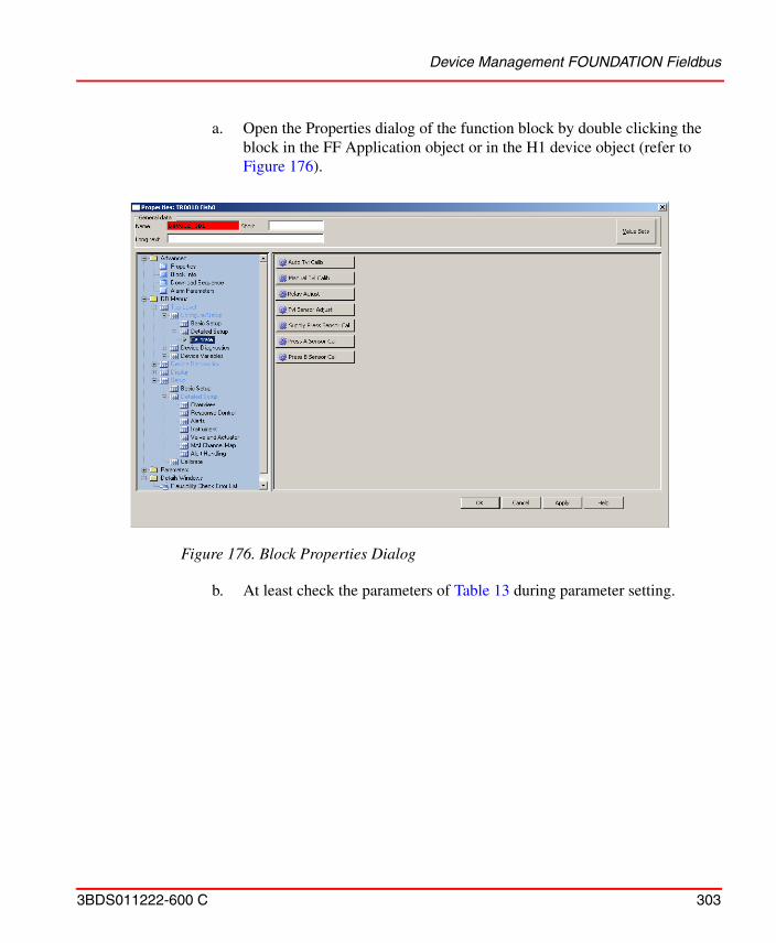
Device Management FOUNDATION Fieldbus
3BDS011222-600 C 303
a. Open the Properties dialog of the function block by double clicking the block in the FF Application object or in the H1 device object (refer to Figure 176).
b. At least check the parameters of Table 13 during parameter setting.
Figure 176. Block Properties Dialog
Device Management FOUNDATION Fieldbus
304 3BDS011222-600 C
Configure Alarms and Events
Configuration of FF alarms and events is done by setting the appropriate block parameters requiring the following steps:
– Enable FF alarms and events for each device.
Table 13. Parameters to be Checked
Parameter Description
ALERT_KEY The value of the ALERT_KEY must be in the range 1 .. 255.
MODE_BLK The mode parameter consists of several parts. The Target mode defines the mode of operation which the block should adopt. The modes of operation into which the block can be switched via the Target mode are specified by means of the Permitted Mode. The Actual mode shows the current mode of the block. The following modes of operation should be set for the block types (refer to Table 14).
Scaling Customize the scaling of the individual blocks to the requirements of your process.
Table 14. Recommended Modes of Operation for FF Blocks
Block Type Recommended Mode of Operation
Resource Block Auto
Transducer Block Auto
Analog input (AI) Auto
PID Controller Block Man, Auto or Cas(1)
(1) Dependent on the functionality of the controller.
Analog Output (AO) Cas
For running a block in the Cascade mode, Auto and Cas are to be set in the target mode at the same time.
Device Management FOUNDATION Fieldbus
3BDS011222-600 C 305
– Configure FF alarms and events for each block.
11. For each FF device which shall support FF alarms and events enable this feature following the procedure below:
a. Open the Properties dialog of the resource block.
b. Check the “Reports” bit of the FEATURE_SEL parameter.
c. Configure the parameter LIM_NOTIFY.This parameter defines the maximum number of alarms the device sends out an event notification for, without receiving a confirmation.LIM_NOTIFY may equal MAX_NOTIFY.If LIM_NOTIFY is set to zero, no alerts are reported.
d. Configure the parameter CONFIRM_TIME.This parameter defines the timeout for confirmation. The alarm notification will be resent, if the device has not received a confirmation within the specified time. Recommended value: 320000 [1/32 ms], which is 10 seconds.
12. Set the values for the following parameters which are relevant for the general alarm configuration in Advanced > Properties view of the Block Properties dialog:
a. ALARM_SUMThis parameter is used to selectively deactivate alarms for the block.
b. STATUS_OPTS (optional)If a block contains the parameter STATUS_OPTS, the "Propagate Fault Forward" bit must be unchecked to enable alarms.Block alarms will be reported regardless of this option.
c. ALERT_KEYThis parameter is used as 800xA area information.
d. ACK_OPTIONThis parameter defines the user acknowledge behavior for the alarms of the block.
13. Configure alarm points for FF Process alarms by setting the following parameters in Advanced > Properties view of the Block Properties dialog:
a. the alarm hysteresis (ALARM_HYS),
Device Management FOUNDATION Fieldbus
306 3BDS011222-600 C
b. a priority (e.g. HI_PRI) for each alarm point, and
c. a limit (e.g. HI_LIM) for each alarm point.
14. With the Alarm Parameters of the block you can:
a. change the default Category value for manufacturer specific alarms,
b. change the default Severity value, and
FF contains the alarm priorities 0 to 15. Priority 15 represents most important alarms.
The FF alarm priority impacts the communication of an alarm. In the case of multiple alarms in a FF device, alarms with the higher priority are communicated with preference. In particular there is no notification for alarms of priority less than 2.
The FF alarm priority has no impact on the OPC Severity or the associated 800xA Alarm Priority of an alarm point.
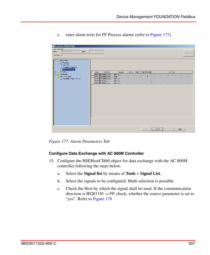
Device Management FOUNDATION Fieldbus
3BDS011222-600 C 307
c. enter alarm texts for FF Process alarms (refer to Figure 177).
Configure Data Exchange with AC 800M Controller
15. Configure the HSEHostCI860 object for data exchange with the AC 800M controller following the steps below.
a. Select the Signal list by means of Tools > Signal List.
b. Select the signals to be configured. Multi selection is possible.
c. Check the Host by which the signal shall be used. If the communication direction is IEC61131 -> FF, check, whether the source parameter is set to “yes”. Refer to Figure 178
Figure 177. Alarm Parameters Tab
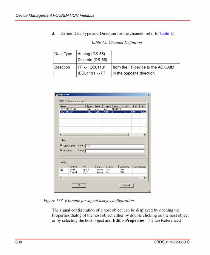
Device Management FOUNDATION Fieldbus
308 3BDS011222-600 C
d. Define Data Type and Direction for the channel; refer to Table 15.
The signal configuration of a host object can be displayed by opening the Properties dialog of the host object either by double clicking on the host object or by selecting the host object and Edit > Properties. The tab Referenced
Table 15. Channel Definition
Data Type Analog (DS-65)
Discrete (DS-66)
Direction FF -> IEC61131
IEC61131 -> FF
from the FF device to the AC 800M
in the opposite direction
Figure 178. Example for signal usage configuration
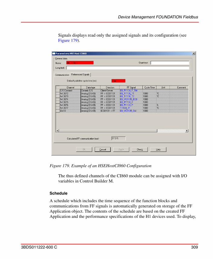
Device Management FOUNDATION Fieldbus
3BDS011222-600 C 309
Signals displays read only the assigned signals and its configuration (see Figure 179).
The thus defined channels of the CI860 module can be assigned with I/O variables in Control Builder M.
Schedule
A schedule which includes the time sequence of the function blocks and communications from FF signals is automatically generated on storage of the FF Application object. The contents of the schedule are based on the created FF Application and the performance specifications of the H1 devices used. To display,
Figure 179. Example of an HSEHostCI860 Configuration
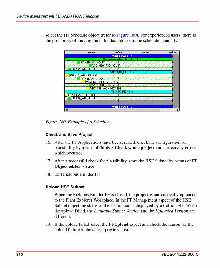
Device Management FOUNDATION Fieldbus
310 3BDS011222-600 C
select the H1 Schedule object (refer to Figure 180). For experienced users, there is the possibility of moving the individual blocks in the schedule manually.
Check and Save Project
16. After the FF Applications have been created, check the configuration for plausibility by means of Tools > Check whole project and correct any errors which occurred.
17. After a successful check for plausibility, store the HSE Subnet by means of FF Object editor > Save.
18. Exit Fieldbus Builder FF.
Upload HSE Subnet
When the Fieldbus Builder FF is closed, the project is automatically uploaded to the Plant Explorer Workplace. In the FF Management aspect of the HSE Subnet object the status of the last upload is displayed by a traffic light. When the upload failed, the Available Subnet Version and the Uploaded Version are different.
19. If the upload failed select the FFUpload aspect and check the reason for the upload failure in the aspect preview area.
Figure 180. Example of a Schedule
Device Management FOUNDATION Fieldbus
3BDS011222-600 C 311
20. After correction of the errors, an upload can be started manually by clicking Upload.
After completion of the upload the Available Subnet Version and the Uploaded Version are identical.
The configuration of the FF network with the FF Application has now been completed. Subsequently the configured data must be distributed to the connected devices.
Step 4: Load the FF Application
Once it has been loaded, the data of the FF Application is distributed over the FF network.
The FF Application is loaded in two steps. In the first step - the precommissioning - a device assignment between the configured devices and the devices which are actually present is carried out. Basic settings are written to the devices.
In the second step - the commissioning - the data of the FF Application is loaded into the individual devices.
Step 4a: Precommissioning
The precommissioning is different for linking devices and H1 devices.
During the precommissioning of a linking device the tag name is written and the configured H1 links are activated. For H1 devices, the tag name is written to the device and the bus address set. The device ID is read out of the device and stored in the Fieldbus Builder FF database. As a result, the device can subsequently be detected. The configured blocks are loaded into H1 devices with instantiable function blocks.
Precommissioning of a Linking Device
1. Select a linking device object in the Plant Explorer Control Structure.
2. Select the FF Management Aspect.
3. Start Fieldbus Builder FF with Open Project.
4. Reserve node by Context menu > Reserve node.
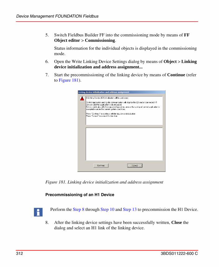
Device Management FOUNDATION Fieldbus
312 3BDS011222-600 C
5. Switch Fieldbus Builder FF into the commissioning mode by means of FF Object editor > Commissioning.
Status information for the individual objects is displayed in the commissioning mode.
6. Open the Write Linking Device Settings dialog by means of Object > Linking device initialization and address assignment...
7. Start the precommissioning of the linking device by means of Continue (refer to Figure 181).
Precommissioning of an H1 Device
8. After the linking device settings have been successfully written, Close the dialog and select an H1 link of the linking device.
Figure 181. Linking device initialization and address assignment
I
Perform the Step 8 through Step 10 and Step 13 to precommission the H1 Device.
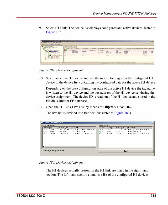
Device Management FOUNDATION Fieldbus
3BDS011222-600 C 313
9. Select H1 Link. The device list displays configured and active devices. Refer to Figure 182.
10. Select an active H1 device and use the mouse to drag it on the configured H1 device in the device list containing the configured data for the active H1 device.
Depending on the pre-configuration state of the active H1 device the tag name is written to the H1 device and the bus address of the H1 device set during the device assignment. The device ID is read out of the H1 device and stored in the Fieldbus Builder FF database.
11. Open the H1 Link Live List by means of Object > Live list....
The live list is divided into two sections (refer to Figure 183).
The H1 devices actually present in the H1 link are listed in the right-hand section. The left-hand section contains a list of the configured H1 devices.
Figure 182. Device Assignment
Figure 183. Device Assignment
Device Management FOUNDATION Fieldbus
314 3BDS011222-600 C
12. Select an active H1 device in the right-hand section and use the mouse to drag it to the configured H1 device in the left-hand section which contains the configured data for the active H1 device.
The tag name is written to the H1 device and the bus address of the H1 device set during the device assignment. The device ID is read out of the H1 device and stored in the Fieldbus Builder FF database.
13. Repeat this process for all H1 devices in the H1 link and for further H1 links and linking devices if required.
Step 4b: Commissioning
After all the requisite FF devices have been assigned, the FF Application can be loaded into the individual FF devices and the OPC Server FF following the description below.
Load FF Devices
14. Select the H1 Link, a Linking Device or if sufficient only a single H1 device. The complete HSE subnet can also be selected for commissioning. Previously not reserved objects will not be considered for commissioning.
You can also carry out the device assignment by selecting an H1 device and opening the H1 Live List by means of Object > Assign device.... Select the H1 device to be assigned from the list and start the device assignment with Assign.
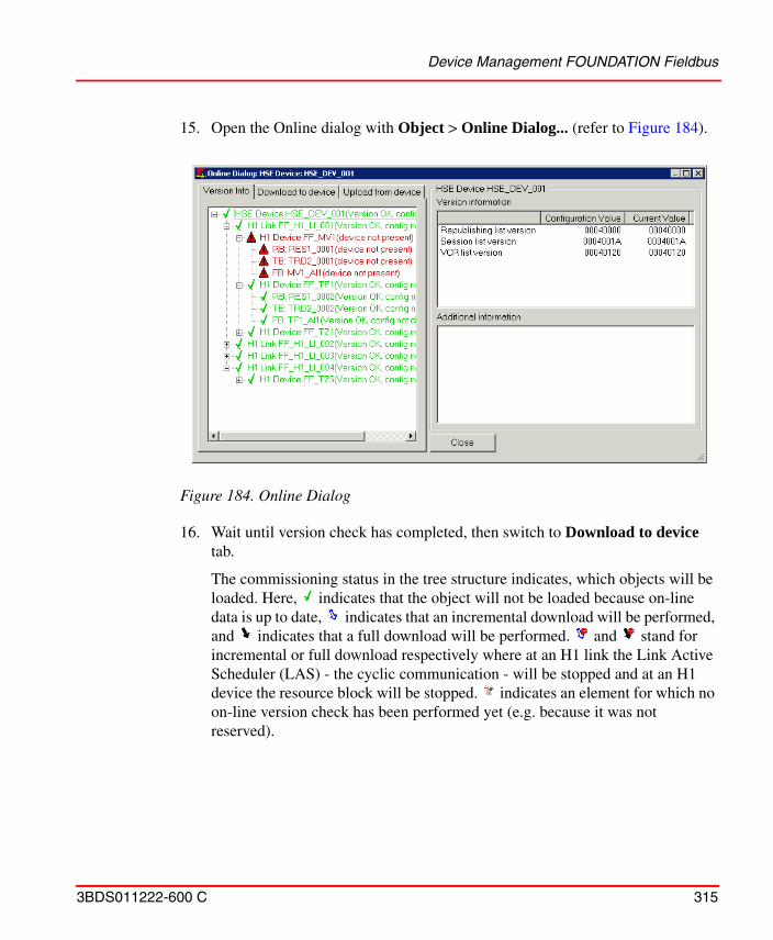
Device Management FOUNDATION Fieldbus
3BDS011222-600 C 315
15. Open the Online dialog with Object > Online Dialog... (refer to Figure 184).
16. Wait until version check has completed, then switch to Download to device tab.
The commissioning status in the tree structure indicates, which objects will be loaded. Here, indicates that the object will not be loaded because on-line data is up to date, indicates that an incremental download will be performed, and indicates that a full download will be performed. and stand for incremental or full download respectively where at an H1 link the Link Active Scheduler (LAS) - the cyclic communication - will be stopped and at an H1 device the resource block will be stopped. indicates an element for which no on-line version check has been performed yet (e.g. because it was not reserved).
Figure 184. Online Dialog
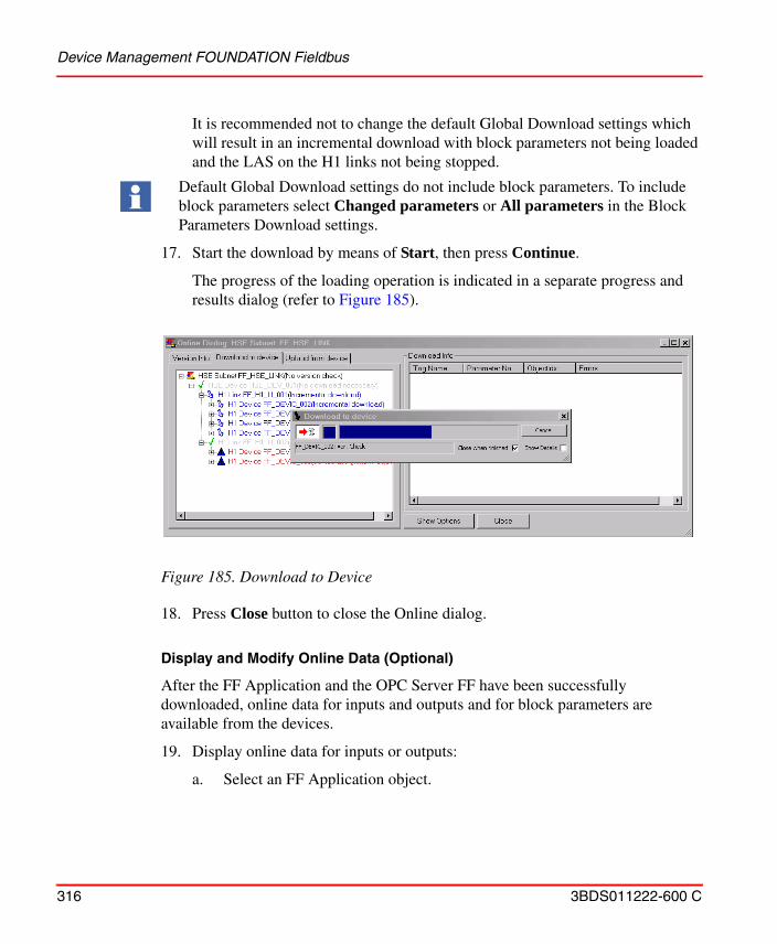
Device Management FOUNDATION Fieldbus
316 3BDS011222-600 C
It is recommended not to change the default Global Download settings which will result in an incremental download with block parameters not being loaded and the LAS on the H1 links not being stopped.
17. Start the download by means of Start, then press Continue.
The progress of the loading operation is indicated in a separate progress and results dialog (refer to Figure 185).
18. Press Close button to close the Online dialog.
Display and Modify Online Data (Optional)
After the FF Application and the OPC Server FF have been successfully downloaded, online data for inputs and outputs and for block parameters are available from the devices.
19. Display online data for inputs or outputs:
a. Select an FF Application object.
Default Global Download settings do not include block parameters. To include block parameters select Changed parameters or All parameters in the Block Parameters Download settings.
Figure 185. Download to Device
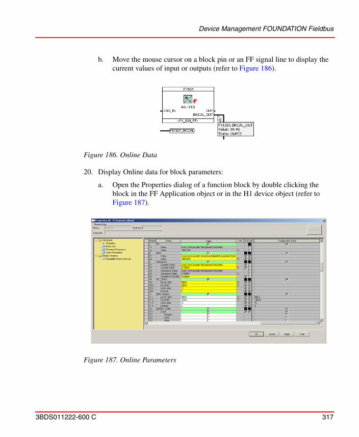
Device Management FOUNDATION Fieldbus
3BDS011222-600 C 317
b. Move the mouse cursor on a block pin or an FF signal line to display the current values of input or outputs (refer to Figure 186).
20. Display Online data for block parameters:
a. Open the Properties dialog of a function block by double clicking the block in the FF Application object or in the H1 device object (refer to Figure 187).
Figure 186. Online Data
Figure 187. Online Parameters
Device Management FOUNDATION Fieldbus
318 3BDS011222-600 C
The column Value shows the Current values, a parameter value displayed with a yellow background indicates that the current value read from the device is different from the configured value in the Fieldbus Builder FF database. The configured values are displayed in the column Configuration Value at the right end of the table.
In commissioning mode methods are processing on the current values. Methods are provided by the device vendors to handle complex device functions and are not available for all devices.
21. To change values of individual parameters:
a. Change the value in the value field.
b. Click Apply to write the new value to the H1 device or
c. Click Cancel to discard the changed value and close the dialog.
d. Click OK to write the new value to the H1 device and close the dialog.
e. Closing the Dialog by OK or Cancel will open a new dialog with the option to write all changes made in the parameter dialog into the Fieldbus Builder FF database.
22. Current values in the H1 device which are not in the Fieldbus Builder FF database (highlighted with yellow background) can be loaded into the database as follows:
a. Mark one or more lines in the parameter dialog.
b. Open the context menu.
c. Start the transfer of the data by means of Upload marked.
For the commissioning of your FF Application, compare the Actual and Target mode of the individual blocks. Actual and Target mode can differ from each other, dependent on the signal statuses at the inputs of a block.
In this case, check the cause for example, if a sensor is not connected to the device.
For easily comparing and reconciling block parameters in the database and in the devices use the Upload from Device tab of the Online dialog described in System 800xA Device Management, FOUNDATION Fieldbus Configuration (3BDD012902*).
Device Management FOUNDATION Fieldbus
3BDS011222-600 C 319
Upload HSE Subnet
23. Exit Fieldbus Builder FF.
When the Fieldbus Builder FF configuration is being saved, the FF data are automatically uploaded to the PPA. In the FF Management aspect of the HSE Subnet object the status of the last upload is displayed by a traffic light. When the upload failed, the Available Subnet Version and the Uploaded Version are different.
24. If the upload failed select the FFUpload aspect and check the reason for the upload failure in the aspect preview area.
25. After correction of the errors, an upload can be started manually by clicking Upload.
After completion of the upload the Available Subnet Version and the Uploaded Version are identical.
Step 5: Using FF Data
For use in the AC 800M.
The FF signals entered in the HSEHostCI860 object in Fieldbus Builder FF are automatically transferred to the CI860 object in Control Builder M.
The following steps require that the requisite hardware has been defined in a Control Network in the Plant Explorer Control Structure.
1. Use the Structure Selector in the Plant Explorer Workplace to open the Control Structure.
2. Navigate to the CI860 object in the Control Network.
3. Select Insert Object from the context menu.
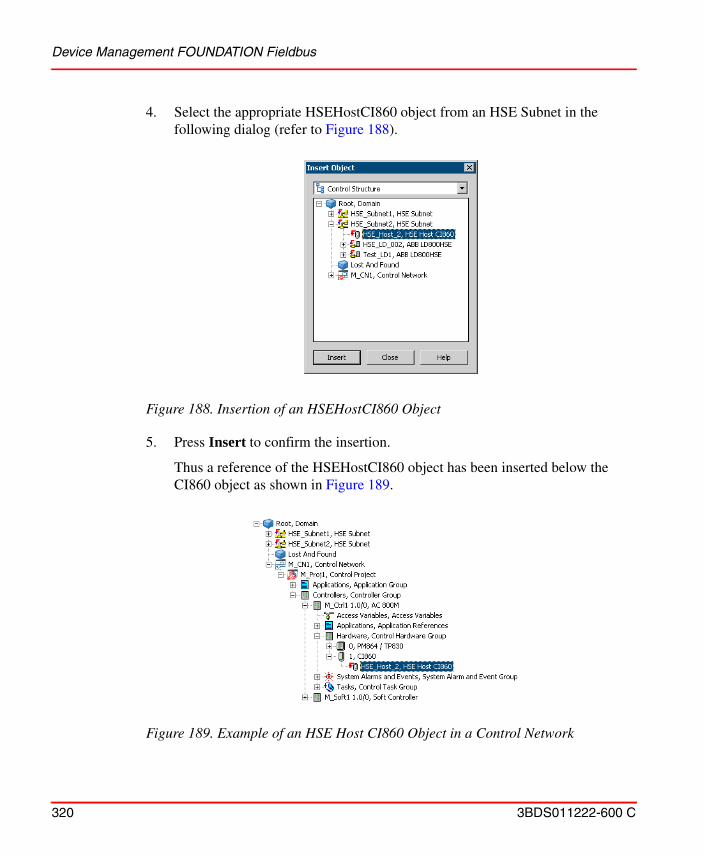
Device Management FOUNDATION Fieldbus
320 3BDS011222-600 C
4. Select the appropriate HSEHostCI860 object from an HSE Subnet in the following dialog (refer to Figure 188).
5. Press Insert to confirm the insertion.
Thus a reference of the HSEHostCI860 object has been inserted below the CI860 object as shown in Figure 189.
Figure 188. Insertion of an HSEHostCI860 Object
Figure 189. Example of an HSE Host CI860 Object in a Control Network
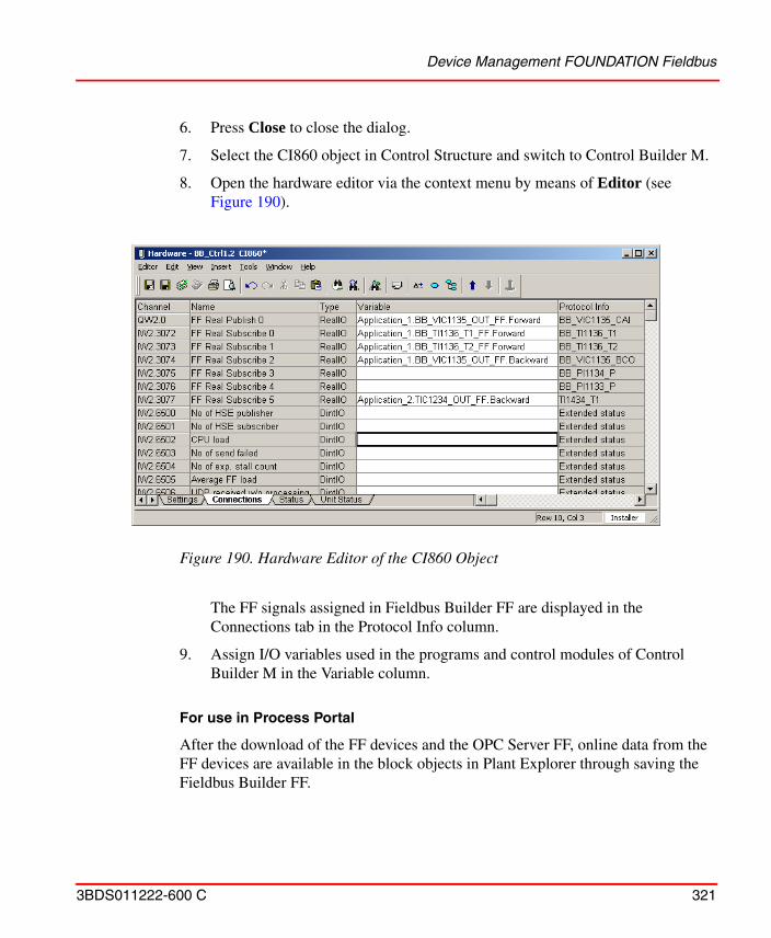
Device Management FOUNDATION Fieldbus
3BDS011222-600 C 321
6. Press Close to close the dialog.
7. Select the CI860 object in Control Structure and switch to Control Builder M.
8. Open the hardware editor via the context menu by means of Editor (see Figure 190).
The FF signals assigned in Fieldbus Builder FF are displayed in the Connections tab in the Protocol Info column.
9. Assign I/O variables used in the programs and control modules of Control Builder M in the Variable column.
For use in Process Portal
After the download of the FF devices and the OPC Server FF, online data from the FF devices are available in the block objects in Plant Explorer through saving the Fieldbus Builder FF.
Figure 190. Hardware Editor of the CI860 Object

Device Management FOUNDATION Fieldbus
322 3BDS011222-600 C
The data for the FF objects is available in the Control Connection Aspect. Graphics, faceplates, trends, archives, among others, can access this data. Refer to the respective manuals to configure these applications.
For further configuration information on Fieldbus Builder FF refer to System 800xA Device Management, FOUNDATION Fieldbus Configuration (3BDD012902*).
Batch Management
3BDS011222-600 C 323
Batch ManagementThis section describes the Batch Management functions.
Flexible Batch Processing
Flexible batch processing permits control logic and resources such as equipment to be used in a variety of ways to produce different products.
Flexibility is built into the Batch Management approach to configuring recipes. The master recipe is created by drawing a flowchart of the process using an object oriented approach. This flowchart is called a procedure function chart (PFC).
The objects used in the PFC represent:
• Batch manager actions such as allocating an equipment resource, sending the operator a message, or collecting data to be used later in a batch report.
• Phase operations (created during controller configuration) specifically for the requirements of a customer.
• A subprocedure.
These objects can be combined in any sequence supported by the batch resources. The system permits configuration of procedures consisting of a single thread of processing, branched logic, or parallel operations. At run time, the operator monitors the progress of the batch run while viewing a copy of the diagram created during procedure configuration.
Flexibility of formulas used to create batch products is enabled in a number of ways:
• The equipment phase logic can find parameters specified by name.
• Values can be assigned to parameters in a number of ways, including by the operator at run time (if the recipe is so configured).
• The values assigned to parameters can be logical expressions, as well as fixed values.
Configuration Overview
The tasks required to take advantage of the benefits of the Batch Management flexible batch subsystem are:
Batch Management
324 3BDS011222-600 C
• Planning resource use.
• Writing equipment phase control logic.
• Configuring the controller modules required to handle input and output data, control loops, and execution of sequence logic.
• Configuring the equipment database that describes the hardware and software resources available at the site.
• Creating recipes that can include both subprocedures and formulas, using reusable logic components.
The controller and Batch Management can be configured simultaneously. Within Batch Management, equipment must be configured before it can be referenced by procedures.
Batch Management Configuration
Batch Management configuration tools (accessed various ways) provide access to the:
• Equipment database configuration - Batch Management records information about the resources available for flexible batch processing in the equipment database.
• Procedure configuration - Batch Management stores procedures in the recipe database.
• Miscellaneous and default batch configuration.
Equipment Database Configuration
The equipment database is a collection of interrelated definitions of phases, equipment and equipment groups. Equipment must be configured before procedures can reference it (although changes can be made later).
The steps to configure the equipment database are:
1. Configure phase definitions, including the phase parameters, default values, and access levels.
Batch Management
3BDS011222-600 C 325
2. Verify the phases match the equipment phases defined for the controller (EPT control modules only).
3. Configure equipment names.
4. Specify equipment attributes. Identify characteristics of the equipment that could have an effect on which equipment should be used for a particular batch.
5. Specify which phases can run on which equipment.
6. Define equipment groups.
Procedure Configuration
Once the equipment has been configured, procedures can be created that reference the equipment.
Batch Management procedures are configured by creating PFCs (procedure function charts). Procedures are drawn using an object oriented approach. The PFC created during procedure configuration will also be used at run time by the operator to monitor the progress of a batch.
The steps to create a procedure are:
1. Configure the procedure header providing information about the procedure.
2. Configure the standard operating procedure (SOP), which is a textual representation of the procedure (optional).
3. Configure procedure parameters.
4. Create the PFC.
a. Add objects representing batch manager actions to acquire equipment.
b. Add objects representing phases, subprocedures, compute batch manager actions, message batch manager actions, and so on, which includes defining each object. Procedure specific values for procedure and phase parameters can be included.
c. Add objects representing batch manager actions to release equipment.
d. Add connector objects linking objects on the PFC.
Prior to procedure configuration, the designer may want to specify batch cells.
800xA History
326 3BDS011222-600 C
Miscellaneous Batch Configuration
Additional batch configuration activities are performed using various methods. These activities include defining message priorities, specifying the number of backup versions of procedures to be retained, and the option to change the colors used in PFCs. The retention limit for display of completed batches is also specified using these methods.
The Batch Management batch manager runs under System 800xA. When the software is installed, a node is designated as a primary server. A second node can optionally be designated as a redundant server.
800xA HistoryThis section describes the configuration of Log Templates and Log Configuration aspects of 800xA History. Every data point stored in the History server is called Tag. User can configure the Tag properties to tune the update rate, compression etc. for data storage.
A Tag can be created and configured using System 800xA which provides common engineering environment for control system objects and history data points. The configuration is automatically synchronized between System 800xA and 800xA History Server.
This section also describes the configuration of event retrieval and event archiving. For more information refer:
• Configuring Event Retrieval
• Configuring Event Archiving
Configuring Using System 800xA
To start the configuration of 800xA History Application, configure the 800xA History Log Collector Link and Sync Service.
800xA History Log Collector Link and 800xA History Sync Service are created automatically by System configuration console.
In redundant History Server (High Availability) configuration, make sure to keep the First Node of High Availability Server Up and Running before creating tags using System 800xA.
Configuring Using System 800xA
3BDS011222-600 C 327
800xA History Logs
1. 800xA History Logs include the following logging options:
a. Current History Only Log
b. Aggregate Log
Follow the steps below to create 800xA History Logs:
1. 800xA History Source on page 327
2. Creating Logs from System 800xA on page 332
800xA History Source
800xA History Source Aspect is used to define the Service Group responsible for handling 800xA History Log Configurations
Import option in Log configuration aspect, which is used to modify historical data in a 800xA History log, is not supported.
800xA History Source Aspect is normally created in the Control Network Object Type.
Configuring Using System 800xA
328 3BDS011222-600 C
1. Right-click the object and click New Aspect from the context-menu.
Figure 191. 800xA History Source Aspect Configuration — New Aspect
Configuring Using System 800xA
3BDS011222-600 C 329
2. Select 800xA History Source Aspect and click Create.
3. In 800xA History Source aspect, select 800xAHistorySync Service Group from the drop down menu and click Apply.
History Source
History Source Aspect is used to define the Service Group used by Log Configurations in all children nodes.
Figure 192. 800xA History Source Aspect Configuration — 800xA History Source Aspect
Import option in Log configuration aspect, which is used to modify historical data in a History log, is not supported.
History Source Aspect is normally created in the Control Network Object Type.
Configuring Using System 800xA
330 3BDS011222-600 C
1. Right-click an object and select New Aspect from the context-menu.
Figure 193. History Source Aspect Configuration — New Aspect
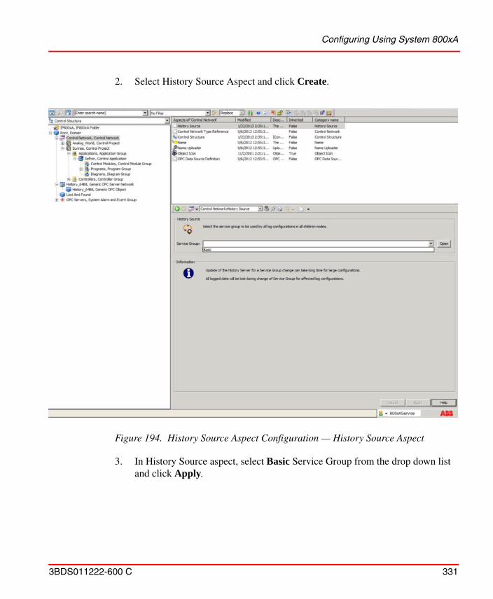
Configuring Using System 800xA
3BDS011222-600 C 331
2. Select History Source Aspect and click Create.
3. In History Source aspect, select Basic Service Group from the drop down list and click Apply.
Figure 194. History Source Aspect Configuration — History Source Aspect
Creating Log Templates
332 3BDS011222-600 C
Creating Logs from System 800xA
The Object property to be historized in 800xA requires creation of Log Configuration Aspect. Once the log configuration is created the storage information is automatically updated in the History Server.
Following steps are required to create the log configuration:
1. Creating Log Templates
2. Creating Log Configuration Aspect in Tags
Creating Log Templates
The Log template is a reusable template for building many similar logs.Log Template specifies the way a property should be logged. It is represented by a Property log template which can consist of a hierarchy of log templates.
The Log Templates are created in 800xA Workplace Library Structure.
Basically there can be three possibilities for configuring the Log Templates for 800xA History. They are:
1. Current History Only Log
2. Aggregate Log
Current History Only Log
The Current History Only Log is used when aggregates are not required for the stored data. This option allows for storing the Current values only (or the data as it is read from the control system).
Execute the following procedure to configure log template:
1. In the plant explorer, select Library Structure > History Log Templates, History Log Template Library.
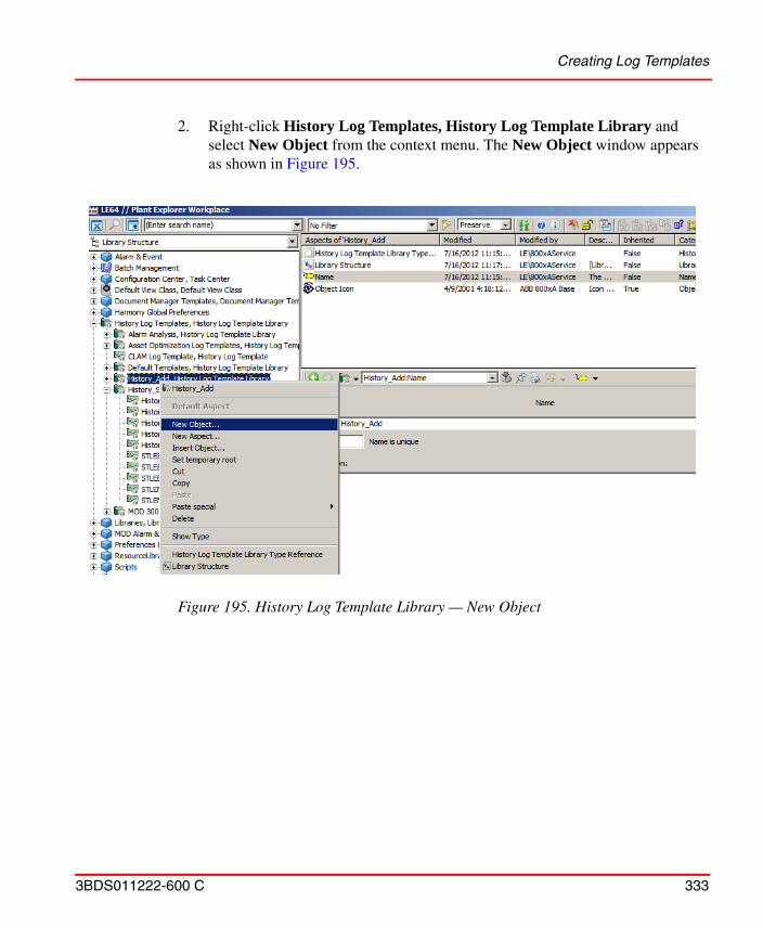
Creating Log Templates
3BDS011222-600 C 333
2. Right-click History Log Templates, History Log Template Library and select New Object from the context menu. The New Object window appears as shown in Figure 195.
Figure 195. History Log Template Library — New Object
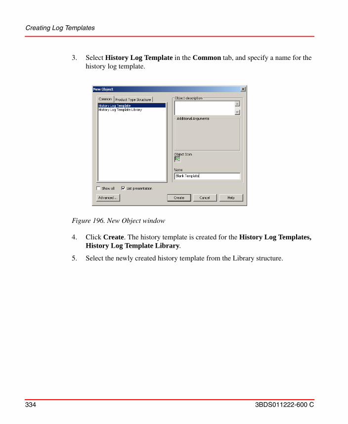
Creating Log Templates
334 3BDS011222-600 C
3. Select History Log Template in the Common tab, and specify a name for the history log template.
4. Click Create. The history template is created for the History Log Templates, History Log Template Library.
5. Select the newly created history template from the Library structure.
Figure 196. New Object window
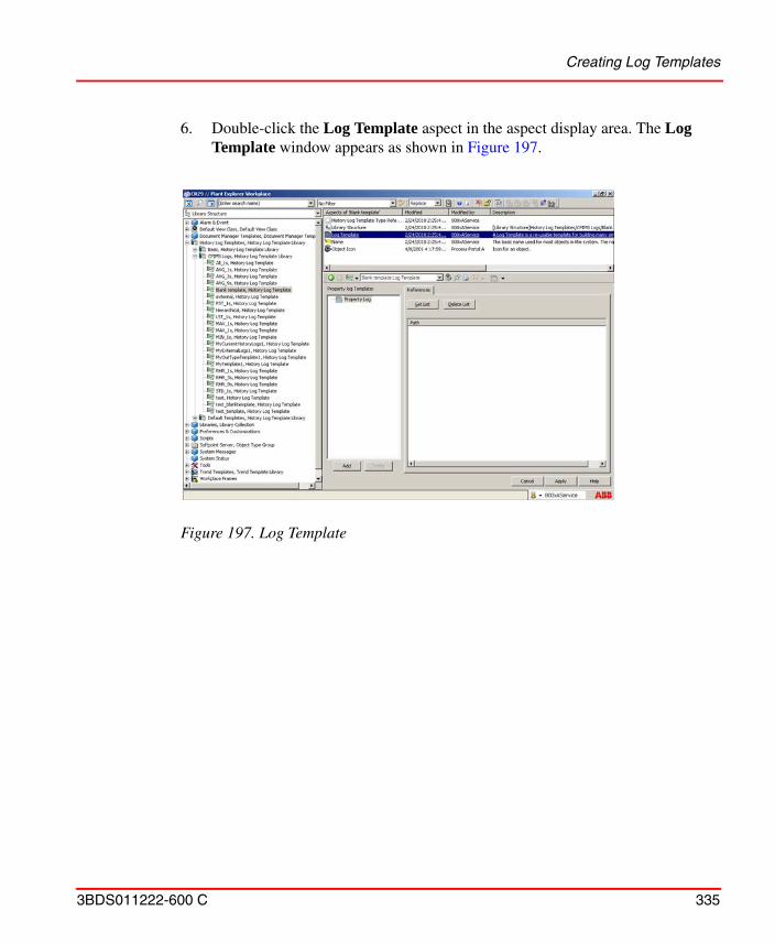
Creating Log Templates
3BDS011222-600 C 335
6. Double-click the Log Template aspect in the aspect display area. The Log Template window appears as shown in Figure 197.
Figure 197. Log Template
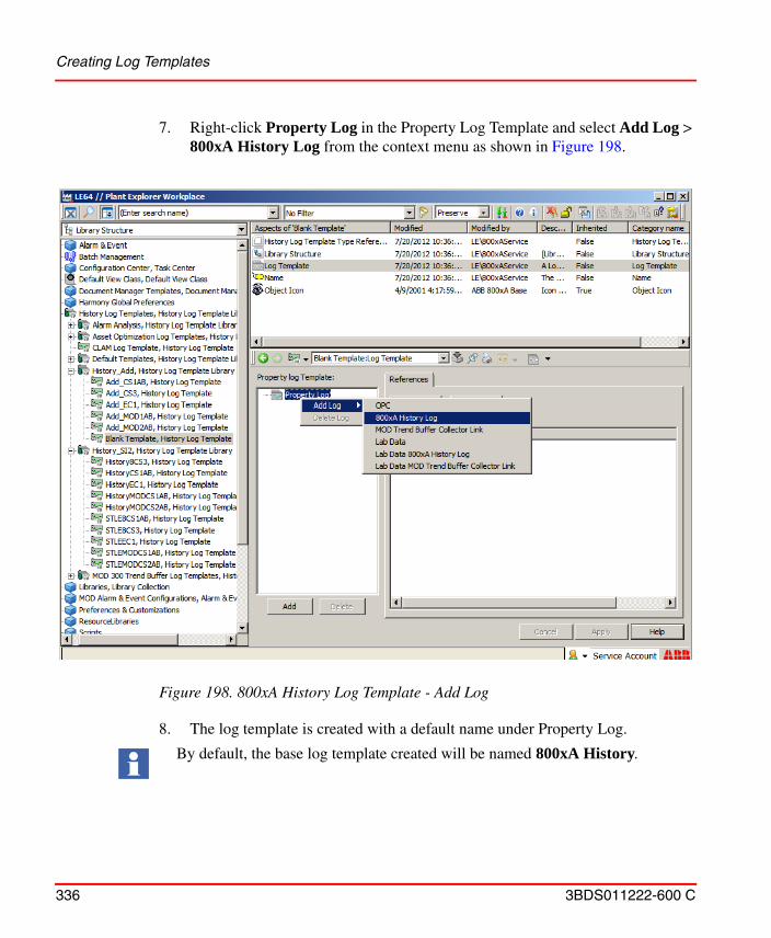
Creating Log Templates
336 3BDS011222-600 C
7. Right-click Property Log in the Property Log Template and select Add Log > 800xA History Log from the context menu as shown in Figure 198.
8. The log template is created with a default name under Property Log.
Figure 198. 800xA History Log Template - Add Log
By default, the base log template created will be named 800xA History.
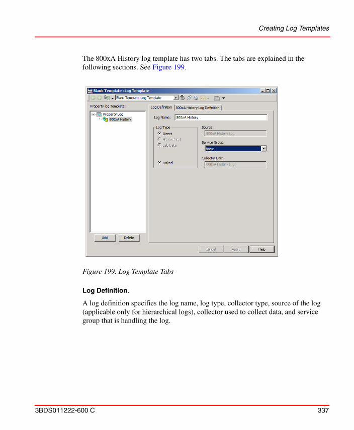
Creating Log Templates
3BDS011222-600 C 337
The 800xA History log template has two tabs. The tabs are explained in the following sections. See Figure 199.
Log Definition.
A log definition specifies the log name, log type, collector type, source of the log (applicable only for hierarchical logs), collector used to collect data, and service group that is handling the log.
Figure 199. Log Template Tabs
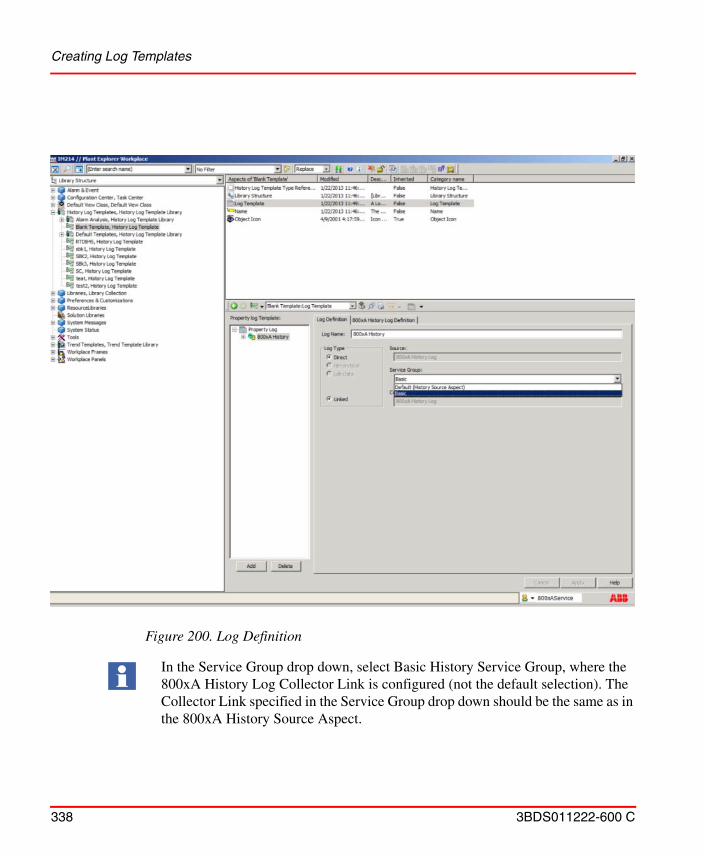
Creating Log Templates
338 3BDS011222-600 C
Figure 200. Log Definition
In the Service Group drop down, select Basic History Service Group, where the 800xA History Log Collector Link is configured (not the default selection). The Collector Link specified in the Service Group drop down should be the same as in the 800xA History Source Aspect.
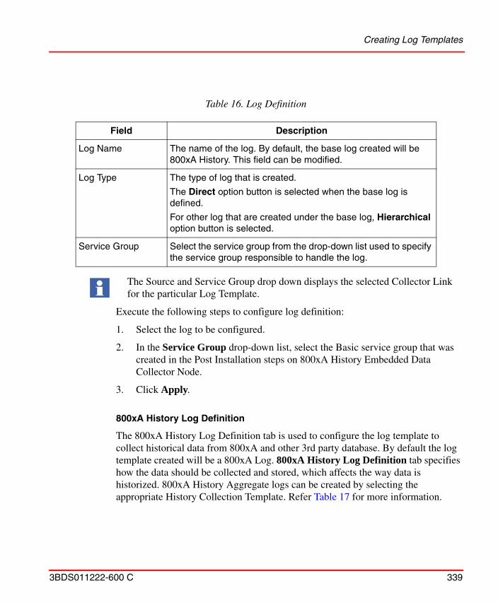
Creating Log Templates
3BDS011222-600 C 339
Execute the following steps to configure log definition:
1. Select the log to be configured.
2. In the Service Group drop-down list, select the Basic service group that was created in the Post Installation steps on 800xA History Embedded Data Collector Node.
3. Click Apply.
800xA History Log Definition
The 800xA History Log Definition tab is used to configure the log template to collect historical data from 800xA and other 3rd party database. By default the log template created will be a 800xA Log. 800xA History Log Definition tab specifies how the data should be collected and stored, which affects the way data is historized. 800xA History Aggregate logs can be created by selecting the appropriate History Collection Template. Refer Table 17 for more information.
Table 16. Log Definition
Field Description
Log Name The name of the log. By default, the base log created will be 800xA History. This field can be modified.
Log Type The type of log that is created.
The Direct option button is selected when the base log is defined.
For other log that are created under the base log, Hierarchical option button is selected.
Service Group Select the service group from the drop-down list used to specify the service group responsible to handle the log.
The Source and Service Group drop down displays the selected Collector Link for the particular Log Template.

Creating Log Templates
340 3BDS011222-600 C
Figure 201. 800xA History Log Definition
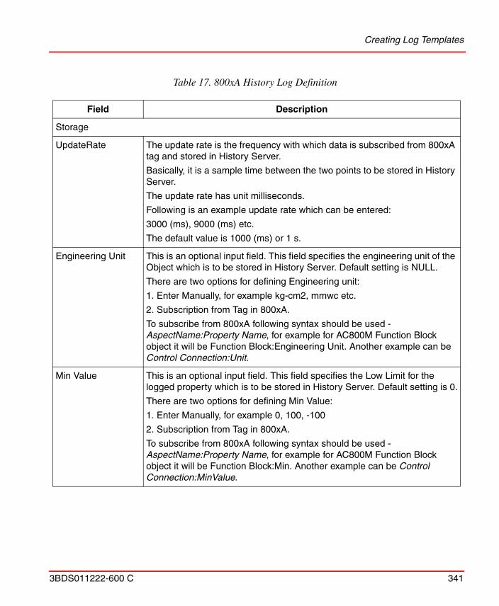
Creating Log Templates
3BDS011222-600 C 341
Table 17. 800xA History Log Definition
Field Description
Storage
UpdateRate The update rate is the frequency with which data is subscribed from 800xA tag and stored in History Server.
Basically, it is a sample time between the two points to be stored in History Server.
The update rate has unit milliseconds.
Following is an example update rate which can be entered:
3000 (ms), 9000 (ms) etc.
The default value is 1000 (ms) or 1 s.
Engineering Unit This is an optional input field. This field specifies the engineering unit of the Object which is to be stored in History Server. Default setting is NULL.
There are two options for defining Engineering unit:
1. Enter Manually, for example kg-cm2, mmwc etc.
2. Subscription from Tag in 800xA.
To subscribe from 800xA following syntax should be used - AspectName:Property Name, for example for AC800M Function Block object it will be Function Block:Engineering Unit. Another example can be Control Connection:Unit.
Min Value This is an optional input field. This field specifies the Low Limit for the logged property which is to be stored in History Server. Default setting is 0.
There are two options for defining Min Value:
1. Enter Manually, for example 0, 100, -100
2. Subscription from Tag in 800xA.
To subscribe from 800xA following syntax should be used - AspectName:Property Name, for example for AC800M Function Block object it will be Function Block:Min. Another example can be Control Connection:MinValue.
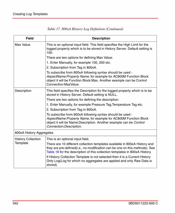
Creating Log Templates
342 3BDS011222-600 C
Max Value This is an optional input field. This field specifies the High Limit for the logged property which is to be stored in History Server. Default setting is 100.
There are two options for defining Max Value:
1. Enter Manually, for example 100, 200 etc.
2. Subscription from Tag in 800xA.
To subscribe from 800xA following syntax should be used - AspectName:Property Name, for example for AC800M Function Block object it will be Function Block:Max. Another example can be Control Connection:MaxValue.
Description This field specifies the Description for the logged property which is to be stored in History Server. Default setting is NULL.
There are two options for defining the description:
1. Enter Manually, for example Pressure Tag,Temperature Tag etc.
2. Subscription from Tag in 800xA.
To subscribe from 800xA following syntax should be used - AspectName:Property Name, for example for AC800M Function Block object it will be Name:Description. Another example can be Control Connection:Description.
800xA History Aggregates
History Collection Template
This is an optional input field.
There are 10 different collection templates available in 800xA History and they are pre-defined(i.e., no modification can be one on this methods). See Table 18 for the description of this collection templates in 800xA History.
If History Collection Template is not selected then it is a Current History Only Log(Log for which no aggregates are applied and only Raw Data is stored).
Table 17. 800xA History Log Definition (Continued)
Field Description
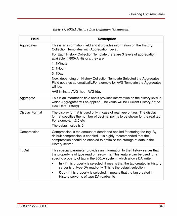
Creating Log Templates
3BDS011222-600 C 343
Aggregates This is an information field and it provides information on the History Collection Templates with Aggregation Level.
For Each History Collection Template there are 3 levels of aggregation available in 800xA History, they are:
1. 1Minute
2. 1Hour
3. 1Day
Now, depending on History Collection Template Selected the Aggregates Field updates automatically.For example for AVG Template the Aggregates will be:
AVG1minute;AVG1hour;AVG1day
Aggregate This is an information field and it provides information on the history level in which Aggregates will be applied. The value will be Current History(or the Raw Data History).
Display Format The display format is used only in case of real type of tags. The display format specifies the number of decimal points to be shown for the real tag. For example, 1,2,5 etc
The default value is 0.
Compression Compression is the amount of deadband applied for storing the tag. By default compression is enabled. It is highly recommended that the compression should be enabled to optimize the storage of data in the History server.
In/Out This special parameter provides an information to the History server that the property is of type read or read/write. This feature can be used for a specific property of tag in the 800xA system, which allows DA write.
• In - If this property is selected, it means that the tag created in History server is of type DA read-only. This is the default selection.
• Out - If this property is selected, it means that the tag created in History server is of type DA read/write
Table 17. 800xA History Log Definition (Continued)
Field Description
Creating Log Templates
344 3BDS011222-600 C
Aggregate Log
The Aggregate Log is an extension to Current History Only Log where a user can add aggregate option for the log. The aggregate methods are pre-configured and have pre-defined level of aggregates, i.e., 1Minute, 1Hour, and 1Day. The various aggregate options available with 800xA History are defined in Table 19:
Table 18. History Collection Template and Description
Template Description
AVG Time Average
MIN Minimum Value
MAX Maximum Value
LVA Last Value
FVA First Value
SUM Sum of Values
DEV Standard Deviation
FOR Forecast Time
OPT Operating time
CNT Startup Count
Table 19. Aggregate Templates and Description
Template name Description
AVG Time Average
MIN Minimum Value
MAX Maximum Value
LVA Last Value
FVA First Value
SUM Sum of Values
Creating Log Templates
3BDS011222-600 C 345
To create an Aggregate Log for 800xA History:
1. Create in Current History Only Log. Refer Current History Only Log for creating Current History Log.
DEV Standard Deviation
FOR Forecast Time
OPT Operating time
CNT Startup Count
Table 19. Aggregate Templates and Description (Continued)
Template name Description
Creating Log Templates
346 3BDS011222-600 C
2. In the Log Template window, select 800xA History Log Definition tab as shown Figure 202.
3. In 800xA History Aggregates section, click Add. A pop-up appears showing all the History Collection template.
4. Select the specific History Collection Template as required by selecting the check-box against the template.
5. Click OK. The selected history collection templates are displayed in the 800xA History Aggregates section.
6. Click Apply.
Figure 202. Log Template
Creating Log Configuration Aspect in Tags
3BDS011222-600 C 347
Creating Log Configuration Aspect in Tags
Log Configuration specify how different properties of an object should be logged. A property log is instantiated with the 800xA History Log Template and the property that should be logged.
The procedure for creating log configuration is same for Current History Only Log and Aggregate Log. Execute the following procedure to configure log:
1. In the Plant Explorer, select any object from Control Structure which is loaded to the controller and values are updating, for example Control Structure > Root, Domain > <select an object>.
2. Right-click the selected object and select New Aspect from the context menu. The New Aspect window appears as shown in Figure 203.
3. Select the List presentation check box available at the bottom of the New Aspect window.
4. In the Common tab, browse and select Log Configuration aspect.
5. Click Create. The Log Configuration aspect is available in the aspect display area of the plant explorer.
Figure 203. New Aspect window
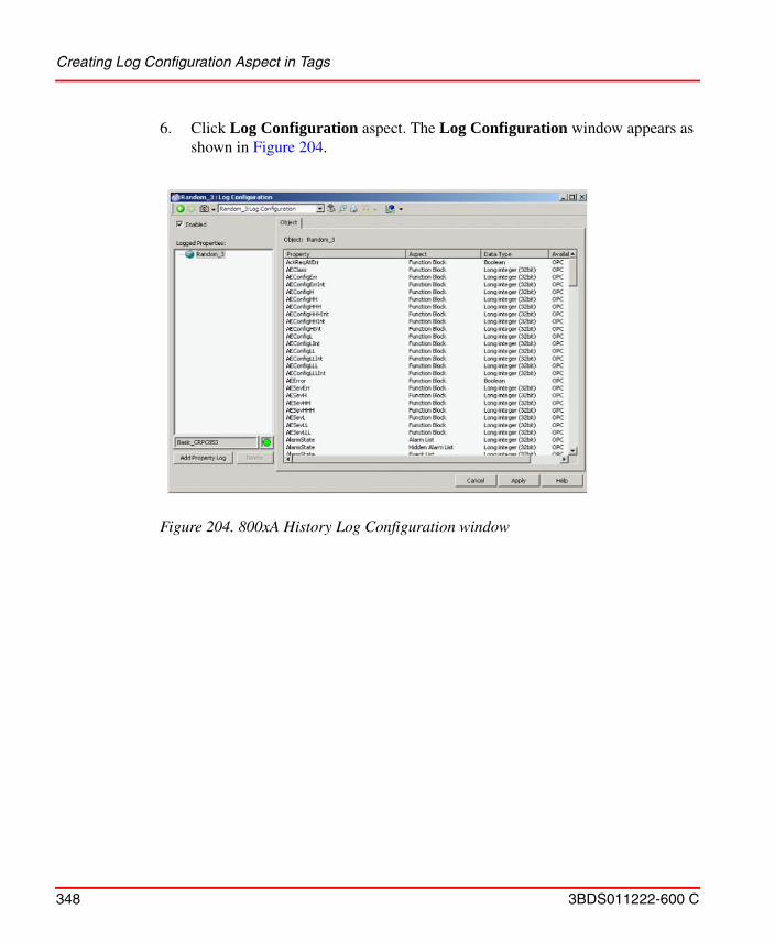
Creating Log Configuration Aspect in Tags
348 3BDS011222-600 C
6. Click Log Configuration aspect. The Log Configuration window appears as shown in Figure 204.
Figure 204. 800xA History Log Configuration window
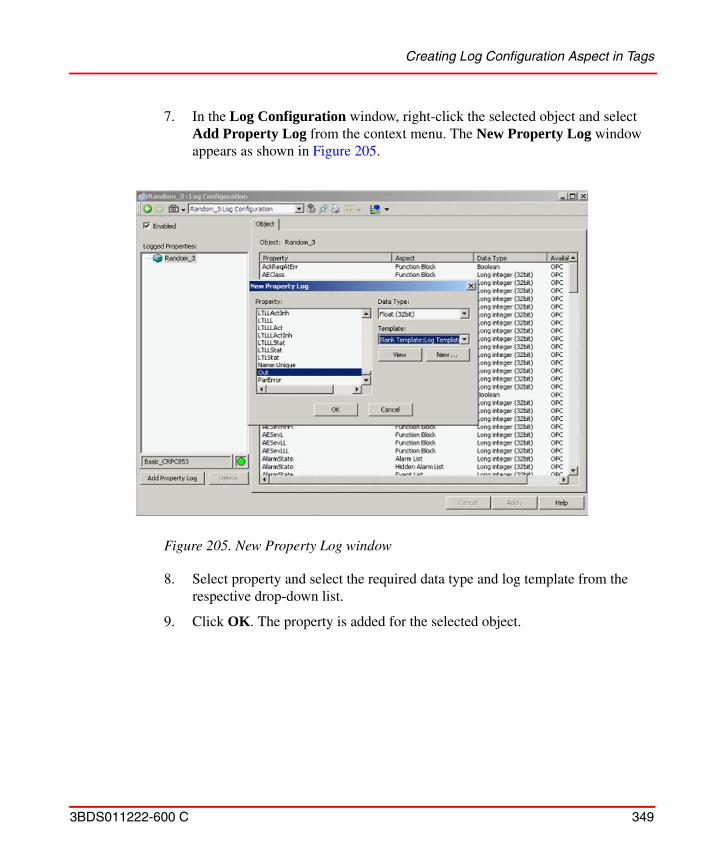
Creating Log Configuration Aspect in Tags
3BDS011222-600 C 349
7. In the Log Configuration window, right-click the selected object and select Add Property Log from the context menu. The New Property Log window appears as shown in Figure 205.
8. Select property and select the required data type and log template from the respective drop-down list.
9. Click OK. The property is added for the selected object.
Figure 205. New Property Log window
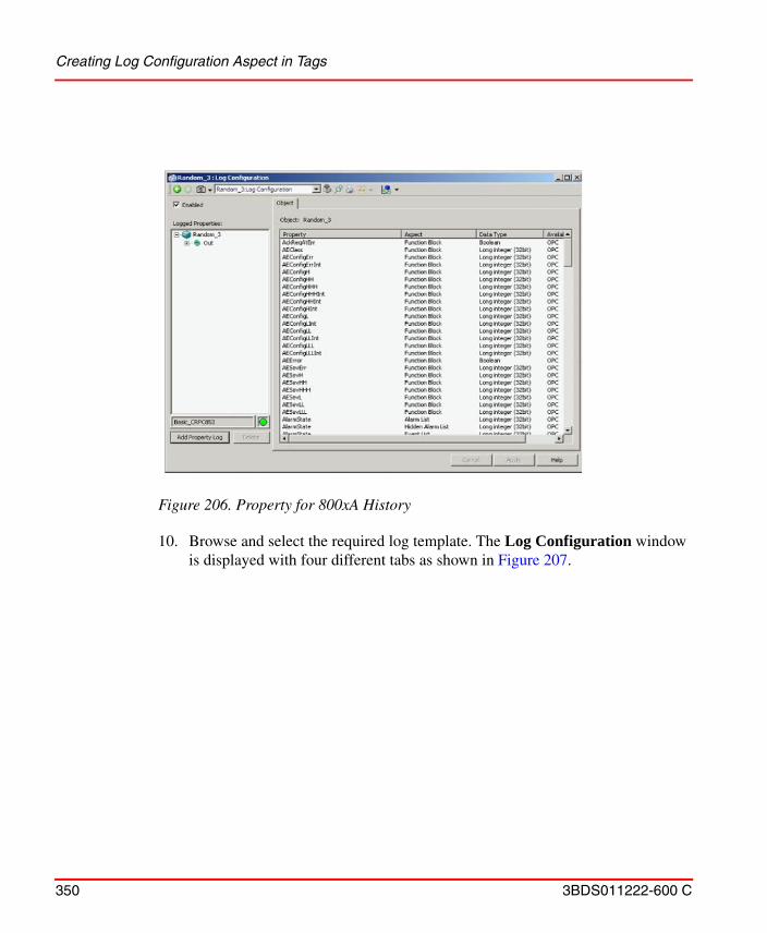
Creating Log Configuration Aspect in Tags
350 3BDS011222-600 C
10. Browse and select the required log template. The Log Configuration window
is displayed with four different tabs as shown in Figure 207.
Figure 206. Property for 800xA History
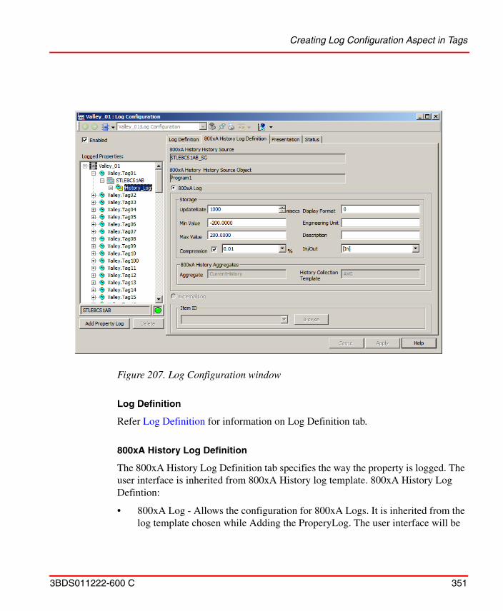
Creating Log Configuration Aspect in Tags
3BDS011222-600 C 351
Log Definition
Refer Log Definition for information on Log Definition tab.
800xA History Log Definition
The 800xA History Log Definition tab specifies the way the property is logged. The user interface is inherited from 800xA History log template. 800xA History Log Defintion:
• 800xA Log - Allows the configuration for 800xA Logs. It is inherited from the log template chosen while Adding the ProperyLog. The user interface will be
Figure 207. Log Configuration window
Creating Log Configuration Aspect in Tags
352 3BDS011222-600 C
enabled only for the base log (800xA History log). The configuration is enabled only for the base logs. Refer Creating Log Templates for more information on configuring log template.
Presentation
Refer to System 800xA Configuration (3BDS011222*), for information on Presentation tab.
Status
Refer to System 800xA Configuration (3BDS011222*), for information on Status tab.
Activate/Deactivate Log
1. Go to Log Configuration aspect of a particular tag.
2. In 800xA History Log Definition tab, by default the tags created will be in active state.
3. To de-activate, click Deactivate to disable the tag updates in 800xA History Server.
To activate the tag updates, click Active to enable it.
Binary Text
User can select the different binary text available in the drop down list for the change in the status of binary signal for the binary log properties.
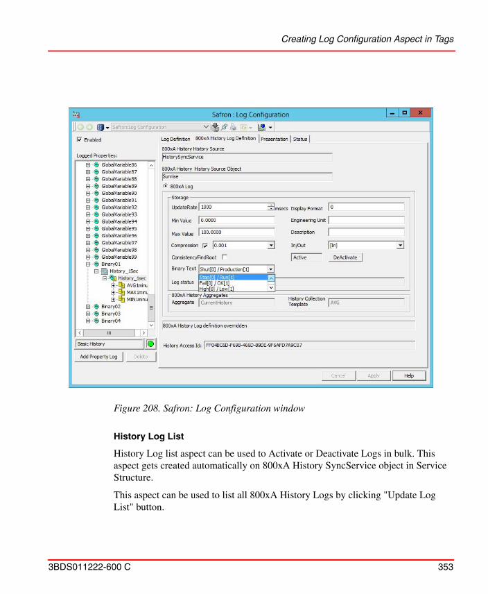
Creating Log Configuration Aspect in Tags
3BDS011222-600 C 353
History Log List
History Log list aspect can be used to Activate or Deactivate Logs in bulk. This aspect gets created automatically on 800xA History SyncService object in Service Structure.
This aspect can be used to list all 800xA History Logs by clicking "Update Log List" button.
Figure 208. Safron: Log Configuration window
Creating Log Configuration Aspect in Tags
354 3BDS011222-600 C
Multiple logs can be selected from the list and can be activated or deactivated.
Bulk Configuration
This section provides a detailed the procedure for using Bulk Import tool for performing bulk configuration.
Using Bulk Import Tool.
This procedure describes how to use the Bulk Import tool to instantiate log configuration aspects for their respective signals. This tool is used to instantiate a large quantity of property logs without having to use the Plant Explorer. This can substantially reduce the time spent configuring logs.
To configure property logs with the Bulk Configuration tool:
1. Launch Microsoft Excel and create a new workbook.
Bulk activation or deactivation of logs might cause a delay in updating the changes in History Server.
It is recommended to perform the bulk import with set of 5000 tags to avoid load on the basic history and avoid more time consumption.
If the user is not logged in with the user credentials that was used for installing the 800xA History Archiving software, then the Bulk Import add-in should be manually added to Excel from the following location:
C:\Program Files (x86)\ABB Industrial IT\Inform IT\History\bin\
For more information about including an add-in to Excel, refer Microsoft documentation. The first time an Excel Worksheet is opened with the add-ins, a prompt to enable macros may be displayed. Enable the macros to use the add-in tools.
Bulk Import tool is available only on the nodes where 800xa History Archiving is installed.
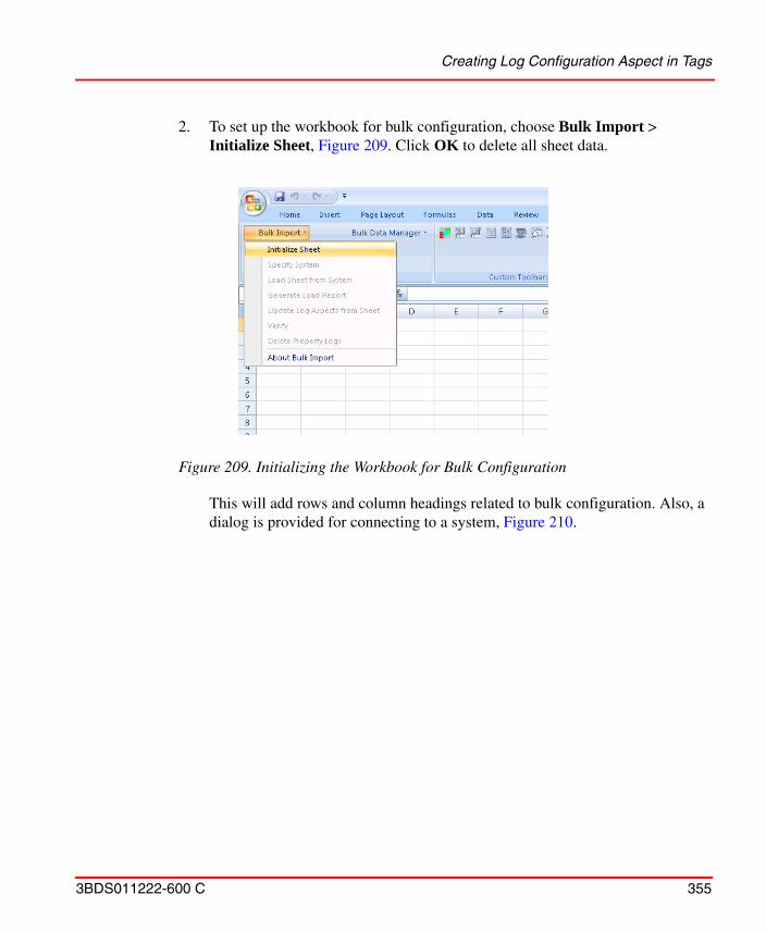
Creating Log Configuration Aspect in Tags
3BDS011222-600 C 355
2. To set up the workbook for bulk configuration, choose Bulk Import > Initialize Sheet, Figure 209. Click OK to delete all sheet data.
This will add rows and column headings related to bulk configuration. Also, a dialog is provided for connecting to a system, Figure 210.
Figure 209. Initializing the Workbook for Bulk Configuration
Creating Log Configuration Aspect in Tags
356 3BDS011222-600 C
3. Click Set System to connect the spreadsheet to the Aspect System as indicated in the Select a System dialog.
4. Import a list of object properties for which historical data will be collected. It is recommended that an import filter be applied so the import list can be limited to just those object properties needed. This minimizes the duration of the import operation and makes it easier to work with the Bulk Configuration tool.
A filter can be specified based on object name, aspect, and property as shown in Figure 211. This filter limits the list of returned properties to Out properties for all Function Block aspects in all Objects whose name pattern fits *SINE*.
Object = *SINE* (* is a wild card character string)Aspect = Function BlockProperty = Out
Figure 210. Initialized Workbook
Creating Log Configuration Aspect in Tags
3BDS011222-600 C 357
5. Once the filter is specified, choose Bulk Import > Load Sheet from System, Figure 212. This displays the Object Browser dialog.
6. Use the Object Browser to select an object that establishes the starting point from where the importer will begin to look for properties to add to the list.
Figure 211. Specifying an Import Filter
Figure 212. Loading the Spreadsheet with Object Properties
Creating Log Configuration Aspect in Tags
358 3BDS011222-600 C
7. Check the Include child objects, Include Logged Properties, and Include All Properties check boxes, Figure 213. This tells the importer to include in the search all child objects under the selected object.
8. Click Add. The import result is shown in Figure 214.
Note that the log configuration aspect created is also in the list. This is because the Include Logged Properties check box was selected.
Figure 213. Selecting the Object
Creating Log Configuration Aspect in Tags
3BDS011222-600 C 359
This example will use the same log template and log configuration aspect name for all the logs.
Every object property to be logged must have a property log template that meets the data collection requirements of the object property. Also, the name of the log configuration aspect must be specified.
These parameters are already specified for the SINE1 object to which the log configuration aspect was added. Make these specifications for the remaining objects as described below.
a. Use the log template specified for the SINE1 object property to apply the same template to any number of contiguous properties in the list by clicking the bottom right corner of the Property Template cell and pulling down to highlight the Property Template column for other contiguous
Figure 214. Import Filter Result
Creating Log Configuration Aspect in Tags
360 3BDS011222-600 C
properties, Figure 215. The template specification will be entered in the highlighted cells when the mouse button is released.
b. Use the same Log Configuration aspect name for all object properties in the list by copying the Log Configuration cell into the other rows in the list in the same manner as the property template.
c. Save the spreadsheet using a unique name.
Figure 215. Applying Property Log Specification to Contiguous Object Properties
The Bulk Configuration tool supports other methods to specify the log template and log configuration aspect name for the first object property in the list when a Log Configuration aspect is not added via the Plant Explorer. The alternatives are:
> entering the name directly if it is known.
> using the template list dialog (available via the context menu).
These methods are not covered in this tutorial.
Creating Log Configuration Aspect in Tags
3BDS011222-600 C 361
9. Once the log template and log configuration aspect definitions have been filled in, run the Bulk Configuration utility to update the log aspects from the spreadsheet. To do this, choose Bulk Import > Update Log Aspects from Sheet, Figure 216.
It is recommended that the spreadsheet be saved before running the Bulk Configuration function. This will enable Excel to be exited without losing the configuration data in the event of a problem. Give the sheet a unique name. If Excel is opened using DataDirect, DO NOT save the sheet using the default name. DataDirect opens the default spreadsheet whenever DataDirect is opened.
Creating Log Configuration Aspect in Tags
362 3BDS011222-600 C
Figure 216. Updating Log Aspects from the Sheet
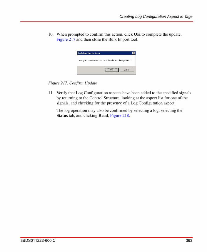
Creating Log Configuration Aspect in Tags
3BDS011222-600 C 363
10. When prompted to confirm this action, click OK to complete the update, Figure 217 and then close the Bulk Import tool.
11. Verify that Log Configuration aspects have been added to the specified signals by returning to the Control Structure, looking at the aspect list for one of the signals, and checking for the presence of a Log Configuration aspect.
The log operation may also be confirmed by selecting a log, selecting the Status tab, and clicking Read, Figure 218.
Figure 217. Confirm Update
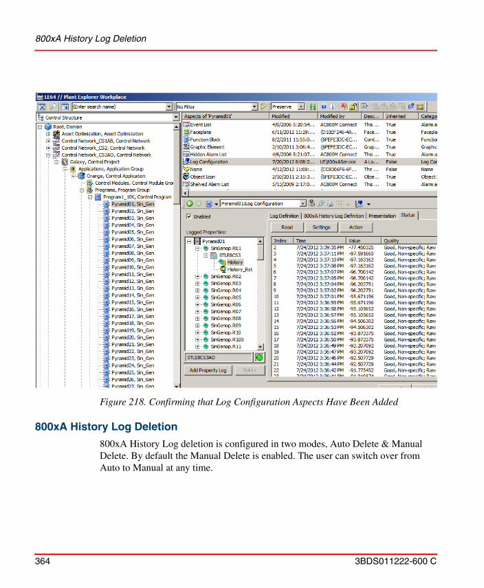
800xA History Log Deletion
364 3BDS011222-600 C
800xA History Log Deletion
800xA History Log deletion is configured in two modes, Auto Delete & Manual Delete. By default the Manual Delete is enabled. The user can switch over from Auto to Manual at any time.
Figure 218. Confirming that Log Configuration Aspects Have Been Added
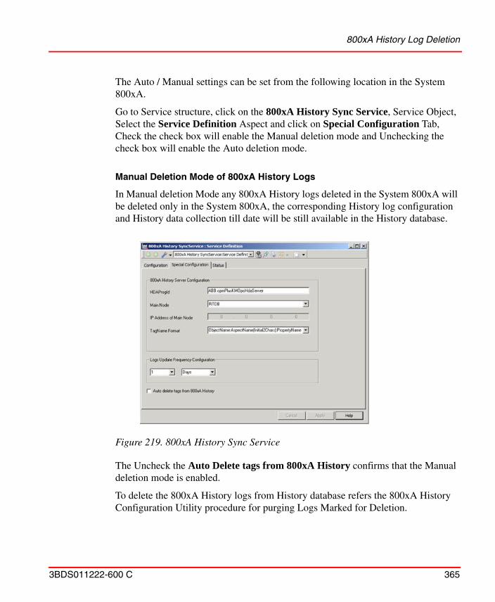
800xA History Log Deletion
3BDS011222-600 C 365
The Auto / Manual settings can be set from the following location in the System 800xA.
Go to Service structure, click on the 800xA History Sync Service, Service Object, Select the Service Definition Aspect and click on Special Configuration Tab, Check the check box will enable the Manual deletion mode and Unchecking the check box will enable the Auto deletion mode.
Manual Deletion Mode of 800xA History Logs
In Manual deletion Mode any 800xA History logs deleted in the System 800xA will be deleted only in the System 800xA, the corresponding History log configuration and History data collection till date will be still available in the History database.
The Uncheck the Auto Delete tags from 800xA History confirms that the Manual deletion mode is enabled.
To delete the 800xA History logs from History database refers the 800xA History Configuration Utility procedure for purging Logs Marked for Deletion.
Figure 219. 800xA History Sync Service
800xA History Log Deletion
366 3BDS011222-600 C
Auto Deletion Mode of 800xA History Logs
When the check box for Auto Delete tags from 800xA History is checked as shown in the figure, it confirms the Auto Deletion mode for 800xA History Logs is Enabled. When this mode is enabled, any 800xA History Log deleted in the System 800xA will be deleted in the History Database including the History data collected till date. The deleted data cannot be recovered.
Invalid 800xA History logs should be removed manually from the 800xA History Vtrin
In 800xA, when 800xA History Log Configuration or child object is deleted, the reference paths still maintained in history. Due to this behavior of 800xA history, when ABB Smart Client accesses the History tags via Smart Client Property Browser, the path and the parent object of deleted log (or deleted child object) still appears.
Follow the below steps to remove the Invalid 800xA History Logs from the Vtrin Equipment Model list.
1. Login into the 800xA History Server with the Admin account.
2. Open the Vtrin, Navigate to the Equipment Model List as shown in Figure 220.
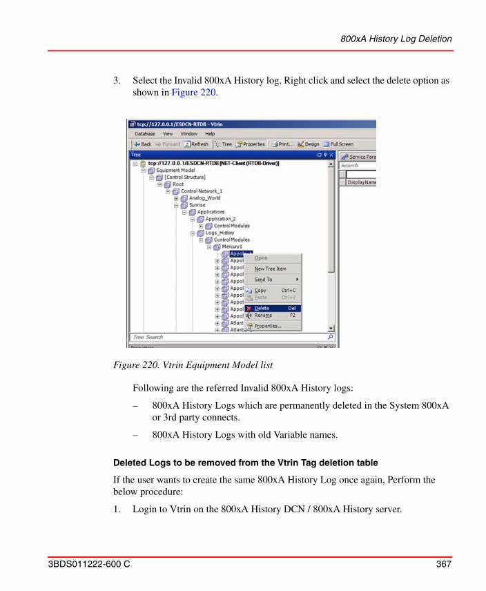
800xA History Log Deletion
3BDS011222-600 C 367
3. Select the Invalid 800xA History log, Right click and select the delete option as shown in Figure 220.
Following are the referred Invalid 800xA History logs:
– 800xA History Logs which are permanently deleted in the System 800xA or 3rd party connects.
– 800xA History Logs with old Variable names.
Deleted Logs to be removed from the Vtrin Tag deletion table
If the user wants to create the same 800xA History Log once again, Perform the below procedure:
1. Login to Vtrin on the 800xA History DCN / 800xA History server.
Figure 220. Vtrin Equipment Model list
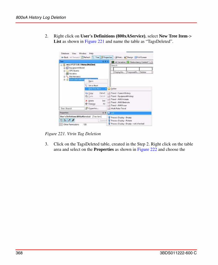
800xA History Log Deletion
368 3BDS011222-600 C
2. Right click on User's Definitions (800xAService), select New Tree Item-> List as shown in Figure 221 and name the table as “TagsDeleted”.
3. Click on the TagsDeleted table, created in the Step 2. Right click on the table area and select on the Properties as shown in Figure 222 and choose the
Figure 221. Vtrin Tag Deletion
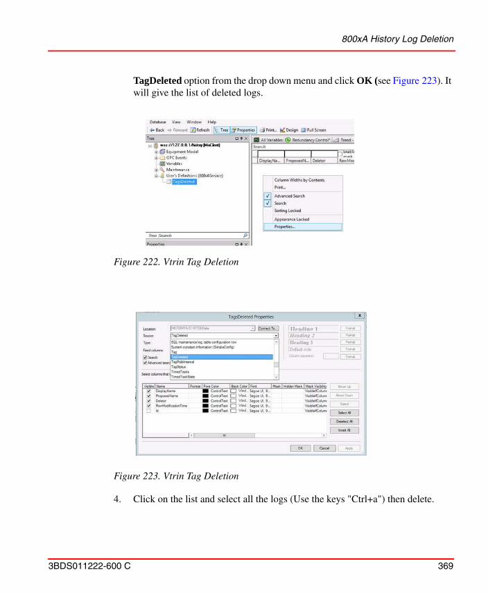
800xA History Log Deletion
3BDS011222-600 C 369
TagDeleted option from the drop down menu and click OK (see Figure 223). It will give the list of deleted logs.
4. Click on the list and select all the logs (Use the keys "Ctrl+a") then delete.
Figure 222. Vtrin Tag Deletion
Figure 223. Vtrin Tag Deletion
800xA History Configuration Utility
370 3BDS011222-600 C
800xA History Configuration Utility
800xA History Configuration utility is a tool which can be utilized for the following:
• To check the History Logs synchronization between History database and System 800xA.
• To Synchronize the History Logs between History database and System 800xA if found Out Of Sync.
• To list the Duplicate History Logs present in the History Database.
• To purge/delete the 800xA History Logs from the History database that are marked for deletion.
• To perform the first function with External 800xA History Data Collector Database configured in another 800xA System.
The utility can also be used for activating and deactivating 800xA History Logs.
The tool should be accessed from the following path only on the 800xA History Data Collector Nodes.
Path: C:\Program Files (x86)\ABB Industrial IT\Inform IT\ABB 800xA History Connectivity\bin
Perform the following steps to use the 800xA History Configuration Utility tool:
1. Login with the 800xA History Installed user account on the Data Collector node.
2. Open the Plant explorer workplace and go to Service structure find the 800xA History Sync Service group of the respective 800xA History Data Collector node and stop its service providers by Unchecking the check box.
3. Navigate to the path: “C:\Program Files (x86)\ABB Industrial IT\Inform IT\ABB 800xA History Connectivity\bin” on the 800xA History Data Collector Nodes and double click on the tool to launch.
Perform this step-2, only while performing the Syncronize and Purge operation using 800xA History Configuration Utility tool
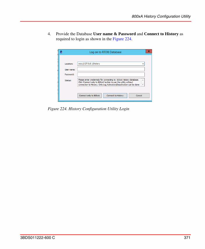
800xA History Configuration Utility
3BDS011222-600 C 371
4. Provide the Database User name & Password and Connect to History as required to login as shown in the Figure 224.
Figure 224. History Configuration Utility Login
800xA History Configuration Utility
372 3BDS011222-600 C
Connect only to 800xA:
The Tool gets connected only to the System 800xA. For changing Active/Inactivate state of the 800xA History Logs, database connection is not required. The user can click Connect only to 800xA without entering database username and password.
Connect to History:
The tool gets connected to 800xA History database, The user can perform all the operations described in 800xA History Configuration Utility tool when connected to the local History Data Collector database. If the user has connected to a remote History Data Collector database only Synchronize operation will be available. Removing duplicate Logs and Purging Marked for Deletion Logs should only be done when connected to the local History Data Collector Database. Engineering should not be done while using the tool.
5. For connecting to the external History Data Collector database on the other system, modify the connecting string in the location. If there are duplicate tags after synchronizing with the external DCN in Engineering System, start the 800xA History Sync service before the duplicate tags can deleted from the local DCN. This is applicable only if the 800xA History Sync service is running in Auto DELETE OFF. Ideally the 800xA History Sync service in the engineering system should either be running with Auto DELETE option or it should not be running at all.
If the external DCN node name is “DCNA” and IpAdress is 172.16.4.1 then URL will be as below:
wss://172.16.4.1:443/history.
• Users can only perform Logs Out of Sync operation when the utility tool connected to the External History Database.
• The CPU load of the 800xA History Data Collector node may be high sometimes when bulk operations are performed using the 800xA History Configuration Utility tool. Hence it is recommended to perform such activities during planned maintenance.
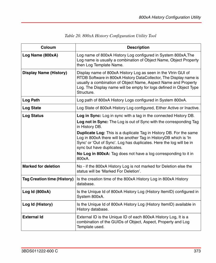
800xA History Configuration Utility
3BDS011222-600 C 373
Table 20. 800xA History Configuration Utility Tool
Coloum Description
Log Name (800xA) Log name of 800xA History Log configured in System 800xA,The Log name is usually a combination of Object Name, Object Property then Log Template Name.
Display Name (History) Display name of 800xA History Log as seen in the Vtrin GUI of RTDB Software in 800xA History DataCollector, The Display name is usually a combination of Object Name, Aspect Name and Property Log. The Display name will be empty for logs defined in Object Type Structure.
Log Path Log path of 800xA History Logs configured in System 800xA.
Log State Log State of 800xA History Log configured, Either Active or Inactive.
Log Status Log in Sync: Log in sync with a tag in the connected History DB.
Log not in Sync: The Log is out of Sync with the corresponding Tag in History DB.
Duplicate Log: This is a duplicate Tag in History DB. For the same Log in 800xA there will be another Tag in HistoryDB which is 'In Sync' or 'Out of Sync'. Log has duplicates. Here the log will be in sync but have duplicates.
No Log in 800xA: Tag does not have a log corresponding to it in 800xA.
Marked for deletion No - if the 800xA History Log is not marked for Deletion else the status will be ‘Marked For Deletion’.
Tag Creation time (History) Is the creation time of the 800xA History Log in 800xA History database.
Log Id (800xA) Is the Unique Id of 800xA History Log (History ItemID) configured in System 800xA.
Log Id (History) Is the Unique Id of 800xA History Log (History ItemID) available in History database.
External Id External ID is the Unique ID of each 800xA History Log, It is a combination of the GUIDs of Object, Aspect, Property and Log Template used.
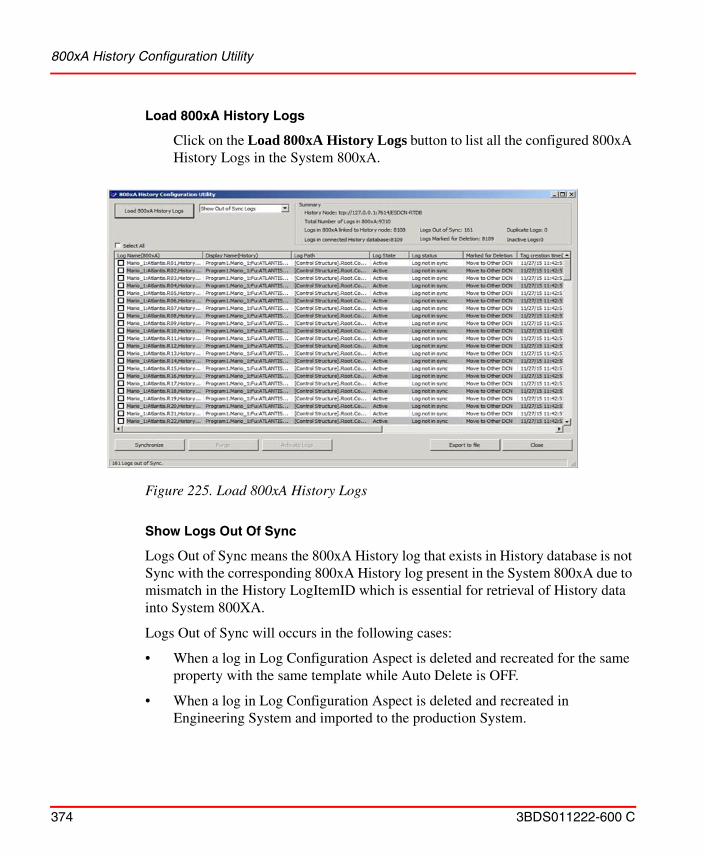
800xA History Configuration Utility
374 3BDS011222-600 C
Load 800xA History Logs
Click on the Load 800xA History Logs button to list all the configured 800xA History Logs in the System 800xA.
Show Logs Out Of Sync
Logs Out of Sync means the 800xA History log that exists in History database is not Sync with the corresponding 800xA History log present in the System 800xA due to mismatch in the History LogItemID which is essential for retrieval of History data into System 800XA.
Logs Out of Sync will occurs in the following cases:
• When a log in Log Configuration Aspect is deleted and recreated for the same property with the same template while Auto Delete is OFF.
• When a log in Log Configuration Aspect is deleted and recreated in Engineering System and imported to the production System.
Figure 225. Load 800xA History Logs
800xA History Configuration Utility
3BDS011222-600 C 375
• When a log in Log Configuration Aspect is deleted in Production System while Auto Delete is ON and recreate the log for the same property with the same template.
In all the above cases, the log in Engineering System also needs to be synchronized with the newly synchronized log in Production System.
Synchronization of tags between Engineering and Production System, should always be done from the Engineering System connecting to production DCN. The tool should never be used to synchronize the tags from production System connecting to Engineering DCN.
If a Log Configuration Aspect or the Object containing the log is deleted and recreated, Tags cannot be (connected) Synchronized back.
But, if the Log configuration Aspect or object is imported back instead of recreating, the tags will be connected back.
Perform the following when Logs Out of Sync occurs:
1. Perform the Sync operations using 800xA History Configuration utility tool, the tool updates the History LogItemID from the History database to the corresponding History Log in the System 800xA.
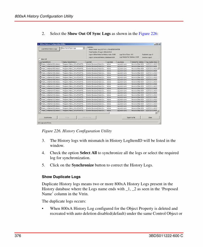
800xA History Configuration Utility
376 3BDS011222-600 C
2. Select the Show Out Of Sync Logs as shown in the Figure 226:
3. The History logs with mismatch in History LogItemID will be listed in the window.
4. Check the option Select All to synchronize all the logs or select the required log for synchronization.
5. Click on the Synchronize button to correct the History Logs.
Show Duplicate Logs
Duplicate History logs means two or more 800xA History Logs present in the History database where the Logs name ends with _1, _2 as seen in the ‘Proposed Name’ column in the Vtrin.
The duplicate logs occurs:
• When 800xA History Log configured for the Object Property is deleted and recreated with auto deletion disabled(default) under the same Control Object or
Figure 226. History Configuration Utility
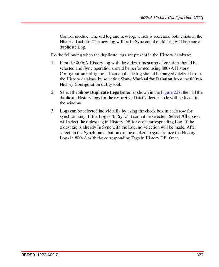
800xA History Configuration Utility
3BDS011222-600 C 377
Control module. The old log and new log, which is recreated both exists in the History database. The new log will be In Sync and the old Log will become a duplicate Log.
Do the following when the duplicate logs are present in the History database:
1. First the 800xA History log with the oldest timestamp of creation should be selected and Sync operation should be performed using 800xA History Configuration utility tool. Then duplicate log should be purged / deleted from the History database by selecting Show Marked for Deletion from the 800xA History Configuration utility tool.
2. Select the Show Duplicate Logs button as shown in the Figure 227, then all the duplicate History logs for the respective DataCollector node will be listed in the window.
3. Logs can be selected individually by using the check box in each row for synchronizing. If the Log is ‘In Sync’ it cannot be selected. Select All option will select the oldest tag in History DB for each corresponding Log. If the oldest tag is already In Sync with the Log, no selection will be made. After selection the Synchronize button can be clicked to synchronize the History Logs in 800xA with the corresponding Tags in History DB. Once
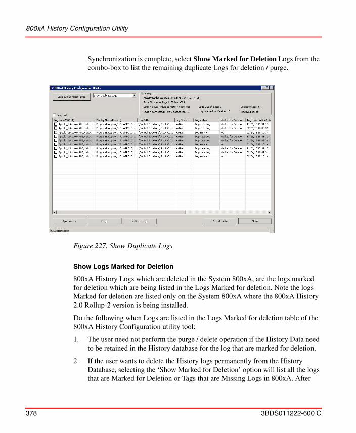
800xA History Configuration Utility
378 3BDS011222-600 C
Synchronization is complete, select Show Marked for Deletion Logs from the combo-box to list the remaining duplicate Logs for deletion / purge.
Show Logs Marked for Deletion
800xA History Logs which are deleted in the System 800xA, are the logs marked for deletion which are being listed in the Logs Marked for deletion. Note the logs Marked for deletion are listed only on the System 800xA where the 800xA History 2.0 Rollup-2 version is being installed.
Do the following when Logs are listed in the Logs Marked for deletion table of the 800xA History Configuration utility tool:
1. The user need not perform the purge / delete operation if the History Data need to be retained in the History database for the log that are marked for deletion.
2. If the user wants to delete the History logs permanently from the History Database, selecting the ‘Show Marked for Deletion’ option will list all the logs that are Marked for Deletion or Tags that are Missing Logs in 800xA. After
Figure 227. Show Duplicate Logs
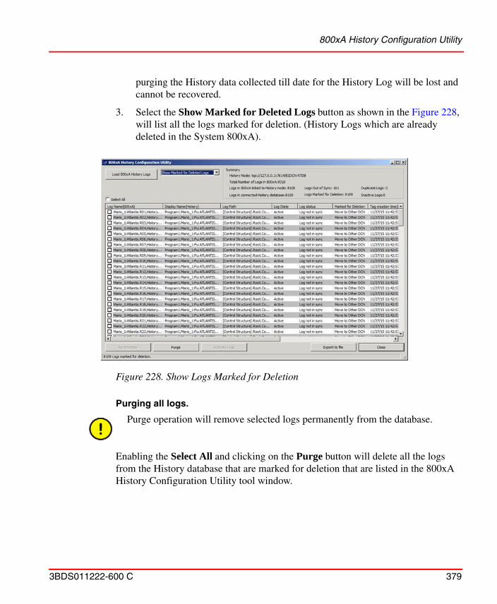
800xA History Configuration Utility
3BDS011222-600 C 379
purging the History data collected till date for the History Log will be lost and cannot be recovered.
3. Select the Show Marked for Deleted Logs button as shown in the Figure 228, will list all the logs marked for deletion. (History Logs which are already deleted in the System 800xA).
Purging all logs.
Enabling the Select All and clicking on the Purge button will delete all the logs from the History database that are marked for deletion that are listed in the 800xA History Configuration Utility tool window.
Figure 228. Show Logs Marked for Deletion
Purge operation will remove selected logs permanently from the database.
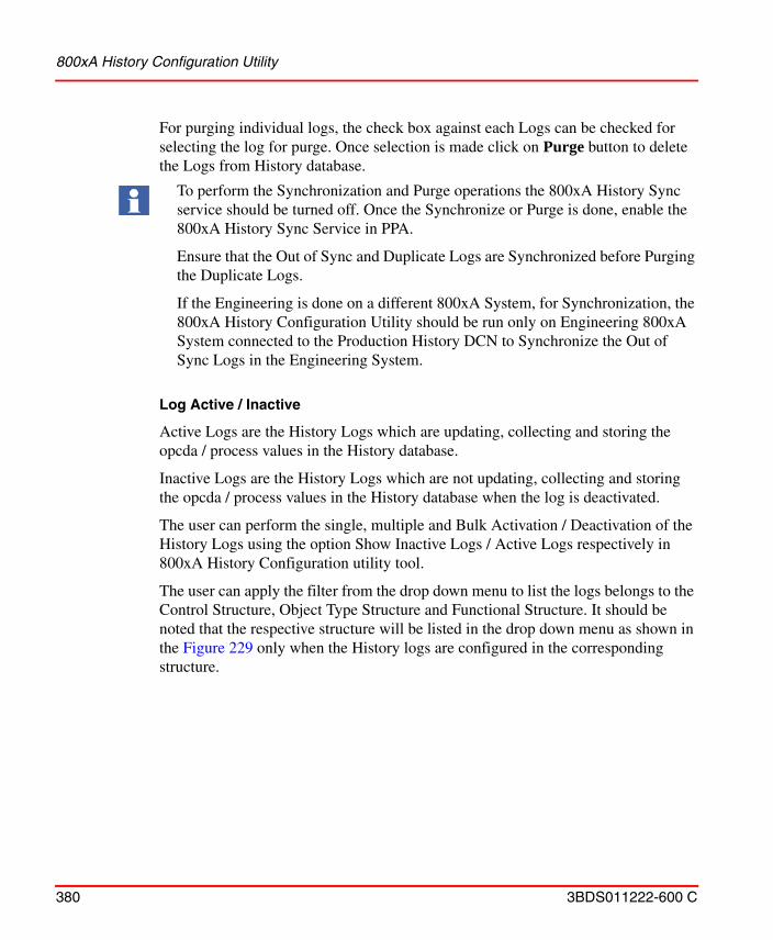
800xA History Configuration Utility
380 3BDS011222-600 C
For purging individual logs, the check box against each Logs can be checked for selecting the log for purge. Once selection is made click on Purge button to delete the Logs from History database.
Log Active / Inactive
Active Logs are the History Logs which are updating, collecting and storing the opcda / process values in the History database.
Inactive Logs are the History Logs which are not updating, collecting and storing the opcda / process values in the History database when the log is deactivated.
The user can perform the single, multiple and Bulk Activation / Deactivation of the History Logs using the option Show Inactive Logs / Active Logs respectively in 800xA History Configuration utility tool.
The user can apply the filter from the drop down menu to list the logs belongs to the Control Structure, Object Type Structure and Functional Structure. It should be noted that the respective structure will be listed in the drop down menu as shown in the Figure 229 only when the History logs are configured in the corresponding structure.
To perform the Synchronization and Purge operations the 800xA History Sync service should be turned off. Once the Synchronize or Purge is done, enable the 800xA History Sync Service in PPA.
Ensure that the Out of Sync and Duplicate Logs are Synchronized before Purging the Duplicate Logs.
If the Engineering is done on a different 800xA System, for Synchronization, the 800xA History Configuration Utility should be run only on Engineering 800xA System connected to the Production History DCN to Synchronize the Out of Sync Logs in the Engineering System.
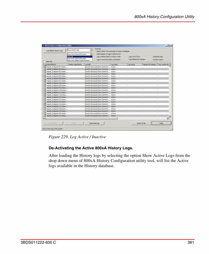
800xA History Configuration Utility
3BDS011222-600 C 381
De-Activating the Active 800xA History Logs.
After loading the History logs by selecting the option Show Active Logs from the drop down menu of 800xA History Configuration utility tool, will list the Active logs available in the History database.
Figure 229. Log Active / Inactive
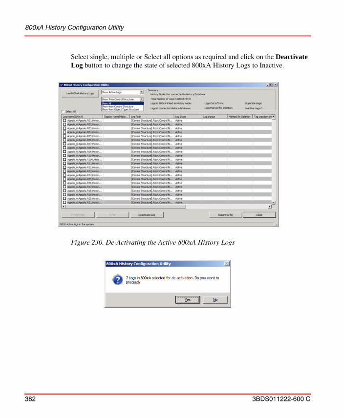
800xA History Configuration Utility
382 3BDS011222-600 C
Select single, multiple or Select all options as required and click on the Deactivate Log button to change the state of selected 800xA History Logs to Inactive.
Figure 230. De-Activating the Active 800xA History Logs

800xA History Configuration Utility
3BDS011222-600 C 383
Activating the InActive 800xA History Logs.
After Loading 800xA History Logs, selecting ‘Show Inactive Logs’ from the drop down menu in the 800xA History configuration utility will list the Inactive logs available in the History database.
Select single, multiple or select all options as required and click on the Activate Log button to change the state of selected 800xA History Logs to Active.
Figure 231. Activating the InActive 800xA History Logs
800xA History Configuration Utility
384 3BDS011222-600 C
Export File
Click on the Export to file button to export the Log Summary of fetched data from the History database to a file which can be saved in the .csv format.
Summary
History Node: Displays the 800xA History Database node to which the tool is connected to.
Total No of Logs in 800xA: The total 800xA History Logs count configured in the System 800xA for all the 800xA History Data Collector nodes in the system.
Logs in 800xA Linked to History: The number of 800xA History logs in the system which are mapped to the 800xA History database.
Logs in Connected History Database: Is the total 800xA History Logs count in the respective 800xA History Data Collector node.
Logs Out of Sync: Is the total 800xA History Logs count, which are Out Of Sync in the respective 800xA History Data Collector node.
Duplicate Logs: Is the total 800xA History duplicate logs count in the respective 800xA History Data Collector node.
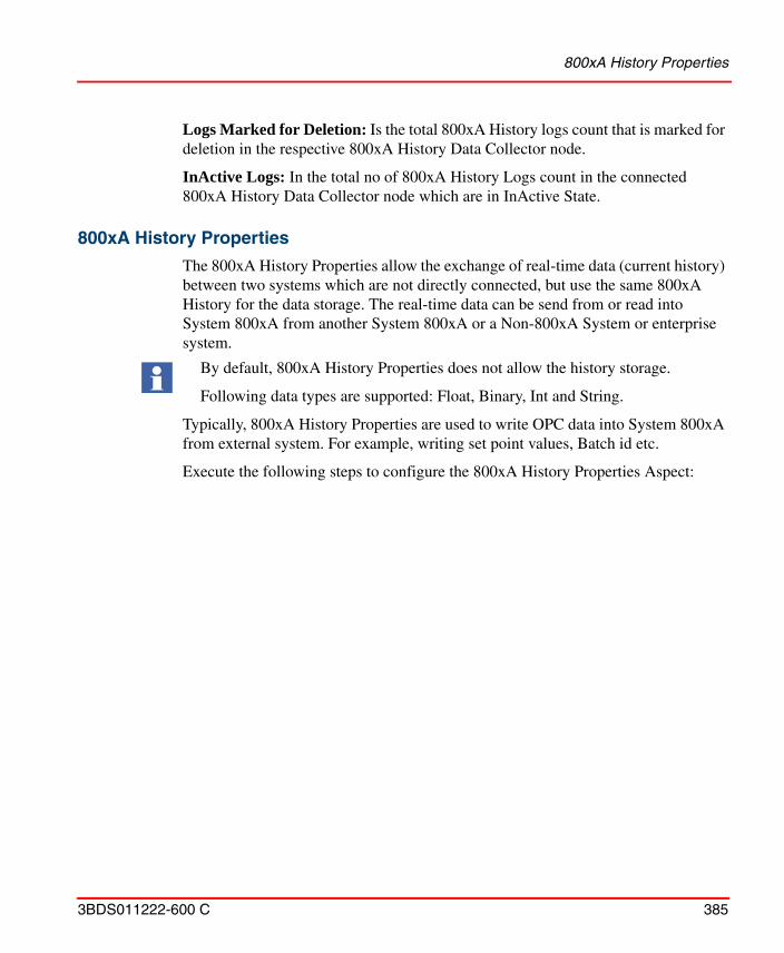
800xA History Properties
3BDS011222-600 C 385
Logs Marked for Deletion: Is the total 800xA History logs count that is marked for deletion in the respective 800xA History Data Collector node.
InActive Logs: In the total no of 800xA History Logs count in the connected 800xA History Data Collector node which are in InActive State.
800xA History Properties
The 800xA History Properties allow the exchange of real-time data (current history) between two systems which are not directly connected, but use the same 800xA History for the data storage. The real-time data can be send from or read into System 800xA from another System 800xA or a Non-800xA System or enterprise system.
Typically, 800xA History Properties are used to write OPC data into System 800xA from external system. For example, writing set point values, Batch id etc.
Execute the following steps to configure the 800xA History Properties Aspect:
By default, 800xA History Properties does not allow the history storage.
Following data types are supported: Float, Binary, Int and String.
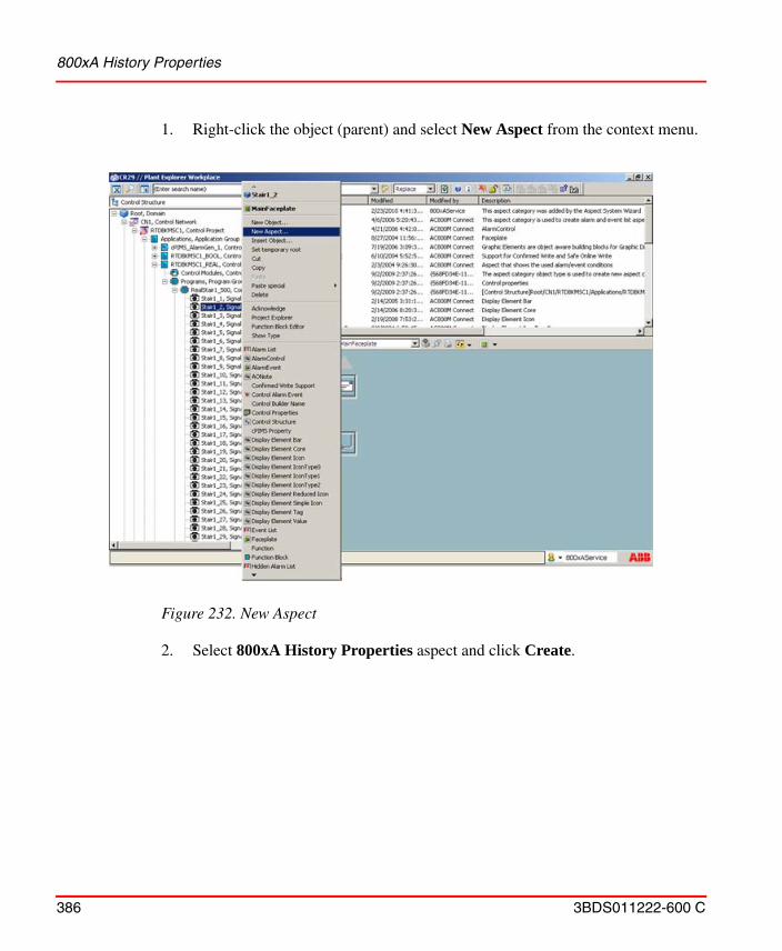
800xA History Properties
386 3BDS011222-600 C
1. Right-click the object (parent) and select New Aspect from the context menu.
2. Select 800xA History Properties aspect and click Create.
Figure 232. New Aspect
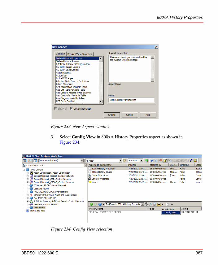
800xA History Properties
3BDS011222-600 C 387
3. Select Config View in 800xA History Properties aspect as shown in Figure 234.
Figure 233. New Aspect window
Figure 234. Config View selection
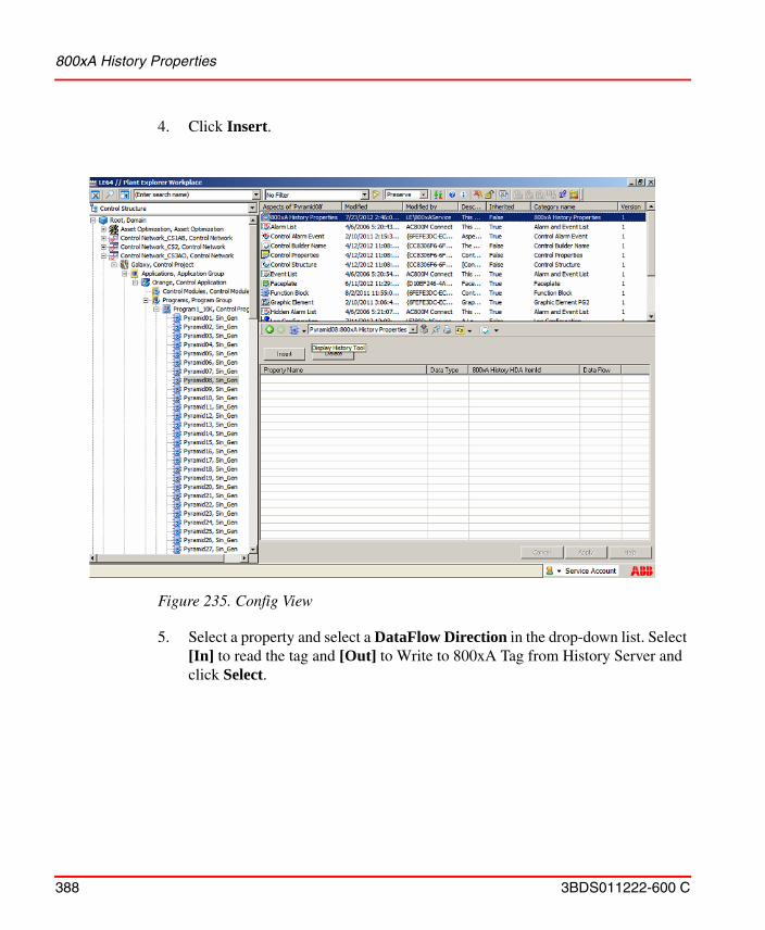
800xA History Properties
388 3BDS011222-600 C
4. Click Insert.
5. Select a property and select a DataFlow Direction in the drop-down list. Select [In] to read the tag and [Out] to Write to 800xA Tag from History Server and click Select.
Figure 235. Config View
Configuring Event Retrieval
3BDS011222-600 C 389
6. Click Apply.
Configuring Event Retrieval
Event retrieval mechanism allows the user to retrieve the events stored in History Server and make them available in 800xA system.
Before you begin with the retrieval of event data, make sure to perform the below procedure.
Create Alarm and Event List Configuration Aspect
1. Create an Alarm Event List aspect under any structure.
2. Right-click on the aspect and select Config View.
Figure 236. Select Properties window
Configuring Event Retrieval
390 3BDS011222-600 C
3. Under Configuration area, select Common Event List Configuration: Alarm and Event List Configuration from the drop-down list as shown in Figure 237.
Figure 237. Alarm and Event List aspect - Config View
Configuring Event Retrieval
3BDS011222-600 C 391
4. Click Copy Template and Apply. Alarm and Event List Configuration aspect is created and appears in the Aspect pane as shown in Figure 238.
1. In the Aspect pane, select Alarm and Event List Configuration aspect.
2. In the Aspect view, under Filter tab, select Source as 800xA History.
The event data can now be retrieved based on the following approach:
• Retrieve Based on Event Type
• Retrieve Events Based on Category
Figure 238. Alarm and Event List Configuration aspect is created
Configuring Event Retrieval
392 3BDS011222-600 C
• Retrieve Events Based on Attributes
• Retrieval Events Based on Event Time
• Retrieval Events Based on PPA Object ID
Retrieve Based on Event Type
Messages retrieved from 800xAHistoryServer can be filtered based on event types i.e., Condition Events, Simple Events, or Tracking Events.
To retrieve events based on event type, do the following:
1. In Categories section, select the corresponding Event type check boxes to include in the event data retrieval.
2. Click Apply.
Figure 239. Retrieval based on event types
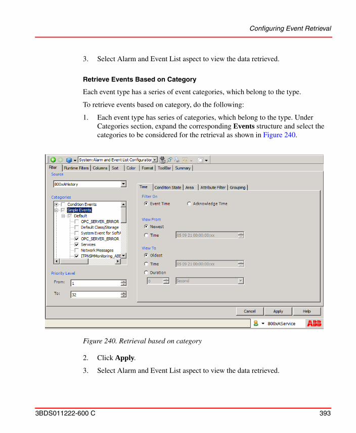
Configuring Event Retrieval
3BDS011222-600 C 393
3. Select Alarm and Event List aspect to view the data retrieved.
Retrieve Events Based on Category
Each event type has a series of event categories, which belong to the type.
To retrieve events based on category, do the following:
1. Each event type has series of categories, which belong to the type. Under Categories section, expand the corresponding Events structure and select the categories to be considered for the retrieval as shown in Figure 240.
2. Click Apply.
3. Select Alarm and Event List aspect to view the data retrieved.
Figure 240. Retrieval based on category
Configuring Event Retrieval
394 3BDS011222-600 C
Retrieve Events Based on Attributes
Event retrieval can be performed based on attributes. Event retrieval based on attributes is supported for the attributes that are part of OpcEvent table of Vtrin in History Server.
Event retrieval by attribute filtering is supported for Class, Priority, BatchId, UnitId, Area, ObjectName, ObjectDescription, Component, SourceId (i.e. SourceGUID in 800xA terms) and the standard OPC attributes. Any other attribute which are not part of Vtrin's OpcEvent table is not supported for attribute filtering.
Wildcard characters (* and ?) can be used for filtering. For example:
i) To search all events having the word "started" in the attribute "Message", the wildcard search string can be "*started*"
ii) To search all events ending with the word "DCN" followed by any two characters in the attribute "Message", the wildcard search string can be "*DCN??"
Runtime filters in Alarm and Event List can also be configured.
Retrieval Events Based on Event Time
Messages retrieved from 800xAHistoryServer can be filtered based on event time.
To retrieve events based on event time, do the following:
1. Select Newest and Oldest to apply no time filter as shown in Figure 241.
2. To apply a time filter, do the following:
a. Select Time in the View From or View To area.
b. Select the month, day, year, hour, minute or second segment of the Time area and use the up and down arrows to the right of the area to adjust the
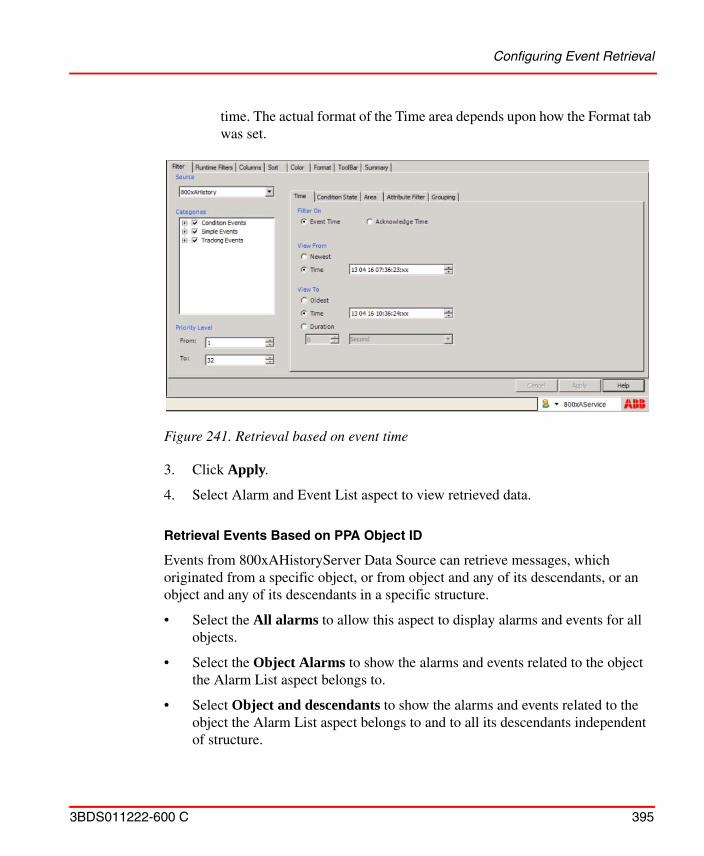
Configuring Event Retrieval
3BDS011222-600 C 395
time. The actual format of the Time area depends upon how the Format tab was set.
3. Click Apply.
4. Select Alarm and Event List aspect to view retrieved data.
Retrieval Events Based on PPA Object ID
Events from 800xAHistoryServer Data Source can retrieve messages, which originated from a specific object, or from object and any of its descendants, or an object and any of its descendants in a specific structure.
• Select the All alarms to allow this aspect to display alarms and events for all objects.
• Select the Object Alarms to show the alarms and events related to the object the Alarm List aspect belongs to.
• Select Object and descendants to show the alarms and events related to the object the Alarm List aspect belongs to and to all its descendants independent of structure.
Figure 241. Retrieval based on event time
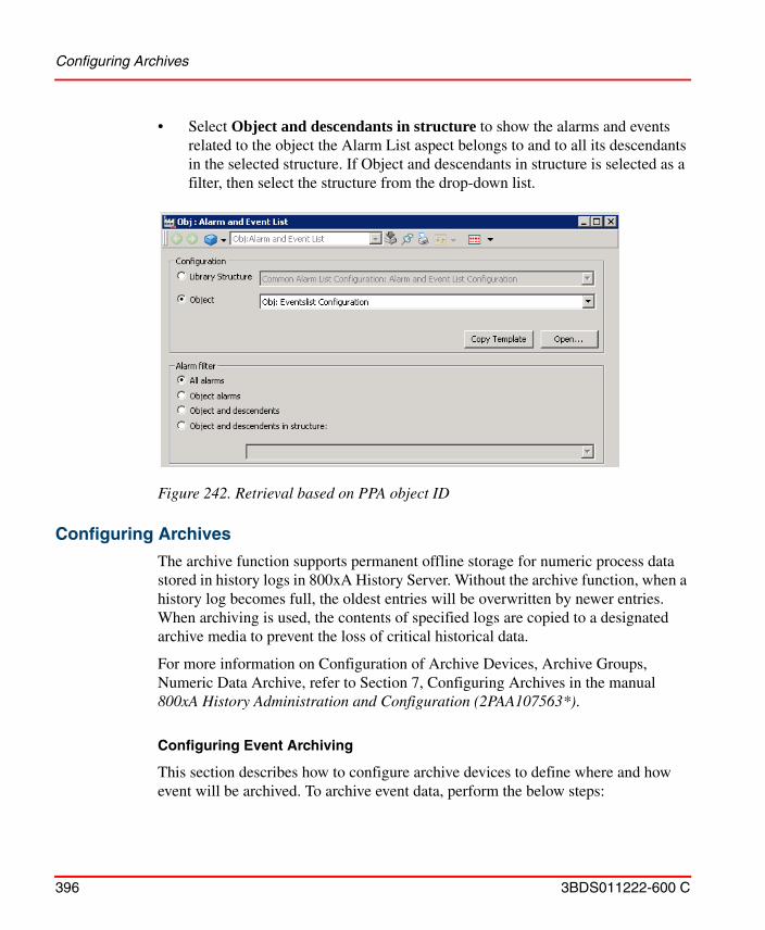
Configuring Archives
396 3BDS011222-600 C
• Select Object and descendants in structure to show the alarms and events related to the object the Alarm List aspect belongs to and to all its descendants in the selected structure. If Object and descendants in structure is selected as a filter, then select the structure from the drop-down list.
Configuring Archives
The archive function supports permanent offline storage for numeric process data stored in history logs in 800xA History Server. Without the archive function, when a history log becomes full, the oldest entries will be overwritten by newer entries. When archiving is used, the contents of specified logs are copied to a designated archive media to prevent the loss of critical historical data.
For more information on Configuration of Archive Devices, Archive Groups, Numeric Data Archive, refer to Section 7, Configuring Archives in the manual 800xA History Administration and Configuration (2PAA107563*).
Configuring Event Archiving
This section describes how to configure archive devices to define where and how event will be archived. To archive event data, perform the below steps:
Figure 242. Retrieval based on PPA object ID
Configuring Archives
3BDS011222-600 C 397
• Adding and Configuring Archive Group
• Adding and Configuring Group Entry
• Performing Manual Archiving
• Making Archived Event Data Available to Client Applications
• Retrieving Published A/E Data
Adding and Configuring Archive Group.
To add and configure an Archive Group:
1. Right click inside the archive groups window (or click Actions) and choose New Group, Figure 243.
Figure 243. Adding an Archive Group
Configuring Archives
398 3BDS011222-600 C
2. Add Archive Group dialog box displays as shown in Figure 244.
3. Enter the Group name, description (optional), and the Industrial IT Archive Service Group whose service provider will manage this archive group.
4. Click OK.
5. Click Apply to initialize the new group.
Figure 244. Add Archive Group dialog
Configuring Archives
3BDS011222-600 C 399
Adding and Configuring Group Entry.
To add and configure group entry, do the following:
1. After creating an archive group, right-click on the group and select New Entry as shown in Figure 245.
2. Add Group Entry dialog box appears as shown in Figure 246.
Figure 245. Selecting New Entry context menu option
Configuring Archives
400 3BDS011222-600 C
3. Select 800xA History Event Log from the drop-down list.
4. Click OK to add the group entry.
Performing Manual Archiving.
Typically, archiving is configured to occur periodically according to schedules configured through the Application Scheduler. A manual (on-demand) archive may also be performed. For manual archives, if the specified time range has no samples, no data will be archived. Follow the below method to perform manual archive:
• Perform a manual archive of an archive group. This functionality is supported by the Archive Group aspect.
Manual Archiving for Archive Groups
This procedure is done using the archive group aspect. This aspect provides a list of all archive groups configured within the system. Other functions supported by this aspect that may be useful for archiving on a group basis are:
• List Group Items
• Resetting the Last Archive Time for an Archive Group
To perform manual archiving, do the following:
1. After creating a group entry, right-click on archive group and select Manual Archive as shown in Figure 247.
Figure 246. Add Group Entry dialog
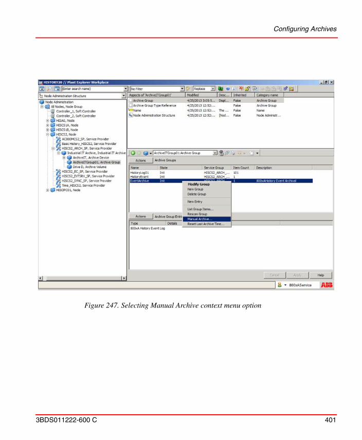
Configuring Archives
3BDS011222-600 C 401
Figure 247. Selecting Manual Archive context menu option
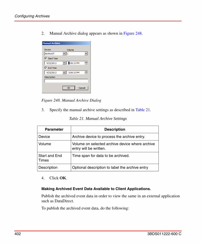
Configuring Archives
402 3BDS011222-600 C
2. Manual Archive dialog appears as shown in Figure 248.
3. Specify the manual archive settings as described in Table 21.
4. Click OK.
Making Archived Event Data Available to Client Applications.
Publish the archived event data in order to view the same in an external application such as DataDirect.
To publish the archived event data, do the following:
Figure 248. Manual Archive Dialog
Table 21. Manual Archive Settings
Parameter Description
Device Archive device to process the archive entry.
Volume Volume on selected archive device where archive entry will be written.
Start and End Times
Time span for data to be archived.
Description Optional description to label the archive entry
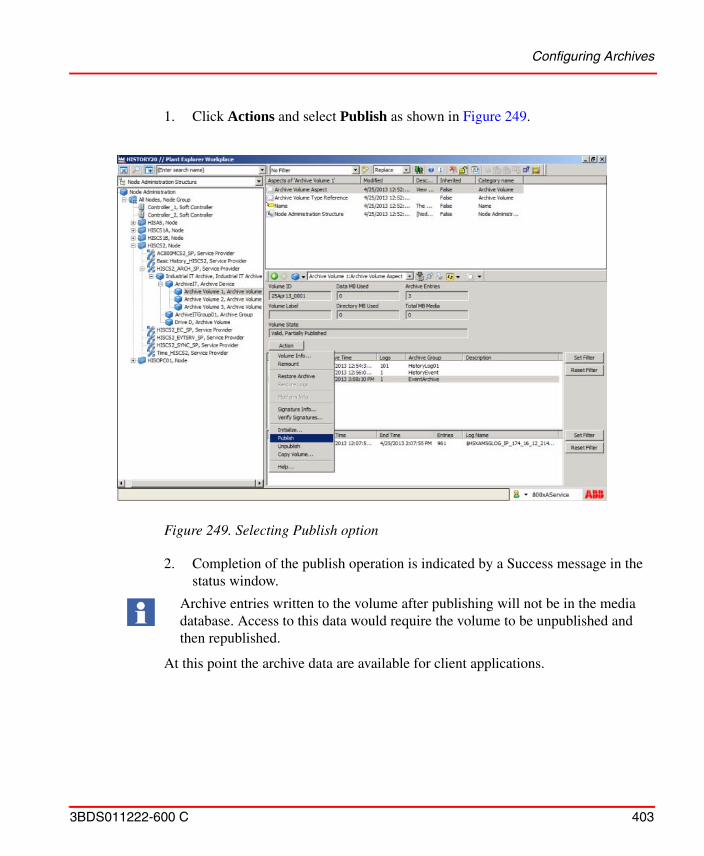
Configuring Archives
3BDS011222-600 C 403
1. Click Actions and select Publish as shown in Figure 249.
2. Completion of the publish operation is indicated by a Success message in the status window.
At this point the archive data are available for client applications.
Figure 249. Selecting Publish option
Archive entries written to the volume after publishing will not be in the media database. Access to this data would require the volume to be unpublished and then republished.
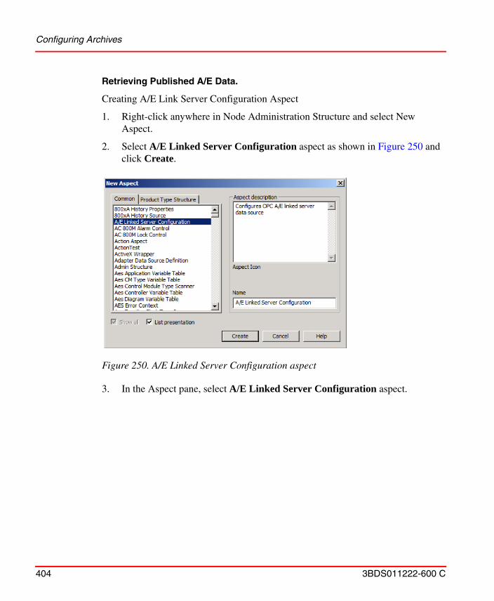
Configuring Archives
404 3BDS011222-600 C
Retrieving Published A/E Data.
Creating A/E Link Server Configuration Aspect
1. Right-click anywhere in Node Administration Structure and select New Aspect.
2. Select A/E Linked Server Configuration aspect as shown in Figure 250 and click Create.
3. In the Aspect pane, select A/E Linked Server Configuration aspect.
Figure 250. A/E Linked Server Configuration aspect
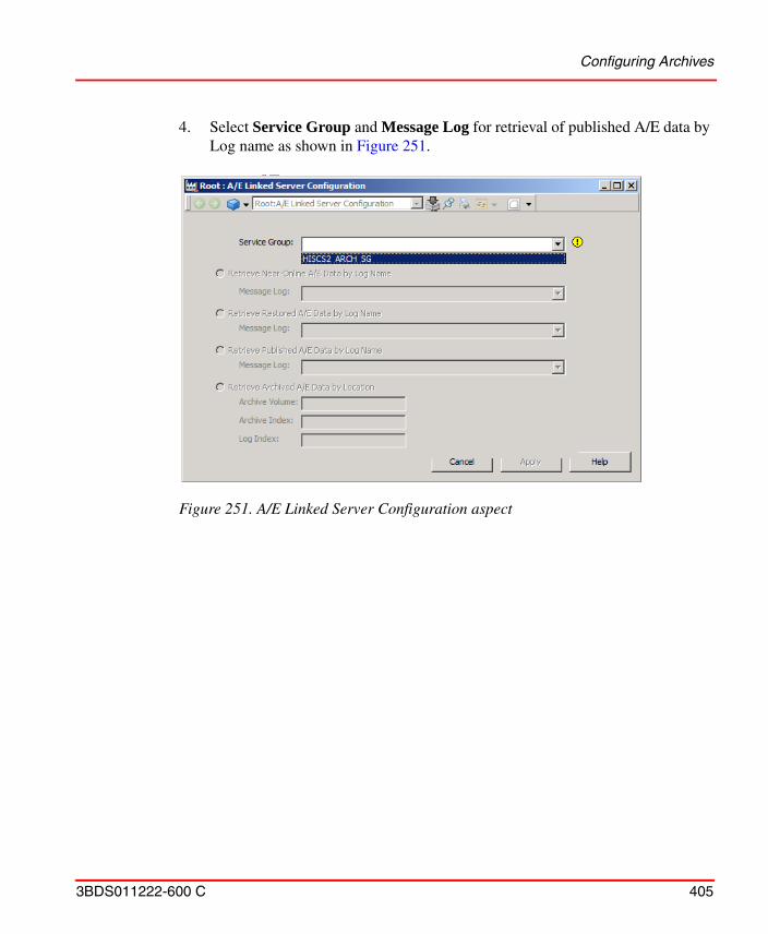
Configuring Archives
3BDS011222-600 C 405
4. Select Service Group and Message Log for retrieval of published A/E data by Log name as shown in Figure 251.
Figure 251. A/E Linked Server Configuration aspect
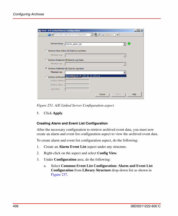
Configuring Archives
406 3BDS011222-600 C
5. Click Apply.
Creating Alarm and Event List Configuration
After the necessary configuration to retrieve archived event data, you must now create an alarm and event list configuration aspect to view the archived event data.
To create alarm and event list configuration aspect, do the following:
1. Create an Alarm Event List aspect under any structure.
2. Right-click on the aspect and select Config View.
3. Under Configuration area, do the following:
a. Select Common Event List Configuration: Alarm and Event List Configuration from Library Structure drop-down list as shown in Figure 237.
Figure 251. A/E Linked Server Configuration aspect
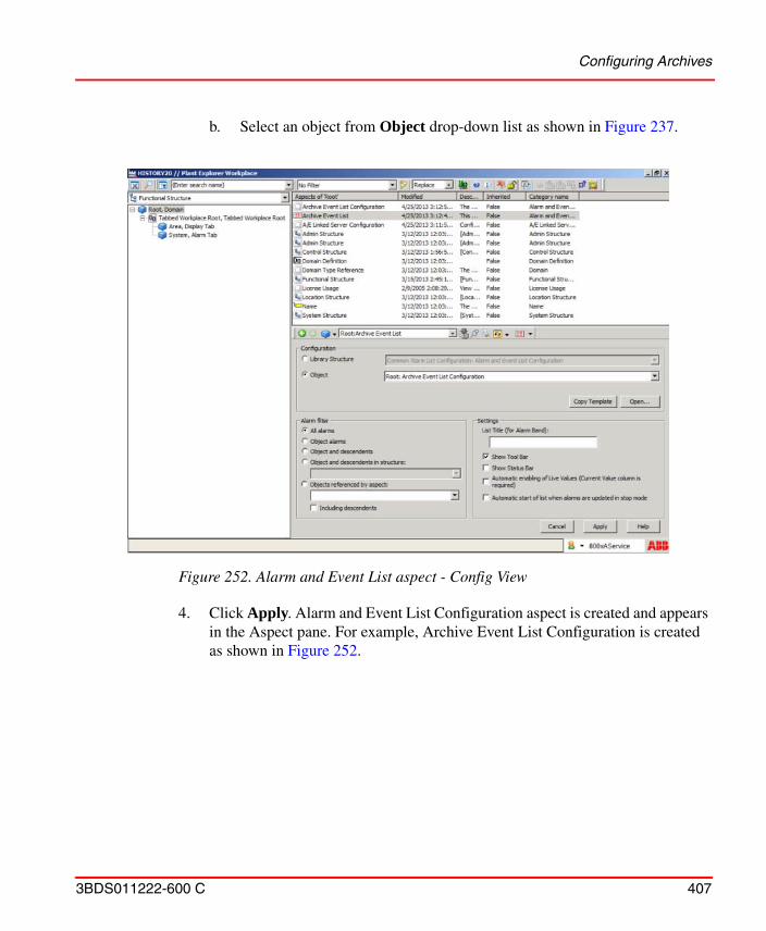
Configuring Archives
3BDS011222-600 C 407
b. Select an object from Object drop-down list as shown in Figure 237.
4. Click Apply. Alarm and Event List Configuration aspect is created and appears in the Aspect pane. For example, Archive Event List Configuration is created as shown in Figure 252.
Figure 252. Alarm and Event List aspect - Config View
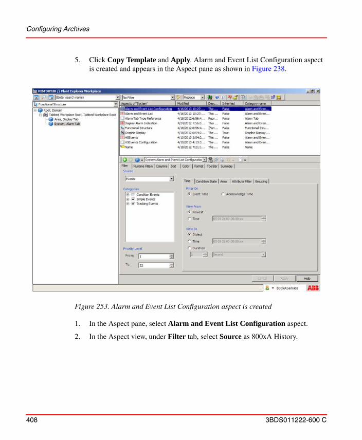
Configuring Archives
408 3BDS011222-600 C
5. Click Copy Template and Apply. Alarm and Event List Configuration aspect is created and appears in the Aspect pane as shown in Figure 238.
1. In the Aspect pane, select Alarm and Event List Configuration aspect.
2. In the Aspect view, under Filter tab, select Source as 800xA History.
Figure 253. Alarm and Event List Configuration aspect is created
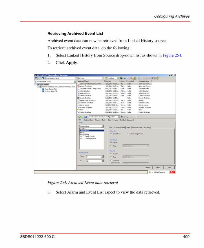
Configuring Archives
3BDS011222-600 C 409
Retrieving Archived Event List
Archived event data can now be retrieved from Linked History source.
To retrieve archived event data, do the following:
1. Select Linked History from Source drop-down list as shown in Figure 254.
2. Click Apply.
3. Select Alarm and Event List aspect to view the data retrieved.
Figure 254. Archived Event data retrieval
History Supervision
410 3BDS011222-600 C
History Supervision
History supervision is an aspect that allows the user to view History Server status in PPA. This aspect can be used to supervise the History Database services that are running History Server. This aspect can also be used to view number of tags, number of active tags and number of inactive tags of History Server.
For more information on configuration and usage of this aspect, refer to Appendix C, History Supervision in 800xA History Administration and Configuration (2PAA107563*).
Information Management
3BDS011222-600 C 411
Information Management
Historical Process Data
Configuration to log historical process data in System 800xA is done using two aspect categories, the Log Template and the Log Configuration. The Log Template defines how to log and the Log Configuration is used to produce a log for every object you would like to log. Default Log Templates are provided in the Library Structure in the Plant Explorer. This applies both for trend logs provided by basic 800xA and for history logs when the basic 800xA is extended with history server of the Information Management option.
Configuration of the basic System 800xA workplace functionality for Trends is done using the Trend Template aspect category. Default Trend Templates are provided in the Library Structure in the Plant Explorer. The Trend Aspect System, which is used to display trends, interacts with the Log Configuration to retrieve information about the logs that exists for an object.
Configuration of Trends and XY-Plots is described in detail in System 800xA Operations, Operator Workplace, Configuration (3BSE030322*)
History Configuration
For conceptual information on history configuration refer to System 800xA, System Guide, Functional Description (3BSE038018*).
The subsections
• Log Template on page 412
• Log Configuration on page 418
• Log Configuration Details on page 422
• Archive Tool on page 442
describe history configuration from a trend log perspective, covering the functions provided by basic 800xA.
Slash characters, “/” and “\” are not supported in object and aspect names being historized.
History Configuration
412 3BDS011222-600 C
History configuration from the history log perspective is described in System 800xA Information Management, Configuration (3BUF001092*).
The subsection Bulk Configuration on page 443 describes how you can do bulk configuration of Log Configuration aspects and of Property Logs of the Information Management History Services.
Log Template
A Log Template is a re-usable template for building many similar logs. If you modify an existing Log Template, the changes will affect existing logs that has been created using that Log Template. For more details see Log Configuration Details on page 422.
To create a new Log Template aspect, follow the steps below:
1. Expand the Library Structure.
2. Select the History Log Templates object and create a new object.
History Configuration
3BDS011222-600 C 413
3. Select the History Log Template Library. Give the object a name and a description. Click Create.
4. Go to the new History Log Template Library object and select New Object from the context menu.
Figure 255. Create a History Log Template Library
History Configuration
414 3BDS011222-600 C
5. Select the History Log Template. Give the object a name and a description.
Click Create.
Figure 256. Mark History Log Template Library
Figure 257. Create a History Log Template
History Configuration
3BDS011222-600 C 415
6. Select the created object in the object area, and select Log Template in the aspect list.
7. Select Property Log in the Property log Template area and either click Add and get the New Log Template dialog box or open the context menu and choose the log needs to be added, without getting the New Log Template dialog box.
Figure 258. Select History Log Template Object
Figure 259. Add Log
History Configuration
416 3BDS011222-600 C
8. In the pop-up dialog box New Log Template, select a source from the Data Source drop-down menu and click OK. In this example OPC is selected. See Figure 260.
9. Type a log name in the Log Name text field under the Log Definition tab.
Figure 260. New Log Template Pop-Up Dialog Box
The sources available depend on the OCS Integration package installed.
The option to configure the Collector Link is only enabled if third party history servers are being used.
The recommended way to write the log name is: Log_<Storage Interval>_<Storage Size>. If there are more logs with the same storage interval and storage size, add _<Aggregate> or _<Index number> at the end of the name.
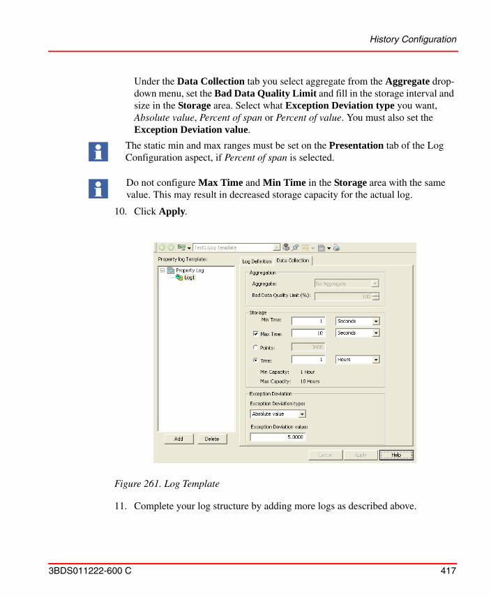
History Configuration
3BDS011222-600 C 417
Under the Data Collection tab you select aggregate from the Aggregate drop-down menu, set the Bad Data Quality Limit and fill in the storage interval and size in the Storage area. Select what Exception Deviation type you want, Absolute value, Percent of span or Percent of value. You must also set the Exception Deviation value.
10. Click Apply.
11. Complete your log structure by adding more logs as described above.
The static min and max ranges must be set on the Presentation tab of the Log Configuration aspect, if Percent of span is selected.
Do not configure Max Time and Min Time in the Storage area with the same value. This may result in decreased storage capacity for the actual log.
Figure 261. Log Template
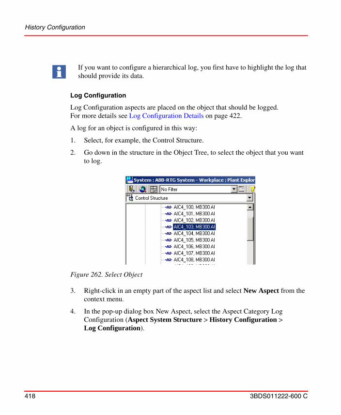
History Configuration
418 3BDS011222-600 C
Log Configuration
Log Configuration aspects are placed on the object that should be logged.For more details see Log Configuration Details on page 422.
A log for an object is configured in this way:
1. Select, for example, the Control Structure.
2. Go down in the structure in the Object Tree, to select the object that you want to log.
3. Right-click in an empty part of the aspect list and select New Aspect from the context menu.
4. In the pop-up dialog box New Aspect, select the Aspect Category Log Configuration (Aspect System Structure > History Configuration > Log Configuration).
If you want to configure a hierarchical log, you first have to highlight the log that should provide its data.
Figure 262. Select Object
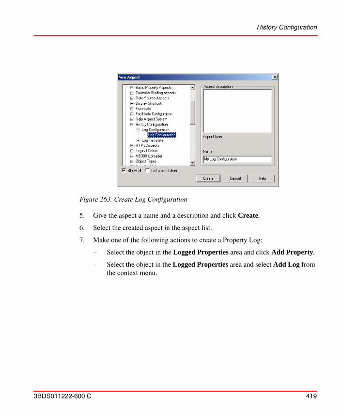
History Configuration
3BDS011222-600 C 419
5. Give the aspect a name and a description and click Create.
6. Select the created aspect in the aspect list.
7. Make one of the following actions to create a Property Log:
– Select the object in the Logged Properties area and click Add Property.
– Select the object in the Logged Properties area and select Add Log from the context menu.
Figure 263. Create Log Configuration
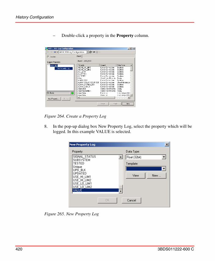
History Configuration
420 3BDS011222-600 C
– Double-click a property in the Property column.
8. In the pop-up dialog box New Property Log, select the property which will be logged. In this example VALUE is selected.
Figure 264. Create a Property Log
Figure 265. New Property Log
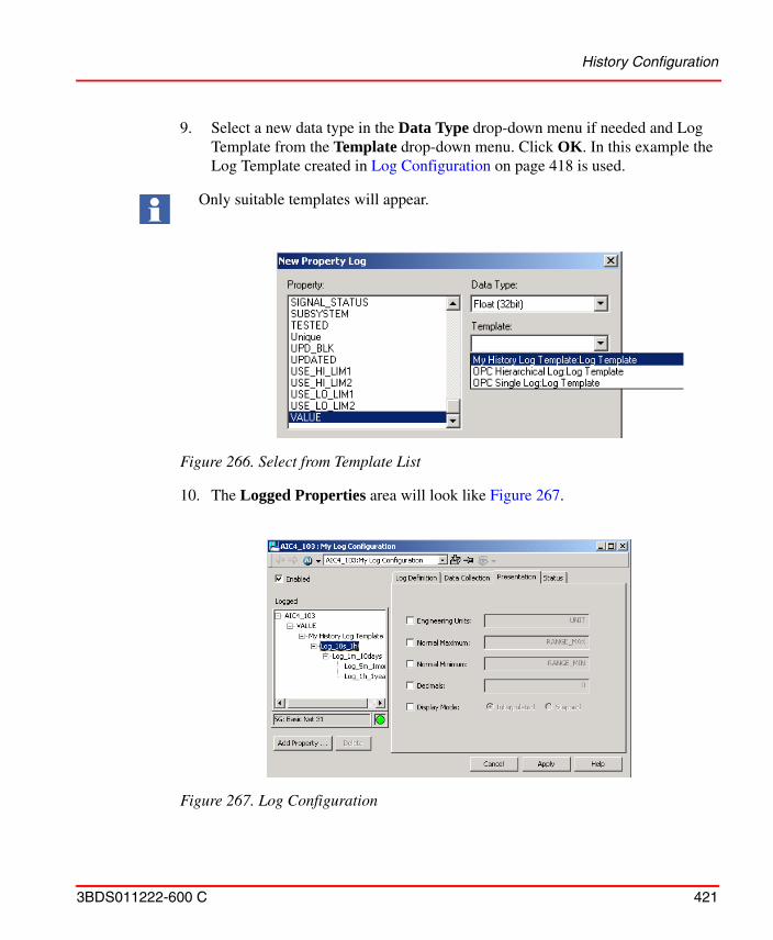
History Configuration
3BDS011222-600 C 421
9. Select a new data type in the Data Type drop-down menu if needed and Log Template from the Template drop-down menu. Click OK. In this example the Log Template created in Log Configuration on page 418 is used.
10. The Logged Properties area will look like Figure 267.
Only suitable templates will appear.
Figure 266. Select from Template List
Figure 267. Log Configuration
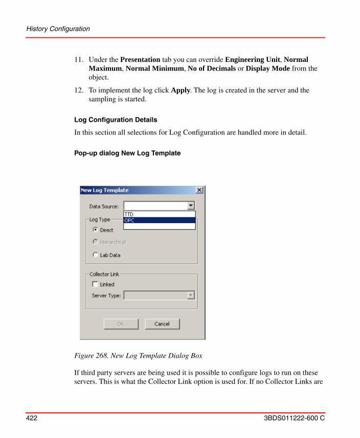
History Configuration
422 3BDS011222-600 C
11. Under the Presentation tab you can override Engineering Unit, Normal Maximum, Normal Minimum, No of Decimals or Display Mode from the object.
12. To implement the log click Apply. The log is created in the server and the sampling is started.
Log Configuration Details
In this section all selections for Log Configuration are handled more in detail.
Pop-up dialog New Log Template
If third party servers are being used it is possible to configure logs to run on these servers. This is what the Collector Link option is used for. If no Collector Links are
Figure 268. New Log Template Dialog Box
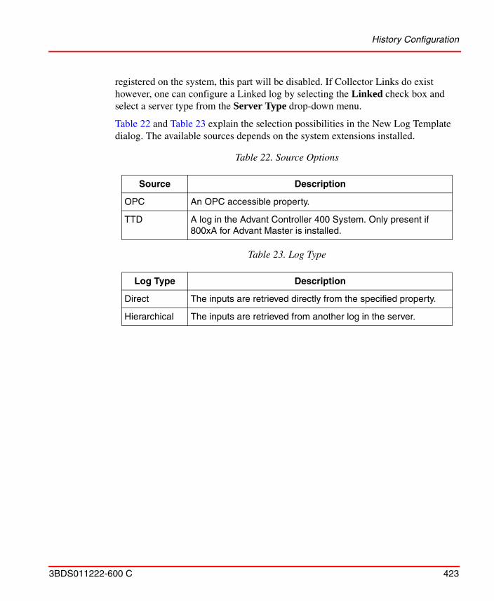
History Configuration
3BDS011222-600 C 423
registered on the system, this part will be disabled. If Collector Links do exist however, one can configure a Linked log by selecting the Linked check box and select a server type from the Server Type drop-down menu.
Table 22 and Table 23 explain the selection possibilities in the New Log Template dialog. The available sources depends on the system extensions installed.
Table 22. Source Options
Source Description
OPC An OPC accessible property.
TTD A log in the Advant Controller 400 System. Only present if 800xA for Advant Master is installed.
Table 23. Log Type
Log Type Description
Direct The inputs are retrieved directly from the specified property.
Hierarchical The inputs are retrieved from another log in the server.
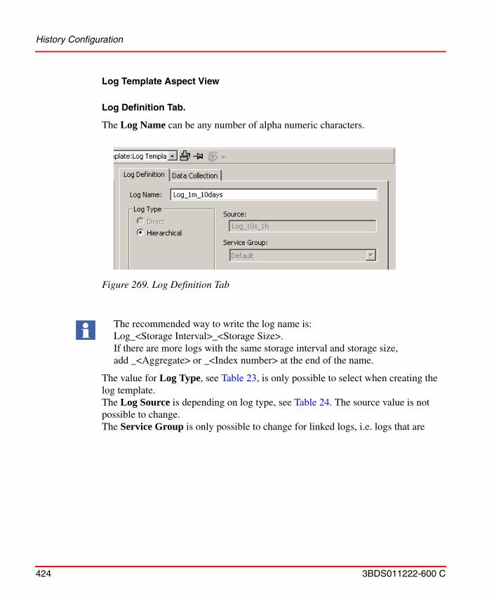
History Configuration
424 3BDS011222-600 C
Log Template Aspect View
Log Definition Tab.
The Log Name can be any number of alpha numeric characters.
The value for Log Type, see Table 23, is only possible to select when creating the log template.The Log Source is depending on log type, see Table 24. The source value is not possible to change.The Service Group is only possible to change for linked logs, i.e. logs that are
Figure 269. Log Definition Tab
The recommended way to write the log name is: Log_<Storage Interval>_<Storage Size>. If there are more logs with the same storage interval and storage size, add _<Aggregate> or _<Index number> at the end of the name.
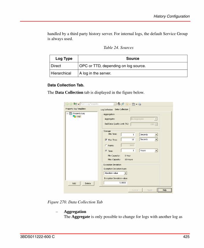
History Configuration
3BDS011222-600 C 425
handled by a third party history server. For internal logs, the default Service Group is always used.
Data Collection Tab.
The Data Collection tab is displayed in the figure below.
– AggregationThe Aggregate is only possible to change for logs with another log as
Table 24. Sources
Log Type Source
Direct OPC or TTD, depending on log source.
Hierarchical A log in the server.
Figure 270. Data Collection Tab
History Configuration
426 3BDS011222-600 C
source. Available aggregates are explained in Table 25.Bad Data Quality Limit specifies the maximum allowed percent of bad data in the resample interval for an aggregated point to be considered to be good. The Bad Data Quality Limit is applicable for all aggregates except those that calculate a value based on the quality of the aggregated points; they are OPCHDA_DURATIONGOOOD, OPCHDA_DURATIONBAD, OPCHDA_PERCENTGOOD, OPCHDA_PERCENTBAD and OPCHDA_WORSTQUALITY.
– Storage areaMin Time is the shortest time between two samples. If Max Time is set it guarantees that you get a new point at that interval, even if the value has not changed. Max Time set to zero means that there is no sampling if the input changes are less than the Exception Deviation. In all other cases Max Time must be greater or equal to Min Time.
Setting a Max Time also enables the trace knee functionality. When a new point is received an extrapolated point is inserted just before the new point, having the same value and quality as the previous point and the timestamp is set to minTime (or updateRate) before the new point. This is only done under the following condition:
– The time span between the new and previous point must be longer than traceKneeConstant * minTime and the values or the qualities of those points must also differ.
The traceKneeConstant is stated in the registry (default 3) and the minTime is taken from the Log Configuration aspect. If no log exists, the update rate of the trend is used instead of the minTime.
Set Max Time greater than 2*Min Time for minimum storage capacity time to be guaranteed.
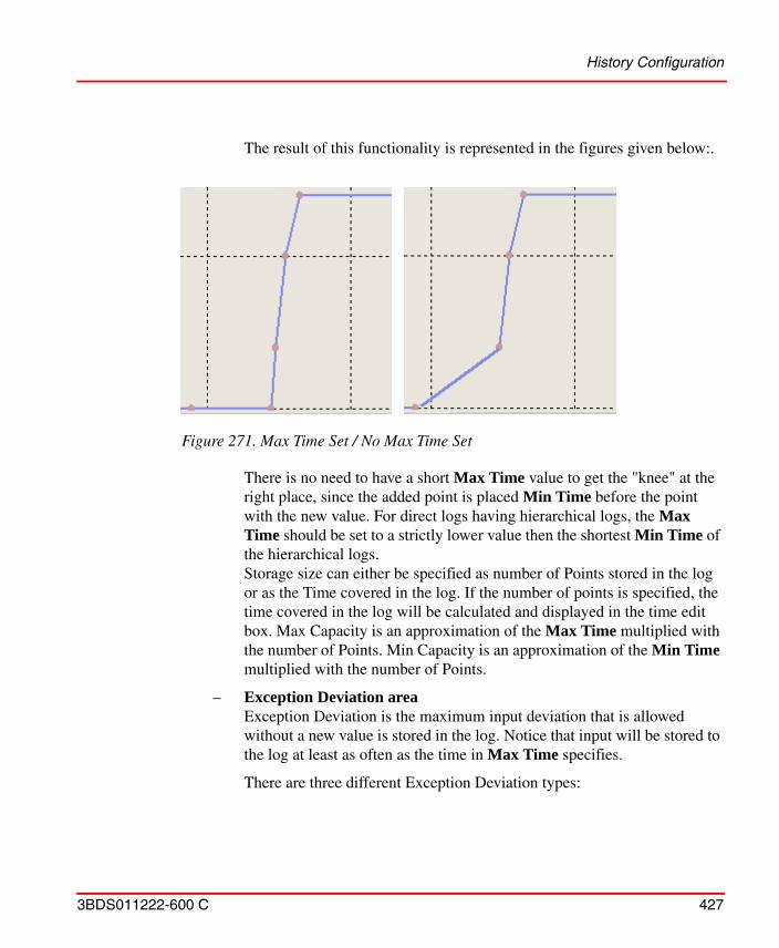
History Configuration
3BDS011222-600 C 427
The result of this functionality is represented in the figures given below:.
There is no need to have a short Max Time value to get the "knee" at the right place, since the added point is placed Min Time before the point with the new value. For direct logs having hierarchical logs, the Max Time should be set to a strictly lower value then the shortest Min Time of the hierarchical logs.Storage size can either be specified as number of Points stored in the log or as the Time covered in the log. If the number of points is specified, the time covered in the log will be calculated and displayed in the time edit box. Max Capacity is an approximation of the Max Time multiplied with the number of Points. Min Capacity is an approximation of the Min Time multiplied with the number of Points.
– Exception Deviation area Exception Deviation is the maximum input deviation that is allowed without a new value is stored in the log. Notice that input will be stored to the log at least as often as the time in Max Time specifies.
There are three different Exception Deviation types:
Figure 271. Max Time Set / No Max Time Set
History Configuration
428 3BDS011222-600 C
Absolute value:For a new point to be added to the log (if not max time is reached), the value must have changed at least as much as the configured Exception Deviation value. For example if the old value = 67, exception deviation = 5, and the exception deviation type = Absolute value, the next value added to the log must be greater or equal to 72 or less or equal to 62.Percent of span:For a new point to be added to the log (if not max time is reached), the value must have changed at least x% of the configured min and max range. x is the configured Exception Deviation value, and the min and max ranges are taken from the Presentation tab of the Log Configuration aspect. For example if the old value = 67, exception deviation value = 5, min range = -100, max range = 100, and the exception deviation type = Percent of span, the next value added to the log must be greater or equal to 77 or less or equal to 57.Percent of value:For a new point to be added to the log (if not max time is reached), the value must have changed at least x%, where x is the configured Exception Deviation value. For example if the old value = 67, exception deviation value = 5, and the exception deviation type = Percent of value, the next value added to the log must be greater or equal to 70.35 or less or equal to 63.65.
The data in a log is reduced by several methods without losing the process critical information because of limited storage capacity in a log. Also refer to Figure 272..
• If a sample is received more often than the minimal storage interval of the log (For example, 1s), the log stores the latest of all values of the interval.
• If a received variable only is changed by a value more than the exception deviation (For example, 5%, analog values only), this is stored in the log.
• If a variable is changed by a value less than the exception deviation, it may be forced into the log after the logs maximum storage interval (For example, 4s) is elapsed. A latest sample received will stored to the log when the Max time is reached. This does not store the previously stored good value if different from the latest sample.
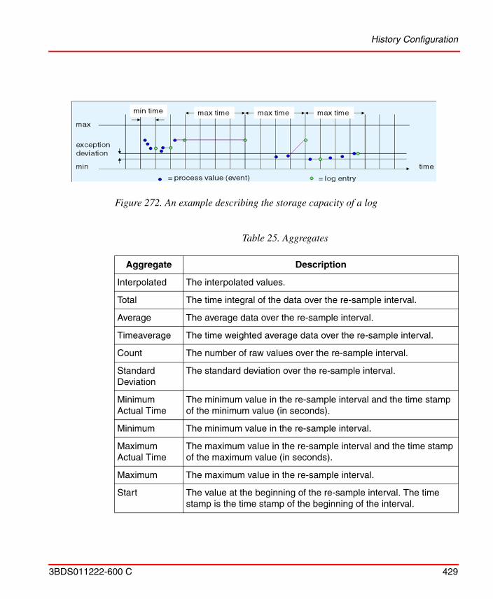
History Configuration
3BDS011222-600 C 429
Figure 272. An example describing the storage capacity of a log
Table 25. Aggregates
Aggregate Description
Interpolated The interpolated values.
Total The time integral of the data over the re-sample interval.
Average The average data over the re-sample interval.
Timeaverage The time weighted average data over the re-sample interval.
Count The number of raw values over the re-sample interval.
Standard Deviation
The standard deviation over the re-sample interval.
Minimum Actual Time
The minimum value in the re-sample interval and the time stamp of the minimum value (in seconds).
Minimum The minimum value in the re-sample interval.
Maximum Actual Time
The maximum value in the re-sample interval and the time stamp of the maximum value (in seconds).
Maximum The maximum value in the re-sample interval.
Start The value at the beginning of the re-sample interval. The time stamp is the time stamp of the beginning of the interval.
History Configuration
430 3BDS011222-600 C
All the timestamps returned are those of the beginning of the aggregate interval, except for those aggregates which explicitly state otherwise.
End The value at the end of the re-sample interval. The time stamp is the time stamp of the end of the interval.
Delta The difference between the first and last value in the re-sample interval.
Regression Slope
The slope (per cycle time) of the regression line over the re-sample interval.
Regression Const
The intercept of the regression line over the re-sample interval. This is the value of the regression line at the start of the interval.
Regression Deviation
The standard deviation of the regression line over the re-sample interval.
Variance The variance over the sample interval.
Range The difference between the minimum and maximum value over the sample interval.
Duration Good The duration (in seconds) of time in the interval during which the data is good.
Duration Bad The duration (in seconds) of time in the interval during which the data is bad.
Percentage Good
The percent of data (one (1) equals 100 percent) in the interval which has good quality.
Percentage Bad
The percent of data (where one (1) equals 100 percent) in the interval which has bad quality.
Worst Quality The worst quality of data in the interval.
Annotations The number of annotations in the interval. (Not implemented)
Table 25. Aggregates (Continued)
Aggregate Description
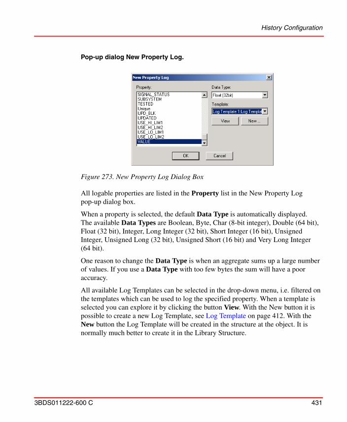
History Configuration
3BDS011222-600 C 431
Pop-up dialog New Property Log.
All logable properties are listed in the Property list in the New Property Log pop-up dialog box.
When a property is selected, the default Data Type is automatically displayed. The available Data Types are Boolean, Byte, Char (8-bit integer), Double (64 bit), Float (32 bit), Integer, Long Integer (32 bit), Short Integer (16 bit), Unsigned Integer, Unsigned Long (32 bit), Unsigned Short (16 bit) and Very Long Integer(64 bit).
One reason to change the Data Type is when an aggregate sums up a large number of values. If you use a Data Type with too few bytes the sum will have a poor accuracy.
All available Log Templates can be selected in the drop-down menu, i.e. filtered on the templates which can be used to log the specified property. When a template is selected you can explore it by clicking the button View. With the New button it is possible to create a new Log Template, see Log Template on page 412. With the New button the Log Template will be created in the structure at the object. It is normally much better to create it in the Library Structure.
Figure 273. New Property Log Dialog Box
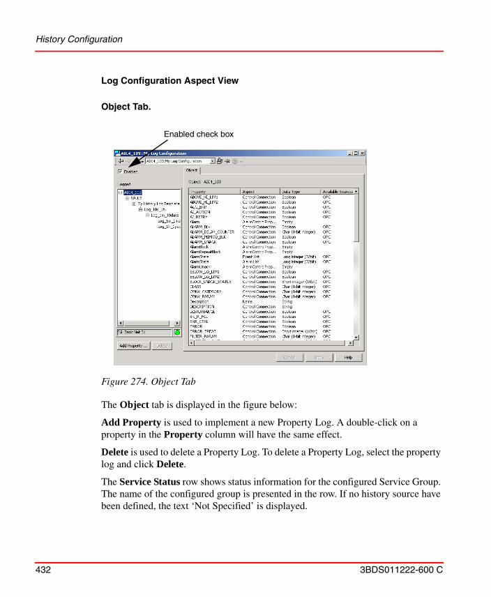
History Configuration
432 3BDS011222-600 C
Log Configuration Aspect View
Object Tab.
The Object tab is displayed in the figure below:
Add Property is used to implement a new Property Log. A double-click on a property in the Property column will have the same effect.
Delete is used to delete a Property Log. To delete a Property Log, select the property log and click Delete.
The Service Status row shows status information for the configured Service Group. The name of the configured group is presented in the row. If no history source have been defined, the text ‘Not Specified’ is displayed.
Figure 274. Object Tab
Enabled check box
History Configuration
3BDS011222-600 C 433
Status for Configured Service Group:
All properties are listed for the selected object. Under the column Available Sources all possible sources for each property are indicated.
The Enabled check box is selected by default. With the Enabled check box cleared, the log will be inactive and there will be no sampling of the source.
Note that you can not delete a single log in the log structure, since the log is defined in the template. For example Log_5m_1month in Figure 274 is not possible to delete.
OK: All providers in the service group are up and running.
OK/ERROR: At least one service provider is up and running.
ERROR: All providers in the service group are down.
History Configuration
434 3BDS011222-600 C
Property Log Tab.
The Property Log tab is displayed in the figure below:
The Property Log tab displays log information. The Data Size is the size of the Property Log on disk. It is the sum of the size of all logs. The size of each log file is the sum of the file header and the data storage size.
Log Definition Tab.
A read-only tab which hold the same information as Log Template, see Figure 269.
Data Collection Tab.
A read-only tab which hold the same information as Log Template, see Figure 270.
Figure 275. Property Log Tab
History Configuration
3BDS011222-600 C 435
Presentation Tab.
The Presentation tab is displayed in the figure below:
All values are used to display the trace in a Trend Display in a proper way.These values can be set in either of:
• the Object Type (i.e. in the Property Aspect).
• the Object Instance (i.e in the Property Aspect).
• the Log (in the Log Configuration Aspect).
• the Trend Display.
The above listed are in override order.
For example you can override a value set in the Object Type by writing a value in the Object Instance. Another example is a value set in the Object Type, the Object Instance for presentation attribute or the Log can be overridden in the Trend Display.
Figure 276. Presentation Tab
When choosing Momentary (raw data) as Treatment the trace can only show a maximum of 86400 points even though more data exists.
History Configuration
436 3BDS011222-600 C
To override a presentation attribute the box for the attribute must be checked. If the box is unchecked the default value is displayed. The default value can be a property name or a value, depending on what is specified in the Control Connection aspect.
Engineering Units are inherited from the source. It is possible to override it.
Normal Maximum and Normal Minimum are scaling factors, used for the scaling of Y-axis in the Trend Display. The values are retrieved from the source but are possible to override.
The Number of Decimals are retrieved from the source but are possible to override.
The Display Mode defines what drawing style to use if Normal style is selected in the trend display, it can be either Interpolated or Stepped. Interpolated is appropriate for real values, Stepped for binary. See Figure 277.
When clicking Apply the log is created in the server and the sampling is started. The button must be clicked to make a change take effect.
Figure 277. Difference between Interpolated and Stepped Display Mode
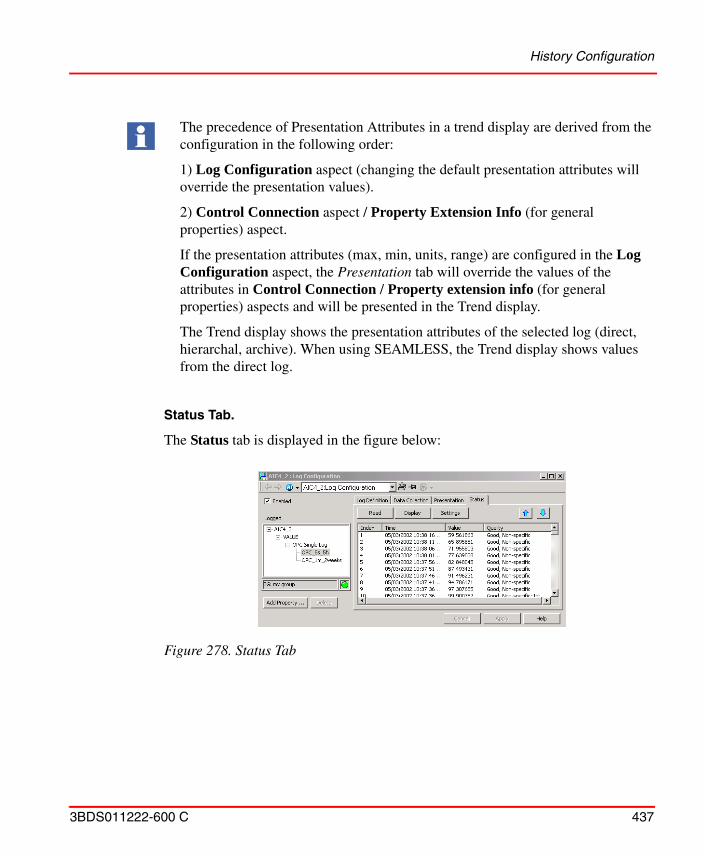
History Configuration
3BDS011222-600 C 437
Status Tab.
The Status tab is displayed in the figure below:
The precedence of Presentation Attributes in a trend display are derived from the configuration in the following order:
1) Log Configuration aspect (changing the default presentation attributes will override the presentation values).
2) Control Connection aspect / Property Extension Info (for general properties) aspect.
If the presentation attributes (max, min, units, range) are configured in the Log Configuration aspect, the Presentation tab will override the values of the attributes in Control Connection / Property extension info (for general properties) aspects and will be presented in the Trend display.
The Trend display shows the presentation attributes of the selected log (direct, hierarchal, archive). When using SEAMLESS, the Trend display shows values from the direct log.
Figure 278. Status Tab
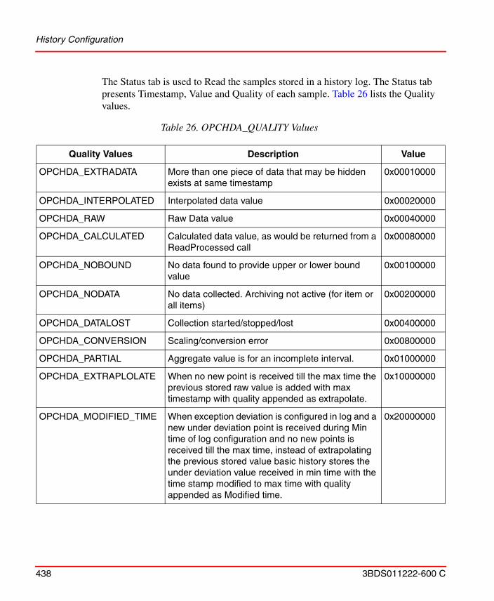
History Configuration
438 3BDS011222-600 C
The Status tab is used to Read the samples stored in a history log. The Status tab presents Timestamp, Value and Quality of each sample. Table 26 lists the Quality values.
Table 26. OPCHDA_QUALITY Values
Quality Values Description Value
OPCHDA_EXTRADATA More than one piece of data that may be hidden exists at same timestamp
0x00010000
OPCHDA_INTERPOLATED Interpolated data value 0x00020000
OPCHDA_RAW Raw Data value 0x00040000
OPCHDA_CALCULATED Calculated data value, as would be returned from a ReadProcessed call
0x00080000
OPCHDA_NOBOUND No data found to provide upper or lower bound value
0x00100000
OPCHDA_NODATA No data collected. Archiving not active (for item or all items)
0x00200000
OPCHDA_DATALOST Collection started/stopped/lost 0x00400000
OPCHDA_CONVERSION Scaling/conversion error 0x00800000
OPCHDA_PARTIAL Aggregate value is for an incomplete interval. 0x01000000
OPCHDA_EXTRAPLOLATE When no new point is received till the max time the previous stored raw value is added with max timestamp with quality appended as extrapolate.
0x10000000
OPCHDA_MODIFIED_TIME When exception deviation is configured in log and a new under deviation point is received during Min time of log configuration and no new points is received till the max time, instead of extrapolating the previous stored value basic history stores the under deviation value received in min time with the time stamp modified to max time with quality appended as Modified time.
0x20000000
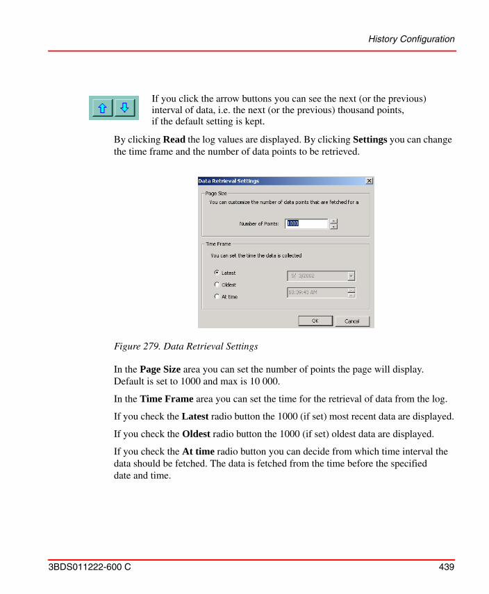
History Configuration
3BDS011222-600 C 439
By clicking Read the log values are displayed. By clicking Settings you can change the time frame and the number of data points to be retrieved.
In the Page Size area you can set the number of points the page will display. Default is set to 1000 and max is 10 000.
In the Time Frame area you can set the time for the retrieval of data from the log.
If you check the Latest radio button the 1000 (if set) most recent data are displayed.
If you check the Oldest radio button the 1000 (if set) oldest data are displayed.
If you check the At time radio button you can decide from which time interval the data should be fetched. The data is fetched from the time before the specified date and time.
Figure 279. Data Retrieval Settings
If you click the arrow buttons you can see the next (or the previous)interval of data, i.e. the next (or the previous) thousand points, if the default setting is kept.
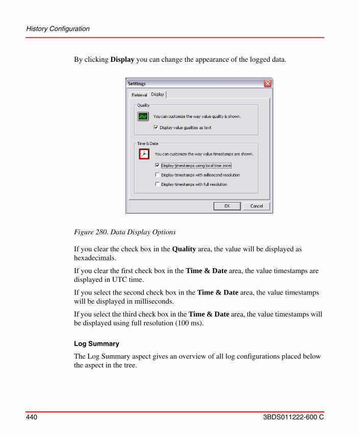
History Configuration
440 3BDS011222-600 C
By clicking Display you can change the appearance of the logged data.
If you clear the check box in the Quality area, the value will be displayed as hexadecimals.
If you clear the first check box in the Time & Date area, the value timestamps are displayed in UTC time.
If you select the second check box in the Time & Date area, the value timestamps will be displayed in milliseconds.
If you select the third check box in the Time & Date area, the value timestamps will be displayed using full resolution (100 ms).
Log Summary
The Log Summary aspect gives an overview of all log configurations placed below the aspect in the tree.
Figure 280. Data Display Options
History Configuration
3BDS011222-600 C 441
In the overview you can see if the Log Configuration is enabled, the path to it and if it is passed the consistency check.
By right-clicking over the list of Log Configurations, a menu will be displayed where you can choose to enable, disable or delete the Log Configurations. You can also choose to run auto-correct if they have not passed the consistency check.See Figure 281.
Figure 281. Log Summary
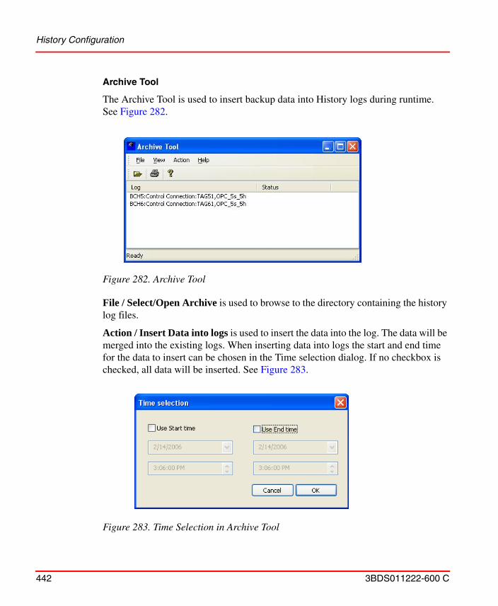
History Configuration
442 3BDS011222-600 C
Archive Tool
The Archive Tool is used to insert backup data into History logs during runtime.See Figure 282.
File / Select/Open Archive is used to browse to the directory containing the history log files.
Action / Insert Data into logs is used to insert the data into the log. The data will be merged into the existing logs. When inserting data into logs the start and end time for the data to insert can be chosen in the Time selection dialog. If no checkbox is checked, all data will be inserted. See Figure 283.
Figure 282. Archive Tool
Figure 283. Time Selection in Archive Tool
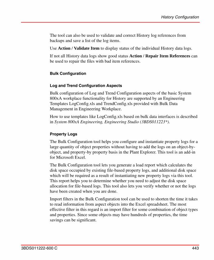
History Configuration
3BDS011222-600 C 443
The tool can also be used to validate and correct History log references from backups and save a list of the log items.
Use Action / Validate Item to display status of the individual History data logs.
If not all History data logs show good status Action / Repair Item References can be used to repair the files with bad item references.
Bulk Configuration
Log and Trend Configuration Aspects
Bulk configuration of Log and Trend Configuration aspects of the basic System 800xA workplace functionality for History are supported by an Engineering Templates LogConfig.xls and TrendConfig.xls provided with Bulk Data Management in Engineering Workplace.
How to use templates like LogConfig.xls based on bulk data interfaces is described in System 800xA Engineering, Engineering Studio (3BDS011223*).
Property Logs
The Bulk Configuration tool helps you configure and instantiate property logs for a large quantity of object properties without having to add the logs on an object-by-object, and property-by property basis in the Plant Explorer. This tool is an add-in for Microsoft Excel.
The Bulk Configuration tool lets you generate a load report which calculates the disk space occupied by existing file-based property logs, and additional disk space which will be required as a result of instantiating new property logs via this tool. This report helps you to determine whether you need to adjust the disk space allocation for file-based logs. This tool also lets you verify whether or not the logs have been created when you are done.
Import filters in the Bulk Configuration tool can be used to shorten the time it takes to read information from aspect objects into the Excel spreadsheet. The most effective filter in this regard is an import filter for some combination of object types and properties. Since some objects may have hundreds of properties, the time savings can be significant.
History Configuration
444 3BDS011222-600 C
You can also create a list of properties for which logs have already been created, in the event that you want to modify or delete the log configurations for those properties.
Work Flow
Configure all other history objects, including log templates, before using this tool. The recommended work flow is as follows:
1. Configure log sets, message logs, report logs as required by your application. If you require archival, create an Archive Device and Archive Groups.
2. Configure the Log Templates. DO NOT create Log Configuration aspects at this time.
3. Create a new workbook in Excel and initialize the workbook to add the Bulk Configuration add-ins.
4. Create a list of object properties whose values are to be logged.
5. For each object property, specify the Log Template that meets its data collection requirements, and specify the name of the Log Configuration aspect.
6. Configure presentation attributes and access name if necessary.
7. Generate a load report to see whether or not you need to adjust the disk space allocation for file-based logs. Make any adjustments as required.
8. Create new property logs based on the spreadsheet specifications.
9. Verify that all property logs and their respective component logs have been created.
10. Run the Load Report function again. This time, the report should indicate that all logs have been created (existing space used = proposed space requirement).
11. Create a backup copy of your database.
12. On all nodes where trend and history logs reside, check the system for fragmented files, and defragment the applicable disks as required.
Extended Configuration Data
3BDS011222-600 C 445
13. History logs will not collect data until they are activated. Test the operation of
one or more property logs. You can use the Status tab on the Log Configuration aspect, or you can use one of the installed desktop tools such as DataDirect or Desktop Trends.
Extended Configuration Data
Parameter Management
Parameter Manager aspects can be used to gather extended configuration data and expose them to other aspects in the system in a very flexible manner.
To provide extended configuration data in Parameter Management aspects you have to perform the following principal steps:
The file system must be in a consistent state at all times. Defragment disks on a regular basis using the defragmentation software provided with the operating system. • Size disks so they will be 25 percent empty for defragmentation purposes.
• Check the system for fragmented files on all nodes where trend and history logs reside, and defragment the applicable disks as required.
• History configuration impacts not only the History Server disks, but also Connectivity Server disks where trend logs are configured. Therefore, check the disks on Connectivity Servers where trend or history logs reside, and defragment them as required.
• Extensive use of the Bulk Configuration tool may cause disks to become fragmented. Check the system for fragmented files after any such procedure, and defragment disks as required.
• Configuration procedures that involve creating, deleting, and then recreating of a large quantity of objects may cause the associated disks to become fragmented. Check the system for fragmented files after any such procedure, and defragment disks as required.
• Deleting and then creating the Aspect System may cause associated disks to become fragmented. Check the system for fragmented files after any such procedure, and defragment disks as required.
Even though server components keep most of their data in cache, it is fairly disk intensive. Thus they may benefit from RAID 5 systems.
Extended Configuration Data
446 3BDS011222-600 C
1. Define a corresponding Parameter Manager aspect category in Aspect System Structure with the needed properties. Simple properties, structured properties and instance specific properties are supported.
2. Create the instances of the new Parameter Manager aspect category in the objects that shall hold the data. Preferably an aspect instance is created in the corresponding object type so that each instance of this object type gets an aspect instance.
3. Fill in the data of Parameter Manager aspects using the Parameter Manager Open Properties aspect context menu item or your specifically configured Bulk Data Management worksheets. Only if single aspects have to be treated use the single aspect pane in Plant Explorer.
4. Connect the properties of other aspects in this object or in other objects to the parameter aspect properties using either property transfer aspects (transferring from source aspect to sink aspect) or property references in the sink aspects.
To “push” data property transfer aspects (for example of category AesPropertyTransfer) can be used. Source and sink aspect have to be contained in the same object. Note that AesPropertyTransfer cannot be used to write to Control Properties of Control Builder M Professional.
To “pull” data you can use property references in the aspects that pull the data. They are supported by Document Management, Bulk Data Management, Control Builder M Professional, Graphics Builder (in the form of object references to configure with Expression Builder), Function Designer, Topology Designer / Topology Status Viewer and Parameter Management itself. Document Management and Bulk Data Management are able to support property references bi-directional.
In cases none of the two methods are applicable you can configure a Bulk Data management worksheet to transfer the data on demand.
To create an own Parameter Manager aspect category with simple table-like properties you perform the steps:
1. In the Aspect System Structure select the Parameter Manager aspect type object.
2. Execute the New Object context menu item and create an object with a name at your choice.
Extended Configuration Data
3BDS011222-600 C 447
3. In the aspect pane of this Aspect Category object add the properties via the context menu on the Categories item.
4. If you want to allow introduction of additional instance specific properties check the InstanceProperties check button.
5. When you create instances of your Parameter Manager aspect category you get a database for your extended configuration data that is optimized for your need.
To create structured properties you have to include into your aspect category object the set of sub-categories each represented by an own categories aspect chained to the superior categories aspect via the SubCategoryOf property. The subcategories each have to contain a property designated as row identifier and specified with a default value.
When you instantiate a structured Parameter Manager aspect category the properties of the most superior category are shown in the instance, the properties of the sub-categories have to be added instance specific by executing the New “sub category” context menu item on the Categories item of the superior category.
If you need a fixed substructure in every case you can implement this by providing the corresponding Parameter Manager aspect in an object type or by providing a corresponding template Parameter Manager aspect in the Library Structure.
Refer to System 800xA Engineering, Engineering Studio (3BDS011223*) for details on configuration of Parameter Management.
Softpoint Configuration Workflow
Configuration of softpoints is done via the Plant Explorer. Softpoint objects are instantiated from softpoint object types configured in Object Type Structure. This requires you to create process object types as children of the Softpoint object type in Object Type Structure.
These object types serve as models by which to instantiate actual process objects under a Softpoint Generic Control Network object in Control Structure. The softpoint object types specify the signal properties for the softpoint objects. This includes signal ranges for real and integer signals, alarm limits, event triggers, and whether or not the signals will be controllable. The process objects inherit the properties of the object types from which they are instantiated.
Extended Configuration Data
448 3BDS011222-600 C
Pre-configuration Set-up
Some pre-configuration set-up is required to connect Softpoint Servers with their respective connectivity Servers, and with History Services.
• For each node where Softpoint Services is installed, you must create a virtual control network by which other system applications (History, desktop applications and so on) can access the softpoint data on that node. You must also configure a Source Definition aspect for each network. This is required to deploy the softpoints on their respective nodes. These procedures are described in the section on configuring softpoints in Information Management Configuration.
• A History Source object must be created under the Softpoints category in Control Structure. This is required to support historical data collection for softpoint values. Instructions for creating this object are provided in the section on History Set-up in System 800xA Information Management, Configuration (3BUF001092*).
• Make sure Softpoint service providers are created and enabled for all nodes where Softpoint Services must run.
Softpoint Configuration
The procedure for configuring softpoints involves the following basic steps:
• Adding and configuring a new softpoint object type.
• Adding signal types and configuring signal properties, including alarms and events for the signal types.
• Instantiating softpoint objects in Control Structure from their respective softpoint object types.
• Adjusting properties of the instantiated softpoint objects if necessary.
• Defining alarm text groups.
• Deploying the finished softpoint configuration.
Whenever you create new softpoint objects, or make changes to existing softpoint objects, the new configuration will not go into effect until the changes are deployed. While softpoint configurations are being deployed, softpoint
Extended Configuration Data
3BDS011222-600 C 449
processing is suspended, current values and new inputs are held. This process is generally completed within five minutes, even for large configurations.
These steps are described in detail in the section on configuring softpoints in System 800xA Information Management, Configuration (3BUF001092*).
Importing and Exporting Softpoint Configuration Data
To make a complete import or export of a softpoint application, including both the softpoint data and the softpoint configuration, use the 800xA system Import/Export utility as described in System 800xA Operations, Operator Workplace, Configuration (3BSE030322*).
The Import and Export tabs on the Generic Control Network Configuration aspect provide an alternative method for importing/exporting a softpoint configuration. This exports softpoint objects and aspects only. The export file is created in XML format. You can import this file on another machine. The data will be added to the softpoint configuration database. This method is recommended to be used only as a supplemental backup to the backup created with the 800xA system Import/Export utility.
Calculations Configuration
The steps to configure calculations are described in the section on Configuring Calculations in System 800xA Information Management, Configuration (3BUF001092*).
Document Management
450 3BDS011222-600 C
Document Management
Document Management functionality can be used for many purposes. It allows to make informations in documents available at aspect objects in structures where you need them.
For example you can include a dynamic document into an object type of the ProcessObjExtLib delivered with of AC 800M connectivity to make it possible to get a snapshot status of the object for maintenance or operation documentation purposes. Assumption is that the Library is closed or released.
The principal steps to include a dynamic document for into a Process Object object type are as follows:
1. Select the object type in the Object Type Structure.
2. Create a Document aspect, by default the Document aspect will be inherited to the instances.
3. Via the aspect context menu item Edit set the corresponding template, for example a blank Word document.
4. Then edit the document content: Texts, graphical parts and dynamic parts. For the dynamic parts you insert the corresponding property references via Document Manager > Insert Property Reference(s) or the corresponding context menu item. You can select properties of the other aspects of the object or of objects relative to your object. The properties can also be OPC properties of control aspects. Note that the Insert Property Reference(s) dialog can only support you if the Structures, Objects and object properties you want to reference are existing. Otherwise you may have to evaluate the needed Reference String by building a prototype in another structure.
5. Check in the document using aspect context menu item Checkin.
6. Create an Object Type Extension Definition if you want to change the default instantiation behavior of your Document aspect, for example to Copy to all instances. This is required if the document content shall be saved per instance.
7. When instantiating the object type the object instance now gets the additional Document aspect.
8. When you open the document it gets updated with the instance specific values retrieved by the property references. In a Graphic Display of Operator
Document Management
3BDS011222-600 C 451
Workplace you can view the document from the object context menu of the Graphic Element for the object the document is contained in.
The steps before assumed that a fitting template was already available. To create an own template you have to perform the following steps:
1. Select the Library Structure / Document Manager Templates / Document File Templates / Documents
2. Select one of the existing document template aspects, copy and rename it or create a completely new one.
3. Edit the document as needed and check it in: The new template is ready.
4. When you now create a Document aspect in an object in the Object Type Structure or in another structure and you set the file for the Document aspect the new template is additionally offered for use.
You also can define own Document aspect categories with a set of document properties adapted to your specific needs:
1. In the Aspect System Structure select the Document Manager Documents aspect type object.
2. Execute the New Object context menu item and create an Aspect Category object with a name at your choice.
3. In the aspect pane of this Aspect Category object add, delete or modify the properties using the context menu on the Categories item or on the CategoriesProp items.
4. When you create instances of your Document aspect category you get an document administration database optimized for your need.
If you want to include an engineering project document into Documentation Structure already substructured as for example given by the documentation object types of the Basic Object Type library you perform the following steps:
1. You create a document object below the corresponding folder object and a Document aspect within this object.
2. Execute Set File on the aspect and select the dialogs tab named From File/Folder
Document Management
452 3BDS011222-600 C
3. Press one of the buttons Copy File, Move File or Reference File depending on how you want to include the file into the Document aspect.
4. Navigate to the stored file and press the Open button of the file selection dialog.
5. Now the Document aspect of your documentation object holds the file you selected either as a copied file or as a moved file or as a referenced file.
If you have many of those files to include into documentation objects as copies you can import them using a Bulk Data Management worksheet. The steps are:
1. On for example the folder object open context menu item Advanced > Bulk Data Manager
2. Drop into the Excel worksheet Documentation Structure aspect and a Document aspect, from the set of properties of the Document aspect select ExternalFilePath
3. Drop in the folder object
4. In the Object Identification column add the document object name with a counting number at the end
5. In the Document.AspectName column edit the aspect name with counting number and the end
6. In the ExternalFilePath column enter the file path including document file name
7. Copy the column as often as needed and do final editing of the names.
8. Then save the objects with Save All Objects button of Bulk Data Manager tool bar. This creates the documentation objects as required including the Document aspects with the file copies.
To re-import the same set or extended set of documents:
1. You first use Open Properties of Document Manager, press the Show All button and delete the imported aspects via multiple select on the AspectName column and using Document Manager > Delete Aspect.
2. Then you save the objects again from the Bulk Data Management worksheet you have configured and extended with the Save All Objects button of Bulk Data Manager tool bar.
Information Access Aspects
3BDS011222-600 C 453
In a similar way as you have added engineering project documents to your system you can add operation / maintenance documents to existing object instances in your system. Instead of creating the objects for the first time from the worksheet you drop in the existing object subtree and add document aspect entries where needed.
If you want also to access the operation / maintenance documents via Documentation Structure you can place the corresponding objects from Functional Structure, Control Structure or Location Structure additionally in the Documentation Structure, e.g. by configuring and using a corresponding Bulk Data Management worksheet.
For more details on Document Management refer to System 800xA Engineering, Engineering Studio (3BDS011223*).
Information Access Aspects
You can use the Information Access aspects to integrate information handled by standard PC applications without any programming.
• The File Viewer Aspect.See How to use the File Viewer on page 454.
• The Bookmark Aspect.See How to use the Bookmark Aspect on page 466,
• The Web Page Aspect.See How to use the Web Page Aspect on page 470.
• The ActiveX Wrapper Aspect.See How to use the ActiveX Wrapper Aspect on page 471.
• The Windows Application Aspect.See How to use the Windows Application Aspect on page 474
• The Help Aspect.See How to use the Help Aspect on page 476
• The CAD Drawing Aspect.See How to add and configure CAD Drawing Aspect on page 479
The concepts of Information Access Aspects are described in System 800xA, System Planning (3BSE041389*).
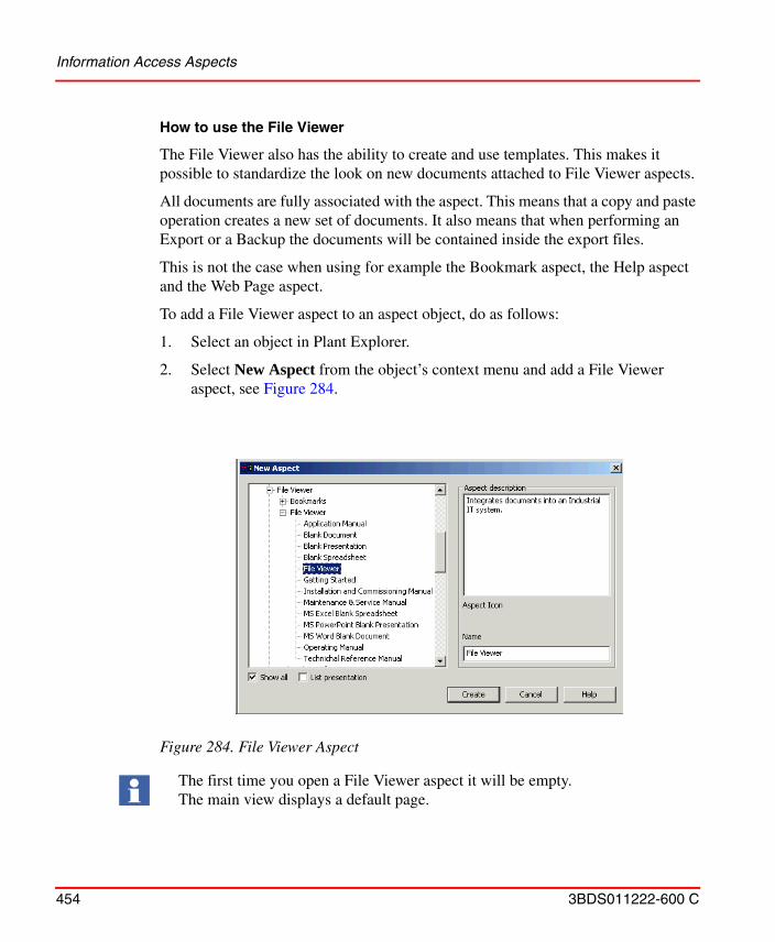
Information Access Aspects
454 3BDS011222-600 C
How to use the File Viewer
The File Viewer also has the ability to create and use templates. This makes it possible to standardize the look on new documents attached to File Viewer aspects.
All documents are fully associated with the aspect. This means that a copy and paste operation creates a new set of documents. It also means that when performing an Export or a Backup the documents will be contained inside the export files.
This is not the case when using for example the Bookmark aspect, the Help aspect and the Web Page aspect.
To add a File Viewer aspect to an aspect object, do as follows:
1. Select an object in Plant Explorer.
2. Select New Aspect from the object’s context menu and add a File Viewer aspect, see Figure 284.
Figure 284. File Viewer Aspect
The first time you open a File Viewer aspect it will be empty. The main view displays a default page.
Information Access Aspects
3BDS011222-600 C 455
The File Viewer aspect has two views, the main view and the configuration view. All formats that can be viewed inside Internet Explorer can be displayed in the main view. The recommended document format is .pdf. For documents to be launched in the web browser, the respective document applications must be supported to display in Internet Explorer.
For example, for Adobe Acrobat PDF documents to be launched in Internet Explorer:
1. Open the PDF viewer (Adobe Acrobat Reader).
2. Select Edit > Preferences... > Internet.
3. In the Web Browser Options section, select the Display PDF in browser check box.
4. Click OK.
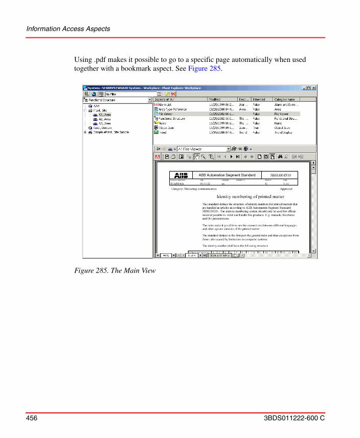
Information Access Aspects
456 3BDS011222-600 C
Using .pdf makes it possible to go to a specific page automatically when used together with a bookmark aspect. See Figure 285.
Figure 285. The Main View
Information Access Aspects
3BDS011222-600 C 457
The configuration view includes two areas, one for a Public document and one for a Work document, see Figure 286 below.
Figure 286. The Configuration View
Pdf document todisplay in the Main View
used to generatethe pdf-file
The source file
Information Access Aspects
458 3BDS011222-600 C
Some status information is displayed in the Work Document area. An example is shown in Figure 287.
• Locked by - displays the name of the user who performed an Edit or a Check Out. This information is only displayed if the document has been checked out by someone other then the current user.
• Directory - displays the name of the directory in which the file is saved. This information is shown only if the current node is the node that the document was checked out from.
• Filename - displays the file name of the document. This information is shown only if the current node is the node that the document was checked out from.
• Attached by - displays the name of the user who performed the last update to the document. A document is updated during an Attach or a Check In. The Attached by information is always available.
• Node - displays the name of the node from which the document was checked out. This information is shown only if the current node is different from the node that the document was checked out from.
Figure 287. Status Information
Information Access Aspects
3BDS011222-600 C 459
File Viewer Functions
The File Viewer functions available in the configuration view are described below, see Figure 288.
Attach.
Use the Attach button to associate a document file with a File Viewer aspect. Attach can be performed on both Public and Work files. To attach a file:
1. Select the File Viewer aspect and the configuration view.
2. Click the Attach button in the Public Document or the Work Document area. A file dialog opens.
Only Adobe Acrobat PDF documents have been tested and verified to work with in the File Viewer aspect main view. However, the File Viewer is based on Microsoft Internet Explorer technology and supports all document formats that can be displayed inside Internet Explorer. Make sure to make the changes in the specific applications to view the documents in Internet Explorer.
Figure 288. File Viewer Functions
Information Access Aspects
460 3BDS011222-600 C
3. Select file and click Open in the dialog.
You can access both Public and Work files from any node on the network.
Automatic Detection of pdf-documents.
When you use the Attach and Check In operations on Work Documents, the file viewer aspect searches the same directory for pdf-files. If a pdf-file with the same name as the Work documents is detected, the file viewer will automatically propose to attach the pdf-file as the Public document.
Edit.
To maintain and update Work files, you use the Edit button. The Edit operation automatically retrieves the Work file from the 800xA system, performs a check out and tags the file as locked in the configuration view. The Work file is placed on local disk, (under My Documents\File Viewer). An application suitable for editing the document is automatically launched.
Follow the instructions below to edit a work file:
1. Select aspect and the configuration view.
2. Select the Edit button in the Work Document area. This will, if available on the client, launch the associated application needed to edit the Work file.
3. Edit the Work file, save and close the application.
4. Use the Save button to make the file available for other users.
Client Version Handling.
When you use edit a Work Document from an aspect of the File Viewer Aspect Category, the file’s name will be modified in order to uniquely identify the file. For example, Work Document 3BSE004510.doc will become 3BSE004510_01.doc on disk when it is checked out, and Work Document 3BSE004510_04.doc is 3BSE004510_05.doc on disk.
For all other categories of the File Viewer Aspect Type, the name is changed during Edit according to the following rule:
<object name>_<aspect name>_<client version>.<suffix>
Information Access Aspects
3BDS011222-600 C 461
Save.
If you edit a Work file, you have to save it before it is updated in the system.
To save a Work file:
1. Select aspect and the configuration view.
2. Click Save in the Work Document area.
Manual File Selection.
If you check the Manual File Selection box, you are able to select file name and directory during Edit.
For example, if you want to make a quick spelling correction, it does not matter where the system saves the file during edit. Whereas if you are going to make considerable changes to a Work file that will take a few days, you might want to save the file to a specific location.
Save Copy .
Save Copy enables you to save a copy of an attached document contained in a File Viewer aspect. Save Copy can be used on both Public and Work documents and the operation never involves Check Out.
To save a copy of a file:
1. Select aspect and bring up configuration view.
2. Select appropriate Save Copy button (Public area or Work area). This will open a save file dialog.
3. Select directory and file name and click Save in the file dialog to save the file to disk.
The Edit operation is also available as aspect verbs
Information Access Aspects
462 3BDS011222-600 C
Clear.
Clear enables you to remove an associated document from an aspect. Clear can be used on both Public and Work documents. This operation is not to be confused with the Delete aspect operation, that is available through the aspect context menu. To Clear a file:
1. Select aspect and bring up the configuration view.
2. Click the Clear button (in appropriate section).
Template Support
The File Viewer aspect supports template functionality. Templates are a quick and easy way to start creating documents.
Any of the supplied File Viewer aspect categories (except the generic File Viewer aspect category) can be used to create a new document. All documents needed are delivered with the Operator Workplace. In addition, there are blank templates that can be used to create a new document.
Usually the proposed name should be used, so that you know where to find documentation. The name of the Operating Manual should be Operating Manual and not Manual or Operators Instructions and so on.
The Predefined File Viewer aspects can be used for creating new documents or for associating existing documents. Then you generate the already associated documents and add your own, or use the existing ones.
Follow the steps below to use any of the predefined templates:
Information Access Aspects
3BDS011222-600 C 463
1. Add a File Viewer aspect to a selected object.
To create your own template, follow the steps below:
1. Go to the Aspect System Structure and select the File Viewer Aspect Type object.
2. Select New Object in the context menu and create a new Aspect Category. This object (Category) will represent the template.
3. Give it a suitable name and click OK.
Figure 289. Existing Templates
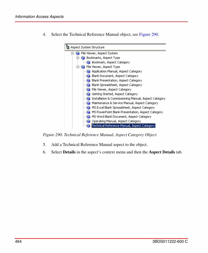
Information Access Aspects
464 3BDS011222-600 C
4. Select the Technical Reference Manual object, see Figure 290.
5. Add a Technical Reference Manual aspect to the object.
6. Select Details in the aspect’s context menu and then the Aspect Details tab.
Figure 290. Technical Reference Manual, Aspect Category Object
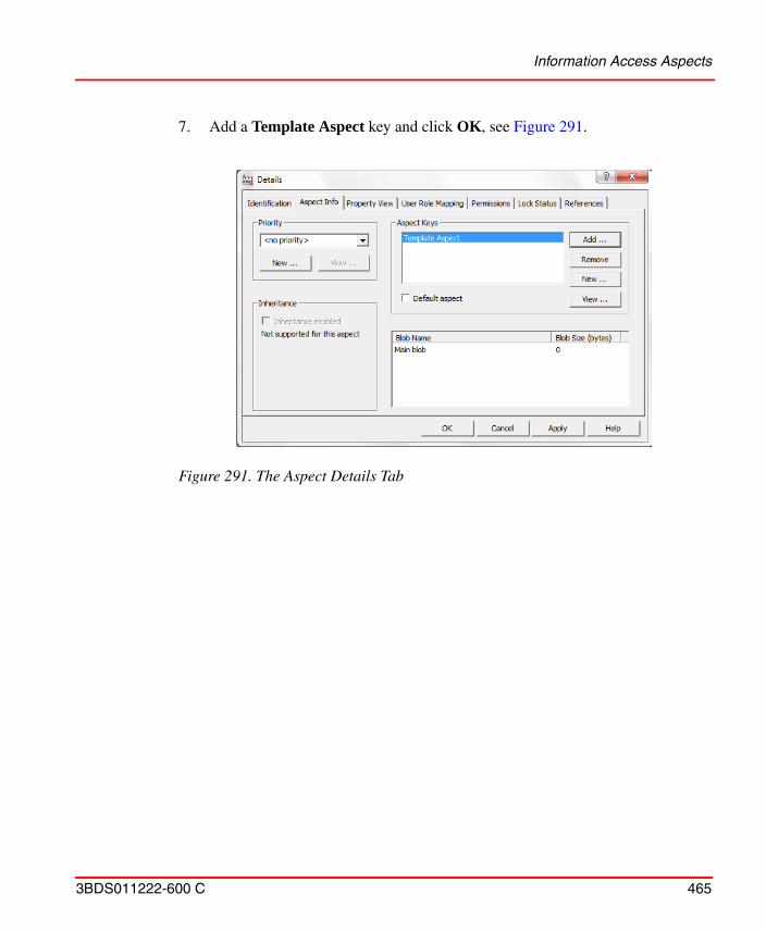
Information Access Aspects
3BDS011222-600 C 465
7. Add a Template Aspect key and click OK, see Figure 291.
Figure 291. The Aspect Details Tab
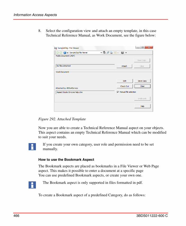
Information Access Aspects
466 3BDS011222-600 C
8. Select the configuration view and attach an empty template, in this case Technical Reference Manual, as Work Document, see the figure below:
Now you are able to create a Technical Reference Manual aspect on your objects. This aspect contains an empty Technical Reference Manual which can be modified to suit your needs.
How to use the Bookmark Aspect
The Bookmark aspects are placed as bookmarks in a File Viewer or Web Page aspect. This makes it possible to enter a document at a specific page You can use predefined Bookmark aspects, or create your own one.
To create a Bookmark aspect of a predefined Category, do as follows:
Figure 292. Attached Template
If you create your own category, user role and permission need to be set manually.
The Bookmark aspect is only supported in files formatted in pdf.
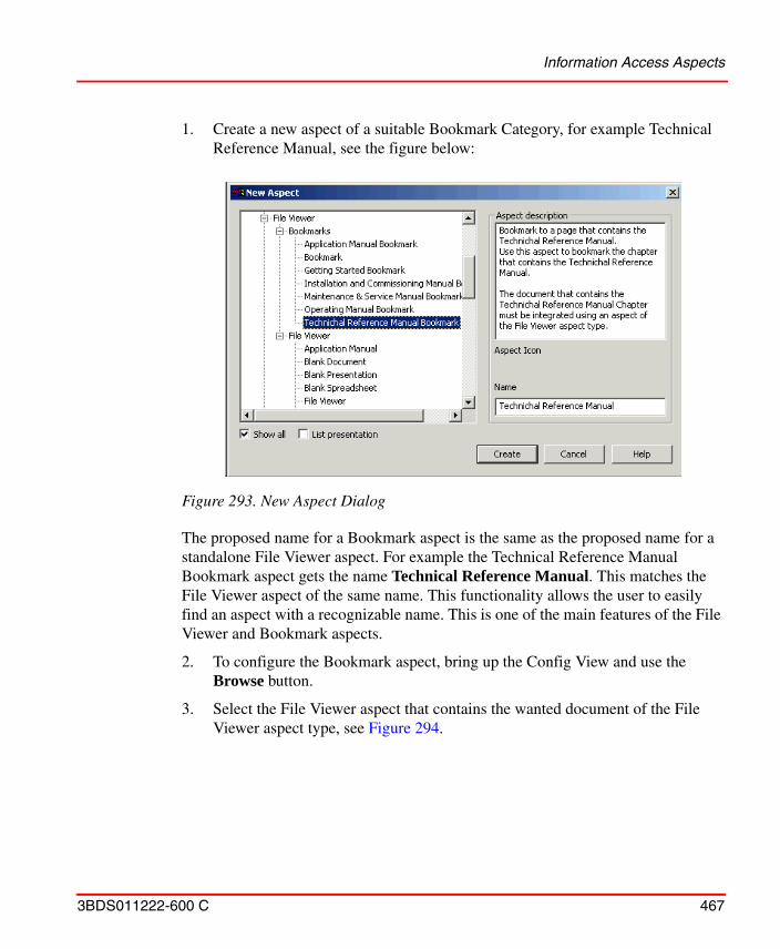
Information Access Aspects
3BDS011222-600 C 467
1. Create a new aspect of a suitable Bookmark Category, for example Technical Reference Manual, see the figure below:
The proposed name for a Bookmark aspect is the same as the proposed name for a standalone File Viewer aspect. For example the Technical Reference Manual Bookmark aspect gets the name Technical Reference Manual. This matches the File Viewer aspect of the same name. This functionality allows the user to easily find an aspect with a recognizable name. This is one of the main features of the File Viewer and Bookmark aspects.
2. To configure the Bookmark aspect, bring up the Config View and use the Browse button.
3. Select the File Viewer aspect that contains the wanted document of the File Viewer aspect type, see Figure 294.
Figure 293. New Aspect Dialog
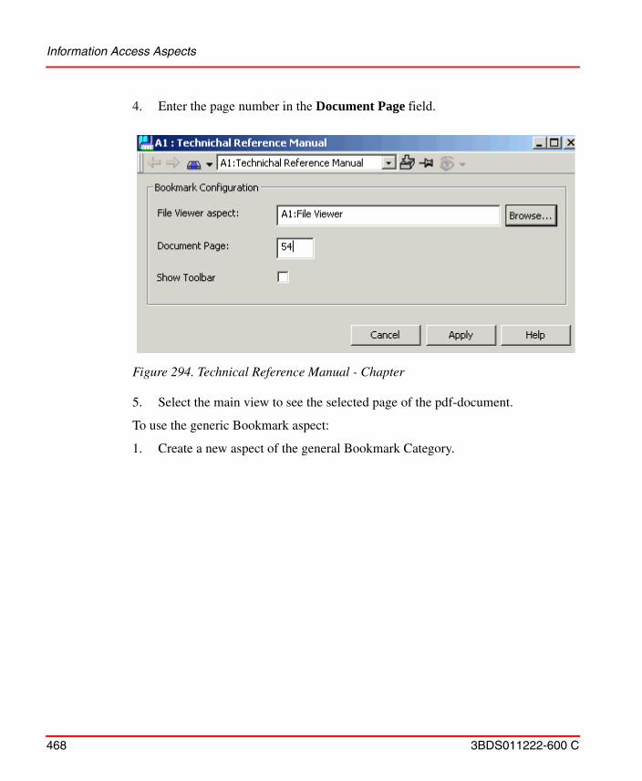
Information Access Aspects
468 3BDS011222-600 C
4. Enter the page number in the Document Page field.
5. Select the main view to see the selected page of the pdf-document.
To use the generic Bookmark aspect:
1. Create a new aspect of the general Bookmark Category.
Figure 294. Technical Reference Manual - Chapter
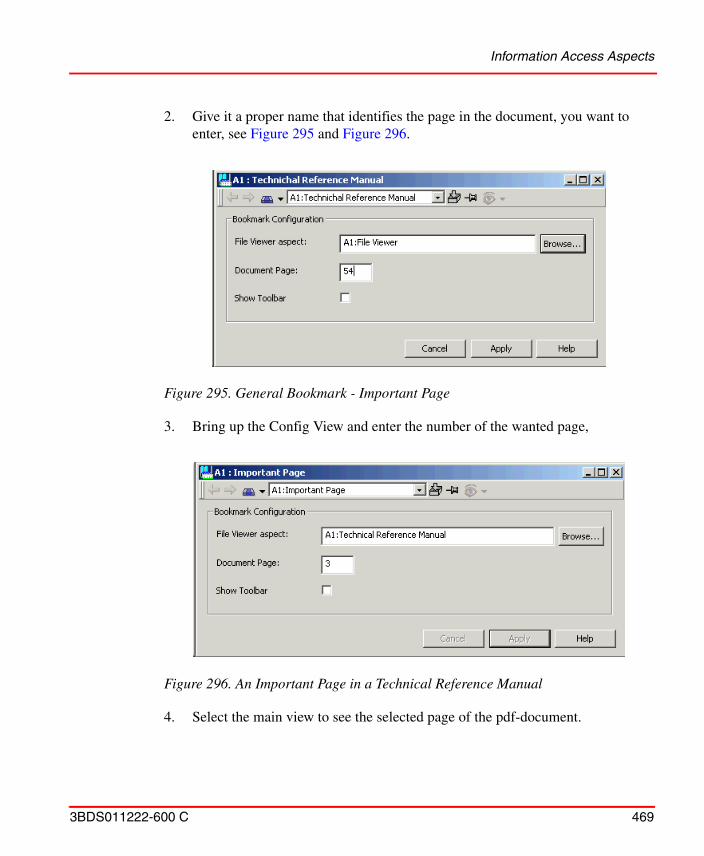
Information Access Aspects
3BDS011222-600 C 469
2. Give it a proper name that identifies the page in the document, you want to enter, see Figure 295 and Figure 296.
3. Bring up the Config View and enter the number of the wanted page,
4. Select the main view to see the selected page of the pdf-document.
Figure 295. General Bookmark - Important Page
Figure 296. An Important Page in a Technical Reference Manual

Information Access Aspects
470 3BDS011222-600 C
How to use the Web Page Aspect
To create a Web Page aspect, do as follows:
1. Add a Web Page aspect to the object concerned.
2. Open the Config View of the Web Page aspect. See Figure 297.
3. Enter the web address in the Address field.
4. Click Show or press Enter to open the web page.
5. Click Apply.
It is also possible to browse another web page in the window and copy the new address to the Address field, by using the Copy Address button. Click Apply to save it. Use the Open file button to browse and open a file in the file system.
Figure 297. The Web Page Aspect in the Config View
Address field
Information Access Aspects
3BDS011222-600 C 471
6. In the upper part of the window the Tool bars check boxes are shown. Select these if you want the Application Bar and the Navigation Bar be shown in the Main View.
How to use the ActiveX Wrapper Aspect
The ActiveX Wrapper aspect provides a container to allow ActiveX Control to be used with the workplace environment. This functionality allows ActiveX Components from various suppliers to be used.
For example ActiveX Controls that are available as part of Windows, such as the Calendar can be used. When you have configured the ActiveX Control, you simply select that aspect to execute it.
To create an ActiveX Wrapper aspect:
1. Add an ActiveX Wrapper aspect to the object concerned.
2. Open the Config View of the aspect.
If you select Explore in the Web Page aspect context menu, your default web browser opens with the web page connected to the Web Page aspect.
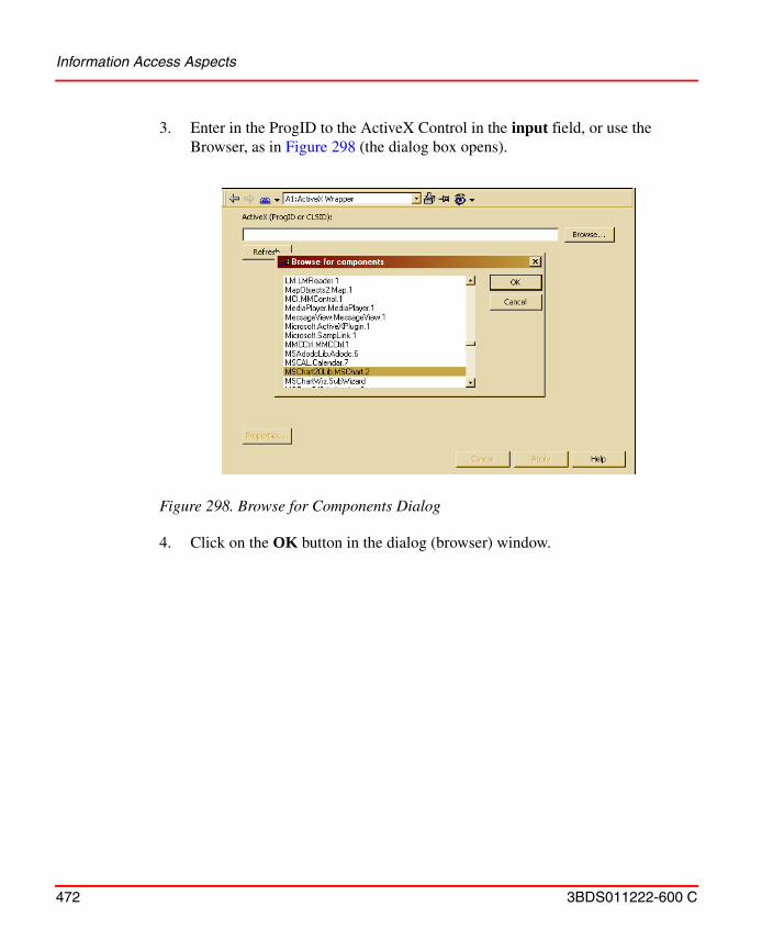
Information Access Aspects
472 3BDS011222-600 C
3. Enter in the ProgID to the ActiveX Control in the input field, or use the Browser, as in Figure 298 (the dialog box opens).
4. Click on the OK button in the dialog (browser) window.
Figure 298. Browse for Components Dialog
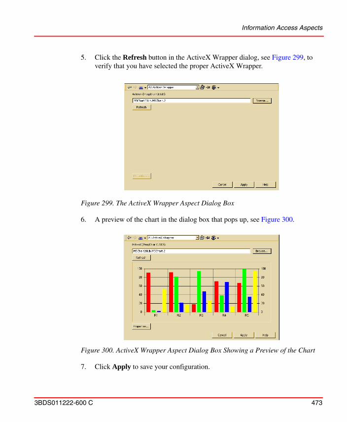
Information Access Aspects
3BDS011222-600 C 473
5. Click the Refresh button in the ActiveX Wrapper dialog, see Figure 299, to verify that you have selected the proper ActiveX Wrapper.
6. A preview of the chart in the dialog box that pops up, see Figure 300.
7. Click Apply to save your configuration.
Figure 299. The ActiveX Wrapper Aspect Dialog Box
Figure 300. ActiveX Wrapper Aspect Dialog Box Showing a Preview of the Chart
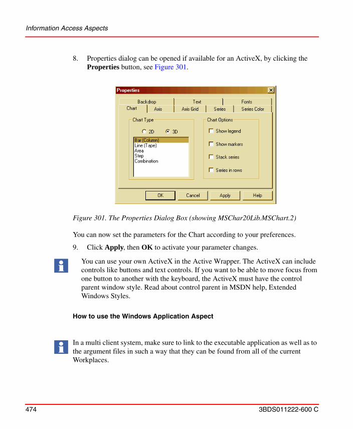
Information Access Aspects
474 3BDS011222-600 C
8. Properties dialog can be opened if available for an ActiveX, by clicking the Properties button, see Figure 301.
You can now set the parameters for the Chart according to your preferences.
9. Click Apply, then OK to activate your parameter changes.
How to use the Windows Application Aspect
Figure 301. The Properties Dialog Box (showing MSChar20Lib.MSChart.2)
You can use your own ActiveX in the Active Wrapper. The ActiveX can include controls like buttons and text controls. If you want to be able to move focus from one button to another with the keyboard, the ActiveX must have the control parent window style. Read about control parent in MSDN help, Extended Windows Styles.
In a multi client system, make sure to link to the executable application as well as to the argument files in such a way that they can be found from all of the current Workplaces.
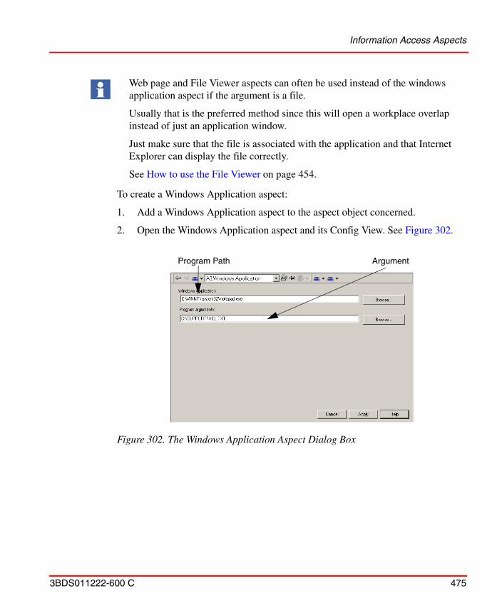
Information Access Aspects
3BDS011222-600 C 475
To create a Windows Application aspect:
1. Add a Windows Application aspect to the aspect object concerned.
2. Open the Windows Application aspect and its Config View. See Figure 302.
Web page and File Viewer aspects can often be used instead of the windows application aspect if the argument is a file.
Usually that is the preferred method since this will open a workplace overlap instead of just an application window.
Just make sure that the file is associated with the application and that Internet Explorer can display the file correctly.
See How to use the File Viewer on page 454.
Figure 302. The Windows Application Aspect Dialog Box
Program Path Argument
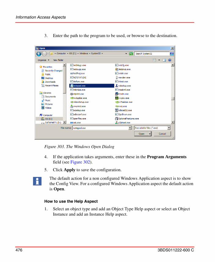
Information Access Aspects
476 3BDS011222-600 C
3. Enter the path to the program to be used, or browse to the destination.
4. If the application takes arguments, enter these in the Program Arguments field (see Figure 302).
5. Click Apply to save the configuration.
How to use the Help Aspect
1. Select an object type and add an Object Type Help aspect or select an Object Instance and add an Instance Help aspect.
Figure 303. The Windows Open Dialog
The default action for a non configured Windows Application aspect is to show the Config View. For a configured Windows Application aspect the default action is Open.
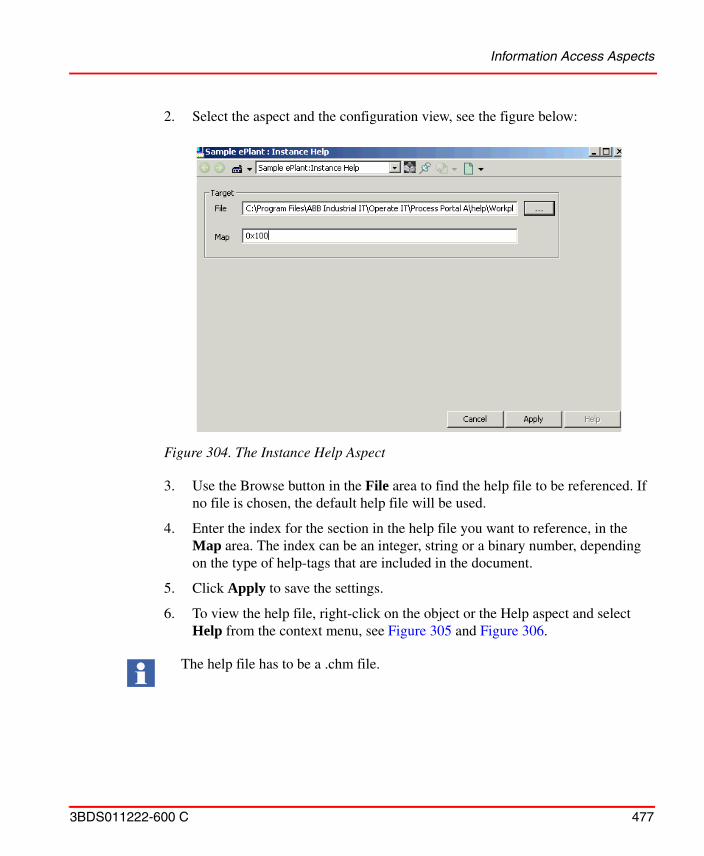
Information Access Aspects
3BDS011222-600 C 477
2. Select the aspect and the configuration view, see the figure below:
3. Use the Browse button in the File area to find the help file to be referenced. If no file is chosen, the default help file will be used.
4. Enter the index for the section in the help file you want to reference, in the Map area. The index can be an integer, string or a binary number, depending on the type of help-tags that are included in the document.
5. Click Apply to save the settings.
6. To view the help file, right-click on the object or the Help aspect and select Help from the context menu, see Figure 305 and Figure 306.
Figure 304. The Instance Help Aspect
The help file has to be a .chm file.
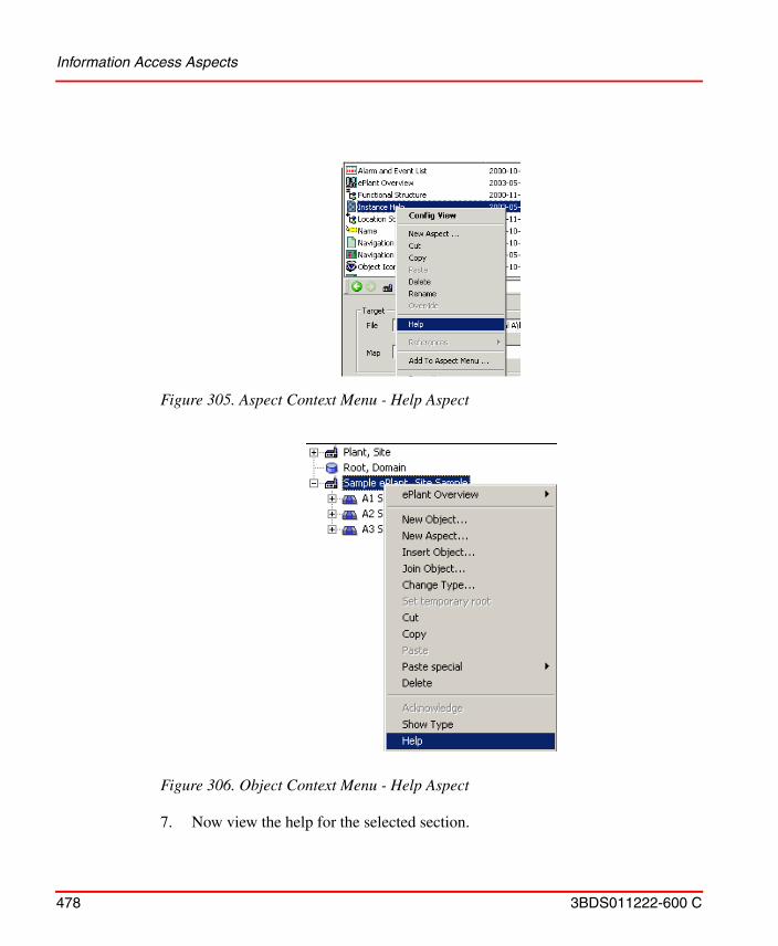
Information Access Aspects
478 3BDS011222-600 C
7. Now view the help for the selected section.
Figure 305. Aspect Context Menu - Help Aspect
Figure 306. Object Context Menu - Help Aspect
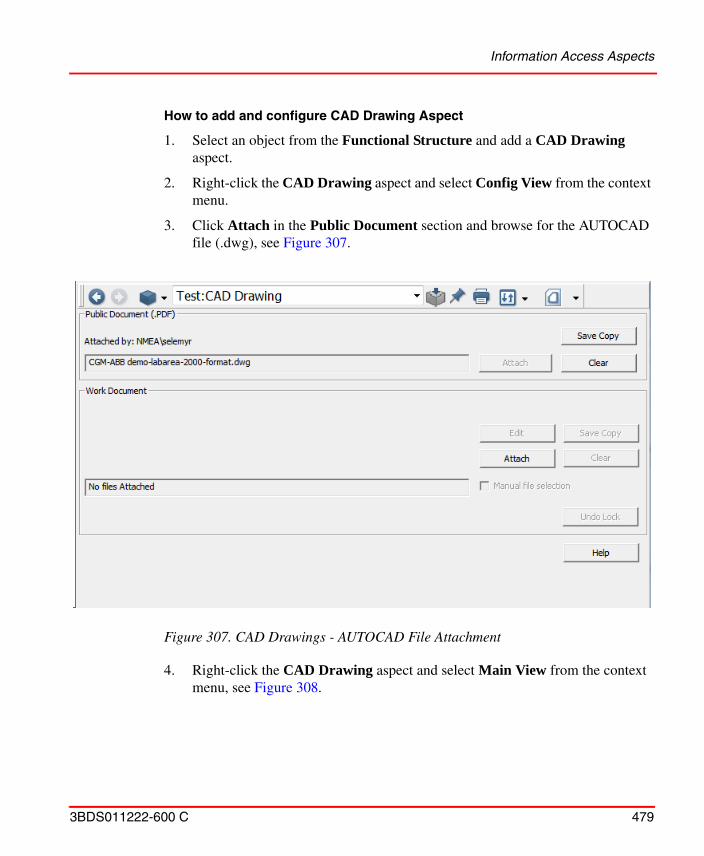
Information Access Aspects
3BDS011222-600 C 479
How to add and configure CAD Drawing Aspect
1. Select an object from the Functional Structure and add a CAD Drawing aspect.
2. Right-click the CAD Drawing aspect and select Config View from the context menu.
3. Click Attach in the Public Document section and browse for the AUTOCAD file (.dwg), see Figure 307.
4. Right-click the CAD Drawing aspect and select Main View from the context menu, see Figure 308.
Figure 307. CAD Drawings - AUTOCAD File Attachment
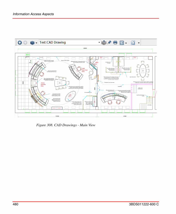
Information Access Aspects
480 3BDS011222-600 C
Figure 308. CAD Drawings - Main View
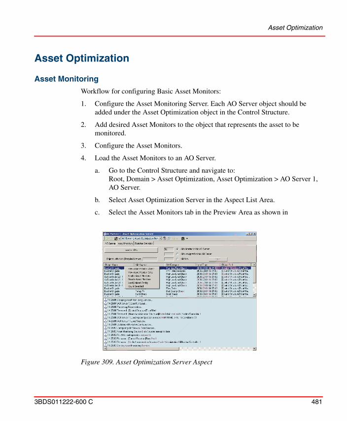
Asset Optimization
3BDS011222-600 C 481
Asset Optimization
Asset Monitoring
Workflow for configuring Basic Asset Monitors:
1. Configure the Asset Monitoring Server. Each AO Server object should be added under the Asset Optimization object in the Control Structure.
2. Add desired Asset Monitors to the object that represents the asset to be monitored.
3. Configure the Asset Monitors.
4. Load the Asset Monitors to an AO Server.
a. Go to the Control Structure and navigate to:Root, Domain > Asset Optimization, Asset Optimization > AO Server 1, AO Server.
b. Select Asset Optimization Server in the Aspect List Area.
c. Select the Asset Monitors tab in the Preview Area as shown in
Figure 309. Asset Optimization Server Aspect
Maximo Integration
482 3BDS011222-600 C
d. Make sure that the Asset Monitor aspects to be loaded are assigned to the target Asset Optimization Server and that they are enabled.
e. To load the enabled Asset Monitor aspects to the Asset Optimization Server, click Load all AMs.
f. To load only selected Asset Monitor aspects, select the AMs Assigned to this AO Srv option, select the desired Asset Monitors, and right-click and select Load/Unload Config from the context menu that appears.
For more details, refer to System 800xA, Asset Optimization, Configuration (3BUA000118*).
Maximo Integration
Workflow for configuring Maximo Connectivity:
1. Set up Maximo Equipment ID in Aspect System Structure to provide CMMS identification information (provider properties). It provides information for mapping the Industrial IT object to the Maximo equipment in the CMMS database for a particular Maximo Server.
2. Set up Fault Report Submitter in Aspect System Structure to set default behavior of the Submit Fault Report view. Options are to delete the Fault Report from the Asset Optimization system and acknowledge the alarm in the Alarm and Event List upon successful submittal, or to not perform these actions.
3. Set up Maximo Credentials that contain the Maximo user credentials used to access the Maximo Server by the specific System 800xA user.
4. Add desired Asset Monitors to the object that represents the asset to be monitored.
5. Configure the CMMS views, which consists of adding the desired views to the desired objects.
For more details see System 800xA, Asset Optimization, Configuration (3BUA000118*).
SAP/PM Integration
3BDS011222-600 C 483
SAP/PM Integration
Workflow for configuring SAP/PM Connectivity:
1. Set up SAP/PM Equipment ID in Aspect System Structure to provide CMMS identification information (provider properties). It provides information for mapping the Industrial IT object to the SAP/PM equipment in the CMMS database for a particular SAP/PM Server.
2. Set up Fault Report Submitter in Aspect System Structure to set default behavior of the Submit Fault Report view. Options are to delete the Fault Report from the Asset Optimization system and acknowledge the alarm in the Alarm and Event List upon successful submittal, or to not perform these actions.
3. Set up SAP/PM Credentials that contain the Maximo user credentials used to access the SAP/PM Server by the specific System 800xA user.
4. Add desired Asset Monitors to the object that represents the asset to be monitored.
5. Configure the CMMS views, which consists of adding the desired views to the desired objects.
For more details refer to System 800xA, Asset Optimization, Configuration (3BUA000118*).
PC, Network and Software MonitoringWorkflow for creating and configuring IT Asset objects using PNSM Asset types. This workflow is generic for any IT Asset type.
1. Create a new object of the appropriate IT Asset type in Control Structure, under the IT OPC Server Network.
2. Edit the IT General Property aspect on the new object to set the appropriate general asset configuration parameters.
3. If necessary, edit the individual IT Device aspects to set the device-specific configuration parameters.
4. If necessary, add and configure additional IT Device aspects to the asset object. This is done by:
Configuration Change and Access Management
484 3BDS011222-600 C
a. Create a new aspect on the object of type IT Device.
b. On the configuration view of the new IT Device aspect, set the Current IT Device Configuration setting to the appropriate Device Configuration.
c. Edit the device-specific parameters as appropriate.
5. Go to the IT Device Manager aspect, and press click Populate. To confirm that the asset object was properly populated, view the property list on the IT Control Connection aspect.
6. If you have Asset Optimization installed and a license for IT Asset Monitoring, generate the Asset Monitor for the object. To do this: Click Generate on the IT Device Manager aspect.
7. Go to Asset Optimization
a. Go to AO Server 1
b. Go to the Asset Optimization Server object
c. Go to the Asset Monitors Tab
d. Click on Load all AMs
For more details refer to System 800xA, PC, Network, and Software Monitoring Configuration (3BUA000447*).
Configuration Change and Access Management
Authorization
For configuration of Security and Authorization for an 800xA system refer to System 800xA, Administration and Security (3BSE037410*).
Access Control
Re-Authentication and Double-Authentication requires activation of Advanced Access Control, by setting its value as True in System Settings aspect. System Settings aspect is placed in Admin Structure under Administrative Objects\Domains\<node> system.
Log Over
3BDS011222-600 C 485
If Authentication is required, then aspect category also has to be configured by checking corresponding check boxes in the Aspect Category Definition aspect. Aspect Category Definition aspect is placed in Aspect System Structure, under Aspect System Structure, Aspect Category object.
Re-Authentication or Double-Authentication can be chosen as required.
For further details see System 800xA, Administration and Security (3BSE037410*).
Log Over
Activation of Log Over requires enabling the corresponding log over setting in Logover Settings aspect of the corresponding System:
Logover Settings aspect is placed in Admin Structure under Administrative Objects\Domains\<node> system.
To enable Log Over, follow the steps below:
1. Check the Enable Logover check box.
2. Click Apply.
For additional configuration of an Inactivity User, follow the steps below:
1. Enable multiple log over by checking the Multiple Logover check box.
2. Select which user should be the inactivity user in the Inactivity User drop-down menu.
3. Set the password for the inactivity user in the Password field.
4. Set the time-out for automatic revert to inactivity user in the Revert to Inactivity User drop-down menu.
5. Click Apply.
For further details refer to System 800xA, Administration and Security (3BSE037410*).
Electronic Signature
Before activate the first and second signatures, set the Signature Required property of System Settings aspect as True. System Setting aspect is placed in Admin Structure under Administrative Objects\Domains\<node> system. Further configure
Configuration Change Management
486 3BDS011222-600 C
the First Signature required / Second Signature required on the Aspect Category Definition aspect of the Aspect Category object in the Aspect System Structure. You can choose to require First Signature or (First and) Second Signature. This is also the place where to configure the required permission for signing via the Permissions tab.
For further details refer to System 800xA, Administration and Security (3BSE037410*).
Configuration Change Management
System Configuration Version
A System Configuration Version is defined by an System Configuration Version Definition object /aspect in the Maintenance Structure beneath the System Configuration Version Definitions root object. A version identity and a label can be set in the Summary tab on the Backup Definition aspect of the System Configuration Version Definition object. Backup / Creation of the System Configuration Version can be started from this tab.
A System Configuration Version is stored in a corresponding object beneath the System Configuration Versions root object.The corresponding backup files are stored on a backup directory on harddisk.
The backup files of a System Configuration Version can be restored to the same or to another node using Configuration Wizard to fall back to a saved consistent version of system configuration.
It can also be used to set up initially an new Engineering System with the current configuration of a Production System.
For more details on System Configuration Version and Backup / Restore refer to System 800xA, Maintenance (3BSE046784*).
Synchronizing Changes Between Systems
Changes done in an Engineering System can be transferred to a Production System using Engineering Repository application server or Import / Export tool.
Engineering Repository
3BDS011222-600 C 487
Engineering Repository
The Engineering Repository is a simple source control system for:
• Storing engineering solutions.• Moving engineering solutions between Engineering and Production systems.• Comparing engineering solutions.
The Engineering Repository on the Application Server is not an integrated part of it, but with communication access to an 800xA system. The Application Server hosts web-services which are reachable from 800xA systems.
Engineering solutions are placed on the Application Server as .afw files. In addition, the Engineering Repository stores metadata in order to gain performance in storing and retrieving afw files.
The user can add the following entities to the Engineering Repository.
• Control Project.• Control Application.• Controller.• Library.• Custom Entities.
The Engineering Repository functionality is initially limited to:
• 800xA Operations.
• Control and I/O (except generic OPC).
• Fieldbuses.
• Batch Management.
• Information Management.
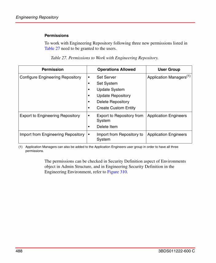
Engineering Repository
488 3BDS011222-600 C
Permissions
To work with Engineering Repository following three new permissions listed in Table 27 need to be granted to the users.
The permissions can be checked in Security Definition aspect of Environments object in Admin Structure, and in Engineering Security Definition in the Engineering Environment, refer to Figure 310.
Table 27. Permissions to Work with Engineering Repository.
Permission Operations Allowed User Group
Configure Engineering Repository • Set Server
• Set System
• Update System
• Update Repository
• Delete Repository
• Create Custom Entity
Application Managers(1)
(1) Application Managers can also be added to the Application Engineers user group in order to have all three permissions.
Export to Engineering Repository • Export to Repository from System
• Delete Item
Application Engineers
Import from Engineering Repository • Import from Repository to System
Application Engineers
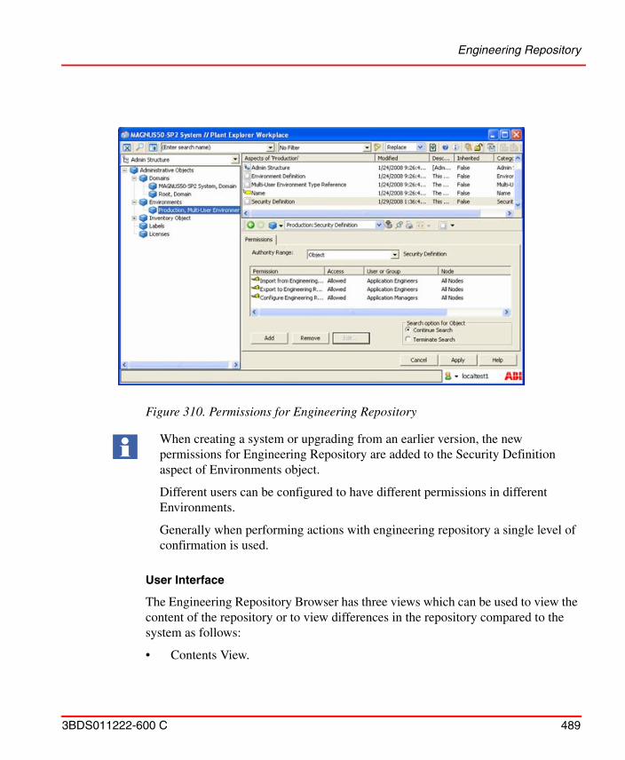
Engineering Repository
3BDS011222-600 C 489
User Interface
The Engineering Repository Browser has three views which can be used to view the content of the repository or to view differences in the repository compared to the system as follows:
• Contents View.
Figure 310. Permissions for Engineering Repository
When creating a system or upgrading from an earlier version, the new permissions for Engineering Repository are added to the Security Definition aspect of Environments object.
Different users can be configured to have different permissions in different Environments.
Generally when performing actions with engineering repository a single level of confirmation is used.
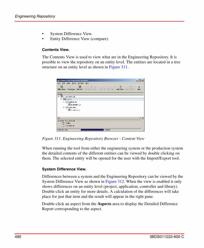
Engineering Repository
490 3BDS011222-600 C
• System Difference View.• Entity Difference View (compare).
Contents View.
The Contents View is used to view what are in the Engineering Repository. It is possible to view the repository on an entity level. The entities are located in a tree structure on an entity level as shown in Figure 311.
When running the tool from either the engineering system or the production system the detailed contents of the different entities can be viewed by double clicking on them. The selected entity will be opened for the user with the Import/Export tool.
System Difference View.
Differences between a system and the Engineering Repository can be viewed by the System Difference View as shown in Figure 312. When the view is enabled it only shows differences on an entity level (project, application, controller and library). Double-click an entity for more details. A calculation of the differences will take place for just that item and the result will appear in the right pane.
Double-click an aspect from the Aspects area to display the Detailed Difference Report corresponding to the aspect.
Figure 311. Engineering Repository Browser - Content View
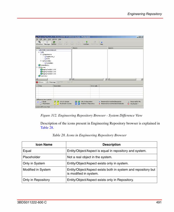
Engineering Repository
3BDS011222-600 C 491
Description of the icons present in Engineering Repository browser is explained in Table 28.
Figure 312. Engineering Repository Browser - System Difference View
Table 28. Icons in Engineering Repository Browser
Icon Name Description
Equal Entity/Object/Aspect is equal in repository and system.
Placeholder Not a real object in the system.
Only in System Entity/Object/Aspect exists only in system.
Modified in System Entity/Object/Aspect exists both in system and repository but is modified in system.
Only in Repository Entity/Object/Aspect exists only in Repository.
Engineering Repository
492 3BDS011222-600 C
The differences UI can be called up either from the Engineering Repository Browser or from the context menu in the Plant Explorer.
Entity Difference View (Compare).
Differences between a specific item in the system and the Engineering Repository can be viewed by the Entity Difference View. When the view is enabled it only shows differences on an entity level (project, application, controller and library). Objects / Aspects that are part of a filter is not included in the difference calculations on an entity level, but in the detailed difference. Double-click on an item for more details. A calculation of the differences will take place for just that item and the result appears in the right pane. There is a checkbox next to the item which is checked by default if there are any differences between the repository and the system. Items that are checked can be exported or imported.
Double-click an aspect from the Aspects area to display the Detailed Difference Report corresponding to the aspect.
Modified in Repository Entity/Object/Aspect exists both in system and repository but is modified in Repository.
Reserved by Another (Breakable)
Entity/Object/Aspect is reserved by another user in the system. The reservation is breakable by current user.
Reserved by Another (Not Breakable)
Entity/Object/Aspect is reserved by another user in the system. The reservation is not breakable by current user.
Reserved by me Entity/Object/Aspect is reserved by me in system.
Modified in ? Entity/Object/Aspect exists both in system and repository and differs but the tool don't know where it is modified.
Calculating differences for the whole repository may take long time (several hours first time) if it contains a lot of Engineering Solutions.
Table 28. Icons in Engineering Repository Browser
Icon Name Description
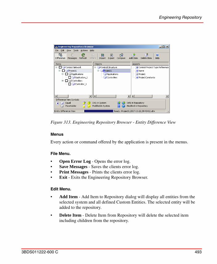
Engineering Repository
3BDS011222-600 C 493
Menus
Every action or command offered by the application is present in the menus.
File Menu.
• Open Error Log - Opens the error log.• Save Messages - Saves the clients error log.• Print Messages - Prints the clients error log.• Exit - Exits the Engineering Repository Browser.
Edit Menu.
• Add Item - Add Item to Repository dialog will display all entities from the selected system and all defined Custom Entities. The selected entity will be added to the repository.
• Delete Item - Delete Item from Repository will delete the selected item including children from the repository.
Figure 313. Engineering Repository Browser - Entity Difference View
Engineering Repository
494 3BDS011222-600 C
• Custom Entity - This opens the Custom Entity Configuration dialog. The dialog is used to define Custom Entities for the repository. When Custom Entities have been defined they can be used in the repository.
• Filter Settings - This opens the filter dialog for Aspect Categories and Object Types
View Menu.
• Contents - Select this to view the contents of the repository.
• Differences - Select this, the Difference View, to view the differences between the repository and the selected system.
• Messages - Select this to view error and warnings generated in the application. When new entries are added to the log the log view is automatically displayed as shown in Figure 314.
Figure 314. Engineering Repository Browser - Messages View
Engineering Repository
3BDS011222-600 C 495
• Details - Choosing details will show different views depending on which view is displayed. If any of the Difference Views is displayed details of the selected entity will be presented in the right pane. If Contents View is the displayed the Import/Export application will be started with the selected item loaded.
• Refresh - Reload the information from the repository and the system.
Tools Menu.
• Select Repository- If an Engineering Repository web service is not installed on the same node as where the application is running the repository must be pointed out.
• Select System - Use Select System when changing from for example the engineering environment to the production environment. When Engineering Repository Browser is first started it connects to a system on the local node.
Actions Menu.
• Export To System - Export will export the selected item with dependencies to the system from the Repository. This can be used when updating the production system with items originating from the engineering system
• Import From System - Import will import the selected item with dependencies from the system to the Repository. This can be used when updating the repository from the engineering system.
• Compare With System - Compare item With System shows Entity Difference View.
• Update System - Update System will export all items from the Repository to the selected system. A confirm dialog will appear.
• Update Repository - Update Repository will import the corresponding members of all entities and custom entities in the repository from the selected system. A confirm dialog will appear.
Update System will overwrite the selected system or parts of the system with the contents of the repository.
Engineering Repository
496 3BDS011222-600 C
• Delete Repository - Delete Repository will delete all items in the repository. Defined custom entities and the entities in the system will not be affected. A confirm dialog will appear.
Help Menu.
• Contents - Displays the Industrial IT 800xA System Online help.
Toolbar
The toolbar contains a subset of the commands found in the menus.
Plant Explorer Context Menu
From the context menu in the Plant Explorer (Figure 315), it is possible to add items (projects, applications, controllers and libraries) to the Engineering Repository. The Engineering Repository context menu entry appears when the selected object belongs to an Entity or a Custom Entity.
Figure 315. Context Menu in Plant Explorer
Engineering Repository
3BDS011222-600 C 497
For the application to be able to know if an object belongs to a Custom Entity the Engineering Repository must be connected.
• Export item to Engineering Repository - Exports the Entity associated to the selected object to the Engineering Repository. If an Engineering Repository is not found on the node a dialog will appear guiding the user to connect to one.
• Import item from Engineering Repository - Imports the Entity associated to selected objects from the Engineering Repository. If an Engineering Repository is not found on the node a dialog will appear guiding the user to connect to one.
• Compare item with Engineering Repository - Opens up the difference UI and makes it possible to see what differs.
Configuration
Custom Entities.
Entities like projects, applications, controllers, libraries, and Control Networks can be exported to the Engineering Repository without any special configuration. Objects which are not part of an entity to the Engineering Repository need to be defined in Engineering Repository as Custom Entities. Custom Entities are only known to repository.
Following properties need to be configured for each object defined as Custom Entity:
• Include Children
All child objects of the object defined as Custom Entity will be included in the Custom Entity.
• Include Dependencies
All dependencies of the object defined as Custom Entity will be included in the Custom Entity.
• Delete at import
Objects or aspects that exist in the target system as part of the Custom Entity but not in the import file will be deleted.
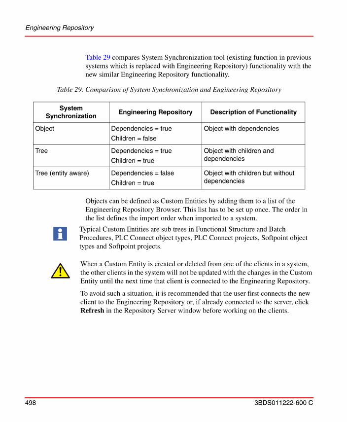
Engineering Repository
498 3BDS011222-600 C
Table 29 compares System Synchronization tool (existing function in previous systems which is replaced with Engineering Repository) functionality with the new similar Engineering Repository functionality.
Objects can be defined as Custom Entities by adding them to a list of the Engineering Repository Browser. This list has to be set up once. The order in the list defines the import order when imported to a system.
Table 29. Comparison of System Synchronization and Engineering Repository
System Synchronization
Engineering Repository Description of Functionality
Object Dependencies = true
Children = false
Object with dependencies
Tree Dependencies = true
Children = true
Object with children and dependencies
Tree (entity aware) Dependencies = false
Children = true
Object with children but without dependencies
Typical Custom Entities are sub trees in Functional Structure and Batch Procedures, PLC Connect object types, PLC Connect projects, Softpoint object types and Softpoint projects.
When a Custom Entity is created or deleted from one of the clients in a system, the other clients in the system will not be updated with the changes in the Custom Entity until the next time that client is connected to the Engineering Repository.
To avoid such a situation, it is recommended that the user first connects the new client to the Engineering Repository or, if already connected to the server, click Refresh in the Repository Server window before working on the clients.
Engineering Repository
3BDS011222-600 C 499
Filters
Filtering of Aspect Categories.
If the user do not want to overwrite specific Aspect Categories (e.g. Operator Note) from the Engineering System to the Production System, that can be configured using the filters for Aspect Categories. Filters are applied at import.
Select the configurable filter for Aspect Categories from the Repository Browser menu. Add the required category to the filter and set one of the following properties:
• Always Filter Out.
• Do not import aspects of a specified category.
• Never Overwrite.
Never overwrite aspects of a specific category.
• Overwrite Older Aspects.
Overwrite aspects of a specific category if current modification date is older than the date in the destination.
The filter applies to the whole repository so that all imports from the repository to the system are filtered.
Filtering of Objects based on Type.
If the user do not want to overwrite specific Object Types (e.g. HART Device objects) from the Engineering System to the Production System, that can be configured using the filters for Object Types.
Select the configurable filter for Object Types from the Repository Browser menu. Add the required types to the filter and set one of the following properties:
• Always Filter Out.
The filter also applies to compare when producing the difference report. Aspects that are filtered out will not indicate differences in the difference view.
Engineering Repository is delivered with the default Aspect Category filter settings that can be used by most of the users. The default settings can be modified to suit any project-specific requirement.
Application Change Management
500 3BDS011222-600 C
Do not import objects of a specified type.
• Never Overwrite.
Never overwrite aspects of a specific object. But creates aspects of the specific object if it is not exist in the destination system.
• Overwrite Older Aspects.
Overwrite aspects of a specific object if current modification date of the aspect is older than the date in the destination.
• The filter applies to the whole repository so that all imports from the repository to the system are filtered.
Application Change Management
Application Change Management (ACM) is a version control tool used for engineering solutions in 800xA System. Multiple versions of 800xA application configuration can be archived in the ACM host and provide an integrated configuration management system utilizing proven in use .afw files technology. The most common actions such as archiving new snapshots of configuration artifacts (For example: Process Displays, Control Libraries, Control Applications, or Controllers) can be accessed through Engineering Workplace context menu. Extended features as browsing through the configuration history and creating baselines of configuration artifacts are accessible through ACM Client Application. All ACM actions changing the content of the ACM archive are being logged in the
The filter also applies to compare when producing the difference report. Aspects that are filtered out will not indicate differences in the difference view.
After modifying filters, Engineering Solutions shall be re-exported from the system to the repository since filtered items are excluded when calculating differences. The re-export is needed to have the compare functionality to work.
For Custom Entities with the property "DeleteAtImport" set the delete will be performed first and the when deleted the filter will be applied at Import.
Avoid using the object type filters with objects that are entities or sub-entities, for example, Soft Controller objects.
Import / Export tool
3BDS011222-600 C 501
ACM system in parallel to 800xA audit trail, which logs any change to the 800xA configuration.
Multiple 800xA systems can be connected to the same ACM host in order to share configuration artifacts effectively. Redundant servers in different security zones can be build up utilizing Microsoft Sharepoint Server technology, where connection can be a limited to a dedicated server to server link.
Application Change Management features are as follows:
• Check-in (archive version), check-out (mark a version in ACM host as checked out with or without retrieving it to the 800xA system) and compare on various levels.
• Baseline for system in ACM host and roll back to required older baseline.
• Supports multiple versions of the configuration artifacts.
• Supports Activity log.
• Supports different access control privilege levels.
• Displays various error reports.
• Support for connecting more than one engineering system.
For more information on ACM, refer to System 800xA, Engineering, Application Change Management (2PAA108438*).
Import / Export tool
Changes done in an Engineering System can be transferred to a Production System using the Import / Export tool by performing the following principal steps:
1. Export the changes on the Engineering System with the Import / Export-tool taking care of the changed entities, objects and aspects and their dependencies by dragging and dropping or adding (Add Item) the items into the tool.
2. Save them to an afw-file or a set of afw-files. Segmentation into several afw-files might be necessary for bigger changes.
3. Transfer the afw-files to the Production System.
4. Load an afw-file with the Import / Export tool.
Synchronizing Changes Between Environments
502 3BDS011222-600 C
5. Verify the changes against the Production System using the Differences tool available in the Import / Export-tool.
6. Check for missing Dependencies.
7. Edit missing Placements if needed.
8. Import the afw-file (Import All) or only a required selected part within the afw-file (Import), taking decisions on replacements if needed.
9. Execute Step 4 to Step 8 for all afw-files.
10. Verify the imported contents, use for example the Consistency Check tool on the imported items.
11. Do further actions make the imported contents work, such as Generate Configuration Data on Function Diagrams, Download the Control Application, and so on.
If on the Production System the Configure-Deploy way of working is used the imports have to be done against the Engineering Environment except for the Production-only aspects. They can only be imported into the Production Environment. If you try to import such aspects into the Engineering environment, the Import tool will skip them.
Synchronizing Changes Between Environments
In a system that has environment support enabled in Configuration Wizard you can work with two separate environments: Engineering and Production. Environment support is a separately licensed functionality.
Engineering Repository application server also can be used to transfer the changes done in Engineering System to a Production System.
Engineering Repository has more intelligence than Import Export tool. It allows the user to save, compare, and retrieve data. Engineering Repository is described in System 800xA, Maintenance (3BSE046784*).
Application Change Management (ACM) can be used to transfer the changes done in Engineering System to a Production System. It allows to save, compare on various levels, and retrieve data. For more information on ACM, refer to System 800xA, Engineering, Application Change Management (2PAA108438*).
Synchronizing Changes Between Environments
3BDS011222-600 C 503
Changes towards the Production environment then can be handled according the Configure-Deploy way of working, performing the following principal steps:
1. In Configuration Wizard refresh the Engineering environment from Production environment.
2. Do the changes in Engineering environment.
3. Pre-test them in Engineering environment.
4. Use the Environment Difference tool to verify the differences between Production environment and Engineering environment.
5. Use the Deploy tool to move the changes from Engineering environment to Production environment.
6. If further changes are done in Production environment the Engineering environment can be updated using the Update and/or Replace tool to prepare Engineering environment for a next change cycle. Be aware that Update cannot be used with Control Builder M related aspects. The Replace tool has to be used in this case.
The Configure-Deploy way of working can be beneficial when doing changes in a Production System, but also in an Engineering and Test System:
How configuration changes can be handled when Load - Evaluate - Go environment support (separately licensed functionality) is enabled in Configuration Wizard is described in System 800xA Engineering, Engineering and Production Environments (3BSE045030*). This instruction gives also more details on the Configure-Deploy way of working.
Note that no download to a controller is possible in the Engineering environment. Only Test Mode (simulated controller) in Control Builder M Professional can be used.
Note that there can be aspect categories that cannot be configured in the Engineering environment: Production-only aspects.
Especially when working in a Production System with Engineering and Production environment you need to be aware of performance issues and disturbances of the running process.
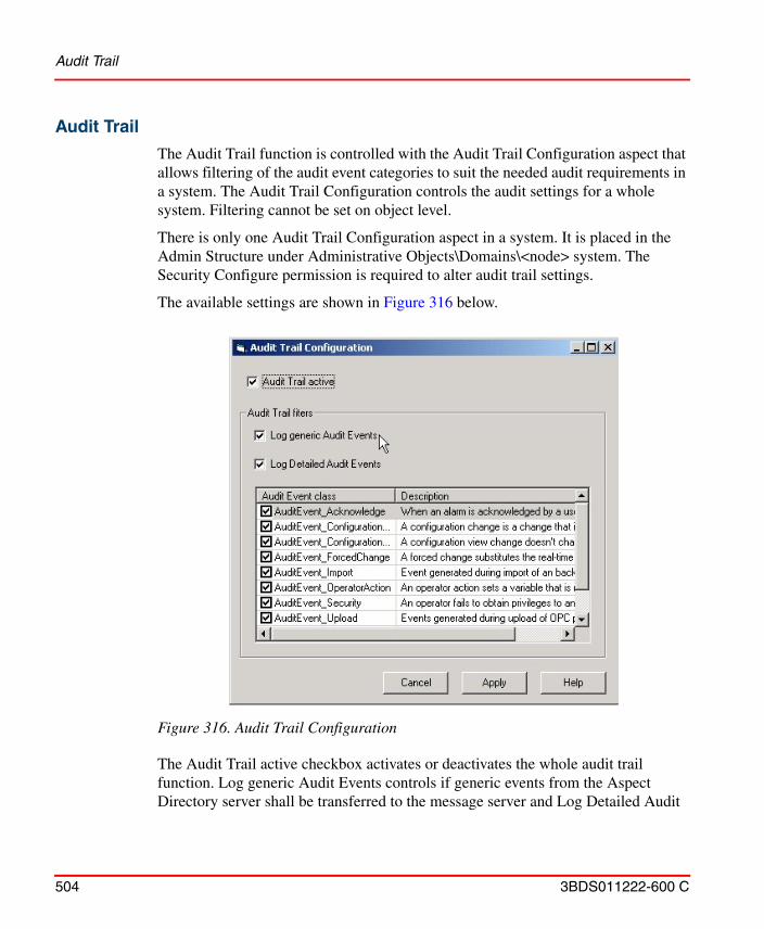
Audit Trail
504 3BDS011222-600 C
Audit Trail
The Audit Trail function is controlled with the Audit Trail Configuration aspect that allows filtering of the audit event categories to suit the needed audit requirements in a system. The Audit Trail Configuration controls the audit settings for a whole system. Filtering cannot be set on object level.
There is only one Audit Trail Configuration aspect in a system. It is placed in the Admin Structure under Administrative Objects\Domains\<node> system. The Security Configure permission is required to alter audit trail settings.
The available settings are shown in Figure 316 below.
The Audit Trail active checkbox activates or deactivates the whole audit trail function. Log generic Audit Events controls if generic events from the Aspect Directory server shall be transferred to the message server and Log Detailed Audit
Figure 316. Audit Trail Configuration
Archive
3BDS011222-600 C 505
Events activates or deactivates the Audit Event class list where filtering of specific audit event classes can be specified.
All changes in Audit Trail Configuration settings are documented as audit events, if the Audit Trail function is activated.
Re-authentication is required to apply changes in the Audit Trail configuration.
Archive
Archiving of data collected in audit trail logs is supported by Information Management History Services. For configuration instructions see System 800xA, Information Management, Configuration (3BUF001092*).
System and Device Checks
For configuration and use of system and device checks see the applicable configuration and operation manuals of the corresponding functional areas of System 800xA.
Data AccessThe client should check the status of 800xA OPC server periodically from the time of connection to the server until the connection is released, to ensure that the server is functioning. It is not necessary to frequently check the status because this may degrade system performance. For more information on checking the status, refer to Accessing 800xA via OPC on page 505.
Accessing 800xA via OPC
800xA OPC functionality consists of two main functions, OPC Support and OPC Connect. This chapter deals with OPC Support, which enables OPC Clients to connect to 800xA in order for the client to read and write OPC data from/to 800xA.
800xA OPC Support is typically used by an OPC Client in order to exchange data between 800xA and third party software applications to be used for e.g. reports, information management, HMIs, optimization algorithms and lab data systems.
The 800xA license feature that the customer pays for to get 800xA OPC Support is called ‘OPC Client Connection’.
Accessing 800xA via OPC
506 3BDS011222-600 C
800xA OPC Support exposes interfaces for OPC Data Access, OPC Alarm and Event and OPC History Data Access. These are three central interface specifications as stated by the OPC Foundation. Refer to the System 800xA, System Planning (3BSE041389*) manual for a definition and explanation of OPC.
In order to use OPC Support both hardware and software must be configured in certain ways. The following sections explain this in more detail.
Hardware Setup
800xA does not impose any restrictions on which machine the third party OPC client software is to be installed. It can be installed directly on the 800xA connectivity servers or on an 800xA workplace client. Installation on an 800xA workplace client gives a slightly better system performance and it gives the 800xA connectivity servers a better fault isolation from poorly implemented OPC clients.
Accessing the 800xA OPC DA Server
OPC DA Server Support in the 800xA system enables you to read, write or subscribe to system properties from a third party OPC DA client.
The status of the server is checked by calling the method GetStatus on IOPCServer. The client should wait for the return code OPC_STATUS_RUNNING before calling the other methods.
OPC DA Program Identities
The Program Identity for the System 800xA OPC DA Server to be used by third party OPC DA clients is ABB.AfwOpcDaSurrogate (local server).
When a new client connection is established the new client will share a running ABB.AfwOpcDaSurrogate process if possible. If not, a new process will be started
To be considered when accessing the 800xA OPC Servers:
Accessing the 800xA OPC Servers will generate load in the system, which may affect normal operation. Especially adding items and doing reads and writes might affect other functions in the system. Ensure to follow the performance and capacity limits described in System 800xA, System Guide Technical Data and Configuration (3BSE041434*).
Accessing 800xA via OPC
3BDS011222-600 C 507
for the new client connection. Use the DCOMCNFG tool to set the DCOM security setting, see DCOM Security Settings for OPC on page 549.
OPC DA Compliancy
The System 800xA OPC Server is compliant with the OPC Data Access Standard Version 1.0 and 2.05A with some comments.
OPC Data Access Version 2.05A.
IOPCBrowseServerAddressSpace
The IOPCBrowseServerAddressSpace interface as implemented by the 800xA System OPC Server is not fully compliant with the OPC Data Access Standard Version 2.05A. This interface can still be used considering the constraints described below:
• Flat namespace is not supported. Retrieving an itemID enumerator from the BrowseOPCItemIDs method with OPC_FLAT as browse filter type will result in an empty enumerator.
• The method BrowseAccessPaths is not supported and will always return E_NOTIMPL.
• BrowseOPCItemIDs will not return any items from the Admin or Aspect System structures. It is however possible to manually add items from these structures.
IOPCGroupStateMgt
• SetState does not change the update rate for a group.
• AddGroup allows requested update rate 0, which is handled as a special case. The items in the group will get a default update rate defined per item in the 800xA system. Revised update rate will be 1000 ms for the group.
OPC Data Access Version 1.0.
• Array data types are not supported.
IOPCAsyncIO and IOPCAsyncIO2
The Write method will fail when the following conditions apply:
Accessing 800xA via OPC
508 3BDS011222-600 C
• The list of server item handles contains the same handle more than once.
• Audit trail is activated for Operator_Action.
The Write method will return S_FALSE and the array with HRESULTs will contain error codes for all the server item handles, indicating that duplicate handles have been found.
Accessing the 800xA OPC AE Server
OPC AE Support in the 800xA system enables you to subscribe to alarm and events from a third party OPC AE client.
The status of the server is checked by calling the method GetStatus on IOPCEventServer. The client should wait for the return code OPCAE_STATUS_RUNNING before calling the other methods.
OPC AE Program Identities
The Program Identity for the System 800xA OPC AE Server to be used by third party OPC AE clients is ABB.OPCEventServer (local server).
For connection via DCOM, use the DCOMCNFG tool to set the DCOM security setting, refer to DCOM Security Settings for OPC on page 549.
OPC AE Compliancy
The System 800xA OPC Server is compliant with the OPC Alarm and Events Standard 1.1 with some deviations. The following optional interfaces are not supported:
• IOPCEventServer2
• IOPCEventSubscriptionMgt2
The optional interface IOPCEventAreaBrowser is partially supported.
Deviations.
• QueryConditionNames is purely dependent on the connected OPC servers.
Integrating OPC Servers into 800xA
3BDS011222-600 C 509
Accessing the 800xA OPC HDA Server
OPC HDA Server Support in the 800xA system enables you to read, write or subscribe to history logs from a third party OPC HDA client.
The status of the server is checked by calling the method GetHistorianStatus on IOPCHDA_Server. The client should wait for the return code OPCHDA_UP before calling the other methods.
OPC HDA Program Identities
The Program Identity for the System 800xA OPC HDA Server to be used by third party OPC HDA clients is ABB.AdvHtHistorySrv (local server). There will be a new process every time a client connection is established. Use the DCOMCNFG tool to set the DCOM security setting, see DCOM Security Settings for OPC on page 549.
OPC HDA Compliancy
The 800xA System OPC HDA is compliant with the OPC Historical Data Access Specification Version 1.20 with one deviation.
• IOPCHDA_Server: CreateBrowse - filters are only applied on item IDs.
Integrating OPC Servers into 800xA
As stated in the previous chapter 800xA OPC functionality consists of two main functions, OPC Support and OPC Connect. This chapter deals with OPC Connect.
OPC Connect enables OPC Servers to be connected and integrated into 800xA so that 800xA can read and write data from/to underlaying OPC Servers.
800xA OPC Connect is typically the means for 800xA to integrate OPC enabled hardware components like DCS controllers, PLCs and field devices.
One area is exposed to be compliant with clients that require the optional interface IOPCEventAreaBrowser. No sources can be browsed.
Condition names defined by alarm expressions are not exposed by the QueryConditionNames method.
Integrating OPC Servers into 800xA
510 3BDS011222-600 C
800xA OPC Connect supports interfaces for OPC Data Access and OPC Alarm and Event.
Hardware Setup
800xA does not impose any restrictions on which machine the third party OPC server software is to be installed. It can be installed directly on the 800xA connectivity servers or on a separate dedicated server. Installation on a separate machine gives better system performance and it gives the 800xA connectivity servers a better fault isolation from poorly implemented OPC servers. CPU, RAM and/or disk intensive OPC servers shall be installed on separate machines.
Integrating OPC DA Servers
In this section you can read about how to connect to a third party OPC Server. This means that you can integrate and then access data from a third party OPC DA Server, conforming to OPC Data Access standard 2.05A or 1.0.
Configuring DA Connectivity
Integration.
Creating aspect objects in Control Structure performs integration of an OPC server into the 800xA system. Every aspect object corresponds to a branch in the address space of the OPC Server.
The 800xA system provides a Generic OPC Server Network Object Type with all functionality required for integration. By creating the Network object, a wizard guides you through the process of connecting an OPC server.
On the Network object you find the Uploader aspect providing a generic tool to mirror the content of an OPC server into Control Structure.
800xA OPC Connect does not include support for integration of OPC HDA servers into 800xA.
The OPC Server must implement the interface IOPCBrowseServerAddressSpace to be able to support the Uploader functionality.
Integrating OPC Servers into 800xA
3BDS011222-600 C 511
When you connect the OPC Server, you must decide if the OPC Server should run on a Connectivity Server or in a non-system node. See DCOM Security Settings for OPC on page 549 for security settings when running the OPC Server on a non-system node.
Running the OPC Server in a Connectivity Server is the standard and recommended configuration.
Connect to an OPC Server.
Connection to an OPC Server or a Generic OPC Server Network Object is described below.
How to Connect to an OPC Server on a Connectivity Server
1. In Control Structure, create a new object of the type Generic OPC Server Network and name it for example Generic OPC Net.
2. Follow the wizard to select Connectivity Server and OPC Server. See Figure 317.
A Service Group will be created and a Data Source Definition Aspect will be configured with this Service Group. The Service Provider will be enabled automatically.
It is also possible to integrate an OPC Server into the aspect directory by importing a Control Structure using the Import/Export tool. Note that you have to add a Service Group from the Data Source Definition aspect, found in the Generic OPC Server Network object, see Configuring DA Connectivity on page 516. Read about how to use the Import/Export tool in System 800xA, Maintenance (3BSE046784*).
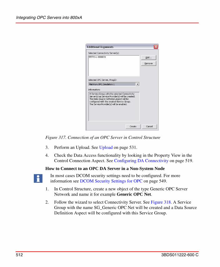
Integrating OPC Servers into 800xA
512 3BDS011222-600 C
3. Perform an Upload. See Upload on page 531.
4. Check the Data Access functionality by looking in the Property View in the Control Connection Aspect. See Configuring DA Connectivity on page 519.
How to Connect to an OPC DA Server in a Non-System Node
1. In Control Structure, create a new object of the type Generic OPC Server Network and name it for example Generic OPC Net.
2. Follow the wizard to select Connectivity Server. See Figure 318. A Service Group with the name SG_Generic OPC Net will be created and a Data Source Definition Aspect will be configured with this Service Group.
Figure 317. Connection of an OPC Server in Control Structure
In most cases DCOM security settings need to be configured. For more information see DCOM Security Settings for OPC on page 549.
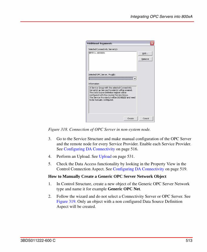
Integrating OPC Servers into 800xA
3BDS011222-600 C 513
3. Go to the Service Structure and make manual configuration of the OPC Server
and the remote node for every Service Provider. Enable each Service Provider. See Configuring DA Connectivity on page 516.
4. Perform an Upload. See Upload on page 531.
5. Check the Data Access functionality by looking in the Property View in the Control Connection Aspect. See Configuring DA Connectivity on page 519.
How to Manually Create a Generic OPC Server Network Object
1. In Control Structure, create a new object of the Generic OPC Server Network type and name it for example Generic OPC Net.
2. Follow the wizard and do not select a Connectivity Server or OPC Server. See Figure 319. Only an object with a non configured Data Source Definition Aspect will be created.
Figure 318. Connection of OPC Server in non-system node.
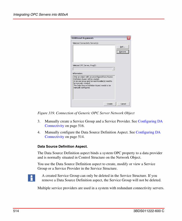
Integrating OPC Servers into 800xA
514 3BDS011222-600 C
3. Manually create a Service Group and a Service Provider. See Configuring DA
Connectivity on page 516.
4. Manually configure the Data Source Definition Aspect. See Configuring DA Connectivity on page 514.
Data Source Definition Aspect.
The Data Source Definition aspect binds a system OPC property to a data provider and is normally situated in Control Structure on the Network Object.
You use the Data Source Definition aspect to create, modify or view a Service Group or a Service Provider in the Service Structure.
Multiple service providers are used in a system with redundant connectivity servers.
Figure 319. Connection of Generic OPC Server Network Object
A created Service Group can only be deleted in the Service Structure. If you remove a Data Source Definition aspect, the Service Group will not be deleted.
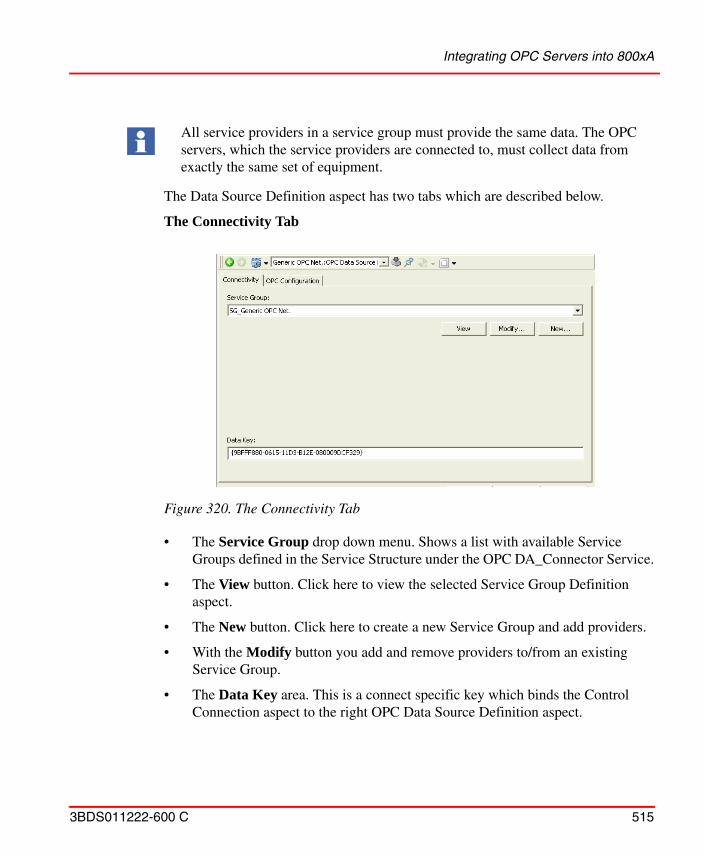
Integrating OPC Servers into 800xA
3BDS011222-600 C 515
The Data Source Definition aspect has two tabs which are described below.
The Connectivity Tab
• The Service Group drop down menu. Shows a list with available Service Groups defined in the Service Structure under the OPC DA_Connector Service.
• The View button. Click here to view the selected Service Group Definition aspect.
• The New button. Click here to create a new Service Group and add providers.
• With the Modify button you add and remove providers to/from an existing Service Group.
• The Data Key area. This is a connect specific key which binds the Control Connection aspect to the right OPC Data Source Definition aspect.
All service providers in a service group must provide the same data. The OPC servers, which the service providers are connected to, must collect data from exactly the same set of equipment.
Figure 320. The Connectivity Tab
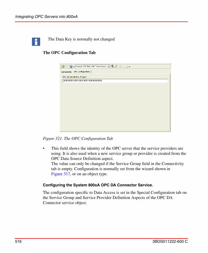
Integrating OPC Servers into 800xA
516 3BDS011222-600 C
The OPC Configuration Tab
• This field shows the identity of the OPC server that the service providers are using. It is also used when a new service group or provider is created from the OPC Data Source Definition aspect. The value can only be changed if the Service Group field in the Connectivity tab is empty. Configuration is normally set from the wizard shown in Figure 317, or on an object type.
Configuring the System 800xA OPC DA Connector Service.
The configuration specific to Data Access is set in the Special Configuration tab on the Service Group and Service Provider Definition Aspects of the OPC DA Connector service object.
The Data Key is normally not changed
Figure 321. The OPC Configuration Tab
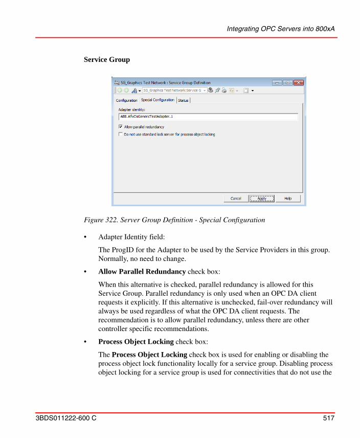
Integrating OPC Servers into 800xA
3BDS011222-600 C 517
Service Group
• Adapter Identity field:
The ProgID for the Adapter to be used by the Service Providers in this group. Normally, no need to change.
• Allow Parallel Redundancy check box:
When this alternative is checked, parallel redundancy is allowed for this Service Group. Parallel redundancy is only used when an OPC DA client requests it explicitly. If this alternative is unchecked, fail-over redundancy will always be used regardless of what the OPC DA client requests. The recommendation is to allow parallel redundancy, unless there are other controller specific recommendations.
• Process Object Locking check box:
The Process Object Locking check box is used for enabling or disabling the process object lock functionality locally for a service group. Disabling process object locking for a service group is used for connectivities that do not use the
Figure 322. Server Group Definition - Special Configuration
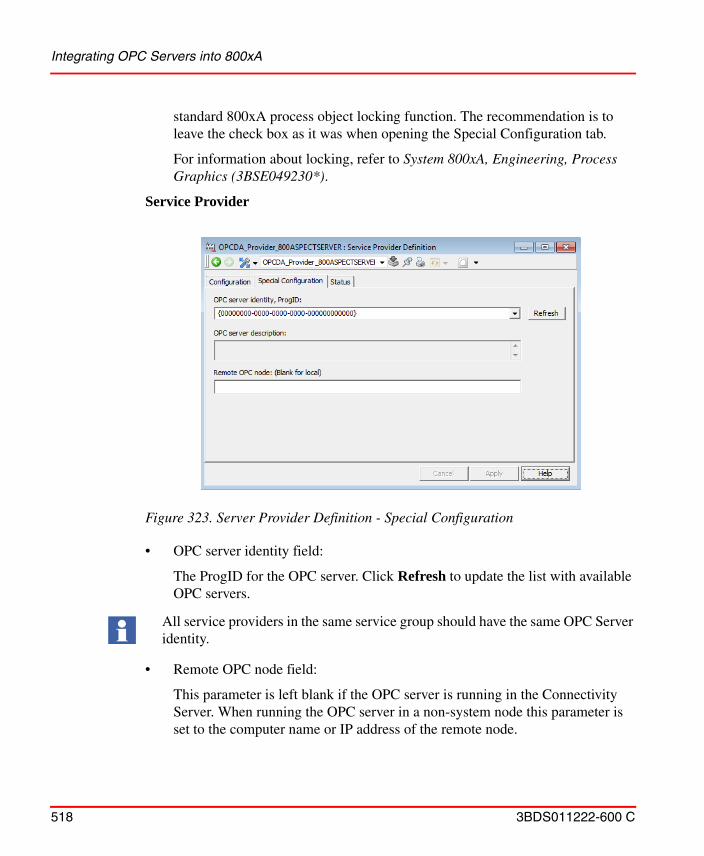
Integrating OPC Servers into 800xA
518 3BDS011222-600 C
standard 800xA process object locking function. The recommendation is to leave the check box as it was when opening the Special Configuration tab.
For information about locking, refer to System 800xA, Engineering, Process Graphics (3BSE049230*).
Service Provider
• OPC server identity field:
The ProgID for the OPC server. Click Refresh to update the list with available OPC servers.
• Remote OPC node field:
This parameter is left blank if the OPC server is running in the Connectivity Server. When running the OPC server in a non-system node this parameter is set to the computer name or IP address of the remote node.
Figure 323. Server Provider Definition - Special Configuration
All service providers in the same service group should have the same OPC Server identity.
Integrating OPC Servers into 800xA
3BDS011222-600 C 519
OPC Control Connection Aspect.
New Generic OPC objects are automatically created in Control Structure, underneath the Generic OPC Server Network object.
Properties of the Control Connection Aspect.
The Properties of the Generic OPC Object are shown in the Control Connection Aspect.
The dialog box has five tabs (some tabs are only visible in Object Type Structure):
• Property View
• Property Info
• Additional Info
• OPC
• Item Properties
Property View Tab
The Property View Tab contains information about the properties in the Control Connection Aspect. See Figure 324.
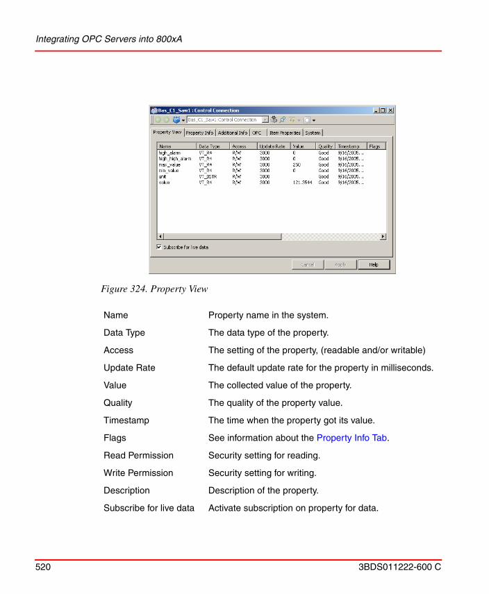
Integrating OPC Servers into 800xA
520 3BDS011222-600 C
Figure 324. Property View
Name Property name in the system.
Data Type The data type of the property.
Access The setting of the property, (readable and/or writable)
Update Rate The default update rate for the property in milliseconds.
Value The collected value of the property.
Quality The quality of the property value.
Timestamp The time when the property got its value.
Flags See information about the Property Info Tab.
Read Permission Security setting for reading.
Write Permission Security setting for writing.
Description Description of the property.
Subscribe for live data Activate subscription on property for data.
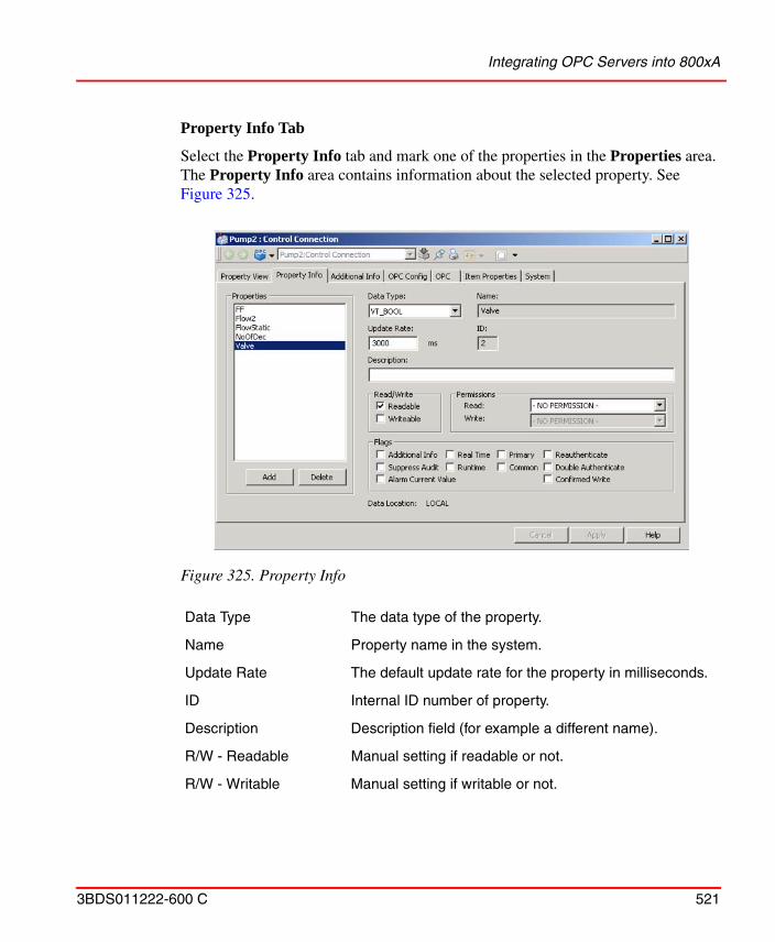
Integrating OPC Servers into 800xA
3BDS011222-600 C 521
Property Info Tab
Select the Property Info tab and mark one of the properties in the Properties area. The Property Info area contains information about the selected property. See Figure 325.
Figure 325. Property Info
Data Type The data type of the property.
Name Property name in the system.
Update Rate The default update rate for the property in milliseconds.
ID Internal ID number of property.
Description Description field (for example a different name).
R/W - Readable Manual setting if readable or not.
R/W - Writable Manual setting if writable or not.
Integrating OPC Servers into 800xA
522 3BDS011222-600 C
Alarm Coloring in Trend Display
The Trend display can be configured by coloring the trace in a different color when the object that the signal originates from is in the alarm state. When this functionality is enabled, the trace will also be drawn in a dotted style, during the period of time starting from when the object that signal originates from is put into manual or blocked mode and until the operator forces the value for the signal.
An alarm state property and an updated state property should be configured together with the signal in order to configure the alarm coloring functionality for a trend. The alarm state property is an OPC property on the same object that indicates whether the object signal resides on is in the alarm state or not. The updated state property is
Read Permission Security setting for reading. A star indicates that the default permission is used.
Write Permission Security setting for writing. A star indicates that the default permission is used.
Additional Info The selected property has additional Info. For example used by Trend and Historian. Can be used for other purpose.
Real Time For application specific use.
Runtime For application specific use.
Primary For application specific use.
Common For application specific use.
Reauthenticate Enables Reauthenticate.
Double authenticate Enables Double authenticate.
Confirmed write Enables Confirmed write.
Suppress Audit Suppresses auditing
Alarm Current Value When checked, the property is chosen for Live Value (when Enabling Live Values) in the Alarm List
This function is used for objects of type analog in (AI) where there is a single signal that can put the object into the alarm state.
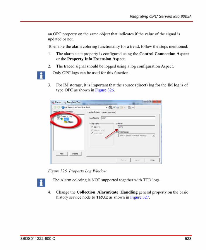
Integrating OPC Servers into 800xA
3BDS011222-600 C 523
an OPC property on the same object that indicates if the value of the signal is updated or not.
To enable the alarm coloring functionality for a trend, follow the steps mentioned:
1. The alarm state property is configured using the Control Connection Aspect or the Property Info Extension Aspect.
2. The traced signal should be logged using a log configuration Aspect.
3. For IM storage, it is important that the source (direct) log for the IM log is of type OPC as shown in Figure 326.
4. Change the Collection_AlarmState_Handling general property on the basic history service node to TRUE as shown in Figure 327.
Only OPC logs can be used for this function.
Figure 326. Property Log Window
The Alarm coloring is NOT supported together with TTD logs.
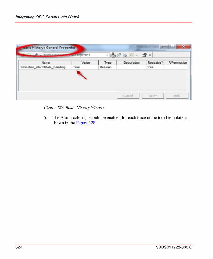
Integrating OPC Servers into 800xA
524 3BDS011222-600 C
5. The Alarm coloring should be enabled for each trace in the trend template as
shown in the Figure 328.
Figure 327. Basic History Window
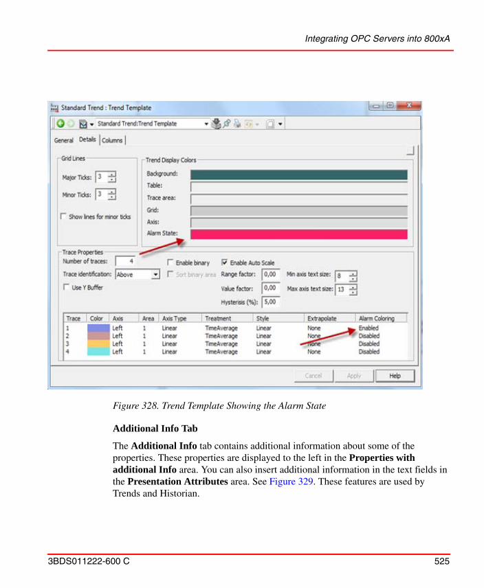
Integrating OPC Servers into 800xA
3BDS011222-600 C 525
Additional Info Tab
The Additional Info tab contains additional information about some of the properties. These properties are displayed to the left in the Properties with additional Info area. You can also insert additional information in the text fields in the Presentation Attributes area. See Figure 329. These features are used by Trends and Historian.
Figure 328. Trend Template Showing the Alarm State
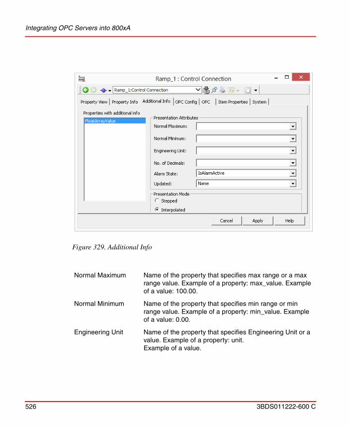
Integrating OPC Servers into 800xA
526 3BDS011222-600 C
Figure 329. Additional Info
Normal Maximum Name of the property that specifies max range or a max range value. Example of a property: max_value. Example of a value: 100.00.
Normal Minimum Name of the property that specifies min range or min range value. Example of a property: min_value. Example of a value: 0.00.
Engineering Unit Name of the property that specifies Engineering Unit or a value. Example of a property: unit. Example of a value.
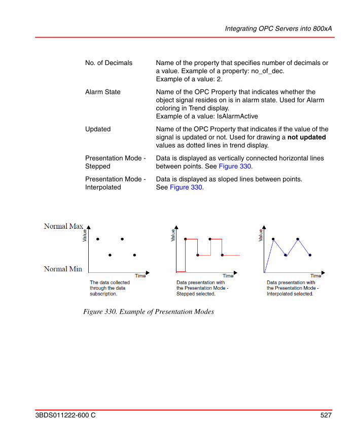
Integrating OPC Servers into 800xA
3BDS011222-600 C 527
No. of Decimals Name of the property that specifies number of decimals or a value. Example of a property: no_of_dec. Example of a value: 2.
Alarm State Name of the OPC Property that indicates whether the object signal resides on is in alarm state. Used for Alarm coloring in Trend display.Example of a value: IsAlarmActive
Updated Name of the OPC Property that indicates if the value of the signal is updated or not. Used for drawing a not updated values as dotted lines in trend display.
Presentation Mode - Stepped
Data is displayed as vertically connected horizontal lines between points. See Figure 330.
Presentation Mode - Interpolated
Data is displayed as sloped lines between points. See Figure 330.
Figure 330. Example of Presentation Modes
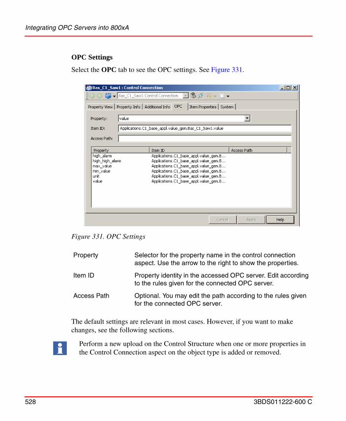
Integrating OPC Servers into 800xA
528 3BDS011222-600 C
OPC Settings
Select the OPC tab to see the OPC settings. See Figure 331.
The default settings are relevant in most cases. However, if you want to make changes, see the following sections.
Figure 331. OPC Settings
Property Selector for the property name in the control connection aspect. Use the arrow to the right to show the properties.
Item ID Property identity in the accessed OPC server. Edit according to the rules given for the connected OPC server.
Access Path Optional. You may edit the path according to the rules given for the connected OPC server.
Perform a new upload on the Control Structure when one or more properties in the Control Connection aspect on the object type is added or removed.
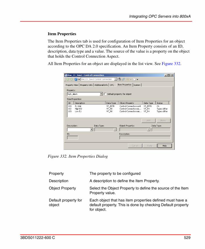
Integrating OPC Servers into 800xA
3BDS011222-600 C 529
Item Properties
The Item Properties tab is used for configuration of Item Properties for an object according to the OPC DA 2.0 specification. An Item Property consists of an ID, description, data type and a value. The source of the value is a property on the object that holds the Control Connection Aspect.
All Item Properties for an object are displayed in the list view. See Figure 332.
Figure 332. Item Properties Dialog
Property The property to be configured
Description A description to define the Item Property.
Object Property Select the Object Property to define the source of the Item Property value.
Default property for object
Each object that has item properties defined must have a default property. This is done by checking Default property for object.
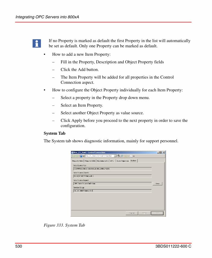
Integrating OPC Servers into 800xA
530 3BDS011222-600 C
• How to add a new Item Property:
– Fill in the Property, Description and Object Property fields
– Click the Add button.
– The Item Property will be added for all properties in the Control Connection aspect.
• How to configure the Object Property individually for each Item Property:
– Select a property in the Property drop down menu.
– Select an Item Property.
– Select another Object Property as value source.
– Click Apply before you proceed to the next property in order to save the configuration.
System Tab
The System tab shows diagnostic information, mainly for support personnel.
If no Property is marked as default the first Property in the list will automatically be set as default. Only one Property can be marked as default.
Figure 333. System Tab
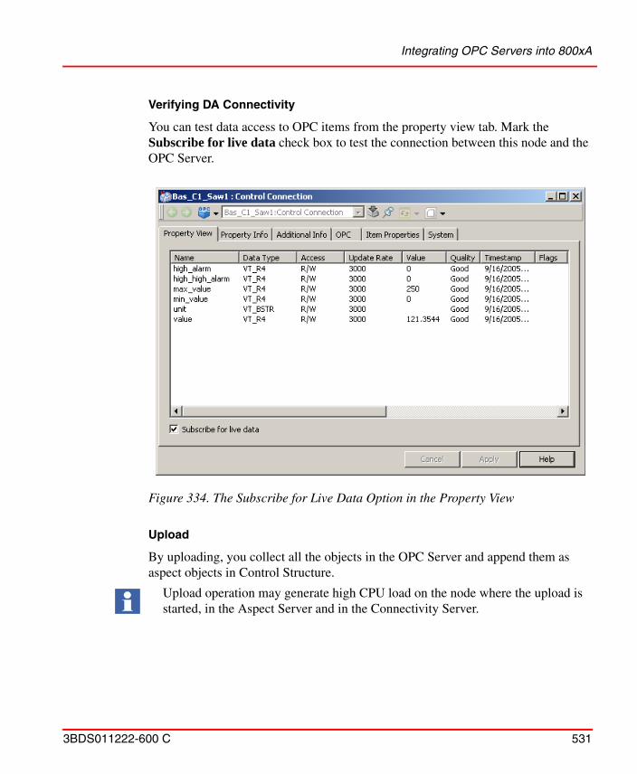
Integrating OPC Servers into 800xA
3BDS011222-600 C 531
Verifying DA Connectivity
You can test data access to OPC items from the property view tab. Mark the Subscribe for live data check box to test the connection between this node and the OPC Server.
Upload
By uploading, you collect all the objects in the OPC Server and append them as aspect objects in Control Structure.
Figure 334. The Subscribe for Live Data Option in the Property View
Upload operation may generate high CPU load on the node where the upload is started, in the Aspect Server and in the Connectivity Server.
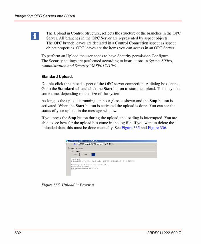
Integrating OPC Servers into 800xA
532 3BDS011222-600 C
To perform an Upload the user needs to have Security permission Configure. The Security settings are performed according to instructions in System 800xA, Administration and Security (3BSE037410*).
Standard Upload.
Double-click the upload aspect of the OPC server connection. A dialog box opens. Go to the Standard tab and click the Start button to start the upload. This may take some time, depending on the size of the system.
As long as the upload is running, an hour glass is shown and the Stop button is activated. When the Start button is activated the upload is done. You can see the status of your upload in the message window.
If you press the Stop button during the upload, the loading is interrupted. You are able to see how far the upload has come in the log file. If you want to delete the uploaded data, this must be done manually. See Figure 335 and Figure 336.
The Upload in Control Structure, reflects the structure of the branches in the OPC Server. All branches in the OPC Server are represented by aspect objects. The OPC branch leaves are declared in a Control Connection aspect as aspect object properties. OPC leaves are the items you can access in an OPC Server.
Figure 335. Upload in Progress
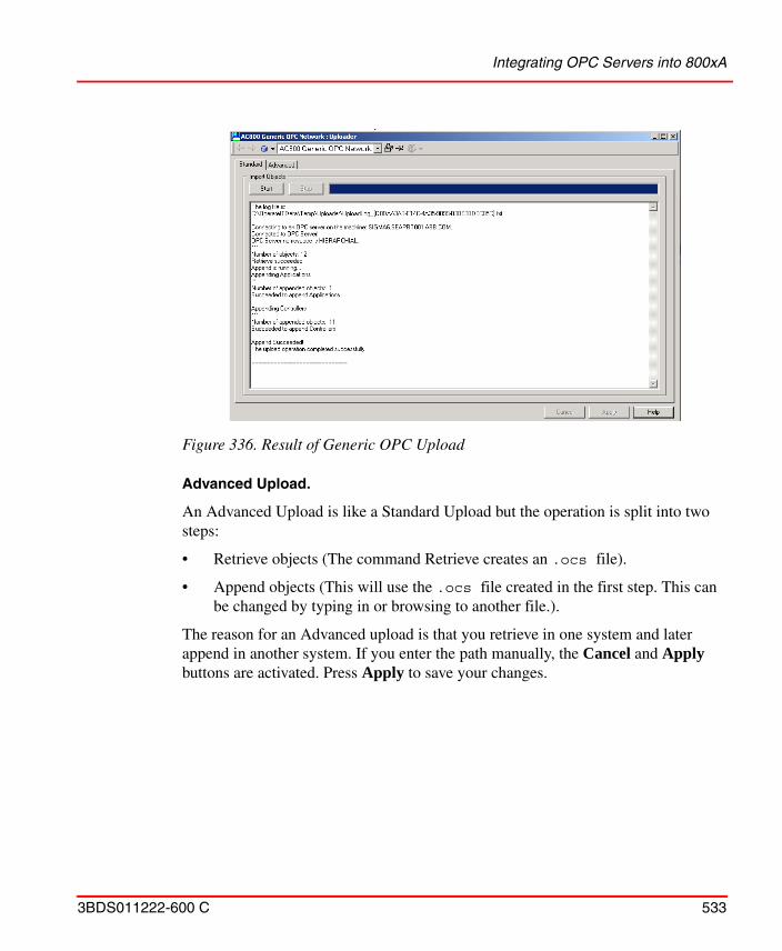
Integrating OPC Servers into 800xA
3BDS011222-600 C 533
Advanced Upload.
An Advanced Upload is like a Standard Upload but the operation is split into two steps:
• Retrieve objects (The command Retrieve creates an .ocs file).
• Append objects (This will use the .ocs file created in the first step. This can be changed by typing in or browsing to another file.).
The reason for an Advanced upload is that you retrieve in one system and later append in another system. If you enter the path manually, the Cancel and Apply buttons are activated. Press Apply to save your changes.
Figure 336. Result of Generic OPC Upload
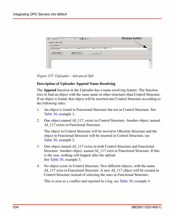
Integrating OPC Servers into 800xA
534 3BDS011222-600 C
Description of Uploader Append Name Resolving
The Append function in the Uploader has a name resolving feature. The function tries to find an object with the same name in other structures than Control Structure. If an object is found, that object will be inserted into Control Structure according to the following rules:
1. An object is found in Functional Structure but not in Control Structure. See Table 30, example 1.
2. One object named AI_117, exists in Control Structure. Another object, named AI_117 exists in Functional Structure.
The object in Control Structure will be moved to Obsolete Structure and the object in Functional Structure will be inserted in Control Structure, see Table 30, example 2.
3. One object named AI_117 exists in both Control Structure and Functional Structure. Another object, named AI_117 exist in Functional Structure. If this is the case, nothing will happen after the upload.See Table 30, example 3.
4. No object exists in Control Structure. Two different objects, with the name AI_117 exist in Functional Structure. A new AI_117 object will be created in Control Structure instead of selecting the ones in Functional Structure.
This is seen as a conflict and reported in a log, see Table 30, example 4.
Figure 337. Uploader - Advanced Tab
Browse button
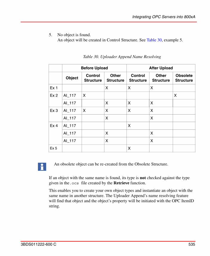
Integrating OPC Servers into 800xA
3BDS011222-600 C 535
5. No object is found. An object will be created in Control Structure. See Table 30, example 5.
If an object with the same name is found, its type is not checked against the type given in the.ocs file created by the Retrieve function.
This enables you to create your own object types and instantiate an object with the same name in another structure. The Uploader Append’s name resolving feature will find that object and the object’s property will be initiated with the OPC ItemID string.
Table 30. Uploader Append Name Resolving
Before Upload After Upload
ObjectControl
StructureOther
StructureControl
StructureOther
StructureObsoleteStructure
Ex 1 X X X
Ex 2 AI_117 X X
AI_117 X X X
Ex 3 AI_117 X X X X
AI_117 X X
Ex 4 AI_117 X
AI_117 X X
AI_117 X X
Ex 5 X
An obsolete object can be re-created from the Obsolete Structure.
Integrating OPC Servers into 800xA
536 3BDS011222-600 C
Changes of the Settings for Uploaded Items
Normally only the Permission, Flags and Additional Info settings is changed. This can be done under the Property Info Tab. See Figure 325.
Property Signal Generator Aspect
You can use the Property Signal Generator aspect to generate a simulated value that can be used to test a display, a display element, or any other client application that subscribes for OPC items (object properties). The Property Signal Generator is only intended for test purposes.
The Property Signal Generator aspect can generate a sinus formed wave, a ramp, a random value or a static value.
Configuration Steps.
To be able to use the Property Signal Generator there must be a data source for the Process Portal OPC property to give the value to. A generic OPC property together with a test OPC adapter delivered with the product can be used as source.
The following steps create a data source and a Property Signal Generator with a sinus wave.
1. Go to Control Structure and create a new object of type Generic OPC Server Network, under the OPC 3rd party OPC support Object Type group. Give the object the name TestAdapterNet.
2. In the Additional Arguments dialog, select the appropriate Connectivity Server and but do not select any OPC server. Press Create.
3. Go to the Service Structure and view the Service Group Definition aspect on the SG_TestAdapterNet object under the OpcDAConnector service. Select the Special Configuration tab and enter ABB.AfwDsGenericTestAdapter.1 in the Adapter field. Press Apply.
4. Go to the Service Provider object under the SG_TestAdapterNet object and view the Service Provider Definition aspect. Select the Configuration tab and check Enabled, then press Apply.
5. Go to Control Structure again. Create a new object of the type Generic OPC Object under the TestAdapterNet object. Give the new object the name Pump.
Integrating OPC Servers into 800xA
3BDS011222-600 C 537
View the Control Connection aspect on the Pump object and select the Property Info tab. Add a new property, Flow, with the type VT_R4. Click Apply.
6. Create a Property Signal Generator aspect on the Pump object and view the aspect. Select the Flow property and select Sine Wave with default values.
7. To test the value, view the Control Connection Aspect and select the Property View tab. Check Subscribe for live data, dynamic values should now appear in the Value column.
8. You can now add other aspects to the object, e.g. a Trend Display or a Graphic Display.
9. It is now possible to add more properties to the object by repeating step 6-7 or to add more objects by repeating step 5-7.
Integrating OPC AE Servers
Configuring AE Connectivity
This section describes how to integrate third party OPC Alarms and Events servers into 800xA. The integration of a third party OPC AE server requires some knowledge about the server for the integration to be successful.
How to do this is described in the following steps:
• Creating an Event Collector Service Provider
• Creating a Collection Definition
• Performing a Category Upload
– Selecting Priority Mappings
– Selecting Category Mappings
• Source Object Interceptor (optional step)
• Adding Translations (optional step)
• Setting up a Redundant Server (optional step)
800xA supports integration of OPC AE Servers compliant to version 1.1 of the specification. No interfaces marked as optional in the specification needs to be supported.
Integrating OPC Servers into 800xA
538 3BDS011222-600 C
Creating an Event Collector Service Provider.
Create an event collector service group and an event collector service provider. Follow the steps below:
1. Create an event collector service group:
a. Locate the Event Collector service in the Service Structure, and create a new service group. Give the group a name which makes it easy to understand from where it is collecting its data.
2. Create an event collector service provider:
a. Create a service provider below the created service group.
b. Open the Service Provider Definition aspect and select the node where the OPC AE server is running. See Configuring AE Connectivity on page 539 on how to connect to an OPC AE Server on an non-system node.
c. Click Apply.
3. Configure the collector group:
a. Select the Special Configuration tab of the Event Collector service group. See Figure 338.
b. Select the OPC server to connect to (the Alarm Server drop-down menu lists OPC servers registered on the node that the Event Collector service provider runs on).
c. Create a new Collection Definition by clicking the New button.
d. Click Apply.
4. Upload event categories:
a. From the Configuration tab of the Event Collector service group select the Upload button.
Integrating OPC Servers into 800xA
3BDS011222-600 C 539
Connecting to a Remote OPC AE Server.
For OPC AE there is no built-in 800xA mechanism to connect to a server on a non-system node. This means the server needs to be registered locally on the machines
Figure 338. Special Configuration Tab
Integrating OPC Servers into 800xA
540 3BDS011222-600 C
that run the event collector service that is used to connect to the OPC AE server. Such a client registration includes information on which node the server is installed. The server can then be accessed through remote activation.
Registration of the 3rd party OPC AE server on the connectivity server can be achieved in the following ways:
1. The install program of the OPC server supports client registration/installation.
2. A registry file is supplied from the 3rd party vendor. If the 3rd party OPC server does not support client installation of the service, contact the 3rd party OPC vendor to get information on how to register it locally for remote activation. Typically a registry file can be supplied for this purpose.
3. A complete installation of the 3rd party software is installed on the connectivity server and DCOM Config is used to configure remote activation.
See DCOM Security Settings for OPC on page 549 for information on how set up proper security settings when connecting to a server on a non-system node.
The Locales field is used to show alarms in a different language other than the system language. This field is normally changed only if the server is running in another 800xA system.
How to configure Remote Activation.
Follow the steps below to configure a server to be activated on a remote machine using DCOM Config.
1. Open the Component Services console (by typing DCOMCNFG in the run program dialog).
2. Locate the server that should be activated remotely. See Figure 339.
Note that alternative 1 or 2 are the recommended methods.
Integrating OPC Servers into 800xA
3BDS011222-600 C 541
3. Open the context menu and select Properties.
4. Select the Location tab and deselect the Run application on this computer check box. Select the Run application on the following computer check box and browse to the machine where the OPC AE server should be instantiated. See Figure 340.
Figure 339. Component Services
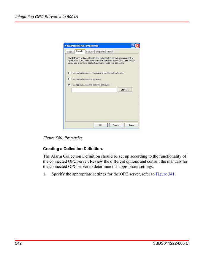
Integrating OPC Servers into 800xA
542 3BDS011222-600 C
Creating a Collection Definition.
The Alarm Collection Definition should be set up according to the functionality of the connected OPC server. Review the different options and consult the manuals for the connected OPC server to determine the appropriate settings.
1. Specify the appropriate settings for the OPC server, refer to Figure 341.
Figure 340. Properties
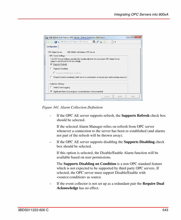
Integrating OPC Servers into 800xA
3BDS011222-600 C 543
– If the OPC AE server supports refresh, the Supports Refresh check box should be selected.
If the selected Alarm Manager relies on refresh from OPC server whenever a connection to the server has been re-established (and alarms not part of the refresh will be thrown away).
– If the OPC AE server supports disabling the Supports Disabling check box should be selected.
If this option is selected, the Disable/Enable Alarm function will be available based on user permissions.
The Supports Disabling on Condition is a non OPC standard feature which is not expected to be supported by third party OPC servers. If selected, the OPC server must support Disable/Enable with <source:condition> as source.
– If the event collector is not set up as a redundant pair the Require Dual Acknowledge has no effect.
Figure 341. Alarm Collection Definition
Integrating OPC Servers into 800xA
544 3BDS011222-600 C
For OPC AE servers that only maintains acknowledge state within the server, with synchronization between two redundant servers, the Require Dual Acknowledge feature can be used so that acknowledge requests also gets sent to the stand-by provider.
– If a connection between an alarm source and an alarm list is lost, an orange frame around the alarm list is displayed by default. To change the default configuration, do the following:
a.Expand the Library Structure and open the Alarm & Event object.
b.Open the Alarm Collection Definitions object and select the server.
c.Select the Alarm Collection Definition aspect and open the Config View.
d.Clear the Significant Alarm Source check box.
The orange frame will not appear from the next time the connection is lost.
Click Apply.
Selecting Priority Mappings.
Event severities are translated to Priority Levels with use of the Priority Mapping aspect. You can specify how OPC severities are translated into priorities:
1. Locate the Event Collection Definition object in the Library Structure which were created for the OPC server.
2. Open the Alarm Priority Mapping aspect.
3. Adjust the priority mappings so that the alarm and events from the connected OPC server harmonize with the rest of the system, refer to Figure 342.
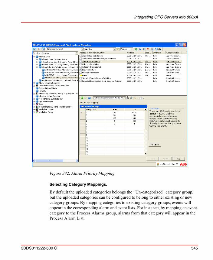
Integrating OPC Servers into 800xA
3BDS011222-600 C 545
Selecting Category Mappings.
By default the uploaded categories belongs the “Un-categorized” category group, but the uploaded categories can be configured to belong to either existing or new category groups. By mapping categories to existing category groups, events will appear in the corresponding alarm and event lists. For instance, by mapping an event category to the Process Alarms group, alarms from that category will appear in the Process Alarm List.
Figure 342. Alarm Priority Mapping
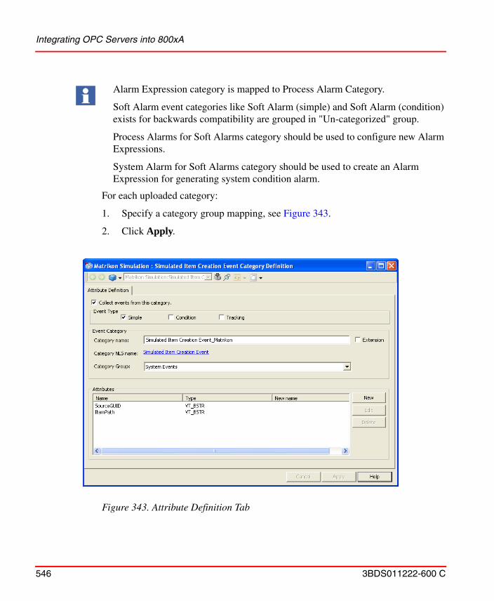
Integrating OPC Servers into 800xA
546 3BDS011222-600 C
For each uploaded category:
1. Specify a category group mapping, see Figure 343.
2. Click Apply.
Alarm Expression category is mapped to Process Alarm Category.
Soft Alarm event categories like Soft Alarm (simple) and Soft Alarm (condition) exists for backwards compatibility are grouped in "Un-categorized" group.
Process Alarms for Soft Alarms category should be used to configure new Alarm Expressions.
System Alarm for Soft Alarms category should be used to create an Alarm Expression for generating system condition alarm.
Figure 343. Attribute Definition Tab
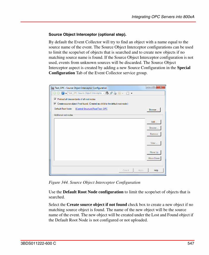
Integrating OPC Servers into 800xA
3BDS011222-600 C 547
Source Object Interceptor (optional step).
By default the Event Collector will try to find an object with a name equal to the source name of the event. The Source Object Interceptor configurations can be used to limit the scope/set of objects that is searched and to create new objects if no matching source name is found. If the Source Object Interceptor configuration is not used, events from unknown sources will be discarded. The Source Object Interceptor aspect is created by adding a new Source Configuration in the Special Configuration Tab of the Event Collector service group.
Use the Default Root Node configuration to limit the scope/set of objects that is searched.
Select the Create source object if not found check box to create a new object if no matching source object is found. The name of the new object will be the source name of the event. The new object will be created under the Lost and Found object if the Default Root Node is not configured or not uploaded.
Figure 344. Source Object Interceptor Configuration
Integrating OPC Servers into 800xA
548 3BDS011222-600 C
Select the Preload all descendants of all root nodes check box if the number of objects associated with the connected alarm and event server is relatively small to boost performance.
Adding Translations (optional step).
When doing a category upload all translations for the category names are added to the system. You can rename and add new translations for the uploaded categories. This is done in the Category Translations aspect of the Collection Definition object.
Setting up a Redundant Server (optional step).
To add a redundant Alarm and Event OPC server simply add a Event Collector provider to an existing service group. First of all an event collector service group and an event collector service provider needs to be created. Select the node where the OPC AE server runs.
1. Locate the event collector service group for the connected OPC AE server.
2. Create a new event collector service provider:
a. Create a service provider under the created service group.
b. Open the Service Provider definition and select the node where the redundant OPC AE server is running.
c. Click Apply.
Verifying AE Connectivity
There are at least two good ways to verify AE connectivity:
If an alarm is generated for any object that is yet to be uploaded, a temporary object is created under the Lost and Found object. When the corresponding source object is uploaded, the system will have two different objects with the same name. The alarm will still be associated with the temporary object until this object is deleted and a new alarm is generated.
Restart the corresponding Event Collector service group(s) for the changes to take effect.
Integrating OPC Servers into 800xA
3BDS011222-600 C 549
1. In the Service Structure open the System Status Viewer aspect located on the Root object. In the System Status Viewer browse down to the Event Collector provider. There you can see connectivity status and if there is a warning or an error there is a problem description in the ‘Description’ column.
2. In the Control Structure browse to the network object of the connected OPC AE server. Insert an ‘Alarm and Event List’ aspect. This list will show all alarms and events generated by the connected OPC AE Server.
Integrating OPC HDA Servers
Integration of OPC HDA servers is not a supported function of 800xA.
DCOM Security Settings for OPC
General DCOM Settings
The recommended configuration is to have all computers involved in remote OPC Access in the same domain. If this is not possible, it is however possible to configure DCOM security to allow OPC Access anyway. Regardless of the configuration some DCOM security settings are however necessary.
This section describes how to configure the DCOM settings in Windows client operating system and Windows server operating system. The settings can however be used with slight adaptations in other Windows versions.
DCOM security settings are made with the DCOM configuration tool, dcomcnfg.
A general recommendation is to use accounts with passwords that never expires, otherwise you will need to change DCOM security settings every time the password is changed.
The DCOM setting Default Properties for the non-system computers must be set to: Default Authentication Level = Connect Default Impersonation Level = Identify
A remote OPC Server must use Authentication Level = Default.
Settings on Windows client operating system.
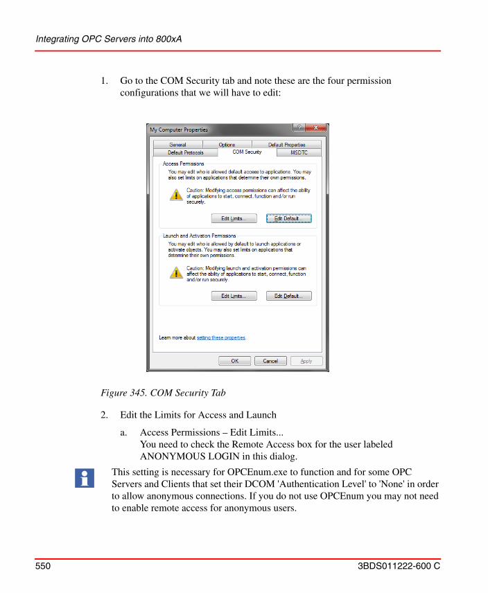
Integrating OPC Servers into 800xA
550 3BDS011222-600 C
1. Go to the COM Security tab and note these are the four permission configurations that we will have to edit:
2. Edit the Limits for Access and Launch
a. Access Permissions – Edit Limits...You need to check the Remote Access box for the user labeled ANONYMOUS LOGIN in this dialog.
Figure 345. COM Security Tab
This setting is necessary for OPCEnum.exe to function and for some OPC Servers and Clients that set their DCOM 'Authentication Level' to 'None' in order to allow anonymous connections. If you do not use OPCEnum you may not need to enable remote access for anonymous users.
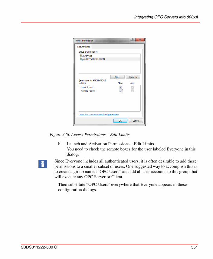
Integrating OPC Servers into 800xA
3BDS011222-600 C 551
b. Launch and Activation Permissions – Edit Limits...
You need to check the remote boxes for the user labeled Everyone in this dialog.
Then substitute “OPC Users” everywhere that Everyone appears in these configuration dialogs.
Figure 346. Access Permissions – Edit Limits
Since Everyone includes all authenticated users, it is often desirable to add these permissions to a smaller subset of users. One suggested way to accomplish this is to create a group named “OPC Users” and add all user accounts to this group that will execute any OPC Server or Client.
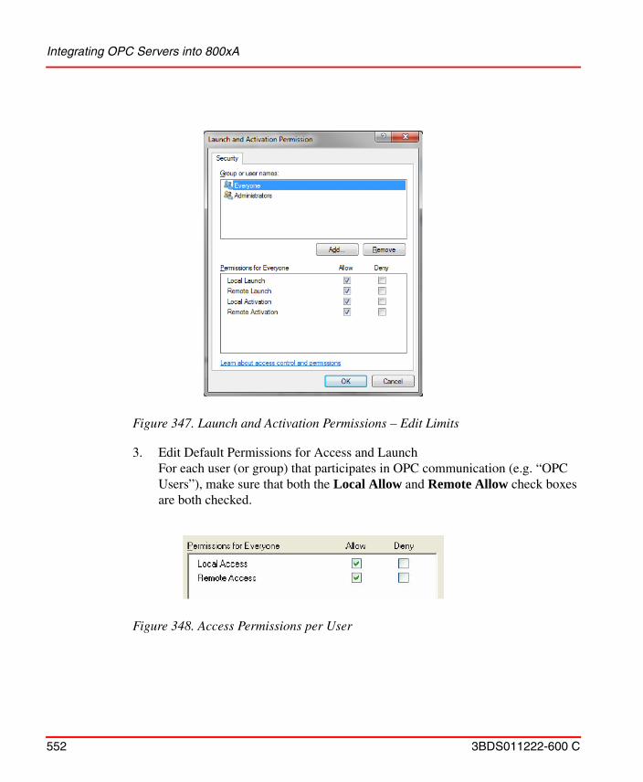
Integrating OPC Servers into 800xA
552 3BDS011222-600 C
3. Edit Default Permissions for Access and Launch
For each user (or group) that participates in OPC communication (e.g. “OPC Users”), make sure that both the Local Allow and Remote Allow check boxes are both checked.
Figure 347. Launch and Activation Permissions – Edit Limits
Figure 348. Access Permissions per User
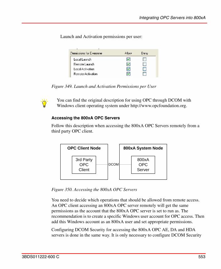
Integrating OPC Servers into 800xA
3BDS011222-600 C 553
Launch and Activation permissions per user:
Accessing the 800xA OPC Servers
Follow this description when accessing the 800xA OPC Servers remotely from a third party OPC client.
You need to decide which operations that should be allowed from remote access. An OPC client accessing an 800xA OPC server remotely will get the same permissions as the account that the 800xA OPC server is set to run as. The recommendation is to create a specific Windows user account for OPC access. Then add this Windows account as an 800xA user and set appropriate permissions.
Configuring DCOM Security for accessing the 800xA OPC AE, DA and HDA servers is done in the same way. It is only necessary to configure DCOM Security
Figure 349. Launch and Activation Permissions per User
You can find the original description for using OPC through DCOM with Windows client operating system under http://www.opcfoundation.org.
Figure 350. Accessing the 800xA OPC Servers
3rd PartyOPCClient
OPC Client Node 800xA System Node
800xAOPC
ServerDCOM
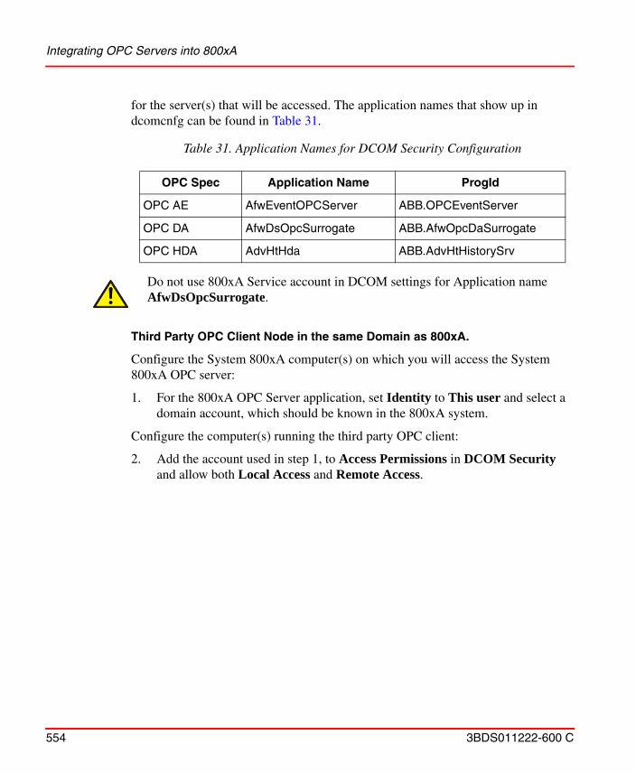
Integrating OPC Servers into 800xA
554 3BDS011222-600 C
for the server(s) that will be accessed. The application names that show up in dcomcnfg can be found in Table 31.
Third Party OPC Client Node in the same Domain as 800xA.
Configure the System 800xA computer(s) on which you will access the System 800xA OPC server:
1. For the 800xA OPC Server application, set Identity to This user and select a domain account, which should be known in the 800xA system.
Configure the computer(s) running the third party OPC client:
2. Add the account used in step 1, to Access Permissions in DCOM Security and allow both Local Access and Remote Access.
Table 31. Application Names for DCOM Security Configuration
OPC Spec Application Name ProgId
OPC AE AfwEventOPCServer ABB.OPCEventServer
OPC DA AfwDsOpcSurrogate ABB.AfwOpcDaSurrogate
OPC HDA AdvHtHda ABB.AdvHtHistorySrv
Do not use 800xA Service account in DCOM settings for Application name AfwDsOpcSurrogate.
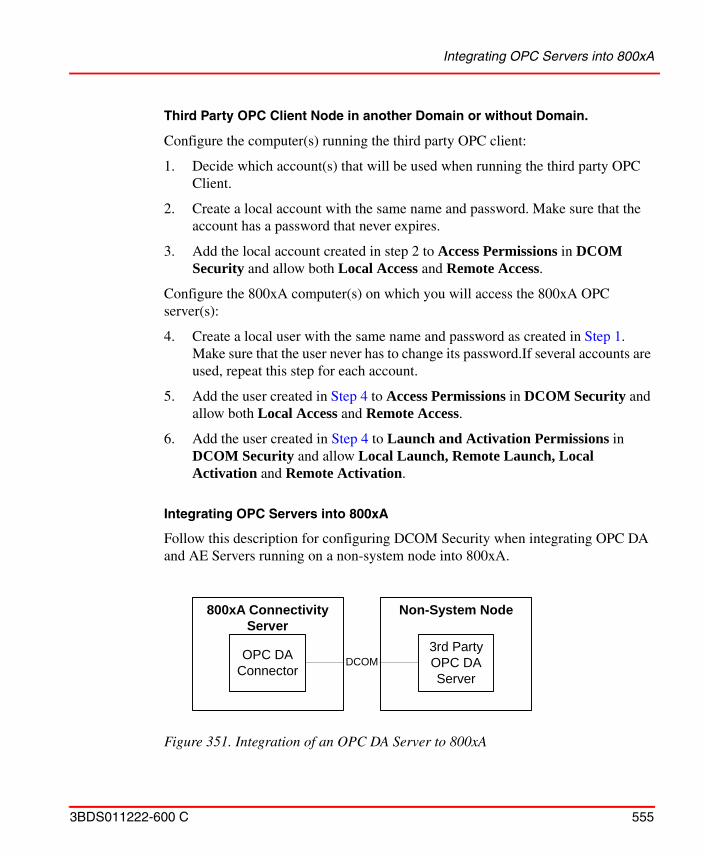
Integrating OPC Servers into 800xA
3BDS011222-600 C 555
Third Party OPC Client Node in another Domain or without Domain.
Configure the computer(s) running the third party OPC client:
1. Decide which account(s) that will be used when running the third party OPC Client.
2. Create a local account with the same name and password. Make sure that the account has a password that never expires.
3. Add the local account created in step 2 to Access Permissions in DCOM Security and allow both Local Access and Remote Access.
Configure the 800xA computer(s) on which you will access the 800xA OPC server(s):
4. Create a local user with the same name and password as created in Step 1. Make sure that the user never has to change its password.If several accounts are used, repeat this step for each account.
5. Add the user created in Step 4 to Access Permissions in DCOM Security and allow both Local Access and Remote Access.
6. Add the user created in Step 4 to Launch and Activation Permissions in DCOM Security and allow Local Launch, Remote Launch, Local Activation and Remote Activation.
Integrating OPC Servers into 800xA
Follow this description for configuring DCOM Security when integrating OPC DA and AE Servers running on a non-system node into 800xA.
Figure 351. Integration of an OPC DA Server to 800xA
OPC DAConnector
800xA ConnectivityServer
Non-System Node
3rd PartyOPC DAServer
DCOM
Integrating OPC Servers into 800xA
556 3BDS011222-600 C
Third Party OPC Server Node in the same Domain.
Configure the computer(s) running the OPC Server.
1. Set Identity to This user and select the same domain account as used for the 800xA System services for the OPC Server.
2. Add the 800xA System service account to Access Permissions in DCOM Security and allow both Local Access and Remote Access.
3. Add the 800xA System service account to Launch and Activation Permissions in DCOM Security and allow Local Launch, Remote Launch, Local Activation and Remote Activation.
If you do not want to use the 800xA System service account, follow the steps for Third Party OPC Server Node in another Domain or without Domain.
Third Party OPC Server Node in another Domain or without Domain.
Configure the computer(s) running the third party OPC Server.
1. Create a local account, e.g. OPCuser.
2. Set Identity to This user and select OPCuser created above for the third party OPC Server.
3. Create a local account with the same name and password as the 800xA System service account.
4. Add the local account created in step 2 to Access Permissions in DCOM Security. Allow both Local Access and Remote Access.
5. Add the local account created in step 2 to Launch and Activation Permissions in DCOM Security. Allow Local Launch, Remote Launch, Local Activation and Remote Activation.
Configure the Connectivity Server(s):
6. Create a local account with the same name and password, as mentioned in Step 1 on the third party OPC Server node.
For Upload to work it is necessary to configure DCOM security on the computer running the remote OPC Server. This must be done for the user(s) that should be able to perform an upload. First you need to configure security according to
Accessing 800xA via OLE DB
3BDS011222-600 C 557
Integrating OPC Servers into 800xA on page 555.
Third Party OPC Server Node in the same Domain.
Configure the computer(s) running the third party OPC Server.
1. Add the account(s) that will be used when performing an upload to Access Permissions in Security for the third party OPC Server. Allow both Local Access and Remote Access.
2. Add the account(s) that will be used when performing an upload to Launch and Activation Permissions in Security for the third party OPC Server. Allow Local Launch, Remote Launch, Local Activation and Remote Activation.
Third Party OPC Server in another Domain or without Domain.
Configure the computer(s) running the third party OPC Server.
1. Create a local user with the same name and password as the account that will be used when performing an upload. Repeat this for all accounts that will be used when performing an upload.
2. Add the local user(s) created in step 2 to Access Permissions in Security for the third party OPC Server. Allow both Local Access and Remote Access.
3. Add the local user(s) created in step 2 to Launch and Activation Permissions in Security for the third party OPC Server. Allow Local Launch, Remote Launch, Local Activation, and Remote Activation.
Accessing 800xA via OLE DB
800xA Core supports OLE DB for DA and HDA.
OLE DB Provider for DA
The OLE DB Provider for DA can be used to retrieve real time process data from the 800xA System.
The OLE DB Providers may be incompatible with some reporting packages because of different standard interpretations.
Accessing 800xA via OLE DB
558 3BDS011222-600 C
The real time process data is accessed through the OLE DB provider with a command syntax. Furthermore, it is possible to create a short reference to history data that is to be exposed through the OLE DB provider. The purpose of this is twofold; you can decrease the complexity and length of the command and the limitation in command length, that some report clients have, can be circumvented. Each short reference is a generic object placed in the Library Structure and includes an aspect called OLE DB Access Table for DS.
The name of the OLE DB provider is ABB OLE DB Provider for Data Access.
Command Line
The syntax for the command line is built up by a command followed by one or more keywords as shown below.
Command Syntax.
The command for Data Access is GET_DATA with the following keywords:
• GET_DATA(STORAGEINFO) You use the keyword STORAGEINFO to get a list of all short references that exits in the Library Structure and are related to data access. No other keywords are allowed.
• GET_DATA(OBJECTHELPER=…) You use the keyword OBJECTHELPER to retrieve real time data according to one of the pre-configured short references. No other keywords are allowed.
• GET_DATA(OBJECT=…; ASPECT=…; PROPERTY=…) You build a query by utilizing the keywords OBJECT, ASPECT and PROPERTY that specify the object and attribute name.
• GET_DATA(VERSION) You use the keyword VERSION to get version information about the provider.
It is only possible to connect to the OLE DB Provider from an OLE DB Client running on an 800xA client workstation.
Accessing 800xA via OLE DB
3BDS011222-600 C 559
Keywords
A description of the keywords and their respective meaning and syntax can be seen in the table below:
Example Command Line
Retrieve version information about the OLE DB provider:
GET_DATA(VERSION)
Get a list of all short references in the 800xA system:
GET_DATA(STORAGEINFO)
Get the data specified by a short reference:
GET_DATA(OBJECTHELPER=DsReference)
Get data by specifying object, aspect and property directly:
GET_DATA(OBJECT=[Control Structure]MB300 Test Network/Extended Process Objects x/MB300 AI/AIC4_1; ASPECT=Control Connection; PROPERTY=VALUE)
Note that the example shows a full path to the object. It is also possible to give shorter reference to the object, as long as it will uniquely identify the object.
Table 32. Keywords
Keyword Description
OBJECTHELPER The name of the short references that holds the OleDB Tables.
OBJECT The full path or the GUID(1) of the object.
(1) The Object GUID, Globally Unique Identifiers, uniquely identifies each object.
ASPECT The name or GUID of the aspect where the property belongs.
PROPERTY The name of the property.
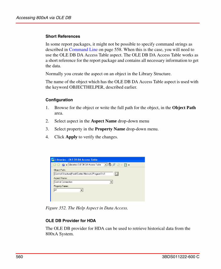
Accessing 800xA via OLE DB
560 3BDS011222-600 C
Short References
In some report packages, it might not be possible to specify command strings as described in Command Line on page 558. When this is the case, you will need to use the OLE DB DA Access Table aspect. The OLE DB DA Access Table works as a short reference for the report package and contains all necessary information to get the data.
Normally you create the aspect on an object in the Library Structure.
The name of the object which has the OLE DB DA Access Table aspect is used with the keyword OBJECTHELPER, described earlier.
Configuration
1. Browse for the object or write the full path for the object, in the Object Path area.
2. Select aspect in the Aspect Name drop-down menu
3. Select property in the Property Name drop-down menu.
4. Click Apply to verify the changes.
OLE DB Provider for HDA
The OLE DB provider for HDA can be used to retrieve historical data from the 800xA System.
Figure 352. The Help Aspect in Data Access.
Accessing 800xA via OLE DB
3BDS011222-600 C 561
System 800xA history data is accessed through the OLE DB provider with a command syntax. Furthermore, it is possible to create a short reference to history data that is to be exposed through the OLE DB provider. The purpose of this is twofold; you can decrease the complexity and length of the command and the limitation in command length, that some report clients have, can be circumvented. Each short reference is a generic object placed in the Library Structure and includes an aspect called OLE DB Access Table for History.
The name of the OLE DB provider is ABB OLE DB Provider for HT.
Command Line
The syntax for the command line is built up by a command followed by one or several keywords as shown below.
Command Syntax.
The command is GET_HISTORY, which has four syntaxes.
• GET_HISTORY(STORAGEINFO): You use the keyword STORAGEINFO to get a list of all short references that exits in the Library Structure and are related to history. No other keywords are allowed.
• GET_HISTORY(OBJECTHELPER=… ): You use the keyword OBJECTHELPER to retrieve historical data according to one of the pre-configured short references. No other keywords are allowed.
• GET_HISTORY(OBJECT=… ; ASPECT=… ; PROPERTY=… ; LOG=… ; FROM=… ; TO=… ; “OTHER KEYWORDS”): You build a query by utilizing a set of keywords that specify the historical log, the time frame and the amount of data to retrieve. All the keywords given above are mandatory except for the other keywords which are optional.
• GET_HISTORY(ITEMID=… ; FROM=… ; TO=… ;“OTHER KEYWORDS”) If you already have the ITEMID string then it can be more convenient for you to use this way of to give the command line. Also here all keywords given are mandatory except for the “other keywords” which are optional.
It is only possible to connect to the OLE DB Provider from the OLE DB Client running on an 800xA client workstation.
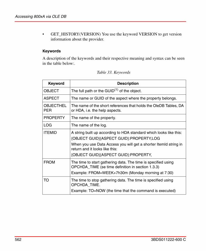
Accessing 800xA via OLE DB
562 3BDS011222-600 C
• GET_HISTORY(VERSION) You use the keyword VERSION to get version information about the provider.
Keywords
A description of the keywords and their respective meaning and syntax can be seen in the table below:.
Table 33. Keywords
Keyword Description
OBJECT The full path or the GUID(1) of the object.
ASPECT The name or GUID of the aspect where the property belongs.
OBJECTHELPER
The name of the short references that holds the OleDB Tables, DA or HDA, i.e. the help aspects.
PROPERTY The name of the property.
LOG The name of the log.
ITEMID A string built up according to HDA standard which looks like this:
{OBJECT GUID}{ASPECT GUID}:PROPERTY,LOG
When you use Data Access you will get a shorter ItemId string in return and it looks like this:
{OBJECT GUID}{ASPECT GUID}:PROPERTY,
FROM The time to start gathering data. The time is specified using OPCHDA_TIME (se time definition in section 1.3.3)
Example: FROM=WEEK+7h30m (Monday morning at 7:30)
TO The time to stop gathering data. The time is specified using OPCHDA_TIME.
Example: TO=NOW (the time that the command is executed)
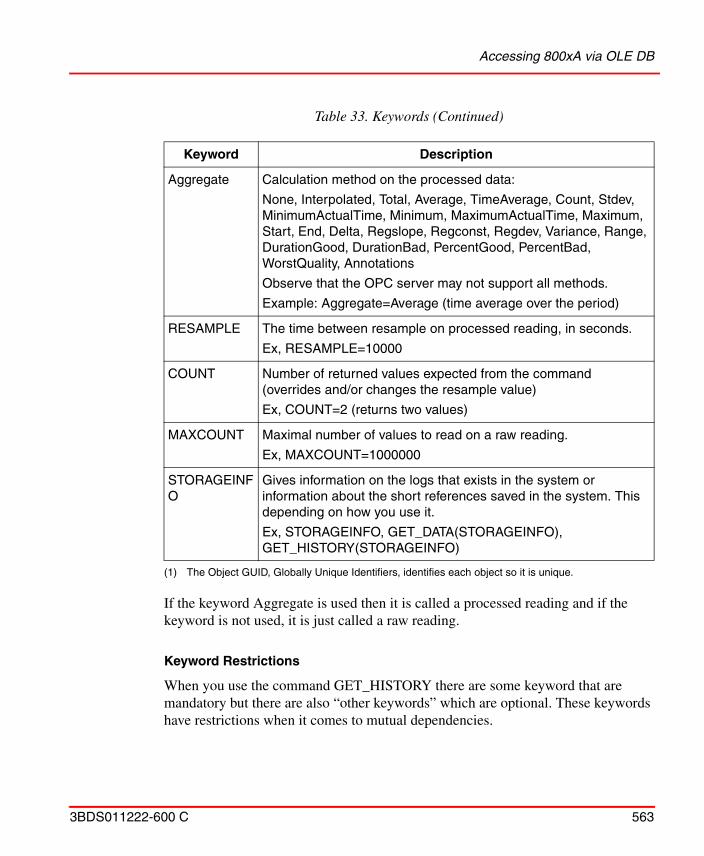
Accessing 800xA via OLE DB
3BDS011222-600 C 563
If the keyword Aggregate is used then it is called a processed reading and if the keyword is not used, it is just called a raw reading.
Keyword Restrictions
When you use the command GET_HISTORY there are some keyword that are mandatory but there are also “other keywords” which are optional. These keywords have restrictions when it comes to mutual dependencies.
Aggregate Calculation method on the processed data:
None, Interpolated, Total, Average, TimeAverage, Count, Stdev, MinimumActualTime, Minimum, MaximumActualTime, Maximum, Start, End, Delta, Regslope, Regconst, Regdev, Variance, Range, DurationGood, DurationBad, PercentGood, PercentBad, WorstQuality, Annotations
Observe that the OPC server may not support all methods.
Example: Aggregate=Average (time average over the period)
RESAMPLE The time between resample on processed reading, in seconds.
Ex, RESAMPLE=10000
COUNT Number of returned values expected from the command (overrides and/or changes the resample value)
Ex, COUNT=2 (returns two values)
MAXCOUNT Maximal number of values to read on a raw reading.
Ex, MAXCOUNT=1000000
STORAGEINFO
Gives information on the logs that exists in the system or information about the short references saved in the system. This depending on how you use it.
Ex, STORAGEINFO, GET_DATA(STORAGEINFO), GET_HISTORY(STORAGEINFO)
(1) The Object GUID, Globally Unique Identifiers, identifies each object so it is unique.
Table 33. Keywords (Continued)
Keyword Description
Accessing 800xA via OLE DB
564 3BDS011222-600 C
• When you use the Aggregate option then you also must give either RESAMPLE or COUNT.
• If you give both RESAMPLE and COUNT, then the resample value calculated from COUNT overrides the value in RESAMPLE.
• You are not allowed to use MAXCOUNT together with any of the other optional keywords. You should only use this to maximize the number of rows read in a raw reading.
• You cannot use the keywords COUNT and RESAMPLE without using the Aggregate keyword.
All the keywords must be written in capital letters. If you do not write the command line according to the syntax and restriction above the provider will return an error code that tells you that you have an invalid argument.
When you use GUIDs to identify the object you also need to use it for the aspect and vice verse.
The Time Definition1
When you use the keywords TO and FROM you have to give the time in so called OPCHDA_TIME. It is a time that is considered to be a relative time local to the server. The format for the relative time is:
• keyword +/-offset +/-offset …
Where keyword and offset are as specified in Table 34 and Table 35 below. White space is ignored. Each offset must be preceded by a signed integer that specifies the number and direction of the offset. If the integer preceding the offset is unsigned, the value of the preceding sign is assumed (beginning default sign is positive).
The keyword refers to the beginning of the specified time period. DAY means the timestamp at the beginning of the current day (00:00 hours, midnight), MONTH means the timestamp at the beginning of the current month, and so on.
For example if you write, “DAY -1D+7H30M”, then it represent the start time for data request for a daily report beginning at 7:30 in the morning of the current day (DAY = the first timestamp for today, -1D makes it the first timestamp for yesterday,
1. See the OPC Historical Data Access Custom Interface Specification 1.0
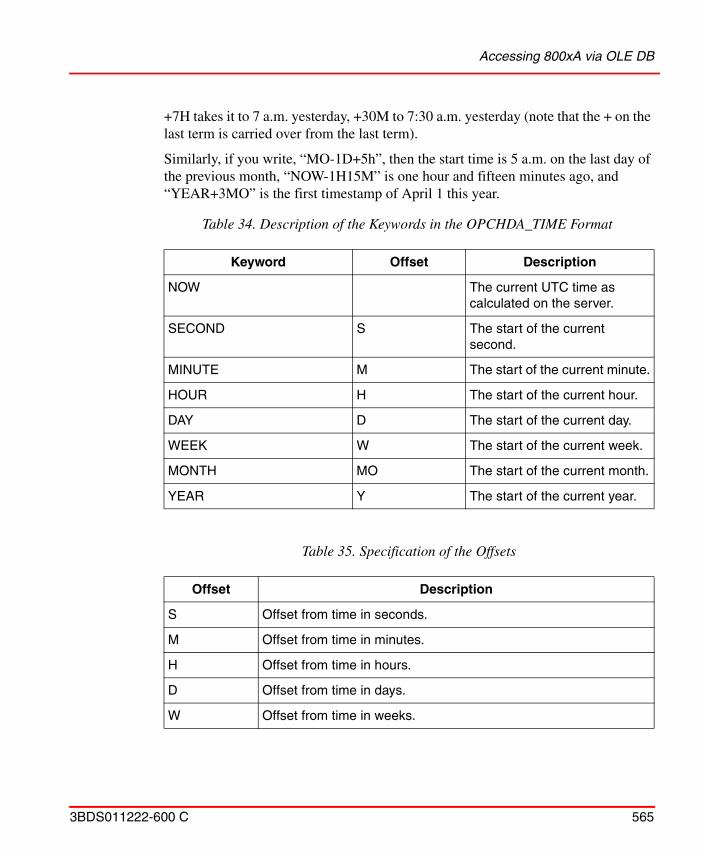
Accessing 800xA via OLE DB
3BDS011222-600 C 565
+7H takes it to 7 a.m. yesterday, +30M to 7:30 a.m. yesterday (note that the + on the last term is carried over from the last term).
Similarly, if you write, “MO-1D+5h”, then the start time is 5 a.m. on the last day of the previous month, “NOW-1H15M” is one hour and fifteen minutes ago, and “YEAR+3MO” is the first timestamp of April 1 this year.
Table 34. Description of the Keywords in the OPCHDA_TIME Format
Keyword Offset Description
NOW The current UTC time as calculated on the server.
SECOND S The start of the current second.
MINUTE M The start of the current minute.
HOUR H The start of the current hour.
DAY D The start of the current day.
WEEK W The start of the current week.
MONTH MO The start of the current month.
YEAR Y The start of the current year.
Table 35. Specification of the Offsets
Offset Description
S Offset from time in seconds.
M Offset from time in minutes.
H Offset from time in hours.
D Offset from time in days.
W Offset from time in weeks.
Accessing 800xA via OLE DB
566 3BDS011222-600 C
Short References.
You use a graphical user interface to predefine short references to Historical logs (OPC HDA) or object properties (OPC DA). These short references are objects of the OLE DB Access Table for DS or the OLE DB Access Table for History object types. The aspects contain all the information needed for a specific OPCHDA or OPCDA call to get the requested data. You can use the short references in two ways, from the command line or through the reporting packages.
The names of the short reference are the “OBJECTHELPER” name mentioned above in Table 32. You can view these aspects in the Library Structure in Plant Explorer.
Graphical User Interface History
To create a short reference you have to create an object in the Library Structure. The name of the object is the name of the short reference you are making. The object can be of the OLE DB Access Table for DS or the OLE DB Access Table for History object type. When you open the matching aspect, you will see the graphical
MO Offset from time in months.
Y Offset from time in years.
Table 35. Specification of the Offsets
Offset Description
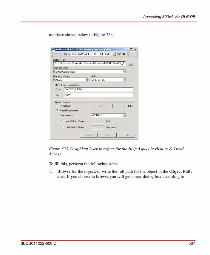
Accessing 800xA via OLE DB
3BDS011222-600 C 567
interface shown below in Figure 353.
To fill this, perform the following steps:
1. Browse for the object, or write the full path for the object in the Object Path area. If you choose to browse you will get a new dialog box according to
Figure 353. Graphical User Interface for the Help Aspect in History & Trend Access
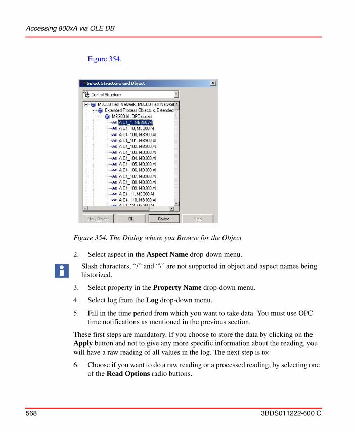
Accessing 800xA via OLE DB
568 3BDS011222-600 C
Figure 354.
2. Select aspect in the Aspect Name drop-down menu.
3. Select property in the Property Name drop-down menu.
4. Select log from the Log drop-down menu.
5. Fill in the time period from which you want to take data. You must use OPC time notifications as mentioned in the previous section.
These first steps are mandatory. If you choose to store the data by clicking on the Apply button and not to give any more specific information about the reading, you will have a raw reading of all values in the log. The next step is to:
6. Choose if you want to do a raw reading or a processed reading, by selecting one of the Read Options radio buttons.
Figure 354. The Dialog where you Browse for the Object
Slash characters, “/” and “\” are not supported in object and aspect names being historized.
Accessing 800xA via OLE DB
3BDS011222-600 C 569
7. If you choose a raw reading the default number of max item returned is 0, which means that you will get all values in the log. You can limit this by putting a number in this field.
8. If you choose a processed reading you have more options. You can choose what kind of calculation you want to perform on the data.
This by changing the calculation field with help of the list. Observe that all OPCHDA servers may not support all type of calculations.
9. After this you have an option to give the number of returned values, Item Return Count, or Resample Interval. When you give the resample rate you give the time in seconds between samples.
10. Click Apply to verify the changes.
Example Command Line
As you could see in the section about the command line the fourth way of giving the command line included the ITEMID keyword. This alternative has best performance of the four. If you use the ITEMID keyword the command line can look like this:
GET_HISTORY(ITEMID={5D941E07-AD9F-40B8-9CBD-4FDDC15BFF3C}{2EAB2220-77C0-46EE-BECB-1C0D6DE0989B}:VALUE,OPC_5s_5h; FROM=HOUR; TO=NOW)
In the third case of GET_HISTORY you can give the GUIDs or path and /or names of the Objects and Aspects. The difference between them is also the performance, i.e. how long time it takes to find the specific object or aspect. If you use the GUIDs for both the OBJECT and the ASPECT, which is the fastest way after using ITEMID, the command line can look like this:
GET_HISTORY(OBJECT={5D941E07-AD9F-40B8-9CBD-4FDDC15BFF3C}; ASPECT={2EAB2220-77C0-46EE-BECB-1C0D6DE0989B}; PROPERTY=VALUE; LOG=OPC_5s_5h; FROM=HOUR; TO=NOW)
If you do not want to use the GUIDs you can give the path to the object and just the name of the aspect. You can choose to use either “/” or “.” in the path as shown below.
Accessing 800xA via OLE DB
570 3BDS011222-600 C
GET_HISTORY(OBJECT=[Control Structure]MB300 Test Network/Extended Process Objects x/MB300 AI/AIC4_1; ASPECT=Control Connection; PROPERTY=VALUE; LOG=OPC_5s_5h; FROM=HOUR; TO=NOW)
GET_HISTORY(OBJECT=[Control Structure]MB300 Test Network.Extended Process Objects x.MB300 AI.AIC4_1; ASPECT=Control Connection; PROPERTY=VALUE; LOG=OPC_5s_5h; FROM=HOUR; TO=NOW)
These paths are fairly long but it is possible to shorting them down. You can just give the name of the structure and the name of the Object itself, which gives the following command line:
GET_HISTORY(OBJECT=[Control Structure]AIC4_1; ASPECT=Control Connection; PROPERTY=VALUE; LOG=OPC_5s_5h; FROM=HOUR; TO=NOW)
The simplest way of stating the names of the objects is just to give the name of the Object.
GET_HISTORY(OBJECT=AIC4_1; ASPECT=Control Connection; PROPERTY=VALUE; LOG=OPC_5s_5h; FROM=HOUR; TO=NOW)
This is the slowest way you can state the objects. The program must search through the whole structure until it finds the object.
The drawback is that it can only be one object with that name in the system. If there is more than one object the program will use the first one that it finds.
As mentioned in the section about keywords you can use different optional keywords. Here are examples on how you can use these keywords. The first two examples just show the two different ways you can give the mandatory ones. All names and values are excluded.
GET_HISTORY(OBJECT= ; ASPECT= ; PROPERTY= ;LOG= ; FROM= ;TO= )
GET_HISTORY(ITEMID= ; FROM= ;TO= )
The following examples are just showing different combinations for the first alternative but you can also apply them to them ITEMID alternative. You can restrict the maximal number of values you want back.
GET_HISTORY(OBJECT= ; ASPECT= ; PROPERTY= ;LOG= ; FROM= ;TO= ;MAXCOUNT= )
Property Transfer
3BDS011222-600 C 571
You can make a processed reading with a certain number of values back.
GET_HISTORY(OBJECT= ; ASPECT= ; PROPERTY= ;LOG= ; FROM= ;TO= ;Aggregate= ;COUNT= )
Another alternative you have is to decide how often the values are read.
GET_HISTORY(OBJECT= ; ASPECT= ; PROPERTY= ;LOG= ; FROM= ;TO= ;Aggregate= ;RESAMPLE= )
You can also give both, but then it is the value on COUNT that decides the sample rate.
GET_HISTORY(OBJECT= ; ASPECT= ; PROPERTY= ;LOG= ; FROM= ;TO= ;Aggregate= ;RESAMPLE= ;COUNT= )
Property Transfer
Purpose
The Property Transfer function is mainly used to transfer data between OPC servers. It can also be used as a calculation function, not only reading data from aspect object properties but also entering these data into a suitable algorithm and delivering the results to aspect object properties.
The data collection as well as the data delivery can be done from/to any public aspect object property (including the aspect properties from aspects such as the General Properties aspect).
Property Transfer Definition Aspect
The Property Transfer aspect is created on the destination object. The property transfer aspect then specifies the data sources and the expression.
You can specify more than one transfer in the same aspect. For each transfer you can set the destination Property (aspect Name and property Name), the source Expression, and bad data replacement Substitution Value. You can also specify
For information on performance and Capacity for supported number of Property Transfer aspects in a System, refer to System 800xA Technical Data and Configuration (3BSE041434*).
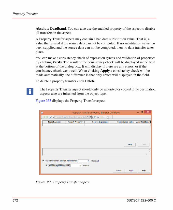
Property Transfer
572 3BDS011222-600 C
Absolute Deadband. You can also use the enabled property of the aspect to disable all transfers in the aspect.
A Property Transfer aspect may contain a bad data substitution value. That is, a value that is used if the source data can not be computed. If no substitution value has been supplied and the source data can not be computed, then no data transfer takes place.
You can make a consistency check of expression syntax and validation of properties by clicking Verify. The result of the consistency check will be displayed in the field at the bottom of the dialog box. It will display if there are any errors, or if the consistency check went well. When clicking Apply a consistency check will be made automatically, the difference is that only errors will displayed in the field.
To delete a property transfer click Delete.
Figure 355 displays the Property Transfer aspect.
The Property Transfer aspect should only be inherited or copied if the destination aspects also are inherited from the object type.
Figure 355. Property Transfer Aspect
Property Transfer
3BDS011222-600 C 573
The different fields in Figure 355 are described below:
Writing on many properties with Property Transfer Definition Aspect
When writing on many properties with the same cycle time and to the same OPC Server, problems can arise. For example, the OPC Server for AC 800M can not handle more than 50 simultaneous write operations per OPC group.
If you for example want to write on 60 properties with the same cycle time of 6000 ms, to an OPC Server for AC 800M, it is possible to "spread out" the cycle times using the Update rate input field in the Property Transfer Aspect (see Figure 355 and Table 36).
To avoid more than 50 simultaneous write operations, you can for example use 3 different Property Transfer Aspects with the different cycle times:
• 5999 ms for 20 properties
• 6000 ms for 20 properties
• 6001 ms for 20 properties
Table 36. Property Transfer Aspect
Target Aspect The destination aspect name.
Target Property A destination property in the selected aspect.
Source Expression Source expression.
Substitution Value This value will be transferred if the source expression results in bad quality.
Abs. Deadband Absolute deadband. An absolute numeric range through which the value can be varied without initiating a transfer.
Transfer all properties every Enable to transfer all properties.
Property Transfers Enabled, maximum rate
Enable/disable all property transfers defined in this aspect.
In the Expression text field you can use the property name as a short reference if the property is defined on the same object as the property transfer aspect.
Property Transfer
574 3BDS011222-600 C
Property Transfer Service
The Property Transfer service runs transfers defined through Property Transfer aspects.
How to set up the Property Transfer
The Property Transfer services are configured using the Configure System task in the System Configuration Console (SCC).
Redundancy Support
The Property Transfer service supports redundancy and allows one or more service providers in each service group. Redundant service provider will use the Service-Standby concept, only one provider will be in Service state and the others in Standby state. The provider in Service state is the only one that will perform writes to the destination properties. The providers in Standby state will have inactive subscriptions from the source properties. In the case of a fail-over, the provider that enters Service state will perform a write to all destination properties to assure that the latest values are transferred.
The Property Transfer service is not started by default, so before you can start any transfers the server must be configured.
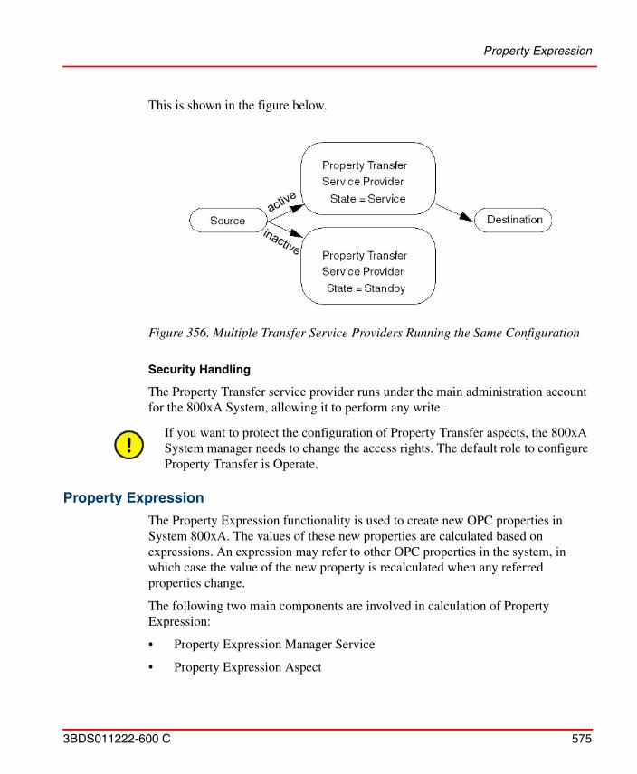
Property Expression
3BDS011222-600 C 575
This is shown in the figure below.
Security Handling
The Property Transfer service provider runs under the main administration account for the 800xA System, allowing it to perform any write.
Property Expression
The Property Expression functionality is used to create new OPC properties in System 800xA. The values of these new properties are calculated based on expressions. An expression may refer to other OPC properties in the system, in which case the value of the new property is recalculated when any referred properties change.
The following two main components are involved in calculation of Property Expression:
• Property Expression Manager Service
• Property Expression Aspect
Figure 356. Multiple Transfer Service Providers Running the Same Configuration
If you want to protect the configuration of Property Transfer aspects, the 800xA System manager needs to change the access rights. The default role to configure Property Transfer is Operate.
Property Expression
576 3BDS011222-600 C
Property Expression Manager Service
The Property Expression Manager Service is used for calculation and OPC management of Property Expressions. When the Property Expression Manager is unavailable no Property Expressions in the system will be available and all will have bad quality. This service can run on redundant nodes.
If there are non-available referenced properties during startup which are later made available. Perform a manual restart of the Property Expression Manager service.
Configure Property Expression Aspect
The Property Expression aspect is used to create new Property Expressions and specify how they should be calculated, refer to Figure 357.
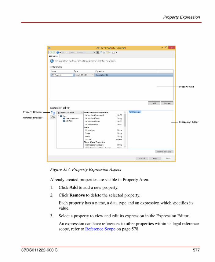
Property Expression
3BDS011222-600 C 577
Already created properties are visible in Property Area.
1. Click Add to add a new property.
2. Click Remove to delete the selected property.
Each property has a name, a data type and an expression which specifies its value.
3. Select a property to view and edit its expression in the Expression Editor.
An expression can have references to other properties within its legal reference scope, refer to Reference Scope on page 578.
Figure 357. Property Expression Aspect
Property Expression
578 3BDS011222-600 C
4. Select Property Browser to browse to properties within the correct scope.
It also helps to resolve ambiguous properties (for example, Properties with the same name but exposed by different aspects on the same object).
5. Click Function Browser to view the supported functions and their signature.
6. Click Parse expression or press Enter to check the expression for correctness.
A new line can be typed in the expression without parsing it by holding the Shift and press Enter.
7. Click Apply.
Reference Scope
Each Property Expression Aspect has a legal reference scope which determines what other properties it can refer to.
The reference scope for an aspect created on the object type and propagated to each instance is the object itself and its children. The reference scope for an aspect created on an object instance is unlimited.
It is possible to refer other Property Expressions (on the same Property Expression Aspect or another within the legal reference scope) in expressions. The aspect GUI prevents circular references by displaying an error message and disabling the Apply button. If circular dependencies are inserted through some other measures the properties with circular dependency will have bad quality.
Timestamp and Quality
The Property Expression contains the following timestamp and quality rules:
• When a Property Expression has referenced properties the timestamp of the resulting property is the latest timestamp for any of its referred properties.
• When a Property Expression has a constant value the timestamp for the resulting property is equal to the aspect modification time for the aspect that defines it.
• When a Property Expression has referenced properties the quality of the resulting property is the product of the qualities of its referred properties.
Property Expression
3BDS011222-600 C 579
• When a Property Expression has a constant value the quality of the resulting property is good.
• When the Property Expression Manager is unavailable the quality for all property expressions will be bad, regardless of their references.
Redundancy
For increased accessibility the Property Expression Manager Service can be configured to run with parallel redundancy on different nodes within the same service group. In such case only one of the services need to be accessible in order for the Property Expression Calculation mechanism to work.
Configuration Rules
The system configuration limits for the Property Expression functionality is provided in Table 37. The limitations are valid if the update rate of the referenced properties is not lower than 9 seconds.
Writing Expressions
An expression can contain operators, operands and functions. An expression performs calculation based on parameter values and yields one value being the result. This result will be mapped to the property defined by the Property Expression. Each Property Expression has a well-defined data type. Examples of data types are Real, Integer, Boolean and String.
For more information on syntax to be used while creating an expression and to write an expression, refer to System 800xA Engineering Process Graphics (3BSE049230*).
Table 37. Configuration Limits for Property Expression
Description Limitation
Maximum number of Expressions
One Property Expression aspect can contain several expressions.
50000 expressions
Maximum number of unique referenced properties in total for all Property Expression aspects
100000 referenced properties
Libraries
580 3BDS011222-600 C
Libraries
Building Versioned Object Type Libraries
The following example creates a new versioned library that shall get object types with control aspects for Control Builder M Professional. How to create object types in this new library is shown in Process Object Type with Signals on page 599 and Process Object Type Built in Function Designer on page 603.
The activities described correspond to workflow step Build Project Library, Versioned Object Type Libraries if you need to build an own library.
To create a new library starting from Control Builder M Professional:
1. In Project Explorer opened on your Control Project select the Libraries folder.
2. On the Libraries folder (with right mouse click) create a new Library. You name it ProcObjSigExtLib. The following happens automatically in Plant Explorer:The Library object and the Library Version object below is created in the Library Structure below the Libraries folder object.The Library Version object is inserted in the Object Type Structure below Object Types/Control System/AC 800M\/C Connect / Libraries.Below the Library Version object, the folder objects Control Module Types, Data Types, Function Block Types, Diagram Types, and Internal Types are created.
3. Now you can start to add your object types to the ProcObjSigExtLib library. This example continues Process Object Type with Signals on page 599.
4. To test the library on another machine you can create a Library Archive via the Library Export button in the General tab of the Library Version Definition aspect on the Library Version object. In the Export Library Dialog you determine where the .afw archive file is stored. Transfer the archive to the other machine and import it with the Import\Export tool there.
Using Versioned Object Type Libraries
To use the new library on another engineering system:
1. Import the library archive with the Import / Export tool.
Object Types
3BDS011222-600 C 581
2. In Control Builder M Professional (or Plant Explorer).
a. Insert the library into your Control Project.
b. Connect the library to the Application.
Access the tool to package libraries from the System 800xA Media as given in the path:
..\Core Functionalities\System Extension Configuration and Packaging
More information, for example how to build a new Library starting with Plant Explorer, how to build a new version of a library, and how to upgrade to a new library version see Appendix B, Library Handling.
Object Types
Building Object Types
This chapter will show, step by step, how to create a simple object type for an imaginary application. A lot of other possibilities are available even for a simple object type, but the full description of all possibilities is in the reference part (Reference Information for Object Types on page 615 in Appendix A, Object Types).
The activities described here correspond to workflow step Build Project Library, Versioned Object Type Libraries if you need to build an own library.
The imaginary application consists of a large number of manufacturing cells. Each cell should have one aspect object containing an operating manual, a general property aspect with cell data and an operator note aspect. It should also be possible, and easy to create a file viewer document to log information about the cell in.
One way to create these information objects could have been to create each object for the cells individually and add the needed aspects on them. Another, more effective, way is to create an object type describing how instances of this object type should be created.
This example will show how to create an object type Cell Information.
To create an Object Type you need to have the Application Engineer role.
Building Object Types
582 3BDS011222-600 C
Object Type Group Creation
Object types are collected into object type groups placed in the Object Type Structure. The following steps have to be done to create a new object type group, in our case named Cell Information Object Type Group.
1. Go to the Object Type Structure and select the root object Object Types.
2. Using the New Object dialog, make a new aspect object of the type Object Type Group below the object Object Types, and name it Cell Information Object Type Group.
The object type group is itself an instance of an object type that only allows object type groups, object types and aspect groups to be created below it.
Object Type Creation
Object types are created within an object type group. To create the Cell Information Object Type, do the following steps:
1. Select the Cell Information Object Type Group object.
2. Using the New Object dialog, make a new aspect object of the type Object Type, and name it Cell Information.
When the Cell Information object is created it gets the following aspects.
Table 38. Aspects on an Empty Object Type
Aspect Description
Name Name of the object type.
Object Type Structure Structure aspect.
Aspect Category Definition
The object type is also an aspect category, which allows aspects to be inherited from the object type.
Cell Information Object Type Group Reference
A reference to the object group where the object type is placed.
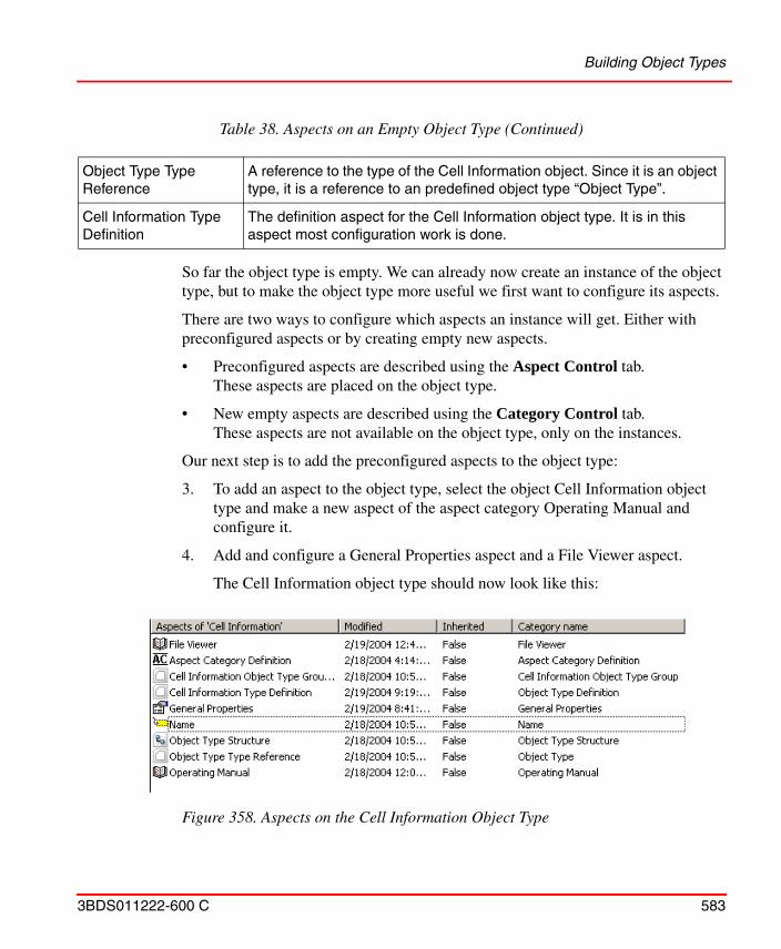
Building Object Types
3BDS011222-600 C 583
So far the object type is empty. We can already now create an instance of the object type, but to make the object type more useful we first want to configure its aspects.
There are two ways to configure which aspects an instance will get. Either with preconfigured aspects or by creating empty new aspects.
• Preconfigured aspects are described using the Aspect Control tab. These aspects are placed on the object type.
• New empty aspects are described using the Category Control tab. These aspects are not available on the object type, only on the instances.
Our next step is to add the preconfigured aspects to the object type:
3. To add an aspect to the object type, select the object Cell Information object type and make a new aspect of the aspect category Operating Manual and configure it.
4. Add and configure a General Properties aspect and a File Viewer aspect.
The Cell Information object type should now look like this:
Object Type Type Reference
A reference to the type of the Cell Information object. Since it is an object type, it is a reference to an predefined object type “Object Type”.
Cell Information Type Definition
The definition aspect for the Cell Information object type. It is in this aspect most configuration work is done.
Figure 358. Aspects on the Cell Information Object Type
Table 38. Aspects on an Empty Object Type (Continued)
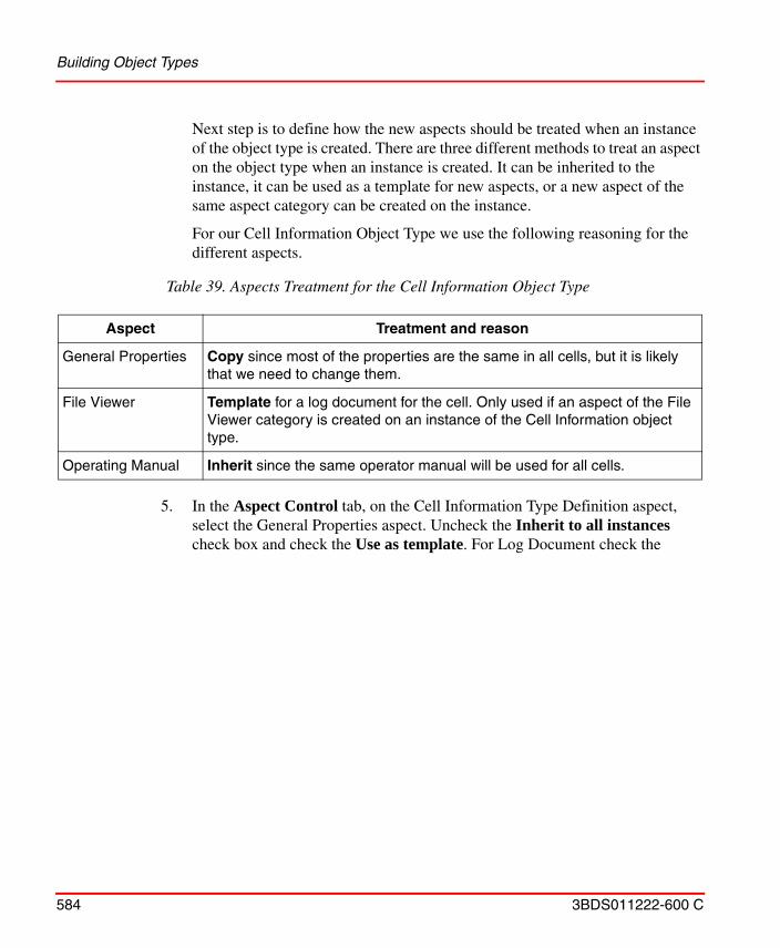
Building Object Types
584 3BDS011222-600 C
Next step is to define how the new aspects should be treated when an instance of the object type is created. There are three different methods to treat an aspect on the object type when an instance is created. It can be inherited to the instance, it can be used as a template for new aspects, or a new aspect of the same aspect category can be created on the instance.
For our Cell Information Object Type we use the following reasoning for the different aspects.
5. In the Aspect Control tab, on the Cell Information Type Definition aspect, select the General Properties aspect. Uncheck the Inherit to all instances check box and check the Use as template. For Log Document check the
Table 39. Aspects Treatment for the Cell Information Object Type
Aspect Treatment and reason
General Properties Copy since most of the properties are the same in all cells, but it is likely that we need to change them.
File Viewer Template for a log document for the cell. Only used if an aspect of the File Viewer category is created on an instance of the Cell Information object type.
Operating Manual Inherit since the same operator manual will be used for all cells.
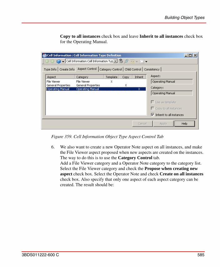
Building Object Types
3BDS011222-600 C 585
Copy to all instances check box and leave Inherit to all instances check box for the Operating Manual.
6. We also want to create a new Operator Note aspect on all instances, and make the File Viewer aspect proposed when new aspects are created on the instances. The way to do this is to use the Category Control tab.Add a File Viewer category and a Operator Note category to the category list. Select the File Viewer category and check the Propose when creating new aspect check box. Select the Operator Note and check Create on all instances check box. Also specify that only one aspect of each aspect category can be created. The result should be:
Figure 359. Cell Information Object Type Aspect Control Tab
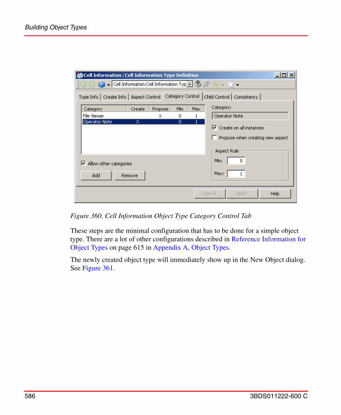
Building Object Types
586 3BDS011222-600 C
These steps are the minimal configuration that has to be done for a simple object type. There are a lot of other configurations described in Reference Information for Object Types on page 615 in Appendix A, Object Types.
The newly created object type will immediately show up in the New Object dialog. See Figure 361.
Figure 360. Cell Information Object Type Category Control Tab
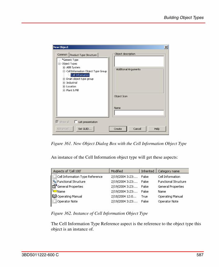
Building Object Types
3BDS011222-600 C 587
An instance of the Cell Information object type will get these aspects:
The Cell Information Type Reference aspect is the reference to the object type this object is an instance of.
Figure 361. New Object Dialog Box with the Cell Information Object Type
Figure 362. Instance of Cell Information Object Type
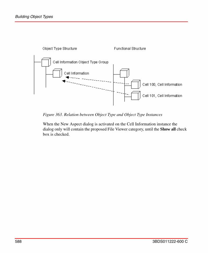
Building Object Types
588 3BDS011222-600 C
When the New Aspect dialog is activated on the Cell Information instance the dialog only will contain the proposed File Viewer category, until the Show all check box is checked.
Figure 363. Relation between Object Type and Object Type Instances
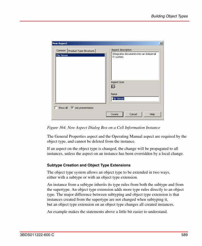
Building Object Types
3BDS011222-600 C 589
The General Properties aspect and the Operating Manual aspect are required by the object type, and cannot be deleted from the instance.
If an aspect on the object type is changed, the change will be propagated to all instances, unless the aspect on an instance has been overridden by a local change.
Subtype Creation and Object Type Extensions
The object type system allows an object type to be extended in two ways, either with a subtype or with an object type extension.
An instance from a subtype inherits its type rules from both the subtype and from the supertype. An object type extension adds more type rules directly to an object type. The major difference between subtyping and object type extension is that instances created from the supertype are not changed when subtyping it, but an object type extension on an object type changes all created instances.
An example makes the statements above a little bit easier to understand.
Figure 364. New Aspect Dialog Box on a Cell Information Instance
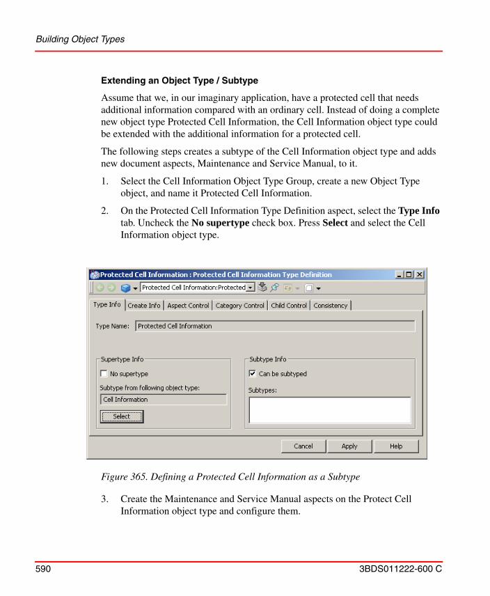
Building Object Types
590 3BDS011222-600 C
Extending an Object Type / Subtype
Assume that we, in our imaginary application, have a protected cell that needs additional information compared with an ordinary cell. Instead of doing a complete new object type Protected Cell Information, the Cell Information object type could be extended with the additional information for a protected cell.
The following steps creates a subtype of the Cell Information object type and adds new document aspects, Maintenance and Service Manual, to it.
1. Select the Cell Information Object Type Group, create a new Object Type object, and name it Protected Cell Information.
2. On the Protected Cell Information Type Definition aspect, select the Type Info tab. Uncheck the No supertype check box. Press Select and select the Cell Information object type.
3. Create the Maintenance and Service Manual aspects on the Protect Cell Information object type and configure them.
Figure 365. Defining a Protected Cell Information as a Subtype
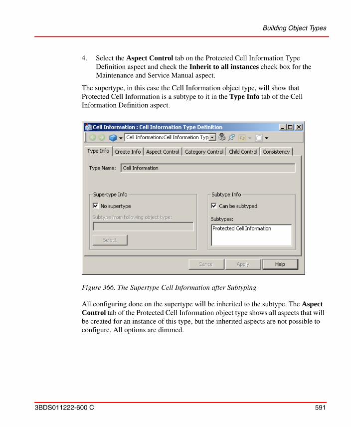
Building Object Types
3BDS011222-600 C 591
4. Select the Aspect Control tab on the Protected Cell Information Type Definition aspect and check the Inherit to all instances check box for the Maintenance and Service Manual aspect.
The supertype, in this case the Cell Information object type, will show that Protected Cell Information is a subtype to it in the Type Info tab of the Cell Information Definition aspect.
All configuring done on the supertype will be inherited to the subtype. The Aspect Control tab of the Protected Cell Information object type shows all aspects that will be created for an instance of this type, but the inherited aspects are not possible to configure. All options are dimmed.
Figure 366. The Supertype Cell Information after Subtyping
Building Object Types
592 3BDS011222-600 C
Extend an Object Type / Object Type Extension Definition Aspect
Sometimes it is necessary to be able to develop an object type at different locations. It could be, for an example, that the subcontractor for the electronic drawings will deliver the drawings that should be part of the Cell Information object type.
The Object Type Extension Definition aspect makes it possible to add, for example a Electrical Drawing aspect to the object type Cell Information from an import file without having to change the Cell Information object type.
To make an extension to an object type in another aspect system than the system where the object type is defined, make the following steps.
1. Create a new Object Type Group and an Object Type. Name it the same way as the object type group and object type to extend.
2. Create an Object Type Extension Definition aspect on the object type to extend.
3. Create and configure the aspects the object type extension should have.
4. Select the Aspect Control tab for the Object Type Extension Definition aspect and configure the treatment of the added aspects, just as we did when creating a simple object type.
5. Export the aspect that extends the object type and the Object Type Extension Definition aspect to an afw-file with the Import/Export tool.
6. Open the afw-file on the system where the object type to extend available using the Import/Export tool. The aspects has to be manually placed on the object type to be extended.
Composite Object Type Creation
Composite Object Types are used to define more complex typical solutions that decrease the engineering effort. This section will outline the principles and provide examples of how to build and use composite object types.
The reasons for building composite object types are:
• The engineering time is decreased due to field proven solution. A composite object type that is tested and verified does not need the same amount of testing when it is reused.
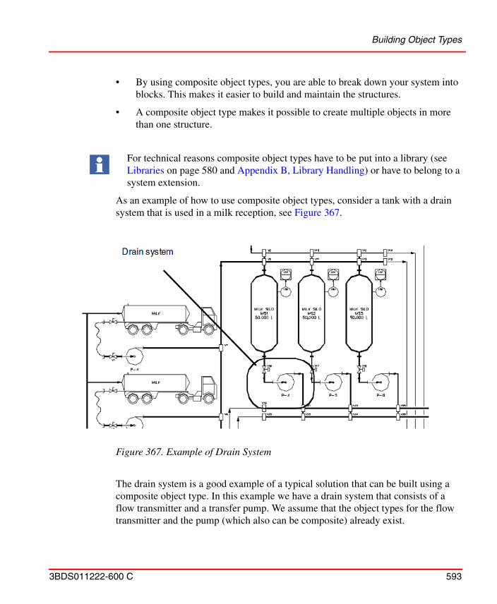
Building Object Types
3BDS011222-600 C 593
• By using composite object types, you are able to break down your system into blocks. This makes it easier to build and maintain the structures.
• A composite object type makes it possible to create multiple objects in more than one structure.
As an example of how to use composite object types, consider a tank with a drain system that is used in a milk reception, see Figure 367.
The drain system is a good example of a typical solution that can be built using a composite object type. In this example we have a drain system that consists of a flow transmitter and a transfer pump. We assume that the object types for the flow transmitter and the pump (which also can be composite) already exist.
For technical reasons composite object types have to be put into a library (see Libraries on page 580 and Appendix B, Library Handling) or have to belong to a system extension.
Figure 367. Example of Drain System
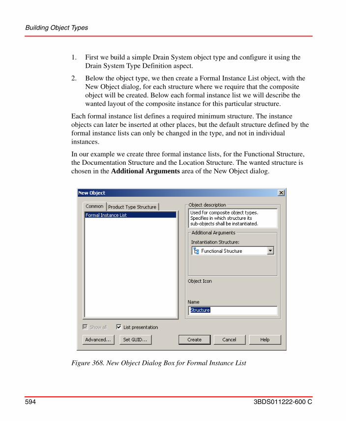
Building Object Types
594 3BDS011222-600 C
1. First we build a simple Drain System object type and configure it using the Drain System Type Definition aspect.
2. Below the object type, we then create a Formal Instance List object, with the New Object dialog, for each structure where we require that the composite object will be created. Below each formal instance list we will describe the wanted layout of the composite instance for this particular structure.
Each formal instance list defines a required minimum structure. The instance objects can later be inserted at other places, but the default structure defined by the formal instance lists can only be changed in the type, and not in individual instances.
In our example we create three formal instance lists, for the Functional Structure, the Documentation Structure and the Location Structure. The wanted structure is chosen in the Additional Arguments area of the New Object dialog.
Figure 368. New Object Dialog Box for Formal Instance List
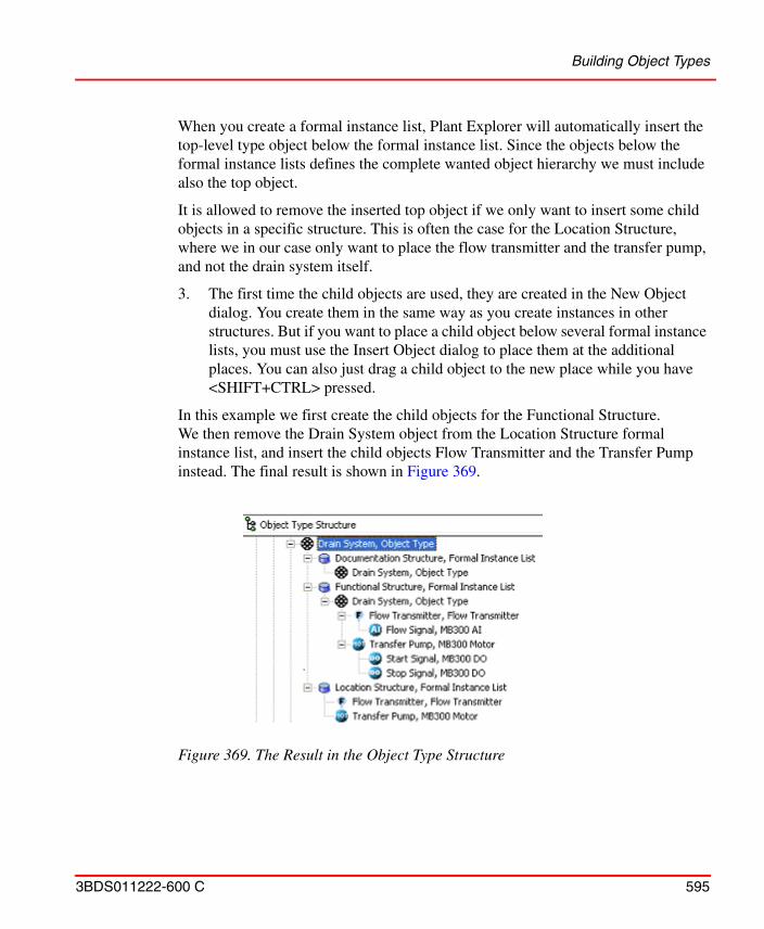
Building Object Types
3BDS011222-600 C 595
When you create a formal instance list, Plant Explorer will automatically insert the top-level type object below the formal instance list. Since the objects below the formal instance lists defines the complete wanted object hierarchy we must include also the top object.
It is allowed to remove the inserted top object if we only want to insert some child objects in a specific structure. This is often the case for the Location Structure, where we in our case only want to place the flow transmitter and the transfer pump, and not the drain system itself.
3. The first time the child objects are used, they are created in the New Object dialog. You create them in the same way as you create instances in other structures. But if you want to place a child object below several formal instance lists, you must use the Insert Object dialog to place them at the additional places. You can also just drag a child object to the new place while you have <SHIFT+CTRL> pressed.
In this example we first create the child objects for the Functional Structure. We then remove the Drain System object from the Location Structure formal instance list, and insert the child objects Flow Transmitter and the Transfer Pump instead. The final result is shown in Figure 369.
Figure 369. The Result in the Object Type Structure
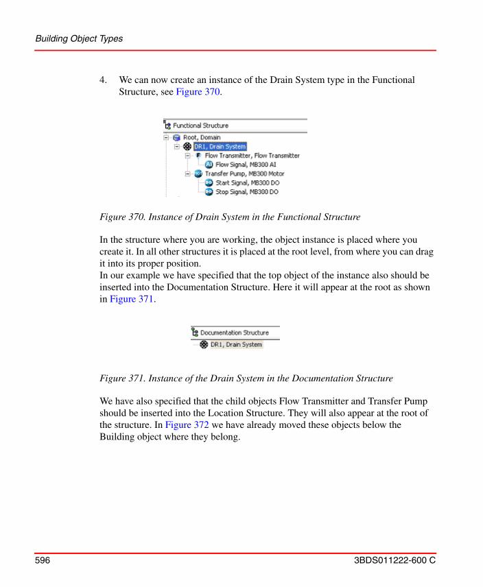
Building Object Types
596 3BDS011222-600 C
4. We can now create an instance of the Drain System type in the Functional Structure, see Figure 370.
In the structure where you are working, the object instance is placed where you create it. In all other structures it is placed at the root level, from where you can drag it into its proper position. In our example we have specified that the top object of the instance also should be inserted into the Documentation Structure. Here it will appear at the root as shown in Figure 371.
We have also specified that the child objects Flow Transmitter and Transfer Pump should be inserted into the Location Structure. They will also appear at the root of the structure. In Figure 372 we have already moved these objects below the Building object where they belong.
Figure 370. Instance of Drain System in the Functional Structure
Figure 371. Instance of the Drain System in the Documentation Structure
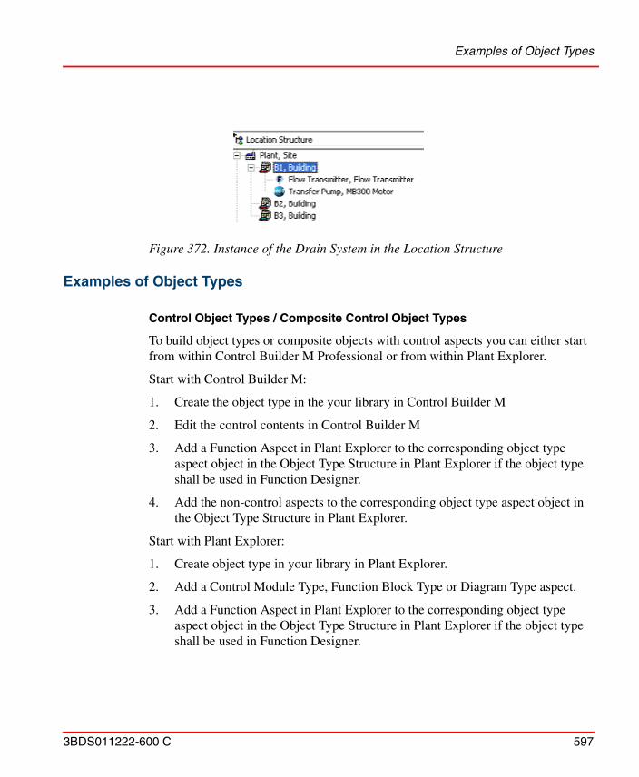
Examples of Object Types
3BDS011222-600 C 597
Examples of Object Types
Control Object Types / Composite Control Object Types
To build object types or composite objects with control aspects you can either start from within Control Builder M Professional or from within Plant Explorer.
Start with Control Builder M:
1. Create the object type in the your library in Control Builder M
2. Edit the control contents in Control Builder M
3. Add a Function Aspect in Plant Explorer to the corresponding object type aspect object in the Object Type Structure in Plant Explorer if the object type shall be used in Function Designer.
4. Add the non-control aspects to the corresponding object type aspect object in the Object Type Structure in Plant Explorer.
Start with Plant Explorer:
1. Create object type in your library in Plant Explorer.
2. Add a Control Module Type, Function Block Type or Diagram Type aspect.
3. Add a Function Aspect in Plant Explorer to the corresponding object type aspect object in the Object Type Structure in Plant Explorer if the object type shall be used in Function Designer.
Figure 372. Instance of the Drain System in the Location Structure

Examples of Object Types
598 3BDS011222-600 C
4. Add the non-control aspects to the corresponding object type aspect object in the Object Type Structure in Plant Explorer.
5. Edit the control content in Control Builder M or, if the control aspect is a Control Module Type, in Function Designer.
To edit control content of a Control Module Type aspect of such an object type you can use Function Designer as shown in Process Object Type Built in Function Designer on page 603.
Refer to System 800xA Control, AC 800M Configuration (3BSE035980*) and in Control Builder M Professional Help for more details on building control aspect contents of object types in Control Builder M Professional.
When you create control object types you should carefully consider which objects shall show up in the Control Structure / Functional Structure of Plant Explorer as described in the following subsection.
Aspect Object Creation in Control Structure
In order to avoid performance issues in the Aspect Directory, there is a way to minimize the number of Aspect Objects created from Control Builder M Professional.
Aspect Object is an attribute on object types, on instances of object types in the application, and on formal instances (instances inside function block, control module or diagram types) in Control Builder M Professional. If the attribute is true on the type an Aspect Object is created. Otherwise, no Aspect Object is created.
On object types it is set by the verb Instantiate as Aspect Object, on instances by the verb Aspect Object.
The user can change the Aspect Object attribute on the instance if he wants to override the default creation as described above.
Function Designer has a corresponding function to switch between Aspect Object and Symbol Object, refer to System 800xA, System Planning (3BSE041389*).
Objects not interacting with other objects in Plant Explorer should have the aspect object attribute set to False for not loading the Aspect Server performance.
For objects created from the Plant Explorer the attribute Aspect Object is always by default set to true.
Examples of Object Types
3BDS011222-600 C 599
Process Object Type with Signals
In the following example you add an composite object type to the library ProcObjSigExtLib created in Building Versioned Object Type Libraries on page 580. It shall contain a process object type with the needed engineering I/O signal objects (from the CBM_Signals object type group provided with the AC 800MC Signal Extension system extension) to support
• I/O Signal Engineering
• and I/O Allocation from the Functional Structure to the Control Structure
• and creation of a complete Function Diagram of the instance in a process function object on the level above the instance.
In our example case the I/O Signal objects correspond to Global Variables on Application level which will be connected to Parameters of the Control Module Type named EW_MotorUniM_IOGAppl_Var.
Steps to build the composite object type:
1. Build the Control Module Type, Function Block Type or Diagram Type in Control Builder M beneath the ProcObjSigExtLib.
2. Add the needed graphical aspects to the object in the Object Type Structure.
3. Extend the object type in the Object Type Structure with formal instances of Signal objects in the Functional Structure as shown in Figure 373.
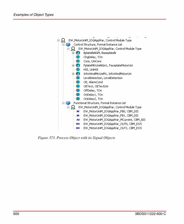
Examples of Object Types
600 3BDS011222-600 C
Figure 373. Process Object with its Signal Objects
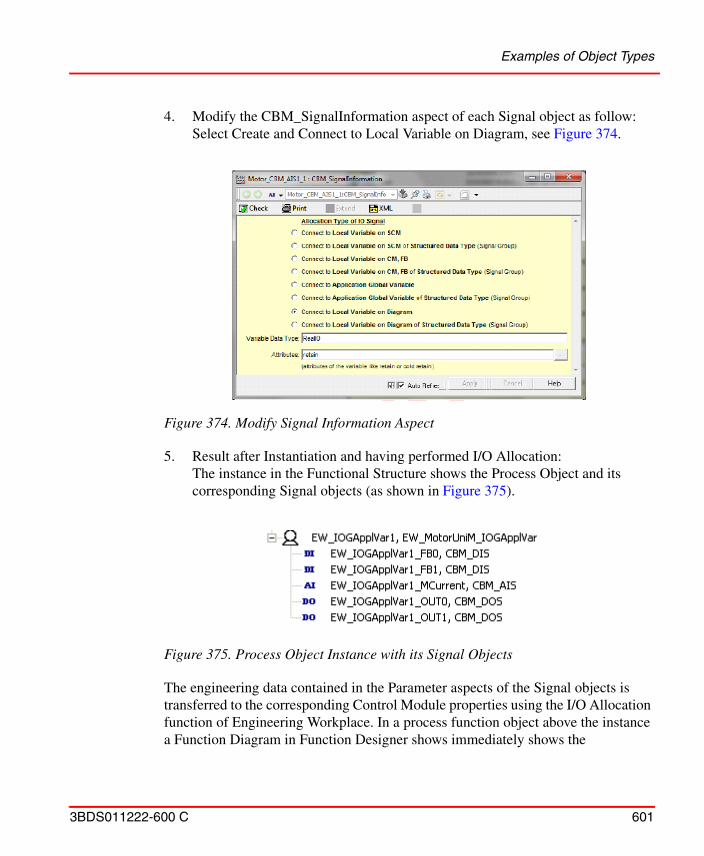
Examples of Object Types
3BDS011222-600 C 601
4. Modify the CBM_SignalInformation aspect of each Signal object as follow: Select Create and Connect to Local Variable on Diagram, see Figure 374.
5. Result after Instantiation and having performed I/O Allocation:The instance in the Functional Structure shows the Process Object and its corresponding Signal objects (as shown in Figure 375).
The engineering data contained in the Parameter aspects of the Signal objects is transferred to the corresponding Control Module properties using the I/O Allocation function of Engineering Workplace. In a process function object above the instance a Function Diagram in Function Designer shows immediately shows the
Figure 374. Modify Signal Information Aspect
Figure 375. Process Object Instance with its Signal Objects
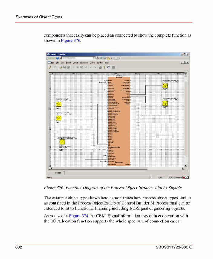
Examples of Object Types
602 3BDS011222-600 C
components that easily can be placed an connected to show the complete function as shown in Figure 376.
The example object type shown here demonstrates how process object types similar as contained in the ProcessObjectExtLib of Control Builder M Professional can be extended to fit to Functional Planning including I/O-Signal engineering objects.
As you see in Figure 374 the CBM_SignalInformation aspect in cooperation with the I/O Allocation function supports the whole spectrum of connection cases.
Figure 376. Function Diagram of the Process Object Instance with its Signals
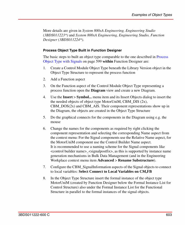
Examples of Object Types
3BDS011222-600 C 603
More details are given in System 800xA Engineering, Engineering Studio (3BDS011223*) and System 800xA Engineering, Engineering Studio, Function Designer (3BDS011224*).
Process Object Type Built in Function Designer
The basic steps to built an object type comparable to the one described in Process Object Type with Signals on page 599 within Function Designer are:
1. Create a Control Module Object Type beneath the Library Version object in the Object Type Structure to represent the process function
2. Add a Function aspect
3. On the Function aspect of the Control Module Object Type representing a process function open the Diagram view and create a new Diagram.
4. Use the Insert > Symbol... menu item and its Insert Objects dialog to insert the the needed objects of object type MotorUniM, CBM_DIS (2x), CBM_DOS(2x) and CBM_AIS. Their component representations show up in the Diagram, the objects are created in the Object Type Structure
5. Do the graphical connects for the components in the Diagram using e.g. the mouse
6. Change the names for the components as required by right clicking the component representation and selecting the corresponding Name aspect from the context menu: For the Signal components use the Relative Name aspect, for the MotorUniM component use the Control Builder Name aspect.It is recommended to use a naming scheme for the Signal components like <control builder name>_<signalpostfix>, as this is supported by instance name generation mechanisms in Bulk Data Management (and in the Engineering Workplace context menu item Advanced > Rename Substructure).
7. Configure the CBM_SignalInformation aspects of the Signal objects to connect to local variables: Select Connect to Local Variables on CM,FB
8. In the Object Type Structure insert the formal instance of the object type MotorUniM (created by Function Designer below the Formal Instance List for Control Structure) also under the Formal Instance List for the Functional Structure in parallel to the formal instances of the signal objects.
Examples of Object Types
604 3BDS011222-600 C
9. With the Insert > Symbol... menu item and its Insert Objects dialog add Input/Output Parameters (from Functional Planning / Generic Function Components / Connectors / Diagram Parameters / ...) as required and connect them to function component ports as required. This will allow you to connect to corresponding ports of the new object type’s component in an upper level Function Diagram.
10. Execute File > Generate Configuration Data: Now the object type is ready to be used.
Note that Function Designer supports creation of Control Module object types. It does not support creation of Function Block object types.
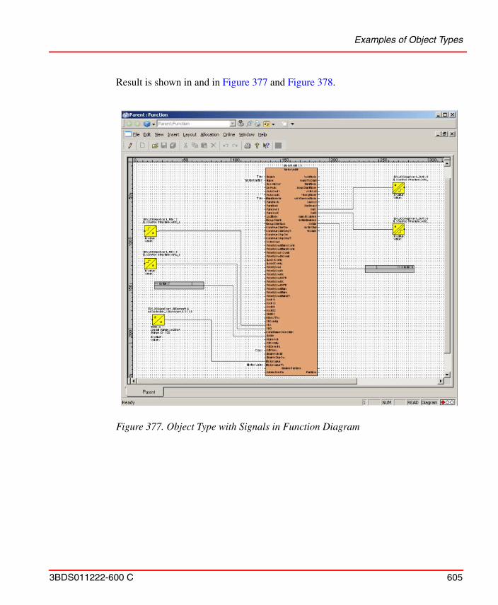
Examples of Object Types
3BDS011222-600 C 605
Result is shown in and in Figure 377 and Figure 378.
Figure 377. Object Type with Signals in Function Diagram
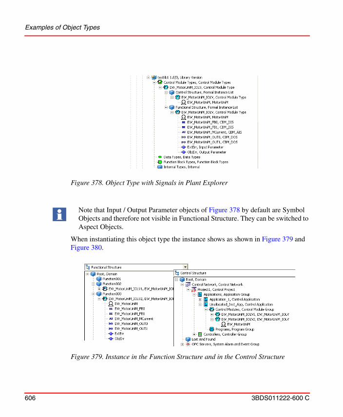
Examples of Object Types
606 3BDS011222-600 C
When instantiating this object type the instance shows as shown in Figure 379 and Figure 380.
Figure 378. Object Type with Signals in Plant Explorer
Note that Input / Output Parameter objects of Figure 378 by default are Symbol Objects and therefore not visible in Functional Structure. They can be switched to Aspect Objects.
Figure 379. Instance in the Function Structure and in the Control Structure
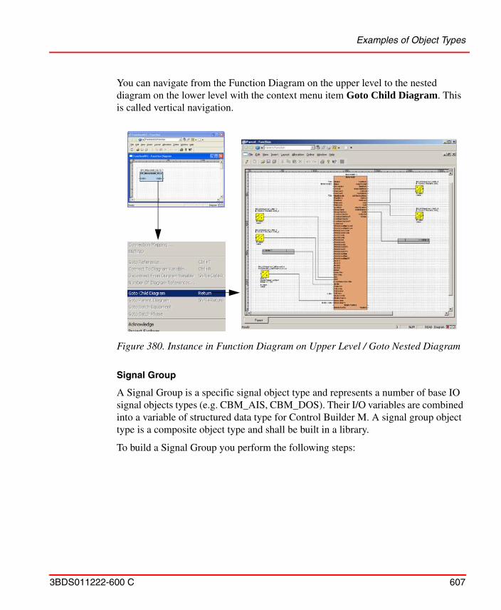
Examples of Object Types
3BDS011222-600 C 607
You can navigate from the Function Diagram on the upper level to the nested diagram on the lower level with the context menu item Goto Child Diagram. This is called vertical navigation.
Signal Group
A Signal Group is a specific signal object type and represents a number of base IO signal objects types (e.g. CBM_AIS, CBM_DOS). Their I/O variables are combined into a variable of structured data type for Control Builder M. A signal group object type is a composite object type and shall be built in a library.
To build a Signal Group you perform the following steps:
Figure 380. Instance in Function Diagram on Upper Level / Goto Nested Diagram
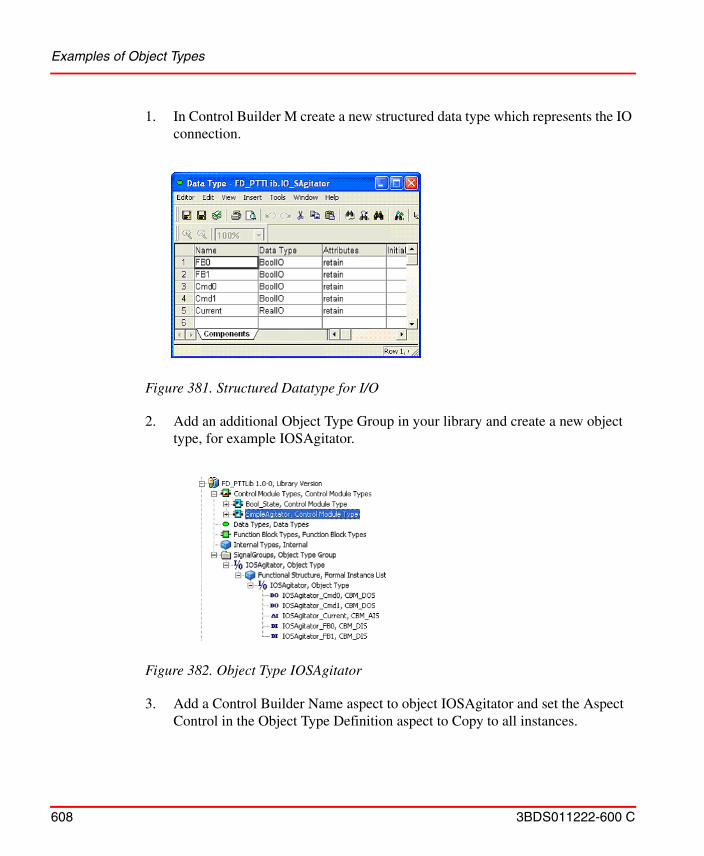
Examples of Object Types
608 3BDS011222-600 C
1. In Control Builder M create a new structured data type which represents the IO connection.
2. Add an additional Object Type Group in your library and create a new object type, for example IOSAgitator.
3. Add a Control Builder Name aspect to object IOSAgitator and set the Aspect Control in the Object Type Definition aspect to Copy to all instances.
Figure 381. Structured Datatype for I/O
Figure 382. Object Type IOSAgitator
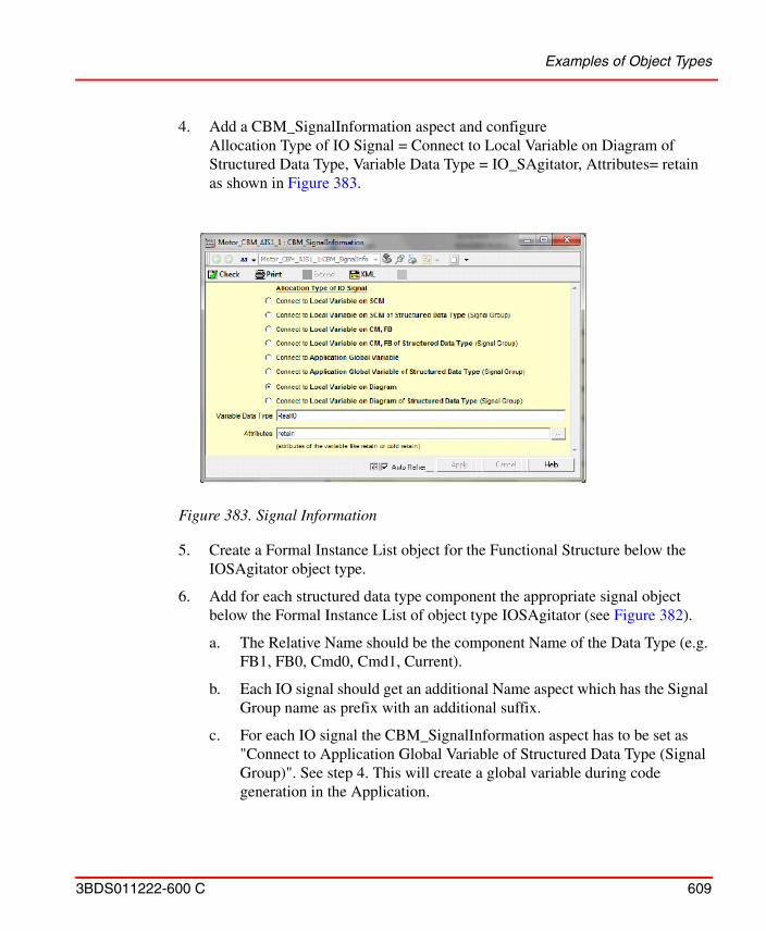
Examples of Object Types
3BDS011222-600 C 609
4. Add a CBM_SignalInformation aspect and configureAllocation Type of IO Signal = Connect to Local Variable on Diagram of Structured Data Type, Variable Data Type = IO_SAgitator, Attributes= retainas shown in Figure 383.
5. Create a Formal Instance List object for the Functional Structure below the IOSAgitator object type.
6. Add for each structured data type component the appropriate signal object below the Formal Instance List of object type IOSAgitator (see Figure 382).
a. The Relative Name should be the component Name of the Data Type (e.g. FB1, FB0, Cmd0, Cmd1, Current).
b. Each IO signal should get an additional Name aspect which has the Signal Group name as prefix with an additional suffix.
c. For each IO signal the CBM_SignalInformation aspect has to be set as "Connect to Application Global Variable of Structured Data Type (Signal Group)". See step 4. This will create a global variable during code generation in the Application.
Figure 383. Signal Information
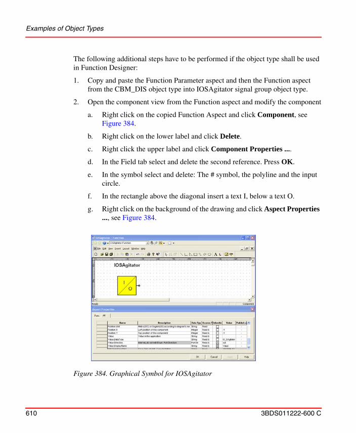
Examples of Object Types
610 3BDS011222-600 C
The following additional steps have to be performed if the object type shall be used in Function Designer:
1. Copy and paste the Function Parameter aspect and then the Function aspect from the CBM_DIS object type into IOSAgitator signal group object type.
2. Open the component view from the Function aspect and modify the component
a. Right click on the copied Function Aspect and click Component, see Figure 384.
b. Right click on the lower label and click Delete.
c. Right click the upper label and click Component Properties ....
d. In the Field tab select and delete the second reference. Press OK.
e. In the symbol select and delete: The # symbol, the polyline and the input circle.
f. In the rectangle above the diagonal insert a text I, below a text O.
g. Right click on the background of the drawing and click Aspect Properties ..., see Figure 384.
Figure 384. Graphical Symbol for IOSAgitator
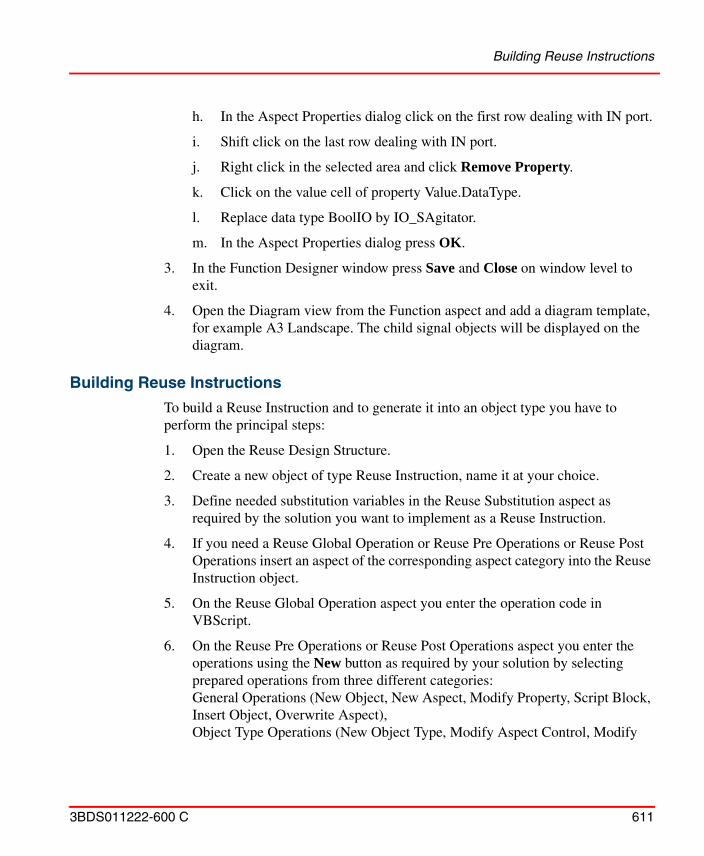
Building Reuse Instructions
3BDS011222-600 C 611
h. In the Aspect Properties dialog click on the first row dealing with IN port.
i. Shift click on the last row dealing with IN port.
j. Right click in the selected area and click Remove Property.
k. Click on the value cell of property Value.DataType.
l. Replace data type BoolIO by IO_SAgitator.
m. In the Aspect Properties dialog press OK.
3. In the Function Designer window press Save and Close on window level to exit.
4. Open the Diagram view from the Function aspect and add a diagram template, for example A3 Landscape. The child signal objects will be displayed on the diagram.
Building Reuse Instructions
To build a Reuse Instruction and to generate it into an object type you have to perform the principal steps:
1. Open the Reuse Design Structure.
2. Create a new object of type Reuse Instruction, name it at your choice.
3. Define needed substitution variables in the Reuse Substitution aspect as required by the solution you want to implement as a Reuse Instruction.
4. If you need a Reuse Global Operation or Reuse Pre Operations or Reuse Post Operations insert an aspect of the corresponding aspect category into the Reuse Instruction object.
5. On the Reuse Global Operation aspect you enter the operation code in VBScript.
6. On the Reuse Pre Operations or Reuse Post Operations aspect you enter the operations using the New button as required by your solution by selecting prepared operations from three different categories:General Operations (New Object, New Aspect, Modify Property, Script Block, Insert Object, Overwrite Aspect),Object Type Operations (New Object Type, Modify Aspect Control, Modify
Building Reuse Instructions
612 3BDS011222-600 C
Category Control, Modify Child Control, Set Supertype)or Control Builder M operations (Add Variable, Add Parameter, Add Alarm, Modify Alarm, Generate FB Calls).
7. Below the Reuse Instruction object you configure the Question and Answer tree by creating instances of Reuse Question and Reuse Answer object types. You name the objects according to the questions and answers. Designate one of the answers to a question as default answer using the object context menu item Default Answer.
8. In each Reuse Answer object you configure the Reuse Answer Operations aspect with operations (see above, as with Reuse Pre Operations or Reuse Post Operations) implementing the answer.
9. When done you select the Reuse Instruction Generator aspect in the Reuse Instruction object and you browse to the object type you want to generate the Reuse Instruction into (and, if not yet available, you create it).
10. To enable consistency checks when instantiating a Reuse Instruction enter the check marks for the required system extensions in the Required System Extension tab.
11. If you have entered script code for operations then also complete the entries in the Required Object Types tab and in the Required Aspect Categories tab.
12. Finally you generate the Reuse Instruction into the object type using the Check and Gen button.
To instantiate the object type with the Reuse Instruction you perform the steps:
1. Create an instance of the object type in an applicable structure.
2. Select the ReuseAssistantBuilder aspect of the instance.
3. Enter the required values for the substitution variables.
4. Press Next button to go to the first question displayed in the aspect pane and press the radio button for the required answer.
5. Do this for all questions.
6. When done, press the Execute button and confirm execution: The object instances will be build / extended according to the choices you have made.
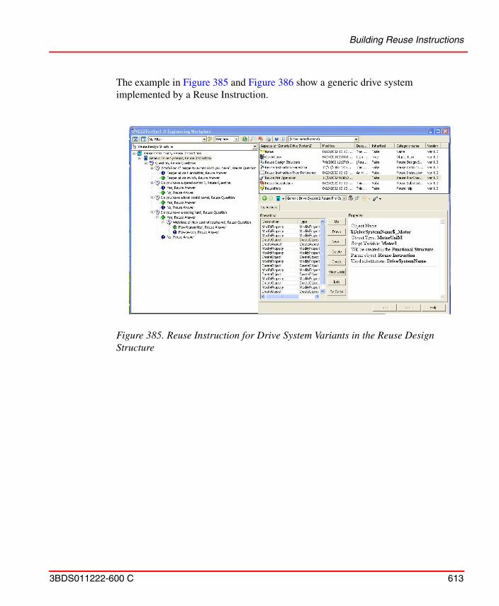
Building Reuse Instructions
3BDS011222-600 C 613
The example in Figure 385 and Figure 386 show a generic drive system implemented by a Reuse Instruction.
Figure 385. Reuse Instruction for Drive System Variants in the Reuse Design Structure
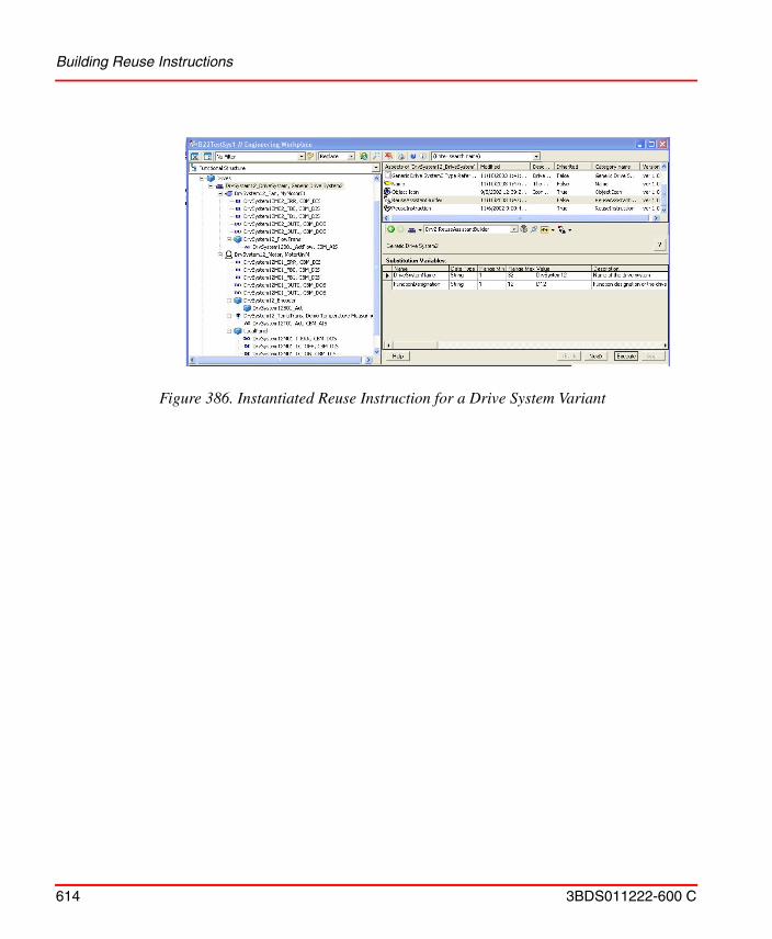
Building Reuse Instructions
614 3BDS011222-600 C
Figure 386. Instantiated Reuse Instruction for a Drive System Variant
3BDS011222-600 C 615
Appendix A Object Types
Reference Information for Object TypesThe chapter contains detailed information about object type configuration, and explains the mechanisms used when creating and maintaining instances of an object type.
The Object Type Structure contains all object types, which are defined in the system. The object types are structured into different folders called Object Type Groups.
Object Type Groups
All object types groups are instantiated from the predefined type Object Type Group, or a subtype of it. An example of such a subtype is the Library Version object.
It is possible to refer to an object type group when you specify the allowed children below an object on the Child Control tab. Instead of enumerating all allowed object types you can specify an object type group instead (see also Child Control Tab on page 626).
The object type group is set up as an aspect category, and all objects in the group will automatically get an aspect of this category. Aspects can therefore be inherited from the parent group. However, use of this functionality is no longer recommended. The preferred ways of inheriting aspects to object types is either to use supertypes or to use aspect groups.
Object Types
All object types are instantiated from the predefined object type Object Type (or a subtype of it).
Aspect Groups Appendix A Object Types
616 3BDS011222-600 C
When an object type is created it automatically gets an Object Type Definition aspect. This aspect defines the behavior of the object type. Its Configuration View has a number of tabs, and they are described in detail in Configuration Dialogs on page 620.
To create an instance of an object type you use the New Object dialog, where you can browse among the object types defined in the Object Type Structure.
An object type also acts as an aspect category. When an instance is created from an object type, one aspect (the Object Type Reference aspect) is created from this aspect category. This implies that all aspects on the object type, which are specified as being ‘inheritable’, are automatically available on any instance of that object type. The inheritable setting can be controlled from the Aspect Control tab (see Aspect Control Tab on page 623).
The Object Type Definition aspect can specify that aspects of certain aspect categories shall be created when object instances are created. Such aspect rules can be set up using the Category Control tab (see Category Control Tab on page 624). These aspects will be created from scratch. If a type-specific initial state is wanted, aspects can be copied from the type instead and this is specified below the Aspect Control tab.
Only objects of the Object Type Group, Object Type, or Aspect Group object types (or subtypes of them) may be part of the Object Type Structure, and it is only allowed to place them in one object type group. Extra insertions into other object type groups are not allowed.
However, it is allowed to insert object type groups, object types, and aspect groups into other structures.
Aspect Groups
An Aspect Group object hold groups of aspects intended to be shared between multiple objects or object types. An aspect group is always created in the Object Type Structure, and is then assigned the aspects it should hold.
For example, an aspect group called ‘Master Motor Control’ may be created which holds a documentation aspect and a faceplate aspect. An aspect of that category can then be created on different types of (compatible) motor devices.
Appendix A Object Types Aspects
3BDS011222-600 C 617
An instance can only be of one object type, and an object type can only have one supertype. But with aspect groups it is possible to inherited aspects from other sources.
When an aspect group is created it automatically gets an Aspect Group Definition aspect. It also gets an Aspect Category Definition aspect, which makes it an aspect category object.
The aspect group categories are visible in the New Aspect dialog (below Aspect Groups / Aspect Group Reference), and aspects of these categories can be added to any existing object. All aspects on the aspect group, which are specified as being ‘inheritable’, will then be inherited to the object.
Aspects
Object Type Definition Aspect
An aspect of the Object Type Definition aspect category is required on all object type objects. It is automatically created when the object type is created, and it is named based on the name of the type. If the type is called Motor, the definition aspect will be called Motor Type Definition.
Object Type Reference Aspect
All instances of an object type have an Object Type Reference aspect, which is an aspect of the aspect category that the object type defines. If the type is called Motor, then this aspect will be called Motor Type Reference.
The type reference aspect has the same user interface as the type definition, but all controls are read-only.
If an Object Type Extension Definition aspect exists on the type, the type reference aspect will show the summary of the main type definition and the extension definitions.
Super Type Reference Aspect
All subtypes have a Super Type Reference aspect, which is an aspect of the aspect category that the supertype defines. If the supertype is called Motor, then this aspect will be called Motor Super Type Reference.
Aspects Appendix A Object Types
618 3BDS011222-600 C
The super type reference aspect has the same user interface as the type definition, but all controls are read-only.
Object Type Extension Definition Aspect
The Object Type Definition aspect mentioned above is a central place where rules regarding many different aspect systems can be specified. If these aspect systems are delivered from different sources, it can be hard to combine all rules in one single type definition aspect.
Aspects of the Object Type Extension Definition aspect category are therefore useful, because they can incrementally add rules to the object type definition aspect. Multiple type extensions are allowed.
Object Factory Aspect
The Object Factory aspect is used when you want to specify category rules and child rules as in the Object Type Definition, but without actually defining an object type. This can be used for untyped singleton objects, where it feels unnecessary to create an object type for this single instance.
Typical examples are the root objects of many structures, such as the Service Structure, the Node Administration Structure, and the User Structure.
Object Factory aspects can also be placed on aspect category objects for structure aspects, to control which object types are allowed at the root of a structure. See Child Control Tab on page 626.
Object Type Group Reference Aspect
All aspect objects in an object type group have an Object Type Group Reference aspect, which is an aspect of the aspect category that the object type group defines. If the object type group is called Motors, then this aspect will be called Motors Reference. It is used as a parent link from each member of the object type group to the object type group itself.
Appendix A Object Types Aspects
3BDS011222-600 C 619
Aspect Category Definition Aspect
The Aspect Category Definition aspect is used internally by the system, and is necessary to make aspect inheritance possible. This aspect is automatically created on object types, object type groups, and aspect groups.
Formal Instance List Definition Aspect
Each formal instance list object has a Formal Instance List Definition aspect that defines which structure the formal instance objects below it should be instantiated in.
Formal Instance Definition Aspect
A formal instance is a child object in a composite object type, below the formal instance list. Each formal instance has a Formal Instance Definition aspect, whose Aspect Control tab defines whether the aspects on the formal instance should be inherited or copied to the actual instances.
Formal Instance Reference Aspect
Each child object in an instance of a composite object type has a Formal Instance Reference aspect that refers to the corresponding formal instance in the object type.
Relative Name
A formal instance object has a Relative Name aspect instead of the normal Name aspect. The Relative Name aspect is inherited to the actual instances, and makes it possible to use type-relative name paths in the instances.
Aspect Group Definition Aspect
An aspect of the Aspect Group Definition aspect category is required on all aspect group objects. It is automatically created when the aspect group is created. It has an Aspect Control tab where inheritance can be enabled or disabled for each aspect in the aspect group.
Configuration Dialogs Appendix A Object Types
620 3BDS011222-600 C
Aspect Group Reference Aspect
When you create an aspect group, you actually define a new aspect category of the predefined aspect type Aspect Group Reference. When you use the aspect group you create an aspect of this aspect category on the objects where you want to inherit the aspects in the aspect group. This aspect that you create acts as a reference to the aspect group, and its aspect name is the same as the aspect group.
Configuration Dialogs
Type Info Tab
The Type Info tab contains the name of the object type, and information about whether the type has a supertype and if it has subtypes. It is available on the Object Type Definition, Object Type Reference and Super Type Reference aspects.
If you want your object type to inherit characteristics of another object type, unmark the No supertype check box and use the Select button to select the wanted supertype.
Figure 387. Type Info Tab
Appendix A Object Types Configuration Dialogs
3BDS011222-600 C 621
Mark the Can be subtyped check box, to allow this object type to be subtyped by other object types. If this box is unmarked, no subtypes are allowed. The Subtype Info area displays the names of the subtypes having inherited characteristics from this object type.
A subtype inherits aspects and type rules of the supertype, and can specify additional aspects and type rules.
The hierarchical relation between supertype and subtype is not visualized in the tree structure. The relation is only shown on the Type Info tab, and with an additional Super Type Reference aspect that is added on the subtype.
Create Info Tab
The Create Info tab displays information about the creation of the object type instance. It is available on the Object Type Definition, Object Type Reference and Super Type Reference aspects.
Subtyping of composite object types is not supported.
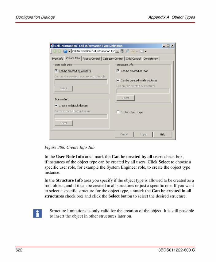
Configuration Dialogs Appendix A Object Types
622 3BDS011222-600 C
In the User Role Info area, mark the Can be created by all users check box, if instances of the object type can be created by all users. Click Select to choose a specific user role, for example the System Engineer role, to create the object type instance.
In the Structure Info area you specify if the object type is allowed to be created as a root object, and if it can be created in all structures or just a specific one. If you want to select a specific structure for the object type, unmark the Can be created in all structures check box and click the Select button to select the desired structure.
Figure 388. Create Info Tab
Structure limitations is only valid for the creation of the object. It is still possible to insert the object in other structures later on.
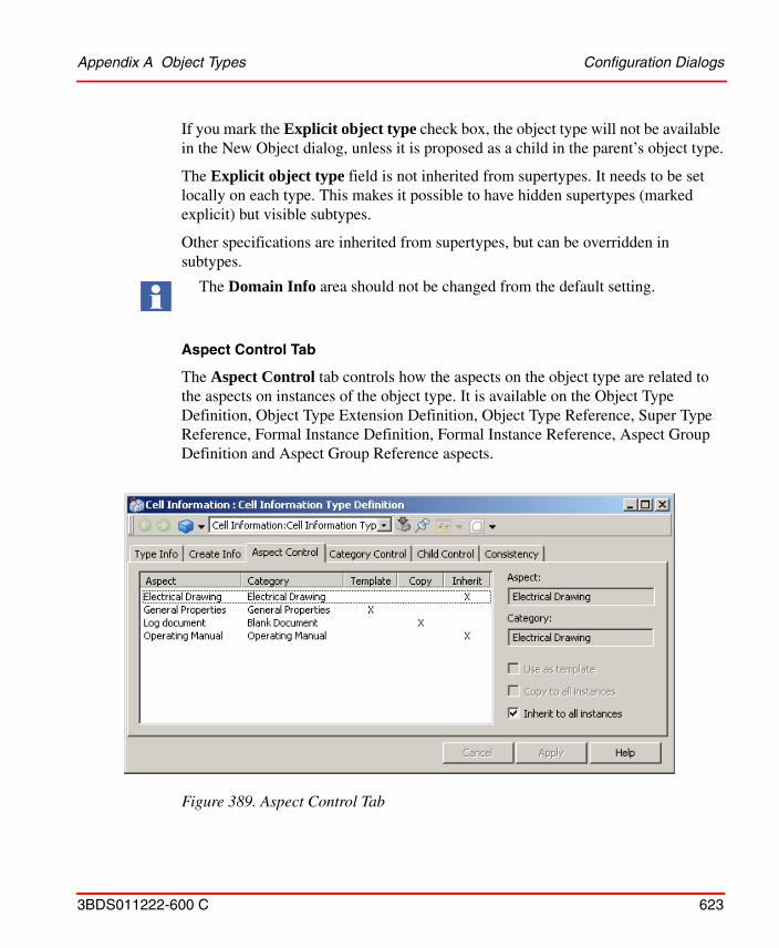
Appendix A Object Types Configuration Dialogs
3BDS011222-600 C 623
If you mark the Explicit object type check box, the object type will not be available in the New Object dialog, unless it is proposed as a child in the parent’s object type.
The Explicit object type field is not inherited from supertypes. It needs to be set locally on each type. This makes it possible to have hidden supertypes (marked explicit) but visible subtypes.
Other specifications are inherited from supertypes, but can be overridden in subtypes.
Aspect Control Tab
The Aspect Control tab controls how the aspects on the object type are related to the aspects on instances of the object type. It is available on the Object Type Definition, Object Type Extension Definition, Object Type Reference, Super Type Reference, Formal Instance Definition, Formal Instance Reference, Aspect Group Definition and Aspect Group Reference aspects.
The Domain Info area should not be changed from the default setting.
Figure 389. Aspect Control Tab
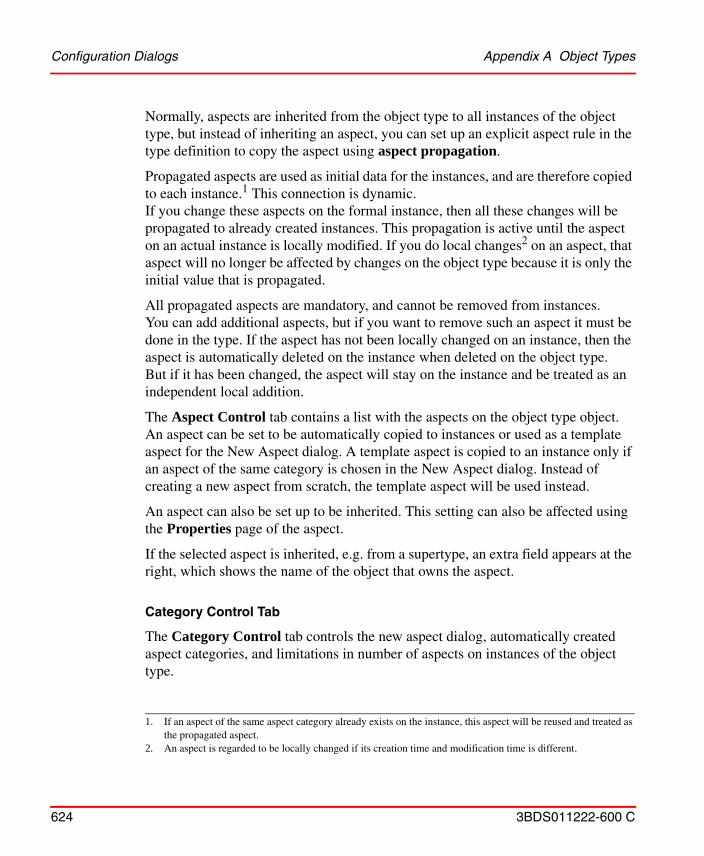
Configuration Dialogs Appendix A Object Types
624 3BDS011222-600 C
Normally, aspects are inherited from the object type to all instances of the object type, but instead of inheriting an aspect, you can set up an explicit aspect rule in the type definition to copy the aspect using aspect propagation.
Propagated aspects are used as initial data for the instances, and are therefore copied to each instance.1 This connection is dynamic.If you change these aspects on the formal instance, then all these changes will be propagated to already created instances. This propagation is active until the aspect on an actual instance is locally modified. If you do local changes2 on an aspect, that aspect will no longer be affected by changes on the object type because it is only the initial value that is propagated.
All propagated aspects are mandatory, and cannot be removed from instances. You can add additional aspects, but if you want to remove such an aspect it must be done in the type. If the aspect has not been locally changed on an instance, then the aspect is automatically deleted on the instance when deleted on the object type. But if it has been changed, the aspect will stay on the instance and be treated as an independent local addition.
The Aspect Control tab contains a list with the aspects on the object type object. An aspect can be set to be automatically copied to instances or used as a template aspect for the New Aspect dialog. A template aspect is copied to an instance only if an aspect of the same category is chosen in the New Aspect dialog. Instead of creating a new aspect from scratch, the template aspect will be used instead.
An aspect can also be set up to be inherited. This setting can also be affected using the Properties page of the aspect.
If the selected aspect is inherited, e.g. from a supertype, an extra field appears at the right, which shows the name of the object that owns the aspect.
Category Control Tab
The Category Control tab controls the new aspect dialog, automatically created aspect categories, and limitations in number of aspects on instances of the object type.
1. If an aspect of the same aspect category already exists on the instance, this aspect will be reused and treated as the propagated aspect.
2. An aspect is regarded to be locally changed if its creation time and modification time is different.
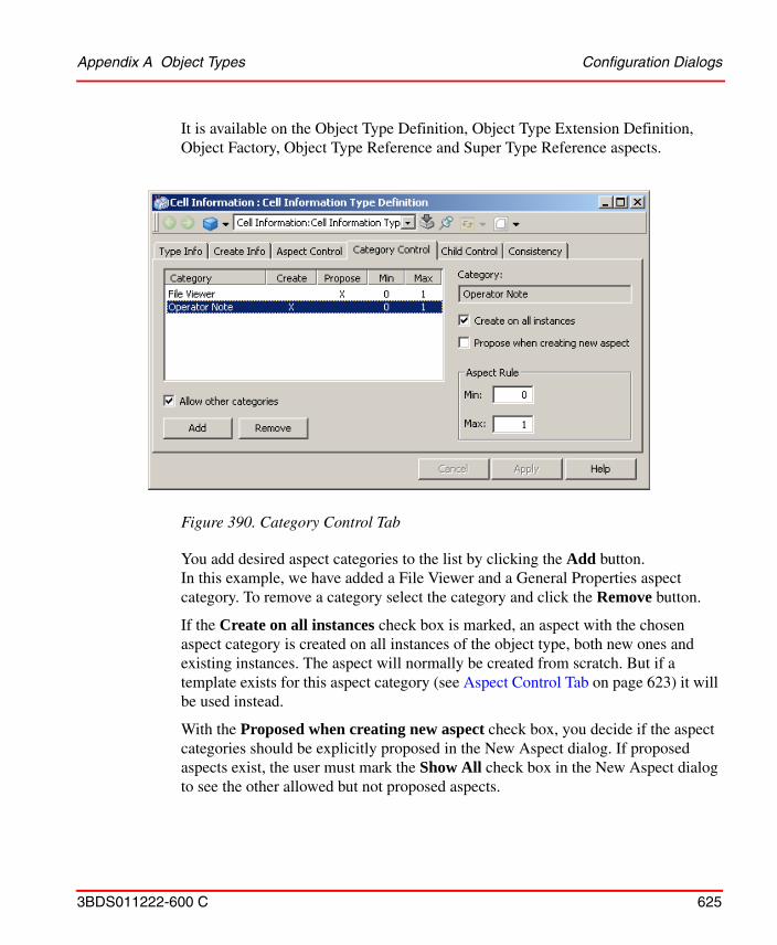
Appendix A Object Types Configuration Dialogs
3BDS011222-600 C 625
It is available on the Object Type Definition, Object Type Extension Definition, Object Factory, Object Type Reference and Super Type Reference aspects.
You add desired aspect categories to the list by clicking the Add button. In this example, we have added a File Viewer and a General Properties aspect category. To remove a category select the category and click the Remove button.
If the Create on all instances check box is marked, an aspect with the chosen aspect category is created on all instances of the object type, both new ones and existing instances. The aspect will normally be created from scratch. But if a template exists for this aspect category (see Aspect Control Tab on page 623) it will be used instead.
With the Proposed when creating new aspect check box, you decide if the aspect categories should be explicitly proposed in the New Aspect dialog. If proposed aspects exist, the user must mark the Show All check box in the New Aspect dialog to see the other allowed but not proposed aspects.
Figure 390. Category Control Tab
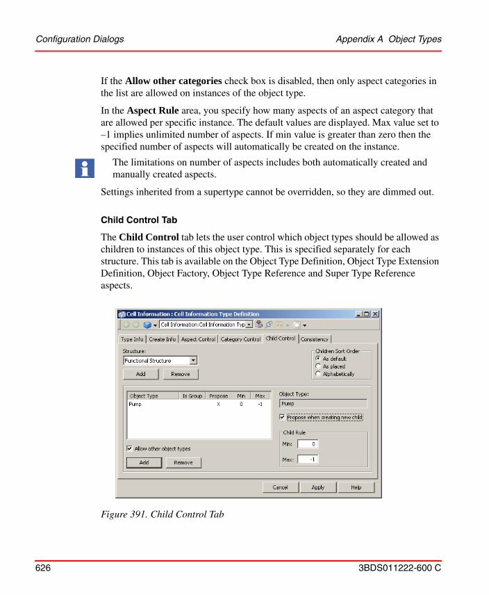
Configuration Dialogs Appendix A Object Types
626 3BDS011222-600 C
If the Allow other categories check box is disabled, then only aspect categories in the list are allowed on instances of the object type.
In the Aspect Rule area, you specify how many aspects of an aspect category that are allowed per specific instance. The default values are displayed. Max value set to –1 implies unlimited number of aspects. If min value is greater than zero then the specified number of aspects will automatically be created on the instance.
Settings inherited from a supertype cannot be overridden, so they are dimmed out.
Child Control Tab
The Child Control tab lets the user control which object types should be allowed as children to instances of this object type. This is specified separately for each structure. This tab is available on the Object Type Definition, Object Type Extension Definition, Object Factory, Object Type Reference and Super Type Reference aspects.
The limitations on number of aspects includes both automatically created and manually created aspects.
Figure 391. Child Control Tab
Appendix A Object Types Configuration Dialogs
3BDS011222-600 C 627
To add settings for a structure, click the Add button below the Structure drop-down menu. In our example Functional Structure has been added. The list in the tab contains object types that have some settings for the specified structure. Use the Add button below the list to add an object type. In our example a Pump object type is added.
Use the Propose when creating new child check box, to set the object type (or object types in the group), to be explicitly proposed to a user in the New Object dialog. If proposed object types exist, the user must mark the Show All check box in the New Object dialog to see the other allowed but not proposed object types.
In the Child Rule area you determine how many child objects of the object type (or object types in the group), there can be for instances of the object type. If the max value is set to –1, the number of child objects are unlimited. If the min value is greater than zero, then this number of child objects will automatically be created below the instances.
The Allow other object types setting is for the specified structure. It determines whether child objects of any object type are allowed for the instances, or if only the types in the list are allowed.
When the Is Group column is marked (x), the added object type is in fact an object type group. The result will be that settings will be done for all object types in the group, see Figure 392.
Configuration Dialogs Appendix A Object Types
628 3BDS011222-600 C
In the Child Sort Order area, you specify how the children created under this object type should be sorted. By default, the As Default radio button is selected. This means that the configuration set up for the Plant Explorer is used as sort order.
Rules inherited from a supertype can only be overridden if they have the default values, otherwise they are dimmed out.
If a setting is inherited from a supertype and it refers to an object type that has subtypes, then a Reduce button appears. When you click on that button you get a dialog box where you can reduce the proposed object type to a subset of the available subtypes.
To specify the allowed and proposed object types at the top of a structure, an Object Factory aspect (and possibly additional Object Type Extension Definition aspects) can be placed on the aspect category object of the structure. The Child Control settings will in this case apply to the top level of the structure.
Figure 392. Select Group of Object Types
Appendix A Object Types Configuration Dialogs
3BDS011222-600 C 629
Composite Info Tab
The Object Type Reference aspect of a composite instance has an additional tab, the Composite Info tab that shows the embedded instances of the composite instance.
Consistency Tab
The Consistency tab is used to activate consistency checking and correction on one specific object type or object type instance. If the object is composite, the children will be checked as well.
This tab is available on the Object Type Definition, Object Type Extension Definition, Object Factory, Object Type Reference, Super Type Reference, Formal Instance Definition and Formal Instance Reference aspects.
Figure 393. Composite Info Tab
Configuration Dialogs Appendix A Object Types
630 3BDS011222-600 C
The consistency checking is the same as performed by the Consistency Checker aspect, except that only the aspects belonging to the Object Types aspect system will be checked here. The consistency of user-added aspects will not be checked.
The Try to Repair button is activated if inconsistencies are detected during a consistency check. If you press it the inconsistency may, if possible, be removed. It is recommended to make a backup before using the repair function.
Figure 394. Consistency Tab
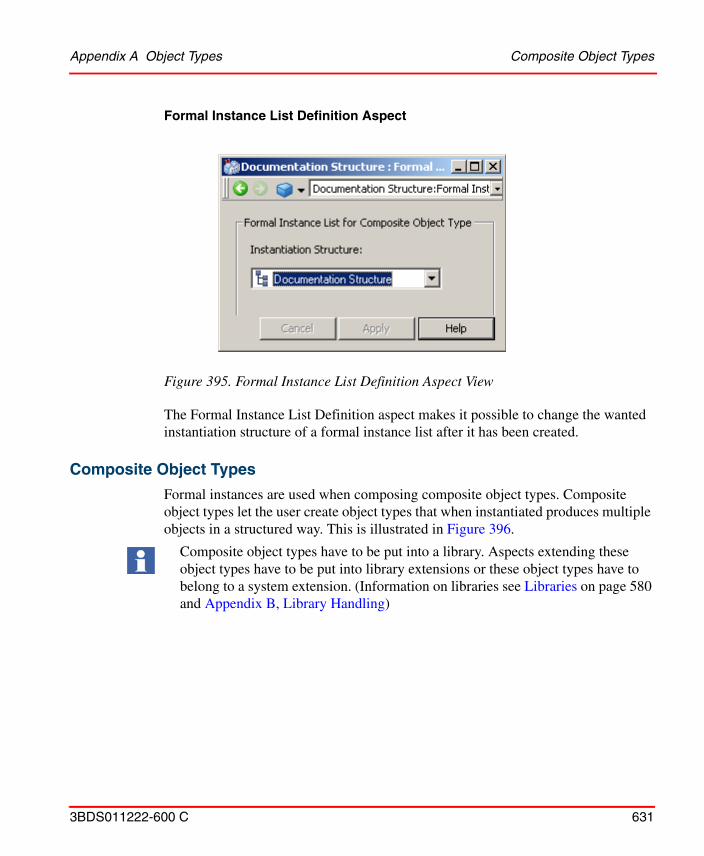
Appendix A Object Types Composite Object Types
3BDS011222-600 C 631
Formal Instance List Definition Aspect
The Formal Instance List Definition aspect makes it possible to change the wanted instantiation structure of a formal instance list after it has been created.
Composite Object Types
Formal instances are used when composing composite object types. Composite object types let the user create object types that when instantiated produces multiple objects in a structured way. This is illustrated in Figure 396.
Figure 395. Formal Instance List Definition Aspect View
Composite object types have to be put into a library. Aspects extending these object types have to be put into library extensions or these object types have to belong to a system extension. (Information on libraries see Libraries on page 580 and Appendix B, Library Handling)
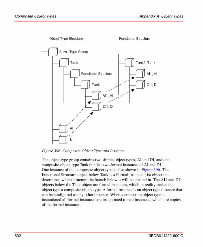
Composite Object Types Appendix A Object Types
632 3BDS011222-600 C
The object type group contains two simple object types, AI and DI, and one composite object type Tank that has two formal instances of AI and DI. One instance of the composite object type is also shown in Figure 396. The Functional Structure object below Tank is a Formal Instance List object that determines which structure the branch below it will be created in. The AI1 and DI1 objects below the Tank object are formal instances, which in reality makes the object type a composite object type. A formal instance is an object type instance that can be configured as any other instance. When a composite object type is instantiated all formal instances are instantiated to real instances, which are copies of the formal instances.
Figure 396. Composite Object Type and Instance
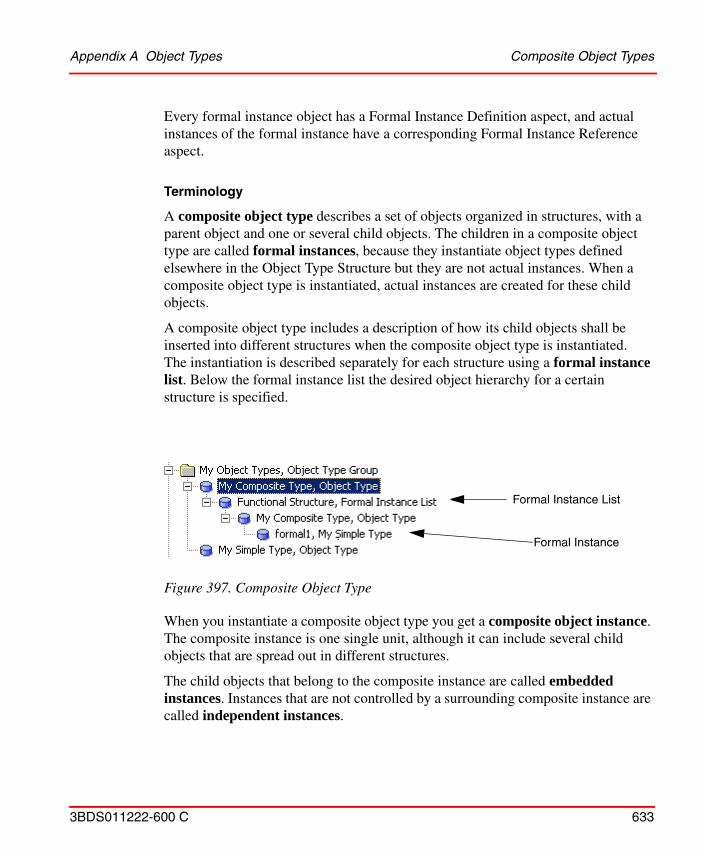
Appendix A Object Types Composite Object Types
3BDS011222-600 C 633
Every formal instance object has a Formal Instance Definition aspect, and actual instances of the formal instance have a corresponding Formal Instance Reference aspect.
Terminology
A composite object type describes a set of objects organized in structures, with a parent object and one or several child objects. The children in a composite object type are called formal instances, because they instantiate object types defined elsewhere in the Object Type Structure but they are not actual instances. When a composite object type is instantiated, actual instances are created for these child objects.
A composite object type includes a description of how its child objects shall be inserted into different structures when the composite object type is instantiated. The instantiation is described separately for each structure using a formal instance list. Below the formal instance list the desired object hierarchy for a certain structure is specified.
When you instantiate a composite object type you get a composite object instance. The composite instance is one single unit, although it can include several child objects that are spread out in different structures.
The child objects that belong to the composite instance are called embedded instances. Instances that are not controlled by a surrounding composite instance are called independent instances.
Figure 397. Composite Object Type
Formal Instance List
Formal Instance
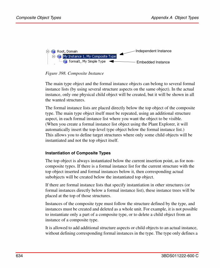
Composite Object Types Appendix A Object Types
634 3BDS011222-600 C
The main type object and the formal instance objects can belong to several formal instance lists (by using several structure aspects on the same object). In the actual instance, only one physical child object will be created, but it will be shown in all the wanted structures.
The formal instance lists are placed directly below the top object of the composite type. The main type object itself must be repeated, using an additional structure aspect, in each formal instance list where you want the object to be visible. (When you create a formal instance list object using the Plant Explorer, it will automatically insert the top-level type object below the formal instance list.) This allows you to define target structures where only some child objects will be instantiated and not the top object itself.
Instantiation of Composite Types
The top object is always instantiated below the current insertion point, as for non-composite types. If there is a formal instance list for the current structure with the top object inserted and formal instances below it, then corresponding actual subobjects will be created below the instantiated top object.
If there are formal instance lists that specify instantiation in other structures (or formal instances directly below a formal instance list), these instance trees will be placed at the top of those structures.
Instances of the composite type must follow the structure defined by the type, and instances must be created and deleted as a whole unit. For example, it is not possible to instantiate only a part of a composite type, or to delete a child object from an instance of a composite type.
It is allowed to add additional structure aspects or child objects to an actual instance, without defining corresponding formal instances in the type. The type only defines a
Figure 398. Composite Instance
Independent Instance
Embedded Instance
Appendix A Object Types Composite Object Types
3BDS011222-600 C 635
minimum structure for the instance, not the complete structure. The minimum structure can be extended in each instance, but not reduced.
In the same way, it is allowed to create additional subobjects below any formal instance. They will be treated as normal formal instances, and be propagated to the actual instances.
The formal instances themselves can also be of composite types, and they must follow the same restrictions as actual instances. The types rules are here interpreted in the context of the structure specified by the formal instance list, and not the Object Type Structure.
Structure Propagation
When you make type changes they take effect immediately. You can add or remove formal instances, and already instantiated objects of the composite type will directly be updated accordingly.
When a structure aspect is deleted below a formal instance list, the change is always propagated to all corresponding embedded instances. If a formal instance is removed completely from the type, all corresponding embedded instances will be deleted as well. However, this delete operation will be made using the Obsolete Handling functionality, which saves the deleted aspect in an import/export file and stores the file using File Set Distribution. This makes it possible to retrieve deleted aspects and place them on some other object.
To retrieve an obsolete-handled aspect, go to the Obsolete Structure and expand the object named with the current date. Below it you find objects representing obsolete-handled delete operations. Select the object with the name “Formal Instance Delete” and the time for the operation, e.g. “14:55:33”. Open its Obsolete Objects aspect, and click on the Open import/export file button. This will open the Import/Export tool with the wanted file, where you can drag wanted aspects back to the system.
Aspect Propagation
The aspects on the formal instances are configured using the Aspect Control tab of the Formal Instance Definition aspect, in the same way as aspects on the top-level object of the composite type are configured in the Object Type Definition aspect.
Creating an Object Icon Aspect Appendix A Object Types
636 3BDS011222-600 C
The only difference is that the Copy to all instances check box is marked by default for formal instances, and not the Inherit to all instances check box. But aspect propagation can be disabled, or replaced with inheritance, using the Aspect Control tab.
If the formal instance itself is an instance of an object type, that object type defines the initial set of aspects for the formal instance. These aspects can then be modified, and new aspects can be added.
Relative References in Composite Types
To make the composite object type really useful you want to do as much aspect configuration as possible on the object type. For example, you may want to add a Graphic Element aspect on the main type object that either presents data retrieved from its child objects or incorporates subordinate Graphic Elements that already exist on the child objects.
To be able to reference the child objects correctly in all composite instances, we use relative references. All formal instances have a Relative Name aspect that is inherited to the corresponding embedded objects in the actual instances. The embedded objects also have a local Name aspect that initially gets the same value, but it can be changed by the user to an instance-specific name. Using the inherited and fixed relative names, an embedded object can still be identified using a relative name path consisting of a series of relative names.
Note that the Graphics Builder automatically inserts such relative references when you create a graphics aspect on an object type.
Creating an Object Icon Aspect
If you create a new object type, you are also able to select its object icon. The object icon will be displayed in the object browser in Plant Explorer.
Follow the steps below to add an Object Icon aspect:
1. Add a new Object Icon aspect to the object type.
2. Right-click on the Object Icon aspect and select the Config View.
In this document we do not describe how you create icons using one of the many possible graphical editors, we just describe how you use an available icon.
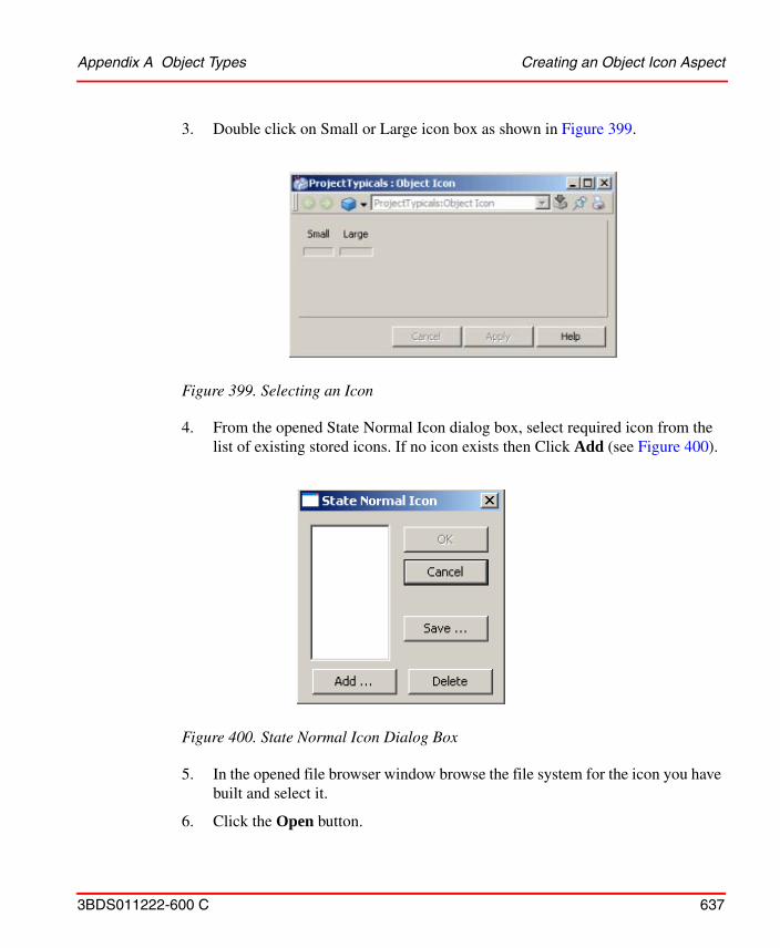
Appendix A Object Types Creating an Object Icon Aspect
3BDS011222-600 C 637
3. Double click on Small or Large icon box as shown in Figure 399.
4. From the opened State Normal Icon dialog box, select required icon from the list of existing stored icons. If no icon exists then Click Add (see Figure 400).
5. In the opened file browser window browse the file system for the icon you have built and select it.
6. Click the Open button.
Figure 399. Selecting an Icon
Figure 400. State Normal Icon Dialog Box
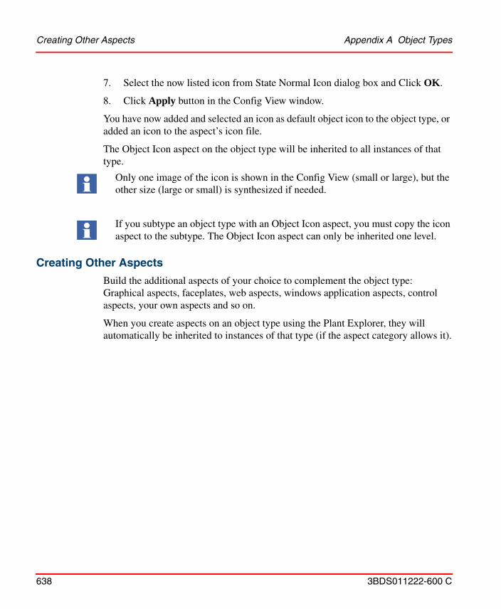
Creating Other Aspects Appendix A Object Types
638 3BDS011222-600 C
7. Select the now listed icon from State Normal Icon dialog box and Click OK.
8. Click Apply button in the Config View window.
You have now added and selected an icon as default object icon to the object type, or added an icon to the aspect’s icon file.
The Object Icon aspect on the object type will be inherited to all instances of that type.
Creating Other Aspects
Build the additional aspects of your choice to complement the object type: Graphical aspects, faceplates, web aspects, windows application aspects, control aspects, your own aspects and so on.
When you create aspects on an object type using the Plant Explorer, they will automatically be inherited to instances of that type (if the aspect category allows it).
Only one image of the icon is shown in the Config View (small or large), but the other size (large or small) is synthesized if needed.
If you subtype an object type with an Object Icon aspect, you must copy the icon aspect to the subtype. The Object Icon aspect can only be inherited one level.
3BDS011222-600 C 639
Appendix B Library Handling
System 800xA supports development, distribution and management of versioned libraries.
Libraries are important entities in the 800xA system. They structure the information in the Object Type Structure into higher-level version-controlled units, and define the building blocks that are used to build the applications that the 800xA system is designed to support.
Libraries in 800xA are used to support the library concept in Control Builder M, but they can also be used for general purposes.
Libraries are distribution units that support version handling and controlled upgrades, i.e. changing an application from using one version of a library to another. A library also keeps a history record and various properties that describe the library and how it can be used (owner, supporting organization and so on).
Two basic types of libraries exist, Base Libraries (often simply called libraries) and Extension Libraries.
For more conceptual information on library handling refer to System 800xA, System Planning (3BSE041389*).
Base Libraries
Creating a New Base Library
From Plant Explorer
To create a new base library from Plant Explorer follow the steps below:
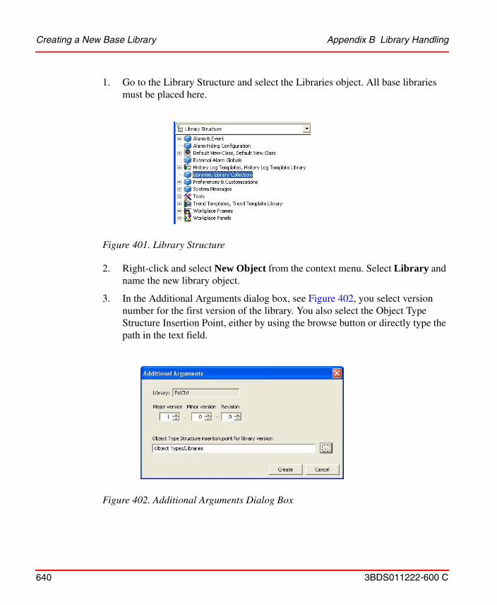
Creating a New Base Library Appendix B Library Handling
640 3BDS011222-600 C
1. Go to the Library Structure and select the Libraries object. All base libraries must be placed here.
2. Right-click and select New Object from the context menu. Select Library and name the new library object.
3. In the Additional Arguments dialog box, see Figure 402, you select version number for the first version of the library. You also select the Object Type Structure Insertion Point, either by using the browse button or directly type the path in the text field.
Figure 401. Library Structure
Figure 402. Additional Arguments Dialog Box
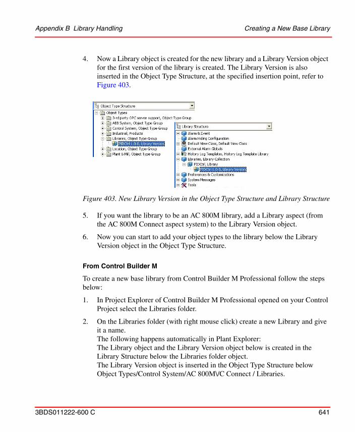
Appendix B Library Handling Creating a New Base Library
3BDS011222-600 C 641
4. Now a Library object is created for the new library and a Library Version object for the first version of the library is created. The Library Version is also inserted in the Object Type Structure, at the specified insertion point, refer to Figure 403.
5. If you want the library to be an AC 800M library, add a Library aspect (from the AC 800M Connect aspect system) to the Library Version object.
6. Now you can start to add your object types to the library below the Library Version object in the Object Type Structure.
From Control Builder M
To create a new base library from Control Builder M Professional follow the steps below:
1. In Project Explorer of Control Builder M Professional opened on your Control Project select the Libraries folder.
2. On the Libraries folder (with right mouse click) create a new Library and give it a name. The following happens automatically in Plant Explorer:The Library object and the Library Version object below is created in the Library Structure below the Libraries folder object.The Library Version object is inserted in the Object Type Structure below Object Types/Control System/AC 800M\/C Connect / Libraries.
Figure 403. New Library Version in the Object Type Structure and Library Structure
Creating a New Base Library Appendix B Library Handling
642 3BDS011222-600 C
Below the Library Version object, the folder objects Control Module Types, Data Types, Function Block Types, Diagram Types, and Internal Types are created.
3. Now you can start to add your object types to the library.
Adding Data to a Base Library Version
A base library can contain object type groups, object types and aspect groups. How to add objects and aspects is described below.
Adding Objects
When an object is created beneath the Library Version object in the Object Type Structure, the new object is always assigned to the base library if the library is open.
The same applies when a complete object (or-sub-tree of objects) is moved or copied into a base library. Both the object and its aspects are assigned to the base library.
If an object is moved or copied out from a library, the assignments will be removed. If it is placed inside another library, everything will be assigned to that library.
If a complete object (or sub-tree) is moved or copied within a base library, all existing aspects will keep their current assignment. But if an aspect belongs to a non-open extension library, a move will be aborted because the location of the aspect is part of the extension library. If an aspect of the non-open extension library is copied, the operation will succeed but the library assignment on the aspect will be removed.
Adding Aspects
If an aspect is created by using the New Aspect dialog box, you can choose to assign it to a base library or (if available) an extension library if the library is open. It s also possible to not assign the aspect to any library.
When an aspect is created by copy/paste within the same base library the following applies:

Appendix B Library Handling Creating a New Base Library
3BDS011222-600 C 643
– If the source aspect belongs to the base library, the target aspect is assigned to the same base library if the source object and the target object belong to the same open base library.
– If the source aspect belongs to an extension library, the target aspect is assigned to the same extension library if the source object and the target object belong to the same base library, and the extension library is open.
When an aspect is copied from one library to another the following applies:
If the source aspect belongs to a base library, the target aspect is assigned to the other base library that owns the target object.
In all other cases, a copied aspect will be unassigned on the target object.
The library assignments can be adjusted afterwards by using the Aspects Tab.
Generating a Library Archive
The Export Library button below the General tab of the Library Version Definition Aspect is used for generating archives. It automatically generates an import/export file which contains the objects and aspects belonging to the library.
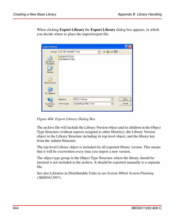
Creating a New Base Library Appendix B Library Handling
644 3BDS011222-600 C
When clicking Export Library the Export Library dialog box appears, in which you decide where to place the import/export file.
The archive file will include the Library Version object and its children in the Object Type Structure (without aspects assigned to other libraries), the Library Version object in the Library Structure including its top-level object, and the library key from the Admin Structure.
The top-level Library object is included for all exported library version. This means that it will be overwritten every time you import a new version.
The object type group in the Object Type Structure where the library should be inserted is not included in the archive. It should be exported manually to a separate file.
See also Libraries as Distributable Units in see System 800xA System Planning (3BSE041389*).
Figure 404. Export Library Dialog Box
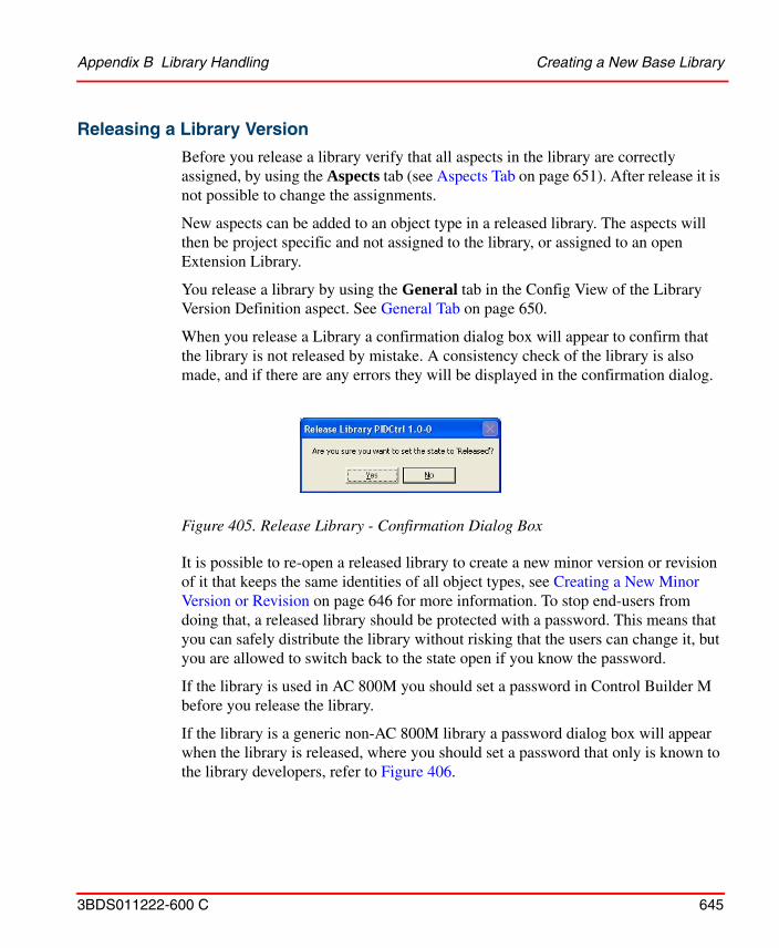
Appendix B Library Handling Creating a New Base Library
3BDS011222-600 C 645
Releasing a Library Version
Before you release a library verify that all aspects in the library are correctly assigned, by using the Aspects tab (see Aspects Tab on page 651). After release it is not possible to change the assignments.
New aspects can be added to an object type in a released library. The aspects will then be project specific and not assigned to the library, or assigned to an open Extension Library.
You release a library by using the General tab in the Config View of the Library Version Definition aspect. See General Tab on page 650.
When you release a Library a confirmation dialog box will appear to confirm that the library is not released by mistake. A consistency check of the library is also made, and if there are any errors they will be displayed in the confirmation dialog.
It is possible to re-open a released library to create a new minor version or revision of it that keeps the same identities of all object types, see Creating a New Minor Version or Revision on page 646 for more information. To stop end-users from doing that, a released library should be protected with a password. This means that you can safely distribute the library without risking that the users can change it, but you are allowed to switch back to the state open if you know the password.
If the library is used in AC 800M you should set a password in Control Builder M before you release the library.
If the library is a generic non-AC 800M library a password dialog box will appear when the library is released, where you should set a password that only is known to the library developers, refer to Figure 406.
Figure 405. Release Library - Confirmation Dialog Box
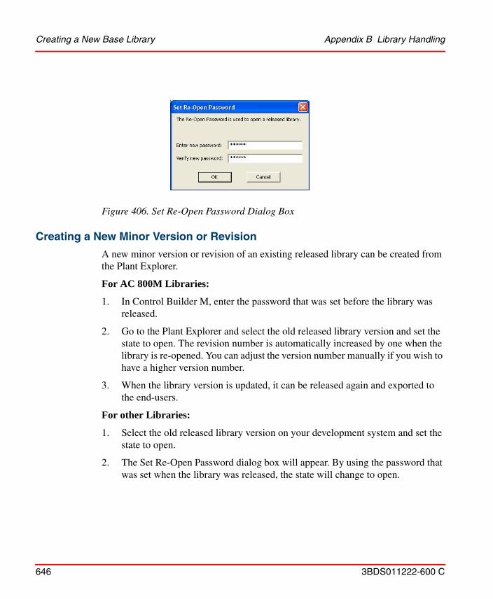
Creating a New Base Library Appendix B Library Handling
646 3BDS011222-600 C
Creating a New Minor Version or Revision
A new minor version or revision of an existing released library can be created from the Plant Explorer.
For AC 800M Libraries:
1. In Control Builder M, enter the password that was set before the library was released.
2. Go to the Plant Explorer and select the old released library version and set the state to open. The revision number is automatically increased by one when the library is re-opened. You can adjust the version number manually if you wish to have a higher version number.
3. When the library version is updated, it can be released again and exported to the end-users.
For other Libraries:
1. Select the old released library version on your development system and set the state to open.
2. The Set Re-Open Password dialog box will appear. By using the password that was set when the library was released, the state will change to open.
Figure 406. Set Re-Open Password Dialog Box
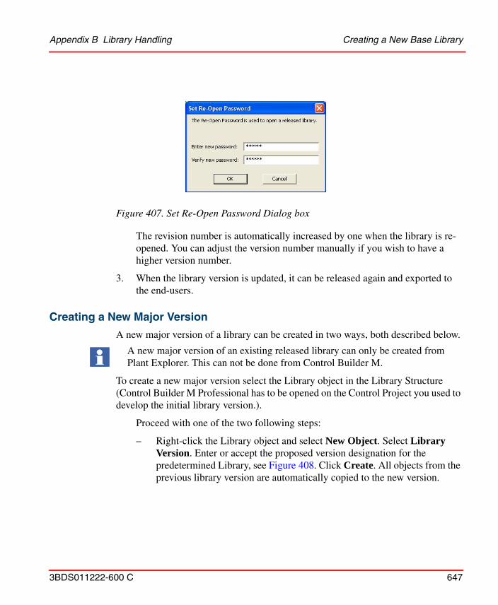
Appendix B Library Handling Creating a New Base Library
3BDS011222-600 C 647
The revision number is automatically increased by one when the library is re-opened. You can adjust the version number manually if you wish to have a higher version number.
3. When the library version is updated, it can be released again and exported to the end-users.
Creating a New Major Version
A new major version of a library can be created in two ways, both described below.
To create a new major version select the Library object in the Library Structure (Control Builder M Professional has to be opened on the Control Project you used to develop the initial library version.).
Proceed with one of the two following steps:
– Right-click the Library object and select New Object. Select Library Version. Enter or accept the proposed version designation for the predetermined Library, see Figure 408. Click Create. All objects from the previous library version are automatically copied to the new version.
Figure 407. Set Re-Open Password Dialog box
A new major version of an existing released library can only be created from Plant Explorer. This can not be done from Control Builder M.
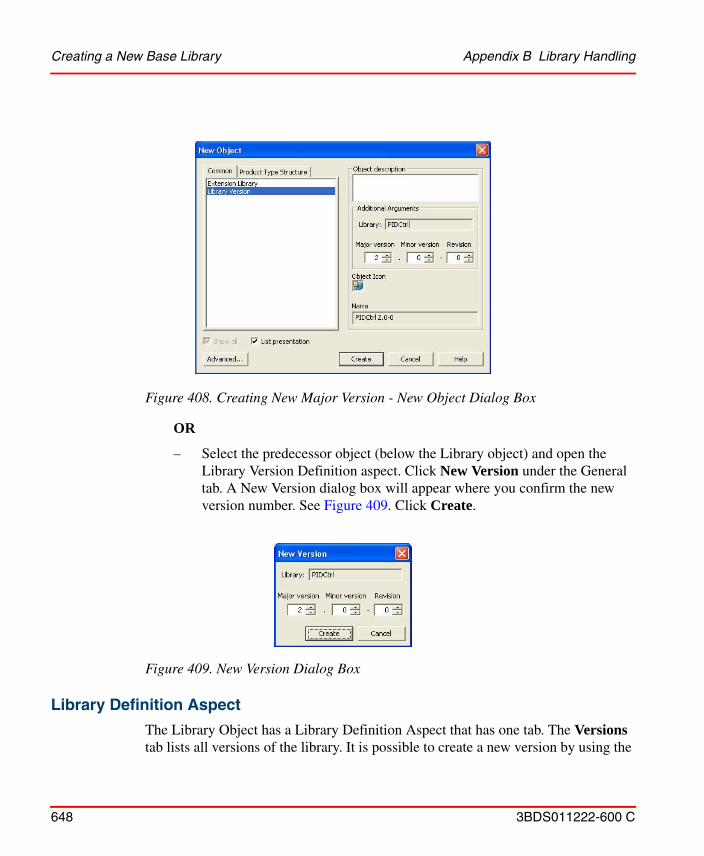
Creating a New Base Library Appendix B Library Handling
648 3BDS011222-600 C
OR
– Select the predecessor object (below the Library object) and open the Library Version Definition aspect. Click New Version under the General tab. A New Version dialog box will appear where you confirm the new version number. See Figure 409. Click Create.
Library Definition Aspect
The Library Object has a Library Definition Aspect that has one tab. The Versions tab lists all versions of the library. It is possible to create a new version by using the
Figure 408. Creating New Major Version - New Object Dialog Box
Figure 409. New Version Dialog Box

Appendix B Library Handling Creating a New Base Library
3BDS011222-600 C 649
New Version button. You also have the possibility to change the insertion point, in the Object Type Structure, for future versions of the library.
Library Version Definition Aspect
Each Library Version object has a Library Version Definition aspect. This aspect manages the version of the base library object and the objects and aspects that belong to the base library version. The aspect has six tabs, which are described below.
• General Tab - Is used for basic management of the library version.
• History Tab - Contain information about the history of the version.
• Dependencies Tab - Shows information about dependencies to other libraries and system extensions.
• Aspects Tab - Manages the aspects in the library.
• Library Usage Tab - A tool for searching instances of the library types, and upgrading or downgrading instances from one library version to another.
• Consistency Tab - Used for checking consistency in the library.
Figure 410. Library Definition Aspect
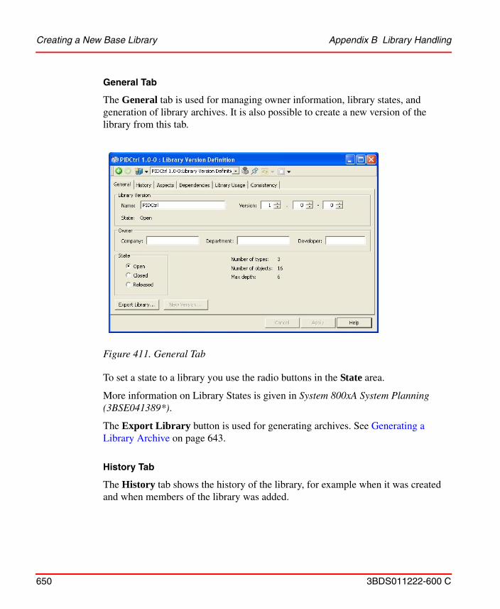
Creating a New Base Library Appendix B Library Handling
650 3BDS011222-600 C
General Tab
The General tab is used for managing owner information, library states, and generation of library archives. It is also possible to create a new version of the library from this tab.
To set a state to a library you use the radio buttons in the State area.
More information on Library States is given in System 800xA System Planning (3BSE041389*).
The Export Library button is used for generating archives. See Generating a Library Archive on page 643.
History Tab
The History tab shows the history of the library, for example when it was created and when members of the library was added.
Figure 411. General Tab
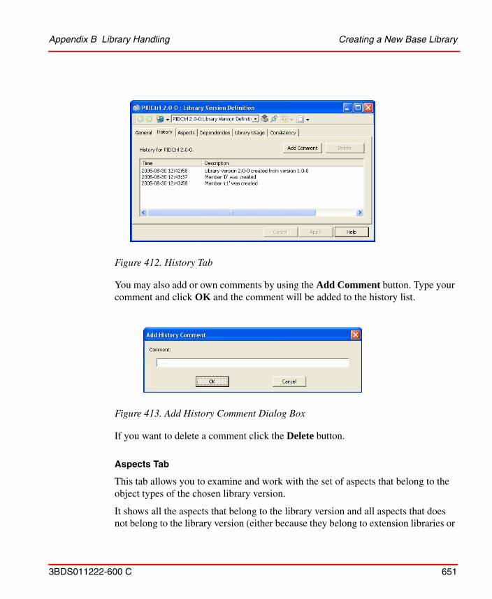
Appendix B Library Handling Creating a New Base Library
3BDS011222-600 C 651
You may also add or own comments by using the Add Comment button. Type your comment and click OK and the comment will be added to the history list.
If you want to delete a comment click the Delete button.
Aspects Tab
This tab allows you to examine and work with the set of aspects that belong to the object types of the chosen library version.
It shows all the aspects that belong to the library version and all aspects that does not belong to the library version (either because they belong to extension libraries or
Figure 412. History Tab
Figure 413. Add History Comment Dialog Box
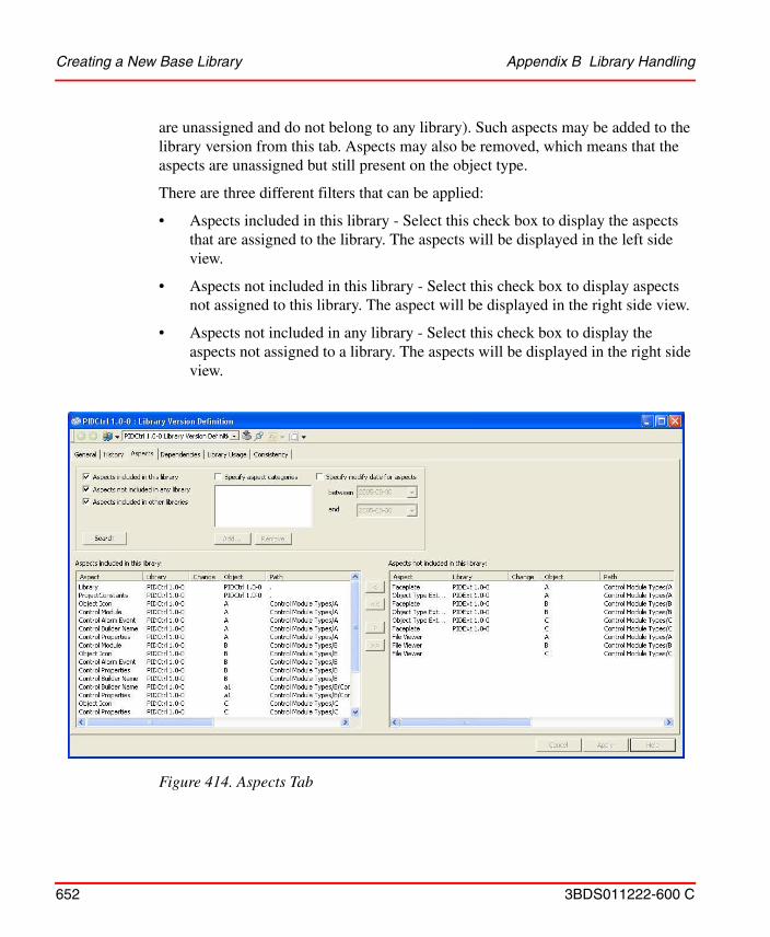
Creating a New Base Library Appendix B Library Handling
652 3BDS011222-600 C
are unassigned and do not belong to any library). Such aspects may be added to the library version from this tab. Aspects may also be removed, which means that the aspects are unassigned but still present on the object type.
There are three different filters that can be applied:
• Aspects included in this library - Select this check box to display the aspects that are assigned to the library. The aspects will be displayed in the left side view.
• Aspects not included in this library - Select this check box to display aspects not assigned to this library. The aspect will be displayed in the right side view.
• Aspects not included in any library - Select this check box to display the aspects not assigned to a library. The aspects will be displayed in the right side view.
Figure 414. Aspects Tab
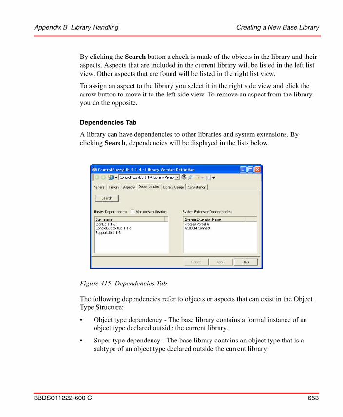
Appendix B Library Handling Creating a New Base Library
3BDS011222-600 C 653
By clicking the Search button a check is made of the objects in the library and their aspects. Aspects that are included in the current library will be listed in the left list view. Other aspects that are found will be listed in the right list view.
To assign an aspect to the library you select it in the right side view and click the arrow button to move it to the left side view. To remove an aspect from the library you do the opposite.
Dependencies Tab
A library can have dependencies to other libraries and system extensions. By clicking Search, dependencies will be displayed in the lists below.
The following dependencies refer to objects or aspects that can exist in the Object Type Structure:
• Object type dependency - The base library contains a formal instance of an object type declared outside the current library.
• Super-type dependency - The base library contains an object type that is a subtype of an object type declared outside the current library.
Figure 415. Dependencies Tab
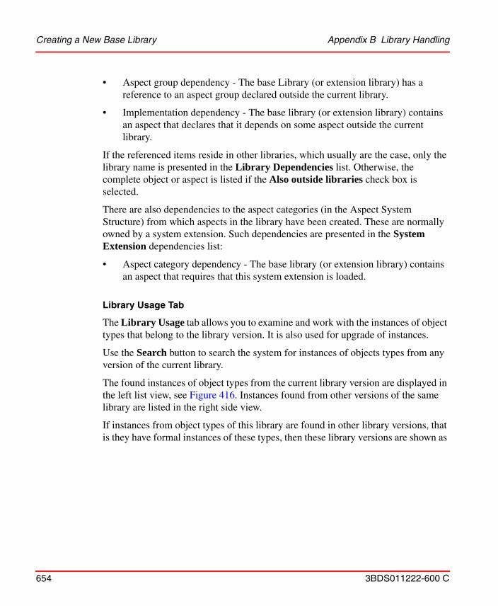
Creating a New Base Library Appendix B Library Handling
654 3BDS011222-600 C
• Aspect group dependency - The base Library (or extension library) has a reference to an aspect group declared outside the current library.
• Implementation dependency - The base library (or extension library) contains an aspect that declares that it depends on some aspect outside the current library.
If the referenced items reside in other libraries, which usually are the case, only the library name is presented in the Library Dependencies list. Otherwise, the complete object or aspect is listed if the Also outside libraries check box is selected.
There are also dependencies to the aspect categories (in the Aspect System Structure) from which aspects in the library have been created. These are normally owned by a system extension. Such dependencies are presented in the System Extension dependencies list:
• Aspect category dependency - The base library (or extension library) contains an aspect that requires that this system extension is loaded.
Library Usage Tab
The Library Usage tab allows you to examine and work with the instances of object types that belong to the library version. It is also used for upgrade of instances.
Use the Search button to search the system for instances of objects types from any version of the current library.
The found instances of object types from the current library version are displayed in the left list view, see Figure 416. Instances found from other versions of the same library are listed in the right side view.
If instances from object types of this library are found in other library versions, that is they have formal instances of these types, then these library versions are shown as
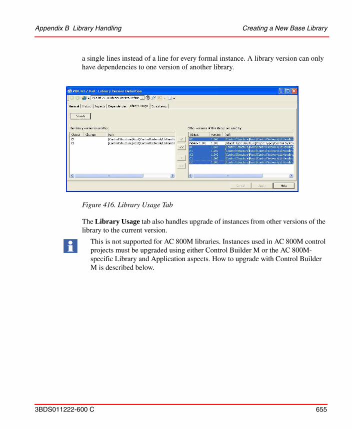
Appendix B Library Handling Creating a New Base Library
3BDS011222-600 C 655
a single lines instead of a line for every formal instance. A library version can only have dependencies to one version of another library.
The Library Usage tab also handles upgrade of instances from other versions of the library to the current version.
Figure 416. Library Usage Tab
This is not supported for AC 800M libraries. Instances used in AC 800M control projects must be upgraded using either Control Builder M or the AC 800M-specific Library and Application aspects. How to upgrade with Control Builder M is described below.
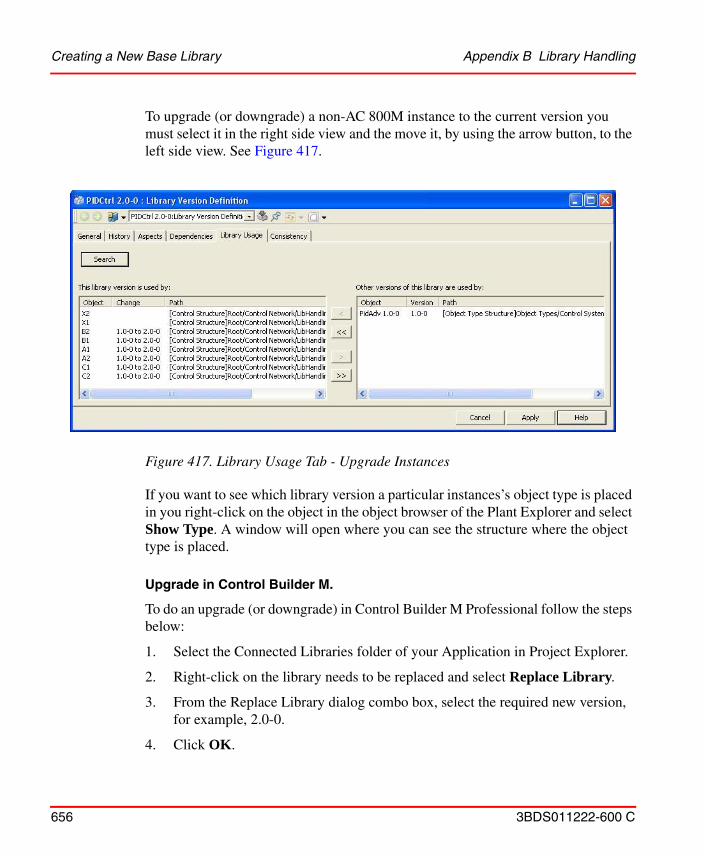
Creating a New Base Library Appendix B Library Handling
656 3BDS011222-600 C
To upgrade (or downgrade) a non-AC 800M instance to the current version you must select it in the right side view and the move it, by using the arrow button, to the left side view. See Figure 417.
If you want to see which library version a particular instances’s object type is placed in you right-click on the object in the object browser of the Plant Explorer and select Show Type. A window will open where you can see the structure where the object type is placed.
Upgrade in Control Builder M.
To do an upgrade (or downgrade) in Control Builder M Professional follow the steps below:
1. Select the Connected Libraries folder of your Application in Project Explorer.
2. Right-click on the library needs to be replaced and select Replace Library.
3. From the Replace Library dialog combo box, select the required new version, for example, 2.0-0.
4. Click OK.
Figure 417. Library Usage Tab - Upgrade Instances
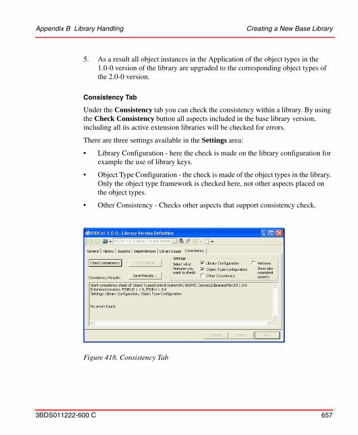
Appendix B Library Handling Creating a New Base Library
3BDS011222-600 C 657
5. As a result all object instances in the Application of the object types in the 1.0-0 version of the library are upgraded to the corresponding object types of the 2.0-0 version.
Consistency Tab
Under the Consistency tab you can check the consistency within a library. By using the Check Consistency button all aspects included in the base library version, including all its active extension libraries will be checked for errors.
There are three settings available in the Settings area:
• Library Configuration - here the check is made on the library configuration for example the use of library keys.
• Object Type Configuration - the check is made of the object types in the library. Only the object type framework is checked here, not other aspects placed on the object types.
• Other Consistency - Checks other aspects that support consistency check.
Figure 418. Consistency Tab
Creating a New Base Library Appendix B Library Handling
658 3BDS011222-600 C
If an aspect reports an error, it sometimes can make a correction to make it consistent again. If at least one aspect can be corrected, the Try to Repair button will be enabled. If you select Try to Repair, all such aspects will be told to repair themselves.
The recommended procedure to repair aspects are:
1. Select the Library Configuration and Object Type Configuration check boxes.
2. If repairable errors are found, do a re-check of the two parts separately. It is recommended to repair all Library Configuration errors, before the object type errors are repaired.
3. Check and repair all other aspects in the library if necessary.
Library Member Aspect
All objects in a base library version is also assigned a Library Member aspect. This aspect is used for enforcing the read-only feature of released libraries as well as capture additional information for library members. The aspect has three tabs; the General tab, the History tab and the Aspects tab.
It is recommended to make a backup before trying to repair aspects.
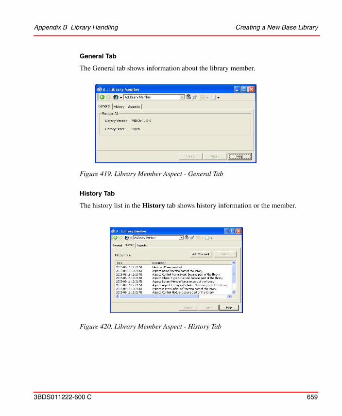
Appendix B Library Handling Creating a New Base Library
3BDS011222-600 C 659
General Tab
The General tab shows information about the library member.
History Tab
The history list in the History tab shows history information or the member.
Figure 419. Library Member Aspect - General Tab
Figure 420. Library Member Aspect - History Tab
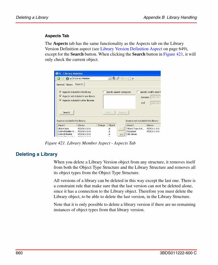
Deleting a Library Appendix B Library Handling
660 3BDS011222-600 C
Aspects Tab
The Aspects tab has the same functionality as the Aspects tab on the Library Version Definition aspect (see Library Version Definition Aspect on page 649), except for the Search button. When clicking the Search button in Figure 421, it will only check the current object.
Deleting a Library
When you delete a Library Version object from any structure, it removes itself from both the Object Type Structure and the Library Structure and removes all its object types from the Object Type Structure.
All versions of a library can be deleted in this way except the last one. There is a constraint rule that make sure that the last version can not be deleted alone, since it has a connection to the Library object. Therefore you must delete the Library object, to be able to delete the last version, in the Library Structure.
Note that it is only possible to delete a library version if there are no remaining instances of object types from that library version.
Figure 421. Library Member Aspect - Aspects Tab
Appendix B Library Handling Renaming a Library
3BDS011222-600 C 661
Renaming a Library
If you rename a Library object in the Library Structure then all open library versions will automatically be renamed as well.
If you rename a specific Library Version object, only that version will be renamed and the Library object keeps its name.
Renaming is done in the Name aspect or under the General tab of the Library Version Definition aspect.
If you use the Name aspect, the version part can be omitted. The current version as specified in the Library Version Definition aspect will the be appended. You can also increase the revision number together with the rename operation in the Name aspect. The Library Version Definition aspect will be updated accordingly.
If the name and/or version are changed in the Library Version Definition aspect, the Name aspect will also be updated.
Moving a Library Version
When the first base version is created, it is initially inserted in the Object Type Structure at the insertion point specified in the New Object dialog box. The following versions are also placed below the same parent in the Object Type Structure, if not the insertion point has been changed in the Library Definition aspect on the base library object.
It is allowed to move a base library version in the Object Type Structure. It can for example be useful to group project-related libraries.
Libraries can not be moved in the Library Structure.
Extension LibrariesIf you want to extend the object types in a library with additional aspects that you want to handle separately, for example faceplates, you can use an Extension Library.
An extension library is similar in many respects to a base library but it can only add additional aspects to existing objects in a base library. This allows certain aspects to be factored out and not be made available unless the extension library is loaded. Any
Extension Libraries Appendix B Library Handling
662 3BDS011222-600 C
base library can be extended with one or several extension libraries that contain additional aspects.
An extension library is always connected to one base library, and one particular extension library version is always connected to one base library version. The connection is made to the object IDs in the base library version, and not to the library version number. The connection is still valid after the base library version has been updated to a new minor version or revision.
An extension library supports the same states as a base library; Open, Closed and Released. The version state of an extension library is independent from the state of its base library. It is possible to release one of them while the other one still is open.
AC 800M related extension libraries shall only be closed/released if the corresponding base library is closed/released.
Extending Object Type Definitions
If the extension library needs to add new type rules for the object types in the base library, e.g. a Copy-to-all-instances rule for an aspect added by the extension library, they could not be set up in the normal Object Type Definition aspect. It always belongs to the base library and the base library can have been released when the extension library is loaded. The extension library, in such cases, should include Object Type Extension Definition aspects for the types where additional type rules are needed.
Creating a New Extension Library
To create a new versioned extension library follow the steps below:
1. Go to the Library Structure and select the base library that should be extended.
During the Control Builder M project upgrade, Function Designer related extension libraries for AC 800M base libraries must be open if the base library is open. An extension library only containing graphics can still be closed/released.
Appendix B Library Handling Extension Libraries
3BDS011222-600 C 663
2. Select New Object from the context menu.
3. Select Extension Library and type the new library name in the Name field. Select version number for the new extension library and the version of the base library to connect with, refer to Figure 423.
4. Click Create.
Figure 422. Create Extension Library
Figure 423. Creating New Extension Library - New Object Dialog Box
Adding Data to an Extension Library Version Appendix B Library Handling
664 3BDS011222-600 C
Now an Extension Library object is created for the new extension library. An Extension Library Version object for the first version of the extension library is also created. The extension library is not inserted into the Object Type Structure.The extension aspects are placed on objects in the Object Type Structure that belong to the base library, and the administrative extension library objects are placed in the Library Structure.
The Extension Library Version object is placed both below the Extension Library object and below the Base Library Version object to which it is connected, refer to Figure 424.
Adding Data to an Extension Library Version
To add data (aspects) to an extension library version, you create aspects on the objects in the corresponding Base Library version in the Object Type Structure.
When you create an aspect using the New Aspect dialog box, see Figure 425, you can select if the aspect should be assigned to an extension library. Copied aspects keep their library assignment if possible.
Figure 424. Extension Library With Three Versions
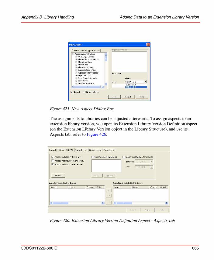
Appendix B Library Handling Adding Data to an Extension Library Version
3BDS011222-600 C 665
The assignments to libraries can be adjusted afterwards. To assign aspects to an extension library version, you open its Extension Library Version Definition aspect (on the Extension Library Version object in the Library Structure), and use its Aspects tab, refer to Figure 426.
Figure 425. New Aspect Dialog Box
Figure 426. Extension Library Version Definition Aspect - Aspects Tab
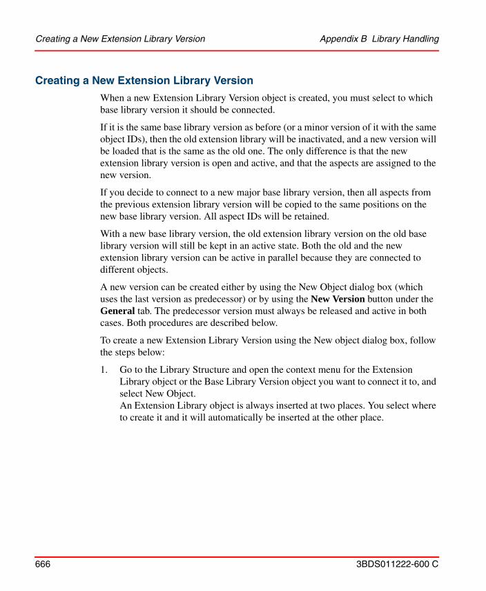
Creating a New Extension Library Version Appendix B Library Handling
666 3BDS011222-600 C
Creating a New Extension Library Version
When a new Extension Library Version object is created, you must select to which base library version it should be connected.
If it is the same base library version as before (or a minor version of it with the same object IDs), then the old extension library will be inactivated, and a new version will be loaded that is the same as the old one. The only difference is that the new extension library version is open and active, and that the aspects are assigned to the new version.
If you decide to connect to a new major base library version, then all aspects from the previous extension library version will be copied to the same positions on the new base library version. All aspect IDs will be retained.
With a new base library version, the old extension library version on the old base library version will still be kept in an active state. Both the old and the new extension library version can be active in parallel because they are connected to different objects.
A new version can be created either by using the New Object dialog box (which uses the last version as predecessor) or by using the New Version button under the General tab. The predecessor version must always be released and active in both cases. Both procedures are described below.
To create a new Extension Library Version using the New object dialog box, follow the steps below:
1. Go to the Library Structure and open the context menu for the Extension Library object or the Base Library Version object you want to connect it to, and select New Object. An Extension Library object is always inserted at two places. You select where to create it and it will automatically be inserted at the other place.
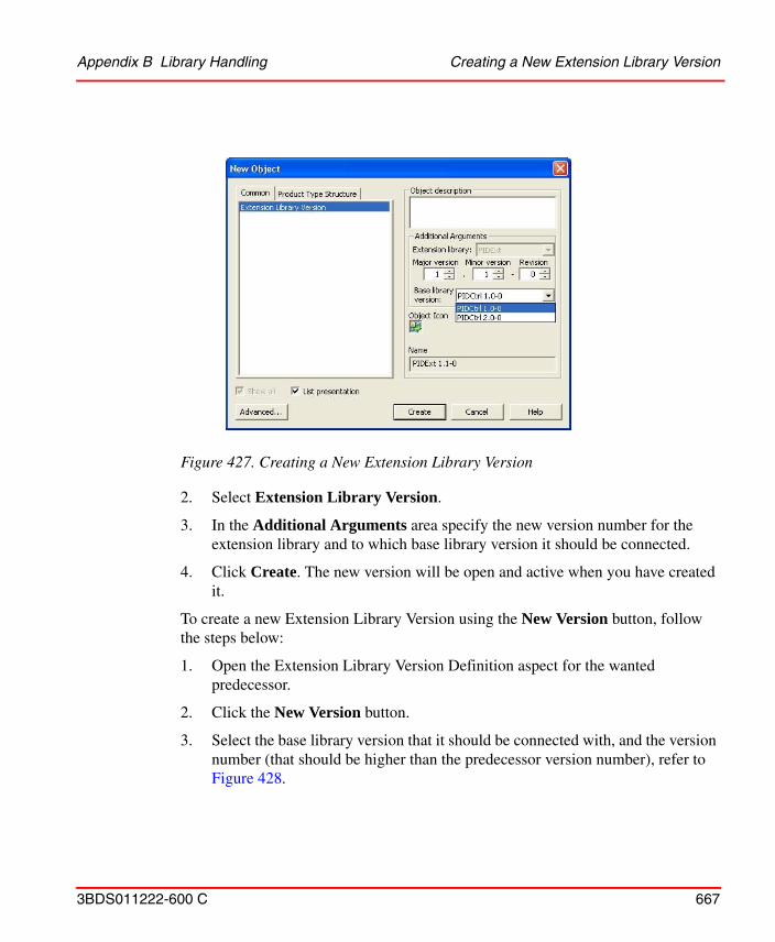
Appendix B Library Handling Creating a New Extension Library Version
3BDS011222-600 C 667
2. Select Extension Library Version.
3. In the Additional Arguments area specify the new version number for the extension library and to which base library version it should be connected.
4. Click Create. The new version will be open and active when you have created it.
To create a new Extension Library Version using the New Version button, follow the steps below:
1. Open the Extension Library Version Definition aspect for the wanted predecessor.
2. Click the New Version button.
3. Select the base library version that it should be connected with, and the version number (that should be higher than the predecessor version number), refer to Figure 428.
Figure 427. Creating a New Extension Library Version
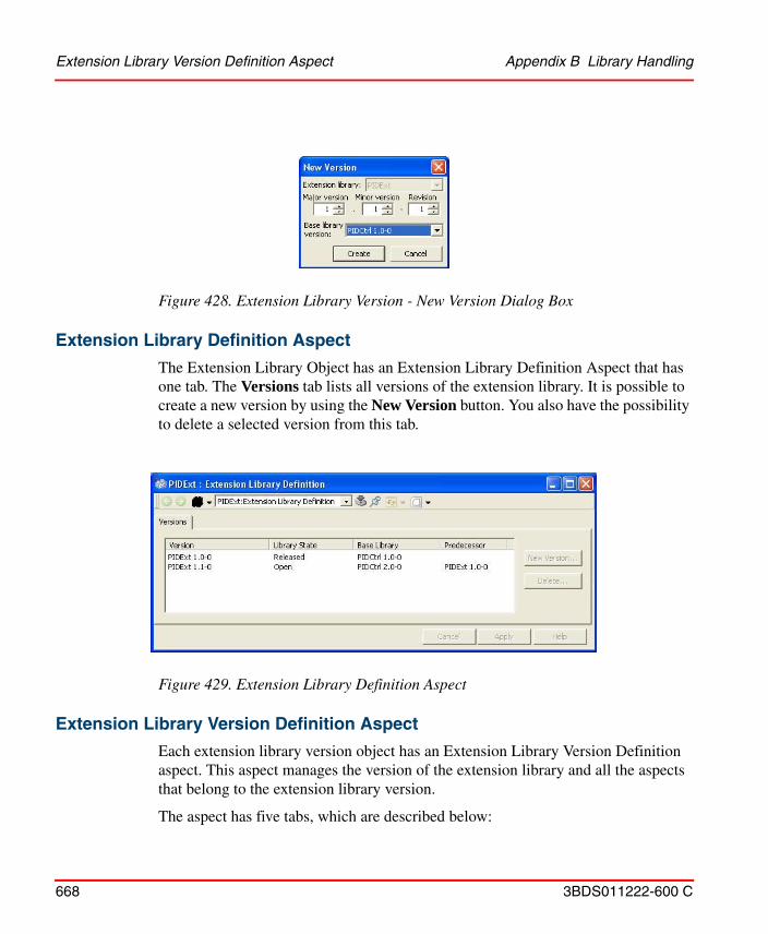
Extension Library Version Definition Aspect Appendix B Library Handling
668 3BDS011222-600 C
Extension Library Definition Aspect
The Extension Library Object has an Extension Library Definition Aspect that has one tab. The Versions tab lists all versions of the extension library. It is possible to create a new version by using the New Version button. You also have the possibility to delete a selected version from this tab.
Extension Library Version Definition Aspect
Each extension library version object has an Extension Library Version Definition aspect. This aspect manages the version of the extension library and all the aspects that belong to the extension library version.
The aspect has five tabs, which are described below:
Figure 428. Extension Library Version - New Version Dialog Box
Figure 429. Extension Library Definition Aspect
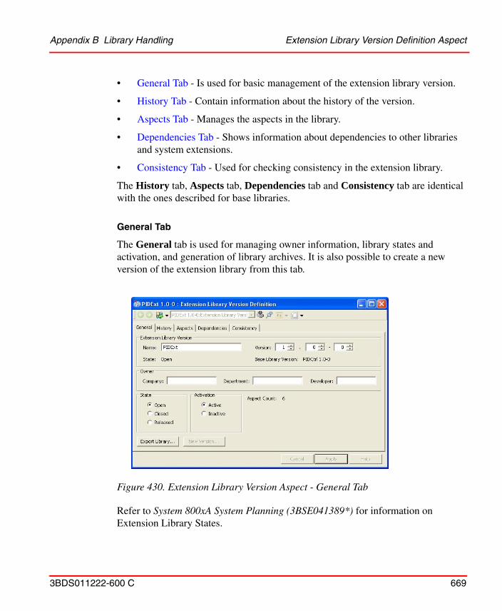
Appendix B Library Handling Extension Library Version Definition Aspect
3BDS011222-600 C 669
• General Tab - Is used for basic management of the extension library version.
• History Tab - Contain information about the history of the version.
• Aspects Tab - Manages the aspects in the library.
• Dependencies Tab - Shows information about dependencies to other libraries and system extensions.
• Consistency Tab - Used for checking consistency in the extension library.
The History tab, Aspects tab, Dependencies tab and Consistency tab are identical with the ones described for base libraries.
General Tab
The General tab is used for managing owner information, library states and activation, and generation of library archives. It is also possible to create a new version of the extension library from this tab.
Refer to System 800xA System Planning (3BSE041389*) for information on Extension Library States.
Figure 430. Extension Library Version Aspect - General Tab
Extension Library Version Definition Aspect Appendix B Library Handling
670 3BDS011222-600 C
The user can create an Import/Export archive containing the aspects that is a part of the extension library version, The Extension Library and the Extension Library Version objects, and the library key object from the Admin Structure.
The objects in the base library version where the extension library aspects should be placed are not included in the library. The user must always import the base library archive before the related extension library archives are imported.
The Export Library button works both for active and inactive extension library versions. The current activation state is kept in the Import/Export file. If the user imports an active extension library version but, one old active version already exists in the system (on the same base library version), the old version will automatically be inactivated.
If the new extension library version includes only a part of the aspects from the old version, the obsolete aspects of the old version will continue to exist in the new version. To overcome this scenario, inactivate the old version prior to importing a new version.
3BDS011222-600 C 671
Appendix C SMS and E-Mail Messaging
Setup and Configuration WorksheetsThe following tables are worksheets to help in setting up and configuring SMS and e-mail Messaging.
• Table 40: GSM Hardware Setup Worksheet.
• Table 41: Aspect System Structure Setup Worksheet.
• Table 42: Users Worksheet.
• Table 43: User Setup Worksheet.
• Table 44: Configuration Worksheet.
The worksheets are also designed to be used as configuration records. Each one starts on a new page for ease of copying. Keep these records in a safe place for future backup/restore or upgrade activities.
It is very important to read, understand, and follow the setup and configuration procedures (see SMS and e-mail Messaging on page 182), before filling in the worksheets.
Table 40. SMS and E-mail Messaging GSM Hardware (SMS/GSM) Setup Worksheet
Item Setting/Value
General Settings
Interval for Checking for Incoming Messages
Value: _____ Seconds Minutes (circle 1)
Unicode Text Checked or Unchecked
Setup and Configuration Worksheets Appendix C SMS and E-Mail Messaging
672 3BDS011222-600 C
Modem Settings
Available COM Ports (Mandatory) Value: COM _____
Baud Rate (Mandatory) Value: _____
PIN (Optional) Value: _____
Preferred SMSC Number (Optional) Value: _____
Table 41. SMS and e-mail Messaging Aspect System Structure Setup Worksheet
Item Setting/Value
Modem Device Aspect
Phone Number (default pager service provider’s Central Paging Terminal telephone number)
Value: ___________________
Email Device Aspect
From (default e-mail address where error messages are sent)
Value: ___________________
SMTP Relay Server (default domain name or IP address of SMTP relay server)
Using SMTP Relay Server? Yes or No (circle one)
Value: ___________________
Table 40. SMS and E-mail Messaging GSM Hardware (SMS/GSM) Setup Worksheet (Continued)
Item Setting/Value
Appendix C SMS and E-Mail Messaging Setup and Configuration Worksheets
3BDS011222-600 C 673
Table 42. SMS and e-mail Messaging Users Worksheet
User Name
User Group (Check all that Apply)
Admin
App Eng
Every-one
OperSW Dev
SW Eng
User Groups Created
√
√
√
√
√
√
√
√
√
√
√
√
√
√
√
√
√
√
√
√
Setup and Configuration Worksheets Appendix C SMS and E-Mail Messaging
674 3BDS011222-600 C
Table 43. SMS and e-mail Messaging User Setup Worksheet
User Name: ___________________________________
Week of (week begins on Sunday): ________________
Message Subscriber Aspect
Device Value Priority
SMTP/Email
TAP/Modem
SMS/GSM
Message Schedule Aspect
Delivery Option
Always deliver Always
Delivery Based on Schedule Start Time End Time
Hour
Min Hour
Min
Sunday
Monday
Tuesday
Wednesday
Thursday
Friday
Saturday
Never Deliver Never
Appendix C SMS and E-Mail Messaging Setup and Configuration Worksheets
3BDS011222-600 C 675
Table 44. SMS and e-mail Messaging Configuration Worksheet
Item Setting/Value
Alarm and Event Message Source Aspect
Alarm List (Alarm and Event List to monitor)
Value: __________________________________
Message Action Option Selection (check one)
Only send message if previous alarm condition was acknowledged (also requires Basic and/or Soft Alarm configuration in Service Structure)
Always send message
Send message on Acknowledgment
Send message on return to normal
Setup and Configuration Worksheets Appendix C SMS and E-Mail Messaging
676 3BDS011222-600 C
Message Configuration
Item in Name Column Selection Order
System Name
Event Time
Object Name
Object Description
Condition
Sub Condition
Priority Level
Severity
Category
Message Description
Actor
Guid
LNDesc
Node Name
Current Value
Class
Process Section
Ack State
Ack Time
Active Change Time
Alarm State
Prefix Value: ________________________
Table 44. SMS and e-mail Messaging Configuration Worksheet (Continued)
Item Setting/Value
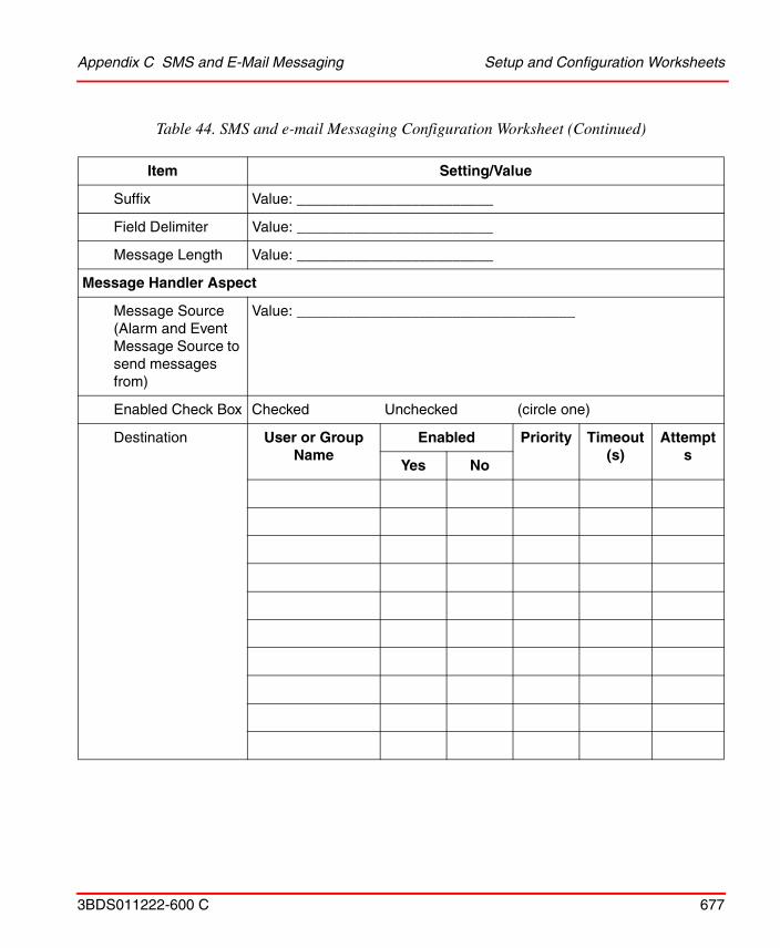
Appendix C SMS and E-Mail Messaging Setup and Configuration Worksheets
3BDS011222-600 C 677
Suffix Value: ________________________
Field Delimiter Value: ________________________
Message Length Value: ________________________
Message Handler Aspect
Message Source (Alarm and Event Message Source to send messages from)
Value: __________________________________
Enabled Check Box Checked Unchecked (circle one)
Destination User or Group Name
Enabled Priority Timeout (s)
Attempts
Yes No
Table 44. SMS and e-mail Messaging Configuration Worksheet (Continued)
Item Setting/Value
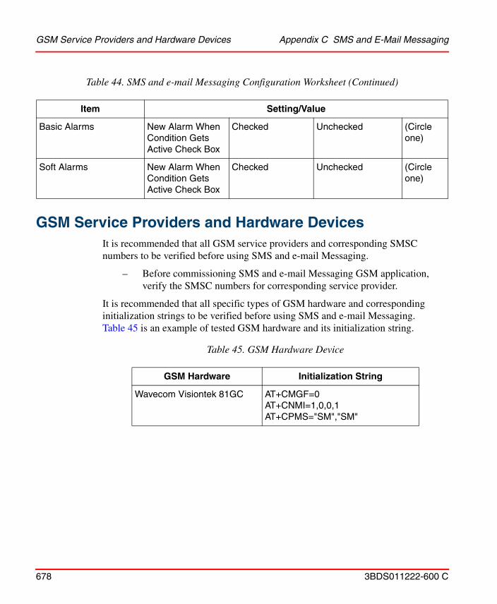
GSM Service Providers and Hardware Devices Appendix C SMS and E-Mail Messaging
678 3BDS011222-600 C
GSM Service Providers and Hardware Devices
It is recommended that all GSM service providers and corresponding SMSC numbers to be verified before using SMS and e-mail Messaging.
– Before commissioning SMS and e-mail Messaging GSM application, verify the SMSC numbers for corresponding service provider.
It is recommended that all specific types of GSM hardware and corresponding initialization strings to be verified before using SMS and e-mail Messaging. Table 45 is an example of tested GSM hardware and its initialization string.
Basic Alarms New Alarm When Condition Gets Active Check Box
Checked Unchecked (Circle one)
Soft Alarms New Alarm When Condition Gets Active Check Box
Checked Unchecked (Circle one)
Table 45. GSM Hardware Device
GSM Hardware Initialization String
Wavecom Visiontek 81GC AT+CMGF=0AT+CNMI=1,0,0,1AT+CPMS="SM","SM"
Table 44. SMS and e-mail Messaging Configuration Worksheet (Continued)
Item Setting/Value
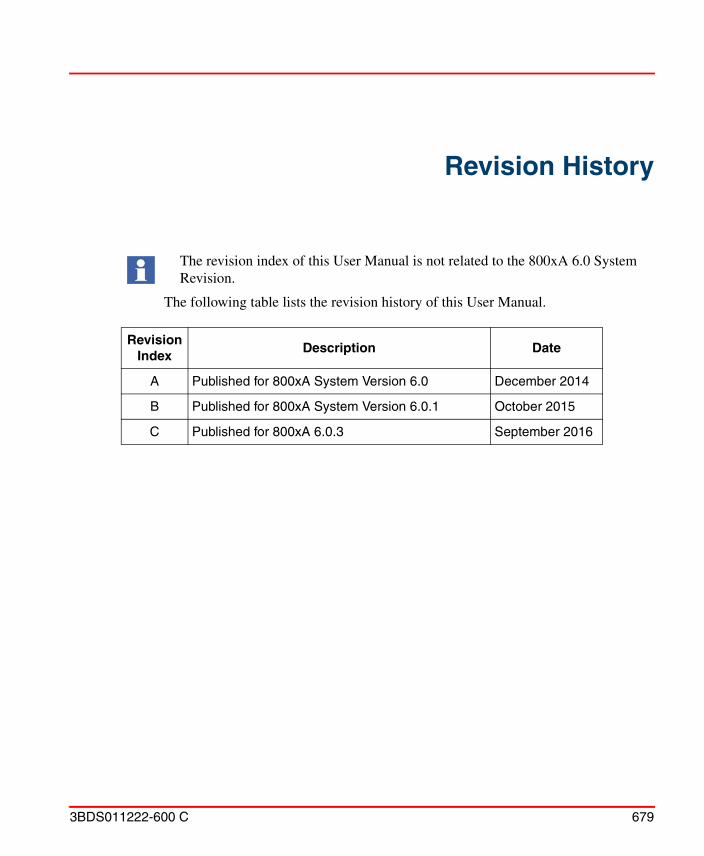
3BDS011222-600 C 679
Revision History
The following table lists the revision history of this User Manual.
The revision index of this User Manual is not related to the 800xA 6.0 System Revision.
Revision Index
Description Date
A Published for 800xA System Version 6.0 December 2014
B Published for 800xA System Version 6.0.1 October 2015
C Published for 800xA 6.0.3 September 2016

680 3BDS011222-600 C
3BDS011222-600 C 681
Numerics800xA History
Logs 327Properties 385Source 327
AABB SolutionsBank 236AC 800M Controller 31Access Control 484Activate/Deactivate Logs 352ActiveX Wrapper Aspect
Add 471Create 471
Additional Info Tab 525Advanced Access Control 484Aggregate 425
Annotations 430Average 429Bad Data Quality Limit 426Count 429Delta 430Duration Bad 430Duration Good 430End 430Exception Deviation 427Interpolated 429Max Actual Time 429Maximum 429Min Actual Time 429Minimum 429Percentage Bad 430Percentage Good 430Range 430Regression Const 430
Regression Deviation 430Regression Slope 430Standard Deviation 429Start 429Timeaverage 429Total 429Variance 430Worst Quality 430
AlarmExternal 176
Alarm and Event List 107Alarm and event list
Configuration 216Alarm list tab 217Edit length dialog box 221Message configuration tab 220
Alarm and event message sourceConfiguration 216
Alarm Band 154Alarm list tab 217Alarm Shelving 130Alarms
Filter 93Alarms and Events 89Application Server 237Archive 505Archive Device
Configuration 396Archive Tool 442Aspect Category Definition 619Aspect Control Tab 584, 616, 623Aspect Group 616Aspect Group Definition 619Aspect Group Reference 620Aspect Object
Index

Index
682 3BDS011222-600 C
Object types provided with the release 597Aspect Propagation 624, 635Aspect Server 237Aspect system structure
Email device 199Modem device 196
Asset Monitoring 481Attempts field 227Audit Trail 504
Configuration 504Authentication 485Authorization 484Automation Solution 29
BBase Library 639
Add Data 642Create New Base Library 639New Major Version 647New Minor Version/Revision 646
Basic Alarm Analysis 143Batch Management 323Bookmark Aspect 466bring on line 448Bulk Configuration 354, 443
Property Logs 443Bulk Data Manager 53
CCategory Control Tab 585, 616, 624Central paging system 199Child Control Tab 626Client 237COM port settings 190Composite Control Object Types 597Composite Info Tab 629Composite Object 631Composite Object Type 633Composite Object Types 592Configuration
Operational structures 216Alarm and event list 216Alarm and event message source 216Message handler 222
SMS and e-mail messaging 216Configuration Change Management 486Configure-Deploy 503Configuring
Event Archiving 396Event Retrieval 389Using System 800xA 326
Connectivity Server 237Consistency Checker 630Consistency Tab 629Control Application 33
Library 34Task 36
Control Builder M Professional 29Control Connection aspect 519Control Hardware Unit 82
Create 40Control Logic 53Control Network 30Control Object Types 597Control Project 31
Create 31Open 41Release 43Reserve 41
Control Structure 30Aspect Object Creation 598
Control Task 35Controller 34
Hardware Library 39Create Info Tab 621Creating
Logs from System 800xA 332Creating Log Configuration Aspect in Tags 347
Index
3BDS011222-600 C 683
DData Collection tab 434Data Source Definition 514DCOM Security Settings 549Destination tab 224Device 244Device Calibration 285Device Checks 505Device Integration Libraries 235Device Library Wizard 235, 291Device Management 235
FOUNDATION Fieldbus 235, 288PROFIBUS & HART 235
Device Management SystemDMS 285
Device Object Types 244Device Type 250device type 240device type file 240Device Type Manager 272device types 235Document Management 450Document Manager 450Documentation 450Double Authentication 484Download 236Download and Upload DTM Data Set 272DTM 241, 272
EEdit destination dialog box 227Edit length dialog box 221Electronic Signature 485Email device 199
Message subscriber 202, 204Relay server 195, 200
E-mail test utility 194Embedded Instance 633Engineering Unit 436Events
Filter 94Exception Deviation 427export 449Export and Import DTM Data Set 272Expressions 168Extended Configuration Data 445Extension Library 661
Add Data 664Create New Extension Library 662New Version 666
External Alarm 180External Alarm Silence View 180
FFF alarm 304FF alarm priority 306FF Application 289, 298, 311FF blocks 289, 298FF device library 291FF HSE subnet 288FF signal 300Field delimiter 221Field Devices 236Fieldbus Builder
PROFIBUS/HART 256fieldbus topology 252File Viewer Aspect 454
How to use 454File Viewer Functions 459Filter
Acknowledge Time 94Events 94Process Alarms 93
Filter states 93Formal Instance 619, 631Formal Instance Definition 619Formal Instance Delete 635Formal Instance List 594, 633Formal Instance List Definition 619, 631Formal Instance Reference 619
Index
684 3BDS011222-600 C
FOUNDATION Fieldbus 235Function Designer 53
Function Diagram 54HART Device 286PROFIBUS Device 288Sequence 63
Function DiagramAllocatable Group 58Allocate 58Bulk Data Management 73Copy 76Create 54Download and Test 61Edit 55Import/Export 79Print 63Sequence 63
Action Diagram 71Allocate 72Detail Diagram 67Download and Test 73Generate Configuration Data 72Insert 63Overview 64Overview Diagram
Edit 65Print 73Transition Detail Diagram 71
Sequence Diagrams 72
GGeneric OPC
Upload 531Advanced 533Standard 532
Graphic Element 636
HH1 device 311H1 link 289, 292
H1 Schedule 310Hardware library 36Hardware setup 184
E-mail test utility 194Modem test utility 192SMS/GSM hardware device 185
HART 235, 250HART Actuators 263HART Device Type Objects 261, 286HART Devices 250HART Transmitter 263Help Aspect
Instance Help 476Hiding Masks 116
Hiding Masks Manager 117Hiding Rules 116Historical Process Data 411History Log Template 412History Source 329HSE Subnet 293HSE subnet 289, 292
II/O Allocation 53I/O Signal Engineering 599Icon Aspect 636import 449Independent Instance 633IOPCBrowseServerAddressSpace 510Item Properties Tab 529
LLibraries 580
Delete 660Move 661Release Version 645Rename 661
Library 244Library Archive
Generate 643
Index
3BDS011222-600 C 685
Library Handling 639linking device 311List View 244 to 246Log Configuration 422, 432Log Configuration Aspect 418Log Definition tab 434Log Information 434Log Source 424
OPC 423TTD 423
Log Template 412, 421, 431Log Type
Direct 423, 425Hierarchical 423, 425
MMaximo Integration 482Message configuration tab 220Message handler
Configuration 222Destination tab 224Edit destination dialog box 227Message source tab 223New destination dialog box 225
Message length 221Message prefix 221Message schedule
Setup 207Message source tab 223Message subscriber
Email device 204Modem device 202, 205Setup 201SMS device 203SMS/GSM 202
Message suffix 221Modem device 196
Message subscriber 202, 205Modem hardware device 190
COM port settings 190
Modem test utility 192
NNew Aspect Dialog 589, 625New Aspect pop-up dialog 418New destination dialog box 225New Log Template pop-up dialog 416, 423New Object Dialog 586, 616, 627New Property Log 420, 431No of Decimals 436Normal Maximum 436Normal Minimum 436
OObject Factory 618Object Type 582, 615Object Type Definition 617Object Type Extension Definition 592, 618Object Type Group 582, 615Object Type Group Reference 618Object Type Reference 617Object Type Structure 582, 615Object Types 581, 597Obsolete Handling 635Obsolete Structure 635OLE DB Provider 558One-shot Shelving 130OPC Configuration Tab 516OPC Control Connection 519OPC Data Source 32OPC Server 510OPC Server PROFIBUS/HART 276OPC Settings 528Operational structures 216
Alarm and event list 216Alarm list tab 217Edit length dialog box 221Message configuration tab 220
Alarm and event message source 216Message handler 222
Index
686 3BDS011222-600 C
Destination tab 224Edit destination dialog box 227Message source tab 223New destination dialog box 225
PPaging service providers 197Parameter Management 445Parameter Manager 445 to 446PC, Network and Software Monitoring 483pdf-file 460Plant Explorer 29Prerequisites 235Process Object Type 599
Built in Function Designer 603PROFIBUS 235, 250PROFIBUS Device Type Objects 266Property
Available Sources 433Data Type 431
Property Info Tab 521Property Log 415Property Signal Generator 536Property Transfer
service 574Property Transfer Definition
aspect 571Property View Tab 519
RRe-Authentication 484Relative Name 619Relative Reference 636Relay server 195, 200Release Notes 240Reuse Design Structure 611Reuse Instruction 611
SSAP/PM Integration 483
Security 484Service Group 517Service Provider 518Service providers
Paging 197Service structure 215
Soft alarms 215SMS and e-mail messaging 182
Configuration 216System setup 196
SMS deviceMessage subscriber 203
SMS/GSM hardware device setup 185Soft alarms 215Softpoint Configuration
Workflow 447Step by Step
Commissioning 314FF Application 298HSE Subnet 292HSEHostCI860 307, 319Precommissioning 311
Step by Step User Instructions 290Storage Interval
Max Time 426Min Time 426
Storage SizeMax Capacity 427Min Capacity 427
Subscribe 531Subtype 590Super Type Reference 617Supertype 591, 624System Checks 505System Configuration Version 486System setup
Aspect system structureEmail device 199Modem device 196
SMS and e-mail messaging 196
Index
3BDS011222-600 C 687
Soft alarms 215User structure 201
Message schedule 207Message subscriber 201
TTemplate Support 462Test utility 192, 194Timeout(s) field 227Tool Routing 253Topology Status Viewer 232Type Info Tab 620
UUpload 531Upload FF Libraries 291Upload HSE Subnet 311, 319User structure 201
User setupMessage schedule 207Message subscriber 201
UsersMessage schedule 207Message subscriber 201
VValid Operators 169Verify DTM Data Set 272Versioned Object Type Libraries 580Versioning 486View Log 249
WWeb Page 470Web Server 266Windows Application 474

Index
688 3BDS011222-600 C


Power and productivityfor a better worldTM
Contact us
Copyright © 2016 ABB.All rights reserved.
3BD
S01
1222
-600
Cwww.abb.com/800xAwww.abb.com/controlsystems