Embed Size (px)
Citation preview
Hardware Configuration Advant Controller 31-SSafety-Related Automation
907 PC 339Programming and Test Software
Safety Manual
Analog Input UnitAdvant Contr. 31-S
07 AI 90-S
07 KT 93-S
Basic UnitAdvant Controller 31-S

907 PC 339 / Issued: 05.01 0-1 Contents 3
1 Structure of the Advant Controller 31-S ..... 1-11.1 Minimum equipment ....................................... 1-21.2 Hardware components
for the Advant Controller 31-S ......................... 1-31.2.1 Safety-related binary and analog
input and output modules for AC31-S ............. 1-31.2.2 Non-safety-related modules
for the Advant Controller 31-S ......................... 1-31.2.3 Communication modules for
networking ..................................................... 1-41.3 Programming software ................................... 1-41.4 Documentation ............................................... 1-52 Technical system data ................................ 2-1
Operating and ambient conditions ............ 2-2Voltage ratings ............................................... 2-2Stored energy time on power failure ................ 2-2Temperature ................................................... 2-2Humidity ........................................................ 2-2Atmospheric pressure .................................... 2-2Creepage distances and clearances ............... 2-2Test voltage .................................................... 2-2Electromagnetic compatibility ........................ 2-2Mechanical data ............................................. 2-3Interfaces ....................................................... 2-3CS31 system bus .......................................... 2-4Wiring ............................................................ 2-4Bus topology .................................................. 2-5Earthing ......................................................... 2-6Bus cycle time and data security ............... 2-7Bus cycle time ............................................... 2-7Data security ................................................. 2-8Replacement of modules on theCS31 system bus .......................................... 2-8Mechanical dimensions of thesafety-related I/O modules .......................... 2-9
Table of Contents
3 Hardware planning ..................................... 3-1
3.1 Preconditions ................................................. 3-13.1.1 Reaction times ............................................... 3-23.1.2 Calculating the maximum settings
for the PLC cycle time ................................... 3-23.1.3 Inputs and outputs of the
central unit 07 KT 94-S .................................. 3-23.1.4 Networking interface and ARCNET
interface ......................................................... 3-23.1.5 Starting the PLC cycle ................................... 3-23.1.6 Devices connected to the interfaces
COM1 and COM2 .......................................... 3-23.1.7 Process and supply voltage ........................... 3-23.2 Addressing the safety-related I/O modules
(setting the module address) .......................... 3-33.3 Configuring the I/O modules ........................... 3-43.3.1 Possible AC31-S module addresses in
relation to the central unit 07 KT 94 R2171 ..... 3-43.3.2 Configuration data 07 DI 90-S ......................... 3-53.3.3 Configuration data 07 DO 90-S ....................... 3-53.3.4 Configuration data 07 AI 90-S ......................... 3-63.3.5 Example for a configuration ............................ 3-63.4 Lightning protection / wiring concept .............. 3-83.4.1 Lightning protection concept .......................... 3-83.4.1.1Connecting the low-voltage system ................ 3-83.4.1.2Connecting the electronic equipment ............. 3-83.4.2 Wiring concept ............................................... 3-93.4.3 Using the Advant Controller 31-S in
networks of overvoltage category III(e.g. in road traffic signal systemsaccording to DIN VDE 0832) ......................... 3-11
3.5 Behaviour on power ON ................................. 3-113.6 Behaviour in case of errors on
the safety-related I/O modules ...................... 3-11
0-23 907 PC 339 / Issued: 05.01Contents
4 Binary input module 07 DI 90-S,safety-related ............................................... 4-1
Intended purpose ........................................... 4-1Indicators and operating elements on
the front panel ........................................ 4-2Functional description .................................... 4-2Electrical connection ...................................... 4-3Addressing (setting the module address) ....... 4-6Auxiliary and diagnosis functions ................... 4-7
Start-up behaviour .................................. 4-7Diagnosis at the module ........................ 4-7
Technical data ................................................ 4-8Installation and dimensions .................... 4-9
5 Binary output module 07 DO 90-S,safety-related ............................................... 5-1
Intended purpose ........................................... 5-1Indicators and operating elements on
the front panel ........................................ 5-2Functional description .................................... 5-2Electrical connection ...................................... 5-3Addressing (setting the module address) ....... 5-5Auxiliary and diagnosis functions ................... 5-6
Start-up behaviour .................................. 5-6Diagnosis at the module ........................ 5-6
Technical data ................................................ 5-7Installation and dimensions .................... 5-9
6 Analog input module 07 AI 90-S,safety-related ............................................... 6-1
Intended purpose ........................................... 6-1Indicators and operating elements on
the front panel ........................................ 6-2Functional description .................................... 6-2Electrical connection ...................................... 6-4Addressing (setting the module address) ....... 6-6Auxiliary and diagnosis functions ................... 6-7
Start-up behaviour .................................. 6-7Diagnosis at the module ........................ 6-7
Technical data ................................................ 6-8Installation and dimensions .................... 6-9
907 PC 339 / Issued: 05.01 1-1 Structure 3
Contents1.1 Minimum equipment .................................................................................................................................1-21.2 Hardware components for the Advant Controller 31-S ...............................................................................1-31.2.1 Safety-related binary and analog input and output modules for AC31-S ...................................................1-31.2.2 Non-safety-related modules for the Advant Controller 31-S........................................................................1-41.3 Programming Software .............................................................................................................................1-41.4 Documentation .........................................................................................................................................1-5
1 Structure of the Advant Controller AC31-S
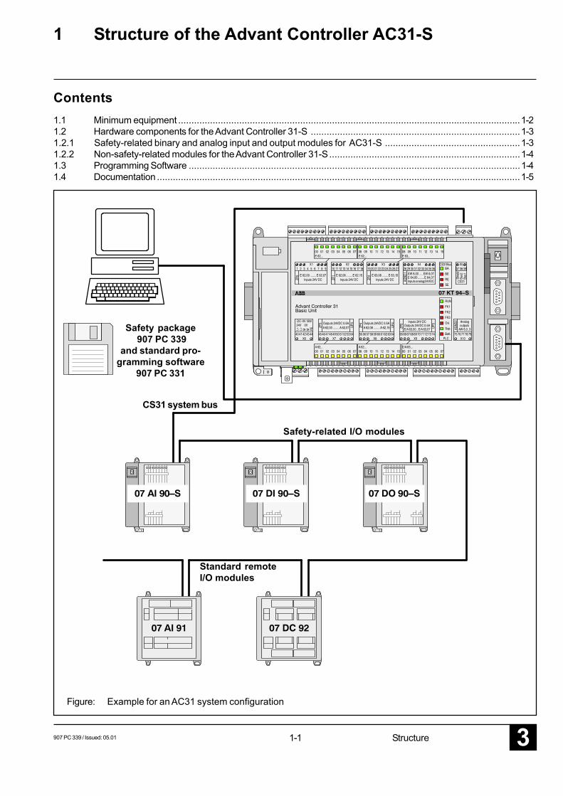
Figure: Example for an AC31 system configuration
Safety package 907 PC 339
and standard pro-gramming software
907 PC 331
CS31 system bus
Standard remoteI/O modules
Safety-related I/O modules
1-23 907 PC 339 / Issued: 05.01Structure
1.1 Minimum equipmentFor the setup of a safety-related automation system with AC31-S, the following equipment is required besides theprogramming software 907 PC 331 and the safety package 907 PC 339:
Central unit 07 KT 94-S R2161
Safety-related I/O modulesBinary input module 07 DI 90-S: 8 binary inputsBinary output module 07 DO 90-S: 8 binary outputsAnalog input module 07 AI 90-S: 4 analog inputs
Process supply voltage:For the process supply, a 24 V DC power supply unit conforming to the following standards is required:
EN 60950 (Informationstechnik) / (Information technology)EN 61000-4-5 Klasse 3 / Class 3VDE 0805 (Sicherheit) / ( Safty)
Power supply units see chapter 1.2.1
Non-safety-related modules:All modules containing a CS31 system bus connection which are mentioned in the documentations"System description of Advant Controller 31" and "System description of ABB Procontic CS31"(see page 1-5 in this volume) can be used.
907 PC 339 / Issued: 05.01 1-3 Structure 3
1.2 Hardware components for the Advant Controller 31-S
1.2.1 Safety-related binary and analog input and output modules AC31-SType Brief description Order number
07 DI 90-S Binary input module, 8 inputs 24 V DC, safety-related GJR5250900R20207 DO 90-S Binary output module, 8 outputs 24 V DC, safety-related GJR5250800R20207 AI 90-S Analog input module, 4 inputs 4...20 mA, safety-related GJR5251200R202
Central unit 07 KT 94-S R216107 KT 94-S R2161 GJR5252100R2161
System cables07 SK 90 Interface cable for connection of KT 94-S R2161 to
the PC, 25/9 poles, length 5 m GJR5250200R0001
AccessoriesType Brief description Order number
07 LE 90 Lithium battery module GJR5250700R0001
The modules are listed in the current technical price list.
1.2.2 Non-safety-related modules for the Advant Controller 31-S
All modules which have a CS31 system bus connectionby standard can be used with the safety-related modules.
Type: 07 NG 32 R1Order No.: GJV3 0756 01 R0001
Power supply unit,primary: 115/230 V AC, secondary: 24 V DC / 2,5 A
Type: 07 NG 34 R1Order No.: GJV3 0756 02 R0001
Power supply unit,primary: 115/230 V AC, secondary: 24 V DC / 5 A
Type: 07 NG 35 R1Order No.: GJV3 0756 03 R0001
Power supply unit,primary: 230/400 V 3-phase AC, secondary: 24 V DC / 10 A
Type: 07 NG 36 R1Order No.: GJV3 0756 04 R0001
Power supply unit,primary: 230/400 V 3-phase AC, secondary: 24 V DC / 20 A
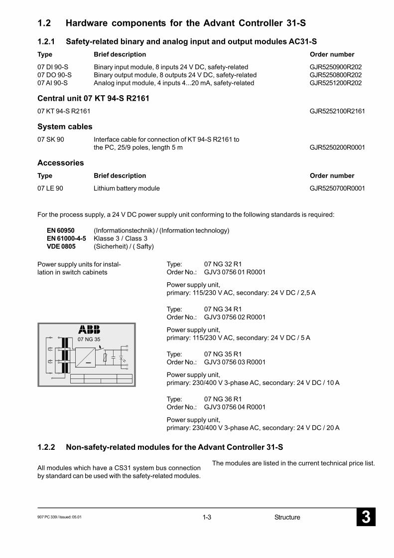
Power supply units for instal-lation in switch cabinets
07 NG 35
For the process supply, a 24 V DC power supply unit conforming to the following standards is required:
EN 60950 (Informationstechnik) / (Information technology)EN 61000-4-5 Klasse 3 / Class 3VDE 0805 (Sicherheit) / ( Safty)
1-43 907 PC 339 / Issued: 05.01Structure
907 PC 33PC programming and test software forIL, LD and FBD.Documentation: General part of theprogramming interface without software(for information about software, refer tothe system-specific part of 907 PC331).
- German GJP 520 3900 R 0302- English GJP 520 4000 R 0302
907 PC 331
PC programming and test software forIL, LD and FBD.Documentation: System-specific part(including the software on floppy disk)for Advant Controller 31 and ABBProcontic T200 (communication pro-cessor 07 KP 62).
- German GJP 520 4500 R 0402- English GJP 520 4600 R 0402
907 PC 339Additional packet with safety-relatedfunctions AC31-S for the programmingand test software 907 PC 331. Includesthe software on floppy disk and thesafety manual.
- German GJP 520 7500 R 0102- English GJP 520 7600 R 0102
Safety-related data transfer via these couplers betweentwo or more central units is prohibited.
1.2.3 Communication modules for networking
All couplers which contain a networking interface by stan-dard can be used. The couplers are listed in the currenttechnical price list.
1.3 Programming SoftwareThe programming software is not part of the certificate.Therefore, applications designed with this software have
to be verified in accordance to this Safety Manual.
907 PC 339 / Issued: 05.01 1-5 Structure 3
System descriptionAdvant Controller 31Complete hardware documentation inone file.General part, hardware, operatinginstructions, planning instructions(central units 07 KT 94).
- German 1SAC 131 699 R 0101- English 1SAC 131 699 R 0201
System descriptionABB Procontic CS31
Complete hardware documentation inone file.General part, hardware, operatinginstructions, planning instructions(central units 07 KR 31, 07 KT 31,07 KR 91, 07 KT 92, 07 KT 94).
- German GATS 131 699 R 1002- English FPTN 440 004 R 2001
1.4 Documentation

1-63 907 PC 339 / Issued: 05.01Structure
907 PC 339 / Issued: 05.01 2-1 System data 3
2 Technical System Data
The relevant product standard for the Advant Controller 31 control system is EN 61131-2 (corresponds to IEC 1131-2).
ContentsOperating and ambient conditions ............................................................................................................... 2-2
Voltage ratings ......................................................................................................................................... 2-2Stored energy time on power failure .......................................................................................................... 2-2Temperature ............................................................................................................................................. 2-2Humidity .................................................................................................................................................. 2-2Atmospheric pressure .............................................................................................................................. 2-2Creepage distances and clearances......................................................................................................... 2-2Test voltages ............................................................................................................................................ 2-2Electromagenetic compatibility ................................................................................................................ 2-2Mechanical data....................................................................................................................................... 2-3Interfaces ................................................................................................................................................. 2-3
CS31 system bus ............................................................................................................................................ 2-4Wiring ...................................................................................................................................................... 2-4Bus topology ............................................................................................................................................ 2-5Earthing ................................................................................................................................................... 2-6
Bus cycle time and data security .................................................................................................................. 2-8Bus cycle time ......................................................................................................................................... 2-9Data security ........................................................................................................................................... 2-9
Replacement of modules on the CS31 system bus ..................................................................................... 2-9Mechanical dimensions of the safety-related I/O modules ...................................................................... 2-10Mechanical dimensions of the safety-related 07 KT 94-S ......................................................................... 2-11
2-23 907 PC 339 / Issued: 05.01System data
Operating and ambient conditions (valid for all safety-related modules)Voltages
24 V DC process and supply voltage 24 V DC (+ 20 %, - 15 %, without ripple)absolute limits 19.2 V ... 30 V incl. rippleripple < 5 %
120 V AC supply voltage 120 V AC (+ 10 %, - 15 %)frequency 50 Hz (+ 5 %, - 5 %) or 60 Hz (+ 5 %, - 5 %)
230 V AC supply voltage 230 V AC (+ 10 %, - 15 %)frequency 50 Hz (+ 5 %, - 5 %) or 60 Hz (+ 5 %, - 5 %)
Allowed interruptions of power supplyDC supply interruption < 10 ms, time between 2 interruptions > 1 s
AC supply interruption < 0.5 periods,time between 2 interruptions > 1 s
Temperature
If the 07 KT 94-S basic unit is used, it must be made sure,that the cabinet temperature does not fall below 0° C.
operation 0 °C ... + 55 °Cstorage - 25 °C ... + 75 °Ctransport - 25 °C ... + 75 °C
Humidity 5...95 %, without condensation
Air pressureoperation > 800 hPa/< 2000 mstorage > 660 hPa/< 3500 m
Creepage distances and clearancesThe creepage distances and clearances meet Overvoltage category II, pollution severity 2
Insulation test voltages230 V circuits (mains, 230 V inputs/outputs)against other circuitry 2500 V120 V circuits (mains) against other circuitry 1500 V24 V circuits (supply, 24 V inputs/outputs), whenelectrically isolated against other circuitry 500 VCS31 bus against other circuitry 500 V
Electromagnetic compatibility• Immunity
against electrostatic discharge (ESD) according to EN 61000-4-2- electrostatic voltage in case of air discharge 8 kV- electrostatic voltage in case of contact discharge 6 kV
• Immunity againstthe influence of radiated interference (CW radiated) according to EN 61000-4-3- test field strength 10 V/m
• Immunityagainst transient interference voltages (burst) according to EN 61000-4-4- supply voltage units (AC/DC) 2 kV- digital inputs/outputs (24 V DC) 1 kV- digital inputs/outputs (120/230 V AC) 2 kV- analog inputs/outputs 1 kV- CS31 system bus 2 kV- serial interfaces (COM:) 0,5 kV- ARCNET 0,5 kV
907 PC 339 / Issued: 05.01 2-3 System data 3
• Immunity against pulse voltages (Surge) according to EN 61000-4-5- DC supply 1 / 0,5 kV- unshielded 24 V I/O 0,5 / 0,5 kV- shielded lines 1 kV
• Immunity against the influence of line-conductedinterferences (CW conducted) according to EN 61000-4-6- test voltage 10 V
• Radio disturbance according to EN 55011 radio interference level A andaccording to EN 55022 radio interference level A (onlyfor communication modules)
Mechanical dataWiring method / terminals
for plug-in base ECZ screw-type terminals for normal and Phillips-headscrewdrivers, conductor cross section max. 2 - 2.5 mm2
for removable terminal blocks (big) screw-type terminals for normal screwdrivers,conductor cross section max. 2.5 mm2
for removable terminal blocks (small) screw-type terminals for normal screwdrivers,conductor cross section max. 1.5 mm2
Degree of protection IP 20
Housing according to UL 94
Vibration resistance all three axes10 Hz...57 Hz continuous: 0,0375 mm
peak: 0,075 mm57 Hz...150 Hz continuous: 0.5 g
peak: 1.0 g
Shock resistance all three axes15 g, 11 ms, half-sinusoidal
Mounting of the modules
DIN rail according to DIN EN 50022, width 35 mm, depth 15 mmonly for plug-in base ECZ: depths 7.5 mm and 15 mm
mounting with screws screws with a diameter of 4 mm
Interfaces
between the basic unit and theinput/output modules, EIA RS-485 (CS31 system bus)
for the programming units and theconnection to a terminal, 9-poleD-SUB, female EIA RS-232
2-43 907 PC 339 / Issued: 05.01System data
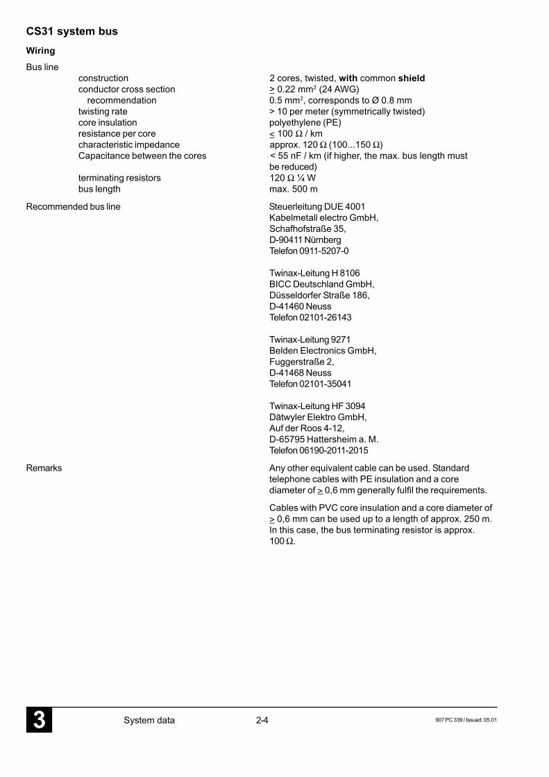
CS31 system busWiringBus line
construction 2 cores, twisted, with common shieldconductor cross section > 0.22 mm2 (24 AWG) recommendation 0.5 mm2, corresponds to Ø 0.8 mmtwisting rate > 10 per meter (symmetrically twisted)core insulation polyethylene (PE)resistance per core < 100 Ω / kmcharacteristic impedance approx. 120 Ω (100...150 Ω)Capacitance between the cores < 55 nF / km (if higher, the max. bus length must
be reduced)terminating resistors 120 Ω ¼ Wbus length max. 500 m
Recommended bus line Steuerleitung DUE 4001Kabelmetall electro GmbH,Schafhofstraße 35,D-90411 NürnbergTelefon 0911-5207-0
Twinax-Leitung H 8106BICC Deutschland GmbH,Düsseldorfer Straße 186,D-41460 NeussTelefon 02101-26143
Twinax-Leitung 9271Belden Electronics GmbH,Fuggerstraße 2,D-41468 NeussTelefon 02101-35041
Twinax-Leitung HF 3094Dätwyler Elektro GmbH,Auf der Roos 4-12,D-65795 Hattersheim a. M.Telefon 06190-2011-2015
Remarks Any other equivalent cable can be used. Standardtelephone cables with PE insulation and a corediameter of > 0,6 mm generally fulfil the requirements.
Cables with PVC core insulation and a core diameter of> 0,6 mm can be used up to a length of approx. 250 m.In this case, the bus terminating resistor is approx.100 Ω.
907 PC 339 / Issued: 05.01 2-5 System data 3
BUS
2BU
S 1
Shie
ld
120 Ω terminalresistor; the 120 Ωresistor is alreadyfitted in the coup-lers 07 CS 61 and35 CS 91
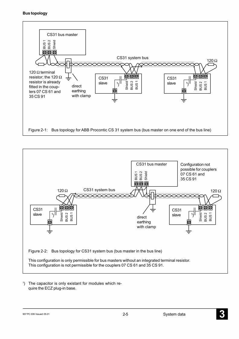
Bus topology
directearthingwith clamp
CS31 system bus
CS31 bus master
CS31slave
Figure 2-1: Bus topology for ABB Procontic CS 31 system bus (bus master on one end of the bus line)
120 Ω
CS31 bus master
CS31slave
120 Ω CS31 system bus
directearthingwith clamp
CS31slave
Configuration notpossible for couplers07 CS 61 and35 CS 91
120 Ω
Figure 2-2: Bus topology for CS31 system bus (bus master in the bus line)
This configuration is only permissible for bus masters without an integrated terminal resistor.This configuration is not permissible for the couplers 07 CS 61 and 35 CS 91.
1) The capacitor is only existant for modules which re-quire the ECZ plug-in base.
BUS
2Sh
ield
BUS
1
CS31slave
BUS
2Sh
ield
BUS
1
1) 1)
BUS
2BU
S 1
Shie
ld
BUS
2BU
S 1
Shie
ld
BUS
2BU
S 1
Shie
ld1) 1)
2-63 907 PC 339 / Issued: 05.01System data
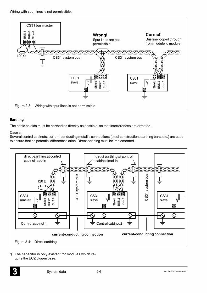
Wiring with spur lines is not permissible.
CS31 system bus
CS31 bus master
CS31slave
CS31slave
CS31 system bus
Wrong!Spur lines are notpermissible
Correct!Bus line looped throughfrom module to module
Earthing
The cable shields must be earthed as directly as possible, so that interferences are arrested.
Case a:Several control cabinets; current-conducting metallic connections (steel construction, earthing bars, etc.) are usedto ensure that no potential differences arise. Direct earthing must be implemented.
CS31master
CS31slave
CS31slave
direct earthing at controlcabinet lead-in
CS3
1 sy
stem
bus
120 Ω
CS3
1 sy
stem
bus
Control cabinet 1 Control cabinet 2
Figure 2-4: Direct earthing
1) The capacitor is only existant for modules which re-quire the ECZ plug-in base.
BUS
2Sh
ield
BUS
1
120 Ω
Figure 2-3: Wiring with spur lines is not permissible
current-conducting connection current-conducting connection
BUS
2BU
S 1
Shie
ld
BUS
2BU
S 1
Shie
ld1) 1)
BUS
2BU
S 1
Shie
ld
BUS
2BU
S 1
Shie
ld1) 1) 1)
direct earthing at controlcabinet lead-in
907 PC 339 / Issued: 05.01 2-7 System data 3
PE
PE
PE
PE
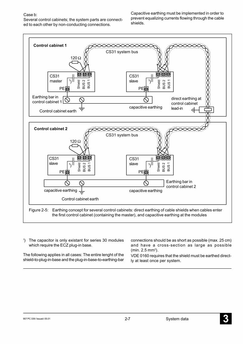
Capacitive earthing must be implemented in order toprevent equalizing currents flowing through the cableshields.
CS31master
CS31slave
capacitive earthing
direct earthing atcontrol cabinetlead-in
CS31 system bus120 Ω
Control cabinet 1
Control cabinet 2
Figure 2-5: Earthing concept for several control cabinets: direct earthing of cable shields when cables enterthe first control cabinet (containing the master), and capacitive earthing at the modules
capacitive earthingControl cabinet earth
Earthing bar incontrol cabinet 1
CS31slave
CS31slave
CS31 system bus120 Ω
capacitive earthing
Earthing bar incontrol cabinet 2
Control cabinet earth
BUS
2BU
S 1
Shie
ld1)
BUS
2BU
S 1
Shie
ld
BUS
2BU
S 1
Shie
ld
BUS
2BU
S 1
Shie
ld
1)
1)1)
Case b:Several control cabinets; the system parts are connect-ed to each other by non-conducting connections.
VDE 0160 requires that the shield must be earthed direct-ly at least once per system.
1) The capacitor is only existant for series 30 moduleswhich require the ECZ plug-in base.
The following applies in all cases: The entire lenght of theshield-to-plug-in-base and the plug-in-base-to-earthing-bar
connections should be as short as possible (max. 25 cm)and have a cross-section as large as possible(min. 2.5 mm2).
2-83 907 PC 339 / Issued: 05.01System data
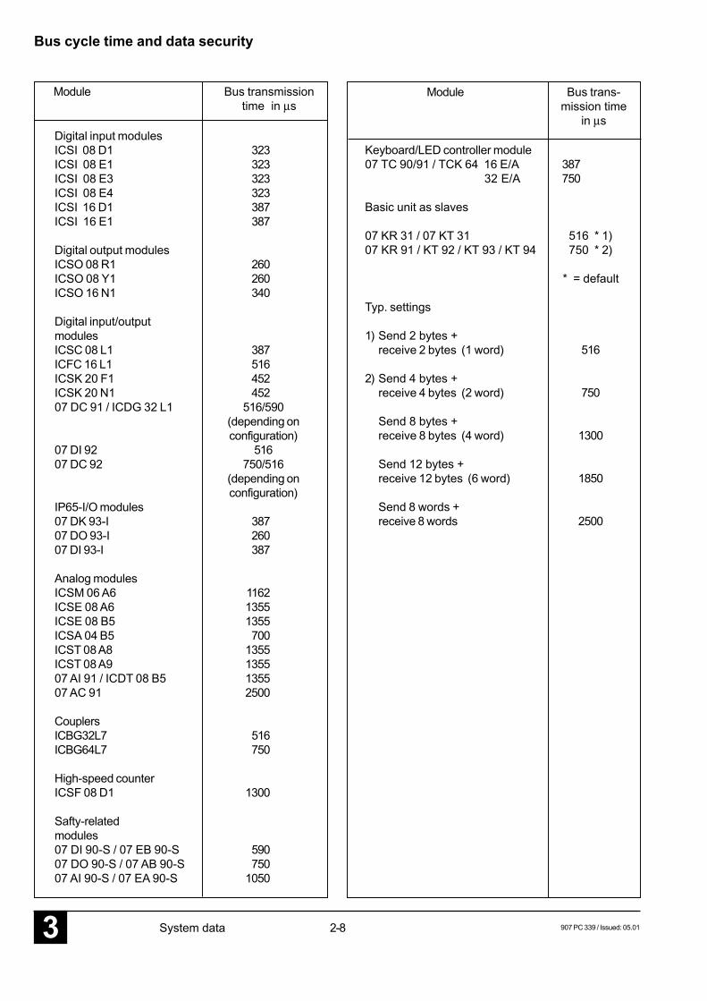
Bus cycle time and data security
Module Bus transmissiontime in µs
Digital input modulesICSI 08 D1 323ICSI 08 E1 323ICSI 08 E3 323ICSI 08 E4 323ICSI 16 D1 387ICSI 16 E1 387
Digital output modulesICSO 08 R1 260ICSO 08 Y1 260ICSO 16 N1 340
Digital input/outputmodulesICSC 08 L1 387ICFC 16 L1 516ICSK 20 F1 452ICSK 20 N1 45207 DC 91 / ICDG 32 L1 516/590
(depending onconfiguration)
07 DI 92 51607 DC 92 750/516
(depending onconfiguration)
IP65-I/O modules07 DK 93-I 38707 DO 93-I 26007 DI 93-I 387
Analog modulesICSM 06 A6 1162ICSE 08 A6 1355ICSE 08 B5 1355ICSA 04 B5 700ICST 08 A8 1355ICST 08 A9 135507 AI 91 / ICDT 08 B5 135507 AC 91 2500
CouplersICBG32L7 516ICBG64L7 750
High-speed counterICSF 08 D1 1300
Safty-relatedmodules07 DI 90-S / 07 EB 90-S 59007 DO 90-S / 07 AB 90-S 75007 AI 90-S / 07 EA 90-S 1050
Module Bus trans-mission time
in µs
Keyboard/LED controller module07 TC 90/91 / TCK 64 16 E/A 387 32 E/A 750
Basic unit as slaves
07 KR 31 / 07 KT 31 516 * 1)07 KR 91 / KT 92 / KT 93 / KT 94 750 * 2)
* = default
Typ. settings
1) Send 2 bytes +receive 2 bytes (1 word) 516
2) Send 4 bytes +receive 4 bytes (2 word) 750
Send 8 bytes +receive 8 bytes (4 word) 1300
Send 12 bytes +receive 12 bytes (6 word) 1850
Send 8 words +receive 8 words 2500
907 PC 339 / Issued: 05.01 2-9 System data 3
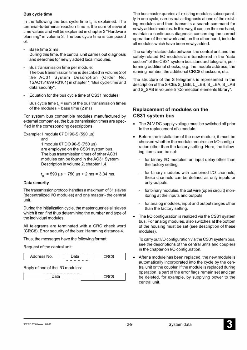
Bus cycle timeIn the following the bus cycle time tB is explained. Theterminal-to-terminal reaction time is the sum of severaltime values and will be explained in chapter 3 "Hardwareplanning" in volume 3. The bus cycle time is composedof:
- Base time 2 msDuring this time, the central unit carries out diagnosisand searches for newly added local modules.
- Bus transmission time per module:The bus transmission time is described in volume 2 ofthe AC31 System Description (Order No.1SAC131699 R0101) in chapter 1 "Bus cycle time anddata security".
- Equation for the bus cycle time of CS31 modules:
Bus cycle time tB = sum of the bus transmission timesof the modules + base time (2 ms)
For system bus compatible modules manufactured byexternal companies, the bus transmission times are spec-ified in the corresponding descriptions.
Example:1 module 07 DI 90-S (590 µs)and1 module 07 DO 90-S (750 µs)are employed on the CS31 system bus.The bus transmission times of other AC31modules can be found in the AC31 SystemDescription in volume 2, chapter 1.4.
tB = 590 µs + 750 µs + 2 ms = 3,34 ms.
Data securityThe transmission protocol handles a maximum of 31 slaves(decentralized I/O modules) and one master - the centralunit.
During the initialization cycle, the master queries all slaveswhich it can find thus determining the number and type ofthe individual modules.
All telegrams are terminated with a CRC check word(CRC8). Error security of the bus: Hamming distance 4.
Thus, the messages have the following format:
Request of the central unit:
Reply of one of the I/O modules:
Address No. Data CRC8
Data CRC8
The bus master queries all existing modules subsequent-ly in one cycle, carries out a diagnosis at one of the exist-ing modules and then transmits a search command fornewly added modules. In this way, it can, on the one hand,maintain a continuous diagnosis concerning the correctoperation of the network and, on the other hand, includeall modules which have been newly added.
The safety-related data between the central unit and thesafety-related I/O modules are transferred in the "datasection" of the CS31 system bus standard telegram, per-forming additional checks, e.g. the module address, therunning number, the additional CRC8 checksum, etc.
The structure of the S telegrams is represented in thedescription of the S-CEs S_LEB, L_LEB, S_LEA, S_LABand S_SAB in volume 5 "Connection elements library".
Replacement of modules on theCS31 system bus• The 24 V DC supply voltage must be switched off prior
to the replacement of a module.
• Before the installation of the new module, it must bechecked whether the module requires an I/O configu-ration other than the factory setting. Here, the follow-ing items can be set:
- for binary I/O modules, an input delay other thanthe factory setting,
- for binary modules with combined I/O channels,these channels can be defined as only-inputs oronly-outputs,
- for binary modules, the cut wire (open circuit) mon-itoring at the inputs and outputs
- for analog modules, input and output ranges otherthan the factory setting.
• The I/O configuration is realized via the CS31 systembus. For analog modules, also switches at the bottomof the housing must be set (see description of thesemodules).
To carry out I/O configuration via the CS31 system bus,see the descriptions of the central units and couplersin the chapter on I/O configuration.
• After a module has been replaced, the new module isautomatically incorporated into the cycle by the cen-tral unit or the coupler. If the module is replaced duringoperation, a part of the error flags remain set and canbe deleted, for example, by supplying power to thecentral unit.
2-103 907 PC 339 / Issued: 05.01System data
6513
065
140
94120
2085
25
111
75
594
Advant Controller 3107 DI 90-S
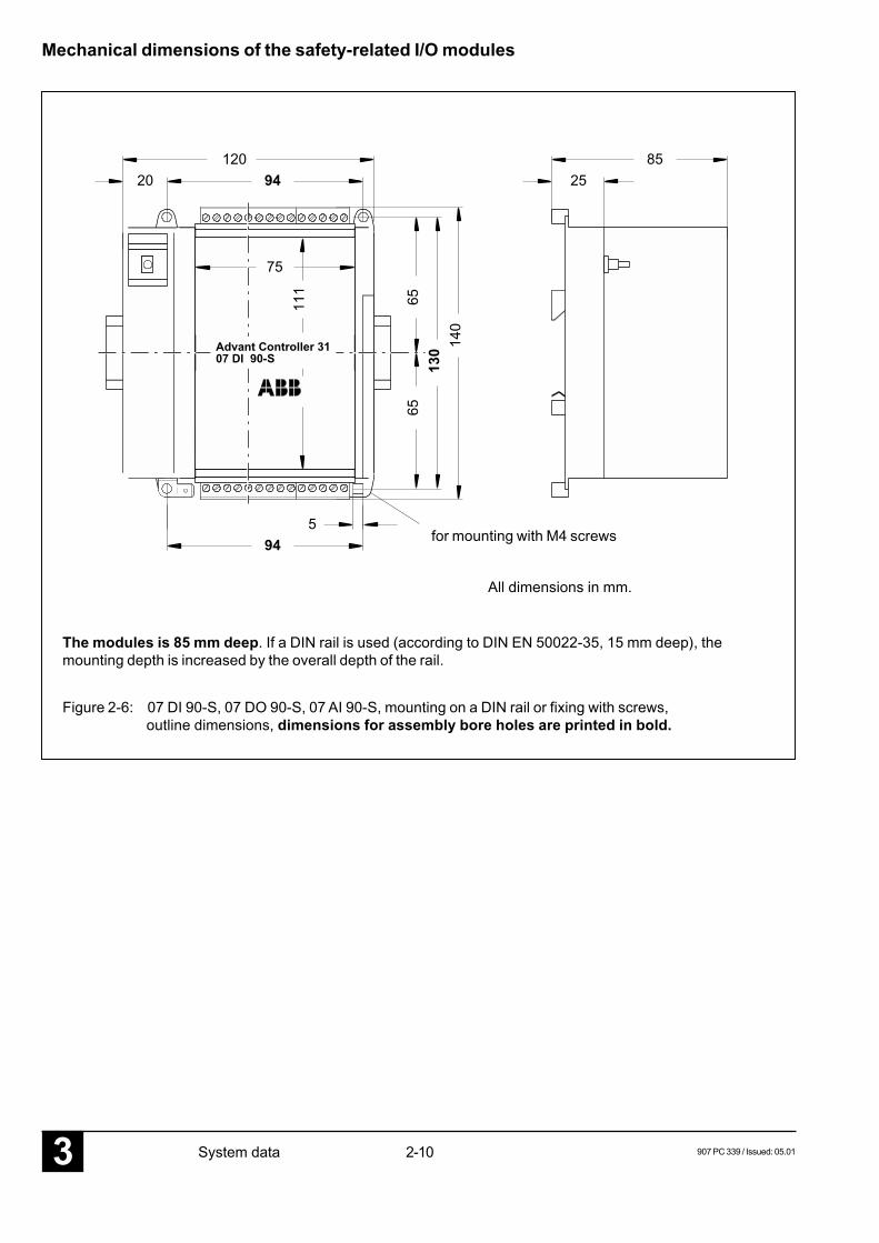
Mechanical dimensions of the safety-related I/O modules
for mounting with M4 screws
All dimensions in mm.
The modules is 85 mm deep. If a DIN rail is used (according to DIN EN 50022-35, 15 mm deep), themounting depth is increased by the overall depth of the rail.
Figure 2-6: 07 DI 90-S, 07 DO 90-S, 07 AI 90-S, mounting on a DIN rail or fixing with screws,outline dimensions, dimensions for assembly bore holes are printed in bold.
907 PC 339 / Issued: 05.01 2-11 System data 3
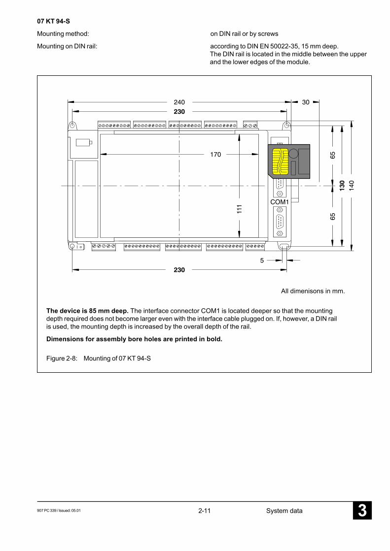
07 KT 94-S
Mounting method: on DIN rail or by screws
Mounting on DIN rail: according to DIN EN 50022-35, 15 mm deep.The DIN rail is located in the middle between the upperand the lower edges of the module.
The device is 85 mm deep. The interface connector COM1 is located deeper so that the mountingdepth required does not become larger even with the interface cable plugged on. If, however, a DIN railis used, the mounting depth is increased by the overall depth of the rail.
Dimensions for assembly bore holes are printed in bold.
Figure 2-8: Mounting of 07 KT 94-S
All dimenisons in mm.

2-123 907 PC 339 / Issued: 05.01System data
907 PC 339 / Issued: 05.01 3-1 Hardware planning 3
3 Hardware planning
Contents3.1 Preconditions ............................................. 3-13.2 Addressing of the safety-related
I/O modules (setting the module address) .. 3-33.3 Configuring the I/O modules ....................... 3-43.3.1 Possible module addresses ....................... 3-43.3.2 Configuration data 07 DI 90-S ..................... 3-53.3.3 Configuration data 07 DO 90-S ................... 3-53.3.4 Configuration data 07 AI 90-S ..................... 3-63.3.5 Example for a configuration ........................ 3-63.4 Lightning protection / wiring concept .......... 3-83.4.1 Lightning protection .................................... 3-83.4.2 Wiring concept ........................................... 3-93.4.3 Using the Advant Controller 31 in
networks of overvoltage category III(e.g. in road traffic signal systemsaccording to DIN VDE 0832) ..................... 3-11
3.5 Behaviour on power ON ............................. 3-113.6 Behaviour in case of errors on
the safety-related I/O modules .................. 3-11
3.1 PreconditionsFor the planning of the Advant Controller 31-S, the AC31planning directives apply for non-safety-related modules.
Additionally, the following planning regulations must beobserved for the safety-related operation:
• The planning is generally to be made in accordancewith the check list for the draft phase and realizationphase (see volume 7).
- The number of I/O ports is known after defining thesafety-related and the non-safety-related signals.The user must provide an I/O reserve for further ex-pansions. This will usually be within a size of plus10 % referred to the I/O points already assigned.
- The result is a list with the number of safety-relatedI/O modules and non-safety-related I/O modules.For setting up the configuration, it must now bechecked whether the required modules fit into oneremote line with reference to the addresses anddata volume. If necessary, several lines must beplanned (see also example configuration).
In addition, the following items must be observed:
• Only one CS31 bus line per central unit 07 KT 94-S ispossible.
• A maximum of 31 modules (including safety-relatedmodules and non-safety-related modules) can be con-nected to the CS31 system bus.
• Generally only module addresses between 0 and 61are permissible; 0 to 61 for bit modules and 0 to 6 forword modules.
• Note that some modules employ more than one ad-dress.
• The safety-related modules 07 DI 90-S, 07 DO 90-Sand 07 AI 90-S can only be set to an address in therange between 0 to 31.
• For the planning, it must be observed that the errortolerance time (200 msec) must not be exceeded. Thiserror tolerance time is determined by:
- Input delay or output delay of the I/O module
- Bus cycle time, to be calculated from the followingtable for S modules or the AC31 System Descrip-tion (1SAC131699R0102, Volume2, chapter 1.4”Bus cycle time") for standard modules.
- Program cycle time, set in the flag KD0,0 (smallestadjustable cycle time = 1 ms; can be increasedonly in steps of 1 ms).
3-23 907 PC 339 / Issued: 05.01Hardware planning
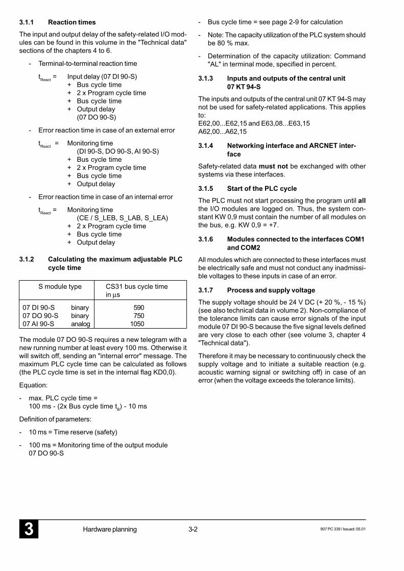
3.1.1 Reaction timesThe input and output delay of the safety-related I/O mod-ules can be found in this volume in the "Technical data"sections of the chapters 4 to 6.
- Terminal-to-terminal reaction time
tReact = Input delay (07 DI 90-S)+ Bus cycle time+ 2 x Program cycle time+ Bus cycle time+ Output delay
(07 DO 90-S)
- Error reaction time in case of an external error
tReact = Monitoring time(DI 90-S, DO 90-S, AI 90-S)
+ Bus cycle time+ 2 x Program cycle time+ Bus cycle time+ Output delay
- Error reaction time in case of an internal error
tReact = Monitoring time(CE / S_LEB, S_LAB, S_LEA)
+ 2 x Program cycle time+ Bus cycle time+ Output delay
3.1.2 Calculating the maximum adjustable PLCcycle time
- Bus cycle time = see page 2-9 for calculation
- Note: The capacity utilization of the PLC system shouldbe 80 % max.
- Determination of the capacity utilization: Command"AL" in terminal mode, specified in percent.
3.1.3 Inputs and outputs of the central unit07 KT 94-S
The inputs and outputs of the central unit 07 KT 94-S maynot be used for safety-related applications. This appliesto:E62,00...E62,15 and E63,08...E63,15A62,00...A62,15
3.1.4 Networking interface and ARCNET inter-face
Safety-related data must not be exchanged with othersystems via these interfaces.
3.1.5 Start of the PLC cycleThe PLC must not start processing the program until allthe I/O modules are logged on. Thus, the system con-stant KW 0,9 must contain the number of all modules onthe bus, e.g. KW 0,9 = +7.
3.1.6 Modules connected to the interfaces COM1and COM2
All modules which are connected to these interfaces mustbe electrically safe and must not conduct any inadmissi-ble voltages to these inputs in case of an error.
3.1.7 Process and supply voltageThe supply voltage should be 24 V DC (+ 20 %, - 15 %)(see also technical data in volume 2). Non-compliance ofthe tolerance limits can cause error signals of the inputmodule 07 DI 90-S because the five signal levels definedare very close to each other (see volume 3, chapter 4"Technical data").
Therefore it may be necessary to continuously check thesupply voltage and to initiate a suitable reaction (e.g.acoustic warning signal or switching off) in case of anerror (when the voltage exceeds the tolerance limits).
S module type CS31 bus cycle timein µs
07 DI 90-S binary 590 07 DO 90-S binary 750 07 AI 90-S analog 1050
The module 07 DO 90-S requires a new telegram with anew running number at least every 100 ms. Otherwise itwill switch off, sending an "internal error" message. Themaximum PLC cycle time can be calculated as follows(the PLC cycle time is set in the internal flag KD0,0).
Equation:
- max. PLC cycle time =100 ms - (2x Bus cycle time tB) - 10 ms
Definition of parameters:
- 10 ms = Time reserve (safety)
- 100 ms = Monitoring time of the output module07 DO 90-S
907 PC 339 / Issued: 05.01 3-3 Hardware planning 3
Input UnitAdvant Contr. 31-S
07 DI 90-S
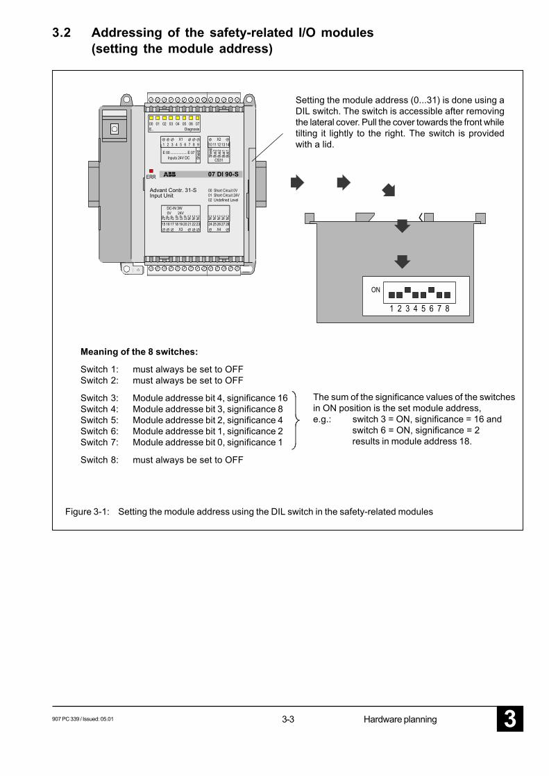
3.2 Addressing of the safety-related I/O modules(setting the module address)
Setting the module address (0...31) is done using aDIL switch. The switch is accessible after removingthe lateral cover. Pull the cover towards the front whiletilting it lightly to the right. The switch is providedwith a lid.
Meaning of the 8 switches:
Switch 1: must always be set to OFFSwitch 2: must always be set to OFF
Switch 3: Module addresse bit 4, significance 16Switch 4: Module addresse bit 3, significance 8Switch 5: Module addresse bit 2, significance 4Switch 6: Module addresse bit 1, significance 2Switch 7: Module addresse bit 0, significance 1
Switch 8: must always be set to OFF
The sum of the significance values of the switchesin ON position is the set module address,e.g.: switch 3 = ON, significance = 16 and
switch 6 = ON, significance = 2results in module address 18.
Figure 3-1: Setting the module address using the DIL switch in the safety-related modules
3-43 907 PC 339 / Issued: 05.01Hardware planning
3.3 Configuring the I/O modules
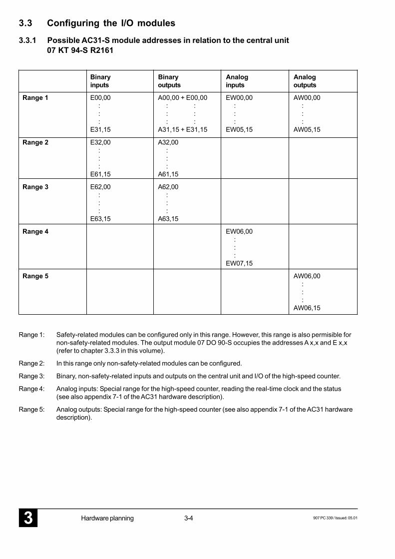
3.3.1 Possible AC31-S module addresses in relation to the central unit07 KT 94-S R2161
Range 1: Safety-related modules can be configured only in this range. However, this range is also permisible fornon-safety-related modules. The output module 07 DO 90-S occupies the addresses A x,x and E x,x(refer to chapter 3.3.3 in this volume).
Range 2: In this range only non-safety-related modules can be configured.
Range 3: Binary, non-safety-related inputs and outputs on the central unit and I/O of the high-speed counter.
Range 4: Analog inputs: Special range for the high-speed counter, reading the real-time clock and the status(see also appendix 7-1 of the AC31 hardware description).
Range 5: Analog outputs: Special range for the high-speed counter (see also appendix 7-1 of the AC31 hardwaredescription).
Binary Binary Analog Analoginputs outputs inputs outputs
Range 1 E00,00 A00,00 + E00,00 EW00,00 AW00,00 : : : : : : : : : : : : : : :E31,15 A31,15 + E31,15 EW05,15 AW05,15
Range 2 E32,00 A32,00 : : : : : :E61,15 A61,15
Range 3 E62,00 A62,00 : : : : : :E63,15 A63,15
Range 4 EW06,00 : : :EW07,15
Range 5 AW06,00 : : :AW06,15
907 PC 339 / Issued: 05.01 3-5 Hardware planning 3
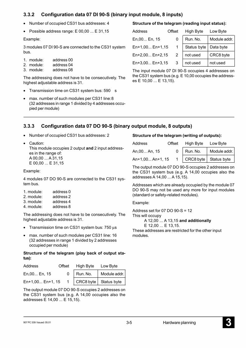
3.3.2 Configuration data 07 DI 90-S (binary input module, 8 inputs)• Number of occupied CS31 bus addresses: 4
• Possible address range: E 00,00 ... E 31,15
Example:
3 modules 07 DI 90-S are connected to the CS31 systembus.
1. module: address 002. module: address 043. module: address 08
The addressing does not have to be consecutively. Thehighest adjustable address is 31.
• Transmission time on CS31 system bus: 590 s
• max. number of such modules per CS31 line:8(32 addresses in range 1 divided by 4 addresses occu-pied per module)
Structure of the telegram (reading input status):
Address Offset High Byte Low Byte
En,00... En, 15 0 Run. No. Module addr.
En+1,00... En+1,15 1 Status byte Data byte
En+2,00... En+2,15 2 not used CRC8 byte
En+3,00... En+3,15 3 not used not used
The input module 07 DI 90-S occupies 4 addresses onthe CS31 system bus (e.g. E 10,00 occupies the address-es E 10,00 ... E 13,15).
• Number of occupied CS31 bus addresses: 2
• Caution:This module occupies 2 output and 2 input address-es in the range of:A 00,00 ... A 31,15E 00,00 ... E 31,15
Example:
4 modules 07 DO 90-S are connected to the CS31 sys-tem bus.
1. module: address 02. module: address 23. module: address 44. module: address 8
The addressing does not have to be consecutively. Thehighest adjustable address is 31.
• Transmission time on CS31 system bus: 750 µs
• max. number of such modules per CS31 line: 16(32 addresses in range 1 divided by 2 addressesoccupied per module)
Structure of the telegram (play back of output sta-tus):
Address Offset High Byte Low Byte
En,00... En, 15 0 Run. No. Module addr.
En+1,00... En+1, 15 1 CRC8 byte Status byte
The output module 07 DO 90-S occupies 2 addresses onthe CS31 system bus (e.g. A 14,00 occupies also theaddresses E 14,00 ... E 15,15).
3.3.3 Configuration data 07 DO 90-S (binary output module, 8 outputs)
Structure of the telegram (writing of outputs):
Address Offset High Byte Low Byte
An,00... An, 15 0 Run. No. Module addr.
An+1,00... An+1, 15 1 CRC8 byte Status byte
The output module 07 DO 90-S occupies 2 addresses onthe CS31 system bus (e.g. A 14,00 occupies also theaddresses A 14,00 ... A 15,15).
Addresses which are already occupied by the module 07DO 90-S may not be used any more for input modules(standard or safety-related modules).
Example:
Address set for 07 DO 90-S = 12This will occupy
A 12,00 ... A 13,15 and additionallyE 12,00 ... E 13,15.
These addresses are restricted for the other inputmodules.
3-63 907 PC 339 / Issued: 05.01Hardware planning
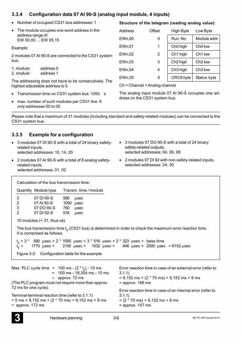
• Number of occupied CS31 bus addresses: 1
• The module occupies one word address in theaddress range of:EW 00,00 ... EW 05,15
Example:
2 modules 07 AI 90-S are connected to the CS31 systembus.
1. module: address 02. module: address 1
The addressing does not have to be consecutively. Thehighest adjustable address is 5.
• Transmission time on CS31 system bus: 1050 s
• max. number of such modules per CS31 line: 6only addresses 00 to 05
3.3.4 Configuration data 07 AI 90-S (analog input module, 4 inputs)
3.3.5 Example for a configuration
Max. PLC cycle time = 100 ms - (2 * tB) - 10 ms= 100 ms - 18,304 ms - 10 ms= approx. 72 ms
(The PLC program must not require more than approx.72 ms for one cycle).
Terminal-terminal reaction time (refer to 3.1.1)= 5 ms + 9,152 ms + (2 * 70 ms) + 9,152 ms + 8 ms= approx. 172 ms
• 3 modules 07 DI 90-S with a total of 24 binary safety-related inputs,selected addresses: 10, 14, 20
• 2 modules 07 AI 90-S with a total of 8 analog safety-related inputs,selected addresses: 01, 02
• 3 modules 07 DO 90-S with a total of 24 binarysafety-related outputs,selected addresses: 04, 06, 08
• 2 modules 07 DI 92 with non-safety-related inputs,selected addresses: 24, 30
Structure of the telegram (reading analog value):
Address Offset High Byte Low Byte
EWn,00 0 Run. No. Module addr.
EWn,01 1 Ch0 high Ch0 low
EWn,02 2 Ch1 high Ch1 low
EWn,03 3 Ch2 high Ch2 low
EWn,04 4 Ch3 high Ch3 low
EWn,05 5 CRC8 byte Status byte
Ch = Channel = Analog channel
The analog input module 07 AI 90-S occupies one ad-dress on the CS31 system bus.
Error reaction time in case of an external error (refer to3.1.1)= 9,152 ms + (2 * 70 ms) + 9,152 ms + 8 ms= approx. 166 ms
Error reaction time in case of an internal error (refer to3.1.1)= (2 * 70 ms) + 9,152 ms + 8 ms= approx. 157 ms
Please note that a maximum of 31 modules (including standard and safety-related modules) can be connected to theCS31 system bus.
Calculation of the bus transmission time:
Quantity Module type Transm. time / module
3 07 DI 90-S 590 µsec2 07 AI 90-S 1050 µsec3 07 DO 90-S 750 µsec2 07 DI 92-S 516 µsec
10 modules (< 31, thus ok)
The bus transmission time tB (CS31 bus) is determined in order to check the maximum error reaction time.It is comprised as follows.
tB = 3 * 590 µsec + 2 * 1050 µsec + 3 * 516 µsec + 2 * 323 µsec + base timetB = 1770 µsec + 2100 µsec + 1032 µsec + 646 µsec + 2000 µsec = 9152 µsec
Figure 3-2: Configuration table for the example
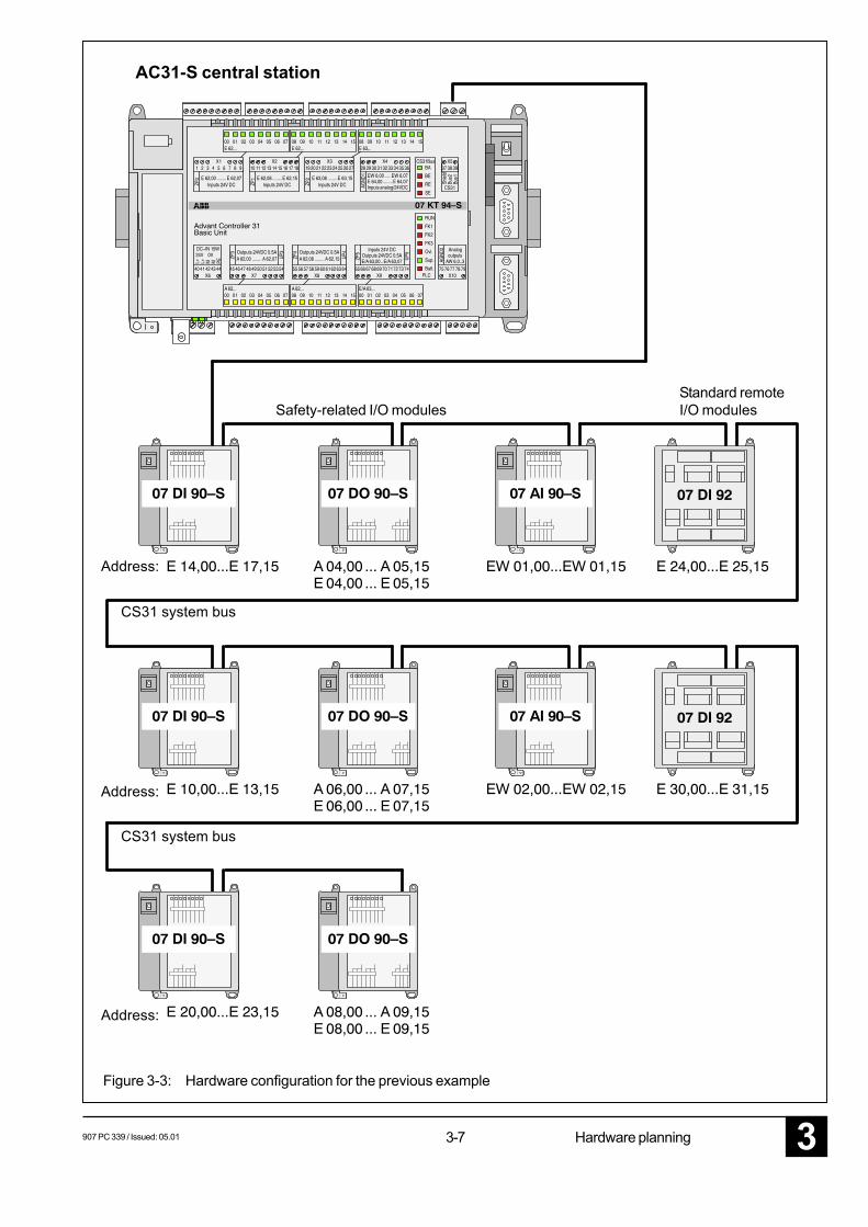
907 PC 339 / Issued: 05.01 3-7 Hardware planning 3Figure 3-3: Hardware configuration for the previous example
Standard remoteI/O modules
CS31 system bus
CS31 system bus
AC31-S central station
Safety-related I/O modules
Address:
Address:
Address:
3-83 907 PC 339 / Issued: 05.01Hardware planning
3.4 Lightning protection / wiring concept
3.4.1 Lightning protection
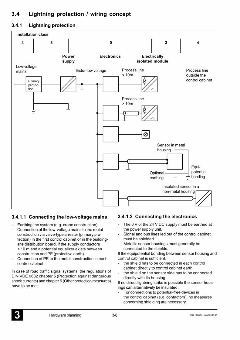
Installation class
Low-voltagemains Extra-low voltage Process line
< 10mProcess lineoutside thecontrol cabinetPrimary
protec-tion
Process line> 10m
Sensor in metalhousing
Optionalearthing
Equi-potentialbonding
Insulated sensor in anon-metal housing
3.4.1.2 Connecting the electronics- The 0 V of the 24 V DC supply must be earthed at
the power supply unit.- Signal and bus lines led out of the control cabinet
must be shielded.- Metallic sensor housings must generally be
connected to the shields.If the equipotential bonding between sensor housing andcontrol cabinet is sufficient,- the shield has to be connected in each control
cabinet directly to control cabinet earth- the shield on the sensor side has to be connected
directly with its housingIf no direct lightning strike is possible the sensor hous-ings can alternatively be insulated.- For connections to potential-free devices in
the control cabinet (e.g. contactors), no measuresconcerning shielding are necessary.
4 433 0
Powersupply
Electronics Electricallyisolated module
3.4.1.1 Connecting the low-voltage mains- Earthing the system (e.g. crane construction)- Connection of the low-voltage mains to the metal
construction via valve-type arrester (primary pro-tection) in the first control cabinet or in the building-site distribution board, if the supply conductors< 10 m and a potential equalizer exists betweenconstruction and PE (protective earth)
- Connection of PE to the metal construction in eachcontrol cabinet
In case of road traffic signal systems, the regulations ofDIN VDE 0832 chapter 5 (Protection against dangerousshock currents) and chapter 6 (Other protection measures)have to be met.
907 PC 339 / Issued: 05.01 3-9 Hardware planning 3
Input
Output
Unshielded signal linefor controlling ofmodules within thecontrol cabinet (< 10m)
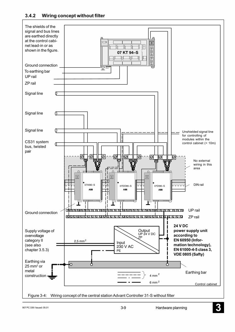
The shields of thesignal and bus linesare earthed directlyat the control cabi-net lead-in or asshown in the figure.
Ground connection
Supply voltage ofovervoltagecategory II(see alsochapter 3.5.3)
Earthing via25 mm2 ormetalconstruction
Ground connection
UP railZP rail
Signal line
CS31 systembus, twistedpair
Signal line
Signal line
To earthing bar
No externalwiring in thisarea
DIN rail
UP rail
ZP rail
24 V DCpower supply unitaccording toEN 60950 (Infor-mation technology),EN 61000-4-5 class 3,VDE 0805 (Safty)
Earthing bar
Control cabinet
Figure 3-4: Wiring concept of the central station Advant Controller 31-S without filter
3.4.2 Wiring concept without filter
3-103 907 PC 339 / Issued: 05.01Hardware planning
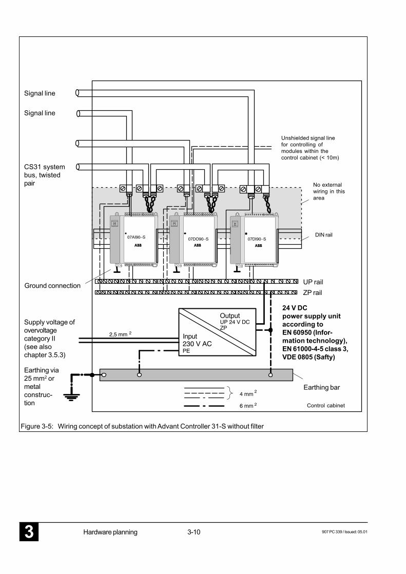
Figure 3-5: Wiring concept of substation with Advant Controller 31-S without filter
Ground connection
24 V DCpower supply unitaccording toEN 60950 (Infor-mation technology),EN 61000-4-5 class 3,VDE 0805 (Safty)
CS31 systembus, twistedpair
Supply voltage ofovervoltagecategory II(see alsochapter 3.5.3)
Earthing via25 mm2 ormetalconstruc-tion
Signal line
Signal line
Unshielded signal linefor controlling ofmodules within thecontrol cabinet (< 10m)
No externalwiring in thisarea
DIN rail
UP railZP rail
Earthing bar
Control cabinet
Input
Output
907 PC 339 / Issued: 05.01 3-11 Hardware planning 3
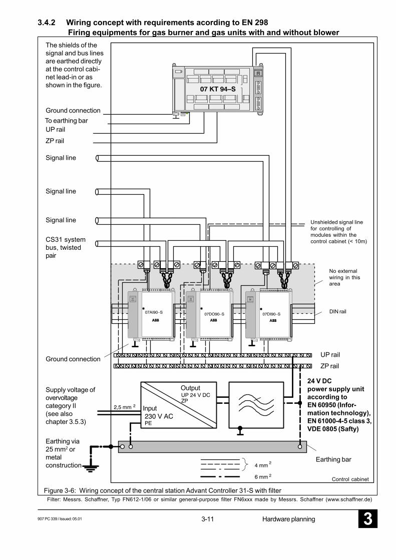
Input
Output
The shields of thesignal and bus linesare earthed directlyat the control cabi-net lead-in or asshown in the figure.
Ground connection
Supply voltage ofovervoltagecategory II(see alsochapter 3.5.3)
Earthing via25 mm2 ormetalconstruction
Ground connection
UP rail
ZP rail
Signal line
CS31 systembus, twistedpair
Signal line
Signal line
To earthing bar
3.4.2 Wiring concept with requirements acording to EN 298 Firing equipments for gas burner and gas units with and without blower
Figure 3-6: Wiring concept of the central station Advant Controller 31-S with filterFilter: Messrs. Schaffner, Typ FN612-1/06 or similar general-purpose filter FN6xxx made by Messrs. Schaffner (www.schaffner.de)
Unshielded signal linefor controlling ofmodules within thecontrol cabinet (< 10m)
No externalwiring in thisarea
DIN rail
UP rail
ZP rail
Earthing bar
Control cabinet
24 V DCpower supply unitaccording toEN 60950 (Infor-mation technology),EN 61000-4-5 class 3,VDE 0805 (Safty)
3-123 907 PC 339 / Issued: 05.01Hardware planning
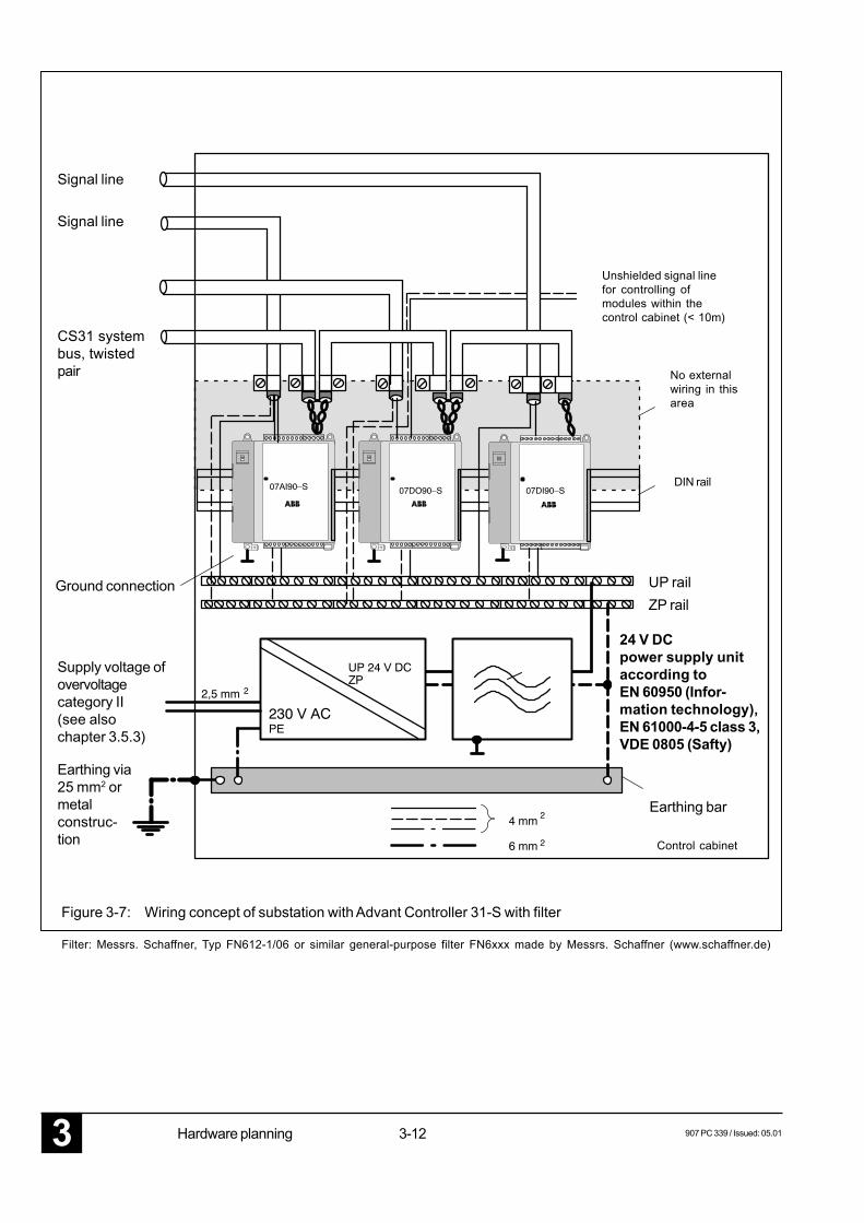
Figure 3-7: Wiring concept of substation with Advant Controller 31-S with filter
CS31 systembus, twistedpair
Supply voltage ofovervoltagecategory II(see alsochapter 3.5.3)
Earthing via25 mm2 ormetalconstruc-tion
Signal line
Signal line
Ground connection
Filter: Messrs. Schaffner, Typ FN612-1/06 or similar general-purpose filter FN6xxx made by Messrs. Schaffner (www.schaffner.de)
Unshielded signal linefor controlling ofmodules within thecontrol cabinet (< 10m)
No externalwiring in thisarea
DIN rail
UP railZP rail
Earthing bar
Control cabinet
24 V DCpower supply unitaccording toEN 60950 (Infor-mation technology),EN 61000-4-5 class 3,VDE 0805 (Safty)
907 PC 339 / Issued: 05.01 3-13 Hardware planning 3
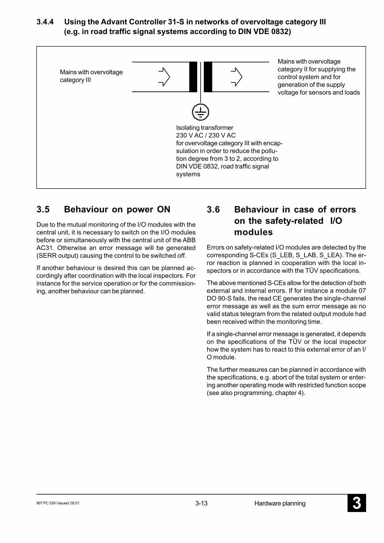
3.4.4 Using the Advant Controller 31-S in networks of overvoltage category III(e.g. in road traffic signal systems according to DIN VDE 0832)
Mains with overvoltagecategory III
Mains with overvoltagecategory II for supplying thecontrol system and forgeneration of the supplyvoltage for sensors and loads
Isolating transformer230 V AC / 230 V ACfor overvoltage category III with encap-sulation in order to reduce the pollu-tion degree from 3 to 2, according toDIN VDE 0832, road traffic signalsystems
3.5 Behaviour on power ONDue to the mutual monitoring of the I/O modules with thecentral unit, it is necessary to switch on the I/O modulesbefore or simultaneously with the central unit of the ABBAC31. Otherwise an error message will be generated(SERR output) causing the control to be switched off.
If another behaviour is desired this can be planned ac-cordingly after coordination with the local inspectors. Forinstance for the service operation or for the commission-ing, another behaviour can be planned.
3.6 Behaviour in case of errorson the safety-related I/Omodules
Errors on safety-related I/O modules are detected by thecorresponding S-CEs (S_LEB, S_LAB, S_LEA). The er-ror reaction is planned in cooperation with the local in-spectors or in accordance with the TÜV specifications.
The above mentioned S-CEs allow for the detection of bothexternal and internal errors. If for instance a module 07DO 90-S fails, the read CE generates the single-channelerror message as well as the sum error message as novalid status telegram from the related output module hadbeen received within the monitoring time.
If a single-channel error message is generated, it dependson the specifications of the TÜV or the local inspectorhow the system has to react to this external error of an I/O module.
The further measures can be planned in accordance withthe specifications, e.g. abort of the total system or enter-ing another operating mode with restricted function scope(see also programming, chapter 4).

3-143 907 PC 339 / Issued: 05.01Hardware planning
907 PC 339 / Issued: 05.01 4-1 07 DI 90-S 3
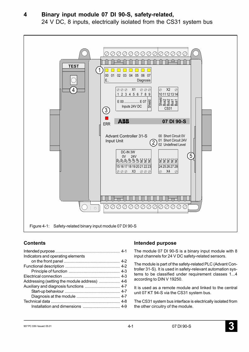
4 Binary input module 07 DI 90-S, safety-related,24 V DC, 8 inputs, electrically isolated from the CS31 system bus
Figure 4-1: Safety-related binary input module 07 DI 90-S
ContentsIntended purpose ....................................................... 4-1Indicators and operating elements
on the front panel ................................................ 4-2Functional description ............................................... 4-2
Principle of function ............................................ 4-3Electrical connection ................................................. 4-3Addressing (setting the module address) .................. 4-6Auxiliary and diagnosis functions .............................. 4-7
Start-up behaviour ............................................... 4-7Diagnosis at the module ..................................... 4-7
Technical data ........................................................... 4-8Installation and dimensions ................................ 4-9
Intended purposeThe module 07 DI 90-S is a binary input module with 8input channels for 24 V DC safety-related sensors.
The module is part of the safety-related PLC (Advant Con-troller 31-S). It is used in safety-relevant automation sys-tems to be classified under requirement classes 1...4according to DIN V 19250.
It is used as a remote module and linked to the centralunit 07 KT 94-S via the CS31 system bus.
The CS31 system bus interface is electrically isolated fromthe other circuitry of the module.
TEST
Input UnitAdvant Controller 31-S
07 DI 90-S
4-23 907 PC 339 / Issued: 05.0107 DI 90-S
The input signals of the module 07 DI 90-S are read in bythe AC31 central unit using special safety-related con-nection elements (CEs).
Indicators and operating elements on thefront panel
1 8 yellow LEDs for indication of the signal state atthe inputs or for error and diagnosis indication
2 List of the diagnosis information referred to the LEDsif these are used for diagnosis indication
3 Red LED for error indication
4 Test button
5 DIL switch for address setting below the cover
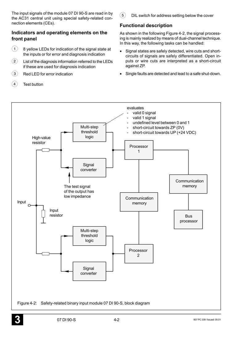
Functional descriptionAs shown in the following Figure 4-2, the signal process-ing is mainly realized by means of dual-channel technique.In this way, the following tasks can be handled:
• Signal states are safely detected, wire cuts and short-circuits of signals are safely differentiated. Open in-puts or wire cuts are interpreted as a short-circuitagainst ZP.
• Single faults are detected and lead to a safe shut-down.
evaluates- valid 0 signal- valid 1 signal- undefined level between 0 and 1- short-circuit towards ZP (0V)- short-circuit towards UP (+24 VDC)
Multi-stepthreshold
logicHigh-valueresistor
Signalconverter
Processor1
Input
Inputresistor
Communicationmemory
Busprocessor
Processor2
The test signalof the output haslow impedance
Figure 4-2: Safety-related binary input module 07 DI 90-S, block diagram
Communicationmemory
Multi-stepthreshold
logic
Signalconverter
907 PC 339 / Issued: 05.01 4-3 07 DI 90-S 3
01
E 0
02
E 1
03
E 2
UP
UP
+24 V
Principle of functionThe input current flowing through the input resistor gener-ates a voltage drop which is led to two identically config-ured evaluation channels via high-value resistors. The high-resistivity of the resistors guarantees a non-interactingbetween both channels.
Both channels mutually supervise each other, by
- their processors comparing the evaluated input signalsto each other;
- their processors generating multi-step binary signalsin check cycles via signal converters and by compar-ing the values derived from this by the threshold switchto the expected value;
- their processors mutually checking each other for theirfunction ability.
The dual-channel principle terminates at the bus proces-sor with a specially safety-related telegram.
System bus interfaceThe CS31 system bus interface, which is electrically iso-lated, provides for the data exchange via the bus.
Process supply voltage UPThere is no electrical isolation between the process sup-ply voltage and the binary inputs.
It must be observed by any means that the binarysafety-related sensors are supplied by the sameUP rail as the module itself. Only in this way, the 5possible states of the module input signals can becorrectly differentiated:
- valid 0 signal- valid 1 signal- undefined level between 0 and 1- short-circuit towards ZP (0V) and- short-circuit towards UP (+24 V).
Electrical connectionFor the planning of the AC31-S, the safety manual for theAC31-S (this file) must be observed. Here, both the archi-tecture of the PLC program and the construction of thehardware components and their wiring are described indetail.
The module is either snapped-on to a DIN rail or directlyscrewed on the control cabinet’s rear wall. The electricalconnection is realized via pluggable terminal blocks. Allterminal blocks must be installed even those which arenot used.
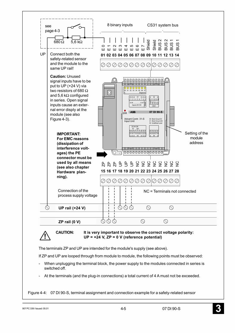
Figure 4-4 on page 4-5 shows the terminal assignment ofthe module with a wiring example for a safety-related sen-sor.
In this example it is assumed that the resistors for theopen-circuit monitoring are integrated into the safety-re-lated sensors. However, this is not the case for all of them.
If safety-related sensors without integrated resistors areto be connected to the module 07 DI 90-S, there are twooptions:
- The wiring of the cables is completed according to thevalid VDE regulations and for instance the fault exclu-sion according to VDE 0116 chapter 8.7.4.1 is used,which means that the short-circuiting of a conductorcan be excluded as possible error source. Furthermore,if the planning is made according to the closed-circuitprinciple, the module detects any wire cut. In this case,the resistors may be mounted directly to the terminalsof the module 07 DI 90-S.
- However, a higher safety level is achieved if the resis-tors are directly connected to the terminals of the safe-ty-related sensor as this guarantees a complete cablemonitoring.
The resistors used for the safety-related sensors mustcome up to the following requirements:
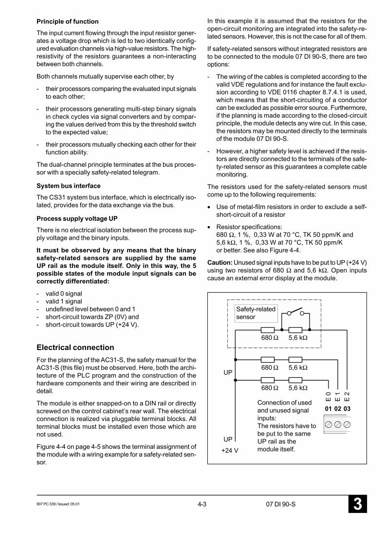
• Use of metal-film resistors in order to exclude a self-short-circuit of a resistor
• Resistor specifications:680 Ω, 1 %, 0,33 W at 70 °C, TK 50 ppm/K and5,6 kΩ, 1 %, 0,33 W at 70 °C, TK 50 ppm/Kor better. See also Figure 4-4.
Caution: Unused signal inputs have to be put to UP (+24 V)using two resistors of 680 Ω and 5,6 kΩ. Open inputscause an external error display at the module.
Connection of usedand unused signalinputs:The resistors have tobe put to the sameUP rail as themodule itself.
680 Ω
680 Ω
680 Ω
5,6 kΩ
5,6 kΩ
5,6 kΩ
Safety-relatedsensor
4-43 907 PC 339 / Issued: 05.0107 DI 90-S
DC
DC
E 0
E 1
E 2
E 3
E 4
E 5
E 6
E 7
ZP
ZP
ZP
UP
UP
NC
NC
NC
NC
NC
PE
UP
NC
NC
NC
8 binary inputs CS31 system bus
Shie
ldSh
ield
AC31 systembus coupling DC/DC
convertersupplies theCS31 systembus coupling
Processing of thebinary inputs seeFigure 4-2
Data exchangevia the CS31system bus
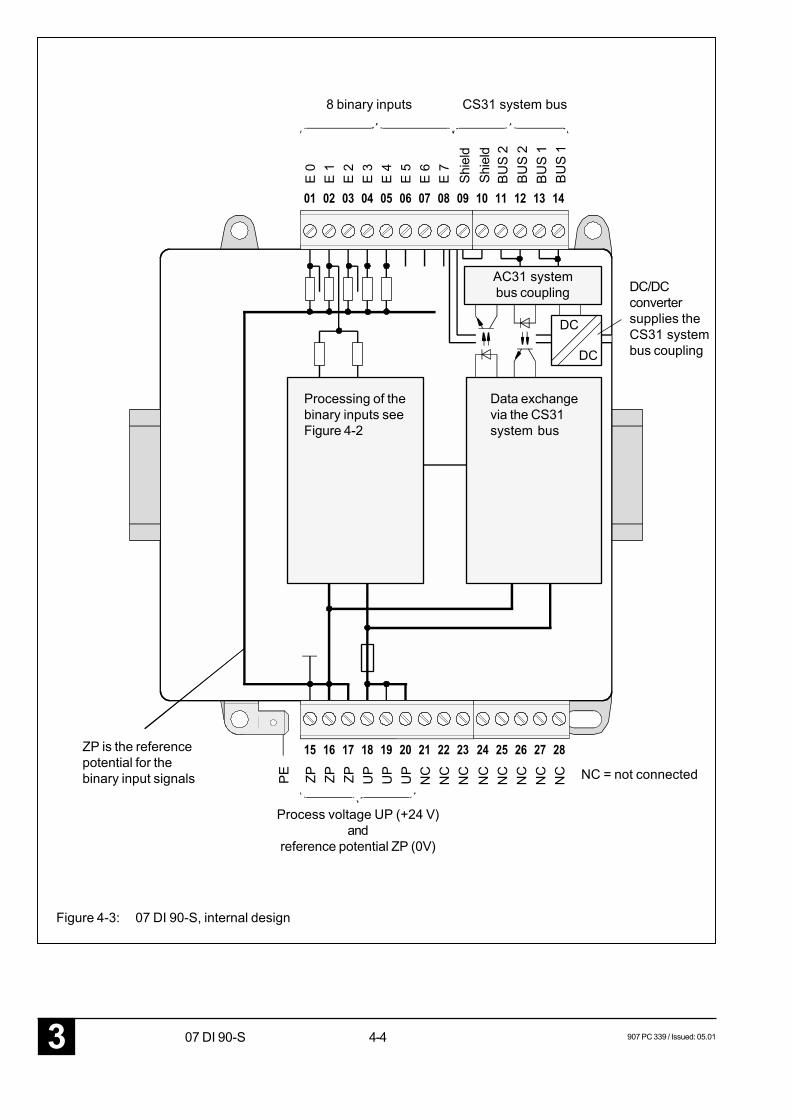
ZP is the referencepotential for thebinary input signals
Process voltage UP (+24 V)and
reference potential ZP (0V)
NC = not connected
Figure 4-3: 07 DI 90-S, internal design
BUS
2BU
S 2
BUS
1BU
S 1
907 PC 339 / Issued: 05.01 4-5 07 DI 90-S 3
01
E 0
02
E 1
03
E 2
04
E 3
05
E 4
06
E 5
07
E 6
08
E 7
09 10 11 12 13 14
Input UnitAdvant Contr. 31-S
07 DI 90-S
UP
!
15
ZP
16
ZP
17
ZP
18
UP
19
UP
20
UP
21
NC
22
NC
23
NC
24
NC
25
NC
26N
C27
NC
28
NC
8 binary inputs CS31 system bus
Shie
ldSh
ield
seepage 4-3
Connect both thesafety-related sensorand the module to thesame UP rail!
Caution: Unusedsignal inputs have to beput to UP (+24 V) viatwo resistors of 680 Ωand 5,6 kΩ configuredin series. Open signalinputs cause an exter-nal error disply at themodule (see alsoFigure 4-3).
IMPORTANT:For EMC reasons(dissipation ofinterference volt-ages) the PEconnector must beused by all means(see also chapterHardware plan-ning).
Connection of theprocess supply voltage
NC = Terminals not connected
Setting of themoduleaddress
UP rail (+24 V)
ZP rail (0 V)
CAUTION: It is very important to observe the correct voltage polarity:UP = +24 V, ZP = 0 V (reference potential)
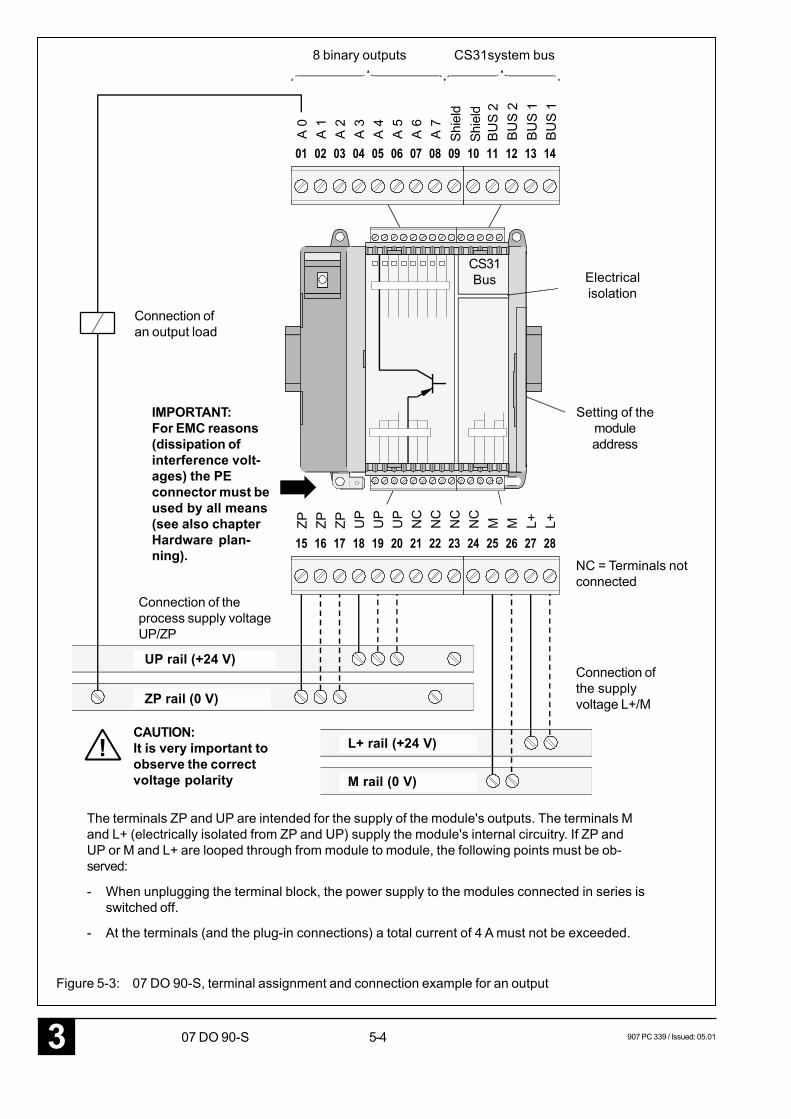
The terminals ZP and UP are intended for the module's supply (see above).
If ZP and UP are looped through from module to module, the following points must be observed:
- When unplugging the terminal block, the power supply to the modules connected in series isswitched off.
- At the terminals (and the plug-in connections) a total current of 4 A must not be exceeded.
Figure 4-4: 07 DI 90-S, terminal assignment and connection example for a safety-related sensor
680 Ω 5,6 kΩ
BUS
2BU
S 2
BUS
1BU
S 1
4-63 907 PC 339 / Issued: 05.0107 DI 90-S
Input UnitAdvant Contr. 31-S
07 DI 90-S
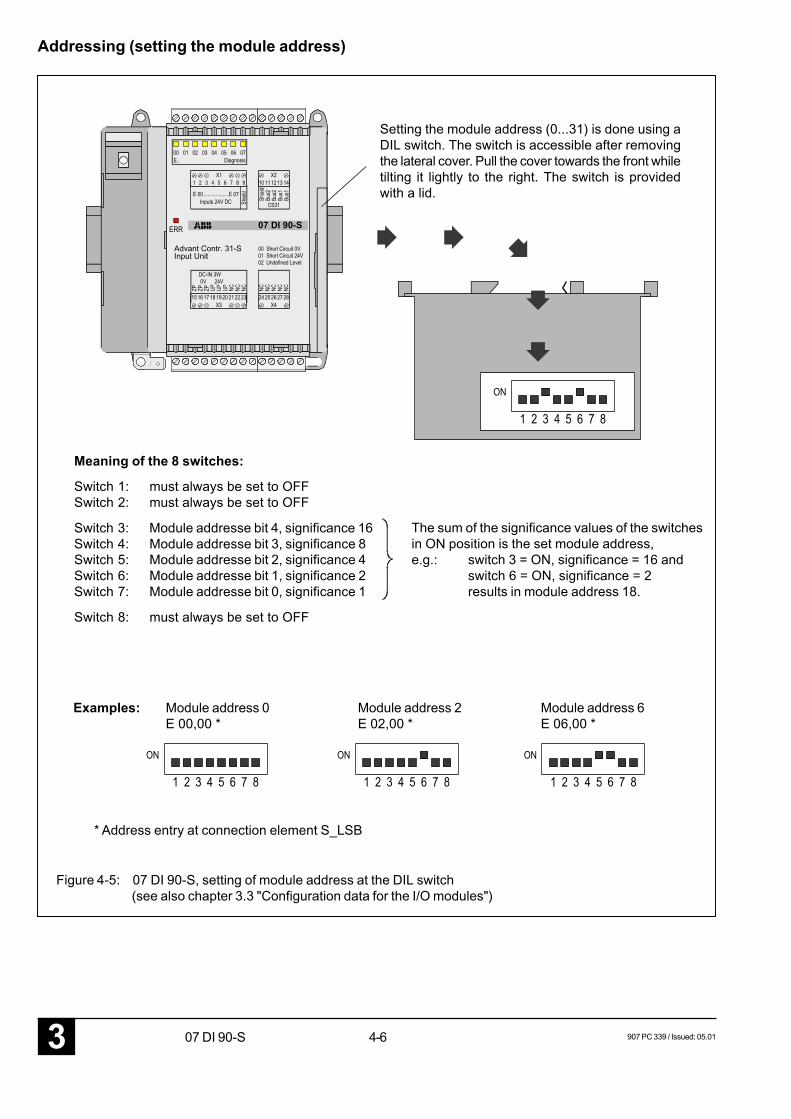
Setting the module address (0...31) is done using aDIL switch. The switch is accessible after removingthe lateral cover. Pull the cover towards the front whiletilting it lightly to the right. The switch is providedwith a lid.
Meaning of the 8 switches:
Switch 1: must always be set to OFFSwitch 2: must always be set to OFF
Switch 3: Module addresse bit 4, significance 16Switch 4: Module addresse bit 3, significance 8Switch 5: Module addresse bit 2, significance 4Switch 6: Module addresse bit 1, significance 2Switch 7: Module addresse bit 0, significance 1
Switch 8: must always be set to OFF
The sum of the significance values of the switchesin ON position is the set module address,e.g.: switch 3 = ON, significance = 16 and
switch 6 = ON, significance = 2results in module address 18.
Figure 4-5: 07 DI 90-S, setting of module address at the DIL switch(see also chapter 3.3 "Configuration data for the I/O modules")
Examples: Module address 0E 00,00 *
Module address 6E 06,00 *
Module address 2E 02,00 *
* Address entry at connection element S_LSB
Addressing (setting the module address)
907 PC 339 / Issued: 05.01 4-7 07 DI 90-S 3
Auxiliary and diagnosis functions
Start-up behaviourAfter switching the power supply (UP) on, the LED ’ERR’will light up for approx. 10 sec. during the switch-on self-test of the module.
After that, the LED ’ERR’ flashes until the module hasbeen adopted in the CS31 bus cycle.
After the ’ERR’ signal has gone out, this shows the cor-rect self-test as well as the end of the initialization andadoption in the CS31 system bus.
If, however, the LED ’ERR’ is lighting permanently (>15 sec)after switching on the power supply, an internal error hasbeen detected.
The LEDs for channel indication remain off until the initial-ization is completed. After that, they show the state of thecorresponding input channel.
Further diagnosis information are included in the AdvantController 31 System Description (AC31 error flags).
FusesThe module has an integrated solder-in-type micro-fusefor the supply voltage UP. If this fuse blows, the followingerror indication takes place:
- The module has no function any more.
- All LEDs are off.
The module has to be replaced.
Diagnosis at the moduleThe module distinguishes between 2 different error types:
• External errors:
- Short-circuit of a sensor line towards 0 V or cut of asensor line
- Short-circuit of a sensor line towards UP
- Input signal has exceeded the permissible input levelranges
• Internal errors:
- all other errors
Reaction to external errors:
• The LED ’ERR’ starts flashing.
• The channel state of the faulty channel is frozen.
• The error can be requested via the test button of themodule.
• The error-free input channels continue the signal pro-cessing.
• The channel is marked as faulty via the CE ’S_LEB’ forthe AC31 central unit.
• After error recovery, the error can be acknowledgedwith the test button.
Reaction to internal errors:
• The LED ’ERR’ and all input channel LEDs are lightingpermanently.
• The module stops the processing of all input signals.
• The entire module is marked as faulty via the CE’S_LEB’ for the AC31 central unit.
• After error recovery, the error can be acknowledged byswitching the power OFF and then ON again.
• Refer to chapter "Diagnosis and troubleshooting" involume 7 for further diagnosis information.
Diagnosis of external errors:
• By pressing the ”TEST” pushbutton, the channels areselected subsequently. After pressing this key, the LEDof the selected channel starts flashing. After releasingthe pushbutton, the error indication of the selectedchannel (e.g. LED 01 for short-circuit towards 0 V) isdisplayed in the channel LEDs for approx. 2 seconds.After that, the module switches back to the status in-dication of the input channels. Now, the next channelcan be selected.
• After selecting and querying channel 7, an LED testwill be carried out after pressing the test pushbutton(all channel LEDs light up). After releasing the push-button, the set module address is displayed for ap-prox. 2 seconds.
• The acknowledgement of external errors is made bypressing the test pushbutton somewhat longer (approx.5 seconds).
4-83 907 PC 339 / Issued: 05.0107 DI 90-S
Technical dataProcess and supply voltage UP(power supply according to VDE 0551 is necessary)
rated voltage 24 V DC ± 5 % rippleupper limit value 24 V DC + 20 % = 28,8 V (± 5 % ripple)lower limit value 24 V DC - 15 % = 20,4 V (± 5 % ripple)
The supply voltage must rise to at least 19 Vwithin 0 to 40 msec after being switched on.
Buffered voltage interruption time > 10 ms
Reference potential ZP 0 V for process voltage UP
Protection against reversed polarity (UP <-> 0V) yes
Number of inputs per module 8 (for safety-related sensors)
Signal levels of the inputs (nominal values)short-circuit towards ZP 0%... 15% of UP (0 V... 3,6 V for UP = 24 V)0 signal 15%... 35% of UP (+3,6 V... 8,4 V for UP = 24 V)undefined level 35%... 65% of UP (+8,4 V...15,6 V for UP = 24 V)1 signal 65%... 85% of UP (+15,6 V...20,4 V for UP = 24 V)short-circuit towards UP 85%...100% of UP (+20,4 V...24,0 V for UP = 24 V)
Input resistance approx. 2,2 kΩ
Input current at 24 V DC approx. 10 mA
Input signal delay (edges 0 -> 1 and 1 -> 0) typ. 5 ms, monitoring to 20 ms
Input frequency max. 20 Hz (higher input frequency leads to an externalor an internal error)
Input signal transition time (edges 0 -> 1 and 1 -> 0) 0 ms...5 ms
Cable lengths with cables laid in parallelshielded max. 1000 munshielded max. 600 m
Conductor cross section of process terminals max. 1 x 2.5 mm2
tightening torque max. 0.5 Nm
Electrical isolation from the CS31 system bus
Rated insulation voltage, process terminalsfrom CS31 system bus:
acc. to VDE 0160, rated direct voltage 0...50 Vtest voltage for reinforced insulation 800 V DC
Current consumption (UP) 110 mA
Total power dissipation max. 3 W
Address setting see page 4-5
Indication of input signals one yellow LED per channelError indication one red LED (ERR)
Safety-related sensor (snap-action contact element)resistance, if contact is open 5,6 kΩ + 680 Ω (±1 %)
contact is closed 680 Ω (±1 %)
Specifications for the resistors of the sensor 680 Ω, 1 %, 0,33 W at 70 °C, TK 50 ppm/K and5,6 kΩ, 1 %, 0,33 W at 70 °C, TK 50 ppm/Kor better
Safety-related CE (S-CE) in the PLC software S_LEB: Read binary S-input module
907 PC 339 / Issued: 05.01 4-9 07 DI 90-S 3
6513
065
140
94120
2085
25
111
75
594
Module-specific CS31 bus transmission time 590 s
Dimensions (width x height x depth) in mm 120 x 140 x 85 mm (see below)
Weight 400 g
Order number 07 DI 90-S GJR5 2509 00 R202
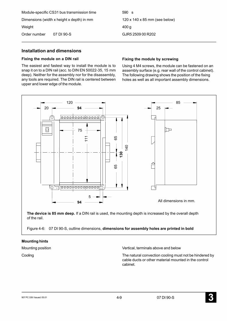
Installation and dimensionsFixing the module on a DIN rail
The easiest and fastest way to install the module is tosnap it on to a DIN rail (acc. to DIN EN 50022-35, 15 mmdeep). Neither for the assembly nor for the disassembly,any tools are required. The DIN rail is centered betweenupper and lower edge of the module.
Fixing the module by screwingUsing 4 M4 screws, the module can be fastened on anassembly surface (e.g. rear wall of the control cabinet).The following drawing shows the position of the fixingholes as well as all important assembly dimensions.
The device is 85 mm deep. If a DIN rail is used, the mounting depth is increased by the overall depthof the rail.
All dimensions in mm.
Figure 4-6: 07 DI 90-S, outline dimensions, dimensions for assembly holes are printed in bold
Mounting hintsMounting position Vertical, terminals above and below
Cooling The natural convection cooling must not be hindered bycable ducts or other material mounted in the controlcabinet.

4-103 907 PC 339 / Issued: 05.0107 DI 90-S
907 PC 339 / Issued: 05.01 5-1 07 DO 90-S 3
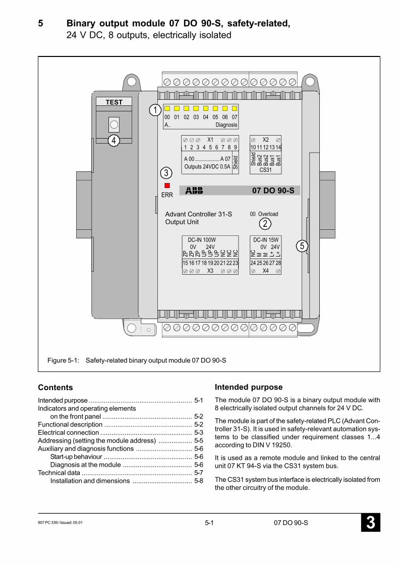
5 Binary output module 07 DO 90-S, safety-related,24 V DC, 8 outputs, electrically isolated
Figure 5-1: Safety-related binary output module 07 DO 90-S
ContentsIntended purpose ....................................................... 5-1Indicators and operating elements
on the front panel ................................................ 5-2Functional description ............................................... 5-2Electrical connection ................................................. 5-3Addressing (setting the module address) .................. 5-5Auxiliary and diagnosis functions .............................. 5-6
Start-up behaviour ............................................... 5-6Diagnosis at the module ..................................... 5-6
Technical data ........................................................... 5-7Installation and dimensions ................................ 5-8
Intended purposeThe module 07 DO 90-S is a binary output module with8 electrically isolated output channels for 24 V DC.
The module is part of the safety-related PLC (Advant Con-troller 31-S). It is used in safety-relevant automation sys-tems to be classified under requirement classes 1...4according to DIN V 19250.
It is used as a remote module and linked to the centralunit 07 KT 94-S via the CS31 system bus.
The CS31 system bus interface is electrically isolated fromthe other circuitry of the module.
TEST
Output UnitAdvant Controller 31-S
07 DO 90-S
5-23 907 PC 339 / Issued: 05.0107 DO 90-S
The outputs of the module 07 DO 90-S are set by theAC31 central unit via special safety-related connectionelements (CEs).
Indicators and operating elements on thefront panel
1 8 yellow LEDs for indication of the signal state atthe outputs or for error and diagnosis indication
2 List of the diagnosis information referred to theLEDs if these are used for diagnosis indication
3 Red LED for error indication
4 Test button
5 DIL switch for address setting under the cover
Functional descriptionsee block diagram on the next page
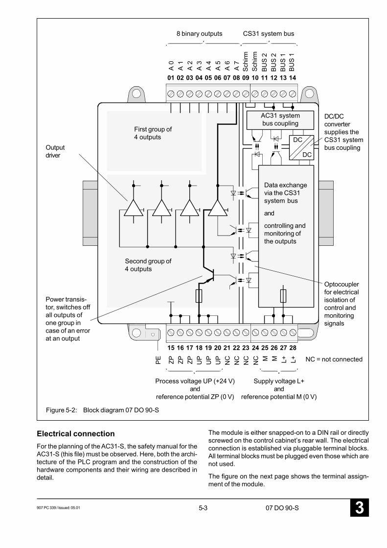
Principle of the safety-related outputsThe safety-related output module is configured in a waythat even in case of errors the safe states at the outputsare granted. The safe state is defined as the off-state ofthe outputs.
The output channels are organized in two groups with 4outputs each. Each group disposes of an additional pow-er transistor as second independent switch-off path be-sides the 4 short-circuit-proof output drivers.
The signal state of each output channel is read back viaan input channel. The connection element (CE) S_LABcompares the sent signal with the signal which is readback at the input channel. If the signals are not equal, amessage is generated.
Partially two-channel configurationThe module is largely configured in dual-channel technique.Two processors control and monitor the output drivers. Anoutput driver is only activated if it is addressed by bothprocessors simultaneously.
External and internal errors of the output moduleOverload (or short-circuit towards ZP) is an external errorand leads to a safe shut-down of the affected group. Allother errors are internal errors and cause the shut-downof all outputs (RESET).
The correct function of the output drivers and the powertransistors responsible for the group shut-down is checkedcyclically as to their switch on/off capacity during the op-eration. For this purpose, the switching states are tempo-rarily changed (duration < 1 msec). Any relays or otherloads controlled by the output drivers must be designed ina way that they do not react to these short pulses.
The changing of the output signal states are detected andtransferred to both processors for checking. By checkingjust one output at the same time, a possible cross-talk toneighboring channels can also be detected.
Power supply for the output circuitry
The output drivers are supplied by ZP and UP (24 V DC).This supply voltage is electrically isolated from theCS31 system bus and also from the 24 V DC supply volt-age (M, L+) for controlling and monitoring the outputs.
Power supply for the CS31 bus couplingThe supply voltage for the bus coupling is provided inter-nally using an electrically isolated DC/DC converter sup-plied from 24 V DC (L+, M).
Electrical isolationAll signals, which are to be led via electrically isolatedbarriers, are transmitted with optocouplers.
907 PC 339 / Issued: 05.01 5-3 07 DO 90-S 3
DC
DC
01
A 0
02
A 1
03
A 2
04
A 3
05
A 4
06
A 5
07
A 6
08
A 7
09 10 11 12 13 14
15
ZP
16
ZP
17
ZP
18
UP
19
UP
24
NC
25
M
26
M
27
L+
28
L+PE
20
UP
21
NC
22
NC
23
NC
8 binary outputs CS31 system bus
Schi
rmSc
hirm
Outputdriver
Power transis-tor, switches offall outputs ofone group incase of an errorat an output
DC/DCconvertersupplies theCS31 systembus coupling
Optocouplerfor electricalisolation ofcontrol andmonitoringsignals
Data exchangevia the CS31system bus
and
controlling andmonitoring ofthe outputs
AC31 systembus coupling
First group of4 outputs
Second group of4 outputs
Process voltage UP (+24 V)and
reference potential ZP (0 V)
Supply voltage L+and
reference potential M (0 V)
NC = not connected
Figure 5-2: Block diagram 07 DO 90-S
Electrical connectionFor the planning of the AC31-S, the safety manual for theAC31-S (this file) must be observed. Here, both the archi-tecture of the PLC program and the construction of thehardware components and their wiring are described indetail.
The module is either snapped-on to a DIN rail or directlyscrewed on the control cabinet’s rear wall. The electricalconnection is established via pluggable terminal blocks.All terminal blocks must be plugged even those which arenot used.
The figure on the next page shows the terminal assign-ment of the module.
BUS
2BU
S 2
BUS
1BU
S 1
5-43 907 PC 339 / Issued: 05.0107 DO 90-S
A 0
A 1
A 2
A 3
A 4
A 5
A 6
A 7
!
ZP
ZP
ZP
UP
UP
UP
NC
NC
NC
NC
M M L+ L+
8 binary outputs CS31system bus
Shie
ldSh
ield
Connection ofan output load
IMPORTANT:For EMC reasons(dissipation ofinterference volt-ages) the PEconnector must beused by all means(see also chapterHardware plan-ning).
Connection of theprocess supply voltageUP/ZP
NC = Terminals notconnected
Setting of themoduleaddress
UP rail (+24 V)
ZP rail (0 V)
CAUTION:It is very important toobserve the correctvoltage polarity
The terminals ZP and UP are intended for the supply of the module's outputs. The terminals Mand L+ (electrically isolated from ZP and UP) supply the module's internal circuitry. If ZP andUP or M and L+ are looped through from module to module, the following points must be ob-served:
- When unplugging the terminal block, the power supply to the modules connected in series isswitched off.
- At the terminals (and the plug-in connections) a total current of 4 A must not be exceeded.
Figure 5-3: 07 DO 90-S, terminal assignment and connection example for an output
Connection ofthe supplyvoltage L+/M
L+ rail (+24 V)
M rail (0 V)
Electricalisolation
BUS
2BU
S 2
BUS
1BU
S 1
CS31Bus
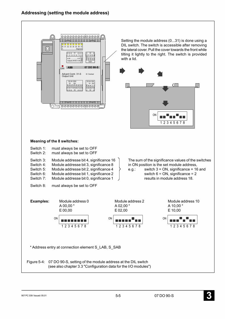
907 PC 339 / Issued: 05.01 5-5 07 DO 90-S 3
Output UnitAdvant Contr. 31-S
07 DO 90-S
Setting the module address (0...31) is done using aDIL switch. The switch is accessible after removingthe lateral cover. Pull the cover towards the front whiletilting it lightly to the right. The switch is providedwith a lid.
Meaning of the 8 switches:
Switch 1: must always be set to OFFSwitch 2: must always be set to OFF
Switch 3: Module addresse bit 4, significance 16Switch 4: Module addresse bit 3, significance 8Switch 5: Module addresse bit 2, significance 4Switch 6: Module addresse bit 1, significance 2Switch 7: Module addresse bit 0, significance 1
Switch 8: must always be set to OFF
The sum of the significance values of the switchesin ON position is the set module address,e.g.: switch 3 = ON, significance = 16 and
switch 6 = ON, significance = 2results in module address 18.
Figure 5-4: 07 DO 90-S, setting of the module address at the DIL switch(see also chapter 3.3 "Configuration data for the I/O modules")
Examples: Module address 0A 00,00 *E 00,00
Module address 10A 10,00 *E 10,00
Module address 2A 02,00 *E 02,00
* Address entry at connection element S_LAB, S_SAB
Addressing (setting the module address)
5-63 907 PC 339 / Issued: 05.0107 DO 90-S
Auxiliary and diagnosis functionsStart-up behaviourAfter switching on the power supply (L+), the LED ’ERR’will light up for approx. 10 sec. during the start-up selftestof the module. The process voltage UP must be switchedon prior to or simultaneously with the supply voltage L+.Otherwise the start-up selftest of the outputs will causethe module's shut-down.
After that, the LED ’ERR’ flashes until the module hasbeen adopted in the CS31 bus cycle.
After the ’ERR’ signal has gone out, this shows the cor-rect self-test as well as the end of the initialization andadoption in the CS31 system bus.
If, however, the LED ’ERR’ is lighting permanently (>15 sec)after switching on the power supply, an internal error hasbeen detected.
The LEDs for channel indication remain off until the initial-ization is completed. After that, they show the state of thecorresponding output channel (when activated by the AC31control unit).
FusesThe module has three integrated solder-in-type micro-fus-es (one for the supply voltage UP and one for each outputgroup, see also Figure 5-2).
If the fuse for UP blows, the following error indication takesplace:
- The module has no function any more.
- All LEDs are off.
If one of the fuses for the output groups blows, the affect-ed output group indicates an external error.
The module has always to be replaced if a fuse has blown.
Diagnosis at the module
The module distinguishes between internal and externalerrors.
Reaction to internal errors:
• The LED ’ERR’ and all output channel LEDs are light-ing permanently.
• The module stops the processing and switches off alloutputs safely.
• After error recovery, the error can be acknowledged byswitching the supply voltage L+ OFF and then ON again.
• The entire module is marked as faulty via the CE’S_LEB’ for the AC31 central unit.
• Refer to chapter "Diagnosis and troubleshooting" involume 7 for further diagnosis information.
Reaction to external errors:
• The LED ’ERR’ is flashing.
• The power supply of the affected driver group (thereare two groups with 4 outputs each) is switched off.
• The error can be requested via the test button of themodule.
• After error recovery, the error can be acknowledged byswitching the supply voltage L+ OFF and then ON again.
Diagnosis pushbutton:
• By pressing the ”TEST” pushbutton, the channels areselected subsequently. After pressing this key, the LEDof the selected channel starts flashing. After releasingthe pushbutton, the error indication of the selectedchannel is displayed in the channel LEDs for approx. 2seconds (no LED is lighting means that no error hasoccurred). After that, the module switches again to thestatus indication of the output channels. Now, the nextchannel can be selected.
• After selecting and querying channel 7, an LED testwill be carried out after pressing the test pushbutton(all channel LEDs light up). After releasing the push-button, the set module address is displayed for ap-prox. 2 seconds.
907 PC 339 / Issued: 05.01 5-7 07 DO 90-S 3
Technical dataProcess voltage UP (supplies the output channels)and supply voltage L+ (supplies the module’s circuitry)(power supplies according to VDE551 are necessary)
rated voltage for UP and L+ 24 V DC ± 5 % rippleupper limit value 24 V DC + 20 % = 28,8 V (± 5 % ripple)lower limit value 24 V DC - 15 % = 20,4 V (± 5 % ripple)
The supply voltages must rise to at least 19 Vwithin 0 to 40 msec after being switched on.
Buffered voltage interruption time,for L+ > 10 msfor Up no interruption allowed (leads to an external error)
Reference potential ZP 0 V for process voltage UP
Reference potential M 0 V for supply voltage L+
Protection against reversed polarity for L+ yes
Number of outputs per module 8
Load currentMaximum value 0.5 ALeakage current at 0 signal max. 0.3 mALamp load max. 5 WTotal current at all 8 outputs max. 4 A
Switching frequency for inductive loads max. 0.5 Hz
Limiting of inductive interrupt voltages yes, with diode
Switching capacitive loads not allowed (leads to an external error)
Short-circuit protection yes, electronically
Output signal delay of the modulesignal edge 0 -> 1 and 1 -> 0 8 ms, monitoring to 8 ms
Duration of test signal < 1 msDuring this time the output has the inverted signal state,see also page 5-2.
Output level0 signal 0 V...3 V1 signal > UP-2.5 Vmonitoring the 0 signal An output level > 8 V (5 V nom.) leads to an internal
error, if the output state is 0 (0 signal)(the module will be switched off).
Cable lengths with cables laid in parallelshielded max. 1000 munshielded max. 600 m
Conductor cross section of process terminals max. 1 x 2.5 mm2
tightening torque max. 0.5 Nm
Electrical isolation against CS31 bus and outputs (as group)
Rated insulation voltage,process terminals from CS31 system bus:
acc. to VDE 0160, rated direct voltage 0...50 Vtest voltage for reinforced insulation 800 V DC
outputs:acc. to VDE 0160, rated direct voltage 0...50 Vtest voltage for basis and additional insulation 500 V DC
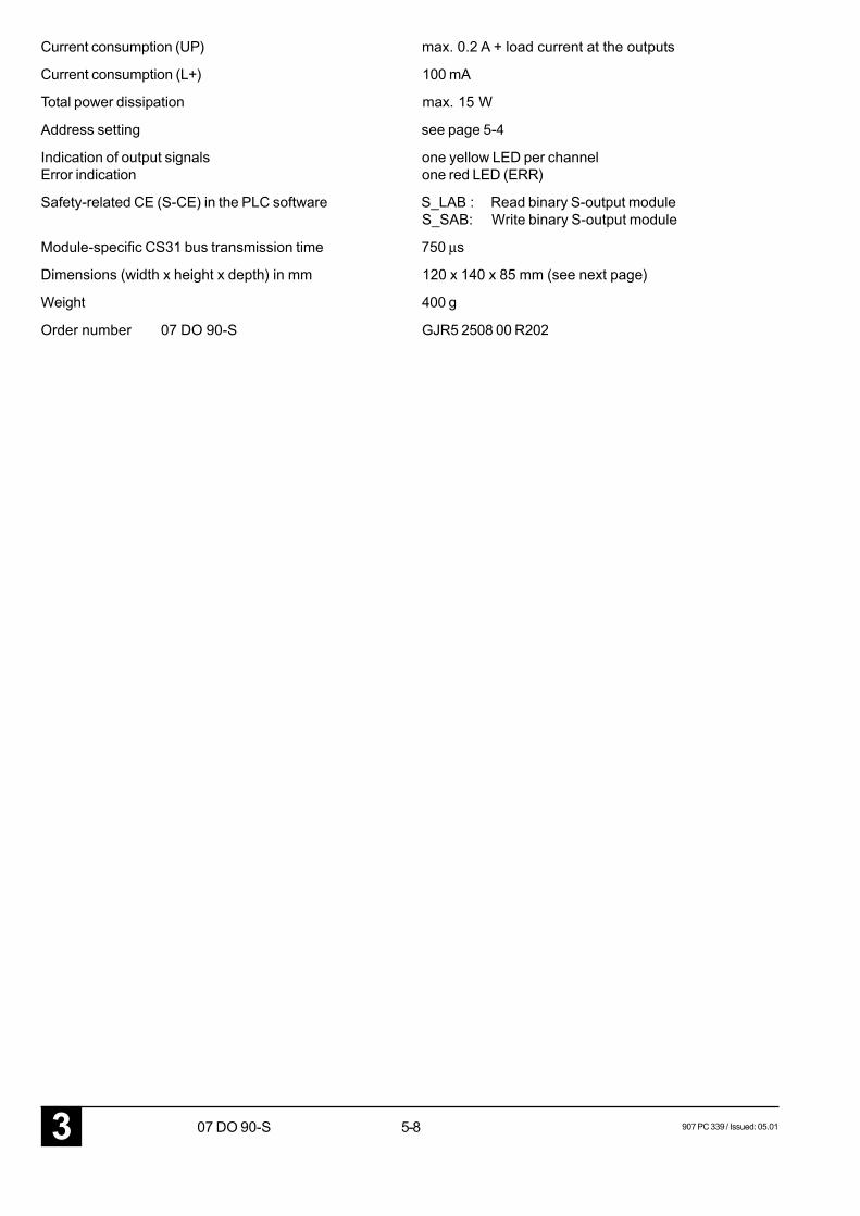
5-83 907 PC 339 / Issued: 05.0107 DO 90-S
Current consumption (UP) max. 0.2 A + load current at the outputs
Current consumption (L+) 100 mA
Total power dissipation max. 15 W
Address setting see page 5-4
Indication of output signals one yellow LED per channelError indication one red LED (ERR)
Safety-related CE (S-CE) in the PLC software S_LAB : Read binary S-output moduleS_SAB: Write binary S-output module
Module-specific CS31 bus transmission time 750 µs
Dimensions (width x height x depth) in mm 120 x 140 x 85 mm (see next page)
Weight 400 g
Order number 07 DO 90-S GJR5 2508 00 R202
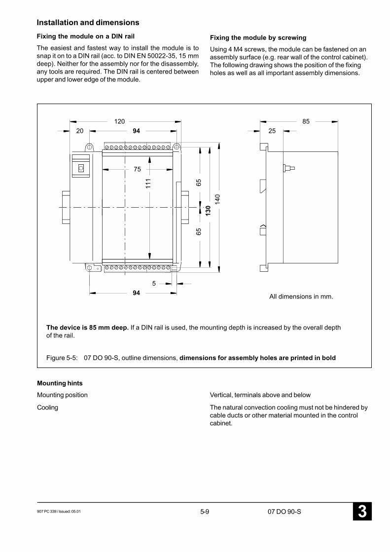
907 PC 339 / Issued: 05.01 5-9 07 DO 90-S 3
6513
065
140
94120
2085
25
111
75
594
Mounting hints
Mounting position Vertical, terminals above and below
Cooling The natural convection cooling must not be hindered bycable ducts or other material mounted in the controlcabinet.
Installation and dimensionsFixing the module on a DIN railThe easiest and fastest way to install the module is tosnap it on to a DIN rail (acc. to DIN EN 50022-35, 15 mmdeep). Neither for the assembly nor for the disassembly,any tools are required. The DIN rail is centered betweenupper and lower edge of the module.
Fixing the module by screwingUsing 4 M4 screws, the module can be fastened on anassembly surface (e.g. rear wall of the control cabinet).The following drawing shows the position of the fixingholes as well as all important assembly dimensions.
The device is 85 mm deep. If a DIN rail is used, the mounting depth is increased by the overall depthof the rail.
All dimensions in mm.
Figure 5-5: 07 DO 90-S, outline dimensions, dimensions for assembly holes are printed in bold

5-103 907 PC 339 / Issued: 05.0107 DO 90-S
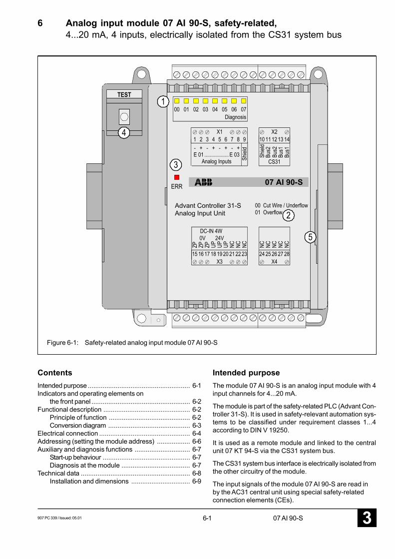
907 PC 339 / Issued: 05.01 6-1 07 AI 90-S 3
6 Analog input module 07 AI 90-S, safety-related,4...20 mA, 4 inputs, electrically isolated from the CS31 system bus
Figure 6-1: Safety-related analog input module 07 AI 90-S
ContentsIntended purpose ....................................................... 6-1Indicators and operating elements on
the front panel ..................................................... 6-2Functional description ............................................... 6-2
Principle of function ............................................ 6-2Conversion diagram ............................................ 6-3
Electrical connection ................................................. 6-4Addressing (setting the module address) .................. 6-6Auxiliary and diagnosis functions .............................. 6-7
Start-up behaviour ............................................... 6-7Diagnosis at the module ..................................... 6-7
Technical data ........................................................... 6-8Installation and dimensions ................................ 6-9
Intended purposeThe module 07 AI 90-S is an analog input module with 4input channels for 4...20 mA.
The module is part of the safety-related PLC (Advant Con-troller 31-S). It is used in safety-relevant automation sys-tems to be classified under requirement classes 1...4according to DIN V 19250.
It is used as a remote module and linked to the centralunit 07 KT 94-S via the CS31 system bus.
The CS31 system bus interface is electrically isolated fromthe other circuitry of the module.
The input signals of the module 07 AI 90-S are read inby the AC31 central unit using special safety-relatedconnection elements (CEs).
Analog Input UnitAdvant Controller 31-S
07 AI 90-S
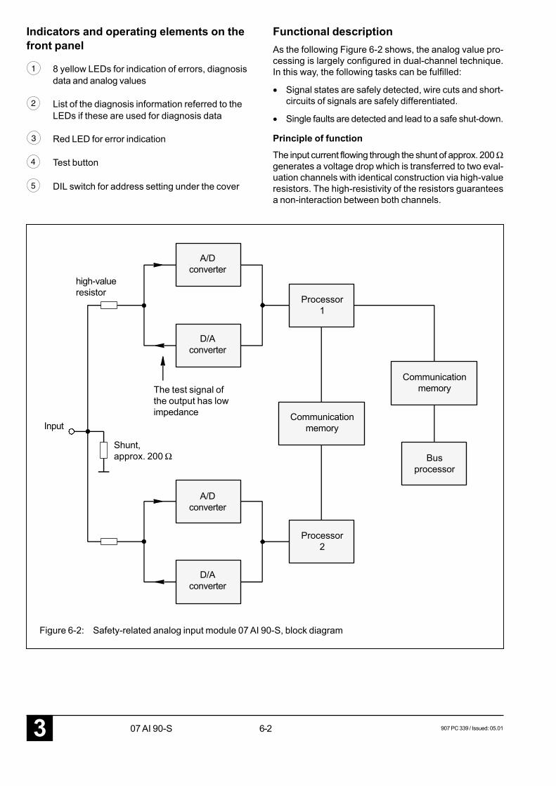
6-23 907 PC 339 / Issued: 05.0107 AI 90-S
Indicators and operating elements on thefront panel
1 8 yellow LEDs for indication of errors, diagnosisdata and analog values
2 List of the diagnosis information referred to theLEDs if these are used for diagnosis data
3 Red LED for error indication
4 Test button
5 DIL switch for address setting under the cover
Functional descriptionAs the following Figure 6-2 shows, the analog value pro-cessing is largely configured in dual-channel technique.In this way, the following tasks can be fulfilled:
• Signal states are safely detected, wire cuts and short-circuits of signals are safely differentiated.
• Single faults are detected and lead to a safe shut-down.
Principle of function
The input current flowing through the shunt of approx. 200 Ωgenerates a voltage drop which is transferred to two eval-uation channels with identical construction via high-valueresistors. The high-resistivity of the resistors guaranteesa non-interaction between both channels.
A/Dconverter
high-valueresistor
D/Aconverter
Processor1
Input
Shunt,approx. 200 Ω
Communicationmemory
Busprocessor
Processor2
The test signal ofthe output has lowimpedance
Figure 6-2: Safety-related analog input module 07 AI 90-S, block diagram
Communicationmemory
A/Dconverter
D/Aconverter
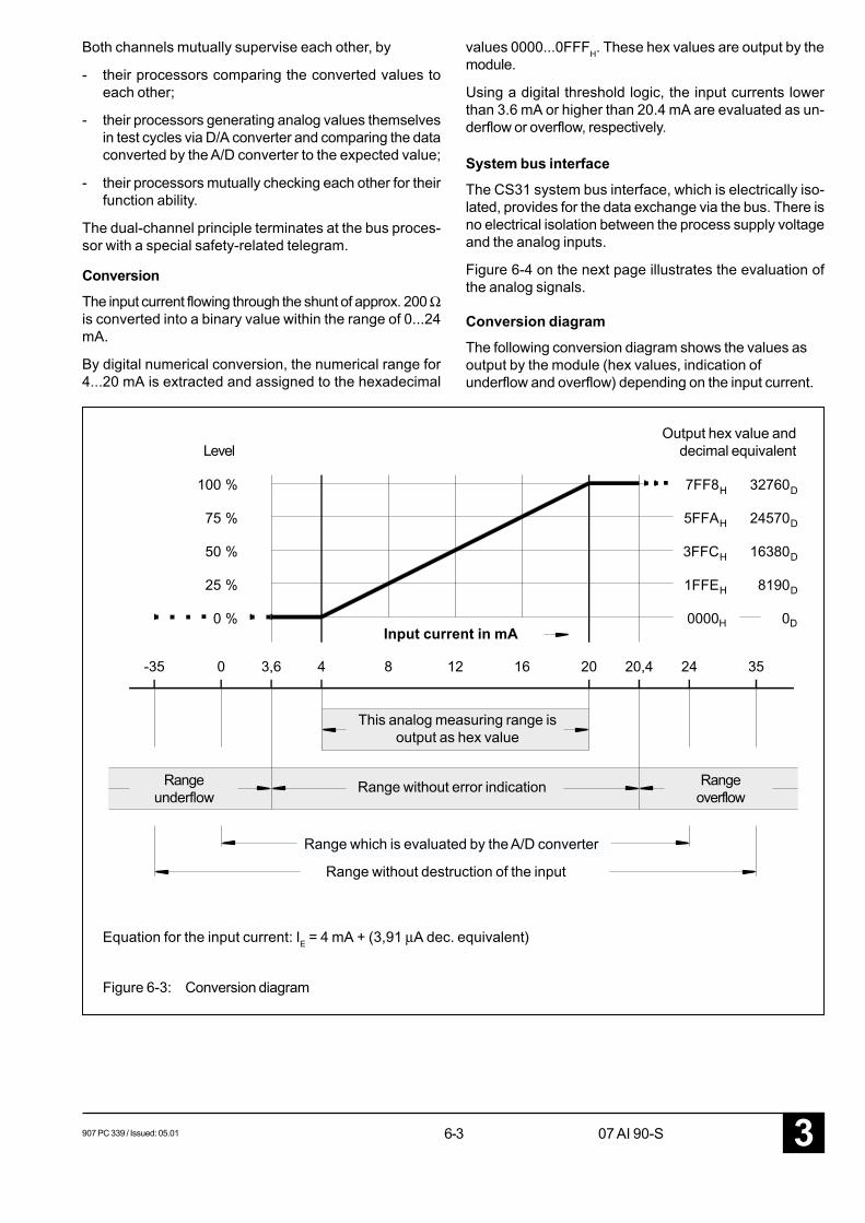
907 PC 339 / Issued: 05.01 6-3 07 AI 90-S 3
7FF8 32760 100 %
4 20 20,43,60 24-35 35
0000 0 0 %
1FFE 8190 25 %
3FFC 16380 50 %
5FFA 24570 75 %
8 12 16
H D
H D
H D
H D
H D
Both channels mutually supervise each other, by
- their processors comparing the converted values toeach other;
- their processors generating analog values themselvesin test cycles via D/A converter and comparing the dataconverted by the A/D converter to the expected value;
- their processors mutually checking each other for theirfunction ability.
The dual-channel principle terminates at the bus proces-sor with a special safety-related telegram.
Conversion
The input current flowing through the shunt of approx. 200 Ωis converted into a binary value within the range of 0...24mA.
By digital numerical conversion, the numerical range for4...20 mA is extracted and assigned to the hexadecimal
values 0000...0FFFH. These hex values are output by themodule.
Using a digital threshold logic, the input currents lowerthan 3.6 mA or higher than 20.4 mA are evaluated as un-derflow or overflow, respectively.
System bus interface
The CS31 system bus interface, which is electrically iso-lated, provides for the data exchange via the bus. There isno electrical isolation between the process supply voltageand the analog inputs.
Figure 6-4 on the next page illustrates the evaluation ofthe analog signals.
Conversion diagram
The following conversion diagram shows the values asoutput by the module (hex values, indication ofunderflow and overflow) depending on the input current.
Output hex value anddecimal equivalentLevel
This analog measuring range isoutput as hex value
Rangeunderflow
Range without error indication Rangeoverflow
Range which is evaluated by the A/D converter
Range without destruction of the input
Input current in mA
Equation for the input current: IE = 4 mA + (3,91 µA dec. equivalent)
Figure 6-3: Conversion diagram
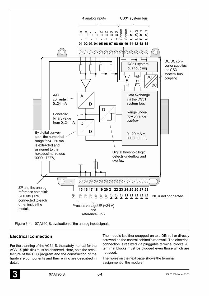
6-43 907 PC 339 / Issued: 05.0107 AI 90-S
DC
DC
01
-
02
+
03
-
04
+
05
-
06
+
07
-
08
+
09 10 11 12 13 14
E 0
E 0
E 1
E 1
E 2
E 2
E 3
E 3
15
ZP
16
ZP
17
ZP
18
UP
19
UP
24
NC
25
NC
26
NC
27
NC
28
NC
PE
20
UP
21
NC
22
NC
23
NC
A
D
D
D
D
4 analog inputs CS31 system bus
Schi
rmSc
hirm
A/Dconverter,0..24 mA
Convertedbinary valuefrom 0..24 mA
AC31 systembus coupling
DC/DC con-verter suppliesthe CS31system buscoupling
Data exchangevia the CS31system bus
Range under-flow or rangeoverflow
0...20 mA =0000...0FFFH
By digital conver-sion, the numericalrange for 4...20 mAis extracted andassigned to thehexadecimal values0000...7FF8H.
ZP and the analogreference potentials(-E0 etc.) areconnected to eachother inside themodule
Digital threshold logic,detects underflow andoverflow
Process voltageUP (+24 V)and
reference (0 V)
NC = not connected
Figure 6-4: 07 AI 90-S, evaluation of the analog input signals
Electrical connection
For the planning of the AC31-S, the safety manual for theAC31-S (this file) must be observed. Here, both the archi-tecture of the PLC program and the construction of thehardware components and their wiring are described indetail.
The module is either snapped-on to a DIN rail or directlyscrewed on the control cabinet’s rear wall. The electricalconnection is realized via pluggable terminal blocks. Allterminal blocks must be plugged even those which arenot used.The figure on the next page shows the terminalassignment of the module.
BUS
2BU
S 2
BUS
1BU
S 1
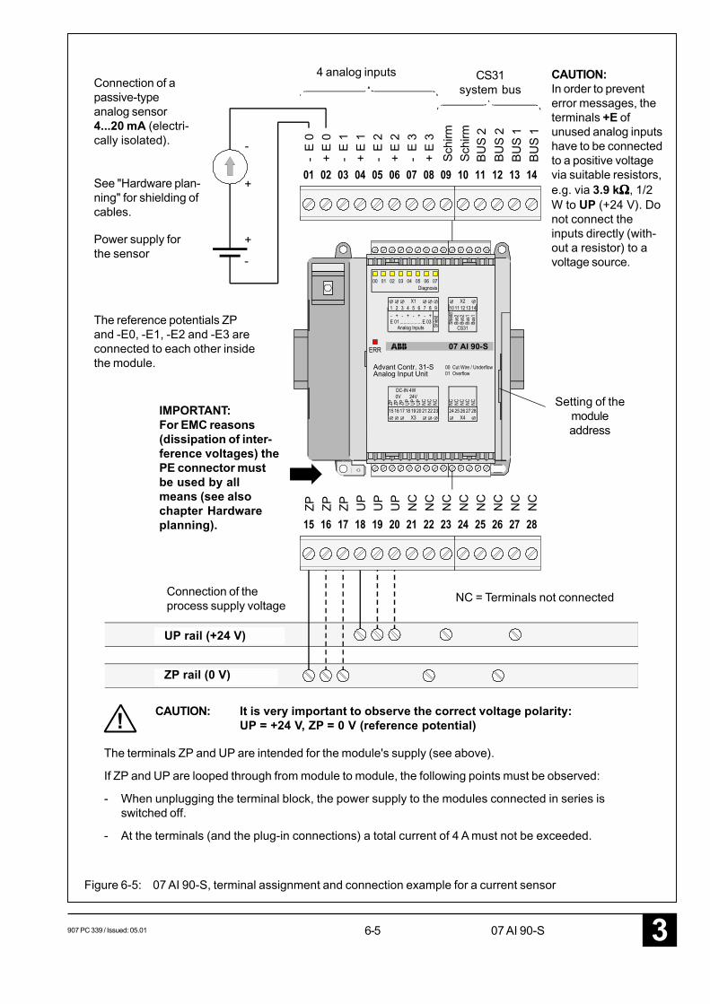
907 PC 339 / Issued: 05.01 6-5 07 AI 90-S 3
Analog Input UnitAdvant Contr. 31-S
07 AI 90-S
+ - + - + - +
!
ZP
ZP
ZP
UP
UP
UP
NC
NC
NC
NC
NC
NC
NC
NC
E 0
E 0
E 1
E 1
E 2
E 2
E 3
E 3
-
4 analog inputs CS31system busConnection of a
passive-typeanalog sensor4...20 mA (electri-cally isolated).
See "Hardware plan-ning" for shielding ofcables.
Power supply forthe sensor
The reference potentials ZPand -E0, -E1, -E2 and -E3 areconnected to each other insidethe module.
IMPORTANT:For EMC reasons(dissipation of inter-ference voltages) thePE connector mustbe used by allmeans (see alsochapter Hardwareplanning).
Connection of theprocess supply voltage
NC = Terminals not connected
Setting of themoduleaddress
UP rail (+24 V)
ZP rail (0 V)
CAUTION: It is very important to observe the correct voltage polarity:UP = +24 V, ZP = 0 V (reference potential)
The terminals ZP and UP are intended for the module's supply (see above).
If ZP and UP are looped through from module to module, the following points must be observed:
- When unplugging the terminal block, the power supply to the modules connected in series isswitched off.
- At the terminals (and the plug-in connections) a total current of 4 A must not be exceeded.
Figure 6-5: 07 AI 90-S, terminal assignment and connection example for a current sensor
CAUTION:In order to preventerror messages, theterminals +E ofunused analog inputshave to be connectedto a positive voltagevia suitable resistors,e.g. via 3.9 kΩΩΩΩΩ, 1/2W to UP (+24 V). Donot connect theinputs directly (with-out a resistor) to avoltage source.
Schi
rmSc
hirm
BUS
2BU
S 2
BUS
1BU
S 1
+
-
+
-
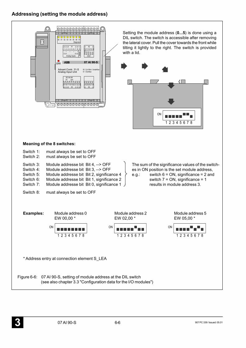
6-63 907 PC 339 / Issued: 05.0107 AI 90-S
Analog Input UnitAdvant Contr. 31-S
07 AI 90-S
Addressing (setting the module address)
Setting the module address (0...5) is done using aDIL switch. The switch is accessible after removingthe lateral cover. Pull the cover towards the front whiletilting it lightly to the right. The switch is providedwith a lid.
Meaning of the 8 switches:
Switch 1: must always be set to OFFSwitch 2: must always be set to OFF
Switch 3: Module addresse bit Bit 4, --> OFFSwitch 4: Module addresse bit Bit 3, --> OFFSwitch 5: Module addresse bit Bit 2, significance 4Switch 6: Module addresse bit Bit 1, significance 2Switch 7: Module addresse bit Bit 0, significance 1
Switch 8: must always be set to OFF
The sum of the significance values of the switch-es in ON position is the set module address,e.g.: switch 6 = ON, significance = 2 and
switch 7 = ON, significance = 1results in module address 3.
Figure 6-6: 07 AI 90-S, setting of module address at the DIL switch(see also chapter 3.3 "Configuration data for the I/O modules")
Examples: Module address 0EW 00,00 *
Module address 5EW 05,00 *
Module address 2EW 02,00 *
* Address entry at connection element S_LEA
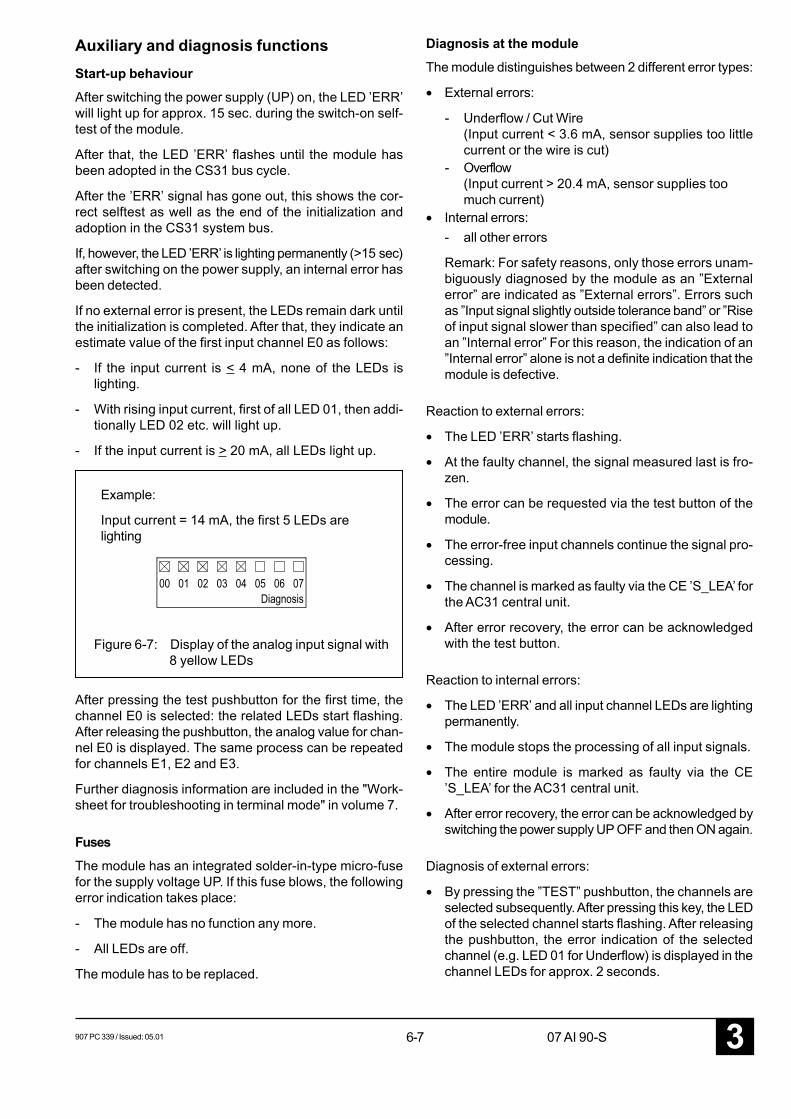
907 PC 339 / Issued: 05.01 6-7 07 AI 90-S 3
Auxiliary and diagnosis functionsStart-up behaviourAfter switching the power supply (UP) on, the LED ’ERR’will light up for approx. 15 sec. during the switch-on self-test of the module.
After that, the LED ’ERR’ flashes until the module hasbeen adopted in the CS31 bus cycle.
After the ’ERR’ signal has gone out, this shows the cor-rect selftest as well as the end of the initialization andadoption in the CS31 system bus.
If, however, the LED ’ERR’ is lighting permanently (>15 sec)after switching on the power supply, an internal error hasbeen detected.
If no external error is present, the LEDs remain dark untilthe initialization is completed. After that, they indicate anestimate value of the first input channel E0 as follows:
- If the input current is < 4 mA, none of the LEDs islighting.
- With rising input current, first of all LED 01, then addi-tionally LED 02 etc. will light up.
- If the input current is > 20 mA, all LEDs light up.
After pressing the test pushbutton for the first time, thechannel E0 is selected: the related LEDs start flashing.After releasing the pushbutton, the analog value for chan-nel E0 is displayed. The same process can be repeatedfor channels E1, E2 and E3.
Further diagnosis information are included in the "Work-sheet for troubleshooting in terminal mode" in volume 7.
FusesThe module has an integrated solder-in-type micro-fusefor the supply voltage UP. If this fuse blows, the followingerror indication takes place:
- The module has no function any more.
- All LEDs are off.
The module has to be replaced.
Example:
Input current = 14 mA, the first 5 LEDs arelighting
Figure 6-7: Display of the analog input signal with8 yellow LEDs
Diagnosis at the moduleThe module distinguishes between 2 different error types:
• External errors:
- Underflow / Cut Wire(Input current < 3.6 mA, sensor supplies too littlecurrent or the wire is cut)
- Overflow(Input current > 20.4 mA, sensor supplies toomuch current)
• Internal errors:- all other errors
Remark: For safety reasons, only those errors unam-biguously diagnosed by the module as an ”Externalerror” are indicated as ”External errors”. Errors suchas ”Input signal slightly outside tolerance band” or ”Riseof input signal slower than specified” can also lead toan ”Internal error” For this reason, the indication of an”Internal error” alone is not a definite indication that themodule is defective.
Reaction to external errors:
• The LED ’ERR’ starts flashing.
• At the faulty channel, the signal measured last is fro-zen.
• The error can be requested via the test button of themodule.
• The error-free input channels continue the signal pro-cessing.
• The channel is marked as faulty via the CE ’S_LEA’ forthe AC31 central unit.
• After error recovery, the error can be acknowledgedwith the test button.
Reaction to internal errors:
• The LED ’ERR’ and all input channel LEDs are lightingpermanently.
• The module stops the processing of all input signals.
• The entire module is marked as faulty via the CE’S_LEA’ for the AC31 central unit.
• After error recovery, the error can be acknowledged byswitching the power supply UP OFF and then ON again.
Diagnosis of external errors:
• By pressing the ”TEST” pushbutton, the channels areselected subsequently. After pressing this key, the LEDof the selected channel starts flashing. After releasingthe pushbutton, the error indication of the selectedchannel (e.g. LED 01 for Underflow) is displayed in thechannel LEDs for approx. 2 seconds.
6-83 907 PC 339 / Issued: 05.0107 AI 90-S
After that, the module switches back to the status in-dication of an input channels. Now, the next channelcan be selected.
• After selecting and querying channel 3, an LED testwill be carried out after pressing the test pushbutton(all channel LEDs light up). After releasing the push-
button, the set module address is displayed for ap-prox. 2 seconds.
• The acknowledgement of external errors is made bypressing the test pushbutton somewhat longer (approx.5 seconds).
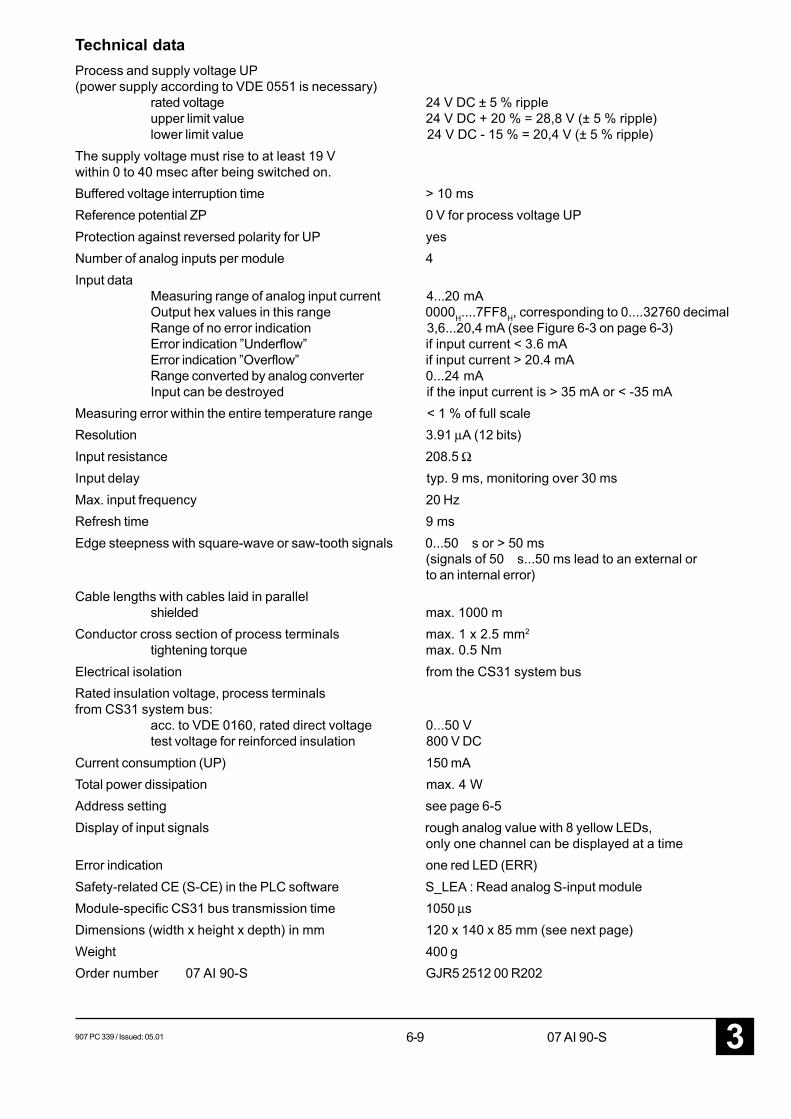
907 PC 339 / Issued: 05.01 6-9 07 AI 90-S 3
Technical dataProcess and supply voltage UP(power supply according to VDE 0551 is necessary)
rated voltage 24 V DC ± 5 % rippleupper limit value 24 V DC + 20 % = 28,8 V (± 5 % ripple)lower limit value 24 V DC - 15 % = 20,4 V (± 5 % ripple)
The supply voltage must rise to at least 19 Vwithin 0 to 40 msec after being switched on.Buffered voltage interruption time > 10 msReference potential ZP 0 V for process voltage UPProtection against reversed polarity for UP yesNumber of analog inputs per module 4Input data
Measuring range of analog input current 4...20 mAOutput hex values in this range 0000H....7FF8H, corresponding to 0....32760 decimalRange of no error indication 3,6...20,4 mA (see Figure 6-3 on page 6-3)Error indication ”Underflow” if input current < 3.6 mAError indication ”Overflow” if input current > 20.4 mARange converted by analog converter 0...24 mAInput can be destroyed if the input current is > 35 mA or < -35 mA
Measuring error within the entire temperature range < 1 % of full scaleResolution 3.91 µA (12 bits)Input resistance 208.5 ΩInput delay typ. 9 ms, monitoring over 30 msMax. input frequency 20 HzRefresh time 9 msEdge steepness with square-wave or saw-tooth signals 0...50 s or > 50 ms
(signals of 50 s...50 ms lead to an external orto an internal error)
Cable lengths with cables laid in parallelshielded max. 1000 m
Conductor cross section of process terminals max. 1 x 2.5 mm2
tightening torque max. 0.5 NmElectrical isolation from the CS31 system busRated insulation voltage, process terminalsfrom CS31 system bus:
acc. to VDE 0160, rated direct voltage 0...50 Vtest voltage for reinforced insulation 800 V DC
Current consumption (UP) 150 mATotal power dissipation max. 4 WAddress setting see page 6-5Display of input signals rough analog value with 8 yellow LEDs,
only one channel can be displayed at a timeError indication one red LED (ERR)Safety-related CE (S-CE) in the PLC software S_LEA : Read analog S-input moduleModule-specific CS31 bus transmission time 1050 µsDimensions (width x height x depth) in mm 120 x 140 x 85 mm (see next page)Weight 400 gOrder number 07 AI 90-S GJR5 2512 00 R202
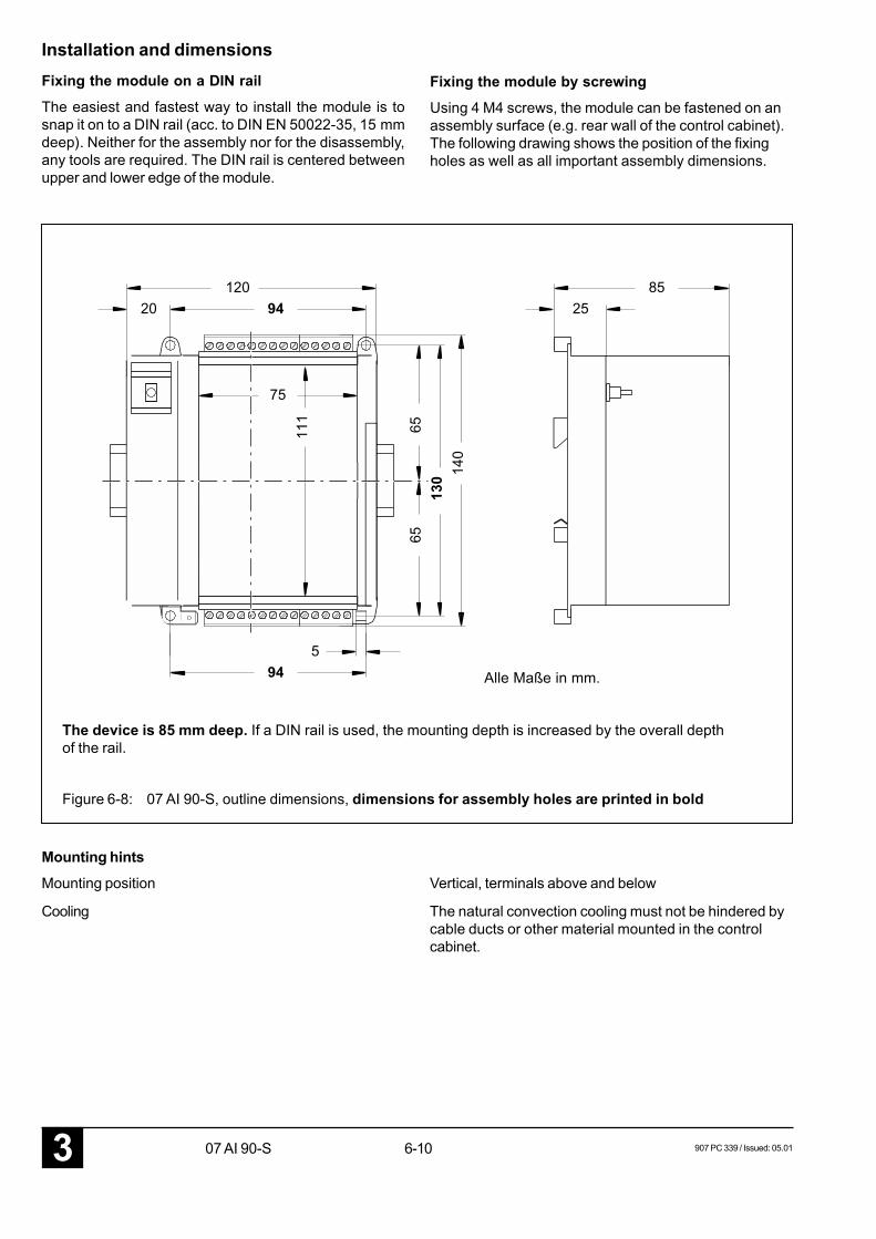
6-103 907 PC 339 / Issued: 05.0107 AI 90-S
6513
065
140
94120
2085
2511
1
75
594
Installation and dimensionsFixing the module on a DIN railThe easiest and fastest way to install the module is tosnap it on to a DIN rail (acc. to DIN EN 50022-35, 15 mmdeep). Neither for the assembly nor for the disassembly,any tools are required. The DIN rail is centered betweenupper and lower edge of the module.
Fixing the module by screwingUsing 4 M4 screws, the module can be fastened on anassembly surface (e.g. rear wall of the control cabinet).The following drawing shows the position of the fixingholes as well as all important assembly dimensions.
The device is 85 mm deep. If a DIN rail is used, the mounting depth is increased by the overall depthof the rail.
Alle Maße in mm.
Figure 6-8: 07 AI 90-S, outline dimensions, dimensions for assembly holes are printed in bold
Mounting hintsMounting position Vertical, terminals above and below
Cooling The natural convection cooling must not be hindered bycable ducts or other material mounted in the controlcabinet.


ABB STOTZ-KONTAKT GmbHEppelheimer Straße 82 Postfach 10168069123 Heidelberg 69006 HeidelbergGermany Germany
Telephone +49 6221 701-0Telefax +49 6221 701-240E-Mail [email protected] http://www.abb.de/stotz-kontakt
Man
ual N
o.:
2CD
C 1
20 0
42 M
020
2