Embed Size (px)
Citation preview
PRE1534
FORM
MEA
SURE
MEN
T
SURFTEST SJ-410 SERIES Portable Surface Roughness Tester
2
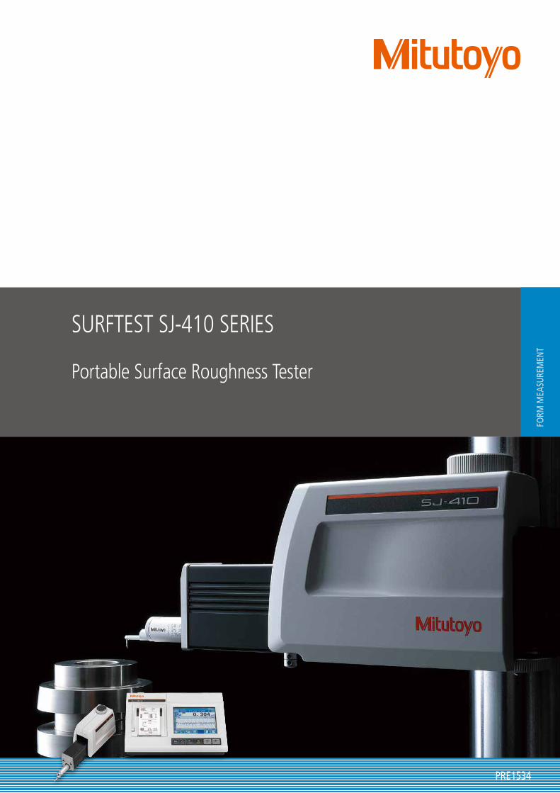
Analysis functions that are a notch above the rest
Portable Surface Roughness Tester
Surftest SJ-410 Series
Easy and safe measurements that anyone can perform
efficiently
User benefit1
A higher-level of quality control
User benefit 2
3
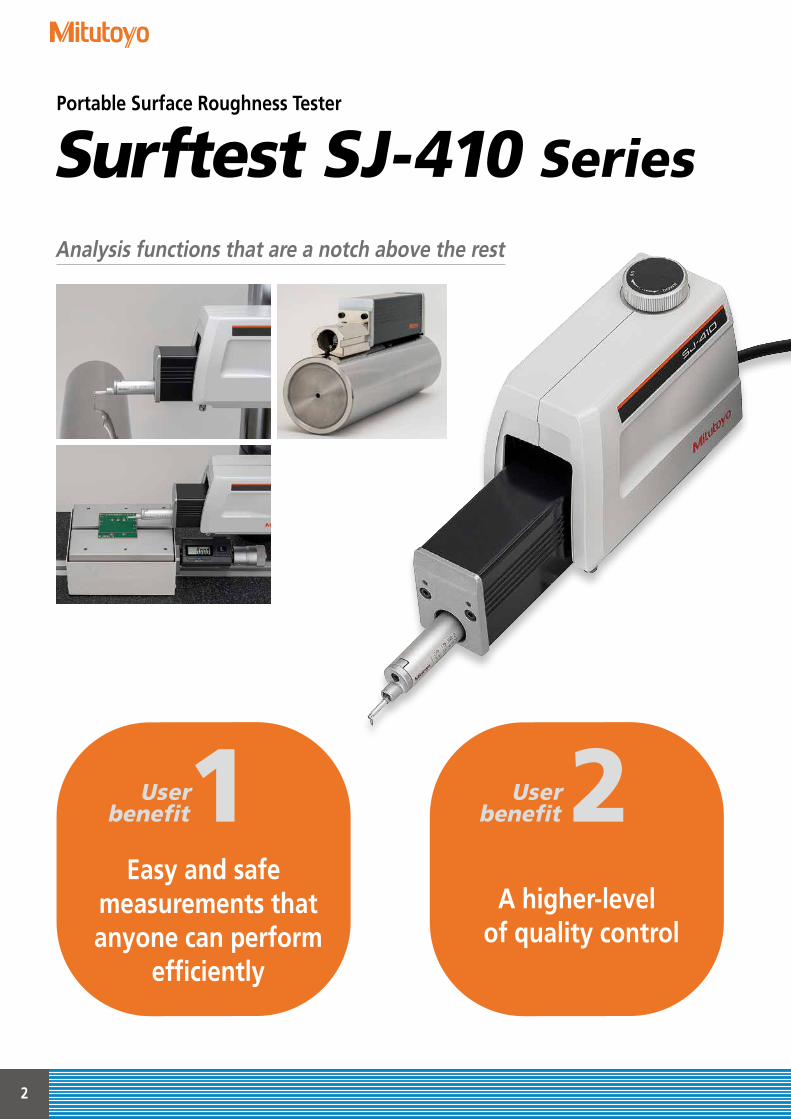
Touch screen for easier operations
The high-visibility color-graphic LCD touch screen clearly displays calculated results and assessed profiles. A backlight enables comfortable viewing even under poor lighting conditions.
Space-saving dual functionality
User benefit 3 SJ-412
Traverse range 50 mm
SJ-411Traverse range 25 mm
4
Easy and safe measurements that anyone can perform
efficiently
User benefit1
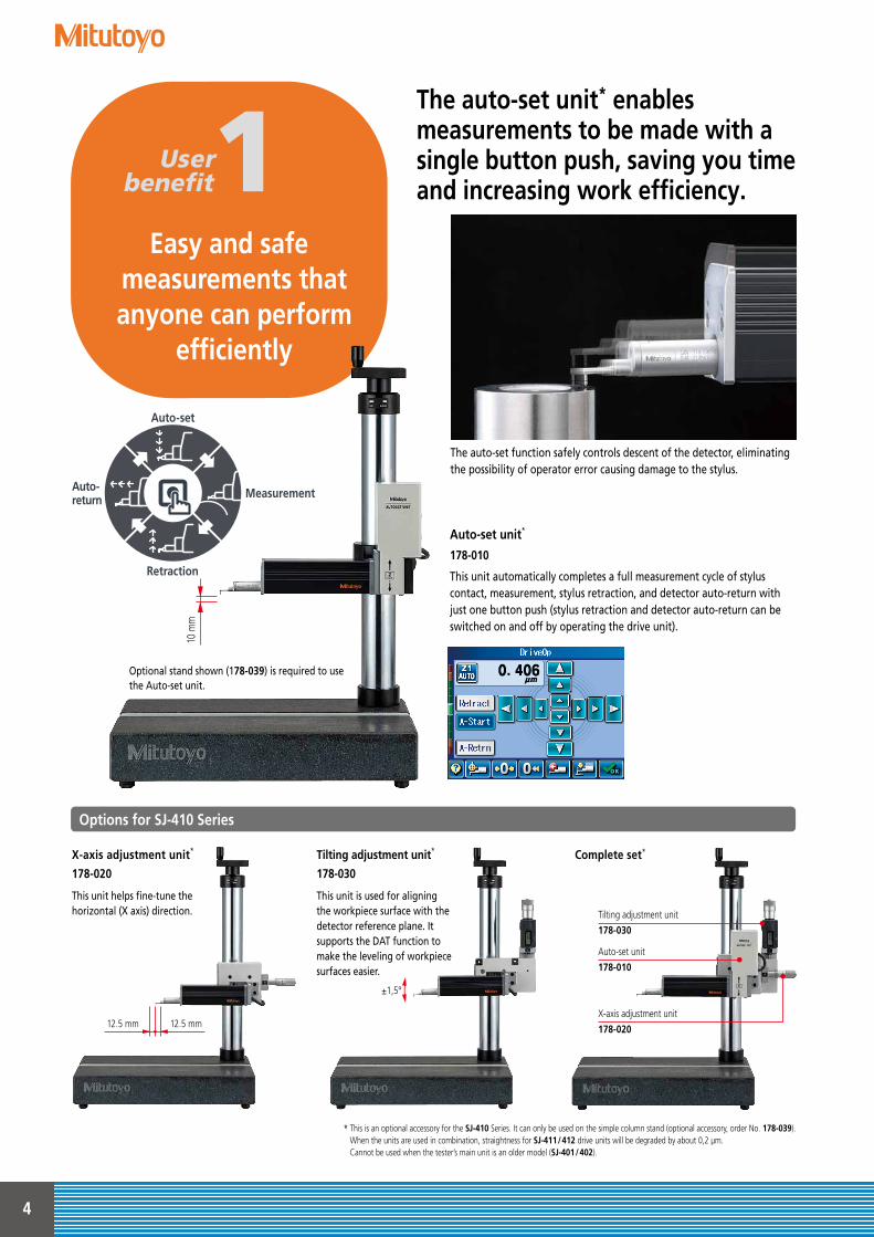
The auto-set unit* enables measurements to be made with a single button push, saving you time and increasing work efficiency.
Options for SJ-410 Series
* This is an optional accessory for the SJ-410 Series. It can only be used on the simple column stand (optional accessory, order No. 178-039). When the units are used in combination, straightness for SJ-411/412 drive units will be degraded by about 0,2 μm. Cannot be used when the tester’s main unit is an older model (SJ-401/402).
Auto-set unit*
178-010
This unit automatically completes a full measurement cycle of stylus contact, measurement, stylus retraction, and detector auto-return with just one button push (stylus retraction and detector auto-return can be switched on and off by operating the drive unit).
X-axis adjustment unit*
178-020
This unit helps fine-tune the horizontal (X axis) direction.
Tilting adjustment unit*
178-030
This unit is used for aligning the workpiece surface with the detector reference plane. It supports the DAT function to make the leveling of workpiece surfaces easier.
Complete set*
Tilting adjustment unit
178-030
X-axis adjustment unit
178-020
Auto-set unit
178-010
12.5 mm 12.5 mm
The auto-set function safely controls descent of the detector, eliminating the possibility of operator error causing damage to the stylus.
±1,5°
10 m
m
Auto-set
Retraction
Auto-return Measurement
Optional stand shown (178-039) is required to use the Auto-set unit.
5
Simple column stand for SJ-410 Series <Option>
178-039Vertical adjustment range: 250 mmDimensions: 400×250×578 mmMass: 20 kg
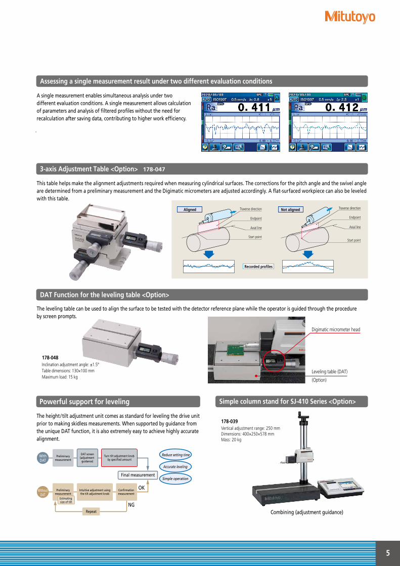
A single measurement enables simultaneous analysis under two different evaluation conditions. A single measurement allows calculation of parameters and analysis of filtered profiles without the need for recalculation after saving data, contributing to higher work efficiency.
Assessing a single measurement result under two different evaluation conditions
This table helps make the alignment adjustments required when measuring cylindrical surfaces. The corrections for the pitch angle and the swivel angle are determined from a preliminary measurement and the Digimatic micrometers are adjusted accordingly. A flat-surfaced workpiece can also be leveled with this table.
The leveling table can be used to align the surface to be tested with the detector reference plane while the operator is guided through the procedure by screen prompts.
3-axis Adjustment Table <Option> 178-047
DAT Function for the leveling table <Option>
Aligned Not aligned
Recorded profiles
Axial line
Traverse direction
Endpoint
Start point
Traverse direction
Endpoint
Axial line
Start point
Digimatic micrometer head
Leveling table (DAT)
(Option)
178-048Inclination adjustment angle: ±1.5° Table dimensions: 130×100 mm Maximum load: 15 kg
The height / tilt adjustment unit comes as standard for leveling the drive unit prior to making skidless measurements. When supported by guidance from the unique DAT function, it is also extremely easy to achieve highly accurate alignment.
Combining (adjustment guidance)
Powerful support for leveling
Preliminarymeasurement
Turn tilt adjustment knob by specified amount
Final measurement
WithDAT
WithoutDAT
DAT screen(adjustment
guidance)
Repeat
OK
NGEstimating size of tilt
Accurate leveling
Reduce setting time
Preliminarymeasurement
Intuitive adjustment using the tilt adjustment knob
Confirmation measurement
Simple operation
6
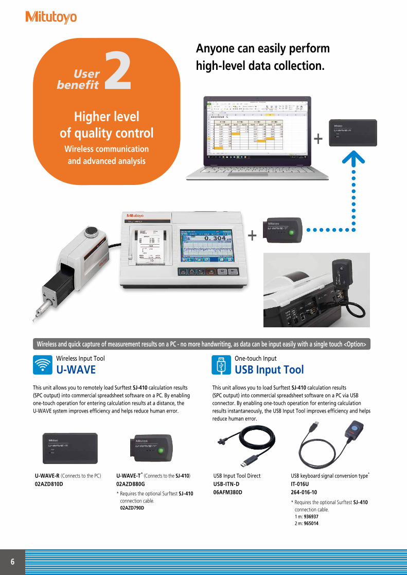
Anyone can easily perform high-level data collection.
This unit allows you to load Surftest SJ-410 calculation results (SPC output) into commercial spreadsheet software on a PC via USB connector. By enabling one-touch operation for entering calculation results instantaneously, the USB Input Tool improves efficiency and helps reduce human error.
USB keyboard signal conversion type*
IT-016U 264-016-10
* Requires the optional Surftest SJ-410 connection cable. 1 m: 936937 2 m: 965014
USB Input Tool DirectUSB-ITN-D 06AFM380D
This unit allows you to remotely load Surftest SJ-410 calculation results (SPC output) into commercial spreadsheet software on a PC. By enabling one-touch operation for entering calculation results at a distance, the U-WAVE system improves efficiency and helps reduce human error.
U-WAVE-T* (Connects to the SJ-410)
02AZD880G
* Requires the optional Surftest SJ-410 connection cable. 02AZD790D
U-WAVE-R (Connects to the PC)
02AZD810D
Wireless and quick capture of measurement results on a PC - no more handwriting, as data can be input easily with a single touch <Option>
Wireless Input Tool
U-WAVEOne-touch Input
USB Input Tool
●●●●●●●●●●●●●●●●●●●●●●●●●●●●●●●●
●
●
●
●
●
●
●
●
●
● ● ● ● ● ● ● ● ● +
+Higher level
of quality controlWireless communication and advanced analysis
User benefit 2
7
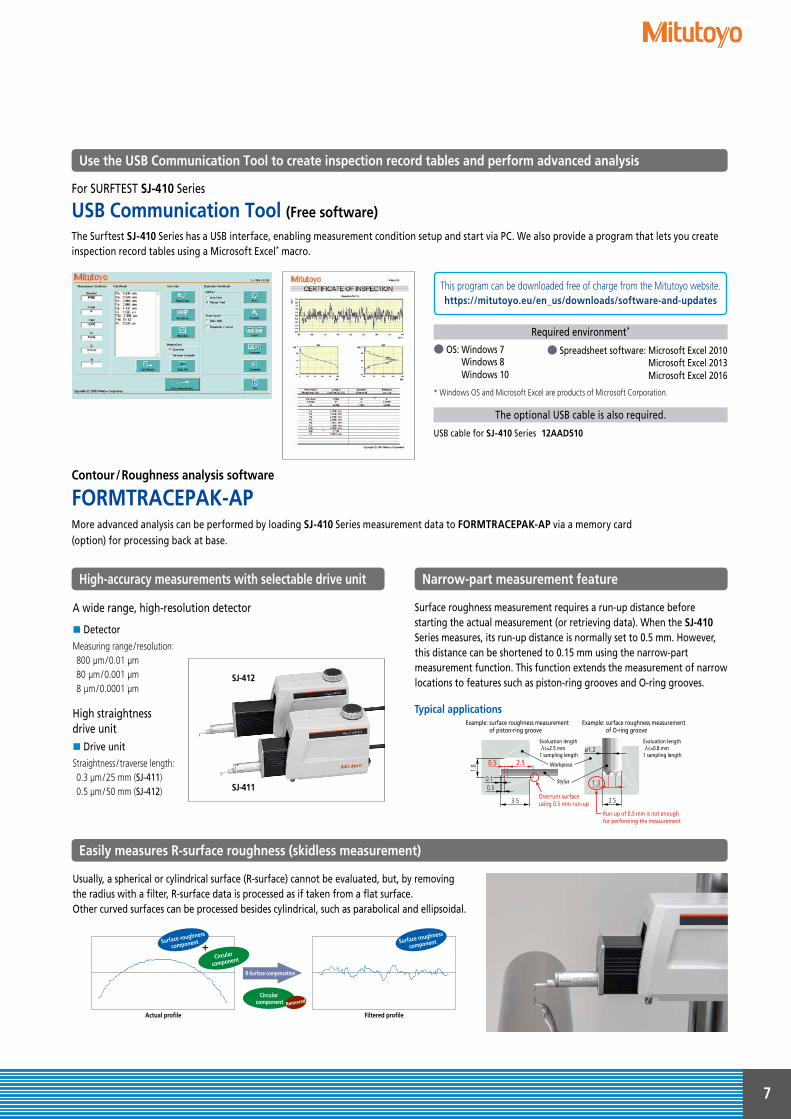
Contour/Roughness analysis software
FORMTRACEPAK-AP
The Surftest SJ-410 Series has a USB interface, enabling measurement condition setup and start via PC. We also provide a program that lets you create inspection record tables using a Microsoft Excel* macro.
● OS: Windows 7 Windows 8 Windows 10
● Spreadsheet software: Microsoft Excel 2010 Microsoft Excel 2013 Microsoft Excel 2016
Required environment*
This program can be downloaded free of charge from the Mitutoyo website.https://mitutoyo.eu/en_us/downloads/software-and-updates
For SURFTEST SJ-410 Series
USB Communication Tool (Free software)
The optional USB cable is also required.
USB cable for SJ-410 Series 12AAD510
* Windows OS and Microsoft Excel are products of Microsoft Corporation.
More advanced analysis can be performed by loading SJ-410 Series measurement data to FORMTRACEPAK-AP via a memory card (option) for processing back at base.
Usually, a spherical or cylindrical surface (R-surface) cannot be evaluated, but, by removing the radius with a filter, R-surface data is processed as if taken from a flat surface.Other curved surfaces can be processed besides cylindrical, such as parabolical and ellipsoidal.
Easily measures R-surface roughness (skidless measurement)
Typical applications
Surface roughness measurement requires a run-up distance before starting the actual measurement (or retrieving data). When the SJ-410 Series measures, its run-up distance is normally set to 0.5 mm. However, this distance can be shortened to 0.15 mm using the narrow-part measurement function. This function extends the measurement of narrow locations to features such as piston-ring grooves and O-ring grooves.
Narrow-part measurement feature
3.5
0.5
0.5 2.5
0.1
Overruns surfaceusing 0.5 mm run-up
Run-up of 0.5 mm is not enough for performing the measurement
Evaluation lengthλc=2.5 mm1 sampling length
Evaluation lengthλc=0.8 mm1 sampling length
2.5
ø1.2
1.3Stylus
Workpiece
1.8
A wide range, high-resolution detector
DetectorMeasuring range / resolution: 800 μm/0.01 μm80 μm/0.001 μm8 μm/0.0001 μm
High straightness drive unit Drive unitStraightness / traverse length: 0.3 μm/25 mm (SJ-411)0.5 μm/50 mm (SJ-412)
High-accuracy measurements with selectable drive unit
SJ-412
SJ-411
Use the USB Communication Tool to create inspection record tables and perform advanced analysis
Example: surface roughness measurement of piston-ring groove
Example: surface roughness measurement of O-ring groove
R-Surface compensation
Actual profile Filtered profile
Circular component
Surface roughness
component Surface roughness
component
Circular
component
Removed
8
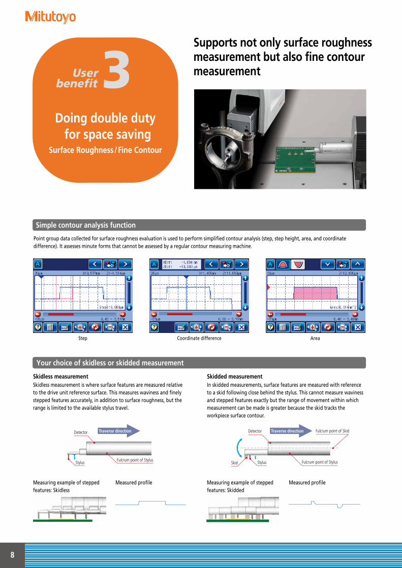
AreaCoordinate differenceStep
Point group data collected for surface roughness evaluation is used to perform simplified contour analysis (step, step height, area, and coordinate difference). It assesses minute forms that cannot be assessed by a regular contour measuring machine.
Simple contour analysis function
Doing double duty for space saving
Surface Roughness/Fine Contour
User benefit 3
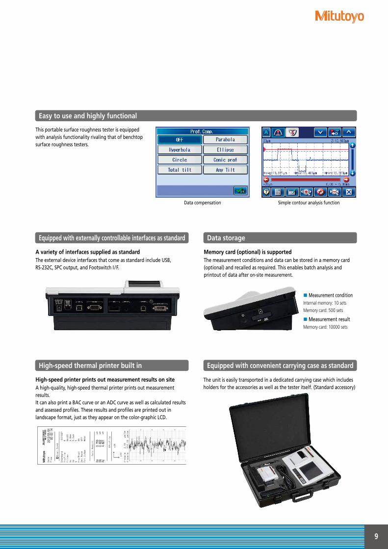
Skidless measurementSkidless measurement is where surface features are measured relative to the drive unit reference surface. This measures waviness and finely stepped features accurately, in addition to surface roughness, but the range is limited to the available stylus travel.
Skidded measurementIn skidded measurements, surface features are measured with reference to a skid following close behind the stylus. This cannot measure waviness and stepped features exactly but the range of movement within which measurement can be made is greater because the skid tracks the workpiece surface contour.
Your choice of skidless or skidded measurement
Measuring example of stepped features: Skidless
Measuring example of stepped features: Skidded
測 定
測定データ
Measured profileMeasured profile
Fulcrum point of StylusStylus
Detector
Traverse direction
測 定
Fulcrum point of StylusStylusSkid
Detector Fulcrum point of SkidTraverse direction
測 定
Traverse direction
測 定
Traverse direction
測 定
Traverse direction
測 定
Supports not only surface roughness measurement but also fine contour measurement
9
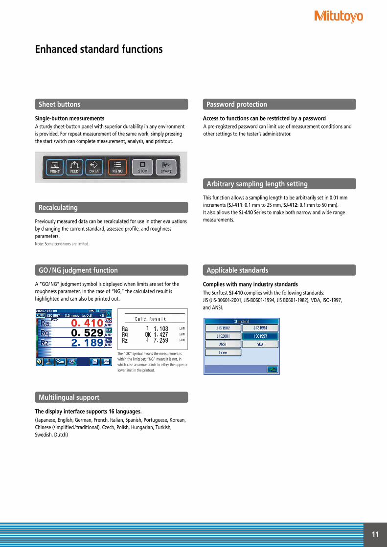
The unit is easily transported in a dedicated carrying case which includes holders for the accessories as well as the tester itself. (Standard accessory)
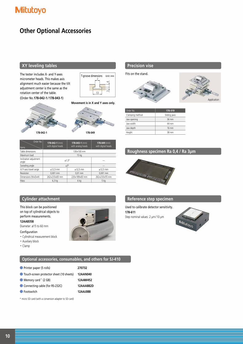
This portable surface roughness tester is equipped with analysis functionality rivaling that of benchtop surface roughness testers.
Equipped with convenient carrying case as standard
Easy to use and highly functional
A variety of interfaces supplied as standard The external device interfaces that come as standard include USB, RS-232C, SPC output, and Footswitch I / F.
Equipped with externally controllable interfaces as standard
High-speed printer prints out measurement results on siteA high-quality, high-speed thermal printer prints out measurement results.It can also print a BAC curve or an ADC curve as well as calculated results and assessed profiles. These results and profiles are printed out in landscape format, just as they appear on the color-graphic LCD.
High-speed thermal printer built in
Memory card (optional) is supportedThe measurement conditions and data can be stored in a memory card (optional) and recalled as required. This enables batch analysis and printout of data after on-site measurement.
Measurement conditionInternal memory: 10 setsMemory card: 500 sets
Measurement resultMemory card: 10000 sets
Data storage
Data compensation Simple contour analysis function
10
The tester includes X- and Y-axes micrometer heads. This makes axis alignment much easier because the tilt adjustment center is the same as the rotation center of the table.
(Order No.178-042-1/178-043-1)
Precision vise
Cylinder attachment
Optional accessories, consumables, and others for SJ-410
Reference step specimen
Roughness specimen Ra 0,4 / Ra 3µm
XY leveling tables
Fits on the stand.
This block can be positioned on top of cylindrical objects to perform measurements.12AAB358Diameter: ø15 to 60 mm
Configuration・ Cylindrical measurement block・ Auxiliary block・ Clamp
Used to calibrate detector sensitivity.178-611Step nominal values: 2 μm/10 μm
Movement is in X and Y axes only.
Order No.
Items
178-042-1 (mm)with digital heads
178-043-1 (mm)with analog heads
178-049 (mm)with digital heads
Table dimensions 130×100 mmMaximum load 15 kgInclination adjustment angle ±1,5° —
Swiveling angle ±3° —X/Y-axis travel range ±12,5 mm ±12,5 mm ±12,5 mmResolution 0,001 mm 0,01 mm 0,001 mmDimensions (W×D×H) 262×233×83 mm 220×189×83 mm 262×233×55 mmMass 6,3 kg 6 kg 5 kg
Order No. 178-019
Clamping method Sliding jaws
Jaw opening 36 mm
Jaw width 44 mm
Jaw depth 16 mm
Height 38 mm
Application
178-042-1 178-049
● Printer paper (5 rolls) 270732
● Touch-screen protector sheet (10 sheets) 12AAN040
● Memory card * (2 GB) 12AAW452
● Connecting cable (for RS-232C) 12AAA882D
● Footswitch 12AAJ088
* micro SD card (with a conversion adapter to SD card)
Other Optional Accessories
T-groove dimensions Unit: mm7
43
13
11
Previously measured data can be recalculated for use in other evaluations by changing the current standard, assessed profile, and roughness parameters. Note: Some conditions are limited.
This function allows a sampling length to be arbitrarily set in 0.01 mm increments (SJ-411: 0.1 mm to 25 mm, SJ-412: 0.1 mm to 50 mm). It also allows the SJ-410 Series to make both narrow and wide range measurements.
The “OK” symbol means the measurement is within the limits set; “NG” means it is not, in which case an arrow points to either the upper or lower limit in the printout.
A “GO/ NG” judgment symbol is displayed when limits are set for the roughness parameter. In the case of “NG,” the calculated result is highlighted and can also be printed out.
Recalculating
Arbitrary sampling length setting
GO/NG judgment function
Access to functions can be restricted by a passwordA pre-registered password can limit use of measurement conditions and other settings to the tester’s administrator.
Password protection
Single-button measurementsA sturdy sheet-button panel with superior durability in any environment is provided. For repeat measurement of the same work, simply pressing the start switch can complete measurement, analysis, and printout.
Sheet buttons
The display interface supports 16 languages.(Japanese, English, German, French, Italian, Spanish, Portuguese, Korean, Chinese (simplified / traditional), Czech, Polish, Hungarian, Turkish, Swedish, Dutch)
Multilingual support
Complies with many industry standardsThe Surftest SJ-410 complies with the following standards: JIS (JIS-B0601-2001, JIS-B0601-1994, JIS B0601-1982), VDA, ISO-1997, and ANSI.
Applicable standards
Enhanced standard functions

12
Detectors/Styli
Styli Unit: mm
Detectors
Standard stylus For deep holes*6
2X stylus12AAC740 (2 μm)12AAB413 (5 μm)*5
12AAB425 (10 μm)*5
( ): Tip radius
12AAE882 (1 μm)12AAE924 (1 μm)*5
12AAC731 (2 μm)12AAB403 (5 μm)*5
12AAB415 (10 μm)*5
12AAE883 (250 μm)*8
( ): Tip radius
NosepieceFor standard measurement12AAB344Remarks ø2 to 20
For round bars12AAB345
3X stylus12AAC741 (2 μm)12AAB414 (5 μm)*5
12AAB426 (10 μm)*5
( ): Tip radius
For small hole measurement Double-length for deep holes*6
12AAE898 (2 μm)12AAE914 (5 μm)*5
( ): Tip radius
12AAC732 (2 μm)12AAB404 (5 μm)*5
12AAB416 (10 μm)*5
( ): Tip radius
NosepieceFor small hole measurement12AAB346
RemarksHole diameter: ø4 or moreHole depth: 15 or less
For small holesDouble-length for deep holes*6
12AAE892 (2 μm)12AAE908 (5 μm)*5
( ): Tip radius
For extra-small holes
12AAC733 (2 μm)12AAB405 (5 μm)*5
12AAB417 (10 μm)*5
( ): Tip radius
For small holes*6*8
12AAE884(ø1.6 mm)
NosepieceFor ultra-small holes12AAB347
RemarksHole diameter: ø2.3 or moreHole depth: 6.5 or less
For ultra-small holes*8
12AAJ662(ø0.5 mm)
For ultra-small holes
12AAC734 (2 μm)12AAB406 (5 μm)*5
12AAB418 (10 μm)*5
( ): Tip radius
For small slotted holes*6
12AAE938 (2 μm)12AAE940 (5 μm)*5
*5 Tip angle 90°*6 For downward-facing measurement only.
小穴用
Color coding*7
0.6
0.4
1.6 ø0.6 ø2
.415
ø1.2
3.4 2.4
1.6
0.6 37.744.4
ADetail-A(S=5/1)
60°
極細穴用
Color coding*7
0.41.2
ø2.48.9
ø0.6
2.5
37.7
1.2
44.2
ADetail-A
ø0.3
(S=5/1)
60°
超小穴用
Color coding*7
Detail-A
ø0.3
0.8
0.4
(S=5/1)
ø2.4
37.7
2.5
ø0.6
8.9
44.2
0.8
A
60°
深穴用 深穴用3倍
Detail-A Detail-A
ø2.4
87.70.994.7
7.6
5.2
A
ø2.4
137.70.9
7.6
144.7
5.2
AColor coding*7
ø1.260°
ø1.260°
Color coding*7
深穴用 深穴用3倍
Detail-A Detail-A
ø2.4
87.70.994.7
7.6
5.2
A
ø2.4
137.70.9
7.6
144.7
5.2
AColor coding*7
ø1.260°
ø1.260°
Color coding*7
深穴2倍用
31.
80.
6
ø2.4
94.787.70.9
小穴用・深穴2倍
ø1.2
1.6
3.4
2.4 ø2.4
94.487.70.6
30
A
0.6
ø0.6
Detail-A
細穴形状用
ø1.2
ø2.4Ball ø1.6
4187.7
93.8
極細穴形状用
ø2.4
ø0.3
A
7
37.743.8
7
ø0.5超硬球
A部詳細
ø2.4
43.837.7
8.5
3.1
A
ø0.3
Ball ø0.5
Detail-A
細長穴用
ø0.3
0.4
1.6
ø1.2
ø2.4
94.487.70.6
45
A
ø0.6
0.6
Detail-A
標準スタイラス
0.9 37.7
7.6
44.7
ø2.45.
2
A
Color coding*7
Detail-Aø1.2
60°
ø1.4
R40
5.6 21.53.6 23.5
3.5
3.6
ø7.2
6.8
7.5
Stylus tip position
150°
ø14
ø7.2
R40
3.6 23.5
3.56.7
3.6
5.6 21.52.8
Stylus tip position
ø14
ø3
R40
0.6
1.6
3.6
21.55.63.6 23.51.4
3.5
15.6 ø7.2
3.8
R2
Stylus tip position
ø14
R40
3.6
1.222.321.5 ø1.92
6.7
3.5
3.8
ø7.2
スタイラス先端位置
ø14
R40
3.6
1.2 22.321.5ø1.9 2
6.7
3.5
3.8
ø7.2
Stylus tip position
Order No. Measuring force
178-396-2*1*3 0,75 mN ’97ISO and ’01JIS compliant detectors
178-397-2*1*4 4 mN Detectors that comply with previous standards, for general use, etc.
178-396*2*3 0,75 mN ’97ISO and ’01JIS compliant detectors
178-397*2*4 4 mN Detectors that comply with previous standards, for general use, etc.
*1 The skidless nosepiece (12AAB355) is a standard accessory.*2 The skidless nosepiece (12AAB355) and the nosepiece (12AAB344) are standard accessories.*3 The standard stylus (12AAC731) is a standard accessory.*4 The standard stylus (12AAB403) is a standard accessory.
1460
ø8
ø14
Detector
ø14
ø7
1011.53.1
3.6
1.3
Skidless nosepiece(12AAB355)
4
ø14 ø14
ø7
6.8
3.6
146027.2
ø8
ø14
24
10.4
2.8
103.1
3.6
1.3
Detector
検出器
NosepieceSkidded ノーズピーススタイラス
(12AAB344)
Skidded
Skidless
*7 Tip radius 1 μm 2 μm 5 μm 10 μm 250 μmColor coding White Black No Color Yellow No notch or color
*8 Used for calibration, a standard step gauge (178-611, option) is also required
Unit: mm

13
For deep grooves (10 mm)
12AAC735 (2 μm)12AAB409 (5 μm)*1
12AAB421 (10 μm)*1
( ): Tip radius
NosepieceFor deep grooves 1012AAB349
RemarksDepth: 10 or less, Width: 9.5 or more
For narrow grooves12AAB350
RemarksDepth: 10 or less, Width: 3 or more
For R-Surface12AAB351
RemarksConvex: R1.5 or moreConcave: R3 or more
For vibration12AAB352
For deep grooves*2 (20 mm)
12AAC736 (2 μm)12AAB408 (5 μm)*1
12AAB420 (10 μm)*1
( ): Tip radius
NosepieceFor deep grooves 20
12AAB348
RemarksGroove depth: 20 or lessGroove pitches: 9.5 or more
For deep grooves*2 (30 mm)
12AAC737 (2 μm)12AAB407 (5 μm)*1
12AAB419 (10 μm)*1
( ): Tip radius
For gear teeth
12AAB339 (2 μm)12AAB410 (5 μm)12AAB422 (10 μm)
( ): Tip radius
NosepieceFor corners12AAB353
For rolling circle waviness surfaces*4
12AAB338 (ø1.588)
( ): Tip radius
*1 Tip angle 90° *2 For downward-facing measurement only.
For knife-edges*4
12AAC738 (2 μm)12AAB411 (5 μm)*1
12AAB423 (10 μm)*1
( ): Tip radius
NosepieceFor knife-edges12AAB354
For eccentric arms*2
12AAC739 (2 μm)12AAB412 (5 μm)*1
12AAB424 (10 μm)*1
( ): Tip radius
For deep grooves*2 (20 mm)
12AAE893 (2 μm)*1
12AAE909 (5 μm)
( ): Tip radius
For deep grooves*2 (40 mm)
12AAE895 (2 μm)*1
12AAE911 (5 μm)
( ): Tip radius
For deep grooves (30 mm) (length doubled for deeper variations) *2
12AAE894 (2 μm)*1
12AAE910 (5 μm)
( ): Tip radius
For gear teeth(length doubled for deeper variations) *2
12AAE896 (2 μm)*1
12AAE912 (5 μm)*1
( ): Tip radius
For rolling circle waviness(length doubled for deeper variations) *2*4
12AAE886 (250 μm)
( ): Tip radius
For corner holes(length doubled for deeper variations) *2
12AAM601 (2 μm)12AAM603 (5 μm)
( ): Tip radius
Hole-bottom cone stylus
12AAE899 (2 μm)12AAE915 (5 μm)*1
( ): Tip radius
23
0.9
φ2.
4
24.2
φ1.2
90°
37.744.7
A識別色
A部詳細
Color coding*3
Detail-A60°
23 ø2.4
ø1.2
24.2
37.744.7
A
深溝用(20mm)
7.6
ø2.4
ø1.2
0.9 37.744.7
Ball ø1.588
5.2
転がり円うねり用
23 21.8 5.2
95.287.7
ø2.4
ø1.2
深溝用2倍(20mm)
43.8
42.6
5.2
ø2.4
45.237.7
ø2.4
ø1.2
深溝用(40mm)
36.5
35
5.2
ø3
93.887.7
ø1.2
深溝用(30mm)深穴2倍
36.5
35
ø393.8
6.77
87.7
ø1.2
60°
歯面用深穴2倍
94.70.9 87.7
ø1.2 ø2.4
5.2
6.4
7.6
転がり円うねり・深穴2倍
93.887.7
φ1.2
60°
60°
7.6 6.4 φ2.
4
穴測定コーナー用・深穴2倍
*3 Tip radius 2 μm 5 μm 10 μmColor coding Black No color Yellow
*4 Used for calibration, a standard step gauge (178-611, option) is also requiredNote: Customized special interchageable styli are available on request. Please contact any Mitutoyo sales office for more information.
13
ø2.4
0.9
ø1.2
60°
14.2
37.744.7
A
Color coding*3
Detail-A
深溝用(10mm)
33 31.8
5.2
ø1.2
A
ø2.4
ø2.4
60°
37.745.2
Color coding*3
Detail-A
深溝用(30mm)
60°
7.6
6.4
37.743.8
ø1.2
ø2.4A
Color coding*3
Detail-A
歯面用
60°
60°
7.6
ø2.4ø1.2
37.70.944.7
AColor coding*3
Detail-A
ナイフエッジ用
A37.70.9
90°ø1.2
45.2
7.6
10
ø2.4
ø2.4
識別色
A部詳細
Color coding*3
Detail-A
心違い用
ø2.4ø1.2
45.21.4 37.7
7.6
ø2.410
A
60°
穴底用
7.4 ø1
0.5
56.2
ø2.4
44.337.7
ø14 R40
17.9
ø7.2
3.5
21.55
331
3.6
4.5
13.4
9
1.45
11.6
10
R2 10
Stylus tip position
ø14
ø7.2
(8.
4)3.
6
3.8 19.51.8 21.5
3.5
13.4
2.5
5
9
10
Stylus tip position
ø1.5
ø14 R40
12.8
0.6
1.4 1.4
3.5
3.8 19.51.8 21.5
4.5
3.6
10
9
ø7.2
Stylus tip position
R24.4
ø14
ø7.2
R40
3.6 23.51.4
13.4
21.55.6
3.6
2.8
10 3.5
Stylus tip position
R2
ø14
R40
3.5
3.8 19.51.8 21.5
22.8
0.61.4
27
20ø7
.2
9Stylus tip position
R21.44.4
コーナー用ノーズピース
ø14
R40
1.4 3.50.5 21.5
ø7.2
19.72.3
6.1
4.5
0.6
1.4
3.6
2.3R2Stylus tip position
4.4
ナイフエッジ用ノーズピース
ø14
R40
21.5
6.7
ø7.2
5.63.6
3.6
3.5
23.52.8Stylus tip position
Flat
14
Specifications
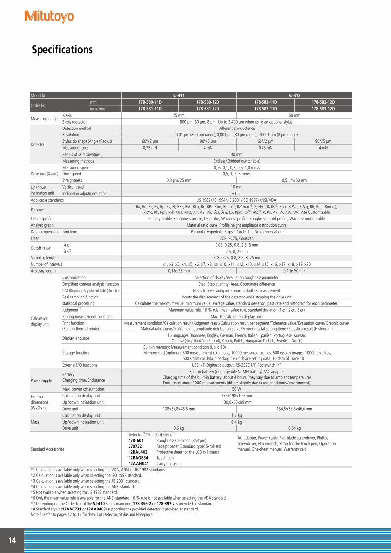
Model No. SJ-411 SJ-412
Order No.mm 178-580-11D 178-580-12D 178-582-11D 178-582-12Dinch /mm 178-581-11D 178-581-12D 178-583-11D 178-583-12D
Measuring rangeX axis 25 mm 50 mmZ axis (detector) 800 μm, 80 μm, 8 μm Up to 2,400 μm when using an optional stylus.
Detector
Detection method Differential inductanceResolution 0,01 μm (800 μm range), 0,001 μm (80 μm range), 0,0001 μm (8 μm range)Stylus tip shape (Angle /Radius) 60° /2 μm 90° /5 μm 60° /2 μm 90° /5 μmMeasuring force 0,75 mN 4 mN 0,75 mN 4 mNRadius of skid curvature 40 mmMeasuring methods Skidless /Skidded (switchable)
Drive unit (X axis)Measuring speed 0,05, 0,1, 0,2, 0,5, 1,0 mm/sDrive speed 0,5, 1, 2, 5 mm/sStraightness 0,3 μm/25 mm 0,5 μm/50 mm
Up/downinclination unit
Vertical travel 10 mmInclination adjustment angle ±1,5°
Applicable standards JIS 1982 / JIS 1994 / JIS 2001 / ISO 1997 /ANSI /VDA
ParameterRa, Rq, Rz, Ry, Rp, Rv, Rt, R3z, Rsk, Rku, Rc, RPc, RSm, Rmax*1, Rz1max*2, S, HSC, RzJIS*3, Rppi, RΔa, RΔq, Rlr, Rmr, Rmr (c),
Rσc, Rk, Rpk, Rvk, Mr1, Mr2, A1, A2, Vo, λa,λq, Lo, Rpm, tp*4, Htp*4, R, Rx, AR, W, AW, Wx, Wte CustomizableFiltered profile Primary profile, Roughness profile, DF profile, Waviness profile, Roughness motif profile, Waviness motif profileAnalysis graph Material ratio curve, Profile height amplitude distribution curveData compensation functions Parabola, Hyperbola, Ellipse, Circle, Tilt, No compensationFilter 2CR, PC75, Gaussian
Cutoff valueλc 0.08, 0.25, 0.8, 2.5, 8 mmλs*5 2.5, 8, 25 μm
Sampling length 0.08, 0.25, 0.8, 2.5, 8, 25 mmNumber of intervals ×1, ×2, ×3, ×4, ×5, ×6, ×7, ×8, ×9, ×10, ×11, ×12, ×13, ×14, ×15, ×16, ×17, ×18, ×19, ×20Arbitrary length 0,1 to 25 mm 0,1 to 50 mm
Calculationdisplay unit
Customization Selection of display /evaluation roughness parameterSimplified contour analysis function Step, Step quantity, Area, Coordinate differenceDAT (Digimatic Adjustment Table) function Helps to level workpiece prior to skidless measurementReal sampling function Inputs the displacement of the detector while stopping the drive unitstatistical processing Calculates the maximum value, minimum value, average value, standard deviation, pass rate and histogram for each parameter.Judgment*6 Maximum value rule, 16 % rule, mean value rule, standard deviation (1σ, 2σ, 3σ)Storing measurement condition Max. 10 (calculation display unit)Print function (Built-in thermal printer)
Measurement condition /Calculation result / Judgment result /Calculation result per segment /Tolerance value /Evaluation curve /Graphic curve /Material ratio curve /Profile height amplitude distribution curve /Environmental setting items /Statistical result (Histogram)
Display language16 languages (Japanese, English, German, French, Italian, Spanish, Portuguese, Korean,
Chinese (simplified / traditional), Czech, Polish, Hungarian,Turkish, Swedish, Dutch)
Storage function Built-in memory: Measurement condition (Up to 10)Memory card (optional): 500 measurement conditions, 10000 measured profiles, 500 display images, 10000 text files,
500 statistical data, 1 backup file of device setting data, 10 data of Trace 10External I /O functions USB I / F, Digimatic output, RS-232C I / F, Footswitch I / F
Power supplyBatteryCharging time / Endurance
Built-in battery (rechargeable Ni-MH battery) /AC adapterCharging time of the built-in battery: about 4 hours (may vary due to ambient temperature)Endurance: about 1000 measurements (differs slightly due to use conditions /environment)
Max. power consumption 50 W
External dimensions(W×D×H)
Calculation display unit 275×198×109 mmUp /down inclination unit 130,9×63×99 mmDrive unit 128×35,8×46,6 mm 154,5×35,8×46,6 mm
MassCalculation display unit 1,7 kg Up /down inclination unit 0,4 kgDrive unit 0,6 kg 0,64 kg
Standard Accessories
Detector*7 / Standard stylus*8
178-601 Roughness specimen (Ra3 μm)270732 Receipt paper (Standard type: 5-roll set)12BAL402 Protective sheet for the LCD (×1 sheet)12BAG834 Touch pen12AAN041 Carrying case
AC adapter, Power cable, Flat-blade screwdriver, Phillipsscrewdriver, Hex wrench, Strap for the touch pen, Operationmanual, One-sheet manual, Warranty card
*1 Calculation is available only when selecting the VDA, ANSI, or JIS 1982 standards.*2 Calculation is available only when selecting the ISO 1997 standard.*3 Calculation is available only when selecting the JIS 2001 standard.*4 Calculation is available only when selecting the ANSI standard.*5 Not available when selecting the JIS 1982 standard.*6 Only the mean value rule is available for the ANSI standard. 16 % rule is not available when selecting the VDA standard.*7 Depending on the Order No. of the SJ-410 Series main unit, 178-396-2 or 178-397-2 is provided as standard.*8 Standard stylus (12AAC731 or 12AAB403) supporting the provided detector is provided as standard.Note 1: Refer to pages 12 to 13 for details of Detector, Stylus and Nosepiece.
15
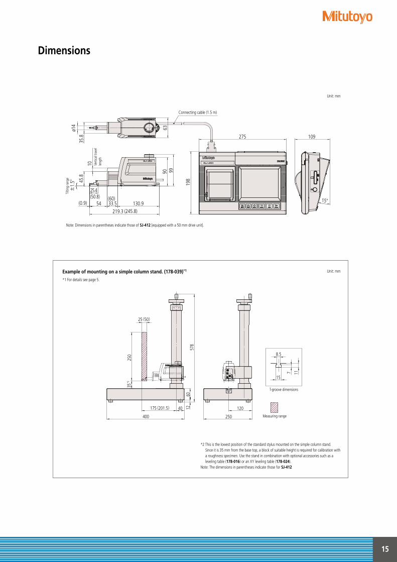
Dimensions
±1.
5°
130.9
45.8
90
ø14
35.8
6399
219.3
33.5(0.9)
25.4
54
10
Connecting cable (1.5 m)
(50.8) (60)
(245.8)
Tilti
ng ra
nge
Verti
cal t
rave
llen
gth
15°
198
109275
Example of mounting on a simple column stand. (178-039)*1
*1 For details see page 5.
12
250
25(50)
12040
6057
8
175(201.5)
35*2
250400
Code No.178-039 簡易スタ ンド外観寸法図
Measuring range
15
8.5
7 11
T-groove dimensions
Unit: mm
Unit: mm
*2 This is the lowest position of the standard stylus mounted on the simple column stand. Since it is 35 mm from the base top, a block of suitable height is required for calibration with a roughness specimen. Use the stand in combination with optional accessories such as a leveling table (178-016) or an XY leveling table (178-024).
Note: The dimensions in parentheses indicate those for SJ-412
Note: Dimensions in parentheses indicate those of SJ-412 [equipped with a 50 mm drive unit].
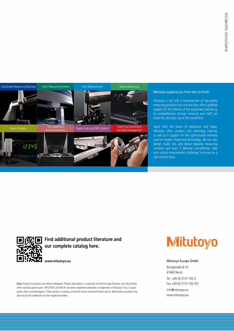
Coordinate Measuring Machines
Sensor Systems
Vision Measuring Systems
Test Equipmentand Seismometers
Form Measurement
Digital Scale and DRO Systems
Optical Measuring
Small Tool Instrumentsand Data Management
Find additional product literature and our complete catalog here.
www.mitutoyo.eu Mitutoyo Europe GmbH
Borsigstraße 8-10 41469 Neuss
Tel. +49 (0) 2137-102-0 Fax +49 (0) 2137-102-351
[email protected] www.mitutoyo.eu
Note: Product illustrations are without obligation. Product descriptions, in particular all technical specifications, are only binding when explicitly agreed upon. MITUTOYO and MiCAT are either registered trademarks or trademarks of Mitutoyo Corp. in Japan and/or other countries/regions. Other product, company, and brand names mentioned herein are for identification purposes only and may be the trademarks of their respective holders.
© M
ITUTO
YO/D
10/
20 P
RE15
34
Mitutoyo supports you from start to finish.
Mitutoyo is not only a manufacturer of top-quality measuring products but one that also offers qualified support for the lifetime of the equipment backed up by comprehensive services, ensuring your staff can make the very best use of the investment.
Apart from the basics of calibration and repair, Mitutoyo offers product and metrology training, as well as IT support for the sophisticated software used in modern measuring technology. We can also design, build, test, and deliver bespoke measuring solutions and even, if deemed cost-effective, take your critical measurement challenges in-house on a sub-contract basis.