Embed Size (px)
Citation preview
« CENTRALE SUPELEC »
THÈSE présentée par
Göknur SIRIN
pour l’obtention du
GRADE DE DOCTEUR
Spécialité : Génie Industriel
Laboratoire d’accueil: Laboratoire de Génie Industriel
SUJET:
Supporting Multidisciplinary Vehicle Modeling: Towards an Ontology-based Knowledge Sharing in Collaborative
Model Based Systems Engineering Environment
soutenue le : 20 Mars 2015
devant un jury composé de :
Bernard Yannou, CentraleSupelec, directeur de thèse
Eric Landel, Renault S.A., tuteur industriel
Irem Tümer, Oregon State University, rapporteur
Eric Bonjour, INP Lorraine, rapporteur
Daniel Krob, Ecole Polytechnique, examinateur
Chris Paredis, Georgia Institute of Technology, examinateur
Torgeir Welo, Norwegian University of Science and Technology, examinateur
2015

i
ii
Résumé
Les systèmes industriels (automobile, aérospatial, etc.) sont de plus en plus complexes à cause des contraintes
économiques et écologiques. Cette complexité croissante impose des nouvelles contraintes au niveau du
développement. La question de la maitrise de la capacité d’analyse de leurs architectures est alors posée.
Pour résoudre cette question, les outils de modélisation et de simulation sont devenus une pratique courante
dans les milieux industriels afin de comparer les multiples architectures candidates. Ces outils de simulations
sont devenus incontournables pour conforter les décisions. Pourtant, la mise en œuvre des modèles
physiques est de plus en plus complexe et nécessite une compréhension spécifique de chaque phénomène
simulé ainsi qu’une description approfondie de l’architecture du système, de ses composants et des liaisons
entre composants. L’objectif de cette thèse est double. Le premier concerne le développement d’une
méthodologie et des outils nécessaires pour construire avec précision les modèles de simulation des
architectures de systèmes qu’on désire étudier. Le deuxième s’intéresse à l’introduction d’une approche
innovante pour la conception, la production et l’intégration des modèles de simulations en mode « plug and
play » afin de garantir la conformité des résultats aux attentes. Notamment, aux niveaux de la qualité et la
maturité. Pour accomplir ces objectifs, des méthodologies et des processus d’ingénierie des systèmes basés
sur les modèles (MBSE) ainsi que les systèmes d’information ont été utilisés. Ce travail de thèse propose
pour la première fois un processus détaillé et un outil pour la conception des modèles de simulation. Un
référentiel commun nommé « Modèle de Carte d'Identité (MIC) » a été développé pour standardiser et
renforcer les interfaces entre les métiers et les fournisseurs sur les plans organisationnels et techniques. MIC
garantit l’évolution et la gestion de la cohérence de l’ensemble des règles et les spécifications des
connaissances des domaines métiers dont la sémantique est multiple. MIC renforce également la cohérence
du modèle et réduit les anomalies qui peuvent interférer pendant la phase dite IVVQ pour Intégration,
Vérification, Validation, Qualification. Finalement, afin de structurer les processus de conception des
modèles de simulation, le travail s’est inspiré des cadres de l’Architecture d’Entreprise en reflétant les
exigences d’intégration et de standardisation du modèle opératoire de l’entreprise. Pour valider les concepts
introduits dans le cadre de cette thèse, des études de cas tirés des domaines automobile et aérospatiale ont
été réalisées. L'objectif de cette validation est d'observer l'amélioration significative du processus actuel en
termes d'efficacité, de réduction de l'ambiguïté et des malentendus dans la modélisation et la simulation du
système à concevoir.
iii
Abstract
Simulation models are widely used by industries as an aid for decision making to explore and optimize a
broad range of complex industrial systems’ architectures. The increased complexity of industrial systems
(cars, airplanes, etc.), ecological and economic concerns implies a need for exploring and analysing
innovative system architectures efficiently and effectively by using simulation models. However, simulations
designers currently suffer from limitations which make simulation models difficult to design and develop in
a collaborative, multidisciplinary design environment. The multidisciplinary nature of simulation models
requires a specific understanding of each phenomenon to simulate and a thorough description of the system
architecture, its components and connections between components. To accomplish these objectives, the
Model-Based Systems Engineering (MBSE) and Information Systems’ (IS) methodologies were used to
support the simulation designer’s analysing capabilities in terms of methods, processes and design tool
solutions. The objective of this thesis is twofold. The first concerns the development of a methodology and
tools to build accurate simulation models. The second focuses on the introduction of an innovative
approach to design, product and integrate the simulation models in a “plug and play" manner by ensuring
the expected model fidelity. However, today, one of the major challenges in full-vehicle simulation model
creation is to get domain level simulation models from different domain experts while detecting any
potential inconsistency problem before the IVVQ (Integration, Verification, Validation, and Qualification)
phase. In the current simulation model development process, most of the defects such as interface mismatch
and interoperability problems are discovered late, during the IVVQ phase. This may create multiple wastes,
including rework and, may-be the most harmful, incorrect simulation models, which are subsequently used
as basis for design decisions. In order to address this problem, this work aims to reduce late inconsistency
detection by ensuring early stage collaborations between the different suppliers and OEM. Thus, this work
integrates first a Detailed Model Design Phase to the current model development process and, second, the
roles have been re-organized and delegated between design actors. Finally an alternative architecture design
tool is supported by an ontology-based DSL (Domain Specific Language) called Model Identity Card (MIC).
The design tools and mentioned activities perspectives (e.g. decisions, views and viewpoints) are structured
by inspiration from Enterprise Architecture Frameworks. To demonstrate the applicability of our proposed
solution, engine-after treatment, hybrid parallel propulsion and electric transmission models are tested
across automotive and aeronautic industries.
iv
Table of contents
Résumé ............................................................................................................................................. ii
Abstract ........................................................................................................................................... iii
Table of contents .............................................................................................................................. iv
List of tables .................................................................................................................................. viii
List of figures .................................................................................................................................. ix
List of abbreviations ........................................................................................................................ xi
Acknowledgements ......................................................................................................................... xi
Extended summary ........................................................................................................................... 1
Résumé étendu .................................................................................................................................. 6
Contexte global: AS-IS ............................................................................................................................................. 7
Enjeux industriel et académique ...........................................................................................................................10
Vue d’ensemble des travaux de recherche ..........................................................................................................16
Etat de l’art ..........................................................................................................................................................16
Objectif ................................................................................................................................................................20
Question de recherche .......................................................................................................................................20
Objectives spécifiés ............................................................................................................................................21
Apports et perspectives .....................................................................................................................................23
Cadre methodologique ......................................................................................................................................23
Limites et perspectives ......................................................................................................................................25
Reference #0 .......................................................................................................................................................27
Dissertation Stracture .........................................................................................................................................28
1 Chapter 1: Introduction ........................................................................................................... 31
1.1 Research and company context ..............................................................................................................31
v
1.1.1 Domain Model Language (DSL) and SysML ..............................................................................35
1.1.2 Model Exchange and Exploitation Barriers in Multidisiplinary Modeling .............................36
1.2 Research objectives ...................................................................................................................................38
1.4 Research methodology .............................................................................................................................38
1.5 Reference #1 ..................................................................................................................... 41
2 Chapitre 2: Research overview ................................................................................................... 42
2 State of the art .........................................................................................................................................................43
2.1 Modeling and Simulation (M&S) as a complex system ..............................................................................43
2.2 Complex system architecture and modularity ..............................................................................................45
2.2.1 Component and port-based modeling .........................................................................................47
2.3 Model exchange: interoperability and inconsistency problems .................................................................49
2.3.1 Product Life Cycle (PLC) and inconsistency ..............................................................................51
2.4 Specified research objectives ...................................................................................................................52
2.4 Reference #2 ..............................................................................................................................................53
3 Chapter 3: Paper #1. Characteristics of a Good Multidisciplinary Model Design Practice:
Toward a Value-Added Thinking ................................................................................................... 57
3.1 Introduction ......................................................................................................................................................58
3.2 Background and state of the art .....................................................................................................................60
3.2.1 Methodological positioning: value in multidisciplinary model development process ...........63
3.3 Characteristics of a good multidisciplinary model design processes .......................................................66
3.3.1 Multidisciplinary collaborative process and stakeholder organization ....................................67
3.3.2 Product level: Referential architecture and simulation models.................................................72
3.3.2.1 Vehicle architecture and architecture reuse .................................................................73
3.3.2.2 Knowledge generation and appropriate model reuse strategy 75
3.3.2.2.1 Model refactoring ...........................................................................................76
3.3.2.2.2 Model reuse .....................................................................................................77
3.3.2.2.2.1 Model reuse (via modification): white box model .................................77
3.3.2.2.2.2 Single source of authority or right from me..............................78
vi
3.3.2.2.2.3 Model reuse: black box model ...................................................79
3.4 Case study ...........................................................................................................................................................80
3.5 Conclusions .......................................................................................................................................................83
3.6 Reference #3 .................................................................................. ................................................................84
4 Chapter 4: Paper #2. Multidisciplinary Simulation Model Development: towards an inconsistency
detection method during the design stage ............................................................................................ 90
4.1 Introduction ...............................................................................................................................................90
4.2 State of the art ...........................................................................................................................................92
4.2.1 Related research methods and industrial projects 92
4.3 Proposed methodology ............................................................................................................................93
4.3.1 Model Identity Card (MIC)..........................................................................................................93
4.3.2 Model of Intention (MoI) .........................................................................................................100
4.3.3 Proposed methodology: a mixed approach.............................................................................102
4.4 Case study..................................................................................................................................................104
4.4.1 First step: Formal model architecting.......................................................................................105
4.4.2 Second step: Model Identity Card (MIC) creation.................................................................107
4.3.3 Third step: MoI building............................................................................................................111
4.5 Comparative analysis of request packages and supplier models ..................................................... 115
4.5.1 Supplier model reception ................................................................................................................. 115
4.5.2 Battery models comparison ............................................................................................................ 116
4.5.3 Global models comparison .............................................................................................................117
4.6 Conclusions and future consideration ................................................................................................ 118
4.7 References #4 ......................................................................................................................................... 119
5 Chapter 5: Paper #3. A Model Identity Card to Support Simulation Model Development Process in
a Collaborative Multidisciplinary Design Environment........................................................................123
5.1 Introduction ............................................................................................................................................ 123
5.1.1 Background........................................................................................................................................123
5.1.2 Problem statement and our contributions....................................................................................125
vii
5.2 Methodology and tate of the art .......................................................................................................... 128
5.2.1 Step 1: Formal vehicle architecture design .................................................................................... 130
5.2.2 Step 2: Vehicle and domain models specifications with Model Identity Card (MIC) ............ 131
5.2.3 Step 3: Correctness control at the early design phase .................................................................. 133
5.3 Model Identity Card (MIC) .................................................................................................................. 133
5.3.1 Motivation for M&S meta-model creation 133
5.3.2 Roadmap for MIC creation 134
5.4 Case study ............................................................................................................................................. 141
5.4.1 Demonstration scenario and MIC validation ................................................................................ 141
5.4.1.1 Step1: Formal system architecture design based on non-formal model architecture 141
5.4.1.2 Step2: Vehicle and domain models specifications with Model Identity Card (MIC) 142
5.4.1.3 Step 3: Correctness control at the early design phase 146
5.5 Validation protocol ................................................................................................................................ 147
5.6 Limitation and future considerations .................................................................................................. 150
5.8 Reference # 5 ......................................................................................................................................... 152
6 Chapter 6: Conduct Change: Tool Development and Deployment .................................... 156
6.1 arKIitect Systems Engineering (SE) Tool and its Customization ................................................. 156
6.1.1 Model Identity Card (MIC) and arKItect Systems Engineering Tool Integration ........... 159
6.2 Graphical User Interface (GUI) for Model Specification .............................................................. 163
6.3 Consistency Properties and Check ..................................................................................................... 166
7 Chapter 7: Conclusion and perspective ................................................................................. 170
Personal Publications .................................................................................................................... 168
Journal papers ....................................................................................................................................................... 168
Conference papers ............................................................................................................................................... 168
A. Appendix ...................................................................................................................................................... 171
viii
List of tables
Table 0-1 Les Acteur de Modelisation ......................................................................................................................................... 15
Table 2-1 Complexity in multidisciplinary M&S environment ................................................................................................ 43
Table 3-1 Actors and their activities ............................................................................................................................................. 72
Table 4-1 Model parameters ........................................................................................................................................................ 114
Table 4-2 Battery model State of Charge (SoC) test ............................................................................................................... 116
Table 5-1 MIC classes and their attributes ................................................................................................................................ 136
Table 5-2 Interface attributes .................................................................................................................................................... 138
ix
List of figures
Figure 0-1 Processus Actuel, V Cycle ..................................................................................................................... 11
Figure 0-2 Architecture de modèle ........................................................................................................................ 15
Figure 0-3 La solution proposée ........................................................................................................................... 19
Figure 0-4 Contribution ........................................................................................................................................ 21
Figure 0-5 Dissertation Structure ............................................................................................................................................... 28
Figure 1-1 Architecture Design Tool and DSL ...................................................................................................... 34
Figure 1-2 Transparency agreement and early stage collaboration ......................................................................... 37
Figure 1-3 Research methodology .............................................................................................................................................. 38
Figure 1-4 Problem-based and theory-based engineering design research methods ......................................................... 39
Figure 2-1 Vehicle decomposition .............................................................................................................................................. 47
Figure 2-2a Port-based design representation ........................................................................................................................... 49
Figure 2-2b Port-based design representation and causality ..................................................................................... 50
Figure 3-1 Value for Product and Process Perspectives ......................................................................................................... 62
Figure 3-2 Add value to the current Simulation Model Development Process ................................................................. 66
Figure 3-3 Majors design actors and concurrent activity ........................................................................................................ 70
Figure 3-4 Pull model development process ............................................................................................................................ 71
Figure 3-5 Vehicle architecture and model ................................................................................................................................. 75
Figure 3-6 Model reuse strategy, general view .......................................................................................................................... 77
Figure 3-7 Model Reuse in Engineering Practice ...................................................................................................................... 79
Figure 3-8 Proposed Process: Link between organization, process and product perspective ......................................... 81
Figure 4-1 Collaboration between major M&S actors ............................................................................................................ 92
Figure 4-2 RFLP Methodology ................................................................................................................................................... 94
Figure 4-3 Conceptual Design Stage .......................................................................................................................................... 96
Figure 4-4 Main Classes and Attributes ..................................................................................................................................... 99
Figure 4-5 Interface Specification ............................................................................................................................................. 100
Figure 4-6 Methodology to support simulation model building based on I&I and MoI ............................................... 101
Figure 4-7 Collaboration between Model Architect and Model Supplier: Information Flow2 .............................. 102
Figure 4-8 Proposed Methodology .......................................................................................................................................... 103
Figure 4-9 Hybrid parallel architecture .................................................................................................................................... 105
Figure 4-10 Formal Model Architecture Design ...................................................................................................................... 107
Figure 4-11 Model Specification with MIC1............................................................................................................................. 108
Figure 4-12 Model Specification with MIC2............................................................................................................................. 109
Figure 4-13 Interface Specification with MIC .......................................................................................................................... 110
Figure 4-14 Global model including electric motor and battery blank models .................................................................. 111
Figure 4-15 Model delivers to suppliers ..................................................................................................................................... 113
Figure 4-16 Battery MoI - MoR comparison ............................................................................................................................ 115
Figure 4-17 Global model MoI - MoR comparison ................................................................................................................ 117
Figure 5-1 Research Gap in Collaborative Model Development Process ......................................................................... 127
Figure 5-2 Integrated model design phase to V-cycle systems engineering process ........................................................ 129
Figure 5-3 MIC Concept ............................................................................................................................................................ 133
Figure 5-4 A part of MIC Meta-Model ................................................................................................................................... 135
Figure 5-5 Interface Characterization ...................................................................................................................................... 137
Figure 5-6 Object Model classes grouping.............................................................................................................................. 140
Figure 5-7 GUI MIC Interface description / Port creation ................................................................................................ 143
Figure 5-8 GUI In-coming, out- coming ports ...................................................................................................................... 144
x
Figure 5-9 Generated block diagram (formal version) ......................................................................................................... 144
Figure 5-10 GUI MIC Model Characteristics ........................................................................................................................... 145
Figure 5-11 Interoperability Check ............................................................................................................................................. 146
Figure 5-12 Proof of Concept .................................................................................................................................................... 147
Figure 5-13 Sources of ambiguity ............................................................................................................................................... 148
Figure 5-14 Ambiguity reduction .............................................................................................................................................. 148
Figure 5-15 Sources of rework and expected improvement .................................................................................................. 150
Figure 6-1 Hierarchical representation of a system................................................................................................................ 158
Figure 6-2 Simulation model view creation ............................................................................................................................. 158
Figure 6-3 System, Component and Port ................................................................................................................................. 159
Figure 6-4 Model and Interface Nature ................................................................................................................................... 160
Figure 6-5 MIC concept (left side) and created new objects in arKItect desing tool (right side) ................................. 161
Figure 6-6 MIC Port and Variable Specification ..................................................................................................................... 162
Figure 6-7 Architecture created with defined graphical editor and MIC ............................................................................ 163
Figure 6-8 MIC GUI for model specification ......................................................................................................................... 164
Figure 6-9 MIC Consistency Check ......................................................................................................................................... 167
Figure 6-10 Causality in Amesim Tool ....................................................................................................................................... 168
xi
List of abbreviations
AFIS Association Française d’Ingénierie Système
API Application Programming Interface
AUTOSAR Automotive Open System ARchitecture
CAE Computer Aided Engineering
CAD Computer Aided Design
CAFE Corporate Average Fuel Efficiency Standards
CE Concurent Engineering
DARPA Defense Advanced Research Projects Agency
DoD Departament of Defense
IVVQ Integration, Verification, Validation, and Qualification
IC Internal Combustion
ISO International Organization for Standardization
M&S Modeling and Simulations
MBSE Model-Based Systems Engineering
MIC Model Identy Card
MoI Model of Intention
NASA National Aeronautics and Space Administration
OEM Original Equipment Manufacturer
SA System Architecture
SE Systems Engineering
PDM Product Data Management
PLM Product Lifecycle Management
PLC Product Life Cycle
RFLP (Requirements > Functionnal > Logical > Physical)
SDM Simulation Data Management
STEP STandard for the Exchange of Product model data
XML eXtensible Markup Language
xii
Acknowledgements/ Remerciements
First of all, I would like to warmly thank the jury members of this PhD thesis: Eric Bonjour, Daniel Krob, Irem Tümer, Chris Paredis and Torgeir Welo for accepting to review and examine this thesis. I appreciated their encouragement, insightful comments, and hard questions. J’aimerais remercier tout d’abord, Bernard Yannou, mon directeur de thèse, pour la confiance et pour la liberté qu’il m’a accordée ainsi que pour son écoute et ses conseils car ils m’ont été précieux. Je tiens ensuite remercier à Eric Landel, tuteur industriel, pour sa connaissance du domaine, son enthousiasme et pour sa gentillesse et surtout son professionnalisme. Il est à l'origine de ce sujet de recherche et a inspiré ce travail. Je tiens ensuite à remercier à ceux sans qui cette thèse n’aurait pas été la même de par leur participation à mes différents travaux avec une mention spéciale à Frederic Ravet, Emmanuel Arnaux, Jean-Marc Gilles, Laurent Noyelle, Amin El-Bakkali, Benjamin Guay de Renault Technocentre et Saina Hassanzadeh de KI pour l’intérêt qu’ils ont porté à ma thèse. Je tiens à remercier les membres du projet SIM d’IRT SystemX pour les échanges productifs. J’en viens maintenant à remercier tous mes collègues et mes amis de Renault, d’IRT SystemX et du LGI. Je voudrais de plus accorder une mention spéciale à Jean-Claude Bocquet, le directeur du LGI, aux « fonctions supports » du laboratoire. Merci à vous quatre, Corinne Ollivier, Sylvie Guillemain, Delphine Martin et Carole Stoll, pour votre aide et votre bonne humeur. Pour conclure, je tiens à remercier du fond du cœur les membres de la famille Sirin et à mon ange Gabriel.
1
Supporting Multidisciplinary Vehicle Modeling:
Towards an Ontology-based Knowledge Sharing in Collaborative
Model Based Systems Engineering Environment
Extended Summary
This PhD thesis dissertation results from a collaboration between Ecole Centrale Paris and Renault Technocentre under a
CIFRE (Conventions Industrielles de Formation par la REcherche) contract between March 2012 and March 2015.
Simulation models are widely used by Original Equipment Manufacturers (OEMs) as an aid for decision
making to explore and optimize a broad range of vehicle architectures. However, simulations designers
currently suffer from limitations which make simulation models difficult to design and develop for complex
multidisciplinary system analysis. The design and development of complex systems is shifting towards a
distributed and collaborative paradigm. Furthermore, multidisciplinary simulation model development
activity is a complex and highly interactive social and design process that covers the individual engineering
disciplines (e.g. aerodynamics, mechanical, electromagnetics, thermal, noise, vibration,) and implies various
design actors (e.g. System Architect, Model Architect and Model Provider). This is particularly challenging
for the design of multidisciplinary systems in which components in different disciplines are tightly coupled
to achieve optimal system performance. The simulation environments for such a paradigm, therefore,
require substantial transparency agreement and collaboration at early design stage. Since the quality of
complex multidisciplinary simulation model strongly depends on inputs from multiple sources, the
semantics and the definition of the interfaces need to be accurate and complete within or between model
components and outside environment (e.g. human and environment). Nevertheless, today’s siloed and
decoupled way of working may create some unnecessary iteration during model integration phase (e.g. co-
simulation), which often results in increased product development lead-time and cost. From a value
perspective, this is particularly wasteful since the ‘cost of learning’ is higher in the final integrating stage.
Several factors may cause inconsistencies during the integration of domain level simulation models into a
system level model; such as lack of early transparency agreement and interface specification, interoperability
based mismatch, human error and lack of common understanding etc.
2
Supporting Multidisciplinary Vehicle Modeling:
Towards an Ontology-based Knowledge Sharing in Collaborative
Model Based Systems Engineering Environment
The above mentioned challenges address the needs of several software tool providers and OEMs as
aerospace and automotive where the design engineers provide digital tools and methods to develop, operate
and maintain complex systems. The overarching goal of this dissertation is to manage the concurrent design
of credible simulation models during a vehicle design process while aiming to detect any model
inconsistencies problems before the Integration / Verification / Validation / Qualification (IVVQ) phase.
To this aim, the research issue has been first split it into three interrelated design objectives:
1. Follow a formal, precise process: The modelling process should be established according to
‘good modelling practices’ to design and manage any multidisciplinary simulation model.
2. Create a credible multidisciplinary model: The model can only be ‘useful’, if it is developed
based on adequate explicit descriptions of the design problem.
3. Support a robust collaboration: Information flows between design actors should be standardized
and supported by a common terminology to decrease the ambiguity and misunderstanding.
The first objective – a valuable process based on a good modelling practices – comprises the second and
third, which is related to the quality of the model and collaboration issues because, it is important to
acknowledge that the quality of the final product is the implicit outcome of a sequence of activities made
through the process. The first objective consists furthermore in the optimization of all standard steps of the
modeling process such as model design, development, integration, validation, verification and decision
making. However, one of the gaps that we noticed during our research investigation in the OEMs is that
there is no clear and formal simulation model specification agreement between the design actors at early
model design phase (or conceptual design phase – downstream phase of V cycle process). Thus to improve
early model design phase, a broader motivating question is addressed:
“How should one design and guide the development of multidisciplinary simulation models?”
Thus, this work proposes a detailed model design phase which is typically composed of the following steps:
1. A System World Specification which is made of:
an operation scenario,
a functional system architecture,
a system analysis application plan with other systems (vehicle and sub systems level).
3
Supporting Multidisciplinary Vehicle Modeling:
Towards an Ontology-based Knowledge Sharing in Collaborative
Model Based Systems Engineering Environment
2- A Model World Specification which is made of:
a structural formal vehicle architecture,
a vehicle domain level models specification (e.g. model and its interfaces),
a complete system level model architecture with negotiated domain model interfaces and related
model specifications,
an early certification (correctness control) before contracting suppliers - advanced checked
options for detecting potential inconsistencies before IVVQ -.
More researchers are recognizing the benefits of Model-Based Systems Engineering (MBSE) for managing
complex system architectures in a formal way. However, semantic misunderstandings and simple human
error can still lead to inconsistencies when specifying a vehicle architecture with a MBSE language (e.g.
SysML). Thus to support model consistency within an MBSE methodology, an ontology based meta-model
named “Model Identity Card (MIC)” is developed. MIC in this case plays a role in the specification of such
systems and improves the reliability of the systems by facilitating checking the match between the system
requirements and the design solution. MIC includes some important and refined characteristics of
simulation model such as modeling assumptions and interfaces specifications. Another MIC objective is to
simplify engineering knowledge capture and ambiguity reduction between design actors. MIC also helps to
support a clear simulation model request creation and design artefact negotiation. Finally, MIC provides an
interfaces correctness control for detecting and preventing interface mismatch problems between two
domain models. Another contribution of this work is to introduce Agent-Based Concurrent Engineering
(CE) environment where the authority delegation is defined and then supported by information flows
between different design actors. Since, there is no clear and formal model specification agreement between
the System Architect and Model Provider, the interaction of these two actors may create a bottleneck for
communication because they do not have the same level of understanding. The System Architects have a
functional view (system world) and they are the sponsors of model development activity. They define an
operational scenario, a trade-off analysis and provide system based requirements to the Model Providers.
On the other side, Model Providers have a physical view (e.g. Simulation Model World) and they are the
domain experts who build models. To reduce the knowledge gap between these two types of design actors
and to support the new activities previously mentioned at the detailed model design phase, a new design
actor named “Model Architect” is introduced. Each Model Architect has a multidisciplinary vision of a
product and of simulation knowledge. He also has a deep understanding of the system-level requirements
4
Supporting Multidisciplinary Vehicle Modeling:
Towards an Ontology-based Knowledge Sharing in Collaborative
Model Based Systems Engineering Environment
for the vehicle model, as well as how their models must interface with other domain models. There are
multiple activities involved in the Model Architecture business cycle such as:
• understanding the system world requirements and interpreting and translating these
requirements in model world,
• analyzing or evaluating and selecting the architecture,
• communicating and playing a transversal view between system architects and model providers.
These activities and proposed MIC meta-model are supported by a new design tool. An industrial tool is
used to instantiate the MIC meta-model and a Graphical User Interface (GUI) is developed to create a
semantically-rich model characterization support for the mentioned design actors. The design tools and
mentioned activities perspectives (e.g. decisions, views and viewpoints) are structured by inspiration from
Enterprise Architecture Frameworks (e.g. NAF, TOGAF, and DoDAF).
To demonstrate the applicability of our proposed solution, engine-after treatment, crash and electric
transmission models are tested across automotive and aeronautic industries. The aim of this demonstration
is to observe the significant improvement of current model design process in term of efficiency, interface
mismatches reduction, and ambiguity and misunderstanding reduction. During this case study, some
selected design actors (system architects and external/internal providers) have participated to the test
scenarios. The objectives of validation of the proposed methods are twofold:
(i) checking the scalability of MIC, i.e. the capacity to cover different natures of simulation models,
(ii) qualitative observation to estimate the rate of model rework and ambiguity reduction
According to return of experience of the design actors who are involved in the case study and of our
qualitative observations, the knowledge gap between the design actors is decreased by providing a MIC
meta-model. (i) The MIC is partially integrated to the company and tested by different engineering teams.
Following the test results, we can say that MIC’s attributes are accurate and contain sufficient information
for characterizing different natures of models (0D reduced, and 1D, 2D and 3D). This kind of test group
experimentation is useful to be able to understand the proposed methods’ functionality and capacity. Our
aim is to make iterations with domain experts in terms of MIC and tool improvement until they succeed in
meeting design requirements. The MIC is potentially a useful concept which contains sufficient information
system to be modeled. MIC could possibly be applicable to another context such as aeronautics but it would
require some work to extend it to support various specific domains of interest.
5
Supporting Multidisciplinary Vehicle Modeling:
Towards an Ontology-based Knowledge Sharing in Collaborative
Model Based Systems Engineering Environment
(ii) Proposed early correctness control within a detailed model design phase aims to reduce the number of
inconsistency based anomalies by a factor of 2. With the provided method, it would take approximately less
than one staff hour of correctness check time for each defect found (e.g. current situation: inconsistency
based rework creates on average, 2 or 3 supplementary staff work per project and 1 to 2 months of delay).
Proposed new activities in the detailed model design phase and MIC concepts will be used in next generation
OEM’s multidisciplinary vehicle modeling strategy. Finally, the OEM that we worked with is creating a job
description for the new design actor ‘Model Architect’ and is currently recruiting for this position.
As a future consideration, a Model of Intention (MoI) concept will be partially integrated to the detailed
model design phase. MoI is a complementary method to MIC and allows to reduce the knowledge gap
between Model Architect and Model Suppliers. MoI is an executable model and contains some observable
parameters so as to be able to understand the requested models’ expected behaviors for a given scenario.
The objective of MoI is to fulfil the transition from the real world to the virtual one in the MBSE spirit.
To highlight the main contribution of this PhD thesis, a set of methods have been proposed and validated
separately with three different industrial case studies, which has allowed to write and submit three scientific
papers [1, 2, 3]. This doctoral dissertation adopts a recent spring-up format — a format that uses published
or submitted scientific articles as main chapters.
[1] G. Sirin, L. Gasser, T. Welo, B. Yannou, and E. Landel, 2015. “Characteristics of a Good Multidisciplinary Model
Design Practice: Toward a Model Reuse and a Value-Added Thinking”, in preparation.
[2] G. Sirin, F. Retho, M. Callot., P. Dessante, E. Landel, B. Yannou, J.C. Vannier, 2014. “Multidisciplinary Simulation
Model Development: towards an inconsistency detection method during the design stage”, submitted to Systems, Man and
Cybernetics, Part A: Systems and Humans, IEEE Transactions.
[3] G. Sirin., C.J.J. Paredis, B. Yannou, E. Landel, E. Coatanea, 2014. "A Model Identity Card to Support Simulation
Model Development Process in a Collaborative Multidisciplinary Design Environment," Systems Journal, IEEE, vol.PP,
no.99, pp.1, 12.
Key words: Collaboration, Design Process, Modeling & Simulation, Model Based Systems Engineering, Ontology-driven
design, Enterprise Architecture Framework
Résumé étendu
6
Supporting Multidisciplinary Vehicle Modeling:
Towards an Ontology-based Knowledge Sharing in Collaborative
Model Based Systems Engineering Environment
Résumé étendu
Le résumé étendu en français a pour double objectif d’exposer le contexte et la problématique industrielle
de notre étude d’une part, et d’autre part de les situer dans les problématiques de recherche du génie
industriel. Dans un premier temps, quelques généralités sur l’activité de conception industrielle, notamment
la conception de modèle de simulation pluridisciplinaire, sont rappelées. Ceci permet d’introduire et de situer
le contexte du constructeur automobile Renault. Puis nous abordons plus précisément les problématiques
concernant l’introduction du point de vue de l’arhitecture et d’un référentiel commun au processus de
conception de simulation numérique pour, de même, introduire et situer le contexte de Renault.
Contexte global de la conception, simulation, validation des véhicules automobiles: AS-IS
L’agence d’informations Thomson Reuters a classé en décembre 2012 Renault parmi les 100 entreprises les
plus innovantes au monde. Renault est le constructeur dont le flux d’innovations est le plus constant depuis
le début de l’histoire automobile. Pour Renault, innover, c’est d’abord concevoir et faire aboutir à un coût
abordable des produits et des services qui ont de la valeur pour les clients, développer des technologies qui
devancent leurs attentes. Mais c’est aussi imaginer aujourd’hui la voiture de demain, grâce à un travail de
prospective et de veille [1]. Pour développer des technologies attirantes et accessibles pour les clients,
Renault travaille aujourd’hui autour de 6 axes prioritaires :
Les architectures innovantes. De la R16 à Twizy en passant par Espace et Twingo, le Groupe a
marqué l’histoire dans ce domaine et cette approche reste une priorité pour Renault.
Les véhicules électriques et leur écosystème. Au-delà d’une gamme de quatre véhicules 100 %
électriques déjà sur les routes, Renault poursuit ses efforts notamment pour explorer de nouvelles
technologies de batterie, augmenter leur autonomie, réduire les temps de charge et les coûts.
Résumé étendu
7
Supporting Multidisciplinary Vehicle Modeling:
Towards an Ontology-based Knowledge Sharing in Collaborative
Model Based Systems Engineering Environment
Les véhicules thermiques. Face aux enjeux de réduction des émissions de CO2, Renault se doit de
modifier son offre en matière de technologies de motorisation afin de répondre aux objectifs dits
de CAFE (Corporate Average Fuel Economy) très ambitieux de l'Union Européenne à l'horizon
2020-2025. Le Groupe s’est fixé comme objectif de diminuer significativement les émissions de
CO2. En 2013, le Groupe était leader en Europe en émissions de CO2 et le premier groupe
automobile sous les 116g de CO2/km sur les ventes de véhicules particuliers [2].
Le bien être à bord. Renault a pour ambition de développer des innovations qui concourent à faire
du déplacement un temps de plaisir et de sérénité comme les technologies électroniques et de
connectivité (notamment via les smartphones) : information en temps réel, continuité d’usage entre
les différents mondes dans lesquels conducteurs et occupants d’un véhicule évoluent, grâce aussi
aux systèmes multimedia embarqués, ou à la personnalisation de l’espace à bord. Le prototype de
véhicule autonome et connecté, NEXT TWO, est un exemple de cette démarche.
Les nouveaux services. Renault travaille pour répondre aux besoins des clients qui cherchent à
retrouver dans leurs véhicules les systèmes d’aide à la conduite peuvent être rangés en plusieurs
catégories: élargir le champ de vision du conducteur, prévenir les baisses de vigilance, proposer du
copilotage électronique et des systèmes d’anticollision et des aides au parking. Certaines de ces
technologies sont aujourd’hui proposée sur les véhicules, dont le Nouvel Espace, pour faciliter la
vie du conducteur.
A des coûts abordables. Dans une approche centrée sur le client, toutes les innovations sont
conçues pour être abordables pour tous, ce qui nécessite de mobiliser toute l’ingéniosité des équipes
pour simplifier et standardiser les solutions que Renault développe.
Pour s’adapter à ces évolutions, le constructeur dispose principalement de deux leviers.
Le premier est l’optimisation des technologies traditionnelles actuellement présentes dans les
véhicules, par example maîtrise de la cylindrée des moteurs (« downsizing »), réduction des
frottements, optimisation de l’aérodynamique, maîtrise de la masse, etc…
Le deuxième levier est l’introduction ou l’exproration de technologies innovantes. Les plus étudiées
actuellement portent principalement sur l’électrification des véhicules (ex: véhicule hybride ou
100% électrique).
Les architectures électriques n’ayant que peu évolué depuis une vingtaine d’années, ces ruptures
technologiques imposent de nouvelles contraintes de développement (ex : coût, sécurité, quantité d’énergie
disponible, poids, volume…) et nécessitent donc des méthodologies et des outils appropriés pour les
analyser. Concernant les outils de conception, très nombreux sont les constructeurs qui s’orientent vers
d’autres solutions que la réalisation systématique de prototypes physiques en faisant appel à la simulation
Résumé étendu
8
Supporting Multidisciplinary Vehicle Modeling:
Towards an Ontology-based Knowledge Sharing in Collaborative
Model Based Systems Engineering Environment
numérique dès le début du cycle de développement (cycle en V) [3] pour réduire les coûts et les délais de
développement, en particulier pour diminuer le nombre de prototypes physiques et d’heures d’essais. La
modélisation et la simulation numérique jouent un rôle central, en privilégiant l'analyse et la mise en œuvre
de modèles, d’algorithmes et de méthodes de calcul intensifs innovants. Ces efforts concernent tant
l’élaboration, l'étude des modèles et la formalisation de problèmes complexes motivés par les sciences que
la mise au point, la validation de nouvelles méthodologies sur de nouvelles architectures de produit.
La simulation de systèmes complexes vue comme un système de simulation
Assurer la bonne qualité du produit et réduire son coût et le temps de conception sont les objectifs
principaux de l’industrie actuelle. Par ailleurs, les systèmes industriels (véhicule automobile, spatial etc…)
deviennent de plus en plus complexes pour des raisons économiques et écologiques. Les systèmes industriels
s’articulent sur plusieurs domaines (mécanique, thermique, magnétique, électrique …). La complexité du
système à concevoir implique de nombreuses interactions et relations entre les sous-systèmes, l’innovation
amène une évolution qui pousse les ingénieurs à reconsidérer leurs approches classiques de type mono-
disciplinaires pour se tourner davantage vers une approche transverse de type ingénierie système, donc
pluridisciplinaire. Pour la conception de système pluridisciplinaire, faire intervenir des métiers ou des
fournisseurs externes et des modèles de simulation de nature différente est donc indispensable. Les
problèmes considérés, qui se prêtent tout particulièrement à une approche interdisciplinaire, couplent des
notions variées, multi-physiques et multi-échelles dans un environnement multi-entreprises (partenaires /
sous-traitants). La communication entre les différents métiers est assez difficile car chaque acteur travaillant
avec des outils qui leur sont propres. Ceci rend la mise en œuvre des simulations numériques difficile
puisqu’elle doit tenir compte aussi de tous ces domaines y compris les méthodes et outils dédiés aux
différents domaines d’activités.
Le système complexe est composé d'un grand nombre d'éléments; -- souvent les éléments sont de plusieurs
types et possèdent une structure interne qui ne peut être négligée; -- les éléments sont reliés par des
interactions non linéaires, souvent de différents types; -- le système est soumis à des influences extérieures
à différentes échelles. J.L. Le Moigne [21] et E. Morin [20] ont contribué à développer une théorie voire
"une science des systèmes" [22] qui se veut d'abord interdisciplinaire et qui vise à rendre compte de
phénomènes complexes. Morin présente aussi les notions d’incertitude et d’indécidabilité comme des
concepts étant étroitement liés à la pensée complexe. Ainsi la complexité s’articule autour des relations
qu’entretiennent quatre principes qui caractérisent cette pensée qui sont : l’ordre, le désordre, l’organisation
Résumé étendu
9
Supporting Multidisciplinary Vehicle Modeling:
Towards an Ontology-based Knowledge Sharing in Collaborative
Model Based Systems Engineering Environment
et l’interaction. La complexité croissante des systèmes pose la question de leur maîtrise et, plus globalement,
de la compétitivité des entreprises en termes de capacité d’analyser l’architecture avec les moyens de
l’ingénierie système. On entend par complexité à la fois la complexité des systèmes eux-mêmes, des cadres
contractuels dans lesquels ceux-ci sont réalisés enfin des organisations impliquées dans les phases de
définition, réalisation et exploitation. Cette complexité impose de faire évoluer les processus d’ingénierie et
les systèmes d’information qui permettent de gérer, partager et capitaliser les données d’ingénierie, et ce sur
tout le cycle de vie du produit. Dans ce travail, les moyens de modélisation et simulation ont été considérés
comme un système complexe et afin de réduire sa complexité, ce système a été décomposé en trois couches
liées; le produit (modèle numérique à produire), le processus de conception et l’organisation (délégation des
rôles des ingénieurs de conception). En considérant donc les aspects humains, processus et produit, ce
travail propose une approche basée modèle qui va considérer de multiples vues et aider à la création de
modèles de simulation.
Conception de simulation multidisciplinaire : découplage fort entre système et physiques
Le processus de l’ingénierie de systèmes prend classiquement la forme d’un "cycle en V" en milieu industriel
qui peut se décrire comme la succession des différentes phases d’ingénierie. La branche descendante (la
phase amont), qui correspond à une démarche de raffinements successifs qui répond à la phase de
conception, partant du général (l’expression des besoins souvent à travers un Cahier des Charges
Fonctionnel (CdCF)) pour déboucher sur le particulier. En effet, la première phase de spécification démarre
avec le Cahier des charges fonctionnelles (CdCF) en spécifiant les exigences et en créant un plan de
validation du système qui sera utilisé en phase finale. La deuxième étape de conception démarre pour aboutir
au dossier de conception, composé d’une spécification de l’architecture du système et des spécifications
techniques des besoins des constituants, et du plan et tests d’intégration. Ensuite vient l’étape de
développent des constituants. Elle peut être vue comme la juxtaposition de multiples sous-cycles en V qui
peuvent se dérouler en parallèle. La branche ascendante, quant à elle, détaille les phases d’intégration et de
validation du système. Pendant cette étape les constituants sont assemblés entre eux en suivant le plan
d’intégration préalablement établi et la dernière étape de validation permet de vérifier que le système répond
bien aux besoins initiaux (le CdCF) et en utilisant le plan de validation. [16].
La conception d’un modèle de simulation peut être vue comme un procesus de transformation des
exigencies et l’architecture de système (automobile) en des specification de modèle de simulation plus en
plus détaillées. Le point de départ est une architecture fonctionnelle/logique bâtie sur les exigences de haut
niveau (Top Level Requirements) cette méthode est la nécessité de répondre à une question par la simulation.
Résumé étendu
10
Supporting Multidisciplinary Vehicle Modeling:
Towards an Ontology-based Knowledge Sharing in Collaborative
Model Based Systems Engineering Environment
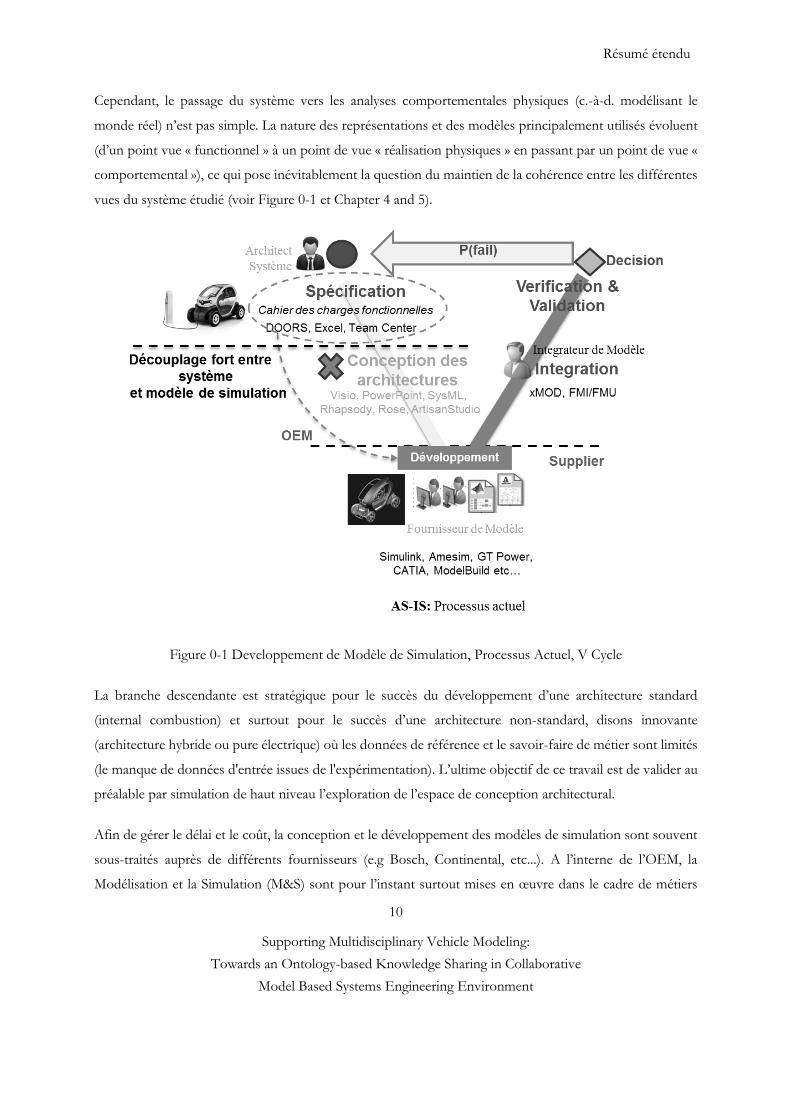
Cependant, le passage du système vers les analyses comportementales physiques (c.-à-d. modélisant le
monde réel) n’est pas simple. La nature des représentations et des modèles principalement utilisés évoluent
(d’un point vue « functionnel » à un point de vue « réalisation physiques » en passant par un point de vue «
comportemental »), ce qui pose inévitablement la question du maintien de la cohérence entre les différentes
vues du système étudié (voir Figure 0-1 et Chapter 4 and 5).
Figure 0-1 Developpement de Modèle de Simulation, Processus Actuel, V Cycle
La branche descendante est stratégique pour le succès du développement d’une architecture standard
(internal combustion) et surtout pour le succès d’une architecture non-standard, disons innovante
(architecture hybride ou pure électrique) où les données de référence et le savoir-faire de métier sont limités
(le manque de données d'entrée issues de l'expérimentation). L’ultime objectif de ce travail est de valider au
préalable par simulation de haut niveau l’exploration de l’espace de conception architectural.
Afin de gérer le délai et le coût, la conception et le développement des modèles de simulation sont souvent
sous-traités auprès de différents fournisseurs (e.g Bosch, Continental, etc...). A l’interne de l’OEM, la
Modélisation et la Simulation (M&S) sont pour l’instant surtout mises en œuvre dans le cadre de métiers
Résumé étendu
11
Supporting Multidisciplinary Vehicle Modeling:
Towards an Ontology-based Knowledge Sharing in Collaborative
Model Based Systems Engineering Environment
(utilisation verticale) ou pour intégrer ou valider les systèmes (utilisation ponctuelle de simulation de
constituants du système, d’interfaces avec des systèmes externes). Chaque métier maîtrise bien son domaine
et dispose des méthodes et outillages requis pour mener les travaux d’ingénierie dont il a la responsabilité.
Ces différents métiers sont des domaines d’expertises confirmées partageant des connaissances et des
sémantiques propres à leur domaine (structure, automatique, hydraulique, électronique, etc.) ou discipline
(mécanique des solides, du point, des fluides, électromagnétisme, etc) (voir Figure 0-3). Un enjeu
particulièrement important pour l’industrie automobile consiste à pouvoir utiliser les modèles de simulations
sous forme de boite noire car la plupart du temps, les sous-modèles arrivent aux OEMs sous un format de
boite noire afin de faciliter le reuse et préservera la propriété intellectuelle. La modèle boite noire est
construit essentiellement sur la base de mesures effectuées sur les entrées et les sorties du processus à
modéliser. Chaque boîte noire peut aussi être appelée module ou composant du système. L’avantage de cette
modularité est de faciliter l’exploration et la réutilisabilité des composants mais nécessite une abstraction
nouvelle : celle de leurs interfaces de communication. Cette abstraction des interfaces de communication
devient aujourd’hui le pivot de la conception des modèles pluridisciplinaires. Sur le plan de la conception,
on établit aussi tôt que possible les interfaces entre les sous modèle, permettant ainsi aux gens chargés de
concevoir chaque homologue de la relation de développer leur module en présumant que l'autre respectera
l'interface choisie. Ceci permet le développement en parallèle de chaque paire d'homologues, et réduit les
dépendances entre les équipes de travail pendant la période de développement. Dans chaque cas, on accélère
et on simplifie la phase de développement, rapportant l'essentiel des problèmes de connectivité, où sont
pensées les manières de connecter les homologues entre eux, et d'intégration, où la connexion effective est
faite et où les irritants résultant d'erreurs ou d'ambiguïtés sont résolus. En effet, si un module a été pensé en
termes d'intégration éventuelle avec d'autres modules, avec des interfaces claires dès le début, on obtiendra
un module qui aura en général tendance à bien s'intégrer avec d'autres modules. Autre avantage significatif
du développement par boîte noire: ayant défini dès le début les modules et leurs interfaces respectives, on
obtient pratiquement un système “prêt à l'emploi”. Pourtant, aujourd’hui, même si la phase de conception
représente par conséquent une étape éminemment stratégique dans le cycle de vie produit, cette phase de
conception n’a jusqu’à présent été outillée ni par un outil de graphique référencé ni par un processus détaillé
et donc OEMs détectent des incohérences très tardivement pendant l’intégration des composants (modèle
de simulation en boite noire ou pas).
Résumé étendu
12
Supporting Multidisciplinary Vehicle Modeling:
Towards an Ontology-based Knowledge Sharing in Collaborative
Model Based Systems Engineering Environment
Au-delà de la problématique de coût et des itérations liées à la détection tardive des erreurs, la non détection
de ces dernières peut entrainer des décisions erronées. La questionne qui se pose est de savoir caractériser
l’architecture de modèle hiérarchiquement avec ses composants et ses interfaces. Ceci demande un effort
méthodologique et organisationnel, qui, en particulier, doit s’appuyer sur des méthodologies des processus
d’ingénierie et les systèmes d’information qui permettent de gérer, partager et capitaliser les données
d’ingénierie, et ce sur tout le cycle de vie du produit et sur surtout dans la phase de conception de modèle
de simulation [9]. Aujourd’hui, la phase de spécification (vue fonctionnelle, systémique) de la branche
descendante de cycle en V a été renforcé par des outils de gestion des exigences et de modélisation SysML
comme Doors, Artisan Studio, Team Center et Reqtify etc (voir Figure 0-2). Le projet du développement
de simulation pluridisciplinaire a été mené en transférant le cahier des charges fonctionnel aux fournisseurs
sans faire la conception détaillée où l’OEM est censé spécifier l’architecture de modèle et les interfaces du
système et des sous-systèmes (vue physique) (voir Figure 0-1).
Analyse des environnements assistant le processus de développement de modèle de
simulation
Une classification des outils assistant le processus d’ingénierie des exigences, le processus de conception, le
développement et l’intégration de systèmes (Figure 0-1) a été identifiée pendant l’audit industriel que nous
avons mené chez Renault. Le découplage entre le monde système et modèle qu’on a évoquée précédemment
pose aussi le problème de traçabilité en terme de l’outil qu’on utilise car chaque entité a fait ses propres
choix d’outils et le passage d’un outil à l’autre n’a pas été assuré (voir Figure 0-2).
- Outils d’ingénierie des exigences [5] : le processus d’ingénierie des exigences regroupe le processus de
définition et le processus de gestion des exigences système. Les outils d’ingénierie des exigences assistent
l’ingénieur système lors de la saisie, la dérivation ou l’allocation des exigences, la saisie des liens d’association
de chaque exigence avec sa source, avec sa justification, avec les hypothèses pour lesquelles elle est
applicable. Les outils DOORS, Team Center et Excel sont des exemples de cette catégorie d’outils (voir
Figure 0-2).
- Les outils de conception et de development de systèmes [6] : parmi les principaux outils de cette
catégorie, citons :
Les outils de modélisation systémique : permettant de représenter les aspects structurels,
comportementaux et sémantiques d’un système. Par exemple des outils comme Rhapsody, Rose,
ArtisanStudio sont des outils de modélisation en SysML pour une représentation formelle et des
outils comme Visio, PowerPoint ou encore MS word sont utilisés pour une représentation non
formelle.
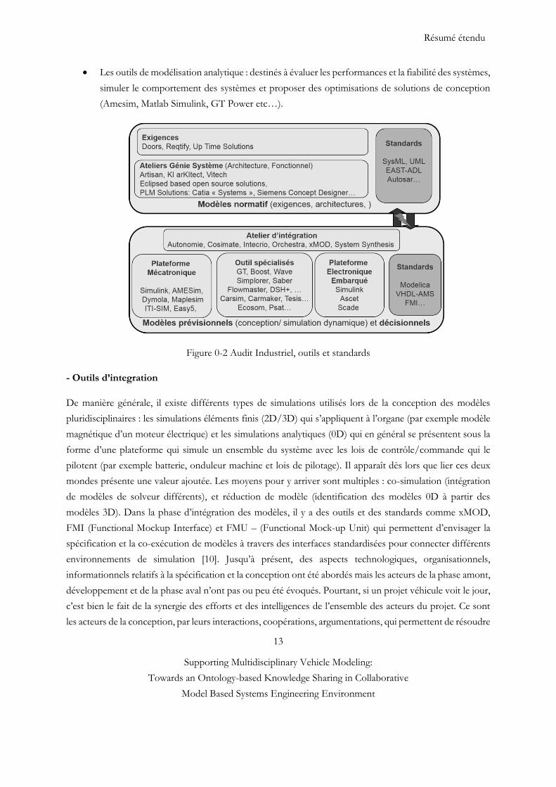
Résumé étendu
13
Supporting Multidisciplinary Vehicle Modeling:
Towards an Ontology-based Knowledge Sharing in Collaborative
Model Based Systems Engineering Environment
Les outils de modélisation analytique : destinés à évaluer les performances et la fiabilité des systèmes,
simuler le comportement des systèmes et proposer des optimisations de solutions de conception
(Amesim, Matlab Simulink, GT Power etc…).
Figure 0-2 Audit Industriel, outils et standards
- Outils d’integration
De manière générale, il existe différents types de simulations utilisés lors de la conception des modèles
pluridisciplinaires : les simulations éléments finis (2D/3D) qui s’appliquent à l’organe (par exemple modèle
magnétique d’un moteur électrique) et les simulations analytiques (0D) qui en général se présentent sous la
forme d’une plateforme qui simule un ensemble du système avec les lois de contrôle/commande qui le
pilotent (par exemple batterie, onduleur machine et lois de pilotage). Il apparaît dès lors que lier ces deux
mondes présente une valeur ajoutée. Les moyens pour y arriver sont multiples : co-simulation (intégration
de modèles de solveur différents), et réduction de modèle (identification des modèles 0D à partir des
modèles 3D). Dans la phase d’intégration des modèles, il y a des outils et des standards comme xMOD,
FMI (Functional Mockup Interface) et FMU – (Functional Mock-up Unit) qui permettent d’envisager la
spécification et la co-exécution de modèles à travers des interfaces standardisées pour connecter différents
environnements de simulation [10]. Jusqu’à présent, des aspects technologiques, organisationnels,
informationnels relatifs à la spécification et la conception ont été abordés mais les acteurs de la phase amont,
développement et de la phase aval n’ont pas ou peu été évoqués. Pourtant, si un projet véhicule voit le jour,
c’est bien le fait de la synergie des efforts et des intelligences de l’ensemble des acteurs du projet. Ce sont
les acteurs de la conception, par leurs interactions, coopérations, argumentations, qui permettent de résoudre
Résumé étendu
14
Supporting Multidisciplinary Vehicle Modeling:
Towards an Ontology-based Knowledge Sharing in Collaborative
Model Based Systems Engineering Environment
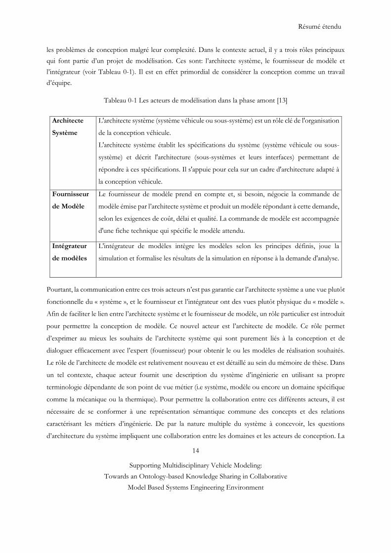
les problèmes de conception malgré leur complexité. Dans le contexte actuel, il y a trois rôles principaux
qui font partie d’un projet de modélisation. Ces sont: l’architecte système, le fournisseur de modèle et
l’intégrateur (voir Tableau 0-1). Il est en effet primordial de considérer la conception comme un travail
d’équipe.
Tableau 0-1 Les acteurs de modélisation dans la phase amont [13]
Architecte
Système
L'architecte système (système véhicule ou sous-système) est un rôle clé de l'organisation
de la conception véhicule.
L'architecte système établit les spécifications du système (système véhicule ou sous-
système) et décrit l'architecture (sous-systèmes et leurs interfaces) permettant de
répondre à ces spécifications. Il s'appuie pour cela sur un cadre d'architecture adapté à
la conception véhicule.
Fournisseur
de Modèle
Le fournisseur de modèle prend en compte et, si besoin, négocie la commande de
modèle émise par l’architecte système et produit un modèle répondant à cette demande,
selon les exigences de coût, délai et qualité. La commande de modèle est accompagnée
d'une fiche technique qui spécifie le modèle attendu.
Intégrateur
de modèles
L'intégrateur de modèles intègre les modèles selon les principes définis, joue la
simulation et formalise les résultats de la simulation en réponse à la demande d'analyse.
Pourtant, la communication entre ces trois acteurs n’est pas garantie car l’architecte système a une vue plutôt
fonctionnelle du « système », et le fournisseur et l’intégrateur ont des vues plutôt physique du « modèle ».
Afin de faciliter le lien entre l’architecte système et le fournisseur de modèle, un rôle particulier est introduit
pour permettre la conception de modèle. Ce nouvel acteur est l’architecte de modèle. Ce rôle permet
d’exprimer au mieux les souhaits de l’architecte système qui sont purement liés à la conception et de
dialoguer efficacement avec l’expert (fournisseur) pour obtenir le ou les modèles de réalisation souhaités.
Le rôle de l’architecte de modèle est relativement nouveau et est détaillé au sein du mémoire de thèse. Dans
un tel contexte, chaque acteur fournit une description du système d’ingénierie en utilisant sa propre
terminologie dépendante de son point de vue métier (i.e système, modèle ou encore un domaine spécifique
comme la mécanique ou la thermique). Pour permettre la collaboration entre ces différents acteurs, il est
nécessaire de se conformer à une représentation sémantique commune des concepts et des relations
caractérisant les métiers d’ingénierie. De par la nature multiple du système à concevoir, les questions
d’architecture du système impliquent une collaboration entre les domaines et les acteurs de conception. La
Résumé étendu
15
Supporting Multidisciplinary Vehicle Modeling:
Towards an Ontology-based Knowledge Sharing in Collaborative
Model Based Systems Engineering Environment
mise en place d’outils au niveau « architecture système » fondés sur des modèles comportementaux de
natures différentes est un point clé́ et encore aujourd’hui un verrou pour aborder efficacement ensuite les
analyses de performances et les optimisations multidisciplinaires nécessaires a ̀ la conception de systèmes.
Vue d’ensemble des travaux de recherche
Etat de l’art
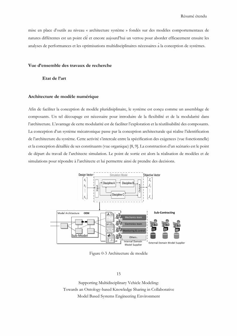
Architecture de modèle numérique
Afin de faciliter la conception de modèle pluridisiplinaire, le système est conçu comme un assemblage de
composants. Un tel découpage est nécessaire pour introduire de la flexibilité et de la modularité dans
l’architecture. L’avantage de cette modularité est de faciliter l’exploration et la réutilisabilité des composants.
La conception d’un système mécatronique passe par la conception architecturale qui réalise l’identification
de l’architecture du système. Cette activité s’intercale entre la spécification des exigences (vue fonctionnelle)
et la conception détaillée de ses constituants (vue organique) [8, 9]. La construction d’un scénario est le point
de départ du travail de l’architecte simulation. Le point de sortie est alors la réalisation de modèles et de
simulations pour répondre à l’architecte et lui permettre ainsi de prendre des decisions.
Figure 0-3 Architecture de modèle
Résumé étendu
16
Supporting Multidisciplinary Vehicle Modeling:
Towards an Ontology-based Knowledge Sharing in Collaborative
Model Based Systems Engineering Environment
Ainsi la conception d’un système consiste surtout à décomposer et rassembler des composants pour
respecter des contraintes de performances et de délai/coût du système global et non plus seulement au
niveau du composant. L'utilisation de la conception modulaire influence directement la structure des
entreprises. L’existence d’une architecture et le référentiel unique partagé permet d’envisager la vérification
et la validation complète d’un modèle complet du système dès les premières étapes et tout au long du
processus de conception, ce qui permet de découvrir le plus tôt possible les incohérences (incompatibilités)
et les problèmes d’intégration susceptibles d’apparaitre en particulier aux niveaux des interfaces entre les
différents domaines de modèles. La combinaison de l’accroissement de la concurrence du fait de la
mondialisation et du développement de nations industrielles puissantes, le besoin de répondre à des besoins
de plus en plus variés en exposant de façon pertinente les aspects différentiateurs de l’entreprise, la
complexité à différents niveaux des systèmes et des contextes dans lesquels ceux-ci sont réalisés et exploités,
le raccourcissement du délai de la mise à jour sur le marché des produits accompagné d’une diminution
parfois sévère des budgets, créent un besoin d’innovation sur au moins deux des axes présentés ci-dessus.
Désormais, celle-ci est incontournable, que ce soit au niveau des processus d’entreprise ou des concepts,
méthodes et moyens déployés pour réaliser l’ingénierie des systèmes.
Ingénierie Système (Systems Engineering)
L’ingénierie système, ou system engineering en anglais, est une démarche méthodologique normalisée de
résolution de problèmes. Basée sur des processus multidisciplinaires, des méthodes et outils, elle guide la
définition, la conception et la vérification d’un système complexe apportant une solution à un besoin
opérationnel. Un système rassemble des produits, processus et personnes qui, une fois intégrés, offrent un
service répondant à un besoin. Dans la pratique, l’ingénierie système conjugue des approches descendantes
(top-down) et ascendante (bottom-up) itératives. La démarche s’initie par une expression de besoin et une
analyse des exigences. Cette première étape nécessite une forte implication et participation de toutes les
parties prenantes impactées par le futur système dont les clients finaux. Chaque exigence est déclinée aux
niveaux systèmes, sous-systèmes et composants à concevoir, puis traduite en fonction : c’est l’architecture
fonctionnelle. Ensuite, pour chaque fonctionnalité, des solutions techniques sont déterminées : c’est
l’architecture organique. En parallèle des définitions fonctionnelles et organiques, les parties prenantes
déterminent les tests de vérification et de validation adéquats qui seront exécutés dans la seconde phase du
cycle, les besoins initiaux, vérifiant ainsi qu’une propriété est mesurable. L'émergence du concept RFLP
(Requirements - Functionnal - Logical - Physical) est défini par cette logique. La gestion associative de ces
quatre mondes prendra du temps mais les enjeux sont là : il en va de l'intégration des aspects
comportementaux dans la definition des produits et de leur traçabilité fonctionnelle. Elle permet de recueillir
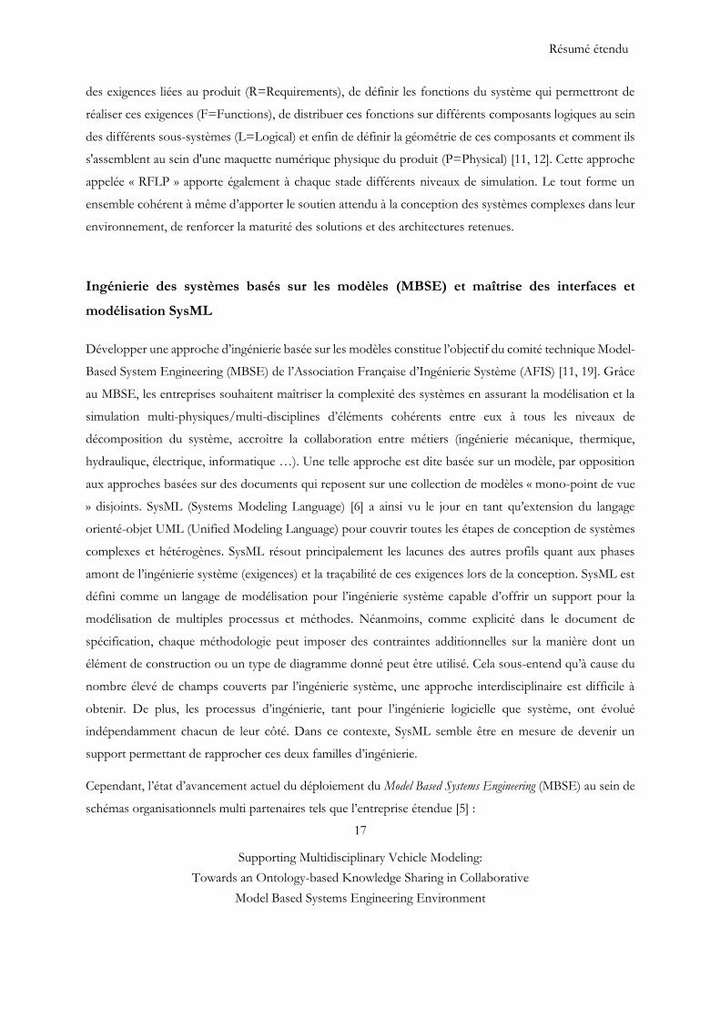
Résumé étendu
17
Supporting Multidisciplinary Vehicle Modeling:
Towards an Ontology-based Knowledge Sharing in Collaborative
Model Based Systems Engineering Environment
des exigences liées au produit (R=Requirements), de définir les fonctions du système qui permettront de
réaliser ces exigences (F=Functions), de distribuer ces fonctions sur différents composants logiques au sein
des différents sous-systèmes (L=Logical) et enfin de définir la géométrie de ces composants et comment ils
s'assemblent au sein d'une maquette numérique physique du produit (P=Physical) [11, 12]. Cette approche
appelée « RFLP » apporte également à chaque stade différents niveaux de simulation. Le tout forme un
ensemble cohérent à même d’apporter le soutien attendu à la conception des systèmes complexes dans leur
environnement, de renforcer la maturité des solutions et des architectures retenues.
Ingénierie des systèmes basés sur les modèles (MBSE) et maîtrise des interfaces et
modélisation SysML
Développer une approche d’ingénierie basée sur les modèles constitue l’objectif du comité technique Model-
Based System Engineering (MBSE) de l’Association Française d’Ingénierie Système (AFIS) [11, 19]. Grâce
au MBSE, les entreprises souhaitent maîtriser la complexité des systèmes en assurant la modélisation et la
simulation multi-physiques/multi-disciplines d’éléments cohérents entre eux à tous les niveaux de
décomposition du système, accroître la collaboration entre métiers (ingénierie mécanique, thermique,
hydraulique, électrique, informatique …). Une telle approche est dite basée sur un modèle, par opposition
aux approches basées sur des documents qui reposent sur une collection de modèles « mono-point de vue
» disjoints. SysML (Systems Modeling Language) [6] a ainsi vu le jour en tant qu’extension du langage
orienté-objet UML (Unified Modeling Language) pour couvrir toutes les étapes de conception de systèmes
complexes et hétérogènes. SysML résout principalement les lacunes des autres profils quant aux phases
amont de l’ingénierie système (exigences) et la traçabilité de ces exigences lors de la conception. SysML est
défini comme un langage de modélisation pour l’ingénierie système capable d’offrir un support pour la
modélisation de multiples processus et méthodes. Néanmoins, comme explicité dans le document de
spécification, chaque méthodologie peut imposer des contraintes additionnelles sur la manière dont un
élément de construction ou un type de diagramme donné peut être utilisé. Cela sous-entend qu’à cause du
nombre élevé de champs couverts par l’ingénierie système, une approche interdisciplinaire est difficile à
obtenir. De plus, les processus d’ingénierie, tant pour l’ingénierie logicielle que système, ont évolué
indépendamment chacun de leur côté. Dans ce contexte, SysML semble être en mesure de devenir un
support permettant de rapprocher ces deux familles d’ingénierie.
Cependant, l’état d’avancement actuel du déploiement du Model Based Systems Engineering (MBSE) au sein de
schémas organisationnels multi partenaires tels que l’entreprise étendue [5] :
Résumé étendu
18
Supporting Multidisciplinary Vehicle Modeling:
Towards an Ontology-based Knowledge Sharing in Collaborative
Model Based Systems Engineering Environment
ne permet pas encore la résolution des problématiques de collaboration multi-domaine, multi-
métier, en particulier du point de vue de la modélisation et de la simulation, point de vue sujet de
l’étude présente,
pose également la difficulté du partage de l’ingénierie du système (donc du modèle du système)
entre partenaires utilisant des méthodes et ateliers d’ingénierie hétérogènes dont l’interopérabilité
doit être assurée. SysML ne dispose ni de semantique nécessaire ni de standards largement déployés.
Objectif
Un enjeu particulièrement important pour l'ingénierie consiste à fournir la capacité méthodologique et un
ensemble d’outils permettant à un architecte système et modèle d’évaluer le comportement, la performance,
de comparer différentes architectures candidates et, plus généralement, de prendre des décisions sur la base
de résultats de simulations dans un environnement collaboratif. Le travail de cette thèse se focalise
essentiellement sur les méthodologies et outils permettant, d’une part, de construire et de spécifier les
architectures de modèles et, d’autre part, de concevoir, produire et intégrer de façon plus efficiente et robuste
des modèles de simulation garantissant des caractéristiques et des critères de qualité (conformité et maturité)
conformes aux attentes de l’architecte de modèles.
Question de recherche
Comme le révèle l’état de l’art, l’enjeu consiste désormais à utiliser un processus robuste, une méthodologie
bien conçue pour réorganiser la phase de conception de façon transverse aux différents métiers (utilisation
horizontale) afin de pouvoir évaluer la conformité du système aux besoins. La finalité de la solution proposée
est un outil d’aide à la décision qui permettant de supporter les activités collaborative à la fois technique et
organisationnelle de l’architecte système et modèle (voir 0-4). Basé sur l'objectif de la recherche, nous
définissons la question de recherche comme suit :
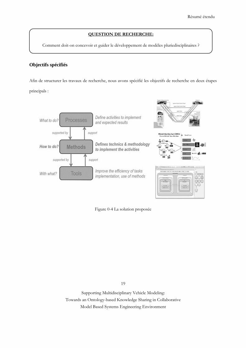
Résumé étendu
19
Supporting Multidisciplinary Vehicle Modeling:
Towards an Ontology-based Knowledge Sharing in Collaborative
Model Based Systems Engineering Environment
Objectifs spécifiés
Afin de structurer les travaux de recherche, nous avons spécifié les objectifs de recherche en deux étapes
principals :
Figure 0-4 La solution proposée
QUESTION DE RECHERCHE:
Comment doit-on concevoir et guider le développement de modèles pluriedisciplinaires ?
Résumé étendu
20
Supporting Multidisciplinary Vehicle Modeling:
Towards an Ontology-based Knowledge Sharing in Collaborative
Model Based Systems Engineering Environment
Apports et perspectives
Contribution et gain de l’entreprise
La contribution la plus importante de ce travail est la détection des incohérences entre ou dans le modèle
en phase amont de processus. Renault souhaite réduire le temps de développement et le nombre de
redondances d'un facteur 2. Lorsque les exigences et l’architecture sont correctement définies et gérées, elles
permettent de réduire de près de 50% les dépassements de projets de modélisation et simulation. Les
malentendus, incompréhensions, incohérences entre les modèles et les fournisseurs sont mis en évidence
tôt dans la phase de conception détaillée où il est donc encore possible de les corriger [15, 16]. Les acteurs
de conception ont la possibilité de clarifier leurs exigences et de détecter les anomalies au fur et à mesure.
Pour cela, le travail propose une méthode, un processus, un outil de support et un nouveau métier pour la
phase de conception (voir Figure 0-5). Ainsi, pour renforcer la cohérence du modèle au sein d'une
méthodologie MBSE, un méta-modèle, référentiel commun nommé « Modèle de carte d'identité (MIC) » a
été développé [13]. MIC est développé pour standardiser et renforcer les interfaces entre les métiers sur les
plans organisationnels et techniques en garantissant l’évolution et la gestion de la cohérence de l’ensemble
des règles et les spécifications des connaissances des domaines dont la sémantique est variée. MIC aide à la
OBJECTIF 1: DEVELOPPER LE PROCESSUS POUR LA PHASE DE CONCEPTION
Mettre en place un processus intégré cadrant des activités (acquisition/cycle de vie) afin de
répondre à des questions bien précises des différents acteurs. S’assurer que le développement des
modèles conduise bien à des résultats cohérents avec les hypothèses émises préalablement et sur
lesquelles des décisions d’ingénierie s’appuient. Cela suppose également que les architectes systèmes
aient confiance dans les résultats produits par l’exécution du système virtuel afin que celui-ci puisse
bien leur permettre d’objectiver et rationaliser les décisions qu’ils prennent.
OBJECTIF 2 : DEVELOPPER LA METHODE ET L’OUTIL POUR LA CONCEPTION DE
MODELE MULTIDISIPLINAIRES
Fournir la capacité méthodologique et un ensemble d’outils permettant à un architecte (architecte
système, niveau système) d’évaluer le comportement, la performance, de comparer différentes
architectures candidates, et plus généralement de prendre des décisions sur la base de résultats de
simulations.
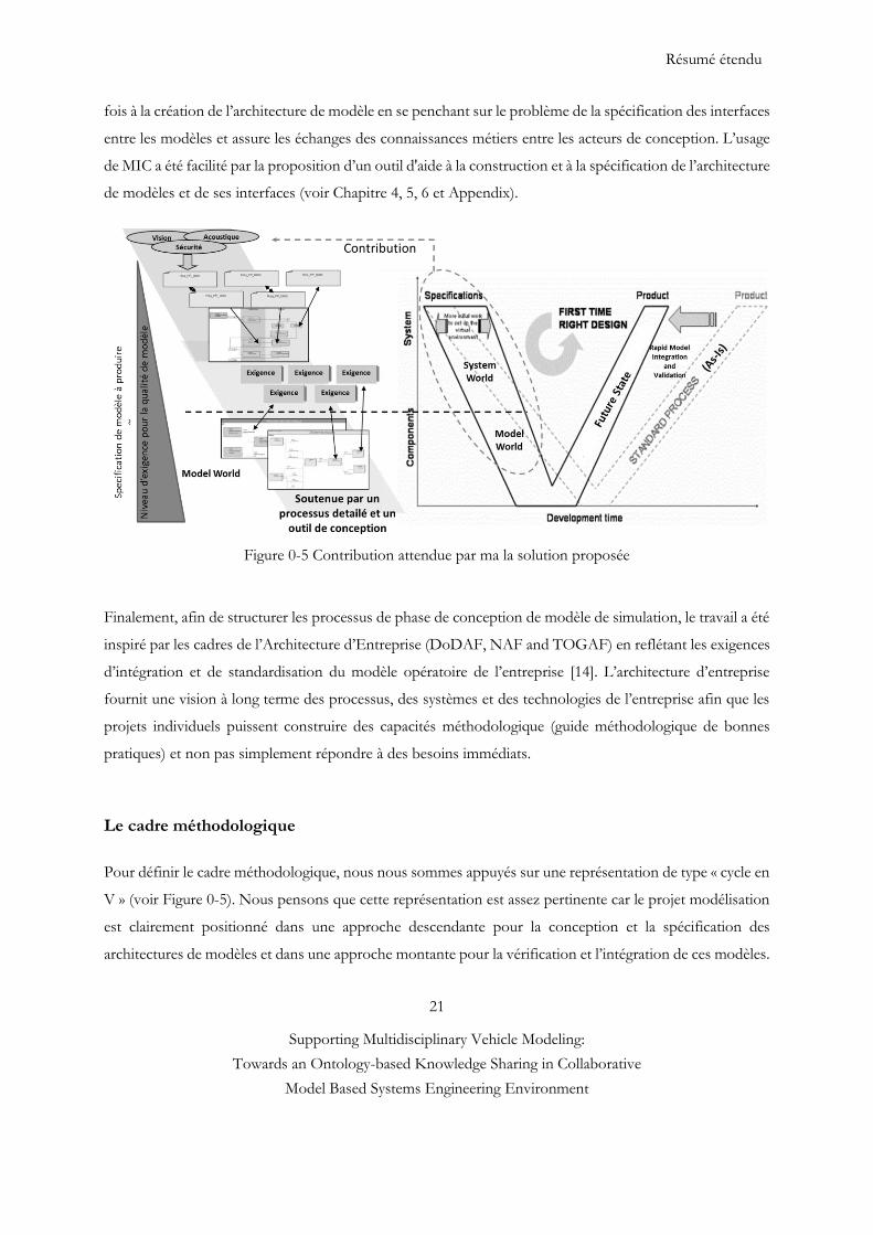
Résumé étendu
21
Supporting Multidisciplinary Vehicle Modeling:
Towards an Ontology-based Knowledge Sharing in Collaborative
Model Based Systems Engineering Environment
fois à la création de l’architecture de modèle en se penchant sur le problème de la spécification des interfaces
entre les modèles et assure les échanges des connaissances métiers entre les acteurs de conception. L’usage
de MIC a été facilité par la proposition d’un outil d'aide à la construction et à la spécification de l’architecture
de modèles et de ses interfaces (voir Chapitre 4, 5, 6 et Appendix).
Figure 0-5 Contribution attendue par ma la solution proposée
Finalement, afin de structurer les processus de phase de conception de modèle de simulation, le travail a été
inspiré par les cadres de l’Architecture d’Entreprise (DoDAF, NAF and TOGAF) en reflétant les exigences
d’intégration et de standardisation du modèle opératoire de l’entreprise [14]. L’architecture d’entreprise
fournit une vision à long terme des processus, des systèmes et des technologies de l’entreprise afin que les
projets individuels puissent construire des capacités méthodologique (guide méthodologique de bonnes
pratiques) et non pas simplement répondre à des besoins immédiats.
Le cadre méthodologique
Pour définir le cadre méthodologique, nous nous sommes appuyés sur une représentation de type « cycle en
V » (voir Figure 0-5). Nous pensons que cette représentation est assez pertinente car le projet modélisation
est clairement positionné dans une approche descendante pour la conception et la spécification des
architectures de modèles et dans une approche montante pour la vérification et l’intégration de ces modèles.
Résumé étendu
22
Supporting Multidisciplinary Vehicle Modeling:
Towards an Ontology-based Knowledge Sharing in Collaborative
Model Based Systems Engineering Environment
La branche « descendante » vise à faire correspondre une expression de besoin fonctionnel (en général via
une question de l’architecte) à une expression de besoin de simulation (décrire les scénarios que l’on a à
simuler). En pratique, la première étape consiste à répondre aux spécifications système par des jeux de
modèles en permettant la vérification. Cela aboutit à une cascade d’exigences de simulation qui doit être
traduite en « identification, appels, besoins de modèles ». La phase Conception des architectures &
Spécification des modèles consiste à définir et à spécifier l’architecture d’un modèle de simulation à partir
d’une architecture organique (structurelle) de référence. Il s’agit donc également de pouvoir cascader ces
spécifications pour les différents niveaux de décomposition du système à analyser. L’intention de simulation
et l’architecture organique de référence sont donc les points de départ de la méthodologie que nous
proposons. Un rôle est alors créé et associé à cette phase : celui de l’Architecte du Modèle qui est
responsable de la définition de l’architecture du modèle intégré et de la spécification (via les MICs) des
caractéristiques attendues du modèle intégré et potentiellement des modèles des sous-systèmes. Ces
spécifications concernent tout autant les aspects techniques et paramètres de modélisation, les spécifications
de modélisation et les paramètres comportementaux propres aux interfaces des modèles, les ressources
(software) à utiliser pour produire et simuler le modèle et enfin les critères qualité à respecter. Afin de fournir
la capacité méthodologique et un ensemble d’outils permettant à un architecte (architecte véhicule, niveau
système) d’évaluer le comportement, la performance, de comparer différentes architectures candidates, et
plus généralement de prendre des décisions sur la base de résultats de simulations. Il s’agit d’organiser les
données de l’architecte et de lier ces données aux résultats de simulation justifiant – ou non – que les
spécifications sont atteintes.
Branche « descendante » IVVQ et prise de décision
Cette phase consiste dans un premier temps à valider les modèles fournis par rapport aux MICs et dans un
second temps d’intégrer de façon automatique les modèles des sous-systèmes avec la notion de « plug &
play (prêt à l'emploi) ». Dans cette phase l’« architecte modèle » a un rôle d’intégrateur et donc de «
fournisseur de modèle » et doit également pouvoir évaluer la qualité du modèle intégré à partir des critères
qualités des modèles des sous-systèmes. Une fois le modèle intégré et qualifié, la carte de simulation peut
être construite en prenant en compte les conditions limites (pouvant provenir de résultats d’autres
simulations), le scénario comportemental (phénomène physique à analyser dans une situation de vie
spécifique du produit) et donc les cas de chargement à appliquer au modèle. La phase de calcul peut alors
être lancée en utilisant le solveur et les algorithmes appropriés. Enfin, la partie haute de cette branche
concerne le post-traitement et l’analyse des résultats bruts ainsi que tous les services et outils d’aide à la
décision qui vont permettre à l’ « Architecte Système » de faire ses choix d’architecture et/ou de gérer ses
Résumé étendu
23
Supporting Multidisciplinary Vehicle Modeling:
Towards an Ontology-based Knowledge Sharing in Collaborative
Model Based Systems Engineering Environment
compromis multidisciplinaires. Dans cette phase on peut également inclure tous les aspects liés à la gestion
et à la redistribution des résultats (aux interfaces notamment) pour des simulations avals (si la simulation
réalisée fait partie d’un processus de simulation plus global).
Synthèse sur la définition des rôles « architect système », « architect modèle » et « fournisseur de
modèle »
Le but du projet est de voir la création du métier « Architect Modèle » dont le rôle est de réaliser des simulations
sur les architectures proposées par le métier déjà existant « Architect Système » [13, 18] :
- L’acteur Architect Système aura pour rôle de concevoir les architectures, et de vérifier le respect des
exigences par rapport aux données fournies par rapport aux modèles testés par l’acteur Architect Modèle.
- L’acteur Architect Modèle a pour rôle de réaliser plusieurs simulations afin de trouver les paramètres,
et les architectures optimales.
Le rôle d’Architect Système a pour l’objectif de définir les architectures organiques (structurelles) candidates
à évaluer et à partir desquelles le Architect Modèle génére les architectures des modèles de simulation. C’est
lui qui analyse les résultats de simulation (à partir des outils et services d’aide à la décision) et qui fait la
sélection des architectures et/ou qui décide du jeu de paramètres optimal dans le cas de compromis
multidisciplinaires. C’est également le « Architect Modèle » qui définit et configure l’architecture du modèle
de simulation intégré avec en perspective la volonté que les modèles des sous-systèmes puissent s’intégrer
rapidement et de façon cohérente. Pour cela il spécifie les caractéristiques des modèles en y intégrant leur
intention de simulation (pour quel contexte et quelle simulation ce modèle peut être utilisé) et cascade ces
spécifications aux Fournisseurs de modèle des sous-systèmes. Pour s’assurer du bon déroulement des
activités et pour automatiser certaines procédures, l’Architect Modèle est donc aussi responsable de définir
et piloter le processus de production et d’intégration des modèles. Le Fournisseur de Modèle est responsable
de fournir (soit en générant, soit en réduisant, soit en réutilisant) des modèles dont les caractéristiques sont
conformes avec les spécifications contenues dans les MICs.
Production des modèles et négociation avec les fournisseurs dans la phase amont
Cette phase consiste à exploiter les Model Identity Card (MICs) soit afin de créer les modèles en conformité
avec ces MICs, soit à requêter un « Model Repository » afin de réutiliser des modèles existants qui sont
adaptés à l’usage que l’on veut en faire (quel système ? quel comportement (scénario) à analyser ? Et quel
type de simulation ?). L’idée est qu’à partir de l’intention de simulation et des MICs fournis par l’architecte
Résumé étendu
24
Supporting Multidisciplinary Vehicle Modeling:
Towards an Ontology-based Knowledge Sharing in Collaborative
Model Based Systems Engineering Environment
du modèle, on puisse automatiser certaines procédures de transformation (réduction) et de composition de
ces modèles. Dans cette phase de production des modèles, le fournisseur de modèle doit, en plus de fournir
des modèles en conformité avec les MICs correspondantes, fournir pour chaque modèle une ensemble de
critères qualité permettant d’évaluer le niveau de confiance, la maturité ou encore la crédibilité de ce modèle.
Le rôle associé à cette phase est celui de « Fournisseur de Modèle qui est responsable d’une part de cascader
correctement les MICs aux niveaux des composants enfants du système étudié et, d’autre part, de fournir
les modèles avec les critères qualités attendus. MIC sert à la fois à la construction de l’architecture modèle
et à la fois à la négociation avec les fournisseurs dans la phase amont.
Limites et perspectives
Pour prouver l'applicabilité de la solution proposée, la methodogie, le processus et l’outil proposés sont
testés dans les industries automobile et aéronautique. L'objectif de cette démonstration est d'observer
l'amélioration significative du processus actuel en termes d'efficacité, de réduction de l'ambiguïté et des
malentendus. Au cours de cette étude de cas, certains acteurs de conception sélectionnés (architectes
système et prestataires externes / internes) ont participé aux scénarios de test. Les objectifs de la validation
des méthodes proposées sont donc :
(i) vérifier l'évolutivité de modèle de MIC, c’est-à-dire la capacité de couvrir différentes natures de modèles
de simulation,
(ii) l'observation qualitative afin d'estimer le taux de reprise d’un modèle et la réduction de l'ambiguïté.
Le retour d'expérience des acteurs de la conception a impliqué dans l'étude de cas et nos observations
qualitatives nous montrent que l'écart de connaissances entre les acteurs de la conception est diminué en
fournissant un méta-modèle MIC. (i) Le modèle MIC est partiellement intégré à Renault et testé par
différentes équipes d'ingénierie. Après les résultats des tests, nous pouvons dire que les attributs du modèle
MIC sont exacts et contiennent suffisamment d'informations pour caractériser différentes natures de
modèles (0D réduite, et 1D, 2D et 3D). Le modèle de MIC est potentiellement un concept utile qui contient
suffisamment d'informations de système à modéliser. Le modèle MIC pourrait être applicable à un autre
contexte comme l'aéronautique, mais il faudrait un travail supplémentaite d’adaptation pour le secteur
spécifique.
Résumé étendu
25
Supporting Multidisciplinary Vehicle Modeling:
Towards an Ontology-based Knowledge Sharing in Collaborative
Model Based Systems Engineering Environment
En tant que perspective, un modèle d'intention (MoI) [17] est partiellement intégré à la phase de conception
de processus de modélisations. MoI est une méthode complémentaire de MIC et permet de réduire l'écart
de connaissances entre l’Architecte du Modèle et les Fournisseurs. MoI est un modèle exécutable et contient
certains paramètres observables de façon à être en mesure de comprendre les comportements attendus des
modèles demandés pour un scénario donné. L'objectif de MoI est de répondre à la transition entre le monde
réel et le monde virtuel dans l'esprit MBSE. En outre, les aspects qualité des modèles ont été peu abordés
dans cette thèse. La qualité des modèles est à étudier suivant deux principaux aspects :
La conformité du modèle par rapport à des exigences d’utilisation (discipline…), des modes
opératoires, des processus.
La maturité du modèle qui correspond à un niveau de confiance sur un modèle à un instant précis
du développement du produit, pour son exploitation dans une activité. C’est par exemple le niveau
de confiance d’un résultat par rapport aux données qui ont été utilisées pour le générer (précision
des données, utilisation des dernières versions et intégration des dernières modifications, etc.)
Reference #0
[1] http://group.renault.com/passion/innovation/renault-laudace-dans-les-genes/ [2] Hybridcars 2010, HybridCars: December 2009 Dashboard: Year-End Tally http://www.hybridcars.com/hybrid-sales-dashboard/december-2009-dashboard.html [3] Systems Engineering Fundamentals, DOD Supplementary text prepared by the defense acquisition university press fort Belvoir, Virginia 22060-5565, USA, 2001. [4] P. Koen et al., 2001. Providing clarity and a common language to the “Fuzzy Front End.” Research Technology Management, 44(2), pp.46–55.
[5] Crescendo (2012). Participants’ handbook. Crescendo Forum Innovation in collaborative modelling and simulation to deliver Behavioral Digital Aircraft 19-20 June 2012, France.
http://cordis.europa.eu/docs/results/234344/final1-crescendo-d017-final-report-20130430-r1.pdf
[6] Object Modeling Group, 2012, "OMG Systems Modeling Language.", www.omg.org/spec/SysML/1.3/. [7] Krob, D. (2009). "Eléments d'architecture des systèmes complexes", Gestion de la Complexité et de l'information Dans les Grands Systèmes Critiques, 179-207.
[8] J.P. Meinadier, "Le métier d’intégration de systèmes", Hermès Sciences Publications, 2002.
[9] N. Suh, "Principles of Design", Oxford University Press, Cambridge, UK, 1990.
Résumé étendu
26
Supporting Multidisciplinary Vehicle Modeling:
Towards an Ontology-based Knowledge Sharing in Collaborative
Model Based Systems Engineering Environment
[10] www.modelisar.com [11] Fisher, J., 1998, "Model-Based Systems Engineering: A New Paradigm," INCOSE Insight, 1(3), pp. 3-16. [12] E. Thomas and M. Ravachol, “Collaborative complex system design applied to an aircraft system” Available Online: http://www.ep.liu.se/ecp/076/088/ecp12076088.pdf [13] G. Sirin., C.J.J. Paredis, B. Yannou, E. Landel, E. Coatanea, "A Model Identity Card to Support Simulation Model Development Process in a Collaborative Multidisciplinary Design Environment," Systems Journal, IEEE , vol.PP, no.99, pp.1,12, 2014. URL: http://ieeexplore.ieee.org/stamp/stamp.jsp?tp=&arnumber=7004782&isnumber=4357939 [14] H. G. Chale-Gongora, A. Dauron, A. Doufene, D. Krob, 2014. “Un cadre methodologique integre pour l architecture et l optimisation de systemes”, In to be published in Revue Génie Logiciel et Systemes, 2014. Available online: http://strategic.mit.edu/docs/Un_cadre_m%C3%A9thodologique_int%C3%A9gr%C3%A9_pour_l-architecture_et_l-optimisation_de_syst%C3%A8mes-RevueGenieLogiciel2014.pdf [15] Projet CSDL : Conception en phase amont de systèmes complexes sur la plateforme PLM/SLM de Dassault Systèmes Michel Ravachol, Jean-Baptiste Quincy, NAFEMS Paris, june 2012. [16] T.R. Browning, 2003, "On Customer Value and Improvement in Product Development Process," Systems Engineering Vol. 6, No.1, pp. 49-61.
[17] F. Retho, H. Smaoui, J.C. Vannier, and P. Dessante, “Model of intention: A concept to support models building in a complex system design project”, ERTS² 2014, France.
[18] G. Sirin, B. Yannou, E. Coatanéa and E. Landel, “Creating a Domain Ontology to Support the Numerical Models Exchange between Suppliers and Users in a Complex System Design”. ASME (IDETC/CIE), Portland, USA, Aug., 4-7, 2013 [19] http://www.afis.fr/
[20] E. Morin, "Introduction à la pensée complexe", Paris, ESF, 1992.
[21] J.L. Le Moigne, "La théorie du système général, Théorie de la modélisation", Paris: Col. SystèmesDécisions, Presses Universitaires de France, 1977.
[22] H.A. Simon, "Sciences des systèmes, Sciences de l’artificiel", version traduite en français par J.L. Le Moigne, Dunod, 1997.
Résumé étendu
27
Supporting Multidisciplinary Vehicle Modeling:
Towards an Ontology-based Knowledge Sharing in Collaborative
Model Based Systems Engineering Environment
Dissertation structure
This doctoral dissertation adopts a recent spring-up format — a format that uses published or submitted
scientific articles as main chapters. Utilization of this format requires the PhD candidate and supervisors to
have a clear overview of the PhD project since the very beginning, separate the research work into relatively
independent parts, and publish each part as scientific paper. This format makes the research work more
organized, the objective of each part more clear, and the contribution of each part validated by publication.
However, this format also causes a certain degree of redundancy among different articles, for which we ask
the comprehension of readers. The main contribution of this PhD project is represented by the following
three scientific papers published or submitted:
[1] G. Sirin, L. Gasser, T. Welo, B. Yannou, and E. Landel, 2015. “Characteristics of Good Multidisciplinary Model Design Practice: Toward a Value-Added Thinking”, submitted to Research in Engineering Design Journal.
[2] G. Sirin, F. Retho, M. Callot., P. Dessante, E. Landel, B. Yannou, J.C. Vannier, 2014. “Multidisciplinary Simulation Model Development: towards an inconsistency detection method during the design stage”, submitted to Systems, Man and Cybernetics, Part A: Systems and Humans, IEEE Transactions.
[3] G. Sirin., C.J.J. Paredis, B. Yannou, E. Landel, E. Coatanea, 2014. “A Model Identity Card to support model
development process in a Collaborative Multidisciplinary Design Environment”, published in IEEE Systems Journal.
Relationships between chapters are shown in Figure 0-6.
Dissertation Structure
28
Supporting Multidisciplinary Vehicle Modeling:
Towards an Ontology-based Knowledge Sharing in Collaborative
Model Based Systems Engineering Environment
Chapter 6 TO-BE / Conduct Change: Deployment Scenario based on Technology,
Process and People Aspects
Ch
ap
ter
1 :
Intr
od
ucti
on
Ch
ap
ter
2:
Rese
arc
h
ove
rvie
w
Paper#1: Characteristics of Good Multidisciplinary Model Design Practice Chapter 3
Case Study 1 Validation Protocol 1 RO1
1.1 Academic and Industrial
Context (AS-IS)
Contributions, Conclusion and Perspectives Chapter 7
1- Follow a formal, precise process
2- Create a credible multidisciplinary model
3- Support a robust collaboration
1.3 R
ese
arc
h M
eth
od
olo
gy
Paper#2: Multidisciplinary Simulation Model Development: towards an
inconsistency detection method during the design stage
Chapter 4
Case Study 2 Validation Protocol 2 RO1 and RO2
Paper#3: A Model Identity Card to Support Simulation Model Development
Process in a Collaborative Multidisciplinary Design Environment Process
Chapter 5
Case Study 3 Validation Protocol 3 RO2 and RO3
1.2 Research Objective
Appendix
Major sources of Complexity : o Interdisciplinary: Social and Technical Aspects o Complex Nature of Product
Modularity and Model Architecture
Model Based Systems Engineering, Enterprise Architecture Framework
Domain Specific Language and Ontology Creation
2.1 State of the art
RO1: Add value to the model development process RO2: Minimize the inconsistencies and rework RO3: Support and delegate the roles of design actors
2.3 Specified Research Objectives (RO)
How should one design and guide the
development of multidisciplinary
models?”
2.2 Research
Question (RQ)
Figure 0-1 Dissertation Structure
Dissertation Structure
29
Supporting Multidisciplinary Vehicle Modeling:
Towards an Ontology-based Knowledge Sharing in Collaborative
Model Based Systems Engineering Environment
Chapter 1 introduces the general problem and the context in which this research has been conducted. Based
on this, the objectives and the scientific approach used in the present thesis are detailed and discussed. In
particular, it provides details about the industrial audit as well as research questions which are not explicitly
explained in other chapters.
Chapter 2 gives on overview of the State of the Art, defines research questions and their connection; as
well as related research obnjectives and contributions. In addition, it gives a synopsis of chapters 3, 4 and 5,
as well as industrial achievements.
Chapter 3 describes the first research cycle. This chapter introduces the characteristics of good
multidisciplinary model design practice: toward a value-added thinking and gives a mild hybrid vehicle case
study.
Chapter 4 presents Multidisciplinary Simulation Model Development: towards an inconsistency detection
method during the design stage. This second research cycle ends with the validation of the overall method
on the industrial case.
Chapter 5 explores the ontology based DSL (Domain Specific Language) called Model Identity Card
concept and its development motivation. A Model Identity Card is developed to support model
development process in a Collaborative Multidisciplinary Design Environment. An industrial case study is
used to illustrate MIC’s capacity.
Chapter 6 introduces a deployment scenario into Renault based on technology, process and people aspects.
Chapter 7 sums up the contributions and limitations of the thesis and describes possible starting points for
future research.
Appendix introduces the question of what a numerical model is?
Chapter 1 : Introduction
30
Supporting Multidisciplinary Vehicle Modeling:
Towards an Ontology-based Knowledge Sharing in Collaborative
Model Based Systems Engineering Environment
1
Introduction
1.1 Research and company context
Simulation models can be used to better understand the impact of different operating conditions on vehicle
performance and attributes. In the endeavor to reduce time to market, OEMs (Original Equipment
Manufacturers) need to create credible simulation models under uncertainty while aiming to detect any
inconsistencies problem before building expensive simulation models. This is particularly challenging for
the design of multidisciplinary systems in which components in different disciplines (e.g., mechanics,
structural dynamics, hydrodynamics, heat conduction, fluid flow, transport, chemistry, or acoustics) are
tightly coupled to achieve optimal system performance [1]. To accurately represent vehicle behavior in a
given field situation, simulation models are created as a module by integrating different simulation models
within a vehicle model, such as model of chassis, engine and transmission, etc. These sub system simulation
models are denoted domain models in the following. Multidisciplinary simulation model development
activity is a complex and highly interactive social process involving multiple distributed design teams and
companies designing coupled simulation models and making many decisions. Multidisciplinary simulation
covers the individual analysis disciplines (aerodynamics, mechanical, electromagnetics, thermal, noise,
vibration etc…) and the links coordination between analysis disciplines [2].
Chapter 1 : Introduction
31
Supporting Multidisciplinary Vehicle Modeling:
Towards an Ontology-based Knowledge Sharing in Collaborative
Model Based Systems Engineering Environment
Since the quality of complex multidisciplinary simulation model strongly depends on input from multiple
sources, efficient collaboration between domain (or discipline) experts is a prerequisite for a successful
outcome. However, today’s siloed way of working and simulation model development approaches have
been developed for individual disciplines, based on discipline-specific simulation tool, language and design
conventions. Furthermore, the interoperability between these heterogeneous tools is poor, as well as the
transversal and holistic view of design and collaboration between the different disciplines. Moreover, the
design and development of domain level simulation models is usually outsourced to different lead suppliers
(or provider) to manage time-to-market and cost. Today, one of the problems in this collaborative
environment is that models are usually considered as available, ready to be integrated (plug and play) or
requested directly from a model provider without specifying any method. However, most of the technology
or service provider’s simulation model is in a Black Box (BB) format for preserving the intellectual
properties. BB models can be interacted only through the inputs and outputs of a well-defined interface.
The challenges is using BB model is to take into consideration the number of distinct interface issues,
parameters, or messages that have to be passed among the components [3].
Another problem is that the supplier is neither integrated in the model design and specification phase, nor
the OEM has access to the simulation model development activity. This decoupled way of working may
create some unnecessary iteration during model integration phase, which often results in increased product
development lead-time and cost. From our experience, specifying a simulation model is not as trivial as
expected; it seems important but underestimated practice. Hence, OEMs must establish an effective
methodology, based on different viewpoints of the actors, to create a credible simulation model while
avoiding project delays and unexpected rework cost by detecting any inconsistencies problems before
building expensive simulation models.
According to de Weck, early design validation and verification may reduce rework in the more expensive
implementation and physical prototype validation phase, which is the main driver for product development
cost [4]. It has been estimated that the cost of imperfect simulation model interoperability is at least $1
billion per year for members of the US automotive OEMs [5] and $400M in an aircraft development
program with 1-2 months of delays [6]. There are many potential sources of inconsistency such as error in
the simulation model code or mismatch of interfaces connections (i.e., differences in time step, units, solver,
hardware and software versioning…). Nevertheless, a significant proportion of defects are associated with
interfaces between modules or between requirements and implementation rather than a design or coding
error within a single module. However, ensuring global consistency is impossible.
Chapter 1 : Introduction
32
Supporting Multidisciplinary Vehicle Modeling:
Towards an Ontology-based Knowledge Sharing in Collaborative
Model Based Systems Engineering Environment
Therefore, the focus must be on managing – that is, identifying and resolving – inconsistencies. In systems
engineering, inconsistencies manifest in a variety of forms: violation of well-formedness rules,
inconsistencies in redundant information, mismatches between model and test data, and not following
heuristics or guidelines. In current practice, most of these inconsistencies are only identified during reviews
that are part of the Verification & Validation (V&V) activities [7]. In between these reviews there is a
possibility of decisions being made based on inconsistent information and knowledge, which can lead to
poor outcomes and costly rework. Typically, the earlier an inconsistency is identified, the cheaper it is to
resolve.
A recent paradigm shift in systems engineering known as Model-Based Systems Engineering (MBSE) has
the potential for the process of identifying inconsistencies to be performed in an automated fashion [8].
This is made possible by the key principle of MBSE: the use of only formal, i.e., computer-interpretable
models. Automated and computer-assisted methods are important enablers for more frequent inconsistency
checks and therefore towards continuously V&V systems. For this purpose, systems engineering approaches
are adopted by most of companies. This research field comprises concepts, methods and best practises
developed in industry in order to master complexity. From this, standards of systems engineering
(ANSI/EIA 632, ISO/ICE 15288) and architectural frameworks (C4ISRAF, MoDAF, DoDAF, TOGAF,
NAF) emerged. In particular, SysML is a semi-formal language that is especially adapted for their
implementation [10].
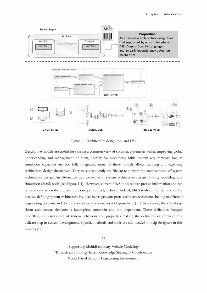
Chapter 1 : Introduction
33
Supporting Multidisciplinary Vehicle Modeling:
Towards an Ontology-based Knowledge Sharing in Collaborative
Model Based Systems Engineering Environment
Figure 1-1 Architecture design tool and DSL
Descriptive models are useful for sharing a common view of complex systems as well as improving global
understanding and management of them, notably for monitoring initial system requirements; but, as
simulation capacities are not fully integrated, none of these models allows defining and exploring
architecture design alternatives. They are consequently insufficient to support the creative phase of system
architecture design. An alternative way to deal with system architecture design is using modelling and
simulation (M&S) tools (see Figure 1-1). However, current M&S tools require precise information and can
be used only when the architecture concept is already defined. Indeed, M&S tools cannot be used earlier
because defining system architecture involves heterogeneous parts: architecture elements belong to different
engineering domains and do not always have the same level of granularity [11]. In addition, the knowledge
about architecture elements is incomplete, uncertain and tool dependent. These difficulties hamper
modelling and assessment of system behaviour and properties making the definition of architecture a
delicate step in system development. Specific methods and tools are still needed to help designers in this
process [12]
Chapter 1 : Introduction
34
Supporting Multidisciplinary Vehicle Modeling:
Towards an Ontology-based Knowledge Sharing in Collaborative
Model Based Systems Engineering Environment
1.1.1 Domain Specific Language (DSL) and SysML
A major open question for advocates of Model-Based Systems Engineering (MBSE) is the question of how
system and subsystem engineers may work together. The Systems Modeling Language (SysML), like any
language intended for a large audience, is in tension between the desires for simplicity and for
expressiveness. In order to be more expressive, many specialized language elements may be introduced,
which unfortunately make a complete understanding of the language a more daunting task. While this may
be acceptable for systems modelers, it increases the challenge of including subsystem engineers in the
modeling effort. One possible answer to this situation is the use of Domain-Specific Languages (DSL),
which are fully supported by the Unified Modeling Language (UML). SysML is in fact a DSL for systems
engineering. The expressive power of a DSL can be enhanced through the use of diagram customization.
Various domains have already developed their own schematic vocabularies. Within the space engineering
community, two excellent examples are the propulsion and telecommunication subsystems. A return to
simple box-and-line diagrams (e.g., the SysML Internal Block Diagram) are in many ways a step backward
(see Figure 1-1). In order to allow subsystem engineers to contribute directly to the model, it is necessary to
make a system modeling tool that is as easy to use and accessible as Microsoft PowerPoint and Visio. Due
to the lack of systematic method and supporting tool for this phase, the architecture and model specification
and formal knowledge exchange between OEM and model suppliers are still done by department based
solutions such as local design tools and documents. At the same time, OEMs tend to rush into the
architecture and model design phase without exploring all possibilities and estimating their overall
performance. In order to support OEMs through the architecture and model specification and design phase,
a decision support tool is needed. Thus, this thesis proposes an alternative architecture design tool that is
supported by an Ontology-based DSL (Domain Specific Language) and an early inconsistency detection
mechanism (see Chapitre 4 and 5).
1.1.2 Model exchange and exploitation barriers in multidisiplinary modeling
In today’s Renault context, the exchange, reuse and exploitation of models are still limited. Boosting model
exchange requires fulfilling expressed and non expressed needs of both model suppliers and model users.
For model suppliers, the main needs are, on the one hand, the ability to easily protect the confidential know-
how contained in the model and, on the other hand, the ability to expose the model at the right abstraction
level. But model users need the ability to quickly use the received models (plug and play) with a reasonable
cost and effort.
Chapter 1 : Introduction
35
Supporting Multidisciplinary Vehicle Modeling:
Towards an Ontology-based Knowledge Sharing in Collaborative
Model Based Systems Engineering Environment
This requires the ability to understand the models without having to explore all their programming details
and without having to be proficient in their modeling languages or development environments.
Building a system model is usually performed through the assembly of its components’ or domain level
models. A hybrid vehicle is a typical example of a complex system. Its design, development and validation
is performed in concurrent cycles, involving various teams, working on a wide range of fields including
mechanics, thermodynamics, hydraulics, power electronics, heat transfer, vibrations, control... During these
cycles, specific modeling and simulation tools might be preferred by these different teams, for example,
AMESim or GT-POWER for engine modeling, Matlab/Simulink for control design, ASCET for control
implementation, Dymola for vehicle dynamics, Comsol for Batteries modeling. Model development is an
iterative process. Starting from a first version, models are progressively improved, refined, calibrated and
validated. For those reasons, there are different models available, at different abstraction levels and precision.
However, the integration and exploitation of these models is still limited, mainly due to model exchange
obstacles, and the lack of dedicated tools allowing model exploitation.
In current model-based design processes, various obstacles limit the possibilities of model exchange. Among
these obstacles, we may cite:
The difficulty to integrate and exploit heterogeneous models without having to explore their
programming details and without having to be proficient in their modeling languages or
development environments.
Model exchange between different entities (for example, an OEM and a tier 1 supplier) requires the
protection of the confidential know-how contained in the exchanged models. A current practice
within the automotive industry is to exchange controllers or models as Matlab/Simulink mexw32
s-functions. Although this means allows to protect model equations, it does not allow to efficiently
personalize the model interface (for example, selecting the variables or signals that may be
monitored), nor to numerically integrate the s-functions with different solvers.
Leveraging the interface inconsistency problem requires an early stage collaboration and transparency
agreement between OEM and model provider. This is also reflect another another gap that we noticed
during our research investigation in Renault is that there is no clear and formal model specification
agreement between design actors in early model development stage (or conceptual design phase). One of
the interests of this work is to create a more formal and clear model request to the domain model providers,
to obtain the right model at the right time (see Figure 0-5 and 1-2).
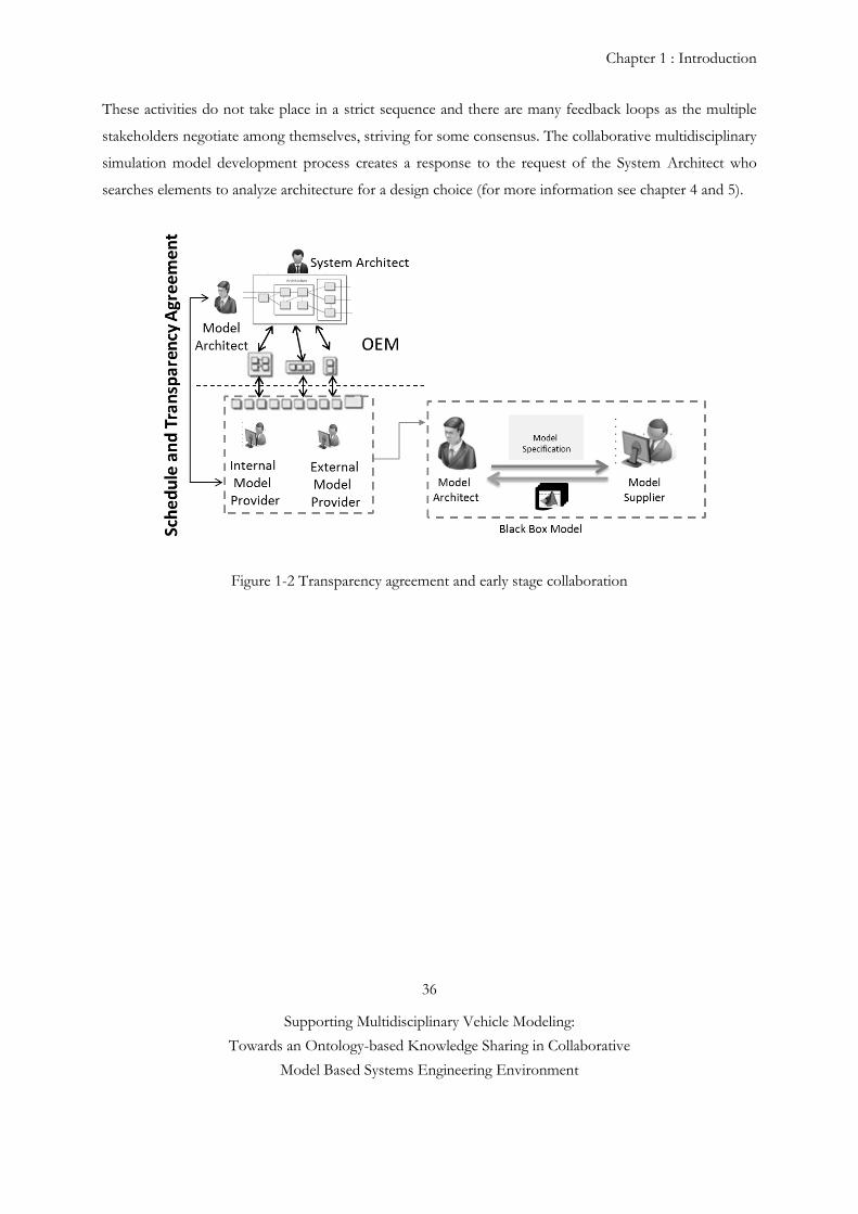
Chapter 1 : Introduction
36
Supporting Multidisciplinary Vehicle Modeling:
Towards an Ontology-based Knowledge Sharing in Collaborative
Model Based Systems Engineering Environment
These activities do not take place in a strict sequence and there are many feedback loops as the multiple
stakeholders negotiate among themselves, striving for some consensus. The collaborative multidisciplinary
simulation model development process creates a response to the request of the System Architect who
searches elements to analyze architecture for a design choice (for more information see chapter 4 and 5).
Figure 1-2 Transparency agreement and early stage collaboration
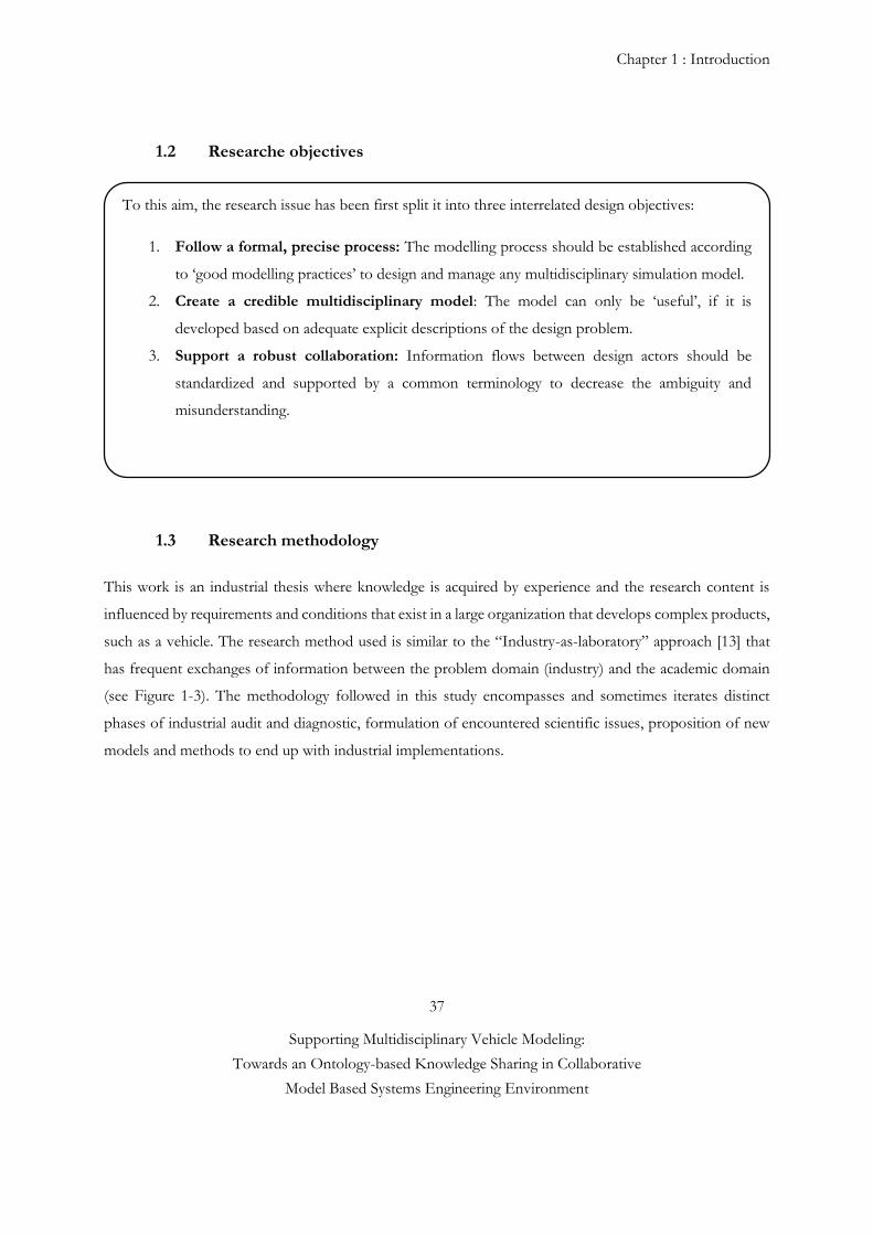
Chapter 1 : Introduction
37
Supporting Multidisciplinary Vehicle Modeling:
Towards an Ontology-based Knowledge Sharing in Collaborative
Model Based Systems Engineering Environment
1.2 Researche objectives
1.3 Research methodology
This work is an industrial thesis where knowledge is acquired by experience and the research content is
influenced by requirements and conditions that exist in a large organization that develops complex products,
such as a vehicle. The research method used is similar to the “Industry-as-laboratory” approach [13] that
has frequent exchanges of information between the problem domain (industry) and the academic domain
(see Figure 1-3). The methodology followed in this study encompasses and sometimes iterates distinct
phases of industrial audit and diagnostic, formulation of encountered scientific issues, proposition of new
models and methods to end up with industrial implementations.
To this aim, the research issue has been first split it into three interrelated design objectives:
1. Follow a formal, precise process: The modelling process should be established according
to ‘good modelling practices’ to design and manage any multidisciplinary simulation model.
2. Create a credible multidisciplinary model: The model can only be ‘useful’, if it is
developed based on adequate explicit descriptions of the design problem.
3. Support a robust collaboration: Information flows between design actors should be
standardized and supported by a common terminology to decrease the ambiguity and
misunderstanding.
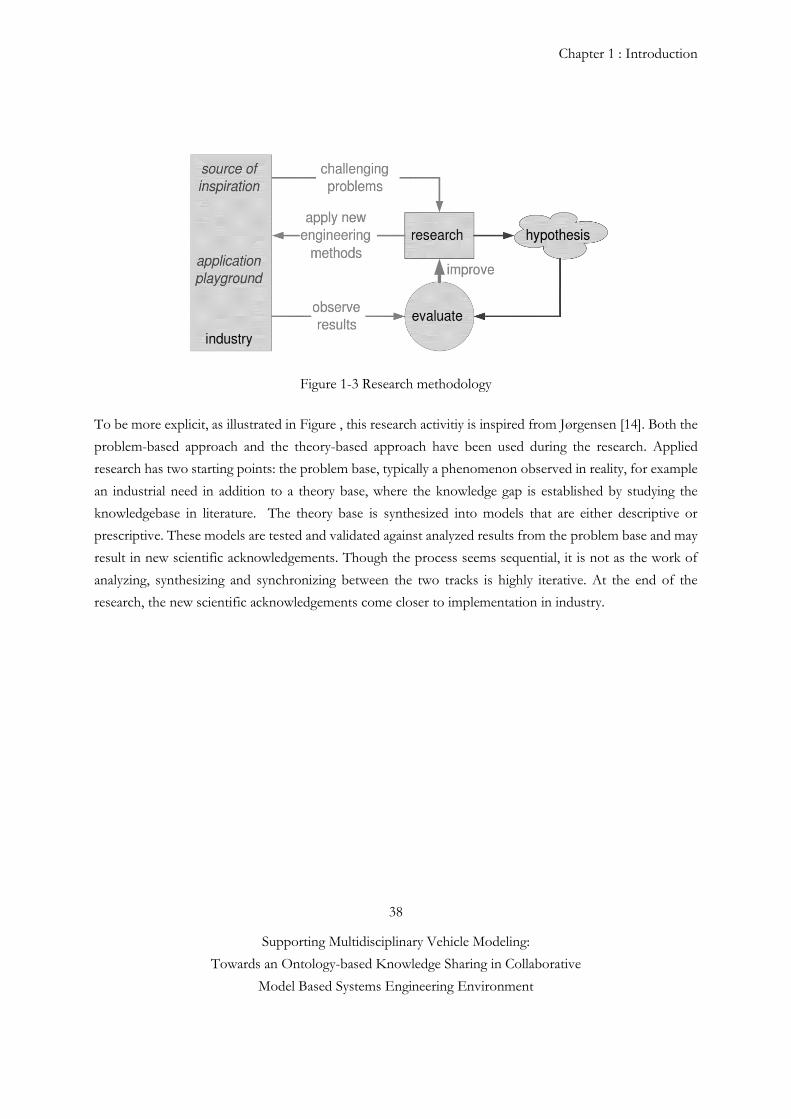
Chapter 1 : Introduction
38
Supporting Multidisciplinary Vehicle Modeling:
Towards an Ontology-based Knowledge Sharing in Collaborative
Model Based Systems Engineering Environment
Figure 1-3 Research methodology
To be more explicit, as illustrated in Figure , this research activitiy is inspired from Jørgensen [14]. Both the
problem-based approach and the theory-based approach have been used during the research. Applied
research has two starting points: the problem base, typically a phenomenon observed in reality, for example
an industrial need in addition to a theory base, where the knowledge gap is established by studying the
knowledgebase in literature. The theory base is synthesized into models that are either descriptive or
prescriptive. These models are tested and validated against analyzed results from the problem base and may
result in new scientific acknowledgements. Though the process seems sequential, it is not as the work of
analyzing, synthesizing and synchronizing between the two tracks is highly iterative. At the end of the
research, the new scientific acknowledgements come closer to implementation in industry.
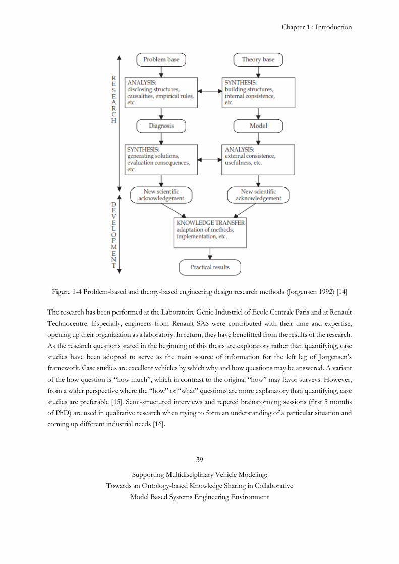
Chapter 1 : Introduction
39
Supporting Multidisciplinary Vehicle Modeling:
Towards an Ontology-based Knowledge Sharing in Collaborative
Model Based Systems Engineering Environment
Figure 1-4 Problem-based and theory-based engineering design research methods (Jørgensen 1992) [14]
The research has been performed at the Laboratoire Génie Industriel of Ecole Centrale Paris and at Renault
Technocentre. Especially, engineers from Renault SAS were contributed with their time and expertise,
opening up their organization as a laboratory. In return, they have benefitted from the results of the research.
As the research questions stated in the beginning of this thesis are exploratory rather than quantifying, case
studies have been adopted to serve as the main source of information for the left leg of Jørgensen’s
framework. Case studies are excellent vehicles by which why and how questions may be answered. A variant
of the how question is “how much”, which in contrast to the original “how” may favor surveys. However,
from a wider perspective where the “how” or “what” questions are more explanatory than quantifying, case
studies are preferable [15]. Semi-structured interviews and repeted brainstorming sessions (first 5 months
of PhD) are used in qualitative research when trying to form an understanding of a particular situation and
coming up different industrial needs [16].
Chapter 1 : Introduction
40
Supporting Multidisciplinary Vehicle Modeling:
Towards an Ontology-based Knowledge Sharing in Collaborative
Model Based Systems Engineering Environment
In the Research clarification stage and the review based descriptive Study I, interviews are used to create an
understanding of the problems that faced by today’s industry, as a complement to the literature study. In
the prescriptive study, demonstrators are created to illustrate cases from industry. The demonstrators are
based on the perceived needs of industry and realized through prescribed methods and tools; they are used
as mediating objects in verifying and validating the results through verification by acceptance with selected
small groups (see Chapter 5, Validation Protocol for more information).
Reference #1
[1] G. Sirin, B. Yannou, E. Coatanea and E. Landel, “Creating Domain Ontology to Support the Numerical
Models Exchange between Suppliers and Users in a Complex System Design”. ASME 2013 International
Design Engineering Technical Conferences and Computers and Information in Engineering Conference
Volume 2B: 33rd Computers and Information in Engineering Conference Portland, Oregon, USA, August
4–7, 2013
[2] M. Ben Gaïd, G. Corde, A. Chasse, B. Léty, R. De La Rubia et M. Ould Abdellahi, " Heterogeneous
Model Integration and Virtual Experimentation using xMOD: Application to Hybrid Powertrain Design
and Validation", Prague (République Tchèque) 7ème Congrès "EUROSIM" (Modeling et de la Simulation)
en septembre 2010.
[3] C.J.J. Paredis, A. Diaz-calderon, R. Sinha and P.K. Khosla, (2001, Apr). Composable models for
simulation-based design. Engineering with Computers Journal, Vol.17, No. 2, p. 112-128
[4] O. De Weck, “Feasibility of a 5x Speedup in System Development due to Meta Design”.
ASME/DETC2012-70791, 2012.
[5] D. Ward and S. Helton, "Estimating Return on Investment for SAVI (a Model-Based Virtual Integration
Process)," SAE Int. J. Aerosp. 4(2):934-943, 2011, doi: 10.4271/2011-01-2576.
[6] G. Tassey, S.B. Brunnermeier, et S.A Martin. (1999). Interoperability cost analysis of the US automotive
supply chain. Research Triangle Institute Final Report. RTI Project 7007-03, Available:
https://www.rti.org/pubs/US_Automotive.pdf
[7] Nasa Technical Standard, (2008). Standard for models and simulations National Aeronautics and Space
Administration Washington, DC 205460001, NASA-STD-7009.
[8] A. Kerzhner, and C. Paredis (2009), "Using domain specific languages to capture design synthesis
knowledge for model-based systems engineering - detc2009-87286". San Diego, California.
Chapter 1 : Introduction
41
Supporting Multidisciplinary Vehicle Modeling:
Towards an Ontology-based Knowledge Sharing in Collaborative
Model Based Systems Engineering Environment
[10] D. Krob, (2009). "Eléments d'architecture des systèmes complexes", Gestion de la Complexité et de
l'information Dans les Grands Systèmes Critiques, 179-207.
[11] D. Scaravetti, (2004). "Formalisation préalable d'un problème de conception, pour l'aide à la décision
en conception préliminaire". Ecole Nationale Supérieure d'Arts et Métiers.
[12] Chakrabarti, A. and Bligh, T. P. (1996). "An approach to functional synthesis of mechanical design
concepts: Theory, applications, and emerging research issues", AI EDAM, 10(04): 313-331.
[13] R. Gunnarson, Vetenskapsteori. Dept of Prim Health Care Göteborg University – Research
methodology web site. 2009-03-20. http://infovoice.se/fou. 2011-03-08.
[14] Jørgensen, K. A., 1992, "Videnskablige arbejdsparadigmer ("Scinetific Work Paradigms", in Danish)",
Institute for Production, Aalborg University Center, Aalborg, Denmark.
[15] Yin, R. K., 2003, "Case Study Research: Design and Methods", SAGE, Thousand Oaks, CA, USA. [16] Robson, C., 2002, "Real World Research: a Resource for Social Scientists and Sractitioner-Researchers", Blackwell Publishers, Madden, Mass.; Oxford.
Chapter 2 : Research overview
42
Supporting Multidisciplinary Vehicle Modeling:
Towards an Ontology-based Knowledge Sharing in Collaborative
Model Based Systems Engineering Environment
2 Research overview
2 State of the art
2.1 Modeling and Simulation (M&S) as a complex system
The fundamental building block of M&S is the model, an abstraction of the real system that is executed
over time with different inputs in a simulation. Simulations provide the means to analyze complex systems
without physical deployment that can be costly or even dangerous [1]. However, modeling and simulation
process is a costly and a complex system itself. A complex system is a system with numerous components
and interconnections, interactions or interdependencies that are difficult to describe, understand, predict,
manage, design, and/or change [2]. The complex multidisciplinary models’ development process require
addional time to design and validation. Validation is of paramount importance, especially when models are
employed for critical decisions such as in military exercises or in the evaluation of safety decisions [3].
However, the size and complexity of simulation models is hard to grasp. As a result of on-going advances
and developments in modeling and simulation, the knowledge is not only becoming more complex to
control, but also involves a data flow, interoperability and human based communication problems to be
solved, which, in turn, increases the pressure on engineers to ensure better data management and
architecture, in order to satisfy the decision makers [4]. In the Modeling and Simulation environment, the
complexity problem arises technical and human based factors.
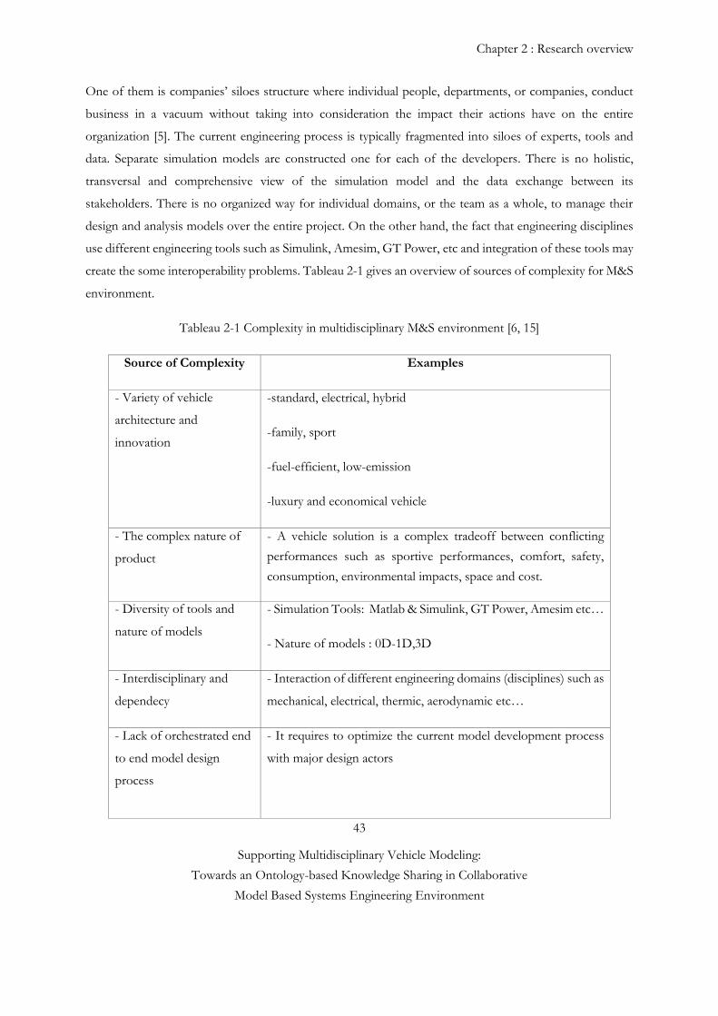
Chapter 2 : Research overview
43
Supporting Multidisciplinary Vehicle Modeling:
Towards an Ontology-based Knowledge Sharing in Collaborative
Model Based Systems Engineering Environment
One of them is companies’ siloes structure where individual people, departments, or companies, conduct
business in a vacuum without taking into consideration the impact their actions have on the entire
organization [5]. The current engineering process is typically fragmented into siloes of experts, tools and
data. Separate simulation models are constructed one for each of the developers. There is no holistic,
transversal and comprehensive view of the simulation model and the data exchange between its
stakeholders. There is no organized way for individual domains, or the team as a whole, to manage their
design and analysis models over the entire project. On the other hand, the fact that engineering disciplines
use different engineering tools such as Simulink, Amesim, GT Power, etc and integration of these tools may
create the some interoperability problems. Tableau 2-1 gives an overview of sources of complexity for M&S
environment.
Tableau 2-1 Complexity in multidisciplinary M&S environment [6, 15]
Source of Complexity Examples
- Variety of vehicle
architecture and
innovation
-standard, electrical, hybrid
-family, sport
-fuel-efficient, low-emission
-luxury and economical vehicle
- The complex nature of
product
- A vehicle solution is a complex tradeoff between conflicting
performances such as sportive performances, comfort, safety,
consumption, environmental impacts, space and cost.
- Diversity of tools and
nature of models
- Simulation Tools: Matlab & Simulink, GT Power, Amesim etc…
- Nature of models : 0D-1D,3D
- Interdisciplinary and
dependecy
- Interaction of different engineering domains (disciplines) such as
mechanical, electrical, thermic, aerodynamic etc…
- Lack of orchestrated end
to end model design
process
- It requires to optimize the current model development process
with major design actors
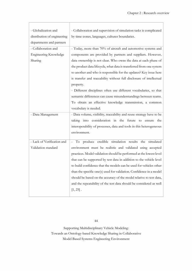
Chapter 2 : Research overview
44
Supporting Multidisciplinary Vehicle Modeling:
Towards an Ontology-based Knowledge Sharing in Collaborative
Model Based Systems Engineering Environment
- Globalization and
distribution of engineering
departments and partners
- Collaboration and supervision of simulation tasks is complicated
by time-zones, languages, cultures boundaries.
- Collaboration and
Engineering Knowledge
Sharing
- Today, more than 70% of aircraft and automotive systems and
components are provided by partners and suppliers. However,
data ownership is not clear. Who owns the data at each phase of
the product data lifecycle, what data is transferred from one system
to another and who is responsible for the updates? Key issue here
is transfer and traceability without full disclosure of intellectual
property.
- Different disciplines often use different vocabularies, so that
semantic differences can cause misunderstandings between teams.
To obtain an effective knowledge transmission, a common
vocabulary is needed.
- Data Management - Data volume, visibility, traceability and reuse strategy have to be
taking into consideration in the future to ensure the
interoperability of processes, data and tools in this heterogeneous
environment.
- Lack of Verification and
Validation standard
- To produce credible simulation results the simulated
environment must be realistic and validated using accepted
practices. Model validation should be performed at the lowest level
that can be supported by test data in addition to the vehicle level
to build confidence that the models can be used for vehicles other
than the specific one(s) used for validation. Confidence in a model
should be based on the accuracy of the model relative to test data,
and the repeatability of the test data should be considered as well
[1, 25] .
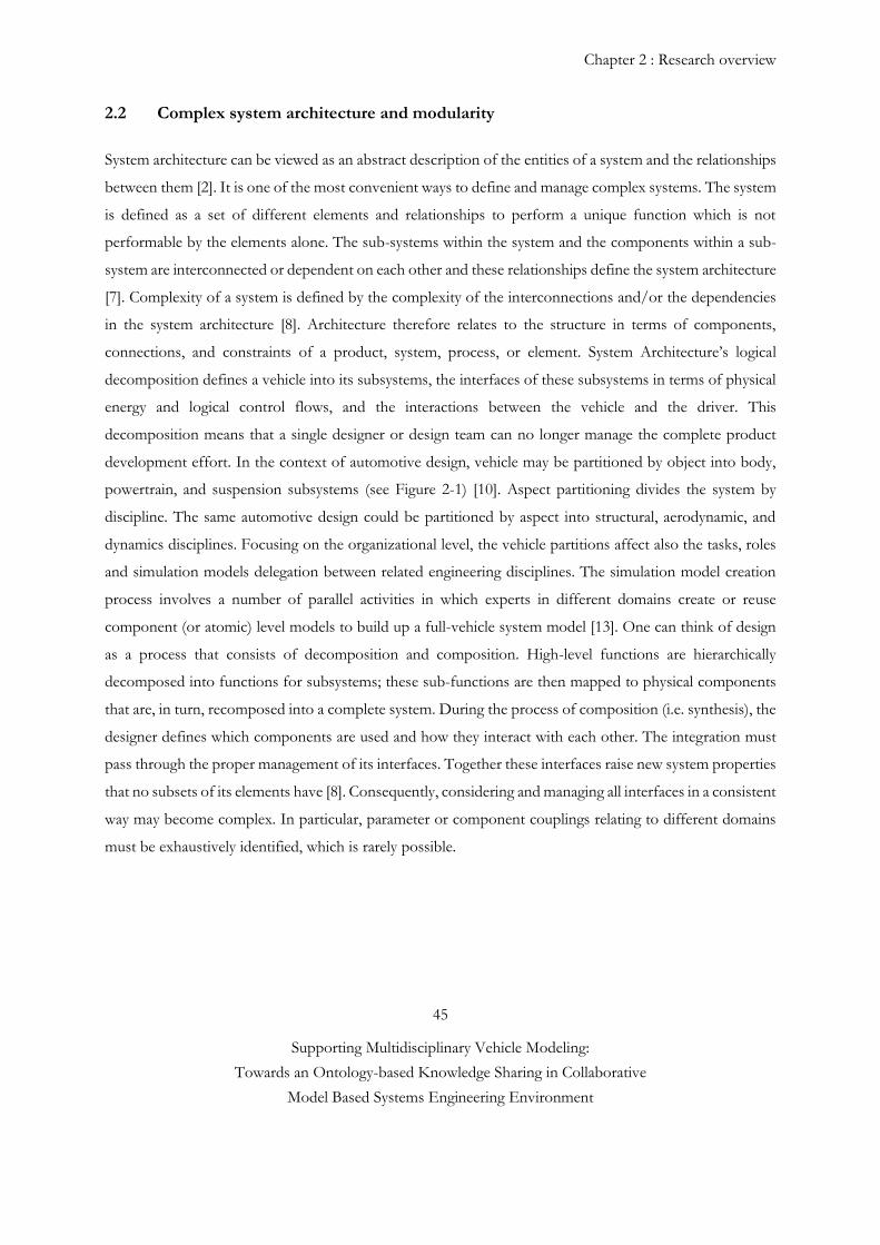
Chapter 2 : Research overview
45
Supporting Multidisciplinary Vehicle Modeling:
Towards an Ontology-based Knowledge Sharing in Collaborative
Model Based Systems Engineering Environment
2.2 Complex system architecture and modularity
System architecture can be viewed as an abstract description of the entities of a system and the relationships
between them [2]. It is one of the most convenient ways to define and manage complex systems. The system
is defined as a set of different elements and relationships to perform a unique function which is not
performable by the elements alone. The sub-systems within the system and the components within a sub-
system are interconnected or dependent on each other and these relationships define the system architecture
[7]. Complexity of a system is defined by the complexity of the interconnections and/or the dependencies
in the system architecture [8]. Architecture therefore relates to the structure in terms of components,
connections, and constraints of a product, system, process, or element. System Architecture’s logical
decomposition defines a vehicle into its subsystems, the interfaces of these subsystems in terms of physical
energy and logical control flows, and the interactions between the vehicle and the driver. This
decomposition means that a single designer or design team can no longer manage the complete product
development effort. In the context of automotive design, vehicle may be partitioned by object into body,
powertrain, and suspension subsystems (see Figure 2-1) [10]. Aspect partitioning divides the system by
discipline. The same automotive design could be partitioned by aspect into structural, aerodynamic, and
dynamics disciplines. Focusing on the organizational level, the vehicle partitions affect also the tasks, roles
and simulation models delegation between related engineering disciplines. The simulation model creation
process involves a number of parallel activities in which experts in different domains create or reuse
component (or atomic) level models to build up a full-vehicle system model [13]. One can think of design
as a process that consists of decomposition and composition. High-level functions are hierarchically
decomposed into functions for subsystems; these sub-functions are then mapped to physical components
that are, in turn, recomposed into a complete system. During the process of composition (i.e. synthesis), the
designer defines which components are used and how they interact with each other. The integration must
pass through the proper management of its interfaces. Together these interfaces raise new system properties
that no subsets of its elements have [8]. Consequently, considering and managing all interfaces in a consistent
way may become complex. In particular, parameter or component couplings relating to different domains
must be exhaustively identified, which is rarely possible.
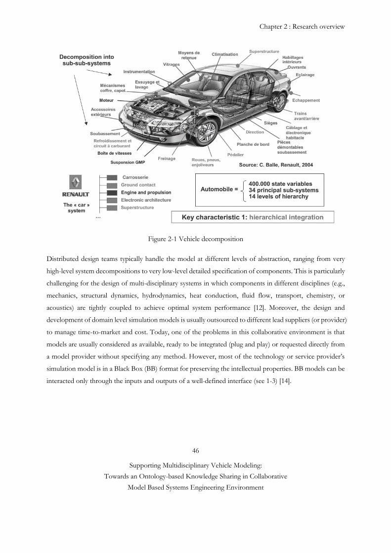
Chapter 2 : Research overview
46
Supporting Multidisciplinary Vehicle Modeling:
Towards an Ontology-based Knowledge Sharing in Collaborative
Model Based Systems Engineering Environment
Figure 2-1 Vehicle decomposition
Distributed design teams typically handle the model at different levels of abstraction, ranging from very
high-level system decompositions to very low-level detailed specification of components. This is particularly
challenging for the design of multi-disciplinary systems in which components in different disciplines (e.g.,
mechanics, structural dynamics, hydrodynamics, heat conduction, fluid flow, transport, chemistry, or
acoustics) are tightly coupled to achieve optimal system performance [12]. Moreover, the design and
development of domain level simulation models is usually outsourced to different lead suppliers (or provider)
to manage time-to-market and cost. Today, one of the problems in this collaborative environment is that
models are usually considered as available, ready to be integrated (plug and play) or requested directly from
a model provider without specifying any method. However, most of the technology or service provider’s
simulation model is in a Black Box (BB) format for preserving the intellectual properties. BB models can be
interacted only through the inputs and outputs of a well-defined interface (see 1-3) [14].
Chapter 2 : Research overview
47
Supporting Multidisciplinary Vehicle Modeling:
Towards an Ontology-based Knowledge Sharing in Collaborative
Model Based Systems Engineering Environment
2.2.1 Component and port-based modeling
A complete vehicle system model must take the response of the various physical subsystems into account,
the function of the controller modules (both subsystem and vehicle level) as well as other external influences
like the environment and the driver [2]. Vehicle-level attributes, such as energy, safety management and
performance, to be examined and optimized for various operating scenarios. These vehicle-level attributes
are tightly coupled; investigating the tradeoffs between these attributes is crucial for system design (see
Figure 2-1) [6]. To create multidisciplinary vehicle model, it is necessary to first plan and develop detailed
domain analysis models according to vehicle-level goals and requirements. Once these domain models have
been planned, developed, verified, and validated, they can be integrated together to simulate a complete
vehicle. Capability for the selection and integration of models is improved by model composability [16 and
33]. The compositional modeling paradigm distributes complexity associated with complex system modeling
to individual components and facilitates reuse of high-fidelity component models, which are expensive and
time consuming to obtain in general. Component-based modeling allows users to quickly and efficiently
create high fidelity simulation models by linking independent model objects. Capabilities for the selection
and assembly of models can be improved by engineering composability. The advantages of this approach
are, however, rapidly offset by the difficulties associated with tracing the impacts of one subsystem design
on another one (i.e. managing interfaces among subsystems). This phenomenon is also referred to as a
‘dependency problem’ [19]. To achieve composability of numerical models, Paredis and Diaz-Calderon [16,
17] introduced a port-based modeling paradigm which can be hierarchically defined when it consists of a
composition of sub-models, resulting in a compound component. When the sub-models are also compound,
multiple levels of hierarchy occur. The composability of a model facilitates to trace the impacts of one
subsystem to another one, managing interfaces among subsystems. It is based on two concepts: port and
interface. Ports correspond to the points where a component exchanges energy or signals with the
environment. (see Figure 2-2a).
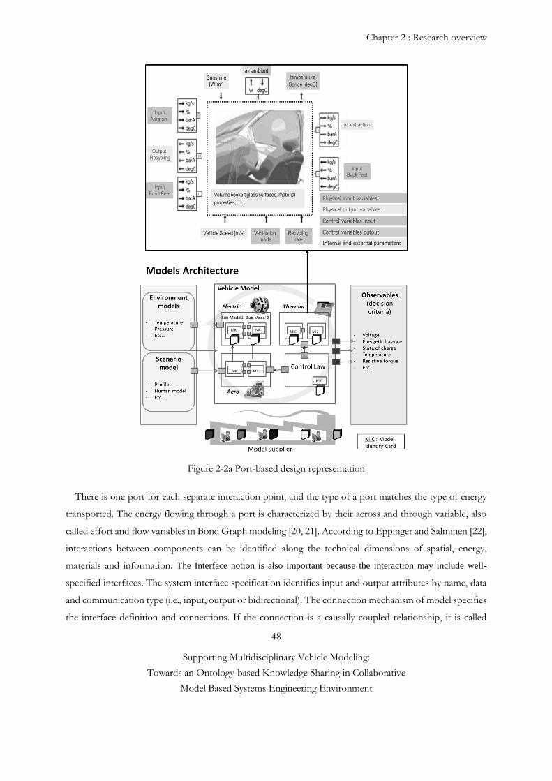
Chapter 2 : Research overview
48
Supporting Multidisciplinary Vehicle Modeling:
Towards an Ontology-based Knowledge Sharing in Collaborative
Model Based Systems Engineering Environment
Figure 2-2a Port-based design representation
There is one port for each separate interaction point, and the type of a port matches the type of energy
transported. The energy flowing through a port is characterized by their across and through variable, also
called effort and flow variables in Bond Graph modeling [20, 21]. According to Eppinger and Salminen [22],
interactions between components can be identified along the technical dimensions of spatial, energy,
materials and information. The Interface notion is also important because the interaction may include well-
specified interfaces. The system interface specification identifies input and output attributes by name, data
and communication type (i.e., input, output or bidirectional). The connection mechanism of model specifies
the interface definition and connections. If the connection is a causally coupled relationship, it is called
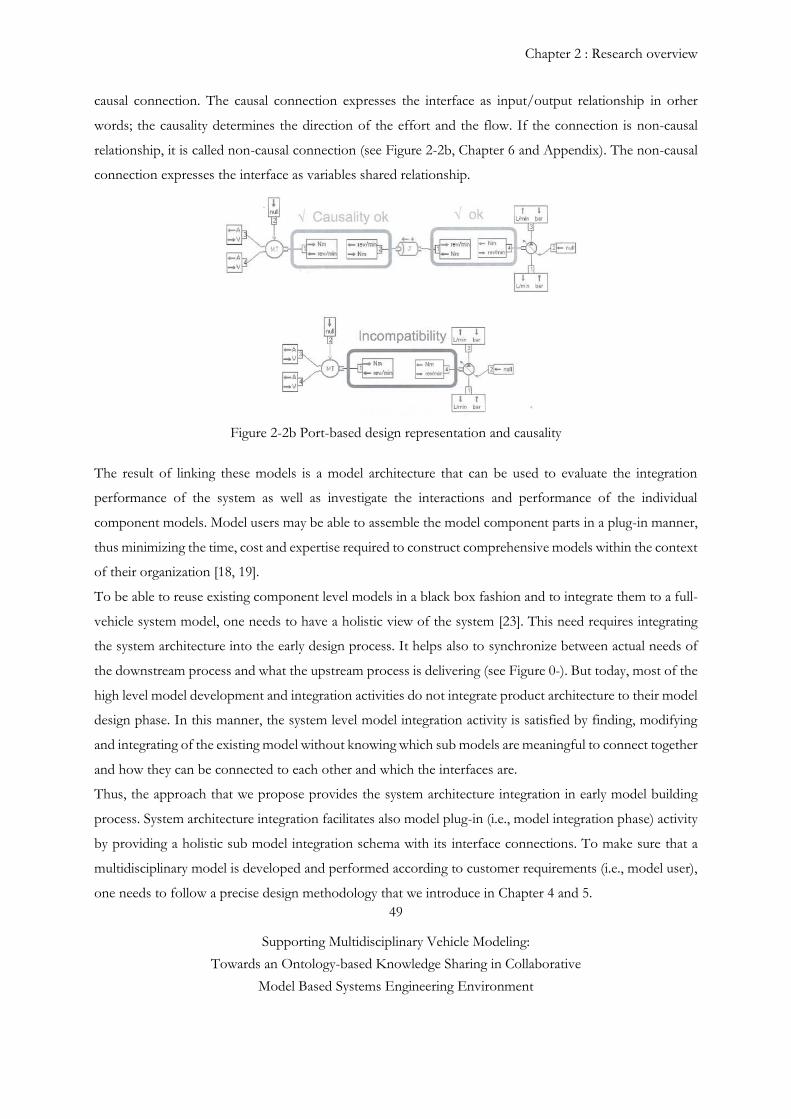
Chapter 2 : Research overview
49
Supporting Multidisciplinary Vehicle Modeling:
Towards an Ontology-based Knowledge Sharing in Collaborative
Model Based Systems Engineering Environment
causal connection. The causal connection expresses the interface as input/output relationship in orher
words; the causality determines the direction of the effort and the flow. If the connection is non-causal
relationship, it is called non-causal connection (see Figure 2-2b, Chapter 6 and Appendix). The non-causal
connection expresses the interface as variables shared relationship.
Figure 2-2b Port-based design representation and causality
The result of linking these models is a model architecture that can be used to evaluate the integration
performance of the system as well as investigate the interactions and performance of the individual
component models. Model users may be able to assemble the model component parts in a plug-in manner,
thus minimizing the time, cost and expertise required to construct comprehensive models within the context
of their organization [18, 19].
To be able to reuse existing component level models in a black box fashion and to integrate them to a full-
vehicle system model, one needs to have a holistic view of the system [23]. This need requires integrating
the system architecture into the early design process. It helps also to synchronize between actual needs of
the downstream process and what the upstream process is delivering (see Figure 0-). But today, most of the
high level model development and integration activities do not integrate product architecture to their model
design phase. In this manner, the system level model integration activity is satisfied by finding, modifying
and integrating of the existing model without knowing which sub models are meaningful to connect together
and how they can be connected to each other and which the interfaces are.
Thus, the approach that we propose provides the system architecture integration in early model building
process. System architecture integration facilitates also model plug-in (i.e., model integration phase) activity
by providing a holistic sub model integration schema with its interface connections. To make sure that a
multidisciplinary model is developed and performed according to customer requirements (i.e., model user),
one needs to follow a precise design methodology that we introduce in Chapter 4 and 5.
Chapter 2 : Research overview
50
Supporting Multidisciplinary Vehicle Modeling:
Towards an Ontology-based Knowledge Sharing in Collaborative
Model Based Systems Engineering Environment
2.3 Model exchange: interoperability and inconsistency problems
Interoperability is the ability of two or more systems to exchange and reuse information efficiently. Multi-
disciplinary simulation interoperability includes both simulation metadata and processes (a field known as
"Simulation Data Management" SDM or "Simulation and Process Data Management" SPDM [32]) and co-
simulation. The works presented below, are basically related to tool and module interoperability problems
(tool and library versioning, data echange standard and co-simulation [30]). Vehicle is a multidisciplinary
system which involves different engineering disciplines in their design. Each engineering discipline tends to
use its own domain-specic languages and tools to model different aspects of a system concurrently. The
concurrent modelling process may introduce inconsistencies due to lack of common knowledge and
communication among domain experts. Especially for co-modelling and co-simulation developments, a
huge amount of models, versions of models and design alternatives may be produced, which highly increases
the design space and the likelihood of yielding inconsistent models. Meanwhile, model exchange and
interoperability problems have already been addressed by some industrials such as AP 2633 model exchange
standard. AP2633 Simulation Models are black-box models, managed through their high-level interfaces:
control, functional and profile [25]. On the other hand, the Functional Mockup Interface (FMI) covers the
aspects of model exchange and of co-simulation [24]. Model exchange problems are tackled by developing
a tool independent standard for the exchange of dynamic models and for co-simulation based on XML
standards. Using the black box model exchange, FMI defines interfaces only and responds to know-how
protection (i.e. non disclosure).
On the other hand, an inconsistency is, by definition, a logical contradiction. In practice, many different
kinds and types of inconsistencies can be distinguished. For example, inconsistencies can be a result of
language non-conformance, or not adhering to heuristics, guidelines or best practices. In current practice,
typically only inconsistencies with respect to language conformance are managed automatically, often merely
in an ad hoc fashion. The works presented below, are basically related to interface and metadata inconsisteny
problems. In common practice, many inconsistencies are only identified after decisions, based on
inconsistent information and knowledge, have already been made. For example, in a systems engineering
workflow, reviews and verification and validation activities often serve this purpose. The costly and
infrequent nature of such activities leads to decisions with poor outcomes and costly rework. However, the
earlier inconsistencies are identified, the cheaper they are to handle. Therefore, automating at least some
early level verification and validation activities has value since this can lead to significant cost savings and,
hence, better decision making, and more effective and efficient development. To create a semantically-rich,
model characterization support, first, it is necessary to create of a common vocabulary for formally
Chapter 2 : Research overview
51
Supporting Multidisciplinary Vehicle Modeling:
Towards an Ontology-based Knowledge Sharing in Collaborative
Model Based Systems Engineering Environment
characterizing numerical model of different domain. Multidisciplinary simulation covers the individual
analysis disciplines (aerodynamics, mechanical, electromagnetics, thermal, noise, vibration,) and the links
coordination between analysis disciplines [28].
Sharing a common vocabulary between the designers and manufacturers allows both sides to identify
potential misunderstanding problems before they start [26, 27]. Another contribution of this work is
reducing the number of the rework while detecting potential inconsistency problems at the early design
stage. Actually, avoiding the misconception is essential to prevent correction on validation phase. Then, the
contextual information for the user becomes a key factor for the performance of the task. In addition,
visualization improves communication and is useful for interpretation results. One of the key contribution
of this thesis is to present a new techniques for interoperating simulation models using ontologies as the
basis for representing [29], visualizing, reasoning about, and securely exchanging abstract engineering
knowledge between simulation models. The modeling knowledge associated with the development of
simulation models ontology has been developed and instantiated to form a knowledge base for representing
analysis modeling knowledge. The instances of the knowledge base are the analysis models of real world
applications (see Chapter 5 and Appendix)
2.3.1 Product Life Cycle (PLC) and inconsistency
Automating the process of managing inconsistencies necessitates that the information and knowledge being
analyzed is captured in a formal manner. In Model-Based Systems Engineering (MBSE) one of the key
principles is that only formal, computer-interpretable models should be used. More specifically, MBSE is
the formalized application of modeling to support system requirements, design, analysis, verification, and
validation activities beginning in the conceptual design phase and continuing throughout development and
later life cycle phases. The use of only formal (and, hence, computer-interpretable) models has a significant
advantage over what is often referred to as a document-based approach: models can, at the very least
theoretically, be integrated computationally. However, in systems engineering the problem hardens due to
the fact that models are typically of a heterogeneous and distributed nature, inherently incomplete, and are
evolved by numerous stakeholders in parallel, hence often lacking. To help control this complexity, the
systems engineering discipline provides a collaborative business methodology that manages all the domains
of engineering and development from a holistic point of view. This approach is significantly enhanced and
improved through a common view on what needs to be accomplished as well as a common model to
develop it in, providing a better understanding for all participants of how the system will operate as a whole.
Increasing vehicle complexity requires the ability to manage development decisions proactively and in ways
Chapter 2 : Research overview
52
Supporting Multidisciplinary Vehicle Modeling:
Towards an Ontology-based Knowledge Sharing in Collaborative
Model Based Systems Engineering Environment
where the impact of any change can be accessed prior to it being made through virtual design and validation.
This can be accomplished through model-based systems engineering methods such as RFLP (requirement,
functional, logical, and physical) [31]. RFLP provides a collaborative systems engineering methodology that
can capture, manage, and track product requirements with full traceability, all from one engineering desktop
window. Model-based engineering as produced by the RFLP approach puts more rigor into the process,
providing a link back to requirements for each logical, functional, and physical change.
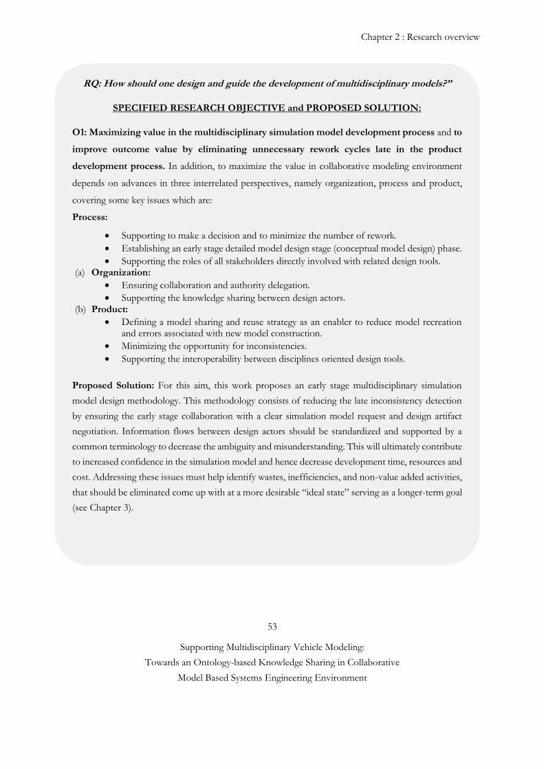
Chapter 2 : Research overview
53
Supporting Multidisciplinary Vehicle Modeling:
Towards an Ontology-based Knowledge Sharing in Collaborative
Model Based Systems Engineering Environment
RQ: How should one design and guide the development of multidisciplinary models?”
SPECIFIED RESEARCH OBJECTIVE and PROPOSED SOLUTION:
O1: Maximizing value in the multidisciplinary simulation model development process and to
improve outcome value by eliminating unnecessary rework cycles late in the product
development process. In addition, to maximize the value in collaborative modeling environment
depends on advances in three interrelated perspectives, namely organization, process and product,
covering some key issues which are:
Process:
Supporting to make a decision and to minimize the number of rework.
Establishing an early stage detailed model design stage (conceptual model design) phase.
Supporting the roles of all stakeholders directly involved with related design tools. (a) Organization:
Ensuring collaboration and authority delegation.
Supporting the knowledge sharing between design actors. (b) Product:
Defining a model sharing and reuse strategy as an enabler to reduce model recreation and errors associated with new model construction.
Minimizing the opportunity for inconsistencies.
Supporting the interoperability between disciplines oriented design tools.
Proposed Solution: For this aim, this work proposes an early stage multidisciplinary simulation
model design methodology. This methodology consists of reducing the late inconsistency detection
by ensuring the early stage collaboration with a clear simulation model request and design artifact
negotiation. Information flows between design actors should be standardized and supported by a
common terminology to decrease the ambiguity and misunderstanding. This will ultimately contribute
to increased confidence in the simulation model and hence decrease development time, resources and
cost. Addressing these issues must help identify wastes, inefficiencies, and non-value added activities,
that should be eliminated come up with at a more desirable “ideal state” serving as a longer-term goal
(see Chapter 3).
To support system requirements, design, analysis, verification, and validation activities beginning in
the conceptual design phase and continuing throughout development and later life cycle phases
Chapter 2 : Research overview
54
Supporting Multidisciplinary Vehicle Modeling:
Towards an Ontology-based Knowledge Sharing in Collaborative
Model Based Systems Engineering Environment
Reference #2
[1] C. Szabo, (2010). Composable simulation models and their formal validation, PhD Thesis, Department
of computer science, National University of Singapore (NUS).
[2] Crawley, E., Weck De, O., Eppinger, S., Magee, C., Moses, J., Seering, W., Schindall, J., Wallace, D. and
Whitney, D. (2004), "The influence of architecture in engineering systems".
[3] G. Sirin, B. Yannou, E. Coatanea and E. Landel, “Creating Domain Ontology to Support the Numerical
Models Exchange between Suppliers and Users in a Complex System Design”. ASME 2013 International
Design Engineering Technical Conferences and Computers and Information in Engineering Conference
Volume 2B: 33rd Computers and Information in Engineering Conference Portland, Oregon, USA, August
4–7, 2013
[4] R. Sinha, V.C. Liang, C.J.J. Paredis, and P.K. Khosla, "Modeling and Simulation Methods for Design of Engineering Systems," Journal of Computing and Information Science in Engineering. Vol. 1, 2001. [5] J. Britt, Holbrook, «What is interdisciplinary communication? Reflections on the very idea of disciplinary integration." Synthese, September 2012. [6] G. Sirin, T. Welo, B. Yannou, E. Landel, “Value Creation in Collaborative Analysis Model Development Processes”. Presented at the Conference on ASME (IDETC/CIE), Buffalo, USA, Aug., 17-20, 2014. [7] G. Sirin., C.J.J. Paredis, B. Yannou, E. Landel, E. Coatanea, 2014. "A Model Identity Card to Support Simulation Model Development Process in a Collaborative Multidisciplinary Design Environment," Systems Journal, IEEE, vol.PP, no.99, pp.1, 12. [8] Crawley, E., Weck De, O., Eppinger, S., Magee, C., Moses, J., Seering, W., Schindall, J., Wallace, D.and
Whitney, D. (2004), "The influence of architecture in engineering systems".
[9] Magee, C. L., & de Weck, O. L. (2004). Complex system classification. Presented at the Fourteenth
annual international symposium of the international council on systems engineering (INCOSE).
[10] D. Turpin, "Changes and Challenges in the Automobile Industry”, IMD, March 2010.
[11] Srini Chari, "Addressing Engineering Simulation Data Management (SDM) Challenges: How Engineering Enterprises Can Improve Productivity, Collaboration and Innovation", MBA, 2013. [12] G. Mocko, R. Malak, C. Paredis and R. Peak, "A knowledge repository for behavioral models in engineering design", ASME International Design Engineering Technical Conferences & Computers and Information in Engineering Conference IDETC/CIE 2004, 2004.
[13] INCOSE, "Systems Engineering Handbook", SE Handbook Working Group International Council on Systems Engineering, San Diego, 2010. [14] R. Glanville (2009), "Black Boxes", Cybernetics and Human Knowing, pp153-167.
Chapter 2 : Research overview
55
Supporting Multidisciplinary Vehicle Modeling:
Towards an Ontology-based Knowledge Sharing in Collaborative
Model Based Systems Engineering Environment
[15] L. Chwif, R. Paul, "On simulation model complexity", Departament of Information Systems and Computing, Brunel University, Uxbridge, U.K. [16] A.D. Calderon, C. Paredis, and Khosla, P. K., "A Composable Simulation Environment for
Mechatronic Systems." SCS 1999 European Simulation Symposium. Erlangen, Germany. Society for
Computer Simulation, 1999.
[17] A.D. Calderon, C. Paredis, and P.K. Khosla, "Reconfigurable Models: A Modeling Paradigm to Support
Simulation-Based Design." 2000 Summer Computer Simulation Conference. Vancouver, Canada. Society
for Computer Simulation, 2000.
[18] J. Badin, D. Monticolo, D. Chamoret, S. Gomes, “Using the Knowledge Configuration Model
(KCModel) to manage knowledge in configuration for upstream phases of the design process” is accepted
in the International Journal on Interactive Design and Manufacturing (IJIDeM), 2011.
[19] S. Halbach, P. Sharer, S. Pagerit, C. Folkerts, A. Rousseau, “Model Architecture, Methods, and
Interfaces for Efficient Math-Based Design and Simulation of Automotive Control Systems”, Argonne
National Laboratory, 2010.
[20] Barreto, J. M., "The Role of Bond Graphs in Qualitative Modelling," Proc. IJCAI-89, pp. 84-87.
[21] Breedveld, P. C., 1984, "A Bond Graph algorithm to determine the equilibrium state of a system,"
Journal of the Franklin Institute, 318(2).
[22] S.D. Eppinger, and V. Salminen, “Patterns of Product Development Interactions”, International
conference on engineering design ICED 01 Glasgow, 2001.
[23] V. Basili and H.D. Rombach, “Towards A Comprehensive Framework for Reuse: Model-based Reuse
Characterization Schemes,” University of Maryland, CS-TR-2446, UMIACS-TR-90-47, April 1990.
[24] Christian Bertsch, Elmar Ahle, Ulrich Schulmeister (2014). The Functional Mockup Interface - seen
from an industrial perspective, Proceedings of the 10th International Modelica Conference; March 10-12;
2014; Lund; Sweden.
[25] Val Serra, S., "AP2633 - Develop, Integrate and Validate Shared Simulation Models," Issue C, Airbus,
France, 3 June 2008.
[26] T. Tudorache, "Employing Ontologies for an Improved Development Process in Collaborative Engineering», Thesis of doctorate, University of Berlin, 2006. [27] W. C. Barley, P. M. Leonardi, and D. E. Bailey, "Engineering Objects for Collaboration: Strategies of Ambiguity and Clarity at Knowledge Boundaries", International Communication Association, 2012.
Chapter 2 : Research overview
56
Supporting Multidisciplinary Vehicle Modeling:
Towards an Ontology-based Knowledge Sharing in Collaborative
Model Based Systems Engineering Environment
[28] N. Kanuri, "Ontologies and Methods for Interoperability of Engineering Analysis Models (EAMs) in an E-Design Environment", Masters Theses, University of Massachussets Amherst, 2007. [29] E. Brun, "Ambiguity Reduction in New Product Development Projects", International Journal of Innovation Management, December 2008. [30] S. Sicklinger et al. (2014). "Interface Jacobian-based Co-Simulation". International Journal for Numerical Methods in Engineering 98 (6): 418–444. doi:10.1002/nme.4637. [31] T. Ambroisine, "Mastering increasing product complexity with Collaborative Systems Engineering and
PLM ", Dassault Système, France, Available online:
http://www.arobs.com/fileadmin/user_upload/Downloads/Articole-Conferinte-
Embedded/04_DS__Mastering_Complexity_with_Systems_Engineering_and_PLM__EW2013.pdf
[32] S. Charles, B. Eynard, “Definition of a Simulation Data Management Environment integrated with
PDM”, Proceedings of International Conference on Engineering Design – ICED’05, Melbourne, Australia,
August 15-18, 2005.
[33] C.J.J. Paredis, A. Diaz-calderon, R. Sinha and P.K. Khosla, (2001, Apr). Composable models for
simulation-based design. Engineering with Computers Journal, Vol.17, No. 2, p. 112-128.
Chapter 3 : Paper #1: Characteristics of a Good Multidisciplinary Model Design Practice: Toward a Model
Reuse and a Value-Added Thinking
57
Supporting Multidisciplinary Vehicle Modeling:
Towards an Ontology-based Knowledge Sharing in Collaborative
Model Based Systems Engineering Environment
3 Paper #1. Characteristics of a Good Multidisciplinary
Model Design Practice: Toward a Model Reuse and a
Value-Added Thinking
Under Preparation
Göknur Sirin1, 4, Laurent Gasser 2, Torgeir Welo3, Bernard Yannou1, Eric Landel4
1 Ecole Centrale Paris, Laboratoire Génie Industriel, Chatenay-Malabry, France
2 IRT-SystemX, Paris-Saclay Campus - Nanno INNOV, Palaiseau, France
3 NTNU, Engineering Design and Materials, Trondheim, Norway
4 Renault SAS Techno-Centre, Guyancourt, France
Abstract. To develop competitive vehicles, automotive engineers continuously improve their ability to explore
and analyze the most relevant system architecture by taking into consideration the vehicle level attributes (e.g.,
drivability and fuel economy) and innovation (e.g., hybrid or full electric vehicle). In the endeavour to reduce
time-to-market, automotive OEMs (Original Equipment Manufacturers) need to create credible simulation
models without inconsistencies before building expensive simulation models. The pursuit for shorter lead times
and higher product quality calls for increasing amount of concurrent activities and effective cross-functional
Chapter 3 : Paper #1: Characteristics of a Good Multidisciplinary Model Design Practice: Toward a Model
Reuse and a Value-Added Thinking
58
Supporting Multidisciplinary Vehicle Modeling:
Towards an Ontology-based Knowledge Sharing in Collaborative
Model Based Systems Engineering Environment
collaboration. In this connection, Systems Engineering (SE) methods are helpful to structure the necessary
activities but they fail to address ‘value’ in much detail. This paper addresses the application of value thinking
in multidisciplinary simulation model development within a SE and MBSE context by considering three
interrelated perspectives: organization, process, and product. Based on these perspectives, we identify some
major problems and suitable characteristics of multidisciplinary simulation model development processes.
These characteristics are subsequently explained as a good modeling practice. Only a few of these problems
are associated with uncertainty and validation issues to improve model credibility, while the majority is
associated with other aspects of the modelling process. An important conclusion of the paper is that to
maintain the competitiveness with other manufacturers, an OEM should therefore not only invest in the
creation of new systems, but also into advancing its systems engineering capabilities.
Chapter 3 : Paper #1: Characteristics of a Good Multidisciplinary Model Design Practice: Toward a Model
Reuse and a Value-Added Thinking
59
Supporting Multidisciplinary Vehicle Modeling:
Towards an Ontology-based Knowledge Sharing in Collaborative
Model Based Systems Engineering Environment
3.1 Introduction
In today’s competitive environment, there is higher pressures than ever to design an innovative architecture
in disruption with the past by analysing any potential architecture (Internal Combustion (IC) engines, hybrid
or electric systems) from a variety of attributes including performance, drivability, fuel economy, durability
or even thermal behaviour. Both the increased complexity of products and the competition on today’s global
market imply a need for exploring and analysing mentioned system architectures efficiently and effectively
[1-2]. To keep pace with the rapid improvements being made to these modern products (i.e. ground vehicles
-cars, trucks, trains- as well as air, space and submarine vehicles) and maintain competitiveness with other
manufacturers, design cycles have become shorter and more efficient.
To support these shorter design cycles during the early design exploration phase, companies use more and
more sophisticated, multidisciplinary simulation model (or numerical or behavioral models) [1]. Simulation
models can be used to better understand the impact of different operating conditions on vehicle
performance and attributes. However, there are numerous challenges when designing and modelling such
complex system architectures. Some of these challenges include making many design decisions, designing
with knowledge from different disciplines, and modelling, exploring and analysing the system architectures.
This is particularly challenging for the design of multidisciplinary systems in which components in different
disciplines (e.g., mechanics, structural dynamics, hydrodynamics, heat conduction, fluid flow, transport,
chemistry, or acoustics) are tightly coupled to achieve optimal system performance [1]. To accurately
represent vehicle behaviour in a given field situation, simulation models are created by integrating different
simulation models within a vehicle model, such as model of chassis, engine and transmission, etc. These sub
system simulation models are denoted domain models in the following. Moreover, each domain model can
be developed and evolved following its own semantics and development tools at different rates [3]. On the
other hand, there are two modelling philosophies for multidisciplinary simulation. In one approach, all
model components are implemented in a single modelling or simulation tool, using common libraries or a
common modelling language, and creating a single model comprising elements of all involved disciplines.
In a second approach, the coupling of specialized tools by the means of interfaces is performed. This is
especially suited for systems where sub-models already exist in specialized tools and where those models are
too large and complex to be transferred into a single simulation tool [4]. This paper focuses especially on
the second approach.
Chapter 3 : Paper #1: Characteristics of a Good Multidisciplinary Model Design Practice: Toward a Model
Reuse and a Value-Added Thinking
60
Supporting Multidisciplinary Vehicle Modeling:
Towards an Ontology-based Knowledge Sharing in Collaborative
Model Based Systems Engineering Environment
The design and development of domain level simulation models is usually outsourced to different lead
suppliers to manage time-to-market and cost. However, because of the multidisciplinary nature of
simulation models, it is key for OEMs to pay close attention to suppliers throughout the design phase, in
order to ensure high quality of model deliverables. Since the quality of complex multidisciplinary simulation
model strongly depends on input from multiple sources, efficient collaboration between domain experts is
a prerequisite for a successful outcome [3]. Hence, ensuring confidence in simulation results, i.e., model
credibility, is particularly challenging when domain models within different disciplines are tightly coupled.
A common problem in today’s model development process is inconsistencies upon the final models
integration stage. From a value perspective, this is particularly wasteful since the ‘cost of learning’ is higher
in the final integrating stage. Incomplete models create undesirable rework that negatively affects cost,
schedule and design decision [3]. Several factors may cause inconsistencies during the integration of domain
level simulation models into a system level model; for example, the models are not ready to use such that
the OEM must modify them before integrating with the other models.
The purpose of this study is to analyze the current simulation model development process of automotive
and aeronautics industries. An initial hypothesis for our study is that the challenges are similar for these two
industries and that they are both leading sectors when it comes to simulation based vehicle design. The
results from the analysis is then further used as a basis to propose a future process. The mentioned future
process is based on good modeling practice towards a value focused thinking from three interrelated
perspectives: organization, the design process, and the product. Product perspective contains simulation
model, referential model architecture, and model specification and calibration and some other documents.
Doing so provides a competitive advantage to OEM, by being able to pursue value opportunities efficiently
and effectively which may be not accessible to its competitors.
The remainder of this paper is organized as follows. In Section 2, we introduce our methodological
positioning based on value thinking with a comparative state-of-the-art review. Section 3 discusses the
desirable characteristics of good multidisciplinary modelling practice. In section 4, we give as an industrial
case study an overview of the proposed valuable multidisciplinary simulation model development process.
The conclusion and discussion are given in Section 5.
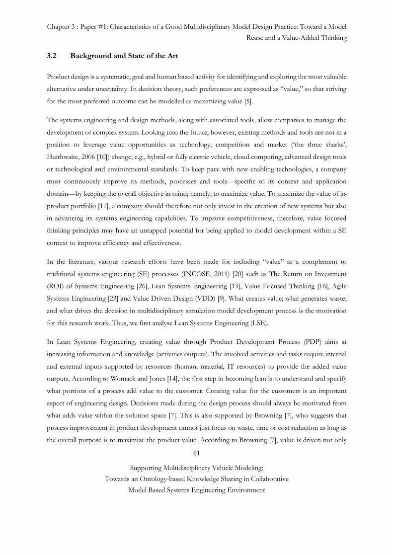
Chapter 3 : Paper #1: Characteristics of a Good Multidisciplinary Model Design Practice: Toward a Model
Reuse and a Value-Added Thinking
61
Supporting Multidisciplinary Vehicle Modeling:
Towards an Ontology-based Knowledge Sharing in Collaborative
Model Based Systems Engineering Environment
3.2 Background and State of the Art
Product design is a systematic, goal and human based activity for identifying and exploring the most valuable
alternative under uncertainty. In decision theory, such preferences are expressed as “value,” so that striving
for the most preferred outcome can be modelled as maximizing value [5].
The systems engineering and design methods, along with associated tools, allow companies to manage the
development of complex system. Looking into the future, however, existing methods and tools are not in a
position to leverage value opportunities as technology, competition and market (‘the three sharks’,
Huithwaite, 2006 [10]) change; e.g., hybrid or fully electric vehicle, cloud computing, advanced design tools
or technological and environmental standards. To keep pace with new enabling technologies, a company
must continuously improve its methods, processes and tools—specific to its context and application
domain—by keeping the overall objective in mind; namely, to maximize value. To maximize the value of its
product portfolio [11], a company should therefore not only invest in the creation of new systems but also
in advancing its systems engineering capabilities. To improve competitiveness, therefore, value focused
thinking principles may have an untapped potential for being applied to model development within a SE
context to improve efficiency and effectiveness.
In the literature, various research efforts have been made for including “value” as a complement to
traditional systems engineering (SE) processes (INCOSE, 2011) [20] such as The Return on Investment
(ROI) of Systems Engineering [26], Lean Systems Engineering [13], Value Focused Thinking [16], Agile
Systems Engineering [23] and Value Driven Design (VDD) [9]. What creates value; what generates waste;
and what drives the decision in multidisciplinary simulation model development process is the motivation
for this research work. Thus, we first analyse Lean Systems Engineering (LSE).
In Lean Systems Engineering, creating value through Product Development Process (PDP) aims at
increasing information and knowledge (activities‘outputs). The involved activities and tasks require internal
and external inputs supported by resources (human, material, IT resources) to provide the added value
outputs. According to Womack and Jones [14], the first step in becoming lean is to understand and specify
what portions of a process add value to the customer. Creating value for the customers is an important
aspect of engineering design. Decisions made during the design process should always be motivated from
what adds value within the solution space [7]. This is also supported by Browning [7], who suggests that
process improvement in product development cannot just focus on waste, time or cost reduction as long as
the overall purpose is to maximize the product value. According to Browning [7], value is driven not only
Chapter 3 : Paper #1: Characteristics of a Good Multidisciplinary Model Design Practice: Toward a Model
Reuse and a Value-Added Thinking
62
Supporting Multidisciplinary Vehicle Modeling:
Towards an Ontology-based Knowledge Sharing in Collaborative
Model Based Systems Engineering Environment
by the presence of necessary (value-adding) activities in the product development process but also by the
way those activities work together to ensure that they use and produce the right work products, service, and
information at the right time. As illustrated in Fig. 3-1, in complex system development, value is driven by
the deliverables (inputs and outputs) as well as by the activities—hence value output is higher than the sum
of value of individual activities—and the goal is mainly to reduce the risk that the product recipe is
unacceptable [8, 9].
Fig. 3-1 Value for Product and Process Perspectives adapted from [Browning, 2003] [7]
The value perspective in Lean Systems Engineering provides an attractive way to think about process
improvements. However, Lean Thinking does not build on decision theory, meaning that there is a need
for better guidance for design choices. Such a guidance should essentially translate the desires of customers
into terms that are immediately meaningful to design engineers. The guidance should be consistent among
vehicle conceptual designers or any engineer making decisions throughout the product development
process. However, an iterative approach called Value Driven Design (VDD) is used to address decision
theory, which prescribes how preferences should be expressed in terms of an objective, value, or utility
function. It is using economic theory to transform systems engineering to better utilize optimization so as
to improve the design of large systems. This is also similar to value driven approach of Agile Software
Development where project stakeholder’s priorities their high-level needs based on the perceived value each
would deliver [23]. On the other hand, in Value Driven Design, to design a system, engineers first take
system attributes such as the range and fuel consumption of a vehicle, and build a system value model that
uses all these attributes as inputs. Next, the conceptual design is optimized to maximize the output of the
value model. Then, when the system is decomposed into components, an objective function for each
component is derived from the system value model through a sensitivity analysis. [9]. Indeed, the Multi-
Objective Optimization (MOO) is also are very useful in the tradeoff analysis and decision making for rapid
analysis of the performance and fuel economy of conventional, electric, and hybrid vehicles. Another MOO
Chapter 3 : Paper #1: Characteristics of a Good Multidisciplinary Model Design Practice: Toward a Model
Reuse and a Value-Added Thinking
63
Supporting Multidisciplinary Vehicle Modeling:
Towards an Ontology-based Knowledge Sharing in Collaborative
Model Based Systems Engineering Environment
method is developed by Smaling and de Weck [25] called “technology infusion assessment methodology”
to quantify the potential performance benefits of new technologies using multi-objective Pareto analysis.
Focus on value is also expressed even before VDD by Keeney as Value Focused Thinking in [16] that
includes specific tasks and addresses explicitly key elements in structuring decision situations. Value-focused
thinking mainly concerns “what is the decision”. The effort to analyzing decision situations can be broken
into two parts: what is the problem and what is the solution. On the other hand, Value-Driven Design
(VDD) and Value Focused Thinking are the systems engineering approach which strives for the
maximization of value rather than for the satisfaction of stakeholder needs as in traditional systems
engineering, such as Goal Oriented Requirements Engineering (GORE) [17]. GORE is often characterized
in Requirements Engineering (RE) used in systems engineering and design literature as the goal to satisfy a
stated need, which then leads to the formulation of a set of requirements to be satisfied [17 and 21].
However, enterprise goals which initiate the goal discovery process do not reflect the actual situation but an
idealized one. Finally, it seems to be difficult to deal with the fuzzy concept of the goal [21]. In order to
overcome some of the limitations of goal-driven approach, several attempts have been made to merge goals
and scenarios, such as Rolland’ CREWS-L’Ecritoire approach developed within the CREWS ESPRIT
project [17 and 21]. These two Requirement Engineering approaches are complementary to SE and to value
focused thinking methods. The advantage of VDD compared to Lean Systems Engineering is that VDD
combines three disciplines (economics, optimization, and systems engineering). It can be defined as: “an
improvement to the systems engineering process by employing economics to enable optimization thinking
at every level of engineering design” [6]. Thus, VDD is an emerging topic within the industry and academia,
providing a concept where designers can utilize value models to represent the value of their product designs
as a single objective function. A number of recent programs incorporate VDD themes such as US DARPA
(Defense Advanced Research Projects Agency), F6 military satellite program, VDD workshop of Rolls-
Royce, and CRESCENDO European project for Digital Aircraft Design [5,12 and 18].
By employing economics in decision making, VDD enables rational decision making in terms of the
optimum business and technical solution at every level of engineering design. Based on the three methods
(Lean Systems Engineering, Value Focused Thinking and VDD) above, we would like to identify first what
creates value in multidisciplinary model development process to identify what is the suitable future state for
this process. In lean terms, we seek a suitable “future state” as an intermediate stage towards the not quite
attainable “ideal state” serving as an ideal target. Second, we would like to introduce value thinking for any
kind of decision support tradeoff analyses that may happen at different levels of abstraction through
Chapter 3 : Paper #1: Characteristics of a Good Multidisciplinary Model Design Practice: Toward a Model
Reuse and a Value-Added Thinking
64
Supporting Multidisciplinary Vehicle Modeling:
Towards an Ontology-based Knowledge Sharing in Collaborative
Model Based Systems Engineering Environment
simulation model development process (e.g. system architecture and simulation model selection from their
alternatives).
3.2.1 Methodological positioning: Value in Multidisciplinary Model Development
Process
Building more eco-friendly vehicles ranks high on the development agenda of OEMs and suppliers. As
illustrated in Figure 3-2 on the left side, the boundary conditions or external influences that are driving
current aircraft and automotive systems architectures, stem from various domains including the political
(e.g., energy (oil prices) and legislation policy (Kyoto and CAFÉ protocols)), economic (e.g., cost
effectiveness of emissions reducing technology versus alternatives), and environmental (e.g., effects on flora
and fauna, global climate change) [25].
All these new concepts and ambition are linked to the successful introduction of hybrid or full electric
technology. However, these concepts strongly impact the optimizing fuel economy and NVH behavior that
is directly influenced by downsizing the internal combustion engine (ICE) as well as further weight
reduction. The challenge in implementing the new technology lies in the architecture one chooses to
implement, since there are multiple ways to integrate an electrical motor and a battery reformer in a vehicle
(e.g. serie, parallel and serie-parallel hybrid or full electric). When developing a new vehicle based on a
chosen architecture, engineers are responsible for meeting a wide variety of often conflicting performance
targets. Noise/vibration/harshness (NVH) and fuel economy often must be traded off against each other
during the vehicle design process. Throughout the entire simulation based vehicle design process, hundreds
of decision are made by different individuals from different disciplines at different levels of abstraction and
within different scopes (see Fig. 3-2). Adequate collaborative design environments are needed to ensure that
partners and co-design teams can share or/and exchange product data and domain knowledge all along the
product development life cycle. Thus partners should be able to bring together their mutual expertise to
build dynamically new collective know-how [4].
However, today, many companies try to use the V-cycle system engineering process for product
development as proposed by Frosberg and adapted by the National Council on Systems Engineering [6].
However, companies’ model building process is typically functioning as a push system rather than a pull
system; i.e., a push system is one where an upstream operation transmits work to a subsequent downstream
operation without being requested as a need for further processing. The push concept, also called ‘over-the-
wall-design/modeling’, is only efficient when looked at from a local, silo-structure’s view point. In a push-
Chapter 3 : Paper #1: Characteristics of a Good Multidisciplinary Model Design Practice: Toward a Model
Reuse and a Value-Added Thinking
65
Supporting Multidisciplinary Vehicle Modeling:
Towards an Ontology-based Knowledge Sharing in Collaborative
Model Based Systems Engineering Environment
type model development process, testing and integration of system level simulation model are mainly done
in later process stages using delivered sub-models (virtual prototypes). This may create multiple wastes,
including waiting (i.e., the model is not available when needed or it is sitting waiting for somebody to process
it further), over-production (i.e., the model is not needed), which may lead to excess inventory (i.e.,
data/models not utilized), unnecessary processing (i.e., sending files/models not requested or recreating
existing models), and may be the most harmful of them all, namely, defects (i.e., incorrect models), which
is subsequently used as basis for design decisions. The company’s current model development process does
not contain any detailed conceptual design process at the early stage. This means that the complex simulation
model design phase is passed quickly with the risk of losing time in efforts to integrate delivered component
level models. One of the major sources to wastes for complex simulation model development process in
Renault Company is the rework caused by substandard and deficient model designs of component-level
models. The root cause may often be the lack of analysis when the design engineer specifies the system
architecture in an early phase. This problem can often be avoided by using an iterative early design process.
Eliminating design iterations is a central issue in the management of product development (PD) projects.
Design iteration is often responsible for increased PD lead-time and cost, and is also a source of major
uncertainties in the management of resources, which ultimately may cause resource shortages in other
projects within the project portfolio of the company. However, iterations, when planned and managed
effectively, can overcome the uncertainties inherent in interdependent development activities and thus,
improve and accelerate PD projects.
An alternative model development process must be more effective and efficient than the existing. Thus, the
aim of this work is to understand the basic characteristics (enablers and inhibitors) of maximizing value in
the multidisciplinary simulation model development process and to improve outcome value by eliminating
unnecessary rework cycles late in the product development process. This ultimately contribute to increased
confidence in the simulation model and hence decrease development time, resources and cost. In modeling
and simulation practice, the applicability of any simulation model depends on the accuracy and reliability of
its output. Performance or model accuracy depends on system architecture consistency, uncertainty (sub
model and system level model uncertainty, change and uncertainty propagation), used method and design
tool, knowledge and data quality that are shared between design actors (see Fig. 3-2).
As illustrated in Fig. 3-2, to be able to evaluate factors that contribute to value creation, addition is paid to
analyzing current Model Development Process. Adding a Detailed Conceptual Model Design stage in the
current model development process improves the traditional V-cycle because this allows problems to be
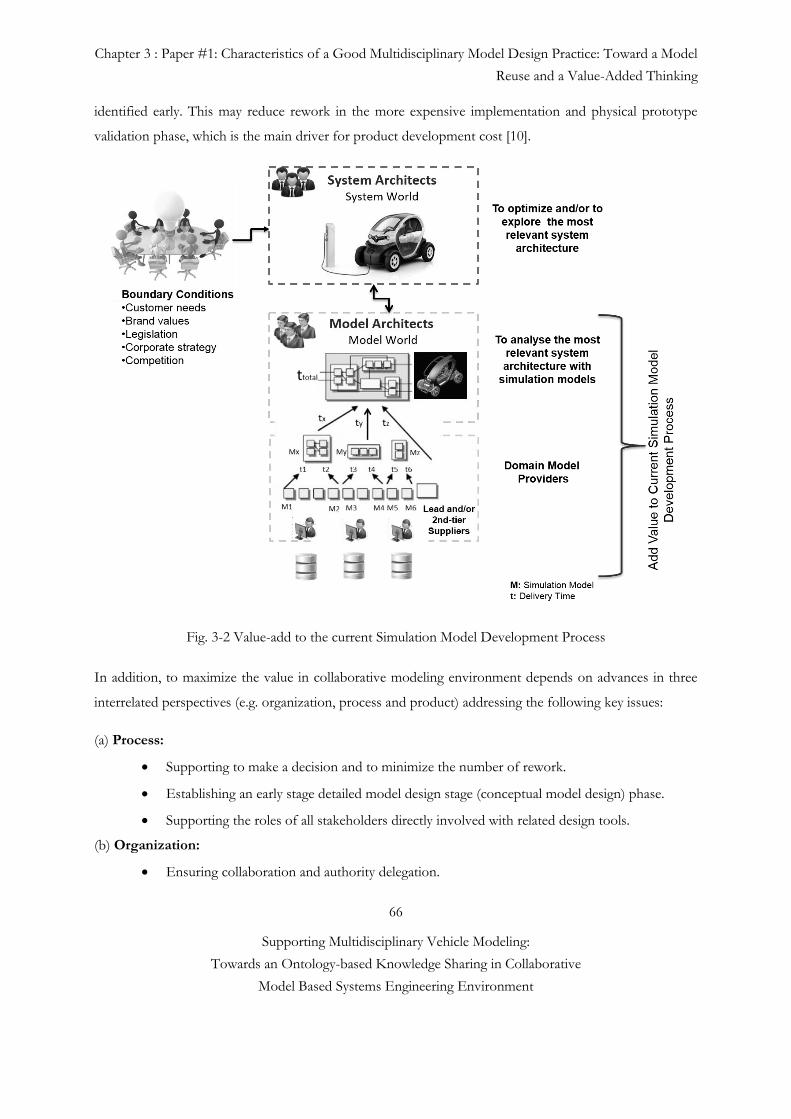
Chapter 3 : Paper #1: Characteristics of a Good Multidisciplinary Model Design Practice: Toward a Model
Reuse and a Value-Added Thinking
66
Supporting Multidisciplinary Vehicle Modeling:
Towards an Ontology-based Knowledge Sharing in Collaborative
Model Based Systems Engineering Environment
identified early. This may reduce rework in the more expensive implementation and physical prototype
validation phase, which is the main driver for product development cost [10].
Fig. 3-2 Value-add to the current Simulation Model Development Process
In addition, to maximize the value in collaborative modeling environment depends on advances in three
interrelated perspectives (e.g. organization, process and product) addressing the following key issues:
(a) Process:
Supporting to make a decision and to minimize the number of rework.
Establishing an early stage detailed model design stage (conceptual model design) phase.
Supporting the roles of all stakeholders directly involved with related design tools.
(b) Organization:
Ensuring collaboration and authority delegation.
Chapter 3 : Paper #1: Characteristics of a Good Multidisciplinary Model Design Practice: Toward a Model
Reuse and a Value-Added Thinking
67
Supporting Multidisciplinary Vehicle Modeling:
Towards an Ontology-based Knowledge Sharing in Collaborative
Model Based Systems Engineering Environment
Supporting the knowledge sharing between design actors.
(c) Product:
Defining a model sharing and reuse strategy as an enabler to reduce model recreation and errors
associated with new model construction.
Minimizing the opportunity for inconsistencies.
Supporting the interoperability between disciplines oriented design tools.
3.3 Characteristics of a Good Multidisciplinary Model Design Processes
The objective of this process is to capture the flow of information and to map activities to certain
stakeholders provides a better understanding of the ultimate decision-makers for each step. Coordinating
all of the different tasks needed to produce an accurate vehicle model requires developing a thorough
understanding of the underlying engineering processes. Thus, it is important to recognize that decision about
the product is the implicit outcome of a sequence of decisions made about the process [5]. Oftentimes,
engineering tasks are performed in an ad hoc manner and rely on the expertise and experience of the
engineers involved to produce results. However, for complex engineering tasks that require coordination
among many individuals, this can be a particularly risky approach. Developing an approach that follows a
formal, precise process can provide a better understanding of the responsibilities of different engineering
teams and areas where issues may arise.
A formal, precise process should define not only the different tasks that stakeholders must perform, but
also more specifically, which pieces of information are expected to be exchanged between stakeholders and
how this should occur.
3.3.1 Multidisciplinary Collaborative Process and Stakeholder Organization
It refers to sequence of activities that produces rigorous descriptions of what the products are, what they
must do, and how they interact to perform as a system [17]. The process of collaboration across disciplines
requires exploration of disciplinary roles, coordination, frequent communication, consensual decision-
making, shared values, cultural beliefs within teams/groups, and facilitative support from the organization.
This contributes to facilitating the collaborative process. In addition, knowledge sharing is one of the key
points in the model development process. Providing a common vocabulary for the Modeling and Simulation
Chapter 3 : Paper #1: Characteristics of a Good Multidisciplinary Model Design Practice: Toward a Model
Reuse and a Value-Added Thinking
68
Supporting Multidisciplinary Vehicle Modeling:
Towards an Ontology-based Knowledge Sharing in Collaborative
Model Based Systems Engineering Environment
users can help communicate fact-based decision in a maker’s assessment of the credibility of Modeling and
Simulation results. The ability for users to select from a list of options is an immensely important capability.
Because creating full-vehicle simulation models is a multidisciplinary process, it is important that the same
strategies are used across different teams of domain experts. By limiting large groups of users to the same
vocabulary and set of options whenever possible, inconsistencies arising from miscommunication or
misinformation can be reduced significantly. In chapter 5, we propose a Model Identity Card concept to
simplify the knowledge sharing and decrease the ambiguity in a collaborative multidisciplinary environment.
Besides the ontology based collaboration, there are some other important points that we should pay
attention to create a robust process such as:
- How to support the roles of all design actors directly involved to the model development process?
- How to reduce the ambiguous terminology and a lack of mutual understanding between design actors?
- How should we assign authority and responsibility?
- How to re-organize the different views and viewpoints based on Enterprise Architecture Framework?
Furthermore, managing several projects simultaneously is not a trivial issue, especially for companies
developing different complex products like automobile engine. One of the key issues is the resource
allocation and finding the balance between single project optimum and overall organizational benefits.
Nowadays, raising designers’ awareness of the value delivered by sub-systems solutions is a major challenge
for automotive manufacturers. The “goodness” of a product/service is mainly assessed from a
“requirements fulfilment” point of view, not taking the bigger picture in consideration. Consequently,
multiple development stages have to be performed in parallel or with some overlap by sharing early
preliminary upstream information with downstream stages. The overall ‘Parallelism’ or Concurrent
engineering (CE) principles rest on a single, but powerful, principle that promotes the incorporation of
downstream concerns into the upstream phases of a development process. This would lead to shorter
development times, improved product quality, and lower development– production costs. Additionally, in
a design process there are different stakeholders such as model and system architects, model providers, who
have different needs and viewpoints. In Model Based System Engineering, Views and Viewpoints can be
used to model the perspectives of different stakeholders and their interests. A viewpoint describes a
particular perspective of interest to a set of stakeholders, while a view is a stereotyped package that is said
to conform to a particular viewpoint [13] (see Fig. 3-3). In a traditional document-based approach, each
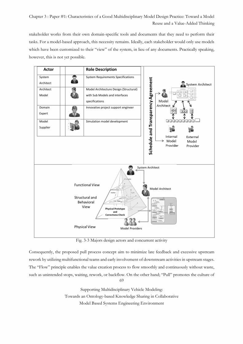
Chapter 3 : Paper #1: Characteristics of a Good Multidisciplinary Model Design Practice: Toward a Model
Reuse and a Value-Added Thinking
69
Supporting Multidisciplinary Vehicle Modeling:
Towards an Ontology-based Knowledge Sharing in Collaborative
Model Based Systems Engineering Environment
stakeholder works from their own domain-specific tools and documents that they need to perform their
tasks. For a model-based approach, this necessity remains. Ideally, each stakeholder would only use models
which have been customized to their “view” of the system, in lieu of any documents. Practically speaking,
however, this is not yet possible.
Actor Role Description
System
Architect
System Requirements Specifications
Architect
Model
Model Architecture Design (Structural)
with Sub Models and interfaces
specifications
Domain
Expert
Innovative project support engineer
Model
Supplier
Simulation model development
Fig. 3-3 Majors design actors and concurrent activity
Consequently, the proposed pull process concept aim to minimize late feedback and excessive upstream
rework by utilizing multifunctional teams and early involvement of downstream activities in upstream stages.
The “Flow” principle enables the value creation process to flow smoothly and continuously without waste,
such as unintended stops, waiting, rework, or backflow. On the other hand; “Pull” promotes the culture of
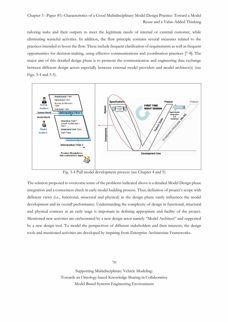
Chapter 3 : Paper #1: Characteristics of a Good Multidisciplinary Model Design Practice: Toward a Model
Reuse and a Value-Added Thinking
70
Supporting Multidisciplinary Vehicle Modeling:
Towards an Ontology-based Knowledge Sharing in Collaborative
Model Based Systems Engineering Environment
tailoring tasks and their outputs to meet the legitimate needs of internal or external customer, while
eliminating wasteful activities. In addition, the flow principle contains several measures related to the
practices intended to boost the flow. These include frequent clarification of requirements as well as frequent
opportunities for decision-making, using effective communications and coordination practices [7-8]. The
major aim of this detailed design phase is to promote the communication and engineering data exchange
between different design actors especially between external model providers and model architect(s) (see
Figs. 3-4 and 3-5).
Fig. 3-4 Pull model development process (see Chapter 4 and 5)
The solution proposed to overcome some of the problems indicated above is a detailed Model Design phase
integration and a correctness check in early model building process. Thus, definition of project’s scope with
different views (i.e., functional, structural and physical) in the design phase vastly influences the model
development and its overall performance. Understanding the complexity of design in functional, structural
and physical contexts at an early stage is important in defining appropriate end facility of the project.
Mentioned new activities are orchestrated by a new design actor namely “Model Architect” and supported
by a new design tool. To model the perspectives of different stakeholders and their interests, the design
tools and mentioned activities are developed by inspiring from Enterprise Architecture Frameworks.
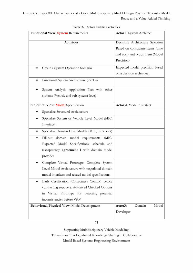
Chapter 3 : Paper #1: Characteristics of a Good Multidisciplinary Model Design Practice: Toward a Model
Reuse and a Value-Added Thinking
71
Supporting Multidisciplinary Vehicle Modeling:
Towards an Ontology-based Knowledge Sharing in Collaborative
Model Based Systems Engineering Environment
Table 3-1 Actors and their activities
Functional View: System Requirements Actor 1: System Architect
Activities Decision: Architecture Selection
Based on constraints-Items (time
and cost) and action Item (Model
Precision)
Create a System Operation Scenario Expected model precision based
on a decision technique.
Functional System Architecture (level n)
System Analysis Application Plan with other
systems (Vehicle and sub systems level)
Structural View: Model Specification Actor 2: Model Architect
Specialize Structural Architecture
Specialize System or Vehicle Level Model (MIC,
Interface)
Specialize Domain Level Models (MIC, Interfaces)
Fill-out domain model requirements (MIC:
Expected Model Specification): schedule and
transparency agreement 1 with domain model
provider
Complete Virtual Prototype: Complete System
Level Model Architecture with negotiated domain
model interfaces and related model specifications
Early Certification (Correctness Control) before
contracting suppliers: Advanced Checked Options
in Virtual Prototype for detecting potential
inconsistencies before V&V
Behavioral, Physical View: Model Development Actor3: Domain Model
Developer
Chapter 3 : Paper #1: Characteristics of a Good Multidisciplinary Model Design Practice: Toward a Model
Reuse and a Value-Added Thinking
72
Supporting Multidisciplinary Vehicle Modeling:
Towards an Ontology-based Knowledge Sharing in Collaborative
Model Based Systems Engineering Environment
3.3.2 Product Level: Referential Architecture and Simulation Models
Simulation model is iterative and hierarchical in nature so, in order to solve product level complexity
problems, a design team typically handles the problem at different levels of abstraction, ranging from very
high-level system decompositions to very low-level detailed specification of components. In the course of
development of these analysis models of physical systems, engineers make numerous modeling idealizations
or assumptions [5]. Capability for the selection and integration of models is improved by model
composability. During the process of composition, the designer defines thanks to system architecture which
components are used and how they interact with each other’s via interface connections [5]. Model
development process is becoming more complex and involves not only system simulation requirements, but
also the need to manage and share huge amounts of engineering information such as model architecture
template (line of products and instantiations), simulation model, its description file (we named it Model
Identity Card) and some other model calibration and validation documents (see Fig. 3-4). In addition to
technology based data management strategy, we must also define an architecture reuse strategy. Sub model
verification and validation do not guarantee system level model credibility. Each sub model may produce
valid results and the integration of models can be verified to be correct, but the simulation can still produce
invalid results. Most often this occurs when the sub model conceptual design includes factors that are not
considered in the system conceptual design, or vice versa. This problem create unnecessary iteration.
Minimizing unnecessary iteration not only within, but also across workflows and the extended enterprise
reduces rework. Thus this saves costs and protects schedule and in turn improves business value and
increases profits. Consequently, late feedback and excessive upstream rework should be minimized; e.g. by
utilizing multifunctional teams and early involvement of downstream activities in upstream stages (see Fig.
3-4).
Questions and Proposed Solution
- How can engineers create analysis architectures that can be reused for different vehicles while remaining consistent with
the base vehicle architecture?
- -How to define a model sharing and reuse strategy as an enabler to reduce model recreation and errors associated with
new model construction?
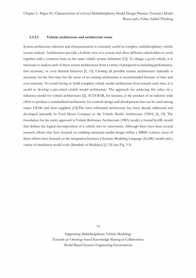
Chapter 3 : Paper #1: Characteristics of a Good Multidisciplinary Model Design Practice: Toward a Model
Reuse and a Value-Added Thinking
73
Supporting Multidisciplinary Vehicle Modeling:
Towards an Ontology-based Knowledge Sharing in Collaborative
Model Based Systems Engineering Environment
3.3.2.1 Vehicle architecture and architecture reuse
System architecture selection and characterization is extremely useful in complex, multidisciplinary vehicle
system analysis. Architectures provide a holistic view of a system and allow different stakeholders to work
together with a common basis in the same vehicle system definition [12]. To design a good vehicle, it is
necessary to analyze each of these system architectures from a variety of perspectives including performance,
fuel economy, or even thermal behavior [2, 13]. Creating all possible system architectures manually is
necessary for the first time but the reuse of an existing architecture is recommended because of time and
cost concerns. To avoid having to build complete vehicle model architecture from scratch each time, it is
useful to develop a pre-wired vehicle model architecture. The approach for achieving this relies on a
reference model for vehicle architectures [2]. AUTOSAR, for instance, is the product of an industry-wide
effort to produce a standardized architecture for controls design and development that can be used among
major OEMs and their suppliers [14].The term referential architecture has been already addressed and
developed internally by Ford Motor Company as the Vehicle Model Architecture (VMA) [2, 15]. The
foundation for the entire approach is Vehicle Reference Architecture (VRA) model, a formal SysML model
that defines the logical decomposition of a vehicle into its subsystems. Although there have been several
research efforts that have focused on enabling structural model design within a MBSE context, most of
these efforts have focused on the integration between a Systems Modeling Language (SysML) model and a
variety of simulation model tools (Simulink or Modelica) [2, 15] (see Fig. 3-5).
Chapter 3 : Paper #1: Characteristics of a Good Multidisciplinary Model Design Practice: Toward a Model
Reuse and a Value-Added Thinking
74
Supporting Multidisciplinary Vehicle Modeling:
Towards an Ontology-based Knowledge Sharing in Collaborative
Model Based Systems Engineering Environment
Fig. 3-5 Vehicle architecture and model
Among inhibitors to consistency management, humans who create or provide models can be a primary
cause when not conforming to the common language, or laws of nature, or introducing changes in a model.
To this end, model provider or developer develop fit-for-purpose instructions model.
A simulation model and its results have to be credible for the decision-makers to accept them as “correct.”
Note here that a credible model is not necessarily valid. The following items may increase credibility of a
model:
• The decision-maker’s (model user) and model suppliers’ understanding and agreement with the
model’s assumptions,
• Demonstration that the model has been verified and validated,
• Reputation of the model developer (provider),
• Importance of conceptual model design and correctness check in early development phase.
Chapter 3 : Paper #1: Characteristics of a Good Multidisciplinary Model Design Practice: Toward a Model
Reuse and a Value-Added Thinking
75
Supporting Multidisciplinary Vehicle Modeling:
Towards an Ontology-based Knowledge Sharing in Collaborative
Model Based Systems Engineering Environment
For the correctness control, we define correctness as a measurement of how well the system design meets
or exceeds its requirements. Due to uncertainty arising from design abstractions as well as system
interactions with the environment and its users, correctness is specified as a probability distribution over
multiple dimensions. These dimensions include the design hierarchy (i.e., subsystems and components),
environment, use conditions, functions, functional failures, and adherence to design rules. After having
established the domain level signals (interfaces and domain level model specifications), the model architects
integrate these sub models into a full virtual prototype. The model architect can evaluate alternative
architectures against different model accuracy constraints. She or he has to detect any potential problem
before the IVVQ (Integration, Verification, Validation, and Qualification) phase. The virtual prototype
contains various correctness checks for interoperability problems such as domain models software names,
versions, models’ min/max values, units, the direction of acausal connections, models’ accuracy levels, etc…
3.3.2.2 Knowledge generation and appropriate model reuse strategy
The knowledge encapsulated in each analysis model must be standard and coherent to be used by another
party. The knowledge must be captured for reuse in future projects. To reduce the possible risk caused by
inappropriate model reuse, therefore, one needs to define a robust model reuse strategy. Here
documentation alone is insufficient; equally important is model providers’ towering knowledge and
experience.
This section presents model reuse strategies (refactoring, reuse and plug-in) which provides advantages and
disadvantages in achieving balance between model credibility and development time and cost. By reusing a
model, designers avoid the expensive and time-consuming task of developing a new model. Designers often
adapt models published in reference library, and they copy computer code to make up parts (or all) of their
new model (a practice known in the computer engineering community as “code scavenging”), and they
invoke software components they have written or purchased previously. However, multidisciplinary analysis
model reuse is much more risky than software code reuse because the former requires engineer’s deep
domain knowledge and system experience [4].
Reuse has different meaning for different modellers. In one case, reuse could be limited to only recomposing
existing models from a library, without modification of components. In other contexts, reuse can involve
both reuse without modification, as well as modifying an existing component if it meets modelling needs
and/or reuse can speed up development (see Fig. 3-6).
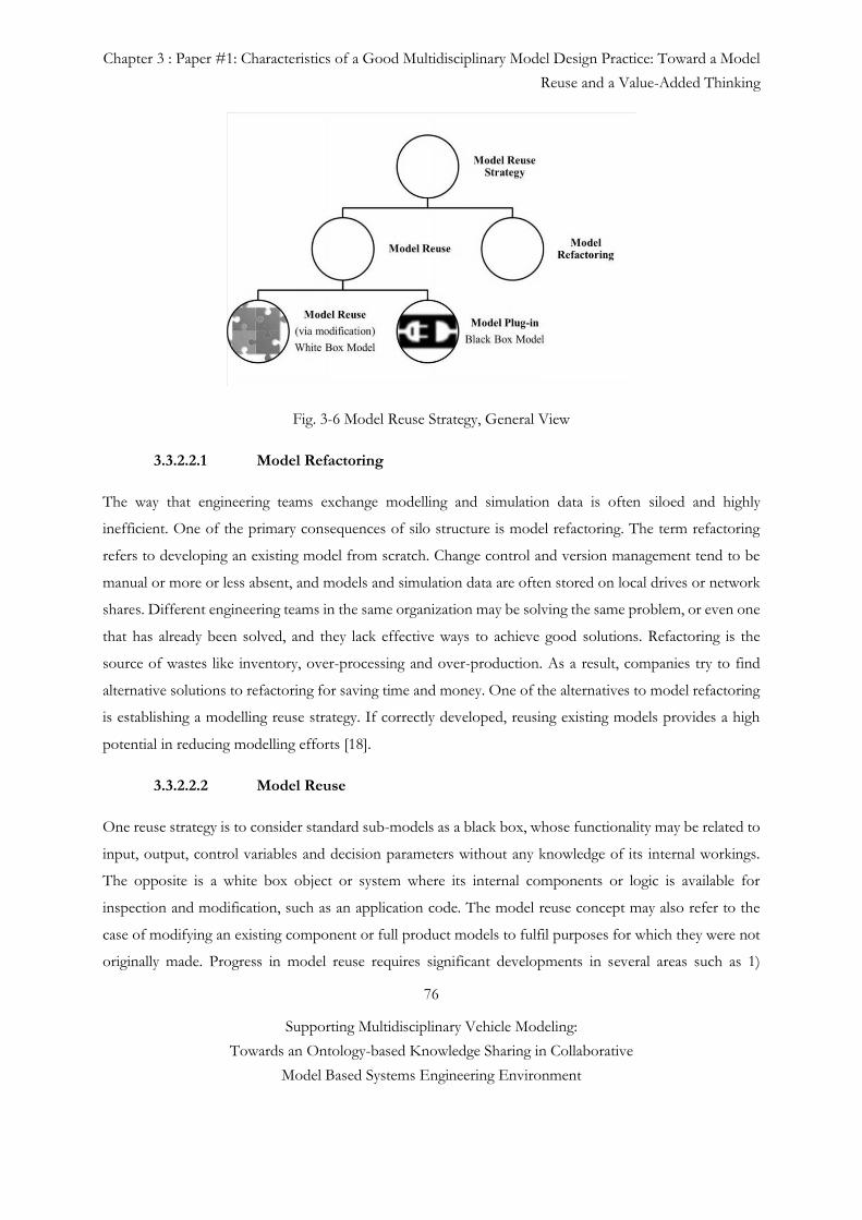
Chapter 3 : Paper #1: Characteristics of a Good Multidisciplinary Model Design Practice: Toward a Model
Reuse and a Value-Added Thinking
76
Supporting Multidisciplinary Vehicle Modeling:
Towards an Ontology-based Knowledge Sharing in Collaborative
Model Based Systems Engineering Environment
Fig. 3-6 Model Reuse Strategy, General View
3.3.2.2.1 Model Refactoring
The way that engineering teams exchange modelling and simulation data is often siloed and highly
inefficient. One of the primary consequences of silo structure is model refactoring. The term refactoring
refers to developing an existing model from scratch. Change control and version management tend to be
manual or more or less absent, and models and simulation data are often stored on local drives or network
shares. Different engineering teams in the same organization may be solving the same problem, or even one
that has already been solved, and they lack effective ways to achieve good solutions. Refactoring is the
source of wastes like inventory, over-processing and over-production. As a result, companies try to find
alternative solutions to refactoring for saving time and money. One of the alternatives to model refactoring
is establishing a modelling reuse strategy. If correctly developed, reusing existing models provides a high
potential in reducing modelling efforts [18].
3.3.2.2.2 Model Reuse
One reuse strategy is to consider standard sub-models as a black box, whose functionality may be related to
input, output, control variables and decision parameters without any knowledge of its internal workings.
The opposite is a white box object or system where its internal components or logic is available for
inspection and modification, such as an application code. The model reuse concept may also refer to the
case of modifying an existing component or full product models to fulfil purposes for which they were not
originally made. Progress in model reuse requires significant developments in several areas such as 1)
Chapter 3 : Paper #1: Characteristics of a Good Multidisciplinary Model Design Practice: Toward a Model
Reuse and a Value-Added Thinking
77
Supporting Multidisciplinary Vehicle Modeling:
Towards an Ontology-based Knowledge Sharing in Collaborative
Model Based Systems Engineering Environment
understanding what information is needed to support reuse and how this should be represented, 2)
developing mechanisms, automated and manual to collect and record this information, 3) understanding
how to design for reuse, 4) developing analysis and search tools to locate appropriate existing components,
5) documentation of Validation and Verification (V&V) steps, which cannot be fully fulfilled [19].
3.3.2.2.2.1 Model Reuse (via modification): White Box Model
Reusing of the entire simulation model which is complex and particularly challenging for model validation.
Model reuse through modification requires well-defined documentation and towering engineer knowledge
about the system and the conditions of interest. The diversity of objectives for different simulation uses
makes creation of models that can satisfy all intended simulation needs infeasible. On the other hand, if the
user lacks critical domain knowledge, model validation can be as time-consuming and costly as developing
a similar model from scratch (Model Refactoring) [4]. Possible risks and consequences of reusing models
include errors-prone decision, loss of intellectual properties and difficulty to modify a model when
requirements change. Thus, the knowledge encapsulated in each numerical model needs to be coherent for
it to be used for different purposes. In most cases, however, model developers and users do not have the
same level of understanding of the model, which may cause them to use different naming conventions,
model organizations, numbers of ports, and other conventions. Not only is it a wasted time for subgroups
to duplicate each other’s work, it can also introduce errors. Unless an Modeling and Simulation practitioner
understands the model’s contextual dependencies accurately and unambiguously, model reuse (via
modification) will continue to be an ineffective trial-and-error effort. Therefore, the main motivation for
model plug-ins is to introduce the ‘single source of authority’ concept as a part of the model reuse strategy
[20]. There exist technologies that may lower the cost of reusing a model or allow reuse of models in
previously impractical situations. However, improper reuse of numerical models can undermine these gains
as the consequences of a bad decision made with an invalid model can easily outweigh the benefits. The
open question about numerical model reuse is not only whether engineers reuse existing models properly,
but how valuable they can make the practice throughout the modelling lifecycle.
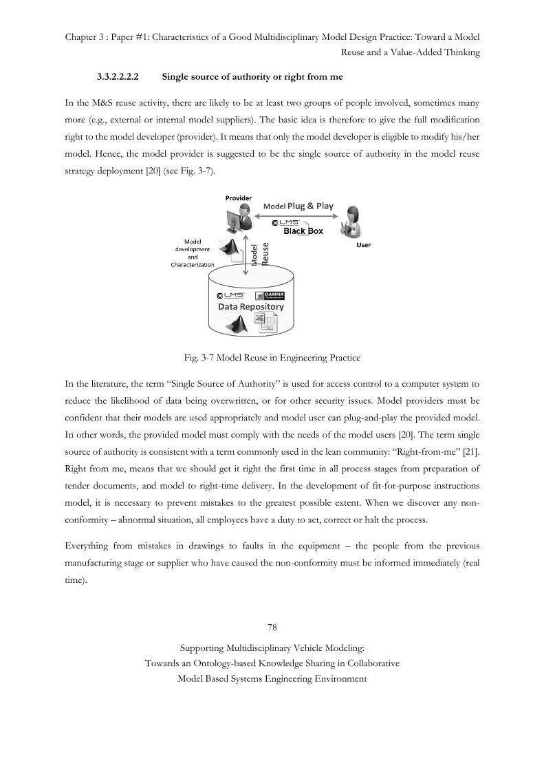
Chapter 3 : Paper #1: Characteristics of a Good Multidisciplinary Model Design Practice: Toward a Model
Reuse and a Value-Added Thinking
78
Supporting Multidisciplinary Vehicle Modeling:
Towards an Ontology-based Knowledge Sharing in Collaborative
Model Based Systems Engineering Environment
3.3.2.2.2.2 Single source of authority or right from me
In the M&S reuse activity, there are likely to be at least two groups of people involved, sometimes many
more (e.g., external or internal model suppliers). The basic idea is therefore to give the full modification
right to the model developer (provider). It means that only the model developer is eligible to modify his/her
model. Hence, the model provider is suggested to be the single source of authority in the model reuse
strategy deployment [20] (see Fig. 3-7).
Fig. 3-7 Model Reuse in Engineering Practice
In the literature, the term “Single Source of Authority” is used for access control to a computer system to
reduce the likelihood of data being overwritten, or for other security issues. Model providers must be
confident that their models are used appropriately and model user can plug-and-play the provided model.
In other words, the provided model must comply with the needs of the model users [20]. The term single
source of authority is consistent with a term commonly used in the lean community: “Right-from-me” [21].
Right from me, means that we should get it right the first time in all process stages from preparation of
tender documents, and model to right-time delivery. In the development of fit-for-purpose instructions
model, it is necessary to prevent mistakes to the greatest possible extent. When we discover any non-
conformity – abnormal situation, all employees have a duty to act, correct or halt the process.
Everything from mistakes in drawings to faults in the equipment – the people from the previous
manufacturing stage or supplier who have caused the non-conformity must be informed immediately (real
time).
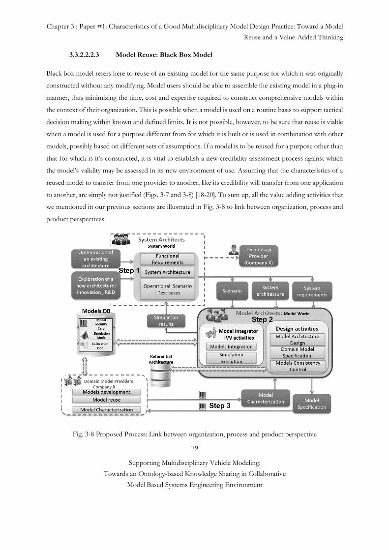
Chapter 3 : Paper #1: Characteristics of a Good Multidisciplinary Model Design Practice: Toward a Model
Reuse and a Value-Added Thinking
79
Supporting Multidisciplinary Vehicle Modeling:
Towards an Ontology-based Knowledge Sharing in Collaborative
Model Based Systems Engineering Environment
3.3.2.2.2.3 Model Reuse: Black Box Model
Black box model refers here to reuse of an existing model for the same purpose for which it was originally
constructed without any modifying. Model users should be able to assemble the existing model in a plug-in
manner, thus minimizing the time, cost and expertise required to construct comprehensive models within
the context of their organization. This is possible when a model is used on a routine basis to support tactical
decision making within known and defined limits. It is not possible, however, to be sure that reuse is viable
when a model is used for a purpose different from for which it is built or is used in combination with other
models, possibly based on different sets of assumptions. If a model is to be reused for a purpose other than
that for which is it’s constructed, it is vital to establish a new credibility assessment process against which
the model’s validity may be assessed in its new environment of use. Assuming that the characteristics of a
reused model to transfer from one provider to another, like its credibility will transfer from one application
to another, are simply not justified (Figs. 3-7 and 3-8) [18-20]. To sum up, all the value adding activities that
we mentioned in our previous sections are illustrated in Fig. 3-8 to link between organization, process and
product perspectives.
Fig. 3-8 Proposed Process: Link between organization, process and product perspective
Chapter 3 : Paper #1: Characteristics of a Good Multidisciplinary Model Design Practice: Toward a Model
Reuse and a Value-Added Thinking
80
Supporting Multidisciplinary Vehicle Modeling:
Towards an Ontology-based Knowledge Sharing in Collaborative
Model Based Systems Engineering Environment
3.5 Discussion and Conclusions
The application of the reuse strategies depends on the intent of the designer and on the domain point of
view. From the organization point of view, the Value Driven Design (VDD) aims to increase the application
of best practices among its members. The reuse of models is facilitated by easy access to well-organized
model repositories and efficient search engines. Intellectual property of models and limitations in their reuse
are clearly stated, with mechanisms enforcing the rules. Finally, a thorough translation of the models
characteristics among the disciplinary ontologies reduces misuse of models. From the process point of view,
the taken reuse strategy should remain a rational choice into a given situation. Rework, or even refactoring,
is legitimate when knowledge transfer is pursued. By creating the simulation anew, the (new) authors gain
competence and experience in the field covered by the model. Rework is also perfectly legitimate when
extending the validity domain of a model. New algorithms, added parameters, or augmented interfaces
justify the rework. Refactoring may be necessary while re-engineering a model to improve its
parameterization or better segregate implemented Laws of Nature from nature of materials or geometries.
From the product point of view, several practices contribute to the value of a model. As already said, a
thorough description of the model characteristics (interfaces, application area...) increases its potential plug-
in reuse. Associating verification cases (like analytical exact solutions) and validation data ensures that the
model value can be assessed at any time. Finally, parameterized models have more opportunities to be
applied in a simulation by proper choice of their parameters. The validation of the model over its entire
parametric set may be difficult to obtain, though. As a future consideration, this value based theoretical
reflection will be illustrated with an industrial case study to be able to show the link between organization,
process and product perspectives.
REFERENCES #3
[1] G. Sirin, B. Yannou, E. Coatanéa and E. Landel, “Creating Domain Ontology to Support the
Numerical Models Exchange between Suppliers and Users in a Complex System Design”. ASME 2013
International Design Engineering Technical Conferences and Computers and Information in Engineering
Conference Volume 2B: 33rd Computers and Information in Engineering Conference Portland, Oregon,
USA, August 4–7, 2013
[2] J.M. Branscomb, C.J.J. Paredis, J. Che, and M.J. Jennings, “Supporting Multidisciplinary Vehicle
Analysis Using a Vehicle Reference Architecture Model in SysML”. Presented at the Conference on Systems
Engineering Research CSER, Atlanta, US-GA, March, 12-22, 2013.
Chapter 3 : Paper #1: Characteristics of a Good Multidisciplinary Model Design Practice: Toward a Model
Reuse and a Value-Added Thinking
81
Supporting Multidisciplinary Vehicle Modeling:
Towards an Ontology-based Knowledge Sharing in Collaborative
Model Based Systems Engineering Environment
[3] G. Sirin, T. Welo, B. Yannou, E. Landel, “Value Creation in Collaborative Analysis Model
Development Processes”. Presented at the Conference on ASME (IDETC/CIE), Buffalo, USA, Aug., 17-
20, 2014.
[4] W.R. Kriger, O. Vaculin, W. Kortiin, “Multi-Disciplinary Simulation of Vehicle System
Dynamics”, Paper presented at the RTO AVT Symposium on "Reduction of Military Vehicle Acquisition
Time and Cost through Advanced Modelling and Virtual Simulation held in Paris, France, 22-25 April 2002,
and published in RTO-MP-089.
[5] B.D. Le and C.J.J. Paredis, “A Conceptual Framework for Value-Driven Design and Systems
Engineering”, 24th CIRP Design Conference, Published by Elsevier B.V. 2212-8271. 2014.
[6] D.G. Reinertsen, 1999, “Lean thinking isn’t so simple”, Electron Des., Vol. 47, No. 19, p.48.
[7] T. R. Browning, 2003, "On Customer Value and Improvement in Product Development Process,"
Systems Engineering Vol. 6, No.1, pp. 49-61.
[8] A.C. Ward, 2007, Lean Product and Process Development, Lean Enterprise Institute Inc.,
Cambridge MA, USA.
[9] Collopy, P., 2005, “Value Driven Design”, Briefing presented at the AIAA Value Driven Design
Program Management meeting, Lockheed Martin, Orlando, FL, 16-17 Aug.
[10] B. Huthwaite, (2007), “The Rules of Innovation – Products, Services and Systems”, Institute of
Lean Innovation, MI, USA.
[11] R.G. Cooper, and S.J. Edgett, “Lean, Rapid and Profitable New Product Development”, Product
Development Institute, 2005.
[12] J. Cheung et al. « Application of Value-Driven Design to Commercial Aero-Engine Systems”,
Published by the American Institute of Aeronautics and Astronautics, Inc., with permission, 2010.
[13] “The Guide to Lean Enablers for Managing Engineering Programs”, Version 1.0, Published by the
Joint MIT PMI INCOSE Community of Practice, May 2012.
[14] J.P. Womack and D.T Jones, “Lean Thinking. Banish Waste and Create Wealth in Your
Corporation”, 2. Edition. New York: Simon and Schuster, 2003.
[15] J. Lee and S.T. Kim, “The Middle-out Systems Engineering for Gray-Box Items and Case Study of
Automotive Lock Housing Assembly”, INCOSE International Symposium, Las Vegas, NV, June 30-July 3,
2014.
[16] R.L. Keeney, 2008, “Special Issue Value Focused Thinking”, Military Operations Research, 13, No.
2, 7-17.
Chapter 3 : Paper #1: Characteristics of a Good Multidisciplinary Model Design Practice: Toward a Model
Reuse and a Value-Added Thinking
82
Supporting Multidisciplinary Vehicle Modeling:
Towards an Ontology-based Knowledge Sharing in Collaborative
Model Based Systems Engineering Environment
[17] C. Rolland and N. Prakash, “From Conceptual Modelling to Requirement Engineering”, Published
in the Annals of Software Engineering, Volume 10, Issue 1-4 , pp 151-176, 2001.
[18] Crescendo (2012). Participants’ handbook. Crescendo Forum Innovation in collaborative modelling
and simulation to deliver Behavioral Digital Aircraft 19-20 June 2012, France.
[19] B. H. Taylor, 2012, “Evaluating Methods for Multi-Level System Design of a Series Hybrid
Vehicle”, Master Thesis, George W. Woodruff School of Mechanical Engineering, Georgia Institute of
Technology.
[20] Haskins, C., 2010, Systems Engineering Handbook: A Guide for System Life Cycle Processes and
Activities, INCOSE, San Diego.
[21] C. Rolland and C. B. Achour, 1997, “Guiding the construction of textual use case specifications”.
Data and Knowledge Engineering Journal Vol.25 No 1, pp.125-160.
[22] C. Bauch, “Lean Product Development: Making waste transparent”, Diploma thesis from TUM
and MIT, August 2004.
[23] M. Sliger et S. Broderick, (2008). “The Software Project Manager's Bridge to Agility. Addison-
Wesley”. p. 46. ISBN 0-321-50275-2.
[24] S. Nurcan, C. Rolland. “A multi-method for defining the organizational change. Journal of
Information and Software Technology”, Elsevier. Journal of Information and Software Technology,
Elsevier. 45:2(2003), p. 61-82.
[25] R. Smaling and O. de Weck, 2006, “Assessing Risks and Opportunities of Technology Infusion in
System Design”, Published online in Wiley InterScience (www.interscience.wiley.com). DOI
10.1002/sys.20061, Systems Engineering, Vol. 10, No. 1, 2007.
[26] E.C. Honour, “Demographics in Measuring Systems Engineering Return on Investment (SE-
ROI)”. INCOSE, 2009.
Chapter 4 : Paper #2: Multidisciplinary Simulation Model Development: towards an inconsistency
detection method during the design stage
83
Supporting Multidisciplinary Vehicle Modeling:
Towards an Ontology-based Knowledge Sharing in Collaborative
Model Based Systems Engineering Environment
4
Paper #2. Multidisciplinary Simulation Model
Development: towards an inconsistency detection
method during the design stage
Submitted to:
IEEE Transactions on Systems, Man, and Cybernetics: Systems
Göknur Sirin1, 4, Fabien Retho2, 3, Martine Callot3, Philippe Dessante2, Eric Landel4, Bernard
Yannou1, Jean-Claude Vannier3
1 Laboratoire Génie Industriel, Ecole Centrale Paris, Châtenay-Malabry, France
2 Département Energie Supélec, Gif-sur-Yvette, 91192, France
3 Airbus Group Innovations, 31025 and 92152, France
4 Techno centre Renault SAS, 78288, France
Abstract. The Integration, Verification and Validation (IVV) practices in the context of simulation based design
helps reducing inconsistencies in multidisciplinary systems – i.e. those combining multiple mechanics, structural,
Chapter 4 : Paper #2: Multidisciplinary Simulation Model Development: towards an inconsistency
detection method during the design stage
84
Supporting Multidisciplinary Vehicle Modeling:
Towards an Ontology-based Knowledge Sharing in Collaborative
Model Based Systems Engineering Environment
hydrodynamic or other complex components. In current multidisciplinary simulation models development process, sub
systems' simulation models are usually Verified and Validated (V&V) at supplier level to assess whether a system
meets its intended goals, in such scenarios, each system is verified and validated separately – i.e. the mechanic,
structural, hydrodynamic etc. However many problems may occur during the actual integration of these modular sub
systems’ simulations in Original Equipment Manufacturers (OEMs) level that increases the risk of late
inconsistencies such as interface mismatches or some other interoperability based problems. In order to address this
problem the current work aims to reduce late inconsistency detection by ensuring early stage collaborations between
the different suppliers and OEM, it does so by proposing a clear simulation model request. The current approach is
validated with an industrial case study to show how a Model Request Package that contains the Model Identity
Card (MIC) and Model of Intention (MoI) concepts, helps reducing the knowledge gap and the inconsistencies
between the OEMs and the model suppliers.
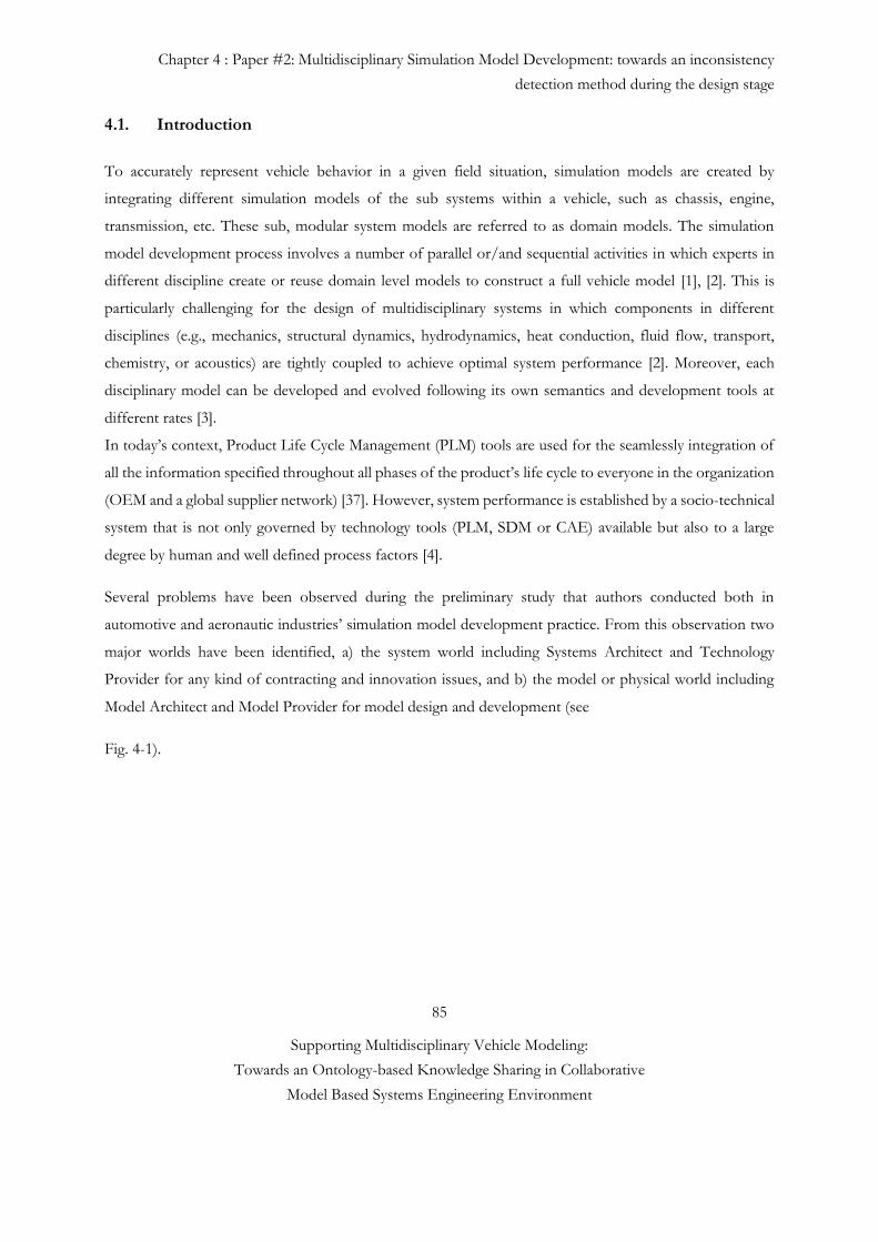
Chapter 4 : Paper #2: Multidisciplinary Simulation Model Development: towards an inconsistency
detection method during the design stage
85
Supporting Multidisciplinary Vehicle Modeling:
Towards an Ontology-based Knowledge Sharing in Collaborative
Model Based Systems Engineering Environment
4.1. Introduction
To accurately represent vehicle behavior in a given field situation, simulation models are created by
integrating different simulation models of the sub systems within a vehicle, such as chassis, engine,
transmission, etc. These sub, modular system models are referred to as domain models. The simulation
model development process involves a number of parallel or/and sequential activities in which experts in
different discipline create or reuse domain level models to construct a full vehicle model [1], [2]. This is
particularly challenging for the design of multidisciplinary systems in which components in different
disciplines (e.g., mechanics, structural dynamics, hydrodynamics, heat conduction, fluid flow, transport,
chemistry, or acoustics) are tightly coupled to achieve optimal system performance [2]. Moreover, each
disciplinary model can be developed and evolved following its own semantics and development tools at
different rates [3].
In today’s context, Product Life Cycle Management (PLM) tools are used for the seamlessly integration of
all the information specified throughout all phases of the product’s life cycle to everyone in the organization
(OEM and a global supplier network) [37]. However, system performance is established by a socio-technical
system that is not only governed by technology tools (PLM, SDM or CAE) available but also to a large
degree by human and well defined process factors [4].
Several problems have been observed during the preliminary study that authors conducted both in
automotive and aeronautic industries’ simulation model development practice. From this observation two
major worlds have been identified, a) the system world including Systems Architect and Technology
Provider for any kind of contracting and innovation issues, and b) the model or physical world including
Model Architect and Model Provider for model design and development (see
Fig. 4-1).
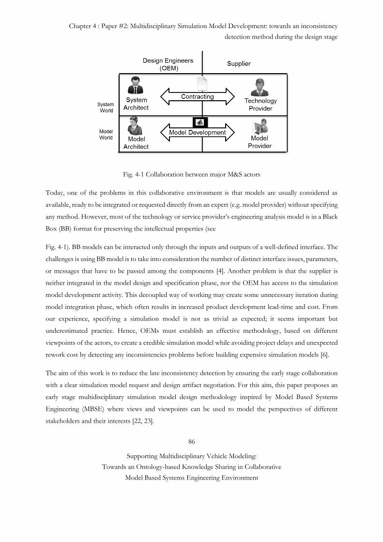
Chapter 4 : Paper #2: Multidisciplinary Simulation Model Development: towards an inconsistency
detection method during the design stage
86
Supporting Multidisciplinary Vehicle Modeling:
Towards an Ontology-based Knowledge Sharing in Collaborative
Model Based Systems Engineering Environment
Fig. 4-1 Collaboration between major M&S actors
Today, one of the problems in this collaborative environment is that models are usually considered as
available, ready to be integrated or requested directly from an expert (e.g. model provider) without specifying
any method. However, most of the technology or service provider’s engineering analysis model is in a Black
Box (BB) format for preserving the intellectual properties (see
Fig. 4-1). BB models can be interacted only through the inputs and outputs of a well-defined interface. The
challenges is using BB model is to take into consideration the number of distinct interface issues, parameters,
or messages that have to be passed among the components [4]. Another problem is that the supplier is
neither integrated in the model design and specification phase, nor the OEM has access to the simulation
model development activity. This decoupled way of working may create some unnecessary iteration during
model integration phase, which often results in increased product development lead-time and cost. From
our experience, specifying a simulation model is not as trivial as expected; it seems important but
underestimated practice. Hence, OEMs must establish an effective methodology, based on different
viewpoints of the actors, to create a credible simulation model while avoiding project delays and unexpected
rework cost by detecting any inconsistencies problems before building expensive simulation models [6].
The aim of this work is to reduce the late inconsistency detection by ensuring the early stage collaboration
with a clear simulation model request and design artifact negotiation. For this aim, this paper proposes an
early stage multidisciplinary simulation model design methodology inspired by Model Based Systems
Engineering (MBSE) where views and viewpoints can be used to model the perspectives of different
stakeholders and their interests [22, 23].
Chapter 4 : Paper #2: Multidisciplinary Simulation Model Development: towards an inconsistency
detection method during the design stage
87
Supporting Multidisciplinary Vehicle Modeling:
Towards an Ontology-based Knowledge Sharing in Collaborative
Model Based Systems Engineering Environment
This work introduces the first necessary step for reducing the knowledge gap between design actors (e.g.
OEM) and model developer (e.g. supplier) by integrating the system architecture into the simulation model
development process, Model Identity Card (MIC) and Model of Intention (MoI). This paper is organized
as follows. In Section 4.2, we provide the general literature review about the role of different actors and
their views and viewpoints management. In Section 4.3, we introduce our methodology of early phase
simulation model design by explaining the formal architecture design, MIC and MoI concepts. Section 4.4
introduces an industrial case study with its validation protocol. The conclusion and future consideration are
in Section 4.5.
4.2 State of the art
The combination of engineers working in silos with the lack of efficiency in current simulation model
development process cause imperfection based on simulation model interfaces mismatches, human errors,
miscommunication between teams and misinterpretations that can be due to imprecision, inconsistency and
uncertainty [7]. Imperfection and inconsistency are properties of the information itself [7]. In the design
environment, it would be ambiguous, vague or approximate information or contradictory conclusions can
be derived from the information. Instead, uncertainty means that an agent (i.e. model design engineer) has
only partial knowledge about the truth value of a given piece of information. When dealing with
multidisciplinary simulation model development process, all decision making occurs under uncertainty. This
is due to the physical attributes of the system being analyzed, the environment in which the system operates,
and the individuals which operate the system [9, 36]. Uncertainty in the context of Modeling and Simulation
(M&S) has been defined by Oberkampf [7].
For example, without knowing the additional model details that still remain to be specified, the results from
the model can only be predicted with limited accuracy. Since, the specification uncertainty is large, the overall
uncertainty is also large no matter how accurate the model [9]. Thus, the model specification and ensured
information flow in modeling practice are the key aspects of its uncertainty, which may imply risk that the
product attributes will not ultimately meet user needs.
4.2.1 Related Research Methods and Industrial Projects
The approach proposed in this paper is developed to support the building effort of the multidisciplinary
virtual product (i.e. simulation model). A virtual product is a global model of the future product (i.e. car,
train, aircraft, helicopter, etc.) that can be simulated to predict its behavior with an estimated accuracy and
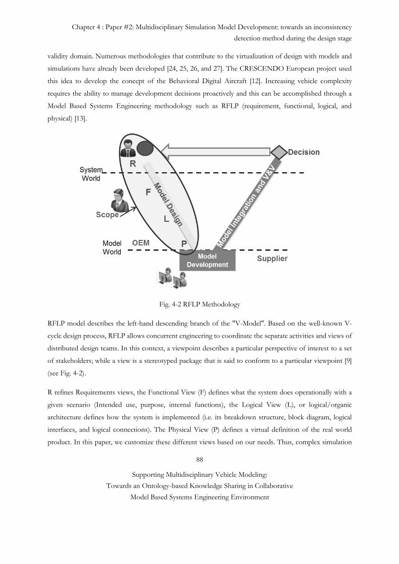
Chapter 4 : Paper #2: Multidisciplinary Simulation Model Development: towards an inconsistency
detection method during the design stage
88
Supporting Multidisciplinary Vehicle Modeling:
Towards an Ontology-based Knowledge Sharing in Collaborative
Model Based Systems Engineering Environment
validity domain. Numerous methodologies that contribute to the virtualization of design with models and
simulations have already been developed [24, 25, 26, and 27]. The CRESCENDO European project used
this idea to develop the concept of the Behavioral Digital Aircraft [12]. Increasing vehicle complexity
requires the ability to manage development decisions proactively and this can be accomplished through a
Model Based Systems Engineering methodology such as RFLP (requirement, functional, logical, and
physical) [13].
Fig. 4-2 RFLP Methodology
RFLP model describes the left-hand descending branch of the "V-Model". Based on the well-known V-
cycle design process, RFLP allows concurrent engineering to coordinate the separate activities and views of
distributed design teams. In this context, a viewpoint describes a particular perspective of interest to a set
of stakeholders; while a view is a stereotyped package that is said to conform to a particular viewpoint [9]
(see Fig. 4-2).
R refines Requirements views, the Functional View (F) defines what the system does operationally with a
given scenario (Intended use, purpose, internal functions), the Logical View (L), or logical/organic
architecture defines how the system is implemented (i.e. its breakdown structure, block diagram, logical
interfaces, and logical connections). The Physical View (P) defines a virtual definition of the real world
product. In this paper, we customize these different views based on our needs. Thus, complex simulation
Chapter 4 : Paper #2: Multidisciplinary Simulation Model Development: towards an inconsistency
detection method during the design stage
89
Supporting Multidisciplinary Vehicle Modeling:
Towards an Ontology-based Knowledge Sharing in Collaborative
Model Based Systems Engineering Environment
model development process can be described in the context of four interrelated types of knowledge –
functional, structural, behavioral, and physical knowledge or views. These views contain numerous sub
views itself such as functional view contains requirement, system architecture and operational views.
Structural knowledge includes definitions of the form, and dimensions of the artifact, its constituent
components, and their arrangement and connection to each other. A structural description is sufficient to
construct the artifact (simulation model). It includes the necessary information about the artifact’s explicit
parameters, which a designer directly determines in order to generate a physical solution to an abstract
problem. Behavioral knowledge includes the description of the artifact’s potential behaviors in response to
its environment in a given scenario.
As vehicle systems are continuously increasing in complexity, it is essential that there is a process flow to
handle the modeling of the vehicle system from beginning to end [2].
There is another industrial methodology called ARCADIA (ARChitecture Analysis & Design Integrated
Approach) that is in operational use since 2008 in Thales Company [38]. ARCADIA is based on
architecture-centric and model-driven engineering and it was supported by use of “standard” language such
as architecture Framework (e.g. NATO AF or NAF), and SysML/UML. However, ARCADIA promotes
driving engineering, no more by requirements only, but mainly by functional need analysis (and operational
analysis as well) [38]. Mentioned industrial method does not allow us to design simulation model world. We
would like to pull and transform the necessary system related information such as system requirements,
functions and operations to design a simulation model in model world.
Thus, the transition from system models (system world) to behavioral physic-based modelling (model world)
should be structured first with architecture framework and after then supported by information flows
between different design actors (see Fig. 4-3). However, today’s internal communication is ensured by
informal knowledge sharing and it becomes an error prone activity because different disciplines often use
different vocabularies. Such semantic differences can cause misunderstandings between these actors [1].
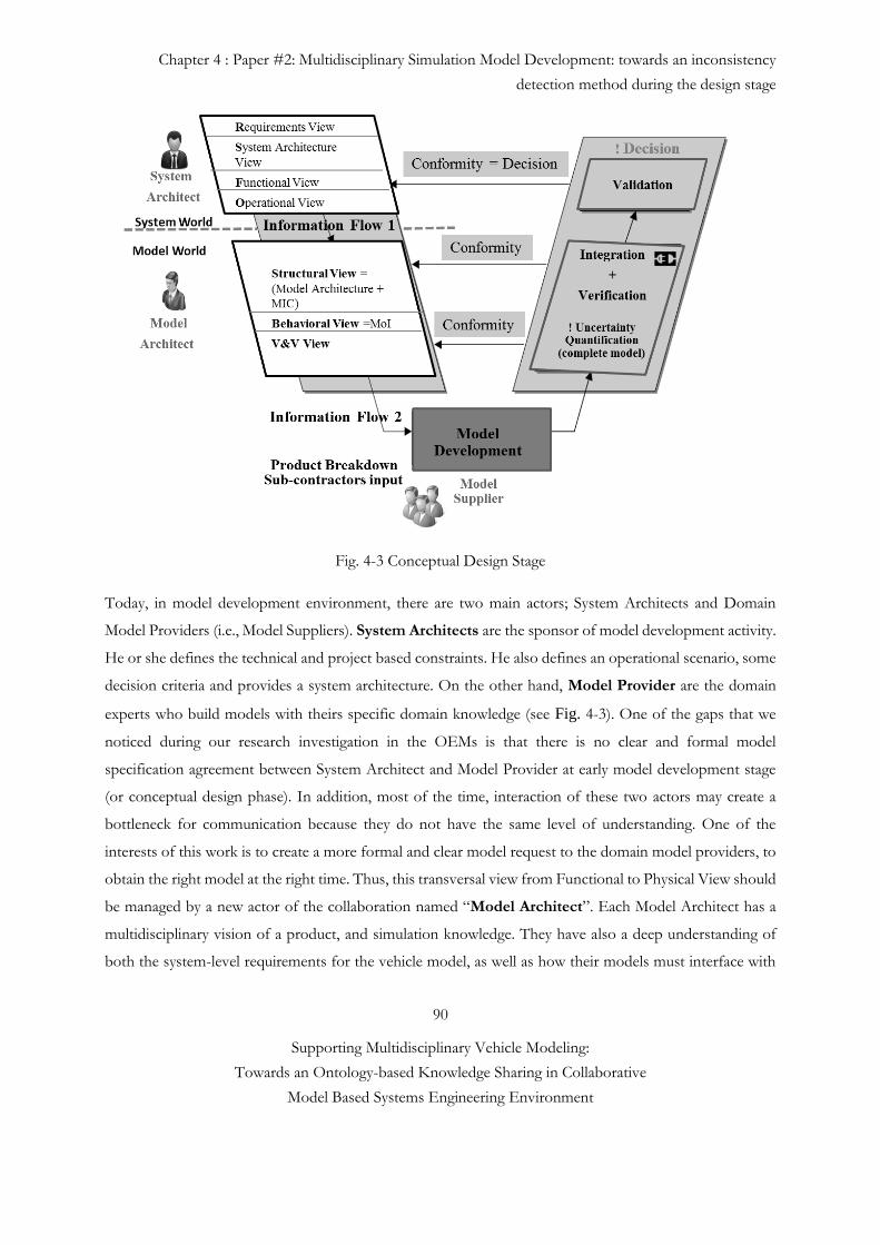
Chapter 4 : Paper #2: Multidisciplinary Simulation Model Development: towards an inconsistency
detection method during the design stage
90
Supporting Multidisciplinary Vehicle Modeling:
Towards an Ontology-based Knowledge Sharing in Collaborative
Model Based Systems Engineering Environment
Fig. 4-3 Conceptual Design Stage
Today, in model development environment, there are two main actors; System Architects and Domain
Model Providers (i.e., Model Suppliers). System Architects are the sponsor of model development activity.
He or she defines the technical and project based constraints. He also defines an operational scenario, some
decision criteria and provides a system architecture. On the other hand, Model Provider are the domain
experts who build models with theirs specific domain knowledge (see Fig. 4-3). One of the gaps that we
noticed during our research investigation in the OEMs is that there is no clear and formal model
specification agreement between System Architect and Model Provider at early model development stage
(or conceptual design phase). In addition, most of the time, interaction of these two actors may create a
bottleneck for communication because they do not have the same level of understanding. One of the
interests of this work is to create a more formal and clear model request to the domain model providers, to
obtain the right model at the right time. Thus, this transversal view from Functional to Physical View should
be managed by a new actor of the collaboration named “Model Architect”. Each Model Architect has a
multidisciplinary vision of a product, and simulation knowledge. They have also a deep understanding of
both the system-level requirements for the vehicle model, as well as how their models must interface with
Chapter 4 : Paper #2: Multidisciplinary Simulation Model Development: towards an inconsistency
detection method during the design stage
91
Supporting Multidisciplinary Vehicle Modeling:
Towards an Ontology-based Knowledge Sharing in Collaborative
Model Based Systems Engineering Environment
other domain models (see Fig. 4-1). There are multiple activities involved in the Model Architecture business
cycle such as:
• understanding the system world requirements and interpreting and translating these requirements in model
world,
• analyzing or evaluating and selecting the architecture and
• communicating with system architects and multiple domain level model providers.
These activities do not take place in a strict sequence and there are many feedback loops as the multiple
stakeholders negotiate among themselves, striving for some consensus. On the other hand, Domain Expert
is also a fundamental role that has expertise, experience and knowledge to support Model Provider’s final
model building and delivering activities.
The collaborative multidisciplinary simulation model development process creates a response to the request
of the System Architect who searches elements to analyze architecture for a design choice. The intent of the
System Architect is to evaluate whether system requirements are foreseeably satisfied, based on the existing
knowledge on the system to be. This evaluation is undertaken using a numerical simulation model of the
system to be.
During this conceptual design stage, the first information flow provides the following elements: an
architecture description, variables of interest, constraints, and scenarios with expected accuracy from System
Architect to Model Architect (see Fig. 4-3).
Architecture Description
The system is functionally and logically described. The logical description covers the topological structure
(existing connections among system components, like SysML Internal Block Diagrams) and other properties
specific to the nature of the component (for example; density, electrical or thermal resistivity, conductivity,
chemical nature). When the System Architect considers several alternatives, each alternative comes with its
own architectural description [4, 14].
Chapter 4 : Paper #2: Multidisciplinary Simulation Model Development: towards an inconsistency
detection method during the design stage
92
Supporting Multidisciplinary Vehicle Modeling:
Towards an Ontology-based Knowledge Sharing in Collaborative
Model Based Systems Engineering Environment
Observable Decision Criteria
A variable of interest is a characteristic of the system (related to its behavior, its structure or to any other
view point on the system) for which the System Architect is interested in. The variable of interest can be a
scalar, a multidimensional vector, or a field in the response space. The noise comfort in a car is such an
example.
Constraints
Technical Constraints
Unless the System Architect is looking for preliminary or exploratory results, he sets boundaries to surpass
(e.g. performance, safety and environment) or to respect (limits) in the response space of variables of
interest. The noise level that causes earing damages is such a limit.
Project Constraints
Project cost and time to development are considered as project constraints.
Scenarios
Multiple scenarios can be proposed in order to fit with the complexity of the vehicle and the different
mission profiles. Such as standardized urban, extra-urban, or mixed gas mileage for a car or in an operational
concept (flight profile typical for a short range commuting airliner).
Expected Accuracy
The applicability of any model depends on the accuracy and reliability of its output. Yet, because all models
are imperfect abstractions of reality and precise input data are rarely available, all output values are subject
to inaccuracies. Accuracy is the closeness of the agreement between the measured value and true value. High
accuracy implies a low error. Thus, depending on the maturity of the design and design specification
provided to Model Architect, the System Architect may insist on having a high degree of confidence of the
model result produced [10].
Second information flow from Model Architect to Model Provider provides the following elements: early
stage simulation model design consisting of a formal architecture representation, a MIC and a MoI. Model
Identity Card (MIC) and Model of intention (MoI), concept that we will describe in the next section, were
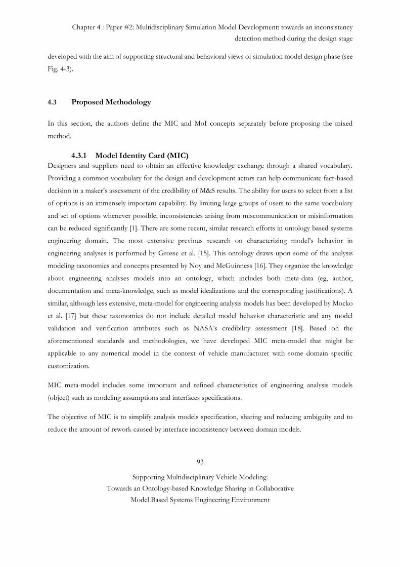
Chapter 4 : Paper #2: Multidisciplinary Simulation Model Development: towards an inconsistency
detection method during the design stage
93
Supporting Multidisciplinary Vehicle Modeling:
Towards an Ontology-based Knowledge Sharing in Collaborative
Model Based Systems Engineering Environment
developed with the aim of supporting structural and behavioral views of simulation model design phase (see
Fig. 4-3).
4.3 Proposed Methodology
In this section, the authors define the MIC and MoI concepts separately before proposing the mixed
method.
4.3.1 Model Identity Card (MIC)
Designers and suppliers need to obtain an effective knowledge exchange through a shared vocabulary.
Providing a common vocabulary for the design and development actors can help communicate fact-based
decision in a maker’s assessment of the credibility of M&S results. The ability for users to select from a list
of options is an immensely important capability. By limiting large groups of users to the same vocabulary
and set of options whenever possible, inconsistencies arising from miscommunication or misinformation
can be reduced significantly [1]. There are some recent, similar research efforts in ontology based systems
engineering domain. The most extensive previous research on characterizing model’s behavior in
engineering analyses is performed by Grosse et al. [15]. This ontology draws upon some of the analysis
modeling taxonomies and concepts presented by Noy and McGuinness [16]. They organize the knowledge
about engineering analyses models into an ontology, which includes both meta-data (eg, author,
documentation and meta-knowledge, such as model idealizations and the corresponding justifications). A
similar, although less extensive, meta-model for engineering analysis models has been developed by Mocko
et al. [17] but these taxonomies do not include detailed model behavior characteristic and any model
validation and verification attributes such as NASA’s credibility assessment [18]. Based on the
aforementioned standards and methodologies, we have developed MIC meta-model that might be
applicable to any numerical model in the context of vehicle manufacturer with some domain specific
customization.
MIC meta-model includes some important and refined characteristics of engineering analysis models
(object) such as modeling assumptions and interfaces specifications.
The objective of MIC is to simplify analysis models specification, sharing and reducing ambiguity and to
reduce the amount of rework caused by interface inconsistency between domain models.
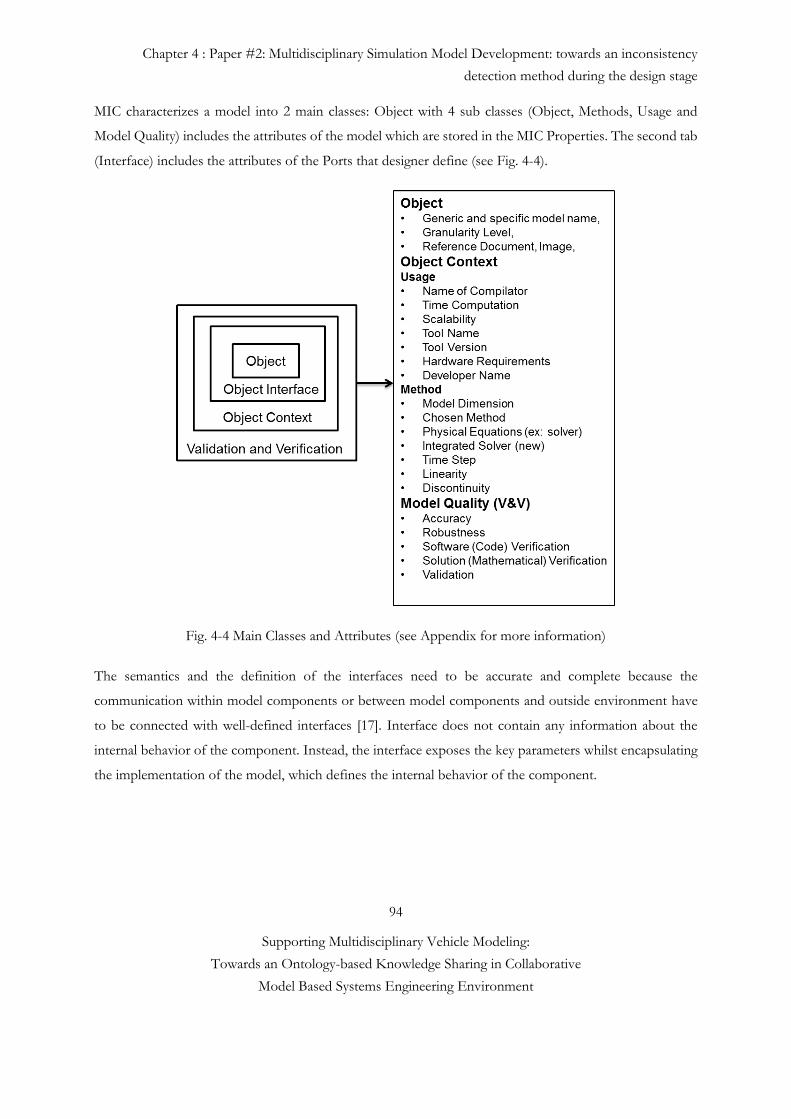
Chapter 4 : Paper #2: Multidisciplinary Simulation Model Development: towards an inconsistency
detection method during the design stage
94
Supporting Multidisciplinary Vehicle Modeling:
Towards an Ontology-based Knowledge Sharing in Collaborative
Model Based Systems Engineering Environment
MIC characterizes a model into 2 main classes: Object with 4 sub classes (Object, Methods, Usage and
Model Quality) includes the attributes of the model which are stored in the MIC Properties. The second tab
(Interface) includes the attributes of the Ports that designer define (see Fig. 4-4).
Fig. 4-4 Main Classes and Attributes (see Appendix for more information)
The semantics and the definition of the interfaces need to be accurate and complete because the
communication within model components or between model components and outside environment have
to be connected with well-defined interfaces [17]. Interface does not contain any information about the
internal behavior of the component. Instead, the interface exposes the key parameters whilst encapsulating
the implementation of the model, which defines the internal behavior of the component.
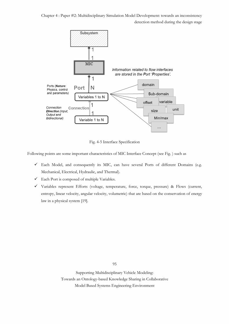
Chapter 4 : Paper #2: Multidisciplinary Simulation Model Development: towards an inconsistency
detection method during the design stage
95
Supporting Multidisciplinary Vehicle Modeling:
Towards an Ontology-based Knowledge Sharing in Collaborative
Model Based Systems Engineering Environment
Fig. 4-5 Interface Specification
Following points are some important characteristics of MIC Interface Concept (see Fig. ) such as
Each Model, and consequently its MIC, can have several Ports of different Domains (e.g.
Mechanical, Electrical, Hydraulic, and Thermal).
Each Port is composed of multiple Variables.
Variables represent Efforts (voltage, temperature, force, torque, pressure) & Flows (current,
entropy, linear velocity, angular velocity, volumetric) that are based on the conservation of energy
law in a physical system [19].
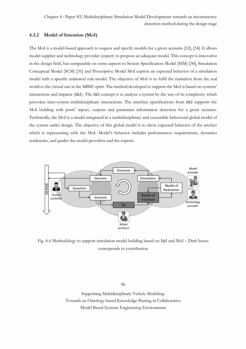
Chapter 4 : Paper #2: Multidisciplinary Simulation Model Development: towards an inconsistency
detection method during the design stage
96
Supporting Multidisciplinary Vehicle Modeling:
Towards an Ontology-based Knowledge Sharing in Collaborative
Model Based Systems Engineering Environment
4.3.2 Model of Intention (MoI)
The MoI is a model-based approach to request and specify models for a given scenario [32], [34]. It allows
model supplier and technology provider (expert) to propose an adequate model. This concept is innovative
in the design field, but comparable on some aspects to System Specification Model (SSM) [30], Simulation
Conceptual Model (SCM) [31] and Prescriptive Model MoI express an expected behavior of a simulation
model with a specific estimated role-model. The objective of MoI is to fulfil the transition from the real
world to the virtual one in the MBSE spirit. The method developed to support the MoI is based on systems’
interactions and impacts (I&I). The I&I concept is to analyze a system by the way of its complexity which
provokes inter-system multidisciplinary interactions. The interface specifications from I&I supports the
MoI building with ports’ inputs, outputs and parameter information detection for a given scenario.
Technically, the MoI is a model integrated in a multidisciplinary and executable behavioral global model of
the system under design. The objective of this global model is to show expected behavior of the artefact
which is representing with the MoI. Model’s behavior includes performances requirements, dynamics
tendencies, and guides the model providers and the experts.
Fig. 4-6 Methodology to support simulation model building based on I&I and MoI – Dark boxes
corresponds to contribution
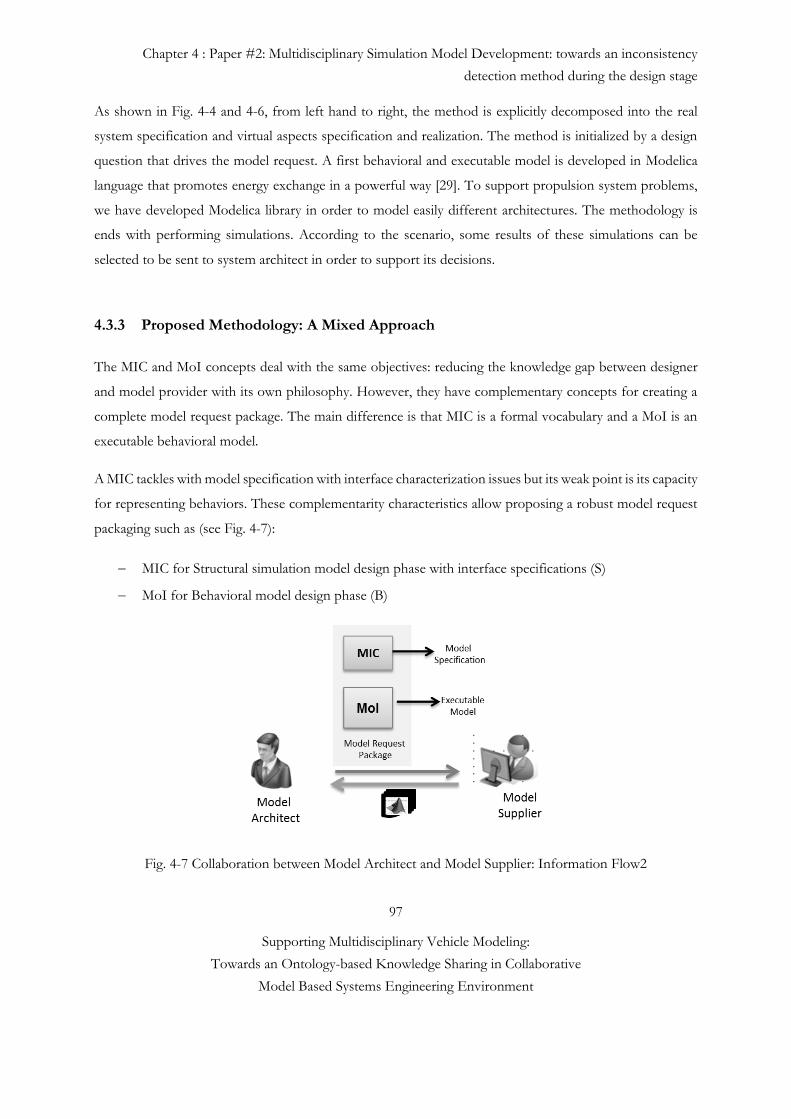
Chapter 4 : Paper #2: Multidisciplinary Simulation Model Development: towards an inconsistency
detection method during the design stage
97
Supporting Multidisciplinary Vehicle Modeling:
Towards an Ontology-based Knowledge Sharing in Collaborative
Model Based Systems Engineering Environment
As shown in Fig. 4-4 and 4-6, from left hand to right, the method is explicitly decomposed into the real
system specification and virtual aspects specification and realization. The method is initialized by a design
question that drives the model request. A first behavioral and executable model is developed in Modelica
language that promotes energy exchange in a powerful way [29]. To support propulsion system problems,
we have developed Modelica library in order to model easily different architectures. The methodology is
ends with performing simulations. According to the scenario, some results of these simulations can be
selected to be sent to system architect in order to support its decisions.
4.3.3 Proposed Methodology: A Mixed Approach
The MIC and MoI concepts deal with the same objectives: reducing the knowledge gap between designer
and model provider with its own philosophy. However, they have complementary concepts for creating a
complete model request package. The main difference is that MIC is a formal vocabulary and a MoI is an
executable behavioral model.
A MIC tackles with model specification with interface characterization issues but its weak point is its capacity
for representing behaviors. These complementarity characteristics allow proposing a robust model request
packaging such as (see Fig. 4-7):
MIC for Structural simulation model design phase with interface specifications (S)
MoI for Behavioral model design phase (B)
Fig. 4-7 Collaboration between Model Architect and Model Supplier: Information Flow2
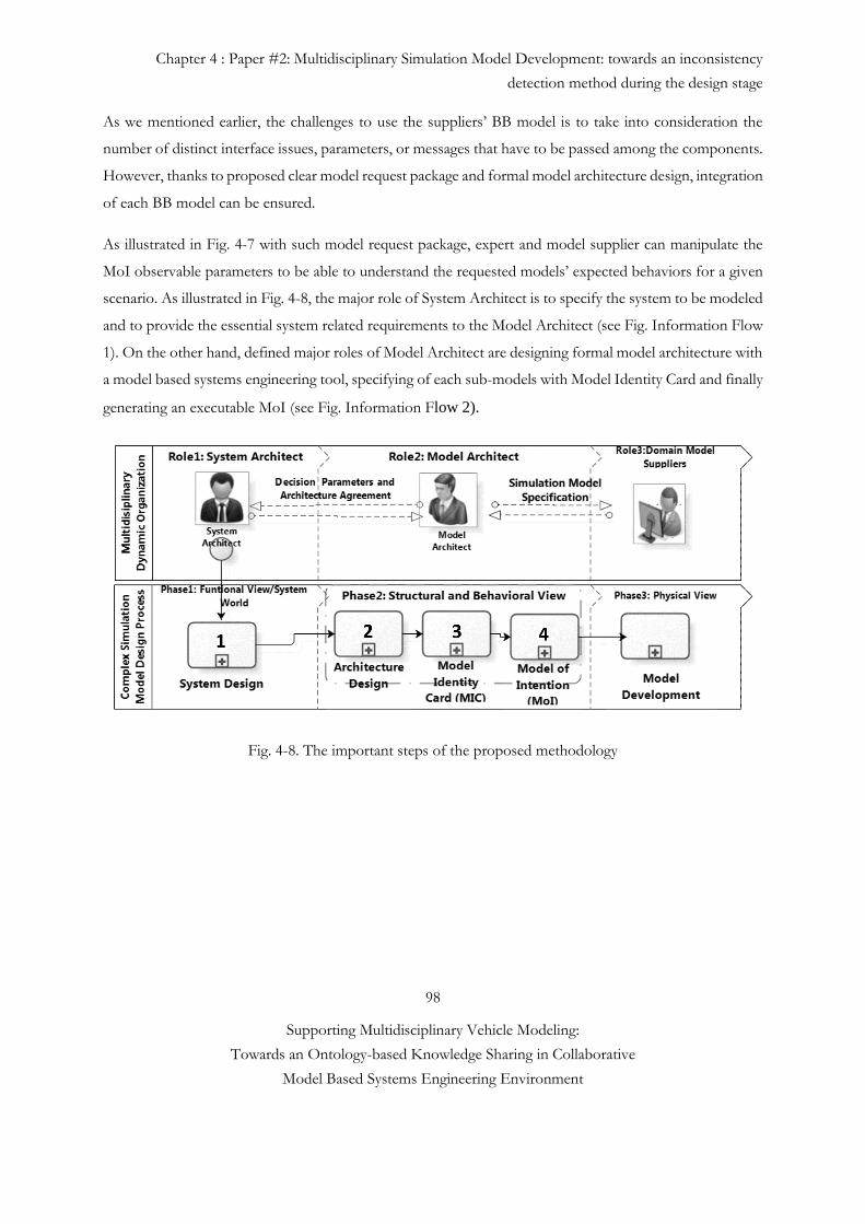
Chapter 4 : Paper #2: Multidisciplinary Simulation Model Development: towards an inconsistency
detection method during the design stage
98
Supporting Multidisciplinary Vehicle Modeling:
Towards an Ontology-based Knowledge Sharing in Collaborative
Model Based Systems Engineering Environment
As we mentioned earlier, the challenges to use the suppliers’ BB model is to take into consideration the
number of distinct interface issues, parameters, or messages that have to be passed among the components.
However, thanks to proposed clear model request package and formal model architecture design, integration
of each BB model can be ensured.
As illustrated in Fig. 4-7 with such model request package, expert and model supplier can manipulate the
MoI observable parameters to be able to understand the requested models’ expected behaviors for a given
scenario. As illustrated in Fig. 4-8, the major role of System Architect is to specify the system to be modeled
and to provide the essential system related requirements to the Model Architect (see Fig. Information Flow
1). On the other hand, defined major roles of Model Architect are designing formal model architecture with
a model based systems engineering tool, specifying of each sub-models with Model Identity Card and finally
generating an executable MoI (see Fig. Information Flow 2).
Fig. 4-8. The important steps of the proposed methodology
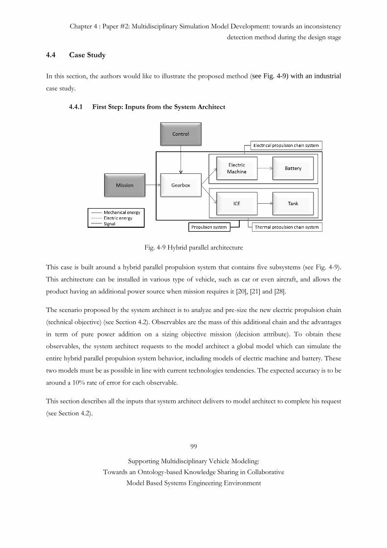
Chapter 4 : Paper #2: Multidisciplinary Simulation Model Development: towards an inconsistency
detection method during the design stage
99
Supporting Multidisciplinary Vehicle Modeling:
Towards an Ontology-based Knowledge Sharing in Collaborative
Model Based Systems Engineering Environment
4.4 Case Study
In this section, the authors would like to illustrate the proposed method (see Fig. 4-9) with an industrial
case study.
4.4.1 First Step: Inputs from the System Architect
Fig. 4-9 Hybrid parallel architecture
This case is built around a hybrid parallel propulsion system that contains five subsystems (see Fig. 4-9).
This architecture can be installed in various type of vehicle, such as car or even aircraft, and allows the
product having an additional power source when mission requires it [20], [21] and [28].
The scenario proposed by the system architect is to analyze and pre-size the new electric propulsion chain
(technical objective) (see Section 4.2). Observables are the mass of this additional chain and the advantages
in term of pure power addition on a sizing objective mission (decision attribute). To obtain these
observables, the system architect requests to the model architect a global model which can simulate the
entire hybrid parallel propulsion system behavior, including models of electric machine and battery. These
two models must be as possible in line with current technologies tendencies. The expected accuracy is to be
around a 10% rate of error for each observable.
This section describes all the inputs that system architect delivers to model architect to complete his request
(see Section 4.2).
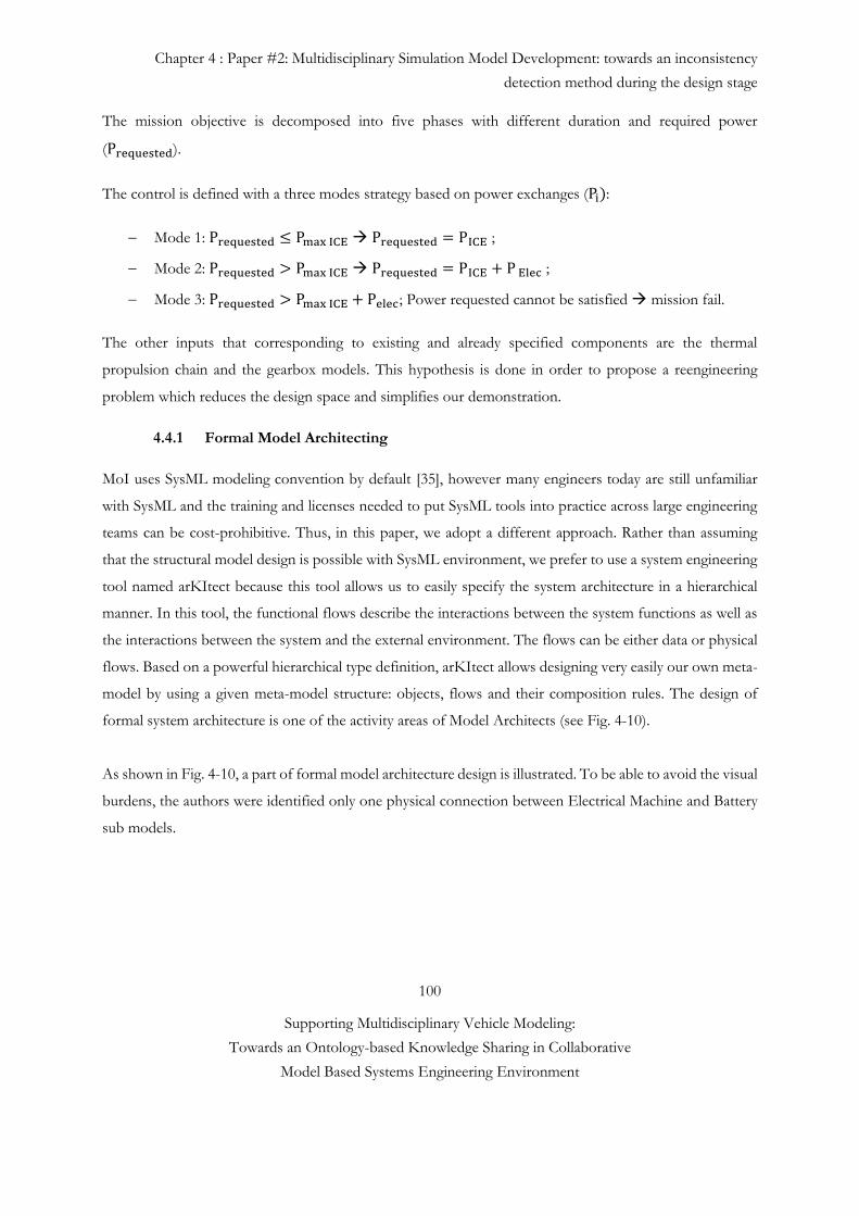
Chapter 4 : Paper #2: Multidisciplinary Simulation Model Development: towards an inconsistency
detection method during the design stage
100
Supporting Multidisciplinary Vehicle Modeling:
Towards an Ontology-based Knowledge Sharing in Collaborative
Model Based Systems Engineering Environment
The mission objective is decomposed into five phases with different duration and required power
(Prequested).
The control is defined with a three modes strategy based on power exchanges (Pi):
Mode 1: Prequested ≤ Pmax ICE Prequested = P ICE ;
Mode 2: Prequested > Pmax ICE Prequested = P ICE + P Elec ;
Mode 3: Prequested > Pmax ICE + Pelec; Power requested cannot be satisfied mission fail.
The other inputs that corresponding to existing and already specified components are the thermal
propulsion chain and the gearbox models. This hypothesis is done in order to propose a reengineering
problem which reduces the design space and simplifies our demonstration.
4.4.1 Formal Model Architecting
MoI uses SysML modeling convention by default [35], however many engineers today are still unfamiliar
with SysML and the training and licenses needed to put SysML tools into practice across large engineering
teams can be cost-prohibitive. Thus, in this paper, we adopt a different approach. Rather than assuming
that the structural model design is possible with SysML environment, we prefer to use a system engineering
tool named arKItect because this tool allows us to easily specify the system architecture in a hierarchical
manner. In this tool, the functional flows describe the interactions between the system functions as well as
the interactions between the system and the external environment. The flows can be either data or physical
flows. Based on a powerful hierarchical type definition, arKItect allows designing very easily our own meta-
model by using a given meta-model structure: objects, flows and their composition rules. The design of
formal system architecture is one of the activity areas of Model Architects (see Fig. 4-10).
As shown in Fig. 4-10, a part of formal model architecture design is illustrated. To be able to avoid the visual
burdens, the authors were identified only one physical connection between Electrical Machine and Battery
sub models.
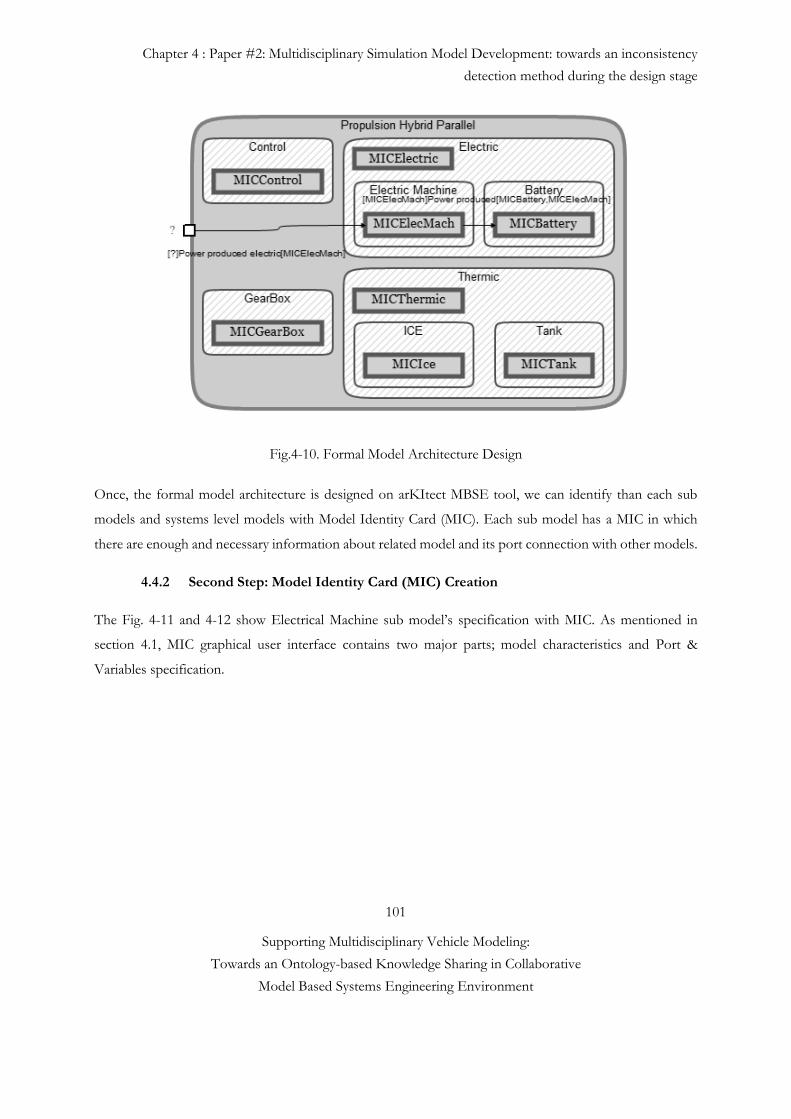
Chapter 4 : Paper #2: Multidisciplinary Simulation Model Development: towards an inconsistency
detection method during the design stage
101
Supporting Multidisciplinary Vehicle Modeling:
Towards an Ontology-based Knowledge Sharing in Collaborative
Model Based Systems Engineering Environment
Fig.4-10. Formal Model Architecture Design
Once, the formal model architecture is designed on arKItect MBSE tool, we can identify than each sub
models and systems level models with Model Identity Card (MIC). Each sub model has a MIC in which
there are enough and necessary information about related model and its port connection with other models.
4.4.2 Second Step: Model Identity Card (MIC) Creation
The Fig. 4-11 and 4-12 show Electrical Machine sub model’s specification with MIC. As mentioned in
section 4.1, MIC graphical user interface contains two major parts; model characteristics and Port &
Variables specification.
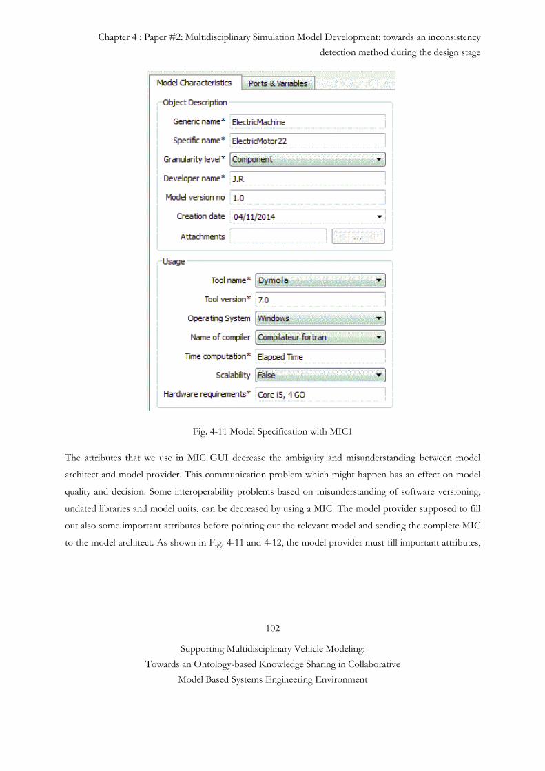
Chapter 4 : Paper #2: Multidisciplinary Simulation Model Development: towards an inconsistency
detection method during the design stage
102
Supporting Multidisciplinary Vehicle Modeling:
Towards an Ontology-based Knowledge Sharing in Collaborative
Model Based Systems Engineering Environment
Fig. 4-11 Model Specification with MIC1
The attributes that we use in MIC GUI decrease the ambiguity and misunderstanding between model
architect and model provider. This communication problem which might happen has an effect on model
quality and decision. Some interoperability problems based on misunderstanding of software versioning,
undated libraries and model units, can be decreased by using a MIC. The model provider supposed to fill
out also some important attributes before pointing out the relevant model and sending the complete MIC
to the model architect. As shown in Fig. 4-11 and 4-12, the model provider must fill important attributes,
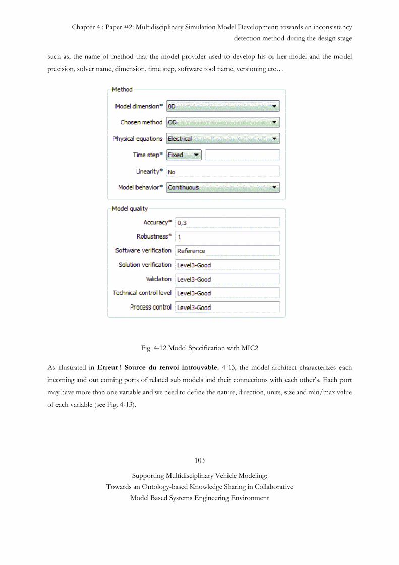
Chapter 4 : Paper #2: Multidisciplinary Simulation Model Development: towards an inconsistency
detection method during the design stage
103
Supporting Multidisciplinary Vehicle Modeling:
Towards an Ontology-based Knowledge Sharing in Collaborative
Model Based Systems Engineering Environment
such as, the name of method that the model provider used to develop his or her model and the model
precision, solver name, dimension, time step, software tool name, versioning etc…
Fig. 4-12 Model Specification with MIC2
As illustrated in Erreur ! Source du renvoi introuvable. 4-13, the model architect characterizes each
incoming and out coming ports of related sub models and their connections with each other’s. Each port
may have more than one variable and we need to define the nature, direction, units, size and min/max value
of each variable (see Fig. 4-13).
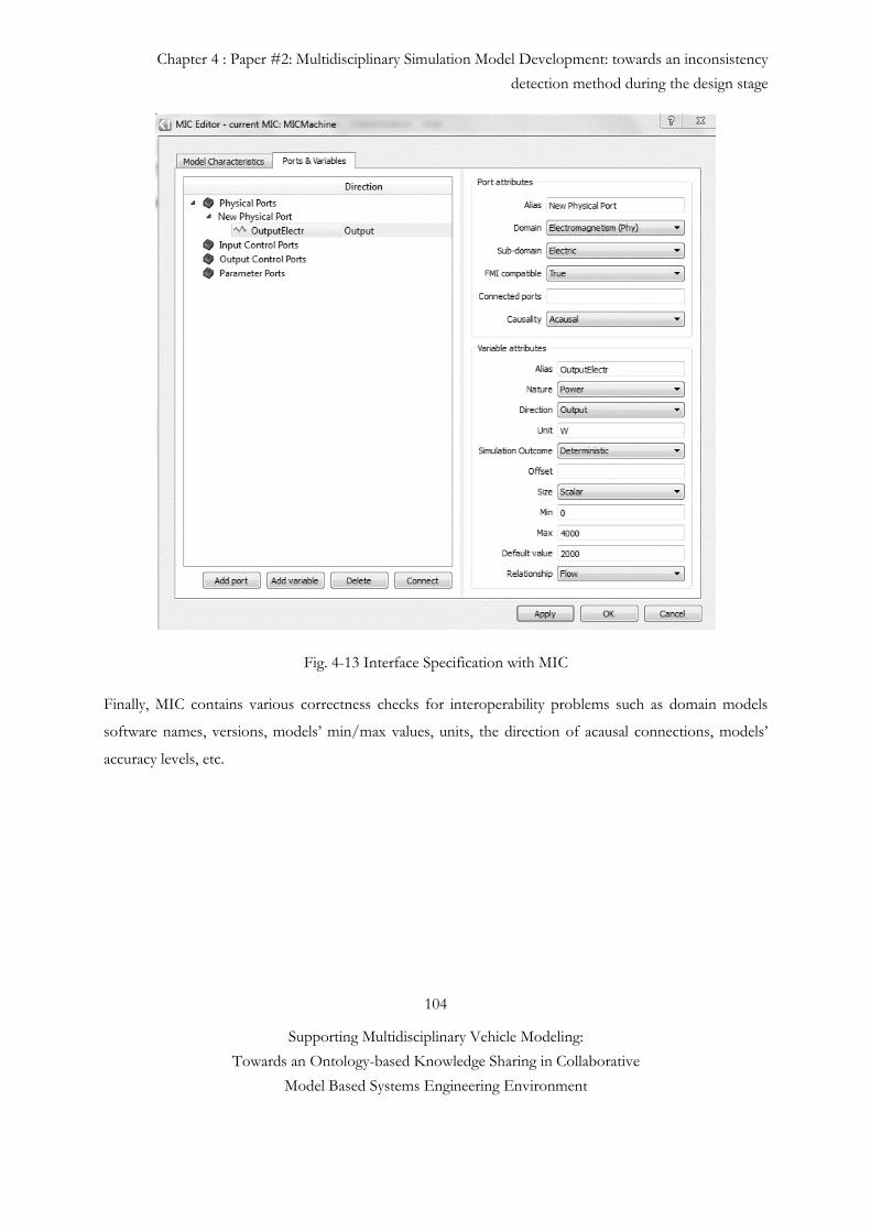
Chapter 4 : Paper #2: Multidisciplinary Simulation Model Development: towards an inconsistency
detection method during the design stage
104
Supporting Multidisciplinary Vehicle Modeling:
Towards an Ontology-based Knowledge Sharing in Collaborative
Model Based Systems Engineering Environment
Fig. 4-13 Interface Specification with MIC
Finally, MIC contains various correctness checks for interoperability problems such as domain models
software names, versions, models’ min/max values, units, the direction of acausal connections, models’
accuracy levels, etc.
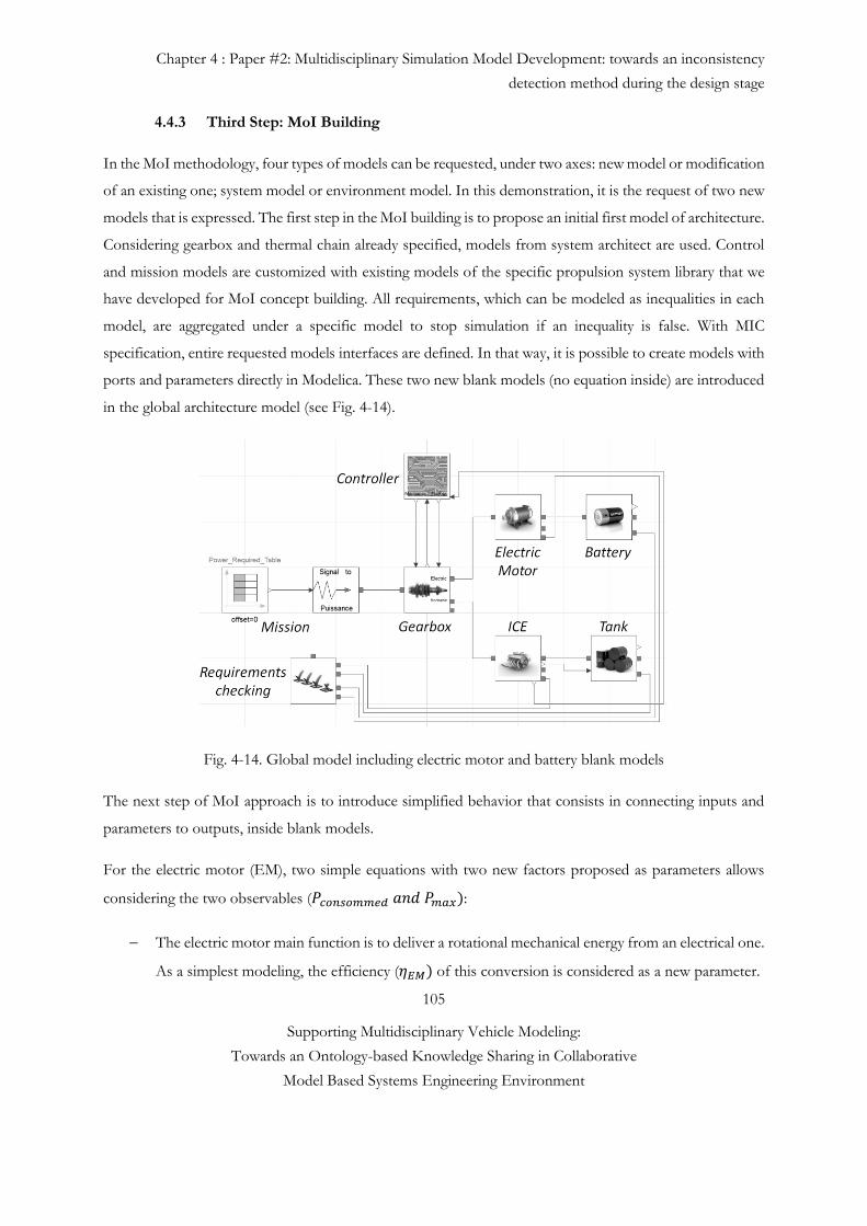
Chapter 4 : Paper #2: Multidisciplinary Simulation Model Development: towards an inconsistency
detection method during the design stage
105
Supporting Multidisciplinary Vehicle Modeling:
Towards an Ontology-based Knowledge Sharing in Collaborative
Model Based Systems Engineering Environment
4.4.3 Third Step: MoI Building
In the MoI methodology, four types of models can be requested, under two axes: new model or modification
of an existing one; system model or environment model. In this demonstration, it is the request of two new
models that is expressed. The first step in the MoI building is to propose an initial first model of architecture.
Considering gearbox and thermal chain already specified, models from system architect are used. Control
and mission models are customized with existing models of the specific propulsion system library that we
have developed for MoI concept building. All requirements, which can be modeled as inequalities in each
model, are aggregated under a specific model to stop simulation if an inequality is false. With MIC
specification, entire requested models interfaces are defined. In that way, it is possible to create models with
ports and parameters directly in Modelica. These two new blank models (no equation inside) are introduced
in the global architecture model (see Fig. 4-14).
Fig. 4-14. Global model including electric motor and battery blank models
The next step of MoI approach is to introduce simplified behavior that consists in connecting inputs and
parameters to outputs, inside blank models.
For the electric motor (EM), two simple equations with two new factors proposed as parameters allows
considering the two observables (𝑃𝑐𝑜𝑛𝑠𝑜𝑚𝑚𝑒𝑑 𝑎𝑛𝑑 𝑃𝑚𝑎𝑥):
The electric motor main function is to deliver a rotational mechanical energy from an electrical one.
As a simplest modeling, the efficiency (𝜂𝐸𝑀) of this conversion is considered as a new parameter.
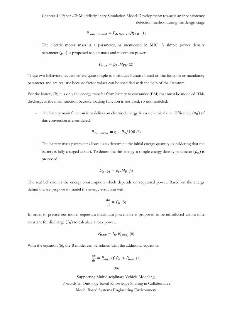
Chapter 4 : Paper #2: Multidisciplinary Simulation Model Development: towards an inconsistency
detection method during the design stage
106
Supporting Multidisciplinary Vehicle Modeling:
Towards an Ontology-based Knowledge Sharing in Collaborative
Model Based Systems Engineering Environment
𝑃𝑐𝑜𝑛𝑠𝑜𝑚𝑚𝑒𝑑 = 𝑃𝑑𝑒𝑙𝑖𝑣𝑒𝑟𝑒𝑑/𝜂𝐸𝑀 (1)
The electric motor mass is a parameter, as mentioned in MIC. A simple power density
parameter (𝜌𝑃) is proposed to join mass and maximum power.
𝑃𝑚𝑎𝑥 = 𝜌𝑃 . 𝑀𝐸𝑀 (2)
These two behavioral equations are quite simple to introduce because based on the function or mandatory
parameter and are realistic because factor values can be specified with the help of the literature.
For the battery (B) it is only the energy transfer from battery to consumer (EM) that must be modeled. This
discharge is the main function because loading function is not used, so not modeled:
The battery main function is to deliver an electrical energy from a chemical one. Efficiency (𝜂𝐵) of
this conversion is considered.
𝑃𝑑𝑒𝑙𝑖𝑣𝑒𝑟𝑒𝑑 = 𝜂𝐵 . 𝑃𝐵/100 (3)
The battery mass parameter allows us to determine the initial energy quantity, considering that the
battery is fully charged at start. To determine this energy, a simple energy density parameter (𝜌𝑒) is
proposed:
𝐸(𝑡=0) = 𝜌𝑒 . 𝑀𝐵 (4)
The real behavior is the energy consumption which depends on requested power. Based on the energy
definition, we propose to model the energy evolution with:
𝑑𝐸
𝑑𝑡= 𝑃𝐵 (5)
In order to precise our model request, a maximum power rate is proposed to be introduced with a time
constant for discharge (𝐼𝐷) to calculate a max power:
𝑃𝑚𝑎𝑥 = 𝐼𝐷 . 𝐸(𝑡=0) (6)
With the equation (6), the B model can be refined with the additional equation:
𝑑𝐸
𝑑𝑡= 𝑃𝑚𝑎𝑥 𝑖𝑓 𝑃𝐵 > 𝑃𝑚𝑎𝑥 (7)
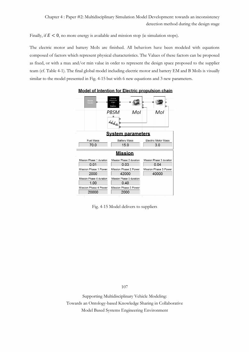
Chapter 4 : Paper #2: Multidisciplinary Simulation Model Development: towards an inconsistency
detection method during the design stage
107
Supporting Multidisciplinary Vehicle Modeling:
Towards an Ontology-based Knowledge Sharing in Collaborative
Model Based Systems Engineering Environment
Finally, if 𝐸 < 0, no more energy is available and mission stop (ie simulation stops).
The electric motor and battery MoIs are finished. All behaviors have been modeled with equations
composed of factors which represent physical characteristics. The Values of these factors can be proposed
as fixed, or with a max and/or min value in order to represent the design space proposed to the supplier
team (cf. Table 4-1). The final global model including electric motor and battery EM and B MoIs is visually
similar to the model presented in Fig. 4-15 but with 6 new equations and 3 new parameters.
Fig. 4-15 Model delivers to suppliers
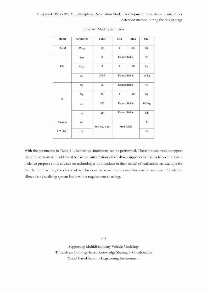
Chapter 4 : Paper #2: Multidisciplinary Simulation Model Development: towards an inconsistency
detection method during the design stage
108
Supporting Multidisciplinary Vehicle Modeling:
Towards an Ontology-based Knowledge Sharing in Collaborative
Model Based Systems Engineering Environment
Table 4-1 Model parameters
Model Parameter Value Min Max Unit
PSBM 𝑀𝐹𝑢𝑒𝑙 70 1 100 kg
EM
𝜂𝐸𝑀 95 Unmodifiable %
𝑀𝐸𝑀 3 1 40 kg
𝜌𝑃 3000 Unmodifiable W/kg
B
𝜂𝐵 95 Unmodifiable %
𝑀𝐵 15 1 40 kg
𝜌𝑒 100 Unmodifiable Wh/kg
𝐼𝐷 20 Unmodifiable 1/h
Mission
𝑖 = [1,5]
𝐷𝑖
See Fig. 4-15 Modifiable
h
𝑃𝑖 W
With the parameters in Table 4-1, numerous simulations can be performed. These induced results support
the supplier team with additional behavioral information which allows suppliers to discuss between them in
order to propose some advices on technologies to introduce in their model of realization. As example for
the electric machine, the choice of synchronous or asynchronous machine can be an advice. Simulation
allows also visualizing system limits with a requirement checking.
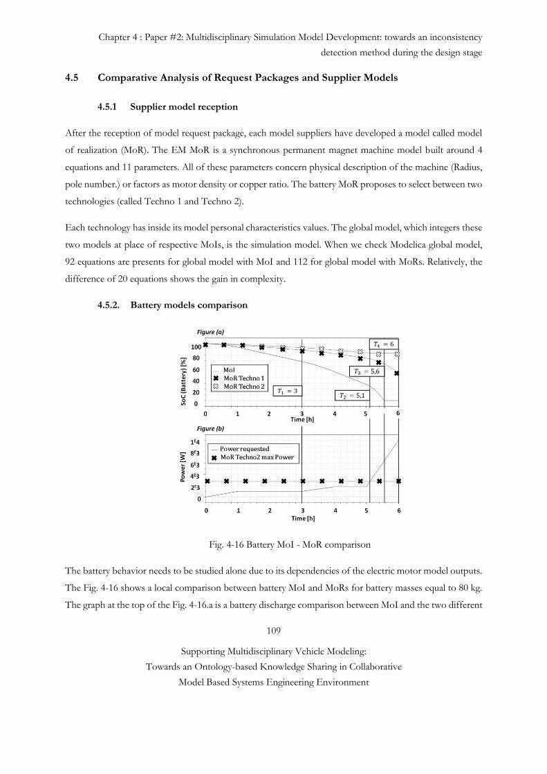
Chapter 4 : Paper #2: Multidisciplinary Simulation Model Development: towards an inconsistency
detection method during the design stage
109
Supporting Multidisciplinary Vehicle Modeling:
Towards an Ontology-based Knowledge Sharing in Collaborative
Model Based Systems Engineering Environment
4.5 Comparative Analysis of Request Packages and Supplier Models
4.5.1 Supplier model reception
After the reception of model request package, each model suppliers have developed a model called model
of realization (MoR). The EM MoR is a synchronous permanent magnet machine model built around 4
equations and 11 parameters. All of these parameters concern physical description of the machine (Radius,
pole number.) or factors as motor density or copper ratio. The battery MoR proposes to select between two
technologies (called Techno 1 and Techno 2).
Each technology has inside its model personal characteristics values. The global model, which integers these
two models at place of respective MoIs, is the simulation model. When we check Modelica global model,
92 equations are presents for global model with MoI and 112 for global model with MoRs. Relatively, the
difference of 20 equations shows the gain in complexity.
4.5.2. Battery models comparison
Fig. 4-16 Battery MoI - MoR comparison
The battery behavior needs to be studied alone due to its dependencies of the electric motor model outputs.
The Fig. 4-16 shows a local comparison between battery MoI and MoRs for battery masses equal to 80 kg.
The graph at the top of the Fig. 4-16.a is a battery discharge comparison between MoI and the two different
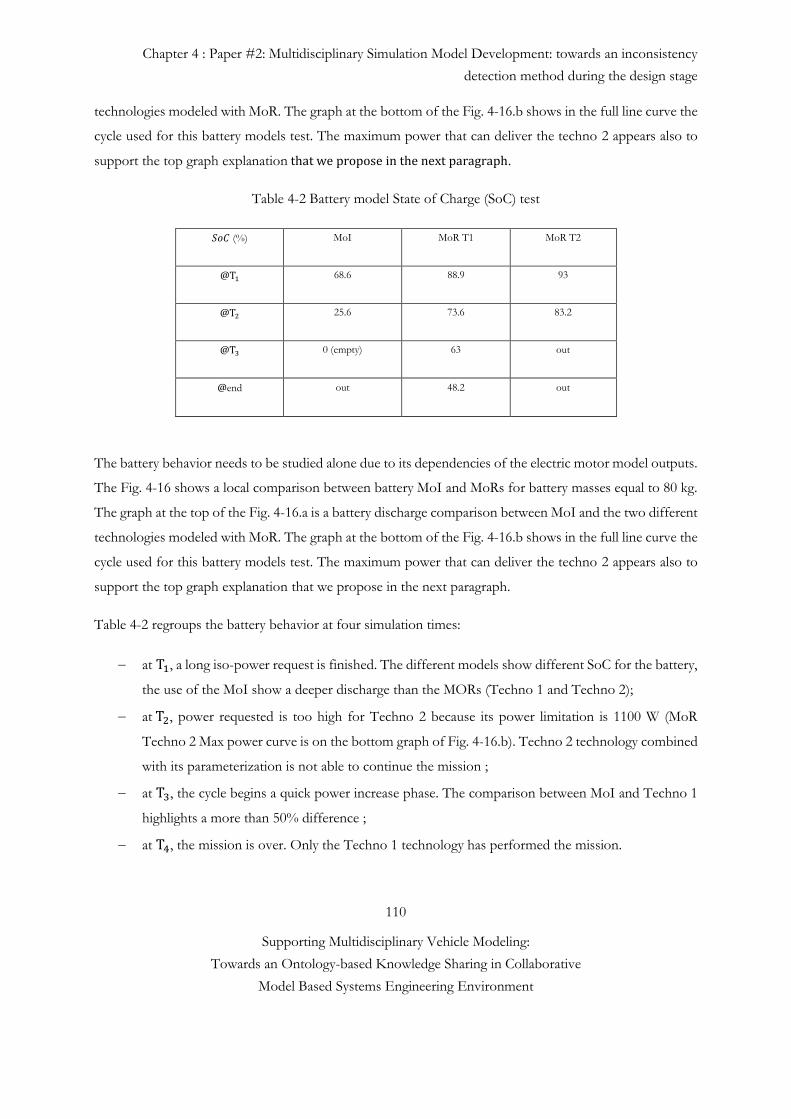
Chapter 4 : Paper #2: Multidisciplinary Simulation Model Development: towards an inconsistency
detection method during the design stage
110
Supporting Multidisciplinary Vehicle Modeling:
Towards an Ontology-based Knowledge Sharing in Collaborative
Model Based Systems Engineering Environment
technologies modeled with MoR. The graph at the bottom of the Fig. 4-16.b shows in the full line curve the
cycle used for this battery models test. The maximum power that can deliver the techno 2 appears also to
support the top graph explanation that we propose in the next paragraph.
Table 4-2 Battery model State of Charge (SoC) test
𝑆𝑜𝐶 (%) MoI MoR T1 MoR T2
@T1 68.6 88.9 93
@T2 25.6 73.6 83.2
@T3 0 (empty) 63 out
@end out 48.2 out
The battery behavior needs to be studied alone due to its dependencies of the electric motor model outputs.
The Fig. 4-16 shows a local comparison between battery MoI and MoRs for battery masses equal to 80 kg.
The graph at the top of the Fig. 4-16.a is a battery discharge comparison between MoI and the two different
technologies modeled with MoR. The graph at the bottom of the Fig. 4-16.b shows in the full line curve the
cycle used for this battery models test. The maximum power that can deliver the techno 2 appears also to
support the top graph explanation that we propose in the next paragraph.
Table 4-2 regroups the battery behavior at four simulation times:
at T1, a long iso-power request is finished. The different models show different SoC for the battery,
the use of the MoI show a deeper discharge than the MORs (Techno 1 and Techno 2);
at T2, power requested is too high for Techno 2 because its power limitation is 1100 W (MoR
Techno 2 Max power curve is on the bottom graph of Fig. 4-16.b). Techno 2 technology combined
with its parameterization is not able to continue the mission ;
at T3, the cycle begins a quick power increase phase. The comparison between MoI and Techno 1
highlights a more than 50% difference ;
at T4, the mission is over. Only the Techno 1 technology has performed the mission.
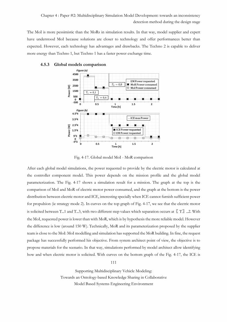
Chapter 4 : Paper #2: Multidisciplinary Simulation Model Development: towards an inconsistency
detection method during the design stage
111
Supporting Multidisciplinary Vehicle Modeling:
Towards an Ontology-based Knowledge Sharing in Collaborative
Model Based Systems Engineering Environment
The MoI is more pessimistic than the MoRs in simulation results. In that way, model supplier and expert
have understood MoI because solutions are closer to technology and offer performances better than
expected. However, each technology has advantages and drawbacks. The Techno 2 is capable to deliver
more energy than Techno 1, but Techno 1 has a faster power exchange time.
4.5.3 Global models comparison
Fig. 4-17. Global model MoI - MoR comparison
After each global model simulations, the power requested to provide by the electric motor is calculated at
the controller component model. This power depends on the mission profile and the global model
parameterization. The Fig. 4-17 shows a simulation result for a mission. The graph at the top is the
comparison of MoI and MoR of electric motor power consumed, and the graph at the bottom is the power
distribution between electric motor and ICE, interesting specially when ICE cannot furnish sufficient power
for propulsion (ie strategy mode 2). In curves on the top graph of Fig. 4-17, we see that the electric motor
is solicited between T_1 and T_3, with two different step values which separation occurs at〖 T〗_2. With
the MoI, requested power is lower than with MoR, which is by hypothesis the more reliable model. However
the difference is low (around 150 W). Technically, MoR and its parameterization proposed by the supplier
team is close to the MoI: MoI modelling and simulation has supported the MoR building. In fine, the request
package has successfully performed his objective. From system architect point of view, the objective is to
propose materials for the scenario. In that way, simulations performed by model architect allow identifying
how and when electric motor is solicited. With curves on the bottom graph of the Fig. 4-17, the ICE is
Chapter 4 : Paper #2: Multidisciplinary Simulation Model Development: towards an inconsistency
detection method during the design stage
112
Supporting Multidisciplinary Vehicle Modeling:
Towards an Ontology-based Knowledge Sharing in Collaborative
Model Based Systems Engineering Environment
unable to furnish 3898 W between T_1 and〖 T 〗_3, during 0.7 h. In the scenario, the system architect
wants to know the advantages of electrical propulsion chain addition before considering replacing or
modifying the ICE. To estimate the architecture, mass balance is a material requested. In order to test the
model, an optimization was done with the minimization of a cost function composed of electric motor and
battery masses and considering the mission success. A very first solution calculates an additional mass equals
to 9.5 kg to the architecture (7.5 kg of Techno 1 battery and 2 kg for electric motor). For system architect,
this kind of information supports his design decisions 5.
4.6 Conclusions and Future Consideration
This paper addresses the common needs of several software tool providers and industrial markets such as
aerospace and automotive. It also describes the methods that have been used to improve a successful
collaboration between the industrial partners, and the challenging topics that need to be explored within a
multidisciplinary environment. Current inefficient way of working creates some unnecessary iterations
during model integration phase, which is often responsible for increased product development lead-time
and cost, schedule risk. To fulfill this need, the multidisciplinary models need to be understandable and easy
to create. Thus, it is necessary to maintain close links with the various disciplines and actors through clear
information exchange. Four major roles have been identified such as System Architect, Model Architect,
Technology Provider and Domain Model Developer. This work proposes also a multi-view architectural
method, aimed at reconciling the necessary high level and detailed design aspects with the help of the
mentioned actors.
The integration of the two methodologies; MoI and MIC allows a knowledge gap reduction between model
designer and developer. The accuracy of the MIC combined with the simulation capability of the MoI
represents a significant advantage. The freedom offered to supplier is counterbalanced by the clear and
direct model specification, in order to integrate it in a simulation chain. The large part of misunderstandings
is reduced while providing a win-win collaboration. It seems interesting to consider the extension and
refinement of the proposed method to support different specific domains of interest. The main long term
benefits of this work include significant reductions in time and in late inconsistency detection.
Chapter 4 : Paper #2: Multidisciplinary Simulation Model Development: towards an inconsistency
detection method during the design stage
113
Supporting Multidisciplinary Vehicle Modeling:
Towards an Ontology-based Knowledge Sharing in Collaborative
Model Based Systems Engineering Environment
References #4
[1] G. Sirin, B. Yannou, E. Coatanea and E. Landel, “Creating Domain Ontology to Support the Numerical
Models Exchange between Suppliers and Users in a Complex System Design”. ASME 2013
International Design Engineering Technical Conferences and Computers and Information in
Engineering Conference Volume 2B: 33rd Computers and Information in Engineering Conference
Portland, Oregon, USA, August 4–7, 2013
[2] J.M. Branscomb, C.J.J. Paredis, J. Che, and M.J. Jennings, “Supporting Multidisciplinary Vehicle
Analysis Using a Vehicle Reference Architecture Model in SysML”. Presented at the Conference on
Systems Engineering Research CSER, Atlanta, US-GA, March, 12-22, 2013.
[3] X. Zhang and J.F. Broenink, “A Model Management Approach for Co-simulation Model Evolution”,
In Proceedings of 1st Int. Conference on Simulation and Modeling Methodologies, Technologies and
Applications, Noordwijkerhout, NL, pages 168-173, SciTecPress, 2011.
[4] G. Sirin, T. Welo, B. Yannou, E. Landel, “Value Creation in Collaborative Analysis Model Development
Processes”. Presented at the Conference on ASME (IDETC/CIE), Buffalo, USA, Aug., 17-20, 2014.
[5] J. Lee and S.T. Kim, “The Middle-out Systems Engineering for Gray-Box Items and Case Study of
Automotive Lock Housing Assembly”, INCOSE International Symposium, Las Vegas, NV, June 30-
July 3, 2014.
[6] O. De Weck, “Feasibility of a 5x Speedup in System Development due to Meta Design”. Presented at
the Conference on ASME/DETC 2012-70791, 2012.
[7] P. Haase and J. Völker, Ontology Learning and Reasoning- Dealing with Uncertainty and Inconsistency,
Uncertainty Reasoning for the Semantic Web I, Vol. 5327, pp.366-384, 2008.
[8] W.L. Oberkampf, (2002). Error and uncertainty in modeling and simulation. Reliability Engineering &
System Safety Book, 333--357.
[9] P. Hester, (2012). Epictemic Uncertainty Analysis: An Approach Using Expert Judgment and Evidential
Credibility, International Journal of Quality, Statistics, and Reliability, vol. 2012, Article ID 617481,
2012.
[10] B.D. Le and C.J.J. Paredis, “A Conceptual Framework for Value-Driven Design and Systems
Engineering”, In Proceedings of 24th CIRP Design Conference, Published by Elsevier B.V. 2212-8271.
2014.
Chapter 4 : Paper #2: Multidisciplinary Simulation Model Development: towards an inconsistency
detection method during the design stage
114
Supporting Multidisciplinary Vehicle Modeling:
Towards an Ontology-based Knowledge Sharing in Collaborative
Model Based Systems Engineering Environment
[11] Systems Engineering Fundamentals, DOD Supplementary text prepared by the defense acquisition
university press fort Belvoir, Virginia 22060-5565, USA, 2001.
Available:http://123management.nl/0/070_methode/072_kwaliteit/Dod%20Systems%20Engineerin
g.pdf
[12] Crescendo European Project. Participants’ handbook. Crescendo Forum Innovation in collaborative
modelling and simulation to deliver Behavioral Digital Aircraft 19-20 June 2012, France
Available:http://www.crescendo-fp7.eu/pages/downloads/crescendo-handbook-of-results.php
[13] S. Kleiner, C. Kramer, Model Based Design with Systems Engineering Based on RFLP Using V6, Smart
Product Engineering, pp 93-102, DOI: 10.1007/978-3-642-30817-8_10, Springer 2013.
[14] C. Belton et al. (2003). A Vehicle Model Architecture for Vehicle System Control Design," SAE
Technical Paper 2003-01-0092, 2003, doi: 10.4271/2003-01-0092.
[15] I.R. Grosse, J.M. Milton–Benoit and J.C. Wileden. (2005). Ontologies for supporting engineering
analysis models. AI EDAM, Vol.19, No.1 p.1-18.
[16] F.N. Noy and McGuinness, (2001). Ontology Development 101: A Guide to Creating Your First
Ontology. Stanford Knowledge Systems Laboratory Technical Report KSL-01-05 and Stanford Medical
Informatics Technical Report SMI-2001-0880. Stanford, CA.
[17] G. Mocko, R.J. Malak, C.J.J. Paredis, and R. Peak, "A Knowledge Repository for Behavioral Models in
Engineering Design". 24th ASME Computers and Information in Engineering Conference, Salt Lake
City, UT, Sept, 2004.
[18] Nasa Technical Standard, (2008). Standard for models and simulations National Aeronautics and Space
Administration Washington, DC 20546-0001, NASA-STD-7009.
[19] D. Karnopp and R.C. Rosenberg. (1968). Analysis and Simulation of multiport Systems. The Bond
Graph approach to physical systems dynamics, MIT Press.
[20] K.T. Chau, (2002). Overview of power management in hybrid electric vehicles. Energy Conversion and
Management, 43(15), 1953-1968. doi:10.1016/S0196-8904(01)00148-0.
[21] C. Mi, M. Abdul Marsrur, D. Wenzhong Gao, (2011). Hybrid Electric Vehicles: Principles and
Applications with Practical Perspectives, ISBN: 978-0-470-74773-5, 468 pages, June 2011.
[22] NASA, (2007). Systems Engineering Handbook
[23] INCOSE, (2006). Systems engineering handbook. INCOSE.
[24] C. De Tenorio, (2010) Methods for collaborative conceptual design of aircraft power architectures
methods for collaborative conceptual design, PhD Thesis.
[25] P.M. Basset, A. Tremolet, F. Cuzieux, G. Reboul, M. Costes, D. Tristrant, D. Petot, ”C.R.E.A.T.I.O.N. the Onera multi-level rotorcraft concepts evaluation tool: the foundations”,
Chapter 4 : Paper #2: Multidisciplinary Simulation Model Development: towards an inconsistency
detection method during the design stage
115
Supporting Multidisciplinary Vehicle Modeling:
Towards an Ontology-based Knowledge Sharing in Collaborative
Model Based Systems Engineering Environment
Available: http://addl.lsis.org/fr/manifs/jdl612/actes/articles/24.pdf [26] S. Liscouët-Hanke, (2008). A model Based Methodology for Integrated Preliminary Sizing and Analysis
of Aircraft Power System Architectures. Architecture. PhD Thesis. INSA de Toulouse. Available:
http://eprint.insa-toulouse.fr/archive/00000251/01/LiscouetHanke.pdf
[27] K. Amadori, (2008). A Framework for Knowledge Based Engineering and Design Optimization.
Engineering. Available: http://www.diva-portal.org/smash/get/diva2:18279/FULLTEXT01.pdf.
[28] C.C. Chan, (2002). The state of the art of electric and hybrid vehicles. Proceedings of the IEEE, 90(2),
247-275. doi: 10.1109/5.989873.
[29] P. Fritzon, (2006). Principles of Object-oriented modeling and simulation with Modelica 21. IEEE press
ISBN 0-471-47163-1
[30] RTCA and EUROCAE. Model based development and Verification, supplement of by
RTCADo178c/Eurocae ED12C. Technical report, 2012.
[31] U.S. Dod. Verification, Validation and Accreditation Recommended Practice Guide (MSCO VV&A
RPG) Glossary.
[32] IEEE Standard Glossary of Modeling and Simulation Terminology, IEEE Std 610.3-1989, vol., no.,
pp.0_1, 1989 doi: 10.1109/IEEESTD.1989.94599.
[33] F. Retho, H. Smaoui, J.C. Vannier, and P. Dessante, “Model of intention: A concept to support models
building in a complex system design project”, ERTS² 2014, France.
[34] F. Retho, H. Smaoui, J.C. Vannier and P. Dessante. (2014). Le modèle d’intention: Un concept clé entre
architecte et expert pour la conception de systèmes complexes, Génie logiciel n°108, Mars 2014.
[35] www.uml-sysml.org.
[36] M. Carlsson, S. Steinkellner, H. Gavel, J. Ölvander, “Enabling Uncertainty Quantification of Large
Aircraft System Simulation Models”, CEAS 2013 Conference, Linköping, Sweden, 2013.
[37] F. Belkadi, N. Troussier, F. Huet, T. Gidel E. Bonjour and B. Eynard. (2008). PLM-based approach for
collaborative design between OEM and suppliers: case study of aeronautic industry”, published in
"Computer-Aided Innovation., Cascini (Ed.) (157-168 (vol. 277)" DOI: 10.1007/978-0-387-09697-1
13.
[38] J.L. Voirin, “Modelling Languages for Functional Analysis Put to the Test of Real Life, Complex
Systems Design & Management” In Proceedings of the Third International Conference on Complex
Systems Design & Management CSD&M 2012, pp 139-150.
Chapter 5 : Paper #3: A Model Identity Card to Support Simulation Model Development Process in a
Collaborative Multidisciplinary Design Environment
116
Supporting Multidisciplinary Vehicle Modeling:
Towards an Ontology-based Knowledge Sharing in Collaborative
Model Based Systems Engineering Environment
5
Paper #3. A Model Identity Card to Support Simulation
Model Development Process in a Collaborative
Multidisciplinary Design Environment
Published online:
IEEE Systems Journal
Göknur Sirin1, 4, Christiaan J.J. Paredis2, Bernard Yannou1, Eric Coatanéa3, Eric Landel4
1 Laboratoire Génie Industriel, Ecole Centrale Paris, Chatenay-Malabry, 92290, France
2 Georgia Institute of Technology, Woodruff School of Mechanical Engineering, Atlanta, GA 30332, USA
3 Product Development research group Department of Engineering Design and Production School of Engineering,
Aalto University, FIN-00076 Aalto, Finland
4 Techno centre Renault SAS, 78288, France
Abstract. Today, one of the major challenges in full-vehicle model creation is to get domain models from different
experts while detecting any potential inconsistency problem before the IVVQ (Integration, Verification, Validation,
Chapter 5 : Paper #3: A Model Identity Card to Support Simulation Model Development Process in a
Collaborative Multidisciplinary Design Environment
117
Supporting Multidisciplinary Vehicle Modeling:
Towards an Ontology-based Knowledge Sharing in Collaborative
Model Based Systems Engineering Environment
and Qualification) phase. To overcome such challenges, Conceptual Design phase has been adapted to the current
Model Development Process (MDP). For that, the system engineers start to define the most relevant system architecture
by respecting quality and time constraints. Next, the simulation model architects design the delivered system architecture
in a more formal way with a modeling and simulation point of view to support the integration of domain level simulation
models in a consistent fashion. Finally, the model architects negotiate with different simulation model providers with
the aim of specifying vehicle and domain level simulation models and their interfaces connections. To improve knowledge
sharing between mentioned actors, we propose a Model Identity Card (MIC) for classifying simulation model knowledge
including input/output parameters, method, and usage specifications. The fundamental concepts that form the basis of
all simulation models are identified and typed for implementation into a computational environment. An industrial
case study of engine-after treatment model is used to show how MICs and integrated model design phase might use in
a given scenario. A validation protocol is conducted through a heuristic observation to estimate the rate of model rework
and ambiguity reduction.
5.1 Introduction
5.1.1 Background
Simulation-based design has gained importance in the past few years in many sectors, especially in aerospace
and in automotive manufacturers where modern engineering products are becoming increasingly complex
[1]. One of the benefits of employing simulation models is that it makes design verification faster and less
expensive; it provides also the designer with immediate feedback on design decision [1]. However, over the
last 15 years, in addition to product variety, the environmental (i.e., fuel-efficient, low-emission) and
economic concerns increase the complexity of modern products. To keep pace with the rapid improvements
being made to these modern products and maintain competitiveness with other manufacturers, design cycles
have become shorter and more efficient. To support these shorter design cycles during the early design
exploration phase, companies use more and more sophisticated, multidisciplinary simulation model (or
numerical or behavioral models) [1]. A complex product development process requires that one decomposes
the system to be able to understand the whole’s details. In the context of automotive design, a vehicle may
be partitioned by objects into body, powertrain, and suspension subsystems. Aspect partitioning divides the
system by discipline. The same automotive design could be partitioned by aspects into structural,
aerodynamic, and dynamics disciplines. Focusing on the companies’ organizational level, the vehicle
partitions affect also the tasks, roles and simulation models delegation between related engineering
disciplines. The complex, multidisciplinary (or multi-domain) simulation model creation process involves a
Chapter 5 : Paper #3: A Model Identity Card to Support Simulation Model Development Process in a
Collaborative Multidisciplinary Design Environment
118
Supporting Multidisciplinary Vehicle Modeling:
Towards an Ontology-based Knowledge Sharing in Collaborative
Model Based Systems Engineering Environment
number of parallel or/and sequential activities in which experts in different domains, possibly in different
companies (i.e., suppliers and sub-tier suppliers) create, reuse and exchange domain (or component or
atomic) level simulation models to build up a full-vehicle system model [2]. Each engineering discipline
tends to use its own domain-specific languages, tools and methods to model different aspects of a system
concurrently. Imperfect interoperability between the OEMs, suppliers and their tooling causes costs
overruns and delays. Distributed design teams typically handle the model at different levels of abstraction,
ranging from very high-level system decompositions to very low-level detailed specification of components
[3]. This is particularly challenging for the design of multidisciplinary systems in which components in
different disciplines (e.g., mechanics, structural dynamics, hydrodynamics, heat conduction, fluid flow,
transport, chemistry, or acoustics) are tightly coupled to achieve optimal system performance [2]. In this
multidisciplinary collaborative design environment, most of the engineers modify the existing simulation
models to fulfill a specific purpose for which they were not originally made; it can be a source of inaccuracy,
uncertainty, duplication and time delay. To this end, Model Validation and Verification (V&V) plays a key
role in mitigation such risks. In this paper a simulation model is considered valid under a set of experimental
conditions, if the model’s response accuracy is within acceptable range for intended purpose [4, 5]. To be
able to build the “right” or “valid” model, in engineering practice, designers need to use the domain level
simulation model as a black box fashion. Although, most of the technology or service provider’s simulation
model is in Black Box (BB) format for preserving the intellectual properties. BB models can be interacted
with only through the inputs and outputs of a well-defined interface. The challenges to use BB model is to
take into consideration the number of distinct interface issues, parameters, or messages that have to be
passed among the components. In addition to the model interface consistency problem, there are many
other factors that may cause inconsistencies, such as human error, miscommunication between teams and
misunderstood assumptions. These inconsistencies are all sources to uncertainty and its propagation in
multidisciplinary modeling environment is more complicated than in a single disciplinary domain [5, 6]. The
effect of the uncertainties in one domain model may propagate to another through interrelated variables,
and the system output finally suffers from the accumulated effect of the individual uncertainties. Thus, the
information flow in modeling practice is one of the key aspects of its uncertainty, which may imply risk that
the product attributes does not ultimately meet user needs [2].
Chapter 5 : Paper #3: A Model Identity Card to Support Simulation Model Development Process in a
Collaborative Multidisciplinary Design Environment
119
Supporting Multidisciplinary Vehicle Modeling:
Towards an Ontology-based Knowledge Sharing in Collaborative
Model Based Systems Engineering Environment
5.1.2 Problem Statement and Our Contributions
Today, many companies use the V-cycle Systems Engineering process for product development as
proposed by Frosberg and adapted by the National Council on Systems Engineering [7]. In this process,
OEMs take the responsibility of requirement specification, system design, and integration and Verification
and Validation (V&V) steps. This is followed by the supplier, which develops the domain models. Although
the simulation model is tested at the supplier level, the OEMs are responsible for the final integration,
system and acceptance testing to ensure that the given implementation of a system level model meets its
intended goals and demands. In this process, most of the defects are discovered late, during the IVVQ
(Integration, Verification, Validation, and Qualification) phase. This may create multiple wastes, including
rework and, may-be the most harmful namely, incorrect simulation models, which are subsequently used as
basis for design decisions. According to de Weck, early design validation and verification may reduce rework
in the more expensive implementation and physical prototype validation phase, which is the main driver for
product development cost [8]. It has been estimated that the cost of imperfect simulation model
interoperability is at least $1 billion per year for members of the US automotive OEMs [9] and $400M in an
aircraft development program with 1-2 months of delays [10].
There are many potential sources of inconsistency such as error in the simulation model code or mismatch
of interfaces connections (i.e., differences in time step, units, solver, hardware and software versioning…).
However, a significant proportion of defects are associated with interfaces between modules or between
requirements and implementation rather than a design or coding error within a single module. Leveraging
the interface inconsistency problem requires a Conceptual Model Design phase and an interface consistency
checking at early development stage. Model Design phase contains schedule and transparency agreement
between OEMs and domain model providers. Today, in model development environment, there are two
main actors; System Architects and Domain Model Providers. System Architects are the sponsor of model
development activity. He or she defines the projects’ expected time, cost and decision parameters issues.
Domain Model Providers are the domain experts who build models with theirs specific domain knowledge.
As illustrated in Fig. 5-1, the System Architect has a functional view (system world). He defines an
operational scenario, a trade-off analysis and provides a draft version of model architecture for Domain
Model Providers who has a physical view. One of the gaps that we noticed during our two years of research
investigation in the automotive OEM Company is that there is no clear and formal scheduling and
transparency agreement between System Architect and Domain Model Provider at early model development
stage (or conceptual design phase). In addition, most of the time, interaction of these two actors may create
a bottleneck for communication because they do not have the same level of understanding. One of the
Chapter 5 : Paper #3: A Model Identity Card to Support Simulation Model Development Process in a
Collaborative Multidisciplinary Design Environment
120
Supporting Multidisciplinary Vehicle Modeling:
Towards an Ontology-based Knowledge Sharing in Collaborative
Model Based Systems Engineering Environment
interests of this work is to create a more formal and clear model request to the domain model providers, in
order to obtain the right model at the right moment. Another gap in model development activity is the lack
of detailed Model design phase at early model development stage (downstream of V-cycle) (see Fig. 5-2).
As illustrated in Fig. 1, in the middle, Model design activity contains formal model architecture design with
domain models’ interfaces definitions. Vehicle level and domain level model specifications include an early
interfaces consistency control between specified interfaces. Model design phase gives a structural and semi-
behavioral view about the system to be modelled. Thus, this transversal view from Functional to Physical
View should be managed by a new actor of the collaboration named “Model Architect”. Each Model
Architect has a multidisciplinary vision of a product, and simulation knowledge. They have also a deep
understanding of both the system-level requirements for the vehicle model, as well as how their models
must interface with other domain models (see Figs. 5-1 and 5-2).
Therefore, knowledge sharing is one of the key points between these three actors but today’s internal
communication is ensured by informal knowledge sharing and it becomes an error prone activity because;
different disciplines often use different vocabularies, so that semantic differences can cause
misunderstandings between these actors [3].
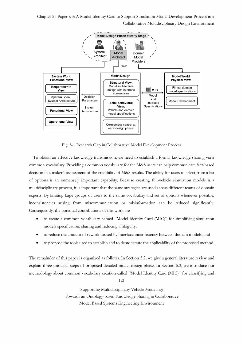
Chapter 5 : Paper #3: A Model Identity Card to Support Simulation Model Development Process in a
Collaborative Multidisciplinary Design Environment
121
Supporting Multidisciplinary Vehicle Modeling:
Towards an Ontology-based Knowledge Sharing in Collaborative
Model Based Systems Engineering Environment
Fig. 5-1 Research Gap in Collaborative Model Development Process
To obtain an effective knowledge transmission, we need to establish a formal knowledge sharing via a
common vocabulary. Providing a common vocabulary for the M&S users can help communicate fact-based
decision in a maker’s assessment of the credibility of M&S results. The ability for users to select from a list
of options is an immensely important capability. Because creating full-vehicle simulation models is a
multidisciplinary process, it is important that the same strategies are used across different teams of domain
experts. By limiting large groups of users to the same vocabulary and set of options whenever possible,
inconsistencies arising from miscommunication or misinformation can be reduced significantly.
Consequently, the potential contributions of this work are
to create a common vocabulary named “Model Identity Card (MIC)” for simplifying simulation
models specification, sharing and reducing ambiguity,
to reduce the amount of rework caused by interface inconsistency between domain models, and
to propose the tools used to establish and to demonstrate the applicability of the proposed method.
The remainder of this paper is organized as follows. In Section 5.2, we give a general literature review and
explain three principal steps of proposed detailed model design phase. In Section 5.3, we introduce our
methodology about common vocabulary creation called “Model Identity Card (MIC)” for classifying and
Chapter 5 : Paper #3: A Model Identity Card to Support Simulation Model Development Process in a
Collaborative Multidisciplinary Design Environment
122
Supporting Multidisciplinary Vehicle Modeling:
Towards an Ontology-based Knowledge Sharing in Collaborative
Model Based Systems Engineering Environment
simplifying simulation models specification. Section 5.4 introduces an after treatment model’s case study
and MIC’s validation protocol. The conclusion and future research are given in Section 5.5.
5.2 Methodology and state of the art
To create a multidisciplinary vehicle model, it is necessary to plan and develop detailed domain level models
according to vehicle-level goals and requirements. Once these domain models have been planned, developed,
verified, and validated, they can be integrated together to simulate a complete vehicle. To be able to detect
any potential integration problem in the early design phase, we add a detailed model design phase with a
correctness check in the current model development process which improves the traditional V-cycle. It
helps to synchronize actual needs of the downstream process with what the upstream process delivers. As
mentioned earlier, in a design process there are different stakeholders such as Model and System Architects
and Model Providers, who have different needs, views and viewpoints. In Model Based System Engineering,
views and viewpoints can be used to model the perspectives of different stakeholders and their interests. A
viewpoint describes a particular perspective of interest to a set of stakeholders, while a view is a stereotyped
package that is said to conform to a particular viewpoint [7]. Dassault Systèmes has already used the MBSE
view/viewpoint approach called RFLP (Requirements/ Functional/ Logical/ Physical) in their industrial
tool (i.e., Catia V6). RFLP model describes the left-hand descending branch of the "V-Model". Based on
the well-known V-cycle design process, RFLP allows concurrent engineering to coordinate the separate
activities and views of distributed design teams. R defines Requirements view. The Functional view (F)
defines what the system does operational (Intended use). The Logical View (L) or logical/organic
architecture defines how the system is implemented, the breakdown structure, the block diagrams, logical
interfaces, logical connections, the behavior (discrete behaviors, physics behaviors, and hybrid behavior).
The Physical View (P) defines a virtual definition of the real world product. In this paper, we customize
these different views based on our needs. We regroup requirement and functional view as a Functional View
and we use the term Structural View instead of Logical View (see Fig. 5-1 and Fig. 5-2).
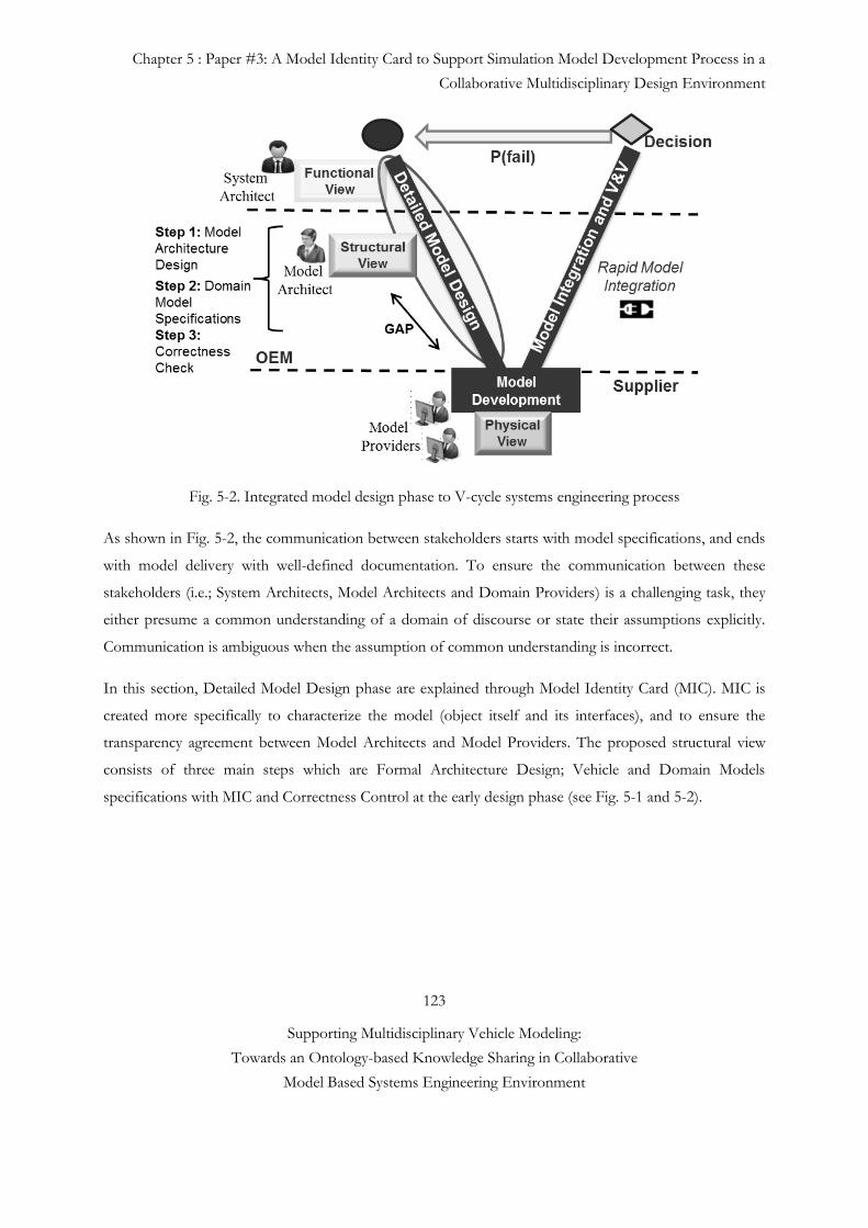
Chapter 5 : Paper #3: A Model Identity Card to Support Simulation Model Development Process in a
Collaborative Multidisciplinary Design Environment
123
Supporting Multidisciplinary Vehicle Modeling:
Towards an Ontology-based Knowledge Sharing in Collaborative
Model Based Systems Engineering Environment
Fig. 5-2. Integrated model design phase to V-cycle systems engineering process
As shown in Fig. 5-2, the communication between stakeholders starts with model specifications, and ends
with model delivery with well-defined documentation. To ensure the communication between these
stakeholders (i.e.; System Architects, Model Architects and Domain Providers) is a challenging task, they
either presume a common understanding of a domain of discourse or state their assumptions explicitly.
Communication is ambiguous when the assumption of common understanding is incorrect.
In this section, Detailed Model Design phase are explained through Model Identity Card (MIC). MIC is
created more specifically to characterize the model (object itself and its interfaces), and to ensure the
transparency agreement between Model Architects and Model Providers. The proposed structural view
consists of three main steps which are Formal Architecture Design; Vehicle and Domain Models
specifications with MIC and Correctness Control at the early design phase (see Fig. 5-1 and 5-2).
Chapter 5 : Paper #3: A Model Identity Card to Support Simulation Model Development Process in a
Collaborative Multidisciplinary Design Environment
124
Supporting Multidisciplinary Vehicle Modeling:
Towards an Ontology-based Knowledge Sharing in Collaborative
Model Based Systems Engineering Environment
5.2.1 Step 1: Formal Vehicle Architecture Design
System architecture selection and characterization is extremely useful in complex, multidisciplinary vehicle
system analysis. Architectures provide a holistic view of a system and allow different stakeholders to work
together with a common basis in the same vehicle system definition [12]. To design a good vehicle, it is
necessary to analyze each of these system architectures from a variety of perspectives including performance,
fuel economy, or even thermal behavior [2, 13]. Creating all possible system architectures manually is
necessary for the first time but the reuse of an existing architecture is recommended because of time and
cost concerns. To avoid having to build complete vehicle model architecture from scratch each time, it is
useful to develop a pre-wired vehicle model architecture. The approach for achieving this relies on a
reference model for vehicle architectures [2]. AUTOSAR, for instance, is the product of an industry-wide
effort to produce a standardized architecture for controls design and development that can be used among
major OEMs and their suppliers [14].The term referential architecture has been already addressed and
developed internally by Ford Motor Company as the Vehicle Model Architecture (VMA) [2, 15]. The
foundation for the entire approach is Vehicle Reference Architecture (VRA) model, a formal SysML model
that defines the logical decomposition of a vehicle into its subsystems. Although there have been several
research efforts that have focused on enabling structural model design within a MBSE context, most of
these efforts have focused on the integration between a Systems Modeling Language (SysML) model and a
variety of simulation model tools (Simulink or Modelica) [2, 15]. However, many engineers today are still
unfamiliar with SysML. Because of this, the training and licenses needed to put SysML tools into practice
across large engineering teams can be cost-prohibitive. In addition to SysML there are some non-formal
architecture design tools such as MS PowerPoint and Visio that design engineers use frequently in current
engineering practice because of its easy usage. Thus, in this paper, we adopt a different approach. Rather
than assuming that the structural model design is possible with SysML environment, we prefer to use a
system engineering tool named arKItect because this tool allows us to easily specify the architecture of
system in a hierarchical manner. In this tool, the functional flows describe the interactions between the
system functions as well as the interactions between the system and the external environment. The flows
can be either data or physical flows. Based on a powerful hierarchical type definition, arKItect allows
designing very easily our own meta-model by using a given meta-model structure: objects, flows and their
composition rules.
Chapter 5 : Paper #3: A Model Identity Card to Support Simulation Model Development Process in a
Collaborative Multidisciplinary Design Environment
125
Supporting Multidisciplinary Vehicle Modeling:
Towards an Ontology-based Knowledge Sharing in Collaborative
Model Based Systems Engineering Environment
To the best of our knowledge there is no similar project that has been developed to support the edition of
model characterization via Model Identity Card (MIC) in early M&S design. The design of formal system
architecture is one of the activity areas of Model Architects.
5.2.2 Step 2: Vehicle and Domain Models Specifications with Model Identity Card (MIC)
Complete vehicle model allow different vehicle-level attributes, such as energy, safety management and
performance to be examined and optimized for various operating scenarios. These vehicle-level attributes
are tightly coupled; investigating the tradeoffs between these attributes is crucial for system design. Model
architects and domain model providers are supposed to specify the domain and vehicle level models via
MIC. While the domain model specifications are intended to specify what kind of model to create, the
vehicle model specifications specify how all of those domain models will be integrated. Model requirements
include defining the operating system that models should be compatible with, expected accuracy, robustness
and which simulation environments will be used to run the integrated vehicle model, and any other
guidelines that the domain model should comply with. While domain engineers can view this information,
they do not have the authority to directly modify any of it. This distinction is important and is made at
several other steps throughout this process. By identifying who has the ultimate authority to make decisions
during different phases of the modeling process, the potential software tools and MIC created to support it
can be tailored to different users. Another important specification is about predefined set of interfaces so
that it may correctly integrate with the other domain models. The set of interfaces modeled is derived directly
from the details of the specialized analysis architecture. These specifications are the utmost importance
because it could result in major inconsistencies between the models created by different domain engineers.
This complete list of model attributes is then reviewed by the model architect, who negotiates with each
domain team to develop a consistent set of models for the entire vehicle. These system and model architects
must negotiate with both the domain engineers providing interfaces and those receiving interfaces, so that
all of the simulation models are compatible. Because this is an iterative process, it may require several rounds
of negotiations with all the different teams before a common vehicle-wide set of interfaces can be agreed
upon. Using a formal check list and a correctness control is critical for early virtual prototype validation.
Model integration and exchange problems have already been addressed in various industrial projects such
as ISO 10303 – STandard for the Exchange of Product model data (STEP) for efficiently exchanging
electronic product data between product life cycle tools. Since then, there has been a strong push to
effectively use structured knowledge to improve the work in the engineering domain because; the
collaboration between knowledge experts in different domains is one of the first steps towards effective
Chapter 5 : Paper #3: A Model Identity Card to Support Simulation Model Development Process in a
Collaborative Multidisciplinary Design Environment
126
Supporting Multidisciplinary Vehicle Modeling:
Towards an Ontology-based Knowledge Sharing in Collaborative
Model Based Systems Engineering Environment
knowledge management strategies [16]. Recent research efforts focused on ontologies and ontology
development methods for engineering design. Ontologies are extensively used to formalize domain
knowledge with concepts, attributes, relationships and instances resulting in reliable, verifiable and
computer-interpretable knowledge mappings of a domain [17]. Formal engineering ontologies are described
by Ahmed et al. [18] as a six-stage methodology for engineering design context. Li et al. [19] propose an
Engineering Ontology (EO) based semantic framework for representing design information in documents,
thus aiding their efficient retrieval. Horváth et al. [20] propose formalizing design concepts using ontologies.
It is evident that ontologies not only provided formal structures for concepts and vocabularies, but they
also have the potential for supporting inferences based on collective knowledge [21]. Shortly thereafter, the
application of the Semantic Web in the field of knowledge management is discussed by Fensel et al. [22].
Earlier efforts in semantic mark-up languages include the Extensible Markup Language (XML), Resource
Description Framework (RDF), Ontology Inference Layer (OIL) and Defense Advanced Research Projects
Agency (DARPA) Agent Markup Language (DAML). Currently, the Web Ontology Language (OWL) is the
de facto standard for developing and representing ontologies. OWL is recommended by the World Wide
Web Consortium (W3C) as the ontology language of the Semantic [23, 24].
Ongoing work in the M&S realm, recent versions of the DEVS formalism provide for modularity and
integration with HLA (DEVS/HLA), but DEVS does not spell out a formal language [26]. In addition,
there are also some industrial standards, such as the language known as the SAE Architecture Analysis &
Design Language (AADL). An AADL model describes a system as a hierarchy of components with their
interfaces and their interconnections [25]. AADL components fall into two major categories: those that
represent the physical hardware and those representing the application software. It describes both functional
interfaces, and aspects critical for performance of individual components and assemblies of components.
The most extensive previous research on characterizing model’s behavior in engineering analyses is
performed by Grosse et al. [23]. This ontology draws upon some of the simulation modeling taxonomies
and concepts presented by Noy and McGuinness [24]. They organize the knowledge about engineering
analyses models into an ontology, which includes both meta-data (eg, author, documentation and meta-
knowledge, such as model idealizations and the corresponding justifications. A similar, although less
extensive, meta-model for simulation models has been developed by Mocko et al. [13] but these taxonomies
do not include detailed model behavior characteristic and any model validation and verification attributes
such as Nasa’s credibility assessment [27]. Based on the aforementioned standards and methodologies, we
have developed MIC meta-model that might be applicable to any numerical model in the context of vehicle
manufacturer. MIC meta-model will be explained in section 3.
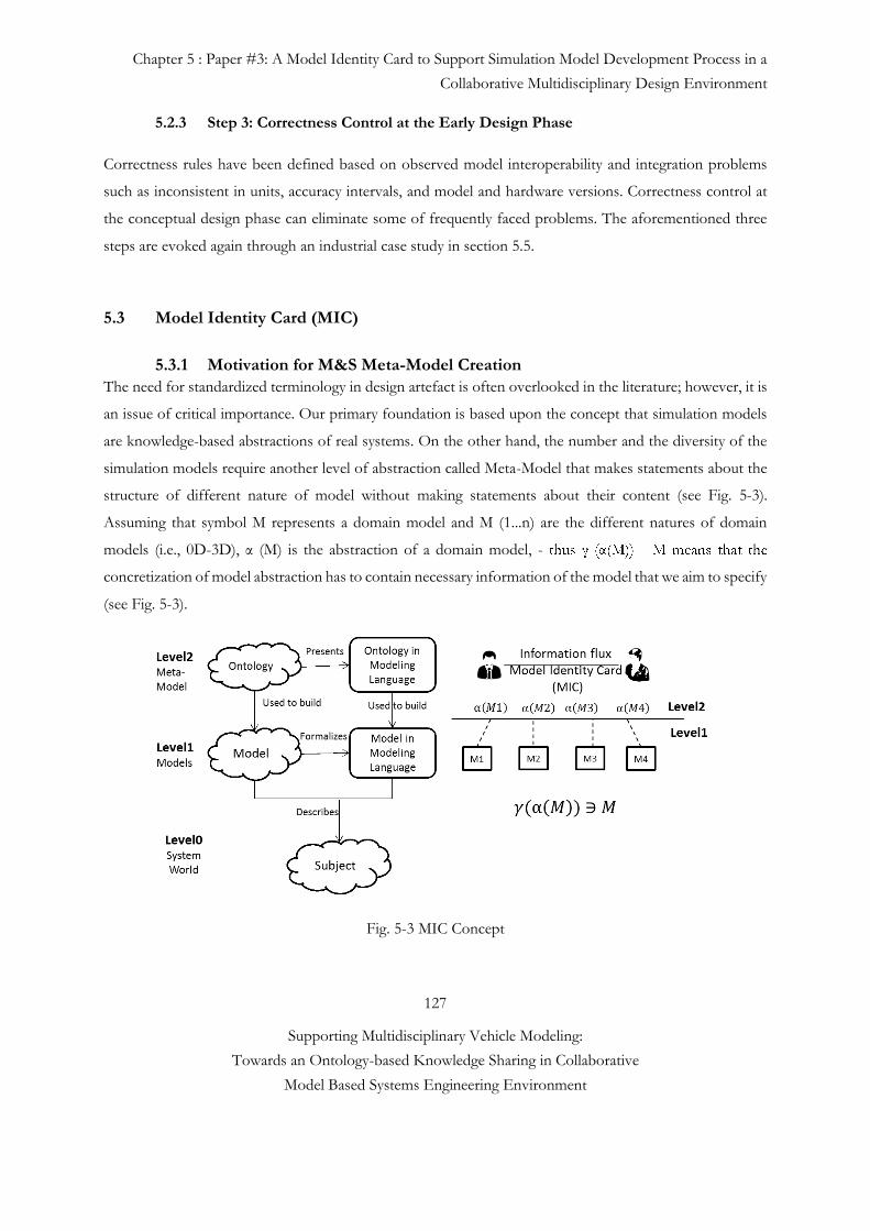
Chapter 5 : Paper #3: A Model Identity Card to Support Simulation Model Development Process in a
Collaborative Multidisciplinary Design Environment
127
Supporting Multidisciplinary Vehicle Modeling:
Towards an Ontology-based Knowledge Sharing in Collaborative
Model Based Systems Engineering Environment
5.2.3 Step 3: Correctness Control at the Early Design Phase
Correctness rules have been defined based on observed model interoperability and integration problems
such as inconsistent in units, accuracy intervals, and model and hardware versions. Correctness control at
the conceptual design phase can eliminate some of frequently faced problems. The aforementioned three
steps are evoked again through an industrial case study in section 5.5.
5.3 Model Identity Card (MIC)
5.3.1 Motivation for M&S Meta-Model Creation
The need for standardized terminology in design artefact is often overlooked in the literature; however, it is
an issue of critical importance. Our primary foundation is based upon the concept that simulation models
are knowledge-based abstractions of real systems. On the other hand, the number and the diversity of the
simulation models require another level of abstraction called Meta-Model that makes statements about the
structure of different nature of model without making statements about their content (see Fig. 5-3).
Assuming that symbol M represents a domain model and M (1...n) are the different natures of domain
models (i.e., 0D-3D), α (M) is the abstraction of a domain model, -
concretization of model abstraction has to contain necessary information of the model that we aim to specify
(see Fig. 5-3).
Fig. 5-3 MIC Concept
Chapter 5 : Paper #3: A Model Identity Card to Support Simulation Model Development Process in a
Collaborative Multidisciplinary Design Environment
128
Supporting Multidisciplinary Vehicle Modeling:
Towards an Ontology-based Knowledge Sharing in Collaborative
Model Based Systems Engineering Environment
MIC meta-model includes some important and refined characteristics of simulation models such as
modeling assumptions, behavior and interfaces specifications. This can help communicate the most
objective decision in a maker’s assessment of the credibility of M&S results. To reinforce this fundamental
point, the concept described here does not claim to provide a measure of credibility. Its function is to enable
clear communication between M&S stakeholders. We argue that formal taxonomy, or vocabulary for the
representation of simulation modeling knowledge, is needed to ensure the following aims:
to facilitate the model specification (object itself and its interfaces),
to obtain an effective knowledge transmission and
to reduce the rework caused by interfaces mismatches (Correctness control with MIC (Step3)).
The main long term benefits of this work include significant reductions in time, effort and interface based
defect reduction throughout simulation-based decision support activities.
The MIC is developed by fifteen engineers of at least five different disciplines (Thermal Comfort, Motor,
Acoustic, Electric, Vibration, etc…) in Renault automotive manufacturer company. They met more than 20
times between September and December 2013 to facilitate and standardize data collection phase using
brainstorming and nominal group technique. Nominal group technique is a structured variation of small
group discussion methods [28]. The process prevents the domination of discussion by a single person,
encourages the more passive group members to participate, and results in a set of prioritized solutions or
recommendations. All participants asked to write their ideas anonymously (or in small groups). Then the
moderator collected the ideas and each is nominated on by the group based on proposed scenarios.
Depending on engineer’s domain knowledge and experience, we defined current MIC attributes.
5.3.2 Roadmap for MIC Creation
MIC is created according to the following steps:
Step1. Identification of main classes and attributes of models.
Step2. MIC attributes grouping and MIC graphical user interface creation on arKItect system engineering
tool.
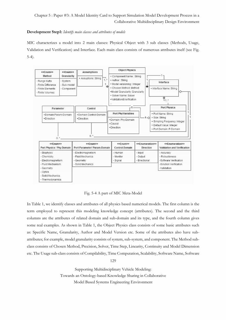
Chapter 5 : Paper #3: A Model Identity Card to Support Simulation Model Development Process in a
Collaborative Multidisciplinary Design Environment
129
Supporting Multidisciplinary Vehicle Modeling:
Towards an Ontology-based Knowledge Sharing in Collaborative
Model Based Systems Engineering Environment
Development Step1: Identify main classes and attributes of models
MIC characterizes a model into 2 main classes: Physical Object with 3 sub classes (Methods, Usage,
Validation and Verification) and Interface. Each main class consists of numerous attributes itself (see Fig.
5-4).
Fig. 5-4 A part of MIC Meta-Model
In Table 1, we identify classes and attributes of all physics based numerical models. The first column is the
term employed to represent this modeling knowledge concept (attributes). The second and the third
columns are the attributes of related domain and sub-domain and its type, and the fourth column gives
some real examples. As shown in Table 1, the Object Physics class consists of some basic attributes such
as: Specific Name, Granularity, Author and Model Version etc. Some of the attributes also have sub-
attributes; for example, model granularity consists of system, sub-system, and component. The Method sub-
class consists of Chosen Method, Precision, Solver, Time Step, Linearity, Continuity and Model Dimension
etc. The Usage sub-class consists of Compilability, Time Computation, Scalability, Software Name, Software
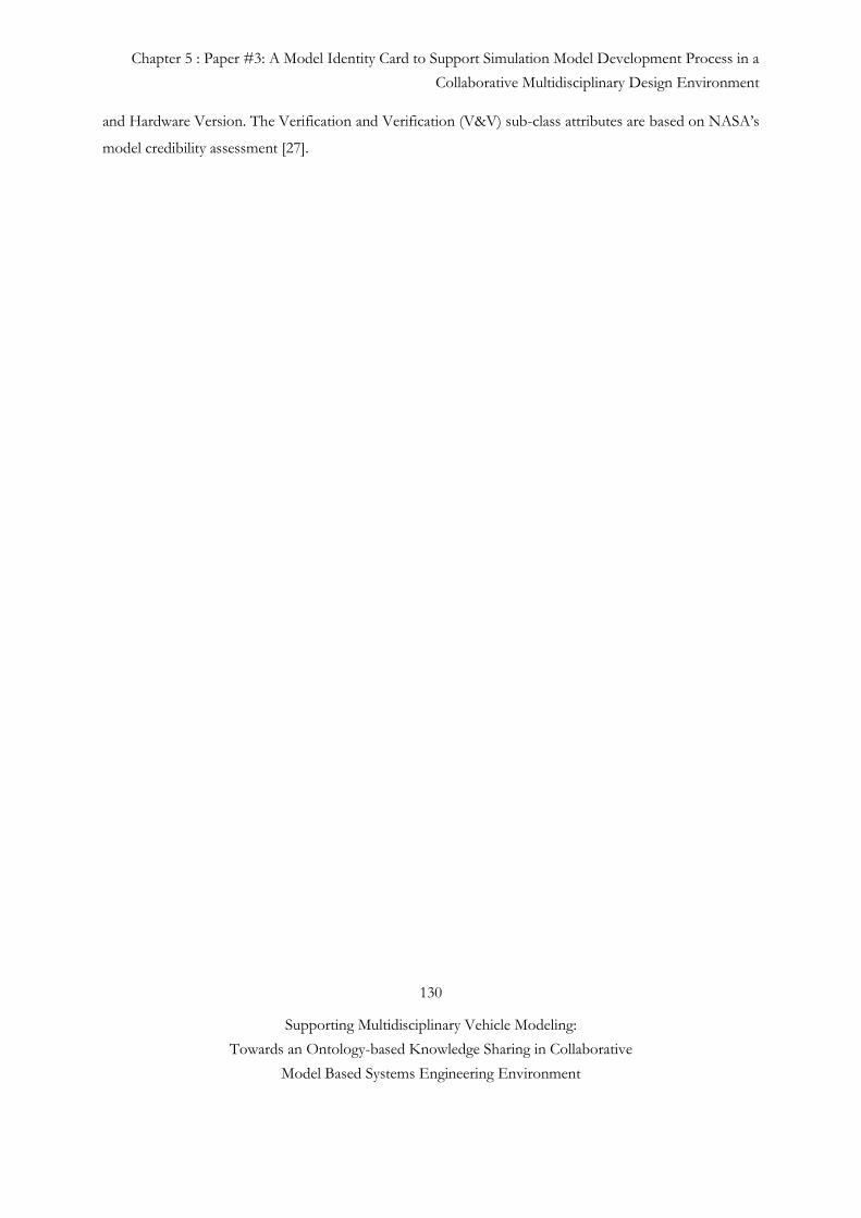
Chapter 5 : Paper #3: A Model Identity Card to Support Simulation Model Development Process in a
Collaborative Multidisciplinary Design Environment
130
Supporting Multidisciplinary Vehicle Modeling:
Towards an Ontology-based Knowledge Sharing in Collaborative
Model Based Systems Engineering Environment
and Hardware Version. The Verification and Verification (V&V) sub-class attributes are based on NASA’s
model credibility assessment [27].
Chapter 5 : Paper #3: A Model Identity Card to Support Simulation Model Development Process in a
Collaborative Multidisciplinary Design Environment
131
Supporting Multidisciplinary Vehicle Modeling:
Towards an Ontology-based Knowledge Sharing in Collaborative
Model Based Systems Engineering Environment
Tableau 5-1 MIC CLASSES AND THEIR ATTRIBUTES
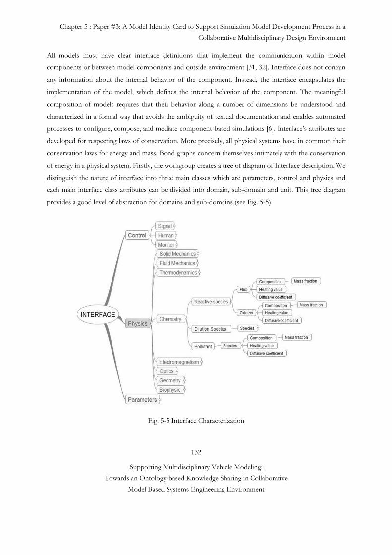
Chapter 5 : Paper #3: A Model Identity Card to Support Simulation Model Development Process in a
Collaborative Multidisciplinary Design Environment
132
Supporting Multidisciplinary Vehicle Modeling:
Towards an Ontology-based Knowledge Sharing in Collaborative
Model Based Systems Engineering Environment
All models must have clear interface definitions that implement the communication within model
components or between model components and outside environment [31, 32]. Interface does not contain
any information about the internal behavior of the component. Instead, the interface encapsulates the
implementation of the model, which defines the internal behavior of the component. The meaningful
composition of models requires that their behavior along a number of dimensions be understood and
characterized in a formal way that avoids the ambiguity of textual documentation and enables automated
processes to configure, compose, and mediate component-based simulations [6]. Interface’s attributes are
developed for respecting laws of conservation. More precisely, all physical systems have in common their
conservation laws for energy and mass. Bond graphs concern themselves intimately with the conservation
of energy in a physical system. Firstly, the workgroup creates a tree of diagram of Interface description. We
distinguish the nature of interface into three main classes which are parameters, control and physics and
each main interface class attributes can be divided into domain, sub-domain and unit. This tree diagram
provides a good level of abstraction for domains and sub-domains (see Fig. 5-5).
Fig. 5-5 Interface Characterization
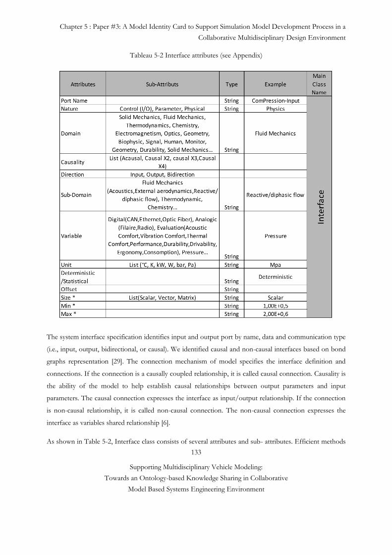
Chapter 5 : Paper #3: A Model Identity Card to Support Simulation Model Development Process in a
Collaborative Multidisciplinary Design Environment
133
Supporting Multidisciplinary Vehicle Modeling:
Towards an Ontology-based Knowledge Sharing in Collaborative
Model Based Systems Engineering Environment
Tableau 5-2 Interface attributes (see Appendix)
The system interface specification identifies input and output port by name, data and communication type
(i.e., input, output, bidirectional, or causal). We identified causal and non-causal interfaces based on bond
graphs representation [29]. The connection mechanism of model specifies the interface definition and
connections. If the connection is a causally coupled relationship, it is called causal connection. Causality is
the ability of the model to help establish causal relationships between output parameters and input
parameters. The causal connection expresses the interface as input/output relationship. If the connection
is non-causal relationship, it is called non-causal connection. The non-causal connection expresses the
interface as variables shared relationship [6].
As shown in Table 5-2, Interface class consists of several attributes and sub- attributes. Efficient methods
Chapter 5 : Paper #3: A Model Identity Card to Support Simulation Model Development Process in a
Collaborative Multidisciplinary Design Environment
134
Supporting Multidisciplinary Vehicle Modeling:
Towards an Ontology-based Knowledge Sharing in Collaborative
Model Based Systems Engineering Environment
and tools are anticipated for extracting simulation modeling knowledge from engineers, and incorporating
this knowledge into a computational environment. Finally, we need methods and associated tools that can
exploit the existence of such knowledge in a computational environment, to improve complex model
integration and design processes. Therefore, the fundamental concepts that form the basis of all numerical
models are identified, described, and typed for implementation into a computational environment. An
industrial tool arKItect is used to instantiate the MIC meta-model and illustrate, how common vocabulary
usage such as MIC, might improve the ability of model characterization. We integrate a graphical user
interface based on MIC vocabulary to create a semantically-rich model characterization support.
Development Step 2: MIC attributes grouping and integration to the arKItect system engineering tool
We suppose that each numerical model is as an object and it has various attributes that describe and frame
it. Most objects are physically part of a system, and they interact with other objects to create a larger object.
In order to extract objects in a system as a unit and understand them, such as, object interfaces, it is necessary
to characterize and reuse an object and its interactions with other objects in the system. Here, we decompose
the object into three levels which are object itself, object interface and object context (see Fig. 5-6).
In order to characterize the object itself, we have grouped ‘Object physics’, ‘Method’s’ and ‘Model quality’
attributes under the heading: ‘Object’. The object interface consists of all Interface class attributes, additional
assumptions and dependencies. Whereas, the object and object interface dimensions provide a snapshot of
the object at hand. The object context dimension provides historical information such as: its usage and
software version etc (see Fig. 5-6).
ArKItect system engineering tool is used to characterize the models via a MIC in a hierarchical manner, and
to generate semi-automatically structural model architecture as a block diagram. This tool is used also for
demonstrating the applicability of MICs to a particular case study.
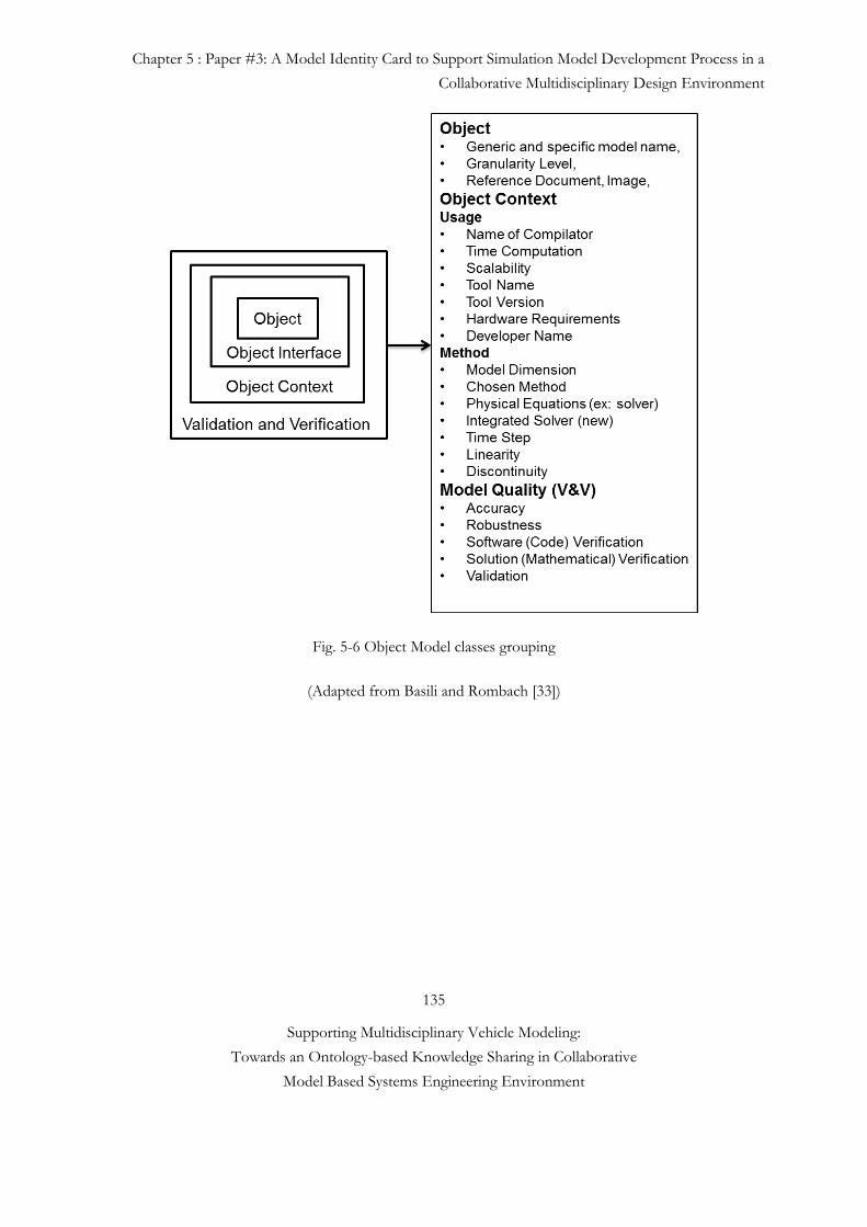
Chapter 5 : Paper #3: A Model Identity Card to Support Simulation Model Development Process in a
Collaborative Multidisciplinary Design Environment
135
Supporting Multidisciplinary Vehicle Modeling:
Towards an Ontology-based Knowledge Sharing in Collaborative
Model Based Systems Engineering Environment
Fig. 5-6 Object Model classes grouping
(Adapted from Basili and Rombach [33])
Chapter 5 : Paper #3: A Model Identity Card to Support Simulation Model Development Process in a
Collaborative Multidisciplinary Design Environment
136
Supporting Multidisciplinary Vehicle Modeling:
Towards an Ontology-based Knowledge Sharing in Collaborative
Model Based Systems Engineering Environment
5.4 Case Study
5.4.1 Demonstration Scenario and MIC Validation
Today, the simulation model supply especially from an external provider is a bottleneck activity. Automotive
manufacturers ask for having a new model or a customized existing model from the suppliers. In the case
of a new model supply, from requirement elicitation phase to model integration tests, as there is not a
common vocabulary; the probability to fail during the model integration is very high. The source of problem
is mostly based on wrong or insufficient knowledge transmission from automotive manufacturer to model
suppliers. As the assumption of common understanding is incorrect, the provided model does not totally
conform to the requirements and the mentioned activities take a lot of time, typically 1 to 6 months after
several meetings and integration tests. In the example scenario, the system architect wishes to know the
behavior of after treatment model with defined boundary conditions. The scenario is realized based on the
3 model design steps that we explained in section 5-2.
Thus, the aims of this Case study are illustrated as below:
• Formal Vehicle Architecture Design based on non-formal model architecture.
• Vehicle and Domain Models Specifications with Model Identity Card (MIC).
• Correctness Control at the Early Design Phase (MIC).
5.4.1.1 Step 1: Formal System Architecture Design based on non-formal model
architecture
First, the System Architect provides a draft version of the model plan which is most of the time on MS
PowerPoint tool and the study objective.
Example:
Technological objectives: Optimizing a combination of after-treatment components. List of the
components to be simulated: Catalyst, SCR, Particles filter. Engine applications: K9, R9M, M9R.
Decision: Volume, Mass and Cost analysis of each after-treatment components.
Application: Transient simulation on homologation cycles for passenger car vehicles.
Expected accuracy: 10 % on the volume, 5% on the mass and 1% on the cost.

Chapter 5 : Paper #3: A Model Identity Card to Support Simulation Model Development Process in a
Collaborative Multidisciplinary Design Environment
137
Supporting Multidisciplinary Vehicle Modeling:
Towards an Ontology-based Knowledge Sharing in Collaborative
Model Based Systems Engineering Environment
Once the model architect receives and checks the consistency of the model and study objective (see Fig. 5-
7), he transforms this model plan into a semantically rich block diagram on the arKitect tool. Formal model
architecture integration to the early design process facilitates model use activity as a plug-in manner by
providing a holistic sub model integration schema with its interface connections.
The model architect characterizes each incoming and out coming ports of related sub models and their
connections with each other’s. Each sub model has a MIC in which there are enough and necessary
information about related model and its port connection with other models. As an example, we characterize
“Combustor/Chamber” sub model’s interface by using MIC GUI (Graphical User Interface), see Fig. 5-7
and 5-8. Each port definition consists of Port Name, Port Nature, Direction, Domain, Sub-domain,
variables, Units, Size, Min, Max values, Resolution, Accuracy etc (see Table 5-2). Once we define the
incoming and outgoing ports and their connections with other sub models one by one, arKItech semi-
automatically generates a block diagram, (see Fig. 5-9).
5.4.1.2 Step 2: Vehicle and Domain Models Specifications with Model Identity
Card (MIC)
The attributes that we use in MIC GUI decrease the ambiguity and misunderstanding between model
architect and model provider. This communication problem which might happen has an effect on model
quality and decision. Some interoperability problems based on misunderstanding of software versioning,
undated libraries and model units, can be decreased by using a MIC. By doing this it minimizes time, cost
and the expertise required to construct comprehensive models within the context of their organization.
Once the model architect sends on-demand requests to the model provider, he/she has to find or develop
the requested model. In the context of after treatment example, the model architect sends the request to
different engineering domain to be able to create a complete high level model.
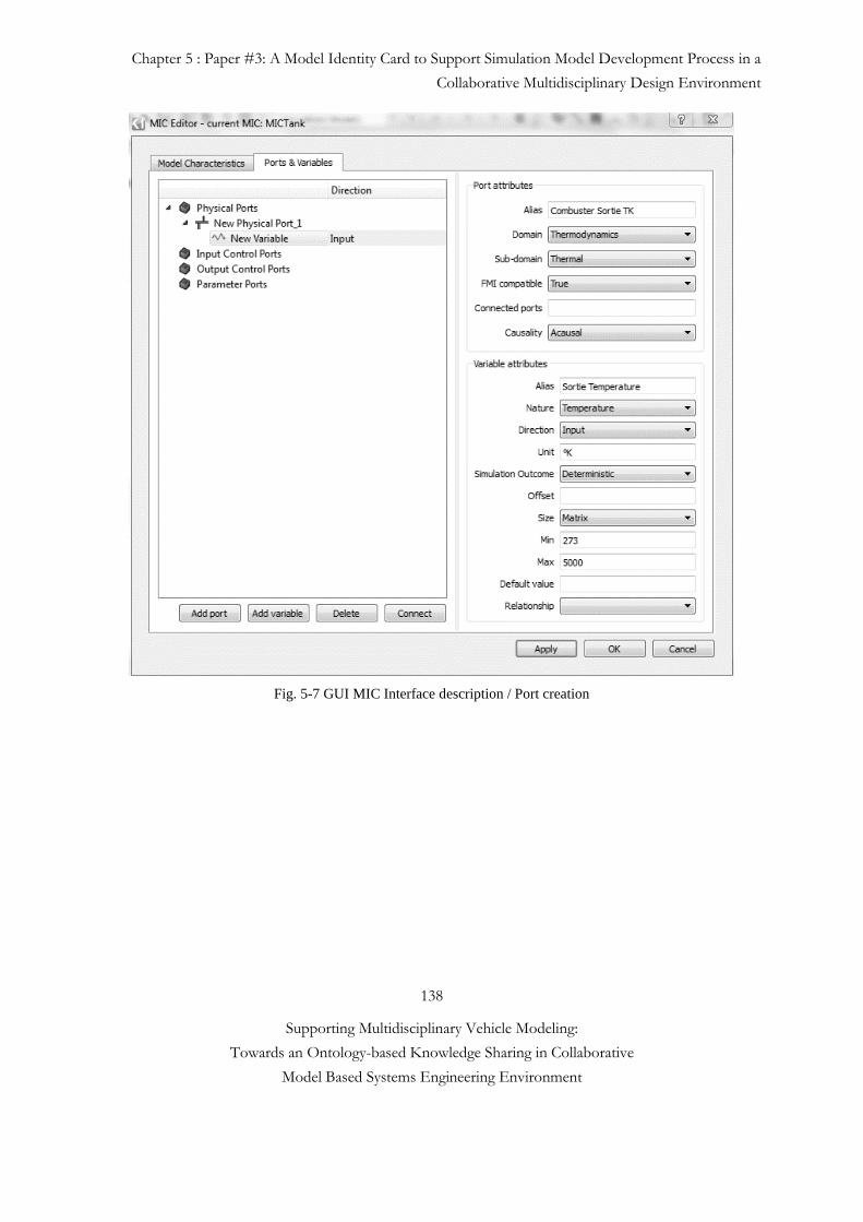
Chapter 5 : Paper #3: A Model Identity Card to Support Simulation Model Development Process in a
Collaborative Multidisciplinary Design Environment
138
Supporting Multidisciplinary Vehicle Modeling:
Towards an Ontology-based Knowledge Sharing in Collaborative
Model Based Systems Engineering Environment
Fig. 5-7 GUI MIC Interface description / Port creation
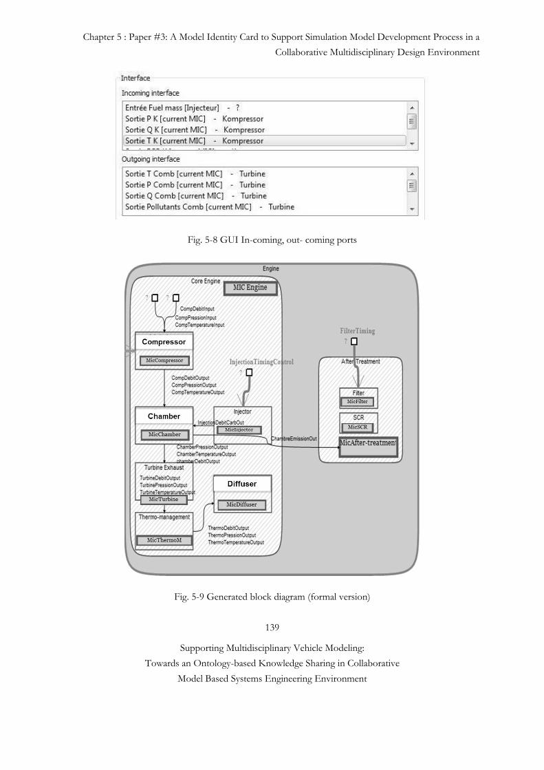
Chapter 5 : Paper #3: A Model Identity Card to Support Simulation Model Development Process in a
Collaborative Multidisciplinary Design Environment
139
Supporting Multidisciplinary Vehicle Modeling:
Towards an Ontology-based Knowledge Sharing in Collaborative
Model Based Systems Engineering Environment
Fig. 5-8 GUI In-coming, out- coming ports
Fig. 5-9 Generated block diagram (formal version)
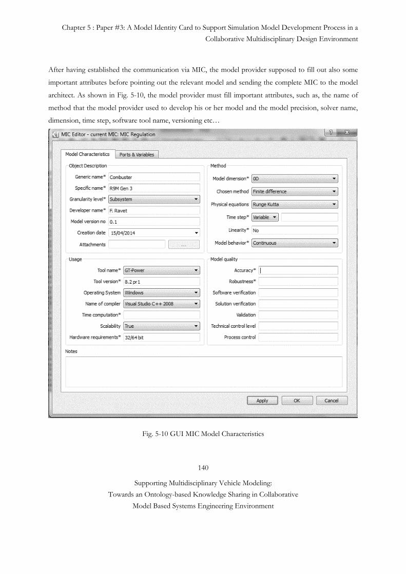
Chapter 5 : Paper #3: A Model Identity Card to Support Simulation Model Development Process in a
Collaborative Multidisciplinary Design Environment
140
Supporting Multidisciplinary Vehicle Modeling:
Towards an Ontology-based Knowledge Sharing in Collaborative
Model Based Systems Engineering Environment
After having established the communication via MIC, the model provider supposed to fill out also some
important attributes before pointing out the relevant model and sending the complete MIC to the model
architect. As shown in Fig. 5-10, the model provider must fill important attributes, such as, the name of
method that the model provider used to develop his or her model and the model precision, solver name,
dimension, time step, software tool name, versioning etc…
Fig. 5-10 GUI MIC Model Characteristics
Chapter 5 : Paper #3: A Model Identity Card to Support Simulation Model Development Process in a
Collaborative Multidisciplinary Design Environment
141
Supporting Multidisciplinary Vehicle Modeling:
Towards an Ontology-based Knowledge Sharing in Collaborative
Model Based Systems Engineering Environment
5.4.1.3 Step 3: Correctness Control at the Early Design Phase
We define correctness as a measurement of how well the system design meets or exceeds its requirements.
Due to uncertainty arising from design abstractions as well as system interactions with the environment and
its users, correctness is specified over multiple dimensions. These dimensions include the design hierarchy
(i.e., subsystems and components), environment, use conditions, functions, functional failures, and
adherence to design rules. After having established the domain level signals (interfaces and domain level
model specifications), the model architects integrate these sub models into a full virtual prototype. The
model architect can evaluate alternative architectures against different model accuracy constraints. She or
he has to detect any potential problem before the IVVQ (Integration, Verification, Validation, and
Qualification) phase. The virtual prototype contains various correctness checks for interoperability
problems such as domain models software names, versions, models’ min/max values, units, the direction
of acausal connections, models’ accuracy levels, etc [see Fig. 5-11].
In the literature there are some related works such as the early stage virtual prototype verification and
validation. To address this issue, Van der Velden et al. [34] recently developed a virtual prototype metric
called the Probabilistic Certificate of Correctness which computes the probability that the actual physical
prototype will meet its benchmark acceptance tests, based on virtual prototype behavior simulations with
known confidence and verified model assumptions. This works however does not use Probabilistic
Certificate of Correctness methods, it checks basically if there is some incoherence in component level
models’ interfaces.
Fig. 5-11 Interoperability Check
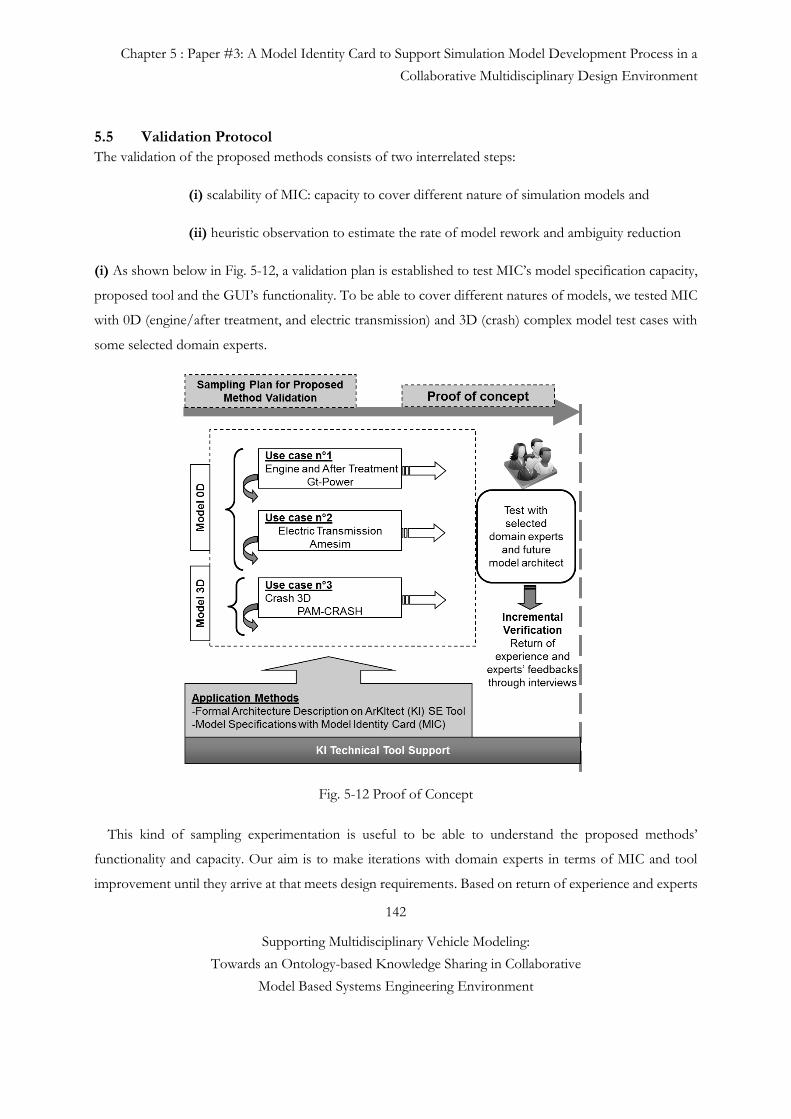
Chapter 5 : Paper #3: A Model Identity Card to Support Simulation Model Development Process in a
Collaborative Multidisciplinary Design Environment
142
Supporting Multidisciplinary Vehicle Modeling:
Towards an Ontology-based Knowledge Sharing in Collaborative
Model Based Systems Engineering Environment
5.5 Validation Protocol
The validation of the proposed methods consists of two interrelated steps:
(i) scalability of MIC: capacity to cover different nature of simulation models and
(ii) heuristic observation to estimate the rate of model rework and ambiguity reduction
(i) As shown below in Fig. 5-12, a validation plan is established to test MIC’s model specification capacity,
proposed tool and the GUI’s functionality. To be able to cover different natures of models, we tested MIC
with 0D (engine/after treatment, and electric transmission) and 3D (crash) complex model test cases with
some selected domain experts.
Fig. 5-12 Proof of Concept
This kind of sampling experimentation is useful to be able to understand the proposed methods’
functionality and capacity. Our aim is to make iterations with domain experts in terms of MIC and tool
improvement until they arrive at that meets design requirements. Based on return of experience and experts
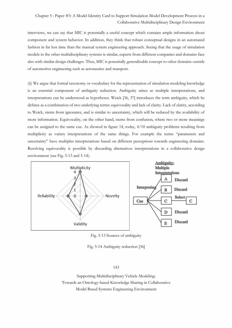
Chapter 5 : Paper #3: A Model Identity Card to Support Simulation Model Development Process in a
Collaborative Multidisciplinary Design Environment
143
Supporting Multidisciplinary Vehicle Modeling:
Towards an Ontology-based Knowledge Sharing in Collaborative
Model Based Systems Engineering Environment
interviews, we can say that MIC is potentially a useful concept which contains ample information about
component and system behavior. In addition, they think that robust conceptual designs in an automated
fashion in far less time than the manual system engineering approach. Seeing that the usage of simulation
models in the other multidisciplinary systems is similar, experts from different companies and domains face
also with similar design challenges. Thus, MIC is potentially generalizable concept to other domains outside
of automotive engineering such as aeronautics and transport.
(ii) We argue that formal taxonomy or vocabulary for the representation of simulation modeling knowledge
is an essential component of ambiguity reduction. Ambiguity arises as multiple interpretations, and
interpretations can be understood as hypotheses. Weick [36, 37] introduces the term ambiguity, which he
defines as a combination of two underlying terms: equivocality and lack of clarity. Lack of clarity, according
to Weick, stems from ignorance, and is similar to uncertainty, which will be reduced by the availability of
more information. Equivocality, on the other hand, stems from confusion, where two or more meanings
can be assigned to the same cue. As showed in figure 14, today, 4/10 ambiguity problems resulting from
multiplicity as variety interpretations of the same things. For example the terms “parameters and
uncertainty” have multiples interpretations based on different perceptions towards engineering domains.
Resolving equivocality is possible by discarding alternatives interpretations in a collaborative design
environment (see Fig. 5-13 and 5-14).
Fig. 5-13 Sources of ambiguity
Fig. 5-14 Ambiguity reduction [36]
Chapter 5 : Paper #3: A Model Identity Card to Support Simulation Model Development Process in a
Collaborative Multidisciplinary Design Environment
144
Supporting Multidisciplinary Vehicle Modeling:
Towards an Ontology-based Knowledge Sharing in Collaborative
Model Based Systems Engineering Environment
Sharing a common vocabulary between the designers and manufacturers allows both sides to identify
potential misunderstanding problems before they start. Another contribution of this work is reducing the
number of the rework while detecting potential inconsistency problems at early design stage. Avoidable
rework consumes a large part of development projects, i.e. 20-80 percent depending on the maturity of the
organization and the complexity of the products. Therefore, typical rework anomalies may be classified such
as
• avoidable rework which consists of the effort spent on fixing difficulties that could have been discovered
earlier or avoided altogether. In M&S context, most of rework anomalies are caused by interface
consistencies and software and hardware versioning problems (see Fig. 5-15). These anomalies would be
detected by correctness control at the early design phase (see section 5.4 for case study). And
• unavoidable rework is work that could not have been avoided because the developers were not aware of
or could not foresee the change when developing the software, e.g. changed user requirements or
environmental constraints.
Today, 4/10 rework anomalies are caused by inconsistent interfaces values and hardware and software
versioning mismatch problems which are potentially avoidable rework anomalies. Since each defect finds
after the product was released to OEM, these reworks create on average, 2 or 3 supplementary staff work
per project and 1 to 2 months of delay. Early correctness control aims to reduce the number of these
anomalies by a factor of 2. With the provided method, it would take approximately less than one staff hour
of correctness check time for each defect found (see Fig. 5-15).
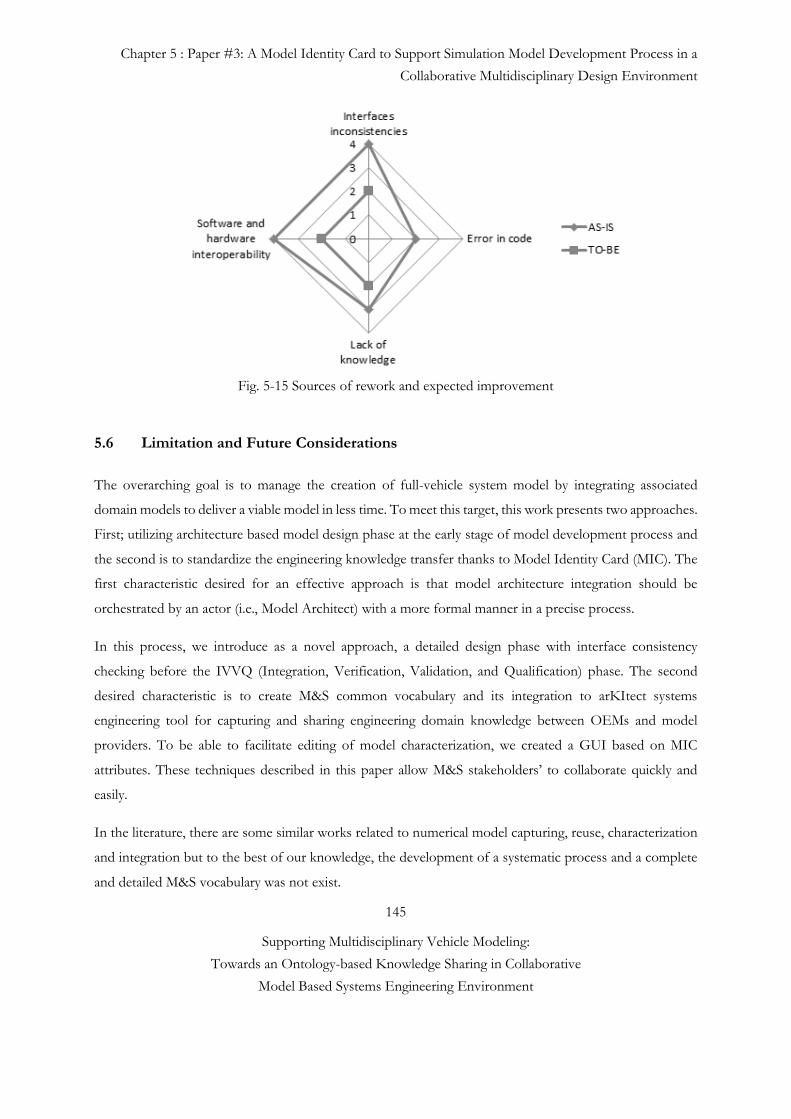
Chapter 5 : Paper #3: A Model Identity Card to Support Simulation Model Development Process in a
Collaborative Multidisciplinary Design Environment
145
Supporting Multidisciplinary Vehicle Modeling:
Towards an Ontology-based Knowledge Sharing in Collaborative
Model Based Systems Engineering Environment
Fig. 5-15 Sources of rework and expected improvement
5.6 Limitation and Future Considerations
The overarching goal is to manage the creation of full-vehicle system model by integrating associated
domain models to deliver a viable model in less time. To meet this target, this work presents two approaches.
First; utilizing architecture based model design phase at the early stage of model development process and
the second is to standardize the engineering knowledge transfer thanks to Model Identity Card (MIC). The
first characteristic desired for an effective approach is that model architecture integration should be
orchestrated by an actor (i.e., Model Architect) with a more formal manner in a precise process.
In this process, we introduce as a novel approach, a detailed design phase with interface consistency
checking before the IVVQ (Integration, Verification, Validation, and Qualification) phase. The second
desired characteristic is to create M&S common vocabulary and its integration to arKItect systems
engineering tool for capturing and sharing engineering domain knowledge between OEMs and model
providers. To be able to facilitate editing of model characterization, we created a GUI based on MIC
attributes. These techniques described in this paper allow M&S stakeholders’ to collaborate quickly and
easily.
In the literature, there are some similar works related to numerical model capturing, reuse, characterization
and integration but to the best of our knowledge, the development of a systematic process and a complete
and detailed M&S vocabulary was not exist.
Chapter 5 : Paper #3: A Model Identity Card to Support Simulation Model Development Process in a
Collaborative Multidisciplinary Design Environment
146
Supporting Multidisciplinary Vehicle Modeling:
Towards an Ontology-based Knowledge Sharing in Collaborative
Model Based Systems Engineering Environment
To demonstrate the applicability of our proposed solution, engine-after treatment, crash and electric
transmission models are tested. Engine-after treatment model is explained as a case study. During this case
study observation, models’ stakeholders (external/internal provider) have participated to the test scenario.
Within model development process, the model and the system architects, characterize and create well-
defined on-demand model requests. Based on this model request, the model provider selects or creates the
model that (1) is appropriate for their desired simulation context and (2) represents the assumptions and
limitations of the model. Thus, according to engineers’ return of experience based on case study, the
knowledge gap between model architect and provider is decreased by providing M&S common vocabulary.
Also, knowledge capturing and understanding about numerical modeling is increased. The MIC is locally
integrated to the company and tested by different engineering teams. Following the test results, we say that
MIC’s attributes are accurate and containing sufficient information for characterization different nature of
models (0D reduced, and 1D, 2D and 3D).
MIC is applicable to another context such as aeronautic but it requires more work, and thus it is important
to extend it to support different specific domains of interest. Model Development Process and MIC
concepts will be used in next generation Company’s multidisciplinary vehicle modeling strategy. Future
works include (1) increasing the number of MIC tests with different engineering teams for testing its capacity
(e.g., HVAC and Battery Aging Model are envisaged) and to extend its usage to support different specific
domains of interest, (2) an extended validation protocol for proposed concepts in terms of value addition
to company’s current situation. (3) We would like to also complete the Vehicle Reference Architecture to
be modeled by using mentioned tool and methods and finally (4) we would like to align of different views
and viewpoints in the same tool.
A long-term vision is to integrate semantically rich domain model libraries and model of behavioral intention
[35] concept to our MIC to be able to increase the probability to get the right model from supplier.
Chapter 5 : Paper #3: A Model Identity Card to Support Simulation Model Development Process in a
Collaborative Multidisciplinary Design Environment
147
Supporting Multidisciplinary Vehicle Modeling:
Towards an Ontology-based Knowledge Sharing in Collaborative
Model Based Systems Engineering Environment
Reference #5
[1] G. Sirin, B. Yannou, E. Coatanéa and E. Landel, “Analysis of the simulation system in an automotive
development project”. Int. Conf. of Complex Systems Design & Management CSDM, Paris, France,
Dec, 12-14, 2012.
[2] J.M. Branscomb, C.J.J. Paredis, J. Che, and M.J. Jennings, “Supporting Multidisciplinary Vehicle
Analysis Using a Vehicle Reference Architecture Model in SysML”. Systems Engineering Research
CSER, Atlanta, US-GA, March, 12-22, 2013.
[3] G. Sirin, B. Yannou, E. Coatanéa and E. Landel, “Creating a Domain Ontology to Support the
Numerical Models Exchange between Suppliers and Users in a Complex System Design”. ASME
(IDETC/CIE), Portland, USA, Aug., 4-7, 2013
[4] C.J.J. Paredis, A. Diaz-calderon, R. Sinha and P.K. Khosla, (2001, Apr). Composable models for
simulation-based design. Engineering with Computers Journal, Vol.17, No. 2, p. 112-128.
[5] L. Yilmaz. (2004). On the Need for Contextualized Introspective Models to Improve Reuse and
Composability of Defense Simulations, JDMS Volume 1, Number 3.
[6] R.J. Malak, and C.J.J. Paredis, (2007). Validating Behavioral Models for Reuse. Research in Engineering
Design, Vol.18, No.3, p.111-128.
[7] Systems Engineering Fundamentals, DOD Supplementary text prepared by the defense acquisition
university press fort Belvoir, Virginia 22060-5565, USA, 2001,
http://123management.nl/0/070_methode/072_kwaliteit/Dod%20Systems%20Engineering.pdf
[8] O. De Weck, “Feasibility of a 5x Speedup in System Development due to Meta Design”.
ASME/DETC2012-70791, 2012.
[9] D. Ward, S. Helton, and G. Polari, (2011). ROI Estimates from SAVI’s Feasibility Demonstration,
Systems Engineering Conference.
[10] G. Tassey, S.B. Brunnermeier, et S.A Martin. (1999). Interoperability cost analysis of the US automotive supply chain. Research Triangle Institute Final Report. RTI Project 7007-03, Available: https://www.rti.org/pubs/US_Automotive.pdf
[11] C. Belton, “Vehicle Model Architecture for Vehicle System Control Design”. SAE World Congress &
Exhibition, Detroit, Michigan, 2003.
[12] E. H. Miller, “A note on reflector arrays,” IEEE Trans. Antennas Propagat., to be published.
[13] G. Mocko, R.J. Malak, C.J.J. Paredis, and R. Peak, "A Knowledge Repository for Behavioral Models in
Engineering Design". 24th ASME Computers and Information in Engineering Conference, Salt Lake
City, UT, Sept, 2004.
Chapter 5 : Paper #3: A Model Identity Card to Support Simulation Model Development Process in a
Collaborative Multidisciplinary Design Environment
148
Supporting Multidisciplinary Vehicle Modeling:
Towards an Ontology-based Knowledge Sharing in Collaborative
Model Based Systems Engineering Environment
[14] AUTOSAR, www.autosar.org.
[15] Belton, “Vehicle Model Architecture for Vehicle System Control Design”. SAE World Congress &
Exhibition, Detroit, Michigan, 2003.
[16] M. Pratt, Introduction to ISO 10303—the STEP standard for product data exchange, J. Comput. Inf.
Sci. Eng. 1 (1) (2001) 102.
[17] W. Verhagen, R. Curran, Ontological modelling of the aerospace composite manufacturing domain, in:
18th ISPE International Conference on Concurrent Engineering, 2011, Advanced Concurrent
Engineering, 2011, pp. 215–222.
[18] S. Ahmed, S. Kim, K. Wallace, A methodology for creating ontologies for engineering design, in:
Proceedings of the ASME IDETC/CIE Conference, Long Beach, CA, 2005.
[19] Z. Li, M. Yang, K. Ramani, A methodology for engineering ontology acquisition and validation, Artif.
Intell. Eng. Des. Anal. Manuf, Special Issue on Developing and Using Engineering Ontologies (23)
(2009) 37–51.
[20] I. Horváth, J. Vergeest, G. Kuczogi, Development and Application of Design Concept Ontologies for
Contextual Conceptualization, Delft University of Technology, 1998.
[21] B. Chandrasekaran, J. Josephson, V. Benjamins, What are ontologies, and why do we need them?, IEEE
Intell Syst. Appl. 14 (1) (1999).
[22] D. Fensel, C. Bussler, Y. Ding, V. Kartseva, M. Klein, M. Korotkiy, B. Omelayenko, R. Siebes, Semantic
Web Application Areas, 2002. <http://www.few.vu.nl/~ronny/work/NLDB02.pdf> (retrieved
17.09.12).
[23] I.R. Grosse, J.M. Milton–Benoit and J.C. Wileden (Juil, 2005) Ontologies for supporting simulation
models. AI EDAM, Vol.19, No.1 p.1-18.
[24] Noy, F. N. and McGuinness, (2001) Ontology Development 101: A Guide to Creating Your First
Ontology. Stanford Knowledge Systems Laboratory Technical Report KSL-01-05 and Stanford Medical
Informatics Technical Report SMI-2001-0880. Stanford, CA.
[25] P. Failer. (2010). SAE AADL V2, An overview. Software Engineering Institute Carnegie Mellon
University Pittsburgh, Available: https://wiki.sei.cmu.edu/aadl/images/7/73/AADLV2Overview-
AADLUserDay-Feb_2010.pdf
[26] B.P. Zeigler et al., The DEVS Environment for High-Performance Modeling and Simulation. IEEE C
S & E, 1997. 4(3): p. 61-71.
Chapter 5 : Paper #3: A Model Identity Card to Support Simulation Model Development Process in a
Collaborative Multidisciplinary Design Environment
149
Supporting Multidisciplinary Vehicle Modeling:
Towards an Ontology-based Knowledge Sharing in Collaborative
Model Based Systems Engineering Environment
[27] S.R. Blattnig et al, Towards a Credibility Assessment of Models and Simulations. 49th
AIAA/ASME/ASCE/AHS/ASC Structures, Structural Dynamics, and Materials, At Schaumburg, IL,
2008.
[28] Delbecq, Andre L., and Van de Ven, Andrew H. (1971), "A Group Process Model for Problem
Identification and Program Planning," Journal of Applied Behavioral Science, 7, 4.
[29] D. Karnopp and R.C. Rosenberg. (1968). Analysis and Simulation of multiport Systems. The Bond
Graph approach to physical systems dynamics, MIT Press.
[30] S.D. Eppinger, and V. Salminen, “Patterns of Product Development Interactions”. 13th International
Conference on Engineering Design ICED, Aug., 21-23, Glasgow, Scotland, 2001.
[31] Nasa Technical Standard (2008), Standard for models and simulations National Aeronautics and Space
Administration Washington, DC 20546-0001, NASA-STD-7009.
[32] S. Halbach, P. Sharer, S. Pagerit, C. Folkerts, A. Rousseau, “Model Architecture, Methods, and
Interfaces for Efficient Math-Based Design and Simulation of Automotive Control Systems”, Argonne
National Laboratory, 2010.
[33] V. Basili and H.D. Rombach. (1990). Towards A Comprehensive Framework for Reuse: Model-based
Reuse Characterization Schemes. University of Maryland, CS-TR-2446, UMIACS-TR-90-47.
[34] A. Van der Velden, P. Koch, S. Devanathan, J. Haan, D. Naehring and D. Fox, “Probabilistic Certificate
of Correctness for Cyber Physical Systems”, Volume 2: 32nd Computers and Information in
Engineering Conference, Parts A and B Chicago, Illinois, USA, August 12–15, 2012.
[35] F. Retho, H. Smaoui, J.C. Vannier, P. Dessante, A model-based method to support complex system
design via systems interactions analysis. Int. Conf. of Complex Systems Design & Management CSDM,
Paris, France, Dec, 12-14, 2013.
[36] E. Brun and A.S. Saetre, Ambiguity Reduction in New Product Development Projects. International
Journal of Innovation Management Vol. 12, No. 4 (Dec. 2008) pp. 573–596.
[37] Weick, K (1995). Sensemaking in Organizations. Thousand Oaks, CA: Sage Publications
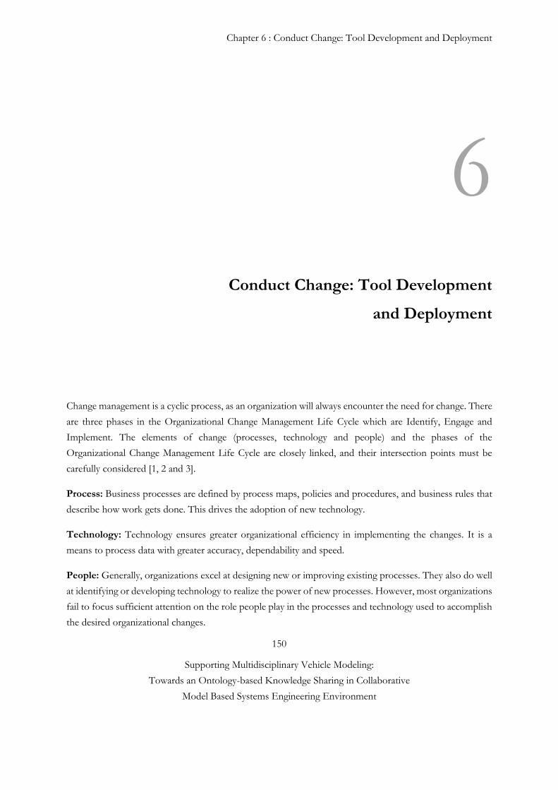
Chapter 6 : Conduct Change: Tool Development and Deployment
150
Supporting Multidisciplinary Vehicle Modeling:
Towards an Ontology-based Knowledge Sharing in Collaborative
Model Based Systems Engineering Environment
6 Conduct Change: Tool Development
and Deployment
Change management is a cyclic process, as an organization will always encounter the need for change. There
are three phases in the Organizational Change Management Life Cycle which are Identify, Engage and
Implement. The elements of change (processes, technology and people) and the phases of the
Organizational Change Management Life Cycle are closely linked, and their intersection points must be
carefully considered [1, 2 and 3].
Process: Business processes are defined by process maps, policies and procedures, and business rules that
describe how work gets done. This drives the adoption of new technology.
Technology: Technology ensures greater organizational efficiency in implementing the changes. It is a
means to process data with greater accuracy, dependability and speed.
People: Generally, organizations excel at designing new or improving existing processes. They also do well
at identifying or developing technology to realize the power of new processes. However, most organizations
fail to focus sufficient attention on the role people play in the processes and technology used to accomplish
the desired organizational changes.
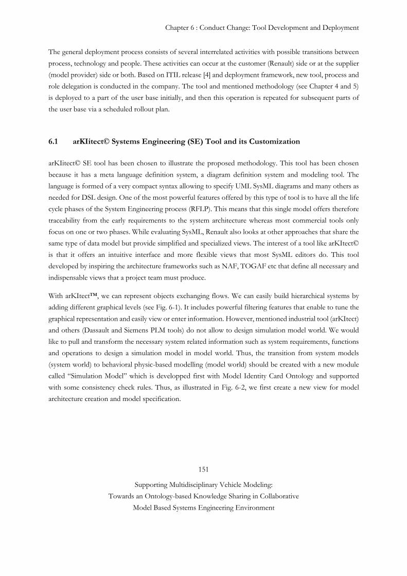
Chapter 6 : Conduct Change: Tool Development and Deployment
151
Supporting Multidisciplinary Vehicle Modeling:
Towards an Ontology-based Knowledge Sharing in Collaborative
Model Based Systems Engineering Environment
The general deployment process consists of several interrelated activities with possible transitions between
process, technology and people. These activities can occur at the customer (Renault) side or at the supplier
(model provider) side or both. Based on ITIL release [4] and deployment framework, new tool, process and
role delegation is conducted in the company. The tool and mentioned methodology (see Chapter 4 and 5)
is deployed to a part of the user base initially, and then this operation is repeated for subsequent parts of
the user base via a scheduled rollout plan.
6.1 arKIitect© Systems Engineering (SE) Tool and its Customization
arKIitect© SE tool has been chosen to illustrate the proposed methodology. This tool has been chosen
because it has a meta language definition system, a diagram definition system and modeling tool. The
language is formed of a very compact syntax allowing to specify UML SysML diagrams and many others as
needed for DSL design. One of the most powerful features offered by this type of tool is to have all the life
cycle phases of the System Engineering process (RFLP). This means that this single model offers therefore
traceability from the early requirements to the system architecture whereas most commercial tools only
focus on one or two phases. While evaluating SysML, Renault also looks at other approaches that share the
same type of data model but provide simplified and specialized views. The interest of a tool like arKItect©
is that it offers an intuitive interface and more flexible views that most SysML editors do. This tool
developed by inspiring the architecture frameworks such as NAF, TOGAF etc that define all necessary and
indispensable views that a project team must produce.
With arKItect™, we can represent objects exchanging flows. We can easily build hierarchical systems by
adding different graphical levels (see Fig. 6-1). It includes powerful filtering features that enable to tune the
graphical representation and easily view or enter information. However, mentioned industrial tool (arKItect)
and others (Dassault and Siemens PLM tools) do not allow to design simulation model world. We would
like to pull and transform the necessary system related information such as system requirements, functions
and operations to design a simulation model in model world. Thus, the transition from system models
(system world) to behavioral physic-based modelling (model world) should be created with a new module
called “Simulation Model” which is developped first with Model Identity Card Ontology and supported
with some consistency check rules. Thus, as illustrated in Fig. 6-2, we first create a new view for model
architecture creation and model specification.
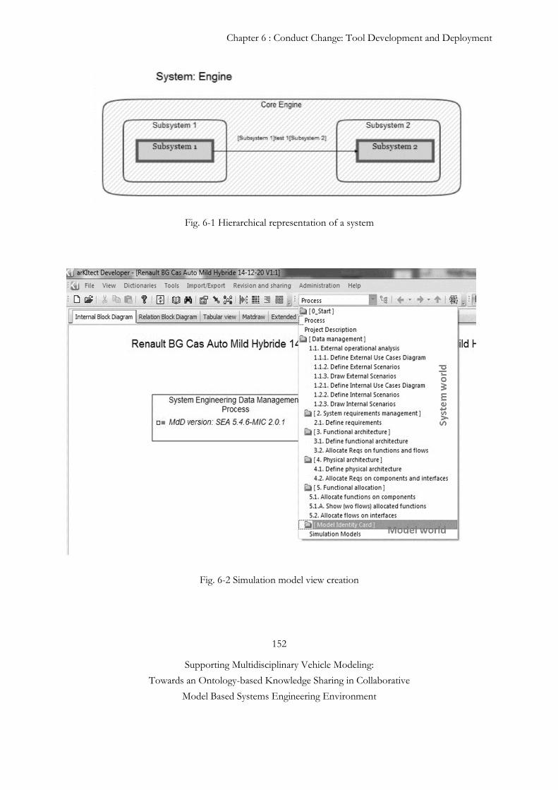
Chapter 6 : Conduct Change: Tool Development and Deployment
152
Supporting Multidisciplinary Vehicle Modeling:
Towards an Ontology-based Knowledge Sharing in Collaborative
Model Based Systems Engineering Environment
Fig. 6-1 Hierarchical representation of a system
Fig. 6-2 Simulation model view creation
Chapter 6 : Conduct Change: Tool Development and Deployment
153
Supporting Multidisciplinary Vehicle Modeling:
Towards an Ontology-based Knowledge Sharing in Collaborative
Model Based Systems Engineering Environment
6.1.1 Model Identity Card (MIC) and arKItect Systems Engineering Tool Integration
Our primary foundation is based upon the concept that simulation models are knowledge-based abstractions
of real systems. A system can be represented as a configuration of components or sub-systems that are
connected to each other through well-defined interfaces. The configuration interface of a component object
consists of ports, which define the intended interaction between a component and its environment;
interactions consist of the exchange of energy, matter, or signals (information) (see Fig. 6-3). For example,
the configuration interface of the motor has ports for the stator, the shaft of the rotor, and the electrical
connectors. A system is a group of multi-domain / multi-physics components interacting together. Systems
have structure, defined by parts and their composition. Systems have behavior, which involves inputs,
processing and outputs of material, energy or information. On the other hand, the number and the diversity
of the simulation models require another level of abstraction called meta-model that makes statements about
the structure of different natures of models without making statements about their content.
Fig. 6-3 System, Component and Port
The word “mathematical or behavioral model” is used to refer to a representation of our understanding
of the conceptual structure and behavioral functioning of the “system”, in a way that facilitates simulation
of the plausible behaviors of that system under various conditions (either historically observed or that might
potentially occur), in support of generating improved understanding about the system or in support of
decision making. Typical outputs from mathematical models in the aerospace and automotive industries are
pressure, temperature, and flow of fuel etc…. Mathematical models attempt to recall the system in terms of
performance or behavior and are therefore also called behavior models. The mathematical models can be
classified and hierarchized in several different ways. The focus in the hierarchical classification below is on
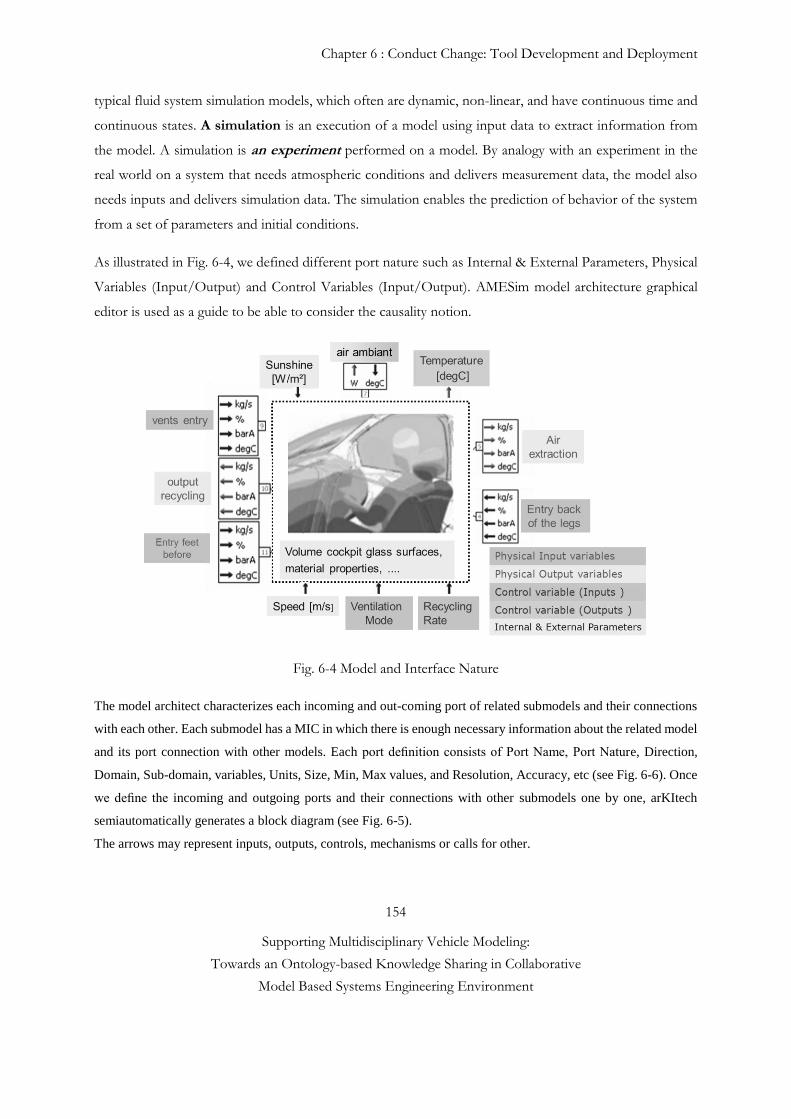
Chapter 6 : Conduct Change: Tool Development and Deployment
154
Supporting Multidisciplinary Vehicle Modeling:
Towards an Ontology-based Knowledge Sharing in Collaborative
Model Based Systems Engineering Environment
typical fluid system simulation models, which often are dynamic, non-linear, and have continuous time and
continuous states. A simulation is an execution of a model using input data to extract information from
the model. A simulation is an experiment performed on a model. By analogy with an experiment in the
real world on a system that needs atmospheric conditions and delivers measurement data, the model also
needs inputs and delivers simulation data. The simulation enables the prediction of behavior of the system
from a set of parameters and initial conditions.
As illustrated in Fig. 6-4, we defined different port nature such as Internal & External Parameters, Physical
Variables (Input/Output) and Control Variables (Input/Output). AMESim model architecture graphical
editor is used as a guide to be able to consider the causality notion.
Fig. 6-4 Model and Interface Nature
The model architect characterizes each incoming and out-coming port of related submodels and their connections
with each other. Each submodel has a MIC in which there is enough necessary information about the related model
and its port connection with other models. Each port definition consists of Port Name, Port Nature, Direction,
Domain, Sub-domain, variables, Units, Size, Min, Max values, and Resolution, Accuracy, etc (see Fig. 6-6). Once
we define the incoming and outgoing ports and their connections with other submodels one by one, arKItech
semiautomatically generates a block diagram (see Fig. 6-5).
The arrows may represent inputs, outputs, controls, mechanisms or calls for other.
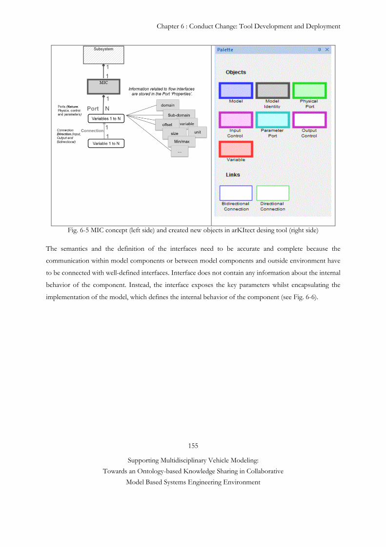
Chapter 6 : Conduct Change: Tool Development and Deployment
155
Supporting Multidisciplinary Vehicle Modeling:
Towards an Ontology-based Knowledge Sharing in Collaborative
Model Based Systems Engineering Environment
Fig. 6-5 MIC concept (left side) and created new objects in arKItect desing tool (right side)
The semantics and the definition of the interfaces need to be accurate and complete because the
communication within model components or between model components and outside environment have
to be connected with well-defined interfaces. Interface does not contain any information about the internal
behavior of the component. Instead, the interface exposes the key parameters whilst encapsulating the
implementation of the model, which defines the internal behavior of the component (see Fig. 6-6).
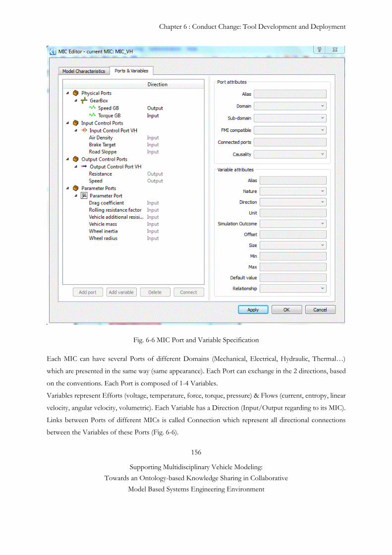
Chapter 6 : Conduct Change: Tool Development and Deployment
156
Supporting Multidisciplinary Vehicle Modeling:
Towards an Ontology-based Knowledge Sharing in Collaborative
Model Based Systems Engineering Environment
Fig. 6-6 MIC Port and Variable Specification
Each MIC can have several Ports of different Domains (Mechanical, Electrical, Hydraulic, Thermal…)
which are presented in the same way (same appearance). Each Port can exchange in the 2 directions, based
on the conventions. Each Port is composed of 1-4 Variables.
Variables represent Efforts (voltage, temperature, force, torque, pressure) & Flows (current, entropy, linear
velocity, angular velocity, volumetric). Each Variable has a Direction (Input/Output regarding to its MIC).
Links between Ports of different MICs is called Connection which represent all directional connections
between the Variables of these Ports (Fig. 6-6).
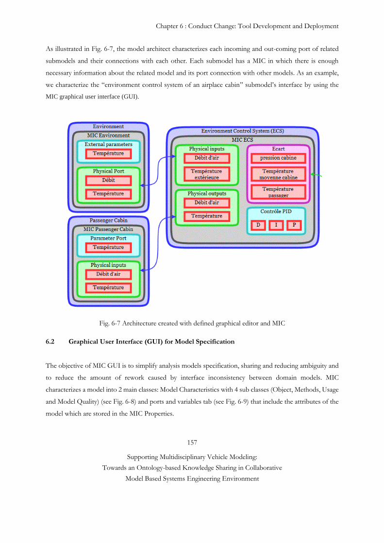
Chapter 6 : Conduct Change: Tool Development and Deployment
157
Supporting Multidisciplinary Vehicle Modeling:
Towards an Ontology-based Knowledge Sharing in Collaborative
Model Based Systems Engineering Environment
As illustrated in Fig. 6-7, the model architect characterizes each incoming and out-coming port of related
submodels and their connections with each other. Each submodel has a MIC in which there is enough
necessary information about the related model and its port connection with other models. As an example,
we characterize the “environment control system of an airplace cabin” submodel’s interface by using the
MIC graphical user interface (GUI).
Fig. 6-7 Architecture created with defined graphical editor and MIC
6.2 Graphical User Interface (GUI) for Model Specification
The objective of MIC GUI is to simplify analysis models specification, sharing and reducing ambiguity and
to reduce the amount of rework caused by interface inconsistency between domain models. MIC
characterizes a model into 2 main classes: Model Characteristics with 4 sub classes (Object, Methods, Usage
and Model Quality) (see Fig. 6-8) and ports and variables tab (see Fig. 6-9) that include the attributes of the
model which are stored in the MIC Properties.
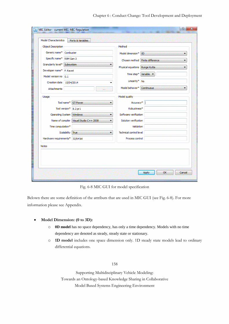
Chapter 6 : Conduct Change: Tool Development and Deployment
158
Supporting Multidisciplinary Vehicle Modeling:
Towards an Ontology-based Knowledge Sharing in Collaborative
Model Based Systems Engineering Environment
Fig. 6-8 MIC GUI for model specification
Belown there are some definition of the attributs that are used in MIC GUI (see Fig. 6-8). For more
information please see Appendix.
Model Dimension: (0 to 3D):
o 0D model has no space dependency, has only a time dependency. Models with no time
dependency are denoted as steady, steady state or stationary.
o 1D model includes one space dimension only. 1D steady state models lead to ordinary
differential equations.
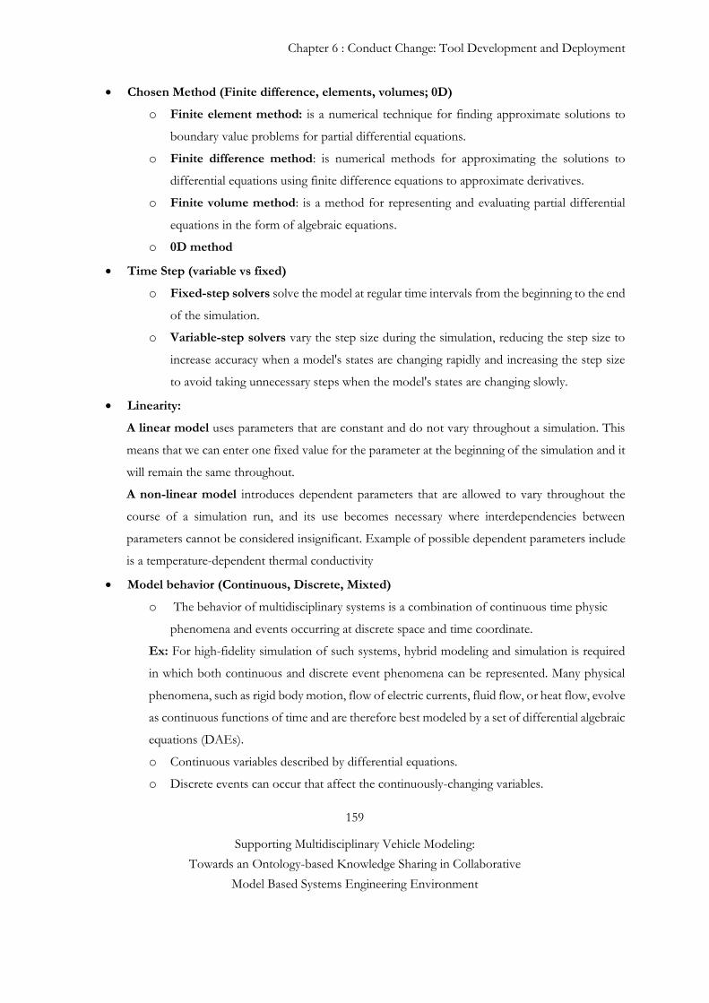
Chapter 6 : Conduct Change: Tool Development and Deployment
159
Supporting Multidisciplinary Vehicle Modeling:
Towards an Ontology-based Knowledge Sharing in Collaborative
Model Based Systems Engineering Environment
Chosen Method (Finite difference, elements, volumes; 0D)
o Finite element method: is a numerical technique for finding approximate solutions to
boundary value problems for partial differential equations.
o Finite difference method: is numerical methods for approximating the solutions to
differential equations using finite difference equations to approximate derivatives.
o Finite volume method: is a method for representing and evaluating partial differential
equations in the form of algebraic equations.
o 0D method
Time Step (variable vs fixed)
o Fixed-step solvers solve the model at regular time intervals from the beginning to the end
of the simulation.
o Variable-step solvers vary the step size during the simulation, reducing the step size to
increase accuracy when a model's states are changing rapidly and increasing the step size
to avoid taking unnecessary steps when the model's states are changing slowly.
Linearity:
A linear model uses parameters that are constant and do not vary throughout a simulation. This
means that we can enter one fixed value for the parameter at the beginning of the simulation and it
will remain the same throughout.
A non-linear model introduces dependent parameters that are allowed to vary throughout the
course of a simulation run, and its use becomes necessary where interdependencies between
parameters cannot be considered insignificant. Example of possible dependent parameters include
is a temperature-dependent thermal conductivity
Model behavior (Continuous, Discrete, Mixted)
o The behavior of multidisciplinary systems is a combination of continuous time physic
phenomena and events occurring at discrete space and time coordinate.
Ex: For high-fidelity simulation of such systems, hybrid modeling and simulation is required
in which both continuous and discrete event phenomena can be represented. Many physical
phenomena, such as rigid body motion, flow of electric currents, fluid flow, or heat flow, evolve
as continuous functions of time and are therefore best modeled by a set of differential algebraic
equations (DAEs).
o Continuous variables described by differential equations.
o Discrete events can occur that affect the continuously-changing variables.
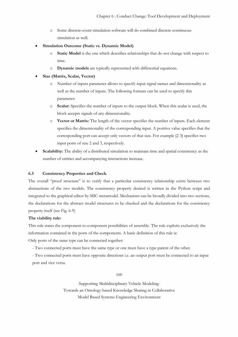
Chapter 6 : Conduct Change: Tool Development and Deployment
160
Supporting Multidisciplinary Vehicle Modeling:
Towards an Ontology-based Knowledge Sharing in Collaborative
Model Based Systems Engineering Environment
o Some discrete-event simulation software will do combined discrete-continuous
simulation as well.
Simulation Outcome (Static vs. Dynamic Model)
o Static Model is the one which describes relationships that do not change with respect to
time.
o Dynamic models are typically represented with differential equations.
Size (Matrix, Scalar, Vector)
o Number of inputs parameter allows to specify input signal names and dimensionality as
well as the number of inputs. The following formats can be used to specify this
parameter:
o Scalar: Specifies the number of inputs to the output block. When this scalar is used, the
block accepts signals of any dimensionality.
o Vector or Matrix: The length of the vector specifies the number of inputs. Each element
specifies the dimensionality of the corresponding input. A positive value specifies that the
corresponding port can accept only vectors of that size. For example [2 3] specifies two
input ports of size 2 and 3, respectively.
Scalability: The ability of a distributed simulation to maintain time and spatial consistency as the
number of entities and accompanying interactions increase.
6.3 Consistency Properties and Check
The overall “proof structure” is to verify that a particular consistency relationship exists between two
abstractions of the two models. The consistency property desired is written in the Python script and
integrated to the graphical editor by MIC metamodel. Mechanism can be broadly divided into two sections,
the declarations for the abstract model structures to be checked and the declarations for the consistency
property itself (see Fig. 6-9)
The viability rule:
This rule states the component-to-component possibilities of assembly. The rule exploits exclusively the
information contained in the ports of the components. A basic definition of this rule is:
Only ports of the same type can be connected together:
- Two connected ports must have the same type or one must have a type parent of the other.
- Two connected ports must have opposite directions i.e. an output port must be connected to an input
port and vice versa.
Chapter 6 : Conduct Change: Tool Development and Deployment
161
Supporting Multidisciplinary Vehicle Modeling:
Towards an Ontology-based Knowledge Sharing in Collaborative
Model Based Systems Engineering Environment
- A port must be connected at most to N ports, N being the port multiplicity.
Interface rules:
Port Nature (mechanic, hydraulic, thermal etc...): only ports of the same type (nature) can be connected together
Causality rule: only causal ports can be connected together
Variable: Unit control (same units), sign convention (same direction) can be connected together Model Context Rules:
Compiler control between 2 connected models
Type of model behavior: continue, discrete, mixed
Tool version
Time Step
Fig. 6-9 MIC Consistency Check
Causality Check:
AMESim components can have ports with different types (mechanical, hydraulic, thermal…)
Each port can exchange information in both directions (see Fig. 6-10):
o Inputs (red)
o Outputs (green)
Flux vs. Effort variables based on Power conservation
The inputs of the first connected port should correspond to the outputs of the second one = causality
Only ports of the same type can be connected together
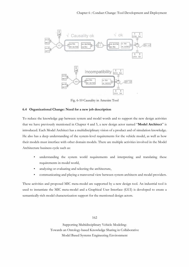
Chapter 6 : Conduct Change: Tool Development and Deployment
162
Supporting Multidisciplinary Vehicle Modeling:
Towards an Ontology-based Knowledge Sharing in Collaborative
Model Based Systems Engineering Environment
Fig. 6-10 Causality in Amesim Tool
6.4 Organizational Change: Need for a new job description
To reduce the knowledge gap between system and model words and to support the new design activities
that we have previously mentioned in Chapter 4 and 5, a new design actor named “Model Architect” is
introduced. Each Model Architect has a multidisciplinary vision of a product and of simulation knowledge.
He also has a deep understanding of the system-level requirements for the vehicle model, as well as how
their models must interface with other domain models. There are multiple activities involved in the Model
Architecture business cycle such as:
• understanding the system world requirements and interpreting and translating these
requirements in model world,
• analyzing or evaluating and selecting the architecture,
• communicating and playing a transversal view between system architects and model providers.
These activities and proposed MIC meta-model are supported by a new design tool. An industrial tool is
used to instantiate the MIC meta-model and a Graphical User Interface (GUI) is developed to create a
semantically-rich model characterization support for the mentioned design actors.
Chapter 6 : Conduct Change: Tool Development and Deployment
163
Supporting Multidisciplinary Vehicle Modeling:
Towards an Ontology-based Knowledge Sharing in Collaborative
Model Based Systems Engineering Environment
Proposed new activities in the detailed model design phase and MIC concepts will be used in next generation
OEM’s multidisciplinary vehicle modeling strategy. Finally, the OEM that we worked with is creating a job
description for the new design actor ‘Model Architect’ and is currently recruiting for this position.
Reference #7
[1] S. Nurcan, C. Rolland. A multi-method for defining the organizational change. Journal of Information
and Software Technology, Elsevier. Journal of Information and Software Technology, Elsevier.
45:2(2003), p. 61-82.
[2] C. Rolland, S. Nurcan, G. Grosz. Enterprise Knowledge Development: the process view, Information
and Management Journal, Elsevier 36(3), 1999, p.165-184.
[3] S. Nurcan, C. Rolland. Using EKD-CMM electronic guide book for managing change in organisations,
in Proceedings of the 9th European-Japanese Conference on Information Modelling and Knowledge
Bases, Iwate, Japan, May 24-28, 1999, p.105-123.
[4] G.Rasa et al. “Release and Deployment Management using ITIL”, Global Journal of Computer Science
and Technology, Vol.10 Issue 15 (Ver.1.0) December 2010
Chapter 7 : Conclusion, limits and research perspectives
164
Supporting Multidisciplinary Vehicle Modeling:
Towards an Ontology-based Knowledge Sharing in Collaborative
Model Based Systems Engineering Environment
7 Conclusion, limits and research
perspectives
This thesis addresses the common needs of several software tool providers and industrial markets such as
aerospace and automotive. It describes the methods, process and tool(s) that have been used to improve a
successful collaboration between the industrial partners, and the modèle architecture design challenges that
need to be explored within a multidisciplinary environment. Current inefficient way of working and lack of
established process and design tools for supporting simulation model archicture design and collaborative
development activity create some unnecessary iterations during simulation model integration phase. This is
often responsible for increased product development lead-time and cost, schedule risk. To fulfill this need,
the multidisciplinary simulation models need to be understandable and easy to create based on its
architecture. Thus, it is necessary to maintain close links with the various disciplines and actors through
clear information exchange in the early design stage.
Chapter 7 : Conclusion, limits and research perspectives
165
Supporting Multidisciplinary Vehicle Modeling:
Towards an Ontology-based Knowledge Sharing in Collaborative
Model Based Systems Engineering Environment
In order to address this problem, this work aims to reduce late inconsistency detection by ensuring early
stage collaborations between the different suppliers and OEM. Thus, this work integrates first a Detailed
Model Design Phase to the current model development process and, second, the roles have been re-
organized and delegated between design actors (Architect System and Model). The proposed detailed model
design phase which is typically composed of the following steps:
A System World Specification which is made of:
an operation scenario,
a functional system architecture,
a system analysis application plan with other systems (vehicle and sub systems level).
A Model World Specification which is made of:
a structural formal vehicle architecture,
a vehicle domain level models specification (e.g. model and its interfaces),
a complete system level model architecture with negotiated domain model interfaces and related
model specifications,
an early certification (correctness control) before contracting suppliers - advanced checked
options for detecting potential inconsistencies before IVVQ -.
These steps are supported by a new design tool and by an ontology based meta-model named “Model
Identity Card (MIC)”. An industrial tool is used to instantiate the MIC meta-model and a Graphical User
Interface (GUI) is developed to create a semantically-rich model characterization support for the mentioned
design actors. MIC includes some important and refined characteristics of simulation model such as
modeling assumptions and interfaces specifications. MIC in this case plays a role in the specification of such
systems and improves the reliability of the systems by facilitating checking the match between the system
requirements and the design solution. Another MIC objective is to simplify engineering knowledge capture
and ambiguity reduction between design actors. MIC also helps to support a clear simulation model request
creation and design artefact negotiation. Finally, MIC provides an interfaces correctness control for
detecting and preventing interface mismatch problems between two domain models. To support the new
activities previously mentioned at the detailed model design phase, a new design actor named “Model
Architect” is introduced. Each Model Architect has a multidisciplinary vision of a product and of simulation
knowledge. He also has a deep understanding of the system-level requirements for the vehicle model, as
well as how their models must interface with other domain models.
Chapter 7 : Conclusion, limits and research perspectives
166
Supporting Multidisciplinary Vehicle Modeling:
Towards an Ontology-based Knowledge Sharing in Collaborative
Model Based Systems Engineering Environment
This work proposes also a multi-view architectural method, aimed at reconciling the necessary high level
and detailed design aspects and steps with the help of the mentioned actors. The design tools and mentioned
activities perspectives (e.g. decisions, views and viewpoints) are structured by inspiration from Enterprise
Architecture Frameworks (e.g. NAF, TOGAF, and DoDAF).
To demonstrate the applicability of our proposed solution, engine-after treatment, crash and electric
transmission models are tested across automotive and aeronautic industries. The aim of this demonstration
is to observe the significant improvement of current model design process in term of efficiency, interface
mismatches reduction, and ambiguity and misunderstanding reduction. During this case study, some
selected design actors (system architects and external/internal providers) have participated to the test
scenarios. The objectives of validation of the proposed methods are twofold:
(i) checking the scalability of MIC, i.e. the capacity to cover different natures of simulation models,
(ii) qualitative observation to estimate the rate of model rework and ambiguity reduction
According to return of experience of the design actors who are involved in the case study and of our
qualitative observations, the knowledge gap between the design actors is decreased by providing a MIC
meta-model. (i) The MIC is partially integrated to the company and tested by different engineering teams.
Following the test results, we can say that MIC’s attributes are accurate and contain sufficient information
for characterizing different natures of models (0D reduced, and 1D, 2D and 3D). This kind of test group
experimentation is useful to be able to understand the proposed methods’ functionality and capacity. Our
aim is to make iterations with domain experts in terms of MIC and tool improvement until they succeed in
meeting design requirements. The MIC is potentially a useful concept which contains sufficient information
system to be modeled. MIC could possibly be applicable to another context such as aeronautics but it would
require some work to extend it to support various specific domains of interest. (ii) Proposed early
correctness control within a detailed model design phase aims to reduce the number of inconsistency based
anomalies by a factor of 2. With the provided method, it would take approximately less than one staff hour
of correctness check time for each defect found (e.g. current situation: inconsistency based rework creates
on average, 2 or 3 supplementary staff work per project and 1 to 2 months of delay).
Chapter 7 : Conclusion, limits and research perspectives
167
Supporting Multidisciplinary Vehicle Modeling:
Towards an Ontology-based Knowledge Sharing in Collaborative
Model Based Systems Engineering Environment
As a future consideration, proposed new activities in the detailed model design phase and MIC concepts
will be used in next generation OEM’s multidisciplinary vehicle modeling strategy. Finally, the OEM that
we worked with is creating a job description for the new design actor ‘Model Architect’ and is currently
recruiting for this position. A training roadmap was prepared for future Model Archiects with the aim of
introducing the new design tool and methodology.
In terms of future development stage, a MIC stand alone version will be shared with our external model
providers for testing the MIC capacity. Another future consideration is that a Model of Intention (MoI)
concept will be partially integrated to the detailed model design phase. MoI is a complementary method to
MIC and allows to reduce the knowledge gap between Model Architect and Model Suppliers. MoI is an
executable model and contains some observable parameters so as to be able to understand the requested
models’ expected behaviors for a given scenario. MIC and MoI are supposed to help also in choice of the
most relevant simulation model available in OEM database.
Chapter 7 : Conclusion, limits and research perspectives
168
Supporting Multidisciplinary Vehicle Modeling:
Towards an Ontology-based Knowledge Sharing in Collaborative
Model Based Systems Engineering Environment
Personal Publications
Journal papers
Paper#1: G. Sirin, L. Gasser, T. Welo, B. Yannou, and E. Landel, 2015. “Characteristics of Good
Multidisciplinary Model Design Practice: Toward a Value-Added Thinking”, in preparation.
Paper#2: G. Sirin, F. Retho, M. Callot., P. Dessante, E. Landel, B. Yannou, J.C. Vannier, 2014.
“Multidisciplinary Simulation Model Development: towards an inconsistency detection method during the
design stage”. Submitted to Systems, Man and Cybernetics, Part A: Systems and Humans, IEEE
Transactions.
Paper#3: G. Sirin., C.J.J. Paredis, B. Yannou, E. Landel, E. Coatanea, 2014. “A Model Identity Card to
support model development process in a Collaborative Multidisciplinary Design Environment”. IEEE
Systems Journal vol.PP, no.99, pp.1, 12.
Paper#4 : G. Sirin, B. Yannou, E. Landel, "Creating a Common Vocabulary to Support the Exchange of
Numerical Models between Suppliers and Users in a Complex System Design", Special section on AFIS
Doctoral Symposium: Systems Engineering Research Challenges in French Universities, Insight Journal of
INCOSE 16/4, 30-32, December, 2013.

Chapter 7 : Conclusion, limits and research perspectives
169
Supporting Multidisciplinary Vehicle Modeling:
Towards an Ontology-based Knowledge Sharing in Collaborative
Model Based Systems Engineering Environment
Conference papers
G. Sirin, B. Yannou, E. Coatanéa, and E. Landel, “Analysis of the simulation system in an
automotive development project”, CSDM Complex Systems Design & Management Paris,
France, 2012.
G. Sirin, B. Yannou, E. Coatanéa, and E. Landel, “Discussion about Goal Oriented Requirement
Elicitation Process into V model”, ICORD International Conference on Research into Design,
Chennai, India, 2013.
G. Sirin, B. Yannou, E. Coatanéa, and E. Landel, “Creating a Common Vocabulary to Support
the Numerical Models Exchange Between Suppliers and Users in a Complex System Design”,
IDETC/CIE, USA, 2013.
G. Sirin, T. Welo, B. Yannou, and E. Landel, “Value Creation in Collaborative Analysis Model
Development Processes”, IDETC/CIE, USA, 2014.

170
Supporting Multidisciplinary Vehicle Modeling:
Towards an Ontology-based Knowledge Sharing in Collaborative
Model Based Systems Engineering Environment
Appendix
171
Supporting Multidisciplinary Vehicle Modeling:
Towards an Ontology-based Knowledge Sharing in Collaborative
Model Based Systems Engineering Environment
Appendix
TECHNICAL DEFINITION
1 Modeling and Simulation Terminology
1.1 System, Model and Simulation
1.2 Model, Variables & Parameters Classification by Nature and Usage
1.3 Causality and Model Development Tool
1.4 Model Quality
1.4.1 Input Pedigree – Uncertainties Quantification - History
1.4.2 Validation & Robustness
1.4.3 Verification
2 Model Identity Card (MIC)
2.1 MIC-FMI Standard Compatibility
This chapter is an overview of Model Identity Card and general M&S domain terminology to describe the
different types of knowledge associated with models.
This document is developed based on Amin El-Bakkali, Sören Steinkellner and some other researcher’s works.
1 MODELING AND SIMULATION TERMINOLOGY
This section provides an overview of model classification, simulation methods and their relation to
engineering and vehicle model classification.
1.1 System, Model and Simulation
The word “system” will be used here to refer to a (generally complex) real world (usually physical)
dynamical system, which can include natural as well as humanly engineered components.
There are many reasons to simulate instead of setting up an experiment on a system in the real
world.
The three main reasons are:
• It is less expensive than perform experiments on real systems,
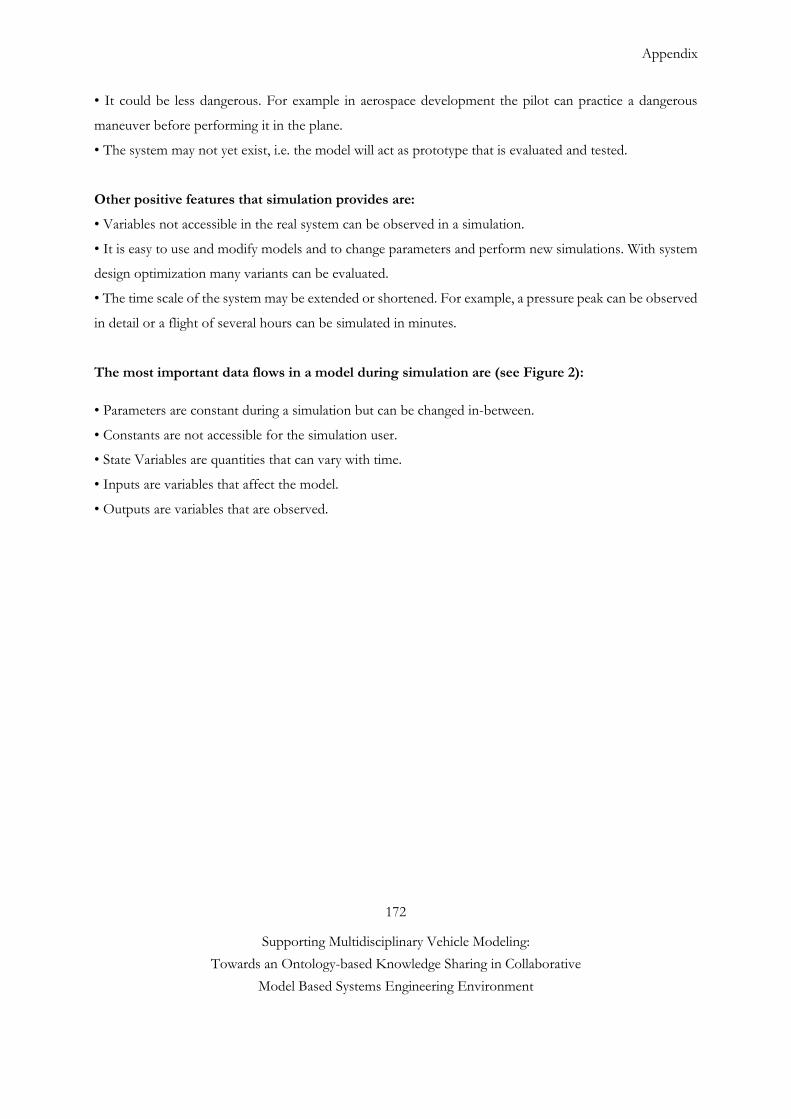
Appendix
172
Supporting Multidisciplinary Vehicle Modeling:
Towards an Ontology-based Knowledge Sharing in Collaborative
Model Based Systems Engineering Environment
• It could be less dangerous. For example in aerospace development the pilot can practice a dangerous
maneuver before performing it in the plane.
• The system may not yet exist, i.e. the model will act as prototype that is evaluated and tested.
Other positive features that simulation provides are:
• Variables not accessible in the real system can be observed in a simulation.
• It is easy to use and modify models and to change parameters and perform new simulations. With system
design optimization many variants can be evaluated.
• The time scale of the system may be extended or shortened. For example, a pressure peak can be observed
in detail or a flight of several hours can be simulated in minutes.
The most important data flows in a model during simulation are (see Figure 2):
• Parameters are constant during a simulation but can be changed in-between.
• Constants are not accessible for the simulation user.
• State Variables are quantities that can vary with time.
• Inputs are variables that affect the model.
• Outputs are variables that are observed.
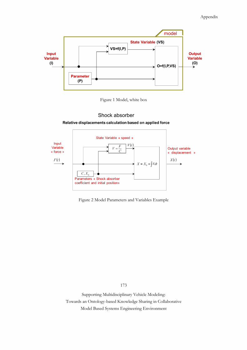
Appendix
173
Supporting Multidisciplinary Vehicle Modeling:
Towards an Ontology-based Knowledge Sharing in Collaborative
Model Based Systems Engineering Environment
Figure 1 Model, white box
Figure 2 Model Parameters and Variables Example
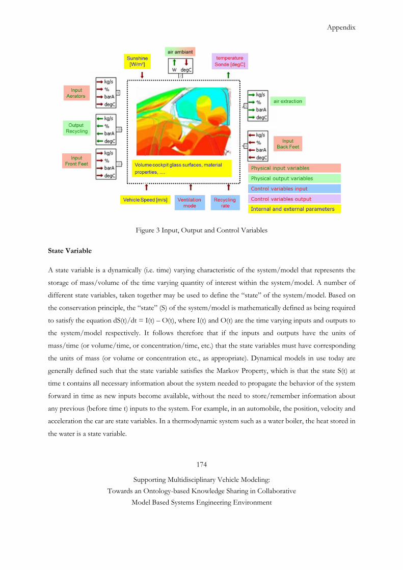
Appendix
174
Supporting Multidisciplinary Vehicle Modeling:
Towards an Ontology-based Knowledge Sharing in Collaborative
Model Based Systems Engineering Environment
Figure 3 Input, Output and Control Variables
State Variable
A state variable is a dynamically (i.e. time) varying characteristic of the system/model that represents the
storage of mass/volume of the time varying quantity of interest within the system/model. A number of
different state variables, taken together may be used to define the “state” of the system/model. Based on
the conservation principle, the “state” (S) of the system/model is mathematically defined as being required
to satisfy the equation dS(t)/dt = I(t) – O(t), where I(t) and O(t) are the time varying inputs and outputs to
the system/model respectively. It follows therefore that if the inputs and outputs have the units of
mass/time (or volume/time, or concentration/time, etc.) that the state variables must have corresponding
the units of mass (or volume or concentration etc., as appropriate). Dynamical models in use today are
generally defined such that the state variable satisfies the Markov Property, which is that the state S(t) at
time t contains all necessary information about the system needed to propagate the behavior of the system
forward in time as new inputs become available, without the need to store/remember information about
any previous (before time t) inputs to the system. For example, in an automobile, the position, velocity and
acceleration the car are state variables. In a thermodynamic system such as a water boiler, the heat stored in
the water is a state variable.
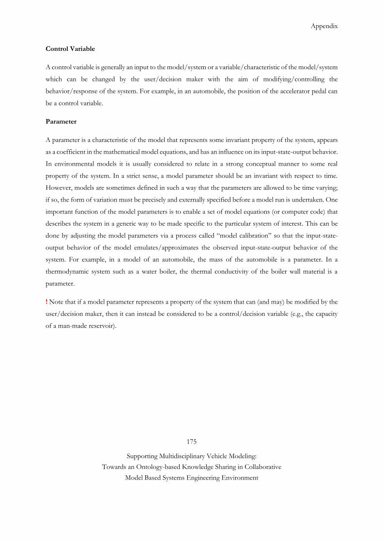
Appendix
175
Supporting Multidisciplinary Vehicle Modeling:
Towards an Ontology-based Knowledge Sharing in Collaborative
Model Based Systems Engineering Environment
Control Variable
A control variable is generally an input to the model/system or a variable/characteristic of the model/system
which can be changed by the user/decision maker with the aim of modifying/controlling the
behavior/response of the system. For example, in an automobile, the position of the accelerator pedal can
be a control variable.
Parameter
A parameter is a characteristic of the model that represents some invariant property of the system, appears
as a coefficient in the mathematical model equations, and has an influence on its input-state-output behavior.
In environmental models it is usually considered to relate in a strong conceptual manner to some real
property of the system. In a strict sense, a model parameter should be an invariant with respect to time.
However, models are sometimes defined in such a way that the parameters are allowed to be time varying;
if so, the form of variation must be precisely and externally specified before a model run is undertaken. One
important function of the model parameters is to enable a set of model equations (or computer code) that
describes the system in a generic way to be made specific to the particular system of interest. This can be
done by adjusting the model parameters via a process called “model calibration” so that the input-state-
output behavior of the model emulates/approximates the observed input-state-output behavior of the
system. For example, in a model of an automobile, the mass of the automobile is a parameter. In a
thermodynamic system such as a water boiler, the thermal conductivity of the boiler wall material is a
parameter.
! Note that if a model parameter represents a property of the system that can (and may) be modified by the
user/decision maker, then it can instead be considered to be a control/decision variable (e.g., the capacity
of a man-made reservoir).
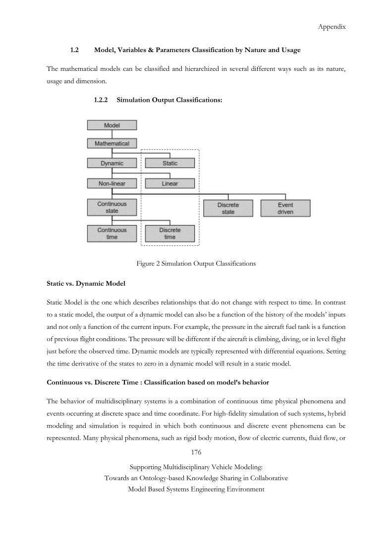
Appendix
176
Supporting Multidisciplinary Vehicle Modeling:
Towards an Ontology-based Knowledge Sharing in Collaborative
Model Based Systems Engineering Environment
1.2 Model, Variables & Parameters Classification by Nature and Usage
The mathematical models can be classified and hierarchized in several different ways such as its nature,
usage and dimension.
1.2.2 Simulation Output Classifications:
Figure 2 Simulation Output Classifications
Static vs. Dynamic Model
Static Model is the one which describes relationships that do not change with respect to time. In contrast
to a static model, the output of a dynamic model can also be a function of the history of the models’ inputs
and not only a function of the current inputs. For example, the pressure in the aircraft fuel tank is a function
of previous flight conditions. The pressure will be different if the aircraft is climbing, diving, or in level flight
just before the observed time. Dynamic models are typically represented with differential equations. Setting
the time derivative of the states to zero in a dynamic model will result in a static model.
Continuous vs. Discrete Time : Classification based on model’s behavior
The behavior of multidisciplinary systems is a combination of continuous time physical phenomena and
events occurring at discrete space and time coordinate. For high-fidelity simulation of such systems, hybrid
modeling and simulation is required in which both continuous and discrete event phenomena can be
represented. Many physical phenomena, such as rigid body motion, flow of electric currents, fluid flow, or
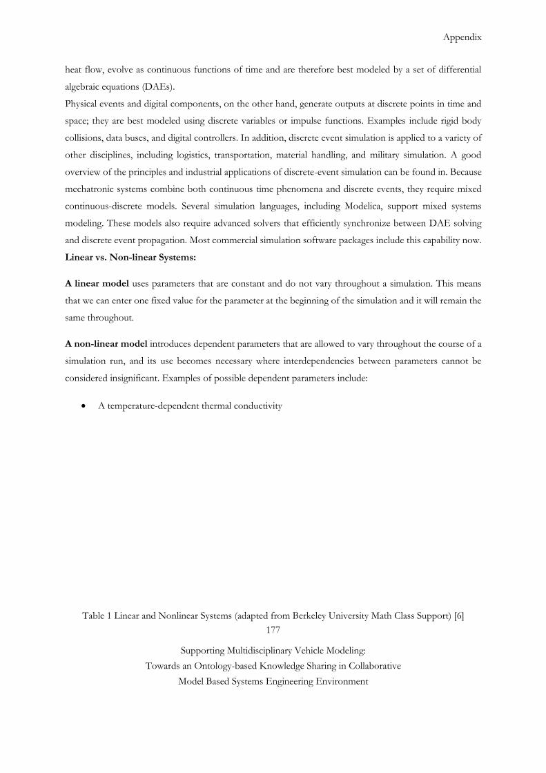
Appendix
177
Supporting Multidisciplinary Vehicle Modeling:
Towards an Ontology-based Knowledge Sharing in Collaborative
Model Based Systems Engineering Environment
heat flow, evolve as continuous functions of time and are therefore best modeled by a set of differential
algebraic equations (DAEs).
Physical events and digital components, on the other hand, generate outputs at discrete points in time and
space; they are best modeled using discrete variables or impulse functions. Examples include rigid body
collisions, data buses, and digital controllers. In addition, discrete event simulation is applied to a variety of
other disciplines, including logistics, transportation, material handling, and military simulation. A good
overview of the principles and industrial applications of discrete-event simulation can be found in. Because
mechatronic systems combine both continuous time phenomena and discrete events, they require mixed
continuous-discrete models. Several simulation languages, including Modelica, support mixed systems
modeling. These models also require advanced solvers that efficiently synchronize between DAE solving
and discrete event propagation. Most commercial simulation software packages include this capability now.
Linear vs. Non-linear Systems:
A linear model uses parameters that are constant and do not vary throughout a simulation. This means
that we can enter one fixed value for the parameter at the beginning of the simulation and it will remain the
same throughout.
A non-linear model introduces dependent parameters that are allowed to vary throughout the course of a
simulation run, and its use becomes necessary where interdependencies between parameters cannot be
considered insignificant. Examples of possible dependent parameters include:
A temperature-dependent thermal conductivity
Table 1 Linear and Nonlinear Systems (adapted from Berkeley University Math Class Support) [6]
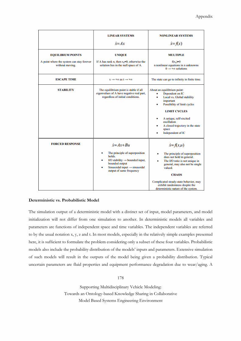
Appendix
178
Supporting Multidisciplinary Vehicle Modeling:
Towards an Ontology-based Knowledge Sharing in Collaborative
Model Based Systems Engineering Environment
Deterministic vs. Probabilistic Model
The simulation output of a deterministic model with a distinct set of input, model parameters, and model
initialization will not differ from one simulation to another. In deterministic models all variables and
parameters are functions of independent space and time variables. The independent variables are referred
to by the usual notation x, y, z and t. In most models, especially in the relatively simple examples presented
here, it is sufficient to formulate the problem considering only a subset of these four variables. Probabilistic
models also include the probability distribution of the models’ inputs and parameters. Extensive simulation
of such models will result in the outputs of the model being given a probability distribution. Typical
uncertain parameters are fluid properties and equipment performance degradation due to wear/aging. A
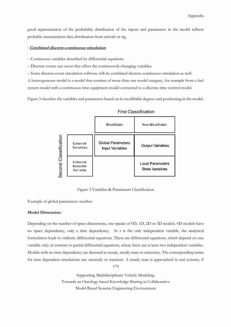
Appendix
179
Supporting Multidisciplinary Vehicle Modeling:
Towards an Ontology-based Knowledge Sharing in Collaborative
Model Based Systems Engineering Environment
good representation of the probability distribution of the inputs and parameters in the model reflects
probable measurement data distribution from aircraft or rig.
! Combined discrete-continuous simulation
– Continuous variables described by differential equations.
– Discrete events can occur that affect the continuously-changing variables.
– Some discrete-event simulation software will do combined discrete-continuous simulation as well.
A heterogeneous model is a model that consists of more than one model category, for example from a fuel
system model with a continuous time equipment model connected to a discrete time control model.
Figure 5 classifies the variables and parameters based on its modifiable degrees and positioning in the model.
Figure 3 Variables & Parameters Classification
Example of global parameters: weather
Model Dimension:
Depending on the number of space dimensions, one speaks of 0D, 1D, 2D or 3D models. 0D models have
no space dependency, only a time dependency. As t is the only independent variable, the analytical
formulation leads to ordinary differential equations. These are differential equations, which depend on one
variable only; in contrast to partial differential equations, where there are at least two independent variables.
Models with no time dependency are denoted as steady, steady state or stationary. The corresponding terms
for time dependent simulations are: unsteady or transient. A steady state is approached in real systems, if
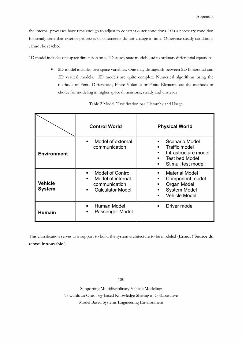
Appendix
180
Supporting Multidisciplinary Vehicle Modeling:
Towards an Ontology-based Knowledge Sharing in Collaborative
Model Based Systems Engineering Environment
the internal processes have time enough to adjust to constant outer conditions. It is a necessary condition
for steady state that exterior processes or parameters do not change in time. Otherwise steady conditions
cannot be reached.
1D model includes one space dimension only. 1D steady state models lead to ordinary differential equations.
2D model includes two space variables. One may distinguish between 2D horizontal and
2D vertical models. 3D models are quite complex. Numerical algorithms using the
methods of Finite Differences, Finite Volumes or Finite Elements are the methods of
choice for modeling in higher space dimensions, steady and unsteady.
Table 2 Model Classification par Hierarchy and Usage
Control World Physical World
Environment
Model of external communication
Scenario Model Traffic model Infrastructure model Test bed Model Stimuli test model
Vehicle System
Model of Control Model of internal
communication Calculator Model
Material Model Component model Organ Model System Model Vehicle Model
Humain Human Model Passenger Model
Driver model
This classification serves as a support to build the system architecture to be modeled (Erreur ! Source du
renvoi introuvable.).
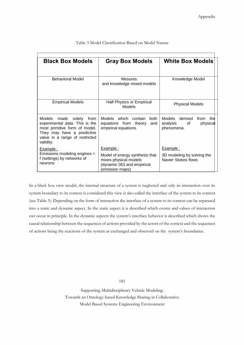
Appendix
181
Supporting Multidisciplinary Vehicle Modeling:
Towards an Ontology-based Knowledge Sharing in Collaborative
Model Based Systems Engineering Environment
Table 3 Model Classification Based on Model Nature
Black Box Models Gray Box Models White Box Models
Behavioral Model Mesures and knowledge mixed models
Knowledge Model
Empirical Models Half Physics or Empirical Models
Physical Models
Models made solely from experimental data. This is the most primitive form of model. They may have a predictive value in a range of restricted validity.
Example : Emissions modeling engines = f (settings) by networks of neurons
Models which contain both equations from theory and empirical equations.
Example :
Model of energy synthesis that mixes physical models (dynamic 0D) and empirical (emission maps)
Models derived from the analysis of physical phenomena.
Example :
3D modeling by solving the Navier Stokes flows
In a black box view model, the internal structure of a system is neglected and only its interaction over its
system boundary to its context is considered this view is also called the interface of the system to its context
(see Table 3). Depending on the form of interaction the interface of a system to its context can be separated
into a static and dynamic aspect. In the static aspect it is described which events and values of interaction
can occur in principle. In the dynamic aspects the system’s interface behavior is described which shows the
causal relationship between the sequences of actions provided by the actors of the context and the sequences
of actions being the reactions of the system as exchanged and observed on the system’s boundaries.
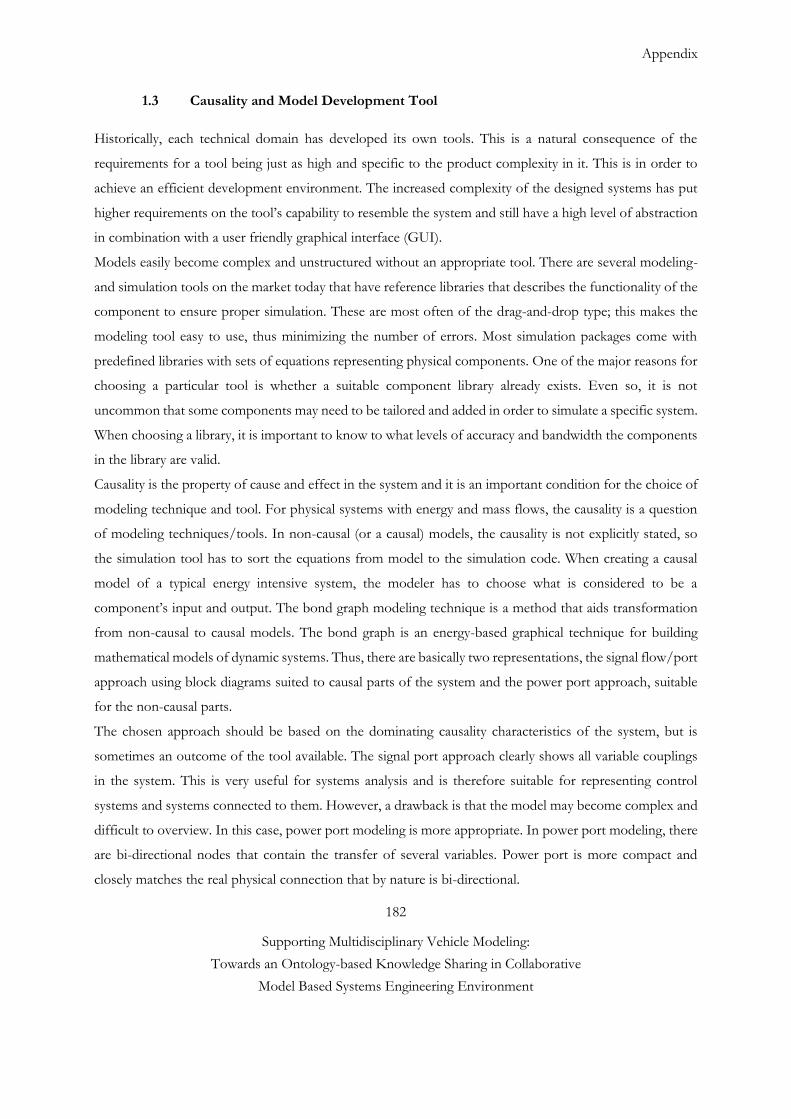
Appendix
182
Supporting Multidisciplinary Vehicle Modeling:
Towards an Ontology-based Knowledge Sharing in Collaborative
Model Based Systems Engineering Environment
1.3 Causality and Model Development Tool
Historically, each technical domain has developed its own tools. This is a natural consequence of the
requirements for a tool being just as high and specific to the product complexity in it. This is in order to
achieve an efficient development environment. The increased complexity of the designed systems has put
higher requirements on the tool’s capability to resemble the system and still have a high level of abstraction
in combination with a user friendly graphical interface (GUI).
Models easily become complex and unstructured without an appropriate tool. There are several modeling-
and simulation tools on the market today that have reference libraries that describes the functionality of the
component to ensure proper simulation. These are most often of the drag-and-drop type; this makes the
modeling tool easy to use, thus minimizing the number of errors. Most simulation packages come with
predefined libraries with sets of equations representing physical components. One of the major reasons for
choosing a particular tool is whether a suitable component library already exists. Even so, it is not
uncommon that some components may need to be tailored and added in order to simulate a specific system.
When choosing a library, it is important to know to what levels of accuracy and bandwidth the components
in the library are valid.
Causality is the property of cause and effect in the system and it is an important condition for the choice of
modeling technique and tool. For physical systems with energy and mass flows, the causality is a question
of modeling techniques/tools. In non-causal (or a causal) models, the causality is not explicitly stated, so
the simulation tool has to sort the equations from model to the simulation code. When creating a causal
model of a typical energy intensive system, the modeler has to choose what is considered to be a
component’s input and output. The bond graph modeling technique is a method that aids transformation
from non-causal to causal models. The bond graph is an energy-based graphical technique for building
mathematical models of dynamic systems. Thus, there are basically two representations, the signal flow/port
approach using block diagrams suited to causal parts of the system and the power port approach, suitable
for the non-causal parts.
The chosen approach should be based on the dominating causality characteristics of the system, but is
sometimes an outcome of the tool available. The signal port approach clearly shows all variable couplings
in the system. This is very useful for systems analysis and is therefore suitable for representing control
systems and systems connected to them. However, a drawback is that the model may become complex and
difficult to overview. In this case, power port modeling is more appropriate. In power port modeling, there
are bi-directional nodes that contain the transfer of several variables. Power port is more compact and
closely matches the real physical connection that by nature is bi-directional.
Appendix
183
Supporting Multidisciplinary Vehicle Modeling:
Towards an Ontology-based Knowledge Sharing in Collaborative
Model Based Systems Engineering Environment
Two examples of tools/languages for vehicle development are:
• Modelica is an object-oriented language for modeling complex physical systems. Modelica is suitable for
multi-domain modeling, for example modeling of mechatronic systems within vehicle applications. Such
systems are composed of mechanical, electrical, and hydraulic subsystems, as well as control systems.
Modelica uses equation-based modeling; the physical behavior of a model is described by differential,
algebraic and discrete equations. Modelica models are acausal and use the power port technique. An M&S
environment is needed to solve actual problems. The environment provides a customizable set of block
libraries that let users design and simulate.
•Simulink from Mathworks and AMESim from LMS is also an environment for multi-domain M&S. The
biggest difference compared to Modelica tools is that the models will be causal and use the signal flow
technique. A causal block diagram is made up of connected operation blocks. The connections stand for
signals, which are propagated from one block to the next. Blocks can be purely algebraic or may involve
some notion of time such as delay or integration (see Figure 6 and 7).
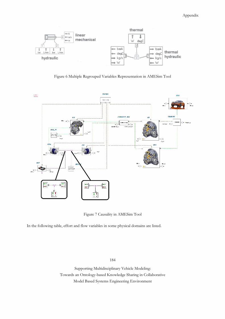
Appendix
184
Supporting Multidisciplinary Vehicle Modeling:
Towards an Ontology-based Knowledge Sharing in Collaborative
Model Based Systems Engineering Environment
Figure 6 Multiple Regrouped Variables Representation in AMESim Tool
Figure 7 Causality in AMESim Tool
In the following table, effort and flow variables in some physical domains are listed.
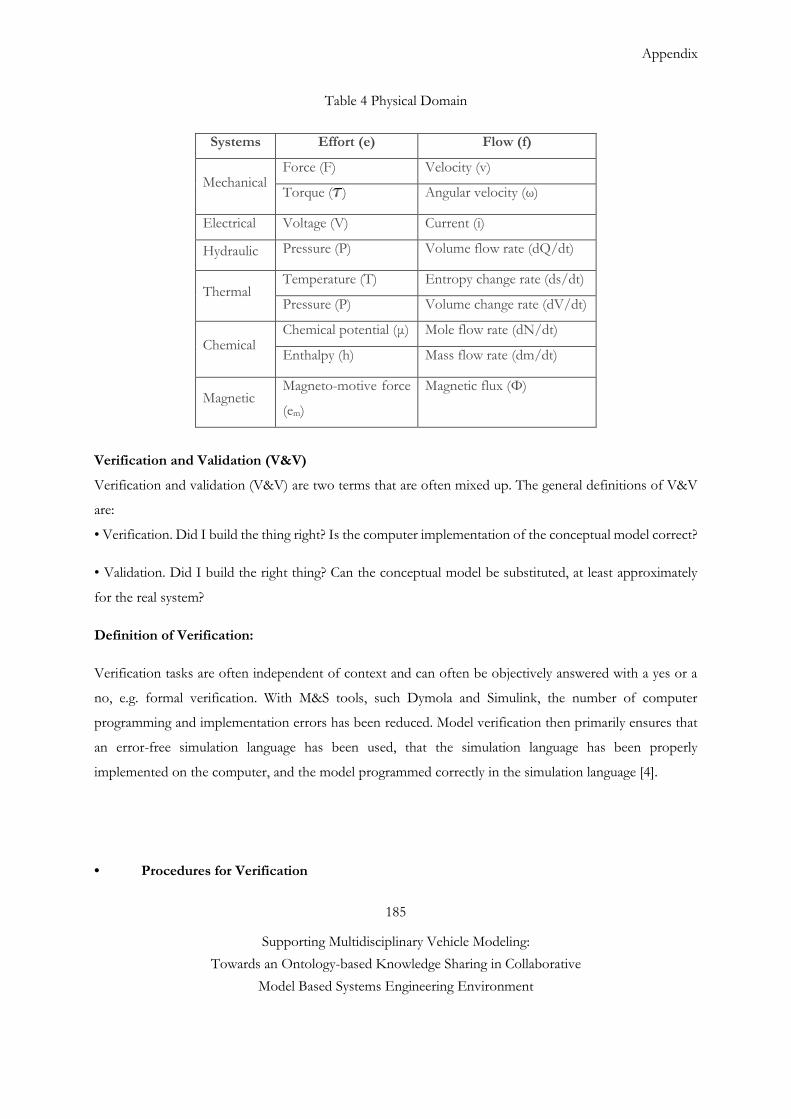
Appendix
185
Supporting Multidisciplinary Vehicle Modeling:
Towards an Ontology-based Knowledge Sharing in Collaborative
Model Based Systems Engineering Environment
Table 4 Physical Domain
Systems Effort (e) Flow (f)
Mechanical Force (F) Velocity (v)
Torque ( ) Angular velocity (ω)
Electrical Voltage (V) Current (i)
Hydraulic Pressure (P) Volume flow rate (dQ/dt)
Thermal Temperature (T) Entropy change rate (ds/dt)
Pressure (P) Volume change rate (dV/dt)
Chemical Chemical potential (μ) Mole flow rate (dN/dt)
Enthalpy (h) Mass flow rate (dm/dt)
Magnetic Magneto-motive force
(em)
Magnetic flux (Φ)
Verification and Validation (V&V)
Verification and validation (V&V) are two terms that are often mixed up. The general definitions of V&V
are:
• Verification. Did I build the thing right? Is the computer implementation of the conceptual model correct?
• Validation. Did I build the right thing? Can the conceptual model be substituted, at least approximately
for the real system?
Definition of Verification:
Verification tasks are often independent of context and can often be objectively answered with a yes or a
no, e.g. formal verification. With M&S tools, such Dymola and Simulink, the number of computer
programming and implementation errors has been reduced. Model verification then primarily ensures that
an error-free simulation language has been used, that the simulation language has been properly
implemented on the computer, and the model programmed correctly in the simulation language [4].
• Procedures for Verification
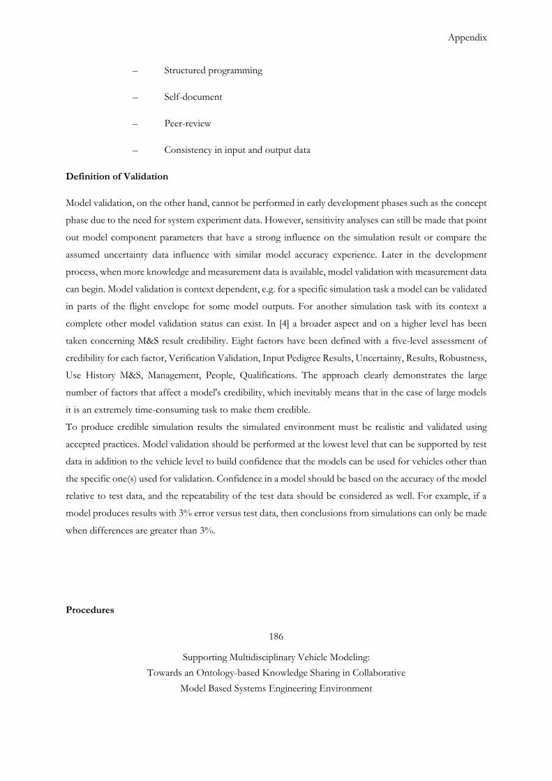
Appendix
186
Supporting Multidisciplinary Vehicle Modeling:
Towards an Ontology-based Knowledge Sharing in Collaborative
Model Based Systems Engineering Environment
– Structured programming
– Self-document
– Peer-review
– Consistency in input and output data
Definition of Validation
Model validation, on the other hand, cannot be performed in early development phases such as the concept
phase due to the need for system experiment data. However, sensitivity analyses can still be made that point
out model component parameters that have a strong influence on the simulation result or compare the
assumed uncertainty data influence with similar model accuracy experience. Later in the development
process, when more knowledge and measurement data is available, model validation with measurement data
can begin. Model validation is context dependent, e.g. for a specific simulation task a model can be validated
in parts of the flight envelope for some model outputs. For another simulation task with its context a
complete other model validation status can exist. In [4] a broader aspect and on a higher level has been
taken concerning M&S result credibility. Eight factors have been defined with a five-level assessment of
credibility for each factor, Verification Validation, Input Pedigree Results, Uncertainty, Results, Robustness,
Use History M&S, Management, People, Qualifications. The approach clearly demonstrates the large
number of factors that affect a model's credibility, which inevitably means that in the case of large models
it is an extremely time-consuming task to make them credible.
To produce credible simulation results the simulated environment must be realistic and validated using
accepted practices. Model validation should be performed at the lowest level that can be supported by test
data in addition to the vehicle level to build confidence that the models can be used for vehicles other than
the specific one(s) used for validation. Confidence in a model should be based on the accuracy of the model
relative to test data, and the repeatability of the test data should be considered as well. For example, if a
model produces results with 3% error versus test data, then conclusions from simulations can only be made
when differences are greater than 3%.
Procedures
Appendix
187
Supporting Multidisciplinary Vehicle Modeling:
Towards an Ontology-based Knowledge Sharing in Collaborative
Model Based Systems Engineering Environment
– Standing to criticism/Peer review (Turing)
– Sensitivity analysis
– Extreme-condition testing
– Validation of Assumptions
– Consistency checks
MIC-FMI Standard Compatibility
MIC and FMI interface specification compatibilities have been verified.
Classification of Interface Variables
Variables exposed by the FMU are categorized in a slightly different way in FMI 2.0:
Attribute “causality” is an enumeration that defines the causality of the variable. Allowed values are:
parameter: An independent variable that must be constant during simulation.
input: The variable value can be provided from another model.
output: The variable value can be used by another model. The algebraic relationship to the inputs
is defined in element Model Structure.
local: Local variable that is calculated from other variables. It is not allowed to use the variable value
in another model
Attribute “variability” is an enumeration that defines the time dependency of the variable, in other words it
defines the time instants when a variable can change its value. Allowed values are:
constant: The value of the variable never changes.
fixed: The value of the variable is fixed after initialization.
tunable: The value of the variable is constant
between externally triggered events due to changing variables with causality = "parameter" or
"input" (see explanation below).
discrete: The value of the variable is constant between internal events (= time, state, step events
defined implicitly in the FMU).
continuous: No restrictions on value changes.
Appendix
188
Supporting Multidisciplinary Vehicle Modeling:
Towards an Ontology-based Knowledge Sharing in Collaborative
Model Based Systems Engineering Environment
Terminology used in the manuscript [2-5]
Adequacy: The decision that the model fidelity is sufficient for the intended use.
Uncertainty: The extent to which a prediction may deviate from a future outcome.
Uncertainty Quantification: The process of characterizing all uncertainties in the model and experiment,
and quantifying their effect on the simulation and experimental outcomes.
Calibration: The process of adjusting numerical or modeling parameters in the model to improve
agreement with a referent.
Contract: a formal or informal specification of agreement that specifies the rights and obligations
associated with a product.
Value: that which makes some party appreciate a product or service
Change Management: Change management processes are used to deliver a finalized and tested change
into a preproduction environment along with a set of tools and/or procedures for migrating the change
into the live production environment.
Deployment: The activity responsible for movement of approved releases of hardware, software,
documentation, process etc. to test and production environments.
Model Dimension 0D : Equation dans un volume défini sans localisation spatiales
1D : On dérive dans les équations suivant un axe dimensionnel
2D : On dérive dans les équations suivant deux axes dimensionnels
3D : On dérive dans les équations suivant les 3 axes dimensionnels
Accuracy: The difference between a parameter or variable (or a set of parameters or variables) within a
model, simulation, or experiment and the true value or the assumed true value.
Verification: The process of determining that a model implementation accurately represents the developer’s
conceptual description of the model.
Validation: The process of determining the degree to which a model is an accurate representation of the
real world from the perspective of the intended uses of the model.
Ontology: An ontology is an explicit specification of conceptualization of a domain. Thus, by the definition,
an ontology is a set of concepts and their relationships.
Appendix
189
Supporting Multidisciplinary Vehicle Modeling:
Towards an Ontology-based Knowledge Sharing in Collaborative
Model Based Systems Engineering Environment
Conceptual model: the collection of abstractions, assumptions and descriptions of physical processes
representing the behavior of the reality of interest from which the mathematical model or validation
experiments can be constructed
Mathematical model: the mathematical equations, boundary values, initial conditions and modeling data
needed to describe the behavior of the conceptual model.
Reference #6
[1] H.V. Gupta, K.J. Beven and T. Wagener, 2005 “Model Calibration and Uncertainty Estimation”, in
Encyclopedia of Hydrologic Sciences, 3 Volumes, John Wiley and Sons.
[2] S. Steinkellner, 2011, “Aircraft Vehicle Systems Modeling and Simulation under Uncertainty”, Linköping
studies in science and technology thesis no 1497, Department of management and engineering division of
machine design Linköpings universitet, Linköping 2011.
[3] Nasa Technical Standard (2008), Standard for models and simulations National Aeronautics and Space
Administration Washington, DC 20546-0001, NASA-STD-7009.
[4] U.S. Dod. Verification, Validation and Accreditation Recommended Practice Guide (MSCO VV&A
RPG) Glossary.
[5] IEEE Standard Glossary of Modeling and Simulation Terminology, IEEE Std 610.3-1989, vol., no.,
pp.0_1, 1989 doi: 10.1109/IEEE STD.1989.94599.
[6] http://www.me.berkeley.edu/ME237/2_general_properties.pdf