Embed Size (px)
Citation preview
A. Tomczyk Suboptimal adaptive control system... 1
Suboptimal adaptive control system for flight quality
improvement
Andrzej Tomczyk
Department of Avionics and Control, Faculty of Mechanical Engineering and Aeronautics
Rzeszów University of Technology, W. Pola 2, 35-959 Rzeszów, Poland
[email protected]; http://www.prz.edu.pl/~atomczyk
Keywords: Flight control system, adaptive control, suboptimal control
Abstract
In this paper the suboptimal algorithm of adaptive control system is presented, which
is specially adjusted for automatic flight control systems of general aviation and commuter
aircraft, and unmanned aircraft (UMA) that conduct flights in atmospheric turbulence. At
first, the method could be applied for correction these changes in flight dynamics parameters,
which cannot be compensated with the aid of an open adaptation loop. At the same time, full
identification of aircraft model in real time is not required.
This method is based on the estimation of most typical parameters of the aircraft
mathematical model, which are most closely related to parameters, which are unmeasurable
during flight, like aircraft real mass and position of center of gravity. The structure of an
adaptation algorithm of aircraft flight control laws is based on the expert knowledge in the
field of flight dynamics and is the result of optimization calculations.
The examples which show attaining better flight comfort of the PZL M20 ,,Mewa"
general aviation aircraft and quality improvement of the UMA ,,Vector" pitch angle automatic
control, have been presented.
A. Tomczyk Suboptimal adaptive control system... 2
Introduction
An aircraft is an object whose dynamic properties have wide scope of change that is
also dependent on changes of flight conditions and airframe configuration. Obtaining required
flight control quality requires adjustment of an autopilot's control laws to changing properties
of an object. Applied methods of adaptive control can be divided into three groups (Aström
and Wittenmark, 1989; Sastry and Bodson, 1989):
parametric adaptation methods which are based on knowledge of an object's model,
and on chosen parameters' measurements describing its state (open system
adaptation),
methods based on algorithms of controlled object's (process) mathematical model
identification in real time (on-line),
methods of tuning controller which minimise chosen criteria of flight control
quality in real time.
Adaptation methods mentioned above are characterized by various levels of controlled
object's necessary knowledge, disturbance sensitivity, amount of calculations in real time,
control quality, etc. Practically it means that the method of adaptation should be chosen
according to a given control task.
In this paper, the method of an autopilot's control laws synthesis has been presented. It
combines chosen features of adaptation steering methods mentioned, and, moreover, some
elements typical for expert systems. The basic features of this method declare the following
steps of control laws synthesis:
1. Choosing the enhance coefficients of autopilot for basic state of flight and aircraft
configuration,
2. Choosing the algorithm of identification the parameters which describe the
aircraft's properties during flight state under analysis,
3. Choosing the method of flight control quality evaluating and calculating of
A. Tomczyk Suboptimal adaptive control system... 3
enhance coefficients optimal values in the range of unmeasuerable parameters of
flight dynamics,
4. Choosing the algorithm for control laws suboptimal adaptation,
5. Evaluation of the results using non-linear computer simulation which takes into
consideration aircraft's and flight system's real properties, as well as limits on
steering signals value (saturation effect), discretisation and quantisation of
measurements, actuator inertia, backlash, etc.
6. Hardware implementation of adaptive aircraft's suboptimal control laws and flight
tests.
The design method aims to obtain the simplest possible structure of an on-board
control system. Optimization calculations are conducted during the step of autopilot design;
during flight, only basic arithmetic operations are conducted. The method of behavior shown
above leads to suboptimal control synthesis, which is close to optimal control in the sense of
assumed control quality coefficient minimization.
The structure of control system
The methodology of choosing the autopilot's adaptive control laws will be shown on
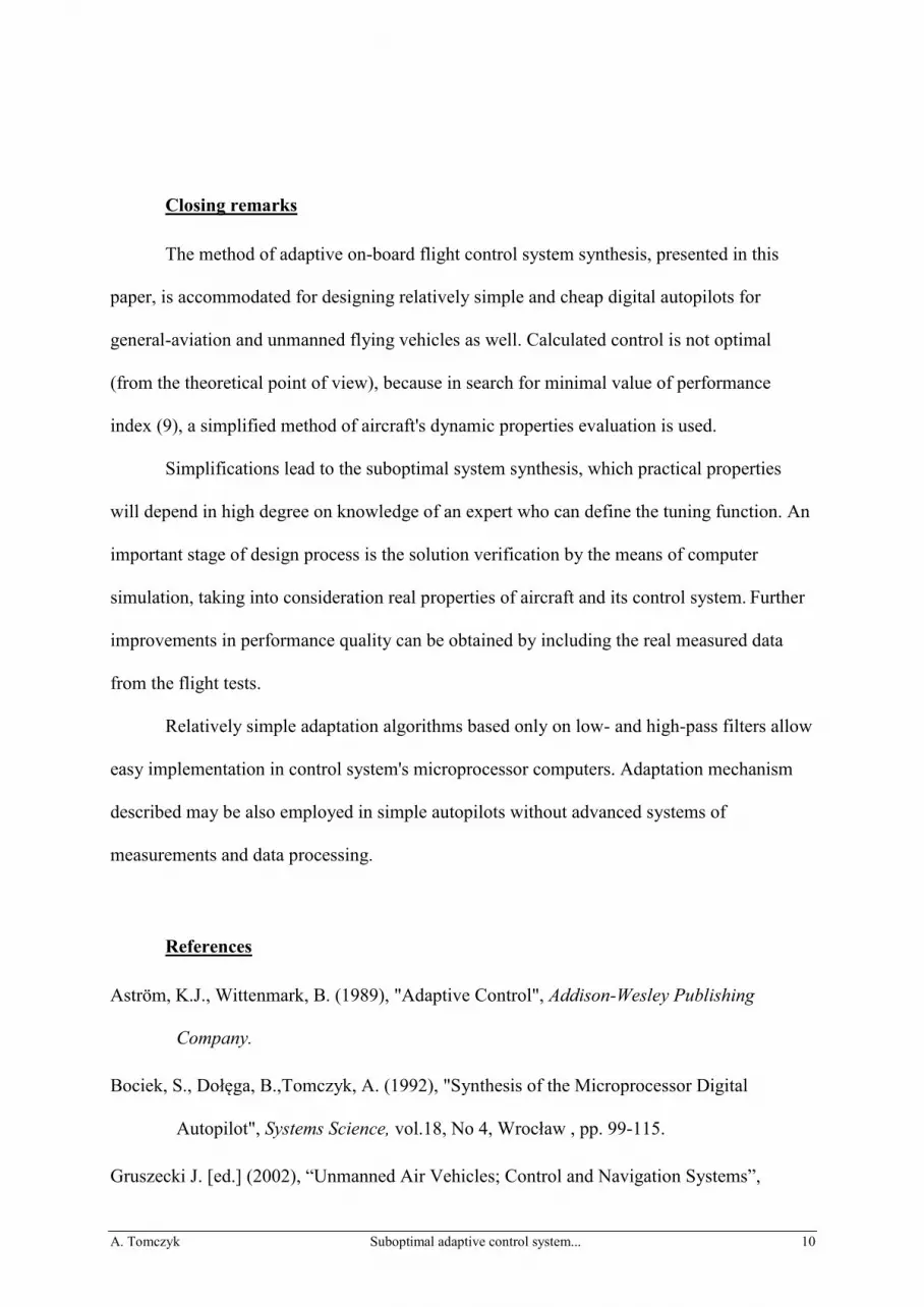
an example of pitch attitude angle stabilization. Figure 1 shows the system's block scheme
used for numerical calculations in the MATRIXx package. Aircraft is described by the linear
differential state equations (block 3) with three measurable output signals: pitch rate q, pitch
attitude increment (theta) and normal acceleration az (az). An additional output of an
aircraft model is the hinge moment of elevator. This moment is not directly measured, but its
value influences real angle of elevator displacement. The hinge moment (Hinge_M) is
calculated for real actuator properties modeling, which is illustrated in Figure 2. An aircraft is

A. Tomczyk Suboptimal adaptive control system... 4
forced by the atmospheric turbulence (block 2) described by the Dryden model (Houbolt,
Steiner and Pratt, 1964). Signals Ug and Wg are horizontal and vertical gust velocity,
respectively. Elevator is turned by the angle E (deltaE) with the help of the actuator (block 5)
with non-linear parameters. The full model of the actuator is shown in Figure 2. The model
contains the main real properties of electric motor and gear-box, as inertia (block 94),
backlash (block 91), rate and position saturation (blocks 96, 32). The safe clutch
characteristics are taken into consideration (block 20), and influence of the automatic trim
servo is included (block 90). Integrator (block 98) with non-linear feedback loop (block 97)
and threshold module (block 1) describe the logic control of the automatic elevator trim. The
adaptive autopilot (AP_ADA_2, block 11) minimizes the differences between real (theta) and
desired (theta_d) pitch angle according to control laws:
dkqk 21kork Ku (1)
where: uk - corrected control signal (u_k),
d - tracking error of pitch angle (theta-theta_d),
K=[k1, k2] - matrix of autopilot gains described for basic flight state,
Kkor - correction coefficient (kor), calculated in adaptation algorithm.
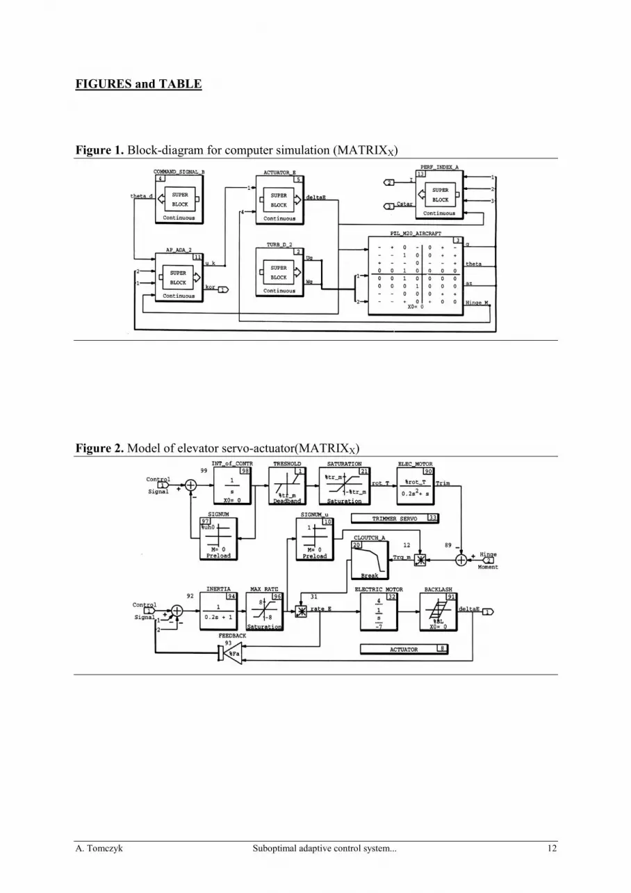
The structure of an autopilot is shown on Fig. 3. The upper part actively controls the
feedback loop while lower part deals with the algorithm of correction coefficient (kor) value
calculation.
take in figure 1 and 2
A. Tomczyk Suboptimal adaptive control system... 5
The suboptimal algorithm of autopilot enhance gains adaptation
The parametric adaptation of control laws based on measurable features (airspeed,
altitude) does not allow to take into consideration the influence of factors which cannot be
measured during the flight, like real mass of an aircraft or center of gravity position, and
changes in aerodynamics performance caused by ice, for example. Methods based on on-line
identification of controlled object's mathematical model and self-tuning methods require
significant amount of calculations by an on-board steering computer (Hammond and D'Azzo,
1991). The method proposed in the present paper is based on approximate estimation of
aircraft's dynamic properties by on-line calculating of parametric sensitivity coefficient
(index), which describes the influence of elevator displacement on pitch rate (Tomczyk, 1997;
Tomczyk, 1999). The measure of sensitivity index S() may be the magnitude of transfer
function M():
ssq
Mands
sqsGsGM
MS
EEjs
;;;)(
1)( (2)
where: q - pitch rate, E - elevator displacement.
The value of magnitude of M() is not measuring during a flight and it's a function of
input signal E frequency, which is dependent on disturbance frequency. If an aircraft is
affected by random disturbances caused by atmospheric turbulence, statistical measurements
are needed for practical calculations. In order to simplify the calculations in real time,
absolute values of pitch rate speed and elevator deflection, smoothed with a low-pass filter,
were used for calculating the sensitivity index:
ssT
sEsqsT
sE E
u
u
q
q 1
1;
1
1
(3)
where: Eq - statistical estimator of a signal q (t), if q (t)=|q(t)|,
A. Tomczyk Suboptimal adaptive control system... 6
Eu - statistical estimator of signal tE , if tt EE ,
uq T,T - time constants of low-pass filters used for averaging the signals.
In the time domain, statistical estimates of signals q(t) and E, Eq and Eu, will be
calculated as filtered absolute values of the signals:
;; tFtEtqFtE Euuqq (4)
where Fq and Fu are operations of low-pass filters.
Time constants of filters Tq and Tu have been selected in such a way that oscillations
of pitch rate resulting from disturbance effects are averaged and, simultaneously, adequate
speed of autopilot's gain coefficients adaptation is assured.
Finally, the estimate actual value S(t) of the sensitivity index S() can be calculated:
)(
)()(
tE
tEtS
q
u (5)
Practical realisation of calculations is presented on Fig. 3, where also a high-pass filter
(block 30) was used in order to separate a constant component of elevator deflection (deltaE).
Blocks 12 and 21 represent low-pass filters, which form pitch rate (Eq) and elevator deflection
(Eu) estimators (formula (3)).
take in figure 3
The main part of the design is the tuning function description for correction coefficient
Kkor (equation (1)). There is no theoretical basis for choosing the tuning function. The
decision should be based upon expert opinion in the fields of flight dynamics, onboard flight
control systems and designing experience. The tuning function can be written in a general
form:
Kkor=fK(S, P) (6)
A. Tomczyk Suboptimal adaptive control system... 7
where: fK – expert-defined estimate function,
S=S(t) – actual value of sensitivity index,
P – matrix of parameters.
In this paper, the following tuning function is proposed:
max
kor
minKKK
;1
)(1)(K
2
1kor
p
ptSt (7)
where: p1, p2 - parameters calculated from the data set {Kkor, S(t)} by least-mean-
squares estimation.
Analytical synthesis of autopilot control laws requires establishing a definition of a
quality index in order to optimize its parameters. The form of quality performance index
should result from substantial evidence. In this design method, for the purpose of evaluating
an aircraft control quality during flight in atmospheric turbulence, the C* criterion concept
has been used (Tobie, Elliot and Malcolm, 1966; Stevens and Levis, 1992):
qg
VntC cozp (8)
where: zpn - the incremental acceleration in g's at the pilot station,
Vco - crossover speed, assumed Vco=400ft/s, g - gravity.
The value of the C* criterion describes well the flight comfort from the pilot point of
view and level of flight precision for UMA. So, for measuring control quality, the
performance index (Fig. 1, block 13) was used:
dttCI
2T
T0
(9)
where: T-T0 - time interval assumed for evaluation.
A. Tomczyk Suboptimal adaptive control system... 8
As a step towards calculating, the minimum value of performance index (9), the vector
of autopilot gain matrix K (Fig. 3, block 90) for chosen basic flight state should be calculated.
This value will be corrected according to estimated dynamic state of controlled aircraft.
Calculations done for the set of unmeasuerable during flight parameter's forecasted ranges of
change allow obtaining optimal values of correction coefficient Kkor (used in formula (1)) and
to calculate estimators Eq and Eu (formula (3 or 4)).
Block 20 on Figure 3 (ADAPTATION) secures equation (7), while next element
(block 32) with feedback loop is a low-pass filter which smoothes short-term fluctuations of
correction coefficient. Block 22 is a multiplying element, which introduces corrections into
main loop of control.
Proving stability of adaptive control system described by equations (1) and (5) directly
is rather difficult. Indirect proof of correct controlling is based on the following assumptions:
• for each value of correction coefficient in range Kkor = {Kmin
, Kmax
}, the control
system is stable,
• rate of change of Kkor coefficient is small, which is assured by appropriate selection
of low-pass filters' time constants Tq and Tu,
• the final evaluation of the closed-loop non-linear control system stability can be
based on representative simulation calculations (so-called technical stability).
Numerical example
The calculations have been conducted with the help of software package MATRIXX
for five flight conditions of PZL M20 "Mewa" aircraft (Polish version of Piper Seneca II;
Bociek, Dolega and Tomczyk, 1992) and for four flight conditions of unmanned aircraft
A. Tomczyk Suboptimal adaptive control system... 9
,,Vector" (Gruszecki [ed.], 2002), presented in Table 1. Versions "A" and "F" are base flight
condition (minimum mass, medium e.g. position), which will serve as a comparison for
autopilot's enhances coefficients correction. Calculations were done for the same realization
of moderate atmospheric turbulence, at the sea level. The example of the UMA ,,Vector"
flight parameters time-history is presented in Figure 4.
take in figure 4, table 1 and figure 5
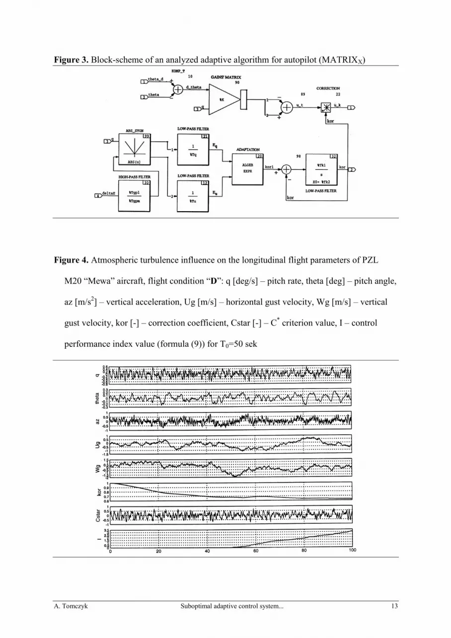
Figure 5 presents the correction coefficient's self-tuning process for the case of
discrete changes in ,,Vector" aircraft's properties (changes in mass or/and center of gravity
position). Assumed parameters of the adaptation module filters, the steady-state values of
correction coefficient are obtained after about 150 seconds; this time constant is acceptable in
real flight. The best adaptation results have been obtained for low-pass filters' time constants
Tq = Tu = 15 sec.
The effects of using the enhance coefficient adaptation may be evaluated on the basis
of comparison the performance index values (formula (9) for T0=150 seconds and T=300
seconds) in case of constant enhance coefficients (IC) and adaptive autopilot (IA). The relative
effect of the suboptimal adaptive control system using can be described by the coefficient e:
C
AC
I
IIe
(10)
The results of numerical calculations are summarized in Table 1 and Figure 6.
take in figure 6
The relative decrease in control performance quality e[%] depends on flight state and
characteristics of disturbances, for example, on turbulence scale length in Dryden's model. A
drop of a few percentage points means lower average level of random load factor of plane
construction and higher level of flight comfort. This effect is obtained with minimal
complications in control algorithm being conducted by the autopilot-computer.
A. Tomczyk Suboptimal adaptive control system... 10
Closing remarks
The method of adaptive on-board flight control system synthesis, presented in this
paper, is accommodated for designing relatively simple and cheap digital autopilots for
general-aviation and unmanned flying vehicles as well. Calculated control is not optimal
(from the theoretical point of view), because in search for minimal value of performance
index (9), a simplified method of aircraft's dynamic properties evaluation is used.
Simplifications lead to the suboptimal system synthesis, which practical properties
will depend in high degree on knowledge of an expert who can define the tuning function. An
important stage of design process is the solution verification by the means of computer
simulation, taking into consideration real properties of aircraft and its control system. Further
improvements in performance quality can be obtained by including the real measured data
from the flight tests.
Relatively simple adaptation algorithms based only on low- and high-pass filters allow
easy implementation in control system's microprocessor computers. Adaptation mechanism
described may be also employed in simple autopilots without advanced systems of
measurements and data processing.
References
Aström, K.J., Wittenmark, B. (1989), "Adaptive Control", Addison-Wesley Publishing
Company.
Bociek, S., Dołęga, B.,Tomczyk, A. (1992), "Synthesis of the Microprocessor Digital
Autopilot", Systems Science, vol.18, No 4, Wrocław , pp. 99-115.
Gruszecki J. [ed.] (2002), “Unmanned Air Vehicles; Control and Navigation Systems”,

A. Tomczyk Suboptimal adaptive control system... 11
Rzeszów University of Technology Press, ISSN 83-7199-221-1 (in Polish).
Hammond, D., D'Azzo, J.J. (1991), "Parameter Adaptive Multivariable Flight Controller
Using a Full Autoregressive Moving Average (ARMA) Model and Recursive Least
Squares (RLS) Estimation", AIAA 91-0420, 29th Aerospace Sciences Meeting, Reno,
Nevada.
Houbolt, J.C., Steiner, R., Pratt, K.G (1964), "Dynamic Response of Airplanes to
Atmospheric Turbulence Including Flight Data on Input and Response", NASA
Technical Report, R-199.
Sastry, S., Bodson, M. (1989), "Adaptive Control -Stability, Convergence, and Robustness",
Prentice Hall, Inc.
Stevens, B.L., Levis, F.L. (1992), "Aircraft Control and Simulation", J.Wiley & Sons, Inc.
ISBN 0-471-61397-5.
Tobie, H.N., Elliot, E.M, Malcolm, L.G. (1966), "A New Longitudinal Handling Qualities
Criterion", Proc. National Aerospace Electronics Conference, Dayton, Ohio.
Tomczyk A. (1997), "A Simple Method of Compensating the Unmeasurable Influence on
Automatic Flight Control Quality", AIAA Paper 97-3635, AIAA Guidance,
Navigation, and Control Conference, New Orleans, LA, USA, 11-13.08.1997, Part 3,
1316-1321
Tomczyk A. (1999), “Digital Flight Control Systems”, Rzeszów University of Technology
Press, Rzeszów, ISBN 83-7199-093-6 (in Polish).
A. Tomczyk Suboptimal adaptive control system... 12
FIGURES and TABLE
Figure 1. Block-diagram for computer simulation (MATRIXX)
Figure 2. Model of elevator servo-actuator(MATRIXX)
A. Tomczyk Suboptimal adaptive control system... 13
Figure 3. Block-scheme of an analyzed adaptive algorithm for autopilot (MATRIXX)
Figure 4. Atmospheric turbulence influence on the longitudinal flight parameters of PZL
M20 “Mewa” aircraft, flight condition “D”: q [deg/s] – pitch rate, theta [deg] – pitch angle,
az [m/s2] – vertical acceleration, Ug [m/s] – horizontal gust velocity, Wg [m/s] – vertical
gust velocity, kor [-] – correction coefficient, Cstar [-] – C* criterion value, I – control
performance index value (formula (9)) for T0=50 sek
A. Tomczyk Suboptimal adaptive control system... 14
Figure 5. Autopilot’s correction coefficient (kor=Kkor) self-tuning process for UMA “Vector”
aircraft; F – basic flight condition, G-K – different flight conditions defined in Table 1
Table 1. Results of the numerical calculations
Aircraft PZL M-20 "Mewa", V=62.8 m/s UMA "Vector", V=41.7 m/s
Flight conditions
Parameters A B C D E F G H K
Mass [kg] 1400 1400 1400 2040 2040 300 300 300 380
c.g. position [m] 0.25 0.198 0.292 0.292 0.198 0.21 0.17 0.24 0.24
Cost function IC 10.66 9.16 13.71 11.26 8.73 16.33 14.95 18.87 17.03
Kkor (steady state) 1.01 1.12 0.91 0.67 1.23 0.99 1.09 0.82 0.78
Cost function IA 10.67 8.82 12.90 10.81 8.56 16.32 14.58 17.53 16.47
e=(ICIA)/IC [%] - 3.7 5.9 4.0 1.9 - 2.5 7.1 3.3
A. Tomczyk Suboptimal adaptive control system... 15
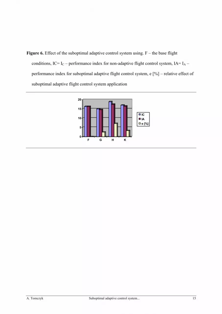
Figure 6. Effect of the suboptimal adaptive control system using. F – the base flight
conditions, IC= IC – performance index for non-adaptive flight control system, IA= IA –
performance index for suboptimal adaptive flight control system, e [%] – relative effect of
suboptimal adaptive flight control system application
0
5
10
15
20
F G H K
IC
IA
e [%]


