Embed Size (px)
Citation preview
International Journal of Engineering Inventions
e-ISSN: 2278-7461, p-ISSN: 2319-6491
Volume 4, Issue 2 (August 2014) PP: 20-30
www.ijeijournal.com Page | 20
Study and Fabrication of Thermoelectric Air Cooling and
Heating System
Prof. N. B. Totala1, Prof. V. P. Desai
2, Rahul K. N. Singh
3,
Debarshi Gangopadhyay4, Mohd. Salman Mohd. Yaqub
5, Nikhil Sharad Jane
6
1,2(Assistant Professor, Department of Mechanical Engineering,MIT Academy of Engineering,Alandi (D), Pune,
Maharashtra, 412105) 3,4,5,6(Department of Mechanical Engineering, MIT Academy of Engineering, Alandi(D), Pune, Maharashtra,
412105)
Abstract: In present scenario, HVAC system (commonly used in the air conditioners) is very efficient and
reliable but it has some demerits. It has been observed during the last two decades that the O3 layer is slowly
destroyed because of the refrigerant (CFC and HFC) used for the refrigeration and air- conditioning purposes.
The common refrigerant used is HFC’s which are leaked and slowly ascend into the atmosphere. When they
reach to O3 layer they act on O3 molecules and the layer of O3 is destroyed. A single molecule of HFC can
destroy thousands of O3 molecules and that's why it has created a threat for the not only to maintain earth eco
system stable but also to existence of earth. Even the percentage of HFCs are emitted into the atmosphere compared to CO2 is negligible but its global warming effect is few thousand times of CO2. The effect of 100 gm
of HFC can destroy 0.5 tons of O3 molecules. These HFCs once destroy O3 layer; it takes hundreds of years to
recover its thickness as it is formed by complex reactions. This is because as HFCs comes in environment, they
remain in atmosphere for 18 years. The capacity of HFCs to increase in earth temperature 10% is contributed
by HFC’s only. That leads to the emergence of finding an alternative of the conventional HVAC system, i.e.
thermo-electric cooling and heating system.
Keywords: Peltier effect, Thermoelectric module, Cooling load, Thermal resistance, COP.
NOMENCLATURE
A -Cross section area (m2)
Ab- Effective base Area of a heat sink (m2)
Afin- Area of a Fin (m2) Cp- Specific heat of air (J/kgK)
D- Diameter of the channel (m)
f -Darcy friction factor (N/A)
h -Heat transfer coefficient W/m2K
H -Height of a channel (m)
I- Operating Current (A)
L -Length of a fin or channel (m)
Lc- Corrected length for a rectangular fin (m)
m - Mass flow rate of air (kg/s)
N - Number of channels (N/A)
Pc- Pressure drop in the circular duct (N/m2) Pe- Electrical input power (W)
Pr- Pressure drop in the rectangular channel (N/m2)
Pt - Total pressure drop (N/m2)
Q - Air flow rate (f 3/min)
Qc - Heat load absorbed by the cold side of TEC (W)
Qh - Amount of heat dissipated at the hot side of TEC (W)
R- Thermal resistance (K/W)
Rb- Base thermal resistance (K/W)
Rf - Fin thermal resistance (K/W)
Rt - Total Thermal resistance (K/W)
r - Radius (m)
t - Thickness of a fin (m) T - Temperature (°C)
Tc - Cold side temperature (°C)
Th - Hot side temperature (°C)
Study and fabrication of thermoelectric air cooling and heating system
www.ijeijournal.com Page | 21
Tin - Inlet temperature (°C)
Tout - Outlet temperature( °C)
T∞ - Ambient temperature (°C) ∆T -Temperature difference (Κ)
v - Velocity of the air (m/s)
I. Introduction Although thermoelectric(TE) phenomena was discovered more than 150 years ago, thermoelectric
devices (TE coolers) have only been applied commercially during recent decades. For some time, commercial
TECs have been developing in parallel with two mainstream directions of technical progress – electronics and
photonics, particularly optoelectronics and laser techniques. Lately, a dramatic increase in the application of TE
solutions in optoelectronic devices has been observed, such as diode lasers, super-luminescent diodes (SLD), various photo-detectors, diode pumped solid state lasers (DPSS), charge-coupled devices (CCDs), focal plane
arrays (FPA) and others. The effect of heating or cooling at the junctions of two different conductors exposed to
the current was named in honor of the French watchmaker Jean Peltier (1785–1845) who discovered it in 1834.
It was found that if a current passes through the contacts of two dissimilar conductors in a circuit, a temperature
differential appears between them. This briefly described phenomenon is the basis of thermoelectricity and is
applied actively in the so-called thermoelectric cooling modules. Thermoelectric devices (thermoelectric
modules) can convert electrical energy into a temperature gradient––this phenomena was discovered by Peltier
in 1834. The application of this cooling or heating effect remained minimal until the development of
semiconductor materials. With the advent of semiconductor materials came the capability for a wide variety of
practical thermoelectric refrigeration applications. Thermoelectric refrigeration is achieved when a direct current
is passed through one or more pairs of n and p-type semiconductor materials. In the cooling mode, direct current passes from the n to p-type semiconductor material. The temperature of the interconnecting conductor decreases
and heat is absorbed from the environment. This heat absorption from the environment (cooling) occurs when
electrons pass from a low energy level in the p-type material through the interconnecting conductor to a higher
energy level in the n-type material. The absorbed heat is transferred through the semiconductor materials by
electron transport to the other end of the junction TH and liberated as the electrons return to a lower energy level
in the p-type material. This phenomenon is called the Peltier effect. 1) "Refrigeration and Air conditioning"
book by Mr. Ambatkar S.D.-From this book we got information about the principle of refrigeration and air
conditioning. We came to learn the domestic refrigeration system. We came to learn the domestic refrigeration
system. We studied calculation related to refrigeration, refrigerants, principle of load estimation etc.
2)"Automotive Air Conditioning" book by Mr. Dwiggins B.H.-From this book we gathered information about
the history of domestic and automotive air conditioning system. We studied the principle, construction and
working and servicing of today's HVAC system.3)"Heat and Thermodynamic" book by Mr. Subramanyam B.N.-In this book we gathered the information about the basic laws of thermodynamics and the role of
thermodynamic in the HVAC system.4)"Refrigeration and Air conditioning" book by Mr. Domkundwar:-This
book proved to be really helpful, especially in areas of duct design and heat load calculation.5)"Automotive
Technology" book by Mr. Jack Erajavec:-We learned mathematical calculation of refrigeration and
thermodynamics. We studied working system of HVAC system and observe temperature and pressure in this
system.
Our aim is to introduce the new HVAC system using thermoelectric couple which shall overcome all
the disadvantages of existing HVAC system. If this system comes in present HVAC system, then revolution will
occur in the automotive sector. With population and pollution increasing at an alarming rate TEC
(thermoelectric couple) system have come to rescue as these are environment friendly, compact and affordable.
Conventional compressor run cooling devices have many drawbacks pertaining to energy efficiency and the use of CFC refrigerants. Both these factors indirectly point to the impending scenario of global warming. As most of
the electricity generation relies on the coal power plants, which add greenhouse gases to the atmosphere is the
major cause of global warming. Although researches are going on, better alternatives for the CFC refrigerants is
still on the hunt. So instead of using conventional air conditioning systems, other products which can efficiently
cool a person are to be devised. By using other efficient cooling mechanisms we can save the electricity bills
and also control the greenhouse gases that are currently released into the atmosphere. Although Thermoelectric
(TE) property was discovered about two centuries ago thermoelectric devices have only been commercialised
during recent years. The applications of TE vary from small refrigerators and electronics package cooling to
Avionic instrumentation illumination control and thermal imaging cameras. Lately a dramatic increase in the
applications of TE coolers in the industry has been observed. It includes water chillers, cold plates, portable
insulin coolers, portable beverage containers and etc.
Study and fabrication of thermoelectric air cooling and heating system
www.ijeijournal.com Page | 22
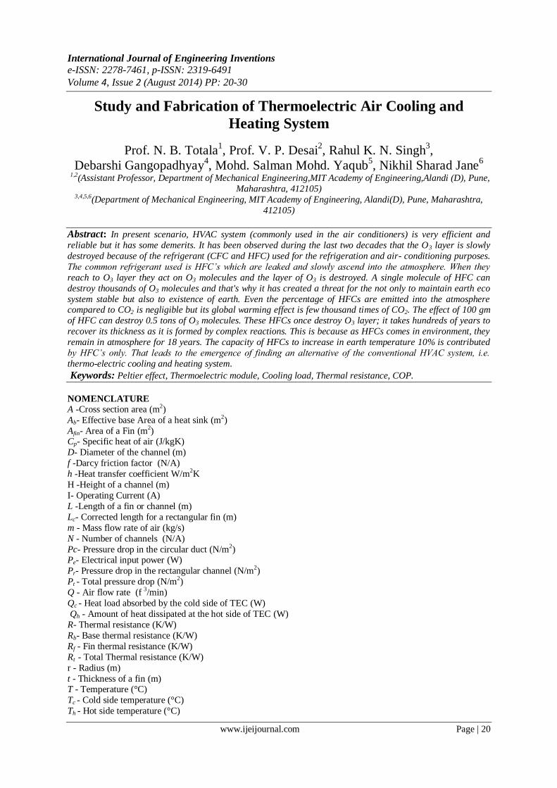
Fig. 1 Schematic of thermoelectric module operation (a) cooling mode (b) heating mode
II. Methodology and Experimentation
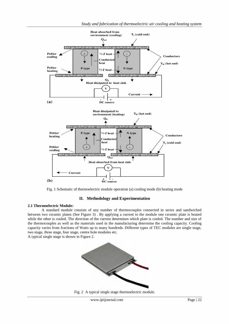
2.1 Thermoelectric Module: A standard module consists of any number of thermocouples connected in series and sandwiched
between two ceramic plates (See Figure 3) . By applying a current to the module one ceramic plate is heated
while the other is cooled. The direction of the current determines which plate is cooled. The number and size of
the thermocouples as well as the materials used in the manufacturing determine the cooling capacity. Cooling
capacity varies from fractions of Watts up to many hundreds. Different types of TEC modules are single stage,
two stage, three stage, four stage, centre hole modules etc.
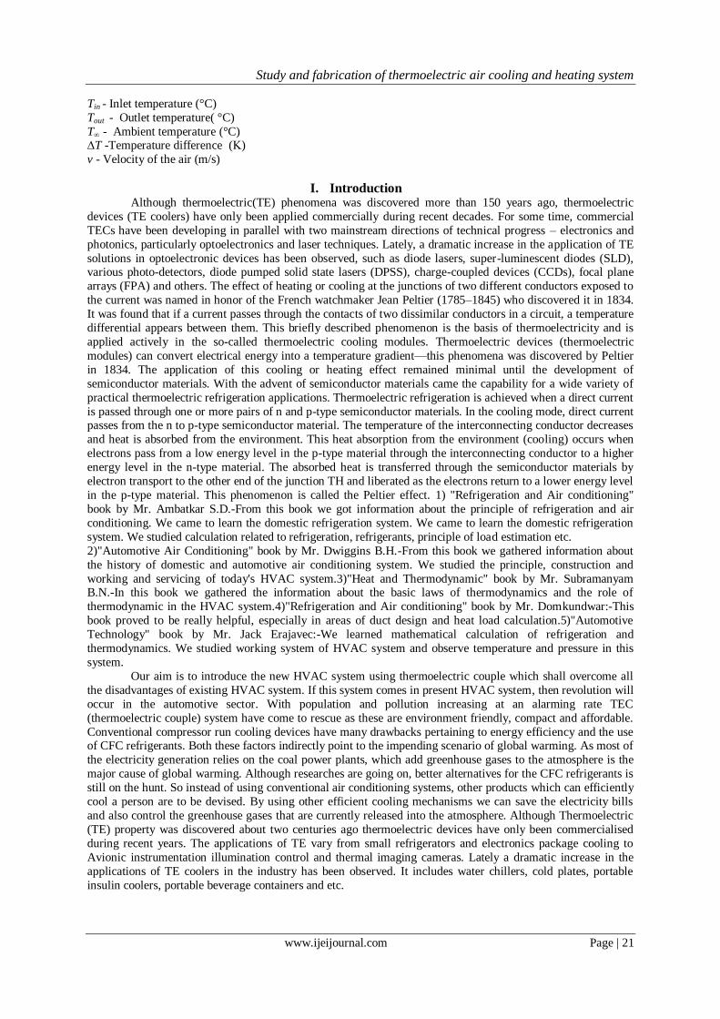
A typical single stage is shown in Figure 2.
Fig. 2 A typical single stage thermoelectric module.
Study and fabrication of thermoelectric air cooling and heating system
www.ijeijournal.com Page | 23
Fig. 3 A Classic TE Module Assembly
Before starting to design a TEC cooling system the designer have to take note the following into consideration.
1. Temperature to be maintained for the object that is to be cooled.
2. Heat to be removed from the cooled object.
3. Time required to attain the cooling after a DC power is applied.
4. Expected ambient temperature.
5. Space available for the module and hot side heat sink.
6. Expected temperature of hot side heat sink.
7. Power available for the TEC.
8. Controlling the temperature of the cooled object if necessary
2.2 Parameters of a Thermoelectric Module
Once it is decided that thermoelectric cooler is to be considered for cooling system, the next step is to
select the thermoelectric module or cooler that can satisfy a particular set of requirements. Modules are available
in great variety of sizes, shapes, operating currents, operating voltages and ranges of heat pumping capacity. The
minimum specifications for finding an appropriate TEC by the designer must be based on the following
parameters. The cutaway of a TEC is shown in Fig4.
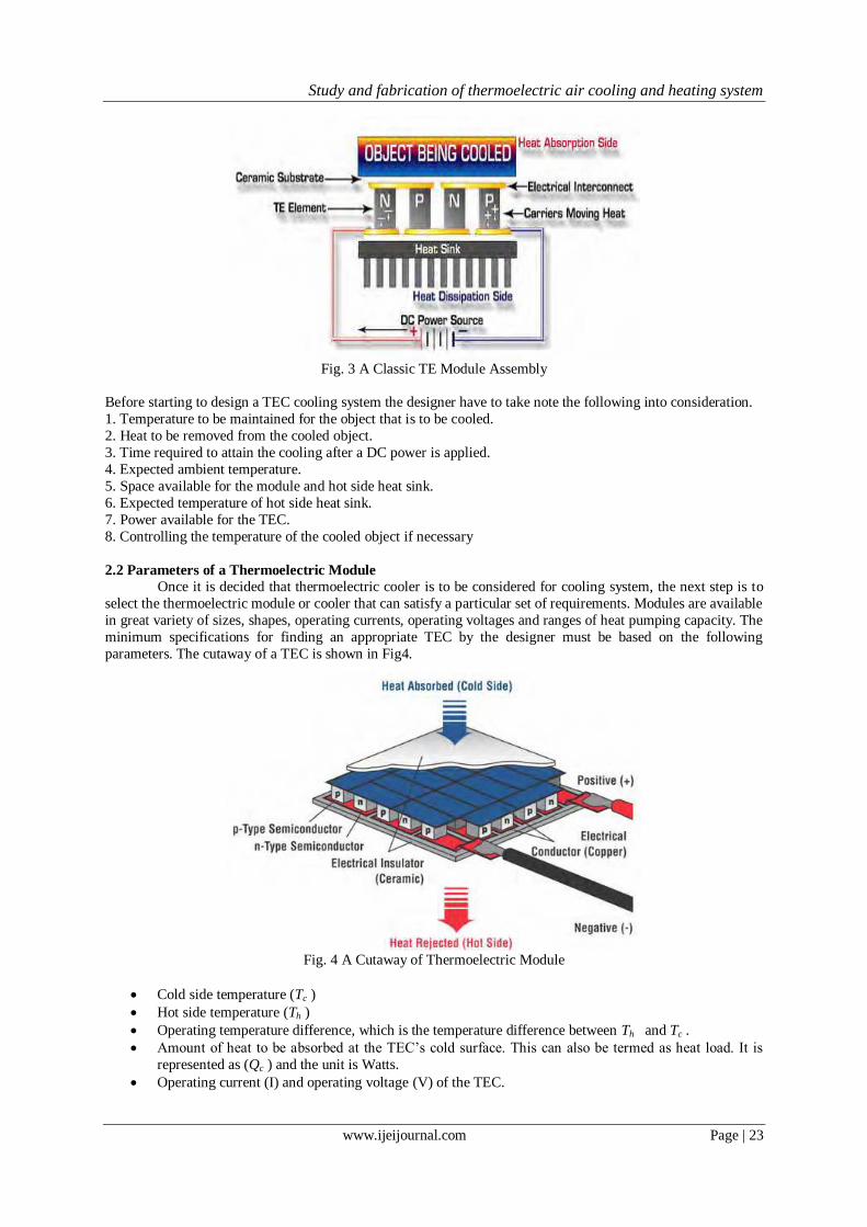
Fig. 4 A Cutaway of Thermoelectric Module
Cold side temperature (Tc )
Hot side temperature (Th )
Operating temperature difference, which is the temperature difference between Th and Tc .
Amount of heat to be absorbed at the TEC’s cold surface. This can also be termed as heat load. It is
represented as (Qc ) and the unit is Watts.
Operating current (I) and operating voltage (V) of the TEC.
Study and fabrication of thermoelectric air cooling and heating system
www.ijeijournal.com Page | 24
Cold side temperature
If the object to be cooled is in direct contact with the cold surface of the TEC, the required temperature
can be considered the temperature of the cold side of TEC (Tc).Here in this project the object is air inside the car, which has to be cooled when passed through a cluster of four Aluminium heat sinks. It is discussed in detail
in the next chapter. The aim is to cool the air flowing through the heat sinks. When this type of system is
employed the cold side temperature of the TEC is needed to be several time colder than the ultimate desired
temperature of the air.
Hot side temperature
The hot side temperature (Th) is mainly based on the two factors. First parameter is the temperature of
the ambient air in environment to which the heat is been rejected. Second factor is the efficiency of the heat sink
that is between the hot side of TEC and the ambient.
Temperature difference The two temperatures Tc and Th and the difference between them ∆T is a very important factor. ∆T has
to be accurately determined if the cooling system is expected to be operating as desired. The following equation
shows the actual ∆T.
∆T = Th -Tc
Actual ∆T is not same as the system ∆T. Actual ∆T is the difference between the hot and cold side of
the TEC. On the other hand system ∆T is the temperature difference between the ambient temperature and
temperature of the load to be cooled.
Cooling Load
The most difficult and important factor to be accurately calculated for a TEC is the amount of heat to
be removed or absorbed (Qc) by the cold side of the TEC. In this project Qc was calculated by finding the
product of mass flow rate of air, specific heat of air and temperature difference. Here the temperature difference system ∆T in the difference between the inlet temperature and outlet temperature of the cooling system. The
mathematical equation for Qc is as shown below.
Qc = m Cp∆T
Thermoelectric Assembly - Heat Sinks
Thermoelectric Assemblies (TEAs) are cooling or heating systems attached to the hot side of the TEC
to transfer heat by air, liquid or conduction. TEAs which dissipate heat from the hot side use heat exchangers.
TEC requires heat exchangers or heat sinks and will be damaged if operated without one. The two ∆T s, actual
∆T and system ∆T depend on the heat sinks fitted at the hot sides or cold sides of TEC. The thermal resistances
of the heat sinks could vary the ∆T across the TEC for a set ambient temperature and cooling load temperature.
Therefore the thermal resistance of the heat sinks could increase the current flowing through the TEC. The three
basic types of heat sinks are: forced convective, natural convective and liquid cooled, where liquid cooled is the most effective. The typical allowances for ∆T at the hot side heat sink of a TEC are
1. 10 to 15 °C for a forced air cooling system with fins - Forced convection
2. 20 to 40 °C for cooling using free convection - Natural convection.
3. 2 to 5 °C for cooling using liquid heat exchangers - Liquid cooled.
There are several different types of heat exchangers available in the market. As far this project is concerned a
forced convection type of heat sink was be used based on the ∆T.
The main heat sink parameter for the selection process is its thermal resistance. Heat sink resistance can be
termed as the measure of the capability of the sink to dissipate the applied heat. The equation is as follows.
R = (Th-T∆ )/Qh
R is the thermal resistance (in oC /W or K/W) and Th, the hot side temperature and T∞ ambient temperature
respectively. Qh is the heat load into the heat sink which is the sum of TEC power Pe and heat absorbed.
Q h=Qc+Pe
The goal of a heat sink design is to lessen the thermal resistance. It can be attained through exposed surface
area of the heat sink. It may also require forced air or liquid cooling.
Power Supply and Temperature Control
Power supply and temperature control are two added items that must be considered wisely for a
successful TE system. TEC is a direct current device. The quality of the DC current is important. Current and
voltage of a TEC can be determined by the charts provided by the manufacturer. TEC’s power is the product of
required voltage and current. (P = IV).
Study and fabrication of thermoelectric air cooling and heating system
www.ijeijournal.com Page | 25
Temperature control is generally categorized into two groups. One is open loop or manual and the other
is closed loop or automatic. For cooling systems normally cold side is used as basis of control. The controlled
temperature is compared to the ambient temperature. An on-off or a control using thermostat is the simplest and easiest techniques to control the temperature of a TEC.
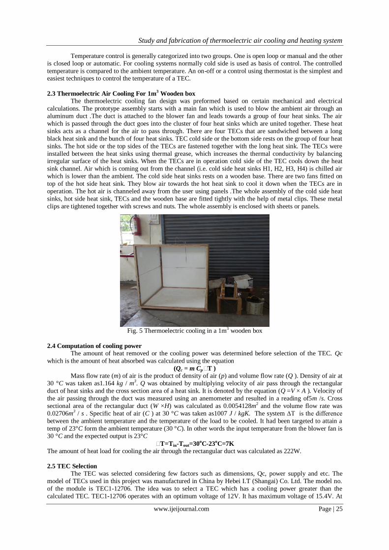
2.3 Thermoelectric Air Cooling For 1m3 Wooden box
The thermoelectric cooling fan design was preformed based on certain mechanical and electrical
calculations. The prototype assembly starts with a main fan which is used to blow the ambient air through an
aluminum duct .The duct is attached to the blower fan and leads towards a group of four heat sinks. The air
which is passed through the duct goes into the cluster of four heat sinks which are united together. These heat
sinks acts as a channel for the air to pass through. There are four TECs that are sandwiched between a long
black heat sink and the bunch of four heat sinks. TEC cold side or the bottom side rests on the group of four heat
sinks. The hot side or the top sides of the TECs are fastened together with the long heat sink. The TECs were
installed between the heat sinks using thermal grease, which increases the thermal conductivity by balancing irregular surface of the heat sinks. When the TECs are in operation cold side of the TEC cools down the heat
sink channel. Air which is coming out from the channel (i.e. cold side heat sinks H1, H2, H3, H4) is chilled air
which is lower than the ambient. The cold side heat sinks rests on a wooden base. There are two fans fitted on
top of the hot side heat sink. They blow air towards the hot heat sink to cool it down when the TECs are in
operation. The hot air is channeled away from the user using panels .The whole assembly of the cold side heat
sinks, hot side heat sink, TECs and the wooden base are fitted tightly with the help of metal clips. These metal
clips are tightened together with screws and nuts. The whole assembly is enclosed with sheets or panels.
Fig. 5 Thermoelectric cooling in a 1m3 wooden box
2.4 Computation of cooling power The amount of heat removed or the cooling power was determined before selection of the TEC. Qc
which is the amount of heat absorbed was calculated using the equation
(Qc = m Cp∆T )
Mass flow rate (m) of air is the product of density of air (p) and volume flow rate (Q ). Density of air at
30 °C was taken as1.164 kg / m3. Q was obtained by multiplying velocity of air pass through the rectangular
duct of heat sinks and the cross section area of a heat sink. It is denoted by the equation (Q =V × A ). Velocity of
the air passing through the duct was measured using an anemometer and resulted in a reading of5m /s. Cross
sectional area of the rectangular duct (W ×H) was calculated as 0.0054128m2 and the volume flow rate was
0.02706m3 / s . Specific heat of air (C ) at 30 °C was taken as1007 J / kgK. The system ∆T is the difference
between the ambient temperature and the temperature of the load to be cooled. It had been targeted to attain a
temp of 23°C form the ambient temperature (30 °C). In other words the input temperature from the blower fan is
30 °C and the expected output is 23°C
∆T=Tin-Tout=30oC-23
oC=7K
The amount of heat load for cooling the air through the rectangular duct was calculated as 222W.
2.5 TEC Selection
The TEC was selected considering few factors such as dimensions, Qc, power supply and etc. The
model of TECs used in this project was manufactured in China by Hebei I.T (Shangai) Co. Ltd. The model no.
of the module is TEC1-12706. The idea was to select a TEC which has a cooling power greater than the
calculated TEC. TEC1-12706 operates with an optimum voltage of 12V. It has maximum voltage of 15.4V. At
Study and fabrication of thermoelectric air cooling and heating system
www.ijeijournal.com Page | 26
12V it draws and maximum DC current of 4 A. The minimum power rating or the cooling power is 37.7 W. The
maximum power is 48W. It has a maximum operating temperature of 200°C of the TEC are 68 when hot side
temperature is 25 °C. The charts from the TEC manufacture were also analyzed while choosing the TEC. It had been decided to choose 4 TECs of the same model so that when the power of all the 4 TECs is higher than the
calculated cooling load. The minimum power rating for 4 TECs added together was more than the cooling load
calculated.
37.7W ×6 = 226W > 222W
The electrical power supplied to the TEC must be higher than the combined power rating of the four
TECs and it also depends on the arrangement of the TEC.
2.6 TEC Arrangement
The ambient air blown from the blower is channeled into a group of four heat sinks which acts as a
rectangular duct as discussed earlier. It was decided to remove maximum amount of heat from the point when
the air started to enter the first heat sink. Keeping that in mind the first heat sink was installed with two TECs in series and the second one also was installed with another two TECs in series. This will help to remove more heat
from of the air when air enters the duct. The third and fourth heat sinks were installed with one TEC each and
they were connected in series also. All the two series connected TECs were connected in parallel.
2.7 Selection of Heat sink
There were two different types of heat sink used for this project. One was for the cold side and another
for hot side. The initial idea of the project was to use a hollow cylinder as duct to channel air, instead of heat
sink on the cold side of the TEC. Initial testing after the proposal stage with hollow cylinder, did not work out
well. This was because there of less heat transfer within the cylinder and the air coming out was not cold
enough. So the decision was made to use to heat sinks which acts a rectangular duct to channel air. A total of
four similar kinds of heat sinks (9Y692 A00-00) were used. .Each heat sinks have 20 fins which helped to
dissipate coldness fast enough from TECs cold side. In this project heat sinks (hot side and cold side) operate by conducting heat or coldness from the TEC to the heat sink and then radiating to air. A better the transfer of
coldness between the two surfaces, the better the cooling will be. When the heat sinks were attached the TECs,
there will be uneven surfaces or gaps. The gap will cause for poor heat transfer, even if it is negligible. To
improve the thermal connection between the TECs and the heat sinks a chemical compound was used. The heat
sink compound, typically a white paste made form zinc oxide in a silicone base ensures a good transfer of heat
between the modules and the heat sinks.
Hot Side heat sink
The hot side heat sink used in the project was a single long one installed on the top side of the TECs.
As discussed , thermal resistance of a heat sink is an important factor while designing a system.
Rt=(Th-T∞)/Qh= 0.038K /W Therefore a forced convection heat sink had to be used. When selecting hot side heat sink for the
project other factors such as dimension to fit into the whole assembly, budget and availability were also taken to
consideration. The heat sink was bought from a local shop and there was no thermal resistance or datasheets
available for the product. The alternative was to calculate Rt from the resistance of the unfinned area (Rb ) and
the resistance offered by the fins (Rf). Since both of these resistances are acting in parallel, total resistance was
found using the equation
1 / Rf = 1/ Rb + 1/ Rf
The calculated value was 0.0145K /W. The calculated thermal resistance of the heat sink was lesser than the
required. But when considered the dimensions of the cooling system the selected heat sink was very apt.
Calculations
All calculations used in the project ,related to cooling load , selection of heat sinks, selection of fans, pressure drop calculations, surface area needed to cool the air etc. are mentioned below-
Cooling load-
Qc the amount heat load to be absorbed by the cold junction has to be calculated before the selection of
TECs.
Qc = m Cp ∆T
m =p. Q
p =1.164 kg/m3( At 30oC)
Q =VxA
Study and fabrication of thermoelectric air cooling and heating system
www.ijeijournal.com Page | 27
A =WxH
=0.098m x0.064m
=0.006272m2 V =2.5m/s
Q =2.5x0.006272
=0.01568m3/s
m =1.164 kg/m3x0.01568m3/s
=0.018252kg/s
Cp =1007J/KgK ( At 30oC)
∆T =32.5-22.1
=10.4oC
Qc =1007x10.4x0.018252
=191.149W
≈191W Qh was calculated by adding the electrical power input and the cooling load.
Pe =18V x 13amp=234W
Qh =191W+234W
=425K
COP = Qc/Pe = 0.81624
This was not the actual COP of the system. It can be higher, as the power input designed is higher than
the calculated Qc. A higher power input for TECs were selected in the project. The system was designed with a
higher power input. Therefore the actual COP can even higher.
Thermal Resistance of the Hot side Heat Sink
Hot side heat sink has to be selected based on its Thermal resistance. The thermal resistance of the hot side heat
sink is calculated below.
Qh =(Th-T∞)/ Rt
Qh=425W(Qc + Pe )
T∞=32.5oC
Th=36.2oC
Rt=(36.2-32.5)/425=0.0087 K/W
Power of blower fan:The power of the fan will be equal to the product of total pressure drop (pt) and volume
flow rate. The total pressure drop will be the sum of pressure drop in cold side heat sink channel (rectangular
channel) and the circular duct.
To calculate the pressure drop using Darcy Law, the equation is as follows: The pressure drop = 0.5*(fL/D)* p * v2
Pressure drop in the circular duct(pc) :-
For the circular duct, Darcy friction factor is value is taken as 0.03 for
f = 0.03
L= 0.22
D =15.5
r = 0.0775
p = 1.164 kg/m3
Q = V A
V = Q/A Q = 0.01568
A = ∏*r2
= 3.14*0.072
= 0.01887 m2
v = 0.83098 m/s
pc = 0.5 * fL/D * p * v2
= 0.5 *( (0.03*0.22)/0.155)* 1.164*0.830982
pc = 0.01711 N/m2
Surface area needed to cool the air
Study and fabrication of thermoelectric air cooling and heating system
www.ijeijournal.com Page | 28
The calculations are computed below.
Qc =m Cp ∆T
QC = hA* ∆T
A = Qc/(h∆T)
h = 100 w/m2 k
∆T = T* - Tc
T* = (T1 + T2)/2
T* = (32.5 oC + 21.1 oC )/2
T* = 27.3 oC
Tc = 15 oC
∆T = 27.3 oC - 15 oC ∆T = 12.3 K
A = 191/(100*12.3)
A = 0.15528 m2
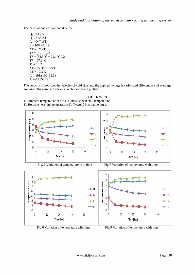
The velocity of hot side, the velocity of cold side ,and the applied voltage is varied and different sets of readings
are taken.The results of various combinations are plotted.
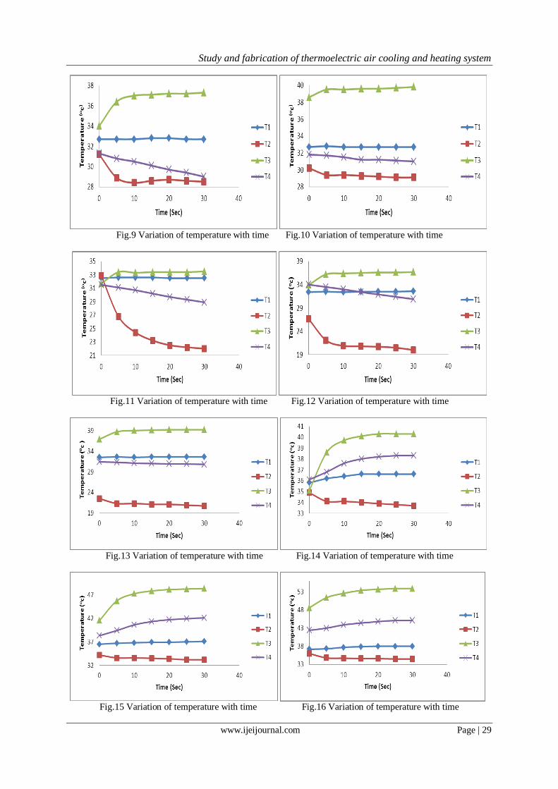
III. Results T1-Ambient temperature of air,T2-Cold side heat sink temperature.
T3-Hot side heat sink temperature,T4-Plywood box temperature.
Fig. 6 Variation of temperature with time Fig.7 Variation of temperature with time
Fig.8 Variation of temperature with time Fig.9 Variation of temperature with time
Study and fabrication of thermoelectric air cooling and heating system
www.ijeijournal.com Page | 29
Fig.9 Variation of temperature with time Fig.10 Variation of temperature with time
Fig.11 Variation of temperature with time Fig.12 Variation of temperature with time
Fig.13 Variation of temperature with time Fig.14 Variation of temperature with time
Fig.15 Variation of temperature with time Fig.16 Variation of temperature with time
Study and fabrication of thermoelectric air cooling and heating system
www.ijeijournal.com Page | 30
IV. Conclusion A Thermoelectric Air cooling & heating system was designed and built which can be used for personal
cooling & heating. Four TECs were used for achieving the cooling with a DC power supply through external
power supply (dimmer stat). It had been shown from testing results that the cooling system is capable of cooling
& heating the air when re circulating the air with the help of blower.TEC cooling designed was able to cool an
ambient air temperature from32.5°C to 22.1°C. Cooling stabilizes within ten minutes once the blower is turned
ON (with a velocity of 2.5 m/s). The system can attain a temperature difference of set target which was 6°C.
Accomplishing the set target establish the success of the project. All the components in the project had been
tested individually and the results were found to be positive.
The prototype can be made compact by selecting as single TEC of higher power (.i.e. of 200W or
more). It can be done by choosing a better cold side heat sink that has twisted channels or pipes for circulating
the air for a longer time. As an alternative for normal axial fan used in this project, if a blower fans is selected, the cooling system would provide better airflow. Even as shown in the appended figure we can mount no of
TEC cooling in Well-known TEC brands (.i.e. Melcor, Ferro TEC etc) must be chosen if there is only one high
power TEC selected for the cooling system. Bigger hot side heat sink has to be selected accurately based its
calculated thermal resistances for best cooling efficiency. With a single TEC, one hot side and a cold side heat
sink a smaller personal TEC cooler which gives comfort can be fabricated and can be installed on roof for
individual cooling by changing the airflow and some mechanical or electronics section modification, the TEC
air cooling for car can be used for heating applications too.
REFERENCES [1] B.J.Huang, C.J. Chin, C.L. Duang, “A design method of thermoelectric cooler”, International Journal of Refrigeration 23 (2000),
200-208.
[2] Manoj Rautl, “Thermoelectric Air Cooling For Cars”, International Journal of Engineering Science and Technology, Volume 4,
Issue 5, May 2012, pp 2381-2394.
[3] S.B. Riffat, Xiaoli Ma, “Thermoelectric: a review of present and potential applications”, Applied Thermal Engineering 23 (2003)
913-935.
[4] Harvie, MR 2005, “Personal cooling and heating system”, Patent Application Publication, US Patent Number 6915641.
[5] Hyeung,SC, Sangkook, Y & Kwang-il, W 2007 , “ Development of a temperature-controlled car-seat system utilizing
thermoelectric device”, Applied Thermal Engineering, pp 2841-2849.
[6] Koetzsch, J & Madden, M 2009, “Thermoelectric cooling for industrial enclosures”, Rittal White Paper 304, pp 1- 6.
[7] Larid 2009, “Thermoelectric AssembliModules for Industrial Applications”, Application Note, Larid Technologies.
[8] Lauwers, W & Angleo, SD 2009, “The Cooling Vest Evaporative Cooling”, Final Year Degree Project, Worcester polytechnic
institute.
[9] Marlow Industries, “Thermoelectric Cooling systems”Design Guide, pp -11, Dallas, Texas.
[10] Melcor 2010, “Thermoelectric Handbook”, Laird Technologies.
[11] McStravick, M et.al 2009, “Medical travel pack with cooling System”, Patent Application Publication, US Patent Number
49845A1.
[12] Rowe, DM & Bhandari CM 2000, “Modern thermoelectric”, Reston Publishing, USA.
[13] Rowe, “CRC handbook of thermoelectrics”, Boca Raton, FL: CRC Press, DM 1995.
[14] Rowe, “Thermoelectric Handbook”, Macro to Nano. Boca Raton, FL: CRCPress, DM 2006
[15] ST Microelectronics 2004, 300W Secondary Controlled Two switch forward converter with L5991A, AN1621 Application Note.
Tan, FL & Fok, SC 2008